RU19420U1 - DEVICE FOR MEASURING ELECTRICAL PARAMETERS AND DETERMINING THE PLACE OF DAMAGE TO CABLE LINES - Google Patents
DEVICE FOR MEASURING ELECTRICAL PARAMETERS AND DETERMINING THE PLACE OF DAMAGE TO CABLE LINES Download PDFInfo
- Publication number
- RU19420U1 RU19420U1 RU2001113173/20U RU2001113173U RU19420U1 RU 19420 U1 RU19420 U1 RU 19420U1 RU 2001113173/20 U RU2001113173/20 U RU 2001113173/20U RU 2001113173 U RU2001113173 U RU 2001113173U RU 19420 U1 RU19420 U1 RU 19420U1
- Authority
- RU
- Russia
- Prior art keywords
- measuring
- cable
- connector
- microcontroller
- switch
- Prior art date
Links
- 238000012360 testing method Methods 0.000 claims abstract description 18
- 238000002955 isolation Methods 0.000 claims abstract description 8
- 239000003990 capacitor Substances 0.000 claims abstract description 3
- 238000010292 electrical insulation Methods 0.000 claims abstract 5
- 239000004973 liquid crystal related substance Substances 0.000 claims abstract 2
- 238000005259 measurement Methods 0.000 claims description 13
- 238000009413 insulation Methods 0.000 description 20
- 101000797092 Mesorhizobium japonicum (strain LMG 29417 / CECT 9101 / MAFF 303099) Probable acetoacetate decarboxylase 3 Proteins 0.000 description 4
- 238000000034 method Methods 0.000 description 4
- 238000012935 Averaging Methods 0.000 description 3
- 238000004364 calculation method Methods 0.000 description 2
- 239000004020 conductor Substances 0.000 description 2
- 238000012937 correction Methods 0.000 description 2
- 238000013461 design Methods 0.000 description 2
- 238000012545 processing Methods 0.000 description 2
- 208000032750 Device leakage Diseases 0.000 description 1
- 108091022873 acetoacetate decarboxylase Proteins 0.000 description 1
- 230000003213 activating effect Effects 0.000 description 1
- 238000004891 communication Methods 0.000 description 1
- 238000010586 diagram Methods 0.000 description 1
- 230000005294 ferromagnetic effect Effects 0.000 description 1
- 238000011022 operating instruction Methods 0.000 description 1
- 239000002689 soil Substances 0.000 description 1
Landscapes
- Measurement Of Resistance Or Impedance (AREA)
- Testing Of Short-Circuits, Discontinuities, Leakage, Or Incorrect Line Connections (AREA)
Abstract
1. Устройство для измерения электрических параметров и определения мест повреждения кабельных линий, содержащее индикатор, а также последовательно соединенные изолированный источник питания и блок измерительных цепей с коммутатором, отличающееся тем, что он дополнительно содержит аналого-цифровой преобразователь и микроконтроллер с панелью управления, соединенный с индикатором непосредственно и через аналого-цифровой преобразователь с выходом блока измерительных цепей.2. Устройство по п.1, отличающееся тем, что индикатор выполнен цифровым в виде жидкокристаллического дисплея, а микроконтроллер - на больших интегральных схемах, например типа МКС-51, КР 18116 БЕЗ1.3. Устройство по пп.1 и 2, отличающееся тем, что блок измерительных цепей содержит четыре коммутируемые цепи измерения емкости, электрического сопротивления изоляции, электрического сопротивления шлейфа и утечки тока кабеля в режимах "емкость", "изоляция", "шлейф", "утечка" соответственно.4. Устройство по п.3, отличающееся тем, что цепь измерения емкости кабеля содержит генератор, соединенный через коммутатор в режиме "емкость" с первым измерительным разъемом непосредственно и через первый измерительный прецизионный резистор и разделительный конденсатор - со вторым измерительным разъемом, при этом параллельно выходу генератора подключен делитель напряжения, состоящий из двух прецизионных резисторов.5. Устройство по п.3, отличающееся тем, что цепь измерения электрического сопротивления изоляции кабеля содержит источник испытательного напряжения с ограничителем тока, который через коммутатор в режиме "изоляции" соединен с первым измерительным разъем�1. A device for measuring electrical parameters and determining the damage points of cable lines, comprising an indicator, as well as a sequentially connected isolated power source and a block of measuring circuits with a switch, characterized in that it further comprises an analog-to-digital converter and a microcontroller with a control panel connected to indicator directly and through an analog-to-digital converter with the output of the measuring circuit block. 2. The device according to claim 1, characterized in that the indicator is digital in the form of a liquid crystal display, and the microcontroller is based on large integrated circuits, for example, type MKS-51, KR 18116 BEZ1.3. The device according to claims 1 and 2, characterized in that the measuring circuit block contains four switched circuits for measuring capacitance, electrical insulation resistance, electrical resistance of the cable and cable current leakage in the modes "capacity", "isolation", "cable", "leak" respectively. 4. The device according to claim 3, characterized in that the cable capacitance measuring circuit comprises a generator connected via a switch in the capacitance mode to the first measuring connector directly and through the first measuring precision resistor and isolation capacitor to the second measuring connector, while parallel to the generator output a voltage divider is connected, consisting of two precision resistors. 5. The device according to claim 3, characterized in that the circuit for measuring the electrical insulation resistance of the cable contains a test voltage source with a current limiter, which is connected to the first measuring connector through the switch in the "isolation" mode�
Description
Устройство для измерения электрических параметров и определения местDevice for measuring electrical parameters and determining places
повреждения кабельных линий.damage to cable lines.
Полезная модель относится к устройствам для измерения электрических параметров и определения местоположения электрических повреждений, а именно в кабельных линиях.The utility model relates to devices for measuring electrical parameters and determining the location of electrical damage, namely in cable lines.
Известно устройство для измерения электрических параметров и определения места повреждения кабельных линий, содержащее последовательно соединенные изолированный источник питания, блок измерительных цепей с коммутатором, мостовые усилители постоянного (УПТ) и переменного тока и электромеханический стрелочный индикатор. При этом блок измерительных цепей с коммутатором выполнен в виде мостовой схемы с магазином сопротивлений, (Прибор кабельный переносный ПКП-5, Техническое описание и инструкция по эксплуатации. ОКП 52 9561 0008. М., Госстандарт, 1983).A device for measuring electrical parameters and determining the location of damage to cable lines, containing a series-connected isolated power source, a block of measuring circuits with a switch, bridge amplifiers DC (AC) and AC and an electromechanical dial indicator. In this case, the block of measuring circuits with a switch is made in the form of a bridge circuit with a resistance store, (Cable portable instrument PKP-5, Technical Description and Operating Instructions. OKP 52 9561 0008. M., Gosstandart, 1983).
Недостатком известного устройства является недостаточная производительность, обусловленная необходимостью ручного уравновешивания мостовой схемы в процессе измерения параметров кабельной линии и ручной обработки результатов измерений параметров кабельной линии.A disadvantage of the known device is the lack of performance, due to the need to manually balance the bridge circuit in the process of measuring cable line parameters and manual processing of the measurement results of cable line parameters.
В основу настоящей полезной модели поставлена задача создания устройства для измерения электрических параметров и определения мест повреждения кабельных линий, конструкция которого позволяет повысить производительность измерений и оценки их результатов.The basis of this utility model is the task of creating a device for measuring electrical parameters and determining the location of damage to cable lines, the design of which allows to increase the measurement performance and evaluate their results.
Решение поставленной задачи достигается тем, что в устройстве для измерения электрических параметров и определения мест повреждения кабельных линий, содержащем индикатор, а также последовательно соединенные изолированный источник питания и блок измерительных цепей с коммутатором согласно полезной модели он дополнительноThe solution to this problem is achieved by the fact that in the device for measuring electrical parameters and determining places of damage to cable lines, containing an indicator, as well as sequentially connected an isolated power source and a block of measuring circuits with a switch according to the utility model, it is additionally
аналого-цифровой преобразователь иanalog to digital converter and
панелью управления, соединенный с индикатором непосредственно и через аналого-цифровой преобразователь с выходом блока измерительных цепей. При этом индикатор выполнен цифровым в виде жидкогфисталлического дисплея, а микроконтроллер на больших интегральных схемах (БИС), например типа MKC-Sl, КР 18116 БЕ31.a control panel connected to the indicator directly and through an analog-to-digital converter with the output of the measuring circuit block. In this case, the indicator is digital in the form of a liquid-hydraulic display, and the microcontroller is based on large integrated circuits (LSI), for example, MKC-Sl type, КР 18116 БЕ31.
Введение указанных отличий позволяет автоматизировать процесс измерения и обработки результатов измерений электрических параметров кабеля, позволяющих в целом повысить производительность устройства для определения мест повреждения кабельных линий. При этом одновременно уменьшены не менее, чем в 5 раз весогабаритныеThe introduction of these differences allows you to automate the process of measuring and processing the results of measurements of the electrical parameters of the cable, which in General can improve the performance of the device to determine the damage points of cable lines. At the same time, weight and size are simultaneously reduced by at least 5 times
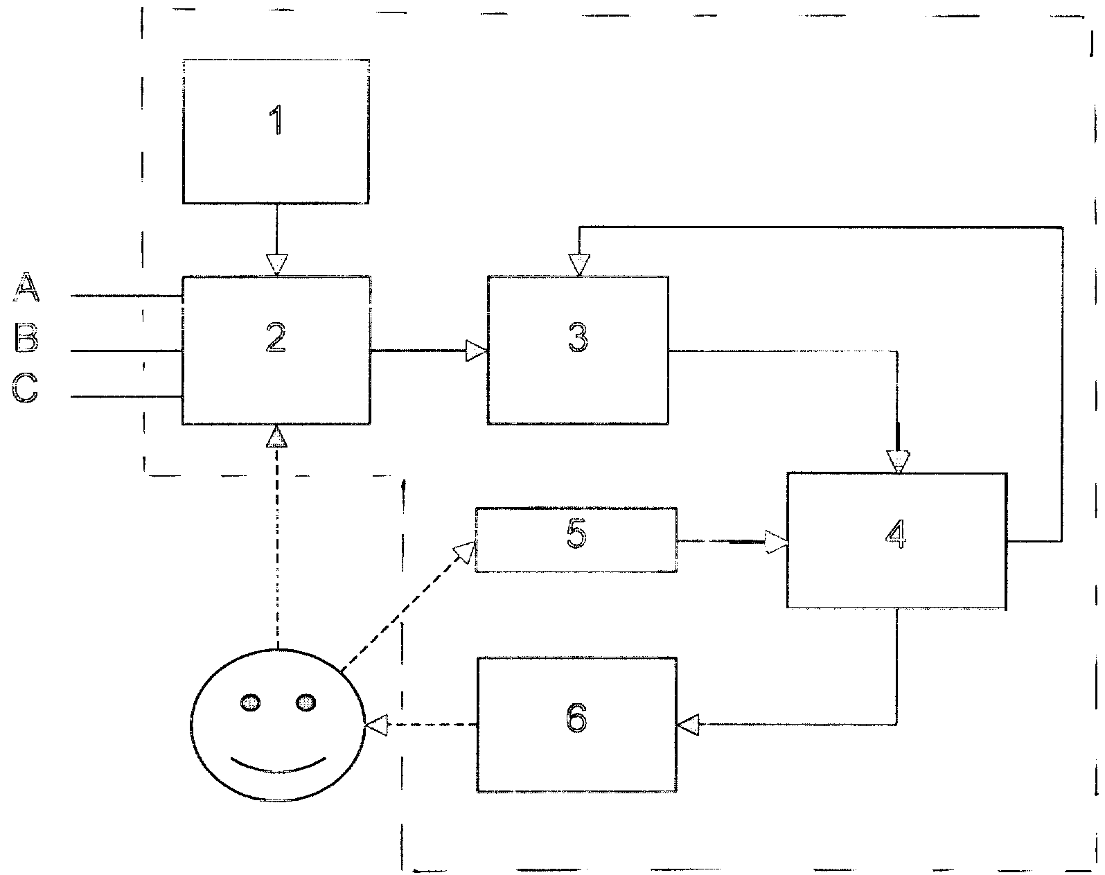
Па фиг. 1 представлена функциональная схема устройства, на фиг. - электрические коммутационные схемы блока измерительных цепей в режимах измерения изоляции, емкости, шлейфа и утечки кабельных линийPa fig. 1 shows a functional diagram of the device, FIG. - electrical switching circuits of the measuring circuit block in the modes of measuring insulation, capacitance, loop and cable leakage
Устройства для измерения электрических параметров и определения мест повреждения кабельных линий содержит последовательно соединенные изолированный источник 1 напряжения, блок 2 измерительных цепей с коммутатором, аналого-цифровой преобразователь 3, микроконтроллер 4 с панелью управления 5 и индикатор 6. Элементы ()устройства заключены в общий корпус 7. Источник 1 выполнен изолированным от Земли. Блок 2 содержит три входных клеммы (А, Б, С), соединенных через коммутатор на четыре рабочих положения (изоляция, шлейф, утечка, емкость) и набор прецизионных и измерительных резисторов с соответствуюш,ими аналоговыми входами преобразователя 3. Выход преобразователя 3 соединен с первым входом микроконтроллера 4, второй (управляющий) вход которого соединен с выходом кнопочной панели 5 управления режимами работы микроконтроллера 4. Микроконтроллер 4 содержитThe device for measuring electrical parameters and determining the damage points of cable lines contains a sequentially connected isolated voltage source 1, a block 2 of measuring circuits with a switch, an analog-to-digital converter 3, a microcontroller 4 with a control panel 5 and an indicator 6. Elements () of the device are enclosed in a common housing 7. Source 1 is made isolated from the Earth. Block 2 contains three input terminals (A, B, C) connected via a switch to four operating positions (isolation, loop, leak, capacitance) and a set of precision and measuring resistors with corresponding analog inputs of converter 3. The output of converter 3 is connected to the first input of the microcontroller 4, the second (control) input of which is connected to the output of the keypad 5 to control the operating modes of the microcontroller 4. The microcontroller 4 contains
процессор с блоками памяти и дешифратор входных сигналов с преобразователя 3 и панели 5 управления. Блоки памяти микроконтроллера 4 выполнены на диодных ячейках и/или ферромагнитных элементах и содержат вшитые данные о параметрах известных кабельных линий, калибровочные и расчетные соотношения для заданных режимов работы устройства.a processor with memory units and an decoder of input signals from the converter 3 and the control panel 5. The memory blocks of the microcontroller 4 are made on diode cells and / or ferromagnetic elements and contain embedded data on the parameters of known cable lines, calibration and calculation ratios for the given operating modes of the device.
Устройство работает следуюш;им образом. Оператор 8 устанавливает коммутатор блока 2 в положение «изоляция и проверяет сопротивление изоляции между жилами и оболочкой кабеля. Измерение сопротивление изоляции кабеля производится с выходных измерительных разъемов устройства В и С, Испытательное напряжение (400 В относительно О, может быть от 1 до 1000 В) через источник или ограничитель тока 9 (в случае ограничителя это резистор или цепочка резисторов) подается на измерительный выходной разъем С устройства, Сопротивление изоляции кабеля рассчитывается микроконтроллером 4 как отношение величины испытательного напряжения, подаваемого на кабель, к току, протекаюш;ему через изоляцию кабеля. Сигнал, пропорциональный испытательному напряжению, поданному на кабель, снимается с делителя R3, R4 (точка О),Сигналы, пропорциональные току, протекающему- через изоляцию кабеля, снимаются с- цепочки резисторов R1, R2 (точки Е, F) (количество резисторов может быть любым), причем АЦП 3 обрабатывает тот сигнал, который выбирает микроконтроллер 4 в зависимости от диапазона, в который попадает измеряемая величина. При определении величины испытательного напряжения, поданного на кабель, микроконтроллер 4 учитывает величину токового сигнала, снимаемого с цепочки резисторов R1, R2, который входит в сигнал, пропорциональный испытательному напряжению, который снимается с делителя R3, R4, При измерениях АЦП 3 микроконтроллер 4 осуществляет учет сигнала с точки О.The device operates as follows; in their image. Operator 8 sets the switch of unit 2 to the “insulation” position and checks the insulation resistance between the cores and the cable sheath. The cable insulation resistance is measured from the output measuring connectors of devices B and C, Test voltage (400 V relative to O, can be from 1 to 1000 V) through a source or current limiter 9 (in the case of a limiter, this is a resistor or a chain of resistors) is supplied to the measuring output connector C of the device, The insulation resistance of the cable is calculated by the microcontroller 4 as the ratio of the value of the test voltage supplied to the cable to the current leaking to it through the cable insulation. A signal proportional to the test voltage supplied to the cable is removed from the divider R3, R4 (point O). Signals proportional to the current flowing through the cable insulation are removed from the c-chain of resistors R1, R2 (points E, F) (the number of resistors can be any), and the ADC 3 processes the signal that the microcontroller 4 selects depending on the range into which the measured value falls. When determining the value of the test voltage supplied to the cable, the microcontroller 4 takes into account the value of the current signal taken from the resistor chain R1, R2, which is included in the signal proportional to the test voltage, which is taken from the divider R3, R4. When measuring the ADC 3, the microcontroller 4 takes into account signal from point O.
Результаты измерений сопротивления изоляции кабеля отображаются на индикаторе 6. В случае сильных помех в линии, влияющих на стабильность показаний индикатора 6 оператор 8 кнопками панели 5 управления включает режим усреднения измерений. По результатам измерений судят о работоспособности изоляции кабеля.The results of measurements of the cable insulation resistance are displayed on indicator 6. In the case of strong interference in the line affecting the stability of the readings of indicator 6, the operator 8 switches the measurement averaging mode with the buttons of the control panel 5. Based on the measurement results, the cable insulation is judged to be operational.
Затем включают коммутатор блока 2 в режим «емкость. Измерение электрической емкости кабеля производится с входных измерительных разъемов В и С, устройства 2. Переменное испытательное напряжение генератора 10 подается на измерительный выходной разъем С устройства 2. Электрическая емкость кабеля рассчитывается микроконтроллером 4 как отношение величины испытательного напряжения, подаваемого на кабель, к току, протекающему через электрическую емкость кабеля. Сигнал, пропорциональный испытательному напряжению, поданному на кабель, снимается с делителя R7, R8 (точка G) и через выпрямитель (не показан) подается на АЦП 3. Сигнал, пропорциональный току, протекающему через электрическую емкость, снимается с резистора R6 (точка L) и через выпрямитель подается на АЦП 3. Конденсатор С1 служит для защиты схемы от постоянного напряжения на кабеле. Результаты измерений электрической емкости кабеля отображаются на индикаторе 6. В случае сильных помех в линии, влияющих на стабильность показаний индикатора 6 оператор 8 кнопками панели 5 управления включает режим усреднения измерений. По результатам измерений судят о работоспособности кабеля и в случае обрыва жилы кабеля определяют расстояние до места обрыва. Расстояние до места обрыва оператор 8 определяет вызывая с помощью панели 5 вшитые в память микроконтроллера 4 справочные данные соответствующего типа кабеля. При этом микроконтроллер пересчитывает измеренные значения емкостей в расстояние или сравнивает емкость поврежденной жилы с емкостью неповрежденной и выводит на индикатор 6 расстояние до обрыва в относительных единицах длины кабеля.Then turn on the switch unit 2 in the mode "capacity. The electric capacitance of the cable is measured from the input measuring sockets B and C of device 2. An alternating test voltage of the generator 10 is supplied to the measuring output connector C of device 2. The electric capacitance of the cable is calculated by the microcontroller 4 as the ratio of the value of the test voltage supplied to the cable to the current flowing through the electric capacity of the cable. A signal proportional to the test voltage supplied to the cable is removed from the divider R7, R8 (point G) and fed through the rectifier (not shown) to the ADC 3. A signal proportional to the current flowing through the electric capacitance is removed from the resistor R6 (point L) and through the rectifier is fed to the ADC 3. Capacitor C1 serves to protect the circuit from constant voltage on the cable. The results of measurements of the electric capacitance of the cable are displayed on indicator 6. In the case of strong interference in the line affecting the stability of the readings of indicator 6, the operator 8 switches the measurement averaging mode using the buttons of the control panel 5. According to the measurement results, the operability of the cable is judged and in the event of a break in the cable core, the distance to the break point is determined. The operator 8 determines the distance to the breakage point by calling, using the panel 5, reference data of the corresponding cable type that are sewn into the memory of the microcontroller 4. In this case, the microcontroller recalculates the measured capacitance values in the distance or compares the capacity of the damaged core with the capacity intact and displays on the indicator 6 the distance to the break in relative units of cable length.
Затем оператор 8 замыкает жилы кабеля на дальнем конце кабеля. При этом замкнутые жилы кабеля образуют так называемый «шлейф.Then the operator 8 closes the cable cores at the far end of the cable. In this case, the closed cable cores form the so-called "loop.
Коммутатором блока 2 включают режим «шлейф. Измерение сопротивление шлейфа производится с выходных измерительных разъемов устройства А и В, Испытательное напряжение через источник или ограничитель тока 9 подается на измерительный выходной разъем А устройства. Параллельно измерительным разъемам А и В включены прецизионные резисторы Е1доб, К2доб (количество резисторов может быть любым). Суммарное сопротивление шлейфа и параллельно включенных резисторов К1доб, К2доб рассчитывается микроконтроллером 4 как отношение величины испытательного напряжения, подаваемого на шлейф, к току, протекающему через шлейф. Сигнал, пропорциональный испытательному напряжению, поданному на шлейф, снимается с измерительного разъема А (точка М). Сигнал, пропорциональный току, протекающему через шлейф, снимается с резистора RTOK (точка N). Сопротивление шлейфа рассчитывается по суммарному сопротивлению шлейфа и параллельно подключенных резисторов К1доб, 112доб. Номиналы резисторов К1доб, К2доб определяются требованием относительной точности измерения шлейфа в диапазоне измерений. При измерениях АЦП микроконтроллер осуществляет учет сигнала с точки О. Измеренное сопротивление шлейфа после включения режима усреднения кнопками панели 5 вносится в память микроконтроллера 4 для последующих расчетов в следующем режиме «утечка работы устройства. При включенном режиме «утечка производится измерение расстояния до места понижения сопротивления изоляции кабеля и омическая асимметрия жил кабеля. При этом предварительно замыкают (на дальнем конце кабеля) поврежденную жилу с исправной и измеряют сопротивление образованного шлейфа. Измерение расстояния производится с входных измерительных разъемов А, В и С блока 2. К разъему А подключают исправную жилу кабеля, к разъему Б жилу с пониженным сопротивлениемBlock 2 switch enable loopback mode. The loop resistance is measured from the output measuring sockets of device A and B. The test voltage is supplied through the source or current limiter 9 to the measuring output connector A of the device. In parallel with measuring connectors A and B, precision resistors E1dob, K2dob are included (the number of resistors can be any). The total resistance of the loop and the parallel connected resistors K1dob, K2dob is calculated by the microcontroller 4 as the ratio of the value of the test voltage supplied to the loop to the current flowing through the loop. A signal proportional to the test voltage applied to the loop is taken from measuring connector A (point M). A signal proportional to the current flowing through the loop is removed from the RTOK resistor (point N). The loop resistance is calculated by the total resistance of the loop and parallel connected resistors K1dob, 112dob. The values of the resistors K1dob, K2dob are determined by the requirement of relative accuracy of measuring the loop in the measurement range. When measuring the ADC, the microcontroller takes into account the signal from point O. The measured loop resistance after activating the averaging mode with the buttons of the panel 5 is entered into the memory of the microcontroller 4 for subsequent calculations in the following mode “device leakage. When the “leakage” mode is on, the distance to the place of lowering the cable insulation resistance and ohmic asymmetry of the cable conductors are measured. At the same time, the damaged core with a working wire is pre-closed (at the far end of the cable) and the resistance of the formed loop is measured. The distance is measured from the input measuring connectors A, B and C of unit 2. Connect a working cable core to connector A, and a low resistance cable to connector B
изоляции, а к разъему С -оболочку кабеля. Испытательное напряжение через источник или ограничитель тока 9 подается на измерительный выходной разъем С устройства. Параллельно измерительным разъемам А и В включены прецизионные резисторы К1доб, 112доб (количество резисторов может быть любым). Относительное сопротивление жилы до места понижения сопротивления изоляции рассчитывается микроконтроллером 4 как отношение разности потенциалов между измерительными разъемами А и В к величине тока, протекающего через изоляцию кабеля. Сигнал, пропорциональный величине тока, протекающего через изоляцию кабеля, снимается с резистора RTOK (точка N), Разность потенциалов между разъемами А и В рассчитывается микроконтроллером 4 как разность сигналов, снимаемых с точки М и точки N. Относительное расстояние до места понижение сопротивления изоляции кабеля рассчитывается микроконтроллером как отношение сопротивления жилы до места повреждения к сопротивлению шлейфа, которое измеряется предварительно и запоминается устройством. При этом на индикаторе отображается расстояние до места повреждения изоляции в относительных единицах. Для определения расстояния до места понижения сопротивления изоляции в метрах оператор с помощью панели управления 5 вводит в микроконтроллер 4 длину кабеля. При этом на экране индикатора 6 отображается расстояние до места повреждения в метрах. Если оператору 8 неизвестна длина кабеля, то он в режиме измерения «шлейф с помощью панели управления 5 вводит в микроконтроллер 4 диаметр жилы кабеля и температуру почвы. По введенным параметрам и измеренному сопротивлению шлейфа микроконтроллер 4 рассчитывает длину кабеля и расстояние до места повреждения его изоляции в метрах. Если кабель состоит из участков с различным диаметром жил, то оператор с помощью панели управления 5 вводит параметры участков, по которым микроконтроллер рассчитывает расстояние до места повреждения изоляции.isolation, and to connector C, the cable sheath. The test voltage through the source or current limiter 9 is supplied to the measuring output connector C of the device. In parallel with measuring connectors A and B, precision resistors K1dob, 112dob are included (the number of resistors can be any). The relative resistance of the core to the place of lowering the insulation resistance is calculated by the microcontroller 4 as the ratio of the potential difference between the measuring connectors A and B to the amount of current flowing through the cable insulation. A signal proportional to the amount of current flowing through the cable insulation is taken from the RTOK resistor (point N). The potential difference between connectors A and B is calculated by microcontroller 4 as the difference between the signals taken from point M and point N. The relative distance to the place is a decrease in the cable insulation resistance calculated by the microcontroller as the ratio of the resistance of the core to the point of damage to the loop resistance, which is measured previously and stored by the device. In this case, the indicator displays the distance to the place of insulation damage in relative units. To determine the distance to the place of lowering the insulation resistance in meters, the operator, using the control panel 5, enters the cable length into the microcontroller 4. At the same time, the indicator 6 displays the distance to the place of damage in meters. If the operator 8 does not know the cable length, then in the measurement mode “loop using the control panel 5 enters the diameter of the cable core and soil temperature into the microcontroller 4. Using the entered parameters and the measured loop resistance, the microcontroller 4 calculates the cable length and the distance to the place of damage to its insulation in meters. If the cable consists of sections with different core diameters, then the operator, using the control panel 5, enters the parameters of the sections by which the microcontroller calculates the distance to the place of insulation damage.
Когда повреждены все жилы кабеля в результат измерения необходимо внести поправочный коэффициент «К. Поправочный коэффициент «К измеряется устройством в режиме утечка при разомкнутых жилах на дальнем конце кабеля. Предусмотрено также измерение расстояния до места понижения сопротивления изоляции с помощью вспомогательного кабеля, который включают вместо исправной жилы, подключаемой к разъему А блока 2 (при повреждении всех жил).When all cable conductors are damaged, the correction factor “K. Correction factor “K is measured by the device in leakage mode with open cores at the far end of the cable. It is also envisaged to measure the distance to the place of lowering the insulation resistance using an auxiliary cable, which is included instead of a working core connected to connector A of block 2 (if all cores are damaged).
В случае измерения омической асимметрии жил кабеля шлейф на дальнем его конце замыкается на оболочку кабеля и также включается режим «утечка. После завершения процесса измерения оператор с панели управления 5 включает режим пересчета микроконтроллера 4. ПаIn the case of measuring the ohmic asymmetry of the cable cores, the cable at its far end closes to the cable sheath and the “leak. After completion of the measurement process, the operator from the control panel 5 turns on the microcontroller 4 recalculation mode. Pa
с/АДJLАЛДc / ADJLALD
индикатор 6 выводится значение омической асимметрии кабеля.indicator 6 displays the value of the ohmic asymmetry of the cable.
Полезная модель не ограничивается приведенным примером ее осуш;ествления. В рамках указанной полезной модели возможны и другие варианты ее осуществления и применения. Так, например, устройство можно применять для асимметричных кабелей. Возможно применение дополнительного коммутатора для ускоренного переключения жил кабеля в режимах измерения сопротивления изоляции и электрической емкости.The utility model is not limited to the given example of its drainage; Within the specified utility model, other options for its implementation and application are possible. So, for example, the device can be used for asymmetric cables. It is possible to use an additional switch for accelerated switching of cable cores in the modes of measuring insulation resistance and electric capacitance.
Авторами разработана конструкция устройства для измерения электрических параметров и определения мест повреждения кабельных линий, разработаны алгоритмы и программное обеспечение устройства, произведены сертификационные испытания, показавшие промышленную применимость и пригодность его применения для измерения параметров линий связи РФ и стран СПГ.The authors developed the design of a device for measuring electrical parameters and determining places of damage to cable lines, developed algorithms and software for the device, performed certification tests that showed industrial applicability and suitability of its use for measuring the parameters of communication lines of the Russian Federation and LNG countries.
Claims (8)
Priority Applications (1)
| Application Number | Priority Date | Filing Date | Title |
|---|---|---|---|
| RU2001113173/20U RU19420U1 (en) | 2001-05-18 | 2001-05-18 | DEVICE FOR MEASURING ELECTRICAL PARAMETERS AND DETERMINING THE PLACE OF DAMAGE TO CABLE LINES |
Applications Claiming Priority (1)
| Application Number | Priority Date | Filing Date | Title |
|---|---|---|---|
| RU2001113173/20U RU19420U1 (en) | 2001-05-18 | 2001-05-18 | DEVICE FOR MEASURING ELECTRICAL PARAMETERS AND DETERMINING THE PLACE OF DAMAGE TO CABLE LINES |
Publications (1)
| Publication Number | Publication Date |
|---|---|
| RU19420U1 true RU19420U1 (en) | 2001-08-27 |
Family
ID=48278833
Family Applications (1)
| Application Number | Title | Priority Date | Filing Date |
|---|---|---|---|
| RU2001113173/20U RU19420U1 (en) | 2001-05-18 | 2001-05-18 | DEVICE FOR MEASURING ELECTRICAL PARAMETERS AND DETERMINING THE PLACE OF DAMAGE TO CABLE LINES |
Country Status (1)
| Country | Link |
|---|---|
| RU (1) | RU19420U1 (en) |
Cited By (7)
| Publication number | Priority date | Publication date | Assignee | Title |
|---|---|---|---|---|
| RU2491562C1 (en) * | 2012-03-14 | 2013-08-27 | Федеральное государственное бюджетное образовательное учреждение высшего профессионального образования "Национальный исследовательский Томский политехнический университет" | Method for testing of cable product insulation |
| MD1023Z (en) * | 2015-11-09 | 2016-11-30 | Технический университет Молдовы | Device for measuring the parameters of sensors based on micro- and nanostructured semiconductor oxides |
| MD1065Z (en) * | 2015-11-09 | 2017-03-31 | Технический университет Молдовы | Device and method for measuring the resistance of sensors based on nanostructured semiconductor oxides |
| RU2690515C1 (en) * | 2018-06-04 | 2019-06-04 | Акционерное общество "Ижевский радиозавод" | Cable condition monitoring device |
| CN110427631A (en) * | 2019-03-27 | 2019-11-08 | 贵州电网有限责任公司 | Major network route needed for theoretical line loss caluclation and the dual check method of transformer parameter |
| RU2727180C1 (en) * | 2019-08-16 | 2020-07-21 | ГаммаСвисс СА | Universal electrical cable |
| RU2848161C1 (en) * | 2024-10-17 | 2025-10-16 | Общество с ограниченной ответственностью СИМПЭК | Method for non-destructive testing of primary parameters of cables, wires, cord for industrial networks, primarily for explosive environments and installation for its implementation |
-
2001
- 2001-05-18 RU RU2001113173/20U patent/RU19420U1/en active
Cited By (8)
| Publication number | Priority date | Publication date | Assignee | Title |
|---|---|---|---|---|
| RU2491562C1 (en) * | 2012-03-14 | 2013-08-27 | Федеральное государственное бюджетное образовательное учреждение высшего профессионального образования "Национальный исследовательский Томский политехнический университет" | Method for testing of cable product insulation |
| MD1023Z (en) * | 2015-11-09 | 2016-11-30 | Технический университет Молдовы | Device for measuring the parameters of sensors based on micro- and nanostructured semiconductor oxides |
| MD1065Z (en) * | 2015-11-09 | 2017-03-31 | Технический университет Молдовы | Device and method for measuring the resistance of sensors based on nanostructured semiconductor oxides |
| RU2690515C1 (en) * | 2018-06-04 | 2019-06-04 | Акционерное общество "Ижевский радиозавод" | Cable condition monitoring device |
| CN110427631A (en) * | 2019-03-27 | 2019-11-08 | 贵州电网有限责任公司 | Major network route needed for theoretical line loss caluclation and the dual check method of transformer parameter |
| CN110427631B (en) * | 2019-03-27 | 2023-03-10 | 贵州电网有限责任公司 | Double checking method for main network line and transformer parameters required by theoretical line loss calculation |
| RU2727180C1 (en) * | 2019-08-16 | 2020-07-21 | ГаммаСвисс СА | Universal electrical cable |
| RU2848161C1 (en) * | 2024-10-17 | 2025-10-16 | Общество с ограниченной ответственностью СИМПЭК | Method for non-destructive testing of primary parameters of cables, wires, cord for industrial networks, primarily for explosive environments and installation for its implementation |
Similar Documents
| Publication | Publication Date | Title |
|---|---|---|
| US4758774A (en) | Portable tester and related method for determining the primary winding to secondary winding current ratio of an in-service current transformer | |
| US6091237A (en) | Three-phrase clamp-type power meter | |
| KR950010295B1 (en) | Auto Function Multimeter | |
| US6147484A (en) | Device for measuring power using switchable impedance | |
| US3248646A (en) | Location of cable faults by comparing a section of the faulted cable with a part of the section | |
| EP1306682B1 (en) | Circuit tester | |
| RU19420U1 (en) | DEVICE FOR MEASURING ELECTRICAL PARAMETERS AND DETERMINING THE PLACE OF DAMAGE TO CABLE LINES | |
| CN210037942U (en) | A kind of power multimeter to prevent the malfunction of power protection | |
| US4023101A (en) | Multiple function electrical measuring and indicating apparatus | |
| US4583043A (en) | Determination of electrical energy diversion | |
| CN207571199U (en) | Loop resistance and direct-current resistance tester for transformer | |
| US6429643B1 (en) | Device for measuring power using switchable impedance | |
| US6442239B1 (en) | Telephone line longitudinal balance tester and method | |
| JP2000214194A (en) | Insulation resistance tester | |
| JP3448735B2 (en) | Multi power meter | |
| JPH06289085A (en) | Testing apparatus for electric power circuit | |
| JP4349599B2 (en) | Electric leakage / open phase discrimination measuring instrument | |
| JP2654493B2 (en) | Digital electric resistance meter circuit | |
| US9804204B2 (en) | Method of implementation of peak hold in a phasing voltmeter | |
| JP2011169703A (en) | Wattmeter | |
| SU104185A1 (en) | Instrument for measuring the insulation resistance of a two-wire direct-current network under voltage | |
| KR200198019Y1 (en) | Complex measuring unit using multi voltage phase and voltage character | |
| JPS6313495Y2 (en) | ||
| SU601638A1 (en) | Arrangement for measuring scattering parameters of transistor | |
| SU1755213A1 (en) | Device for measuring ohmic resistance of ac voltage sources |