RU188354U1 - Thermoelectric generator - Google Patents
Thermoelectric generator Download PDFInfo
- Publication number
- RU188354U1 RU188354U1 RU2018142530U RU2018142530U RU188354U1 RU 188354 U1 RU188354 U1 RU 188354U1 RU 2018142530 U RU2018142530 U RU 2018142530U RU 2018142530 U RU2018142530 U RU 2018142530U RU 188354 U1 RU188354 U1 RU 188354U1
- Authority
- RU
- Russia
- Prior art keywords
- hot
- cold
- unit
- casing
- knot
- Prior art date
Links
Images

Classifications
-
- H—ELECTRICITY
- H10—SEMICONDUCTOR DEVICES; ELECTRIC SOLID-STATE DEVICES NOT OTHERWISE PROVIDED FOR
- H10N—ELECTRIC SOLID-STATE DEVICES NOT OTHERWISE PROVIDED FOR
- H10N10/00—Thermoelectric devices comprising a junction of dissimilar materials, i.e. devices exhibiting Seebeck or Peltier effects
- H10N10/10—Thermoelectric devices comprising a junction of dissimilar materials, i.e. devices exhibiting Seebeck or Peltier effects operating with only the Peltier or Seebeck effects
Landscapes
- Heat Treatment Of Water, Waste Water Or Sewage (AREA)
Abstract
Полезная модель относится к судостроению, а именно к устройствам прямого преобразования тепловой энергии в электрическую, для утилизации теплоты отработавших газов в судовых энергетических установках.The utility model relates to shipbuilding, namely, devices for the direct conversion of thermal energy into electrical energy, for the utilization of the heat of exhaust gases in marine power plants.
Технический результат - повышение производительности устройства за счет усовершенствования конструкции.The technical result is an increase in productivity of the device due to improvements in design.
Устройство содержит горячий узел, термогенераторные модули, холодный узел, кожух, причем горячий и холодный узлы выполнены в виде шестиугольника в поперечном сечении, а между кожухом и холодным узлом образована водяная рубашка, жестко фиксированные металлические пластины на внутренней поверхности горячего узла и жестко фиксированную по всей внутренней поверхности металлическую винтовую вставку.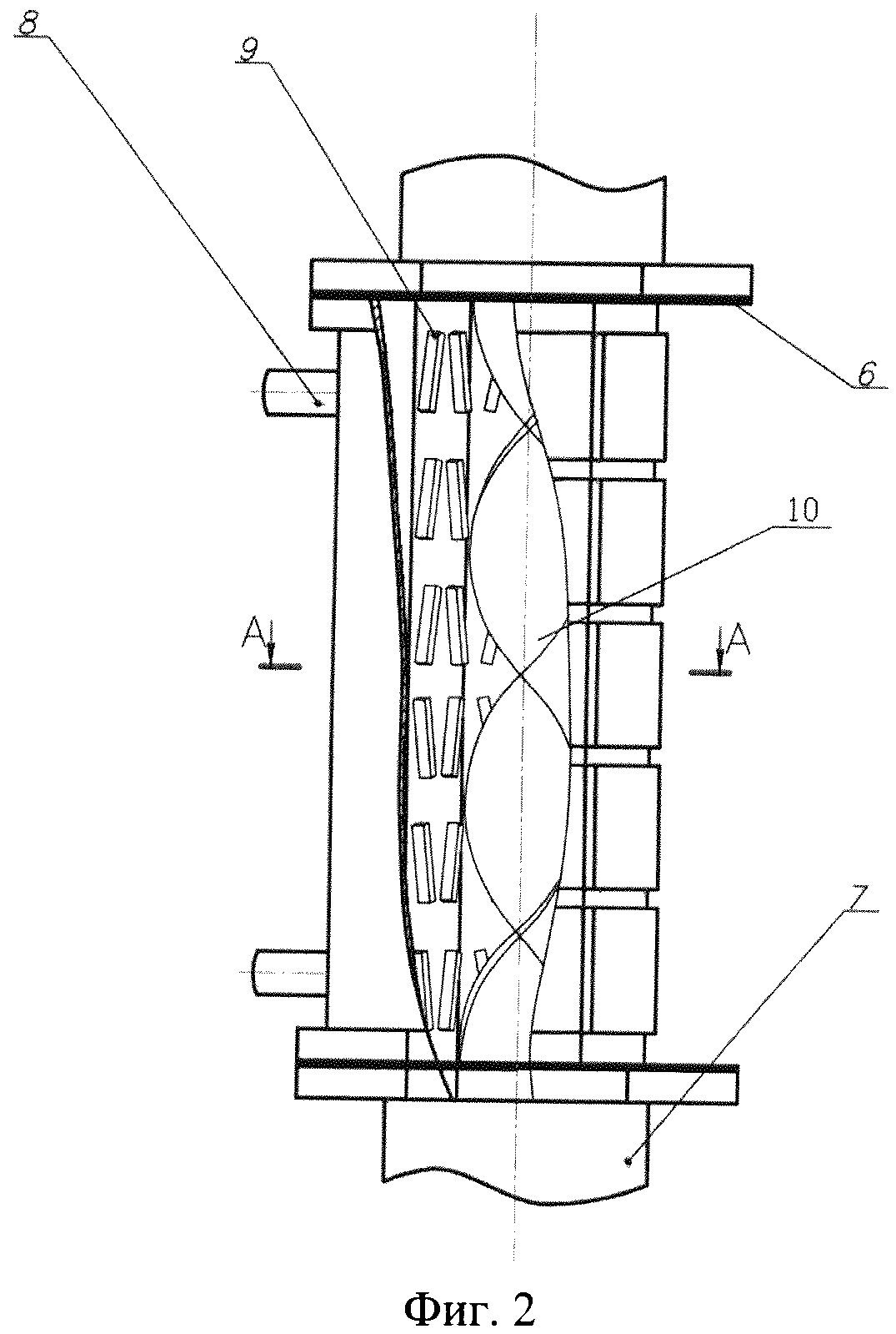
Description
Полезная модель относится к судостроению, а именно к устройствам прямого преобразования тепловой энергии в электрическую, для утилизации теплоты отработавших газов в судовых энергетических установках.The utility model relates to shipbuilding, namely, devices for the direct conversion of thermal energy into electrical energy, for the utilization of the heat of exhaust gases in marine power plants.
Известен термоэлектрический генератор, работающий от теплоты отработавших газов дизеля и имеющий в поперечном сечении развитую поверхность в виде многоконечной звезды (см. патент РФ 2191447, 2000 г.). Недостатком данного термоэлектрического генератора является то, что конструкция устройства обладает большими габаритами для машинного отделения судна. Также недостатком является система охлаждения забортной водой, температура которой значительно колеблется в зависимости от района плавания и времени года и являющейся агрессивной средой для металлических деталей конструкции.Known thermoelectric generator that runs on the heat of the exhaust gases of a diesel engine and having in cross section a developed surface in the form of a multi-pointed star (see RF patent 2191447, 2000). The disadvantage of this thermoelectric generator is that the design of the device has large dimensions for the engine compartment of the vessel. Another drawback is the outboard water cooling system, the temperature of which varies significantly depending on the area of navigation and the time of year and which is an aggressive environment for metal structural parts.
Наиболее близким по конструкции является термоэлектрический генератор, содержащий кожух, горячий узел, термогенераторные модули и холодный узел, при этом горячий и холодный узлы выполнены в виде шестиугольника в поперечном сечении, а между кожухом и холодным узлом образована водяная рубашка, причем на внутренней поверхности горячего узла установлены и жестко фиксированы металлические пластины (см. СВ. Виноградов, Ч.X. Хоанг, Н.К. Доан. Конструкция и расчет термоэлектрического генератора для судовых энергетических установок). Недостатком данной конструкции является низкий КПД.The closest in design is a thermoelectric generator containing a casing, a hot knot, thermogenerator modules and a cold knot, while the hot and cold knots are made in the form of a hexagon in cross section, and a water jacket is formed between the casing and the cold knot, and on the inner surface of the hot knot metal plates were installed and rigidly fixed (see SV. Vinogradov, Ch. X. Hoang, NK Doan. Design and calculation of a thermoelectric generator for ship power plants). The disadvantage of this design is the low efficiency.
Техническая задача - создание устройства с более высокой производительностью, которая позволила бы напрямую преобразовывать тепловую энергию в электрическую и вырабатывать дополнительно горячую воду для общесудовых нужд.The technical task is to create a device with higher performance, which would directly convert thermal energy into electrical energy and generate additional hot water for general ship needs.
Технический результат - повышение эффективности работы устройства за счет усовершенствования конструкции.The technical result is an increase in the efficiency of the device due to improvement of the design.
Он достигается тем, что в известном устройстве, содержащем кожух, горячий узел, термогенераторные модули и холодный узел, причем горячий и холодный узлы выполнены в виде шестиугольника в поперечном сечении, а между кожухом и холодным узлом образована водяная рубашка, на внутренней поверхности горячего узла установлены и жестко фиксированы металлические пластины, а по всей внутренней поверхности горячего узла со стороны входа и выхода в горячий узел установлена и жестко фиксирована металлическая винтовая вставка.It is achieved by the fact that in the known device comprising a casing, a hot knot, thermogenerator modules and a cold knot, the hot and cold knots being made in the form of a hexagon in cross section, and a water jacket is formed between the casing and the cold knot and installed on the inner surface of the hot knot and metal plates are rigidly fixed, and a metal screw insert is fixed and rigidly fixed over the entire inner surface of the hot unit from the input and output side of the hot unit.
Металлические пластины, установленные на внутренней поверхности горячего узла, в сочетании с винтовой вставкой помогают направлять поток воздуха по направлению к поверхности границы горячего узла и обеспечивают большую площадь теплообмена на поверхности, а также больший перепад температур, в результате чего повышается эффективность работы термоэлектрического генератора. Металлическая винтовая вставка также интенсифицирует тепловой обмен и повышает эффективность работы устройства.Metal plates mounted on the inner surface of the hot unit, in combination with a screw insert, help direct the air flow towards the boundary surface of the hot unit and provide a larger heat exchange area on the surface, as well as a greater temperature difference, which increases the efficiency of the thermoelectric generator. The metal screw insert also intensifies heat exchange and increases the efficiency of the device.
Предлагаемое устройство изображено на чертеже (фиг 1 - вид сверху, фиг 2 - вид в разрезе). Устройство содержит горячий узел 1, к которому прижимаются термогенераторные модули 2 при помощи планок 3, образующих холодный узел. Полость охлаждающей воды 4 ограничена планками 3 холодного узла и кожухом 5. Фланцы 6 крепятся к торцам установки с одной стороны и к выхлопной трубе 1-е другой. Подвод и отвод охлаждающей воды осуществляется при помощи патрубков 8. На внутренней поверхности горячего узла 1 установлены, жестко фиксированы металлические пластины 9 и винтовая вставка 10.The proposed device is shown in the drawing (Fig 1 is a top view, Fig 2 is a sectional view). The device comprises a hot unit 1, to which the
Устройство работает следующим образом: отработавший газ, имеющий температуру 150-450°С, проходит внутри шестиугольной трубы, образованной горячим узлом 1, тем самым нагревая его и горячие спаи модулей 2. Винтовая вставка 10 помогает направить поток выхлопных газов к наклонным пластинам 9 и к выходу на горячем узле, тем самым обеспечивает большую площадь теплообмена на поверхности. Процесс направления потока газа к наклонным пластинам зависит от соотношения шагов, диаметра и спирали. Наклонные пластины 9 внутри горячего узла 1 образуют турбулентные газовые потоки после того, как спиральный винт направляет входящий поток газа, разрушают постоянный поток пограничного слоя, усиливают теплообмен в нагретой поверхности, тем самым повышая эффективность термоэлектрического генератора. Охлаждающая вода, подводимая в полость охлаждения 4 и отводимая от нее при помощи патрубков 8, охлаждает холодный узел и холодные спаи модулей 2. В результате разности температур, между спаями возникает термоЭДС. Полученное электричество может быть использовано для освещения, подзарядки аккумуляторных батарей или для других потребителей, но с применением инвертора. Полученная горячая вода может быть использована для общесудовых нужд.The device operates as follows: the exhaust gas having a temperature of 150-450 ° C passes inside the hexagonal pipe formed by the hot unit 1, thereby heating it and the hot junctions of the
Положительный эффект - предлагаемое устройство позволяет преобразовать разность температур в электричество, повысить эффективность устройства и получить горячую воду для общесудовых нужд.A positive effect - the proposed device allows you to convert the temperature difference into electricity, increase the efficiency of the device and get hot water for general ship needs.
Claims (1)
Priority Applications (1)
| Application Number | Priority Date | Filing Date | Title |
|---|---|---|---|
| RU2018142530U RU188354U1 (en) | 2018-11-30 | 2018-11-30 | Thermoelectric generator |
Applications Claiming Priority (1)
| Application Number | Priority Date | Filing Date | Title |
|---|---|---|---|
| RU2018142530U RU188354U1 (en) | 2018-11-30 | 2018-11-30 | Thermoelectric generator |
Publications (1)
| Publication Number | Publication Date |
|---|---|
| RU188354U1 true RU188354U1 (en) | 2019-04-09 |
Family
ID=66087757
Family Applications (1)
| Application Number | Title | Priority Date | Filing Date |
|---|---|---|---|
| RU2018142530U RU188354U1 (en) | 2018-11-30 | 2018-11-30 | Thermoelectric generator |
Country Status (1)
| Country | Link |
|---|---|
| RU (1) | RU188354U1 (en) |
Citations (6)
| Publication number | Priority date | Publication date | Assignee | Title |
|---|---|---|---|---|
| RU2191447C2 (en) * | 2000-06-08 | 2002-10-20 | Федеральное государственное унитарное предприятие "Центральный научно-исследовательский институт технологии судостроения" | Thermoelectric generator |
| WO2004059138A1 (en) * | 2002-12-26 | 2004-07-15 | Toyota Jidosha Kabushiki Kaisha | Exhaust heat power generation apparatus |
| US8881513B2 (en) * | 2008-05-16 | 2014-11-11 | Emitec Gesellschaft Fuer Emissionstechnologie Mbh | Device for producing electrical energy from exhaust gas heat and motor vehicle having the device |
| US8927849B2 (en) * | 2013-02-15 | 2015-01-06 | Aleksandr Sergey Kushch | Waste heat thermoelectric generator with auxiliary burner |
| US20160233403A1 (en) * | 2009-07-24 | 2016-08-11 | Gentherm Incorporated | Thermoelectric-based power generation systems and methods |
| RU2606300C1 (en) * | 2015-12-30 | 2017-01-10 | Федеральное государственное бюджетное образовательное учреждение высшего профессионального образования "Московский государственный технический университет имени Н.Э. Баумана" (МГТУ им. Н.Э. Баумана) | Thermoelectric generator in internal combustion engine exhaust gases exhaust system |
-
2018
- 2018-11-30 RU RU2018142530U patent/RU188354U1/en active
Patent Citations (6)
| Publication number | Priority date | Publication date | Assignee | Title |
|---|---|---|---|---|
| RU2191447C2 (en) * | 2000-06-08 | 2002-10-20 | Федеральное государственное унитарное предприятие "Центральный научно-исследовательский институт технологии судостроения" | Thermoelectric generator |
| WO2004059138A1 (en) * | 2002-12-26 | 2004-07-15 | Toyota Jidosha Kabushiki Kaisha | Exhaust heat power generation apparatus |
| US8881513B2 (en) * | 2008-05-16 | 2014-11-11 | Emitec Gesellschaft Fuer Emissionstechnologie Mbh | Device for producing electrical energy from exhaust gas heat and motor vehicle having the device |
| US20160233403A1 (en) * | 2009-07-24 | 2016-08-11 | Gentherm Incorporated | Thermoelectric-based power generation systems and methods |
| US8927849B2 (en) * | 2013-02-15 | 2015-01-06 | Aleksandr Sergey Kushch | Waste heat thermoelectric generator with auxiliary burner |
| RU2606300C1 (en) * | 2015-12-30 | 2017-01-10 | Федеральное государственное бюджетное образовательное учреждение высшего профессионального образования "Московский государственный технический университет имени Н.Э. Баумана" (МГТУ им. Н.Э. Баумана) | Thermoelectric generator in internal combustion engine exhaust gases exhaust system |
Non-Patent Citations (1)
| Title |
|---|
| S. V. VINOGRADOV et al, Design and calculation of the thermoelectric generator for ship power plants, Вестник АГТУ, Сер. Морская техника и технология, 2017, 4, подписано в печать 03.11.2017, с. 62-71. * |
Similar Documents
| Publication | Publication Date | Title |
|---|---|---|
| Grubišić-Čabo et al. | Photovoltaic panels: A review of the cooling techniques | |
| RU2010129500A (en) | ELECTRIC HEATING DEVICE INCLUDING A THERMOELECTRIC GENERATOR | |
| CN207304410U (en) | Thermal difference power generation device based on fin heat exchange for high temperature exhaust gas waste heat of ship incinerator | |
| JP6008315B2 (en) | Waste heat recovery thermoelectric power generation system, and ship equipped with exhaust heat recovery thermoelectric power generation system | |
| RU188354U1 (en) | Thermoelectric generator | |
| RU108214U1 (en) | DEVICE FOR DISPOSAL OF HEAT OF EXHAUST GASES IN SHIP'S POWER PLANTS | |
| Musiał et al. | The influence of a dispersion cone on the temperature distribution in the heat exchanger of a thermoelectric generator | |
| RU2191447C2 (en) | Thermoelectric generator | |
| CN113530704A (en) | Thermoelectric conversion system for recovering waste heat in engine cooling water and tail gas | |
| RU189936U1 (en) | THERMOELECTRIC GENERATOR MODULE | |
| RU2081337C1 (en) | Exhaust system of external combustion engine | |
| RU162072U1 (en) | THERMOELECTRIC GENERATOR | |
| Gavica et al. | A review of waste heat recovery methods using thermoelectric devices | |
| CN207304411U (en) | Thermal difference power generation device using heat transfer oil structure for ship main engine exhaust gas waste heat utilization | |
| SU1321906A1 (en) | Air-driven power plant | |
| JP2014194192A (en) | Exhaust emission control system in ship | |
| RU2755980C1 (en) | Thermoelectric generator with forced cooling system | |
| CN106870075A (en) | A kind of cogeneration system of utilization marine vehicle diesel residual heat | |
| RU2830789C1 (en) | Device for utilization of heat of mobile power plant of drilling rig | |
| RU157995U1 (en) | NATURAL GAS CONVERTER MONOBLOCK WITH HEAT EXCHANGE EQUIPMENT | |
| Kuznetsov | Multi-Level Estimation of the Heat Transfer Processes Efficiency in the Power Plants Elements | |
| RU233532U1 (en) | THERMOELECTRIC GENERATOR | |
| RU96709U1 (en) | THERMOELECTRIC GENERATOR | |
| UA138532U (en) | THERMOELECTRIC MOTORPUMP GENERATOR | |
| RU2279558C2 (en) | Plant for converting low-grade heat into electric energy |