RU173557U1 - Traction motor suspension unit - Google Patents
Traction motor suspension unit Download PDFInfo
- Publication number
- RU173557U1 RU173557U1 RU2017105600U RU2017105600U RU173557U1 RU 173557 U1 RU173557 U1 RU 173557U1 RU 2017105600 U RU2017105600 U RU 2017105600U RU 2017105600 U RU2017105600 U RU 2017105600U RU 173557 U1 RU173557 U1 RU 173557U1
- Authority
- RU
- Russia
- Prior art keywords
- suspension
- traction
- frame
- trolley
- suspension unit
- Prior art date
Links
Images
Classifications
-
- B—PERFORMING OPERATIONS; TRANSPORTING
- B61—RAILWAYS
- B61C—LOCOMOTIVES; MOTOR RAILCARS
- B61C9/00—Locomotives or motor railcars characterised by the type of transmission system used; Transmission systems specially adapted for locomotives or motor railcars
- B61C9/38—Transmission systems in or for locomotives or motor railcars with electric motor propulsion
Landscapes
- Engineering & Computer Science (AREA)
- Chemical & Material Sciences (AREA)
- Combustion & Propulsion (AREA)
- Transportation (AREA)
- Mechanical Engineering (AREA)
- Current-Collector Devices For Electrically Propelled Vehicles (AREA)
Abstract
Полезная модель относится к транспортному машиностроению, а именно к узлам подвешивания тягового электродвигателя или тягового редуктора к раме тележки локомотива. Узел подвешивания тягового электродвигателя, содержащий подшипниковые опоры для опирания на ось колесной пары и поводок, концами посредством сайлент-блоков связанный с корпусом двигателя и рамой тележки. Отличительной особенностью предлагаемого узла подвешивания тягового электродвигателя является то, что верхний сайлент-блок связан с рамой тележки посредством рычага, который, в свою очередь, связан с рамой тележки посредством шарнира и резиновых амортизаторов. Предложенный узел подвешивания тягового электродвигателя позволяет снизить затраты при эксплуатации локомотива благодаря амортизации продольных динамических усилий в поводке, ведущей к снижению нагрузок на узлы колесно-моторного блока, и удобству внешнего осмотра частей подвески.The utility model relates to transport engineering, namely, to the suspension nodes of the traction motor or traction reducer to the frame of the locomotive trolley. A suspension unit for a traction electric motor, comprising bearing bearings for supporting the wheel pair and the leash on the ends, by means of silent blocks, connected to the engine casing and the trolley frame. A distinctive feature of the proposed traction motor suspension assembly is that the upper silent block is connected to the trolley frame by means of a lever, which, in turn, is connected to the trolley frame by means of a hinge and rubber shock absorbers. The proposed suspension unit of the traction electric motor allows to reduce costs during the operation of the locomotive due to the amortization of longitudinal dynamic forces in the leash, leading to lower loads on the nodes of the wheel-motor unit, and the convenience of external inspection of the suspension parts.
Description
Полезная модель относится к транспортному машиностроению, а именно к узлам подвешивания тягового электродвигателя или тягового редуктора к раме тележки локомотива.The utility model relates to transport engineering, namely, to the suspension nodes of the traction motor or traction reducer to the frame of the locomotive trolley.
Известен узел подвешивания тягового электродвигателя, включающий шарнир и две пружины ( В.Б. Медель. Подвижной состав электрических железных дорог. Т. 1. Конструкция и динамика. Изд 2-е, переработ. Транс-желдориздат. М., 1957, с. 158, рис. 224).Known suspension unit traction electric motor, including a hinge and two springs (VB Medel. Rolling stock of electric railways. T. 1. Design and dynamics. Vol. 2, revised. Trans-zheldorizdat. M., 1957, p. 158, Fig. 224).
Недостатком узла подвешивания является возможность применять его только при малых мощностях вследствие недостаточной прочности пружин.The disadvantage of the suspension unit is the ability to use it only at low capacities due to insufficient spring strength.
Известен также узел подвешивания тягового электродвигателя, включающий пружинную подвеску, состоящую из двух балочек, между которыми размещены четыре пружины. В отверстия балочек и кронштейнов, укрепленных на раме тележки, пропущены стержни, соединяющие комплект пружин с кронштейнами. Корпус тягового электродвигателя, имеющий два выступа с прикрепленными к ним сменными прокладками, опирается на балочки пружинной подвески (Конструкция и динамика тепловозов. / Под ред. В.Н. Иванова. М., Транспорт, 1974, с. 173-174).Also known is the suspension unit of the traction electric motor, including a spring suspension, consisting of two beams, between which four springs are placed. The holes connecting the set of springs with brackets are passed into the holes of the beams and brackets mounted on the frame of the trolley. The body of the traction electric motor, which has two protrusions with interchangeable gaskets attached to them, rests on the beams of the spring suspension (Design and dynamics of diesel locomotives. / Ed. By V.N. Ivanov. M., Transport, 1974, p. 173-174).
Недостатком указанного узла подвешивания является повышенный износ прокладок уже через 200 тыс.км. пробега локомотива, что ведет к увеличению динамической нагруженности кронштейна рамы тележки, появлению усталостных трещин, снижению безопасности движения и увеличению трудоемкости при замене сменных прокладок на текущих ремонтах.The disadvantage of this suspension unit is the increased wear of the gaskets after 200 thousand km. mileage of the locomotive, which leads to an increase in the dynamic loading of the bracket of the trolley frame, the appearance of fatigue cracks, a decrease in traffic safety and an increase in the complexity of replacing replaceable gaskets for current repairs.
В качестве прототипа предлагаемой полезной модели выбран узел подвешивания тягового электродвигателя, применяемый на электровозе 2ЭС6 отечественных железных дорог (см. Электровоз грузовой постоянного тока 2ЭС6 с коллекторными тяговыми электродвигателями. Руководство по эксплуатации. Часть 6. Описание и работа. Механическое оборудование и системы вентиляции. 2ЭС6.00.000.000 РЭ5 / ОАО «УЗЖМ», Лист 49-51, рис. 3.10). Он содержит подшипниковые опоры для опирания на ось колесной пары и поводок, концами посредством сайлент-блоков связанный с корпусом двигателя и рамой тележки.As a prototype of the proposed utility model, the traction motor suspension unit used on the 2ES6 electric locomotive of the domestic railways was selected (see 2ES6 DC freight electric locomotive with collector traction electric motors. Operation manual.
Этот узел подвешивания тягового электродвигателя также имеет свои недостатки. Сайлент-блоки имеют высокую радиальную жесткость, вследствие чего узел подвешивания не способен амортизировать удары, возникающие в узле подвешивания и тяговой передаче при проезде неровностей пути. При эксплуатации электровоза 2ЭС6 высокие динамические нагрузки в узле подвешивания приводили к разрушению резиновых элементов сайлент-блоков, возникновению трещин в кронштейнах их крепления и являлись причиной обрыва подвески.This suspension unit of the traction motor also has its drawbacks. Silent blocks have high radial stiffness, as a result of which the suspension unit is not able to absorb shock arising from the suspension unit and the traction drive during travel irregularities. During operation of the 2ES6 electric locomotive, high dynamic loads in the suspension unit led to the destruction of the rubber elements of the silent blocks, the occurrence of cracks in their brackets, and caused the suspension to break.
Задача, на решение которой направлена полезная модель, состоит в снижении затрат при эксплуатации и ремонте локомотива посредством снижения динамических нагрузок в узлах экипажной части.The problem, which the utility model is aimed at, is to reduce costs during operation and repair of a locomotive by reducing dynamic loads in the nodes of the crew.
Это достигается тем, что в узле подвешивания тягового электродвигателя, содержащем подшипниковые опоры для опирания на ось колесной пары и поводок, концами посредством сайлент-блоков связанный с корпусом двигателя и рамой тележки, верхний сайлент-блок связан с рамой тележки посредством рычага, который, в свою очередь, связан с рамой тележки посредством шарнира и резиновых амортизаторов.This is achieved by the fact that in the suspension unit of the traction motor containing bearing bearings for supporting the wheelset and the leash axis, the ends are connected by means of silent blocks to the engine housing and the frame of the cart, the upper silent block is connected to the frame of the cart by means of a lever, which, in in turn, connected to the frame of the trolley by means of a hinge and rubber shock absorbers.
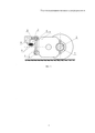
Сущность предлагаемой полезной модели поясняется фиг. 1, на которой изображено описываемое устройство.The essence of the proposed utility model is illustrated in FIG. 1, which shows the described device.
Предлагаемый узел подвешивания тягового электродвигателя содержит подшипниковые опоры 1 для опирания на ось колесной пары 2 и поводок 3, концами посредством сайлент-блоков 4 связанный с корпусом двигателя 5 и рамой тележки 6.The proposed suspension unit of the traction motor contains
При этом один из сайлент-блоков 4 непосредственно связан с корпусом двигателя 5, а другой из сайлент-блоков 4 непосредственно связан с рычагом 7, который связан с рамой тележки 6 посредством шарнира 8 и резиновых амортизаторов 9.In this case, one of the
При перемещении корпуса двигателя 5 относительно рамы тележки 6 поводок 3 перемещается за счет вращения и перекоса сайлент-блоков 4. При этом продольные динамические усилия, возникающие в поводке 3 при проезде неровностей пути, амортизируются за счет поворота рычага 7 вокруг оси шарнира 8 и податливости резиновых амортизаторов 9. Благодаря расположению резиновых амортизаторов 9 внизу рамы тележки 6 возможна проверка их исправности путем внешнего осмотра без демонтажа частей.When moving the
Технико-экономический эффект заявленной полезной модели заключается в том, что амортизация продольных динамических усилий в поводке, ведущая к снижению нагрузок на узлы колесно-моторного блока, и удобство внешнего осмотра частей подвески снижают затраты при эксплуатации локомотива.The technical and economic effect of the claimed utility model consists in the fact that the amortization of longitudinal dynamic forces in the leash, leading to lower loads on the nodes of the wheel-motor block, and the convenience of the external inspection of the suspension parts reduce the cost of operating the locomotive.
Claims (1)
Priority Applications (1)
| Application Number | Priority Date | Filing Date | Title |
|---|---|---|---|
| RU2017105600U RU173557U1 (en) | 2017-02-20 | 2017-02-20 | Traction motor suspension unit |
Applications Claiming Priority (1)
| Application Number | Priority Date | Filing Date | Title |
|---|---|---|---|
| RU2017105600U RU173557U1 (en) | 2017-02-20 | 2017-02-20 | Traction motor suspension unit |
Publications (1)
| Publication Number | Publication Date |
|---|---|
| RU173557U1 true RU173557U1 (en) | 2017-08-30 |
Family
ID=59798295
Family Applications (1)
| Application Number | Title | Priority Date | Filing Date |
|---|---|---|---|
| RU2017105600U RU173557U1 (en) | 2017-02-20 | 2017-02-20 | Traction motor suspension unit |
Country Status (1)
| Country | Link |
|---|---|
| RU (1) | RU173557U1 (en) |
Cited By (2)
| Publication number | Priority date | Publication date | Assignee | Title |
|---|---|---|---|---|
| RU180215U1 (en) * | 2017-09-11 | 2018-06-06 | Общество с ограниченной ответственностью "Уральские локомотивы" | PENDULUM BASIC AND AXIAL SUSPENSION OF A LOCOMOTIVE POWER ELECTRIC MOTOR |
| RU210965U1 (en) * | 2021-04-05 | 2022-05-16 | ФЕДЕРАЛЬНОЕ ГОСУДАРСТВЕННОЕ БЮДЖЕТНОЕ ОБРАЗОВАТЕЛЬНОЕ УЧРЕЖДЕНИЕ ВЫСШЕГО ОБРАЗОВАНИЯ "Брянский государственный технический университет" | DEVICE FOR FASTENING LOCOMOTIVE TRACTION ELECTRIC MOTOR TO BOgie FRAME |
Citations (3)
| Publication number | Priority date | Publication date | Assignee | Title |
|---|---|---|---|---|
| EP0873929B1 (en) * | 1997-04-22 | 2003-07-02 | Railway Technical Research Institute | Variable gauge bogie for rolling stock |
| RU2438897C1 (en) * | 2010-04-05 | 2012-01-10 | Открытое акционерное общество "Всероссийский научно-исследовательский и проектно-конструкторский институт электровозостроения" (ОАО "ВЭлНИИ") | Railway vehicle bogie |
| US9352758B2 (en) * | 2012-07-10 | 2016-05-31 | Csr Nanjing Puzhen Co., Ltd. | Flexible direct drive bogie |
-
2017
- 2017-02-20 RU RU2017105600U patent/RU173557U1/en not_active IP Right Cessation
Patent Citations (3)
| Publication number | Priority date | Publication date | Assignee | Title |
|---|---|---|---|---|
| EP0873929B1 (en) * | 1997-04-22 | 2003-07-02 | Railway Technical Research Institute | Variable gauge bogie for rolling stock |
| RU2438897C1 (en) * | 2010-04-05 | 2012-01-10 | Открытое акционерное общество "Всероссийский научно-исследовательский и проектно-конструкторский институт электровозостроения" (ОАО "ВЭлНИИ") | Railway vehicle bogie |
| US9352758B2 (en) * | 2012-07-10 | 2016-05-31 | Csr Nanjing Puzhen Co., Ltd. | Flexible direct drive bogie |
Cited By (2)
| Publication number | Priority date | Publication date | Assignee | Title |
|---|---|---|---|---|
| RU180215U1 (en) * | 2017-09-11 | 2018-06-06 | Общество с ограниченной ответственностью "Уральские локомотивы" | PENDULUM BASIC AND AXIAL SUSPENSION OF A LOCOMOTIVE POWER ELECTRIC MOTOR |
| RU210965U1 (en) * | 2021-04-05 | 2022-05-16 | ФЕДЕРАЛЬНОЕ ГОСУДАРСТВЕННОЕ БЮДЖЕТНОЕ ОБРАЗОВАТЕЛЬНОЕ УЧРЕЖДЕНИЕ ВЫСШЕГО ОБРАЗОВАНИЯ "Брянский государственный технический университет" | DEVICE FOR FASTENING LOCOMOTIVE TRACTION ELECTRIC MOTOR TO BOgie FRAME |
Similar Documents
| Publication | Publication Date | Title |
|---|---|---|
| RU166921U1 (en) | MOTOR MOTOR SUSPENSION ASSEMBLY | |
| RU2549427C1 (en) | Traction motor suspension assembly | |
| CN110641503A (en) | A new type of bogie | |
| CN204488808U (en) | The universal subway engineering bogie of car | |
| RU154856U1 (en) | Tram Car with 100% Reduced Floor Level | |
| RU173557U1 (en) | Traction motor suspension unit | |
| CN103101542A (en) | Elastic joint structure suitable for cantilever-type flexible suspension of CRH (China railway high-speed) train traction motor | |
| CN203543990U (en) | Standard track gauge control type railway vehicle bogie | |
| CN203474263U (en) | Hoisting device and locomotive bogie | |
| CN2920770Y (en) | Wide rail welding bogie | |
| RU2606417C1 (en) | Diesel locomotive non-pedestal bogie | |
| CN2931192Y (en) | Board gauge bogie with electricity generating device | |
| RU2525631C1 (en) | Railway rolling stock bogie axle box assy (versions) | |
| RU133486U1 (en) | TWO-axle RAILWAY TRUCK CAR | |
| RU186173U1 (en) | Traction motor suspension unit | |
| RU2284937C1 (en) | Frame of three-axle bogie of railway traction vehicle (versions) | |
| RU176844U1 (en) | Traction motor suspension unit | |
| RU176907U1 (en) | MOTOR MOTOR SUSPENSION ASSEMBLY | |
| RU2432278C1 (en) | Locomotive geared wheel unit | |
| CN207345834U (en) | A kind of guider of the sky rail bogie of car | |
| RU159661U1 (en) | DRIVE TROLLEY OF ELECTRIC TRAIN CARS | |
| RU189359U1 (en) | Suspension unit for traction motor | |
| CN104401356A (en) | Railway locomotive dry rim lubricating device capable of being used for double-side tread brake | |
| RU176843U1 (en) | Traction motor suspension unit | |
| CN202089069U (en) | Full-suspension device for traction motor of rail vehicle |
Legal Events
| Date | Code | Title | Description |
|---|---|---|---|
| MM9K | Utility model has become invalid (non-payment of fees) |
Effective date: 20170927 |