RU155014U1 - AUTOMATIC MULTIPLE SWITCH - Google Patents
AUTOMATIC MULTIPLE SWITCH Download PDFInfo
- Publication number
- RU155014U1 RU155014U1 RU2015103048/07U RU2015103048U RU155014U1 RU 155014 U1 RU155014 U1 RU 155014U1 RU 2015103048/07 U RU2015103048/07 U RU 2015103048/07U RU 2015103048 U RU2015103048 U RU 2015103048U RU 155014 U1 RU155014 U1 RU 155014U1
- Authority
- RU
- Russia
- Prior art keywords
- contact
- electrical contacts
- movable
- fixed
- trip mechanism
- Prior art date
Links
- 230000007246 mechanism Effects 0.000 claims abstract description 41
- 239000002184 metal Substances 0.000 claims abstract description 18
- 230000005405 multipole Effects 0.000 claims abstract description 12
- 230000005520 electrodynamics Effects 0.000 claims abstract description 11
- 239000012772 electrical insulation material Substances 0.000 claims abstract description 9
- 239000011810 insulating material Substances 0.000 claims abstract description 6
- 230000003993 interaction Effects 0.000 claims abstract description 4
- 238000005452 bending Methods 0.000 description 7
- 230000009471 action Effects 0.000 description 5
- 238000005520 cutting process Methods 0.000 description 5
- 238000003825 pressing Methods 0.000 description 5
- 239000004020 conductor Substances 0.000 description 4
- 238000004519 manufacturing process Methods 0.000 description 3
- 239000000463 material Substances 0.000 description 3
- 229910000831 Steel Inorganic materials 0.000 description 2
- 230000015572 biosynthetic process Effects 0.000 description 2
- 238000010586 diagram Methods 0.000 description 2
- 238000000034 method Methods 0.000 description 2
- 238000005192 partition Methods 0.000 description 2
- 230000008569 process Effects 0.000 description 2
- 230000001105 regulatory effect Effects 0.000 description 2
- 239000010959 steel Substances 0.000 description 2
- 230000001960 triggered effect Effects 0.000 description 2
- 230000004913 activation Effects 0.000 description 1
- 239000000956 alloy Substances 0.000 description 1
- 229910045601 alloy Inorganic materials 0.000 description 1
- 238000001816 cooling Methods 0.000 description 1
- 230000007423 decrease Effects 0.000 description 1
- 230000000694 effects Effects 0.000 description 1
- 238000010891 electric arc Methods 0.000 description 1
- 238000004870 electrical engineering Methods 0.000 description 1
- 238000005516 engineering process Methods 0.000 description 1
- 230000014759 maintenance of location Effects 0.000 description 1
- 230000001681 protective effect Effects 0.000 description 1
- 230000007704 transition Effects 0.000 description 1
Images


Landscapes
- Breakers (AREA)
Abstract
Выключатель автоматический многополюсный, содержащий выполненные из электроизоляционного материала корпус с крышкой, электромагнитные максимальные расцепители тока, расцепители тока перегрузки, дугогасительное устройство, механизм свободного расцепления с рукояткой и установленными на общей траверсе, выполненной из электроизоляционного материала, коромыслами, несущими подвижно закрепленные на них подвижные электрические контакты, снабженные контактными пружинами, закрепленными с двух сторон от оси вращения коромысел одним концом на выступах подвижных электрических контактов, установленных с возможностью контакта с неподвижными электрическим контактами, закрепленными в корпусе и расположенными в зоне действия дугогасительного устройства, выполненного в виде дугогасительных камер, каждая из которых содержит боковые стенки из электроизоляционного материала, между которыми расположены и жестко соединены с ними металлические пластины, конец одной из которых, наиболее удаленной от неподвижного электрического контакта, установлен с возможностью взаимодействия с концом подвижного электрического контакта после его электродинамического отброса и последующего срабатывания механизма свободного расцепления для возврата подвижных электрических контактов в положение, при котором они имеют возможность контактировать с неподвижными электрическими контактами после взвода механизма свободного расцепления в рабочее положение, отличающийся тем, что конец металлической пластины, наиболее удаленной от неподвижного электрического контакта, расположен в одной плоскости с этой пластиной.A multi-pole circuit breaker containing a housing with a cover made of an insulating material, electromagnetic maximum current releases, overload current releases, an arcing device, a free trip mechanism with a handle and mounted on a common traverse made of electrical insulation material, rocker arms carrying movable electric mounted on them contacts equipped with contact springs fixed on both sides of the axis of rotation of the rocker arm one end m on the protrusions of movable electrical contacts installed with the possibility of contact with fixed electrical contacts fixed in the housing and located in the range of the arcing device, made in the form of arcing chambers, each of which contains side walls of electrical insulation material, between which are located and rigidly connected to metal plates, the end of one of which is farthest from the stationary electrical contact, is installed with the possibility of interaction I with the end of the movable electrical contact after its electrodynamic rejection and subsequent operation of the free trip mechanism to return the movable electrical contacts to a position in which they are able to contact the stationary electrical contacts after cocking the free trip mechanism to the operating position, characterized in that the end of the metal plate , farthest from a stationary electrical contact, is located in the same plane with this plate.
Description
Область техники, к которой относится полезная модельThe technical field to which the utility model relates.
Полезная модель относится к электротехнике, а именно, к защитным максимальным автоматическим выключателям с электротермическим, электромагнитным и электродинамическим автоматическим размыканием, требующим отдельного действия для осуществления повторного включения.The utility model relates to electrical engineering, namely, to maximum protective circuit breakers with electrothermal, electromagnetic and electrodynamic automatic opening, requiring a separate action for the implementation of the repeated inclusion.
Уровень техникиState of the art
Известен выключатель автоматический многополюсный, включающий корпус с крышкой, механизм свободного расцепления с рейкой, контактную систему с подвижным контактом и дугогасительными камерами, тепловой расцепитель и электромагнитный максимальный расцепитель тока в каждом полюсе, соединенные электрически и соединением электромагнитного расцепителя, содержащего подпружиненный якорь с регулировочным винтом, с подвижным контактом контактной системы гибким токопроводом, в котором по обе стороны закрепленного на оси вращения подвижного контакта зафиксированы пружины растяжения, оси фиксации которых расположены с возможностью перехода в момент отбрасывания контакта через мертвую точку, располагаемую на оси вращения контакта, механизм свободного расцепления дополнительно содержит валик и скобу с пазом, выполненным с возможностью перемещения в ней валика, подпружиненный якорь с регулировочным винтом закреплен в пазах корпуса выключателя (см. патент на полезную модель №53814, опубл. 27.05.2006 [1]).A well-known multi-pole automatic switch, comprising a housing with a cover, a free trip mechanism with a rail, a contact system with a movable contact and arcing chambers, a thermal release and an electromagnetic maximum current release in each pole, electrically connected and connected to an electromagnetic release containing a spring-loaded armature with an adjusting screw, with a movable contact of the contact system with a flexible current lead, in which on both sides of the movable the contact fixed tensile springs, the fixing axis of which are located with the possibility of transition at the moment the contact is dropped through the dead point located on the axis of rotation of the contact, the free trip mechanism further comprises a roller and a bracket with a groove configured to move the roller in it, a spring-loaded anchor with an adjusting screw fixed in the grooves of the circuit breaker housing (see patent for utility model No. 53814, publ. 05.27.2006 [1]).
Недостатком известного выключателя автоматического многополюсного [1] является то, что в нем не предусмотрен автоматический возврат подвижных контактов в исходное положение через неустойчивое положение, именуемое мертвой точкой. Если их не вернуть в исходное положение, то повторно взвести выключатель в рабочее положение будет невозможно.A disadvantage of the known automatic multi-pole switch [1] is that it does not provide for the automatic return of the movable contacts to their original position through an unstable position called dead center. If they are not returned to their original position, then it will not be possible to re-engage the switch to its working position.
Известен также выключатель автоматический многополюсный, содержащий корпус с крышкой, электромагнитные максимальные расцепители тока, как минимум один механизм свободного расцепления с рукояткой и скобами, имеющими упорный выступ и установленными на общей траверсе, контактную систему, состоящую из неподвижных контактов в виде петли и подвижных контактов с зафиксированными на осях пружинами контактного нажатия, установленных с возможностью вращения на другой оси, проходящей через скобы механизма свободного расцепления, дугогасительную систему в виде камер, установленных в корпусе, зафиксированных крышкой и содержащих боковые стенки из электроизоляционного материала, между которыми расположены и жестко соединены с ними металлические пластины, образующие деионную решетку, ограниченную со стороны рукоятки изогнутой металлической пластиной, также жестко соединенной со стенками камеры, при этом конец указанной пластины, обращенный к механизму свободного расцепления, имеет отгиб в сторону подвижного контакта и выполняет функцию упора для подвижного контакта при срабатывании механизма свободного расцепления (см. патент на полезную модель №65294, опубл. 27.07.2007 [2]).Also known is a multi-pole automatic switch comprising a housing with a cover, electromagnetic maximum current releases, at least one free trip mechanism with a handle and brackets having a thrust protrusion and mounted on a common traverse, a contact system consisting of fixed contacts in the form of a loop and movable contacts with contact pressing springs fixed on the axes, mounted for rotation on another axis passing through the brackets of the free trip mechanism, the arrester a system in the form of chambers installed in the housing, fixed by a cover and containing side walls of electrical insulation material, between which metal plates are located and rigidly connected to them, forming a deionic lattice bounded on the handle side by a curved metal plate, also rigidly connected to the chamber walls, the end of the plate, facing the free trip mechanism, has a limb towards the movable contact and acts as a stop for the movable contact at activation of the free release mechanism (see Utility Model Patent No. 65294, publ. July 27, 2007 [2]).
В известном устройстве подвижные контакты автоматически возвращаются в исходное положение с прохождением неустойчивого положения при срабатывании механизма свободного расцепления. Это происходит за счет удержания подвижных контактов отогнутыми концами металлических пластин деионных решеток при срабатывании механизма свободного расцепления. Недостатком известного путевого переключателя является то, что указанные металлические пластины имею сложную изогнутую форму, требующую для их изготовления дополнительной операции гибки с использованием специального инструмента - гибочного штампа.In the known device, the movable contacts automatically return to their original position with the passage of an unstable position when the mechanism of free tripping. This is due to the retention of the moving contacts by the bent ends of the metal plates of the deionic lattices when the free trip mechanism is activated. A disadvantage of the known travel switch is that these metal plates have a complex curved shape, requiring an additional bending operation for their manufacture using a special tool - a bending stamp.
Наиболее близким аналогом по совокупности существенных признаков и достигаемому техническому результату является выключатель автоматический многополюсный [2].The closest analogue in terms of the set of essential features and the achieved technical result is an automatic multi-pole circuit breaker [2].
Раскрытие полезной моделиUtility Model Disclosure
Техническая задача, на решение которой направлена полезная модель, заключается в упрощение конструкции выключателя автоматического многополюсного и технологии его изготовления.The technical problem to which the utility model is directed is to simplify the design of an automatic multi-pole circuit breaker and its manufacturing technology.
Указанная задача решается тем, что выключатель автоматический многополюсный, содержащий выполненные из электроизоляционного материала корпус с крышкой, электромагнитные максимальные расцепители тока, расцепители тока перегрузки, дугогасительное устройство, механизм свободного расцепления с рукояткой и установленными на общей траверсе, выполненной из электроизоляционного материала, коромыслами, несущими подвижно закрепленные на них подвижные электрические контакты, снабженные контактными пружинами, закрепленными с двух сторон от оси вращения коромысел одним концом на подвижных электрических контактах, установленных с возможностью контакта с неподвижными электрическим контактами, закрепленными в корпусе и расположенными в зоне действия дугогасительного устройства, выполненного в виде дугогасительных камер, каждая из которых содержит боковые стенки из электроизоляционного материала, между которыми расположены и жестко соединены с ними металлические пластины, конец одной из которых, наиболее удаленной от неподвижного электрического контакта, установлен с возможностью взаимодействия с концом подвижного электрического контакта после его электродинамического отброса и последующего срабатывания механизма свободного расцепления для возврата подвижных электрических контактов в положение, при котором они имеют возможность контактировать с неподвижными электрическими контактами после взвода механизма свободного расцепления в рабочее положение, при этом конец металлической пластины, наиболее удаленной от неподвижного электрического контакта, расположен в одной плоскости с этой пластиной.This problem is solved by the fact that the circuit breaker is multi-pole, comprising a housing with a cover made of an insulating material, electromagnetic maximum current releases, overload current releases, an arcing device, a free trip mechanism with a handle and rocker arms mounted on a common traverse made of electrical insulation material movable electrical contacts movably fixed on them, provided with contact springs fixed on both sides of the axis of rotation of the rocker arm at one end on movable electrical contacts installed with the possibility of contact with fixed electrical contacts fixed in the housing and located in the range of the arcing device, made in the form of arcing chambers, each of which contains side walls of electrical insulation material, between which are located metal plates are rigidly connected to them, the end of one of which, the farthest from the stationary electrical contact, is installed with the possibility of interaction with the end of the movable electrical contact after its electrodynamic rejection and subsequent operation of the free trip mechanism to return the movable electrical contacts to a position in which they are able to contact the stationary electrical contacts after cocking the free trip mechanism to the operating position, while the end of the metal plate, most remote from a stationary electrical contact, is located in the same plane with this plate.
Общими с прототипом [2] существенными признаками являются: Выключатель автоматический многополюсный, содержащий выполненные из электроизоляционного материала корпус с крышкой, электромагнитные максимальные расцепители тока, расцепители тока перегрузки, дугогасительное устройство, механизм свободного расцепления с рукояткой и установленными на общей траверсе, выполненной из электроизоляционного материала, коромыслами, несущими подвижно закрепленные на них подвижные электрические контакты, снабженные контактными пружинами, закрепленными с двух сторон от оси вращения коромысел одним концом на подвижных электрических контактах, установленных с возможностью контакта с неподвижными электрическим контактами, закрепленными в корпусе и расположенными в зоне действия дугогасительного устройства, выполненного в виде дугогасительных камер, каждая из которых содержит боковые стенки из электроизоляционного материала, между которыми расположены и жестко соединены с ними металлические пластины, конец одной из которых, наиболее удаленной от неподвижного электрического контакта, установлен с возможностью взаимодействия с концом подвижного электрического контакта после его электродинамического отброса и последующего срабатывания механизма свободного расцепления для возврата подвижных электрических контактов в положение, при котором они имеют возможность контактировать с неподвижными электрическими контактами после взвода механизма свободного расцепления в рабочее положение.The essential features common with the prototype [2] are: A multi-pole circuit breaker containing a body with a cover made of an insulating material, electromagnetic maximum current releases, overload current releases, an arcing device, a free trip mechanism with a handle and mounted on a common traverse made of electrical insulation material , rocker arms carrying movable electrical contacts movably fixed to them, provided with contact springs, mounted on two sides of the axis of rotation of the rocker arm with one end on movable electrical contacts mounted with the possibility of contact with stationary electrical contacts fixed in the housing and located in the range of the arcing device, made in the form of arcing chambers, each of which contains side walls of electrical insulation material between which metal plates are located and rigidly connected with them, the end of one of which is farthest from the stationary electric ntakta, set to interact with the end of the movable electrical contact after electrodynamic garbage and subsequent actuation trip-free mechanism for returning the movable electrical contacts in the position in which they are able to contact with the stationary electrical contacts after cocking trip-free mechanism in working position.
Отличительным существенным признаком выключателя путевого мгновенного действия, не известным из прототипа [2], является выполнение конца металлической пластины, наиболее удаленной от неподвижного электрического контакта, расположенным в одной плоскости с этой пластиной.A distinctive essential feature of the switch instantaneous travel, not known from the prototype [2], is the execution of the end of the metal plate, the most remote from the stationary electrical contact, located in the same plane with this plate.
Краткое описание чертежейBrief Description of the Drawings
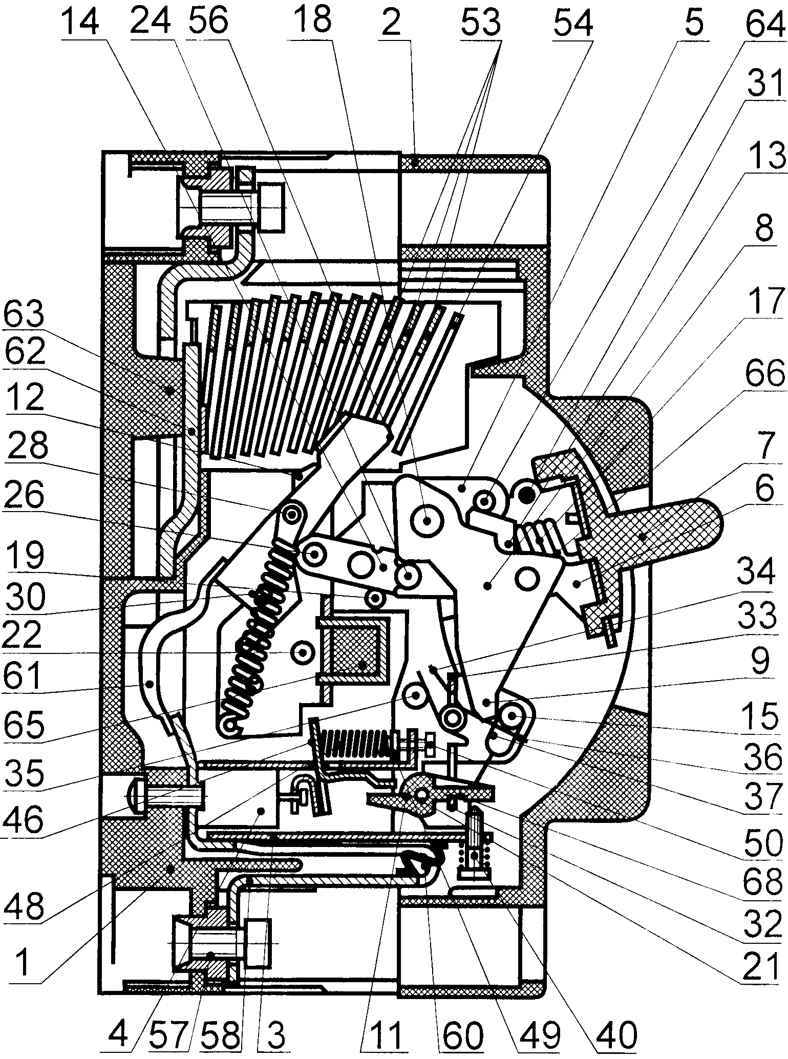
На фиг. 1 представлена конструкция выключателя автоматического многополюсного со средством зацепления в виде стержня с поперечным пазом -поперечное сечение по механизму свободного расцепления.In FIG. 1 shows the design of an automatic multi-pole circuit breaker with a means of gearing in the form of a rod with a transverse groove — a cross-section according to the free trip mechanism.
На фиг. 2 представлена конструкция выключателя автоматического многополюсного со средством зацепления в виде стержня с цилиндрической поверхностью - поперечное сечение по механизму свободного расцепления.In FIG. 2 shows the design of an automatic multi-pole circuit breaker with a means of gearing in the form of a rod with a cylindrical surface — a cross section according to the free trip mechanism.
На фиг. 3 представлена схема механизма свободного в положении, при котором рукоятка после срабатывания механизма свободного расцепления повернута по часовой стрелке до зацепления рычага со стержнем, при этом контактные пружины зафиксированы одним концом относительно подвижного контакта, а другим концом - относительно шарнирно связанного с ним коромысла.In FIG. Figure 3 shows a diagram of the free mechanism in a position in which the handle after turning on the free-release mechanism is turned clockwise until the lever engages with the rod, while the contact springs are fixed at one end relative to the movable contact and the other end relative to the rocker arm pivotally connected to it.
На фиг. 4 представлена схема механизма свободного в положении, при котором рукоятка после срабатывания механизма свободного расцепления повернута по часовой стрелке до зацепления рычага со стержнем, при этом контактные пружины зафиксированы одним концом относительно подвижного контакта, а другим концом - относительно шатуна, шарнирно связанного с коромыслом.In FIG. Figure 4 shows a diagram of the free mechanism in a position in which the handle after turning on the free-release mechanism is turned clockwise until the lever engages with the rod, while the contact springs are fixed at one end relative to the movable contact and the other end relative to the connecting rod pivotally connected to the beam.
Полезная модель может быть осуществлена в следующем конструктивном исполнении.The utility model can be implemented in the following design.
Выключатель автоматический многополюсный (фиг. 1 и 2) содержит корпус 1, крышку 2, механизм свободного расцепления, контактную группу, расцепители тока перегрузки 3 (тепловые), электромагнитные максимальные расцепители тока 4, дугогасительное устройство, выводы для внешних проводников.The multi-pole automatic switch (Fig. 1 and 2) contains a
Механизм свободного расцепления содержит стойку 5, взводной рычаг 6 с рукояткой 7, рычаг 8 с выступом 9, коромысло 10, поворотную рейку 11, коромысло 12, шатуны 13 и 14, стержень 15, контактные пружины 16 и пружины растяжения 17 (фиг. 1, 2 и 3).The free trip mechanism comprises a
Рычаги 6 и 8, коромысло 10 и поворотная рейка 11 закреплены на стойке 5 посредством осей 18, 19, 20, 21 и 22 с возможностью вращения. Пружины растяжения 17 одним концом закреплены на перемычках 23 взводного рычага 6, а другим - на оси 24, шарнирно соединяющей шатуны 13 и 14. Шатун 13 посредством оси 25 шарнирно соединен с рычагом 8, а шатун 14 посредством оси 26 шарнирно соединен с коромыслом 12. Контактные пружины 16 одним концом закреплены на выступах 27 коромысел 12, а другим концом - на выступах 28 подвижных электрических контактов 29. При этом на одном подвижном электрическом контакте 29 зафиксированы концы двух контактных пружин 16 с двух его сторон. Выступы 27 и 28 могут быть образованы путем установки цилиндрических стержней, длина которых превышает ширину подвижных электрических контактов 29, в отверстиях подвижных электрических контактов 29. Между концами контактных пружин расположены оси 30, соединяющие коромысла 12 с подвижными электрическими контактами 29 и обеспечивающие вращение подвижных электрических контактов 29 относительно коромысел 12.The
Корпус 1 разделен перегородками на три отсека. В среднем отсеке расположена стойка 5, выполненная в виде двух одинаковых пластин, неподвижно закрепленных в корпусе 1 между перегородками. Взводной рычаг 6 выполнен из листового материала путем вырубки и гибки и имеет П-образную форму в поперечном сечении. На боковинах взводного рычага 6 выполнены отверстия для установки оси 19 и стержня 31. Между боковинами на средней части рычага 9 вдоль боковин выполнены два продольных паза с перемычками 23 (фиг. 4), предназначенными для удержания концов пружин растяжения 17.
Рычаг 8 выполнен в виде пластины, установлен посредине между боковинами взводного рычага 6 и закреплен на оси 18, установленной с возможностью вращения в отверстиях стойки 5.The
Коромысло 10 выполнено из листового материала путем вырубки и гибки до образования П-образной формы. В боковинах коромысла 10 выполнены отверстия для установки цилиндрического стержня 15 и оси 20, установленной также в отверстиях стойки 5. В средней части коромысла 10, расположенной между боковинами, выполнено сквозное отверстие Т-образной формы, образующее П-образную перемычку 32 со стороны основания буквы «Т» отверстия и перемычку 33 со стороны перекладины буквы «Т» отверстия. На оси 20 установлена пружина кручения 34, создающая на коромысле момент силы, действующий по часовой стрелке (фиг. 1 и 2). Для этого концы пружины кручения 34 установлены между стержнем 35, установленным в стойке 5, и перемычкой 33.The
Отверстия в боковинах коромысла для установки стержня 15 могут иметь цилиндрическую форму (фиг. 1, 3 и 4).The holes in the sides of the rocker arm for installing the
В этом случае стержень 15 может быть выполнен с двумя поперечными пазами, один из которых предназначен для прохождения выступа 9 рычага 8, а второй - для размещения конца пружины кручения 36 (фиг. 2), установленной на оси 20, второй конец которой заведен за перемычку 33 коромысла 10 (фиг. 1 и 2).In this case, the
Отверстия в боковинах коромысла 10 для установки стержня 15 могут иметь продолговатую форму 37 (фиг. 2) в виде пазов шириной, обеспечивающей свободное движение концов стержня вдоль пазов. В этом случае стержень 15 может быть выполнен гладким, при этом конец пружины кручения 36 заводится за стержень 15, прижимая его к краям отверстий в направлении выступа 9 рычага 8.The holes in the sides of the
Возможны и другие варианты выполнения средства для фиксации рычага 8 в определенном положении, например, в виде защелки, установленной на коромысле 10 или на стойке 5. В этом случае нет необходимости в наличии отверстий и стержня. При установке защелки на стойке 5 защелка должна непосредственно взаимодействовать с поворотной рейкой 11.Other embodiments of means for fixing the
Контактная группа состоит из подвижных электрических контактов 29, неподвижных электрических контактов 38 (фиг. 1) и контактных пружин 16. В положении на фиг. 1 подвижные и неподвижные электрические контакты находятся в замкнутом состоянии, которое обеспечивается моментом силы, создаваемом контактными пружинами 16, расположенными со смещением относительно оси 30. На фиг. 2 подвижные электрические контакты находятся в положении после электродинамического отброса, вызванного током короткого замыкания, в несколько раз превышающим заданную величину.The contact group consists of movable
Расцепитель тока перегрузки 3 (фиг. 2) представляет собой биметаллическую пластину 39 (фиг. 1), состоящую из двух слоев сплавов с различными коэффициентами термического расширения. На конце биметаллической пластины 39 выполнено резьбовое отверстие, в котором установлен подпружиненный винт 40 (фиг. 2), конец которого имеет возможность взаимодействовать с плечом 41 поворотной рейки 11 при изгибе биметаллической пластины 39 (фиг. 1).The overload current release 3 (Fig. 2) is a bimetallic plate 39 (Fig. 1), consisting of two layers of alloys with different coefficients of thermal expansion. At the end of the
Электромагнитный максимальный расцепитель тока 4 (фиг. 2) содержит соленоид 42 с якорем 43, удерживаемым пружиной (фиг. 1). Наружный конец якоря 43 имеет буртик 44 и установлен в пазу изогнутой пластины 45 таким образом, чтобы буртик 44 был расположен между концами изогнутой пластины 45 (фиг. 1). Изогнутая пластина 45 закреплена на планке 46, установленной в отверстии стойки 47, неподвижно закрепленной в пазах корпуса 1. На планке 46 выполнены препятствующие смещению планки 46 поперек стойки 47 две пары плечиков, между которыми расположена стойка 47. Ширина отверстия в стойке 47 более чем в два раза превышает толщину планки 46. Длина отверстия в стойке 47, в котором расположена планка 46, соответствует ширине планки 46, при этом часть отверстия, расположенного со стороны крышки 2, в которой планка 46 не расположена, соответствует расстоянию между плечиками планки, исходя из необходимости проведения через эту часть отверстия плечиков планки 46 при ее монтаже.The electromagnetic maximum current release 4 (Fig. 2) contains a
На планке 46 выполнен выступ для фиксации конца пружины 48, второй конец которой зафиксирован на участке наружной цилиндрической поверхности вставки 49 (фиг. 2) с упором в торцевую поверхность ее буртика. Во вставке 49 выполнено глухое отверстие, в котором установлен конец резьбовой части винта 50 (фиг. 2), установленного в резьбовом отверстии отогнутого под прямым углом конца стойки 47.On the
Отогнутый конец планки 46 предназначен для взаимодействия с плечом 51 поворотной рейки 11 при срабатывании электромагнитного максимального расцепите ля тока 4.The bent end of the
На поворотной рейке 11 имеется еще одно плечо (не показано), расположенное в плоскости, перпендикулярной плечам 41 и 51 поворотной рейки 11, и предназначенное для ручного принудительного срабатывания механизма свободного расцепления. Для этого в крышке 2 устанавливают подпружиненную кнопку управления, взаимодействующую с этим плечом поворотной рейки 11 при ее нажатии.On the
Дугогасительное устройство представляет собой несколько дугогасительных камер 52, каждая из которых расположена в одном полюсе и выполнена в виде деионной решетки из металлических пластин 53 и 54, закрепленных с зазором друг относительно друга на боковых стенках 55, выполненных из электроизоляционного материала. Металлические пластины 53 выполнены с пазами для беспрепятственного прохождения подвижных электрических контактов 29. Металлическая пластина 54, наиболее удаленная от неподвижного электрического контакта 38, в каждом полюсе установлена с возможностью взаимодействия своим концом с выступом 56 (фиг. 2) конца подвижного электрического контакта 29 при срабатывании механизма свободного расцепления после электродинамического отброса подвижного электрического контакта 29, вызванного током короткого замыкания. Пластина 54 не имеет паза и изготавливается путем вырубки из металлического листа.The arcing device consists of
Выводы для внешних проводников являются винтовыми и выполнены в виде гаек 57 с комбинированной наружной цилиндрической и шестигранной поверхностью головки. Гайки 57 установлены в отверстиях корпуса 1, выполненных с соответствующими внутренними цилиндрическими и шестигранными поверхностями. Со стороны шестигранников головок гаек 57 установлены концы шин 58 (фиг. 2) и неподвижных электрических контактов 38 с отверстиями, сквозь которые вставлены винты 59 с цилиндрическими головками, в которых выполнены шестигранные отверстия. Концы шин 58 размещены между головками винтов 59 и гайками 57. Каждая шина 58 выполнена в виде незамкнутой петли с отверстием для прохождения резьбового участка винтов 59 и прямоугольным отверстием, расположенным напротив биметаллической пластины 39, через которое проведен гибкий проводник 60 (фиг. 2), соединяющий шину 58 с биметаллической пластиной 39 на участке, приближенном к винту 40. С противоположной стороны биметаллическая пластина 39 присоединена к другому участку шины 58. Конец шины 58 гибким проводником 61 присоединен к концу подвижного электрического контакта 29. Каждый неподвижный электрический контакт 38 выполнен в виде изогнутой зигзагообразно под прямыми углами продолговатой пластины с круглым отверстием, выполненном на отогнутом участке с короткой стороной, и продолговатым отверстием, полученным на длинном участке путем частичной вырубки и отгиба внутренней части на длинном участке с параллельным расположением отогнутой внутренней части 62 относительно короткой стороны и внешней части длинного участка с образованием петли вокруг продолговатого отверстия.The findings for the external conductors are screw and made in the form of
Отогнутая внутренняя часть 62 неподвижного контакта 38 опирается на выступ 63 задней крышки корпуса 1.The bent inner part 62 of the fixed
В стойке 5 закреплен стержень 64. Все коромысла 12 неподвижно закреплены на общей траверсе 65 (фиг. 2). На рычаге 8 выполнен выступ 66 (фиг. 3 и 4), имеющий возможность взаимодействовать со стержнем 64, и выступ 67, имеющий возможность взаимодействовать со стержнем 31 взводного рычага 6. На плече 41 (фиг. 1) поворотной рейки 11 выполнен паз 68 (фиг. 2). Вращение подвижного электрического контакта 29 относительно коромысла 12 ограничено его осью 22, в которую упирается один конец подвижного электрического контакта 29 в одном его крайнем положении относительно коромысла 12, и концом 69 (фиг. 4), в который упираются выступы 28 в другом крайнем положении подвижного электрического контакта 29 относительно коромысла 12.In the
Корпус 1, крышка 2, задняя крышка и общая траверса 65 выполнены из электроизоляционного материала.The
Устройство (фиг. 4) может содержать в каждом полюсе дополнительный шатун 70, установленный с возможностью вращения на оси 71, установленной на коромысле 12, при этом выступы 27, на которых зафиксированы концы контактных пружин 16, установлены на конце шатуна 70, другой конец которого снабжен двумя выступами 72, предназначенными для поочередного взаимодействия с двух сторон с концом подвижного электрического контакта 29, на котором контактный элемент отсутствует. Выступ 27 при этом имеет возможность взаимодействовать с концом 73 коромысла 12.The device (Fig. 4) may contain in each pole an additional connecting
При испытании конструкций устройств, изготовленных в соответствии данной полезной моделью, было установлено, что в фиксации боковых стенок 55 дугогасительных камер 52 в корпусе 1 нет необходимости, т.к. при электродинамическом отбросе подвижных электрических контактов 29 они удерживаются в отброшенном положении до срабатывания механизма свободного расцепления даже при незначительных моментах сил, прижимающих подвижные электрические контакты 29 посредством выступов 28 к концам 69 коромыслел 12. Данные обстоятельства, впрочем, не исключают возможность фиксировать дугогасительные камеры 52 путем прижатия их боковых стенок 55 крышкой 2 к донной поверхности корпуса 1.When testing the designs of devices manufactured in accordance with this utility model, it was found that there is no need to fix the
Устройство работает следующим образом.The device operates as follows.
При протекании токов короткого замыкания, достигших заданной величины тока, якорь 43 втягивается соленоидом 42 и вращает планку 46 по часовой стрелке, которая своим отогнутым концом нажимает на плечо 51 поворотной рейки 11. Заданную величину тока регулируют регулировочным винтом 50. Поворотная рейка 11 выходит из зацепления с П-образной перемычкой 32 коромысла 10 механизма свободного расцепления, коромысло 10 вращается по часовой стрелке (фиг. 1) и выводит из зацепления с выступом 9 рычага 8 стержень 15. В результате этого освобождается рычаг 8 механизма свободного расцепления, который под действием пружин растяжения 17 и шатуна 13 мгновенно поворачивается против часовой стрелки до упора в стержень 64 стойки 5. При этом шатун 14 вращает коромысло 12 по часовой стрелке вокруг оси 22 до упора его конца в ось 18 вращения рычага 8. Вместе с коромыслом 12 вращается общая траверса 65, несущая коромысла 12 всех полюсов. Вместе с общей траверсой 65 вращаются все коромысла 12, а с ними - подвижные электрические контакты 29. Происходит размыкание одновременно во всех полюсах.When short-circuit currents have reached a predetermined current value, the
При протекании токов перегрузки, меньших заданных токов короткого замыкания, биметаллическая пластина 39 нагревается под действием протекающего тока и изгибается в сторону слоя с меньшим коэффициентом термического расширения - в сторону плеча 41 (фиг. 1) поворотной рейки 5, вращая ее. Заданную величину перегрузки регулируют регулировочным винтом 40. Поворотная рейка 11 выходит из зацепления с П-образной перемычкой 32 коромысла 10 механизма свободного расцепления. Далее работа механизма свободного расцепления происходит так же, как было описано выше.When overload currents are lower than the specified short circuit currents, the
При протекании токов короткого замыкания, в несколько раз превышающих заданную величину, под действием электродинамических сил подвижные электрические контакты 29 отбрасываются от неподвижных 38 и вращаются на осях 30, установленных на коромыслах 12. При этом в первой стадии вращения усилие контактных пружин 16 увеличивается, а момент сил от этого усилия, препятствующий вращению, уменьшается за счет уменьшения длины плеча, на котором действует это усилие. В момент прохождения подвижными электрическими контактами 29 положения, при котором выступы 27 и 28, на которых закреплены концы контактных пружин 16, окажутся в одной плоскости с осями 30 вращения подвижных электрических контактов 29, усилия от контактных пружин будет максимальным, а вращающий момент, создаваемый пружинами, будет равен нулю. Данное положение подвижных электрических контактов 29 является неустойчивым. После его прохождения, момент силы от контактных пружин 16 будет направлен в сторону вращения подвижных электрических контактов 29. После этого подвижные электрические контакты 29, дойдя до упора осями 28 в коромысла 12, останавливаются в другом устойчивом положении. При быстром размыкании электрических контактов 29 и 38 токи коротких замыканий не успевают достигнуть предельных значений, и тепловое воздействие тока уменьшается. После этого срабатывает электромагнитный максимальный расцепитель тока 4, при этом поворотная рейка 11 вращается против часовой стрелки, П-образная перемычка 32 коромысла 10 выходит из паза 68 (фиг. 2) на плече 41 поворотной рейки 11, коромысло 10 поворачивается по часовой стрелке до упора П-образной перемычки 32 в поверхность рейки 11, расположенную между осью 21 вращения рейки 11 и пазом 68, при этом стержень 15 отводится от выступа 9 рычага 8, происходит расцепление рычага 8 со стержнем 15 и срабатывание механизма свободного расцепления, при котором рычаг 8 вращается против часовой стрелки до упора в стержень 64 стойки 5, по часовой стрелке вращаются вместе общая траверса 65, коромысла 12 и подвижные электрические контакты 29, выступы которых, войдя в контакт с пластинами 54, встречают с их стороны сопротивление, препятствующее их вращению вместе с коромыслами. В процессе дальнейшего вращения коромысел 12 ось 30 пересекает плоскость, в которой расположены выступы 27 и 28 для фиксации концов контактных пружин 16. После этого под действием контактных пружин 16 подвижные электрические контакты 29 вращаются против часовой стрелки до упора в оси 22 вращения коромысел 12.When short-circuit currents are several times higher than the specified value, under the action of electrodynamic forces, the movable
Использование механизма свободного расцепления, представленного на фиг. 4, позволяет уменьшить габариты механизма за счет дополнительного шатуна 70, который поворачивается в противоположную сторону относительно подвижного электрического контакта 29, при этом необходимое плечо момента силы, создающей контактное давление между электрическими контактами 29 и 38, а также необходимое плечо для создание момента силы, удерживающего подвижный электрический контакт 29 после электродинамического отброса и препятствующего повторному замыканию электрических контактов до срабатывания механизма свободного расцепления, будут создаваться при меньшем угле поворота подвижного электрического контакта 29.Using the free trip mechanism shown in FIG. 4, allows to reduce the dimensions of the mechanism due to the additional connecting
Возникающая в процессе размыкания электрических контактов электрическая дуга втягивается за счет электродинамических сил и магнитных полей в узкий промежуток между стальными пластинами 53 и 54 деионной решетки дугогасительной камеры 52 и, за счет охлаждения и разбивки на отдельные маленькие дуги между стальными пластинами 53 и 54, гаснет.The electric arc arising during the opening of electrical contacts is drawn due to electrodynamic forces and magnetic fields into the narrow gap between the
Повторный взвод механизма свободного расцепления в рабочее положение осуществляется путем перемещения рукоятки 7 сначала по часовой стрелке, в процессе которого стержень 31, установленный на взводном рычаге 6, цепляет выступ 67 рычага 8, расположенный с противоположной от выступа 9 стороны, и вращает рычаг 8, в процессе которого выступ 9 рычага 8 поворачивает стержень 15 вокруг собственной оси или отводит его и одновременно надавливает на перемычку 33 (фиг. 1 и 2) коромысла 10 поверхностью рычага, расположенной под выступом 9, коромысло 10 вращается против часовой стрелки и заходит перемычкой 32 в паз 68. После этого рукоятку 7 отпускают, рычаг 8 поворачивается против часовой стрелки и его выступ 9 входит в зацепление со стержнем 15, одновременно коромысло 10 поворачивается по часовой стрелке до упора перемычкой 32 в боковую поверхность паза 68, расположенную со стороны оси 21 вращения поворотной рейки 11. Затем рукоятку 7 вращают против часовой стрелки, при этом рычаг 8 удерживается стержнем 15 от перемещения вместе рукояткой и взводным рычагом 6, а пружина 17 удерживает от перемещения остальные звенья механизма свободного расцепления.Re-cocking the free trip mechanism to the operating position is carried out by moving the
В процессе вращения рукоятки 7 с взводным рычагом 6, вместе с ними перемещаются концы пружины 17, зафиксированные на перемычках 23 взводного рычага 6. После того, как проходящая через концы каждой пружины 17 линия пересечет центр оси 25 (фиг. 3 и 4), соединяющей рычаг 8 с шатуном 13, усилие пружин 17 создаст момент силы, направленный против часовой стрелки относительно оси 25, в связи с этим шатун мгновенно 13 повернется по часовой стрелке вокруг оси 25, при этом шатун 14 мгновенно повернется против часовой стрелки, вращая коромысла 12 и общую траверсу 65, а вместе с ними и подвижные электрические контакты 29 вокруг оси 22 против часовой стрелки до контакта с неподвижными электрическими контактами 38.During rotation of the
Выполнение конца металлической пластины 54, наиболее удаленной от неподвижного электрического контакта 38, расположенным в одной плоскости с этой пластиной, позволяет изготовить пластину целиком из листового материала одной операцией - вырубкой, в отличие от прототипа [2], в котором конец металлической пластины, наиболее удаленной от неподвижного электрического контакта 38, отогнут.В связи с этим изготовление этой пластины требует дополнительной операции - гибки и дополнительного инструмента - гибочного штампа. Кроме того, предлагаемое техническое решение не требует фиксации боковых стенок дугогасительных камер путем прижатия их крышкой к донной поверхности корпуса, что также упрощает конструкцию устройства.The execution of the end of the
Claims (1)
Priority Applications (1)
| Application Number | Priority Date | Filing Date | Title |
|---|---|---|---|
| RU2015103048/07U RU155014U1 (en) | 2015-01-30 | 2015-01-30 | AUTOMATIC MULTIPLE SWITCH |
Applications Claiming Priority (1)
| Application Number | Priority Date | Filing Date | Title |
|---|---|---|---|
| RU2015103048/07U RU155014U1 (en) | 2015-01-30 | 2015-01-30 | AUTOMATIC MULTIPLE SWITCH |
Publications (1)
| Publication Number | Publication Date |
|---|---|
| RU155014U1 true RU155014U1 (en) | 2015-09-20 |
Family
ID=54148079
Family Applications (1)
| Application Number | Title | Priority Date | Filing Date |
|---|---|---|---|
| RU2015103048/07U RU155014U1 (en) | 2015-01-30 | 2015-01-30 | AUTOMATIC MULTIPLE SWITCH |
Country Status (1)
| Country | Link |
|---|---|
| RU (1) | RU155014U1 (en) |
Cited By (3)
| Publication number | Priority date | Publication date | Assignee | Title |
|---|---|---|---|---|
| WO2018212687A1 (en) * | 2017-05-15 | 2018-11-22 | Alfanar Comapny | An instantaneous tripping device for a miniature circuit breaker and miniature circuit breaker comprising the same |
| RU191065U1 (en) * | 2019-04-16 | 2019-07-23 | Акционерное общество "Курский электроаппаратный завод" | The mechanism of the maximum current release circuit breaker automatic |
| RU194211U1 (en) * | 2019-08-27 | 2019-12-03 | Елена Евгеньевна Кашичкина | Circuit Breaker Free Release |
-
2015
- 2015-01-30 RU RU2015103048/07U patent/RU155014U1/en active
Cited By (6)
| Publication number | Priority date | Publication date | Assignee | Title |
|---|---|---|---|---|
| WO2018212687A1 (en) * | 2017-05-15 | 2018-11-22 | Alfanar Comapny | An instantaneous tripping device for a miniature circuit breaker and miniature circuit breaker comprising the same |
| CN110622274A (en) * | 2017-05-15 | 2019-12-27 | 阿尔法纳公司 | Instantaneous trip device for miniature circuit breaker and miniature circuit breaker including the same |
| GB2580744A (en) * | 2017-05-15 | 2020-07-29 | Alfanar Company | An instantaneous tripping device for a miniature circuit breaker and miniature circuit breaker comprising the same |
| GB2580744B (en) * | 2017-05-15 | 2022-06-01 | Alfanar Company | An instantaneous tripping device for a miniature circuit breaker and miniature circuit breaker comprising the same |
| RU191065U1 (en) * | 2019-04-16 | 2019-07-23 | Акционерное общество "Курский электроаппаратный завод" | The mechanism of the maximum current release circuit breaker automatic |
| RU194211U1 (en) * | 2019-08-27 | 2019-12-03 | Елена Евгеньевна Кашичкина | Circuit Breaker Free Release |
Similar Documents
| Publication | Publication Date | Title |
|---|---|---|
| EP2251887B1 (en) | Electromagnetic trip device | |
| KR101026306B1 (en) | Circuit breaker with instantaneous trip device | |
| RU155014U1 (en) | AUTOMATIC MULTIPLE SWITCH | |
| JPH0828180B2 (en) | Circuit breaker | |
| US5831499A (en) | Selective trip unit for a multipole circuit breaker | |
| DE19808231A1 (en) | Compact current limiting switch | |
| DE19526592C2 (en) | Electrical switch, in particular circuit breaker | |
| GB1583570A (en) | Current limiting circuit breaker | |
| DE19741173A1 (en) | Automatic switch e.g. for LV power distribution circuits | |
| RU166467U1 (en) | AUTOMATIC MULTIPLE SWITCH | |
| US4417223A (en) | Multipole electric circuit breaker with improved current limiting device | |
| AU605012B2 (en) | Molded case circuit breaker with viewing window and sliding barrier | |
| CA1273039A (en) | Circuit breaker with magnetic shunt hold back circuit | |
| US4146855A (en) | Low profile multi-pole circuit breaker having multiple toggle springs | |
| US4611188A (en) | Circuit breaker | |
| CN204204685U (en) | There is the switchgear of the device for jumper connection | |
| US3222475A (en) | Operating mechanism for multipole electrical circuit breaker | |
| US20170194123A1 (en) | Shifting device | |
| EP0013642A1 (en) | Low voltage current limiting circuit breaker | |
| US4620171A (en) | Molded case circuit breaker with resettable combined undervoltage and manual trip mechanism | |
| RU2363066C2 (en) | Switch device | |
| CN201160057Y (en) | Selective protection switch | |
| CN110024073B (en) | Electrical switching apparatus and thermal trip assembly therefor | |
| EP3084797B1 (en) | Trip assembly | |
| KR100798340B1 (en) | Circuit breaker with current-limiting function |