KR930010086B1 - Semiconductor integrated circuit device - Google Patents
Semiconductor integrated circuit device Download PDFInfo
- Publication number
- KR930010086B1 KR930010086B1 KR1019890019299A KR890019299A KR930010086B1 KR 930010086 B1 KR930010086 B1 KR 930010086B1 KR 1019890019299 A KR1019890019299 A KR 1019890019299A KR 890019299 A KR890019299 A KR 890019299A KR 930010086 B1 KR930010086 B1 KR 930010086B1
- Authority
- KR
- South Korea
- Prior art keywords
- integrated circuit
- circuit device
- terminals
- semiconductor integrated
- wiring film
- Prior art date
- Legal status (The legal status is an assumption and is not a legal conclusion. Google has not performed a legal analysis and makes no representation as to the accuracy of the status listed.)
- Expired - Fee Related
Links
Images


Classifications
-
- H10W90/00—
-
- H10W70/60—
-
- H10W70/611—
-
- H10W72/00—
-
- H10W72/701—
-
- H10W90/811—
-
- H10W46/00—
-
- H10W72/077—
-
- H10W90/20—
-
- H10W90/22—
-
- H10W90/297—
-
- H10W90/724—
Landscapes
- Wire Bonding (AREA)
- Semiconductor Integrated Circuits (AREA)
Abstract
내용 없음.No content.
Description
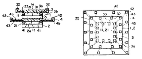
제 1a 도와 제 1b 도는 이 발명의 제 1 실시예에 따른 반도체 집적회로장치의 단면도와 평면도를 각각 표시하는 도면.1A and 1B show a cross-sectional view and a plan view, respectively, of a semiconductor integrated circuit device according to a first embodiment of the present invention;
제 2a 도는 제 1 실시예에서 사용되는 배선필름의 구조를 표시하는 단면도.2A is a sectional view showing a structure of a wiring film used in the first embodiment.
제 2b 도는 배선필름의 변형예를 표시하는 단면도.2B is a sectional view showing a modification of the wiring film.
제 3 도는 이 발명의 제 2 실시예를 표시하는 단면도.3 is a sectional view showing a second embodiment of this invention.
제 4 도는 이 발명의 제 3 실시예를 표시하는 단면도.4 is a sectional view showing a third embodiment of the present invention.
제 5 도는 이 발명의 제 4 실시예를 표시하는 단면도.5 is a sectional view showing a fourth embodiment of the present invention.
제 6 도는 이 발명의 제 5 실시예를 표시하는 단면도.6 is a sectional view showing a fifth embodiment of this invention.
제 7 도는 제 6 실시예를 표시하는 단면도.7 is a sectional view showing a sixth embodiment.
제 8 도는 종래의 반도체장치의 사시도.8 is a perspective view of a conventional semiconductor device.
* 도면의 주요부분에 대한 부호의 설명* Explanation of symbols for main parts of the drawings
1, 2 : 반도체칩 3 : 제 1 배선필름1, 2: semiconductor chip 3: first wiring film
11, 21 : 전극패드 31, 32 : 제 2 단자11 and 21:
3 : 배선필름 51 : 필름본체3: wiring film 51: film body
이 발명은 반도체 집적회로장치에 관한 것이고 특히 복수의 반도체칩을 다층으로 구성한 장치에 관한 것이다.BACKGROUND OF THE INVENTION 1. Field of the Invention The present invention relates to a semiconductor integrated circuit device, and more particularly, to an apparatus in which a plurality of semiconductor chips are formed in multiple layers.
제 8 도는 종래의 반도체장치의 사시도이다.8 is a perspective view of a conventional semiconductor device.
표시된 장치는 패키기(package)(81)와 거기에 수용되어 있는 LSI칩(82)으로 구성된다. LSI칩(82)는 그의 표면상에 다수의 전극패드(83)를 가지고 있고 패키기(81)는 전극패드(83)에 대응하는 다수의 핀(84)을 가지고 있다. LSI칩(82)의 각 전극패드(83)는 와이어(85)를 통하여 대응하는 핀(84)에 전기적으로 접속되어 있다. 동작시에 있어서는 핀(84)은 이 반도체장치 외부의 회로에 전기적으로 접속되어 외부회로에서의 입력신호가 핀(84)과 와이어(85)를 통하여 LSI칩(82)의 전극패드(83)에 전송된다.The device shown consists of a
한편 LSI칩(82)에서의 출력신호가 전극패드(83), 와이어(85) 그리고 핀(84)을 통하여 외부회로에 출력된다. 복수의 LSI칩이 이러한 방법으로 구성되는 종래의 반도체장치에서 사용될때 각 LSI칩(82)이 수용되는 복수의 패키기(81)는 단일 기판상에 배치되고 핀(84)을 통하여 패키기(81)사이 및 반도체장치와 외부회로사이를 전기적으로 접속되었다. 결과로서 패키기(81)의 설치는 큰 면적을 필요하고 그리고 그러한 반도체장치가 사용되는 전기장치의 대형화를 초래한다.On the other hand, the output signal from the
비록 LSI칩(82)이 패키기(81)에 수용되지 않고 사용되더라도 복수의 LSI칩(82)이 평면에 필연적으로 배치되어야 하기 때문에 그들의 설치에 요구되는 큰 면적의 문제가 있다. 이 발명은 이러한 문제를 해소하는 목적으로 고안되었다.Although the
따라서 복수의 반도체칩이 비치되었어도 큰 면적을 점유함이 없이 장치될 수 있는 반도체 집적회로장치를 제공하는 것이 이 발명의 목적이다. 이 발명에 따라 반도체 집적회로장치는 각 복수의 전극패드를 가지고 다층구조를 형성하는 그러한 수단으로 배치되는 복수의 반도체칩이고 대응하는 반도체칩을 설치하기 위해 적용되고 반도체칩과 대응하게 배치되는 복수의 배선필름, 상기 배선필름의 각각에 제공되는 복수의 제 1 단자와 배선필름에 대응하는 반도체칩의 복수의 전극패드에 각 접속되고 각 배선필름의 상기 제 1 단자 외부에 설치되고 대응하는 제 1 단자에 전기적으로 접속되는 복수의 제 2 단자로 구성된다.Therefore, it is an object of the present invention to provide a semiconductor integrated circuit device that can be installed without occupying a large area even if a plurality of semiconductor chips are provided. According to the present invention, a semiconductor integrated circuit device is a plurality of semiconductor chips arranged by such means having a plurality of electrode pads each to form a multilayer structure, and a plurality of semiconductor chips applied to install corresponding semiconductor chips and correspondingly arranged with the semiconductor chips A first film each connected to a wiring film, a plurality of first terminals provided on each of the wiring films, and a plurality of electrode pads of a semiconductor chip corresponding to the wiring film, and installed outside and corresponding to the first terminal of each wiring film. It is comprised by the some 2nd terminal electrically connected to the.
[실시예]EXAMPLE
이 발명의 실시예는 첨부도면에 의거하여 설명된다.Embodiments of this invention are described based on the accompanying drawings.
제 1a 도에 표시된 반도체 집적회로장치는 제 1 반도체칩(1)과 제 2 반도체칩(2)을 포함하고 제 1 반도체칩 밑에 곧바로 제 2 의 반도체칩이 배치되어 있다. 복수의 전극패드(11, 21)는 반도체칩(1, 2)의 각 상면(1a, 2a)에 주변에 따라 형성되어 있다.The semiconductor integrated circuit device shown in FIG. 1A includes a first semiconductor chip 1 and a
제 1 반도체칩(1)의 위에 제 1 반도체칩보다 더 큰 면적을 가지고 제 1 배선필름(3)이 배치되고 있다. 더욱 제 1 배선필름(3)보다 더 큰 면적을 가지는 제 2 배선필름(4)이 제 1 과 제 2 반도체칩(1, 2)사이에 배치된다. 복수의 제 1 단자(31)는 제 1 반도체칩(1)의 전극패드(11)의 그러한 것에 대응하는 위치에 제 1 배선필름(3)의 하면 (3b)상에 형성된다.The
각 제 1 단자(31)는 도전성 접착제의 방법에 의해 또는 납땜에 의해 제 1 반도체칩(1)상의 대응하는 전극패드(11)에 접속된다. 제 1 단자(31)에 대응하는 복수의 제 2 단자(32)는 제 1 배선필름(3)의 상면(3a)에 주변을 따라 형성되고 대응하는 제 1 과 제 2 단자(31, 32)는 배선필름(3)의 배선(33)을 통하여 서로가 전기적으로 접속되어 있다.Each
한편 복수의 제 1 단자(41)는 반도체칩(2)의 전극패드(21)의 그러한 것들에 대응하는 위치에서 제 2 배선필름(4)의 하면(4b)상에 형성되고 제 1 단자(41)의 각각은 납땜 또는 도전성 접착제에 의해 제 2 반도체칩(2)의 대응하는 전극패드(21)에 연결된다.Meanwhile, the plurality of
제 1 단자(41)에 대응하는 복수의 제 2 단자(42)는 제 2 배선필름(4)의 상면(4a)상에 주변을 따라 형성되고 대응하는 제 1 과 제 2 단자(41, 42)는 배선필름(4)의 배선(43)을 통하여 서로가 접속된다.The plurality of
제 1 반도체칩(1)의 하면 (1b)은 접착제(5)의 수단에 의해 제 2 배선필름(4)의 상면(4a)에 접속된다. 제 2 배선필름(4)이 제 1 배선필름(3)보다 더 큰 면적을 가지기 때문에 제 2 배선필름(4)의 상면(4a)상에 제공되는 제 2 단자(42)는 제 1b 도에 표시된 것과 같이 제 1 배선필름(3)의 상면(3a)상에 제공되는 제 2 단자(32) 외측에 위치하고 있다. 제 1 과 제 2 배선필름(3, 4)의 제 2 단자(32, 42)는 이 반도체 집적회로장치의 외부단자를 형성한다.The lower surface 1b of the first semiconductor chip 1 is connected to the upper surface 4a of the
이리하여 구성된 반도체 집적회로장치는 외부회로 또는 기판에 접속되는 제 1 과 제 2 배선필름(3, 4)상에 각각 형성되는 제 2 단자(32, 42)에 의해 사용된다.The semiconductor integrated circuit device thus constructed is used by the
따라서 예를 들면 외부회로에서 제 1 배선필름(3)의 제 2 단자(32)에 입력되는 신호는 배선(33) 및 제 1 단자(31)를 통하여 제 1 반도체칩(1)의 전극패드(11)에 전송된다.Therefore, for example, a signal input to the
한편 제 1 반도체칩(1)의 전극패드(11)에서 출력된 신호는 제 1 배선필름(3)의 제 2 단자(32) 및 배선(33)을 통하여 외부회로등에 전송된다. 동일하게 제 2 반도체칩(2)의 입출력신호도 제 2 배선필름(4)의 제 2 단자(42), 배선(43) 그리고 제 1 단자(41)를 통하여 외부회로등 사이에서 전송된다.The signal output from the
제 2a 도는 제 1 과 제 2 배선필름(3, 4)의 구체적인 구조예를 표시한다. 표시되는 이 배선필름은 포리이미드로 만들어진 필름본체(51)를 가지고 있다. 이 필름본체(51)의 하면(51b)에 소정의 패턴으로 제공되는 동박(52b)이 접합되어 있다. 이 동박(52b)의 1단부에는 제 1 단자로서 작동하는 땜납범프(53b)가 형성되어 있고 기타부분의 동박(52b)은 포리-이미드와 같은 전기 절연물로 만들어진 피막(54)에 의해 피복되어 있다. 도박(52b)의 타단부가 위치하는 필름본체(51)에는 필름본체(51)의 상면(51a)에서 하면(51b)까지 관통하는 관통구멍(55)이 형성되어 이 관통구멍(52)내에 도금금속(56)이 묻혀있다. 필름본체(51)의 상면(51a)에 관통구멍(55)위에 동박(52)이 접합되고 이 동박(52)상에 제 2 의 단자(32)로서 작동하는 땜납범프(53a)가 형성되어 있다.2A shows a specific structural example of the first and
즉 제 1 과 제 2 단자로서 작동하는 필름본체(51)표리의 쌍방의 범프(53a, 53b)는 배선을 구성하는 동박(52a, 52b)과 도금금속(56)을 통하여 서로 전기적으로 접속되어 있다.That is, the
이와 같이 배선필름은 다음과 같이 작성된다.Thus, the wiring film is made as follows.
우선 포리이미드로 만들어진 필름본체(51)의 하면(51b)에서 단자를 내고 싶은 장소에 펀치등에 의해 관통구멍(55)이 형성된다.First, a through
다음에 이 필름본체(51)의 상면(51a)에 동작(52)이 접합되고 사진제판기술과 에칭기술을 이용하여 동박(52a)을 패턴으로 한다. 패터닝은 관통구멍(55)위에 위치하는 동박(52a)의 그러한 부분들이 제거되지 않도록 실행되어야 한다.Next, the
그후 필름본체(51)의 상면(51a)측에 단자를 내고 싶은 장소의 동박(52a)을 남기고 다른 부분의 동박(52a)의 표면상을 전기 절연물로 되는 피막(54)으로 덮어 동박을 전극으로서 전기도금을 한다. 필름본체(51)의 하면(51b)에는 피막(54)으로 덮혀져 있지 않기 때문에 관통구멍(55)을 통하여 동박(52a)의 하면상에 도금금속(56)이 축적되어 차차 관통구멍(55)이 도금금속에 의해 메워진다. 이 관통구멍(55)내의 도금금속(56)이 필름본체(51)의 하면(51b)에 도달되었을때 도금은 종료된다.Thereafter, the
이번에는 필름본체(51)의 하면(51b)에 동박(52b)이 접착되어 사진제판기술과 에칭기술에 의해 패턴이 된다. 이때 관통구멍(55)내에는 도금금속(56)이 필름본체(51)의 하면(51b)까지 도달하였기 때문에 이 하면(51b)에 접착된 동박(52b)과 관통구멍(55)내의 도금금속(56)이 전기적으로 서로 접속된다.This time, the
최후에 필름본체(51)의 하면(51b)상에 단자를 내고 싶은 장소 이외의 동박(52b)의 표면상에 피막(54)을 형성한 후에 필름본체(51)의 상면(51a) 및 하면(51b)에 단자를 내고 싶은 장소의 동박(52b)상에 땜납범프(53a, 53b)가 형성된다.Lastly, after the
더욱 제 1 의 단자로서 작동하는 그러한 땜납범프(53b)와 이것에 접속되는 제 2 의 단자로서 작동하는 그러한 땜납범프(53a)를 필름본체(51)의 서로 다른 면에 형성하지 않고 필요에 따라 제 2b 도에 표시한 것과 같이 필름본체(51)의 동일면에 형성하여도 좋다.Further, such solder bumps 53b acting as first terminals and those
제 3 도는 이 발명의 제 2 실시예를 표시한다.3 shows a second embodiment of this invention.
이 실시예에 있어서는 제 1 과 제 2 반도체칩(1, 2)은 같은 신호를 취급하는 전극패드(11, 21)를 가지고 있다. 전극패드(11, 21)에 전기적으로 접속되는 제 1 과 제 2 배선필름(3, 4)의 제 2 단차(32, 42)가 같은 위치에 배치되어 서로가 접속되어 있다. 제 2 단자(32, 42)사이의 접합을 용이하게 하기 위해 제 1 배선필름(3)의 제 2 단자(32)는 배선필름(3)의 하면(3b)상에 설정되고 하향으로 향하게 된다. 제 1 과 제 2 배선필름(3, 4)의 제 2 단자(32, 42)는 땜납 또는 도전성 접착제에 의해 서로가 접합된다.In this embodiment, the first and
더욱 제 1 과 제 2 반도체칩(1, 2)의 외부단자(34)가 제 1 배선필름(3)의 상면(3a)에 형성되어도 좋고 필요에 따라 서로가 접합된 제 2 단자(32, 42)에 접속되어도 좋다.Further, the
더욱 제 1 과 제 2 배선필름(3, 4)이 이 실시예에 있어서와 같이 몇개의 제 2 단자(32, 42)로 서로가 접합될때에는 제 1 반도체칩(1)의 하면(1b)은 접착제로 제 2 배선필름(4)의 상면(4a)에 접합되지 않아도 된다.Further, when the first and
제 4 도는 이 발명의 제 3 실시예를 표시하고 있다.4 shows a third embodiment of this invention.
이 실시예에 있어서와 같이 반도체칩의 수는 2개로 한정될 필요는 없다.As in this embodiment, the number of semiconductor chips need not be limited to two.
예를 들면 제 4 도에 표시한 실시예는 각 배선필름(3, 4, 7)상에 설치되는 3개의 반도체칩(1, 2, 6)을 포함하고 다층구조를 형성하게 서로가 적층된다. 표시된 실시예에서 제 2 와 제 3 배선필름(4, 7)의 제 2 단자(42, 72)는 서로가 접속되고 양 반도체칩(2, 6)의 외부단자(44)는 그곳위에 형성된다.For example, the embodiment shown in FIG. 4 includes three
만약 제 1 배선필름(3)이 그 외부단자(44)의 직상에 위치되면 열릴부분(35)이 외부단자(44)위의 제 1 배선필름(3)에 설정되고 그 외부단자(44)는 열린부분(35)을통하여 밖으로 나오게 된다.If the
동일하게 만약 제 1 과 제 3 배선필름(3, 7)의 제 2 단자(32, 72)가 서로 접속되면 열린부분(45)은 제 2 배선필름(4)에 설정되고 단자(32, 72)사이의 접속은 이 열린부분(45)을 통하여 이루어진다.Similarly, if the
제 5 도는 이 발명의 제 4 실시예를 표시한다.5 shows a fourth embodiment of this invention.
이 실시예에서는 접속단자(46)는 제 1 과 제 2 단자(41, 42)에서 독립하여 제 2 배선필름(4)에 설정되고 그곳을 통하여 확장한다.In this embodiment, the connecting
제 1 배선필름(3)의 제 2 단자와 제 3 배선필름(7)의 제 2 단자(72)는 이 접속단자(46)를 통하여 서로가 접속된다.The
더욱 제 1 배선필름(3)은 역시 거기를 통하여 확장하는 접속단자(36)를 포함하고 제 2 배선필름(4)의 제 2 단자(42)는 이 접속단자(36)에 접속되고 이 단자를 통하여 밖으로 나온다.Further, the
제 6 도는 이 발명의 제 5 실시예를 표시한다.6 shows a fifth embodiment of this invention.
이 실시예에서는 Cu 또는 Al와 같이 고열도전율(high heat conductivity)을 가지는 재료로 형성되는 방열판(8, 9)은 반도체칩(1, 2)의 각 하면(1b, 2b)에 접합되고 방열판(8)과 제 2 배선필름(4)은 접착제(5)로 서로가 접속된다.In this embodiment, the
이것은 반도체 집적회로장치의 방열성을 향상하게 한다. 더욱 방열판(8, 9)이 전기적 도전재로 형성되는 경우에는 반도체칩(1, 2)이 각 하면(1b, 2b)상에 전극을 가질때 전위는 방열판(8, 9)을 통하여 반도체칩(1, 2)에 제공될 수가 있다.This improves heat dissipation of the semiconductor integrated circuit device. In addition, when the
제 7 도는 이 발명의 제 6 실시예를 표시한다.7 shows a sixth embodiment of this invention.
이 실시예에 있어서는 서로 적층되는 제 1, 제 2, 제 3 반도체칩(1, 2, 6)은 수지(10)로 봉지되어 있다. 각 반도체칩(1, 2, 6)이 설치되는 제 1, 제 2 그리고 제 3 배선필름(3, 4, 7)도 역시 수지(10)로 봉지되어 있다. 밖으로 나오게할 필요가 있는 단자(34, 44)는 각각 핀(12, 13)의 1단이 접속되어 이들 핀(12, 13)의 타단이 수지(10)의 외부에 끌려나와 있다.In this embodiment, the first, second, and
상기 실시예에서는 2 또는 3개의 반도체칩이 적층된 예를 표시했으나 더욱 더 많은 반도체칩을 적층할 수도 있다.In the above embodiment, an example in which two or three semiconductor chips are stacked is shown, but more and more semiconductor chips may be stacked.
더욱 각 반도체칩은 같은 방향을 향할 필요가 없고 뒤집인 반도체칩이 포함되어도 좋다.Further, each semiconductor chip does not have to face in the same direction and may include an inverted semiconductor chip.
더욱 한개의 배선필름의 양면에 각각 제 1 및 제 2 의 반도체칩의 전극패드가 접합하여도 좋다.Further, electrode pads of the first and second semiconductor chips may be bonded to both surfaces of one wiring film, respectively.
또 반도체칩으로서는 IC칩, LSI칩등 각종의 칩이 적용된다.As the semiconductor chip, various chips such as an IC chip and an LSI chip are used.
Claims (13)
Applications Claiming Priority (2)
| Application Number | Priority Date | Filing Date | Title |
|---|---|---|---|
| JP327609 | 1988-12-27 | ||
| JP63327609A JPH02174255A (en) | 1988-12-27 | 1988-12-27 | Semiconductor integrated circuit |
Publications (2)
| Publication Number | Publication Date |
|---|---|
| KR900010988A KR900010988A (en) | 1990-07-11 |
| KR930010086B1 true KR930010086B1 (en) | 1993-10-14 |
Family
ID=18200970
Family Applications (1)
| Application Number | Title | Priority Date | Filing Date |
|---|---|---|---|
| KR1019890019299A Expired - Fee Related KR930010086B1 (en) | 1988-12-27 | 1989-12-22 | Semiconductor integrated circuit device |
Country Status (4)
| Country | Link |
|---|---|
| US (1) | US4941033A (en) |
| EP (1) | EP0377932A3 (en) |
| JP (1) | JPH02174255A (en) |
| KR (1) | KR930010086B1 (en) |
Families Citing this family (89)
| Publication number | Priority date | Publication date | Assignee | Title |
|---|---|---|---|---|
| US5917707A (en) | 1993-11-16 | 1999-06-29 | Formfactor, Inc. | Flexible contact structure with an electrically conductive shell |
| GB8918482D0 (en) * | 1989-08-14 | 1989-09-20 | Inmos Ltd | Packaging semiconductor chips |
| JPH03227541A (en) * | 1990-02-01 | 1991-10-08 | Hitachi Ltd | Semiconductor device |
| US5019943A (en) * | 1990-02-14 | 1991-05-28 | Unisys Corporation | High density chip stack having a zigzag-shaped face which accommodates connections between chips |
| EP0454447A3 (en) | 1990-04-26 | 1993-12-08 | Hitachi Ltd | Semiconductor device assembly |
| USH1267H (en) | 1990-07-05 | 1993-12-07 | Boyd Melissa D | Integrated circuit and lead frame assembly |
| US5148266A (en) * | 1990-09-24 | 1992-09-15 | Ist Associates, Inc. | Semiconductor chip assemblies having interposer and flexible lead |
| US7198969B1 (en) | 1990-09-24 | 2007-04-03 | Tessera, Inc. | Semiconductor chip assemblies, methods of making same and components for same |
| US20010030370A1 (en) * | 1990-09-24 | 2001-10-18 | Khandros Igor Y. | Microelectronic assembly having encapsulated wire bonding leads |
| US5679977A (en) * | 1990-09-24 | 1997-10-21 | Tessera, Inc. | Semiconductor chip assemblies, methods of making same and components for same |
| US5148265A (en) | 1990-09-24 | 1992-09-15 | Ist Associates, Inc. | Semiconductor chip assemblies with fan-in leads |
| US5258330A (en) * | 1990-09-24 | 1993-11-02 | Tessera, Inc. | Semiconductor chip assemblies with fan-in leads |
| US5689428A (en) * | 1990-09-28 | 1997-11-18 | Texas Instruments Incorporated | Integrated circuits, transistors, data processing systems, printed wiring boards, digital computers, smart power devices, and processes of manufacture |
| JP2816028B2 (en) * | 1991-02-18 | 1998-10-27 | 株式会社東芝 | Method for manufacturing semiconductor device |
| US5222014A (en) * | 1992-03-02 | 1993-06-22 | Motorola, Inc. | Three-dimensional multi-chip pad array carrier |
| US5567550A (en) * | 1993-03-25 | 1996-10-22 | Texas Instruments Incorporated | Method of making a mask for making integrated circuits |
| US5414298A (en) * | 1993-03-26 | 1995-05-09 | Tessera, Inc. | Semiconductor chip assemblies and components with pressure contact |
| US5423416A (en) * | 1993-09-03 | 1995-06-13 | Ashworth Brothers, Inc. | Conveyor belts with spiral overlay |
| US5820014A (en) | 1993-11-16 | 1998-10-13 | Form Factor, Inc. | Solder preforms |
| US7073254B2 (en) | 1993-11-16 | 2006-07-11 | Formfactor, Inc. | Method for mounting a plurality of spring contact elements |
| US6486528B1 (en) | 1994-06-23 | 2002-11-26 | Vertical Circuits, Inc. | Silicon segment programming apparatus and three terminal fuse configuration |
| US6080596A (en) * | 1994-06-23 | 2000-06-27 | Cubic Memory Inc. | Method for forming vertical interconnect process for silicon segments with dielectric isolation |
| US5698895A (en) * | 1994-06-23 | 1997-12-16 | Cubic Memory, Inc. | Silicon segment programming method and apparatus |
| US5657206A (en) * | 1994-06-23 | 1997-08-12 | Cubic Memory, Inc. | Conductive epoxy flip-chip package and method |
| US5891761A (en) * | 1994-06-23 | 1999-04-06 | Cubic Memory, Inc. | Method for forming vertical interconnect process for silicon segments with thermally conductive epoxy preform |
| US6255726B1 (en) | 1994-06-23 | 2001-07-03 | Cubic Memory, Inc. | Vertical interconnect process for silicon segments with dielectric isolation |
| US6124633A (en) * | 1994-06-23 | 2000-09-26 | Cubic Memory | Vertical interconnect process for silicon segments with thermally conductive epoxy preform |
| US5675180A (en) | 1994-06-23 | 1997-10-07 | Cubic Memory, Inc. | Vertical interconnect process for silicon segments |
| US6160218A (en) * | 1995-02-02 | 2000-12-12 | Fraunhofer-Gesellschaft Zur Forderung Der Angewandten Forschung E.V | Chip housing |
| WO2004093183A1 (en) * | 1995-03-17 | 2004-10-28 | Atsushi Hino | Film carrier and semiconductor device using the same |
| US5834163A (en) * | 1995-08-22 | 1998-11-10 | Daewoo Electronics Co., Ltd. | Method for forming an electrical connection in a thin film actuated mirror |
| US5861666A (en) * | 1995-08-30 | 1999-01-19 | Tessera, Inc. | Stacked chip assembly |
| US5567657A (en) * | 1995-12-04 | 1996-10-22 | General Electric Company | Fabrication and structures of two-sided molded circuit modules with flexible interconnect layers |
| US8033838B2 (en) | 1996-02-21 | 2011-10-11 | Formfactor, Inc. | Microelectronic contact structure |
| US5994152A (en) | 1996-02-21 | 1999-11-30 | Formfactor, Inc. | Fabricating interconnects and tips using sacrificial substrates |
| US6121676A (en) * | 1996-12-13 | 2000-09-19 | Tessera, Inc. | Stacked microelectronic assembly and method therefor |
| US7149095B2 (en) * | 1996-12-13 | 2006-12-12 | Tessera, Inc. | Stacked microelectronic assemblies |
| US5937276A (en) * | 1996-12-13 | 1999-08-10 | Tessera, Inc. | Bonding lead structure with enhanced encapsulation |
| US6225688B1 (en) | 1997-12-11 | 2001-05-01 | Tessera, Inc. | Stacked microelectronic assembly and method therefor |
| US6885106B1 (en) | 2001-01-11 | 2005-04-26 | Tessera, Inc. | Stacked microelectronic assemblies and methods of making same |
| US20030048624A1 (en) * | 2001-08-22 | 2003-03-13 | Tessera, Inc. | Low-height multi-component assemblies |
| US6952047B2 (en) * | 2002-07-01 | 2005-10-04 | Tessera, Inc. | Assemblies having stacked semiconductor chips and methods of making same |
| US6765288B2 (en) * | 2002-08-05 | 2004-07-20 | Tessera, Inc. | Microelectronic adaptors, assemblies and methods |
| US20050167817A1 (en) * | 2002-08-05 | 2005-08-04 | Tessera, Inc. | Microelectronic adaptors, assemblies and methods |
| US7071547B2 (en) * | 2002-09-11 | 2006-07-04 | Tessera, Inc. | Assemblies having stacked semiconductor chips and methods of making same |
| US6940158B2 (en) * | 2003-05-30 | 2005-09-06 | Tessera, Inc. | Assemblies having stacked semiconductor chips and methods of making same |
| US8641913B2 (en) * | 2003-10-06 | 2014-02-04 | Tessera, Inc. | Fine pitch microcontacts and method for forming thereof |
| US7495179B2 (en) | 2003-10-06 | 2009-02-24 | Tessera, Inc. | Components with posts and pads |
| US7709968B2 (en) * | 2003-12-30 | 2010-05-04 | Tessera, Inc. | Micro pin grid array with pin motion isolation |
| US7245021B2 (en) | 2004-04-13 | 2007-07-17 | Vertical Circuits, Inc. | Micropede stacked die component assembly |
| US7215018B2 (en) | 2004-04-13 | 2007-05-08 | Vertical Circuits, Inc. | Stacked die BGA or LGA component assembly |
| US7705432B2 (en) * | 2004-04-13 | 2010-04-27 | Vertical Circuits, Inc. | Three dimensional six surface conformal die coating |
| US7368695B2 (en) * | 2004-05-03 | 2008-05-06 | Tessera, Inc. | Image sensor package and fabrication method |
| US20070176297A1 (en) * | 2006-01-31 | 2007-08-02 | Tessera, Inc. | Reworkable stacked chip assembly |
| US7545029B2 (en) * | 2006-08-18 | 2009-06-09 | Tessera, Inc. | Stack microelectronic assemblies |
| US8569876B2 (en) | 2006-11-22 | 2013-10-29 | Tessera, Inc. | Packaged semiconductor chips with array |
| WO2009045371A2 (en) | 2007-09-28 | 2009-04-09 | Tessera, Inc. | Flip chip interconnection with double post |
| US20090109636A1 (en) * | 2007-10-25 | 2009-04-30 | Chipstack, Inc. | Multiple package module using a rigid flex printed circuit board |
| TWI362732B (en) * | 2008-04-07 | 2012-04-21 | Nanya Technology Corp | Multi-chip stack package |
| US8330272B2 (en) | 2010-07-08 | 2012-12-11 | Tessera, Inc. | Microelectronic packages with dual or multiple-etched flip-chip connectors |
| US9640437B2 (en) | 2010-07-23 | 2017-05-02 | Tessera, Inc. | Methods of forming semiconductor elements using micro-abrasive particle stream |
| US8580607B2 (en) | 2010-07-27 | 2013-11-12 | Tessera, Inc. | Microelectronic packages with nanoparticle joining |
| US8847380B2 (en) | 2010-09-17 | 2014-09-30 | Tessera, Inc. | Staged via formation from both sides of chip |
| US8610259B2 (en) | 2010-09-17 | 2013-12-17 | Tessera, Inc. | Multi-function and shielded 3D interconnects |
| US8553420B2 (en) | 2010-10-19 | 2013-10-08 | Tessera, Inc. | Enhanced stacked microelectronic assemblies with central contacts and improved thermal characteristics |
| US8378478B2 (en) | 2010-11-24 | 2013-02-19 | Tessera, Inc. | Enhanced stacked microelectronic assemblies with central contacts and vias connected to the central contacts |
| US8587126B2 (en) | 2010-12-02 | 2013-11-19 | Tessera, Inc. | Stacked microelectronic assembly with TSVs formed in stages with plural active chips |
| US8736066B2 (en) | 2010-12-02 | 2014-05-27 | Tessera, Inc. | Stacked microelectronic assemby with TSVS formed in stages and carrier above chip |
| US8610264B2 (en) | 2010-12-08 | 2013-12-17 | Tessera, Inc. | Compliant interconnects in wafers |
| US8853558B2 (en) | 2010-12-10 | 2014-10-07 | Tessera, Inc. | Interconnect structure |
| KR101061531B1 (en) | 2010-12-17 | 2011-09-01 | 테세라 리써치 엘엘씨 | Enhanced stacked microelectronic assemblies with central contacts and improved ground or power distribution |
| KR101118711B1 (en) | 2010-12-17 | 2012-03-12 | 테세라, 인코포레이티드 | Enhanced stacked microelectric assemblies with central contacts |
| US9041221B2 (en) | 2010-12-24 | 2015-05-26 | Panasonic Intellectual Property Management Co., Ltd. | Electronic component implementing structure intermediate body, electronic component implementing structure body and manufacturing method of electronic component implementing structure body |
| US8633576B2 (en) | 2011-04-21 | 2014-01-21 | Tessera, Inc. | Stacked chip-on-board module with edge connector |
| US8304881B1 (en) | 2011-04-21 | 2012-11-06 | Tessera, Inc. | Flip-chip, face-up and face-down wirebond combination package |
| US8338963B2 (en) | 2011-04-21 | 2012-12-25 | Tessera, Inc. | Multiple die face-down stacking for two or more die |
| US8952516B2 (en) | 2011-04-21 | 2015-02-10 | Tessera, Inc. | Multiple die stacking for two or more die |
| US8928153B2 (en) | 2011-04-21 | 2015-01-06 | Tessera, Inc. | Flip-chip, face-up and face-down centerbond memory wirebond assemblies |
| US9013033B2 (en) | 2011-04-21 | 2015-04-21 | Tessera, Inc. | Multiple die face-down stacking for two or more die |
| US8970028B2 (en) | 2011-12-29 | 2015-03-03 | Invensas Corporation | Embedded heat spreader for package with multiple microelectronic elements and face-down connection |
| US8841765B2 (en) | 2011-04-22 | 2014-09-23 | Tessera, Inc. | Multi-chip module with stacked face-down connected dies |
| EP2880685A1 (en) | 2012-08-02 | 2015-06-10 | Tessera Interconnect Materials, Inc. | Multiple die face-down stacking for two or more die |
| US8846447B2 (en) | 2012-08-23 | 2014-09-30 | Invensas Corporation | Thin wafer handling and known good die test method |
| US10886250B2 (en) | 2015-07-10 | 2021-01-05 | Invensas Corporation | Structures and methods for low temperature bonding using nanoparticles |
| US9633971B2 (en) | 2015-07-10 | 2017-04-25 | Invensas Corporation | Structures and methods for low temperature bonding using nanoparticles |
| TWI822659B (en) | 2016-10-27 | 2023-11-21 | 美商艾德亞半導體科技有限責任公司 | Structures and methods for low temperature bonding |
| CN108346640B (en) * | 2017-01-25 | 2020-02-07 | 华邦电子股份有限公司 | Semiconductor structure and manufacturing method thereof |
| KR20230126736A (en) | 2020-12-30 | 2023-08-30 | 아데이아 세미컨덕터 본딩 테크놀로지스 인코포레이티드 | Structures with Conductive Features and Methods of Forming The Same |
| US12438114B2 (en) | 2022-03-18 | 2025-10-07 | Meta Platforms, Inc. | Flex bonded integrated circuits |
Family Cites Families (7)
| Publication number | Priority date | Publication date | Assignee | Title |
|---|---|---|---|---|
| FR2382101A1 (en) * | 1977-02-28 | 1978-09-22 | Labo Electronique Physique | SEMICONDUCTOR DEVICE, INCLUDING INSULATED METAL LEGS |
| US4445274A (en) * | 1977-12-23 | 1984-05-01 | Ngk Insulators, Ltd. | Method of manufacturing a ceramic structural body |
| JPS61111561A (en) * | 1984-10-05 | 1986-05-29 | Fujitsu Ltd | Semiconductor device |
| US4744008A (en) * | 1986-11-18 | 1988-05-10 | International Business Machines Corporation | Flexible film chip carrier with decoupling capacitors |
| US4855867A (en) * | 1987-02-02 | 1989-08-08 | International Business Machines Corporation | Full panel electronic packaging structure |
| US4862249A (en) * | 1987-04-17 | 1989-08-29 | Xoc Devices, Inc. | Packaging system for stacking integrated circuits |
| JP2631665B2 (en) * | 1987-09-24 | 1997-07-16 | 日立マクセル株式会社 | Manufacturing method of stacked semiconductor device |
-
1988
- 1988-12-27 JP JP63327609A patent/JPH02174255A/en active Pending
-
1989
- 1989-03-24 US US07/328,539 patent/US4941033A/en not_active Expired - Lifetime
- 1989-04-11 EP EP19890303575 patent/EP0377932A3/en not_active Ceased
- 1989-12-22 KR KR1019890019299A patent/KR930010086B1/en not_active Expired - Fee Related
Also Published As
| Publication number | Publication date |
|---|---|
| EP0377932A2 (en) | 1990-07-18 |
| US4941033A (en) | 1990-07-10 |
| JPH02174255A (en) | 1990-07-05 |
| KR900010988A (en) | 1990-07-11 |
| EP0377932A3 (en) | 1990-12-12 |
Similar Documents
| Publication | Publication Date | Title |
|---|---|---|
| KR930010086B1 (en) | Semiconductor integrated circuit device | |
| US5942795A (en) | Leaded substrate carrier for integrated circuit device and leaded substrate carrier device assembly | |
| KR970008356B1 (en) | Semiconductor device | |
| US5578525A (en) | Semiconductor device and a fabrication process thereof | |
| US4949224A (en) | Structure for mounting a semiconductor device | |
| US5289346A (en) | Peripheral to area adapter with protective bumper for an integrated circuit chip | |
| US5442231A (en) | Semiconductor device | |
| KR100926002B1 (en) | Semiconductor package device and method of formation and testing | |
| EP3547364B1 (en) | Semiconductor chip and semiconductor package including the same | |
| US8153516B2 (en) | Method of ball grid array package construction with raised solder ball pads | |
| KR0185570B1 (en) | Manufacturing method of chip scale package | |
| KR100271676B1 (en) | Package and semiconductor device for semiconductor device and their manufacturing method | |
| JPH04273451A (en) | Semiconductor device | |
| US6495400B1 (en) | Method of forming low profile semiconductor package | |
| JP2949969B2 (en) | Film carrier semiconductor device | |
| EP0413542A2 (en) | Direct mount semiconductor package | |
| JPH10125721A (en) | Semiconductor device | |
| KR100762871B1 (en) | Chip size package manufacturing method | |
| JPH0462457B2 (en) | ||
| JP2822990B2 (en) | CSP type semiconductor device | |
| JP3670466B2 (en) | Semiconductor device package manufacturing method | |
| JP2836597B2 (en) | Film carrier tape and semiconductor device using the same | |
| KR100219473B1 (en) | Semiconductor device the use for tab lead and method of mount of the same | |
| JPH03236245A (en) | Semiconductor device | |
| JPH03139871A (en) | Lead frame |
Legal Events
| Date | Code | Title | Description |
|---|---|---|---|
| A201 | Request for examination | ||
| PA0109 | Patent application |
St.27 status event code: A-0-1-A10-A12-nap-PA0109 |
|
| PA0201 | Request for examination |
St.27 status event code: A-1-2-D10-D11-exm-PA0201 |
|
| R17-X000 | Change to representative recorded |
St.27 status event code: A-3-3-R10-R17-oth-X000 |
|
| P11-X000 | Amendment of application requested |
St.27 status event code: A-2-2-P10-P11-nap-X000 |
|
| P13-X000 | Application amended |
St.27 status event code: A-2-2-P10-P13-nap-X000 |
|
| PG1501 | Laying open of application |
St.27 status event code: A-1-1-Q10-Q12-nap-PG1501 |
|
| E902 | Notification of reason for refusal | ||
| PE0902 | Notice of grounds for rejection |
St.27 status event code: A-1-2-D10-D21-exm-PE0902 |
|
| T11-X000 | Administrative time limit extension requested |
St.27 status event code: U-3-3-T10-T11-oth-X000 |
|
| T11-X000 | Administrative time limit extension requested |
St.27 status event code: U-3-3-T10-T11-oth-X000 |
|
| P11-X000 | Amendment of application requested |
St.27 status event code: A-2-2-P10-P11-nap-X000 |
|
| P13-X000 | Application amended |
St.27 status event code: A-2-2-P10-P13-nap-X000 |
|
| G160 | Decision to publish patent application | ||
| PG1605 | Publication of application before grant of patent |
St.27 status event code: A-2-2-Q10-Q13-nap-PG1605 |
|
| E701 | Decision to grant or registration of patent right | ||
| PE0701 | Decision of registration |
St.27 status event code: A-1-2-D10-D22-exm-PE0701 |
|
| GRNT | Written decision to grant | ||
| PR0701 | Registration of establishment |
St.27 status event code: A-2-4-F10-F11-exm-PR0701 |
|
| PR1002 | Payment of registration fee |
St.27 status event code: A-2-2-U10-U11-oth-PR1002 Fee payment year number: 1 |
|
| PR1001 | Payment of annual fee |
St.27 status event code: A-4-4-U10-U11-oth-PR1001 Fee payment year number: 4 |
|
| PR1001 | Payment of annual fee |
St.27 status event code: A-4-4-U10-U11-oth-PR1001 Fee payment year number: 5 |
|
| PR1001 | Payment of annual fee |
St.27 status event code: A-4-4-U10-U11-oth-PR1001 Fee payment year number: 6 |
|
| PN2301 | Change of applicant |
St.27 status event code: A-5-5-R10-R13-asn-PN2301 St.27 status event code: A-5-5-R10-R11-asn-PN2301 |
|
| PN2301 | Change of applicant |
St.27 status event code: A-5-5-R10-R13-asn-PN2301 St.27 status event code: A-5-5-R10-R11-asn-PN2301 |
|
| R18-X000 | Changes to party contact information recorded |
St.27 status event code: A-5-5-R10-R18-oth-X000 |
|
| PN2301 | Change of applicant |
St.27 status event code: A-5-5-R10-R13-asn-PN2301 St.27 status event code: A-5-5-R10-R11-asn-PN2301 |
|
| PR1001 | Payment of annual fee |
St.27 status event code: A-4-4-U10-U11-oth-PR1001 Fee payment year number: 7 |
|
| PR1001 | Payment of annual fee |
St.27 status event code: A-4-4-U10-U11-oth-PR1001 Fee payment year number: 8 |
|
| PR1001 | Payment of annual fee |
St.27 status event code: A-4-4-U10-U11-oth-PR1001 Fee payment year number: 9 |
|
| PR1001 | Payment of annual fee |
St.27 status event code: A-4-4-U10-U11-oth-PR1001 Fee payment year number: 10 |
|
| PR1001 | Payment of annual fee |
St.27 status event code: A-4-4-U10-U11-oth-PR1001 Fee payment year number: 11 |
|
| PR1001 | Payment of annual fee |
St.27 status event code: A-4-4-U10-U11-oth-PR1001 Fee payment year number: 12 |
|
| PR1001 | Payment of annual fee |
St.27 status event code: A-4-4-U10-U11-oth-PR1001 Fee payment year number: 13 |
|
| R18-X000 | Changes to party contact information recorded |
St.27 status event code: A-5-5-R10-R18-oth-X000 |
|
| FPAY | Annual fee payment |
Payment date: 20061011 Year of fee payment: 14 |
|
| PR1001 | Payment of annual fee |
St.27 status event code: A-4-4-U10-U11-oth-PR1001 Fee payment year number: 14 |
|
| PN2301 | Change of applicant |
St.27 status event code: A-5-5-R10-R13-asn-PN2301 St.27 status event code: A-5-5-R10-R11-asn-PN2301 |
|
| LAPS | Lapse due to unpaid annual fee | ||
| PC1903 | Unpaid annual fee |
St.27 status event code: A-4-4-U10-U13-oth-PC1903 Not in force date: 20071015 Payment event data comment text: Termination Category : DEFAULT_OF_REGISTRATION_FEE |
|
| PC1903 | Unpaid annual fee |
St.27 status event code: N-4-6-H10-H13-oth-PC1903 Ip right cessation event data comment text: Termination Category : DEFAULT_OF_REGISTRATION_FEE Not in force date: 20071015 |
|
| P22-X000 | Classification modified |
St.27 status event code: A-4-4-P10-P22-nap-X000 |
|
| P22-X000 | Classification modified |
St.27 status event code: A-4-4-P10-P22-nap-X000 |
|
| P22-X000 | Classification modified |
St.27 status event code: A-4-4-P10-P22-nap-X000 |