KR20250063951A - Display device, and head mount display device including the same - Google Patents
Display device, and head mount display device including the same Download PDFInfo
- Publication number
- KR20250063951A KR20250063951A KR1020230146878A KR20230146878A KR20250063951A KR 20250063951 A KR20250063951 A KR 20250063951A KR 1020230146878 A KR1020230146878 A KR 1020230146878A KR 20230146878 A KR20230146878 A KR 20230146878A KR 20250063951 A KR20250063951 A KR 20250063951A
- Authority
- KR
- South Korea
- Prior art keywords
- semiconductor substrate
- crystal semiconductor
- display device
- light
- layer
- Prior art date
- Legal status (The legal status is an assumption and is not a legal conclusion. Google has not performed a legal analysis and makes no representation as to the accuracy of the status listed.)
- Pending
Links
Images


Classifications
-
- H—ELECTRICITY
- H10—SEMICONDUCTOR DEVICES; ELECTRIC SOLID-STATE DEVICES NOT OTHERWISE PROVIDED FOR
- H10K—ORGANIC ELECTRIC SOLID-STATE DEVICES
- H10K77/00—Constructional details of devices covered by this subclass and not covered by groups H10K10/80, H10K30/80, H10K50/80 or H10K59/80
- H10K77/10—Substrates, e.g. flexible substrates
-
- G—PHYSICS
- G02—OPTICS
- G02B—OPTICAL ELEMENTS, SYSTEMS OR APPARATUS
- G02B27/00—Optical systems or apparatus not provided for by any of the groups G02B1/00 - G02B26/00, G02B30/00
- G02B27/01—Head-up displays
- G02B27/017—Head mounted
-
- G—PHYSICS
- G02—OPTICS
- G02B—OPTICAL ELEMENTS, SYSTEMS OR APPARATUS
- G02B27/00—Optical systems or apparatus not provided for by any of the groups G02B1/00 - G02B26/00, G02B30/00
- G02B27/01—Head-up displays
- G02B27/017—Head mounted
- G02B27/0172—Head mounted characterised by optical features
-
- H—ELECTRICITY
- H10—SEMICONDUCTOR DEVICES; ELECTRIC SOLID-STATE DEVICES NOT OTHERWISE PROVIDED FOR
- H10K—ORGANIC ELECTRIC SOLID-STATE DEVICES
- H10K59/00—Integrated devices, or assemblies of multiple devices, comprising at least one organic light-emitting element covered by group H10K50/00
- H10K59/10—OLED displays
- H10K59/12—Active-matrix OLED [AMOLED] displays
- H10K59/121—Active-matrix OLED [AMOLED] displays characterised by the geometry or disposition of pixel elements
- H10K59/1213—Active-matrix OLED [AMOLED] displays characterised by the geometry or disposition of pixel elements the pixel elements being TFTs
-
- H—ELECTRICITY
- H10—SEMICONDUCTOR DEVICES; ELECTRIC SOLID-STATE DEVICES NOT OTHERWISE PROVIDED FOR
- H10K—ORGANIC ELECTRIC SOLID-STATE DEVICES
- H10K59/00—Integrated devices, or assemblies of multiple devices, comprising at least one organic light-emitting element covered by group H10K50/00
- H10K59/10—OLED displays
- H10K59/12—Active-matrix OLED [AMOLED] displays
- H10K59/123—Connection of the pixel electrodes to the thin film transistors [TFT]
-
- H—ELECTRICITY
- H10—SEMICONDUCTOR DEVICES; ELECTRIC SOLID-STATE DEVICES NOT OTHERWISE PROVIDED FOR
- H10K—ORGANIC ELECTRIC SOLID-STATE DEVICES
- H10K59/00—Integrated devices, or assemblies of multiple devices, comprising at least one organic light-emitting element covered by group H10K50/00
- H10K59/10—OLED displays
- H10K59/12—Active-matrix OLED [AMOLED] displays
- H10K59/127—Active-matrix OLED [AMOLED] displays comprising two substrates, e.g. display comprising OLED array and TFT driving circuitry on different substrates
- H10K59/1275—Electrical connections of the two substrates
-
- H—ELECTRICITY
- H10—SEMICONDUCTOR DEVICES; ELECTRIC SOLID-STATE DEVICES NOT OTHERWISE PROVIDED FOR
- H10K—ORGANIC ELECTRIC SOLID-STATE DEVICES
- H10K59/00—Integrated devices, or assemblies of multiple devices, comprising at least one organic light-emitting element covered by group H10K50/00
- H10K59/10—OLED displays
- H10K59/12—Active-matrix OLED [AMOLED] displays
- H10K59/131—Interconnections, e.g. wiring lines or terminals
-
- H—ELECTRICITY
- H10—SEMICONDUCTOR DEVICES; ELECTRIC SOLID-STATE DEVICES NOT OTHERWISE PROVIDED FOR
- H10K—ORGANIC ELECTRIC SOLID-STATE DEVICES
- H10K59/00—Integrated devices, or assemblies of multiple devices, comprising at least one organic light-emitting element covered by group H10K50/00
- H10K59/80—Constructional details
- H10K59/87—Passivation; Containers; Encapsulations
-
- G—PHYSICS
- G02—OPTICS
- G02B—OPTICAL ELEMENTS, SYSTEMS OR APPARATUS
- G02B27/00—Optical systems or apparatus not provided for by any of the groups G02B1/00 - G02B26/00, G02B30/00
- G02B27/01—Head-up displays
- G02B27/017—Head mounted
- G02B2027/0178—Eyeglass type
Landscapes
- Engineering & Computer Science (AREA)
- Microelectronics & Electronic Packaging (AREA)
- Physics & Mathematics (AREA)
- Geometry (AREA)
- General Physics & Mathematics (AREA)
- Optics & Photonics (AREA)
- Devices For Indicating Variable Information By Combining Individual Elements (AREA)
Abstract
표시 장치, 및 이를 포함하는 헤드 장착형 디스플레이 장치가 제공된다. 표시 장치는 복수의 제1 트랜지스터들이 형성된 제1 단결정 반도체 기판, 및 상기 제1 단결정 반도체 기판 상에 배치되고, 복수의 발광 소자들이 배치된 표시 영역 및 상기 표시 영역 주변에 배치된 비표시 영역을 포함하는 제2 단결정 반도체 기판을 포함하고, 상기 제2 단결정 반도체 기판은 상기 표시 영역에 배치되고 상기 발광 소자와 전기적으로 연결된 제1 도전성 비아가 배치된 복수의 제1 관통홀들, 상기 표시 영역에 배치되고 상기 제1 트랜지스터와 전기적으로 연결된 제2 도전성 비아가 배치된 복수의 제2 관통홀들, 및 상기 비표시 영역에 배치되고 제3 도전성 비아가 배치된 복수의 제3 관통홀들을 포함하고, 상기 제1 단결정 반도체 기판의 평면 상의 면적은 상기 제2 단결정 반도체 기판의 평면 상의 면적보다 작다.A display device and a head-mounted display device including the same are provided. The display device includes a first single-crystal semiconductor substrate having a plurality of first transistors formed thereon, and a second single-crystal semiconductor substrate disposed on the first single-crystal semiconductor substrate and including a display area having a plurality of light-emitting elements disposed thereon and a non-display area disposed around the display area, wherein the second single-crystal semiconductor substrate includes a plurality of first through-holes in which first conductive vias are disposed in the display area and electrically connected to the light-emitting elements, a plurality of second through-holes in which second conductive vias are disposed in the display area and electrically connected to the first transistors, and a plurality of third through-holes in which third conductive vias are disposed in the non-display area, wherein an area on a plane of the first single-crystal semiconductor substrate is smaller than an area on a plane of the second single-crystal semiconductor substrate.
Description
본 발명은 표시 장치 및 이를 포함하는 헤드 장착형 디스플레이 장치에 관한 것이다.The present invention relates to a display device and a head-mounted display device including the same.
헤드 장착형 디스플레이 장치(Head Mounted Display device, HMD)는 사용자의 머리에 안경이나 헬멧 형태로 착용되어, 사용자의 눈앞 가까운 거리에 초점이 형성되는 영상 표시 장치이다. 헤드 장착형 디스플레이 장치는 가상 현실(Virtual Reality, VR) 또는 증강 현실(Augmented Reality, AR)을 구현할 수 있다.A head-mounted display device (HMD) is a device that is worn on the user's head in the form of glasses or a helmet, and focuses on an image at a close distance in front of the user's eyes. A head-mounted display device can implement virtual reality (VR) or augmented reality (AR).
헤드 장착형 디스플레이 장치는 소형의 표시 장치가 표시하는 영상을 복수의 렌즈들을 이용하여 확대하여 표시한다. 그러므로, 헤드 장착형 디스플레이 장치에 적용되는 표시 장치는 고해상도의 영상, 예를 들어 3000 PPI(Pixels Per Inch) 이상의 해상도를 갖는 영상을 제공할 필요가 있다. 이를 위해서, 헤드 장착형 디스플레이 장치에 적용되는 표시 장치로서 고해상도의 소형 유기 발광 표시 장치인 OLEDoS(Organic Light Emitting Diode on Silicon)가 이용되고 있다. OLEDoS는 CMOS(Complementary Metal Oxide Semiconductor)가 배치된 반도체 웨이퍼 기판 상에 유기 발광 다이오드(Organic Light Emitting Diode, OLED)를 배치하여 영상을 표시하는 장치이다.A head-mounted display device magnifies and displays an image displayed by a small display device using a plurality of lenses. Therefore, a display device applied to a head-mounted display device needs to provide a high-resolution image, for example, an image having a resolution of 3000 PPI (Pixels Per Inch) or higher. To this end, a high-resolution small organic light-emitting display device, OLEDoS (Organic Light Emitting Diode on Silicon), is used as a display device applied to a head-mounted display device. OLEDoS is a device that displays an image by placing an organic light-emitting diode (OLED) on a semiconductor wafer substrate on which a CMOS (Complementary Metal Oxide Semiconductor) is placed.
본 발명이 해결하고자 하는 과제는 서로 다른 복수의 단결정 반도체 기판을 포함하는 초소형 표시 장치 및 이를 포함하는 헤드 장착형 디스플레이 장치를 제공하는 것이다.The problem to be solved by the present invention is to provide an ultra-small display device including a plurality of different single crystal semiconductor substrates and a head-mounted display device including the same.
본 발명의 해결하고자 하는 과제는 서로 다른 단결정 반도체 기판에 회로 소자들이 나누어 배치된 초소형 표시 장치 및 이를 포함하는 헤드 장착형 디스플레이 장치를 제공하는 것이다.The problem to be solved by the present invention is to provide an ultra-small display device in which circuit elements are divided and arranged on different single crystal semiconductor substrates, and a head-mounted display device including the same.
본 발명의 과제들은 이상에서 언급한 과제로 제한되지 않으며, 언급되지 않은 또 다른 기술적 과제들은 아래의 기재로부터 당업자에게 명확하게 이해될 수 있을 것이다.The tasks of the present invention are not limited to the tasks mentioned above, and other technical tasks not mentioned will be clearly understood by those skilled in the art from the description below.
상기 과제를 해결하기 위한 일 실시예에 따른 표시 장치는 복수의 제1 트랜지스터들이 형성된 제1 단결정 반도체 기판, 및 상기 제1 단결정 반도체 기판 상에 배치되고, 복수의 발광 소자들이 배치된 표시 영역 및 상기 표시 영역 주변에 배치된 비표시 영역을 포함하는 제2 단결정 반도체 기판을 포함하고, 상기 제2 단결정 반도체 기판은 상기 표시 영역에 배치되고 상기 발광 소자와 전기적으로 연결된 제1 도전성 비아가 배치된 복수의 제1 관통홀들, 상기 표시 영역에 배치되고 상기 제1 트랜지스터와 전기적으로 연결된 제2 도전성 비아가 배치된 복수의 제2 관통홀들, 및 상기 비표시 영역에 배치되고 제3 도전성 비아가 배치된 복수의 제3 관통홀들을 포함하고, 상기 제1 단결정 반도체 기판의 평면 상의 면적은 상기 제2 단결정 반도체 기판의 평면 상의 면적보다 작다.According to one embodiment of the present invention for solving the above problem, a display device includes a first single-crystal semiconductor substrate having a plurality of first transistors formed thereon, and a second single-crystal semiconductor substrate disposed on the first single-crystal semiconductor substrate and including a display area having a plurality of light-emitting elements disposed thereon and a non-display area disposed around the display area, wherein the second single-crystal semiconductor substrate includes a plurality of first through-holes in which first conductive vias are disposed in the display area and electrically connected to the light-emitting elements, a plurality of second through-holes in which second conductive vias are disposed in the display area and electrically connected to the first transistors, and a plurality of third through-holes in which third conductive vias are disposed in the non-display area, wherein an area on a plane of the first single-crystal semiconductor substrate is smaller than an area on a plane of the second single-crystal semiconductor substrate.
상기 제1 단결정 반도체 기판 상에 형성되고 상기 제1 트랜지스터들 중 적어도 일부를 포함하는 화소 회로부, 상기 제1 단결정 반도체 기판 상에 형성되고 상기 제1 트랜지스터들 중 적어도 일부를 포함하는 신호 구동부, 및 상기 제2 단결정 반도체 기판에 형성된 복수의 제2 트랜지스터들을 더 포함할 수 있다.It may further include a pixel circuit portion formed on the first single-crystal semiconductor substrate and including at least some of the first transistors, a signal driver portion formed on the first single-crystal semiconductor substrate and including at least some of the first transistors, and a plurality of second transistors formed on the second single-crystal semiconductor substrate.
상기 발광 소자는 상기 제1 도전성 비아를 통해 상기 화소 회로부의 상기 제1 트랜지스터와 전기적으로 연결되고, 상기 제2 트랜지스터들은 상기 제2 도전성 비아를 통해 상기 화소 회로부의 상기 제1 트랜지스터와 전기적으로 연결될 수 있다.The light emitting element may be electrically connected to the first transistor of the pixel circuit portion through the first conductive via, and the second transistors may be electrically connected to the first transistor of the pixel circuit portion through the second conductive via.
상기 제2 단결정 반도체 기판 상에서 상기 표시 영역 및 상기 비표시 영역에 걸쳐 배치되고 상기 비표시 영역에서 상기 제3 도전성 비아와 연결된 복수의 신호 배선들을 더 포함할 수 있다.The second single crystal semiconductor substrate may further include a plurality of signal wires arranged across the display area and the non-display area and connected to the third conductive via in the non-display area.
상기 신호 배선들은 상기 표시 영역에서 상기 제2 트랜지스터와 전기적으로 연결되고, 상기 제3 도전성 비아를 통해 상기 신호 구동부와 전기적으로 연결될 수 있다.The above signal wires can be electrically connected to the second transistor in the display area and electrically connected to the signal driver through the third conductive via.
상기 제1 트랜지스터의 최소 선폭은 상기 제2 트랜지스터의 최소 선폭보다 작을 수 있다.The minimum line width of the first transistor may be smaller than the minimum line width of the second transistor.
상기 복수의 제1 관통홀들 및 상기 제2 관통홀들의 개수는 서로 동일할 수 있다.The number of the plurality of first through holes and the number of the second through holes may be the same.
상기 복수의 제1 관통홀들 및 상기 제2 관통홀들의 개수는 상기 제3 관통홀들의 개수보다 많을 수 있다.The number of the plurality of first through holes and the number of the second through holes may be greater than the number of the third through holes.
상기 복수의 제1 관통홀들은 상기 발광 소자와 두께 방향으로 중첩할 수 있다.The above plurality of first through holes can overlap with the light emitting element in the thickness direction.
상기 복수의 제1 관통홀들 및 상기 제2 관통홀들 중 적어도 일부는 상기 제1 단결정 반도체 기판과 비중첩할 수 있다.At least some of the plurality of first through holes and the second through holes may non-overlap with the first single crystal semiconductor substrate.
상기 복수의 제3 관통홀들은 상기 제1 단결정 반도체 기판과 비중첩할 수 있다.The above plurality of third through holes may not overlap with the first single crystal semiconductor substrate.
상기 제1 단결정 반도체 기판과 상기 발광 소자들이 배치된 발광 소자층 사이에 배치되고, 상기 제1 도전성 비아, 상기 제2 도전성 비아, 및 상기 제3 도전성 비아들 중 어느 하나와 전기적으로 연결된 복수의 연결 배선들을 포함하는 연결 배선층을 더 포함할 수 있다.The device may further include a connection wiring layer disposed between the first single crystal semiconductor substrate and the light emitting element layer on which the light emitting elements are disposed, and including a plurality of connection wirings electrically connected to any one of the first conductive via, the second conductive via, and the third conductive via.
상기 연결 배선층은 상기 제1 단결정 반도체 기판과 상기 제2 단결정 반도체 기판 사이에 배치될 수 있다.The above-mentioned connection wiring layer can be arranged between the first single-crystal semiconductor substrate and the second single-crystal semiconductor substrate.
상기 연결 배선층은 상기 제2 단결정 반도체 기판과 상기 발광 소자층 사이에 배치될 수 있다.The above-mentioned connecting wiring layer can be arranged between the second single crystal semiconductor substrate and the light emitting element layer.
상기 제1 단결정 반도체 기판을 둘러싸며 상기 제2 단결정 반도체 기판과 부분적으로 접촉하는 보호층을 더 포함할 수 있다.It may further include a protective layer surrounding the first single crystal semiconductor substrate and partially in contact with the second single crystal semiconductor substrate.
상기 과제를 해결하기 위한 일 실시예에 따른 표시 장치는 복수의 제1 트랜지스터들이 형성된 제1 단결정 반도체 기판, 상기 제1 단결정 반도체 기판 상에 배치되고, 복수의 제2 트랜지스터들이 형성되고 상기 제2 트랜지스터와 전기적으로 연결된 적어도 하나의 신호 배선들이 배치된 제2 단결정 반도체 기판, 상기 제2 단결정 반도체 기판 상에 배치되고 복수의 발광 소자들을 포함하는 발광 소자층, 및 상기 발광 소자층과 상기 제1 단결정 반도체 기판 사이에 배치된 연결 배선층을 포함하고, 상기 연결 배선층은 상기 제2 단결정 반도체 기판을 관통하는 제1 관통홀에 배치된 제1 도전성 비아와 연결된 제1 연결 배선, 및 상기 제2 단결정 반도체 기판을 관통하는 제2 관통홀에 배치된 제2 도전성 비아와 연결된 제2 연결 배선을 포함하며, 상기 제1 연결 배선은 상기 제2 트랜지스터 및 상기 제1 트랜지스터와 전기적으로 연결되고, 상기 제2 연결 배선은 상기 신호 배선들 중 어느 하나와 전기적으로 연결된다.According to one embodiment of the present invention for solving the above problem, a display device includes a first single-crystal semiconductor substrate having a plurality of first transistors formed thereon, a second single-crystal semiconductor substrate disposed on the first single-crystal semiconductor substrate, having a plurality of second transistors formed thereon and at least one signal wiring electrically connected to the second transistors, a light-emitting element layer disposed on the second single-crystal semiconductor substrate and including a plurality of light-emitting elements, and a connection wiring layer disposed between the light-emitting element layer and the first single-crystal semiconductor substrate, wherein the connection wiring layer includes a first connection wiring connected to a first conductive via disposed in a first through-hole penetrating the second single-crystal semiconductor substrate, and a second connection wiring connected to a second conductive via disposed in a second through-hole penetrating the second single-crystal semiconductor substrate, wherein the first connection wiring is electrically connected to the second transistor and the first transistor, and the second connection wiring is electrically connected to one of the signal wirings.
상기 연결 배선층은 상기 제2 단결정 반도체 기판을 관통하는 제3 관통홀에 배치된 제3 도전성 비아와 연결된 제3 연결 배선을 더 포함하고, 상기 제3 연결 배선은 상기 발광 소자 및 상기 제1 트랜지스터와 전기적으로 연결될 수 있다.The above-described connecting wiring layer further includes a third connecting wiring connected to a third conductive via arranged in a third through-hole penetrating the second single-crystal semiconductor substrate, and the third connecting wiring can be electrically connected to the light-emitting element and the first transistor.
상기 신호 배선은 상기 제2 도전성 비아 및 상기 제2 연결 배선을 통해 상기 제1 단결정 반도체 기판에 형성된 상기 제1 트랜지스터들 중 일부와 전기적으로 연결될 수 있다.The above signal wiring can be electrically connected to some of the first transistors formed on the first single crystal semiconductor substrate through the second conductive via and the second connection wiring.
상기 제1 단결정 반도체 기판의 평면 상의 면적은 상기 제2 단결정 반도체 기판의 평면 상의 면적보다 작을 수 있다.The area on the plane of the first single crystal semiconductor substrate may be smaller than the area on the plane of the second single crystal semiconductor substrate.
상기 과제를 해결하기 위한 일 실시예에 따른 헤드 장착형 디스플레이 장치는 사용자의 신체에 장착되고 좌안과 우안에 대응되는 프레임, 상기 프레임에 배치되는 복수의 표시 장치, 및 상기 복수의 표시 장치 상에 각각 배치되는 렌즈를 포함하고, 상기 표시 장치는 복수의 제1 트랜지스터들이 형성된 제1 단결정 반도체 기판, 상기 제1 단결정 반도체 기판 상에 배치되고, 복수의 제2 트랜지스터들이 형성되고 상기 제2 트랜지스터와 전기적으로 연결된 적어도 하나의 신호 배선들이 배치된 제2 단결정 반도체 기판, 상기 제2 단결정 반도체 기판 상에 배치되고 복수의 발광 소자들을 포함하는 발광 소자층, 및 상기 발광 소자층과 상기 제1 단결정 반도체 기판 사이에 배치된 연결 배선층을 포함하고, 상기 연결 배선층은 상기 제2 단결정 반도체 기판을 관통하는 제1 관통홀에 배치된 제1 도전성 비아와 연결된 제1 연결 배선, 및 상기 제2 단결정 반도체 기판을 관통하는 제2 관통홀에 배치된 제2 도전성 비아와 연결된 제2 연결 배선을 포함하며, 상기 제1 연결 배선은 상기 제2 트랜지스터 및 상기 제1 트랜지스터와 전기적으로 연결되고, 상기 제2 연결 배선은 상기 신호 배선들 중 어느 하나와 전기적으로 연결된다.According to one embodiment of the present invention for solving the above problem, a head-mounted display device is provided that is mounted on a user's body and includes a frame corresponding to the left and right eyes, a plurality of display devices arranged on the frame, and lenses arranged on each of the plurality of display devices, wherein the display devices include a first single-crystal semiconductor substrate having a plurality of first transistors formed thereon, a second single-crystal semiconductor substrate arranged on the first single-crystal semiconductor substrate and having a plurality of second transistors formed thereon and at least one signal wiring electrically connected to the second transistors, a light-emitting element layer arranged on the second single-crystal semiconductor substrate and including a plurality of light-emitting elements, and a connection wiring layer arranged between the light-emitting element layer and the first single-crystal semiconductor substrate, wherein the connection wiring layer includes a first connection wiring connected to a first conductive via arranged in a first through-hole penetrating the second single-crystal semiconductor substrate, and a second connection wiring connected to a second conductive via arranged in a second through-hole penetrating the second single-crystal semiconductor substrate, wherein the first connection wiring is electrically connected to the second transistor and the first transistor, and the second connection wiring is electrically connected to the signal Electrically connected to one of the wires.
기타 실시예의 구체적인 사항들은 상세한 설명 및 도면들에 포함되어 있다.Specific details of other embodiments are included in the detailed description and drawings.
일 실시예에 따른 표시 장치는 서로 다른 두 단결정 반도체 기판을 포함하고, 하부에 배치된 단결정 반도체 기판의 제조 공정은 단위 웨이퍼 기판 당 많은 수로 제작이 가능하여 제조 수율이 향상될 수 있다.A display device according to one embodiment includes two different single-crystal semiconductor substrates, and a manufacturing process of the single-crystal semiconductor substrate disposed underneath can be performed in a large number per unit wafer substrate, thereby improving the manufacturing yield.
또한, 일 실시예에 따른 표시 장치는 서로 다른 두 단결정 반도체 기판에 각각 화소 회로를 구성하는 회로 소자들이 나누어 배치될 수 있고, 좁은 면적의 단결정 반도체 기판에서 높은 집적도를 완화하고 인접 회로 소자들 사이에 형성될 수 있는 기생 커패시턴스를 줄일 수 있다.In addition, a display device according to one embodiment can have circuit elements constituting pixel circuits separately arranged on two different single crystal semiconductor substrates, thereby easing high integration in a narrow area single crystal semiconductor substrate and reducing parasitic capacitance that may be formed between adjacent circuit elements.
실시예들에 따른 효과는 이상에서 예시된 내용에 의해 제한되지 않으며, 더욱 다양한 효과들이 본 명세서 내에 포함되어 있다.The effects according to the embodiments are not limited to the contents exemplified above, and more diverse effects are included in the present specification.
도 1은 일 실시예에 따른 표시 장치의 분해 사시도이다.
도 2는 도 1에 도시된 구동부의 일 예를 보여주는 평면도이다.
도 3은 도 1에 도시된 표시부의 일 예를 보여주는 평면도이다.
도 4는 일 실시예에 따른 표시 장치를 보여주는 블록도이다.
도 5는 일 실시예에 따른 일 서브 화소의 등가 회로도이다.
도 6은 일 실시예에 따른 표시 장치의 구동부의 일부분을 확대하여 도시하는 평면도이다.
도 7은 일 실시예에 따른 표시 장치의 표시부의 일부분을 확대하여 도시하는 평면도이다.
도 8은 일 실시예에 따른 표시 장치의 구동부와 표시부의 연결을 개략적으로 도시하는 도면이다.
도 9는 일 실시예에 따른 표시 장치의 개략적인 단면도이다.
도 10은 일 실시예에 따른 구동부의 개략적인 단면도이다.
도 11은 일 실시예에 따른 표시부의 표시 영역에 배치된 화소들의 배치를 보여주는 평면도이다.
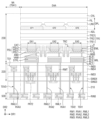
도 12는 일 실시예에 따른 표시부의 표시 영역과 비표시 영역의 일부분을 보여주는 단면도이다.
도 13 및 도 14는 다른 실시예에 따른 표시부의 표시 영역의 배치를 보여주는 평면도이다.
도 15는 다른 실시예에 따른 표시 장치의 일 서브 화소의 등가 회로도이다.
도 16은 다른 실시예에 따른 표시 장치의 개략적인 단면도이다.
도 17은 일 실시예에 따른 헤드 장착형 디스플레이 장치를 보여주는 사시도이다.
도 18은 도 17의 헤드 장착형 디스플레이 장치의 일 예를 보여주는 분해 사시도이다.
도 19는 일 실시예에 따른 헤드 장착형 디스플레이 장치를 보여주는 사시도이다.Figure 1 is an exploded perspective view of a display device according to one embodiment.
Fig. 2 is a plan view showing an example of the driving unit illustrated in Fig. 1.
Figure 3 is a plan view showing an example of the display unit illustrated in Figure 1.
FIG. 4 is a block diagram showing a display device according to one embodiment.
Figure 5 is an equivalent circuit diagram of one sub-pixel according to one embodiment.
FIG. 6 is a plan view illustrating an enlarged portion of a driving unit of a display device according to one embodiment.
FIG. 7 is a plan view illustrating an enlarged portion of a display portion of a display device according to one embodiment.
FIG. 8 is a drawing schematically illustrating the connection of a driving unit and a display unit of a display device according to one embodiment.
Figure 9 is a schematic cross-sectional view of a display device according to one embodiment.
Fig. 10 is a schematic cross-sectional view of a driving unit according to one embodiment.
FIG. 11 is a plan view showing the arrangement of pixels arranged in a display area of a display unit according to one embodiment.
FIG. 12 is a cross-sectional view showing a portion of a display area and a non-display area of a display unit according to one embodiment.
FIGS. 13 and 14 are plan views showing the arrangement of the display area of the display unit according to another embodiment.
Fig. 15 is an equivalent circuit diagram of one sub-pixel of a display device according to another embodiment.
Fig. 16 is a schematic cross-sectional view of a display device according to another embodiment.
FIG. 17 is a perspective view showing a head-mounted display device according to one embodiment.
FIG. 18 is an exploded perspective view showing an example of the head-mounted display device of FIG. 17.
FIG. 19 is a perspective view showing a head-mounted display device according to one embodiment.
본 발명의 이점 및 특징, 그리고 그것들을 달성하는 방법은 첨부되는 도면과 함께 상세하게 후술되어 있는 실시예들을 참조하면 명확해질 것이다. 그러나 본 발명은 이하에서 개시되는 실시예들에 한정되는 것이 아니라 서로 다른 다양한 형태로 구현될 것이며, 단지 본 실시예들은 본 발명의 개시가 완전하도록 하며, 본 발명이 속하는 기술분야에서 통상의 지식을 가진 자에게 발명의 범주를 완전하게 알려주기 위해 제공되는 것이며, 본 발명은 청구항의 범주에 의해 정의될 뿐이다. The advantages and features of the present invention, and the method for achieving them, will become clear with reference to the embodiments described in detail below together with the accompanying drawings. However, the present invention is not limited to the embodiments disclosed below, but may be implemented in various different forms, and these embodiments are provided only to make the disclosure of the present invention complete and to fully inform a person having ordinary skill in the art to which the present invention belongs of the scope of the invention, and the present invention is defined only by the scope of the claims.
소자(Elements) 또는 층이 다른 소자 또는 층의 "상(On)"으로 지칭되는 것은 다른 소자 바로 위에 또는 중간에 다른 층 또는 다른 소자를 개재한 경우를 모두 포함한다. 이와 마찬가지로, "하(Below)", "좌(Left)" 및 "우(Right)"로 지칭되는 것들은 다른 소자와 바로 인접하게 개재된 경우 또는 중간에 다른 층 또는 다른 소재를 개재한 경우를 모두 포함한다. 명세서 전체에 걸쳐 동일 참조 부호는 동일 구성 요소를 지칭한다.When an element or layer is referred to as being "on" another element or layer, it includes both the case where it is directly above the other element or layer, or where there is another layer or material intervening therebetween. Similarly, when an element or layer is referred to as being "below," "left," and "right," it includes the case where it is directly adjacent to the other element or where there is another layer or material intervening therebetween. Like reference numerals throughout the specification refer to like elements.
비록 제1, 제2 등이 다양한 구성요소들을 서술하기 위해서 사용되나, 이들 구성요소들은 이들 용어에 의해 제한되지 않음은 물론이다. 이들 용어들은 단지 하나의 구성요소를 다른 구성요소와 구별하기 위하여 사용하는 것이다. 따라서, 이하에서 언급되는 제1 구성요소는 본 발명의 기술적 사상 내에서 제2 구성요소일 수도 있음은 물론이다.Although the terms first, second, etc. are used to describe various components, it is to be understood that these components are not limited by these terms. These terms are merely used to distinguish one component from another. Accordingly, it is to be understood that the first component referred to below may also be the second component within the technical concept of the present invention.
이하, 첨부된 도면을 참고로 하여 실시예들에 대해 설명한다. Hereinafter, embodiments will be described with reference to the attached drawings.
도 1은 일 실시예에 따른 표시 장치의 분해 사시도이다.Figure 1 is an exploded perspective view of a display device according to one embodiment.
도 1을 참조하면, 일 실시예에 따른 표시 장치(10)는 동영상이나 정지영상을 표시하는 장치이다. 일 실시예에 따른 표시 장치(10)는 모바일 폰(Mobile Phone), 스마트 폰(Smart Phone), 태블릿 PC(Tablet Personal Computer), 이동 통신 단말기, 전자 수첩, 전자 책, PMP(Portable Multimedia Player), 네비게이션, UMPC(Ultra Mobile PC) 등과 같은 휴대용 전자 장치에 적용될 수 있다. 예를 들어, 표시 장치(10)는 텔레비전, 노트북, 모니터, 광고판, 또는 사물 인터넷(Internet Of Things, IOT)의 표시부로 적용될 수 있다. 또는, 표시 장치(10)는 스마트 워치(Smart Watch), 워치 폰(Watch Phone), 가상 현실 및 증강 현실을 구현하기 위한 헤드 장착형 디스플레이(Head Mounted Display Device, HMD)에 적용될 수 있다.Referring to FIG. 1, a display device (10) according to one embodiment is a device that displays a moving image or a still image. The display device (10) according to one embodiment can be applied to portable electronic devices such as a mobile phone, a smart phone, a tablet personal computer (PC), a mobile communication terminal, an electronic notebook, an electronic book, a portable multimedia player (PMP), a navigation device, an ultra mobile PC (UMPC), etc. For example, the display device (10) can be applied as a display unit of a television, a laptop, a monitor, a billboard, or the Internet of Things (IOT). Alternatively, the display device (10) can be applied to a smart watch, a watch phone, a head mounted display device (HMD) for implementing virtual reality and augmented reality.
일 실시예에 따른 표시 장치(10)는 구동부(100), 표시부(200), 및 회로 보드(300)를 포함할 수 있다. 표시 장치(10)는 구동부(100) 주변에 배치된 보호층(900)을 더 포함할 수 있다.A display device (10) according to one embodiment may include a driving unit (100), a display unit (200), and a circuit board (300). The display device (10) may further include a protective layer (900) arranged around the driving unit (100).
구동부(100)는 사각형과 유사한 평면 형태를 가질 수 있다. 예를 들어, 구동부(100)는 제1 방향(DR1)의 일 변과 제1 방향(DR1)과 교차하는 제2 방향(DR2)의 타 변을 갖는 정사각형과 유사한 평면 형태를 가질 수 있다. 구동부(100)에서 제1 방향(DR1)의 일 변과 제2 방향(DR2)의 타 변이 만나는 모서리는 소정의 곡률을 갖도록 둥글게 형성되거나 직각으로 형성될 수 있다. 구동부(100)의 평면 형태는 사각형에 한정되지 않고, 다른 다각형, 원형 또는 타원형과 유사하게 형성될 수 있다. 표시 장치(10)의 평면 형태는 구동부(100)의 평면 형태를 추종할 수 있으나, 이에 제한되지 않는다.The driving unit (100) may have a planar shape similar to a square. For example, the driving unit (100) may have a planar shape similar to a square having one side in a first direction (DR1) and the other side in a second direction (DR2) intersecting the first direction (DR1). In the driving unit (100), an edge where one side in the first direction (DR1) and the other side in the second direction (DR2) meet may be formed rounded to have a predetermined curvature or formed at a right angle. The planar shape of the driving unit (100) is not limited to a square and may be formed similarly to other polygons, circles, or ovals. The planar shape of the display device (10) may follow the planar shape of the driving unit (100), but is not limited thereto.
표시부(200)는 구동부(100) 상에 배치될 수 있다. 도 1에서는 표시부(200)와 구동부(100)가 이격된 것으로 예시되어 있으나, 이는 구동부(100)를 도시하기 위해 이들을 분리하여 예시한 것일 뿐이다. 표시 장치(10)에서 구동부(100)와 표시부(200)는 서로 접합될 수 있다. 표시부(200)는 실질적으로 구동부(100)와 유사한 형태를 가질 수 있다. 예를 들어, 구동부(100)는 제1 방향(DR1)의 일 변과 제1 방향(DR1)과 교차하는 제2 방향(DR2)의 타 변을 갖는 정사각형과 유사한 평면 형태를 가질 수 있다. 표시부(200)의 평면 형태는 사각형에 한정되지 않고, 다른 다각형, 원형 또는 타원형과 유사하게 형성될 수 있다.The display unit (200) may be placed on the driving unit (100). In FIG. 1, the display unit (200) and the driving unit (100) are illustrated as being spaced apart, but this is merely an example in which they are separated in order to illustrate the driving unit (100). In the display device (10), the driving unit (100) and the display unit (200) may be joined to each other. The display unit (200) may have a shape substantially similar to that of the driving unit (100). For example, the driving unit (100) may have a planar shape similar to a square having one side in a first direction (DR1) and the other side in a second direction (DR2) intersecting the first direction (DR1). The planar shape of the display unit (200) is not limited to a square, and may be formed similarly to other polygons, circles, or ovals.
일 실시예에 따르면, 표시 장치(10)는 표시부(200)의 평면 상의 면적이 구동부(100)의 평면 상의 면적보다 클 수 있다. 표시 장치(10)는 서로 다른 기판을 포함하는 구동부(100)와 표시부(200)를 포함하고, 이들이 서로 다른 면적을 가질 수 있다. 구동부(100)에 형성된 소자와 표시부(200)에 형성된 소자는 서로 다를 수 있고, 상기 소자들은 서로 다른 기판에서 각각 개별적으로 형성될 수 있다. 표시 장치(10)는 크기, 선폭, 및 제조 공정 등이 서로 다른 복수의 소자들을 서로 다른 기판에 형성한 뒤 이들을 접합시켜 제조될 수 있고, 제품의 성능 및 제조 수율 등을 향상시킬 수 있는 이점이 있다. 이에 대한 보다 자세한 설명은 다른 도면들을 참조하여 후술하기로 한다.According to one embodiment, the display device (10) may have a larger area on a plane of the display unit (200) than a larger area on a plane of the driving unit (100). The display device (10) includes a driving unit (100) and a display unit (200) that include different substrates, and they may have different areas. The elements formed on the driving unit (100) and the elements formed on the display unit (200) may be different from each other, and the elements may be individually formed on different substrates. The display device (10) may be manufactured by forming a plurality of elements having different sizes, line widths, manufacturing processes, etc. on different substrates and then bonding them, and there is an advantage in that the performance of the product and the manufacturing yield, etc. may be improved. A more detailed description thereof will be described later with reference to other drawings.
회로 보드(300)는 이방성 도전 필름(anisotropic conductive film)과 같은 도전성 접착 부재를 이용하여 표시부(200)의 패드 영역의 복수의 패드들에 전기적으로 연결될 수 있다. 회로 보드(300)는 유연한 재질을 갖는 연성 인쇄 회로 보드(flexible printed circuit board), 또는 연성 필름(flexible film)일 수 있다. 도 1에서는 회로 보드(300)가 펼쳐진 것을 예시하였으나, 회로 보드(300)는 구부러질 수 있다. 이 경우, 회로 보드(300)의 일 단은 구동부(100)의 하면 상에 배치될 수 있다. 회로 보드(300)의 타 단은 도전성 접착 부재를 이용하여 표시부(200)의 패드 영역의 복수의 패드들에 연결될 수 있다. The circuit board (300) can be electrically connected to a plurality of pads in the pad area of the display unit (200) using a conductive adhesive material such as an anisotropic conductive film. The circuit board (300) can be a flexible printed circuit board having a flexible material or a flexible film. In FIG. 1, the circuit board (300) is illustrated as being unfolded, but the circuit board (300) can be bent. In this case, one end of the circuit board (300) can be placed on the lower surface of the driving unit (100). The other end of the circuit board (300) can be connected to a plurality of pads in the pad area of the display unit (200) using a conductive adhesive material.
도면으로 도시하지 않았으나, 표시 장치(10)는 구동부(100) 및 표시부(200)와 제3 방향(DR3)으로 중첩하는 방열층을 더 포함할 수 있다. 방열층은 구동부(100)의 하면 상에 배치될 수 있고, 구동부(100) 및 표시부(200)에서 발생한 열을 방출할 수 있다. 방열층은 열 전도율이 높은 그라파이트(graphite), 은(Ag), 구리(Cu), 또는 알루미늄(Al)과 같은 금속층을 포함할 수 있다.Although not illustrated in the drawing, the display device (10) may further include a heat dissipation layer overlapping the driving unit (100) and the display unit (200) in a third direction (DR3). The heat dissipation layer may be arranged on the lower surface of the driving unit (100) and may release heat generated from the driving unit (100) and the display unit (200). The heat dissipation layer may include a metal layer such as graphite, silver (Ag), copper (Cu), or aluminum (Al) having high thermal conductivity.
보호층(900)은 구동부(100)를 둘러싸며 표시부(200)의 하면에 배치될 수 있다. 보호층(900)은 구동부(100)와 표시부(200)의 면적 차이에 의한 단차를 줄일 수 있고, 구동부(100) 및 표시부(200)를 보호할 수도 있다.The protective layer (900) surrounds the driving unit (100) and can be placed on the lower surface of the display unit (200). The protective layer (900) can reduce the step caused by the difference in area between the driving unit (100) and the display unit (200), and can also protect the driving unit (100) and the display unit (200).
도 2는 도 1에 도시된 구동부의 일 예를 보여주는 평면도이다. 도 3은 도 1에 도시된 표시부의 일 예를 보여주는 평면도이다. 도 4는 일 실시예에 따른 표시 장치를 보여주는 블록도이다.Fig. 2 is a plan view showing an example of the driving unit illustrated in Fig. 1. Fig. 3 is a plan view showing an example of the display unit illustrated in Fig. 1. Fig. 4 is a block diagram showing a display device according to one embodiment.
도 2 내지 도 4를 참조하면, 표시 장치(10)의 구동부(100)는 표시 장치(10)의 구동 회로 소자들을 포함할 수 있다. 구동부(100)는 제1 단결정 반도체 기판(110) 및 제1 단결정 반도체 기판(110)에 형성된 구동 회로부(400), 게이트 구동부(600), 데이터 구동부(700), 및 화소 회로부(800)를 포함할 수 있다. Referring to FIGS. 2 to 4, the driving unit (100) of the display device (10) may include driving circuit elements of the display device (10). The driving unit (100) may include a first single-crystal semiconductor substrate (110) and a driving circuit unit (400), a gate driving unit (600), a data driving unit (700), and a pixel circuit unit (800) formed on the first single-crystal semiconductor substrate (110).
제1 단결정 반도체 기판(110)은 실리콘 기판, 게르마늄 기판 또는 실리콘-게르마늄 기판일 수 있다. 제1 단결정 반도체 기판(110)에는 구동 회로 소자들의 트랜지스터들이 형성될 수 있다. 상기 복수의 트랜지스터들은 서로 전기적으로 연결되어 구동 회로부(400), 게이트 구동부(600), 데이터 구동부(700), 및 화소 회로부(800)를 형성할 수 있다.The first single-crystal semiconductor substrate (110) may be a silicon substrate, a germanium substrate, or a silicon-germanium substrate. Transistors of driving circuit elements may be formed on the first single-crystal semiconductor substrate (110). The plurality of transistors may be electrically connected to each other to form a driving circuit unit (400), a gate driving unit (600), a data driving unit (700), and a pixel circuit unit (800).
도면에서는 구동부(100)의 중앙에 화소 회로부(800)가 배치되고, 그 우측에 게이트 구동부(600)가 배치되고, 화소 회로부(800)의 하측에 데이터 구동부(700)와 구동 회로부(400)가 배치된 것이 예시되어 있다. 다만, 이에 제한되지 않는다. 구동부(100)는 제1 단결정 반도체 기판(110)에 형성된 복수의 회로 소자들의 설계 구조에 따라 구동 회로부(400), 게이트 구동부(600), 데이터 구동부(700), 및 화소 회로부(800)의 위치는 다양하게 변형될 수 있다.In the drawing, the pixel circuit unit (800) is arranged in the center of the driving unit (100), the gate driving unit (600) is arranged to the right of the driving unit, and the data driving unit (700) and the driving circuit unit (400) are arranged below the pixel circuit unit (800). However, this is not limited thereto. The positions of the driving circuit unit (400), the gate driving unit (600), the data driving unit (700), and the pixel circuit unit (800) of the driving unit (100) may be variously modified depending on the design structure of the plurality of circuit elements formed on the first single crystal semiconductor substrate (110).
구동 회로부(400)는 타이밍 제어 회로(410)와 전원 공급 회로(420)를 포함할 수 있다. 또한, 구동 회로부(400)는 감마 회로, 및 로직 회로 등 표시 장치(10)의 구동에 관여하는 다양한 회로들을 더 포함할 수 있다. 구동 회로부(400)는 제1 단결정 반도체 기판(110)에 형성된 복수의 트랜지스터들을 포함할 수 있다. 상기 트랜지스터들은 반도체 공정으로 형성될 수 있다. 예를 들어, 복수의 트랜지스터들은 CMOS(Complementary Metal Oxide Semiconductor) 트랜지스터로 형성될 수 있다. The driving circuit unit (400) may include a timing control circuit (410) and a power supply circuit (420). In addition, the driving circuit unit (400) may further include various circuits involved in driving the display device (10), such as a gamma circuit and a logic circuit. The driving circuit unit (400) may include a plurality of transistors formed on a first single crystal semiconductor substrate (110). The transistors may be formed by a semiconductor process. For example, the plurality of transistors may be formed by a CMOS (Complementary Metal Oxide Semiconductor) transistor.
타이밍 제어 회로(410)는 외부로부터 디지털 비디오 데이터와 타이밍 신호들을 입력 받을 수 있다. 타이밍 제어 회로(410)는 타이밍 신호들에 따라 표시부(200)를 제어하기 위한 스캔 타이밍 제어 신호(SCS), 발광 타이밍 제어 신호(ECS), 및 데이터 타이밍 제어 신호(DCS)를 생성할 수 있다. 타이밍 제어 회로(410)는 스캔 타이밍 제어 신호(SCS)를 게이트 구동부(600)의 스캔 구동부(610)로 출력하고, 발광 타이밍 제어 신호(ECS)를 게이트 구동부(600)의 발광 구동부(620)로 출력할 수 있다. 타이밍 제어 회로(410)는 디지털 비디오 데이터와 데이터 타이밍 제어 신호(DCS)를 데이터 구동부(700)로 출력할 수 있다.The timing control circuit (410) can receive digital video data and timing signals from the outside. The timing control circuit (410) can generate a scan timing control signal (SCS), an emission timing control signal (ECS), and a data timing control signal (DCS) for controlling the display unit (200) according to the timing signals. The timing control circuit (410) can output the scan timing control signal (SCS) to the scan driving unit (610) of the gate driving unit (600) and output the emission timing control signal (ECS) to the emission driving unit (620) of the gate driving unit (600). The timing control circuit (410) can output digital video data and a data timing control signal (DCS) to the data driving unit (700).
전원 공급 회로(420)는 외부로부터 전원 전압에 따라 복수의 패널 구동 전압들을 생성할 수 있다. 예를 들어, 전원 공급 회로(420)는 제1 구동 전압(VSS), 및 제2 구동 전압(VDD)을 생성하여 화소 회로부(800)에 공급할 수 있다. 제1 구동 전압(VSS), 및 제2 구동 전압(VDD)에 대한 설명은 도 5를 참조하여 후술한다.The power supply circuit (420) can generate a plurality of panel driving voltages according to a power voltage from the outside. For example, the power supply circuit (420) can generate a first driving voltage (VSS) and a second driving voltage (VDD) and supply them to the pixel circuit unit (800). The first driving voltage (VSS) and the second driving voltage (VDD) will be described later with reference to FIG. 5.
타이밍 제어 회로(410)의 스캔 타이밍 제어 신호(SCS), 발광 타이밍 제어 신호(ECS), 디지털 비디오 데이터(DATA), 및 데이터 타이밍 제어 신호(DCS)는 화소 회로부(800)에 공급될 수 있다. 전원 공급 회로(420)의 제1 구동 전압(VSS), 및 제2 구동 전압(VDD)도 화소 회로부(800)에 공급될 수 있다. 구동부(100)는 표시부(200)의 하면에 접합되고, 구동부(100)의 구동 회로부(400)는 표시부(200)와 전기적으로 연결될 수 있다.The scan timing control signal (SCS), the emission timing control signal (ECS), the digital video data (DATA), and the data timing control signal (DCS) of the timing control circuit (410) can be supplied to the pixel circuit unit (800). The first driving voltage (VSS) and the second driving voltage (VDD) of the power supply circuit (420) can also be supplied to the pixel circuit unit (800). The driving unit (100) is connected to the lower surface of the display unit (200), and the driving circuit unit (400) of the driving unit (100) can be electrically connected to the display unit (200).
게이트 구동부(600)는 스캔 구동부(610)와 발광 구동부(620)를 포함할 수 있다. 스캔 구동부(610)는 제1 단결정 반도체 기판(110)에 형성된 복수의 스캔 트랜지스터들을 포함하고, 발광 구동부(620)는 제1 단결정 반도체 기판(110)에 형성된 복수의 발광 트랜지스터들을 포함한다. 복수의 스캔 트랜지스터들과 복수의 발광 트랜지스터들은 반도체 공정으로 형성될 수 있다. 예를 들어, 복수의 스캔 트랜지스터들과 복수의 발광 트랜지스터들은 CMOS 트랜지스터로 형성될 수 있다.The gate driver (600) may include a scan driver (610) and a light emitting driver (620). The scan driver (610) includes a plurality of scan transistors formed on a first single-crystal semiconductor substrate (110), and the light emitting driver (620) includes a plurality of light emitting transistors formed on the first single-crystal semiconductor substrate (110). The plurality of scan transistors and the plurality of light emitting transistors may be formed by a semiconductor process. For example, the plurality of scan transistors and the plurality of light emitting transistors may be formed by CMOS transistors.
스캔 구동부(610)는 제1 스캔 신호 출력부(611), 및 제2 스캔 신호 출력부(612)를 포함할 수 있다. 제1 스캔 신호 출력부(611), 및 제2 스캔 신호 출력부(612) 각각은 타이밍 제어 회로(410)로부터 스캔 타이밍 제어 신호(SCS)를 입력 받을 수 있다. 제1 스캔 신호 출력부(611)는 타이밍 제어 회로(410)의 스캔 타이밍 제어 신호(SCS)에 따라 기입 스캔 신호들을 생성하여 제1 스캔 라인(GWL)들에 순차적으로 출력할 수 있다. 제2 스캔 신호 출력부(612)는 스캔 타이밍 제어 신호(SCS)에 따라 바이어스 스캔 신호들을 생성하여 제2 스캔 라인(GBL)들에 순차적으로 출력할 수 있다. The scan driving unit (610) may include a first scan signal output unit (611) and a second scan signal output unit (612). Each of the first scan signal output unit (611) and the second scan signal output unit (612) may receive a scan timing control signal (SCS) from the timing control circuit (410). The first scan signal output unit (611) may generate write scan signals according to the scan timing control signal (SCS) of the timing control circuit (410) and sequentially output the same to the first scan lines (GWL). The second scan signal output unit (612) may generate bias scan signals according to the scan timing control signal (SCS) and sequentially output the same to the second scan lines (GBL).
발광 구동부(620)는 타이밍 제어 회로(410)로부터 발광 타이밍 제어 신호(ECS)를 입력 받을 수 있다. 발광 구동부(620)는 발광 타이밍 제어 신호(ECS)에 따라 발광 제어 신호들을 생성하여 발광 제어 라인(EL)들에 순차적으로 출력할 수 있다. The light emitting driver (620) can receive a light emitting timing control signal (ECS) from the timing control circuit (410). The light emitting driver (620) can generate light emitting control signals according to the light emitting timing control signal (ECS) and sequentially output them to the light emitting control lines (EL).
데이터 구동부(700)는 제1 단결정 반도체 기판(110)에 형성된 복수의 데이터 트랜지스터들을 포함한다. 복수의 데이터 트랜지스터들은 반도체 공정으로 형성될 수 있다. 예를 들어, 복수의 데이터 트랜지스터들은 CMOS 트랜지스터로 형성될 수 있다. 데이터 구동부(700)는 타이밍 제어 회로(410)로부터 디지털 비디오 데이터(DATA)와 데이터 타이밍 제어 신호(DCS)를 입력 받을 수 있다. 데이터 구동부(700)는 데이터 타이밍 제어 신호(DCS)에 따라 디지털 비디오 데이터(DATA)를 아날로그 데이터 전압들로 변환하여 데이터 라인(DL)들에 출력한다. 이 경우, 스캔 구동부(610)의 기입 스캔 신호에 의해 서브 화소들(SP)이 선택되며, 선택된 서브 화소들(SP)에 데이터 전압들이 공급될 수 있다. 게이트 구동부(600)와 데이터 구동부(700)는 구동부(100)에 포함된 신호 구동부들 중 어느 하나일 수 있다.The data driving unit (700) includes a plurality of data transistors formed on a first single-crystal semiconductor substrate (110). The plurality of data transistors may be formed by a semiconductor process. For example, the plurality of data transistors may be formed by CMOS transistors. The data driving unit (700) may receive digital video data (DATA) and a data timing control signal (DCS) from a timing control circuit (410). The data driving unit (700) converts the digital video data (DATA) into analog data voltages according to the data timing control signal (DCS) and outputs the same to the data lines (DL). In this case, the sub-pixels (SP) are selected by the write scan signal of the scan driving unit (610), and the data voltages may be supplied to the selected sub-pixels (SP). The gate driving unit (600) and the data driving unit (700) may be any one of the signal driving units included in the driving unit (100).
제1 패드 영역(PDA1)은 제1 방향(DR1)으로 배치된 복수의 제1 패드(PD1)들을 포함할 수 있다. 복수의 제1 패드(PD1)들은 표시부(200)의 복수의 제2 패드(PD2)들과 전기적으로 연결될 수 있으며, 이들을 통해 회로 보드(300)와 전기적으로 연결될 수 있다. 제1 패드(PD1)들은 회로 보드(300)에서 인가된 전기 신호를 구동 회로부(400), 게이트 구동부(600), 데이터 구동부(700), 및 화소 회로부(800)에 전달할 수 있다. The first pad area (PDA1) may include a plurality of first pads (PD1) arranged in a first direction (DR1). The plurality of first pads (PD1) may be electrically connected to a plurality of second pads (PD2) of the display unit (200) and may be electrically connected to the circuit board (300) through these. The first pads (PD1) may transmit an electric signal applied from the circuit board (300) to the driving circuit unit (400), the gate driving unit (600), the data driving unit (700), and the pixel circuit unit (800).
화소 회로부(800)는 제1 단결정 반도체 기판(110)에 형성된 복수의 화소 트랜지스터들을 포함한다. 복수의 화소 트랜지스터들은 반도체 공정으로 형성될 수 있다. 예를 들어, 복수의 화소 트랜지스터들은 CMOS 트랜지스터로 형성될 수 있다. 화소 회로부(800)는 구동부(100)에 포함된 구동 회로들 중 어느 하나일 수 있다.The pixel circuit unit (800) includes a plurality of pixel transistors formed on a first single-crystal semiconductor substrate (110). The plurality of pixel transistors may be formed by a semiconductor process. For example, the plurality of pixel transistors may be formed by CMOS transistors. The pixel circuit unit (800) may be any one of the driving circuits included in the driving unit (100).
화소 회로부(800)는 복수의 화소 회로(PXC)들, 복수의 제2 스캔 라인(도 4의 GBL)들 및 복수의 발광 제어 라인(도 4의 EL)이 배치될 수 있다. 복수의 화소 회로(PXC)들은 제1 방향(DR1) 및 제2 방향(DR2)으로 서로 이격되어 배치될 수 있다. 복수의 제2 스캔 라인(GBL)들과 발광 제어 라인(EL)들은 제1 방향(DR1)으로 연장되고 서로 제2 방향(DR2)으로 이격되어 배열될 수 있다. 제2 스캔 라인(GBL), 및 발광 제어 라인(EL)은 표시 장치(10)의 구동부(100)에 포함된 신호 배선들 중 어느 하나일 수 있다.The pixel circuit unit (800) may include a plurality of pixel circuits (PXC), a plurality of second scan lines (GBL of FIG. 4), and a plurality of emission control lines (EL of FIG. 4). The plurality of pixel circuits (PXC) may be arranged to be spaced apart from each other in a first direction (DR1) and a second direction (DR2). The plurality of second scan lines (GBL) and the emission control lines (EL) may be arranged to extend in the first direction (DR1) and be spaced apart from each other in the second direction (DR2). The second scan line (GBL) and the emission control line (EL) may be any one of the signal wires included in the driving unit (100) of the display device (10).
복수의 데이터 라인(DL)들, 및 복수의 제1 스캔 라인(GWL)들은 표시부(200)에 배치될 수 있다. 복수의 데이터 라인(DL)들은 제2 방향(DR2)으로 연장되고 서로 제1 방향(DR1)으로 이격되어 배열될 수 있다. 복수의 제1 스캔 라인(GWL)들은 제1 방향(DR1)으로 연장되고 서로 제2 방향(DR2)으로 이격되어 배열될 수 있다. 제1 스캔 라인(GWL), 및 데이터 라인(DL)은 표시 장치(10)의 표시부(200)에 포함된 신호 배선들 중 어느 하나일 수 있다.A plurality of data lines (DL) and a plurality of first scan lines (GWL) may be arranged in a display unit (200). The plurality of data lines (DL) may extend in a second direction (DR2) and may be arranged to be spaced apart from each other in a first direction (DR1). The plurality of first scan lines (GWL) may extend in the first direction (DR1) and may be arranged to be spaced apart from each other in a second direction (DR2). The first scan line (GWL) and the data line (DL) may be any one of the signal wires included in the display unit (200) of the display device (10).
일 실시예에 따른 표시 장치(10)는 서브 화소(SP)와 연결된 화소 회로(PXC)에 포함된 트랜지스터(도 5의 T1~T4)들 및 이들에 각각 연결된 복수의 배선들 중 일부가 서로 다른 단결정 반도체 기판에 배치될 수 있다. 표시 장치(10)는 각각 서로 다른 단결정 반도체 기판을 포함하는 구동부(100)와 표시부(200)를 포함하고, 화소 회로(PXC)의 트랜지스터들 및 복수의 배선들이 각각 구동부(100)와 표시부(200)에 나누어 배치될 수 있다. In one embodiment, a display device (10) may include transistors (T1 to T4 in FIG. 5) included in a pixel circuit (PXC) connected to a sub-pixel (SP) and some of the plurality of wires connected thereto may be arranged on different single-crystal semiconductor substrates. The display device (10) may include a driving unit (100) and a display unit (200), each of which includes different single-crystal semiconductor substrates, and the transistors and the plurality of wires of the pixel circuit (PXC) may be arranged separately in the driving unit (100) and the display unit (200).
예를 들어, 복수의 배선들 중 복수의 제2 스캔 라인(도 4의 GBL)들 및 복수의 발광 제어 라인(도 4의 EL)은 구동부(100)에 배치되고, 복수의 데이터 라인(DL)들, 및 복수의 제1 스캔 라인(GWL)들은 표시부(200)에 배치될 수 있다. 화소 회로(PXC)에 포함된 회로 소자들 중, 데이터 라인(DL) 및 제1 스캔 라인(GWL)에 연결된 회로 소자는 표시부(200)에 배치되고, 다른 회로 소자들은 구동부(100)의 화소 회로부(800)에 배치될 수 있다. 표시 장치(10)는 화소 회로(PXC)의 일부 회로 소자들 및 배선들이 각각 다른 단결정 반도체 기판에 나누어 배치됨에 따라 좁은 면적에서 높은 집적도로 인한 배치 설계의 어려움을 해소할 수 있고, 인접 소자들 사이의 기생 커패시턴스의 형성을 방지할 수 있다. 보다 자세한 설명은 다른 도면들을 참조하여 후술하기로 한다.For example, among the plurality of wires, the plurality of second scan lines (GBL of FIG. 4) and the plurality of light emission control lines (EL of FIG. 4) may be arranged in the driver unit (100), and the plurality of data lines (DL) and the plurality of first scan lines (GWL) may be arranged in the display unit (200). Among the circuit elements included in the pixel circuit (PXC), the circuit elements connected to the data lines (DL) and the first scan lines (GWL) may be arranged in the display unit (200), and the other circuit elements may be arranged in the pixel circuit unit (800) of the driver unit (100). Since some of the circuit elements and wires of the pixel circuit (PXC) are arranged separately on different single crystal semiconductor substrates, the display device (10) can resolve the difficulty of layout design due to high integration in a narrow area, and can prevent the formation of parasitic capacitance between adjacent elements. A more detailed description will be given later with reference to other drawings.
복수의 스캔 라인(SL)들은 복수의 제1 스캔 라인(GWL)들, 및 복수의 제2 스캔 라인(GBL)들을 포함할 수 있다. 복수의 스캔 라인(SL)들, 복수의 발광 제어 라인(EL)들, 및 복수의 데이터 라인(DL)들은 복수의 화소 트랜지스터들과 전기적으로 연결될 수 있고, 화소 회로부(800)는 표시부(200)의 서브 화소(SP)들과 전기적으로 연결되어 발광 소자의 발광에 필요한 전기 신호를 전달할 수 있다. The plurality of scan lines (SL) may include a plurality of first scan lines (GWL) and a plurality of second scan lines (GBL). The plurality of scan lines (SL), the plurality of light emission control lines (EL), and the plurality of data lines (DL) may be electrically connected to a plurality of pixel transistors, and the pixel circuit unit (800) may be electrically connected to the sub-pixels (SP) of the display unit (200) to transmit an electrical signal required for light emission of the light emitting element.
표시부(200)는 광을 방출하는 발광 소자들이 배치되어 영상을 표시하는 표시 영역(DAA) 및 표시 영역(DAA) 주변에 배치된 비표시 영역(NA)을 포함할 수 있다. 표시부(200)는 제2 단결정 반도체 기판(210) 및 제2 단결정 반도체 기판(210) 상에 배치된 서브 화소 회로부(도 9의 '220')와 표시 소자층(도 9의 '230')을 포함할 수 있다. The display unit (200) may include a display area (DAA) in which light-emitting elements that emit light are arranged to display an image, and a non-display area (NA) arranged around the display area (DAA). The display unit (200) may include a second single-crystal semiconductor substrate (210), a sub-pixel circuit unit ('220' of FIG. 9) arranged on the second single-crystal semiconductor substrate (210), and a display element layer ('230' of FIG. 9).
제2 단결정 반도체 기판(210)은 실리콘 기판, 게르마늄 기판 또는 실리콘-게르마늄 기판일 수 있다. 제2 단결정 반도체 기판(210)은 트랜지스터 소자들이 형성되지 않을 수 있다. 다만, 이에 제한되지 않는다. 다른 실시예에서, 제2 단결정 반도체 기판(210)도 표시 장치(10)의 구동에 필요한 회로 소자들을 포함할 수도 있다.The second single crystal semiconductor substrate (210) may be a silicon substrate, a germanium substrate, or a silicon-germanium substrate. The second single crystal semiconductor substrate (210) may not have transistor elements formed thereon. However, the present invention is not limited thereto. In another embodiment, the second single crystal semiconductor substrate (210) may also include circuit elements necessary for driving the display device (10).
표시 영역(DAA)은 제1 방향(DR1)으로 연장되고 제2 방향(DR2)으로 배열된 복수의 제1 스캔 라인(GWL)들, 및 제2 방향(DR2)으로 연장되고 제1 방향(DR1)으로 배열된 복수의 데이터 라인(DL)들이 배치될 수 있다. 제1 스캔 라인(GWL)들 및 데이터 라인(DL)들은 표시 영역(DAA)의 복수의 서브 화소(SP)들 각각에 연결될 수 있다. 또한, 제1 스캔 라인(GWL)들 및 데이터 라인(DL)들은 구동부(100)의 게이트 구동부(600) 및 데이터 구동부(700)와 연결될 수 있다.A display area (DAA) may have a plurality of first scan lines (GWLs) extending in a first direction (DR1) and arranged in a second direction (DR2), and a plurality of data lines (DLs) extending in the second direction (DR2) and arranged in the first direction (DR1). The first scan lines (GWLs) and the data lines (DLs) may be connected to each of a plurality of sub-pixels (SPs) of the display area (DAA). In addition, the first scan lines (GWLs) and the data lines (DLs) may be connected to a gate driving unit (600) and a data driving unit (700) of a driving unit (100).
표시 영역(DAA)은 발광 소자들을 포함하는 복수의 서브 화소(SP)들이 배치될 수 있다. 복수의 서브 화소(SP)들, 예컨대 3개의 서브 화소(SP)는 하나의 화소(PX)를 구성하여 색을 표시할 수 있다. 다만, 이에 제한되지 않으며, 하나의 화소(PX)는 3개 이상의 서브 화소(SP)들을 포함할 수 있다. 복수의 서브 화소(SP)들은 제1 방향(DR1)과 제2 방향(DR2)에서 매트릭스 형태로 배열될 수 있다. 복수의 서브 화소(SP)들 각각은 구동부(100)의 화소 회로부(800) 및 표시부(200)의 서브 화소 회로부(도 9의 '220')와 전기적으로 연결될 수 있다. 서브 화소(SP)들 각각은 발광 소자들을 포함하며, 발광 소자는 화소 회로부(800)로부터 인가된 전기 신호에 따라 광을 방출할 수 있다. 표시부(200)의 표시 영역(DAA)에 배치되는 서브 화소(SP)들 중 일부는 구동부(100)의 화소 회로부(800)와 두께 방향으로 중첩할 수 있다. 다만, 이들은 서로 다른 단결정 반도체 기판(110, 210)에 배치되고, 이들은 그 사이에 배치된 연결 배선층(도 9의 '500')을 통해 전기적으로 연결될 수 있다.The display area (DAA) may have a plurality of sub-pixels (SP) including light-emitting elements arranged therein. A plurality of sub-pixels (SP), for example, three sub-pixels (SP), may constitute one pixel (PX) to display a color. However, the present invention is not limited thereto, and one pixel (PX) may include three or more sub-pixels (SP). The plurality of sub-pixels (SP) may be arranged in a matrix form in the first direction (DR1) and the second direction (DR2). Each of the plurality of sub-pixels (SP) may be electrically connected to the pixel circuit unit (800) of the driving unit (100) and the sub-pixel circuit unit ('220' of FIG. 9) of the display unit (200). Each of the sub-pixels (SP) includes light-emitting elements, and the light-emitting elements may emit light according to an electrical signal applied from the pixel circuit unit (800). Some of the sub-pixels (SP) arranged in the display area (DAA) of the display unit (200) may overlap with the pixel circuit unit (800) of the driving unit (100) in the thickness direction. However, they are arranged on different single-crystal semiconductor substrates (110, 210), and they may be electrically connected through a connection wiring layer ('500' in FIG. 9) arranged therebetween.
복수의 서브 화소들(SP) 각각은 제1 스캔 라인(GWL)과 데이터 라인(DL), 및 화소 회로부(800)의 제2 스캔 라인(GBL)과 발광 제어 라인(EL)에 연결될 수 있다. 복수의 서브 화소들(SP) 각각은 제1 스캔 라인(GWL)의 기입 스캔 신호에 따라 데이터 라인(DL)의 데이터 전압을 공급받고, 상기 데이터 전압에 따라 발광 소자를 발광할 수 있다. Each of the plurality of sub-pixels (SP) may be connected to a first scan line (GWL) and a data line (DL), and a second scan line (GBL) and an emission control line (EL) of a pixel circuit unit (800). Each of the plurality of sub-pixels (SP) may be supplied with a data voltage of a data line (DL) according to a write scan signal of the first scan line (GWL), and may emit light using a light-emitting element according to the data voltage.
비표시 영역(NA)은 표시 영역(DAA)을 둘러싸도록 배치될 수 있다. 비표시 영역(NA)은 화소(PX)들이 배치되지 않아 광이 방출되지 않는 영역일 수 있다. 비표시 영역(NA)에는 복수의 관통홀 영역(TSA1, TSA2)들, 및 제2 패드 영역(PDA2)이 배치될 수 있다.A non-display area (NA) may be arranged to surround the display area (DAA). The non-display area (NA) may be an area where pixels (PX) are not arranged and thus light is not emitted. A plurality of through-hole areas (TSA1, TSA2) and a second pad area (PDA2) may be arranged in the non-display area (NA).
제2 패드 영역(PDA2)은 제1 방향(DR1)으로 배치된 복수의 제2 패드(PD2)들을 포함할 수 있다. 복수의 제2 패드(PD2)들은 구동부(100)의 복수의 제1 패드(PD1)들과 전기적으로 연결될 수 있으며, 그 상에는 회로 보드(300)가 부착될 수 있다. 제2 패드(PD2)들은 회로 보드(300)와 전기적으로 연결되며, 회로 보드(300)에서 인가된 전기 신호를 구동부(100)로 전달할 수 있다.The second pad area (PDA2) may include a plurality of second pads (PD2) arranged in the first direction (DR1). The plurality of second pads (PD2) may be electrically connected to a plurality of first pads (PD1) of the driving unit (100), and a circuit board (300) may be attached thereon. The second pads (PD2) are electrically connected to the circuit board (300) and may transmit an electric signal applied from the circuit board (300) to the driving unit (100).
복수의 관통홀 영역(TSA1, TSA2)들은 각각 표시 영역(DAA)의 일 측에 배치될 수 있다. 예를 들어, 제1 관통홀 영역(TSA1)은 표시 영역(DAA)의 제1 방향(DR1) 일 측인 우측에 배치되고, 제2 관통홀 영역(TSA2)은 표시 영역(DAA)의 제2 방향(DR2) 타 측인 하측에 배치될 수 있다. 제2 관통홀 영역(TSA2)은 표시 영역(DAA)과 제2 패드 영역(PDA2) 사이에 배치될 수 있다. 다만, 관통홀 영역(TSA1, TSA2)의 위치는 이에 제한되지 않으며, 표시부(200) 및 구동부(100)의 설계에 따라 다양하게 변형될 수 있다. The plurality of through-hole areas (TSA1, TSA2) may be respectively arranged on one side of the display area (DAA). For example, the first through-hole area (TSA1) may be arranged on the right side of the display area (DAA) in the first direction (DR1), and the second through-hole area (TSA2) may be arranged on the lower side of the display area (DAA) in the second direction (DR2). The second through-hole area (TSA2) may be arranged between the display area (DAA) and the second pad area (PDA2). However, the positions of the through-hole areas (TSA1, TSA2) are not limited thereto, and may be variously modified depending on the design of the display unit (200) and the driving unit (100).
복수의 제1 스캔 라인(GWL)들은 제1 관통홀 영역(TSA1)으로부터 제1 방향(DR1)으로 연장되어 표시 영역(DAA)에 배치될 수 있다. 제1 스캔 라인(GWL)들은 제1 관통홀 영역(TSA1)에 배치된 제1 단자(TD1)와 연결될 수 있다. 복수의 데이터 라인(DL)들은 제2 관통홀 영역(TSA2)으로부터 제2 방향(DR2)으로 연장되어 표시 영역(DAA)에 배치될 수 있다. 데이터 라인(DL)들은 제2 관통홀 영역(TSA2)에 배치된 제2 단자(TD2)와 연결될 수 있다.A plurality of first scan lines (GWL) may be arranged in a display area (DAA) extending in a first direction (DR1) from a first through-hole area (TSA1). The first scan lines (GWL) may be connected to a first terminal (TD1) arranged in the first through-hole area (TSA1). A plurality of data lines (DL) may be arranged in a second direction (DR2) extending in the display area (DAA) from a second through-hole area (TSA2). The data lines (DL) may be connected to a second terminal (TD2) arranged in the second through-hole area (TSA2).
표시 장치(10)는 구동부(100)와 표시부(200)에 각각 배치된 서로 다른 소자, 배선, 회로 등이 표시부(200)의 제2 단결정 반도체 기판(210)을 관통하는 관통홀을 통해 서로 연결될 수 있다. 예를 들어, 제1 단자(TD1)는 제1 관통홀 영역(TSA1)에 형성된 관통홀(도 7의 'TSV3')을 통해 구동부(100)의 게이트 구동부(600)와 연결될 수 있다. 제2 단자(TD2)는 제2 관통홀 영역(TSA2)에 형성된 관통홀(도 7의 'TSV4')을 통해 구동부(100)의 데이터 구동부(700)와 연결될 수 있다. 또한, 도 3에 도시하지 않았으나, 표시 영역(DAA)에 배치된 서브 화소 회로부(220)의 회로 소자들, 및 서브 화소(SP)의 발광 소자도 표시 영역(DAA)에 형성된 복수의 관통홀들을 통해 구동부(100)의 화소 회로부(800)와 전기적으로 연결될 수 있다. 표시 장치(10)는 구동부(100)와 표시부(200)에 각각 발광 소자의 발광을 위한 소자들이 나누어 배치될 수 있고, 구동부(100)는 높은 집적도로 많은 수의 회로 소자들이 배치될 수 있고, 소자의 크기 소형화에 따른 소비 전력이 감소할 수 있다. 또한, 서브 화소(SP)의 발광을 위한 화소 회로(PXC)의 소자들도 구동부(100)와 표시부(200)에 각각 구분되어 배치됨에 따라, 회로 소자들이 구동부(100)에 집중적으로 배치되는 것을 분산시켜 높은 집적도에 따른 설계의 어려움을 해소할 수 있다. 또한, 회로 소자들이 좁은 면적의 구동부(100)에 집중되지 않으므로, 인접 소자들 사이의 기생 커패시턴스도 줄어들 수 있다. The display device (10) may be connected to each other through a through-hole that penetrates the second single crystal semiconductor substrate (210) of the display unit (200) in which different elements, wires, circuits, etc., respectively arranged in the driving unit (100) and the display unit (200). For example, the first terminal (TD1) may be connected to the gate driving unit (600) of the driving unit (100) through a through-hole ('TSV3' of FIG. 7) formed in the first through-hole area (TSA1). The second terminal (TD2) may be connected to the data driving unit (700) of the driving unit (100) through a through-hole ('TSV4' of FIG. 7) formed in the second through-hole area (TSA2). In addition, although not shown in FIG. 3, the circuit elements of the sub-pixel circuit unit (220) arranged in the display area (DAA) and the light-emitting elements of the sub-pixel (SP) may be electrically connected to the pixel circuit unit (800) of the driving unit (100) through a plurality of through holes formed in the display area (DAA). The display device (10) may have elements for emitting light separately arranged in the driving unit (100) and the display unit (200), and the driving unit (100) may have a large number of circuit elements arranged with a high degree of integration, and power consumption may be reduced due to miniaturization of the elements. In addition, since the elements of the pixel circuit (PXC) for emitting light of the sub-pixel (SP) are also separately arranged in the driving unit (100) and the display unit (200), the circuit elements may be distributed from being concentrated in the driving unit (100), thereby resolving design difficulties due to high degree of integration. Additionally, since the circuit elements are not concentrated in a narrow area of the driving part (100), the parasitic capacitance between adjacent elements can also be reduced.
도 5는 일 실시예에 따른 일 화소의 등가 회로도이다.Figure 5 is an equivalent circuit diagram of one pixel according to one embodiment.
도 5를 참조하면, 서브 화소(SP)의 화소 회로(PXC)는 복수의 트랜지스터(T1, T2, T3, T4)들, 및 복수의 커패시터(C1, C2)를 포함할 수 있다. 화소 회로(PXC)는 발광 소자(LE), 제1 스캔 라인(GWL), 제2 스캔 라인(GBL), 발광 제어 라인(EL) 및 데이터 라인(DL)에 연결될 수 있다. 또한, 화소 회로(PXC)는 저전위 전압에 해당하는 제1 구동 전압(VSS)이 인가되는 제1 구동 전압 라인(VSL), 및 고전위 전압에 해당하는 제2 구동 전압(VDD)이 인가되는 제2 구동 전압 라인(VDL)에 연결될 수 있다. 제1 구동 전압 라인(VSL)은 저전위 전압 라인이고, 제2 구동 전압 라인(VDL)은 고전위 전압 라인일 수 있다. Referring to FIG. 5, a pixel circuit (PXC) of a sub-pixel (SP) may include a plurality of transistors (T1, T2, T3, T4) and a plurality of capacitors (C1, C2). The pixel circuit (PXC) may be connected to a light-emitting element (LE), a first scan line (GWL), a second scan line (GBL), a light-emitting control line (EL), and a data line (DL). In addition, the pixel circuit (PXC) may be connected to a first driving voltage line (VSL) to which a first driving voltage (VSS) corresponding to a low potential voltage is applied, and a second driving voltage line (VDL) to which a second driving voltage (VDD) corresponding to a high potential voltage is applied. The first driving voltage line (VSL) may be a low potential voltage line, and the second driving voltage line (VDL) may be a high potential voltage line.
서브 화소(SP)의 화소 회로(PXC)는 발광 소자(LE)와 전기적으로 연결된 복수의 트랜지스터들(T1~T4), 제1 커패시터(C1), 및 제2 커패시터(C2)를 포함한다.A pixel circuit (PXC) of a sub-pixel (SP) includes a plurality of transistors (T1 to T4) electrically connected to a light-emitting element (LE), a first capacitor (C1), and a second capacitor (C2).
발광 소자(LE)는 제1 트랜지스터(T1)의 채널에 흐르는 구동 전류에 따라 발광할 수 있다. 발광 소자(LE)의 발광량은 구동 전류에 비례할 수 있다. 발광 소자(LE)는 제1 트랜지스터(T1)와 제1 구동 전압 라인(VSL) 사이에 배치될 수 있다. 발광 소자(LE)의 제1 전극은 제1 트랜지스터(T1)의 드레인 전극에 연결되고, 제2 전극은 제1 구동 전압 라인(VSL)에 접속될 수 있다. 발광 소자(LE)의 제1 전극은 애노드 전극이고, 발광 소자(LE)의 제2 전극은 캐소드 전극일 수 있다. 발광 소자(LE)는 제1 전극, 제2 전극, 및 제1 전극과 제2 전극 사이에 배치된 유기 발광층을 포함하는 유기 발광 다이오드일 수 있으나, 이에 제한되지 않는다. 예를 들어, 발광 소자(LE)는 제1 전극, 제2 전극, 및 제1 전극과 제2 전극 사이에 배치된 무기 반도체를 포함하는 무기 발광 소자일 수 있다.The light emitting element (LE) can emit light according to a driving current flowing in a channel of the first transistor (T1). The amount of light emitted by the light emitting element (LE) can be proportional to the driving current. The light emitting element (LE) can be disposed between the first transistor (T1) and a first driving voltage line (VSL). A first electrode of the light emitting element (LE) can be connected to a drain electrode of the first transistor (T1), and a second electrode can be connected to the first driving voltage line (VSL). The first electrode of the light emitting element (LE) can be an anode electrode, and the second electrode of the light emitting element (LE) can be a cathode electrode. The light emitting element (LE) can be an organic light emitting diode including a first electrode, a second electrode, and an organic light emitting layer disposed between the first electrode and the second electrode, but is not limited thereto. For example, the light emitting element (LE) can be an inorganic light emitting element including a first electrode, a second electrode, and an inorganic semiconductor disposed between the first electrode and the second electrode.
제1 트랜지스터(T1)는 게이트 전극에 인가되는 전압에 따라 소스 전극과 드레인 전극 사이에 흐르는 소스-드레인간 전류(이하 “구동 전류”라 칭함)를 제어하는 구동 트랜지스터일 수 있다. 제1 트랜지스터(T1)는 제1 노드(N1)에 연결되는 게이트 전극, 제3 트랜지스터(T3)의 드레인 전극에 연결되는 소스 전극, 및 제2 노드(N2)에 연결되는 드레인 전극을 포함한다.The first transistor (T1) may be a driving transistor that controls a source-drain current (hereinafter referred to as “driving current”) flowing between the source electrode and the drain electrode according to a voltage applied to the gate electrode. The first transistor (T1) includes a gate electrode connected to a first node (N1), a source electrode connected to a drain electrode of a third transistor (T3), and a drain electrode connected to a second node (N2).
제2 트랜지스터(T2)는 제1 트랜지스터(T1)의 게이트 전극과 데이터 라인(DL) 사이에 배치될 수 있다. 제2 트랜지스터(T2)는 제1 스캔 라인(GWL)의 기입 스캔 신호에 의해 턴-온되어 제1 트랜지스터(T1)의 게이트 전극을 데이터 라인(DL)에 연결한다. 이로 인해, 제1 트랜지스터(T1)의 게이트 전극에는 데이터 라인(DL)의 데이터 전압이 인가될 수 있다. 제2 트랜지스터(T2)는 제1 스캔 라인(GWL)에 연결되는 게이트 전극, 데이터 라인(DL)에 연결되는 드레인 전극, 및 제1 트랜지스터(T1)의 게이트 전극에 연결되는 소스 전극을 포함한다.The second transistor (T2) may be arranged between the gate electrode of the first transistor (T1) and the data line (DL). The second transistor (T2) is turned on by a write scan signal of the first scan line (GWL) to connect the gate electrode of the first transistor (T1) to the data line (DL). As a result, the data voltage of the data line (DL) may be applied to the gate electrode of the first transistor (T1). The second transistor (T2) includes a gate electrode connected to the first scan line (GWL), a drain electrode connected to the data line (DL), and a source electrode connected to the gate electrode of the first transistor (T1).
제3 트랜지스터(T3)는 제2 구동 전압 라인(VDL)과 제3 노드(N3), 또는 제1 트랜지스터(T1)의 소스 전극 사이에 배치될 수 있다. 제3 트랜지스터(T3)는 발광 제어 라인(EL)의 발광 제어 신호에 의해 턴-온되어 제2 구동 전압 라인(VDL)을 제1 트랜지스터(T1)의 소스 전극에 연결한다. 이로 인해, 제1 트랜지스터(T1)의 소스 전극에는 제2 구동 전압 라인(VDL)의 제2 구동 전압(VDD)이 인가될 수 있다. 제3 트랜지스터(T3)는 발광 제어 라인(EL)에 연결되는 게이트 전극, 제2 구동 전압 라인(VDL)에 연결되는 소스 전극, 및 제3 노드(N3), 또는 제1 트랜지스터(T1)의 소스 전극에 연결되는 드레인 전극을 포함한다.The third transistor (T3) can be arranged between the second driving voltage line (VDL) and the third node (N3), or the source electrode of the first transistor (T1). The third transistor (T3) is turned on by the emission control signal of the emission control line (EL) to connect the second driving voltage line (VDL) to the source electrode of the first transistor (T1). As a result, the second driving voltage (VDD) of the second driving voltage line (VDL) can be applied to the source electrode of the first transistor (T1). The third transistor (T3) includes a gate electrode connected to the emission control line (EL), a source electrode connected to the second driving voltage line (VDL), and a drain electrode connected to the third node (N3), or the source electrode of the first transistor (T1).
제4 트랜지스터(T4)는 제2 구동 전압 라인(VDL)과 제2 노드(N2), 또는 제1 트랜지스터(T1)의 드레인 전극 사이에 배치될 수 있다. 제4 트랜지스터(T4)는 제2 스캔 라인(GBL)의 바이어스 스캔 신호에 의해 턴-온되어 제2 노드(N2)를 제2 구동 전압 라인(VDL)에 연결한다. 이로 인해, 발광 소자(LE)의 제1 전극에는 제2 구동 전압 라인(VDL)의 제2 구동 전압(VDD)이 인가될 수 있다. 다만, 제4 트랜지스터(T4)를 통해 인가되는 제2 구동 전압(VDD)은 발광 소자(LE)의 초기화를 위한 초기화 전압일 수 있다. 제4 트랜지스터(T4)는 제2 스캔 라인(GBL)에 연결되는 게이트 전극, 제2 구동 전압 라인(VDL)에 연결되는 소스 전극, 및 제2 노드(N2)에 연결되는 드레인 전극을 포함한다.The fourth transistor (T4) may be arranged between the second driving voltage line (VDL) and the second node (N2), or the drain electrode of the first transistor (T1). The fourth transistor (T4) is turned on by a bias scan signal of the second scan line (GBL) to connect the second node (N2) to the second driving voltage line (VDL). Accordingly, the second driving voltage (VDD) of the second driving voltage line (VDL) may be applied to the first electrode of the light emitting element (LE). However, the second driving voltage (VDD) applied through the fourth transistor (T4) may be an initialization voltage for initializing the light emitting element (LE). The fourth transistor (T4) includes a gate electrode connected to the second scan line (GBL), a source electrode connected to the second driving voltage line (VDL), and a drain electrode connected to the second node (N2).
제1 커패시터(C1)는 제1 노드(N1)와 제3 노드(N3) 사이에 형성된다. 또는, 제1 커패시터(C1)는 제1 트랜지스터(T1)의 소스 전극과 게이트 전극 사이에 형성될 수 있다. 제1 커패시터(C1)는 제1 노드(N1)에 연결된 일 전극과 제3 노드(N3)에 연결된 타 전극을 포함한다. 제2 커패시터(C2)는 제1 노드(N1)와 제2 노드(N2) 사이에 형성된다. 또는, 제2 커패시터(C2)는 제1 트랜지스터(T1)의 게이트 전극과 드레인 전극 사이에 형성될 수 있다. 제2 커패시터(C2)는 제1 노드(N1)에 연결된 일 전극과 제2 노드(N2)에 연결된 타 전극을 포함한다.The first capacitor (C1) is formed between the first node (N1) and the third node (N3). Alternatively, the first capacitor (C1) may be formed between the source electrode and the gate electrode of the first transistor (T1). The first capacitor (C1) includes one electrode connected to the first node (N1) and the other electrode connected to the third node (N3). The second capacitor (C2) is formed between the first node (N1) and the second node (N2). Alternatively, the second capacitor (C2) may be formed between the gate electrode and the drain electrode of the first transistor (T1). The second capacitor (C2) includes one electrode connected to the first node (N1) and the other electrode connected to the second node (N2).
제1 노드(N1)는 제1 트랜지스터(T1)의 게이트 전극, 제2 트랜지스터(T2)의 소스 전극, 제1 커패시터(C1)의 일 전극, 및 제2 커패시터(C2)의 일 전극의 접점이다. 제2 노드(N2)는 제1 트랜지스터(T1)의 드레인 전극, 제4 트랜지스터(T4)의 드레인 전극, 제2 커패시터(C2)의 타 전극, 및 발광 소자(LE)의 제1 전극의 접점이다. 제3 노드(N3)는 제1 트랜지스터(T1)의 소스 전극, 제1 커패시터(C1)의 타 전극, 및 제3 트랜지스터(T3)의 드레인 전극의 접점이다.A first node (N1) is a contact point of a gate electrode of a first transistor (T1), a source electrode of a second transistor (T2), a first electrode of a first capacitor (C1), and a first electrode of a second capacitor (C2). A second node (N2) is a contact point of a drain electrode of a first transistor (T1), a drain electrode of a fourth transistor (T4), the other electrode of a second capacitor (C2), and a first electrode of a light-emitting element (LE). A third node (N3) is a contact point of a source electrode of a first transistor (T1), the other electrode of a first capacitor (C1), and a drain electrode of a third transistor (T3).
제1 내지 제4 트랜지스터들(T1~T4) 각각은 MOSFET(Metal-Oxide-Semiconductor Field Effect Transistor)일 수 있다. 예를 들어, 제1 내지 제4 트랜지스터들(T1~T4) 각각은 P 타입의 MOSFET일 수 있으나, 이에 제한되지 않는다. 제1 내지 제4 트랜지스터들(T1~T4) 각각은 N 타입의 MOSFET일 수 있다. 또는, 제1 내지 제4 트랜지스터들(T1~T4) 중에서 일부 트랜지스터들 각각은 P 타입의 MOSFET이고, 나머지 트랜지스터들 각각은 N 타입의 MOSFET일 수 있다.Each of the first to fourth transistors (T1 to T4) may be a MOSFET (Metal-Oxide-Semiconductor Field Effect Transistor). For example, each of the first to fourth transistors (T1 to T4) may be a P-type MOSFET, but is not limited thereto. Each of the first to fourth transistors (T1 to T4) may be an N-type MOSFET. Alternatively, among the first to fourth transistors (T1 to T4), some of the transistors may be P-type MOSFETs, and the remaining transistors may be N-type MOSFETs.
도 5에서는 서브 화소(SP)의 화소 회로(PXC)가 4 개의 트랜지스터들(T1~T4)과 2 개의 커패시터들(C1, C2)을 포함하는 것을 예시하였으나, 화소 회로(PXC)는 도 5에 도시된 바에 한정되지 않음에 주의하여야 한다. 예를 들어, 서브 화소(SP)의 화소 회로(PXC)의 트랜지스터의 개수와 커패시터의 개수는 도 5에 도시된 바에 제한되지 않는다.Although FIG. 5 illustrates that the pixel circuit (PXC) of the sub-pixel (SP) includes four transistors (T1 to T4) and two capacitors (C1, C2), it should be noted that the pixel circuit (PXC) is not limited to that illustrated in FIG. 5. For example, the number of transistors and the number of capacitors of the pixel circuit (PXC) of the sub-pixel (SP) are not limited to those illustrated in FIG. 5.
일 실시예에 따르면, 표시 장치(10)는 화소 회로(PXC)의 제1 트랜지스터(T1), 제3 트랜지스터(T3), 제4 트랜지스터(T4), 제1 커패시터(C1), 및 제2 커패시터(C2)는 구동부(100)에 배치되고, 제2 트랜지스터(T2)는 표시부(200)에 배치될 수 있다. 또한, 서브 화소(SP)의 발광 소자(LE)도 표시부(200)에 배치될 수 있다. 제1 트랜지스터(T1), 제3 트랜지스터(T3), 제4 트랜지스터(T4), 제1 커패시터(C1), 및 제2 커패시터(C2)는 구동부(100)의 화소 회로부(800)에 배치되어 제1 단결정 반도체 기판(110) 상에 형성될 수 있다. 제2 트랜지스터(T2)는 표시부(200)의 표시 영역(DAA), 또는 서브 화소 회로부(220)에 배치되어 제2 단결정 반도체 기판(210) 상에 형성될 수 있다. 발광 소자(LE)는 표시부(200)의 표시 영역(DAA), 또는 표시 소자층(230)에 배치될 수 있다. According to one embodiment, the display device (10) may include a first transistor (T1), a third transistor (T3), a fourth transistor (T4), a first capacitor (C1), and a second capacitor (C2) of a pixel circuit (PXC) disposed in a driving unit (100), and the second transistor (T2) disposed in a display unit (200). In addition, a light emitting element (LE) of a sub-pixel (SP) may also be disposed in the display unit (200). The first transistor (T1), the third transistor (T3), the fourth transistor (T4), the first capacitor (C1), and the second capacitor (C2) disposed in a pixel circuit unit (800) of the driving unit (100) and formed on a first single-crystal semiconductor substrate (110). The second transistor (T2) may be disposed in a display area (DAA) of the display unit (200) or a sub-pixel circuit unit (220) and formed on a second single-crystal semiconductor substrate (210). The light emitting element (LE) can be placed in the display area (DAA) of the display unit (200) or in the display element layer (230).
서로 다른 단결정 반도체 기판 상에 형성된 회로 소자들 및 발광 소자(LE)는 관통홀(TSV1~TSV4)들을 통해 연결될 수 있다. 예를 들어, 발광 소자(LE)는 표시부(200)에 배치되어 제1 관통홀(TSV1)을 통해 구동부(100)의 제1 트랜지스터(T1)와 전기적으로 연결될 수 있다. 제2 트랜지스터(T2)는 표시부(200)에 배치되어 제2 관통홀(TSV2)을 통해 구동부(100)의 제1 트랜지스터(T1)와 전기적으로 연결될 수 있다. Circuit elements and light-emitting elements (LE) formed on different single crystal semiconductor substrates can be connected through through-holes (TSV1 to TSV4). For example, the light-emitting element (LE) can be arranged in the display unit (200) and electrically connected to the first transistor (T1) of the driving unit (100) through the first through-hole (TSV1). The second transistor (T2) can be arranged in the display unit (200) and electrically connected to the first transistor (T1) of the driving unit (100) through the second through-hole (TSV2).
제2 스캔 라인(GBL), 발광 제어 라인(EL), 및 제2 구동 전압 라인(VDL)은 구동부(100)에 배치되고, 제1 스캔 라인(GWL) 및 데이터 라인(DL)은 표시부(200)에 배치될 수 있다. 제1 스캔 라인(GWL)은 제3 관통홀(TSV3)을 통해 구동부(100)의 게이트 구동부(600)와 연결되어 기입 스캔 신호를 전달받고, 데이터 라인(DL)은 제4 관통홀(TSV4)을 통해 구동부(100)의 데이터 구동부(700)와 연결되어 데이터 신호를 전달받을 수 있다. The second scan line (GBL), the emission control line (EL), and the second driving voltage line (VDL) may be arranged in the driving unit (100), and the first scan line (GWL) and the data line (DL) may be arranged in the display unit (200). The first scan line (GWL) may be connected to the gate driving unit (600) of the driving unit (100) through the third through hole (TSV3) to receive a write scan signal, and the data line (DL) may be connected to the data driving unit (700) of the driving unit (100) through the fourth through hole (TSV4) to receive a data signal.
도 6은 일 실시예에 따른 표시 장치의 구동부의 일부분을 확대하여 도시하는 평면도이다. 도 7은 일 실시예에 따른 표시 장치의 표시부의 일부분을 확대하여 도시하는 평면도이다. 도 8은 일 실시예에 따른 표시 장치의 구동부와 표시부의 연결을 개략적으로 도시하는 도면이다. 도 8에서는 설명의 편의를 위해 구동부(100)와 표시부(200) 및 이들의 연결 경로가 되는 관통홀(TSV1, TSV2, TSV3, TSV4)들의 대략적인 배치를 도시하고 있다.FIG. 6 is a plan view illustrating a portion of a driving unit of a display device according to one embodiment in an enlarged manner. FIG. 7 is a plan view illustrating a portion of a display unit of a display device according to one embodiment in an enlarged manner. FIG. 8 is a drawing schematically illustrating a connection between a driving unit and a display unit of a display device according to one embodiment. For convenience of explanation, FIG. 8 illustrates a rough arrangement of a driving unit (100), a display unit (200), and through-holes (TSV1, TSV2, TSV3, TSV4) that serve as connection paths therebetween.
도 6 내지 도 8을 참조하면, 일 실시예에 따른 표시 장치(10)는 표시부(200)의 제2 단결정 반도체 기판(210)을 관통하는 복수의 관통홀(TSV1~TSV4)들을 포함할 수 있다. 복수의 관통홀(TSV1~TSV4)들은 표시부(200)의 표시 영역(DAA) 또는 비표시 영역(NA)에 배치될 수 있다. 표시부(200)의 표시 영역(DAA)에 배치된 관통홀들은 발광 소자(LE) 및 표시부(200)의 트랜지스터, 예를 들어 화소 회로(PXC)의 제2 트랜지스터(T2)들이 화소 회로부(800)와 연결되는 경로를 형성할 수 있다. 표시부(200)의 비표시 영역(NA)에 배치된 관통홀들은 제1 스캔 라인(GWL)들 및 데이터 라인(DL)들이 각각 게이트 구동부(600) 및 데이터 구동부(700)와 연결되는 경로를 형성할 수 있다. 복수의 관통홀(TSV1~TSV4)들 각각에는 후술하는 라우팅 배선(도 9의 'RM')이 배치되고, 표시부(200)는 라우팅 배선(RM)을 통해 구동부(100)와 전기적으로 연결될 수 있다. Referring to FIGS. 6 to 8, a display device (10) according to one embodiment may include a plurality of through holes (TSV1 to TSV4) penetrating a second single-crystal semiconductor substrate (210) of a display unit (200). The plurality of through holes (TSV1 to TSV4) may be arranged in a display area (DAA) or a non-display area (NA) of the display unit (200). The through holes arranged in the display area (DAA) of the display unit (200) may form a path through which a light-emitting element (LE) and a transistor of the display unit (200), for example, a second transistor (T2) of a pixel circuit (PXC), are connected to a pixel circuit unit (800). The through holes arranged in the non-display area (NA) of the display unit (200) may form a path through which first scan lines (GWL) and data lines (DL) are connected to a gate driver (600) and a data driver (700), respectively. A routing wire ('RM' in FIG. 9) described later is arranged in each of the plurality of through holes (TSV1 to TSV4), and the display unit (200) can be electrically connected to the driving unit (100) through the routing wire (RM).
예를 들어, 표시 장치(10)는 표시부(200)의 표시 영역(DAA)과 중첩하도록 배치된 복수의 제1 관통홀(TSV1)들 및 제2 관통홀(TSV2)들을 포함할 수 있다. 제1 관통홀(TSV1)에 배치된 라우팅 배선들은 구동부(100)의 화소 회로부(800) 및 표시부(200)의 발광 소자(LE)와 전기적으로 연결될 수 있다. 제2 관통홀(TSV2)에 배치된 라우팅 배선들은 구동부(100)의 화소 회로부(800) 및 표시부(200)의 제2 트랜지스터(T2)와 전기적으로 연결될 수 있다. 제1 관통홀(TSV1)은 화소 회로(PXC)와 발광 소자(LE)가 전기적으로 연결되는 경로이고, 제2 관통홀(TSV2)은 화소 회로(PXC)의 일부 트랜지스터와 다른 회로 소자들이 전기적으로 연결되는 경로일 수 있다.For example, the display device (10) may include a plurality of first through-holes (TSV1) and second through-holes (TSV2) arranged to overlap the display area (DAA) of the display unit (200). The routing wires arranged in the first through-hole (TSV1) may be electrically connected to the pixel circuit unit (800) of the driving unit (100) and the light-emitting element (LE) of the display unit (200). The routing wires arranged in the second through-hole (TSV2) may be electrically connected to the pixel circuit unit (800) of the driving unit (100) and the second transistor (T2) of the display unit (200). The first through-hole (TSV1) may be a path through which the pixel circuit (PXC) and the light-emitting element (LE) are electrically connected, and the second through-hole (TSV2) may be a path through which some transistors of the pixel circuit (PXC) and other circuit elements are electrically connected.
일 실시예에 따르면, 복수의 제1 관통홀(TSV1)들 및 제2 관통홀(TSV2)들의 개수는 화소 회로부(800)에 배치된 복수의 화소 회로(PXC)의 개수, 또는 표시부(200)에 배치된 복수의 서브 화소(SP)의 개수와 동일할 수 있다. 하나의 화소 회로(PXC)는 하나의 서브 화소(SP) 및 하나의 발광 소자(LE)와 대응되므로, 하나의 화소 회로(PXC)는 하나의 제1 관통홀(TSV1) 및 하나의 제2 관통홀(TSV2)을 통해 표시부(200)에 배치된 발광 소자(LE) 및 제2 트랜지스터(T2)와 전기적으로 연결될 수 있다. 다만, 표시 장치(10)는 표시부(200)와 구동부(100)의 평면 상의 면적이 다를 수 있고, 표시부(200)의 표시 영역(DAA)과 구동부(100)의 화소 회로부(800)의 평면 상의 면적도 다를 수 있다. 그에 따라, 제1 관통홀(TSV1) 및 제2 관통홀(TSV2)은 반드시 화소 회로부(800) 및 화소 회로(PXC)와 중첩하지 않을 수 있다.According to one embodiment, the number of the plurality of first through-holes (TSV1) and the number of the second through-holes (TSV2) may be the same as the number of the plurality of pixel circuits (PXC) arranged in the pixel circuit unit (800) or the number of the plurality of sub-pixels (SP) arranged in the display unit (200). Since one pixel circuit (PXC) corresponds to one sub-pixel (SP) and one light-emitting element (LE), one pixel circuit (PXC) may be electrically connected to the light-emitting element (LE) and the second transistor (T2) arranged in the display unit (200) through one first through-hole (TSV1) and one second through-hole (TSV2). However, in the display device (10), the areas on a plane of the display unit (200) and the driving unit (100) may be different, and the areas on a plane of the display area (DAA) of the display unit (200) and the pixel circuit unit (800) of the driving unit (100) may also be different. Accordingly, the first through hole (TSV1) and the second through hole (TSV2) may not necessarily overlap with the pixel circuit unit (800) and the pixel circuit (PXC).
표시 장치(10)는 표시부(200)의 비표시 영역(NA)과 중첩하도록 배치된 복수의 제3 관통홀(TSV3)들 및 제4 관통홀(TSV4)들을 포함할 수 있다. 제3 관통홀(TSV3)들은 비표시 영역(NA)의 제1 관통홀 영역(TSA1)에 배치되고, 제4 관통홀(TSV4)들은 제2 관통홀 영역(TSA2)에 배치될 수 있다. 제1 관통홀 영역(TSA1)과 제2 관통홀 영역(TSA2)에는 각각 복수의 단자(TD1, TD2)들이 배치되는데, 이들 각각과 중첩하는 복수의 제3 관통홀(TSV3) 및 제4 관통홀(TSV4)들이 형성된 영역일 수 있다. The display device (10) may include a plurality of third through holes (TSV3) and fourth through holes (TSV4) arranged to overlap with a non-display area (NA) of the display portion (200). The third through holes (TSV3) may be arranged in a first through hole area (TSA1) of the non-display area (NA), and the fourth through holes (TSV4) may be arranged in a second through hole area (TSA2). A plurality of terminals (TD1, TD2) may be arranged in the first through hole area (TSA1) and the second through hole area (TSA2), respectively, and the third through holes (TSV3) and fourth through holes (TSV4) may be formed in areas where they overlap with each other.
제1 스캔 라인(GWL)은 제1 관통홀 영역(TSA1)에서 제1 단자(TD1)와 연결되고, 제1 단자(TD1)는 제3 관통홀(TSV3)에 배치된 라우팅 배선을 통해 구동부(100)의 게이트 구동부(600)와 전기적으로 연결될 수 있다. 데이터 라인(DL)은 제2 관통홀 영역(TSA2)에서 제2 단자(TD2)와 연결되고, 제2 단자(TD2)는 제4 관통홀(TSV4)에 배치된 라우팅 배선을 통해 구동부(100)의 데이터 구동부(700)와 전기적으로 연결될 수 있다. 다만, 상술한 바와 같이, 표시 장치(10)는 표시부(200)와 구동부(100)의 평면 상의 면적이 다를 수 있고, 표시부(200)의 관통홀 영역(TSA1, TSA2)과 구동부(100)의 게이트 구동부(600) 및 데이터 구동부(700)는 평면 상의 면적이 서로 다를 수 있다. 그에 따라, 제3 관통홀(TSV3) 및 제4 관통홀(TSV4) 각각은 반드시 게이트 구동부(600) 및 데이터 구동부(700)와 각각 중첩하지 않을 수 있다.The first scan line (GWL) is connected to the first terminal (TD1) in the first through-hole area (TSA1), and the first terminal (TD1) can be electrically connected to the gate driver (600) of the driver (100) through a routing wire arranged in the third through-hole (TSV3). The data line (DL) is connected to the second terminal (TD2) in the second through-hole area (TSA2), and the second terminal (TD2) can be electrically connected to the data driver (700) of the driver (100) through a routing wire arranged in the fourth through-hole (TSV4). However, as described above, the display device (10) may have different areas on the plane of the display unit (200) and the driving unit (100), and the through hole areas (TSA1, TSA2) of the display unit (200) and the gate driving unit (600) and data driving unit (700) of the driving unit (100) may have different areas on the plane. Accordingly, the third through hole (TSV3) and the fourth through hole (TSV4) may not necessarily overlap with the gate driving unit (600) and the data driving unit (700), respectively.
일 실시예에 따르면, 복수의 제3 관통홀(TSV3)들의 개수는 제1 스캔 라인(GWL)의 개수와 동일하고, 제4 관통홀(TSV4)들의 개수는 데이터 라인(DL)들의 개수와 동일할 수 있다. 또는, 제3 관통홀(TSV3)들의 개수는 복수의 화소 회로(PXC)들의 배열에서 화소 회로의 행 수와 동일하고, 제4 관통홀(TSV4)들의 개수는 복수의 화소 회로(PXC)들의 배열에서 화소 회로의 열 수와 동일할 수 있다. According to one embodiment, the number of the third through holes (TSV3) may be equal to the number of the first scan lines (GWL), and the number of the fourth through holes (TSV4) may be equal to the number of the data lines (DL). Alternatively, the number of the third through holes (TSV3) may be equal to the number of rows of pixel circuits in the array of the plurality of pixel circuits (PXC), and the number of the fourth through holes (TSV4) may be equal to the number of columns of pixel circuits in the array of the plurality of pixel circuits (PXC).
예를 들어, 하나의 제1 스캔 라인(GWL)은 제2 방향(DR2)으로 연장되어 동일한 행에 속한 복수의 서브 화소(SP)들에 연결될 수 있다. 제1 스캔 라인(GWL)의 개수는 복수의 서브 화소(SP)들의 배열에서 화소 행의 개수와 동일할 수 있다. 복수의 서브 화소(SP)들 각각은 화소 회로(PXC)에 각각 대응되어 배치되므로, 제1 스캔 라인(GWL)들의 개수는 화소 회로(PXC)의 배열에서 화소 회로의 행 개수와 동일할 수 있고, 제3 관통홀(TSV3)을 개수도 그와 동일할 수 있다.For example, one first scan line (GWL) may extend in the second direction (DR2) and be connected to a plurality of sub-pixels (SPs) belonging to the same row. The number of first scan lines (GWLs) may be the same as the number of pixel rows in the array of the plurality of sub-pixels (SPs). Since each of the plurality of sub-pixels (SPs) is arranged to correspond to a pixel circuit (PXC), the number of first scan lines (GWLs) may be the same as the number of rows of pixel circuits in the array of pixel circuits (PXC), and the number of third through holes (TSV3) may also be the same.
하나의 데이터 라인(DL)은 제1 방향(DR1)으로 연장되어 동일한 열에 속한 복수의 서브 화소(SP)들에 연결될 수 있다. 데이터 라인(DL)의 개수는 복수의 서브 화소(SP)들의 배열에서 화소 열의 개수와 동일할 수 있다. 복수의 서브 화소(SP)들 각각은 화소 회로(PXC)에 각각 대응되어 배치되므로, 데이터 라인(DL)들의 개수는 화소 회로(PXC)의 배열에서 화소 회로의 열 개수와 동일할 수 있고, 제4 관통홀(TSV4)을 개수도 그와 동일할 수 있다. 그에 따라, 표시 장치(10)는 제1 관통홀(TSV1) 및 제2 관통홀(TSV2) 각각의 개수가 제3 관통홀(TSV3) 및 제4 관통홀(TSV4)의 개수보다 많을 수 있다.One data line (DL) may extend in a first direction (DR1) and be connected to a plurality of sub-pixels (SP) belonging to the same column. The number of data lines (DL) may be the same as the number of pixel columns in the arrangement of the plurality of sub-pixels (SP). Since each of the plurality of sub-pixels (SP) is arranged to correspond to a pixel circuit (PXC), the number of data lines (DL) may be the same as the number of columns of pixel circuits in the arrangement of the pixel circuits (PXC), and the number of fourth through holes (TSV4) may also be the same. Accordingly, the display device (10) may have a number of each of the first through holes (TSV1) and the second through holes (TSV2) greater than the number of the third through holes (TSV3) and the fourth through holes (TSV4).
일 실시예에 따른 표시 장치(10)는 서브 화소(SP)에 배치된 발광 소자(LE)와 화소 회로부(800)가 다른 단결정 반도체 기판에 배치되고, 화소 회로부(800)의 화소 회로(PXC) 중 일부 회로 소자(예컨대, 트랜지스터)도 다른 단결정 반도체 기판에 배치될 수 있다. 표시 장치(10)는 화소 회로부(800)와 발광 소자(LE) 및 상기 일부 회로 소자가 다른 단결정 반도체 기판에 나누어 배치됨에 따라 높은 집적도를 완화하여 설계의 자유로움을 확보할 수 있다. 또한, 화소 회로(PXC)에서 일부 트랜지스터를 다른 기판에 형성하여 인접한 회로 소자들 간의 기생 커패시턴스 형성도 줄일 수 있다.In one embodiment, a display device (10) has a light-emitting element (LE) disposed in a sub-pixel (SP) and a pixel circuit unit (800) disposed on different single-crystal semiconductor substrates, and some circuit elements (e.g., transistors) of a pixel circuit (PXC) of the pixel circuit unit (800) may also be disposed on different single-crystal semiconductor substrates. Since the pixel circuit unit (800), the light-emitting element (LE), and some of the circuit elements are disposed on different single-crystal semiconductor substrates, the display device (10) can secure freedom of design by alleviating high integration. In addition, by forming some of the transistors in the pixel circuit (PXC) on different substrates, the formation of parasitic capacitance between adjacent circuit elements can also be reduced.
도 9는 일 실시예에 따른 표시 장치의 개략적인 단면도이다.Figure 9 is a schematic cross-sectional view of a display device according to one embodiment.
도 9를 참조하면, 일 실시예에 따른 표시 장치(10)는 제1 단결정 반도체 기판(110), 및 제1 단결정 반도체 기판(110) 상에 배치된 구동 회로층(120)을 포함하는 구동부(100)와, 제2 단결정 반도체 기판(210) 및 제2 단결정 반도체 기판(210) 상에 배치된 서브 화소 회로부(220) 및 표시 소자층(230)을 포함하는 표시부(200)를 포함할 수 있다. 표시 장치(10)는 표시 장치(10)의 두께 방향인 제3 방향(DR3)으로 중첩하는 서로 다른 두 단결정 반도체 기판(110, 210)들을 포함할 수 있다. Referring to FIG. 9, a display device (10) according to one embodiment may include a driving unit (100) including a first single-crystal semiconductor substrate (110) and a driving circuit layer (120) disposed on the first single-crystal semiconductor substrate (110), and a display unit (200) including a second single-crystal semiconductor substrate (210) and a sub-pixel circuit unit (220) and a display element layer (230) disposed on the second single-crystal semiconductor substrate (210). The display device (10) may include two different single-crystal semiconductor substrates (110, 210) that overlap each other in a third direction (DR3), which is a thickness direction of the display device (10).
구동부(100)는 표시부(200)의 표시 소자층(230)에 포함된 발광 소자들의 발광에 필요한 회로 소자들을 포함할 수 있다. 상술한 바와 같이, 구동부(100)의 구동 회로층(120)은 구동 회로부(400), 게이트 구동부(600), 데이터 구동부(700), 화소 회로부(800) 등을 포함할 수 있고, 이들을 구성하는 회로 소자들, 예컨대 트랜지스터 및 커패시터 등은 제1 단결정 반도체 기판(110)에서 CMOS로 형성될 수 있다. The driving unit (100) may include circuit elements required for the light emitting elements included in the display element layer (230) of the display unit (200). As described above, the driving circuit layer (120) of the driving unit (100) may include a driving circuit unit (400), a gate driving unit (600), a data driving unit (700), a pixel circuit unit (800), etc., and the circuit elements constituting these, such as transistors and capacitors, may be formed as CMOS on the first single crystal semiconductor substrate (110).
표시부(200)는 표시 장치(10)의 영상을 표시할 수 있도록 광을 방출하는 복수의 발광 소자들을 포함할 수 있다. 발광 소자들은 구동부(100)에 형성된 회로 소자들과 전기적으로 연결되어 광을 방출할 수 있다. 또한, 표시부(200)는 화소 회로부(800)의 화소 회로(PXC)를 구성하는 일부 회로 소자 및 복수의 배선들이 배치된 서브 화소 회로부(220)를 포함할 수 있다. 서브 화소 회로부(220)는 화소 회로(PXC) 중 일부 회로 소자들, 예컨대 도 4의 제2 트랜지스터(T2)를 포함할 수 있다. 또한, 서브 화소 회로부(220)는 표시부(200)의 비표시 영역(NA)에 배치된 제1 스캔 라인(GWL)과 데이터 라인(DL), 및 관통홀 영역(TSA1, TSA2)에 배치된 복수의 단자(TD1, TD2)들을 포함할 수 있다.The display unit (200) may include a plurality of light-emitting elements that emit light so as to display an image of the display device (10). The light-emitting elements may be electrically connected to circuit elements formed in the driving unit (100) to emit light. In addition, the display unit (200) may include a sub-pixel circuit unit (220) in which some circuit elements and a plurality of wires constituting a pixel circuit (PXC) of the pixel circuit unit (800) are arranged. The sub-pixel circuit unit (220) may include some circuit elements of the pixel circuit (PXC), for example, the second transistor (T2) of FIG. 4. In addition, the sub-pixel circuit unit (220) may include a first scan line (GWL) and a data line (DL) arranged in a non-display area (NA) of the display unit (200), and a plurality of terminals (TD1, TD2) arranged in through-hole areas (TSA1, TSA2).
일 실시시예에 따르면, 표시 장치(10)는 구동부(100), 또는 제1 단결정 반도체 기판(110)의 평면 상의 면적이 표시부(200), 또는 제2 단결정 반도체 기판(210)의 평면 상의 면적보다 작을 수 있다. 구동부(100)에 형성된 복수의 트랜지스터들은 반도체 미세 공정을 통해 형성되어 크기나 선폭 등이 매우 작을 수 있다. 구동부(100)는 높은 집적도로 많은 수의 회로 소자들이 배치될 수 있고, 소자의 크기 소형화에 따른 소비 전력이 감소하는 이점이 있다. According to one embodiment, the display device (10) may have a smaller area on a plane of the driving unit (100) or the first single crystal semiconductor substrate (110) than an area on a plane of the display unit (200) or the second single crystal semiconductor substrate (210). A plurality of transistors formed on the driving unit (100) may be formed through a semiconductor micro-process and may have very small sizes or line widths. The driving unit (100) has the advantage of allowing a large number of circuit elements to be arranged with a high degree of integration, and reducing power consumption due to miniaturization of the elements.
또한, 구동부(100)는 제1 단결정 반도체 기판(110)에서 CMOS로 형성되는 회로 소자들만을 포함하고 발광 소자들은 포함하지 않으므로, 미세 공정으로 형성되는 소자들이 배치될 수 있을 정도의 공간만 확보하면 충분할 수 있다. 제1 단결정 반도체 기판(110)은 제2 단결정 반도체 기판(210)보다 작은 면적을 갖더라도 충분하고, 구동 회로층(120)을 형성하는 공정이 수행되는 하나의 웨이퍼 기판에서 많은 수의 구동부(100)들을 제조할 수 있어 제조 수율이 향상될 수 있다. 특히, 구동부(100)는 고비용의 반도체 공정이 수행되므로, 구동부(100)의 제조 수율 향상에 따른 비용 절감의 효과도 가질 수 있다. 또한, 표시부(200)는 상대적으로 넓은 면적의 제2 단결정 반도체 기판(210)에서 많은 수의 발광 소자들을 형성할 수 있어 고해상도 표시 장치의 구현이 가능하다.In addition, since the driving unit (100) includes only circuit elements formed as CMOS on the first single-crystal semiconductor substrate (110) and does not include light-emitting elements, it may be sufficient to secure a space in which elements formed by a fine process can be arranged. Even if the first single-crystal semiconductor substrate (110) has a smaller area than the second single-crystal semiconductor substrate (210), it is sufficient, and since a large number of driving units (100) can be manufactured on a single wafer substrate on which a process for forming a driving circuit layer (120) is performed, the manufacturing yield can be improved. In particular, since the driving unit (100) is performed on a high-cost semiconductor process, it may also have the effect of reducing costs due to the improved manufacturing yield of the driving unit (100). In addition, since the display unit (200) can form a large number of light-emitting elements on a relatively large area of the second single-crystal semiconductor substrate (210), it is possible to implement a high-resolution display device.
일 실시예에 따르면, 표시 장치(10)는 표시부(200)의 제2 단결정 반도체 기판(210)과 구동부(100)의 구동 회로층(120) 사이에 배치된 연결 배선층(500)을 포함할 수 있다. 연결 배선층(500)은 제2 단결정 반도체 기판(210)의 하면에 배치될 수 있다. 연결 배선층(500)은 복수의 라우팅 배선(RM: RM1, RM2, RM3, RM4, RMF)들을 포함하고, 라우팅 배선(RM)은 표시부(200) 상에 배치된 서브 화소 회로부(220), 표시 소자층(230)의 발광 소자들, 및 회로 보드(300)를 구동부(100)와 연결할 수 있다. 구동부(100)의 구동 회로층(120)은 연결 배선층(500)의 라우팅 배선(RM)들을 통해 표시부(200) 및 회로 보드(300)와 전기적으로 연결되어 발광을 위한 전기 신호를 전달할 수 있다. According to one embodiment, the display device (10) may include a connection wiring layer (500) disposed between a second single-crystal semiconductor substrate (210) of the display unit (200) and a driving circuit layer (120) of the driving unit (100). The connection wiring layer (500) may be disposed on a lower surface of the second single-crystal semiconductor substrate (210). The connection wiring layer (500) includes a plurality of routing wirings (RMs: RM1, RM2, RM3, RM4, RMF), and the routing wirings (RMs) may connect a sub-pixel circuit unit (220) disposed on the display unit (200), light-emitting elements of the display element layer (230), and a circuit board (300) to the driving unit (100). The driving circuit layer (120) of the driving unit (100) can be electrically connected to the display unit (200) and the circuit board (300) through the routing wires (RM) of the connection wiring layer (500) to transmit an electric signal for light emission.
제1 라우팅 배선(RM1)은 표시부(200)에 배치된 표시 소자층(230)과 연결될 수 있다. 제1 라우팅 배선(RM1)은 표시 소자층(230)의 발광 소자 및 구동부(100)의 화소 회로부(800)와 각각 전기적으로 연결될 수 있다. 제1 라우팅 배선(RM1)은 표시 소자층(230)에 포함된 발광 소자들의 발광에 필요한 회로 신호를 전달하는 배선일 수 있다.The first routing wire (RM1) may be connected to a display element layer (230) arranged in a display portion (200). The first routing wire (RM1) may be electrically connected to each of a light-emitting element of the display element layer (230) and a pixel circuit unit (800) of a driving unit (100). The first routing wire (RM1) may be a wire that transmits a circuit signal required for light emission of light-emitting elements included in the display element layer (230).
제2 라우팅 배선(RM2), 제3 라우팅 배선(RM3), 및 제4 라우팅 배선(RM4)은 각각 표시부(200)의 서브 화소 회로부(220)와 연결될 수 있다. 제2 라우팅 배선(RM2)은 서브 화소 회로부(220)에 배치되고 화소 회로(PXC)를 구성하는 일부 회로 소자, 예컨대 제2 트랜지스터(T2) 및 구동부(100)의 화소 회로부(800)와 전기적으로 연결될 수 있다. 제2 라우팅 배선(RM2)은 서브 화소 회로부(220)에 배치된 제2 트랜지스터(T2)와 화소 회로부(800)의 화소 회로(PXC)를 연결하는 배선일 수 있다.The second routing wire (RM2), the third routing wire (RM3), and the fourth routing wire (RM4) may each be connected to the sub-pixel circuit unit (220) of the display unit (200). The second routing wire (RM2) may be arranged in the sub-pixel circuit unit (220) and may be electrically connected to some circuit elements constituting the pixel circuit (PXC), such as the second transistor (T2) and the pixel circuit unit (800) of the driver unit (100). The second routing wire (RM2) may be a wire that connects the second transistor (T2) arranged in the sub-pixel circuit unit (220) and the pixel circuit (PXC) of the pixel circuit unit (800).
제3 라우팅 배선(RM3)은 서브 화소 회로부(220)에 배치된 제1 단자(TD1)들 및 구동부(100)의 게이트 구동부(600)와 전기적으로 연결될 수 있다. 제4 라우팅 배선(RM4)은 서브 화소 회로부(220)에 배치된 제2 단자(TD2)들 및 구동부(100)의 데이터 구동부(700)와 전기적으로 연결될 수 있다. 제3 라우팅 배선(RM3)과 제4 라우팅 배선(RM4)은 각각 구동부(100)에서 전달되는 기입 스캔 신호와 데이터 신호를 전달하는 배선일 수 있다.The third routing wire (RM3) may be electrically connected to the first terminals (TD1) arranged in the sub-pixel circuit unit (220) and the gate driving unit (600) of the driving unit (100). The fourth routing wire (RM4) may be electrically connected to the second terminals (TD2) arranged in the sub-pixel circuit unit (220) and the data driving unit (700) of the driving unit (100). The third routing wire (RM3) and the fourth routing wire (RM4) may be wires that transmit a write scan signal and a data signal transmitted from the driving unit (100), respectively.
제5 라우팅 배선(RMF)은 회로 보드(300)와 연결될 수 있다. 제5 라우팅 배선(RMF)은 구동부(100)의 제1 패드(PD1) 및 표시부(200)의 제2 패드(PD2)와 각각 전기적으로 연결될 수 있다. 제5 라우팅 배선(RMF)은 회로 보드(300)로부터 인가되는 신호를 구동부(100)에 전달하는 배선일 수 있다. The fifth routing wire (RMF) may be connected to the circuit board (300). The fifth routing wire (RMF) may be electrically connected to the first pad (PD1) of the driving unit (100) and the second pad (PD2) of the display unit (200), respectively. The fifth routing wire (RMF) may be a wire that transmits a signal applied from the circuit board (300) to the driving unit (100).
일 실시예에 따르면, 표시 장치(10)의 표시부(200)는 제2 단결정 반도체 기판(210)에 형성된 복수의 관통홀들을 포함하고, 연결 배선층(500)의 라우팅 배선(RM)들은 각각 제2 단결정 반도체 기판(210)의 관통홀을 통해 서브 화소 회로부(220) 또는 표시 소자층(230)과 전기적으로 연결될 수 있다. 제2 단결정 반도체 기판(210)은 표시 소자층(230)과 구동 회로층(120) 사이에 배치되고 적어도 하나 이상의 복수의 관통홀들을 포함하여 라우팅 배선(RM)들의 전기적 연결 경로를 제공할 수 있다.According to one embodiment, the display unit (200) of the display device (10) includes a plurality of through holes formed in a second single-crystal semiconductor substrate (210), and the routing wires (RM) of the connection wiring layer (500) can be electrically connected to the sub-pixel circuit unit (220) or the display element layer (230) through the through holes of the second single-crystal semiconductor substrate (210), respectively. The second single-crystal semiconductor substrate (210) is disposed between the display element layer (230) and the driving circuit layer (120) and can include at least one or more through holes to provide an electrical connection path of the routing wires (RM).
라우팅 배선(RM)들은 연결 배선층(500)에 배치된 연결 배선(도 12의 'RML1', 'RML2', 'RML3')과 제2 단결정 반도체 기판(210)의 관통홀 내에 배치된 도전성 비아(도 12의 'RVA1', 'RVA2', 'RVA3')들을 포함할 수 있다. 라우팅 배선(RM)은 제2 단결정 반도체 기판(210)을 기준으로 그 상부와 하부에 배치된 층들을 전기적으로 연결하는 배선으로, 제2 단결정 반도체 기판(210)에 형성된 관통홀들의 배치 및 설계는 라우팅 배선(RM)들과 전기적으로 연결되는 층들의 배치에 따라 달라질 수 있다. The routing wires (RM) may include connecting wires ('RML1', 'RML2', 'RML3' in FIG. 12) arranged in a connecting wire layer (500) and conductive vias ('RVA1', 'RVA2', 'RVA3' in FIG. 12) arranged in through-holes of a second single-crystal semiconductor substrate (210). The routing wires (RM) are wires that electrically connect layers arranged above and below the second single-crystal semiconductor substrate (210), and the arrangement and design of the through-holes formed in the second single-crystal semiconductor substrate (210) may vary depending on the arrangement of layers electrically connected to the routing wires (RMs).
예를 들어, 도 9의 실시예에서 제2 단결정 반도체 기판(210)은 평면 상 면적이 제1 단결정 반도체 기판(110)보다 크기 때문에, 표시부(200)의 표시 소자층(230)에 포함된 몇몇 서브 화소(SP)들은 화소 회로부(800)와 두께 방향으로 중첩하는 반면, 다른 일부의 서브 화소(SP)들은 화소 회로부(800)와 두께 방향으로 중첩하지 않을 수 있다. For example, in the embodiment of FIG. 9, since the second single-crystal semiconductor substrate (210) has a larger planar surface area than the first single-crystal semiconductor substrate (110), some of the sub-pixels (SP) included in the display element layer (230) of the display unit (200) may overlap with the pixel circuit unit (800) in the thickness direction, while some of the other sub-pixels (SP) may not overlap with the pixel circuit unit (800) in the thickness direction.
제1 라우팅 배선(RM1)은 표시 소자층(230)의 복수의 서브 화소(SP)들에 배치된 발광 소자(LE)들 및 구동부(100)의 화소 회로부(800)와 전기적으로 연결될 수 있다. 제1 라우팅 배선(RM1)의 도전성 비아(도 12의 'RVA1')들은 표시부(200)의 표시 소자층(230)과 두께 방향으로 중첩하도록 배치되고, 제2 단결정 반도체 기판(210)에 형성된 복수의 관통홀들 중 제1 라우팅 배선(RM1)이 배치되는 관통홀(도 12의 'TSV1')들도 표시 소자층(230)과 두께 방향으로 중첩할 수 있다. 제1 라우팅 배선(RM1)의 연결 배선(도 12의 'RML1')은 도전성 비아(RVA1) 및 구동부(100)의 화소 회로부(800)와 전기적으로 연결될 수 있다. 연결 배선(RML1)들은 적어도 화소 회로부(800)와 연결된 끝 단은 구동부(100)와 중첩할 수 있다. The first routing wire (RM1) can be electrically connected to the light emitting elements (LEs) arranged in the plurality of sub-pixels (SP) of the display element layer (230) and the pixel circuit unit (800) of the driver unit (100). The conductive vias ('RVA1' of FIG. 12) of the first routing wire (RM1) are arranged to overlap the display element layer (230) of the display unit (200) in the thickness direction, and the through holes ('TSV1' of FIG. 12) in which the first routing wire (RM1) is arranged among the plurality of through holes formed in the second single crystal semiconductor substrate (210) can also overlap the display element layer (230) in the thickness direction. The connection wire ('RML1' of FIG. 12) of the first routing wire (RM1) can be electrically connected to the conductive via (RVA1) and the pixel circuit unit (800) of the driver unit (100). The connecting wires (RML1) can overlap at least the end connected to the pixel circuit unit (800) with the driving unit (100).
일 실시예에서, 제1 라우팅 배선(RM1)이 배치되는 관통홀(도 12의 'TSV1'), 및 도전성 비아(도 12의 'TSV1')들 중 일부는 구동부(100)와 중첩하도록 배치되고, 다른 일부는 구동부(100)와 비중첩할 수 있다. 예를 들어, 표시부(200)의 표시 영역(DAA)이 구동부(100)보다 평면 상의 면적이 더 큰 실시예에서, 제1 라우팅 배선(RM1)이 배치되는 관통홀(도 12의 'TSV1'), 및 도전성 비아(도 12의 'TSV1')들 중 적어도 일부는 구동부(100)와 비중첩할 수 있다.In one embodiment, some of the through-holes ('TSV1' in FIG. 12) in which the first routing wire (RM1) is arranged and the conductive vias ('TSV1' in FIG. 12) may be arranged to overlap the driving unit (100), and others may not overlap the driving unit (100). For example, in an embodiment in which the display area (DAA) of the display unit (200) has a larger area on a plane than the driving unit (100), at least some of the through-holes ('TSV1' in FIG. 12) in which the first routing wire (RM1) is arranged and the conductive vias ('TSV1' in FIG. 12) may not overlap the driving unit (100).
제2 라우팅 배선(RM2)은 서브 화소 회로부(220)의 화소 회로(PXC) 중 일부 회로 소자, 예컨대 제2 트랜지스터(T2) 및 구동부(100)의 화소 회로부(800)와 전기적으로 연결될 수 있다. 제2 라우팅 배선(RM2)의 도전성 비아(도 12의 'RVA2')들은 표시부(200)의 서브 화소 회로부(220)와 두께 방향으로 중첩하도록 배치되고, 제2 단결정 반도체 기판(210)에 형성된 복수의 관통홀들 중 제2 라우팅 배선(RM2)이 배치되는 관통홀(도 12의 'TSV2')들도 서브 화소 회로부(220)와 두께 방향으로 중첩할 수 있다. 제2 라우팅 배선(RM2)의 연결 배선(도 12의 'RML2')은 도전성 비아(RVA2) 및 구동부(100)의 화소 회로부(800)와 전기적으로 연결될 수 있다. 연결 배선(RML2)들은 적어도 화소 회로부(800)와 연결된 끝 단은 구동부(100)와 중첩할 수 있다. The second routing wire (RM2) can be electrically connected to some circuit elements of the pixel circuit (PXC) of the sub-pixel circuit unit (220), for example, the second transistor (T2) and the pixel circuit unit (800) of the driver unit (100). The conductive vias ('RVA2' of FIG. 12) of the second routing wire (RM2) are arranged to overlap the sub-pixel circuit unit (220) of the display unit (200) in the thickness direction, and the through-holes ('TSV2' of FIG. 12) in which the second routing wire (RM2) is arranged among the plurality of through-holes formed in the second single-crystal semiconductor substrate (210) can also overlap the sub-pixel circuit unit (220) in the thickness direction. The connection wire ('RML2' of FIG. 12) of the second routing wire (RM2) can be electrically connected to the conductive via (RVA2) and the pixel circuit unit (800) of the driver unit (100). The connecting wires (RML2) can overlap at least the end connected to the pixel circuit unit (800) with the driving unit (100).
일 실시예에서, 제2 라우팅 배선(RM2)이 배치되는 관통홀(도 12의 'TSV2'), 및 도전성 비아(도 12의 'TSV2')들 중 일부는 구동부(100)와 중첩하도록 배치되고, 다른 일부는 구동부(100)와 비중첩할 수 있다. 예를 들어, 표시부(200)의 서브 화소 회로부(220)가 구동부(100)보다 평면 상의 면적이 더 큰 실시예에서, 제2 라우팅 배선(RM2)이 배치되는 관통홀(도 12의 'TSV2'), 및 도전성 비아(도 12의 'TSV2')들 중 적어도 일부는 구동부(100)와 비중첩할 수 있다.In one embodiment, some of the through-holes ('TSV2' in FIG. 12) and conductive vias ('TSV2' in FIG. 12) in which the second routing wire (RM2) is arranged may be arranged to overlap the driving unit (100), and others may not overlap the driving unit (100). For example, in an embodiment in which the sub-pixel circuit unit (220) of the display unit (200) has a larger area on a plane than the driving unit (100), at least some of the through-holes ('TSV2' in FIG. 12) and conductive vias ('TSV2' in FIG. 12) in which the second routing wire (RM2) is arranged may not overlap the driving unit (100).
제3 라우팅 배선(RM3)과 제4 라우팅 배선(RM4)은 서브 화소 회로부(220) 및 구동부(100)의 게이트 구동부(600) 또는 데이터 구동부(700)와 전기적으로 연결될 수 있다. 제3 라우팅 배선(RM3)의 도전성 비아(도 12의 'RVA3')들은 표시부(200)의 비표시 영역(NA)에 배치된 제1 관통홀 영역(TSA1)에 배치되고, 제4 라우팅 배선(RM4)의 도전성 비아들은 표시부(200)의 비표시 영역(NA)에 배치된 제2 관통홀 영역(TSA2)에 배치될 수 있다. 그에 따라, 제3 라우팅 배선(RM3)의 도전성 비아(도 12의 'RVA3') 및 제3 라우팅 배선(RM3)이 배치되는 제3 관통홀(도 12의 'TSV3')은 구동부(100)와 두께 방향으로 비중첩할 수 있다. 다만, 제3 라우팅 배선(RM3)의 연결 배선(도 12의 'RML3')은 도전성 비아(RVA3) 및 구동부(100)와 연결되므로, 연결 배선(RML3)은 적어도 게이트 구동부(600)와 연결된 끝 단은 구동부(100)와 중첩할 수 있다. 제3 라우팅 배선(RM3)의 배치 및 관통홀(TSV3)에 대한 설명은 제4 라우팅 배선(RM4)에도 동일하게 적용될 수 있다.The third routing wire (RM3) and the fourth routing wire (RM4) may be electrically connected to the gate driver (600) or the data driver (700) of the sub-pixel circuit (220) and the driver (100). The conductive vias ('RVA3' in FIG. 12) of the third routing wire (RM3) may be arranged in a first through-hole area (TSA1) arranged in a non-display area (NA) of the display unit (200), and the conductive vias of the fourth routing wire (RM4) may be arranged in a second through-hole area (TSA2) arranged in the non-display area (NA) of the display unit (200). Accordingly, the conductive vias ('RVA3' in FIG. 12) of the third routing wire (RM3) and the third through-hole ('TSV3' in FIG. 12) in which the third routing wire (RM3) is arranged may not overlap with the driver unit (100) in the thickness direction. However, since the connection wiring ('RML3' in FIG. 12) of the third routing wiring (RM3) is connected to the conductive via (RVA3) and the driver (100), at least the end of the connection wiring (RML3) connected to the gate driver (600) can overlap with the driver (100). The description of the arrangement and through-hole (TSV3) of the third routing wiring (RM3) can be equally applied to the fourth routing wiring (RM4).
제5 라우팅 배선(RMF)의 도전성 비아들은 구동부(100)의 제1 패드(PD1)와 중첩하도록 배치되고, 제2 단결정 반도체 기판(210)에 형성된 복수의 관통홀들 중 제5 라우팅 배선(RMF)이 배치되는 관통홀들도 제1 패드(PD1)와 두께 방향으로 중첩할 수 있다. 제5 라우팅 배선(RMF)의 연결 배선들은 표시부(200)의 제2 패드(PD2)와 전기적으로 연결되어 제1 패드(PD1)와 연결되는 도전성 비아들과의 전기적 연결 경로를 형성할 수 있다. The conductive vias of the fifth routing wire (RMF) are arranged to overlap with the first pad (PD1) of the driving unit (100), and the through holes in which the fifth routing wire (RMF) is arranged among the plurality of through holes formed in the second single crystal semiconductor substrate (210) can also overlap with the first pad (PD1) in the thickness direction. The connection wires of the fifth routing wire (RMF) can be electrically connected to the second pad (PD2) of the display unit (200) to form an electrical connection path with the conductive vias connected to the first pad (PD1).
다만, 이에 제한되지 않는다. 복수의 라우팅 배선(RM)들의 배치 및 연결 설계는 다양하게 변형될 수 있다. However, this is not limited to this. The layout and connection design of multiple routing wires (RMs) can be modified in various ways.
보호층(900)은 구동부(100)의 주변에 배치될 수 있다. 보호층(900)은 구동부(100)를 둘러싸며 표시부(200)의 하면에 배치될 수 있다. 보호층(900)은 표시 장치(10)의 제조 공정 중 구동부(100)를 덮도록 형성되며, 구동부(100)와 표시부(200) 사이의 단차를 채울 수 있다. 표시 장치(10)의 제조 공정에서 면적이 다른 제2 단결정 반도체 기판(210)의 하면에 제1 단결정 반도체 기판(110)이 부착되면, 보호층(900)이 제1 단결정 반도체 기판(110)과 제2 단결정 반도체 기판(210)을 단차를 채우고 제2 단결정 반도체 기판(210) 상에서 추가 공정이 수행될 수 있다. The protective layer (900) may be arranged around the driving unit (100). The protective layer (900) may surround the driving unit (100) and may be arranged on the lower surface of the display unit (200). The protective layer (900) is formed to cover the driving unit (100) during the manufacturing process of the display device (10) and may fill the step between the driving unit (100) and the display unit (200). When the first single-crystal semiconductor substrate (110) is attached to the lower surface of the second single-crystal semiconductor substrate (210) having a different area during the manufacturing process of the display device (10), the protective layer (900) may fill the step between the first single-crystal semiconductor substrate (110) and the second single-crystal semiconductor substrate (210), and an additional process may be performed on the second single-crystal semiconductor substrate (210).
일 실시예에서, 보호층(900)의 두께는 제1 단결정 반도체 기판(110)의 두께보다 크거나 두꺼울 수 있다. 보호층(900)은 구동부(100)의 제1 단결정 반도체 기판(110) 및 그 상에 배치된 구동 회로층(120)보다 두께가 두껍거나 이들의 두께의 합과 동일할 수 있다. 보호층(900)은 구동부(100)보다 두껍게 형성되어 일부분은 표시부(200)의 하면과 직접 접촉하고, 일부분은 구동부(100)의 하면과 직접 접촉할 수 있다. 그에 따라, 표시 장치(10)의 하면에서는 구동부(100)와 표시부(200)가 보호층(900)에 의해 완전히 커버될 수 있다. In one embodiment, the thickness of the protective layer (900) may be greater than or thicker than the thickness of the first single-crystal semiconductor substrate (110). The protective layer (900) may be thicker than the first single-crystal semiconductor substrate (110) of the driving unit (100) and the driving circuit layer (120) disposed thereon, or may be equal to the sum of their thicknesses. The protective layer (900) may be formed thicker than the driving unit (100), such that a portion thereof may directly contact the lower surface of the display unit (200), and a portion thereof may directly contact the lower surface of the driving unit (100). Accordingly, the driving unit (100) and the display unit (200) may be completely covered by the protective layer (900) on the lower surface of the display device (10).
또한, 보호층(900)은 평면 상 면적이 제2 단결정 반도체 기판(210)과 동일하고, 보호층(900)의 측면은 제2 단결정 반도체 기판(210)의 측면과 나란할 수 있다. 보호층(900)은 표시 장치(10)의 제조 공정에서 제2 단결정 반도체 기판(210)이 웨이퍼 기판에서 분할될 때 함께 분할될 수 있고, 보호층(900)의 평면 상의 면적은 제2 단결정 반도체 기판(210)의 평면 상의 면적과 동일할 수 있다. 표시 장치(10)는 평면 상의 면적이 서로 다른 제1 단결정 반도체 기판(110) 및 제2 단결정 반도체 기판(210)을 포함하더라도, 보호층(900)에 의하여 부분적인 단차들이 모두 보상되어 구조적 안정성을 확보할 수 있다.In addition, the protective layer (900) may have the same area on a plane as the second single-crystal semiconductor substrate (210), and the side surface of the protective layer (900) may be parallel to the side surface of the second single-crystal semiconductor substrate (210). The protective layer (900) may be divided together when the second single-crystal semiconductor substrate (210) is divided from the wafer substrate in the manufacturing process of the display device (10), and the area on a plane of the protective layer (900) may be the same as the area on a plane of the second single-crystal semiconductor substrate (210). Even if the display device (10) includes the first single-crystal semiconductor substrate (110) and the second single-crystal semiconductor substrate (210) having different areas on a plane, partial steps may all be compensated for by the protective layer (900), thereby ensuring structural stability.
이하, 다른 도면들을 더 참조하여 구동부(100)의 구동 회로층(120)과 표시부(200)의 표시 소자층(230)의 구조에 대하여 자세하게 설명하기로 한다.Hereinafter, the structure of the driving circuit layer (120) of the driving unit (100) and the display element layer (230) of the display unit (200) will be described in detail with reference to other drawings.
도 10은 일 실시예에 따른 구동부의 개략적인 단면도이다.Fig. 10 is a schematic cross-sectional view of a driving unit according to one embodiment.
도 10을 참조하면, 구동부(100)는 제1 단결정 반도체 기판(110), 및 그 상에 배치된 구동 회로층(120)을 포함할 수 있다. 도 10에서는 구동부(100)에 배치된 회로부들 중 화소 회로부(800) 및 데이터 구동부(700)의 단면 구조를 대략적으로 도시하고 있다. Referring to FIG. 10, the driving unit (100) may include a first single crystal semiconductor substrate (110) and a driving circuit layer (120) disposed thereon. FIG. 10 roughly illustrates a cross-sectional structure of a pixel circuit unit (800) and a data driving unit (700) among the circuit units disposed in the driving unit (100).
제1 단결정 반도체 기판(110)은 실리콘 기판, 게르마늄 기판 또는 실리콘-게르마늄 기판일 수 있다. 제1 단결정 반도체 기판(110)은 제1 형 불순물로 도핑된 기판일 수 있다. 제1 단결정 반도체 기판(110)의 상면에는 복수의 웰 영역들이 배치될 수 있다. 복수의 웰 영역들은 제2 형 불순물로 도핑된 영역일 수 있다. 제2 형 불순물은 전술된 제1 형 불순물과 다를 수 있다. 예컨대, 제1 형 불순물이 p형 불순물인 경우, 제2 형 불순물은 n형 불순물일 수 있다. 또는, 제1 형 불순물이 n형 불순물인 경우, 제2 형 불순물은 p형 불순물일 수 있다.The first single-crystal semiconductor substrate (110) may be a silicon substrate, a germanium substrate, or a silicon-germanium substrate. The first single-crystal semiconductor substrate (110) may be a substrate doped with a first-type impurity. A plurality of well regions may be arranged on an upper surface of the first single-crystal semiconductor substrate (110). The plurality of well regions may be regions doped with a second-type impurity. The second-type impurity may be different from the first-type impurity described above. For example, when the first-type impurity is a p-type impurity, the second-type impurity may be an n-type impurity. Or, when the first-type impurity is an n-type impurity, the second-type impurity may be a p-type impurity.
제1 단결정 반도체 기판(110)은 구동부(100)의 복수의 회로 소자들을 구성하는 복수의 제1 트랜지스터(PTR1)들을 포함할 수 있다. 제1 단결정 반도체 기판(110)에 형성된 복수의 웰 영역들은 각각 제1 트랜지스터(PTR1)의 소스 전극에 대응되는 소스 영역(SA), 드레인 전극에 대응되는 드레인 영역(DA), 및 소스 영역(SA)과 드레인 영역(DA) 사이에 배치되는 채널 영역(CH)을 포함할 수 있다. The first single-crystal semiconductor substrate (110) may include a plurality of first transistors (PTR1) constituting a plurality of circuit elements of the driving unit (100). The plurality of well regions formed in the first single-crystal semiconductor substrate (110) may each include a source region (SA) corresponding to a source electrode of the first transistor (PTR1), a drain region (DA) corresponding to a drain electrode, and a channel region (CH) disposed between the source region (SA) and the drain region (DA).
제1 단결정 반도체 기판(110)이 제1 형의 불순물로 도핑된 기판인 실시예에서, 소스 영역(SA) 및 드레인 영역(DA) 각각은 제1 형의 불순물로 도핑된 영역일 수 있다. 게이트 전극(GE)은 소스 영역(SA)과 드레인 영역(DA) 사이의 웰 영역과 중첩하도록 배치되고, 채널 영역(CH)은 소스 영역(SA)과 드레인 영역(DA) 사이에 형성될 수 있다. 제1 반도체 절연층(SINS1)의 일부분은 게이트 전극(GE)과 중첩하고, 게이트 전극(GE)과 웰 영역 사이에 배치될 수 있다. 몇몇 실시예에서, 게이트 전극(GE), 및 게이트 전극(GE)과 중첩하는 제1 반도체 절연층(SINS1)의 일부분은 각각 양 단이 소스 영역(SA) 및 드레인 영역(DA)과 부분적으로 중첩할 수 있다. 도면에 도시된 화소 회로부(800)를 구성하는 제1 트랜지스터(PTR1)들은 도 5의 화소 회로(PXC)를 구성하는 트랜지스터들 중 하나로, 구동부(100)에 배치된 제1 트랜지스터(T1), 제3 트랜지스터(T3) 및 제4 트랜지스터(T4) 중 어느 하나일 수 있다. 데이터 구동부(700)의 트랜지스터들은 타이밍 제어 회로(410) 및 전원 공급 회로(420) 등과 같은 회로들을 구성하는 트랜지스터들일 수 있다.In an embodiment where the first single-crystal semiconductor substrate (110) is a substrate doped with a first type impurity, each of the source region (SA) and the drain region (DA) may be a region doped with a first type impurity. The gate electrode (GE) is arranged to overlap a well region between the source region (SA) and the drain region (DA), and a channel region (CH) may be formed between the source region (SA) and the drain region (DA). A portion of the first semiconductor insulating layer (SINS1) may overlap the gate electrode (GE) and be arranged between the gate electrode (GE) and the well region. In some embodiments, the gate electrode (GE) and the portion of the first semiconductor insulating layer (SINS1) overlapping the gate electrode (GE) may have both ends partially overlap the source region (SA) and the drain region (DA), respectively. The first transistors (PTR1) constituting the pixel circuit unit (800) illustrated in the drawing are among the transistors constituting the pixel circuit (PXC) of FIG. 5, and may be any one of the first transistor (T1), the third transistor (T3), and the fourth transistor (T4) arranged in the driving unit (100). The transistors of the data driving unit (700) may be transistors constituting circuits such as the timing control circuit (410) and the power supply circuit (420).
제1 단결정 반도체 기판(110)은 실리콘 웨이퍼 기판 상에 구동 회로층(120)이 형성되면 그 두께를 줄이는 공정이 수행될 수 있다. 제1 단결정 반도체 기판(110)은 구동 회로층(120)의 형성을 위한 반도체 공정이 수행되는 웨이퍼 기판보다 얇은 두께를 가질 수 있다. 몇몇 실시예에서, 제1 단결정 반도체 기판(110)의 두께는 100㎛이하, 예를 들어, 80㎛ 내지 100㎛의 범위를 가질 수 있다.When a driving circuit layer (120) is formed on a silicon wafer substrate, a process for reducing the thickness of the first single-crystal semiconductor substrate (110) may be performed. The first single-crystal semiconductor substrate (110) may have a thickness thinner than a wafer substrate on which a semiconductor process for forming the driving circuit layer (120) is performed. In some embodiments, the thickness of the first single-crystal semiconductor substrate (110) may be 100 μm or less, for example, in a range of 80 μm to 100 μm.
구동 회로층(120)은 제1 반도체 절연층(SINS1), 제2 반도체 절연층(SINS2), 복수의 접촉 전극(CTE)들, 제1 층간 절연층(INS1), 제2 층간 절연층(INS2) 및 복수의 도전층(ML1~ML8)들과 복수의 비아(VA1~VA8)들을 포함할 수 있다. 구동 회로층(120)은 제1 단결정 반도체 기판(110)에 포함된 복수의 제1 트랜지스터(PTR1)들과 전기적으로 연결된 배선들을 포함할 수 있다. The driving circuit layer (120) may include a first semiconductor insulating layer (SINS1), a second semiconductor insulating layer (SINS2), a plurality of contact electrodes (CTEs), a first interlayer insulating layer (INS1), a second interlayer insulating layer (INS2), a plurality of conductive layers (ML1 to ML8), and a plurality of vias (VA1 to VA8). The driving circuit layer (120) may include wirings electrically connected to a plurality of first transistors (PTR1) included in a first single crystal semiconductor substrate (110).
제1 반도체 절연층(SINS1)과 제2 반도체 절연층(SINS2)은 제1 단결정 반도체 기판(110) 상에 배치될 수 있다. 제1 반도체 절연층(SINS1)은 제1 단결정 반도체 기판(110) 상에 배치된 절연층이고, 제2 반도체 절연층(SINS2)은 제1 트랜지스터(PTR1)의 게이트 전극(GE) 상에 배치된 절연층일 수 있다. 제1 반도체 절연층(SINS1)과 제2 반도체 절연층(SINS2)은 질화탄소규소(SiCN), 또는 실리콘 옥사이드(SiOx) 계열의 무기막으로 형성될 수 있으나, 이에 제한되지 않는다. 도면에서는 제1 반도체 절연층(SINS1)과 제2 반도체 절연층(SINS2)이 소정의 두께를 갖는 각각 하나의 층으로 형성된 것이 예시되어 있으나, 이에 제한되지 않는다. 반도체 제1 반도체 절연층(SINS1)과 제2 반도체 절연층(SINS2)은 적어도 한 층 이상의 층들이 서로 적층된 구조를 가질 수도 있다.A first semiconductor insulating layer (SINS1) and a second semiconductor insulating layer (SINS2) may be disposed on a first single-crystal semiconductor substrate (110). The first semiconductor insulating layer (SINS1) may be an insulating layer disposed on the first single-crystal semiconductor substrate (110), and the second semiconductor insulating layer (SINS2) may be an insulating layer disposed on a gate electrode (GE) of the first transistor (PTR1). The first semiconductor insulating layer (SINS1) and the second semiconductor insulating layer (SINS2) may be formed of an inorganic film of silicon nitride carbon (SiCN) or silicon oxide (SiO x ) series, but are not limited thereto. In the drawing, the first semiconductor insulating layer (SINS1) and the second semiconductor insulating layer (SINS2) are exemplified as being formed as one layer each having a predetermined thickness, but are not limited thereto. The first semiconductor insulating layer (SINS1) and the second semiconductor insulating layer (SINS2) may have a structure in which at least one or more layers are laminated on each other.
복수의 접촉 전극(CTE)들은 제1 단결정 반도체 기판(110) 상에 배치될 수 있다. 복수의 접촉 전극(CTE)들은 반도체 절연층(SINS1, SINS2)을 관통하는 홀을 통해 제1 단결정 반도체 기판(110)에 형성된 제1 트랜지스터(PTR1) 각각의 게이트 전극(GE), 소스 영역(SA), 및 드레인 영역(DA) 중 어느 하나에 연결될 수 있다. 복수의 접촉 전극(CTE)들은 구리(Cu), 알루미늄(Al), 텅스텐(W), 몰리브덴(Mo), 크롬(Cr), 금(Au), 티타늄(Ti), 니켈(Ni), 및 네오디뮴(Nd) 중 어느 하나 또는 이들 중 어느 하나를 포함하는 합금으로 이루어질 수 있다. 복수의 접촉 전극(CTE)들은 상면이 반도체 절연층(SINS1, SINS2)에 의해 덮이지 않고 노출될 수 있다.A plurality of contact electrodes (CTEs) may be arranged on a first single-crystal semiconductor substrate (110). The plurality of contact electrodes (CTEs) may be connected to one of a gate electrode (GE), a source region (SA), and a drain region (DA) of each of a first transistor (PTR1) formed on the first single-crystal semiconductor substrate (110) through a hole penetrating a semiconductor insulating layer (SINS1, SINS2). The plurality of contact electrodes (CTEs) may be made of one of copper (Cu), aluminum (Al), tungsten (W), molybdenum (Mo), chromium (Cr), gold (Au), titanium (Ti), nickel (Ni), and neodymium (Nd), or an alloy including one of these. The plurality of contact electrodes (CTEs) may be exposed so that their upper surfaces are not covered by the semiconductor insulating layer (SINS1, SINS2).
제1 층간 절연층(INS1)은 복수의 접촉 전극(CTE)들 및 반도체 절연층(SINS1, SINS2) 상에 배치될 수 있다. 제2 층간 절연층(INS2)은 제1 층간 절연층(INS1) 상에 배치될 수 있다. 제1 층간 절연층(INS1)과 제2 층간 절연층(INS2)은 각각 질화탄소규소(SiCN), 또는 실리콘 옥사이드(SiOx) 계열의 무기막으로 형성될 수 있으나, 이에 제한되지 않는다. 도면에서는 제1 층간 절연층(INS1)과 제2 층간 절연층(INS2)이 각각 하나의 층으로 형성된 것이 예시되어 있으나, 이에 제한되지 않는다. 제1 층간 절연층(INS1)과 제2 층간 절연층(INS2)은 각각 적어도 한 층 이상의 층들이 서로 적층된 구조를 가질 수도 있고, 이들은 후술하는 복수의 제1 내지 제8 도전층(ML1~ML8)들 사이에 배치될 수 있다. The first interlayer insulating layer (INS1) may be disposed on a plurality of contact electrodes (CTEs) and the semiconductor insulating layers (SINS1, SINS2). The second interlayer insulating layer (INS2) may be disposed on the first interlayer insulating layer (INS1). The first interlayer insulating layer (INS1) and the second interlayer insulating layer (INS2) may each be formed of an inorganic film of silicon carbon nitride (SiCN) or silicon oxide (SiO x ) series, but are not limited thereto. In the drawing, it is exemplified that the first interlayer insulating layer (INS1) and the second interlayer insulating layer (INS2) are each formed of one layer, but are not limited thereto. The first interlayer insulating layer (INS1) and the second interlayer insulating layer (INS2) may each have a structure in which at least one or more layers are laminated with each other, and they may be disposed between a plurality of first to eighth conductive layers (ML1 to ML8) described below.
제1 내지 제8 도전층(ML1~ML8)들과 제1 내지 제8 비아(VA1~VA8)들은 복수의 접촉 전극(CTE)들과 전기적으로 연결되며 구동부(100)의 화소 회로부(800), 또는 구동부(400, 600, 700)들을 형성할 수 있다. 제1 단결정 반도체 기판(110)에 형성된 복수의 제1 트랜지스터(PTR1)들은 제1 내지 제8 도전층(ML1~ML8)들 및 제1 내지 제8 비아(VA1~VA8)들을 통해 서로 전기적으로 연결되며, 구동부(100)의 구동 회로부(400), 게이트 구동부(600), 데이터 구동부(700), 및 화소 회로부(800)를 형성할 수 있다. 예를 들어, 도 5에 도시된 서브 화소(SP)의 화소 회로(PXC)에 포함된 제1 트랜지스터(T1), 제3 트랜지스터(T3) 및 제4 트랜지스터(T4)들은 제1 단결정 반도체 기판(110)에 포함된 복수의 제1 트랜지스터(PTR1)들이고, 이들 트랜지스터(T1, T3, T4)들의 연결 및 제1 커패시터(C1)와 제2 커패시터(C2)는 제1 내지 제8 도전층들(ML1~ML8)을 통해 형성될 수 있다. The first to eighth conductive layers (ML1 to ML8) and the first to eighth vias (VA1 to VA8) are electrically connected to a plurality of contact electrodes (CTEs) and can form a pixel circuit unit (800) of a driving unit (100) or driving units (400, 600, 700). A plurality of first transistors (PTR1) formed on a first single crystal semiconductor substrate (110) are electrically connected to each other through the first to eighth conductive layers (ML1 to ML8) and the first to eighth vias (VA1 to VA8) and can form a driving circuit unit (400), a gate driving unit (600), a data driving unit (700), and a pixel circuit unit (800) of the driving unit (100). For example, the first transistor (T1), the third transistor (T3), and the fourth transistor (T4) included in the pixel circuit (PXC) of the sub-pixel (SP) illustrated in FIG. 5 are a plurality of first transistors (PTR1) included in the first single-crystal semiconductor substrate (110), and the connection of these transistors (T1, T3, T4) and the first capacitor (C1) and the second capacitor (C2) can be formed through the first to eighth conductive layers (ML1 to ML8).
제1 도전층(ML1)은 제1 비아(VA1)를 통해 접촉 전극(CTE)과 연결될 수 있다. 제1 도전층(ML1)은 접촉 전극(CTE) 상에 배치되고, 제1 비아(VA1)는 제1 도전층(ML1)과 접촉 전극(CTE) 사이에 배치되어 이들과 각각 접촉할 수 있다. 제2 도전층(ML2)은 제2 비아(VA2)를 통해 제1 도전층(ML1)과 연결될 수 있다. 제2 도전층(ML2)은 제1 도전층(ML1) 상에 배치되고, 제2 비아(VA2)는 제1 도전층(ML1) 및 제2 도전층(ML2) 사이에 배치되어 이들과 각각 접촉할 수 있다. The first conductive layer (ML1) can be connected to the contact electrode (CTE) through the first via (VA1). The first conductive layer (ML1) is disposed on the contact electrode (CTE), and the first via (VA1) is disposed between the first conductive layer (ML1) and the contact electrode (CTE) to contact them, respectively. The second conductive layer (ML2) can be connected to the first conductive layer (ML1) through the second via (VA2). The second conductive layer (ML2) is disposed on the first conductive layer (ML1), and the second via (VA2) is disposed between the first conductive layer (ML1) and the second conductive layer (ML2) to contact them, respectively.
제3 도전층(ML3)은 제3 비아(VA3)를 통해 제2 도전층(ML2)과 연결될 수 있다. 제4 도전층(ML4)은 제4 비아(VA4)를 통해 제3 도전층(ML3)과 연결되고, 제5 도전층(ML5)은 제5 비아(VA5)를 통해 제4 도전층(ML4)과 연결되며, 제6 도전층(ML6)은 제6 비아(VA6)를 통해 제5 도전층(ML5)과 연결될 수 있다. 제3 도전층(ML3), 제4 도전층(ML4), 제5 도전층(ML5) 및 제6 도전층(ML6)은 제2 도전층(ML2) 상에서 순차적으로 배치되고, 이들 사이에는 제3 비아(VA3), 제4 비아(VA4), 제5 비아(VA5) 및 제6 비아(VA6)가 배치될 수 있다. 제3 내지 제6 비아(VA6)는 각각 그 상부 및 하부에 배치된 서로 다른 금속층과 각각 접촉할 수 있다. 제7 비아(VA7)는 제6 도전층(ML6) 상에 배치될 수 있다. 제7 비아(VA7)는 그 상에 배치된 제7 도전층(ML7) 및 제6 도전층(ML6)과 각각 접촉할 수 있다. The third conductive layer (ML3) can be connected to the second conductive layer (ML2) through a third via (VA3). The fourth conductive layer (ML4) can be connected to the third conductive layer (ML3) through the fourth via (VA4), the fifth conductive layer (ML5) can be connected to the fourth conductive layer (ML4) through the fifth via (VA5), and the sixth conductive layer (ML6) can be connected to the fifth conductive layer (ML5) through the sixth via (VA6). The third conductive layer (ML3), the fourth conductive layer (ML4), the fifth conductive layer (ML5), and the sixth conductive layer (ML6) are sequentially arranged on the second conductive layer (ML2), and the third via (VA3), the fourth via (VA4), the fifth via (VA5), and the sixth via (VA6) can be arranged between them. The third to sixth vias (VA6) may each contact different metal layers disposed thereon, respectively. The seventh via (VA7) may be disposed on the sixth conductive layer (ML6). The seventh via (VA7) may each contact the seventh conductive layer (ML7) and the sixth conductive layer (ML6) disposed thereon.
제1 내지 제6 도전층(ML1~ML6)들, 및 제1 내지 제7 비아(VA1~VA7)들은 제1 층간 절연층(INS1)에 배치될 수 있다. 제1 내지 제6 도전층(ML1~ML6)들, 및 제1 내지 제7 비아(VA1~VA7)들은 구동 회로층(120) 중 제1 층간 절연층(INS1)에 배치된 제1 구동 회로층을 구성할 수 있다.The first to sixth conductive layers (ML1 to ML6) and the first to seventh vias (VA1 to VA7) may be arranged in a first interlayer insulating layer (INS1). The first to sixth conductive layers (ML1 to ML6) and the first to seventh vias (VA1 to VA7) may form a first driving circuit layer arranged in the first interlayer insulating layer (INS1) among the driving circuit layers (120).
제7 도전층(ML7)은 제7 비아(VA7)를 통해 제6 도전층(ML6)과 연결될 수 있다. 제7 도전층(ML7)은 제1 층간 절연층(INS1) 및 제6 도전층(ML6) 상에 배치되고, 제7 비아(VA7)는 제6 도전층(ML6) 및 제7 도전층(ML7) 사이에 배치되어 이들과 각각 접촉할 수 있다. 제8 도전층(ML8)은 제8 비아(VA8)를 통해 제7 도전층(ML7)과 연결될 수 있다. 제8 도전층(ML8)은 제7 도전층(ML7) 상에 배치되고, 제8 비아(VA8)는 제7 도전층(ML7) 및 제8 도전층(ML8) 사이에 배치되어 이들과 각각 접촉할 수 있다. 제8 도전층(ML8)은 상면이 제2 층간 절연층(INS2)에 의해 덮이지 않고 노출될 수 있으며, 상술한 표시부(200)에 배치된 라우팅 배선(RM)과 전기적으로 연결될 수 있다. The seventh conductive layer (ML7) can be connected to the sixth conductive layer (ML6) through the seventh via (VA7). The seventh conductive layer (ML7) is disposed on the first interlayer insulating layer (INS1) and the sixth conductive layer (ML6), and the seventh via (VA7) is disposed between the sixth conductive layer (ML6) and the seventh conductive layer (ML7) to contact them, respectively. The eighth conductive layer (ML8) can be connected to the seventh conductive layer (ML7) through the eighth via (VA8). The eighth conductive layer (ML8) is disposed on the seventh conductive layer (ML7), and the eighth via (VA8) is disposed between the seventh conductive layer (ML7) and the eighth conductive layer (ML8) to contact them, respectively. The eighth challenge layer (ML8) may be exposed without its upper surface being covered by the second interlayer insulating layer (INS2) and may be electrically connected to the routing wire (RM) arranged in the display portion (200) described above.
제7 도전층(ML7), 제8 비아(VA8), 및 제8 도전층(ML8)들은 제2 층간 절연층(INS2)에 배치될 수 있다. 제7 도전층(ML7), 제8 비아(VA8), 및 제8 도전층(ML8)들은 구동 회로층(120) 중 제2 층간 절연층(INS2)에 배치된 제2 구동 회로층을 구성할 수 있다.The seventh conductive layer (ML7), the eighth via (VA8), and the eighth conductive layer (ML8) may be arranged in the second interlayer insulating layer (INS2). The seventh conductive layer (ML7), the eighth via (VA8), and the eighth conductive layer (ML8) may form a second driving circuit layer arranged in the second interlayer insulating layer (INS2) among the driving circuit layers (120).
도면에서는 제1 내지 제8 도전층(ML1~ML8)들과 제1 내지 제8 비아(VA1~VA8)들이 서로 순차적으로 적층된 구조를 갖는 것이 예시되어 있으나, 이들의 배치 및 연결은 구동부(100)의 구동 회로부(400), 게이트 구동부(600), 데이터 구동부(700), 및 화소 회로부(800)의 회로에 따라 다양하게 변형될 수 있다. 도면에 도시된 연결 구조는 하나의 일 예시일 뿐이며, 표시 장치(10)의 구동부(100)에 배치된 구동 회로층(120)의 연결이 이에 제한되지 않는다. 또한, 구동 회로층(120)이 반드시 제1 내지 제8 도전층들(ML1~ML8)과 제1 내지 제8 비아들(VA1~VA8)들을 포함하지 않을 수 있으며, 이들 중 몇몇 층들은 생략되거나 더 많은 수의 층들이 배치될 수도 있다.Although the drawing illustrates a structure in which the first to eighth conductive layers (ML1 to ML8) and the first to eighth vias (VA1 to VA8) are sequentially stacked, their arrangement and connection may be variously modified depending on the circuits of the driving circuit unit (400), the gate driving unit (600), the data driving unit (700), and the pixel circuit unit (800) of the driving unit (100). The connection structure illustrated in the drawing is only one example, and the connection of the driving circuit layer (120) arranged in the driving unit (100) of the display device (10) is not limited thereto. In addition, the driving circuit layer (120) may not necessarily include the first to eighth conductive layers (ML1 to ML8) and the first to eighth vias (VA1 to VA8), and some of these layers may be omitted or a greater number of layers may be arranged.
제1 내지 제8 도전층들(ML1~ML8)과 제1 내지 제8 비아들(VA1~VA8)들은 실질적으로 동일한 물질로 이루어질 수 있다. 예를 들어, 제1 내지 제8 도전층들(ML1~ML8)과 제1 내지 제8 비아들(VA1~VA8)들은 구리(Cu), 알루미늄(Al), 텅스텐(W), 몰리브덴(Mo), 크롬(Cr), 금(Au), 티타늄(Ti), 니켈(Ni), 및 네오디뮴(Nd) 중 어느 하나 또는 이들 중 어느 하나를 포함하는 합금으로 이루어질 수 있다.The first to eighth conductive layers (ML1 to ML8) and the first to eighth vias (VA1 to VA8) can be made of substantially the same material. For example, the first to eighth conductive layers (ML1 to ML8) and the first to eighth vias (VA1 to VA8) can be made of any one of copper (Cu), aluminum (Al), tungsten (W), molybdenum (Mo), chromium (Cr), gold (Au), titanium (Ti), nickel (Ni), and neodymium (Nd), or an alloy including any one of these.
제1 도전층(ML1)의 두께, 제2 도전층(ML2)의 두께, 제3 도전층(ML3)의 두께, 제4 도전층(ML4)의 두께, 제5 도전층(ML5)의 두께, 및 제6 도전층(ML6)의 두께 각각은 제1 비아(VA1)의 두께, 제2 비아(VA2)의 두께, 제3 비아(VA3)의 두께, 제4 비아(VA4)의 두께, 제5 비아(VA5)의 두께, 및 제6 비아(VA6)의 두께 각각보다 클 수 있다. 제2 도전층(ML2)의 두께, 제3 도전층(ML3)의 두께, 제4 도전층(ML4)의 두께, 제5 도전층(ML5)의 두께, 및 제6 도전층(ML6)의 두께 각각은 제1 도전층(ML1)의 두께보다 클 수 있다. 제2 도전층(ML2)의 두께, 제3 도전층(ML3)의 두께, 제4 도전층(ML4)의 두께, 제5 도전층(ML5)의 두께, 및 제6 도전층(ML6)의 두께는 실질적으로 동일할 수 있다. 예를 들어, 제1 도전층(ML1)의 두께는 대략 1360Å이고, 제2 도전층(ML2)의 두께, 제3 도전층(ML3)의 두께, 제4 도전층(ML4)의 두께, 제5 도전층(ML5)의 두께, 및 제6 도전층(ML6)의 두께 각각은 대략 1440Å이며, 제1 비아(VA1)의 두께, 제2 비아(VA2)의 두께, 제3 비아(VA3)의 두께, 제4 비아(VA4)의 두께, 제5 비아(VA5)의 두께, 및 제6 비아(VA6)의 두께 각각의 두께는 대략 1150Å일 수 있다.Each of the thicknesses of the first conductive layer (ML1), the second conductive layer (ML2), the third conductive layer (ML3), the fourth conductive layer (ML4), the fifth conductive layer (ML5), and the sixth conductive layer (ML6) may be greater than each of the thicknesses of the first via (VA1), the second via (VA2), the third via (VA3), the fourth via (VA4), the fifth via (VA5), and the sixth via (VA6). Each of the thicknesses of the second conductive layer (ML2), the third conductive layer (ML3), the fourth conductive layer (ML4), the fifth conductive layer (ML5), and the sixth conductive layer (ML6) may be greater than the thickness of the first conductive layer (ML1). The thickness of the second conductive layer (ML2), the thickness of the third conductive layer (ML3), the thickness of the fourth conductive layer (ML4), the thickness of the fifth conductive layer (ML5), and the thickness of the sixth conductive layer (ML6) can be substantially the same. For example, the thickness of the first conductive layer (ML1) can be approximately 1360 Å, the thickness of the second conductive layer (ML2), the thickness of the third conductive layer (ML3), the thickness of the fourth conductive layer (ML4), the thickness of the fifth conductive layer (ML5), and the thickness of the sixth conductive layer (ML6) can each be approximately 1440 Å, and the thickness of the first via (VA1), the thickness of the second via (VA2), the thickness of the third via (VA3), the thickness of the fourth via (VA4), the thickness of the fifth via (VA5), and the thickness of the sixth via (VA6) can each be approximately 1150 Å.
제7 도전층(ML7)의 두께와 제8 도전층(ML8)의 두께 각각은 제1 도전층(ML1)의 두께, 제2 도전층(ML2)의 두께, 제3 도전층(ML3)의 두께, 제4 도전층(ML4)의 두께, 제5 도전층(ML5)의 두께, 및 제6 도전층(ML6)의 두께 각각보다 클 수 있다. 제7 도전층(ML7)의 두께와 제8 도전층(ML8)의 두께 각각은 제7 비아(VA7)의 두께 및 제8 비아(VA8)의 두께 각각보다 클 수 있다. 제7 비아(VA7)의 두께 및 제8 비아(VA8)의 두께 각각은 제1 비아(VA1)의 두께, 제2 비아(VA2)의 두께, 제3 비아(VA3)의 두께, 제4 비아(VA4)의 두께, 제5 비아(VA5)의 두께, 및 제6 비아(VA6)의 두께 각각보다 클 수 있다. 제7 도전층(ML7)의 두께와 제8 도전층(ML8)의 두께는 실질적으로 동일할 수 있다. 예를 들어, 제7 도전층(ML7)의 두께와 제8 도전층(ML8)의 두께 각각은 대략 9000Å일 수 있다. 제7 비아(VA7)의 두께 및 제8 비아(VA8)의 두께 각각은 대략 6000Å일 수 있다.The thickness of the seventh conductive layer (ML7) and the thickness of the eighth conductive layer (ML8) may each be greater than the thickness of the first conductive layer (ML1), the thickness of the second conductive layer (ML2), the thickness of the third conductive layer (ML3), the thickness of the fourth conductive layer (ML4), the thickness of the fifth conductive layer (ML5), and the thickness of the sixth conductive layer (ML6), respectively. The thickness of the seventh conductive layer (ML7) and the thickness of the eighth conductive layer (ML8) may each be greater than the thickness of the seventh via (VA7) and the thickness of the eighth via (VA8), respectively. The thickness of the seventh via (VA7) and the thickness of the eighth via (VA8) may each be greater than the thickness of the first via (VA1), the thickness of the second via (VA2), the thickness of the third via (VA3), the thickness of the fourth via (VA4), the thickness of the fifth via (VA5), and the thickness of the sixth via (VA6), respectively. The thickness of the seventh conductive layer (ML7) and the thickness of the eighth conductive layer (ML8) may be substantially the same. For example, the thickness of the seventh conductive layer (ML7) and the thickness of the eighth conductive layer (ML8) may each be approximately 9000 Å. The thickness of the seventh via (VA7) and the thickness of the eighth via (VA8) may each be approximately 6000 Å.
도 11은 일 실시예에 따른 표시부의 표시 영역에 배치된 화소들의 배치를 보여주는 평면도이다. 도 12는 일 실시예에 따른 표시부의 표시 영역과 비표시 영역의 일부분을 보여주는 단면도이다.Fig. 11 is a plan view showing the arrangement of pixels arranged in a display area of a display unit according to one embodiment. Fig. 12 is a cross-sectional view showing a portion of a display area and a non-display area of a display unit according to one embodiment.
도 11 및 도 12를 참조하면, 복수의 화소(PX)들 각각은 서로 다른 복수의 발광 영역인 제1 발광 영역(EA1), 제2 발광 영역(EA2), 및 제3 발광 영역(EA3)을 포함할 수 있다. 복수의 발광 영역(EA1, EA2, EA3)들은 각각 하나의 서브 화소(SP)에 대응되어 배치될 수 있다.Referring to FIGS. 11 and 12, each of the plurality of pixels (PX) may include a first light-emitting area (EA1), a second light-emitting area (EA2), and a third light-emitting area (EA3) that are different from each other. The plurality of light-emitting areas (EA1, EA2, EA3) may be arranged to correspond to each sub-pixel (SP).
제1 발광 영역(EA1), 제2 발광 영역(EA2), 및 제3 발광 영역(EA3) 각각은 직사각형, 정사각형 또는 마름모와 같은 사각형의 평면 형태를 가질 수 있다. 예를 들어, 제1 발광 영역(EA1)은 제1 방향(DR1)의 단변과 제2 방향(DR2)의 장변을 갖는 직사각형의 평면 형태를 가질 수 있다. 또한, 제2 발광 영역(EA2)과 제3 발광 영역(EA3) 각각은 제1 방향(DR1)의 장변과 제2 방향(DR2)의 단변을 갖는 직사각형의 평면 형태를 가질 수 있다.Each of the first light-emitting area (EA1), the second light-emitting area (EA2), and the third light-emitting area (EA3) may have a rectangular planar shape, such as a rectangle, a square, or a rhombus. For example, the first light-emitting area (EA1) may have a rectangular planar shape having a short side in the first direction (DR1) and a long side in the second direction (DR2). In addition, the second light-emitting area (EA2) and the third light-emitting area (EA3) may each have a rectangular planar shape having a long side in the first direction (DR1) and a short side in the second direction (DR2).
제1 발광 영역(EA1)의 제1 방향(DR1)의 길이는 제2 발광 영역(EA2)의 제1 방향(DR1)의 길이보다 작고, 제3 발광 영역(EA3)의 제1 방향(DR1)의 길이보다 작을 수 있다. 제2 발광 영역(EA2)의 제1 방향(DR1)의 길이와 제3 발광 영역(EA3)의 제1 방향(DR1)의 길이는 실질적으로 동일할 수 있다.The length of the first light-emitting area (EA1) in the first direction (DR1) may be shorter than the length of the second light-emitting area (EA2) in the first direction (DR1) and may be shorter than the length of the third light-emitting area (EA3) in the first direction (DR1). The length of the second light-emitting area (EA2) in the first direction (DR1) and the length of the third light-emitting area (EA3) in the first direction (DR1) may be substantially the same.
제1 발광 영역(EA1)의 제2 방향(DR2)의 길이는 제2 발광 영역(EA2)의 제2 방향(DR2)의 길이와 제3 발광 영역(EA3)의 제2 방향(DR2)의 길이의 합보다 클 수 있다. 제2 발광 영역(EA2)의 제2 방향(DR2)의 길이는 제3 발광 영역(EA3)의 제2 방향(DR2)의 길이보다 클 수 있다.The length of the first light-emitting area (EA1) in the second direction (DR2) may be greater than the sum of the length of the second light-emitting area (EA2) in the second direction (DR2) and the length of the third light-emitting area (EA3) in the second direction (DR2). The length of the second light-emitting area (EA2) in the second direction (DR2) may be greater than the length of the third light-emitting area (EA3) in the second direction (DR2).
도면에서는 제1 발광 영역(EA1), 제2 발광 영역(EA2), 및 제3 발광 영역(EA3) 각각이 사각형의 평면 형태를 갖는 것을 예시하였으나, 이에 제한되지 않는다. 예를 들어, 제1 발광 영역(EA1), 제2 발광 영역(EA2), 및 제3 발광 영역(EA3) 각각은 사각형 이외의 다른 다각형, 원형 또는 타원형의 평면 형태를 가질 수 있다.In the drawing, each of the first light-emitting area (EA1), the second light-emitting area (EA2), and the third light-emitting area (EA3) has a planar shape of a square, but is not limited thereto. For example, each of the first light-emitting area (EA1), the second light-emitting area (EA2), and the third light-emitting area (EA3) may have a planar shape of a polygon, circle, or ellipse other than a square.
복수의 화소(PX)들 각각에서 제1 발광 영역(EA1)과 제2 발광 영역(EA2)은 제1 방향(DR1)에서 이웃할 수 있다. 또한, 제1 발광 영역(EA1)과 제3 발광 영역(EA3)은 제1 방향(DR1)에서 이웃할 수 있다. 또한, 제2 발광 영역(EA2)과 제3 발광 영역(EA3)은 제2 방향(DR2)에서 이웃할 수 있다. 제1 발광 영역(EA1)의 면적, 제2 발광 영역(EA2)의 면적, 및 제3 발광 영역(EA3)의 면적은 상이할 수 있다.In each of the plurality of pixels (PX), the first light-emitting area (EA1) and the second light-emitting area (EA2) may be adjacent in the first direction (DR1). In addition, the first light-emitting area (EA1) and the third light-emitting area (EA3) may be adjacent in the first direction (DR1). In addition, the second light-emitting area (EA2) and the third light-emitting area (EA3) may be adjacent in the second direction (DR2). The area of the first light-emitting area (EA1), the area of the second light-emitting area (EA2), and the area of the third light-emitting area (EA3) may be different.
제1 발광 영역(EA1)은 제1 색의 광을 출광하고, 제2 발광 영역(EA2)은 제2 색의 광을 출광하며, 제3 발광 영역(EA3)은 제3 색의 광을 출광할 수 있다. 여기서, 제1 색의 광은 청색 파장 대역의 광이고, 제2 색의 광은 녹색 파장 대역의 광이며, 제3 색의 광은 적색 파장 대역의 광일 수 있다. 예를 들어, 청색 파장 대역은 광의 메인 피크 파장이 대략 370㎚ 내지 460㎚의 파장 대역에 포함된 것을 가리키고, 녹색 파장 대역은 광의 메인 피크 파장은 대략 480㎚ 내지 560㎚의 파장 대역에 포함된 것을 가리키며, 적색 파장 대역은 광의 메인 피크 파장이 대략 600㎚ 내지 750㎚에 파장 대역에 포함된 것을 가리킬 수 있다.The first light emitting area (EA1) can emit light of a first color, the second light emitting area (EA2) can emit light of a second color, and the third light emitting area (EA3) can emit light of a third color. Here, the light of the first color can be light in a blue wavelength band, the light of the second color can be light in a green wavelength band, and the light of the third color can be light in a red wavelength band. For example, the blue wavelength band can refer to light whose main peak wavelength is included in a wavelength band of about 370 nm to 460 nm, the green wavelength band can refer to light whose main peak wavelength is included in a wavelength band of about 480 nm to 560 nm, and the red wavelength band can refer to light whose main peak wavelength is included in a wavelength band of about 600 nm to 750 nm.
도면에서는 복수의 화소(PX)들 각각이 3 개의 발광 영역들(EA1, EA2, EA3)을 포함하는 것을 예시하였으나, 이에 제한되지 않는다. 즉, 복수의 화소(PX)들 각각은 4 개의 발광 영역들을 포함할 수도 있다.Although the drawing illustrates that each of the plurality of pixels (PX) includes three light-emitting areas (EA1, EA2, EA3), the present invention is not limited thereto. That is, each of the plurality of pixels (PX) may include four light-emitting areas.
또한, 복수의 화소(PX)들의 발광 영역들의 배치는 도면에 도시된 바에 한정되지 않는다. 예를 들어, 복수의 화소(PX)들의 발광 영역들은 발광 영역들이 제1 방향(DR1)으로 배열되는 스트라이프(stripe) 구조, 발광 영역들이 다이아몬드 배열을 갖는 펜타일(PenTile®) 구조, 또는 육각형의 평면 형태를 갖는 발광 영역들이 배열되는 헥사고날(hexagonal) 구조로 배치될 수 있다.In addition, the arrangement of the light-emitting areas of the plurality of pixels (PX) is not limited to that illustrated in the drawing. For example, the light-emitting areas of the plurality of pixels (PX) may be arranged in a stripe structure in which the light-emitting areas are arranged in the first direction (DR1), a PenTile® structure in which the light-emitting areas have a diamond arrangement, or a hexagonal structure in which the light-emitting areas having a hexagonal planar shape are arranged.
도 13 및 도 14는 다른 실시예에 따른 표시부의 표시 영역의 배치를 보여주는 평면도이다.FIGS. 13 and 14 are plan views showing the arrangement of the display area of the display unit according to another embodiment.
도 13 및 도 14를 참조하면, 일 실시예에 따른 표시 장치(10)는 표시부(200)의 발광 영역(EA1, EA2, EA3)들의 배치가 도 10에 예시된 바와 다를 수 있다. 예를 들어, 도 14의 표시 장치(10)는 복수의 화소(PX)들 각각에서 제1 발광 영역(EA1)과 제2 발광 영역(EA2)은 제2 방향(DR2)에서 이웃할 수 있다. 또한, 제1 발광 영역(EA1)과 제3 발광 영역(EA3)은 제2 방향(DR2)에서 이웃할 수 있다. 또한, 제2 발광 영역(EA2)과 제3 발광 영역(EA3)은 제1 방향(DR1)에서 이웃할 수 있다. 제1 발광 영역(EA1)의 면적, 제2 발광 영역(EA2)의 면적, 및 제3 발광 영역(EA3)의 면적은 상이할 수 있다. 도 10의 표시 장치(10)에서 제1 발광 영역(EA1)은 제2 방향(DR2)으로 연장된 형상을 갖지만, 도 10의 표시 장치(10)에서 제1 발광 영역(EA1)은 제1 방향(DR1)으로 연장된 형상을 가질 수 있다. 도 14의 표시 장치(10)는 제1 발광 영역(EA1), 제2 발광 영역(EA2) 및 제3 발광 영역(EA3)들이 각각 육각형의 평면 형태를 갖고, 서로 대각선 방향으로 이격되어 배열될 수 있다. 도면에서는 제1 발광 영역(EA1)과 제2 발광 영역(EA2)이 서로 가로 방향으로 이격되어 배치되고, 제3 발광 영역(EA3)이 제1 발광 영역(EA1) 및 제2 발광 영역(EA2)과 각각 대각선 방향으로 이격되어 배치된 것이 예시되어 있다. 다만, 복수의 발광 영역(EA1, EA2, EA3)들의 배열은 이에 제한되지 않는다. Referring to FIGS. 13 and 14, the display device (10) according to one embodiment may have a different arrangement of the light-emitting areas (EA1, EA2, EA3) of the display unit (200) from that illustrated in FIG. 10. For example, in the display device (10) of FIG. 14, the first light-emitting area (EA1) and the second light-emitting area (EA2) of each of the plurality of pixels (PX) may be adjacent in the second direction (DR2). In addition, the first light-emitting area (EA1) and the third light-emitting area (EA3) may be adjacent in the second direction (DR2). In addition, the second light-emitting area (EA2) and the third light-emitting area (EA3) may be adjacent in the first direction (DR1). The area of the first light-emitting area (EA1), the area of the second light-emitting area (EA2), and the area of the third light-emitting area (EA3) may be different. In the display device (10) of FIG. 10, the first light-emitting area (EA1) has a shape extending in the second direction (DR2), but in the display device (10) of FIG. 10, the first light-emitting area (EA1) may have a shape extending in the first direction (DR1). In the display device (10) of FIG. 14, the first light-emitting area (EA1), the second light-emitting area (EA2), and the third light-emitting area (EA3) may each have a hexagonal plane shape and may be arranged diagonally spaced apart from each other. In the drawing, the first light-emitting area (EA1) and the second light-emitting area (EA2) are arranged horizontally spaced apart from each other, and the third light-emitting area (EA3) is arranged diagonally spaced apart from the first light-emitting area (EA1) and the second light-emitting area (EA2). However, the arrangement of the plurality of light-emitting areas (EA1, EA2, EA3) is not limited thereto.
표시부(200)는 제2 단결정 반도체 기판(210), 반사층(MIL), 발광 소자층(EML), 봉지층(TFE), 광학층(OPL), 및 커버층(CVL)을 포함할 수 있다. 연결 배선층(500)은 제2 단결정 반도체 기판(210)과 제1 단결정 반도체 기판(110) 사이에 배치될 수 있다. 또는, 연결 배선층(500)은 발광 소자층(EML)과 제1 단결정 반도체 기판(110) 사이에 배치될 수 있다.The display unit (200) may include a second single-crystal semiconductor substrate (210), a reflective layer (MIL), a light-emitting element layer (EML), an encapsulation layer (TFE), an optical layer (OPL), and a cover layer (CVL). The connection wiring layer (500) may be disposed between the second single-crystal semiconductor substrate (210) and the first single-crystal semiconductor substrate (110). Alternatively, the connection wiring layer (500) may be disposed between the light-emitting element layer (EML) and the first single-crystal semiconductor substrate (110).
제2 단결정 반도체 기판(210)은 실리콘 기판, 게르마늄 기판 또는 실리콘-게르마늄 기판일 수 있다. 제2 단결정 반도체 기판(210)은 불순물로 도핑된 기판일 수 있다. 제2 단결정 반도체 기판(210)의 상면에는 복수의 웰 영역들이 배치될 수 있다. 복수의 웰 영역들은 제2 형 불순물로 도핑된 영역일 수 있다. 제2 형 불순물은 전술된 제1 형 불순물과 다를 수 있다. 예컨대, 제1 형 불순물이 p형 불순물인 경우, 제2 형 불순물은 n형 불순물일 수 있다. 또는, 제1 형 불순물이 n형 불순물인 경우, 제2 형 불순물은 p형 불순물일 수 있다. 다만, 이에 제한되지 않는다. 제2 단결정 반도체 기판(210)은 불순물로 도핑되지 않은 실리콘 기판일 수도 있다. The second single-crystal semiconductor substrate (210) may be a silicon substrate, a germanium substrate, or a silicon-germanium substrate. The second single-crystal semiconductor substrate (210) may be a substrate doped with impurities. A plurality of well regions may be arranged on an upper surface of the second single-crystal semiconductor substrate (210). The plurality of well regions may be regions doped with second-type impurities. The second-type impurities may be different from the first-type impurities described above. For example, when the first-type impurities are p-type impurities, the second-type impurities may be n-type impurities. Or, when the first-type impurities are n-type impurities, the second-type impurities may be p-type impurities. However, the present invention is not limited thereto. The second single-crystal semiconductor substrate (210) may also be a silicon substrate that is not doped with impurities.
제2 단결정 반도체 기판(210)은 화소 회로(PXC)의 일부 회로 소자인 제2 트랜지스터(PTR2)를 포함할 수 있다. 제2 단결정 반도체 기판(210)에 형성된 복수의 웰 영역들은 각각 제2 트랜지스터(PTR2)의 소스 전극에 대응되는 소스 영역(SA), 드레인 전극에 대응되는 드레인 영역(DA), 및 소스 영역(SA)과 드레인 영역(DA) 사이에 배치되는 채널 영역(CH)을 포함할 수 있다. 도면에 도시된 제2 트랜지스터(PTR2)들은 도 5의 화소 회로(PXC)를 구성하는 트랜지스터들 중 하나로, 표시부(200)에 배치된 제2 트랜지스터(T2)일 수 있다. 다만, 이에 제한되지 않으며, 제2 트랜지스터(PTR2)는 도 5의 화소 회로(PXC)에 포함된 다른 트랜지스터일 수도 있다. The second single-crystal semiconductor substrate (210) may include a second transistor (PTR2), which is a circuit element of a pixel circuit (PXC). The plurality of well regions formed in the second single-crystal semiconductor substrate (210) may each include a source region (SA) corresponding to a source electrode of the second transistor (PTR2), a drain region (DA) corresponding to a drain electrode, and a channel region (CH) disposed between the source region (SA) and the drain region (DA). The second transistors (PTR2) illustrated in the drawing are among the transistors constituting the pixel circuit (PXC) of FIG. 5, and may be the second transistor (T2) disposed in the display unit (200). However, the present invention is not limited thereto, and the second transistor (PTR2) may be another transistor included in the pixel circuit (PXC) of FIG. 5.
한편, 표시 장치(10)는 구동부(100)의 제1 단결정 반도체 기판(110)에 형성된 제1 트랜지스터(PTR1), 및 표시부(200)의 제2 단결정 반도체 기판(210)에 형성된 제2 트랜지스터(PTR2)가 형성되는 웨이퍼 기판도 서로 다를 수 있다. 일 실시예에 따르면, 표시 장치(10)는 제1 단결정 반도체 기판(110)에 형성된 제1 트랜지스터(PTR1)와 제2 단결정 반도체 기판(210)에 형성된 제2 트랜지스터(PTR2)의 크기 및 선폭 등이 서로 다를 수 있다. Meanwhile, the display device (10) may have different wafer substrates on which the first transistor (PTR1) formed on the first single-crystal semiconductor substrate (110) of the driving unit (100) and the second transistor (PTR2) formed on the second single-crystal semiconductor substrate (210) of the display unit (200) are formed. According to one embodiment, the display device (10) may have different sizes and line widths, etc., of the first transistor (PTR1) formed on the first single-crystal semiconductor substrate (110) and the second transistor (PTR2) formed on the second single-crystal semiconductor substrate (210).
예를 들어, 표시 장치(10)는 제1 단결정 반도체 기판(110)에 형성된 제1 트랜지스터(PTR1)의 최소 선폭은 제2 단결정 반도체 기판(210)에 형성된 제2 트랜지스터(PTR2)의 최소 선폭 보다 작을 수 있다. 제1 트랜지스터(PTR1)의 형성을 위해 제1 웨이퍼 기판에서 수행되는 반도체 공정은 제2 트랜지스터(PTR2)의 형성을 위해 제2 웨이퍼 기판에서 수행되는 반도체 공정보다 더 높은 해상력을 갖는 공정이고, 그에 따라 제조된 트랜지스터와 같은 소자의 크기가 더 작을 수 있다. 다시 말해, 제2 웨이퍼 기판에서 수행되는 반도체 공정보다 제1 웨이퍼 기판에서 수행되는 반도체 공정이 더 미세한 공정일 수 있다.For example, the display device (10) may have a minimum line width of a first transistor (PTR1) formed on a first single-crystal semiconductor substrate (110) smaller than a minimum line width of a second transistor (PTR2) formed on a second single-crystal semiconductor substrate (210). A semiconductor process performed on a first wafer substrate to form the first transistor (PTR1) is a process having a higher resolution than a semiconductor process performed on a second wafer substrate to form the second transistor (PTR2), and thus, a size of a device such as a manufactured transistor may be smaller. In other words, a semiconductor process performed on a first wafer substrate may be a finer process than a semiconductor process performed on a second wafer substrate.
상술한 바와 같이, 구동부(100)의 제1 단결정 반도체 기판(110)은 표시부(200)의 제2 단결정 반도체 기판(210)보다 평면 상 면적이 더 작을 수 있고, 작은 크기의 소자들이 높은 집적도로 배치되어 소비 전력을 줄이고 제조 수율을 향상시킬 수 있다. 반면, 표시부(200)의 제2 단결정 반도체 기판(210)은 제1 단결정 반도체 기판(110)보다 평면 상 면적이 더 크고 상대적으로 선폭이 큰 공정이 수행될 수도 있다. 제2 단결정 반도체 기판(210)에 배치된 제2 트랜지스터(PTR2)는 제1 단결정 반도체 기판(110)에 형성되는 경우보다 더 넓은 면적에서 형성될 수도 있고, 화소 회로(PXC)를 구성하는 제2 트랜지스터(PTR2)들은 높은 집적도가 요구되지 않을 수 있다. 그에 따라, 제1 웨이퍼 기판 상에 수행되는 반도체 공정은 선폭이 작은 고비용의 공정으로 수행되고, 제2 웨이퍼 기판 상에 수행되는 반도체 공정은 상대적으로 선폭이 큰 저비용의 공정으로 수행될 수 있다. As described above, the first single-crystal semiconductor substrate (110) of the driving unit (100) may have a smaller area on a plane than the second single-crystal semiconductor substrate (210) of the display unit (200), and small-sized elements may be arranged with a high degree of integration to reduce power consumption and improve manufacturing yield. On the other hand, the second single-crystal semiconductor substrate (210) of the display unit (200) may have a larger area on a plane than the first single-crystal semiconductor substrate (110), and a process having a relatively large linewidth may be performed. The second transistor (PTR2) arranged on the second single-crystal semiconductor substrate (210) may be formed in a larger area than when formed on the first single-crystal semiconductor substrate (110), and the second transistors (PTR2) constituting the pixel circuit (PXC) may not require a high degree of integration. Accordingly, the semiconductor process performed on the first wafer substrate can be performed as a high-cost process with a small line width, and the semiconductor process performed on the second wafer substrate can be performed as a low-cost process with a relatively large line width.
예시적인 실시예에서, 복수의 트랜지스터(PTR1, PTR2)들은 채널 영역(CH)의 길이가 서로 다를 수 있고, 제1 트랜지스터(PTR1)의 최소 선폭 또는 채널 영역(CH)의 길이는 제2 트랜지스터(PTR2)의 최소 선폭 또는 채널 영역(CH)의 길이보다 작을 수 있다. 제1 트랜지스터(PTR1)의 최소 선폭 또는 채널 영역(CH)의 길이는 100nm 이하, 또는 2nm 내지 80nm의 범위를 가질 수 있다. 제2 트랜지스터(PTR2)의 최소 선폭 또는 채널 영역(CH)의 길이는 100nm 이상, 또는 100nm 내지 5㎛의 범위를 가질 수 있다.In an exemplary embodiment, the plurality of transistors (PTR1, PTR2) may have different lengths of the channel regions (CH), and the minimum line width or the length of the channel region (CH) of the first transistor (PTR1) may be smaller than the minimum line width or the length of the channel region (CH) of the second transistor (PTR2). The minimum line width or the length of the channel region (CH) of the first transistor (PTR1) may be 100 nm or less, or in a range of 2 nm to 80 nm. The minimum line width or the length of the channel region (CH) of the second transistor (PTR2) may be 100 nm or more, or in a range of 100 nm to 5 μm.
제2 단결정 반도체 기판(210)은 서로 이격된 복수의 관통홀(TSV1, TSV2, TSV3)들을 포함할 수 있다. 관통홀(TSV1, TSV2, TSV3)은 제2 단결정 반도체 기판(210)의 상면으로부터 하면까지 관통할 수 있고, 라우팅 배선(RM1, RM2, RM3)의 도전성 비아(RVA1, RVA2, RVA3)가 배치될 수 있다. 관통홀(TSV1, TSV2, TSV3)은 구동부(100)와 표시부(200)의 발광 소자, 또는 서브 화소 회로부(220)들을 전기적으로 연결하는 라우팅 배선(RM1, RM2, RM3)들의 연결 통로를 형성할 수 있다. 몇몇 실시예에서, 제2 단결정 반도체 기판(210)의 관통홀(TSV1, TSV2, TSV3)은 웨이퍼 기판을 관통하는 홀을 형성하는 TSV(Through silicon via) 공정을 통해 형성될 수 있다. 제2 단결정 반도체 기판(210)에 형성된 관통홀(TSV1, TSV2, TSV3)을 통해 표시 소자층(230)과 구동부(100)는 별도의 와이어(wire) 없이 라우팅 배선(RM1, RM2, RM3)을 통해 서로 전기적으로 연결될 수 있다.The second single crystal semiconductor substrate (210) may include a plurality of through holes (TSV1, TSV2, TSV3) spaced apart from each other. The through holes (TSV1, TSV2, TSV3) may penetrate from the upper surface to the lower surface of the second single crystal semiconductor substrate (210), and conductive vias (RVA1, RVA2, RVA3) of routing wires (RM1, RM2, RM3) may be arranged. The through holes (TSV1, TSV2, TSV3) may form connection passages of routing wires (RM1, RM2, RM3) that electrically connect the driving unit (100) and the light-emitting elements of the display unit (200), or the sub-pixel circuit units (220). In some embodiments, the through holes (TSV1, TSV2, TSV3) of the second single crystal semiconductor substrate (210) may be formed through a TSV (Through Silicon Via) process that forms holes penetrating the wafer substrate. Through the through holes (TSV1, TSV2, TSV3) formed in the second single crystal semiconductor substrate (210), the display element layer (230) and the driver (100) may be electrically connected to each other through routing wires (RM1, RM2, RM3) without a separate wire.
제2 단결정 반도체 기판(210)은 실리콘 웨이퍼 기판 상에 구동부(100)가 접합된 후에 그 두께를 줄이는 공정이 수행될 수 있다. 제2 단결정 반도체 기판(210)은 도전층들의 형성을 위한 공정이 수행되는 웨이퍼 기판보다 얇은 두께를 가질 수 있다. 몇몇 실시예에서, 제2 단결정 반도체 기판(210)의 두께는 100㎛이하, 예를 들어, 80㎛ 내지 100㎛의 범위를 가질 수 있다.The second single crystal semiconductor substrate (210) may undergo a process of reducing its thickness after the driving unit (100) is bonded onto the silicon wafer substrate. The second single crystal semiconductor substrate (210) may have a thickness thinner than the wafer substrate on which the process for forming conductive layers is performed. In some embodiments, the thickness of the second single crystal semiconductor substrate (210) may be 100 μm or less, for example, in a range of 80 μm to 100 μm.
서브 화소 회로부(220)는 제2 단결정 반도체 기판(210) 상에 배치될 수 있다. 서브 화소 회로부(220)는 제3 반도체 절연층(SINS3), 제4 반도체 절연층(SINS4), 제3 층간 절연층(INS3), 제4 층간 절연층(INS4), 제2 트랜지스터(PTR2)의 접촉 전극들과 복수의 라우팅 도전층(RMT)을 포함할 수 있다. 서브 화소 회로부(220)는 제2 단결정 반도체 기판(210)에 형성된 복수의 제2 트랜지스터(PTR2)들과 전기적으로 연결된 배선들, 및 표시부(200)에 배치된 제1 스캔 라인(GWL)과 데이터 라인(DL), 및 단자(TD1, TD2)들을 포함할 수 있다. The sub-pixel circuit unit (220) may be arranged on a second single-crystal semiconductor substrate (210). The sub-pixel circuit unit (220) may include a third semiconductor insulating layer (SINS3), a fourth semiconductor insulating layer (SINS4), a third interlayer insulating layer (INS3), a fourth interlayer insulating layer (INS4), contact electrodes of a second transistor (PTR2), and a plurality of routing conductive layers (RMT). The sub-pixel circuit unit (220) may include wirings electrically connected to a plurality of second transistors (PTR2) formed on the second single-crystal semiconductor substrate (210), and a first scan line (GWL) and a data line (DL) arranged on the display unit (200), and terminals (TD1, TD2).
표시부(200)의 서브 화소 회로부(220)는 구동부(100)의 구동 회로층(120)과 유사한 구조를 가질 수 있다. 예를 들어, 제3 반도체 절연층(SINS3)과 제4 반도체 절연층(SINS4)은 제2 단결정 반도체 기판(210) 상에 배치될 수 있다. 제3 반도체 절연층(SINS3)은 제2 단결정 반도체 기판(210) 상에 배치된 절연층이고, 제4 반도체 절연층(SINS4)은 제2 트랜지스터(PTR2)의 게이트 전극(GE) 상에 배치된 절연층일 수 있다. 제3 반도체 절연층(SINS3)과 제4 반도체 절연층(SINS4)은 질화탄소규소(SiCN), 또는 실리콘 옥사이드(SiOx) 계열의 무기막으로 형성될 수 있으나, 이에 제한되지 않는다. The sub-pixel circuit unit (220) of the display unit (200) may have a structure similar to the driving circuit layer (120) of the driving unit (100). For example, the third semiconductor insulating layer (SINS3) and the fourth semiconductor insulating layer (SINS4) may be disposed on the second single-crystal semiconductor substrate (210). The third semiconductor insulating layer (SINS3) may be an insulating layer disposed on the second single-crystal semiconductor substrate (210), and the fourth semiconductor insulating layer (SINS4) may be an insulating layer disposed on the gate electrode (GE) of the second transistor (PTR2). The third semiconductor insulating layer (SINS3) and the fourth semiconductor insulating layer (SINS4) may be formed of an inorganic film of the silicon nitride carbon (SiCN) or silicon oxide (SiO x ) series, but are not limited thereto.
제2 트랜지스터(PTR2)와 연결된 복수의 접촉 전극들은 제2 단결정 반도체 기판(210) 상에 배치될 수 있다. 복수의 접촉 전극들은 반도체 절연층(SINS3, SINS4)을 관통하는 홀을 통해 제2 단결정 반도체 기판(210)에 형성된 제2 트랜지스터(PTR2) 각각의 게이트 전극, 소스 영역, 및 드레인 영역 중 어느 하나에 연결될 수 있다. A plurality of contact electrodes connected to the second transistor (PTR2) may be arranged on a second single-crystal semiconductor substrate (210). The plurality of contact electrodes may be connected to any one of the gate electrode, source region, and drain region of each of the second transistors (PTR2) formed on the second single-crystal semiconductor substrate (210) through a hole penetrating the semiconductor insulating layer (SINS3, SINS4).
제3 층간 절연층(INS3)은 복수의 접촉 전극들 및 반도체 절연층(SINS3, SINS4) 상에 배치될 수 있다. 제4 층간 절연층(INS4)은 제3 층간 절연층(INS3) 상에 배치될 수 있다. 제3 층간 절연층(INS3)과 제4 층간 절연층(INS4)은 각각 질화탄소규소(SiCN), 또는 실리콘 옥사이드(SiOx) 계열의 무기막으로 형성될 수 있으나, 이에 제한되지 않는다. The third interlayer insulating layer (INS3) may be disposed on the plurality of contact electrodes and the semiconductor insulating layer (SINS3, SINS4). The fourth interlayer insulating layer (INS4) may be disposed on the third interlayer insulating layer (INS3). The third interlayer insulating layer (INS3) and the fourth interlayer insulating layer (INS4) may each be formed of an inorganic film of the silicon nitride carbon (SiCN) or silicon oxide (SiO x ) series, but are not limited thereto.
라우팅 도전층(RMT)은 구동 회로층(120)의 복수의 도전층(ML1~ML8)들 및 비아(VA1~VA8)와 유사한 구조를 포함할 수 있다. 라우팅 도전층(RMT)은 적어도 한 층 이상의 도전층과 이들 사이에 배치된 비아들을 포함하여 표시부(200)에 배치된 배선들, 또는 단자(TD1, TD2)들을 구성할 수 있다. 예를 들어, 서브 화소 회로부(220) 중 표시 영역(DAA)에 배치된 라우팅 도전층(RMT)들은 제2 트랜지스터(PTR2)와 전기적으로 연결될 수 있다. 도 12에 도시된 제2 트랜지스터(PTR2)는 도 5의 화소 회로(PXC)에 포함된 제2 트랜지스터(T2)일 수 있다. 라우팅 도전층(RMT)들은 제2 트랜지스터(PTR2)와 다른 회로 소자들을 연결하는 연결 배선의 역할을 할 수 있다. 또한, 도면에 도시하지 않았으나, 서브 화소 회로부(220) 중 표시 영역(DAA)에 배치된 라우팅 도전층(RMT)들 중 일부는 제1 스캔 라인(GWL), 또는 데이터 라인(DL)일 수 있다. The routing conductive layer (RMT) may include a structure similar to the plurality of conductive layers (ML1 to ML8) and vias (VA1 to VA8) of the driving circuit layer (120). The routing conductive layer (RMT) may include at least one layer of conductive layers and vias arranged therebetween, and may constitute wires or terminals (TD1, TD2) arranged in the display unit (200). For example, the routing conductive layers (RMT) arranged in the display area (DAA) among the sub-pixel circuit units (220) may be electrically connected to the second transistor (PTR2). The second transistor (PTR2) illustrated in FIG. 12 may be the second transistor (T2) included in the pixel circuit (PXC) of FIG. 5. The routing conductive layers (RMTs) may serve as connection wires that connect the second transistor (PTR2) and other circuit elements. In addition, although not shown in the drawing, some of the routing conductive layers (RMT) arranged in the display area (DAA) of the sub-pixel circuit unit (220) may be the first scan line (GWL) or the data line (DL).
서브 화소 회로부(220) 중 비표시 영역(NA)에는 복수의 단자(TD1)들을 포함할 수 있다. 단자(TD1)들은 표시 영역(DAA)에 배치된 제1 스캔 라인(GWL), 또는 데이터 라인(DL)과 전기적으로 연결될 수 있다. A non-display area (NA) of the sub-pixel circuit unit (220) may include a plurality of terminals (TD1). The terminals (TD1) may be electrically connected to a first scan line (GWL) or a data line (DL) arranged in the display area (DAA).
연결 배선층(500)은 제2 단결정 반도체 기판(210)의 하면에 배치될 수 있다. 연결 배선층(500)은 층간 절연층(RINS), 및 복수의 연결 배선(RML1, RML2, RML3)들을 포함할 수 있다. The connection wiring layer (500) may be arranged on the lower surface of the second single crystal semiconductor substrate (210). The connection wiring layer (500) may include an interlayer insulating layer (RINS) and a plurality of connection wirings (RML1, RML2, RML3).
층간 절연층(RINS)은 제2 단결정 반도체 기판(210)의 하면에 배치될 수 있다. 층간 절연층(RINS)은 질화탄소규소(SiCN), 또는 실리콘 옥사이드(SiOx) 계열의 무기막으로 형성될 수 있으나, 이에 제한되지 않는다. 도면에서는 층간 절연층(RINS)이 각각 하나의 층으로 형성된 것이 예시되어 있으나, 이에 제한되지 않고 적어도 한 층 이상의 층들이 서로 적층된 구조를 가질 수도 있고, 이들은 연결 배선(RML1, RML2, RML3)들 사이에 배치될 수 있다.The interlayer insulating layer (RINS) may be arranged on the lower surface of the second single crystal semiconductor substrate (210). The interlayer insulating layer (RINS) may be formed of an inorganic film of silicon carbon nitride (SiCN) or silicon oxide (SiO x ) series, but is not limited thereto. In the drawing, the interlayer insulating layer (RINS) is exemplified as being formed of one layer each, but is not limited thereto and may have a structure in which at least one or more layers are laminated with each other, and these may be arranged between the connection wires (RML1, RML2, RML3).
연결 배선(RML1, RML2, RML3)들은 복수의 도전성 비아(RVA1, RVA2, RVA3)와 함께 라우팅 배선(RM1, RM2, RM3)을 형성할 수 있다. 연결 배선(RML1, RML2, RML3)은 적어도 한층 이상의 도전층, 및 이들을 서로 연결하는 하나 이상의 비아를 포함할 수 있다. 연결 배선(RML1, RML2, RML3)들의 연결 및 구조는 상술한 복수의 도전층(ML1~ML8)들 및 비아(VA1~VA8)들에 대한 설명과 동일할 수 있다. 연결 배선(RML1, RML2, RML3)은 제2 단결정 반도체 기판(210)의 관통홀(TSV1, TSV2, TSV3)에 배치된 도전성 비아(RVA1, RVA2, RVA3)를 통해 발광 소자층(EML)의 발광 소자, 또는 서브 화소 회로부(220)와 전기적으로 연결되고, 구동부(100)의 구동 회로층(120)과 전기적으로 연결될 수 있다. The connecting wires (RML1, RML2, RML3) can form a routing wire (RM1, RM2, RM3) together with a plurality of conductive vias (RVA1, RVA2, RVA3). The connecting wires (RML1, RML2, RML3) can include at least one conductive layer and one or more vias connecting them to each other. The connection and structure of the connecting wires (RML1, RML2, RML3) can be the same as the description of the plurality of conductive layers (ML1 to ML8) and vias (VA1 to VA8) described above. The connecting wiring (RML1, RML2, RML3) is electrically connected to the light-emitting element of the light-emitting element layer (EML) or the sub-pixel circuit unit (220) through the conductive vias (RVA1, RVA2, RVA3) arranged in the through holes (TSV1, TSV2, TSV3) of the second single crystal semiconductor substrate (210), and can be electrically connected to the driving circuit layer (120) of the driving unit (100).
일 실시예에 따르면, 표시 장치(10)의 표시부(200)는 제2 단결정 반도체 기판(210)을 관통하는 제1 관통홀(TSV1), 제2 관통홀(TSV2) 및 제3 관통홀(TSV3)을 포함할 수 있다. 제1 관통홀(TSV1) 및 제2 관통홀(TSV2)은 표시 영역(DAA)에 배치되고, 제3 관통홀(TSV3)은 비표시 영역(NA), 예컨대 제1 관통홀 영역(TSA1)에 배치될 수 있다. 또한, 도면에 도시하지 않았으나, 표시 장치(10)는 비표시 영역(NA) 중 제2 관통홀 영역(TSA2)에 배치된 제4 관통홀(TSV4)을 더 포함할 수 있다.According to one embodiment, the display portion (200) of the display device (10) may include a first through hole (TSV1), a second through hole (TSV2), and a third through hole (TSV3) penetrating a second single crystal semiconductor substrate (210). The first through hole (TSV1) and the second through hole (TSV2) may be arranged in a display area (DAA), and the third through hole (TSV3) may be arranged in a non-display area (NA), for example, the first through hole area (TSA1). In addition, although not shown in the drawing, the display device (10) may further include a fourth through hole (TSV4) arranged in the second through hole area (TSA2) of the non-display area (NA).
제1 관통홀(TSV1)은 후술하는 발광 소자층(EML)의 발광 소자와 구동부(100)의 구동 회로층(120)을 연결하는 제1 라우팅 배선(RM1)이 배치될 수 있다. 제1 라우팅 배선(RM1)은 제1 관통홀(TSV1) 내에 배치된 제1 도전성 비아(RVA1), 및 연결 배선층(500)에 배치된 제1 연결 배선(RML1)을 포함할 수 있다. 제1 관통홀(TSV1)은 제2 단결정 반도체 기판(210)과 반도체 절연층(SINS3, SINS4), 및 층간 절연층(INS3, INS4, INS5)을 관통하여 후술하는 반사층(MIL)의 하면으로부터 제2 단결정 반도체 기판(210)의 하면까지 관통할 수 있다. 제1 도전성 비아(RVA1)도 반사층(MIL)의 하면으로부터 제2 단결정 반도체 기판(210)의 하면까지 배치되어 반사층(MIL) 및 제1 연결 배선(RML1)과 각각 연결될 수 있다. 제1 라우팅 배선(RM1)은 발광 소자층(EML)의 발광 소자와 구동부(100)의 화소 회로부(800)를 연결할 수 있다.A first through-hole (TSV1) may be provided with a first routing wire (RM1) that connects a light-emitting element of a light-emitting element layer (EML) described below and a driving circuit layer (120) of a driving unit (100). The first routing wire (RM1) may include a first conductive via (RVA1) disposed within the first through-hole (TSV1) and a first connection wire (RML1) disposed in a connection wire layer (500). The first through-hole (TSV1) may penetrate through a second single-crystal semiconductor substrate (210), semiconductor insulating layers (SINS3, SINS4), and interlayer insulating layers (INS3, INS4, INS5) and may extend from a lower surface of a reflective layer (MIL) described below to a lower surface of the second single-crystal semiconductor substrate (210). The first conductive via (RVA1) may be arranged from the lower surface of the reflective layer (MIL) to the lower surface of the second single crystal semiconductor substrate (210) and may be connected to the reflective layer (MIL) and the first connecting wire (RML1), respectively. The first routing wire (RM1) may connect the light emitting element of the light emitting element layer (EML) and the pixel circuit unit (800) of the driver unit (100).
제2 관통홀(TSV2)은 서브 화소 회로부(220)의 라우팅 도전층(RMT) 중 제2 트랜지스터(PTR2)와 구동부(100)의 구동 회로층(120)을 연결하는 제2 라우팅 배선(RM2)이 배치될 수 있다. 제2 라우팅 배선(RM2)은 제2 관통홀(TSV2) 내에 배치된 제2 도전성 비아(RVA2), 및 연결 배선층(500)에 배치된 제2 연결 배선(RML2)을 포함할 수 있다. 제2 관통홀(TSV2)은 제2 단결정 반도체 기판(210)과 반도체 절연층(SINS3, SINS4), 및 층간 절연층(INS3, INS4) 중 일부를 관통하여 라우팅 도전층(RMT)의 일부 도전층 하면으로부터 제2 단결정 반도체 기판(210)의 하면까지 관통할 수 있다. 제2 도전성 비아(RVA2)도 라우팅 도전층(RMT)의 일부 도전층 하면으로부터 제2 단결정 반도체 기판(210)의 하면까지 배치되어 라우팅 도전층(RMT) 및 제2 연결 배선(RML2)과 각각 연결될 수 있다. 제2 라우팅 배선(RM2)은 표시부(200)에 배치된 제2 트랜지스터(PTR2)들과 구동부(100)의 화소 회로부(800)에 배치된 화소 회로(PXC)를 연결할 수 있다.A second through hole (TSV2) may be provided with a second routing wire (RM2) connecting a second transistor (PTR2) of a routing conductive layer (RMT) of a sub-pixel circuit unit (220) and a driving circuit layer (120) of a driving unit (100). The second routing wire (RM2) may include a second conductive via (RVA2) provided in the second through hole (TSV2) and a second connection wire (RML2) provided in a connection wiring layer (500). The second through hole (TSV2) may penetrate through a part of a second single-crystal semiconductor substrate (210), semiconductor insulating layers (SINS3, SINS4), and interlayer insulating layers (INS3, INS4), and may penetrate from a lower surface of a part of the routing conductive layer (RMT) to a lower surface of the second single-crystal semiconductor substrate (210). A second conductive via (RVA2) may also be arranged from a bottom surface of a portion of the routing conductive layer (RMT) to a bottom surface of the second single crystal semiconductor substrate (210) and may be connected to the routing conductive layer (RMT) and the second connection wiring (RML2), respectively. The second routing wiring (RM2) may connect the second transistors (PTR2) arranged in the display unit (200) and the pixel circuit (PXC) arranged in the pixel circuit unit (800) of the driver unit (100).
제3 관통홀(TSV3)은 서브 화소 회로부(220)의 단자(TD1)와 구동부(100)의 구동 회로층(120)을 연결하는 제3 라우팅 배선(RM3)이 배치될 수 있다. 제3 라우팅 배선(RM3)은 제3 관통홀(TSV3) 내에 배치된 제3 도전성 비아(RVA3), 및 연결 배선층(500)에 배치된 제3 연결 배선(RML3)을 포함할 수 있다. 제3 관통홀(TSV3)은 제2 단결정 반도체 기판(210)과 반도체 절연층(SINS3, SINS4), 및 층간 절연층(INS3, INS4) 중 일부를 관통하여 단자(TD1)의 하면으로부터 제2 단결정 반도체 기판(210)의 하면까지 관통할 수 있다. 제3 도전성 비아(RVA3)도 라우팅 도전층(RMT)의 일부 도전층 하면으로부터 제2 단결정 반도체 기판(210)의 하면까지 배치되어 라우팅 도전층(RMT) 및 제3 연결 배선(RML3)과 각각 연결될 수 있다. 제3 라우팅 배선(RM3)은 표시부(200)에 배치된 단자(TD1)들을 통해 제1 스캔 라인(GWL) 또는 데이터 라인(DL)을 구동부(100)의 구동 회로층(120), 또는 게이트 구동부(600)나 데이터 구동부(700)와 연결할 수 있다.A third through hole (TSV3) may be provided with a third routing wire (RM3) connecting a terminal (TD1) of a sub-pixel circuit unit (220) and a driving circuit layer (120) of a driving unit (100). The third routing wire (RM3) may include a third conductive via (RVA3) provided within the third through hole (TSV3) and a third connection wire (RML3) provided in a connection wire layer (500). The third through hole (TSV3) may penetrate through a portion of a second single-crystal semiconductor substrate (210), semiconductor insulating layers (SINS3, SINS4), and interlayer insulating layers (INS3, INS4), and may penetrate from a lower surface of the terminal (TD1) to a lower surface of the second single-crystal semiconductor substrate (210). A third conductive via (RVA3) may also be arranged from a portion of the conductive layer of the routing conductive layer (RMT) to the bottom surface of the second single crystal semiconductor substrate (210) and may be connected to the routing conductive layer (RMT) and the third connecting wire (RML3), respectively. The third routing wire (RM3) may connect the first scan line (GWL) or the data line (DL) to the driving circuit layer (120) of the driving unit (100), or the gate driving unit (600) or the data driving unit (700) through the terminals (TD1) arranged in the display unit (200).
일 실시예에 따르면, 복수의 관통홀(TSV1, TSV2, TSV3), 연결 배선(RML1, RML2, RML3)과 도전성 비아(RVA1, RVA2, RVA3)들 중 적어도 일부는 각각 표시 영역(DAA)에 배치될 수 있다. 예를 들어, 제1 관통홀(TSV1), 제2 관통홀(TSV2), 제1 도전성 비아(RVA1) 및 제2 도전성 비아(RVA2)는 각각 표시 영역(DAA)에 배치될 수 있다. 그 중, 제1 관통홀(TSV1), 및 제1 도전성 비아(RVA1)는 발광 소자층(EML)의 발광 영역(EA1, EA2, EA3)과 각각 두께 방향으로 중첩할 수 있다. 제2 관통홀(TSV2)과 제2 도전성 비아(RVA2)는 경우에 따라 발광 소자층(EML)의 발광 영역(EA1, EA2, EA3)과 중첩할 수 있으나, 이에 제한되지 않는다. 도면에서는 제2 관통홀(TSV2)과 제2 도전성 비아(RVA2)가 발광 소자층(EML)의 발광 영역(EA1, EA2, EA3)과 비중첩하는 경우가 예시되어 있다.According to one embodiment, at least some of the plurality of through holes (TSV1, TSV2, TSV3), connecting wires (RML1, RML2, RML3) and conductive vias (RVA1, RVA2, RVA3) may be respectively disposed in the display area (DAA). For example, the first through hole (TSV1), the second through hole (TSV2), the first conductive via (RVA1) and the second conductive via (RVA2) may each be disposed in the display area (DAA). Among them, the first through hole (TSV1) and the first conductive via (RVA1) may overlap with the light-emitting areas (EA1, EA2, EA3) of the light-emitting element layer (EML) in the thickness direction, respectively. The second through hole (TSV2) and the second conductive via (RVA2) may in some cases overlap with the light-emitting areas (EA1, EA2, EA3) of the light-emitting element layer (EML), but are not limited thereto. The drawing illustrates an example in which the second through hole (TSV2) and the second conductive via (RVA2) do not overlap with the light-emitting areas (EA1, EA2, EA3) of the light-emitting element layer (EML).
또한, 제3 관통홀(TSV3)과 제3 도전성 비아(RVA3)는 각각 비표시 영역(NA)과 중첩하도록 배치될 수 있다. 상술한 바와 같이, 제3 관통홀(TSV3)은 비표시 영역(NA)의 관통홀 영역(TSA1)에 배치될 수 있고, 제3 관통홀(TSV3)과 제3 도전성 비아(RVA3)는 표시 영역(DAA)과 비중첩할 수 있다. 도면에 도시하지 않은 제4 관통홀(TSV4), 및 제4 라우팅 배선(RM4)의 도전성 비아도 동일하다.In addition, the third through hole (TSV3) and the third conductive via (RVA3) may be arranged to overlap with the non-display area (NA), respectively. As described above, the third through hole (TSV3) may be arranged in the through hole area (TSA1) of the non-display area (NA), and the third through hole (TSV3) and the third conductive via (RVA3) may not overlap with the display area (DAA). The fourth through hole (TSV4), not shown in the drawing, and the conductive via of the fourth routing wiring (RM4) are also the same.
연결 배선(RML1, RML2, RML3) 중 일부는 표시 영역(DAA)에 배치되고, 다른 일부는 비표시 영역(NA)에 배치될 수 있다. 예를 들어, 제1 연결 배선(RML1) 및 제2 연결 배선(RML2)은 표시 영역(DAA)에 배치되고, 제3 연결 배선(RML3)은 비표시 영역(NA)에 배치될 수 있다. 표시 영역(DAA)에 배치된 연결 배선(RML1, RML2, RML3)들 중 일부는 발광 소자층(EML)과 중첩할 수 있다. 도면에 도시되지 않은 제4 라우팅 배선(RM4)의 연결 배선도 비표시 영역(NA)에 배치될 수 있다.Some of the connection wires (RML1, RML2, RML3) may be arranged in the display area (DAA), and others may be arranged in the non-display area (NA). For example, the first connection wire (RML1) and the second connection wire (RML2) may be arranged in the display area (DAA), and the third connection wire (RML3) may be arranged in the non-display area (NA). Some of the connection wires (RML1, RML2, RML3) arranged in the display area (DAA) may overlap the light emitting element layer (EML). The connection wire of the fourth routing wire (RM4), which is not illustrated in the drawing, may also be arranged in the non-display area (NA).
라우팅 배선(RM1, RM2, RM3)은 제2 단결정 반도체 기판(210) 상에 배치된 소자들을 제1 단결정 반도체 기판(110)에 상에 배치된 구동 회로층(120)과 전기적으로 연결하므로, 연결 배선(RML1, RML2, RML3)들, 및 관통홀(TSV1, TSV2, TSV3)들과 도전성 비아(RVA1, RVA2, RVA3)들의 배치는 발광 소자층(EML)과 제1 단결정 반도체 기판(110)과의 상대적인 배치에 따라 다양하게 변형될 수 있다.Since the routing wires (RM1, RM2, RM3) electrically connect the elements arranged on the second single crystal semiconductor substrate (210) to the driving circuit layer (120) arranged on the first single crystal semiconductor substrate (110), the arrangement of the connection wires (RML1, RML2, RML3) and the through holes (TSV1, TSV2, TSV3) and the conductive vias (RVA1, RVA2, RVA3) can be variously modified depending on the relative arrangement of the light emitting element layer (EML) and the first single crystal semiconductor substrate (110).
예를 들어, 연결 배선층(500)이 제2 단결정 반도체 기판(210)의 하면에 배치되고, 관통홀(TSV1, TSV2, TSV3)들 및 도전성 비아(RVA1, RVA2, RVA3)들은 제2 단결정 반도체 기판(210)의 전체에 걸쳐 배치되고, 연결 배선(RML1, RML2, RML3)들은 제2 단결정 반도체 기판(210) 전체에 걸쳐 배치되되 제1 단결정 반도체 기판(110)이 위치한 영역으로 집중될 수 있다. 일 실시예에 따르면, 표시 장치(10)는 복수의 제1 관통홀(TSV1)들, 제2 관통홀(TSV2)들, 제1 도전성 비아(RVA1)들 및 제2 도전성 비아(RVA2)들은 각각 표시 영역(DAA)에 배치되어 소자층(EML)과 두께 방향으로 중첩하고, 이들 각각은 적어도 일부가 제1 단결정 반도체 기판(110)과 두께 방향으로 비중첩할 수 있다. 상술한 바와 같이, 제1 단결정 반도체 기판(110)의 평면 상의 면적은 제2 단결정 반도체 기판(210)의 평면 상의 면적보다 작을 수 있고, 제2 단결정 반도체 기판(210) 전면에 걸쳐 배치된 복수의 제1 관통홀(TSV1)들, 제2 관통홀(TSV2)들, 제1 도전성 비아(RVA1)들 및 제2 도전성 비아(RVA2)들 중 일부만이 제1 단결정 반도체 기판(110)과 두께 방향으로 중첩할 수 있다. 반면, 복수의 제3 관통홀(TSV3)들, 및 제3 도전성 비아(RVA3)들은 각각 비표시 영역(NA)에 배치되어 소자층(EML)과 두께 방향으로 비중첩하고, 제1 단결정 반도체 기판(110)과도 두께 방향으로 비중첩할 수 있다.For example, the connection wiring layer (500) is arranged on the lower surface of the second single-crystal semiconductor substrate (210), the through-holes (TSV1, TSV2, TSV3) and the conductive vias (RVA1, RVA2, RVA3) are arranged over the entire second single-crystal semiconductor substrate (210), and the connection wirings (RML1, RML2, RML3) are arranged over the entire second single-crystal semiconductor substrate (210), but may be concentrated in an area where the first single-crystal semiconductor substrate (110) is located. According to one embodiment, the display device (10) may have a plurality of first through-holes (TSV1), second through-holes (TSV2), first conductive vias (RVA1), and second conductive vias (RVA2) respectively arranged in the display area (DAA) to overlap with the element layer (EML) in the thickness direction, and at least a portion of each of them may not overlap with the first single-crystal semiconductor substrate (110) in the thickness direction. As described above, the area on the plane of the first single-crystal semiconductor substrate (110) may be smaller than the area on the plane of the second single-crystal semiconductor substrate (210), and only some of the plurality of first through-holes (TSV1), second through-holes (TSV2), first conductive vias (RVA1), and second conductive vias (RVA2) arranged across the entire surface of the second single-crystal semiconductor substrate (210) may overlap with the first single-crystal semiconductor substrate (110) in the thickness direction. On the other hand, the plurality of third through-holes (TSV3) and the third conductive vias (RVA3) may be arranged in the non-display area (NA) so as not to overlap with the element layer (EML) in the thickness direction and may also not overlap with the first single-crystal semiconductor substrate (110) in the thickness direction.
연결 배선(RML1, RML2, RML3)들도 적어도 일부가 제1 단결정 반도체 기판(110)과 두께 방향으로 비중첩할 수 있다. 제1 연결 배선(RML1)들은 표시 영역(DAA)에 배치된 제1 도전성 비아(RVA1) 및 제1 단결정 반도체 기판(110) 상에 형성된 화소 회로부(800)와 전기적으로 연결할 수 있다. 복수의 제1 연결 배선(RML1)들 중 일부는 제1 단결정 반도체 기판(110)과 두께 방향으로 중첩하며 여러 층으로 구성된 제1 연결 배선(RML1)의 말단도 제1 단결정 반도체 기판(110)의 두께 방향으로 중첩할 수 있다. 또한, 복수의 제1 연결 배선(RML1)들 중 제1 단결정 반도체 기판(110)과 비중첩하는 제1 도전성 비아(RVA1)와 연결된 연결 배선은 제1 단결정 반도체 기판(110)과 두께 방향으로 비중첩하되, 여러 층으로 구성된 제1 연결 배선(RML1)의 말단은 제1 단결정 반도체 기판(110)의 두께 방향으로 중첩할 수 있다. 제1 연결 배선(RML1)과 동일하게, 제2 연결 배선(RML2)도 일부는 제1 단결정 반도체 기판(110)과 중첩하고, 다른 일부는 비중첩할 수 있다. 다만, 적어도 여러 층으로 구성된 제2 연결 배선(RML2)의 말단은 제1 단결정 반도체 기판(110)의 두께 방향으로 중첩할 수 있다.At least some of the connection wires (RML1, RML2, RML3) may not overlap with the first single-crystal semiconductor substrate (110) in the thickness direction. The first connection wires (RML1) may be electrically connected to the first conductive via (RVA1) arranged in the display area (DAA) and the pixel circuit unit (800) formed on the first single-crystal semiconductor substrate (110). Some of the plurality of first connection wires (RML1) overlap with the first single-crystal semiconductor substrate (110) in the thickness direction, and ends of the first connection wires (RML1) configured in multiple layers may also overlap with the first single-crystal semiconductor substrate (110) in the thickness direction. In addition, among the plurality of first connection wirings (RML1), the connection wiring connected to the first conductive via (RVA1) that does not overlap with the first single-crystal semiconductor substrate (110) does not overlap with the first single-crystal semiconductor substrate (110) in the thickness direction, but an end of the first connection wiring (RML1) composed of multiple layers may overlap with the first single-crystal semiconductor substrate (110) in the thickness direction. Similar to the first connection wiring (RML1), some of the second connection wirings (RML2) may overlap with the first single-crystal semiconductor substrate (110) and other parts may not overlap. However, at least an end of the second connection wiring (RML2) composed of multiple layers may overlap with the first single-crystal semiconductor substrate (110) in the thickness direction.
제3 연결 배선(RML3)은 비표시 영역(NA)에 배치된 제3 도전성 비아(RVA3) 및 제1 단결정 반도체 기판(110) 상에 형성된 게이트 구동부(600) 또는 데이터 구동부(700)와 전기적으로 연결할 수 있다. 복수의 제3 연결 배선(RML3)들은 제1 단결정 반도체 기판(110)과 두께 방향으로 비중첩하되, 여러 층으로 구성된 제3 연결 배선(RML3)의 말단은 제1 단결정 반도체 기판(110)의 두께 방향으로 중첩할 수 있다. 연결 배선(RML1, RML2, RML3)들은 더 넓은 면적의 제2 단결정 반도체 기판(210) 전체에 걸쳐 배치된 도전성 비아(RVA1, RVA2, RVA2)들을 상대적으로 작은 면적의 제1 단결정 반도체 기판(110)에 배치된 구동 회로층(120)과 전기적으로 연결하는 경로를 형성할 수 있다.The third connecting wire (RML3) can be electrically connected to the third conductive via (RVA3) arranged in the non-display area (NA) and the gate driver (600) or the data driver (700) formed on the first single-crystal semiconductor substrate (110). The plurality of third connecting wires (RML3) do not overlap with the first single-crystal semiconductor substrate (110) in the thickness direction, but ends of the third connecting wires (RML3) composed of multiple layers can overlap with the first single-crystal semiconductor substrate (110) in the thickness direction. The connecting wires (RML1, RML2, RML3) can form a path that electrically connects the conductive vias (RVA1, RVA2, RVA2) arranged over the entire second single-crystal semiconductor substrate (210) having a larger area with the driving circuit layer (120) arranged on the first single-crystal semiconductor substrate (110) having a relatively smaller area.
표시 장치(10)는 구동부(100)에 형성되는 회로부들을 고비용의 미세 반도체 공정으로 형성하여 작은 면적의 제1 단결정 반도체 기판(110) 상에서 높은 집적도로 형성할 수 있다. 구동부(100)의 제조 공정은 단위 웨이퍼 기판 당 높은 수율을 가질 수 있고, 회로 소자(예컨대, 제1 트랜지스터)가 작은 크기를 가짐으로써 소비 전력도 감소할 수 있다. 이에 더하여, 발광 소자의 발광을 위한 화소 회로(PXC) 중 일부 회로 소자, 및 몇몇 배선들을 표시부(200)에 배치함에 따라, 제1 단결정 반도체 기판(110)의 집적도가 너무 높아지는 것을 해소할 수 있다. 나아가, 높은 집적도로 배치되는 회로 소자들을 서로 다른 단결정 반도체 기판(110, 210)에 나누어 배치함에 따라, 인접한 회로 소자들 사이에 기생 커패시턴스가 형성되는 것을 최소화할 수 있다. The display device (10) can form circuits formed in the driving unit (100) with a high degree of integration on a small area first single crystal semiconductor substrate (110) by forming them using a high-cost micro semiconductor process. The manufacturing process of the driving unit (100) can have a high yield per unit wafer substrate, and power consumption can be reduced because the circuit elements (e.g., the first transistor) have a small size. In addition, since some circuit elements of the pixel circuit (PXC) for emitting light of the light-emitting element and some wirings are arranged on the display unit (200), it is possible to resolve the problem of the first single crystal semiconductor substrate (110) becoming too highly integrated. Furthermore, since the circuit elements arranged with a high degree of integration are divided and arranged on different single crystal semiconductor substrates (110, 210), it is possible to minimize the formation of parasitic capacitance between adjacent circuit elements.
표시 소자층(230)은 반사층(MIL), 발광 소자층(EML), 봉지층(TFE), 광학층(OPL), 및 커버층(CVL)을 포함할 수 있다. 표시 소자층(230)은 서브 화소 회로부(220) 및 구동부(100)의 화소 회로부(800)와 전기적으로 연결된 발광 소자들을 포함하여 광을 방출할 수 있다. The display element layer (230) may include a reflective layer (MIL), a light-emitting element layer (EML), an encapsulation layer (TFE), an optical layer (OPL), and a cover layer (CVL). The display element layer (230) may include light-emitting elements electrically connected to the sub-pixel circuit unit (220) and the pixel circuit unit (800) of the driver unit (100) to emit light.
반사층(MIL)은 제2 단결정 반도체 기판(210) 상에 배치될 수 있다. 또는, 반사층(MIL)은 서브 화소 회로부(220) 상에 배치될 수 있다. 반사층(MIL)은 한층 이상의 반사 전극(RL1, RL2, RL3, RL4)들을 포함할 수 있다. 반사층(MIL)의 복수의 반사 전극(RL1, RL2, RL3, RL4)들은 각각 발광 영역(EA1, EA2, EA3)과 중첩하도록 배치될 수 있다. 반사층(MIL)은 그 상에 배치된 발광 소자층(EML)에서 방출된 광들이 제2 단결정 반도체 기판(210)을 향해 방출되면 이를 표시부(200)의 상부 방향으로 반사시킬 수 있다. 또한, 반사층(MIL)은 도전성 금속층으로 형성되어 발광 소자의 제1 전극(AND) 및 연결 배선(RML)과 각각 전기적으로 연결될 수 있다.The reflection layer (MIL) may be disposed on the second single crystal semiconductor substrate (210). Alternatively, the reflection layer (MIL) may be disposed on the sub-pixel circuit portion (220). The reflection layer (MIL) may include one or more reflective electrodes (RL1, RL2, RL3, RL4). The plurality of reflective electrodes (RL1, RL2, RL3, RL4) of the reflection layer (MIL) may be disposed to overlap the light-emitting areas (EA1, EA2, EA3), respectively. The reflection layer (MIL) may reflect light emitted from the light-emitting element layer (EML) disposed thereon toward the second single crystal semiconductor substrate (210), thereby reflecting the light in the upper direction of the display portion (200). In addition, the reflection layer (MIL) may be formed of a conductive metal layer and may be electrically connected to the first electrode (AND) and the connection wiring (RML) of the light-emitting element, respectively.
제1 반사 전극(RL1)들 각각은 제5 층간 절연층(INS5) 상에 배치되며, 제1 라우팅 배선(RM1)에 연결될 수 있다. 제1 반사 전극(RL1)들은 구리(Cu), 알루미늄(Al), 텅스텐(W), 몰리브덴(Mo), 크롬(Cr), 금(Au), 티타늄(Ti), 니켈(Ni), 및 네오디뮴(Nd) 중 어느 하나 또는 이들 중 어느 하나를 포함하는 합금으로 이루어질 수 있다.Each of the first reflective electrodes (RL1) is disposed on the fifth interlayer insulating layer (INS5) and can be connected to the first routing wire (RM1). The first reflective electrodes (RL1) can be made of any one of copper (Cu), aluminum (Al), tungsten (W), molybdenum (Mo), chromium (Cr), gold (Au), titanium (Ti), nickel (Ni), and neodymium (Nd), or an alloy including any one of these.
제2 반사 전극(RL2)들 각각은 제1 반사 전극(RL1) 상에 배치될 수 있다. 제2 반사 전극(RL2)들은 구리(Cu), 알루미늄(Al), 텅스텐(W), 몰리브덴(Mo), 크롬(Cr), 금(Au), 티타늄(Ti), 니켈(Ni), 및 네오디뮴(Nd) 중 어느 하나 또는 이들 중 어느 하나를 포함하는 합금으로 이루어질 수 있다. 예를 들어, 제2 반사 전극(RL2)들은 질화 티타늄(TiN)일 수 있다.Each of the second reflective electrodes (RL2) may be disposed on the first reflective electrode (RL1). The second reflective electrodes (RL2) may be made of one of copper (Cu), aluminum (Al), tungsten (W), molybdenum (Mo), chromium (Cr), gold (Au), titanium (Ti), nickel (Ni), and neodymium (Nd) or an alloy including one of these. For example, the second reflective electrodes (RL2) may be titanium nitride (TiN).
제1 발광 영역(EA1)과 중첩하는 제2 반사 전극(RL2) 상에는 단차층(STPL)이 배치될 수 있다. 제2 발광 영역(EA2) 및 제3 발광 영역(EA3)과 중첩하는 제2 반사 전극(RL2) 상에는 단차층(STPL)이 배치되지 않을 수 있다. 단차층(STPL)의 두께는 중간층(IL1, IL2, IL3)으로부터 발광되는 광을 반사하기 유리하도록 광의 파장 및 발광 소자의 제2 전극(CAT)으로부터 제4 반사 전극(RL4)까지의 거리를 고려하여 설정될 수 있다. 단차층(STPL)은 질화탄소규소(SiCN), 또는 실리콘 옥사이드(SiOx) 계열의 무기막으로 형성될 수 있으나, 이에 제한되지 않는다. 단차층(STPL)의 두께는 대략 400Å일 수 있다. A step layer (STPL) may be arranged on the second reflective electrode (RL2) overlapping the first light-emitting area (EA1). The step layer (STPL) may not be arranged on the second reflective electrode (RL2) overlapping the second light-emitting area (EA2) and the third light-emitting area (EA3). The thickness of the step layer (STPL) may be set in consideration of the wavelength of light and the distance from the second electrode (CAT) of the light-emitting element to the fourth reflective electrode (RL4) so as to advantageously reflect light emitted from the intermediate layers (IL1, IL2, IL3). The step layer (STPL) may be formed of an inorganic film of the silicon nitride carbon (SiCN) or silicon oxide (SiO x ) series, but is not limited thereto. The thickness of the step layer (STPL) may be approximately 400 Å.
제1 발광 영역(EA1)에서 제3 반사 전극(RL3)은 제2 반사 전극(RL2)과 단차층(STPL) 상에 배치될 수 있다. 제2 발광 영역(EA2)과 제3 발광 영역(EA3)에서 제3 반사 전극(RL3)은 제2 반사 전극(RL2) 상에 배치될 수 있다. 제3 반사 전극(RL3)들은 구리(Cu), 알루미늄(Al), 텅스텐(W), 몰리브덴(Mo), 크롬(Cr), 금(Au), 티타늄(Ti), 니켈(Ni), 및 네오디뮴(Nd) 중 어느 하나 또는 이들 중 어느 하나를 포함하는 합금으로 이루어질 수 있다.In the first light-emitting area (EA1), the third reflective electrode (RL3) may be disposed on the second reflective electrode (RL2) and the step layer (STPL). In the second light-emitting area (EA2) and the third light-emitting area (EA3), the third reflective electrode (RL3) may be disposed on the second reflective electrode (RL2). The third reflective electrodes (RL3) may be made of any one of copper (Cu), aluminum (Al), tungsten (W), molybdenum (Mo), chromium (Cr), gold (Au), titanium (Ti), nickel (Ni), and neodymium (Nd), or an alloy including any one of these.
제1 반사 전극(RL1), 제2 반사 전극(RL2), 및 제3 반사 전극(RL3) 중 적어도 하나는 생략될 수 있다.At least one of the first reflective electrode (RL1), the second reflective electrode (RL2), and the third reflective electrode (RL3) may be omitted.
제4 반사 전극(RL4)들 각각은 제3 반사 전극(RL3) 상에 배치될 수 있다. 제4 반사 전극(RL4)들은 제1 내지 제3 중간층들(IL1, IL2, IL3)로부터의 광을 반사하는 층일 수 있다. 복수의 반사 전극(RL1, RL2, RL3, RL4)들 중 적어도 최상층의 제4 반사 전극(RL4)은 광의 반사에 유리하도록 반사율이 높은 금속을 포함할 수 있다. 제4 반사 전극(RL4)들은 알루미늄(Al), 알루미늄과 티타늄의 적층 구조(Ti/Al/Ti), 알루미늄과 ITO의 적층 구조(ITO/Al/ITO), 은(Ag), 팔라듐(Pd), 및 구리(Cu)의 합금인 APC 합금, 및 APC 합금과 ITO의 적층 구조(ITO/APC/ITO)로 형성될 수 있으나, 이에 제한되지 않는다. 제4 반사 전극(RL4)들 각각의 두께는 대략 850Å일 수 있다. Each of the fourth reflective electrodes (RL4) may be disposed on the third reflective electrode (RL3). The fourth reflective electrodes (RL4) may be layers that reflect light from the first to third intermediate layers (IL1, IL2, IL3). At least the fourth reflective electrode (RL4) of the uppermost layer among the plurality of reflective electrodes (RL1, RL2, RL3, RL4) may include a metal having a high reflectivity to facilitate reflection of light. The fourth reflective electrodes (RL4) may be formed of, but are not limited to, aluminum (Al), a laminated structure of aluminum and titanium (Ti/Al/Ti), a laminated structure of aluminum and ITO (ITO/Al/ITO), an APC alloy which is an alloy of silver (Ag), palladium (Pd), and copper (Cu), and a laminated structure of an APC alloy and ITO (ITO/APC/ITO). The thickness of each of the fourth reflective electrodes (RL4) may be approximately 850 Å.
한편, 중간층(IL1, IL2, IL3)에서 방출되는 광을 반사층(MIL)에서 반사하기에 유리하도록 설정하는 방법은 단차층(STPL)을 배치하는 것에 제한되지 않는다. 발광 소자의 제1 전극(AND)과 제4 반사 전극(RL4) 사이에 배치된 제4 층간 절연층(INS4)의 두께에 따라 중간층(IL1, IL2, IL3)에서 방출되는 광의 반사가 유리할 수도 있다. 표시 장치(10)는 서로 다른 발광 영역(EA1, EA2, EA3)에서 방출되는 광의 파장을 고려하여, 몇몇 발광 영역(EA1, EA2, EA3)에서 발광 소자의 제1 전극(AND)과 제4 반사 전극(RL4) 사이에 배치된 제6 층간 절연층(INS6)의 두께가 조절될 수 있다. Meanwhile, the method of setting the light emitted from the intermediate layers (IL1, IL2, IL3) to be advantageously reflected by the reflection layer (MIL) is not limited to arranging the step layer (STPL). Depending on the thickness of the fourth interlayer insulating layer (INS4) arranged between the first electrode (AND) of the light-emitting element and the fourth reflective electrode (RL4), the reflection of the light emitted from the intermediate layers (IL1, IL2, IL3) may be advantageous. In the display device (10), the thickness of the sixth interlayer insulating layer (INS6) arranged between the first electrode (AND) of the light-emitting element and the fourth reflective electrode (RL4) in several light-emitting areas (EA1, EA2, EA3) can be adjusted in consideration of the wavelengths of the light emitted from different light-emitting areas (EA1, EA2, EA3).
도 12의 표시 장치(10)는 제1 발광 영역(EA1)의 발광 소자와 중첩하는 단차층(STPL)이 배치되는 반면, 제2 발광 영역(EA2)과 제3 발광 영역(EA3)에는 단차층(STPL)이 배치되지 않는 실시예이다. 다만, 이에 제한되지 않으며, 제2 발광 영역(EA2) 및 제3 발광 영역(EA3) 중 적어도 어느 하나에서 단차층(STPL)이 더 배치될 수도 있다. 또는, 단차층(STPL)이 배치되지 않고 발광 소자의 제1 전극(AND)과 제4 반사 전극(RL4) 사이의 제6 층간 절연층(INS6)의 두께가 서로 다를 수도 있다.The display device (10) of FIG. 12 is an embodiment in which a step layer (STPL) overlapping a light-emitting element of a first light-emitting area (EA1) is arranged, while no step layer (STPL) is arranged in a second light-emitting area (EA2) and a third light-emitting area (EA3). However, the present invention is not limited thereto, and a step layer (STPL) may be further arranged in at least one of the second light-emitting area (EA2) and the third light-emitting area (EA3). Alternatively, the step layer (STPL) may not be arranged, and the thicknesses of the sixth interlayer insulating layer (INS6) between the first electrode (AND) of the light-emitting element and the fourth reflective electrode (RL4) may be different from each other.
제6 층간 절연층(INS6)은 제5 층간 절연층(INS5) 및 제4 반사 전극(RL4)들 상에 배치될 수 있다. 제6 층간 절연층(INS6)은 질화탄소규소(SiCN), 또는 실리콘 옥사이드(SiOx) 계열의 무기막으로 형성될 수 있으나, 이에 제한되지 않는다. 도면에서는 제6 층간 절연층(INS6)이 하나의 층으로 형성된 것이 예시되어 있으나, 이에 제한되지 않는다. 제6 층간 절연층(INS6)은 각각 적어도 한 층 이상의 층들이 서로 적층된 구조를 가질 수도 있다. The sixth interlayer insulating layer (INS6) may be disposed on the fifth interlayer insulating layer (INS5) and the fourth reflective electrodes (RL4). The sixth interlayer insulating layer (INS6) may be formed of an inorganic film of silicon nitride carbon (SiCN) or silicon oxide (SiOx) series, but is not limited thereto. In the drawing, the sixth interlayer insulating layer (INS6) is exemplified as being formed as a single layer, but is not limited thereto. The sixth interlayer insulating layer (INS6) may have a structure in which at least one or more layers are laminated on each other.
비아(VAM)는 제4 반사 전극(RL4)과 발광 소자층(EML) 사이에 배치될 수 있다. 비아(VAM)는 제4 반사 전극(RL4)과 발광 소자층(EML)의 제1 전극(AND) 사이에 배치되어 이들과 각각 연결될 수 있다. 비아(VAM)는 구리(Cu), 알루미늄(Al), 텅스텐(W), 몰리브덴(Mo), 크롬(Cr), 금(Au), 티타늄(Ti), 니켈(Ni), 및 네오디뮴(Nd) 중 어느 하나 또는 이들 중 어느 하나를 포함하는 합금으로 이루어질 수 있다. 단차층(STPL)으로 인해, 제1 발광 영역(EA1)과 중첩하는 비아(VAM)의 두께는 제2 발광 영역(EA2)과 제3 발광 영역(EA3) 각각에서 비아(VAM)의 두께보다 작을 수 있다. 예를 들어, 제1 발광 영역(EA1)에서 비아(VAM)의 두께는 대략 800Å이고, 제2 발광 영역(EA2)과 제3 발광 영역(EA3) 각각에서 비아(VAM)의 두께는 대략 1200Å일 수 있다.The via (VAM) can be arranged between the fourth reflective electrode (RL4) and the light emitting element layer (EML). The via (VAM) can be arranged between the fourth reflective electrode (RL4) and the first electrode (AND) of the light emitting element layer (EML) and be connected to them, respectively. The via (VAM) can be made of any one of copper (Cu), aluminum (Al), tungsten (W), molybdenum (Mo), chromium (Cr), gold (Au), titanium (Ti), nickel (Ni), and neodymium (Nd), or an alloy including any one of them. Due to the step layer (STPL), the thickness of the via (VAM) overlapping the first light emitting area (EA1) can be smaller than the thickness of the via (VAM) in each of the second light emitting area (EA2) and the third light emitting area (EA3). For example, the thickness of the via (VAM) in the first light-emitting area (EA1) may be approximately 800 Å, and the thickness of the via (VAM) in each of the second light-emitting area (EA2) and the third light-emitting area (EA3) may be approximately 1200 Å.
발광 소자층(EML)은 제6 층간 절연층(INS6) 상에 배치될 수 있다. 발광 소자층(EML)은 제1 전극(AND), 중간층(IL1, IL2, IL3), 및 제2 전극(CAT)을 각각 포함하는 발광 소자(LE)들, 화소 정의막(PDL), 및 복수의 트렌치(TRC)들을 포함할 수 있다.The light emitting element layer (EML) may be disposed on the sixth interlayer insulating layer (INS6). The light emitting element layer (EML) may include light emitting elements (LEs) each including a first electrode (AND), intermediate layers (IL1, IL2, IL3), and a second electrode (CAT), a pixel defining layer (PDL), and a plurality of trenches (TRC).
발광 소자(LE)들 각각의 제1 전극(AND)은 제6 층간 절연층(INS6) 상에 배치되며, 비아(VAM)에 연결될 수 있다. 발광 소자(LE)들 각각의 제1 전극(AND)은 비아(VAM), 제1 내지 제4 반사 전극들(RL1~RL4), 및 제1 라우팅 배선(RM1)을 통해 구동부(100)의 화소 회로부(800)와 전기적으로 연결될 수 있다. 발광 소자(LE)들 각각의 제1 전극(AND)은 구리(Cu), 알루미늄(Al), 텅스텐(W), 몰리브덴(Mo), 크롬(Cr), 금(Au), 티타늄(Ti), 니켈(Ni), 및 네오디뮴(Nd) 중 어느 하나 또는 이들 중 어느 하나를 포함하는 합금으로 이루어질 수 있다. 예를 들어, 발광 소자(LE)들 각각의 제1 전극(AND)은 질화 티타늄(TiN)일 수 있다.The first electrode (AND) of each of the light emitting elements (LE) is disposed on the sixth interlayer insulating layer (INS6) and can be connected to the via (VAM). The first electrode (AND) of each of the light emitting elements (LE) can be electrically connected to the pixel circuit unit (800) of the driving unit (100) through the via (VAM), the first to fourth reflective electrodes (RL1 to RL4), and the first routing wire (RM1). The first electrode (AND) of each of the light emitting elements (LE) can be made of any one of copper (Cu), aluminum (Al), tungsten (W), molybdenum (Mo), chromium (Cr), gold (Au), titanium (Ti), nickel (Ni), and neodymium (Nd), or an alloy including any one of these. For example, the first electrode (AND) of each of the light emitting elements (LE) can be titanium nitride (TiN).
화소 정의막(PDL)은 발광 소자(LE)들 각각의 제1 전극(AND)의 일부 영역 상에 배치될 수 있다. 화소 정의막(PDL)은 발광 소자(LE)들 각각의 제1 전극(AND)의 가장자리를 덮을 수 있다. 화소 정의막(PDL)은 제1 발광 영역(EA1)들, 제2 발광 영역(EA2)들, 및 제3 발광 영역(EA3)들을 구획할 수 있다.A pixel defining layer (PDL) may be disposed on a portion of a first electrode (AND) of each of the light emitting elements (LE). The pixel defining layer (PDL) may cover an edge of the first electrode (AND) of each of the light emitting elements (LE). The pixel defining layer (PDL) may define first light emitting areas (EA1), second light emitting areas (EA2), and third light emitting areas (EA3).
제1 발광 영역(EA1)은 제1 서브 화소에서 제1 전극(AND), 중간층(IL1, IL2, IL3), 및 제2 전극(CAT)이 순차적으로 적층되어 광을 발광하는 영역으로 정의될 수 있다. 제2 발광 영역(EA2)은 제2 서브 화소에서 제1 전극(AND), 중간층(IL1, IL2, IL3), 및 제2 전극(CAT)이 순차적으로 적층되어 광을 발광하는 영역으로 정의될 수 있다. 제3 발광 영역(EA3)은 제3 서브 화소에서 제1 전극(AND), 중간층(IL1, IL2, IL3), 및 제2 전극(CAT)이 순차적으로 적층되어 광을 발광하는 영역으로 정의될 수 있다.The first light-emitting area (EA1) may be defined as an area in which a first electrode (AND), an intermediate layer (IL1, IL2, IL3), and a second electrode (CAT) are sequentially stacked in a first sub-pixel and emit light. The second light-emitting area (EA2) may be defined as an area in which a first electrode (AND), an intermediate layer (IL1, IL2, IL3), and a second electrode (CAT) are sequentially stacked in a second sub-pixel and emit light. The third light-emitting area (EA3) may be defined as an area in which a first electrode (AND), an intermediate layer (IL1, IL2, IL3), and a second electrode (CAT) are sequentially stacked in a third sub-pixel and emit light.
화소 정의막(PDL)은 제1 내지 제3 화소 정의막들(PDL1, PDL2, PDL3)을 포함할 수 있다. 제1 화소 정의막(PDL1)은 발광 소자들 각각의 제1 전극(AND)의 가장자리 상에 배치되며, 제2 화소 정의막(PDL2)은 제1 화소 정의막(PDL1) 상에 배치되고, 제3 화소 정의막(PDL3)은 제2 화소 정의막(PDL2) 상에 배치될 수 있다. 제1 화소 정의막(PDL1), 제2 화소 정의막(PDL2), 및 제3 화소 정의막(PDL3)은 실리콘 옥사이드(SiOx) 계열의 무기막으로 형성될 수 있으나, 이에 제한되지 않는다. 제1 화소 정의막(PDL1)의 두께, 제2 화소 정의막(PDL2)의 두께, 및 제3 화소 정의막(PDL3)의 두께 각각은 대략 500Å일 수 있다.The pixel defining layer (PDL) may include first to third pixel defining layers (PDL1, PDL2, and PDL3). The first pixel defining layer (PDL1) may be disposed on an edge of a first electrode (AND) of each of the light-emitting elements, the second pixel defining layer (PDL2) may be disposed on the first pixel defining layer (PDL1), and the third pixel defining layer (PDL3) may be disposed on the second pixel defining layer (PDL2). The first pixel defining layer (PDL1), the second pixel defining layer (PDL2), and the third pixel defining layer (PDL3) may be formed of an inorganic layer of a silicon oxide (SiO x ) series, but are not limited thereto. The thickness of the first pixel defining layer (PDL1), the thickness of the second pixel defining layer (PDL2), and the thickness of the third pixel defining layer (PDL3) may each be approximately 500 Å.
복수의 트렌치(TRC)들 각각은 제1 화소 정의막(PDL1), 제2 화소 정의막(PDL2), 및 제3 화소 정의막(PDL3)을 관통할 수 있다. 복수의 트렌치(TRC)들 각각에서 제6 층간 절연층(INS6)의 일부가 파인 형태를 가질 수 있다.Each of the plurality of trenches (TRC) can penetrate the first pixel defining film (PDL1), the second pixel defining film (PDL2), and the third pixel defining film (PDL3). In each of the plurality of trenches (TRC), a portion of the sixth interlayer insulating layer (INS6) can have a fine shape.
서로 이웃하는 발광 영역(EA1, EA2, EA3)들 사이에는 적어도 하나의 트렌치(TRC)가 배치될 수 있다. 도 12에서는 서로 이웃하는 발광 영역(EA1, EA2, EA3) 사이에 두 개의 트렌치(TRC)들이 배치된 것을 예시하였으나, 이에 제한되지 않는다. 트렌치(TRC)는 후술하는 중간층(IL1, IL2, IL3)의 형성 공정에서 서로 다른 발광 영역(EA1, EA2, EA3), 또는 화소 정의막(PDL)의 개구부 사이에서 중간층(IL1, IL2, IL3)의 재료가 연결되는 것을 방지할 수 있다.At least one trench (TRC) may be arranged between adjacent light-emitting areas (EA1, EA2, EA3). In Fig. 12, two trenches (TRC) are arranged between adjacent light-emitting areas (EA1, EA2, EA3), but the present invention is not limited thereto. The trench (TRC) may prevent materials of the intermediate layers (IL1, IL2, IL3) from being connected between different light-emitting areas (EA1, EA2, EA3) or between openings of the pixel defining film (PDL) in a process of forming the intermediate layers (IL1, IL2, IL3) described below.
중간층(IL1, IL2, IL3)은 제1 중간층(IL1), 제2 중간층(IL2), 및 제3 중간층(IL3)을 포함할 수 있다.The intermediate layers (IL1, IL2, IL3) may include a first intermediate layer (IL1), a second intermediate layer (IL2), and a third intermediate layer (IL3).
중간층(IL1, IL2, IL3)은 서로 다른 광을 발광하는 복수의 중간층들(IL1, IL2, IL3)을 포함하는 탠덤 구조를 가질 수 있다. 예를 들어, 중간층(IL1, IL2, IL3)은 제1 색의 광을 방출하는 제1 중간층(IL1), 제3 색의 광을 방출하는 제2 중간층(IL2), 및 제2 색의 광을 방출하는 제3 중간층(IL3)을 포함할 수 있다. 제1 중간층(IL1), 제2 중간층(IL2), 및 제3 중간층(IL3)은 순차적으로 적층될 수 있다. 서로 다른 색의 광을 방출하는 제1 내지 제3 중간층(IL1, IL2, IL3)의 적층 순서는 다르게 변형될 수 있다.The intermediate layers (IL1, IL2, IL3) may have a tandem structure including a plurality of intermediate layers (IL1, IL2, IL3) emitting different lights. For example, the intermediate layers (IL1, IL2, IL3) may include a first intermediate layer (IL1) emitting light of a first color, a second intermediate layer (IL2) emitting light of a third color, and a third intermediate layer (IL3) emitting light of the second color. The first intermediate layer (IL1), the second intermediate layer (IL2), and the third intermediate layer (IL3) may be sequentially laminated. The lamination order of the first to third intermediate layers (IL1, IL2, IL3) emitting light of different colors may be modified differently.
제1 중간층(IL1)은 제1 정공 수송층, 제1 색의 광을 발광하는 제1 유기 발광층, 및 제1 전자 수송층이 순차적으로 적층된 구조를 가질 수 있다. 제2 중간층(IL2)은 제2 정공 수송층, 제3 색의 광을 발광하는 제2 유기 발광층, 및 제2 전자 수송층이 순차적으로 적층된 구조를 가질 수 있다. 제3 중간층(IL3)은 제3 정공 수송층, 제2 색의 광을 발광하는 제3 유기 발광층, 및 제3 전자 수송층이 순차적으로 적층된 구조를 가질 수 있다.The first intermediate layer (IL1) may have a structure in which a first hole transport layer, a first organic light-emitting layer emitting light of a first color, and a first electron transport layer are sequentially laminated. The second intermediate layer (IL2) may have a structure in which a second hole transport layer, a second organic light-emitting layer emitting light of a third color, and a second electron transport layer are sequentially laminated. The third intermediate layer (IL3) may have a structure in which a third hole transport layer, a third organic light-emitting layer emitting light of a second color, and a third electron transport layer are sequentially laminated.
제1 중간층(IL1)과 제2 중간층(IL2) 사이에는 제2 중간층(IL2)으로 전하를 공급하고 제1 중간층(IL1)으로 전자를 공급하기 위한 제1 전하 생성층이 배치될 수 있다. 제2 중간층(IL2)과 제3 중간층(IL3) 사이에는 제3 중간층(IL3)으로 전하를 공급하고 제2 중간층(IL2)으로 전자를 공급하기 위한 제2 전하 생성층이 배치될 수 있다.A first charge generation layer may be arranged between the first intermediate layer (IL1) and the second intermediate layer (IL2) to supply charges to the second intermediate layer (IL2) and electrons to the first intermediate layer (IL1). A second charge generation layer may be arranged between the second intermediate layer (IL2) and the third intermediate layer (IL3) to supply charges to the third intermediate layer (IL3) and electrons to the second intermediate layer (IL2).
제1 중간층(IL1)은 제1 전극(AND)들과 화소 정의막(PDL) 상에 배치되며, 트렌치(TRC)들 각각에서 트렌치(TRC)의 바닥면에 배치될 수 있다. 트렌치(TRC)로 인하여, 제1 중간층(IL1)은 서로 이웃하는 발광 영역(EA1, EA2, EA3)들 사이에서 끊어질 수 있다. 제2 중간층(IL2)은 제1 중간층(IL1) 상에 배치될 수 있다. 트렌치(TRC)로 인하여, 제2 중간층(IL2)은 서로 이웃하는 발광 영역(EA1, EA2, EA3)들 사이에서 끊어질 수 있다. 제3 중간층(IL3)은 제2 중간층(IL2) 상에 배치될 수 있다. 트렌치(TRC)로 인하여, 제3 중간층(IL3)은 서로 이웃하는 발광 영역(EA1, EA2, EA3)들 사이에서 끊어질 수 있다. 즉, 복수의 트렌치(TRC)들 각각은 서로 이웃하는 발광 영역(EA1, EA2, EA3)들 사이에서 발광 소자층(EML)의 제1 내지 제3 중간층들(IL1, IL2, IL3)을 끊기 위한 구조물일 수 있다.The first intermediate layer (IL1) is disposed on the first electrodes (AND) and the pixel defining layer (PDL), and may be disposed on the bottom surface of the trench (TRC) in each of the trenches (TRC). Due to the trench (TRC), the first intermediate layer (IL1) may be disconnected between the adjacent light-emitting areas (EA1, EA2, EA3). The second intermediate layer (IL2) may be disposed on the first intermediate layer (IL1). Due to the trench (TRC), the second intermediate layer (IL2) may be disconnected between the adjacent light-emitting areas (EA1, EA2, EA3). The third intermediate layer (IL3) may be disposed on the second intermediate layer (IL2). Due to the trench (TRC), the third intermediate layer (IL3) may be disconnected between the adjacent light-emitting areas (EA1, EA2, EA3). That is, each of the plurality of trenches (TRC) may be a structure for disconnecting the first to third intermediate layers (IL1, IL2, IL3) of the light-emitting element layer (EML) between adjacent light-emitting regions (EA1, EA2, EA3).
서로 이웃하는 발광 영역(EA1, EA2, EA3)들 사이에서 발광 소자층(EML)의 제1 내지 제3 중간층들(IL1, IL2, IL3)을 안정적으로 끊기 위해, 복수의 트렌치(TRC)들 각각의 깊이는 화소 정의막(PDL)의 높이보다 클 수 있다. 복수의 트렌치(TRC)들 각각의 깊이는 제3 방향(DR3)으로 측정된 트렌치(TRC)의 길이일 수 있다. 화소 정의막(PDL)의 높이는 제3 방향(DR3)으로 측정된 화소 정의막(PDL)의 길이일 수 있다.In order to stably disconnect the first to third intermediate layers (IL1, IL2, IL3) of the light emitting element layer (EML) between the adjacent light emitting areas (EA1, EA2, EA3), the depth of each of the plurality of trenches (TRC) may be greater than the height of the pixel defining film (PDL). The depth of each of the plurality of trenches (TRC) may be the length of the trench (TRC) measured in the third direction (DR3). The height of the pixel defining film (PDL) may be the length of the pixel defining film (PDL) measured in the third direction (DR3).
몇몇 실시예에서, 서로 이웃하는 발광 영역(EA1, EA2, EA3)들 사이에서 발광 소자층(EML)의 제1 내지 제3 중간층들(IL1, IL2, IL3)을 끊기 위해, 트렌치(TRC) 대신에 다른 구조물이 배치될 수도 있다. 예를 들어, 서로 이웃하는 발광 영역(EA1, EA2, EA3)들 사이의 화소 정의막(PDL) 상에 역테이퍼 형태의 격벽이 배치될 수도 있다.In some embodiments, other structures may be arranged instead of the trenches (TRC) to separate the first to third intermediate layers (IL1, IL2, IL3) of the light emitting element layer (EML) between the adjacent light emitting areas (EA1, EA2, EA3). For example, a reverse tapered barrier rib may be arranged on the pixel defining layer (PDL) between the adjacent light emitting areas (EA1, EA2, EA3).
서로 다른 광을 발광하는 중간층들(IL1, IL2, IL3)의 개수는 도 9에 도시된 바에 한정되지 않는다. 예를 들어, 중간층(IL1, IL2, IL3)은 두 개의 중간층을 포함할 수 있다. 이 경우, 두 개의 중간층 중에서 어느 하나는 제1 중간층(IL1)과 실질적으로 동일하며, 다른 하나는 제2 정공 수송층, 제2 유기 발광 소자층, 제3 유기 발광층, 및 제2 전자 수송층을 포함할 수 있다. 이 경우, 두 개의 중간층 사이에는 어느 하나의 중간층으로 전자를 공급하고, 다른 하나의 중간층으로 전하를 공급하기 위한 전하 생성층이 배치될 수 있다.The number of intermediate layers (IL1, IL2, IL3) emitting different light is not limited to that illustrated in FIG. 9. For example, the intermediate layers (IL1, IL2, IL3) may include two intermediate layers. In this case, one of the two intermediate layers may be substantially identical to the first intermediate layer (IL1), and the other may include a second hole transport layer, a second organic light-emitting element layer, a third organic light-emitting layer, and a second electron transport layer. In this case, a charge generation layer may be disposed between the two intermediate layers to supply electrons to one of the intermediate layers and charges to the other intermediate layer.
또한, 도면에서는 제1 내지 제3 중간층들(IL1, IL2, IL3)이 제1 발광 영역(EA1), 제2 발광 영역(EA2), 및 제3 발광 영역(EA3)에 모두 배치되는 것을 예시하였으나, 이에 제한되지 않는다. 예를 들어, 제1 중간층(IL1)은 제1 발광 영역(EA1)에 배치되고, 제2 발광 영역(EA2)과 제3 발광 영역(EA3)에 배치되지 않을 수 있다. 또한, 제2 중간층(IL2)은 제3 발광 영역(EA3)에 배치되고 제1 발광 영역(EA1)과 제2 발광 영역(EA2)에 배치되지 않을 수 있다. 또한, 제3 중간층(IL3)은 제2 발광 영역(EA2)에 배치되고 제1 발광 영역(EA1)과 제3 발광 영역(EA3)에 배치되지 않을 수 있다. 이 경우, 광학층(OPL)의 제1 내지 제3 컬러 필터(CF1, CF2, CF3)들은 생략될 수 있다.In addition, although the drawing illustrates that the first to third intermediate layers (IL1, IL2, IL3) are disposed in all of the first light-emitting area (EA1), the second light-emitting area (EA2), and the third light-emitting area (EA3), the present invention is not limited thereto. For example, the first intermediate layer (IL1) may be disposed in the first light-emitting area (EA1) and may not be disposed in the second light-emitting area (EA2) and the third light-emitting area (EA3). In addition, the second intermediate layer (IL2) may be disposed in the third light-emitting area (EA3) and may not be disposed in the first light-emitting area (EA1) and the second light-emitting area (EA2). In addition, the third intermediate layer (IL3) may be disposed in the second light-emitting area (EA2) and may not be disposed in the first light-emitting area (EA1) and the third light-emitting area (EA3). In this case, the first to third color filters (CF1, CF2, CF3) of the optical layer (OPL) may be omitted.
제2 전극(CAT)은 제3 중간층(IL3) 상에 배치될 수 있다. 제2 전극(CAT)은 복수의 트렌치(TRC)들 각각에서 제3 중간층(IL3) 상에 배치될 수 있다. 제2 전극(CAT)은 광을 투과시킬 수 있는 ITO, IZO와 같은 투명한 도전 물질(TCO, Transparent Conductive Material), 또는 마그네슘(Mg), 은(Ag), 또는 마그네슘(Mg)과 은(Ag)의 합금과 같은 반투과 금속물질(Semi-transmissive Conductive Material)로 형성될 수 있다. 제2 전극(CAT)이 반투과 금속물질로 형성되는 경우, 미세 공진(micro cavity)에 의해 발광 영역(EA1, EA2, EA3)들 각각에서 출광 효율이 향상될 수 있다.The second electrode (CAT) may be disposed on the third intermediate layer (IL3). The second electrode (CAT) may be disposed on the third intermediate layer (IL3) in each of the plurality of trenches (TRC). The second electrode (CAT) may be formed of a transparent conductive material (TCO, Transparent Conductive Material) such as ITO or IZO that can transmit light, or a semi-transmissive conductive material such as magnesium (Mg), silver (Ag), or an alloy of magnesium (Mg) and silver (Ag). When the second electrode (CAT) is formed of a semi-transmissive metal material, the light emission efficiency in each of the light-emitting areas (EA1, EA2, EA3) may be improved by a micro cavity.
봉지층(TFE)은 발광 소자층(EML) 상에 배치될 수 있다. 봉지층(TFE)은 발광 소자층(EML)에 산소 또는 수분이 침투되는 것을 방지하기 위해 적어도 하나의 무기막(TFE1, TFE3)을 포함할 수 있다. 또한, 봉지층(TFE)은 먼지와 같은 이물질로부터 발광 소자층(EML)을 보호하기 위해 적어도 하나의 유기막을 포함할 수 있다. 예를 들어, 봉지층(TFE)은 제1 봉지 무기막(TFE1), 봉지 유기막(TFE2), 및 제2 봉지 무기막(TFE3)을 포함할 수 있다.The encapsulation layer (TFE) may be disposed on the light-emitting element layer (EML). The encapsulation layer (TFE) may include at least one inorganic film (TFE1, TFE3) to prevent oxygen or moisture from penetrating into the light-emitting element layer (EML). In addition, the encapsulation layer (TFE) may include at least one organic film to protect the light-emitting element layer (EML) from foreign substances such as dust. For example, the encapsulation layer (TFE) may include a first encapsulation inorganic film (TFE1), an encapsulation organic film (TFE2), and a second encapsulation inorganic film (TFE3).
제1 봉지 무기막(TFE1)은 제2 전극(CAT) 상에 배치되고, 봉지 유기막(TFE2)은 제1 봉지 무기막(TFE1) 상에 배치되며, 제2 봉지 무기막(TFE3)은 봉지 유기막(TFE2) 상에 배치될 수 있다. 제1 봉지 무기막(TFE1)과 제2 봉지 무기막(TFE3)은 실리콘 나이트라이드(SiNx), 실리콘 옥시 나이트라이드(SiOxNy), 실리콘 옥사이드(SiOx), 티타늄옥사이드(TiOx), 및 알루미늄옥사이드층(AlOx) 중 하나 이상의 무기막이 교번하여 적층된 다중막으로 형성될 수 있다. 봉지 유기막(TFE2)은 모노머(monomer)일 수 있다. 또는, 봉지 유기막(TFE2)은 아크릴 수지(acryl resin), 에폭시 수지(epoxy resin), 페놀 수지(phenolic resin), 폴리아미드 수지(polyamide resin), 폴리이미드 수지(polyimide resin) 등의 유기막일 수 있다.A first encapsulating inorganic film (TFE1) may be disposed on the second electrode (CAT), an encapsulating organic film (TFE2) may be disposed on the first encapsulating inorganic film (TFE1), and a second encapsulating inorganic film (TFE3) may be disposed on the encapsulating organic film (TFE2). The first encapsulating inorganic film (TFE1) and the second encapsulating inorganic film (TFE3) may be formed as a multi-film in which one or more inorganic films of silicon nitride (SiN x ), silicon oxynitride (SiO x N y ), silicon oxide (SiO x ), titanium oxide (TiO x ), and aluminum oxide layers (AlO x ) are alternately laminated. The encapsulating organic film (TFE2) may be a monomer. Alternatively, the encapsulating organic film (TFE2) may be an organic film such as an acrylic resin, an epoxy resin, a phenolic resin, a polyamide resin, or a polyimide resin.
접착층(ADL)은 봉지층(TFE)과 광학층(OPL)을 접착하기 위한 층일 수 있다. 접착층(ADL)은 양면 접착 부재일 수 있다. 또한, 접착층(ADL)은 투명 접착제 또는 투명 접착 레진과 같이 투명한 접착 부재일 수 있다.The adhesive layer (ADL) may be a layer for bonding the encapsulation layer (TFE) and the optical layer (OPL). The adhesive layer (ADL) may be a double-sided adhesive member. In addition, the adhesive layer (ADL) may be a transparent adhesive member such as a transparent adhesive or a transparent adhesive resin.
광학층(OPL)은 복수의 컬러 필터들(CF1, CF2, CF3), 복수의 렌즈(LNS)들, 및 충진층(FIL)을 포함할 수 있다. 복수의 컬러 필터(CF1, CF2, CF3)들은 제1 내지 제3 컬러 필터(CF1, CF2, CF3)들을 포함할 수 있다. 제1 내지 제3 컬러 필터(CF1, CF2, CF3)들은 접착층(ADL) 상에 배치될 수 있다.The optical layer (OPL) may include a plurality of color filters (CF1, CF2, CF3), a plurality of lenses (LNS), and a filling layer (FIL). The plurality of color filters (CF1, CF2, CF3) may include first to third color filters (CF1, CF2, CF3). The first to third color filters (CF1, CF2, CF3) may be arranged on an adhesive layer (ADL).
제1 컬러 필터(CF1)는 제1 발광 영역(EA1)과 중첩할 수 있다. 제1 컬러 필터(CF1)는 제1 색의 광, 즉 청색 파장 대역의 광을 투과할 수 있다. 청색 파장 대역은 대략 370㎚ 내지 460㎚일 수 있다. 제1 컬러 필터(CF1)는 제1 발광 영역(EA1)에서 발광하는 광 중에서 제1 색의 광을 투과할 수 있다.The first color filter (CF1) can overlap with the first light emitting area (EA1). The first color filter (CF1) can transmit light of a first color, that is, light of a blue wavelength band. The blue wavelength band can be approximately 370 nm to 460 nm. The first color filter (CF1) can transmit light of a first color among light emitted from the first light emitting area (EA1).
제2 컬러 필터(CF2)는 제2 발광 영역(EA2)과 중첩할 수 있다. 제2 컬러 필터(CF2)는 제2 색의 광, 즉 녹색 파장 대역의 광을 투과할 수 있다. 녹색 파장 대역은 대략 480㎚ 내지 560㎚일 수 있다. 제2 컬러 필터(CF2)는 제2 발광 영역(EA2)에서 발광하는 광 중에서 제2 색의 광을 투과할 수 있다.The second color filter (CF2) can overlap with the second emission area (EA2). The second color filter (CF2) can transmit light of a second color, that is, light of a green wavelength band. The green wavelength band can be approximately 480 nm to 560 nm. The second color filter (CF2) can transmit light of a second color among the light emitted from the second emission area (EA2).
제3 컬러 필터(CF3)는 제3 발광 영역(EA3)과 중첩할 수 있다. 제3 컬러 필터(CF3)는 제3 색의 광, 즉 적색 파장 대역의 광을 투과할 수 있다. 적색 파장 대역은 대략 600㎚ 내지 750㎚일 수 있다. 제3 컬러 필터(CF3)는 제3 발광 영역(EA3)에서 발광하는 광 중에서 제3 색의 광을 투과할 수 있다.The third color filter (CF3) can overlap with the third emission area (EA3). The third color filter (CF3) can transmit light of a third color, that is, light of a red wavelength band. The red wavelength band can be approximately 600 nm to 750 nm. The third color filter (CF3) can transmit light of a third color among the light emitted from the third emission area (EA3).
복수의 렌즈(LNS)들 각각은 제1 컬러 필터(CF1), 제2 컬러 필터(CF2), 및 제3 컬러 필터(CF3) 각각 상에 배치될 수 있다. 복수의 렌즈(LNS)들 각각은 표시 장치(10)의 정면으로 향하는 광의 비율을 높이기 위한 구조물일 수 있다. 복수의 렌즈(LNS)들 각각은 상부 방향으로 볼록한 단면 형상을 가질 수 있다.Each of the plurality of lenses (LNS) may be arranged on each of the first color filter (CF1), the second color filter (CF2), and the third color filter (CF3). Each of the plurality of lenses (LNS) may be a structure for increasing the proportion of light directed toward the front of the display device (10). Each of the plurality of lenses (LNS) may have a cross-sectional shape that is convex in the upward direction.
충진층(FIL)은 복수의 렌즈(LNS)들 상에 배치될 수 있다. 충진층(FIL)은 복수의 렌즈(LNS)들과 충진층(FIL) 사이의 계면에서 광이 제3 방향(DR3)으로 진행하기 위해 소정의 굴절률을 가질 수 있다. 또한, 충진층(FIL)은 평탄화층일 수 있다. 충진층(FIL)은 아크릴 수지(acryl resin), 에폭시 수지(epoxy resin), 페놀 수지(phenolic resin), 폴리아미드 수지(polyamide resin), 폴리이미드 수지(polyimide resin) 등의 유기막일 수 있다. The filling layer (FIL) may be arranged on a plurality of lenses (LNS). The filling layer (FIL) may have a predetermined refractive index so that light may travel in a third direction (DR3) at an interface between the plurality of lenses (LNS) and the filling layer (FIL). In addition, the filling layer (FIL) may be a planarizing layer. The filling layer (FIL) may be an organic film such as an acrylic resin, an epoxy resin, a phenolic resin, a polyamide resin, or a polyimide resin.
커버층(CVL)은 충진층(FIL) 상에 배치될 수 있다. 커버층(CVL)은 유리 기판이거나 레진과 같은 고분자 수지일 수 있다. 커버층(CVL)이 유리 기판인 경우, 충진층(FIL) 상에 부착될 수 있다. 이 경우, 충진층(FIL)은 커버층(CVL)을 접착하기 위한 역할을 할 수 있다. 커버층(CVL)이 유리 기판인 경우, 봉지 기판으로 역할을 할 수 있다. 커버층(CVL)이 레진과 같은 고분자 수지인 경우, 충진층(FIL) 상에 직접 도포될 수 있다.The cover layer (CVL) can be arranged on the filling layer (FIL). The cover layer (CVL) can be a glass substrate or a polymer resin such as resin. When the cover layer (CVL) is a glass substrate, it can be attached on the filling layer (FIL). In this case, the filling layer (FIL) can serve to adhere the cover layer (CVL). When the cover layer (CVL) is a glass substrate, it can serve as an encapsulating substrate. When the cover layer (CVL) is a polymer resin such as resin, it can be applied directly on the filling layer (FIL).
도면에 도시하지 않았으나, 표시부(200)는 커버층(CVL) 상에 배치된 편광판을 더 포함할 수 있다. 편광판은 커버층(CVL)의 일면 상에 배치될 수 있다. 편광판은 외부 광 반사로 인한 시인성 저하를 방지하기 위한 구조물일 수 있다. 편광판은 선편광판 및 위상지연필름을 포함할 수 있다. 예를 들어, 위상지연필름은 λ/4 판(quarter-wave plate)일 수 있으나, 이에 제한되지 않는다. 다만, 제1 내지 제3 컬러 필터들(CF1, CF2, CF3)에 의해 외부 광 반사로 인한 시인성이 충분히 개선되는 경우, 편광판은 생략될 수도 있다.Although not shown in the drawing, the display unit (200) may further include a polarizing plate arranged on the cover layer (CVL). The polarizing plate may be arranged on one surface of the cover layer (CVL). The polarizing plate may be a structure for preventing visibility degradation due to external light reflection. The polarizing plate may include a linear polarizing plate and a phase retardation film. For example, the phase retardation film may be a λ/4 plate (quarter-wave plate), but is not limited thereto. However, if visibility due to external light reflection is sufficiently improved by the first to third color filters (CF1, CF2, CF3), the polarizing plate may be omitted.
이하, 다른 도면들을 참조하여 표시 장치(10)의 다양한 실시예들에 대하여 설명한다.Hereinafter, various embodiments of the display device (10) will be described with reference to other drawings.
도 15는 다른 실시예에 따른 표시 장치의 일 서브 화소의 등가 회로도이다.Fig. 15 is an equivalent circuit diagram of one sub-pixel of a display device according to another embodiment.
도 15를 참조하면, 일 실시예에 따른 표시 장치(10)는 화소 회로(PXC) 중 서로 다른 단결정 반도체 기판(110, 210)에 형성되는 트랜지스터가 반드시 제2 트랜지스터(T2)로 제한되지 않는다. 몇몇 실시예에서, 표시 장치(10)는 화소 회로(PXC) 중 제4 트랜지스터(T4)가 표시부(200)에 배치되고, 제1 내지 제3 트랜지스터(T1, T2, T3)와 커패시터(C1, C2)는 구동부(100)에 배치될 수 있다. 또한, 표시부(200)에는 제2 스캔 라인(GBL), 및 발광 소자(LE)가 배치되고, 구동부(100)에는 데이터 라인(DL), 제1 스캔 라인(GWL), 발광 제어 라인(EL) 등이 배치될 수 있다. Referring to FIG. 15, in a display device (10) according to one embodiment, a transistor formed on different single-crystal semiconductor substrates (110, 210) among pixel circuits (PXC) is not necessarily limited to the second transistor (T2). In some embodiments, in the display device (10), a fourth transistor (T4) among the pixel circuits (PXC) may be disposed in a display unit (200), and the first to third transistors (T1, T2, T3) and capacitors (C1, C2) may be disposed in a driving unit (100). In addition, a second scan line (GBL) and a light-emitting element (LE) may be disposed in the display unit (200), and a data line (DL), a first scan line (GWL), a light-emitting control line (EL), etc. may be disposed in the driving unit (100).
구동부(100)의 제1 단결정 반도체 기판(110)과 표시부(200)의 제2 단결정 반도체 기판(210)에 각각 화소 회로(PXC)의 회로 소자들을 나누어 배치함에 따라, 인접한 회로 소자들 사이에 형성될 수 있는 기생 커패시턴스를 줄일 수 있다. 제2 단결정 반도체 기판(210)에 배치되는 회로 소자는 더 효과적으로 기생 커패시턴스를 줄일 수 있는 회로 소자가 선택될 수 있다. 예를 들어, 도 5의 실시예에서는 스위칭 소자인 제2 트랜지스터(T2)를 제2 단결정 반도체 기판(210)에 형성하였다면, 도 15의 실시예에서는 스위칭 소자인 제4 트랜지스터(T4)가 제2 단결정 반도체 기판(210)에 형성될 수 있다. 그에 따라, 제2 단결정 반도체 기판(210) 상에 배치되는 신호 배선들의 종류도 달라질 수 있다. 제2 단결정 반도체 기판(210)에는 화소 회로(PXC)를 구성하는 적어도 하나의 트랜지스터가 형성되고, 제2 단결정 반도체 기판(210) 상에는 상기 트랜지스터와 전기적으로 연결된 적어도 하나의 신호 배선이 배치될 수 있다. 표시 장치(10)는 표시부(200)의 표시 영역(DAA) 및 비표시 영역(NA)에 배치된 복수의 관통홀(TSV1, TSV2, TSV3, TSV4)들을 포함하여 구동부(100)에 요구되는 높은 집적도를 완화할 수 있다면 화소 회로(PXC)의 배치 설계는 다양하게 변형될 수 있다.By dividing and arranging the circuit elements of the pixel circuit (PXC) on the first single-crystal semiconductor substrate (110) of the driving unit (100) and the second single-crystal semiconductor substrate (210) of the display unit (200), the parasitic capacitance that may be formed between adjacent circuit elements can be reduced. The circuit elements arranged on the second single-crystal semiconductor substrate (210) can be selected as circuit elements that can more effectively reduce the parasitic capacitance. For example, in the embodiment of FIG. 5, if the second transistor (T2), which is a switching element, is formed on the second single-crystal semiconductor substrate (210), in the embodiment of FIG. 15, the fourth transistor (T4), which is a switching element, can be formed on the second single-crystal semiconductor substrate (210). Accordingly, the types of signal wires arranged on the second single-crystal semiconductor substrate (210) can also vary. At least one transistor constituting a pixel circuit (PXC) is formed on a second single-crystal semiconductor substrate (210), and at least one signal wire electrically connected to the transistor may be arranged on the second single-crystal semiconductor substrate (210). The display device (10) includes a plurality of through holes (TSV1, TSV2, TSV3, TSV4) arranged in a display area (DAA) and a non-display area (NA) of a display unit (200), so that if the high integration required for the driving unit (100) can be alleviated, the layout design of the pixel circuit (PXC) may be modified in various ways.
도 16은 다른 실시예에 따른 표시 장치의 개략적인 단면도이다.Fig. 16 is a schematic cross-sectional view of a display device according to another embodiment.
도 16을 참조하면, 일 실시예에 따른 표시 장치(10)는 복수의 연결 배선(RML)들을 포함하는 연결 배선층(500)이 제2 단결정 반도체 기판(210)과 표시 소자층(230) 사이에 배치될 수 있다. 연결 배선층(500)이 제2 단결정 반도체 기판(210)의 하면이 아닌 상면에 배치됨에 따라, 라우팅 배선(RM1, RM2, RM3, RM4)들의 연결 배선들과 도전성 비아, 및 관통홀들의 배치가 다른 점에서 상술한 실시예와 차이가 있다. Referring to FIG. 16, a display device (10) according to one embodiment may have a connection wiring layer (500) including a plurality of connection wirings (RML) disposed between a second single crystal semiconductor substrate (210) and a display element layer (230). Since the connection wiring layer (500) is disposed on the upper surface rather than the lower surface of the second single crystal semiconductor substrate (210), there is a difference from the above-described embodiment in that the connection wirings of the routing wirings (RM1, RM2, RM3, and RM4), conductive vias, and through-holes are arranged differently.
연결 배선층(500)은 제2 단결정 반도체 기판(210)의 상면에 배치될 수 있다. 연결 배선층(500)의 층간 절연층(도 12의 RINS)은 제2 단결정 반도체 기판(210)의 상면에 배치될 수 있다. 이에 대한 설명은 상술한 바와 동일하므로, 자세한 설명은 생략한다.The connection wiring layer (500) may be arranged on the upper surface of the second single crystal semiconductor substrate (210). The interlayer insulating layer (RNS of FIG. 12) of the connection wiring layer (500) may be arranged on the upper surface of the second single crystal semiconductor substrate (210). Since the description thereof is the same as that described above, a detailed description thereof will be omitted.
복수의 라우팅 배선(RM1, RM2, RM3, RM4, RMF)들은 라우팅 배선(RM1, RM2, RM3, RM4, RMF) 중 표시부(200)에 위치한 일 단은 제2 단결정 반도체 기판(210)의 전체에 걸쳐 형성될 수 있고, 구동부(100)와 연결된 타 단은 제1 단결정 반도체 기판(110)에 대응되어 형성될 수 있다. 연결 배선층(500)이 제2 단결정 반도체 기판(210)의 상면에 배치됨에 따라, 라우팅 배선(RM1, RM2, RM3, RM4, RMF)의 상기 일 단은 연결 배선이고, 상기 타 단은 도전성 비아일 수 있다.A plurality of routing wires (RM1, RM2, RM3, RM4, RMF) may have one end positioned on the display portion (200) among the routing wires (RM1, RM2, RM3, RM4, RMF) formed over the entire second single-crystal semiconductor substrate (210), and the other end connected to the driving portion (100) may be formed corresponding to the first single-crystal semiconductor substrate (110). As the connection wiring layer (500) is arranged on the upper surface of the second single-crystal semiconductor substrate (210), the one end of the routing wires (RM1, RM2, RM3, RM4, RMF) may be a connection wiring, and the other end may be a conductive via.
예시적인 실시예에서, 복수의 라우팅 배선(RM1, RM2, RM3, RM4, RMF)들은 관통홀 내에 배치된 도전성 비아들이 각각 구동부(100)와 중첩하도록 배치될 수 있다. 반면, 라우팅 배선(RM1, RM2, RM3, RM4, RMF)들의 연결 배선들은 일부는 구동부(100)와 중첩하되, 다른 일부는 비중첩할 수 있다. 라우팅 배선(RM1, RM2, RM3, RM4, RMF)들의 연결 배선들은 제2 단결정 반도체 기판(210) 전체에 걸쳐 배치되되, 도전성 비아와 연결된 끝 단은 제1 단결정 반도체 기판(110)이 배치된 영역으로 집중될 수 있다.In an exemplary embodiment, a plurality of routing wires (RM1, RM2, RM3, RM4, RMF) may be arranged such that the conductive vias arranged in the through-holes overlap the driving unit (100), respectively. On the other hand, some of the connection wires of the routing wires (RM1, RM2, RM3, RM4, RMF) may overlap the driving unit (100), while others may not overlap. The connection wires of the routing wires (RM1, RM2, RM3, RM4, RMF) may be arranged over the entire second single-crystal semiconductor substrate (210), and the ends connected to the conductive vias may be concentrated on an area where the first single-crystal semiconductor substrate (110) is arranged.
상술한 바와 같이, 제1 단결정 반도체 기판(110)의 평면 상의 면적은 제2 단결정 반도체 기판(210)의 평면 상의 면적보다 작을 수 있고, 제2 단결정 반도체 기판(210) 전면에 걸쳐 배치된 연결 배선들 중 일부만이 제1 단결정 반도체 기판(110)과 두께 방향으로 중첩할 수 있다. 그에 따라, 연결 배선들은 제2 단결정 반도체 기판(210) 전면에 걸쳐 배치되되, 여러 층으로 구성된 연결 배선의 끝 단은 제1 단결정 반도체 기판(110)과 두께 방향으로 중첩하며, 복수의 관통홀들 및 도전성 비아들과 연결될 수 있다. As described above, the area on the plane of the first single-crystal semiconductor substrate (110) may be smaller than the area on the plane of the second single-crystal semiconductor substrate (210), and only some of the connection wirings arranged across the entire surface of the second single-crystal semiconductor substrate (210) may overlap with the first single-crystal semiconductor substrate (110) in the thickness direction. Accordingly, the connection wirings are arranged across the entire surface of the second single-crystal semiconductor substrate (210), and ends of the connection wirings composed of multiple layers overlap with the first single-crystal semiconductor substrate (110) in the thickness direction and may be connected to a plurality of through holes and conductive vias.
도 17은 일 실시예에 따른 헤드 장착형 디스플레이 장치를 보여주는 사시도이다. 도 18은 도 17의 헤드 장착형 디스플레이 장치의 일 예를 보여주는 분해 사시도이다.FIG. 17 is a perspective view showing a head-mounted display device according to one embodiment. FIG. 18 is an exploded perspective view showing an example of the head-mounted display device of FIG. 17.
도 17 및 도 18을 참조하면, 일 실시예에 따른 헤드 장착형 디스플레이 장치(1000)는 제1 표시 장치(11), 제2 표시 장치(12), 표시 장치 수납부(1100), 수납부 커버(1200), 제1 접안 렌즈(1210), 제2 접안 렌즈(1220), 헤드 장착 밴드(1300), 미들 프레임(1400), 제1 광학 부재(1510), 제2 광학 부재(1520), 제어 회로 보드(1600), 및 커넥터를 포함한다.Referring to FIGS. 17 and 18, a head-mounted display device (1000) according to one embodiment includes a first display device (11), a second display device (12), a display device storage unit (1100), a storage unit cover (1200), a first eyepiece lens (1210), a second eyepiece lens (1220), a head-mounted band (1300), a middle frame (1400), a first optical member (1510), a second optical member (1520), a control circuit board (1600), and a connector.
제1 표시 장치(11)는 사용자의 좌안에 영상을 제공하고, 제2 표시 장치(12)는 사용자의 우안에 영상을 제공한다. 제1 표시 장치(11)와 제2 표시 장치(12) 각각은 도 1을 결부하여 설명한 표시 장치(10)와 실질적으로 동일하므로, 제1 표시 장치(11)와 제2 표시 장치(12)에 대한 설명은 생략한다.The first display device (11) provides an image to the user's left eye, and the second display device (12) provides an image to the user's right eye. Since each of the first display device (11) and the second display device (12) is substantially the same as the display device (10) described in conjunction with Fig. 1, a description of the first display device (11) and the second display device (12) is omitted.
제1 광학 부재(1510)는 제1 표시 장치(11)와 제1 접안 렌즈(1210) 사이에 배치될 수 있다. 제2 광학 부재(1520)는 제2 표시 장치(12)와 제2 접안 렌즈(1220) 사이에 배치될 수 있다. 제1 광학 부재(1510)와 제2 광학 부재(1520) 각각은 적어도 하나의 볼록 렌즈를 포함할 수 있다.The first optical member (1510) may be arranged between the first display device (11) and the first eyepiece lens (1210). The second optical member (1520) may be arranged between the second display device (12) and the second eyepiece lens (1220). Each of the first optical member (1510) and the second optical member (1520) may include at least one convex lens.
미들 프레임(1400)은 제1 표시 장치(11)와 제어 회로 보드(1600) 사이에 배치되고, 제2 표시 장치(12)와 제어 회로 보드(1600) 사이에 배치될 수 있다. 미들 프레임(1400)은 제1 표시 장치(11), 제2 표시 장치(12), 및 제어 회로 보드(1600)를 지지 및 고정하는 역할을 한다.The middle frame (1400) is arranged between the first display device (11) and the control circuit board (1600), and can be arranged between the second display device (12) and the control circuit board (1600). The middle frame (1400) serves to support and fix the first display device (11), the second display device (12), and the control circuit board (1600).
제어 회로 보드(1600)는 미들 프레임(1400)과 표시 장치 수납부(1100) 사이에 배치될 수 있다. 제어 회로 보드(1600)는 커넥터를 통해 제1 표시 장치(11) 및 제2 표시 장치(12)에 연결될 수 있다. 제어 회로 보드(1600)는 외부로부터 입력되는 영상 소스를 디지털 비디오 데이터(DATA)로 변환하고, 디지털 비디오 데이터(DATA)를 커넥터를 통해 제1 표시 장치(11)와 제2 표시 장치(12)에 전송할 수 있다.The control circuit board (1600) may be placed between the middle frame (1400) and the display device housing (1100). The control circuit board (1600) may be connected to the first display device (11) and the second display device (12) through connectors. The control circuit board (1600) may convert an image source input from the outside into digital video data (DATA) and transmit the digital video data (DATA) to the first display device (11) and the second display device (12) through the connectors.
제어 회로 보드(1600)는 사용자의 좌안에 최적화된 좌안 영상에 해당하는 디지털 비디오 데이터(DATA)를 제1 표시 장치(11)로 전송하고, 사용자의 우안에 최적화된 우안 영상에 해당하는 디지털 비디오 데이터(DATA)를 제2 표시 장치(12)로 전송할 수 있다. 또는, 제어 회로 보드(1600)는 동일한 디지털 비디오 데이터(DATA)를 제1 표시 장치(11)와 제2 표시 장치(12)로 전송할 수 있다.The control circuit board (1600) can transmit digital video data (DATA) corresponding to a left-eye image optimized for the user's left eye to the first display device (11) and digital video data (DATA) corresponding to a right-eye image optimized for the user's right eye to the second display device (12). Alternatively, the control circuit board (1600) can transmit the same digital video data (DATA) to the first display device (11) and the second display device (12).
표시 장치 수납부(1100)는 제1 표시 장치(11), 제2 표시 장치(12), 미들 프레임(1400), 제1 광학 부재(1510), 제2 광학 부재(1520), 제어 회로 보드(1600), 및 커넥터를 수납하는 역할을 한다. 수납부 커버(1200)는 표시 장치 수납부(1100)의 개방된 일면을 덮도록 배치된다. 수납부 커버(1200)는 사용자의 좌안이 배치되는 제1 접안 렌즈(1210)와 사용자의 우안이 배치되는 제2 접안 렌즈(1220)를 포함할 수 있다. 도면에서는 제1 접안 렌즈(1210)와 제2 접안 렌즈(1220)가 따로 배치되는 것을 예시하였으나, 이에 제한되지 않는다. 제1 접안 렌즈(1210)와 제2 접안 렌즈(1220)는 하나로 합쳐질 수 있다.The display device storage unit (1100) serves to store the first display device (11), the second display device (12), the middle frame (1400), the first optical member (1510), the second optical member (1520), the control circuit board (1600), and the connector. The storage unit cover (1200) is arranged to cover an open surface of the display device storage unit (1100). The storage unit cover (1200) may include a first eyepiece (1210) on which the user's left eye is placed and a second eyepiece (1220) on which the user's right eye is placed. In the drawing, the first eyepiece (1210) and the second eyepiece (1220) are exemplified as being arranged separately, but the present invention is not limited thereto. The first eyepiece (1210) and the second eyepiece (1220) may be combined into one.
제1 접안 렌즈(1210)는 제1 표시 장치(11) 및 제1 광학 부재(1510)와 정렬되며, 제2 접안 렌즈(1220)는 제2 표시 장치(12) 및 제2 광학 부재(1520)와 정렬될 수 있다. 따라서, 사용자는 제1 접안 렌즈(1210)를 통해 제1 광학 부재(1510)에 의해 허상으로 확대된 제1 표시 장치(11)의 영상을 볼 수 있으며, 제2 접안 렌즈(1220)를 통해 제2 광학 부재(1520)에 의해 허상으로 확대된 제2 표시 장치(12)의 영상을 볼 수 있다.The first eyepiece (1210) can be aligned with the first display device (11) and the first optical member (1510), and the second eyepiece (1220) can be aligned with the second display device (12) and the second optical member (1520). Accordingly, a user can view an image of the first display device (11) enlarged into a virtual image by the first optical member (1510) through the first eyepiece (1210), and can view an image of the second display device (12) enlarged into a virtual image by the second optical member (1520) through the second eyepiece (1220).
헤드 장착 밴드(1300)는 수납부 커버(1200)의 제1 접안 렌즈(1210)와 제2 접안 렌즈(1220)가 사용자의 좌안과 우안에 각각 배치된 상태를 유지할 수 있도록 표시 장치 수납부(1100)를 사용자의 머리에 고정하는 역할을 한다. 표시 장치 수납부(1200)가 경량 소형으로 구현되는 경우, 헤드 장착형 디스플레이 장치(1000)는 헤드 장착 밴드(1300) 대신에 도 18과 같이 안경테를 구비할 수 있다.The head-mounted band (1300) serves to secure the display device storage unit (1100) to the user's head so that the first eyepiece (1210) and the second eyepiece (1220) of the storage unit cover (1200) can be positioned respectively for the user's left and right eyes. If the display device storage unit (1200) is implemented in a lightweight and compact form, the head-mounted display device (1000) may be provided with a glasses frame as shown in FIG. 18 instead of the head-mounted band (1300).
이 외에, 헤드 장착형 디스플레이 장치(1000)는 전원을 공급하기 위한 배터리, 외장 메모리를 수납할 수 있는 외장 메모리 슬롯, 및 영상 소스를 공급받기 위한 외부 연결 포트 및 무선 통신 모듈을 더 구비할 수 있다. 외부 연결 포트는 USB(universe serial bus) 단자, 디스플레이 포트(display port), 또는 HDMI(high-definition multimedia interface) 단자일 수 있으며, 무선 통신 모듈은 5G 통신 모듈, 4G 통신 모듈, 와이 파이 모듈 또는 블루투스 모듈일 수 있다.In addition, the head-mounted display device (1000) may further include a battery for supplying power, an external memory slot for storing external memory, and an external connection port and wireless communication module for receiving a video source. The external connection port may be a USB (universe serial bus) terminal, a display port, or an HDMI (high-definition multimedia interface) terminal, and the wireless communication module may be a 5G communication module, a 4G communication module, a Wi-Fi module, or a Bluetooth module.
도 19는 일 실시예에 따른 헤드 장착형 디스플레이 장치를 보여주는 사시도이다.FIG. 19 is a perspective view showing a head-mounted display device according to one embodiment.
도 19를 참조하면, 일 실시예에 따른 헤드 장착형 디스플레이 장치(1000_1)는 표시 장치 수납부(1200_1)가 경량 소형으로 구현된 안경 형태의 표시 장치일 수 있다. 일 실시예에 따른 헤드 장착형 디스플레이 장치(1000_1)는 표시 장치(13), 좌안 렌즈(1010), 우안 렌즈(1020), 지지 프레임(1030), 안경테 다리들(1040, 1050), 광학 부재(1060), 광 경로 변환 부재(1070), 및 표시 장치 수납부(1200_1)를 포함할 수 있다.Referring to FIG. 19, a head-mounted display device (1000_1) according to one embodiment may be a display device in the form of glasses in which a display device storage unit (1200_1) is implemented as a lightweight and compact device. The head-mounted display device (1000_1) according to one embodiment may include a display device (13), a left-eye lens (1010), a right-eye lens (1020), a support frame (1030), glasses frame legs (1040, 1050), an optical member (1060), an optical path conversion member (1070), and a display device storage unit (1200_1).
표시 장치 수납부(1200_1)는 표시 장치(13), 광학 부재(1060), 및 광 경로 변환 부재(1070)를 포함할 수 있다. 표시 장치(13)에 표시되는 영상은 광학 부재(1060)에 의해 확대되고, 광 경로 변환 부재(1070)에 의해 광 경로가 변환되어 우안 렌즈(1020)를 통해 사용자의 우안에 제공될 수 있다. 이로 인해, 사용자는 우안을 통해 표시 장치(13)에 표시되는 가상의 영상과 우안 렌즈(1020)를 통해 보이는 현실의 영상이 합쳐진 증강 현실 영상을 시청할 수 있다.The display device storage unit (1200_1) may include a display device (13), an optical member (1060), and an optical path conversion member (1070). An image displayed on the display device (13) may be magnified by the optical member (1060), and an optical path may be converted by the optical path conversion member (1070) to be provided to the user's right eye through the right eye lens (1020). As a result, the user may view an augmented reality image that combines a virtual image displayed on the display device (13) through the right eye and a real image seen through the right eye lens (1020).
도면에서는 표시 장치 수납부(1200_1)가 지지 프레임(1030)의 우측 끝단에 배치된 것을 예시하였으나, 이에 제한되지 않는다. 예를 들어, 표시 장치 수납부(1200_1)는 지지 프레임(1030)의 좌측 끝단에 배치될 수 있으며, 이 경우 표시 장치(13)의 영상은 사용자의 좌안에 제공될 수 있다. 또는, 표시 장치 수납부(1200_1)는 지지 프레임(1030)의 좌측 끝단과 우측 끝단에 모두 배치될 수 있으며, 이 경우 사용자는 좌안과 우안 모두를 통해 표시 장치(13)에 표시되는 영상을 시청할 수 있다.In the drawing, the display device storage unit (1200_1) is exemplified as being arranged at the right end of the support frame (1030), but is not limited thereto. For example, the display device storage unit (1200_1) may be arranged at the left end of the support frame (1030), in which case the image of the display device (13) may be provided to the user's left eye. Alternatively, the display device storage unit (1200_1) may be arranged at both the left end and the right end of the support frame (1030), in which case the user may view the image displayed on the display device (13) through both the left and right eyes.
이상 첨부된 도면을 참조하여 본 발명의 실시예들을 설명하였지만, 본 발명이 속하는 기술분야에서 통상의 지식을 가진 자는 본 발명의 그 기술적 사상이나 필수적인 특징을 변경하지 않고서 다른 구체적인 형태로 실시될 수 있다는 것을 이해할 수 있을 것이다. 그러므로 이상에서 기술한 실시예들은 모든 면에서 예시적인 것이며 한정적이 아닌 것으로 이해해야만 한다.Although the embodiments of the present invention have been described with reference to the attached drawings, those skilled in the art will understand that the present invention can be implemented in other specific forms without changing the technical idea or essential features of the present invention. Therefore, it should be understood that the embodiments described above are exemplary in all respects and not restrictive.
10: 표시 장치
100: 구동부
110: 제1 단결정 반도체 기판
120: 구동 회로층
200: 표시부
210: 제2 단결정 반도체 기판
220: 서브 화소 회로부
230: 표시 소자층
300: 회로 보드
400: 구동 회로부
500: 연결 배선층
600: 게이트 구동부
700: 데이터 구동부
800: 화소 회로부
1000: 헤드 장착형 디스플레이 장치
MIL: 반사층
EML: 발광 소자층
TFE: 봉지층
OPL: 광학층
INS: 층간절연층
SINS: 반도체 절연층
10: Display device
100: Drive Unit
110: First single crystal semiconductor substrate 120: Driving circuit layer
200: Display
210: Second single crystal semiconductor substrate 220: Sub pixel circuit section
230: Display element layer
300: Circuit Board
400: Driving circuit section 500: Connection wiring layer
600: Gate driver 700: Data driver
800: Pixel circuit
1000: Head-mounted display device
MIL: Reflective layer EML: Light-emitting element layer
TFE: Encapsulation layer OPL: Optical layer
INS: interlayer insulation layer SINS: semiconductor insulation layer
Claims (20)
상기 제1 단결정 반도체 기판 상에 배치되고, 복수의 발광 소자들이 배치된 표시 영역 및 상기 표시 영역 주변에 배치된 비표시 영역을 포함하는 제2 단결정 반도체 기판을 포함하고,
상기 제2 단결정 반도체 기판은 상기 표시 영역에 배치되고 상기 발광 소자와 전기적으로 연결된 제1 도전성 비아가 배치된 복수의 제1 관통홀들, 상기 표시 영역에 배치되고 상기 제1 트랜지스터와 전기적으로 연결된 제2 도전성 비아가 배치된 복수의 제2 관통홀들, 및 상기 비표시 영역에 배치되고 제3 도전성 비아가 배치된 복수의 제3 관통홀들을 포함하고,
상기 제1 단결정 반도체 기판의 평면 상의 면적은 상기 제2 단결정 반도체 기판의 평면 상의 면적보다 작은 표시 장치.A first single crystal semiconductor substrate having a plurality of first transistors formed thereon; and
A second single-crystal semiconductor substrate is disposed on the first single-crystal semiconductor substrate, and includes a display area in which a plurality of light-emitting elements are disposed, and a non-display area disposed around the display area,
The second single crystal semiconductor substrate includes a plurality of first through holes arranged in the display area and having first conductive vias electrically connected to the light emitting element, a plurality of second through holes arranged in the display area and having second conductive vias electrically connected to the first transistor, and a plurality of third through holes arranged in the non-display area and having third conductive vias,
A display device wherein the area on a plane of the first single crystal semiconductor substrate is smaller than the area on a plane of the second single crystal semiconductor substrate.
상기 제1 단결정 반도체 기판 상에 형성되고 상기 제1 트랜지스터들 중 적어도 일부를 포함하는 화소 회로부,
상기 제1 단결정 반도체 기판 상에 형성되고 상기 제1 트랜지스터들 중 적어도 일부를 포함하는 신호 구동부, 및
상기 제2 단결정 반도체 기판에 형성된 복수의 제2 트랜지스터들을 더 포함하는 표시 장치.In the first paragraph,
A pixel circuit portion formed on the first single crystal semiconductor substrate and including at least some of the first transistors,
A signal driving unit formed on the first single crystal semiconductor substrate and including at least some of the first transistors, and
A display device further comprising a plurality of second transistors formed on the second single crystal semiconductor substrate.
상기 발광 소자는 상기 제1 도전성 비아를 통해 상기 화소 회로부의 상기 제1 트랜지스터와 전기적으로 연결되고,
상기 제2 트랜지스터들은 상기 제2 도전성 비아를 통해 상기 화소 회로부의 상기 제1 트랜지스터와 전기적으로 연결된 표시 장치.In the second paragraph,
The light emitting element is electrically connected to the first transistor of the pixel circuit portion through the first conductive via,
A display device in which the second transistors are electrically connected to the first transistor of the pixel circuit section through the second conductive via.
상기 제2 단결정 반도체 기판 상에서 상기 표시 영역 및 상기 비표시 영역에 걸쳐 배치되고 상기 비표시 영역에서 상기 제3 도전성 비아와 연결된 복수의 신호 배선들을 더 포함하는 표시 장치.In the second paragraph,
A display device further comprising a plurality of signal wires arranged across the display area and the non-display area on the second single crystal semiconductor substrate and connected to the third conductive via in the non-display area.
상기 신호 배선들은 상기 표시 영역에서 상기 제2 트랜지스터와 전기적으로 연결되고, 상기 제3 도전성 비아를 통해 상기 신호 구동부와 전기적으로 연결된 표시 장치.In the fourth paragraph,
A display device in which the signal wires are electrically connected to the second transistor in the display area and electrically connected to the signal driver through the third conductive via.
상기 제1 트랜지스터의 최소 선폭은 상기 제2 트랜지스터의 최소 선폭보다 작은 표시 장치.In the second paragraph,
A display device wherein the minimum line width of the first transistor is smaller than the minimum line width of the second transistor.
상기 복수의 제1 관통홀들 및 상기 제2 관통홀들의 개수는 서로 동일한 표시 장치.In the first paragraph,
A display device wherein the numbers of the plurality of first through holes and the second through holes are the same.
상기 복수의 제1 관통홀들 및 상기 제2 관통홀들의 개수는 상기 제3 관통홀들의 개수보다 많은 표시 장치.In the first paragraph,
A display device wherein the number of the plurality of first through holes and the number of the second through holes is greater than the number of the third through holes.
상기 복수의 제1 관통홀들은 상기 발광 소자와 두께 방향으로 중첩하는 표시 장치.In the first paragraph,
A display device in which the plurality of first through holes overlap with the light emitting element in the thickness direction.
상기 복수의 제1 관통홀들 및 상기 제2 관통홀들 중 적어도 일부는 상기 제1 단결정 반도체 기판과 비중첩하는 표시 장치.In the first paragraph,
A display device wherein at least some of the plurality of first through holes and the second through holes do not overlap with the first single crystal semiconductor substrate.
상기 복수의 제3 관통홀들은 상기 제1 단결정 반도체 기판과 비중첩하는 표시 장치.In the first paragraph,
A display device in which the plurality of third through holes do not overlap with the first single crystal semiconductor substrate.
상기 제1 단결정 반도체 기판과 상기 발광 소자들이 배치된 발광 소자층 사이에 배치되고, 상기 제1 도전성 비아, 상기 제2 도전성 비아, 및 상기 제3 도전성 비아들 중 어느 하나와 전기적으로 연결된 복수의 연결 배선들을 포함하는 연결 배선층을 더 포함하는 표시 장치.In the first paragraph,
A display device further comprising a connection wiring layer disposed between the first single crystal semiconductor substrate and the light emitting element layer on which the light emitting elements are arranged, the connection wiring layer including a plurality of connection wirings electrically connected to any one of the first conductive via, the second conductive via, and the third conductive via.
상기 연결 배선층은 상기 제1 단결정 반도체 기판과 상기 제2 단결정 반도체 기판 사이에 배치된 표시 장치.In Article 12,
A display device in which the above-mentioned connection wiring layer is disposed between the first single-crystal semiconductor substrate and the second single-crystal semiconductor substrate.
상기 연결 배선층은 상기 제2 단결정 반도체 기판과 상기 발광 소자층 사이에 배치된 표시 장치.In Article 12,
A display device in which the above-mentioned connecting wiring layer is disposed between the second single crystal semiconductor substrate and the above-mentioned light emitting element layer.
상기 제1 단결정 반도체 기판을 둘러싸며 상기 제2 단결정 반도체 기판과 부분적으로 접촉하는 보호층을 더 포함하는 표시 장치.In the first paragraph,
A display device further comprising a protective layer surrounding the first single crystal semiconductor substrate and partially in contact with the second single crystal semiconductor substrate.
상기 제1 단결정 반도체 기판 상에 배치되고, 복수의 제2 트랜지스터들이 형성되고 상기 제2 트랜지스터와 전기적으로 연결된 적어도 하나의 신호 배선들이 배치된 제2 단결정 반도체 기판;
상기 제2 단결정 반도체 기판 상에 배치되고 복수의 발광 소자들을 포함하는 발광 소자층; 및
상기 발광 소자층과 상기 제1 단결정 반도체 기판 사이에 배치된 연결 배선층을 포함하고,
상기 연결 배선층은 상기 제2 단결정 반도체 기판을 관통하는 제1 관통홀에 배치된 제1 도전성 비아와 연결된 제1 연결 배선, 및 상기 제2 단결정 반도체 기판을 관통하는 제2 관통홀에 배치된 제2 도전성 비아와 연결된 제2 연결 배선을 포함하며,
상기 제1 연결 배선은 상기 제2 트랜지스터 및 상기 제1 트랜지스터와 전기적으로 연결되고,
상기 제2 연결 배선은 상기 신호 배선들 중 어느 하나와 전기적으로 연결된 표시 장치.A first single crystal semiconductor substrate having a plurality of first transistors formed thereon;
A second single-crystal semiconductor substrate disposed on the first single-crystal semiconductor substrate, on which a plurality of second transistors are formed and at least one signal wire electrically connected to the second transistors is disposed;
A light-emitting element layer disposed on the second single crystal semiconductor substrate and including a plurality of light-emitting elements; and
Including a connection wiring layer arranged between the light-emitting element layer and the first single crystal semiconductor substrate,
The above-mentioned connection wiring layer includes a first connection wiring connected to a first conductive via arranged in a first through-hole penetrating the second single-crystal semiconductor substrate, and a second connection wiring connected to a second conductive via arranged in a second through-hole penetrating the second single-crystal semiconductor substrate.
The above first connection wiring is electrically connected to the second transistor and the first transistor,
The above second connecting wire is a display device electrically connected to one of the above signal wires.
상기 연결 배선층은 상기 제2 단결정 반도체 기판을 관통하는 제3 관통홀에 배치된 제3 도전성 비아와 연결된 제3 연결 배선을 더 포함하고,
상기 제3 연결 배선은 상기 발광 소자 및 상기 제1 트랜지스터와 전기적으로 연결된 표시 장치.In Article 16,
The above connecting wiring layer further includes a third connecting wiring connected to a third conductive via arranged in a third through hole penetrating the second single crystal semiconductor substrate,
The third connecting wire is a display device electrically connected to the light-emitting element and the first transistor.
상기 신호 배선은 상기 제2 도전성 비아 및 상기 제2 연결 배선을 통해 상기 제1 단결정 반도체 기판에 형성된 상기 제1 트랜지스터들 중 일부와 전기적으로 연결된 표시 장치.In Article 16,
A display device in which the signal wiring is electrically connected to some of the first transistors formed on the first single crystal semiconductor substrate through the second conductive via and the second connection wiring.
상기 제1 단결정 반도체 기판의 평면 상의 면적은 상기 제2 단결정 반도체 기판의 평면 상의 면적보다 작은 표시 장치.In Article 16,
A display device wherein the area on a plane of the first single crystal semiconductor substrate is smaller than the area on a plane of the second single crystal semiconductor substrate.
상기 프레임에 배치되는 복수의 표시 장치; 및
상기 복수의 표시 장치 상에 각각 배치되는 렌즈를 포함하고,
상기 표시 장치는 복수의 제1 트랜지스터들이 형성된 제1 단결정 반도체 기판;
상기 제1 단결정 반도체 기판 상에 배치되고, 복수의 제2 트랜지스터들이 형성되고 상기 제2 트랜지스터와 전기적으로 연결된 적어도 하나의 신호 배선들이 배치된 제2 단결정 반도체 기판;
상기 제2 단결정 반도체 기판 상에 배치되고 복수의 발광 소자들을 포함하는 발광 소자층; 및
상기 발광 소자층과 상기 제1 단결정 반도체 기판 사이에 배치된 연결 배선층을 포함하고,
상기 연결 배선층은 상기 제2 단결정 반도체 기판을 관통하는 제1 관통홀에 배치된 제1 도전성 비아와 연결된 제1 연결 배선, 및 상기 제2 단결정 반도체 기판을 관통하는 제2 관통홀에 배치된 제2 도전성 비아와 연결된 제2 연결 배선을 포함하며,
상기 제1 연결 배선은 상기 제2 트랜지스터 및 상기 제1 트랜지스터와 전기적으로 연결되고,
상기 제2 연결 배선은 상기 신호 배선들 중 어느 하나와 전기적으로 연결된 헤드 장착형 디스플레이 장치.A frame that is mounted on the user's body and corresponds to the left and right eyes;
A plurality of display devices arranged in the above frame; and
Including lenses respectively arranged on the plurality of display devices,
The display device comprises: a first single crystal semiconductor substrate on which a plurality of first transistors are formed;
A second single-crystal semiconductor substrate disposed on the first single-crystal semiconductor substrate, on which a plurality of second transistors are formed and at least one signal wire electrically connected to the second transistors is disposed;
A light-emitting element layer disposed on the second single crystal semiconductor substrate and including a plurality of light-emitting elements; and
Including a connection wiring layer arranged between the light-emitting element layer and the first single crystal semiconductor substrate,
The above-mentioned connection wiring layer includes a first connection wiring connected to a first conductive via arranged in a first through-hole penetrating the second single-crystal semiconductor substrate, and a second connection wiring connected to a second conductive via arranged in a second through-hole penetrating the second single-crystal semiconductor substrate.
The above first connection wiring is electrically connected to the second transistor and the first transistor,
A head-mounted display device wherein the second connecting wire is electrically connected to one of the signal wires.
Priority Applications (3)
| Application Number | Priority Date | Filing Date | Title |
|---|---|---|---|
| KR1020230146878A KR20250063951A (en) | 2023-10-30 | 2023-10-30 | Display device, and head mount display device including the same |
| US18/798,636 US20250143104A1 (en) | 2023-10-30 | 2024-08-08 | Display device, and head mounted display device including the same |
| CN202411503002.2A CN119923176A (en) | 2023-10-30 | 2024-10-25 | Display device and head-mounted display device including the same |
Applications Claiming Priority (1)
| Application Number | Priority Date | Filing Date | Title |
|---|---|---|---|
| KR1020230146878A KR20250063951A (en) | 2023-10-30 | 2023-10-30 | Display device, and head mount display device including the same |
Publications (1)
| Publication Number | Publication Date |
|---|---|
| KR20250063951A true KR20250063951A (en) | 2025-05-09 |
Family
ID=95483626
Family Applications (1)
| Application Number | Title | Priority Date | Filing Date |
|---|---|---|---|
| KR1020230146878A Pending KR20250063951A (en) | 2023-10-30 | 2023-10-30 | Display device, and head mount display device including the same |
Country Status (3)
| Country | Link |
|---|---|
| US (1) | US20250143104A1 (en) |
| KR (1) | KR20250063951A (en) |
| CN (1) | CN119923176A (en) |
-
2023
- 2023-10-30 KR KR1020230146878A patent/KR20250063951A/en active Pending
-
2024
- 2024-08-08 US US18/798,636 patent/US20250143104A1/en active Pending
- 2024-10-25 CN CN202411503002.2A patent/CN119923176A/en active Pending
Also Published As
| Publication number | Publication date |
|---|---|
| US20250143104A1 (en) | 2025-05-01 |
| CN119923176A (en) | 2025-05-02 |
Similar Documents
| Publication | Publication Date | Title |
|---|---|---|
| CN119562703A (en) | Display device and mobile electronic device including the same | |
| KR20250153334A (en) | Display device and manufacturing method thereof and mobile electronic device | |
| KR20250171493A (en) | Display device, method for manufacturing the display device, and head mount display including the display device | |
| KR20250054886A (en) | Display device and head mount display | |
| KR20250090476A (en) | Display device, and head mount display including the display device | |
| KR20250102242A (en) | Display device and head mount display device including the same | |
| KR20250028560A (en) | display device AND method for fabricating the same | |
| KR20250063951A (en) | Display device, and head mount display device including the same | |
| KR20250019228A (en) | Display device, method of fabricating the same and head mount display device including the same | |
| KR20250079989A (en) | Display device, and head mount display device including the same | |
| KR20250113571A (en) | Display device, mehtod for fabricating thereof, and head mount display device | |
| EP4608106A1 (en) | Display device, method for fabricating the same and head mounted display device including the same | |
| KR20250152149A (en) | Display device and head mount display device | |
| US20250287816A1 (en) | Display device and mobile electronic device including the same | |
| KR20250131905A (en) | Display device, mehtod for fabricating thereof, and head mount display device | |
| US20250048851A1 (en) | Display device | |
| KR20250108023A (en) | Display device, and head mount display device including the same | |
| CN121488611A (en) | Display device, method of manufacturing the same, and head-mounted display device including the same | |
| KR20250156881A (en) | Display device and head mount display device | |
| KR20250147811A (en) | Display device and head mount display device including the same | |
| KR20250166373A (en) | Display device | |
| KR20250134762A (en) | Display device and head mount display device | |
| KR20250033471A (en) | Display device and manufacturing method thereof | |
| KR20250042915A (en) | Display device, mobile electronic device including the same | |
| KR20250152720A (en) | Display device and METHOD FOR FABRICATING THE SAME |
Legal Events
| Date | Code | Title | Description |
|---|---|---|---|
| PA0109 | Patent application |
Patent event code: PA01091R01D Comment text: Patent Application Patent event date: 20231030 |
|
| PG1501 | Laying open of application |