KR20250034149A - Transition drive mode for impulse balancing when switching between global color mode and direct update mode for electrophoretic displays - Google Patents
Transition drive mode for impulse balancing when switching between global color mode and direct update mode for electrophoretic displays Download PDFInfo
- Publication number
- KR20250034149A KR20250034149A KR1020257004116A KR20257004116A KR20250034149A KR 20250034149 A KR20250034149 A KR 20250034149A KR 1020257004116 A KR1020257004116 A KR 1020257004116A KR 20257004116 A KR20257004116 A KR 20257004116A KR 20250034149 A KR20250034149 A KR 20250034149A
- Authority
- KR
- South Korea
- Prior art keywords
- white
- state
- particles
- driving
- mode
- Prior art date
- Legal status (The legal status is an assumption and is not a legal conclusion. Google has not performed a legal analysis and makes no representation as to the accuracy of the status listed.)
- Pending
Links
Images


Classifications
-
- G—PHYSICS
- G09—EDUCATION; CRYPTOGRAPHY; DISPLAY; ADVERTISING; SEALS
- G09G—ARRANGEMENTS OR CIRCUITS FOR CONTROL OF INDICATING DEVICES USING STATIC MEANS TO PRESENT VARIABLE INFORMATION
- G09G3/00—Control arrangements or circuits, of interest only in connection with visual indicators other than cathode-ray tubes
- G09G3/20—Control arrangements or circuits, of interest only in connection with visual indicators other than cathode-ray tubes for presentation of an assembly of a number of characters, e.g. a page, by composing the assembly by combination of individual elements arranged in a matrix no fixed position being assigned to or needed to be assigned to the individual characters or partial characters
- G09G3/34—Control arrangements or circuits, of interest only in connection with visual indicators other than cathode-ray tubes for presentation of an assembly of a number of characters, e.g. a page, by composing the assembly by combination of individual elements arranged in a matrix no fixed position being assigned to or needed to be assigned to the individual characters or partial characters by control of light from an independent source
- G09G3/3433—Control arrangements or circuits, of interest only in connection with visual indicators other than cathode-ray tubes for presentation of an assembly of a number of characters, e.g. a page, by composing the assembly by combination of individual elements arranged in a matrix no fixed position being assigned to or needed to be assigned to the individual characters or partial characters by control of light from an independent source using light modulating elements actuated by an electric field and being other than liquid crystal devices and electrochromic devices
- G09G3/344—Control arrangements or circuits, of interest only in connection with visual indicators other than cathode-ray tubes for presentation of an assembly of a number of characters, e.g. a page, by composing the assembly by combination of individual elements arranged in a matrix no fixed position being assigned to or needed to be assigned to the individual characters or partial characters by control of light from an independent source using light modulating elements actuated by an electric field and being other than liquid crystal devices and electrochromic devices based on particles moving in a fluid or in a gas, e.g. electrophoretic devices
-
- G—PHYSICS
- G09—EDUCATION; CRYPTOGRAPHY; DISPLAY; ADVERTISING; SEALS
- G09G—ARRANGEMENTS OR CIRCUITS FOR CONTROL OF INDICATING DEVICES USING STATIC MEANS TO PRESENT VARIABLE INFORMATION
- G09G3/00—Control arrangements or circuits, of interest only in connection with visual indicators other than cathode-ray tubes
- G09G3/20—Control arrangements or circuits, of interest only in connection with visual indicators other than cathode-ray tubes for presentation of an assembly of a number of characters, e.g. a page, by composing the assembly by combination of individual elements arranged in a matrix no fixed position being assigned to or needed to be assigned to the individual characters or partial characters
- G09G3/34—Control arrangements or circuits, of interest only in connection with visual indicators other than cathode-ray tubes for presentation of an assembly of a number of characters, e.g. a page, by composing the assembly by combination of individual elements arranged in a matrix no fixed position being assigned to or needed to be assigned to the individual characters or partial characters by control of light from an independent source
- G09G3/38—Control arrangements or circuits, of interest only in connection with visual indicators other than cathode-ray tubes for presentation of an assembly of a number of characters, e.g. a page, by composing the assembly by combination of individual elements arranged in a matrix no fixed position being assigned to or needed to be assigned to the individual characters or partial characters by control of light from an independent source using electrochromic devices
-
- G—PHYSICS
- G02—OPTICS
- G02F—OPTICAL DEVICES OR ARRANGEMENTS FOR THE CONTROL OF LIGHT BY MODIFICATION OF THE OPTICAL PROPERTIES OF THE MEDIA OF THE ELEMENTS INVOLVED THEREIN; NON-LINEAR OPTICS; FREQUENCY-CHANGING OF LIGHT; OPTICAL LOGIC ELEMENTS; OPTICAL ANALOGUE/DIGITAL CONVERTERS
- G02F1/00—Devices or arrangements for the control of the intensity, colour, phase, polarisation or direction of light arriving from an independent light source, e.g. switching, gating or modulating; Non-linear optics
- G02F1/01—Devices or arrangements for the control of the intensity, colour, phase, polarisation or direction of light arriving from an independent light source, e.g. switching, gating or modulating; Non-linear optics for the control of the intensity, phase, polarisation or colour
- G02F1/165—Devices or arrangements for the control of the intensity, colour, phase, polarisation or direction of light arriving from an independent light source, e.g. switching, gating or modulating; Non-linear optics for the control of the intensity, phase, polarisation or colour based on translational movement of particles in a fluid under the influence of an applied field
- G02F1/166—Devices or arrangements for the control of the intensity, colour, phase, polarisation or direction of light arriving from an independent light source, e.g. switching, gating or modulating; Non-linear optics for the control of the intensity, phase, polarisation or colour based on translational movement of particles in a fluid under the influence of an applied field characterised by the electro-optical or magneto-optical effect
- G02F1/167—Devices or arrangements for the control of the intensity, colour, phase, polarisation or direction of light arriving from an independent light source, e.g. switching, gating or modulating; Non-linear optics for the control of the intensity, phase, polarisation or colour based on translational movement of particles in a fluid under the influence of an applied field characterised by the electro-optical or magneto-optical effect by electrophoresis
-
- G—PHYSICS
- G02—OPTICS
- G02F—OPTICAL DEVICES OR ARRANGEMENTS FOR THE CONTROL OF LIGHT BY MODIFICATION OF THE OPTICAL PROPERTIES OF THE MEDIA OF THE ELEMENTS INVOLVED THEREIN; NON-LINEAR OPTICS; FREQUENCY-CHANGING OF LIGHT; OPTICAL LOGIC ELEMENTS; OPTICAL ANALOGUE/DIGITAL CONVERTERS
- G02F1/00—Devices or arrangements for the control of the intensity, colour, phase, polarisation or direction of light arriving from an independent light source, e.g. switching, gating or modulating; Non-linear optics
- G02F1/01—Devices or arrangements for the control of the intensity, colour, phase, polarisation or direction of light arriving from an independent light source, e.g. switching, gating or modulating; Non-linear optics for the control of the intensity, phase, polarisation or colour
- G02F1/165—Devices or arrangements for the control of the intensity, colour, phase, polarisation or direction of light arriving from an independent light source, e.g. switching, gating or modulating; Non-linear optics for the control of the intensity, phase, polarisation or colour based on translational movement of particles in a fluid under the influence of an applied field
- G02F1/1685—Operation of cells; Circuit arrangements affecting the entire cell
-
- G—PHYSICS
- G09—EDUCATION; CRYPTOGRAPHY; DISPLAY; ADVERTISING; SEALS
- G09G—ARRANGEMENTS OR CIRCUITS FOR CONTROL OF INDICATING DEVICES USING STATIC MEANS TO PRESENT VARIABLE INFORMATION
- G09G2230/00—Details of flat display driving waveforms
-
- G—PHYSICS
- G09—EDUCATION; CRYPTOGRAPHY; DISPLAY; ADVERTISING; SEALS
- G09G—ARRANGEMENTS OR CIRCUITS FOR CONTROL OF INDICATING DEVICES USING STATIC MEANS TO PRESENT VARIABLE INFORMATION
- G09G2310/00—Command of the display device
- G09G2310/06—Details of flat display driving waveforms
- G09G2310/068—Application of pulses of alternating polarity prior to the drive pulse in electrophoretic displays
-
- G—PHYSICS
- G09—EDUCATION; CRYPTOGRAPHY; DISPLAY; ADVERTISING; SEALS
- G09G—ARRANGEMENTS OR CIRCUITS FOR CONTROL OF INDICATING DEVICES USING STATIC MEANS TO PRESENT VARIABLE INFORMATION
- G09G2320/00—Control of display operating conditions
- G09G2320/02—Improving the quality of display appearance
- G09G2320/0219—Reducing feedthrough effects in active matrix panels, i.e. voltage changes on the scan electrode influencing the pixel voltage due to capacitive coupling
-
- G—PHYSICS
- G09—EDUCATION; CRYPTOGRAPHY; DISPLAY; ADVERTISING; SEALS
- G09G—ARRANGEMENTS OR CIRCUITS FOR CONTROL OF INDICATING DEVICES USING STATIC MEANS TO PRESENT VARIABLE INFORMATION
- G09G2320/00—Control of display operating conditions
- G09G2320/02—Improving the quality of display appearance
- G09G2320/0242—Compensation of deficiencies in the appearance of colours
-
- G—PHYSICS
- G09—EDUCATION; CRYPTOGRAPHY; DISPLAY; ADVERTISING; SEALS
- G09G—ARRANGEMENTS OR CIRCUITS FOR CONTROL OF INDICATING DEVICES USING STATIC MEANS TO PRESENT VARIABLE INFORMATION
- G09G2320/00—Control of display operating conditions
- G09G2320/02—Improving the quality of display appearance
- G09G2320/0257—Reduction of after-image effects
-
- G—PHYSICS
- G09—EDUCATION; CRYPTOGRAPHY; DISPLAY; ADVERTISING; SEALS
- G09G—ARRANGEMENTS OR CIRCUITS FOR CONTROL OF INDICATING DEVICES USING STATIC MEANS TO PRESENT VARIABLE INFORMATION
- G09G2380/00—Specific applications
- G09G2380/14—Electronic books and readers
-
- G—PHYSICS
- G09—EDUCATION; CRYPTOGRAPHY; DISPLAY; ADVERTISING; SEALS
- G09G—ARRANGEMENTS OR CIRCUITS FOR CONTROL OF INDICATING DEVICES USING STATIC MEANS TO PRESENT VARIABLE INFORMATION
- G09G3/00—Control arrangements or circuits, of interest only in connection with visual indicators other than cathode-ray tubes
- G09G3/20—Control arrangements or circuits, of interest only in connection with visual indicators other than cathode-ray tubes for presentation of an assembly of a number of characters, e.g. a page, by composing the assembly by combination of individual elements arranged in a matrix no fixed position being assigned to or needed to be assigned to the individual characters or partial characters
- G09G3/2007—Display of intermediate tones
- G09G3/2044—Display of intermediate tones using dithering
Landscapes
- Engineering & Computer Science (AREA)
- Physics & Mathematics (AREA)
- Computer Hardware Design (AREA)
- General Physics & Mathematics (AREA)
- Theoretical Computer Science (AREA)
- Electrochromic Elements, Electrophoresis, Or Variable Reflection Or Absorption Elements (AREA)
- Control Of Indicators Other Than Cathode Ray Tubes (AREA)
Abstract
각 픽셀에서 적어도 3개의 컬러, 예컨대 8개의 컬러를 가능하게 하도록 설계되는 멀티픽셀 전기 영동 디스플레이를 구동하는 방법이 제공된다. 이 방법은, 각 픽셀에서 디스플레이될 수 있는 모든 컬러 상태들 간의 전환을 시행할 수 있는 제1 구동 방식, 및 흰색 또는 검은색으로 끝나는 전환만 포함하는 제2 구동 방식을 사용하는데, 이는 흰색 페이지 상에 검은색 선을 그리거나, 흰색 페이지 상의 검은색 텍스트를 읽거나, 검은색 페이지 상의 흰색 텍스트를 읽는 데 매우 유용하다. 구동 모드 간 스위칭 동안 각 픽셀에 축적되는 임펄스 전위의 양을 제어하기 위하여 두 개의 중간 전환 모드가 추가된다.A method of driving a multipixel electrophoretic display is provided, wherein each pixel is designed to enable at least three colors, for example eight colors. The method uses a first driving mode capable of transitioning between all color states that can be displayed at each pixel, and a second driving mode including only transitions that end in white or black, which is very useful for drawing a black line on a white page, reading black text on a white page, or reading white text on a black page. Two intermediate transition modes are added to control the amount of impulse potential accumulated in each pixel during switching between the driving modes.
Description
관련 출원Related Applications
본 출원은 2022년 8월 25일 출원된 미국 가출원 번호 제63/401,110호의 우선권을 주장한다. 본원에 개시된 모든 특허 및 공보는 그 전체가 참조로 포함된다.This application claims the benefit of U.S. Provisional Application No. 63/401,110, filed August 25, 2022. All patents and publications disclosed herein are incorporated by reference in their entirety.
전기 영동 디스플레이(EPD; electrophoretic display)는 광 투과성 시청 표면(viewing surface)에 대한 하전 컬러 입자의 위치를 수정함으로써 컬러를 변경한다. 이러한 전기 영동 디스플레이는 통상적으로 "전자 종이" 또는 "ePaper"로 지칭되는데, 결과적인 디스플레이가 높은 대비를 가지며 종이 상의 잉크와 매우 유사하게 햇빛 판독 가능하기 때문이다. 전기 영동 디스플레이는 책과 비슷한 독서 경험을 제공하고 전력을 거의 사용하지 않으며 사용자가 경량의 휴대용 디바이스로 수백 권의 책 라이브러리를 휴대할 수 있게 해주기 때문에, 전기 영동 디스플레이는 AMAZON KINDLE®과 같은 eReaders에서 널리 채택되어 왔다.Electrophoretic displays (EPDs) change color by modifying the position of charged color particles relative to a light-transmitting viewing surface. These electrophoretic displays are commonly referred to as "electronic paper" or "ePaper" because the resulting display has high contrast and is sunlight readable, much like ink on paper. Because electrophoretic displays provide a book-like reading experience, use very little power, and allow users to carry a library of hundreds of books on a lightweight, portable device, electrophoretic displays have been widely adopted in eReaders such as the AMAZON KINDLE®.
수년 동안, 전기 영동 디스플레이는 오로지 두 가지 유형의 하전 컬러 입자, 흑백만을 포함하였다. (확실히, 본원에서 사용되는 "컬러"는 검은색(black) 및 흰색(white)을 포함한다.) 흰색 입자는 흔히 광 산란 유형이고 예컨대 티타늄 이산화물을 포함하며, 검은색 입자는 가시 스펙트럼에 걸쳐 흡수성이고 카본 블랙 또는 구리 크로마이트와 같은 흡수성 금속 산화물을 포함할 수 있다. 가장 단순한 의미에서, 흑백 전기 영동 디스플레이는, 단지 시청 표면에 있는 광 투과성 전극, 후방 전극, 그리고 반대로 하전된 흰색 및 검은색 입자를 포함한 전기 영동 매질만을 필요로 한다. 한 극성의 전압이 제공될 때, 흰색 입자가 시청 표면으로 이동하고, 반대 극성의 전압이 제공될 때, 검은색 입자가 시청 표면으로 이동한다. 후방 전극이 제어 가능 영역(픽셀) - 트랜지스터에 의해 제어되는 픽셀 전극의 액티브 매트릭스 또는 분할된 전극 - 을 포함하는 경우, 패턴이 시청 표면에 전자적으로 나타나도록 만들어질 수 있다. 패턴은, 예를 들어, 책의 텍스트일 수 있다.For many years, electrophoretic displays have included only two types of charged color particles, black and white. (Of course, "color" as used herein includes black and white.) The white particles are often of the light-scattering type and include, for example, titanium dioxide, while the black particles are absorptive across the visible spectrum and may include absorbing metal oxides such as carbon black or copper chromite. In the simplest sense, a black-and-white electrophoretic display requires only a light-transmitting electrode at the viewing surface, a rear electrode, and an electrophoretic medium containing oppositely charged white and black particles. When a voltage of one polarity is applied, the white particles move toward the viewing surface, and when a voltage of the opposite polarity is applied, the black particles move toward the viewing surface. If the rear electrode includes controllable regions (pixels) - either an active matrix of pixel electrodes or segmented electrodes controlled by transistors - a pattern can be made to appear electronically on the viewing surface. The pattern could be, for example, the text of a book.
보다 최근에는, 3색 디스플레이(검은색, 흰색, 빨간색(red); 검은색, 흰색, 노란색(yellow)) 및 4 컬러 디스플레이(검은색, 흰색, 빨간색, 노란색)를 비롯하여, 다양한 컬러 옵션이 전기 영동 디스플레이에 대해 상업적으로 입수가능하게 되었다. 흑백 전기 영동 디스플레이의 동작과 유사하게, 3개 또는 4개의 반사성 입자를 갖는 전기 영동 디스플레이는 원하는 컬러 입자가 시청 표면으로 구동되기 때문에 간단한 흑백 디스플레이와 유사하게 동작한다. 구동 방식(driving schemes)은 흑백만 있는 것보다는 훨씬 더 복잡하지만, 결국 입자의 광학 기능은 동일하다.More recently, a variety of color options have become commercially available for electrophoretic displays, including three-color displays (black, white, red; black, white, yellow) and four-color displays (black, white, red, yellow). Similar to the operation of a monochrome electrophoretic display, electrophoretic displays with three or four reflective particles operate similarly to a simple monochrome display because the desired color particles are driven to the viewing surface. The driving schemes are much more complex than those for just monochrome, but the optical function of the particles is ultimately the same.
ACeP®(Advanced Color electronic Paper)도 4개의 입자를 포함하지만, 청록색(cyan), 노란색 및 자홍색(magenta) 입자는 반사성이 아니라 감산성(subtractive)이어서, 각 픽셀에서 수천 가지 컬러가 생성될 수 있게 한다. 컬러 프로세스는 오프셋 인쇄 및 잉크젯 프린터에서 오랫동안 사용되어 온 인쇄 방법과 기능적으로 동등하다. 주어진 컬러는 밝은 흰색 종이 배경에 정확한 비율의 청록색, 노란색 및 자홍색을 사용함으로써 생성된다. ACeP의 경우, 시청 표면에 대한 청록색, 노란색, 자홍색 및 흰색 입자의 상대 위치가 각 픽셀에서의 컬러를 결정할 것이다. 이러한 유형의 전기 영동 디스플레이는 각 픽셀에서 수천 가지의 컬러를 가능하게 하지만, 두께가 약 10 내지 20 마이크로미터인 작업 공간 내에서 (50 내지 500 나노미터 크기인) 안료 각각의 위치를 주의깊게 제어하는 것이 중요하다. 명백하게, 입자의 위치 변동은 주어진 픽셀에서 잘못된 컬러가 디스플레이되게 될 것이다. 따라서, 이러한 시스템에는 정교한 전압 제어가 필요하다. 이 시스템에 대한 더 많은 세부사항은 다음 미국 특허에서 확인할 수 있으며, 이들 특허는 전부 그 전체가 참조로 포함되어 있다: 미국 특허 번호 9,361,836, 9,921,451, 10,276,109, 10,353,266, 10,467,984, 및 10,593,272.Advanced Color electronic Paper (ACeP®) also contains four particles, but the cyan, yellow, and magenta particles are subtractive rather than reflective, allowing thousands of colors to be produced from each pixel. The color process is functionally equivalent to the printing methods used for many years in offset and inkjet printers. A given color is produced by using precise proportions of cyan, yellow, and magenta on a bright white paper background. In the case of ACeP, the relative positions of the cyan, yellow, magenta, and white particles with respect to the viewing surface will determine the color at each pixel. This type of electrophoretic display allows for thousands of colors at each pixel, but it is important to carefully control the position of each pigment (which is 50 to 500 nanometers in size) within a working space that is about 10 to 20 micrometers thick. Obviously, any variation in the position of the particles will result in an incorrect color being displayed at a given pixel. Therefore, such systems require precise voltage control. Further details regarding this system may be found in the following U.S. patents, all of which are incorporated by reference in their entireties: U.S. Patent Nos. 9,361,836, 9,921,451, 10,276,109, 10,353,266, 10,467,984, and 10,593,272.
이러한 컬러 전기 영동 디스플레이로 생성된 컬러는 다양한 "에러 축적(accumulation of errors)" 현상을 경험할 수 있다. 이들 에러는 구동 전압의 미세 변동, 구동 픽셀에 대한 축적된 잔류 전압, 또는 일련의 전환(transition) 동안 전기 영동 매질의 온도 변동으로 인한 것일 수 있다. 결과적으로, 원하는 컬러 상태가, 픽셀에 대한 축적된 전압 및/또는 해당 픽셀에 인접한 내부 상(internal phase) 매질의 무질서로 인해, 디스플레이된 컬러 상태와는 다를 수 있다. 예를 들어, 디스플레이의 한 영역에서 100회의 연속적인 컬러 전환 후에, 검은색 상태로 돌아가는 픽셀은 6의 L*을 가질 수 있으며(여기서 L*은 일반적인 CIE 정의를 갖는다:The colors produced by such color electrophoretic displays may experience various "accumulation of errors" phenomena. These errors may be due to microscopic fluctuations in the driving voltage, accumulated residual voltage across the driven pixels, or temperature fluctuations in the electrophoretic medium during a series of transitions. As a result, the desired color state may differ from the displayed color state due to accumulated voltage across the pixel and/or disorder of the internal phase medium adjacent to that pixel. For example, after 100 consecutive color transitions in one area of the display, a pixel that returns to a black state may have an L * of 6, where L * has the usual CIE definition:
R은 반사율이고, R0은 표준 반사율 값임), 그 100회의 연속적인 전환 동안 변경되지 않은 또다른 인접한 픽셀은 검은색에서 시작되어 유지되고, 동일한 100회의 전환 후에 4의 L*을 갖는다. 2L*의 편차는 평균 관찰자에게 명백하며, 디스플레이의 전반적인 경험을 저하시킨다.(R is the reflectance and R0 is the standard reflectance value), another adjacent pixel that did not change during those 100 consecutive transitions starts out at and remains black, and has an L * of 4 after the same 100 transitions. A deviation of 2L * is apparent to the average observer, and degrades the overall experience of the display.
이 에러 축적 현상은 컬러 상태 뿐만 아니라 흑백 상태에도 적용된다. 다시, 전기 영동 입자의 상호 작용으로 인해, 국부 전압 또는 전기 영동 매질 환경의 작은 변화는 디스플레이 상에 상이한 컬러가 나타나게 할 수 있다. 또한, 사람의 눈이 채도 변화에 더욱 민감한 특정 컬러 상태에 대하여, 특히 노란색 및 초록색(green)에서, 컬러 상태의 미묘한 변동이 물리적으로 불쾌감을 줄 수 있다. 예를 들어, 초록색 색조를 띤 피부 톤은 시청자에게 매우 불쾌감을 줄 수 있다. 따라서, 일반적인 그레이스케일/컬러 이미지 흐름은 양호한 결과를 제공하기 위해 적용된 임펄스의 매우 정밀한 제어를 요구한다.This error accumulation phenomenon applies not only to color states but also to grayscale states. Again, due to the interaction of electrophoretic particles, small changes in the local voltage or the electrophoretic medium environment can cause different colors to appear on the display. Also, for certain color states, where the human eye is more sensitive to saturation changes, particularly yellow and green, subtle changes in the color state can be physically unpleasant. For example, a skin tone with a green tint can be very unpleasant to the viewer. Therefore, the general grayscale/color image flow requires very precise control of the applied impulses to provide good results.
사안을 더 복잡하게 하도록, 일부 상황에서, 단일 디스플레이가 다수의 구동 방식을 사용하는 것이 바람직할 수 있다. 예를 들어, 각 픽셀에서 많은 컬러를 생성할 수 있는 디스플레이는 보통 “Global Complete” ("GC 모드")에서 동작할 수 있으며, 여기서 각 컬러 픽셀은 각 이미지가 업데이트되는 동안 제1 컬러로부터 제2 컬러로 전환할 수 있는 능력을 갖는다. 물론, 예컨대 미국 특허 번호 제10,657,869호에 기재된 바와 같이, 이러한 업데이트는 시간 소모적(예컨대, 1초 이상)일 수 있는데, 특히 최고 품질 컬러를 달성하기 위해 DC 밸런싱 및 잔류 전압 관리가 요구될 때에 그러하다. 그러나, 스타일러스로 그리기를 하거나 텍스트 페이지를 넘기는 것과 같은 다른 경우에, 매우 빠른 업데이트가 요구되고, 사용자는 더 빠른 업데이트 경험을 위한 대가로 컬러 충실도를 희생하려고 할 것이다. 이러한 더 빠른 업데이트 방식은 통상적으로 “Direct Update”("DU 모드")로 알려져 있고, 통상적으로 단순히 흑백 범위로 전기 영동 매질을 구동하는 것을 수반한다. 예컨대, 미국 특허 번호 제9,672,766호를 참조한다. 컬러 eReader/태블릿과 같은 고급 제품의 경우, 디스플레이되고 있는 콘텐츠에 따라, 각 모드에 다수의 종류가 있을 수 있다. 애니메이션(일명 "A2 모드")과 같은 추가 모드가 또한 포함될 수 있고, 디스플레이 컨트롤러는, 디스플레이되고 있는 콘텐츠 또는 스타일러스로 터치하는 것과 같은 사용자의 액션에 따라 모드들 간에 자동으로 스위칭하도록 프로그램될 수 있다.To complicate matters further, in some situations it may be desirable for a single display to utilize multiple drive schemes. For example, a display capable of producing multiple colors at each pixel may typically operate in “Global Complete” (“GC mode”), where each color pixel has the ability to switch from a primary color to a secondary color during each image update. Of course, such updates can be time consuming (e.g., more than a second), especially when DC balancing and residual voltage management are required to achieve the highest quality color, as described in, for example, U.S. Pat. No. 10,657,869. However, in other cases, such as drawing with a stylus or turning pages of text, very fast updates are required, and the user may be willing to sacrifice color fidelity in exchange for a faster update experience. Such faster update schemes are commonly known as “Direct Update” (“DU mode”), and typically involve simply driving the electrophoretic medium in the black and white range. See, for example, U.S. Pat. No. 9,672,766. For advanced products such as color eReaders/tablets, there may be multiple variations of each mode, depending on the content being displayed. Additional modes such as animation (aka "A2 mode") may also be included, and the display controller may be programmed to automatically switch between modes based on the content being displayed or user actions such as touching with a stylus.
미국 특허 제11,686,989호에서 설명된 바와 같이, 프로세스 블랙 또는 프로세스 화이트를 사용하는 다중입자 시스템에서, 흰색 상태와 검은색 상태 간의 구동은 상당히 상이한 임펄스 전위(시간 경과에 따른 축적된 전압)를 요구할 수 있다. 예를 들어, 하나의 네가티브(negative) 흰색 흰자와 3개의 상이하게 하전된 포지티브(positive) 입자를 포함하며 함께 검은색 상태를 일으키는 ACeP®에서, 양호한 흰색 상태보다 양호한 검은색 상태를 달성하기 위해 훨씬 더 큰 임펄스 전위를 취할 수 있다. 즉, 흰색을 만들기 위해, 단지 네가티브 흰색 입자가 시청자와 컬러 입자 사이에 배치되기만 하면 되는 반면, 양호한 검은색 상태를 달성하기 위해서는, 포지티브 하전된 입자 전부가 시청 표면으로 구동되어야 하고 - 그리고 혼합되어야 하고 - 모든 흰색 입자가 포지티브 컬러 입자 뒤로 구동되어야 한다. 통상의 "GC" 모드에서, 흰색 및 검은색 상태는 DC 밸런싱으로 달성되며, 그리하여 흑백 상태 둘 다에 대한 왕복이 해당 컬러 상태에 대해 어떠한 임펄스 전위도 초래하지 않는다. 그러나, 이는 더 긴 파형, 즉 통상적으로 약 1초, 예를 들어 500ms 내지 3초, 예컨대 700ms 내지 1초의 희생을 치르고 행해진다. DU 모드의 경우, 검은색 상태와 흰색 상태 간의 스위칭 시간이 훨씬 더 짧아야 하는 것이 바람직하며, 예컨대 500ms 미만, 예컨대 300ms 미만, 예컨대 약 250ms이다. 그러나, 검은색 상태와 흰색 상태 간의 임펄스 전위의 차이 때문에 임펄스 전위를 주의깊게 관리하여 픽셀에 전하가 축적되지 않도록 해야 하며, 픽셀 상의 전하 축적은 나중에 열악한 컬러 상태를 초래하게 될 것이다. 이 상태는, eReader에서 독자가 20페이지 분량의 텍스트를 본 다음 풀 컬러 이미지를 보는 경우에 마주칠 수 있다.In multiparticle systems using process black or process white, as described in U.S. Patent No. 11,686,989, driving between the white and black states can require significantly different impulse potentials (voltages accumulated over time). For example, in ACeP®, which includes one negative white particle and three differently charged positive particles that together produce a black state, it can take a much larger impulse potential to achieve a good black state than a good white state. That is, to produce white, only the negative white particles need to be placed between the viewer and the color particles, whereas to achieve a good black state, all of the positively charged particles must be driven to the viewing surface - and mixed - and all of the white particles must be driven behind the positive color particles. In the conventional "GC" mode, the white and black states are achieved by DC balancing, so that a back-and-forth to both the black and white states does not result in any impulse potential for the corresponding color state. However, this comes at the expense of a longer waveform, typically about 1 second, for example 500ms to 3 seconds, for example 700ms to 1 second. For DU mode, the switching time between black and white states should preferably be much shorter, for example less than 500ms, for example less than 300ms, for example about 250ms. However, because of the difference in impulse potential between black and white states, the impulse potential must be carefully managed to avoid charge build-up on the pixels, which would later result in poor color conditions. This condition can be encountered in an eReader when a reader views 20 pages of text and then views a full color image.
용어 그레이(gray) 상태는, 픽셀의 2가지 극단적 광학 상태의 중간 상태를 지칭하도록 이미징 기술분야에서의 통상적인 의미로 본원에서 사용되며, 반드시 이들 2가지 극단적 상태 간의 흑백 전환을 암시하는 것은 아니다. 예를 들어, 아래에 참조되는 E Ink 특허 및 공개 출원 중 몇몇은 극단적 상태가 흰색 및 진한 파란색인 전기 영동 디스플레이를 기재하며, 그리하여 중간 그레이 상태가 실제로는 연한 파란색일 것이다. 실제로, 이미 언급한 바와 같이, 광학 상태의 변화는 컬러 변화가 전혀 아닐 수 있다. 용어 블랙(black) 및 화이트(white)는 디스플레이의 2가지 극단적 광학 상태를 지칭하도록 이하에서 사용될 수 있고, 보통 엄밀히 흑백인 것이 아닌 극단적 광학 상태, 예를 들어 전술한 흰색 및 어두운 파란색 상태를 포함하는 것으로 이해되어야 한다.The term gray state is used herein in its conventional sense in the imaging arts to refer to an intermediate state between two extreme optical states of a pixel, and does not necessarily imply a black-and-white transition between these two extreme states. For example, some of the E Ink patents and published applications referenced below describe electrophoretic displays where the extreme states are white and deep blue, such that the intermediate gray state would actually be light blue. In fact, as previously noted, a change in optical state may not be a color change at all. The terms black and white may be used hereinafter to refer to two extreme optical states of a display, and should generally be understood to include extreme optical states that are not strictly black and white, such as the white and dark blue states described above.
용어 쌍안정(bistable) 및 쌍안정성은, 적어도 하나의 광학 특성이 상이한 제1 및 제2 디스플레이 상태를 갖는 디스플레이 요소를 포함하는 디스플레이를 지칭하도록 당업계에서의 통상적인 의미로 본원에서 사용되며, 그리하여 임의의 주어진 요소가 구동된 후에는, 유한 지속기간의 어드레싱 펄스에 의해, 그의 제1 또는 제2 디스플레이 상태를 가정하고, 어드레싱 펄스가 종료된 후에는, 해당 상태가, 디스플레이 요소의 상태를 변경하는 데 필요한 어드레싱 펄스의 최소 지속기간인 적어도 여러 번, 예를 들어 적어도 4회 지속될 것인 디스플레이를 지칭하도록 한다. 미국 특허 제7,170,670호에는, 그레이 스케일이 가능한 일부 입자 기반 전기 영동 디스플레이가 극단적인 흑백 상태 뿐만 아니라 중간 그레이 상태에서도 안정적이라는 것이 나와 있으며, 일부 다른 유형의 전기 광학 디스플레이에서도 마찬가지이다. 이 유형의 디스플레이는 쌍안정보다는 다중 안정(multi-stable)이라고 부르는 것이 적절하지만, 편의상 본원에서는 쌍안정성 및 다중 안정 디스플레이 모두를 포괄하도록 쌍안정이라는 용어가 사용될 수 있다.The terms bistable and bi-stability are used herein in their usual sense in the art to refer to a display comprising a display element having first and second display states having at least one optical characteristic that differs, such that after any given element is actuated, by an addressing pulse of finite duration, it will assume its first or second display state, and after the addressing pulse is terminated, that state will persist for at least a number of times, for example at least four times, which is the minimum duration of the addressing pulse necessary to change the state of the display element. U.S. Patent No. 7,170,670 discloses that certain particle-based electrophoretic displays capable of grayscale are stable not only in extreme black and white states but also in intermediate gray states, as are some other types of electro-optical displays. It would be appropriate to refer to these types of displays as multi-stable rather than bistable, but for convenience the term bistable may be used herein to encompass both bistable and multi-stable displays.
용어 임펄스는, 사용될 때, 전기 영동 디스플레이를 구동하는 것을 지칭하고, 디스플레이가 구동되는 기간 동안의 시간에 대해 인가된 전압의 적분을 지칭한다.The term impulse, when used, refers to driving an electrophoretic display and refers to the integral of the applied voltage with respect to time during the period that the display is driven.
광대역 또는 선택된 파장의 광을 흡수, 산란 또는 반사시키는 입자가 본원에서 컬러 또는 안료 입자로서 지칭된다. 염료 또는 광결정 등과 같이 광을 흡수 또는 반사시키는 안료 이외의 다양한 재료(엄격한 의미에서 불용성 컬러 재료를 의미함)도 또한 본 발명의 전기 영동 매질 및 디스플레이에 사용될 수 있다.Particles that absorb, scatter or reflect light of a broad or selected wavelength are referred to herein as color or pigment particles. Various materials other than pigments that absorb or reflect light, such as dyes or photonic crystals (meaning insoluble color materials in the strict sense), can also be used in the electrophoretic medium and display of the present invention.
입자 기반의 전기 영동 디스플레이는 수년 동안 집중적인 연구 및 개발의 대상이 되어 왔다. 이러한 디스플레이에서, 복수의 하전 입자(때로는 안료 입자로 지칭됨)가 전기장의 영향 하에서 유체를 통해 이동한다. 전기 영동 디스플레이는 액정 디스플레이와 비교할 때 양호한 밝기 및 콘트라스트, 넓은 시야각, 상태 쌍안정성 및 낮은 전력 소비의 속성을 가질 수 있다. 그럼에도 불구하고, 이 디스플레이의 장기적인 이미지 품질에 대한 문제로 인해 널리 사용되지 못하였다. 예를 들어, 전기 영동 디스플레이를 구성하는 입자가 침전되려는(settle) 경향이 있어서, 이 디스플레이에 대한 불충분한 서비스 수명을 초래한다.Particle-based electrophoretic displays have been the subject of intensive research and development for many years. In these displays, a plurality of charged particles (sometimes referred to as pigment particles) move through a fluid under the influence of an electric field. Electrophoretic displays can have the properties of good brightness and contrast, wide viewing angles, state bistability, and low power consumption compared to liquid crystal displays. Nevertheless, problems with the long-term image quality of these displays have prevented their widespread use. For example, the particles that make up electrophoretic displays tend to settle, which results in an insufficient service life for these displays.
위에서 언급된 바와 같이, 전기 영동 매질은 유체의 존재를 필요로 한다. 대부분의 종래 기술의 전기 영동 매질에서, 이 유체는 액체이지만, 전기 영동 매질은 가스 유체를 사용하여 생성될 수 있다; 예를 들어, Kitamura, T., et al., Electrical toner movement for electronic paper-like display, IDW Japan, 2001, Paper HCS1-1, and Yamaguchi, Y., et al., Toner display using insulative particles charged triboelectrically, IDW Japan, 2001, Paper AMD4-4 참조. 또한, 미국 특허 번호 7,321,459 및 7,236,291도 참조한다. 이러한 가스 기반 전기 영동 매질은, 그러한 침전을 허용하는 배향으로 매질이 사용될 때, 예를 들어 매질이 수직 평면에 배치되는 표지판에서, 입자 침전으로 인해 액체 기반 전기 영동 매질과 동일한 유형의 문제에 취약한 것으로 보인다. 실제로, 입자 침전은 액체 기반 전기 영동 매질에서보다 가스 기반 전기 영동 매질에서 더 심각한 문제인 것으로 나타나는데, 액체 경우와 비교하여 가스 부유 유체의 더 낮은 점도로 인해 전기 영동 입자의 더 빠른 침전이 가능하기 때문이다.As mentioned above, the electrophoretic medium requires the presence of a fluid. In most prior art electrophoretic media, this fluid is a liquid, but the electrophoretic medium can be created using a gaseous fluid; see, e.g., Kitamura, T., et al., Electrical toner movement for electronic paper-like display, IDW Japan, 2001, Paper HCS1-1, and Yamaguchi, Y., et al., Toner display using insulative particles charged triboelectrically, IDW Japan, 2001, Paper AMD4-4. See also U.S. Pat. Nos. 7,321,459 and 7,236,291. Such gas-based electrophoretic media appear to be susceptible to the same types of problems as liquid-based electrophoretic media due to particle precipitation when the media is used in an orientation that permits such precipitation, e.g., in signs where the media is positioned in a vertical plane. In fact, particle sedimentation appears to be a more serious problem in gas-based electrophoretic media than in liquid-based electrophoretic media, because the lower viscosity of the gas-suspended fluid allows for faster sedimentation of the electrophoretic particles compared to the liquid case.
MIT(Massachusetts Institute of Technology) 및 E Ink Corporation에 양도되거나 이들 명의인 수많은 특허 및 출원에서는 캡슐화 전기 영동 및 기타 전기 광학 매질에 사용되는 다양한 기술에 대해 기재한다. 이러한 캡슐화된 매질은 수많은 작은 캡슐들을 포함하며, 각각의 캡슐 자체는 유체 매질에 전기 영동 이동 입자가 들어 있는 내부 상과 내부 상을 둘러싸는 캡슐 벽을 포함한다. 통상적으로 캡슐 자체가 중합성 바인더 내에 고정되어 두 전극 사이에 위치된 응집층(coherent layer)을 형성한다. 이들 특허 및 출원에 기재된 기술은 다음을 포함한다:Numerous patents and applications assigned to or in the name of MIT (Massachusetts Institute of Technology) and E Ink Corporation describe various techniques used in encapsulated electrophoresis and other electro-optical media. These encapsulated media comprise a number of small capsules, each capsule itself comprising an internal phase containing electrophoretically mobile particles in a fluid medium and a capsule wall surrounding the internal phase. Typically, the capsules themselves are held in a polymeric binder to form a coherent layer positioned between two electrodes. The techniques described in these patents and applications include:
(a) 전기 영동 입자, 유체 및 유체 첨가제; 예를 들어 미국 특허 번호 7,002,728 및 7,679,814 참조;(a) electrophoretic particles, fluids and fluid additives; see, e.g., U.S. Patent Nos. 7,002,728 and 7,679,814;
(b) 캡슐, 바인더 및 캡슐화 프로세스; 예를 들어 미국 특허 번호 6,922,276 및 7,411,719 참조;(b) Capsules, binders and encapsulation processes; see, e.g., U.S. Patent Nos. 6,922,276 and 7,411,719;
(c) 마이크로셀 구조, 벽 재료 및 마이크로셀 형성 방법; 예를 들어 미국 특허 번호 7,072,095 및 9,279,906 참조;(c) Microcell structures, wall materials and methods of forming microcells; see, e.g., U.S. Patent Nos. 7,072,095 and 9,279,906;
(d) 마이크로셀을 채우고 밀봉하는 방법; 예를 들어 미국 특허 번호 7,144,942 및 7,715,088 참조;(d) Methods of filling and sealing microcells; see, e.g., U.S. Patent Nos. 7,144,942 and 7,715,088;
(e) 전자 광학 재료를 포함하는 필름 및 서브어셈블리; 예를 들어 미국 특허 번호 6,982,178 및 7,839,564 참조;(e) films and subassemblies comprising electro-optical materials; see, e.g., U.S. Patent Nos. 6,982,178 and 7,839,564;
(f) 디스플레이에 사용되는 백플레인(backplane), 접착 층 및 기타 보조 층 및 방법; 예를 들어 미국 특허 번호 7,116,318 및 7,535,624 참조;(f) backplanes, adhesive layers, and other auxiliary layers and methods used in displays; see, e.g., U.S. Patent Nos. 7,116,318 and 7,535,624;
(g) 컬러 형성 및 컬러 조정; 예를 들어 미국 특허 번호 6,017,584; 6,545,797; 6,664,944; 6,788,452; 6,864,875; 6,914,714; 6,972,893; 7,038,656; 7,038,670; 7,046,228; 7,052,571; 7,075,502***; 7,167,155; 7,385,751; 7,492,505; 7,667,684; 7,684,108; 7,791,789; 7,800,813; 7,821,702; 7,839,564***; 7,910,175; 7,952,790; 7,956,841; 7,982,941; 8,040,594; 8,054,526; 8,098,418; 8,159,636; 8,213,076; 8,363,299; 8,422,116; 8,441,714; 8,441,716; 8,466,852; 8,503,063; 8,576,470; 8,576,475; 8,593,721; 8,605,354; 8,649,084; 8,670,174; 8,704,756; 8,717,664; 8,786,935; 8,797,634; 8,810,899; 8,830,559; 8,873,129; 8,902,153; 8,902,491; 8,917,439; 8,964,282; 9,013,783; 9,116,412; 9,146,439; 9,164,207; 9,170,467; 9,170,468; 9,182,646; 9,195,111; 9,199,441; 9,268,191; 9,285,649; 9,293,511; 9,341,916; 9,360,733; 9,361,836; 9,383,623; 및 9,423,666; 및 미국 특허 출원 공개 번호 2008/0043318; 2008/0048970; 2009/0225398; 2010/0156780; 2011/0043543; 2012/0326957; 2013/0242378; 2013/0278995; 2014/0055840; 2014/0078576; 2014/0340430; 2014/0340736; 2014/0362213; 2015/0103394; 2015/0118390; 2015/0124345; 2015/0198858; 2015/0234250; 2015/0268531; 2015/0301246; 2016/0011484; 2016/0026062; 2016/0048054; 2016/0116816; 2016/0116818; 및 2016/0140909 참조;(g) Color formation and color control; see, for example, U.S. Patent Nos. 6,017,584; 6,545,797; 6,664,944; 6,788,452; 6,864,875; 6,914,714; 6,972,893; 7,038,656; 7,038,670; 7,046,228; 7,052,571; 7,075,502***; 7,167,155; 7,385,751; 7,492,505; 7,667,684; 7,684,108; 7,791,789; 7,800,813; 7,821,702; 7,839,564***; 7,910,175; 7,952,790; 7,956,841; 7,982,941; 8,040,594; 8,054,526; 8,098,418; 8,159,636; 8,213,076; 8,363,299; 8,422,116; 8,441,714; 8,441,716; 8,466,852; 8,503,063; 8,576,470; 8,576,475; 8,593,721; 8,605,354; 8,649,084; 8,670,174; 8,704,756; 8,717,664; 8,786,935; 8,797,634; 8,810,899; 8,830,559; 8,873,129; 8,902,153; 8,902,491; 8,917,439; 8,964,282; 9,013,783; 9,116,412; 9,146,439; 9,164,207; 9,170,467; 9,170,468; 9,182,646; 9,195,111; 9,199,441; 9,268,191; 9,285,649; 9,293,511; 9,341,916; 9,360,733; 9,361,836; 9,383,623; and 9,423,666; and U.S. Patent Application Publication Nos. 2008/0043318; 2008/0048970; 2009/0225398; 2010/0156780; 2011/0043543; 2012/0326957; 2013/0242378; 2013/0278995; 2014/0055840; 2014/0078576; 2014/0340430; 2014/0340736; See 2014/0362213; 2015/0103394; 2015/0118390; 2015/0124345; 2015/0198858; 2015/0234250; 2015/0268531; 2015/0301246; 2016/0011484; 2016/0026062; 2016/0048054; 2016/0116816; 2016/0116818; and 2016/0140909;
(h) 디스플레이 구동 방법; 예를 들어 미국 특허 번호 5,930,026; 6,445,489; 6,504,524; 6,512,354; 6,531,997; 6,753,999; 6,825,970; 6,900,851; 6,995,550; 7,012,600; 7,023,420; 7,034,783; 7,061,166; 7,061,662; 7,116,466; 7,119,772; 7,177,066; 7,193,625; 7,202,847; 7,242,514; 7,259,744; 7,304,787; 7,312,794; 7,327,511; 7,408,699; 7,453,445; 7,492,339; 7,528,822; 7,545,358; 7,583,251; 7,602,374; 7,612,760; 7,679,599; 7,679,813; 7,683,606; 7,688,297; 7,729,039; 7,733,311; 7,733,335; 7,787,169; 7,859,742; 7,952,557; 7,956,841; 7,982,479; 7,999,787; 8,077,141; 8,125,501; 8,139,050; 8,174,490; 8,243,013; 8,274,472; 8,289,250; 8,300,006; 8,305,341; 8,314,784; 8,373,649; 8,384,658; 8,456,414; 8,462,102; 8,514,168; 8,537,105; 8,558,783; 8,558,785; 8,558,786; 8,558,855; 8,576,164; 8,576,259; 8,593,396; 8,605,032; 8,643,595; 8,665,206; 8,681,191; 8,730,153; 8,810,525; 8,928,562; 8,928,641; 8,976,444; 9,013,394; 9,019,197; 9,019,198; 9,019,318; 9,082,352; 9,171,508; 9,218,773; 9,224,338; 9,224,342; 9,224,344; 9,230,492; 9,251,736; 9,262,973; 9,269,311; 9,299,294; 9,373,289; 9,390,066; 9,390,661; 및 9,412,314; 및 미국 특허 출원 공개 번호 2003/0102858; 2004/0246562; 2005/0253777; 2007/0091418; 2007/0103427; 2007/0176912; 2008/0024429; 2008/0024482; 2008/0136774; 2008/0291129; 2008/0303780; 2009/0174651; 2009/0195568; 2009/0322721; 2010/0194733; 2010/0194789; 2010/0220121; 2010/0265561; 2010/0283804; 2011/0063314; 2011/0175875; 2011/0193840; 2011/0193841; 2011/0199671; 2011/0221740; 2012/0001957; 2012/0098740; 2013/0063333; 2013/0194250; 2013/0249782; 2013/0321278; 2014/0009817; 2014/0085355; 2014/0204012; 2014/0218277; 2014/0240210; 2014/0240373; 2014/0253425; 2014/0292830; 2014/0293398; 2014/0333685; 2014/0340734; 2015/0070744; 2015/0097877; 2015/0109283; 2015/0213749; 2015/0213765; 2015/0221257; 2015/0262255; 2015/0262551; 2016/0071465; 2016/0078820; 2016/0093253; 2016/0140910; 및 2016/0180777 참조(이들 특허 및 출원은 이하 MEDEOD(MEthods for Driving Electro-optic Displays) 출원으로서 지칭될 수 있음);(h) a method of driving a display; for example, U.S. Patent Nos. 5,930,026; 6,445,489; 6,504,524; 6,512,354; 6,531,997; 6,753,999; 6,825,970; 6,900,851; 6,995,550; 7,012,600; 7,023,420; 7,034,783; 7,061,166; 7,061,662; 7,116,466; 7,119,772; 7,177,066; 7,193,625; 7,202,847; 7,242,514; 7,259,744; 7,304,787; 7,312,794; 7,327,511; 7,408,699; 7,453,445; 7,492,339; 7,528,822; 7,545,358; 7,583,251; 7,602,374; 7,612,760; 7,679,599; 7,679,813; 7,683,606; 7,688,297; 7,729,039; 7,733,311; 7,733,335; 7,787,169; 7,859,742; 7,952,557; 7,956,841; 7,982,479; 7,999,787; 8,077,141; 8,125,501; 8,139,050; 8,174,490; 8,243,013; 8,274,472; 8,289,250; 8,300,006; 8,305,341; 8,314,784; 8,373,649; 8,384,658; 8,456,414; 8,462,102; 8,514,168; 8,537,105; 8,558,783; 8,558,785; 8,558,786; 8,558,855; 8,576,164; 8,576,259; 8,593,396; 8,605,032; 8,643,595; 8,665,206; 8,681,191; 8,730,153; 8,810,525; 8,928,562; 8,928,641; 8,976,444; 9,013,394; 9,019,197; 9,019,198; 9,019,318; 9,082,352; 9,171,508; 9,218,773; 9,224,338; 9,224,342; 9,224,344; 9,230,492; 9,251,736; 9,262,973; 9,269,311; 9,299,294; 9,373,289; 9,390,066; 9,390,661; and 9,412,314; and U.S. Patent Application Publication Nos. 2003/0102858; 2004/0246562; 2005/0253777; 2007/0091418; 2007/0103427; 2007/0176912; 2008/0024429; 2008/0024482; 2008/0136774; 2008/0291129; 2008/0303780; 2009/0174651; 2009/0195568; 2009/0322721; 2010/0194733; 2010/0194789; 2010/0220121; 2010/0265561; 2010/0283804; 2011/0063314; 2011/0175875; 2011/0193840; 2011/0193841; 2011/0199671; 2011/0221740; 2012/0001957; 2012/0098740; 2013/0063333; 2013/0194250; 2013/0249782; 2013/0321278; 2014/0009817; 2014/0085355; 2014/0204012; 2014/0218277; 2014/0240210; 2014/0240373; 2014/0253425; 2014/0292830; 2014/0293398; 2014/0333685; 2014/0340734; 2015/0070744; 2015/0097877; See 2015/0109283; 2015/0213749; 2015/0213765; 2015/0221257; 2015/0262255; 2015/0262551; 2016/0071465; 2016/0078820; 2016/0093253; 2016/0140910; and 2016/0180777 (which patents and applications may be hereinafter referred to as MEthods for Driving Electro-optic Displays (MEDEOD) applications);
(i) 디스플레이의 응용; 예를 들어 미국 특허 번호 7,312,784 및 8,009,348 참조; 및(i) Applications of displays; see, for example, U.S. Patent Nos. 7,312,784 and 8,009,348; and
(j) 미국 특허 번호 6,241,921 및 미국 특허 출원 공개 번호 2015/0277160; 및 미국 특허 출원 공개 번호 2015/0005720 및 2016/0012710에 기재된 바와 같은, 비-전기 영동 디스플레이.(j) Non-electrophoretic displays, as described in U.S. Patent No. 6,241,921 and U.S. Patent Application Publication No. 2015/0277160; and U.S. Patent Application Publication Nos. 2015/0005720 and 2016/0012710.
전술한 특허 및 출원 중 다수는, 캡슐화된 전기 영동 매질에서 개별 마이크로캡슐을 둘러싸는 벽이 연속 상(continuous phase)으로 대체될 수 있으며, 이에 따라 전기 영동 매질이 전기 영동 유체의 복수의 이산 액적 및 중합성 재료의 연속 상을 포함하는 소위 폴리머 분산 전기 영동 디스플레이를 생성할 수 있고, 이러한 폴리머 분산 전기 영동 디스플레이 내의 전기 영동 유체의 이산 액적은 어떠한 이산 캡슐 멤브레인도 각각의 개별 액적과 연관되어 있지 않더라도 캡슐 또는 마이크로캡슐로서 간주될 수 있다는 것을 인식하고 있으며; 예를 들어, 미국 특허 번호 6,866,760을 참조한다. 그에 따라, 본 출원의 목적을 위해, 이러한 폴리머 분산 전기 영동 매질은 캡슐화된 전기 영동 매질의 아종으로 간주된다.Many of the aforementioned patents and applications recognize that the walls surrounding individual microcapsules in an encapsulated electrophoretic medium may be replaced by a continuous phase, thereby creating a so-called polymer dispersed electrophoretic display wherein the electrophoretic medium comprises a plurality of discrete droplets of electrophoretic fluid and a continuous phase of polymeric material, and that the discrete droplets of electrophoretic fluid within such polymer dispersed electrophoretic displays may be considered capsules or microcapsules even though no discrete capsule membrane is associated with each individual droplet; see, e.g., U.S. Pat. No. 6,866,760. Accordingly, for the purposes of the present application, such polymer dispersed electrophoretic media are considered a subspecies of encapsulated electrophoretic media.
관련된 유형의 전기 영동 디스플레이는 소위 마이크로셀 전기 영동 디스플레이이다. 마이크로셀 전기 영동 디스플레이에서는, 하전 입자 및 유체가 마이크로캡슐 내에 캡슐화되지 않고 대신 캐리어 매질, 통상적으로 중합성 필름 내에 형성된 복수의 캐비티 내에 유지된다. 예를 들어, 미국 특허 번호 6,672,921 및 6,788,449를 참조한다.A related type of electrophoretic display is the so-called microcell electrophoretic display. In a microcell electrophoretic display, the charged particles and fluid are not encapsulated within microcapsules, but instead are held within a plurality of cavities formed within a carrier medium, typically a polymeric film. See, e.g., U.S. Pat. Nos. 6,672,921 and 6,788,449.
전기 영동 매질은 종종 불투명하고(예를 들어 많은 전기 영동 매질에서 입자가 디스플레이를 통한 가시광의 투과를 실질적으로 차단하기 때문에) 반사 모드로 동작하지만, 많은 전기 영동 디스플레이는, 하나의 디스플레이 상태가 실질적으로 불투명하고 하나가 광 투과성인, 소위 셔터 모드로 동작하도록 이루어질 수 있다. 예를 들어 미국 특허 번호 5,872,552; 6,130,774; 6,144,361; 6,172,798; 6,271,823; 6,225,971; 및 6,184,856를 참조한다. 전기 영동 디스플레이와 유사하지만 전기장 강도의 변동에 의존하는 유전 영동 디스플레이는 유사한 모드에서 동작할 수 있으며; 미국 특허 번호 4,418,346를 참조한다. 다른 유형의 전기 광학 디스플레이도 또한 셔터 모드로 동작할 수 있다. 셔터 모드로 동작하는 전기 광학 매질은 풀 컬러 디스플레이를 위한 다층 구조에 사용될 수 있고, 이러한 구조에서, 디스플레이의 시청 표면에 인접한 적어도 하나의 층은 시청 표면으로부터 더 멀리 떨어진 제2 층을 노출시키거나 은폐하도록 셔터 모드로 동작한다.Although electrophoretic media are often opaque (e.g., because the particles in many electrophoretic media substantially block the transmission of visible light through the display) and operate in a reflective mode, many electrophoretic displays can be configured to operate in a so-called shutter mode, where one display state is substantially opaque and one is light transmissive; see, e.g., U.S. Patent Nos. 5,872,552; 6,130,774; 6,144,361; 6,172,798; 6,271,823; 6,225,971; and 6,184,856. Dielectrophoretic displays, which are similar to electrophoretic displays but rely on variations in electric field strength, can operate in a similar mode; see U.S. Patent No. 4,418,346. Other types of electro-optical displays can also operate in a shutter mode. An electro-optic medium operating in shutter mode can be used in a multilayer structure for a full color display, wherein at least one layer adjacent to the viewing surface of the display operates in shutter mode to expose or conceal a second layer further from the viewing surface.
캡슐화된 전기 영동 디스플레이는 통상적으로 전통적인 전기 영동 디바이스의 클러스터링 및 침전 장애 모드로 인한 문제를 겪지 않으며, 다양한 연성 및 강성 기판 상에 디스플레이를 인쇄하거나 코팅할 수 있는 능력과 같은 추가 이점을 제공한다. (단어 인쇄의 사용은, 패치 다이 코팅, 슬롯 또는 압출 코팅, 슬라이드 또는 캐스케이드 코팅, 커튼 코팅과 같은 사전 계량 코팅; 나이프 오버 롤 코팅, 정방향 및 역방향 롤 코팅과 같은 롤 코팅; 그라비아 코팅; 딥 코팅; 스프레이 코팅; 메니스커스 코팅; 스핀 코팅; 브러시 코팅; 에어 나이프 코팅; 실크 스크린 인쇄 프로세스; 정전 인쇄 프로세스; 열 인쇄 프로세스; 잉크젯 인쇄 프로세스; 전기 영동 퇴적(미국 특허 번호 7,339,715 참조); 및 기타 유사한 기술을 포함하되, 이에 한정되는 것은 아닌, 모든 형태의 인쇄 및 코팅을 포함하도록 의도된다.) 따라서, 결과적인 디스플레이는 유연할 수 있다. 또한, 디스플레이 매질이 인쇄될 수 있기 때문에(다양한 방법을 사용하여), 디스플레이 자체가 저렴하게 만들어질 수 있다.Encapsulated electrophoretic displays typically do not suffer from the clustering and precipitation failure modes of traditional electrophoretic devices, and offer additional advantages such as the ability to print or coat the display on a variety of flexible and rigid substrates. (The use of word printing is intended to encompass all forms of printing and coating, including but not limited to, pre-metered coatings such as patch die coating, slot or extrusion coating, slide or cascade coating, curtain coating; roll coating such as knife-over-roll coating, forward and reverse roll coating; gravure coating; dip coating; spray coating; meniscus coating; spin coating; brush coating; air knife coating; silk screen printing processes; electrostatic printing processes; thermal printing processes; inkjet printing processes; electrophoretic deposition (see U.S. Pat. No. 7,339,715); and other similar techniques.) Thus, the resulting display can be flexible. Furthermore, because the display medium can be printed (using a variety of methods), the display itself can be made inexpensively.
위에 나타낸 바와 같이, 가장 간단한 종래 기술의 전기 영동 매질은 본질적으로 2개의 컬러만 디스플레이한다. 이러한 전기 영동 매질은, 제2의 상이한 컬러를 갖는 유색 유체 내에 제1 컬러를 갖는 단일 유형의 전기 영동 입자를 사용하거나(이 경우, 입자들이 디스플레이의 시청 표면에 인접하게 놓일 때 제1 컬러가 디스플레이되고, 입자들이 시청 표면으로부터 이격될 때 제2 컬러가 디스플레이됨), 아니면 무색 유체 내에 상이한 제1 및 제2 컬러를 갖는 제1 및 제2 유형의 전기 영동 입자를 사용한다(이 경우, 제1 유형의 입자들이 디스플레이의 시청 표면에 인접하게 놓일 때 제1 컬러가 디스플레이되고, 제2 유형의 입자들이 시청 표면에 인접하게 놓일 때 제2 컬러가 디스플레이됨). 통상적으로 2개의 컬러는 검은색과 흰색이다. 풀 컬러 디스플레이가 필요한 경우, 컬러 필터 어레이가 모노크롬(흑백) 디스플레이의 시청 표면 위에 퇴적될 수 있다. 컬러 필터 어레이를 갖는 디스플레이는 영역 공유 및 컬러 블렌딩에 의존하여 컬러 자극을 생성한다. 이용 가능한 디스플레이 영역은 RGB(red/green/blue) 또는 RGBW(red/green/blue/white)와 같은 3개 또는 4개의 기본 컬러(primary color) 간에 공유되고, 필터는 1차원(스트라이프) 또는 2차원(2x2) 반복 패턴으로 배열될 수 있다. 기본 컬러에 대한 다른 선택사항 또는 3개보다 많은 기본색이 또한 당업계에 공지되어 있다. 3개(RGB 디스플레이의 경우) 또는 4개(RGBW 디스플레이의 경우) 서브픽셀은, 의도한 시청 거리에서 균일한 컬러 자극을 갖는 단일 픽셀로 함께 시각적으로 혼합되도록('컬러 블렌딩') 충분히 작게 선택된다. 영역 공유의 고유한 단점은, 색료가 항상 존재하며, 컬러가 단지, 아래에 있는 모노크롬 디스플레이의 대응하는 픽셀을 흰색 또는 검은색으로 스위칭하는 것에 의해서만(대응하는 기본 컬러를 온 또는 오프 스위칭시킴) 변조될 수 있다는 것이다. 예를 들어, 이상적인 RGBW 디스플레이에서, 빨간색, 초록색, 파란색 및 흰색의 기본색 각각은 디스플레이 영역의 1/4(4개 중 1개의 서브픽셀)을 차지하며, 흰색 서브픽셀이 아래에 있는 모노크롬 디스플레이 흰색만큼 밝고, 컬러 서브픽셀 각각은 모노크롬 디스플레이 흰색의 1/3 보다도 밝지 않다. 디스플레이에 의해 전체적으로 보이는 흰색의 밝기는 흰색 서브픽셀의 밝기의 절반을 넘을 수 없다(디스플레이의 흰색 영역은 각 4개 중 1개의 흰색 서브픽셀을 디스플레이함으로써 생성되며, 각 컬러 서브픽셀은 그의 컬러 형태로 흰색 서브픽셀의 1/3에 상응하므로, 3개의 컬러 서브픽셀의 조합은 1개의 흰색 서브픽셀 이상을 기여하지 않는다). 컬러의 밝기 및 채도가 영역 공유에 의해 낮아지며 컬러 픽셀이 검은색으로 스위칭된다. 노란색은 동일 밝기의 임의의 다른 컬러보다 밝고 포화된 노란색은 거의 흰색만큼 밝기 때문에, 영역 공유는 노란색을 혼합할 때 특히 문제가 된다. 파란색 픽셀(디스플레이 영역의 1/4)을 검은색으로 스위칭하면 노란색을 너무 어둡게 한다.As shown above, the simplest prior art electrophoretic media essentially display only two colors. These electrophoretic media either use a single type of electrophoretic particles having a first color in a colored fluid having a second different color (in which case the first color is displayed when the particles are placed adjacent to the viewing surface of the display, and the second color is displayed when the particles are moved away from the viewing surface), or use first and second types of electrophoretic particles having different first and second colors in a colorless fluid (in which case the first color is displayed when the first type of particles are placed adjacent to the viewing surface of the display, and the second color is displayed when the second type of particles are placed adjacent to the viewing surface). Typically the two colors are black and white. If a full color display is required, a color filter array can be deposited over the viewing surface of a monochrome display. Displays having color filter arrays rely on area sharing and color blending to generate color stimuli. The available display area is shared between three or four primary colors, such as red/green/blue (RGB) or red/green/blue/white (RGBW), and the filters may be arranged in a one-dimensional (stripe) or two-dimensional (2x2) repeating pattern. Other choices for the primary colors, or more than three primaries, are also known in the art. The three (for an RGB display) or four (for an RGBW display) subpixels are chosen to be sufficiently small that they visually blend together into a single pixel with a uniform color stimulus ('color blending') at the intended viewing distance. An inherent disadvantage of area sharing is that the colorant is always present, and the color can only be modulated by switching the corresponding pixel of the underlying monochrome display to white or black (switching the corresponding primary color on or off). For example, in an ideal RGBW display, the primary colors red, green, blue, and white each occupy 1/4 of the display area (1 subpixel out of 4), with the white subpixel being as bright as the monochrome display white beneath it, and each color subpixel being no brighter than 1/3 of the monochrome display white. The brightness of the white seen as a whole by the display cannot be more than half the brightness of a white subpixel (since the white area of the display is created by displaying 1 white subpixel out of 4, and since each color subpixel corresponds to 1/3 of the white subpixel in its color form, no combination of three color subpixels contributes more than 1 white subpixel). The brightness and saturation of the colors are lowered by gamut sharing, and the color pixels are switched to black. Gamut sharing is particularly problematic when mixing yellow, since yellow is brighter than any other color of equal brightness, and a saturated yellow is almost as bright as white. Switching the blue pixels (1/4 of the display area) to black makes the yellow too dark.
미국 특허 번호 8,576,476 및 8,797,634는 독립적으로 어드레싱 가능한 픽셀 전극을 포함하는 단일 백플레인 및 공통 광 투과성 전방 전극을 갖는 다색 전기 영동 디스플레이를 기재한다. 백플레인과 전방 전극 사이에는 복수의 전기 영동 층이 배치된다. 이들 출원에 기재된 디스플레이는 임의의 픽셀 위치에서 기본 컬러(빨간색, 초록색, 파란색, 청록색, 자홍색, 노란색, 흰색 및 검은색) 중 임의의 컬러를 렌더링할 수 있다. 그러나, 단일 세트의 어드레싱 전극 사이에 위치되는 다수의 전기 영동 층의 사용에 대한 단점이 존재한다. 특정 층 내의 입자가 경험하는 전기장은 동일 전압으로 어드레싱된 단일 전기 영동 층에 대한 경우보다 더 낮다. 추가적으로, 시청 표면에 가장 가까운 전기 영동 층에서의 광학 손실(예를 들어, 광 산란 또는 원치 않는 흡수에 의해 야기됨)은 아래에 있는 전기 영동 층에 형성된 이미지의 외관에 영향을 미칠 수 있다.U.S. Patent Nos. 8,576,476 and 8,797,634 describe multicolor electrophoretic displays having a single backplane including independently addressable pixel electrodes and a common optically transmissive front electrode. A plurality of electrophoretic layers are disposed between the backplane and the front electrode. The displays described in these applications are capable of rendering any of the primary colors (red, green, blue, cyan, magenta, yellow, white, and black) at any pixel location. However, there is a drawback to the use of multiple electrophoretic layers positioned between a single set of addressable electrodes. The electric field experienced by particles within a particular layer is lower than would be the case for a single electrophoretic layer addressed at the same voltage. Additionally, optical losses (e.g., caused by light scattering or unwanted absorption) in the electrophoretic layer closest to the viewing surface can affect the appearance of the image formed in the underlying electrophoretic layer.
임의의 픽셀 위치에서 임의의 컬러를 렌더링할 수 있는 두 번째 형태의 전기 영동 매질이 미국 특허 번호 9,921,451에 기재되어 있다. '451 특허에서, 전기 영동 매질은 4개의 입자, 즉 흰색, 청록색, 자홍색 및 노란색을 포함하며, 입자 중 2개는 포지티브 하전되고 2개는 네가티브 하전된다. 그러나, '451 특허의 디스플레이도 또한, 흰색 상태와의 컬러 혼합으로 인한 문제를 겪는다. 입자 중의 하나가 흰색 입자와 동일한 전하를 갖기 때문에, 흰색 상태가 요구될 때 동일-전하 입자의 일부 양이 흰색과 함께 시청 표면을 향해 이동한다. 복잡한 파형으로 이 원치 않는 색조를 극복하는 것이 가능하지만, 이러한 파형은 디스플레이의 업데이트 시간을 크게 증가시키고, 일부 경우에 이미지 사이에 용인할 수 없는 "깜박임(flashing)"을 초래한다.A second form of electrophoretic medium capable of rendering arbitrary colors at arbitrary pixel locations is described in U.S. Patent No. 9,921,451. In the '451 patent, the electrophoretic medium includes four particles, namely white, cyan, magenta, and yellow, two of which are positively charged and two are negatively charged. However, the display of the '451 patent also suffers from color mixing with the white state. Since one of the particles has the same charge as the white particle, some amount of the same-charge particle moves toward the viewing surface along with the white when the white state is desired. It is possible to overcome this unwanted color mixing with complex waveforms, but such waveforms significantly increase the update time of the display and, in some cases, cause unacceptable "flashing" between images.
위에 설명된 바와 같이, 미국 특허 11,686,989에 대해, 하나의 해결책은, 4개의 입자, 즉 흰색, 청록색, 자홍색 및 노란색 입자를 포함하며, 입자 중 3개는 포지티브 하전되고 네가티브 하전된 입자는 흰색인, 전기 영동 매질을 사용하는 것이다. 흰색이 아닌 모든 입자가 흰색 입자와는 반대 하전되게 하는 것은 흰색 상태에서의 컬러 오염을 감소시키는 데 도움을 주지만, 이 조합은 컬러 상태로부터 흰색 또는 검은색 상태로 전환할 때 불균형 파형을 초래한다. 특히, 검은색 상태는 통상적으로 포지티브 하전된 입자 모두가 시청 표면으로 이동되는 것을 보장하기 위해 지속적인 높은 포지티브 구동을 필요로 한다.As described above, for U.S. Patent 11,686,989, one solution is to use an electrophoretic medium containing four particles, namely white, cyan, magenta and yellow, three of the particles being positively charged and the negatively charged particles being white. Having all of the non-white particles be oppositely charged to the white particles helps reduce color contamination in the white state, but this combination results in an unbalanced waveform when transitioning from the color state to the white or black states. In particular, the black state typically requires a sustained high positive drive to ensure that all of the positively charged particles are transferred to the viewing surface.
본 발명의 제1 양상에서, 복수의 픽셀들을 갖는 전기 영동 디스플레이를 구동하는 방법이 제공되며, 각각의 픽셀은 흰색, 검은색, 및 흰색도 검은색도 아닌 컬러를 포함하는 적어도 3개의 광학 상태들을 디스플레이할 수 있다. 상기 방법은, 모든 광학 상태들 간의 전환(transition)을 허용하는 제1 구동 모드로 상기 전기 영동 디스플레이를 구동하는 단계; 검은색 광학 상태와 흰색 광학 상태 간의 전환만을 포함하는 제2 구동 모드로 상기 전기 영동 디스플레이를 구동하는 단계 - 상기 제2 구동 모드에서, 상기 흰색 상태로부터 상기 검은색 상태로 가는 픽셀이 경험하는 임펄스 전위는, 상기 검은색 상태로부터 상기 흰색 상태로 가는 픽셀이 경험하는 임펄스 전위와 동일하고 반대임 - ; 상기 제1 구동 모드의 컬러 상태로부터 상기 제2 구동 모드의 상기 흰색 상태로 또는 상기 검은색 상태로의 전환을 허용하는 제1 전환 모드로 상기 전기 영동 디스플레이를 구동하는 단계 - 상기 제1 전환 모드는 상기 제2 구동 모드에서 상기 픽셀로 전달될 과도한 임펄스 전위를 보상함 - ; 및 상기 제2 구동 모드의 상기 흰색 상태로부터 또는 상기 검은색 상태로부터 상기 제1 구동 모드의 컬러 상태로의 전환을 허용하는 제2 전환 모드로 상기 전기 영동 디스플레이를 구동하는 단계 - 상기 제2 전환 모드는 상기 제2 구동 모드에서 상기 픽셀로 전달된 과도한 임펄스 전위를 보상함 - 를 포함한다. 하나의 실시예에서, 상기 제1 구동 모드에서, 상기 흰색 상태로부터 상기 검은색 상태로 가는 픽셀이 경험하는 임펄스 전위는, 상기 검은색 상태로부터 상기 흰색 상태로 가는 픽셀이 경험하는 임펄스 전위와 동일하지 않고 반대이다. 하나의 실시예에서, 상기 제1 전환 모드 및 상기 제2 전환 모드는 상기 제1 구동 모드의 컬러 상태와 상기 제2 구동 모드의 흰색 상태 간에 그리고 상기 제1 구동 모드의 컬러 상태와 상기 제2 구동 모드의 검은색 상태 간에 동일한 임펄스 전위 보상을 갖지 않는다. 하나의 실시예에서, 상기 제1 전환 모드 및 상기 제2 전환 모드는 상기 제1 구동 모드의 컬러 상태와 상기 제2 구동 모드의 흰색 상태 간에 그리고 상기 제1 구동 모드의 컬러 상태와 상기 제2 구동 모드의 검은색 상태 간에 동일한 파형을 갖지 않는다. 하나의 실시예에서, 상기 제2 구동 상태에서, 상기 흰색 상태로부터 상기 검은색 상태로의 전환을 야기하는 파형은 최대 포지티브 전압의 적어도 5 프레임을 포함한다. 하나의 실시예에서, 상기 제2 구동 상태에서, 상기 검은색 상태로부터 상기 흰색 상태로의 전환을 야기하는 파형은 최대 네가티브 전압의 적어도 5 프레임을 포함한다. 하나의 실시예에서, 상기 제1 구동 모드는 DC 밸런싱된다. 하나의 실시예에서, 상기 제1 및 제2 전환 모드는 DC 밸런싱되지 않는다. 하나의 실시예에서, 각각의 픽셀은 적어도 8개의 광학 상태들을 디스플레이할 수 있으며, 상기 제1 전환 모드는, 검은색이 아닌 그리고 흰색이 아닌 6개의 컬러 광학 상태 각각으로부터 상기 제2 구동 모드의 상기 흰색 상태로 또는 상기 검은색 상태로의 전환을 허용한다. 하나의 실시예에서, 상기 8개의 광학 상태들은 검은색, 흰색, 빨간색, 자홍색, 노란색, 초록색, 청록색 및 파란색이다. In a first aspect of the present invention, a method of driving an electrophoretic display having a plurality of pixels is provided, each pixel being capable of displaying at least three optical states including white, black, and a color that is neither white nor black. The method comprises the steps of: driving the electrophoretic display in a first driving mode that allows transitions between all the optical states; driving the electrophoretic display in a second driving mode that only includes transitions between a black optical state and a white optical state, wherein in the second driving mode, an impulse potential experienced by a pixel transitioning from the white state to the black state is equal to and opposite to an impulse potential experienced by a pixel transitioning from the black state to the white state; driving the electrophoretic display in a first transition mode that allows transitions from a color state of the first driving mode to the white state or to the black state of the second driving mode, wherein the first transition mode compensates for an excess impulse potential that would otherwise be transmitted to the pixel in the second driving mode; And driving the electrophoretic display in a second switching mode allowing a transition from the white state of the second driving mode or from the black state to the color state of the first driving mode, wherein the second switching mode compensates for an excessive impulse potential delivered to the pixel in the second driving mode. In one embodiment, in the first driving mode, an impulse potential experienced by a pixel going from the white state to the black state is not equal to but opposite to an impulse potential experienced by a pixel going from the black state to the white state. In one embodiment, the first switching mode and the second switching mode do not have the same impulse potential compensation between the color state of the first driving mode and the white state of the second driving mode and between the color state of the first driving mode and the black state of the second driving mode. In one embodiment, the first switching mode and the second switching mode do not have the same waveform between the color state of the first driving mode and the white state of the second driving mode and between the color state of the first driving mode and the black state of the second driving mode. In one embodiment, in the second driving state, the waveform causing the transition from the white state to the black state comprises at least 5 frames of maximum positive voltage. In one embodiment, in the second driving state, the waveform causing the transition from the black state to the white state comprises at least 5 frames of maximum negative voltage. In one embodiment, the first driving mode is DC balanced. In one embodiment, the first and second switching modes are not DC balanced. In one embodiment, each pixel is capable of displaying at least 8 optical states, wherein the first switching mode allows transitioning from each of six non-black and non-white color optical states to the white state or to the black state of the second driving mode. In one embodiment, the eight optical states are black, white, red, magenta, yellow, green, cyan, and blue.
다른 양상에서, 위의 방법 중 임의의 방법을 수행하도록 구성된 디스플레이 컨트롤러가 제공된다. In another aspect, a display controller is provided configured to perform any of the above methods.
다른 양상에서, 위의 방법 중 임의의 방법을 구현하도록 구성된 전기 영동 디스플레이가 제공된다. 하나의 실시예에서, 상기 전기 영동 디스플레이는 상이한 전기 영동 이동도를 갖는 적어도 3가지 유형의 입자들을 포함한 전기 영동 매질을 포함한다. 하나의 실시예에서, 상기 입자들의 3가지 유형 중 적어도 둘은, 동일한 전기 전하를 갖지만 상이한 전하 크기를 갖는다. 하나의 실시예에서, 상기 입자 유형 중 하나는 네가티브 하전되고 컬러가 흰색이다. 하나의 실시예에서, 상기 디스플레이는 3가지 포지티브 하전 유형의 입자들을 포함하고, 각 유형의 포지티브 하전 입자는 부분적으로 광 흡수성이며 다른 유형의 포지티브 하전 입자와는 컬러가 상이하다. 하나의 실시예에서, 상기 전기 영동 매질은 복수의 캡슐들 또는 복수의 마이크로셀들 내에 국한된다. In another aspect, an electrophoretic display configured to implement any of the above methods is provided. In one embodiment, the electrophoretic display comprises an electrophoretic medium comprising at least three types of particles having different electrophoretic mobilities. In one embodiment, at least two of the three types of particles have the same electric charge but different charge magnitudes. In one embodiment, one of the types of particles is negatively charged and is white in color. In one embodiment, the display comprises three types of positively charged particles, each type of positively charged particle being partially light absorbing and having a different color than the other types of positively charged particles. In one embodiment, the electrophoretic medium is confined within a plurality of capsules or a plurality of microcells.
도 1은 검은색, 흰색, 3개의 감산성 기본 컬러 및 3개의 추가 기본 컬러를 디스플레이할 때 본 발명의 전기 영동 매질 내의 다양한 컬러 입자들의 위치를 도시하는 개략적인 단면도이다.
도 2a는 비극성 유체 내에 4가지 유형의 입자를 갖는 전기 영동 디스플레이의 일반적인 예시이며, 각각의 픽셀 전극에서 풀 컬러 범위가 이용 가능하다. 일부 실시예에서, 네가티브 하전 입자의 유형은 흰색이고, 포지티브 하전 입자의 하나의 유형은 노란색이고, 포지티브 하전 입자의 하나의 유형은 자홍색이고, 포지티브 하전 입자의 하나의 유형은 청록색이지만, 본 발명은 전하 극성 및 크기의 예시적인 컬러 세트 또는 조합에 한정되지 않는다는 것이 이해된다.
도 2b는, 시청 표면에 제1 전하 극성의 입자 모두를 갖는 제1 광학 상태와, 시청 표면에 제2 (반대) 극성을 갖는 입자를 갖는 제2 광학 상태 간의 전환을 예시한다.
도 2c는, 시청 표면에 제1 전하 극성의 입자 모두를 갖는 제1 광학 상태와, 시청 표면에 위치되는 제1 극성의 중간 하전 입자 뒤에 제2 (반대) 극성을 갖는 입자를 갖는 제3 광학 상태 간의 전환을 예시한다.
도 2d는, 시청 표면에 제1 전하 극성의 입자 모두를 갖는 제1 광학 상태와, 시청 표면에 위치되는 제1 극성의 로우(low) 하전 입자 뒤에 제2 (반대) 극성을 갖는 입자를 갖는 제4 광학 상태 간의 전환을 예시한다.
도 2e는, 시청 표면에 제1 전하 극성의 입자 모두를 갖는 제1 광학 상태와, 시청 표면에 위치되는 제1 극성의 로우 하전 입자 및 중간 하전 입자의 조합 뒤에 제2 (반대) 극성을 갖는 입자를 갖는 제5 광학 상태 간의 전환을 예시한다.
도 3은 전기 영동 디스플레이의 단일 픽셀의 예시적인 등가 회로를 예시한다.
도 4는 예시적인 전기 영동 컬러 디스플레이의 층들을 도시한다.
도 5는 3개의 감산성 입자 및 산란성 (흰색) 입자를 포함하는 전기 영동 매질을 어드레싱하기 위한 예시적인 푸시-풀 구동 방식을 도시한다. 이러한 어드레싱 펄스는 통상적으로 각 컬러 상태가 모든 다른 컬러 상태로 스위칭될 수 있게 하도록 DC-밸런싱 클리어링 펄스를 동반한다.
도 6은 본 발명의 방법을 사용하여 디스플레이 컨트롤러에 의해 실행될 수 있는 구동 모드의 워크플로우를 예시한다. 특히, 디스플레이의 구동 모드는 디스플레이될 이미지의 컬러 콘텐츠 및/또는 빠른 페이지 넘김의 필요성 및/또는 스타일러스 업데이트에 대한 필요성에 기초하여 변경된다. 일부 실시예에서, 컨트롤러는 모드들 간에 자동으로 스위칭된다. 다른 실시예에서, 모드를 스위칭하려면 사용자 입력이 필요하다.
도 7은 "GC"(Global Complete) 모드와 DU 모드 간에 이동할 때 그리고 다시 돌아올 때 임펄스 전위를 보상하는 DUin 및 DUout 전환 모드를 도시하는 본 발명의 일반화된 도면이다.
도 8은 "DU"(Direct Update) 모드에서 흰색 광학 상태와 검은색 광학 상태 간의 빠른 전환을 제공하는 데 사용될 수 있는 파형을 예시한다. 검은색 상태와 흰색 상태 간에 이동할 때 임펄스 전위를 오프셋시키는 결과를 가져온다면, 다른 파형이 사용될 수 있다.
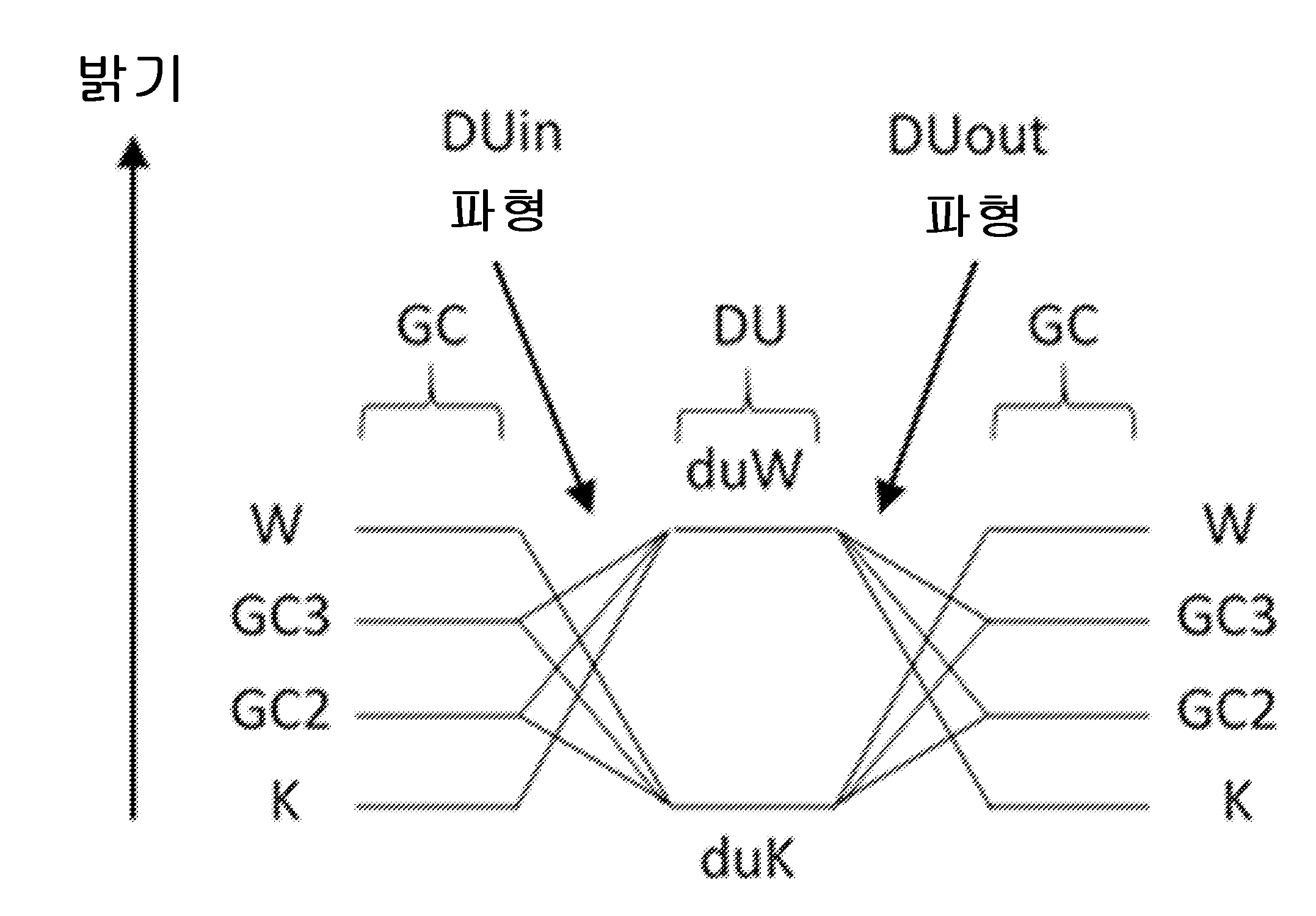
도 9a는 GC 모드와 DU 모드 간의 임펄스 전위 보상 전환을 가능하게 하는 DUin 모드(본 발명의 모드)에서 다수의 전환에 대하여 전압 프레임으로서의 일련의 파형을 도시한다. 특히, "duK" 및 "duW"는 각각 DU 모드에서의 검은색 및 흰색 광학 상태에 대응한다. K, W, GC2 및 GC3는 각각 GC 모드 내의 검은색, 흰색, 그리고 일반화된 제2 및 제3 컬러에 대응한다. 통상적으로, GC 모드에서, K가 첫 번째 컬러이고 W가 마지막이다.
도 9b는, 즉 도 9a에 도시된 파형에 대응하는, DUin 모드에서의 각각의 프레임에 대한 실제 시각적 전환을 도시한다.
도 10a는 DU 모드와 GC 모드 간의 임펄스 전위 보상 전환을 가능하게 하는 DUout 모드에서 다수의 전환에 대하여 전압 프레임으로서의 일련의 파형을 도시한다.
도 10b는, 즉 도 10a에 도시된 파형에 대응하는, DUout 모드에서의 각각의 프레임에 대한 실제 시각적 전환을 도시한다.
도 11은 GC 모드와 DU 모드 간에 이동할 때 임펄스 전위가 어떻게 보상되는지에 대한 예시적인 예이다. 특히, GC로부터 DU로의 임펄스 보상(즉, DUin)은 DU로부터 GC로의 임펄스 보상(즉, DUout)과는 상이하다.FIG. 1 is a schematic cross-sectional view illustrating the positions of various color particles within the electrophoretic medium of the present invention when displaying black, white, three subtractive primary colors, and three additional primary colors.
FIG. 2A is a general example of an electrophoretic display having four types of particles in a nonpolar fluid, with a full color range available at each pixel electrode. In some embodiments, one type of negatively charged particles is white, one type of positively charged particles is yellow, one type of positively charged particles is magenta, and one type of positively charged particles is cyan, although it is understood that the present invention is not limited to the exemplary color sets or combinations of charge polarities and sizes.
Figure 2b illustrates the transition between a first optical state having all particles of the first charge polarity at the viewing surface, and a second optical state having particles of the second (opposite) polarity at the viewing surface.
Figure 2c illustrates the transition between a first optical state having all particles of the first charge polarity on the viewing surface, and a third optical state having particles of the second (opposite) polarity behind the intermediate charged particles of the first polarity located on the viewing surface.
Figure 2d illustrates the transition between a first optical state having all particles of the first charge polarity on the viewing surface, and a fourth optical state having particles of the second (opposite) polarity behind the low charge particles of the first polarity located on the viewing surface.
Figure 2e illustrates a transition between a first optical state having all particles of the first charge polarity on the viewing surface, and a fifth optical state having particles of the second (opposite) polarity behind a combination of low and intermediate charge particles of the first polarity positioned on the viewing surface.
Figure 3 illustrates an exemplary equivalent circuit of a single pixel of an electrophoretic display.
Figure 4 illustrates the layers of an exemplary electrophoretic color display.
Figure 5 illustrates an exemplary push-pull drive scheme for addressing an electrophoretic medium comprising three subtractive particles and a scattering (white) particle. The addressing pulses are typically accompanied by a DC-balancing clearing pulse to enable each color state to be switched to all other color states.
FIG. 6 illustrates a workflow of drive modes that may be executed by a display controller using the method of the present invention. In particular, the drive mode of the display is changed based on the color content of the image to be displayed and/or the need for fast page turning and/or the need for stylus updates. In some embodiments, the controller automatically switches between modes. In other embodiments, user input is required to switch modes.
FIG. 7 is a generalized diagram of the present invention showing the DUin and DUout transition modes for compensating impulse potentials when moving between the "GC" (Global Complete) mode and the DU mode and back again.
Figure 8 illustrates a waveform that may be used to provide rapid transitions between white and black optical states in "DU" (Direct Update) mode. Other waveforms may be used if this results in offsets in the impulse potential when transitioning between black and white states.
FIG. 9a illustrates a series of waveforms as voltage frames for a number of transitions in the DUin mode (the mode of the present invention) which enables impulse potential compensation switching between the GC mode and the DU mode. In particular, "duK" and "duW" correspond to black and white optical states in the DU mode, respectively. K, W, GC2 and GC3 correspond to black, white and a generalized second and third color, respectively, in the GC mode. Typically, in the GC mode, K is the first color and W is the last.
Figure 9b shows the actual visual transitions for each frame in DUin mode, corresponding to the waveforms shown in Figure 9a.
Figure 10a shows a series of waveforms as voltage frames for a number of transitions in DUout mode, which enables impulse potential compensation switching between DU mode and GC mode.
Figure 10b illustrates the actual visual transitions for each frame in DUout mode, corresponding to the waveforms depicted in Figure 10a.
Figure 11 is an exemplary example of how impulse potentials are compensated when moving between GC mode and DU mode. In particular, impulse compensation from GC to DU (i.e., DUin) is different from impulse compensation from DU to GC (i.e., DUout).
본 발명은, 각각의 픽셀에서 적어도 3개의 컬러, 예컨대 8개의 컬러를 가능하게 하도록 설계되는 멀티픽셀 전기 영동 디스플레이를 구동하는 방법을 제공한다. 이 방법은, 각각의 픽셀에서 디스플레이될 수 있는 모든 컬러들 간의 전환을 시행할 수 있는 제1 구동 방식, 및 흰색 페이지 상에 검은색 선을 그리거나 흰색 페이지 상의 검은색 텍스트를 읽거나 검은색 페이지 상의 흰색 텍스트를 읽는 데 매우 유용한, 흰색 또는 검은색으로 끝나는 전환만 포함하는 제2 구동 방식을 사용한다. 제2 구동 방식은, 예를 들어 사용자가 터치 스크린 또는 전자기 공명(EMR; electromagnetic resonance)을 통합한 디스플레이 상에 스타일러스로 "쓰는" 것 또는 또다른 형태의 스타일러스 또는 터치 상호작용 등의, 사용자 입력에 대한 디스플레이의 신속한 응답을 가능하게 하도록 의도된다. 본 발명은 또한 제1 구동 방식과 제2 구동 방식 간에 스위칭하기 위한 전환 구동 방식을 제공한다.The present invention provides a method of driving a multipixel electrophoretic display designed to enable at least three colors, for example eight colors, at each pixel. The method uses a first driving scheme capable of transitioning between all the colors that can be displayed at each pixel, and a second driving scheme that includes only transitions that end in white or black, which is very useful for drawing a black line on a white page, or reading black text on a white page, or reading white text on a black page. The second driving scheme is intended to enable rapid response of the display to user input, such as, for example, a user "writing" with a stylus on a touch screen or an electromagnetic resonance (EMR)-incorporated display, or another form of stylus or touch interaction. The invention also provides a switching driving scheme for switching between the first and second driving schemes.
본 발명은, 제1 극성의 제1 입자, 및 반대 극성을 가지며 상이한 전하 크기를 갖는 3개의 다른 입자들을 포함하는, 개선된 4입자 전기 영동 매질을 포함한다. 통상적으로, 이러한 시스템은 네가티브 흰색 입자 및 감산성 기본 컬러를 갖는 노란색, 자홍색 및 청록색 포지티브 하전 입자를 포함한다. 추가적으로, 일부 입자는 인가된 전기장의 강도에 대해 이들의 전기 영동 이동도가 비선형적이도록 설계될 수 있다. 그에 따라, 하나 이상의 입자는 올바른 극성의 높은 전기장(예컨대, 20V 이상)의 인가에 의해 전기 영동 이동도 감소를 경험할 것이다. 이러한 4입자 시스템은 도 1에 개략적으로 도시되어 있으며, 모든 각 픽셀에서 흰색, 노란색, 빨간색, 자홍색, 파란색, 청록색, 초록색 및 검은색을 제공할 수 있다.The present invention comprises an improved four-particle electrophoretic medium comprising a first particle of a first polarity and three other particles of opposite polarity and different charge magnitudes. Typically, such a system comprises negative white particles and positively charged particles of yellow, magenta and cyan having subtractive primary colors. Additionally, some of the particles may be designed such that their electrophoretic mobility is non-linear with respect to the strength of the applied electric field. Accordingly, one or more of the particles will experience a decrease in their electrophoretic mobility upon application of a high electric field of the correct polarity (e.g., greater than 20 V). Such a four-particle system is schematically illustrated in FIG. 1 and can provide white, yellow, red, magenta, blue, cyan, green and black at each individual pixel.
도 1에 도시된 바와 같이, 8개의 주 컬러(빨간색, 초록색, 파란색, 청록색, 자홍색, 노란색, 검은색 및 흰색) 각각은 4개 입자의 상이한 배열에 대응하며, 그리하여 시청자는 흰색 입자(즉, 광을 산란시키는 유일한 입자)의 시청 측에 있는 컬러 입자만을 보도록 한다. 광범위한 컬러를 달성하기 위해서는, 입자의 보다 미세한 제어를 위해 추가적인 전압 레벨이 사용되어야 한다. 기재되는 공식화에서, 제1(통상적으로 네가티브) 입자는 반사성이며(통상적으로 흰색), 반대로 하전된(통상적으로 포지티브) 입자는 3개의 실질적 비-광산란성("SNLS", substantially non-light-scattering) 입자를 포함한다. SNLS 입자의 사용은 컬러의 혼합을 허용하고, 동일한 개수의 산란성 입자로 달성할 수 있는 것보다 더 많은 컬러 결과를 제공한다. 이들 임계치는 크로스토크를 피하기 위해 충분히 분리되어야 하고, 이러한 분리는 일부 컬러에 대해 높은 어드레싱 전압의 사용을 필요로 한다. 개시된 4입자 전기 영동 매질은 또한 더 빠르게 업데이트될 수 있고, "깜박임이 덜한" 전환을 요하며, 시청자에게 더욱 만족스러운(그리고 그에 따라 상업적으로 더 가치 있는) 컬러 스펙트럼을 생성할 수 있다. 추가적으로, 개시된 공식화는 검은색 픽셀과 흰색 픽셀 간에 빠른(예컨대, 500 ms 미만, 예컨대 300 ms 미만, 예컨대 200 ms 미만, 예컨대 100 ms 미만) 업데이트를 제공하며, 그에 의해 흑백 텍스트에 대한 빠른 페이지 넘김을 가능하게 한다.As illustrated in Figure 1, each of the eight primary colors (red, green, blue, cyan, magenta, yellow, black, and white) corresponds to a different arrangement of four particles, so that the viewer sees only the color particles on the viewing side of the white particle (i.e., the only particle that scatters light). To achieve a wide range of colors, additional voltage levels must be used for finer control of the particles. In the formulation described, the first (typically negative) particle is reflective (typically white), and the oppositely charged (typically positive) particle comprises three substantially non-light-scattering ("SNLS") particles. The use of SNLS particles allows for mixing of colors, providing a wider range of color results than would be possible with the same number of scattering particles. These thresholds must be sufficiently separated to avoid crosstalk, and this separation necessitates the use of high addressing voltages for some colors. The disclosed four-particle electrophoretic medium can also be updated more quickly, requires "flicker-less" transitions, and produces a more viewer-pleasing (and therefore commercially more valuable) color spectrum. Additionally, the disclosed formulation provides fast (e.g., less than 500 ms, e.g., less than 300 ms, e.g., less than 200 ms, e.g., less than 100 ms) updating between black and white pixels, thereby enabling fast page turns for black and white text.
도 1에서, 디스플레이의 시청 표면은 상단에 있으며(예시된 바와 같이), 즉 사용자가 이 방향으로부터 디스플레이를 바라보고, 광이 이 방향으로부터 입사되는 것으로 가정한다. 앞서 언급한 바와 같이, 바람직한 실시예에서, 본 발명의 전기 영동 매질에서 사용되는 4개의 입자 중 하나만 광을 실질적으로 산란시키고, 도 1에서 이 입자는 흰색 안료인 것으로 가정한다. 이러한 광 산란성 흰색 입자는, 흰색 입자 위의 임의의 입자(도 1에 예시된 바와 같이)가 보이게 되는 흰색 반사기를 형성한다. 디스플레이의 시청 표면에 진입하는 광은 이들 입자를 통과하고, 흰색 입자로부터 반사되며, 이들 입자를 다시 통과하여 디스플레이로부터 나온다. 따라서, 흰색 입자 위의 입자는 다양한 컬러를 흡수할 수 있고, 사용자에게 나타나는 컬러는 흰색 입자 위의 입자들 조합으로부터 비롯된 것이다. 흰색 입자 아래에(사용자의 시점에서 뒤에) 배치되는 임의의 입자는 흰색 입자에 의해 가려지고, 디스플레이되는 컬러에 영향을 주지 않는다. 제2 입자, 제3 입자 및 제4 입자는 실질적으로 비-광산란성이기 때문에, 서로에 대한 그들의 순서 또는 배열은 중요하지 않지만, 앞서 서술한 이유로 인해 흰색(광 산란성) 입자에 대한 그들의 순서 또는 배열은 중요하다.In Fig. 1, the viewing surface of the display is at the top (as illustrated), i.e., it is assumed that the user is viewing the display from this direction and that light is incident from this direction. As previously noted, in a preferred embodiment, only one of the four particles used in the electrophoretic medium of the present invention substantially scatters light, and in Fig. 1, this particle is assumed to be a white pigment. These light-scattering white particles form a white reflector that makes any particles above the white particles (as illustrated in Fig. 1) visible. Light entering the viewing surface of the display passes through these particles, is reflected by the white particles, and passes through these particles again to exit the display. Thus, the particles above the white particles can absorb various colors, and the color that is seen by the user is derived from the combination of particles above the white particles. Any particles positioned below the white particles (behind the user's viewpoint) are obscured by the white particles and do not affect the displayed color. Since the second, third and fourth particles are substantially non-light-scattering, their order or arrangement with respect to one another is not important, but their order or arrangement with respect to the white (light-scattering) particles is important for the reasons described above.
보다 구체적으로, 청록색, 자홍색 및 노란색 입자가 흰색 입자 아래에 놓일 때(도 1의 상황 [A]), 흰색 입자 위에 입자가 존재하지 않으며, 픽셀은 단순히 흰색 컬러를 디스플레이한다. 단일 입자가 흰색 입자 위에 놓일 때, 도 1에서 각각 상황 [B], [D] 및 [F]에서 노란색, 자홍색 및 청록색으로, 그 단일 입자의 컬러가 디스플레이된다. 2개의 입자가 흰색 입자 위에 놓일 때, 디스플레이되는 컬러는 이들 2개의 입자의 조합이며; 도 1에서, 상황 [C]에서, 자홍색 및 노란색 입자는 빨간색 컬러를 디스플레이하고, 상황 [E]에서, 청록색 및 자홍색 입자는 파란색 컬러를 디스플레이하고, 상황 [G]에서, 노란색 및 청록색 입자는 초록색 컬러를 디스플레이한다. 마지막으로, 3개의 컬러 입자 모두가 흰색 입자 위에 놓일 때(도 1의 상황 [H]), 모든 유입 광이 3개의 감산성 기본 컬러 입자에 의해 흡수되고 픽셀은 검은색 컬러를 디스플레이한다.More specifically, when cyan, magenta, and yellow particles are placed below a white particle (situation [A] in FIG. 1), there are no particles above the white particle, and the pixel simply displays a white color. When a single particle is placed above a white particle, the color of that single particle is displayed, yellow, magenta, and cyan in situations [B], [D], and [F] in FIG. 1, respectively. When two particles are placed above a white particle, the displayed color is a combination of these two particles; in FIG. 1, in situation [C], the magenta and yellow particles display a red color, in situation [E], the cyan and magenta particles display a blue color, and in situation [G], the yellow and cyan particles display a green color. Finally, when all three color particles are placed above a white particle (situation [H] in FIG. 1), all of the incoming light is absorbed by the three subtractive primary color particles, and the pixel displays a black color.
하나의 감산성 기본 컬러가 광을 산란시키는 입자에 의해 렌더링될 수 있으므로, 디스플레이가 2가지 유형의 광 산란성 입자를 포함하는 것이 가능하며, 그 중 하나는 흰색이고 다른 하나는 다른 컬러일 것이다. 그러나, 이 경우에, 흰색 입자 위에 놓이는 다른 컬러 입자에 대한 광 산란성 컬러 입자의 위치가 중요할 것이다. 예를 들어, 컬러를 검은색으로 렌더링하는 데 있어서(3개의 컬러 입자 모두가 흰색 입자 위에 놓일 때), 산란성 컬러 입자는 비-산란성 컬러 입자 위에 놓일 수 없다(그렇지 않으면, 이들은 산란성 입자 뒤에 부분적으로 또는 완전히 가려질 것이고, 렌더링되는 컬러는 검은색이 아닌 산란성 컬러 입자의 컬러일 것이다).Since one subtractive primary color can be rendered by light-scattering particles, it is possible for a display to include two types of light-scattering particles, one of which would be white and the other of which would be some other color. However, in this case, the position of the light-scattering color particles with respect to the other color particles that lie over the white particles would be important. For example, in rendering a color as black (when all three color particles lie over white particles), the scattering color particles cannot lie over the non-scattering color particles (otherwise they would be partially or completely hidden behind the scattering particles, and the color rendered would be the color of the scattering color particles, not black).
도 1은 컬러들이 오염되지 않는 이상적인 상황을 도시한다(즉, 광 산란성 흰색 입자가 흰색 입자 뒤에 놓인 임의의 입자를 완전히 마스킹함). 실제로, 흰색 입자에 의한 마스킹은 불완전할 수 있으며, 그리하여 이상적으로는 완전히 마스킹되었을 입자에 의해 약간의 작은 광 흡수가 존재할 수 있다. 이러한 오염은 통상적으로 렌더링되는 컬러의 밝기 및 채도 둘 다를 감소시킨다. 본 발명의 전기 영동 매질에서, 이러한 컬러 오염은 형성되는 컬러가 컬러 표현에 대한 산업 표준에 상응하는 지점으로 최소화되어야 한다. 특히 선호되는 표준은 SNAP(신문 광고 제작을 위한 표준)이며, 이는 위에 언급된 8개의 기본 컬러 각각에 대한 L*, a* 및 b* 값을 지정한다. (이하, "기본 컬러"는 도 1에 도시된 바와 같은 8개의 컬러, 즉 검은색, 흰색, 3개의 감산성 기본색 및 3개의 추가 기본색을 지칭하는 데 사용될 것이다.)Figure 1 illustrates an ideal situation where the colors are uncontaminated (i.e., the light-scattering white particles completely mask any particles behind the white particles). In practice, the masking by the white particles may be incomplete, so that there may be some small light absorption by particles that would ideally be completely masked. This contamination typically reduces both the brightness and saturation of the rendered colors. In the electrophoretic medium of the present invention, this color contamination should be minimized to the point where the colors formed correspond to industry standards for color representation. A particularly preferred standard is SNAP (Simple Newspaper Advertising Production Standard), which specifies L * , a * , and b * values for each of the eight primary colors mentioned above. (Hereinafter, the term "primary colors" will be used to refer to the eight colors as illustrated in Figure 1, namely black, white, three subtractive primary colors, and three additive primary colors.)
도 2a 내지 도 2e는 본 발명에서 사용되는 4가지 입자 유형의 개략적인 단면도를 도시한다. 개선된 전기 영동 매질을 이용하는 디스플레이 층은, 시청 측의 제1 (시청) 표면(13) 및 제1 표면(13)의 반대측의 제2 표면(14)을 포함한다. 전기 영동 매질은 2개의 표면 사이에 배치된다. 두 개의 수직 점선 사이의 각각의 공간은 픽셀을 나타낸다. 각각의 픽셀 내에서 전기 영동 매질이 어드레싱될 수 있고, 각각의 픽셀의 시청 표면(13)은 추가 층에 대한 필요 없이 그리고 컬러 필터 어레이 없이 도 1에 도시된 컬러 상태를 달성할 수 있다.Figures 2a to 2e illustrate schematic cross-sectional views of four types of particles used in the present invention. A display layer utilizing an improved electrophoretic medium includes a first (viewing) surface (13) on the viewing side and a second surface (14) opposite the first surface (13). The electrophoretic medium is disposed between the two surfaces. Each space between two vertical dotted lines represents a pixel. The electrophoretic medium within each pixel is addressable, and the viewing surface (13) of each pixel can achieve the color state illustrated in Figure 1 without the need for additional layers and without a color filter array.
전기 영동 디스플레이에 대한 표준으로서, 제1 표면(13)은 공통 전극(11)을 포함하며, 이는 광 투과성이고, 예를 들어 인듐 주석 산화물(ITO)이 위에 배치되어 있는 PET 시트로 구성된다. 제2 표면(14) 상에, 복수의 픽셀 전극(15)을 포함하는 전극 층(12)이 있다. 이러한 픽셀 전극은 미국 특허 번호 7,046,228에 기재되어 있으며, 이의 내용은 그 전체가 참조로 본원에 포함된다. 박막 트랜지스터(TFT; thin film transistor) 백플레인을 이용한 액티브 매트릭스 구동이 픽셀 전극 층에 대해 언급되어 있지만, 본 발명의 범위는 전극이 원하는 기능을 제공하는 한 다른 유형의 전극 어드레싱을 포함한다는 점에 유의한다. 예를 들어, 상부 및 하부 전극은 연속적일 수 있다. 추가적으로, '228 특허에 기재된 바와는 상이한 픽셀 전극 백플레인도 또한 적합하며, 비정질 실리콘 박막 트랜지스터 백플레인으로 통상적으로 확인되는 것보다 더 높은 구동 전압을 제공할 수 있는 액티브 매트릭스 백플레인을 포함할 수 있다.As a standard for electrophoretic displays, the first surface (13) includes a common electrode (11), which is optically transparent and is comprised of, for example, a PET sheet having indium tin oxide (ITO) disposed thereon. On the second surface (14) is an electrode layer (12) including a plurality of pixel electrodes (15). Such pixel electrodes are described in U.S. Patent No. 7,046,228, the contents of which are incorporated herein by reference in their entirety. While active matrix driving using a thin film transistor (TFT) backplane is mentioned with respect to the pixel electrode layer, it is noted that the scope of the present invention includes other types of electrode addressing so long as the electrodes provide the desired function. For example, the top and bottom electrodes may be continuous. Additionally, pixel electrode backplanes different from those described in the '228 patent are also suitable, and may include active matrix backplanes capable of providing higher drive voltages than are typically found with amorphous silicon thin film transistor backplanes.
새롭게 개발된 액티브 매트릭스 백플레인은, 텅스텐 산화물, 주석 산화물, 인듐 산화물, 아연 산화물, 또는 인듐 갈륨 지르코늄 산화물과 같은 보다 복잡한 금속 산화물과 같은 금속 산화물 재료를 포함하는 박막 트랜지스터를 포함할 수 있다. 이들 응용에서, 채널 형성 영역이 이러한 금속 산화물 재료를 사용하여 각각의 트랜지스터에 대해 형성되며, 더 높은 전압의 더 빠른 스위칭을 가능하게 한다. 이러한 금속 산화물 트랜지스터는 또한, 예를 들어 비정질 실리콘 TFT에 의해 달성할 수 있는 것보다, 박막 트랜지스터(TFT)의 "오프" 상태에서 누설이 더 적다. n개의 라인을 포함하는 통상적인 스캐닝 TFT 백플레인에서, 트랜지스터는 디스플레이의 모든 라인을 리프레시하는 데 필요한 시간의 대략 (n-1)/n 비율 동안 "오프" 상태에 있을 것이다. 각각의 픽셀과 연관된 저장 커패시터로부터의 임의의 전하 누설은 디스플레이의 전기 광학 성능의 저하를 초래할 것이다. TFT는 통상적으로 게이트 전극, 게이트 절연 필름(통상적으로 SiO2), 금속 소스 전극, 금속 드레인 전극, 및 게이트 전극, 소스 전극 및 드레인 전극과 적어도 부분적으로 중첩되는 게이트 절연 필름 위의 금속 산화물 반도체 필름을 포함한다. 이러한 백플레인은 Sharp/Foxconn, LG 및 BOE와 같은 제조업체로부터 입수 가능하다. 이러한 백플레인은 ±30V(또는 그 이상)의 구동 전압을 제공할 수 있다. 일부 실시예에서, 중간 전압 구동기가 포함되며, 그리하여 결과적인 구동 파형이 5개 레벨 또는 7개 레벨 또는 9개 레벨 이상을 포함할 수 있다.The newly developed active matrix backplane may include thin film transistors comprising metal oxide materials such as tungsten oxide, tin oxide, indium oxide, zinc oxide, or more complex metal oxides such as indium gallium zirconium oxide. In these applications, a channel forming region is formed for each transistor using these metal oxide materials, allowing for faster switching at higher voltages. These metal oxide transistors also have lower leakage in the "off" state of the thin film transistor (TFT) than can be achieved with, for example, amorphous silicon TFTs. In a typical scanning TFT backplane containing n lines, the transistors will be "off" for approximately (n-1)/n of the time required to refresh all the lines of the display. Any charge leakage from the storage capacitors associated with each pixel will result in a degradation of the electro-optical performance of the display. A TFT typically includes a gate electrode, a gate insulating film (typically SiO 2 ), a metal source electrode, a metal drain electrode, and a metal oxide semiconductor film over the gate insulating film that at least partially overlaps the gate electrode, source electrode, and drain electrodes. Such backplanes are available from manufacturers such as Sharp/Foxconn, LG, and BOE. Such backplanes can provide a driving voltage of ±30 V (or higher). In some embodiments, an intermediate voltage driver is included, such that the resulting driving waveform can include 5 levels or 7 levels or 9 levels or more.
이러한 응용을 위한 하나의 바람직한 금속 산화물 재료는 인듐 갈륨 아연 산화물(IGZO)이다. IGZO-TFT는 비정질 실리콘의 전자 이동도의 20 내지 50배를 갖는다. 액티브 매트릭스 백플레인에 IGZO TFT를 사용함으로써, 적합한 디스플레이 드라이버를 통해 30V보다 큰 전압을 제공하는 것이 가능하다. 또한, 적어도 5개 그리고 바람직하게는 7개 레벨을 공급할 수 있는 소스 드라이버는 4입자 전기 영동 디스플레이 시스템을 위한 상이한 구동 패러다임을 제공한다. 실시예에서, 2개의 포지티브 전압, 2개의 네가티브 전압 및 0 볼트가 있을 것이다. 다른 실시예에서, 3개의 포지티브 전압, 3개의 네가티브 전압 및 0 볼트가 있을 것이다. 실시예에서, 4개의 포지티브 전압, 4개의 네가티브 전압 및 0 볼트가 있을 것이다. 이들 레벨은, 위에 기재된 바와 같은 상부 평면 스위칭에 의해 부과되는 제한 없이, 약 -27V 내지 +27V의 범위 이내에서 선택될 수 있다.One preferred metal oxide material for these applications is indium gallium zinc oxide (IGZO). IGZO TFTs have 20 to 50 times the electron mobility of amorphous silicon. By using IGZO TFTs in the active matrix backplane, it is possible to provide voltages greater than 30 V via a suitable display driver. Additionally, a source driver capable of supplying at least five and preferably seven levels provides different driving paradigms for the four-particle electrophoretic display system. In an embodiment, there will be two positive voltages, two negative voltages, and 0 volts. In another embodiment, there will be three positive voltages, three negative voltages, and 0 volts. In an embodiment, there will be four positive voltages, four negative voltages, and 0 volts. These levels can be selected within the range of about -27 V to +27 V without the limitations imposed by the top plane switching as described above.
본 발명의 전기 영동 매질은, 도 2a 내지 도 2e에 도시된 바와 같이, 비-극성 유체(17) 내의 4가지 유형의 전기 영동 입자를 포함한다. 제1 입자(W-*; 오픈 서클)는 네가티브 하전되고, 제1 입자의 전기 영동 이동도가 구동 전기장의 강도에 따라 달라지도록 표면 처리될 수 있다(아래에 보다 상세하게 설명됨). 이러한 경우에, 입자의 전기 영동 이동도는 더 강한 전기장의 존재 시에 실제로 감소하는데, 이는 다소 반직관적이다. 제2 입자(M++*; 다크 서클)는 포지티브 하전되고, 또한 제2 입자의 전기 영동 이동도가 구동 전기장의 강도에 따라 달라지도록, 또는 전기장 방향의 반전 시에 입자를 수용하는 캐비티의 일측으로 구동된 후의 제2 입자의 집합체의 풀림 속도가 제3 입자 및 제4 입자의 집합체의 풀림 속도보다 더 느리도록, 표면 처리될 수 있다(또는 의도적으로 처리되지 않음). 제3 입자(Y+; 체크 무늬 서클)는 포지티브이지만, 제2 입자보다 작은 전하 크기를 갖는다. 추가적으로, 제3 입자는 표면 처리될 수 있지만, 제3 입자의 전기 영동 이동도가 구동 전기장의 강도에 따라 달라지게 하는 식으로는 아니다. 즉, 제3 입자는 표면 처리를 할 수 있지만, 이러한 표면 처리는 전기장 증가에 따라 전기 영동 이동도가 전술한 대로 감소하는 결과를 초래하지는 않는다. 제4 입자(C++; 회색 서클)는 가장 높은 크기의 포지티브 전하 및 제3 입자와 동일한 유형의 표면 처리를 갖는다. 도 2a에 나타낸 바와 같이, 입자들은 명목상 컬러가 흰색, 자홍색, 노란색 및 청록색이어서 도 1에 도시된 바와 같은 컬러를 생성한다. 그러나, 본 발명은 이 특정 컬러 세트에 한정되지 않으며, 또한 하나의 반사성 입자 및 3개의 흡수성 입자에 한정되지도 않는다. 예를 들어, 시스템은 적합하게 매칭되는 반사 스펙트럼으로 하나의 검은색 흡수성 입자와 빨간색, 노란색 및 파란색의 3개의 반사성 입자를 포함하여, 3개의 반사성 입자 모두가 혼합되고 표면에서 볼 수 있을 때 프로세스 화이트 상태를 생성하도록 할 수 있다.The electrophoretic medium of the present invention comprises four types of electrophoretic particles in a non-polar fluid (17), as illustrated in FIGS. 2A to 2E . The first particle (W- * ; open circles) is negatively charged and may be surface treated (as described in more detail below) such that the electrophoretic mobility of the first particle varies with the strength of the driving electric field. In this case, the electrophoretic mobility of the particle actually decreases in the presence of a stronger electric field, which is somewhat counterintuitive. The second particle (M++ * ; dark circles) is positively charged and may also be surface treated (or intentionally left untreated) such that the electrophoretic mobility of the second particle varies with the strength of the driving electric field, or such that the unfolding speed of an aggregate of the second particles after being driven to one side of a cavity containing the particles upon reversal of the electric field direction is slower than the unfolding speeds of aggregates of the third and fourth particles. The third particle (Y+; checkered circle) is positive, but has a smaller charge magnitude than the second particle. Additionally, the third particle may be surface treated, but not in a way that causes its electrophoretic mobility to vary with the strength of the driving electric field. That is, the third particle may be surface treated, but such surface treatment does not result in the electrophoretic mobility decreasing as the electric field increases as described above. The fourth particle (C++; gray circle) has the highest magnitude positive charge and the same type of surface treatment as the third particle. As shown in FIG. 2A, the particles are nominally colored white, magenta, yellow, and cyan, producing the colors illustrated in FIG. 1 . However, the present invention is not limited to this particular set of colors, nor is it limited to one reflective particle and three absorptive particles. For example, the system could include one black absorbing particle and three reflective particles, red, yellow and blue, with suitably matched reflectance spectra, such that when all three reflective particles are mixed and visible on the surface, a process white state is generated.
바람직한 실시예에서, 제1 입자(네가티브)는 흰색이고 산란성이다. 제2 입자(포지티브, 중간 전하 크기)는 자홍색이고 흡수성이다. 제3 입자(포지티브, 낮은 전하 크기)는 노란색이고 흡수성이다. 제4 입자(포지티브, 높은 전하 크기)는 청록색이고 흡수성이다. 아래의 표 1은, 본 발명의 전기 영동 매질에 유용한 예시적인 노란색, 자홍색, 청록색 및 흰색 입자의 확산 반사율을, 폴리(이소부틸렌) 매트릭스 내에 분산된 이들 재료의 쿠벨카-뭉크(Kubelka-Munk) 분석에 따른 흡수 및 산란 계수의 비율과 함께 보여준다.In a preferred embodiment, the first particle (negative) is white and scattering. The second particle (positive, medium charge magnitude) is magenta and absorbing. The third particle (positive, low charge magnitude) is yellow and absorbing. The fourth particle (positive, high charge magnitude) is cyan and absorbing. Table 1 below shows the diffuse reflectance of exemplary yellow, magenta, cyan, and white particles useful in the electrophoretic media of the present invention, along with the ratio of absorption and scattering coefficients according to Kubelka-Munk analysis of these materials dispersed in a poly(isobutylene) matrix.
표 1. 바람직한 노란색, 자홍색, 청록색 및 흰색 입자의 확산 반사율.Table 1. Diffuse reflectance of desirable yellow, magenta, cyan, and white particles.
본 발명의 전기 영동 매질은 위에 설명된 임의의 형태일 수 있다. 따라서, 전기 영동 매질은 캡슐화되지 않거나, 캡슐 벽으로 둘러싸인 이산 캡슐에 캡슐화되거나, 밀봉된 마이크로셀에 또는 폴리머-분산 매질의 형태로 캡슐화될 수 있다. 안료는 미국 특허 번호 9,697,778 및 9,921,451와 같은 다른 곳에 상세하게 기재되어 있다. 간단히 말해, 흰색 입자(W1)는 미국 특허 번호 7,002,728에 기재된 바와 같이 라우릴 메타크릴레이트(LMA) 모노머를 포함하는 중합성 재료가 부착된 실란올-기능화된 광 산란성 안료(티타늄 이산화물)이다. 흰색 입자(W2)는, 실질적으로 미국 특허 번호 5,852,196의 예시 1에 기재된 바와 같이 제조되는 폴리머 코팅된 티타니아이며, 폴리머 코팅은 대략 99:1 비율의 라우릴 메타크릴레이트 및 2,2,2-트리플루오로에틸 메타크릴레이트를 포함한다. 노란색 입자(Y1)는, 미국 특허 번호 9,697,778에 일반적으로 기재된 바와 같이, 코팅 없이 사용되며 Solsperse 19000의 존재시 마모에 의해 분산되는 C.I. Pigment Yellow 180이다. 노란색 입자(Y2)는, 미국 특허 번호 9,697,778에 일반적으로 기재된 바와 같이, 코팅 없이 사용되며 Solsperse 19000의 존재시 마모에 의해 분산되는 C.I. Pigment Yellow 155이다. 노란색 입자(Y3)는, 미국 특허 번호 9,697,778에 일반적으로 기재된 바와 같이, 코팅 없이 사용되며 Solsperse 19000의 존재시 마모에 의해 분산되는 C.I. Pigment Yellow 139이다. 노란색 입자(Y4)는, 미국 특허 번호 9,921,451의 예시 4에 기재된 바와 같이, 트리플루오로에틸 메타크릴레이트, 메틸 메타크릴레이트 및 디메틸실록산 함유 모노머를 포함하며 분산 중합에 의해 코팅되는 C.I. Pigment Yellow 139이다. 자홍색 입자(M1)는, 미국 특허 번호 9,697,778 및 미국 특허 번호 9,921,451의 예시 5에 기재된 바와 같이, 비닐벤질 클로라이드 및 LMA를 사용하여 코팅된 포지티브 하전 자홍색 재료(디메틸퀴나크리돈, C.I. Pigment Red 122)이다.The electrophoretic medium of the present invention can be in any of the forms described above. Thus, the electrophoretic medium can be unencapsulated, encapsulated in discrete capsules surrounded by a capsule wall, encapsulated in sealed microcells or in the form of a polymer-dispersed medium. The pigment is described in detail elsewhere, such as in U.S. Patent Nos. 9,697,778 and 9,921,451. Briefly, the white particles (W1) are a silanol-functionalized light-scattering pigment (titanium dioxide) to which is attached a polymerizable material comprising a lauryl methacrylate (LMA) monomer as described in U.S. Patent No. 7,002,728. The white particles (W2) are polymer coated titania prepared substantially as described in Example 1 of U.S. Patent No. 5,852,196, wherein the polymer coating comprises lauryl methacrylate and 2,2,2-trifluoroethyl methacrylate in a ratio of about 99:1. The yellow particles (Y1) are C.I. Pigment Yellow 180, used uncoated and dispersed by abrasion in the presence of Solsperse 19000, as generally described in U.S. Patent No. 9,697,778. The yellow particles (Y2) are C.I. Pigment Yellow 155, used uncoated and dispersed by abrasion in the presence of Solsperse 19000, as generally described in U.S. Patent No. 9,697,778. The yellow particles (Y3) are C.I. Pigment Yellow 139, which is used uncoated and dispersed by abrasion in the presence of Solsperse 19000 as generally described in U.S. Patent No. 9,697,778. The yellow particles (Y4) are C.I. Pigment Yellow 139, which comprises trifluoroethyl methacrylate, methyl methacrylate and dimethylsiloxane containing monomers and is coated by dispersion polymerization as described in Example 4 of U.S. Patent No. 9,921,451. The magenta particles (M1) are a positively charged magenta material (dimethylquinacridone, C.I. Pigment Red 122) coated using vinylbenzyl chloride and LMA as described in Example 5 of U.S. Patent No. 9,697,778 and U.S. Patent No. 9,921,451.
자홍색 입자(M2)는, 미국 특허 번호 9,921,451의 예시 6에 기재된 바와 같이, 메틸 메타크릴레이트 및 디메틸실록산 함유 모노머를 포함하며 분산 중합에 의해 코팅되는 C.I. Pigment Red 122이다. 청록색 입자(C1)는, 미국 특허 번호 9,921,451의 예시 7에 기재된 바와 같이, 메틸 메타크릴레이트 및 디메틸실록산 함유 모노머를 포함하며 분산 중합에 의해 코팅되는 구리 프탈로시아닌 재료(C.I. Pigment Blue 15:3)이다. 일부 실시예에서, 메틸 메타크릴레이트 표면 폴리머의 포함과 함께 코어 노란색 안료로서 Ink Jet Yellow 4GC(Clariant)를 사용함으로써 색 영역이 개선되는 것으로 밝혀졌다. 이 노란색 안료의 제타 전위는 2,2,2-트리플루오로에틸 메타크릴레이트(TFEM) 모노머 및 모노메타크릴레이트 말단 폴리(디메틸실록산)의 첨가에 의해 조정될 수 있다.The magenta particles (M2) are C.I. Pigment Red 122, which comprises methyl methacrylate and dimethylsiloxane containing monomers and is coated by dispersion polymerization, as described in Example 6 of U.S. Pat. No. 9,921,451. The cyan particles (C1) are copper phthalocyanine material (C.I. Pigment Blue 15:3), which comprises methyl methacrylate and dimethylsiloxane containing monomers and is coated by dispersion polymerization, as described in Example 7 of U.S. Pat. In some embodiments, it has been found that the color gamut is improved by using Ink Jet Yellow 4GC (Clariant) as a core yellow pigment together with the inclusion of a methyl methacrylate surface polymer. The zeta potential of this yellow pigment can be tuned by addition of 2,2,2-trifluoroethyl methacrylate (TFEM) monomer and monomethacrylate-terminated poly(dimethylsiloxane).
상이한 전기 영동 이동도를 용이하게 하기 위한 전기 영동 매질 첨가제 및 표면 처리 뿐만 아니라, 표면 처리와 주변 전하 제어제 및/또는 자유 폴리머 간의 상호작용을 위한 메커니즘 제안이, 그 전체가 참조로 포함되는, 미국 특허 번호 9,697,778에 상세하게 설명되어 있다. 이러한 전기 영동 매질에서, 다양한 유형의 입자들 간의 상호작용을 제어하는 한 가지 방법은 입자 상의 중합성 코팅의 종류, 양 및 두께를 제어하는 것이다. 예를 들어, 입자-입자 상호작용이, 제2 유형의 입자와 제3 및 제4 유형의 입자 간에, 예를 들어 제3 유형의 입자와 제3 종의 제4 유형의 입자 간보다 작도록 입자 특성을 제어하기 위해, 제2 유형의 입자는 중합성 표면 처리를 받을 수 있으며, 제3 및 제4 유형의 입자는 제2 유형의 입자보다 입자 표면의 단위 면적당 더 낮은 질량 커버리지를 갖는 중합성 표면 처리를 받거나 아니면 어떠한 중합체 표면 처리도 받지 않는다. 보다 일반적으로, 하마커(Hamaker) 상수(2개의 입자 간의 반 데르 발스 상호작용의 강도의 척도이며, 쌍 전위는 하마커 상수에 비례하고 2개의 입자 간의 거리의 6제곱에 반비례함) 및/또는 입자간 간격은 3개의 입자 종에 대한 중합성 코팅(들)의 신중한 선택에 의해 조정될 필요가 있다.Electrophoretic medium additives and surface treatments to facilitate different electrophoretic mobilities, as well as proposed mechanisms for interactions between the surface treatment and the surrounding charge control agent and/or free polymer, are described in detail in U.S. Patent No. 9,697,778, which is incorporated by reference in its entirety. In such electrophoretic media, one way to control interactions between different types of particles is to control the type, amount, and thickness of the polymeric coating on the particles. For example, to control particle properties such that particle-particle interactions are less between a second type of particle and third and fourth types of particles than, for example, between a third type of particle and a fourth type of particle of the third type, the second type of particle can receive a polymeric surface treatment and the third and fourth types of particles can receive a polymeric surface treatment having a lower mass coverage per unit area of particle surface than the second type of particle, or no polymeric surface treatment at all. More generally, the Hamaker constant (a measure of the strength of the van der Waals interaction between two particles, with the pair potential being proportional to the Hamaker constant and inversely proportional to the sixth power of the distance between the two particles) and/or the interparticle spacing need to be tuned by careful selection of the polymeric coating(s) for the three particle species.
미국 특허 번호 9,921,451에서 설명된 바와 같이, 상이한 유형의 폴리머는 상이한 유형의 중합체 표면 처리를 포함할 수 있다. 예를 들어, 반대 하전된 입자의 가장 가까운 접근 거리가 입체 장벽(통상적으로, 하나 또는 둘 다의 입자의 표면에 그래프팅되거나 흡착된 폴리머)에 의해 최대화될 때 쿨롱 상호작용이 약화될 수 있다. 폴리머 쉘은, 당업계에 잘 알려진 바와 같은 그래프팅 프로세스 또는 화학 흡착에 의해 만들어진 공유 결합 폴리머일 수 있거나, 또는 입자 표면에 물리 흡착될 수 있다. 예를 들어, 폴리머는 불용성 및 가용성 세그먼트를 포함하는 블록 공중합체일 수 있다. 대안적으로, 폴리머 쉘은, 충분한 양과 종류의 전하 제어제(CCA; charge control agent, 아래에 설명됨) 및 전기장의 존재시 안료 입자와 복합화되는 전기 영동 매질로부터의 자유 폴리머의 느슨한 네트워크라는 점에서 동적일 수 있다. 따라서, 전기장의 강도 및 극성에 따라, 입자는 더 많은 연관된 폴리머를 가질 수 있으며, 이로 인해 입자가 컨테이너(예컨대, 마이크로캡슐 또는 마이크로셀) 및 다른 입자와 상이하게 상호작용하게 한다. [폴리머 쉘의 범위는, 입자의 건조 샘플의 온도가 상승되며 열분해로 인한 질량 손실이 온도의 함수로서 측정되는 기술인, 열 중량 분석(TGA; thermal gravimetric analysis)에 의해 편리하게 평가된다. TGA를 사용하여, 폴리머인 입자의 질량의 비율이 측정될 수 있고, 이는 코어 안료 및 이에 부착된 폴리머의 알려진 밀도를 사용하여 체적 분율로 변환될 수 있다.] 폴리머 코팅은 손실되지만 코어 안료는 유지되는 조건을 찾을 수 있다(이 조건은 사용되는 정확한 코어 안료 입자에 따라 달라짐). 다양한 폴리머 조합이 도 2a 내지 도 2e에 대해 아래에 기재된 바와 같이 작용하도록 이루어질 수 있다. 예를 들어, 일부 실시예에서, 입자(통상적으로 제1 및/또는 제2 입자)는, 컨테이너(예컨대, 마이크로셀 또는 마이크로캡슐)와 강하게 상호 작용하는 공유 결합으로 부착된 폴리머 쉘을 가질 수 있다. 한편, 동일한 전하의 다른 입자는 폴리머 코팅이 없거나 용액 내의 자유 폴리머와 복합체를 이루며, 그리하여 이들 입자는 컨테이너와 거의 상호 작용하지 않는다. 다른 실시예에서, 입자(통상적으로 제1 및/또는 제2 입자)는 표면 코팅을 갖지 않을 것이며, 그리하여 그 입자가 전하 이중층을 형성하는 것이 더 쉽고 강한 전기장의 존재 시에 전기 영동 이동도 감소를 경험한다.As described in U.S. Patent No. 9,921,451, different types of polymers can include different types of polymer surface treatments. For example, Coulomb interactions can be weakened when the closest approach distance of the oppositely charged particles is maximized by a steric barrier (typically a polymer grafted or adsorbed to the surface of one or both particles). The polymer shell can be a covalently bonded polymer formed by grafting processes or chemical adsorption, as is well known in the art, or can be physisorbed to the particle surface. For example, the polymer can be a block copolymer comprising insoluble and soluble segments. Alternatively, the polymer shell can be dynamic in that it is a loose network of free polymers from the electrophoretic medium that complexes with the pigment particles in the presence of a sufficient amount and type of charge control agent (CCA; described below) and an electric field. Thus, depending on the strength and polarity of the electric field, the particle may have more polymer associated with it, causing the particle to interact differently with the container (e.g., microcapsule or microcell) and with other particles. [The extent of the polymer shell is conveniently assessed by thermal gravimetric analysis (TGA), a technique in which a dry sample of the particle is heated and the mass loss due to thermal decomposition is measured as a function of temperature. Using TGA, the mass fraction of the particle that is polymer can be measured, which can be converted to a volume fraction using the known density of the core pigment and the polymer attached to it.] Conditions can be found in which the polymer coating is lost but the core pigment is retained (this condition will depend on the exact core pigment particle used). Various polymer combinations can be made to function as described below for FIGS. 2A-2E . For example, in some embodiments, the particles (typically the first and/or second particles) may have a covalently attached polymer shell that interacts strongly with a container (e.g., a microcell or microcapsule). Meanwhile, other particles of the same charge may have no polymer coating or may be complexed with free polymer in solution, such that these particles interact little with the container. In other embodiments, the particles (typically the first and/or second particles) may not have a surface coating, such that the particles are more likely to form charge double layers and experience reduced electrophoretic mobility in the presence of strong electric fields.
4가지 유형의 입자가 분산되어 있는 유체(17)는 투명하고 무색이다. 유체는 전기장의 영향 하에 유체를 통해 이동하는 하전된 전기 영동 입자를 함유한다. 바람직한 현탁 유체는, 낮은 유전 상수(약 2), 높은 체적 저항률(약 1015 Ohm.cm), 낮은 점도(5 mPas 미만), 낮은 독성 및 환경 영향, 낮은 물 용해도(전통적인 수성 캡슐화 방법이 사용될 경우, 10 ppm(parts per million) 미만; 그러나 이 요건은 비-캡슐화 또는 특정 마이크로셀 디스플레이의 경우 완화될 수 있다는 것을 유의한다), 높은 비등점(약 90℃ 초과) 및 낮은 굴절률(1.5 미만)을 갖는다. 마지막 요건은 높은 굴절률의 산란성(통상적으로 흰색) 안료의 사용으로부터 발생하며, 이의 산란 효율은 입자와 유체 간의 굴절률 불일치에 따라 달라진다.The fluid (17) in which the four types of particles are dispersed is transparent and colorless. The fluid contains charged electrophoretic particles that move through the fluid under the influence of an electric field. A desirable suspension fluid has a low dielectric constant (about 2), a high volume resistivity (about 10 15 Ohm.cm), a low viscosity (less than 5 mPas), low toxicity and environmental impact, low water solubility (less than 10 ppm (parts per million) when traditional aqueous encapsulation methods are used; however, it is noted that this requirement may be relaxed for non-encapsulated or specific microcell displays), a high boiling point (greater than about 90°C) and a low refractive index (less than 1.5). The last requirement arises from the use of a high refractive index scattering (typically white) pigment, the scattering efficiency of which depends on the refractive index mismatch between the particles and the fluid.
포화 선형 또는 분지형 탄화수소, 실리콘 오일, 할로겐화된 유기 용매 및 저분자량 할로겐 함유 폴리머와 같은 유기 용매가 몇몇 유용한 유체이다. 유체는 그의 화학적 및 물리적 특성을 조정하기 위하여 단일 성분을 포함할 수 있거나 하나보다 많은 성분의 혼합물일 수 있다. 오일 가용성 모노머와 같은 마이크로캡슐화 프로세스(사용되는 경우)를 위한 반응제 또는 용매도 또한 유체에 함유될 수 있다.Organic solvents such as saturated linear or branched hydrocarbons, silicone oils, halogenated organic solvents, and low molecular weight halogen-containing polymers are some useful fluids. The fluid may contain a single component or may be a mixture of more than one component to tailor its chemical and physical properties. Reagents or solvents for the microencapsulation process (if used), such as oil-soluble monomers, may also be contained in the fluid.
유체는 바람직하게는 낮은 점도 및 약 2 내지 약 30, 바람직하게는 높은 입자 이동도를 위해 약 2 내지 약 15 범위의 유전 상수를 갖는다. 적합한 유전체 유체의 예로는 탄화수소, 예컨대 Isopar®, 데카하이드로나프탈렌(DECALIN), 5-에틸리덴-2-노보넨, 지방 오일, 파라핀 오일, 실리콘 유체, 방향족 탄화수소, 예컨대 톨루엔, 크실렌, 페닐자일릴에탄, 도데실벤젠 또는 알킬나프탈렌, 할로겐화 용매, 예컨대 퍼플루오로데칼린, 퍼플루오로톨루엔, 퍼플루오로자일렌, 디클로로벤조트리플루오라이드, 3,4,5-트리클로로벤조트리 플루오라이드, 클로로펜타플루오로-벤젠, 디클로로노난 또는 펜타클로로벤젠, 및 3M Company(St. Paul MN)로부터의 FC-43, FC-70 또는 FC-5060과 같은 퍼플루오르화 용매, TCI America(Portland, Oregon)로부터의 폴리(퍼플루오로프로필렌 옥사이드)와 같은 저분자량 할로겐 함유 폴리머, Halocarbon Product Corp.(River Edge, NJ)로부터의 Halocarbon Oils와 같은 폴리(클로로트리플루오로-에틸렌), Ausimont로부터의 Galden 또는 DuPont(Delaware)로부터의 Krytox Oils and Greases K-Fluid Series와 같은 퍼플루오로폴리알킬에테르, Dow-corning(DC -200)로부터의 폴리디메틸실록산 기반 실리콘 오일을 포함한다.The fluid preferably has a low viscosity and a dielectric constant in the range of about 2 to about 30, preferably about 2 to about 15 for high particle mobility. Examples of suitable dielectric fluids include hydrocarbons such as Isopar®, decahydronaphthalene (DECALIN), 5-ethylidene-2-norbornene, fatty oils, paraffin oils, silicone fluids, aromatic hydrocarbons such as toluene, xylene, phenylxylylethane, dodecylbenzene or alkylnaphthalenes, halogenated solvents such as perfluorodecaline, perfluorotoluene, perfluoroxylene, dichlorobenzotrifluoride, 3,4,5-trichlorobenzotrifluoride, chloropentafluoro-benzene, dichlorononane or pentachlorobenzene, and perfluorinated solvents such as FC-43, FC-70 or FC-5060 from 3M Company (St. Paul MN), low molecular weight halogen-containing polymers such as poly(perfluoropropylene oxide) from TCI America (Portland, Oregon), Halocarbon Product Corp. (River Edge, NJ), poly(chlorotrifluoro-ethylene), perfluoropolyalkyl ethers such as Galden from Ausimont or Krytox Oils and Greases K-Fluid Series from DuPont (Delaware), and polydimethylsiloxane-based silicone oils from Dow-Corning (DC -200).
전기 영동 매질은 통상적으로 하나 이상의 전하 제어제(CCA)도 포함하고, 또한 전하 디렉터도 포함할 수 있다. CCA 및 전하 디렉터는 통상적으로 저분자량 계면활성제, 중합성 제제, 또는 하나 이상의 성분의 블렌드를 포함하고, 전기 영동 입자 상의 전하의 부호 및/또는 크기를 안정화하거나 달리 수정하는 역할을 한다. CCA는 통상적으로 이온성 또는 다른 극성 그룹을 포함하는 분자이며, 이하 헤드 그룹으로 지칭된다. 포지티브 또는 네가티브 이온성 헤드 그룹 중 적어도 하나는 바람직하게는, 이하 테일 그룹으로 지칭되는 비극성 체인(통상적으로 탄화수소 체인)에 부착된다. CCA는 내부 상에서 역 미셀(reverse micelles)을 형성하고 통상적으로 전기 영동 유체로서 사용되는 매우 비극성인 유체에서 전기 전도성을 유발하는 것은 하전된 역 미셀의 작은 집단인 것으로 생각된다.The electrophoretic medium typically also includes one or more charge controlling agents (CCAs), and may also include a charge director. The CCAs and charge directors typically include low molecular weight surfactants, polymeric agents, or blends of one or more components, and serve to stabilize or otherwise modify the sign and/or magnitude of the charge on the electrophoretic particles. The CCAs are typically molecules comprising ionic or other polar groups, hereinafter referred to as head groups. At least one of the positive or negative ionic head groups is preferably attached to a nonpolar chain (typically a hydrocarbon chain), hereinafter referred to as a tail group. The CCAs form reverse micelles in the internal phase, and it is believed that it is small populations of charged reverse micelles that cause electrical conductivity in the highly nonpolar fluids typically used as electrophoretic fluids.
CCA의 추가는, CCA 분자의 비극성 테일 그룹으로 둘러싸인 1 nm 내지 수십 나노미터의 크기가 다양할 수 있는(그리고 구형, 원통형 또는 다른 기하 형상을 가질 수 있는) 높은 극성 코어를 포함하는 역 미셀의 생성을 제공한다. 전기 영동 매질에서, 통상적으로 3개의 상이 구분될 수 있다: 표면을 갖는 고체 입자, 극히 작은 액적(역 미셀)의 형태로 분포되는 높은 극성 상, 및 유체를 포함하는 연속 상. 하전 입자와 하전 역 미셀 둘 다 전기장의 인가 시 유체를 통해 이동할 수 있고, 따라서 유체를 통한 전기 전도를 위한 2개의 병렬 경로가 있다(통상적으로 그 자체는 소실될 정도로 작은 전기 전도성을 가짐).The addition of CCA provides for the creation of reverse micelles comprising a highly polar core, which can vary in size from 1 nm to tens of nanometers (and can have spherical, cylindrical or other geometries), surrounded by nonpolar tail groups of CCA molecules. In an electrophoretic medium, typically three phases can be distinguished: solid particles with a surface, a highly polar phase distributed in the form of extremely small droplets (reverse micelles), and a continuous phase comprising the fluid. Both the charged particles and the charged reverse micelles can move through the fluid upon application of an electric field, so there are two parallel paths for electrical conduction through the fluid (which typically have negligible electrical conductivity themselves).
CCA의 극성 코어는 표면에의 흡착에 의해 표면 상의 전하에 영향을 미치는 것으로 생각된다. 전기 영동 디스플레이에서 이러한 흡착은 마이크로캡슐(또는 마이크로셀의 벽과 같은 다른 고체 상)의 내부 벽 또는 전기 영동 입자의 표면에 이루어져 역 미셀과 유사한 구조를 형성할 수 있으며, 이들 구조는 이하 헤미미셀(hemi-micelles)로 지칭된다. 이온 쌍의 한 이온이 다른 이온보다 표면에 더 강하게 부착될 때(예를 들어, 공유 결합에 의해), 헤미미셀과, 결합되지 않은 역 미셀 사이의 이온 교환으로 인해, 더 강하게 결합된 이온은 입자와 연관된 상태로 남아 있고 덜 강하게 결합된 이온은 자유 역 미셀의 코어에 통합되는, 전하 분리를 초래할 수 있다.The polar core of CCA is thought to influence the charge on the surface by adsorption to the surface. In an electrophoretic display, this adsorption can occur on the inner wall of a microcapsule (or other solid phase, such as the wall of a microcell) or on the surface of the electrophoretic particle, forming structures similar to reverse micelles, which are referred to hereinafter as hemi-micelles. When one ion of an ion pair is more strongly attached to the surface than the other ion (e.g., by covalent bonding), charge separation can occur due to ion exchange between the hemi-micelle and the unbound reverse micelle, with the more strongly bound ion remaining associated with the particle and the less strongly bound ion being incorporated into the core of the free reverse micelle.
CCA의 헤드 그룹을 형성하는 이온성 재료가 입자(또는 다른) 표면에서 이온 쌍 형성을 유도할 수 있는 것도 가능하다. 따라서 CCA는 두 가지 기본 기능, 즉 표면에서의 전하 생성 및 표면으로부터의 전하 분리를 수행할 수 있다. 전하 생성은, CCA 분자에 존재하거나 역 미셀 코어 또는 유체 내에 다른 방식으로 통합된 일부 모이어티와 입자 표면 사이의 산-염기 또는 이온-교환 반응으로부터 초래될 수 있다. 따라서, 유용한 CCA 재료는, 이러한 반응 또는 당업계에 공지된 임의의 다른 하전 반응에 참여할 수 있는 재료이다.It is also possible that the ionic material forming the head group of the CCA can induce ion pair formation at the particle (or other) surface. Thus, the CCA can perform two basic functions, namely, charge generation at the surface and charge separation from the surface. The charge generation can result from an acid-base or ion-exchange reaction between some moiety present in the CCA molecule or otherwise incorporated in the reverse micelle core or fluid and the particle surface. Thus, useful CCA materials are those that can participate in these reactions or any other charge reaction known in the art.
본 발명의 매질에서 유용한 전하 제어제의 비한정적인 클래스로는, 유기 설페이트 또는 설포네이트, 금속 비누, 블록 또는 빗형 공중합체, 유기 아미드, 유기 양쪽성이온, 및 유기 인산염 및 포스포네이트를 포함한다. 유용한 유기 설페이트 및 설포네이트는 나트륨 비스(2-에틸헥실) 설포숙시네이트, 칼슘 도데실벤젠설포네이트, 칼슘 석유 설포네이트, 중성 또는 염기성 바륨 디노닐나프탈렌 설포네이트, 중성 또는 염기성 칼슘 디노닐나프탈렌 설포네이트, 도데실벤젠설폰산 나트륨 염 및 암모늄 라우릴 설페이트를 포함하지만, 이에 한정되는 것은 아니다. 유용한 금속 비누는 염기성 또는 중성 바륨 페트로네이트, 칼슘 페트로네이트, 코발트, 칼슘, 구리, 망간, 마그네슘, 니켈, 아연, 알루미늄 및 나프텐산, 옥탄산, 올레산, 팔미트산, 스테아릭산 및 미리스트산과 같은 카르복실산의 철 염 등을 포함하지만, 이에 한정되는 것은 아니다. 유용한 블록 또는 빗형 공중합체는, (A) 메틸 p-톨루엔설포네이트로 4등화된 2-(N,N-디메틸아미노)에틸 메타크릴레이트의 중합체 및 (B) 폴리(2-에틸헥실 메타크릴레이트)의 AB 다이블록 공중합체, 및 폴리(12-히드록시스테아릭산)의 유용성 테일이 있고 폴리(메틸 메타크릴레이트-메타크릴산)의 유용성 앵커 그룹에 펜던트된 약 1800의 분자량을 갖는 빗형 그래프트 공중합체를 포함하지만, 이에 한정되는 것은 아니다. 유용한 유기 아미드/아민은 폴리이소부틸렌 숙신이미드, 예컨대 OLOA 371 또는 1200(Chevron Oronite Company LLC(Houston, Tex.)로부터 입수가능함) 또는 SOLSPERSE 17000 또는 19000(Lubrizol(Wickliffe, OH)로부터 입수가능함: Solsperse는 등록 상표임), 및 N-비닐피롤리돈 폴리머를 포함하지만, 이에 한정되는 것은 아니다. 유용한 유기 양쪽성이온은 레시틴을 포함하지만 이에 한정되는 것은 아니다. 유용한 유기 인산염 및 포스포네이트는 포화 및 불포화 산 치환기를 갖는 인산화된 모노- 및 디-글리세라이드의 나트륨 염을 포함하지만, 이에 한정되는 것은 아니다. CCA를 위한 유용한 테일 그룹은 200 내지 10,000의 범위의 분자량의 폴리(이소부틸렌)과 같은 올레핀의 폴리머를 포함한다. 헤드 그룹은 설폰산, 인산 또는 카르복실산 또는 아미드, 또는 대안적으로 1차, 2차, 3차 또는 4차 암모늄 기와 같은 아미노 그룹일 수 있다. 개시된 4입자 전기 영동 매질에서 유용한 CCA의 하나의 클래스가, 그 전체가 참조로 본원에 포함되는, 미국 특허 공보 2017/0097556에 개시되어 있다. 이러한 CCA는 통상적으로 4원 아민 헤드 그룹 및 불포화 폴리머 테일, 즉 적어도 하나의 C-C 이중 결합을 포함한 것을 포함한다. 폴리머 테일은 통상적으로 지방산 테일이다. 다양한 CCA 분자량이 사용될 수 있다. 일부 실시예에서, CCA의 분자량은 12,000 그램/몰 이상, 예를 들어 14,000 그램/몰 내지 22,000 그램/몰이다.Non-limiting classes of charge control agents useful in the media of the present invention include organic sulfates or sulfonates, metal soaps, block or comb copolymers, organic amides, organic zwitterions, and organic phosphates and phosphonates. Useful organic sulfates and sulfonates include, but are not limited to, sodium bis(2-ethylhexyl) sulfosuccinate, calcium dodecylbenzenesulfonate, calcium petroleum sulfonate, neutral or basic barium dinonylnaphthalene sulfonate, neutral or basic calcium dinonylnaphthalene sulfonate, sodium dodecylbenzenesulfonic acid, and ammonium lauryl sulfate. Useful metal soaps include, but are not limited to, basic or neutral barium petrolate, calcium petrolate, cobalt, calcium, copper, manganese, magnesium, nickel, zinc, aluminum and iron salts of carboxylic acids such as naphthenic, octanoic, oleic, palmitic, stearic and myristic acids. Useful block or comb copolymers include, but are not limited to, (A) polymers of 2-(N,N-dimethylamino)ethyl methacrylate quaternized with methyl p-toluenesulfonate and (B) AB diblock copolymers of poly(2-ethylhexyl methacrylate), and comb graft copolymers having a molecular weight of about 1800 having an oil-soluble tail of poly(12-hydroxystearic acid) pendant to oil-soluble anchor groups of poly(methyl methacrylate-methacrylic acid). Useful organic amides/amines include, but are not limited to, polyisobutylene succinimides, such as OLOA 371 or 1200 (available from Chevron Oronite Company LLC, Houston, Tex.) or SOLSPERSE 17000 or 19000 (available from Lubrizol, Wickliffe, OH; Solsperse is a registered trademark), and N-vinylpyrrolidone polymers. Useful organic zwitterions include, but are not limited to, lecithin. Useful organic phosphates and phosphonates include, but are not limited to, the sodium salts of phosphorylated mono- and di-glycerides having saturated and unsaturated acid substituents. Useful tail groups for the CCA include polymers of olefins, such as poly(isobutylene) having molecular weights in the range of 200 to 10,000. The head group can be an amino group, such as a sulfonic acid, a phosphoric acid, or a carboxylic acid or an amide, or alternatively a primary, secondary, tertiary, or quaternary ammonium group. One class of CCAs useful in the disclosed four-particle electrophoresis media is disclosed in U.S. Patent Publication No. 2017/0097556, which is herein incorporated by reference in its entirety. Such CCAs typically comprise a 4-membered amine head group and an unsaturated polymer tail, i.e., one containing at least one C-C double bond. The polymer tail is typically a fatty acid tail. Various CCA molecular weights can be used. In some embodiments, the CCA has a molecular weight greater than 12,000 grams/mole, for example, from 14,000 grams/mole to 22,000 grams/mole.
본 발명의 매질에서 사용되는 전하 보조제(charge adjuvant)는 아래에 더 상세히 기재되는 바와 같이 전기 영동 입자 표면 상의 전하를 편향시킬 수 있다. 이러한 전하 보조제는 브론스테드(Bronsted) 또는 루이스(Lewis) 산 또는 염기일 수 있다. 예시적인 전하 보조제가 미국 특허 번호 9,765,015, 10,233,339 및 10,782,586에 개시되어 있으며, 이들 모두는 그 전체가 참조로 포함된다. 예시적인 보조제는 적어도 2개의 하이드록실기를 함유하는 폴리하이드록시 화합물을 포함할 수 있으며, 이는 에틸렌 글리콜, 2,4,7,9-테트라메틸데신-4,7-디올, 폴리(프로필렌 글리콜), 펜타에틸렌 글리콜, 트리프로필렌 글리콜, 트리에틸렌 글리콜, 글리세롤, 펜타에릴스리톨, 글리세롤 트리스(12-하이드록시스테아레이트), 프로필렌 글리세롤 모노하이드록시스테아레이트 및 에틸렌 글리콜 모노하이드록시스테아레이트를 포함하지만, 이에 한정되는 것은 아니다. 동일한 분자에 적어도 하나의 알코올 작용기 및 하나의 아민 작용기를 함유하는 아미노알코올 화합물의 예로는, 트리이소프로판올아민, 트리에탄올아민, 에탄올아민, 3-아미노-1-프로판올, o-아미노페놀, 5-아미노-1-펜탄올 및 테트라키스(2-하이드록시에틸)에틸렌디아민을 포함하지만, 이에 한정되는 것은 아니다. 일부 실시예에서, 전하 보조제는 입자 질량의 그램당 약 1 내지 약 500 밀리그램("mg/g"), 보다 바람직하게는 약 50 내지 약 200 mg/g의 양으로 전기 영동 디스플레이 매질에 존재한다.The charge adjuvant used in the medium of the present invention can bias the charge on the surface of the electrophoretic particles as described in more detail below. Such charge adjuvants can be Bronsted or Lewis acids or bases. Exemplary charge adjuvants are disclosed in U.S. Patent Nos. 9,765,015, 10,233,339, and 10,782,586, all of which are incorporated by reference in their entireties. Exemplary adjuvants can include polyhydroxy compounds containing at least two hydroxyl groups, including but not limited to ethylene glycol, 2,4,7,9-tetramethyldecyne-4,7-diol, poly(propylene glycol), pentaethylene glycol, tripropylene glycol, triethylene glycol, glycerol, pentaerythritol, glycerol tris(12-hydroxystearate), propylene glycerol monohydroxystearate, and ethylene glycol monohydroxystearate. Examples of aminoalcohol compounds containing at least one alcohol functionality and one amine functionality in the same molecule include but are not limited to triisopropanolamine, triethanolamine, ethanolamine, 3-amino-1-propanol, o-aminophenol, 5-amino-1-pentanol, and tetrakis(2-hydroxyethyl)ethylenediamine. In some embodiments, the charge carrier is present in the electrophoretic display medium in an amount of from about 1 to about 500 milligrams per gram of particle mass ("mg/g"), more preferably from about 50 to about 200 mg/g.
캡슐 또는 다른 벽 또는 표면에 대한 입자 응집 또는 부착을 방지하기 위해 입자 분산 안정제가 첨가될 수 있다. 전기 영동 디스플레이에서 유체로서 사용되는 통상적인 고저항성 액체의 경우, 비수성 계면활성제가 사용될 수 있다. 이들은 글리콜 에테르, 아세틸렌 글리콜, 알카놀아미드, 소르비톨 유도체, 알킬 아민, 4차 아민, 이미다졸린, 디알킬 산화물 및 설포숙시네이트를 포함하지만, 이에 한정되는 것은 아니다.Particle dispersion stabilizers may be added to prevent particle agglomeration or adhesion to the capsule or other walls or surfaces. For typical high-resistivity liquids used as fluids in electrophoretic displays, non-aqueous surfactants may be used. These include, but are not limited to, glycol ethers, acetylene glycols, alkanolamides, sorbitol derivatives, alkyl amines, quaternary amines, imidazolines, dialkyl oxides, and sulfosuccinates.
미국 특허 번호 7,170,670에 기재된 바와 같이, 전기 영동 매질의 쌍안정성은 수 평균 분자량이 약 20,000을 초과하는 폴리머를 유체에 포함시킴으로써 개선될 수 있으며, 이 폴리머는 본질적으로 전기 영동 입자에 대해 비-흡수성이고; 폴리(이소부틸렌)은 이러한 목적을 위해 바람직한 폴리머이다. 또한, 예를 들어 미국 특허 번호 6,693,620에 기재된 바와 같이, 표면에 고정화된(immobilize) 전하를 갖는 입자는 주변 유체에 반대 전하의 전기 이중층을 설정한다. CCA의 이온성 헤드 그룹은 전기 영동 입자 표면 상의 하전 그룹과 이온 쌍을 이루며, 고정화된 또는 부분적으로 고정화된 하전 종의 층을 형성할 수 있다. 이 층 외부에는 유체 내의 CCA 분자를 포함하는 하전 (역) 미셀을 포함하는 확산 층이 있다. 종래의 DC 전기 영동에서는, 인가된 전기장이 고정된 표면 전하에 힘을 그리고 이동하는 반대 전하에 반대 힘을 가하며, 그리하여 확산층 내에서 미끄러짐이 발생하고 입자가 유체에 대해 이동하도록 한다. 슬립면에서의 전위는 제타 전위로 알려져 있다.As described in U.S. Patent No. 7,170,670, the bistability of the electrophoretic medium can be improved by including in the fluid a polymer having a number average molecular weight greater than about 20,000, which polymer is essentially non-absorbable to the electrophoretic particles; poly(isobutylene) is a preferred polymer for this purpose. Also, as described, for example, in U.S. Patent No. 6,693,620, particles having immobilized charges on their surfaces establish an electric double layer of opposite charge in the surrounding fluid. The ionic head groups of the CCA can form ion pairs with charged groups on the surface of the electrophoretic particles to form a layer of immobilized or partially immobilized charged species. Outside this layer is a diffuse layer comprising charged (reverse) micelles containing CCA molecules within the fluid. In conventional DC electrophoresis, an applied electric field exerts a force on a fixed surface charge and an opposing force on a moving opposing charge, causing slippage within the diffusion layer and movement of the particle relative to the fluid. The potential at the slip plane is known as the zeta potential.
그 결과, 전기 영동 매질 내의 입자 유형 중 일부는 전기 영동 매질을 가로지르는 전기장의 강도에 따라 상이한 전기 영동 이동도를 갖는다. 예를 들어, 제1(낮은(low) 강도, 즉 약 ±10V 이하) 전기장이 전기 영동 매질에 인가될 때, 제1 유형의 입자는 전기장에 대해 한 방향으로 이동하지만, 제1 전기장과 동일한 극성을 갖는 제2(높은(high) 강도, 즉 약 ±20V 이상) 전기장이 인가될 때, 제1 유형의 입자는 전기장에 대해 반대 방향으로 이동하기 시작한다. 이러한 거동은 하전 역 미셀 또는 반대 하전된 전기 영동 입자에 의해 매개되는 매우 비극성인 유체 내의 전도에서 비롯되는 것으로 이론화된다. 따라서, 임의의 전기화학적으로 생성된 양자(또는 다른 이온)는 아마도 미셀 코어에서 비극성 유체를 통해 운반되거나 전기 영동 입자 상에 흡착된다. 예를 들어, 미국 특허 번호 9,697,778의 도 5b에 예시된 바와 같이, 포지티브 하전된 역 미셀이 반대 방향으로 이동하는 네가티브 전기 영동 입자에 접근할 수 있으며, 역 미셀은 네가티브 하전 입자 주위의 전기 이중층으로 통합된다. (전기 이중층은, 강화된 반대 이온 농도를 갖는 전하의 확산층 및 입자 상의 헤미미셀 표면 흡착된 코팅 둘 다를 포함하며; 후자의 경우, 역 미셀 전하는, 위에 언급된 바와 같이, 입자의 제타 전위를 정의하는 슬립 엔벨로프 내의 입자와 연관되게 될 것이다.) 이 메커니즘을 통해, 포지티브 하전 이온의 전기화학 전류가 전기 영동 유체를 통해 흐르고, 네가티브 하전 입자는 더 포지티브 전하 쪽으로 편향될 수 있다. 그 결과, 예컨대 제1 네가티브 유형의 입자의 전기 영동 이동도는 전기화학 전류의 크기 및 입자 표면에 가까운 포지티브 전하의 체류 시간의 함수이며, 이는 전기장의 강도의 함수이다.As a result, some types of particles within the electrophoretic medium have different electrophoretic mobilities depending on the strength of the electric field across the electrophoretic medium. For example, when a first (low strength, i.e., less than about ±10 V) electric field is applied to the electrophoretic medium, the first type of particles migrate in one direction relative to the electric field, but when a second (high strength, i.e., greater than about ±20 V) electric field having the same polarity as the first electric field is applied, the first type of particles begin to migrate in the opposite direction relative to the electric field. This behavior is theorized to result from conduction within the highly nonpolar fluid mediated by charged reverse micelles or oppositely charged electrophoretic particles. Thus, any electrochemically generated protons (or other ions) are presumably transported through the nonpolar fluid in the micelle core or adsorbed on the electrophoretic particles. For example, as illustrated in FIG. 5b of U.S. Patent No. 9,697,778, a positively charged reverse micelle can approach a negatively charged electrophoretic particle moving in the opposite direction, and the reverse micelle becomes incorporated into an electric double layer around the negatively charged particle. (The electric double layer includes both a diffusion layer of charge with an enhanced concentration of counter ions and a surface-adsorbed coating of hemimicelles on the particle; in the latter case, the reverse micelle charge will become associated with the particle within the slip envelope, which defines the zeta potential of the particle, as described above.) Through this mechanism, an electrochemical current of positively charged ions flows through the electrophoretic fluid, and the negatively charged particle can be deflected toward the more positive charge side. As a result, the electrophoretic mobility of, for example, a first negative type particle is a function of the magnitude of the electrochemical current and the residence time of the positive charge near the particle surface, which is a function of the strength of the electric field.
또한, 미국 특허 번호 9,697,778에 또한 기재된 바와 같이, 인가된 전기장에 따라 상이한 전기 영동 이동도를 또한 나타내는 포지티브 하전 입자가 준비될 수 있다. 일부 실시예에서, 2차(또는 공동-) CCA가 다양한 입자의 제타 전위를 조정하기 위해 전기 영동 매질에 추가될 수 있다. 공동-CCA를 주의깊게 선택하면, 한 입자의 제타 전위의 변경을 허용하면서 다른 입자의 제타 전위를 본질적으로 변하지 않게 할 수 있으며, 스위칭 동안 다양한 입자의 전기 영동 속도와 입자간 상호작용 둘 다의 면밀한 제어를 가능하게 한다.Additionally, positively charged particles can be prepared that also exhibit different electrophoretic mobilities depending on the applied electric field, as also described in U.S. Patent No. 9,697,778. In some embodiments, a secondary (or co-) CCA can be added to the electrophoretic medium to tune the zeta potential of the various particles. Carefully selected co-CCAs can allow for modification of the zeta potential of one particle while leaving the zeta potential of the other particle essentially unchanged, allowing for close control of both the electrophoretic velocities of the various particles and particle-to-particle interactions during switching.
일부 실시예에서, 최종 공식화를 위한 전하 제어제의 일부가 전기 영동 입자의 합성 동안 추가되어, 원하는 제타 전위를 설계하고 강한 전기장으로 인한 전기 영동 이동도의 감소에 영향을 미친다. 예를 들어, 폴리머 그래프팅 동안 4차 아민 전하 제어제를 첨가하면 일부 양의 CCA가 입자에 복합화되게 될 것이라는 것이 관찰되었다. (이는, 전기 영동 유체로부터 입자를 제거함으로써 그리고 이후에 THF로 안료로부터 표면 종을 스트리핑하여 모든 흡착된 종을 제거함으로써, 확인될 수 있다. THF 추출물이 1H NMR로 평가될 때, 상당한 양의 CCA가 안료 입자에 흡착되거나 표면 폴리머와 복합화되었다는 것이 명백하다.) 실험에서는, 입자의 표면 폴리머 사이의 높은 CCA 로딩은 강한 전기장의 존재시 입자 주위에 전하 이중층의 형성을 용이하게 한다는 것을 시사한다. 예를 들어, 완성된 자홍색 입자의 그램당 200 mg를 초과하는 전하 제어제(CCA)를 갖는 자홍색 입자는 높은 포지티브 전기장의 존재 시에 우수한 체류 특성을 갖는다. (예컨대, 도 2c 및 위의 기재를 참조한다.) 일부 실시예에서, CCA는 4차 아민 헤드 그룹 및 지방산 테일을 포함한다. 일부 실시예에서, 지방산 테일은 불포화된다. 전기 영동 매질 내의 입자 중 일부가 높은 CCA 로딩을 포함할 때, 일관된 전기 영동 이동도가 요구되는 입자는 상당한 CCA 로딩을 갖지 않는 것이 중요하며, 예를 들어 완성된 입자의 그램당 50 mg 미만의 전하 제어제(CCA), 예컨대 완성된 입자의 그램당 10 mg 미만의 전하 제어제(CCA)를 갖는다. In some embodiments, a portion of the charge control agent for the final formulation is added during the synthesis of the electrophoretic particles to design the desired zeta potential and to influence the reduction in electrophoretic mobility due to strong electric fields. For example, it has been observed that addition of a quaternary amine charge control agent during polymer grafting will result in some amount of CCA being complexed to the particles. (This can be verified by removing the particles from the electrophoretic fluid and subsequently stripping the surface species from the pigment with THF to remove any adsorbed species. When the THF extract is evaluated by 1H NMR, it is evident that a significant amount of CCA is adsorbed to the pigment particles or complexed with the surface polymer.) Experiments suggest that high CCA loading between the surface polymers of the particles facilitates the formation of a charge double layer around the particles in the presence of strong electric fields. For example, magenta particles having greater than 200 mg of charge control agent (CCA) per gram of finished magenta particles have excellent retention properties in the presence of high positive electric fields. (See, e.g., FIG. 2c and the description above.) In some embodiments, the CCA comprises a quaternary amine head group and a fatty acid tail. In some embodiments, the fatty acid tail is unsaturated. When some of the particles within the electrophoretic medium comprise high CCA loading, it is important that the particles for which consistent electrophoretic mobility is desired do not have significant CCA loading, e.g., less than 50 mg of charge control agent (CCA) per gram of finished particle, such as less than 10 mg of charge control agent (CCA) per gram of finished particle.
다른 실시예에서, Isopar E의 Solsperse 17000의 존재 시에, 4가지 유형의 입자를 포함하는 전기 영동 매질은, 예를 들어, di-t-부틸 살리실산의 알루미늄 염(Orient Corporation(Kenilworth, NJ)로부터 입수 가능한 Bontron E-88)과 같은, 소량의 산성 엔티티의 추가로부터 이점을 얻는다. 산성 재료의 추가는 많은 입자들(전부는 아니지만)의 제타 전위를 더 포지티브 값으로 이동시킨다. 하나의 실시예에서, 약 1%의 산성 재료 및 99%의 Solsperse 17000(2개 재료의 총 중량에 기초하여)는 제3 유형의 입자(Y+)의 제타 전위를 -5mV에서 약 +20mV로 이동시킨다. 특정 입자의 제타 전위가 알루미늄 염과 같은 루이스 산성 재료에 의해 변하는지 여부는 입자의 표면 화학의 세부사항에 따라 달라질 것이다.In another embodiment, the electrophoretic medium comprising four types of particles, in the presence of Solsperse 17000 of Isopar E, benefits from the addition of a small amount of an acidic entity, such as, for example, the aluminum salt of di-t-butyl salicylic acid (Bontron E-88, available from Orient Corporation, Kenilworth, NJ). The addition of the acidic material shifts the zeta potential of many (but not all) of the particles toward more positive values. In one embodiment, about 1% acidic material and 99% Solsperse 17000 (based on the total weight of the two materials) shifts the zeta potential of the third type of particle (Y+) from -5 mV to about +20 mV. Whether the zeta potential of a particular particle is shifted by the addition of a Lewis acidic material, such as an aluminum salt, will depend upon the details of the surface chemistry of the particle.
표 2는 바람직한 실시예에서 3가지 유형의 컬러 입자 및 단일 흰색 입자의 예시적인 상대 제타 전위를 도시한다.Table 2 illustrates exemplary relative zeta potentials of three types of colored particles and a single white particle in a preferred embodiment.
표 2. 흰색 입자의 상대 제타 전위의 존재시 컬러 입자의 상대 제타 전위.Table 2. Relative zeta potential of colored particles in the presence of relative zeta potential of white particles.
실시예에서, 네가티브(흰색) 입자는 -30mV의 제타 전위를 가지며, 나머지 3개의 입자는 모두 흰색 입자에 대해 포지티브이다. 따라서, 포지티브 청록색, 자홍색 및 노란색 입자를 포함하는 디스플레이는, 검은색 상태(시청 표면에 대해 흰색 입자 앞에 모든 컬러 입자가 있음)와, 흰색 입자가 시청자에게 가장 가까이 있으며 시청자가 나머지 3개의 입자를 인식하는 것을 차단하는 흰색 상태 간에 스위칭될 수 있다. 대조적으로, 흰색 입자가 0V의 제타 전위를 가질 때, 네가티브 하전된 노란색 입자가 모든 입자 중에서 가장 네가티브이고, 따라서 이 입자를 포함하는 디스플레이는 노란색 상태와 파란색 상태 간에 스위칭할 것이다. 이는 또한, 흰색 입자가 포지티브 하전된 경우에도 발생할 것이다. 그러나, 포지티브 하전된 노란색 입자는, 그의 제타 전위가 +20mV를 넘지 않는 한, 흰색 입자보다 더 포지티브일 것이다.In an embodiment, the negative (white) particle has a zeta potential of -30 mV, and the other three particles are all positive with respect to the white particle. Therefore, a display including positive cyan, magenta, and yellow particles can be switched between a black state (where all colored particles are in front of the white particle with respect to the viewing surface) and a white state where the white particle is closest to the viewer and blocks the viewer from perceiving the other three particles. In contrast, when the white particle has a zeta potential of 0 V, the negatively charged yellow particle is the most negative of all particles, and therefore a display including this particle will switch between the yellow state and the blue state. This will also occur if the white particle is positively charged. However, the positively charged yellow particle will be more positive than the white particle as long as its zeta potential does not exceed +20 mV.
본 발명의 전기 영동 매질의 거동은 흰색 입자의 이동도(표 2에서 제타 전위로 나타냄)가 인가된 전기장에 따라 달라지는 것과 일치한다. 따라서, 표 2에 예시된 예에서, 낮은 전압으로 어드레싱될 때, 흰색 입자는 그의 제타 전위가 -30mV인 것처럼 거동할 수 있지만, 더 높은 전압으로 어드레싱될 때, 그의 제타 전위가 더 포지티브인 것처럼 거동할 수 있을 것이며, 심지어 +20mV(노란색 입자의 제타 전위와 일치함)만큼 높을 수 있다. 따라서, 낮은 전압으로 어드레싱될 때, 디스플레이는 흑백 상태 간에 스위칭될 것이지만, 더 높은 전압으로 어드레싱될 때, 파란색 상태와 노란색 상태 간에 스위칭될 것이다.The behavior of the electrophoretic medium of the present invention is consistent with the fact that the mobility of the white particles (represented by zeta potential in Table 2) varies with the applied electric field. Thus, in the example illustrated in Table 2, when addressed with a low voltage, the white particles may behave as if their zeta potential is -30 mV, but when addressed with a higher voltage, their zeta potential may behave as if it is more positive, even as high as +20 mV (which matches the zeta potential of the yellow particles). Thus, when addressed with a low voltage, the display will switch between black and white states, but when addressed with a higher voltage, it will switch between blue and yellow states.
높은(예컨대, "±H", 예컨대 ±20V, 예컨대 ±25V) 전기장 및 낮은(예컨대, "±L", 예컨대, ±5V, 예컨대 ±10V) 전기장의 존재 시에 다양한 입자들의 움직임이 도 2b 내지 도 2e에 도시되어 있다. 예시를 위해, 점선으로 경계지은 각각의 박스는, 액티브 매트릭스의 픽셀 전극일 수 있지만 광 투과성 전극 또는 분할된 전극 등일 수도 있는, 상부 광 투과성 전극(21) 및 하부 전극(22)에 의해 경계지어진 픽셀을 나타낸다. 모든 포지티브 입자가 시청 표면에 존재하는 제1 상태(명목상 검은색)로부터 시작하여, 전기 영동 매질은 도 2b 내지 도 2e에 도시된 바와 같이 4개의 상이한 광학 상태로 구동될 수 있다. 바람직한 실시예에서, 이는 흰색 광학 상태(도 2b), 자홍색 광학 상태(도 2c), 노란색 광학 상태(도 2d) 및 빨간색 광학 상태(도 2e)를 초래한다. 도 1의 나머지 4개의 광학 상태는, 도 5에 간단히 도시된 바와 같이, 처음 상태와 구동 전기장의 순서를 반전시킴으로써 달성될 수 있다는 것이 명백하다.The motion of various particles in the presence of high (e.g., "±H", e.g., ±20 V, e.g., ±25 V) and low (e.g., "±L", e.g., ±5 V, e.g., ±10 V) electric fields are illustrated in FIGS. 2b to 2e . For purposes of illustration, each box bordered by a dashed line represents a pixel bordered by an upper optically transmissive electrode (21) and a lower electrode (22), which may be pixel electrodes of an active matrix but may also be optically transmissive electrodes or segmented electrodes, etc. Starting from a first state (nominally black) where all positive particles are present at the viewing surface, the electrophoretic medium can be driven into four different optical states as illustrated in FIGS. 2b to 2e . In a preferred embodiment, this results in a white optical state ( FIG. 2b ), a magenta optical state ( FIG. 2c ), a yellow optical state ( FIG. 2d ) and a red optical state ( FIG. 2e ). It is clear that the remaining four optical states in Fig. 1 can be achieved by reversing the order of the initial state and the driving electric field, as simply illustrated in Fig. 5.
도 2b에서와 같이, 낮은 전압으로 어드레싱될 때, 입자들은 네가티브 전압이 백플레인에 인가될 때의 경우에 대해 화살표로 예시된 상대 속도로 그의 상대 제타 전위에 따라 거동한다. 따라서, 이 예에서, 청록색 입자는 자홍색 입자보다 더 빠르게 이동하며, 자홍색 입자는 노란색 입자보다 더 빠르게 이동한다. 제1 (포지티브) 펄스는 입자들의 위치를 변경하지 않는데, 이들이 이미 인클로저의 벽에 의해 움직임이 제한되기 때문이다. 제2 (네가티브) 펄스는 컬러 입자와 흰색 입자의 위치를 교환하고, 따라서 디스플레이는 흑백 상태 간에 스위칭하지만, 컬러 입자들의 상대 이동도를 반영하는 일시적인 컬러가 있다. 펄스의 시작 위치 및 극성을 반전시키면, 흰색으로부터 검은색으로 전환할 수 있다. 따라서, 이 실시예는 프로세스 블랙 또는 프로세스 화이트를 통해 다수의 컬러로 달성되는 다른 흑백 공식화와 비교하여 더 낮은 전압을 요하는(그리고 더 적은 전력을 소모함) 흑백 업데이트를 제공한다.As in Fig. 2b, when addressed with a low voltage, the particles move according to their relative zeta potentials at the relative speeds illustrated by the arrows for the case when a negative voltage is applied to the backplane. Thus, in this example, the cyan particles move faster than the magenta particles, and the magenta particles move faster than the yellow particles. The first (positive) pulse does not change the positions of the particles, because their movement is already restricted by the walls of the enclosure. The second (negative) pulse exchanges the positions of the colored and white particles, so that the display switches between black and white states, but with a temporary color that reflects the relative mobility of the colored particles. Reversing the starting position and polarity of the pulses allows switching from white to black. Thus, this embodiment provides a black and white update that requires lower voltage (and consumes less power) compared to other black and white formulations that are achieved with multiple colors via process black or process white.
도 2c에서, 제1 (포지티브) 펄스는, 자홍색 입자(즉, 3개의 포지티브 하전 컬러 입자 중 중간 이동도의 입자)의 이동도를 감소시키기에 충분한, 높은 포지티브 전압이다. 감소된 이동도 때문에, 자홍색 입자는 본질적으로 제자리에 고정된 상태로 유지되고, 낮은 전압의 반대 방향으로의 후속 펄스가, 청록색, 흰색 및 노란색 입자를 자홍색 입자보다 더 많이 이동시키며, 그에 의해 시청 표면에 자홍색 컬러를 생성하며 네가티브 흰색 입자가 자홍색 입자 뒤에 있다. 중요한 점은, 펄스의 시작 위치 및 극성이 반전되는 경우(시청 표면의 반대 측으로부터, 즉 전극(22)을 통해, 디스플레이를 보는 것과 동등함), 이 펄스 시퀀스는 초록색 컬러(즉, 노란색 입자와 청록색 입자의 혼합)를 생성할 것이다.In Figure 2c, the first (positive) pulse is of high positive voltage sufficient to reduce the mobility of the magenta particles (i.e., the intermediate mobility particles of the three positively charged color particles). Because of their reduced mobility, the magenta particles remain essentially fixed in place, while a subsequent pulse in the opposite direction of lower voltage moves the cyan, white and yellow particles more than the magenta particles, thereby producing a magenta color at the viewing surface, with the negative white particles behind the magenta particles. Importantly, if the starting position and polarity of the pulses are reversed (equivalent to viewing the display from the opposite side of the viewing surface, i.e., through the electrodes (22),) this pulse sequence will produce a green color (i.e., a mixture of yellow and cyan particles).
도 2d에서, 제1 펄스는, 자홍색 입자 또는 흰색 입자의 이동도를 크게 감소시키지 않는 낮은 전압이다. 그러나, 제2 펄스는, 흰색 입자의 이동도를 감소시키는 높은 네가티브 전압이다. 이를 통해 3개의 포지티브 입자들 간의 보다 효과적인 경주가 가능하며, 그리하여 가장 느린 유형의 입자(이 예에서 노란색)는, 이전의 네가티브 펄스에 의해 움직임이 감소된 흰색 입자 앞에 계속 보이는 채로 유지된다. 특히, 노란색 입자는 입자를 수용하는 캐비티의 상단 표면으로 가지 않도록 한다. 중요한 점은, 펄스의 시작 위치 및 극성이 반전되는 경우(시청 표면의 반대 측으로부터, 즉 전극(22)을 통해, 디스플레이를 보는 것과 동등함), 이 펄스 시퀀스는 파란색 컬러(즉, 자홍색 입자와 청록색 입자의 혼합)를 생성할 것이다.In Fig. 2d, the first pulse is a low voltage that does not significantly reduce the mobility of either the magenta or white particles. However, the second pulse is a high negative voltage that reduces the mobility of the white particles. This allows for a more efficient racing between the three positive particles, so that the slowest type of particle (yellow in this example) remains visible in front of the white particles whose movement has been reduced by the previous negative pulse. In particular, the yellow particles are prevented from going to the top surface of the cavity that receives the particles. Importantly, if the starting position and polarity of the pulses are reversed (equivalent to viewing the display from the opposite side of the viewing surface, i.e. through the electrode (22),) this pulse sequence will produce a blue color (i.e. a mixture of magenta and cyan particles).
마지막으로, 도 2e는, 둘 다의 펄스가 높은 전압일 때, 자홍색 입자 이동도가 제1 높은 포지티브 펄스에 의해 감소될 것이고, 제2 높은 네가티브 펄스에 의해 야기된 흰색 이동도 감소에 의해 청록색과 노란색 간의 경주가 강화될 것임을 보여준다. 이는 빨간색 컬러를 생성한다. 중요한 점은, 펄스의 시작 위치 및 극성이 반전되는 경우(시청 표면의 반대 측으로부터, 즉 전극(22)을 통해, 디스플레이를 보는 것과 동등함), 이 펄스 시퀀스는 청록색 컬러를 생성할 것이다.Finally, Fig. 2e shows that when both pulses are at high voltage, the magenta particle mobility will be reduced by the first high positive pulse, and the race between cyan and yellow will be enhanced by the white mobility reduction caused by the second high negative pulse. This produces a red color. Importantly, if the starting position and polarity of the pulses are reversed (equivalent to viewing the display from the opposite side of the viewing surface, i.e. through electrode (22)), this pulse sequence will produce a cyan color.
고해상도 디스플레이를 얻기 위해, 디스플레이의 개별 픽셀이 인접한 픽셀로부터의 간섭 없이 어드레싱 가능하여야 한다. 이 목적을 달성하기 위한 한 가지 방법은, "액티브 매트릭스" 디스플레이를 생성하기 위해, 적어도 하나의 비선형 요소가 각각의 픽셀과 연관되어 있는, 트랜지스터 또는 다이오드와 같은 비선형 요소들의 어레이를 제공하는 것이다. 하나의 픽셀을 어드레싱하는 어드레싱 또는 픽셀 전극은 연관된 비선형 요소를 통해 적절한 전압 소스에 연결된다. 통상적으로, 비선형 요소가 트랜지스터일 때, 픽셀 전극은 트랜지스터의 드레인에 연결되고, 다음의 기재에서 이 배열이 가정될 것이지만, 이는 본질적으로 임의적인 것이이고 픽셀 전극이 트랜지스터의 소스에 연결될 수 있다. 관례적으로, 고해상도 어레이에서, 픽셀들은 행과 열의 2차원 어레이로 배열되며, 그리하여 임의의 특정 픽셀이 하나의 지정된 행과 하나의 지정된 열의 교차에 의해 고유하게 정의된다. 각 열에 있는 모든 트랜지스터의 소스는 단일 열 전극에 연결되며, 각 행에 있는 모든 트랜지스터의 게이트는 단일 행 전극에 연결되고; 다시 말해, 소스를 행에 그리고 게이트를 열에 할당하는 것이 관례적이지만 본질적으로 임의적이며, 원하는 경우 반전될 수 있다. 행 전극은 행 드라이버에 연결되며, 이는 임의의 주어진 순간에 단 하나의 열만 선택되는 것, 즉 선택된 행 전극에 선택 전압이 인가되는 것을 본질적으로 보장하고, 예컨대 선택된 행에 있는 모든 트랜지스터가 전도성임을 보장하며, 모든 다른 행에 비-선택 전압이 인가되고, 예컨대 이 선택되지 않은 행에 있는 모든 트랜지스터가 비전도성을 유지함을 보장한다. 열 전극은 열 드라이버에 연결되고, 열 드라이버는 선택된 행에 있는 픽셀을 그의 원하는 광학 상태로 구동하도록 선택된 전압을 다양한 열 전극에 가한다. (전술한 전압은, 관례적으로 비선형 어레이로부터 전기 광학 매질의 반대 측에 제공되며 전체 디스플레이에 걸쳐 연장되는 공통 전방 전극에 대한 것이다.) "라인 어드레스 시간"으로 알려진 미리 선택된 간격 후에, 선택된 행이 선택 해제되고, 다음 행이 선택되며, 디스플레이의 다음 라인이 기록되도록 열 드라이버 상의 전압이 변경된다. 이 프로세스는 행 단위 방식으로 전체 디스플레이가 기록되도록 반복된다.In order to achieve a high resolution display, individual pixels of the display must be addressable without interference from adjacent pixels. One way to achieve this goal is to provide an array of nonlinear elements, such as transistors or diodes, with at least one nonlinear element associated with each pixel, to create an "active matrix" display. The addressing or pixel electrode addressing a pixel is connected to a suitable voltage source through the associated nonlinear element. Typically, when the nonlinear element is a transistor, the pixel electrode is connected to the drain of the transistor, and this arrangement will be assumed in the following description, although it is essentially arbitrary and the pixel electrode may be connected to the source of the transistor. Conventionally, in a high resolution array, the pixels are arranged in a two-dimensional array of rows and columns, so that any particular pixel is uniquely defined by the intersection of a given row with a given column. The sources of all the transistors in each column are connected to a single column electrode, and the gates of all the transistors in each row are connected to a single row electrode; In other words, the assignment of sources to rows and gates to columns is conventional but essentially arbitrary and can be reversed if desired. The row electrodes are connected to the row drivers, which essentially ensure that only one row is selected at any given moment, i.e., that the selected row electrodes are given a selection voltage, i.e., that all transistors in the selected row are conductive, and that all other rows are given a non-selection voltage, i.e., that all transistors in the non-selected rows remain non-conductive. The column electrodes are connected to the column drivers, which apply a selected voltage to the various column electrodes so as to drive the pixels in the selected row to their desired optical state. (The voltages mentioned above are conventionally provided on the opposite side of the electro-optic medium from the non-linear array and are relative to a common front electrode that extends across the entire display.) After a pre-selected interval known as the "line address time", the selected row is deselected, the next row is selected, and the voltage on the column drivers is changed so that the next line of the display is written. This process is repeated row by row so that the entire display is written.
관례적으로, 각각의 픽셀 전극은, 픽셀 전극 및 커패시터 전극이 커패시터를 형성하도록 커패시터 전극과 연관되어 있으며; 예를 들어, 국제 특허 출원 WO 01/07961을 참조한다. 일부 실시예에서, N형 반도체(예컨대, 비정질 실리콘)가 트랜지스터를 형성하는 데 사용될 수 있고, 게이트 전극에 인가되는 "선택" 및 "비-선택" 전압은 각각 포지티브 및 네가티브일 수 있다.Conventionally, each pixel electrode is associated with a capacitor electrode such that the pixel electrode and the capacitor electrode form a capacitor; see, e.g., International Patent Application WO 01/07961. In some embodiments, an N-type semiconductor (e.g., amorphous silicon) may be used to form the transistor, and the "select" and "non-select" voltages applied to the gate electrode may be positive and negative, respectively.
첨부 도면의 도 3은 전기 영동 디스플레이의 단일 픽셀의 예시적인 등가 회로를 도시한다. 예시된 바와 같이, 회로는 픽셀 전극과 커패시터 전극 사이에 형성된 커패시터(10)를 포함한다. 전기 영동 매질(20)은 병렬인 커패시터와 저항기로서 나타나 있다. 일부 경우에, 픽셀과 연관된 트랜지스터의 게이트 전극과 픽셀 전극 사이의 직접 또는 간접 커플링 커패시턴스(30)(일반적으로 "기생 커패시턴스"로 지칭됨)는 디스플레이에 원치 않는 노이즈를 생성할 수 있다. 일반적으로, 기생 커패시턴스(30)는 저장 커패시터(10)의 커패시턴스보다 훨씬 더 작고, 디스플레이의 픽셀 열이 선택 또는 선택 해제될 때, 기생 커패시턴스(30)로 인해 픽셀 전극에 "킥백 전압(kickback voltage)"이라고도 알려진 작은 네가티브 오프셋 전압을 초래할 수 있으며, 이는 일반적으로 2 볼트 미만이다. 일부 실시예에서, 원치 않는 "킥백 전압"을 보상하기 위해, 공통 전위 Vcom가, 각각의 픽셀과 연관된 상부 평면 전극 및 커패시터 전극에 공급될 수 있으며, 그리하여 Vcom가 킥백 전압(VKB)과 동일한 값으로 설정될 때, 디스플레이에 공급된 모든 전압이 동일한 양만큼 오프셋될 수 있도록 하고 순 DC-불균형을 경험하지 않는다. FIG. 3 of the accompanying drawings illustrates an exemplary equivalent circuit of a single pixel of an electrophoretic display. As illustrated, the circuit includes a capacitor (10) formed between a pixel electrode and a capacitor electrode. The electrophoretic medium (20) is represented as a capacitor and a resistor in parallel. In some cases, direct or indirect coupling capacitance (30) (generally referred to as "parasitic capacitance") between the gate electrode of a transistor associated with a pixel and the pixel electrode can generate unwanted noise in the display. Typically, the parasitic capacitance (30) is much smaller than the capacitance of the storage capacitor (10), and when a row of pixels in the display is selected or deselected, the parasitic capacitance (30) can cause a small negative offset voltage, also known as a "kickback voltage," across the pixel electrode, which is typically less than 2 volts. In some embodiments, to compensate for the unwanted "kickback voltage", a common potential V com can be supplied to the top plane electrode and the capacitor electrode associated with each pixel, such that when V com is set to a value equal to the kickback voltage (V KB ), all voltages supplied to the display are offset by the same amount and do not experience a net DC-imbalance.
그러나, Vcom가 킥백 전압에 대해 보상되지 않는 전압으로 설정될 때, 문제가 발생할 수 있다. 이는 백플레인만으로 이용 가능한 것보다 더 높은 전압을 디스플레이에 인가하고자 할 때 발생할 수 있다. 예를 들어, 백플레인에 공칭 +V, 0 또는 -V의 선택사항이 공급되는 반면, 예를 들어 Vcom이 -V로 공급될 때, 디스플레이에 인가되는 최대 전압이 2배가 될 수 있다는 것이 당업계에 잘 알려져 있다. 이 경우 경험되는 최대 전압은 +2V(즉, 상부 평면에 대해 백플레인에서)이며, 최소값은 0이다. 네가티브 전압이 필요한 경우, Vcom 전위는 적어도 0으로 상승되어야 한다. 따라서 상부 평면 스위칭을 사용하여 포지티브 및 네가티브 전압으로 디스플레이를 어드레싱하는 데 사용되는 파형은 하나보다 많은 Vcom 전압 설정 각각에 할당된 특정 프레임을 가져야 한다.However, problems can arise when V com is set to a voltage that is not compensated for the kickback voltage. This can occur when one wishes to drive a higher voltage to the display than is available from the backplane alone. For example, it is well known in the art that when the backplane is supplied with the nominal +V, 0 or -V options, while V com is supplied as -V, for example, the maximum voltage applied to the display can be doubled. In this case, the maximum voltage experienced is +2V (i.e., at the backplane with respect to the top plane), and the minimum is 0. If a negative voltage is required, the V com potential must be raised to at least 0. Therefore, the waveform used to address the display with positive and negative voltages using top plane switching must have a specific frame assigned to each of the more than one V com voltage settings.
4개의 입자를 갖는 컬러 전기 영동 디스플레이를 구동하기 위한 파형 세트가, 본원에 참조로 포함되는, 미국 특허 번호 9,921,451에 기재되어 있다. 미국 특허 번호 9,921,451에서는, 7개의 상이한 전압, 즉 3개의 포지티브, 3개의 네가티브 및 0의 전압이 픽셀 전극에 인가된다. 그러나, 일부 실시예에서, 이들 파형에서 사용되는 최대 전압은 비정질 실리콘 박막 트랜지스터에 의해 취급될 수 있는 것보다 더 높다. 이러한 경우에, 상부 평면 스위칭의 사용에 의해 적합한 높은 전압이 획득될 수 있다. (위에 기재된 바와 같이) Vcom이 의도적으로 VKB로 설정될 때, 별개의 전원 공급장치가 사용될 수 있다. 그러나, 상부 평면 스위칭이 사용될 때 Vcom 설정이 있는 만큼 많은 별개의 전원 공급 장치를 사용하는 것은 비용이 많이 들고 불편하다. 또한, 상부 평면 스위칭은 킥백을 증가시키며 그로 인해 컬러 상태의 안정성을 저하시키는 것으로 알려져 있다.A set of waveforms for driving a color electrophoretic display having four particles is described in U.S. Patent No. 9,921,451, which is incorporated herein by reference. In U.S. Patent No. 9,921,451, seven different voltages are applied to the pixel electrodes, namely three positive, three negative, and zero. However, in some embodiments, the maximum voltages used in these waveforms are higher than can be handled by the amorphous silicon thin film transistors. In such cases, the appropriately high voltages can be obtained by using top plane switching. When V com is intentionally set to V KB (as described above), a separate power supply can be used. However, it is expensive and inconvenient to use as many separate power supplies as there are V com settings when top plane switching is used. In addition, top plane switching is known to increase kickback, thereby degrading the stability of the color states.
디스플레이 디바이스는 종래 기술에 공지된 여러 방식으로 본 발명의 전기 영동 유체를 사용하여 구성될 수 있다. 전기 영동 유체는 마이크로캡슐에 캡슐화되거나 마이크로셀 구조로 통합될 수 있으며, 이는 그 후에 중합체 층으로 밀봉된다. 마이크로캡슐 또는 마이크로셀 층은, 전기 전도성 재료의 투명 코팅을 지닌 플라스틱 기판 또는 필름에 코팅되거나 엠보싱될 수 있다. 이 어셈블리는 전기 전도성 접착제를 사용하여 픽셀 전극을 지닌 백플레인에 적층될 수 있다. 대안적으로, 전기 영동 유체는, 픽셀 전극의 액티브 매트릭스를 포함하는 백플레인 상에 배열된 얇은 개방-셀 그리드 상에 직접 디스펜싱될 수 있다. 그 다음, 채워진 그리드는 통합된 보호 시트/광 투과성 전극에 의해 상단 밀봉될 수 있다.The display device can be constructed using the electrophoretic fluid of the present invention in a number of ways known in the art. The electrophoretic fluid can be encapsulated in microcapsules or incorporated into a microcell structure, which is then sealed with a polymer layer. The microcapsule or microcell layer can be coated or embossed onto a plastic substrate or film having a transparent coating of an electrically conductive material. This assembly can be laminated to a backplane having pixel electrodes using an electrically conductive adhesive. Alternatively, the electrophoretic fluid can be dispensed directly onto a thin open-cell grid arranged on a backplane containing an active matrix of pixel electrodes. The filled grid can then be top sealed with an integrated protective sheet/light-transmitting electrode.
도 4는 본 발명과 함께 사용하기에 적합한 디스플레이 구조물(200)의 개략적인 단면도(실축척이 아님)를 도시한다. 디스플레이(200)에서, 전기 영동 유체는 마이크로셀에 국한되는 것으로서 예시되어 있지만, 마이크로캡슐을 포함하는 등가의 구조물이 또한 사용될 수 있다. 유리 또는 플라스틱일 수 있는 기판(202)은, 개별적으로 어드레싱된 세그먼트이거나 또는 액티브 매트릭스 배열에서 박막 트랜지스터와 연관되는 픽셀 전극(204)을 지닌다. (기판(202)과 전극(204)의 조합은 관례적으로 디스플레이의 백플레인으로 지칭된다.) 층(206)은 백플레인에 적용되는 본 발명에 따른 선택적인 유전체 층이다. (적합한 유전체 층을 퇴적하기 위한 방법이, 참조로 포함되는, 미국 특허 출원 번호 16/862,750에 기재되어 있다.) 디스플레이의 전방 평면은 투명 전기 전도성 코팅(220)을 지닌 투명 기판(222)을 포함한다. 위에 있는 전극 층(220)은 선택적인 유전체 층(218)이다. 층(또는 층들)(216)은, 투명 전극 층(220)에 마이크로셀의 접착을 위한 프라이머 층 및 마이크로셀의 바닥을 포함한 일부 잔류 폴리머를 포함할 수 있는, 중합성 층(들)이다. 마이크로셀(212)의 벽은 전기 영동 유체(214)를 수용하기 위해 사용된다. 마이크로셀은 층(210)으로 밀봉되고, 전체 전방 평면 구조물이 전기 전도성 접착 층(208)을 사용하여 백플레인에 접착된다. 마이크로셀을 형성하기 위한 프로세스는 선행 기술, 예컨대 미국 특허 번호 6,930,818에 기재되어 있다. 일부 경우에, 마이크로셀은 20 μm 미만의 깊이, 예컨대 15 μm 미만의 깊이, 예컨대 12 μm 미만의 깊이, 예컨대 약 10 μm 깊이, 예컨대 약 8 μm 깊이이다.FIG. 4 illustrates a schematic cross-sectional view (not to scale) of a display structure (200) suitable for use with the present invention. In the display (200), the electrophoretic fluid is illustrated as being confined to microcells, although equivalent structures comprising microcapsules may also be used. A substrate (202), which may be glass or plastic, has pixel electrodes (204), which are individually addressed segments or associated with thin film transistors in an active matrix arrangement. (The combination of substrate (202) and electrodes (204) is conventionally referred to as the backplane of the display.) A layer (206) is an optional dielectric layer according to the present invention that is applied to the backplane. (Methods for depositing suitable dielectric layers are described in U.S. patent application Ser. No. 16/862,750, which is incorporated by reference.) The front plane of the display includes a transparent substrate (222) having a transparent electrically conductive coating (220). The electrode layer (220) above is an optional dielectric layer (218). The layer (or layers) (216) is a polymeric layer(s) that may include a primer layer for adhesion of the microcell to the transparent electrode layer (220) and some residual polymer including the bottom of the microcell. The walls of the microcell (212) are used to contain the electrophoretic fluid (214). The microcell is sealed with the layer (210) and the entire front plane structure is adhered to the backplane using an electrically conductive adhesive layer (208). Processes for forming the microcell are described in the prior art, such as in U.S. Pat. No. 6,930,818. In some cases, the microcell is less than 20 μm deep, such as less than 15 μm deep, such as less than 12 μm deep, such as about 10 μm deep, such as about 8 μm deep.
대부분의 상업적 전기 영동 디스플레이는 제조 설비의 넓은 이용 가능성 및 다양한 시작 재료의 비용 때문에 액티브 매트릭스 백플레인(202/204)의 구성에 비정질 실리콘 기반 박막 트랜지스터(TFT)를 사용한다. 불행히도, 비정질 실리콘 박막 트랜지스터는 약 +/-15V보다 높은 전압의 스위칭을 허용할 게이트 전압이 공급될 때 불안정해진다. 그럼에도 불구하고, 아래에 기재된 바와 같이, 높은 포지티브 전압 및 네가티브 전압의 크기가 +/-15V를 초과하도록 허용될 때 ACeP의 성능은 개선된다. 그에 따라, 이전 개시에서 기재된 바와 같이, 상부 평면 스위칭으로도 알려진, 백플레인 픽셀 전극 상의 바이어스에 대한 상부 광 투과성 전극의 바이어스를 추가적으로 변경함으로써, 개선된 성능이 달성된다. 따라서, (백플레인에 비해) +30V의 전압이 필요한 경우, 적절한 백플레인 픽셀이 +15V로 스위칭되면서, 상부 평면은 -15V로 스위칭될 수 있다. 상부 평면 스위칭을 이용한 4입자 전기 영동 시스템을 구동하는 방법은, 예를 들어, 미국 특허 번호 9,921,451에 더 상세하게 기재되어 있다.Most commercial electrophoretic displays use amorphous silicon based thin film transistors (TFTs) in the construction of the active matrix backplane (202/204) due to the wide availability of fabrication equipment and the cost of various starting materials. Unfortunately, amorphous silicon TFTs become unstable when supplied with gate voltages that would allow switching at voltages higher than about +/-15 V. Nevertheless, as described below, the performance of ACePs is improved when the magnitude of the high positive and negative voltages is allowed to exceed +/-15 V. Accordingly, improved performance is achieved by additionally varying the bias of the top optically transmissive electrode relative to the bias on the backplane pixel electrodes, also known as top plane switching, as described in the previous disclosure. Thus, when a voltage of +30 V (relative to the backplane) is required, the top plane can be switched at -15 V while the appropriate backplane pixel is switched at +15 V. A method of driving a four-particle electrophoretic system using upper plane switching is described in more detail, for example, in U.S. Patent No. 9,921,451.
이들 파형은, 디스플레이의 각 픽셀이, 30V, 15V, 0, -15V 및 -30V로서 예시된, +Vhigh, +Vlow, 0, -Vlow 및 -Vhigh로 지정되는, 5개의 상이한 어드레싱 전압으로 구동될 수 있어야 한다. 실제로, 더 많은 수의 어드레싱 전압을 사용하는 것이 바람직할 수 있다. 3개의 전압만 이용 가능한 경우(즉, +Vhigh, 0 및 -Vhigh), 전압 Vhigh의 펄스이지만 1/n의 듀티 사이클로 어드레싱함으로써, 더 낮은 전압으로 어드레싱하는 것과 동일한 결과(말하자면, Vhigh/n, 여기서 n은 양의 정수>1 임)를 달성하는 것이 가능할 수 있다.These waveforms require that each pixel of the display can be driven by five different addressing voltages, designated +V high , +V low , 0, -V low and -V high , exemplified as 30 V, 15 V, 0, -15 V and -30 V. In practice, it may be desirable to use a greater number of addressing voltages. When only three voltages are available (i.e., +V high , 0 and -V high ), it may be possible to achieve the same result as addressing with a lower voltage (say, V high /n, where n is a positive integer > 1) by addressing with pulses of voltage V high but with a duty cycle of 1/n.
도 5는 위에 기재된 4입자 컬러 전기 영동 디스플레이 시스템을 구동하는 데 사용되는 통상적인 파형(단순화된 형태)을 도시한다. 이러한 파형은 "푸시-풀" 구조를 갖는다: 즉, 이들은 반대 극성의 2개의 펄스를 포함하는 다이폴로 구성된다. 이들 펄스의 크기 및 길이는 획득되는 컬러를 결정한다. 최소한, 5개의 이러한 전압 레벨이 있어야 한다. 도 5는 하이(high) 및 로우(low) 포지티브 및 네가티브 전압 뿐만 아니라, 0 볼트도 도시한다. 통상적으로, "로우"(L)는 약 5 내지 15V의 범위를 지칭하며, "하이"(H)는 약 15 내지 30V의 범위를 지칭한다. 일반적으로, "하이" 전압의 크기가 높을수록 디스플레이에 의해 달성되는 색 영역이 더 양호하다. 일부 실시예에서, 통상적으로 15V 정도인, 추가 "중간"(M) 레벨이 사용되지만; M에 대한 값은 입자의 조성 뿐만 아니라 전기 영동 매질의 환경에 따라 다소 달라질 것이다. 아래에 나타낸 많은 파형에서, +Vhigh/-Vhigh = ±24V, +Vmed/-Vmed = ±17V, 및 +Vlow/-Vlow = ±10V이며, 이는 전력 관리 집적 회로(PMIC; power management integrated circuit) 및 IGZO와 같은, 즉 위에 설명된 바와 같은, 금속 산화물 트랜지스터를 통합한 구동 백플레인을 사용하여 달성된다. UltraChip UC8152c 또는 UC8159c, 또는 Solomon Systech SPD1656과 같이, 본 발명의 디스플레이에의 통합을 위해 적합한 컨트롤러가 상업적으로 이용 가능하다.Figure 5 illustrates typical waveforms (in simplified form) used to drive the four particle color electrophoretic display system described above. These waveforms have a "push-pull" structure: that is, they consist of a dipole containing two pulses of opposite polarity. The magnitude and length of these pulses determine the color obtained. At a minimum, there must be five such voltage levels. Figure 5 illustrates high and low positive and negative voltages, as well as 0 volts. Typically, "low" (L) refers to a range of about 5 to 15 V, and "high" (H) refers to a range of about 15 to 30 V. Generally, the higher the "high" voltage, the better the color gamut achieved by the display. In some embodiments, an additional "middle" (M) level, typically of the order of 15 V, is used; however, the value for M will vary somewhat depending on the composition of the particles as well as the environment of the electrophoretic medium. In many of the waveforms shown below, +V high /-V high = ±24 V, +V med /-V med = ±17 V, and +V low /-V low = ±10 V, this is accomplished using a power management integrated circuit (PMIC) and a driving backplane incorporating metal oxide transistors, such as IGZO, as described above. Suitable controllers are commercially available for integration into the display of the present invention, such as the UltraChip UC8152c or UC8159c, or the Solomon Systech SPD1656.
도 5는 컬러를 형성하는 데 필요한 가장 단순한 다이폴을 보여주지만, 실제 파형은 이러한 패턴의 다수 반복이거나 비주기적이며 5개 초과의 전압 레벨을 사용하는 다른 패턴일 수 있다는 것을 알 것이다. 통상적으로, 이러한 파형은 프레임에 대응하는 일련의 임펄스, 즉 액티브 매트릭스 어레이의 TFT에 대한 게이트 개방의 새로운 사이클 사이의 시간 양으로서 나타난다. 그에 따라, 도 9a 내지 도 10b는, 예를 들어, 프레임 번호를 포함하는데, 여기서 각 프레임은 대략 20ms를 나타내는 것으로 이해된다. 그러나, 각 프레임의 크기는, 예컨대 더 큰 어레이 또는 더 빠른 트랜지스터로 인해 달라질 수 있다.Fig. 5 shows the simplest dipole required to form a color, but it will be appreciated that actual waveforms may be multiple repetitions of this pattern or other patterns that are non-periodic and use more than five voltage levels. Typically, these waveforms are represented as a series of impulses corresponding to a frame, i.e. the amount of time between new cycles of gate opening for the TFTs of the active matrix array. Accordingly, Figs. 9a to 10b include, for example, frame numbers, where each frame is understood to represent approximately 20 ms. However, the size of each frame may vary, for example, due to larger arrays or faster transistors.
물론, 도 5의 구동 펄스로 원하는 컬러를 달성하는 것은 입자가 알려진 상태로부터 프로세스를 시작하는 것에 좌우되며, 이는 픽셀에 디스플레이된 마지막 컬러가 아닐 가능성이 높다. 따라서, 일련의 리셋 펄스가 구동 펄스에 앞서고, 이는 픽셀을 제1 컬러로부터 제2 컬러로 업데이트하는 데 필요한 시간을 증가시킨다. 리셋 펄스는, 참조로 포함되는, 미국 특허 번호 10,593,272에 더 상세하게 기재되어 있다. 이들 펄스(리프레시 및 어드레스) 및 임의의 휴지부(rest)(즉, 이들 사이의 제로 전압의 기간)의 길이는, 전체 파형(즉, 전체 파형에 걸쳐 시간에 대한 전압의 적분)이 DC 밸런싱되도록(즉, 시간에 걸친 전압의 적분이 실질적으로 제로임) 선택될 수 있다. 리셋 단계에서 공급되는 순 임펄스가, 어드레스 단계에서 공급되는 순 임펄스에 대해 크기가 동일하고 부호가 반대이도록, 리셋 단계에서 펄스 및 휴지부의 길이를 조정함으로써 DC 밸런스가 달성될 수 있으며, 어드레스 단계 동안 디스플레이는 특정 원하는 컬러로 스위칭된다. 그러나, 도 2b 내지 도 2e에 도시된 바와 같이, 8개의 기본 컬러에 대한 시작 상태는 검은색 상태이거나 흰색 상태이며, 이는 지속적인 낮은 전압 구동 펄스로 달성될 수 있다. 이 시작 상태를 달성하는 것이 단순함으로써, 상태들 간의 업데이트 시간을 더 감소시키며, 이는 사용자에게 더욱 만족스러운 일이고, 또한 소모되는 전력의 양도 감소시킨다(따라서 배터리 수명을 증가시킴).Of course, achieving the desired color with the drive pulses of Fig. 5 depends on the particles starting the process from a known state, which is likely not the last color displayed on the pixel. Therefore, a series of reset pulses precede the drive pulses, which increase the time required to update the pixel from the first color to the second color. The reset pulses are described in more detail in U.S. Patent No. 10,593,272, which is incorporated by reference. The lengths of these pulses (refresh and address) and any rests (i.e., periods of zero voltage between them) can be selected such that the overall waveform (i.e., the voltage integral over time over the entire waveform) is DC balanced (i.e., the voltage integral over time is substantially zero). DC balance can be achieved by adjusting the lengths of the pulses and rests in the reset phase so that the net impulse supplied in the reset phase is equal in magnitude and opposite in sign to the net impulse supplied in the address phase, while the display switches to the particular desired color during the address phase. However, as illustrated in FIGS. 2b to 2e, the starting state for the eight primary colors is either a black state or a white state, which can be achieved with continuous low voltage drive pulses. The simplicity of achieving this starting state further reduces the update time between states, which is more pleasing to the user, and also reduces the amount of power consumed (thus increasing battery life).
추가적으로, 파형에 대한 전술한 설명 그리고 구체적으로 DC 밸런스에 대한 설명은 킥백 전압에 대한 문제를 무시한다. 실제로, 이전과 마찬가지로, 모든 백플레인 전압은 전원 공급장치에 의해 공급되는 전압으로부터 킥백 전압(VKB)과 동일한 양만큼 오프셋된다. 따라서, 사용되는 전원 공급장치가 3개의 전압 +V, 0 및 -V를 제공하는 경우, 백플레인은 실제로 전압 V+VKB, VKB, 및 -V+VKB를 받을 것이다(VKB는, 비정질 실리콘 TFT의 경우, 일반적으로 음수인 것을 유의함). 그러나, 동일한 전원 공급장치는 임의의 킥백 전압 오프셋 없이 전방 전극에 +V, 0 및 -V를 공급할 것이다. 따라서, 예를 들어, 전방 전극에 -V가 공급될 때 디스플레이는 2V+VKB의 최대 전압 및 VKB의 최소 전압을 경험할 것이다. 비용이 많이 들고 불편할 수 있는, 전방 전극에 VKB를 공급하기 위해 별개의 전원 공급장치를 사용하는 대신에, 전방 전극에 포지티브 전압, 네가티브 전압 및 VKB가 공급되는 섹션들로 파형이 분할될 수 있다.Additionally, the above description of waveforms, and specifically of DC balance, ignores the issue of kickback voltage. In fact, as before, all backplane voltages are offset from the voltage supplied by the power supply by an amount equal to the kickback voltage (V KB ). Thus, if a power supply is used that provides three voltages, +V, 0, and -V, the backplane will actually receive voltages V+V KB , VKB , and -V+V KB (note that V KB is typically negative for amorphous silicon TFTs). However, the same power supply will supply +V, 0, and -V to the front electrode without any kickback voltage offset. Thus, for example, when -V is supplied to the front electrode, the display will experience a maximum voltage of 2V+V KB and a minimum voltage of V KB . Instead of using a separate power supply to supply V KB to the front electrode, which can be expensive and inconvenient, the waveform can be split into sections supplying the positive voltage, the negative voltage, and V KB to the front electrode.
컨트롤러의 예시적인 워크플로우가 도 6에 도시되어 있다. 상부 워크플로우는 미국 특허 번호 9,672,766에 기재된 바와 같은 2입자 시스템에 대한 전통적인 워크플로우를 나타내며, GC 모드에서 검은색-흰색 및 흰색-검은색 전환은 대략 대칭이다. 따라서, 사용 사례(예컨대, 메뉴, 스크롤, 스타일러스 쓰기 등)에 따라, 필요한 대로 GC 모드와 DU 모드 간에 스위칭하는 것이 매우 쉽다. 임펄스 전위의 축적이 거의 없고, 그에 따라 2입자 시스템으로는 중간 전환 모드에 대한 필요성이 없다.An exemplary workflow of the controller is illustrated in FIG. 6. The upper workflow represents a traditional workflow for a two-particle system as described in U.S. Patent No. 9,672,766, where in GC mode the black-to-white and white-to-black transitions are roughly symmetrical. Therefore, it is very easy to switch between GC mode and DU mode as needed, depending on the use case (e.g., menus, scrolling, stylus writing, etc.). There is little accumulation of impulse potentials, and therefore no need for intermediate switching modes in a two-particle system.
그러나, ACeP®와 같은 특정 다중 입자 시스템에서는, GC 모드에서 대칭적인 흰색-검은색 및 검은색-흰색 전환이 사용될 때, 전기 영동 매질은 큰 차동 블루밍 기반 고스트를 경험한다. 그에 따라, GC 파형은 비대칭이고, 관례적인 전환 규칙이 사용될 때, 디바이스가 DU(direct update) 모드로 스위될칭 때 임펄스 전위 축적을 초래한다. 그러나, 본 발명을 사용하면, 즉 도 6의 하부 워크플로우에 예시된 바와 같이, 다중 입자 시스템에 대하여 GC 모드와 DU 모드 간에 스위칭할 때, GC 모드에서 흑백 상태 간에 이동할 때의 불균형 임펄스 전위를 보상하기 위해 전환 모드(DU_IN; DU_OUT)가 사용된다. 하나의 실시예에서, DU 모드는 검은색 및 흰색 상태를 매우 높은 임펄스 전위(약 400V*프레임)로 설정하며, 그에 의해 디스플레이가 DU 모드에서 동작할 때 양호한 검은색 상태 및 밸런싱된 임펄스 전위를 보장한다. 본질적으로, 본 발명은 검은색 상태 임펄스 전위를 DU 모드와 GC 모드 간에 일관되게 유지하며, DU 모드에서의 흰색 상태를 검은색 상태와 동일한 그리고 반대인 임펄스 전위로 구동하고, GC 모드와 DU 모드 간에 전환할 때 흰색 상태를 임펄스 전위가 일치하지 않더라도 광학적으로 일치하는 상태로 유지될 수 있도록 한다.However, in certain multi-particle systems, such as ACeP®, when symmetric white-to-black and black-to-white transitions are used in GC mode, the electrophoretic medium experiences large differential blooming-based ghosting. Accordingly, the GC waveform is asymmetric, which results in impulse potential accumulation when the device switches to DU (direct update) mode, when conventional switching rules are used. However, using the present invention, when switching between GC and DU modes for a multi-particle system, as illustrated in the lower workflow of Fig. 6, the switching modes (DU_IN; DU_OUT) are used to compensate for the imbalanced impulse potentials when moving between black and white states in GC mode. In one embodiment, the DU mode sets the black and white states to very high impulse potentials (about 400 V*frame), thereby ensuring good black states and balanced impulse potentials when the display operates in DU mode. In essence, the present invention maintains the black state impulse potential consistent between DU mode and GC mode, drives the white state in DU mode with an impulse potential that is identical and opposite to that of the black state, and allows the white state to remain optically matched even when the impulse potentials do not match when switching between GC mode and DU mode.
DUin 및 DUout 모드의 일반화된 시각화가 도 7에 도시되어 있다. 도 7에서, 일련의 GC 상태 각각은 임펄스 차이를 보상하는 DUin 파형 세트를 통해 DU 모드로 전환하는 것으로 도시되어 있다. 또한, DU 모드를 종료할 때, 디스플레이는 DUout 파형을 통해, 즉 DUout 모드에서, GC 모드로 다시 전환한다. 도 7의 도면은 일반적이며, 8개, 16개, 32개, 64개 또는 그 이상의 컬러 상태를 포함하는 GC 모드에 대해서도 동일하게 적합하다. 대부분의 경우, DU 모드는 흰색 상태 및 검은색 상태만 포함할 것이지만, 컬러 입자의 정확한 선택으로, 예를 들어 DU 상태로서 초록색 및 흰색과 같이, 대안적인 DU 모드가 달성될 수 있다는 것이 실현 가능하다.A generalized visualization of the DUin and DUout modes is illustrated in Fig. 7. In Fig. 7, each of the series of GC states is depicted as transitioning into the DU mode via a set of DUin waveforms that compensate for the impulse differences. Additionally, upon exiting the DU mode, the display transitions back to the GC mode via the DUout waveforms, i.e., from the DUout mode. The diagram of Fig. 7 is general and is equally suitable for GC modes comprising 8, 16, 32, 64 or more color states. In most cases, the DU mode will only comprise a white state and a black state, but it is feasible that alternative DU modes can be achieved by precise selection of the color particles, such as, for example, green and white as DU states.
네가티브 흰색 입자와 청록색, 노란색 및 자홍색의 3개의 (상이하게 하전된) 포지티브 입자를 포함하는, 4 입자 ACEP® 시스템의 DU 모드에 적합한 예시적인 파형이 도 8에 도시되어 있다. 파형은 대칭(또는 반대)이 아니지만, 축적된 임펄스(전압*프레임)는 흰색-검은색 전환(오른쪽 위 파형) 및 검은색-흰색 전환(왼쪽 아래 파형) 둘 다에 대해 400V*프레임 정도이다. 따라서, 픽셀이 DU 모드에서 흑백 간에 전환할 때에 축적된 임펄스 전위는 거의 없을 것이다. 일부 실시예에서, duK 및 duW는 별개의 컨트롤러 상태이며, a) 왕복 밸런싱을 유지하고 b) 광학 성능을 대응하는 GC 광학 상태와 일치시키는 전환이다. 또한, 대부분의 DU 파형에 대한 고전압 구동으로 인해, 대략 250ms 내에 검은색에서 흰색으로 또는 흰색에서 검은색으로 픽셀 업데이트를 달성하는 것이 가능하다. 이는 최상의 흑백(만의) 전기 영동 디스플레이와 비교할 때 여전히 약간 느리지만, 페이지 넘김 및 스타일러스 입력에는 충분한 업데이트 시간이다.An exemplary waveform suitable for DU mode of a 4 particle ACEP® system, including a negative white particle and three (differently charged) positive particles of cyan, yellow and magenta, is shown in FIG. 8 . The waveforms are not symmetrical (or inversely symmetrical), but the accumulated impulse (voltage*frame) is on the order of 400 V*frame for both the white-to-black transition (top right waveform) and the black-to-white transition (bottom left waveform). Thus, there will be very little accumulated impulse potential when the pixel transitions between black and white in DU mode. In some embodiments, duK and duW are separate controller states, transitions that a) maintain round-trip balancing and b) match the optical performance to the corresponding GC optical state. Additionally, due to the high voltage drive for most DU waveforms, it is possible to achieve a pixel update from black to white or white to black in approximately 250 ms. This is still a bit slow compared to the best black-and-white electrophoretic displays, but it's plenty of update time for page turns and stylus input.
위에 설명된 바와 같이, 고스팅(ghosting)으로서 나타나며 백플레인 전자기기의 수명을 단축시킬 수도 있는 과도한 임펄스 전위 없이 디스플레이가 GC 모드와 DU 모드 간에 이동할 수 있도록 할 전환 모드(DU_IN; DU_OUT)에 대한 필요성이 존재한다. 이러한 전환에서 부과되는 구조는, DUin을 사용할 때, duK로의 전환이 직접적이도록, 즉 섬광이 없고, 단일 펄스이며, duK과 K 간의 광학 상태 매칭이 강제되도록 하는 것이다. 대조적으로, 종래 DU 모드에서는 K -> K를 비어있는(empty) 전환으로서 유지한다. DUin 방식에서, 도 9a에 도시된 바와 같이, duK -> duK은 비어 있지만, K -> duK는 채워지고 직접 전환으로 이루어진다. 도 9a는 DU_IN에 대한 전위 전환 파형 세트를 도시하며, 여기서 전압은 y축 상에 있고 프레임 번호는 x축 상에 있다. 많은 전환들이 실제로 비어 있다는 것, 즉 펄스가 전달되지 않는다는 것을 주목할 만하다. 일반적으로, 텍스트 모드 상태(K, GT2, GT3, W)와 DU 상태(duK, duW) 간에 전환할 때 적용되도록 의도되는 DUin은, duK 임펄스 전위와 동일한 순 임펄스로 전환을 적용하여 duK로 간다. 이는, GC 모드에서 K의 임펄스 전위가, 연관된 클리어링 펄스로 인해, 0이기 때문이다. GC에서 W 상태의 임펄스 전위도 또한 0이다. 흰색 상태 간의 모든 전환은 0의 순 임펄스 전위를 유지하도록 선택된다. 마지막으로, 그레이 톤으로부터 DU 흑백으로의 전환은 원래의 텍스트 모드 순 임펄스 전위를 유지한다. 실제로 경험되는 광학적 전환을 파악하기 위해, 네가티브 흰색 입자와 청록색, 노란색 및 자홍색의 3개의 (상이하게 하전된) 포지티브 입자를 포함하는, 4 입자 ACEP® 시스템의 시뮬레이터에서 도 9a의 파형이 실행되었다. 결과적인 전환은 도 9b에서 볼 수 있다. 비어있는 전환의 경우 컬러의 변화가 없다. 그러나, GC2로부터 duK로 그리고 GC2로부터 duW로의 전환과 같은, 일부 전환의 경우, 디스플레이는 몇몇 프레임에 대해 밝은 컬러(예컨대, 빨간색, 파란색)을 "깜박일" 것이다. 그러나, DUin 전환이 365ms 정도이기 때문에, 컬러 전환은 특별히 눈에 띄지 않는다. 동일한 방식으로, 도 10a 및 도 10b는, DU로부터 GC로, 즉 DU_OUT 모드의 전환에 사용될 수 있는 다양한 파형의 실시예를 나타낸다. 다시, duK로부터 GC2로의 전환과 같은 일부 전환은 밝은 컬러를 통해 전환할 것이지만, 전환이 빠르기 때문에 눈에 띄지 않는다.As described above, there is a need for a transition mode (DU_IN; DU_OUT) that allows the display to transition between GC mode and DU mode without excessive impulse potentials, which would manifest as ghosting and possibly shorten the life of the backplane electronics. The structure imposed in this transition is such that when using DUin, the transition to duK is direct, i.e., glare-free, single pulse and optical state matching between duK and K is enforced. In contrast, conventional DU mode maintains K -> K as an empty transition. In the DUin scheme, duK -> duK is empty, while K -> duK is filled and is a direct transition, as illustrated in Fig. 9a. Fig. 9a shows a set of potential transition waveforms for DU_IN, where the voltages are on the y-axis and the frame number is on the x-axis. It is noteworthy that many of the transitions are actually empty, i.e., no pulses are delivered. In general, DUin, which is intended to be applied when transitioning between text mode states (K, GT2, GT3, W) and DU states (duK, duW), goes to duK by applying a net impulse potential equal to the duK impulse potential. This is because in GC mode the impulse potential of K is zero due to the associated clearing pulse. The impulse potential of the W state in GC is also zero. All transitions between white states are chosen to maintain a net impulse potential of zero. Finally, the transition from gray tone to DU black and white maintains the original text mode net impulse potential. In order to understand the optical transitions that are actually experienced, the waveforms of Fig. 9a were run in a simulator of a 4-particle ACEP® system containing negative white particles and three (differently charged) positive particles of cyan, yellow and magenta. The resulting transitions can be seen in Fig. 9b. For empty transitions there is no change in color. However, for some transitions, such as from GC2 to duK and from GC2 to duW, the display will "flicker" a bright color (e.g., red, blue) for a few frames. However, since the DUin transition is on the order of 365ms, the color transition is not particularly noticeable. In the same manner, FIGS. 10A and 10B illustrate examples of various waveforms that may be used for transitions from DU to GC, i.e., in DU_OUT mode. Again, some transitions, such as from duK to GC2, will transition via a bright color, but because the transition is fast, it is not noticeable.
GC 모드로부터 DU 모드로 그리고 다시 GC 모드로의 왕복 임펄스 밸런스는 특정 순 임펄스 전위를 갖도록 DUout 전환을 조정함으로써 보존된다. 특히, DU 상태(duK, duW)와 GC 모드 상태(K, GC2, GC3, W) 간에 전환하는 것은, 도 10a에 도시된 바와 같이, 네가티브 duK IP와 동일한 순 임펄스 전위를 갖는다. duW로부터 W/K로의 전환은 0의 순 임펄스를 갖는다. 일반적으로, DUout을 사용하여 DU 상태로부터 GC 상태로의 모든 전환은, 도 10b에서 볼 수 있는 바와 같이, 텍스트 모드 상태로 전환하기 전에 흰색으로 스위칭되는 것처럼 나타날 것이다. DU_OUT을 사용하여 DU로부터 GC로의 전체 전환은 통상적으로 576ms 정도이다.The round trip impulse balance from GC mode to DU mode and back to GC mode is preserved by coordinating the DUout transitions to have specific net impulse potentials. In particular, transitions between DU states (duK, duW) and GC mode states (K, GC2, GC3, W) have net impulse potentials equal to negative duK IP, as illustrated in Fig. 10a. Transitions from duW to W/K have net impulses of zero. In general, all transitions from DU state to GC state using DUout will appear as a white switch before transitioning to text mode state, as can be seen in Fig. 10b. The entire transition from DU to GC using DU_OUT is typically on the order of 576ms.
임펄스 전위 계산의 예가 도 11에 도시되어 있다. 도 11에서, 4개의 디스플레이 픽셀이 상단 박스에 정사각형으로서 나타나 있고, 임펄스 전위 밸런싱을 위한 행렬이 하단 박스에 도시되어 있다(즉, 하단 박스는 픽셀이 아님). 시작 상태와 최종 상태는 GC 모드이며, 상부에 2개의 검은색 픽셀이 그리고 하부에 2개의 흰색 픽셀이 있다. 가장 왼쪽 정사각형에 도시된 바와 같이, 4개의 픽셀은 마지막 GC 업데이트를 0의 임펄스 전위로 완료한다. 중간 2개의 하단 행렬로 나타나 있는 DU 모드에서, duW로부터 duK로의 전환에서 +1의 임펄스가 생성되며, duK로부터 duW로의 전환에서 -1의 임펄스가 생성된다. +1 및 -1은 임의의 단위인 것으로 이해된다. 도 8의 파형을 사용하면, +1은 약 400V*프레임에 대응할 것이다. 중요한 점은, DU 모드에서, 전환은 동일한 임펄스 전위 및 반대 부호로 이루어진다는 것이다.An example of impulse potential calculation is illustrated in Fig. 11. In Fig. 11, four display pixels are shown as squares in the upper box, and the matrix for impulse potential balancing is illustrated in the lower box (i.e., the lower box is not a pixel). The starting and final states are GC mode, with two black pixels on the upper side and two white pixels on the lower side. As illustrated in the leftmost square, the four pixels complete their last GC update with an impulse potential of 0. In DU mode, which is illustrated by the middle two lower matrices, a +1 impulse is generated on the transition from duW to duK, and a -1 impulse is generated on the transition from duK to duW. It is understood that +1 and -1 are arbitrary units. Using the waveforms of Fig. 8, +1 would correspond to about 400 V*frames. The important point is that in DU mode, the transitions are made with the same impulse potential and opposite sign.
그러나, DU 모드 계산을 수용하기 위하여, K로부터, 즉 GC 모드에서의 검은색 상태로부터, DU 모드에서의 duK로의 전환도 +1의 임펄스 전위를 경험해야 한다. 이는 왼쪽 아래 행렬에 도시되어 있다. 이는 직관적이지 않다. 대부분의 종래 기술의 검은색 상태 간의 GC 대 DU 전환에서는, 픽셀에 추가되는 추가적인 임펄스가 존재하지 않는다. W에서 duK로의 전환도 또한 +1 임펄스 전위를 요구하지만, 이는 픽셀의 컬러 상태가 변경되어야 하기 때문에 그다지 놀라운 일은 아니다. 그럼에도 불구하고, 이러한 정도의 임펄스가 보통 흰색으로부터 검은색으로 구동하는 데 필요하지 않지만, DU 모드에서 상태들 간에 스위칭하는 데 사용되고 있는 증가된 임펄스 전위에 필요할 것이다. 중간 3개의 픽셀 박스에서 볼 수 있는 바와 같이, 픽셀이 DU 모드에서 흑백 간에 이동함에 따라, 임펄스 전위는 GC 모드로 다시 스위칭할 때까지 순환한다. 이 시점에서, GC 모드에서 고스팅을 없애기 위하여 임의의 남아있는 임펄스 전위를 무효화할 필요가 있다. 따라서, DU out 행렬은, duK로부터 검은색 또는 흰색으로 이동하기 위해 -1의 임펄스 전위가 필요하다는 것을 보여준다.However, in order to accommodate DU mode computation, the transition from K, i.e. from the black state in GC mode, to duK in DU mode must also experience an impulse potential of +1. This is illustrated in the lower left matrix. This is counterintuitive. In most prior art GC to DU transitions between the black states, there is no additional impulse added to the pixel. The transition from W to duK also requires a +1 impulse potential, which is not surprising since the color state of the pixel must change. Nevertheless, while this degree of impulse is not normally needed to drive from white to black, it will be needed for the increased impulse potential used to switch between states in DU mode. As can be seen in the middle three pixel boxes, as the pixel moves between black and white in DU mode, the impulse potential cycles until it switches back to GC mode. At this point, any remaining impulse potential needs to be nullified to eliminate ghosting in GC mode. Therefore, the DU out matrix shows that an impulse potential of -1 is required to go from duK to black or white.
전술한 바로부터, 본 발명의 전환 구동 모드 방법은 컬러 전기 영동 디스플레이를 위한 개선된 업데이트를 제공할 수 있고, 따라서 디바이스 설계자가 보다 상호작용적인 애플리케이션을 만들 수 있도록 하고, 그리하여 이러한 디스플레이를 포함하는 디바이스의 유용성을 증가시킨다는 것을 알 수 있을 것이다. 본 발명의 범위를 벗어나지 않고서 위에 기재된 본 발명의 특정 실시예에서 수많은 변경 및 수정이 행해질 수 있다는 것이 당업자에게 명백할 것이다. 따라서, 전술한 기재 전체는 한정적인 의미가 아닌 예시적인 것으로 해석되어야 한다.From the foregoing, it will be appreciated that the switching drive mode method of the present invention can provide improved updates for color electrophoretic displays, thereby enabling device designers to create more interactive applications, thereby increasing the usability of devices including such displays. It will be apparent to those skilled in the art that numerous changes and modifications can be made to the specific embodiments of the invention described above without departing from the scope of the invention. Accordingly, the entire foregoing description is to be construed in an illustrative rather than a restrictive sense.
Claims (17)
모든 광학 상태들 간의 전환(transition)을 허용하는 제1 구동 모드로 상기 전기 영동 디스플레이를 구동하는 단계;
검은색 광학 상태와 흰색 광학 상태 간의 전환만을 포함하는 제2 구동 모드로 상기 전기 영동 디스플레이를 구동하는 단계 - 상기 제2 구동 모드에서, 상기 흰색 상태로부터 상기 검은색 상태로 가는 픽셀이 경험하는 임펄스 전위는, 상기 검은색 상태로부터 상기 흰색 상태로 가는 픽셀이 경험하는 임펄스 전위와 동일하고 반대임 - ;
상기 제1 구동 모드의 컬러 상태로부터 상기 제2 구동 모드의 상기 흰색 상태로 또는 상기 검은색 상태로의 전환을 허용하는 제1 전환 모드로 상기 전기 영동 디스플레이를 구동하는 단계 - 상기 제1 전환 모드는 상기 제2 구동 모드에서 상기 픽셀로 전달될 과도한 임펄스 전위를 보상함 - ; 및
상기 제2 구동 모드의 상기 흰색 상태로부터 또는 상기 검은색 상태로부터 상기 제1 구동 모드의 컬러 상태로의 전환을 허용하는 제2 전환 모드로 상기 전기 영동 디스플레이를 구동하는 단계 - 상기 제2 전환 모드는 상기 제2 구동 모드에서 상기 픽셀로 전달된 과도한 임펄스 전위를 보상함 -
를 포함하는, 전기 영동 디스플레이를 구동하는 방법. A method of driving an electrophoretic display having a plurality of pixels, each pixel being capable of displaying at least three optical states including white, black, and a color that is neither white nor black, the method comprising:
A step of driving the electrophoretic display in a first driving mode that allows transition between all optical states;
A step of driving the electrophoretic display in a second driving mode which includes only a transition between a black optical state and a white optical state, wherein in the second driving mode, an impulse potential experienced by a pixel going from the white state to the black state is equal to and opposite to an impulse potential experienced by a pixel going from the black state to the white state;
driving the electrophoretic display in a first transition mode allowing a transition from a color state of the first driving mode to the white state or the black state of the second driving mode, wherein the first transition mode compensates for an excessive impulse potential to be delivered to the pixel in the second driving mode; and
A step of driving the electrophoretic display in a second switching mode allowing a transition from the white state of the second driving mode or from the black state to the color state of the first driving mode, wherein the second switching mode compensates for an excessive impulse potential transmitted to the pixel in the second driving mode.
A method for driving an electrophoretic display, comprising:
상기 제1 구동 모드에서, 상기 흰색 상태로부터 상기 검은색 상태로 가는 픽셀이 경험하는 임펄스 전위는, 상기 검은색 상태로부터 상기 흰색 상태로 가는 픽셀이 경험하는 임펄스 전위와 동일하지 않고 반대인 것인, 전기 영동 디스플레이를 구동하는 방법. In claim 1,
A method for driving an electrophoretic display, wherein in the first driving mode, an impulse potential experienced by a pixel going from the white state to the black state is not identical to but opposite to an impulse potential experienced by a pixel going from the black state to the white state.
상기 제1 전환 모드 및 상기 제2 전환 모드는 상기 제1 구동 모드의 컬러 상태와 상기 제2 구동 모드의 흰색 상태 간에 그리고 상기 제1 구동 모드의 컬러 상태와 상기 제2 구동 모드의 검은색 상태 간에 동일한 임펄스 전위 보상을 갖지 않는 것인, 전기 영동 디스플레이를 구동하는 방법. In claim 1,
A method for driving an electrophoretic display, wherein the first switching mode and the second switching mode do not have the same impulse potential compensation between the color state of the first driving mode and the white state of the second driving mode and between the color state of the first driving mode and the black state of the second driving mode.
상기 제1 전환 모드 및 상기 제2 전환 모드는 상기 제1 구동 모드의 컬러 상태와 상기 제2 구동 모드의 흰색 상태 간에 그리고 상기 제1 구동 모드의 컬러 상태와 상기 제2 구동 모드의 검은색 상태 간에 동일한 파형을 갖지 않는 것인, 전기 영동 디스플레이를 구동하는 방법. In claim 1,
A method for driving an electrophoretic display, wherein the first switching mode and the second switching mode do not have the same waveform between the color state of the first driving mode and the white state of the second driving mode and between the color state of the first driving mode and the black state of the second driving mode.
상기 제2 구동 상태에서, 상기 흰색 상태로부터 상기 검은색 상태로의 전환을 야기하는 파형은 최대 포지티브 전압의 적어도 5 프레임을 포함하는 것인, 전기 영동 디스플레이를 구동하는 방법. In claim 1,
A method for driving an electrophoretic display, wherein, in the second driving state, a waveform causing a transition from the white state to the black state includes at least 5 frames of maximum positive voltage.
상기 제2 구동 상태에서, 상기 검은색 상태로부터 상기 흰색 상태로의 전환을 야기하는 파형은 최대 네가티브 전압의 적어도 5 프레임을 포함하는 것인, 전기 영동 디스플레이를 구동하는 방법. In claim 1,
A method for driving an electrophoretic display, wherein, in the second driving state, a waveform causing a transition from the black state to the white state includes at least 5 frames of maximum negative voltage.
상기 제1 구동 모드는 DC 밸런싱되는 것인, 전기 영동 디스플레이를 구동하는 방법. In claim 1,
A method for driving an electrophoretic display, wherein the first driving mode is DC balanced.
상기 제1 및 제2 전환 모드는 DC 밸런싱되지 않는 것인, 전기 영동 디스플레이를 구동하는 방법. In claim 1,
A method for driving an electrophoretic display, wherein the first and second switching modes are not DC balanced.
각각의 픽셀은 적어도 8개의 광학 상태들을 디스플레이할 수 있으며, 상기 제1 전환 모드는, 검은색이 아닌 그리고 흰색이 아닌 6개의 컬러 광학 상태 각각으로부터 상기 제2 구동 모드의 상기 흰색 상태로 또는 상기 검은색 상태로의 전환을 허용하는 것인, 전기 영동 디스플레이를 구동하는 방법. In claim 1,
A method of driving an electrophoretic display, wherein each pixel is capable of displaying at least eight optical states, and wherein the first switching mode allows switching from each of six non-black and non-white color optical states to the white state or to the black state of the second driving mode.
상기 8개의 광학 상태들은 검은색, 흰색, 빨간색, 자홍색, 노란색, 초록색, 청록색 및 파란색인 것인, 전기 영동 디스플레이를 구동하는 방법. In claim 9,
A method for driving an electrophoretic display, wherein the eight optical states are black, white, red, magenta, yellow, green, cyan and blue.
상기 전기 영동 디스플레이는 상이한 전기 영동 이동도를 갖는 적어도 3가지 유형의 입자들을 포함한 전기 영동 매질을 포함하는 것인, 전기 영동 디스플레이. In claim 12,
An electrophoretic display, wherein the electrophoretic display comprises an electrophoretic medium including at least three types of particles having different electrophoretic mobilities.
상기 입자들의 3가지 유형 중 적어도 둘은, 동일한 전기 전하를 갖지만 상이한 전하 크기를 갖는 것인, 전기 영동 디스플레이. In claim 13,
An electrophoretic display, wherein at least two of the three types of particles have the same electric charge but different charge magnitudes.
상기 입자 유형 중 하나는 네가티브 하전되고 컬러가 흰색인 것인, 전기 영동 디스플레이. In claim 13,
An electrophoretic display, wherein one of the above particle types is negatively charged and white in color.
3가지 포지티브 하전 유형의 입자들을 더 포함하고, 각 유형의 포지티브 하전 입자는 부분적으로 광 흡수성이며 다른 유형의 포지티브 하전 입자와는 컬러가 상이한 것인, 전기 영동 디스플레이. In claim 15,
An electrophoretic display further comprising three types of positively charged particles, each type of positively charged particle being partially light absorbing and having a different color than the other types of positively charged particles.
상기 전기 영동 매질은 복수의 캡슐들 또는 복수의 마이크로셀들 내에 국한되는 것인, 전기 영동 디스플레이. In claim 12,
An electrophoretic display, wherein the electrophoretic medium is confined within a plurality of capsules or a plurality of microcells.
Applications Claiming Priority (3)
| Application Number | Priority Date | Filing Date | Title |
|---|---|---|---|
| US202263401110P | 2022-08-25 | 2022-08-25 | |
| US63/401,110 | 2022-08-25 | ||
| PCT/US2023/030659 WO2024044119A1 (en) | 2022-08-25 | 2023-08-21 | Transitional driving modes for impulse balancing when switching between global color mode and direct update mode for electrophoretic displays |
Publications (1)
| Publication Number | Publication Date |
|---|---|
| KR20250034149A true KR20250034149A (en) | 2025-03-10 |
Family
ID=88021033
Family Applications (1)
| Application Number | Title | Priority Date | Filing Date |
|---|---|---|---|
| KR1020257004116A Pending KR20250034149A (en) | 2022-08-25 | 2023-08-21 | Transition drive mode for impulse balancing when switching between global color mode and direct update mode for electrophoretic displays |
Country Status (7)
| Country | Link |
|---|---|
| US (1) | US20240078981A1 (en) |
| EP (1) | EP4578003A1 (en) |
| JP (1) | JP2025528088A (en) |
| KR (1) | KR20250034149A (en) |
| CN (1) | CN119698651A (en) |
| TW (1) | TWI903216B (en) |
| WO (1) | WO2024044119A1 (en) |
Families Citing this family (2)
| Publication number | Priority date | Publication date | Assignee | Title |
|---|---|---|---|---|
| WO2025198932A1 (en) | 2024-03-19 | 2025-09-25 | E Ink Corporation | Methods and systems for managing remnant voltage during fast updates in electrophoretic displays |
| CN118762658B (en) * | 2024-07-30 | 2025-06-13 | 惠科股份有限公司 | Electronic paper driving method, driving integrated circuit and display panel |
Family Cites Families (244)
| Publication number | Priority date | Publication date | Assignee | Title |
|---|---|---|---|---|
| US7339A (en) | 1850-05-07 | Bedstead-fastening | ||
| US4418346A (en) | 1981-05-20 | 1983-11-29 | Batchelder J Samuel | Method and apparatus for providing a dielectrophoretic display of visual information |
| US5745094A (en) | 1994-12-28 | 1998-04-28 | International Business Machines Corporation | Electrophoretic display |
| US7193625B2 (en) | 1999-04-30 | 2007-03-20 | E Ink Corporation | Methods for driving electro-optic displays, and apparatus for use therein |
| US7023420B2 (en) | 2000-11-29 | 2006-04-04 | E Ink Corporation | Electronic display with photo-addressing means |
| US6866760B2 (en) | 1998-08-27 | 2005-03-15 | E Ink Corporation | Electrophoretic medium and process for the production thereof |
| US7956841B2 (en) | 1995-07-20 | 2011-06-07 | E Ink Corporation | Stylus-based addressing structures for displays |
| US6664944B1 (en) | 1995-07-20 | 2003-12-16 | E-Ink Corporation | Rear electrode structures for electrophoretic displays |
| US7999787B2 (en) | 1995-07-20 | 2011-08-16 | E Ink Corporation | Methods for driving electrophoretic displays using dielectrophoretic forces |
| US6017584A (en) | 1995-07-20 | 2000-01-25 | E Ink Corporation | Multi-color electrophoretic displays and materials for making the same |
| US7327511B2 (en) | 2004-03-23 | 2008-02-05 | E Ink Corporation | Light modulators |
| US7167155B1 (en) | 1995-07-20 | 2007-01-23 | E Ink Corporation | Color electrophoretic displays |
| US7583251B2 (en) | 1995-07-20 | 2009-09-01 | E Ink Corporation | Dielectrophoretic displays |
| US8139050B2 (en) | 1995-07-20 | 2012-03-20 | E Ink Corporation | Addressing schemes for electronic displays |
| US7411719B2 (en) | 1995-07-20 | 2008-08-12 | E Ink Corporation | Electrophoretic medium and process for the production thereof |
| US8089453B2 (en) | 1995-07-20 | 2012-01-03 | E Ink Corporation | Stylus-based addressing structures for displays |
| US7259744B2 (en) | 1995-07-20 | 2007-08-21 | E Ink Corporation | Dielectrophoretic displays |
| US5930026A (en) | 1996-10-25 | 1999-07-27 | Massachusetts Institute Of Technology | Nonemissive displays and piezoelectric power supplies therefor |
| US5852196A (en) | 1997-03-11 | 1998-12-22 | The United States Of America As Represented By The Secretary Of The Agriculture | 12,13,17-trihydroxy-9(z)-octadeoenoic acid and derivatives and microbial isolate for production of the acid |
| US8040594B2 (en) | 1997-08-28 | 2011-10-18 | E Ink Corporation | Multi-color electrophoretic displays |
| US7002728B2 (en) | 1997-08-28 | 2006-02-21 | E Ink Corporation | Electrophoretic particles, and processes for the production thereof |
| US8213076B2 (en) | 1997-08-28 | 2012-07-03 | E Ink Corporation | Multi-color electrophoretic displays and materials for making the same |
| EP1064584B1 (en) | 1998-03-18 | 2004-05-19 | E Ink Corporation | Electrophoretic display |
| US6753999B2 (en) | 1998-03-18 | 2004-06-22 | E Ink Corporation | Electrophoretic displays in portable devices and systems for addressing such displays |
| US7075502B1 (en) | 1998-04-10 | 2006-07-11 | E Ink Corporation | Full color reflective display with multichromatic sub-pixels |
| EP1075670B1 (en) | 1998-04-27 | 2008-12-17 | E-Ink Corporation | Shutter mode microencapsulated electrophoretic display |
| US6241921B1 (en) | 1998-05-15 | 2001-06-05 | Massachusetts Institute Of Technology | Heterogeneous display elements and methods for their fabrication |
| US20030102858A1 (en) | 1998-07-08 | 2003-06-05 | E Ink Corporation | Method and apparatus for determining properties of an electrophoretic display |
| AU5094899A (en) | 1998-07-08 | 2000-02-01 | E-Ink Corporation | Method and apparatus for sensing the state of an electrophoretic display |
| ATE349722T1 (en) | 1998-07-08 | 2007-01-15 | E Ink Corp | IMPROVED COLOR MICRO-ENCAPSULED ELECTROPHORETIC DISPLAY |
| US6271823B1 (en) | 1998-09-16 | 2001-08-07 | International Business Machines Corporation | Reflective electrophoretic display with laterally adjacent color cells using a reflective panel |
| US6144361A (en) | 1998-09-16 | 2000-11-07 | International Business Machines Corporation | Transmissive electrophoretic display with vertical electrodes |
| US6184856B1 (en) | 1998-09-16 | 2001-02-06 | International Business Machines Corporation | Transmissive electrophoretic display with laterally adjacent color cells |
| US6225971B1 (en) | 1998-09-16 | 2001-05-01 | International Business Machines Corporation | Reflective electrophoretic display with laterally adjacent color cells using an absorbing panel |
| US7119772B2 (en) | 1999-04-30 | 2006-10-10 | E Ink Corporation | Methods for driving bistable electro-optic displays, and apparatus for use therein |
| US6531997B1 (en) | 1999-04-30 | 2003-03-11 | E Ink Corporation | Methods for addressing electrophoretic displays |
| US7012600B2 (en) | 1999-04-30 | 2006-03-14 | E Ink Corporation | Methods for driving bistable electro-optic displays, and apparatus for use therein |
| US6504524B1 (en) | 2000-03-08 | 2003-01-07 | E Ink Corporation | Addressing methods for displays having zero time-average field |
| US6693620B1 (en) | 1999-05-03 | 2004-02-17 | E Ink Corporation | Threshold addressing of electrophoretic displays |
| US8009348B2 (en) | 1999-05-03 | 2011-08-30 | E Ink Corporation | Machine-readable displays |
| JP4744757B2 (en) | 1999-07-21 | 2011-08-10 | イー インク コーポレイション | Use of storage capacitors to enhance the performance of active matrix driven electronic displays. |
| US6672921B1 (en) | 2000-03-03 | 2004-01-06 | Sipix Imaging, Inc. | Manufacturing process for electrophoretic display |
| US6930818B1 (en) | 2000-03-03 | 2005-08-16 | Sipix Imaging, Inc. | Electrophoretic display and novel process for its manufacture |
| US6788449B2 (en) | 2000-03-03 | 2004-09-07 | Sipix Imaging, Inc. | Electrophoretic display and novel process for its manufacture |
| US6545797B2 (en) | 2001-06-11 | 2003-04-08 | Sipix Imaging, Inc. | Process for imagewise opening and filling color display components and color displays manufactured thereof |
| US7052571B2 (en) | 2000-03-03 | 2006-05-30 | Sipix Imaging, Inc. | Electrophoretic display and process for its manufacture |
| US6972893B2 (en) | 2001-06-11 | 2005-12-06 | Sipix Imaging, Inc. | Process for imagewise opening and filling color display components and color displays manufactured thereof |
| US7715088B2 (en) | 2000-03-03 | 2010-05-11 | Sipix Imaging, Inc. | Electrophoretic display |
| JP4198999B2 (en) | 2001-03-13 | 2008-12-17 | イー インク コーポレイション | Equipment for displaying drawings |
| WO2002079869A1 (en) | 2001-04-02 | 2002-10-10 | E Ink Corporation | Electrophoretic medium with improved image stability |
| US7679814B2 (en) | 2001-04-02 | 2010-03-16 | E Ink Corporation | Materials for use in electrophoretic displays |
| US20020188053A1 (en) | 2001-06-04 | 2002-12-12 | Sipix Imaging, Inc. | Composition and process for the sealing of microcups in roll-to-roll display manufacturing |
| US7385751B2 (en) | 2001-06-11 | 2008-06-10 | Sipix Imaging, Inc. | Process for imagewise opening and filling color display components and color displays manufactured thereof |
| US6788452B2 (en) | 2001-06-11 | 2004-09-07 | Sipix Imaging, Inc. | Process for manufacture of improved color displays |
| US6982178B2 (en) | 2002-06-10 | 2006-01-03 | E Ink Corporation | Components and methods for use in electro-optic displays |
| US7535624B2 (en) | 2001-07-09 | 2009-05-19 | E Ink Corporation | Electro-optic display and materials for use therein |
| US7038670B2 (en) | 2002-08-16 | 2006-05-02 | Sipix Imaging, Inc. | Electrophoretic display with dual mode switching |
| US7492505B2 (en) | 2001-08-17 | 2009-02-17 | Sipix Imaging, Inc. | Electrophoretic display with dual mode switching |
| TW550529B (en) | 2001-08-17 | 2003-09-01 | Sipix Imaging Inc | An improved electrophoretic display with dual-mode switching |
| US6825970B2 (en) | 2001-09-14 | 2004-11-30 | E Ink Corporation | Methods for addressing electro-optic materials |
| US7202847B2 (en) | 2002-06-28 | 2007-04-10 | E Ink Corporation | Voltage modulated driver circuits for electro-optic displays |
| US8593396B2 (en) | 2001-11-20 | 2013-11-26 | E Ink Corporation | Methods and apparatus for driving electro-optic displays |
| US8125501B2 (en) | 2001-11-20 | 2012-02-28 | E Ink Corporation | Voltage modulated driver circuits for electro-optic displays |
| US9412314B2 (en) | 2001-11-20 | 2016-08-09 | E Ink Corporation | Methods for driving electro-optic displays |
| US7952557B2 (en) | 2001-11-20 | 2011-05-31 | E Ink Corporation | Methods and apparatus for driving electro-optic displays |
| US7528822B2 (en) | 2001-11-20 | 2009-05-05 | E Ink Corporation | Methods for driving electro-optic displays |
| US8558783B2 (en) | 2001-11-20 | 2013-10-15 | E Ink Corporation | Electro-optic displays with reduced remnant voltage |
| US6900851B2 (en) | 2002-02-08 | 2005-05-31 | E Ink Corporation | Electro-optic displays and optical systems for addressing such displays |
| JP4202266B2 (en) | 2002-03-06 | 2008-12-24 | 株式会社ブリヂストン | Image display apparatus and method |
| US6950220B2 (en) | 2002-03-18 | 2005-09-27 | E Ink Corporation | Electro-optic displays, and methods for driving same |
| AU2003232018A1 (en) | 2002-04-24 | 2003-11-10 | E Ink Corporation | Electronic displays |
| US8363299B2 (en) | 2002-06-10 | 2013-01-29 | E Ink Corporation | Electro-optic displays, and processes for the production thereof |
| US7649674B2 (en) | 2002-06-10 | 2010-01-19 | E Ink Corporation | Electro-optic display with edge seal |
| US20080024482A1 (en) | 2002-06-13 | 2008-01-31 | E Ink Corporation | Methods for driving electro-optic displays |
| US20110199671A1 (en) | 2002-06-13 | 2011-08-18 | E Ink Corporation | Methods for driving electrophoretic displays using dielectrophoretic forces |
| US7347957B2 (en) | 2003-07-10 | 2008-03-25 | Sipix Imaging, Inc. | Methods and compositions for improved electrophoretic display performance |
| US7038656B2 (en) | 2002-08-16 | 2006-05-02 | Sipix Imaging, Inc. | Electrophoretic display with dual-mode switching |
| US7839564B2 (en) | 2002-09-03 | 2010-11-23 | E Ink Corporation | Components and methods for use in electro-optic displays |
| CN100397227C (en) | 2002-09-03 | 2008-06-25 | 伊英克公司 | Electrophoretic medium and method of forming electrophoretic medium |
| US20130063333A1 (en) | 2002-10-16 | 2013-03-14 | E Ink Corporation | Electrophoretic displays |
| TWI229230B (en) | 2002-10-31 | 2005-03-11 | Sipix Imaging Inc | An improved electrophoretic display and novel process for its manufacture |
| AU2003299673A1 (en) | 2002-12-16 | 2004-07-22 | E Ink Corporation | Backplanes for electro-optic displays |
| US6922276B2 (en) | 2002-12-23 | 2005-07-26 | E Ink Corporation | Flexible electro-optic displays |
| US7461166B2 (en) | 2003-02-21 | 2008-12-02 | International Business Machines Corporation | Autonomic service routing using observed resource requirement for self-optimization |
| US7910175B2 (en) | 2003-03-25 | 2011-03-22 | E Ink Corporation | Processes for the production of electrophoretic displays |
| US7236291B2 (en) | 2003-04-02 | 2007-06-26 | Bridgestone Corporation | Particle use for image display media, image display panel using the particles, and image display device |
| WO2004104979A2 (en) | 2003-05-16 | 2004-12-02 | Sipix Imaging, Inc. | Improved passive matrix electrophoretic display driving scheme |
| US8174490B2 (en) | 2003-06-30 | 2012-05-08 | E Ink Corporation | Methods for driving electrophoretic displays |
| WO2005020199A2 (en) | 2003-08-19 | 2005-03-03 | E Ink Corporation | Methods for controlling electro-optic displays |
| JP5506137B2 (en) | 2003-09-19 | 2014-05-28 | イー インク コーポレイション | Method for reducing edge effects in electro-optic displays |
| JP2007507737A (en) | 2003-10-03 | 2007-03-29 | コーニンクレッカ フィリップス エレクトロニクス エヌ ヴィ | Electrophoretic display unit |
| US7061662B2 (en) | 2003-10-07 | 2006-06-13 | Sipix Imaging, Inc. | Electrophoretic display with thermal control |
| US8514168B2 (en) | 2003-10-07 | 2013-08-20 | Sipix Imaging, Inc. | Electrophoretic display with thermal control |
| US7177066B2 (en) | 2003-10-24 | 2007-02-13 | Sipix Imaging, Inc. | Electrophoretic display driving scheme |
| US8928562B2 (en) | 2003-11-25 | 2015-01-06 | E Ink Corporation | Electro-optic displays, and methods for driving same |
| CN1886776A (en) | 2003-11-25 | 2006-12-27 | 皇家飞利浦电子股份有限公司 | Display device with display device and cycle orbit stabilization method for driving the display device |
| EP1723630B1 (en) * | 2004-03-01 | 2010-10-13 | Koninklijke Philips Electronics N.V. | Transition between grayscale and monochrome addressing of an electrophoretic display |
| US7492339B2 (en) | 2004-03-26 | 2009-02-17 | E Ink Corporation | Methods for driving bistable electro-optic displays |
| US8289250B2 (en) | 2004-03-31 | 2012-10-16 | E Ink Corporation | Methods for driving electro-optic displays |
| US7374634B2 (en) | 2004-05-12 | 2008-05-20 | Sipix Imaging, Inc. | Process for the manufacture of electrophoretic displays |
| US20050253777A1 (en) | 2004-05-12 | 2005-11-17 | E Ink Corporation | Tiled displays and methods for driving same |
| WO2006015044A1 (en) | 2004-07-27 | 2006-02-09 | E Ink Corporation | Electro-optic displays |
| US20080136774A1 (en) | 2004-07-27 | 2008-06-12 | E Ink Corporation | Methods for driving electrophoretic displays using dielectrophoretic forces |
| US7453445B2 (en) | 2004-08-13 | 2008-11-18 | E Ink Corproation | Methods for driving electro-optic displays |
| US8643595B2 (en) | 2004-10-25 | 2014-02-04 | Sipix Imaging, Inc. | Electrophoretic display driving approaches |
| JP4718859B2 (en) | 2005-02-17 | 2011-07-06 | セイコーエプソン株式会社 | Electrophoresis apparatus, driving method thereof, and electronic apparatus |
| JP4690079B2 (en) | 2005-03-04 | 2011-06-01 | セイコーエプソン株式会社 | Electrophoresis apparatus, driving method thereof, and electronic apparatus |
| US8159636B2 (en) | 2005-04-08 | 2012-04-17 | Sipix Imaging, Inc. | Reflective displays and processes for their manufacture |
| US7408699B2 (en) | 2005-09-28 | 2008-08-05 | Sipix Imaging, Inc. | Electrophoretic display and methods of addressing such display |
| US20080043318A1 (en) | 2005-10-18 | 2008-02-21 | E Ink Corporation | Color electro-optic displays, and processes for the production thereof |
| US20070176912A1 (en) | 2005-12-09 | 2007-08-02 | Beames Michael H | Portable memory devices with polymeric displays |
| US7952790B2 (en) | 2006-03-22 | 2011-05-31 | E Ink Corporation | Electro-optic media produced using ink jet printing |
| US7982479B2 (en) | 2006-04-07 | 2011-07-19 | Sipix Imaging, Inc. | Inspection methods for defects in electrophoretic display and related devices |
| US7683606B2 (en) | 2006-05-26 | 2010-03-23 | Sipix Imaging, Inc. | Flexible display testing and inspection |
| US20150005720A1 (en) | 2006-07-18 | 2015-01-01 | E Ink California, Llc | Electrophoretic display |
| US20080024429A1 (en) | 2006-07-25 | 2008-01-31 | E Ink Corporation | Electrophoretic displays using gaseous fluids |
| US8274472B1 (en) | 2007-03-12 | 2012-09-25 | Sipix Imaging, Inc. | Driving methods for bistable displays |
| US8243013B1 (en) | 2007-05-03 | 2012-08-14 | Sipix Imaging, Inc. | Driving bistable displays |
| US10319313B2 (en) | 2007-05-21 | 2019-06-11 | E Ink Corporation | Methods for driving video electro-optic displays |
| US20080303780A1 (en) | 2007-06-07 | 2008-12-11 | Sipix Imaging, Inc. | Driving methods and circuit for bi-stable displays |
| US9199441B2 (en) | 2007-06-28 | 2015-12-01 | E Ink Corporation | Processes for the production of electro-optic displays, and color filters for use therein |
| US8902153B2 (en) | 2007-08-03 | 2014-12-02 | E Ink Corporation | Electro-optic displays, and processes for their production |
| US9224342B2 (en) | 2007-10-12 | 2015-12-29 | E Ink California, Llc | Approach to adjust driving waveforms for a display device |
| JP2011517490A (en) | 2008-03-21 | 2011-06-09 | イー インク コーポレイション | Electro-optic display and color filter |
| CN102177463B (en) | 2008-04-03 | 2015-04-22 | 希毕克斯影像有限公司 | color display device |
| JP5904791B2 (en) | 2008-04-11 | 2016-04-20 | イー インク コーポレイション | Method for driving an electro-optic display |
| US8373649B2 (en) | 2008-04-11 | 2013-02-12 | Seiko Epson Corporation | Time-overlapping partial-panel updating of a bistable electro-optic display |
| CN102027528B (en) * | 2008-04-14 | 2014-08-27 | 伊英克公司 | Method for driving an electro-optic display |
| US8462102B2 (en) | 2008-04-25 | 2013-06-11 | Sipix Imaging, Inc. | Driving methods for bistable displays |
| WO2010014359A2 (en) | 2008-08-01 | 2010-02-04 | Sipix Imaging, Inc. | Gamma adjustment with error diffusion for electrophoretic displays |
| JP5310145B2 (en) * | 2008-08-20 | 2013-10-09 | 株式会社リコー | Electrophoretic liquid and display element using the same |
| CN102138094B (en) | 2008-09-02 | 2015-07-29 | 希毕克斯影像有限公司 | Color display apparatus |
| US9019318B2 (en) | 2008-10-24 | 2015-04-28 | E Ink California, Llc | Driving methods for electrophoretic displays employing grey level waveforms |
| US8558855B2 (en) | 2008-10-24 | 2013-10-15 | Sipix Imaging, Inc. | Driving methods for electrophoretic displays |
| US8503063B2 (en) | 2008-12-30 | 2013-08-06 | Sipix Imaging, Inc. | Multicolor display architecture using enhanced dark state |
| US20100194789A1 (en) | 2009-01-30 | 2010-08-05 | Craig Lin | Partial image update for electrophoretic displays |
| US20100194733A1 (en) | 2009-01-30 | 2010-08-05 | Craig Lin | Multiple voltage level driving for electrophoretic displays |
| US8717664B2 (en) | 2012-10-02 | 2014-05-06 | Sipix Imaging, Inc. | Color display device |
| US9251736B2 (en) | 2009-01-30 | 2016-02-02 | E Ink California, Llc | Multiple voltage level driving for electrophoretic displays |
| US8964282B2 (en) | 2012-10-02 | 2015-02-24 | E Ink California, Llc | Color display device |
| US8098418B2 (en) | 2009-03-03 | 2012-01-17 | E. Ink Corporation | Electro-optic displays, and color filters for use therein |
| US8576259B2 (en) | 2009-04-22 | 2013-11-05 | Sipix Imaging, Inc. | Partial update driving methods for electrophoretic displays |
| US9460666B2 (en) | 2009-05-11 | 2016-10-04 | E Ink California, Llc | Driving methods and waveforms for electrophoretic displays |
| TWI400510B (en) | 2009-07-08 | 2013-07-01 | Prime View Int Co Ltd | Display device and microelectromechanical array substrate thereof |
| US20110043543A1 (en) | 2009-08-18 | 2011-02-24 | Hui Chen | Color tuning for electrophoretic display |
| US20150301246A1 (en) | 2009-08-18 | 2015-10-22 | E Ink California, Llc | Color tuning for electrophoretic display device |
| US9390661B2 (en) | 2009-09-15 | 2016-07-12 | E Ink California, Llc | Display controller system |
| US20110063314A1 (en) | 2009-09-15 | 2011-03-17 | Wen-Pin Chiu | Display controller system |
| US8810525B2 (en) | 2009-10-05 | 2014-08-19 | E Ink California, Llc | Electronic information displays |
| US8576164B2 (en) | 2009-10-26 | 2013-11-05 | Sipix Imaging, Inc. | Spatially combined waveforms for electrophoretic displays |
| US9390066B2 (en) | 2009-11-12 | 2016-07-12 | Digital Harmonic Llc | Precision measurement of waveforms using deconvolution and windowing |
| US7859742B1 (en) | 2009-12-02 | 2010-12-28 | Sipix Technology, Inc. | Frequency conversion correction circuit for electrophoretic displays |
| US8928641B2 (en) | 2009-12-02 | 2015-01-06 | Sipix Technology Inc. | Multiplex electrophoretic display driver circuit |
| US11049463B2 (en) | 2010-01-15 | 2021-06-29 | E Ink California, Llc | Driving methods with variable frame time |
| US8558786B2 (en) | 2010-01-20 | 2013-10-15 | Sipix Imaging, Inc. | Driving methods for electrophoretic displays |
| US20140078576A1 (en) | 2010-03-02 | 2014-03-20 | Sipix Imaging, Inc. | Electrophoretic display device |
| US9224338B2 (en) | 2010-03-08 | 2015-12-29 | E Ink California, Llc | Driving methods for electrophoretic displays |
| TWI409767B (en) | 2010-03-12 | 2013-09-21 | Sipix Technology Inc | Driving method of electrophoretic display |
| TWI591604B (en) | 2010-04-09 | 2017-07-11 | 電子墨水股份有限公司 | Methods for driving electro-optic displays |
| TWI484275B (en) | 2010-05-21 | 2015-05-11 | E Ink Corp | Electro-optic display, method for driving the same and microcavity electrophoretic display |
| US8704756B2 (en) | 2010-05-26 | 2014-04-22 | Sipix Imaging, Inc. | Color display architecture and driving methods |
| US9116412B2 (en) | 2010-05-26 | 2015-08-25 | E Ink California, Llc | Color display architecture and driving methods |
| KR101495414B1 (en) | 2010-06-02 | 2015-02-24 | 이 잉크 코포레이션 | Color electro-optic displays |
| US9013394B2 (en) | 2010-06-04 | 2015-04-21 | E Ink California, Llc | Driving method for electrophoretic displays |
| US9058778B2 (en) * | 2010-06-29 | 2015-06-16 | Ricoh Co., Ltd. | Maintaining DC balance in electronic paper displays using contrast correction |
| TWI436337B (en) | 2010-06-30 | 2014-05-01 | Sipix Technology Inc | Electrophoretic display and driving method thereof |
| TWI444975B (en) | 2010-06-30 | 2014-07-11 | Sipix Technology Inc | Electrophoretic display and driving method thereof |
| TWI455088B (en) | 2010-07-08 | 2014-10-01 | Sipix Imaging Inc | Three dimensional driving scheme for electrophoretic display devices |
| WO2012012875A1 (en) | 2010-07-26 | 2012-02-02 | Kaleidoflex Technologies Inc. | Method, apparatus, and system for forming filter elements on display substrates |
| US8665206B2 (en) | 2010-08-10 | 2014-03-04 | Sipix Imaging, Inc. | Driving method to neutralize grey level shift for electrophoretic displays |
| TWI493520B (en) | 2010-10-20 | 2015-07-21 | Sipix Technology Inc | Electro-phoretic display apparatus and driving method thereof |
| TWI518652B (en) | 2010-10-20 | 2016-01-21 | 達意科技股份有限公司 | Electro-phoretic display apparatus |
| TWI409563B (en) | 2010-10-21 | 2013-09-21 | Sipix Technology Inc | Electro-phoretic display apparatus |
| US20160180777A1 (en) | 2010-11-11 | 2016-06-23 | E Ink California, Inc. | Driving method for electrophoretic displays |
| TWI598672B (en) | 2010-11-11 | 2017-09-11 | 希畢克斯幻像有限公司 | Driving method for electrophoretic displays |
| US8670174B2 (en) | 2010-11-30 | 2014-03-11 | Sipix Imaging, Inc. | Electrophoretic display fluid |
| WO2012074792A1 (en) | 2010-11-30 | 2012-06-07 | E Ink Corporation | Multi-color electrophoretic displays |
| US10514583B2 (en) | 2011-01-31 | 2019-12-24 | E Ink California, Llc | Color electrophoretic display |
| US9146439B2 (en) | 2011-01-31 | 2015-09-29 | E Ink California, Llc | Color electrophoretic display |
| US8873129B2 (en) | 2011-04-07 | 2014-10-28 | E Ink Corporation | Tetrachromatic color filter array for reflective display |
| US9013783B2 (en) | 2011-06-02 | 2015-04-21 | E Ink California, Llc | Color electrophoretic display |
| US8786935B2 (en) | 2011-06-02 | 2014-07-22 | Sipix Imaging, Inc. | Color electrophoretic display |
| US8649084B2 (en) | 2011-09-02 | 2014-02-11 | Sipix Imaging, Inc. | Color display devices |
| US8605354B2 (en) | 2011-09-02 | 2013-12-10 | Sipix Imaging, Inc. | Color display devices |
| US9514667B2 (en) | 2011-09-12 | 2016-12-06 | E Ink California, Llc | Driving system for electrophoretic displays |
| US9019197B2 (en) | 2011-09-12 | 2015-04-28 | E Ink California, Llc | Driving system for electrophoretic displays |
| US9423666B2 (en) | 2011-09-23 | 2016-08-23 | E Ink California, Llc | Additive for improving optical performance of an electrophoretic display |
| US8902491B2 (en) | 2011-09-23 | 2014-12-02 | E Ink California, Llc | Additive for improving optical performance of an electrophoretic display |
| EP2810273A4 (en) | 2012-02-01 | 2015-12-23 | E Ink Corp | Methods for driving electro-optic displays |
| US8917439B2 (en) | 2012-02-09 | 2014-12-23 | E Ink California, Llc | Shutter mode for color display devices |
| TWI537661B (en) | 2012-03-26 | 2016-06-11 | 達意科技股份有限公司 | Electrophoretic display system |
| US9513743B2 (en) | 2012-06-01 | 2016-12-06 | E Ink Corporation | Methods for driving electro-optic displays |
| TWI470606B (en) | 2012-07-05 | 2015-01-21 | Sipix Technology Inc | Driving methof of passive display panel and display apparatus |
| US9279906B2 (en) | 2012-08-31 | 2016-03-08 | E Ink California, Llc | Microstructure film |
| TWI550580B (en) | 2012-09-26 | 2016-09-21 | 達意科技股份有限公司 | Electro-phoretic display and driving method thereof |
| US9360733B2 (en) | 2012-10-02 | 2016-06-07 | E Ink California, Llc | Color display device |
| US9726957B2 (en) * | 2013-01-10 | 2017-08-08 | E Ink Corporation | Electro-optic display with controlled electrochemical reactions |
| US9218773B2 (en) | 2013-01-17 | 2015-12-22 | Sipix Technology Inc. | Method and driving apparatus for outputting driving signal to drive electro-phoretic display |
| US9792862B2 (en) | 2013-01-17 | 2017-10-17 | E Ink Holdings Inc. | Method and driving apparatus for outputting driving signal to drive electro-phoretic display |
| TWI600959B (en) | 2013-01-24 | 2017-10-01 | 達意科技股份有限公司 | Electrophoretic display and method for driving panel thereof |
| TWI490839B (en) | 2013-02-07 | 2015-07-01 | Sipix Technology Inc | Electrophoretic display and method of operating an electrophoretic display |
| US9195111B2 (en) | 2013-02-11 | 2015-11-24 | E Ink Corporation | Patterned electro-optic displays and processes for the production thereof |
| TWI490619B (en) | 2013-02-25 | 2015-07-01 | Sipix Technology Inc | Electrophoretic display |
| US9721495B2 (en) | 2013-02-27 | 2017-08-01 | E Ink Corporation | Methods for driving electro-optic displays |
| WO2014134504A1 (en) | 2013-03-01 | 2014-09-04 | E Ink Corporation | Methods for driving electro-optic displays |
| WO2014138630A1 (en) | 2013-03-07 | 2014-09-12 | E Ink Corporation | Method and apparatus for driving electro-optic displays |
| TWI502573B (en) | 2013-03-13 | 2015-10-01 | Sipix Technology Inc | Electrophoretic display capable of reducing passive matrix coupling effect and method thereof |
| US20140293398A1 (en) | 2013-03-29 | 2014-10-02 | Sipix Imaging, Inc. | Electrophoretic display device |
| CN103258504A (en) * | 2013-04-16 | 2013-08-21 | 鸿富锦精密工业(深圳)有限公司 | Electrophoretic display driving method |
| US9759980B2 (en) | 2013-04-18 | 2017-09-12 | Eink California, Llc | Color display device |
| CN105264434B (en) | 2013-04-18 | 2018-09-21 | 伊英克加利福尼亚有限责任公司 | color display device |
| EP2997419B1 (en) | 2013-05-14 | 2020-07-15 | E Ink Corporation | Method of driving a colored electrophoretic display |
| JP6393747B2 (en) | 2013-05-17 | 2018-09-19 | イー・インク・カリフォルニア・リミテッド・ライアビリティ・カンパニーE Ink California,Llc | Driving method of color display device |
| US9383623B2 (en) | 2013-05-17 | 2016-07-05 | E Ink California, Llc | Color display device |
| TWI514063B (en) | 2013-05-17 | 2015-12-21 | Sipix Imaging Inc | Color display device |
| EP2997420B1 (en) | 2013-05-17 | 2018-06-06 | E Ink California, LLC | Color display device with color filters |
| US20140362213A1 (en) | 2013-06-05 | 2014-12-11 | Vincent Tseng | Residence fall and inactivity monitoring system |
| TWI526765B (en) | 2013-06-20 | 2016-03-21 | 達意科技股份有限公司 | Electrophoretic display and method of operating an electrophoretic display |
| US9620048B2 (en) | 2013-07-30 | 2017-04-11 | E Ink Corporation | Methods for driving electro-optic displays |
| TWI550332B (en) | 2013-10-07 | 2016-09-21 | 電子墨水加利福尼亞有限責任公司 | Driving methods for color display device |
| TWI534520B (en) | 2013-10-11 | 2016-05-21 | 電子墨水加利福尼亞有限責任公司 | Color display device |
| US9361836B1 (en) | 2013-12-20 | 2016-06-07 | E Ink Corporation | Aggregate particles for use in electrophoretic color displays |
| EP3095007B1 (en) | 2014-01-14 | 2020-03-25 | E Ink California, LLC | Method of driving a color display layer |
| PT3210076T (en) | 2014-02-19 | 2021-10-20 | E Ink California Llc | Color display device |
| US20150262255A1 (en) | 2014-03-12 | 2015-09-17 | Netseer, Inc. | Search monetization of images embedded in text |
| US20150268531A1 (en) | 2014-03-18 | 2015-09-24 | Sipix Imaging, Inc. | Color display device |
| US10444553B2 (en) | 2014-03-25 | 2019-10-15 | E Ink California, Llc | Magnetophoretic display assembly and driving scheme |
| US10891906B2 (en) * | 2014-07-09 | 2021-01-12 | E Ink California, Llc | Color display device and driving methods therefor |
| WO2016007633A1 (en) | 2014-07-09 | 2016-01-14 | E Ink California, Llc | Color display device |
| TWI559915B (en) | 2014-07-10 | 2016-12-01 | Sipix Technology Inc | Smart medication device |
| US10657869B2 (en) | 2014-09-10 | 2020-05-19 | E Ink Corporation | Methods for driving color electrophoretic displays |
| PL3191892T3 (en) | 2014-09-10 | 2020-06-29 | E Ink Corporation | Colored electrophoretic displays |
| EP3198861A4 (en) | 2014-09-26 | 2018-04-11 | E Ink Corporation | Color sets for low resolution dithering in reflective color displays |
| KR102100601B1 (en) | 2014-11-17 | 2020-04-13 | 이 잉크 캘리포니아 엘엘씨 | Color display device |
| US10040954B2 (en) | 2015-05-28 | 2018-08-07 | E Ink California, Llc | Electrophoretic medium comprising a mixture of charge control agents |
| CN108138038B (en) | 2015-10-06 | 2020-10-09 | 伊英克公司 | Improved low temperature electrophoretic media |
| WO2017123581A1 (en) | 2016-01-17 | 2017-07-20 | E Ink California, Llc | Branched polyol additives for electrophoretic media |
| US10593272B2 (en) | 2016-03-09 | 2020-03-17 | E Ink Corporation | Drivers providing DC-balanced refresh sequences for color electrophoretic displays |
| WO2017156254A1 (en) | 2016-03-09 | 2017-09-14 | E Ink Corporation | Methods for driving electro-optic displays |
| EP3571548B1 (en) | 2017-01-20 | 2025-06-11 | E Ink Corporation | Color organic pigments and electrophoretic display media containing the same |
| CN112259034B (en) | 2017-03-06 | 2024-04-23 | 伊英克公司 | Method and apparatus for presenting color images |
| CN107065375B (en) * | 2017-04-28 | 2024-03-12 | 大连龙宁科技有限公司 | Differential charge color electrophoresis type display device |
| CA3188075A1 (en) * | 2020-09-15 | 2022-03-24 | Stephen J. Telfer | Four particle electrophoretic medium providing fast, high-contrast optical state switching |
| CN116490916B (en) * | 2020-11-02 | 2026-01-27 | 伊英克公司 | Method for reducing image artifacts during partial updating of an electrophoretic display |
-
2023
- 2023-08-21 CN CN202380061466.XA patent/CN119698651A/en active Pending
- 2023-08-21 EP EP23769003.7A patent/EP4578003A1/en active Pending
- 2023-08-21 US US18/235,927 patent/US20240078981A1/en active Pending
- 2023-08-21 WO PCT/US2023/030659 patent/WO2024044119A1/en not_active Ceased
- 2023-08-21 KR KR1020257004116A patent/KR20250034149A/en active Pending
- 2023-08-21 JP JP2025506118A patent/JP2025528088A/en active Pending
- 2023-08-25 TW TW112132108A patent/TWI903216B/en active
Also Published As
| Publication number | Publication date |
|---|---|
| WO2024044119A1 (en) | 2024-02-29 |
| TW202424948A (en) | 2024-06-16 |
| US20240078981A1 (en) | 2024-03-07 |
| CN119698651A (en) | 2025-03-25 |
| EP4578003A1 (en) | 2025-07-02 |
| JP2025528088A (en) | 2025-08-26 |
| TWI903216B (en) | 2025-11-01 |
Similar Documents
| Publication | Publication Date | Title |
|---|---|---|
| JP7774099B2 (en) | Four-particle electrophoretic medium providing fast and high-contrast optical state switching | |
| KR20250034149A (en) | Transition drive mode for impulse balancing when switching between global color mode and direct update mode for electrophoretic displays | |
| KR20240129051A (en) | Electrophoretic media comprising combinations of charge modifiers and electrophoretic particles | |
| TWI889373B (en) | Color electrophoretic medium having four pigmentparticle system addressable by waveforms having four voltage levelsand method for addressing such a medium | |
| US12181767B2 (en) | Five-particle electrophoretic medium with improved black optical state | |
| TWI912055B (en) | Five-particle electrophoretic medium with improved black optical state | |
| TW202534391A (en) | Five-particle electrophoretic medium with improved black optical state | |
| HK40126614A (en) | Color electrophoretic medium having four pigment particle system addressable by waveforms having four voltage levels | |
| HK40117400A (en) | Transitional driving modes for impulse balancing when switching between global color mode and direct update mode for electrophoretic displays | |
| HK40085159A (en) | Four particle electrophoretic medium providing fast, high-contrast optical state switching |
Legal Events
| Date | Code | Title | Description |
|---|---|---|---|
| PA0105 | International application |
St.27 status event code: A-0-1-A10-A15-nap-PA0105 |
|
| PA0201 | Request for examination |
St.27 status event code: A-1-2-D10-D11-exm-PA0201 |
|
| PG1501 | Laying open of application |
St.27 status event code: A-1-1-Q10-Q12-nap-PG1501 |
|
| E902 | Notification of reason for refusal | ||
| PE0902 | Notice of grounds for rejection |
St.27 status event code: A-1-2-D10-D21-exm-PE0902 |
|
| P11 | Amendment of application requested |
Free format text: ST27 STATUS EVENT CODE: A-2-2-P10-P11-NAP-X000 (AS PROVIDED BY THE NATIONAL OFFICE) |
|
| P11-X000 | Amendment of application requested |
St.27 status event code: A-2-2-P10-P11-nap-X000 |
|
| P13 | Application amended |
Free format text: ST27 STATUS EVENT CODE: A-2-2-P10-P13-NAP-X000 (AS PROVIDED BY THE NATIONAL OFFICE) |
|
| P13-X000 | Application amended |
St.27 status event code: A-2-2-P10-P13-nap-X000 |