KR20250021051A - Aerosol generating device - Google Patents
Aerosol generating device Download PDFInfo
- Publication number
- KR20250021051A KR20250021051A KR1020230167184A KR20230167184A KR20250021051A KR 20250021051 A KR20250021051 A KR 20250021051A KR 1020230167184 A KR1020230167184 A KR 1020230167184A KR 20230167184 A KR20230167184 A KR 20230167184A KR 20250021051 A KR20250021051 A KR 20250021051A
- Authority
- KR
- South Korea
- Prior art keywords
- battery
- aerosol generating
- generating device
- control unit
- removable battery
- Prior art date
- Legal status (The legal status is an assumption and is not a legal conclusion. Google has not performed a legal analysis and makes no representation as to the accuracy of the status listed.)
- Pending
Links
Images


Classifications
-
- A—HUMAN NECESSITIES
- A24—TOBACCO; CIGARS; CIGARETTES; SIMULATED SMOKING DEVICES; SMOKERS' REQUISITES
- A24F—SMOKERS' REQUISITES; MATCH BOXES; SIMULATED SMOKING DEVICES
- A24F40/00—Electrically operated smoking devices; Component parts thereof; Manufacture thereof; Maintenance or testing thereof; Charging means specially adapted therefor
- A24F40/50—Control or monitoring
-
- A—HUMAN NECESSITIES
- A24—TOBACCO; CIGARS; CIGARETTES; SIMULATED SMOKING DEVICES; SMOKERS' REQUISITES
- A24F—SMOKERS' REQUISITES; MATCH BOXES; SIMULATED SMOKING DEVICES
- A24F40/00—Electrically operated smoking devices; Component parts thereof; Manufacture thereof; Maintenance or testing thereof; Charging means specially adapted therefor
- A24F40/40—Constructional details, e.g. connection of cartridges and battery parts
- A24F40/46—Shape or structure of electric heating means
-
- A—HUMAN NECESSITIES
- A24—TOBACCO; CIGARS; CIGARETTES; SIMULATED SMOKING DEVICES; SMOKERS' REQUISITES
- A24F—SMOKERS' REQUISITES; MATCH BOXES; SIMULATED SMOKING DEVICES
- A24F40/00—Electrically operated smoking devices; Component parts thereof; Manufacture thereof; Maintenance or testing thereof; Charging means specially adapted therefor
- A24F40/50—Control or monitoring
- A24F40/53—Monitoring, e.g. fault detection
-
- A—HUMAN NECESSITIES
- A24—TOBACCO; CIGARS; CIGARETTES; SIMULATED SMOKING DEVICES; SMOKERS' REQUISITES
- A24F—SMOKERS' REQUISITES; MATCH BOXES; SIMULATED SMOKING DEVICES
- A24F40/00—Electrically operated smoking devices; Component parts thereof; Manufacture thereof; Maintenance or testing thereof; Charging means specially adapted therefor
- A24F40/50—Control or monitoring
- A24F40/57—Temperature control
-
- A—HUMAN NECESSITIES
- A24—TOBACCO; CIGARS; CIGARETTES; SIMULATED SMOKING DEVICES; SMOKERS' REQUISITES
- A24F—SMOKERS' REQUISITES; MATCH BOXES; SIMULATED SMOKING DEVICES
- A24F40/00—Electrically operated smoking devices; Component parts thereof; Manufacture thereof; Maintenance or testing thereof; Charging means specially adapted therefor
- A24F40/90—Arrangements or methods specially adapted for charging batteries thereof
- A24F40/95—Arrangements or methods specially adapted for charging batteries thereof structurally associated with cases
-
- H—ELECTRICITY
- H02—GENERATION; CONVERSION OR DISTRIBUTION OF ELECTRIC POWER
- H02J—CIRCUIT ARRANGEMENTS OR SYSTEMS FOR SUPPLYING OR DISTRIBUTING ELECTRIC POWER; SYSTEMS FOR STORING ELECTRIC ENERGY
- H02J7/00—Circuit arrangements for charging or depolarising batteries or for supplying loads from batteries
- H02J7/00032—Circuit arrangements for charging or depolarising batteries or for supplying loads from batteries characterised by data exchange
-
- H02J7/40—
-
- Y—GENERAL TAGGING OF NEW TECHNOLOGICAL DEVELOPMENTS; GENERAL TAGGING OF CROSS-SECTIONAL TECHNOLOGIES SPANNING OVER SEVERAL SECTIONS OF THE IPC; TECHNICAL SUBJECTS COVERED BY FORMER USPC CROSS-REFERENCE ART COLLECTIONS [XRACs] AND DIGESTS
- Y02—TECHNOLOGIES OR APPLICATIONS FOR MITIGATION OR ADAPTATION AGAINST CLIMATE CHANGE
- Y02E—REDUCTION OF GREENHOUSE GAS [GHG] EMISSIONS, RELATED TO ENERGY GENERATION, TRANSMISSION OR DISTRIBUTION
- Y02E60/00—Enabling technologies; Technologies with a potential or indirect contribution to GHG emissions mitigation
- Y02E60/10—Energy storage using batteries
Landscapes
- Engineering & Computer Science (AREA)
- Power Engineering (AREA)
- Charge And Discharge Circuits For Batteries Or The Like (AREA)
Abstract
일 측면에 따른 에어로졸 생성 장치는, 에어로졸 생성 기질을 가열하는 가열부, 상기 가열부에 전력을 공급하기 위한 착탈식 배터리를 수용하는 배터리 수용부 및 상기 배터리 수용부에 수용된 상기 착탈식 배터리의 정품 인증 여부를 판단하고, 상기 착탈식 배터리의 정품 인증 여부에 기초하여, 상기 가열부에 공급되는 가열 전력 및 상기 착탈식 배터리의 충전 전력을 제어하는 제어부를 포함한다.An aerosol generating device according to one aspect includes a heating unit that heats an aerosol generating substrate, a battery receiving unit that receives a removable battery for supplying power to the heating unit, and a control unit that determines whether the removable battery received in the battery receiving unit is genuine and controls heating power supplied to the heating unit and charging power of the removable battery based on whether the removable battery is genuine.

Description
본 개시는 에어로졸 생성 장치에 관한 것으로서, 보다 상세하게는 착탈식 배터리의 정품 인증 여부에 따라, 가열 전력 및 충전 전력을 제어할 수 있는 에어로졸 생성 장치에 관한 것이다.The present disclosure relates to an aerosol generating device, and more particularly, to an aerosol generating device capable of controlling heating power and charging power depending on whether a removable battery is authenticated.
근래에 일반적인 궐련의 단점들을 극복하는 대체 방법에 관한 수요가 증가하고 있다. 예를 들어, 궐련을 연소시켜 에어로졸을 생성하는 방법이 아닌, 에어로졸 생성 장치를 이용하여 궐련(또는 ‘에어로졸 생성 물품’)을 가열함으로써 에어로졸을 생성하는 시스템에 관한 수요가 증가하고 있다.In recent years, there has been a growing demand for alternative methods that overcome the disadvantages of conventional cigarettes. For example, there has been a growing demand for systems that generate aerosols by heating a cigarette (or “aerosol generating article”) using an aerosol generating device, rather than by burning the cigarette to generate the aerosol.
한편, 에어로졸 생성 장치의 전력원으로써, 착탈식 배터리가 사용되는 경우, 착탈식 배터리는 사용자에 의해 용이하게 분리 및 교환이 가능하다. 이 때, 미인증 배터리의 사용은 에어로졸 생성 장치의 수명을 단축시키거나 고장을 야기할 수 있다. 따라서, 에어로졸 생성 장치에 정품 인증된 착탈식 배터리가 삽입된 경우와, 정품 인증되지 않은 착탈식 배터리가 삽입된 경우를 구분하여, 가열 및 충전을 제어할 필요가 있다.Meanwhile, when a removable battery is used as a power source for the aerosol generating device, the removable battery can be easily separated and replaced by the user. At this time, the use of an uncertified battery may shorten the life of the aerosol generating device or cause it to malfunction. Therefore, it is necessary to control heating and charging by distinguishing between the case where a genuinely certified removable battery is inserted into the aerosol generating device and the case where a non-certified removable battery is inserted.
본 개시의 기술적 과제는 착탈식 배터리의 정품 인증 여부에 따라, 가열 전력 및 충전 전력을 제어할 수 있는 에어로졸 생성 장치를 제공하는 데 있다.The technical problem of the present disclosure is to provide an aerosol generating device capable of controlling heating power and charging power depending on whether a removable battery is authenticated.
본 개시의 기술적 과제는 상술한 바에 한정되지 않으며 이하의 예들로부터 또 다른 기술적 과제들이 유추될 수 있다.The technical problems of the present disclosure are not limited to those described above, and other technical problems can be inferred from the following examples.
일 측면에 따른 에어로졸 생성 장치는, 에어로졸 생성 기질을 가열하는 가열부, 상기 가열부에 전력을 공급하기 위한 착탈식 배터리를 수용하는 배터리 수용부 및 상기 배터리 수용부에 수용된 상기 착탈식 배터리의 정품 인증 여부를 판단하고, 상기 착탈식 배터리의 정품 인증 여부에 기초하여, 상기 가열부에 공급되는 가열 전력 및 상기 착탈식 배터리의 충전 전력을 제어하는 제어부를 포함한다.An aerosol generating device according to one aspect includes a heating unit that heats an aerosol generating substrate, a battery receiving unit that receives a removable battery for supplying power to the heating unit, and a control unit that determines whether the removable battery received in the battery receiving unit is genuine and controls heating power supplied to the heating unit and charging power of the removable battery based on whether the removable battery is genuine.
본 개시의 에어로졸 생성 장치는 착탈식 배터리를 이용하여 에어로졸 생성 장치의 내부 구성들에 전력을 공급하므로, 기기 충전으로 인한 사용자 불편이 제거된다.The aerosol generating device of the present disclosure supplies power to the internal components of the aerosol generating device using a removable battery, thereby eliminating user inconvenience caused by device charging.
또한, 에어로졸 생성 장치는 정품 인증된 착탈식 배터리가 삽입된 경우와 정품 인증되지 않은 착탈식 배터리가 삽입된 경우를 구분하여 가열 및 충전을 제어하므로, 기기 수명을 증가시키고, 기기 고장을 방지할 수 있다.In addition, the aerosol generating device controls heating and charging by distinguishing between when a genuinely certified removable battery is inserted and when a non-certified removable battery is inserted, thereby increasing the life of the device and preventing device failure.
또한, 에어로졸 생성 장치는 근거리 통신 모듈을 통해 착탈식 배터리의 정품 인증 정보를 용이하게 판단할 수 있다. 또한, 에어로졸 생성 장치는 착탈식 배터리 자체에 구비된 인증칩을 통해서도 착탈식 배터리의 정품 인증 정보를 용이하게 판단할 수 있다. 착탈식 배터리 자체에 구비된 인증칩을 통해 정품 인증 여부를 판단하는 경우, 보안이 강화되는 이점이 있다.In addition, the aerosol generating device can easily determine the authenticity information of the removable battery through the short-range communication module. In addition, the aerosol generating device can easily determine the authenticity information of the removable battery through the authentication chip equipped in the removable battery itself. If the authenticity is determined through the authentication chip equipped in the removable battery itself, there is an advantage of enhanced security.
또한, 에어로졸 생성 장치는 정품 인증되지 않은 착탈식 배터리가 삽입되는 경우, 온도 프로파일을 제한하여 기기를 보호할 수 있다. 반면, 에어로졸 생성 장치는 정품 인증된 착탈식 배터리가 삽입되는 경우, 가열부를 최적의 온도 프로파일로 제어할 수 있다.Additionally, the aerosol generating device can protect the device by limiting the temperature profile when an uncertified removable battery is inserted. On the other hand, the aerosol generating device can control the heating element to an optimal temperature profile when an authenticated removable battery is inserted.
또한, 에어로졸 생성 장치는 정품 인증되지 않은 착탈식 배터리가 삽입되는 경우, 충전 횟수에 따라 완충 용량을 제한함으로써, 착탈식 배터리의 수명을 증가시킬 수 있다.Additionally, the aerosol generating device can increase the life of a removable battery by limiting the full charge capacity based on the number of charge cycles when a non-certified removable battery is inserted.
발명의 효과는 이상에서 예시된 내용에 의해 제한되지 않으며, 더욱 다양한 효과들이 본 명세서 내에 포함되어 있다.The effects of the invention are not limited to those exemplified above, and further diverse effects are included in the present specification.
도 1은 일 실시예에 따른 에어로졸 생성 시스템을 설명하기 위한 도면이다.
도 2a 내지 도 2e는 다양한 타입들로 구현된 도 1의 에어로졸 생성 장치의 실시예들을 도시한 도면이다.
도 3은 일 실시예에 따른 에어로졸 생성 장치의 내부 블록도이다.
도 4a 내지 도 4b는 일 실시예에 따른 착탈식 배터리의 내부 구성을 나타내는 도면이다.
도 5a 내지 도 5b는 일 실시예에 따른 에어로졸 생성 장치와 착탈식 배터리 사이의 정보 송수신 방법을 설명하기 위한 도면이다.
도 6은 일 실시예에 따른 정품 인증 정보에 기초한 가열 전력의 제어 방법을 설명하기 위한 도면이다.
도 7은 일 실시예에 따른 정품 인증 정보에 기초한 충전 전력의 제어 방법을 설명하기 위한 도면이다.
도 8a 내지 도 8b는 일 실시예에 따른 충전 횟수의 카운트 방법을 설명하기 위한 도면이다.
도 9는 일 실시예에 따른 정품 인증 정보에 기초한 가열 전력의 제어 방법을 설명하기 위한 순서도이다.
도 10은 일 실시예에 따른 정품 인증 정보에 기초한 충전 전력의 제어 방법을 설명하기 위한 순서도이다.FIG. 1 is a drawing for explaining an aerosol generating system according to one embodiment.
FIGS. 2A to 2E are drawings illustrating embodiments of the aerosol generating device of FIG. 1 implemented in various types.
Figure 3 is an internal block diagram of an aerosol generating device according to one embodiment.
FIGS. 4A and 4B are drawings showing the internal configuration of a removable battery according to one embodiment.
FIGS. 5A and 5B are drawings for explaining a method of transmitting and receiving information between an aerosol generating device and a removable battery according to one embodiment.
FIG. 6 is a drawing for explaining a method for controlling heating power based on genuine authentication information according to one embodiment.
FIG. 7 is a diagram for explaining a method for controlling charging power based on genuine authentication information according to one embodiment.
FIGS. 8A and 8B are drawings for explaining a method for counting the number of charges according to one embodiment.
FIG. 9 is a flowchart for explaining a method for controlling heating power based on genuine authentication information according to one embodiment.
FIG. 10 is a flowchart for explaining a method for controlling charging power based on genuine authentication information according to one embodiment.
이하, 첨부된 도면을 참조하여 본 명세서에 개시된 실시 예를 상세히 설명하되, 도면 부호에 관계없이 동일하거나 유사한 구성요소는 동일한 참조 번호를 부여하고 이에 대한 중복되는 설명은 생략하기로 한다. Hereinafter, embodiments disclosed in this specification will be described in detail with reference to the attached drawings. Regardless of the drawing symbols, identical or similar components will be given the same reference numerals and redundant descriptions thereof will be omitted.
이하의 설명에서 사용되는 구성요소에 대한 접미사 "모듈" 및 "부"는 명세서 작성의 용이함만이 고려되어 부여되거나 혼용되는 것으로서, 그 자체로 서로 구별되는 의미 또는 역할을 갖는 것은 아니다. The suffixes "module" and "part" used for components in the following description are given or used interchangeably only for the convenience of writing the specification, and do not have distinct meanings or roles in themselves.
또한, 본 명세서에 개시된 실시 예를 설명함에 있어서 관련된 공지 기술에 대한 구체적인 설명이 본 명세서에 개시된 실시 예의 요지를 흐릴 수 있다고 판단되는 경우 그 상세한 설명을 생략한다. 또한, 첨부된 도면은 본 명세서에 개시된 실시 예를 쉽게 이해할 수 있도록 하기 위한 것일 뿐, 첨부된 도면에 의해 본 명세서에 개시된 기술적 사상이 제한되지 않으며, 본 개시의 사상 및 기술 범위에 포함되는 모든 변경, 균등물 내지 대체물을 포함하는 것으로 이해되어야 한다. In addition, when describing the embodiments disclosed in this specification, if it is determined that a detailed description of a related known technology may obscure the gist of the embodiments disclosed in this specification, the detailed description thereof will be omitted. In addition, the attached drawings are only intended to facilitate easy understanding of the embodiments disclosed in this specification, and the technical ideas disclosed in this specification are not limited by the attached drawings, and should be understood to include all modifications, equivalents, or substitutes included in the spirit and technical scope of the present disclosure.
제1, 제2 등과 같이 서수를 포함하는 용어는 다양한 구성요소들을 설명하는데 사용될 수 있지만, 상기 구성요소들은 상기 용어들에 의해 한정되지는 않는다. 상기 용어들은 하나의 구성요소를 다른 구성요소로부터 구별하는 목적으로만 사용된다.Terms including ordinal numbers, such as first, second, etc., may be used to describe various components, but the components are not limited by the terms. The terms are used only to distinguish one component from another.
어떤 구성요소가 다른 구성요소에 "연결되어" 있다거나 "접속되어" 있다고 언급된 때에는, 그 다른 구성요소에 직접적으로 연결되어 있거나 또는 접속되어 있을 수도 있지만, 중간에 다른 구성요소가 존재할 수도 있다고 이해되어야 할 것이다. 반면에, 어떤 구성요소가 다른 구성요소에 "직접 연결되어" 있다거나 "직접 접속되어" 있다고 언급된 때에는, 중간에 다른 구성요소가 존재하지 않는 것으로 이해되어야 할 것이다.When it is said that a component is "connected" or "connected" to another component, it should be understood that it may be directly connected or connected to that other component, but that there may be other components in between. On the other hand, when it is said that a component is "directly connected" or "directly connected" to another component, it should be understood that there are no other components in between.
단수의 표현은 문맥상 명백하게 다르게 뜻하지 않는 한, 복수의 표현을 포함한다. Singular expressions include plural expressions unless the context clearly indicates otherwise.
도 1은 일 실시예에 따른 에어로졸 생성 시스템을 설명하기 위한 도면이다.FIG. 1 is a drawing for explaining an aerosol generating system according to one embodiment.
도 1을 참조하면, 에어로졸 생성 시스템(1)은 에어로졸 생성 장치(100) 및 에어로졸 생성 물품(20)을 포함할 수 있다.Referring to FIG. 1, an aerosol generating system (1) may include an aerosol generating device (100) and an aerosol generating article (20).
에어로졸 생성 장치(100)는 도 2a 내지 도 2e의 에어로졸 생성 장치(100a, 100b, 100c, 100d, 100e)에 대응되는 구성일 수 있다. 에어로졸 생성 물품(20)은 도 2a 내지 도 2d의 궐련(20a, 20b, 20c, 20d)에 대응되는 구성일 수 있다. 또한 에어로졸 생성 물품(20)은 도 2d의 액상 조성물(20e)에 대응되는 구성일 수 있다.The aerosol generating device (100) may have a configuration corresponding to the aerosol generating devices (100a, 100b, 100c, 100d, 100e) of FIGS. 2a to 2e. The aerosol generating article (20) may have a configuration corresponding to the cigarettes (20a, 20b, 20c, 20d) of FIGS. 2a to 2d. In addition, the aerosol generating article (20) may have a configuration corresponding to the liquid composition (20e) of FIG. 2d.
에어로졸 생성 장치(100)는, 에어로졸을 생성하고 제공할 수 있다.An aerosol generating device (100) can generate and provide an aerosol.
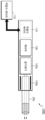
에어로졸 생성 장치(100)는 바디(101)를 포함할 수 있다. 바디(101)는 에어로졸 생성 장치(100)의 전체적인 외관을 형성하고, 내부에 공간을 포함할 수 있다. 후술하는 에어로졸 생성 장치(100)의 내부 구성들은 바디(101)의 내부에 배치될 수 있다. 착탈식 배터리(도 3의 110)는 에어로졸 생성 장치(100)에 분리 가능하게 장착될 수 있다. 착탈식 배터리(110)가 에어로졸 생성 장치(100)에 삽입되는 경우, 착탈식 배터리(110)는 에어로졸 생성 장치(100)의 내부 구성으로 정의될 수 있다.The aerosol generating device (100) may include a body (101). The body (101) forms the overall appearance of the aerosol generating device (100) and may include a space therein. The internal components of the aerosol generating device (100) described below may be arranged inside the body (101). A removable battery (110 of FIG. 3) may be detachably mounted to the aerosol generating device (100). When the removable battery (110) is inserted into the aerosol generating device (100), the removable battery (110) may be defined as an internal component of the aerosol generating device (100).
물품 수용부(10h)는 에어로졸 생성 물품(20)이 분리 가능하게 결합(삽입)될 수 있는 공간을 제공할 수 있다. 에어로졸 생성 물품(20)은, 가열부(도 3의 120)에 의하여 가열되어 에어로졸을 생성하는 에어로졸 생성 물질을 포함할 수 있다. 물품 수용부(10h)는 에어로졸 생성 물품(20)이 삽입되도록 바디(101)의 외측을 향하여 개방된 공간을 제공할 수 있다.The article receiving portion (10h) can provide a space into which an aerosol generating article (20) can be detachably coupled (inserted). The aerosol generating article (20) can include an aerosol generating material that is heated by a heating portion (120 of FIG. 3) to generate an aerosol. The article receiving portion (10h) can provide a space open toward the outside of the body (101) so that the aerosol generating article (20) can be inserted.
물품 수용부(10h)는, 에어로졸 생성 물품(20)의 적어도 일부가 삽입 가능하도록, 바디(101)의 내부를 향해 함몰될 수 있다. 물품 수용부(10h)가 함몰된 깊이는, 에어로졸 생성 물품(20)에서 에어로졸 생성 물질 및/또는 매질이 포함된 영역의 길이에 대응될 수 있다. 에어로졸 생성 물품(20)의 일부는 바디(101)의 내부에 삽입되고, 에어로졸 생성 물품(20)의 다른 일부는 바디(101)의 외부를 향하여 돌출될 수 있다. 사용자는 바디(101)의 외부를 향하여 노출된 에어로졸 생성 물품(20)의 일부를 입에 물고 에어로졸을 포함하는 공기를 흡입할 수 있다.The article receiving portion (10h) may be sunken toward the interior of the body (101) such that at least a portion of the aerosol-generating article (20) may be inserted therein. The depth to which the article receiving portion (10h) is sunken may correspond to the length of a region of the aerosol-generating article (20) containing an aerosol-generating material and/or medium. A portion of the aerosol-generating article (20) may be inserted into the interior of the body (101), and another portion of the aerosol-generating article (20) may protrude toward the exterior of the body (101). A user may hold a portion of the aerosol-generating article (20) exposed toward the exterior of the body (101) in his/her mouth and inhale air containing the aerosol.
바디(101)는 에어로졸 생성 장치(100)의 전체적인 외관을 형성하며, 에어로졸 생성 장치(100)의 구성 요소들이 배치될 수 있는 내부 공간을 포함할 수 있다. 도면 상에는 바디(101)가 전체적으로 단면이 사각 기둥 형상으로 형성되는 실시 예에 대해서만 도시되어 있으나, 바디(101)의 형상이 이에 한정되는 것은 아니며, 바디(101)는 전체적으로 원기둥 형상으로 형성되거나, 다각형 기둥 형상으로 형성될 수도 있다.The body (101) forms the overall appearance of the aerosol generating device (100) and may include an internal space in which components of the aerosol generating device (100) may be arranged. In the drawing, only an embodiment in which the body (101) is formed in a cross-section of a square pillar shape is illustrated, but the shape of the body (101) is not limited thereto, and the body (101) may be formed in a cylindrical shape overall or in a polygonal pillar shape.
바디(101)는 물품 수용부(10h)를 개방 또는 폐쇄하는 커버(11)를 더 포함할 수 있다. 커버(11)는 바디(101)에 이동 가능하게 배치되어 물품 수용부(10h)를 에어로졸 생성 장치(100)의 외부에 노출시키거나, 물품 수용부(10h)를 덮어 물품 수용부(10h)가 에어로졸 생성 장치(100)의 외부에 노출되지 않도록 할 수 있다. 예를 들어, 커버(11)는 제1 위치에서 물품 수용부(10h)를 개방하여 물품 수용부(10h)가 외부에 노출되도록 함으로써, 에어로졸 생성 물품(20)이 물품 수용부(10h)에 삽입되도록 할 수 있다. 또한, 커버(11)는 제1 위치에서 제2 위치로 이동하며 물품 수용부(10h)를 폐쇄하여 물품 수용부(10h)가 외부에 노출되지 않도록 함으로써, 물품 수용부(10h)를 외부 충격 또는 외부 이물질의 유입으로부터 보호할 수 있다.The body (101) may further include a cover (11) that opens or closes the article receiving portion (10h). The cover (11) may be movably arranged on the body (101) to expose the article receiving portion (10h) to the outside of the aerosol generating device (100), or may cover the article receiving portion (10h) so that the article receiving portion (10h) is not exposed to the outside of the aerosol generating device (100). For example, the cover (11) may open the article receiving portion (10h) at a first position so that the article receiving portion (10h) is exposed to the outside, thereby allowing an aerosol generating article (20) to be inserted into the article receiving portion (10h). In addition, the cover (11) moves from the first position to the second position and closes the article receiving portion (10h) so that the article receiving portion (10h) is not exposed to the outside, thereby protecting the article receiving portion (10h) from external impact or the inflow of external foreign substances.
바디(101)의 내부에 배치된 가열부(120)는 에어로졸 생성 물품(20)을 가열할 수 있다. 예를 들어, 가열부(120)는 관 형 가열 요소, 판 형 가열 요소, 침 형 가열 요소 또는 봉 형의 가열 요소를 포함할 수 있다. 가열부(120)는, 전기 저항성 히터 및/또는 유도 가열식 히터를 포함할 수 있다. 가열부(120)가 유도 가열식 히터로 구성되는 경우, 가열부(120)는 서셉터 및 유도 코일을 포함할 수 있다. 가열부(120)는 도 2a 내지 도 2e의 히터(120a, 120b, 120c, 120d, 120e)에 대응되는 구성일 수 있다.A heating element (120) disposed inside the body (101) can heat the aerosol generating article (20). For example, the heating element (120) can include a tubular heating element, a plate-shaped heating element, a needle-shaped heating element, or a rod-shaped heating element. The heating element (120) can include an electrical resistance heater and/or an induction heating heater. When the heating element (120) is configured as an induction heating heater, the heating element (120) can include a susceptor and an induction coil. The heating element (120) can have a configuration corresponding to the heaters (120a, 120b, 120c, 120d, 120e) of FIGS. 2A to 2E.
착탈식 배터리(110)는 에어로졸 생성 장치(100)의 구성요소들이 동작하도록 전력을 공급할 수 있다. 착탈식 배터리(110)는 배터리 수용부(도 3의 131h)를 통해 바디(101)의 내부로 수용될 수 있다. 실시예에 따라, 에어로졸 생성 장치(100)는 착탈식 배터리(110)와 구분되며, 바디(101) 내부에 고정된 내부 배터리(도 3의 170)를 더 포함할 수 있다. 내부 배터리(170)는 착탈식 배터리(110)보다 출력이 작으며, 착탈식 배터리(110)가 배터리 수용부(131h)에 수용되지 않은 경우라도, 에어로졸 생성 장치(100)의 내부 구성들에 최소한의 전력을 제공할 수 있다.A removable battery (110) can supply power to operate components of an aerosol generating device (100). The removable battery (110) can be accommodated inside the body (101) through a battery receiving portion (131h of FIG. 3). According to an embodiment, the aerosol generating device (100) may further include an internal battery (170 of FIG. 3) that is separated from the removable battery (110) and fixed inside the body (101). The internal battery (170) has a lower output than the removable battery (110), and can provide a minimum amount of power to internal components of the aerosol generating device (100) even when the removable battery (110) is not accommodated in the battery receiving portion (131h).
제어부(도 3의 130)는 바디(101)에 수용되며, 에어로졸 생성 장치(100)의 전반적인 동작을 제어할 수 있다. 제어부(130)는 인쇄회로기판(PCB)에 실장될 수 있다. 제어부(130)는 입력부(140)를 통해 사용자 입력을 수신하고, 사용자 입력에 기초하여 가열부(120)의 동작을 제어할 수 있다. 또한, 제어부(130)는 출력부(150)를 제어하여 에어로졸 생성 장치(100)의 상태 정보를 출력할 수 있다. 제어부(130)는 도 2a 내지 2a의 제어부(130)에 대응되는 구성일 수 있다.The control unit (130 of FIG. 3) is accommodated in the body (101) and can control the overall operation of the aerosol generating device (100). The control unit (130) can be mounted on a printed circuit board (PCB). The control unit (130) can receive user input through the input unit (140) and control the operation of the heating unit (120) based on the user input. In addition, the control unit (130) can control the output unit (150) to output status information of the aerosol generating device (100). The control unit (130) can have a configuration corresponding to the control unit (130) of FIGS. 2A to 2A.
입력부(140)는 사용자 입력을 수신할 수 있다. 일 실시예에서, 입력부(140)는 가압식 푸쉬 버튼 또는 터치 센서로 구성될 수 있다. 입력부(140)는 바디(101)의 외주면으로부터 적어도 일부 영역에 돌출되어 배치될 수 있고, 사용자의 입력부(140)에 대한 가압 또는 터치에 대응하여 사용자 입력을 수신할 수 있다.The input unit (140) can receive user input. In one embodiment, the input unit (140) can be configured as a pressurized push button or a touch sensor. The input unit (140) can be positioned to protrude from at least a portion of the outer surface of the body (101), and can receive user input in response to the user's pressing or touching the input unit (140).
출력부(150)는 에어로졸 생성 장치(100)의 상태에 대한 정보를 출력할 수 있다. 출력부(150)는 착탈식 배터리(110) 및/또는 내부 배터리(170)의 충/방전 상태, 가열부(120)의 가열 상태, 에어로졸 생성 물품(20)의 삽입 상태 및 에어로졸 생성 장치(100)의 에러 정보를 출력할 수 있다. 이를 위하여, 출력부(150)는 디스플레이, 햅틱 모터, 및 음향 출력부를 포함할 수 있다. 출력부(150)는 바디(101)의 외주면으로부터 적어도 일부 영역에 배치될 수 있다. 도 1에는 출력부(150)가 입력부(140)에 대하여 -z방향에 배치되는 것이 도시되어 있으나, 출력부(150)의 위치는 이에 제한되지 않는다.The output unit (150) can output information about the status of the aerosol generating device (100). The output unit (150) can output the charge/discharge status of the removable battery (110) and/or the internal battery (170), the heating status of the heating unit (120), the insertion status of the aerosol generating article (20), and error information of the aerosol generating device (100). To this end, the output unit (150) can include a display, a haptic motor, and a sound output unit. The output unit (150) can be arranged in at least a portion of an outer surface of the body (101). Although FIG. 1 illustrates that the output unit (150) is arranged in the -z direction with respect to the input unit (140), the position of the output unit (150) is not limited thereto.
도 2a 내지 도 2e는 다양한 타입들로 구현된 도 1의 에어로졸 생성 장치의 실시예들을 도시한 도면이다.FIGS. 2A to 2E are drawings illustrating embodiments of the aerosol generating device of FIG. 1 implemented in various types.
도 2a 내지 도 2e를 참고하면, 에어로졸 생성 장치(100)는 전기 저항 가열 방식 또는 유도 가열 방식을 이용하거나, 증기화기를 추가로 구비하는 방식, 카트리지 방식을 이용하는 등 다양한 타입들의 에어로졸 생성 장치들(100a 내지 100e)로 구현될 수 있다. 도 2a 내지 도 2e에는 에어로졸 생성 장치들(100a 내지 100e)의 타입들을 설명하기 위한 일부 요소들만이 도시되어 있을 뿐, 도 2a 내지 도 2e에 도시된 요소들 외에 다른 범용적인 요소들이 에어로졸 생성 장치들(100a 내지 100e)에 더 포함될 수 있다.Referring to FIGS. 2a to 2e, the aerosol generating device (100) may be implemented as various types of aerosol generating devices (100a to 100e), such as those using an electric resistance heating method or an induction heating method, those additionally equipped with a vaporizer, and those using a cartridge method. Only some elements for explaining the types of aerosol generating devices (100a to 100e) are illustrated in FIGS. 2a to 2e, and other general-purpose elements may be further included in the aerosol generating devices (100a to 100e) in addition to the elements illustrated in FIGS. 2a to 2e.
도 2a에서 에어로졸 생성 장치(100a)는 착탈식 배터리(110), 히터(120a) 및 제어부(130)를 포함할 수 있다.In FIG. 2a, the aerosol generating device (100a) may include a removable battery (110), a heater (120a), and a control unit (130).
에어로졸 생성 장치(100a)의 내부의 수용 공간에는 궐련(20a)이 삽입될 수 있다. 궐련(20a)이 에어로졸 생성 장치(100a)에 삽입되면, 에어로졸 생성 장치(100a)는 히터(120a)를 이용하여 궐련(20a)을 가열함으로써 궐련(20a)으로부터 에어로졸을 생성시킬 수 있다. 생성된 에어로졸은 궐련(20a)을 통과하여 사용자에게 전달될 수 있다.A cigarette (20a) can be inserted into the receiving space inside the aerosol generating device (100a). When the cigarette (20a) is inserted into the aerosol generating device (100a), the aerosol generating device (100a) can generate an aerosol from the cigarette (20a) by heating the cigarette (20a) using the heater (120a). The generated aerosol can pass through the cigarette (20a) and be delivered to the user.
히터(120a)는 착탈식 배터리(110)로부터 공급된 전력에 의하여 가열될 수 있다. 히터(120a)는 전기 저항성 히터일 수 있다. 예를 들어, 히터(120a)는 전기 전도성 트랙(track)을 포함하고, 전기 전도성 트랙에 전류가 흐름에 따라 히터(120a)가 가열될 수 있다.The heater (120a) can be heated by power supplied from the removable battery (110). The heater (120a) can be an electrical resistive heater. For example, the heater (120a) includes an electrically conductive track, and the heater (120a) can be heated as current flows through the electrically conductive track.
히터(120a)의 전기 전도성 트랙은 전기 저항성 재료로 제작되어, 저항의 소비 전력에 따라 가열 온도가 결정될 수 있고, 전기 전도성 트랙의 저항의 소비 전력들에 기초하여 전기 전도성 트랙의 저항 값이 설정될 수 있다. 전기 전도성 트랙의 저항 값은 전기 저항성 재료의 구성 물질, 길이, 너비, 두께 또는 패턴 등에 의하여 다양하게 설정될 수 있다.The electrically conductive track of the heater (120a) is made of an electrically resistive material, so that the heating temperature can be determined according to the power consumption of the resistor, and the resistance value of the electrically conductive track can be set based on the power consumption of the resistor of the electrically conductive track. The resistance value of the electrically conductive track can be set in various ways according to the constituent material, length, width, thickness, or pattern of the electrically resistive material.
전기 전도성 트랙은 저항 온도 계수 특성에 따라, 온도가 상승할수록 내부 저항의 크기가 증가할 수 있다. 예를 들어, 소정의 온도 구간에서 전기 전도성 트랙의 온도와 저항의 크기는 비례할 수 있다. 이와 같은 원리를 이용하여, 전기 전도성 트랙으로 제작된 히터(120a)는 전기 저항 방식으로 궐련(20a)을 가열할 수 있다.The electrically conductive track may have an internal resistance that increases as the temperature increases, depending on the resistance temperature coefficient characteristic. For example, the temperature and the resistance of the electrically conductive track may be proportional in a given temperature range. Using this principle, a heater (120a) made of an electrically conductive track may heat a cigarette (20a) in an electrical resistance manner.
전기 전도성 트랙은 텅스텐, 금, 백금, 은 구리, 니켈 팔라듐, 또는 이들의 조합으로 제작될 수 있다. 또한, 전기 전도성 트랙은 적절한 도핑재에 의해 도핑될 수 있고, 합금을 포함할 수 있다.The electrically conductive tracks can be made of tungsten, gold, platinum, silver copper, nickel palladium, or a combination thereof. Additionally, the electrically conductive tracks can be doped with a suitable doping agent and can include an alloy.
히터(120a)의 형상은, 튜브 형, 판 형, 침 형 또는 봉 형 등 다양하게 제작될 수 있다. 또한, 히터(120a)는 복수 개 배치될 수도 있다. 히터(120a)는 궐련(20a)의 내부로 삽입되어 궐련(20a)의 내부를 가열하는 내부 가열 방식으로 이용될 수 있다.The shape of the heater (120a) can be manufactured in various ways, such as a tube shape, a plate shape, a needle shape, or a rod shape. In addition, a plurality of heaters (120a) can be arranged. The heater (120a) can be inserted into the interior of the cigarette (20a) and used as an internal heating method to heat the interior of the cigarette (20a).
착탈식 배터리(110)는 에어로졸 생성 장치(100a)로부터 분리되거나 장착될 수 있고, 에어로졸 생성 장치(100a)에 착탈식 배터리(110)가 장착된 경우, 히터(120a)의 가열 동작을 위해 착탈식 배터리(110)로부터 히터(120a)로 전력이 공급되어 전기 전도성 트랙의 온도가 제어될 수 있다.The removable battery (110) can be separated from or mounted on the aerosol generating device (100a), and when the removable battery (110) is mounted on the aerosol generating device (100a), power can be supplied from the removable battery (110) to the heater (120a) for heating operation of the heater (120a), thereby controlling the temperature of the electrically conductive track.
제어부(130)는 히터(120a)에 공급되는 전력을 제어함으로써 히터(120a)의 가열 동작을 제어할 수 있다. 예를 들어, 제어부(130)는 온도 프로파일에 따라 히터(120a)에 의해 궐련(20a)이 가열되는 온도를 제어할 수 있다.The control unit (130) can control the heating operation of the heater (120a) by controlling the power supplied to the heater (120a). For example, the control unit (130) can control the temperature at which the cigarette (20a) is heated by the heater (120a) according to the temperature profile.
도 2b 및 도 2c는 예시적인 실시예들에 따른 증기화기(125b, 125c)를 추가로 구비한 에어로졸 생성 장치들(100b, 100c)을 설명하기 위한 도면들이다. 에어로졸 생성 장치들(100b, 100c) 각각은 에어로졸 생성 장치(100)의 일 타입일 수 있다.FIGS. 2b and 2c are drawings for explaining aerosol generating devices (100b, 100c) additionally equipped with a vaporizer (125b, 125c) according to exemplary embodiments. Each of the aerosol generating devices (100b, 100c) may be a type of aerosol generating device (100).
도 2b 및 도 2c를 참조하면, 에어로졸 생성 장치(100b, 100c)는 증기화기(125b, 125c)를 더 포함한다. 에어로졸 생성 장치(100b, 100c)의 내부 공간에는 궐련(20b, 20c)이 삽입될 수 있다.Referring to FIGS. 2b and 2c, the aerosol generating device (100b, 100c) further includes a vaporizer (125b, 125c). A cigarette (20b, 20c) can be inserted into the internal space of the aerosol generating device (100b, 100c).
도 2b에는 증기화기(125b) 및 히터(120b)가 일렬로 배치된 것으로 도시되어 있다. 하지만, 도 2c에는 증기화기(125c) 및 히터(120c)가 병렬로 배치된 것으로 도시되어 있다. 즉, 증기화기(125b)가 배치된 방식 별로 에어로졸 생성 장치들(100b, 100c)이 구별될 수 있다.In Fig. 2b, the vaporizer (125b) and the heater (120b) are depicted as being arranged in a row. However, in Fig. 2c, the vaporizer (125c) and the heater (120c) are depicted as being arranged in parallel. That is, the aerosol generating devices (100b, 100c) can be distinguished depending on the way the vaporizer (125b) is arranged.
히터(120b, 120c)는 착탈식 배터리(110)로부터 공급된 전력에 의하여 가열될 수 있다. 히터(120b, 120c)는 전기 저항성 히터로서, 예를 들어 전기 전도성 트랙을 포함할 수 있다.The heater (120b, 120c) can be heated by power supplied from a removable battery (110). The heater (120b, 120c) is an electrical resistive heater and may include, for example, an electrically conductive track.
도 2a에서 설명된 히터(120a)와 달리, 도 2b 및 도 2c의 히터(120b, 120c)는 궐련(20b, 20c)의 외부 둘레에 배치되어 궐련(20b, 20c)의 외측면을 가열하는 외부 가열 방식으로 구현될 수 있다.Unlike the heater (120a) described in Fig. 2a, the heaters (120b, 120c) of Figs. 2b and 2c can be implemented in an external heating manner by being placed around the outer perimeter of the cigarette (20b, 20c) to heat the outer surface of the cigarette (20b, 20c).
증기화기(125b, 125c)는 액상 조성물을 가열하여 에어로졸을 생성할 수 있으며, 생성된 에어로졸은 궐련(20b, 20c)을 통과하여 사용자에게 전달될 수 있다. 즉, 증기화기(125b, 125c)에 의하여 생성된 에어로졸은 에어로졸 생성 장치(100b, 100c)의 기류 통로를 따라 이송될 수 있고, 기류 통로는 증기화기(125b, 125c)에 의하여 생성된 에어로졸이 궐련(20b, 20c)을 통과하여 사용자에게 전달될 수 있도록 구성될 수 있다.The vaporizer (125b, 125c) can heat the liquid composition to generate an aerosol, and the generated aerosol can be delivered to a user through a cigarette (20b, 20c). That is, the aerosol generated by the vaporizer (125b, 125c) can be transported along the airflow passage of the aerosol generating device (100b, 100c), and the airflow passage can be configured so that the aerosol generated by the vaporizer (125b, 125c) can be delivered to a user through a cigarette (20b, 20c).
증기화기(125b, 125c)는 액체 저장부, 액체 전달 수단 및 가열 요소(또는 증기화 요소)를 포함할 수 있다. 다만, 액체 저장부, 액체 전달 수단 및 가열 요소 각각은 독립적인 모듈로서 증기화기(125b, 125c) 내부가 아닌, 에어로졸 생성 장치(100) 내 다른 위치에 배치될 수도 있다.The vaporizer (125b, 125c) may include a liquid storage, a liquid delivery means, and a heating element (or vaporization element). However, each of the liquid storage, the liquid delivery means, and the heating element may be positioned as an independent module at a different location within the aerosol generating device (100) rather than within the vaporizer (125b, 125c).
액체 저장부는 액상 조성물을 저장할 수 있다. 예를 들어, 액상 조성물은 휘발성 담배 향 성분을 포함하는 담배 함유 물질을 포함하는 액체일 수 있고, 비 담배 물질을 포함하는 액체일 수도 있다. 액체 저장부는 증기화기(125b, 125c)로부터 탈/부착될 수 있도록 제작될 수도 있고, 증기화기(125b, 125c)와 일체로서 제작될 수도 있다. 예를 들어, 액상 조성물은 물, 솔벤트, 에탄올, 식물 추출물, 향료, 향미제, 또는 비타민 혼합물을 포함할 수 있다. 또한, 액상 조성물은 글리세린 및 프로필렌 글리콜과 같은 에어로졸 형성제를 포함할 수 있다.The liquid reservoir can store a liquid composition. For example, the liquid composition can be a liquid containing a tobacco-containing material including a volatile tobacco flavoring component, or can be a liquid containing a non-tobacco material. The liquid reservoir can be constructed to be detachable from/attachable to the vaporizer (125b, 125c), or can be constructed integrally with the vaporizer (125b, 125c). For example, the liquid composition can contain water, a solvent, ethanol, a plant extract, a flavoring agent, a flavoring agent, or a vitamin mixture. In addition, the liquid composition can contain an aerosol forming agent such as glycerin and propylene glycol.
액체 전달 수단은 액체 저장부의 액상 조성물을 가열 요소로 전달할 수 있다. 예를 들어, 액체 전달 수단은 면 섬유, 세라믹 섬유, 유리 섬유, 다공성 세라믹과 같은 심지(wick)가 될 수 있으나, 이에 한정되지 않는다.The liquid transfer means can transfer the liquid composition from the liquid storage to the heating element. For example, the liquid transfer means can be a wick such as, but not limited to, cotton fibers, ceramic fibers, glass fibers, or porous ceramics.
증기화기(125b, 125c) 내에 구비된 가열 요소는 액체 전달 수단에 의해 전달되는 액상 조성물을 가열(증기화)하기 위한 요소이다. 예를 들어, 가열 요소는 금속 열선, 금속 열판, 세라믹 히터 등이 될 수 있으나, 이에 한정되지 않는다. 또한, 가열 요소는 니크롬선과 같은 전도성 필라멘트로 구성될 수 있고, 액체 전달 수단에 감기는 구조로 배치될 수 있다. 가열 요소는, 전류 공급에 의해 가열될 수 있으며, 가열 요소와 접촉된 액체 조성물에 열을 전달하여, 액체 조성물을 가열할 수 있다. 그 결과, 에어로졸이 생성될 수 있다. 이에 따라, 증기화기(125b, 125c)는 카토마이저(cartomizer) 또는 무화기(atomizer)와 같은 다른 용어들로도 지칭될 수 있다.The heating element provided in the vaporizer (125b, 125c) is an element for heating (vaporizing) a liquid composition delivered by a liquid delivery means. For example, the heating element may be, but is not limited to, a metal heating wire, a metal heating plate, a ceramic heater, etc. In addition, the heating element may be composed of a conductive filament such as a nichrome wire, and may be arranged in a structure that is wound around the liquid delivery means. The heating element may be heated by supplying current, and may transfer heat to a liquid composition in contact with the heating element, thereby heating the liquid composition. As a result, an aerosol may be generated. Accordingly, the vaporizer (125b, 125c) may also be referred to as other terms such as a cartomizer or an atomizer.
착탈식 배터리(110)는 에어로졸 생성 장치(100b, 100c)로부터 분리되거나 장착될 수 있고, 에어로졸 생성 장치(100b, 100c)에 착탈식 배터리(110)가 장착된 경우, 히터(120b, 120c) 및 증기화기(125b, 125c)의 가열 동작을 위해 착탈식 배터리(110)로부터 히터(120b, 120c) 및 증기화기(125b, 125c)에 전력이 공급될 수 있다.The removable battery (110) can be separated from or mounted on the aerosol generating device (100b, 100c), and when the removable battery (110) is mounted on the aerosol generating device (100b, 100c), power can be supplied from the removable battery (110) to the heater (120b, 120c) and the vaporizer (125b, 125c) for heating operation of the heater (120b, 120c) and the vaporizer (125b, 125c).
제어부(130)는 히터(120b, 120c) 및 증기화기(125b, 125c)에 공급되는 전력을 제어함으로써 히터(120b, 120c) 및 증기화기(125b, 125c)의 가열 동작을 제어할 수 있다. 예를 들어, 제어부(130)는 온도 프로파일에 따라 히터(120b, 120c) 및 증기화기(125b, 125c)에 의해 궐련(20b, 20c)이 가열되는 온도를 제어할 수 있다.The control unit (130) can control the heating operation of the heaters (120b, 120c) and the vaporizer (125b, 125c) by controlling the power supplied to the heaters (120b, 120c) and the vaporizer (125b, 125c). For example, the control unit (130) can control the temperature at which the cigarettes (20b, 20c) are heated by the heaters (120b, 120c) and the vaporizer (125b, 125c) according to the temperature profile.
도 2d는 예시적인 실시예에 따른 유도 가열(induction heating) 방식의 에어로졸 생성 장치(100d)를 설명하기 위한 도면이다. 에어로졸 생성 장치(100d)는 에어로졸 생성 장치(100)의 일 타입일 수 있다.FIG. 2d is a drawing for explaining an aerosol generating device (100d) of an induction heating method according to an exemplary embodiment. The aerosol generating device (100d) may be one type of the aerosol generating device (100).
도 2d를 참조하면, 에어로졸 생성 장치(100d)는 코일(121d) 및 서셉터(susceptor)(122d)를 포함하는 히터(120d), 착탈식 배터리(110) 및 제어부(130)를 포함할 수 있다.Referring to FIG. 2d, the aerosol generating device (100d) may include a heater (120d) including a coil (121d) and a susceptor (122d), a removable battery (110), and a control unit (130).
에어로졸 생성 장치(100d)는 유도 가열 방식으로 에어로졸 생성 장치(100d)에 수용되는 궐련(20d)을 가열함으로써 에어로졸을 생성할 수 있다. 유도 가열 방식은 외부 자기장에 의해 발열하는 자성체에 주기적으로 방향이 변하는 교번 자기장(alternating magnetic field)을 인가하여 자성체를 발열시키는 방식을 의미할 수 있다. 따라서, 에어로졸 생성 장치(100d)는 자성체에 교번 자기장을 인가함으로써 자성체로부터 열에너지를 방출시킬 수 있고, 자성체로부터 방출되는 열에너지를 궐련에 전달함으로써 궐련(20d)을 가열할 수 있다. 여기서, 외부 자기장에 의해 발열하는 자성체는 서셉터(122d)일 수 있다. 서셉터(122d)는 에어로졸 생성 장치(100d)에 구비될 수 있다. 또는, 서셉터(122d)는 에어로졸 생성 장치(100d)에 구비되지 않는 대신 조각, 박편, 스트립 등의 형상으로 궐련(20d) 내부에 구비될 수도 있다. The aerosol generating device (100d) can generate an aerosol by heating a cigarette (20d) accommodated in the aerosol generating device (100d) by an induction heating method. The induction heating method may refer to a method of applying an alternating magnetic field, the direction of which changes periodically, to a magnetic body that generates heat by an external magnetic field to heat the magnetic body. Accordingly, the aerosol generating device (100d) can release heat energy from the magnetic body by applying an alternating magnetic field to the magnetic body, and can heat the cigarette (20d) by transferring the heat energy released from the magnetic body to the cigarette. Here, the magnetic body that generates heat by the external magnetic field may be a susceptor (122d). The susceptor (122d) may be provided in the aerosol generating device (100d). Alternatively, the susceptor (122d) may be provided inside the cigarette (20d) in the shape of a piece, flake, strip, etc. instead of being provided in the aerosol generating device (100d).
서셉터(122d)는 강자성체(ferromagnetic substance)로 형성될 수 있다. 예를 들면, 서셉터(122d)의 물질은 금속 또는 탄소를 포함할 수 있다. 서셉터(122d)의 물질은 페라이트(ferrite), 강자성 합금(ferromagnetic alloy), 스테인리스강(stainless steel) 및 알루미늄(Al) 중 적어도 하나를 포함할 수 있다. 또한, 서셉터(122d)의 물질은 흑연(graphite), 지르코니아(zirconia) 등과 같은 세라믹, 니켈(Ni)이나 코발트(Co) 등과 같은 전이 금속, 붕소(B)나 인(P)과 같은 준금속 중 적어도 하나를 포함할 수도 있다.The susceptor (122d) may be formed of a ferromagnetic substance. For example, the material of the susceptor (122d) may include a metal or carbon. The material of the susceptor (122d) may include at least one of ferrite, a ferromagnetic alloy, stainless steel, and aluminum (Al). In addition, the material of the susceptor (122d) may include at least one of a ceramic such as graphite or zirconia, a transition metal such as nickel (Ni) or cobalt (Co), and a metalloid such as boron (B) or phosphorus (P).
에어로졸 생성 장치(100d)는 궐련(20d)을 수용할 수 있다. 에어로졸 생성 장치(100d)에는 궐련(20d)을 수용하기 위한 공간이 형성될 수 있다. 궐련(20d)을 수용하는 공간의 둘레에는 서셉터(122d)가 배치될 수 있다. 예를 들어, 서셉터(122d)는 궐련(20d)의 외부를 둘러싸는 원통 형상을 가질 수 있다. 따라서, 궐련(20d)이 에어로졸 생성 장치(100d)에 수용되는 경우 궐련(20d)은 서셉터(122d)의 수용 공간에 수용될 수 있고, 궐련(20d)의 외측면의 적어도 일부를 둘러싸는 위치에 서셉터(122d)가 배치될 수 있다. 다만, 서셉터(122d)의 형상은 이에 제한되지 않고, 다양할 수 있다. 예들 들어, 서셉터(122d)는 궐련(20d)의 내부에 삽입되는 봉 형상으로 제작될 수도 있다.The aerosol generating device (100d) can accommodate a cigarette (20d). A space for accommodating the cigarette (20d) can be formed in the aerosol generating device (100d). A susceptor (122d) can be arranged around the periphery of the space accommodating the cigarette (20d). For example, the susceptor (122d) can have a cylindrical shape surrounding the outside of the cigarette (20d). Therefore, when the cigarette (20d) is accommodated in the aerosol generating device (100d), the cigarette (20d) can be accommodated in the accommodation space of the susceptor (122d), and the susceptor (122d) can be arranged at a position surrounding at least a portion of the outer surface of the cigarette (20d). However, the shape of the susceptor (122d) is not limited thereto and can vary. For example, the susceptor (122d) may be manufactured in a rod shape to be inserted into the inside of the cigarette (20d).
히터(120d)는 유도 가열 방식으로서, 히터(120d)는 코일(121d)에 의해 발생된 외부 자기장에 의해 발열하는 서셉터(122d)를 이용하여 에어로졸 생성 장치(100d)에 수용된 궐련(20d)을 가열할 수 있다.The heater (120d) is an induction heating method, and the heater (120d) can heat a cigarette (20d) accommodated in an aerosol generating device (100d) by using a susceptor (122d) that generates heat by an external magnetic field generated by a coil (121d).
코일(121d)은 서셉터(122d)의 외측면을 따라 권선되도록 배치되어, 서셉터(122d)에 교번 자기장을 인가할 수 있다. 에어로졸 생성 장치(100d)로부터 코일(121d)에 전력이 공급되는 경우 코일(121d) 내부 영역에 자기장이 형성될 수 있다. 코일(121d)에 교류 전류가 인가되는 경우 코일(121d) 내부에 형성되는 자기장의 방향은 지속적으로 변경될 수 있다. 서셉터(122d)가 코일(121d) 내부에 위치하여 주기적으로 방향이 변하는 교번 자기장에 노출되는 경우, 서셉터(122d)가 발열할 수 있고, 서셉터(122d)에 수용되는 궐련이 가열될 수 있다. 코일(121d)의 형상은 궐련(20d)의 길이 방향을 따라 감긴 원통형의 형상일 수 있으나, 이에 제한되지 않고 코일(121d)은 평면형 코일 등의 다양한 타입으로 구현될 수도 있다.The coil (121d) is arranged to be wound along the outer surface of the susceptor (122d), so that an alternating magnetic field can be applied to the susceptor (122d). When power is supplied to the coil (121d) from the aerosol generating device (100d), a magnetic field can be formed in an internal region of the coil (121d). When an alternating current is applied to the coil (121d), the direction of the magnetic field formed inside the coil (121d) can be continuously changed. When the susceptor (122d) is positioned inside the coil (121d) and exposed to an alternating magnetic field whose direction changes periodically, the susceptor (122d) can generate heat, and a cigarette accommodated in the susceptor (122d) can be heated. The shape of the coil (121d) may be a cylindrical shape wound along the length direction of the cigarette (20d), but is not limited thereto, and the coil (121d) may be implemented in various types such as a flat coil.
착탈식 배터리(110)는 에어로졸 생성 장치(100d)로부터 분리되거나 장착될 수 있고, 에어로졸 생성 장치(100d)에 착탈식 배터리(110)가 장착된 경우, 예를 들어 히터(120d)의 가열 동작을 위해 코일(121d)에 전력을 공급할 수 있다.The removable battery (110) can be separated from or mounted on the aerosol generating device (100d), and when the aerosol generating device (100d) is equipped with the removable battery (110), it can supply power to the coil (121d) for heating operation of the heater (120d), for example.
제어부(130)는 코일(121d)에 공급되는 전력을 제어함으로써 히터(120d)의 가열 동작을 제어할 수 있다. 예를 들어, 제어부(130)는 온도 프로파일에 따라 코일(121d)에 의해 유도된 자기장 세기를 조절함으로써 서셉터(122d)의 유도 가열에 의해 궐련(20d)이 가열되는 온도를 제어할 수 있다.The control unit (130) can control the heating operation of the heater (120d) by controlling the power supplied to the coil (121d). For example, the control unit (130) can control the temperature at which the cigarette (20d) is heated by induction heating of the susceptor (122d) by adjusting the strength of the magnetic field induced by the coil (121d) according to the temperature profile.
도 2e는 예시적인 실시예에 따른 액상 조성물(20e)을 보유한 교체 가능 카트리지(210e)를 구비한 에어로졸 생성 장치(100e)를 설명하기 위한 도면이다.FIG. 2e is a drawing illustrating an aerosol generating device (100e) having a replaceable cartridge (210e) containing a liquid composition (20e) according to an exemplary embodiment.
도 2e의 에어로졸 생성 장치(100e)는 액상 조성물(20e)을 보유한 카트리지(210e)와, 카트리지(210e)를 지지하는 본체(220e)를 포함한다. 에어로졸 생성 장치(100e)는 에어로졸 생성 장치(100)의 일 타입에 해당할 수 있다. 이때, 에어로졸 생성 장치(100)에 포함된 하드웨어 구성들은 본체(220e) 및 카트리지(210e)에 나뉘어 위치할 수 있다.The aerosol generating device (100e) of FIG. 2e includes a cartridge (210e) containing a liquid composition (20e) and a main body (220e) supporting the cartridge (210e). The aerosol generating device (100e) may correspond to one type of the aerosol generating device (100). At this time, the hardware components included in the aerosol generating device (100) may be divided and positioned in the main body (220e) and the cartridge (210e).
카트리지(210e)는 내부에 액상 조성물(20e)을 수용한 상태에서 본체(220e)에 결합될 수 있다. 카트리지(210e)의 일부분이 본체(220e)의 리셉터클(receptacle)에 삽입됨으로써 카트리지(210e)가 본체(220e)에 장착될 수 있다.The cartridge (210e) can be coupled to the main body (220e) while containing a liquid composition (20e) therein. The cartridge (210e) can be mounted on the main body (220e) by inserting a portion of the cartridge (210e) into a receptacle of the main body (220e).
카트리지(210e)는 액상 조성물의 액상 조성물(20e)을 보유할 수 있으나, 이에 제한되지 않고 고체 상태, 기체 상태, 또는 겔(gel) 상태 등의 어느 하나의 상태를 갖는 액상 조성물(20e)을 보유할 수도 있다. 예를 들어, 액상 조성물은 휘발성 담배 향 성분을 포함하는 담배 함유 물질을 포함하는 액체일 수 있고, 비 담배 물질을 포함하는 액체일 수도 있다. The cartridge (210e) may hold a liquid composition (20e) of a liquid composition, but is not limited thereto, and may also hold a liquid composition (20e) having any one of a solid state, a gaseous state, or a gel state. For example, the liquid composition may be a liquid containing a tobacco-containing material including a volatile tobacco flavoring component, or may be a liquid containing a non-tobacco material.
카트리지(210e) 내에 구비된 히터(120e)는 본체(220e)로부터 전달되는 전기 신호 또는 무선 신호 등에 의해 가열 동작을 수행한다. 이에 따라, 카트리지(210e)의 내부의 액상 조성물(20e)이 히터(120e)의 가열로 인해 기화됨으로써 에어로졸이 생성될 수 있다.The heater (120e) provided in the cartridge (210e) performs a heating operation by an electric signal or a wireless signal transmitted from the main body (220e). Accordingly, the liquid composition (20e) inside the cartridge (210e) may be vaporized due to heating by the heater (120e), thereby generating an aerosol.
히터(120e)는 전기 저항에 의해 열을 발생시킴으로써 액체 전달 수단에 전달되는 에어로졸 생성 물질을 가열하기 위하여 구리, 니켈, 텅스텐 등의 금속 소재의 전도성 필라멘트나 세라믹 발열체 등으로 구현될 수 있고, 액체 전달 수단에 감기거나 액체 전달 수단에 인접하게 배치될 수 있다. The heater (120e) may be implemented with a conductive filament made of a metal material such as copper, nickel, or tungsten, or a ceramic heating element, to heat an aerosol generating substance delivered to a liquid delivery means by generating heat through electrical resistance, and may be wound around the liquid delivery means or placed adjacent to the liquid delivery means.
착탈식 배터리(110)는 에어로졸 생성 장치(100e)로부터 분리되거나 장착될 수 있고, 에어로졸 생성 장치(100e)에 착탈식 배터리(110)가 장착된 경우, 히터(120e)의 가열 동작을 위해 착탈식 배터리(110)로부터 히터(120e)에 전력이 공급될 수 있다.The removable battery (110) can be separated from or mounted on the aerosol generating device (100e), and when the aerosol generating device (100e) is equipped with the removable battery (110), power can be supplied to the heater (120e) from the removable battery (110) for heating operation of the heater (120e).
제어부(130)는 히터(120e)에 공급되는 전력을 제어함으로써 히터(120e)의 가열 동작을 제어할 수 있다. 예를 들어, 제어부(130)는 온도 프로파일에 따라 히터(120e)에 의해 액상 조성물(20e)이 가열되는 온도를 제어할 수 있다.The control unit (130) can control the heating operation of the heater (120e) by controlling the power supplied to the heater (120e). For example, the control unit (130) can control the temperature at which the liquid composition (20e) is heated by the heater (120e) according to the temperature profile.
한편, 도 2a 내지 도 2e에는 도시되지 않았으나, 에어로졸 생성 장치(100a 내지 100e)는 별도의 크래들과 함께 시스템을 구성할 수도 있다. 예를 들어, 크래들은 에어로졸 생성 장치(100a 내지 100e)를 보관하거나, 에어로졸 생성 장치(100a 내지 100e)의 착탈식 배터리(110)의 충전을 수행할 수 있다.Meanwhile, although not shown in FIGS. 2a to 2e, the aerosol generating devices (100a to 100e) may also form a system together with a separate cradle. For example, the cradle may store the aerosol generating devices (100a to 100e) or charge the removable battery (110) of the aerosol generating devices (100a to 100e).
다양한 실시예들에 따르면, 도 1의 에어로졸 생성 장치(100)는 도 2a 내지 도 2e의 에어로졸 생성 장치들(100a 내지 100e)의 타입들 중 적어도 하나로 구현된 것일 수 있으나, 반드시 이에 제한되지 않고 다른 타입으로도 구현될 수 있다.According to various embodiments, the aerosol generating device (100) of FIG. 1 may be implemented as at least one of the types of aerosol generating devices (100a to 100e) of FIGS. 2a to 2e, but is not necessarily limited thereto and may be implemented as other types as well.
도 2a 내지 도 2e의 에어로졸 생성 장치(100a 내지 100e)는 공통적으로 전원 소스로서 착탈식 배터리(110)를 이용할 수 있다. 착탈식 배터리(110)는 에어로졸 생성 장치(100a 내지 100e)로부터 장착되거나 분리됨으로써, 교체될 수 있는 배터리이다.The aerosol generating devices (100a to 100e) of FIGS. 2a to 2e can commonly use a removable battery (110) as a power source. The removable battery (110) is a battery that can be replaced by being mounted or detached from the aerosol generating devices (100a to 100e).
다만, 착탈식 배터리(110)가 용이하게 분리 및 장착이 가능한 경우, 사용자에 의해 정품 인증되지 않은 착탈식 배터리(110)가 에어로졸 생성 장치에 장착될 수도 있다. 에어로졸 생성 장치(100)의 성능은 인증된 정품의 착탈식 배터리(110)에 의해 최적화 되도록 설계되어 있으므로, 이러한 미인증의 착탈식 배터리(110)가 에어로졸 생성 장치(100)에 장착되는 경우, 기기 수명이 단축되고, 기기 고정을 유발할 수 있다. 따라서, 착탈식 배터리(110)의 정품 인증 여부에 따라 가열 전력 및 충전 전력을 제어할 필요성이 있다. 본 개시는 착탈식 배터리(110)의 정품 인증 여부를 판단하고, 정품 인증의 판단에 따라 가열 전력 및 충전 전력을 제어할 수 있는 에어로졸 생성 장치(100)를 제공한다.However, if the removable battery (110) is easily detachable and mountable, a removable battery (110) that has not been authenticated by the user may be mounted in the aerosol generating device. Since the performance of the aerosol generating device (100) is designed to be optimized by a genuine, authenticated removable battery (110), if such an unauthenticated removable battery (110) is mounted in the aerosol generating device (100), the life of the device may be shortened and device fixation may be caused. Therefore, there is a need to control heating power and charging power depending on whether the removable battery (110) is authenticated. The present disclosure provides an aerosol generating device (100) that can determine whether the removable battery (110) is authenticated and control heating power and charging power depending on the determination of authenticity.
도 3은 일 실시예에 따른 에어로졸 생성 장치의 내부 블록도이다.Figure 3 is an internal block diagram of an aerosol generating device according to one embodiment.
도 3을 참조하면, 에어로졸 생성 장치(100)는 착탈식(removable) 배터리(110), 가열부(120), 제어부(130), 입력부(140), 출력부(150), 메모리(160), 내부 배터리(170), 통신부(180), 센서부(190), 정품 인증부(200), 배터리 수용부(131h) 및 충전기 인터페이스부(131i)를 포함할 수 있다. 다만, 에어로졸 생성 장치(100) 내부의 하드웨어 구성요소들은 도 3에 도시된 것에 한정되지 않는다. 에어로졸 생성 장치(100)의 설계에 따라, 도 3에 도시된 하드웨어 구성 중 일부가 생략되거나 새로운 구성이 더 추가될 수 있음을 본 실시예와 관련된 기술분야에서 통상의 지식을 가진 자라면 이해할 수 있다.Referring to FIG. 3, the aerosol generating device (100) may include a removable battery (110), a heating unit (120), a control unit (130), an input unit (140), an output unit (150), a memory (160), an internal battery (170), a communication unit (180), a sensor unit (190), a genuine authentication unit (200), a battery receiving unit (131h), and a charger interface unit (131i). However, the hardware components inside the aerosol generating device (100) are not limited to those illustrated in FIG. 3. Those skilled in the art related to the present embodiment will understand that some of the hardware configurations illustrated in FIG. 3 may be omitted or new configurations may be added depending on the design of the aerosol generating device (100).
착탈식 배터리(110)는 에어로졸 생성 장치(100)가 동작하는데 이용되는 전력을 공급한다. 예를 들어, 착탈식 배터리(110)는 가열부(120)가 가열될 수 있도록 전력을 공급할 수 있다. 또한, 착탈식 배터리(110)는 에어로졸 생성 장치(100) 내에 구비된 다른 하드웨어 구성들, 즉 가열부(120), 제어부(130), 입력부(140), 출력부(150), 메모리(160), 통신부(180) 및 센서부(190)의 동작에 필요한 전력을 공급할 수 있다.The removable battery (110) supplies power used to operate the aerosol generating device (100). For example, the removable battery (110) may supply power so that the heating unit (120) may be heated. In addition, the removable battery (110) may supply power required for the operation of other hardware components provided in the aerosol generating device (100), namely, the heating unit (120), the control unit (130), the input unit (140), the output unit (150), the memory (160), the communication unit (180), and the sensor unit (190).
착탈식 배터리(110)는 예를 들어, 리튬폴리머(LiPoly) 배터리, 리튬이온 배터리일 수 있으나, 이에 제한되지 않는다.The removable battery (110) may be, for example, a lithium polymer (LiPoly) battery or a lithium ion battery, but is not limited thereto.
착탈식 배터리(110)는 교체 가능한(replaceable) 타입(분리형)의 전원으로서, 에어로졸 생성 장치(100) 내에 마련된 배터리 수용부(131h)에 장착되거나 배터리 수용부(131h)로부터 분리될(remove) 수 있다. 착탈식 배터리(110)에는 배터리 단자가 구비되어 있고, 착탈식 배터리(110)가 에어로졸 생성 장치(100)에 장착된 경우 착탈식 배터리(110)의 배터리 단자는 에어로졸 생성 장치(100)에 구비된 단자부(220)에 전기적으로 연결되어 에어로졸 생성 장치(100)에 전력을 공급하도록 구현될 수 있다.The removable battery (110) is a replaceable type (separate) power source, and can be mounted in a battery receiving portion (131h) provided in the aerosol generating device (100) or removed from the battery receiving portion (131h). The removable battery (110) is provided with a battery terminal, and when the removable battery (110) is mounted in the aerosol generating device (100), the battery terminal of the removable battery (110) can be implemented to be electrically connected to a terminal portion (220) provided in the aerosol generating device (100) so as to supply power to the aerosol generating device (100).
착탈식 배터리(110)의 배터리 단자는 2핀 또는 4핀으로 구성될 수 있다. 배터리 단자가 2핀으로 구성되는 경우, 착탈식 배터리(110)는 2핀을 통해 전력 및 배터리 정보를 에어로졸 생성 장치(100)로 전송할 수 있다. 이 경우, 배터리 정보는 전력선 통신(Power Line Communication: PLC) 방법으로 에어로졸 생성 장치(100)에 전송될 수 있다. 배터리 단자가 4핀으로 구성되는 경우, 착탈식 배터리(110)의 전력은 배터리 단자의 2핀을 통해 에어로졸 생성 장치(100)에 제공되고, 나머지 2핀을 통해 배터리 정보가 에어로졸 생성 장치(100)에 전송될 수 있다.The battery terminal of the removable battery (110) may be configured with 2 pins or 4 pins. When the battery terminal is configured with 2 pins, the removable battery (110) can transmit power and battery information to the aerosol generating device (100) through the 2 pins. In this case, the battery information can be transmitted to the aerosol generating device (100) by a power line communication (PLC) method. When the battery terminal is configured with 4 pins, the power of the removable battery (110) is provided to the aerosol generating device (100) through 2 pins of the battery terminal, and the battery information can be transmitted to the aerosol generating device (100) through the remaining 2 pins.
에어로졸 생성 장치(100)는 외부 전력과 연결될 수 있는 충전기 인터페이스부(131i)를 구비하고, 외부 전력은 충전기 인터페이스부(131i)를 통해 에어로졸 생성 장치(100) 내로 인가될 수 있다. 제어부(130)는 충전기 인터페이스부(131i)를 통해 공급받은 외부 전력을 이용하여 착탈식 배터리(110)의 충전 전력을 제어할 수 있다.The aerosol generating device (100) has a charger interface unit (131i) that can be connected to external power, and the external power can be applied into the aerosol generating device (100) through the charger interface unit (131i). The control unit (130) can control the charging power of the removable battery (110) using the external power supplied through the charger interface unit (131i).
착탈식 배터리(110)는 NFC 태그를 구비할 수 있다. 착탈식 배터리(110)에 구비된 NFC 태그는 NFC 모듈(210)과의 근거리 통신의 프로토콜을 통해 리드(read)될 수 있다. 착탈식 배터리(110)의 NFC 태그는 착탈식 배터리(110)와 관련된 식별 정보를 포함하며, 배터리 식별 정보를 통해 착탈식 배터리(110)의 정품 인증 여부가 확인될 수 있다.The removable battery (110) may be equipped with an NFC tag. The NFC tag equipped in the removable battery (110) may be read through a protocol of short-range communication with the NFC module (210). The NFC tag of the removable battery (110) includes identification information related to the removable battery (110), and whether the removable battery (110) is genuine may be confirmed through the battery identification information.
착탈식 배터리(110)는 정품 인증 칩을 포함할 수 있다. 착탈식 배터리(110)가 정품 인증 칩을 포함하는 경우, 착탈식 배터리(110)는 배터리 모듈 형태로 제공될 수 있다. 정품 인증 칩은 배터리 모듈 내의 PCB 기판에 실장될 수 있고, 착탈식 배터리(110)가 단자부(220)와 전기적 접촉하는 경우, 착탈식 배터리(110)의 배터리 정보를 단자부(220)를 통해 제어부(130)로 전송할 수 있다.The removable battery (110) may include a genuine authentication chip. When the removable battery (110) includes a genuine authentication chip, the removable battery (110) may be provided in the form of a battery module. The genuine authentication chip may be mounted on a PCB board within the battery module, and when the removable battery (110) is in electrical contact with the terminal portion (220), battery information of the removable battery (110) may be transmitted to the control portion (130) through the terminal portion (220).
배터리 수용부(131h)는 착탈식 배터리(110)를 수용하며, 착탈식 배터리(110)가 수용되는 경우, 착탈식 배터리(110)가 외부로 노출되는 것을 방지하기 위한 도어를 포함할 수 있다. 도어는 사용자에 의해 수동으로 개폐 되거나, 전기 신호에 의해 자동으로 개폐될 수 있다.The battery receiving portion (131h) receives a removable battery (110), and when the removable battery (110) is received, may include a door to prevent the removable battery (110) from being exposed to the outside. The door may be opened and closed manually by a user, or automatically by an electric signal.
단자부(220)는 배터리 수용부(131h)의 일단에 배치되며, 착탈식 배터리(110)와 전기적 접속하기 위한 도체를 포함할 수 있다. 단자부(220)는 착탈식 배터리(110)로부터 전력 및 배터리 정보를 수신하기 위한 복수의 전극들을 포함할 수 있다. 단자부(220)는 착탈식 배터리(110)의 배터리 단자에 대응하여, 4핀 또는 2핀으로 구성될 수 있다. 단자부(220)가 2핀으로 구성되는 경우, 단자부(220)는 2핀을 통해 전력 및 배터리 정보를 착탈식 배터리(110)로부터 수신할 수 있다. 이 경우, 배터리 정보는 전력선 통신(Power Line Communication: PLC) 방법에 의해 착탈식 배터리(110)로부터 제공될 수 있다. 단자부(220)가 4핀으로 구성되는 경우, 착탈식 배터리(110)의 전력은 단자부(220)의 2핀을 통해 제공되고, 나머지 2핀을 통해 배터리 정보가 제공될 수 있다.The terminal portion (220) is arranged at one end of the battery receiving portion (131h) and may include a conductor for electrical connection with the removable battery (110). The terminal portion (220) may include a plurality of electrodes for receiving power and battery information from the removable battery (110). The terminal portion (220) may be configured with 4 pins or 2 pins corresponding to the battery terminal of the removable battery (110). When the terminal portion (220) is configured with 2 pins, the terminal portion (220) may receive power and battery information from the removable battery (110) through the 2 pins. In this case, the battery information may be provided from the removable battery (110) by a power line communication (PLC) method. When the terminal part (220) is configured with 4 pins, power of the removable battery (110) can be provided through 2 pins of the terminal part (220), and battery information can be provided through the remaining 2 pins.
배터리 정보는 착탈식 배터리(110)의 정품 인증 정보, 충방전 횟수, 사용 시간 및 잔여 용량에 대한 정보를 포함하고, 제어부(130)는 배터리 정보에 기초하여 가열부(120)의 가열을 제어하거나, 착탈식 배터리(110)의 충전을 제어할 수 있다. 착탈식 배터리(110)의 정품 인증 정보가 단자부(220)를 통해 수신된다는 점에서 단자부(220)는 정품 인증부(200)에 포함되는 구성일 수 있다.The battery information includes information on the genuine authentication information, number of charge/discharge cycles, usage time, and remaining capacity of the removable battery (110), and the control unit (130) can control heating of the heating unit (120) or control charging of the removable battery (110) based on the battery information. Since the genuine authentication information of the removable battery (110) is received through the terminal unit (220), the terminal unit (220) may be a component included in the genuine authentication unit (200).
정품 인증부(200)는 착탈식 배터리(110)의 정품 여부를 확인하기 위해 구비될 수 있다. 이를 위하여, 정품 인증부(200)는 NFC 모듈(210) 및 단자부(220)를 포함할 수 있다.A genuine product authentication unit (200) may be provided to verify whether the removable battery (110) is genuine. To this end, the genuine product authentication unit (200) may include an NFC module (210) and a terminal unit (220).
NFC 모듈(210)은 NFC 리더 기능을 수행할 수 있는 통신 하드웨어로서, NFC 기능을 활성화하여 NFC 통신을 수행할 수 있는 안테나를 포함할 수 있다. 즉, NFC 모듈(210)은 다른 디바이스의 NFC 태그를 리드하는 리더(reader)로 동작할 수 있다. 실시예에 따라, NFC 모듈(210)은 다른 디바이스의 NFC 태그에 정보를 입력하는 라이터(writer)로도 동작할 수도 있다.The NFC module (210) is a communication hardware capable of performing an NFC reader function, and may include an antenna capable of performing NFC communication by activating the NFC function. That is, the NFC module (210) may operate as a reader that reads an NFC tag of another device. According to an embodiment, the NFC module (210) may also operate as a writer that inputs information into an NFC tag of another device.
NFC 모듈(210)은 기 설정된 거리 내에 위치한 NFC 태그 인식을 시도할 수 있다. NFC 태그는 착탈식 배터리(110)에 구비되며, NFC 태깅이 성공적으로 수행되는 경우, NFC 모듈(210)은 태깅된 NFC 태그에 저장되어 있는 배터리 정보를 리드(read)하여 획득할 수 있다. 또한, NFC 모듈(210)은 획득된 배터리 정보를 제어부(130)에 전송할 수 있다. 이러한 NFC 모듈(210)의 동작에 필요한 전력은 내부 배터리(170)로부터 제공될 수 있다. 실시예에 따라, NFC 모듈(210)의 동작에 필요한 전력은 내부 배터리(170)로부터 제공될 수 있다. 예를 들어, 착탈식 배터리(110)가 분리된 상태에서, 새로운 착탈식 배터리(110)가 배터리 수용부(131h)에 수용되어야하는 경우, NFC 모듈(210)은 내부 배터리(170)를 이용하여, 새로운 착탈식 배터리(110)의 배터리 정보를 리드(read) 수 있다. 다른 예로, 착탈식 배터리(110)가 결합된 상태에서, 업데이트된 배터리 정보를 착탈식 배터리(110)로 전송하는 경우, NFC 모듈(210)은 이미 장착된 착탈식 배터리(110)의 전력을 이용하여, 배터리 정보를 이미 장착된 착탈식 배터리(110)에 라이트(write) 할 수 있다.The NFC module (210) can attempt to recognize an NFC tag located within a preset distance. The NFC tag is provided in the removable battery (110), and when NFC tagging is successfully performed, the NFC module (210) can read and acquire battery information stored in the tagged NFC tag. In addition, the NFC module (210) can transmit the acquired battery information to the control unit (130). The power required for the operation of the NFC module (210) can be provided from the internal battery (170). According to an embodiment, the power required for the operation of the NFC module (210) can be provided from the internal battery (170). For example, when the removable battery (110) is separated and a new removable battery (110) must be accommodated in the battery receiving portion (131h), the NFC module (210) can read battery information of the new removable battery (110) using the internal battery (170). As another example, when the removable battery (110) is connected and updated battery information is transmitted to the removable battery (110), the NFC module (210) can use the power of the already-mounted removable battery (110) to write the battery information to the already-mounted removable battery (110).
제어부(130)는 정품 인증부(200)가 획득한 배터리 정보에 기초하여 착탈식 배터리(110)의 정품 인증 여부를 판단할 수 있다. 배터리 정보는 암호화된 정품 인증 정보를 포함할 수 있다. 예를 들어, 정품 인증 정보는 배터리 고유의 식별 정보로써, 제조자, 배터리 납품사 및 기타 판매 주체 등에 의해 관리되고 있는 배터리인지 여부를 확인할 수 있는 정보를 의미할 수 있다. 정품 인증 정보는 시리얼 넘버 타입 또는 암호화된 코드 타입으로 저장될 수 있으나 이에 제한되지 않는다. 다시 말해, 정품 인증 정보는 정품 인증된 착탈식 배터리(110)의 고유성에 대해 인증할 수 있는 수단이라면 어느 하나의 타입으로 제한되지 않고 다양한 타입들로 구현될 수 있다.The control unit (130) can determine whether the removable battery (110) is authenticated based on the battery information acquired by the genuine product authentication unit (200). The battery information can include encrypted genuine product authentication information. For example, the genuine product authentication information can mean information that can confirm whether the battery is managed by a manufacturer, a battery supplier, or other sales entity as unique identification information of the battery. The genuine product authentication information can be stored as a serial number type or an encrypted code type, but is not limited thereto. In other words, the genuine product authentication information can be implemented in various types without being limited to a single type as long as it is a means that can authenticate the uniqueness of the genuinely authenticated removable battery (110).
제어부(130)는 정품 인증부(200)가 획득한 정품 인증 정보에 기초하여 착탈식 배터리(110)의 정품 여부를 판단할 수 있다. 예를 들어, 제어부(130)는 착탈식 배터리(110)로부터 수신한 정품 인증 정보를 복호화하고, 복호화된 정품 인증 정보를 메모리(160)에 저장된 정보와 비교함으로써, 착탈식 배터리(110)의 정품 여부를 판단할 수 있다.The control unit (130) can determine whether the removable battery (110) is genuine based on the genuine authentication information acquired by the genuine authentication unit (200). For example, the control unit (130) can determine whether the removable battery (110) is genuine by decrypting the genuine authentication information received from the removable battery (110) and comparing the decrypted genuine authentication information with the information stored in the memory (160).
제어부(130)는 착탈식 배터리(110)의 정품 인증 여부에 기초하여 가열부(120)에 공급되는 가열 전력 및 착탈식 배터리(110)의 충전 전력을 제어할 수 있다.The control unit (130) can control the heating power supplied to the heating unit (120) and the charging power of the removable battery (110) based on whether the removable battery (110) is authenticated.
제어부(130)는 착탈식 배터리(110)가 정품 인증 제품인 경우, 기 설정된 제1 온도 프로파일에 따라 가열부(120)에 공급되는 전력을 제어할 수 있다. 일 실시예에서, 제어부(130)는 착탈식 배터리(110)가 정품 인증된 제1 배터리인 경우, 예열 구간에서 제1 목표 온도에 따라 가열부(120)에 공급되는 전력을 제어하고, 예열 구간 이후 흡연 구간에서 제 1 목표 온도 보다 낮은 제2 목표 온도에 따라 가열부(120)에 공급되는 전력을 제어할 수 있다. 또한, 제어부(130)는 흡연 구간에서의 시간 경과에 따라 제2 목표 온도를 단계적으로 감소시킬 수 있고, 감소된 목표 온도에 따라 가열부(120)에 공급되는 전력을 제어할 수 있다.The control unit (130) can control the power supplied to the heating unit (120) according to the first temperature profile set in advance when the removable battery (110) is a genuine product. In one embodiment, when the removable battery (110) is a genuine first battery, the control unit (130) can control the power supplied to the heating unit (120) according to the first target temperature in the preheating section, and control the power supplied to the heating unit (120) according to the second target temperature lower than the first target temperature in the smoking section after the preheating section. In addition, the control unit (130) can gradually reduce the second target temperature according to the passage of time in the smoking section, and control the power supplied to the heating unit (120) according to the reduced target temperature.
제어부(130)는 착탈식 배터리(110)가 정품 인증되지 않은 배터리인 경우, 제1 온도 프로파일과 상이한 제2 온도 프로파일에 따라 가열부(120)에 공급되는 전력을 제어할 수 있다. 각각의 구간에서의 목표 온도는 제1 온도 프로파일보다 제2 온도 프로파일이 더 작게 설정될 수 있다. 일 실시예에서, 제어부(130)는 착탈식 배터리(110)가 정품 인증되지 않은 제2 배터리인 경우, 예열 구간에서 제1 목표 온도 보다 낮고, 제2 목표 온도 보다 큰 제3 목표 온도에 따라 가열부(120)에 공급되는 전력을 제어할 수 있다. 또한 제어부(130)는 에열 구간 이후 흡연 구간에서 제2 목표 온도 보다 낮은 제4 목표 온도에 따라 가열부(120)에 공급되는 전력을 제어할 수 있다. 제2 온도 프로파일의 경우 각각의 구간에서의 목표 온도를 제1 온도 프로파일보다 작게 설정함에 따라, 미인증의 착탈식 배터리(110)로 인한 기기 수명 단축 및 고장을 방지할 수 있다.The control unit (130) may control the power supplied to the heating unit (120) according to a second temperature profile that is different from the first temperature profile when the removable battery (110) is an uncertified battery. The target temperature in each section may be set to be lower in the second temperature profile than in the first temperature profile. In one embodiment, the control unit (130) may control the power supplied to the heating unit (120) according to a third target temperature that is lower than the first target temperature and higher than the second target temperature in the preheating section when the removable battery (110) is an uncertified second battery. In addition, the control unit (130) may control the power supplied to the heating unit (120) according to a fourth target temperature that is lower than the second target temperature in the smoking section after the preheating section. In the case of the second temperature profile, by setting the target temperature in each section to be lower than the first temperature profile, it is possible to prevent shortening of the device lifespan and failure due to an uncertified removable battery (110).
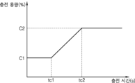
제어부(130)는 정품 인증된 배터리와 정품 인증되지 않은 배터리를 구분하여 배터리의 충전 전력을 제어할 수도 있다. 제어부(130)는 착탈식 배터리(110)가 정품 인증된 배터리인 경우, 제1 충전 프로파일에 따라 배터리의 충전 전력을 제어할 수 있다. 일 실시예에서, 제어부(130)는 착탈식 배터리(110)가 정품 인증된 제1 배터리인 경우, 제1 배터리의 충방전 횟수에 기초하여 제1 배터리의 완충 전압을 조절할 수 있다. 예를 들어, 제어부(130)는 제1 배터리의 충방전 횟수가 제1 기준 횟수 이하인 경우, 제1 완충 전압에 따라 제1 배터리를 충전하고, 제1 배터리의 충방전 횟수가 제1 기준 횟수 초과 및 제1 기준 횟수 보다 큰 제2 기준 횟수 이하인 경우, 제1 완충 전압 보다 작은 제2 완충 전압에 따라 제1 배터리를 충전할 수 있다. 또한, 제어부(130)는 제1 배터리의 충방전 횟수가 제2 기준 횟수를 초과하는 경우, 기 설정된 조건에 따라, 제2 완충 전압을 단계적으로 감소시킬 수 있다.The control unit (130) may also control the charging power of the battery by distinguishing between a genuinely certified battery and a non-certified battery. If the removable battery (110) is a genuinely certified battery, the control unit (130) may control the charging power of the battery according to the first charging profile. In one embodiment, if the removable battery (110) is a genuinely certified first battery, the control unit (130) may adjust the charging voltage of the first battery based on the number of charge and discharge cycles of the first battery. For example, if the number of charge and discharge cycles of the first battery is equal to or less than a first reference number, the control unit (130) may charge the first battery according to the first charging voltage, and if the number of charge and discharge cycles of the first battery is equal to or less than a second reference number that is greater than the first reference number and greater than the first reference number, the control unit (130) may charge the first battery according to the second charging voltage that is less than the first charging voltage. In addition, the control unit (130) can gradually reduce the second charging voltage according to preset conditions when the number of charge/discharge cycles of the first battery exceeds the second reference number.
한편, 배터리의 충방전 횟수는 충전 용량 및 방전 용량에 의해 결정될 수 있다. 일 실시예에서, 제어부(130)는 정품 인증된 제1 배터리의 충전 개시 시점과 충전 완료 시점의 제1 잔여 용량 차이 및 제1 배터리의 방전 개시 시점과 방전 완료 시점의 제2 잔여 용량 차이 중 적어도 어느 하나에 기초하여 제1 배터리의 충방전 횟수를 카운트할 수 있다.Meanwhile, the number of charge/discharge cycles of the battery may be determined by the charge capacity and the discharge capacity. In one embodiment, the control unit (130) may count the number of charge/discharge cycles of the first battery based on at least one of the difference between the first residual capacity between the charging start time and the charging completion time of the authenticated first battery and the difference between the second residual capacity between the discharging start time and the discharging completion time of the first battery.
제어부(130)는 착탈식 배터리(110)가 정품 인증되지 않은 배터리인 경우, 제1 충전 프로파일과 상이한 제2 충전 프로파일에 따라 배터리의 충전 전력을 제어할 수 있다. 일 실시예에서, 제어부(130)는 착탈식 배터리(110)가 정품 인증되지 않은 제2 배터리인 경우, 제2 배터리의 충방전 횟수와 무관하게 제1 배터리의 최저 완충 전압 보다 낮은 전압으로 제2 배터리를 충전할 수 있다.The control unit (130) may control the charging power of the battery according to a second charging profile that is different from the first charging profile when the removable battery (110) is a non-certified battery. In one embodiment, the control unit (130) may charge the second battery at a voltage lower than the lowest charging voltage of the first battery regardless of the number of charge/discharge cycles of the second battery when the removable battery (110) is a non-certified second battery.
가열부(120)는 제어부(130)의 제어에 따라 착탈식 배터리(110)로부터 전력을 공급받는다. 착탈식 배터리(110)의 정품 인증 여부에 따라 가열부(120)에 공급되는 전력은 가변될 수 있다. 가열부(120)는 착탈식 배터리(110)로부터 공급된 전력을 이용하여, 에어로졸 생성 장치(100)에 삽입된 궐련을 가열하거나, 에어로졸 생성 장치(100)에 장착된 카트리지를 가열할 수 있다. 즉, 가열부(120)는 궐련 또는 카트리지에 구비된 에어로졸 생성 물질을 가열함으로써 에어로졸을 생성할 수 있다.The heating unit (120) receives power from the removable battery (110) under the control of the control unit (130). The power supplied to the heating unit (120) may vary depending on whether the removable battery (110) is authenticated. The heating unit (120) may heat a cigarette inserted into the aerosol generating device (100) or a cartridge mounted on the aerosol generating device (100) using the power supplied from the removable battery (110). That is, the heating unit (120) may generate an aerosol by heating an aerosol generating material provided in the cigarette or cartridge.
가열부(120)는 에어로졸 생성 장치(100)의 본체(body)에 위치할 수 있다. 또는, 에어로졸 생성 장치(100)가 본체 및 카트리지로 구성되는 경우, 가열부(120)는 카트리지에 위치할 수 있다. 가열부(120)가 카트리지에 위치하는 경우, 가열부(120)는 본체에 위치한 착탈식 배터리(110)로부터 전력을 공급받을 수 있다.The heating unit (120) may be located in the body of the aerosol generating device (100). Alternatively, if the aerosol generating device (100) is composed of a body and a cartridge, the heating unit (120) may be located in the cartridge. If the heating unit (120) is located in the cartridge, the heating unit (120) may be supplied with power from a removable battery (110) located in the body.
가열부(120)는 전기 저항성 히터 또는 유도 가열 방식의 히터로 구성될 수 있으며, 이에 대한 설명은 도 2a 내지 도 2e를 참조한다.The heating unit (120) may be composed of an electric resistance heater or an induction heating heater, and a description thereof is given in FIGS. 2a to 2e.
입력부(140)는 사용자 입력을 수신할 수 있다. 예를 들어, 입력부(140)는 단일의 가압식 푸쉬 버튼으로 마련될 수 있다. 다른 예로, 입력부(140)는 적어도 하나의 터치 센서를 포함하는 터치 패널일 수 있다.The input unit (140) can receive user input. For example, the input unit (140) can be provided as a single pressure-sensitive push button. As another example, the input unit (140) can be a touch panel including at least one touch sensor.
입력부(140)는 사용자 입력을 입력 신호로 변환하여 제어부(130)에 전달할 수 있다. 제어부(130)는 사용자 입력에 기초하여 가열부(120)에 전력을 공급하거나, 출력부(150)를 제어하여 사용자 알림을 출력할 수 있다. 또한 입력부(140)는 착탈식 배터리(110)의 정품 인증 여부를 확인하기 사용자 입력을 수신할 수 있고, 제어부(130)는 사용자 입력을 수신하는 경우 NFC 모듈(210)을 동작시켜, 착탈식 배터리(110)로부터 배터리 정보를 획득할 수 있다.The input unit (140) can convert user input into an input signal and transmit it to the control unit (130). The control unit (130) can supply power to the heating unit (120) based on the user input or control the output unit (150) to output a user notification. In addition, the input unit (140) can receive a user input to check whether the removable battery (110) is genuine, and when the control unit (130) receives the user input, it can operate the NFC module (210) to obtain battery information from the removable battery (110).
출력부(150)는 에어로졸 생성 장치(100)의 상태에 대한 정보를 출력할 수 있다. 출력부(150)는 착탈식 배터리(110) 및/또는 내부 배터리(170)의 충/방전 상태, 가열부(120)의 가열 상태, 에어로졸 생성 물품(20)의 삽입 상태 및 에어로졸 생성 장치(100)의 에러 정보를 출력할 수 있다. 또한, 출력부(150)는 착탈식 배터리(110)의 정품 인증 여부를 출력할 수도 있다. 이를 위하여, 출력부(150)는 디스플레이, 햅틱 모터, 및 음향 출력부를 포함할 수 있다.The output unit (150) can output information about the status of the aerosol generating device (100). The output unit (150) can output the charge/discharge status of the removable battery (110) and/or the internal battery (170), the heating status of the heating unit (120), the insertion status of the aerosol generating article (20), and error information of the aerosol generating device (100). In addition, the output unit (150) can also output whether the removable battery (110) is genuine. To this end, the output unit (150) can include a display, a haptic motor, and an audio output unit.
센서부(190)는 에어로졸 생성 장치(100)의 상태 또는 에어로졸 생성 장치(100)의 주변 상태를 감지하고, 감지된 정보를 제어부(130)에 전달할 수 있다. 이를 위하여, 센서부(190)는 온도 센서, 퍼프 센서, 및 삽입 감지 센서를 포함할 수 있다. 다만, 센서부(190)에 포함되는 센서들은 상술한 예들에 한정되지 않고, 실시예에 따라 추가의 센서들이 포함될 수 있다. 예를 들어, 센서부(190)는 재사용 감지 센서, 움직임 감지 센서, 습도 센서, 기압 센서, 지자기 센서(magnetic sensor), 커버 탈착 감지 센서, 위치 센서(GPS), 및 근접 센서 등을 추가로 포함할 수 있다. 각 센서들의 기능은 그 명칭으로부터 직관적으로 추론할 수 있으므로, 구체적인 설명은 생략한다.The sensor unit (190) can detect the status of the aerosol generating device (100) or the surrounding status of the aerosol generating device (100) and transmit the detected information to the control unit (130). To this end, the sensor unit (190) can include a temperature sensor, a puff sensor, and an insertion detection sensor. However, the sensors included in the sensor unit (190) are not limited to the examples described above, and additional sensors may be included according to embodiments. For example, the sensor unit (190) can additionally include a reuse detection sensor, a motion detection sensor, a humidity sensor, a barometric pressure sensor, a magnetic sensor, a cover removal detection sensor, a location sensor (GPS), and a proximity sensor. Since the function of each sensor can be intuitively inferred from its name, a detailed description is omitted.
제어부(130)는 감지된 정보에 기초하여, 가열부(120)의 가열 제어, 흡연 제한, 에어로졸 생성 물품(20)의 삽입 여부 판단, 알림 표시 등과 같은 다양한 기능들이 수행되도록 에어로졸 생성 장치(100)를 제어할 수 있다.The control unit (130) can control the aerosol generating device (100) to perform various functions such as heating control of the heating unit (120), smoking restriction, determining whether an aerosol generating article (20) is inserted, and displaying a notification based on the detected information.
통신부(180)는 외부 전자 장치와의 통신을 위한 적어도 하나의 통신 모듈을 포함할 수 있다. 정품 인증부(200)의 NFC 모듈(210)이 근거리 통신 모듈을 포함한다는 점에서 NFC 모듈(210)을 통신부(180)의 구성으로 간주할 수도 있다.The communication unit (180) may include at least one communication module for communication with an external electronic device. Since the NFC module (210) of the genuine authentication unit (200) includes a short-range communication module, the NFC module (210) may be considered as a component of the communication unit (180).
제어부(130)는 통신부(180)를 제어하여, 에어로졸 생성 장치(100)에 대한 정보를 외부 전자 장치에 전송할 수 있다. 또는 제어부(130)는 통신부(180)를 통해 외부 전자 장치로부터 정보를 수신하여, 에어로졸 생성 장치(100)에 포함된 구성들을 제어할 수 있다. 예를 들어, 통신부(180)와 외부 전자 장치 사이의 전송 정보는 사용자 인증 정보, 펌웨어 업데이트 정보, 및 사용자 흡연 패턴 정보 등을 포함할 수 있다.The control unit (130) can control the communication unit (180) to transmit information about the aerosol generating device (100) to an external electronic device. Alternatively, the control unit (130) can receive information from the external electronic device through the communication unit (180) to control components included in the aerosol generating device (100). For example, information transmitted between the communication unit (180) and the external electronic device can include user authentication information, firmware update information, and user smoking pattern information.
메모리(160)는 에어로졸 생성 장치(100) 내에서 처리되는 각종 데이터들을 저장하는 하드웨어로서, 제어부(130)에서 처리된 데이터들 및 처리될 데이터들을 저장할 수 있다. 예를 들어, 메모리(160)는 에어로졸 생성 장치(100)의 동작 시간, 최대 퍼프 횟수, 현재 퍼프 횟수, 적어도 하나의 온도 프로 파일 및 사용자의 흡연 패턴에 대한 데이터 등을 저장할 수 있다. 또한, 메모리(160)는 착탈식 배터리(110)의 정품 인증을 위한 정보를 포함할 수도 있다.The memory (160) is a hardware that stores various data processed within the aerosol generating device (100), and can store data processed and data to be processed by the control unit (130). For example, the memory (160) can store the operation time of the aerosol generating device (100), the maximum number of puffs, the current number of puffs, at least one temperature profile, and data on the user's smoking pattern. In addition, the memory (160) may also include information for authenticating the removable battery (110).
내부 배터리(170)는 착탈식 배터리(110)와 구분되는 구성이며, 에어로졸 생성 장치(100) 내부에 고정될 수 있다. 내부 배터리(170)는 착탈식 배터리(110)와 달리 분리 되지 않으며, 에어로졸 생성 장치(100)의 내부 구성들에 최소한의 전력을 공급할 수 있다. 내부 배터리(170)의 제1 용량은 착탈식 배터리(110)의 제2 용량보다 작을 수 있다. 또한, 내부 배터리(170)에서 출력된 제1 출력 전력은 착탈식 배터리(110)의 제2 출력 전력 보다 작게 설정될 수 있다. The internal battery (170) has a configuration distinct from the removable battery (110) and can be fixed inside the aerosol generating device (100). Unlike the removable battery (110), the internal battery (170) is not separated and can supply a minimum amount of power to the internal components of the aerosol generating device (100). The first capacity of the internal battery (170) can be smaller than the second capacity of the removable battery (110). In addition, the first output power output from the internal battery (170) can be set to be smaller than the second output power of the removable battery (110).
내부 배터리(170)는 착탈식 배터리(110)가 에어로졸 생성 장치(100)에 장착되지 않을 경우에도, 에어로졸 생성 장치(100)의 내부 구성들에 전력을 공급할 수 있다. 예를 들어, 내부 배터리(170)는 제어부(130)의 요청에 의해 대기 전력 보다 큰 전력을 제어부(130)에 공급할 수 있다. 또한, 내부 배터리(170)는 착탈식 배터리(110)의 정품 인증을 위해 NFC 모듈(210)에 전력을 공급할 수 있다. 다만, 착탈식 배터리(110)와 달리, 내부 배터리(170)에서 출력된 전력은 가열부(120)의 가열을 위해서 사용되지 않는다.The internal battery (170) can supply power to the internal components of the aerosol generating device (100) even when the removable battery (110) is not mounted on the aerosol generating device (100). For example, the internal battery (170) can supply power greater than the standby power to the control unit (130) at the request of the control unit (130). In addition, the internal battery (170) can supply power to the NFC module (210) for authenticating the removable battery (110). However, unlike the removable battery (110), the power output from the internal battery (170) is not used for heating the heating unit (120).
실시예에 따라, 내부 배터리(170)는 착탈식 배터리(110)가 에어로졸 생성 장치(100)에 장착된 경우에도 에어로졸 생성 장치(100)의 내부 구성들에 전력을 공급할 수 있다. 예를 들어, 내부 배터리(170)에서 출력된 전력은 착탈식 배터리(110)가 장착된 상태에서, NFC 모듈(210)의 라이트(write) 동작을 위해, NFC 모듈(210)에 제공될 수 있다. NFC 모듈(210)의 라이트(write) 동작에 따라 업데이트된 배터리 정보가 착탈식 배터리(110)에 전송될 수 있다. 다만, 착탈식 배터리(110)의 장착 여부에 무관하게 내부 배터리(170)의 전력은 가열부(120)에 제공되지 않을 수 있다.According to an embodiment, the internal battery (170) may supply power to internal components of the aerosol generating device (100) even when the removable battery (110) is mounted in the aerosol generating device (100). For example, power output from the internal battery (170) may be provided to the NFC module (210) for a write operation of the NFC module (210) when the removable battery (110) is mounted. Updated battery information may be transmitted to the removable battery (110) according to the write operation of the NFC module (210). However, regardless of whether the removable battery (110) is mounted, power from the internal battery (170) may not be provided to the heating unit (120).
내부 배터리(170)는 착탈식 배터리(110)에 의해 충전될 수 있다. 예를 들어, 내부 배터리(170)는 가열부(120)가 가열하지 않는 동안 충전될 수 있다.The internal battery (170) can be charged by the removable battery (110). For example, the internal battery (170) can be charged while the heating element (120) is not heating.
제어부(130)는 에어로졸 생성 장치(100)의 전반적인 동작을 제어하는 하드웨어이다. 제어부(130)는 MCU(Micro Controller Unit)와 같은, 적어도 하나의 프로세싱 유닛을 포함할 수 있다. 제어부(130)는 다수의 논리 게이트들의 어레이로 구현될 수도 있고, 범용적인 마이크로 프로세서와 이 마이크로 프로세서에서 실행될 수 있는 프로그램이 저장된 메모리의 조합으로 구현될 수도 있다. 또한, 다른 형태의 하드웨어로 구현될 수도 있음을 본 실시예가 속하는 기술분야에서 통상의 지식을 가진 자라면 이해할 수 있다.The control unit (130) is hardware that controls the overall operation of the aerosol generating device (100). The control unit (130) may include at least one processing unit, such as an MCU (Micro Controller Unit). The control unit (130) may be implemented as an array of a plurality of logic gates, or may be implemented as a combination of a general-purpose microprocessor and a memory storing a program that can be executed by the microprocessor. In addition, it will be understood by those skilled in the art to which the present embodiment pertains that the control unit (130) may be implemented as other types of hardware.
제어부(130)는 착탈식 배터리(110)가 장착되지 않은 경우에도, 내부 배터리(170)를 통해 전력을 공급 받을 수 있다. 제어부(130)는 내부 배터리(170)를 이용하여 시간에 대한 정보를 업데이트하거나, 출력부(150)를 제어하여 사용자 입력에 따른 정보 표시를 출력할 수 있다. 예를 들어, 제어부(130)는 출력부(150)를 제어하여, 시간 정보, 착탈식 배터리(110)의 삽입 정보 및 흡연 정보 등을 출력할 수 있다.The control unit (130) can be powered by the internal battery (170) even when the removable battery (110) is not installed. The control unit (130) can update time information using the internal battery (170) or control the output unit (150) to output information according to user input. For example, the control unit (130) can control the output unit (150) to output time information, insertion information of the removable battery (110), smoking information, etc.
제어부(130)는 착탈식 배터리(110)가 삽입된 경우, 착탈식 배터리(110)의 정품 인증 여부를 판단하고, 판단 결과에 기초하여 가열부(120)를 가열할 수 있다. 제어부(130)는 착탈식 배터리(110)의 정품 인증 여부에 따라 가열부(120)가 기 설정된 온도 프로파일에 따라 가열되도록 착탈식 배터리(110)에서 출력된 전력의 양 및 공급 시간을 제어할 수 있다. 또한, 제어부(130)는 센서부(190) 내 퍼프 센서를 이용하여 사용자의 퍼프를 센싱한 후 가열부(120)의 온도를 제어할 수 있다. 또한, 제어부(130)는 퍼프 센서를 이용하여 퍼프 횟수를 카운트한 후 퍼프 횟수가 기설정된 횟수에 도달하면 가열부(120)로의 전력 공급을 중단시킬 수 있다. 제어부(130)는 센싱 결과에 기초하여, 출력부(150)를 제어할 수도 있다. 예를 들어, 퍼프 센서를 이용하여 퍼프 횟수를 카운트한 후 퍼프 횟수가 기설정된 횟수에 도달하면, 제어부(130)는 램프, 모터 또는 스피커를 이용하여 사용자에게 에어로졸 생성 장치(100)가 곧 종료될 것임을 예고할 수 있다.The control unit (130) can determine whether the removable battery (110) is authenticated when the removable battery (110) is inserted, and heat the heating unit (120) based on the determination result. The control unit (130) can control the amount of power output from the removable battery (110) and the supply time so that the heating unit (120) is heated according to a preset temperature profile depending on whether the removable battery (110) is authenticated. In addition, the control unit (130) can sense the user's puff using the puff sensor in the sensor unit (190) and then control the temperature of the heating unit (120). In addition, the control unit (130) can count the number of puffs using the puff sensor and then stop supplying power to the heating unit (120) when the number of puffs reaches a preset number. The control unit (130) can also control the output unit (150) based on the sensing result. For example, when the number of puffs is counted using a puff sensor and the number of puffs reaches a preset number, the control unit (130) can use a lamp, motor, or speaker to notify the user that the aerosol generating device (100) will soon be terminated.
도 4a 내지 도 4b는 일 실시예에 따른 착탈식 배터리의 내부 구성을 나타내는 도면이다.FIGS. 4A and 4B are drawings showing the internal configuration of a removable battery according to one embodiment.
보다 구체적으로, 도 4a에는 배터리 정보 전송을 위하여, 착탈식 배터리(110)가 NFC 태그(112)를 포함하는 실시예가 도시되어 있고, 도 4b에는 배터리 정보 전송을 위하여, 착탈식 배터리(110)가 인증칩(113)을 포함하는 실시예가 도시되어 있다.More specifically, FIG. 4a illustrates an embodiment in which a removable battery (110) includes an NFC tag (112) for transmitting battery information, and FIG. 4b illustrates an embodiment in which a removable battery (110) includes an authentication chip (113) for transmitting battery information.
도 4a를 참조하면, 착탈식 배터리(110)는 배터리셀(111)과 NFC 태그(112)를 포함할 수 있다.Referring to FIG. 4a, the removable battery (110) may include a battery cell (111) and an NFC tag (112).
배터리셀(111)은 에어로졸 생성 장치(100)를 구동하기 위한 전기 에너지를 저장하고 있는 전원 공급원에 해당한다. 배터리셀(111)은 리튬(Li), 카드뮴(Cd), 니켈(Ni)과 같은 금속을 이용한 전지로 구성될 수 있고, 예를 들어 Li-Ion 배터리셀에 해당할 수 있다. 즉, 배터리셀(111)은 일정 수명 동안 반복적으로 충전 및 방전이 가능한 이차전지일 수 있다. 다만, 배터리셀(111)은 이에 제한되지 않고 다른 종류의 리튬 폴리머 배터리(lithium polymer battery)로도 구현될 수 있다.The battery cell (111) corresponds to a power supply source that stores electric energy for driving the aerosol generating device (100). The battery cell (111) may be composed of a battery using a metal such as lithium (Li), cadmium (Cd), or nickel (Ni), and may correspond to, for example, a Li-Ion battery cell. That is, the battery cell (111) may be a secondary battery that can be repeatedly charged and discharged over a certain lifespan. However, the battery cell (111) is not limited thereto and may also be implemented as another type of lithium polymer battery.
NFC 태그(112)는 RFID 통신표준 중에서 프록시미티 카드 기술인 ISO/IEC 14443, FeliCa, MIFARE 등을 사용하는 NFC 표준 기술에 적합하도록 제작된 태그로서, 착탈식 배터리(110)에 스티커 형태로 부착되거나, 또는 착탈식 배터리(110) 내부에 임베디드될 수 있다.The NFC tag (112) is a tag manufactured to be suitable for NFC standard technology using proximity card technology such as ISO/IEC 14443, FeliCa, and MIFARE among RFID communication standards, and can be attached to a removable battery (110) in the form of a sticker or embedded inside the removable battery (110).
NFC 태그(112)는 각종 정보를 저장하는 메모리와, 다른 NFC 리더 디바이스(예를 들어, NFC 모듈(210)과의 무선 통신을 수행하기 위한 코일/루프 형태의 안테나를 구비할 수 있다. NFC 태그(112)는 착탈식 배터리(110)의 인증 정보와 그 외 기타 정보를 기록하고 있는 NFC 칩을 포함한다. NFC 태그(112)는 NFC 모듈(210)과 같은 NFC 리더(NFC reader) 디바이스와의 비접촉식의 근거리 통신을 통한 데이터 교환이 가능할 수 있다.The NFC tag (112) may be equipped with a memory for storing various types of information and a coil/loop-shaped antenna for performing wireless communication with another NFC reader device (e.g., an NFC module (210). The NFC tag (112) includes an NFC chip that records authentication information of a removable battery (110) and other information. The NFC tag (112) may be capable of exchanging data through non-contact, short-range communication with an NFC reader device such as an NFC module (210).
NFC 태그(112)는 착탈식 배터리(110)에 대한 배터리 정보를 저장할 수 있다. 배터리 정보는 정품 인증 정보, 충방전 횟수, 사용 시간 및 잔여 용량에 대한 정보를 포함할 수 있다. NFC 태그(1120)에는 착탈식 배터리(110)에 대한 고유 정보로서 배터리 정품 인증 정보가 암호화되어 저장되어 있으므로, 미인증의 착탈식 배터리(110)는 정품 인증 정보를 도용하기 용이하지 않을 수 있다.The NFC tag (112) can store battery information about the removable battery (110). The battery information can include information about genuine authentication information, number of charge/discharge cycles, usage time, and remaining capacity. Since the NFC tag (1120) encrypts and stores battery genuine authentication information as unique information about the removable battery (110), it may not be easy for an unauthenticated removable battery (110) to steal genuine authentication information.
착탈식 배터리(110)는 NFC 태그(112)에 의해 NFC 모듈(210)과 태깅을 수행함으로써, 배터리 정보를 에어로졸 생성 장치(100)와 송수신할 수 있다.The removable battery (110) can transmit and receive battery information to and from the aerosol generating device (100) by performing tagging with the NFC module (210) via the NFC tag (112).
도 4b를 참조하면, 착탈식 배터리(110)는 배터리셀(111)과 인증칩(113)을 포함할 수 있다. 배터리셀(111)은 도 4a의 배터리셀(111)과 동일한 구성이므로, 이하 중복되는 설명은 생략한다.Referring to FIG. 4b, the removable battery (110) may include a battery cell (111) and an authentication chip (113). Since the battery cell (111) has the same configuration as the battery cell (111) of FIG. 4a, any duplicate description will be omitted below.
인증칩(113)은 집적회로(Integrated Circuit: IC) 형태로 구현될 수 있으며, 착탈식 배터리(110) 내부에 임베디드될 수 있다. 임베디드된 인증칩(113)의 경우 정보 보안이 더욱 강화될 수 있다. 인증칩(113)은 암호화된 배터리 정보를 저장하며, 배터리 단자를 통해 배터리 정보를 에어로졸 생성 장치(100)로 전송할 수 있다. 배터리 정보는 정품 인증 정보, 충방전 횟수, 사용 시간 및 잔여 용량에 대한 정보를 포함할 수 있다. 일 실시예에서, 인증칩(113)은 배터리 단자와 단자부(220) 사이의 전기적 접속에 의해 에어로졸 생성 장치(100)와 통신 가능할 수 있다.The authentication chip (113) may be implemented in the form of an integrated circuit (IC) and may be embedded inside a removable battery (110). In the case of an embedded authentication chip (113), information security may be further enhanced. The authentication chip (113) stores encrypted battery information and may transmit the battery information to the aerosol generating device (100) through the battery terminal. The battery information may include information on genuine authentication information, the number of charge/discharge cycles, usage time, and remaining capacity. In one embodiment, the authentication chip (113) may be able to communicate with the aerosol generating device (100) by electrical connection between the battery terminal and the terminal portion (220).
한편, 도 4a 내지 도 4b에는 착탈식 배터리(110)가 NFC 태그(112) 및 인증칩(113) 중 어느 하나만을 포함하는 것으로 도시되어 있으나, 실시예에 따라, 착탈식 배터리(110)는 NFC 태그(112) 및 인증칩(113) 모두를 포함할 수도 있다.Meanwhile, in FIGS. 4A and 4B, the removable battery (110) is illustrated as including only one of the NFC tag (112) and the authentication chip (113), but depending on the embodiment, the removable battery (110) may include both the NFC tag (112) and the authentication chip (113).
도 5a 내지 도 5b는 일 실시예에 따른 에어로졸 생성 장치와 착탈식 배터리 사이의 정보 송수신 방법을 설명하기 위한 도면이다.FIGS. 5A and 5B are drawings for explaining a method of transmitting and receiving information between an aerosol generating device and a removable battery according to one embodiment.
보다 구체적으로, 도 5a에는 에어로졸 생성 장치(100)가 착탈식 배터리(110)와 NFC 모듈(210)을 통해 배터리 정보를 송수신하는 방법을 설명하기 위한 도면이 도시되어 있고, 도 5b에는 에어로졸 생성 장치(100)가 착탈식 배터리(110)와 단자부(220)를 통해 배터리 정보를 송수신하는 방법을 설명하기 위한 도면이 도시되어 있다.More specifically, FIG. 5a illustrates a drawing for explaining a method for an aerosol generating device (100) to transmit and receive battery information through a removable battery (110) and an NFC module (210), and FIG. 5b illustrates a drawing for explaining a method for an aerosol generating device (100) to transmit and receive battery information through a removable battery (110) and a terminal portion (220).
도 5a를 참조하면, 에어로졸 생성 장치(100)는 착탈식 배터리(110)가 장착 또는 분리된 상태이다. 착탈식 배터리(110)가 에어로졸 생성 장치(100)로부터 분리된 경우, 도 5a의 제어부(130), NFC 모듈(210) 및 출력부(150)는 내부 배터리(170)로부터 전력을 공급 받을 수 있다.Referring to FIG. 5a, the aerosol generating device (100) is in a state where the removable battery (110) is mounted or removed. When the removable battery (110) is removed from the aerosol generating device (100), the control unit (130), NFC module (210), and output unit (150) of FIG. 5a can be supplied with power from the internal battery (170).
새로운 착탈식 배터리(110)는 에어로졸 생성 장치(100)로부터 기설정된 거리 내에 배치될 수 있다. NFC 모듈(210)은 기 설정된 거리 내에 배치된 착탈식 배터리(110)의 NFC 태그(112)를 태깅하고, 착탈식 배터리(110)로부터 배터리 정보를 수신할 수 있다.A new removable battery (110) can be placed within a preset distance from an aerosol generating device (100). An NFC module (210) can tag an NFC tag (112) of the removable battery (110) placed within a preset distance and receive battery information from the removable battery (110).
배터리 정보는 정품 인증 정보, 충방전 횟수, 사용 시간 및 잔여 용량에 대한 정보를 포함하고, NFC 모듈(210)은 배터리 정보를 제어부(130)에 전송할 수 있다. 제어부(130)는 착탈식 배터리(110)로부터 수신한 정품 인증 정보를 복호화하고, 복호화된 정품 인증 정보에 기초하여 착탈식 배터리(110)의 정품 여부를 판단할 수 있다. 일 실시예에서, 정품 인증 정보는 시리얼 넘버 형태로 제공되고, 제어부(130)는 시리얼 넘버를 메모리(160)에 포함된 정보와 비교함으로써, 착탈식 배터리(110)의 정품 여부를 판단할 수 있다. 다만, 정품 인증 정보의 제공 형태 및 정품 인증 판단 방법은 상술한 예에 한정되지 않는다.The battery information includes information on genuine authentication information, number of charge/discharge cycles, usage time, and remaining capacity, and the NFC module (210) can transmit the battery information to the control unit (130). The control unit (130) can decrypt the genuine authentication information received from the removable battery (110) and determine whether the removable battery (110) is genuine based on the decrypted genuine authentication information. In one embodiment, the genuine authentication information is provided in the form of a serial number, and the control unit (130) can determine whether the removable battery (110) is genuine by comparing the serial number with information included in the memory (160). However, the form of providing the genuine authentication information and the method of determining genuine authentication are not limited to the above-described examples.
제어부(130)는 착탈식 배터리(110)의 정품 판단에 따라 출력부(150)를 제어할 수 있다. 일 실시예에서, 제어부(130)는 착탈식 배터리(110)가 정품 인증된 제1 배터리인 경우, 출력부(150)를 제어하여 "정품 배터리 확인"과 같은 텍스트 및 정품 배터리에 대응되는 그래픽 객체 중 적어도 어느 하나를 출력할 수 있다. 또한, 제어부(130)는 착탈식 배터리(110)가 정품 인증되지 않은 제2 배터리인 경우, 출력부(150)를 제어하여 "미인증 배터리"와 같은 텍스트 및 미인증 배터리에 대응되는 그래픽 객체 중 적어도 어느 하나를 출력할 수 있다. The control unit (130) can control the output unit (150) based on the determination of the authenticity of the removable battery (110). In one embodiment, if the removable battery (110) is a first battery that has been authenticated, the control unit (130) can control the output unit (150) to output at least one of text such as “verified genuine battery” and a graphic object corresponding to the genuine battery. In addition, if the removable battery (110) is a second battery that has not been authenticated, the control unit (130) can control the output unit (150) to output at least one of text such as “uncertified battery” and a graphic object corresponding to the uncertified battery.
도 5b를 참조하면, 에어로졸 생성 장치(100)는 착탈식 배터리(110)가 장착된 상태이다. 착탈식 배터리(110)가 장착된 경우, 도 5b의 제어부(130), 단자부(220) 및 출력부(150)는 착탈식 배터리(110)로부터 전력을 공급 받을 수 있다.Referring to FIG. 5b, the aerosol generating device (100) is equipped with a removable battery (110). When the removable battery (110) is equipped, the control unit (130), terminal unit (220), and output unit (150) of FIG. 5b can receive power from the removable battery (110).
착탈식 배터리(110)는 배터리 전극을 구비하고, 배터리 전극은 단자부(220)와 전기적 접촉할 수 있다. 배터리 전극은 2핀 또는 4핀으로 구성될 수 있고, 단자부(220)는 배터리 전극에 대응하여, 2핀 또는 4핀 형태로 구성될 수 있다. 배터리 전극이 2핀으로 구성되는 경우, 착탈식 배터리(110)는 2핀을 통해 전력 및 배터리 정보를 에어로졸 생성 장치(100)로 전송하고, 배터리 전극이 4핀으로 구성되는 경우, 착탈식 배터리(110)는 2핀을 통해 전력을 에어로졸 생성 장치(100)로 전달하고, 나머지 2핀을 통해 배터리 정보를 에어로졸 생성 장치(100)에 전송할 수 있다.The removable battery (110) has a battery electrode, and the battery electrode can be in electrical contact with the terminal portion (220). The battery electrode can be configured with 2 pins or 4 pins, and the terminal portion (220) can be configured with 2 pins or 4 pins corresponding to the battery electrode. When the battery electrode is configured with 2 pins, the removable battery (110) transmits power and battery information to the aerosol generating device (100) through the 2 pins, and when the battery electrode is configured with 4 pins, the removable battery (110) can transmit power to the aerosol generating device (100) through 2 pins and transmit battery information to the aerosol generating device (100) through the remaining 2 pins.
착탈식 배터리(110)는 인증칩(113)을 구비하고, 착탈식 배터리(110)와 단자부(220)가 전기적 접촉하는 경우, 배터리 정보를 단자부(220)에 전송할 수 있다.The removable battery (110) is equipped with an authentication chip (113), and when the removable battery (110) and the terminal (220) are in electrical contact, battery information can be transmitted to the terminal (220).
배터리 정보는 정품 인증 정보, 충방전 횟수, 사용 시간 및 잔여 용량에 대한 정보를 포함하고, 단자부(220)는 배터리 정보를 제어부(130)에 전송할 수 있다. 제어부(130)는 착탈식 배터리(110)로부터 수신한 정품 인증 정보를 복호화하고, 복호화된 정품 인증 정보에 기초하여 착탈식 배터리(110)의 정품 여부를 판단할 수 있다. 일 실시예에서, 정품 인증 정보는 시리얼 넘버 형태로 제공되고, 제어부(130)는 시리얼 넘버를 메모리(160)에 포함된 정보와 비교함으로써, 착탈식 배터리(110)의 정품 여부를 판단할 수 있다. 다만, 정품 인증 정보의 제공 형태 및 정품 인증 판단 방법은 상술한 예에 한정되지 않는다.The battery information includes information on genuine authentication information, number of charge/discharge cycles, usage time, and remaining capacity, and the terminal unit (220) can transmit the battery information to the control unit (130). The control unit (130) can decrypt the genuine authentication information received from the removable battery (110) and determine whether the removable battery (110) is genuine based on the decrypted genuine authentication information. In one embodiment, the genuine authentication information is provided in the form of a serial number, and the control unit (130) can determine whether the removable battery (110) is genuine by comparing the serial number with information included in the memory (160). However, the form of providing the genuine authentication information and the method of determining genuine authentication are not limited to the above-described examples.
제어부(130)는 착탈식 배터리(110)의 정품 판단에 따라 출력부(150)를 제어할 수 있다. 일 실시예에서, 제어부(130)는 착탈식 배터리(110)가 정품 인증된 제1 배터리인 경우, 출력부(150)를 제어하여 "정품 배터리 확인"과 같은 텍스트 및 정품 배터리에 대응되는 그래픽 객체 중 적어도 어느 하나를 출력할 수 있다. 또한, 제어부(130)는 착탈식 배터리(110)가 정품 인증되지 않은 제2 배터리인 경우, 출력부(150)를 제어하여 "미인증 배터리"와 같은 텍스트 및 미인증 배터리에 대응되는 그래픽 객체 중 적어도 어느 하나를 출력할 수 있다. The control unit (130) can control the output unit (150) based on the determination of the authenticity of the removable battery (110). In one embodiment, if the removable battery (110) is a first battery that has been authenticated, the control unit (130) can control the output unit (150) to output at least one of text such as “verified genuine battery” and a graphic object corresponding to the genuine battery. In addition, if the removable battery (110) is a second battery that has not been authenticated, the control unit (130) can control the output unit (150) to output at least one of text such as “uncertified battery” and a graphic object corresponding to the uncertified battery.
메모리(160)는 착탈식 배터리(110)의 분리 전까지 착탈식 배터리(110)의 사용 이력을 저장하고, 제어부(130)는 기설정된 주기에 따라 업데이트된 배터리 정보를 착탈식 배터리(110)에 전송할 수 있다. 착탈식 배터리(110)가 기설정된 주기에 따라 업데이트된 배터리 정보를 송신하는 것은 착탈식 배터리(110)의 의도치 않은 분리에 대응하기 위함이다. 예를 들어, 기설정된 주기는 100ms 내지 6000s 범위에서 선택될 수 있으나 이에 제한되지 않는다.The memory (160) stores the usage history of the removable battery (110) until the removable battery (110) is removed, and the control unit (130) can transmit updated battery information to the removable battery (110) according to a preset cycle. The removable battery (110) transmits the updated battery information according to a preset cycle to respond to unintentional removal of the removable battery (110). For example, the preset cycle can be selected from a range of 100 ms to 6000 s, but is not limited thereto.
일 실시예에서, 제어부(130)는 착탈식 배터리(110)의 충방전 횟수, 사용 시간 및 잔여 용량 중 적어도 어느 하나의 정보를 업데이트하고, 업데이트된 배터리 정보를 착탈식 배터리(110)에 전송할 수 있다. 제어부(130)는 업데이트된 배터리 정보를 단자부(220)를 통해 전기적 접촉된 착탈식 배터리(110)에 전송할 수 있다. 착탈식 배터리(110)는 업데이트된 배터리 정보를 수신하고, 인증칩(113)에 저장된 배터리 정보를 업데이트할 수 있다. 이를 위하여, 인증칩(113)은 비휘발성의 읽기/쓰기 가능한 메모리를 포함할 수 있다.In one embodiment, the control unit (130) can update at least one of information on the number of charge/discharge cycles, usage time, and remaining capacity of the removable battery (110), and transmit the updated battery information to the removable battery (110). The control unit (130) can transmit the updated battery information to the removable battery (110) in electrical contact through the terminal unit (220). The removable battery (110) can receive the updated battery information, and update the battery information stored in the authentication chip (113). To this end, the authentication chip (113) can include a nonvolatile read/write memory.
한편, 도 5a 내지 도 5b에는 착탈식 배터리(110)가 NFC 태그(112) 및 인증칩(113) 중 어느 하나만을 이용하여 배터리 정보를 송신하는 예만 도시되어 있으나, 실시예에 따라, 착탈식 배터리(110)는 NFC 태그(112) 및 인증칩(113) 모두를 이용하여 배터리 정보를 에어로졸 생성 장치(100)로 송신할 수 있다. 착탈식 배터리(110)가 NFC 태그(112) 및 인증칩(113) 모두를 이용하여 배터리 정보를 에어로졸 생성 장치(100)로 송신하는 경우, 에어로졸 생성 장치(100)는 NFC 모듈(210)을 통해 착탈식 배터리(110)로부터 1차적으로 제1 배터리 정보를 수신하고, 단자부(220)를 통해 착탈식 배터리(110)로부터 2차적으로 제2 배터리 정보를 수신할 수 있다. 에어로졸 생성 장치(100)는 제1 배터리 정보가 제2 배터리 정보와 일치하는 경우, 제1 배터리 정보 및 제2 배터리 정보 중 어느 하나에 기초하여 착탈식 배터리(110)의 정품 인증 여부를 판단할 수 있다. 반면, 에어로졸 생성 장치(100)는 제1 배터리 정보가 제2 배터리 정보와 일치하지 않는 경우, 제2 배터리 정보에 기초하여 착탈식 배터리(110)의 정품 인증 여부를 판단할 수 있다. 이는 NFC 태깅된 착탈식 배터리(110)와 상이한 착탈식 배터리(110)가 에어로졸 생성 장치(100)에 삽입된 경우, 정품 인증 판단의 오류가 발생될 수 있기 때문이다.Meanwhile, although FIGS. 5A and 5B only illustrate examples in which the removable battery (110) transmits battery information using only one of the NFC tag (112) and the authentication chip (113), in some embodiments, the removable battery (110) may transmit battery information to the aerosol generating device (100) using both the NFC tag (112) and the authentication chip (113). When the removable battery (110) transmits battery information to the aerosol generating device (100) using both the NFC tag (112) and the authentication chip (113), the aerosol generating device (100) may primarily receive first battery information from the removable battery (110) through the NFC module (210) and secondarily receive second battery information from the removable battery (110) through the terminal portion (220). The aerosol generating device (100) can determine whether the removable battery (110) is authenticated based on either the first battery information or the second battery information if the first battery information matches the second battery information. On the other hand, the aerosol generating device (100) can determine whether the removable battery (110) is authenticated based on the second battery information if the first battery information does not match the second battery information. This is because, if a removable battery (110) different from the NFC-tagged removable battery (110) is inserted into the aerosol generating device (100), an error in determining whether the battery is authentic may occur.
착탈식 배터리(110)가 NFC 태그(112) 및 인증칩(113) 모두를 포함하는 경우, 착탈식 배터리(110)는 업데이트된 배터리 정보를 이용하여 NFC 태그(112)에 저장된 배터리 정보를 업데이트할 수 있다. NFC 태그(112)를 이용한 정품 인증 방법은 착탈식 배터리(110)와 에어로졸 생성 장치가 전기적 접촉없이 무선으로도 가능하기 때문에, 실시예에 따라, 에어로졸 생성 장치(100)는 인증칩(113)에게만 업데이트된 배터리 정보를 제공할 수 있다. 이 경우, NFC 태깅된 착탈식 배터리(110)와 상이한 착탈식 배터리(110)가 에어로졸 생성 장치(100)에 삽입되더라도, 정보의 오인 전송의 위험을 방지할 수 있다.When the removable battery (110) includes both an NFC tag (112) and an authentication chip (113), the removable battery (110) can update the battery information stored in the NFC tag (112) using the updated battery information. Since the method of authenticating the product using the NFC tag (112) can be performed wirelessly without electrical contact between the removable battery (110) and the aerosol generating device, in some embodiments, the aerosol generating device (100) can provide the updated battery information only to the authentication chip (113). In this case, even if a removable battery (110) different from the NFC-tagged removable battery (110) is inserted into the aerosol generating device (100), the risk of mistransmission of information can be prevented.
도 6은 일 실시예에 따른 정품 인증 정보에 기초한 가열 전력의 제어 방법을 설명하기 위한 도면이다.FIG. 6 is a drawing for explaining a method for controlling heating power based on genuine authentication information according to one embodiment.
도 6을 참조하면, 제어부(130)는 착탈식 배터리(110)의 정품 인증 여부에 기초하여 가열부(120)에 공급되는 가열 전력을 제어할 수 있다.Referring to FIG. 6, the control unit (130) can control the heating power supplied to the heating unit (120) based on whether the removable battery (110) is authenticated.
제어부(130)는 착탈식 배터리(110)가 정품 인증된 제1 배터리인 경우 제1 온도 프로파일(610)에 따라 가열부(120)에 공급되는 전력을 제어하고, 착탈식 배터리(110)가 정품 인증된 제2 배터리인 경우 제1 온도 프로파일(610)과 상이한 제2 온도 프로파일(620)에 따라 가열부(120)에 공급되는 전력을 제어할 수 있다.The control unit (130) controls the power supplied to the heating unit (120) according to the first temperature profile (610) when the removable battery (110) is a genuinely certified first battery, and can control the power supplied to the heating unit (120) according to the second temperature profile (620) that is different from the first temperature profile (610) when the removable battery (110) is a genuinely certified second battery.
제2 온도 프로파일(620) 각각의 구간에서의 목표 온도는 제1 온도 프로파일(610) 각각의 구간에서의 목표 온도 보다 작게 설정될 수 있다.The target temperature in each section of the second temperature profile (620) may be set to be lower than the target temperature in each section of the first temperature profile (610).
제어부(130)는 제1 배터리가 배터리 수용부(131h)에 장착된 경우, 예열 구간 및 예열 구간 이후의 흡연 구간에서 제1 온도 프로파일(610)에 따라 가열부(120)에 공급되는 전력을 제어할 수 있다.The control unit (130) can control the power supplied to the heating unit (120) according to the first temperature profile (610) in the preheating section and the smoking section after the preheating section when the first battery is mounted in the battery receiving section (131h).
제어부(130)는 예열 구간에서 제1 목표 온도(Te1)에 기초하여 가열부(120)에 공급되는 가열 전력을 제어할 수 있다. 예를 들어, 제1 목표 온도(Te1)는 335도 내지 340도 범위 내에서 선택될 수 있다. 예열 구간은 에어로졸 생성 물품(20)의 기화 온도 이상까지 가열부(120)의 온도를 상승시키는 구간을 의미하며, 도 6의 제1 시간(t1)에 대응될 수 있다. 예를 들어, 제1 시간(t1)은 18초 내지 20초 범위 내에서 선택될 수 있다. 제어부(130)는 제1 시간(t1) 동안 가열부(120)의 온도를 제1 목표 온도(Te1)까지 증가시키기 위하여 제1 전력을 가열부(120)에 공급할 수 있다.The control unit (130) can control the heating power supplied to the heating unit (120) based on the first target temperature (Te1) in the preheating section. For example, the first target temperature (Te1) can be selected within the range of 335 degrees to 340 degrees. The preheating section means a section in which the temperature of the heating unit (120) is increased to a temperature higher than the vaporization temperature of the aerosol generating article (20), and can correspond to the first time (t1) of FIG. 6. For example, the first time (t1) can be selected within the range of 18 seconds to 20 seconds. The control unit (130) can supply the first power to the heating unit (120) to increase the temperature of the heating unit (120) to the first target temperature (Te1) during the first time (t1).
제어부(130)는 흡연 구간의 개시 시점에 제1 목표 온도(Te1) 보다 낮은 제2 목표 온도(Te2)에 기초하여 가열부(120)에 공급되는 전력을 제어할 수 있다. 예를 들어, 제2 목표 온도(Te2)는 325도 내지 330도 범위 내에서 선택될 수 있다. 흡연 구간은 에어로졸 생성 물품(20)의 기화 온도를 유지하기 위한 구간을 의미하며, 도 6의 제1 시간(t1) 이후의 시간들에 대응될 수 있다. 예를 들어, 흡연 구간은 4분 내지 4분 30초 범위에서 선택될 수 있다. 제어부(130)는 제1 시간(t1) 이후의 제2 시간(t2)까지 가열부(120)의 온도를 제2 목표 온도(Te2)로 감소 및 유지시키기 위하여 제1 전력 보다 작은 제2 전력을 가열부(120)에 공급할 수 있다.The control unit (130) can control the power supplied to the heating unit (120) based on the second target temperature (Te2) lower than the first target temperature (Te1) at the start of the smoking section. For example, the second target temperature (Te2) can be selected within the range of 325 degrees to 330 degrees. The smoking section means a section for maintaining the vaporization temperature of the aerosol generating article (20) and can correspond to times after the first time (t1) of FIG. 6. For example, the smoking section can be selected within the range of 4 minutes to 4 minutes and 30 seconds. The control unit (130) can supply second power, which is lower than the first power, to the heating unit (120) in order to reduce and maintain the temperature of the heating unit (120) to the second target temperature (Te2) until the second time (t2) after the first time (t1).
한편, 본 개시의 예열 구간 및 목표 온도는 예시적인 것으로써, 정품 인증 배터리의 열화 속도 및/또는 정품 인증 배터리의 출력에 따른 에어로졸 생성 장치(100)의 부하에 기초하여 실험적으로 최적 값으로 설정될 수 있다.Meanwhile, the preheating section and target temperature of the present disclosure are exemplary and can be experimentally set to an optimal value based on the deterioration rate of the genuine certification battery and/or the load of the aerosol generating device (100) according to the output of the genuine certification battery.
한편, 제어부(130)는 제2 배티리가 배터리 수용부(131h)에 장착되는 경우, 에어로졸 생성 장치(100)의 과부하를 방지하기 위하여, 각각의 구간에서 목표 온도를 제한한다.Meanwhile, the control unit (130) limits the target temperature in each section to prevent overload of the aerosol generating device (100) when the second battery is mounted in the battery receiving portion (131h).
제어부(130)는 제2 배터리가 배터리 수용부(131h)에 장착되는 경우, 예열 구간 및 예열 구간 이후의 흡연 구간에서 제2 온도 프로파일(620)에 따라 가열부(120)에 공급되는 전력을 제어할 수 있다.The control unit (130) can control the power supplied to the heating unit (120) according to the second temperature profile (620) in the preheating section and the smoking section after the preheating section when the second battery is mounted in the battery receiving section (131h).
제어부(130)는 예열 구간에서 제1 목표 온도(Te1) 보다 낮고, 제2 목표 온도(Te2) 보다 큰 제3 목표 온도(Te3)에 기초하여 가열부(120)에 공급되는 전력을 제어할 수 있다. 예를 들어, 제3 목표 온도(Te3)는 330도 내지 335도 범위 내에서 선택될 수 있다. 제어부(130)가 제1 시간(t1) 동안 가열부(120)의 온도를 제3 목표 온도(Te3)까지 증가시키기 위하여 제1 전력 보다 작고, 제2 전력 보다 큰 제3 전력을 가열부(120)에 공급할 수 있다. 제어부(130)는 미인증 배터리가 장착된 경우에도 예열 시간을 인증 배터리가 장착된 경우와 동일하게 설정함에 따라, 사용자의 만족감을 저해하지 않으면서, 기기 부하를 방지하는 효과를 제공한다. The control unit (130) can control the power supplied to the heating unit (120) based on a third target temperature (Te3) that is lower than the first target temperature (Te1) and greater than the second target temperature (Te2) in the preheating section. For example, the third target temperature (Te3) can be selected within a range of 330 to 335 degrees. The control unit (130) can supply a third power, which is lower than the first power and greater than the second power, to the heating unit (120) in order to increase the temperature of the heating unit (120) to the third target temperature (Te3) during the first time (t1). The control unit (130) provides an effect of preventing device load without lowering user satisfaction by setting the preheating time to be the same as when an authenticated battery is installed even when an uncertified battery is installed.
제어부(130)는 흡연 구간의 개시 시점에 제2 목표 온도(Te2) 보다 낮은 제4 목표 온도(Te4)에 기초하여 가열부(120)에 공급되는 전력을 제어할 수 있다. 예를 들어, 제4 목표 온도(Te4)는 320도 내지 325도 범위 내에서 선택될 수 있다. 제어부(130)는 제1 시간(t1) 이후의 제2 시간(t2)까지 가열부(120)의 온도를 제4 목표 온도로 감소 및 유지시키기 위하여 제2 전력 보다 작은 제4 전력을 가열부(120)에 공급할 수 있다. The control unit (130) can control the power supplied to the heating unit (120) based on the fourth target temperature (Te4) lower than the second target temperature (Te2) at the start of the smoking section. For example, the fourth target temperature (Te4) can be selected within the range of 320 to 325 degrees. The control unit (130) can supply the fourth power, which is lower than the second power, to the heating unit (120) in order to reduce and maintain the temperature of the heating unit (120) to the fourth target temperature until the second time (t2) after the first time (t1).
한편, 제1 온도 프로파일(610) 및 제2 온도 프로파일(620) 각각은 흡연 구간에서 목표 온도가 점진적으로 감소할 수 있다.Meanwhile, each of the first temperature profile (610) and the second temperature profile (620) may have a target temperature that gradually decreases in the smoking section.
제어부(130)는 제1 배터리가 배터리 수용부(131h)에 장착된 경우 제2 시간(t2) 이후 제3 시간(t3)까지 제2 목표 온도(Te2) 보다 낮은 제5 목표 온도(Te5)에 기초하여 가열부(120)에 공급되는 전력을 제어할 수 있다. 또한, 제어부(130)는 제3 시간(t3) 이후 가열 종료 시점까지 제5 목표 온도(Te5) 보다 낮은 제6 목표 온도(Te6)에 기초하여 가열부(120)에 공급되는 전력을 제어할 수 있다. 제2 시간(t2) 이후 제3 시간(t3)까지 제2 전력 보다 작은 제5 전력이 가열부(120)에 공급되고, 제3 시간(t3) 이후 가열 종료 시점까지 제5 전력 보다 작은 제6 전력이 가열부(120)에 공급될 수 있다. 제5 전력은 제4 전력 보다 크게 설정될 수 있다.The control unit (130) can control the power supplied to the heating unit (120) based on the fifth target temperature (Te5) lower than the second target temperature (Te2) from the second time (t2) to the third time (t3) when the first battery is mounted in the battery receiving unit (131h). In addition, the control unit (130) can control the power supplied to the heating unit (120) based on the sixth target temperature (Te6) lower than the fifth target temperature (Te5) from the third time (t3) to the heating end point. The fifth power, which is lower than the second power, can be supplied to the heating unit (120) from the second time (t2) to the third time (t3), and the sixth power, which is lower than the fifth power, can be supplied to the heating unit (120) from the third time (t3) to the heating end point. The fifth power can be set to be greater than the fourth power.
또한, 제어부(130)는 제2 배터리가 배터리 수용부(131h)에 장착된 경우 제2 시간(t2) 이후 제3 시간(t3)까지 제5 목표 온도(Te5) 보다 낮은 제7 목표 온도(Te7)에 기초하여 가열부(120)에 공급되는 전력을 제어할 수 있다. 또한, 제어부(130)는 제3 시간(t3) 이후 가열 종료 시점까지 제6 목표 온도(Te9) 보다 낮은 제8 목표 온도(Te8)에 기초하여 가열부(120)에 공급되는 전력을 제어할 수 있다. 제2 시간(t2) 이후 제3 시간(t3)까지 제5 전력 및 제6 전력 보다 작은 제7 전력이 가열부(120)에 공급되고, 제3 시간(t3) 이후 가열 종료 시점까지 제7 전력 보다 작은 제8 전력이 가열부(120)에 공급될 수 있다. 제어부(130)가 미인증 배터리가 장착된 경우에도 흡연 구간에서의 목표 온도의 변경 시점을 인증 배터리가 장착된 경우와 동일하게 설정함에 따라 제어의 용이성을 증가시키는 효과를 제공한다. In addition, the control unit (130) can control the power supplied to the heating unit (120) based on the seventh target temperature (Te7) lower than the fifth target temperature (Te5) from the second time (t2) to the third time (t3) when the second battery is mounted in the battery receiving unit (131h). In addition, the control unit (130) can control the power supplied to the heating unit (120) based on the eighth target temperature (Te8) lower than the sixth target temperature (Te9) from the third time (t3) to the heating end point. The seventh power, which is lower than the fifth power and the sixth power, can be supplied to the heating unit (120) from the second time (t2) to the third time (t3), and the eighth power, which is lower than the seventh power, can be supplied to the heating unit (120) from the third time (t3) to the heating end point. The control unit (130) provides the effect of increasing the ease of control by setting the change point of the target temperature in the smoking section to the same point as when a certified battery is installed, even when an uncertified battery is installed.
도 7은 일 실시예에 따른 정품 인증 정보에 기초한 충전 전력의 제어 방법을 설명하기 위한 도면이다.FIG. 7 is a diagram for explaining a method for controlling charging power based on genuine authentication information according to one embodiment.
도 7을 참조하면, 에어로졸 생성 장치(100)는 외부 전력과 연결될 수 있는 충전기 인터페이스부(131i)를 구비하고, 제어부(130)는 외부 전력을 이용하여 착탈식 배터리(110)의 충전 전력을 제어할 수 있다.Referring to FIG. 7, the aerosol generating device (100) has a charger interface unit (131i) that can be connected to external power, and the control unit (130) can control the charging power of the removable battery (110) using the external power.
제어부(130)는 착탈식 배터리(110)가 정품 인증된 제1 배터리인 경우, 충전횟수에 기초하여 제1 배터리의 완충 전압(fully charged voltage)을 조절할 수 있다. 완충 전압은 제1 배터리의 내부 에너지와 관련된 파라미터로써, 본 개시의 완충 전압의 조절은 제1 배터리의 충전 한계를 조절하는 것과 동일한 의미일 수 있다. 다시 말해, 본 개시의 완충 전압의 조절은 제1 배터리가 소정 임계값 이상으로 충전되지 않도록 조절 또는 제한하는 것으로써, 소정 임계값은 완충 전압에 대응되며 충전 전압으로 지칭될 수도 있다. 제1 배터리의 완충 전압의 조절은 별도 구비된 충전 IC에 의해서도 수행될 수 있으며, 이 경우 충전 IC는 제어부(130)와 구분될 수 있도록 충전 제어부로 명명될 수 있다.The control unit (130) can adjust the fully charged voltage of the first battery based on the number of charging cycles when the removable battery (110) is a genuinely certified first battery. The fully charged voltage is a parameter related to the internal energy of the first battery, and the adjustment of the fully charged voltage of the present disclosure may have the same meaning as adjusting the charge limit of the first battery. In other words, the adjustment of the fully charged voltage of the present disclosure is to adjust or limit the first battery so that it is not charged above a predetermined threshold value, and the predetermined threshold value corresponds to the fully charged voltage and may be referred to as the charge voltage. The adjustment of the fully charged voltage of the first battery may also be performed by a separately provided charging IC, and in this case, the charging IC may be named a charge control unit so as to be distinguished from the control unit (130).
제어부(130)는 제1 배터리로부터 배터리 정보를 수신하고, 배터리 정보로부터 제1 배터리의 충방전 횟수에 대한 정보를 추출할 수 있다. 제어부(130)는 제1 배터리의 충방전 횟수가 제1 기준 횟수(N1) 이하인 경우, 제1 완충 전압(Vf1)에 따라 제1 배터리를 충전할 수 있다. 제어부(130)는 제1 배터리의 충전 전압이 제1 완충 전압(Vf1)을 초과하지 않도록 제1 배터리에 전력을 공급할 수 있다. 제1 기준 횟수(N1)는 300회이고, 제1 완충 전압(Vf1)은 4.1V일 수 있다.The control unit (130) can receive battery information from the first battery and extract information on the number of times of charging and discharging the first battery from the battery information. If the number of times of charging and discharging the first battery is less than or equal to a first reference number (N1), the control unit (130) can charge the first battery according to the first charging voltage (Vf1). The control unit (130) can supply power to the first battery so that the charging voltage of the first battery does not exceed the first charging voltage (Vf1). The first reference number of times (N1) can be 300 times, and the first charging voltage (Vf1) can be 4.1 V.
제어부(130)는 제1 배터리의 충방전 횟수가 제1 기준 횟수(N1) 초과 및 제1 기준 횟수(N1)보다 큰 제2 기준 횟수(N2) 이하인 경우, 제1 완충 전압(Vf1) 보다 작은 제2 완충 전압(Vf2)에 따라 제1 배터리를 충전할 수 있다. 제어부(130)는 제1 배터리의 충전 전압이 제2 완충 전압(Vf2)을 초과하지 않도록 제1 배터리에 전력을 공급할 수 있다. 제2 기준 횟수(N2)는 400회이고, 제2 완충 전압(Vf2)은 4.05V일 수 있다.The control unit (130) can charge the first battery according to a second buffer voltage (Vf2) that is smaller than the first buffer voltage (Vf1) when the number of charge/discharge cycles of the first battery exceeds a first reference number (N1) and is equal to or smaller than a second reference number (N2) that is larger than the first reference number (N1). The control unit (130) can supply power to the first battery so that the charge voltage of the first battery does not exceed the second buffer voltage (Vf2). The second reference number (N2) can be 400 cycles, and the second buffer voltage (Vf2) can be 4.05 V.
제어부(130)는 제1 배터리의 충방전 횟수가 제2 기준 횟수(N2) 초과 및 제2 기준 횟수(N2)보다 큰 제3 기준 횟수(N3) 이하인 경우, 제2 완충 전압(Vf2) 보다 작은 제3 완충 전압(Vf3)에 따라 제1 배터리를 충전할 수 있다. 제어부(130)는 제1 배터리의 충전 전압이 제3 완충 전압(Vf3)을 초과하지 않도록 제1 배터리에 전력을 공급할 수 있다. 제3 기준 횟수(N3)는 500회이고, 제3 완충 전압(Vf3)은 4V일 수 있다.The control unit (130) can charge the first battery according to a third buffer voltage (Vf3) that is smaller than the second buffer voltage (Vf2) when the number of charge/discharge cycles of the first battery exceeds the second reference number (N2) and is equal to or smaller than a third reference number (N3) that is larger than the second reference number (N2). The control unit (130) can supply power to the first battery so that the charge voltage of the first battery does not exceed the third buffer voltage (Vf3). The third reference number (N3) can be 500 cycles, and the third buffer voltage (Vf3) can be 4 V.
제어부(130)는 제1 배터리의 충방전 횟수가 제3 기준 횟수(N3)를 초과하는 경우, 제3 완충 전압(Vf3) 보다 작은 제4 완충 전압(Vf4)에 따라 제1 배터리를 충전할 수 있다. 제어부(130)는 제1 배터리의 충전 전압이 제4 완충 전압(Vf4)을 초과하지 않도록 제1 배터리에 전력을 공급할 수 있다. 한편 제어부(130)는 제1 배터리의 충전 횟수가 제3 기준 횟수(N3)를 초과하는 어느 하나의 충전 횟수에 해당하더라도 더 이상 완충 전압을 조절하지 않고 출력부(150)를 통해 착탈식 배터리(110)의 교체 필요성을 통지할 수 있다. 이는 완충 전압의 지나친 감소로 인한 사용자 불편을 해소하기 위함이다.The control unit (130) can charge the first battery according to a fourth charging voltage (Vf4) that is lower than the third charging voltage (Vf3) when the number of charge/discharge cycles of the first battery exceeds the third reference number (N3). The control unit (130) can supply power to the first battery so that the charging voltage of the first battery does not exceed the fourth charging voltage (Vf4). Meanwhile, even if the number of charge cycles of the first battery corresponds to any one of the charging cycles exceeding the third reference number (N3), the control unit (130) can no longer adjust the charging voltage and can notify the user of the need for replacement of the removable battery (110) through the output unit (150). This is to eliminate user inconvenience caused by excessive decrease in the charging voltage.
한편, 제어부(130)는 정품 인증되지 않은 제2 배터리가 배터리 수용부(131h)에 수용된 경우, 제2 배터리의 충방전 횟수와 무관하게 제1 배터리의 최저 완충 전압 보다 낮은 전압으로 제2 배터리를 충전할 수 있다. 다시 말해, 제어부(130)는 제2 배터리의 충전 전압이 제4 완충 전압(Vf4)을 초과하지 않도록 제2 배터리에 전력을 공급할 수 있다. 제어부(130)가 제2 배터리의 완충 전압을 제1 배터리의 최저 완충 전압보다 낮게 설정함으로써, 정품 인증 배터리의 사용을 유도할 수 있다.Meanwhile, if a non-certified second battery is accommodated in the battery receiving unit (131h), the control unit (130) can charge the second battery at a voltage lower than the lowest charging voltage of the first battery, regardless of the number of charge/discharge cycles of the second battery. In other words, the control unit (130) can supply power to the second battery so that the charging voltage of the second battery does not exceed the fourth charging voltage (Vf4). By setting the charging voltage of the second battery lower than the lowest charging voltage of the first battery, the control unit (130) can induce the use of a genuinely certified battery.
한편, 상술한 바와 같이, 본 개시에서 기준 횟수들의 간격은 일정하게 설정되지 않는다. 이는 배터리 성능이 제1 기준 횟수(N1)까지 일관되게 유지되기 때문이다. 다시 말해, 본 개시의 기준 횟수는 배터리 열화 정도를 고려하여 설정될 수 있다. 또한, 본 개시는 완충 전압 사이의 간격도 일정하게 설정하지 않으며, 이 역시 배터리 열화 정도를 고려하여 설정된 값에 해당한다.Meanwhile, as described above, the intervals between the reference times in the present disclosure are not set to be constant. This is because the battery performance is consistently maintained up to the first reference number of times (N1). In other words, the reference number of the present disclosure can be set by considering the degree of battery deterioration. In addition, the present disclosure does not set the intervals between the charging voltages to be constant, and this also corresponds to a value set by considering the degree of battery deterioration.
도 8a 내지 도 8b는 일 실시예에 따른 충전 횟수의 카운트 방법을 설명하기 위한 도면이다.FIGS. 8A and 8B are drawings for explaining a method for counting the number of charges according to one embodiment.
도 8a에는 정품 인증된 제1 배터리의 충전에 따른 충전 용량의 변화 그래프가 도시되어 있고, 도 8b는 제1 배터리의 방전에 따른 방전 용량의 변화 그래프가 도시되어 있다. 제어부(130)는 제1 배터리의 충전 용량 및 방전 용량 중 적어도 어느 하나에 기초하여 충방전 횟수를 카운트한다.Fig. 8a shows a graph of change in charge capacity according to charging of a genuinely certified first battery, and Fig. 8b shows a graph of change in discharge capacity according to discharging of the first battery. The control unit (130) counts the number of charge and discharge cycles based on at least one of the charge capacity and the discharge capacity of the first battery.
도 8a를 참조하면, 제어부(130)는 제1 배터리의 충전 개시 시점(tc1)과 충전 완료 시점(tc2) 사이의 제1 잔여 용량 차이를 계산할 수 있다. 잔여 용량은 제1 배터리의 총 용량 대비 현재 용량을 백분율로 표현한 값일 수 있다. 예를 들어, 제1 배터리는 충전 개시 시점(tc1)에 제1 잔여 용량(C1)을 저장하고, 충전 완료 시점(tc2)에 제1 잔여 용량(C1) 보다 큰 제2 잔여 용량(C2)을 저장할 수 있다. 제1 잔여 용량(C1)은 40%이고, 제2 잔여 용량(C2)은 70%일 수 있다. 제어부(130)는 제1 잔여 용량(C1)과 제2 잔여 용량(C2) 사이의 차이인 30%를 제1 잔여 용량 차이로 계산할 수 있다. 제어부(130)는 제1 배터리의 충전에 따른 제1 잔여 용량 차이를 누적하고, 제1 잔여 용량 차이가 100%인 경우, 제1 배터리가 1회 충전되었다고 판단한다.Referring to FIG. 8A, the control unit (130) can calculate a first residual capacity difference between a charging start time (tc1) and a charging completion time (tc2) of the first battery. The residual capacity can be a value expressed as a percentage of the current capacity compared to the total capacity of the first battery. For example, the first battery can store a first residual capacity (C1) at the charging start time (tc1) and a second residual capacity (C2) greater than the first residual capacity (C1) at the charging completion time (tc2). The first residual capacity (C1) can be 40%, and the second residual capacity (C2) can be 70%. The control unit (130) can calculate a difference of 30% between the first residual capacity (C1) and the second residual capacity (C2) as the first residual capacity difference. The control unit (130) accumulates the first remaining capacity difference according to the charging of the first battery, and if the first remaining capacity difference is 100%, it determines that the first battery has been charged once.
도 8b를 참조하면, 제어부(130)는 제1 배터리의 방전 개시 시점(td1)과 방전 완료 시점(td2) 사이의 제2 잔여 용량 차이를 계산할 수 있다. 마찬가지로, 잔여 용량은 제1 배터리의 총 용량 대비 현재 용량을 백분율로 표현한 값일 수 있다. 예를 들어, 제1 배터리는 방전 개시 시점(td1)에 제3 잔여 용량(C3)을 저장하고, 방전 완료 시점(td2)에 제3 잔여 용량(C3) 보다 작은 제4 잔여 용량(C4)을 저장할 수 있다. 제3 잔여 용량(C3)은 70%이고, 제4 잔여 용량(C4)은 30%일 수 있다. 제어부(130)는 제3 잔여 용량(C3)과 제4 잔여 용량(C4) 사이의 차이인 30%를 제2 잔여 용량 차이로 계산할 수 있다. 제어부(130)는 제1 배터리의 방전에 따른 제2 잔여 용량 차이를 누적하고, 제2 잔여 용량 차이가 100%인 경우, 제1 배터리가 1회 방전되었다고 판단한다.Referring to FIG. 8b, the control unit (130) can calculate a second residual capacity difference between the discharge start time (td1) and the discharge completion time (td2) of the first battery. Similarly, the residual capacity can be a value expressed as a percentage of the current capacity compared to the total capacity of the first battery. For example, the first battery can store a third residual capacity (C3) at the discharge start time (td1) and a fourth residual capacity (C4) smaller than the third residual capacity (C3) at the discharge completion time (td2). The third residual capacity (C3) can be 70%, and the fourth residual capacity (C4) can be 30%. The control unit (130) can calculate the difference of 30% between the third residual capacity (C3) and the fourth residual capacity (C4) as the second residual capacity difference. The control unit (130) accumulates the second remaining capacity difference according to the discharge of the first battery, and if the second remaining capacity difference is 100%, it determines that the first battery has been discharged once.
제어부(130)는 충전 횟수 및 방전 횟수 중 적어도 어느 하나에 기초하여 제1 배터리의 충방전 횟수를 카운트할 수 있다. 일 실시예에서, 제어부(130)는 제1 배터리의 누적 충전량이 100%인 경우, 충전 횟수를 1 누적하고, 누적 충전량을 다시 리셋할 수 있다. 또한, 제어부(130)는 제1 배터리의 누적 충전량이 100%인 경우마다 충전 횟수를 누적하고, 이를 충방전 횟수로 간주할 수 있다. 다른 실시예에서, 제어부(130)는 제1 배터리의 누적 방전량이 100%인 경우, 방전 횟수를 1 누적하고, 누적 방전량을 다시 리셋할 수 있다. 또한, 제어부(130)는 제1 배터리의 누적 방전량이 100%인 경우마다 방전 횟수를 누적하고, 이를 충방전 횟수로 간주할 수 있다.The control unit (130) may count the number of charge and discharge cycles of the first battery based on at least one of the number of charge cycles and the number of discharge cycles. In one embodiment, the control unit (130) may accumulate the number of charge cycles by 1 when the accumulated charge amount of the first battery is 100%, and reset the accumulated charge amount again. In addition, the control unit (130) may accumulate the number of charge cycles whenever the accumulated charge amount of the first battery is 100%, and consider this as the number of charge and discharge cycles. In another embodiment, the control unit (130) may accumulate the number of discharge cycles by 1 when the accumulated discharge amount of the first battery is 100%, and reset the accumulated discharge amount again. In addition, the control unit (130) may accumulate the number of discharge cycles whenever the accumulated discharge amount of the first battery is 100%, and consider this as the number of charge and discharge cycles.
실시예에 따라, 제어부(130)는 제1 배터리의 누적 충전량 및 누적 방전량에 기초하여 충방전 횟수를 판단할 수도 있다. 제어부(130)는 제1 배터리의 누적 충전량 및 누적 방전량 중 어느 하나가 100%인 경우, 해당 누적량을 더 이상 누적하기 않고 나머지 누적량까지 100%가 된 경우, 충방전 횟수를 카운트할 수 있다. 다시 말해, 제어부(130)는 제1 배터리의 누적 충전량 또는 누적 방전량 중 어느 하나가 100%인 상태에서 나머지 하나까지 100%가 된 경우 충방전 횟수를 누적할 수 있다. 예를 들어, 제어부(130)는 제1 배터리의 누적 충전량이 100%인 경우, 제1 배터리의 충전량을 더 이상 누적하기 않고 제1 배터리의 누적 방전량을 연속적으로 획득한다. 또한, 제어부(130)는 제1 배터리의 누적 충전량이 100%인 상태에서 제1 배터리의 누적 방전량까지 100%가 된 경우, 배터리의 충방전 횟수를 1회 카운트할 수 있다. 반대로, 제어부(130)는 제1 배터리의 누적 방전량이 100%인 경우, 제1 배터리의 방전량을 더 이상 누적하기 않고 제1 배터리의 누적 충전량을 연속적으로 획득한다. 또한, 제어부(130)는 제1 배터리의 누적 방전량이 100%인 상태에서 제1 배터리의 누적 충전량까지 100%가 된 경우, 배터리의 충방전 횟수를 1회 카운트할 수 있다. 제어부(130)가 누적 충전량 및 누적 방전량 모두에 기초하여 충방전 횟수를 판단함에 따라, 제1 배터리의 방전 종지부터 완충까지의 사용 이력을 보다 구체적으로 판단할 수 있고, 따라서, 제1 배터리의 열화 정도를 보다 정확하게 판단할 수 있다.According to an embodiment, the control unit (130) may determine the number of charge/discharge cycles based on the accumulated charge amount and the accumulated discharge amount of the first battery. If either the accumulated charge amount or the accumulated discharge amount of the first battery is 100%, the control unit (130) may count the number of charge/discharge cycles when the corresponding accumulated amount is no longer accumulated and the remaining accumulated amount reaches 100%. In other words, the control unit (130) may accumulate the number of charge/discharge cycles when either the accumulated charge amount or the accumulated discharge amount of the first battery is 100% and the remaining one reaches 100%. For example, if the accumulated charge amount of the first battery is 100%, the control unit (130) may no longer accumulate the charge amount of the first battery and continuously acquire the accumulated discharge amount of the first battery. In addition, the control unit (130) can count the number of times the battery has been charged and discharged once when the cumulative charge amount of the first battery has reached 100% and the cumulative discharge amount of the first battery has reached 100%. Conversely, when the cumulative discharge amount of the first battery has reached 100%, the control unit (130) no longer accumulates the discharge amount of the first battery and continuously acquires the cumulative charge amount of the first battery. In addition, the control unit (130) can count the number of times the battery has been charged and discharged once when the cumulative discharge amount of the first battery has reached 100% and the cumulative charge amount of the first battery has reached 100%. Since the control unit (130) determines the number of times the battery has been charged and discharged based on both the cumulative charge amount and the cumulative discharge amount, the usage history of the first battery from the end of discharge to full charging can be determined more specifically, and thus the degree of deterioration of the first battery can be determined more accurately.
한편, 제어부(130)는 정품 인증되지 않은 제2 배터리가 배터리 수용부(131h)에 장착된 경우, 배터리의 충방전 횟수를 카운트하지 않고, 충방전 횟수와 무관하게 일 정 전력으로 제2 배터리를 충전한다.Meanwhile, if a second battery that has not been authenticated is mounted in the battery receiving unit (131h), the control unit (130) does not count the number of times the battery has been charged and discharged, and charges the second battery with a constant power regardless of the number of times the battery has been charged and discharged.
도 9는 일 실시예에 따른 정품 인증 정보에 기초한 가열 전력의 제어 방법을 설명하기 위한 순서도이다.FIG. 9 is a flowchart for explaining a method for controlling heating power based on genuine authentication information according to one embodiment.
도 9를 참조하면, S910 단계에서, 배터리 수용부(131h)는 착탈식 배터리(110)를 수용할 수 있다.Referring to FIG. 9, at step S910, the battery receiving portion (131h) can receive a removable battery (110).
배터리 수용부(131h)는 착탈식 배터리(110)를 수용하며, 착탈식 배터리(110)가 수용되는 경우, 착탈식 배터리(110)가 외부로 노출되는 것을 방지하기 위한 도어를 포함할 수 있다. 도어는 사용자에 의해 수동으로 개폐 되거나, 전기 신호에 의해 자동으로 개폐될 수 있다.The battery receiving portion (131h) receives a removable battery (110), and when the removable battery (110) is received, may include a door to prevent the removable battery (110) from being exposed to the outside. The door may be opened and closed manually by a user, or automatically by an electric signal.
S920 단계에서, 제어부(130)는 착탈식 배터리(110)의 배터리 정보를 획득할 수 있다.At step S920, the control unit (130) can obtain battery information of the removable battery (110).
정품 인증부(200)는 착탈식 배터리(110)의 배터리 정보를 획득하기 위해 구비되며, NFC 모듈(210) 및 단자부(220)를 포함할 수 있다. 정품 인증부(200)는 NFC 모듈(210) 및 단자부(220) 중 적어도 어느 하나를 이용하여 착탈식 배터리(110)의 배터리 정보를 획득하고, 이를 제어부(130)에 전송할 수 있다.The genuine authentication unit (200) is provided to obtain battery information of the removable battery (110) and may include an NFC module (210) and a terminal unit (220). The genuine authentication unit (200) may obtain battery information of the removable battery (110) using at least one of the NFC module (210) and the terminal unit (220) and transmit the same to the control unit (130).
NFC 모듈(210)은 기 설정된 거리 내에 위치한 NFC 태그 인식을 시도할 수 있다. NFC 태그는 착탈식 배터리(110)에 구비되며, NFC 태깅이 성공적으로 수행되는 경우, NFC 모듈(210)은 태깅된 NFC 태그에 저장되어 있는 배터리 정보를 리드(read)하여 획득할 수 있다.The NFC module (210) can attempt to recognize an NFC tag located within a preset distance. The NFC tag is provided in a removable battery (110), and if NFC tagging is successfully performed, the NFC module (210) can read and obtain battery information stored in the tagged NFC tag.
단자부(220)는 배터리 수용부(131h)의 일단에 배치되며, 착탈식 배터리(110)와 전기적 접속하기 위한 도체를 포함할 수 있다. 단자부(220)는 착탈식 배터리(110)로부터 전력 및 배터리 정보를 수신하기 위한 복수의 전극들을 포함할 수 있다. 단자부(220)는 착탈식 배터리(110)의 배터리 단자에 대응하여, 4핀 또는 2핀으로 구성될 수 있다. 단자부(220)가 2핀으로 구성되는 경우, 단자부(220)는 2핀을 통해 전력 및 배터리 정보를 착탈식 배터리(110)로부터 수신할 수 있다. 이 경우, 배터리 정보는 전력선 통신(Power Line Communication: PLC) 방법에 의해 착탈식 배터리(110)로부터 제공될 수 있다. 단자부(220)가 4핀으로 구성되는 경우, 착탈식 배터리(110)의 전력은 단자부(220)의 2핀을 통해 제공되고, 나머지 2핀을 통해 배터리 정보가 제공될 수 있다.The terminal portion (220) is arranged at one end of the battery receiving portion (131h) and may include a conductor for electrical connection with the removable battery (110). The terminal portion (220) may include a plurality of electrodes for receiving power and battery information from the removable battery (110). The terminal portion (220) may be configured with 4 pins or 2 pins corresponding to the battery terminal of the removable battery (110). When the terminal portion (220) is configured with 2 pins, the terminal portion (220) may receive power and battery information from the removable battery (110) through the 2 pins. In this case, the battery information may be provided from the removable battery (110) by a power line communication (PLC) method. When the terminal part (220) is configured with 4 pins, power of the removable battery (110) can be provided through 2 pins of the terminal part (220), and battery information can be provided through the remaining 2 pins.
S930 단계에서, 제어부(130)는 정품 인증부(200)가 획득한 배터리 정보에 기초하여 착탈식 배터리(110)의 정품 인증 여부를 판단할 수 있다.At step S930, the control unit (130) can determine whether the removable battery (110) is authenticated based on the battery information acquired by the authentication unit (200).
착탈식 배터리(110)가 정품인 경우, 배터리 정보는 정품 인증 정보, 충방전 횟수, 사용 시간 및 잔여 용량에 대한 정보를 포함할 수 있다. 정품 인증 정보는 암호화되어 제공될 수 있다. 예를 들어, 정품 인증 정보는 배터리 고유의 식별 정보로써, 제조자, 배터리 납품사 및 기타 판매 주체 등에 의해 관리되고 있는 배터리인지 여부를 확인할 수 있는 정보를 의미할 수 있다. 정품 인증 정보는 시리얼 넘버 타입 또는 암호화된 코드 타입으로 저장될 수 있으나 이에 제한되지 않는다. 다시 말해, 정품 인증 정보는 정품 인증된 착탈식 배터리(110)의 고유성에 대해 인증할 수 있는 수단이라면 어느 하나의 타입으로 제한되지 않고 다양한 타입들로 구현될 수 있다.If the removable battery (110) is genuine, the battery information may include genuine authentication information, charge/discharge counts, usage time, and remaining capacity information. The genuine authentication information may be provided in an encrypted form. For example, the genuine authentication information may refer to information that can be used to verify whether the battery is managed by a manufacturer, battery supplier, or other sales entity as unique identification information of the battery. The genuine authentication information may be stored as a serial number type or an encrypted code type, but is not limited thereto. In other words, the genuine authentication information may be implemented in various types without being limited to a single type as long as it is a means that can authenticate the uniqueness of the genuinely certified removable battery (110).
제어부(130)는 착탈식 배터리(110)로부터 수신한 정품 인증 정보를 복호화하고, 복호화된 정품 인증 정보를 메모리(160)에 저장된 정보와 비교함으로써, 착탈식 배터리(110)의 정품 여부를 판단할 수 있다.The control unit (130) can determine whether the removable battery (110) is genuine by decrypting the genuine authentication information received from the removable battery (110) and comparing the decrypted genuine authentication information with the information stored in the memory (160).
S940 단계에서, 제어부(130)는 착탈식 배터리(110)가 정품 인증된 제1 배터리인 경우, 제1 온도 프로파일에 기초하여 가열부(120)에 공급되는 가열 전력을 제어할 수 있다.At step S940, the control unit (130) can control the heating power supplied to the heating unit (120) based on the first temperature profile if the removable battery (110) is a genuinely certified first battery.
제어부(130)는 예열 구간에서 제1 목표 온도에 기초하여 가열부(120)에 공급되는 가열 전력을 제어할 수 있다. 제어부(130)는 제1 시간 동안 가열부(120)의 온도를 제1 목표 온도까지 증가시키기 위하여 제1 전력을 가열부(120)에 공급할 수 있다.The control unit (130) can control the heating power supplied to the heating unit (120) based on the first target temperature in the preheating section. The control unit (130) can supply the first power to the heating unit (120) to increase the temperature of the heating unit (120) to the first target temperature for a first time period.
제어부(130)는 흡연 구간의 개시 시점에 제1 목표 온도 보다 낮은 제2 목표 온도에 기초하여 가열부(120)에 공급되는 전력을 제어할 수 있다. 제어부(130)는 제1 시간 이후의 제2 시간까지 가열부(120)의 온도를 제2 목표 온도로 감소 및 유지시키기 위하여 제1 전력 보다 작은 제2 전력을 가열부(120)에 공급할 수 있다.The control unit (130) can control the power supplied to the heating unit (120) based on a second target temperature that is lower than the first target temperature at the start of the smoking section. The control unit (130) can supply a second power that is lower than the first power to the heating unit (120) in order to reduce and maintain the temperature of the heating unit (120) to the second target temperature until a second time period after the first time period.
제1 목표 온도 및 제2 목표 온도는 정품 인증 배터리의 열화 속도 및/또는 정품 인증 배터리의 출력에 따른 에어로졸 생성 장치(100)의 부하에 기초하여 실험적으로 최적 값으로 설정될 수 있다.The first target temperature and the second target temperature can be experimentally set to optimal values based on the deterioration rate of the genuine certification battery and/or the load of the aerosol generating device (100) according to the output of the genuine certification battery.
제어부(130)는 제2 시간 이후에는 시간 경과에 따라 목표 온도를 제2 목표 온도 보다 낮은 온도로 단계적으로 감소시킬 수 있다.The control unit (130) can gradually reduce the target temperature to a temperature lower than the second target temperature over time after the second time.
S950 단계에서, 제어부(130)는 착탈식 배터리(110)가 정품 인증되지 않은 제2 배터리인 경우, 제2 온도 프로파일에 기초하여 가열부(120)에 공급되는 가열 전력을 제어할 수 있다.At step S950, the control unit (130) can control the heating power supplied to the heating unit (120) based on the second temperature profile when the removable battery (110) is a second battery that has not been authenticated.
제2 온도 프로파일 각각의 구간에서의 목표 온도는 제1 온도 프로파일 각각의 구간에서의 목표 온도 보다 작게 설정될 수 있다.The target temperature in each section of the second temperature profile can be set to be smaller than the target temperature in each section of the first temperature profile.
제어부(130)는 예열 구간에서 제1 목표 온도 보다 낮고, 제2 목표 온도 보다 큰 제3 목표 온도에 기초하여 가열부(120)에 공급되는 전력을 제어할 수 있다. 제어부(130)는 제1 시간 동안 가열부(120)의 온도를 제3 목표 온도까지 증가시키기 위하여 제1 전력 보다 작고, 제2 전력 보다 큰 제3 전력을 가열부(120)에 공급할 수 있다. 제어부(130)가 미인증 배터리가 장착된 경우에도 예열 시간을 인증 배터리가 장착된 경우와 동일하게 설정함에 따라, 사용자의 만족감을 저해하지 않으면서, 기기 부하를 방지하는 효과를 제공한다. The control unit (130) can control the power supplied to the heating unit (120) based on a third target temperature that is lower than the first target temperature and higher than the second target temperature in the preheating section. The control unit (130) can supply a third power that is lower than the first power and higher than the second power to the heating unit (120) in order to increase the temperature of the heating unit (120) to the third target temperature during the first time period. Since the control unit (130) sets the preheating time to be the same as when an authenticated battery is installed even when an unauthenticated battery is installed, it provides the effect of preventing device load without lowering user satisfaction.
제어부(130)는 흡연 구간의 개시 시점에 제2 목표 온도 보다 낮은 제4 목표 온도에 기초하여 가열부(120)에 공급되는 전력을 제어할 수 있다. 제어부(130)는 제1 시간 이후의 제2 시간까지 가열부(120)의 온도를 제4 목표 온도로 감소 및 유지시키기 위하여 제2 전력 보다 작은 제4 전력을 가열부(120)에 공급할 수 있다. The control unit (130) can control the power supplied to the heating unit (120) based on the fourth target temperature that is lower than the second target temperature at the start of the smoking section. The control unit (130) can supply the fourth power that is lower than the second power to the heating unit (120) in order to reduce and maintain the temperature of the heating unit (120) to the fourth target temperature until a second time period after the first time period.
제어부(130)는 제2 시간 이후에는 시간 경과에 따라 목표 온도를 제4 목표 온도 보다 낮은 온도로 단계적으로 감소시킬 수 있다. 제어부(130)는 제2 시간 이후에서 목표 온도의 변경 시점의 제1 배터리의 목표 온도 변경 시점과 일치시킬 수 있으며, 이에 따라, 제어 용이성이 증가될 수 있다.The control unit (130) can gradually reduce the target temperature to a temperature lower than the fourth target temperature over time after the second time. The control unit (130) can match the target temperature change point of the first battery with the target temperature change point after the second time, thereby increasing the ease of control.
도 10은 일 실시예에 따른 정품 인증 정보에 기초한 충전 전력의 제어 방법을 설명하기 위한 순서도이다.FIG. 10 is a flowchart for explaining a method for controlling charging power based on genuine authentication information according to one embodiment.
도 10에서 S1010, S1020 및 S1030 각각은 도 9의 S910, S920 및 S930에 대응될 수 있다. 따라서, 이하에서 S1010, S1020 및 S1030에 대한 설명은 생략한다.In Fig. 10, S1010, S1020, and S1030 may correspond to S910, S920, and S930 of Fig. 9, respectively. Therefore, the description of S1010, S1020, and S1030 is omitted below.
S1040 단계에서, 제어부(130)는 착탈식 배터리(110)가 정품 인증된 제1 배터리인 경우, 제1 충전 프로 파일에 기초하여 착탈식 배터리(110)의 충전 전력을 제어할 수 있다.At step S1040, the control unit (130) can control the charging power of the removable battery (110) based on the first charging profile if the removable battery (110) is a genuinely authenticated first battery.
제어부(130)는 착탈식 배터리(110)가 정품 인증된 제1 배터리인 경우, 충전횟수에 기초하여 제1 배터리의 완충 전압(fully charged voltage)을 조절할 수 있다. 제어부(130)는 제1 배터리로부터 배터리 정보를 수신하고, 배터리 정보로부터 제1 배터리의 충방전 횟수에 대한 정보를 추출할 수 있다. 제어부(130)는 제1 배터리의 충방전 횟수가 제1 기준 횟수 이하인 경우, 제1 완충 전압에 따라 제1 배터리를 충전할 수 있다. 제어부(130)는 제1 배터리의 충전 전압이 제1 완충 전압을 초과하지 않도록 제1 배터리에 전력을 공급할 수 있다. The control unit (130) can adjust the fully charged voltage of the first battery based on the number of charging cycles when the removable battery (110) is a genuinely certified first battery. The control unit (130) can receive battery information from the first battery and extract information on the number of charging and discharging cycles of the first battery from the battery information. When the number of charging and discharging cycles of the first battery is equal to or less than a first reference number, the control unit (130) can charge the first battery according to the first fully charged voltage. The control unit (130) can supply power to the first battery so that the charging voltage of the first battery does not exceed the first fully charged voltage.
제어부(130)는 제1 배터리의 충방전 횟수가 제1 기준 횟수 초과 및 제1 기준 횟수 보다 큰 제2 기준 횟수 이하인 경우, 제1 완충 전압 보다 작은 제2 완충 전압에 따라 제1 배터리를 충전할 수 있다. 제어부(130)는 제1 배터리의 충전 전압이 제2 완충 전압을 초과하지 않도록 제1 배터리에 전력을 공급할 수 있다.The control unit (130) can charge the first battery according to a second charging voltage that is lower than the first charging voltage when the number of charge/discharge cycles of the first battery exceeds the first reference number and is lower than or equal to a second reference number that is greater than the first reference number. The control unit (130) can supply power to the first battery so that the charging voltage of the first battery does not exceed the second charging voltage.
제어부(130)는 제2 기준 횟수 및 제3 기준 횟수에 따라서도 제1 배터리의 완충 전압을 감소시킬 수 있다. 다만, 제어부(130)는 제1 배터리의 충방전 횟수가 제3 기준 횟수(N3)를 초과하는 어느 하나의 충전 횟수에 해당하더라도 더 이상 완충 전압을 조절하지 않고 출력부(150)를 통해 착탈식 배터리(110)의 교체 필요성을 통지할 수 있다. 이는 완충 전압의 지나친 감소로 인한 사용자 불편을 해소하기 위함이다.The control unit (130) may also reduce the charging voltage of the first battery according to the second reference number of times and the third reference number of times. However, even if the number of charge/discharge cycles of the first battery exceeds the third reference number (N3), the control unit (130) may not adjust the charging voltage any further and may notify the user of the need for replacement of the removable battery (110) through the output unit (150). This is to eliminate user inconvenience caused by excessive reduction in the charging voltage.
S1050 단계에서, 제어부(130)는 착탈식 배터리(110)가 정품 인증되지 않은 제2 배터리인 경우, 제2 충전 프로파일에 기초하여 착탈식 배터리(110)의 충전 전력을 제어할 수 있다.At step S1050, the control unit (130) can control the charging power of the removable battery (110) based on the second charging profile if the removable battery (110) is a second battery that has not been authenticated.
한편, 제어부(130)는 정품 인증되지 않은 제2 배터리가 배터리 수용부(131h)에 수용된 경우, 제2 배터리의 충방전 횟수와 무관하게 제1 배터리의 최저 완충 전압 보다 낮은 전압으로 제2 배터리를 충전할 수 있다. 제어부(130)가 제2 배터리의 완충 전압을 제1 배터리의 최저 완충 전압보다 낮게 설정함으로써, 정품 인증 배터리의 사용을 유도할 수 있다.Meanwhile, if a non-certified second battery is accommodated in the battery receiving unit (131h), the control unit (130) can charge the second battery at a voltage lower than the lowest charging voltage of the first battery, regardless of the number of charge/discharge cycles of the second battery. By setting the charging voltage of the second battery to be lower than the lowest charging voltage of the first battery, the control unit (130) can induce the use of a genuinely certified battery.
앞에서 설명된 본 개시의 어떤 실시예들 또는 다른 실시예들은 서로 배타적이거나 구별되는 것은 아니다. 앞서 설명된 본 개시의 어떤 실시예들 또는 다른 실시예들은 각각의 구성 또는 기능이 병용되거나 조합될 수 있다.Any of the embodiments or other embodiments of the present disclosure described above are not mutually exclusive or distinct. Any of the embodiments or other embodiments of the present disclosure described above may have their respective components or functions combined or used together.
예를 들어 특정 실시예 및/또는 도면에 설명된 A 구성과 다른 실시예 및/또는 도면에 설명된 B 구성이 결합될 수 있음을 의미한다. 즉, 구성 간의 결합에 대해 직접적으로 설명하지 않은 경우라고 하더라도 결합이 불가능하다고 설명한 경우를 제외하고는 결합이 가능함을 의미한다.For example, it means that a configuration A described in a particular embodiment and/or drawing can be combined with a configuration B described in another embodiment and/or drawing. That is, even if a combination between configurations is not directly described, it means that a combination is possible, except in cases where a combination is described as impossible.
상기의 상세한 설명은 모든 면에서 제한적으로 해석되어서는 아니되고 예시적인 것으로 고려되어야 한다. 본 발명의 범위는 첨부된 청구항의 합리적 해석에 의해 결정되어야 하고, 본 발명의 등가적 범위 내에서의 모든 변경은 본 발명의 범위에 포함된다.The above detailed description should not be construed as restrictive in all respects but should be considered as illustrative. The scope of the invention should be determined by a reasonable interpretation of the appended claims, and all changes coming within the equivalent scope of the invention are intended to be embraced within the scope of the invention.
100: 에어로졸 생성 장치
110: 착탈식 배터리
120: 가열부
130: 제어부
131h: 배터리 수용부100: Aerosol generating device
110: Removable battery
120: Heating section
130: Control Unit
131h: Battery compartment
Claims (10)
에어로졸 생성 기질을 가열하는 가열부;
상기 가열부에 전력을 공급하기 위한 착탈식 배터리를 수용하는 배터리 수용부; 및
상기 배터리 수용부에 수용된 상기 착탈식 배터리의 정품 인증 여부를 판단하고, 상기 착탈식 배터리의 정품 인증 여부에 기초하여, 상기 가열부에 공급되는 가열 전력 및 상기 착탈식 배터리의 충전 전력을 제어하는 제어부;를 포함하는 에어로졸 생성 장치.In an aerosol generating device,
A heating unit for heating the aerosol generating substrate;
A battery compartment for accommodating a removable battery for powering the heating unit; and
An aerosol generating device including a control unit that determines whether the removable battery accommodated in the battery accommodation unit is genuine and controls heating power supplied to the heating unit and charging power of the removable battery based on whether the removable battery is genuine.
상기 착탈식 배터리와 NFC 태깅(taggin)하여 정품 인증 정보를 수신하는 NFC 모듈;을 더 포함하고,
상기 제어부는
상기 NFC 모듈이 획득한 상기 정품 인증 정보에 기초하여 상기 착탈식 배터리의 정품 인증 여부를 판단하는 에어로졸 생성 장치.In the first paragraph,
Further comprising: an NFC module for receiving authentication information by NFC tagging with the removable battery;
The above control unit
An aerosol generating device that determines whether the removable battery is authenticated based on the authenticity authentication information acquired by the NFC module.
상기 배터리 수용부에 배치되어 상기 착탈식 배터리와 전기적 접속되며, 전기적 접속된 상기 착탈식 배터리로부터 정품 인증 정보를 수신하는 단자부;를 더 포함하고,
상기 제어부는
상기 단자부가 획득한 상기 정품 인증 정보에 기초하여 상기 착탈식 배터리의 정품 인증 여부를 판단하는 에어로졸 생성 장치.In the first paragraph,
It further includes a terminal portion arranged in the battery receiving portion and electrically connected to the removable battery, and receiving genuine authentication information from the electrically connected removable battery;
The above control unit
An aerosol generating device that determines whether the removable battery is genuine based on the genuine authentication information acquired by the terminal.
상기 제어부는
상기 배터리 수용부에 수용된 상기 착탈식 배터리가 정품 인증된 제1 배터리인 경우, 예열 구간에서 제1 목표 온도에 따라 상기 가열부에 공급되는 전력을 제어하고, 상기 예열 구간 이후 흡연 구간에서 상기 제1 목표 온도 보다 낮은 제2 목표 온도에 따라 상기 가열부에 공급되는 전력을 제어하는 에어로졸 생성 장치.In the first paragraph,
The above control unit
An aerosol generating device that controls power supplied to the heating unit according to a first target temperature in a preheating section, and controls power supplied to the heating unit according to a second target temperature lower than the first target temperature in a smoking section after the preheating section, when the removable battery accommodated in the battery accommodation section is a genuine first battery.
상기 제어부는
상기 배터리 수용부에 수용된 상기 착탈식 배터리가 정품 인증되지 않은 제2 배터리인 경우, 상기 예열 구간에서 상기 제1 목표 온도 보다 낮고, 상기 제2 목표 온도 보다 큰 제3 목표 온도에 따라 상기 가열부에 공급되는 전력을 제어하고, 상기 흡연 구간에서 상기 제2 목표 온도 보다 낮은 제4 목표 온도에 따라 상기 가열부에 공급되는 전력을 제어하는 에어로졸 생성 장치.In paragraph 4,
The above control unit
An aerosol generating device that controls power supplied to the heating unit according to a third target temperature that is lower than the first target temperature and higher than the second target temperature in the preheating section, and controls power supplied to the heating unit according to a fourth target temperature that is lower than the second target temperature in the smoking section, when the removable battery accommodated in the battery accommodation section is a second battery that is not authenticated.
상기 제어부는
상기 배터리 수용부에 수용된 상기 착탈식 배터리가 정품 인증된 제1 배터리인 경우, 상기 제1 배터리로부터 배터리 정보를 수신하고,
상기 제1 배터리의 사용 이력에 따라 상기 배터리 정보를 업데이트하고,
기 설정된 기준 주기에 따라 업데이트된 상기 배터리 정보를 상기 착탈식 배터리에 전송하는 에어로졸 생성 장치.In the first paragraph,
The above control unit
If the removable battery accommodated in the battery compartment is a genuine first battery, battery information is received from the first battery,
Update the battery information according to the usage history of the first battery,
An aerosol generating device that transmits updated battery information to the removable battery according to a preset reference cycle.
상기 배터리 정보는
상기 제1 배터리의 충방전 횟수, 사용 시간 및 잔여 용량에 대한 정보를 포함하는 에어로졸 생성 장치.In Article 6,
The above battery information is
An aerosol generating device comprising information about the number of charge/discharge cycles, usage time, and remaining capacity of the first battery.
상기 제어부는
상기 배터리 수용부에 수용된 상기 착탈식 배터리가 정품 인증된 제1 배터리인 경우, 충방전 횟수에 기초하여 상기 제1 배터리의 완충(full charge) 전압을 조절하는 에어로졸 생성 장치.In the first paragraph,
The above control unit
An aerosol generating device that controls the full charge voltage of the first battery based on the number of charge and discharge cycles when the removable battery accommodated in the battery accommodation portion is a genuine first battery.
상기 제어부는
상기 제1 배터리의 충방전 횟수가 제1 기준 횟수 이하인 경우, 제1 완충 전압에 따라 상기 제1 배터리를 충전하고,
상기 제1 배터리의 충방전 횟수가 상기 제1 기준 횟수 초과 및 상기 제1 기준 횟수 보다 큰 제2 기준 횟수 이하인 경우, 상기 제1 완충 전압 보다 작은 제2 완충 전압에 따라 상기 제1 배터리를 충전하는 에어로졸 생성 장치.In Article 8,
The above control unit
If the number of charge/discharge cycles of the first battery is less than or equal to the first reference cycle, the first battery is charged according to the first charging voltage,
An aerosol generating device that charges the first battery according to a second charging voltage that is lower than the first charging voltage when the number of charge/discharge cycles of the first battery exceeds the first reference number and is lower than or equal to a second reference number that is greater than the first reference number.
상기 제어부는
상기 제1 배터리의 충전 개시 시점과 충전 완료 시점의 제1 잔여 용량 차이 및 상기 제1 배터리의 방전 개시 시점과 방전 완료 시점의 제2 잔여 용량 차이 중 적어도 어느 하나에 기초하여 상기 제1 배터리의 충방전 횟수를 카운트하는 에어로졸 생성 장치. In Article 8,
The above control unit
An aerosol generating device that counts the number of charge and discharge cycles of the first battery based on at least one of a first residual capacity difference between the start time of charging and the end time of charging of the first battery and a second residual capacity difference between the start time of discharging and the end time of discharging of the first battery.
Applications Claiming Priority (2)
| Application Number | Priority Date | Filing Date | Title |
|---|---|---|---|
| KR20230102243 | 2023-08-04 | ||
| KR1020230102243 | 2023-08-04 |
Publications (1)
| Publication Number | Publication Date |
|---|---|
| KR20250021051A true KR20250021051A (en) | 2025-02-11 |
Family
ID=94614234
Family Applications (1)
| Application Number | Title | Priority Date | Filing Date |
|---|---|---|---|
| KR1020230167184A Pending KR20250021051A (en) | 2023-08-04 | 2023-11-27 | Aerosol generating device |
Country Status (1)
| Country | Link |
|---|---|
| KR (1) | KR20250021051A (en) |
-
2023
- 2023-11-27 KR KR1020230167184A patent/KR20250021051A/en active Pending
Similar Documents
| Publication | Publication Date | Title |
|---|---|---|
| US20250170346A1 (en) | Radio-frequency identification (rfid) authentication system for aerosol delivery devices | |
| US20200275697A1 (en) | Connection device, cartridge and electronic vaping device | |
| EP2399636A1 (en) | An improved aerosol generator and liquid storage portion for use with the aerosol generator | |
| JP2021523685A (en) | Method and device for transmitting and receiving data to and from the aerosol generator | |
| KR20200004695A (en) | Aerosol generating apparatus and method for recognizing of puff of aerosol generating apparatus | |
| CN115209755B (en) | Aerosol generating device | |
| US12520879B2 (en) | Aerosol generating device and method of controlling the same | |
| EP3897239A1 (en) | Aerosol provision system | |
| EP3995009A1 (en) | A rechargeable aerosol generating device | |
| US20240381943A1 (en) | Aerosol generating device and method of operating the same | |
| KR20250021051A (en) | Aerosol generating device | |
| KR102372336B1 (en) | Apparatus and method for generating aerosol | |
| CN120322167A (en) | Aerosol generating device with modular heater unit | |
| KR102830775B1 (en) | Aerosol generating device and method thereof | |
| KR20250023233A (en) | Aerosol generating device and method for authenticating removable battery thereof | |
| CN120882328A (en) | Aerosol generating device and method for performing authentication of removable battery in aerosol generating device | |
| KR20250023240A (en) | Aerosol generating device and method for authenticating removable battery thereof | |
| US20240118802A1 (en) | Method and apparatus for unlocking based on user input | |
| KR20250021053A (en) | Aerosol generating device | |
| KR20250019557A (en) | Aerosol generating device and method for protecting aerosol generating device | |
| CN120957628A (en) | Aerosol generating apparatus and operating method for the apparatus | |
| CN121038650A (en) | Aerosol generating apparatus and operating method for the apparatus | |
| KR20250021052A (en) | Aerosol generating device | |
| KR20260000494A (en) | Aerosol generating device | |
| KR20260000495A (en) | Aerosol generating apparatus and method for performing sensor calibration thereof |
Legal Events
| Date | Code | Title | Description |
|---|---|---|---|
| PA0109 | Patent application |
St.27 status event code: A-0-1-A10-A12-nap-PA0109 |
|
| R18-X000 | Changes to party contact information recorded |
St.27 status event code: A-3-3-R10-R18-oth-X000 |
|
| PG1501 | Laying open of application |
St.27 status event code: A-1-1-Q10-Q12-nap-PG1501 |
|
| P22-X000 | Classification modified |
St.27 status event code: A-2-2-P10-P22-nap-X000 |