KR20240152854A - Rigid compartmental pressware plate with high baffles - Google Patents
Rigid compartmental pressware plate with high baffles Download PDFInfo
- Publication number
- KR20240152854A KR20240152854A KR1020247028150A KR20247028150A KR20240152854A KR 20240152854 A KR20240152854 A KR 20240152854A KR 1020247028150 A KR1020247028150 A KR 1020247028150A KR 20247028150 A KR20247028150 A KR 20247028150A KR 20240152854 A KR20240152854 A KR 20240152854A
- Authority
- KR
- South Korea
- Prior art keywords
- plate
- pressware
- partition
- compartmentalized
- curvature
- Prior art date
- Legal status (The legal status is an assumption and is not a legal conclusion. Google has not performed a legal analysis and makes no representation as to the accuracy of the status listed.)
- Pending
Links
Images


Classifications
-
- A—HUMAN NECESSITIES
- A47—FURNITURE; DOMESTIC ARTICLES OR APPLIANCES; COFFEE MILLS; SPICE MILLS; SUCTION CLEANERS IN GENERAL
- A47G—HOUSEHOLD OR TABLE EQUIPMENT
- A47G19/00—Table service
- A47G19/02—Plates, dishes or the like
- A47G19/03—Plates, dishes or the like for using only once, e.g. made of paper
-
- A—HUMAN NECESSITIES
- A47—FURNITURE; DOMESTIC ARTICLES OR APPLIANCES; COFFEE MILLS; SPICE MILLS; SUCTION CLEANERS IN GENERAL
- A47G—HOUSEHOLD OR TABLE EQUIPMENT
- A47G19/00—Table service
- A47G19/02—Plates, dishes or the like
- A47G19/06—Plates with integral holders for spoons, glasses, or the like
-
- B—PERFORMING OPERATIONS; TRANSPORTING
- B65—CONVEYING; PACKING; STORING; HANDLING THIN OR FILAMENTARY MATERIAL
- B65D—CONTAINERS FOR STORAGE OR TRANSPORT OF ARTICLES OR MATERIALS, e.g. BAGS, BARRELS, BOTTLES, BOXES, CANS, CARTONS, CRATES, DRUMS, JARS, TANKS, HOPPERS, FORWARDING CONTAINERS; ACCESSORIES, CLOSURES, OR FITTINGS THEREFOR; PACKAGING ELEMENTS; PACKAGES
- B65D1/00—Rigid or semi-rigid containers having bodies formed in one piece, e.g. by casting metallic material, by moulding plastics, by blowing vitreous material, by throwing ceramic material, by moulding pulped fibrous material or by deep-drawing operations performed on sheet material
- B65D1/34—Trays or like shallow containers
- B65D1/36—Trays or like shallow containers with moulded compartments or partitions
-
- A—HUMAN NECESSITIES
- A47—FURNITURE; DOMESTIC ARTICLES OR APPLIANCES; COFFEE MILLS; SPICE MILLS; SUCTION CLEANERS IN GENERAL
- A47G—HOUSEHOLD OR TABLE EQUIPMENT
- A47G2400/00—Details not otherwise provided for in A47G19/00-A47G23/16
- A47G2400/10—Articles made from a particular material
Landscapes
- Engineering & Computer Science (AREA)
- Food Science & Technology (AREA)
- Ceramic Engineering (AREA)
- Mechanical Engineering (AREA)
- Containers Having Bodies Formed In One Piece (AREA)
- Electron Tubes For Measurement (AREA)
- Table Devices Or Equipment (AREA)
- Cartons (AREA)
Abstract
각각 한 쌍의 칸막이 측벽 표면을 갖고 칸막이 측벽 표면으로 전이되는 접시 바닥(14)에 인접한 하나 이상의 높은 칸막이(22, 24, 26)를 갖는 구획형 프레스웨어 종이 접시(10)로서, 하나 이상의 높은 칸막이는 칸막이 높이 DH가 0.714375cm보다 높고 그 정점에서 높이 H인 플랜지(20)와 플랜지 정점에 대하여 거리 V만큼 아래쪽으로 연장되는 외측 플랜지 다운턴(54)을 가지며, V:H의 비율은 약 0.1 내지 약 0.75이고, 바람직하게는 바닥면의 인접한 표면과 칸막이 측벽 표면 사이의 가변 곡률 반경 VR을 갖는 전이를 포함하며, 가변 곡률 반경은 2개의 표면 사이의 전이에 근접한 제1 값에서 3개의 표면의 교차점에 근접한 전이에서 제1 값보다 큰 제2 값으로 변화한다.A compartmentalized pressware paper plate (10) having one or more elevated partitions (22, 24, 26) adjacent a plate bottom (14) that transition to the partition side surfaces, each having a pair of partition side surfaces, wherein the one or more elevated partitions have a partition height DH greater than 0.714375 cm and a flange (20) having a height H at an apex thereof and an outer flange downturn (54) extending downward a distance V with respect to the flange apex, the ratio of V:H being from about 0.1 to about 0.75, and preferably including a transition having a variable radius of curvature VR between the adjacent surfaces of the bottom surface and the partition side surfaces, the variable radius of curvature varying from a first value proximate the transition between the two surfaces to a second value greater than the first value at the transition proximate the intersection of the three surfaces.
Description
관련 출원의 교차 참조Cross-reference to related applications
본 출원은 2022년 3월 4일자로 출원된 미국 임시 특허 출원 제63/316,482호를 기초로 하고, 이는 그 전체 내용이 본원에 인용되어 포함된다.This application is based upon U.S. Provisional Patent Application No. 63/316,482, filed March 4, 2022, which is incorporated herein by reference in its entirety.
기술 분야Technical field
본 발명은 음식에 대한 복수의 서빙 구획을 규정하기 위해 그 내부에 높은 칸막이가 형성된 프레스웨어 종이 접시에 관한 것이다.The present invention relates to a pressware paper plate having tall dividers formed therein to define a plurality of serving compartments for food.
많은 소비자는, 음식을 섭취할 때, 자신의 접시 위에서 상이한 음식을 서로 분리하는 것을 선호한다. 칸막이가 없으면, 식사 중에 음식과 액체가 서로 섞이거나 흘러 들어갈 수 있어서, 상이한 음식들 사이의 분리 상태를 유지하기 어렵게 한다. 다양한 유형의 구획형 일회용 접시는 여러 해 동안 사용 가능하였다. 이들 중 일부는 이하에 더 상세하게 설명된다.Many consumers prefer to separate different foods from each other on their plates when eating. Without a divider, food and liquids can mix or spill over during a meal, making it difficult to maintain separation between different foods. Various types of compartmentalized disposable plates have been available for many years. Some of these are described in more detail below.
펄프 성형 종이, 발포형 및 고체 플라스틱 구획형 접시는, 그들 개개의 제조 방법으로 인해, 구획들 사이의 높은 칸막이와 함께 쉽게 제조될 수 있다. 펄프 성형 접시는 몰드를 섬유 슬러리에 담가서 섬유를 접시 및 구획형 칸막이 표면 전반에 걸쳐 분배하여 제조된다. 고체 및 발포형 플라스틱 구획형 접시는 열 성형(thermoforming), 열 연화(heat softening) 및 진공 연신(vacuum stretching)을 통해 재료를 접시 몰드로 성형하여 생산된다. Littlejohn 등에 의한 미국 특허 제6,440,509호를 참조한다. 이들 제품은, 그 제품의 재료 및/또는 제조 방법 비용으로 인해, 압착 종이 접시에 비해 상대적으로 비싼 편이다. 또한, 재생 가능하고 재활용 가능하며 퇴비화 가능한 종이 대체재와 비교하여, 환경 문제(예를 들어, 펄프 성형 접시의 퍼플루오로옥탄산(PFOA: Perfluorooctanoic acid), 및 일회용 플라스틱 제품)로 인해 이들 제품에 대한 인식과 압력이 증가하고 있다.Pulp-formed paper, foamed and solid plastic compartmented plates can be readily manufactured with high partitions between the compartments because of their respective manufacturing methods. Pulp-formed plates are manufactured by dipping a mold into a fiber slurry to distribute the fibers throughout the surface of the plate and the compartmented compartments. Solid and foamed plastic compartmented plates are produced by forming the material into a plate mold by thermoforming, heat softening and vacuum stretching. See U.S. Patent No. 6,440,509 to Littlejohn et al . These products are relatively expensive compared to pressed paper plates because of the cost of the materials and/or manufacturing methods for the products. Additionally, there is increasing awareness and pressure regarding these products due to environmental concerns (e.g., perfluorooctanoic acid (PFOA) in pulp-formed plates and disposable plastic products) compared to renewable, recyclable and compostable paper alternatives.
제조업체들은 압착 종이 구획형 접시를 성공적으로 생산하여 판매하였다. 상업적으로 판매된 이러한 압착 종이 구획형 접시는 낮은 칸막이 높이(5/16" 미만) 및/또는 외부 다운턴(outer downturn)(즉, 평평한 플랜지)이 없는 열악한 프로파일로 인해 제품 강성이 낮고 음식 적재 능력이 떨어진다. 이제까지 이용 가능했던 더 높은 높이(7/16" 초과)의 구획형 프레스웨어 접시는 외부 다운턴이 없는 평평한 플랜지로 구성되어 있다. 정사각형의 구획된 프레스웨어 접시는 Chu에 의한 미국 특허 제5,236,119호에서 볼 수 있다.Manufacturers have successfully produced and sold press-paper compartmented plates. These commercially available press-paper compartmented plates have poor product rigidity and poor food loading capacity due to their low baffle heights (less than 5/16") and/or poor profiles without an outer downturn (i.e., flat flange). Taller height (greater than 7/16") compartmented pressware plates that have been available so far have been constructed with flat flanges without an outer downturn. A square compartmented pressware plate is shown in U.S. Patent No. 5,236,119 to Chu .
출원인은 이전에 외부 다운턴을 구비한 공칭 10", 3 구획형 접시(Dixie® Kids™)를 상업적으로 판매하였으며, 이는 4 반경 프로파일을 사용했지만, 칸막이 높이는 단지 9/32"(0.281")였다. 출원인은 이전에 외부 다운턴을 구비한 공칭 9", 3 구획형 접시(Krazy Kritters™)도 상업적으로 판매하였으며, 이것도 역시 4 반경 프로파일을 사용했지만 칸막이 높이는 단지 0.25"였다. 4 반경 프로파일은 Littlejohn에 의한 미국 특허 제5,088,640호에 설명되어 있다. Pactiv는 최근 칸막이 높이가 3/16"(0.188")인 EarthChoice® 브랜드의 3 구획형 압착 종이 접시를 소개하였다. 이러한 모든 프레스웨어 접시는 일반적으로 칸막이 높이가 1/2" 또는 그 이상인 펄프 성형 및 발포 플라스틱/고체 플라스틱 제품에 비해 구획형 칸막이의 높이가 더 낮다. 더 낮은 칸막이 높이는 음식/액체가 서로 섞이는 것을 겨우 막을 수 있다.Applicants previously commercially sold a nominal 10", 3 compartment plate with outside downturn (Dixie® Kids™) which utilized a 4 radius profile, but had divider heights of only 9/32"(0.281"). Applicants previously also commercially sold a nominal 9", 3 compartment plate with outside downturn (Krazy Kritters™) which also utilized a 4 radius profile, but had divider heights of only 0.25". The 4 radius profile is described in U.S. Patent No. 5,088,640 to Littlejohn . Pactiv recently introduced its EarthChoice® brand of 3 compartment pressed paper plates with divider heights of 3/16"(0.188"). All of these pressware plates have lower divider heights than pulp molded and foamed plastic/solid plastic products which typically have divider heights of 1/2" or greater. Lower baffle heights can barely prevent foods/liquids from mixing with each other.
Pactiv는 또한 칸막이 높이가 5/8"(0.625")인 ZooPals라고 지칭되는 3 구획형 7-3/8" 직경의 압착 종이 접시를 판매했지만, 이 접시는 외부 다운턴이 없었고 상대적으로 낮은 강도였다. 2개의 추가 구획은 크기가 더 작고 접시의 중앙 부분 바깥쪽에 위치하며, 각기 약 1온스 용량의 케첩과 같은 양념을 담을 수 있었다. Schiltz 등에 의한 미국 특허 제7,484,344호를 참조한다.Pactiv also sold a three-compartment, 7-3/8" diameter pressed paper plate called ZooPals with 5/8"(0.625") divider height, but this plate had no exterior downturn and was of relatively low strength. The two additional compartments were smaller and located outside the center portion of the plate, each holding about a 1-ounce serving of condiment such as ketchup. See U.S. Patent No. 7,484,344 to Schiltz et al .
압착 용기는, 펄프 성형 접시와 달리, 성형 전에 판지에 연속적인 기능성 코팅을 쉽게 적용할 수 있어, 뜨겁고 습한 음식에 대한 성능이 향상되지만, 프레스웨어 종이 접시를 위한 구조적 피처를 형성하는 것은 펄프 성형 접시나 플라스틱 접시의 경우보다 훨씬 더 어렵다. 접시를 형성하는 다양한 기술, 즉, 펄프 성형, 판지 프레스 성형 및 열성형은, 특히, 이들 프로세스에서 접시가 형성되는 물리적인 큰 차이를 고려할 때, 상호 대체가 불가능하다. 특히, 강한 주름(pleat)을 형성해야 한다는 필요성 때문에, 압착 판지 접시를 성형하는 데 있어서 다른 포맷팅 기술에서는 겪지 않는 심각한 제약이 발생한다. 판지 블랭크를 압착하여 용기를 만들 때, 블랭크를 원하는 3차원 형상으로 형성하기 위해서는, 평평한 블랭크가 형상과 영역으로 왜곡 및 변경되어야 한다. 이러한 필수적인 왜곡으로 인해, 용기를 압착 성형하는 과정에서 용기의 중앙을 향해 당겨지는 영역인 측벽과 테두리에 접힘이나 주름이 생기며, 이는 블랭크에 비해 성형된 용기의 둘레가 감소하기 때문에 발생한다. 압착 프로세스 동안 상당한 주의를 기울이지 않으면, 이들 접힘이나 주름은 측벽 및 테두리 영역에서 재료의 약점이 될 수 있으며, 이와 같은 용기는 측벽과 테두리에 주름이 없는 용기보다 더 쉽게 구부러지는 경향이 있다. 높은 칸막이를 프레스웨어 접시에 형성하면, 원하지 않는 영역에서의 주름 형성, 제품의 힌징(hinging), 및 특히, 바닥, 접시 측벽 및 칸막이 측벽 사이의 3차원 모서리에서의 판지의 찢어짐 등을 포함하는 추가적인 복잡성이 생긴다.Press-type containers, unlike pulp-formed plates, can easily have a continuous functional coating applied to the paperboard prior to forming, which improves performance for hot and moist foods, but forming structural features for press-type paper plates is much more difficult than for pulp-formed plates or plastic plates. The various techniques for forming plates, namely pulp-formed, paperboard press-formed, and thermoforming, are not interchangeable, especially given the significant physical differences in the way plates are formed in these processes. In particular, the need to form strong pleats imposes serious limitations on the forming of press-type paperboard plates that other formatting techniques do not. When a paperboard blank is pressed to form a container, the flat blank must be distorted and deformed into shape and area in order to form the blank into the desired three-dimensional shape. This necessary distortion results in folds or creases in the sidewalls and edges, which are areas that are pulled toward the center of the container during the press-formed process, and this occurs because the formed container has a reduced perimeter compared to the blank. If not given due care during the pressing process, these folds or creases can become weak points in the material in the sidewall and rim areas, and such containers tend to buckle more easily than containers without creases in the sidewalls and rim. Forming high baffles into pressware plates introduces additional complications, including wrinkle formation in undesirable areas, hinging of the product, and tearing of the cardboard at the three-dimensional edges, particularly between the bottom, plate sidewalls, and baffle sidewalls.
다양한 피처를 통해, 성형 및 적층 문제를 최소화하면서, 높은 칸막이를 구비한 강하고 견고한 프레스웨어 접시를 제조할 수 있는 것으로 밝혀졌다. 본 발명의 접시는 놀라운 강성과 강도를 갖는다.Through various features, it has been found that strong and rigid pressware plates with high baffles can be manufactured while minimizing forming and lamination problems. The plates of the present invention have remarkable rigidity and strength.
본 발명의 제1 양태에서는 외부 다운턴과 높은 구획형 칸막이 높이를 구비한 경질 구획형 압착 종이 접시가 제공되고, 칸막이 높이는 바람직하게는 9/32", 7/16" 또는 1/2"보다 높다. 본 발명의 높은 칸막이를 구비한 구획형 접시는 음식/액체를 서로 분리하고, 한 손으로 잡았을 때 휘어지거나 깨지지 않고 1 b 이상의 음식을 담을 수 있다. 본 발명의 접시는 일반적으로 FPI 기하학적 평균 접시 강성 (MD*CD)^0.5가 약 100그램 이상이다. "FPI"는 이하에 설명되는 접시용 강성 시험기를 제공하는 Foodservice Packaging Institute를 의미한다. 또한, 본 발명의 접시는, 큰 구획에서 일반적으로 약 1 lb 이상의 "한 손 잡기"(실험실 테스트)를 나타내고, 이는 한 손으로 잡고 있는 동안, 음식물 하중을 지탱하기 위한 접시의 최대 용량을 시뮬레이팅한다.In a first aspect of the present invention, a rigid compartmentalized press paper plate is provided having external downturns and high partition heights, the partition heights preferably being greater than 9/32", 7/16" or 1/2". The compartmentalized plate with high partitions of the present invention separates food/liquid from one another and can hold greater than 1 b of food without warping or breaking when held in one hand. The plates of the present invention typically have a FPI geometric mean plate stiffness (MD*CD)^0.5 of greater than or equal to about 100 grams. "FPI" stands for the Foodservice Packaging Institute, which provides a stiffness tester for plates, described below. Additionally, the plates of the present invention exhibit a "one-handed grip" (laboratory test) of greater than or equal to about 1 lb in the large compartments, which simulates the maximum capacity of the plate to support a food load while being held in one hand.
하기의 실시예에서 볼 수 있는 바와 같이, 외부 다운턴은 제품에 놀라운 강성과 강도를 제공한다.As can be seen in the examples below, the external downturn provides the product with remarkable stiffness and strength.
본 발명의 제2 양태에서는, 위에서 언급한 제1 양태에 설명된 것과 같은 구획형 압착 종이 접시에 추가적으로, 국부적인 과도한 연신으로 인해 종이가 찢어질 수 있는 3D 모서리를 블렌딩하기 위해 칸막이 측벽(들)과 바닥(들)의 접합부를 따라 길이(들)를 따른 가변 반경이 제공된다. 가변 반경은, 첨부 도면에 도시되고 본원에 설명된 바와 같이, 선택적으로 별개의 영역에서 발생될 수 있다. 접시 주위의 가변 필렛(fillet)은 성형 문제, 특히, 제조 동안 판지에의 과도한 응력으로 인해 종이가 찢어지는 문제를 해결한다. 필렛으로 인해, 구획 부피가 다소 줄어들지만, 필렛을 3D 모서리로 국한하여 그 영향을 최소화한다.In a second aspect of the present invention, in addition to the compartmentalized press-laminated paper plate as described in the first aspect mentioned above, a variable radius along the length(s) is provided along the junction of the compartmentalized sidewall(s) and the bottom(s) to blend in 3D edges where localized excessive stretching may cause the paper to tear. The variable radius may optionally occur in separate areas as illustrated in the accompanying drawings and described herein. The variable fillet around the plate addresses forming issues, particularly the problem of paper tearing due to excessive stress on the paperboard during manufacturing. Although the fillet results in some reduction in compartment volume, its impact is minimized by confining the fillet to the 3D edge.
본 발명의 제3 양태에서는, 위에서 언급한 제1 양태에 설명된 것과 같은 구획형 압착 종이 접시에 추가적으로, 판지 재료를 잡는 것을 돕기 위해 칸막이가 접치 측벽과 만나는 칸막이(들)의 단부에서 국부적인 높이 강하("딥다운(dip-down)")가 추가로 제공되어, 스택 안정성 문제/기울기를 유발할 수 있는 국부적인 재료 주름/웨빙을 방지하고/방지하거나, 교차 방향으로 정렬된 3 구획 접시에서 작은 구획 2개와 큰 구획 1개 사이에 칸막이를 구비하여 접시가 기계 방향으로 휘어질 때 칸막이의 힌지 경향을 감소시켜 제품 강도를 증가시킨다(FEA 컴퓨터 모델링당 +6%). 약 1파운드까지의 일반적인 음식 하중에서는 접시가 구부러지지만, 파손되지는 않을 것이다. 바람직하게는 높이 강하 또는 딥 다운이 1/8" 이상이다.In a third aspect of the present invention, in addition to the compartmentalized press paper plate as described in the first aspect mentioned above, a localized height drop ("dip-down") is further provided at the ends of the dividers where the dividers meet the folding side walls to assist in gripping the paperboard material and/or to prevent localized material wrinkling/webbing that could cause stack stability issues/tilting, and/or to provide the dividers between the two smaller compartments and the one larger compartment in a cross-aligned three-compartment plate to reduce the hinge tendency of the dividers when the plate flexes in the machine direction, thereby increasing product strength (+6% per FEA computer modeling). For typical food loads up to about 1 pound, the plate will flex, but not break. Preferably the height drop or dip down is 1/8" or greater.
본 발명의 제4 양태에서는, 위에서 언급한 제1 양태에 설명된 것과 같은 구획형 압착 종이 접시에 추가적으로, 칸막이(들)의 단부에서 추가 재료 다운턴 길이 로브(lobe)("개 귀(dog-ear)")가 제공되어, 국부적으로 향상된 강도를 제공하고, 구부러질 때 칸막이 힌지 경향을 더욱 감소시킨다. 로브는 스택에서 서로 정렬되며, 미관상으로도 적합하여 성형 후 사후 트리밍이 필요하지 않다. 칸막이의 단부에서 판지가 칸막이들 사이의 다른 위치만큼 다이 세트로 당겨질 필요가 없기 때문에, 성형 프로세스 동안 로브가 발생하여, 로브가 접시의 플랜지의 인접 영역보다 아래쪽으로 더 많이 연장된다. 위에서 언급한 바와 같이, 로브는 성형 후에 사후 트리밍될 수 있지만, 적층을 방해하지 않고 예기치 않게 제품에 약간의 강도 증가를 제공하는 것으로 밝혀졌다.In a fourth aspect of the present invention, in addition to the compartmentalized press paper plate as described in the first aspect mentioned above, additional material downturn length lobes (“dog-ears”) are provided at the ends of the partitions(s) to provide locally enhanced strength and further reduce the tendency of the partitions to hinge when bent. The lobes align with one another in the stack and are aesthetically pleasing so that no post-forming trimming is required. Since the paperboard at the ends of the partitions does not need to be pulled into the die set as much as other locations between the partitions, the lobes are formed during the forming process so that the lobes extend downward more than the adjacent areas of the flanges of the plate. As mentioned above, the lobes may be post-trimmed after forming, but it has been found that this does not interfere with the stacking and unexpectedly provides a small increase in strength to the product.
본 발명의 특히 바람직한 실시형태는 위에서 언급한 다양한 피처를 조합한다. 따라서, 본 발명에 따르면, 접시 바닥 주위로 연장되고 그로부터 바깥쪽 및 위쪽으로 돌출되는 접시 측벽에 인접하여 전이되는 바닥면을 규정하는 접시 바닥을 포함하는 판지 블랭크로 형성된 높은 칸막이를 갖춘 구획형 프레스웨어 종이 접시가 제공되고, 접시 측벽은, 접시 측벽 표면을 규정하고 측벽으로부터 바깥쪽으로 플래어링된 플랜지에 인접하며, 접시는 각각 한 쌍의 칸막이 측벽 표면을 갖고 칸막이 측벽 표면으로 전이되는 접시 바닥에 인접한 하나 이상의 높은 칸막이를 더 포함하고, 하나 이상의 높은 칸막이는 접시 바닥으로부터 칸막이 높이(DH)가 9/32"보다 큰 것을 특징으로 하고, 상기 하나 이상의 높은 칸막이는 측벽으로부터 접시 바닥의 중앙 부분을 향해 연장되고, 접시 바닥을 복수의 서빙 구획으로 분할하도록 구성된다. 플랜지는 접시 바닥으로부터 접시 정점의 높이(H)와 플랜지의 정점에 대해 거리(V)만큼 아래쪽으로 연장되는 외측 플랜지 다운턴을 갖는 것을 특징으로 하며, 여기서 V:H의 비율은 약 0.1 내지 약 0.75이다. 바닥면과 칸막이 측벽 표면의 인접한 표면 사이의 전이는 가변 곡률 반경에 의해 특징지어지며, 여기서 가변 곡률 반경은 2개의 표면 사이의 전이에 근접한 제1 값에서 3개 표면의 교차점에 근접한 전이에서 제1 값보다 큰 제2 값으로 변경되고, 이 변경은 중간 거리에서 점진적으로 진행되어 접시 표면의 필렛 영역의 매끄러움에 지장을 주지 않는 것이 바람직하다. 칸막이는 DH보다 낮은 높이(SDH)에서 접시의 측벽에 인접하고(이에 따라 칸막이가 "딥 다운"으로 정의됨), 플랜지에는 하나 이상의 칸막이와 측벽의 접합부 부근에서 강화된 다운턴이 선택적으로 제공되며, 이 강화된 다운턴은 플랜지의 인접한 부분보다 아래쪽으로 더 많이 연장되는 로브를 구비한다.A particularly preferred embodiment of the present invention combines the various features mentioned above. Accordingly, in accordance with the present invention, there is provided a compartmentalized pressware paper plate having tall dividers formed from a cardboard blank including a plate bottom defining a bottom surface transitioning adjacent plate sidewalls extending around a plate bottom and projecting outwardly and upwardly therefrom, the plate sidewalls adjacent flanges defining the plate sidewall surfaces and flaring outwardly from the sidewalls, the plate further comprising at least one tall divider adjacent the plate bottom transitioning to the divider sidewall surfaces, each of the at least one tall divider characterized in that a divider height (DH) from the plate bottom is greater than 9/32", the at least one tall divider extending from the sidewalls toward a central portion of the plate bottom and configured to divide the plate bottom into a plurality of serving compartments. The flange is characterized in that it has an outer flange downturn extending downwardly from the plate bottom a distance (V) from the plate apex to the apex of the flange and a height (H) of the plate apex, wherein the ratio of V:H is from about 0.1 to about 0.75. The transition between the adjacent surfaces of the bottom surface and the baffle side wall surfaces is characterized by a variable radius of curvature, wherein the variable radius of curvature changes from a first value near the transition between the two surfaces to a second value greater than the first value near the intersection of the three surfaces, the change being gradual over intermediate distances so as not to disturb the smoothness of the fillet region of the plate surface. The baffle is adjacent the side wall of the plate at a height (SDH) less than the DH (hence defining the baffle as "deep down"), and the flange is optionally provided with a reinforced downturn near the junction of one or more of the baffles and the side wall, said reinforced downturn having a lobe extending further downwards than the adjacent portion of the flange.
본원에 기술된(및 예시된) 발명의 경질 압착 종이 구획형 원형 접시는 외부 다운턴 및 더 높은 칸막이(7/16" 이상)를 갖추어, 소비자에게 기능성 압착 종이와 더 저렴한 옵션을 함께 제공한다. 도 1 내지 도 15와 관련하여 설명된 공칭 10" 직경의 원형 접시는 직경 프로파일이 10-1/4"이고 칸막이의 높이가 ½"이며, 이는 발명의 명칭이 "선형 측벽 프로파일과 아치형 외부 플랜지를 구비한 일회용 식품 용기(DISPOSABLE FOOD CONTAINER WITH A LINEAR SIDEWALL PROFILE AND AN ARCUATE OUTER FLANGE)"인 Littlejohn 등에 의한 미국 특허 제6,715,630호에 설명된 프로파일을 기초로 한다. 이 접시는 11.562" 직경의 블랭크가 필요하며, 이는 칸막이를 형성하기 위한 추가 재료 길이로 인해 구획이 없는 유사한 접시를 형성하는 데 사용되는 11.094" 직경의 블랭크보다 약간 크고, 57" 폭의 프레스 성형 시스템에서는 4개 그리고 70" 폭의 프레스 성형 시스템에서는 5개에서 6개까지 형성될 수 있다. 예시된 구획형 제품을 제조하는 데 사용된 블랭크는 각각 길이가 1.422"인 주름에 대한 (48) 방사형 스코어를 갖는다. 이상적으로는, 칸막이 접합부에도 스코어를 사용하여 재료가 모이는 것을 제어할 수 있지만, 성형 전 블랭킹 후에 회전할 수 있는 원형 블랭크를 사용하면, 성형 시에 이들 스코어의 정확한 위치를 결정할 수 없으므로, 원형 접시의 경우에 중앙에 위치된 스코어가 생략된다.The rigid press paper compartmentalized round plates of the invention described (and exemplified) herein have an exterior downturn and a taller divider (greater than 7/16") to provide the consumer with a functional press paper and a less expensive option. The nominal 10" diameter round plates described in connection with FIGS. 1-15 have a diameter profile of 10-1/4" and a divider height of ½", which is based on the profile described in U.S. Patent No. 6,715,630 to Littlejohn et al ., entitled "DISPOSABLE FOOD CONTAINER WITH A LINEAR SIDEWALL PROFILE AND AN ARCUATE OUTER FLANGE." This plate requires an 11.562" diameter blank, which is slightly larger than the 11.094" diameter blank used to form a similar plate without compartments due to the additional material length to form the compartments, which can be formed in four sections on a 57" wide press forming system, or in five or six sections on a 70" wide press forming system. The blanks used to make the illustrated compartmented product have (48) radial scores for the corrugations, each measuring 1.422" in length. Ideally, scores would also be used at the compartment joints to control material gathering, but with a circular blank that can be rotated after blanking prior to forming, the exact location of these scores cannot be determined at the time of forming, so the centrally located scores are omitted in the case of the circular plates.
다각형 용기 또는 접시의 경우, 성형을 용이하게 하기 위해 블랭크 상의 중앙에 위치된 스코어가 사용될 수 있다.For polygonal containers or plates, a score positioned centrally on the blank may be used to facilitate forming.
추가 세부사항 및 장점은 첨부된 도면과 관련하여 이하에 설명된다.Additional details and advantages are described below with reference to the attached drawings.
본 발명은 유사한 참조번호가 유사한 부분을 나타내는 도면을 참조하여 이하에서 상세히 설명된다.
도 1은 본 발명의 구획형 프레스웨어 종이 접시의 등각 평면도이다.
도 1a는 도 1의 구획형 프레스웨어 종이 접시의 등각 평면도로, 접시 측벽 및 접시의 플랜지 주위의 주름을 도시한다.
도 2는 도 1의 구획형 프레스웨어 종이 접시의 평면도로, 성형 중에 찢어질 수 있는 3차원 모서리를 식별한다.
도 3은 도 1의 구획형 프레스웨어 종이 접시의 평면도로, 가변 필렛의 위치를 식별한다.
도 4는 도 1의 구획형 프레스웨어 종이 접시의 상부 개략도로, 접시의 칸막이와 연관된 테두리의 아래쪽으로 로빙된 돌출부를 예시한다.
도 5는 도 1의 구획형 프레스웨어 종이 접시의 프로파일을 예시하는 개략도이다.
도 6은 도 1의 구획형 종이 접시의 측벽 및 플랜지 프로파일을 예시하는 개략도로, 예시를 위해 칸막이가 생략되어 있다.
도 7은 도 1의 구획형 프레스웨어 종이 접시의 평면도로, 구획 칸막이의 중앙 접합부의 기하학적 구조를 예시한다.
도 8 및 도 8a는 도 1의 구획형 프레스웨어 종이 접시의 칸막이의 단면 치수를 예시하는 개략도이다.
도 9는 도 1의 구획형 프레스웨어 종이 접시의 칸막이에 따른 프로파일 치수를 예시하는 개략도이다.
도 10은 도 1의 구획형 프레스웨어 종이 접시의 접시 측벽과의 접합부 및 칸막이의 딥 다운의 프로파일 치수를 예시하는 개략도이다.
도 11 내지 도 13은 도 1의 구획형 프레스웨어 종이 접시의 확대된 부분 평면도로, 칸막이의 측벽과 도 1의 구획형 종이 접시의 바닥을 구비한 접시의 중앙 접합부 사이의 선택적인 가변 곡률 반경을 예시한다.
도 11 내지 도 13의 굵은 선은 육안으로 관찰할 수 있는 필렛의 경계와, 접시 바닥과 접시나 칸막이 측벽 사이의 전이를 나타낸다.
도 14는 도 1 내지 도 13의 접시의 다양한 피처를 포함하는 구획형 프레스웨어 접시의 평면도로, 접시의 중앙 칸막이 접합부로부터 접시의 측벽까지 더 긴 리브의 아치형 궤적을 예시한다.
도 15는 도 14의 구획형 프레스웨어 접시의 다른 평면도이다.
도 16은 프레스웨어 접시 상의 FPI 강성 측정을 예시하는 개략도이다.
도 17은 프레스웨어 접시 상의 하중에 대한 파손 측정을 예시하는 개략도이다.
도 18은 도 1 내지 도 15와 관련하여 설명된 다양한 피처를 포함하는 본 발명의 팔각형 종이 프레스웨어 접시의 등각 평면도이다.
도 19는 도 18의 팔각형 종이 프레스웨어 접시의 평면도로, 접시의 중앙 칸막이 접합부로부터 접시의 측벽까지 더 긴 리브의 아치형 궤적을 예시한다.
도 20은 도 18 및 도 19의 팔각형 종이 프레스웨어 접시를 제조하기 위해 스코어링된 판지 블랭크의 평면도로, 접시의 중앙 칸막이 접합부로부터 접시의 측벽까지 더 긴 리브의 아치형 궤적을 예시한다.The present invention is described in detail below with reference to the drawings in which like reference numerals represent like parts.
Figure 1 is an isometric plan view of a compartmental pressware paper plate of the present invention.
Figure 1a is an isometric plan view of the compartmental pressware paper plate of Figure 1, showing the wrinkles around the plate sidewalls and the flange of the plate.
Figure 2 is a plan view of the compartmental pressware paper plate of Figure 1, identifying three-dimensional edges that may tear during forming.
Figure 3 is a plan view of the compartmental pressware paper plate of Figure 1, identifying the locations of the variable fillets.
Figure 4 is a top schematic drawing of the compartmental pressware paper plate of Figure 1, illustrating a roving protrusion downwardly of the rim associated with the plate's dividers.
Figure 5 is a schematic diagram illustrating the profile of the compartmental pressware paper plate of Figure 1.
Figure 6 is a schematic diagram illustrating the side wall and flange profiles of the compartmentalized paper plate of Figure 1, with the partitions omitted for illustration purposes.
Figure 7 is a plan view of the compartmental pressware paper plate of Figure 1, illustrating the geometric structure of the central joint of the compartment dividers.
FIG. 8 and FIG. 8a are schematic diagrams illustrating cross-sectional dimensions of the partitions of the compartmental pressware paper plate of FIG. 1.
FIG. 9 is a schematic diagram illustrating profile dimensions according to the partitions of the compartmental pressware paper plate of FIG. 1.
FIG. 10 is a schematic diagram illustrating the profile dimensions of the joint with the plate side wall and the deep down of the partition of the compartmental pressware paper plate of FIG. 1.
FIGS. 11 to 13 are enlarged partial plan views of the compartmental pressware paper plate of FIG. 1, illustrating an optional variable radius of curvature between the side walls of the dividers and the central joint of the plate having the bottom of the compartmental paper plate of FIG. 1.
The bold lines in Figures 11 to 13 represent the boundaries of fillets that can be observed with the naked eye, and the transition between the bottom of the plate and the side walls of the plate or baffle.
FIG. 14 is a plan view of a compartmental pressware plate including various features of the plates of FIGS. 1 to 13, illustrating the arcuate trajectory of the longer ribs from the center baffle joint of the plate to the side walls of the plate.
Fig. 15 is another plan view of the compartmental pressware plate of Fig. 14.
Figure 16 is a schematic diagram illustrating FPI stiffness measurements on a pressware plate.
Figure 17 is a schematic diagram illustrating failure measurements for loads on a pressware plate.
FIG. 18 is an isometric plan view of an octagonal paper pressware plate of the present invention incorporating various features described in connection with FIGS. 1 through 15.
Figure 19 is a plan view of the octagonal paper pressware plate of Figure 18, illustrating the arched trajectory of the longer ribs from the center baffle joint of the plate to the side walls of the plate.
Figure 20 is a plan view of a scored cardboard blank for manufacturing the octagonal paper pressware plates of Figures 18 and 19, illustrating the arched trajectory of the longer ribs from the center baffle joint of the plate to the side walls of the plate.
본 발명은 단지 예시의 목적으로 도면과 관련하여 아래에서 상세히 설명된다. 본 발명은 첨부된 청구항에 정의되어 있다. 달리 명시하지 않는 한, 본원에 사용된 용어 및 기호는 바로 아래에 설명된 예시적인 정의와 일치하는 일반적인 의미로 주어지고, 예를 들어, "in." 또는 "과 같은 숫자 값 뒤에 오는 용어는 인치를 나타내며, #은 파운드를 나타내고, ft2 또는 fts는 평방피트를 나타내는 등이다.The present invention is described in detail below with reference to the drawings for illustrative purposes only. The invention is defined in the appended claims. Unless otherwise specified, terms and symbols used herein are to be given their ordinary meanings consistent with the exemplary definitions set forth immediately below, for example, terms following a numerical value such as "in." or " represent inches, # represents pounds, ft2 or fts represent square feet, etc.
원형 접시의 중심은 원주에서 등거리에 있는 지점이다. 정다각형 형상의 접시의 경우, 중심은 각 꼭지점이나 모서리에서 등거리에 있는 지점이다. 이것은 또한 정다각형의 내접원과 외접원의 중심이다. 접시가 불규칙한 다각형 형상이나, 난형(ovoid), 타원형 또는 형상들의 조합과 같은 다른 형상인 경우, 본원에 사용되는 중심이라는 용어는 형상의 표면이 일정한 밀도를 갖는 것으로 간주하여 생기는 도심(면적의 중심)을 의미한다.The center of a circular plate is a point equidistant from the circumference. For a plate of regular polygonal shape, the center is a point equidistant from each vertex or edge. It is also the center of the inscribed and circumscribed circles of the regular polygon. When the plate is of an irregular polygonal shape, or of another shape such as an ovoid, an ellipse, or a combination of shapes, the term center as used herein means the city center (center of area) resulting from considering the surface of the shape as having a constant density.
접시 바닥의 중앙 부분, 높은 칸막이가 만나는 접시의 중앙 접합부 및 유사한 용어는 프레스웨어 접시의 중심에 근접한 구조물을 의미한다.The terms central portion of the plate bottom, central joint of the plate where the high baffles meet, and similar terms refer to the structure near the center of a pressware plate.
"특성 직경(Characteristic diameter)", "접시 직경" 및 이와 유사한 용어는 원형 접시의 직경을 의미하거나, 다른 형상인 경우, 2X √A/π(또는 대체 표현으로 (4 A/π)1/2)와 같으며, 이 식에서 A는 완성된 접시의 돌출 면적이다. 바람직한 실시형태에서, 본 발명의 접시의 특성 직경은 약 8" 내지 12"이다.The terms "characteristic diameter", "plate diameter" and similar terms mean the diameter of a circular plate, or, for another shape, equal to 2X √A/π (or alternatively (4 A/π) ½ ), where A is the projected area of the finished plate. In a preferred embodiment, the characteristic diameter of the plate of the present invention is about 8" to 12".
필렛 특성 곡률 반경은 필렛 내의 칸막이 측벽과 접시 바닥 사이의 최대 곡률 반경을 의미한다.Fillet characteristic radius of curvature is the maximum radius of curvature between the side walls of the fillet and the bottom of the plate.
FPI 강성 및 한 손 하중에서 파손까지의 테스트는 이하에 설명된 바와 같이 수행된다. 또한, FPI 강성은 설계 평가 목적으로 유한 요소 분석(FEA: finite element analysis)으로 계산할 수 있다.FPI stiffness and single-handed load to failure tests are performed as described below. Additionally, FPI stiffness can be calculated by finite element analysis (FEA) for design evaluation purposes.
"근접", "근처" 등은 인용된 요소들 사이의 거리가 일반적으로 접시의 특성 직경의 0.35배 이하이고, 인용된 요소들 사이의 거리는 전형적으로 접시의 특성 직경의 0.25배 이하이며, 대부분의 경우, 인용된 요소들 사이의 거리는 접시의 특성 직경의 0.1배 이하인 것을 의미한다.“Proximity”, “nearby”, etc. mean that the distance between the cited elements is generally no more than 0.35 times the characteristic diameter of the plate, the distance between the cited elements is typically no more than 0.25 times the characteristic diameter of the plate, and in most cases, the distance between the cited elements is no more than 0.1 times the characteristic diameter of the plate.
프레스웨어 판지 접시는 일회용 접시에 선호되는 옵션으로, 일반적으로 판지 스톡이 전분에 함침될 수 있고, 한쪽 면에 방수층 또는 제조 과정에서 일반적으로 보드에 도포되는 무기 안료 위에 압착 방식으로 적용된 수성 코팅으로 구성된 층으로 코팅될 수 있기 때문이다. 원하는 경우, 카르복실화된 스티렌-부타디엔 수지가 충전제와 함께 또는 충전제 없이 사용될 수 있다. 또한, 심미적인 이유로, 판지 스톡은 종종 오버코트 층으로 코팅되기 전에 먼저 인쇄될 수 있다. 전형적인 코팅 재료의 예로서, 인쇄된 판지 위에 라텍스 코팅의 제1 층을 도포하고, 그 제1 층 위에 아크릴 코팅의 제2 층을 도포할 수 있다. 이들 코팅은 장식 인쇄를 적용하는 데 사용되는 기존 인쇄기(printing press)를 사용하여 도포될 수 있거나, 기존 프레스 코터(press coater)의 일부 다른 형태를 사용하여 도포될 수 있다. 코팅에는 약 6 lbs/3,000 ft2 리움(ream)의 바인더가 포함된 2개의 안료(점토) 함유층과 그 뒤를 이어 약 0.5 내지 1 lbs/3,000 ft2 리움의 2개의 아크릴 층을 포함할 수 있다. 점토 함유층은 보드 제조 시에 먼저 제공되며, 아크릴 층은 그 후 프레스 코팅 방법, 예를 들어, 비용이 많이 들고 오프라인 처리 및 대량의 코팅 재료가 필요할 수 있는 압출 또는 필름 라미네이팅 방법이 아닌 그라비어, 코일 코팅, 플렉소그래픽 방법 등에 의해 도포된다. 예를 들어, 압출 필름에는 25 lbs/3,000 ft2 리움이 필요할 수 있다.Pressware board plates are a preferred option for disposable plates, as the board stock can typically be impregnated with starch and coated on one side with a layer consisting of a water-based coating applied by pressure over a water-resistant layer or an inorganic pigment that is usually applied to the board during the manufacturing process. If desired, carboxylated styrene-butadiene resins can be used with or without fillers. Additionally, for aesthetic reasons, the board stock can often be printed first before being coated with an overcoat layer. As an example of a typical coating material, a first layer of a latex coating can be applied over the printed board, and a second layer of an acrylic coating can be applied over the first layer. These coatings can be applied using a conventional printing press used to apply decorative printing, or they can be applied using some other form of conventional press coater. The coating may include two pigmented (clay) bearing layers containing about 6 lbs/3,000 ft 2 ream of binder, followed by two acrylic layers of about 0.5 to 1 lbs/3,000 ft 2 ream. The clay bearing layers are applied first during board manufacture, and the acrylic layers are then applied by a press coating method, such as gravure, coil coating, flexographic processing, or the like, rather than extrusion or film laminating methods which are expensive and may require off-line processing and large amounts of coating material. For example, an extruded film may require 25 lbs/3,000 ft 2 ream.
라텍스를 포함하는 층은 당업계에 공지된 임의의 적합한 라텍스를 함유할 수 있다. 예를 들어, 적합한 라텍스에는 스티렌-아크릴 공중합체, 아크릴로니트릴 스티렌-아크릴 공중합체, 폴리비닐 알코올 중합체, 아크릴산 중합체, 에틸렌 비닐 알코올 공중합체, 에틸렌-비닐 클로라이드 공중합체, 에틸렌 비닐 아세테이트 공중합체, 비닐 아세테이트 아크릴 공중합체, 스티렌-부타디엔 공중합체 및 아세테이트 에틸렌 공중합체가 포함된다. 라텍스를 함유하는 층은 스티렌-아크릴 공중합체, 스티렌부타디엔 공중합체, 또는 비닐 아세테이트-아크릴 공중합체 중 하나 이상을 포함할 수 있지만, 이들로 국한되는 것은 아니다. 일부 실시예에서, 라텍스를 함유하는 층은 비닐 아세테이트 에틸렌 공중합체를 포함할 수 있다. 라텍스를 함유하는 층은 착색될 수 있는 라텍스를 포함할 수 있다. 라텍스를 착색하면 라텍스를 함유하는 층의 코팅 중량이 증가하여, 블레이드 코터를 사용하여 기재를 코팅할 때의 실행성 문제가 줄어든다. 라텍스를 착색하는 것은 코팅된 판지에 도포될 수 있는 인쇄물의 최종 품질도 향상시킨다. 적합한 안료 또는 충전재에는 카올린 점토(kaolin clay), 박리 점토(delaminated clay), 구조화 점토, 소성 점토(calcined clay), 알루미나, 실리카, 알루미노실리케이트, 활석, 황산칼슘, 분쇄 탄산칼슘 및 침강성 탄산칼슘이 포함된다. 안료는 카올린 점토 및 통상적인 박리 코팅 점토를 포함할 수 있다. 라텍스를 포함하는 층은 코팅된 판지의 속성을 향상시키기 위해 당업계에 공지된 다른 첨가제를 함유할 수도 있다. 예를 들어, 적합한 첨가제에는 분산제, 윤활제, 디포머(defoamer), 필름 형성제, 소포제 및/또는 가교제가 포함된다.The layer comprising latex may contain any suitable latex known in the art. For example, suitable latexes include styrene-acrylic copolymers, acrylonitrile styrene-acrylic copolymers, polyvinyl alcohol polymers, acrylic acid polymers, ethylene vinyl alcohol copolymers, ethylene-vinyl chloride copolymers, ethylene vinyl acetate copolymers, vinyl acetate acrylic copolymers, styrene-butadiene copolymers, and acetate ethylene copolymers. The layer comprising latex may include, but is not limited to, one or more of a styrene-acrylic copolymer, a styrene-butadiene copolymer, or a vinyl acetate-acrylic copolymer. In some embodiments, the layer comprising latex may include a vinyl acetate ethylene copolymer. The layer comprising latex may include a latex that is pigmented. Pigmenting the latex increases the coating weight of the layer comprising latex, thereby reducing runnability problems when coating a substrate using a blade coater. Pigmenting the latex also improves the final quality of the print that can be applied to the coated paperboard. Suitable pigments or fillers include kaolin clay, delaminated clay, structured clay, calcined clay, alumina, silica, aluminosilicates, talc, calcium sulfate, ground calcium carbonate and precipitated calcium carbonate. The pigments can include kaolin clay and conventional delaminated coating clays. The layer comprising the latex may also contain other additives known in the art to improve the properties of the coated paperboard. For example, suitable additives include dispersants, lubricants, defoamer, film formers, defoamers and/or crosslinking agents.
일반적으로, 프레스웨어 용기용 판지에는 최대 약 6 lbs/3,000 ft2 전분이 포함될 수 있지만, 미국 특허 제5,938,112호 및 제5,326,020호에 추가로 설명된 바와 같이, 약 9 lbs/3,000 ft2 내지 약 12 lbs/3,000 ft2 전분의 판지를 사용하면 강성이 상당히 향상될 수 있고, 그 개시내용이 본원에 인용되어 포함된다.Typically, board for pressware containers can contain up to about 6 lbs/3,000 ft 2 of starch, but significantly improved stiffness can be achieved by using board having from about 9 lbs/3,000 ft 2 to about 12 lbs/3,000 ft 2 of starch, as further described in U.S. Patent Nos. 5,938,112 and 5,326,020, the disclosures of which are incorporated herein by reference.
본 발명의 접시는 실질적으로 평면형 판지 블랭크로부터 준비되며, 이는 분할된 프레스웨어 다이 세트에 삽입 및 성형되기 전에 습윤 처리되고 전분으로 함침되고 스코어링된다. 블랭크는 약 1.25" 내지 1.75" 길이의 테두리를 형성하기 위해, 그 주변부에 약 35개 내지 65개의 스코어를 가질 수 있다. 더 상세한 내용은 Littlejohn 등에 의한 미국 특허 제8,584,929호, Sofronie 등에 의한 미국 특허 제8,047,834호, 및 Johns 등에 의한 미국 특허 제6,783,720호뿐만 아니라, 미국 특허출원공개 제2017/0065110호에서 제공된다.The plate of the present invention is prepared from a substantially flat cardboard blank that is wetted, starch impregnated, and scored prior to insertion and forming in a segmented pressware die set. The blank can have from about 35 to 65 scores around its perimeter to form a border about 1.25" to 1.75" long. Further details are provided in U.S. Patent No. 8,584,929 to Littlejohn et al. , U.S. Patent No. 8,047,834 to Sofronie et al. , and U.S. Patent No. 6,783,720 to Johns et al. , as well as in U.S. Patent Application Publication No. 2017/0065110.
본 발명의 구획형 프레스웨어를 형성할 때, 처리 동안에 블랭크가 찢어지는 것을 감소시키기 위해 용기 테두리를 최종적으로 압착하기 전에 칸막이를 전체 높이 또는 실질적 전체 높이로 형성하는 것이 바람직하다. "실질적 전체 높이"는 완제품의 칸막이 전체 높이의 75%에서 100% 사이일 수 있다.When forming the compartmental pressware of the present invention, it is preferred to form the partitions to full height or substantially full height before final pressing of the container rim to reduce tearing of the blank during processing. "Substantially full height" may be between 75% and 100% of the full height of the partitions in the finished product.
도 1 내지 도 15를 참조하면, 접시 바닥면(14)(평탄하거나 약간의 크라운이 있을 수 있음)을 규정하는 접시 바닥(12)을 갖는 원형 구획형 프레스웨어 접시(10)가 예시되어 있으며, 접시 바닥면(14)은 바닥(12) 주위로 연장되고 그로부터 위쪽과 바깥쪽으로 돌출되는 접시 측벽(16)에 인접하여 전이된다. 접시 측벽은 측벽(16)에서 바깥쪽으로 플래어링된 플랜지(20)에 인접하는 접시 측벽 표면(18)을 규정한다. 접시(10)는, 도시된 바와 같이, 3개의 높은 칸막이(22, 24, 26)를 규정하며, 칸막이(22)는 구획들(28, 30) 사이에서 길이가 더 짧고, 칸막이(24, 26)는 구획들(30, 32 및 28, 32) 사이에서 길이가 더 길다. 본 발명의 프레스웨어 접시는, 위에 언급한 바와 같이, 스코어링된 판지 블랭크로 제조되며, 도 1a에 나타내는 바와 같이, 복수의 주름(P)을 갖는다. 다른 도면에서 주름은 예시를 위해 생략되었다.Referring to FIGS. 1 through 15, a circular compartmental pressware dish (10) is illustrated having a dish bottom (12) defining a dish bottom surface (14) (which may be flat or slightly crowned) that transitions adjacent a dish sidewall (16) extending about the bottom (12) and projecting upwardly and outwardly therefrom. The dish sidewall defines a dish sidewall surface (18) adjacent a flange (20) that flares outwardly from the sidewall (16). The dish (10) defines three tall partitions (22, 24, 26), as shown, the partitions (22) being shorter in length between compartments (28, 30) and the partitions (24, 26) being longer in length between compartments (30, 32) and 28, 32. The pressware plate of the present invention is manufactured from a scored cardboard blank as mentioned above and has a plurality of wrinkles (P) as shown in Fig. 1a. In other drawings, the wrinkles are omitted for illustrative purposes.
도 2로부터 이해할 수 있는 바와 같이, 접시(10)는 3개의 표면이 교차하는, 즉, 측벽 표면, 높은 칸막이 측벽 표면 및 접시 바닥면이 교차하거나, 2개의 칸막이 측벽 표면과 바닥면이 교차하는 복수의 3차원 모서리(34)를 구비한다. 판지에 대한 기하학적 요구로 인해, 높은 칸막이가 있는 접시를 만들 때, 프레스웨어 접시(10)를 성형하는 동안, 이들 영역에서 찢어짐이 발생할 수 있다.As can be seen from FIG. 2, the plate (10) has a plurality of three-dimensional edges (34) where three surfaces intersect, i.e., a side wall surface, a high baffle side wall surface and a plate bottom surface, or where two baffle side wall surfaces intersect a bottom surface. Due to the geometrical demands on the paperboard, when making plates with high baffles, tearing may occur in these areas during forming of the pressware plate (10).
3차원 모서리(34)에서 찢어짐을 개선하기 위해, 도 3에 표시되고 이후에 설명되는 바와 같이, 제1 복수의 가변 필렛(36), 선택적으로 제2 복수의 가변 필렛(38) 및 제3 복수의 필렛(40)이 제공된다.To improve tearing at the three-dimensional edge (34), a first plurality of variable fillets (36), optionally a second plurality of variable fillets (38) and a third plurality of fillets (40) are provided, as shown in FIG. 3 and described later.
높은 칸막이의 성형 문제를 완화하고 여분의 재료를 모을 수 있는 영역을 제공하는 또 다른 피처는 접시의 측벽과 만나는 칸막이의 "딥 다운" 또는 높이 감소부이다.Another feature that alleviates the forming problems of high baffles and provides an area to collect excess material is a "dip down" or height reduction section of the baffle where it meets the side wall of the plate.
도 4 및 도 5를 참조하면, 접시(10)는 접시(10)의 측벽에 인접하는 3개의 칸막이 높이 감소부 또는 "딥 다운"(42, 44, 46)뿐만 아니라, 높이 감소부(42, 44, 46)에 대해 각각 방사상으로 정렬된 로브(48, 50, 52)를 갖는 것을 알 수 있고, 즉, 이들은 플랜지(20) 주위의 각각의 근방에 존재한다.Referring to FIGS. 4 and 5, it can be seen that the plate (10) has three baffle height reducing portions or "deep downs" (42, 44, 46) adjacent the side walls of the plate (10), as well as lobes (48, 50, 52) radially aligned relative to the height reducing portions (42, 44, 46), i.e., they are present in their respective vicinity around the flange (20).
도 5는 칸막이(22)를 따라 구획(28, 30) 사이에서 연장되는 접시(10)의 프로파일을 예시하는 개략도이다. 접시는 약 10.25"인 길이 D의 접시 중심을 통과하는 직경, 접시 바닥(12)에서 약 0.8"의 정점에 있는 플랜지 높이 H, 접시의 바닥으로부터 약 0.5"의 칸막이 높이 DH, 및 접시 바닥(12)으로부터 약 0.3" 내지 약 0.4"의 더 낮은 높이 SDH에서의 칸막이(22)와 측벽(16)의 교차점을 특징으로 한다. 로브(48, 50, 52)는, 도 5 및 도 6에서 알 수 있는 바와 같이, 플랜지의 인접한 부분보다 약 0.05" 내지 0.25" 더 아래쪽으로 추가 거리 L을 연장한다.FIG. 5 is a schematic diagram illustrating the profile of a plate (10) extending between compartments (28, 30) along a baffle (22). The plate is characterized by a diameter passing through the center of the plate of a length D of about 10.25", a flange height H at a apex of about 0.8" from the plate bottom (12), a baffle height DH of about 0.5" from the plate bottom, and an intersection of the baffle (22) and the sidewall (16) at a lower height SDH of about 0.3" to about 0.4" from the plate bottom (12). The lobes (48, 50, 52) extend an additional distance L downwardly of about 0.05" to 0.25" further than adjacent portions of the flange, as can be seen in FIGS. 5 and 6.
"딥 다운" 및 로브는, 후술하는 바와 같이, 접시의 적층성을 허용하고 약간의 강도 향상을 제공한다.The "deep down" and lobes, as described below, allow for layering of the plate and provide some strength enhancement.
도 6은 접시(10)의 전체 프로파일을 개략적으로 예시한다(칸막이는 도시되지 않음). 다양한 치수의 값이 이하의 표 1에 제공된다. R = ½ D.Figure 6 schematically illustrates the overall profile of the plate (10) (the baffles are not shown). The values of the various dimensions are given in Table 1 below. R = ½ D.
[표 1][Table 1]

도 5 및 도 6으로부터, 플랜지(20)에는 그 외주에 상당한 다운턴(54)이 있다는 것을 알 수 있고, 다운턴(54)은 칸막이 부근의 정점(플랜지의 최고 지점)으로부터 높이 H의 50% 정도의 거리 V만큼 아래쪽으로 연장된다. V:H 비율은 0.1 내지 0.75인 것이 적합하다.From FIGS. 5 and 6, it can be seen that the flange (20) has a significant downturn (54) on its outer periphery, and the downturn (54) extends downwards by a distance V of about 50% of the height H from the peak near the partition (the highest point of the flange). The V:H ratio is suitably between 0.1 and 0.75.
표 1의 치수는 성형된 접시(10)의 치수에 대응하는 성형 다이 세트 값이다. 본 목적을 위해, 곡률 반경 R1을 특징으로 하는 전이는 접시 바닥(12)과 접시 측벽(16) 양쪽 모두의 일부인 것으로 간주된다.The dimensions in Table 1 are the molding die set values corresponding to the dimensions of the molded plate (10). For this purpose, the transition characterized by the radius of curvature R1 is considered to be part of both the plate bottom (12) and the plate sidewall (16).
도 7을 참조하면, 접시(10)의 평면도가 도시되어 있으며, 여기서, 칸막이(22, 24, 26)에 의해 규정된 중앙 접합부(56)는 2개의 접시 직경 D의 교차점에 있는 접시(10)의 중심(58) 근처에 형성되어 있는 것을 알 수 있다. 중앙 접합부(56)는 중심(58)에서 약 0.6"의 거리(60)만큼 반경 방향으로 오프셋된다. 즉, 중앙 접합부(56)는 칸막이(22, 24, 26)의 교차점에 의해 형성되고, 이 교차점은 접시(10)의 중심(58)으로부터 약간 오프셋된 중심에 위치된다.Referring to FIG. 7, a plan view of a plate (10) is illustrated, wherein it can be seen that a central joint (56) defined by the baffles (22, 24, 26) is formed near the center (58) of the plate (10) at the intersection of two plate diameters D. The central joint (56) is radially offset from the center (58) by a distance (60) of about 0.6". That is, the central joint (56) is formed by the intersection of the baffles (22, 24, 26), and this intersection is located at a center that is slightly offset from the center (58) of the plate (10).
칸막이(22)는 직경을 따라 정렬되는 반면, 칸막이(24, 26)는 도시된 바와 같이 직경으로부터 15°의 각도만큼 오프셋된 방향으로 정렬된다. 각각의 칸막이는 접시 측벽(16)에 말단 부분(62, 64, 66)을 갖고, 3차원 모서리 사이에 중간 부분(68, 70, 72)을 구비한다. 3개의 높은 칸막이는 곡률 반경 R4를 특징으로 하는 스위핑 방향 변경이 있는 Y 구성으로 되어 있고, 이는 적절하게는, 공칭 10" 직경 접시의 경우 1.062" 또는 1.281" 또는 1.438"과 같이 0.75" 내지 1.5"의 길이이다.The baffles (22) are aligned along the diameter, while the baffles (24, 26) are aligned in a direction offset from the diameter by an angle of 15° as shown. Each baffle has a terminal portion (62, 64, 66) on the plate sidewall (16) and a middle portion (68, 70, 72) between the three-dimensional edges. The three tall baffles are configured in a Y configuration with a sweeping direction change characterized by a radius of curvature R4, which is suitably 0.75" to 1.5" long, such as 1.062" or 1.281" or 1.438" for a nominal 10" diameter plate.
바람직한 실시형태에서, 칸막이(22, 24, 26)의 말단 부분(62, 64, 66)과 중간 부분(68, 70, 72)은 도 8, 도 8a, 도 9 및 도 10과 관련하여 이하에 추가로 설명되는 구조를 구비한다.In a preferred embodiment, the end portions (62, 64, 66) and the middle portions (68, 70, 72) of the partitions (22, 24, 26) have structures further described below with respect to FIGS. 8, 8a, 9 and 10.
도 8은 칸막이(22)의 중간 부분(68)의 단면도이며, 여기서, 칸막이는 접시 바닥으로부터의 수직 방향과 30°의 각도를 이루는 선형 측벽 부분(74)을 구비한다. 칸막이(22)는 곡률 반경 R5로 접시 바닥(12)으로부터 전이되고, 곡률 반경 R6을 규정하는 곡선형 상부 부분(76)을 구비한다. R6과 R5는 양쪽 모두 길이가 0.188"일 수 있다. 칸막이는, 도시된 바와 같이, 한 쌍의 칸막이 측벽(22A, 22B)뿐만 아니라, 위에서 언급한 바와 같이, 높이 DH가 0.5"이다.FIG. 8 is a cross-sectional view of a middle portion (68) of a baffle (22), wherein the baffle has a linear side wall portion (74) that forms a 30° angle with the vertical from the plate bottom. The baffle (22) transitions from the plate bottom (12) with a radius of curvature R5 and has a curved upper portion (76) that defines the radius of curvature R6. Both R6 and R5 can be 0.188" in length. The baffle, as shown, has a pair of baffle side walls (22A, 22B), as well as a height DH of 0.5", as noted above.
도 8a는 칸막이(22)의 말단 부분(62)의 평면도이며, 여기서, 칸막이의 상부 부분(76)은 칸막이의 단부에서 약 0.06"의 더 작은 곡률 반경 R7을 갖고, 즉, 칸막이 높이의 감소가 시작된다.FIG. 8a is a plan view of the end portion (62) of the partition (22), wherein the upper portion (76) of the partition has a smaller radius of curvature R7 of about 0.06" at the end of the partition, i.e., where the reduction in the partition height begins.
도 9는 칸막이(22)를 따른 접시(10)의 또 다른 프로파일이다. 칸막이(22)의 말단 부분(62)은 곡률 반경 R8로 선형 섹션(78A)(도 10)으로 하향 전이되고, 이는 곡률 반경 R9로 하향 연장되며, 측벽에서 "딥 다운" 또는 칸막이 높이 감소부를 형성하는 0.125" 또는 0.188"의 높이 강하부(78)를 구비하는 측벽(16)을 향해 외측으로 전이된다. 선형 섹션은 도시된 바와 같이 수평과 60°의 각도를 이룬다.FIG. 9 is another profile of the plate (10) along the baffle (22). The distal portion (62) of the baffle (22) transitions downwardly with a radius of curvature R8 into a linear section (78A) (FIG. 10) which extends downwardly with a radius of curvature R9 and transitions outwardly toward the sidewall (16) having a height drop (78) of 0.125" or 0.188" forming a "dip down" or baffle height reduction in the sidewall. The linear section forms a 60° angle with the horizontal as shown.
도 10은 말단 부분(62)의 측벽에서 높이 감소부의 기하학적 구조를 도시하는 확대도이다. 선형 섹션(78A)은 도시된 바와 같이 수직 방향과 30°의 각도를 이룬다. 곡률 반경 R8 및 R9의 길이는 0.09" 내지 0.16"의 범위, 일반적으로, 0.125"이다.FIG. 10 is an enlarged view showing the geometry of the height reduction portion in the side wall of the distal portion (62). The linear section (78A) forms an angle of 30° with the vertical direction as shown. The lengths of the radii of curvature R8 and R9 are in the range of 0.09" to 0.16", typically 0.125".
도 11, 12, 및 13은 선택적인 가변 필렛(36, 38, 40)뿐만 아니라, 접시 바닥과 높은 칸막이 사이의 가변 곡률 반경을 도시하는 확대된 세부도이다.Figures 11, 12, and 13 are enlarged details showing the variable radius of curvature between the plate bottom and the high baffle, as well as the optional variable fillets (36, 38, 40).
도 11은 구획(28)과 칸막이(22, 24)뿐만 아니라, 선택적인 필렛(36, 38)을 도시한다. 가변 곡률 반경 VR이 도면에 도시된다. 접시 바닥과 측벽 사이의 곡률 반경은 칸막이(24)의 중간 부분(70)을 따라 일정하고 선택적인 필렛(36, 38)에서 실질적으로 변화한다는 것을 알 수 있다.Figure 11 illustrates the compartment (28) and the partitions (22, 24), as well as optional fillets (36, 38). A variable radius of curvature VR is depicted in the drawing. It can be seen that the radius of curvature between the bottom of the plate and the side walls is constant along the middle portion (70) of the partition (24) and varies substantially at the optional fillets (36, 38).
도 12는 높은 칸막이(22, 24, 26)의 중앙 접합부(56) 근처의 선택적인 가변 필렛(38) 주위의 높은 칸막이와 접시 바닥 사이의 가변 곡률 반경을 도시한다.Figure 12 illustrates the variable radius of curvature between the high baffle and the plate bottom around an optional variable fillet (38) near the central junction (56) of the high baffles (22, 24, 26).
도 13은 접시 바닥과 칸막이(22) 사이에서 접시의 말단 부분(62)에 있는 필렛(40)에서의 가변 곡률 반경 VR을 도시한다. 도 13에서 VR 길이는 칸막이(22)의 외부 부분까지 실질적으로 감소하는 것을 볼 수 있다. 도 11 및 도 13에서, 가변 필렛(36)은 방향(24A)을 따라 칸막이(24)의 중간 부분(70)과 정렬되는 반면, 가변 필렛(40)은 방향(62B)을 따라 말단 부분(62)에 있는 접시의 측벽을 가진 칸막이(22)의 접합부와 정렬되는 것을 알 수 있다.FIG. 13 illustrates a variable radius of curvature VR at a fillet (40) at the end portion (62) of the plate between the plate bottom and the baffle (22). It can be seen in FIG. 13 that the VR length substantially decreases to the outer portion of the baffle (22). In FIGS. 11 and 13, it can be seen that the variable fillet (36) is aligned with the middle portion (70) of the baffle (24) along the direction (24A), while the variable fillet (40) is aligned with the junction of the baffle (22) with the side wall of the plate at the end portion (62) along the direction (62B).
도 11, 도 12 및 도 13에 도시된 가변 곡률 반경 값은, 도 1, 도 2 및 도 3과 앞선 설명으로부터 알 수 있는 바와 같이, 칸막이(22, 24, 26)와 접시 바닥(12) 사이의 전이에 공통적으로 적용된다.The variable curvature radius values shown in FIGS. 11, 12 and 13 are commonly applied to the transition between the baffles (22, 24, 26) and the plate bottom (12), as can be seen from FIGS. 1, 2 and 3 and the preceding description.
도 14 및 도 15는 칸막이가 Y 구성의 중앙 접합부(56AT)에서 만나는 것을 제외하고는 도 1 내지 도 13의 접시와 실질적으로 동일한 접시를 예시한 것으로서, 두 층 칸막이(24AT, 26AT)는, 도시한 바와 같이, 아치형 궤적으로 중앙 접합부(56AT)에서 측벽(16)을 향해 바깥쪽으로 돌출된다. 점선으로 표시된 중심으로부터의 오프셋에 유의한다.FIGS. 14 and 15 illustrate a plate substantially identical to the plates of FIGS. 1 to 13 except that the baffles meet at a central junction (56AT) in a Y configuration, wherein the two layer baffles (24AT, 26AT) project outwardly from the central junction (56AT) toward the side walls (16) in an arcuate trajectory, as shown. Note the offset from the center indicated by the dashed line.
칸막이(22, 24AT, 26AT)는 아치형 방향 변경(R4, 위에서 설명됨)에서 중앙 접합부(56AT)를 중심으로 전이되는 반면, 칸막이(24AT, 26AT)는 측벽(16)으로 돌출할 때 곡률 반경 R10을 규정한다. R10는 10.188"가 적합하며, 도시된 디자인에서는 선택적으로 8" 내지 11"의 값일 수 있다. 일부 디자인에서, R10은 특성 접시 직경의 0.5 내지 1.5배, 바람직하게는 특성 접시 직경의 0.75 내지 1.25배 사이일 수 있다.The baffles (22, 24AT, 26AT) transition about the central joint (56AT) at the arcuate change in direction (R4, described above), while the baffles (24AT, 26AT) define a radius of curvature R10 as they protrude into the side walls (16). R10 is suitably 10.188", and may optionally be a value of 8" to 11" in the designs shown. In some designs, R10 may be between 0.5 and 1.5 times the characteristic plate diameter, preferably between 0.75 and 1.25 times the characteristic plate diameter.
FPI 강성은 그램/0.5" 편향으로 표현되며, Foodservice Packaging Institute, Inc., Falls Church, Va., 22043(www.fpi.org)에서 또는 이를 통해 이용 가능한 Foodservice Packaging Institute Rigidity Tester로 측정된다. 본 테스트는 제품이 기하학적 중심에서 지지되는 동안 이들 제품의 테두리를 0.5" 거리만큼 편향시키는 데 필요한 힘을 측정함으로써 종이 및 플라스틱 접시, 그릇, 접시 및 트레이의 강성(즉, 좌굴 및 굽힘에 대한 저항성)을 측정하기 위해 설계되었다. 구체적으로, 접시 표본은 한쪽의 조정 가능한 막대에 의해 고정되고 중앙에서 지지된다. 고정된 쪽의 반대쪽 테두리 또는 플랜지 쪽은 로드 셀(load cell)이 장착된 전동 캠 조립체를 통해 0.5" 편향이 가해지며 힘(그램)이 기록된다. 본 테스트는 소비자가 용기를 손에 쥐었을 때 용기 내용물의 무게를 지탱하는 용기의 성능을 여러 측면에서 시뮬레이팅한다. 더 높은 FPI 값은 더 견고한 제품을 나타내므로 바람직하다.FPI stiffness is expressed in grams per 0.5" deflection and is measured on a Foodservice Packaging Institute Rigidity Tester available from or through the Foodservice Packaging Institute, Inc., Falls Church, Va., 22043 (www.fpi.org). This test is designed to measure the stiffness (i.e., resistance to buckling and bending) of paper and plastic plates, bowls, plates, and trays by measuring the force required to deflect the rim of these products a distance of 0.5" while the product is supported at its geometric center. Specifically, a plate specimen is secured by an adjustable bar on one end and supported at the center. The rim or flange end opposite the secured end is deflected 0.5" by a motorized cam assembly equipped with a load cell and the force (in grams) is recorded. This test simulates in many respects the ability of a container to support the weight of its contents when held in the hand of a consumer. A higher FPI value is desirable because it indicates a stiffer product.
도 16은 일반적으로 도면부호 100으로 표시된 시험대를 포함하는 FPI 강성을 측정하기 위한 Foodservice Packaging Institute Rigidity Tester의 개략적인 사시도이다. 구획형 프레스웨어 접시(10)와 같은 접시가, 도시된 바와 같이, 클램핑 부재(110)를 사용하여 시험대에 고정되고, 포스트(120, 130, 140, 150)에 의해 중앙에 위치되며, 더 짧은 칸막이(22)는 힘 변환기 프로브(160) 및 클램핑 부재(110)와 정렬된다. 포스트(140, 150)는 힘을 측정하기 전에 제거된다. 이 방향은 기계 방향(MD)으로 간주된다. 힘 변환기는 접시의 플랜지를 0.5" 편향시키는 힘을 측정한다. 교차 방향(CD)에서 FPI 강성을 측정하기 위해, 접시는 90° 회전된다.FIG. 16 is a schematic isometric drawing of a Foodservice Packaging Institute Rigidity Tester for measuring FPI rigidity including a test stand generally designated by the
FPI 강성은 또한 MD와 CD 양쪽 모두에서 유한 요소 분석(FEA)을 통해 추정할 수 있다.The FPI stiffness can also be estimated via finite element analysis (FEA) in both MD and CD.
도 17은 종이 접시의 파손 용량에 대한 하중을 측정하기 위한 시험 장치의 개략적인 사시도이다. 일반적으로 도면부호 100(a)로 표시된 시험대는 클램핑 조립체(110(a))와 지지부재(150(a))를 포함한다. 도시된 바와 같이, 접시(10)와 같은 접시는 칸막이(22)에서 접시의 플랜지가 조립체(110(a))에 의해 고정되고, 접시 아래에 있는 부재(150(a))에 의해 칸막이(22)의 중간 부분 아래에서 지지된 상태로 배치되어, 가장 큰 구획(32)이 캠핑 조립체(110(a)) 반대편에 위치하도록 하여 접시가 테스트를 위해 가장 약한 방향으로 배치되도록 한다. 접시가 하중으로 인해 휘어질 때까지, 1/4 lb. 중량이 구획(32)에 점진적으로 추가된다. 따라서, 테스트는 접시(10)의 "한 손으로 잡을 수 있는 최대값"의 시뮬레이션을 제공하며, 다음의 실시예에서는 "한 손으로 잡을 수 있는 최대 콩 주머니들(One Hand Hold-Maximum-Bean Bags)"로 표시된다.FIG. 17 is a schematic perspective view of a test apparatus for measuring the load to breaking capacity of a paper plate. The test stand, generally designated by reference numeral 100(a), includes a clamping assembly (110(a)) and a support member (150(a)). As illustrated, a plate, such as a plate (10), is positioned in a partition (22) such that a flange of the plate is secured to the assembly (110(a)) and supported below the middle portion of the partition (22) by a member (150(a)) beneath the plate, such that the largest compartment (32) is positioned opposite the clamping assembly (110(a)) so that the plate is positioned in the weakest orientation for testing. A 1/4 lb. weight is incrementally added to the compartments (32) until the plate buckles under the load. Therefore, the test provides a simulation of the "one hand hold maximum" of the plate (10), which is denoted in the following examples as "One Hand Hold-Maximum-Bean Bags".
실시예Example
일련의 10.25" 원형 프레스웨어 접시를 준비하고, FPI 강성 및 파손 하중(한 손으로 잡을 수 있는 최대값)에 대해 테스트하였다. 접시는 기본 중량이 163 lbs/3000 ft2 및 180 lbs/3000 ft2인 판지 블랭크로 제조되었다. 표 2 및 표 3에서 테스트된 접시는 외측 플랜지 다운턴, 접시 바닥과 칸막이 측벽 사이의 가변 곡률 반경, 접시 측벽에서의 높은 칸막이의 말단 부분에서의 "딥 다운", 및 전술한 강화된 다운턴을 구비했다. 모든 접시는 동일했으며, 다음을 제외하고는 도 1 내지 도 13과 관련하여 예시된 구성을 가졌다. (a) 표 4 및 표 5의 접시는 플랜지 주변에 외부 다운턴이 없었다. (b) 표 6 및 표 7의 접시에는 강화된 다운턴 로브("개 귀(dog ears)")가 없었고, 표 8 및 표 9는 도 1 내지 도 13의 접시와 도 1 내지 도 13에서와 같은 직선 칸막이 대신 아치형의 외부 궤적을 구비한 2개의 칸막이를 포함하는 실질적으로 동일한 도 14 및 도 15의 접시와 비교한다.A series of 10.25" round pressware plates were prepared and tested for FPI stiffness and failure load (maximum one-hand grip). The plates were fabricated from cardboard blanks having basis weights of 163 lbs/3000 ft 2 and 180 lbs/3000 ft 2 . The plates tested in Tables 2 and 3 had outer flange downturn, variable radii of curvature between the plate bottom and the baffle sidewalls, a "dip down" at the end of the high baffle in the plate sidewalls, and the reinforced downturn described above. All plates were identical and had the configuration illustrated in FIGS. 1 through 13 , except for the following: (a) the plates in Tables 4 and 5 had no outer downturn around the flange; (b) the plates in Tables 6 and 7 had no reinforced downturn lobes ("dog ears"); and Tables 8 and 9 show the plates in FIGS. 1 through 13 and FIG. 1 Compare with the plates of Figs. 14 and 15 which are substantially identical, but which include two baffles with arched external trajectories instead of the straight baffles as in Fig. 13.
테스트의 세부 사항 및 결과는 표 2 내지 표 7과 표 8 및 표9에 나와 있다.Details and results of the tests are given in Tables 2 to 7 and Tables 8 and 9.
10-1/4" 원형 구획형 접시 FPI 강성 및 한 손으로 잡을 수 있는 최대값 비교10-1/4" Round Sectional Plate FPI Stiffness and One-Handed Maximum Comparison
[표 2][Table 2]

[표 3][Table 3]

[표 4][Table 4]

[표 5][Table 5]

[표 6][Table 6]

[표 7][Table 7]

표 2 및 표 3을 표 4 및 표 5와 비교하면, 플랜지 주변의 외부 다운턴이 FPI 강성과 한 손으로 잡을 수 있는 최대값 또는 파손 하중의 양쪽 모두에 극적인, 실제로 놀라운 영향을 미치는 것을 알 수 있다. 외부 다운턴이 없는 표 4 및 표 5의 접시는 표 2 및 표 3의 대응하는 접시에 비해 기하학적 평균 FPI 강성이 50% 이상 낮았다. 표 4 및 표 5의 접시는 또한 표 2 및 표 3의 접시보다 20% 내지 25% 더 낮은 파손 하중 값을 보였는데, 이 또한 극적인 결과이다.Comparing Tables 2 and 3 with Tables 4 and 5, it can be seen that the external downturn around the flange has a dramatic, indeed surprising, effect on both the FPI stiffness and the maximum one-hand grip or failure load. The plates in Tables 4 and 5 without external downturn had geometric mean FPI stiffnesses more than 50% lower than the corresponding plates in Tables 2 and 3. The plates in Tables 4 and 5 also had failure load values that were 20% to 25% lower than the plates in Tables 2 and 3, which is also dramatic.
강화된 다운턴 로브가 없는 표 6 및 표 7의 접시는 또한 표 2 및 표 3의 대응하는 접시보다 FPI 강성이 더 낮았으며, 각각 7% 더 낮은 GM FPI 강성, 13% 더 낮은 GM FPI 강성을 나타내었다. 파손 하중 최대 하중의 차이는 쉽게 검출할 수 없었고, 즉, 측정된 동일한 14파운드 하중 증분 내에 있었다.The plates in Tables 6 and 7 without the reinforced downturn lobes also had lower FPI stiffness than the corresponding plates in Tables 2 and 3, exhibiting 7% lower GM FPI stiffness and 13% lower GM FPI stiffness, respectively. The difference in failure load peak load was not readily detectable, i.e., within the same 14 lb load increment measured.
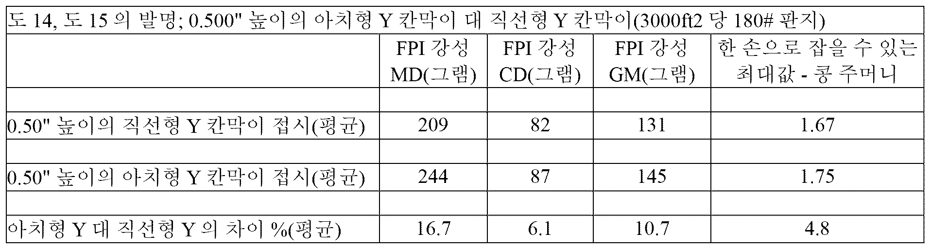
이하의 표 8, 표 9에서는 더 큰 칸막이의 아치형 외부 궤적이 접시의 FPI 강성 및 한 손으로 잡을 수 있는 최대값에 대해 상당한 개선을 제공한다는 것을 알 수 있다.Tables 8 and 9 below show that the arched outer trajectory of the larger baffles provides significant improvements to the FPI stiffness and maximum one-handed grip of the plate.
[표 8][Table 8]

[표 9][Table 9]
FEA 분석FEA Analysis
측벽 또는 "딥 다운"(주름 없음)에서의 칸막이 높이 감소를 포함하여 도 1 내지 도 13의 특징을 갖는 접시를 유한 요소 분석 FEA(0.014" 두께, 300,000 psi 탄성 계수, 0.29 푸아송 비)로 모델링 및 분석하여 141 g의 FPI 강성 값을 도출했다. 칸막이 높이 감소 또는 "딥 다운"이 없는 동일한 접시는 FEA로 모델링 및 분석한 결과, 다른 모든 사항이 동일할 때, FPI 강성 값이 133 g인 것, 또는 "딥 다운"이 있는 접시보다 6% 낮은 것으로 나타났다.A plate having the features of FIGS. 1-13, including the baffle height reduction in the sidewall or "dip down" (no crease), was modeled and analyzed using finite element analysis FEA (0.014" thickness, 300,000 psi elastic modulus, 0.29 Poisson's ratio) and yielded an FPI stiffness value of 141 g. The same plate without the baffle height reduction or "dip down", when modeled and analyzed using FEA, yielded an FPI stiffness value of 133 g, or 6% lower than the plate with the "dip down", all other things being equal.
FPI 강성 측정, 파손 하중 테스트 및 FEA 분석은 본 발명의 프레스웨어 접시가 본 발명의 구획형 프레스웨어 접시의 두드러진 특징이 없는 접시보다 예상 외로 우수하다는 것을 일관되게 보여준다.FPI stiffness measurements, failure load tests, and FEA analyses consistently show that the pressware plates of the present invention are unexpectedly superior to plates without the salient features of the compartmental pressware plates of the present invention.
전술한 데이터로부터, 약 120 또는 150 lbs/3000 ft2(최대 약 300 lbs/3000 ft2 정도)보다 기본 중량이 큰 판지 블랭크로부터 제조되는 본 발명의 구획형 프레스웨어 접시가, (a) 한 손으로 잡을 수 있는 최대 무게가 적어도 1 lb 또는, 대부분의 경우, 적어도 1.25 lbs이고, (b) 75 g보다 큰 FPI-GM 강성, 보다 바람직하게는 적어도 100 g, 적어도 110 g, 적어도 115 g 또는 120 g 이상의 FPI-GM 강성을 나타낸다는 것이 이해될 것이다.From the above data, it will be appreciated that the compartmentalized pressware plates of the present invention, fabricated from cardboard blanks having a basis weight greater than about 120 or 150 lbs/3000 ft 2 (up to about 300 lbs/3000 ft 2 ), exhibit (a) a maximum one-hand grippable weight of at least 1 lb, or, in most cases, at least 1.25 lbs, and (b) a FPI-GM stiffness greater than 75 g, more preferably at least 100 g, at least 110 g, at least 115 g or at least 120 g.
이상과 같이, 원형 프레스웨어 접시에 대해 상세하게 설명하고 강성과 강도를 평가했지만, 본 발명의 접시는 정사각형 접시, 다각형 접시, 타원형 접시 등을 포함하는 다양한 형상으로 제조될 수 있다. 도 16은 도 1 내지 도 13과 관련하여 설명된 다양한 특징을 갖는 본 발명의 팔각형의, 공칭 10인치 종이 프레스웨어 접시의 등각 평면도이고, 도 17은 접시의 중앙 칸막이 접합부에서 접시의 측벽까지 긴 리브의 아치형 궤적을 예시하는 도 16의 팔각형 프레스웨어 접시의 평면도이다. 대응하는 특징은 도 1 내지 도 13에서보다 200만큼 더 큰 숫자로 표시되어 있다.While the above has been described in detail and evaluated for stiffness and strength with respect to a circular pressware plate, the plate of the present invention may be manufactured in a variety of shapes including square plates, polygonal plates, oval plates, etc. FIG. 16 is an isometric plan view of an octagonal, nominally 10 inch paper pressware plate of the present invention having various features described with respect to FIGS. 1-13, and FIG. 17 is a plan view of the octagonal pressware plate of FIG. 16 illustrating the arcuate trajectory of the long rib from the center baffle joint of the plate to the side walls of the plate. Corresponding features are indicated by numbers 200 larger than in FIGS. 1-13.
도 18 및 도 19를 참조하면, 접시 바닥면(214)을 규정하는 접시 바닥(212)을 갖는 팔각형 구획형 프레스웨어 접시(210)가 예시되어 있으며, 접시 바닥면(214)은 접시 바닥(212) 주위로 연장되고 그로부터 위쪽과 바깥쪽으로 돌출되는 접시 측벽(216)에 인접하여 전이된다. 접시 프로파일은 발명의 명칭이 "아치형의 바닥 패널과 예리한 브림 전이를 갖춘 압착 판지 서빙웨어(Pressed paperboard servingware with arched bottom panel and sharp brim transition)"인 Littlejohn에 의한 미국 특허 제8,177,119호에 개시된 것에 기초한다. 접시 측벽은 측벽(216)에서 바깥쪽으로 플래어링된 플랜지(220)에 인접하는 접시 측벽 표면(218)을 규정한다. 접시(210)는 3개의 높은 칸막이(222, 224, 226)를 규정하며, 칸막이(222)는 구획들(228, 230) 사이에서 길이가 더 짧고, 칸막이(224, 226)는 구획들(230, 232 및 228, 232) 사이에서 길이가 더 길다. 중앙 접합부(256)는 칸막이(222, 224, 226)의 교차점에 의해 형성된다. 칸막이(224, 226)는, 도시된 바와 같이, 아치형 궤적을 따라 중앙 접합부(256)로부터 측벽까지 연장된다. 프레스웨어 접시(210)는 전술한 원형 프레스웨어 접시(10)와 관련하여 언급된 선택적인 가변 전이 반경 및 필렛 피처를 포함한다.Referring to FIGS. 18 and 19, an octagonal sectioned pressware plate (210) is illustrated having a plate bottom (212) defining a plate bottom surface (214) that transitions adjacent a plate sidewall (216) extending about the plate bottom (212) and projecting upwardly and outwardly therefrom. The plate profile is based on that disclosed in U.S. Pat. No. 8,177,119 to Littlejohn entitled "Pressed paperboard servingware with arched bottom panel and sharp brim transition." The plate sidewall defines a plate sidewall surface (218) adjacent a flange (220) that flares outwardly from the sidewall (216). The plate (210) defines three tall baffles (222, 224, 226), with the baffle (222) being shorter in length between the compartments (228, 230) and the baffles (224, 226) being longer in length between the compartments (230, 232 and 228, 232). A central joint (256) is formed by the intersection of the baffles (222, 224, 226). The baffles (224, 226) extend from the central joint (256) to the side walls along an arcuate trajectory, as illustrated. The pressware plate (210) includes the optional variable transition radius and fillet features noted with respect to the previously described circular pressware plate (10).
도 20에는, 접시가 형성될 때 대응하는 영역에서 도금을 용이하게 하기 위해 블랭크의 모서리와 블랭크의 중앙 스팬(310, 320) 주위에 클러스터로 배열된 복수의 주변 스코어(P)를 포함하는 편평한 판지 블랭크(300)가 예시되어 있다. 블랭크(및 성형된 접시)의 주변 내부에 간격을 두고 배치된 복수의 중앙 스코어(CP)는 또한, 프레스웨어가 형성될 때, 접시와 칸막이의 중앙 접합부에 대한 주름을 수용하기 위해 제공된다. 중앙 스코어가 블랭크 상의 CP 스코어의 Y 구성의 중심으로부터 측벽이 형성되는 가장자리를 향해 아치형 궤적으로 배열되는 것에 유의한다.FIG. 20 illustrates a flat cardboard blank (300) including a plurality of perimeter scores (P) arranged in clusters around the edges of the blank and the central span (310, 320) of the blank to facilitate plating in corresponding areas when the plate is formed. A plurality of center scores (CP) spaced apart within the perimeter of the blank (and the formed plate) are also provided to accommodate wrinkling about the central joint of the plate and the baffle when the pressware is formed. Note that the center scores are arranged in an arcuate trajectory from the center of the Y configuration of CP scores on the blank toward the edge where the sidewall is formed.
블랭크(300)는 또한 블랭크의 다른 영역보다 중앙 접합부 및 칸막이 주위에 판지가 모이는 것을 수용할 수 있는 형상이다. 이와 관련하여, 블랭크는 제2 스팬(316)보다 약간 더 짧은 제1 스팬(314)을 구비한다. 공칭 10" 접시의 경우, 약 3"의 곡률 반경 R11과 각도가 3°인 것을 특징으로 하는 필렛을 통한 상이한 가장자리 영역들 사이의 블랭크 전이가 도시되었지만, 다른 크기의 접시인 경우, 상이한 전이가 사용될 수 있다.The blank (300) is also shaped to accommodate gathering of the cardboard around the central joint and dividers more than other areas of the blank. In this regard, the blank has a first span (314) that is slightly shorter than the second span (316). For a nominal 10" plate, the blank transition between the different edge areas via fillets is shown, characterized by a radius of curvature R11 of about 3" and an angle of 3°, although for other sized plates, different transitions may be used.
예시적인 실시 형태Exemplary embodiment
따라서, 본 발명의 다양한 실시형태가 제공되며, 실시형태 1은 판지 블랭크로 형성된 높은 칸막이를 갖춘 구획형 프레스웨어 종이 접시로서, 접시 바닥 주위로 연장되고 측벽에서 바깥쪽으로 플래어링된 플랜지를 향해 바깥쪽 및 위쪽으로 돌출된 접시 측벽에 인접하는 접시 바닥, 접시 바닥과 인접하고 접시 바닥으로부터의 칸막이 높이 DH가 9/32"보다 큰 것을 특징으로 하는 하나 이상의 높은 칸막이 - 상기 하나 이상의 높은 칸막이는 측벽에서 접시 바닥의 중앙 부분까지 연장되고, 접시 바닥을 복수의 서빙 구획으로 나누도록 구성되며, 플랜지는 접시 바닥에서 정점까지의 높이 H를 특징으로 함 -, 및 플랜지의 정점에 대해 거리 V만큼 아래쪽으로 연장되는 외측 플랜지 다운턴을 포함하며, V:H의 비율은 약 0.1 내지 0.75이다.Accordingly, various embodiments of the present invention are provided,
실시형태 2는 판지 블랭크로 형성된 높은 칸막이를 갖춘 구획형 프레스웨어 종이 접시로서, 접시 바닥 주위로 연장되고 그로부터 바깥쪽 및 위쪽으로 돌출된 접시 측벽에 인접하여 전이되는 바닥면을 규정하는 접시 바닥, 및 접시 측벽 표면을 규정하고 그 측벽에서 바깥쪽으로 플래어링된 플랜지에 인접한 접시 측벽을 포함하고, 접시는 또한 각각 한 쌍의 칸막이 측벽 표면을 갖고 그 칸막이 측벽 표면으로 전이되는 접시 바닥에 인접한 하나 이상의 높은 칸막이를 더 포함하며, 여기서, 하나 이상의 높은 칸막이는 접시 바닥으로부터의 칸막이 높이 DH가 9/32"보다 큰 것을 특징으로 하고, 상기 하나 이상의 높은 칸막이는 측벽에서부터 접시 바닥의 중앙 부분을 향해 연장되며, 접시 바닥을 복수의 서빙 구획으로 나누도록 구성되고, 플랜지는 접시 바닥에서 정점까지의 높이 H와 플랜지의 정점에 대해 거리 V만큼 아래쪽으로 연장되는 외측 플랜지 다운턴을 특징으로 하며, 여기서, V:H의 비율은 약 01 내지 약 0.75이고, 접시 바닥면과 칸막이 측벽 표면 사이의 인접한 표면들 간의 전이는 가변 곡률 반경으로 특징지어지며, 이 가변 곡률 반경은 두 표면 사이의 전이에 근접한 제1 값으로부터 3개 표면 사이의 교차점에 근접한 전이에서 제1 값보다 높은 제2 값으로 변화한다.Embodiment 2 is a compartmentalized pressware paper plate having tall dividers formed from a cardboard blank, the plate bottom defining a bottom surface transitioning adjacent to plate sidewalls extending around the plate bottom and projecting outwardly and upwardly therefrom, and a plate sidewall adjacent a flange flared outwardly from the sidewalls, the plate further comprising one or more tall dividers adjacent the plate bottom each having a pair of divider sidewall surfaces and transitioning to the divider sidewall surfaces, wherein the one or more tall dividers are characterized by a divider height DH from the plate bottom greater than 9/32", the one or more tall dividers extending from the sidewalls toward a central portion of the plate bottom and configured to divide the plate bottom into a plurality of serving compartments, the flange being characterized by a height H from the plate bottom to a vertex and an outer flange downturn extending downward a distance V relative to the vertex of the flange, wherein the ratio of V:H is from about 0.1 to about 0.75, and the plate bottom surface and the dividers The transition between adjacent surfaces between the sidewall surfaces is characterized by a variable radius of curvature that varies from a first value near the transition between the two surfaces to a second value higher than the first value near the intersection between the three surfaces.
실시형태 3은 실시형태 2에 따른 구획형 프레스웨어 접시로서, 2개의 표면 사이의 전이에 근접한 전이의 제1 값에 대한 3개의 표면의 교차점에 근접한 가변 곡률 반경의 제2 값의 비율은 1.25 내지 2.5이다.Embodiment 3 is a compartmentalized pressware plate according to Embodiment 2, wherein a ratio of a second value of the variable radius of curvature proximate the intersection of the three surfaces to a first value of the transition proximate the transition between the two surfaces is 1.25 to 2.5.
실시형태 4는 실시형태 3에 따른 구획형 프레스웨어 접시로서, 2개의 표면 사이의 전이에 근접한 전이의 제1 값에 대한 3개의 표면의 교차점에 근접한 가변 곡률 반경의 제2 값의 비율은 1.3 내지 2.25이다.Embodiment 4 is a compartmentalized pressware plate according to Embodiment 3, wherein a ratio of a second value of the variable radius of curvature proximate the intersection of the three surfaces to a first value of the transition proximate the transition between the two surfaces is from 1.3 to 2.25.
실시형태 5는 실시형태 4에 따른 구획형 프레스웨어 접시로서, 2개의 표면 사이의 전이에 근접한 전이의 제1 값에 대한 3개의 표면의 교차점에 근접한 가변 곡률 반경의 제2 값의 비율은 1.35 내지 2.1이다.Embodiment 5 is a compartmentalized pressware plate according to Embodiment 4, wherein a ratio of a second value of the variable radius of curvature proximate the intersection of the three surfaces to a first value of the transition proximate the transition between the two surfaces is 1.35 to 2.1.
실시형태 6은 실시형태 2 내지 실시형태 5에 따른 구획형 프레스웨어 접시로서, 하나 이상의 높은 칸막이는 3개 표면의 교차점들 사이에서 중간 부분을 갖고, 하나 이상의 높은 칸막이의 측벽 표면은 접시의 바닥면에서 일정한 중간 전이 곡률 반경으로 전이된다.Embodiment 6 is a compartmentalized pressware plate according to Embodiments 2 to 5, wherein the at least one high baffle has a middle portion between the intersections of three surfaces, and a side wall surface of the at least one high baffle transitions from a bottom surface of the plate with a constant middle transition radius of curvature.
실시형태 7은 실시형태 6에 따른 구획형 프레스웨어 접시로서, 중간 전이 곡률 반경은 0.15" 내지 0.4" 또는 0.225"이다.Embodiment 7 is a compartmental pressware plate according to embodiment 6, wherein the intermediate transition radius of curvature is 0.15" to 0.4" or 0.225".
실시형태 8은 실시형태 2 내지 실시형태 7에 따른 구획형 프레스웨어 접시로서, 3개 표면의 교차점에 근접한 접시의 하나 이상의 영역은 접시 바닥과 칸막이 측벽(들) 사이에 곡률 반경의 제2 값이 0.25" 내지 0.5"인 필렛 구조(filleted structure)인 것을 특징으로 한다.Embodiment 8 is a compartmentalized pressware plate according to embodiments 2 to 7, characterized in that at least one region of the plate proximate the intersection of the three surfaces has a filleted structure having a second value of radius of curvature of 0.25" to 0.5" between the plate bottom and the partition sidewall(s).
실시형태 9는 판지 블랭크로 형성된 높은 칸막이를 갖춘 구획형 프레스웨어 종이 접시로서, 접시 바닥 주위로 연장되고 그로부터 바깥쪽 및 위쪽으로 돌출된 접시 측벽에 인접하여 전이되는 바닥면을 규정하는 접시 바닥, 및 접시 측벽 표면을 규정하고 그 측벽에서 바깥쪽으로 플래어링된 플랜지에 인접한 접시 측벽을 포함하고, 접시는 또한 각각 한 쌍의 칸막이 측벽 표면을 갖고 그 칸막이 측벽 표면으로 전이되는 접시 바닥에 인접한 하나 이상의 높은 칸막이를 더 포함하며, 여기서, 하나 이상의 높은 칸막이는 접시 바닥으로부터의 칸막이 높이 DH가 9/32"보다 큰 것을 특징으로 하고, 상기 하나 이상의 높은 칸막이는 측벽에서부터 접시 바닥의 중앙 부분을 향해 연장되며, 접시 바닥을 복수의 서빙 구획으로 나누도록 구성되고, 하나 이상의 높은 칸막이는 측벽에 근접한 외부 말단 부분과 하나 이상의 높은 칸막이의 말단 부분과 접시의 중앙 부분 사이에 중간 부분을 갖고, 하나 이상의 높은 칸막이의 측벽 표면은 접시의 바닥면에서 중간 부분에 걸쳐 일정한 중간 전이 곡률 반경으로 전이되고, 하나 이상의 높은 칸막이의 외부 말단 부분은 칸막이 측벽과 접시 바닥 사이의 필렛 특성 곡률 반경이 하나 이상의 높은 칸막이의 중간 부분의 중간 곡률 반경보다 큰 것을 포함하여 가변 곡률 반경을 갖는 필렛 구조를 갖고, 플랜지는 또한 접시 바닥에서 정점까지의 높이 H와 플랜지의 정점에 대해 거리 V만큼 아래쪽으로 연장되는 외측 플랜지 다운턴을 특징으로 하며, 여기서, V:H의 비율은 약 0.1 내지 약 0.75이다.Embodiment 9 is a compartmentalized pressware paper plate having tall dividers formed from a cardboard blank, the plate bottom defining a bottom surface transitioning adjacent to plate sidewalls extending around the plate bottom and projecting outwardly and upwardly therefrom, and a plate sidewall adjacent a flange flared outwardly from the sidewalls defining the plate sidewall surfaces, the plate further comprising one or more tall dividers adjacent the plate bottom each having a pair of divider sidewall surfaces and transitioning to the divider sidewall surfaces, wherein the one or more tall dividers are characterized in that a divider height DH from the plate bottom is greater than 9/32", the one or more tall dividers extending from the sidewalls toward a central portion of the plate bottom and configured to divide the plate bottom into a plurality of serving compartments, the one or more tall dividers having an outer end portion proximate the sidewalls and an intermediate portion between the end portions of the one or more tall dividers and the central portion of the plate, the sidewall surfaces of the one or more tall dividers having a constant intermediate transition from the plate bottom surface to the intermediate portion. The outer end portions of the one or more high baffles have a fillet structure having a variable radius of curvature, including a fillet characteristic radius of curvature between the baffle side walls and the bottom of the dish being greater than a middle radius of curvature of a middle portion of the one or more high baffles, the flange further characterized by an outer flange downturn having a height H from the bottom of the dish to a vertex and extending downward a distance V relative to the vertex of the flange, wherein the ratio of V:H is from about 0.1 to about 0.75.
실시형태 10은 실시형태 9에 따른 구획형 프레스웨어 접시로서, 중간 전이 곡률 반경은 0.15" 내지 0.4" 또는 0.15" 내지 0.225"이다.
실시형태 11은 실시형태 8 또는 실시형태 9에 따른 구획형 프레스웨어 접시로서, 높은 칸막이의 외부 말단 부분의 필렛 구조는 높은 칸막이 측벽 표면을 따라 하나 이상의 높은 칸막이의 중간 부분과 정렬된 제1 필렛 쌍을 포함한다.Embodiment 11 is a compartmentalized pressware plate according to embodiment 8 or embodiment 9, wherein the fillet structure of the outer end portion of the high partition comprises a first fillet pair aligned with a middle portion of at least one high partition along a side wall surface of the high partition.
실시형태 12는 실시형태 11에 따른 구획형 프레스웨어 접시로서, 높은 칸막이의 외부 말단 부분의 필렛 구조는 높은 칸막이 측벽 표면을 따라 하나 이상의 높은 칸막이의 외부 말단 부분과 정렬된 제2 필렛 쌍을 포함한다.
실시형태 13은 실시형태 8 내지 실시형태 12 중 어느 하나에 따른 구획형 프레스웨어 접시로서, 중간 곡률 반경에 대한 필렛 특성 곡률 반경의 비율은 1.25 내지 2.5이다.Embodiment 13 is a compartmental pressware plate according to any one of Embodiments 8 to 12, wherein a ratio of the fillet characteristic radius of curvature to the intermediate radius of curvature is 1.25 to 2.5.
실시형태 14는 실시형태 13에 따른 구획형 프레스웨어 접시로서, 중간 곡률 반경에 대한 필렛 특성 곡률 반경의 비율은 1.3 내지 2.25이다.
실시형태 15는 실시형태 14에 따른 구획형 프레스웨어 접시로서, 중간 곡률 반경에 대한 필렛 특성 곡률 반경의 비율은 1.35 내지 2.1이다.
실시형태 16은 실시형태 8 내지 실시형태 15 중 어느 하나에 따른 구획형 프레스웨어 접시로서, 필렛 특성 곡률 반경은 0.25" 내지 0.5"이다.
실시형태 17은 판지 블랭크로 형성된 높은 칸막이를 갖춘 구획형 프레스웨어 종이 접시로서, 접시 바닥 주위로 연장되고 측벽에서 바깥쪽으로 플래어링된 플랜지를 향해 바깥쪽 및 위쪽으로 돌출된 접시 측벽에 인접하는 접시 바닥과, 접시 바닥과 인접하고 접시 바닥으로부터의 칸막이 높이 DH가 9/32"보다 큰 것을 특징으로 하는 하나 이상의 높은 칸막이 - 상기 하나 이상의 높은 칸막이는 측벽에서 접시 바닥의 중앙 부분까지 연장되고, 접시 바닥을 복수의 서빙 구획으로 나누도록 구성되며, 플랜지는 접시 바닥에서 정점까지의 높이 H를 특징으로 함 -, 및 플랜지의 정점에 대해 거리 V만큼 아래쪽으로 연장되는 외측 플랜지 다운턴을 포함하며, V:H의 비율은 약 0.1 내지 0.75이고, 상기 하나 이상의 칸막이는 또한 DH보다 낮은 높이 SDH로 접시의 측벽에 인접하며, 여기서, 플랜지에는 선택적으로 측벽과 하나 이상의 칸막이의 접합부 부근에서 강화된 다운턴이 제공되고, 강화된 다운턴은 플랜지의 인접한 부분보다 아래쪽으로 더 많이 연장되는 로브를 구비한다.Embodiment 17 is a compartmentalized pressware paper plate having tall dividers formed from a cardboard blank, the plate bottom protruding outwardly and upwardly from the plate sidewall toward a flange extending around the plate bottom and flared outwardly from the sidewall, and at least one tall divider adjacent the plate bottom and characterized by a divider height DH from the plate bottom greater than 9/32", the at least one tall divider extending from the sidewall to a central portion of the plate bottom and configured to divide the plate bottom into a plurality of serving compartments, the flange characterized by a height H from the plate bottom to the apex, and an outer flange downturn extending downward a distance V relative to the apex of the flange, the ratio of V:H being from about 0.1 to 0.75, the at least one divider also being adjacent the plate sidewall at a height SDH less than DH, wherein the flange is optionally provided with a reinforced downturn near the junction of the sidewall and the at least one divider, the reinforced downturn being adjacent the flange. It has lobes that extend more downward than the portion.
실시형태 18은 실시형태 17에 따른 구획형 프레스웨어 접시로서, SDH 대 DH의 비율은 0.15 내지 0.75이다.
실시형태 19은 실시형태 18에 따른 구획형 프레스웨어 접시로서, SDH 대 DH의 비율은 0.25 내지 0.65이다.Embodiment 19 is a compartmental pressware plate according to
실시형태 20은 실시형태 17, 18, 또는 19에 따른 구획형 프레스웨어로서, 플랜지의 인접 부분보다 0.05" 내지 0.4"의 거리만큼 더 아래쪽으로 연장되는 로브를 구비한다.
실시형태 21은 실시형태 17 내지 실시형태 20에 따른 구획형 프레스웨어로서, 로브는 플랜지의 인접 부분보다 0.1" 내지 0.35"의 거리만큼 더 아래쪽으로 연장된다.Embodiment 21 is a compartmental pressware according to embodiments 17 to 20, wherein the lobes extend downward a distance of 0.1" to 0.35" further than an adjacent portion of the flange.
실시형태 22는 실시형태 21에 따른 구획형 프레스웨어로서, 로브는 플랜지의 인접 부분보다 0.1" 내지 0.25"의 거리만큼 더 아래쪽으로 연장된다.
실시형태 23은 판지 블랭크로 형성된 높은 칸막이를 갖춘 구획형 프레스웨어 종이 접시로서, 접시 바닥 주위로 연장되고 그로부터 바깥쪽 및 위쪽으로 돌출된 접시 측벽에 인접하여 전이되는 바닥면을 규정하는 접시 바닥, 및 접시 측벽 표면을 규정하고 그 측벽에서 바깥쪽으로 플래어링된 플랜지에 인접한 접시 측벽을 포함하고, 접시는 또한 각각 한 쌍의 칸막이 측벽 표면을 갖고 그 칸막이 측벽 표면으로 전이되는 접시 바닥에 인접한 하나 이상의 높은 칸막이를 더 포함하며, 여기서, 하나 이상의 높은 칸막이는 접시 바닥으로부터의 칸막이 높이 DH가 9/32"보다 큰 것을 특징으로 하고, 상기 하나 이상의 높은 칸막이는 측벽에서부터 접시 바닥의 중앙 부분을 향해 연장되며, 접시 바닥을 복수의 서빙 구획으로 나누도록 구성되고, 플랜지는 접시 바닥에서 정점까지의 높이 H와 플랜지의 정점에 대해 거리 V만큼 아래쪽으로 연장되는 외측 플랜지 다운턴을 특징으로 하며, 여기서, V:H의 비율은 약 0.1 내지 약 0.75이고, 접시 바닥면과 칸막이 측벽 표면 사이의 인접한 표면들 간의 전이는 가변 곡률 반경으로 특징지어지며, 이 가변 곡률 반경은 두 표면 사이의 전이에 근접한 제1 값으로부터 3개의 표면 사이의 교차점에 근접한 전이에서 제1 값보다 높은 제2 값으로 변화하고, 상기 하나 이상의 칸막이는 또한 접시의 측벽에 DH보다 낮은 높이 SDH에서 인접하며, 여기서, 플랜지에는 선택적으로 하나 이상의 칸막이와 측벽의 접합부 부근에서 강화된 다운턴이 제공되며, 강화된 다운턴은 플랜지의 인접 부분보다 더 아래쪽으로 연장되는 로브를 구비한다.Embodiment 23 is a compartmentalized pressware paper plate having tall dividers formed from a cardboard blank, the plate bottom defining a bottom surface transitioning adjacent to plate sidewalls extending around the plate bottom and projecting outwardly and upwardly therefrom, and a plate sidewall adjacent a flange flared outwardly from the sidewalls, the plate further comprising one or more tall dividers adjacent the plate bottom each having a pair of divider sidewall surfaces and transitioning to the divider sidewall surfaces, wherein the one or more tall dividers are characterized by a divider height DH from the plate bottom greater than 9/32", the one or more tall dividers extending from the sidewalls toward a central portion of the plate bottom and configured to divide the plate bottom into a plurality of serving compartments, the flange being characterized by a height H from the plate bottom to a vertex and an outer flange downturn extending downward a distance V relative to the vertex of the flange, wherein the ratio of V:H is from about 0.1 to about 0.75, and the plate bottom surface and the A transition between adjacent surfaces between the baffle side wall surfaces is characterized by a variable radius of curvature, which varies from a first value proximate the transition between the two surfaces to a second value higher than the first value at the transition proximate the intersection between the three surfaces, wherein the one or more baffles are also abutting the side wall of the dish at a height SDH lower than DH, wherein the flange is optionally provided with a reinforced downturn proximate the junction of the one or more baffles and the side wall, the reinforced downturn having a lobe extending further downward than the adjacent portion of the flange.
실시형태 24는 실시형태 23에 따른 구획형 프레스웨어 접시로서, 2개의 표면 사이의 전이에 근접한 전이의 제1 값에 대한 3개의 표면의 교차점에 근접한 가변 곡률 반경의 제2 값의 비율은 1.25 내지 2.5이다.
실시형태 25는 실시형태 24에 따른 구획형 프레스웨어 접시로서, 2개의 표면 사이의 전이에 근접한 전이의 제1 값에 대한 3개의 표면의 교차점에 근접한 가변 곡률 반경의 제2 값의 비율은 1.3 내지 2.25이다.Embodiment 25 is a compartmental pressware plate according to
실시형태 26은 실시형태 25에 따른 구획형 프레스웨어 접시로서, 2개의 표면 사이의 전이에 근접한 전이의 제1 값에 대한 3개의 표면의 교차점에 근접한 가변 곡률 반경의 제2 값의 비율은 1.35 내지 2.1이다.
실시형태 27은 실시형태 23 내지 실시형태 26에 따른 구획형 프레스웨어 접시로서, 하나 이상의 높은 칸막이는 3개 표면의 교차점들 사이에서 중간 부분을 갖고, 하나 이상의 높은 칸막이의 측벽 표면은 접시의 바닥면에서 일정한 중간 전이 곡률 반경으로 전이된다.Embodiment 27 is a compartmentalized pressware plate according to embodiments 23 to 26, wherein the at least one high baffle has a middle portion between the intersections of three surfaces, and a side wall surface of the at least one high baffle transitions from a bottom surface of the plate with a constant middle transition radius of curvature.
실시형태 28은 실시형태 27에 따른 구획형 프레스웨어 접시로서, 중간 전이 곡률 반경은 0.15" 내지 0.4"이다.
실시형태 29는 실시형태 23 내지 실시형태 28에 따른 구획형 프레스웨어 접시로서, 3개 표면의 교차점에 근접한 접시의 하나 이상의 영역은 필렛 특성 곡률 반경이 0.25" 내지 0.5"인 필렛 구조를 특징으로 한다.Embodiment 29 is a compartmentalized pressware plate according to embodiments 23 to 28, wherein at least one region of the plate proximate the intersection of the three surfaces is characterized by a fillet structure having a fillet characteristic radius of curvature of from 0.25" to 0.5".
실시형태 30은 실시형태 23 내지 실시형태 29에 따른 구획형 프레스웨어 접시로서, SDH 대 DH의 비율은 0.15 내지 0.75이다.
실시형태 31은 실시형태 30에 따른 구획형 프레스웨어 접시로서, SDH 대 DH의 비율이 0.25 내지 0.65 또는 0.4이다.Embodiment 31 is a compartmental pressware plate according to
실시형태 32는 실시형태 23 내지 실시형태 31에 따른 구획형 프레스웨어 접시로서, 플랜지의 인접 부분보다 0.05" 내지 0.4"의 거리만큼 더 아래쪽으로 연장되는 로브를 구비한다.
실시형태 33은 실시형태 32에 따른 구획형 프레스웨어 접시로서, 로브는 플랜지의 인접 부분보다 0.1" 내지 0.35"의 거리만큼 더 아래쪽으로 연장된다.Embodiment 33 is a compartmental pressware plate according to
실시형태 34는 실시형태 33에 따른 구획형 프레스웨어 접시로서, 로브는 플랜지의 인접 부분보다 0.1" 내지 0.25"의 거리만큼 더 아래쪽으로 연장된다.
실시형태 35는 전술한 실시형태 중 어느 하나에 따른 구획형 프레스웨어 접시로서, 접시는 적어도 2개의 높은 칸막이를 구비한다.Embodiment 35 is a compartmental pressware plate according to any one of the embodiments described above, wherein the plate has at least two high partitions.
실시형태 36은 실시형태 35에 따른 구획형 프레스웨어 접시로서, 접시는 접시의 중앙 접합부에서 Y 구성의 3개의 높은 칸막이를 구비한다.
실시형태 37은 실시형태 36에 따른 구획형 프레스웨어 접시로서, 중앙 접합부는 곡률 반경이 0.75" 내지 1.5"인 칸막이 사이에서 전이된다.Embodiment 37 is a compartmental pressware plate according to
실시형태 38은 실시형태 36 또는 실시형태 37에 따른 구획형 프레스웨어 접시로서, 적어도 2개의 높은 칸막이는 접시의 중앙 접합부로부터 접시의 측벽까지의 아치형 궤적이다. 바깥쪽으로 돌출된 칸막이는 측벽으로 돌출될 때 곡률 반경을 규정한다. 바깥쪽 궤적에 적합한 곡률 반경은 특성 접시 직경의 0.5 내지 1.5배, 바람직하게는 특성 접시 직경의 0.75 내지 1.25배 사이일 수 있다.
실시형태 39는 전술한 실시형태 중 어느 하나에 따른 구획형 프레스웨어 접시로서, 높은 칸막이는 칸막이 높이 DH가 최대 3/4"이다.Embodiment 39 is a compartmentalized pressware plate according to any one of the preceding embodiments, wherein the high baffles have a baffle height DH of at most 3/4".
실시형태 40은 실시형태 39에 따른 구획형 프레스웨어 접시로서, 높은 칸막이는 칸막이 높이 DH가 약 0.3" 내지 0.75"이다.
실시형태 41은 실시형태 39에 따른 구획형 프레스웨어 접시로서, 높은 칸막이는 칸막이 높이 DH가 약 0.475" 내지 0.625"이다.Embodiment 41 is a compartmentalized pressware plate according to embodiment 39, wherein the high baffles have a baffle height DH of about 0.475" to 0.625".
실시형태 42는 전술한 실시형태 중 어느 하나에 따른 구획형 프레스웨어 접시로서, V:H의 비율은 0.15 내지 0.75이다.
실시형태 43은 전술한 실시형태 중 어느 하나에 따른 구획형 프레스웨어 접시로서, V:H의 비율은 0.2 내지 0.75이다.Embodiment 43 is a compartmental pressware plate according to any one of the aforementioned embodiments, wherein the ratio of V:H is from 0.2 to 0.75.
실시형태 44는 전술한 실시형태 중 어느 하나에 따른 구획형 프레스웨어 접시로서, V:H의 비율은 0.3 내지 0.65이다.
실시형태 45는 실시형태 44에 따른 구획형 프레스웨어 접시로서, V:H의 비율은 0.35 내지 0.6이다.Embodiment 45 is a compartmental pressware plate according to
실시형태 46은 전술한 실시형태 중 어느 하나에 따른 구획형 프레스웨어 접시로서, 구획형 프레스웨어 접시는 원형이다.
실시형태 47은 실시형태 1 내지 실시형태 45 중 어느 하나에 따른 구획형 프레스웨어 접시로서, 구획형 프레스웨어 접시는 다각형이다.Embodiment 47 is a compartmental pressware plate according to any one of
실시형태 48은 실시형태 47에 따른 구획형 프레스웨어 접시로서, 구획형 프레스웨어 접시는 팔각형이다.
실시형태 49는 실시형태 46, 47, 또는 48에 따른 구획형 프레스웨어 접시로서, 구획형 프레스웨어 접시는 특성 직경이 8" 내지 12"이다.Embodiment 49 is a compartmental pressware plate according to
실시형태 50은 실시형태 49에 따른 구획형 프레스웨어 접시로서, 구획형 프레스웨어 접시는 특성 직경이 8-1/2" 내지 11"이다.
실시형태 51은 실시형태 50에 따른 구획형 프레스웨어 접시로서, 구획형 프레스웨어 접시는 특성 직경이 9" 내지 10-1/2"이다.Embodiment 51 is a compartmental pressware plate according to
실시형태 52는 전술한 실시형태 중 어느 하나에 따른 구획형 프레스웨어 접시로서, 구획형 프레스웨어 접시는 기본 중량이 80 lbs/3000 ft2 내지 300 lbs/3000 ft2인 판지 블랭크로 제조된다.
실시형태 53은 실시형태 52에 따른 구획형 프레스웨어 접시로서, 구획형 프레스웨어 접시는 기본 중량이 145 lbs/3000 ft2 내지 240 lbs/3000 ft2인 판지 블랭크로 제조된다.Embodiment 53 is a compartmental pressware plate according to
실시형태 54은 실시형태 53에 따른 구획형 프레스웨어 접시로서, 구획형 프레스웨어 접시는 기본 중량이 155 lbs/3000 ft2 내지 190 lbs/3000 ft2인 판지 블랭크로 제조된다.
실시형태 55는 판지 블랭크로 형성된 칸막이를 갖춘 구획형 프레스웨어 종이 접시로서, 접시 바닥 주위로 연장되고 그로부터 바깥쪽 및 위쪽으로 돌출된 접시 측벽에 인접하여 전이되는 바닥면을 규정하는 접시 바닥, 및 접시 측벽 표면을 규정하고 그 측벽에서 바깥쪽으로 플래어링된 플랜지에 인접한 접시 측벽을 포함하고, 접시는 또한 각각 한 쌍의 칸막이 측벽 표면을 갖고 그 칸막이 측벽 표면으로 전이되는 접시 바닥에 인접한 하나 이상의 칸막이를 더 포함하며, 여기서, 하나 이상의 칸막이는 접시 바닥으로부터의 칸막이 높이 DH를 특징으로 하고, 상기 하나 이상의 칸막이는 측벽에서부터 접시 바닥의 중앙 부분을 향해 연장되며, 접시 바닥을 복수의 서빙 구획으로 나누도록 구성되고, 접시 바닥면의 인접한 표면과 칸막이 측벽 표면 사이의 전이는 가변 곡률 반경으로 특징지어지며, 이 가변 곡률 반경은 2개의 표면 사이의 전이에 근접한 제1 값으로부터 3개의 표면 사이의 교차점에 근접한 전이에서 제1 값보다 높은 제2 값으로 변화한다.Embodiment 55 is a compartmentalized pressware paper plate having a partition formed from a cardboard blank, the plate bottom defining a bottom surface transitioning adjacent a plate sidewall extending around the plate bottom and projecting outwardly and upwardly therefrom, and a plate sidewall adjacent a flange flared outwardly from the sidewall defining the plate sidewall surfaces, the plate further comprising at least one partition adjacent the plate bottom transitioning to the partition sidewall surfaces, each partition characterized by a partition height DH from the plate bottom, the at least one partition extending from the sidewall toward a central portion of the plate bottom and configured to divide the plate bottom into a plurality of serving compartments, the transition between the adjacent surface of the plate bottom surface and the partition sidewall surface being characterized by a variable radius of curvature, the variable radius of curvature varying from a first value proximate the transition between two surfaces to a second value higher than the first value at the transition proximate the intersection between three surfaces.
실시형태 56은 실시형태 55에 따른 구획형 프레스웨어 접시로서, 2개의 표면 사이의 전이에 근접한 전이의 제1 값에 대한 3개의 표면의 교차점에 근접한 가변 곡률 반경의 제2 값의 비율은 1.25 내지 2.5이다.
실시형태 57은 실시형태 56에 따른 구획형 프레스웨어 접시로서, 2개의 표면 사이의 전이에 근접한 전이의 제1 값에 대한 3개의 표면의 교차점에 근접한 가변 곡률 반경의 제2 값의 비율은 1.3 내지 2.25이다.Embodiment 57 is a compartmentalized pressware plate according to
실시형태 58은 실시형태 57에 따른 구획형 프레스웨어 접시로서, 2개의 표면 사이의 전이에 근접한 전이의 제1 값에 대한 3개의 표면의 교차점에 근접한 가변 곡률 반경의 제2 값의 비율은 1.35 내지 2.1이다.
실시형태 59는 실시형태 55 내지 실시형태 58에 따른 구획형 프레스웨어 접시로서, 하나 이상의 칸막이는 3개 표면의 교차점 사이의 중간 부분을 갖고, 하나 이상의 칸막이의 측벽 표면은 접시의 바닥면에서 일정한 중간 전이 곡률 반경으로 전이된다.Embodiment 59 is a compartmental pressware plate according to embodiments 55 to 58, wherein one or more of the partitions has a middle portion between the intersections of three surfaces, and a side wall surface of one or more of the partitions transitions from a bottom surface of the plate with a constant middle transition radius of curvature.
실시형태 60은 실시형태 59에 따른 구획형 프레스웨어 접시로서, 중간 전이 곡률 반경은 0.15" 내지 0.4"이다.
실시형태 61은 실시형태 55 내지 실시형태 60에 따른 구획형 프레스웨어 접시로서, 3개 표면의 교차점에 근접한 접시의 하나 이상의 영역은 접시 바닥과 칸막이 측벽(들) 사이에 곡률 반경의 제2 값이 0.25" 내지 0.5"인 필렛 구조인 것을 특징으로 한다.Embodiment 61 is a compartmentalized pressware plate according to embodiments 55 to 60, characterized in that at least one region of the plate proximate the intersection of the three surfaces has a fillet structure having a second value of radius of curvature of 0.25" to 0.5" between the plate bottom and the partition sidewall(s).
실시형태 62는 실시형태 59 내지 실시형태 61에 따른 구획형 프레스웨어 접시로서, 하나 이상의 칸막이는 접시의 측벽에 근접하고 접시의 측벽과 칸막이의 중간 부분 사이에 외부 말단 부분을 갖고, 하나 이상의 칸막이의 외부 말단 부분은 하나 이상의 칸막이의 중간 부분의 중간 곡률 반경보다 큰, 칸막이 측벽과 접시 바닥 사이의 필렛 특성 곡률 반경을 포함하여, 가변 곡률 반경을 갖는 필렛 구조를 갖는다.
실시형태 63은 실시형태 62에 따른 구획형 프레스웨어 접시로서, 칸막이의 외부 말단 부분의 필렛 구조는 높은 칸막이 측벽 표면을 따라 하나 이상의 칸막이의 중간 부분과 정렬된 제1 필렛 쌍을 포함한다.Embodiment 63 is a compartmentalized pressware plate according to
실시형태 64는 실시형태 63에 따른 구획형 프레스웨어 접시로서, 칸막이의 외부 말단 부분의 필렛 구조는 칸막이 측벽 표면을 따라 하나 이상의 칸막이의 외부 말단 부분과 정렬된 제2 필렛 쌍을 포함한다.
실시형태 65는 실시형태 62 내지 실시형태 64 중 어느 하나에 따른 구획형 프레스웨어 접시로서, 중간 곡률 반경에 대한 필렛 특성 곡률 반경의 비율은 1.25 내지 2.5이다.Embodiment 65 is a compartmental pressware plate according to any one of
실시형태 66은 실시형태 65에 따른 구획형 프레스웨어 접시로서, 중간 곡률 반경에 대한 필렛 특성 곡률 반경의 비율은 1.3 내지 2.25이다.
실시형태 67은 실시형태 66에 따른 구획형 프레스웨어 접시로서, 중간 곡률 반경에 대한 필렛 특성 곡률 반경의 비율은 1.35 내지 2.1이다.Embodiment 67 is a compartmental pressware plate according to
실시형태 68은 실시형태 62 내지 실시형태 67 중 어느 하나에 따른 구획형 프레스웨어 접시로서, 필렛 특성 곡률 반경은 0.25" 내지 0.5"이다.
실시형태 69는 실시형태 55 내지 실시형태 68 중 어느 하나에 따른 구획형 프레스웨어 접시로서, 상기 하나 이상의 칸막이는 DH보다 작은 높이 SDH에서 접시의 측벽에 인접하고, 플랜지에는 선택적으로 측벽과 하나 이상의 칸막이의 접합부 부근에 강화된 다운턴이 제공되며, 강화된 다운턴은 플랜지의 인접한 부분보다 아래쪽으로 더 연장되는 로브를 포함한다.Embodiment 69 is a compartmentalized pressware dish according to any one of embodiments 55 to 68, wherein the one or more baffles are adjacent a side wall of the dish at a height SDH less than DH, the flange optionally having a reinforced downturn provided near the junction of the side wall and the one or more baffles, the reinforced downturn comprising a lobe extending further downwardly than an adjacent portion of the flange.
실시형태 70은 실시형태 69에 따른 구획형 프레스웨어 접시로서, SDH 대 DH의 비율은 0.15 내지 0.75이다.
실시형태 71은 실시형태 70에 따른 구획형 프레스웨어 접시로서, SDH 대 DH의 비율이 0.25 내지 0.4 또는 0.65이다.Embodiment 71 is a compartmental pressware plate according to
실시형태 72는 실시형태 69 내지 실시형태 71에 따른 구획형 프레스웨어로서, 플랜지의 인접 부분보다 0.05" 내지 0.4"의 거리만큼 더 아래쪽으로 연장되는 로브를 구비한다.
실시형태 73은 실시형태 72에 따른 구획형 프레스웨어로서, 로브는 플랜지의 인접 부분보다 0.1" 내지 0.35"의 거리만큼 더 아래쪽으로 연장된다.Embodiment 73 is a compartmental pressware according to
실시형태 74는 실시형태 33에 따른 구획형 프레스웨어로서, 로브는 플랜지의 인접 부분보다 0.1" 내지 0.25"의 거리만큼 더 아래쪽으로 연장된다.
실시형태 75는 판지 블랭크로 형성된 칸막이를 갖춘 구획형 프레스웨어 종이 접시로서, 접시 바닥 주위로 연장되고 측벽에서 바깥쪽으로 플래어링된 플랜지를 향해 바깥쪽 및 위쪽으로 돌출된 접시 측벽에 인접하는 접시 바닥, 및 접시 바닥과 인접하고 접시 바닥으로부터의 칸막이 높이 DH를 특징으로 하는 하나 이상의 칸막이를 포함하고, 상기 하나 이상의 칸막이는 측벽에서 접시 바닥의 중앙 부분까지 연장되고, 접시 바닥을 복수의 서빙 구획으로 나누도록 구성되며, 상기 하나 이상의 칸막이는 DH보다 낮은 높이 SDH에서 접시의 측벽에 인접하며, 여기서, 플랜지에는 선택적으로 측벽과 하나 이상의 칸막이의 접합부 부근에서 강화된 다운턴이 제공되고, 강화된 다운턴은 플랜지의 인접한 부분보다 아래쪽으로 더 많이 연장되는 로브를 구비한다.Embodiment 75 is a compartmentalized pressware paper plate having a divider formed from a cardboard blank, comprising: a plate bottom adjacent the plate sidewall extending around the plate bottom and protruding outwardly and upwardly toward a flange flared outwardly from the sidewall; and at least one divider adjacent the plate bottom and characterized by a divider height DH from the plate bottom, the at least one divider extending from the sidewall to a central portion of the plate bottom and configured to divide the plate bottom into a plurality of serving compartments, the at least one divider being adjacent the sidewall of the plate at a height SDH less than DH, wherein the flange is optionally provided with a reinforced downturn near the junction of the sidewall and the at least one divider, the reinforced downturn having a lobe extending further downwardly than an adjacent portion of the flange.
실시형태 76은 실시형태 75에 따른 구획형 프레스웨어 접시로서, SDH 대 DH의 비율은 0.15 내지 0.5이다.
실시형태 77은 실시형태 76에 따른 구획형 프레스웨어 접시로서, SDH 대 DH의 비율은 0.25 내지 0.4이다.Embodiment 77 is a compartmental pressware plate according to
실시형태 78은 실시형태 75, 76, 또는 79에 따른 구획형 프레스웨어 접시로서, 플랜지의 인접 부분보다 0.05" 내지 0.4"의 거리만큼 더 아래쪽으로 연장되는 로브를 구비한다.
실시형태 79는 실시형태 75 내지 실시형태 78에 따른 구획형 프레스웨어 접시로서, 로브는 플랜지의 인접 부분보다 0.1" 내지 0.35"의 거리만큼 더 아래쪽으로 연장된다.Embodiment 79 is a compartmental pressware plate according to embodiments 75 to 78, wherein the lobes extend downward a distance of from 0.1" to 0.35" beyond an adjacent portion of the flange.
실시형태 80은 실시형태 79에 따른 구획형 프레스웨어 접시로서, 로브는 플랜지의 인접 부분보다 0.1" 내지 0.25"의 거리만큼 더 아래쪽으로 연장된다.Embodiment 80 is a compartmental pressware plate according to embodiment 79, wherein the lobes extend downward a distance of from 0.1" to 0.25" further than adjacent portions of the flanges.
실시형태 81은 실시형태 55 내지 실시형태 80 중 어느 하나에 따른 구획형 프레스웨어 접시로서, 접시는 적어도 2개의 칸막이를 갖는다.Embodiment 81 is a compartmental pressware plate according to any one of embodiments 55 to 80, wherein the plate has at least two partitions.
실시형태 82는 실시형태 81에 따른 구획형 프레스웨어 접시로서, 접시는 접시의 중앙 접합부에서 Y 구성의 3개의 칸막이를 갖는다.Embodiment 82 is a compartmental pressware plate according to embodiment 81, wherein the plate has three compartments in a Y configuration at a central joint of the plate.
실시형태 83은 실시형태 82에 따른 구획형 프레스웨어 접시로서, 중앙 접합부는 0.75" 내지 1.5"의 곡률 반경으로 칸막이 사이에서 전이된다.Embodiment 83 is a compartmental pressware plate according to embodiment 82, wherein the center joint transitions between the baffles with a radius of curvature of from 0.75" to 1.5".
실시형태 84는 실시형태 82 또는 실시형태 83에 따른 구획형 프레스웨어 접시로서, 적어도 2개의 칸막이는 접시의 중앙 접합부로부터 접시의 측벽까지의 아치형 궤적이다.
실시형태 85는 실시형태 55 내지 실시형태 84 중 어느 하나에 따른 구획형 프레스웨어 접시로서, 칸막이는 칸막이 높이 DH가 최대 3/4"이다.Embodiment 85 is a compartmentalized pressware plate according to any one of embodiments 55 to 84, wherein the partitions have a partition height DH of at most 3/4".
실시형태 86은 실시형태 85에 따른 구획형 프레스웨어 접시로서, 칸막이는 칸막이 높이 DH가 약 0.3" 내지 0.75"이다.Embodiment 86 is a compartmentalized pressware plate according to embodiment 85, wherein the partitions have a partition height DH of about 0.3" to 0.75".
실시형태 87은 실시형태 86에 따른 구획형 프레스웨어 접시로서, 높은 칸막이는 칸막이 높이 DH가 약 0.475" 내지 0.625"이다.Embodiment 87 is a compartmentalized pressware plate according to embodiment 86, wherein the high baffles have a baffle height DH of about 0.475" to 0.625".
실시형태 88은 실시형태 55 내지 실시형태 87 중 어느 하나에 따른 구획형 프레스웨어 접시로서, 구획형 프레스웨어 접시는 원형이다.Embodiment 88 is a compartmental pressware plate according to any one of embodiments 55 to 87, wherein the compartmental pressware plate is circular.
실시형태 89는 실시형태 55 내지 실시형태 87 중 어느 하나에 따른 구획형 프레스웨어 접시로서, 구획형 프레스웨어 접시는 다각형이다.Embodiment 89 is a compartmental pressware plate according to any one of embodiments 55 to 87, wherein the compartmental pressware plate is polygonal.
실시형태 90은 실시형태 89에 따른 구획형 프레스웨어 접시로서, 구획형 프레스웨어 접시는 팔각형이다.Embodiment 90 is a compartmental pressware plate according to embodiment 89, wherein the compartmental pressware plate is octagonal.
실시형태 91은 실시형태 88, 89, 또는 90에 따른 구획형 프레스웨어 접시로서, 구획형 프레스웨어 접시는 특성 직경이 8" 내지 12"이다.Embodiment 91 is a compartmental pressware plate according to embodiments 88, 89, or 90, wherein the compartmental pressware plate has a characteristic diameter of from 8" to 12".
실시형태 92는 실시형태 91에 따른 구획형 프레스웨어 접시로서, 구획형 프레스웨어 접시는 특성 직경이 8-1/2" 내지 11"이다.Embodiment 92 is a compartmental pressware plate according to embodiment 91, wherein the compartmental pressware plate has a characteristic diameter of from 8-1/2" to 11".
실시형태 93은 실시형태 92에 따른 구획형 프레스웨어 접시로서, 구획형 프레스웨어 접시는 특성 직경이 9" 내지 10-1/2"이다.Embodiment 93 is a compartmental pressware plate according to embodiment 92, wherein the compartmental pressware plate has a characteristic diameter of from 9" to 10-1/2".
실시형태 94는 실시형태 55 내지 실시형태 93 중 어느 하나에 따른 구획형 프레스웨어 접시로서, 구획형 프레스웨어 접시는 기본 중량이 80 lbs/3000 ft2 내지 300 lbs/3000 ft2인 판지 블랭크로 제조된다.Embodiment 94 is a compartmental pressware plate according to any one of embodiments 55 to 93, wherein the compartmental pressware plate is manufactured from a paperboard blank having a basis weight of from 80 lbs/3000 ft 2 to 300 lbs/3000 ft 2 .
실시형태 95는 실시형태 94에 따른 구획형 프레스웨어 접시로서, 구획형 프레스웨어 접시는 기본 중량이 145 lbs/3000 ft2 내지 240 lbs/3000 ft2의 판지 블랭크로 제조된다.Embodiment 95 is a compartmental pressware plate according to embodiment 94, wherein the compartmental pressware plate is manufactured from a paperboard blank having a basis weight of from 145 lbs/3000 ft 2 to 240 lbs/3000 ft 2 .
실시형태 96은 실시형태 95에 따른 구획형 프레스웨어 접시로서, 구획형 프레스웨어 접시는 기본 중량이 155 lbs/3000 ft2 내지 190 lbs/3000 ft2인 판지 블랭크로 제조된다.Embodiment 96 is a compartmental pressware plate according to embodiment 95, wherein the compartmental pressware plate is manufactured from a paperboard blank having a basis weight of from 155 lbs/3000 ft 2 to 190 lbs/3000 ft 2 .
본 발명이 수많은 실시예와 관련하여 설명되었지만, 당업자는 다양한 형상 및 크기를 갖는 접시, 그릇, 타원형 접시 및 트레이 등이 본 발명의 특성을 갖는 것으로 개발될 수 있다는 것을 이해할 것이다. 일부는 모따기된 정사각형 또는 직사각형, 삼각형, 다변형, 다각형 및 설명된 프로파일과 구획을 갖는 유사한 형상일 수 있다. 따라서, 단일 판지 층 블랭크를 사용하는 대신 복합 판지 블랭크가 사용될 수도 있다. 예를 들어, 본 발명의 용기는 복합 판지 재료로 성형될 수 있으며, 여기서, 용기는 본원에 기술된 형상을 갖는 용기의 형태로 3개의 개별 판지 층을 서로 적층함으로써 형성된다. 복합재 접시를 성형하는 특정 조작 단계는 미국 특허 제6,039,682호, 제6,186,394호 및 제6,287,247호에 더 상세하게 설명되어 있다. 전술한 설명, 관련 기술분야의 지식, 및 본 발명의 상세한 설명 및 배경기술을 포함하는 전술한 설명과 관련하여 위에서 참조된 참고문헌을 고려하면, 본 개시내용은 모두 본 명세서에 참조로 포함되어 있으며, 추가 설명은 불필요한 것으로 간주된다. 아울러, 전술한 설명으로부터 본 발명의 양태와 다양한 실시형태의 일부가 전체적 또는 부분적으로 조합되거나 상호교환될 수 있음을 이해해야 한다. 따라서, 본 발명의 용기는 FPI 강성의 증가뿐만 아니라, 하중을 지지하는 향상된 능력을 제공한다. 첨부된 청구범위에 설명된 바와 같이, 본 발명의 사상 및 범위 내에서의 위에서 설명된 특정 실시형태에 대한 수정은 당업자에게 쉽게 명백해질 것이다.While the present invention has been described in connection with numerous embodiments, those skilled in the art will appreciate that plates, bowls, oval plates, trays, and the like having various shapes and sizes may be developed to have the properties of the present invention. Some may be chamfered squares or rectangles, triangles, polygons, polygons, and similar shapes having the profiles and compartments described. Thus, instead of using a single layer of cardboard blank, a composite cardboard blank may be used. For example, the containers of the present invention may be formed from a composite cardboard material, wherein the containers are formed by laminating three individual layers of cardboard together in the shape of a container having the shapes described herein. The specific operating steps for forming a composite plate are described in more detail in U.S. Patent Nos. 6,039,682, 6,186,394, and 6,287,247. In view of the foregoing description, the knowledge of the relevant art, and the references referenced above in connection with the foregoing description, including the detailed description and background of the present invention, the entire disclosure of the present invention is incorporated herein by reference and no further description is deemed necessary. In addition, it should be understood from the foregoing description that aspects of the present invention and portions of the various embodiments may be combined or interchanged in whole or in part. Accordingly, the containers of the present invention provide not only increased FPI stiffness, but also improved load-bearing capabilities. Modifications to the specific embodiments described above within the spirit and scope of the present invention, as set forth in the appended claims, will be readily apparent to those skilled in the art.
Claims (25)
Applications Claiming Priority (3)
| Application Number | Priority Date | Filing Date | Title |
|---|---|---|---|
| US202263316482P | 2022-03-04 | 2022-03-04 | |
| US63/316,482 | 2022-03-04 | ||
| PCT/IB2023/051855 WO2023166415A1 (en) | 2022-03-04 | 2023-02-28 | Rigid compartmented pressware plate with tall dividers |
Publications (1)
| Publication Number | Publication Date |
|---|---|
| KR20240152854A true KR20240152854A (en) | 2024-10-22 |
Family
ID=85640730
Family Applications (1)
| Application Number | Title | Priority Date | Filing Date |
|---|---|---|---|
| KR1020247028150A Pending KR20240152854A (en) | 2022-03-04 | 2023-02-28 | Rigid compartmental pressware plate with high baffles |
Country Status (5)
| Country | Link |
|---|---|
| US (1) | US20230276968A1 (en) |
| KR (1) | KR20240152854A (en) |
| CA (1) | CA3249266A1 (en) |
| MX (1) | MX2024010552A (en) |
| WO (1) | WO2023166415A1 (en) |
Families Citing this family (1)
| Publication number | Priority date | Publication date | Assignee | Title |
|---|---|---|---|---|
| USD1052347S1 (en) * | 2022-08-01 | 2024-11-26 | BabyBjörn AB | Three part plate |
Family Cites Families (33)
| Publication number | Priority date | Publication date | Assignee | Title |
|---|---|---|---|---|
| US1848066A (en) * | 1929-07-12 | 1932-03-01 | Fidelity Trust Company | Molded pulp article |
| USD185911S (en) * | 1958-05-27 | 1959-08-18 | Keyes Fibre Co | Divided plate |
| US3601277A (en) * | 1969-08-20 | 1971-08-24 | Sinclair Koppers Co | Disposable food tray |
| BE755278A (en) * | 1969-08-25 | 1971-02-01 | Standard Oil Co | CONTAINER FOR HOT FOOD |
| US4149841A (en) * | 1978-03-27 | 1979-04-17 | Peerless Machine & Tool Corporation | Apparatus of making a compartment tray |
| US5088640A (en) | 1991-09-06 | 1992-02-18 | James River Corporation Of Virginia | Rigid four radii rim paper plate |
| US5335787A (en) * | 1991-09-20 | 1994-08-09 | Amoco Corporation | Food and beverage tray |
| DE69319809T2 (en) | 1992-09-01 | 1998-12-03 | Fort James Corp., Richmond, Va. | Rigid cardboard container |
| US5236119A (en) * | 1992-11-05 | 1993-08-17 | Chu Ming Hsiang | Paper plate |
| US5938112A (en) | 1995-08-28 | 1999-08-17 | Fort James Corporation | Rigid paperboard container |
| US5915581A (en) * | 1996-05-15 | 1999-06-29 | Boston Chicken, Inc. | Compartmental container for serving food products |
| US6039682A (en) | 1996-10-23 | 2000-03-21 | Fort James Corporation | Containers formed of a composite paperboard web and methods of forming |
| USD426110S (en) * | 1998-09-22 | 2000-06-06 | Schmidt Norbert T | Non-spill party plate |
| US6241096B1 (en) * | 1999-06-18 | 2001-06-05 | Fort James Corporation | Disposable servingware with nesting resistant flange patterns |
| US6440509B1 (en) * | 1999-07-16 | 2002-08-27 | Fort James Corporation | Compartmented disposable plate with asymmetric rib geometry |
| US6589043B1 (en) | 1999-10-04 | 2003-07-08 | Fort James Corporation | Punch stripper ring knock-out for pressware die sets |
| US7104030B2 (en) | 2001-05-01 | 2006-09-12 | Pactiv Corporation | Compartment plates having themes and method for manufacturing and packaging the same |
| US6715630B2 (en) | 2002-01-23 | 2004-04-06 | Fort James Corporation | Disposable food container with a linear sidewall profile and an arcuate outer flange |
| US7337943B2 (en) * | 2002-06-27 | 2008-03-04 | Dixie Consumer Products Llc | Disposable servingware containers with flange tabs |
| US8584929B2 (en) | 2003-10-20 | 2013-11-19 | Dixie Consumer Products Llc | Pressed paperboard servingware with improved rigidity and rim stiffness |
| US8047834B2 (en) | 2005-08-19 | 2011-11-01 | Dixie Consumer Products Llc | Segmented pressware die set with anti-twist guide keys |
| CA2654333A1 (en) * | 2006-06-08 | 2007-12-13 | Nestec S.A. | Microwave food packaging |
| US20090029111A1 (en) * | 2007-07-24 | 2009-01-29 | Harfmann Walter R | Embossed low density polymeric foams and articles made thereof |
| US8177119B2 (en) | 2007-11-01 | 2012-05-15 | Dixie Consumer Products Llc | Pressed paperboard servingware with arched bottom panel and sharp brim transition |
| USD695077S1 (en) * | 2013-03-14 | 2013-12-10 | Target Brands, Inc. | Compartmentalized container |
| CA2865090C (en) * | 2013-10-01 | 2021-04-20 | Kurt Reichel | Assisted eating aid |
| US20170013980A1 (en) * | 2015-07-15 | 2017-01-19 | Rebecca Susanne Pickett | Disposable Divided Bowls |
| CA2940303C (en) | 2015-09-08 | 2023-08-01 | Dixie Consumer Products Llc | Pressware paperboard plate with wide brim and greater strength |
| CA2947636A1 (en) * | 2016-11-07 | 2018-05-07 | Michel Aufoujal | Biodegradable, recyclable and compostable natural fibers food containers |
| USD884483S1 (en) * | 2017-05-31 | 2020-05-19 | D6 Inc. | Container |
| US11807418B2 (en) * | 2017-06-30 | 2023-11-07 | Sabert Corporation | Food display, transport, storage, and serving system |
| CA3104534A1 (en) * | 2018-07-09 | 2020-01-16 | Heat Seal Llc | Packaging for food and beverage |
| USD926525S1 (en) * | 2019-03-20 | 2021-08-03 | Pactiv LLC | Tray |
-
2023
- 2023-02-27 US US18/175,029 patent/US20230276968A1/en active Pending
- 2023-02-28 WO PCT/IB2023/051855 patent/WO2023166415A1/en not_active Ceased
- 2023-02-28 CA CA3249266A patent/CA3249266A1/en active Pending
- 2023-02-28 MX MX2024010552A patent/MX2024010552A/en unknown
- 2023-02-28 KR KR1020247028150A patent/KR20240152854A/en active Pending
Also Published As
| Publication number | Publication date |
|---|---|
| MX2024010552A (en) | 2024-09-06 |
| US20230276968A1 (en) | 2023-09-07 |
| WO2023166415A1 (en) | 2023-09-07 |
| CA3249266A1 (en) | 2023-09-07 |
Similar Documents
| Publication | Publication Date | Title |
|---|---|---|
| US9833088B2 (en) | Pressed paperboard servingware with improved rigidity and rim stiffness | |
| US8177119B2 (en) | Pressed paperboard servingware with arched bottom panel and sharp brim transition | |
| US8684260B2 (en) | Paperboard plate with corner walls | |
| CA2433438C (en) | Disposable servingware containers with flange tabs | |
| US6715630B2 (en) | Disposable food container with a linear sidewall profile and an arcuate outer flange | |
| US5326020A (en) | Rigid paperboard container | |
| US7048176B2 (en) | Deep dish disposable container | |
| US9655461B2 (en) | Pressware paperboard plate with wide brim and greater strength | |
| US8651366B2 (en) | Rigid-buckling-resistant-fluted paperboard container with arcuate outer region | |
| US11554569B2 (en) | Blank and forming tool for forming a container | |
| KR20240152854A (en) | Rigid compartmental pressware plate with high baffles | |
| US12016474B2 (en) | Pressed paperboard bowl with wide upper rim |
Legal Events
| Date | Code | Title | Description |
|---|---|---|---|
| PA0105 | International application |
Patent event date: 20240822 Patent event code: PA01051R01D Comment text: International Patent Application |
|
| PG1501 | Laying open of application |