KR20240021063A - A lens driving device, a camera device and an optical apparatus - Google Patents
A lens driving device, a camera device and an optical apparatus Download PDFInfo
- Publication number
- KR20240021063A KR20240021063A KR1020220099581A KR20220099581A KR20240021063A KR 20240021063 A KR20240021063 A KR 20240021063A KR 1020220099581 A KR1020220099581 A KR 1020220099581A KR 20220099581 A KR20220099581 A KR 20220099581A KR 20240021063 A KR20240021063 A KR 20240021063A
- Authority
- KR
- South Korea
- Prior art keywords
- ois
- carrier
- magnet
- disposed
- coil
- Prior art date
- Legal status (The legal status is an assumption and is not a legal conclusion. Google has not performed a legal analysis and makes no representation as to the accuracy of the status listed.)
- Pending
Links
- 230000003287 optical effect Effects 0.000 title claims abstract description 126
- 239000000758 substrate Substances 0.000 claims description 90
- 230000006641 stabilisation Effects 0.000 description 15
- 238000011105 stabilization Methods 0.000 description 15
- 239000000853 adhesive Substances 0.000 description 10
- 230000001070 adhesive effect Effects 0.000 description 10
- 230000003993 interaction Effects 0.000 description 7
- 230000007935 neutral effect Effects 0.000 description 6
- 230000008859 change Effects 0.000 description 4
- 238000010586 diagram Methods 0.000 description 4
- 230000004048 modification Effects 0.000 description 4
- 238000012986 modification Methods 0.000 description 4
- 238000005516 engineering process Methods 0.000 description 3
- 239000004519 grease Substances 0.000 description 3
- 239000002184 metal Substances 0.000 description 3
- 230000002093 peripheral effect Effects 0.000 description 2
- 230000009467 reduction Effects 0.000 description 2
- 239000004593 Epoxy Substances 0.000 description 1
- 230000008878 coupling Effects 0.000 description 1
- 238000010168 coupling process Methods 0.000 description 1
- 238000005859 coupling reaction Methods 0.000 description 1
- 229910044991 metal oxide Inorganic materials 0.000 description 1
- 150000004706 metal oxides Chemical class 0.000 description 1
- 239000004065 semiconductor Substances 0.000 description 1
- 239000000126 substance Substances 0.000 description 1
- 229920001187 thermosetting polymer Polymers 0.000 description 1
Images


Classifications
-
- G—PHYSICS
- G03—PHOTOGRAPHY; CINEMATOGRAPHY; ANALOGOUS TECHNIQUES USING WAVES OTHER THAN OPTICAL WAVES; ELECTROGRAPHY; HOLOGRAPHY
- G03B—APPARATUS OR ARRANGEMENTS FOR TAKING PHOTOGRAPHS OR FOR PROJECTING OR VIEWING THEM; APPARATUS OR ARRANGEMENTS EMPLOYING ANALOGOUS TECHNIQUES USING WAVES OTHER THAN OPTICAL WAVES; ACCESSORIES THEREFOR
- G03B3/00—Focusing arrangements of general interest for cameras, projectors or printers
- G03B3/10—Power-operated focusing
-
- G—PHYSICS
- G02—OPTICS
- G02B—OPTICAL ELEMENTS, SYSTEMS OR APPARATUS
- G02B27/00—Optical systems or apparatus not provided for by any of the groups G02B1/00 - G02B26/00, G02B30/00
- G02B27/64—Imaging systems using optical elements for stabilisation of the lateral and angular position of the image
- G02B27/646—Imaging systems using optical elements for stabilisation of the lateral and angular position of the image compensating for small deviations, e.g. due to vibration or shake
-
- G—PHYSICS
- G02—OPTICS
- G02B—OPTICAL ELEMENTS, SYSTEMS OR APPARATUS
- G02B7/00—Mountings, adjusting means, or light-tight connections, for optical elements
- G02B7/02—Mountings, adjusting means, or light-tight connections, for optical elements for lenses
- G02B7/04—Mountings, adjusting means, or light-tight connections, for optical elements for lenses with mechanism for focusing or varying magnification
-
- G—PHYSICS
- G03—PHOTOGRAPHY; CINEMATOGRAPHY; ANALOGOUS TECHNIQUES USING WAVES OTHER THAN OPTICAL WAVES; ELECTROGRAPHY; HOLOGRAPHY
- G03B—APPARATUS OR ARRANGEMENTS FOR TAKING PHOTOGRAPHS OR FOR PROJECTING OR VIEWING THEM; APPARATUS OR ARRANGEMENTS EMPLOYING ANALOGOUS TECHNIQUES USING WAVES OTHER THAN OPTICAL WAVES; ACCESSORIES THEREFOR
- G03B17/00—Details of cameras or camera bodies; Accessories therefor
- G03B17/02—Bodies
- G03B17/12—Bodies with means for supporting objectives, supplementary lenses, filters, masks, or turrets
-
- G—PHYSICS
- G03—PHOTOGRAPHY; CINEMATOGRAPHY; ANALOGOUS TECHNIQUES USING WAVES OTHER THAN OPTICAL WAVES; ELECTROGRAPHY; HOLOGRAPHY
- G03B—APPARATUS OR ARRANGEMENTS FOR TAKING PHOTOGRAPHS OR FOR PROJECTING OR VIEWING THEM; APPARATUS OR ARRANGEMENTS EMPLOYING ANALOGOUS TECHNIQUES USING WAVES OTHER THAN OPTICAL WAVES; ACCESSORIES THEREFOR
- G03B5/00—Adjustment of optical system relative to image or object surface other than for focusing
-
- H—ELECTRICITY
- H02—GENERATION; CONVERSION OR DISTRIBUTION OF ELECTRIC POWER
- H02K—DYNAMO-ELECTRIC MACHINES
- H02K33/00—Motors with reciprocating, oscillating or vibrating magnet, armature or coil system
- H02K33/16—Motors with reciprocating, oscillating or vibrating magnet, armature or coil system with polarised armatures moving in alternate directions by reversal or energisation of a single coil system
-
- G—PHYSICS
- G03—PHOTOGRAPHY; CINEMATOGRAPHY; ANALOGOUS TECHNIQUES USING WAVES OTHER THAN OPTICAL WAVES; ELECTROGRAPHY; HOLOGRAPHY
- G03B—APPARATUS OR ARRANGEMENTS FOR TAKING PHOTOGRAPHS OR FOR PROJECTING OR VIEWING THEM; APPARATUS OR ARRANGEMENTS EMPLOYING ANALOGOUS TECHNIQUES USING WAVES OTHER THAN OPTICAL WAVES; ACCESSORIES THEREFOR
- G03B2205/00—Adjustment of optical system relative to image or object surface other than for focusing
- G03B2205/0007—Movement of one or more optical elements for control of motion blur
-
- G—PHYSICS
- G03—PHOTOGRAPHY; CINEMATOGRAPHY; ANALOGOUS TECHNIQUES USING WAVES OTHER THAN OPTICAL WAVES; ELECTROGRAPHY; HOLOGRAPHY
- G03B—APPARATUS OR ARRANGEMENTS FOR TAKING PHOTOGRAPHS OR FOR PROJECTING OR VIEWING THEM; APPARATUS OR ARRANGEMENTS EMPLOYING ANALOGOUS TECHNIQUES USING WAVES OTHER THAN OPTICAL WAVES; ACCESSORIES THEREFOR
- G03B2205/00—Adjustment of optical system relative to image or object surface other than for focusing
- G03B2205/0053—Driving means for the movement of one or more optical element
- G03B2205/0069—Driving means for the movement of one or more optical element using electromagnetic actuators, e.g. voice coils
Landscapes
- Physics & Mathematics (AREA)
- General Physics & Mathematics (AREA)
- Optics & Photonics (AREA)
- Engineering & Computer Science (AREA)
- Power Engineering (AREA)
- Lens Barrels (AREA)
Abstract
Description
본 실시예는 렌즈 구동 장치, 카메라 장치 및 광학기기에 관한 것이다.This embodiment relates to a lens driving device, a camera device, and an optical device.
카메라 장치는 피사체를 사진이나 동영상으로 촬영하는 장치이며, 스마트폰과 같은 광학기기, 드론, 차량 등에 장착되고 있다.A camera device is a device that takes photos or videos of a subject, and is mounted on optical devices such as smartphones, drones, vehicles, etc.
카메라 장치에는 피사체의 거리에 따라 초점이 자동으로 조절되는 오토 포커스 기능이 적용되고 있다. 또한, 사용자의 손떨림에 의해 초점이 흔들리는 현상을 방지하는 손떨림 보정 기능이 적용되고 있다.Camera devices are equipped with an autofocus function that automatically adjusts focus depending on the distance to the subject. In addition, a hand shake correction function is applied to prevent the focus from shaking due to the user's hand shaking.
종래에는 손떨림 보정 기능을 수행하는 손떨림 보정 모듈이 오토 포커스 기능을 수행하는 오토 포커스 모듈 내에 배치되고 있다.Conventionally, an image stabilization module that performs an image stabilization function is placed within an autofocus module that performs an autofocus function.
이 경우, 오토 포커스 구동을 위해 렌즈와 함께 손떨림 보정 모듈까지 이동시켜야 하므로 오토 포커스 구동을 위한 마그네트의 크기와 무게가 증가하는 문제가 있다.In this case, since the image stabilization module must be moved along with the lens for autofocus operation, there is a problem that the size and weight of the magnet for autofocus operation increase.
특히, 최근에는 이미지 센서 고화소화에 따라 렌즈 직경이 증가되고 이에 따라 렌즈의 무게도 증가되어 문제가 가중되고 있다.In particular, recently, as image sensors have become higher resolution, the diameter of the lens has increased and the weight of the lens has also increased, aggravating the problem.
(특허문헌 1) KR 10-2015-0118005 A(Patent Document 1) KR 10-2015-0118005 A
본 실시예는 손떨림 보정 모듈 내에 오토 포커스 모듈이 배치되는 렌즈 구동 장치를 제공하고자 한다. 즉, 오토 포커스 구동 시 손떨림 보정 모듈은 이동하지 않는 렌즈 구동 장치를 제공하고자 한다.This embodiment seeks to provide a lens driving device in which an autofocus module is disposed within an image stabilization module. In other words, the aim is to provide a lens driving device in which the image stabilization module does not move during autofocus operation.
본 실시예에 따른 렌즈 구동 장치는 고정부; 상기 고정부 내에 배치되는 제1이동부; 상기 제1이동부 내에 배치되는 제2이동부; 상기 제1이동부를 광축에 수직한 방향으로 이동시키는 제1구동부; 및 상기 제2이동부를 광축방향으로 이동시키는 제2구동부를 포함하고, 상기 제2구동부는 상기 제2이동부에 배치되는 제1마그네트와, 상기 제1마그네트와 대향하도록 배치되고 상기 고정부에 배치되는 제1코일을 포함할 수 있다.The lens driving device according to this embodiment includes a fixing part; a first moving part disposed within the fixing part; a second moving part disposed within the first moving part; a first driving unit that moves the first moving unit in a direction perpendicular to the optical axis; and a second driving part that moves the second moving part in the optical axis direction, wherein the second driving part includes a first magnet disposed in the second moving part, and arranged to face the first magnet and disposed in the fixing part. It may include a first coil.
본 실시예에 따른 렌즈 구동 장치는 고정부; 광축방향에 수직한 x축으로 이동가능한 제1캐리어와 상기 광축방향과 수직한 y축으로 이동가능한 제2캐리어를 포함하는 제1이동부; 상기 제1이동부 내에 배치되고 상기 광축방향으로 이동가능한 제2이동부; 상기 제2이동부에 배치되는 제1마그네트; 상기 제1캐리어에 배치되는 제2마그네트; 상기 제2캐리어에 배치되는 제3마그네트; 상기 제1마그네트와 대향하도록 배치되는 제1코일; 상기 제2마그네트와 상기 광축방향으로 대향하도록 배치되는 제2코일; 및 상기 제3마그네트와 상기 광축방향으로 대향하도록 배치되는 제3코일을 포함하고, 상기 제1코일은 상기 고정부의 제1측면에 배치될 수 있다.The lens driving device according to this embodiment includes a fixing part; a first moving unit including a first carrier movable in an x-axis perpendicular to the optical axis direction and a second carrier movable in a y-axis perpendicular to the optical axis direction; a second moving part disposed within the first moving part and movable in the optical axis direction; A first magnet disposed on the second moving part; a second magnet disposed on the first carrier; A third magnet disposed on the second carrier; a first coil disposed to face the first magnet; a second coil disposed to face the second magnet in the optical axis direction; and a third coil disposed to face the third magnet in the optical axis direction, and the first coil may be disposed on a first side of the fixing part.
본 실시예에 따른 렌즈 구동 장치는 코일부; 상기 코일부 상에 배치되는 하우징; 광축방향에 수직한 x축으로 이동가능한 제1캐리어; 상기 광축방향과 수직한 y축으로 이동가능한 제2캐리어; 상기 제2캐리어 내에 배치되는 보빈; 상기 보빈에 배치되는 제1마그네트; 상기 제1캐리어에 배치되는 제2마그네트; 상기 제2캐리어에 배치되는 제3마그네트; 상기 하우징과 상기 제1캐리어 사이에 배치되는 제1볼; 및 상기 제1캐리어와 상기 제2캐리어 사이에 배치되는 제2볼을 포함하고, 상기 코일부는 상기 제2마그네트와 상기 광축방향으로 대향하도록 배치되는 제2코일과 상기 제3마그네트와 상기 광축방향으로 대향하도록 배치되는 제3코일을 포함할 수 있다.The lens driving device according to this embodiment includes a coil unit; a housing disposed on the coil unit; A first carrier movable in the x-axis perpendicular to the optical axis direction; a second carrier movable in a y-axis perpendicular to the optical axis direction; a bobbin disposed within the second carrier; A first magnet disposed on the bobbin; a second magnet disposed on the first carrier; A third magnet disposed on the second carrier; a first ball disposed between the housing and the first carrier; and a second ball disposed between the first carrier and the second carrier, wherein the coil unit includes a second coil disposed to face the second magnet in the optical axis direction and a second ball disposed to face the third magnet in the optical axis direction. It may include a third coil arranged to face each other.
상기 제3마그네트는 상기 제2캐리어와 상기 제3코일 사이에 배치되고, 상기 제2볼보다는 낮게 배치될 수 있다.The third magnet may be placed between the second carrier and the third coil, and may be placed lower than the second ball.
상기 하우징은 이동하지 않을 수 있다.The housing may not move.
상기 렌즈 구동 장치는 상기 하우징에 배치되고, 상기 제1마그네트와 대향하도록 배치되는 제1코일을 포함할 수 있다.The lens driving device is disposed in the housing and may include a first coil disposed to face the first magnet.
상기 렌즈 구동 장치는 상기 보빈과 상기 제2캐리어 사이에 배치되는 제3볼을 포함할 수 있다.The lens driving device may include a third ball disposed between the bobbin and the second carrier.
상기 제2캐리어는 상기 제3코일 방향으로 돌출되는 돌기를 포함하고, 상기 제3마그네트는 상기 돌기에 배치될 수 있다.The second carrier may include a protrusion protruding in the direction of the third coil, and the third magnet may be disposed on the protrusion.
상기 제1캐리어는 상기 돌기가 삽입되는 홈을 포함할 수 있다.The first carrier may include a groove into which the protrusion is inserted.
상기 제2마그네트와 상기 제3마그네트는 상기 광축방향과 수직한 가상의 평면과 중첩될 수 있다.The second magnet and the third magnet may overlap a virtual plane perpendicular to the optical axis direction.
상기 가상의 평면과 상기 제1마그네트는 중첩되지 않을 수 있다.The virtual plane and the first magnet may not overlap.
상기 렌즈 구동 장치는 상기 하우징에 배치되는 제1기판을 포함하고, 상기 제1코일은 상기 제1기판에 배치될 수 있다.The lens driving device may include a first substrate disposed in the housing, and the first coil may be disposed on the first substrate.
상기 제1코일은 상기 제1기판의 내면에 배치되고, 상기 제1기판의 외면에는 요크가 배치되고, 상기 제1마그네트와 상기 요크 사이에는 인력이 작용할 수 있다.The first coil is disposed on the inner surface of the first substrate, and a yoke is disposed on the outer surface of the first substrate, and an attractive force may act between the first magnet and the yoke.
상기 제3마그네트와 상기 제3코일에 의해 상기 제2캐리어가 이동하는 경우 상기 보빈도 상기 제2캐리어와 함께 이동해서 상기 제1마그네트와 상기 제1코일 사이의 거리가 변화될 수 있다.When the second carrier moves by the third magnet and the third coil, the bobbin also moves with the second carrier, so that the distance between the first magnet and the first coil may change.
상기 제1마그네트와 상기 제1코일에 의해 상기 보빈이 이동하는 경우 상기 제1마그네트와 상기 제1코일 사이의 상기 y축 방향으로의 거리는 일정하게 유지되고, 상기 제2마그네트와 상기 제2코일에 의해 상기 제1캐리어, 상기 제2캐리어 및 상기 보빈이 함께 이동하는 경우 상기 제1마그네트와 상기 제1코일 사이의 상기 y축 방향으로의 거리는 일정하게 유지될 수 있다.When the bobbin moves by the first magnet and the first coil, the distance in the y-axis direction between the first magnet and the first coil is maintained constant, and the distance between the second magnet and the second coil is maintained constant. When the first carrier, the second carrier, and the bobbin move together, the distance in the y-axis direction between the first magnet and the first coil may be maintained constant.
상기 렌즈 구동 장치는 베이스를 포함하고, 상기 코일부는 상기 베이스에 배치되는 제2기판을 포함하고, 상기 제2코일과 상기 제3코일은 상기 제2기판에 배치될 수 있다.The lens driving device may include a base, the coil unit may include a second substrate disposed on the base, and the second coil and the third coil may be disposed on the second substrate.
상기 제2코일과 상기 제3코일은 상기 제2기판의 상면에 배치되고, 상기 제2기판의 하면의 상기 제2코일과 상기 제3코일과 대응하는 위치에는 요크가 배치되고, 상기 베이스는 상기 베이스의 상면에 오목하게 형성되고 상기 요크가 배치되는 홈을 포함할 수 있다.The second coil and the third coil are disposed on the upper surface of the second substrate, a yoke is disposed at a position corresponding to the second coil and the third coil on the lower surface of the second substrate, and the base is It may be concavely formed on the upper surface of the base and may include a groove in which the yoke is disposed.
상기 제1마그네트는 상기 제1코일을 향하는 외면과, 상기 외면의 반대편의 내면과, 상면과 하면과, 양측면과, 상기 내면과 상기 양측면을 연결하는 챔퍼면을 포함할 수 있다.The first magnet may include an outer surface facing the first coil, an inner surface opposite the outer surface, an upper surface and a lower surface, both sides, and a chamfer surface connecting the inner surface and the both sides.
본 실시예에 따른 카메라 장치는 인쇄회로기판; 상기 인쇄회로기판에 배치되는 이미지 센서; 상기 인쇄회로기판에 배치되는 상기 렌즈 구동 장치; 및 상기 렌즈 구동 장치에 결합되는 렌즈를 포함할 수 있다.The camera device according to this embodiment includes a printed circuit board; an image sensor disposed on the printed circuit board; The lens driving device disposed on the printed circuit board; And it may include a lens coupled to the lens driving device.
본 실시예에 따른 광학기기는 본체; 상기 본체에 배치되는 상기 카메라 장치; 및 상기 본체에 배치되고 상기 카메라 장치에 의해 촬영된 영상과 이미지 중 어느 하나 이상을 출력하는 디스플레이를 포함할 수 있다.The optical device according to this embodiment includes a main body; the camera device disposed on the main body; and a display disposed on the main body and outputting at least one of a video and an image captured by the camera device.
본 실시예를 통해, 손떨림 보정 모듈 내에 오토 포커스 모듈이 배치되어 오토 포커스 구동 시 손떨림 보정 모듈은 이동하지 않을 수 있다.Through this embodiment, the autofocus module is disposed within the camera shake correction module, so the camera shake correction module may not move when the autofocus is driven.
이를 통해, 오토 포커스 구동을 위해 필요한 전자기력이 감소하여 오토 포커스 구동을 위한 마그네트의 크기와 무게가 감소될 수 있다. 이에 따라, 더 큰 직경과 무게의 렌즈가 장착될 수 있다. Through this, the electromagnetic force required for autofocus driving can be reduced, thereby reducing the size and weight of the magnet for autofocus driving. Accordingly, a lens of larger diameter and weight can be installed.
보다 상세히, AF스트로크 길이가 OIS스트로크 길이보다 길기 때문에 상대적으로 더 긴 AF스트로크 구간을 이동하는 AF이동부의 무게 감소는 소비전력 감소로 이어질 수 있다.More specifically, since the AF stroke length is longer than the OIS stroke length, a reduction in the weight of the AF moving part that moves over a relatively longer AF stroke section can lead to a reduction in power consumption.
나아가, 본 실시예에서는 손떨림 보정을 위한 코일이 바닥에 배치됨에 따라 렌즈 구동 장치의 광축에 수직한 방향으로의 사이즈가 축소될 수 있다. 손떨림 보정을 위한 코일은 마그네트의 아래에 배치될 수 있다.Furthermore, in this embodiment, the size of the lens driving device in the direction perpendicular to the optical axis can be reduced as the coil for image stabilization is placed on the floor. A coil for image stabilization may be placed below the magnet.
도 1은 본 실시예에 따른 렌즈 구동 장치의 사시도이다.
도 2는 도 1의 A-A에서 본 단면도이다.
도 3은 도 1의 B-B에서 본 단면도이다.
도 4는 도 1의 C-C에서 본 단면도이다.
도 5는 도 1의 D-D에서 본 단면도이다.
도 6은 본 실시예에 따른 렌즈 구동 장치를 광축에 수직한 방향으로 자른 단면도이다.
도 7 내지 도 9는 본 실시예에 따른 렌즈 구동 장치를 서로 다른 방향에서 본 분해사시도이다.
도 10은 본 실시예에 따른 렌즈 구동 장치에서 커버를 생략한 상태의 사시도이다.
도 11은 본 실시예에 따른 렌즈 구동 장치의 베이스와 OIS기판 및 관련 구성의 결합 구조를 도시하는 분해사시도이다.
도 12는 본 실시예에 따른 렌즈 구동 장치의 고정부의 일부 및 관련 구성을 도시하는 사시도이다.
도 13은 도 12의 고정부와 결합되는 OIS-x캐리어와 관련 구성을 도시하는 저면사시도이다.
도 14는 도 12 상태의 렌즈 구동 장치에 OIS-x캐리어가 배치된 모습을 도시하는 사시도이다.
도 15a는 14의 OIS-x캐리어와 결합되는 OIS-y캐리어와 관련 구성을 도시하는 저면사시도이다.
도 15b는 본 실시예에 따른 렌즈 구동 장치의 OIS-x캐리어와 OIS-y캐리어의 분해사시도이다.
도 15c는 본 실시예에 따른 렌즈 구동 장치의 OIS-x캐리어와 OIS-y캐리어의 저면분해사시도이다.
도 16은 도 14 상태의 렌즈 구동 장치에 OIS-y캐리어가 배치된 모습을 도시하는 사시도이다.
도 17은 본 실시예에 따른 렌즈 구동 장치의 OIS-x캐리어와 OIS-y캐리어 및 관련 구성을 도시하는 사시도이다.
도 18은 본 실시예에 따른 렌즈 구동 장치의 AF캐리어와 관련 구성을 도시하는 사시도이다.
도 19는 본 실시예에 따른 렌즈 구동 장치의 커버와 하우징을 제거한 상태의 사시도이다.
도 20은 도 19 상태의 렌즈 구동 장치에서 AF기판을 제거한 상태의 정면도이다.
도 21은 도 19 상태의 렌즈 구동 장치를 다른 방향에서 바라본 측면도이다.
도 22는 도 21 상태의 렌즈 구동 장치를 도 20과 반대 방향에서 바라본 측면도이다.
도 23은 본 실시예에 따른 렌즈 구동 장치에서 커버와 이동부를 제거한 상태의 사시도이다.
도 24는 본 실시예에 따른 렌즈 구동 장치의 구동부와 관련 구성을 도시하는 사시도이다.
도 25a는 도 24 상태의 렌즈 구동 장치를 다른 방향에서 바라본 사시도이다.
도 25b는 변형례에 따른 AF마그네트의 형상과 관련 구성을 도시하는 사시도이다.
도 26 내지 도 28은 본 실시예에 따른 렌즈 구동 장치의 오토 포커스 구동을 설명하기 위한 도면이다. 도 26은 AF코일에 전류가 인가되지 않은 초기상태에서의 이동부의 모습을 도시하는 단면도이다. 도 27은 AF코일에 정방향 전류가 인가되어 이동부가 광축방향 상측으로 이동한 모습을 도시하는 단면도이다. 도 28은 AF코일에 역방향 전류가 인가되어 이동부가 광축방향 하측으로 이동한 모습을 도시하는 단면도이다.
도 29 내지 도 32은 본 실시예에 따른 렌즈 구동 장치의 손떨림 보정 구동을 설명하기 위한 도면이다. 도 29와 도 31은 OIS-x코일과 OIS-y코일에 전류가 인가되지 않은 초기상태에서의 이동부의 모습을 도시하는 단면도이다. 도 30은 OIS-x코일에 전류가 인가되어 OIS-x캐리어와 OIS-y캐리어가 광축에 수직한 x축 방향으로 이동한 모습을 도시하는 단면도이다. 도 32는 OIS-y코일에 전류가 인가되어 OIS-y캐리어가 광축과 x축 모두에 수직한 y축 방향으로 이동한 모습을 도시하는 단면도이다.
도 33은 본 실시예에 따른 카메라 장치의 분해사시도이다.
도 34는 본 실시예에 따른 광학기기의 사시도이다.
도 35는 변형례에 따른 광학기기의 사시도이다.1 is a perspective view of a lens driving device according to this embodiment.
Figure 2 is a cross-sectional view seen from AA in Figure 1.
Figure 3 is a cross-sectional view seen from BB in Figure 1.
Figure 4 is a cross-sectional view seen from CC of Figure 1.
Figure 5 is a cross-sectional view seen from DD in Figure 1.
Figure 6 is a cross-sectional view of the lens driving device according to this embodiment cut in a direction perpendicular to the optical axis.
7 to 9 are exploded perspective views of the lens driving device according to this embodiment seen from different directions.
Figure 10 is a perspective view of the lens driving device according to this embodiment with the cover omitted.
Figure 11 is an exploded perspective view showing the combined structure of the base of the lens driving device, the OIS substrate, and related components according to this embodiment.
Figure 12 is a perspective view showing a part of the fixing part and related configuration of the lens driving device according to this embodiment.
Figure 13 is a bottom perspective view showing the OIS-x carrier and related configurations combined with the fixing part of Figure 12.
FIG. 14 is a perspective view showing the OIS-x carrier disposed in the lens driving device in the state of FIG. 12.
Figure 15a is a bottom perspective view showing the OIS-y carrier combined with the OIS-x carrier of 14 and the related configuration.
Figure 15b is an exploded perspective view of the OIS-x carrier and OIS-y carrier of the lens driving device according to this embodiment.
Figure 15c is an exploded bottom perspective view of the OIS-x carrier and OIS-y carrier of the lens driving device according to this embodiment.
FIG. 16 is a perspective view showing the OIS-y carrier disposed in the lens driving device in the state of FIG. 14.
Figure 17 is a perspective view showing the OIS-x carrier, OIS-y carrier and related configuration of the lens driving device according to this embodiment.
Figure 18 is a perspective view showing the AF carrier and related configuration of the lens driving device according to this embodiment.
Figure 19 is a perspective view of the lens driving device according to this embodiment with the cover and housing removed.
FIG. 20 is a front view of the lens driving device of FIG. 19 with the AF substrate removed.
FIG. 21 is a side view of the lens driving device shown in FIG. 19 when viewed from another direction.
FIG. 22 is a side view of the lens driving device in the state of FIG. 21 viewed from the direction opposite to that of FIG. 20.
Figure 23 is a perspective view of the lens driving device according to this embodiment with the cover and moving part removed.
Figure 24 is a perspective view showing the driving unit and related configuration of the lens driving device according to this embodiment.
FIG. 25A is a perspective view of the lens driving device shown in FIG. 24 when viewed from another direction.
Figure 25b is a perspective view showing the shape and related configuration of an AF magnet according to a modified example.
26 to 28 are diagrams for explaining autofocus driving of the lens driving device according to this embodiment. Figure 26 is a cross-sectional view showing the moving part in the initial state in which no current is applied to the AF coil. Figure 27 is a cross-sectional view showing the moving part moving upward in the optical axis direction when a forward current is applied to the AF coil. Figure 28 is a cross-sectional view showing the moving part moving downward in the optical axis direction when a reverse current is applied to the AF coil.
29 to 32 are diagrams for explaining the image stabilization operation of the lens driving device according to this embodiment. Figures 29 and 31 are cross-sectional views showing the moving part in the initial state in which no current is applied to the OIS-x coil and the OIS-y coil. Figure 30 is a cross-sectional view showing how the OIS-x carrier and OIS-y carrier move in the x-axis direction perpendicular to the optical axis when current is applied to the OIS-x coil. Figure 32 is a cross-sectional view showing how the OIS-y carrier moves in the y-axis direction perpendicular to both the optical axis and the x-axis when current is applied to the OIS-y coil.
Figure 33 is an exploded perspective view of the camera device according to this embodiment.
Figure 34 is a perspective view of an optical device according to this embodiment.
Figure 35 is a perspective view of an optical device according to a modification.
이하, 첨부된 도면을 참조하여 본 발명의 바람직한 실시예를 상세히 설명한다. Hereinafter, preferred embodiments of the present invention will be described in detail with reference to the attached drawings.
다만, 본 발명의 기술 사상은 설명되는 일부 실시 예에 한정되는 것이 아니라 서로 다른 다양한 형태로 구현될 수 있고, 본 발명의 기술 사상 범위 내에서라면, 실시 예들간 그 구성 요소들 중 하나 이상을 선택적으로 결합 또는 치환하여 사용할 수 있다.However, the technical idea of the present invention is not limited to some of the described embodiments, but may be implemented in various different forms, and as long as it is within the scope of the technical idea of the present invention, one or more of the components may be optionally used between the embodiments. It can be used by combining or replacing.
또한, 본 발명의 실시예에서 사용되는 용어(기술 및 과학적 용어를 포함)는, 명백하게 특별히 정의되어 기술되지 않는 한, 본 발명이 속하는 기술분야에서 통상의 지식을 가진 자에게 일반적으로 이해될 수 있는 의미로 해석될 수 있으며, 사전에 정의된 용어와 같이 일반적으로 사용되는 용어들은 관련 기술의 문맥상의 의미를 고려하여 그 의미를 해석할 수 있을 것이다.In addition, terms (including technical and scientific terms) used in the embodiments of the present invention, unless explicitly specifically defined and described, are generally understood by those skilled in the art to which the present invention pertains. It can be interpreted as meaning, and the meaning of commonly used terms, such as terms defined in a dictionary, can be interpreted by considering the contextual meaning of the related technology.
또한, 본 발명의 실시예에서 사용된 용어는 실시예들을 설명하기 위한 것이며 본 발명을 제한하고자 하는 것은 아니다. Additionally, the terms used in the embodiments of the present invention are for describing the embodiments and are not intended to limit the present invention.
본 명세서에서, 단수형은 문구에서 특별히 언급하지 않는 한 복수형도 포함할 수 있고, "A 및(와) B, C 중 적어도 하나(또는 한 개 이상)"로 기재되는 경우 A, B, C로 조합할 수 있는 모든 조합 중 하나 이상을 포함할 수 있다.In this specification, the singular may also include the plural unless specifically stated in the phrase, and when described as "at least one (or more than one) of A and B and C", it is combined with A, B, and C. It can contain one or more of all possible combinations.
또한, 본 발명의 실시 예의 구성 요소를 설명하는데 있어서, 제1, 제2, A, B, (a), (b) 등의 용어를 사용할 수 있다. 이러한 용어는 그 구성 요소를 다른 구성 요소와 구별하기 위한 것일 뿐, 그 용어에 의해 해당 구성요소의 본질이나 차례 또는 순서 등으로 한정되지 않는다.Additionally, in describing the components of the embodiments of the present invention, terms such as first, second, A, B, (a), and (b) may be used. These terms are only used to distinguish the component from other components, and are not limited to the essence, order, or order of the component.
그리고, 어떤 구성 요소가 다른 구성 요소에 '연결', '결합', 또는 '접속'된다고 기재된 경우, 그 구성 요소는 그 다른 구성 요소에 직접적으로 '연결', '결합', 또는 '접속'되는 경우뿐만 아니라, 그 구성 요소와 그 다른 구성 요소 사이에 있는 또 다른 구성 요소로 인해 '연결', '결합', 또는 '접속'되는 경우도 포함할 수 있다.And, when a component is described as being 'connected', 'coupled', or 'connected' to another component, that component is directly 'connected', 'coupled', or 'connected' to that other component. In addition to cases, it may also include cases where the component is 'connected', 'coupled', or 'connected' by another component between that component and that other component.
또한, 각 구성 요소의 "상(위)" 또는 "하(아래)"에 형성 또는 배치되는 것으로 기재되는 경우, "상(위)" 또는 "하(아래)"는 두 개의 구성 요소들이 서로 직접 접촉되는 경우뿐만 아니라, 하나 이상의 또 다른 구성 요소가 두 개의 구성 요소들 사이에 형성 또는 배치되는 경우도 포함한다. 또한, "상(위)" 또는 "하(아래)"로 표현되는 경우 하나의 구성 요소를 기준으로 위쪽 방향뿐만 아니라 아래쪽 방향의 의미도 포함될 수 있다. Additionally, when described as being formed or disposed “on top” or “bottom” of each component, “top” or “bottom” means that the two components are directly adjacent to each other. This includes not only the case of contact, but also the case where one or more other components are formed or disposed between the two components. In addition, when expressed as “top” or “bottom,” the meaning of not only the upward direction but also the downward direction can be included based on one component.
이하에서 사용되는 '광축(Optical Axis, 도 26의 OA 참조) 방향'은 렌즈 구동 장치에 결합되는 렌즈 및/또는 이미지 센서의 광축방향으로 정의한다.The 'Optical Axis (see OA in FIG. 26) direction' used below is defined as the optical axis direction of the lens and/or image sensor coupled to the lens driving device.
이하에서 사용되는 '수직방향'은 광축방향과 평행한 방향 내지 같은 방향일 수 있다. 수직방향은 'z축 방향'과 대응할 수 있다. 이하에서 사용되는 '수평방향'은 수직방향과 수직한 방향일 수 있다. 즉, 수평방향은 광축에 수직한 방향일 수 있다. 따라서, 수평방향은 'x축 방향'과 'y축 방향'을 포함할 수 있다.The 'vertical direction' used below may be a direction parallel to or the same direction as the optical axis direction. The vertical direction may correspond to the 'z-axis direction'. The 'horizontal direction' used below may be a direction perpendicular to the vertical direction. That is, the horizontal direction may be a direction perpendicular to the optical axis. Therefore, the horizontal direction may include the 'x-axis direction' and the 'y-axis direction'.
이하에서 사용되는 '오토 포커스(AF, auto focus) 기능'는 이미지 센서에 피사체의 선명한 영상이 얻어질 수 있도록 피사체의 거리에 따라 렌즈를 광축방향으로 이동시켜 이미지 센서와의 거리를 조절함으로써 피사체에 대한 초점을 자동으로 맞추는 기능으로 정의한다. 또한, '오토 포커스 피드백(CLAF, closed-loop auto focus) 제어'는 포커스 조절의 정확성을 향상시키기 위해 이미지 센서와 렌즈 사이의 거리를 감지하여 렌즈의 위치를 실시간으로 피드백(feedback, 되먹임) 제어하는 것으로 정의한다.The 'auto focus (AF) function' used below is used to adjust the distance to the image sensor by moving the lens in the optical axis direction according to the distance to the subject so that a clear image of the subject can be obtained on the image sensor. It is defined as a function that automatically focuses on In addition, 'closed-loop auto focus (CLAF) control' detects the distance between the image sensor and the lens to improve the accuracy of focus control and controls the position of the lens in real time. It is defined as
이하에서 사용되는 '손떨림 보정(OIS, optical image stabilization) 기능'은 사용자의 손떨림에 의해 이미지 또는 영상이 흔들리는 현상을 방지하기 위해 손떨림을 상쇄하도록 렌즈를 광축에 수직한 방향으로 이동 또는 틸트시키는 기능으로 정의한다. 또한, 또한, '손떨림 보정 피드백(CLAF, closed-loop auto focus) 제어'는 손떨림 보정의 정확성을 향상시키기 위해 이미지 센서에 대한 렌즈의 위치를 감지하여 렌즈의 위치를 실시간으로 피드백(feedback, 되먹임) 제어하는 것으로 정의한다.The 'optical image stabilization (OIS) function' used below is a function that moves or tilts the lens in a direction perpendicular to the optical axis to offset hand shaking in order to prevent the image or video from shaking due to the user's hand shaking. define. In addition, 'closed-loop auto focus (CLAF) control' detects the position of the lens relative to the image sensor and provides real-time feedback on the position of the lens to improve the accuracy of camera shake correction. Defined as controlling.
이하에서 "OIS캐리어(200)"와 "AF캐리어(300)" 중 어느 하나는 "제1캐리어"라 하고 다른 하나는 "제2캐리어"라 할 수 있다.Hereinafter, one of the “
이하에서 "OIS-x캐리어(210)", "OIS-y캐리어(220)" 및 "AF캐리어(300)" 중 어느 하나는 "제1캐리어"라 하고 다른 하나는 "제2캐리어"라 하고 또 다른 하나는 "제3캐리어"라 할 수 있다.Hereinafter, one of the "OIS-x carrier (210)", "OIS-y carrier (220)" and "AF carrier (300)" will be referred to as the "first carrier" and the other will be referred to as the "second carrier". Another one can be called the “third carrier.”
이하에서 "OIS이동부"와 "AF이동부" 중 어느 하나는 "제1이동부"라 하고 다른 하나는 "제2이동부"라 할 수 있다.Hereinafter, one of the “OIS moving unit” and the “AF moving unit” may be referred to as the “first moving unit” and the other may be referred to as the “second moving unit.”
이하에서 "OIS기판(130)"과 "AF기판(140)" 중 어느 하나는 "제1기판"이라 하고 다른 하나는 "제2기판"이라 할 수 있다.Hereinafter, one of the “
이하에서 "OIS구동부"와 "AF구동부" 중 어느 하나는 "제1구동부"라 하고 다른 하나는 "제2구동부"라 할 수 있다.Hereinafter, one of the “OIS driving unit” and the “AF driving unit” may be referred to as the “first driving unit” and the other may be referred to as the “second driving unit”.
이하에서 "OIS-x코일(410)", "OIS-y코일(510)" 및 "AF코일(610)" 중 어느 하나는 "제1코일"이라 하고 다른 하나는 "제2코일"이라 하고 또 다른 하나는 "제3코일"이라 할 수 있다.Hereinafter, one of the "OIS-x coil (410)", "OIS-y coil (510)", and "AF coil (610)" will be referred to as the "first coil" and the other will be referred to as the "second coil". Another one can be called the “third coil.”
이하에서 "OIS-x마그네트(420)", "OIS-y마그네트(520)" 및 "AF마그네트(620)" 중 어느 하나는 "제1마그네트"라 하고 다른 하나는 "제2마그네트"라 하고 또 다른 하나는 "제3마그네트"라 할 수 있다.Hereinafter, one of the "OIS-x magnet (420)", "OIS-y magnet (520)", and "AF magnet (620)" will be referred to as the "first magnet" and the other will be referred to as the "second magnet". Another one can be called the “third magnet.”
이하에서 "OIS-x센서(430)", "OIS-y센서(530)" 및 "AF센서(630)" 중 어느 하나는 "제1센서"라 하고 다른 하나는 "제2센서"라 하고 또 다른 하나는 "제3센서" 라 할 수 있다.Hereinafter, one of the "OIS-
이하에서 "OIS-x요크(440)", "OIS-y요크(540)" 및 "AF요크(640)" 중 어느 하나는 "제1요크"라 하고 다른 하나는 "제2요크"라 하고 다른 하나는 "제3요크" 라 할 수 있다.Hereinafter, one of “OIS-x yoke (440)”, “OIS-y yoke (540)” and “AF yoke (640)” will be referred to as “first yoke” and the other will be referred to as “second yoke”. The other one can be called “Third York.”
이하에서 "OIS-x가이드볼(710)", "OIS-y가이드볼(720)" 및 "AF가이드볼(730)" 중 어느 하나는 "제1볼"이라 하고 다른 하나는 "제2볼"이라 하고 또 다른 하나는 "제3볼"이라 할 수 있다.Hereinafter, one of the “OIS-x guide ball (710)”, “OIS-y guide ball (720)”, and “AF guide ball (730)” will be referred to as the “first ball” and the other will be referred to as the “second ball”. ", and the other one can be called "the third ball."
이하에서는 본 실시예에 따른 렌즈 구동 장치의 구성을 도면을 참조하여 설명한다.Hereinafter, the configuration of the lens driving device according to this embodiment will be described with reference to the drawings.
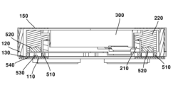
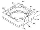
도 1은 본 실시예에 따른 렌즈 구동 장치의 사시도이고, 도 2는 도 1의 A-A에서 본 단면도이고, 도 3은 도 1의 B-B에서 본 단면도이고, 도 4는 도 1의 C-C에서 본 단면도이고, 도 5는 도 1의 D-D에서 본 단면도이고, 도 6은 본 실시예에 따른 렌즈 구동 장치를 광축에 수직한 방향으로 자른 단면도이고, 도 7 내지 도 9는 본 실시예에 따른 렌즈 구동 장치를 서로 다른 방향에서 본 분해사시도이고, 도 10은 본 실시예에 따른 렌즈 구동 장치에서 커버를 생략한 상태의 사시도이고, 도 11은 본 실시예에 따른 렌즈 구동 장치의 베이스와 OIS기판 및 관련 구성의 결합 구조를 도시하는 분해사시도이고, 도 12는 본 실시예에 따른 렌즈 구동 장치의 고정부의 일부 및 관련 구성을 도시하는 사시도이고, 도 13은 도 12의 고정부와 결합되는 OIS-x캐리어와 관련 구성을 도시하는 저면사시도이고, 도 14는 도 12 상태의 렌즈 구동 장치에 OIS-x캐리어가 배치된 모습을 도시하는 사시도이고, 도 15a는 14의 OIS-x캐리어와 결합되는 OIS-y캐리어와 관련 구성을 도시하는 저면사시도이고, 도 15b는 본 실시예에 따른 렌즈 구동 장치의 OIS-x캐리어와 OIS-y캐리어의 분해사시도이고, 도 15c는 본 실시예에 따른 렌즈 구동 장치의 OIS-x캐리어와 OIS-y캐리어의 저면분해사시도이고, 도 16은 도 14 상태의 렌즈 구동 장치에 OIS-y캐리어가 배치된 모습을 도시하는 사시도이고, 도 17은 본 실시예에 따른 렌즈 구동 장치의 OIS-x캐리어와 OIS-y캐리어 및 관련 구성을 도시하는 사시도이고, 도 18은 본 실시예에 따른 렌즈 구동 장치의 AF캐리어와 관련 구성을 도시하는 사시도이고, 도 19는 본 실시예에 따른 렌즈 구동 장치의 커버와 하우징을 제거한 상태의 사시도이고, 도 20은 도 19 상태의 렌즈 구동 장치에서 AF기판을 제거한 상태의 정면도이고, 도 21은 도 19 상태의 렌즈 구동 장치를 다른 방향에서 바라본 측면도이고, 도 22는 도 21 상태의 렌즈 구동 장치를 도 20과 반대 방향에서 바라본 측면도이고, 도 23은 본 실시예에 따른 렌즈 구동 장치에서 커버와 이동부를 제거한 상태의 사시도이고, 도 24는 본 실시예에 따른 렌즈 구동 장치의 구동부와 관련 구성을 도시하는 사시도이고, 도 25a는 도 24 상태의 렌즈 구동 장치를 다른 방향에서 바라본 사시도이고, 도 25b는 변형례에 따른 AF마그네트의 형상과 관련 구성을 도시하는 사시도이다.FIG. 1 is a perspective view of a lens driving device according to this embodiment, FIG. 2 is a cross-sectional view seen along A-A in FIG. 1, FIG. 3 is a cross-sectional view viewed along B-B in FIG. 1, and FIG. 4 is a cross-sectional view seen along C-C in FIG. 1. , FIG. 5 is a cross-sectional view seen from line D-D of FIG. 1, FIG. 6 is a cross-sectional view of the lens driving device according to this embodiment cut in a direction perpendicular to the optical axis, and FIGS. 7 to 9 are cross-sectional views of the lens driving device according to this embodiment. It is an exploded perspective view seen from different directions, Figure 10 is a perspective view of the lens driving device according to this embodiment with the cover omitted, and Figure 11 is a view of the base, OIS substrate, and related components of the lens driving device according to this embodiment. It is an exploded perspective view showing the coupling structure, FIG. 12 is a perspective view showing a part of the fixing part and related configuration of the lens driving device according to this embodiment, and FIG. 13 is an OIS-x carrier combined with the fixing part of FIG. 12 and It is a bottom perspective view showing the related configuration, and FIG. 14 is a perspective view showing the OIS-x carrier disposed in the lens driving device of FIG. 12, and FIG. 15A is an OIS-y carrier combined with the OIS-x carrier of FIG. 14. It is a bottom perspective view showing the related configuration, Figure 15b is an exploded perspective view of the OIS-x carrier and OIS-y carrier of the lens driving device according to this embodiment, and Figure 15c is an exploded perspective view of the OIS-y carrier of the lens driving device according to this embodiment. It is an exploded perspective view of the bottom of the It is a perspective view showing the OIS-x carrier, the OIS-y carrier and related configurations, FIG. 18 is a perspective view showing the AF carrier and related configurations of the lens driving device according to this embodiment, and FIG. 19 is a lens according to this embodiment. It is a perspective view with the cover and housing of the driving device removed, FIG. 20 is a front view with the AF substrate removed from the lens driving device in the state of FIG. 19, and FIG. 21 is a side view of the lens driving device in the state of FIG. 19 viewed from another direction. , FIG. 22 is a side view of the lens driving device in the state of FIG. 21 viewed from the direction opposite to that of FIG. 20, FIG. 23 is a perspective view of the lens driving device according to the present embodiment with the cover and moving part removed, and FIG. 24 is the present embodiment. It is a perspective view showing the driving unit and related configuration of the lens driving device according to , FIG. 25A is a perspective view of the lens driving device in the state of FIG. 24 viewed from another direction, and FIG. 25B shows the shape and related configuration of the AF magnet according to the modification. This is a perspective view.
렌즈 구동 장치(10)는 보이스 코일 모터(VCM, Voice Coil Motor)일 수 있다. 렌즈 구동 장치(10)는 렌즈 구동 모터일 수 있다. 렌즈 구동 장치(10)는 렌즈 구동 액츄에이터일 수 있다. 렌즈 구동 장치(10)는 AF 모듈을 포함할 수 있다. 렌즈 구동 장치(10)는 OIS 모듈을 포함할 수 있다.The
렌즈 구동 장치(10)는 고정부(100)를 포함할 수 있다. 고정부(100)는 이동부의 이동시에 상대적으로 고정된 부분일 수 있다. 이동부는 고정부(100)에 대해 이동할 수 있다.The
렌즈 구동 장치(10)는 베이스(110)를 포함할 수 있다. 고정부(100)는 베이스(110)를 포함할 수 있다. 베이스(110)는 OIS캐리어의 아래에 배치될 수 있다. 베이스(110)는 AF캐리어(300)의 아래에 배치될 수 있다. 베이스(110)는 커버(150)와 결합될 수 있다. AF캐리어(300)와 OIS캐리어(200)는 베이스(110) 상에 배치될 수 있다. AF캐리어(300)와 OIS캐리어(200)는 베이스(110)의 하판 상에 배치될 수 있다. AF캐리어(300)와 OIS캐리어(200)는 베이스(110) 내에 배치될 수 있다. AF캐리어(300)와 OIS캐리어(200)는 베이스(110)의 측판 내에 배치될 수 있다. OIS캐리어(200)에 대한 설명은 OIS-x캐리어(210)와 OIS-y캐리어(220) 각각에 적용될 수 있다.The
베이스(110)는 홈(111)을 포함할 수 있다. 홈(111)은 '요크 수용홈'일 수 있다. 홈(111)은 베이스(110)의 상면에 오목하게 형성될 수 있다. 홈(111)은 요크(440, 540)를 수용할 수 있다. 홈(111)에는 요크(440, 540)가 배치될 수 있다. 홈(111)은 요크(440, 540)와 대응하는 형상으로 형성될 수 있다. 홈(111)은 복수의 홈을 포함할 수 있다. 홈(111)은 4개의 홈을 포함할 수 있다. 홈(111)은 제1 내지 제4홈을 포함할 수 있다.
베이스(110)는 홈(112)을 포함할 수 있다. 홈(112)은 '단자 수용홈'일 수 있다. 홈(111)은 베이스(110)의 외측면에 오목하게 형성될 수 있다. 홈(111)에는 OIS기판(130)의 단자부(131)가 배치될 수 있다. 홈(111)에는 AF기판(140)의 적어도 일부가 배치될 수 있다. 홈(111)에는 AF기판(140)의 단자부가 배치될 수 있다.
베이스(110)의 홈(111)과 홈(112) 중 어느 하나를 '제1홈'이라 하고 다른 하나를 '제2홈'이라 할 수 있다.One of the
렌즈 구동 장치(10)는 하우징(120)을 포함할 수 있다. 고정부(100)는 하우징(120)을 포함할 수 있다. 하우징(120)은 베이스(110)에 배치될 수 있다. 하우징(120)은 베이스(110) 상에 배치될 수 있다. 하우징(120)은 OIS캐리어(200)의 외측에 배치될 수 있다. 하우징(120)은 OIS-x캐리어(210)의 외측에 배치될 수 있다. 하우징(120)은 OIS-y캐리어(220)의 외측에 배치될 수 있다. 하우징(120)은 AF캐리어(300)의 외측에 배치될 수 있다. 하우징(120)은 커버(150)와 OIS캐리어(200) 사이에 배치될 수 있다. 하우징(120)은 커버(150)와 AF캐리어(300) 사이에 배치될 수 있다. 하우징(120)은 커버(150)와 베이스(110) 사이에 배치될 수 있다. 하우징(120)은 OIS기판(130)에 배치될 수 있다. 하우징(120)은 OIS기판(130) 상에 배치될 수 있다. 하우징(120)은 이동하지 않을 수 있다.The
변형례로, 하우징(120)과 베이스(110)는 일체로 형성될 수 있다. 즉, 일체화된 베이스(110)만 구비되고 하우징(120)은 생략될 수 있다. 또는, 일체화된 하우징(120)만 구비되고 베이스(110)는 생략될 수 있다.In a variant example, the
또는, 베이스(110)만 생략될 수 있다. 이 경우 OIS기판(130)은 센서 베이스(40)와 하우징(120) 사이에 배치될 수 있다.Alternatively, only the base 110 may be omitted. In this case, the
하우징(120)은 단차부(121)를 포함할 수 있다. 단차부(121)는 하우징(120)의 외주면에 형성될 수 있다. 단차부(121)는 하우징(120)의 외주면의 하단에 돌출 형성될 수 있다. 단차부(121)에는 커버(150)의 측판(152)이 배치될 수 있다. 단차부(121)는 커버(150)의 측판(152)과 광축방향으로 오버랩될 수 있다.The
하우징(120)은 하판(122)을 포함할 수 있다. 하판(122)은 베이스(110) 상에 배치될 수 있다. 하판(122)은 OIS캐리어(200) 아래에 배치될 수 있다. 하판(122)은 AF캐리어(300) 아래에 배치될 수 있다. 하판(122)은 베이스(110)와 OIS캐리어(200) 사이에 배치될 수 있다. 하판(122)은 OIS캐리어(200)를 지지할 수 있다. 하판(122)은 AF캐리어(300)를 지지할 수 있다.
하우징(120)은 홈(123)을 포함할 수 있다. 홈(123)은 'OIS-x가이드볼 수용홈'일 수 있다. 홈(123)은 하우징(120)의 하판(122)의 상면에 형성될 수 있다. 홈(123)은 하우징(120)의 하판(122)의 상면에 오목하게 형성될 수 있다. 홈(123)은 OIS-x가이드볼(710)의 적어도 일부를 수용할 수 있다. 홈(123)에는 OIS-x가이드볼(710)이 배치될 수 있다. 홈(123)은 단면이 V자 형상인 V자 홈으로 형성될 수 있다. 홈(123)은 OIS-x가이드볼(710)과 2점에서 접촉될 수 있다. 홈(123)은 복수의 홈을 포함할 수 있다. 홈(123)은 4개의 홈을 포함할 수 있다. 홈(123)은 제1 내지 제4홈을 포함할 수 있다.
렌즈 구동 장치(10)는 기판을 포함할 수 있다. 기판은 OIS기판(130)을 포함할 수 있다. 기판은 AF기판(140)을 포함할 수 있다. OIS기판(130)과 AF기판(140)은 별도로 형성될 수 있다. 변형례로, OIS기판(130)과 AF기판(140)은 일체로 형성될 수 있다.The
렌즈 구동 장치(10)는 OIS기판(130)을 포함할 수 있다. 고정부(100)는 OIS기판(130)을 포함할 수 있다. OIS기판(130)은 FPCB(flexible printed circuit board)일 수 있다. OIS기판(130)은 베이스(110)에 배치될 수 있다. OIS기판(130)에는 OIS-x코일(410)이 배치될 수 있다. OIS기판(130)에는 OIS-y코일(510)이 배치될 수 있다. OIS기판(130)에는 OIS-x센서(430)가 배치될 수 있다. OIS기판(130)에는 OIS-y센서(530)가 배치될 수 있다. OIS기판(130)에는 OIS-x요크(440)가 배치될 수 있다. OIS기판(130)에는 OIS-y요크(540)가 배치될 수 있다. OIS기판(130)의 상면에는 OIS-x코일(410), OIS-y코일(510), OIS-x센서(430) 및 OIS-y센서(530)가 배치될 수 있다. OIS기판(130)의 하면에는 OIS-x요크(440)와 OIS-y요크(540)가 배치될 수 있다. OIS기판(130)은 OIS-x코일(410), OIS-y코일(510), OIS-x센서(430) 및 OIS-y센서(530)와 전기적으로 연결될 수 있다.The
OIS기판(130)은 몸체부를 포함할 수 있다. 몸체부는 베이스(110)의 상면에 배치될 수 있다. 몸체부에는 OIS-x코일(410), OIS-y코일(510), OIS-x센서(430), OIS-y센서(530), OIS-x요크(440) 및 OIS-y요크(540)가 배치될 수 있다. 몸체부는 중공홀을 포함할 수 있다.The
OIS기판(130)은 단자부(131)를 포함할 수 있다. 단자부(131)는 몸체부로부터 연장될 수 있다. 단자부(131)는 몸체부의 외측 가장자리로부터 연장될 수 있다. 단자부(131)는 몸체부의 외측 가장자리로부터 아래로 연장될 수 있다. 단자부(131)는 몸체부로부터 절곡될 수 있다. 단자부(131)는 베이스(110)의 측면에 배치될 수 있다. 단자부(131)에는 단자가 배치될 수 있다. 단자부(131)의 외면에는 복수의 단자가 배치될 수 있다. OIS기판(130)의 단자는 OIS-x코일(410), OIS-y코일(510), OIS-x센서(430) 및 OIS-y센서(530)와 전기적으로 연결될 수 있다.The
렌즈 구동 장치(10)는 AF기판(140)을 포함할 수 있다. 고정부(100)는 AF기판(140)을 포함할 수 있다. AF기판AF기판(140)은 FPCB(flexible printed circuit board)일 수 있다. AF기판(140)은 하우징(120)에 배치될 수 있다. AF기판(140)에는 AF코일(610)이 배치될 수 있다. AF기판(140)에는 AF센서(630)가 배치될 수 있다. AF기판(140)에는 AF요크(640)가 배치될 수 있다. AF기판(140)의 내면에는 AF코일(610)과 AF센서(630)가 배치될 수 있다. AF기판(140)의 외면에는 AF요크(640)가 배치될 수 있다. AF기판(141)은 AF코일(610)과 AF센서(630)와 전기적으로 연결될 수 있다.The
AF기판(140)은 단자(141)를 포함할 수 있다. AF기판(141)의 단자(141)는 AF코일(610)과 AF센서(630)와 전기적으로 연결될 수 있다. 단자(141)는 AF기판(140)의 외면의 하단부에 형성될 수 있다. 단자(141)는 복수의 단자를 포함할 수 있다.
렌즈 구동 장치(10)는 커버(150)를 포함할 수 있다. 고정부(100)는 커버(150)를 포함할 수 있다. 커버(150)는 베이스(110)에 배치될 수 있다. 커버(150)는 베이스(110)에 결합될 수 있다. 커버(150)는 베이스(110)에 고정될 수 있다. 커버(150)는 하우징(120)에 배치될 수 있다. 커버(150)는 하우징(120)에 결합될 수 있다. 커버(150)는 하우징(120)에 고정될 수 있다. 커버(150)는 AF캐리어(300)를 내부에 수용할 수 있다. 커버(150)는 OIS캐리어(200)를 내부에 수용할 수 있다. 커버(150)는 쉴드부재일 수 있다. 커버(150)는 쉴드캔일 수 있다.The
커버(150)는 상판(151)을 포함할 수 있다. 상판(151)은 이동부 상에 배치될 수 있다. 이동부의 상측 이동은 이동부가 상판(151)에 접촉되는 것에 의해 제한될 수 있다. 상판(151)은 광이 통과하는 홀을 포함할 수 있다.Cover 150 may include a
커버(150)는 측판(152)을 포함할 수 있다. 측판(152)은 상판(151)으로부터 연장될 수 있다. 측판(152)은 하우징(120)에 배치될 수 있다. 측판(152)은 하우징(120)의 외측면의 하단부에 돌출형성되는 단차부(121)에 배치될 수 있다. 측판(152)은 복수의 측판을 포함할 수 있다. 측판(152)은 4개의 측판을 포함할 수 있다. 측판(152)은 서로 반대편에 배치되는 제1측판과 제2측판과, 서로 반대편에 배치되는 제3측판과 제4측판을 포함할 수 있다.Cover 150 may include a
렌즈 구동 장치(10)는 이동부를 포함할 수 있다. 이동부는 고정부(100)에 배치될 수 있다. 이동부는 고정부(100) 내에 배치될 수 있다. 이동부는 고정부(100) 상에 배치될 수 있다. 이동부는 고정부(100)에 이동가능하게 배치될 수 있다. 이동부는 구동부에 의해 고정부(100)를 기준으로 이동할 수 있다. 이동부는 AF 구동시에 이동할 수 있다. 이동부는 OIS 구동시에 이동할 수 있다. 이동부에는 렌즈가 결합될 수 있다. The
이동부는 OIS이동부를 포함할 수 있다. 이동부는 OIS-x이동부를 포함할 수 있다. 이동부는 OIS-y이동부를 포함할 수 있다. 이동부는 AF이동부를 포함할 수 있다.The moving part may include the OIS moving part. The moving part may include the OIS-x moving part. The moving part may include the OIS-y moving part. The moving unit may include an AF moving unit.
렌즈 구동 장치(10)는 OIS이동부를 포함할 수 있다. OIS이동부는 고정부(100)에 배치될 수 있다. OIS이동부는 고정부(100) 내에 배치될 수 있다. OIS이동부는 고정부(100) 상에 배치될 수 있다. OIS이동부는 고정부(100)와 AF이동부 사이에 배치될 수 있다. OIS이동부는 이동가능하게 배치될 수 있다. OIS이동부는 OIS구동부에 의해 광축에 수직한 방향으로 이동할 수 있다. OIS이동부는 손떨림 보정(OIS) 구동시에 이동할 수 있다.The
렌즈 구동 장치(10)는 OIS캐리어(200)를 포함할 수 있다. OIS캐리어(200)는 'OIS홀더'일 수 있다. OIS캐리어(200)는 고정부(100)에 배치될 수 있다. OIS캐리어(200)는 고정부(100) 내에 배치될 수 있다. OIS캐리어(200)는 고정부(100) 상에 배치될 수 있다. OIS캐리어(200)는 고정부(100)와 AF이동부 사이에 배치될 수 있다. OIS캐리어(200)는 이동가능하게 배치될 수 있다. OIS캐리어(200)는 OIS구동부에 의해 광축에 수직한 방향으로 이동할 수 있다. OIS캐리어(200)는 손떨림 보정(OIS) 구동시에 이동할 수 있다.The
렌즈 구동 장치(10)는 OIS-x이동부를 포함할 수 있다. OIS이동부는 OIS-x이동부를 포함할 수 있다. OIS-x이동부는 고정부(100)에 배치될 수 있다. OIS-x이동부는 고정부(100) 내에 배치될 수 있다. OIS-x이동부는 고정부(100) 상에 배치될 수 있다. OIS-x이동부는 고정부(100)와 OIS-y이동부 사이에 배치될 수 있다. OIS-x이동부는 고정부(100)와 AF이동부 사이에 배치될 수 있다. OIS-x이동부는 이동가능하게 배치될 수 있다. OIS-x이동부는 OIS-x구동부에 의해 광축에 수직한 x축 방향으로 이동할 수 있다.The
렌즈 구동 장치(10)는 OIS-x캐리어(210)를 포함할 수 있다. 이동부는 OIS-x캐리어(210)를 포함할 수 있다. OIS-x이동부는 OIS-x캐리어(210)를 포함할 수 있다. OIS캐리어(200)는 OIS-x캐리어(210)를 포함할 수 있다. OIS-x캐리어(210)는 'OIS-x홀더'일 수 있다. OIS-x캐리어(210)는 고정부(100)에 배치될 수 있다. OIS-x캐리어(210)는 하우징(120)에 배치될 수 있다. OIS-x캐리어(210)는 고정부(100) 내에 배치될 수 있다. OIS-x캐리어(210)는 하우징(120) 내에 배치될 수 있다. OIS-x캐리어(210)는 고정부(100) 상에 배치될 수 있다. OIS-x캐리어(210)는 베이스(110) 상에 배치될 수 있다. OIS-x캐리어(210)는 하우징(120) 상에 배치될 수 있다. OIS-x캐리어(210)는 고정부(100)와 OIS-y캐리어(220) 사이에 배치될 수 있다. OIS-x캐리어(210)는 고정부(100)와 AF캐리어(300) 사이에 배치될 수 있다. OIS-x캐리어(210)는 이동가능하게 배치될 수 있다. OIS-x캐리어(210)는 OIS-x구동부에 의해 광축에 수직한 x축 방향으로 이동할 수 있다.The
OIS-x캐리어(210)는 x축 방향의 양측으로 하우징(120)에 접촉할 때까지 이동 가능할 수 있다. OIS-x캐리어(210)와 하우징(120)이 접촉하는 지점이 최대이동구간일 수 있다. OIS-x캐리어(210)는 최대이동구간 내에서 이동할 수 있다. 즉, OIS-x캐리어(210)의 x축 방향으로의 이동 거리의 제한은 하우징(120)과의 접촉에 의할 수 있다. 다시 말해, OIS-x캐리어(210)는 x축 방향으로의 이동 과정에서 OIS-y캐리어(220) 등과 접촉하지 않고 하우징(120)에 접촉할 수 있다. OIS-x캐리어(210)는 하우징(120)과 접촉하는 스토퍼를 포함할 수 있다. 하우징(120)은 OIS-x캐리어(210)의 스토퍼와 접촉하는 스토퍼를 포함할 수 있다.The OIS-
OIS-x캐리어(210)는 홈(211)을 포함할 수 있다. 홈(211)은 'OIS-x가이드볼 수용홈'일 수 있다. 홈(211)은 OIS-x캐리어(210)의 하면에 형성될 수 있다. 홈(211)은 OIS-x캐리어(210)의 하면에 오목하게 형성될 수 있다. 홈(211)은 OIS-x가이드볼(710)의 적어도 일부를 수용할 수 있다. 홈(211)에는 OIS-x가이드볼(710)이 배치될 수 있다. 홈(211)은 단면이 V자 형상인 V자 홈으로 형성될 수 있다. 홈(211)은 OIS-x가이드볼(710)과 2점에서 접촉될 수 있다. 홈(211)은 복수의 홈을 포함할 수 있다. 홈(211)은 4개의 홈을 포함할 수 있다. 홈(211)은 제1 내지 제4홈을 포함할 수 있다.The OIS-
OIS-x캐리어(210)의 홈(211)은 하우징(120)의 홈(123)과 대응하는 위치에 형성될 수 있다. OIS-x캐리어(210)의 홈(211)은 하우징(120)의 홈(123)과 광축방향으로 대응하는 위치에 형성될 수 있다. OIS-x캐리어(210)의 홈(211)은 하우징(120)의 홈(123)과 광축방향으로 오버랩될 수 있다. OIS-x캐리어(210)의 홈(211)은 하우징(120)의 홈(123)과 마주보게 배치될 수 있다.The
OIS-x캐리어(210)는 홈(212)을 포함할 수 있다. 홈(212)은 'OIS-y가이드볼 수용홈'일 수 있다. 홈(212)은 OIS-x캐리어(210)의 상면에 형성될 수 있다. 홈(212)은 OIS-x캐리어(210)의 상면에 오목하게 형성될 수 있다. 홈(212)은 OIS-y가이드볼(720)의 적어도 일부를 수용할 수 있다. 홈(212)에는 OIS-y가이드볼(720)이 배치될 수 있다. 홈(212)은 단면이 V자 형상인 V자 홈으로 형성될 수 있다. 홈(212)은 OIS-y가이드볼(720)과 2점에서 접촉될 수 있다. 홈(212)은 복수의 홈을 포함할 수 있다. 홈(212)은 4개의 홈을 포함할 수 있다. 홈(212)은 제1 내지 제4홈을 포함할 수 있다.The OIS-
OIS-x캐리어(210)는 홈(213)을 포함할 수 있다. 홈(213)은 'OIS-y캐리어 돌출부 회피홈'일 수 있다. 홈(213)은 OIS-x캐리어(210)의 코너 영역에 형성될 수 있다. 홈(213)은 OIS-x캐리어(210)의 4개의 코너 영역 중 2개의 코너 영역에 형성될 수 있다. 2개의 코너 영역은 서로 대각 방향에 배치될 수 있다. 홈(213)에는 OIS-y캐리어(220)의 돌출부(223)가 배치될 수 있다. 홈(213)은 OIS-x캐리어(210)와 OIS-y캐리어(220)의 돌출부(223)가 서로 간섭되지 않도록 형성될 수 있다. 홈(213)에는 OIS-y캐리어(220)의 돌출부(223)가 삽입될 수 있다. 홈(213)은 돌출부(223)의 크기보다 클 수 있다. OIS-y캐리어(220)가 이동하는 경우에도 돌출부(223)는 홈(213)과 접촉하지 않을 수 있다.The OIS-
OIS-x캐리어(210)의 홈(211), 홈(212) 및 홈(213) 중 어느 하나를 '제1홈'이라 하고 다른 하나를 '제2홈'이라 하고 또 다른 하나를 '제3홈'이라 할 수 있다.One of the
렌즈 구동 장치(10)는 OIS-y이동부를 포함할 수 있다. OIS이동부는 OIS-y이동부를 포함할 수 있다. OIS-y이동부는 고정부(100)에 배치될 수 있다. OIS-y이동부는 고정부(100) 내에 배치될 수 있다. OIS-y이동부는 고정부(100) 상에 배치될 수 있다. OIS-y이동부는 OIS-x이동부와 AF이동부 사이에 배치될 수 있다. OIS-y이동부는 고정부(100)와 AF이동부 사이에 배치될 수 있다. OIS-y이동부는 이동가능하게 배치될 수 있다. OIS-y이동부는 OIS-x구동부에 의해 광축에 수직한 y축 방향으로 이동할 수 있다.The
렌즈 구동 장치(10)는 OIS-y캐리어(220)를 포함할 수 있다. 이동부는 OIS-y캐리어(220)를 포함할 수 있다. OIS-y이동부는 OIS-y캐리어(220)를 포함할 수 있다. OIS캐리어(200)는 OIS-y캐리어(220)를 포함할 수 있다. OIS-y캐리어(220)는 'OIS-y홀더'일 수 있다. OIS-y캐리어(220)는 고정부(100)에 배치될 수 있다. OIS-y캐리어(220)는 고정부(100) 내에 배치될 수 있다. OIS-y캐리어(220)는 하우징(120) 내에 배치될 수 있다. OIS-y캐리어(220)는 고정부(100) 상에 배치될 수 있다. OIS-y캐리어(220)는 베이스(110) 상에 배치될 수 있다. OIS-y캐리어(220)는 OIS-x캐리어(210)에 배치될 수 있다. OIS-y캐리어(220)는 OIS-x캐리어(210) 상에 배치될 수 있다. OIS-y캐리어(220)는 고정부(100)와 AF캐리어(300) 사이에 배치될 수 있다. OIS-y캐리어(220)는 OIS-x캐리어(210)와 AF캐리어(300) 사이에 배치될 수 있다. OIS-y캐리어(220)는 이동가능하게 배치될 수 있다. OIS-y캐리어(220)는 OIS-y구동부에 의해 광축에 수직한 y축 방향으로 이동할 수 있다.The
OIS-y캐리어(220)는 홈(221)을 포함할 수 있다. 홈(221)은 'AF가이드볼 수용홈'일 수 있다. 홈(221)은 OIS-y캐리어(220)의 내측면에 형성될 수 있다. 홈(221)은 OIS-y캐리어(220)의 내측면에 오목하게 형성될 수 있다. 홈(221)은 AF가이드볼(730)의 적어도 일부를 수용할 수 있다. 홈(221)에는 AF가이드볼(730)이 배치될 수 있다. 홈(221)은 단면이 V자 형상인 V자 홈으로 형성될 수 있다. 홈(221)은 AF가이드볼(730)과 2점에서 접촉될 수 있다. 홈(221)은 복수의 홈을 포함할 수 있다. 홈(221)은 2개의 홈을 포함할 수 있다. 홈(221)은 제1 및 제2홈을 포함할 수 있다. 2개의 홈 각각에는 3개의 볼이 배치될 수 있다.The OIS-
OIS-y캐리어(220)는 홈(222)을 포함할 수 있다. 홈(222)은 'OIS-y가이드볼 수용홈'일 수 있다. 홈(222)은 OIS-y캐리어(220)의 하면에 형성될 수 있다. 홈(222)은 OIS-y캐리어(220)의 하면에 오목하게 형성될 수 있다. 홈(222)은 OIS-y가이드볼(720)의 적어도 일부를 수용할 수 있다. 홈(222)에는 OIS-y가이드볼(720)이 배치될 수 있다. 홈(222)은 단면이 V자 형상인 V자 홈으로 형성될 수 있다. 홈(222)은 OIS-y가이드볼(720)과 2점에서 접촉될 수 있다. 홈(222)은 복수의 홈을 포함할 수 있다. 홈(222)은 4개의 홈을 포함할 수 있다. 홈(222)은 제1 내지 제4홈을 포함할 수 있다.The OIS-
OIS-y캐리어(220)의 홈(222)은 OIS-x캐리어(210)의 홈(212)과 대응하는 위치에 형성될 수 있다. OIS-y캐리어(220)의 홈(222)은 OIS-x캐리어(210)의 홈(212)과 광축방향으로 대응하는 위치에 형성될 수 있다. OIS-y캐리어(220)의 홈(222)은 OIS-x캐리어(210)의 홈(212)과 광축방향으로 오버랩될 수 있다. OIS-y캐리어(220)의 홈(222)은 OIS-x캐리어(210)의 홈(212)과 마주보게 배치될 수 있다.The
OIS-y캐리어(220)는 돌출부(223)를 포함할 수 있다. 돌출부(223)는 '마그네트 배치부'일 수 있다. 돌출부(223)는 '돌기'일 수 있다. 돌출부(223)에는 OIS-y마그네트(520)가 배치될 수 있다. 돌출부(223)는 OIS-y마그네트(520)가 배치되는 홈을 포함할 수 있다. 돌출부(223)는 OIS-x캐리어(210)와 광축에 수직한 방향으로 오버랩될 수 있다. 돌출부(223)는 OIS-y코일(510) 방향으로 돌출될 수 있다. 돌출부(223)는 아래방향으로 돌출될 수 있다.The OIS-
OIS-y캐리어(220)는 돌출부(224)를 포함할 수 있다. 돌출부(224)는 OIS-x캐리어(210)의 홈과 형합되는 형상일 수 있다. 다만, 돌출부(224)는 OIS-x캐리어(210)와 접촉되지 않을 수 있다.OIS-
OIS-y캐리어(220)의 홈(221)과 홈(222) 중 어느 하나를 '제1홈'이라 하고 다른 하나를 '제2홈'이라 할 수 있다. OIS-y캐리어(220)의 돌출부(223)와 돌출부(224) 중 어느 하나를 '제1돌출부'라 하고 다른 하나를 '제2돌출부'라 할 수 있다.One of the
렌즈 구동 장치(10)는 AF이동부를 포함할 수 있다. 이동부는 AF이동부를 포함할 수 있다. AF이동부는 고정부(100)에 배치될 수 있다. AF이동부는 고정부(100) 내에 배치될 수 있다. AF이동부는 고정부(100) 상에 배치될 수 있다. AF이동부는 OIS이동부에 배치될 수 있다. AF이동부는 OIS이동부 내에 배치될 수 있다. AF이동부는 OIS이동부 상에 배치될 수 있다. AF이동부는 고정부(100)에 이동가능하게 배치될 수 있다. AF이동부는 OIS이동부에 이동가능하게 배치될 수 있다. AF이동부는 AF구동부에 의해 고정부(100)와 OIS이동부에 대해 광축방향으로 이동할 수 있다. AF이동부는 오토 포커스(AF) 구동시에 이동할 수 있다.The
렌즈 구동 장치(10)는 AF캐리어(300)를 포함할 수 있다. 이동부는 AF캐리어(300)를 포함할 수 있다. AF캐리어(300)는 'AF홀더'일 수 있다. AF캐리어(300)는 '보빈'일 수 있다. AF캐리어(300)는 하우징(120) 내에 배치될 수 있다. AF캐리어(300)는 베이스(110) 상에 배치될 수 있다. AF캐리어(300)는 커버(150) 내에 배치될 수 있다. AF캐리어(300)는 OIS캐리어(200) 상에 배치될 수 있다. AF캐리어(300)는 OIS캐리어(200) 내에 배치될 수 있다. AF캐리어(300)는 OIS-x캐리어(210) 상에 배치될 수 있다. AF캐리어(300)는 OIS-y캐리어(220) 상에 배치될 수 있다. AF캐리어(300)는 OIS-y캐리어(220)에 배치될 수 있다. AF캐리어(300)는 광축방향으로 이동가능하게 배치될 수 있다.The
AF캐리어(300)는 OIS캐리어(200)와 함께 이동할 수 있다. AF캐리어(300)는 OIS-x캐리어(210)와 함께 이동할 수 있다. AF캐리어(300)는 OIS-y캐리어(220)와 함께 이동할 수 있다. OIS구동부에 의해 OIS캐리어(200)가 이동하는 경우 AF캐리어(300)도 OIS캐리어(200)와 함께 이동할 수 있다.The
AF캐리어(300)는 홈(310)을 포함할 수 있다. 홈(310)은 'AF가이드볼 수용홈'일 수 있다. 홈(310)은 AF캐리어(300)의 외측면에 형성될 수 있다. 홈(310)은 AF캐리어(300)의 외측면에 오목하게 형성될 수 있다. 홈(310)은 AF가이드볼(730)의 적어도 일부를 수용할 수 있다. 홈(310)에는 AF가이드볼(730)이 배치될 수 있다. 홈(310)은 단면이 V자 형상인 V자 홈으로 형성될 수 있다. 홈(310)은 AF가이드볼(730)과 2점에서 접촉될 수 있다. 홈(310)은 복수의 홈을 포함할 수 있다. 홈(310)은 2개의 홈을 포함할 수 있다. 홈(310)은 제1 및 제2홈을 포함할 수 있다. 2개의 홈 각각에는 3개의 볼이 배치될 수 있다.The
AF캐리어(300)의 홈(310)은 OIS-y캐리어(220)의 홈(221)과 대응하는 위치에 형성될 수 있다. AF캐리어(300)의 홈(310)은 OIS-y캐리어(220)의 홈(221)과 광축에 수직한 방향으로 대응하는 위치에 형성될 수 있다. AF캐리어(300)의 홈(310)은 OIS-y캐리어(220)의 홈(221)과 광축과 수직한 방향으로 오버랩될 수 있다. AF캐리어(300)의 홈(310)은 OIS-y캐리어(220)의 홈(221)과 광축과 수직한 y축 방향으로 오버랩될 수 있다. AF캐리어(300)의 홈(310)은 OIS-y캐리어(220)의 홈(221)과 마주보게 배치될 수 있다.The
AF캐리어(300)는 상판(320)을 포함할 수 있다. AF캐리어(300)의 상판(320)은 OIS-y캐리어(220) 상에 배치될 수 있다. AF캐리어(300)의 상판(320)은 OIS-y캐리어(220)와 광축방향으로 오버랩될 수 있다. AF캐리어(300)의 상판(320)은 OIS-y캐리어(220)와 커버(150)의 상판(151) 사이에 배치될 수 있다.The
렌즈 구동 장치(10)는 구동부를 포함할 수 있다. 구동부는 고정부(100)에 대해 이동부를 이동시킬 수 있다. 구동부는 AF 구동부를 포함할 수 있다. 구동부는 OIS 구동부를 포함할 수 있다. 구동부는 코일과 마그네트를 포함할 수 있다.The
OIS구동부는 렌즈를 광축에 수직한 방향으로 이동시킬 수 있다. OIS구동부는 고정부(100)에 대해 OIS캐리어(200)를 광축에 수직한 방향으로 이동시킬 수 있다. OIS구동부는 OIS-x구동부를 포함할 수 있다. OIS구동부는 OIS-y구동부를 포함할 수 있다.The OIS driving unit can move the lens in a direction perpendicular to the optical axis. The OIS driving unit may move the
렌즈 구동 장치(10)는 OIS-x구동부를 포함할 수 있다. OIS-x구동부는 OIS-x캐리어(210)를 광축에 수직한 x축 방향으로 이동시킬 수 있다. OIS-x구동부는 전자기력을 통해 OIS-x캐리어(210)를 광축에 수직한 x축 방향으로 이동시킬 수 있다. OIS-x구동부는 코일과 마그네트를 포함할 수 있다. OIS-x구동부는 광축에 수직한 x축 방향으로 OIS캐리어(200)를 이동시키는 OIS-x마그네트(420)와 OIS-x코일(410)를 포함할 수 있다. OIS-x구동부는 광축에 수직한 x축 방향으로 OIS-x캐리어(210)를 이동시키는 OIS-x마그네트(420)와 OIS-x코일(410)를 포함할 수 있다. OIS-x구동부는 광축에 수직한 x축 방향으로 OIS-x캐리어(210)와 OIS-y캐리어(220)를 이동시키는 OIS-x마그네트(420)와 OIS-x코일(410)를 포함할 수 있다.The
렌즈 구동 장치(10)는 OIS-x코일(410)을 포함할 수 있다. OIS-x구동부는 OIS-x코일(410)을 포함할 수 있다. OIS-x코일(410)은 OIS-x마그네트(420)와 상호작용할 수 있다. OIS-x코일(410)은 광축에 수직한 x축 방향으로 OIS-x마그네트(420)를 이동시킬 수 있다. OIS-x코일(410)은 OIS-x마그네트(420)와의 상호작용을 통해 OIS-x마그네트(420)를 x축 방향으로 이동시킬 수 있다. OIS-x코일(410)은 OIS-x마그네트(420)와 대향할 수 있다. OIS-x코일(410)은 OIS-x마그네트(420)와 마주볼 수 있다. OIS-x코일(410)은 OIS-x마그네트(420)와 대응하는 위치에 배치될 수 있다. OIS-x코일(410)은 광축방향으로 OIS-x마그네트(420)와 오버랩될 수 있다. OIS-x코일(410)은 OIS기판(130)에 배치될 수 있다. OIS-x코일(410)은 OIS기판(130)의 상면에 배치될 수 있다. OIS-x코일(410)은 OIS기판(130)의 몸체부에 배치될 수 있다. OIS-x코일(410)은 베이스(110)에 배치될 수 있다. OIS-x코일(410)은 고정부(100)에 배치될 수 있다.The
렌즈 구동 장치(10)는 OIS-x마그네트(420)를 포함할 수 있다. OIS-x구동부는 OIS-x마그네트(420)를 포함할 수 있다. OIS-x마그네트(420)는 OIS-x캐리어(210)에 배치될 수 있다. OIS-x마그네트(420)는 OIS-x캐리어(210)의 하면에 배치될 수 있다. OIS-x마그네트(420)는 OIS-x캐리어(210)에 고정될 수 있다. OIS-x마그네트(420)는 OIS-x캐리어(210)에 결합될 수 있다. OIS-x마그네트(420)는 OIS-x캐리어(210)에 접착제로 접착될 수 있다. OIS-x마그네트(420)는 커버(150) 내에 배치될 수 있다. OIS-x마그네트(420)는 OIS-x코일(410)과 상호작용할 수 있다. OIS-x마그네트(420)는 OIS-x코일(410)과 전자기적 상호작용할 수 있다. OIS-x마그네트(420)는 OIS-x코일(410)과 대응하는 위치에 배치될 수 있다. OIS-x마그네트(420)는 OIS-x코일(410)과 마주볼 수 있다. OIS-x마그네트(420)는 OIS-x코일(410)과 대향할 수 있다. OIS-x마그네트(420)는 OIS-x코일(410)과 광축방향으로 오버랩될 수 있다.The
OIS-x마그네트(420)와 OIS-y마그네트(520)는 광축방향과 수직한 가상의 평면과 중첩될 수 있다. 이때, 가상의 평면과 AF마그네트(620)는 중첩되지 않을 수 있다. OIS-x마그네트(420)와 OIS-y마그네트(520)는 광축과 수직한 방향으로 서로 오버랩될 수 있다. OIS-x마그네트(420)와 OIS-y마그네트(520)는 광축과 수직한 방향으로 AF마그네트(620)와 오버랩되지 않을 수 있다.The OIS-
OIS-x마그네트(420)는 4극 마그네트일 수 있다. OIS-x마그네트(420)는 4극 착자 마그네트를 포함할 수 있다. OIS-x마그네트(420)는 N극과 S극을 포함하는 제1마그네트부와, N극과 S극을 포함하는 제2마그네트부를 포함할 수 있다. 제1마그네트부와 제2마그네트부는 수평방향으로 배치될 수 있다. 제1마그네트부와 제2마그네트부는 수평방향으로 이격되고 제1마그네트부와 제2마그네트부 사이에는 중립부가 배치될 수 있다. 중립부는 광축과 평행하게 배치될 수 있다.The OIS-
렌즈 구동 장치(10)는 OIS-x센서(430)를 포함할 수 있다. OIS-x구동부는 OIS-x센서(430)를 포함할 수 있다. OIS-x센서(430)는 OIS기판(130)에 배치될 수 있다. OIS-x센서(430)는 OIS기판(130)의 몸체부에 배치될 수 있다. OIS-x센서(430)는 홀센서(Hall sensor)를 포함할 수 있다. OIS-x센서(430)는 OIS-x마그네트(420)를 감지할 수 있다. OIS-x센서(430)는 OIS-x마그네트(420)의 자기력을 감지할 수 있다. OIS-x센서(430)는 OIS-x코일(410) 내에 배치될 수 있다. OIS-x센서(430)는 광축에 수직한 방향으로 OIS-x코일(410)과 오버랩될 수 있다. OIS-x센서(430)는 OIS-x마그네트(420)와 대향할 수 있다. OIS-x센서(430)는 OIS-x마그네트(420)와 대응하는 위치에 배치될 수 있다. OIS-x센서(430)는 OIS-x마그네트(420)의 이동을 감지할 수 있다. OIS-x센서(430)에 의해 감지된 OIS-x마그네트(420)의 이동량 또는 위치는 x축 방향으로의 손떨림 보정 구동의 피드백을 위해 사용될 수 있다.The
렌즈 구동 장치(10)는 OIS-x요크(440)를 포함할 수 있다. OIS-x요크(440)는 OIS기판(130)에 배치될 수 있다. OIS-x요크(440)는 OIS기판(130)의 하면에 배치될 수 있다. OIS-x요크(440)는 베이스(110)의 홈(111)에 배치될 수 있다. OIS-x요크(440)는 OIS-x코일(410)과 대응하는 위치에 배치될 수 있다. OIS-x요크(440)는 OIS-x마그네트(420)와 대응하는 위치에 배치될 수 있다.The
OIS-x마그네트(420)와 OIS-x요크(440) 사이에는 인력이 작용할 수 있다. OIS-x마그네트(420)는 OIS-x요크(440)를 향하는 방향으로 가압될 수 있다. OIS-x캐리어(210)는 하우징(120)의 하판(122)을 향하는 방향으로 가압될 수 있다. OIS-x캐리어(210)는 하우징(120)의 하판(122)과의 사이에 OIS-x가이드볼(710)을 두고 하우징(120)의 하판(122)을 향하는 방향으로 가압될 수 있다. 이를 통해, OIS-x가이드볼(710)은 OIS-x캐리어(210)와 하우징(120)의 하판(122)에 접촉된 상태로 유지될 수 있다.An attractive force may act between the OIS-x magnet (420) and the OIS-x yoke (440). The OIS-
렌즈 구동 장치(10)는 OIS-y구동부를 포함할 수 있다. OIS-y구동부는 OIS-y캐리어(220)를 광축에 수직한 y축 방향으로 이동시킬 수 있다. OIS-y구동부는 전자기력을 통해 OIS-y캐리어(220)를 광축에 수직한 y축 방향으로 이동시킬 수 있다. OIS-y구동부는 코일과 마그네트를 포함할 수 있다. OIS-y구동부는 광축과 x축 모두에 수직한 y축 방향으로 OIS캐리어(200)를 이동시키는 OIS-y마그네트(520)와 OIS-y코일(510)을 포함할 수 있다. OIS-y구동부는 광축과 x축 모두에 수직한 y축 방향으로 OIS-y캐리어(220)를 이동시키는 OIS-y마그네트(520)와 OIS-y코일(510)을 포함할 수 있다.The
렌즈 구동 장치(10)는 OIS-y코일(510)을 포함할 수 있다. OIS-y구동부는 OIS-y코일(510)을 포함할 수 있다. OIS-y코일(510)은 OIS-y마그네트(520)와 상호작용할 수 있다. OIS-y코일(510)은 광축에 수직한 y축 방향으로 OIS-y마그네트(520)를 이동시킬 수 있다. OIS-y코일(510)은 OIS-y마그네트(520)와의 상호작용을 통해 OIS-y마그네트(520)를 y축 방향으로 이동시킬 수 있다. OIS-y코일(510)은 OIS-y마그네트(520)와 대향할 수 있다. OIS-y코일(510)은 OIS-y마그네트(520)와 마주볼 수 있다. OIS-y코일(510)은 OIS-y마그네트(520)와 대응하는 위치에 배치될 수 있다. OIS-y코일(510)은 광축방향으로 OIS-y마그네트(520)와 오버랩될 수 있다. OIS-y코일(510)은 OIS기판(130)에 배치될 수 있다. OIS-y코일(510)은 OIS기판(130)의 상면에 배치될 수 있다. OIS-y코일(510)은 OIS기판(130)의 몸체부에 배치될 수 있다. OIS-y코일(510)은 베이스(110)에 배치될 수 있다. OIS-y코일(510)은 고정부(100)에 배치될 수 있다.The
렌즈 구동 장치(10)는 OIS-y마그네트(520)를 포함할 수 있다. OIS-y구동부는 OIS-y마그네트(520)를 포함할 수 있다. OIS-y마그네트(520)는 OIS-y캐리어(220)에 배치될 수 있다. OIS-y마그네트(520)는 OIS-y캐리어(220)의 하면에 배치될 수 있다. OIS-y마그네트(520)는 OIS-y캐리어(220)에 고정될 수 있다. OIS-y마그네트(520)는 OIS-y캐리어(220)에 결합될 수 있다. OIS-y마그네트(520)는 OIS-y캐리어(220)에 접착제로 접착될 수 있다. OIS-y마그네트(520)는 커버(150) 내에 배치될 수 있다. OIS-y마그네트(520)는 OIS-y코일(510)과 상호작용할 수 있다. OIS-y마그네트(520)는 OIS-y코일(510)과 전자기적 상호작용할 수 있다. OIS-y마그네트(520)는 OIS-y코일(510)과 대응하는 위치에 배치될 수 있다. OIS-y마그네트(520)는 OIS-y코일(510)과 마주볼 수 있다. OIS-y마그네트(520)는 OIS-y코일(510)과 대향할 수 있다. OIS-y마그네트(520)는 OIS-y코일(510)과 광축방향으로 오버랩될 수 있다. OIS-y마그네트(520)는 OIS-y캐리어(220)와 OIS-y코일(510) 사이에 배치될 수 있다. OIS-y마그네트(520)는 OIS-x가이드볼(710)보다 낮게 배치될 수 있다.The
OIS-y마그네트(520)는 4극 마그네트일 수 있다. OIS-y마그네트(520)는 4극 착자 마그네트를 포함할 수 있다. OIS-y마그네트(520)는 N극과 S극을 포함하는 제1마그네트부와, N극과 S극을 포함하는 제2마그네트부를 포함할 수 있다. 제1마그네트부와 제2마그네트부는 수평방향으로 배치될 수 있다. 제1마그네트부와 제2마그네트부는 수평방향으로 이격되고 제1마그네트부와 제2마그네트부 사이에는 중립부가 배치될 수 있다. 중립부는 광축과 평행하게 배치될 수 있다.The OIS-
렌즈 구동 장치(10)는 OIS-y센서(530)를 포함할 수 있다. OIS-y구동부는 OIS-y센서(530)를 포함할 수 있다. OIS-y센서(530)는 OIS기판(130)에 배치될 수 있다. OIS-y센서(530)는 OIS기판(130)의 몸체부에 배치될 수 있다. OIS-y센서(530)는 홀센서(Hall sensor)를 포함할 수 있다. OIS-y센서(530)는 OIS-y마그네트(520)를 감지할 수 있다. OIS-y센서(530)는 OIS-y마그네트(520)의 자기력을 감지할 수 있다. OIS-y센서(530)는 OIS-y코일(510) 내에 배치될 수 있다. OIS-y센서(530)는 광축에 수직한 방향으로 OIS-y코일(510)과 오버랩될 수 있다. OIS-y센서(530)는 OIS-y마그네트(520)와 대향할 수 있다. OIS-y센서(530)는 OIS-y마그네트(520)와 대응하는 위치에 배치될 수 있다. OIS-y센서(530)는 OIS-y마그네트(520)의 이동을 감지할 수 있다. OIS-y센서(530)에 의해 감지된 OIS-y마그네트(520)의 이동량 또는 위치는 y축 방향으로의 손떨림 보정 구동의 피드백을 위해 사용될 수 있다.The
렌즈 구동 장치(10)는 OIS-y요크(540)를 포함할 수 있다. OIS-y요크(540)는 OIS기판(130)에 배치될 수 있다. OIS-y요크(540)는 OIS기판(130)의 하면에 배치될 수 있다. OIS-y요크(540)는 베이스(110)의 홈(111)에 배치될 수 있다. OIS-y요크(540)는 OIS-y코일(510)과 대응하는 위치에 배치될 수 있다. OIS-y요크(540)는 OIS-y마그네트(520)와 대응하는 위치에 배치될 수 있다.The
OIS-y마그네트(520)와 OIS-y요크(540) 사이에는 인력이 작용할 수 있다. OIS-y마그네트(520)는 OIS-y요크(540)를 향하는 방향으로 가압될 수 있다. OIS-y캐리어(220)는 OIS-x캐리어(210)를 향하는 방향으로 가압될 수 있다. OIS-y캐리어(220)는 OIS-x캐리어(210)와의 사이에 OIS-y가이드볼(720)을 두고 OIS-x캐리어(210)를 향하는 방향으로 가압될 수 있다. 이를 통해, OIS-y가이드볼(720)은 OIS-y캐리어(220)와 OIS-x캐리어(210)에 접촉된 상태로 유지될 수 있다.An attractive force may act between the OIS-y magnet (520) and the OIS-y yoke (540). The OIS-
렌즈 구동 장치(10)는 AF구동부를 포함할 수 있다. AF구동부는 고정부(100)에 대해 AF캐리어(300)를 광축방향으로 이동시킬 수 있다. AF구동부는 AF캐리어(300)를 광축방향으로 이동시킬 수 있다. AF구동부는 전자기력을 통해 AF캐리어(300)를 광축방향으로 이동시킬 수 있다. AF구동부는 코일과 마그네트를 포함할 수 있다.The
렌즈 구동 장치(10)는 AF코일(610)을 포함할 수 있다. AF구동부는 AF코일(610)을 포함할 수 있다. AF코일(610)은 AF마그네트(620)와 상호작용할 수 있다. AF코일(610)은 AF마그네트(620)를 광축방향으로 이동시킬 수 있다. AF코일(610)은 AF마그네트(620)와의 상호작용을 통해 AF마그네트(620)를 광축방향으로 이동시킬 수 있다. AF코일(610)은 AF마그네트(620)와 대향할 수 있다. AF코일(610)은 AF마그네트(620)와 마주볼 수 있다. AF코일(610)은 AF마그네트(620)와 대응하는 위치에 배치될 수 있다. AF코일(610)은 광축에 수직한 방향으로 AF마그네트(620)와 오버랩될 수 있다. AF코일(610)은 AF기판(140)에 배치될 수 있다. AF코일(610)은 AF기판(140)의 내면에 배치될 수 있다. AF코일(610)은 AF기판(140)의 내측면에 배치될 수 있다. AF코일(610)은 하우징(120)에 배치될 수 있다. The
본 실시예에서 AF코일(610)은 고정부(100)에 배치될 수 있다. AF코일(610)은 하우징(120)에 배치될 수 있다. 즉, AF코일(610)은 고정될 수 있다. AF코일(610)은 AF구동 시에도 이동하지 않고 고정될 수 있다. 나아가, AF코일(610)은 OIS구동 시에도 이동하지 않고 고정될 수 있다. 이러한 구조에 의해 OIS구동 시에 AF코일(610)과 AF마그네트(620) 사이의 거리가 변경될 수 있다. OIS구동부에 의해 OIS캐리어(200)가 이동하는 경우 AF캐리어(300)도 OIS캐리어(200)와 함께 이동할 수 있다. OIS-y마그네트(520)와 OIS-y코일(510)에 의해 OIS캐리어(200)가 이동하는 경우 AF캐리어(300)도 OIS캐리어(200)와 함께 이동해서 AF마그네트(620)와 AF코일(610) 사이의 거리가 변화될 수 있다. OIS-y마그네트(520)와 OIS-y코일(510)에 의해 OIS캐리어(200)가 이동하는 경우 AF캐리어(300)도 OIS캐리어(200)와 함께 이동해서 AF마그네트(620)와 AF코일(610) 사이의 거리가 가변될 수 있다. OIS-y마그네트(520)와 OIS-y코일(510)에 의해 OIS-y캐리어(220)가 이동하는 경우 AF캐리어(300)도 OIS-y캐리어(220)와 함께 이동해서 AF마그네트(620)와 AF코일(610) 사이의 거리가 변화될 수 있다. OIS-y마그네트(520)와 OIS-y코일(510)에 의해 OIS-y캐리어(220)가 이동하는 경우 AF캐리어(300)도 OIS-y캐리어(220)와 함께 이동해서 AF마그네트(620)와 AF코일(610) 사이의 y축 방향으로의 거리가 변화될 수 있다.In this embodiment, the
본 실시예에서는 AF코일(610)과 AF마그네트(620) 사이의 거리가 변화되더라도 AF코일(610)에 전류를 인가하는 제어부를 통해 AF기능이 문제없이 수행될 수 있다. 예를 들어, 제어부에는 AF코일(610)과 AF마그네트(620) 사이의 거리에 따른 AF구동 전류가 미리 설정되어 있어 AF코일(610)과 AF마그네트(620) 사이에 거리에 따라 AF구동 전류가 달리 제어될 수 있다.In this embodiment, even if the distance between the
AF캐리어(300)가 광축방향으로 이동하는 경우 AF마그네트(620)와 AF코일(610) 사이의 거리는 유지될 수 있다. AF캐리어(300)가 x축 방향으로 이동하는 경우 AF마그네트(620)와 AF코일(610) 사이의 거리는 유지될 수 있다. AF캐리어(300)가 y축 방향으로 이동하는 경우 AF마그네트(620)와 AF코일(610) 사이의 거리는 가변될 수 있다.When the
AF마그네트(620)와 AF코일(610)에 의해 AF캐리어(300)가 이동하는 경우 AF마그네트(620)와 AF코일(610) 사이의 y축 방향으로의 거리는 일정하게 유지될 수 있다. OIS-x마그네트(420)와 OIS-x코일(410)에 의해 OIS캐리어(200)와 AF캐리어(300)가 함께 이동하는 경우 AF마그네트(620)와 AF코일(610) 사이의 y축 방향으로의 거리는 일정하게 유지될 수 있다.When the
렌즈 구동 장치(10)는 AF마그네트(620)를 포함할 수 있다. AF구동부는 AF마그네트(620)를 포함할 수 있다. AF마그네트(620)는 AF캐리어(300)에 배치될 수 있다. AF마그네트(620)는 AF캐리어(300)의 외측면에 배치될 수 있다. AF마그네트(620)는 AF캐리어(300)에 고정될 수 있다. AF마그네트(620)는 AF캐리어(300)에 결합될 수 있다. AF마그네트(620)는 AF캐리어(300)에 접착제로 접착될 수 있다. AF마그네트(620)는 커버(150) 내에 배치될 수 있다. AF마그네트(620)는 AF코일(610)과 상호작용할 수 있다. AF마그네트(620)는 AF코일(610)과 전자기적 상호작용할 수 있다. AF마그네트(620)는 AF코일(610)과 대응하는 위치에 배치될 수 있다. AF마그네트(620)는 AF코일(610)과 마주볼 수 있다. AF마그네트(620)는 AF코일(610)과 대향할 수 있다. AF마그네트(620)는 AF코일(610)과 광축에 수직한 방향으로 오버랩될 수 있다.The
AF마그네트(620)는 4극 마그네트일 수 있다. AF마그네트(620)는 4극 착자 마그네트를 포함할 수 있다. AF마그네트(620)는 N극과 S극을 포함하는 제1마그네트부와, N극과 S극을 포함하는 제2마그네트부를 포함할 수 있다. 제1마그네트부와 제2마그네트부는 수직방향으로 배치될 수 있다. 제1마그네트부와 제2마그네트부는 수직방향으로 이격 배치되고 제1마그네트부와 제2마그네트부 사이에 중립부가 배치될 수 있다.The
변형례로, AF마그네트(620)는 인접한 마그네트와의 자계 간섭을 최소화하기 위한 형상을 포함할 수 있다. AF마그네트(620)는 AF코일(610)을 향하는 외면과, 외면의 반대편의 내면과, 상면과 하면과, 양측면과, 내면과 양측면을 연결하는 챔퍼면(625)을 포함할 수 있다. 이때, 챔퍼면(625)에 의해 인접하게 배치되는 마그네트와의 자계 간섭이 최소화될 수 있다. 챔퍼면(625)은 경사면일 수 있다. 변형례로, 챔퍼면(625)은 AF마그네트(620)의 일측면에만 형성될 수 있다. 챔퍼면(625)은 AF마그네트(620)의 일측면과 내면을 연결할 수 있다.As a modified example, the
다른 변형례로, AF마그네트(620)에 배치되는 요크를 포함할 수 있다. AF마그네트(620)는 AF코일(610)을 향하는 외면과, 외면의 반대편의 내면과, 상면과 하면과, 양측면을 포함할 수 있다. 이때, AF마그네트(620)의 양측면에는 요크가 배치될 수 있다. 이 경우, 요크에 의해 AF마그네트(620)와 AF마그네트(620)에 인접하게 배치되는 마그네트 사이의 자계 간섭이 최소화될 수 있다. 변형례로, 요크는 AF마그네트(620)의 일측면에만 배치될 수 있다. 요크는 AF마그네트(620)의 일측면과 대응하는 크기로 형성될 수 있다. 요크는 AF마그네트(620)의 일측면에 접착제로 고정될 수 있다.As another modification, a yoke disposed on the
렌즈 구동 장치(10)는 AF센서(630)을 포함할 수 있다. AF구동부는 AF센서(630)을 포함할 수 있다. AF센서(630)는 홀센서일 수 있다. AF센서(630)는 AF기판(140)에 배치될 수 있다. AF센서(630)는 AF기판(140)의 내측면에 배치될 수 있다. AF센서(630)는 AF마그네트(620)를 감지할 수 있다. AF센서(630)는 AF마그네트(620)의 이동을 감지할 수 있다. AF센서(630)에 의해 감지된 AF마그네트(620)의 이동량 또는 위치는 오토 포커스 구동의 피드백을 위해 사용될 수 있다.The
AF센서(630)는 드라이버 IC일 수 있다. 드라이버 IC는 센싱부를 포함할 수 있다. 센싱부는 홀 소자(Hall IC)를 포함할 수 있다. 드라이버 IC는 AF코일(610)과 전기적으로 연결될 수 있다. 드라이버 IC는 AF코일(610)에 전류를 공급할 수 있다. The
AF센서(630)는 AF코일(610) 내에 배치될 수 있다. AF센서(630)는 광축에 수직한 방향으로 AF마그네트(620)의 중립부와 오버랩될 수 있다. 변형례로, AF센서(630)는 AF코일(610)의 외측에 배치될 수 있다.The
렌즈 구동 장치(10)는 AF요크(640)를 포함할 수 있다. AF요크(640)는 AF기판(140)에 배치될 수 있다. AF요크(640)는 AF기판(140)의 외면에 배치될 수 있다. AF마그네트(620)와 AF요크(640) 사이에는 인력이 작용할 수 있다. AF마그네트(620)는 AF요크(640)를 향하는 방향으로 가압될 수 있다. AF캐리어(300)는 하우징(120)의 제1측판을 향하는 방향으로 가압될 수 있다. 이때, AF요크(640)는 하우징(120)의 제1측판에 대응하는 위치에 배치될 수 있다. AF캐리어(300)는 하우징(120)의 제1측판과의 사이에 AF가이드볼(730)을 두고 하우징(120)의 제1측판을 향하는 방향으로 가압될 수 있다. 이를 통해, AF가이드볼(730)은 AF캐리어(300)와 하우징(120)의 제1측판에 접촉된 상태로 유지될 수 있다.The
렌즈 구동 장치(10)는 가이드 부재를 포함할 수 있다. 가이드 부재는 볼을 포함할 수 있다. 가이드 부재는 핀을 포함할 수 있다. 가이드 부재는 원통형 부재를 포함할 수 있다. 가이드 부재는 고정부(100)에 대한 이동부의 이동을 특정 방향으로 가이드할 수 있다.The
렌즈 구동 장치(10)는 OIS-x가이드볼(710)을 포함할 수 있다. OIS-x가이드볼(710)은 OIS-x캐리어(210)의 하우징(120)에 대한 이동을 x축 방향으로 가이드할 수 있다. OIS-x가이드볼(710)은 하우징(120)과 OIS-x캐리어(210) 사이에 배치될 수 있다. OIS-x가이드볼(710)은 하우징(120)과 OIS-x캐리어(210)와 접촉될 수 있다. OIS-x가이드볼(710)은 하우징(120)의 하판(122)의 홈(123)과 OIS-x캐리어(210)의 하면의 홈(211) 사이에 배치될 수 있다. OIS-x가이드볼(710)은 하우징(120)의 하판(122)의 홈(123)과 OIS-x캐리어(210)의 하면의 홈(211)과 접촉될 수 있다. OIS-x가이드볼(710)은 OIS-x캐리어(210)와 하우징(120)에 4점으로 접촉하는 제1볼과, OIS-x캐리어(210)와 하우징(120)에 3점으로 접촉하는 제2볼을 포함할 수 있다. OIS-x가이드볼(710)은 구형상일 수 있다. OIS-x가이드볼(710)은 금속으로 형성될 수 있다. OIS-x가이드볼(710)의 표면에는 구리스가 도포될 수 있다.The
OIS-x가이드볼(710)은 복수의 볼을 포함할 수 있다. OIS-x가이드볼(710)은 4개의 볼을 포함할 수 있다. OIS-x가이드볼(710)은 서로 이격되는 4개의 볼을 포함할 수 있다.The OIS-
렌즈 구동 장치(10)는 OIS-y가이드볼(720)을 포함할 수 있다. OIS-y가이드볼(720)은 OIS-y캐리어(220)의 OIS-x캐리어(210)에 대한 이동을 y축 방향으로 가이드할 수 있다. OIS-y가이드볼(720)은 OIS-x캐리어(210)와 OIS-y캐리어(220) 사이에 배치될 수 있다. OIS-y가이드볼(720)은 OIS-x캐리어(210)와 OIS-y캐리어(220)에 접촉될 수 있다. OIS-y가이드볼(720)은 OIS-x캐리어(210)의 상면의 홈(212)과 OIS-y캐리어(220)의 하면의 홈(222) 사이에 배치될 수 있다. OIS-y가이드볼(720)은 OIS-x캐리어(210)의 상면의 홈(212)과 OIS-y캐리어(220)의 하면의 홈(222)과 접촉될 수 있다. OIS-y가이드볼(720)은 OIS-x캐리어(210)와 OIS-y캐리어(220)에 4점으로 접촉하는 제1볼과, OIS-x캐리어(210)와 OIS-y캐리어(220)에 3점으로 접촉하는 제2볼을 포함할 수 있다. OIS-y가이드볼(720)은 구형상일 수 있다. OIS-y가이드볼(720)은 금속으로 형성될 수 있다. OIS-y가이드볼(720)의 표면에는 구리스가 도포될 수 있다.The
OIS-y가이드볼(720)은 복수의 볼을 포함할 수 있다. OIS-y가이드볼(720)은 4개의 볼을 포함할 수 있다. OIS-y가이드볼(720)은 서로 이격되는 4개의 볼을 포함할 수 있다.The OIS-
변형례로, OIS가이드볼은 x축 방향과 y축 방향 모두로 가이드하는 공통볼을 포함할 수 있다. 공통볼은 OIS-y캐리어(220)와 하우징(120) 사이에 배치될 수 있다. 이때, 4개의 OIS-y가이드볼(720) 중 하나가 공통볼로 대체될 수 있다.As a variation, the OIS guide ball may include a common ball that guides in both the x-axis direction and the y-axis direction. The common ball may be placed between the OIS-
렌즈 구동 장치(10)는 AF가이드볼(730)을 포함할 수 있다. AF가이드볼(730)은 AF캐리어(300)의 OIS-y캐리어(220)에 대한 이동을 광축방향으로 가이드할 수 있다. AF가이드볼(730)은 OIS-y캐리어(220)와 AF캐리어(300) 사이에 배치될 수 있다. AF가이드볼(730)은 광축에 수직한 방향으로 OIS-y캐리어(220)와 AF캐리어(300) 사이에 배치될 수 있다. AF가이드볼(730)은 OIS-y캐리어(220)의 홈(221)에 배치될 수 있다. AF가이드볼(730)은 AF캐리어(300)의 홈(310)에 배치될 수 있다. AF가이드볼(730)은 OIS-y캐리어(220)와 AF캐리어(300)에 4점으로 접촉하는 제1볼과, OIS-y캐리어(220)와 AF캐리어(300)에 3점으로 접촉하는 제2볼을 포함할 수 있다. AF가이드볼(730)은 구형상일 수 있다. AF가이드볼(730)은 금속으로 형성될 수 있다. AF가이드볼(730)의 표면에는 구리스가 도포될 수 있다.The
AF가이드볼(730)은 복수의 볼을 포함할 수 있다. AF가이드볼(730)는 6개의 볼을 포함할 수 있다. 3개의 AF가이드볼(730)은 AF마그네트(620)의 일측에 배치되고 나머지 3개의 AF가이드볼(730)은 AF마그네트(620)의 타측에 배치될 수 있다.The
이하에서는 본 실시예에 따른 렌즈 구동 장치의 오토 포커스(AF, auto focus) 구동을 도면을 참조하여 설명한다.Hereinafter, auto focus (AF) operation of the lens driving device according to this embodiment will be described with reference to the drawings.
도 26 내지 도 28은 본 실시예에 따른 렌즈 구동 장치의 오토 포커스 구동을 설명하기 위한 도면이다. 도 26은 AF코일에 전류가 인가되지 않은 초기상태에서의 이동부의 모습을 도시하는 단면도이다. 도 27은 AF코일에 정방향 전류가 인가되어 이동부가 광축방향 상측으로 이동한 모습을 도시하는 단면도이다. 도 28은 AF코일에 역방향 전류가 인가되어 이동부가 광축방향 하측으로 이동한 모습을 도시하는 단면도이다.26 to 28 are diagrams for explaining autofocus driving of the lens driving device according to this embodiment. Figure 26 is a cross-sectional view showing the moving part in the initial state in which no current is applied to the AF coil. Figure 27 is a cross-sectional view showing the moving part moving upward in the optical axis direction when a forward current is applied to the AF coil. Figure 28 is a cross-sectional view showing the moving part moving downward in the optical axis direction when a reverse current is applied to the AF coil.
이동부는 AF코일(610)에 전류가 인가되지 않은 초기위치에서 커버(150)의 상판(151)과 베이스(110) 모두와 이격된 위치에 배치될 수 있다. 이때, 이동부는 AF이동부일 수 있다. 이동부는 AF캐리어(300)를 포함할 수 있다.The moving part may be disposed at a position spaced apart from both the
AF코일(610)에 정방향 전류가 인가되면 AF코일(610)과 AF마그네트(620)의 전자기적 상호작용에 의해 AF마그네트(620)는 광축방향 상측으로 이동할 수 있다(도 27의 A 참조). 이때, AF마그네트(620)와 함께 AF캐리어(300)가 광축방향 상측으로 이동할 수 있다. 나아가, AF캐리어(300)와 함께 렌즈가 광축방향 상측으로 이동할 수 있다. 이에 따라, 렌즈와 이미지 센서 사이의 거리가 변화되어 렌즈를 통해 이미지 센서에 결상되는 이미지의 초점이 조절될 수 있다.When a forward current is applied to the
AF코일(610)에 역방향 전류가 인가되면 AF코일(610)과 AF마그네트(620)의 전자기적 상호작용에 의해 AF마그네트(620)는 광축방향 하측으로 이동할 수 있다(도 28의 B 참조). 이때, AF마그네트(620)와 함께 AF캐리어(300)가 광축방향 하측으로 이동할 수 있다. 나아가, AF캐리어(300)와 함께 렌즈가 광축방향 하측으로 이동할 수 있다. 이에 따라, 렌즈와 이미지 센서 사이의 거리가 변화되어 렌즈를 통해 이미지 센서에 결상되는 이미지의 초점이 조절될 수 있다.When a reverse current is applied to the
한편, AF마그네트(620)의 이동 과정에서 AF센서(630)는 AF마그네트(620)의 자기장의 세기를 감지해서 렌즈의 광축방향으로의 이동량이나 위치를 감지할 수 있다. AF센서(630)에서 감지된 렌즈의 광축방향으로의 이동량이나 위치는 오토 포커스 피드백 제어를 위해 사용될 수 있다.Meanwhile, during the movement of the
이하에서는 본 실시예에 따른 렌즈 구동 장치의 손떨림 보정(OIS, optical image stabilization) 구동을 도면을 참조하여 설명한다.Hereinafter, optical image stabilization (OIS) operation of the lens driving device according to this embodiment will be described with reference to the drawings.
도 29 내지 도 32은 본 실시예에 따른 렌즈 구동 장치의 손떨림 보정 구동을 설명하기 위한 도면이다. 도 29와 도 31은 OIS-x코일과 OIS-y코일에 전류가 인가되지 않은 초기상태에서의 이동부의 모습을 도시하는 단면도이다. 도 30은 OIS-x코일에 전류가 인가되어 OIS-x캐리어와 OIS-y캐리어가 광축에 수직한 x축 방향으로 이동한 모습을 도시하는 단면도이다. 도 32는 OIS-y코일에 전류가 인가되어 OIS-y캐리어가 광축과 x축 모두에 수직한 y축 방향으로 이동한 모습을 도시하는 단면도이다.29 to 32 are diagrams for explaining the image stabilization operation of the lens driving device according to this embodiment. Figures 29 and 31 are cross-sectional views showing the moving part in the initial state in which no current is applied to the OIS-x coil and the OIS-y coil. Figure 30 is a cross-sectional view showing how the OIS-x carrier and OIS-y carrier move in the x-axis direction perpendicular to the optical axis when current is applied to the OIS-x coil. Figure 32 is a cross-sectional view showing the current applied to the OIS-y coil and the OIS-y carrier moving in the y-axis direction perpendicular to both the optical axis and the x-axis.
도 29와 도 31에 도시된 바와 같이 이동부는 OIS-x코일(410)과 OIS-y코일(510)에 전류가 인가되지 않은 초기위치에 배치될 수 있다. 이때, 이동부는 OIS이동부일 수 있다. 또한, 이동부는 OIS이동부와 AF이동부를 포함할 수 있다. 이동부는 OIS-x캐리어(210), OIS-y캐리어(220) 및 AF캐리어(300)를 포함할 수 있다.As shown in FIGS. 29 and 31, the moving part may be placed in an initial position where no current is applied to the OIS-
OIS-x코일(410)에 전류가 인가되면 OIS-x코일(410)과 OIS-x마그네트(420)의 전자기적 상호작용에 의해 OIS-x마그네트(420)는 광축에 수직한 x축 방향으로 이동할 수 있다(도 30의 A 참조). 이때, OIS-x마그네트(420)와 함께 OIS-x캐리어(210)가 x축 방향으로 이동할 수 있다. 나아가, OIS-x캐리어(210)와 함께 OIS-y캐리어(220), AF캐리어(300) 및 렌즈가 x축 방향으로 이동할 수 있다. OIS-x코일(410)에 정방향 전류가 인가되는 경우 OIS-x마그네트(420), OIS-x캐리어(210), OIS-y캐리어(220), AF캐리어(300) 및 렌즈는 x축 상의 일방향으로 이동할 수 있다. 또한, OIS-x코일(410)에 역방향 전류가 인가되는 경우 OIS-x마그네트(420), OIS-x캐리어(210), OIS-y캐리어(220), AF캐리어(300) 및 렌즈는 x축 상의 타방향으로 이동할 수 있다.When current is applied to the OIS-x coil (410), the OIS-x magnet (420) moves in the x-axis direction perpendicular to the optical axis due to electromagnetic interaction between the OIS-x coil (410) and the OIS-x magnet (420). It can be moved (see A in Figure 30). At this time, the OIS-
OIS-y코일(510)에 전류가 인가되면 OIS-y코일(510)과 OIS-y마그네트(520)의 전자기적 상호작용에 의해 OIS-y마그네트(520)는 광축에 수직한 y축 방향으로 이동할 수 있다(도 32의 A 참조). 이때, OIS-y마그네트(520)와 함께 OIS-y캐리어(220)가 y축 방향으로 이동할 수 있다. 나아가, OIS-y캐리어(220)와 함께 AF캐리어(300)와 렌즈가 y축 방향으로 이동할 수 있다. OIS-y코일(510)에 정방향 전류가 인가되는 경우 OIS-y마그네트(520), OIS-y캐리어(220), AF캐리어(300) 및 렌즈는 y축 상의 일방향으로 이동할 수 있다. 또한, OIS-y코일(510)에 역방향 전류가 인가되는 경우 OIS-y마그네트(520), OIS-y캐리어(220), AF캐리어(300) 및 렌즈는 y축 상의 타방향으로 이동할 수 있다.When current is applied to the OIS-
한편, OIS-x센서(430)는 OIS-x마그네트(420)의 자기장의 세기를 감지해서 OIS-x마그네트(420)의 이동량이나 위치를 감지할 수 있다. OIS-x센서(430)에서 감지된 이동량이나 위치는 x축 방향 손떨림 보정 피드백 제어를 위해 사용될 수 있다. OIS-y센서(530)는 OIS-y마그네트(520)의 자기장의 세기를 감지해서 OIS-y마그네트(520)의 이동량이나 위치를 감지할 수 있다. OIS-y센서(530)에서 감지된 이동량이나 위치는 y축 방향 손떨림 보정 피드백 제어를 위해 사용될 수 있다.Meanwhile, the OIS-
이하에서는 본 실시예에 따른 카메라 장치를 도면을 참조하여 설명한다.Hereinafter, the camera device according to this embodiment will be described with reference to the drawings.
도 33은 본 실시예에 따른 카메라 장치의 분해사시도이다.Figure 33 is an exploded perspective view of the camera device according to this embodiment.
카메라 장치(10A)는 카메라 모듈을 포함할 수 있다.The
카메라 장치(10A)는 렌즈 모듈(20)을 포함할 수 있다. 렌즈 모듈(20)은 적어도 하나의 렌즈를 포함할 수 있다. 렌즈는 이미지 센서(60)와 대응하는 위치에 배치될 수 있다. 렌즈 모듈(20)은 렌즈 및 배럴을 포함할 수 있다. 렌즈 모듈(20)은 렌즈 구동 장치(10)의 홀더(210)에 결합될 수 있다. 렌즈 모듈(20)은 홀더(210)에 나사 결합 및/또는 접착제에 의해 결합될 수 있다. 렌즈 모듈(20)은 홀더(210)와 일체로 이동할 수 있다.
카메라 장치(10A)는 필터(30)를 포함할 수 있다. 필터(30)는 렌즈 모듈(20)을 통과하는 광에서 특정 주파수 대역의 광이 이미지 센서(60)로 입사하는 것을 차단하는 역할을 할 수 있다. 필터(30)는 x-y평면과 평행하도록 배치될 수 있다. 필터(30)는 렌즈 모듈(20)과 이미지 센서(60) 사이에 배치될 수 있다. 필터(30)는 센서 베이스(40)에 배치될 수 있다. 변형례로, 필터(30)는 베이스(110)에 배치될 수 있다. 필터(30)는 적외선 필터를 포함할 수 있다. 적외선 필터는 이미지 센서(60)에 적외선 영역의 광이 입사되는 것을 차단할 수 있다.
카메라 장치(10A)는 센서 베이스(40)를 포함할 수 있다. 센서 베이스(40)는 렌즈 구동 장치(10)와 인쇄회로기판(50) 사이에 배치될 수 있다. 센서 베이스(40)는 필터(30)가 배치되는 돌출부(41)를 포함할 수 있다. 필터(30)가 배치되는 센서 베이스(40)의 부분에는 필터(30)를 통과하는 광이 이미지 센서(60)에 입사할 수 있도록 개구가 형성될 수 있다. 접착 부재는 렌즈 구동 장치(10)의 베이스(310)를 센서 베이스(40)에 결합 또는 접착시킬 수 있다. 접착 부재는 추가로 렌즈 구동 장치(10)의 내부로 이물질이 유입되지 않도록 하는 역할을 할 수 있다. 접착 부재는 에폭시, 열경화성 접착제, 자외선 경화성 접착제 중 어느 하나 이상을 포함할 수 있다.
카메라 장치(10A)는 인쇄회로기판(PCB, Printed Circuit Board)(50)을 포함할 수 있다. 인쇄회로기판(50)은 기판 또는 회로기판일 수 있다. 인쇄회로기판(50)에는 렌즈 구동 장치(10)가 배치될 수 있다. 인쇄회로기판(50)과 렌즈 구동 장치(10) 사이에는 센서 베이스(40)가 배치될 수 있다. 인쇄회로기판(50)은 렌즈 구동 장치(10)와 전기적으로 연결될 수 있다. 인쇄회로기판(50)에는 이미지 센서(60)가 배치될 수 있다. 인쇄회로기판(50)에는 이미지 센서(60)에 결상되는 이미지를 전기적 신호로 변환하여 외부장치로 전송하기 위해, 각종 회로, 소자, 제어부 등이 구비될 수도 있다.The
카메라 장치(10A)는 이미지 센서(60)를 포함할 수 있다. 이미지 센서(60)는 렌즈와 필터(30)를 통과한 광이 입사하여 이미지가 결상되는 구성일 수 있다. 이미지 센서(60)는 인쇄회로기판(50)에 실장될 수 있다. 이미지 센서(60)는 인쇄회로기판(50)에 전기적으로 연결될 수 있다. 일례로, 이미지 센서(60)는 인쇄회로기판(50)에 표면 실장 기술(SMT, Surface Mounting Technology)에 의해 결합될 수 있다. 다른 예로, 이미지 센서(60)는 인쇄회로기판(50)에 플립 칩(flip chip) 기술에 의해 결합될 수 있다. 이미지 센서(60)는 렌즈와 광축이 일치되도록 배치될 수 있다. 즉, 이미지 센서(60)의 광축과 렌즈의 광축은 얼라인먼트(alignment) 될 수 있다. 이미지 센서(60)는 이미지 센서(60)의 유효화상 영역에 조사되는 광을 전기적 신호로 변환할 수 있다. 이미지 센서(60)는 CCD(charge coupled device, 전하 결합 소자), MOS(metal oxide semi-conductor, 금속 산화물 반도체), CPD 및 CID 중 어느 하나일 수 있다.The
카메라 장치(10A)는 모션 센서(70)를 포함할 수 있다. 모션 센서(70)는 인쇄회로기판(50)에 실장될 수 있다. 모션 센서(70)는 인쇄회로기판(50)에 제공되는 회로 패턴을 통하여 제어부(80)와 전기적으로 연결될 수 있다. 모션 센서(70)는 카메라 장치(10A)의 움직임에 의한 회전 각속도 정보를 출력할 수 있다. 모션 센서(70)는 2축 또는 3축 자이로 센서(Gyro Sensor), 또는 각속도 센서를 포함할 수 있다.
카메라 장치(10A)는 제어부(80)를 포함할 수 있다. 제어부(80)는 인쇄회로기판(50)에 배치될 수 있다. 제어부(80)는 렌즈 구동 장치(10)의 코일(330)과 전기적으로 연결될 수 있다. 제어부(80)는 코일(330)에 공급하는 전류의 방향, 세기 및 진폭 등을 개별적으로 제어할 수 있다. 제어부(80)는 렌즈 구동 장치(10)를 제어하여 오토 포커스 기능 및/또는 손떨림 보정 기능을 수행할 수 있다. 나아가, 제어부(80)는 렌즈 구동 장치(10)에 대한 오토 포커스 피드백 제어 및/또는 손떨림 보정 피드백 제어를 수행할 수 있다.The
카메라 장치(10A)는 커넥터(90)를 포함할 수 있다. 커넥터(90)는 인쇄회로기판(50)과 전기적으로 연결될 수 있다. 커넥터(90)는 외부 장치와 전기적으로 연결되기 위한 포트(port)를 포함할 수 있다.
이하에서는 본 실시예에 따른 광학기기를 도면을 참조하여 설명한다.Hereinafter, the optical device according to this embodiment will be described with reference to the drawings.
도 34는 본 실시예에 따른 광학기기의 사시도이고, 도 35는 변형례에 따른 광학기기의 사시도이다.Figure 34 is a perspective view of an optical device according to this embodiment, and Figure 35 is a perspective view of an optical device according to a modification.
광학기기(1)는 핸드폰, 휴대폰, 휴대 단말기, 이동 단말기, 스마트폰(smart phone), 스마트 패드, 휴대용 스마트 기기, 디지털 카메라, 노트북 컴퓨터(laptop computer), 디지털방송용 단말기, PDA(Personal Digital Assistants), PMP(Portable Multimedia Player) 및 네비게이션 중 어느 하나 이상을 포함할 수 있다. 광학기기(1)는 영상 또는 사진을 촬영하기 위한 어떠한 장치도 포함할 수 있다.Optical devices (1) include cell phones, mobile phones, portable terminals, mobile terminals, smart phones, smart pads, portable smart devices, digital cameras, laptop computers, digital broadcasting terminals, and PDAs (Personal Digital Assistants). , PMP (Portable Multimedia Player), and navigation may be included. The
광학기기(1)는 본체(20)를 포함할 수 있다. 광학기기(1)는 카메라 장치(10A)를 포함할 수 있다. 카메라 장치(10A)는 본체(20)에 배치될 수 있다. 카메라 장치(10A)는 피사체를 촬영할 수 있다. 광학기기(1)는 디스플레이를 포함할 수 있다. 디스플레이는 본체(20)에 배치될 수 있다. 디스플레이는 카메라 장치(10A)에 의해 촬영된 영상과 이미지 중 어느 하나 이상을 출력할 수 있다. 디스플레이는 본체(20)의 제1면에 배치될 수 있다. 카메라 장치(10A)는 본체(20)의 제1면과, 제1면의 반대편의 제2면 중 어느 하나 이상에 배치될 수 있다. 도 34에 도시된 바와 같이 카메라 장치(10A)는 트리플 카메라가 세로 방향으로 배치될 수 있다. 도 35에 도시된 바와 같이 카메라 장치(10A-1)는 트리플 카메라가 가로 방향으로 배치될 수 있다.The
이상 첨부된 도면을 참조하여 본 발명의 실시예를 설명하였지만, 본 발명이 속하는 기술분야에서 통상의 지식을 가진 자는 본 발명이 그 기술적 사상이나 필수적인 특징을 변경하지 않고서 다른 구체적인 형태로 실시될 수 있다는 것을 이해할 수 있을 것이다. 그러므로 이상에서 기술한 실시예들은 모든 면에서 예시적인 것이며 한정적이 아닌 것으로 이해해야만 한다.Although embodiments of the present invention have been described above with reference to the attached drawings, those skilled in the art will understand that the present invention can be implemented in other specific forms without changing the technical idea or essential features. You will be able to understand it. Therefore, the embodiments described above should be understood in all respects as illustrative and not restrictive.
Claims (20)
상기 고정부 내에 배치되는 제1이동부;
상기 제1이동부 내에 배치되는 제2이동부;
상기 제1이동부를 광축에 수직한 방향으로 이동시키는 제1구동부; 및
상기 제2이동부를 광축방향으로 이동시키는 제2구동부를 포함하고,
상기 제2구동부는 상기 제2이동부에 배치되는 제1마그네트와, 상기 제1마그네트와 대향하도록 배치되고 상기 고정부에 배치되는 제1코일을 포함하는 렌즈 구동 장치.fixing part;
a first moving part disposed within the fixing part;
a second moving part disposed within the first moving part;
a first driving unit that moves the first moving unit in a direction perpendicular to the optical axis; and
It includes a second driving part that moves the second moving part in the optical axis direction,
The second driving unit includes a first magnet disposed in the second moving unit, and a first coil disposed to face the first magnet and disposed in the fixing unit.
광축방향에 수직한 x축으로 이동가능한 제1캐리어와 상기 광축방향과 수직한 y축으로 이동가능한 제2캐리어를 포함하는 제1이동부;
상기 제1이동부 내에 배치되고 상기 광축방향으로 이동가능한 제2이동부;
상기 제2이동부에 배치되는 제1마그네트;
상기 제1캐리어에 배치되는 제2마그네트;
상기 제2캐리어에 배치되는 제3마그네트;
상기 제1마그네트와 대향하도록 배치되는 제1코일;
상기 제2마그네트와 상기 광축방향으로 대향하도록 배치되는 제2코일; 및
상기 제3마그네트와 상기 광축방향으로 대향하도록 배치되는 제3코일을 포함하고,
상기 제1코일은 상기 고정부의 제1측면에 배치되는 렌즈 구동 장치.fixing part;
a first moving unit including a first carrier movable in an x-axis perpendicular to the optical axis direction and a second carrier movable in a y-axis perpendicular to the optical axis direction;
a second moving part disposed within the first moving part and movable in the optical axis direction;
A first magnet disposed on the second moving part;
a second magnet disposed on the first carrier;
A third magnet disposed on the second carrier;
a first coil disposed to face the first magnet;
a second coil disposed to face the second magnet in the optical axis direction; and
It includes a third coil disposed to face the third magnet in the optical axis direction,
The first coil is a lens driving device disposed on a first side of the fixing part.
상기 코일부 상에 배치되는 하우징;
광축방향에 수직한 x축으로 이동가능한 제1캐리어;
상기 광축방향과 수직한 y축으로 이동가능한 제2캐리어;
상기 제2캐리어 내에 배치되는 보빈;
상기 보빈에 배치되는 제1마그네트;
상기 제1캐리어에 배치되는 제2마그네트;
상기 제2캐리어에 배치되는 제3마그네트;
상기 하우징과 상기 제1캐리어 사이에 배치되는 제1볼; 및
상기 제1캐리어와 상기 제2캐리어 사이에 배치되는 제2볼을 포함하고,
상기 코일부는 상기 제2마그네트와 상기 광축방향으로 대향하도록 배치되는 제2코일과 상기 제3마그네트와 상기 광축방향으로 대향하도록 배치되는 제3코일을 포함하는 렌즈 구동 장치.coil part;
a housing disposed on the coil unit;
A first carrier movable in the x-axis perpendicular to the optical axis direction;
a second carrier movable in a y-axis perpendicular to the optical axis direction;
a bobbin disposed within the second carrier;
A first magnet disposed on the bobbin;
a second magnet disposed on the first carrier;
A third magnet disposed on the second carrier;
a first ball disposed between the housing and the first carrier; and
Includes a second ball disposed between the first carrier and the second carrier,
The coil unit includes a second coil disposed to face the second magnet in the optical axis direction, and a third coil disposed to face the third magnet in the optical axis direction.
상기 제3마그네트는 상기 제2캐리어와 상기 제3코일 사이에 배치되고, 상기 제2볼보다는 낮게 배치되는 렌즈 구동 장치.According to paragraph 3,
The third magnet is disposed between the second carrier and the third coil and is lower than the second ball.
상기 하우징은 이동하지 않는 렌즈 구동 장치.According to paragraph 3,
A lens driving device in which the housing does not move.
상기 하우징에 배치되고, 상기 제1마그네트와 대향하도록 배치되는 제1코일을 포함하는 렌즈 구동 장치.According to paragraph 3,
A lens driving device including a first coil disposed in the housing and disposed to face the first magnet.
상기 보빈과 상기 제2캐리어 사이에 배치되는 제3볼을 포함하는 렌즈 구동 장치.According to paragraph 3,
A lens driving device including a third ball disposed between the bobbin and the second carrier.
상기 제2캐리어는 상기 제3코일 방향으로 돌출되는 돌기를 포함하고,
상기 제3마그네트는 상기 돌기에 배치되는 렌즈 구동 장치.According to paragraph 3,
The second carrier includes a protrusion protruding in the direction of the third coil,
The third magnet is a lens driving device disposed on the protrusion.
상기 제1캐리어는 상기 돌기가 삽입되는 홈을 포함하는 렌즈 구동 장치.According to clause 8,
The first carrier is a lens driving device including a groove into which the protrusion is inserted.
상기 제2마그네트와 상기 제3마그네트는 상기 광축방향과 수직한 가상의 평면과 중첩되는 렌즈 구동 장치.According to paragraph 3,
A lens driving device wherein the second magnet and the third magnet overlap a virtual plane perpendicular to the optical axis direction.
상기 가상의 평면과 상기 제1마그네트는 중첩되지 않는 렌즈 구동 장치.According to clause 10,
A lens driving device in which the virtual plane and the first magnet do not overlap.
상기 하우징에 배치되는 제1기판을 포함하고,
상기 제1코일은 상기 제1기판에 배치되는 렌즈 구동 장치.According to clause 6,
Includes a first substrate disposed in the housing,
The first coil is a lens driving device disposed on the first substrate.
상기 제1코일은 상기 제1기판의 내면에 배치되고,
상기 제1기판의 외면에는 요크가 배치되고,
상기 제1마그네트와 상기 요크 사이에는 인력이 작용하는 렌즈 구동 장치.According to clause 12,
The first coil is disposed on the inner surface of the first substrate,
A yoke is disposed on the outer surface of the first substrate,
A lens driving device in which an attractive force acts between the first magnet and the yoke.
상기 제3마그네트와 상기 제3코일에 의해 상기 제2캐리어가 이동하는 경우 상기 보빈도 상기 제2캐리어와 함께 이동해서 상기 제1마그네트와 상기 제1코일 사이의 거리가 변화되는 렌즈 구동 장치.According to clause 6,
A lens driving device in which, when the second carrier moves by the third magnet and the third coil, the bobbin also moves with the second carrier and the distance between the first magnet and the first coil changes.
상기 제1마그네트와 상기 제1코일에 의해 상기 보빈이 이동하는 경우 상기 제1마그네트와 상기 제1코일 사이의 상기 y축 방향으로의 거리는 일정하게 유지되고,
상기 제2마그네트와 상기 제2코일에 의해 상기 제1캐리어, 상기 제2캐리어 및 상기 보빈이 함께 이동하는 경우 상기 제1마그네트와 상기 제1코일 사이의 상기 y축 방향으로의 거리는 일정하게 유지되는 렌즈 구동 장치.According to clause 6,
When the bobbin moves by the first magnet and the first coil, the distance in the y-axis direction between the first magnet and the first coil is maintained constant,
When the first carrier, the second carrier, and the bobbin move together by the second magnet and the second coil, the distance in the y-axis direction between the first magnet and the first coil is maintained constant. Lens driving device.
베이스를 포함하고,
상기 코일부는 상기 베이스에 배치되는 제2기판을 포함하고,
상기 제2코일과 상기 제3코일은 상기 제2기판에 배치되는 렌즈 구동 장치.According to paragraph 3,
Includes base,
The coil unit includes a second substrate disposed on the base,
The second coil and the third coil are disposed on the second substrate.
상기 제2코일과 상기 제3코일은 상기 제2기판의 상면에 배치되고,
상기 제2기판의 하면의 상기 제2코일과 상기 제3코일과 대응하는 위치에는 요크가 배치되고,
상기 베이스는 상기 베이스의 상면에 오목하게 형성되고 상기 요크가 배치되는 홈을 포함하는 렌즈 구동 장치.According to clause 16,
The second coil and the third coil are disposed on the upper surface of the second substrate,
A yoke is disposed at a position corresponding to the second coil and the third coil on the lower surface of the second substrate,
The base is a lens driving device that is concavely formed on an upper surface of the base and includes a groove in which the yoke is disposed.
상기 제1마그네트는 상기 제1코일을 향하는 외면과, 상기 외면의 반대편의 내면과, 상면과 하면과, 양측면과, 상기 내면과 상기 양측면을 연결하는 챔퍼면을 포함하는 렌즈 구동 장치.According to clause 6,
The first magnet is a lens driving device including an outer surface facing the first coil, an inner surface opposite the outer surface, an upper surface and a lower surface, both sides, and a chamfer surface connecting the inner surface and the both sides.
상기 인쇄회로기판에 배치되는 이미지 센서;
상기 인쇄회로기판에 배치되는 제1항 내지 제18항 중 어느 한 항의 렌즈 구동 장치; 및
상기 렌즈 구동 장치에 결합되는 렌즈를 포함하는 카메라 장치.printed circuit board;
an image sensor disposed on the printed circuit board;
The lens driving device of any one of claims 1 to 18 disposed on the printed circuit board; and
A camera device including a lens coupled to the lens driving device.
상기 본체에 배치되는 제19항의 카메라 장치; 및
상기 본체에 배치되고 상기 카메라 장치에 의해 촬영된 영상과 이미지 중 어느 하나 이상을 출력하는 디스플레이를 포함하는 광학기기.main body;
The camera device of claim 19 disposed in the main body; and
An optical device including a display disposed on the main body and outputting at least one of a video captured by the camera device and an image.
Priority Applications (5)
| Application Number | Priority Date | Filing Date | Title |
|---|---|---|---|
| KR1020220099581A KR20240021063A (en) | 2022-08-09 | 2022-08-09 | A lens driving device, a camera device and an optical apparatus |
| EP23852702.2A EP4571414A1 (en) | 2022-08-09 | 2023-06-12 | Lens driving device, camera device, and optical device |
| JP2025507687A JP2025526106A (en) | 2022-08-09 | 2023-06-12 | Lens drive device, camera device and optical equipment |
| PCT/KR2023/008002 WO2024034815A1 (en) | 2022-08-09 | 2023-06-12 | Lens driving device, camera device, and optical device |
| CN202380058173.6A CN119654594A (en) | 2022-08-09 | 2023-06-12 | Lens driving device, camera device and optical device |
Applications Claiming Priority (1)
| Application Number | Priority Date | Filing Date | Title |
|---|---|---|---|
| KR1020220099581A KR20240021063A (en) | 2022-08-09 | 2022-08-09 | A lens driving device, a camera device and an optical apparatus |
Publications (1)
| Publication Number | Publication Date |
|---|---|
| KR20240021063A true KR20240021063A (en) | 2024-02-16 |
Family
ID=90056239
Family Applications (1)
| Application Number | Title | Priority Date | Filing Date |
|---|---|---|---|
| KR1020220099581A Pending KR20240021063A (en) | 2022-08-09 | 2022-08-09 | A lens driving device, a camera device and an optical apparatus |
Country Status (1)
| Country | Link |
|---|---|
| KR (1) | KR20240021063A (en) |
Cited By (1)
| Publication number | Priority date | Publication date | Assignee | Title |
|---|---|---|---|---|
| WO2026019019A1 (en) * | 2024-07-19 | 2026-01-22 | 엘지이노텍 주식회사 | Lens driving device, camera device, and optical instrument |
-
2022
- 2022-08-09 KR KR1020220099581A patent/KR20240021063A/en active Pending
Cited By (1)
| Publication number | Priority date | Publication date | Assignee | Title |
|---|---|---|---|---|
| WO2026019019A1 (en) * | 2024-07-19 | 2026-01-22 | 엘지이노텍 주식회사 | Lens driving device, camera device, and optical instrument |
Similar Documents
| Publication | Publication Date | Title |
|---|---|---|
| US20240040253A1 (en) | Lens driving device, camera module, and optical device | |
| KR20220035718A (en) | Lens actuators, camera modules and optical devices | |
| KR20240021063A (en) | A lens driving device, a camera device and an optical apparatus | |
| KR20240056339A (en) | A lens driving device, a camera device and an optical apparatus | |
| KR20240057273A (en) | A lens driving device, a camera device and an optical apparatus | |
| KR20230109081A (en) | Lens driving device and camera device | |
| CN118843824A (en) | Lens driving device, camera device and optical apparatus | |
| KR20240014982A (en) | A lens driving device, a camera device and an optical apparatus | |
| KR20240037817A (en) | A lens driving device, a camera device and an optical apparatus | |
| EP4610722A1 (en) | Lens driving device, camera device, and optical device | |
| KR20240044928A (en) | A lens driving device, a camera device and an optical apparatus | |
| KR20240044263A (en) | A lens driving device, a camera device and an optical apparatus | |
| EP4632478A1 (en) | Lens driving device, camera device, and optics | |
| KR20240039666A (en) | A lens driving device, a camera device and an optical apparatus | |
| EP4589379A1 (en) | Lens-driving device, camera device, and optical device | |
| KR20240037779A (en) | A lens driving device, a camera device and an optical apparatus | |
| KR20240043544A (en) | A lens driving device, a camera device and an optical apparatus | |
| KR20240043543A (en) | A lens driving device, a camera device and an optical apparatus | |
| KR20240112692A (en) | A lens driving device, a camera device and an optical apparatus | |
| KR20240057279A (en) | A lens driving device, a camera device and an optical apparatus | |
| KR20240010232A (en) | A lens driving device, a camera device and an optical apparatus | |
| KR20240112691A (en) | A lens driving device, a camera device and an optical apparatus | |
| KR20240083739A (en) | A lens driving device, a camera device and an optical apparatus | |
| KR20250017575A (en) | A lens driving device, a camera device and an optical apparatus | |
| KR20250145398A (en) | A lens driving device, a camera device and an optical apparatus |
Legal Events
| Date | Code | Title | Description |
|---|---|---|---|
| PA0109 | Patent application |
Patent event code: PA01091R01D Comment text: Patent Application Patent event date: 20220809 |
|
| PG1501 | Laying open of application |