KR20240008646A - Battery charging system and external voltage conversion device for the same - Google Patents
Battery charging system and external voltage conversion device for the same Download PDFInfo
- Publication number
- KR20240008646A KR20240008646A KR1020220085741A KR20220085741A KR20240008646A KR 20240008646 A KR20240008646 A KR 20240008646A KR 1020220085741 A KR1020220085741 A KR 1020220085741A KR 20220085741 A KR20220085741 A KR 20220085741A KR 20240008646 A KR20240008646 A KR 20240008646A
- Authority
- KR
- South Korea
- Prior art keywords
- charging
- leg
- switching circuit
- direct current
- pins
- Prior art date
- Legal status (The legal status is an assumption and is not a legal conclusion. Google has not performed a legal analysis and makes no representation as to the accuracy of the status listed.)
- Pending
Links
Images


Classifications
-
- H—ELECTRICITY
- H02—GENERATION; CONVERSION OR DISTRIBUTION OF ELECTRIC POWER
- H02J—CIRCUIT ARRANGEMENTS OR SYSTEMS FOR SUPPLYING OR DISTRIBUTING ELECTRIC POWER; SYSTEMS FOR STORING ELECTRIC ENERGY
- H02J7/00—Circuit arrangements for charging or depolarising batteries or for supplying loads from batteries
- H02J7/02—Circuit arrangements for charging or depolarising batteries or for supplying loads from batteries for charging batteries from AC mains by converters
- H02J7/04—Regulation of charging current or voltage
- H02J7/06—Regulation of charging current or voltage using discharge tubes or semiconductor devices
-
- H—ELECTRICITY
- H02—GENERATION; CONVERSION OR DISTRIBUTION OF ELECTRIC POWER
- H02J—CIRCUIT ARRANGEMENTS OR SYSTEMS FOR SUPPLYING OR DISTRIBUTING ELECTRIC POWER; SYSTEMS FOR STORING ELECTRIC ENERGY
- H02J7/00—Circuit arrangements for charging or depolarising batteries or for supplying loads from batteries
- H02J7/02—Circuit arrangements for charging or depolarising batteries or for supplying loads from batteries for charging batteries from AC mains by converters
-
- B—PERFORMING OPERATIONS; TRANSPORTING
- B60—VEHICLES IN GENERAL
- B60L—PROPULSION OF ELECTRICALLY-PROPELLED VEHICLES; SUPPLYING ELECTRIC POWER FOR AUXILIARY EQUIPMENT OF ELECTRICALLY-PROPELLED VEHICLES; ELECTRODYNAMIC BRAKE SYSTEMS FOR VEHICLES IN GENERAL; MAGNETIC SUSPENSION OR LEVITATION FOR VEHICLES; MONITORING OPERATING VARIABLES OF ELECTRICALLY-PROPELLED VEHICLES; ELECTRIC SAFETY DEVICES FOR ELECTRICALLY-PROPELLED VEHICLES
- B60L53/00—Methods of charging batteries, specially adapted for electric vehicles; Charging stations or on-board charging equipment therefor; Exchange of energy storage elements in electric vehicles
- B60L53/20—Methods of charging batteries, specially adapted for electric vehicles; Charging stations or on-board charging equipment therefor; Exchange of energy storage elements in electric vehicles characterised by converters located in the vehicle
- B60L53/22—Constructional details or arrangements of charging converters specially adapted for charging electric vehicles
-
- B—PERFORMING OPERATIONS; TRANSPORTING
- B60—VEHICLES IN GENERAL
- B60L—PROPULSION OF ELECTRICALLY-PROPELLED VEHICLES; SUPPLYING ELECTRIC POWER FOR AUXILIARY EQUIPMENT OF ELECTRICALLY-PROPELLED VEHICLES; ELECTRODYNAMIC BRAKE SYSTEMS FOR VEHICLES IN GENERAL; MAGNETIC SUSPENSION OR LEVITATION FOR VEHICLES; MONITORING OPERATING VARIABLES OF ELECTRICALLY-PROPELLED VEHICLES; ELECTRIC SAFETY DEVICES FOR ELECTRICALLY-PROPELLED VEHICLES
- B60L50/00—Electric propulsion with power supplied within the vehicle
- B60L50/50—Electric propulsion with power supplied within the vehicle using propulsion power supplied by batteries or fuel cells
- B60L50/51—Electric propulsion with power supplied within the vehicle using propulsion power supplied by batteries or fuel cells characterised by AC-motors
-
- B—PERFORMING OPERATIONS; TRANSPORTING
- B60—VEHICLES IN GENERAL
- B60L—PROPULSION OF ELECTRICALLY-PROPELLED VEHICLES; SUPPLYING ELECTRIC POWER FOR AUXILIARY EQUIPMENT OF ELECTRICALLY-PROPELLED VEHICLES; ELECTRODYNAMIC BRAKE SYSTEMS FOR VEHICLES IN GENERAL; MAGNETIC SUSPENSION OR LEVITATION FOR VEHICLES; MONITORING OPERATING VARIABLES OF ELECTRICALLY-PROPELLED VEHICLES; ELECTRIC SAFETY DEVICES FOR ELECTRICALLY-PROPELLED VEHICLES
- B60L53/00—Methods of charging batteries, specially adapted for electric vehicles; Charging stations or on-board charging equipment therefor; Exchange of energy storage elements in electric vehicles
- B60L53/10—Methods of charging batteries, specially adapted for electric vehicles; Charging stations or on-board charging equipment therefor; Exchange of energy storage elements in electric vehicles characterised by the energy transfer between the charging station and the vehicle
- B60L53/11—DC charging controlled by the charging station, e.g. mode 4
-
- B—PERFORMING OPERATIONS; TRANSPORTING
- B60—VEHICLES IN GENERAL
- B60L—PROPULSION OF ELECTRICALLY-PROPELLED VEHICLES; SUPPLYING ELECTRIC POWER FOR AUXILIARY EQUIPMENT OF ELECTRICALLY-PROPELLED VEHICLES; ELECTRODYNAMIC BRAKE SYSTEMS FOR VEHICLES IN GENERAL; MAGNETIC SUSPENSION OR LEVITATION FOR VEHICLES; MONITORING OPERATING VARIABLES OF ELECTRICALLY-PROPELLED VEHICLES; ELECTRIC SAFETY DEVICES FOR ELECTRICALLY-PROPELLED VEHICLES
- B60L53/00—Methods of charging batteries, specially adapted for electric vehicles; Charging stations or on-board charging equipment therefor; Exchange of energy storage elements in electric vehicles
- B60L53/10—Methods of charging batteries, specially adapted for electric vehicles; Charging stations or on-board charging equipment therefor; Exchange of energy storage elements in electric vehicles characterised by the energy transfer between the charging station and the vehicle
- B60L53/14—Conductive energy transfer
- B60L53/16—Connectors, e.g. plugs or sockets, specially adapted for charging electric vehicles
-
- B—PERFORMING OPERATIONS; TRANSPORTING
- B60—VEHICLES IN GENERAL
- B60L—PROPULSION OF ELECTRICALLY-PROPELLED VEHICLES; SUPPLYING ELECTRIC POWER FOR AUXILIARY EQUIPMENT OF ELECTRICALLY-PROPELLED VEHICLES; ELECTRODYNAMIC BRAKE SYSTEMS FOR VEHICLES IN GENERAL; MAGNETIC SUSPENSION OR LEVITATION FOR VEHICLES; MONITORING OPERATING VARIABLES OF ELECTRICALLY-PROPELLED VEHICLES; ELECTRIC SAFETY DEVICES FOR ELECTRICALLY-PROPELLED VEHICLES
- B60L53/00—Methods of charging batteries, specially adapted for electric vehicles; Charging stations or on-board charging equipment therefor; Exchange of energy storage elements in electric vehicles
- B60L53/10—Methods of charging batteries, specially adapted for electric vehicles; Charging stations or on-board charging equipment therefor; Exchange of energy storage elements in electric vehicles characterised by the energy transfer between the charging station and the vehicle
- B60L53/14—Conductive energy transfer
- B60L53/18—Cables specially adapted for charging electric vehicles
-
- B—PERFORMING OPERATIONS; TRANSPORTING
- B60—VEHICLES IN GENERAL
- B60L—PROPULSION OF ELECTRICALLY-PROPELLED VEHICLES; SUPPLYING ELECTRIC POWER FOR AUXILIARY EQUIPMENT OF ELECTRICALLY-PROPELLED VEHICLES; ELECTRODYNAMIC BRAKE SYSTEMS FOR VEHICLES IN GENERAL; MAGNETIC SUSPENSION OR LEVITATION FOR VEHICLES; MONITORING OPERATING VARIABLES OF ELECTRICALLY-PROPELLED VEHICLES; ELECTRIC SAFETY DEVICES FOR ELECTRICALLY-PROPELLED VEHICLES
- B60L53/00—Methods of charging batteries, specially adapted for electric vehicles; Charging stations or on-board charging equipment therefor; Exchange of energy storage elements in electric vehicles
- B60L53/20—Methods of charging batteries, specially adapted for electric vehicles; Charging stations or on-board charging equipment therefor; Exchange of energy storage elements in electric vehicles characterised by converters located in the vehicle
- B60L53/24—Using the vehicle's propulsion converter for charging
-
- B—PERFORMING OPERATIONS; TRANSPORTING
- B60—VEHICLES IN GENERAL
- B60L—PROPULSION OF ELECTRICALLY-PROPELLED VEHICLES; SUPPLYING ELECTRIC POWER FOR AUXILIARY EQUIPMENT OF ELECTRICALLY-PROPELLED VEHICLES; ELECTRODYNAMIC BRAKE SYSTEMS FOR VEHICLES IN GENERAL; MAGNETIC SUSPENSION OR LEVITATION FOR VEHICLES; MONITORING OPERATING VARIABLES OF ELECTRICALLY-PROPELLED VEHICLES; ELECTRIC SAFETY DEVICES FOR ELECTRICALLY-PROPELLED VEHICLES
- B60L53/00—Methods of charging batteries, specially adapted for electric vehicles; Charging stations or on-board charging equipment therefor; Exchange of energy storage elements in electric vehicles
- B60L53/30—Constructional details of charging stations
-
- B—PERFORMING OPERATIONS; TRANSPORTING
- B60—VEHICLES IN GENERAL
- B60L—PROPULSION OF ELECTRICALLY-PROPELLED VEHICLES; SUPPLYING ELECTRIC POWER FOR AUXILIARY EQUIPMENT OF ELECTRICALLY-PROPELLED VEHICLES; ELECTRODYNAMIC BRAKE SYSTEMS FOR VEHICLES IN GENERAL; MAGNETIC SUSPENSION OR LEVITATION FOR VEHICLES; MONITORING OPERATING VARIABLES OF ELECTRICALLY-PROPELLED VEHICLES; ELECTRIC SAFETY DEVICES FOR ELECTRICALLY-PROPELLED VEHICLES
- B60L58/00—Methods or circuit arrangements for monitoring or controlling batteries or fuel cells, specially adapted for electric vehicles
- B60L58/10—Methods or circuit arrangements for monitoring or controlling batteries or fuel cells, specially adapted for electric vehicles for monitoring or controlling batteries
- B60L58/12—Methods or circuit arrangements for monitoring or controlling batteries or fuel cells, specially adapted for electric vehicles for monitoring or controlling batteries responding to state of charge [SoC]
-
- H—ELECTRICITY
- H02—GENERATION; CONVERSION OR DISTRIBUTION OF ELECTRIC POWER
- H02M—APPARATUS FOR CONVERSION BETWEEN AC AND AC, BETWEEN AC AND DC, OR BETWEEN DC AND DC, AND FOR USE WITH MAINS OR SIMILAR POWER SUPPLY SYSTEMS; CONVERSION OF DC OR AC INPUT POWER INTO SURGE OUTPUT POWER; CONTROL OR REGULATION THEREOF
- H02M1/00—Details of apparatus for conversion
- H02M1/0067—Converter structures employing plural converter units, other than for parallel operation of the units on a single load
- H02M1/007—Plural converter units in cascade
-
- H—ELECTRICITY
- H02—GENERATION; CONVERSION OR DISTRIBUTION OF ELECTRIC POWER
- H02M—APPARATUS FOR CONVERSION BETWEEN AC AND AC, BETWEEN AC AND DC, OR BETWEEN DC AND DC, AND FOR USE WITH MAINS OR SIMILAR POWER SUPPLY SYSTEMS; CONVERSION OF DC OR AC INPUT POWER INTO SURGE OUTPUT POWER; CONTROL OR REGULATION THEREOF
- H02M1/00—Details of apparatus for conversion
- H02M1/42—Circuits or arrangements for compensating for or adjusting power factor in converters or inverters
- H02M1/4208—Arrangements for improving power factor of AC input
- H02M1/4216—Arrangements for improving power factor of AC input operating from a three-phase input voltage
-
- H—ELECTRICITY
- H02—GENERATION; CONVERSION OR DISTRIBUTION OF ELECTRIC POWER
- H02M—APPARATUS FOR CONVERSION BETWEEN AC AND AC, BETWEEN AC AND DC, OR BETWEEN DC AND DC, AND FOR USE WITH MAINS OR SIMILAR POWER SUPPLY SYSTEMS; CONVERSION OF DC OR AC INPUT POWER INTO SURGE OUTPUT POWER; CONTROL OR REGULATION THEREOF
- H02M1/00—Details of apparatus for conversion
- H02M1/42—Circuits or arrangements for compensating for or adjusting power factor in converters or inverters
- H02M1/4208—Arrangements for improving power factor of AC input
- H02M1/4233—Arrangements for improving power factor of AC input using a bridge converter comprising active switches
-
- H—ELECTRICITY
- H02—GENERATION; CONVERSION OR DISTRIBUTION OF ELECTRIC POWER
- H02M—APPARATUS FOR CONVERSION BETWEEN AC AND AC, BETWEEN AC AND DC, OR BETWEEN DC AND DC, AND FOR USE WITH MAINS OR SIMILAR POWER SUPPLY SYSTEMS; CONVERSION OF DC OR AC INPUT POWER INTO SURGE OUTPUT POWER; CONTROL OR REGULATION THEREOF
- H02M1/00—Details of apparatus for conversion
- H02M1/42—Circuits or arrangements for compensating for or adjusting power factor in converters or inverters
- H02M1/4208—Arrangements for improving power factor of AC input
- H02M1/4258—Arrangements for improving power factor of AC input using a single converter stage both for correction of AC input power factor and generation of a regulated and galvanically isolated DC output voltage
-
- H—ELECTRICITY
- H02—GENERATION; CONVERSION OR DISTRIBUTION OF ELECTRIC POWER
- H02M—APPARATUS FOR CONVERSION BETWEEN AC AND AC, BETWEEN AC AND DC, OR BETWEEN DC AND DC, AND FOR USE WITH MAINS OR SIMILAR POWER SUPPLY SYSTEMS; CONVERSION OF DC OR AC INPUT POWER INTO SURGE OUTPUT POWER; CONTROL OR REGULATION THEREOF
- H02M3/00—Conversion of DC power input into DC power output
- H02M3/02—Conversion of DC power input into DC power output without intermediate conversion into AC
- H02M3/04—Conversion of DC power input into DC power output without intermediate conversion into AC by static converters
- H02M3/10—Conversion of DC power input into DC power output without intermediate conversion into AC by static converters using discharge tubes with control electrode or semiconductor devices with control electrode
- H02M3/145—Conversion of DC power input into DC power output without intermediate conversion into AC by static converters using discharge tubes with control electrode or semiconductor devices with control electrode using devices of a triode or transistor type requiring continuous application of a control signal
- H02M3/155—Conversion of DC power input into DC power output without intermediate conversion into AC by static converters using discharge tubes with control electrode or semiconductor devices with control electrode using devices of a triode or transistor type requiring continuous application of a control signal using semiconductor devices only
- H02M3/156—Conversion of DC power input into DC power output without intermediate conversion into AC by static converters using discharge tubes with control electrode or semiconductor devices with control electrode using devices of a triode or transistor type requiring continuous application of a control signal using semiconductor devices only with automatic control of output voltage or current, e.g. switching regulators
- H02M3/158—Conversion of DC power input into DC power output without intermediate conversion into AC by static converters using discharge tubes with control electrode or semiconductor devices with control electrode using devices of a triode or transistor type requiring continuous application of a control signal using semiconductor devices only with automatic control of output voltage or current, e.g. switching regulators including plural semiconductor devices as final control devices for a single load
- H02M3/1582—Buck-boost converters
-
- H—ELECTRICITY
- H02—GENERATION; CONVERSION OR DISTRIBUTION OF ELECTRIC POWER
- H02M—APPARATUS FOR CONVERSION BETWEEN AC AND AC, BETWEEN AC AND DC, OR BETWEEN DC AND DC, AND FOR USE WITH MAINS OR SIMILAR POWER SUPPLY SYSTEMS; CONVERSION OF DC OR AC INPUT POWER INTO SURGE OUTPUT POWER; CONTROL OR REGULATION THEREOF
- H02M7/00—Conversion of AC power input into DC power output; Conversion of DC power input into AC power output
- H02M7/02—Conversion of AC power input into DC power output without possibility of reversal
- H02M7/04—Conversion of AC power input into DC power output without possibility of reversal by static converters
- H02M7/12—Conversion of AC power input into DC power output without possibility of reversal by static converters using discharge tubes with control electrode or semiconductor devices with control electrode
- H02M7/21—Conversion of AC power input into DC power output without possibility of reversal by static converters using discharge tubes with control electrode or semiconductor devices with control electrode using devices of a triode or transistor type requiring continuous application of a control signal
- H02M7/217—Conversion of AC power input into DC power output without possibility of reversal by static converters using discharge tubes with control electrode or semiconductor devices with control electrode using devices of a triode or transistor type requiring continuous application of a control signal using semiconductor devices only
- H02M7/219—Conversion of AC power input into DC power output without possibility of reversal by static converters using discharge tubes with control electrode or semiconductor devices with control electrode using devices of a triode or transistor type requiring continuous application of a control signal using semiconductor devices only in a bridge configuration
-
- H—ELECTRICITY
- H02—GENERATION; CONVERSION OR DISTRIBUTION OF ELECTRIC POWER
- H02M—APPARATUS FOR CONVERSION BETWEEN AC AND AC, BETWEEN AC AND DC, OR BETWEEN DC AND DC, AND FOR USE WITH MAINS OR SIMILAR POWER SUPPLY SYSTEMS; CONVERSION OF DC OR AC INPUT POWER INTO SURGE OUTPUT POWER; CONTROL OR REGULATION THEREOF
- H02M7/00—Conversion of AC power input into DC power output; Conversion of DC power input into AC power output
- H02M7/42—Conversion of DC power input into AC power output without possibility of reversal
- H02M7/44—Conversion of DC power input into AC power output without possibility of reversal by static converters
- H02M7/48—Conversion of DC power input into AC power output without possibility of reversal by static converters using discharge tubes with control electrode or semiconductor devices with control electrode
- H02M7/53—Conversion of DC power input into AC power output without possibility of reversal by static converters using discharge tubes with control electrode or semiconductor devices with control electrode using devices of a triode or transistor type requiring continuous application of a control signal
- H02M7/537—Conversion of DC power input into AC power output without possibility of reversal by static converters using discharge tubes with control electrode or semiconductor devices with control electrode using devices of a triode or transistor type requiring continuous application of a control signal using semiconductor devices only, e.g. single switched pulse inverters
- H02M7/5387—Conversion of DC power input into AC power output without possibility of reversal by static converters using discharge tubes with control electrode or semiconductor devices with control electrode using devices of a triode or transistor type requiring continuous application of a control signal using semiconductor devices only, e.g. single switched pulse inverters in a bridge configuration
-
- B—PERFORMING OPERATIONS; TRANSPORTING
- B60—VEHICLES IN GENERAL
- B60L—PROPULSION OF ELECTRICALLY-PROPELLED VEHICLES; SUPPLYING ELECTRIC POWER FOR AUXILIARY EQUIPMENT OF ELECTRICALLY-PROPELLED VEHICLES; ELECTRODYNAMIC BRAKE SYSTEMS FOR VEHICLES IN GENERAL; MAGNETIC SUSPENSION OR LEVITATION FOR VEHICLES; MONITORING OPERATING VARIABLES OF ELECTRICALLY-PROPELLED VEHICLES; ELECTRIC SAFETY DEVICES FOR ELECTRICALLY-PROPELLED VEHICLES
- B60L2210/00—Converter types
- B60L2210/30—AC to DC converters
-
- B—PERFORMING OPERATIONS; TRANSPORTING
- B60—VEHICLES IN GENERAL
- B60Y—INDEXING SCHEME RELATING TO ASPECTS CROSS-CUTTING VEHICLE TECHNOLOGY
- B60Y2200/00—Type of vehicle
- B60Y2200/90—Vehicles comprising electric prime movers
- B60Y2200/91—Electric vehicles
-
- H02J2105/37—
-
- H—ELECTRICITY
- H02—GENERATION; CONVERSION OR DISTRIBUTION OF ELECTRIC POWER
- H02J—CIRCUIT ARRANGEMENTS OR SYSTEMS FOR SUPPLYING OR DISTRIBUTING ELECTRIC POWER; SYSTEMS FOR STORING ELECTRIC ENERGY
- H02J2207/00—Indexing scheme relating to details of circuit arrangements for charging or depolarising batteries or for supplying loads from batteries
- H02J2207/20—Charging or discharging characterised by the power electronics converter
-
- Y—GENERAL TAGGING OF NEW TECHNOLOGICAL DEVELOPMENTS; GENERAL TAGGING OF CROSS-SECTIONAL TECHNOLOGIES SPANNING OVER SEVERAL SECTIONS OF THE IPC; TECHNICAL SUBJECTS COVERED BY FORMER USPC CROSS-REFERENCE ART COLLECTIONS [XRACs] AND DIGESTS
- Y02—TECHNOLOGIES OR APPLICATIONS FOR MITIGATION OR ADAPTATION AGAINST CLIMATE CHANGE
- Y02T—CLIMATE CHANGE MITIGATION TECHNOLOGIES RELATED TO TRANSPORTATION
- Y02T10/00—Road transport of goods or passengers
- Y02T10/60—Other road transportation technologies with climate change mitigation effect
- Y02T10/70—Energy storage systems for electromobility, e.g. batteries
-
- Y—GENERAL TAGGING OF NEW TECHNOLOGICAL DEVELOPMENTS; GENERAL TAGGING OF CROSS-SECTIONAL TECHNOLOGIES SPANNING OVER SEVERAL SECTIONS OF THE IPC; TECHNICAL SUBJECTS COVERED BY FORMER USPC CROSS-REFERENCE ART COLLECTIONS [XRACs] AND DIGESTS
- Y02—TECHNOLOGIES OR APPLICATIONS FOR MITIGATION OR ADAPTATION AGAINST CLIMATE CHANGE
- Y02T—CLIMATE CHANGE MITIGATION TECHNOLOGIES RELATED TO TRANSPORTATION
- Y02T10/00—Road transport of goods or passengers
- Y02T10/60—Other road transportation technologies with climate change mitigation effect
- Y02T10/7072—Electromobility specific charging systems or methods for batteries, ultracapacitors, supercapacitors or double-layer capacitors
-
- Y—GENERAL TAGGING OF NEW TECHNOLOGICAL DEVELOPMENTS; GENERAL TAGGING OF CROSS-SECTIONAL TECHNOLOGIES SPANNING OVER SEVERAL SECTIONS OF THE IPC; TECHNICAL SUBJECTS COVERED BY FORMER USPC CROSS-REFERENCE ART COLLECTIONS [XRACs] AND DIGESTS
- Y02—TECHNOLOGIES OR APPLICATIONS FOR MITIGATION OR ADAPTATION AGAINST CLIMATE CHANGE
- Y02T—CLIMATE CHANGE MITIGATION TECHNOLOGIES RELATED TO TRANSPORTATION
- Y02T90/00—Enabling technologies or technologies with a potential or indirect contribution to GHG emissions mitigation
- Y02T90/10—Technologies relating to charging of electric vehicles
- Y02T90/14—Plug-in electric vehicles
Landscapes
- Engineering & Computer Science (AREA)
- Power Engineering (AREA)
- Transportation (AREA)
- Mechanical Engineering (AREA)
- Life Sciences & Earth Sciences (AREA)
- Sustainable Development (AREA)
- Sustainable Energy (AREA)
- Charge And Discharge Circuits For Batteries Or The Like (AREA)
- Electric Propulsion And Braking For Vehicles (AREA)
Abstract
Description
본 발명은 전동화 차량에 탑재된 배터리를 안정적이고 효율적으로 충전하는 배터리 충전 시스템 및 이를 위한 외장 전압 변환 장치에 관한 것이다.The present invention relates to a battery charging system that stably and efficiently charges a battery mounted on an electric vehicle and an external voltage conversion device therefor.
최근, 세계적인 이산화탄소 배출량 저감 추세에 따라 화석 연료의 연소를 통해 주행 동력을 생성하는 전형적인 내연 기관 자동차 대신 배터리와 같은 에너지 저장 장치에 저장된 전기 에너지로 모터를 구동하여 주행 동력을 생성하는 전동화 차량에 대한 수요가 크게 증가하고 있다.Recently, in accordance with the global trend of reducing carbon dioxide emissions, instead of typical internal combustion engine vehicles that generate driving power through the combustion of fossil fuels, electric vehicles that generate driving power by driving motors with electrical energy stored in energy storage devices such as batteries are being developed. Demand is increasing significantly.
전동화 차량에 구비된 배터리를 충전하는 방식에는 급속 충전 방식과 완속 충전 방식이 있다. There are two types of charging methods for batteries installed in electric vehicles: fast charging and slow charging.
급속 충전 방식이란 전기차 공급 설비(EVSE, Electric Vehicle Supply Equipment)의 급속 충전 커넥터 등으로부터 직류 전압을 급속 충전용 충전구를 통해 인가받고, DC/DC 컨버터를 통해 인가받은 직류 전압을 조정하여 배터리를 충전하는 방식을 말한다. The fast charging method receives direct current voltage from the fast charging connector of the electric vehicle supply equipment (EVSE) through a fast charging port, and adjusts the direct current voltage applied through the DC/DC converter to charge the battery. It says how to do it.
완속 충전 방식이란 전기차 공급 설비(EVSE)의 완속 충전 커넥터 및 가정용 충전기 등으로부터 교류 전압을 완속 충전용 충전구를 통해 인가받고, 탑재형 충전기(OBC, On-Board Charger)를 통해 인가받은 교류 전압을 직류 전압으로 변환하여 배터리를 충전하는 방식을 말한다. The slow charging method refers to receiving AC voltage from the slow charging connector of an electric vehicle supply equipment (EVSE) or a home charger through a charging port for slow charging, and applying AC voltage through an on-board charger (OBC, On-Board Charger). This refers to a method of charging a battery by converting it to direct current voltage.
일반적으로, 탑재형 충전기(OBC)는 교류 전원의 역률을 보상하는 역률 보상 회로(PFC, Power Factor Correction circuit)와 역률이 보상된 전력을 배터리가 요구하는 직류 전압으로 변환하는 DC/DC 컨버터로 구성된다.Generally, an on-board charger (OBC) consists of a power factor correction circuit (PFC) that corrects the power factor of AC power and a DC/DC converter that converts the power factor-corrected power into the direct current voltage required by the battery. do.
최근, 전동화 차량의 주행 거리를 늘리기 위해 탑재형 충전기(OBC)의 충전 용량이 증가됨에 따라, 탑재형 충전기(OBC)에서 소모되는 소자 및 면적이 증가하고 있다. 이에 따라, 탑재형 충전기(OBC)에 소모되는 소자 및 면적을 줄일 수 있는 방안이 필요하다.Recently, as the charging capacity of on-board chargers (OBCs) is increased to increase the driving distance of electric vehicles, the elements and area consumed by the on-board chargers (OBCs) are increasing. Accordingly, a method is needed to reduce the elements and area consumed by the on-board charger (OBC).
상기의 배경기술로서 설명된 사항들은 본 발명의 배경에 대한 이해 증진을 위한 것일 뿐, 이 기술분야에서 통상의 지식을 가진 자에게 이미 알려진 종래기술에 해당함을 인정하는 것으로 받아들여져서는 안 될 것이다.The matters described as background technology above are only for the purpose of improving understanding of the background of the present invention, and should not be taken as acknowledgment that they correspond to prior art already known to those skilled in the art.
이에 본 발명은, 급속 충전을 위한 DC/DC 컨버터와 완속 충전을 위한 DC/DC 컨버터를 모터를 구동하기 위한 인버터로 대체함으로써, 배터리 충전 시스템에서 소모되는 소자 및 면적을 줄이는 것을 해결하고자 하는 기술적 과제로 한다.Accordingly, the present invention aims to solve the technical problem of reducing the elements and area consumed in the battery charging system by replacing the DC/DC converter for fast charging and the DC/DC converter for slow charging with an inverter for driving the motor. Do this.
또한, 본 발명은, 완속 충전을 위한 역률 보상 회로가 포함된 외장 전원 변환 장치를 지원함으로써, 전동화 차량의 내부 공간 활용성을 증대하고, 급속 충전용 충전구와 완속 충전용 충전구를 공유하는 것을 해결하고자 하는 기술적 과제로 한다. In addition, the present invention increases the internal space utilization of electric vehicles by supporting an external power conversion device including a power factor correction circuit for slow charging, and enables sharing of charging ports for fast charging and charging ports for slow charging. It is a technical problem to be solved.
본 발명에서 이루고자 하는 기술적 과제들은 이상에서 언급한 기술적 과제들로 제한되지 않으며, 언급하지 않은 또 다른 기술적 과제들은 아래의 기재로부터 본 발명이 속하는 기술분야에서 통상의 지식을 가진 자에게 명확하게 이해될 수 있을 것이다.The technical problems to be achieved in the present invention are not limited to the technical problems mentioned above, and other technical problems not mentioned will be clearly understood by those skilled in the art from the description below. You will be able to.
상기 기술적 과제를 해결하기 위한 수단으로서, 배터리 충전 시스템은 계통 교류 전압이 인가되는 입력부 및 충전 직류 전압을 출력하는 출력부를 가지고, 상기 입력부에 연결된 제1 스위칭 회로, 상기 출력부에 연결된 제2 스위칭 회로 및 상기 제1 스위칭 회로와 상기 제2 스위칭 회로 사이에 연결된 변압기를 구비한 역률 보상 회로를 포함하는 외장 전압 변환 장치; 및 상기 충전 직류 전압을 인가받는 충전구를 가지고, 배터리, 복수의 권선을 가지는 모터, 상기 복수의 권선의 일단 각각에 연결되는 인버터 및 상기 충전구와 상기 복수의 권선에 대한 중성단 사이에 연결된 릴레이를 포함하되, 상기 배터리를 충전할 때 상기 릴레이를 제어하는 전동화 차량을 포함할 수 있다.As a means to solve the above technical problem, a battery charging system has an input unit to which a grid alternating voltage is applied and an output unit to output a charging direct current voltage, and includes a first switching circuit connected to the input unit, and a second switching circuit connected to the output unit. and an external voltage converter including a power factor correction circuit having a transformer connected between the first switching circuit and the second switching circuit; and a charging port for receiving the charging direct current voltage, a battery, a motor having a plurality of windings, an inverter connected to one end of each of the plurality of windings, and a relay connected between the charging port and a neutral terminal for the plurality of windings. It may include an electric vehicle that controls the relay when charging the battery.
본 발명의 일 실시형태에서, 상기 입력부는, 전기차 공급 설비(Electric Vehicle Supply Equipment)의 충전 커넥터로부터 상기 계통 교류 전압을 인가받는 제1 및 제2 교류핀을 포함할 수 있다.In one embodiment of the present invention, the input unit may include first and second AC pins that receive the system AC voltage from a charging connector of electric vehicle supply equipment.
본 발명의 일 실시형태에서, 상기 출력부는, 상기 충전 직류 전압을 상기 전동화 차량의 상기 충전구로 출력하는 제1 및 제2 직류핀을 포함할 수 있다.In one embodiment of the present invention, the output unit may include first and second DC pins that output the charging DC voltage to the charging port of the electric vehicle.
본 발명의 일 실시형태에서, 상기 변압기는, 일차측 코일과 이차측 코일을 가지고, 상기 제1 스위칭 회로는, 상기 입력부의 제1 및 제2 교류핀과 상기 일차측 코일에 연결되며, 상기 제2 스위칭 회로는, 상기 출력부의 제1 및 제2 직류핀과 상기 이차측 코일에 연결되되, 상기 역률 보상 회로는, 상기 출력부의 제1 및 제2 직류핀 사이에 연결되는 출력 커패시터를 더 포함할 수 있다.In one embodiment of the present invention, the transformer has a primary coil and a secondary coil, and the first switching circuit is connected to the first and second AC pins of the input unit and the primary coil, and the first switching circuit is connected to the first and second AC pins of the input unit and the primary coil, 2 The switching circuit is connected to the first and second direct current pins of the output unit and the secondary coil, and the power factor correction circuit may further include an output capacitor connected between the first and second direct current pins of the output unit. You can.
본 발명의 일 실시형태에서, 상기 제1 스위칭 회로는, 제1 입력 인덕터를 통해 상기 제1 교류핀에 연결되고, 상기 일차측 코일의 일단과 연결되는 제1 레그; 제2 입력 인덕터를 통해 상기 제1 교류핀에 연결되고, 상기 일차측 코일의 타단과 연결되는 제2 레그; 및 상기 제2 교류핀에 연결되는 제3 레그를 포함할 수 있다.In one embodiment of the present invention, the first switching circuit includes a first leg connected to the first AC pin through a first input inductor and connected to one end of the primary coil; a second leg connected to the first AC pin through a second input inductor and connected to the other end of the primary coil; And it may include a third leg connected to the second AC pin.
본 발명의 일 실시형태에서, 상기 제2 스위칭 회로는, 상기 제1 및 제2 직류핀 사이에 연결되고, 상기 이차측 코일의 일단과 연결되는 제4 레그; 및 상기 제1 및 제2 직류핀 사이에 연결되고, 상기 이차측 코일의 타단과 연결되는 제5 레그를 포함할 수 있다.In one embodiment of the present invention, the second switching circuit includes a fourth leg connected between the first and second direct current pins and connected to one end of the secondary coil; and a fifth leg connected between the first and second direct current pins and connected to the other end of the secondary coil.
본 발명의 일 실시형태에서, 상기 충전구는, 상기 외장 전압 변환 장치로부터 상기 충전 직류 전압을 인가받는 제3 및 제4 직류핀을 포함할 수 있다.In one embodiment of the present invention, the charging port may include third and fourth DC pins that receive the charging DC voltage from the external voltage converter.
본 발명의 일 실시형태에서, 상기 전동화 차량은, 상기 충전구의 제3 및 제4 직류핀 사이에 연결되는 입력 커패시터를 더 포함하되, 상기 릴레이는, 상기 제3 직류핀 및 상기 중성단 사이에 연결될 수 있다.In one embodiment of the present invention, the electric vehicle further includes an input capacitor connected between the third and fourth DC pins of the charging port, and the relay is connected between the third DC pin and the neutral terminal. can be connected
본 발명의 일 실시형태에서, 상기 전동화 차량은, 상기 배터리의 일단이 연결되는 직류단 및 상기 중성단 사이에 연결된 다이오드를 더 포함할 수 있다.In one embodiment of the present invention, the electric vehicle may further include a diode connected between a direct current terminal to which one end of the battery is connected and the neutral terminal.
또한, 상기 기술적 과제를 해결하기 위한 수단으로서, 외장 전압 변환 장치는 계통 교류 전압이 인가되는 입력부; 충전 직류 전압을 출력하는 출력부; 상기 입력부에 연결된 제1 스위칭 회로, 상기 출력부에 연결된 제2 스위칭 회로 및 상기 제1 스위칭 회로와 상기 제2 스위칭 회로 사이에 연결된 변압기를 구비한 역률 보상 회로; 및 상기 제1 스위칭 회로에 포함된 적어도 하나의 레그의 스위칭 위상을 기준으로, 상기 제2 스위칭 회로에 포함된 적어도 하나의 레그의 스위칭 위상을 조정하는 역률 보상 제어기를 포함할 수 있다.Additionally, as a means to solve the above technical problem, an external voltage conversion device includes an input unit to which a grid alternating voltage is applied; An output unit that outputs a charging direct current voltage; a power factor correction circuit including a first switching circuit connected to the input unit, a second switching circuit connected to the output unit, and a transformer connected between the first switching circuit and the second switching circuit; and a power factor correction controller that adjusts the switching phase of at least one leg included in the second switching circuit based on the switching phase of the at least one leg included in the first switching circuit.
본 발명의 일 실시형태에서, 상기 역률 보상 제어기는, 상기 제4 레그의 스위칭 주파수를 상기 제1 레그의 스위칭 주파수와 동일하게 설정하고, 상기 제4 레그의 스위칭 위상을 상기 제1 레그의 스위칭 위상을 기준으로 조정하며, 상기 제5 레그의 스위칭 주파수를 상기 제2 레그의 스위칭 주파수와 동일하게 설정하고, 상기 제5 레그의 스위칭 위상을 상기 제2 레그의 스위칭 위상을 기준으로 조정할 수 있다.In one embodiment of the present invention, the power factor correction controller sets the switching frequency of the fourth leg to be the same as the switching frequency of the first leg, and sets the switching phase of the fourth leg to the switching phase of the first leg. Adjusted based on , the switching frequency of the fifth leg may be set to be the same as the switching frequency of the second leg, and the switching phase of the fifth leg may be adjusted based on the switching phase of the second leg.
본 발명에 의하면, 급속 충전을 위한 DC/DC 컨버터와 완속 충전을 위한 DC/DC 컨버터를 모터를 구동하기 위한 인버터로 대체함으로써, 배터리 충전 시스템에서 소모되는 소자 및 면적을 줄일 수 있다.According to the present invention, the elements and area consumed in the battery charging system can be reduced by replacing the DC/DC converter for fast charging and the DC/DC converter for slow charging with an inverter for driving a motor.
또한, 본 발명에 의하면, 완속 충전을 위한 역률 보상 회로가 포함된 외장 전원 변환 장치를 지원함으로써, 전동화 차량의 내부 공간 활용성을 증대하고, 급속 충전용 충전구와 완속 충전용 충전구를 공유할 수 있다.In addition, according to the present invention, by supporting an external power conversion device including a power factor correction circuit for slow charging, the internal space utilization of the electric vehicle is increased, and the charging port for fast charging and the charging port for slow charging can be shared. You can.
본 발명에서 얻을 수 있는 효과는 이상에서 언급한 효과들로 제한되지 않으며, 언급하지 않은 또 다른 효과들은 아래의 기재로부터 본 발명이 속하는 기술분야에서 통상의 지식을 가진 자에게 명확하게 이해될 수 있을 것이다.The effects that can be obtained from the present invention are not limited to the effects mentioned above, and other effects not mentioned can be clearly understood by those skilled in the art from the description below. will be.
본 명세서에서 첨부되는 다음의 도면들은 본 발명의 바람직한 실시 예를 예시하는 것이며, 후술하는 발명의 상세한 설명과 함께 본 발명의 기술사상을 더욱 이해시키는 역할을 하는 것이므로, 본 발명은 그러한 도면에 기재된 사항에만 한정되어 해석되어서는 아니된다.
도 1은 본 발명의 일 실시예에 따른 완속 충전을 위한 배터리 충전 시스템의 구성을 도시한 블럭도이다.
도 2는 본 발명의 일 실시예에 따른 전동화 차량의 구성을 도시한 도면이다.
도 3는 본 발명의 일 실시예에 따른 외장 전압 변환 장치의 구성을 도시한 도면이다.
도 4는 도 3에 도시된 외장 전압 변환 장치의 동작을 설명하기 위한 파형도이다.
도 5는 본 발명의 다른 실시예에 따른 완속 충전을 위한 배터리 충전 시스템의 구성을 도시한 블럭도이다.
도 6은 본 발명의 또 다른 실시예에 따른 급속 충전을 위한 배터리 충전 시스템의 구성을 도시한 블럭도이다.The following drawings attached to this specification illustrate preferred embodiments of the present invention, and together with the detailed description of the invention described later, serve to further understand the technical idea of the present invention. Therefore, the present invention includes the matters described in such drawings. It should not be interpreted as limited to only .
Figure 1 is a block diagram showing the configuration of a battery charging system for slow charging according to an embodiment of the present invention.
Figure 2 is a diagram showing the configuration of an electric vehicle according to an embodiment of the present invention.
Figure 3 is a diagram showing the configuration of an external voltage converter according to an embodiment of the present invention.
FIG. 4 is a waveform diagram for explaining the operation of the external voltage converter shown in FIG. 3.
Figure 5 is a block diagram showing the configuration of a battery charging system for slow charging according to another embodiment of the present invention.
Figure 6 is a block diagram showing the configuration of a battery charging system for rapid charging according to another embodiment of the present invention.
다음의 실시예들의 기재에 있어서, "기 설정된"이라는 용어는 프로세스나 알고리즘에서 매개변수를 사용할 때 매개변수의 수치가 미리 결정되어 있음을 의미한다. 매개변수의 수치는 실시예에 따라서 프로세스나 알고리즘이 시작할 때 설정되거나 프로세스나 알고리즘이 수행되는 구간 동안 설정될 수 있다.In the description of the following embodiments, the term “preset” means that the value of the parameter is predetermined when using the parameter in a process or algorithm. Depending on the embodiment, the numerical value of the parameter may be set when a process or algorithm starts or may be set during a section in which the process or algorithm is performed.
다양한 구성요소들을 구별하는데 사용되는 "제1" 및 "제2" 등의 용어는 구성요소들에 의해 한정되지 않는다. 예를 들어, 제1 구성요소는 제2 구성요소로 명명될 수 있고, 반대로 제2 구성요소는 제1 구성요소로 명명될 수 있다. Terms such as “first” and “second” used to distinguish various components are not limited by the components. For example, a first component may be named a second component, and conversely, the second component may be named a first component.
하나의 구성요소가 다른 구성요소에 "연결되어" 있다거나 "접속되어" 있다고 할 때 직접적으로 연결되거나 중간에 다른 구성요소를 매개로 연결될 수도 있다고 이해되어야 한다. 반면 "직접 연결되어" 및 "직접 접속되어"라는 기재는 하나의 구성요소가 다른 구성요소에 또 다른 구성요소를 사이에 두지 않고 직접 연결된다고 이해되어야 한다.When one component is said to be “connected” or “connected” to another component, it should be understood that it may be connected directly or may be connected through another component in the middle. On the other hand, the descriptions “directly connected” and “directly connected” should be understood to mean that one component is directly connected to another component without an intervening component.
이하, 실시예를 통하여 본 발명을 더욱 상세히 설명하기로 한다. 이들 실시예는 단지 본 발명을 예시하기 위한 것이며, 본 발명의 권리 보호 범위가 이들 실시예에 의해 제한되는 것은 아니다.Hereinafter, the present invention will be described in more detail through examples. These examples are only for illustrating the present invention, and the scope of rights protection of the present invention is not limited by these examples.
도 1은 본 발명의 일 실시예에 따른 완속 충전을 위한 배터리 충전 시스템의 구성을 도시한 블럭도이다.Figure 1 is a block diagram showing the configuration of a battery charging system for slow charging according to an embodiment of the present invention.
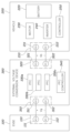
도 1에 도시된 바와 같이, 완속 충전을 위한 배터리 충전 시스템은 전기차 공급 설비(EVSE, 100), 전동화 차량(200) 및 외장 전압 변환 장치(300)를 포함할 수 있다.As shown in FIG. 1, a battery charging system for slow charging may include an electric vehicle supply equipment (EVSE) 100, an
전기차 공급 설비(100)는 계통 교류 전압(Vg)을 출력하는 교류핀(111, 112)을 가지는 완속 충전 커넥터(110)를 포함할 수 있다.The electric
전동화 차량(200)은 충전 직류 전압(Vb)을 인가받는 직류핀(211, 212)을 가지는 충전구(210), 배터리(220), 모터(230), 배터리(220)의 전압을 기반으로 모터(230)를 구동하는 인버터(240) 및 인버터(240)의 구동을 제어하는 제어기(250)를 포함할 수 있다. The
충전구(210)를 통해 충전 직류 전압(Vb)이 전동화 차량(200)에 인가될 경우, 제어기(250)는 인버터(240)를 DC/DC 컨버터로 동작시키고, 인버터(240)는 모터(230)를 통해 충전 직류 전압(Vb)을 조정하여 배터리(220)를 충전할 수 있다. 이에 따라, 급속 충전을 위한 DC/DC 컨버터를 모터(230)를 구동하기 위한 인버터(240)로 대체함으로써, 배터리 충전 시스템에서 소모되는 소자 및 면적을 줄일 수 있다.When the charging direct current voltage (Vb) is applied to the
외장 전압 변환 장치(300)는 전기차 공급 설비(100)의 완속 충전 커넥터(110)와 연결되는 입력부(310), 전동화 차량(200)의 충전구(210)와 연결되는 출력부(320), 입력부(310) 및 출력부(320) 사이에 계통 교류 전압(Vg)을 충전 직류 전압(Vb)으로 변환하는 역률 보상 회로(330, PFC) 및 역률 보상 회로(330)의 구동을 제어하는 역률 보상 제어기(340)를 포함할 수 있다. 입력부(310)는 전기차 공급 설비(100)의 완속 충전 커넥터(110)로부터 계통 교류 전압(Vg)을 인가받는 교류핀(311, 312)를 가지고, 출력부(320)는 전동화 차량(200)의 충전구(210)로 충전 직류 전압(Vb)을 출력하는 직류핀(321, 322)를 가질 수 있다. 외장 전압 변환 장치(300)는 휴대용 장치로 구현될 수 있다.The
본 발명의 일 실시예에서, 완속 충전을 위한 역률 보상 회로(330)가 전동화 차량(200)이 아닌 외장 전압 변환 장치(300)에 구비됨에 따라, 전동화 차량의 내부 공간 활용성을 증대할 수 있다. In one embodiment of the present invention, the power
또한, 외장 전압 변환 장치(300)를 전기차 공급 설비(100)와 전동화 차량(200) 사이에 연결함에 따라, 완속 충전을 위한 DC/DC 컨버터를 모터(230)를 구동하기 위한 인버터(240)로 대체하고, 전동화 차량(200)의 충전구(210)를 통해 급속 충전용 충전구와 완속 충전용 충전구를 공유할 수 있다.In addition, by connecting the
도 2는 본 발명의 일 실시예에 따른 전동화 차량(200)의 구성을 도시한 도면이다.Figure 2 is a diagram showing the configuration of an
도 2에 도시된 바와 같이, 전동화 차량(200)은 충전 직류 전압(Vb)을 인가받는 직류핀(211, 212), 직류단(D1, D2) 사이에 연결된 배터리(220), 모터(230), 제1 인버터(240_1), 제2 인버터(240_2), 구동 모드 전환부(245) 및 제어기(250)를 포함할 수 있다.As shown in FIG. 2, the
모터(230)는 복수의 상 각각에 대응하는 복수의 권선(La, Lb, Lc)을 가질 수 있다. 제1 인버터(240_1)는 직류단(D1, D2) 사이에 연결되고, 복수의 권선(La, Lb, Lc)의 일단 각각에 연결되는 복수의 레그(S1-S2, S3-S4, S5-S6)를 포함할 수 있다. 제2 인버터(240_2)는 직류단(D1, D2) 사이에 연결되고, 복수의 권선(La, Lb, Lc)의 타단 각각에 연결되는 복수의 레그(S'1-S'2, S'3-S'4, S'5-S'6)를 포함할 수 있다. 본 실시예에서, 레그는 복수의 스위치 소자들이 연결된 구성을 의미한다. 스위치 소자(S1-S6, S'1-S'6) 각각은 트랜지스터로 구현될 수 있다.The
구동 모드 전환부(245)는 복수의 절환 스위치(M1-M3)를 포함할 수 있다. 절환 스위치(M1-M3)의 일단은 복수의 권선(La, Lb, Lc)에 대한 중성단(N)에 연결되고, 절환 스위치(M1-M3)의 타단은 복수의 권선(La, Lb, Lc)의 타단에 각각 연결될 수 있다. 복수의 절환 스위치(M1-M3)는 모터(230)의 구동 모드에 따라 제어기(250)에 의해 턴-온 상태가 제어될 수 있다. 이에 따라, 모터(230)는 제1 인버터(240_1)만을 통해 구동되거나 제1 인버터(240_1)와 함께 제2 인버터(240_2)를 통해 구동될 수 있다. 절환 스위치(M1-M3) 각각은 트랜지스터로 구현될 수 있다.The driving
다이오드(D)는 직류단(D1) 및 중성단(N) 사이에 연결되고, 입력 커패시터(C1)는 직류핀(211, 212) 사이에 연결되며, 출력 커패시터(C2)는 직류단(D1) 및 직류단(D2) 사이에 연결될 수 있다.The diode (D) is connected between the DC terminal (D1) and the neutral terminal (N), the input capacitor (C1) is connected between the DC pins (211 and 212), and the output capacitor (C2) is connected to the DC terminal (D1). and the direct current terminal (D2).
릴레이(R1)는 직류핀(221) 및 중성단(N) 사이에 연결될 수 있다. 제어기(250)는 배터리(220)를 충전할 때 릴레이(R1)를 턴-온 상태로 제어함으로써, 직류핀(211)과 모터(230)가 전기적으로 연결되도록 제어할 수 있다.The relay (R1) may be connected between the DC pin 221 and the neutral terminal (N). The
제어기(250)는 배터리(220)를 충전할 때, 절환 스위치(M1-M3)를 통해 중성단(N)과 복수의 권선(La, Lb, Lc) 간의 도통 상태를 제어하고, 제1 인버터(240_1)를 DC/DC 컨버터로 동작시킬지 여부를 결정할 수 있다. When charging the
좀 더 구체적으로, 제어기(250)가 복수의 절환 스위치(M1-M3)를 턴-오프시켜 중성단(N)과 복수의 권선(La, Lb, Lc)을 비도통 상태로 제어할 경우, 중성단(N)의 전류는 다이오드(D)를 통해 배터리(220)로 출력될 수 있다. 이 경우, 제어기(250)는 다이오드(D)와 직류단(D1) 사이에 연결된 릴레이(R2)를 턴-온 상태로 제어할 수 있다.More specifically, when the
이와 달리, 제어기(250)가 복수의 절환 스위치(M1-M3)를 턴-온시켜 중성단(N)과 복수의 권선(La, Lb, Lc)을 도통 상태로 제어할 경우, 중성단(N)의 전류는 복수의 권선(La, Lb, Lc)으로 출력될 수 있다. 이 경우, 제어기(250)는 제1 인버터(240_1)에 포함된 복수의 레그(S1-S2, S3-S4, S5-S6)를 스위칭하고, 충전 직류 전압(Vb)은 제1 인버터(240_1)를 통해 승압 또는 강압되어 배터리(220)로 출력될 수 있다. 본 실시예에서, 레그가 스위칭된다라고 함은 레그에 포함된 복수의 스위치 소자가 상보적으로 스위칭되는 것을 의미한다.In contrast, when the
도 3는 본 발명의 일 실시예에 따른 외장 전압 변환 장치(300)의 구성을 도시한 도면이다.FIG. 3 is a diagram illustrating the configuration of an
도 3에 도시된 바와 같이, 외장 전압 변환 장치(300)는 계통 교류 전압(Vg)을 인가받는 교류핀(311, 312) 및 충전 직류 전압(Vb)을 출력하는 직류핀(321, 322)을 가지고, 역률 보상 회로(330) 및 역률 보상 제어기(340)를 포함할 수 있다. 교류핀(311)에는 계통 교류(Ig)가 흐르고, 직류핀(321)에는 충전 직류(Ib)가 흐를 수 있다.As shown in FIG. 3, the
역률 보상 회로(330)는 교류핀(311, 312)에 연결된 제1 스위칭 회로(331) 및 직류핀(321, 322)에 연결된 제2 스위칭 회로(333)를 포함하며, 전기차 공급 설비(도 1의 100)와 전동화 차량(도 1의 200)을 전기적으로 절연하기 위해 제1 스위칭 회로(331) 및 제2 스위칭 회로(333) 사이에 연결된 변압기(332)를 포함할 수 있다. 변압기(332)는 일차측 코일(L1), 이차측 코일(L2), 자화 인덕터(Lm) 및 누설 인덕터(Ls)를 포함하며, 일차측 코일(L1) 및 이차측 코일(L2)의 권선 비에 따라 전류 및 전압을 변환할 수 있다. 출력 커패시터(Co)는 직류핀(321, 322)사이에 연결될 수 있다.The power
제1 스위칭 회로(331)는 복수의 레그(Q1-Q2, Q3-Q4, Q5-Q6)를 포함할 수 있다. 스위치 소자(Q1-Q6) 각각은 트랜지스터로 구현될 수 있다.The
레그(Q1-Q2)는 입력 인덕터(Lg1)를 통해 교류핀(311)과 연결되고, 변압기(332)의 일차측 코일(L1)의 일단과 연결될 수 있다. 레그(Q3-Q4)는 입력 인덕터(Lg2)를 통해 교류핀(311)과 연결되고, 변압기(332)의 일차측 코일(L1)의 타단과 연결될 수 있다. 레그(Q1-Q2) 및 레그(Q3-Q4)는 역률 보상 제어기(340)에 의해 인터리빙(interleaving) 방식으로 고주파수로 스위칭될 수 있다. 레그(Q5-Q6)는 교류핀(312)과 연결되고, 동기 정류 제어를 위해 역률 보상 제어기(340)에 의해 계통 교류 전압(Vg)의 주파수(저주파수)로 스위칭될 수 있다. 클램프 커패시터(Cc)는 복수의 레그들(Q1-Q2, Q3-Q4, Q5-Q6)의 양 단 사이에 연결될 수 있다.The legs (Q1-Q2) are connected to the
제2 스위칭 회로(333)는 제1 스위칭 회로(331)의 레그(Q1-Q2) 및 레그(Q3-Q4)와 DAB(Dual Active Bridge) 구조를 형성하기 위한 레그(Q′1-Q′2) 및 레그(Q'3-Q'4)를 포함할 수 있다. 레그(Q′1-Q′2)는 직류핀(321, 322) 사이에 연결되고, 변압기(332)의 이차측 코일(L2)의 일단과 연결될 수 있다. 레그(Q'3-Q'4)는 직류핀(321, 322) 사이에 연결되고, 변압기(332)의 이차측 코일(L2)의 타단과 연결될 수 있다. 스위치 소자(Q'1-Q'4) 각각은 트랜지스터로 구현될 수 있다.The
역률 보상 제어기(340)는 제1 스위칭 회로(331)에 포함된 레그(Q1-Q2, Q3-Q4)의 스위칭 주파수와 제2 스위칭 회로(333)에 포함된 레그(Q'1-Q'2, Q'3-Q'4)의 스위칭 주파수를 동일하게 설정할 수 있다. 좀 더 구체적으로, 레그(Q′1-Q′2)의 스위칭 주파수는 레그(Q1-Q2)의 스위칭 주파수와 동일하게 설정되고, 레그(Q′3-Q′4)의 스위칭 주파수는 레그(Q3-Q4)의 스위칭 주파수와 동일하게 설정될 수 있다.The power
또한, 역률 보상 제어기(340)는 제1 스위칭 회로(331)에 포함된 레그(Q1-Q2, Q3-Q4)의 스위칭 위상을 기준으로, 제2 스위칭 회로(333)에 포함된 레그(Q'1-Q'2, Q'3-Q'4)의 스위칭 위상을 조정할 수 있다. 좀 더 구체적으로, 레그(Q′1-Q′2)의 스위칭 위상은 레그(Q1-Q2)의 스위칭 위상을 기준으로 조정되고, 레그(Q′3-Q′4)의 스위칭 위상은 레그(Q3-Q4)의 스위칭 위상을 기준으로 조정될 수 있다. 이에 따라, 역률 보상 회로(330)는 충전 직류(Ib)를 제어할 수 있다.In addition, the power
도 4는 도 3에 도시된 외장 전압 변환 장치(300)의 동작을 설명하기 위한 파형도이다. 도 4를 참조하면, 계통 교류 전압(Vg), 계통 교류(Ig) 및 충전 직류(Ib)의 파형이 도시되어 있다. 출력 전류(Ib)는 일차측 코일(L1)의 전압(VL1)과 이차측 코일(L2)의 전압(VL2)에 의해 결정될 수 있다.FIG. 4 is a waveform diagram for explaining the operation of the
역률 보상 제어기(340)는 레그(Q1-Q2) 및 레그(Q3-Q4)를 인터리빙(interleaving) 방식으로 스위칭할 수 있다. 좀 더 구체적으로, 역률 보상 제어기(340)는 스위치 소자(Q1, Q4) 및 스위치 소자(Q2, Q3)를 180° 위상 간격으로 스위칭할 수 있다. 이에 따라, 일차측 코일(L1)의 전압(VL1)은 180° 위상 간격으로 극성이 변경된다. 또한, 일차측 코일(L1)의 전압(VL1)에 대한 상한은 클램프 커패시터(Cc)의 전압(VCc)으로 설정될 수 있다.The power
역률 보상 제어기(340)는 스위치 소자(Q'1, Q'4)에 대한 반송파와 신호파(ds)를 기반으로 스위치 소자(Q'1, Q'4)를 스위칭하고, 스위치 소자(Q'2, Q'3)에 대한 반송파와 신호파(ds)를 기반으로 스위치 소자(Q'2, Q'3)를 스위칭할 수 있다. 이에 따라, 이차측 코일(L2)의 전압(VL2)은 도 4에 도시된 바와 같은 파형을 가질 수 있다.The power
도 5는 본 발명의 다른 실시예에 따른 완속 충전을 위한 배터리 충전 시스템의 구성을 도시한 블럭도이다.Figure 5 is a block diagram showing the configuration of a battery charging system for slow charging according to another embodiment of the present invention.
도 5에 도시된 바와 같이, 외장 전압 변환 장치(300)는 복수의 역률 보상 회로(330a, 330b, 330c)를 포함할 수 있다. 복수의 역률 보상 회로(330a, 330b, 330c) 각각은 도 3에 도시된 역률 보상 회로(330)와 동일하게 구현될 수 있다. 외장 전압 변환 장치(300)가 복수의 역률 보상 회로(330a, 330b, 330c)를 구비함에 따라, 전기차 공급 설비(100)에 대한 인프라 현황에 대응하여 외장 전압 변환 장치(300)의 출력 전력을 조정하고, 단상 및 삼상 교류 전원에 관계없이 계통 교류 전압(Vg)을 충전 직류 전압(Vb)로 변환할 수 있다.As shown in FIG. 5, the
도 6은 본 발명의 또 다른 실시예에 따른 급속 충전을 위한 배터리 충전 시스템의 구성을 도시한 블럭도이다.Figure 6 is a block diagram showing the configuration of a battery charging system for rapid charging according to another embodiment of the present invention.
도 6에 도시된 바와 같이, 급속 충전을 위한 배터리 충전 시스템에서 전기차 공급 설비(100)는 계통 직류 전압(Vgd)을 출력하는 직류핀(121, 122)를 가지는 급속 충전 커넥터(120)를 포함할 수 있다. 급속 충전을 위한 배터리 충전 시스템은 외장 전압 변환 장치(도 1의 300) 없이 전기차 공급 설비(100)의 급속 충전 커넥터(120)를 전동화 차량(200)의 충전구(210)에 체결함으로써, 전동화 차량(200)에 탑재된 배터리(220)를 충전할 수 있다.As shown in FIG. 6, in the battery charging system for rapid charging, the electric
한편, 전술한 본 발명은, 프로그램이 기록된 매체에 컴퓨터가 읽을 수 있는 코드로서 구현하는 것이 가능하다. 컴퓨터가 읽을 수 있는 매체는, 컴퓨터 시스템에 의하여 읽혀질 수 있는 데이터가 저장되는 모든 종류의 기록장치를 포함한다. 컴퓨터가 읽을 수 있는 매체의 예로는, HDD(Hard Disk Drive), SSD(Solid State Disk), SDD(Silicon Disk Drive), ROM, RAM, CD-ROM, 자기 테이프, 플로피 디스크, 광 데이터 저장 장치 등이 있다. 따라서, 상기의 상세한 설명은 모든 면에서 제한적으로 해석되어서는 아니되고 예시적인 것으로 고려되어야 한다. 본 발명의 범위는 첨부된 청구항의 합리적 해석에 의해 결정되어야 하고, 본 발명의 등가적 범위 내에서의 모든 변경은 본 발명의 범위에 포함된다.Meanwhile, the above-described present invention can be implemented as computer-readable code on a program-recorded medium. Computer-readable media includes all types of recording devices that store data that can be read by a computer system. Examples of computer-readable media include HDD (Hard Disk Drive), SSD (Solid State Disk), SDD (Silicon Disk Drive), ROM, RAM, CD-ROM, magnetic tape, floppy disk, optical data storage device, etc. There is. Accordingly, the above detailed description should not be construed as restrictive in all respects and should be considered illustrative. The scope of the present invention should be determined by reasonable interpretation of the appended claims, and all changes within the equivalent scope of the present invention are included in the scope of the present invention.
100: 전기차 공급 설비
110: 완속 충전 커넥터
120: 급속 충전 커넥터
200: 전동화 차량
210: 충전구
220: 배터리
230: 모터
240: 인버터
250: 제어기
300: 외장 전압 변환 장치
310: 입력부
320: 출력부
330: 역률 보상 회로
340: 역률 보상 제어기100: Electric vehicle supply facility 110: Slow charging connector
120: Fast charging connector 200: Electric vehicle
210: charging port 220: battery
230: motor 240: inverter
250: Controller 300: External voltage converter
310: input unit 320: output unit
330: Power factor correction circuit 340: Power factor correction controller
Claims (16)
상기 충전 직류 전압을 인가받는 충전구를 가지고, 배터리, 복수의 권선을 가지는 모터, 상기 복수의 권선의 일단 각각에 연결되는 인버터 및 상기 충전구와 상기 복수의 권선에 대한 중성단 사이에 연결된 릴레이를 포함하되, 상기 배터리를 충전할 때 상기 릴레이를 제어하는 전동화 차량을 포함하는, 배터리 충전 시스템.
It has an input unit to which system alternating voltage is applied and an output unit to output a charging direct current voltage, a first switching circuit connected to the input unit, a second switching circuit connected to the output unit, and a connection between the first switching circuit and the second switching circuit. An external voltage conversion device including a power factor correction circuit with a connected transformer; and
It has a charging port for receiving the charging DC voltage, and includes a battery, a motor having a plurality of windings, an inverter connected to each end of the plurality of windings, and a relay connected between the charging port and the neutral terminal of the plurality of windings. However, a battery charging system including an electric vehicle that controls the relay when charging the battery.
상기 입력부는,
전기차 공급 설비(Electric Vehicle Supply Equipment)의 충전 커넥터로부터 상기 계통 교류 전압을 인가받는 제1 및 제2 교류핀을 포함하는, 배터리 충전 시스템.
According to claim 1,
The input unit,
A battery charging system comprising first and second AC pins that receive the grid AC voltage from a charging connector of Electric Vehicle Supply Equipment.
상기 출력부는,
상기 충전 직류 전압을 상기 전동화 차량의 상기 충전구로 출력하는 제1 및 제2 직류핀을 포함하는, 배터리 충전 시스템.
According to claim 1,
The output unit,
A battery charging system comprising first and second direct current pins that output the charging direct current voltage to the charging port of the electric vehicle.
상기 변압기는,
일차측 코일과 이차측 코일을 가지고,
상기 제1 스위칭 회로는,
상기 입력부의 제1 및 제2 교류핀과 상기 일차측 코일에 연결되며,
상기 제2 스위칭 회로는,
상기 출력부의 제1 및 제2 직류핀과 상기 이차측 코일에 연결되되,
상기 역률 보상 회로는,
상기 출력부의 제1 및 제2 직류핀 사이에 연결되는 출력 커패시터를 더 포함하는, 배터리 충전 시스템.
According to claim 1,
The transformer is,
With a primary coil and a secondary coil,
The first switching circuit,
Connected to the first and second AC pins of the input unit and the primary coil,
The second switching circuit is,
Connected to the first and second direct current pins of the output unit and the secondary coil,
The power factor correction circuit is,
A battery charging system further comprising an output capacitor connected between the first and second direct current pins of the output unit.
상기 제1 스위칭 회로는,
제1 입력 인덕터를 통해 상기 제1 교류핀에 연결되고, 상기 일차측 코일의 일단과 연결되는 제1 레그;
제2 입력 인덕터를 통해 상기 제1 교류핀에 연결되고, 상기 일차측 코일의 타단과 연결되는 제2 레그; 및
상기 제2 교류핀에 연결되는 제3 레그를 포함하는, 배터리 충전 시스템.
According to clause 4,
The first switching circuit,
A first leg connected to the first AC pin through a first input inductor and connected to one end of the primary coil;
a second leg connected to the first AC pin through a second input inductor and connected to the other end of the primary coil; and
A battery charging system comprising a third leg connected to the second AC pin.
상기 제2 스위칭 회로는,
상기 제1 및 제2 직류핀 사이에 연결되고, 상기 이차측 코일의 일단과 연결되는 제4 레그; 및
상기 제1 및 제2 직류핀 사이에 연결되고, 상기 이차측 코일의 타단과 연결되는 제5 레그를 포함하는, 배터리 충전 시스템.
According to clause 4,
The second switching circuit is,
a fourth leg connected between the first and second direct current pins and connected to one end of the secondary coil; and
A battery charging system comprising a fifth leg connected between the first and second direct current pins and connected to the other end of the secondary coil.
상기 충전구는,
상기 외장 전압 변환 장치로부터 상기 충전 직류 전압을 인가받는 제3 및 제4 직류핀을 포함하는, 배터리 충전 시스템.
According to claim 1,
The charging port is,
A battery charging system comprising third and fourth DC pins that receive the charging DC voltage from the external voltage conversion device.
상기 전동화 차량은,
상기 충전구의 제3 및 제4 직류핀 사이에 연결되는 입력 커패시터를 더 포함하되,
상기 릴레이는,
상기 제3 직류핀 및 상기 중성단 사이에 연결되는, 배터리 충전 시스템
According to claim 1,
The electric vehicle,
It further includes an input capacitor connected between the third and fourth direct current pins of the charging port,
The relay is,
A battery charging system connected between the third direct current pin and the neutral terminal.
상기 전동화 차량은,
상기 배터리의 일단이 연결되는 직류단 및 상기 중성단 사이에 연결된 다이오드를 더 포함하는, 배터리 충전 시스템.
According to clause 8,
The electric vehicle,
A battery charging system further comprising a diode connected between a direct current terminal to which one end of the battery is connected and the neutral terminal.
충전 직류 전압을 출력하는 출력부;
상기 입력부에 연결된 제1 스위칭 회로, 상기 출력부에 연결된 제2 스위칭 회로 및 상기 제1 스위칭 회로와 상기 제2 스위칭 회로 사이에 연결된 변압기를 구비한 역률 보상 회로; 및
상기 제1 스위칭 회로에 포함된 적어도 하나의 레그의 스위칭 위상을 기준으로, 상기 제2 스위칭 회로에 포함된 적어도 하나의 레그의 스위칭 위상을 조정하는 역률 보상 제어기를 포함하는, 외장 전압 변환 장치.
An input unit to which grid alternating voltage is applied;
An output unit that outputs a charging direct current voltage;
a power factor correction circuit including a first switching circuit connected to the input unit, a second switching circuit connected to the output unit, and a transformer connected between the first switching circuit and the second switching circuit; and
An external voltage conversion device comprising a power factor correction controller that adjusts the switching phase of at least one leg included in the second switching circuit based on the switching phase of the at least one leg included in the first switching circuit.
상기 입력부는,
전기차 공급 설비(Electric Vehicle Supply Equipment)의 충전 커넥터로부터 상기 계통 교류 전압을 인가받는 제1 및 제2 교류핀을 포함하는, 외장 전압 변환 장치.
According to claim 10,
The input unit,
An external voltage conversion device comprising first and second AC pins that receive the system AC voltage from a charging connector of electric vehicle supply equipment.
상기 출력부는,
상기 충전 직류 전압을 전동화 차량의 충전구로 출력하는 제1 및 제2 직류핀을 포함하는, 외장 전압 변환 장치.
According to claim 10,
The output unit,
An external voltage conversion device comprising first and second direct current pins that output the charging direct current voltage to a charging port of an electric vehicle.
상기 변압기는,
일차측 코일과 이차측 코일을 가지고,
상기 제1 스위칭 회로는,
상기 입력부의 제1 및 제2 교류핀과 상기 일차측 코일에 연결되며,
상기 제2 스위칭 회로는,
상기 출력부의 제1 및 제2 직류핀과 상기 이차측 코일에 연결되되,
상기 역률 보상 회로는,
상기 출력부의 제1 및 제2 직류핀 사이에 연결되는 출력 커패시터를 더 포함하는, 외장 전압 변환 장치.
According to claim 10,
The transformer is,
With a primary coil and a secondary coil,
The first switching circuit,
Connected to the first and second AC pins of the input unit and the primary coil,
The second switching circuit is,
Connected to the first and second direct current pins of the output unit and the secondary coil,
The power factor correction circuit is,
An external voltage conversion device further comprising an output capacitor connected between the first and second direct current pins of the output unit.
상기 제1 스위칭 회로는,
제1 입력 인덕터를 통해 상기 제1 교류핀에 연결되고, 상기 일차측 코일의 일단과 연결되는 제1 레그;
제2 입력 인덕터를 통해 상기 제1 교류핀에 연결되고, 상기 일차측 코일의 타단과 연결되는 제2 레그; 및
상기 제2 교류핀에 연결되는 제3 레그를 포함하는, 외장 전압 변환 장치.
According to claim 13,
The first switching circuit,
A first leg connected to the first AC pin through a first input inductor and connected to one end of the primary coil;
a second leg connected to the first AC pin through a second input inductor and connected to the other end of the primary coil; and
An external voltage converter device comprising a third leg connected to the second AC pin.
상기 제2 스위칭 회로는,
상기 제1 및 제2 직류핀 사이에 연결되고, 상기 이차측 코일의 일단과 연결되는 제4 레그; 및
상기 제1 및 제2 직류핀 사이에 연결되고, 상기 이차측 코일의 타단과 연결되는 제5 레그를 포함하는, 외장 전압 변환 장치.
According to claim 14,
The second switching circuit is,
a fourth leg connected between the first and second direct current pins and connected to one end of the secondary coil; and
An external voltage converter comprising a fifth leg connected between the first and second direct current pins and connected to the other end of the secondary coil.
상기 역률 보상 제어기는,
상기 제4 레그의 스위칭 주파수를 상기 제1 레그의 스위칭 주파수와 동일하게 설정하고, 상기 제4 레그의 스위칭 위상을 상기 제1 레그의 스위칭 위상을 기준으로 조정하며,
상기 제5 레그의 스위칭 주파수를 상기 제2 레그의 스위칭 주파수와 동일하게 설정하고, 상기 제5 레그의 스위칭 위상을 상기 제2 레그의 스위칭 위상을 기준으로 조정하는, 외장 전압 변환 장치.According to claim 15,
The power factor correction controller,
Setting the switching frequency of the fourth leg to be the same as the switching frequency of the first leg, and adjusting the switching phase of the fourth leg based on the switching phase of the first leg,
An external voltage converter device that sets the switching frequency of the fifth leg to be the same as the switching frequency of the second leg and adjusts the switching phase of the fifth leg based on the switching phase of the second leg.
Priority Applications (3)
| Application Number | Priority Date | Filing Date | Title |
|---|---|---|---|
| KR1020220085741A KR20240008646A (en) | 2022-07-12 | 2022-07-12 | Battery charging system and external voltage conversion device for the same |
| US17/985,589 US20240017629A1 (en) | 2022-07-12 | 2022-11-11 | Battery Charging System and External Voltage Conversion Device for the Same |
| CN202211501158.8A CN117439241A (en) | 2022-07-12 | 2022-11-28 | Battery charging systems and external voltage conversion devices therefor |
Applications Claiming Priority (1)
| Application Number | Priority Date | Filing Date | Title |
|---|---|---|---|
| KR1020220085741A KR20240008646A (en) | 2022-07-12 | 2022-07-12 | Battery charging system and external voltage conversion device for the same |
Publications (1)
| Publication Number | Publication Date |
|---|---|
| KR20240008646A true KR20240008646A (en) | 2024-01-19 |
Family
ID=89510396
Family Applications (1)
| Application Number | Title | Priority Date | Filing Date |
|---|---|---|---|
| KR1020220085741A Pending KR20240008646A (en) | 2022-07-12 | 2022-07-12 | Battery charging system and external voltage conversion device for the same |
Country Status (3)
| Country | Link |
|---|---|
| US (1) | US20240017629A1 (en) |
| KR (1) | KR20240008646A (en) |
| CN (1) | CN117439241A (en) |
Family Cites Families (5)
| Publication number | Priority date | Publication date | Assignee | Title |
|---|---|---|---|---|
| CN102904322B (en) * | 2011-07-28 | 2015-05-27 | 台达电子企业管理(上海)有限公司 | Battery charging system |
| FR2987953B1 (en) * | 2012-03-09 | 2017-04-28 | Intelligent Electronic Systems | CHARGING DEVICE COMPRISING AN INSULATED AC-DC CONVERTER |
| KR102433999B1 (en) * | 2017-08-24 | 2022-08-19 | 현대자동차주식회사 | Motor driving/battery charging apparatus and vehicle |
| KR102022705B1 (en) * | 2017-11-13 | 2019-09-18 | 주식회사 이진스 | Complex circuit for charging and low voltage converting of electric vehicle |
| KR102730545B1 (en) * | 2019-08-06 | 2024-11-14 | 현대자동차주식회사 | Electric power conversion system and control method therefor |
-
2022
- 2022-07-12 KR KR1020220085741A patent/KR20240008646A/en active Pending
- 2022-11-11 US US17/985,589 patent/US20240017629A1/en active Pending
- 2022-11-28 CN CN202211501158.8A patent/CN117439241A/en active Pending
Also Published As
| Publication number | Publication date |
|---|---|
| CN117439241A (en) | 2024-01-23 |
| US20240017629A1 (en) | 2024-01-18 |
Similar Documents
| Publication | Publication Date | Title |
|---|---|---|
| US10793015B2 (en) | Charging apparatus for electric vehicle | |
| US20220355686A1 (en) | Vehicle and energy conversion device and power system thereof | |
| US11196349B2 (en) | Resonant DC-DC voltage converter | |
| US10654371B2 (en) | Charging apparatus for electric vehicle | |
| US12483054B2 (en) | Charger capable of bidirectional power transfer | |
| JP2011211889A (en) | Battery charging circuit | |
| US12199465B2 (en) | System for charging battery for vehicle using motor driving system | |
| KR20230009661A (en) | Bidirectional charging system for vehicle | |
| EP4564662A1 (en) | Electric motor control system, control method for electric motor control system, and vehicle | |
| EP4231493A1 (en) | Charging device and vehicle | |
| US20250135926A1 (en) | Systems and methods for integrated high voltage and low voltage converter for bidirectional onboard battery charger | |
| KR20200014214A (en) | Resonant dc-dc voltage converter | |
| US12341440B2 (en) | Systems and methods for capacitor voltage control for inverter for electric vehicle | |
| KR20240036980A (en) | Electrified vehicle | |
| KR20230003888A (en) | Charging system and method using motor driving system | |
| KR20240006343A (en) | Electrified vehicle | |
| KR20240008646A (en) | Battery charging system and external voltage conversion device for the same | |
| EP4468558A1 (en) | Systems and methods for capacitor discharge control in forward and reverse charging | |
| US20240429831A1 (en) | Systems and methods for common design for single, split, and three phase inverter for v2x applications | |
| KR20240002572A (en) | Electric charger for electric vehicle | |
| US20240405560A1 (en) | Battery charging device | |
| KR20240014854A (en) | Electrified vehicle | |
| US12027865B2 (en) | Battery charging apparatus | |
| KR102568218B1 (en) | Method and system for slow charging based on inverter and single phase system | |
| EP4472018A1 (en) | Systems and methods for capacitor discharge control in forward and reverse charging |
Legal Events
| Date | Code | Title | Description |
|---|---|---|---|
| PA0109 | Patent application |
Patent event code: PA01091R01D Comment text: Patent Application Patent event date: 20220712 |
|
| PG1501 | Laying open of application | ||
| A201 | Request for examination | ||
| PA0201 | Request for examination |
Patent event code: PA02012R01D Patent event date: 20250610 Comment text: Request for Examination of Application |