KR20230168345A - Method and apparatus for determining interference between heterogeneous services - Google Patents
Method and apparatus for determining interference between heterogeneous services Download PDFInfo
- Publication number
- KR20230168345A KR20230168345A KR1020220068702A KR20220068702A KR20230168345A KR 20230168345 A KR20230168345 A KR 20230168345A KR 1020220068702 A KR1020220068702 A KR 1020220068702A KR 20220068702 A KR20220068702 A KR 20220068702A KR 20230168345 A KR20230168345 A KR 20230168345A
- Authority
- KR
- South Korea
- Prior art keywords
- interference
- virtual
- receiving device
- heterogeneous
- received signal
- Prior art date
- Legal status (The legal status is an assumption and is not a legal conclusion. Google has not performed a legal analysis and makes no representation as to the accuracy of the status listed.)
- Ceased
Links
Images


Classifications
-
- H—ELECTRICITY
- H04—ELECTRIC COMMUNICATION TECHNIQUE
- H04W—WIRELESS COMMUNICATION NETWORKS
- H04W28/00—Network traffic management; Network resource management
- H04W28/16—Central resource management; Negotiation of resources or communication parameters, e.g. negotiating bandwidth or QoS [Quality of Service]
-
- H—ELECTRICITY
- H04—ELECTRIC COMMUNICATION TECHNIQUE
- H04W—WIRELESS COMMUNICATION NETWORKS
- H04W24/00—Supervisory, monitoring or testing arrangements
- H04W24/02—Arrangements for optimising operational condition
-
- H—ELECTRICITY
- H04—ELECTRIC COMMUNICATION TECHNIQUE
- H04B—TRANSMISSION
- H04B17/00—Monitoring; Testing
- H04B17/30—Monitoring; Testing of propagation channels
- H04B17/309—Measuring or estimating channel quality parameters
- H04B17/318—Received signal strength
-
- H—ELECTRICITY
- H04—ELECTRIC COMMUNICATION TECHNIQUE
- H04B—TRANSMISSION
- H04B17/00—Monitoring; Testing
- H04B17/30—Monitoring; Testing of propagation channels
- H04B17/309—Measuring or estimating channel quality parameters
- H04B17/345—Interference values
-
- H—ELECTRICITY
- H04—ELECTRIC COMMUNICATION TECHNIQUE
- H04L—TRANSMISSION OF DIGITAL INFORMATION, e.g. TELEGRAPHIC COMMUNICATION
- H04L43/00—Arrangements for monitoring or testing data switching networks
- H04L43/02—Capturing of monitoring data
- H04L43/022—Capturing of monitoring data by sampling
-
- H—ELECTRICITY
- H04—ELECTRIC COMMUNICATION TECHNIQUE
- H04L—TRANSMISSION OF DIGITAL INFORMATION, e.g. TELEGRAPHIC COMMUNICATION
- H04L43/00—Arrangements for monitoring or testing data switching networks
- H04L43/08—Monitoring or testing based on specific metrics, e.g. QoS, energy consumption or environmental parameters
- H04L43/0823—Errors, e.g. transmission errors
- H04L43/0829—Packet loss
-
- H—ELECTRICITY
- H04—ELECTRIC COMMUNICATION TECHNIQUE
- H04W—WIRELESS COMMUNICATION NETWORKS
- H04W16/00—Network planning, e.g. coverage or traffic planning tools; Network deployment, e.g. resource partitioning or cells structures
- H04W16/18—Network planning tools
-
- H—ELECTRICITY
- H04—ELECTRIC COMMUNICATION TECHNIQUE
- H04W—WIRELESS COMMUNICATION NETWORKS
- H04W24/00—Supervisory, monitoring or testing arrangements
- H04W24/06—Testing, supervising or monitoring using simulated traffic
-
- H—ELECTRICITY
- H04—ELECTRIC COMMUNICATION TECHNIQUE
- H04W—WIRELESS COMMUNICATION NETWORKS
- H04W24/00—Supervisory, monitoring or testing arrangements
- H04W24/08—Testing, supervising or monitoring using real traffic
-
- H—ELECTRICITY
- H04—ELECTRIC COMMUNICATION TECHNIQUE
- H04L—TRANSMISSION OF DIGITAL INFORMATION, e.g. TELEGRAPHIC COMMUNICATION
- H04L41/00—Arrangements for maintenance, administration or management of data switching networks, e.g. of packet switching networks
- H04L41/14—Network analysis or design
-
- H—ELECTRICITY
- H04—ELECTRIC COMMUNICATION TECHNIQUE
- H04L—TRANSMISSION OF DIGITAL INFORMATION, e.g. TELEGRAPHIC COMMUNICATION
- H04L43/00—Arrangements for monitoring or testing data switching networks
- H04L43/20—Arrangements for monitoring or testing data switching networks the monitoring system or the monitored elements being virtualised, abstracted or software-defined entities, e.g. SDN or NFV
Landscapes
- Engineering & Computer Science (AREA)
- Computer Networks & Wireless Communication (AREA)
- Signal Processing (AREA)
- Quality & Reliability (AREA)
- Physics & Mathematics (AREA)
- Electromagnetism (AREA)
- Environmental & Geological Engineering (AREA)
- Mobile Radio Communication Systems (AREA)
Abstract
이기종 서비스간 간섭 판정 기술이 개시된다. 통신 시스템의 수신 장치의 동작 방법으로서, 동기종 송신 장치로부터 동기종 신호를 수신하는 단계; 기지국 설치 대상 지역의 표본 설치 지점에 설치된 이기종 송신 장치들로부터 간섭 신호들을 수신하는 단계; 및 상기 간섭 신호들의 수신 신호 세기들을 참조하여 허용 간섭 기준을 설정하는 단계를 포함하는, 수신 장치의 동작 방법이 제공될 수 있다.A technology for determining interference between heterogeneous services is disclosed. A method of operating a receiving device in a communication system, comprising: receiving a same-type signal from a same-type transmitting device; Receiving interference signals from heterogeneous transmitting devices installed at a sample installation point in a base station installation target area; A method of operating a receiving device may be provided, including setting an allowable interference standard with reference to received signal strengths of the interference signals.
Description
본 발명은 이기종 서비스간 간섭 판정 기술에 관한 것으로, 더욱 상세하게는 이기종 서비스간에 상호 공존을 위하여 보호 이격 거리와 보호 영역을 산출할 수 있도록 하는 이기종 서비스간 간섭 판정 기술에 관한 것이다.The present invention relates to interference determination technology between heterogeneous services, and more specifically, to interference determination technology between heterogeneous services that allows calculating the protection separation distance and protection area for mutual coexistence between heterogeneous services.
정보통신 기술의 발전과 더불어 다양한 무선 통신 기술이 개발될 수 있다. 대표적인 무선 통신 기술로 3GPP(3rd generation partnership project) 표준에서 규정된 LTE(long term evolution), NR(new radio) 등이 있을 수 있다. LTE는 4G(4th Generation) 무선 통신 기술들 중에서 하나의 무선 통신 기술일 수 있고, NR은 5G(5th Generation) 무선 통신 기술들 중에서 하나의 무선 통신 기술일 수 있다. 4G 통신 시스템(예를 들어, LTE를 지원하는 통신 시스템)의 상용화 이후에 급증하는 무선 데이터의 처리를 위해, 4G 통신 시스템의 주파수 대역(예를 들어, 6GHz 이하의 주파수 대역)뿐만 아니라 4G 통신 시스템의 주파수 대역보다 높은 주파수 대역(예를 들어, 6GHz 이상의 주파수 대역)을 사용하는 5G 통신 시스템(예를 들어, NR을 지원하는 통신 시스템)이 고려될 수 있다. 5G 통신 시스템은 eMBB(enhanced Mobile BroadBand), URLLC(Ultra-Reliable and Low Latency Communication) 및 mMTC(massive Machine Type Communication)을 지원할 수 있다.With the advancement of information and communication technology, various wireless communication technologies can be developed. Representative wireless communication technologies may include long term evolution (LTE) and new radio (NR), which are defined in the 3rd generation partnership project (3GPP) standard. LTE may be a wireless communication technology among 4G (4th Generation) wireless communication technologies, and NR may be a wireless communication technology among 5G (5th Generation) wireless communication technologies. In order to handle the rapid increase in wireless data after the commercialization of the 4G communication system (e.g., a communication system supporting LTE), the frequency band of the 4G communication system (e.g., a frequency band below 6 GHz) as well as the 4G communication system A 5G communication system (e.g., a communication system supporting NR) that uses a frequency band higher than the frequency band (e.g., a frequency band of 6 GHz or higher) may be considered. The 5G communication system can support enhanced Mobile BroadBand (eMBB), Ultra-Reliable and Low Latency Communication (URLLC), and massive Machine Type Communication (mMTC).
이와 같은 통신 시스템은 동일한 주파수 대역 또는 인접한 주파수 대역을 사용하는 고정 시스템의 수신기에 간섭을 미칠 수 있다. 이때, 간섭의 영향을 받는 고정 시스템의 수신 장치는 원활한 서비스를 제공할 수 없다. 특히 방송과 같이 전파를 수신하여 영상을 출력하는 수신 장치는 강한 세기의 간섭으로 인해 서비스의 제공이 어려울 수 있다. 이를 해결하기 위하여 이기종 기기간의 공간적 분리는 원활한 서비스에 영향을 주지 않도록 하는 가장 효율적인 방법일 수 있다. 하지만, 이기종 기기간의 공간적 분리는 공간을 효율적으로 사용하지 못하는 단점이 있을 수 있다. 따라서 통신 시스템은 이기종 기기간의 공간적 분리를 최소화할 필요가 있을 수 있다.Such communication systems may interfere with receivers in fixed systems using the same or adjacent frequency bands. At this time, a receiving device in a fixed system affected by interference cannot provide smooth service. In particular, a receiving device that receives radio waves and outputs images, such as in broadcasting, may have difficulty providing services due to strong interference. To solve this problem, spatial separation between heterogeneous devices may be the most efficient way to avoid affecting smooth service. However, spatial separation between heterogeneous devices may have the disadvantage of not using space efficiently. Therefore, communication systems may need to minimize spatial separation between heterogeneous devices.
상기와 같은 문제점을 해결하기 위한 본 발명의 목적은, 이기종 서비스간에 상호 공존을 위하여 보호 이격 거리와 보호 영역을 산출할 수 있도록 하는 이기종 서비스간 간섭 판정 방법 및 장치를 제공하는데 있다.The purpose of the present invention to solve the above problems is to provide a method and device for determining interference between heterogeneous services that can calculate a protection separation distance and protection area for mutual coexistence between heterogeneous services.
상기 목적을 달성하기 위한 본 발명의 제1 실시예에 따른 이기종 서비스간 간섭 판정 방법은, 통신 시스템의 수신 장치의 동작 방법으로서, 동기종 송신 장치로부터 동기종 신호를 수신하는 단계; 기지국 설치 대상 지역의 표본 설치 지점에 설치된 이기종 송신 장치들로부터 간섭 신호들을 수신하는 단계; 및 상기 간섭 신호들의 수신 신호 세기들을 참조하여 허용 간섭 기준을 설정하는 단계를 포함할 수 있다.A method for determining interference between heterogeneous services according to a first embodiment of the present invention for achieving the above object is a method of operating a receiving device in a communication system, comprising: receiving a signal of the same type from a transmitting device of the same type; Receiving interference signals from heterogeneous transmitting devices installed at a sample installation point in a base station installation target area; And it may include setting an allowable interference standard with reference to the received signal strengths of the interference signals.
여기서, 상기 간섭 신호들의 수신 신호 세기들을 참조하여 허용 간섭 기준을 설정하는 단계는, 상기 간섭 신호들의 수신 신호 세기들을 측정하는 단계; 상기 동기종 신호에 영향을 주는 상기 간섭 신호들의 간섭 정도를 판단하는 단계; 허용 가능하지 않은 간섭을 발생시키는 간섭 신호들을 분류하는 단계; 및 상기 허용 가능하지 않은 간섭을 발생시키는 간섭 신호들의 수신 신호 세기들을 참조하여 상기 허용 간섭 기준을 설정하는 단계를 포함할 수 있다.Here, setting an allowable interference standard with reference to the received signal strengths of the interference signals includes measuring the received signal strengths of the interference signals; determining the degree of interference of the interference signals affecting the same-type signal; Classifying interfering signals that cause unacceptable interference; and setting the allowable interference standard with reference to received signal strengths of interference signals causing the unacceptable interference.
여기서, 상기 동기종 신호에 영향을 주는 상기 간섭 신호들의 간섭 정도를 판단하는 단계는, 각각의 간섭 신호의 영향에 따른 상기 동기종 신호의 패킷 손실률을 산출하는 단계; 상기 패킷 손실률이 기준 미만인 경우, 상기 기준 미만의 상기 패킷 손실률을 가지는 상기 간섭 신호를 허용 가능한 간섭으로 판단하는 단계; 및 상기 패킷 손실률이 기준 이상인 경우, 상기 기준 이상의 상기 패킷 손실률을 가지는 상기 간섭 신호를 허용 가능하지 않은 간섭으로 판단하는 단계를 포함할 수 있다.Here, the step of determining the degree of interference of the interference signals affecting the same-type signal includes calculating a packet loss rate of the same-type signal according to the influence of each interference signal; When the packet loss rate is less than a standard, determining the interference signal having the packet loss rate less than the standard as acceptable interference; And when the packet loss rate is greater than a standard, it may include determining the interference signal having the packet loss rate greater than the standard as unacceptable interference.
여기서, 상기 허용 가능하지 않은 간섭을 발생시키는 간섭 신호들의 수신 신호 세기들을 참조하여 상기 허용 간섭 기준을 설정하는 단계는, 상기 허용 가능하지 않은 간섭을 발생시키는 간섭 신호들의 수신 신호 세기들에서 최소 수신 신호 세기를 검출하는 단계; 및 상기 검출된 최소 수신 신호 세기를 상기 허용 간섭 기준으로 설정하는 단계를 포함할 수 있다.Here, the step of setting the allowable interference standard with reference to the received signal strengths of the interference signals that generate the unacceptable interference includes the minimum received signal strength in the received signal strengths of the interference signals that generate the unacceptable interference. detecting intensity; and setting the detected minimum received signal strength as the allowable interference standard.
여기서, 상기 허용 가능하지 않은 간섭을 발생시키는 간섭 신호들의 수신 신호 세기들을 참조하여 상기 허용 간섭 기준을 설정하는 단계는, 간섭 신호의 수신 신호 세기의 구간 별 이기종 송신 장치의 개수를 나타내는 히스토그램을 생성하는 단계; 각 구간에 대하여 허용 가능하지 않은 간섭을 발생하는 상기 이기종 송신 장치의 개수와 허용 가능한 간섭을 발생하는 상기 이기종 송신 장치의 개수의 비율을 산출하는 단계; 및 상기 비율이 일정 이상인 구간들 중에서 최소 비율을 가지는 구간의 중앙값을 상기 간섭 허용 기준으로 설정하는 단계를 포함할 수 있다.Here, the step of setting the allowable interference standard with reference to the received signal strengths of the interference signals that generate the unacceptable interference includes generating a histogram representing the number of heterogeneous transmitting devices for each section of the received signal strength of the interference signal. step; calculating a ratio between the number of heterogeneous transmission devices generating unacceptable interference and the number of heterogeneous transmission devices generating acceptable interference for each section; And it may include setting the median value of the section with the minimum ratio among sections where the ratio is above a certain level as the interference tolerance standard.
여기서, 지리 정보 시스템의 맵에 가상 수신 장치와 가상 설치 지점들에 가상 이기종 송신 장치들을 설치하는 단계; 상기 가상 수신 장치가 상기 가상 이기종 송신 장치들로부터 가상 간섭 신호들을 수신하도록 시뮬레이션하는 단계; 및 상기 가상 간섭 신호들의 수신 신호 세기들을 참조하여 보호 이격 거리를 설정하는 단계를 더 포함할 수 있다.Here, installing virtual heterogeneous transmitting devices at virtual receiving devices and virtual installation points on a map of the geographic information system; simulating the virtual receiving device to receive virtual interference signals from the virtual heterogeneous transmitting devices; And it may further include setting a protection separation distance with reference to received signal strengths of the virtual interference signals.
여기서, 상기 지리 정보 시스템의 맵에 가상 수신 장치와 가상 이기종 송신 장치들을 설치하는 단계는, 상기 지리 정보 시스템의 상기 맵에 상기 가상 수신 장치를 가상으로 설치하는 단계; 상기 지리 정보 시스템의 상기 맵에 가상 설치 지점들을 설정하는 단계; 및 상기 가상 설치 지점들에 상기 가상 이기종 송신 장치들을 가상으로 설치하는 단계를 포함할 수 있다.Here, the step of installing a virtual receiving device and virtual heterogeneous transmitting devices on the map of the geographic information system includes: virtually installing the virtual receiving device on the map of the geographic information system; establishing virtual installation points on the map of the geographic information system; and virtually installing the virtual heterogeneous transmission devices at the virtual installation points.
여기서, 상기 가상 간섭 신호들의 수신 신호 세기들을 참조하여 보호 이격 거리를 설정하는 단계는, 상기 가상 수신 장치에서 가상으로 수신하는 상기 가상 간섭 신호들의 수신 신호 세기들을 추정하는 단계; 상기 허용 간섭 기준에 기반하여 허용 가능하지 않은 간섭을 발생시키는 가상 간섭 신호들을 분류하는 단계; 및 상기 분류된 가상 간섭 신호들의 수신 신호 세기들을 참조하여 상기 보호 이격 거리를 설정하는 단계를 포함할 수 있다.Here, setting the protection separation distance with reference to the received signal strengths of the virtual interference signals includes estimating the received signal strengths of the virtual interference signals virtually received by the virtual receiving device; classifying virtual interference signals that generate unacceptable interference based on the allowable interference criterion; and setting the protection separation distance with reference to received signal strengths of the classified virtual interference signals.
여기서, 상기 가상 수신 장치에서 가상으로 수신하는 상기 가상 간섭 신호들의 수신 신호 세기들을 추정하는 단계 이후에, 상기 표본 설치 지점들에 대응하는 상기 가상 설치 지점들을 탐색하는 단계; 상기 탐색된 가상 설치 지점들의 각각의 가상 간섭 신호의 수신 신호 세기와 상기 탐색된 가상 설치 지점들의 각각에 대응되는 표본 설치 지점에서 실측한 수신 신호 세기의 오차를 산출하는 단계; 및 상기 산출한 오차를 반영하여 상기 각각의 가상 간섭 신호의 수신 신호 세기를 보정하는 단계를 더 포함할 수 있다.Here, after estimating received signal strengths of the virtual interference signals virtually received by the virtual receiving device, searching for the virtual installation points corresponding to the sample installation points; calculating an error between the received signal strength of the virtual interference signal of each of the discovered virtual installation points and the received signal strength actually measured at a sample installation point corresponding to each of the found virtual installation points; And it may further include correcting the received signal strength of each virtual interference signal by reflecting the calculated error.
여기서, 상기 가상 간섭 신호들의 수신 신호 세기들을 참조하여 상기 보호 이격 거리를 벗어난 지역에 허용 가능하지 않은 간섭을 발생시키는 군집을 이루고 있는 가상 이기종 송신 장치들이 위치하는 일부 영역을 보호 영역을 설정하는 단계를 더 포함할 수 있다.Here, the step of setting a protection area in a partial area where virtual heterogeneous transmitting devices forming a cluster that generate unacceptable interference in an area outside the protection separation distance are located with reference to the received signal strengths of the virtual interference signals. More may be included.
한편, 상기 목적을 달성하기 위한 본 발명의 제1 실시예에 따른 이기종 서비스간 간섭 판정 장치는, 수신 장치로서, 프로세서(processor); 상기 프로세서와 전자적(electronic)으로 통신하는 메모리(memory); 및 상기 메모리에 저장되는 명령들(instructions)을 포함하며, 상기 명령들이 상기 프로세서에 의해 실행되는 경우, 상기 명령들은 상기 수신 장치가, 동기종 송신 장치로부터 동기종 신호를 수신하고; 기지국 설치 대상 지역의 표본 설치 지점에 설치된 이기종 송신 장치들로부터 간섭 신호들을 수신하고; 그리고 상기 간섭 신호들의 수신 신호 세기들을 참조하여 허용 간섭 기준을 설정하는 것을 야기하도록 동작할 수 있다.Meanwhile, an apparatus for determining interference between heterogeneous services according to a first embodiment of the present invention for achieving the above object includes, as a receiving device, a processor; a memory that communicates electronically with the processor; and instructions stored in the memory, wherein when the instructions are executed by the processor, the instructions cause the receiving device to receive a same-type signal from a same-type transmitting device; Receiving interference signals from heterogeneous transmitting devices installed at sample installation points in the base station installation target area; And it may operate to cause setting an allowable interference standard with reference to the received signal strengths of the interference signals.
여기서, 상기 간섭 신호들의 수신 신호 세기들을 참조하여 허용 간섭 기준을 설정하는 경우 상기 명령들은 상기 수신 장치가, 상기 간섭 신호들의 수신 신호 세기들을 측정하고; 상기 동기종 신호에 영향을 주는 상기 간섭 신호들의 간섭 정도를 판단하고; 허용 가능하지 않은 간섭을 발생시키는 간섭 신호들을 분류하고; 그리고 상기 허용 가능하지 않은 간섭을 발생시키는 간섭 신호들의 수신 신호 세기들을 참조하여 상기 허용 간섭 기준을 설정하는 것을 야기하도록 동작할 수 있다.Here, when setting an allowable interference standard with reference to the received signal strengths of the interference signals, the commands include: the receiving device measures the received signal strengths of the interference signals; determine the degree of interference of the interfering signals affecting the same-type signal; classify interfering signals that cause unacceptable interference; and may operate to cause setting of the allowable interference standard with reference to received signal strengths of interfering signals causing the unacceptable interference.
여기서, 상기 명령들은 상기 수신 장치가, 지리 정보 시스템의 맵에 가상 수신 장치와 가상 설치 지점들에 가상 이기종 송신 장치들을 설치하고; 상기 가상 수신 장치가 상기 가상 이기종 송신 장치들로부터 가상 간섭 신호들을 수신하도록 시뮬레이션하고; 그리고 상기 가상 간섭 신호들의 수신 신호 세기들을 참조하여 보호 이격 거리를 설정하는 것을 더 야기하도록 동작할 수 있다.Here, the instructions cause the receiving device to install virtual heterogeneous transmitting devices at virtual receiving devices and virtual installation points on a map of the geographic information system; simulate the virtual receiving device to receive virtual interference signals from the virtual heterogeneous transmitting devices; And it may further operate to set a protective separation distance with reference to received signal strengths of the virtual interference signals.
본 출원에 따르면, 수신 장치는 동기종 송신 장치에서 신호를 수신할 수 있고, 기지국 설치 대상 지역들에 설치된 이기종 송신 장치들로부터 간섭 신호를 수신할 수 있어 허용 가능한 간섭 정도를 판단할 수 있는 허용 간섭 기준을 설정할 수 있다.According to the present application, the receiving device can receive signals from the same type of transmitting device and can receive interference signals from heterogeneous transmitting devices installed in areas subject to base station installation, so that the acceptable interference level can be determined. Standards can be set.
또한, 본 출원에 따르면, 수신 장치는 지리 정보 시스템이 제공하는 맵(map) 상에 가상 수신 장치와 가상 이기종 송신 장치들을 설치하여 가상 이기종 송신 장치에서 가상 이기종 신호를 송신하도록 시뮬레이션할 수 있다.In addition, according to the present application, the receiving device can simulate transmitting a virtual heterogeneous signal from the virtual heterogeneous transmitting device by installing a virtual receiving device and a virtual heterogeneous transmitting device on a map provided by a geographic information system.
이에 따라, 수신 장치는 가상 수신 장치에서 수신하는 가상 이기종 신호들의 수신 신호 세기들을 추정할 수 있다. 그리고, 수신 장치는 가상 이기종 신호들의 수신 신호 세기에 기반하여 보호 이격 거리와 보호 영역을 설정할 수 있다.Accordingly, the receiving device can estimate the received signal strengths of virtual heterogeneous signals received by the virtual receiving device. Additionally, the receiving device may set the protection separation distance and protection area based on the received signal strength of the virtual heterogeneous signals.
도 1은 통신 시스템의 제1 실시예를 나타내는 개념도이다.
도 2는 이기종 서비스간 간섭 판정 방법의 제1 실시예를 나타내는 흐름도이다.
도 3은 이기종 서비스간 간섭 판정 시스템의 제1 실시예를 나타내는 개념도이다.
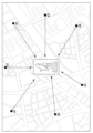
도 4는 간섭 판정 장치가 설정한 표본 설치 지점들의 제1 실시예를 나타내는 개념도이다.
도 5는 수신 신호 세기들의 간섭 발생 비율을 나타내는 히스토그램의 제1 실시예를 나타내는 그래프이다.
도 6은 도 2의 제1 허용 간섭 기준에 기반하여 제2 허용 간섭 기준을 설정하는 과정의 제1 실시예를 나타내는 순서도이다.
도 7은 도 3의 간섭 신호 송신 장치의 제1 실시예를 나타내는 개념도이다.
도 8은 도 3의 간섭 판정 장치의 제1 실시예를 나타내는 개념도이다.
도 9는 도 2의 지리 정보 시스템을 이용하여 보호 이격 거리 및 보호 영역을 설정하는 과정의 제1 실시예를 나타내는 순서도이다.
도 10은 맵상의 이기종 송신 장치들에 대한 간섭 정도를 표시한 제1 실시예를 나타내는 개념도이다.
도 11은 맵상에 보호 이격 거리 및 보호 영역을 표시한 제1 실시예를 나타내는 개념도이다.
도 12는 이기종 서비스간 간섭 판정 시스템을 구성하는 간섭 판정 장치의 제1 실시예를 도시한 블록도이다.1 is a conceptual diagram showing a first embodiment of a communication system.
Figure 2 is a flowchart showing a first embodiment of a method for determining interference between heterogeneous services.
Figure 3 is a conceptual diagram showing a first embodiment of an interference determination system between heterogeneous services.
Figure 4 is a conceptual diagram showing a first embodiment of sample installation points set by the interference determination device.
Figure 5 is a graph showing a first embodiment of a histogram showing the interference occurrence rate of received signal strengths.
FIG. 6 is a flowchart showing a first embodiment of a process for setting a second allowable interference standard based on the first allowable interference standard of FIG. 2.
FIG. 7 is a conceptual diagram showing a first embodiment of the interference signal transmission device of FIG. 3.
FIG. 8 is a conceptual diagram showing a first embodiment of the interference determination device of FIG. 3.
FIG. 9 is a flowchart showing a first embodiment of a process for setting a protection separation distance and a protection area using the geographic information system of FIG. 2.
Figure 10 is a conceptual diagram showing a first embodiment showing the degree of interference with heterogeneous transmission devices on a map.
Figure 11 is a conceptual diagram showing a first embodiment in which a protection separation distance and a protection area are displayed on a map.
Figure 12 is a block diagram showing a first embodiment of an interference determination device that constitutes an interference determination system between heterogeneous services.
본 발명은 다양한 변경을 가할 수 있고 여러 가지 실시예를 가질 수 있는 바, 특정 실시예들을 도면에 예시하고 상세하게 설명하고자 한다. 그러나 이는 본 발명을 특정한 실시 형태에 대해 한정하려는 것이 아니며, 본 발명의 사상 및 기술 범위에 포함되는 모든 변경, 균등물 내지 대체물을 포함하는 것으로 이해되어야 한다.Since the present invention can make various changes and have various embodiments, specific embodiments will be illustrated in the drawings and described in detail. However, this is not intended to limit the present invention to specific embodiments, and should be understood to include all changes, equivalents, and substitutes included in the spirit and technical scope of the present invention.
제1, 제2 등의 용어는 다양한 구성요소들을 설명하는데 사용될 수 있지만, 상기 구성요소들은 상기 용어들에 의해 한정되어서는 안 된다. 상기 용어들은 하나의 구성요소를 다른 구성요소로부터 구별하는 목적으로만 사용된다. 예를 들어, 본 발명의 권리 범위를 벗어나지 않으면서 제1 구성요소는 제2 구성요소로 명명될 수 있고, 유사하게 제2 구성요소도 제1 구성요소로 명명될 수 있다. 및/또는 이라는 용어는 복수의 관련된 기재된 항목들의 조합 또는 복수의 관련된 기재된 항목들 중의 어느 항목을 포함한다.Terms such as first, second, etc. may be used to describe various components, but the components should not be limited by the terms. The above terms are used only for the purpose of distinguishing one component from another. For example, a first component may be named a second component, and similarly, the second component may also be named a first component without departing from the scope of the present invention. The term and/or includes any of a plurality of related stated items or a combination of a plurality of related stated items.
본 출원의 실시예들에서, "A 및 B 중에서 적어도 하나"는 "A 또는 B 중에서 적어도 하나" 또는 "A 및 B 중 하나 이상의 조합들 중에서 적어도 하나"를 의미할 수 있다. 또한, 본 출원의 실시예들에서, "A 및 B 중에서 하나 이상"은 "A 또는 B 중에서 하나 이상" 또는 "A 및 B 중 하나 이상의 조합들 중에서 하나 이상"을 의미할 수 있다.In embodiments of the present application, “at least one of A and B” may mean “at least one of A or B” or “at least one of combinations of one or more of A and B.” Additionally, in embodiments of the present application, “one or more of A and B” may mean “one or more of A or B” or “one or more of combinations of one or more of A and B.”
어떤 구성요소가 다른 구성요소에 "연결되어" 있다거나 "접속되어" 있다고 언급된 때에는, 그 다른 구성요소에 직접적으로 연결되어 있거나 또는 접속되어 있을 수도 있지만, 중간에 다른 구성요소가 존재할 수도 있다고 이해되어야 할 것이다. 반면에, 어떤 구성요소가 다른 구성요소에 "직접 연결되어" 있다거나 "직접 접속되어" 있다고 언급된 때에는, 중간에 다른 구성요소가 존재하지 않는 것으로 이해되어야 할 것이다.When a component is said to be "connected" or "connected" to another component, it is understood that it may be directly connected to or connected to the other component, but that other components may exist in between. It should be. On the other hand, when it is mentioned that a component is “directly connected” or “directly connected” to another component, it should be understood that there are no other components in between.
본 출원에서 사용한 용어는 단지 특정한 실시예를 설명하기 위해 사용된 것으로, 본 발명을 한정하려는 의도가 아니다. 단수의 표현은 문맥상 명백하게 다르게 뜻하지 않는 한, 복수의 표현을 포함한다. 본 출원에서, "포함하다" 또는 "가지다" 등의 용어는 명세서상에 기재된 특징, 숫자, 단계, 동작, 구성요소, 부품 또는 이들을 조합한 것이 존재함을 지정하려는 것이지, 하나 또는 그 이상의 다른 특징들이나 숫자, 단계, 동작, 구성요소, 부품 또는 이들을 조합한 것들의 존재 또는 부가 가능성을 미리 배제하지 않는 것으로 이해되어야 한다.The terms used in this application are only used to describe specific embodiments and are not intended to limit the invention. Singular expressions include plural expressions unless the context clearly dictates otherwise. In this application, terms such as “comprise” or “have” are intended to designate the presence of features, numbers, steps, operations, components, parts, or combinations thereof described in the specification, but are not intended to indicate the presence of one or more other features. It should be understood that this does not exclude in advance the possibility of the existence or addition of elements, numbers, steps, operations, components, parts, or combinations thereof.
다르게 정의되지 않는 한, 기술적이거나 과학적인 용어를 포함해서 여기서 사용되는 모든 용어들은 본 발명이 속하는 기술 분야에서 통상의 지식을 가진 자에 의해 일반적으로 이해되는 것과 동일한 의미를 가지고 있다. 일반적으로 사용되는 사전에 정의되어 있는 것과 같은 용어들은 관련 기술의 문맥 상 가지는 의미와 일치하는 의미를 가진 것으로 해석되어야 하며, 본 출원에서 명백하게 정의하지 않는 한, 이상적이거나 과도하게 형식적인 의미로 해석되지 않는다.Unless otherwise defined, all terms used herein, including technical or scientific terms, have the same meaning as commonly understood by a person of ordinary skill in the technical field to which the present invention pertains. Terms defined in commonly used dictionaries should be interpreted as having a meaning consistent with the meaning in the context of the related technology, and unless explicitly defined in the present application, should not be interpreted in an idealized or excessively formal sense. No.
명세서 전체에서 망(network)은, 예를 들어, WiFi(wireless fidelity)와 같은 무선 인터넷, WiBro(wireless broadband internet) 또는 WiMax(world interoperability for microwave access)와 같은 휴대 인터넷, GSM(global system for mobile communication) 또는 CDMA(code division multiple access)와 같은 2G 이동 통신망, WCDMA(wideband code division multiple access) 또는 CDMA2000과 같은 3G 이동 통신망, HSDPA(high speed downlink packet access) 또는 HSUPA(high speed uplink packet access)와 같은 3.5G 이동 통신망, LTE(long term evolution)망 또는 LTE-Advanced망과 같은 4G 이동 통신망, 5G 이동 통신망, 6G 이동 통신망 등을 포함할 수 있다.Throughout the specification, network refers to, for example, wireless Internet such as WiFi (wireless fidelity), mobile Internet such as WiBro (wireless broadband internet) or WiMax (world interoperability for microwave access), and GSM (global system for mobile communication). ) or 2G mobile networks such as code division multiple access (CDMA), 3G mobile networks such as wideband code division multiple access (WCDMA) or CDMA2000, high speed downlink packet access (HSDPA) or high speed uplink packet access (HSUPA). It may include a 3.5G mobile communication network, a 4G mobile communication network such as an LTE (long term evolution) network or an LTE-Advanced network, a 5G mobile communication network, and a 6G mobile communication network.
명세서 전체에서 단말(terminal)은 이동국(mobile station), 이동 단말(mobile terminal), 가입자국(subscriber station), 휴대 가입자국(portable subscriber station), 사용자 장치(user equipment), 접근 단말(access terminal) 등을 지칭할 수도 있고, 단말, 이동국, 이동 단말, 가입자국, 휴대 가입자국, 사용자 장치, 접근 단말 등의 전부 또는 일부의 기능을 포함할 수도 있다.Throughout the specification, terminal refers to a mobile station, mobile terminal, subscriber station, portable subscriber station, user equipment, and access terminal. It may refer to the like, and may include all or part of the functions of a terminal, a mobile station, a mobile terminal, a subscriber station, a portable subscriber station, a user device, an access terminal, etc.
여기서, 단말로 통신이 가능한 데스크탑 컴퓨터(desktop computer), 랩탑 컴퓨터(laptop computer), 태블릿(tablet) PC, 무선 전화기(wireless phone), 모바일 폰(mobile phone), 스마트 폰(smart phone), 스마트 워치(smart watch), 스마트 글래스(smart glass), e-book 리더기, PMP(portable multimedia player), 휴대용 게임기, 네비게이션(navigation) 장치, 디지털 카메라(digital camera), DMB (digital multimedia broadcasting) 재생기, 디지털 음성 녹음기(digital audio recorder), 디지털 음성 재생기(digital audio player), 디지털 영상 녹화기(digital picture recorder), 디지털 영상 재생기(digital picture player), 디지털 동영상 녹화기(digital video recorder), 디지털 동영상 재생기(digital video player) 등을 사용할 수 있다.Here, a desktop computer, a laptop computer, a tablet PC, a wireless phone, a mobile phone, a smart phone, and a smart watch capable of communicating with a terminal. (smart watch), smart glass, e-book reader, PMP (portable multimedia player), portable game console, navigation device, digital camera, DMB (digital multimedia broadcasting) player, digital voice digital audio recorder, digital audio player, digital picture recorder, digital picture player, digital video recorder, digital video player ), etc. can be used.
명세서 전체에서 기지국(base station)은 접근점(access point), 무선 접근국(radio access station), 노드B(node B), 고도화 노드B(evolved nodeB), 송수신 기지국(base transceiver station), MMR(mobile multihop relay)-BS 등을 지칭할 수도 있고, 기지국, 접근점, 무선 접근국, 노드B, eNodeB, 송수신 기지국, MMR-BS 등의 전부 또는 일부의 기능을 포함할 수도 있다.Throughout the specification, base station refers to an access point, radio access station, node B, evolved node B, base transceiver station, and MMR ( It may refer to a mobile multihop relay)-BS, etc., and may include all or part of the functions of a base station, access point, wireless access station, Node B, eNodeB, transmitting and receiving base station, and MMR-BS.
이하, 첨부한 도면들을 참조하여, 본 발명의 바람직한 실시예를 보다 상세하게 설명하고자 한다. 본 발명을 설명함에 있어 전체적인 이해를 용이하게 하기 위하여 도면상의 동일한 구성요소에 대해서는 동일한 참조부호를 사용하고 동일한 구성요소에 대해서 중복된 설명은 생략한다.Hereinafter, preferred embodiments of the present invention will be described in more detail with reference to the attached drawings. In order to facilitate overall understanding when describing the present invention, the same reference numerals are used for the same components in the drawings, and duplicate descriptions for the same components are omitted.
도 1은 통신 시스템의 제1 실시예를 나타내는 개념도이다.1 is a conceptual diagram showing a first embodiment of a communication system.
도 1을 참조하면, 통신 시스템은 기지국(110), 단말(111), 수신 장치(120), 송신국(121) 및 위성 방송 송신 장치(122)를 포함할 수 있다. 여기서, 기지국(110)과 단말(111)은 제1 무선 통신 네트워크를 구성할 수 있다. 이러한 제1 무선 통신 네트워크는 이동 통신 네트워크로서 이동 통신 시스템을 구성하는 통신 장치를 포함할 수 있다. 따라서, 제1 무선 통신 네트워크에 포함된 통신 장치는 이동 통신을 수행할 수 있다.Referring to FIG. 1, the communication system may include a
그리고, 수신 장치(120), 송신국(121) 및 위성 방송 송신 장치(122)는 제2 무선 통신 네트워크를 구성할 수 있다. 이러한, 제2 무선 통신 네트워크는 위성 방송 통신 네트워크로서 위성 방송 통신 시스템을 구성하는 통신 장치를 포함할 수 있다. 이때, 위성 방송에 이용되는 수신 장치(120)는 고정된 상태일 수 있으며, 송신국(121)은 위성과 같이 고정되지 않은 상태일 수 있다. And, the receiving
여기서, 위성 방송 송신 장치(122)는 위성 방송 전송 기술을 적용하여 위성 방송 신호를 송신국(121)을 통하여 수신 장치(120)로 전송할 수 있다. 이와 같은 송신국(121)은 위성에 탑재되어 있으며 위성 방송 송신 장치(122)에서 송출되는 위성 방송 신호를 수신하여 수신 장치(120)로 전송할 수 있다. 이에 따라, 수신 장치(120)는 송신국(121)으로부터 위성 방송 신호를 수신할 수 있다. Here, the satellite broadcasting transmission device 122 can transmit a satellite broadcasting signal to the receiving
그리고, 수신 장치(120)는 수신한 위성 방송 신호에 따라 위성 방송 서비스를 수신자에게 제공할 수 있다. 여기서, 위성 방송 송신 장치(122)는 이기종 서비스간 간섭 판정 시스템의 이기종 서비스간 간섭 판정에 통계적 다양성을 확보할 수 있도록 위성 방송 서비스에 해당하는 임의의 신호를 선정하여 송신할 수 있다.Additionally, the receiving
이와 같은 상황에서, 제1 무선 통신 네트워크는 제2 무선 통신 네트워크와 동일한 주파수 대역 또는 인접한 주파수 대역을 이용하여 데이터를 송수신할 수 있다. 이때, 제2 무선 통신 네트워크의 통신 장치인 수신 장치(120)는 제1 무선 통신 네트워크에 의해 간섭을 받을 수 있다.In this situation, the first wireless communication network may transmit and receive data using the same frequency band or an adjacent frequency band as the second wireless communication network. At this time, the receiving
이를 좀더 상세히 살펴보면, 제1 무선 통신 네트워크를 구성하는 기지국(110)은 실시간으로 단말(111)의 위치를 추적할 수 있다. 그리고, 기지국(110)은 데이터를 송수신하기 위해 단말(111)의 위치를 반영하여 빔포밍할 수 있다. 이처럼, 기지국(110)이 단말(111)로 송신하는 신호는 수신 장치(120)에 간섭을 미칠 수 있다. 따라서, 기지국(110)은 수신 장치(120)에 간섭을 덜 미치도록 배치될 수 있다.Looking at this in more detail, the
일 실시예에 따르면, 제2 무선 통신 네트워크의 통신 장치인 수신 장치(120)는 고정된 위치에 배치되어 있다. 이와 달리 제1 무선 통신 네트워크의 통신 장치인 기지국(110)은 수신 장치(120)의 주위에 배치될 수 있다. 이에 따라, 수신 장치(120)는 기지국(110)의 배치에 의해 받게 될 간섭을 평가할 수 있다. 일 예로, 수신 장치(120)는 기지국(110)으로부터 수신하게 될 수신 신호가 송신국(121)으로부터 수신한 수신 신호에 미치는 영향을 미리 평가하여 기지국(110)으로부터 받게 될 간섭을 평가할 수 있다. 이때, 수신 장치(120)는 송신국(121)에서 수신한 수신 신호의 신호 품질이 허용 간섭 기준 이하이면 허용 가능한 간섭으로 판단할 수 있다. 여기서, 허용 간섭 기준은 일 예로 방송 신호인 경우에 10% 이상의 패킷 손실률일 수 있다. 이에 따라, 수신 장치(120)는 송신국(121)에서 수신한 수신 신호의 패킷 손실률이 10% 이하이면 허용 가능한 간섭으로 판단할 수 있다.According to one embodiment, the receiving
이러한 간섭 평가를 기반으로, 기지국(110)은 수신 장치(120)에 허용 가능한 간섭을 주도록 수신 장치(120)로부터 적절한 이격 거리를 가지며 배치될 수 있다. 여기서, 제1 무선 통신 네트워크는 이동 통신 네트워크였으나 이에 한정되지 않으며 필요에 따라 방송 네트워크일 수 있다. 그리고, 제2 무선 통신 네트워크는 위성 방송 통신 네트워크를 예로 들었으나 이에 한정되지 않으며 일반적인 방송 네트워크일 수 있다. 제2 무선 통신 네트워크는 필요에 따라 이동 통신 네트워크일 수도 있다. 이처럼, 제1 무선 통신 네트워크와 제2 무선 통신 네트워크는 서로 다른 통신 네트워크로 서로 다른 서비스(즉 이기종 서비스)를 제공할 수 있다.Based on this interference evaluation, the
한편, 제1 무선 통신 네트워크의 통신 장치인 기지국들은 수신 장치를 중심으로 여러 지점들에 배치될 수 있다. 이때, 기지국 설치 사업자는 모든 기지국들을 각각의 설치 지점에 설치한 후에 수신 장치를 이용하여 각각의 기지국이 미치는 간섭을 평가하여 허용 가능한 간섭인 경우에 설치된 기지국을 유지할 수 있다. 이와 달리, 기지국 설치 사업자는 설치된 기지국이 수신 장치에 미치는 간섭이 허용 가능하지 않은 경우에 다른 지점으로 이동하여 기지국을 다시 설치한 후에 간섭을 다시 평가할 수 있다. Meanwhile, base stations, which are communication devices of the first wireless communication network, may be placed at various points around the receiving device. At this time, after installing all base stations at each installation point, the base station installation operator can use a receiving device to evaluate the interference caused by each base station and maintain the installed base station if the interference is acceptable. In contrast, if the interference caused by the installed base station to the receiving device is unacceptable, the base station installer can move to another location and re-install the base station and then re-evaluate the interference.
이처럼 기지국 설치 사업자가 기지국들을 직접 설치한 후에 간섭을 평가하여 적합하지 않은 경우에 다른 지역으로 이동하면서 적절한 설치 지점을 탐색하게 되면 많은 비용이 소요될 수 있다. 따라서, 이를 개선하기 위하여 기지국 설치 사업자는 기지국에서 출력하는 신호와 동일한 신호를 출력할 수 있는 간섭 신호 발생 장치를 이용하여 간편하게 적절한 기지국의 설치 지점을 탐색할 수 있다.In this way, if a base station installation operator installs the base stations directly, evaluates interference, and if it is not suitable, moves to another area to search for a suitable installation point, which can cost a lot of money. Therefore, in order to improve this, a base station installation business can easily search for an appropriate base station installation point by using an interference signal generator that can output the same signal as the signal output from the base station.
하지만, 기지국 설치 사업자가 기지국들을 설치할 지역의 여러 지점들에 대하여 이와 같은 작업을 수행하게 되면 여전히 많은 비용이 소요될 수 있다. 따라서, 기지국 설치 사업자는 기지국들을 설치할 지역에서 표본 설치 지점들을 설정할 수 있다. 그리고, 기지국 설치 사업자는 설정한 표본 설치 지점들에 간섭 신호 발생 장치들을 직접 설치하여 수신 장치에 간섭 신호 발생 장치들에서 발생한 간섭 신호들이 미치는 간섭을 평가할 수 있다.However, if a base station installation operator performs this work at various points in the area where base stations are to be installed, it may still cost a lot of money. Accordingly, a base station installation operator can set sample installation points in the area where base stations will be installed. In addition, the base station installation operator can directly install the interference signal generating devices at the set sample installation points and evaluate the interference caused by the interference signals generated by the interference signal generating devices on the receiving device.
도 2는 이기종 서비스간 간섭 판정 방법의 제1 실시예를 나타내는 흐름도이다.Figure 2 is a flowchart showing a first embodiment of a method for determining interference between heterogeneous services.
도 2를 참조하면, 이기종 서비스간 간섭 판정 방법은 제1 허용 간섭 기준에 기반하여 제2 허용 간섭 기준을 설정하는 과정(S201 내지 S205)와 지리 정보 시스템을 이용하여 보호 이격 거리 및 보호 영역을 설정하는 과정(S206 내지 S210)을 포함할 수 있다. 이와 같은 이기종 서비스간 간섭 판정 방법에서 송신국은 제1 무선 통신 네트워크에서 사용하는 방송 신호를 송신할 수 있다. 그러면, 수신 장치에 설치된 간섭 판정 장치는 송신국에서 송신하는 제1 무선 통신 네트워크에서 사용하는 방송 신호를 수신할 수 있다(S201). Referring to FIG. 2, the method for determining interference between heterogeneous services includes a process of setting a second allowable interference standard based on the first allowable interference standard (S201 to S205) and setting a protection separation distance and a protection area using a geographic information system. It may include a process (S206 to S210). In this method for determining interference between heterogeneous services, the transmitting station can transmit a broadcast signal used in the first wireless communication network. Then, the interference determination device installed in the receiving device can receive the broadcast signal used in the first wireless communication network transmitted from the transmitting station (S201).
한편, 간섭 신호 발생 장치들은 표본 설치 지점들에 각각 설치되어 있을 수 있다. 그리고, 간섭 신호 발생 장치들은 간섭 신호들을 송신할 수 있다. 그러면, 수신 장치에 설치된 간섭 판정 장치는 간섭 신호 발생 장치들로부터 간섭 신호들을 수신할 수 있다(S202). 이때, 간섭 판정 장치는 간섭 신호 발생 장치들에서 수신한 수신 신호들의 수신 신호 세기들을 측정할 수 있다(S203). Meanwhile, interference signal generating devices may be installed at each sample installation point. And, interference signal generating devices can transmit interference signals. Then, the interference determination device installed in the receiving device can receive interference signals from the interference signal generating devices (S202). At this time, the interference determination device can measure the received signal strengths of the received signals from the interference signal generating devices (S203).
이후에, 간섭 판정 장치는 간섭 신호 발생 장치들로부터 수신한 간섭 신호들이 송신국으로부터 수신한 수신 신호에 미치는 영향을 평가하여 간섭 신호 발생 장치들로부터 받게 될 간섭을 평가할 수 있다(S204). 이때, 간섭 판정 장치는 송신국에서 수신한 수신 신호의 간섭 정도가 제1 허용 간섭 기준 이하이면 해당 간섭 신호 발생 장치로부터 수신한 수신 신호에 대하여 허용 가능한 간섭으로 판단할 수 있다. 이와 달리, 간섭 판정 장치는 송신국에서 수신한 수신 신호의 간섭 정도가 제1 허용 간섭 기준을 초과하면 해당 간섭 신호 발생 장치로부터 수신한 신호에 대하여 허용 가능하지 않은 간섭으로 판단할 수 있다. Afterwards, the interference determination device may evaluate the interference to be received from the interference signal generating devices by evaluating the effect of the interference signals received from the interference signal generating devices on the received signal received from the transmitting station (S204). At this time, if the degree of interference of the received signal from the transmitting station is less than or equal to the first allowable interference standard, the interference determination device may determine that the received signal received from the corresponding interference signal generating device is acceptable interference. In contrast, if the degree of interference of the signal received from the transmitting station exceeds the first allowable interference standard, the interference determination device may determine the signal received from the interference signal generating device as unacceptable interference.
이에 따라, 간섭 판정 장치는 허용 가능한 간섭을 발생시키는 간섭 신호 발생 장치들에서 수신한 수신 신호들의 수신 신호 세기들과 허용 가능하지 않은 간섭을 발생시키는 간섭 신호 발생 장치들에서 수신한 수신 신호들의 수신 신호 세기들을 참조하여 제2 허용 간섭 기준을 설정할 수 있다(S205). 이때, 제2 허용 간섭 기준은 간섭 신호 발생 장치들에서 수신한 수신 신호 세기들 중에서 하나일 수 있다. Accordingly, the interference determination device determines the received signal strengths of the received signals received from the interference signal generating devices that generate acceptable interference and the received signal strengths of the received signals received from the interference signal generating devices that generate unacceptable interference. A second allowable interference standard can be set by referring to the intensities (S205). At this time, the second allowable interference standard may be one of the received signal strengths received from the interference signal generating devices.
한편, 간섭 판정 장치는 3D(dimension) 지리 정보 시스템(geographic information system, GIS)이 제공하는 맵(map) 상에 기지국들을 설치할 여러 가상 설치 지점들을 설정할 수 있다(S206). 그리고, 간섭 판정 장치는 가상 설치 지점들에 간섭 신호 발생 장치들을 가상으로 설치할 수 있다(S207). 간섭 판정 장치는 가상 설치 지점들에 설치된 간섭 신호 발생 장치들로부터 수신할 수신 신호들의 수신 신호 세기들을 전파전파(電波傳播) 알고리즘을 이용하여 산출할 수 있다(S208). 그리고, 간섭 판정 장치는 산출한 간섭 신호 발생 장치들의 수신 신호 세기를 이용하여 수신 장치에 간섭 신호 발생 장치들에서 발생한 간섭 신호들이 미치는 간섭을 평가할 수 있다(S209).Meanwhile, the interference determination device can set several virtual installation points where base stations will be installed on a map provided by a 3D (dimension) geographic information system (GIS) (S206). And, the interference determination device can virtually install interference signal generating devices at virtual installation points (S207). The interference determination device may calculate the received signal strengths of the received signals to be received from the interference signal generating devices installed at the virtual installation points using a radio wave propagation algorithm (S208). Additionally, the interference determination device can evaluate the interference caused by the interference signals generated from the interference signal generating devices to the receiving device using the calculated strength of the received signals from the interference signal generating devices (S209).
일 예로, 간섭 판정 장치는 산출한 수신 신호 세기가 제2 허용 간섭 기준 이하이면 해당 간섭 신호 발생 장치의 간섭 신호에 대하여 허용 가능한 간섭으로 판단할 수 있다. 이와 달리, 간섭 판정 장치는 산출한 수신 신호 세기가 제2 허용 간섭 기준을 초과하면 해당 간섭 신호 발생 장치의 간섭 신호에 대하여 허용 가능하지 않은 간섭으로 판단할 수 있다.For example, if the calculated received signal strength is less than or equal to the second allowable interference standard, the interference determination device may determine that the interference signal from the corresponding interference signal generating device is allowable interference. In contrast, if the calculated received signal strength exceeds the second allowable interference standard, the interference determination device may determine that the interference signal from the corresponding interference signal generating device is unacceptable interference.
이때, 간섭 판정 장치는 허용 가능한 간섭을 발생할 것으로 판단된 간섭 신호 발생 장치들의 가상 설치 지점들에 대한 위치 정보와 허용 가능 하지 않은 간섭을 발생할 것으로 판단된 간섭 신호 발생 장치들의 가상 설치 지점들에 대한 위치 정보를 기반으로 보호 이격 거리와 보호 영역을 설정할 수 있다(S210).At this time, the interference determination device provides location information on the virtual installation points of the interference signal generating devices determined to generate acceptable interference and the locations of virtual installation points of the interference signal generating devices determined to generate unacceptable interference. Based on the information, the protection separation distance and protection area can be set (S210).
도 3은 이기종 서비스간 간섭 판정 시스템의 제1 실시예를 나타내는 개념도이다.Figure 3 is a conceptual diagram showing a first embodiment of an interference determination system between heterogeneous services.
도 3을 참조하면, 이기종 서비스간 간섭 판정 시스템은 송신국(300), 간섭 신호 송신 장치들(310-1 내지 310-n) 및 간섭 판정 장치(320)를 포함할 수 있다. 그리고, 간섭 판정 장치(320)는 신호 수신부(321), 간섭 판정부(322) 및 제어부(323)를 포함할 수 있다. Referring to FIG. 3, the heterogeneous inter-service interference determination system may include a transmitting
여기서, 제어부(323)는 기지국을 설치할 표본 설치 지점들을 설정할 수 있고, 설정한 표본 설치 지점들에 대한 위치 정보를 간섭 신호 송신 장치들(310-1 내지 310-n)로 전송할 수 있다. 이때, 제어부(323)는 표본 설치 지점들을 여러 채널 환경을 반영하여 통계적 모수를 확보하기 위해 다양하게 선정할 수 있다. 일 예로, 제어부(323)은 표본 설치 지점들을 방사형이 되도록 설정할 수 있다. 이러한, 간섭 신호 송신 장치들(310-1 내지 310-n)의 각각은 제어부(323)로부터 각각에 해당하는 표본 설치 지점에 대한 위치 정보를 수신할 수 있다. 그리고, 간섭 신호 송신 장치들(310-1 내지 310-n)은 GPS(global positioning system) 수신기를 이용하여 현재 위치를 확인한 후에 제어부(323)로부터 수신한 해당하는 각각의 표본 설치 지점으로 이동할 수 있다. Here, the
한편, 제어부(323)는 표본 설치 지점들에 대하여 지점별 안테나 높이들과 지점별 안테나 지향 방향들을 설정할 수 있다. 그리고, 제어부(323)는 간섭 신호 송신 장치들(310-1 내지 310-n)의 각각으로 해당하는 간섭 신호 발생 지점에 대하여 설정한 지점별 안테나 높이 정보와 지점별 안테나 지향 방향 정보를 전송할 수 있다. 그러면, 간섭 신호 송신 장치들(310-1 내지 310-n)의 각각은 제어부(323)로부터 해당하는 표본 설치 지점에 대한 지점별 안테나 높이 정보와 지점별 안테나 지향 방향 정보를 수신할 수 있다. 이때, 제어부(323)는 안테나 높이를 일 예로 3m 또는 9m로 설정할 수 있다.Meanwhile, the
또한, 제어부(223)는 표본 설치 지점들에 대하여 지점별 안테나 종류들, 지점별 안테나 종류별 이득, 지점별 안테나 종류별 EIRP(effective isotropically radiated power)들을 설정할 수 있다. 이때, 제어부(323)는 안테나 종류로 일 예로 옴니 안테나 또는 지향성 안테나를 설정할 수 있다. 그리고, 제어부(323)는 지점별 안테나 종류별 이득으로 일 예로 옴니 안테나에 대하여 6dBi를 설정할 수 있고, 지향성 안테나에 대하여 19.5dBi를 설정할 수 있다. 다음으로, 제어부(323)는 지점별 안테나 종류별 EIRP로 일 예로 옴니 안테나에 대하여 44.5dBm/100MHz를 설정할 수 있고, 지향성 안테나에 대하여 58dBm/100MHz를 설정할 수 있다. Additionally, the control unit 223 may set antenna types for each point, gains for each antenna type for each point, and effective isotropically radiated power (EIRP) for each antenna type for the sample installation points. At this time, the
또한, 제어부(323)는 표본 설치 지점들에 대하여 간섭 신호를 측정하기를 원하는 지점별 송출 시간들을 설정할 수 있다. 이때, 제어부(323)는 표본 설치 지점들의 각각에 대하여 지점별 송출 시간을 복수의 시간 구간들로 설정할 수 있다. 그리고, 제어부(323)는 설정한 지점별 송출 시간들에 대한 지점별 송출 시간 정보를 간섭 신호 송신 장치들(310-1 내지 310-n)로 전송할 수 있다. 그러면, 간섭 신호 송신 장치들(310-1 내지 310-n)은 제어부(323)로부터 표본 설치 지점별로 간섭 신호를 측정하기를 원하는 지점별 송출 시간 정보를 수신할 수 있다.Additionally, the
또한, 제어부(323)는 표본 설치 지점들에 대하여 간섭 신호 특성들을 설정할 수 있다. 이때, 제어부(323)는 간섭 신호 특성들을 각 시험 시 다양한 데이터를 변조하여 송신하도록 설정할 수 있다. 또한, 제어부(323)는 통계적 다양성을 확보하기 위해 각 서비스에 해당하는 임의의 신호를 간섭 신호들로 선정할 수 있다. 일 예로, 간섭 신호는 이동 통신 간섭 신호일 수 있다. 일 예로, 이동 통신 간섭 신호는 5G 이동 통신 간섭 신호 또는 6G 이동 통신 간섭 신호일 수 있다. 여기서, 간섭 신호 특성은 송신 데이터, 송신 주파수 또는 송신 전력 중에서 적어도 하나를 포함할 수 있다. 그리고, 제어부(323)는 설정한 표본 설치 지점별 간섭 신호 특성들의 정보를 간섭 신호 송신 장치들(310-1 내지 310-n)로 전송할 수 있다. 그러면, 간섭 신호 송신 장치들(310-1 내지 310-n)은 제어부(323)로부터 표본 설치 지점별로 지점별 간섭 신호 특성 정보를 수신할 수 있다.Additionally, the
또한, 제어부(323)는 간섭 신호 송신 장치들(310-1 내지 310-n)로 간섭 판정 장치(320)의 위치 정보를 전송할 수 있다. 그러면, 간섭 신호 송신 장치들(310-1 내지 310-n)은 제어부(323)로부터 간섭 판정 장치(320)의 위치 정보를 수신할 수 있다. 또한, 제어부(323)는 간섭 신호 송신 장치들(310-1 내지 310-n)로 간섭 발생 여부를 측정하기를 원하는 위성 채널의 중심 주파수 정보를 전송할 수 있다. 그러면, 간섭 신호 송신 장치들(310-1 내지 310-n)은 제어부(323)로부터 간섭 발생 여부를 측정하기를 원하는 위성 채널의 중심 주파수 정보를 수신할 수 있다. Additionally, the
이에 따라, 간섭 신호 송신 장치들(310-1 내지 310-n)은 각각 해당하는 표본 설치 지점에서 지점별 송출 시간 정보에 따른 지점별 송출 시간에 제어부(323)로부터 수신한 위성 채널의 중심 주파수에 해당하는 이동 통신 간섭 신호를 생성하여 신호 수신부(321)를 향하여 송신할 수 있다. 이때, 간섭 신호 송신 장치들(310-1 내지 310-n)은 각각 해당하는 표본 설치 지점에서 지점별 안테나 높이 정보에 따른 안테나 높이에서 지점별 지향 방향 정보에 따른 지향 방향으로 송신할 수 있다. 또한, 간섭 신호 송신 장치들(310-1 내지 310-n)은 각각 해당하는 표본 설치 지점에서 지점별 안테나 종류들 정보에 따른 지점별 안테나 종류를 선택하여, 지점별 안테나 종류별 이득 정보에 따른 지점별 안테나 종류별 이득에 따라 지점별 안테나 종류별 EIRP 정보에 따른 지점별 안테나 종류별 EIRP로 송신할 수 있다.Accordingly, the interference signal transmission devices 310-1 to 310-n each transmit at the center frequency of the satellite channel received from the
이때, 간섭 신호 송신 장치들(310-1 내지 310-n)은 제어부(323)로 각각의 식별자, 위치 정보(예를 들어, GPS 좌표 정보), 사용한 안테나의 안테나 높이, 사용한 안테나의 안테나 지향 방향, 사용한 안테나의 안테나 종류, 사용한 안테나의 안테나 이득, 사용한 안테나의 EIRP 또는 송출 시간 중에서 적어도 하나를 제공할 수 있다. At this time, the interference signal transmission devices 310-1 to 310-n provide each identifier, location information (e.g., GPS coordinate information), antenna height of the used antenna, and antenna directing direction of the used antenna to the
여기서, 이기종 서비스간 간섭 판정 시스템은 복수의 간섭 신호 송신 장치들(310-1 내지 310-n)을 구비하여 각각의 간섭 신호 송신 장치가 각각의 표본 설치 지점에서 간섭 신호를 송출할 수 있다. 하지만, 이와 달리 이기종 서비스간 간섭 판정 시스템은 하나의 간섭 신호 송신 장치를 구비하여, 구비한 하나의 간섭 신호 송신 장치를 이동 수단(일 예로, 차량)에 설치하여 신호 수신부(321)를 중심으로 하여 이동하면서 복수의 표본 설치 지점들에서 이동 통신 간섭 신호를 신호 수신부(321)를 향하여 전송할 수 있다. Here, the heterogeneous inter-service interference determination system is provided with a plurality of interference signal transmission devices 310-1 to 310-n, so that each interference signal transmission device can transmit an interference signal at each sample installation point. However, unlike this, the interference determination system between heterogeneous services is provided with one interference signal transmission device, and the one interference signal transmission device is installed in a mobile means (for example, a vehicle) and centers on the
한편, 위성 방송 송신 장치는 이기종 서비스간 간섭 판정 시스템의 이기종 서비스간 간섭 판정에 통계적 다양성을 확보할 수 있도록 각 서비스에 해당하는 임의의 신호를 선정하여 송신할 수 있다. 이에 따라, 송신국(300)은 위성 방송 송신 장치로부터 송신된 이와 같은 위성 방송 신호를 수신하여 신호 수신부(321)로 중계할 수 있다. 이와 같은 송신국(300)은 도 2의 송신국과 동일할 수 있다. Meanwhile, the satellite broadcast transmission device can select and transmit an arbitrary signal corresponding to each service so as to secure statistical diversity in the interference determination between heterogeneous services in the heterogeneous inter-service interference determination system. Accordingly, the transmitting
그러면, 수신부(321)는 송신국(300)으로부터 위성 방송 신호를 수신할 수 있다. 이때, 신호 수신부(321)는 제어부(323)가 설정한 위성 채널의 중심 주파수에 따른 해당 채널의 위성 방송 신호를 수신할 수 있다. 한편, 신호 수신부(321)는 간섭 신호 송신 장치들(310-1 내지 310-n)로부터 이동 통신 간섭 신호들을 수신할 수 있다. 이때, 신호 수신부(321)는 간섭 신호 송신 장치들(310-1 내지 310-n)로부터 이동 통신 간섭 신호들을 정해진 지점별 송출 시간들에서 수신할 수 있다. Then, the receiving
이와 달리, 신호 수신부(321)는 간섭 신호 송신 장치들(310-1 내지 310-n)로부터 이동 통신 간섭 신호들을 정해진 시간과 관계없이 수신할 수 있다. 이와 같이 신호 수신부(321)가 이동 통신 간섭 신호들을 정해진 시간과 관계없이 수신하는 경우에 제어부(323)는 간섭 신호 송신 장치들(310-1 내지 310-n)로부터 각각의 식별자 정보, 이동 통신 간섭 신호의 송출 지점 정보 및 송출 시간 정보를 수신할 수 있다. 그리고, 제어부(323)는 간섭 신호 송신 장치들(310-1 내지 310-n)로부터 수신한 각각의 식별자 정보, 이동 통신 간섭 신호의 송출 지점 정보 및 송출 시간 정보를 참조하여 신호 수신부(321)에서 수신한 이동 통신 간섭 신호들의 송출 지점들, 즉 표본 설치 지점들을 확인할 수 있다. In contrast, the
이처럼, 신호 수신부(321)는 위성 방송 신호와 이동 통신 간섭 신호들을 동시에 수신할 수 있다. 이에 따라, 신호 수신부(321)는 위성 방송 신호와 이동 통신 간섭 신호들이 결합된 결합 신호들을 간섭 판정부(322)로 제공할 수 있다. 이때, 신호 수신부(321)는 위성 방송 신호와 이동 통신 간섭 신호들의 수신 시간 정보를 간섭 판정부(322)로 제공할 수 있다. 물론, 신호 수신부(321)는 위성 방송 신호만 복조할 수 있다. 그리고, 신호 수신부(321)는 위성 방송 신호만 간섭 판정부(322)로 제공할 수 있다.In this way, the
한편, 간섭 판정부(322)는 신호 수신부(321)로부터 위성 방송 신호와 이동 통신 간섭 신호들이 결합된 결합 신호들을 수신할 수 있다. 또한, 간섭 판정부(322)는 신호 수신부(321)로부터 결합 신호들의 수신 시간 정보를 수신할 수 있다. 물론, 간섭 판정부(322)는 신호 수신부(321)로부터 위성 방송 신호만 수신할 수 있다. 이에 따라, 간섭 판정부(322)는 결합 신호들에 기반하여 허용 가능한 간섭의 발생 여부를 판정할 수 있다. 일 예로, 간섭 판정부(322)는 방송 서비스가 정상적으로 이루어지는 경우에 허용 가능한 간섭의 발생으로 판정할 수 있다. Meanwhile, the
여기서, 방송 서비스가 정상적으로 이루어지는 경우란 화면 깨짐 현상 등이 발생하지 않은 경우일 수 있다. 이와 달리 간섭 판정부(322)는 방송 서비스가 정상적으로 이루어지지 않는 경우에 허용 가능하지 않은 간섭의 발생으로 판정할 수 있다. 여기서, 방송 서비스가 정상적으로 이루어지지 않은 경우란 화면 깨짐 현상 등이 발생한 경우일 수 있다. Here, a case where the broadcasting service is performed normally may mean a case where no screen tearing phenomenon occurs. In contrast, the
다른 예로, 간섭 판정부(322)는 결합 신호들에서 방송 신호의 패킷 손실률들을 산출할 수 있다. 그리고, 간섭 판정부(322)는 산출한 패킷 손실률이 일 예로 10% 이하이면 허용 가능한 간섭으로 판정할 수 있다. 이와 달리, 간섭 판정부(322)는 산출한 패킷 손실률이 일 예로 10% 초과하면 허용 가능하지 않은 간섭의 발생으로 판정할 수 있다. 여기서, 10%의 패킷 손실률은 제1 허용 간섭 기준일 수 있다.As another example, the
한편, 간섭 판정부(322)는 이동 통신 간섭 신호가 수신되기 이전의 방송 신호의 수신 신호 세기(received signal strength indication, RSSI)와 이동 통신 간섭 신호가 수신된 경우의 결합 신호의 수신 신호 세기를 측정할 수 있다. 그리고, 간섭 판정부(322)는 방송 신호의 수신 신호 세기와 결합 신호의 수신 신호 세기의 수신 신호 세기 차이를 산출할 수 있다. 이러한 수신 신호 세기 차이는 이동 통신 간섭 신호의 수신 신호 세기일 수 있다. 그리고, 간섭 판정부(322)는 각각의 결합 신호에 대하여 간섭 판정 결과와 수신 신호 세기를 제어부(323)로 제공할 수 있다. 이때, 간섭 판정부(322)는 신호 수신부(321)로부터 수신한 결합 신호들의 수신 시간 정보를 제어부(323)로 제공할 수 있다. Meanwhile, the
한편, 제어부(323)는 간섭 판정부(322)로부터 각각의 결합 신호에 대한 간섭 판정 결과와 수신 신호 세기를 수신할 수 있다. 이때, 제어부(323)는 간섭 판정부(322)로부터 결합 신호들의 수신 시간 정보를 수신할 수 있다. 이에 따라, 제어부(323)는 저장하여 관리하고 있을 수 있는 표본 설치 지점들에 대한 지점별 송출 시간들과 결합 신호들의 수신 시간들을 매칭하여 결합 신호들에 대응되는 표본 설치 지점들을 식별할 수 있다. Meanwhile, the
이와 같은 상황에서, 간섭 신호 송신 장치들(310-1 내지 310-n) 중에서 적어도 하나 이상은 간섭 판정 장치(320)에 간섭을 미치지 않을 정도로 멀리 떨어져 있을 수 있다. 그러면, 간섭 신호 송신 장치들(310-1 내지 310-n) 중에서 적어도 하나 이상은 간섭 판정 장치(320)에 간섭을 미치지 않을 수 있다. In this situation, at least one of the interference signal transmission devices 310-1 to 310-n may be far enough not to interfere with the
이에 따라, 제어부(323)가 식별한 표본 설치 지점들의 개수는 간섭 신호 송신 장치들(310-1 내지 310-n)의 개수보다 작을 수 있다. 이때, 제어부(323)는 아래 표 1과 같은 간섭 현황표를 제작할 수 있다. 여기서, n은 일 예로 7일 수 있다. 이와 관련하여 도 4는 n이 7인 경우에 표본 설치 지점들(A1 내지 A7)을 지도상에 표시한 일 예일 수 있다. 표본 설치 지점들(A1 내지 A7)은 수신 장치(R)의 주변에 여러 방향에 걸쳐 흩어져 있을 수 있다. Accordingly, the number of sample installation points identified by the
제어부(323)는 간섭 신호 송신 장치들(310-1 내지 310-n) 중에서 어느 하나의 간섭 신호 송신 장치로부터 간섭 신호가 수신되지 않은 경우에 해당하는 간섭 신호 송신 장치에 대하여 간섭이 없는 것으로 처리할 수 있다. 이때, 제어부(323)는 간섭 신호의 수신 신호 세기들과 간섭 판정 결과들을 참조하여 간섭이 발생하는 경계 지점의 수신 신호 세기를 산출할 수 있다. 제어부(323)는 아래 표 1에서 경계 지점의 수신 신호 세기를 최소의 수신 신호 세기인 일 예로 25dBm으로 설정할 수 있다. 간섭이 발생하는 경계 지점의 수신 신호 세기는 제2 간섭 허용 기준일 수 있다. 여기서, 제2 간섭 허용 기준은 25dBm의 수신 신호 세기일 수 있다.When an interference signal is not received from any one of the interference signal transmission devices 310-1 to 310-n, the
여기서, n이 7개인 경우를 설명하였지만, n은 그보다 더 클 수 있다. 이와 같은 경우에는 제어부(323)는 간섭 신호 송신 장치들(310-1 내지 310-n)에서 수신한 수신 신호 세기들을 이용하여 히스토그램을 그릴 수 있다. 이때, 히스토그램은 가로축이 수신 신호 세기일 수 있고, 세로축이 비율일 수 있다. Here, the case where n is 7 has been described, but n may be larger than that. In this case, the
도 5는 수신 신호 세기들의 간섭 발생 비율을 나타내는 히스토그램의 제1 실시예를 나타내는 그래프이다.Figure 5 is a graph showing a first embodiment of a histogram showing the interference occurrence rate of received signal strengths.
도 5를 참조하면, 히스토그램의 가로축은 일 예로 1dBm의 수신 신호 세기의 구간을 가질 수 있다. 그리고, 히스토그램의 세로축은 각 구간에 들어가는 허용 가능하지 않은 간섭이 발생한 수신 신호 세기를 가지는 간섭 신호 송신 장치들과 허용 가능한 간섭이 발생한 수신 신호 세기를 가지는 간섭 신호 송신 장치들의 개수일 수 있다. 히스토그램은 각 직사각형의 상부에 허용 가능하지 않은 간섭이 발생한 수신 신호 세기를 가지는 간섭 신호 송신 장치들과 허용 가능한 간섭이 발생한 수신 신호 세기를 가지는 간섭 신호 송신 장치들의 비율이 표시될 수 있다.Referring to FIG. 5, the horizontal axis of the histogram may have a section with a received signal strength of 1 dBm, for example. Additionally, the vertical axis of the histogram may represent the number of interference signal transmission devices with received signal strength in which unacceptable interference occurred and interference signal transmission devices with received signal strength in which acceptable interference occurred in each section. The histogram may display, at the top of each rectangle, the ratio of interference signal transmitting devices having received signal strength in which unacceptable interference occurred and interference signal transmitting devices having received signal strength in which acceptable interference occurred.
이때, 간섭 판정 장치의 제어부는 50% 비율을 가지는 구간들 중에서 최소 비율을 가지는 구간의 중앙값을 제2 간섭 허용 기준으로 설정할 수 있다. 일 예로, 도 5에서 21.5dBm 이상 내지 22.5dBm 미만 구간이 비율이 20%일 수 있고, 22.5dBm 이상 내지 23.5dBm 미만 구간이 비율이 31%일 수 있으며, 23.5dBm 이상 내지 24.5dBm 미만 구간이 비율이 48%일 수 있고, 24.5dBm 이상 내지 25.5dBm 미만 구간이 비율이 51%일 수 있으며, 25.5dBm 이상 내지 26.5dBm 미만 구간이 비율이 55%일 수 있고, 26.5dBm 이상 내지 27.5dBm 미만 구간이 비율이 61%일 수 있다. 이와 같은 경우에, 간섭 판정 장치의 제어부는 50% 비율을 가지는 구간들 중에서 최소 비율을 가지는 구간인 24.5dBm 이상 내지 25.5dBm 미만 구간의 중앙값 25dBm을 제2 간섭 허용 기준으로 설정할 수 있다.At this time, the control unit of the interference determination device may set the median value of the section with the minimum ratio among the sections with the 50% ratio as the second interference tolerance standard. For example, in Figure 5, the ratio may be 20% in the section from 21.5 dBm to less than 22.5 dBm, the section from 22.5 dBm to less than 23.5 dBm may have a ratio of 31%, and the section from 23.5 dBm to less than 24.5 dBm may have a ratio of 20%. This may be 48%, the section above 24.5 dBm and below 25.5 dBm may have a ratio of 51%, the section between 25.5 dBm and above and below 26.5 dBm may have a ratio of 55%, and the section between 26.5 dBm and above and below 27.5 dBm may be 55%. The ratio may be 61%. In this case, the control unit of the interference determination device may set the median value of 25 dBm in the section between 24.5 dBm and less than 25.5 dBm, which is the section with the minimum ratio among sections with 50% ratio, as the second interference tolerance standard.
도 6은 도 2의 제1 허용 간섭 기준에 기반하여 제2 허용 간섭 기준을 설정하는 과정의 제1 실시예를 나타내는 순서도이다.FIG. 6 is a flowchart showing a first embodiment of a process for setting a second allowable interference standard based on the first allowable interference standard of FIG. 2.
도 6을 참조하면, 제1 허용 간섭 기준에 기반하여 제2 허용 간섭 기준을 설정하는 과정에서 수신 장치는 동일기종 송신 조건을 설정할 수 있다(S600). 여기서, 동일기종 송신 조건은 이기종 서비스간 간섭 판정 시스템의 이기종 서비스간 간섭 판정에 통계적 다양성을 확보할 수 있도록 각 서비스에 해당하는 임의의 신호를 선정하여 동일기종 신호로 설정할 수 있고, 송신 전력 등도 이에 적합하게 설정할 수 있다. Referring to FIG. 6, in the process of setting the second allowable interference standard based on the first allowable interference standard, the receiving device may set the same-type transmission condition (S600). Here, the same-type transmission condition can be set as the same-type signal by selecting an arbitrary signal corresponding to each service to ensure statistical diversity in the interference determination between heterogeneous services in the heterogeneous inter-service interference determination system, and the transmission power, etc. It can be set appropriately.
그리고, 수신 장치는 설정된 송신 조건을 동일기종 송신 장치로 전송할 수 있다(S610). 그러면, 동일기종 송신 장치는 수신 장치로부터 송신 조건을 수신할 수 있다. 그리고, 동일기종 송신 장치는 수신한 송신 조건에 따라 동일기종 신호를 수신 장치로 송신할 수 있다(S620). 여기서, 수신 장치와 동일기종 송신 장치는 고정된 위치에 설치되어 있을 수 있다.Then, the receiving device can transmit the set transmission conditions to the same type of transmitting device (S610). Then, the same type of transmitting device can receive transmission conditions from the receiving device. And, the same-type transmitting device can transmit the same-type signal to the receiving device according to the received transmission conditions (S620). Here, the receiving device and the same type of transmitting device may be installed at a fixed location.
한편, 수신 장치는 이기종 송신 조건을 설정할 수 있고(S630), 설정한 이기종 송신 조건을 이기종 송신 장치들로 전송할 수 있다(S640). 그러면, 이기종 송신 장치들은 수신 장치로부터 이기종 송신 조건을 수신할 수 있다. 그리고, 이기종 송신 장치들은 이기종 송신 조건에 따른 이기종 신호들을 수신 장치로 전송할 수 있다(S650). 이에 따라, 수신 장치는 이기종 송신 장치로부터 이기종 신호들을 수신할 수 있다. 여기서, 이기종 송신 조건은 표본 설치 지점들의 위치, 지점별 안테나 높이들, 지점별 안테나 지향 방향들, 지점별 안테나 종류들, 지점별 안테나 종류별 이득, 지점별 안테나 종류별 EIRP들, 지점별 송출 시간들, 이기종 신호 특성들, 수신 장치의 위치 또는 간섭 발생 여부를 측정하기를 원하는 채널의 중심 주파수 중에서 적어도 하나를 포함할 수 있다.Meanwhile, the receiving device can set heterogeneous transmission conditions (S630) and transmit the set heterogeneous transmission conditions to heterogeneous transmission devices (S640). Then, heterogeneous transmission devices can receive heterogeneous transmission conditions from the receiving device. And, heterogeneous transmission devices can transmit heterogeneous signals according to heterogeneous transmission conditions to the reception device (S650). Accordingly, the receiving device can receive heterogeneous signals from the heterogeneous transmitting device. Here, heterogeneous transmission conditions include the locations of sample installation points, antenna heights for each point, antenna pointing directions for each point, antenna types for each point, gain for each antenna type for each point, EIRPs for each antenna type for each point, transmission times for each point, It may include at least one of heterogeneous signal characteristics, the location of the receiving device, or the center frequency of the channel for which it is desired to measure whether interference occurs.
이에 대하여 상세히 살펴보면, 수신 장치는 표본 설치 지점들을 설정할 수 있고, 설정한 표본 설치 지점들에 대한 위치 정보를 이기종 송신 장치들로 전송할 수 있다. 이때, 수신 장치는 표본 설치 지점들을 여러 채널 환경을 반영하여 통계적 모수를 확보하기 위해 다양하게 선정할 수 있다. 이때, 이기종 송신 장치들은 수신 장치로부터 해당하는 표본 설치 지점에 대한 위치 정보를 수신할 수 있다. 그리고, 이기종 송신 장치들은 GPS 수신기를 이용하여 현재 위치를 확인한 후에 수신 장치로부터 수신한 해당하는 표본 설치 지점으로 이동할 수 있다. Looking at this in detail, the receiving device can set sample installation points and transmit location information about the set sample installation points to heterogeneous transmitting devices. At this time, the receiving device can select various sample installation points to reflect various channel environments and secure statistical parameters. At this time, heterogeneous transmitting devices can receive location information about the corresponding sample installation point from the receiving device. In addition, heterogeneous transmitting devices can check their current location using a GPS receiver and then move to the corresponding sample installation point received from the receiving device.
한편, 수신 장치는 표본 설치 지점들에 대하여 지점별 안테나 높이들과 지점별 안테나 지향 방향들을 설정할 수 있다. 그리고, 수신 장치는 이기종 송신 장치들로 표본 설치 지점들에 대하여 설정한 지점별 안테나 높이 정보와 지점별 안테나 지향 방향 정보를 전송할 수 있다. 그러면, 이기종 송신 장치들은 수신 장치로부터 표본 설치 지점들에 대한 지점별 안테나 높이 정보와 지점별 안테나 지향 방향 정보를 수신할 수 있다. 이때, 수신 장치는 안테나 높이를 3m 또는 9m로 설정할 수 있다.Meanwhile, the receiving device can set antenna heights for each point and antenna directing directions for each point with respect to the sample installation points. In addition, the receiving device can transmit antenna height information for each point and antenna direction information for each point set for the sample installation points to heterogeneous transmitting devices. Then, the heterogeneous transmitting devices can receive antenna height information for each point and antenna direction information for each point for the sample installation points from the receiving device. At this time, the receiving device can set the antenna height to 3m or 9m.
또한, 수신 장치는 표본 설치 지점들에 대하여 지점별 안테나 종류들, 지점별 안테나 종류별 이득, 지점별 안테나 종류별 EIRP들을 설정할 수 있다. 이때, 수신 장치는 안테나 종류로 옴니 안테나 또는 지향성 안테나를 설정할 수 있다. 그리고, 수신 장치는 지점별 안테나 종류별 이득으로 옴니 안테나에 대하여 6dBi을 설정할 수 있고, 지향성 안테나에 대하여 19.5dBi을 설정할 수 있다. 다음으로, 수신 장치는 지점별 안테나 종류별 EIRP로 옴니 안테나에 대하여 44.5dBm/100MHz을 설정할 수 있고, 지향성 안테나에 대하여 58dBm/100MHz을 설정할 수 있다. Additionally, the receiving device can set antenna types for each point, gain for each antenna type for each point, and EIRPs for each antenna type for each sample installation point. At this time, the receiving device can set omni antenna or directional antenna as the antenna type. In addition, the receiving device can set 6 dBi for the omni antenna and 19.5 dBi for the directional antenna as the gain for each antenna type for each point. Next, the receiving device can set 44.5dBm/100MHz for the omni antenna and 58dBm/100MHz for the directional antenna with the EIRP for each point and antenna type.
또한, 수신 장치는 표본 설치 지점들에 대하여 간섭 신호를 측정하기를 원하는 지점별 송출 시간들을 설정할 수 있다. 이때, 수신 장치는 표본 설치 지점들의 각각에 대하여 지점별 송출 시간을 복수의 시간 구간들로 설정할 수 있다. 그리고, 수신 장치는 설정한 지점별 송출 시간들에 대한 지점별 송출 시간 정보를 이기종 송신 장치들로 전송할 수 있다. 그러면, 이기종 송신 장치들은 수신 장치로부터 표본 설치 지점별로 간섭 신호를 측정하기를 원하는 지점별 송출 시간 정보를 수신할 수 있다.Additionally, the receiving device can set transmission times for each point at which it wishes to measure the interference signal with respect to the sample installation points. At this time, the receiving device may set the transmission time for each point to a plurality of time sections for each of the sample installation points. Additionally, the receiving device can transmit point-specific transmission time information regarding the set point-specific transmission times to heterogeneous transmission devices. Then, the heterogeneous transmitting devices can receive transmission time information for each point from which the interference signal is desired to be measured for each sample installation point from the receiving device.
또한, 수신 장치는 표본 설치 지점들에 대하여 이기종 신호 특성들을 설정할 수 있다. 이때, 수신 장치는 이기종 신호 특성들을 각 시험 시 다양한 데이터를 변조하여 송신하도록 설정할 수 있다. 또한, 수신 장치는 통계적 다양성을 확보하기 위해 각 서비스에 해당하는 임의의 신호를 이기종 신호들로 선정할 수 있다. 일 예로, 이기종 신호는 이동 통신 간섭 신호일 수 있다. 여기서, 송신 특성은 송신 데이터, 송신 주파수 또는 송신 전력 중에서 적어도 하나를 포함할 수 있다. 그리고, 수신 장치는 설정한 지점별 이기종 신호 특성들의 정보를 이기종 송신 장치들로 전송할 수 있다. 그러면, 이기종 송신 장치들은 수신 장치로부터 표본 설치 지점별로 지점별 이기종 신호 특성 정보를 수신할 수 있다.Additionally, the receiving device can set heterogeneous signal characteristics for sample installation points. At this time, the receiving device can be set to modulate and transmit various data on heterogeneous signal characteristics during each test. Additionally, the receiving device may select an arbitrary signal corresponding to each service as heterogeneous signals to ensure statistical diversity. As an example, the heterogeneous signal may be a mobile communication interference signal. Here, the transmission characteristics may include at least one of transmission data, transmission frequency, or transmission power. And, the receiving device can transmit information on heterogeneous signal characteristics for each set point to heterogeneous transmitting devices. Then, the heterogeneous transmitting devices can receive heterogeneous signal characteristic information for each sample installation point from the receiving device.
또한, 수신 장치는 이기종 송신 장치들로 수신 장치의 위치 정보를 전송할 수 있다. 그러면, 이기종 송신 장치들은 수신 장치로부터 수신 장치의 위치 정보를 수신할 수 있다. 또한, 수신 장치는 이기종 송신 장치들로 간섭 발생 여부를 측정하기를 원하는 채널의 중심 주파수 정보를 전송할 수 있다. 그러면, 이기종 송신 장치들은 수신 장치로부터 간섭 발생 여부를 측정하기를 원하는 채널의 중심 주파수 정보를 수신할 수 있다. Additionally, the receiving device can transmit location information of the receiving device to heterogeneous transmitting devices. Then, heterogeneous transmitting devices can receive location information of the receiving device from the receiving device. Additionally, the receiving device can transmit center frequency information of the channel for which it wants to measure whether interference has occurred to heterogeneous transmitting devices. Then, heterogeneous transmitting devices can receive center frequency information of the channel on which they want to measure whether interference has occurred from the receiving device.
이에 따라, 이기종 송신 장치들은 각각 해당하는 표본 설치 지점에서 지점별 송출 시간 정보에 따른 지점별 송출 시간에 수신 장치로부터 수신한 채널의 중심 주파수에 해당하는 이기종 신호를 생성하여 수신 장치를 향하여 송신할 수 있다. 이때, 이기종 송신 장치들은 각각 해당하는 표본 설치 지점에서 지점별 안테나 높이 정보에 따른 안테나 높이에서 지점별 지향 방향 정보에 따른 지향 방향으로 송신할 수 있다. 또한, 이기종 송신 장치들은 각각 해당하는 표본 설치 지점에서 지점별 안테나 종류들 정보에 따른 지점별 안테나 종류를 선택하여, 지점별 안테나 종류별 이득 정보에 따른 지점별 안테나 종류별 이득에 따라 지점별 안테나 종류별 EIRP 정보에 따른 지점별 안테나 종류별 EIRP로 송신할 수 있다.Accordingly, heterogeneous transmitting devices can generate heterogeneous signals corresponding to the center frequency of the channel received from the receiving device at each point's transmission time according to the point-by-point transmission time information at the corresponding sample installation point and transmit it toward the receiving device. there is. At this time, the heterogeneous transmitting devices can transmit in a direction according to the pointing direction information for each point at the antenna height according to the antenna height information for each point at the corresponding sample installation point. In addition, heterogeneous transmitting devices select an antenna type for each point according to the antenna type information for each point at each corresponding sample installation point, and provide EIRP information for each antenna type for each point according to the gain for each antenna type for each point according to the gain information for each antenna type. It can be transmitted with EIRP for each point and antenna type according to .
이때, 이기종 송신 장치들은 수신 장치로 각각의 식별자, 위치 정보(예를 들어, GPS 좌표 정보), 사용한 안테나의 안테나 높이, 사용한 안테나의 안테나 지향 방향, 사용한 안테나의 안테나 종류, 사용한 안테나의 안테나 이득, 사용한 안테나의 EIRP 또는 송출 시간 중에서 적어도 하나를 제공할 수 있다. At this time, the heterogeneous transmitting devices are receiving devices, each identifier, location information (for example, GPS coordinate information), antenna height of the used antenna, antenna pointing direction of the used antenna, antenna type of the used antenna, antenna gain of the used antenna, At least one of the EIRP or transmission time of the antenna used can be provided.
여기서, 이기종 서비스간 간섭 판정 시스템은 복수의 이기종 송신 장치들을 구비하여 각각의 표본 설치 지점에서 이기종 신호를 송출할 수 있다. 하지만, 이와 달리 이기종 서비스간 간섭 판정 시스템은 하나의 이기종 송신 장치를 구비하여, 구비한 하나의 이기종 송신 장치를 이동 수단(일 예로, 차량)에 설치하여 수신 장치를 중심으로 하여 이동하면서 복수의 표본 설치 지점들에서 이기종 신호를 수신 장치를 향하여 전송하도록 할 수 있다.Here, the heterogeneous inter-service interference determination system may be equipped with a plurality of heterogeneous transmission devices to transmit heterogeneous signals from each sample installation point. However, unlike this, the interference determination system between heterogeneous services is equipped with one heterogeneous transmitting device, and installs one heterogeneous transmitting device on a moving means (for example, a vehicle) to move around the receiving device and transmit a plurality of samples. Installation points can allow heterogeneous signals to be transmitted toward a receiving device.
한편, 수신 장치는 동일기종 송신기로부터 동일기종 신호를 수신할 수 있다. 이때, 수신 장치는 설정한 채널의 중심 주파수에 따른 해당 채널의 동일기종 신호를 수신할 수 있다. 한편, 수신 장치는 이기종 송신 장치들로부터 이기종 신호들을 수신할 수 있다. 이때, 수신 장치는 이기종 송신 장치들로부터 이기종 신호들을 정해진 지점별 송출 시간들에서 수신할 수 있다. Meanwhile, the receiving device can receive the same type of signal from the same type of transmitter. At this time, the receiving device can receive the same type of signal of the corresponding channel according to the center frequency of the set channel. Meanwhile, the receiving device can receive heterogeneous signals from heterogeneous transmitting devices. At this time, the receiving device can receive heterogeneous signals from heterogeneous transmitting devices at designated transmission times for each point.
이와 달리, 수신 장치는 이기종 송신 장치들로부터 이기종 신호들을 정해진 시간과 관계없이 수신할 수 있다. 이와 같이 수신 장치가 이기종 신호들을 정해진 시간과 관계없이 수신하는 경우에 수신 장치는 이기종 송신 장치들로부터 각각의 식별자 정보, 이동 통신 간섭 신호의 송출 지점 정보 및 송출 시간 정보를 수신할 수 있다. 그리고, 수신 장치는 이기종 송신 장치들로부터 수신한 각각의 식별자 정보, 이기종 신호의 송출 지점 정보 및 송출 시간 정보를 참조하여 수신한 이기종 신호들의 표본 설치 지점들을 확인할 수 있다. In contrast, the receiving device can receive heterogeneous signals from heterogeneous transmitting devices regardless of the designated time. In this way, when the receiving device receives heterogeneous signals regardless of the designated time, the receiving device can receive each identifier information, transmission point information and transmission time information of the mobile communication interference signal from the heterogeneous transmitting devices. Additionally, the receiving device can identify sample installation points of the received heterogeneous signals by referring to each identifier information, transmission point information, and transmission time information of the heterogeneous signals received from the heterogeneous transmission devices.
이처럼, 수신 장치는 동일기종 신호와 이기종 신호들을 동시에 수신할 수 있다. 이에 따라, 수신 장치는 동일기종 신호와 이기종 신호들이 결합된 결합 신호들을 수신할 수 있다. 이때, 수신 장치는 동일기종 신호와 이기종 신호들의 수신 시간 정보를 구비한 타이머를 사용하여 확인할 수 있다. 물론, 수신 장치는 동일기종 신호만 복조할 수 있다. In this way, the receiving device can simultaneously receive signals of the same type and different types. Accordingly, the receiving device can receive combined signals that combine signals of the same type and signals of different types. At this time, the receiving device can check using a timer containing reception time information of the same type of signal and heterogeneous signal. Of course, the receiving device can only demodulate signals of the same type.
한편, 수신 장치는 결합 신호들에 기반하여 간섭 발생 여부를 판정할 수 있다(S660). 일 예로, 수신 장치는 방송의 경우에 방송 서비스가 정상적으로 이루어지는 경우에 허용 가능한 간섭 발생으로 판정할 수 있다. 이와 달리 수신 장치는 방송 서비스가 정상적으로 이루어지지 않는 경우에 허용 가능하지 않은 간섭의 발생으로 판정할 수 있다. 여기서, 방송 서비스가 정상적으로 이루어지지 않은 경우란 화면 깨짐 현상 등이 발생한 경우일 수 있다. Meanwhile, the receiving device can determine whether interference has occurred based on the combined signals (S660). For example, in the case of broadcasting, the receiving device may determine that acceptable interference occurs when the broadcasting service is normally performed. In contrast, the receiving device may determine that unacceptable interference has occurred when the broadcast service is not performed normally. Here, a case where the broadcast service is not performed normally may mean a case where a screen is broken, etc.
다른 예로, 수신 장치는 결합 신호들에서 방송 신호의 패킷 손실률들을 산출할 수 있다. 그리고, 수신 장치는 산출한 패킷 손실률이 일 예로 10% 이하이면 허용 가능한 간섭으로 판정할 수 있다. 이와 달리, 수신 장치는 산출한 패킷 손실률이 일 예로 10% 초과하면 허용 가능하지 않은 간섭의 발생으로 판정할 수 있다. 여기서, 10%의 패킷 손실률은 제1 허용 간섭 기준일 수 있다.As another example, the receiving device can calculate the packet loss rates of the broadcast signal from the combined signals. Additionally, the receiving device may determine that interference is acceptable if the calculated packet loss rate is, for example, 10% or less. In contrast, the receiving device may determine that unacceptable interference has occurred if the calculated packet loss rate exceeds 10%, for example. Here, a packet loss rate of 10% may be the first acceptable interference standard.
다른 예로, 이동 통신 신호인 경우 수신 장치는 패킷 손실률이 10% 초과의 경우에 허용 가능하지 않은 간섭으로 판정할 수 있다. 그리고, 이동 통신의 경우 수신 장치는 패킷 손실률이 10% 이하이면 허용 가능한 간섭으로 판단할 수 있다.As another example, in the case of a mobile communication signal, the receiving device may determine interference as unacceptable if the packet loss rate exceeds 10%. Additionally, in the case of mobile communication, the receiving device can determine interference as acceptable if the packet loss rate is 10% or less.
또 다른 예로, 이동 통신의 경우 수신 장치는 3GPP에서 정의하는 전송률(data rate) 파라미터인 요구되는 사용자 체감 전송률(user experienced data rate) 또는 최대 전송률(peak data rate)의 95% 이하이면 허용 가능하지 않은 간섭으로 판정할 수 있다. 이와 달리, 이동 통신의 경우 수신 장치는 3GPP에서 정의하는 전송률 파라미터인 요구되는 사용자 체감 전송률 또는 최대 전송률의 일 예로 95% 초과이면 허용 가능한 간섭으로 판정할 수 있다. 여기서, 비율은 일 예로 필요한 서비스 품질에 따라 변동 가능할 수 있다. As another example, in the case of mobile communication, the receiving device is unacceptable if it is less than 95% of the required user experienced data rate or peak data rate, which are data rate parameters defined by 3GPP. It can be judged as interference. On the other hand, in the case of mobile communication, the receiving device may determine that interference is acceptable if it exceeds, for example, 95% of the required user-perceived data rate or maximum data rate, which are data rate parameters defined by 3GPP. Here, the ratio may be variable depending on the required service quality, for example.
한편, 수신 장치는 이기종 신호가 수신되기 이전의 동일기종 신호의 수신 신호 세기와 이기종 신호가 수신된 경우의 결합 신호의 수신 신호 세기의 수신 신호 세기 차이를 산출할 수 있다. 이러한 수신 신호 세기 차이는 이기종 신호의 수신 신호 세기일 수 있다. 이에 따라, 수신 장치는 저장하여 관리하고 있을 수 있는 간섭 신호 발생 지점들에 대한 지점별 송출 시간들과 결합 신호들의 수신 시간들을 매칭하여 결합 신호들에 대응되는 표본 설치 지점들을 식별할 수 있다. Meanwhile, the receiving device may calculate the difference in received signal strength between the received signal strength of the same type signal before the heterogeneous signal is received and the received signal strength of the combined signal when the heterogeneous signal is received. This difference in received signal strength may be the received signal strength of heterogeneous signals. Accordingly, the receiving device can identify sample installation points corresponding to the combined signals by matching the transmission times for each point for the interference signal generation points that may be stored and managed with the reception times of the combined signals.
이와 같은 상황에서, 이기종 송신 장치들 중에서 적어도 하나 이상은 수신 장치에 간섭을 미치지 않을 정도로 멀리 떨어져 있을 수 있다. 그러면, 이기종 송신 장치들 중에서 적어도 하나 이상은 수신 장치에 간섭을 미치지 않을 수 있다. 이에 따라, 수신 장치는 식별한 간섭 신호 송출 지점들의 개수는 이기종 송신 장치들의 개수보다 작을 수 있다. 이때, 수신 장치는 표 1과 같은 간섭 현황표를 제작할 수 있다. 여기서, n은 6일 수 있다. 수신 장치는 이기종 송신 장치로부터 이기종 신호가 수신되지 않은 경우에 간섭이 없는 것으로 처리할 수 있다. 이때, 수신 장치는 이기종 신호의 수신 신호 세기들과 간섭 판정 결과들을 참조하여 제2 허용 간섭 기준을 산출할 수 있다(S670).In this situation, at least one of the heterogeneous transmitting devices may be far enough away to not interfere with the receiving device. Then, at least one of the heterogeneous transmitting devices may not interfere with the receiving device. Accordingly, the number of interference signal transmission points identified by the receiving device may be smaller than the number of heterogeneous transmitting devices. At this time, the receiving device can create an interference status table as shown in Table 1. Here, n may be 6. When a heterogeneous signal is not received from a heterogeneous transmitting device, the receiving device can treat it as if there is no interference. At this time, the receiving device may calculate the second allowable interference standard by referring to the received signal strengths of the heterogeneous signal and the interference determination results (S670).
이때, 수신 장치는 간섭 신호의 수신 신호 세기들과 간섭 판정 결과들을 참조하여 간섭이 발생하는 경계 지점의 수신 신호 세기를 산출하여 제2 허용 간섭 기준으로 할 수 있다. 이와 다른 방법으로, 수신 장치는 간섭 신호 송신 장치들에서 수신한 수신 신호 세기들을 이용하여 히스토그램을 그릴 수 있다. 이때, 히스토그램은 가로축이 수신 신호 세기일 수 있고, 세로축이 비율일 수 있다. At this time, the receiving device may refer to the received signal strengths of the interference signal and the interference determination results to calculate the received signal strength at the boundary point where interference occurs and use it as the second allowable interference standard. Alternatively, the receiving device may draw a histogram using the received signal strengths received from the interference signal transmitting devices. At this time, the horizontal axis of the histogram may be the received signal strength, and the vertical axis may be the ratio.
그리고, 히스토그램의 세로축은 각 구간에 들어가는 허용 가능하지 않은 간섭이 발생한 수신 신호 세기를 가지는 간섭 신호 송신 장치들과 허용 가능한 간섭이 발생한 수신 신호 세기를 가지는 간섭 신호 송신 장치들의 개수일 수 있다. 히스토그램은 각 직사각형의 상부에 허용 가능하지 않은 간섭이 발생한 수신 신호 세기를 가지는 간섭 신호 송신 장치들과 허용 가능한 간섭이 발생한 수신 신호 세기를 가지는 간섭 신호 송신 장치들의 비율이 표시될 수 있다. 이때, 수신 장치는 50% 비율을 가지는 구간들 중에서 최소 비율을 가지는 구간의 중앙값을 제2 간섭 허용 기준으로 설정할 수 있다.Additionally, the vertical axis of the histogram may represent the number of interference signal transmission devices with received signal strength in which unacceptable interference occurred and interference signal transmission devices with received signal strength in which acceptable interference occurred in each section. The histogram may display, at the top of each rectangle, the ratio of interference signal transmitting devices having received signal strength in which unacceptable interference occurred and interference signal transmitting devices having received signal strength in which acceptable interference occurred. At this time, the receiving device may set the median value of the section with the minimum ratio among the sections with the 50% ratio as the second interference tolerance standard.
도 7은 도 3의 간섭 신호 송신 장치의 제1 실시예를 나타내는 개념도이다.FIG. 7 is a conceptual diagram showing a first embodiment of the interference signal transmission device of FIG. 3.
도 7을 참조하면, 간섭 신호 송신 장치는 간섭 신호 발생기(711), 전력 증폭기(712), 대역 통과 필터(band pass filter, BPF)(713), 안테나(714) 및 스펙트럼 분석기(715)를 포함할 수 있다. 여기서, 간섭 신호 발생기(711)는 간섭 판정 장치의 제어부로부터 위성 채널의 중심 주파수를 확인하여 확인된 중심 주파수를 가지는 이동 통신 간섭 신호를 생성하여 출력할 수 있다. Referring to FIG. 7, the interference signal transmission device includes an
그리고, 전력 증폭기(712)는 간섭 신호 발생기(711)에서 발생된 이동 통신 간섭 신호를 증폭하여 출력할 수 있다. 그러면, 대역 통과 필터(713)는 이동 통신 간섭 신호를 대역 필터링하여 안테나(714)로 제공할 수 있다. 이때, 대역 통과 필터(713)은 3.7GHz 내지 4.0GHz의 이동 통신 간섭 신호를 안테나(714)로 제공할 수 있다. 안테나(714)는 이동 통신 간섭 신호를 간섭 판정 장치의 수신부를 향하여 송출할 수 있다. Additionally, the
한편, 스펙트럼 분석기(715)는 전력 증폭기(713)로부터 분기되는 이동 통신 간섭 신호를 수신하여 파형의 진폭과 위상을 보여줄 수 있다. 이에 따라, 사용자는 출력 신호의 파형을 육안으로 확인할 수 있다. 여기서, 안테나(714)는 옴니 안테나 또는 지향성 안테나를 사용할 수 있다. 그리고, 옴니 안테나인 경우에 안테나 이득은 일 예로 6dBi일 수 있고, 지향성 안테나인 경우에 안테나 이득은 일 예로 19.5dBi일 수 있다. 또한, 안테나(714)의 높이는 3m 또는 9m일 수 있다. 또한, 안테나(714)는 지점별 안테나 종류별 EIRP로 옴니 안테나에 대하여 44.5dBm/100MHz을 설정할 수 있고, 지향성 안테나에 대하여 58dBm/100MHz을 설정할 수 있다.Meanwhile, the
도 8은 도 3의 간섭 판정 장치의 제1 실시예를 나타내는 개념도이다.FIG. 8 is a conceptual diagram showing a first embodiment of the interference determination device of FIG. 3.
도 8을 참조하면, 간섭 판정 장치는 위성 수신 안테나(811), 대역 통과 필터(BPF)(812), 커플러(813), 저잡음 증폭기(low-noise amplifier, LNA)(814), 저잡음 블록 하향 컨버터(low noise block downconverter, LNB)(815), 제1 분배기(816), 제2 분배기(817), 직류 차단 블록(818), 간섭 신호 복조기(819), 제1 스펙트럼 분석기(820), 제2 스펙트럼 분석기(821), 셋톱 박스(822) 및 모니터(823)를 포함할 수 있다.Referring to FIG. 8, the interference determination device includes a
여기서, 위성 수신 안테나(811)는 위성 신호를 수신하여 수신한 위성 신호를 출력할 수 있다. 또한, 위성 수신 안테나(811)는 간섭 신호(일 예로 이기종 신호)가 존재하는 경우에 위성 신호와 간섭 신호를 수신하여 위성 신호와 간섭 신호가 결합된 결합 신호를 출력할 수 있다. 이러한 위성 수신 안테나(811)는 3.7m의 직경을 가질 수 있다. 그리고, 대역 통과 필터(812)는 위성 수신 안테나(811)로부터 신호를 수신하여 설정된 대역의 신호를 통과시킬 수 있다. 이때, 설정된 대역은 일 예로 3.7GHz 내지 4.0GHz일 수 있다. Here, the
다음으로, 커플러(813)는 대역 통과 필터(812)를 통과한 신호를 저잡음 증폭기(814)와 저잡음 블록 하향 컨버터(815)로 분기시킬 수 있다. 그러면, 저잡음 증폭기(814)는 대역 통과 필터(813)를 통과한 신호를 증폭하여 증폭된 신호를 출력할 수 있다. 다음으로, 제1 분배기(816)는 저잡음 증폭기(814)에서 증폭된 신호를 수신하여 간섭 신호 복조기(819)와 제1 스펙트럼 분석기(820)로 분배할 수 있다. Next, the
이에 따라, 간섭 신호 복조기(819)는 제1 분배기(816)로부터 분배된 신호를 수신하여 수신한 신호에 대하여 주파수 스캐닝을 수행할 수 있다. 그리고, 간섭 신호 복조기(819)는 제1 분배기(816)로부터 수신한 신호에 간섭 신호가 존재하는 경우에 간섭 신호의 주파수, 진폭과 위상을 검출하여 표시할 수 있다. 또한, 제1 스펙트럼 분석기(820)는 제1 분배기(816)로부터 분배된 신호를 수신하여 수신한 신호에 대하여 스펙트럼 분석을 수행할 수 있다. Accordingly, the
그리고, 제1 스펙트럼 분석기(820)는 제1 분배기(816)로부터 수신한 신호의 주파수, 진폭 및 위상을 검출하여 표시할 수 있다. 이때, 제1 스펙트럼 분석기(820)는 제1 분배기(816)로부터 수신한 신호에 위성 신호와 간섭 신호가 존재하는 경우에 위성 신호와 간섭 신호의 결합 신호에 대하여 주파수, 진폭 및 위상을 검출하여 표시할 수 있다. 이에 따라, 간섭 판정 장치는 간섭 신호가 없을 시 동일 기종의 위성 신호 세기를 알고 있기 때문에 결합 신호 수신시의 수신 신호 세기와 비교하여 간섭 신호의 주파수, 진폭 및 위상을 파악할 수 있다.Additionally, the
한편, 저잡음 블록 하향 컨버터(815)는 대역 통과 필터(812)를 통과한 신호를 커플러(813)를 통해 수신하여 셋톱 박스(822)에서 처리할 수 있는 1.15GHz 내지 1.45GHz의 주파수로 낮추어서 주파수가 하향된 신호를 출력할 수 있다. 다음으로, 제2 분배기(817)는 저잡음 블록 하향 컨버터(815)에서 하향된 신호를 제2 스펙트럼 분석기(821)와 셋톱 박스(822)로 분배할 수 있다. 그러면, 제2 스펙트럼 분석기(821)는 제2 분배기(817)로부터 분배된 신호를 수신하여 수신한 신호에 대하여 스펙트럼 분석을 수행할 수 있다. Meanwhile, the low-noise block down
그리고, 제2 스펙트럼 분석기(821)는 제2 분배기(817)로부터 수신한 신호의 주파수, 진폭 및 위상을 검출하여 표시할 수 있다. 이때, 제2 스펙트럼 분석기(821)는 제2 분배기(817)로부터 수신한 신호에 위성 신호와 간섭 신호가 존재하는 경우에 위성 신호와 간섭 신호의 결합 신호에 대하여 주파수, 진폭 및 위상을 검출하여 표시할 수 있다. 이에 따라, 간섭 판정 장치는 간섭 신호가 없을 시 동일 기종의 위성 신호 세기를 알고 있기 때문에 결합 신호 수신시의 수신 신호 세기와 비교하여 간섭 신호의 주파수, 진폭 및 위상을 파악할 수 있다.Additionally, the
한편, 직류 차단 블록(818)은 하향된 신호에서 직류 성분을 제거하여 직류 성분이 제거된 하향된 신호를 제2 스펙트럼 분석기(821)로 제공할 수 있다. 한편, 셋톱 박스(822)는 하향 변환된 신호를 수신하여 하향 변환된 신호에서 영상을 복원하여 모니터(823)를 통하여 출력할 수 있다.Meanwhile, the
도 9는 도 2의 지리 정보 시스템을 이용하여 보호 이격 거리 및 보호 영역을 설정하는 과정의 제1 실시예를 나타내는 흐름도이다.FIG. 9 is a flowchart showing a first embodiment of a process for setting a protection separation distance and a protection area using the geographic information system of FIG. 2.
도 9를 참조하면, 지리 정보 시스템을 이용하여 보호 이격 거리 및 보호 영역을 설정하는 과정에서 수신 장치는 가상 수신 장치의 설치 위치를 지리 정보 시스템이 제공하는 맵에 가상으로 설정할 수 있다(S901). 즉, 수신 장치는 가상 수신 장치의 가상 설치 위치를 지리 정보 시스템이 제공하는 맵에 설정할 수 있다. 여기서, 지리 정보 시스템은 3D 지리 정보 시스템일 수 있다.Referring to FIG. 9, in the process of setting the protection separation distance and protection area using the geographic information system, the receiving device can virtually set the installation location of the virtual receiving device on the map provided by the geographic information system (S901). That is, the receiving device can set the virtual installation location of the virtual receiving device on a map provided by the geographic information system. Here, the geographic information system may be a 3D geographic information system.
그리고, 수신 장치는 가상 이기종 송신 장치들의 설치 위치들을 지리 정보 시스템이 제공하는 맵(map)에 설정할 수 있다(S902). 즉, 수신 장치는 가상 이기종 송신 장치들의 가상 설치 위치(즉, 가상 설치 지점)들을 지리 정보 시스템이 제공하는 맵에 설정할 수 있다. And, the receiving device can set the installation locations of the virtual heterogeneous transmitting devices on a map provided by the geographic information system (S902). That is, the receiving device can set the virtual installation locations (i.e., virtual installation points) of virtual heterogeneous transmitting devices on a map provided by the geographic information system.
그리고, 수신 장치는 이기종 송신 조건을 설정할 수 있다(S903). 여기서, 이기종 송신 조건은 지점별 안테나 높이들, 지점별 안테나 지향 방향들, 지점별 안테나 종류들, 지점별 안테나 종류별 이득, 지점별 안테나 종류별 EIRP들, 지점별 송출 시간들, 이기종 신호 특성들 또는 간섭 발생 여부를 측정하기를 원하는 채널의 중심 주파수 중에서 적어도 하나를 포함할 수 있다.And, the receiving device can set heterogeneous transmission conditions (S903). Here, heterogeneous transmission conditions include antenna heights for each point, antenna directing directions for each point, antenna types for each point, gain for each antenna type for each point, EIRPs for each antenna type for each point, transmission times for each point, and heterogeneous signal characteristics or interference. It may include at least one of the center frequencies of the channel whose occurrence is desired to be measured.
한편, 수신 장치는 지점별 안테나 높이를 3m 또는 9m로 설정할 수 있다. 또한, 수신 장치는 지점별 안테나 종류로 옴니 안테나 또는 지향성 안테나를 설정할 수 있다. 또한, 수신 장치는 지점별 안테나 종류별 이득으로 옴니 안테나에 대하여 6dBi을 설정할 수 있고, 지향성 안테나에 대하여 19.5dBi을 설정할 수 있다. 또한, 수신 장치는 지점별 안테나 종류별 EIRP로 옴니 안테나에 대하여 44.5dBm/100MHz을 설정할 수 있고, 지향성 안테나에 대하여 58dBm/100MHz을 설정할 수 있다. Meanwhile, the receiving device can set the antenna height for each point to 3m or 9m. Additionally, the receiving device can set an omni antenna or a directional antenna as the antenna type for each point. In addition, the receiving device can set 6 dBi for the omni antenna and 19.5 dBi for the directional antenna as the gain for each antenna type for each point. In addition, the receiving device can set 44.5dBm/100MHz for the omni antenna and 58dBm/100MHz for the directional antenna with EIRP for each point and antenna type.
또한, 수신 장치는 가상 이기종 송신 장치의 설치 지점들에 대하여 간섭 신호를 측정하기를 원하는 지점별 송출 시간들을 설정할 수 있다. 이때, 수신 장치는 가상 이기종 송신 장치의 가상 설치 지점들의 각각에 대하여 지점별 송출 시간을 복수의 시간 구간들로 설정할 수 있다. 또한, 수신 장치는 가상 이기종 송신 장치의 가상 설치 지점들에 대하여 이기종 신호 특성들을 설정할 수 있다. Additionally, the receiving device can set transmission times for each point at which it wishes to measure the interference signal with respect to the installation points of the virtual heterogeneous transmitting device. At this time, the receiving device may set the transmission time for each point into a plurality of time sections for each of the virtual installation points of the virtual heterogeneous transmitting device. Additionally, the receiving device may set heterogeneous signal characteristics for virtual installation points of the virtual heterogeneous transmitting device.
이때, 수신 장치는 이기종 신호 특성들을 각 시험 시 다양한 데이터를 변조하여 송신하도록 설정할 수 있다. 또한, 수신 장치는 통계적 다양성을 확보하기 위해 각 서비스에 해당하는 임의의 신호를 이기종 신호들로 선정할 수 있다. 일 예로, 이기종 신호는 이동 통신 간섭 신호일 수 있다. 여기서, 송신 특성은 송신 데이터, 송신 주파수 또는 송신 전력 중에서 적어도 하나를 포함할 수 있다. 또한, 수신 장치는 가상 이기종 송신 장치들로 간섭 발생 여부를 측정하기를 원하는 채널의 중심 주파수 정보를 설정할 수 있다.At this time, the receiving device can be set to modulate and transmit various data on heterogeneous signal characteristics during each test. Additionally, the receiving device may select an arbitrary signal corresponding to each service as heterogeneous signals to ensure statistical diversity. As an example, the heterogeneous signal may be a mobile communication interference signal. Here, the transmission characteristics may include at least one of transmission data, transmission frequency, or transmission power. Additionally, the receiving device can set the center frequency information of the channel for which it wants to measure whether interference occurs with virtual heterogeneous transmitting devices.
이후에, 수신 장치는 가상 이기종 송신 장치들이 가상 간섭 신호들을 가상 수신 장치를 향하여 송신하도록 시뮬레이션할 수 있다(S904). 이때, 수신 장치는 설정된 이기종 송신 조건에 따라 가상 이기종 송신 장치들이 가상 간섭 신호들을 가상 수신 장치를 향하여 송신하도록 시뮬레이션할 수 있다. 그리고, 수신 장치는 지리 정보 시스템이 제공하는 지리 정보를 기반으로 전파전파(電波傳播) 알고리즘을 이용하여 가장 수신 장치가 가상 이기종 송신 장치들로부터 가상 간섭 신호들을 수신한 경우에 예측되는 수신 신호 세기들을 추정할 수 있다(S905). Afterwards, the receiving device may simulate virtual heterogeneous transmitting devices to transmit virtual interference signals toward the virtual receiving device (S904). At this time, the receiving device may simulate virtual heterogeneous transmitting devices to transmit virtual interference signals toward the virtual receiving device according to the set heterogeneous transmission conditions. In addition, the receiving device uses a radio wave propagation algorithm based on geographic information provided by the geographic information system to determine the received signal strengths predicted when the receiving device receives virtual interference signals from virtual heterogeneous transmitting devices. It can be estimated (S905).
이때, 지리 정보 시스템은 실환경을 완벽하게 모사하지 못하는 3D 지리 정보를 제공할 수 있다. 또한, 전파전파 알고리즘은 실제 전파 현상을 완벽히 모델링하지 못할 수 있다. 이에 따라, 수신 장치가 추정한 수신 신호 세기들은 실환경을 완벽하게 모사하지 못하는 지리 정보와 실제 전파 현상을 완벽히 모델링하지 못하는 전파전파 알고리즘으로 인해 부정확할 수 있다. At this time, the geographic information system may provide 3D geographic information that does not perfectly replicate the real environment. Additionally, the radio wave propagation algorithm may not perfectly model the actual radio wave phenomenon. Accordingly, the received signal strengths estimated by the receiving device may be inaccurate due to geographic information that does not perfectly simulate the real environment and a radio wave propagation algorithm that does not completely model the actual radio wave phenomenon.
이러한 문제를 해결하기 위해, 수신 장치는 도 6의 제1 허용 간섭 기준에 기반하여 제2 허용 간섭 기준을 설정하는 과정에서 표본 설치 지점들의 각각에 대하여 실측한 수신 신호 세기와 표본 설치 지점에 해당하는 가상 이기종 송신 장치의 가상 설치 위치에서 추정한 수신 신호 세기를 비교할 수 있다(S906). To solve this problem, the receiving device uses the actually measured received signal strength for each of the sample installation points and the corresponding sample installation point in the process of setting the second allowable interference standard based on the first allowable interference standard of FIG. 6. The received signal strength estimated at the virtual installation location of the virtual heterogeneous transmitting device can be compared (S906).
그리고, 수신 장치는 표본 설치 지점에서 실측한 수신 신호 세기와 가상 설치 위치에서 추정한 수신 신호 세기가 다른 경우에 실측한 수신 신호 세기에서 추정한 수신 신호 세기의 수신 신호 세기 차이, 즉 오차값을 산출할 수 있다(S907). 이후에, 수신 장치는 산출한 오차값을 반영하여 추정한 수신 신호 세기를 실측한 수신 신호 세기와 동일하게 되도록 보정할 수 있다(S908). In addition, when the received signal strength actually measured at the sample installation point is different from the received signal strength estimated at the virtual installation location, the receiving device calculates the difference in received signal strength between the received signal strength estimated from the actually measured received signal strength, that is, an error value. You can do it (S907). Afterwards, the receiving device may reflect the calculated error value and correct the estimated received signal strength to be the same as the actually measured received signal strength (S908).
이때, 수신 장치가 설정한 가상 설치 지점들의 개수가 표본 설치 지점들에 비하여 현저하게 많을 수 있다. 이에 따라, 일부 가상 설치 지점들은 이에 대응되는 표본 설치 지점들이 없을 수 있다. 이처럼, 수신 장치는 대응되는 표본 설치 지점이 없는 가상 설치 지점의 추정 수신 신호 세기에 대하여 주변에 위치하는 대응하는 표본 설치 지점이 있는 가상 설치 지점들의 추정 수신 신호 세기들의 오차값들의 공간적 보간(interpolation)을 통하여 보간 오차값을 산출할 수 있다. 그리고, 수신 장치는 산출한 보간 오차값을 추정한 수신 신호 세기에 감산 또는 가산하여 추정한 수신 신호 세기를 보정할 수 있다.At this time, the number of virtual installation points set by the receiving device may be significantly greater than the sample installation points. Accordingly, some virtual installation points may not have corresponding sample installation points. In this way, the receiving device spatially interpolates the error values of the estimated received signal strengths of virtual installation points with corresponding sample installation points located nearby with respect to the estimated received signal strength of a virtual installation point without a corresponding sample installation point. The interpolation error value can be calculated through . Additionally, the receiving device may correct the estimated received signal strength by subtracting or adding the calculated interpolation error value to the estimated received signal strength.
이때, 수신 장치는 보정한 추정 수신 신호 세기들에 대하여 제2 허용 간섭 기준에 기반하여 간섭의 정도를 판정할 수 있다(S909). 이때, 수신 장치는 추정 수신 신호 세기가 제2 허용 간섭 기준보다 작으면 허용 가능한 간섭이 발생으로 판정할 수 있다. 이와 달리, 수신 장치는 추정 수신 세기가 제2 허용 간섭 기준보다 크거나 같으면 허용 가능하지 않은 간섭의 발생으로 판정할 수 있다. At this time, the receiving device may determine the degree of interference based on the second allowable interference standard for the corrected estimated received signal strengths (S909). At this time, the receiving device may determine that allowable interference occurs if the estimated received signal strength is less than the second allowable interference standard. Alternatively, the receiving device may determine that unacceptable interference has occurred if the estimated reception strength is greater than or equal to the second acceptable interference standard.
수신 장치는 이러한 간섭의 정도의 판정 결과에 기반하여 보호 이격 거리 및 보호 영역을 설정할 수 있다(S910). 여기서, 보호 이격 거리는 가상 수신 장치를 기준으로 동심원을 설정할 때에 허용 가능한 간섭 발생으로 판정한 가상 이기종 송신 장치들의 개수가 일정 개수 이상인 원의 반경일 수 있다. 여기서, 보호 영역은 보호 이격 거리를 반경으로 갖는 원을 벗어나 비교적 원거리에 위치하지만 허용 가능하지 않은 간섭 발생으로 판정받은 가상 이기종 송신 장치들이 군집을 이루고 있는 경우에 해당하는 가상 이기종 송신 장치들이 위치하는 일부 영역을 의미할 수 있다.The receiving device can set the protection separation distance and protection area based on the determination result of the degree of interference (S910). Here, the protective separation distance may be the radius of a circle in which the number of virtual heterogeneous transmitting devices determined to cause acceptable interference when setting a concentric circle based on the virtual receiving device is more than a certain number. Here, the protection area is a part of the virtual heterogeneous transmitting devices where virtual heterogeneous transmitting devices that are located relatively far away from the circle with the radius of the protection separation distance but are determined to generate unacceptable interference are clustered. It can mean area.
도 10은 맵상의 이기종 송신 장치들에 대한 간섭 정도를 표시한 제1 실시예를 나타내는 개념도이다.Figure 10 is a conceptual diagram showing a first embodiment showing the degree of interference with heterogeneous transmission devices on a map.
도 10을 참조하면, 가상 이기종 송신 장치들은 가장 수신 장치에 근접한 경우에 허용 가능하지 않은 간섭을 발생시킬 수 있다. 이와 달리, 가상 이기종 송신 장치들은 가상 수신 장치에서 멀어지는 경우에 허용 가능한 간섭을 발생시킬 수 있다. 다만, 가상 이기종 송신 장치들은 가상 수신 장치에서 멀어지는 경우에도 지리적으로 지대가 높은 경우 또는 주변에 전파를 반사할 구조물들이 있는 경우에 허용 가능하지 않은 간섭을 발생시킬 수 있다. Referring to FIG. 10, virtual heterogeneous transmitting devices may generate unacceptable interference when they are closest to the receiving device. In contrast, virtual heterogeneous transmitting devices may generate acceptable interference when moving away from the virtual receiving device. However, virtual heterogeneous transmitting devices may cause unacceptable interference even if they are far away from the virtual receiving device if they are located in a high geographical area or if there are structures nearby that reflect radio waves.
도 11은 맵상에 보호 이격 거리 및 보호 영역을 표시한 제1 실시예를 나타내는 개념도이다.Figure 11 is a conceptual diagram showing a first embodiment in which a protection separation distance and a protection area are displayed on a map.
도 11을 참조하면, 수신 장치는 간섭의 정도의 판정 결과에 기반하여 보호 이격 거리 및 보호 영역을 설정할 수 있다. 여기서, 보호 이격 거리는 가상 수신 장치를 기준으로 동심원을 설정할 때에 허용 가능한 간섭 발생으로 판정한 가상 이기종 송신 장치들의 개수가 일정 개수 이상인 원의 반경일 수 있다. 여기서, 보호 영역은 보호 이격 거리를 반경으로 갖는 원을 벗어나 비교적 원거리에 위치하지만 허용 가능하지 않은 간섭 발생으로 판정받은 가상 이기종 송신 장치들이 군집을 이루고 있는 경우에 해당하는 가상 이기종 송신 장치들이 위치하는 일부 영역을 의미할 수 있다.Referring to FIG. 11, the receiving device can set the protection separation distance and protection area based on the determination result of the degree of interference. Here, the protective separation distance may be the radius of a circle in which the number of virtual heterogeneous transmitting devices determined to cause acceptable interference when setting a concentric circle based on the virtual receiving device is more than a certain number. Here, the protection area is a part of the virtual heterogeneous transmitting devices where virtual heterogeneous transmitting devices that are located relatively far away from the circle with the radius of the protection separation distance but are determined to generate unacceptable interference are clustered. It can mean area.
도 12는 이기종 서비스간 간섭 판정 시스템을 구성하는 간섭 판정 장치의 제1 실시예를 도시한 블록도이다.Figure 12 is a block diagram showing a first embodiment of an interference determination device that constitutes an interference determination system between heterogeneous services.
도 12를 참조하면, 간섭 판정 장치(1200)는 적어도 하나의 프로세서(1210), 메모리(1220) 및 네트워크와 연결되어 통신을 수행하는 송수신 장치(1230)를 포함할 수 있다. 또한, 간섭 판정 장치(1200)는 입력 인터페이스 장치(1240), 출력 인터페이스 장치(1250), 저장 장치(1260) 등을 더 포함할 수 있다. 간섭 판정 장치(1200)에 포함된 각각의 구성 요소들은 버스(bus)(1270)에 의해 연결되어 서로 통신을 수행할 수 있다. 다만, 간섭 판정 장치(1200)에 포함된 각각의 구성요소들은 공통 버스(1270)가 아니라, 프로세서(1210)를 중심으로 개별 인터페이스 또는 개별 버스를 통하여 연결될 수도 있다. 예를 들어, 프로세서(1210)는 메모리(1220), 송수신 장치(1230), 입력 인터페이스 장치(1240), 출력 인터페이스 장치(1250) 및 저장 장치(1260) 중에서 적어도 하나와 전용 인터페이스를 통하여 연결될 수도 있다.Referring to FIG. 12, the
프로세서(1210)는 메모리(1220) 및 저장 장치(1260) 중에서 적어도 하나에 저장된 프로그램 명령(program command)을 실행할 수 있다. 프로세서(1210)는 중앙 처리 장치(central processing unit, CPU), 그래픽 처리 장치(graphics processing unit, GPU), 또는 본 발명의 실시예들에 따른 방법들이 수행되는 전용의 프로세서를 의미할 수 있다. 메모리(1220) 및 저장 장치(1260) 각각은 휘발성 저장 매체 및 비휘발성 저장 매체 중에서 적어도 하나로 구성될 수 있다. 예를 들어, 메모리(1220)는 읽기 전용 메모리(read only memory, ROM) 및 랜덤 액세스 메모리(random access memory, RAM) 중에서 적어도 하나로 구성될 수 있다.The
본 발명에 따른 방법들은 다양한 컴퓨터 수단을 통해 수행될 수 있는 프로그램 명령 형태로 구현되어 컴퓨터 판독 가능 매체에 기록될 수 있다. 컴퓨터 판독가능 매체는 프로그램 명령, 데이터 파일, 데이터 구조 등을 단독으로 또는 조합하여 포함할 수 있다. 컴퓨터 판독 가능 매체에 기록되는 프로그램 명령은 본 발명을 위해 특별히 설계되고 구성된 것들이거나 컴퓨터 소프트웨어 당업자에게 공지되어 사용 가능한 것일 수도 있다. 컴퓨터 판독 가능 매체의 예에는 롬(ROM), 램(RAM), 플래시 메모리(flash memory) 등과 같이 프로그램 명령을 저장하고 수행하도록 특별히 구성된 하드웨어 장치가 포함될 수 있다. 프로그램 명령의 예에는 컴파일러(compiler)에 의해 만들어지는 것과 같은 기계어 코드뿐만 아니라 인터프리터(interpreter) 등을 사용해서 컴퓨터에 의해 실행될 수 있는 고급 언어 코드를 포함할 수 있다. 상술한 하드웨어 장치는 본 발명의 동작을 수행하기 위해 적어도 하나의 소프트웨어 모듈로 작동하도록 구성될 수 있으며, 그 역도 마찬가지이다.Methods according to the present invention may be implemented in the form of program instructions that can be executed through various computer means and recorded on a computer-readable medium. Computer-readable media may include program instructions, data files, data structures, etc., singly or in combination. Program instructions recorded on a computer-readable medium may be specially designed and constructed for the present invention or may be known and usable by those skilled in the computer software art. Examples of computer-readable media may include hardware devices specifically configured to store and execute program instructions, such as ROM, RAM, flash memory, etc. Examples of program instructions may include machine language code such as that created by a compiler, as well as high-level language code that can be executed by a computer using an interpreter, etc. The above-described hardware device may be configured to operate with at least one software module to perform the operations of the present invention, and vice versa.
또한, 상술한 방법 또는 장치는 그 구성이나 기능의 전부 또는 일부가 결합되어 구현되거나, 분리되어 구현될 수 있다.Additionally, the above-described method or device may be implemented by combining all or part of its components or functions, or may be implemented separately.
상기에서는 본 발명의 바람직한 실시예를 참조하여 설명하였지만, 해당 기술 분야의 숙련된 당업자는 하기의 특허 청구의 범위에 기재된 본 발명의 사상 및 영역으로부터 벗어나지 않는 범위 내에서 본 발명을 다양하게 수정 및 변경시킬 수 있음을 이해할 수 있을 것이다. Although the present invention has been described above with reference to preferred embodiments, those skilled in the art may make various modifications and changes to the present invention without departing from the spirit and scope of the present invention as set forth in the claims below. You will understand that you can do it.
Claims (13)
동기종 송신 장치로부터 동기종 신호를 수신하는 단계;
기지국 설치 대상 지역의 표본 설치 지점에 설치된 이기종 송신 장치들로부터 간섭 신호들을 수신하는 단계; 및
상기 간섭 신호들의 수신 신호 세기들을 참조하여 허용 간섭 기준을 설정하는 단계를 포함하는, 수신 장치의 동작 방법.A method of operating a receiving device in a communication system, comprising:
Receiving a synchronous signal from a synchronous type transmitting device;
Receiving interference signals from heterogeneous transmitting devices installed at a sample installation point in a base station installation target area; and
A method of operating a receiving device, comprising setting an acceptable interference standard with reference to received signal strengths of the interference signals.
상기 간섭 신호들의 수신 신호 세기들을 참조하여 허용 간섭 기준을 설정하는 단계는,
상기 간섭 신호들의 수신 신호 세기들을 측정하는 단계;
상기 동기종 신호에 영향을 주는 상기 간섭 신호들의 간섭 정도를 판단하는 단계;
허용 가능하지 않은 간섭을 발생시키는 간섭 신호들을 분류하는 단계; 및
상기 허용 가능하지 않은 간섭을 발생시키는 간섭 신호들의 수신 신호 세기들을 참조하여 상기 허용 간섭 기준을 설정하는 단계를 포함하는, 수신 장치의 동작 방법.In claim 1,
The step of setting an allowable interference standard with reference to the received signal strengths of the interference signals,
measuring received signal strengths of the interference signals;
determining the degree of interference of the interference signals affecting the same-type signal;
Classifying interfering signals that cause unacceptable interference; and
A method of operating a receiving device, comprising setting the allowable interference standard with reference to received signal strengths of interference signals causing the unacceptable interference.
상기 동기종 신호에 영향을 주는 상기 간섭 신호들의 간섭 정도를 판단하는 단계는,
각각의 간섭 신호의 영향에 따른 상기 동기종 신호의 패킷 손실률을 산출하는 단계;
상기 패킷 손실률이 기준 미만인 경우, 상기 기준 미만의 상기 패킷 손실률을 가지는 상기 간섭 신호를 허용 가능한 간섭으로 판단하는 단계; 및
상기 패킷 손실률이 기준 이상인 경우, 상기 기준 이상의 상기 패킷 손실률을 가지는 상기 간섭 신호를 허용 가능하지 않은 간섭으로 판단하는 단계를 포함하는, 수신 장치의 동작 방법.In claim 2,
The step of determining the degree of interference of the interfering signals affecting the same-type signal,
calculating a packet loss rate of the same type signal according to the influence of each interference signal;
When the packet loss rate is less than a standard, determining the interference signal having the packet loss rate less than the standard as acceptable interference; and
When the packet loss rate is greater than a standard, determining the interference signal having the packet loss rate greater than the standard as unacceptable interference.
상기 허용 가능하지 않은 간섭을 발생시키는 간섭 신호들의 수신 신호 세기들을 참조하여 상기 허용 간섭 기준을 설정하는 단계는,
상기 허용 가능하지 않은 간섭을 발생시키는 간섭 신호들의 수신 신호 세기들에서 최소 수신 신호 세기를 검출하는 단계; 및
상기 검출된 최소 수신 신호 세기를 상기 허용 간섭 기준으로 설정하는 단계를 포함하는, 수신 장치의 동작 방법.In claim 2,
The step of setting the allowable interference standard with reference to the received signal strengths of the interference signals causing the unacceptable interference,
detecting a minimum received signal strength from the received signal strengths of the interfering signals causing the unacceptable interference; and
A method of operating a receiving device, comprising setting the detected minimum received signal strength as the allowable interference standard.
상기 허용 가능하지 않은 간섭을 발생시키는 간섭 신호들의 수신 신호 세기들을 참조하여 상기 허용 간섭 기준을 설정하는 단계는,
간섭 신호의 수신 신호 세기의 구간 별 이기종 송신 장치의 개수를 나타내는 히스토그램을 생성하는 단계;
각 구간에 대하여 허용 가능하지 않은 간섭을 발생하는 상기 이기종 송신 장치의 개수와 허용 가능한 간섭을 발생하는 상기 이기종 송신 장치의 개수의 비율을 산출하는 단계; 및
상기 비율이 일정 이상인 구간들 중에서 최소 비율을 가지는 구간의 중앙값을 상기 간섭 허용 기준으로 설정하는 단계를 포함하는, 수신 장치의 동작 방법.In claim 2,
The step of setting the allowable interference standard with reference to the received signal strengths of the interference signals causing the unacceptable interference,
Generating a histogram representing the number of heterogeneous transmitting devices for each section of the received signal strength of the interference signal;
calculating a ratio between the number of heterogeneous transmission devices generating unacceptable interference and the number of heterogeneous transmission devices generating acceptable interference for each section; and
A method of operating a receiving device, comprising setting the median value of a section with the minimum ratio among sections where the ratio is above a certain level as the interference tolerance standard.
지리 정보 시스템의 맵에 가상 수신 장치와 가상 설치 지점들에 가상 이기종 송신 장치들을 설치하는 단계;
상기 가상 수신 장치가 상기 가상 이기종 송신 장치들로부터 가상 간섭 신호들을 수신하도록 시뮬레이션하는 단계; 및
상기 가상 간섭 신호들의 수신 신호 세기들을 참조하여 보호 이격 거리를 설정하는 단계를 더 포함하는, 수신 장치의 동작 방법.In claim 1,
installing virtual heterogeneous transmitting devices at virtual receiving devices and virtual installation points on a map of a geographic information system;
simulating the virtual receiving device to receive virtual interference signals from the virtual heterogeneous transmitting devices; and
A method of operating a receiving device, further comprising setting a protection separation distance with reference to received signal strengths of the virtual interference signals.
상기 지리 정보 시스템의 맵에 가상 수신 장치와 가상 이기종 송신 장치들을 설치하는 단계는,
상기 지리 정보 시스템의 상기 맵에 상기 가상 수신 장치를 가상으로 설치하는 단계;
상기 지리 정보 시스템의 상기 맵에 가상 설치 지점들을 설정하는 단계; 및
상기 가상 설치 지점들에 상기 가상 이기종 송신 장치들을 가상으로 설치하는 단계를 포함하는, 수신 장치의 동작 방법.In claim 6,
The step of installing a virtual receiving device and a virtual heterogeneous transmitting device on the map of the geographic information system includes:
virtually installing the virtual receiving device on the map of the geographic information system;
establishing virtual installation points on the map of the geographic information system; and
A method of operating a receiving device, comprising the step of virtually installing the virtual heterogeneous transmitting devices at the virtual installation points.
상기 가상 간섭 신호들의 수신 신호 세기들을 참조하여 보호 이격 거리를 설정하는 단계는,
상기 가상 수신 장치에서 가상으로 수신하는 상기 가상 간섭 신호들의 수신 신호 세기들을 추정하는 단계;
상기 허용 간섭 기준에 기반하여 허용 가능하지 않은 간섭을 발생시키는 가상 간섭 신호들을 분류하는 단계; 및
상기 분류된 가상 간섭 신호들의 수신 신호 세기들을 참조하여 상기 보호 이격 거리를 설정하는 단계를 포함하는, 수신 장치의 동작 방법.In claim 6,
The step of setting a protection separation distance with reference to the received signal strengths of the virtual interference signals,
estimating received signal strengths of the virtual interference signals virtually received by the virtual receiving device;
classifying virtual interference signals that generate unacceptable interference based on the allowable interference criterion; and
A method of operating a receiving device, comprising setting the protection separation distance with reference to received signal strengths of the classified virtual interference signals.
상기 가상 수신 장치에서 가상으로 수신하는 상기 가상 간섭 신호들의 수신 신호 세기들을 추정하는 단계 이후에,
상기 표본 설치 지점들에 대응하는 상기 가상 설치 지점들을 탐색하는 단계;
상기 탐색된 가상 설치 지점들의 각각의 가상 간섭 신호의 수신 신호 세기와 상기 탐색된 가상 설치 지점들의 각각에 대응되는 표본 설치 지점에서 실측한 수신 신호 세기의 오차를 산출하는 단계; 및
상기 산출한 오차를 반영하여 상기 각각의 가상 간섭 신호의 수신 신호 세기를 보정하는 단계를 더 포함하는, 수신 장치의 동작 방법.In claim 8,
After estimating the received signal strengths of the virtual interference signals virtually received by the virtual receiving device,
searching for the virtual installation points corresponding to the sample installation points;
calculating an error between the received signal strength of the virtual interference signal of each of the discovered virtual installation points and the received signal strength actually measured at a sample installation point corresponding to each of the found virtual installation points; and
A method of operating a receiving device further comprising correcting the received signal strength of each virtual interference signal by reflecting the calculated error.
상기 가상 간섭 신호들의 수신 신호 세기들을 참조하여 상기 보호 이격 거리를 벗어난 지역에 허용 가능하지 않은 간섭을 발생시키는 군집을 이루고 있는 가상 이기종 송신 장치들이 위치하는 일부 영역을 보호 영역을 설정하는 단계를 더 포함하는, 수신 장치의 동작 방법.In claim 6,
It further includes setting a protection area in a partial area where virtual heterogeneous transmitting devices forming a cluster that generate unacceptable interference in an area outside the protection separation distance are located with reference to the received signal strengths of the virtual interference signals. A method of operating a receiving device.
프로세서(processor);
상기 프로세서와 전자적(electronic)으로 통신하는 메모리(memory); 및
상기 메모리에 저장되는 명령들(instructions)을 포함하며,
상기 명령들이 상기 프로세서에 의해 실행되는 경우, 상기 명령들은 상기 수신 장치가,
동기종 송신 장치로부터 동기종 신호를 수신하고;
기지국 설치 대상 지역의 표본 설치 지점에 설치된 이기종 송신 장치들로부터 간섭 신호들을 수신하고; 그리고
상기 간섭 신호들의 수신 신호 세기들을 참조하여 허용 간섭 기준을 설정하는 것을 야기하도록 동작하는, 수신 장치.As a receiving device,
processor;
a memory that communicates electronically with the processor; and
Contains instructions stored in the memory,
When the instructions are executed by the processor, the instructions cause the receiving device to:
Receiving a synchronous signal from a synchronous transmitting device;
Receiving interference signals from heterogeneous transmitting devices installed at sample installation points in the base station installation target area; and
A receiving device operative to cause setting an acceptable interference criterion with reference to received signal strengths of the interfering signals.
상기 간섭 신호들의 수신 신호 세기들을 참조하여 허용 간섭 기준을 설정하는 경우 상기 명령들은 상기 수신 장치가,
상기 간섭 신호들의 수신 신호 세기들을 측정하고;
상기 동기종 신호에 영향을 주는 상기 간섭 신호들의 간섭 정도를 판단하고;
허용 가능하지 않은 간섭을 발생시키는 간섭 신호들을 분류하고; 그리고
상기 허용 가능하지 않은 간섭을 발생시키는 간섭 신호들의 수신 신호 세기들을 참조하여 상기 허용 간섭 기준을 설정하는 것을 야기하도록 동작하는, 수신 장치.In claim 11,
When setting an allowable interference standard with reference to the received signal strengths of the interference signals, the commands are given by the receiving device,
measure received signal strengths of the interfering signals;
determine the degree of interference of the interfering signals affecting the same-type signal;
classify interfering signals that cause unacceptable interference; and
A receiving device operative to cause setting the acceptable interference criterion with reference to received signal strengths of interfering signals causing the unacceptable interference.
상기 명령들은 상기 수신 장치가,
지리 정보 시스템의 맵에 가상 수신 장치와 가상 설치 지점들에 가상 이기종 송신 장치들을 설치하고;
상기 가상 수신 장치가 상기 가상 이기종 송신 장치들로부터 가상 간섭 신호들을 수신하도록 시뮬레이션하고; 그리고
상기 가상 간섭 신호들의 수신 신호 세기들을 참조하여 보호 이격 거리를 설정하는 것을 더 야기하도록 동작하는, 수신 장치.In claim 11,
The commands are given by the receiving device,
Installing virtual heterogeneous transmitting devices at virtual receiving devices and virtual installation points on the map of the geographic information system;
simulate the virtual receiving device to receive virtual interference signals from the virtual heterogeneous transmitting devices; and
Receiving device operative to further cause setting a protective separation distance with reference to received signal strengths of the virtual interfering signals.
Priority Applications (2)
| Application Number | Priority Date | Filing Date | Title |
|---|---|---|---|
| KR1020220068702A KR20230168345A (en) | 2022-06-07 | 2022-06-07 | Method and apparatus for determining interference between heterogeneous services |
| US18/080,985 US12507124B2 (en) | 2022-06-07 | 2022-12-14 | Method and apparatus for determining interference between heterogeneous services |
Applications Claiming Priority (1)
| Application Number | Priority Date | Filing Date | Title |
|---|---|---|---|
| KR1020220068702A KR20230168345A (en) | 2022-06-07 | 2022-06-07 | Method and apparatus for determining interference between heterogeneous services |
Publications (1)
| Publication Number | Publication Date |
|---|---|
| KR20230168345A true KR20230168345A (en) | 2023-12-14 |
Family
ID=88976421
Family Applications (1)
| Application Number | Title | Priority Date | Filing Date |
|---|---|---|---|
| KR1020220068702A Ceased KR20230168345A (en) | 2022-06-07 | 2022-06-07 | Method and apparatus for determining interference between heterogeneous services |
Country Status (2)
| Country | Link |
|---|---|
| US (1) | US12507124B2 (en) |
| KR (1) | KR20230168345A (en) |
Family Cites Families (15)
| Publication number | Priority date | Publication date | Assignee | Title |
|---|---|---|---|---|
| KR100291022B1 (en) | 1999-03-11 | 2001-05-15 | 윤종용 | Method and system for predicting location of mobile station using angle of arrival |
| ATE402577T1 (en) | 2000-05-03 | 2008-08-15 | Ericsson Telefon Ab L M | CALIBRATION OF POSITIONING SYSTEMS |
| KR100497894B1 (en) | 2000-12-27 | 2005-06-29 | 엘지전자 주식회사 | Method of Electromagnetic Wave Electric Wave Model Optimum in Wireless Network |
| DE60209051T2 (en) | 2001-04-20 | 2006-10-26 | Lg Electronics Inc. | Location determination of a mobile communication terminal based on a combination of measurements of signals exchanged between the mobile communication terminal and base stations |
| US8108144B2 (en) | 2007-06-28 | 2012-01-31 | Apple Inc. | Location based tracking |
| KR101348033B1 (en) | 2007-09-21 | 2014-01-03 | 주식회사 케이티 | Method for analyzing interference of heterogeneous base station systems in base station management system |
| KR20100123550A (en) | 2009-05-15 | 2010-11-24 | 아주대학교산학협력단 | Method for resource allocation considering overlaid-cell interference in communication system |
| KR101577289B1 (en) | 2009-10-09 | 2015-12-14 | 삼성전자주식회사 | Method and apparatus for assigning physical cell identifiers in a wireless communication system |
| KR20140042347A (en) | 2012-09-28 | 2014-04-07 | 주식회사 팬택 | Method and apparatus for coordinating in-device coexistence interference in wireless communication system |
| US9386542B2 (en) | 2013-09-19 | 2016-07-05 | Google Technology Holdings, LLC | Method and apparatus for estimating transmit power of a wireless device |
| KR102234495B1 (en) | 2015-01-26 | 2021-03-31 | 한국전자통신연구원 | Method for cancellating interference in satellite communications system and satellite communications system |
| KR20180112969A (en) | 2017-04-05 | 2018-10-15 | 한국전자통신연구원 | Apparatus and method for analyzing interference between wireless system |
| US11456809B2 (en) | 2018-05-31 | 2022-09-27 | Electronics And Telecommunications Research Institute | Position estimation method for estimating position of interference signal source and position estimation system for performing the method |
| KR102135766B1 (en) | 2018-10-18 | 2020-07-20 | 한국전자통신연구원 | Method and apparatus for assessing interference effect of the fixed system by the mobile system considering time percentage |
| WO2020229505A1 (en) * | 2019-05-16 | 2020-11-19 | Signify Holding B.V. | Location system congestion management |
-
2022
- 2022-06-07 KR KR1020220068702A patent/KR20230168345A/en not_active Ceased
- 2022-12-14 US US18/080,985 patent/US12507124B2/en active Active
Also Published As
| Publication number | Publication date |
|---|---|
| US12507124B2 (en) | 2025-12-23 |
| US20230397049A1 (en) | 2023-12-07 |
Similar Documents
| Publication | Publication Date | Title |
|---|---|---|
| US9762421B2 (en) | Method and device for determining available spectrums | |
| US8983454B2 (en) | Method and apparatus for detection of intermodulation products | |
| López‐Benítez et al. | Methodological aspects of spectrum occupancy evaluation in the context of cognitive radio | |
| CN107872827B (en) | Wireless interference test method and system | |
| US9049603B2 (en) | Wireless station, determination apparatus, wireless communication system, determination method, and storage medium | |
| EP3197199B1 (en) | Method and system for locating interference to base station | |
| US12010716B2 (en) | User equipment that transmits identity information for an interference analysis | |
| US20120322390A1 (en) | Wireless communication apparatus, wireless communication system, interference causing control method, storage medium and control apparatus | |
| US10567093B1 (en) | Combined parallel processing of spectral information for a radio frequency environment | |
| US12250750B2 (en) | Communication method, communications apparatus, device, and communications system | |
| Hussien et al. | Coexistence of TV white space devices and DTV services in Ethiopian geolocation white space spectrum database | |
| US20180176867A1 (en) | Headend device of distributed antenna system and signal processing method thereof | |
| Talmola et al. | Field measurements of WSD-DTT protection ratios over outdoor and indoor reference geometries | |
| KR20230168345A (en) | Method and apparatus for determining interference between heterogeneous services | |
| KR102153434B1 (en) | Apparatus for setting gain of a wireless repeater using a synchronous signal and method for the same | |
| JP5597287B1 (en) | Interference level prediction system, interference level prediction program, recording medium, interference level prediction method, and communication module | |
| US20250056241A1 (en) | Methods for supporting coexistence in the presence of non-terrestrial networks | |
| EP3010269A1 (en) | Use management device and use management method | |
| CN110784820B (en) | Wireless network equipment positioning method and device, storage medium and wireless network equipment | |
| Okamoto et al. | Analysis of the interference from LTE system in ISDB-TB Digital TV system at 700 MHz | |
| Denkovska et al. | DTT performance degradation in presence of coexisting LTE network interference | |
| US9026157B1 (en) | Identifying frequency band interference using a frequency activity record of a mobile device | |
| Odiaga et al. | Interference between UHF analog/digital television and LTE APT 700 MHz band: A field evaluation | |
| KR20180112969A (en) | Apparatus and method for analyzing interference between wireless system | |
| Muñoz et al. | Preliminary results of medium wave mobile reception measurements in a dense urban region |
Legal Events
| Date | Code | Title | Description |
|---|---|---|---|
| PA0109 | Patent application |
St.27 status event code: A-0-1-A10-A12-nap-PA0109 |
|
| PA0201 | Request for examination |
St.27 status event code: A-1-2-D10-D11-exm-PA0201 |
|
| D13-X000 | Search requested |
St.27 status event code: A-1-2-D10-D13-srh-X000 |
|
| P22-X000 | Classification modified |
St.27 status event code: A-2-2-P10-P22-nap-X000 |
|
| PG1501 | Laying open of application |
St.27 status event code: A-1-1-Q10-Q12-nap-PG1501 |
|
| E902 | Notification of reason for refusal | ||
| PE0902 | Notice of grounds for rejection |
St.27 status event code: A-1-2-D10-D21-exm-PE0902 |
|
| E13-X000 | Pre-grant limitation requested |
St.27 status event code: A-2-3-E10-E13-lim-X000 |
|
| P11-X000 | Amendment of application requested |
St.27 status event code: A-2-2-P10-P11-nap-X000 |
|
| B15 | Application refused following examination |
Free format text: ST27 STATUS EVENT CODE: N-2-6-B10-B15-EXM-PE0601 (AS PROVIDED BY THE NATIONAL OFFICE) |
|
| PE0601 | Decision on rejection of patent |
St.27 status event code: N-2-6-B10-B15-exm-PE0601 |