KR20230163324A - A glider drone capable of vertical take-off and landing with a variable main wing - Google Patents
A glider drone capable of vertical take-off and landing with a variable main wing Download PDFInfo
- Publication number
- KR20230163324A KR20230163324A KR1020230159363A KR20230159363A KR20230163324A KR 20230163324 A KR20230163324 A KR 20230163324A KR 1020230159363 A KR1020230159363 A KR 1020230159363A KR 20230159363 A KR20230159363 A KR 20230159363A KR 20230163324 A KR20230163324 A KR 20230163324A
- Authority
- KR
- South Korea
- Prior art keywords
- landing
- takeoff
- wing
- main wing
- actuator
- Prior art date
- Legal status (The legal status is an assumption and is not a legal conclusion. Google has not performed a legal analysis and makes no representation as to the accuracy of the status listed.)
- Ceased
Links
Images


Classifications
-
- B—PERFORMING OPERATIONS; TRANSPORTING
- B64—AIRCRAFT; AVIATION; COSMONAUTICS
- B64U—UNMANNED AERIAL VEHICLES [UAV]; EQUIPMENT THEREFOR
- B64U10/00—Type of UAV
- B64U10/20—Vertical take-off and landing [VTOL] aircraft
-
- B—PERFORMING OPERATIONS; TRANSPORTING
- B64—AIRCRAFT; AVIATION; COSMONAUTICS
- B64C—AEROPLANES; HELICOPTERS
- B64C11/00—Propellers, e.g. of ducted type; Features common to propellers and rotors for rotorcraft
- B64C11/46—Arrangements of, or constructional features peculiar to, multiple propellers
-
- B—PERFORMING OPERATIONS; TRANSPORTING
- B64—AIRCRAFT; AVIATION; COSMONAUTICS
- B64C—AEROPLANES; HELICOPTERS
- B64C25/00—Alighting gear
- B64C25/02—Undercarriages
- B64C25/08—Undercarriages non-fixed, e.g. jettisonable
- B64C25/10—Undercarriages non-fixed, e.g. jettisonable retractable, foldable, or the like
- B64C25/18—Operating mechanisms
-
- B—PERFORMING OPERATIONS; TRANSPORTING
- B64—AIRCRAFT; AVIATION; COSMONAUTICS
- B64C—AEROPLANES; HELICOPTERS
- B64C3/00—Wings
- B64C3/38—Adjustment of complete wings or parts thereof
- B64C3/54—Varying in area
-
- B—PERFORMING OPERATIONS; TRANSPORTING
- B64—AIRCRAFT; AVIATION; COSMONAUTICS
- B64C—AEROPLANES; HELICOPTERS
- B64C39/00—Aircraft not otherwise provided for
- B64C39/02—Aircraft not otherwise provided for characterised by special use
- B64C39/024—Aircraft not otherwise provided for characterised by special use of the remote controlled vehicle type, i.e. RPV
-
- B—PERFORMING OPERATIONS; TRANSPORTING
- B64—AIRCRAFT; AVIATION; COSMONAUTICS
- B64U—UNMANNED AERIAL VEHICLES [UAV]; EQUIPMENT THEREFOR
- B64U30/00—Means for producing lift; Empennages; Arrangements thereof
- B64U30/10—Wings
- B64U30/12—Variable or detachable wings, e.g. wings with adjustable sweep
-
- B—PERFORMING OPERATIONS; TRANSPORTING
- B64—AIRCRAFT; AVIATION; COSMONAUTICS
- B64U—UNMANNED AERIAL VEHICLES [UAV]; EQUIPMENT THEREFOR
- B64U30/00—Means for producing lift; Empennages; Arrangements thereof
- B64U30/20—Rotors; Rotor supports
- B64U30/29—Constructional aspects of rotors or rotor supports; Arrangements thereof
- B64U30/296—Rotors with variable spatial positions relative to the UAV body
- B64U30/297—Tilting rotors
-
- B—PERFORMING OPERATIONS; TRANSPORTING
- B64—AIRCRAFT; AVIATION; COSMONAUTICS
- B64U—UNMANNED AERIAL VEHICLES [UAV]; EQUIPMENT THEREFOR
- B64U50/00—Propulsion; Power supply
- B64U50/10—Propulsion
- B64U50/13—Propulsion using external fans or propellers
-
- B—PERFORMING OPERATIONS; TRANSPORTING
- B64—AIRCRAFT; AVIATION; COSMONAUTICS
- B64U—UNMANNED AERIAL VEHICLES [UAV]; EQUIPMENT THEREFOR
- B64U60/00—Undercarriages
- B64U60/40—Undercarriages foldable or retractable
-
- B—PERFORMING OPERATIONS; TRANSPORTING
- B64—AIRCRAFT; AVIATION; COSMONAUTICS
- B64U—UNMANNED AERIAL VEHICLES [UAV]; EQUIPMENT THEREFOR
- B64U60/00—Undercarriages
- B64U60/50—Undercarriages with landing legs
-
- Y—GENERAL TAGGING OF NEW TECHNOLOGICAL DEVELOPMENTS; GENERAL TAGGING OF CROSS-SECTIONAL TECHNOLOGIES SPANNING OVER SEVERAL SECTIONS OF THE IPC; TECHNICAL SUBJECTS COVERED BY FORMER USPC CROSS-REFERENCE ART COLLECTIONS [XRACs] AND DIGESTS
- Y02—TECHNOLOGIES OR APPLICATIONS FOR MITIGATION OR ADAPTATION AGAINST CLIMATE CHANGE
- Y02T—CLIMATE CHANGE MITIGATION TECHNOLOGIES RELATED TO TRANSPORTATION
- Y02T50/00—Aeronautics or air transport
- Y02T50/10—Drag reduction
Landscapes
- Engineering & Computer Science (AREA)
- Aviation & Aerospace Engineering (AREA)
- Mechanical Engineering (AREA)
- Chemical & Material Sciences (AREA)
- Combustion & Propulsion (AREA)
- Remote Sensing (AREA)
- Toys (AREA)
Abstract
본 발명은 가변형 주익을 구비하여 수직이착륙이 가능한 글라이더 드론에 관한 것이다.
본 발명은 수직이착륙을 하기 위해 주익(20)에 구비되는 프로펠러(660)를 수직 방향으로 회전시키고, 이륙된 동체(10)가 전방 비행을 할 수 있도록 프로펠러(660)를 수평 방향으로 회전시키는 제1 로터(600)와; 상기 제1 로터(600)에 연결되어 회전하며 프로펠러(660)를 구동시키는 제2 로터(640)와; 수직 이륙 시 이륙 항력을 최소화시키기 위해 접혀지고, 이륙 후 고도 상승 및 전방 비행을 위해 인출되는 주익(20)의 보조날개(220)와; 상기 보조날개(220)를 인출시키기 위해 구동되는 제1 액츄에이터(700) 및 랜딩기어(60)를 동체(10)에 밀착 및 인출시키는 제2 액츄에이터(800)를 포함하여 수직이착륙과 장시간 비행이 가능하게 되는 것이다.The present invention relates to a glider drone equipped with variable main wings and capable of vertical takeoff and landing.
The present invention is a device that rotates the propeller 660 provided on the main wing 20 in the vertical direction for vertical takeoff and landing, and rotates the propeller 660 in the horizontal direction so that the taken-off fuselage 10 can fly forward. 1 rotor 600; a second rotor 640 that is connected to the first rotor 600 and rotates to drive a propeller 660; Aileron wings 220 of the main wing 20 that are folded to minimize takeoff drag during vertical takeoff and are withdrawn for altitude gain and forward flight after takeoff; Vertical takeoff and landing and long-term flight are possible, including a first actuator 700 driven to pull out the auxiliary wings 220 and a second actuator 800 to bring the landing gear 60 into close contact with the fuselage 10. It will be done.
Description
본 발명은 수직 이착륙이 가능한 드론에 관한 것으로, 더욱 구체적으로는 열섬현상의 상승기류 및 자연현상의 리프트 기법을 이용하면서, 주익을 접고 펼수 있는 가변형으로 구성하고, 고정익 드론과 회전익 드론의 장점을 모두 구비하여 수직 이착륙과 장시간 체공, 그리고 빠른 비행이 가능하도록 가변형 주익을 구비하여 수직이착륙이 가능한 글라이더 드론에 관한 것이다.The present invention relates to a drone capable of vertical takeoff and landing. More specifically, it uses the rising air current of the heat island phenomenon and the lift technique of natural phenomena, and configures the main wing as a variable type that can be folded and unfolded, and has the advantages of both fixed-wing drones and rotary-wing drones. This relates to a glider drone capable of vertical takeoff and landing, with variable main wings that enable vertical takeoff and landing, long-term hovering, and fast flight.
드론(drone)은 조종사가 비행체에 직접 탑승하지 않고, 지상에서 원격조종(Remote piloted), 사전 프로그램된 경로에 따라 자동(auto-piloted) 또는 반자동(Semi-auto-piloted)형식으로 자율비행하거나 인공지능을 탑재하여 자체 환경판단에 따라 임무를 수행하는 비행체와 지상통제장비(GCS: Ground Control Station/System) 및 통신장비(Data link) 지원장비(Support Equipments) 등의 전체 시스템을 통칭하는 것으로, 공기역학적 힘에 의해 부양하여 자율적으로 또는 원격조종으로 비행을 하며, 화물운반이나 고도촬영 등과 같이 데이터를 획득할 수 있도록 일회용 또는 재사용할 수 있는 동력 비행체를 말한다.Drones do not have a pilot directly board the aircraft, but are remotely piloted on the ground and fly autonomously or artificially in an auto-piloted or semi-automatic manner according to a pre-programmed route. It refers to the entire system, including an aircraft equipped with intelligence and performing missions according to its own environmental judgment, ground control station/system (GCS), communication equipment (data link), and support equipment. It refers to a powered aircraft that floats by mechanical force and flies autonomously or by remote control, and can be disposable or reused to acquire data such as cargo transportation or altitude photography.
이러한 드론은 날개의 구조에 따라 고정익 방식과 회전익 방식이 있다.Depending on the structure of the wings, these drones are divided into fixed-wing and rotary-wing types.
고정익 방식은 날개가 달린 일반적인 비행기의 형태로 되는 것으로, 장시간 비행이 가능하고 속도가 빠른 장점이 있다. 그러나 이착륙을 하기 위해서는 활주로나 충분한 공간이 필요하고, 사람이 접근하기 어려운 지형에서는 임무를 수행할 수 없으며, 호버링(hovering)이나 자유롭게 방향을 바꾸기 어려운 단점이 있다.The fixed-wing method is in the form of a regular airplane with wings, and has the advantage of being able to fly for long periods of time and being fast. However, it requires a runway or sufficient space for takeoff and landing, cannot perform its mission in terrain that is difficult for humans to access, and has the disadvantages of making it difficult to hover or change direction freely.
회전익 방식은 헬리콥터와 같이 프로펠러를 구비하는 형태로 고정익과는 달리 수직 이착륙은 물론이고 호버링이 가능해 어디서나 운영할 수 있지만 연료 소모가 커 장시간 비행이 어렵고 속도가 느린 단점이 있다.The rotary wing type is equipped with a propeller like a helicopter, and unlike the fixed wing, it is capable of vertical takeoff and landing as well as hovering, so it can be operated anywhere, but it has the disadvantage of being difficult to fly for long periods of time due to high fuel consumption and being slow.
일반적으로 비행체는 날개의 면적이 클수록 고도상승 시 저항이 크고, 날개가 길수록 날개가 받는 하중이 커진다. 따라서 수직으로 비행할 때 짧은 날개가 유리하다.In general, the larger the wing area of an aircraft, the greater the resistance when ascending to altitude, and the longer the wing, the greater the load it receives. Therefore, short wings are advantageous when flying vertically.
수직 상승할 때, 날개 면적이 작을수록 더 빠르고 안정적이다. 이는 헬리곱터와 같은 회전익은 날개가 작고, 일반 비행기와 같은 고정익은 날개가 큰 이유이기도 하다.When climbing vertically, the smaller the wing area, the faster and more stable it is. This is also the reason why rotary wings like helicopters have small wings, and fixed wings like regular airplanes have large wings.
비행체를 상승시키는 기법에는 서멀 리프트(Thermal lift), 릿지 리프트(Ridge lift), 워이브 리프트(Wave lift)가 있다,Techniques for raising an aircraft include thermal lift, ridge lift, and wave lift.
서멀 리프트(Thermal lift)는 기압 차이로 인해 발생하는 기류를 타고 상승하는 기법이고, 릿지 리프트(Ridge lift)는 산, 구조물 등의 경사를 타고 올라오는 기류를 타고 상승하는 기법이며, 웨이브 리프트(Wave lift)는 산, 구조물 등을 타고 튕겨올라오는 기류를 타고 상승하는 기법이다.Thermal lift is a technique of ascending by riding air currents generated by differences in air pressure, Ridge lift is a technique of rising by riding air currents rising up the slope of mountains, structures, etc., and Wave Lift lift is a technique of ascending by riding air currents bouncing off mountains, structures, etc.
또한, 도시에서 발생한 인공열이 갇혀 온도가 상승하는 열섬현상으로 인해 대류가 발생한다.Additionally, convection occurs due to the heat island phenomenon, in which artificial heat generated in the city is trapped and the temperature rises.
일반적으로 고도가 높아지면 공기 밀도가 상대적으로 낮아지게 되어 프로펠로로 계속 비행하려면 많은 동력을 필요로 한다. 또한 글라이더는 이착륙을 위해 활주로를 필요로 하므로 산간지역이나 도심에서 사용할 수 없는 제약이 따른다.In general, as altitude increases, air density becomes relatively lower, so a lot of power is required to continue flying with a propeller. Additionally, gliders require a runway for takeoff and landing, which limits their use in mountainous areas or urban areas.
본 발명은 상기한 열섬현상과 3가지 리프트 기법을 적용하여, 자연현상에서 발생하는 기류를 적극적으로 이용할 수 있는 방법에 대해 연구한 결과, 비행체에 헬리곱터의 회전익과 글라이더 방식의 고정익을 결합하여 헬리곱터 방식으로 수직 이착륙이 가능하게 하면서, 리프트 기법이나 열섬효과를 이용하면 글라이더의 고도를 상승시켜 비행체의 효율성을 증가시킬 수 있다는 점에 착안하여 본 발명을 완성하게 되었다.The present invention applied the heat island phenomenon and three lift techniques, and as a result of research into a method to actively utilize air currents occurring in natural phenomena, the helicopter type was developed by combining a helicopter's rotary wing and a glider-type fixed wing in an aircraft. The present invention was completed by focusing on the fact that vertical takeoff and landing is possible and that the efficiency of the aircraft can be increased by increasing the altitude of the glider using lift techniques or the heat island effect.
이와 같은 본 발명의 목적은 고정익과 회전익 방식의 장점만을 취합하여 적당한 고도까지 프로펠러를 이용하여 수직 이륙하고, 그 다음에는 상승기류를 이용하여 효율을 높일 수 있도록 하며, 수직 이륙 시 긴 주익의 공기저항으로 동체가 불안정하게 되는 문제점을 해결하기 위해 수직 이륙 시 주익을 가변시켜 면적을 줄임으로써 수직 이륙 양력을 위한 공기저항을 감소시킬 수 있게 되어 산간지역이나 도심에서 효율적으로 사용할 수 있는 글라이더 드론을 제공하고자 한다.The purpose of the present invention is to combine only the advantages of the fixed-wing and rotary-wing methods to enable vertical takeoff using a propeller to an appropriate altitude, and then to increase efficiency by using the rising airflow, and to reduce the air resistance of the long main wing during vertical takeoff. In order to solve the problem of the fuselage becoming unstable, we aim to provide a glider drone that can be used efficiently in mountainous areas or urban areas by reducing the area by changing the main wing during vertical takeoff, thereby reducing air resistance for vertical takeoff lift. do.
본 발명이 이루고자 하는 목적 및 그 기술적 과제는 앞서 기재한 기술적 과제에 한정되는 것이 아니다. 따라서 언급되지 않은 또 다른 기술적 과제들은 아래의 기재로부터 본 발명이 속하는 기술분야에서 통상의 지식을 가진 자에게 명확하게 이해될 수 있을 것이다.The purpose of the present invention and its technical problems are not limited to the technical problems described above. Therefore, other technical problems not mentioned will be clearly understood by those skilled in the art from the description below.
본 발명이 의도하는 목적을 달성하기 위한 기술적인 특징은 열섬현상의 기류와 자연현상의 비행 동체를 상승시키는 서멀 리프트(Thermal lift), 릿지 리프트(Ridge lift) 및 웨이브 리프트(Wave lift) 기법을 이용하며, 동체(10)의 좌우측 전방에 주익과 프로펠러가 구비되고, 상기 동체의 후방의 수평꼬리날개와 수직꼬리날개 및 이착륙을 위한 랜딩기어가 구비되는 글라이더 드론에 있어서, 수직이착륙을 하기 위해 주익에 구비되는 프로펠러를 수직 방향으로 회전시키고, 이륙된 동체가 상승 및 전방 비행을 할 수 있도록 프로펠러를 임의의 각도와 수평 방향으로 회전시키는 제1 로터와, 상기 제1 로터와 구동로드로 연결되어 회전하며 프로펠러를 구동시키는 제2 로터를 포함하고, 상기 주익은 제1 액츄에이터에 의해 접혀지고, 인출되는 보조날개가 형성되어, 수직 이륙 시 수직 이륙 항력을 최소화시키기 위해 상기 제1 액츄에이터가 보조날개를 접고, 이륙 후 전방 비행시 보조날개를 인출시키게 되며, 상기 랜딩기어는 제2 액츄에이터에 의해 이륙 시 동체 측으로 밀착되고, 착륙 시 인출되어 비행항력을 감소시키게 되며, 상기 보조날개는 인출된 상태에서 동력없이 활공 가능하게 되는 것을 특징으로 하는 것이다.The technical feature for achieving the intended purpose of the present invention is the use of thermal lift, ridge lift, and wave lift techniques to raise the airflow of the heat island phenomenon and the flight body of natural phenomena. In the glider drone, which is provided with a main wing and a propeller on the left and right front sides of the fuselage, a horizontal tail wing and a vertical tail wing at the rear of the fuselage, and a landing gear for takeoff and landing, the main wing is provided for vertical takeoff and landing. A first rotor that rotates the provided propeller in the vertical direction and rotates the propeller at a random angle and horizontal direction so that the taken-off fuselage can rise and fly forward, and the first rotor is connected to the driving rod and rotates. It includes a second rotor that drives a propeller, the main wing is folded by a first actuator, and an auxiliary wing is formed to be drawn out, so that the first actuator folds the auxiliary wing to minimize vertical takeoff drag during vertical takeoff, The ailerons are withdrawn during forward flight after takeoff, and the landing gear is brought into close contact with the fuselage during takeoff by the second actuator, and is pulled out during landing to reduce flight drag. The ailerons glide without power in the pulled out state. It is characterized by being possible.
이와 같은 본 발명의 글라이더 드론은 통상적인 글라이더 드론이 활주로를 이용한 비행을 하면서 주익을 통해 양력을 얻어 이륙하게 되는 것과 달리 수직 이착륙 시 상기 제1 액츄에이터가 주익을 접고, 상기 제1 로터는 제2 로터와 프로펠러를 수직 방향으로 회전시키게 되며, 이륙 후에는 상기 제1 액츄에이터가 접혀진 주익을 인출하여 펼치고, 상기 제1 로터는 제2 로터와 프로펠러를 수평 방향으로 회전시켜서 전방 비행을 할 수 있게 되는 것이다Unlike a typical glider drone of the present invention, which takes off by obtaining lift through the main wings while flying on a runway, the first actuator folds the main wings during vertical takeoff and landing, and the first rotor is connected to the second rotor. It rotates the propeller in the vertical direction, and after takeoff, the first actuator pulls out the folded main wing and unfolds it, and the first rotor rotates the second rotor and propeller in the horizontal direction to enable forward flight.
본 발명은 주익으로부터 보조날개가 은폐 및 인출되는 가변형 주익에 의해 적은 동력으로 수직 이륙이 가능하게 되며, 펼쳐진 보조날개에 의해 동력없이 활공 가능하며, 글라이더형 동체의 빠른 비행 기동력과 장시간 체공 능력으로 조난자 발견, 구호물 운반, 산불조기발견 등의 임무를 효율적으로 수행할 수 있게 된다The present invention enables vertical takeoff with little power by means of a variable main wing in which the ailerons are concealed and withdrawn from the main wing, and is capable of gliding without power due to the unfolded ailerons. The fast flight maneuverability of the glider-type fuselage and long-term loitering ability make it possible for victims to escape. You will be able to efficiently perform missions such as discovery, transport of relief materials, and early detection of forest fires.
도 1은 본 발명에 따른 가변형 주익을 구비하여 수직이착륙이 가능한 글라이더 드론을 나타내는 도면.
도 2는 본 발명에 따른 가변형 주익을 구비하여 수직이착륙이 가능한 글라이더 드론의 보조날개가 주익에 은폐된 상태를 나타내는 도면.
도 3은 본 발명에 따른 가변형 주익을 구비하여 수직이착륙이 가능한 글라이더 드론의 보조날개가 분리된 상태를 나타내는 도면.
도 4는 본 발명에 따른 가변형 주익을 구비하여 수직이착륙이 가능한 글라이더 드론의 수직이착륙 상태를 나타내는 도면.
도 5는 본 발명에 따른 가변형 주익을 구비하여 수직이착륙이 가능한 글라이더 드론의 전방 비행 상태를 나타낸 도면.Figure 1 is a diagram showing a glider drone capable of vertical takeoff and landing with a variable main wing according to the present invention.
Figure 2 is a diagram showing a state in which the auxiliary wings of a glider drone capable of vertical takeoff and landing with variable main wings according to the present invention are concealed on the main wings.
Figure 3 is a diagram showing a state in which the ailerons of a glider drone capable of vertical takeoff and landing with variable main wings according to the present invention are separated.
Figure 4 is a diagram showing the vertical takeoff and landing state of a glider drone capable of vertical takeoff and landing with a variable main wing according to the present invention.
Figure 5 is a diagram showing the forward flight state of a glider drone capable of vertical takeoff and landing with a variable main wing according to the present invention.
본 발명의 특징과 장점은 첨부된 도면에 의하여 설명되는 실시예에 의하여 보다 명확하게 이해될 수 있을 것이다.The features and advantages of the present invention can be understood more clearly by looking at the embodiments illustrated in the accompanying drawings.
본 발명의 실시예에 기재되거나 도면에 도시된 구성요소들의 구성 및 배열에 의해 본 발명의 응용이 제한되는 것이 아니다. 본 발명은 다른 실시예 들로 구현될 수 있고, 다양한 방법으로 수행될 수 있다. 또한 장치 또는 요소의 방향 등과 같은 용어들에 관하여 실시예에 사용된 표현 및 술어는 단지 본 발명의 설명을 단순화하기 위해 사용되며, 관련된 장치 또는 요소가 단순히 특정 방향을 가져야 함을 나타내거나 의미하지 않는다. 예를 들면, "제1", "제2"와 같은 용어가 본 발명을 설명하는 실시예와 청구항에 사용되는데, 이러한 용어가 상대적인 중요성 또는 취지를 나타내거나 의미하는 것으로 의도되지 않는다.The application of the present invention is not limited by the configuration and arrangement of components described in the embodiments of the present invention or shown in the drawings. The invention may be implemented in different embodiments and carried out in various ways. Additionally, expressions and predicates used in the embodiments regarding terms such as orientation of a device or element, etc. are merely used to simplify the description of the invention and do not indicate or imply that the device or element involved should simply have a specific orientation. . For example, terms such as “first” and “second” are used in the examples and claims to describe the invention, but these terms are not intended to indicate or imply relative importance or intent.
또한 본 명세서 및 청구범위에 사용된 용어나 단어는 통상적이거나 사전적인 의미로 한정하여 해석되어서는 아니되며, 발명자가 발명의 용어와 개념을 가장 최선의 방법으로 설명하기 위하여 본 발명의 기술적 사상에 부합하는 의미와 개념에 입각하여 기재한 것으로 해석하여야 한다.In addition, terms or words used in this specification and claims should not be construed as limited to their common or dictionary meanings, and the inventor must comply with the technical idea of the present invention in order to explain the terms and concepts of the invention in the best possible way. It should be interpreted as written based on the meaning and concept.
따라서 본 발명은 제시되는 실시예에 한정되지 않으며, 본 발명이 속하는 기술 분야에서 통상의 지식을 가진 자에 의하여 본 발명의 기술 사상과 아래에 기재될 특허청구범위에 기재된 기술사상의 균등한 범위 내에서 다양한 수정 및 변경이 가능하다.Therefore, the present invention is not limited to the presented embodiments, and is within the equivalent scope of the technical idea of the present invention and the technical idea described in the patent claims below, as can be understood by those skilled in the art to which the present invention pertains. Various modifications and changes are possible.
본 발명은 첨부된 도면을 참조하여 바람직한 실시예를 중심으로 기술되었지만 당업자라면 이러한 기재로부터 본 발명의 범주를 벗어남이 없이 많은 다양하고 자명한 변형이 가능하다는 것은 명백하다. 따라서 본 발명의 범주는 이러한 많은 변형예 들을 포함하도록 기술된 특허청구범위에 의해서 해석되어져야 한다.Although the present invention has been described with a focus on preferred embodiments with reference to the accompanying drawings, it is clear to those skilled in the art that many various and obvious modifications can be made from this description without departing from the scope of the present invention. Accordingly, the scope of the present invention should be interpreted by the stated claims to include these many modifications.
다음에서 첨부된 도면을 참조하여 본 발명의 바람직한 실시예를 상세하게 설명한다.In the following, preferred embodiments of the present invention will be described in detail with reference to the attached drawings.
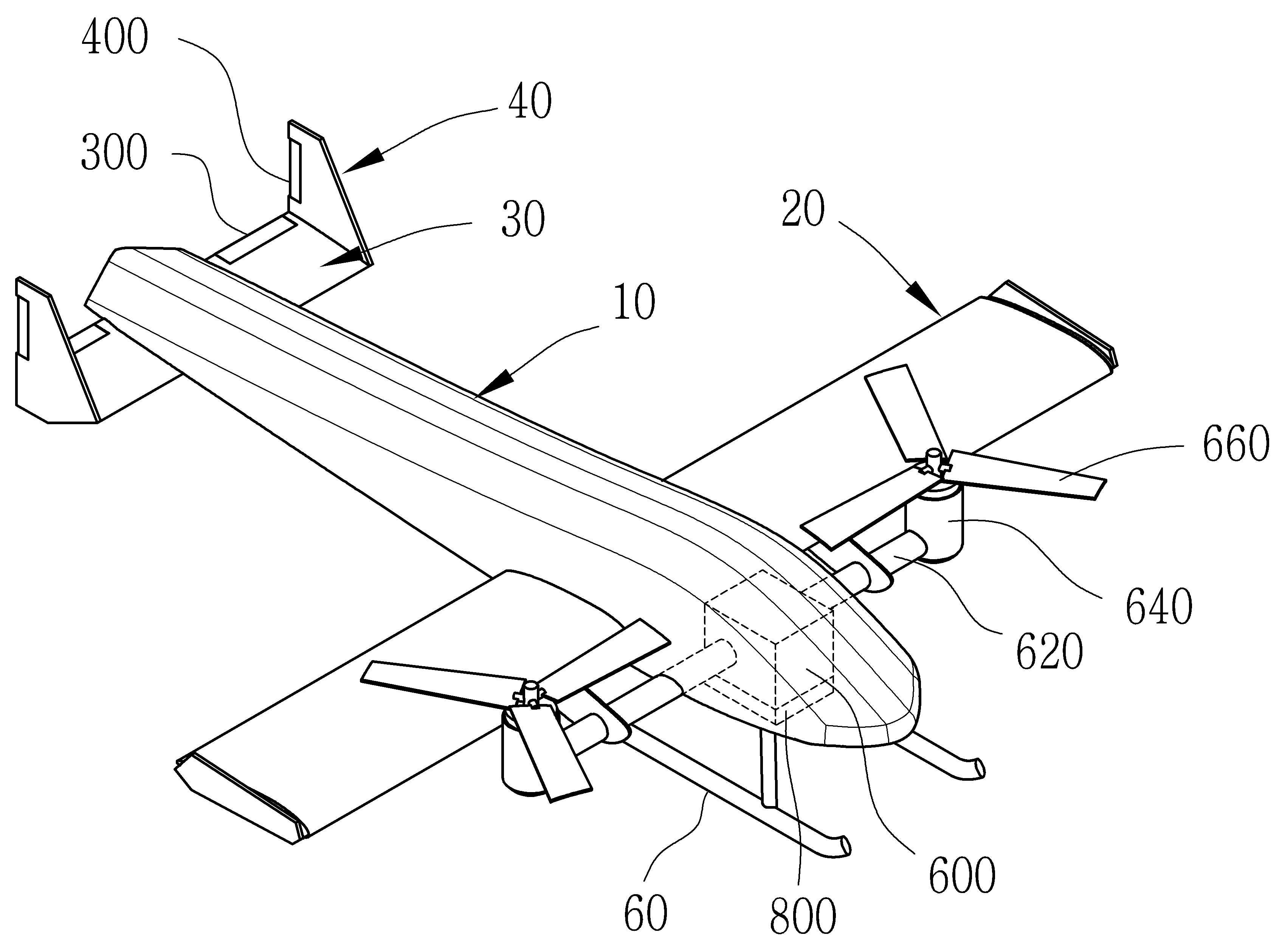
도 1은 본 발명에 따른 가변형 주익을 구비하여 수직이착륙이 가능한 글라이더 드론을 나타내는 도면이고, 도 2는 본 발명에 따른 가변형 주익을 구비하여 수직이착륙이 가능한 글라이더 드론의 보조날개가 주익에 은폐된 상태를 나타내는 도면이다.Figure 1 is a diagram showing a glider drone capable of vertical takeoff and landing with a variable main wing according to the present invention, and Figure 2 is a state where the auxiliary wings of a glider drone capable of vertical takeoff and landing with a variable main wing according to the present invention are hidden in the main wing. This is a drawing showing .
도 1 및 도 2에 따르면, 본 발명의 글라이더 드론은 통상적인 고정익 비행체의 구조와 같이 동체(10), 주익(20), 수평꼬리날개(30) 및 수직꼬리날개(40)로 구성되면서, 상기 수평꼬리날개(30)는 승강타(300)가 형성되며, 상기 수직꼬리날개(40)는 방향타(400)가 형성된다.According to Figures 1 and 2, the glider drone of the present invention is composed of a
통상적인 글라이더 드론이 활주로를 이용한 비행을 통해 양력을 얻어 이착륙하게 되는 것과 달리 본 발명의 글라이더 드론은 수직이착륙이 가능하게 구성된다.Unlike a typical glider drone that takes off and lands by gaining lift through flight using a runway, the glider drone of the present invention is configured to enable vertical takeoff and landing.
수직이착륙을 가능하게 하기 위해 주익(20)의 전방에 프로펠러(660)가 설치된다.A
상기 프로펠러(660)는 수직 방향과 수평 방향으로 전환시키는 전환수단에 의해 방향 전환이 가능하게 구성된다.The
상기 전환수단은 동체(10) 내에 설치되는 제1 로터(600)와, 상기 제1 로터의 출력 동력을 전달하는 구동로드(620)로 구성된다.The switching means consists of a
제1 로터(600)는 감속기구를 구비하여 출력축에 구동로드(620)가 연결되며, 구동로드(620)를 대략 90° 범위 내에서 회전시킬 수 있게 된다.The
구동로드(620)는 동체(10) 내부에서 주익(20)의 전방 측에서 양측의 주익(20)과 나란하게 외부로 인출되어 그 단부에 제2 로터(640)가 고정된다.The
제2 로터(640)는 프로펠러(660)가 고정되어 프로펠러(660)를 구동시킬 수 있게 되고, 구동로드(620)의 단부에 고정되어 구동로드(620)의 동력으로 수직 및 수평 방향으로 회전하게 된다.The
주익(20)은 가변형으로 구성되며, 주익(20)으로부터 가변되는 보조날개(220)가 형성된다.The
도 3은 본 발명에 따른 가변형 주익을 구비하여 수직이착륙이 가능한 글라이더 드론의 보조날개가 분리된 상태를 나타내는 도면이다.Figure 3 is a diagram showing a state in which the auxiliary wings of a glider drone capable of vertical takeoff and landing with variable main wings according to the present invention are separated.
도 3에 따르면, 보조날개(220)는 동체(10)에 형성되는 주익(20)의 단부에 슬라이딩 가능하게 설치되어 제1 액츄에이터(700)에 의해 은폐 및 인출 가능하게 된다.According to FIG. 3, the
제1 액츄에이터(700)는 왕복 구동 가능한 것으로, 주익(20) 내부에 설치되며, 피스톤로드(720)가 보조날개(220)에 고정된다.The
이에 따라, 제1 액츄에이터(700)가 구동하면 피스톤로드(720)에 고정된 보조날개(220)가 주익(20) 내부로 은폐되고, 또한 외부로 인출될 수 있게 된다.Accordingly, when the
상기 제1 액츄에이터(700)가 양측의 주익(20)에 형성되며, 보조날개(220) 또한 양측의 주익(20)에 은폐 및 인출 가능하게 형성되는 것임은 물론이다.It goes without saying that the
그리고, 랜딩기어(60)는 동체(10) 내에 설치되는 제2 액츄에이터(800)에 의해 동체(10) 측으로 밀착되거나 인출될 수 있게 된다.In addition, the
상기 제2 액츄에이터(800)는 유압, 또는 공압을 이용하는 현수장치를 이용하여 구성 가능하며, 이러한 유공압 현수장치의 구성은 당 업계에서 통상의 지식을 가진 사람에 의해 자명하게 실시 가능하므로 구체적인 설명은 생략한다.The
위와 같이 구성되는 본 발명은 수직이착륙이 가능하게 된다.The present invention configured as above enables vertical takeoff and landing.
도 4는 본 발명에 따른 가변형 주익을 구비하여 수직이착륙이 가능한 글라이더 드론의 수직이착륙 상태를 나타내는 도면이고, 도 5는 본 발명에 따른 가변형 주익을 구비하여 수직이착륙이 가능한 글라이더 드론의 전방 비행 상태를 나타낸 도면이다.Figure 4 is a diagram showing the vertical takeoff and landing state of a glider drone capable of vertical takeoff and landing with variable main wings according to the present invention, and Figure 5 is a diagram showing the forward flight state of a glider drone capable of vertical takeoff and landing with variable main wings according to the present invention. This is the drawing shown.
도 4 및 도 5에 따르면, 수직 이륙 시에는 제1 액츄에이터(700)에 의해 보조날개(220)가 주익(20) 내부에 은폐되어 수직 이륙 시 이륙 항력을 최소화시킬 수 있게 되고, 제1 로터(600)에 의해 제2 로터(640)는 수직 방향에 위치하여 프로펠러(660)가 상측을 향하고 있다.According to Figures 4 and 5, during vertical takeoff, the
이와 같은 상태에서 제2 로터(640)가 구동하면 프로펠러(660)가 회전하면서 수직 이륙 양력이 발생하여 동체(10)가 이륙하게 된다. 이때, 보조날개(220)가 주익(20) 내부로 접혀져서 수직 이륙 항력에 대한 주익의 공기저항 면적이 감소됨으로써 적은 동력으로 신속하게 수직 이륙할 수 있게 된다.In this state, when the
또한, 동체(10)의 착륙 시에는 랜딩기어(60)가 도 5의 ‘A’위치와 같이 동체(10)로부터 인출되어 착지된 상태에서, 이륙 시 제2 액츄에이터(800)에 의해 가상선‘B’와 같이 동체(10) 측에 밀착되어 수직상승 항력을 감소시키며, 전방 비행시 양력을 향상시킬 수 있게 된다.In addition, when the
그리고 일정 고도에 도달하면, 제1 액츄에이터(700)가 구동하여 주익(20)에서 보조날개(220)가 인출되고, 제1 로터(600)가 제2 로터(640)를 일정 각도로 경사지게 하거나 수평 방향으로 회전시키게 되면, 빠른 속도로 상승 하강 및 전방 비행이 가능하게 된다.And when a certain altitude is reached, the
10: 동체 20: 주익
30: 수평꼬리날개 40: 수직꼬리날개
60: 랜딩기어
220: 보조날개 300: 승강타
400: 방향타 600: 제1 로터
620: 구동로드 640: 제2 로터
660: 프로펠러 700: 제1 액츄에이터
720: 피스톤로드 800: 제2 액츄에이터10: fuselage 20: main wing
30: Horizontal tail blade 40: Vertical tail blade
60: Landing gear
220: Aileron wing 300: Elevator
400: rudder 600: first rotor
620: driving rod 640: second rotor
660: propeller 700: first actuator
720: Piston rod 800: Second actuator
Claims (1)
수직이착륙을 하기 위해 주익(20)에 구비되는 프로펠러(660)를 수직 방향으로 회전시키거나, 이륙된 동체(10)가 상승 및 전방 비행을 할 수 있도록 프로펠러(660)를 임의의 각도로 회전시키는 제1 로터(600)와;
상기 제1 로터(600)와 구동로드(620)로 연결되어 회전하며 프로펠러(660)를 구동시키는 제2 로터(640);
를 포함하고,
상기 주익(20)은,
제1 액츄에이터(700)에 의해 접혀지고, 인출되는 보조날개(220)가 형성되어, 수직 이륙 시 수직 이륙 항력을 최소화시키기 위해 상기 제1 액츄에이터(700)가 보조날개(220)를 접고, 이륙 후 전방 비행시 보조날개(220)를 인출시키게 되며,
상기 랜딩기어(60)는,
제2 액츄에이터(800)에 의해 이륙 시 동체(10) 측으로 밀착되어 공기저항계수를 감소시키고, 착륙 시 인출되어 착륙 안성을 향상시키도록 구성되며,
상기 보조날개(220)는,
인출된 상태에서 동력 없이 활공 가능하도록 구성되고,
상기 보조날개(220)는,
상기 제1 액츄에이터(700)에 의해 피스톤 운동되도록 구성되는 피스톤로드(720)에 연결되도록 구성되어 상기 피스톤로드(720)에 의해 상기 주익(20)의 내부로 인입되거나 상기 주익(20)의 외부로 인출 가능하도록 구성됨으로써, 수직 이륙 시 제1 액츄에이터(700)에 의해 주익(20)의 내부로 인입되어 이륙 항력을 최소화시키도록 구성되며, 지상에서의 인입 및 인출이 가능하여 상기 보조날개(220), 제1 액츄에이터(700) 및 피스톤로드(720)에 대한 점검이 가능하도록 구성되고,
상기 제1 로터(600)는,
감속기구를 구비하여 상기 구동로드(620)를 90° 범위 내에서 회전시키도록 구성되며,
상기 피스톤로드(720)는,
상기 주익(20)의 전방 측에만 설치되어 상기 보조날개(220)를 인입 및 인출시키도록 구성되는 것을 특징으로 하는 가변형 주익을 구비하여 수직이착륙이 가능한 글라이더 드론.Thermal lift, ridge lift, and wave lift techniques are used to raise the airflow of the heat island phenomenon and the flying fuselage of natural phenomena, and the main wings (20) are installed in front of the left and right sides of the fuselage (10). In a glider drone equipped with a propeller 660, a horizontal tail blade 30 and a vertical tail blade 40 at the rear of the fuselage 10, and a landing gear 60 for takeoff and landing,
For vertical takeoff and landing, the propeller 660 provided on the main wing 20 is rotated in the vertical direction, or the propeller 660 is rotated at a random angle so that the taken-off fuselage 10 can rise and fly forward. a first rotor 600;
A second rotor 640 is connected to the first rotor 600 and the driving rod 620 and rotates to drive the propeller 660;
Including,
The main wing (20) is,
Aileron wings 220 are formed that are folded and pulled out by the first actuator 700, so that the first actuator 700 folds the auxiliary wings 220 to minimize vertical takeoff drag during vertical takeoff. When flying forward, the ailerons (220) are pulled out,
The landing gear 60 is,
It is configured to be closely adhered to the fuselage 10 during takeoff by the second actuator 800 to reduce the air resistance coefficient, and to improve landing stability by being pulled out during landing.
The auxiliary wing 220 is,
It is configured to glide without power in a drawn-out state,
The auxiliary wing 220 is,
It is configured to be connected to the piston rod 720, which is configured to move the piston by the first actuator 700, and is drawn into the inside of the main wing 20 or outside the main wing 20 by the piston rod 720. By being configured to be retractable, it is configured to be retracted into the interior of the main wing 20 by the first actuator 700 during vertical takeoff to minimize takeoff drag, and can be retracted and withdrawn from the ground, so that the auxiliary wing 220 , It is configured to enable inspection of the first actuator 700 and the piston rod 720,
The first rotor 600,
It is configured to rotate the driving rod 620 within a 90° range by providing a deceleration mechanism,
The piston rod 720 is,
A glider drone capable of vertical takeoff and landing with a variable main wing, which is installed only on the front side of the main wing 20 and configured to retract and withdraw the auxiliary wing 220.
Priority Applications (1)
| Application Number | Priority Date | Filing Date | Title |
|---|---|---|---|
| KR1020230159363A KR20230163324A (en) | 2021-01-27 | 2023-11-16 | A glider drone capable of vertical take-off and landing with a variable main wing |
Applications Claiming Priority (2)
| Application Number | Priority Date | Filing Date | Title |
|---|---|---|---|
| KR1020210011143A KR20220108309A (en) | 2021-01-27 | 2021-01-27 | A glider drone capable of vertical take-off and landing with a variable main wing |
| KR1020230159363A KR20230163324A (en) | 2021-01-27 | 2023-11-16 | A glider drone capable of vertical take-off and landing with a variable main wing |
Related Parent Applications (1)
| Application Number | Title | Priority Date | Filing Date |
|---|---|---|---|
| KR1020210011143A Division KR20220108309A (en) | 2021-01-27 | 2021-01-27 | A glider drone capable of vertical take-off and landing with a variable main wing |
Publications (1)
| Publication Number | Publication Date |
|---|---|
| KR20230163324A true KR20230163324A (en) | 2023-11-30 |
Family
ID=82847287
Family Applications (2)
| Application Number | Title | Priority Date | Filing Date |
|---|---|---|---|
| KR1020210011143A Ceased KR20220108309A (en) | 2021-01-27 | 2021-01-27 | A glider drone capable of vertical take-off and landing with a variable main wing |
| KR1020230159363A Ceased KR20230163324A (en) | 2021-01-27 | 2023-11-16 | A glider drone capable of vertical take-off and landing with a variable main wing |
Family Applications Before (1)
| Application Number | Title | Priority Date | Filing Date |
|---|---|---|---|
| KR1020210011143A Ceased KR20220108309A (en) | 2021-01-27 | 2021-01-27 | A glider drone capable of vertical take-off and landing with a variable main wing |
Country Status (1)
| Country | Link |
|---|---|
| KR (2) | KR20220108309A (en) |
Families Citing this family (3)
| Publication number | Priority date | Publication date | Assignee | Title |
|---|---|---|---|---|
| CN116986026B (en) * | 2023-09-26 | 2023-12-19 | 中国飞机强度研究所 | Oil surveys with integration unmanned aerial vehicle system |
| CN117401192A (en) * | 2023-10-24 | 2024-01-16 | 北京淳一航空科技有限公司 | A kind of peak group combat drone |
| CN119284138B (en) * | 2024-10-10 | 2025-06-06 | 西安昱辉千星航空科技有限公司 | Fixed-wing aircraft and take-off and landing methods |
Citations (3)
| Publication number | Priority date | Publication date | Assignee | Title |
|---|---|---|---|---|
| KR101883196B1 (en) | 2016-01-11 | 2018-07-31 | 드림스페이스월드주식회사 | Vertical takeoff and landing drone and docking station |
| KR20180116849A (en) | 2017-04-18 | 2018-10-26 | 주식회사 창성에프티 | Fixed wing drone using variable pitch propeller |
| KR102010964B1 (en) | 2018-12-19 | 2019-08-16 | (주)한국유에이브이 | Vertical takeoff and landing type hybrid drones |
-
2021
- 2021-01-27 KR KR1020210011143A patent/KR20220108309A/en not_active Ceased
-
2023
- 2023-11-16 KR KR1020230159363A patent/KR20230163324A/en not_active Ceased
Patent Citations (3)
| Publication number | Priority date | Publication date | Assignee | Title |
|---|---|---|---|---|
| KR101883196B1 (en) | 2016-01-11 | 2018-07-31 | 드림스페이스월드주식회사 | Vertical takeoff and landing drone and docking station |
| KR20180116849A (en) | 2017-04-18 | 2018-10-26 | 주식회사 창성에프티 | Fixed wing drone using variable pitch propeller |
| KR102010964B1 (en) | 2018-12-19 | 2019-08-16 | (주)한국유에이브이 | Vertical takeoff and landing type hybrid drones |
Also Published As
| Publication number | Publication date |
|---|---|
| KR20220108309A (en) | 2022-08-03 |
Similar Documents
| Publication | Publication Date | Title |
|---|---|---|
| US20240166260A1 (en) | Folded wing multi rotor | |
| US11634222B2 (en) | Vertical take-off and landing unmanned aerial vehicle having foldable fixed wing and based on twin-ducted fan power system | |
| CN102126553B (en) | Vertically taking off and landing small unmanned aerial vehicle | |
| CN111498109B (en) | Vertical take-off and landing aircraft | |
| KR20230163324A (en) | A glider drone capable of vertical take-off and landing with a variable main wing | |
| US5086993A (en) | Airplane with variable-incidence wing | |
| US10144509B2 (en) | High performance VTOL aircraft | |
| US20080272244A1 (en) | Hybrid Aircraft | |
| CN202011472U (en) | Tilting duct unmanned aerial vehicle | |
| CN105966612B (en) | Become posture VTOL unmanned plane | |
| CN203681869U (en) | Power system structure suitable for vertical take-off and landing air vehicle | |
| US20150102175A1 (en) | Fixed winged aircraft with foldable auto-rotation rotor | |
| CN110683045A (en) | Aircraft with a flight control device | |
| CN103738496A (en) | Dynamical system structure suitable for vertical take-off and landing aircraft and control method thereof | |
| US10562626B2 (en) | Tandem wing aircraft with variable lift and enhanced safety | |
| CN103241376A (en) | Vector power vertical takeoff and landing aircraft and vector power system thereof | |
| USRE36487E (en) | Airplane with variable-incidence wing | |
| CN105366049A (en) | Vertical takeoff and landing unmanned aerial vehicle | |
| CN108528692A (en) | Folding-wing dual-rotor aircraft and control method thereof | |
| CN110712742A (en) | A kind of UAV transformed from a controllable umbrella wing to a foldable fixed wing and its transformation method | |
| JP2023042607A (en) | Drone with wings | |
| RU152807U1 (en) | AIRCRAFT | |
| JP2024522597A (en) | A convertible aircraft capable of hovering | |
| CN105129097A (en) | A UAV layout capable of vertical take-off and landing | |
| US11919633B2 (en) | Convertiplane |
Legal Events
| Date | Code | Title | Description |
|---|---|---|---|
| A107 | Divisional application of patent | ||
| PA0107 | Divisional application |
St.27 status event code: A-0-1-A10-A18-div-PA0107 St.27 status event code: A-0-1-A10-A16-div-PA0107 |
|
| PA0201 | Request for examination |
St.27 status event code: A-1-2-D10-D11-exm-PA0201 |
|
| PG1501 | Laying open of application |
St.27 status event code: A-1-1-Q10-Q12-nap-PG1501 |
|
| P22-X000 | Classification modified |
St.27 status event code: A-2-2-P10-P22-nap-X000 |
|
| E902 | Notification of reason for refusal | ||
| PE0902 | Notice of grounds for rejection |
St.27 status event code: A-1-2-D10-D21-exm-PE0902 |
|
| P11-X000 | Amendment of application requested |
St.27 status event code: A-2-2-P10-P11-nap-X000 |
|
| P13-X000 | Application amended |
St.27 status event code: A-2-2-P10-P13-nap-X000 |
|
| B15 | Application refused following examination |
Free format text: ST27 STATUS EVENT CODE: N-2-6-B10-B15-EXM-PE0601 (AS PROVIDED BY THE NATIONAL OFFICE) |
|
| PE0601 | Decision on rejection of patent |
St.27 status event code: N-2-6-B10-B15-exm-PE0601 |