KR20230020382A - High Inherent Quality Receiver Construction - Google Patents
High Inherent Quality Receiver Construction Download PDFInfo
- Publication number
- KR20230020382A KR20230020382A KR1020227034632A KR20227034632A KR20230020382A KR 20230020382 A KR20230020382 A KR 20230020382A KR 1020227034632 A KR1020227034632 A KR 1020227034632A KR 20227034632 A KR20227034632 A KR 20227034632A KR 20230020382 A KR20230020382 A KR 20230020382A
- Authority
- KR
- South Korea
- Prior art keywords
- receiver
- wireless charging
- systems
- dielectric separator
- receiver antenna
- Prior art date
- Legal status (The legal status is an assumption and is not a legal conclusion. Google has not performed a legal analysis and makes no representation as to the accuracy of the status listed.)
- Pending
Links
Images


Classifications
-
- H—ELECTRICITY
- H02—GENERATION; CONVERSION OR DISTRIBUTION OF ELECTRIC POWER
- H02J—CIRCUIT ARRANGEMENTS OR SYSTEMS FOR SUPPLYING OR DISTRIBUTING ELECTRIC POWER; SYSTEMS FOR STORING ELECTRIC ENERGY
- H02J50/00—Circuit arrangements or systems for wireless supply or distribution of electric power
- H02J50/70—Circuit arrangements or systems for wireless supply or distribution of electric power involving the reduction of electric, magnetic or electromagnetic leakage fields
-
- H—ELECTRICITY
- H02—GENERATION; CONVERSION OR DISTRIBUTION OF ELECTRIC POWER
- H02J—CIRCUIT ARRANGEMENTS OR SYSTEMS FOR SUPPLYING OR DISTRIBUTING ELECTRIC POWER; SYSTEMS FOR STORING ELECTRIC ENERGY
- H02J50/00—Circuit arrangements or systems for wireless supply or distribution of electric power
- H02J50/005—Mechanical details of housing or structure aiming to accommodate the power transfer means, e.g. mechanical integration of coils, antennas or transducers into emitting or receiving devices
-
- H—ELECTRICITY
- H02—GENERATION; CONVERSION OR DISTRIBUTION OF ELECTRIC POWER
- H02J—CIRCUIT ARRANGEMENTS OR SYSTEMS FOR SUPPLYING OR DISTRIBUTING ELECTRIC POWER; SYSTEMS FOR STORING ELECTRIC ENERGY
- H02J50/00—Circuit arrangements or systems for wireless supply or distribution of electric power
- H02J50/10—Circuit arrangements or systems for wireless supply or distribution of electric power using inductive coupling
-
- H—ELECTRICITY
- H01—ELECTRIC ELEMENTS
- H01F—MAGNETS; INDUCTANCES; TRANSFORMERS; SELECTION OF MATERIALS FOR THEIR MAGNETIC PROPERTIES
- H01F27/00—Details of transformers or inductances, in general
- H01F27/34—Special means for preventing or reducing unwanted electric or magnetic effects, e.g. no-load losses, reactive currents, harmonics, oscillations, leakage fields
- H01F27/36—Electric or magnetic shields or screens
- H01F27/366—Electric or magnetic shields or screens made of ferromagnetic material
-
- H—ELECTRICITY
- H01—ELECTRIC ELEMENTS
- H01F—MAGNETS; INDUCTANCES; TRANSFORMERS; SELECTION OF MATERIALS FOR THEIR MAGNETIC PROPERTIES
- H01F38/00—Adaptations of transformers or inductances for specific applications or functions
- H01F38/14—Inductive couplings
Landscapes
- Engineering & Computer Science (AREA)
- Power Engineering (AREA)
- Computer Networks & Wireless Communication (AREA)
- Physics & Mathematics (AREA)
- Electromagnetism (AREA)
- Charge And Discharge Circuits For Batteries Or The Like (AREA)
- Shielding Devices Or Components To Electric Or Magnetic Fields (AREA)
Abstract
무선 충전 시스템용 수신기 시스템은, 제1 평면 층을 형성하는 수신기 안테나; 수신기 안테나에 인접하고, 제2 평면 층을 형성하는 차폐재; 및 수신기 안테나와 차폐재 층 사이에 배치되는 유전체 분리재 층을 포함하고, 유전체 분리재는 1MHz 주파수에서 유전 손실 계수가 0.01 이하이고, 두께가 0.1mm 이상이며, 유전체 분리재는 수신기 안테나의 고유 품질 인자 "Q" 값이 목표 고유 Q 값을 초과하여 유지되도록 구성된다.A receiver system for a wireless charging system includes a receiver antenna forming a first planar layer; a shield adjacent to the receiver antenna and forming a second planar layer; and a dielectric separator layer disposed between the receiver antenna and the shield layer, wherein the dielectric separator has a dielectric loss factor of 0.01 or less at a frequency of 1 MHz and a thickness of 0.1 mm or more, and the dielectric separator has a characteristic quality factor "Q" of the receiver antenna. " value is configured to remain above the target intrinsic Q value.

Description
본 출원은 2020년 3월 5일자로 출원된 발명의 명칭이 "높은 고유 품질 수신기 구성(HIGH INTRINSIC QUALITY RECEIVER CONSTRUCTION)"인 미국 가특허 출원 제62/985,799호에 대한 우선권 및 이익을 주장하며, 상기 미국 가특허 출원은 전체적으로 본 명세서에 참고로 포함된다. This application claims priority to and benefit from U.S. Provisional Patent Application Serial No. 62/985,799, filed on March 5, 2020, entitled "HIGH INTRINSIC QUALITY RECEIVER CONSTRUCTION", The US Provisional Patent Application is incorporated herein by reference in its entirety.
근래, 전자 기기의 무선 충전을 가능하게 하는 제품이 인기를 얻고 있다. 실질적으로 배터리 전력을 사용하여 작동하는 많은 기기가 무선으로 충전될 수 있는 것이 앞으로의 추세일 수 있다.Recently, products enabling wireless charging of electronic devices are gaining popularity. Wireless charging of many devices that operate on practically battery power may be the trend going forward.
높은 고유 품질 수신기를 구현하기 위한 다양한 기술이 개시되어 있다. 이들 기술은 차폐재 층과 수신기 안테나 사이에 배치된 유전체 분리 층을 포함하는 무선 충전 시스템 수신기를 구성하기 위한 무선 충전 시스템의 실시예에 의해 사용될 수 있으며, 여기서 유전체 분리 층의 특성 및 두께는 차폐재 층이 수신기 안테나의 고유 품질 인자를 감소시키는 것을 방지한다.Various techniques have been disclosed for implementing high intrinsic quality receivers. These techniques may be used by embodiments of a wireless charging system to construct a wireless charging system receiver that includes a dielectric isolation layer disposed between a shield layer and a receiver antenna, wherein the characteristics and thickness of the dielectric isolation layer are Avoid reducing the intrinsic quality factor of the receiver antenna.
일 예시적 양태에서, 무선 충전 시스템용 수신기 시스템이 개시된다. 동 수신기 시스템은, 제1 평면 층을 형성하는 수신기 안테나; 수신기 안테나에 인접하고, 제2 평면 층을 형성하는 차폐재; 및 수신기 안테나와 차폐재 층 사이에 배치되는 유전체 분리재 층을 포함하고, 유전체 분리재는 1MHz 주파수에서 유전 손실 계수(dissipation factor)가 0.01 이하이고, 두께가 0.1mm 이상이며, 유전체 분리재는 수신기 안테나의 고유 품질 인자 "Q" 값이 목표 고유 Q 값을 초과하여 유지되도록 구성된다.In one exemplary aspect, a receiver system for a wireless charging system is disclosed. The receiver system includes a receiver antenna forming a first planar layer; a shield adjacent to the receiver antenna and forming a second planar layer; and a dielectric separator layer disposed between the receiver antenna and the shield layer, wherein the dielectric separator has a dissipation factor of 0.01 or less at a frequency of 1 MHz and a thickness of 0.1 mm or more, and the dielectric separator is inherent to the receiver antenna. The quality factor “Q” value is configured to remain above a target intrinsic Q value.
다른 예시적 실시예에서, 무선 충전 시스템용 수신기 시스템을 제조하는 방법이 개시된다. 동 방법은, 제1 평면 층에 수신기 안테나를 형성하는 단계; 제2 평면 층에 제1 유전체 분리재를 형성하는 단계; 제3 평면 층에 차폐재를 형성하는 단계를 포함하고, 제2 평면 층은 제1 평면 층과 제3 평면 층 사이에 배치되고, 제1 유전체 분리재는 수신기 안테나의 고유 품질 인자 "Q" 값이 목표 고유 Q 값을 초과하여 유지되도록 구성되고, 제1 유전체 분리재는 1MHz 주파수에서 유전 손실 계수가 0.01 이하이고, 두께가 0.1mm 이상이다.In another exemplary embodiment, a method of manufacturing a receiver system for a wireless charging system is disclosed. The method includes forming a receiver antenna in a first planar layer; forming a first dielectric separator in the second planar layer; forming a shield on a third planar layer, wherein the second planar layer is disposed between the first planar layer and the third planar layer, and the first dielectric separator has a target intrinsic quality factor “Q” value of the receiver antenna It is configured to maintain above a specific Q value, and the first dielectric separator has a dielectric dissipation factor of 0.01 or less at a frequency of 1 MHz and a thickness of 0.1 mm or more.
이들 양태 및 기타의 양태가 본 문헌 전반에 걸쳐 개시된다.These and other aspects are disclosed throughout this document.
도 1a는 무선 충전 시스템에 대한 대표적인 수신기 시스템 구성이고,
도 1b는 무선 충전 시스템에 대한 다른 대표적인 수신기 시스템 구성이고,
도 2a는 높은 고유 품질 수신기 안테나를 위한 무선 충전 시스템에 대한 대표적인 수신기 시스템 구성이고,
도 2b는 높은 고유 품질 수신기 안테나를 위한 무선 충전 시스템에 대한 다른 대표적인 수신기 시스템 구성이고,
도 3은 차폐재 및 유전체 분리재를 포함하는 무선 충전 시스템에 대한 수신기 시스템 구성의 대표적인 예시이고,
도 4a는 폰 케이스에 내장된 수신기 시스템의 대표적인 제1 사시도이고,
도 4b는 폰 케이스에 내장된 수신기 시스템의 대표적인 제2 사시도이고,
도 4c는 조립 완료된 폰 케이스의 대표도이고,
도 5는 수신기 시스템을 제조하는 방법에 대한 흐름도를 도시한다.1A is a representative receiver system configuration for a wireless charging system;
1B is another exemplary receiver system configuration for a wireless charging system;
2A is a representative receiver system configuration for a wireless charging system for a high intrinsic quality receiver antenna;
2B is another exemplary receiver system configuration for a wireless charging system for a high intrinsic quality receiver antenna;
3 is a representative example of a receiver system configuration for a wireless charging system including a shielding material and a dielectric separator,
4A is a representative first perspective view of a receiver system embedded in a phone case;
4B is a representative second perspective view of a receiver system embedded in a phone case;
Figure 4c is a representative view of the assembled phone case,
5 shows a flow diagram of a method for manufacturing a receiver system.
무선 충전 시스템용 수신기 안테나의 고유 품질 인자 또는 "Q" 값은 무선 충전 시스템이 얼마나 잘 실행되는지 여부를 결정하는데 있어 중요한 인자이다. 안테나의 Q는 안테나에 저장된 에너지에 대한 안테나에서 소산되는 에너지의 측정값이고, 안테나의 효율에 대한 지표이다. Q가 높을수록, 안테나는 전자기장에 더 잘 결합할 수 있게 되어, 더 많은 전력이 부하로 전달될 수 있다.The intrinsic quality factor or “Q” value of a receiver antenna for a wireless charging system is an important factor in determining how well a wireless charging system performs. The Q of an antenna is a measure of the energy dissipated by the antenna relative to the energy stored in the antenna, and is an indicator of the efficiency of the antenna. The higher the Q, the better the antenna can couple into the electromagnetic field, so more power can be delivered to the load.
종래의 무선 충전 시스템 수신기는 전형적으로는, 안테나의 고유 Q를 최적화하도록 구성되어 있지는 않다. 예를 들어, 공진형 유도 충전 패드는 전형적으로는 스마트폰이나 태블릿을 충전 패드의 상부에 물리적으로 놓아 둘 때 작동한다.Conventional wireless charging system receivers are typically not configured to optimize the intrinsic Q of the antenna. For example, resonant inductive charging pads typically work when a smartphone or tablet is physically placed on top of the charging pad.
후술하는 설명에서는 차폐재 층과 수신기 안테나 사이에 배치되는 유전체 분리 층을 포함하는 무선 충전 시스템 수신기를 구성하는 시스템 및 방법이 설명되며, 여기서 유전체 분리 층의 특성 및 두께는 차폐재 층이 수신기 안테나의 고유 품질 인자를 감소시키는 것(즉, 수신기 안테나를 디-큐잉(de-Qing)하는 것)을 방지한다.In the following description, a system and method of constructing a wireless charging system receiver including a dielectric isolation layer disposed between a shielding material layer and a receiver antenna is described, wherein the characteristics and thickness of the dielectric isolation layer determine the inherent quality of the shielding material layer and the receiver antenna. Reduce factor (i.e., de-Qing the receiver antenna).
이제, 다양한 실시예가 설명될 것이다. 이하의 설명은 이들 실시예에 대한 철저한 이해 및 지원 설명을 위한 구체적인 상세를 제공한다. 그러나, 본 기술 분야의 통상의 기술을 가진 자는 본 발명이 이러한 많은 상세 없이도 실시될 수 있다는 것을 이해할 것이다. 또한, 다양한 실시예에 대한 관련 설명을 불필요하게 모호하게 하는 것을 피하기 위해, 일부 잘 알려진 구조 또는 기능은 상세히 도시되거나 설명되지 않을 수 있다. 아래에 제시된 설명에 사용되는 용어는 본 발명의 특정 구체적인 실시예들에 대한 상세한 설명과 함께 사용되고 있음에도 불구하고, 가장 폭넓고 합리적인 방식으로 해석되기 위한 것이다.Now, various embodiments will be described. The following description provides specific details for a thorough understanding and supporting description of these embodiments. However, one of ordinary skill in the art will understand that the present invention may be practiced without many of these details. In addition, some well-known structures or functions may not be shown or described in detail in order to avoid unnecessarily obscuring the relevant description of the various embodiments. The terminology used in the description presented below is intended to be interpreted in the broadest and most reasonable manner, although used in conjunction with the detailed description of certain specific embodiments of the present invention.
도 1a는 종래의 무선 충전 시스템에 대한 대표적인 수신기 시스템 구성이다. 전자 디바이스(110)(예를 들어, 스마트폰, 태블릿 등)가 당해 전자 디바이스 내에 무선 충전 칩을 내장하고 있지 않은 경우에, 수신기 구성은 전형적으로, 도 1a에 예시된 바와 같은데, 여기서 전자 디바이스(110)는 통상적으로 디바이스와 디바이스의 케이스 사이에 개재되거나 디바이스의 케이스 내에 직접 내장된 수신기를 구비한다. 수신기는 디바이스(110)와 수신기 안테나(180) 사이에 차폐 층 또는 차폐재(120)를 포함한다. 차폐재(120)는 100kHz 또는 6.78MHz와 같은 무선 전력 전송 주파수에서 고투자율, 저손실 재료일 수 있다. 이러한 구성 방법은 또한 디바이스 내에 직접 내장된 무선 충전 수신기에 대해 전형적이다.1A is a representative receiver system configuration for a conventional wireless charging system. If the electronic device 110 (eg, smart phone, tablet, etc.) does not have a wireless charging chip embedded within the electronic device, the receiver configuration is typically as illustrated in FIG. 1A , where the electronic device ( 110) typically has a receiver interposed between the device and the case of the device or directly embedded in the case of the device. The receiver includes a shielding layer or
도 1b에서, 도 1a의 수신기 시스템은 또한, 자속을 안테나(180) 주위 영역으로 제한하기 위해, 안테나(180) 주위(예를 들어, 안테나의 아래 및/또는 측면 및/또는 중심)에 배치되는 코어(190)를 포함할 수 있다.In FIG. 1B, the receiver system of FIG. 1A is also disposed around the antenna 180 (e.g., below and/or to the side and/or center of the antenna) to confine magnetic flux to the area around the
도 1a 및 도 1b의 수신기 구성에서 안테나(180)의 품질 인자("Q")는 저하된다. 도 1a 및 도 1b의 수신기 구성이 수신기 안테나를 디-큐하는 몇몇 이유가 있다. 예를 들어, 차폐재(120)가 수신기 안테나(180)와 직접 접촉하기 때문에, 안테나(180)에 추가 저항이 추가됨으로써, 안테나의 고유 Q가 감소할 수 있다. 이는 차폐재(120)가 전형적으로는 스마트폰과 같은 전자 디바이스로부터 수신기 안테나(180)를 차폐하고자 하는 것이기 때문에 반직관적으로 보일 수 있다. 그러나, 비록 차폐재(120)가 전자 디바이스(110)의 금속성 또는 전도성 구조체로부터 안테나(180)를 부분적으로 차폐할 수 있겠지만, 차폐재(120)는 또한 안테나 트레이스와 접촉하여 추가 저항을 도입함으로써 수신기 안테나(180)의 고유 Q를 감소시킨다. 이는 수신기 안테나(180)의 고유 Q의 추가적인 저하를 가져온다.The quality factor (“Q”) of the
비록, 도 1a 및 도 1b의 수신기 구성은 저전력 신호, 예를 들어 무선 주파수 식별(RFID) 태그에 사용되는 신호에 대해 잘 작동할 수 있지만, 이들 구성은 무선 전력 전송, 특히 밀리와트 범위 이상의 고전력의 전송 및 고주파수 신호에 대해 효과적이거나 효율적이지 않다. 송신기(예를 들어, 무선 충전 패드)와 수신기(예를 들어, 스마트폰) 사이의 물리적인 분리가 작은(예를 들어, 수 밀리미터) 적용예는 높은 고유 Q 수신기 안테나를 필요로 하지 않을 수 있다. 높은 고유 Q에 대한 요구는 또한 전력 효율이 아닌 신호 강도가 주요 설계 포커스일 수 있는 RFID 태그와 같은 다른 적용예에서는 완화될 수 있다. 그러나, 높은 고유 Q를 유지하는 것은 송신기 및 수신기가 물리적으로 멀리 떨어져 있는 적용예, 예를 들어 느슨하게-결합된 무선 충전 시스템에서 중요한 설계 기준이다. 높은 고유 Q는 또한 전력 효율이 특히 중요한 적용예에서, 예를 들어 저전력 또는 배터리-작동식 시스템에서 중요한 설계 기준이다. 따라서, 수신기 안테나의 높은 고유 Q를 유지하는 구성 방법이 필요하다. 높은 고유 Q의 예에는 대략 100을 초과(예를 들어, 200 내지 800)하는 Q가 있다.Although the receiver configurations of FIGS. 1A and 1B may work well for low-power signals, such as those used in radio frequency identification (RFID) tags, these configurations are suitable for wireless power transfer, especially at high power in the milliwatt range and beyond. It is not effective or efficient for transmission and high frequency signals. Applications where the physical separation between the transmitter (e.g., wireless charging pad) and the receiver (e.g., a smartphone) is small (e.g., a few millimeters) may not require a high intrinsic Q receiver antenna. . The need for high intrinsic Q can also be relaxed in other applications, such as RFID tags, where signal strength, rather than power efficiency, may be a major design focus. However, maintaining a high intrinsic Q is an important design criterion in applications where the transmitter and receiver are physically distant, such as loosely-coupled wireless charging systems. A high intrinsic Q is also an important design criterion in applications where power efficiency is particularly important, for example in low-power or battery-operated systems. Accordingly, a method of construction that maintains a high intrinsic Q of a receiver antenna is needed. An example of a high intrinsic Q is a Q greater than approximately 100 (eg, 200 to 800).
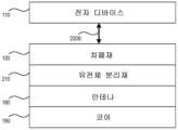
도 2a는 높은 고유 품질 수신기 안테나를 실현 및 유지하는 무선 충전 시스템에 대한 대표적인 수신기 구성이다. 도 2a의 구성에 있어서, 유전체 분리재 층(210)은 안테나(180)와 차폐재 층(120) 사이에 배치된다. 전자 디바이스(110)는 차폐재(120)에 근접하여 위치된다. 일부 실시예에서, 전자 디바이스(110)는 거리(220A)만큼 차폐재(120)로부터 분리되어 있다. 일부 실시예에서, 간격(220A)이 영이거나, 전자 디바이스가 차폐재(120) 상에 직접 위치된다. 다른 실시예에서, 간격(220A)은 케이스의 재료, 예를 들어 폰이나 태블릿 케이스의 플라스틱 재료로 인해 고정적인 간격일 수 있으며, 여기서 간격 재료는 유전체 분리재와 유사할 수 있다.2A is a representative receiver configuration for a wireless charging system that realizes and maintains a high intrinsic quality receiver antenna. In the configuration of FIG. 2A ,
유전체 분리재(210)는 수신기 안테나(180)와 차폐재(120) 사이에서 물리적인 버퍼로서 작용한다. 전술한 바와 같이 수신기 안테나를 디-큐하는 차폐재(120)와 달리, 유전체 분리재(210)는 안테나의 고유 효율을 유지하는데 필요한 특정 특성, 예를 들어 저 유전 손실 계수 및 저 유전율을 갖는다. 일부 실시예에서, 유전체 분리재(210)는, 1MHz에서 유전 손실 계수가 대략 0.0003이고 1MHz에서 유전율이 대략 2.2인 폴리프로필렌 플라스틱일 수 있다. 따라서, 유전체 분리재(210)와 안테나의 물리적인 접촉은 수신기 안테나(180)의 고유 효율 감소에 최소한의 영향을 미칠 것이다.The
일반적으로는, 유전체 분리재(210)의 두께가 수 밀리미터인 것이 바람직하다. 그러나, 유전체 분리재(210)의 두께는 유전체 분리재가 의도한 적용예의 크기 제한 내에 맞춰지도록 감소될 수 있다. 예를 들어, 스마트폰 수신기 액세서리는 스마트폰과 폰 케이스 사이에 물리적으로 들어 맞도록 매우 얇을 수 있다(예를 들어, 1mm 내지 2mm). 유사하게, 수신기는 내측에 수신기가 내장된 개장된 폰 케이스 내에 들어 맞도록 얇을 필요가 있다(예를 들어, 1mm 내지 3mm). 이러한 적용예에서, 유전체 분리재는 더 얇을 필요가 있을 것이다. 예를 들어, 두께가 적어도 0.1mm이고, 대략 1MHz 시험 주파수에서 유전 손실 계수가 0.01 이하인 유전체 분리재(210)는 차폐재(120)로부터 수신기 안테나(180)를 물리적으로 더욱 효과적으로 절연할 수 있다.In general, it is desirable that the thickness of the
일부 실시예에서, 차폐재(120)는 페라이트일 수 있고, 유전체 분리재(210)는 두께가 대략 0.1mm 이상(예를 들어, 개별 또는 결합된 두께가 0.4mm)인 폴리카르보네이트 플라스틱 시트로 제조될 수 있으며, 수신기 안테나는 각각의 인쇄 회로 기판(PCB)에 연결될 수 있다. 이러한 구성에 있어서, 수신기는 전자 디바이스와 차폐재 사이에 최소(예를 들어, 0.1mm) 내지 영의 간격을 가질 수 있다. 즉, 간격(220A)은 영에 가까울 수 있다. 일부 실시예에서, 유전체 분리재는 대략 0.2mm 내지 대략 0.5mm의 두께를 가질 수 있지만, 선택된 수신기 구성에 따라 더 넓은 범위를 가질 수 있다.In some embodiments, shield 120 may be ferrite, and
일부 실시예에서, 세퍼레이터가 차폐재와 전자 디바이스 사이의 간격(220A)을 차지할 수 있다. 세퍼레이터는 두께가 대략 0.4mm인 폴리카르보네이트 플라스틱과 같은 다른 저 유전 손실 계수의 재료일 수 있다. 예를 들어, 간격(220A)의 세퍼레이터는 폰이나 태블릿 케이스와 같은 수신기 케이스 내 저 유전 손실 계수 플라스틱일 수 있다.In some embodiments, a separator may occupy the
도 2b는 높은 고유 품질 수신기 안테나를 위한 무선 충전 시스템에 대한 다른 대표적인 수신기 구성이다. 도 2b에서, 코어(190)는 자속을 안테나의 영역으로 제한하는데 조력하기 위해 안테나 아래에 배치된다. 일부 실시예에서, 안테나 구성에 따라, 코어(190)는 생성된 자속을 안테나 주위, 내부 또는 근처 영역으로 제한하기 위해, 안테나 주위에, 안테나의 중심에, 또는 안테나에 대해 달리 배치된 위치에 있을 수 있다.2B is another representative receiver configuration for a wireless charging system for a high intrinsic quality receiver antenna. In FIG. 2B, a
일 실시예에서, 안테나는 각각의 코일이 단절부(break) 또는 무선 주파수 불연속부가 없는 연속 도체로 제조된 표면 나선 코일로서 배열되는 하나 이상의 코일을 포함할 수 있다. 도체는 무선 충전 송신기 디바이스의 작동 주파수에서 근접 효과를 감소시키고, 작동 주파수에서 표면 나선 코일의 높은 고유 품질 인자("Q")를 유지하기 위해, 유전체 재료 주위에 일정한 각도로 권취될 수 있다. 연속 도체는 대략 40㎛의 두께를 가질 수 있다.In one embodiment, the antenna may include one or more coils arranged as surface helix coils where each coil is made of continuous conductor without breaks or radio frequency discontinuities. The conductor may be wound at an angle around the dielectric material to reduce the proximity effect at the operating frequency of the wireless charging transmitter device and to maintain a high intrinsic quality factor ("Q") of the surface helix coil at the operating frequency. The continuous conductor may have a thickness of approximately 40 μm.
무선 충전 시스템용 수신기를 제조하기 위해, 제2 평면 층이 제1 평면 층과 제3 평면 층 사이에 배치되도록(즉, 제2 층을 형성하는 유전체 분리재(210)가 수신기 안테나(180)와 차폐재(120) 사이에 개재되도록), 수신기 안테나(180)는 제1 평면 층 상에 형성될 수 있고, 유전체 분리재(210)는 제2 평면 층 상에 형성될 수 있으며, 차폐재(120)는 제3 평면 층 상에 형성될 수 있다. 유전체 분리재는 수신기 안테나의 고유 품질 "Q"가 목표 고유 Q 값을 초과하여 유지되도록 구성되고, 적어도 0.1mm의 두께를 가지며, 선택된 유전체 분리재에 대해 대략 1MHz 시험 주파수에서 0.01 이하의 유전 손실 계수를 갖는다.To manufacture a receiver for a wireless charging system, a second planar layer is disposed between the first planar layer and the third planar layer (i.e., the
일부 실시예에서, 코어는 안테나(180)에 의해 생성된 자속을 안테나(180) 주위 영역으로 제한하기 위해, 안테나(180) 주위에 형성될 수 있다. 또한, 분리 거리(220B) 내 영역은 제4 평면 층 상의 제2 유전체 분리재를 포함할 수 있으며, 여기서 제4 평면 층은 제3 평면 층(차폐재(120))과 전자 디바이스(110) 사이에 배치된다. 안테나(180)와 차폐재 층(120) 사이의 제1 유전체 분리재 층과 같이, 제2 유전체 분리재 층은 분리재가 특정 특성을 유지하도록 함으로써, 수신기의 고유 Q를 목표 고유 Q 값을 초과하여 유지하도록 구성된다. 제2 유전체 분리재는 대략 1MHz 시험 주파수에서 두께가 0.01 이하일 수 있다. 일부 실시예에서, 예를 들어, 공진형 유도 시스템에서, 목표 고유 Q 값은 적어도 100이다. 다른 실시예에서, 목표 고유 Q 값은 적어도 700이다. 제2 유전체 분리재, 예를 들어 폰 케이스의 중앙 프레임은 수신기의 성능을 저하시키지 않도록 특정 특성(예를 들어, 특정 유전 손실 계수)을 가질 필요가 있다. 예를 들어, 높은 유전 손실 계수 플라스틱(예를 들어, ABS 플라스틱)이 제1 또는 제2 유전체 분리재에 대해 사용되는 경우, 고유 Q는 50%를 초과하여 감소될 수 있다. 또한, 안테나의 트레이스가 차폐재와 직접 접촉하는 경우(예를 들어, 도 1a 및 도 1b 구성 방법에서)에도, 고유 Q는 50%를 초과하여 감소될 수 있다.In some embodiments, a core may be formed around
도 3은 차폐재 및 유전체 분리재를 포함하는 무선 충전 시스템에 대한 수신기 구성의 대표적인 예시이다. 본 예시에 개시된 대표적인 실시예는 차폐재(310)(예를 들어, 페라이트 차폐재); 유전체 분리재(320)(예를 들어, 총 두께가 대략 0.4mm인 하나 이상의 폴리카르보네이트 플라스틱 시트로 구성됨); 및 각각의 PCB에 연결되는 수신기 안테나(330)를 포함한다. 일 실시예에서, 대략 1MHz 주파수에서 유전 손실 계수가 0.01 이하이고, 두께가 적어도 0.1mm인 유전체 분리재(320)는 차폐재(310)로부터 수신기 안테나(330)를 물리적으로 적절하게 절연한다.3 is a representative example of a receiver configuration for a wireless charging system including a shielding material and a dielectric separator. Representative embodiments disclosed in this example include a shielding material 310 (eg, a ferrite shielding material); dielectric separator 320 (eg, composed of one or more sheets of polycarbonate plastic having a total thickness of approximately 0.4 mm); and a
도 4a 및 도 4b는 폰 케이스에 내장된 수신기의 대표적인 사시도이다. 도 4c는 조립 완료된 폰 케이스의 대표도이다. 도시된 대표적인 실시예는 도 3의 수신기와 동일한 구성을 포함하지만, 수신기가 케이스에 내장되어 있기 때문에, 전자 디바이스와 차폐재(220B) 사이의 분리 거리는 폰 케이스의 제2 분리 거리 재료에 대해 대략 1MHz 주파수에서 0.01 이하의 저 유전 손실 계수 플라스틱으로 대체된다. 전자 디바이스와 차폐 층 사이의 이러한 추가적인 재료의 배치도 성능을 개선할 수 있다. 도 4a의 구조체(410)는 저 유전 손실 계수 분리재 및 차폐재와 함께 안테나 및 각각의 PCB(415)를 도시한다. 구조체(410)의 케이스 내 안테나용 홀더에 대한 플라스틱 부분은 저 유전 손실 계수 재료를 포함하여 성능을 개선한다. 구조체(420)는 구조체(410) 뒤에 있는 폰 케이스의 후면을 도시한다. 구조체(420)가 구조체(410)와 결합하면, 이는 도 4b의 구조체(440)처럼 보인다. 구조체(440)에서, 그리고 도 4c의 완전 조립된 케이스(460)에서 커넥터 플러그(465)를 볼 수 있다. 도 4a의 구조체(430)는 제2 분리재와 등가인 오버레이 시트를 도시한다(또는 적용예에 따라 다른 차폐의 층으로 대체될 수 있다).4A and 4B are representative perspective views of a receiver embedded in a phone case. 4C is a representative view of the assembled phone case. The representative embodiment shown includes the same configuration as the receiver of FIG. 3 , but because the receiver is embedded in the case, the separation between the electronic device and
일부 실시예에서, 전자 디바이스는 본 명세서에서 설명된 것과 같은 무선 충전 수신기를 포함할 수 있다. 전자 디바이스는 휴대폰, 휴대용 디바이스 등과 같이 전원으로서 배터리나 셀을 사용하는 임의의 사용자 디바이스일 수 있다. 전자 디바이스는 차량 운행에 사용되는 전자 시스템, 차량 내 제어부, 자동 유도 차량(AGV) 및 비행기의 전자 장치와 같은 자동차, 항공 우주, 농업 장비 및 산업용 전자 장치를 포함할 수 있다.In some embodiments, an electronic device may include a wireless charging receiver as described herein. An electronic device may be any user device that uses a battery or cell as a power source, such as a mobile phone or a portable device. Electronic devices may include automotive, aerospace, agricultural equipment, and industrial electronics, such as electronic systems used to drive vehicles, in-vehicle controls, automated guided vehicles (AGVs), and electronic devices in airplanes.
전체적으로 본 명세서에 참고로 포함되는 미국 특허 출원 제15/759,473호(공개공보 제US2018/0262050호)에는 본 명세서에 설명된 기술을 사용할 수 있는 몇몇 예시적인 코일 구성이 설명되어 있다.US patent application Ser. No. 15/759,473 (Pub. No. US2018/0262050), which is incorporated herein by reference in its entirety, describes some exemplary coil configurations that may utilize the techniques described herein.
일부 실시예에 의해 바람직하게 구현되는 솔루션의 목록이 이하의 항목을 사용하여 설명될 수 있다.A list of solutions that are preferably implemented by some embodiments can be described using the following items.
항목 1. 무선 충전 시스템용 수신기 시스템으로서, 제1 평면 층을 형성하는 수신기 안테나; 수신기 안테나에 인접하고, 제2 평면 층을 형성하는 차폐재; 및 수신기 안테나와 차폐재 층 사이에 배치되는 유전체 분리재 층을 포함하고, 유전체 분리재는 1MHz 주파수에서 유전 손실 계수가 0.01 이하이고, 두께가 0.1mm 이상이며, 유전체 분리재는 수신기 안테나의 고유 품질 인자 "Q" 값이 목표 고유 Q 값을 초과하여 유지되도록 구성되는 무선 충전 시스템용 수신기 시스템. 일부 예시적 실시예가 도 1a 내지 도 3을 참고하여 설명된다.Item 1. A receiver system for a wireless charging system, comprising: a receiver antenna forming a first planar layer; a shield adjacent to the receiver antenna and forming a second planar layer; and a dielectric separator layer disposed between the receiver antenna and the shield layer, wherein the dielectric separator has a dielectric loss factor of 0.01 or less at a frequency of 1 MHz and a thickness of 0.1 mm or more, and the dielectric separator has a characteristic quality factor "Q" of the receiver antenna. A receiver system for a wireless charging system configured to maintain a value above a target intrinsic Q value. Some exemplary embodiments are described with reference to FIGS. 1A-3.
항목 2. 항목 1에 있어서, 수신기 안테나에 의해 생성되는 자속을 수신기 안테나 주위 영역으로 제한하기 위해, 수신기 안테나 주위 또는 수신기 안테나의 중심에 배치되는 코어를 추가로 포함하는 무선 충전 시스템용 수신기 시스템.Item 2. The receiver system according to item 1, further comprising a core disposed around or at a center of the receiver antenna for confining magnetic flux generated by the receiver antenna to an area around the receiver antenna.
항목 3. 항목 1에 있어서, 유전체 분리재는 1MHz 시험 주파수에서 대략 4 이하의 유전율을 갖는 재료를 포함하는 무선 충전 시스템용 수신기 시스템.Item 3. The receiver system of item 1, wherein the dielectric separator comprises a material having a permittivity of approximately 4 or less at a test frequency of 1 MHz.
항목 4. 항목 1에 있어서, 유전체 분리재는 폴리프로필렌 플라스틱을 포함하는 무선 충전 시스템용 수신기 시스템.Item 4. The receiver system for a wireless charging system according to item 1, wherein the dielectric separator comprises a polypropylene plastic.
항목 5. 항목 1에 있어서, 유전체 분리재는 폴리카르보네이트 플라스틱을 포함하는 무선 충전 시스템용 수신기 시스템.Item 5. The receiver system for a wireless charging system according to item 1, wherein the dielectric separator comprises a polycarbonate plastic.
항목 6. 항목 1에 있어서, 차폐재는 페라이트를 포함하고, 유전체 분리재는 결합된 두께가 대략 0.1mm 이상인 하나 이상의 폴리카르보네이트 시트를 포함하는 무선 충전 시스템용 수신기 시스템.Item 6. The receiver system for a wireless charging system of item 1, wherein the shielding material comprises ferrite and the dielectric separator comprises one or more polycarbonate sheets having a combined thickness of at least about 0.1 mm.
항목 7. 항목 1에 있어서, 목표 고유 Q 값은 적어도 100인 무선 충전 시스템용 수신기 시스템.Item 7. The receiver system of item 1, wherein the target intrinsic Q value is at least 100.
항목 8. 항목 1에 있어서, 유전체 분리재 층의 하나 이상의 특성은 수신기 안테나가 유전체 분리재와 물리적으로 접촉할 때 수신기 안테나의 고유 효율을 유지하도록 선택되는 무선 충전 시스템용 수신기 시스템.Item 8. The receiver system for a wireless charging system of item 1, wherein the one or more properties of the dielectric separator layer are selected such that the receiver antenna maintains an intrinsic efficiency of the receiver antenna when in physical contact with the dielectric separator.
항목 9. 항목 1에 있어서, 유전체 분리재는 1MHz에서 유전율이 대략 2.2이고, 유전 손실 계수가 대략 0.0003인 무선 충전 시스템용 수신기 시스템.Item 9. The receiver system according to item 1, wherein the dielectric separator has a permittivity of approximately 2.2 at 1 MHz and a dielectric dissipation factor of approximately 0.0003.
항목 10. 항목 1에 있어서, 수신기 안테나는 무선 충전 송신기로부터 무선 전력을 수신하도록 구성되는 무선 충전 시스템용 수신기 시스템.Item 10. The receiver system of item 1, wherein the receiver antenna is configured to receive wireless power from the wireless charging transmitter.
항목 11. 항목 1에 있어서, 수신기 안테나는 전자 디바이스에 전력을 제공하도록 구성되는 무선 충전 시스템용 수신기 시스템.Item 11. The receiver system of item 1, wherein the receiver antenna is configured to provide power to an electronic device.
항목 12. 무선 충전 시스템용 수신기 시스템을 제조하는 방법(예를 들어, 도 5에 도시된 방법)으로서, 제1 평면 층에 수신기 안테나를 형성하는 단계(510); 제2 평면 층에 제1 유전체 분리재를 형성하는 단계(520); 제3 평면 층에 차폐재를 형성하는 단계(530)를 포함하고, 제2 평면 층은 제1 평면 층과 제3 평면 층 사이에 배치되고, 제1 유전체 분리재는 수신기 안테나의 고유 품질 인자 "Q" 값이 목표 고유 Q 값을 초과하여 유지되도록 구성되고, 제1 유전체 분리재는 유전 손실 계수가 1MHz 주파수에서 0.01 이하이고, 두께가 0.1mm 이상인 무선 충전 시스템용 수신기 시스템을 제조하는 방법. 예를 들어, 이 방법을 사용하여, 도 1a 내지 도 4c의 도면에 도시된 수신기 시스템이 제조될 수 있다.Item 12. A method of fabricating a receiver system for a wireless charging system (eg, the method shown in FIG. 5), comprising: forming (510) a receiver antenna in a first planar layer; forming (520) a first dielectric separator in the second planar layer; forming (530) a shield on a third planar layer, wherein the second planar layer is disposed between the first planar layer and the third planar layer, and the first dielectric isolator forms an intrinsic quality factor "Q" of the receiver antenna; A method of manufacturing a receiver system for a wireless charging system, wherein the first dielectric isolator has a dielectric dissipation factor of 0.01 or less at a frequency of 1 MHz and a thickness of 0.1 mm or more. For example, using this method, the receiver system shown in the diagrams of FIGS. 1A-4C can be manufactured.
항목 13. 항목 12에 있어서, 제4 평면 층에 제2 유전체 분리재를 형성하는 단계를 추가로 포함하고, 제4 평면 층은 제3 평면 층과 전자 디바이스 사이에 배치되는 무선 충전 시스템용 수신기 시스템을 제조하는 방법.Item 13. The receiver system of item 12, further comprising forming a second dielectric separator in the fourth planar layer, wherein the fourth planar layer is disposed between the third planar layer and the electronic device. How to manufacture.
항목 14. 항목 12에 있어서, 수신기 안테나에 의해 생성되는 자속을 수신기 안테나 주위 영역으로 제한하기 위해, 수신기 안테나 주위 또는 수신기 안테나의 중심에 코어를 형성하는 단계를 추가로 포함하는 무선 충전 시스템용 수신기 시스템을 제조하는 방법.Item 14. The receiver system according to item 12, further comprising forming a core around or at the center of the receiver antenna to confine magnetic flux produced by the receiver antenna to an area around the receiver antenna. How to manufacture.
항목 15. 항목 12에 있어서, 제1 유전체 분리재는 1MHz 시험 주파수에서 대략 4 이하의 유전율을 갖는 재료를 포함하는 무선 충전 시스템용 수신기 시스템을 제조하는 방법.Clause 15. The method of clause 12, wherein the first dielectric separator comprises a material having a permittivity of about 4 or less at a test frequency of 1 MHz.
항목 16. 항목 12에 있어서, 제1 유전체 분리재는 폴리프로필렌 플라스틱 또는 폴리카르보네이트 플라스틱 중 적어도 하나를 포함하는 무선 충전 시스템용 수신기 시스템을 제조하는 방법.Clause 16. The method of clause 12, wherein the first dielectric separator comprises at least one of a polypropylene plastic or a polycarbonate plastic.
항목 17. 항목 12에 있어서, 차폐재는 페라이트를 포함하고, 제1 유전체 분리재는 결합된 두께가 대략 0.1 밀리미터 이상인 하나 이상의 폴리카르보네이트 시트를 포함하는 무선 충전 시스템용 수신기 시스템을 제조하는 방법.Clause 17. The method of clause 12, wherein the shield comprises ferrite and the first dielectric isolator comprises one or more polycarbonate sheets having a combined thickness of at least approximately 0.1 millimeter.
항목 18. 항목 12에 있어서, 목표 고유 Q 값은 적어도 100인 무선 충전 시스템용 수신기 시스템을 제조하는 방법.Clause 18. The method of clause 12, wherein the target intrinsic Q value is at least 100.
항목 19. 항목 12에 있어서, 제1 유전체 분리재 층의 하나 이상의 특성은 수신기 안테나가 제1 유전체 분리재와 물리적으로 접촉할 때 수신기 안테나의 고유 효율을 유지하도록 선택되는 무선 충전 시스템용 수신기 시스템을 제조하는 방법.Item 19. The receiver system of item 12, wherein the one or more characteristics of the first dielectric separator layer are selected such that the receiver antenna maintains an intrinsic efficiency of the receiver antenna when in physical contact with the first dielectric separator layer. How to manufacture.
항목 20. 항목 12에 있어서, 수신기 안테나는 무선 충전 송신기로부터 무선 전력을 수신하고, 무선 전력을 전자 디바이스에 제공하도록 구성되는 무선 충전 시스템용 수신기 시스템을 제조하는 방법.Item 20. The method of item 12, wherein the receiver antenna is configured to receive wireless power from the wireless charging transmitter and provide wireless power to the electronic device.
리마크Remark
도면 및 위의 설명은 본 발명을 구현할 수 있는 적합한 환경의 간략하고 전반적인 설명을 제공한다. 본 발명의 예에 대한 전술한 상세한 설명은 전체를 포괄하거나 본 발명을 위에 개시된 정확한 형태로 제한하려는 것이 아니다. 비록, 본 발명에 대한 특정 예들이 예시의 목적으로 전술되어 있지만, 관련 분야의 통상의 지식을 가진 자가 인식할 수 있는 바와 같이, 본 발명의 범위 내에서 등가의 다양한 변형예들이 가능하다. 예를 들어, 공정 또는 블록이 주어진 순서로 제시되어 있지만, 대안적인 구현예들이 단계/블록을 갖는 루틴을 수행하거나, 다른 순서로 블록을 갖는 시스템을 채용할 수 있으며, 일부 공정 또는 블록은 대안예 또는 하위 조합을 제공하기 위해, 제거, 이동, 추가, 세분화, 결합 또는 수정될 수 있다. 이들 공정 또는 블록의 각각은 여러 다양한 방식으로 구현될 수 있다. 또한, 공정 또는 블록이 직렬로 수행되는 것으로 도시되어 있지만, 이들 공정 또는 블록은 대신 병렬로 수행 또는 구현되거나, 상이한 시간에 수행될 수 있다. 또한, 본 명세서에 언급된 모든 특정 숫자는 단지 예시일 뿐이다: 대안적인 구현예들은 상이한 값 또는 범위를 채용할 수 있다. 예를 들어, 구현을 위해, 최대 ±10%의 작동 공차가 사용될 수 있다.The drawings and the above description provide a brief and general description of a suitable environment in which the present invention may be implemented. The foregoing detailed description of examples of the invention is not intended to be exhaustive or to limit the invention to the precise form disclosed above. Although specific examples of the present invention have been described above for purposes of illustration, various equivalent modifications are possible within the scope of the present invention, as will be appreciated by those skilled in the art. For example, while processes or blocks are presented in a given order, alternative implementations may perform routines with steps/blocks, or employ systems with blocks in a different order, and some processes or blocks may be alternatively performed. or may be removed, moved, added, subdivided, combined or modified to provide sub-combinations. Each of these processes or blocks can be implemented in many different ways. Also, while processes or blocks are shown as being performed in series, these processes or blocks may instead be performed or implemented in parallel, or performed at different times. Also, any specific numbers mentioned herein are by way of example only: alternative implementations may employ different values or ranges. For implementation, for example, operating tolerances of up to ±10% may be used.
전술한 상세한 설명을 고려하여, 본 발명에 대해 이들 및 기타 변경이 이루어질 수 있다. 전술한 설명은 본 발명의 특정 예를 설명하고, 고려되는 최상의 모드를 설명하지만, 위의 내용이 본문에 어느 정도로 상세하게 나타나 있느냐와 상관 없이, 본 발명은 많은 방식으로 실시될 수 있다. 시스템의 상세는 그 특정 구현예에 있어서 상당히 다양할 수 있지만, 여전히 본 명세서에 개시된 발명에 포함된다. 위에서 언급한 바와 같이, 본 발명의 특정 특징 또는 양태를 설명할 때 사용된 용어는 그 용어가 관련된 본 발명의 임의의 특정 특성, 특징 또는 양태로 제한되도록 당해 용어가 본 명세서에서 재정의되고 있음을 암시하는 것으로 간주되어서는 안 된다. 일반적으로, 전술한 상세한 설명 섹션이 이들 용어를 명시적으로 정의하지 않는 한, 이하의 청구범위에 사용된 용어는 본 발명을 본 명세서에 개시된 특정 예로 제한하는 것으로 해석되어서는 안 된다. 따라서, 본 발명의 실제 범위는 개시된 예뿐만 아니라, 청구범위 하에 본 발명을 실시하거나 구현하는 모든 등가의 방식을 포함한다.In view of the foregoing detailed description, these and other changes may be made to the present invention. While the foregoing description sets forth specific examples of the invention and describes the best mode contemplated, the invention can be practiced in many ways, regardless of how detailed the above may appear in text. The details of the system may vary considerably in its particular implementation, but are still included in the invention disclosed herein. As noted above, a term used when describing a particular feature or aspect of the invention implies that the term is being redefined herein to be limited to any particular feature, feature, or aspect of the invention to which that term relates. should not be regarded as In general, the terms used in the claims below should not be construed as limiting the invention to the specific examples disclosed herein, unless the foregoing Detailed Description section explicitly defines these terms. Accordingly, the actual scope of the present invention includes not only the disclosed examples, but all equivalent ways of practicing or implementing the present invention under the claims.
Claims (20)
제1 평면 층을 형성하는 수신기 안테나;
상기 수신기 안테나에 인접하고, 제2 평면 층을 형성하는 차폐재; 및
상기 수신기 안테나와 상기 차폐재 층 사이에 배치되는 유전체 분리재 층
을 포함하고,
상기 유전체 분리재는 1MHz 주파수에서 유전 손실 계수(dissipation factor)가 0.01 이하이고, 두께가 0.1mm 이상이며,
상기 유전체 분리재는 상기 수신기 안테나의 고유 품질 인자 "Q" 값이 목표 고유 Q 값을 초과하여 유지되도록 구성되는
무선 충전 시스템용 수신기 시스템.As a receiver system for a wireless charging system,
a receiver antenna forming a first planar layer;
a shield adjacent to the receiver antenna and forming a second planar layer; and
A layer of dielectric separator disposed between the receiver antenna and the shield layer.
including,
The dielectric separator has a dissipation factor of 0.01 or less at a frequency of 1 MHz and a thickness of 0.1 mm or more,
The dielectric separator is configured such that the intrinsic quality factor "Q" value of the receiver antenna is maintained in excess of the target intrinsic Q value.
Receiver systems for wireless charging systems.
무선 충전 시스템용 수신기 시스템.The method of claim 1, further comprising a core disposed around the receiver antenna or at the center of the receiver antenna to limit the magnetic flux generated by the receiver antenna to an area around the receiver antenna.
Receiver systems for wireless charging systems.
무선 충전 시스템용 수신기 시스템.2. The method of claim 1, wherein the dielectric separator comprises a material having a permittivity of about 4 or less at a test frequency of 1 MHz.
Receiver systems for wireless charging systems.
무선 충전 시스템용 수신기 시스템.The method of claim 1, wherein the dielectric separator comprises a polypropylene plastic
Receiver systems for wireless charging systems.
무선 충전 시스템용 수신기 시스템.The method of claim 1, wherein the dielectric separator comprises a polycarbonate plastic
Receiver systems for wireless charging systems.
무선 충전 시스템용 수신기 시스템.2. The method of claim 1, wherein the shielding material comprises ferrite and the dielectric separator comprises one or more polycarbonate sheets having a combined thickness of approximately 0.1 mm or greater.
Receiver systems for wireless charging systems.
무선 충전 시스템용 수신기 시스템.2. The method of claim 1, wherein the target eigenQ value is at least 100.
Receiver systems for wireless charging systems.
무선 충전 시스템용 수신기 시스템.2. The method of claim 1, wherein one or more characteristics of the dielectric separator layer are selected to maintain an intrinsic efficiency of the receiver antenna when the receiver antenna is in physical contact with the dielectric separator.
Receiver systems for wireless charging systems.
무선 충전 시스템용 수신기 시스템.The method of claim 1, wherein the dielectric separator has a permittivity of about 2.2 at 1 MHz and a dielectric dissipation factor of about 0.0003.
Receiver systems for wireless charging systems.
무선 충전 시스템용 수신기 시스템.The method of claim 1, wherein the receiver antenna is configured to receive wireless power from a wireless charging transmitter
Receiver systems for wireless charging systems.
무선 충전 시스템용 수신기 시스템.2. The method of claim 1, wherein the receiver antenna is configured to provide power to an electronic device.
Receiver systems for wireless charging systems.
제1 평면 층에 수신기 안테나를 형성하는 단계;
제2 평면 층에 제1 유전체 분리재를 형성하는 단계;
제3 평면 층에 차폐재를 형성하는 단계
를 포함하고,
상기 제2 평면 층은 상기 제1 평면 층과 상기 제3 평면 층 사이에 배치되고,
상기 제1 유전체 분리재는 상기 수신기 안테나의 고유 품질 인자 "Q" 값이 목표 고유 Q 값을 초과하여 유지되도록 구성되고,
상기 제1 유전체 분리재는 유전 손실 계수가 1MHz 주파수에서 0.01 이하이고, 두께가 0.1mm 이상인
무선 충전 시스템용 수신기 시스템을 제조하는 방법.A method of manufacturing a receiver system for a wireless charging system, comprising:
forming a receiver antenna in the first planar layer;
forming a first dielectric separator in the second planar layer;
forming a shielding material on the third planar layer;
including,
the second planar layer is disposed between the first planar layer and the third planar layer;
The first dielectric separator is configured such that the intrinsic quality factor “Q” value of the receiver antenna is maintained in excess of a target intrinsic Q value,
The first dielectric separator has a dielectric loss factor of 0.01 or less at a frequency of 1 MHz and a thickness of 0.1 mm or more.
A method of manufacturing a receiver system for a wireless charging system.
무선 충전 시스템용 수신기 시스템을 제조하는 방법.13. The method of claim 12 further comprising forming a second dielectric separator in a fourth planar layer, the fourth planar layer disposed between the third planar layer and the electronic device.
A method of manufacturing a receiver system for a wireless charging system.
무선 충전 시스템용 수신기 시스템을 제조하는 방법.13. The method of claim 12, further comprising forming a core around the receiver antenna or at the center of the receiver antenna to confine magnetic flux generated by the receiver antenna to an area around the receiver antenna.
A method of manufacturing a receiver system for a wireless charging system.
상기 제1 유전체 분리재는 1MHz 시험 주파수에서 대략 4 이하의 유전율을 갖는 재료를 포함하는
무선 충전 시스템용 수신기 시스템을 제조하는 방법.According to claim 12,
The first dielectric separator comprises a material having a permittivity of about 4 or less at a 1 MHz test frequency.
A method of manufacturing a receiver system for a wireless charging system.
상기 제1 유전체 분리재는 폴리프로필렌 플라스틱 또는 폴리카르보네이트 플라스틱 중 적어도 하나를 포함하는
무선 충전 시스템용 수신기 시스템을 제조하는 방법.According to claim 12,
The first dielectric separator includes at least one of polypropylene plastic or polycarbonate plastic
A method of manufacturing a receiver system for a wireless charging system.
상기 차폐재는 페라이트를 포함하고, 상기 제1 유전체 분리재는 결합된 두께가 대략 0.1 밀리미터 이상인 하나 이상의 폴리카르보네이트 시트를 포함하는
무선 충전 시스템용 수신기 시스템을 제조하는 방법.According to claim 12,
Wherein the shielding material comprises ferrite and the first dielectric separator comprises one or more polycarbonate sheets having a combined thickness of at least about 0.1 millimeters.
A method of manufacturing a receiver system for a wireless charging system.
무선 충전 시스템용 수신기 시스템을 제조하는 방법.13. The method of claim 12, wherein the target eigenQ value is at least 100.
A method of manufacturing a receiver system for a wireless charging system.
무선 충전 시스템용 수신기 시스템을 제조하는 방법.13. The method of claim 12, wherein one or more properties of the first dielectric separator layer are selected to maintain an intrinsic efficiency of the receiver antenna when the receiver antenna is in physical contact with the first dielectric separator layer.
A method of manufacturing a receiver system for a wireless charging system.
무선 충전 시스템용 수신기 시스템을 제조하는 방법.13. The method of claim 12, wherein the receiver antenna is configured to receive wireless power from a wireless charging transmitter and provide the wireless power to an electronic device.
A method of manufacturing a receiver system for a wireless charging system.
Applications Claiming Priority (3)
| Application Number | Priority Date | Filing Date | Title |
|---|---|---|---|
| US202062985799P | 2020-03-05 | 2020-03-05 | |
| US62/985,799 | 2020-03-05 | ||
| PCT/US2021/021088 WO2021178801A1 (en) | 2020-03-05 | 2021-03-05 | High intrinsic quality receiver construction |
Publications (1)
| Publication Number | Publication Date |
|---|---|
| KR20230020382A true KR20230020382A (en) | 2023-02-10 |
Family
ID=77613029
Family Applications (1)
| Application Number | Title | Priority Date | Filing Date |
|---|---|---|---|
| KR1020227034632A Pending KR20230020382A (en) | 2020-03-05 | 2021-03-05 | High Inherent Quality Receiver Construction |
Country Status (6)
| Country | Link |
|---|---|
| US (1) | US20230095693A1 (en) |
| EP (1) | EP4115488A4 (en) |
| JP (1) | JP7689974B2 (en) |
| KR (1) | KR20230020382A (en) |
| CN (1) | CN115398766A (en) |
| WO (1) | WO2021178801A1 (en) |
Family Cites Families (14)
| Publication number | Priority date | Publication date | Assignee | Title |
|---|---|---|---|---|
| US8922160B2 (en) * | 2007-08-21 | 2014-12-30 | Kabushiki Kaisha Toshiba | Non-contact type power receiving apparatus, electronic equipment and charging system using the power receiving apparatus |
| US9515494B2 (en) * | 2008-09-27 | 2016-12-06 | Witricity Corporation | Wireless power system including impedance matching network |
| KR101789904B1 (en) * | 2008-09-27 | 2017-10-25 | 위트리시티 코포레이션 | Wireless energy transfer systems |
| AR076361A1 (en) * | 2009-04-21 | 2011-06-08 | Immunoligtht Llc | PHARMACEUTICAL COMPOSITION KIT NON-INVASIVE ASCENDING ENERGY CONVERSION METHODS AND SYSTEMS FOR IN-SITU PHOTOBIOMODULATION |
| WO2013095036A1 (en) * | 2011-12-21 | 2013-06-27 | 주식회사 아모센스 | Magnetic field shielding sheet for a wireless charger, method for manufacturing same, and receiving apparatus for a wireless charger using the sheet |
| US8551163B2 (en) * | 2010-10-07 | 2013-10-08 | Everheart Systems Inc. | Cardiac support systems and methods for chronic use |
| US9496732B2 (en) * | 2011-01-18 | 2016-11-15 | Mojo Mobility, Inc. | Systems and methods for wireless power transfer |
| WO2014081449A1 (en) * | 2012-11-21 | 2014-05-30 | Circuit Therapeutics, Inc. | System and method for optogenetic therapy |
| US10038342B2 (en) * | 2013-05-15 | 2018-07-31 | Nec Corporation | Power transfer system with shielding body, power transmitting device with shielding body, and power transfer method for power transmitting system |
| AU2016321421B2 (en) | 2015-09-11 | 2020-09-17 | Yank Technologies, Inc. | Wireless charging platforms via three-dimensional phased coil arrays |
| CN108141994B (en) * | 2015-09-30 | 2020-02-07 | 阿莫善斯有限公司 | Magnetic field shielding unit, module including the same, and portable device including the same |
| US10229782B2 (en) * | 2015-12-21 | 2019-03-12 | Mediatek Inc. | Wireless power coil with multi-layer shield |
| WO2019169003A1 (en) * | 2018-02-27 | 2019-09-06 | Thin Film Electronics Asa | Printed and/or thin film integrated circuit with integrated antenna, and methods of making and using the same |
| GB2574668B (en) * | 2018-06-15 | 2020-12-09 | Drayson Tech Europe Ltd | Circuitry for use in smart cards and other applications |
-
2021
- 2021-03-05 KR KR1020227034632A patent/KR20230020382A/en active Pending
- 2021-03-05 US US17/905,470 patent/US20230095693A1/en active Pending
- 2021-03-05 WO PCT/US2021/021088 patent/WO2021178801A1/en not_active Ceased
- 2021-03-05 JP JP2022552811A patent/JP7689974B2/en active Active
- 2021-03-05 CN CN202180028561.0A patent/CN115398766A/en active Pending
- 2021-03-05 EP EP21764300.6A patent/EP4115488A4/en active Pending
Also Published As
| Publication number | Publication date |
|---|---|
| JP2023516688A (en) | 2023-04-20 |
| EP4115488A1 (en) | 2023-01-11 |
| JP7689974B2 (en) | 2025-06-09 |
| WO2021178801A1 (en) | 2021-09-10 |
| EP4115488A4 (en) | 2024-03-20 |
| US20230095693A1 (en) | 2023-03-30 |
| CN115398766A (en) | 2022-11-25 |
Similar Documents
| Publication | Publication Date | Title |
|---|---|---|
| EP3696944B1 (en) | Wireless power transmission device | |
| KR101939663B1 (en) | Shielding sheet for wireless charging and wireless charging receive module having the same | |
| KR102017621B1 (en) | Coil substrate for cordless charging and electric device using the same | |
| KR101865540B1 (en) | Wireless charging module and portable auxiliary battery comprising the same | |
| KR102136216B1 (en) | wireless power transmission device for car | |
| US9390849B2 (en) | Magnetic element for wireless power transmission and power supply device | |
| US20120062435A1 (en) | Magnetic sheet, antenna module, electronic apparatus, and magnetic sheet manufacturing method | |
| CN111527666B (en) | wireless power transmission device | |
| US11282639B2 (en) | Antenna device and electronic apparatus | |
| EP2852028A1 (en) | Antenna sheet for contactless charging device and charging device using said sheet | |
| KR101795546B1 (en) | Shielding unit for a wireless charging and wireless power transfer module including the same | |
| KR101646492B1 (en) | A wireless charging module and shielding sheet for wireless charging apparatus | |
| KR102441822B1 (en) | Wireless charging transmission module for vehicle | |
| KR20140089192A (en) | Soft magnetic sheet, soft magnetic plate and soft magnetic pellet for antenna of wireless power receiving apparatus | |
| KR102400391B1 (en) | Shielding unit for combo antenna and wireless charging module having the same | |
| WO2019111848A1 (en) | Coil module | |
| US10903557B2 (en) | Antenna device and electronic device | |
| KR20230020382A (en) | High Inherent Quality Receiver Construction | |
| JP2007012689A (en) | Composite magnetic body for rfid and antenna equipment for rfid | |
| KR101693538B1 (en) | wireless charging transmission module for car | |
| KR102503650B1 (en) | wireless power transmission module | |
| KR102839848B1 (en) | Shielding structures for wireless charging systems | |
| JPWO2021178801A5 (en) | ||
| KR101697304B1 (en) | wireless charging transmission module for car | |
| KR20160096498A (en) | A wireless charging receiver module and a portable electronic device having the same |
Legal Events
| Date | Code | Title | Description |
|---|---|---|---|
| PA0105 | International application |
St.27 status event code: A-0-1-A10-A15-nap-PA0105 |
|
| T11-X000 | Administrative time limit extension requested |
St.27 status event code: U-3-3-T10-T11-oth-X000 |
|
| P11-X000 | Amendment of application requested |
St.27 status event code: A-2-2-P10-P11-nap-X000 |
|
| P13-X000 | Application amended |
St.27 status event code: A-2-2-P10-P13-nap-X000 |
|
| PG1501 | Laying open of application |
St.27 status event code: A-1-1-Q10-Q12-nap-PG1501 |
|
| E13-X000 | Pre-grant limitation requested |
St.27 status event code: A-2-3-E10-E13-lim-X000 |
|
| P11-X000 | Amendment of application requested |
St.27 status event code: A-2-2-P10-P11-nap-X000 |
|
| P13-X000 | Application amended |
St.27 status event code: A-2-2-P10-P13-nap-X000 |
|
| PA0201 | Request for examination |
St.27 status event code: A-1-2-D10-D11-exm-PA0201 |
|
| D21 | Rejection of application intended |
Free format text: ST27 STATUS EVENT CODE: A-1-2-D10-D21-EXM-PE0902 (AS PROVIDED BY THE NATIONAL OFFICE) |
|
| PE0902 | Notice of grounds for rejection |
St.27 status event code: A-1-2-D10-D21-exm-PE0902 |
|
| T11 | Administrative time limit extension requested |
Free format text: ST27 STATUS EVENT CODE: U-3-3-T10-T11-OTH-X000 (AS PROVIDED BY THE NATIONAL OFFICE) |
|
| T11-X000 | Administrative time limit extension requested |
St.27 status event code: U-3-3-T10-T11-oth-X000 |
|
| E13-X000 | Pre-grant limitation requested |
St.27 status event code: A-2-3-E10-E13-lim-X000 |
|
| P11-X000 | Amendment of application requested |
St.27 status event code: A-2-2-P10-P11-nap-X000 |