KR20230010685A - Heat-resisting buffer sheet and heat press treatment method - Google Patents
Heat-resisting buffer sheet and heat press treatment method Download PDFInfo
- Publication number
- KR20230010685A KR20230010685A KR1020227043331A KR20227043331A KR20230010685A KR 20230010685 A KR20230010685 A KR 20230010685A KR 1020227043331 A KR1020227043331 A KR 1020227043331A KR 20227043331 A KR20227043331 A KR 20227043331A KR 20230010685 A KR20230010685 A KR 20230010685A
- Authority
- KR
- South Korea
- Prior art keywords
- heat
- sheet
- buffer sheet
- resistant
- resistant buffer
- Prior art date
- Legal status (The legal status is an assumption and is not a legal conclusion. Google has not performed a legal analysis and makes no representation as to the accuracy of the status listed.)
- Pending
Links
Images


Classifications
-
- B—PERFORMING OPERATIONS; TRANSPORTING
- B32—LAYERED PRODUCTS
- B32B—LAYERED PRODUCTS, i.e. PRODUCTS BUILT-UP OF STRATA OF FLAT OR NON-FLAT, e.g. CELLULAR OR HONEYCOMB, FORM
- B32B7/00—Layered products characterised by the relation between layers; Layered products characterised by the relative orientation of features between layers, or by the relative values of a measurable parameter between layers, i.e. products comprising layers having different physical, chemical or physicochemical properties; Layered products characterised by the interconnection of layers
- B32B7/02—Physical, chemical or physicochemical properties
- B32B7/027—Thermal properties
-
- C—CHEMISTRY; METALLURGY
- C08—ORGANIC MACROMOLECULAR COMPOUNDS; THEIR PREPARATION OR CHEMICAL WORKING-UP; COMPOSITIONS BASED THEREON
- C08J—WORKING-UP; GENERAL PROCESSES OF COMPOUNDING; AFTER-TREATMENT NOT COVERED BY SUBCLASSES C08B, C08C, C08F, C08G or C08H
- C08J7/00—Chemical treatment or coating of shaped articles made of macromolecular substances
- C08J7/04—Coating
- C08J7/042—Coating with two or more layers, where at least one layer of a composition contains a polymer binder
-
- B—PERFORMING OPERATIONS; TRANSPORTING
- B29—WORKING OF PLASTICS; WORKING OF SUBSTANCES IN A PLASTIC STATE IN GENERAL
- B29C—SHAPING OR JOINING OF PLASTICS; SHAPING OF MATERIAL IN A PLASTIC STATE, NOT OTHERWISE PROVIDED FOR; AFTER-TREATMENT OF THE SHAPED PRODUCTS, e.g. REPAIRING
- B29C43/00—Compression moulding, i.e. applying external pressure to flow the moulding material; Apparatus therefor
- B29C43/02—Compression moulding, i.e. applying external pressure to flow the moulding material; Apparatus therefor of articles of definite length, i.e. discrete articles
- B29C43/20—Making multilayered or multicoloured articles
-
- B—PERFORMING OPERATIONS; TRANSPORTING
- B29—WORKING OF PLASTICS; WORKING OF SUBSTANCES IN A PLASTIC STATE IN GENERAL
- B29C—SHAPING OR JOINING OF PLASTICS; SHAPING OF MATERIAL IN A PLASTIC STATE, NOT OTHERWISE PROVIDED FOR; AFTER-TREATMENT OF THE SHAPED PRODUCTS, e.g. REPAIRING
- B29C43/00—Compression moulding, i.e. applying external pressure to flow the moulding material; Apparatus therefor
- B29C43/32—Component parts, details or accessories; Auxiliary operations
-
- B—PERFORMING OPERATIONS; TRANSPORTING
- B30—PRESSES
- B30B—PRESSES IN GENERAL
- B30B15/00—Details of, or accessories for, presses; Auxiliary measures in connection with pressing
- B30B15/06—Platens or press rams
- B30B15/061—Cushion plates
-
- B—PERFORMING OPERATIONS; TRANSPORTING
- B32—LAYERED PRODUCTS
- B32B—LAYERED PRODUCTS, i.e. PRODUCTS BUILT-UP OF STRATA OF FLAT OR NON-FLAT, e.g. CELLULAR OR HONEYCOMB, FORM
- B32B25/00—Layered products comprising a layer of natural or synthetic rubber
- B32B25/04—Layered products comprising a layer of natural or synthetic rubber comprising rubber as the main or only constituent of a layer, which is next to another layer of the same or of a different material
- B32B25/08—Layered products comprising a layer of natural or synthetic rubber comprising rubber as the main or only constituent of a layer, which is next to another layer of the same or of a different material of synthetic resin
-
- B—PERFORMING OPERATIONS; TRANSPORTING
- B32—LAYERED PRODUCTS
- B32B—LAYERED PRODUCTS, i.e. PRODUCTS BUILT-UP OF STRATA OF FLAT OR NON-FLAT, e.g. CELLULAR OR HONEYCOMB, FORM
- B32B25/00—Layered products comprising a layer of natural or synthetic rubber
- B32B25/20—Layered products comprising a layer of natural or synthetic rubber comprising silicone rubber
-
- B—PERFORMING OPERATIONS; TRANSPORTING
- B32—LAYERED PRODUCTS
- B32B—LAYERED PRODUCTS, i.e. PRODUCTS BUILT-UP OF STRATA OF FLAT OR NON-FLAT, e.g. CELLULAR OR HONEYCOMB, FORM
- B32B27/00—Layered products comprising a layer of synthetic resin
- B32B27/06—Layered products comprising a layer of synthetic resin as the main or only constituent of a layer, which is next to another layer of the same or of a different material
- B32B27/08—Layered products comprising a layer of synthetic resin as the main or only constituent of a layer, which is next to another layer of the same or of a different material of synthetic resin
-
- B—PERFORMING OPERATIONS; TRANSPORTING
- B32—LAYERED PRODUCTS
- B32B—LAYERED PRODUCTS, i.e. PRODUCTS BUILT-UP OF STRATA OF FLAT OR NON-FLAT, e.g. CELLULAR OR HONEYCOMB, FORM
- B32B27/00—Layered products comprising a layer of synthetic resin
- B32B27/28—Layered products comprising a layer of synthetic resin comprising synthetic resins not wholly covered by any one of the sub-groups B32B27/30 - B32B27/42
- B32B27/281—Layered products comprising a layer of synthetic resin comprising synthetic resins not wholly covered by any one of the sub-groups B32B27/30 - B32B27/42 comprising polyimides
-
- B—PERFORMING OPERATIONS; TRANSPORTING
- B32—LAYERED PRODUCTS
- B32B—LAYERED PRODUCTS, i.e. PRODUCTS BUILT-UP OF STRATA OF FLAT OR NON-FLAT, e.g. CELLULAR OR HONEYCOMB, FORM
- B32B27/00—Layered products comprising a layer of synthetic resin
- B32B27/28—Layered products comprising a layer of synthetic resin comprising synthetic resins not wholly covered by any one of the sub-groups B32B27/30 - B32B27/42
- B32B27/285—Layered products comprising a layer of synthetic resin comprising synthetic resins not wholly covered by any one of the sub-groups B32B27/30 - B32B27/42 comprising polyethers
-
- B—PERFORMING OPERATIONS; TRANSPORTING
- B32—LAYERED PRODUCTS
- B32B—LAYERED PRODUCTS, i.e. PRODUCTS BUILT-UP OF STRATA OF FLAT OR NON-FLAT, e.g. CELLULAR OR HONEYCOMB, FORM
- B32B27/00—Layered products comprising a layer of synthetic resin
- B32B27/28—Layered products comprising a layer of synthetic resin comprising synthetic resins not wholly covered by any one of the sub-groups B32B27/30 - B32B27/42
- B32B27/286—Layered products comprising a layer of synthetic resin comprising synthetic resins not wholly covered by any one of the sub-groups B32B27/30 - B32B27/42 comprising polysulphones; polysulfides
-
- B—PERFORMING OPERATIONS; TRANSPORTING
- B32—LAYERED PRODUCTS
- B32B—LAYERED PRODUCTS, i.e. PRODUCTS BUILT-UP OF STRATA OF FLAT OR NON-FLAT, e.g. CELLULAR OR HONEYCOMB, FORM
- B32B27/00—Layered products comprising a layer of synthetic resin
- B32B27/28—Layered products comprising a layer of synthetic resin comprising synthetic resins not wholly covered by any one of the sub-groups B32B27/30 - B32B27/42
- B32B27/288—Layered products comprising a layer of synthetic resin comprising synthetic resins not wholly covered by any one of the sub-groups B32B27/30 - B32B27/42 comprising polyketones
-
- B—PERFORMING OPERATIONS; TRANSPORTING
- B32—LAYERED PRODUCTS
- B32B—LAYERED PRODUCTS, i.e. PRODUCTS BUILT-UP OF STRATA OF FLAT OR NON-FLAT, e.g. CELLULAR OR HONEYCOMB, FORM
- B32B27/00—Layered products comprising a layer of synthetic resin
- B32B27/30—Layered products comprising a layer of synthetic resin comprising vinyl (co)polymers; comprising acrylic (co)polymers
- B32B27/308—Layered products comprising a layer of synthetic resin comprising vinyl (co)polymers; comprising acrylic (co)polymers comprising acrylic (co)polymers
-
- B—PERFORMING OPERATIONS; TRANSPORTING
- B32—LAYERED PRODUCTS
- B32B—LAYERED PRODUCTS, i.e. PRODUCTS BUILT-UP OF STRATA OF FLAT OR NON-FLAT, e.g. CELLULAR OR HONEYCOMB, FORM
- B32B27/00—Layered products comprising a layer of synthetic resin
- B32B27/32—Layered products comprising a layer of synthetic resin comprising polyolefins
- B32B27/322—Layered products comprising a layer of synthetic resin comprising polyolefins comprising halogenated polyolefins, e.g. PTFE
-
- B—PERFORMING OPERATIONS; TRANSPORTING
- B32—LAYERED PRODUCTS
- B32B—LAYERED PRODUCTS, i.e. PRODUCTS BUILT-UP OF STRATA OF FLAT OR NON-FLAT, e.g. CELLULAR OR HONEYCOMB, FORM
- B32B27/00—Layered products comprising a layer of synthetic resin
- B32B27/34—Layered products comprising a layer of synthetic resin comprising polyamides
-
- B—PERFORMING OPERATIONS; TRANSPORTING
- B32—LAYERED PRODUCTS
- B32B—LAYERED PRODUCTS, i.e. PRODUCTS BUILT-UP OF STRATA OF FLAT OR NON-FLAT, e.g. CELLULAR OR HONEYCOMB, FORM
- B32B27/00—Layered products comprising a layer of synthetic resin
- B32B27/38—Layered products comprising a layer of synthetic resin comprising epoxy resins
-
- B—PERFORMING OPERATIONS; TRANSPORTING
- B32—LAYERED PRODUCTS
- B32B—LAYERED PRODUCTS, i.e. PRODUCTS BUILT-UP OF STRATA OF FLAT OR NON-FLAT, e.g. CELLULAR OR HONEYCOMB, FORM
- B32B27/00—Layered products comprising a layer of synthetic resin
- B32B27/40—Layered products comprising a layer of synthetic resin comprising polyurethanes
-
- B—PERFORMING OPERATIONS; TRANSPORTING
- B32—LAYERED PRODUCTS
- B32B—LAYERED PRODUCTS, i.e. PRODUCTS BUILT-UP OF STRATA OF FLAT OR NON-FLAT, e.g. CELLULAR OR HONEYCOMB, FORM
- B32B37/00—Methods or apparatus for laminating, e.g. by curing or by ultrasonic bonding
- B32B37/10—Methods or apparatus for laminating, e.g. by curing or by ultrasonic bonding characterised by the pressing technique, e.g. using action of vacuum or fluid pressure
-
- B—PERFORMING OPERATIONS; TRANSPORTING
- B32—LAYERED PRODUCTS
- B32B—LAYERED PRODUCTS, i.e. PRODUCTS BUILT-UP OF STRATA OF FLAT OR NON-FLAT, e.g. CELLULAR OR HONEYCOMB, FORM
- B32B38/00—Ancillary operations in connection with laminating processes
- B32B38/0036—Heat treatment
- B32B38/004—Heat treatment by physically contacting the layers, e.g. by the use of heated platens or rollers
-
- B—PERFORMING OPERATIONS; TRANSPORTING
- B32—LAYERED PRODUCTS
- B32B—LAYERED PRODUCTS, i.e. PRODUCTS BUILT-UP OF STRATA OF FLAT OR NON-FLAT, e.g. CELLULAR OR HONEYCOMB, FORM
- B32B7/00—Layered products characterised by the relation between layers; Layered products characterised by the relative orientation of features between layers, or by the relative values of a measurable parameter between layers, i.e. products comprising layers having different physical, chemical or physicochemical properties; Layered products characterised by the interconnection of layers
- B32B7/02—Physical, chemical or physicochemical properties
-
- B—PERFORMING OPERATIONS; TRANSPORTING
- B32—LAYERED PRODUCTS
- B32B—LAYERED PRODUCTS, i.e. PRODUCTS BUILT-UP OF STRATA OF FLAT OR NON-FLAT, e.g. CELLULAR OR HONEYCOMB, FORM
- B32B7/00—Layered products characterised by the relation between layers; Layered products characterised by the relative orientation of features between layers, or by the relative values of a measurable parameter between layers, i.e. products comprising layers having different physical, chemical or physicochemical properties; Layered products characterised by the interconnection of layers
- B32B7/04—Interconnection of layers
- B32B7/12—Interconnection of layers using interposed adhesives or interposed materials with bonding properties
-
- C—CHEMISTRY; METALLURGY
- C08—ORGANIC MACROMOLECULAR COMPOUNDS; THEIR PREPARATION OR CHEMICAL WORKING-UP; COMPOSITIONS BASED THEREON
- C08J—WORKING-UP; GENERAL PROCESSES OF COMPOUNDING; AFTER-TREATMENT NOT COVERED BY SUBCLASSES C08B, C08C, C08F, C08G or C08H
- C08J5/00—Manufacture of articles or shaped materials containing macromolecular substances
- C08J5/18—Manufacture of films or sheets
-
- C—CHEMISTRY; METALLURGY
- C08—ORGANIC MACROMOLECULAR COMPOUNDS; THEIR PREPARATION OR CHEMICAL WORKING-UP; COMPOSITIONS BASED THEREON
- C08J—WORKING-UP; GENERAL PROCESSES OF COMPOUNDING; AFTER-TREATMENT NOT COVERED BY SUBCLASSES C08B, C08C, C08F, C08G or C08H
- C08J7/00—Chemical treatment or coating of shaped articles made of macromolecular substances
- C08J7/04—Coating
- C08J7/0427—Coating with only one layer of a composition containing a polymer binder
-
- C—CHEMISTRY; METALLURGY
- C08—ORGANIC MACROMOLECULAR COMPOUNDS; THEIR PREPARATION OR CHEMICAL WORKING-UP; COMPOSITIONS BASED THEREON
- C08J—WORKING-UP; GENERAL PROCESSES OF COMPOUNDING; AFTER-TREATMENT NOT COVERED BY SUBCLASSES C08B, C08C, C08F, C08G or C08H
- C08J7/00—Chemical treatment or coating of shaped articles made of macromolecular substances
- C08J7/04—Coating
- C08J7/043—Improving the adhesiveness of the coatings per se, e.g. forming primers
-
- C—CHEMISTRY; METALLURGY
- C08—ORGANIC MACROMOLECULAR COMPOUNDS; THEIR PREPARATION OR CHEMICAL WORKING-UP; COMPOSITIONS BASED THEREON
- C08J—WORKING-UP; GENERAL PROCESSES OF COMPOUNDING; AFTER-TREATMENT NOT COVERED BY SUBCLASSES C08B, C08C, C08F, C08G or C08H
- C08J7/00—Chemical treatment or coating of shaped articles made of macromolecular substances
- C08J7/04—Coating
- C08J7/05—Forming flame retardant coatings or fire resistant coatings
-
- B—PERFORMING OPERATIONS; TRANSPORTING
- B29—WORKING OF PLASTICS; WORKING OF SUBSTANCES IN A PLASTIC STATE IN GENERAL
- B29C—SHAPING OR JOINING OF PLASTICS; SHAPING OF MATERIAL IN A PLASTIC STATE, NOT OTHERWISE PROVIDED FOR; AFTER-TREATMENT OF THE SHAPED PRODUCTS, e.g. REPAIRING
- B29C43/00—Compression moulding, i.e. applying external pressure to flow the moulding material; Apparatus therefor
- B29C43/02—Compression moulding, i.e. applying external pressure to flow the moulding material; Apparatus therefor of articles of definite length, i.e. discrete articles
- B29C43/18—Compression moulding, i.e. applying external pressure to flow the moulding material; Apparatus therefor of articles of definite length, i.e. discrete articles incorporating preformed parts or layers, e.g. compression moulding around inserts or for coating articles
- B29C2043/185—Compression moulding, i.e. applying external pressure to flow the moulding material; Apparatus therefor of articles of definite length, i.e. discrete articles incorporating preformed parts or layers, e.g. compression moulding around inserts or for coating articles using adhesives
- B29C2043/187—Compression moulding, i.e. applying external pressure to flow the moulding material; Apparatus therefor of articles of definite length, i.e. discrete articles incorporating preformed parts or layers, e.g. compression moulding around inserts or for coating articles using adhesives pressure activated or pressure sensitive adhesives
-
- B—PERFORMING OPERATIONS; TRANSPORTING
- B29—WORKING OF PLASTICS; WORKING OF SUBSTANCES IN A PLASTIC STATE IN GENERAL
- B29C—SHAPING OR JOINING OF PLASTICS; SHAPING OF MATERIAL IN A PLASTIC STATE, NOT OTHERWISE PROVIDED FOR; AFTER-TREATMENT OF THE SHAPED PRODUCTS, e.g. REPAIRING
- B29C43/00—Compression moulding, i.e. applying external pressure to flow the moulding material; Apparatus therefor
- B29C43/02—Compression moulding, i.e. applying external pressure to flow the moulding material; Apparatus therefor of articles of definite length, i.e. discrete articles
- B29C43/18—Compression moulding, i.e. applying external pressure to flow the moulding material; Apparatus therefor of articles of definite length, i.e. discrete articles incorporating preformed parts or layers, e.g. compression moulding around inserts or for coating articles
- B29C2043/189—Compression moulding, i.e. applying external pressure to flow the moulding material; Apparatus therefor of articles of definite length, i.e. discrete articles incorporating preformed parts or layers, e.g. compression moulding around inserts or for coating articles the parts being joined
-
- B—PERFORMING OPERATIONS; TRANSPORTING
- B29—WORKING OF PLASTICS; WORKING OF SUBSTANCES IN A PLASTIC STATE IN GENERAL
- B29C—SHAPING OR JOINING OF PLASTICS; SHAPING OF MATERIAL IN A PLASTIC STATE, NOT OTHERWISE PROVIDED FOR; AFTER-TREATMENT OF THE SHAPED PRODUCTS, e.g. REPAIRING
- B29C43/00—Compression moulding, i.e. applying external pressure to flow the moulding material; Apparatus therefor
- B29C43/02—Compression moulding, i.e. applying external pressure to flow the moulding material; Apparatus therefor of articles of definite length, i.e. discrete articles
- B29C43/18—Compression moulding, i.e. applying external pressure to flow the moulding material; Apparatus therefor of articles of definite length, i.e. discrete articles incorporating preformed parts or layers, e.g. compression moulding around inserts or for coating articles
- B29C43/183—Compression moulding, i.e. applying external pressure to flow the moulding material; Apparatus therefor of articles of definite length, i.e. discrete articles incorporating preformed parts or layers, e.g. compression moulding around inserts or for coating articles the preformed layer being a lining, e.g. shaped in the mould before compression moulding, or a preformed shell adapted to the shape of the mould
-
- B—PERFORMING OPERATIONS; TRANSPORTING
- B29—WORKING OF PLASTICS; WORKING OF SUBSTANCES IN A PLASTIC STATE IN GENERAL
- B29K—INDEXING SCHEME ASSOCIATED WITH SUBCLASSES B29B, B29C OR B29D, RELATING TO MOULDING MATERIALS OR TO MATERIALS FOR MOULDS, REINFORCEMENTS, FILLERS OR PREFORMED PARTS, e.g. INSERTS
- B29K2995/00—Properties of moulding materials, reinforcements, fillers, preformed parts or moulds
- B29K2995/0012—Properties of moulding materials, reinforcements, fillers, preformed parts or moulds having particular thermal properties
- B29K2995/0017—Heat stable
-
- B—PERFORMING OPERATIONS; TRANSPORTING
- B32—LAYERED PRODUCTS
- B32B—LAYERED PRODUCTS, i.e. PRODUCTS BUILT-UP OF STRATA OF FLAT OR NON-FLAT, e.g. CELLULAR OR HONEYCOMB, FORM
- B32B2250/00—Layers arrangement
- B32B2250/24—All layers being polymeric
-
- B—PERFORMING OPERATIONS; TRANSPORTING
- B32—LAYERED PRODUCTS
- B32B—LAYERED PRODUCTS, i.e. PRODUCTS BUILT-UP OF STRATA OF FLAT OR NON-FLAT, e.g. CELLULAR OR HONEYCOMB, FORM
- B32B2307/00—Properties of the layers or laminate
- B32B2307/30—Properties of the layers or laminate having particular thermal properties
- B32B2307/306—Resistant to heat
-
- C—CHEMISTRY; METALLURGY
- C08—ORGANIC MACROMOLECULAR COMPOUNDS; THEIR PREPARATION OR CHEMICAL WORKING-UP; COMPOSITIONS BASED THEREON
- C08J—WORKING-UP; GENERAL PROCESSES OF COMPOUNDING; AFTER-TREATMENT NOT COVERED BY SUBCLASSES C08B, C08C, C08F, C08G or C08H
- C08J2327/00—Characterised by the use of homopolymers or copolymers of compounds having one or more unsaturated aliphatic radicals, each having only one carbon-to-carbon double bond, and at least one being terminated by a halogen; Derivatives of such polymers
- C08J2327/02—Characterised by the use of homopolymers or copolymers of compounds having one or more unsaturated aliphatic radicals, each having only one carbon-to-carbon double bond, and at least one being terminated by a halogen; Derivatives of such polymers not modified by chemical after-treatment
- C08J2327/12—Characterised by the use of homopolymers or copolymers of compounds having one or more unsaturated aliphatic radicals, each having only one carbon-to-carbon double bond, and at least one being terminated by a halogen; Derivatives of such polymers not modified by chemical after-treatment containing fluorine atoms
- C08J2327/18—Homopolymers or copolymers of tetrafluoroethylene
-
- C—CHEMISTRY; METALLURGY
- C08—ORGANIC MACROMOLECULAR COMPOUNDS; THEIR PREPARATION OR CHEMICAL WORKING-UP; COMPOSITIONS BASED THEREON
- C08J—WORKING-UP; GENERAL PROCESSES OF COMPOUNDING; AFTER-TREATMENT NOT COVERED BY SUBCLASSES C08B, C08C, C08F, C08G or C08H
- C08J2465/00—Characterised by the use of macromolecular compounds obtained by reactions forming a carbon-to-carbon link in the main chain; Derivatives of such polymers
-
- C—CHEMISTRY; METALLURGY
- C08—ORGANIC MACROMOLECULAR COMPOUNDS; THEIR PREPARATION OR CHEMICAL WORKING-UP; COMPOSITIONS BASED THEREON
- C08J—WORKING-UP; GENERAL PROCESSES OF COMPOUNDING; AFTER-TREATMENT NOT COVERED BY SUBCLASSES C08B, C08C, C08F, C08G or C08H
- C08J2471/00—Characterised by the use of polyethers obtained by reactions forming an ether link in the main chain; Derivatives of such polymers
-
- C—CHEMISTRY; METALLURGY
- C08—ORGANIC MACROMOLECULAR COMPOUNDS; THEIR PREPARATION OR CHEMICAL WORKING-UP; COMPOSITIONS BASED THEREON
- C08J—WORKING-UP; GENERAL PROCESSES OF COMPOUNDING; AFTER-TREATMENT NOT COVERED BY SUBCLASSES C08B, C08C, C08F, C08G or C08H
- C08J2479/00—Characterised by the use of macromolecular compounds obtained by reactions forming in the main chain of the macromolecule a linkage containing nitrogen with or without oxygen, or carbon only, not provided for in groups C08J2461/00 - C08J2477/00
- C08J2479/04—Polycondensates having nitrogen-containing heterocyclic rings in the main chain; Polyhydrazides; Polyamide acids or similar polyimide precursors
- C08J2479/08—Polyimides; Polyester-imides; Polyamide-imides; Polyamide acids or similar polyimide precursors
-
- C—CHEMISTRY; METALLURGY
- C08—ORGANIC MACROMOLECULAR COMPOUNDS; THEIR PREPARATION OR CHEMICAL WORKING-UP; COMPOSITIONS BASED THEREON
- C08J—WORKING-UP; GENERAL PROCESSES OF COMPOUNDING; AFTER-TREATMENT NOT COVERED BY SUBCLASSES C08B, C08C, C08F, C08G or C08H
- C08J2481/00—Characterised by the use of macromolecular compounds obtained by reactions forming in the main chain of the macromolecule a linkage containing sulfur with or without nitrogen, oxygen, or carbon only; Polysulfones; Derivatives of such polymers
- C08J2481/06—Polysulfones; Polyethersulfones
-
- C—CHEMISTRY; METALLURGY
- C08—ORGANIC MACROMOLECULAR COMPOUNDS; THEIR PREPARATION OR CHEMICAL WORKING-UP; COMPOSITIONS BASED THEREON
- C08J—WORKING-UP; GENERAL PROCESSES OF COMPOUNDING; AFTER-TREATMENT NOT COVERED BY SUBCLASSES C08B, C08C, C08F, C08G or C08H
- C08J2483/00—Characterised by the use of macromolecular compounds obtained by reactions forming in the main chain of the macromolecule a linkage containing silicon with or without sulfur, nitrogen, oxygen, or carbon only; Derivatives of such polymers
- C08J2483/04—Polysiloxanes
Landscapes
- Chemical & Material Sciences (AREA)
- Chemical Kinetics & Catalysis (AREA)
- Health & Medical Sciences (AREA)
- Medicinal Chemistry (AREA)
- Polymers & Plastics (AREA)
- Organic Chemistry (AREA)
- Engineering & Computer Science (AREA)
- Physics & Mathematics (AREA)
- Mechanical Engineering (AREA)
- Manufacturing & Machinery (AREA)
- Thermal Sciences (AREA)
- Materials Engineering (AREA)
- Fluid Mechanics (AREA)
- Laminated Bodies (AREA)
Abstract
제공되는 내열 완충 시트는, 대상물의 열 가압 처리 시에 열 가압 장치의 열 가압면과 대상물 사이에 배치되는 시트이며, 불소 수지의 기재와, 상기 기재의 한쪽 주면 측에 배치된 내열성 수지의 피복층을 구비한다. 내열 완충 시트의 한쪽 노출면은, 피복층에 의해 구성된다. 내열성 수지는, 불소 수지 이외의 수지임과 함께, 280℃ 이상의 융점 및/또는 210℃ 이상의 유리 전이 온도를 갖는다. 제공되는 내열 완충 시트는, 예상되는 처리 온도 및 압력의 가일층의 상승에 대한 대응성이 우수하다.The provided heat-resistant buffer sheet is a sheet disposed between a heat-pressing surface of a heat-pressing device and an object during heat-pressing treatment of an object, and includes a base material of fluorine resin and a coating layer of heat-resistant resin disposed on one main surface side of the base material. provide One exposed surface of the heat-resistant buffer sheet is constituted by a coating layer. The heat-resistant resin has a melting point of 280°C or higher and/or a glass transition temperature of 210°C or higher, while being a resin other than a fluororesin. The provided heat-resistant buffer sheet is excellent in response to further increases in expected processing temperature and pressure.
Description
본 발명은 내열 완충 시트 및 이것을 사용한 열 가압 처리 방법에 관한 것이다.The present invention relates to a heat-resistant cushioning sheet and a heat press treatment method using the same.
내열성 수지로서 불소 수지가 알려져 있다. 특허문헌 1에는, 불소 수지의 일종인 폴리테트라플루오로에틸렌(이하, 「PTFE」라고 기재함)의 시트가 개시되어 있다. 내열성 수지 시트인 PTFE 시트는, 고온 하에서의 사용이 상정된다.A fluororesin is known as a heat-resistant resin.
열 가압 장치를 사용하여 대상물을 열 가압 처리하는 경우가 있다. 그때, 열 가압 장치의 열 가압면과 대상물(처리 대상물) 사이에 내열 완충 시트를 배치하여, 대상물과 열 가압면의 직접 접촉을 방지하는 것, 및 내열 완충 시트로서 내열성 수지 시트, 예를 들어 특허문헌 1의 PTFE 시트를 사용하는 것이 생각된다. 그러나, 본 발명자들의 검토에 의하면, 특허문헌 1의 PTFE 시트를 내열 완충 시트에 사용한 경우에는, 이후 예상되는 처리 온도 및 압력의 가일층의 상승에 대하여 반드시 충분한 대응을 할 수는 없다. 처리 온도 및 압력을 더욱 상승시킨 경우에는, 압력이나 온도의 불균일한 인가가 원인으로 추정되는 처리 불균일이 발생하거나, 대상물에 있어서의 내열 완충 시트와 접촉해 있던 면에, 대상물에 포함되는 이외의 물질의 부착이 발생하거나 하기 쉬워진다는 것이 상기 검토에 의해 판명되었다.In some cases, an object is subjected to a thermal pressurization process using a thermal pressurization device. At that time, a heat-resistant buffer sheet is placed between the heat-pressing surface of the heat-pressing device and the object (process object) to prevent direct contact between the object and the heat-pressing surface, and a heat-resistant resin sheet as the heat-resistant buffer sheet, for example, patented It is conceivable to use the PTFE sheet of
본 발명의 목적은, 대상물의 열 가압 처리 시에 열 가압 장치의 열 가압면과 대상물 사이에 배치되는 내열 완충 시트이며, 예상되는 처리 온도 및 압력의 가일층의 상승에 대하여 보다 확실하게 대응할 수 있는 시트의 제공에 있다.An object of the present invention is a heat-resistant buffer sheet disposed between a heat-pressing surface of a heat-pressing device and an object during heat-pressing treatment of an object, and a sheet capable of more reliably responding to an expected further increase in processing temperature and pressure. is in the provision of
본 발명은,The present invention,
대상물의 열 가압 처리 시에 열 가압 장치의 열 가압면과 상기 대상물 사이에 배치되는 내열 완충 시트이며,A heat-resistant buffer sheet disposed between a heat-pressing surface of a heat-pressing device and an object during heat-pressing treatment of an object,
불소 수지의 기재와, 상기 기재의 한쪽 주면 측에 배치된 내열성 수지의 피복층을 구비하고,A substrate of fluorine resin and a coating layer of heat-resistant resin disposed on one main surface side of the substrate,
상기 내열 완충 시트의 한쪽 노출면은 상기 피복층에 의해 구성되며,One exposed surface of the heat-resistant buffer sheet is constituted by the coating layer,
상기 내열성 수지는, 상기 불소 수지 이외의 수지임과 함께, 280℃ 이상의 융점 및/또는 210℃ 이상의 유리 전이 온도를 갖는, 내열 완충 시트The heat-resistant buffer sheet is a resin other than the fluororesin and has a melting point of 280°C or higher and/or a glass transition temperature of 210°C or higher.
를 제공한다.provides
다른 측면에서, 본 발명은,In another aspect, the present invention
열 가압 장치에 의한 대상물의 열 가압 처리 방법이며,It is a method of heat-pressing treatment of an object by a heat-pressing device,
상기 대상물과 상기 장치의 열 가압면 사이에 내열 완충 시트를 배치한 상태에서 상기 열 가압 처리를 실시하고,The heat-pressing treatment is performed in a state where a heat-resistant buffer sheet is disposed between the object and a heat-pressing surface of the apparatus;
상기 내열 완충 시트는, 상기 본 발명의 내열 완충 시트이며,The heat-resistant buffer sheet is the heat-resistant buffer sheet of the present invention,
상기 열 가압 처리에 있어서 상기 내열 완충 시트는, 상기 피복층에 의해 구성되는 상기 한쪽 노출면이 상기 대상물에 접하도록, 상기 대상물과 상기 열 가압면 사이에 배치되는, 열 가압 처리 방법In the heat-pressing treatment, the heat-resistant buffer sheet is disposed between the object and the heat-pressing surface so that the one exposed surface constituted by the coating layer is in contact with the object.
을 제공한다.provides
본 발명자들의 검토에 의하면, (1) 가일층의 높은 압력 및 온도에 의해 PTFE 시트의 표면이 유동하여, 대상물과의 사이에 어긋남 방향의 힘이 가해짐으로써, 섬유상의 PTFE가 당해 표면에 생성되는 것, (2) 생성된 섬유상의 PTFE가 내열 완충 시트와 대상물 사이에 끼워 넣어진 상태에서 열 가압 처리됨으로써, 상술한 문제가 발생하는 것으로 생각되는 것, (3) 대상물에 부착된 물질은, 상기 섬유상의 PTFE인 것, 및 (4) PTFE 등의 불소 수지는, 다른 내열성 수지에 비하여 유연함으로써 내열 완충 시트의 높은 완충성에 기여하지만, 어긋남 방향의 힘 같은 수지를 잡아 늘이는 힘에 의해 섬유상이 되기 쉬운 성질을 갖고, 섬유상의 PTFE의 형성에는 이 성질이 크게 영향을 미치고 있는 것이 판명되었다.According to the study of the present inventors, (1) the surface of the PTFE sheet is fluidized by a further high pressure and temperature, and a force in the direction of displacement is applied between it and the object, so that fibrous PTFE is formed on the surface , (2) it is considered that the above-described problems occur when the produced fibrous PTFE is subjected to thermal pressure treatment in a state where it is sandwiched between the heat-resistant buffer sheet and the object, (3) the substance adhering to the object is the fibrous material of PTFE, and (4) fluororesins such as PTFE are softer than other heat-resistant resins, contributing to high buffering properties of the heat-resistant buffer sheet, but tend to become fibrous by forces that stretch the resin, such as force in the direction of displacement. It has been found that this property greatly affects the formation of fibrous PTFE.
본 발명의 내열 완충 시트에서는, 높은 완충성에 기여하는 불소 수지의 기재를 구비함과 함께, 불소 수지 이외의 내열성 수지의 피복층에 의해 한쪽 노출면이 구성되어 있다. 피복층에 의해 구성되는 노출면이 대상물에 접하도록 내열성 완충 시트를 사용함으로써, 상기 문제의 발생이 억제되어, 예상되는 처리 온도 및 압력의 가일층의 상승에 대하여 보다 확실하게 대응하는 것이 가능하게 된다.In the heat-resistant buffer sheet of the present invention, a base material of fluororesin contributing to high buffering properties is provided, and one exposed surface is constituted by a coating layer of a heat-resistant resin other than fluororesin. By using the heat-resistant buffer sheet so that the exposed surface constituted by the coating layer is in contact with the object, the occurrence of the above problem is suppressed, and it is possible to respond more reliably to expected further increases in processing temperature and pressure.
도 1은 본 발명의 내열 완충 시트의 일례를 모식적으로 나타내는 단면도이다.
도 2는 본 발명의 내열 완충 시트의 일례를 모식적으로 나타내는 단면도이다.
도 3은 본 발명의 내열 완충 시트를 사용한 열 가압 처리의 일례를 설명하기 위한 모식도이다.
도 4는 실시예에서 실시한, 반도체 칩을 포함하는 대상물에 대한 열 프레스 시험 후의 당해 반도체 칩의 표면의 확대 관찰상을 나타내는 도면이다.1 is a cross-sectional view schematically showing an example of a heat-resistant buffer sheet of the present invention.
Fig. 2 is a cross-sectional view schematically showing an example of the heat-resistant buffer sheet of the present invention.
Fig. 3 is a schematic diagram for explaining an example of a heat pressurization treatment using the heat-resistant buffer sheet of the present invention.
Fig. 4 is a diagram showing an enlarged observation image of the surface of a semiconductor chip after a hot press test on an object including a semiconductor chip carried out in an example.
이하, 본 발명의 실시 형태에 대하여 도면을 참조하면서 설명한다. 본 발명은 이하의 실시 형태에 한정되지는 않는다.EMBODIMENT OF THE INVENTION Hereinafter, embodiment of this invention is described, referring drawings. The present invention is not limited to the following embodiments.
[내열 완충 시트][Heat Resistant Buffer Sheet]
본 발명의 내열 완충 시트의 일례를 도 1에 나타낸다. 도 1에 나타내는 내열 완충 시트(1)는 불소 수지의 기재(2)와, 내열성 수지의 피복층(3)으로 구성된다. 피복층(3)은 기재(2)의 한쪽 주면 측, 보다 구체적으로는, 기재(2)의 한쪽 주면 상에 배치되어 있다. 내열 완충 시트(1)의 한쪽 노출면(11)은 피복층(3)에 의해 구성된다. 내열 완충 시트(1)의 다른 쪽 노출면(12)은 기재(2)에 의해 구성된다. 도 1의 내열 완충 시트(1)는 기재(2) 및 피복층(3)의 2층 구조를 갖는다. 내열 완충 시트(1)는 기재(2)에 포함되는 불소 수지에서 유래되는 높은 유연성(완충성)과, 기재(2)에 포함되는 불소 수지 및 피복층(3)에 포함되는 내열성 수지에서 유래되는 높은 내열성을 갖고 있다. 내열성 수지는, 불소 수지 이외의 수지임과 함께, 280℃ 이상의 융점 및/또는 210℃ 이상의 유리 전이 온도를 갖는다. 내열 완충 시트(1)는 대상물(처리 대상물)과 열 가압면의 직접 접촉을 방지하는 것 이외에도, 그 구체적인 양태나 열 가압 처리의 종류, 열 가압 장치의 구조 등에 따라서는, 열 가압면으로부터 대상물에 인가되는 열 및/또는 압력을 균일화하고, 열 및/또는 압력의 인가 속도를 조정하는 기능을 가질 수 있다.An example of the heat-resistant buffer sheet of the present invention is shown in FIG. 1 . The heat-
기재(2)의 두께 t1은, 피복층(3)의 두께 t2보다도 커도 된다. 기재(2)의 두께 t1에 대한 피복층(3)의 두께 t2의 비 t2/t1은, 예를 들어 0.001 내지 2이며, 0.01 내지 1, 나아가 0.02 내지 0.5여도 된다. 비 t2/t1의 상한은, 1.5 이하, 1 이하, 0.8 이하, 0.6 이하, 0.5 이하, 0.4 이하, 나아가 0.3 이하여도 된다. 비 t2/t1의 하한은, 0.05 이상, 0.1 이상, 0.15 이상, 나아가 0.2 이상이어도 된다. 비 t2/t1이 이들 범위에 있는 경우, 열 가압 처리에 있어서의 내열 완충 시트(1)의 양호한 완충성을 확보하면서, 처리 온도 및 압력을 더욱 상승시킨 경우에도, 상술한 처리 불균일의 발생이나, 대상물에 있어서의 내열 완충 시트(1)와의 접촉면에 대한 기재(2)에서 유래되는 물질의 부착을 보다 확실하게 억제할 수 있다.The thickness t1 of the
기재(2)의 두께는, 예를 들어 10㎛ 내지 5mm이다. 기재(2)의 두께의 하한은, 30㎛ 이상, 40㎛ 이상, 50㎛ 이상, 75㎛ 이상, 100㎛ 이상, 200㎛ 이상, 300㎛ 이상, 400㎛ 이상, 나아가 500㎛ 이상이어도 된다. 기재(2)의 두께의 상한은, 3mm 이하, 2mm 이하, 1mm 이하, 800㎛ 이하, 600㎛ 이하, 500㎛ 이하, 400㎛ 이하, 300㎛ 이하, 200㎛ 이하, 나아가 150㎛ 이하여도 된다.The thickness of the
피복층(3)의 두께는, 예를 들어 0.5 내지 50㎛이다. 피복층(3)의 두께의 상한은, 40㎛ 이하, 30㎛ 이하, 25㎛ 이하, 20㎛ 이하, 15㎛ 이하, 나아가 12㎛ 이하여도 된다. 피복층(3)의 두께의 하한은, 1㎛ 이상, 1.5㎛ 이상, 2㎛ 이상, 5㎛ 이상, 10㎛ 이상, 15㎛ 이상, 나아가 20㎛ 이상이어도 된다.The thickness of the
도 1의 예에서는, 기재(2) 및 피복층(3)의 양쪽이 단층이다. 기재(2) 및 피복층(3)은, 모두, 2 이상의 층으로 구성되어도 되지만, 열 가압 처리 시의 층간의 박리를 억제할 수 있음과 함께, 열 가압면으로부터 대상물로의 높은 열전도성을 확보할 수 있다는 점에서, 기재(2) 및/또는 피복층(3)은 단층인 것이 바람직하다.In the example of FIG. 1, both the
기재(2)는 불소 수지로 구성된다. 기재(2)는 불소 수지만으로 구성되어 있어도 되고, 본 발명의 효과가 얻어지는 한, 불소 수지 이외의 재료를 포함하고 있어도 된다. 본 명세서에 있어서 불소 수지란, 주쇄를 구성하는 구성 단위가 불소 원자를 포함하는 수지를 의미한다. 불소 원자는, 통상, 주쇄의 일부인 탄소 원자에 결합된 수소 원자를 치환하는 원자로서, 당해 구성 단위에 존재한다.The
불소 수지의 예는, PTFE, 변성 PTFE, 에틸렌-테트라플루오로에틸렌 공중합체(ETFE), 테트라플루오로에틸렌-헥사플루오로프로필렌 공중합체(FEP), 테트라플루오로에틸렌-퍼플루오로알킬비닐에테르 공중합체(PFA) 및 폴리불화비닐리덴(PVDF)이다. 불소 수지는, 내열성 및 유연성이 특히 우수하다는 점에서, PTFE, 변성 PTFE 및 ETFE가 바람직하고, PTFE 및 변성 PTFE가 특히 바람직하다. 또한, PTFE 및 변성 PTFE는, 통상, 높은 이형성을 갖기 때문에, 도 1의 예와 같이 피복층(3)의 측과는 반대측의 노출면(12)이 기재(2)에 의해 구성되는 내열 완충 시트(1)에서는, 열 가압 처리 후에 있어서의 열 가압면에 대한 우수한 이형성을 확보할 수 있다.Examples of the fluororesin include PTFE, modified PTFE, ethylene-tetrafluoroethylene copolymer (ETFE), tetrafluoroethylene-hexafluoropropylene copolymer (FEP), tetrafluoroethylene-perfluoroalkylvinyl ether copolymer composite (PFA) and polyvinylidene fluoride (PVDF). As for the fluororesin, PTFE, modified PTFE and ETFE are preferable, and PTFE and modified PTFE are particularly preferable in that they are particularly excellent in heat resistance and flexibility. In addition, since PTFE and modified PTFE usually have high releasability, as in the example of FIG. In 1), excellent releasability to the hot press surface after the hot press treatment can be ensured.
변성 PTFE는, TFE와 변성 코모노머의 공중합체이다. 변성 PTFE로서 분류되기 위해서는, 공중합체에 있어서의 테트라플루오로에틸렌(TFE) 단위의 함유율은 99질량% 이상이 필요하다. 변성 PTFE는, 예를 들어, TFE와, 에틸렌, 퍼플루오로알킬비닐에테르 및 헥사플루오로프로필렌에서 선택되는 적어도 1종의 변성 코모노머의 공중합체이다.Modified PTFE is a copolymer of TFE and a modified comonomer. In order to be classified as modified PTFE, the content of tetrafluoroethylene (TFE) units in the copolymer is required to be 99% by mass or more. Modified PTFE is, for example, a copolymer of TFE and at least one modified comonomer selected from ethylene, perfluoroalkyl vinyl ether and hexafluoropropylene.
기재(2)는, 바람직하게는 소성을 거친 PTFE를 포함하는 소성 PTFE 시트이다. 본 명세서에 있어서 PTFE의 소성이란, 중합에 의해 얻은 PTFE를 그 융점(327℃) 이상의 온도, 예를 들어 340 내지 380℃로 가열하는 것을 의미한다.The
기재(2)는 불소 수지의 절삭 시트여도 된다. 절삭 시트인 것은, 당해 시트의 표면을 확대 관찰했을 때, 절삭 시트에 특유의 선 형상의 흠집(절삭 흠집으로서 당업자에게 주지)이 확인되는 것으로부터 판별할 수 있다. 표면의 확대 관찰에는, 광학 현미경 등의 현미경이나 표면 성상 평가 장치를 사용할 수 있다. 절삭 흠집은, 절삭 가공에 의해 시트를 얻을 때 절삭 날에 퇴적된 수지의 절삭 찌꺼기가 시트 표면에 선 형상으로 흠집을 내기 때문에 발생한다. 절삭 흠집은, 통상, 기재(2)의 MD 방향으로 연장된다. 띠 형상의 기재(2)의 MD 방향은, 통상, 시트의 길이 방향이다.The
피복층(3)은 내열성 수지로 구성된다. 피복층(3)은 내열성 수지만으로 구성되어 있어도 되고, 본 발명의 효과가 얻어지는 한, 내열성 수지 이외의 재료를 포함할 수 있다.The
내열성 수지는, 280℃ 이상의 융점 및/또는 210℃ 이상의 유리 전이 온도를 갖는다. 단, 내열성 수지로부터는, 불소 수지가 제외된다. 융점은, 310℃ 이상, 315℃ 이상, 320℃ 이상, 나아가 325℃ 이상이어도 된다. 융점의 상한은, 예를 들어 400℃ 이하이다. 유리 전이 온도는, 220℃ 이상, 230℃ 이상, 240℃ 이상, 나아가 250℃ 이상이어도 된다. 유리 전이 온도의 상한은, 예를 들어 300℃ 이하이다. 본 명세서에 있어서 수지의 융점이란, 시차 주사 열량 측정(이하, 「DSC」라고 기재)에 있어서 일정 승온 속도, 예를 들어 10℃/분으로 수지를 승온한 경우에 측정되는, 결정 융해에 기초한 흡열 피크의 피크 온도를 의미한다. 수지의 유리 전이 온도란, DSC에 있어서 일정 승온 속도, 예를 들어 10℃/분으로 수지를 승온한 경우에 측정되는, 유리 전이에 기초한 흡열 피크의 피크 온도를 의미한다.The heat-resistant resin has a melting point of 280°C or higher and/or a glass transition temperature of 210°C or higher. However, fluororesins are excluded from heat-resistant resins. The melting point may be 310°C or higher, 315°C or higher, 320°C or higher, or even 325°C or higher. The upper limit of the melting point is, for example, 400°C or less. The glass transition temperature may be 220°C or higher, 230°C or higher, 240°C or higher, or even 250°C or higher. The upper limit of the glass transition temperature is, for example, 300°C or less. In the present specification, the melting point of a resin is an endothermic heat based on crystal melting, which is measured when the resin is heated at a constant heating rate, for example, 10 ° C./min, in differential scanning calorimetry (hereinafter referred to as “DSC”). Means the peak temperature of the peak. The glass transition temperature of a resin means the peak temperature of an endothermic peak based on glass transition, which is measured in DSC when the resin is heated at a constant heating rate, for example, 10°C/min.
내열성 수지는, 예를 들어, 폴리이미드, 폴리에테르이미드, 폴리술폰, 폴리에테르술폰, 방향족 폴리에테르케톤 및 폴리아미드이미드에서 선택되는 적어도 1종이다. 고온에서의 치수 안정성이 특히 우수한 관점에서는, 내열성 수지는, 폴리이미드 및/또는 방향족 폴리에테르케톤이어도 된다. 방향족 폴리에테르케톤은, 예를 들어, 폴리에테르에테르케톤(PEEK), 폴리에테르케톤, 폴리에테르케톤케톤, 폴리에테르에테르케톤케톤이다. 방향족 폴리에테르케톤은, PEEK여도 된다.The heat-resistant resin is, for example, at least one selected from polyimide, polyetherimide, polysulfone, polyethersulfone, aromatic polyetherketone, and polyamideimide. From the standpoint of particularly excellent dimensional stability at high temperatures, the heat-resistant resin may be polyimide and/or aromatic polyether ketone. Aromatic polyether ketones are, for example, polyether ether ketone (PEEK), polyether ketone, polyether ketone ketone, and polyether ether ketone ketone. Aromatic polyether ketone may be PEEK.
폴리이미드는, 예를 들어, 테트라카르복실산 이무수물과 디아민의 축합 중합체이다. 단, 폴리이미드는 상기 예에 한정되지는 않는다. 또한, 폴리이미드가 상기 축합 중합체인 경우, 테트라카르복실산 이무수물 및 디아민의 종류는 한정되지는 않는다. 폴리이미드는, 전형적으로는, 방향족 폴리아미드이다.A polyimide is, for example, a condensation polymer of tetracarboxylic dianhydride and diamine. However, polyimide is not limited to the above examples. In addition, when the polyimide is the above condensation polymer, the types of tetracarboxylic dianhydride and diamine are not limited. Polyimide is typically an aromatic polyamide.
도 1의 예의 피복층(3)은 내열 완충 시트(1)의 주면에 수직인 방향에서 보아, 기재(2)의 전체를 덮도록 배치되어 있다. 단, 피복층(3)의 배치의 양태는, 상기 예에 한정되지는 않는다. 피복층(3)은 열 가압 처리 시에 대상물과 접하는 영역(내열 완충 시트(1)의 사용 영역)에 적어도 배치되어 있으면 된다.The
기재(2)와 피복층(3)은 서로 접합되어 있다. 접합은, 예를 들어, 접착제(접착제에는 점착제가 포함된다)에 의해 실시할 수 있다. 바꾸어 말하면, 내열 완충 시트(1)는 접착층(4)을 더 구비하고, 기재(2)와 피복층(3)은 접착층(4)에 의해 서로 접합되어 있어도 된다(도 2 참조). 기재(2)와 피복층(3)은, 열 라미네이트 등의 다른 방법에 의해 접합되어 있어도 된다. 단, 접착층(4)에 의한 접합이, 열 가압 처리의 고온 하에서는 보다 안정적이다.The
접착층(4)은 접착제 조성물 및/또는 그 경화물을 포함한다. 접착제 조성물의 예는, 실리콘계 조성물, 아크릴계 조성물, 우레탄계 조성물, 에폭시계 조성물 및 고무계 조성물이다. 내열성이 우수한 관점에서는, 접착제 조성물은 실리콘계 조성물이어도 된다.The
접착층(4)의 두께는, 예를 들어 3 내지 50㎛이며, 4 내지 45㎛, 5 내지 40㎛, 나아가 5 내지 35㎛여도 된다. 접착층(4)의 두께는, 기재(2)의 두께에 비하여 작아도 되고, 피복층(3)의 두께에 비하여 커도 된다.The thickness of the
피복층(3) 및 접착층(4)은, 각각 내열성 수지의 기층과, 당해 기층의 주면 상에 형성된 점착제층을 구비하는 점착 테이프의 기층 및 점착제층이어도 된다.The
내열 완충 시트(1)는 본 발명의 효과가 얻어지는 한, 기재(2) 및 피복층(3) 이외의 부재 및/또는 층을 갖고 있어도 된다. 단, 도 1의 예와 같이, 기재(2) 및 피복층(3) 이외의 부재 및 층을 갖지 않는 형태는, 열 가압면으로부터 대상물로의 높은 열전도성을 확보할 수 있는 점에 있어서 유리하다. 또한, 이때, 내열 완충 시트(1)의 노출면(12)이 불소 수지의 기재(2)에 의해 구성되기 때문에, 열 가압 처리 후의 열 가압면에 대하여 불소 수지에서 유래되는 높은 이형성을 확보할 수 있다.The heat-
내열 완충 시트(1)는, 바람직하게는 비다공질 시트이다. 내열 완충 시트(1)는 적어도 사용 영역에 있어서, 양쪽의 주면을 연통하는 구멍을 갖지 않는 무공 시트여도 된다. 내열 완충 시트(1)는 기재(2) 및/또는 피복층(3)에 포함되는 재료, 예를 들어 PTFE가 갖는 높은 발액성(발수성 및 발유성)에 기초하여, 물 등의 유체(fluid)를 두께 방향으로 투과시키지 않는 불투성 시트여도 된다. 또한, 내열 완충 시트(1)는 기재(2) 및/또는 피복층(3)에 포함되는 재료, 예를 들어 PTFE가 갖는 높은 절연성에 기초하여, 절연성 시트(비도전 시트)여도 된다. 절연성은, 적어도 한쪽 노출면에 있어서의, 예를 들어 1×10¹⁴Ω/□ 이상의 표면 저항률에 의해 표현된다. 표면 저항률은, 1×10¹⁵Ω/□ 이상, 1×10¹⁶Ω/□ 이상, 나아가 1×10¹⁷Ω/□ 이상이어도 된다. 기재(2) 및/또는 피복층(3)은 카본 블랙, 도전성 폴리머, 도전성 금속 산화물 등의 도전성 재료를 포함하고 있어도 된다. 이 경우, 내열 완충 시트(1)는 도전성 재료에 기초한 기능, 예를 들어 대전 방지 기능을 가질 수 있다. 도전성 재료를 포함하는 내열 완충 시트(1)의 표면 저항률은, 적어도 한쪽 노출면에 있어서, 예를 들어 1×10¹²Ω/□ 이하이며, 1×10⁸Ω/□ 이하, 1×10⁴Ω/□ 이하여도 된다. 상기 각 표면 저항률을 나타내는 노출면은, 열 가압 처리 시에 대상물에 접하는 노출면(11)이어도 된다.The heat-
내열 완충 시트(1)의 형상은, 예를 들어 정사각형 및 직사각형을 포함하는 다각형, 원형, 타원형, 그리고 띠 형상이다. 다각형의 각은 둥글게 되어 있어도 된다. 단, 내열 완충 시트(1)의 형상은, 상기 예에 한정되지는 않는다. 다각형, 원형 및 타원형의 내열 완충 시트(1)는 매엽으로서의 유통이, 띠 형상의 내열 완충 시트(1)는 권취 코어에 권회한 권회체(롤)로서의 유통이, 각각 가능하다. 띠 형상인 내열 완충 시트(1)의 폭 및 띠 형상인 내열 완충 시트(1)를 권회한 권회체의 폭은, 자유롭게 설정할 수 있다.The shape of the heat-
내열 완충 시트(1)의 두께는, 예를 들어 10.5㎛ 이상이며, 20㎛ 이상, 30㎛ 이상, 50㎛ 이상, 100㎛ 이상, 125㎛ 이상, 150㎛ 이상, 200㎛ 이상, 250㎛ 이상, 300㎛ 이상, 400㎛ 이상, 500㎛ 이상, 나아가 550㎛ 이상이어도 된다. 두께의 상한은, 예를 들어 5100㎛ 이하이며, 5000㎛ 이하, 4000㎛ 이하, 3000㎛ 이하, 2000㎛ 이하, 1500㎛ 이하, 1000㎛ 이하, 800㎛ 이하, 600㎛ 이하, 500㎛ 이하, 400㎛ 이하, 300㎛ 이하, 나아가 200㎛ 이하여도 된다.The thickness of the heat-
기재(2)와 피복층(3) 사이의 접합력은, 1.5N/20mm 이상이어도 되고, 1.6N/20mm 이상, 1.8N/20mm 이상, 2N/20mm 이상, 2.5N/20mm 이상, 3N/20mm 이상, 4N/20mm 이상, 5N/20mm 이상, 6N/20mm 이상, 나아가 7N/20mm 이상이어도 된다. 접합력의 상한은, 예를 들어 15N/20mm 이하이다. 기재(2)와 피복층(3) 사이의 접합력은, 피복층(3)을 기재(2)로부터 박리하는 180° 박리 시험(박리 속도: 300mm/분)에 의해 평가할 수 있다. 기재(2)와 피복층(3)이 접착층(4)에 의해 서로 접합되어 있는 경우, 박리 시험 시의 박리면은, 기재(2)와 접착층(4) 사이에 있어도 된다.The bonding strength between the
[내열 완충 시트의 제조 방법][Method of manufacturing heat-resistant buffer sheet]
내열 완충 시트(1)는, 예를 들어, 이하의 방법에 의해 제조할 수 있다. 단, 내열 완충 시트(1)의 제법은, 이하에 제시하는 예에 한정되지는 않는다.The heat-
기재(2)의 제법을, PTFE 또는 변성 PTFE로 구성되는 기재(2)를 예로 들어, 설명한다. 먼저, PTFE 분말(몰딩 파우더)을 금형에 도입하고, 금형 내의 분말에 대하여 소정의 압력을 소정의 시간 가하여 예비 성형한다. 예비 성형은 상온에서 실시할 수 있다. 금형의 내부 공간의 형상은, 후술하는 절삭 선반에 의한 절삭을 가능하게 하기 위해 원기둥상인 것이 바람직하다. 이 경우, 원기둥상의 예비 성형품 및 PTFE 블록이 얻어진다. PTFE 블록이 원기둥상인 경우에는, 블록을 회전시키면서 연속적으로 표면을 절삭하는 절삭 선반의 이용이 가능하게 되어, 기재(2)를 효율적으로 형성할 수 있다. 다음으로, 얻어진 예비 성형품을 금형으로부터 취출하여, PTFE의 융점(327℃) 이상의 온도에서 소정의 시간 소성하여, PTFE 블록을 얻는다. 다음으로, 얻어진 PTFE 블록을 소정의 두께로 절삭하여, 절삭 시트인 PTFE 시트를 얻는다. 얻어진 PTFE 시트는, 그대로 기재(2)로서 사용해도 되고, 소정의 처리나 다른 층의 적층 등을 거친 후에 기재(2)로서 사용해도 된다. 상기 제법에 의하면, 형성하는 기재(2)의 두께의 제어가 비교적 용이하여, 띠 형상의 기재(2)도 비교적 용이하게 형성할 수 있다. 또한, PTFE 분말을 대신하여 변성 PTFE 분말을 사용함으로써, 상기 방법에 의해, 절삭 시트인 변성 PTFE 시트를 형성할 수 있다.The manufacturing method of the
PTFE 또는 변성 PTFE로 구성되는 기재(2)는 이하의 방법에 의해 제조해도 된다. 먼저, PTFE 분산액을 표면에 도포하는 베이스 시트를 준비한다. 베이스 시트는, 예를 들어, 수지, 금속, 종이 및 이들의 복합 재료로 구성된다. 베이스 시트에 있어서의 PTFE 분산액을 도포하는 표면에는, 베이스 시트로부터의 PTFE 시트의 박리를 용이하게 하기 위한 박리 처리가 실시되어 있어도 된다. 박리 처리에는 공지의 방법을 적용할 수 있다. 다음으로, 베이스 시트의 표면에 PTFE 분산액의 도포막을 형성한다. PTFE 분산액의 도포에는, 공지의 각종 코터를 사용할 수 있다. 베이스 시트를 PTFE 분산액에 침지시킴으로써, 베이스 시트의 표면에 PTFE 분산액을 도포해도 된다. 다음으로, 베이스 시트의 표면에 형성한 PTFE 분산액의 도포막으로부터, 건조 및 소성에 의해 PTFE 시트를 형성한다. 다음으로, 형성한 PTFE 시트를 베이스 시트로부터 박리하여, 캐스트 시트인 PTFE 시트를 얻는다. 얻어진 PTFE 시트는, 그대로 기재(2)로서 사용해도 되고, 소정의 처리나 다른 층의 적층 등을 거친 후에 기재(2)로서 사용해도 된다. 이 방법에서는, 베이스 시트에 대한 PTFE 분산액의 도포 두께 및/또는 도포 횟수에 의해, 형성하는 PTFE 시트의 두께를 제어할 수 있다. 또한, PTFE 분산액을 대신하여 변성 PTFE 분산액을 사용함으로써 상기 방법에 의해, 변성 PTFE 시트를 형성할 수 있다.The
PTFE 시트 등의 불소 수지 시트에 대한 상기 소정의 처리의 예는, 다른 부재에 대한 불소 수지 시트의 표면의 접합력을 높이는 접착 용이화 처리이다. 접착 용이화 처리는, 화학 처리여도 되고 물리 처리여도 된다. 화학 처리의 예는, 금속 나트륨을 포함하는 처리액을 사용한 표면 처리이다. 물리 처리의 예는, 스퍼터 에칭 처리, 플라스마 에칭 처리, 그리고, 코로나 방전 처리 등의 저온 플라스마 처리이다. 이 측면에서는, 기재(2)에 있어서의 피복층(3) 측의 주면은, 접착 용이화 처리되어 있어도 된다.An example of the predetermined treatment for a fluororesin sheet such as a PTFE sheet is an adhesion facilitating treatment for increasing the bonding strength of the surface of the fluororesin sheet to other members. The adhesion-facilitating treatment may be a chemical treatment or a physical treatment. An example of chemical treatment is surface treatment using a treatment liquid containing metallic sodium. Examples of the physical treatment are low-temperature plasma treatment such as sputter etching treatment, plasma etching treatment, and corona discharge treatment. In this aspect, the main surface of the
피복층(3)의 제법을, 폴리이미드로 구성되는 피복층(3)을 예로 들어, 설명한다. 폴리이미드로 구성되는 피복층(3)은, 예를 들어, 일반적인 폴리이미드 시트의 제조 방법에 기초하여 제조할 수 있다. 제조 방법의 일례를 이하에 나타낸다. 먼저, 테트라카르복실산 이무수물과 디아민으로부터 폴리이미드의 전구체인 폴리아믹산의 용액을 형성한다. 다음으로, 형성한 폴리아믹산 용액을 베이스 시트의 표면에 도포한다. 베이스 시트는, 예를 들어, 수지, 금속, 종이 및 이들의 복합 재료로 구성된다. 베이스 시트에 있어서의 폴리아믹산 용액을 도포하는 표면에는, 베이스 시트로부터의 폴리이미드 시트의 박리를 용이하게 하기 위한 박리 처리가 실시되어 있어도 된다. 박리 처리에는 공지의 방법을 적용할 수 있다. 베이스 시트에의 폴리아믹산 용액의 도포에는, 공지의 각종 코터를 사용할 수 있다. 베이스 시트를 폴리아믹산 용액에 침지시킴으로써, 베이스 시트의 표면에 폴리아믹산 용액을 도포해도 된다. 다음으로, 베이스 시트의 표면에 형성한 폴리아믹산 용액의 도포막에 대하여 이미드화를 진행시켜 폴리이미드 시트를 형성한다. 이미드화는, 예를 들어, 가열 및/또는 촉매의 첨가에 의해 진행시킬 수 있다. 다음으로, 용매 등을 제거하기 위한 후가열을 필요에 따라 실시한 후, 형성한 폴리이미드 시트를 베이스 시트로부터 박리하여, 폴리이미드 시트가 얻어진다. 얻어진 폴리이미드 시트는, 그대로 피복층(3)으로서 사용해도 되고, 소정의 처리를 거친 후에 피복층(3)으로서 사용해도 된다. 이 방법에서는, 베이스 시트에 대한 폴리아믹산 용액의 도포 두께에 의해, 얻어지는 폴리이미드 시트의 두께를 제어할 수 있다.The manufacturing method of the
폴리이미드 시트 이외의 피복층(3)은, 예를 들어, 용융 압출 등의 각종 시트 성형 방법에 기초하여 제조해도 된다.You may manufacture
다음으로, 형성한 기재(2)와 피복층(3)을 서로 접합하여, 내열 완충 시트(1)가 얻어진다. 접합에는, 예를 들어, 접착제를 사용할 수 있다.Next, the formed
[내열 완충 시트의 사용][Use of heat-resistant buffer sheet]
도 3에 나타내는 바와 같이, 내열 완충 시트(1)는 열 가압 장치(31)에 의한 대상물(35)의 열 가압 처리 시에 열 가압 장치(31)의 열 가압면(34)과 대상물(35) 사이에 배치하여 사용할 수 있다. 내열 완충 시트(1)에 의하면, 대상물(35)과 열 가압면(34)의 직접 접촉이 방지되고, 이에 의해, 예를 들어, 양자의 고착을 방지할 수 있다. 내열 완충 시트(1)는 완충성이 우수하다. 도 3의 열 가압 장치(31)는 스테이지(32)와, 열 가압면(34)을 갖는 열 가압 헤드(33)를 구비한다. 내열 완충 시트(1)는 열 가압 헤드(33)와 대상물(35) 사이에, 피복층(3)에 의해 구성되는 노출면(11)이 대상물(35)과 접하도록 배치하여 사용할 수 있다. 이 예에 있어서의 열 가압 처리는, 대상물(35)을 스테이지(32) 상에 올려 놓은 상태에서 열 가압 헤드(33)와 스테이지(32)를 접근시켜, 전형적으로는 열 가압 헤드(33)를 하강시켜, 실시된다. 열 가압 처리의 예는, 대상물(35)의 열 압착, 열 프레스이다. 단, 열 가압 처리는 상기 예에 한정되지는 않는다.As shown in FIG. 3 , the heat-
내열 완충 시트(1)는 열 가압면(34)과 대상물(35) 사이에 반송에 의해 공급 및 배치해도 된다. 반송에 의해 공급 및 배치되는 내열 완충 시트(1)는, 예를 들어, 띠 형상이다.The heat-
열 가압 처리에 있어서의 열 가압 장치(31)의 가열 설정 온도, 바꾸어 말하면, 내열 완충 시트(1)의 사용 온도는, 예를 들어 200℃ 이상이며, 225℃ 이상, 250℃ 이상, 275℃ 이상, 나아가 300℃ 이상이어도 된다. 사용 온도의 상한은, 예를 들어 330℃ 이하이다. 열 가압 처리에 있어서의 열 가압 장치(31)의 가압 설정 압력, 바꾸어 말하면, 내열 완충 시트(1)의 사용 압력은, 예를 들어 10MPa 이상이며, 15MPa 이상, 20MPa 이상, 25MPa 이상, 나아가 30MPa 이상이어도 된다. 사용 압력의 상한은, 예를 들어 50MPa 이하이다. 단, 내열 완충 시트(1)의 사용 온도 및 사용 압력은, 이들 범위에 한정되지는 않는다. 상기 예시보다 낮은 사용 온도 및/또는 사용 압력에서의 내열 완충 시트(1)의 사용도 가능하다.The heating set temperature of the
[열 가압 처리 방법][Heat pressure treatment method]
본 발명의 내열 완충 시트(1)를 사용하여 대상물(35)을 열 가압 처리할 수 있다. 열 가압 처리는, 예를 들어, 열 가압 장치(31)에 의해 실시할 수 있다. 보다 구체적으로는, 대상물(35)과 열 가압면(34) 사이에, 피복층(3)에 의해 구성되는 노출면(11)이 대상물(35)과 접하도록 내열 완충 시트(1)를 배치한 상태에서, 열 가압 처리를 실시할 수 있다. 내열 완충 시트(1)에 의하면, 대상물(35)과 열 가압면(34)의 직접 접촉이 방지된다. 내열 완충 시트(1)는 예를 들어 반송에 의해, 대상물(35)과 열 가압면(34) 사이에 공급 및 배치할 수 있다.An
[열 가압 처리물의 제조 방법][Method for producing heat-pressurized material]
본 발명의 내열 완충 시트(1)를 사용하여, 열 가압 처리물을 제조할 수 있다. 내열 완충 시트(1)를 사용한 열 가압 처리물의 제조 방법은, 대상물(35)과 열 가압면(34) 사이에, 피복층(3)에 의해 구성되는 노출면(11)이 대상물(35)과 접하도록 내열 완충 시트(1)를 배치한 상태에서 열 가압 처리를 실시하여, 대상물의 열 가압 처리물을 얻는 공정을 포함한다. 내열 완충 시트(1)에 의하면, 대상물(35)과 열 가압면(34)의 직접 접촉이 방지된다. 열 가압 처리는, 예를 들어, 대상물(35)의 열 압착, 열 프레스이다. 이 경우, 열 가압 처리물로서 열 압착물, 열 프레스물이 얻어진다.Using the heat-
실시예Example
이하, 실시예에 의해 본 발명을 보다 상세하게 설명한다. 본 발명은 이하의 실시예에 한정되지는 않는다.Hereinafter, the present invention will be described in more detail by examples. The present invention is not limited to the following examples.
먼저, 본 실시예에 있어서 제작한 기재, 피복층 및 내열 완충 시트의 평가 방법을 제시한다.First, evaluation methods for the base material, coating layer, and heat-resistant buffer sheet fabricated in this example are presented.
[두께][thickness]
기재, 피복층 및 내열 완충 시트의 두께는, 임의의 3점에 대한 디지털 마이크로미터(최소 눈금 0.001mm)에 의한 25℃에서의 측정값의 평균값으로서 구하였다.The thicknesses of the base material, coating layer, and heat-resistant buffer sheet were obtained as an average value of values measured at 25°C with a digital micrometer (minimum scale: 0.001 mm) at arbitrary three points.
[접합력][bonding strength]
기재와 피복층 사이의 접합력은, 이하와 같이 평가하였다. 제작한 내열 완충 시트를 폭 20mm 및 길이 200mm의 직사각형으로 잘라내어 시험편으로 하였다. 잘라내기는, PTFE 절삭 시트(기재)에 점착 테이프(피복층 및 접착층)를 접합한 후, 일본 산업 규격(구 일본 공업 규격; JIS) Z0237:2009에 정해진 질량 2kg의 압착 롤러를 25℃에서 1왕복시킴과 함께, 추가로 20분 방치하여 양자의 접합을 안정화시킨 후에, 실시하였다. 다음으로, 양면 점착 테이프(닛토 덴코제, No. 500)를 사용하여, 스테인리스판의 표면에 시험편을 접합하였다. 접합은, PTFE 절삭 시트의 전체가 스테인리스판에 접하도록 실시하였다. 양면 점착 테이프는, 평가 중에 시험편이 스테인리스판으로부터 박리되지 않을 정도의 충분한 점착력을 갖는 것을 선택하였다. 다음으로, 길이 방향의 단부로부터 10mm 정도, 점착 테이프를 기재로부터 손으로 박리하여, 점착 테이프에 자유 단부를 마련하였다. 다음으로, 시험편 및 스테인리스판을 인장 시험기에 세트하였다. 세트는, 시험편의 길이 방향이 시험기의 척간의 방향과 일치하도록, 또한 시험기의 한쪽의 척이 스테인리스판을 파지함과 함께, 다른 쪽의 척이 점착 테이프의 자유 단부를 파지하도록 실시하였다. 다음으로, 박리 각도 180° 및 박리 속도 300mm/분으로 점착 테이프를 PTFE 절삭 시트로부터 박리하는 180° 박리 시험을 실시하였다. 시험의 개시 후, 점착 테이프가 20mm 박리된 시점으로부터 150mm 박리된 시점까지의 응력의 측정값의 평균을, 기재와 피복층 사이의 접합력으로 하였다. 시험은, 온도 25±1℃, 상대 습도 50±5%의 환경에서 실시하였다.Bonding strength between the substrate and the coating layer was evaluated as follows. The prepared heat-resistant buffer sheet was cut into a rectangle having a width of 20 mm and a length of 200 mm, and was used as a test piece. For cutting, after attaching the adhesive tape (coating layer and adhesive layer) to the PTFE cutting sheet (substrate), a pressure roller with a mass of 2 kg determined in Japanese Industrial Standards (old Japanese Industrial Standards; JIS) Z0237: 2009 is made one reciprocation at 25 ° C. In addition, it was carried out after leaving it to stand for 20 minutes to stabilize the bonding of both. Next, the test piece was bonded to the surface of the stainless plate using a double-sided adhesive tape (Nitto Denko, No. 500). Bonding was performed so that the entire PTFE cutting sheet was in contact with the stainless steel plate. As the double-sided adhesive tape, one having sufficient adhesive strength to the extent that the test piece does not peel off from the stainless steel plate was selected during evaluation. Next, about 10 mm from the end in the longitudinal direction, the adhesive tape was peeled off from the substrate by hand, and a free end was provided on the adhesive tape. Next, the test piece and the stainless steel plate were set in a tensile tester. The set was performed so that the longitudinal direction of the test piece coincided with the direction of the chuck of the testing machine, and the chuck on one side of the testing machine gripped the stainless plate and the chuck on the other gripped the free end of the adhesive tape. Next, a 180° peeling test was conducted in which the adhesive tape was peeled from the PTFE cutting sheet at a peeling angle of 180° and a peeling speed of 300 mm/min. After the start of the test, the average of the measured values of the stress from the point at which the adhesive tape was peeled by 20 mm to the point at which the adhesive tape was peeled by 150 mm was taken as the bonding force between the base material and the coating layer. The test was conducted in an environment of a temperature of 25±1° C. and a relative humidity of 50±5%.
[열 가압 처리 시의 이형성][Releasability during heat pressurization]
내열 완충 시트에 대하여 열 가압 처리 시의 이형성을, 모의 대상물을 사용한 열 프레스 시험에 의해, 이하와 같이 평가하였다.Releasability of the heat-resistant cushioning sheet during hot pressing treatment was evaluated as follows by a hot press test using a simulated object.
열 가압 헤드와 스테이지를 구비하는 열 프레스 장치(하쿠토제, HTM-3000)의 스테이지 상에, 모의적인 압착 대상물을 배치하였다. 압착 대상물에는, 칩 배치면에 대하여 은 도금이 이루어진 구리 기판(사이즈 20mm×20mm, 두께 3mm)과, 접합면에 대하여 은 도금 및 소결 접합 은 페이스트재(오요 나노 류시 겐큐쇼제, ANP-1)의 도포가 이루어진 Si 반도체 칩(사이즈 5mm×5mm, 두께 0.2mm)의 적층체를 사용하였다. 압착 대상물의 배치는, 스테이지와 구리 기판이 접하도록 실시하였다. 다음으로, 상기 적층체의 Si 반도체 칩 상에, 사이즈 30mm×30mm로 재단한 평가 대상의 내열 완충 시트를 배치하였다. 내열 완충 시트는, 상기 방향에서 보아, 내열 완충 시트의 거의 중앙에 반도체 칩이 위치하도록 배치하였다. 스테이지의 설정 온도는 80℃로 하였다. 다음으로, 열 가압 헤드를 20MPa의 압력에 도달하도록 하강시킨 후, 당해 헤드를 300℃로 승온하고(승온 속도 1℃/초), 승온 후의 가압 시간 300초의 열 프레스 시험을 실시하여, 열 가압 헤드 또는 압착 대상물인 적층체에 대한 내열 완충 시트의 열 고착이 발생하는지를 평가하였다. 시험 후에 열 가압 헤드 및 Si 반도체 칩으로부터 내열 완충 시트가 자연적으로, 또는 손으로 시트를 잡아당김으로써 박리된 경우를 양호(○)로 하고, 손으로 시트를 잡아당겨도 박리되지 않은 경우를 불가(×)로 하였다.An object to be simulated compression was placed on a stage of a hot press apparatus (manufactured by Hakuto, HTM-3000) equipped with a hot press head and a stage. For the bonding object, a copper substrate (size: 20 mm × 20 mm, thickness: 3 mm) with silver plating on the chip mounting surface and silver plating and sintering silver paste material (ANP-1, manufactured by Oyo Nano Ryushi Genkyusho) on the bonding surface. A laminated body of coated Si semiconductor chips (size 5 mm x 5 mm, thickness 0.2 mm) was used. The crimping object was placed so that the stage and the copper substrate were in contact with each other. Next, a heat-resistant buffer sheet to be evaluated cut to a size of 30 mm x 30 mm was placed on the Si semiconductor chip of the laminate. The heat-resistant buffer sheet was arranged so that the semiconductor chip was positioned substantially at the center of the heat-resistant buffer sheet when viewed from the above direction. The setting temperature of the stage was 80 degreeC. Next, after lowering the hot press head to reach a pressure of 20 MPa, the head was heated up to 300 ° C (
[대상물에의 PTFE의 부착의 유무][Presence or absence of adhesion of PTFE to object]
상기 열 프레스 시험의 실시 후에 있어서의 Si 반도체 칩의 표면을 광학 현미경(배율 150배)에 의해 확인하여, 당해 표면에의 PTFE, 전형적으로는 섬유상의 PTFE의 부착의 유무를 확인하였다. 확인은, 고콘트라스트의 확대 관찰상이 얻어지는 점에서, 암시야 검경에 의해 실시하였다.After the hot press test, the surface of the Si semiconductor chip was checked with an optical microscope (magnification: 150 times) to confirm whether or not PTFE, typically fibrous PTFE, adhered to the surface. Confirmation was performed by dark-field microscopy because a high-contrast magnified observation image was obtained.
(비교예 1)(Comparative Example 1)
PTFE 분말(다이킨 고교제, 폴리플론 PTFE M-12)을 원통 형상의 금형에 도입하고, 온도 23℃, 압력 8.5MPa 및 압력 인가 시간 1시간의 조건에서 예비 성형하였다. 다음으로, 형성된 예비 성형품을 금형으로부터 취출하여, 370℃에서 24시간 소성하여, 높이 300mm, 외경 470mm의 원기둥상인 PTFE 블록을 얻었다. 다음으로, 얻어진 PTFE 블록을 절삭 선반에 의해 절삭하여 PTFE 절삭 시트(두께 100㎛)를 제작하고, 이것을 비교예 1의 내열 완충 시트로 하였다.PTFE powder (Polyflon PTFE M-12, manufactured by Daikin Kogyo) was introduced into a cylindrical mold and preformed under conditions of a temperature of 23°C, a pressure of 8.5 MPa, and a pressure application time of 1 hour. Next, the formed preform was taken out of the mold and fired at 370°C for 24 hours to obtain a cylindrical PTFE block having a height of 300 mm and an outer diameter of 470 mm. Next, the obtained PTFE block was cut with a cutting lathe to produce a PTFE cut sheet (thickness: 100 μm), which was used as a heat-resistant buffer sheet of Comparative Example 1.
(실시예 1)(Example 1)
두께 60㎛의 폴리이미드 점착 테이프(닛토 덴코제 No. 360UL, 폴리이미드층의 두께는 25㎛)를 준비하였다. 준비한 점착 테이프를 피복층(3) 및 점착층(4)으로 하고, 비교예 1에서 제작한 PTFE 절삭 시트를 기재(2)로 하여 서로 접합하여, 이것을 실시예 1의 내열 완충 시트로 하였다.A polyimide adhesive tape (Nitto Denko No. 360UL, the thickness of the polyimide layer is 25 μm) having a thickness of 60 μm was prepared. The prepared adhesive tape was used as the coating layer (3) and the adhesive layer (4), and the PTFE cutting sheet prepared in Comparative Example 1 was used as the base material (2) and bonded to each other to obtain a heat-resistant buffer sheet of Example 1.
(실시예 2)(Example 2)
비교예 1에서 제작한 PTFE 절삭 시트의 한쪽 주면에 대하여, 아르곤을 사용한 스퍼터 에칭 처리(가스량 300 내지 600scc/분, 진공도 8 내지 15Pa, 출력 6 내지 10kW, 주파수 13.56MHz)를 실시하였다. 다음으로, 실시예 1에서 준비한 점착 테이프를 피복층(3) 및 점착층(4)으로 하고, 상기 PTFE 절삭 시트의 스퍼터 에칭 처리면에 접합하여, 이것을 실시예 2의 내열 완충 시트로 하였다.One main surface of the PTFE cutting sheet produced in Comparative Example 1 was subjected to sputter etching treatment using argon (gas amount: 300 to 600 scc/min, vacuum degree: 8 to 15 Pa, output: 6 to 10 kW, frequency: 13.56 MHz). Next, the adhesive tape prepared in Example 1 was used as the coating layer (3) and the adhesive layer (4) and bonded to the sputter etching treated surface of the above-mentioned PTFE cutting sheet to obtain a heat-resistant buffer sheet in Example 2.
(실시예 3)(Example 3)
두께 25㎛의 PEEK 시트(신에츠 폴리머제, Shin-Etsu Sepla Film)를 준비하였다. 준비한 PEEK 시트를 피복층(3)으로 하여, 비교예 1에서 제작한 PTFE 절삭 시트에 적층하여, 이것을 실시예 3의 내열 완충 시트로 하였다.A PEEK sheet (manufactured by Shin-Etsu Polymer, Shin-Etsu Sepla Film) having a thickness of 25 μm was prepared. The prepared PEEK sheet was used as the coating layer (3) and laminated on the PTFE cutting sheet produced in Comparative Example 1, and this was used as the heat-resistant buffer sheet of Example 3.
평가 결과를 이하의 표 1에 정리한다. 또한, 실시예 1 및 비교예 1에 대하여, 열 프레스 시험의 실시 후에 있어서의 Si 반도체 칩의 표면의 확대 관찰상(광학 현미경에 의한 명시야상 및 암시야상)을 도 4에 나타낸다.The evaluation results are put together in Table 1 below. In addition, for Example 1 and Comparative Example 1, enlarged observation images (bright field images and dark field images by an optical microscope) of the surface of the Si semiconductor chip after the hot press test are shown in FIG. 4 .
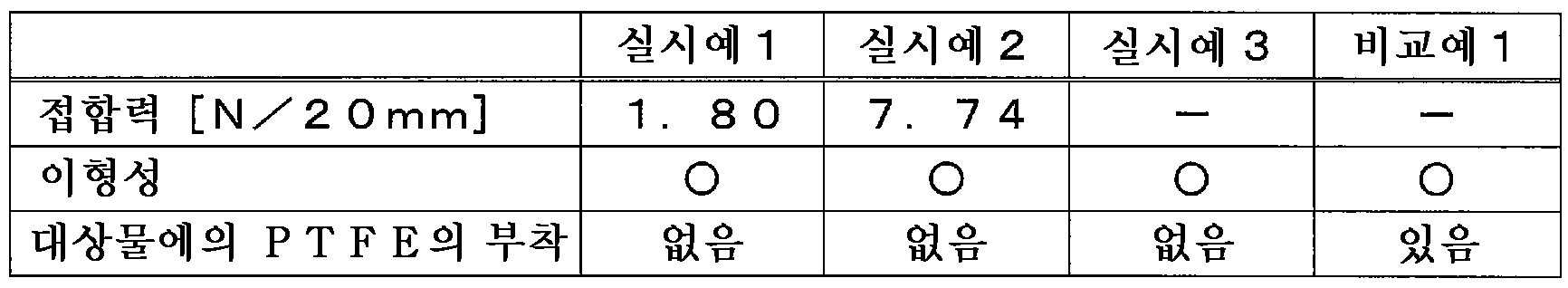
실시예 1, 2 및 비교예 1 모두, 구리 기판과 Si 반도체 칩의 접합은 문제 없이 실시 가능하였다. 그러나, 표 1 및 도 4에 나타내는 바와 같이, 비교예 1에서는, Si 반도체 칩의 표면에 대한 섬유상의 PTFE의 부착이 많이 보였다. 한편, 실시예 1, 2에서는, PTFE의 부착은 보이지 않았다. 또한, PTFE의 부착은, 명시야상에서는 확인이 어렵고, 암시야상으로 함으로써 확인할 수 있었다(도 4 참조). 또한, PTFE 시트에 대한 스퍼터 에칭 처리에 의해, 기재(2)와 피복층(3)의 접합력을 향상시킬 수 있는 것이 확인되었다.In all of Examples 1 and 2 and Comparative Example 1, bonding between the copper substrate and the Si semiconductor chip could be performed without any problems. However, as shown in Table 1 and Fig. 4, in Comparative Example 1, adhesion of the fibrous PTFE to the surface of the Si semiconductor chip was frequently observed. On the other hand, in Examples 1 and 2, adhesion of PTFE was not observed. In addition, adhesion of PTFE was difficult to confirm on a bright field image, and could be confirmed by using a dark field image (see Fig. 4). Further, it was confirmed that the adhesion between the
본 발명의 내열 완충 시트는, 대상물의 열 가압 처리 시에 열 가압 장치의 열 가압면과 대상물 사이에 배치하여 사용할 수 있다. 열 가압 처리는, 예를 들어, 열 압착, 열 프레스이다.The heat-resistant cushioning sheet of the present invention can be used by placing it between a heat-pressing surface of a heat-pressing device and an object when heat-pressing an object. The heat press treatment is, for example, heat compression and heat press.
Claims (9)
불소 수지의 기재와, 상기 기재의 한쪽 주면 측에 배치된 내열성 수지의 피복층을 구비하고,
상기 내열 완충 시트의 한쪽 노출면은 상기 피복층에 의해 구성되며,
상기 내열성 수지는, 상기 불소 수지 이외의 수지임과 함께, 280℃ 이상의 융점 및/또는 210℃ 이상의 유리 전이 온도를 갖는, 내열 완충 시트.A heat-resistant buffer sheet disposed between a heat-pressing surface of a heat-pressing device and an object during heat-pressing treatment of an object,
A substrate of fluorine resin and a coating layer of heat-resistant resin disposed on one main surface side of the substrate,
One exposed surface of the heat-resistant buffer sheet is constituted by the coating layer,
The heat-resistant buffer sheet, wherein the heat-resistant resin is a resin other than the fluororesin and has a melting point of 280°C or higher and/or a glass transition temperature of 210°C or higher.
상기 기재의 두께는 상기 피복층의 두께보다도 큰, 내열 완충 시트.According to claim 1,
The heat-resistant buffer sheet, wherein the thickness of the substrate is greater than the thickness of the coating layer.
상기 기재 및/또는 상기 피복층이 단층인, 내열 완충 시트.According to claim 1 or 2,
The heat-resistant buffer sheet in which the base material and/or the cover layer is a single layer.
접착층을 더 구비하고,
상기 기재와 상기 피복층은 상기 접착층에 의해 서로 접합되어 있는, 내열 완충 시트.According to any one of claims 1 to 3,
An adhesive layer is further provided,
The heat-resistant buffer sheet, wherein the substrate and the coating layer are bonded to each other by the adhesive layer.
상기 기재는, 상기 불소 수지의 절삭 시트인, 내열 완충 시트.According to any one of claims 1 to 4,
The heat-resistant buffer sheet, wherein the substrate is a cutting sheet of the fluororesin.
상기 불소 수지는, 폴리테트라플루오로에틸렌(PTFE) 또는 변성 PTFE이며,
상기 변성 PTFE에 있어서의 테트라플루오로에틸렌(TFE) 단위의 함유율이 99질량% 이상인, 내열 완충 시트.According to any one of claims 1 to 5,
The fluororesin is polytetrafluoroethylene (PTFE) or modified PTFE,
A heat-resistant buffer sheet wherein the modified PTFE has a tetrafluoroethylene (TFE) unit content of 99% by mass or more.
상기 내열성 수지는, 폴리이미드, 폴리에테르이미드, 폴리술폰, 폴리에테르술폰, 방향족 폴리에테르케톤 및 폴리아미드이미드에서 선택되는 적어도 1종인, 내열 완충 시트.According to any one of claims 1 to 6,
The heat-resistant buffer sheet, wherein the heat-resistant resin is at least one selected from polyimide, polyetherimide, polysulfone, polyethersulfone, aromatic polyetherketone, and polyamideimide.
상기 기재와 상기 피복층 사이의 접합력이 1.5N/20mm 이상인, 내열 완충 시트.According to any one of claims 1 to 7,
A heat-resistant buffer sheet having a bonding strength between the substrate and the coating layer of 1.5 N/20 mm or more.
상기 대상물과 상기 장치의 열 가압면 사이에 내열 완충 시트를 배치한 상태에서 상기 열 가압 처리를 실시하고,
상기 내열 완충 시트는, 제1항 내지 제8항 중 어느 한 항에 기재된 내열 완충 시트이며,
상기 열 가압 처리에 있어서 상기 내열 완충 시트는, 상기 피복층에 의해 구성되는 상기 한쪽 노출면이 상기 대상물에 접하도록, 상기 대상물과 상기 열 가압면 사이에 배치되는, 열 가압 처리 방법.It is a method of heat-pressing treatment of an object by a heat-pressing device,
The heat-pressing treatment is performed in a state where a heat-resistant buffer sheet is disposed between the object and a heat-pressing surface of the apparatus;
The heat-resistant buffer sheet is the heat-resistant buffer sheet according to any one of claims 1 to 8,
In the heat-pressing treatment, the heat-resistant buffer sheet is disposed between the object and the heat-pressing surface so that the one exposed surface constituted by the coating layer is in contact with the object.
Applications Claiming Priority (3)
| Application Number | Priority Date | Filing Date | Title |
|---|---|---|---|
| JP2020085472 | 2020-05-14 | ||
| JPJP-P-2020-085472 | 2020-05-14 | ||
| PCT/JP2021/017289 WO2021230116A1 (en) | 2020-05-14 | 2021-04-30 | Heat-resistant buffering sheet, and heating/pressurizing treatment method |
Publications (1)
| Publication Number | Publication Date |
|---|---|
| KR20230010685A true KR20230010685A (en) | 2023-01-19 |
Family
ID=78525723
Family Applications (1)
| Application Number | Title | Priority Date | Filing Date |
|---|---|---|---|
| KR1020227043331A Pending KR20230010685A (en) | 2020-05-14 | 2021-04-30 | Heat-resisting buffer sheet and heat press treatment method |
Country Status (7)
| Country | Link |
|---|---|
| US (1) | US20230173795A1 (en) |
| EP (1) | EP4151404A4 (en) |
| JP (1) | JP7805714B2 (en) |
| KR (1) | KR20230010685A (en) |
| CN (1) | CN115605346A (en) |
| TW (1) | TW202210263A (en) |
| WO (1) | WO2021230116A1 (en) |
Families Citing this family (1)
| Publication number | Priority date | Publication date | Assignee | Title |
|---|---|---|---|---|
| KR102908883B1 (en) * | 2023-04-17 | 2026-01-07 | 주식회사 아모그린텍 | Semiconductor chip mounting method using conductive paste |
Citations (1)
| Publication number | Priority date | Publication date | Assignee | Title |
|---|---|---|---|---|
| WO2007046482A1 (en) | 2005-10-20 | 2007-04-26 | Asahi Glass Company, Limited | Aqueous polytetrafluoroethylene dispersion and product made from same |
Family Cites Families (7)
| Publication number | Priority date | Publication date | Assignee | Title |
|---|---|---|---|---|
| JP3461291B2 (en) * | 1998-08-06 | 2003-10-27 | ヤマウチ株式会社 | Rubber for hot press cushion material, cushion material for hot press, and method of manufacturing printed circuit board |
| JP4659241B2 (en) * | 2001-03-19 | 2011-03-30 | ジャパンゴアテックス株式会社 | Polytetrafluoroethylene membrane and method for producing the same |
| JP2003211472A (en) * | 2002-01-21 | 2003-07-29 | Showa Electric Wire & Cable Co Ltd | Cushioning material for molding press |
| CN107969123A (en) * | 2015-05-14 | 2018-04-27 | 住友电工超效能高分子股份有限公司 | The manufacture method of gluing reinforcing sheet, sliding component and gluing reinforcing sheet |
| WO2018181403A1 (en) * | 2017-03-30 | 2018-10-04 | 日東電工株式会社 | Heat resistant release sheet and method for manufacturing same |
| WO2020045338A1 (en) * | 2018-08-30 | 2020-03-05 | 三井化学東セロ株式会社 | Release film |
| WO2020071388A1 (en) * | 2018-10-04 | 2020-04-09 | 日東電工株式会社 | Heat-resistant release sheet and thermocompression bonding method |
-
2021
- 2021-04-30 KR KR1020227043331A patent/KR20230010685A/en active Pending
- 2021-04-30 EP EP21804829.6A patent/EP4151404A4/en active Pending
- 2021-04-30 US US17/924,038 patent/US20230173795A1/en not_active Abandoned
- 2021-04-30 CN CN202180035211.7A patent/CN115605346A/en active Pending
- 2021-04-30 WO PCT/JP2021/017289 patent/WO2021230116A1/en not_active Ceased
- 2021-04-30 JP JP2021078051A patent/JP7805714B2/en active Active
- 2021-05-12 TW TW110117055A patent/TW202210263A/en unknown
Patent Citations (1)
| Publication number | Priority date | Publication date | Assignee | Title |
|---|---|---|---|---|
| WO2007046482A1 (en) | 2005-10-20 | 2007-04-26 | Asahi Glass Company, Limited | Aqueous polytetrafluoroethylene dispersion and product made from same |
Also Published As
| Publication number | Publication date |
|---|---|
| US20230173795A1 (en) | 2023-06-08 |
| WO2021230116A1 (en) | 2021-11-18 |
| EP4151404A1 (en) | 2023-03-22 |
| JP7805714B2 (en) | 2026-01-26 |
| EP4151404A4 (en) | 2024-06-19 |
| JP2021181222A (en) | 2021-11-25 |
| TW202210263A (en) | 2022-03-16 |
| CN115605346A (en) | 2023-01-13 |
Similar Documents
| Publication | Publication Date | Title |
|---|---|---|
| JP6970153B2 (en) | Heat-resistant mold release sheet and thermocompression bonding method | |
| TWI762611B (en) | Heat-resistant release sheet and method for producing the same | |
| KR20230010685A (en) | Heat-resisting buffer sheet and heat press treatment method | |
| KR102857329B1 (en) | Heat-resistant release sheet and heat-compression method | |
| WO2006054473A1 (en) | Composite sheet for thermal compression bonding and method for producing same | |
| CN114829469B (en) | Heat-resistant buffer sheet and heat-pressing treatment method | |
| EP3862161A1 (en) | Heat-resistant release sheet and thermocompression bonding method | |
| JP7735064B2 (en) | A method for carrying out a process involving the heating and melting of a heat-resistant release sheet and a resin | |
| JP2022160045A (en) | Resin metal composite film and method for manufacturing resin metal composite film | |
| JP2022086179A (en) | Heating element for electromagnetic induction heating |
Legal Events
| Date | Code | Title | Description |
|---|---|---|---|
| PA0105 | International application |
St.27 status event code: A-0-1-A10-A15-nap-PA0105 |
|
| PG1501 | Laying open of application |
St.27 status event code: A-1-1-Q10-Q12-nap-PG1501 |
|
| PA0201 | Request for examination |
St.27 status event code: A-1-2-D10-D11-exm-PA0201 |
|
| R18-X000 | Changes to party contact information recorded |
St.27 status event code: A-3-3-R10-R18-oth-X000 |
|
| R18-X000 | Changes to party contact information recorded |
St.27 status event code: A-3-3-R10-R18-oth-X000 |
|
| D21 | Rejection of application intended |
Free format text: ST27 STATUS EVENT CODE: A-1-2-D10-D21-EXM-PE0902 (AS PROVIDED BY THE NATIONAL OFFICE) |
|
| PE0902 | Notice of grounds for rejection |
St.27 status event code: A-1-2-D10-D21-exm-PE0902 |
|
| P11 | Amendment of application requested |
Free format text: ST27 STATUS EVENT CODE: A-2-2-P10-P11-NAP-X000 (AS PROVIDED BY THE NATIONAL OFFICE) |
|
| P11-X000 | Amendment of application requested |
St.27 status event code: A-2-2-P10-P11-nap-X000 |