KR20220167427A - Display device - Google Patents
Display device Download PDFInfo
- Publication number
- KR20220167427A KR20220167427A KR1020210076006A KR20210076006A KR20220167427A KR 20220167427 A KR20220167427 A KR 20220167427A KR 1020210076006 A KR1020210076006 A KR 1020210076006A KR 20210076006 A KR20210076006 A KR 20210076006A KR 20220167427 A KR20220167427 A KR 20220167427A
- Authority
- KR
- South Korea
- Prior art keywords
- weight
- reference point
- display panel
- image signals
- display device
- Prior art date
Links
- 238000000605 extraction Methods 0.000 claims description 22
- 238000000034 method Methods 0.000 claims description 2
- 238000010586 diagram Methods 0.000 description 23
- 239000010410 layer Substances 0.000 description 22
- 101150022905 RDR1 gene Proteins 0.000 description 21
- 101150066141 RDR2 gene Proteins 0.000 description 21
- 101100175003 Oryza sativa subsp. japonica RGB1 gene Proteins 0.000 description 13
- 238000006243 chemical reaction Methods 0.000 description 13
- 101150060692 RDR4 gene Proteins 0.000 description 11
- 239000013256 coordination polymer Substances 0.000 description 11
- 230000005540 biological transmission Effects 0.000 description 10
- 239000002313 adhesive film Substances 0.000 description 8
- 239000000284 extract Substances 0.000 description 8
- 102100033595 Dynein axonemal intermediate chain 1 Human genes 0.000 description 6
- 102100033596 Dynein axonemal intermediate chain 2 Human genes 0.000 description 6
- 102100029688 Dynein axonemal intermediate chain 3 Human genes 0.000 description 6
- 101000872267 Homo sapiens Dynein axonemal intermediate chain 1 Proteins 0.000 description 6
- 101000872272 Homo sapiens Dynein axonemal intermediate chain 2 Proteins 0.000 description 6
- 101000865953 Homo sapiens Dynein axonemal intermediate chain 3 Proteins 0.000 description 6
- 239000004973 liquid crystal related substance Substances 0.000 description 5
- 102100027557 Calcipressin-1 Human genes 0.000 description 4
- 101100247605 Homo sapiens RCAN1 gene Proteins 0.000 description 4
- 239000008186 active pharmaceutical agent Substances 0.000 description 4
- 238000000576 coating method Methods 0.000 description 4
- 101150064416 csp1 gene Proteins 0.000 description 4
- 239000000463 material Substances 0.000 description 4
- 239000002096 quantum dot Substances 0.000 description 4
- 241001270131 Agaricus moelleri Species 0.000 description 3
- 101100441251 Arabidopsis thaliana CSP2 gene Proteins 0.000 description 3
- 239000011248 coating agent Substances 0.000 description 3
- 230000006866 deterioration Effects 0.000 description 3
- 239000004820 Pressure-sensitive adhesive Substances 0.000 description 2
- 230000000903 blocking effect Effects 0.000 description 2
- 238000010924 continuous production Methods 0.000 description 2
- 230000014509 gene expression Effects 0.000 description 2
- 230000033001 locomotion Effects 0.000 description 2
- 230000008447 perception Effects 0.000 description 2
- 239000000853 adhesive Substances 0.000 description 1
- 230000001070 adhesive effect Effects 0.000 description 1
- 239000003990 capacitor Substances 0.000 description 1
- 239000003086 colorant Substances 0.000 description 1
- 239000011521 glass Substances 0.000 description 1
- 230000000977 initiatory effect Effects 0.000 description 1
- 239000012044 organic layer Substances 0.000 description 1
- 230000000149 penetrating effect Effects 0.000 description 1
- 239000004033 plastic Substances 0.000 description 1
- 229920005989 resin Polymers 0.000 description 1
- 239000011347 resin Substances 0.000 description 1
- 229910052594 sapphire Inorganic materials 0.000 description 1
- 239000010980 sapphire Substances 0.000 description 1
- 239000002356 single layer Substances 0.000 description 1
- 239000000126 substance Substances 0.000 description 1
- 229920003002 synthetic resin Polymers 0.000 description 1
- 239000000057 synthetic resin Substances 0.000 description 1
- 239000012780 transparent material Substances 0.000 description 1
Images


Classifications
-
- G—PHYSICS
- G09—EDUCATION; CRYPTOGRAPHY; DISPLAY; ADVERTISING; SEALS
- G09G—ARRANGEMENTS OR CIRCUITS FOR CONTROL OF INDICATING DEVICES USING STATIC MEANS TO PRESENT VARIABLE INFORMATION
- G09G3/00—Control arrangements or circuits, of interest only in connection with visual indicators other than cathode-ray tubes
- G09G3/20—Control arrangements or circuits, of interest only in connection with visual indicators other than cathode-ray tubes for presentation of an assembly of a number of characters, e.g. a page, by composing the assembly by combination of individual elements arranged in a matrix no fixed position being assigned to or needed to be assigned to the individual characters or partial characters
- G09G3/2007—Display of intermediate tones
-
- G—PHYSICS
- G06—COMPUTING; CALCULATING OR COUNTING
- G06F—ELECTRIC DIGITAL DATA PROCESSING
- G06F3/00—Input arrangements for transferring data to be processed into a form capable of being handled by the computer; Output arrangements for transferring data from processing unit to output unit, e.g. interface arrangements
- G06F3/01—Input arrangements or combined input and output arrangements for interaction between user and computer
- G06F3/011—Arrangements for interaction with the human body, e.g. for user immersion in virtual reality
- G06F3/013—Eye tracking input arrangements
-
- G—PHYSICS
- G09—EDUCATION; CRYPTOGRAPHY; DISPLAY; ADVERTISING; SEALS
- G09G—ARRANGEMENTS OR CIRCUITS FOR CONTROL OF INDICATING DEVICES USING STATIC MEANS TO PRESENT VARIABLE INFORMATION
- G09G3/00—Control arrangements or circuits, of interest only in connection with visual indicators other than cathode-ray tubes
- G09G3/20—Control arrangements or circuits, of interest only in connection with visual indicators other than cathode-ray tubes for presentation of an assembly of a number of characters, e.g. a page, by composing the assembly by combination of individual elements arranged in a matrix no fixed position being assigned to or needed to be assigned to the individual characters or partial characters
- G09G3/2092—Details of a display terminals using a flat panel, the details relating to the control arrangement of the display terminal and to the interfaces thereto
-
- G—PHYSICS
- G09—EDUCATION; CRYPTOGRAPHY; DISPLAY; ADVERTISING; SEALS
- G09G—ARRANGEMENTS OR CIRCUITS FOR CONTROL OF INDICATING DEVICES USING STATIC MEANS TO PRESENT VARIABLE INFORMATION
- G09G3/00—Control arrangements or circuits, of interest only in connection with visual indicators other than cathode-ray tubes
- G09G3/20—Control arrangements or circuits, of interest only in connection with visual indicators other than cathode-ray tubes for presentation of an assembly of a number of characters, e.g. a page, by composing the assembly by combination of individual elements arranged in a matrix no fixed position being assigned to or needed to be assigned to the individual characters or partial characters
- G09G3/22—Control arrangements or circuits, of interest only in connection with visual indicators other than cathode-ray tubes for presentation of an assembly of a number of characters, e.g. a page, by composing the assembly by combination of individual elements arranged in a matrix no fixed position being assigned to or needed to be assigned to the individual characters or partial characters using controlled light sources
- G09G3/30—Control arrangements or circuits, of interest only in connection with visual indicators other than cathode-ray tubes for presentation of an assembly of a number of characters, e.g. a page, by composing the assembly by combination of individual elements arranged in a matrix no fixed position being assigned to or needed to be assigned to the individual characters or partial characters using controlled light sources using electroluminescent panels
- G09G3/32—Control arrangements or circuits, of interest only in connection with visual indicators other than cathode-ray tubes for presentation of an assembly of a number of characters, e.g. a page, by composing the assembly by combination of individual elements arranged in a matrix no fixed position being assigned to or needed to be assigned to the individual characters or partial characters using controlled light sources using electroluminescent panels semiconductive, e.g. using light-emitting diodes [LED]
- G09G3/3208—Control arrangements or circuits, of interest only in connection with visual indicators other than cathode-ray tubes for presentation of an assembly of a number of characters, e.g. a page, by composing the assembly by combination of individual elements arranged in a matrix no fixed position being assigned to or needed to be assigned to the individual characters or partial characters using controlled light sources using electroluminescent panels semiconductive, e.g. using light-emitting diodes [LED] organic, e.g. using organic light-emitting diodes [OLED]
-
- G—PHYSICS
- G09—EDUCATION; CRYPTOGRAPHY; DISPLAY; ADVERTISING; SEALS
- G09G—ARRANGEMENTS OR CIRCUITS FOR CONTROL OF INDICATING DEVICES USING STATIC MEANS TO PRESENT VARIABLE INFORMATION
- G09G5/00—Control arrangements or circuits for visual indicators common to cathode-ray tube indicators and other visual indicators
- G09G5/10—Intensity circuits
-
- G—PHYSICS
- G09—EDUCATION; CRYPTOGRAPHY; DISPLAY; ADVERTISING; SEALS
- G09G—ARRANGEMENTS OR CIRCUITS FOR CONTROL OF INDICATING DEVICES USING STATIC MEANS TO PRESENT VARIABLE INFORMATION
- G09G2320/00—Control of display operating conditions
- G09G2320/02—Improving the quality of display appearance
- G09G2320/0233—Improving the luminance or brightness uniformity across the screen
-
- G—PHYSICS
- G09—EDUCATION; CRYPTOGRAPHY; DISPLAY; ADVERTISING; SEALS
- G09G—ARRANGEMENTS OR CIRCUITS FOR CONTROL OF INDICATING DEVICES USING STATIC MEANS TO PRESENT VARIABLE INFORMATION
- G09G2320/00—Control of display operating conditions
- G09G2320/02—Improving the quality of display appearance
- G09G2320/0261—Improving the quality of display appearance in the context of movement of objects on the screen or movement of the observer relative to the screen
-
- G—PHYSICS
- G09—EDUCATION; CRYPTOGRAPHY; DISPLAY; ADVERTISING; SEALS
- G09G—ARRANGEMENTS OR CIRCUITS FOR CONTROL OF INDICATING DEVICES USING STATIC MEANS TO PRESENT VARIABLE INFORMATION
- G09G2320/00—Control of display operating conditions
- G09G2320/02—Improving the quality of display appearance
- G09G2320/0271—Adjustment of the gradation levels within the range of the gradation scale, e.g. by redistribution or clipping
-
- G—PHYSICS
- G09—EDUCATION; CRYPTOGRAPHY; DISPLAY; ADVERTISING; SEALS
- G09G—ARRANGEMENTS OR CIRCUITS FOR CONTROL OF INDICATING DEVICES USING STATIC MEANS TO PRESENT VARIABLE INFORMATION
- G09G2320/00—Control of display operating conditions
- G09G2320/06—Adjustment of display parameters
- G09G2320/0613—The adjustment depending on the type of the information to be displayed
-
- G—PHYSICS
- G09—EDUCATION; CRYPTOGRAPHY; DISPLAY; ADVERTISING; SEALS
- G09G—ARRANGEMENTS OR CIRCUITS FOR CONTROL OF INDICATING DEVICES USING STATIC MEANS TO PRESENT VARIABLE INFORMATION
- G09G2320/00—Control of display operating conditions
- G09G2320/06—Adjustment of display parameters
- G09G2320/0626—Adjustment of display parameters for control of overall brightness
-
- G—PHYSICS
- G09—EDUCATION; CRYPTOGRAPHY; DISPLAY; ADVERTISING; SEALS
- G09G—ARRANGEMENTS OR CIRCUITS FOR CONTROL OF INDICATING DEVICES USING STATIC MEANS TO PRESENT VARIABLE INFORMATION
- G09G2320/00—Control of display operating conditions
- G09G2320/06—Adjustment of display parameters
- G09G2320/0686—Adjustment of display parameters with two or more screen areas displaying information with different brightness or colours
-
- G—PHYSICS
- G09—EDUCATION; CRYPTOGRAPHY; DISPLAY; ADVERTISING; SEALS
- G09G—ARRANGEMENTS OR CIRCUITS FOR CONTROL OF INDICATING DEVICES USING STATIC MEANS TO PRESENT VARIABLE INFORMATION
- G09G2330/00—Aspects of power supply; Aspects of display protection and defect management
- G09G2330/02—Details of power systems and of start or stop of display operation
- G09G2330/021—Power management, e.g. power saving
- G09G2330/022—Power management, e.g. power saving in absence of operation, e.g. no data being entered during a predetermined time
-
- G—PHYSICS
- G09—EDUCATION; CRYPTOGRAPHY; DISPLAY; ADVERTISING; SEALS
- G09G—ARRANGEMENTS OR CIRCUITS FOR CONTROL OF INDICATING DEVICES USING STATIC MEANS TO PRESENT VARIABLE INFORMATION
- G09G2354/00—Aspects of interface with display user
-
- G—PHYSICS
- G09—EDUCATION; CRYPTOGRAPHY; DISPLAY; ADVERTISING; SEALS
- G09G—ARRANGEMENTS OR CIRCUITS FOR CONTROL OF INDICATING DEVICES USING STATIC MEANS TO PRESENT VARIABLE INFORMATION
- G09G2360/00—Aspects of the architecture of display systems
- G09G2360/16—Calculation or use of calculated indices related to luminance levels in display data
Landscapes
- Engineering & Computer Science (AREA)
- Theoretical Computer Science (AREA)
- Physics & Mathematics (AREA)
- General Physics & Mathematics (AREA)
- Computer Hardware Design (AREA)
- General Engineering & Computer Science (AREA)
- Human Computer Interaction (AREA)
- Control Of Indicators Other Than Cathode Ray Tubes (AREA)
Abstract
Description
본 발명은 표시 장치에 관한 것으로, 상세하게는 소비전력을 절감할 수 있는 표시장치에 관한 것이다.The present invention relates to a display device, and more particularly, to a display device capable of reducing power consumption.
영상 정보를 제공하기 위하여 다양한 형태의 표시 장치가 사용되고 있다. 특히, 표시 장치에는 유기 발광 표시(Organic Light Emitting Display, OLED) 장치, 퀀텀닷 표시(Quantum Dot Display) 장치, 액정 표시(Liquid Crystal Display, LCD) 장치, 플라즈마(Plasma)표시 장치 등이 사용되고 있다.Various types of display devices are used to provide image information. In particular, an organic light emitting display (OLED) device, a quantum dot display device, a liquid crystal display (LCD) device, a plasma display device, and the like are used as display devices.
표시 장치는 영상을 표시하는 표시 패널 및 표시패널에 결합되어 표시 패널로 구동신호를 제공하는 패널 구동 블럭을 포함한다. 표시 패널은 광을 발생하는 발광 소자들을 포함한다. 유기발광 표시장치의 경우 광을 발생하는 유기발광 소자를 포함한다.The display device includes a display panel displaying an image and a panel driving block coupled to the display panel and providing driving signals to the display panel. The display panel includes light emitting elements that generate light. An organic light emitting display device includes an organic light emitting device that generates light.
본 발명의 목적은 소비 전력을 절감할 수 있는 표시 장치를 제공하는 데 있다.An object of the present invention is to provide a display device capable of reducing power consumption.
본 발명의 일 실시예에 따른 표시 장치는 영상을 표시하는 표시 패널 및 제어 신호를 수신하는 패널 구동 블럭을 포함한다. 상기 패널 구동 블럭은 상기 제어 신호를 토대로 상기 영상의 휘도를 조정하기 위한 기준점에 대한 정보를 포함하는 기준점 신호를 생성한다. 상기 패널 구동 블럭은 영상 신호들을 수신하고, 상기 영상 신호들 각각이 상기 표시 패널 상에서 표시되는 위치와 상기 기준점과의 거리 정보를 토대로 보정값을 생성한다. 상기 패널 구동 블럭은 상기 보정값을 토대로 상기 영상 신호들을 변환하여 보정 영상 신호들을 생성한다.A display device according to an exemplary embodiment includes a display panel displaying an image and a panel driving block receiving control signals. The panel driving block generates a reference point signal including information on a reference point for adjusting luminance of the image based on the control signal. The panel driving block receives image signals and generates a correction value based on distance information between a position where each image signal is displayed on the display panel and the reference point. The panel driving block generates corrected image signals by converting the image signals based on the correction value.
본 발명의 일 실시예로 상기 보정 영상 신호들에 대응하는 계조는, 상기 영상 신호들에 대응하는 계조보다 작을 수 있다.In an embodiment of the present invention, a gray level corresponding to the corrected image signals may be smaller than a gray level corresponding to the image signals.
본 발명의 일 실시예로 상기 표시 패널 상에서, 상기 기준점의 위치는 상기 표시 패널에 표시되는 상기 영상의 종류에 따라 달라질 수 있다.In an embodiment of the present invention, the position of the reference point on the display panel may vary according to the type of the image displayed on the display panel.
본 발명의 일 실시예로 상기 표시 패널은 상기 기준점을 기준으로 분할된 복수의 영역들을 포함한다. 상기 패널 구동 블럭은 상기 제어 신호를 토대로 상기 영역들 각각에 대한 가중치를 생성하고, 상기 거리 정보 및 상기 가중치를 토대로 상기 보정값을 생성한다.In one embodiment of the present invention, the display panel includes a plurality of regions divided based on the reference point. The panel driving block generates a weight for each of the regions based on the control signal, and generates the correction value based on the distance information and the weight.
본 발명의 일 실시예로 상기 영역들은 상기 기준점을 기준으로 제1 기준 방향으로 연장된 제1 축 및 상기 기준점을 기준으로 제2 기준 방향으로 연장된 제2 축에 의해 정의된 제1 사분면에 대응되는 제1 영역을 포함한다. 상기 영역들은 상기 기준점을 기준으로 상기 제1 기준 방향과 반대하는 제3 기준 방향으로 연장된 제3 축과 상기 제2 축에 의해 정의된 제2 사분면에 대응되는 제2 영역을 포함한다. 상기 영역들은 상기 기준점을 기준으로 상기 제2 기준 방향과 반대하는 제4 기준 방향으로 연장된 제4 축과 상기 제1 축에 의해 정의된 제3 사분면에 대응되는 제3 영역을 포함한다. 상기 영역들은 상기 제1 축과 상기 제4 축에 의해 정의된 제4 사분면에 대응되는 제4 영역을 포함한다. 상기 가중치는 상기 제1 영역에 대응되는 제1 가중치, 상기 제2 영역에 대응되는 제2 가중치, 상기 제3 영역에 대응되는 제3 가중치 및 상기 제4 영역에 대응되는 제4 가중치를 포함한다.In one embodiment of the present invention, the regions correspond to a first quadrant defined by a first axis extending in a first reference direction based on the reference point and a second axis extending in a second reference direction based on the reference point. It includes a first area to be. The areas include a third axis extending in a third reference direction opposite to the first reference direction based on the reference point and a second area corresponding to a second quadrant defined by the second axis. The areas include a fourth axis extending in a fourth reference direction opposite to the second reference direction based on the reference point and a third area corresponding to a third quadrant defined by the first axis. The regions include a fourth region corresponding to a fourth quadrant defined by the first axis and the fourth axis. The weights include a first weight corresponding to the first area, a second weight corresponding to the second area, a third weight corresponding to the third area, and a fourth weight corresponding to the fourth area.
본 발명의 일 실시예로 상기 제1 내지 제4 가중치는 서로 다른 값을 가질 수 있다.In an embodiment of the present invention, the first to fourth weights may have different values.
본 발명의 일 실시예로 상기 영역들은 상기 기준점을 포함하는 제1 영역 및 상기 제1 영역을 에워싸는 제2 영역을 포함한다. 상기 가중치는 상기 제1 영역에 대응되는 제1 가중치 및 상기 제2 영역에 대응되는 제2 가중치를 포함한다.In one embodiment of the present invention, the regions include a first region including the reference point and a second region surrounding the first region. The weight includes a first weight corresponding to the first area and a second weight corresponding to the second area.
본 발명의 일 실시예로 상기 제1 가중치와 상기 제2 가중치는 서로 다른 값을 가질 수 있다.In an embodiment of the present invention, the first weight and the second weight may have different values.
본 발명의 일 실시예로 상기 패널 구동 블럭은 상기 영상 신호들을 상기 보정값을 토대로 변환하여 상기 보정 영상 신호들을 생성하며, 상기 보정 영상 신호들을 토대로 영상 데이터를 생성하는 컨트롤러를 포함한다. 상기 패널 구동 블럭은 상기 영상 데이터를 토대로 데이터 신호를 생성하여 상기 표시 패널에 상기 데이터 신호를 송신하는 소스 드라이버를 포함한다.In one embodiment of the present invention, the panel driving block includes a controller that converts the image signals based on the correction value to generate the corrected image signals and generates image data based on the corrected image signals. The panel driving block includes a source driver generating a data signal based on the image data and transmitting the data signal to the display panel.
본 발명의 일 실시예로 상기 패널 구동 블럭은 상기 제어 신호를 토대로 상기 기준점 신호를 생성하는 추출부를 더 포함한다.In one embodiment of the present invention, the panel driving block further includes an extraction unit generating the reference point signal based on the control signal.
본 발명의 일 실시예로 상기 컨트롤러는 상기 영상 신호들 각각에 대해 상기 거리 정보를 추출하는 거리 계산부 및 상기 거리 정보를 토대로 상기 보정값을 생성하는 보정값 계산부를 포함한다. 상기 컨트롤러는 상기 영상 신호들을 상기 보정값을 토대로 변환하여 상기 보정 영상 신호들을 생성하는 보정부를 포함한다.In one embodiment of the present invention, the controller includes a distance calculation unit for extracting the distance information for each of the video signals and a correction value calculation unit for generating the correction value based on the distance information. The controller includes a correction unit generating the correction image signals by converting the image signals based on the correction values.
본 발명의 일 실시예로 상기 표시 패널은 상기 기준점을 기준으로 분할된 복수의 영역들을 포함한다. 상기 추출부는 상기 제어 신호를 토대로 상기 영역들 각각에 대한 가중치를 더 추출한다.In one embodiment of the present invention, the display panel includes a plurality of regions divided based on the reference point. The extractor further extracts a weight for each of the regions based on the control signal.
본 발명의 일 실시예로 상기 보정값 계산부는 상기 거리 정보 및 상기 가중치를 토대로 상기 보정값을 생성한다.In one embodiment of the present invention, the correction value calculation unit generates the correction value based on the distance information and the weight.
본 발명의 일 실시예로 상기 컨트롤러는 상기 제어 신호를 토대로 상기 기준점 신호를 생성하는 추출부를 포함한다.In one embodiment of the present invention, the controller includes an extractor for generating the reference point signal based on the control signal.
본 발명의 일 실시예로 상기 표시 패널은 상기 기준점을 기준으로 분할된 복수의 영역들을 포함한다. 상기 추출부는 상기 제어 신호를 토대로 상기 영역들 각각에 대한 가중치를 더 생성한다.In one embodiment of the present invention, the display panel includes a plurality of regions divided based on the reference point. The extractor further generates a weight for each of the regions based on the control signal.
본 발명의 일 실시예로 상기 표시 패널은 상기 기준점을 기준으로 분할된 복수의 영역을 포함한다. 상기 패널 구동 블럭은 상기 영역들 각각에 대한 가중치를 포함하는 설정 신호를 더 수신하고, 상기 거리 정보 및 상기 가중치를 토대로 상기 보정값을 생성한다.In one embodiment of the present invention, the display panel includes a plurality of regions divided based on the reference point. The panel driving block further receives a setting signal including a weight for each of the regions, and generates the correction value based on the distance information and the weight.
본 발명의 일 실시예로 상기 가중치의 크기는 외부 입력에 의하여 결정된다.In one embodiment of the present invention, the size of the weight is determined by an external input.
본 발명의 일 실시예로 상기 표시 패널에는 상기 가중치의 크기를 조절할 수 있는 설정 어플리케이션이 표시된다. 상기 가중치의 크기는 상기 설정 어플리케이션에서 상기 가중치의 크기를 선택하는 상기 외부 입력에 의해 결정된다.In one embodiment of the present invention, a setting application capable of adjusting the size of the weight is displayed on the display panel. The size of the weight is determined by the external input for selecting the size of the weight in the setting application.
본 발명의 일 실시예에 따른 표시 장치는 영상을 표시하는 표시 패널 및 패널 구동 블럭을 포함한다. 상기 패널 구동 블럭은 영상 신호들을 수신하고, 상기 영상 신호들 각각이 상기 표시 패널 상에서 표시되는 위치와 상기 영상의 휘도를 조정하기 위한 기준점과의 거리 정보를 산출한다. 상기 표시 패널은 상기 기준점을 기준으로 분할된 복수의 영역들을 포함한다. 상기 패널 구동 블럭은 상기 영역들 각각에 대한 가중치를 포함하는 설정 신호를 수신하고, 상기 거리 정보 및 상기 설정 신호를 토대로 보정값을 생성한다. 상기 패널 구동 블럭은 상기 영상 신호를 상기 보정값을 토대로 변환하여 보정 영상 신호를 생성한다.A display device according to an exemplary embodiment includes a display panel displaying an image and a panel driving block. The panel driving block receives image signals and calculates distance information between a position where each image signal is displayed on the display panel and a reference point for adjusting the luminance of the image. The display panel includes a plurality of regions divided based on the reference point. The panel driving block receives a setting signal including a weight for each of the regions and generates a correction value based on the distance information and the setting signal. The panel driving block generates a corrected image signal by converting the image signal based on the correction value.
본 발명의 일 실시예로 상기 보정 영상 신호들에 대응하는 계조는, 상기 영상 신호들에 대응하는 계조보다 작을 수 있다.In an embodiment of the present invention, a gray level corresponding to the corrected image signals may be smaller than a gray level corresponding to the image signals.
본 발명의 일 실시예로 상기 설정 신호에 포함된 상기 가중치의 크기는 외부 입력에 의하여 결정될 수 있다.In one embodiment of the present invention, the size of the weight included in the setting signal may be determined by an external input.
본 발명의 일 실시예로 상기 표시 패널에는, 상기 가중치의 크기를 조절할 수 있는 설정 어플리케이션이 표시된다. 상기 가중치의 크기는 상기 설정 어플리케이션에서 상기 가중치의 크기를 선택하는 상기 외부 입력에 의해 결정될 수 있다.According to an embodiment of the present invention, a setting application capable of adjusting the size of the weight is displayed on the display panel. The size of the weight may be determined by the external input for selecting the size of the weight in the setting application.
본 발명의 일 실시예로 상기 패널 구동 블럭은 제어 신호를 더 수신하고, 상기 제어 신호를 토대로 상기 기준점에 대한 정보를 포함하는 기준점 신호를 생성할 수 있다.In one embodiment of the present invention, the panel driving block may further receive a control signal and generate a reference point signal including information on the reference point based on the control signal.
본 발명의 일 실시예에 따른 표시 장치는 영상을 표시하는 표시 패널을 포함하는 표시 패널 및 패널 구동 블럭을 포함한다. 상기 패널 구동 블럭은 상태 신호에 응답하여 상기 표시 패널을 제1 모드 또는 제2 모드로 구동할 수 있다. 상기 제1 모드에서 상기 패널 구동 블럭은 영상 신호들을 토대로 상기 표시 패널을 구동한다. 상기 제2 모드에서 상기 패널 구동 블럭은 상기 영상 신호들 각각이 상기 표시 패널상에서 표시되는 위치와 상기 영상의 휘도를 조정하기 위한 기준점과의 거리 정보를 토대로 제1 보정값을 생성한다. 상기 제2 모드에서, 상기 패널 구동 블럭은 상기 영상 신호들을 상기 제1 보정값을 토대로 변환하여 생성한 제1 보정 영상 신호들을 토대로 상기 표시 패널을 구동한다.A display device according to an embodiment of the present invention includes a display panel including a display panel displaying an image and a panel driving block. The panel driving block may drive the display panel in a first mode or a second mode in response to a state signal. In the first mode, the panel driving block drives the display panel based on image signals. In the second mode, the panel driving block generates a first correction value based on distance information between a position where each of the image signals are displayed on the display panel and a reference point for adjusting the luminance of the image. In the second mode, the panel driving block drives the display panel based on first correction image signals generated by converting the image signals based on the first correction value.
본 발명의 일 실시예로 상기 제1 보정 영상 신호들에 대응하는 계조는 상기 영상 신호들에 대응하는 계조보다 작을 수 있다.In an embodiment of the present invention, a gray level corresponding to the first corrected image signals may be smaller than a gray level corresponding to the image signals.
본 발명의 일 실시예로 상기 상태 신호는 사용자가 상기 표시 장치에 제공하는 외부 입력에 따라 달라질 수 있다. 상기 패널 구동 블럭은 상기 사용자가 상기 표시 장치에 상기 외부 입력을 제공할 때 상기 제1 모드로 동작한다. 상기 패널 구동 블럭은 상기 사용자가 상기 표시 장치에 상기 외부 입력을 제공하지 않을 때 상기 제2 모드로 동작한다.According to an embodiment of the present invention, the state signal may vary according to an external input provided by a user to the display device. The panel driving block operates in the first mode when the user provides the external input to the display device. The panel driving block operates in the second mode when the user does not provide the external input to the display device.
본 발명의 일 실시예로 상기 제2 모드에서, 상기 패널 구동 블럭은 상기 제1 보정 영상 신호들을 상기 표시 패널에 표시되는 상기 영상의 계조를 낮추는 제2 보정값을 토대로 변환하여 생성한 제2 보정 영상 신호들을 토대로 상기 표시 패널을 구동할 수 있다.According to an embodiment of the present invention, in the second mode, the panel driving block converts the first correction image signals based on a second correction value for lowering the gray level of the image displayed on the display panel, and generates the second correction. The display panel may be driven based on image signals.
본 발명의 일 실시예로 상기 패널 구동 블럭은 상기 사용자가 상기 표시 장치에 상기 외부 입력을 제1 시간동안 제공하지 않을 때 상기 제1 보정 영상 신호들을 토대로 상기 표시 패널을 구동할 수 있다. 상기 패널 구동 블럭은 상기 사용자가 상기 표시 장치에 상기 외부 입력을 상기 제1 시간보다 긴 제2 시간동안 제공하지 않을 때 상기 제2 보정 영상 신호들을 토대로 상기 표시 패널을 구동할 수 있다.In one embodiment of the present invention, the panel driving block may drive the display panel based on the first correction image signals when the user does not provide the external input to the display device for a first time. The panel driving block may drive the display panel based on the second corrected image signals when the user does not provide the external input to the display device for a second time period longer than the first time period.
본 발명의 일 실시예로 상기 패널 구동 블럭은 제어 신호를 수신하고, 상기 제어 신호를 토대로 상기 기준점에 대한 정보를 포함하는 기준점 신호를 생성할 수 있다.In one embodiment of the present invention, the panel driving block may receive a control signal and generate a reference point signal including information on the reference point based on the control signal.
본 발명의 일 실시예로 상기 표시 패널은 상기 기준점을 기준으로 분할된 복수의 영역들을 포함한다. 상기 패널 구동 블럭은 상기 제어 신호를 토대로 상기 영역들 각각에 대한 가중치를 추출하고, 상기 거리 정보 및 상기 가중치를 토대로 상기 제1 보정값을 생성할 수 있다.In one embodiment of the present invention, the display panel includes a plurality of regions divided based on the reference point. The panel driving block may extract a weight for each of the regions based on the control signal and generate the first correction value based on the distance information and the weight.
본 발명의 일 실시예로 상기 표시 패널은, 상기 기준점을 기준으로 분할된 복수의 영역들을 포함한다. 상기 패널 구동 블럭은 상기 영역들 각각에 대한 가중치를 포함하는 설정 신호를 더 수신하고, 상기 거리 정보 및 상기 가중치를 토대로 상기 제1 보정값을 생성할 수 있다.In one embodiment of the present invention, the display panel includes a plurality of regions divided based on the reference point. The panel driving block may further receive a setting signal including a weight for each of the regions, and generate the first correction value based on the distance information and the weight.
본 발명에 따르면, 외부에서 인가되는 신호에 따라 표시 패널의 외곽부에 표시되는 영상의 휘도를 조정함으로써 표시 장치의 소비전력을 절감할 수 있다.According to the present invention, power consumption of the display device can be reduced by adjusting the luminance of an image displayed on the outer portion of the display panel according to a signal applied from the outside.
도 1은 본 발명의 일 실시예에 따른 표시 장치의 사시도이다.
도 2는 도 1에 도시된 표시 장치의 분해 사시도이다.
도 3은 본 발명의 일 실시예에 따른 표시 장치의 블럭도이다.
도 4a 및 도 4b는 본 발명의 실시예들에 따른 제어 신호에 따른 추출부 및 컨트롤러의 동작을 설명하기 위한 블럭도들이다.
도 5a 내지 도 5c는 본 발명의 실시예들에 따른 영상의 종류에 따라 달라지는 기준점 및 가중치를 설명하기 위한 개념도들이다.
도 6는 본 발명의 일 실시예에 따른 영상 신호들이 표시 패널 상에서 표시되는 위치와 기준점과의 거리를 설명하기 위한 개념도이다.
도 7a 및 도 7b는 본 발명의 실시예들에 따른 영역들 각각에 대한 가중치를 설명하기 위한 개념도들이다.
도 8a 및 도 8b는 본 발명의 실시예들에 따른 설정 신호에 따른 추출부 및 컨트롤러의 동작을 설명하기 위한 블럭도들이다.
도 9는 본 발명의 일 실시예에 따른 가중치의 크기를 조절할 수 있는 설정 어플리케이션을 설명하기 위한 개념도이다.
도 10은 본 발명의 일 실시예에 따른 상태 신호에 따른 추출부 및 컨트롤러의 동작을 설명하기 위한 블럭도이다.
도 11a 내지 도 11c는 본 발명의 실시예들에 따른 상태 신호를 설명하기 위한 개념도들이다.
도 12는 본 발명의 일 실시예에 따른 사용자의 상태에 따른 상태 신호를 설명하기 위한 그래프이다.
도 13a 및 도 13b는 본 발명의 실시예들에 따른 상태 신호에 따른 패널 구동 블럭의 동작을 설명하기 위한 개념도들이다.1 is a perspective view of a display device according to an exemplary embodiment of the present invention.
FIG. 2 is an exploded perspective view of the display device shown in FIG. 1 .
3 is a block diagram of a display device according to an exemplary embodiment of the present invention.
4A and 4B are block diagrams for explaining operations of an extractor and a controller according to a control signal according to embodiments of the present invention.
5A to 5C are conceptual diagrams for explaining reference points and weights that vary according to types of images according to embodiments of the present invention.
6 is a conceptual diagram illustrating a distance between a position where image signals are displayed on a display panel and a reference point according to an embodiment of the present invention.
7A and 7B are conceptual diagrams for explaining weights for each of regions according to embodiments of the present invention.
8A and 8B are block diagrams for explaining operations of an extraction unit and a controller according to a setting signal according to embodiments of the present invention.
9 is a conceptual diagram illustrating a setting application capable of adjusting the size of weights according to an embodiment of the present invention.
10 is a block diagram for explaining operations of an extraction unit and a controller according to a state signal according to an embodiment of the present invention.
11A to 11C are conceptual diagrams for explaining state signals according to embodiments of the present invention.
12 is a graph for explaining a state signal according to a user's state according to an embodiment of the present invention.
13A and 13B are conceptual diagrams for explaining an operation of a panel driving block according to a state signal according to embodiments of the present invention.
본 명세서에서, 어떤 구성요소(또는 영역, 층, 부분 등)가 다른 구성요소 “상에 있다”, “연결된다”, 또는 “결합된다”고 언급되는 경우에 그것은 다른 구성요소 상에 직접 배치/연결/결합될 수 있거나 또는 그들 사이에 제3의 구성요소가 배치될 수도 있다는 것을 의미한다. In this specification, when an element (or region, layer, section, etc.) is referred to as being “on,” “connected to,” or “coupled to” another element, it is directly placed/placed on the other element. It means that they can be connected/combined or a third component may be placed between them.
동일한 도면부호는 동일한 구성요소를 지칭한다. 또한, 도면들에 있어서, 구성요소들의 두께, 비율, 및 치수는 기술적 내용의 효과적인 설명을 위해 과장된 것이다. “및/또는”은 연관된 구성요소들이 정의할 수 있는 하나 이상의 조합을 모두 포함한다.Like reference numerals designate like components. Also, in the drawings, the thickness, ratio, and dimensions of components are exaggerated for effective description of technical content. “And/or” includes any combination of one or more that the associated elements may define.
제1, 제2 등의 용어는 다양한 구성요소들을 설명하는데 사용될 수 있지만, 상기 구성요소들은 상기 용어들에 의해 한정되어서는 안 된다. 상기 용어들은 하나의 구성요소를 다른 구성요소로부터 구별하는 목적으로만 사용된다. 예를 들어, 본 발명의 권리 범위를 벗어나지 않으면서 제1 구성요소는 제2 구성요소로 명명될 수 있고, 유사하게 제2 구성요소도 제1 구성요소로 명명될 수 있다. 단수의 표현은 문맥상 명백하게 다르게 뜻하지 않는 한, 복수의 표현을 포함한다.Terms such as first and second may be used to describe various components, but the components should not be limited by the terms. These terms are only used for the purpose of distinguishing one component from another. For example, a first element may be termed a second element, and similarly, a second element may be termed a first element, without departing from the scope of the present invention. Singular expressions include plural expressions unless the context clearly dictates otherwise.
또한, “아래에”, “하측에”, “위에”, “상측에” 등의 용어는 도면에 도시된 구성요소들의 연관관계를 설명하기 위해 사용된다. 상기 용어들은 상대적인 개념으로, 도면에 표시된 방향을 기준으로 설명된다.In addition, terms such as “below”, “lower side”, “above”, and “upper side” are used to describe the relationship between components shown in the drawings. The above terms are relative concepts and will be described based on the directions shown in the drawings.
"포함하다" 또는 "가지다" 등의 용어는 명세서 상에 기재된 특징, 숫자, 단계, 동작, 구성요소, 부품 또는 이들을 조합한 것이 존재함을 지정하려는 것이지, 하나 또는 그 이상의 다른 특징들이나 숫자, 단계, 동작, 구성요소, 부품 또는 이들을 조합한 것들의 존재 또는 부가 가능성을 미리 배제하지 않는 것으로 이해되어야 한다. Terms such as "include" or "have" are intended to indicate that a feature, number, step, operation, component, part, or combination thereof described in the specification exists, but that one or more other features, numbers, or steps are present. However, it should be understood that it does not preclude the possibility of existence or addition of operations, components, parts, or combinations thereof.
다르게 정의되지 않는 한, 본 명세서에서 사용된 모든 용어 (기술 용어 및 과학 용어 포함)는 본 발명이 속하는 기술 분야의 당업자에 의해 일반적으로 이해되는 것과 동일한 의미를 갖는다. 또한, 일반적으로 사용되는 사전에서 정의된 용어와 같은 용어는 관련 기술의 맥락에서 갖는 의미와 일치하는 의미를 갖는 것으로 해석되어야 하고, 여기서 명시적으로 정의되지 않는 한 너무 이상적이거나 지나치게 형식적인 의미로 해석되어서는 안된다.Unless defined otherwise, all terms (including technical terms and scientific terms) used herein have the same meaning as commonly understood by one of ordinary skill in the art to which this invention belongs. In addition, terms such as terms defined in commonly used dictionaries should be interpreted as having a meaning consistent with the meaning in the context of the related art, and unless explicitly defined herein, interpreted as too idealistic or too formal. It shouldn't be.
이하, 도면을 참조하여 본 발명의 실시예들을 설명한다.Hereinafter, embodiments of the present invention will be described with reference to the drawings.
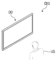
도 1은 본 발명의 일 실시예에 따른 표시 장치의 사시도이고, 도 2는 도 1에 도시된 표시 장치의 분해 사시도이다.1 is a perspective view of a display device according to an exemplary embodiment, and FIG. 2 is an exploded perspective view of the display device shown in FIG. 1 .
도 1 및 도 2를 참조하면, 표시 장치(DD)는 전기적 신호에 따라 활성화되는 장치일 수 있다. 본 발명에 따른 표시 장치(DD)는 텔레비전, 모니터 등과 같은 대형 표시 장치를 비롯하여, 휴대 전화, 태블릿, 노트북, 자동차 네비게이션, 게임기 등과 같은 중소형 표시 장치일 수 있다. 이것들은 단지 실시예로서 제시된 것들로서, 본 발명의 개념에서 벗어나지 않은 이상 다른 전자 기기에도 채용될 수 있음은 물론이다.Referring to FIGS. 1 and 2 , the display device DD may be a device that is activated according to an electrical signal. The display device DD according to the present invention may be a large display device such as a television or a monitor, as well as a small or medium-sized display device such as a mobile phone, tablet, laptop computer, car navigation system, or game machine. These are merely presented as examples and, of course, may be employed in other electronic devices as long as they do not deviate from the concept of the present invention.
표시 장치(DD)는 제1 방향(DR1)으로 장변을 갖고, 제1 방향(DR1)과 교차하는 제2 방향(DR2)으로 단변을 갖는 직사각형 형상을 갖는다. 그러나, 표시 장치(DD)의 형상은 이에 한정되지 않고, 다양한 형상의 표시 장치(DD)가 제공될 수 있다. 표시 장치(DD)는 제1 방향(DR1) 및 제2 방향(DR2) 각각에 평행한 표시면(IS)에 제3 방향(DR3)을 향해 영상(IM)을 표시할 수 있다. 영상(IM)이 표시되는 표시면(IS)은 표시 장치(DD)의 전면(front surface)과 대응될 수 있다. The display device DD has a rectangular shape having a long side in a first direction DR1 and a short side in a second direction DR2 crossing the first direction DR1. However, the shape of the display device DD is not limited thereto, and display devices DD of various shapes may be provided. The display device DD may display the image IM in the third direction DR3 on the display surface IS parallel to the first and second directions DR1 and DR2 respectively. The display surface IS on which the image IM is displayed may correspond to the front surface of the display device DD.
본 실시예에서는 영상(IM)이 표시되는 방향을 기준으로 각 부재들의 전면(또는 상면)과 배면(또는 하면)이 정의된다. 전면과 배면은 제3 방향(DR3)에서 서로 대향(opposing)되고, 전면과 배면 각각의 법선 방향은 제3 방향(DR3)과 평행할 수 있다. In this embodiment, the front (or upper surface) and the rear surface (or lower surface) of each member are defined based on the direction in which the image IM is displayed. The front surface and the rear surface oppose each other in the third direction DR3, and a normal direction of each of the front surface and the rear surface may be parallel to the third direction DR3.
제3 방향(DR3)에서의 전면과 배면 사이의 이격 거리는 표시 장치(DD)의 제3 방향(DR3)에서의 두께와 대응될 수 있다. 한편, 제1 내지 제3 방향들(DR1, DR2, DR3)이 지시하는 방향은 상대적인 개념으로서 다른 방향으로 변환될 수 있다.The distance between the front and rear surfaces in the third direction DR3 may correspond to the thickness of the display device DD in the third direction DR3. Meanwhile, directions indicated by the first to third directions DR1 , DR2 , and DR3 may be converted into other directions as a relative concept.
표시 장치(DD)는 외부에서 인가되는 외부 입력을 감지할 수 있다. 외부 입력은 표시 장치(DD)의 외부에서 제공되는 다양한 형태의 입력들을 포함할 수 있다. 본 발명의 일 실시예에 따른 표시 장치(DD)는 외부에서 인가되는 사용자(US, 도 11a 참조)의 외부 입력을 감지할 수 있다. 사용자(US)의 외부 입력은 사용자(US) 신체의 일부, 광, 열, 시선, 또는 압력 등 다양한 형태의 외부 입력들 중 어느 하나 또는 그들의 조합일 수 있다. 또한, 표시 장치(DD)는 표시 장치(DD)의 구조에 따라 표시 장치(DD)의 측면이나 배면에 인가되는 사용자(US)의 외부 입력을 감지할 수도 있으며, 어느 하나의 실시예로 한정되지 않는다. 본 발명의 일 예로, 외부 입력은 입력 장치(예를 들어, 스타일러스 펜, 액티브 펜, 터치 펜, 전자 펜, e-펜 등)에 의한 입력 등을 포함할 수도 있다.The display device DD may detect an external input applied from the outside. The external input may include various types of inputs provided from the outside of the display device DD. The display device DD according to an embodiment of the present invention may detect an external input of a user (US, see FIG. 11A) applied from the outside. The external input of the user US may be any one or a combination of various types of external inputs, such as a part of the user's body, light, heat, line of sight, or pressure. In addition, the display device DD may detect an external input of the user US applied to the side or rear surface of the display device DD according to the structure of the display device DD, and is not limited to any one embodiment. don't As an example of the present invention, the external input may include an input by an input device (eg, a stylus pen, an active pen, a touch pen, an electronic pen, an e-pen, etc.).
표시 장치(DD)의 전면은 투과 영역(TA) 및 베젤 영역(BZA)으로 구분될 수 있다. 투과 영역(TA)은 영상(IM)이 표시되는 영역일 수 있다. 사용자(US)는 투과 영역(TA)을 통해 영상(IM)을 시인한다. 본 실시예에서, 투과 영역(TA)은 꼭지점들이 둥근 사각 형상으로 도시되었다. 다만, 이는 예시적으로 도시한 것이고, 투과 영역(TA)은 다양한 형상을 가질 수 있으며, 어느 하나의 실시예로 한정되지 않는다.The front surface of the display device DD may be divided into a transmission area TA and a bezel area BZA. The transmission area TA may be an area where the image IM is displayed. The user US views the image IM through the transmission area TA. In this embodiment, the transmission area TA is shown as a quadrangular shape with rounded vertices. However, this is shown as an example, and the transmission area TA may have various shapes, and is not limited to one embodiment.
베젤 영역(BZA)은 투과 영역(TA)에 인접한다. 베젤 영역(BZA)은 소정의 컬러를 가질 수 있다. 베젤 영역(BZA)은 투과 영역(TA)을 에워쌀 수 있다. 이에 따라, 투과 영역(TA)의 형상은 실질적으로 베젤 영역(BZA)에 의해 정의될 수 있다. 다만, 이는 예시적으로 도시한 것이고, 베젤 영역(BZA)은 투과 영역(TA)의 일 측에만 인접하여 배치될 수도 있고, 생략될 수도 있다. 본 발명의 일 실시예에 따른 표시 장치(DD)는 다양한 실시예들을 포함할 수 있으며, 어느 하나의 실시예로 한정되지 않는다.The bezel area BZA is adjacent to the transmission area TA. The bezel area BZA may have a predetermined color. The bezel area BZA may surround the transmission area TA. Accordingly, the shape of the transmission area TA may be substantially defined by the bezel area BZA. However, this is shown as an example, and the bezel area BZA may be disposed adjacent to only one side of the transmission area TA or may be omitted. The display device DD according to an embodiment of the present invention may include various embodiments, and is not limited to any one embodiment.
도 2에 도시된 바와 같이, 표시 장치(DD)는 표시 모듈(DM) 및 표시 모듈(DM) 상에 배치된 윈도우(WM)를 포함할 수 있다. 표시 모듈(DM)은 표시 패널(DP) 및 입력 감지층(ISP)를 포함할 수 있다. As shown in FIG. 2 , the display device DD may include a display module DM and a window WM disposed on the display module DM. The display module DM may include a display panel DP and an input sensing layer ISP.
본 발명의 일 실시예에 따른 표시 패널(DP)은 발광형 표시 패널일 수 있다. 그 일 예로 표시 패널(DP)은 유기발광 표시 패널, 무기발광 표시 패널 또는 퀀텀닷(quantum dot) 발광 표시 패널일 수 있다. 유기발광 표시 패널의 발광층은 유기발광물질을 포함할 수 있다. 무기발광 표시 패널의 발광층은 무기발광물질을 포함할 수 있다. 퀀텀닷 발광 표시 패널의 발광층은 퀀텀닷, 및 퀀텀로드 등을 포함할 수 있다. 이하, 본 실시예에서 표시 패널(DP)은 유기발광 표시 패널로 설명된다.The display panel DP according to an exemplary embodiment of the present invention may be a light emitting display panel. For example, the display panel DP may be an organic light emitting display panel, an inorganic light emitting display panel, or a quantum dot light emitting display panel. The light emitting layer of the organic light emitting display panel may include an organic light emitting material. The light emitting layer of the inorganic light emitting display panel may include an inorganic light emitting material. The light emitting layer of the quantum dot light emitting display panel may include quantum dots and quantum rods. Hereinafter, in this embodiment, the display panel DP will be described as an organic light emitting display panel.
표시 패널(DP)은 영상(IM)을 출력하고, 출력된 영상(IM)은 표시면(IS)을 통해 표시될 수 있다.The display panel DP outputs an image IM, and the output image IM may be displayed on the display surface IS.
입력 감지층(ISP)는 표시 패널(DP) 상에 배치되어 외부 입력을 감지할 수 있다. 입력 감지층(ISP)은 표시 패널(DP) 상에 직접 배치될 수 있다. 본 발명의 일 실시예에 따르면, 입력 감지층(ISP)은 연속공정에 의해 표시 패널(DP) 상에 형성될 수 있다. 즉, 입력 감지층(ISP)이 표시 패널(DP) 상에 직접 배치되는 경우, 내부 접착 필름(미도시)이 입력 감지층(ISP)과 표시 패널(DP) 사이에 배치되지 않는다. 그러나, 입력 감지층(ISP)과 표시 패널(DP) 사이에 내부 접착 필름이 배치될 수 있다. 이 경우, 입력 감지층(ISP)은 표시 패널(DP)과 연속 공정에 의해 제조되지 않으며, 표시 패널(DP)과 별도의 공정을 통해 제조된 후, 내부 접착 필름에 의해 표시 패널(DP)의 상면에 고정될 수 있다.The input sensing layer ISP may be disposed on the display panel DP to detect an external input. The input sensing layer ISP may be directly disposed on the display panel DP. According to an embodiment of the present invention, the input sensing layer ISP may be formed on the display panel DP by a continuous process. That is, when the input sensing layer ISP is directly disposed on the display panel DP, an internal adhesive film (not shown) is not disposed between the input sensing layer ISP and the display panel DP. However, an internal adhesive film may be disposed between the input sensing layer ISP and the display panel DP. In this case, the input sensing layer ISP is not manufactured in a continuous process with the display panel DP, but is manufactured in a process separate from the display panel DP, and then is attached to the display panel DP by an internal adhesive film. It can be fixed on the top surface.
윈도우(WM)는 영상(IM)을 출사할 수 있는 투명한 물질로 이루어질 수 있다. 예를 들어, 유리, 사파이어, 플라스틱 등으로 구성될 수 있다. 윈도우(WM)는 단일층으로 도시되었으나, 이에 한정하는 것은 아니며 복수 개의 층들을 포함할 수 있다. The window WM may be made of a transparent material capable of emitting an image IM. For example, it may be made of glass, sapphire, plastic, or the like. The window WM is illustrated as a single layer, but is not limited thereto and may include a plurality of layers.
한편, 도시되지 않았으나, 상술한 표시 장치(DD)의 베젤 영역(BZA)은 실질적으로 윈도우(WM)의 일 영역에 소정의 컬러를 포함하는 물질이 인쇄된 영역으로 제공될 수 있다. 본 발명의 일 예로, 윈도우(WM)는 베젤 영역(BZA)을 정의하기 위한 차광패턴을 포함할 수 있다. 차광패턴은 유색의 유기막으로써 예컨대, 코팅 방식으로 형성될 수 있다.Meanwhile, although not shown, the bezel area BZA of the above-described display device DD may be substantially provided as an area where a material including a predetermined color is printed on one area of the window WM. As an example of the present invention, the window WM may include a light blocking pattern for defining the bezel area BZA. The light-shielding pattern may be formed as a colored organic layer, for example, by a coating method.
윈도우(WM)는 접착 필름을 통해 표시 모듈(DM)에 결합될 수 있다. 본 발명의 일 예로, 접착 필름은 광학투명접착필름(OCA, Optically Clear Adhesive film)을 포함할 수 있다. 그러나, 접착 필름은 이에 한정되지 않으며, 통상의 접착제 또는 점착제를 포함할 수 있다. 예를 들어, 접착 필름은 광학투명접착수지(OCR, Optically Clear Resin) 또는 감압접착필름(PSA, Pressure Sensitive Adhesive film)을 포함할 수 있다.The window WM may be coupled to the display module DM through an adhesive film. As an example of the present invention, the adhesive film may include an optically clear adhesive film (OCA). However, the adhesive film is not limited thereto and may include a conventional adhesive or pressure-sensitive adhesive. For example, the adhesive film may include an optically clear resin (OCR) or a pressure sensitive adhesive film (PSA).
윈도우(WM)와 표시 모듈(DM) 사이에는 반사방지층이 더 배치될 수 있다. 반사방지층은 윈도우(WM)의 상측으로부터 입사되는 외부광의 반사율을 감소시킨다. 본 발명의 일 실시예에 따른 반사방지층은 위상지연자(retarder) 및 편광자(polarizer)를 포함할 수 있다. 위상지연자는 필름타입 또는 액정 코팅타입일 수 있고, λ/2위상지연자 및/또는 λ/4위상지연자를 포함할 수 있다. 편광자 역시 필름타입 또는 액정 코팅타입일 수 있다. 필름타입은 연신형 합성수지 필름을 포함하고, 액정 코팅타입은 소정의 배열로 배열된 액정들을 포함할 수 있다. 위상지연자 및 편광자는 하나의 편광필름으로 구현될 수 있다.An antireflection layer may be further disposed between the window WM and the display module DM. The antireflection layer reduces the reflectance of external light incident from the upper side of the window WM. The antireflection layer according to an embodiment of the present invention may include a retarder and a polarizer. The phase retarder may be a film type or a liquid crystal coating type, and may include a λ/2 phase retarder and/or a λ/4 phase retarder. A polarizer may also be a film type or a liquid crystal coating type. The film type may include a stretchable synthetic resin film, and the liquid crystal coating type may include liquid crystals arranged in a predetermined arrangement. The phase retarder and the polarizer may be implemented as one polarizing film.
본 발명의 일 예로, 반사방지층은 컬러 필터들을 포함할 수도 있다. 표시 패널(DP)에 포함된 복수의 화소들(PX, 도 3 참조)이 생성하는 광의 컬러들을 고려하여 컬러 필터들의 배열이 결정될 수 있다. 반사방지층은 차광 패턴을 더 포함할 수도 있다.As an example of the present invention, the antireflection layer may include color filters. The arrangement of color filters may be determined in consideration of the colors of light generated by the plurality of pixels PX included in the display panel DP (refer to FIG. 3 ). The antireflection layer may further include a light blocking pattern.
표시 모듈(DM)은 전기적 신호에 따라 영상을 표시하고, 외부 입력에 대한 정보를 송/수신할 수 있다. 표시 모듈(DM)은 유효 영역(AA) 및 비유효 영역(NAA)으로 정의될 수 있다. 유효 영역(AA)은 표시 모듈(DM)에서 제공되는 영상을 출사하는 영역으로 정의될 수 있다. 또한 유효 영역(AA)은 입력 감지층(ISP)이 외부에서 인가되는 외부 입력을 감지하는 영역으로 정의될 수도 있다.The display module DM may display an image according to an electrical signal and transmit/receive information about an external input. The display module DM may be defined as an effective area AA and a non-active area NAA. The effective area AA may be defined as an area from which an image provided from the display module DM is emitted. Also, the effective area AA may be defined as an area where the input sensing layer ISP senses an external input applied from the outside.
비유효 영역(NAA)은 유효 영역(AA)에 인접한다. 예를 들어, 비유효 영역(NAA)은 유효 영역(AA)을 에워쌀 수 있다. 다만, 이는 예시적으로 도시한 것이고, 비유효 영역(NAA)은 다양한 형상으로 정의될 수 있으며, 어느 하나의 실시예로 한정되지 않는다. 일 실시예에 따르면, 표시 모듈(DM)의 유효 영역(AA)은 투과 영역(TA)의 적어도 일부와 대응될 수 있다.The non-valid area NAA is adjacent to the valid area AA. For example, the non-effective area NAA may surround the active area AA. However, this is shown as an example, and the non-effective area NAA may be defined in various shapes, and is not limited to one embodiment. According to an embodiment, the effective area AA of the display module DM may correspond to at least a portion of the transmission area TA.
표시 모듈(DM)은 메인회로기판(MCB), 복수의 연성회로필름들(D-FCB) 및 복수의 구동칩들(DIC)을 더 포함할 수 있다. 메인회로기판(MCB)은 연성회로필름들(D-FCB)과 접속되어 표시 패널(DP)과 전기적으로 연결될 수 있다. 연성회로필름들(D-FCB)은 표시 패널(DP)에 접속되어 표시 패널(DP)과 메인회로기판(MCB)을 전기적으로 연결한다. 메인회로기판(MCB)은 복수의 구동 소자를 포함할 수 있다. 복수의 구동 소자는 표시 패널(DP)을 구동하기 위한 회로부를 포함할 수 있다. 연성회로필름들(D-FCB) 상에는 구동칩들(DIC)이 실장될 수 있다. The display module DM may further include a main circuit board MCB, a plurality of flexible circuit films D-FCB, and a plurality of driving chips DIC. The main circuit board MCB may be connected to the flexible circuit films D-FCB and electrically connected to the display panel DP. The flexible circuit films D-FCB are connected to the display panel DP to electrically connect the display panel DP and the main circuit board MCB. The main circuit board MCB may include a plurality of driving elements. The plurality of driving elements may include a circuit unit for driving the display panel DP. Driving chips DIC may be mounted on the flexible circuit films D-FCB.
본 발명의 일 예로, 연성회로필름들(D-FCB)은 제1 연성회로필름(D-FCB1), 제2 연성회로필름(D-FCB2) 및 제3 연성회로필름(D-FCB3)을 포함할 수 있다. 구동칩들(DIC)은 제1 구동칩(DIC1), 제2 구동칩(DIC2) 및 제3 구동칩(DIC3)을 포함할 수 있다. 제1 내지 제3 연성회로필름들(D-FCB1, D-FCB2, D-FCB3)은 서로간에 제1 방향(DR1)으로 이격되어 배치되고, 표시 패널(DP)에 접속되어 표시 패널(DP)과 메인회로기판(MCB)을 전기적으로 연결할 수 있다. 제1 연성회로필름(D-FCB1) 상에는 제1 구동칩(DIC1)이 실장될 수 있다. 제2 연성회로필름(D-FCB2) 상에는 제2 구동칩(DIC2)이 실장될 수 있다. 제3 연성회로필름(D-FCB3)에는 제3 구동칩(DIC3)이 실장될 수 있다. 그러나, 본 발명의 실시예는 이에 한정되지 않는다. 예를 들어, 표시 패널(DP)은 하나의 연성회로필름을 통하여 메인회로기판(MCB)에 전기적으로 연결되고, 하나의 연성회로필름 상에는 하나의 구동칩만이 실장될 수도 있다. 또한, 표시 패널(DP)은 네 개 이상의 연성회로필름들을 통하여 메인회로기판(MCB)에 전기적으로 연결되고, 연성회로필름들 상에 구동칩들이 각각 실장될 수도 있다.As an example of the present invention, the flexible circuit films D-FCB include a first flexible circuit film D-FCB1, a second flexible circuit film D-FCB2, and a third flexible circuit film D-FCB3. can do. The driving chips DIC may include a first driving chip DIC1 , a second driving chip DIC2 , and a third driving chip DIC3 . The first to third flexible circuit films D-FCB1 , D-FCB2 , and D-FCB3 are spaced apart from each other in the first direction DR1 and are connected to the display panel DP to form a display panel DP. and the main circuit board (MCB) may be electrically connected. A first driving chip DIC1 may be mounted on the first flexible circuit film D-FCB1. A second driving chip DIC2 may be mounted on the second flexible circuit film D-FCB2. A third driving chip DIC3 may be mounted on the third flexible circuit film D-FCB3. However, embodiments of the present invention are not limited thereto. For example, the display panel DP may be electrically connected to the main circuit board MCB through one flexible circuit film, and only one driving chip may be mounted on one flexible circuit film. Also, the display panel DP may be electrically connected to the main circuit board MCB through four or more flexible circuit films, and driving chips may be respectively mounted on the flexible circuit films.
도 2에서는 제1 내지 제3 구동칩들(DIC1, DIC2, DIC3)이 제1 내지 제3 연성회로필름들(D-FCB1, D-FCB2, D-FCB3) 상에 각각 실장된 구조를 도시하였으나, 본 발명은 이에 한정되지 않는다. 예를 들어, 제1 내지 제3 구동칩들(DIC1, DIC2, DIC3)은 표시 패널(DP) 상에 직접 실장될 수 있다. 이 경우, 표시 패널(DP)의 제1 내지 제3 구동칩(DIC1, DIC2, DIC3)이 실장된 부분은 밴딩되어 표시 모듈(DM)의 후면에 배치될 수 있다. 또한, 제1 내지 제3 구동칩들(DIC1, DIC2, DIC3)은 메인회로기판(MCB) 상에 직접 실장될 수도 있다.2 shows a structure in which the first to third driving chips DIC1 , DIC2 , and DIC3 are respectively mounted on the first to third flexible circuit films D-FCB1 , D-FCB2 , and D-FCB3 ; , the present invention is not limited thereto. For example, the first to third driving chips DIC1 , DIC2 , and DIC3 may be directly mounted on the display panel DP. In this case, portions of the display panel DP on which the first to third driving chips DIC1 , DIC2 , and DIC3 are mounted may be bent and disposed on the rear surface of the display module DM. Also, the first to third driving chips DIC1 , DIC2 , and DIC3 may be directly mounted on the main circuit board MCB.
입력 감지층(ISP)은 연성회로필름들(D-FCB)을 통해 메인회로기판(MCB)과 전기적으로 연결될 수 있다. 그러나, 본 발명의 실시예는 이에 한정되지 않는다. 즉, 표시 모듈(DM)은 입력 감지층(ISP)을 메인회로기판(MCB)과 전기적으로 연결하기 위한 별도의 연성회로필름을 추가적으로 포함할 수 있다.The input sensing layer ISP may be electrically connected to the main circuit board MCB through the flexible circuit films D-FCB. However, embodiments of the present invention are not limited thereto. That is, the display module DM may additionally include a separate flexible circuit film for electrically connecting the input sensing layer ISP to the main circuit board MCB.
표시 장치(DD)는 표시 모듈(DM)을 수용하는 외부케이스(EDC)를 더 포함한다. 외부케이스(EDC)는 윈도우(WM)와 결합되어 표시 장치(DD)의 외관을 정의할 수 있다. 외부케이스(EDC)는 외부로부터 가해지는 충격을 흡수하며 표시 모듈(DM)로 침투되는 이물질/수분 등을 방지하여 외부케이스(EDC)에 수용된 구성들을 보호한다. 한편, 본 발명의 일 예로, 외부케이스(EDC)는 복수의 수납 부재들이 결합된 형태로 제공될 수 있다.The display device DD further includes an outer case EDC accommodating the display module DM. The outer case EDC may be combined with the window WM to define the appearance of the display device DD. The outer case EDC absorbs an impact applied from the outside and prevents foreign substances/moisture from penetrating into the display module DM to protect components accommodated in the outer case EDC. Meanwhile, as an example of the present invention, the outer case EDC may be provided in a form in which a plurality of storage members are combined.
일 실시예에 따른 표시 장치(DD)는 표시 모듈(DM)을 동작시키기 위한 다양한 기능성 모듈을 포함하는 전자모듈, 표시 장치(DD)의 전반적인 동작에 필요한 전원을 공급하는 전원공급모듈, 표시 모듈(DM) 및/또는 외부케이스(EDC)와 결합되어 표시 장치(DD)의 내부 공간을 분할하는 브라켓 등을 더 포함할 수 있다. 본 발명의 일 예로, 전자모듈은 표시 장치(DD)의 전반적인 동작을 제어하는 제어 모듈을 포함할 수 있다. 제어 모듈은 표시 패널(DP)에 각종 정보를 그래픽(graphic)이나 텍스트(text)로 표시하기 위한 신호를 생성하는 그래픽 처리 장치(graphic processing unit, GPU)를 포함할 수 있다. The display device DD according to an embodiment includes an electronic module including various functional modules for operating the display module DM, a power supply module supplying power required for overall operation of the display device DD, and a display module ( DM) and/or an outer case EDC, and may further include a bracket dividing an inner space of the display device DD. As an example of the present invention, the electronic module may include a control module that controls overall operations of the display device DD. The control module may include a graphic processing unit (GPU) that generates signals for displaying various types of information in graphics or text on the display panel DP.
도 3은 본 발명의 일 실시예에 따른 표시 장치의 블럭도이다.3 is a block diagram of a display device according to an exemplary embodiment of the present invention.
도 3을 참조하면, 표시 장치(DD)는 표시 패널(DP) 및 패널 구동 블럭(PDB)을 포함한다. 패널 구동 블럭(PDB)은 표시 패널(DP)의 구동을 제어한다.Referring to FIG. 3 , the display device DD includes a display panel DP and a panel driving block PDB. The panel driving block PDB controls driving of the display panel DP.
본 발명의 일 예로, 패널 구동 블럭(PDB)은 컨트롤러(CR), 소스 드라이버(SD), 게이트 드라이버(GD), 발광 드라이버(ED) 및 전압 생성 블럭(VGB)을 포함한다.As an example of the present invention, the panel driving block PDB includes a controller CR, a source driver SD, a gate driver GD, a light emitting driver ED, and a voltage generating block VGB.
컨트롤러(CR)는 외부로부터 영상 신호(RGB) 및 외부 제어 신호(CTRL)을 수신한다. 컨트롤러(CR)는 소스 드라이버(SD)와의 인터페이스(interface) 사양에 맞도록 영상 신호(RGB)의 데이터 포맷을 변환하여 영상 데이터(IMD)를 생성한다. 컨트롤러(CR)는 외부 제어 신호(CTRL)에 기초하여 소스 구동 신호(SDS), 게이트 구동 신호(GDS) 및 발광 제어 신호(EDS)를 생성한다. 외부 제어 신호(CTRL)는 수직 동기 신호, 수평 동기 신호 및 메인 클럭 등을 포함할 수 있다. The controller CR receives an image signal RGB and an external control signal CTRL from the outside. The controller (CR) converts the data format of the image signal (RGB) to meet the interface specifications with the source driver (SD) to generate the image data (IMD). The controller CR generates a source driving signal SDS, a gate driving signal GDS, and an emission control signal EDS based on the external control signal CTRL. The external control signal CTRL may include a vertical synchronizing signal, a horizontal synchronizing signal, and a main clock.
컨트롤러(CR)는 영상 데이터(IMD) 및 소스 구동 신호(SDS)를 소스 드라이버(SD)에 송신한다. 소스 구동 신호(SDS)는 소스 드라이버(SD)의 동작을 개시하는 수평 시작 신호를 포함할 수 있다. 소스 드라이버(SD)는 소스 구동 신호(SDS)에 응답하여, 영상 데이터(IMD)를 토대로 데이터 신호(DS)를 생성한다. 소스 드라이버(SD)는 데이터 신호(DS)를 후술하는 복수 개의 데이터 라인들(DL1 내지 DLm)에 출력한다. 데이터 신호(DS)는 영상 데이터(IMD)의 계조 값에 대응하는 아날로그 전압일 수 있다.The controller CR transmits the image data IMD and the source driving signal SDS to the source driver SD. The source driving signal SDS may include a horizontal start signal initiating an operation of the source driver SD. The source driver SD generates a data signal DS based on the image data IMD in response to the source driving signal SDS. The source driver SD outputs the data signal DS to a plurality of data lines DL1 to DLm, which will be described later. The data signal DS may be an analog voltage corresponding to the grayscale value of the image data IMD.
컨트롤러(CR)는 게이트 구동 신호(GDS)를 게이트 드라이버(GD)로 송신한다. 게이트 구동 신호(GDS)는 게이트 드라이버(GD)의 동작을 개시하는 수직 시작 신호, 스캔 신호들(SS1 내지 SSn)의 출력 시기를 결정하는 스캔 클럭 신호 등을 포함할 수 있다. 게이트 드라이버(GD)는 게이트 구동 신호(GDS)를 토대로 스캔 신호들(SS1 내지 SSn)을 생성한다. 게이트 드라이버(GD)는 스캔 신호들(SS1 내지 SSn)을 후술하는 복수 개의 스캔 라인들(SL1 내지 SLn)에 출력한다.The controller CR transmits the gate driving signal GDS to the gate driver GD. The gate driving signal GDS may include a vertical start signal that initiates the operation of the gate driver GD, a scan clock signal that determines output timing of the scan signals SS1 to SSn, and the like. The gate driver GD generates scan signals SS1 to SSn based on the gate driving signal GDS. The gate driver GD outputs the scan signals SS1 to SSn to a plurality of scan lines SL1 to SLn, which will be described later.
컨트롤러(CR)는 발광 제어 신호(EDS)를 발광 드라이버(ED)에 송신한다. 발광 드라이버(ED)는 발광 제어 신호(EDS)에 응답하여 발광 제어 신호들(ES1 내지 ESn)을 복수 개의 발광 라인들(EL1 내지 ELn)에 출력한다.The controller CR transmits the light emission control signal EDS to the light driver ED. The light driver ED outputs the light emission control signals ES1 to ESn to the plurality of light emitting lines EL1 to ELn in response to the light emission control signal EDS.
전압 생성 블럭(VGB)은 표시 패널(DP)의 동작에 필요한 전압들을 생성한다. 본 발명의 일 예로, 전압 생성 블럭(VGB)은 제1 구동 전압(ELVDD), 제2 구동 전압(ELVSS) 및 초기화 전압(Vinit)을 생성한다. 본 발명의 일 예로, 전압 생성 블럭(VGB)은 컨트롤러(CR)의 제어에 따라 동작할 수 있다. 본 발명의 일 예로, 제1 구동 전압(ELVDD)의 전압 레벨은 제2 구동 전압(ELVSS)의 전압 레벨보다 크다. 본 발명의 일 예로, 제1 구동 전압(ELVDD)의 전압 레벨은 20V 내지 30V일 수 있다. 초기화 전압(Vinit)의 전압 레벨은 제2 구동 전압(ELVSS)의 전압 레벨보다 작다. 본 발명의 일 예로, 초기화 전압(Vinit)의 전압 레벨은 1V 내지 9V일 수 있다.The voltage generating block VGB generates voltages necessary for the operation of the display panel DP. As an example of the present invention, the voltage generation block VGB generates a first driving voltage ELVDD, a second driving voltage ELVSS, and an initialization voltage Vinit. As an example of the present invention, the voltage generation block VGB may operate under the control of the controller CR. As an example of the present invention, the voltage level of the first driving voltage ELVDD is higher than that of the second driving voltage ELVSS. As an example of the present invention, the voltage level of the first driving voltage ELVDD may be 20V to 30V. The voltage level of the initialization voltage Vinit is lower than that of the second driving voltage ELVSS. As an example of the present invention, the voltage level of the initialization voltage Vinit may be 1V to 9V.
본 발명의 일 예로, 표시 패널(DP)은 복수 개의 스캔 라인들(SL1 내지 SLn), 복수 개의 데이터 라인들(DL1 내지 DLm), 복수 개의 발광 라인들(EL1 내지 ELn) 및 복수 개의 화소들(PX)을 포함한다.As an example of the present invention, the display panel DP includes a plurality of scan lines SL1 to SLn, a plurality of data lines DL1 to DLm, a plurality of emission lines EL1 to ELn, and a plurality of pixels ( PX).
스캔 라인들(SL1 내지 SLn)은 게이트 드라이버(GD)으로부터 제1 방향(DR1)으로 연장되고, 제2 방향(DR2)으로 서로 이격하여 배열된다. 데이터 라인들(DL1 내지 DLm)은 소스 드라이버(SD)으로부터 제2 방향(DR2)의 반대 방향으로 연장되며, 제1 방향(DR1)으로 서로 이격되어 배열된다. The scan lines SL1 to SLn extend from the gate driver GD in the first direction DR1 and are spaced apart from each other in the second direction DR2. The data lines DL1 to DLm extend from the source driver SD in a direction opposite to the second direction DR2 and are spaced apart from each other in the first direction DR1.
화소들(PX) 각각은 스캔 라인들(SL1 내지 SLn) 중 대응하는 3개의 스캔 라인에 전기적으로 연결된다. 또한, 화소들(PX) 각각은 발광 라인들(EL1 내지 ELn) 중 대응하는 하나의 발광 라인 및 데이터 라인들(DL1 내지 DLm) 중 대응하는 하나의 데이터 라인에 각각 전기적으로 연결된다. 예를 들어, 도 3에 도시된 바와 같이, 1 번째 행의 화소들은 제1 내지 제3 스캔 라인들(SL1, SL2, SL3), 제1 발광 라인(EL1) 및 제1 데이터 라인(DL1)에 연결될 수 있다. 다만, 본 발명의 일 예로, 화소들(PX)의 구동회로의 구성에 따라, 화소들(PX)과 스캔 라인들(SL1 내지 SLn), 데이터 라인들(DL1 내지 DLm) 및 발광 라인들(EL1 내지 ELn)의 연결 관계는 변경될 수 있다.Each of the pixels PX is electrically connected to three corresponding scan lines among the scan lines SL1 to SLn. Also, each of the pixels PX is electrically connected to a corresponding one of the light emitting lines EL1 to ELn and a corresponding one of the data lines DL1 to DLm. For example, as shown in FIG. 3 , the pixels in the first row are connected to the first to third scan lines SL1 , SL2 , and SL3 , the first emission line EL1 , and the first data line DL1 . can be connected However, as an example of the present invention, the pixels PX, the scan lines SL1 to SLn, the data lines DL1 to DLm, and the emission lines EL1 according to the configuration of the driving circuit of the pixels PX. to ELn) may be changed.
화소들(PX) 각각은 발광 다이오드 및 발광 다이오드의 발광을 제어하는 화소 회로부를 포함한다. 화소 회로부는 복수의 트랜지스터들 및 커패시터를 포함할 수 있다. 화소들(PX) 각각은 제1 구동 전압(ELVDD), 제2 구동 전압(ELVSS) 및 초기화 전압(Vinit)을 수신한다.Each of the pixels PX includes a light emitting diode and a pixel circuit unit that controls light emission of the light emitting diode. The pixel circuit unit may include a plurality of transistors and capacitors. Each of the pixels PX receives a first driving voltage ELVDD, a second driving voltage ELVSS, and an initialization voltage Vinit.
화소들(PX) 각각은 컬러광을 생성하는 발광 다이오드를 포함할 수 있다. 예컨대, 화소들(PX)은 레드 컬러광을 생성하는 레드 화소들, 그린 컬러광을 생성하는 그린 화소들, 및 블루 컬러광을 생성하는 블루 화소들을 포함할 수 있다. 레드 화소의 발광 다이오드, 그린 화소의 발광 다이오드 및 블루 화소의 발광 다이오드는 서로 다른 물질의 발광층을 포함할 수 있다.Each of the pixels PX may include a light emitting diode that generates color light. For example, the pixels PX may include red pixels generating red color light, green pixels generating green color light, and blue pixels generating blue color light. The light emitting diodes of the red pixels, the light emitting diodes of the green pixels, and the light emitting diodes of the blue pixels may include light emitting layers of different materials.
패널 구동 블럭(PDB)은 제어 신호(CTS)를 수신하고, 제어 신호(CTS)를 토대로 영상(IM, 도 1 참조)의 휘도를 조정하기 위한 기준점에 대한 정보를 포함하는 기준점 신호(CPS)를 생성할 수 있다. 본 발명의 일 예로, 패널 구동 블럭(PDB)은 제어 신호(CTS)를 토대로 가중치(WT)를 더 생성할 수 있다. 기준점 신호(CPS) 및 가중치(WT)는 도 4a 내지 도 6b에 대한 설명에서 후술하도록 한다. 본 발명의 일 예로, 패널 구동 블럭(PDB)은 추출부(EXP)를 더 포함할 수 있다. 추출부(EXP)는 제어 신호(CTS)를 토대로 기준점 신호(CPS) 및 가중치(WT)를 생성할 수 있다. 도 3에 도시된 바와 같이, 추출부(EXP)는 컨트롤러(CR)와 독립된 구성으로 구비될 수 있다. 대안적으로, 추출부(EXP)는 컨트롤러(CR)에 포함될 수도 있다.The panel driving block (PDB) receives the control signal (CTS), and based on the control signal (CTS), the reference point signal (CPS) including information on the reference point for adjusting the luminance of the image (IM, see FIG. 1) can create As an example of the present invention, the panel driving block PDB may further generate the weight WT based on the control signal CTS. The reference point signal (CPS) and the weight (WT) will be described later in the description of FIGS. 4A to 6B. As an example of the present invention, the panel driving block PDB may further include an extraction unit EXP. The extraction unit EXP may generate the reference point signal CPS and the weight value WT based on the control signal CTS. As shown in FIG. 3 , the extraction unit EXP may be provided as an independent component from the controller CR. Alternatively, the extractor EXP may be included in the controller CR.
컨트롤러(CR)는 기준점 신호(CPS) 및 가중치(WT)를 토대로 영상 신호들(RGB)을 변환하여 보정 영상 신호(RGB`, 도 4a 참조)을 생성하고, 보정 영상 신호(RGB`)를 토대로 영상 데이터(IMD)를 생성할 수 있다. The controller CR converts the image signals RGB based on the reference point signal CPS and the weight WT to generate a corrected image signal RGB′ (see FIG. 4A), and based on the corrected image signal RGB′ Image data IMD may be generated.
도 4a 및 도 4b는 본 발명의 실시예들에 따른 제어 신호에 따른 추출부 및 컨트롤러의 동작을 설명하기 위한 블럭도들이다. 도 5a 내지 도 5c는 본 발명의 실시예들에 따른 영상의 종류에 따라 달라지는 기준점 및 가중치를 설명하기 위한 개념도들이다. 도 6는 본 발명의 일 실시예에 따른 영상 신호들이 표시 패널 상에서 표시되는 위치와 기준점과의 거리를 설명하기 위한 개념도이다. 도 7a 및 도 7b는 본 발명일 실시예들에 따른 영역들 각각에 대한 가중치를 설명하기 위한 개념도들이다.4A and 4B are block diagrams for explaining operations of an extractor and a controller according to a control signal according to embodiments of the present invention. 5A to 5C are conceptual diagrams for explaining reference points and weights that vary according to types of images according to embodiments of the present invention. 6 is a conceptual diagram illustrating a distance between a position where image signals are displayed on a display panel and a reference point according to an embodiment of the present invention. 7A and 7B are conceptual diagrams for explaining weights for each of regions according to exemplary embodiments of the present invention.
도 4a를 참조하면, 패널 구동 블럭(PDB)은 추출부(EXP) 및 컨트롤러(CR)를 포함할 수 있다.Referring to FIG. 4A , the panel driving block PDB may include an extractor EXP and a controller CR.
본 발명의 일 예로, 추출부(EXP)는 제어 신호(CTS)를 수신한다. 추출부(EXP)는 제어 신호(CTS)를 토대로 기준점 신호(CPS)을 생성할 수 있다. 또한, 추출부(EXP)는 제어 신호(CTS)를 토대로 가중치(WT)를 더 생성할 수도 있다.As an example of the present invention, the extraction unit EXP receives the control signal CTS. The extraction unit EXP may generate a reference point signal CPS based on the control signal CTS. Also, the extractor EXP may further generate the weight WT based on the control signal CTS.
도 4a, 도 5a 내지 도 5c를 참조하면, 제어 신호(CTS)는 표시 패널(DP)에 표시되는 영상(IM, 도 1 참조)의 종류에 대한 정보를 포함한다. 패널 구동 블럭(PDB)이 제어 신호(CTS)를 토대로 생성하는 기준점(CP1, CP2, CP3)의 위치 및 가중치(WT)의 값은 표시 패널(DP)에 표시되는 영상(IM)의 종류에 따라 달라질 수 있다. 본 발명의 일 예로, 그래픽 처리 장치가 제어 신호(CTS)를 패널 구동 블럭(PDB)에 송신할 수도 있다.Referring to FIGS. 4A and 5A to 5C , the control signal CTS includes information about the type of image (IM, see FIG. 1 ) displayed on the display panel DP. The positions of the reference points CP1, CP2, and CP3 generated by the panel driving block PDB based on the control signal CTS and the value of the weight WT depend on the type of image IM displayed on the display panel DP. It can vary. As an example of the present invention, the graphic processing device may transmit the control signal CTS to the panel driving block PDB.
본 발명의 일 예로, 패널 구동 블럭(PDB)은 표시 장치(DD)를 사용하는 사용자(US, 도 11a 참조)의 시선이 표시 패널(DP) 중 가장 많이 집중되는 곳을 기준점(CP1, CP2, CP3)으로 생성할 수 있다. 패널 구동 블럭(PDB)은 생성한 기준점(CP1, CP2, CP3)을 기준으로 사용자(US)의 시선이 향하는 빈도를 기준으로 가중치(WT)를 생성할 수 있다.As an example of the present invention, the panel driving block PDB determines the point where the gaze of the user (US, see FIG. 11A) using the display device DD is most concentrated among the display panels DP is reference points CP1, CP2, CP3) can be created. The panel driving block PDB may generate the weight WT based on the frequency at which the gaze of the user US directs with respect to the generated reference points CP1 , CP2 , and CP3 .
표시 패널(DP)에 제1 영상(IM1)이 표시되는 경우, 기준점 신호(CPS)는 제1 기준점(CP1)의 위치에 대한 정보를 포함할 수 있다. 표시 패널(DP)에 제2 영상(IM2)이 표시되는 경우, 기준점 신호(CPS)는 제2 기준점(CP2)의 위치에 대한 정보를 포함할 수 있다. 표시 패널(DP)에 제3 영상(IM3)이 표시되는 경우, 기준점 신호(CPS)는 제3 기준점(CP3)의 위치에 대한 정보를 포함할 수 있다. When the first image IM1 is displayed on the display panel DP, the reference point signal CPS may include information about the location of the first reference point CP1. When the second image IM2 is displayed on the display panel DP, the reference point signal CPS may include information about the location of the second reference point CP2. When the third image IM3 is displayed on the display panel DP, the reference point signal CPS may include information about the location of the third reference point CP3.
도 5a에는 표시 패널(DP)에 제1 영상(IM1)이 표시된 개념도가 도시되어 있다. 본 발명의 일 예로, 제1 영상(IM1)은 표시 장치(DD)에 실행되는 운영체제의 배경화면일 수 있다. 본 발명은 이에 제한되지 않고, 제1 영상(IM1)은 일정 시간동안 움직임이 없는 영상일 수도 있다. 이 경우, 패널 구동 블럭(PDB)은 표시 패널(DP)에 제1 영상(IM1)이 표시된다는 정보를 포함한 제어 신호(CTS)를 수신한다. 5A is a conceptual diagram in which the first image IM1 is displayed on the display panel DP. As an example of the present invention, the first image IM1 may be a background screen of an operating system executed on the display device DD. The present invention is not limited thereto, and the first image IM1 may be an image without motion for a certain period of time. In this case, the panel driving block PDB receives the control signal CTS including information indicating that the first image IM1 is displayed on the display panel DP.
도 4a 및 도 5a에는 표시 패널(DP)에 제1 영상(IM1)이 표시된다는 정보를 포함하는 제어 신호(CTS)를 토대로 패널 구동 블럭(PDB)이 생성한 기준점 신호(CPS)에 포함된 제1 기준점(CP1) 및 가중치(WT)가 도시되어 있다.4A and 5A , the first image IM1 is included in the reference point signal CPS generated by the panel driving block PDB based on the control signal CTS including information indicating that the first image IM1 is displayed on the display panel DP. 1 reference point CP1 and weights WT are shown.
표시 패널(DP)에 제1 영상(IM1)이 표시될 때, 표시 장치(DD)를 사용하는 사용자(US)의 시선은 표시 패널(DP)의 중심부(CT)에 가장 많이 집중될 수 있다. 따라서 패널 구동 블럭(PDB)이 생성한 제1 기준점(CP1)은 중심부(CT) 내에 위치할 수도 있다. 다만, 본 발명은 이에 제한되지 않고, 표시 패널(DP)에 제1 영상(IM1)이 표시될 때 패널 구동 블럭(PDB)이 제어 신호(CTS)를 토대로 생성하는 제1 기준점(CP1)의 위치는 중심부(CT)에 포함되지 않을 수도 있다. When the first image IM1 is displayed on the display panel DP, the gaze of the user US using the display device DD may be most concentrated on the center CT of the display panel DP. Accordingly, the first reference point CP1 generated by the panel driving block PDB may be located in the center CT. However, the present invention is not limited thereto, and the position of the first reference point CP1 generated by the panel driving block PDB based on the control signal CTS when the first image IM1 is displayed on the display panel DP. may not be included in the center CT.
본 발명의 일 예로, 표시 패널(DP)에 제1 영상(IM1)이 표시될 때, 제1 기준점(CP1)을 기준으로 제1 기준 방향(RDR1)으로 사용자(US)의 시선이 향하는 빈도와 제1 기준 방향(RDR1)과 반대하는 제3 기준 방향(RDR3)으로 사용자(US)의 시선이 향하는 빈도는 같을 수 있다. 따라서 패널 구동 블럭(PDB)이 추출한 가중치(WT) 중 제1 기준점(CP1)을 기준으로 제1 기준 방향(RDR1)으로의 제1 방향 가중치(x1)와 제1 기준점(CP1)을 기준으로 제3 기준 방향(RDR3)으로의 제3 방향 가중치(x1`)의 값은 서로 같을 수 있다. As an example of the present invention, when the first image IM1 is displayed on the display panel DP, the frequency of the gaze of the user US in the first reference direction RDR1 based on the first reference point CP1 and The frequency of the gaze of the user US toward the third reference direction RDR3 opposite to the first reference direction RDR1 may be the same. Therefore, among the weights WT extracted by the panel driving block PDB, the first direction weight x1 in the first reference direction RDR1 based on the first reference point CP1 and the weight value x1 based on the first reference point CP1 are determined. Values of the third direction weights x1′ in the three reference directions RDR3 may be equal to each other.
본 발명의 일 예로, 표시 패널(DP)에 제1 영상(IM1)이 표시될 때, 제1 기준점(CP1)을 기준으로 제1 기준 방향(RDR1)과 교차하는 방향인 제2 기준 방향(RDR2)으로 사용자(US)의 시선이 향하는 빈도와 제2 기준 방향(RDR2)과 반대하는 제4 기준 방향(RDR4)으로 사용자(US)의 시선이 향하는 빈도는 같을 수 있다. 따라서 패널 구동 블럭(PDB)이 추출한 가중치(WT) 중 제1 기준점(CP1)을 기준으로 제2 기준 방향(RDR2)으로의 제2 방향 가중치(y1)와 제1 기준점(CP1)을 기준으로 제4 기준 방향(RDR4)으로의 제4 방향 가중치(y1`)의 값은 서로 같을 수 있다. 본 발명의 일 예로, 제1 기준 방향(RDR1)은 제1 방향(DR1, 도 1 참조)과 평행한 방향일 수 있다. 제2 기준 방향(RDR2)은 제2 방향(DR2, 도 1 참조)과 평행한 방향일 수 있다.As an example of the present invention, when the first image IM1 is displayed on the display panel DP, the second reference direction RDR2 is a direction crossing the first reference direction RDR1 based on the first reference point CP1. ) may be the same as the frequency of the user US's gaze directed to the fourth reference direction RDR4 opposite to the second reference direction RDR2. Therefore, among the weights WT extracted by the panel driving block PDB, the weight value y1 in the second direction in the second reference direction RDR2 based on the first reference point CP1 and the weight value y1 in the second reference direction RDR2 are determined based on the first reference point CP1. Values of the fourth direction weights y1′ in the 4 reference directions RDR4 may be equal to each other. As an example of the present invention, the first reference direction RDR1 may be a direction parallel to the first direction DR1 (see FIG. 1 ). The second reference direction RDR2 may be a direction parallel to the second direction DR2 (refer to FIG. 1 ).
표시 패널(DP)은 제1 기준점(CP1)을 기준으로 분할된 복수의 영역들(AR1, AR2, AR3, AR4)을 포함할 수 있다.The display panel DP may include a plurality of areas AR1 , AR2 , AR3 , and AR4 divided based on the first reference point CP1 .
영역들(AR1, AR2, AR3, AR4)은 제1 기준점(CP1)을 기준으로 제1 기준 방향(RDR1)으로 연장된 제1 축(AX1) 및 제1 기준점(CP1)을 기준으로 제2 기준 방향(RDR2)으로 연장된 제2 축(AX2)에 의해 정의된 제1 사분면에 대응되는 제1 영역(AR1)을 포함한다. 영역들(AR1, AR2, AR3, AR4)은 제1 기준점(CP1)을 기준으로 제3 기준 방향(RDR3)으로 연장된 제3 축(AX3) 및 제2 축(AX2)에 의해 정의된 제2 사분면에 대응되는 제2 영역(AR2)을 포함한다. 영역들(AR1, AR2, AR3, AR4)은 제1 기준점(CP1)을 기준으로 제4 기준 방향(RDR4)으로 연장된 제4 축(AX4) 및 제3 축(AX3)에 의해 정의된 제3 사분면에 대응되는 제3 영역(AR3)을 포함한다. 영역들(AR1, AR2, AR3, AR4)은 제1 축(AX1)과 제4 축(AX4)에 의해 정의된 제4 사분면에 대응되는 제4 영역(AR4)을 포함한다.The regions AR1 , AR2 , AR3 , and AR4 include a first axis AX1 extending in the first reference direction RDR1 from the first reference point CP1 and a second reference point based on the first reference point CP1 . A first area AR1 corresponding to the first quadrant defined by the second axis AX2 extending in the direction RDR2 is included. The regions AR1 , AR2 , AR3 , and AR4 are second axes defined by a third axis AX3 and a second axis AX2 extending in the third reference direction RDR3 based on the first reference point CP1 . A second area AR2 corresponding to the quadrant is included. The regions AR1 , AR2 , AR3 , and AR4 include a third axis defined by a fourth axis AX4 and a third axis AX3 extending in the fourth reference direction RDR4 based on the first reference point CP1 . A third area AR3 corresponding to the quadrant is included. The areas AR1 , AR2 , AR3 , and AR4 include a fourth area AR4 corresponding to a fourth quadrant defined by the first axis AX1 and the fourth axis AX4 .
가중치(WT) 중 제1 영역(AR1)에 대응하는 제1 가중치는 제1 방향 가중치(x1) 및 제2 방향 가중치(y1)를 포함할 수 있다. 가중치(WT) 중 제2 영역(AR2)에 대응하는 가중치는 제3 방향 가중치(x1`) 및 제2 방향 가중치(y1)를 포함할 수 있다. 가중치(WT) 중 제3 영역(AR3)에 대응하는 가중치는 제3 방향 가중치(x1`) 및 제4 방향 가중치(y1`)를 포함할 수 있다. 가중치(WT) 중 제4 영역(AR4)에 대응하는 가중치는 제1 방향 가중치(x1) 및 제4 방향 가중치(y1`)를 포함할 수 있다. 본 발명의 일 예로, 제1 내지 제4 가중치는 서로 같은 값을 가질 수도 있다. Among the weights WT, a first weight corresponding to the first area AR1 may include a first direction weight x1 and a second direction weight y1. Among the weights WT, the weight corresponding to the second area AR2 may include a third direction weight x1′ and a second direction weight y1. Among the weights WT, the weight corresponding to the third area AR3 may include a third direction weight x1' and a fourth direction weight y1'. Among the weights WT, a weight corresponding to the fourth area AR4 may include a first direction weight x1 and a fourth direction weight y1′. As an example of the present invention, the first to fourth weights may have the same value.
도 5b에는 표시 패널(DP)에 제2 영상(IM1)이 표시된 개념도가 도시되어 있다. 본 발명의 일 예로, 제2 영상(IM2)은 표시 장치(DD)에 실행되는 게임 등의 영상일 수 있다. 본 발명은 이에 제한되지 않고, 제2 영상(IM2)은 사용자(US, 도 11a 참조)가 표시 장치(DD)에 제공하는 외부 입력에 의하여 움직임이 발생하는 영상일 수도 있다. 이 경우, 패널 구동 블럭(PDB)은 표시 패널(DP)에 제2 영상(IM2)이 표시된다는 정보를 포함한 제어 신호(CTS)를 수신한다. 5B shows a conceptual diagram in which the second image IM1 is displayed on the display panel DP. As an example of the present invention, the second image IM2 may be an image of a game or the like being executed on the display device DD. The present invention is not limited thereto, and the second image IM2 may be an image in which movement is generated by an external input provided to the display device DD by a user (US, see FIG. 11A). In this case, the panel driving block PDB receives the control signal CTS including information indicating that the second image IM2 is displayed on the display panel DP.
도 4 및 도 5b에는 표시 패널(DP)에 제2 영상(IM2)이 표시된다는 정보를 포함하는 제어 신호(CTS)를 토대로 패널 구동 블럭(PDB)이 생성한 기준점 신호(CPS)에 포함된 제2 기준점(CP2) 및 가중치(WT)가 도시되어 있다.4 and 5B, the reference point signal CPS generated by the panel driving block PDB based on the control signal CTS including information indicating that the second image IM2 is displayed on the display panel DP is included in the reference point signal CPS. Two reference points CP2 and weights WT are shown.
표시 패널(DP)에 제2 영상(IM2)이 표시될 때, 표시 장치(DD)를 사용하는 사용자(US)의 시선은 표시 패널(DP)의 중심부(CT)로부터 제4 기준 방향(RDR4) 쪽에 위치한 지점에 가장 많이 집중될 수 있다. 따라서 패널 구동 블럭(PDB)이 추출한 제2 기준점(CP2)은 중심부(CT)으로부터 제4 기준 방향(RDR4)으로 이격된 지점에 위치할 수도 있다. 다만, 본 발명은 이에 제한되지 않고, 표시 패널(DP)에 제2 영상(IM2)이 표시될 때 패널 구동 블럭(PDB)이 제어 신호(CTS)를 토대로 생성하는 제2 기준점(CP2)의 위치는 표시 장치(DD)에 실행되는 게임의 종류에 따라 달라질 수도 있다. 본 발명의 일 예로, 제2 기준점(CP2)의 위치는 중심부(CT)로부터 제2 기준 방향(RDR2)으로 이격된 지점에 위치할 수도 있다. 또한, 제2 기준점(CP2)의 위치는 중심부(CT)로부터 제1 기준 방향(RDR1) 또는 제3 기준 방향(RDR3)의 반대 방향으로 이격된 지점에 위치할 수도 있다.When the second image IM2 is displayed on the display panel DP, the gaze of the user US using the display device DD moves from the center CT of the display panel DP to the fourth reference direction RDR4. It can be most concentrated on the point located on the side. Accordingly, the second reference point CP2 extracted by the panel driving block PDB may be located at a point spaced apart from the center CT in the fourth reference direction RDR4. However, the present invention is not limited thereto, and the position of the second reference point CP2 generated by the panel driving block PDB based on the control signal CTS when the second image IM2 is displayed on the display panel DP. may vary depending on the type of game being executed on the display device DD. As an example of the present invention, the location of the second reference point CP2 may be located at a point spaced apart from the center CT in the second reference direction RDR2. Also, the location of the second reference point CP2 may be located at a point spaced apart from the center CT in a direction opposite to the first reference direction RDR1 or the third reference direction RDR3.
본 발명의 일 예로, 표시 패널(DP)에 제2 영상(IM2)이 표시될 때, 제2 기준점(CP2)을 기준으로 제1 기준 방향(RDR1)으로 사용자(US)의 시선이 향하는 빈도와 제3 기준 방향(RDR3)으로 사용자(US)의 시선이 향하는 빈도는 다를 수 있다. 따라서 패널 구동 블럭(PDB)이 추출한 가중치(WT) 중 제2 기준점(CP2)을 기준으로 제1 기준 방향(RDR1)으로의 제1 방향 가중치(x2)와 제2 기준점(CP2)을 기준으로 제3 기준 방향(RDR3)으로의 제3 방향 가중치(x2`)의 값은 서로 다를 수 있다. 다만, 본 발명은 이에 제한되지 않고, 제2 기준점(CP2)을 기준으로 제1 및 제3 기준 방향(RDR1, RDR3)으로 사용자(US)의 시선이 향하는 빈도에 따라 제1 방향 가중치(x2)와 제3 방향 가중치(x2`)의 값은 서로 같을 수도 있다. As an example of the present invention, when the second image IM2 is displayed on the display panel DP, the frequency of the gaze of the user US toward the first reference direction RDR1 based on the second reference point CP2 and The frequency of the gaze of the user US toward the third reference direction RDR3 may be different. Therefore, among the weights WT extracted by the panel driving block PDB, the first direction weight x2 in the first reference direction RDR1 based on the second reference point CP2 and the weight value x2 based on the second reference point CP2 are determined. Values of the third direction weight (x2′) in the three reference directions (RDR3) may be different from each other. However, the present invention is not limited thereto, and the first direction weight (x2) is calculated based on the frequency of the gaze of the user US in the first and third reference directions RDR1 and RDR3 based on the second reference point CP2. and the value of the third direction weight (x2′) may be equal to each other.
본 발명의 일 예로, 표시 패널(DP)에 제2 영상(IM2)이 표시될 때, 제2 기준점(CP2)을 기준으로 제2 기준 방향(RDR2)으로 사용자(US)의 시선이 향하는 정도와 제4 기준 방향(RDR4)으로 사용자(US)의 시선이 향하는 정도는 다를 수 있다. 따라서 패널 구동 블럭(PDB)이 추출한 가중치(WT) 중 제2 기준점(CP2)을 기준으로 제2 기준 방향(RDR2)으로의 제2 방향 가중치(y2)와 제2 기준점(CP2)을 기준으로 제4 기준 방향(RDR4)으로의 제4 방향 가중치(y2`)의 값은 서로 다를 수 있다. 다만, 본 발명은 이에 제한되지 않고, 제2 기준점(CP2)을 기준으로 제2 및 제4 기준 방향(RDR2, RDR4)으로 사용자(US)의 시선이 향하는 빈도에 따라 제2 방향 가중치(y2)와 제4 방향 가중치(y2`)의 값은 서로 같을 수도 있다.As an example of the present invention, when the second image IM2 is displayed on the display panel DP, the degree to which the gaze of the user US is directed in the second reference direction RDR2 based on the second reference point CP2 and The degree to which the gaze of the user US is directed toward the fourth reference direction RDR4 may be different. Therefore, among the weights WT extracted by the panel driving block PDB, the second direction weight y2 in the second reference direction RDR2 based on the second reference point CP2 and the weight value y2 based on the second reference point CP2 Values of the fourth direction weights y2′ in the 4 reference directions RDR4 may be different from each other. However, the present invention is not limited thereto, and the second direction weight value y2 is determined according to the frequency of the gaze of the user US toward the second and fourth reference directions RDR2 and RDR4 based on the second reference point CP2. and the value of the fourth direction weight (y2′) may be equal to each other.
표시 패널(DP)은 제2 기준점(CP2)을 기준으로 분할된 복수의 영역들(AR1_a, AR2_a, AR3_a, AR4_a)을 포함할 수 있다.The display panel DP may include a plurality of regions AR1_a, AR2_a, AR3_a, and AR4_a divided based on the second reference point CP2.
영역들(AR1_a, AR2_a, AR3_a, AR4_a)은 제2 기준점(CP2)을 기준으로 제1 기준 방향(RDR1)으로 연장된 제1 축(AX1_a) 및 제2 기준점(CP2)을 기준으로 제2 기준 방향(RDR2)으로 연장된 제2 축(AX2_a)에 의해 정의된 제1 사분면에 대응되는 제1 영역(AR1_a)을 포함한다. 영역들(AR1, AR2, AR3, AR4)은 제2 기준점(CP2)을 기준으로 제3 기준 방향(RDR3)으로 연장된 제3 축(AX3_a) 및 제2 축(AX2_a)에 의해 정의된 제2 사분면에 대응되는 제2 영역(AR2_a)을 포함한다. 영역들(AR1, AR2, AR3, AR4)은 제2 기준점(CP2)을 기준으로 제4 기준 방향(RDR4)으로 연장된 제4 축(AX4_a) 및 제3 축(AX3_a)에 의해 정의된 제3 사분면에 대응되는 제3 영역(AR3_a)을 포함한다. 영역들(AR1, AR2, AR3, AR4)은 제1 축(AX1_a)과 제4 축(AX4_a)에 의해 정의된 제4 사분면에 대응되는 제4 영역(AR4_a)을 포함한다.The regions AR1_a, AR2_a, AR3_a, and AR4_a are formed based on the first axis AX1_a extending in the first reference direction RDR1 from the second reference point CP2 and the second reference point CP2. A first area AR1_a corresponding to the first quadrant defined by the second axis AX2_a extending in the direction RDR2 is included. The regions AR1 , AR2 , AR3 , and AR4 include a second axis defined by a third axis AX3_a extending in a third reference direction RDR3 based on the second reference point CP2 and a second axis AX2_a. A second area AR2_a corresponding to the quadrant is included. The regions AR1 , AR2 , AR3 , and AR4 include a third axis defined by a fourth axis AX4_a and a third axis AX3_a extending in the fourth reference direction RDR4 based on the second reference point CP2. A third area AR3_a corresponding to the quadrant is included. The areas AR1 , AR2 , AR3 , and AR4 include a fourth area AR4_a corresponding to the fourth quadrant defined by the first axis AX1_a and the fourth axis AX4_a.
가중치(WT) 중 제1 영역(AR1_a)에 대응하는 제1 가중치는 제1 방향 가중치(x2) 및 제2 방향 가중치(y2)를 포함할 수 있다. 가중치(WT) 중 제2 영역(AR2_a)에 대응하는 가중치는 제3 방향 가중치(x2`) 및 제2 방향 가중치(y2)를 포함할 수 있다. 가중치(WT) 중 제3 영역(AR3_a)에 대응하는 가중치는 제3 방향 가중치(x2`) 및 제4 방향 가중치(y2`)를 포함할 수 있다. 가중치(WT) 중 제4 영역(AR4_a)에 대응하는 가중치는 제1 방향 가중치(x2) 및 제4 방향 가중치(y2`)를 포함할 수 있다. 본 발명의 일 예로, 제1 내지 제4 가중치는 서로 다른 값을 가질 수도 있다. Among the weights WT, a first weight corresponding to the first area AR1_a may include a first direction weight x2 and a second direction weight y2. Among the weights WT, the weight corresponding to the second area AR2_a may include a third direction weight x2′ and a second direction weight y2. Among the weights WT, the weight corresponding to the third area AR3_a may include a third direction weight x2' and a fourth direction weight y2'. Among the weights WT, a weight corresponding to the fourth area AR4_a may include a first direction weight x2 and a fourth direction weight y2′. As an example of the present invention, the first to fourth weights may have different values.
도 5c에는 표시 패널(DP)에 제3 영상(IM3)이 표시된 개념도가 도시되어 있다. 본 발명의 일 예로, 제3 영상(IM3)은 표시 장치(DD)에서 실행되는 영화 등의 영상일 수 있다. 본 발명은 이에 제한되지 않고, 제3 영상(IM3)은 사용자(US, 도 11a 참조)가 표시 장치(DD)에 외부 입력을 제공하지 않아도 움직임이 있는 동영상일 수도 있다. 이 경우, 패널 구동 블럭(PDB)은 표시 패널(DP)에 제3 영상(IM3)이 표시된다는 정보를 포함한 제어 신호(CTS)를 수신한다. 5C shows a conceptual diagram in which the third image IM3 is displayed on the display panel DP. As an example of the present invention, the third image IM3 may be an image such as a movie being executed on the display device DD. The present invention is not limited thereto, and the third image IM3 may be a moving image even when the user (US, see FIG. 11A) does not provide an external input to the display device DD. In this case, the panel driving block PDB receives the control signal CTS including information indicating that the third image IM3 is displayed on the display panel DP.
도 4 및 도 5c에는 표시 패널(DP)에 제3 영상(IM3)이 표시된다는 정보를 포함하는 제어 신호(CTS)를 토대로 패널 구동 블럭(PDB)이 생성한 기준점 신호(CPS)에 포함된 제3 기준점(CP3) 및 가중치(WT)가 도시되어 있다.4 and 5C , the third image IM3 is included in the reference point signal CPS generated by the panel driving block PDB based on the control signal CTS including information indicating that the third image IM3 is displayed on the display panel DP. 3 reference points CP3 and weights WT are shown.
표시 패널(DP)에 제3 영상(IM3)이 표시될 때, 표시 장치(DD)를 사용하는 사용자(US)의 시선은 표시 패널(DP)의 중심부(CT)에 가장 많이 집중될 수 있다. 따라서 패널 구동 블럭(PDB)이 추출한 제3 기준점(CP3)은 중심부(CT) 내에 위치할 수도 있다. 다만, 본 발명은 이에 제한되지 않고, 표시 패널(DP)에 제3 영상(IM3)이 표시될 때 패널 구동 블럭(PDB)이 제어 신호(CTS)를 토대로 생성하는 제3 기준점(CP3)의 위치는 중심부(CT)에 포함되지 않을 수도 있다.When the third image IM3 is displayed on the display panel DP, the gaze of the user US using the display device DD may be most concentrated on the center CT of the display panel DP. Accordingly, the third reference point CP3 extracted by the panel driving block PDB may be located in the center CT. However, the present invention is not limited thereto, and the position of the third reference point CP3 generated by the panel driving block PDB based on the control signal CTS when the third image IM3 is displayed on the display panel DP. may not be included in the center CT.
본 발명의 일 예로, 표시 패널(DP)에 제3 영상(IM3)이 표시될 때, 제3 기준점(CP3)을 기준으로 제1 기준 방향(RDR1)으로 사용자(US)의 시선이 향하는 빈도와 제3 기준 방향(RDR3)으로 사용자(US)의 시선이 향하는 빈도는 같을 수 있다. 따라서 패널 구동 블럭(PDB)이 추출한 가중치(WT) 중 제3 기준점(CP3)을 기준으로 제1 기준 방향(RDR1)으로의 제1 방향 가중치(x3)와 제3 기준점(CP3)을 기준으로 제3 기준 방향(RDR1)으로의 제3 방향 가중치(x3`)의 값은 서로 같을 수 있다. As an example of the present invention, when the third image IM3 is displayed on the display panel DP, the frequency of the gaze of the user US in the first reference direction RDR1 based on the third reference point CP3 and The frequency of the gaze of the user US toward the third reference direction RDR3 may be the same. Accordingly, among the weights WT extracted by the panel driving block PDB, the weight value x3 in the first direction in the first reference direction RDR1 based on the third reference point CP3 and the weight value x3 based on the third reference point CP3 are determined. Values of the third direction weights x3′ in the three reference directions RDR1 may be equal to each other.
본 발명의 일 예로, 표시 패널(DP)에 제3 영상(IM3)이 표시될 때, 제3 기준점(CP3)을 기준으로 제2 기준 방향(RDR2)으로 사용자(US)의 시선이 향하는 빈도와 제4 기준 방향(RDR4)으로 사용자(US)의 시선이 향하는 빈도는 다를 수 있다. 따라서 패널 구동 블럭(PDB)이 추출한 가중치(WT) 중 제3 기준점(CP3)을 기준으로 제2 기준 방향(RDR2)으로의 제2 방향 가중치(y3)와 제3 기준점(CP3)을 기준으로 제4 기준 방향(RDR4)으로의 제4 방향 가중치(y3`)의 값은 서로 다를 수 있다.As an example of the present invention, when the third image IM3 is displayed on the display panel DP, the frequency of the gaze of the user US in the second reference direction RDR2 based on the third reference point CP3 and The frequency of the gaze of the user US toward the fourth reference direction RDR4 may be different. Therefore, among the weights WT extracted by the panel driving block PDB, the second direction weight y3 in the second reference direction RDR2 based on the third reference point CP3 and the weight value y3 based on the third reference point CP3 Values of the fourth direction weights y3′ in the 4 reference directions RDR4 may be different from each other.
표시 패널(DP)은 제3 기준점(CP3)을 기준으로 분할된 제1 영역(AR1_b), 제2 영역(AR2_b), 제3 영역(AR3_b) 및 제4 영역(AR4_b)을 포함할 수 있다.The display panel DP may include a first area AR1_b, a second area AR2_b, a third area AR3_b, and a fourth area AR4_b divided based on the third reference point CP3.
가중치(WT) 중 제1 영역(AR1_b)에 대응하는 제1 가중치는 제1 방향 가중치(x3) 및 제2 방향 가중치(y3)를 포함할 수 있다. 가중치(WT) 중 제2 영역(AR2_b)에 대응하는 가중치는 제3 방향 가중치(x3`) 및 제2 방향 가중치(y3)를 포함할 수 있다. 가중치(WT) 중 제3 영역(AR3_b)에 대응하는 가중치는 제3 방향 가중치(x3`) 및 제4 방향 가중치(y3`)를 포함할 수 있다. 가중치(WT) 중 제4 영역(AR4_b)에 대응하는 가중치는 제1 방향 가중치(x3) 및 제4 방향 가중치(y3`)를 포함할 수 있다. 본 발명의 일 예로, 제1 가중치와 제2 가중치는 서로 같은 값을 가질 수 있다. 제3 가중치와 제4 가중치는 서로 같은 값을 가질 수 있다. 제1 가중치와 제4 가중치는 서로 다른 값을 가질 수도 있다.Among the weights WT, a first weight corresponding to the first area AR1_b may include a first direction weight x3 and a second direction weight y3. Among the weights WT, a weight corresponding to the second area AR2_b may include a third direction weight x3′ and a second direction weight y3. Among the weights WT, a weight corresponding to the third area AR3_b may include a third direction weight x3′ and a fourth direction weight y3′. Among the weights WT, a weight corresponding to the fourth area AR4_b may include a first direction weight x3 and a fourth direction weight y3′. As an example of the present invention, the first weight and the second weight may have the same value. The third weight and the fourth weight may have the same value. The first weight and the fourth weight may have different values.
다시 도 4a 및 도 6을 참조하면, 컨트롤러(CR)는 거리 계산부(DSC), 보정값 계산부(CSC), 보정부(CSP) 및 변환부(CVP)를 포함한다. 이하, 설명의 편의를 위해, 도 6, 도 7a 및 도 7b에서는 표시 패널(DP)에 제2 영상(IM2)이 표시될 때를 기준으로 설명한다.Referring back to FIGS. 4A and 6 , the controller CR includes a distance calculation unit DSC, a correction value calculation unit CSC, a correction unit CSP, and a conversion unit CVP. Hereinafter, for convenience of explanation, description will be made based on when the second image IM2 is displayed on the display panel DP in FIGS. 6, 7A, and 7B.
거리 계산부(DSC)는 외부로부터 영상 신호들(RGB)을 수신하고, 추출부(EXP)로부터 기준점 신호(CPS)를 수신한다. 거리 계산부(DSC)는 영상 신호들(RGB) 각각이 표시 패널(DP) 상에서 표시되는 위치와 제2 기준점(CP2)과의 거리 정보(DTS)를 계산한다. The distance calculation unit DSC receives the image signals RGB from the outside and receives the reference point signal CPS from the extraction unit EXP. The distance calculation unit DSC calculates distance information DTS between a position where each of the image signals RGB is displayed on the display panel DP and the second reference point CP2.
영상 신호들(RGB) 각각이 표시 패널(DP) 상에 표시되는 위치들 중 하나를 표시 위치(AP)라고 할 때, 거리 정보(DTS)는 표시 위치(AP)와 제2 기준점(CP2)간의 제1 기준 방향(RDR1)으로의 제1 방향 거리(dx)와 제2 기준 방향(RDR2)으로의 제2 방향 거리(dy)를 포함한다.When one of the positions where each of the image signals RGB is displayed on the display panel DP is referred to as a display position AP, the distance information DTS indicates a distance between the display position AP and the second reference point CP2. A first direction distance dx in the first reference direction RDR1 and a second direction distance dy in the second reference direction RDR2 are included.
본 발명의 일 예로, 표시 위치(AP)와 제2 기준점(CP2)간의 제1 방향 거리(dx1) 및 제2 방향 거리(dy)는 제2 기준점(CP2)의 위치에 따라 달라진다. 도 6에는 미도시되었지만, 제2 기준점(CP2)이 중심부(CT, 도 5a 참조)에 위치할 경우, 표시 위치(AP)와 제2 기준점(CP2)간의 제1 방향 거리(dx)는 동일하지만, 제2 방향 거리(dy)는 작아질 수 있다.As an example of the present invention, the first direction distance dx1 and the second direction distance dy between the display position AP and the second reference point CP2 vary according to the position of the second reference point CP2. Although not shown in FIG. 6, when the second reference point CP2 is located at the center (CT, see FIG. 5A), the first direction distance dx between the display position AP and the second reference point CP2 is the same, but , the distance dy in the second direction may be reduced.
따라서 거리 정보(DTS)는 제2 기준점(CP2)의 위치에 따라 달라질 수 있다. 결국, 거리 계산부(DSC)가 추출하는 거리 정보(DTS)는 표시 패널(DP)에 표시되는 영상(IM, 도 1 참조)의 종류에 따라 달라질 수 있다.Accordingly, the distance information DTS may vary according to the position of the second reference point CP2. As a result, the distance information DTS extracted by the distance calculation unit DSC may vary depending on the type of image (IM, see FIG. 1 ) displayed on the display panel DP.
보정값 계산부(CSC)는 거리 계산부(DSC)로부터 거리 정보(DTS)를 수신한다. 보정값 계산부(CSC)는 거리 정보(DTS)를 토대로 보정값(CSV)를 생성할 수 있다. 본 발명의 일 예로, 보정값 계산부(CSC)는 추출부(EXP)로부터 가중치(WT)를 더 수신할 수 있다. 보정값 계산부(CSC)는 거리 정보(DTS) 및 가중치(WT)를 토대로 보정값(CSV)을 생성할 수 있다.The correction value calculator CSC receives the distance information DTS from the distance calculator DSC. The correction value calculator CSC may generate a correction value CSV based on the distance information DTS. As an example of the present invention, the correction value calculator CSC may further receive the weight WT from the extractor EXP. The correction value calculator CSC may generate a correction value CSV based on the distance information DTS and the weight WT.
도 4a, 도 5b 및 도 7a를 참조하면, 영상 신호들(RGB) 각각이 표시 패널(DP) 상에 표시되는 위치들 중 제1 영역(AR1_a) 내에 표시되는 하나의 위치를 제1 표시 위치(AP1), 제2 영역(AR2_a) 내에 표시되는 하나의 위치를 제2 표시 위치(AP2)라 할 수 있다.Referring to FIGS. 4A, 5B, and 7A, one position displayed in the first area AR1_a among positions where each of the image signals RGB is displayed on the display panel DP is a first display position ( AP1) and one position displayed in the second area AR2_a may be referred to as a second display position AP2.
제1 표시 위치(AP1)와 제2 기준점(CP2)간의 제1 기준 방향(RDR1)으로의 제1 방향 거리(dx1)는 크기와 제2 표시 위치(AP2)와 제2 기준점(CP2)간의 제3 기준 방향(RDR3)으로의 제3 방향 거리(dx2)의 크기는 동일할 수 있다. 본 발명의 일 예로, 제1 방향 거리(dx1)와 제3 방향 거리(dx2)의 부호는 반대지만, 크기는 동일할 수 있다. 제1 표시 위치(AP1)와 제2 기준점(CP2)간의 제2 기준 방향(RDR2)으로의 제2 방향 거리(dy1)의 크기와 제2 표시 위치(AP2)와 제2 기준점(CP2)간의 제2 기준 방향(RDR2)으로의 제4 방향 거리(dy2)의 크기는 동일할 수 있다. The first direction distance dx1 in the first reference direction RDR1 between the first display location AP1 and the second reference point CP2 is the size and the distance between the second display location AP2 and the second reference point CP2. The distance dx2 in the third direction in the three reference directions RDR3 may have the same size. As an example of the present invention, the signs of the distance dx1 in the first direction and the distance dx2 in the third direction are opposite, but may have the same magnitude. The size of the distance dy1 in the second direction in the second reference direction RDR2 between the first display position AP1 and the second reference point CP2 and the distance between the second display position AP2 and the second reference point CP2. The size of the distance dy2 in the fourth direction in the two reference directions RDR2 may be the same.
그러나, 제1 영역(AR1_a)에 대응되는 제1 가중치의 값과 제2 영역(AR2_a)에 대응되는 제2 가중치의 값은 서로 다를 수 있다. 제1 가중치는 제1 방향 가중치(x2) 및 제2 방향 가중치(y2)를 포함할 수 있다. 제2 가중치는 제3 방향 가중치(x2`) 및 제2 방향 가중치(y2)를 포함할 수 있다. However, the value of the first weight corresponding to the first area AR1_a and the value of the second weight corresponding to the second area AR2_a may be different from each other. The first weight may include a first direction weight x2 and a second direction weight y2. The second weight may include a third direction weight (x2′) and a second direction weight (y2).
본 발명의 일 예로, 보정값 계산부(CSC)가 거리 정보(DTS) 및 가중치(WT)를 토대로 생성하는 보정값(CSV)은 아래 수학식 1과 같이 정의될 수 있다.As an example of the present invention, the correction value CSV generated by the correction value calculator CSC based on the distance information DTS and the weight WT may be defined as in
[수학식 1] [Equation 1]

여기서, CSV는 보정값(CSV)이고, RFV는 제2 기준점(CP2)에서의 보정값(CSV)이며, 1일 수 있고, ![]()
![]()
![]()
![]()
![]()
![]()
![]()
![]()
![]()
![]()
![]()
![]()
![]()
![]()
![]()
![]()
따라서, 보정값 계산부(CSC)가 거리 정보(DTS) 및 가중치(WT)를 토대로 생성한 보정값(CSV)은 제1 표시 위치(AP1)와 제2 표시 위치(AP2)에 대하여 다른 값을 가질 수 있다. Therefore, the correction value CSV generated by the correction value calculator CSC based on the distance information DTS and the weight WT has different values for the first display position AP1 and the second display position AP2. can have
도 4a 및 도 7b를 참조하면, 표시 패널(DP)은 제2 기준점(CP2)을 기준으로 분할된 복수의 영역들(AR1_a, AR2_a)을 포함할 수 있다.Referring to FIGS. 4A and 7B , the display panel DP may include a plurality of areas AR1_a and AR2_a divided based on the second reference point CP2 .
영역들(AR1_a, AR2_a)은 제2 기준점(CP2)을 포함하는 제1 영역(AR1_a) 및 제1 영역(AR1_a)을 에워싸는 제2 영역(AR2_a)을 포함한다. 본 발명의 일 예로, 표시 패널(DP)은 제2 영역(AR2_a)을 에워싸는 제3 영역을 더 포함할 수도 있다.The areas AR1_a and AR2_a include a first area AR1_a including the second reference point CP2 and a second area AR2_a surrounding the first area AR1_a. As an example of the present invention, the display panel DP may further include a third area surrounding the second area AR2_a.
패널 구동 블럭(PDB)은 제어 신호(CTS)를 토대로 제1 영역(AR1_c)에 대응되는 제1 가중치 및 제2 영역(AR2_c)에 대응되는 제2 가중치를 추출할 수 있다. 본 발명의 일 예로, 제1 가중치와 제2 가중치는 서로 다른 값을 가질 수 있다. 본 발명의 일 예로, 제2 가중치는 제1 가중치보다 큰 값을 가질 수도 있다. 본 발명의 일 예로, 제1 가중치에 포함된 제1 기준 방향(RDR1)으로의 제1 방향 가중치 및 제2 기준 방향(RDR2)으로의 제2 방향 가중치는 서로 같은 값을 가질 수 있다. 본 발명의 일 예로, 제2 가중치에 포함된 제1 기준 방향(RDR1)으로의 제1 방향 가중치 및 제2 기준 방향(RDR2)으로의 제2 방향 가중치는 서로 같은 값을 가질 수 있다. The panel driving block PDB may extract a first weight corresponding to the first area AR1_c and a second weight corresponding to the second area AR2_c based on the control signal CTS. As an example of the present invention, the first weight and the second weight may have different values. As an example of the present invention, the second weight may have a greater value than the first weight. As an example of the present invention, a first direction weight in the first reference direction RDR1 and a second direction weight in the second reference direction RDR2 included in the first weight may have the same value. As an example of the present invention, a first direction weight in the first reference direction RDR1 and a second direction weight in the second reference direction RDR2 included in the second weight may have the same value.
본 발명의 일 예로, 영상 신호들(RGB) 각각이 표시 패널(DP) 상에 표시되는 위치들 중 제1 영역(AR1_c) 내에 표시되는 하나의 위치를 제3 표시 위치(AP3), 제2 영역(AR2_c) 내에 표시되는 하나의 위치를 제4 표시 위치(AP4)라 할 수 있다.As an example of the present invention, among the positions where each of the image signals RGB is displayed on the display panel DP, one position displayed in the first area AR1_c is defined as a third display position AP3 and a second area. One position displayed in (AR2_c) may be referred to as a fourth display position AP4.
제4 표시 위치(AP4)와 제2 기준점(CP2)간의 제1 기준 방향(RDR1)으로의 제6 방향 거리(dx4)의 크기는 제3 표시 위치(AP3)와 제2 기준점(CP2)간의 제1 기준 방향(RDR1)으로의 제5 방향 거리(dx3)의 크기보다 클 수 있다. 제6 방향 거리(dx4)의 크기는 제5 방향 거리(dx3)의 크기의 두 배일 수 있다.The size of the distance dx4 in the sixth direction in the first reference direction RDR1 between the fourth display position AP4 and the second reference point CP2 is the distance dx4 between the third display position AP3 and the second reference point CP2. It may be greater than the size of the distance dx3 in the fifth direction in one reference direction RDR1. The size of the sixth directional distance dx4 may be twice the size of the fifth directional distance dx3.
제4 표시 위치(AP4)와 제2 기준점(CP2)간의 제2 기준 방향(RDR2)으로의 제8 방향 거리(dy4)의 크기는 제3 표시 위치(AP3)와 제2 기준점(CP2)간의 제2 기준 방향(RDR2)으로의 제7 방향 거리(dy3)의 크기보다 클 수 있다. 제 8 방향 거리(dy4)의 크기는 제7 방향 거리(dy3)의 크기의 두 배일 수 있다.The size of the distance dy4 in the eighth direction in the second reference direction RDR2 between the fourth display position AP4 and the second reference point CP2 is the distance between the third display position AP3 and the second reference point CP2. It may be greater than the size of the distance dy3 in the seventh direction in the second reference direction RDR2. The size of the distance dy4 in the eighth direction may be twice the size of the distance dy3 in the seventh direction.
따라서, 보정값 계산부(CSC)가 거리 정보(DTS) 및 가중치(WT)를 토대로 생성한 보정값(CSV)은 제3 표시 위치(AP3)와 제4 표시 위치(AP4)에 대하여 다른 값을 가질 수 있다. 본 발명의 일 예로, 제4 표시 위치(AP4)에 대한 보정값(CSV)의 크기는 제3 표시 위치(AP3)에 대한 보정값(CSV)의 크기보다 클 수 있다. 이때, 제1 가중치 및 제2 가중치의 값이 동일할 경우와 비교하여, 제2 가중치가 제1 가중치보다 큰 값을 가질 때 제4 표시 위치(AP4)에 대한 보정값(CSV)의 크기가 제3 표시 위치(AP3)에 대한 보정값(CSV)의 크기보다 큰 정도가 커질 수 있다.Therefore, the correction value CSV generated by the correction value calculation unit CSC based on the distance information DTS and the weight WT has different values for the third display position AP3 and the fourth display position AP4. can have As an example of the present invention, the size of the correction value CSV for the fourth display position AP4 may be greater than the size of the correction value CSV for the third display position AP3. At this time, compared to the case where the values of the first weight and the second weight are the same, when the second weight has a greater value than the first weight, the size of the correction value CSV for the fourth display position AP4 is the first. 3 A greater degree than the size of the correction value (CSV) for the display position (AP3) may be greater.
보정부(CSP)는 외부로부터 영상 신호들(RGB)을 수신하고, 보정값 계산부(CSC)로부터 보정값(CSV)을 수신한다. 보정부(CSP)는 보정값(CSV)을 토대로 영상 신호들(RGB)을 변환하여 보정 영상 신호들(RGB`)을 생성한다.The correction unit CSP receives the image signals RGB from the outside and receives the correction value CSV from the correction value calculator CSC. The correction unit CSP converts the image signals RGB based on the correction value CSV to generate corrected image signals RGB′.
본 발명의 일 예로, 보정부(CSP)가 보정값(CSV)을 토대로 영상 신호들(RGB)을 변환하여 보정 영상 신호들(RGB`)을 생성하는 것은 아래 수학식 2와 같이 정의될 수 있다.As an example of the present invention, generating the corrected image signals RGB′ by converting the image signals RGB based on the correction value CSV by the correction unit CSP may be defined as Equation 2 below. .
[수학식 2][Equation 2]
![]()
![]()
여기서, ![]()
![]()
![]()
![]()
![]()
![]()
![]()
![]()
본 발명의 일 예로, 보정값(CSV)은 1 이하의 값일 수 있다. 보정 영상 신호들(RGB`)에 대응하는 계조는 영상 신호들(RGB)에 대응하는 계조보다 작을 수 있다. 본 발명의 일 예로, 영상 신호들(RGB)에 대응하는 보정값(CSV)의 크기는, 영상 신호들(RGB)이 표시 패널(DP) 상에서 표시되는 위치가 제2 기준점(CP2)에서 멀어질수록 작아진다. 따라서, 보정 영상 신호들(RGB`)에 대응하는 계조와 영상 신호들(RGB)에 대응하는 계조의 차이는 제2 기준점(CP2)에서 멀어질수록 커질 수 있다.As an example of the present invention, the correction value CSV may be a value of 1 or less. A grayscale corresponding to the corrected image signals RGB′ may be smaller than a grayscale corresponding to the image signals RGB. As an example of the present invention, the size of the correction value CSV corresponding to the image signals RGB is such that the position where the image signals RGB are displayed on the display panel DP is far from the second reference point CP2. the smaller the Accordingly, a difference between the gray level corresponding to the corrected image signals RGB′ and the gray level corresponding to the image signals RGB may increase as the distance from the second reference point CP2 increases.
변환부(CVP)는 보정부(CSP)로부터 보정 영상 신호들(RGB`)을 수신한다. 변환부(CVP)는 보정 영상 신호들(RGB`)을 토대로 영상 데이터(IMD)를 생성한다.The conversion unit CVP receives the corrected image signals RGB′ from the correction unit CSP. The conversion unit CVP generates image data IMD based on the corrected image signals RGB′.
도 4b를 참조하면, 본 발명의 일 예로, 추출부(EXP_a)는 컨트롤러(CR_a)에 포함될 수도 있다. 컨트롤러(CR_a)는 추출부(EXP_a), 거리 계산부(DSC_a), 보정값 계산부(CSC_a), 보정부(CSP_a) 및 변환부(CVP_a)을 포함한다. 이하, 도 4a에서 설명한 구성과 동일한 구성에 대해서는 동일한 도면부호를 부여하고, 중복된 설명은 생략하기로 한다.Referring to FIG. 4B , as an example of the present invention, the extraction unit EXP_a may be included in the controller CR_a. The controller CR_a includes an extraction unit EXP_a, a distance calculation unit DSC_a, a correction value calculation unit CSC_a, a correction unit CSP_a, and a conversion unit CVP_a. Hereinafter, the same reference numerals are assigned to the same components as those described in FIG. 4A, and duplicate descriptions will be omitted.
도 8a 및 도 8b는 본 발명의 실시예들에 따른 설정 신호에 따른 추출부 및 컨트롤러의 동작을 설명하기 위한 블럭도들이다. 도 9는 본 발명의 일 실시예에 따른 가중치의 크기를 조절할 수 있는 설정 어플리케이션을 설명하기 위한 개념도이다. 이하, 설명의 편의를 위해 표시 패널(DP)에 제2 영상(IM2)이 표시되는 경우로 설명한다.8A and 8B are block diagrams for explaining operations of an extraction unit and a controller according to a setting signal according to embodiments of the present invention. 9 is a conceptual diagram illustrating a setting application capable of adjusting the size of weights according to an embodiment of the present invention. Hereinafter, for convenience of description, a case in which the second image IM2 is displayed on the display panel DP will be described.
도 8a를 참조하면, 컨트롤러(CR_b)는 거리 계산부(DSC_b), 보정값 계산부(CSC_b), 보정부(CSP_b) 및 변환부(CVP_b)을 포함한다. 이하, 도 4a에서 설명한 구성과 동일한 구성에 대해서는 동일한 도면부호를 부여하고, 중복된 설명은 생략하기로 한다.Referring to FIG. 8A , the controller CR_b includes a distance calculation unit DSC_b, a correction value calculation unit CSC_b, a correction unit CSP_b, and a conversion unit CVP_b. Hereinafter, the same reference numerals are assigned to the same components as those described in FIG. 4A, and duplicate descriptions will be omitted.
거리 계산부(DCS_b)는 외부로부터 영상 신호들(RGB)을 수신한다. 거리 계산부(DSC_b)는 기 설정된 기준점 신호(CPS_a)를 수신한다. 기 설정된 기준점 신호(CPS_a)에는 영상(IM, 도 1 참조)의 휘도를 조정하기 위한 기준점의 위치에 대한 정보가 포함될 수 있다. 기 설정된 기준점 신호(CPS_a)는 표시 패널(DP)에 표시되는 영상(IM)의 종류와 무관하게 설정된 기준점의 위치에 대한 정보가 포함될 수 있다. The distance calculator DCS_b receives image signals RGB from the outside. The distance calculator DSC_b receives a preset reference point signal CPS_a. The preset reference point signal CPS_a may include information about the location of a reference point for adjusting the luminance of the image IM (refer to FIG. 1 ). The preset reference point signal CPS_a may include information about the location of the set reference point regardless of the type of the image IM displayed on the display panel DP.
거리 계산부(DSC_b)는 영상 신호들(RGB) 각각이 표시 패널(DP, 도 9 참조) 상에서 표시되는 위치와 기 설정된 기준점과의 거리를 추출하고, 상기 거리에 대한 정보를 포함하는 거리 정보(DTS_a)를 생성할 수 있다. 본 발명의 일 예로, 기 설정된 기준점의 위치는 영상(IM)의 종류와 무관하게 중심부(CT, 도 5a 참조)에 위치할 수 있다.The distance calculation unit DSC_b extracts a distance between a position where each of the image signals RGB is displayed on the display panel DP (see FIG. 9) and a preset reference point, and obtains distance information including information about the distance ( DTS_a) can be created. As an example of the present invention, the location of the preset reference point may be located at the center (CT, see FIG. 5A) regardless of the type of image IM.
보정값 계산부(CSC_b)는 거리 계산부(DSC_b)로부터 거리 정보(DTS_a)를 수신하고, 외부로부터 설정 신호(SES)를 수신한다. 설정 신호(SES)에는 표시 패널(DP)에 포함된 복수의 영역들(AR1, AR2, AR3, AR4, 도 7a 참조)에 대한 가중치(WT, 도 4a 참조)가 포함될 수 있다. 보정값 계산부(CSC_b)는 설정 신호(SES)에 포함된 가중치(WT) 및 거리 정보(DTS_a)를 토대로 보정값(CSV_a)를 생성할 수 있다.The correction value calculator CSC_b receives the distance information DTS_a from the distance calculator DSC_b and receives a setting signal SES from the outside. The setting signal SES may include weights (WT, see FIG. 4A) for the plurality of areas (AR1, AR2, AR3, AR4, see FIG. 7A) included in the display panel DP. The correction value calculator CSC_b may generate the correction value CSV_a based on the weight WT and the distance information DTS_a included in the setting signal SES.
도 9를 참조하면, 표시 패널(DP)에 가중치(WT, 도 4a 참조)의 크기를 조절할 수 있는 설정 어플리케이션(APP)이 표시될 수 있다. 가중치의 크기는 설정 어플리케이션(APP)에서 가중치(WT)의 크기를 선택하는 외부 입력에 의하여 결정될 수 있다. 본 발명의 일 예로, 외부 입력은 표시 장치(DD)를 사용하는 사용자(US, 도 11a 참조)에 의해 제공되는 입력일 수 있다. 사용자(US)는 상기 설정 어플리케이션(APP)을 통하여 가중치(WT)의 크기를 조절할 수 있다. 본 발명의 일 예로, 사용자(US)가 설정 어플리케이션(APP)에 표시된 “Power Efficiency” 설정에서 설정한 크기에 따라 가중치(WT)의 크기가 결정될 수 있다. 본 발명의 일 예로, 사용자(US)는 표시 패널(DP)에 제2 영상(IM2)이 표시되는 상태에서, 설정 어플리케이션(APP)을 통하여 가중치(WT)의 크기를 조절할 수 있다. 본 발명의 일 예로, 사용자가 설정한 가중치(WT)에 포함된 제1 기준 방향(RDR1)으로의 제1 방향 가중치 및 제2 기준 방향(RDR2)으로의 제2 방향 가중치는 서로 같은 값을 가질 수 있다. 다만, 본 발명은 이에 제한되지 않고, 설정 어플리케이션(APP)은 사용자가 제1 방향 가중치의 크기 및 제2 방향 가중치의 크기를 각각 조절할 수 있는 별도의 설정을 더 포함할 수도 있다. 도 9에는 사용자(US)가 가중치(WT)의 크기를 1 내지 6 중 하나로 선택할 수 있도록 도시되었으나, 본 발명은 이에 제한되지 않는다. 사용자(US)의 편의를 위하여 사용자가 선택할 수 있는 가중치(WT)의 크기는 다양하게 설정될 수 있다.Referring to FIG. 9 , a setting application APP capable of adjusting the size of the weight (WT, see FIG. 4A ) may be displayed on the display panel DP. The size of the weight may be determined by an external input for selecting the size of the weight WT in the setting application APP. As an example of the present invention, the external input may be an input provided by a user (US, see FIG. 11A) using the display device DD. The user US may adjust the size of the weight WT through the setting application APP. As an example of the present invention, the size of the weight WT may be determined according to the size set by the user US in the “Power Efficiency” setting displayed on the setting application APP. As an example of the present invention, the user US may adjust the size of the weight WT through the setting application APP while the second image IM2 is displayed on the display panel DP. As an example of the present invention, the weight in the first direction in the first reference direction RDR1 and the weight in the second direction in the second reference direction RDR2 included in the weight WT set by the user have the same value. can However, the present invention is not limited thereto, and the setting application (APP) may further include separate settings for allowing the user to adjust the size of the weight in the first direction and the size of the second direction weight, respectively. 9 shows that the user US can select one of 1 to 6 as the size of the weight WT, but the present invention is not limited thereto. For the convenience of the user US, the size of the weight WT that can be selected by the user can be set in various ways.
설정 어플리케이션(APP)을 통하여 사용자(US)는 제2 영상(IM2)의 화질 열화가 느껴지지 않으면서, 표시 장치(DD)의 소비 전력 절감을 위한 가중치(WT)의 크기를 결정할 수 있다. 본 발명의 일 예로, 사용자(US)가 설정 어플리케이션(APP)을 통하여 가중치(WT)의 크기를 결정하면, 그래픽 처리 장치가 해당 정보를 포함한 설정 신호(SES, 도 8a 참조)를 컨트롤러(CR_b, 도 8a 참조)에 송신할 수 있다.Through the setting application APP, the user US may determine the size of the weight WT for reducing power consumption of the display device DD without feeling deterioration in the image quality of the second image IM2. As an example of the present invention, when the user US determines the size of the weight WT through the setting application APP, the graphic processing device transmits a setting signal SES including the corresponding information (see FIG. 8A) to the controller CR_b, See FIG. 8A).
본 발명의 일 예로, 사용자(US)는 설정 어플리케이션(APP)를 통하여 표시 패널(DP)에 표시되는 영상(IM, 도 1 참조)의 계조가 낮아지지 않도록 설정할 수 있다. 본 발명의 일 예로, 사용자(US)가 설정 어플리케이션(APP)에 표시된 “Display Power Saving” 설정에서 “Off”를 선택할 경우, 표시 패널(DP)에 표시되는 영상(IM)의 계조가 낮아지지 않을 수 있다. 이 경우, 변환부(CVP_b, 도 8a 참조)는 영상 신호들(RGB, 도 8a 참조)을 토대로 영상 데이터(IMD_a, 도 8a 참조)을 생성할 수 있다. 사용자(US)가 “Display Power Saving” 설정에서 “On”을 선택한 경우, “Power Efficiency” 설정에서 설정한 크기에 가중치(WT)의 크기가 결정될 수 있다. As an example of the present invention, the user US may set the gray level of the image (IM, see FIG. 1 ) displayed on the display panel DP through the setting application APP so that the gray level is not lowered. As an example of the present invention, when the user (US) selects “Off” in the “Display Power Saving” setting displayed on the setting application (APP), the gradation of the image (IM) displayed on the display panel (DP) may not be lowered. can In this case, the conversion unit (CVP_b, see FIG. 8A) may generate image data (IMD_a, see FIG. 8A) based on the image signals (RGB, see FIG. 8A). When the user (US) selects “On” in the “Display Power Saving” setting, the size of the weight (WT) may be determined by the size set in the “Power Efficiency” setting.
보정부(CSP_b)는 외부로부터 영상 신호들(RGB)을 수신하고, 보정값 계산부(CSC_b)로부터 보정값(CSV_a)을 수신한다. 보정부(CSP_b)는 영상 신호들(RGB)을 보정값(CSV_a)를 토대로 변환하여 보정 영상 신호들(RGB_a`)을 생성한다.The correction unit CSP_b receives the image signals RGB from the outside and receives the correction value CSV_a from the correction value calculator CSC_b. The correction unit CSP_b converts the image signals RGB based on the correction value CSV_a to generate corrected image signals RGB_a′.
변환부(CVP_b)는 보정부(CSP_b)로부터 보정 영상 신호들(RGB_a`)를 수신한다. 변환부(CVP)는 보정 영상 신호들(RGB_a`)을 토대로 영상 데이터(IMD_a)를 생성한다.The conversion unit CVP_b receives the corrected image signals RGB_a′ from the correction unit CSP_b. The conversion unit CVP generates image data IMD_a based on the corrected image signals RGB_a′.
도 8b를 참조하면, 패널 구동 블럭(PDB_a)은 추출부(EXP_b)를 더 포함할 수 있다. 이하, 도 4a 및 도 8a에서 설명한 구성과 동일한 구성에 대해서는 동일한 도면부호를 부여하고, 중복된 설명은 생략하기로 한다.Referring to FIG. 8B , the panel driving block PDB_a may further include an extractor EXP_b. Hereinafter, the same reference numerals are given to the same components as those described in FIGS. 4A and 8A, and duplicate descriptions will be omitted.
추출부(EXP_b)는 외부로부터 제어 신호(CTS)를 수신한다. 추출부(EXP_b)는 제어 신호(CTS)를 토대로 기준점 신호(CPS)을 추출할 수 있다.The extraction unit EXP_b receives the control signal CTS from the outside. The extraction unit EXP_b may extract the reference point signal CPS based on the control signal CTS.
거리 계산부(DSC_c)는 외부로부터 영상 신호들(RGB)을 수신하고, 추출부(EXP_b)로부터 기준점 신호(CPS)를 수신한다. 거리 계산부(DSC_c)는 영상 신호들(RGB) 각각이 표시 패널(DP) 상에서 표시되는 위치와 제2 기준점(CP2, 도 5b 참조)과의 거리 정보(DTS)를 계산한다. 본 발명의 일 예로, 도 8a의 기 설정된 기준점 신호(CPS_a)에 포함된 기 설정 기준점과 달리, 추출부(EXP_a)로부터 수신하는 기준점 신호(CPS)에 포함된 기준점의 위치는 표시 패널(DP, 도2 참조)에 표시되는 영상(IM, 도1 참조)의 종류에 따라 달라질 수 있다.The distance calculator DSC_c receives the image signals RGB from the outside and receives the reference point signal CPS from the extractor EXP_b. The distance calculation unit DSC_c calculates distance information DTS between a position where each of the image signals RGB is displayed on the display panel DP and a second reference point CP2 (see FIG. 5B). As an example of the present invention, unlike the preset reference point included in the preset reference point signal CPS_a of FIG. 8A, the location of the reference point included in the reference point signal CPS received from the extractor EXP_a is the display panel DP, It may vary depending on the type of image (IM, see FIG. 1) displayed on (see FIG. 2).
보정값 계산부(CSC_c)는 외부로부터 설정 신호(SES)를 수신하고, 거리 계산부(DSC_c)로부터 거리 정보(DTS)를 수신한다. 보정값 계산부(CSC_c)는 설정 신호(SES)에 포함된 가중치(WT) 및 거리 정보(DTS)를 토대로 보정값(CSV_b)을 생성할 수 있다.The correction value calculator CSC_c receives the setting signal SES from the outside and receives distance information DTS from the distance calculator DSC_c. The correction value calculator CSC_c may generate the correction value CSV_b based on the weight WT and the distance information DTS included in the setting signal SES.
본 발명의 일 예로, 표시 패널(DP)에 제2 영상(IM2)이 표시되고, 사용자가 설정 어플리케이션(APP)을 통하여 가중치(WT)의 크기를 선택할 때, 그래픽 처리 장치는 추출부(EXP_b)에 제어 신호(CTS)를 송신하고, 컨트롤러(CR_c)에 설정 신호(SES)를 송신할 수 있다. 제어 신호(CTS)에는 표시 패널(DP)에 제2 영상(IM2)이 표시된다는 정보가 포함될 수 있다. 설정 신호(SES)에는 사용자가 설정 어플리케이션(APP)을 통하여 설정한 가중치(WT)의 크기에 대한 정보가 포함될 수 있다.As an example of the present invention, when the second image IM2 is displayed on the display panel DP and the user selects the size of the weight WT through the setting application APP, the graphic processing device extracts the extractor EXP_b A control signal (CTS) can be transmitted to and a setting signal (SES) can be transmitted to the controller (CR_c). The control signal CTS may include information indicating that the second image IM2 is displayed on the display panel DP. The setting signal SES may include information about the size of the weight WT set by the user through the setting application APP.
보정부(CSP_c)는 외부로부터 영상 신호들(RGB)을 수신하고, 보정값 계산부(CSC_c)로부터 보정값(CSV_b)을 수신한다. 보정부(CSP_c)는 영상 신호들(RGB)을 보정값(CSV_b)을 토대로 변환하여 보정 영상 신호들(RGB_b`)을 생성한다.The correction unit CSP_c receives the image signals RGB from the outside and receives the correction value CSV_b from the correction value calculator CSC_c. The correction unit CSP_c converts the image signals RGB based on the correction value CSV_b to generate corrected image signals RGB_b′.
변환부(CVP_c)는 보정부(CSP_c)로부터 보정 영상 신호들(RGB_b`)을 수신한다. 변환부(CVP_c)는 보정 영상 신호들(RGB_b`)을 토대로 영상 데이터(IMD_b)를 생성한다.The conversion unit CVP_c receives the corrected image signals RGB_b′ from the correction unit CSP_c. The conversion unit CVP_c generates image data IMD_b based on the corrected image signals RGB_b′.
도 10은 본 발명의 일 실시예에 따른 상태 신호에 따른 추출부 및 컨트롤러의 동작을 설명하기 위한 블럭도이다. 도 11a 내지 도 11c는 본 발명의 실시예들에 따른 상태 신호를 설명하기 위한 개념도들이다. 도 12는 본 발명의 일 실시예에 따른 사용자의 상태에 따른 상태 신호의 크기를 설명하기 위한 그래프이다. 도 13a 및 도 13b는 본 발명의 실시예들에 따른 상태 신호에 따른 패널 구동 블럭의 동작을 설명하기 위한 개념도들이다.10 is a block diagram for explaining operations of an extraction unit and a controller according to a state signal according to an embodiment of the present invention. 11A to 11C are conceptual diagrams for explaining state signals according to embodiments of the present invention. 12 is a graph for explaining the magnitude of a state signal according to a user's state according to an embodiment of the present invention. 13A and 13B are conceptual diagrams for explaining an operation of a panel driving block according to a state signal according to embodiments of the present invention.
도 10을 참조하면, 패널 구동 블럭(PDB_c)은 모드 결정부(MDP), 추출부(EXP_c), 및 컨트롤러(CR_d)를 포함할 수 있다. 이하, 도 4a 및 도 8b에서 설명한 구성과 동일한 구성에 대해서는 동일한 도면부호를 부여하고, 중복된 설명은 생략하기로 한다.Referring to FIG. 10 , the panel driving block PDB_c may include a mode determining unit MDP, an extracting unit EXP_c, and a controller CR_d. Hereinafter, the same reference numerals are given to the same components as those described in FIGS. 4A and 8B, and redundant descriptions will be omitted.
패널 구동 블럭(PDB_c)은 상태 신호(STS)에 응답하여 표시 패널(DP, 도 2 참조)을 제1 모드 또는 제2 모드로 구동한다. 본 발명의 일 예로, 모드 결정부(MDP)는 외부로부터 상태 신호(STS) 및 영상 신호들(RGB)을 수신한다. 모드 결정부(MDP)는 상태 신호(STS)에 응답하여 표시 패널(DP)을 제1 모드로 구동할지, 제2 모드로 구동할지를 결정한다.The panel driving block PDB_c drives the display panel DP (see FIG. 2 ) in a first mode or a second mode in response to the state signal STS. As an example of the present invention, the mode determining unit (MDP) receives the state signal (STS) and image signals (RGB) from the outside. The mode determining unit MDP determines whether to drive the display panel DP in the first mode or the second mode in response to the state signal STS.
패널 구동 블럭(PDB_c)은 제1 모드에서 영상 신호들(RGB)을 토대로 영상 데이터를 생성한다. 변환부(CVP_d)는 모드 결정부(MDP)로부터 영상 신호들(RGB)을 수신하고, 영상 신호들(RGB)을 토대로 제1 영상 데이터(IMD_c)를 생성한다. 본 발명의 일 예로, 변환부(CVP_d)는 외부로부터 영상 신호들(RGB)을 수신할 수도 있다.The panel driving block PDB_c generates image data based on the image signals RGB in the first mode. The conversion unit CVP_d receives the image signals RGB from the mode determination unit MDP and generates first image data IMD_c based on the image signals RGB. As an example of the present invention, the conversion unit CVP_d may receive image signals RGB from the outside.
패널 구동 블럭(PDB_c)이 표시 패널(DP)을 제2 모드로 구동할 때, 추출부(EXP_c)는 외부로부터 제어 신호(CTS)를 수신한다. 추출부(EXP_c)는 제어 신호(CTS)를 토대로 기준점 신호(CPS)를 추출할 수 있다. 이하, 패널 구동 블럭(PDB_c)이 제2 모드로 구동될 때의 경우로 설명한다.When the panel driving block PDB_c drives the display panel DP in the second mode, the extractor EXP_c receives the control signal CTS from the outside. The extraction unit EXP_c may extract the reference point signal CPS based on the control signal CTS. Hereinafter, a case in which the panel driving block PDB_c is driven in the second mode will be described.
거리 계산부(DSC_d)는 추출부(EXP_c)로부터 기준점 신호(CPS)를 수신하고, 모드 결정부(MDP)로부터 영상 신호들(RGB)을 수신한다. 본 발명의 일 예로, 거리 계산부(DSC_d)는 외부로부터 영상 신호들(RGB)을 수신할 수도 있다. 거리 계산부(DSC_d)는 영상 신호들(RGB) 각각이 표시 패널(DP) 상에서 표시되는 위치와 기준점(CP, 도 13a 참조)과의 거리 정보(DTS)를 계산한다. The distance calculation unit DSC_d receives the reference point signal CPS from the extraction unit EXP_c and receives the image signals RGB from the mode determination unit MDP. As an example of the present invention, the distance calculator DSC_d may receive image signals RGB from the outside. The distance calculator DSC_d calculates distance information DTS between a position where each of the image signals RGB is displayed on the display panel DP and a reference point CP (refer to FIG. 13A).
보정값 계산부(CSC_d)는 외부로부터 설정 신호(SES)를 수신하고, 거리 계산부(DSC_d)로부터 거리 정보(DTS_d)를 수신한다. 보정값 계산부(CSC_d)는 설정 신호(SES)에 포함된 가중치(WT, 도 4a 참조) 및 거리 정보(DTS_d)를 토대로 제1 보정값(CSV1)을 생성할 수 있다. 다만, 본 발명의 일 예로, 추출부(EXP_c)가 제어 신호(CTS)로부터 가중치(WT)를 더 추출하고, 보정값 계산부(CSC_d)는 추출부(EXP_c)로부터 수신한 가중치(WT)를 토대로 제1 보정값(CSV1)을 생성할 수도 있다.The correction value calculator CSC_d receives the setting signal SES from the outside and receives distance information DTS_d from the distance calculator DSC_d. The correction value calculator CSC_d may generate the first correction value CSV1 based on the weight (WT, see FIG. 4A ) and the distance information DTS_d included in the setting signal SES. However, as an example of the present invention, the extractor EXP_c further extracts the weight WT from the control signal CTS, and the correction value calculator CSC_d calculates the weight WT received from the extractor EXP_c. Based on this, the first correction value CSV1 may be generated.
제1 보정부(CSP1)는 외부로부터 영상 신호들(RGB)을 수신하고, 보정값 계산부(CSC_d)로부터 제1 보정값(CSV1)을 수신한다. 제1 보정부(CSP1)는 영상 신호들(RGB)을 제1 보정값(CSV1)을 토대로 변환하여 제1 보정 영상 신호들(RGB1)을 생성한다. 본 발명의 일 예로, 패널 구동 블럭(PDB_c)은 제1 보정 영상 신호들(RGB1)을 토대로 표시 패널(DP)을 구동할 수 있다. 본 발명의 일 예로, 제1 보정 영상 신호들(RGB1)에 대응하는 계조는 영상 신호들(RGB)에 대응하는 계조보다 작을 수 있다.The first correction unit CSP1 receives the image signals RGB from the outside and receives the first correction value CSV1 from the correction value calculator CSC_d. The first correction unit CSP1 converts the image signals RGB based on the first correction value CSV1 to generate first correction image signals RGB1. As an example of the present invention, the panel driving block PDB_c may drive the display panel DP based on the first corrected image signals RGB1. As an example of the present invention, the gray level corresponding to the first corrected image signals RGB1 may be smaller than the gray level corresponding to the image signals RGB.
제2 보정부(CSP2)는 제1 보정부(CSP1)로부터 제1 보정 영상 신호들(RGB1)을 수신하고, 외부로부터 제2 보정값(CSV2)을 수신한다. 본 발명의 일 예로, 제2 보정값(CSV2)는 제2 기준점(CP2)과의 거리에 상관없이, 표시 패널(DP)에 표시되는 영상(IM)의 계조를 낮추는 보정값일 수 있다. 제2 보정부(CSP2)는 제1 보정 영상 신호들(RGB1)을 제2 보정값(CSV2)을 토대로 변환하여 제2 보정 영상 신호들(RGB2)을 생성한다. 패널 구동 블럭(PDB_c)은 제2 보정 영상 신호들(RGB2)을 토대로 표시 패널(DP)을 구동할 수 있다. 본 발명의 일 예로, 제2 보정 영상 신호들(RGB2)에 대응하는 계조는 영상 신호들(RGB)에 대응하는 계조보다 작을 수 있다.The second corrector CSP2 receives the first corrected image signals RGB1 from the first corrector CSP1 and receives a second corrected value CSV2 from the outside. As an example of the present invention, the second correction value CSV2 may be a correction value that lowers the gray level of the image IM displayed on the display panel DP regardless of the distance from the second reference point CP2. The second corrector CSP2 converts the first corrected image signals RGB1 based on the second corrected value CSV2 to generate second corrected image signals RGB2. The panel driving block PDB_c may drive the display panel DP based on the second corrected image signals RGB2. As an example of the present invention, the gray level corresponding to the second corrected image signals RGB2 may be smaller than the gray level corresponding to the image signals RGB.
변환부(CVP_d)는 제2 보정부(CSP2)로부터 제2 보정 영상 신호들(RGB2)을 수신한다. 변환부(CVP_d)는 제2 보정 영상 신호들(RGB2)을 토대로 제2 영상 데이터(IMD_c`)를 생성할 수 있다. 다만, 본 발명의 일 예로, 변환부(CVP_d)는 제1 보정부(CSP1)로부터 제1 보정 영상 신호들(RGB1)을 수신하고, 제1 보정 영상 신호들(RGB1)을 토대로 제3 영상 데이터를 생성할 수도 있다.The converter CVP_d receives the second corrected image signals RGB2 from the second corrector CSP2. The converter CVP_d may generate second image data IMD_c′ based on the second corrected image signals RGB2. However, as an example of the present invention, the conversion unit CVP_d receives the first corrected image signals RGB1 from the first corrector CSP1 and third image data based on the first corrected image signals RGB1. can also create
도 11a 내지 도 12를 참조하면, 사용자가 표시 장치(DD)를 사용하는 상태는 제1 상태, 제2 상태 및 제3 상태로 구분될 수 있다. 상태 신호(STS)의 크기는 사용자가 표시 장치(DD)를 사용하는 상태에 대응하여 변경될 수 있다.Referring to FIGS. 11A to 12 , states in which the user uses the display device DD may be classified into a first state, a second state, and a third state. The size of the state signal STS may be changed according to a state in which the user uses the display device DD.
도 11a에 도시된 것과 같이 사용자가 표시 장치(DD)에 외부 입력을 제공하는 상태를 제1 상태(CD1)라 할 수 있다. 본 발명의 일 예로, 사용자가 표시 장치(DD)에 제공하는 외부 입력은 마우스(mouse)나 키보드(keyboard)등을 외부 입력 장치를 통해 제공하는 입력일 수 있다. 또한, 사용자 신체의 일부, 광, 열, 시선, 또는 압력 등 다양한 형태의 입력 등을 포함할 수 있다. 본 발명의 일 예로, 제1 상태(CD1)에서 상태 신호(STS)는 제1 크기(Lv1)를 가질 수 있다. 상태 신호(STS)가 제1 크기(Lv1)를 가질 때, 패널 구동 블럭(PDB_c)은 제1 모드로 표시 패널(DP)을 구동할 수 있다.As shown in FIG. 11A , a state in which the user provides an external input to the display device DD may be referred to as a first state CD1 . As an example of the present invention, the external input provided by the user to the display device DD may be an input provided through an external input device such as a mouse or a keyboard. In addition, various forms of input such as a part of the user's body, light, heat, line of sight, or pressure may be included. As an example of the present invention, in the first state CD1 , the state signal STS may have a first magnitude Lv1. When the state signal STS has the first level Lv1, the panel driving block PDB_c may drive the display panel DP in the first mode.
도 11b에 도시된 것과 같이, 사용자가 표시 장치(DD) 앞에 위치하나, 표시 장치(DD)에 외부 입력을 제공하지 않는 상태를 제2 상태(CD2)라 할 수 있다. 본 발명의 일 예로, 제2 상태(CD2)는 사용자가 표시 장치(DD) 앞에 위치하나 사용자의 시선등이 표시 장치(DD)가 아닌 다른 곳을 향하는 상태 등을 포함한다. 본 발명의 일 예로, 제2 상태(CD2)는 제1 서브 상태(CD2_a) 및 제2 서브 상태(CD2_b)를 포함할 수 있다. 제1 서브 상태(CD2_a)는 사용자가 표시 장치(DD)에 외부 입력을 제1 시간동안 제공하지 않는 상태일 수 있다. 제2 서브 상태(CD2_b)는 사용자가 표시 장치(DD)에 외부 입력을 제1 시간보다 긴 제2 시간동안 제공하지 않는 상태일 수 있다. 본 발명의 일 예로, 제1 서브 상태(CD2_a)에서 상태 신호(STS)는 제2 크기(Lv2)를 가질 수 있다. 제2 서브 상태(CD2_b)에서 상태 신호(STS)는 제3 크기(Lv3)를 가질 수 있다. 본 발명의 일 예로, 상태 신호(STS)가 제2 크기(Lv2)를 가질 때, 패널 구동 블럭(PDB_c)은 제2 모드로 표시 패널(DP)을 구동하고, 제1 보정 영상 신호들(RGB1)을 토대로 표시 패널(DP)을 구동할 수 있다. 본 발명의 일 예로, 상태 신호(STS)가 제3 크기(Lv3)를 가질 때, 패널 구동 블럭(PDB_c)은 제2 모드로 표시 패널(DP)을 구동하고, 제2 보정 영상 신호들(RGB2)을 토대로 표시 패널(DP)을 구동할 수 있다.As shown in FIG. 11B , a state in which the user is located in front of the display device DD but does not provide an external input to the display device DD may be referred to as a second state CD2 . As an example of the present invention, the second state CD2 includes a state in which the user is located in front of the display device DD but the user's line of sight is directed to a place other than the display device DD. As an example of the present invention, the second state CD2 may include a first sub state CD2_a and a second sub state CD2_b. The first sub state CD2_a may be a state in which the user does not provide an external input to the display device DD for a first time. The second sub-state CD2_b may be a state in which the user does not provide an external input to the display device DD for a second time period longer than the first time period. As an example of the present invention, in the first sub-state CD2_a, the state signal STS may have a second level Lv2. In the second sub-state CD2_b, the state signal STS may have a third level Lv3. As an example of the present invention, when the state signal STS has the second level Lv2, the panel driving block PDB_c drives the display panel DP in the second mode and generates the first correction image signals RGB1. ), the display panel DP may be driven. As an example of the present invention, when the state signal STS has the third level Lv3, the panel driving block PDB_c drives the display panel DP in the second mode, and the second correction image signals RGB2 ), the display panel DP may be driven.
도 11c에 도시된 것과 같이, 사용자가 표시 장치(DD) 앞에 위치하지 않는 상태를 제3 상태(CD3)라 할 수 있다. 본 발명의 일 예로, 제3 상태(CD3)에서는 표시 장치(DD)에 사용자에 의한 외부 입력이 제공되지 않는다. 본 발명의 일 예로, 제3 상태(CD3)에서 상태 신호(STS)는 제4 크기(Lv4)를 가질 수 있다. 본 발명의 일 예로, 제2 상태(CD2)에서 제2 시간보다 긴 시간 동안 사용자가 표시 장치(DD)에 외부 입력을 제공하지 않는 경우에도 상태 신호(STS)는 제4 크기(Lv4)를 가질 수 있다. 본 발명의 일 예로, 상태 신호(STS)가 제4 크기(Lv4)를 가질 때 패널 구동 블럭(PDB_c)는 표시 패널(DP)에 영상(IM)이 표시되지 않도록 표시 패널(DP)을 구동할 수 있다. 다만, 본 발명은 이에 제한되지 않고, 상태 신호(STS)가 제4 크기(Lv4)를 가질 때, 패널 구동 블럭(PDB_c)은 제2 보정 영상 신호들(RGB2)을 토대로 표시 패널(DP)을 구동할 수 있다. 또한, 상태 신호(STS)가 제4 크기(Lv4)를 가질 때, 패널 구동 블럭(PDB_c)은 제2 보정 영상 신호들(RGB2)에 대응하는 계조보다 낮은 계조를 갖는 제3 보정 영상 신호들을 토대로 표시 패널(DP)을 구동할 수도 있다.As shown in FIG. 11C , a state in which the user is not located in front of the display device DD may be referred to as a third state CD3. As an example of the present invention, no external input by the user is provided to the display device DD in the third state CD3. As an example of the present invention, in the third state CD3, the state signal STS may have a fourth level Lv4. As an example of the present invention, even when the user does not provide an external input to the display device DD for a time longer than the second time in the second state CD2, the state signal STS has a fourth level Lv4. can As an example of the present invention, when the state signal STS has the fourth level Lv4, the panel driving block PDB_c drives the display panel DP so that the image IM is not displayed on the display panel DP. can However, the present invention is not limited thereto, and when the state signal STS has the fourth level Lv4, the panel driving block PDB_c drives the display panel DP based on the second corrected image signals RGB2. can drive Also, when the state signal STS has the fourth level Lv4, the panel driving block PDB_c is configured based on the third correction image signals having a lower gray level than the corresponding second correction image signals RGB2. The display panel DP may also be driven.
도 13a 및 도 13b를 참조하면, 도 13a에는 제1 보정 영상 신호들(RGB1)에 대응하는 계조들이 표시 패널(DP)에 도시되어 있고, 도 13b에는 제2 보정 영상 신호들(RGB2)에 대응하는 계조들이 표시 패널(DP)에 도시되어 있다.Referring to FIGS. 13A and 13B , grayscales corresponding to the first corrected image signals RGB1 are shown on the display panel DP in FIG. 13A and correspond to the second corrected image signals RGB2 in FIG. 13B . Gradations that are applied are shown on the display panel DP.
도 10 및 도 13a을 참조하면, 추출부(EXP_c)가 생성한 기준점 신호(CPS)에 포함된 기준점(CP)는 중심부(CT) 내에 위치할 수 있다. 표시 패널(DP)은 복수의 영역들(AR1_d, AR2_d, AR3_d)를 포함할 수 있다. 영역들(AR1_d, AR2_d, AR3_d)은 기준점(CP)을 포함하는 제1 영역(AR1_d), 제1 영역(AR1_d)을 에워싸는 제2 영역(AR2_d) 및 제2 영역(AR2_d)을 에워싸는 제3 영역(AR3_d)을 포함할 수 있다.Referring to FIGS. 10 and 13A , the reference point CP included in the reference point signal CPS generated by the extraction unit EXP_c may be located in the center CT. The display panel DP may include a plurality of areas AR1_d, AR2_d, and AR3_d. The regions AR1_d, AR2_d, and AR3_d include a first region AR1_d including the reference point CP, a second region AR2_d surrounding the first region AR1_d, and a third region surrounding the second region AR2_d. (AR3_d) may be included.
설명의 편의를 위하여, 도 13a에는 기준점(CP)으로부터의 거리에 따른 제1 보정 영상 신호들(RGB1)에 대응하는 계조들의 차이가 제1 영역(AR1_d), 제2 영역(AR2_d) 및 제3 영역(AR3_d)에 단계적으로 발생하는 것으로 도시되어 있다. 다만, 본 발명은 이에 제한되지 않고, 제1 보정 영상 신호들(RGB1)에 대응하는 계조들의 차이는 기준점(CP)으로부터의 거리에 비례할 수 있다.For convenience of description, FIG. 13A shows differences in gray levels corresponding to the first corrected image signals RGB1 according to the distance from the reference point CP in the first area AR1_d, the second area AR2_d, and the third area AR2_d. It is shown to occur step by step in area AR3_d. However, the present invention is not limited thereto, and the difference between gray levels corresponding to the first corrected image signals RGB1 may be proportional to the distance from the reference point CP.
본 발명의 일 예로, 설정 신호(SES)는 제1 영역(AR1_d), 제2 영역(AR2_d) 및 제3 영역(AR3_d)에 대한 가중치(WT)를 포함할 수 있다.As an example of the present invention, the setting signal SES may include weights WT for the first area AR1_d, the second area AR2_d, and the third area AR3_d.
제1 보정 영상 신호들(RGB1)은 제1 영역(AR1_d)에 대응하는 제1 서브 영상 신호, 제2 영역(AR2_d)에 대응하는 제2 서브 영상 신호 및 제3 영역(AR3_d)에 대응하는 제3 서브 영상 신호를 포함할 수 있다. 제1 내지 제3 서브 영상 신호들에 대응하는 계조들은 서로 다를 수 있다. 본 발명의 일 예로, 제1 서브 영상 신호에 대응하는 계조는 제2 서브 영상 신호에 대응하는 계조보다 클 수 있다. 제2 서브 영상 신호에 대응하는 계조는 제3 서브 영상 신호에 대응하는 계조보다 클 수 있다.The first corrected image signals RGB1 include a first sub-image signal corresponding to the first area AR1_d, a second sub-image signal corresponding to the second area AR2_d, and a third sub-image signal corresponding to the third area AR3_d. 3 sub video signals may be included. Grayscales corresponding to the first to third sub image signals may be different from each other. As an example of the present invention, a grayscale corresponding to the first sub-image signal may be greater than a grayscale corresponding to the second sub-image signal. A grayscale corresponding to the second sub-image signal may be greater than a grayscale corresponding to the third sub-image signal.
따라서, 사용자의 시선이 집중되는 기준점(CP)을 포함하는 제1 영역(AR1_d)에 표시되는 영상의 계조 변화를 제2 영역(AR2_d) 및 제3 영역(AR3_d)에 표시되는 영상의 계조 변화보다 작게 할 수 있다. 기준점(CP)으로부터의 거리가 가장 먼 제3 영역(AR3_d)에 표시되는 영상의 계조 변화를 제1 영역(AR1_d) 및 제2 영역(AR2_d)에 표시되는 영상의 계조 변화보다 크게 할 수 있다. 이를 통해, 사용자에게 표시 패널(DP)에 표시되는 영상(IM, 도 1 참조)의 계조 변화에 의한 화질 열화가 시인되는 것을 최소화하면서 표시 장치(DD)의 소비 전력을 절감할 수 있다.Therefore, the grayscale change of the image displayed in the first area AR1_d including the reference point CP on which the user's gaze is focused is greater than the grayscale change of the image displayed in the second area AR2_d and the third area AR3_d. can be made small The grayscale change of the image displayed in the third area AR3_d farthest from the reference point CP can be greater than the grayscale change of the image displayed in the first area AR1_d and the second area AR2_d. Through this, it is possible to reduce power consumption of the display device DD while minimizing the user's perception of deterioration in image quality due to a change in gray level of the image IM (refer to FIG. 1 ) displayed on the display panel DP.
도 13b를 참조하면, 설명의 편의를 위하여, 도 13b에는 기준점(CP)으로부터의 거리에 따른 제2 보정 영상 신호들(RGB2)에 대응하는 계조들의 차이가 제1 영역(AR1_d), 제2 영역(AR2_d) 및 제3 영역(AR3_d)에 단계적으로 발생하는 것으로 도시되어 있다. 다만, 본 발명은 이에 제한되지 않고, 제2 보정 영상 신호들(RGB2)에 대응하는 계조들의 차이는 기준점(CP)으로부터의 거리에 비례할 수 있다. Referring to FIG. 13B , for convenience of description, FIG. 13B shows a difference between the gray levels corresponding to the second corrected image signals RGB2 according to the distance from the reference point CP in the first area AR1_d and the second area. (AR2_d) and the third area (AR3_d) are illustrated as occurring in stages. However, the present invention is not limited thereto, and the difference between gray levels corresponding to the second corrected image signals RGB2 may be proportional to the distance from the reference point CP.
본 발명의 일 예로, 제2 보정값(CSV2)은 제1 내지 제3 영역(AR1_d, AR2_d, AR3_d)에 표시되는 영상의 계조를 낮추는 보정값일 수 있다.As an example of the present invention, the second correction value CSV2 may be a correction value for lowering the gradation of images displayed in the first to third regions AR1_d, AR2_d, and AR3_d.
제2 보정 영상 신호들(RGB2)은 제1 영역(AR1_d)에 대응하는 제4 서브 영상 신호, 제2 영역(AR2_d)에 대응하는 제5 서브 영상 신호 및 제3 영역(AR3_d)에 대응하는 제6 서브 영상 신호를 포함할 수 있다. 제4 내지 제6 서브 영상 신호들에 대응하는 계조들은 서로 다를 수 있다. 본 발명의 일 예로, 제4 서브 영상 신호에 대응하는 계조는 제5 서브 영상 신호에 대응하는 계조보다 클 수 있다. 제5 서브 영상 신호에 대응하는 계조는 제6 서브 영상 신호에 대응하는 계조보다 클 수 있다.The second corrected image signals RGB2 include a fourth sub-image signal corresponding to the first area AR1_d, a fifth sub-image signal corresponding to the second area AR2_d, and a third sub-image signal corresponding to the third area AR3_d. 6 sub video signals may be included. Grayscales corresponding to the fourth to sixth sub image signals may be different from each other. As an example of the present invention, the gray level corresponding to the fourth sub-image signal may be greater than the gray level corresponding to the fifth sub-image signal. A grayscale corresponding to the fifth sub-image signal may be greater than a grayscale corresponding to the sixth sub-image signal.
또한, 제4 서브 영상 신호에 대응하는 계조는 제1 서브 영상 신호에 대응하는 계조보다 작을 수 있다. 제5 서브 영상 신호에 대응하는 계조는 제2 서브 영상 신호에 대응하는 계조보다 작을 수 있다. 제6 서브 영상 신호에 대응하는 계조는 제3 서브 영상 신호에 대응하는 계조보다 작을 수 있다.Also, a grayscale corresponding to the fourth sub-image signal may be smaller than a grayscale corresponding to the first sub-image signal. A grayscale corresponding to the fifth sub-image signal may be smaller than a grayscale corresponding to the second sub-image signal. A grayscale corresponding to the sixth sub-image signal may be smaller than a grayscale corresponding to the third sub-image signal.
도 13a와 비교하여, 표시 패널(DP)에 표시되는 영상(IM)의 전체적인 계조를 낮추어 표시 장치(DD)의 소비 전력을 더 절감할 수 있다. 또한, 사용자의 시선이 집중되는 기준점(CP)을 포함하는 제1 영역(AR1_d)에 표시되는 영상의 계조 변화를 제2 영역(AR2_d) 및 제3 영역(AR3_d)에 표시되는 영상의 계조 변화보다 작게 하여 사용자에게 영상(IM)의 계조 변화에 의한 화질 열화가 시인되는 것을 최소화할 수 있다.Compared to FIG. 13A , the overall grayscale of the image IM displayed on the display panel DP may be lowered to further reduce the power consumption of the display device DD. In addition, the grayscale change of the image displayed in the first area AR1_d including the reference point CP on which the user's gaze is focused is higher than the grayscale change of the image displayed in the second area AR2_d and the third area AR3_d. By making it small, it is possible to minimize the user's perception of deterioration in image quality due to a change in the gray level of the image IM.
이상에서는 본 발명의 바람직한 실시예를 참조하여 설명하였지만, 해당 기술 분야의 숙련된 당업자 또는 해당 기술 분야에 통상의 지식을 갖는 자라면, 후술될 특허청구범위에 기재된 본 발명의 사상 및 기술 영역으로부터 벗어나지 않는 범위 내에서 본 발명을 다양하게 수정 및 변경시킬 수 있음을 이해할 수 있을 것이다.Although the above has been described with reference to preferred embodiments of the present invention, those skilled in the art or those having ordinary knowledge in the art do not deviate from the spirit and technical scope of the present invention described in the claims to be described later. It will be understood that the present invention can be variously modified and changed within the scope not specified.
따라서, 본 발명의 기술적 범위는 명세서의 상세한 설명에 기재된 내용으로 한정되는 것이 아니라 특허청구범위에 의해 정하여져야만 할 것이다.Therefore, the technical scope of the present invention is not limited to the contents described in the detailed description of the specification, but should be defined by the claims.
DD: 표시 장치
DP: 표시 패널
PDB: 패널 구동 블럭
CTS: 제어 신호
CP: 기준점
RGB: 영상 신호들
DTS: 거리 정보
CSV: 보정값
RGB`: 보정 영상 신호
AR1, AR2, AR3: 영역들
WT: 가중치
CR: 컨트롤러
IMD: 영상 데이터
SD: 소스 드라이버
DS: 데이터 신호
EXP: 추출부
DSC: 거리 계산부
CSC: 보정값 계산부
CSP: 보정부
SES: 설정 신호
APP: 설정 어플리케이션
STS: 상태 신호
CSV1: 제1 보정값
CSV2: 제2 보정값
RGB1: 제1 보정 영상 신호들
RGB2: 제2 보정 영상 신호들DD: display device DP: display panel
PDB: panel drive block CTS: control signal
CP: reference point RGB: video signals
DTS: distance information CSV: correction value
RGB`: correction video signal AR1, AR2, AR3: areas
WT: Weight CR: Controller
IMD: video data SD: source driver
DS: data signal EXP: extraction unit
DSC: distance calculation unit CSC: correction value calculation unit
CSP: correction part SES: setting signal
APP: setting application STS: status signal
CSV1: first correction value CSV2: second correction value
RGB1: First correction image signals RGB2: Second correction image signals
Claims (31)
제어 신호를 수신하고, 상기 제어 신호를 토대로 상기 영상의 휘도를 조정하기 위한 기준점에 대한 정보를 포함하는 기준점 신호를 생성하는 패널 구동 블럭을 포함하고,
상기 패널 구동 블럭은,
영상 신호들을 수신하고, 상기 영상 신호들 각각이 상기 표시 패널 상에서 표시되는 위치와 상기 기준점과의 거리 정보를 토대로 보정값을 생성하며, 상기 보정값을 토대로 상기 영상 신호들을 변환하여 보정 영상 신호들을 생성하는 표시 장치.a display panel displaying an image; and
A panel driving block for receiving a control signal and generating a reference point signal including information on a reference point for adjusting the luminance of the image based on the control signal;
The panel driving block,
Image signals are received, a correction value is generated based on information on a position of each of the image signals displayed on the display panel and the reference point, and based on the correction value, the image signals are converted to generate correction image signals. display device.
상기 보정 영상 신호들에 대응하는 계조는, 상기 영상 신호들에 대응하는 계조보다 작은 표시 장치.According to claim 1,
The gray level corresponding to the corrected image signals is smaller than the gray level corresponding to the image signals.
상기 표시 패널 상에서, 상기 기준점의 위치는 상기 표시 패널에 표시되는 상기 영상의 종류에 따라 달라지는 표시 장치.According to claim 1,
On the display panel, the position of the reference point varies according to the type of the image displayed on the display panel.
상기 표시 패널은,
상기 기준점을 기준으로 분할된 복수의 영역들을 포함하고,
상기 패널 구동 블럭은,
상기 제어 신호를 토대로 상기 영역들 각각에 대한 가중치를 생성하고,
상기 거리 정보 및 상기 가중치를 토대로 상기 보정값을 생성하는 표시 장치.According to claim 1,
The display panel,
Including a plurality of regions divided based on the reference point,
The panel driving block,
generating a weight for each of the regions based on the control signal;
A display device configured to generate the correction value based on the distance information and the weight.
상기 영역들은,
상기 기준점을 기준으로 제1 기준 방향으로 연장된 제1 축 및 상기 기준점을 기준으로 제2 기준 방향으로 연장된 제2 축에 의해 정의된 제1 사분면에 대응되는 제1 영역, 상기 기준점을 기준으로 상기 제1 기준 방향과 반대하는 제3 기준 방향으로 연장된 제3 축과 상기 제2 축에 의해 정의된 제2 사분면에 대응되는 제2 영역, 상기 기준점을 기준으로 상기 제2 기준 방향과 반대하는 제4 기준 방향으로 연장된 제4 축과 상기 제1 축에 의해 정의된 제3 사분면에 대응되는 제3 영역 및 상기 제1 축과 상기 제4 축에 의해 정의된 제4 사분면에 대응되는 제4 영역을 포함하고,
상기 가중치는,
상기 제1 영역에 대응되는 제1 가중치, 상기 제2 영역에 대응되는 제2 가중치, 상기 제3 영역에 대응되는 제3 가중치 및 상기 제4 영역에 대응되는 제4 가중치를 포함하는 표시 장치.According to claim 4,
These areas are
A first region corresponding to a first quadrant defined by a first axis extending in a first reference direction based on the reference point and a second axis extending in a second reference direction based on the reference point, based on the reference point A second area corresponding to a second quadrant defined by a third axis extending in a third reference direction opposite to the first reference direction and the second axis, and a second area opposite to the second reference direction based on the reference point A fourth axis extending in a fourth reference direction and a third area corresponding to the third quadrant defined by the first axis and a fourth region corresponding to the fourth quadrant defined by the first axis and the fourth axis. contain the area,
The weight is
A display device including a first weight corresponding to the first area, a second weight corresponding to the second area, a third weight corresponding to the third area, and a fourth weight corresponding to the fourth area.
상기 제1 내지 제4 가중치는 서로 다른 값을 갖는 표시 장치.According to claim 5,
The first to fourth weights have different values.
상기 영역들은,
상기 기준점을 포함하는 제1 영역 및 상기 제1 영역을 에워싸는 제2 영역을 포함하고,
상기 가중치는,
상기 제1 영역에 대응되는 제1 가중치 및 상기 제2 영역에 대응되는 제2 가중치를 포함하는 표시 장치.According to claim 4,
These areas are
A first region including the reference point and a second region surrounding the first region,
The weight is
A display device comprising a first weight corresponding to the first area and a second weight corresponding to the second area.
상기 제1 가중치와 상기 제2 가중치는 서로 다른 값을 갖는 표시 장치.According to claim 7,
The first weight and the second weight have different values.
상기 패널 구동 블럭은,
상기 영상 신호들을 상기 보정값을 토대로 변환하여 상기 보정 영상 신호들을 생성하며, 상기 보정 영상 신호들을 토대로 영상 데이터를 생성하는 컨트롤러; 및
상기 영상 데이터를 토대로 데이터 신호를 생성하여 상기 표시 패널에 상기 데이터 신호를 송신하는 소스 드라이버를 포함하는 표시 장치.According to claim 1,
The panel driving block,
a controller generating the corrected image signals by converting the image signals based on the correction value, and generating image data based on the corrected image signals; and
and a source driver configured to generate a data signal based on the image data and transmit the data signal to the display panel.
상기 패널 구동 블럭은,
상기 제어 신호를 토대로 상기 기준점 신호를 생성하는 추출부를 더 포함하는 표시 장치.According to claim 9,
The panel driving block,
The display device further includes an extractor configured to generate the reference point signal based on the control signal.
상기 컨트롤러는,
상기 영상 신호들 각각에 대해 상기 거리 정보를 추출하는 거리 계산부;
상기 거리 정보를 토대로 상기 보정값을 생성하는 보정값 계산부; 및
상기 영상 신호들을 상기 보정값을 토대로 변환하여 상기 보정 영상 신호들을 생성하는 보정부를 포함하는 표시 장치.According to claim 10,
The controller,
a distance calculation unit extracting the distance information for each of the video signals;
a correction value calculation unit generating the correction value based on the distance information; and
and a correction unit configured to generate the correction image signals by converting the image signals based on the correction value.
상기 표시 패널은,
상기 기준점을 기준으로 분할된 복수의 영역들을 포함하고,
상기 추출부는,
상기 제어 신호를 토대로 상기 영역들 각각에 대한 가중치를 더 생성하는 표시 장치.According to claim 11,
The display panel,
Including a plurality of regions divided based on the reference point,
The extraction part,
A display device further generating a weight for each of the regions based on the control signal.
상기 보정값 계산부는, 상기 거리 정보 및 상기 가중치를 토대로 상기 보정값을 생성하는 표시 장치.According to claim 12,
The correction value calculation unit generates the correction value based on the distance information and the weight.
상기 컨트롤러는,
상기 제어 신호를 토대로 상기 기준점 신호를 생성하는 추출부를 포함하는 표시 장치.According to claim 9,
The controller,
and an extraction unit configured to generate the reference point signal based on the control signal.
상기 표시 패널은,
상기 기준점을 기준으로 분할된 복수의 영역들을 포함하고,
상기 추출부는,
상기 제어 신호를 토대로 상기 영역들 각각에 대한 가중치를 더 생성하는 표시 장치.According to claim 14,
The display panel,
Including a plurality of regions divided based on the reference point,
The extraction part,
A display device further generating a weight for each of the regions based on the control signal.
상기 표시 패널은,
상기 기준점을 기준으로 분할된 복수의 영역을 포함하고,
상기 패널 구동 블럭은,
상기 영역들 각각에 대한 가중치를 포함하는 설정 신호를 더 수신하고, 상기 거리 정보 및 상기 가중치를 토대로 상기 보정값을 생성하는 표시 장치.According to claim 1,
The display panel,
Including a plurality of regions divided based on the reference point,
The panel driving block,
The display device further receives a setting signal including a weight for each of the regions, and generates the correction value based on the distance information and the weight.
상기 가중치의 크기는 외부 입력에 의하여 결정되는 표시 장치.According to claim 16,
The weight value is determined by an external input.
상기 표시 패널에는,
상기 가중치의 크기를 조절할 수 있는 설정 어플리케이션이 표시되고,
상기 가중치의 크기는, 상기 설정 어플리케이션에서 상기 가중치의 크기를 선택하는 상기 외부 입력에 의해 결정되는 표시 장치.According to claim 17,
On the display panel,
A setting application capable of adjusting the size of the weight is displayed,
The size of the weight is determined by the external input for selecting the size of the weight in the setting application.
영상 신호들을 수신하고, 상기 영상 신호들 각각이 상기 표시 패널 상에서 표시되는 위치와 상기 영상의 휘도를 조정하기 위한 기준점과의 거리 정보를 산출하는 패널 구동 블럭을 포함하고,
상기 표시 패널은,
상기 기준점을 기준으로 분할된 복수의 영역들을 포함하고,
상기 패널 구동 블럭은,
상기 영역들 각각에 대한 가중치를 포함하는 설정 신호를 수신하고, 상기 거리 정보 및 상기 설정 신호를 토대로 보정값을 생성하며, 상기 영상 신호를 상기 보정값을 토대로 변환하여 보정 영상 신호를 생성하는 표시 장치.a display panel displaying an image; and
a panel driving block that receives image signals and calculates distance information between a position where each of the image signals is displayed on the display panel and a reference point for adjusting the luminance of the image;
The display panel,
Including a plurality of regions divided based on the reference point,
The panel driving block,
A display device configured to receive a setting signal including a weight for each of the regions, generate a correction value based on the distance information and the setting signal, and generate a correction image signal by converting the image signal based on the correction value .
상기 보정 영상 신호들에 대응하는 계조는, 상기 영상 신호들에 대응하는 계조보다 작은 표시 장치.According to claim 19,
The gray level corresponding to the corrected image signals is smaller than the gray level corresponding to the image signals.
상기 설정 신호에 포함된 상기 가중치의 크기는 외부 입력에 의하여 결정되는 표시 장치.21. The method of claim 20,
The display device of claim 1 , wherein the magnitude of the weight included in the setting signal is determined by an external input.
상기 표시 패널에는,
상기 가중치의 크기를 조절할 수 있는 설정 어플리케이션이 표시되고,
상기 가중치의 크기는, 상기 설정 어플리케이션에서 상기 가중치의 크기를 선택하는 상기 외부 입력에 의해 결정되는 표시 장치.According to claim 21,
On the display panel,
A setting application capable of adjusting the size of the weight is displayed,
The size of the weight is determined by the external input for selecting the size of the weight in the setting application.
상기 패널 구동 블럭은 제어 신호를 더 수신하고, 상기 제어 신호를 토대로 상기 기준점에 대한 정보를 포함하는 기준점 신호를 생성하는 표시 장치.According to claim 19,
The panel driving block further receives a control signal, and generates a reference point signal including information on the reference point based on the control signal.
상태 신호에 응답하여 상기 표시 패널을 제1 모드 또는 제2 모드로 구동하는 패널 구동 블럭을 포함하고,
상기 제1 모드에서,
상기 패널 구동 블럭은 영상 신호들을 토대로 상기 표시 패널을 구동하고,
상기 제2 모드에서,
상기 패널 구동 블럭은, 상기 영상 신호들 각각이 상기 표시 패널상에서 표시되는 위치와 상기 영상의 휘도를 조정하기 위한 기준점과의 거리 정보를 토대로 제1 보정값을 생성하고,
상기 영상 신호들을 상기 제1 보정값을 토대로 변환하여 생성한 제1 보정 영상 신호들을 토대로 상기 표시 패널을 구동하는 표시 장치.a display panel displaying an image; and
a panel driving block for driving the display panel in a first mode or a second mode in response to a status signal;
In the first mode,
The panel driving block drives the display panel based on image signals;
In the second mode,
The panel driving block generates a first correction value based on distance information between a position where each of the image signals is displayed on the display panel and a reference point for adjusting the luminance of the image;
A display device that drives the display panel based on first corrected image signals generated by converting the image signals based on the first correction value.
상기 제1 보정 영상 신호들에 대응하는 계조는 상기 영상 신호들에 대응하는 계조보다 작은 표시 장치.According to claim 24,
The display device of claim 1 , wherein a grayscale corresponding to the first corrected image signals is smaller than a grayscale corresponding to the image signals.
상기 상태 신호는 사용자가 상기 표시 장치에 제공하는 외부 입력에 따라 달라지고,
상기 패널 구동 블럭은,
상기 사용자가 상기 표시 장치에 상기 외부 입력을 제공할 때 상기 제1 모드로 동작하고,
상기 사용자가 상기 표시 장치에 상기 외부 입력을 제공하지 않을 때 상기 제2 모드로 동작하는 표시 장치.According to claim 24,
The state signal varies according to an external input provided by a user to the display device,
The panel driving block,
Operating in the first mode when the user provides the external input to the display device;
A display device operating in the second mode when the user does not provide the external input to the display device.
상기 제2 모드에서,
상기 패널 구동 블럭은, 상기 제1 보정 영상 신호들을 상기 표시 패널에 표시되는 상기 영상의 계조를 낮추는 제2 보정값을 토대로 변환하여 생성한 제2 보정 영상 신호들을 토대로 상기 표시 패널을 구동하는 표시 장치.According to claim 24,
In the second mode,
The panel driving block is a display device that drives the display panel based on second correction image signals generated by converting the first correction image signals based on a second correction value for lowering the gray level of the image displayed on the display panel. .
상기 패널 구동 블럭은,
사용자가 상기 표시 장치에 외부 입력을 제1 시간동안 제공하지 않을 때 상기 제1 보정 영상 신호들을 토대로 상기 표시 패널을 구동하고,
상기 사용자가 상기 표시 장치에 상기 외부 입력을 상기 제1 시간보다 긴 제2 시간동안 제공하지 않을 때 상기 제2 보정 영상 신호들을 토대로 상기 표시 패널을 구동하는 표시 장치.According to claim 27,
The panel driving block,
driving the display panel based on the first corrected image signals when a user does not provide an external input to the display device for a first time;
and driving the display panel based on the second corrected image signals when the user does not provide the external input to the display device for a second time period longer than the first time period.
상기 패널 구동 블럭은 제어 신호를 수신하고, 상기 제어 신호를 토대로 상기 기준점에 대한 정보를 포함하는 기준점 신호를 생성하는 표시 장치.According to claim 24,
The panel driving block receives a control signal and generates a reference point signal including information on the reference point based on the control signal.
상기 표시 패널은,
상기 기준점을 기준으로 분할된 복수의 영역들을 포함하고,
상기 패널 구동 블럭은,
상기 제어 신호를 토대로 상기 영역들 각각에 대한 가중치를 생성하고,
상기 거리 정보 및 상기 가중치를 토대로 상기 제1 보정값을 생성하는 표시 장치.According to claim 29,
The display panel,
Including a plurality of regions divided based on the reference point,
The panel driving block,
generating a weight for each of the regions based on the control signal;
A display device configured to generate the first correction value based on the distance information and the weight.
상기 표시 패널은,
상기 기준점을 기준으로 분할된 복수의 영역들을 포함하고,
상기 패널 구동 블럭은,
상기 영역들 각각에 대한 가중치를 포함하는 설정 신호를 더 수신하고,
상기 거리 정보 및 상기 가중치를 토대로 상기 제1 보정값을 생성하는 표시 장치.According to claim 29,
The display panel,
Including a plurality of regions divided based on the reference point,
The panel driving block,
Further receiving a setting signal including a weight for each of the regions,
A display device configured to generate the first correction value based on the distance information and the weight.
Priority Applications (4)
| Application Number | Priority Date | Filing Date | Title |
|---|---|---|---|
| KR1020210076006A KR20220167427A (en) | 2021-06-11 | 2021-06-11 | Display device |
| US17/721,719 US12033558B2 (en) | 2021-06-11 | 2022-04-15 | Display device |
| CN202210653986.7A CN115472124A (en) | 2021-06-11 | 2022-06-10 | Display device |
| EP22178354.1A EP4102495A1 (en) | 2021-06-11 | 2022-06-10 | Display device |
Applications Claiming Priority (1)
| Application Number | Priority Date | Filing Date | Title |
|---|---|---|---|
| KR1020210076006A KR20220167427A (en) | 2021-06-11 | 2021-06-11 | Display device |
Publications (1)
| Publication Number | Publication Date |
|---|---|
| KR20220167427A true KR20220167427A (en) | 2022-12-21 |
Family
ID=82019345
Family Applications (1)
| Application Number | Title | Priority Date | Filing Date |
|---|---|---|---|
| KR1020210076006A KR20220167427A (en) | 2021-06-11 | 2021-06-11 | Display device |
Country Status (4)
| Country | Link |
|---|---|
| US (1) | US12033558B2 (en) |
| EP (1) | EP4102495A1 (en) |
| KR (1) | KR20220167427A (en) |
| CN (1) | CN115472124A (en) |
Family Cites Families (13)
| Publication number | Priority date | Publication date | Assignee | Title |
|---|---|---|---|---|
| JP3025251B2 (en) | 1997-12-27 | 2000-03-27 | キヤノン株式会社 | Image display device and driving method of image display device |
| KR100658632B1 (en) | 2005-11-22 | 2006-12-15 | 삼성에스디아이 주식회사 | Plasma display device and driving method thereof |
| US8434153B2 (en) * | 2009-08-24 | 2013-04-30 | Microsoft Corporation | Application display on a locked device |
| CN103765374A (en) | 2011-09-08 | 2014-04-30 | 英特尔公司 | Interactive screen viewing |
| KR102120424B1 (en) | 2013-11-20 | 2020-06-09 | 삼성디스플레이 주식회사 | Luminance control device of display device and method thereof |
| WO2016122671A1 (en) * | 2015-01-30 | 2016-08-04 | Hewlett-Packard Development Company, L.P. | Electronic display illumination |
| KR102448919B1 (en) | 2016-03-16 | 2022-10-04 | 삼성디스플레이 주식회사 | Display device |
| US20180136719A1 (en) * | 2016-11-16 | 2018-05-17 | Wuhan China Star Optoelectronics Technology Co., Ltd. | Image brightness adjusting method and image brightness adjusting device |
| KR102076506B1 (en) | 2017-08-21 | 2020-02-13 | 경희대학교 산학협력단 | Apparatus and method for controlling brightness of display based on eye tracking |
| KR102528996B1 (en) | 2018-06-28 | 2023-05-08 | 엘지디스플레이 주식회사 | Touch display device |
| US10719127B1 (en) | 2018-08-29 | 2020-07-21 | Rockwell Collins, Inc. | Extended life display by utilizing eye tracking |
| US10997773B2 (en) | 2019-06-13 | 2021-05-04 | Facebook Technologies, Llc | Dynamic tiling for foveated rendering |
| US11176637B2 (en) * | 2019-12-03 | 2021-11-16 | Facebook Technologies, Llc | Foveated rendering using eye motion |
-
2021
- 2021-06-11 KR KR1020210076006A patent/KR20220167427A/en not_active Application Discontinuation
-
2022
- 2022-04-15 US US17/721,719 patent/US12033558B2/en active Active
- 2022-06-10 CN CN202210653986.7A patent/CN115472124A/en active Pending
- 2022-06-10 EP EP22178354.1A patent/EP4102495A1/en active Pending
Also Published As
| Publication number | Publication date |
|---|---|
| EP4102495A1 (en) | 2022-12-14 |
| US20220398963A1 (en) | 2022-12-15 |
| US12033558B2 (en) | 2024-07-09 |
| CN115472124A (en) | 2022-12-13 |
Similar Documents
| Publication | Publication Date | Title |
|---|---|---|
| KR102488538B1 (en) | Foveally-rendered display | |
| EP3754713A1 (en) | Display device | |
| US20210090526A1 (en) | Electronic Device With Foveated Display System | |
| KR101415571B1 (en) | Display device and driving method of the same | |
| KR102159151B1 (en) | Electronic device and display method | |
| US20240395210A1 (en) | Display apparatus | |
| KR20150019884A (en) | Display Driving Circuit and Display Device | |
| KR102582841B1 (en) | Display device | |
| KR20170040865A (en) | Display device and image rendering method thereof | |
| KR102237388B1 (en) | Display device | |
| KR102390099B1 (en) | Data driver, display device, and method for driving the display device | |
| KR102388478B1 (en) | Display device and controlling method for the same | |
| KR20220167427A (en) | Display device | |
| KR102416710B1 (en) | Touch display device and driving method for the same | |
| KR102467882B1 (en) | Personal immersion display device and driving method thereof | |
| EP4500518A1 (en) | Grouped demultiplexing for foveated-resolution display | |
| JP2023058464A (en) | Device and method for foveated rendering | |
| KR20230063967A (en) | Display device and driving method of display device | |
| KR20220145964A (en) | Display device | |
| KR102170549B1 (en) | Display device | |
| US11900888B2 (en) | Electronic device and driving method of electronic device | |
| US20230092330A1 (en) | Display device | |
| US20240062701A1 (en) | Display device | |
| US20240296769A1 (en) | Display device and driving method thereof | |
| US20230237947A1 (en) | Display device and method of driving the same |
Legal Events
| Date | Code | Title | Description |
|---|---|---|---|
| PA0109 | Patent application |
Patent event code: PA01091R01D Comment text: Patent Application Patent event date: 20210611 |
|
| PG1501 | Laying open of application | ||
| A201 | Request for examination | ||
| PA0201 | Request for examination |
Patent event code: PA02012R01D Patent event date: 20240528 Comment text: Request for Examination of Application Patent event code: PA02011R01I Patent event date: 20210611 Comment text: Patent Application |
|
| E902 | Notification of reason for refusal | ||
| PE0902 | Notice of grounds for rejection |
Comment text: Notification of reason for refusal Patent event date: 20241107 Patent event code: PE09021S01D |