KR20220156622A - Electrically Operated Displacement Pump - Google Patents
Electrically Operated Displacement Pump Download PDFInfo
- Publication number
- KR20220156622A KR20220156622A KR1020227037150A KR20227037150A KR20220156622A KR 20220156622 A KR20220156622 A KR 20220156622A KR 1020227037150 A KR1020227037150 A KR 1020227037150A KR 20227037150 A KR20227037150 A KR 20227037150A KR 20220156622 A KR20220156622 A KR 20220156622A
- Authority
- KR
- South Korea
- Prior art keywords
- pump
- rotor
- screw
- fluid
- displacement member
- Prior art date
- Legal status (The legal status is an assumption and is not a legal conclusion. Google has not performed a legal analysis and makes no representation as to the accuracy of the status listed.)
- Pending
Links
Images


Classifications
-
- F—MECHANICAL ENGINEERING; LIGHTING; HEATING; WEAPONS; BLASTING
- F04—POSITIVE - DISPLACEMENT MACHINES FOR LIQUIDS; PUMPS FOR LIQUIDS OR ELASTIC FLUIDS
- F04B—POSITIVE-DISPLACEMENT MACHINES FOR LIQUIDS; PUMPS
- F04B43/00—Machines, pumps, or pumping installations having flexible working members
- F04B43/02—Machines, pumps, or pumping installations having flexible working members having plate-like flexible members, e.g. diaphragms
- F04B43/04—Pumps having electric drive
-
- F—MECHANICAL ENGINEERING; LIGHTING; HEATING; WEAPONS; BLASTING
- F04—POSITIVE - DISPLACEMENT MACHINES FOR LIQUIDS; PUMPS FOR LIQUIDS OR ELASTIC FLUIDS
- F04B—POSITIVE-DISPLACEMENT MACHINES FOR LIQUIDS; PUMPS
- F04B1/00—Multi-cylinder machines or pumps characterised by number or arrangement of cylinders
- F04B1/02—Multi-cylinder machines or pumps characterised by number or arrangement of cylinders having two cylinders
-
- F—MECHANICAL ENGINEERING; LIGHTING; HEATING; WEAPONS; BLASTING
- F04—POSITIVE - DISPLACEMENT MACHINES FOR LIQUIDS; PUMPS FOR LIQUIDS OR ELASTIC FLUIDS
- F04B—POSITIVE-DISPLACEMENT MACHINES FOR LIQUIDS; PUMPS
- F04B17/00—Pumps characterised by combination with, or adaptation to, specific driving engines or motors
- F04B17/03—Pumps characterised by combination with, or adaptation to, specific driving engines or motors driven by electric motors
-
- F—MECHANICAL ENGINEERING; LIGHTING; HEATING; WEAPONS; BLASTING
- F04—POSITIVE - DISPLACEMENT MACHINES FOR LIQUIDS; PUMPS FOR LIQUIDS OR ELASTIC FLUIDS
- F04B—POSITIVE-DISPLACEMENT MACHINES FOR LIQUIDS; PUMPS
- F04B43/00—Machines, pumps, or pumping installations having flexible working members
- F04B43/02—Machines, pumps, or pumping installations having flexible working members having plate-like flexible members, e.g. diaphragms
- F04B43/025—Machines, pumps, or pumping installations having flexible working members having plate-like flexible members, e.g. diaphragms two or more plate-like pumping members in parallel
- F04B43/026—Machines, pumps, or pumping installations having flexible working members having plate-like flexible members, e.g. diaphragms two or more plate-like pumping members in parallel each plate-like pumping flexible member working in its own pumping chamber
-
- F—MECHANICAL ENGINEERING; LIGHTING; HEATING; WEAPONS; BLASTING
- F04—POSITIVE - DISPLACEMENT MACHINES FOR LIQUIDS; PUMPS FOR LIQUIDS OR ELASTIC FLUIDS
- F04B—POSITIVE-DISPLACEMENT MACHINES FOR LIQUIDS; PUMPS
- F04B49/00—Control, e.g. of pump delivery, or pump pressure of, or safety measures for, machines, pumps, or pumping installations, not otherwise provided for, or of interest apart from, groups F04B1/00 - F04B47/00
- F04B49/02—Stopping, starting, unloading or idling control
-
- F—MECHANICAL ENGINEERING; LIGHTING; HEATING; WEAPONS; BLASTING
- F04—POSITIVE - DISPLACEMENT MACHINES FOR LIQUIDS; PUMPS FOR LIQUIDS OR ELASTIC FLUIDS
- F04B—POSITIVE-DISPLACEMENT MACHINES FOR LIQUIDS; PUMPS
- F04B49/00—Control, e.g. of pump delivery, or pump pressure of, or safety measures for, machines, pumps, or pumping installations, not otherwise provided for, or of interest apart from, groups F04B1/00 - F04B47/00
- F04B49/06—Control using electricity
- F04B49/065—Control using electricity and making use of computers
-
- F—MECHANICAL ENGINEERING; LIGHTING; HEATING; WEAPONS; BLASTING
- F04—POSITIVE - DISPLACEMENT MACHINES FOR LIQUIDS; PUMPS FOR LIQUIDS OR ELASTIC FLUIDS
- F04B—POSITIVE-DISPLACEMENT MACHINES FOR LIQUIDS; PUMPS
- F04B49/00—Control, e.g. of pump delivery, or pump pressure of, or safety measures for, machines, pumps, or pumping installations, not otherwise provided for, or of interest apart from, groups F04B1/00 - F04B47/00
- F04B49/20—Control, e.g. of pump delivery, or pump pressure of, or safety measures for, machines, pumps, or pumping installations, not otherwise provided for, or of interest apart from, groups F04B1/00 - F04B47/00 by changing the driving speed
-
- F—MECHANICAL ENGINEERING; LIGHTING; HEATING; WEAPONS; BLASTING
- F04—POSITIVE - DISPLACEMENT MACHINES FOR LIQUIDS; PUMPS FOR LIQUIDS OR ELASTIC FLUIDS
- F04B—POSITIVE-DISPLACEMENT MACHINES FOR LIQUIDS; PUMPS
- F04B53/00—Component parts, details or accessories not provided for in, or of interest apart from, groups F04B1/00 - F04B23/00 or F04B39/00 - F04B47/00
- F04B53/08—Cooling; Heating; Preventing freezing
-
- F—MECHANICAL ENGINEERING; LIGHTING; HEATING; WEAPONS; BLASTING
- F04—POSITIVE - DISPLACEMENT MACHINES FOR LIQUIDS; PUMPS FOR LIQUIDS OR ELASTIC FLUIDS
- F04B—POSITIVE-DISPLACEMENT MACHINES FOR LIQUIDS; PUMPS
- F04B53/00—Component parts, details or accessories not provided for in, or of interest apart from, groups F04B1/00 - F04B23/00 or F04B39/00 - F04B47/00
- F04B53/18—Lubricating
-
- F—MECHANICAL ENGINEERING; LIGHTING; HEATING; WEAPONS; BLASTING
- F04—POSITIVE - DISPLACEMENT MACHINES FOR LIQUIDS; PUMPS FOR LIQUIDS OR ELASTIC FLUIDS
- F04B—POSITIVE-DISPLACEMENT MACHINES FOR LIQUIDS; PUMPS
- F04B9/00—Piston machines or pumps characterised by the driving or driven means to or from their working members
- F04B9/02—Piston machines or pumps characterised by the driving or driven means to or from their working members the means being mechanical
-
- F—MECHANICAL ENGINEERING; LIGHTING; HEATING; WEAPONS; BLASTING
- F04—POSITIVE - DISPLACEMENT MACHINES FOR LIQUIDS; PUMPS FOR LIQUIDS OR ELASTIC FLUIDS
- F04B—POSITIVE-DISPLACEMENT MACHINES FOR LIQUIDS; PUMPS
- F04B49/00—Control, e.g. of pump delivery, or pump pressure of, or safety measures for, machines, pumps, or pumping installations, not otherwise provided for, or of interest apart from, groups F04B1/00 - F04B47/00
- F04B49/12—Control, e.g. of pump delivery, or pump pressure of, or safety measures for, machines, pumps, or pumping installations, not otherwise provided for, or of interest apart from, groups F04B1/00 - F04B47/00 by varying the length of stroke of the working members
- F04B49/14—Adjusting abutments located in the path of reciprocation
Landscapes
- Engineering & Computer Science (AREA)
- Mechanical Engineering (AREA)
- General Engineering & Computer Science (AREA)
- Computer Hardware Design (AREA)
- Reciprocating Pumps (AREA)
- Control Of Positive-Displacement Pumps (AREA)
- Fertilizing (AREA)
Abstract
전기 작동식 변위 펌프는 고정자(28) 및 회전자(30)를 갖는 전기 모터(22)를 포함한다. 회전자(30)는 유체 변위 부재(20a, 20b)에 연결되어 유체 변위 부재(20a, 20b)의 축방향 왕복을 구동한다. 구동 메커니즘(24)은 회전자(30)로부터 회전 출력을 수신하고 유체 변위 부재(20a; 20b)에 선형 입력을 제공한다. 구동 메커니즘(24)은 유체 변위 부재(20a; 20b)에 연결되고 회전자(30)와 동축으로 배치된 스크류(92), 및 스크류(92)와 회전자(30) 사이에 배치된 복수의 롤링 요소(98)를 포함한다.An electrically operated displacement pump includes an electric motor (22) having a stator (28) and a rotor (30). The rotor 30 is connected to the fluid displacement members 20a and 20b to drive the axial reciprocation of the fluid displacement members 20a and 20b. Drive mechanism 24 receives rotational output from rotor 30 and provides a linear input to fluid displacement members 20a; 20b. The drive mechanism 24 includes a screw 92 coupled to the fluid displacement members 20a; 20b and disposed coaxially with the rotor 30, and a plurality of rolling elements disposed between the screw 92 and the rotor 30. element 98.
Description
관련 출원에 대한 상호 참조CROSS REFERENCES TO RELATED APPLICATIONS
본 출원은 그 개시내용이 본 명세서에 그대로 참조로서 합체되어 있는, 2020년 3월 31일 출원되고 발명의 명칭이 "전기 작동식 변위 펌프(ELECTRICALLY OPERATED DISPLACEMENT PUMP)"인 미국 가출원 제63/002,674호의 이익을 주장한다.This application claims the benefit of U.S. Provisional Application Serial No. 63/002,674, filed March 31, 2020, entitled "ELECTRICALLY OPERATED DISPLACEMENT PUMP", the disclosure of which is incorporated herein by reference in its entirety. Claim the benefit.
본 개시내용은 정변위 펌프(positive displacement pumps)에 관한 것으로서, 더 구체적으로는 정변위 펌프용 구동 시스템에 관한 것이다.The present disclosure relates to positive displacement pumps, and more particularly to drive systems for positive displacement pumps.
정변위 펌프는 선택된 유량으로 프로세스 유체(process fluid)를 토출한다. 통상적인 정변위 펌프에서, 유체 변위 부재, 일반적으로 피스톤 또는 다이어프램은 프로세스 유체를 펌핑한다.Positive displacement pumps deliver process fluid at a selected flow rate. In conventional positive displacement pumps, a fluid displacement member, usually a piston or diaphragm, pumps the process fluid.
유체 작동식 이중 변위 펌프는 통상적으로 유체 변위 부재로서 다이어프램을 채용하고 유체 변위 부재를 구동하기 위한 작동 유체로서 공기 또는 유압 유체를 채용한다. 공기 작동식 이중 변위 펌프에서, 2개의 다이어프램은 샤프트에 의해 연결되고 압축 공기는 작동 유체이다. 압축 공기는 각각의 다이어프램과 연관된 2개의 챔버 중 하나에 인가된다. 제1 다이어프램은 펌핑 행정을 통해 구동되고, 압축 공기가 제1 챔버에 제공될 때 흡입 행정을 통해 제2 다이어프램을 견인한다. 다이어프램은 압축 공기가 제2 챔버에 제공될 때 역행정을 통해 이동한다. 압축 공기의 전달은 공기 밸브에 의해 제어되고, 공기 밸브는 일반적으로 다이어프램에 의해 기계적으로 작동된다. 하나의 다이어프램은 액추에이터가 공기 밸브를 토글하게 할 때까지 견인된다. 공기 밸브를 토글하는 것은 제1 챔버로부터 분위기로 압축 공기를 배기하고 신선한 압축 공기를 제2 챔버로 도입하여, 이에 의해 각각의 다이어프램의 왕복을 유발한다.Fluid operated double displacement pumps typically employ a diaphragm as a fluid displacement member and air or hydraulic fluid as a working fluid to drive the fluid displacement member. In an air operated double displacement pump, the two diaphragms are connected by a shaft and compressed air is the working fluid. Compressed air is applied to one of the two chambers associated with each diaphragm. The first diaphragm is driven through the pumping stroke and pulls the second diaphragm through the suction stroke when compressed air is provided to the first chamber. The diaphragm moves through a reverse stroke when compressed air is provided to the second chamber. The delivery of compressed air is controlled by an air valve, which is usually actuated mechanically by a diaphragm. One diaphragm is pulled until an actuator toggles the air valve. Toggling the air valve exhausts compressed air from the first chamber to atmosphere and introduces fresh compressed air into the second chamber, thereby causing reciprocation of each diaphragm.
이중 변위 펌프는 또한 펌프가 작동 유체의 사용을 요구하지 않도록 기계적으로 작동될 수 있다. 이러한 경우에, 모터는 왕복 구동하기 위해 유체 변위 부재에 작동식으로 연결된다. 유체 변위 부재를 연결하는 샤프트와 모터 사이에 기어 트레인(gear train)이 배치되어 펌프가 펌핑 중에 충분한 토크를 제공할 수 있는 것을 보장한다. 모터와 기어 트레인은 펌프의 본체 외부에 배치된다.Double displacement pumps can also be operated mechanically such that the pump does not require the use of a working fluid. In this case, the motor is operatively connected to the fluid displacement member to reciprocate. A gear train is placed between the motor and the shaft connecting the fluid displacement member to ensure that the pump can provide sufficient torque during pumping. The motor and gear train are arranged outside the body of the pump.
본 개시내용의 일 양태에 따르면, 유체를 펌핑하기 위한 변위 펌프는 고정자 및 회전자를 포함하는 전기 모터; 유체를 펌핑하도록 구성된 유체 변위 부재; 및 회전자와 유체 변위 부재에 연결된 구동 메커니즘을 포함한다. 구동 메커니즘은 회전자로부터의 회전 출력을 유체 변위 부재에 대한 선형 입력으로 변환한다. 구동 메커니즘은 유체 변위 부재에 연결된 스크류 및 스크류와 회전자 사이에 배치된 복수의 롤링 요소를 포함한다. 스크류는 회전자와 동축으로 배치된다. 복수의 롤링 요소는 회전자에 대해 스크류를 지지하고 스크류를 축방향으로 구동한다.According to one aspect of the present disclosure, a displacement pump for pumping fluid includes an electric motor comprising a stator and a rotor; a fluid displacement member configured to pump fluid; and a drive mechanism connected to the rotor and the fluid displacement member. The drive mechanism converts the rotational output from the rotor into a linear input to the fluid displacement member. The drive mechanism includes a screw connected to the fluid displacement member and a plurality of rolling elements disposed between the screw and the rotor. The screw is arranged coaxially with the rotor. A plurality of rolling elements support the screw relative to the rotor and axially drive the screw.
본 개시내용의 다른 양태에 따르면, 펌핑 방법은 전기 모터의 회전자의 회전을 구동하는 단계; 스크류 샤프트가 제1 흡입 행정 및 제1 펌핑 행정 중 하나를 통해 스크류 샤프트의 제1 단부에 부착된 제1 유체 변위 부재를 구동하도록 스크류 샤프트를 제1 축방향으로 선형 변위하는 단계로서, 스크류는 회전자와 동축이고 회전자와 스크류 샤프트 사이에 배치된 복수의 롤링 요소에 의해 지지되는, 선형 변위 단계; 및 복수의 롤링 요소에 의해, 스크류 샤프트를 제1 축방향에 대향하는 제2 축방향으로 선형 변위하는 단계를 포함한다.According to another aspect of the present disclosure, a pumping method includes driving rotation of a rotor of an electric motor; linearly displacing a screw shaft in a first axial direction such that the screw shaft drives a first fluid displacement member attached to a first end of the screw shaft through one of a first suction stroke and a first pumping stroke, wherein the screw rotates a linear displacement step supported by a plurality of rolling elements coaxial with the former and disposed between the rotor and the screw shaft; and linearly displacing, by the plurality of rolling elements, the screw shaft in a second axial direction opposite to the first axial direction.
본 개시내용의 또 다른 양태에 따르면, 유체를 펌핑하기 위한 변위 펌프는 펌프 하우징 내에 배치된 전기 모터; 유체를 펌핑하도록 구성되고 유체 변위 부재가 펌프 하우징에 대해 회전하는 것이 방지되도록 펌프 하우징과 계면 접촉하도록 구성되는 유체 변위 부재; 및 전기 모터의 회전자와 유체 변위 부재에 연결되고 회전자로부터의 회전 출력을 유체 변위 부재에 대한 선형 입력으로 변환하도록 구성된 구동 메커니즘을 포함한다. 구동 메커니즘은 유체 변위 부재에 연결된 스크류를 포함한다. 스크류는 유체 변위 부재에 선형 입력을 제공한다. 스크류는 스크류가 유체 변위 부재에 대해 회전하는 것이 방지되도록 유체 변위 부재와 계면 접촉한다.According to another aspect of the present disclosure, a displacement pump for pumping fluid includes an electric motor disposed within a pump housing; a fluid displacement member configured to pump fluid and configured to interfacially contact the pump housing to prevent rotation of the fluid displacement member relative to the pump housing; and a drive mechanism coupled to the rotor of the electric motor and the fluid displacement member and configured to convert a rotational output from the rotor into a linear input to the fluid displacement member. The drive mechanism includes a screw connected to the fluid displacement member. The screw provides a linear input to the fluid displacement member. The screw is in interfacial contact with the fluid displacement member to prevent rotation of the screw relative to the fluid displacement member.
본 개시내용의 또 다른 양태에 따르면, 유체를 펌핑하기 위한 변위 펌프는 펌프 하우징 내에 배치되고 고정자 및 펌프 축을 중심으로 회전 가능한 회전자를 포함하는 전기 모터; 유체를 펌핑하기 위해 펌프 축 상에서 왕복하도록 구성된 유체 변위 부재; 및 회전자와 유체 변위 부재에 연결되고 회전자로부터의 회전 출력을 유체 변위 부재에 대한 선형 입력으로 변환하도록 구성된 구동 메커니즘을 포함한다. 유체 변위 부재는 제1 계면에서 펌프 하우징과 계면 접촉한다. 구동 메커니즘은 제2 계면에서 유체 변위 부재에 연결된 스크류를 포함한다. 제1 계면과 제2 계면은 스크류가 펌프 축을 중심으로 유체 변위 부재 및 펌프 하우징에 대해 회전하는 것을 방지한다.According to another aspect of the present disclosure, a displacement pump for pumping fluid includes an electric motor disposed within a pump housing and including a stator and a rotor rotatable about a pump axis; a fluid displacement member configured to reciprocate on the pump shaft to pump fluid; and a drive mechanism connected to the rotor and the fluid displacement member and configured to convert a rotational output from the rotor into a linear input to the fluid displacement member. The fluid displacement member is in interfacial contact with the pump housing at a first interface. The drive mechanism includes a screw coupled to the fluid displacement member at the second interface. The first and second interfaces prevent rotation of the screw about the pump axis relative to the fluid displacement member and the pump housing.
본 개시내용의 또 다른 양태에 따르면, 전기 모터를 갖는 이중 다이어프램 펌프는 하우징; 고정자 및 회전자를 포함하는 전기 모터로서, 회전자는 회전 입력을 발생하기 위해 회전하도록 구성되는, 전기 모터; 회전 입력을 수신하고 회전 입력을 선형 입력으로 변환하는 스크류; 제1 다이어프램 및 제2 다이어프램을 포함한다. 스크류는 제1 및 제2 다이어프램 사이에 위치설정되고, 제1 및 제2 다이어프램의 각각은 제1 및 제2 다이어프램의 각각이 유체를 펌핑하기 위해 왕복하도록 선형 입력을 수신한다. 제1 및 제2 다이어프램의 각각은 하우징에 의해 회전 고정된다. 제1 및 제2 다이어프램은 스크류에 대해 회전 고정되어, 스크류를 회전 고정하는 제1 및 제2 다이어프램에 의해, 회전 입력에도 불구하고, 스크류가 회전되는 것이 방지되게 된다.According to another aspect of the present disclosure, a double diaphragm pump having an electric motor includes a housing; an electric motor comprising a stator and a rotor, wherein the rotor is configured to rotate to generate a rotational input; a screw that receives a rotational input and converts the rotational input into a linear input; It includes a first diaphragm and a second diaphragm. A screw is positioned between the first and second diaphragms and each of the first and second diaphragms receives a linear input such that each of the first and second diaphragms reciprocates to pump fluid. Each of the first and second diaphragms is rotationally fixed by the housing. The first and second diaphragms are rotationally fixed relative to the screw, so that the screw is prevented from rotating despite rotational input by the first and second diaphragms rotationally fixing the screw.
본 개시내용의 또 다른 양태에 따르면, 유체를 펌핑하기 위한 변위 펌프는 펌프 하우징 내에 배치된 전기 모터로서, 전기 모터는 고정자 및 회전자를 포함하고 회전자는 펌프 축을 중심으로 회전하도록 구성되는, 전기 모터, 유체 변위 부재의 선형 왕복에 의해 유체를 펌핑하도록 구성된 유체 변위 부재, 및 회전자 및 유체 변위 부재에 연결된 구동 메커니즘을 포함한다. 유체 변위 부재는 유체 변위 부재가 펌프 하우징에 대해 회전하는 것이 방지되도록 펌프 하우징과 계면 접촉한다. 구동 메커니즘은 유체 변위 부재에 연결된 스크류를 포함하고 회전자로부터 회전 출력을 수신하고 회전자로부터의 회전 출력을 유체 변위 부재를 선형 왕복시키기 위한 유체 변위 부재에 대한 선형 입력으로 변환하도록 구성된다. 스크류와 펌프 하우징 사이의 계면에 의해 스크류가 회전 출력에 의해 회전되는 것이 방지된다.According to another aspect of the present disclosure, a displacement pump for pumping fluid is an electric motor disposed within a pump housing, the electric motor including a stator and a rotor, the rotor configured to rotate about a pump axis , a fluid displacement member configured to pump fluid by linear reciprocation of the fluid displacement member, and a drive mechanism connected to the rotor and the fluid displacement member. The fluid displacement member is in interfacial contact with the pump housing to prevent rotation of the fluid displacement member relative to the pump housing. The drive mechanism includes a screw connected to the fluid displacement member and is configured to receive a rotational output from the rotor and convert the rotational output from the rotor into a linear input to the fluid displacement member for linearly reciprocating the fluid displacement member. The interface between the screw and the pump housing prevents the screw from being rotated by the rotational output.
본 개시내용의 또 다른 양태에 따르면, 왕복 펌프에 의해 유체를 펌핑하는 방법은 전기 모터의 고정자에 의해 전기 모터의 회전자의 회전을 구동하는 단계; 회전자의 회전에 의해, 회전자와 동축으로 배치된 스크류 샤프트가 펌프 축을 따라 왕복하게 하는 단계로서, 스크류 샤프트는 흡입 행정 및 펌핑 행정을 통해 유체 변위 부재를 구동하는, 왕복하게 하는 단계; 유체 변위 부재와 펌프 하우징 사이의 제1 계면에 의해 펌프의 펌프 하우징에 대한 유체 변위 부재의 회전을 방지하는 단계; 및 스크류 샤프트와 유체 변위 부재 사이의 제1 계면 및 제2 계면에 의해 축을 중심으로 하는 스크류 샤프트의 회전을 방지하는 단계를 포함한다.According to another aspect of the present disclosure, a method of pumping a fluid by a reciprocating pump includes driving rotation of a rotor of an electric motor by a stator of the electric motor; causing rotation of the rotor to cause a screw shaft disposed coaxially with the rotor to reciprocate along the axis of the pump, wherein the screw shaft drives a fluid displacement member through a suction stroke and a pumping stroke; preventing rotation of the fluid displacement member relative to the pump housing of the pump by a first interface between the fluid displacement member and the pump housing; and preventing rotation of the screw shaft about its axis by the first and second interfaces between the screw shaft and the fluid displacement member.
본 개시내용의 또 다른 양태에 따르면, 유체를 펌핑하기 위한 변위 펌프는 펌프 하우징 내에 배치되고 고정자 및 회전자를 포함하는 전기 모터; 유체를 펌핑하도록 구성된 유체 변위 부재; 및 유체 변위 부재에 연결된 스크류를 포함한다. 스크류는 회전자의 회전이 펌프 축을 따른 스크류의 선형 변위를 구동하도록 회전자에 작동 가능하게 연결된다. 스크류는 샤프트 본체와, 샤프트 본체를 통해 연장하고 스크류와 회전자 사이의 계면에 윤활제를 제공하도록 구성된 윤활제 경로를 포함한다.According to another aspect of the present disclosure, a displacement pump for pumping fluid includes an electric motor disposed within a pump housing and including a stator and a rotor; a fluid displacement member configured to pump fluid; and a screw connected to the fluid displacement member. The screw is operatively connected to the rotor such that rotation of the rotor drives linear displacement of the screw along the pump axis. The screw includes a shaft body and a lubricant pathway extending through the shaft body and configured to provide lubricant to an interface between the screw and the rotor.
본 개시내용의 또 다른 양태에 따르면, 전기 변위 펌프를 윤활하는 방법은 스크류 샤프트를 통해 연장하는 윤활제 경로를 통해 펌프의 펌프 모터의 회전자와 스크류 샤프트 사이의 계면에 윤활제를 제공하는 단계를 포함하고, 스크류 샤프트는 회전자와 동축으로 배치된다.According to another aspect of the present disclosure, a method of lubricating an electric displacement pump includes providing lubricant to an interface between a screw shaft and a rotor of a pump motor of the pump via a lubricant pathway extending through a screw shaft, comprising: , the screw shaft is arranged coaxially with the rotor.
본 개시내용의 또 다른 양태에 따르면, 유체를 펌핑하기 위한 변위 펌프는 펌프 하우징 내에 적어도 부분적으로 배치되고 고정자 및 회전자를 포함하는 전기 모터 및 회전자로부터의 회전 출력이 제1 유체 변위 부재에 선형 왕복 입력을 제공하도록 회전자에 연결된 제1 유체 변위 부재를 포함한다. 제1 유체 변위 부재는 제1 유체 변위 부재의 제1 측면에 배치된 제1 프로세스 유체 챔버를 제1 유체 변위 부재의 제2 측면에 배치된 제1 냉각 챔버로부터 유체적으로 분리한다. 제1 유체 변위 부재는 동시에 제1 프로세스 유체 챔버를 통해 프로세스 유체를 펌핑하고 제1 냉각 챔버를 통해 공기를 펌핑한다.According to another aspect of the present disclosure, a displacement pump for pumping fluid is disposed at least partially within a pump housing and includes an electric motor comprising a stator and a rotor, and a rotational output from the rotor is linear to a first fluid displacement member. and a first fluid displacement member coupled to the rotor to provide a reciprocating input. A first fluid displacement member fluidly separates a first process fluid chamber disposed on a first side of the first fluid displacement member from a first cooling chamber disposed on a second side of the first fluid displacement member. The first fluid displacement member simultaneously pumps process fluid through the first process fluid chamber and pumps air through the first cooling chamber.
본 개시내용의 또 다른 양태에 따르면, 전기 모터를 갖는 이중 다이어프램 펌프는 하우징; 고정자 및 회전자를 포함하는 전기 모터로서, 회전자는 회전 입력을 발생하기 위해 회전하도록 구성되는, 전기 모터; 회전자로부터의 회전 출력이 제1 다이어프램에 선형 왕복 입력을 제공하도록 회전자에 연결된 제1 다이어프램; 및 회전자로부터의 회전 출력이 제2 다이어프램에 선형 왕복 입력을 제공하도록 회전자에 연결된 제2 다이어프램을 포함한다. 제1 다이어프램은 제1 다이어프램의 제1 측면에 배치된 제1 프로세스 유체 챔버를 제1 다이어프램의 제2 측면에 배치된 제1 냉각 챔버로부터 유체적으로 분리한다. 제2 다이어프램은 제2 다이어프램의 제1 측면에 배치된 제2 프로세스 유체 챔버를 제2 다이어프램의 제2 측면에 배치된 제2 냉각 챔버로부터 유체적으로 분리한다. 제1 다이어프램과 제2 다이어프램은 제1 방향 및 제2 방향으로 왕복한다. 제1 다이어프램은 제1 다이어프램이 제1 방향으로 이동함에 따라 프로세스 유체의 펌핑 행정과 공기의 흡입 행정을 동시에 수행한다. 제2 다이어프램은 제2 다이어프램이 제1 방향으로 이동함에 따라 프로세스 유체의 흡입 행정과 공기의 펌핑 행정을 동시에 수행한다. 제1 다이어프램은 제1 다이어프램이 제2 방향으로 이동함에 따라 공기의 펌핑 행정과 프로세스 유체의 흡입 행정을 동시에 수행한다. 제2 다이어프램은 제2 다이어프램이 제2 방향으로 이동함에 따라 프로세스 유체의 펌핑 행정과 공기의 흡입 행정을 동시에 수행한다.According to another aspect of the present disclosure, a double diaphragm pump having an electric motor includes a housing; an electric motor comprising a stator and a rotor, wherein the rotor is configured to rotate to generate a rotational input; a first diaphragm coupled to the rotor such that a rotational output from the rotor provides a linear reciprocating input to the first diaphragm; and a second diaphragm coupled to the rotor such that rotational output from the rotor provides a linear reciprocating input to the second diaphragm. A first diaphragm fluidly separates a first process fluid chamber disposed on a first side of the first diaphragm from a first cooling chamber disposed on a second side of the first diaphragm. A second diaphragm fluidly separates a second process fluid chamber disposed on a first side of the second diaphragm from a second cooling chamber disposed on a second side of the second diaphragm. The first diaphragm and the second diaphragm reciprocate in the first and second directions. The first diaphragm simultaneously performs a process fluid pumping process and an air intake process as the first diaphragm moves in the first direction. As the second diaphragm moves in the first direction, the second diaphragm simultaneously performs a suction stroke of the process fluid and a pumping stroke of air. As the first diaphragm moves in the second direction, the first diaphragm simultaneously performs an air pumping stroke and a process fluid suction stroke. The second diaphragm simultaneously performs a process fluid pumping process and an air intake process as the second diaphragm moves in the second direction.
본 개시내용의 또 다른 양태에 따르면, 전기 작동식 다이어프램 펌프를 냉각하는 방법은 펌프 축을 중심으로 회전하도록 구성된 회전자를 갖는 전기 모터에 의해 제1 유체 변위 부재 및 제2 유체 변위 부재의 왕복을 구동하는 단계로서, 제1 유체 변위 부재 및 제2 유체 변위 부재는 회전자와 동축으로 배치되고 구동 메커니즘을 통해 회전자에 연결되는, 구동 단계; 제1 유체 변위 부재에 의해 펌프의 냉각 회로의 제1 냉각 챔버 내로 공기를 흡인하는 단계로서, 제1 냉각 챔버는 제1 유체 변위 부재와 회전자 사이에 배치되는, 흡인 단계; 제1 냉각 챔버로부터 제2 유체 변위 부재와 회전자 사이에 배치된 제2 냉각 챔버로 공기를 펌핑하는 단계; 및 냉각 회로로부터 공기를 배기하기 위해 제2 유체 변위 부재에 의해 제2 모터 챔버 외부로 공기를 구동하는 단계를 포함한다.According to another aspect of the present disclosure, a method of cooling an electrically operated diaphragm pump includes driving a first fluid displacement member and a second fluid displacement member to and fro by an electric motor having a rotor configured to rotate about a pump axis. a driving step, wherein the first fluid displacement member and the second fluid displacement member are disposed coaxially with the rotor and connected to the rotor through a drive mechanism; drawing air into a first cooling chamber of a cooling circuit of the pump by means of a first fluid displacement member, the first cooling chamber being disposed between the first fluid displacement member and the rotor; pumping air from the first cooling chamber into a second cooling chamber disposed between the second fluid displacement member and the rotor; and driving air out of the second motor chamber by the second fluid displacement member to evacuate the air from the cooling circuit.
본 개시내용의 또 다른 양태에 따르면, 유체를 펌핑하기 위한 변위 펌프는 회전자 및 회전자 둘레로 연장하는 고정자를 포함하는 전기 모터, 유체를 펌핑하도록 구성되고 회전자와 동축으로 배치된 유체 변위 부재, 회전자 및 유체 변위 부재에 연결된 구동 메커니즘, 및 회전자에 근접하게 배치된 위치 센서를 포함하고, 위치 센서는 회전자의 회전을 감지하고 제어기에 데이터를 제공하도록 구성된다. 구동 메커니즘은 회전자로부터의 회전 출력을 유체 변위 부재에 대한 선형 입력으로 변환하도록 구성된다.According to another aspect of the present disclosure, a displacement pump for pumping fluid includes an electric motor comprising a rotor and a stator extending around the rotor, a fluid displacement member configured to pump fluid and disposed coaxially with the rotor. , a drive mechanism coupled to the rotor and the fluid displacement member, and a position sensor disposed proximate to the rotor, the position sensor configured to sense rotation of the rotor and provide data to a controller. The drive mechanism is configured to convert a rotational output from the rotor into a linear input to the fluid displacement member.
본 개시내용의 또 다른 양태에 따르면, 유체를 펌핑하기 위한 변위 펌프는 고정자 및 회전자를 포함하는 전기 모터; 유체를 펌핑하도록 구성되고 회전자와 동축으로 배치되는 유체 변위 부재; 회전자와 유체 변위 부재에 연결된 구동 메커니즘으로서, 구동 메커니즘은 회전자로부터의 회전 출력을 유체 변위 부재에 대한 선형 입력으로 변환하도록 구성된, 구동 메커니즘; 및 제어기를 포함한다. 제어기는 회전자가 펌프가 펌핑 상태와 실속 상태의 모두에 있는 상태에서 구동 메커니즘에 토크를 인가하도록 전기 모터로의 전류 흐름을 조절하도록 구성된다. 펌핑 상태에서, 회전자는 구동 메커니즘에 토크를 인가하고 펌프 축을 중심으로 회전하여 유체 변위 부재가 프로세스 유체에 힘을 인가하고 펌프 축을 따라 축방향으로 변위하게 한다. 실속 상태에서, 회전자는 구동 메커니즘에 토크를 인가하고 펌프 축을 중심으로 회전하지 않아 유체 변위 부재 프로세스 유체에 힘을 인가하고 축방향으로 변위하지 않게 된다.According to another aspect of the present disclosure, a displacement pump for pumping fluid includes an electric motor including a stator and a rotor; a fluid displacement member configured to pump fluid and disposed coaxially with the rotor; a drive mechanism coupled to the rotor and the fluid displacement member, the drive mechanism configured to convert a rotational output from the rotor into a linear input to the fluid displacement member; and a controller. The controller is configured to regulate current flow to the electric motor so that the rotor applies torque to the drive mechanism while the pump is in both a pumping state and a stall state. In the pumped state, the rotor applies a torque to the drive mechanism and rotates about the pump axis causing the fluid displacement member to apply a force to the process fluid and displace it axially along the pump axis. In the stalled condition, the rotor applies torque to the drive mechanism and does not rotate about the pump axis so that the fluid displacement member applies a force to the process fluid and does not displace axially.
본 개시내용의 또 다른 양태에 따르면, 왕복 펌프의 작동 방법은 전기 모터의 회전자에 회전력을 전자기적으로 인가하는 단계; 회전자에 의해, 구동 메커니즘에 토크를 인가하는 단계; 구동 메커니즘에 의해, 프로세스 유체를 펌핑하기 위해 펌프 축 상에서 왕복하도록 구성된 유체 변위 부재에 축방향 힘을 인가하는 단계; 및 제어기에 의해, 펌핑 상태 및 실속 상태의 모두 동안 회전력이 회전자에 인가되도록 전기 모터의 고정자로의 전류 흐름을 조절하는 단계를 포함한다. 펌핑 상태에서, 회전자는 구동 메커니즘에 토크를 인가하고 펌프 축을 중심으로 회전하여 유체 변위 부재가 프로세스 유체에 힘을 인가하고 펌프 축을 따라 축방향으로 변위하게 한다. 실속 상태에서, 회전자는 구동 메커니즘에 토크를 인가하고 펌프 축을 중심으로 회전하지 않아 유체 변위 부재 프로세스 유체에 힘을 인가하고 축방향으로 변위하지 않게 된다.According to another aspect of the present disclosure, a method of operating a reciprocating pump includes electromagnetically applying a rotational force to a rotor of an electric motor; applying torque, by the rotor, to the drive mechanism; applying, by the drive mechanism, an axial force to a fluid displacement member configured to reciprocate on a pump shaft to pump process fluid; and regulating, by the controller, current flow to the stator of the electric motor such that rotational force is applied to the rotor during both the pumping and stalling conditions. In the pumped state, the rotor applies a torque to the drive mechanism and rotates about the pump axis causing the fluid displacement member to apply a force to the process fluid and displace it axially along the pump axis. In the stalled condition, the rotor applies torque to the drive mechanism and does not rotate about the pump axis, so the fluid displacement member applies a force to the process fluid and does not displace axially.
본 개시내용의 또 다른 양태에 따르면, 왕복 펌프의 작동 방법은 펌프 축 상에 배치되고 펌프 축을 따라 왕복하도록 구성된 유체 변위 부재에 연결된 전기 모터에 전류를 제공하는 단계; 및 제어기에 의해, 펌프에 의한 압력 출력을 타겟 압력으로 제어하기 위해 전기 모터로의 전류 흐름을 조절하는 단계를 포함한다.According to another aspect of the present disclosure, a method of operating a reciprocating pump includes providing current to an electric motor coupled to a fluid displacement member disposed on a pump shaft and configured to reciprocate along the pump shaft; and regulating, by the controller, current flow to the electric motor to control the pressure output by the pump to the target pressure.
본 개시내용의 또 다른 양태에 따르면, 유체를 펌핑하기 위한 변위 펌프는 고정자 및 펌프 축을 중심으로 회전하도록 구성된 회전자를 포함하는 전기 모터; 유체를 펌핑하도록 구성되고 회전자와 동축으로 배치되는 유체 변위 부재; 회전자와 유체 변위 부재에 연결된 구동 메커니즘; 및 제어기를 포함한다. 구동 메커니즘은 회전자로부터의 회전 출력을 유체 변위 부재에 대한 선형 입력으로 변환하도록 구성된다. 제어기는 전류가 고정자에 제공되게 하여 회전자의 회전을 구동하여, 이에 의해 유체 변위 부재의 왕복을 구동하고; 펌프에 의한 압력 출력을 타겟 압력으로 제어하기 위해 전기 모터로의 전류 흐름을 조절하도록 구성된다.According to another aspect of the present disclosure, a displacement pump for pumping fluid includes an electric motor including a stator and a rotor configured to rotate about a pump axis; a fluid displacement member configured to pump fluid and disposed coaxially with the rotor; a drive mechanism coupled to the rotor and the fluid displacement member; and a controller. The drive mechanism is configured to convert a rotational output from the rotor into a linear input to the fluid displacement member. The controller causes current to be provided to the stator to drive rotation of the rotor, thereby driving reciprocation of the fluid displacement member; It is configured to regulate current flow to the electric motor to control the pressure output by the pump to a target pressure.
본 개시내용의 또 다른 양태에 따르면, 왕복 펌프의 작동 방법은 전기 모터에 의해, 펌프 축을 따라 유체 변위 부재의 왕복을 구동하는 단계로서, 유체 변위 부재는 전기 모터의 회전자와 동축으로 배치되는, 구동 단계; 제어기에 의해, 회전자의 회전 속도를 조절하여 이에 의해 회전 속도가 최대 속도 이하가 되도록 유체 변위 부재의 축방향 속도를 직접 제어하는 단계; 및 제어기에 의해, 제공된 전류가 최대 전류 이하가 되도록 전기 모터에 제공되는 전류를 조절하는 단계를 더 포함한다.According to another aspect of the present disclosure, a method of operating a reciprocating pump includes driving, by an electric motor, a fluid displacement member to reciprocate along a pump axis, the fluid displacement member being disposed coaxially with a rotor of the electric motor. drive step; adjusting, by the controller, the rotational speed of the rotor thereby directly controlling the axial speed of the fluid displacement member so that the rotational speed is less than or equal to the maximum speed; and regulating, by the controller, the current provided to the electric motor such that the current provided is less than or equal to the maximum current.
본 개시내용의 또 다른 양태에 따르면, 왕복 펌프의 작동 방법은 전기 모터에 의해, 펌프 축을 따라 유체 변위 부재의 왕복을 구동하는 단계로서, 유체 변위 부재는 전기 모터의 회전자와 동축으로 배치되고, 유체 변위 부재는 가변 작업 표면적을 포함하는, 구동 단계; 및 제어기에 의해, 유체 변위 부재의 펌핑 행정의 시작시에 제1 전류가 전기 모터에 제공되고 펌핑 행정의 종료시에 제2 전류가 전기 모터에 제공되도록 전기 모터에 제공되는 전류를 변동하는 단계로서, 제2 전류는 제1 전류보다 더 작은, 변동 단계를 포함한다.According to another aspect of the present disclosure, a method of operating a reciprocating pump includes driving, by an electric motor, a fluid displacement member to reciprocate along a pump axis, the fluid displacement member being disposed coaxially with a rotor of the electric motor, a driving step, wherein the fluid displacement member includes a variable working surface area; and varying, by the controller, the current provided to the electric motor such that a first current is provided to the electric motor at the start of a pumping stroke of the fluid displacement member and a second current is provided to the electric motor at the end of the pumping stroke; The second current includes a smaller, fluctuating step than the first current.
본 개시내용의 또 다른 양태에 따르면, 유체를 펌핑하기 위한 이중 펌프는 고정자 및 회전자를 포함하는 전기 모터로서, 회전자는 회전 입력을 발생하도록 구성되는, 전기 모터; 전기 모터로의 전류 흐름을 조절하도록 구성된 제어기; 회전자 내에서 연장하고 회전 입력을 수신하고 회전 입력을 스크류의 선형 왕복 운동으로 변환하도록 구성된 스크류를 포함하는 구동 메커니즘, 제1 유체 변위 부재, 및 제2 유체 변위 부재를 포함한다. 제1 방향으로의 회전자의 회전은 축을 따라 제1 방향으로 선형 이동하도록 스크류를 구동하고, 제2 방향으로의 회전자의 회전은 축을 따라 제2 방향으로 선형 이동하도록 스크류를 구동한다. 스크류는 제1 및 제2 유체 변위 부재 사이에 위치설정된다. 스크류는 회전자가 제1 방향으로 회전할 때 축을 따라 제1 방향으로 그리고 회전자가 제2 방향으로 회전할 때 축을 따라 제2 방향으로 제1 및 제2 유체 변위 부재를 왕복시킨다. 제1 유체 변위부는 프로세스 유체의 펌핑 행정을 수행하고 제2 유체 변위부는 스크류가 제1 방향으로 이동할 때 프로세스 유체의 흡입 행정을 수행한다. 제1 유체 변위부는 프로세스 유체의 흡입 행정을 수행하고 제2 유체 변위부는 스크류가 제2 방향으로 이동할 때 프로세스 유체의 펌핑 행정을 수행한다. 제어기는 모터로의 전류 흐름을 조절함으로써 프로세스 유체의 출력 압력을 조절하여, 전류가 제어기에 의해 모터에 계속 공급되는 동안에도 제1 유체 변위 부재가 펌프 행정에 있고 제2 유체 변위 부재가 흡입 행정에 있는 동안 프로세스 유체의 압력이 회전자를 실속할 때까지 회전자가 회전하여 제1 및 제2 유체 변위 부재가 왕복하게 하여 프로세스 유체를 펌핑하고, 제1 및 제2 유체 변위 부재는 회전자가 실속을 극복하고 회전을 재개하게 하기 위해 충분하게 프로세스 유체의 압력이 강하할 때 펌핑을 재개한다.According to another aspect of the present disclosure, a dual pump for pumping fluid is an electric motor comprising a stator and a rotor, the rotor being configured to generate a rotational input; a controller configured to regulate current flow to the electric motor; A drive mechanism including a screw extending within the rotor and configured to receive rotational input and convert the rotational input into linear reciprocating motion of the screw, a first fluid displacement member, and a second fluid displacement member. Rotation of the rotor in a first direction drives the screw to move linearly along the axis in a first direction, and rotation of the rotor in a second direction drives the screw to move linearly along the axis in a second direction. A screw is positioned between the first and second fluid displacement members. The screw reciprocates the first and second fluid displacement members in a first direction along the axis as the rotor rotates in the first direction and in a second direction along the axis as the rotor rotates in the second direction. The first fluid displacement part performs a pumping stroke of the process fluid and the second fluid displacement part performs a suction stroke of the process fluid when the screw moves in the first direction. The first fluid displacement part performs a suction stroke of the process fluid and the second fluid displacement part performs a pumping stroke of the process fluid when the screw moves in the second direction. The controller regulates the output pressure of the process fluid by regulating current flow to the motor so that the first fluid displacement member is on the pump stroke and the second fluid displacement member is on the suction stroke while current is still supplied to the motor by the controller. While there, the rotor rotates causing the first and second fluid displacement members to reciprocate and pump process fluid until the pressure of the process fluid stalls the rotor, wherein the first and second fluid displacement members overcome the stall. and resume pumping when the pressure of the process fluid has dropped sufficiently to resume rotation.
본 개시내용의 또 다른 양태에 따르면, 유체를 펌핑하기 위한 변위 펌프는 고정자 및 펌프 축을 중심으로 회전하도록 구성된 회전자를 포함하는 전기 모터; 유체를 펌핑하도록 구성되고 회전자와 동축으로 배치되는 제1 유체 변위 부재; 유체를 펌핑하도록 구성되고 회전자와 동축으로 배치되는 제2 유체 변위 부재; 회전자와 제1 및 제2 유체 변위 부재에 연결되고 스크류를 포함하고 회전자로부터의 회전 출력을 제1 및 제2 유체 변위 부재에 대한 선형 입력으로 변환하도록 구성된 구동 메커니즘, 및 펌프를 시동 모드와 펌핑 모드에서 작동하도록 구성된 제어기를 포함한다. 시동 모드 동안 제어기는 모터가 제1 및 제2 유체 변위 부재를 제1 축방향으로 구동하게 하고; 제1 및 제2 유체 변위 부재 중 적어도 하나가 제1 스톱에 조우할 때 제어기가 제1 전류 스파이크를 검출하는 것에 기초하여 제1 및 제2 유체 변위 부재 중 적어도 하나의 축방향 로케이션을 결정하도록 구성된다. 제1 및 제2 유체 변위 부재를 제1 축방향으로 이동시키는 것은 제1 및 제2 유체 변위 부재 중 하나를 펌핑 행정을 통해 이동시키고 제1 및 제2 유체 변위 부재 중 다른 하나를 흡입 행정을 통해 이동시킨다. 제1 및 제2 유체 변위 부재를 제1 축방향에 대향하는 제2 축방향으로 이동시키는 것은 제1 및 제2 유체 변위 부재 중 하나를 흡입 행정을 통해 이동시키고 제1 및 제2 유체 변위 부재 중 다른 하나를 펌핑 행정을 통해 이동시킨다.According to another aspect of the present disclosure, a displacement pump for pumping fluid includes an electric motor including a stator and a rotor configured to rotate about a pump axis; a first fluid displacement member configured to pump fluid and disposed coaxially with the rotor; a second fluid displacement member configured to pump fluid and disposed coaxially with the rotor; A drive mechanism connected to the rotor and the first and second fluid displacement members and comprising a screw and configured to convert a rotational output from the rotor into a linear input to the first and second fluid displacement members, and a pump in a start mode and and a controller configured to operate in a pumping mode. During the startup mode the controller causes the motor to drive the first and second fluid displacement members in the first axial direction; wherein the controller is configured to determine an axial location of at least one of the first and second fluid displacement members based on detecting the first current spike when at least one of the first and second fluid displacement members encounters the first stop. do. Moving the first and second fluid displacement members in the first axial direction moves one of the first and second fluid displacement members through a pumping stroke and moves the other of the first and second fluid displacement members through a suction stroke. move Moving the first and second fluid displacement members in a second axial direction opposite to the first axial direction moves one of the first and second fluid displacement members through the suction stroke and moves one of the first and second fluid displacement members through the suction stroke. The other moves through the pumping stroke.
본 개시내용의 또 다른 양태에 따르면, 유체를 펌핑하기 위한 변위 펌프는 고정자 및 펌프 축을 중심으로 회전하도록 구성된 회전자를 포함하는 전기 모터; 유체를 펌핑하도록 구성되고 회전자와 동축으로 배치되는 유체 변위 부재; 회전자와 유체 변위 부재에 연결된 구동 메커니즘; 및 시동 모드 및 펌핑 모드에서 펌프를 작동시키도록 구성된 제어기를 포함한다. 구동 메커니즘은 회전자로부터의 회전 출력을 유체 변위 부재에 대한 선형 입력으로 변환하도록 구성된다. 시동 모드 동안 제어기는 모터가 유체 변위 부재를 제1 축방향으로 구동하게 하고; 유체 변위 부재가 제1 스톱에 조우할 때 제어기가 제1 전류 스파이크를 검출하는 것에 기초하여 유체 변위 부재의 축방향 로케이션을 결정하도록 구성된다.According to another aspect of the present disclosure, a displacement pump for pumping fluid includes an electric motor including a stator and a rotor configured to rotate about a pump axis; a fluid displacement member configured to pump fluid and disposed coaxially with the rotor; a drive mechanism coupled to the rotor and the fluid displacement member; and a controller configured to operate the pump in a start-up mode and a pumping mode. The drive mechanism is configured to convert a rotational output from the rotor into a linear input to the fluid displacement member. During the startup mode the controller causes the motor to drive the fluid displacement member in the first axial direction; The controller is configured to determine an axial location of the fluid displacement member based on detecting the first current spike when the fluid displacement member encounters the first stop.
본 개시내용의 또 다른 양태에 따르면, 왕복 펌프의 작동 방법은 전기 모터에 의해, 펌프 축 상에서 제1 축방향으로 제1 유체 변위 부재를 구동하는 단계로서, 제1 유체 변위 부재는 전기 모터의 회전자와 동축으로 배치되는, 구동 단계; 제어기에 의해, 제1 유체 변위 부재가 제1 스톱에 조우하고 회전자가 회전을 정지하는 것으로 인해 제어기가 전류 스파이크를 검출하는 것에 기초하여 제1 유체 변위 부재의 축방향 로케이션을 결정하는 단계를 포함한다.According to another aspect of the present disclosure, a method of operating a reciprocating pump includes driving, by an electric motor, a first fluid displacement member in a first axial direction on a pump shaft, the first fluid displacement member comprising a rotation of the electric motor. a driving step, disposed coaxially with the electrons; determining, by the controller, an axial location of the first fluid displacement member based on the controller detecting a current spike due to the first fluid displacement member encountering the first stop and the rotor stopping rotation. .
본 개시내용의 또 다른 양태에 따르면, 왕복 펌프의 작동 방법은 전기 모터에 의해, 펌프 축을 따라 제1 축방향으로 제1 유체 변위 부재를 구동하는 단계로서, 제1 유체 변위 부재는 전기 모터의 회전자와 동축으로 배치되는, 구동 단계; 제어기에 의해, 제1 유체 변위 부재가 펌프 축을 따라 제1 타겟 지점으로부터 제1 축방향 거리에 배치된 제1 감속 지점에 있을 때 회전자의 감속을 시작하는 단계; 제어기에 의해, 제1 정지 지점과 제1 타겟 지점 사이의 제1 축방향 거리에 기초하여 제1 조정 인자를 결정하는 단계로서, 제1 정지 지점은 제1 유체 변위 부재가 제1 축방향으로 변위를 정지하는 축방향 로케이션인, 제1 조정 인자 결정 단계; 및 제어기에 의해, 제1 조정 인자에 기초하여 행정 길이를 관리하는 단계를 포함한다.According to another aspect of the present disclosure, a method of operating a reciprocating pump includes driving, by an electric motor, a first fluid displacement member in a first axial direction along a pump axis, the first fluid displacement member comprising a rotation of the electric motor. a driving step, disposed coaxially with the electrons; starting, by the controller, deceleration of the rotor when the first fluid displacement member is at a first deceleration point disposed a first axial distance from the first target point along the pump axis; determining, by a controller, a first adjustment factor based on a first axial distance between the first stop point and the first target point, the first stop point displaced by the first fluid displacement member in the first axial direction; determining a first adjustment factor; and managing, by the controller, the stroke length based on the first adjustment factor.
본 개시내용의 또 다른 양태에 따르면, 유체를 펌핑하기 위한 변위 펌프는 고정자 및 회전자를 포함하는 전기 모터; 회전자로부터의 회전 출력이 제1 유체 변위 부재에 선형 왕복 입력을 제공하도록 회전자에 연결된 유체 변위 부재; 및 제어기를 포함한다. 제어기는 전류 한계에 기초하여 전기 모터로의 전류 흐름을 조절하여 이에 의해 유체 변위 부재에 의해 펌핑된 유체의 출력 압력을 조절하고; 속도 한계에 기초하여 회전자의 회전 속도를 조절하여 이에 의해 유체 변위 부재에 의해 펌핑된 유체의 출력 유량을 조절하고; 제어기에 의해 수신된 단일 파라미터 명령에 기초하여 전류 한계 및 속도 한계를 설정하도록 구성된다.According to another aspect of the present disclosure, a displacement pump for pumping fluid includes an electric motor including a stator and a rotor; a fluid displacement member coupled to the rotor such that rotational output from the rotor provides a linear reciprocating input to the first fluid displacement member; and a controller. The controller regulates current flow to the electric motor based on the current limit to thereby regulate the output pressure of the fluid pumped by the fluid displacement member; adjusting the rotational speed of the rotor based on the speed limit, thereby adjusting the output flow rate of the fluid pumped by the fluid displacement member; and set current limit and speed limit based on a single parameter command received by the controller.
본 개시내용의 또 다른 양태에 따르면, 왕복 펌프의 작동 방법은 전기 모터의 회전자에 회전력을 전자기적으로 인가하는 단계; 회전자에 의해, 구동 메커니즘에 토크를 인가하는 단계; 구동 메커니즘에 의해, 프로세스 유체를 펌핑하기 위해 펌프 축 상에서 왕복하도록 구성된 유체 변위 부재에 축방향 힘을 인가하는 단계; 제어기에 의해, 전류 한계에 기초하여 전기 모터의 고정자로의 전류 흐름을 조절하는 단계; 제어기에 의해, 속도 한계에 기초하여 회전자의 속도를 조절하는 단계; 사용자로부터의 단일 입력에 기초하여 단일 파라미터 명령을 발생하는 단계; 및 제어기에 의해, 제어기에 의해 수신된 단일 파라미터 명령에 기초하여 전류 한계 및 속도 한계의 모두를 설정하는 단계를 포함한다.According to another aspect of the present disclosure, a method of operating a reciprocating pump includes electromagnetically applying a rotational force to a rotor of an electric motor; applying torque, by the rotor, to the drive mechanism; applying, by the drive mechanism, an axial force to a fluid displacement member configured to reciprocate on a pump shaft to pump process fluid; regulating, by the controller, current flow to the stator of the electric motor based on the current limit; adjusting, by the controller, the speed of the rotor based on the speed limit; generating a single parameter command based on a single input from a user; and setting, by the controller, both the current limit and the speed limit based on the single parameter command received by the controller.
본 개시내용의 또 다른 양태에 따르면, 유체를 펌핑하기 위한 변위 펌프는 고정자 및 펌프 축을 중심으로 회전하도록 구성된 회전자를 포함하는 전기 모터; 유체를 펌핑하기 위해 왕복하도록 회전자에 작동식으로 연결된 유체 변위 부재; 및 시동 모드 및 펌핑 모드에서 모터를 작동시키도록 구성된 제어기를 포함한다. 펌핑 모드 동안 제어기는 타겟 전류 및 타겟 속도에 기초하여 전기 모터를 작동하도록 구성된다. 시동 모드 동안 제어기는 타겟 속도 미만인 최대 프라이밍 속도에 기초하여 전기 모터를 작동하도록 구성된다.According to another aspect of the present disclosure, a displacement pump for pumping fluid includes an electric motor including a stator and a rotor configured to rotate about a pump axis; a fluid displacement member operatively connected to the rotor for reciprocating to pump fluid; and a controller configured to operate the motor in a start-up mode and a pumping mode. During the pumping mode, the controller is configured to operate the electric motor based on the target current and target speed. During start-up mode, the controller is configured to operate the electric motor based on a maximum priming rate that is less than the target rate.
본 개시내용의 또 다른 양태에 따르면, 왕복 펌프의 작동 방법은 전기 모터의 회전자에 회전력을 전자기적으로 인가하는 단계; 회전자에 의해, 구동 메커니즘에 토크를 인가하는 단계; 구동 메커니즘에 의해, 프로세스 유체를 펌핑하기 위해 펌프 축 상에서 왕복하도록 구성된 유체 변위 부재에 축방향 힘을 인가하는 단계; 제어기에 의해, 실제 속도가 최대 프라이밍 속도 미만이 되도록 시동 모드 동안 회전자의 실제 속도를 제어하기 위해 제어기에 의해 전기 모터에 대한 전력을 조절하는 단계; 제어기에 의해, 실제 속도가 타겟 속도 미만이 되도록 펌핑 모드 동안 회전자의 실제 속도를 제어하기 위해 제어기에 의해 전기 모터에 대한 전력을 조절하는 단계를 포함한다. 최대 프라이밍 속도는 타겟 속도 미만이다.According to another aspect of the present disclosure, a method of operating a reciprocating pump includes electromagnetically applying a rotational force to a rotor of an electric motor; applying torque, by the rotor, to the drive mechanism; applying, by the drive mechanism, an axial force to a fluid displacement member configured to reciprocate on a pump shaft to pump process fluid; regulating, by the controller, power to the electric motor to control the actual speed of the rotor during start-up mode such that the actual speed is less than the maximum priming speed; regulating, by the controller, power to the electric motor to control the actual speed of the rotor during the pumping mode such that the actual speed is less than the target speed. The maximum priming rate is less than the target rate.
본 개시내용의 또 다른 양태에 따르면, 왕복 펌프의 작동 방법은 전기 모터에 의해, 펌프 축을 따라 제1 축방향으로 펌핑 행정을 통해 제1 유체 변위 부재를 구동하는 단계로서, 제1 유체 변위 부재는 전기 모터의 회전자와 동축으로 배치되는, 구동 단계; 및 제어기에 의해, 제2 작동 모드 동안 행정 길이가 제1 작동 모드 동안 행정 길이보다 짧도록 제1 작동 모드 및 제2 작동 모드 동안 제1 유체 변위 부재의 행정 길이를 관리하는 단계를 포함한다.According to another aspect of the present disclosure, a method of operating a reciprocating pump includes driving, by an electric motor, a first fluid displacement member through a pumping stroke in a first axial direction along a pump axis, the first fluid displacement member comprising: a driving step, disposed coaxially with the rotor of the electric motor; and managing, by the controller, the stroke length of the first fluid displacement member during the first mode of operation and the second mode of operation such that the stroke length during the second mode of operation is less than the stroke length during the first mode of operation.
본 개시내용의 또 다른 양태에 따르면, 왕복 펌프의 작동 방법은 전기 모터에 의해, 펌프 축을 따라 제1 축방향으로 펌핑 행정을 통해 제1 유체 변위 부재를 구동하는 단계로서, 제1 유체 변위 부재는 전기 모터의 회전자와 동축으로 배치되는, 구동 단계; 및 제어기에 의해, 펌프 행정이 펌프 축을 따라 제1 변위 범위에서 발생하도록 제1 작동 모드 동안 제1 유체 변위 부재의 행정을 관리하는 단계; 및 제어기에 의해, 펌프 행정이 펌프 축을 따라 제2 변위 범위에서 발생하도록 제1 작동 모드 동안 제1 유체 변위 부재의 행정을 관리하는 단계를 포함하고; 제2 변위 범위는 제1 변위 범위의 부분집합이다.According to another aspect of the present disclosure, a method of operating a reciprocating pump includes driving, by an electric motor, a first fluid displacement member through a pumping stroke in a first axial direction along a pump axis, the first fluid displacement member comprising: a driving step, disposed coaxially with the rotor of the electric motor; and managing, by the controller, the stroke of the first fluid displacement member during the first mode of operation such that the pump stroke occurs in a first displacement range along the pump axis; and managing, by the controller, the stroke of the first fluid displacement member during the first mode of operation such that the pump stroke occurs in a second displacement range along the pump axis; The second displacement range is a subset of the first displacement range.
본 개시내용의 또 다른 양태에 따르면, 유체를 펌핑하기 위한 변위 펌프는 고정자 및 펌프 축을 중심으로 회전하도록 구성된 회전자를 포함하는 전기 모터; 유체를 펌핑하기 위해 펌프 축을 따라 왕복하도록 회전자에 작동식으로 연결된 유체 변위 부재; 제1 작동 모드 및 제2 작동 모드에서 모터를 작동시키도록 구성된 제어기를 포함한다. 제1 작동 모드 동안 제어기는 유체 변위 부재의 펌프 행정이 펌프 축을 따른 제1 변위 범위에서 발생하도록 유체 변위 부재의 행정 길이를 관리하도록 구성된다. 제2 작동 모드 동안 제어기는 유체 변위 부재의 펌프 행정이 펌프 축을 따른 제2 변위 범위에서 발생하도록 유체 변위 부재의 행정 길이를 관리하도록 구성된다. 제2 변위 범위는 제1 변위 범위보다 더 작은 축방향 범위를 갖는다.According to another aspect of the present disclosure, a displacement pump for pumping fluid includes an electric motor including a stator and a rotor configured to rotate about a pump axis; a fluid displacement member operatively connected to the rotor for reciprocating along the pump axis to pump fluid; and a controller configured to operate the motor in a first mode of operation and a second mode of operation. During the first mode of operation the controller is configured to manage a stroke length of the fluid displacement member such that a pump stroke of the fluid displacement member occurs in a first displacement range along the pump axis. During the second mode of operation the controller is configured to manage a stroke length of the fluid displacement member such that a pump stroke of the fluid displacement member occurs in a second displacement range along the pump axis. The second displacement range has a smaller axial range than the first displacement range.
본 개시내용의 또 다른 양태에 따르면, 왕복 펌프의 작동 방법은 전기 모터에 의해, 유체를 펌핑하기 위해 제1 유체 변위 부재 및 제2 유체 변위 부재의 왕복을 구동하는 단계; 및 제어기에 의해, 전기 모터의 실제 작동 파라미터를 모니터링하는 단계; 및 제어기에 의해, 펌프 사이클의 특정 위상 동안 예상 작동 파라미터와는 상이한 실제 작동 파라미터에 기초하여 에러가 발생했다고 결정하는 단계를 포함한다.According to another aspect of the present disclosure, a method of operating a reciprocating pump includes driving, by an electric motor, reciprocation of a first fluid displacement member and a second fluid displacement member to pump fluid; and monitoring, by the controller, actual operating parameters of the electric motor; and determining, by the controller, that an error has occurred based on actual operating parameters that differ from expected operating parameters during the particular phase of the pump cycle.
본 개시내용의 또 다른 양태에 따르면, 유체를 펌핑하기 위한 변위 펌프는 고정자 및 펌프 축을 중심으로 회전하도록 구성된 회전자를 포함하는 전기 모터; 회전자에 연결된 구동부로서, 구동부는 회전자로부터의 회전 출력을 선형 입력으로 변환하도록 구성되는, 구동부; 선형 입력에 의해 구동되도록 구동부에 연결된 제1 유체 변위 부재; 및 제어기를 포함한다. 제어기는 전류가 고정자에 제공되게 하여 회전자의 회전을 구동하여, 이에 의해 유체 변위 부재의 왕복을 구동하고; 전기 모터의 실제 작동 파라미터를 모니터링하고; 펌프 사이클의 특정 위상 동안 예상 작동 파라미터와는 상이한 실제 작동 파라미터에 기초하여 에러가 발생했다고 결정하도록 구성된다.According to another aspect of the present disclosure, a displacement pump for pumping fluid includes an electric motor including a stator and a rotor configured to rotate about a pump axis; a drive coupled to the rotor, the drive configured to convert a rotational output from the rotor into a linear input; a first fluid displacement member coupled to the drive to be driven by a linear input; and a controller. The controller causes current to be provided to the stator to drive rotation of the rotor, thereby driving reciprocation of the fluid displacement member; monitoring the actual operating parameters of the electric motor; and determine that an error has occurred based on actual operating parameters that differ from expected operating parameters during a particular phase of the pump cycle.
도 1a는 전기 작동식 펌프의 정면 등각도이다.
도 1b는 전기 작동식 펌프의 후면 등각도이다.
도 1c는 전기 작동식 펌프의 개략 블록도이다.
도 2는 전기 작동식 펌프의 유로를 도시하고 있는 개략 블록도이다.
도 3a는 전기 작동식 펌프의 분해 후면 등각도이다.
도 3b는 전기 작동식 펌프의 부분의 분해 정면 등각도이다.
도 4a는 도 1b의 라인 A-A를 따라 취한 단면도이다.
도 4b는 도 4a의 상세 B의 확대도이다.
도 4c는 도 1a의 라인 C-C를 따라 취한 단면도이다.
도 4d는 도 4b의 라인 D-D를 따라 취한 단면도이다.
도 5a는 내부 체크 밸브 및 단부 캡의 등각도이다.
도 5b는 전기 작동식 펌프의 부분의 확대 단면도이다.
도 6a는 에어 체크 조립체의 분해도이다.
도 6b는 에어 체크 조립체의 내부측의 등각도이다.
도 6c는 펌프에 장착된 에어 체크 조립체의 확대 단면도이다.
도 7은 유체 변위 부재, 유체 커버, 및 구동 메커니즘의 부분의 분해 단면도이다.
도 8a는 전기 작동식 펌프의 등각도이다.
도 8b는 하우징 커버가 제거되어 있는 상태의 도 8a에 도시되어 있는 전기 작동식 펌프의 등각도이다.
도 8c는 도 8a에 도시되어 있는 전기 작동식 펌프의 펌프 본체의 등각도이다.
도 8d는 도 8a의 라인 D-D를 따라 취한 단면도이다.
도 8e는 도 8a의 라인 E-E를 따라 취한 단면도이다.
도 9a는 전기 작동식 펌프의 부분 분해 등각도이다.
도 9b는 유체 변위 부재와 구동 메커니즘 사이의 계면의 분해 단면도이다.
도 9c는 스크류의 단부의 등각도이다.
도 10은 회전 방지 계면을 도시하고 있는 단면 블록도이다.
도 11은 회전 방지 계면을 도시하고 있는 블록도이다.
도 12는 전기 작동식 펌프의 모터 및 구동 메커니즘을 도시하고 있는 등각 부분 단면도이다.
도 13은 구동 너트의 일부가 제거된 상태의 구동 메커니즘의 등각도이다.
도 14는 구동 너트의 일부가 제거된 상태의 구동 메커니즘의 등각도이다.
도 15는 롤링 요소를 나타내기 위해 구동 너트의 본체가 제거된 상태의 도 13에 도시되어 있는 구동 메커니즘의 등각도이다.
도 16a는 모터 너트의 제1 등각도이다.
도 16b는 모터 너트의 제2 등각도이다.
도 17a는 전기 작동식 펌프의 부분의 확대 단면도이다.
도 17b는 회전자의 부분의 등각도이다.
도 18은 전기 작동식 펌프의 부분의 확대 단면도이다.
도 19는 전기 작동식 펌프의 블록도이다.
도 20a는 타겟 지점에 대한 제1 전환 로케이션을 도시하고 있는 블록도이다.
도 20b는 타겟 지점에 대한 제2 전환 로케이션을 도시하고 있는 블록도이다.
도 20c는 타겟 지점에 대한 제3 전환 로케이션을 도시하고 있는 블록도이다.
도 21은 왕복 펌프의 작동 방법을 도시하고 있는 흐름도이다.
도 22는 왕복 펌프의 작동 방법을 도시하고 있는 흐름도이다.
도 23은 왕복 펌프의 작동 방법을 도시하고 있는 흐름도이다.
도 24는 왕복 펌프의 작동 방법을 도시하고 있는 흐름도이다.
도 25a는 회전자 조립체의 등각도이다.
도 25b는 도 25a의 회전자 조립체의 분해도이다.
도 25c는 도 25a의 회전자 조립체의 단면도이다.
도 26은 회전자 조립체의 단면도이다.
도 27은 회전자 조립체의 단면도이다.1A is a front isometric view of an electrically actuated pump.
1B is an isometric view of the back of an electrically actuated pump.
1C is a schematic block diagram of an electrically actuated pump.
2 is a schematic block diagram showing the flow path of an electrically operated pump.
3A is an exploded rear isometric view of an electrically actuated pump.
3B is an exploded front isometric view of a portion of an electrically actuated pump.
4A is a cross-sectional view taken along line AA in FIG. 1B.
Fig. 4b is an enlarged view of detail B of Fig. 4a.
4C is a cross-sectional view taken along line CC in FIG. 1A.
Fig. 4d is a cross-sectional view taken along line DD in Fig. 4b.
5A is an isometric view of an internal check valve and end cap.
5B is an enlarged cross-sectional view of a portion of an electrically operated pump.
6A is an exploded view of an air check assembly.
6B is an isometric view of the inner side of the air check assembly.
6C is an enlarged cross-sectional view of an air check assembly mounted on a pump.
7 is an exploded cross-sectional view of portions of the fluid displacement member, fluid cover, and drive mechanism.
8A is an isometric view of an electrically actuated pump.
FIG. 8B is an isometric view of the electrically actuated pump shown in FIG. 8A with the housing cover removed.
FIG. 8C is an isometric view of the pump body of the electrically operated pump shown in FIG. 8A.
Fig. 8d is a cross-sectional view taken along line DD in Fig. 8a.
8E is a cross-sectional view taken along line EE in FIG. 8A.
9A is a partially exploded isometric view of an electrically actuated pump.
9B is an exploded cross-sectional view of the interface between the fluid displacement member and the drive mechanism.
9C is an isometric view of the end of a screw.
10 is a cross-sectional block diagram illustrating an anti-rotation interface.
11 is a block diagram illustrating an anti-rotation interface.
12 is an isometric partial sectional view showing the motor and drive mechanism of the electrically actuated pump.
13 is an isometric view of the drive mechanism with a portion of the drive nut removed.
14 is an isometric view of the drive mechanism with a portion of the drive nut removed.
15 is an isometric view of the drive mechanism shown in FIG. 13 with the body of the drive nut removed to reveal the rolling elements.
16A is a first isometric view of a motor nut.
16B is a second isometric view of the motor nut.
17A is an enlarged cross-sectional view of a portion of an electrically operated pump.
17B is an isometric view of a portion of a rotor.
18 is an enlarged cross-sectional view of a portion of an electrically operated pump.
19 is a block diagram of an electrically actuated pump.
20A is a block diagram illustrating a first transition location relative to a target point.
20B is a block diagram illustrating a second transition location for a target point.
20C is a block diagram illustrating a third transition location for a target point.
21 is a flow chart illustrating a method of operating a reciprocating pump.
22 is a flow chart illustrating a method of operating a reciprocating pump.
23 is a flow chart showing a method of operating a reciprocating pump.
24 is a flow chart showing a method of operating a reciprocating pump.
25A is an isometric view of the rotor assembly.
25B is an exploded view of the rotor assembly of FIG. 25A.
25C is a cross-sectional view of the rotor assembly of FIG. 25A.
26 is a cross-sectional view of the rotor assembly.
27 is a cross-sectional view of the rotor assembly.
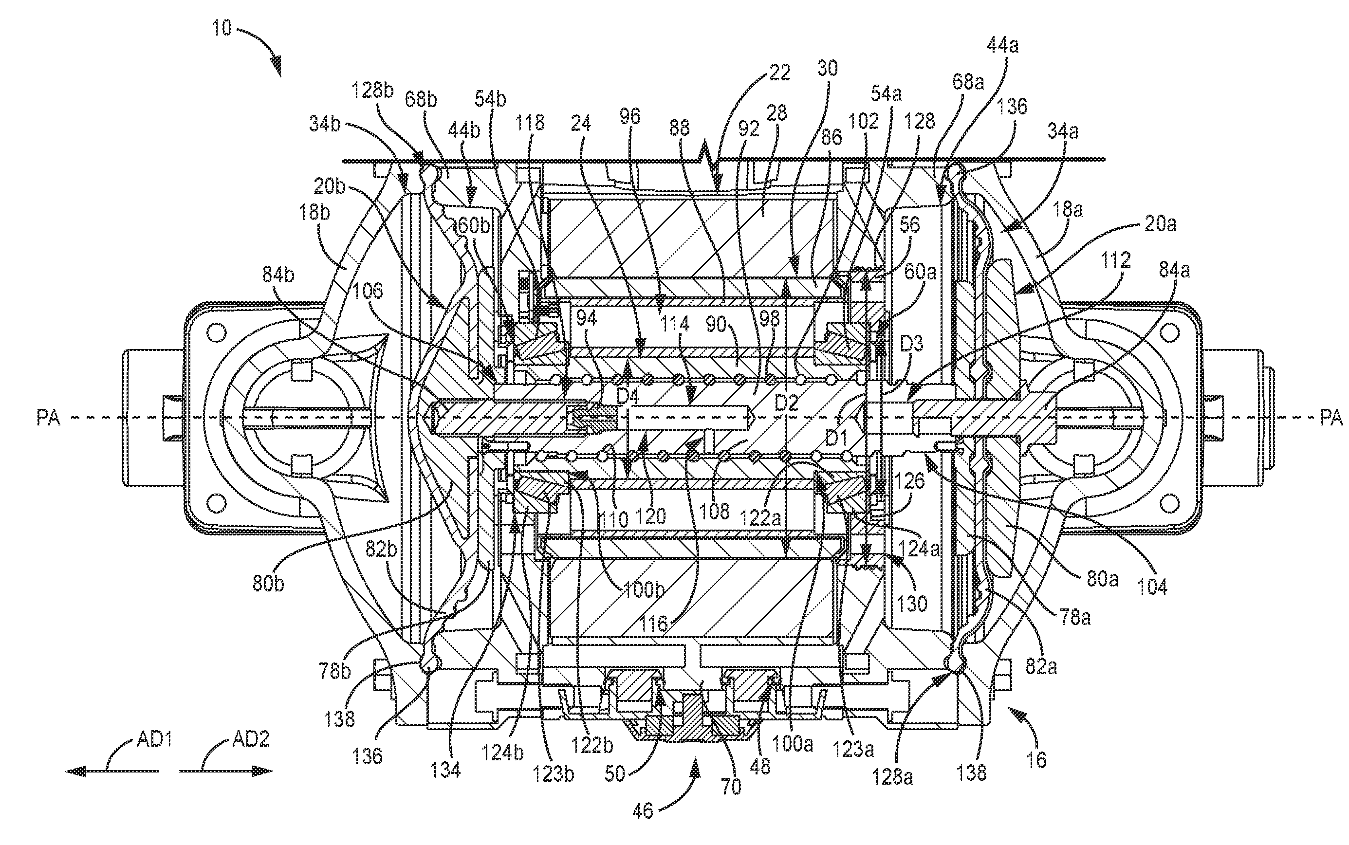
도 1a는 전기 작동식 펌프(10)의 정면 등각도이다. 도 1b는 펌프(10)의 후면 등각도이다. 도 1c는 펌프(10)의 개략 블록도이다. 도 1a 내지 도 1c가 함께 설명될 것이다. 펌프(10)는 입구 매니폴드(12), 출구 매니폴드(14), 펌프 본체(16), 유체 커버(18a, 18b)(여기서 집합적으로 "유체 커버(18") 또는 "유체 커버(18")), 유체 변위 부재(20a, 20b)(여기서 집합적으로 "유체 변위 부재(20") 또는 "유체 변위 부재(20")), 모터(22), 구동 메커니즘(24) 및 제어기(26)를 포함한다. 모터(22)는 고정자(28) 및 회전자(30)를 포함한다.1A is a front isometric view of an electrically operated
펌프 본체(16)는 유체 커버(18a, 18b) 사이에 배치된다. 모터(22)는 펌프 본체(16) 내에 배치되고, 이하에 더 상세히 설명되는 바와 같이, 유체 변위 부재(20)와 동축이다. 모터(22)는 고정자(28) 및 회전자(30)를 갖는 전기 모터이다. 고정자(28)는 전기자 권선을 포함하고 회전자(30)는 영구 자석을 포함한다. 회전자(30)는 고정자(28)를 통한 전류(직류(DC) 신호 및/또는 교류(AC) 신호와 같은)에 응답하여 펌프 축(PA-PA)을 중심으로 회전하도록 구성된다. 모터(22)는 고정자(28)가 회전자(30)를 2개의 회전 방향 중 어느 하나로(예를 들어, 시계 방향과 반시계 방향 사이에서 교번하여)으로 회전하게 할 수 있다는 점에서 가역 모터이다. 회전자(30)는, 회전자(30)로부터 회전 출력을 수신하고 유체 변위 부재(20)에 선형 왕복 입력을 제공하는 구동 메커니즘(24)을 통해 유체 변위 부재(20)에 연결된다. 유체 변위 부재(20)는 다이어프램 또는 피스톤과 같이, 입구 매니폴드(12)로부터 출구 매니폴드(14)로 유체를 펌핑하기 위해 적합한 임의의 유형일 수 있다. 펌프(10)는 2개의 유체 변위 부재(20)를 포함하는 것으로서 도시되어 있지만, 펌프(10)의 몇몇 예는 단일 유체 변위 부재(20)를 포함하는 것으로 이해된다. 또한, 2개의 유체 변위 부재(20)는 여기서 다이어프램으로서 도시되어 있지만, 이들은 대신에 다양한 다른 실시예에서 피스톤일 수 있고, 본 명세서에 제공된 교시는 피스톤 펌프에 적용될 수 있다.The
제어기(26)는 모터(22)의 작동을 제어하기 위해 모터(22)에 작동식으로 연결된다. 제어기(26)의 사용자 인터페이스(27)가 도시되어 있다. 작동 중에, 전류 신호가 고정자(28)에 제공되어 고정자(28)가 회전자(30)의 회전을 구동하게 한다. 구동 메커니즘(24)은 회전자(30)로부터 회전 출력을 수신하고 그 회전 출력을 선형 출력으로 변환하여 유체 변위 부재(20)를 구동한다. 몇몇 예에서, 회전자(30)는 제1 회전 방향으로 회전하여 유체 변위 부재(20)를 제1 축방향으로 구동하고 제2 회전 방향으로 회전하여 유체 변위 부재(20)를 제2 축방향으로 구동한다.
구동 메커니즘(24)은 유체 변위 부재(20)가 교번하는 흡입 및 펌핑 행정을 통해 펌프 축(PA-PA)을 따라 왕복하게 한다. 흡입 행정 동안, 유체 변위 부재(20)는 입구 매니폴드(12)로부터 유체 커버(18) 및 유체 변위 부재(20)에 의해 적어도 부분적으로 형성된 프로세스 유체 챔버 내로 프로세스 유체를 흡인한다. 펌핑 행정 동안, 유체 변위 부재(20)는 프로세스 유체 챔버로부터 출구 매니폴드(14)로 유체를 구동한다. 통상적으로, 체크 밸브의 배열에 따라, 2개의 유체 변위 부재(20)는 180도 역위상(out of phase)으로 작동되어, 제1 유체 변위 부재(20)가 펌핑 행정을 통해 구동되게 되고(예를 들어, 펌프로부터 하류로 프로세스 유체를 구동함), 반면 제2 유체 변위 부재(20)는 흡입 행정을 통해 구동되게 된다(예를 들어, 펌프로부터 상류로 프로세스 유체를 견인함). 2개의 유체 변위 부재(20)는 또한 동시에 그러나 서로에 대해 180도 역위상으로 전환한다(예를 들어, 펌핑 행정과 흡입 행정 사이에서 전이함).
구동 메커니즘(24)은 회전자(30)에 직접 연결되고 유체 변위 부재(20)는 구동 메커니즘(24)에 의해 직접 구동된다. 이와 같이, 모터(22)는 감속 기어 장치와 같은 중간 기어 장치의 존재 없이 유체 변위 부재(20)를 직접 구동한다. 전원 코드(32)가 펌프(10)로부터 연장되고 펌프(10)의 전자 부품에 전력을 제공하도록 구성된다. 전원 코드(32)는 벽 소켓에 연결할 수 있다.The
도 2는 펌프(10)를 통한 유체 유로를 도시하고 있는 펌프(10)의 블록도이다. 프로세스 유체 유로(PF)는 프로세스 유체 챔버(34a, 34b)(여기서 집합적으로 "프로세스 유체 챔버(34") 또는 "프로세스 유체 챔버들(34"))를 통해 입구 매니폴드(12)로부터 출구 매니폴드(14)로 연장한다. 프로세스 유체 챔버(34)는 공통 입구 매니폴드(12) 및 출구 매니폴드(14)에 연결될 수 있는 것으로 이해된다. 냉각 유체 회로(CF)는 펌프(10)의 내부를 통해 연장되고 공기와 같은 냉각 유체를 펌프(10)를 통해 유도하여 펌프(10)의 구성요소를 냉각시킨다. 펌프(10)의 주요 열원은 제어기(26), 고정자(28) 및 구동 메커니즘(24)을 포함한다. 냉각 유체 회로(CF)는 냉각 공기와 열원 사이의 열 교환에 영향을 미치고 이에 의해 펌프(10)를 냉각시키기 위해 발열 구성요소에 근접한 통로를 통해 냉각 공기를 안내한다. 모든 실시예가 반드시 냉각 유체 회로 또는 다른 펌프 냉각 공기를 포함하는 것은 아니다.2 is a block diagram of the
냉각 유체 회로(CF)는 펌프(10)를 통해 냉각 공기를 안내하여 구동 메커니즘(24), 제어기(26) 및 고정자(28)와 같은 펌프(10)의 발열 구성요소를 냉각하도록 구성된다. 펌프(10)는 냉각 유체 회로(CF)를 통해 냉각 공기를 펌핑한다. 유체 변위 부재(20a, 20b)는 역위상으로 배치되어, 하나의 유체 변위 부재(20)는 다른 부재가 냉각 공기에 대한 흡입 행정을 통해 이동할 때 냉각 공기에 대한 펌핑 행정을 통해 이동하게 되고, 체크 밸브(48, 50, 52)는 냉각 공기가 펌프(10)의 일 측으로 진입하고 펌프(10)의 다른 측에서 진출하도록 배열된다. 비교적 더 차가운 공기가 펌프(10)로 진입하고 비교적 더 따뜻한 공기는 펌프(10)에서 진출한다. 유체 변위 부재(20)는, 유체 변위 부재(20)가 작동 유체(예를 들어, 압축 공기)에 의해 이동되지 않고 대신에 모터(22) 및 구동 메커니즘(24)에 의해 전기기계적으로 구동되기 때문에 냉각 공기를 펌핑하기 위해 이용될 수 있다. 따라서, 유체 변위 부재(20)는 펌프(10)를 통해 프로세스 유체와 냉각 공기의 모두를 펌핑할 수 있다.Cooling fluid circuit CF is configured to direct cooling air through
냉각 유체 회로(CF)는 제1 냉각 통로(36), 제2 냉각 통로(38), 제3 냉각 통로(40), 제4 냉각 통로(42), 및 냉각 챔버(44a, 44b)(여기서 집합적으로 "냉각 챔버(44") 또는 "냉각 챔버들(44"))를 포함한다. 에어 체크(46)는 냉각 유체 회로(CF)의 입구/배기구에 배치되고 유로(CF)를 통한 단방향성 유동을 위한 냉각 공기의 유동을 제어한다.The cooling fluid circuit CF includes a
에어 체크(46)는 입구 밸브(48) 및 출구 밸브(50)를 포함한다. 입구 밸브(48)는 냉각 공기가 냉각 유체 회로(CF)로 진입하는 것을 허용하고 냉각 공기가 에어 체크(46)를 통해 냉각 챔버(44a) 외부로 역류하는 것을 방지하는 일방향 밸브이다. 출구 밸브(50)는 냉각 공기가 냉각 유체 회로(CF)에서 진출하는 것을 허용하고 분위기 공기가 출구 밸브(50)를 통해 냉각 유체 회로(CF)로 진입하는 것을 방지하는 일방향 밸브이다. 에어 체크(46)는 배기 및 흡기 유동 중 하나 또는 모두가 펌프 본체(16) 상에 형성된 냉각 휜(fin) 위로 안내되어, 펌프(10)에 추가 냉각을 제공하도록 구성될 수 있다.The
내부 밸브(52)는 제2 냉각 통로(38) 및 제3 냉각 통로(40)가 냉각 챔버(44b)에 냉각 공기를 제공하는 냉각 유체 회로(CF) 내에 배치된다. 내부 밸브(52)는 냉각 유체 회로(CF)를 통한 단방향성 유동을 야기하도록 냉각 유체 회로(CF) 내의 냉각 공기의 유동을 제어하는 일방향 밸브이다. 내부 밸브(52)는 냉각 공기가 냉각 챔버(44b) 내로 유동하는 것을 허용하고 냉각 챔버(44b)로부터 역행 유동을 방지하는 일방향 밸브이다.The
제1 냉각 통로(36)는 입구 밸브(48)의 공기 입구로부터 냉각 챔버(44a)로 연장된다. 냉각 챔버(44a)는 유체 변위 부재(20a)와 모터(22) 사이에 배치된다(도 4a, 도 4b 및 도 4d에 도시되어 있는 바와 같이). 제2 냉각 통로(38) 및 제3 냉각 통로(40)는 냉각 챔버(44a)로부터 냉각 챔버(44b)로 연장된다. 제2 냉각 통로(38) 및 제3 냉각 통로(40)의 각각은 하나 이상의 개별 통로를 포함할 수 있다. 몇몇 예에서, 제2 냉각 통로(38)는 복수의 개별 통로를 포함한다. 몇몇 예에서, 제2 냉각 통로(38)는 상이한 수의 입구/출구 구멍(38i/38o) 및 입구 구멍(들)(38i)과 출구 구멍(들)(38o) 사이에서 연장하는 경로(38p)를 포함한다. 일 예에서, 제2 냉각 통로(38)는 냉각 챔버(44a)와 직접 유체 연통하는 단일 입구 구멍(38i), 복수의 경로(38p), 및 냉각 챔버(44b)와 직접 유체 연통하는 단일 출구 구멍(38o)을 포함한다. 몇몇 예에서, 제3 냉각 통로(40)는 복수의 개별 통로를 포함한다. 몇몇 예에서, 제3 냉각 통로(40)는 제3 냉각 통로(40)를 통해 상이한 축방향 로케이션에 가변 수의 개별 통로를 포함한다. 예를 들어, 제3 냉각 통로(40)는 제1 수의 입구 구멍(40i), 제2 수의 경로(40p), 및 제3 수의 출구 구멍(40o)을 포함할 수 있다. 제1 수, 제2 수, 제3 수는 각각 동일할 수 있고, 모두 상이할 수 있고, 또는 2개는 동일하고 제3 수는 상이할 수 있다.The
몇몇 예에서, 제2 냉각 통로(38)는 작동 중에 펌프 축(PA-PA)에 대해 정지 상태로 유지되는 고정자 통로를 포함하고, 제3 냉각 통로(40)는 회전자(30)(도 4a 내지 도 4d 및 도 12에서 가장 양호하게 볼 수 있음)를 통해 연장하고 작동 중에 펌프 축(PA-PA에 대해)을 중심으로 회전하는 회전자 통로를 포함한다. 예를 들어, 제2 냉각 통로(38)는 펌프 본체(16)의 부분에 의해 형성될 수 있고 제어기(26)(도 1c 및 도 16)와 고정자(28)(도 4a 내지 도 4d 및 도 12에서 가장 양호하게 볼 수 있음) 사이에 적어도 부분적으로 배치될 수 있다. 제3 냉각 통로(40)는 회전자(30)의 본체를 통해 형성될 수 있고 고정자(28)와 구동 메커니즘(24) 사이에 배치될 수 있다. 그러나, 제2 냉각 통로(38) 및 제3 냉각 통로(40)는 냉각 챔버(44a)와 냉각 챔버(44b) 사이에 냉각 공기를 통과시키기 위해 적합한 임의의 원하는 구성일 수 있는 것으로 이해된다.In some instances, the
내부 밸브(52)는 제2 냉각 통로(38)와 냉각 챔버(44b) 사이 및 제3 냉각 통로(40)와 냉각 챔버(44b) 사이에 배치된다. 내부 밸브(52)는 제2 냉각 통로(38)의 출구(38o)와 제3 냉각 통로(40)의 출구(40o)에 배치된다. 냉각 챔버(44b)는 유체 변위 부재(20b)와 모터(22) 사이에 배치된다. 내부 밸브(52)는 제2 냉각 통로(38) 및 제3 냉각 통로(40)를 통한 역행 유동을 방지하면서 냉각 공기가 냉각 챔버(44b)로 유동할 수 있게 한다. 몇몇 예에서, 내부 밸브(52)는 제2 냉각 통로(38) 및 제3 냉각 통로(40)의 각각과 연관된 단일 밸브 부재를 포함한다. 예를 들어, 플래퍼(flapper) 밸브 부재가 다수의 출구로 연장될 수 있다. 몇몇 예에서, 내부 밸브(52)는 제2 냉각 통로(38) 및 제3 냉각 통로(40)의 하나 이상의 출구와 연관된 다수의 밸브 부재를 포함한다. 몇몇 예에서, 내부 밸브(52)는 출구가 있는 것과 동일한 수의 밸브 부재를 포함하여, 각각의 출구는 전용 밸브 부재를 갖게 된다. 예를 들어, 다른 옵션들 중에서도, 볼 밸브가 각각의 출구에 배치될 수 있다. 제4 냉각 통로(42)는 냉각 챔버(44b)로부터 출구 밸브(50)의 배기 출구까지 연장된다. 냉각 공기는 출구 밸브(50)를 통해 유로(CF)에서 진출한다.The
유체 변위 부재(20a)는 프로세스 유체 챔버(34a)와 냉각 챔버(44a) 사이에 배치되어 이들을 유체적으로 격리시킨다. 유체 변위 부재(20a)는 프로세스 유체 챔버(34a) 및 냉각 챔버(44)의 각각을 적어도 부분적으로 형성할 수 있다. 유체 변위 부재(20a)는 제1 축방향(AD1)으로 시프트하여 프로세스 유체 챔버(34a)의 체적을 감소시켜, 프로세스 유체를 프로세스 유체 챔버(34a) 외부로 구동하고, 냉각 챔버(44a)의 체적을 증가시켜, 냉각 공기를 냉각 챔버(44a) 내로 흡인한다. 유체 변위 부재(20a)는 제1 축방향(AD1)에 대향하는 제2 축방향(AD2)으로 시프트하여 프로세스 유체 챔버(34a)의 체적을 증가시켜, 입구 매니폴드(12)로부터 프로세스 유체 챔버(34a) 내로 프로세스 유체를 흡인하고, 냉각 챔버(44a)의 체적을 감소시켜, 냉각 공기를 냉각 챔버(44a) 외부로 구동한다. 이와 같이, 유체 변위 부재(20a)는 냉각 공기에 대한 흡입 행정을 통해 동시에 진행하면서 프로세스 유체에 대한 펌핑 행정을 통해 진행하고, 냉각 공기에 대한 펌핑 행정을 통해 동시에 진행하면서 프로세스 유체에 대한 흡입 행정을 통해 진행한다. 유체 변위 부재(20a)는 프로세스 유체와 냉각 공기를 동시에 펌핑한다.The
유체 변위 부재(20b)는 유체 변위 부재(20a)와 실질적으로 유사하다. 유체 변위 부재(20b)는 프로세스 유체 챔버(34b)를 통해 프로세스 유체를 펌핑하고 냉각 챔버(44b)를 통해 냉각 공기를 펌핑한다. 유체 변위 부재(20b)는 펌프 행정이 역전되도록 유체 변위 부재(20a)에 연결된다. 이와 같이, 유체 변위 부재(20b)는 제2 축방향(AD2)으로 구동될 때 프로세스 유체 챔버(34b)의 펌핑 행정 및 냉각 챔버(44b)의 흡입 행정을 통해 진행하고, 제1 축방향(AD1)으로 구동될 때 프로세스 유체 챔버(34b)의 흡입 행정 및 냉각 챔버(44b)의 펌핑 행정을 통해 진행한다.
작동 중에, 유체 변위 부재(20)는 제1 및 제2 행정을 통해 축방향으로 시프트한다. 제1 행정 동안, 유체 변위 부재(20a)는 프로세스 유체 챔버(34a)에 대한 펌핑 행정 및 냉각 챔버(44a)에 대한 흡입 행정을 통해 시프트한다. 유체 변위 부재(20a)는 프로세스 유체를 프로세스 유체 챔버(34a)로부터 출구 매니폴드(14)로 구동한다. 동시에, 유체 변위 부재(20a)는 냉각 챔버(44a)가 팽창하게 하여, 냉각 공기를 입구 밸브(48) 및 제1 냉각 통로(36)를 통해 냉각 챔버(44a) 내로 흡인한다. 유체 변위 부재(20b)는 프로세스 유체 챔버(34b)에 대한 흡입 행정 및 냉각 챔버(44b)에 대한 펌핑 행정을 통해 시프트한다. 유체 변위 부재(20b)는 프로세스 유체 챔버(34b)의 체적이 증가하게 하여, 프로세스 유체를 입구 매니폴드(12)로부터 프로세스 유체 챔버(34b) 내로 흡인한다. 동시에, 유체 변위 부재(20b)는 냉각 챔버(44b)가 수축되게 하고, 이에 의해 냉각 챔버(44b)로부터 그리고 제4 냉각 통로(42) 및 출구 밸브(50)를 통해 유로(CF) 외부로 냉각 공기를 구동한다. 입구 밸브(48) 및 출구 밸브(50)의 각각은 제1 행정 동안 개방된다. 이와 같이, 에어 체크(46)는 제1 행정 동안 개방 상태에 있다. 냉각 챔버(44b) 수축 및 냉각 챔버(44a) 팽창은 내부 밸브(52)가 폐쇄 상태로 유지되거나 복귀하게 하여, 냉각 공기가 냉각 챔버(44b)로부터 제2 냉각 통로(38) 또는 제3 냉각 통로(40)를 통해 상류로 유동하는 것을 방지한다.During operation, the
유체 변위 부재(20)는 제1 행정의 단부에서 전환되고 제2 행정 동안 대향 축방향으로 구동된다. 유체 변위 부재(20a)는 프로세스 유체 챔버(34a)에 대한 흡입 행정을 통해 시프트하고 입구 매니폴드(12)로부터 프로세스 유체 챔버(34a) 내로 프로세스 유체를 흡인한다. 동시에, 유체 변위 부재(20a)는 냉각 챔버(44a)에 대한 펌핑 행정을 통해 시프트한다. 냉각 챔버(44a) 내의 압력 상승은 입구 밸브(48)가 폐쇄 상태로 시프트하게 하여, 입구 밸브(48)를 통해 유로(CF) 외부로 냉각 공기의 역행 유동을 방지한다. 유체 변위 부재(20a)는 냉각 공기를 냉각 챔버(44a)로부터 제2 냉각 통로(38) 및 제3 냉각 통로(40)를 통해 냉각 챔버(44b)로 구동한다.The
유체 변위 부재(20b)는 유체 변위 부재(20a)와 동시에 시프트한다. 유체 변위 부재(20b)는 프로세스 유체 챔버(34b)에 대한 펌핑 행정 및 냉각 챔버(44b)에 대한 흡입 행정을 통해 시프트한다. 흡입 행정은 출구 밸브(50)를 폐쇄 상태로 시프트하게 하여, 에어 체크(46)를 통해 냉각 챔버(44b) 내로의 분위기 유동을 방지한다. 유체 변위 부재(20b)는 냉각 공기를 냉각 챔버(44a)로부터 제2 냉각 통로(38) 및 제3 냉각 통로(40)를 통해 냉각 챔버(44b) 내로 흡인한다. 입구 밸브(48)와 출구 밸브(50)의 모두는 제2 행정 동안 폐쇄된다. 이와 같이, 에어 체크(46)는 제2 행정 동안 폐쇄 상태에 있다.The
냉각 챔버(44a) 내의 압력 및 냉각 챔버(44b) 내의 흡입은 내부 밸브(52)가 개방 상태로 시프트되게 하여, 이에 의해 제2 냉각 통로(38) 및 제3 냉각 통로(40)를 통해 냉각 챔버(44a)와 냉각 챔버(44b) 사이의 유로를 개방한다. 냉각 챔버(44a) 내의 냉각 공기의 제1 부분은 제2 냉각 통로(38)를 통해 펌핑되고 냉각 챔버(44a) 내의 냉각 공기의 제2 부분은 제3 냉각 통로(40)를 통해 펌핑된다. 냉각 공기의 제1 및 제2 부분은 펌프(10)의 발열 구성요소를 지나 유도된다. 냉각 공기는 펌프(10)의 일 측으로부터 다른 측으로 이동된다. 더 구체적으로, 냉각 공기는 모터(22)를 통해 강제로 유동하게 된다. 냉각 공기는 구동 메커니즘(24) 위로 강제로 유동하게 된다. 몇몇 예에서, 냉각 공기는 구동 메커니즘(24)을 통해 강제로 유동하게 되어, 유동하는 공기가 스크류 및/또는 복수의 롤링 요소와 접촉하게 된다. 냉각 공기는 제2 냉각 통로(38) 및 제3 냉각 통로(40)를 통해 유동할 때 이들 구성요소로부터 열을 흡수한다. 냉각 챔버(44b) 내의 흡입 행정 및 냉각 챔버(44a) 내의 펌핑 행정은 내부 밸브(52)가 개방되게 하고, 이에 의해 냉각 공기의 제1 및 제2 부분이 냉각 챔버(44b) 내로 유동할 수 있게 한다.The pressure in the cooling chamber 44a and the suction in the
제2 행정을 완료한 후, 유체 변위 부재(20)는 제1 행정을 통해 다시 구동되고 냉각 공기와 프로세스 유체의 모두를 계속 펌핑한다. 몇몇 예에서, 유체 변위 부재(20a, 20b)는 프로세스 유체 유로(PF)에 대해 병렬로 배치된다. 각각의 유체 변위 부재(20a, 20b)는 입구 매니폴드(12)의 하류 및 출구 매니폴드(14)의 상류에 있다. 유체 변위 부재(20a, 20b) 중 어느 하나도 유체 변위 부재(20a, 20b) 중 다른 하나의 상류 또는 하류에 있지 않다. 유체 변위 부재(20a, 20b) 중 어느 하나도 유체 변위 부재(20a, 20b) 중 다른 하나로부터 프로세스 유체를 수용하거나 그에 프로세스 유체를 제공하지 않는다.After completing the second stroke, the
유체 변위 부재(20a, 20b)는 프로세스 유체 유로(PF) 내에 병렬로 배치되지만, 유체 변위 부재(20a, 20b)는 냉각 유체 회로(CF) 내에서는 직렬로 배치된다. 냉각 챔버(44a)는 냉각 챔버(44b)의 상류에 배치되고 그에 냉각 공기를 제공한다. 유체 변위 부재(20a)는 냉각 챔버(44a)를 위한 펌핑 요소를 형성하고 유체 변위 부재(20b)는 냉각 챔버(44b)를 위한 펌핑 요소를 형성한다. 유체 변위 부재(20a, 20b)는 냉각 챔버(44a)로부터 냉각 챔버(44b)로 냉각 공기를 구동하기 위해 협력하여 작동한다.The
냉각 유체 회로(CF)는 펌프(10)에 공기 냉각을 제공한다. 제어기(26), 고정자(28), 및 구동 메커니즘(24)을 포함하는 펌프(10)의 주요 발열 구성요소는 냉각 공기와의 열 교환 관계를 촉진하기 위해 제2 냉각 통로(38) 및 제3 냉각 통로(40)에 대해 배치된다. 냉각 유체 회로(CF)의 입구 및/또는 출구는 펌프(10)를 추가로 냉각시키기 위해 펌프 본체(16) 상에 형성된 휜 위로 기류를 안내하도록 배향될 수 있다. 프로세스 유체와 냉각 공기의 모두를 구동하는 유체 변위 부재(20)는 팬과 같은 부가의 구성요소를 필요로 하지 않고 효율적인 냉각을 제공한다.A cooling fluid circuit (CF) provides air cooling to the pump (10). The main heat generating components of the
도 3a는 펌프(10)의 분해 정면 등각도이다. 도 3b는 펌프(10)의 구성요소의 부분집합을 도시하고 있는 분해 후면 등각도이다. 도 3a 및 도 3b가 함께 설명될 것이다. 펌프(10)는 입구 매니폴드(12), 출구 매니폴드(14), 펌프 본체(16), 유체 커버(18a, 18b), 유체 변위 부재(20a, 20b), 모터(22), 구동 메커니즘(24), 에어 체크(46), 내부 밸브(52), 베어링(54a, 54b)(여기서 집합적으로 "베어링(54") 또는 "베어링들(54")), 모터 너트(56), 펌프 체크 밸브(58), 그리스 캡(60a, 60b)(여기서 집합적으로 "그리스 캡(60") 또는 "그리스 캡들(60")), 위치 센서(62), 및 하우징 체결구(64)를 포함한다.3A is an exploded front isometric view of
펌프 본체(16)는 중심부(66) 및 단부 캡(68a, 68b)(여기서 집합적으로 "단부 캡(68") 또는 "단부 캡들(68"))을 포함한다. 중심부(66)는 모터 하우징(70), 제어 하우징(72), 히트 싱크(74), 및 고정자 통로(76)(도 3b)를 포함한다. 유체 변위 부재(20a, 20b)는 각각 내부 플레이트(78a, 78b)(여기서 집합적으로 "내부 플레이트(78") 또는 "내부 플레이트들(78")); 외부 플레이트(80a, 80b)(여기서 집합적으로 "외부 플레이트(80") 또는 "외부 플레이트들(80")); 멤브레인(82a, 82b)(여기서 집합적으로 "멤브레인(82") 또는 "멤브레인들(82")) 및 체결구(84a, 84b)를 포함한다. 모터(22)는 고정자(28) 및 회전자(30)를 포함한다. 회전자(30)는 영구 자석 어레이(86) 및 회전자 본체(88)를 포함한다. 구동 메커니즘(24)의 구동 너트(90) 및 스크류(92)가 도시되어 있다.The
단부 캡(68a, 68b)은 중심부(66)의 대향 측면들에 배치되고 중심부(66)에 부착되어 펌프 본체(16)를 형성한다. 하우징 체결구(64)는 단부 캡(68)을 펌프 본체(16)에 고정하기 위해 단부 캡(68)을 통해 펌프 본체(16) 내로 연장된다. 히트 싱크(74)는 중심부(66) 상에 형성된다. 도시되어 있는 예에서, 히트 싱크(74)는 휜에 의해 형성되지만, 히트 싱크는 펌프(10)를 냉각시키기 위한 열 교환을 촉진하기 위해 펌프 본체(16)의 표면적을 증가시키기 위해 적합한 임의의 구성일 수 있다는 것이 이해된다. 고정자 통로는 모터 하우징(70)과 제어 하우징(72) 사이의 계면에서 중심부(66) 상에 형성된다. 고정자 통로(76)는 제2 냉각 통로(38)(도 2)의 부분을 형성한다. 고정자 통로(76)는 펌프 본체(16) 내의 발열 요소와 고정자 통로(76)를 통해 유동하는 냉각 공기에 노출된 적어도 4개의 측면을 포함하는 돌출부로서 형성된다. 예를 들어, 각각의 고정자 통로(76)의 일 측면은 고정자(28)에 인접하게 배치될 수 있고, 반면 각각의 고정자 통로(76)의 3개의 측면은 제어 하우징(72) 내의 가열된 공기에 노출될 수 있다. 몇몇 예에서, 고정자 통로(76)는 작동 중에 에워싸여 고정자 통로(76)가 분위기에 직접 노출되지 않게 된다.End caps 68a and 68b are disposed on opposite sides of the
유체 커버(18a, 18b)는 단부 캡(68a, 68b)에 각각 연결된다. 하우징 체결구(64)는 유체 커버(18)를 단부 캡(68)에 고정한다. 입구 매니폴드(12)는 각각의 유체 커버(18)에 연결된다. 펌프 체크(58)의 입구는 입구 매니폴드(12)와 유체 커버(18a, 18b) 사이에 배치된다. 펌프 체크(58)의 입구는 프로세스 유체가 프로세스 유체 챔버(34a, 34b)(도 2 및 도 4a)로 유동하는 것을 허용하고 프로세스 유체 챔버(34a, 34b)로부터 입구 매니폴드(12)로의 역행 유동을 방지하도록 구성된 일방향 밸브이다. 출구 매니폴드(14)는 각각의 유체 커버(18)에 연결된다. 펌프 체크(58)의 출구는 출구 매니폴드(14)와 유체 커버(18a, 18b) 사이에 배치된다. 펌프 체크(58)의 출구는 프로세스 유체가 프로세스 유체 챔버(34a, 34b) 외부로 출구 매니폴드(14)로 유동하는 것을 허용하고 출구 매니폴드(14)로부터 프로세스 유체 챔버(34a, 34b)로의 역행 유동을 방지하도록 구성된 일방향 밸브이다.Fluid covers 18a and 18b are connected to end
모터(22)는 단부 캡(68) 사이에 모터 하우징(70) 내에 배치된다. 제어 하우징(72)은 모터 하우징(70)에 연결되고 그로부터 연장된다. 제어 하우징(72)은 제어기(26)(도 1c 및 도 19)와 같은 펌프(10)의 제어 요소를 수용하도록 구성된다. 고정자(28)는 회전자(30)를 둘러싸고 회전자(30)의 회전을 구동한다. 회전자(30)는 펌프 축(PA-PA)을 중심으로 회전하고 구동 메커니즘(24) 및 유체 변위 부재(20)와 동축으로 배치된다. 영구 자석 어레이(86)는 회전자 본체(88) 상에 배치된다.
구동 너트(90)는 회전자 본체(88) 내에 배치되고 그에 연결된다. 구동 너트(90)는 다른 옵션들 중에서도, 체결구(예를 들어, 볼트), 접착제 또는 압입을 통해 회전자 본체(88)에 부착될 수 있다. 구동 너트(90)는 회전자 본체(88)와 함께 회전한다. 구동 너트(90)는 구동 너트(90)의 대향 축방향 단부에서 베어링(54a, 54b)에 장착된다. 베어링(54)은 축방향 및 반경방향 힘의 모두를 지지하도록 구성된다. 몇몇 예에서, 베어링(54)은 테이퍼 롤러 베어링을 포함한다. 스크류(92)는 구동 너트(90)를 통해 연장되고 각각의 유체 변위 부재(20)에 연결된다. 스크류(92)는 펌프 축(PA-PA)을 따라 왕복하여 각각의 펌핑 및 흡입 행정을 통해 유체 변위 부재(20)를 구동한다.A
모터 너트(56)는 고정자(28)를 수용하는 펌프 본체(16)의 부분에 연결된다. 모터 너트(56)는 펌프(10)의 고정자 하우징에 연결되는 것으로 고려될 수 있는데, 이 고정자 하우징은 모터 하우징(70) 및 단부 캡(68a, 68b)에 의해 형성될 수 있다. 도시되어 있는 예에서, 모터 너트(56)는 단부 캡(68a)에 연결되고 펌프 본체(16) 내에 베어링(54)을 고정한다. 모터 너트(56)는 베어링(54)을 예압한다(preloads). 스크류(92)는 작동 중에 모터 너트(56)를 통해 왕복할 수 있다. 그리스 캡(60a)은 모터 너트(56)에 의해 지지되고 모터 너트(56)는 베어링(54a)에 대해 그리스 캡(60a)을 정렬한다. 그리스 캡(60b)은 베어링(54b)에 인접하게 배치된다. 그리스 캡(60)은 오염물이 베어링(54)에 진입하는 것을 방지하고 작동 중에 액화될 수도 있는 임의의 그리스를 보유한다.The
내부 밸브(52)는 단부 캡(68b)에 연결된다. 내부 밸브(52)는 그리스 캡(60b)에 의해 단부 캡(68b)에 연결된다. 내부 밸브(52)는 유체 변위 부재(20b)에 대면하는 단부 캡(68b)의 측면에 배치된다. 도시되어 있는 예에서, 내부 밸브(52)는 플래퍼 밸브이다.The
유체 변위 부재(20a)는 스크류(92)의 제1 단부에 연결된다. 멤브레인(82a)은 내부 플레이트(78a)와 외부 플레이트(80a) 사이에 포획된다. 체결구(84a)는 내부 플레이트(78a), 외부 플레이트(80a) 및 멤브레인(82)의 각각을 통해 그리고 스크류(92) 내로 연장되어 유체 변위 부재(20a)를 구동 메커니즘(24)에 연결한다. 멤브레인(82a)의 외주 에지는 유체 커버(18a)와 단부 캡(68a) 사이에 포획된다. 멤브레인(82a)은 유체 변위 부재(20a)가 펌프 축(PA-PA)을 중심으로 회전하는 것을 방지하도록 포획된다.
유체 변위 부재(20b)는 유체 변위 부재(20a)로부터 스크류(92)의 대향 축방향 단부에 연결된다. 도시되어 있는 예에서, 멤브레인(82b)은 외부 플레이트(80b) 상에 오버몰딩된다. 체결구(84b)는 외부 플레이트(80b)로부터 내부 플레이트(78b)를 통해 스크류(92) 내로 연장되어 유체 변위 부재(20b)를 구동 메커니즘(24)에 연결한다. 멤브레인(82b)의 외주 에지는 유체 커버(18b)와 단부 캡(68b) 사이에 포획된다. 멤브레인(82b)은 유체 변위 부재(20b)가 펌프 축(PA-PA)을 중심으로 회전하는 것을 방지하기 위해 포획된다. 유체 변위 부재(20)는 상이한 구성을 갖는 것으로서 설명되지만, 펌프(10)는 동일하거나 상이한 구성을 갖는 유체 변위 부재(20)를 포함할 수 있는 것으로 이해된다.
작동 중에, 전류 신호가 고정자(28)에 제공되어 회전자(30)의 회전을 구동한다. 위치 센서(62)는 이하에 더 상세히 설명되는 바와 같이, 회전자(30)에 근접하게 배치되고, 고정자(28)에 대한 회전자(30)의 회전 위치에 관한 위치 데이터를 발생한다. 예를 들어, 위치 센서(62)는 영구 자석 어레이(86) 내의 영구 자석의 극성에 응답하는 홀 효과 센서의 어레이를 포함할 수 있다. 제어기(26)는 모터(22)를 정류하기 위해 위치 데이터를 이용한다.During operation, a current signal is provided to the
구동 메커니즘(24)은 회전자(30)로부터의 회전 운동을 유체 변위 부재(20)의 선형 운동으로 변환한다. 회전자 본체(88)는 펌프 축(PA-PA)(도 4a에서 가장 양호하게 볼 수 있음)를 중심으로 회전하고 구동 너트(90)의 회전을 구동한다. 구동 너트(90)는 구동 너트(90)와 스크류(92) 사이에 배치되어 스크류(92)에 대해 구동 너트(90)를 지지하는 롤링 요소(98)(도 12 및 도 13에서 가장 양호하게 볼 수 있음)와 같은 롤링 요소의 맞물림에 의해 펌프 축(PA-PA)을 따라 스크류(92)를 축방향으로 구동한다. 롤링 요소는 구동 너트(90)가 작동 중에 스크류(92)와 접촉하지 않도록 스크류(92)에 대해 구동 너트(90)를 지지한다. 롤링 요소는 구동 너트(90)의 회전을 스크류(92)의 선형 운동으로 변환한다. 스크류(92)는 각각의 펌핑 및 흡입 행정을 통해 유체 변위 부재(20)를 구동한다. 회전자(30)는 스크류(92)가 제1 축방향으로 변위하게 하도록 제1 회전 방향으로 회전된다. 회전자(30)는 제1 회전 방향에 대향하는 제2 회전 방향으로 회전되어 스크류(92)가 제1 축방향에 대향하는 제2 축방향으로 변위되게 한다.
모터(22)는 유체 변위 부재(20)와 축방향으로 정렬되고 유체 변위 부재(20)의 왕복을 구동한다. 회전자(30)는 펌프 축(PA-PA)을 중심으로 회전하고 유체 변위 부재(20)는 펌프 축(PA-PA) 상에서 왕복한다. 펌프(10)는 상당한 장점을 제공한다. 모터(22)가 유체 변위 부재(20)와 축방향으로 정렬되는 것은 다른 기계 구동 및 전기 구동 펌프에 비해 더 작은 패키지를 제공하는 콤팩트한 펌프 배열을 용이하게 한다. 게다가, 모터(22)는 모터(22)와 유체 변위 부재(20) 사이에 감속 기어와 같은 기어 장치를 포함하지 않는다. 이러한 기어 장치를 제거하는 것은 이동 부품의 수를 감소시킴으로써 더 신뢰적이고 더 간단한 펌프를 제공한다. 기어 장치를 제거하는 것은 또한 더 조용한 펌프 작동을 제공한다.
회전자(30) 및 구동 메커니즘(24, 24', 24")은 원하는 회전 대 행정 비를 제공하도록 크기 설정된다. 몇몇 예에서, 회전자(30) 및 구동 메커니즘(24, 24', 24")은 회전자(30)의 1 회전이 제1 축방향(AD1) 및 제2 축방향(AD2) 중 하나에서 스크류(92)의 전체 행정을 야기하도록 크기 설정된다. 대향 회전 방향으로 완전한 회전은 대향 축방향으로 스크류(92)의 완전 행정을 야기한다. 이와 같이, 대향 방향들에서의 2회 회전은 각각의 유체 변위 부재(20)에 대해 완전 펌프 사이클을 제공할 수 있다. 펌프(10)는 이에 의해 회전자(30)의 회전과 펌핑 행정 사이에 1:1 비를 제공할 수 있다. 도시되어 있는 예에서, 펌프(10)는 하나의 유체 변위 부재(20)가 단일 행정 동안 펌핑 행정을 통해 진행하고 다른 유체 변위 부재(20)가 단일 행정 동안 흡입 행정을 통해 진행함에 따라, 회전자(30)의 회전과 펌프 사이클 사이에 1:1 비를 제공할 수 있다. 회전 대 행정 비는 행정 길이와 스크류(92)의 리드(단일 회전에 대한 축방향 이동)에 의존한다. 몇몇 예에서, 스크류(92)는 약 5 내지 35 밀리미터(mm)(약 0.2 내지 1.4 인치(in))의 리드를 갖는다. 몇몇 예에서, 스크류(92)는 약 10 내지 25 mm(약 0.4 내지 1.0 in)의 리드를 갖는다. 몇몇 예에서, 행정 길이는 약 12.7 내지 76.2 mm(약 0.5 내지 3 in)이다. 몇몇 예에서, 행정 길이는 약 19 내지 63.5 mm(약 0.75 내지 2.5 in)이다. 몇몇 예에서, 행정 길이는 약 21.6 내지 58.4 mm(0.85 내지 2.3 in)이다. 회전자(30) 및 구동 메커니즘(24, 24', 24")은 임의의 원하는 회전 대 행정 비를 제공하도록 크기 설정될 수 있는 것으로 이해된다. 예를 들어, 펌프(10)는 약 0.25:1 내지 약 7:1의 회전 대 행정 비를 가질 수 있다. 몇몇 예에서, 펌프(10)는 약 0.5:1 내지 약 3:1의 회전 대 행정 비를 갖는다. 더 특정 예에서, 펌프(10)는 약 0.8:1 내지 약 1.5:1의 회전 대 행정 비를 갖는다. 비교적 더 큰 회전 대 행정 비는 더 큰 펌핑 압력을 촉진한다. 비교적 더 작은 회전 대 행정 비는 더 큰 유량을 촉진한다.
그러나, 회전자(30) 및 구동 메커니즘(24, 24', 24")은 임의의 원하는 회전 대 행정 비를 제공하도록 크기 설정될 수 있는 것으로 이해된다. 제어기(26)는 실제 행정 길이가 동적이고 작동 중에 변동할 수 있도록 모터(22)의 작동을 제어할 수 있다는 것이 또한 이해된다. 제어기(26)는 행정 길이가 하강행정(downstroke)과 상승행정(upstroke) 사이에서 변동하게 할 수 있다. 몇몇 예에서, 제어기(26)는 최대 회전 대 행정 비와 최소 회전 대 행정 비 사이의 작동을 제어하도록 구성된다. 펌프(10)는 임의의 원하는 회전 대 행정 비를 제공하도록 구성될 수 있다. 몇몇 예에서, 펌프(10)는 최대 약 4:1의 회전 대 행정 비를 제공한다. 다른 옵션들 중에서도, 약 1:1, 2:1, 3:1, 또는 5:1과 같은 다른 최대 회전 대 행정 비가 가능하다는 것이 이해된다. 설명된 임의의 범위는 경계 값이 범위 내에 포함되도록 포괄적인 범위일 수 있다는 것이 이해된다. 설명된 각각의 범위는 본 개시내용의 범주 내에 여전히 속하면서 명시된 범위로부터 변동할 수 있다는 것이 또한 이해된다.However, it is understood that the
모터(22) 및 구동 메커니즘(24, 24', 24")은 유체 변위 부재(20)를 회전자 회전당 적어도 약 6.35 mm(약 0.25 in) 변위시키도록 구성될 수 있다. 몇몇 예에서, 모터(22) 및 구동 메커니즘(24, 24', 24")은 유체 변위 부재(20)를 회전자 회전당 약 8.9 내지 30.5 mm(약 0.35 내지 1.2 in) 사이에서 변위시키도록 구성된다. 몇몇 예에서, 모터(22) 및 구동 메커니즘(24, 24', 24")은 유체 변위 부재(20)를 약 8.9 내지 11.4 mm(약 0.35 내지 0.45 in) 사이에서 변위시키도록 구성된다. 몇몇 예에서, 모터(22) 및 구동 메커니즘(24, 24', 24")은 유체 변위 부재(20)를 약 19 내지 21.6 mm(약 0.75 내지 0.85 in) 사이에서 변위시키도록 구성된다. 몇몇 예에서, 모터(22) 및 구동 메커니즘(24, 24', 24")은 약 24, 24', 24".1 내지 26.7 mm(약 0.95 내지 1.05 in) 사이에서 유체 변위 부재(20)를 변위시키도록 구성된다. 펌프(10)에 의해 제공되는 회전자 회전당 축방향 변위는 펌핑 동안 정확한 제어 및 신속한 응답을 촉진한다. 회전자 회전당 축방향 변위는 신속한 전환을 촉진하고 펌프(10)의 구성요소에 대한 마모를 감소시키면서 더 효율적인 펌핑을 제공한다.
펌프(10)는 회전 대 변위 비에 따라 펌핑하도록 구성된다. 더 구체적으로, 모터(22) 및 구동 메커니즘(24, 24', 24")은 회전자(30)의 각각의 회전에 대해, 인치 단위로 측정된 바와 같은, 회전자(30)의 회전과 유체 변위 부재(20)의 선형 변위 사이의 원하는 회전 대 변위 비를 제공하도록 구성된다. 몇몇 예에서, 회전 대 변위 비(rev/in.)는 약 4:1 미만이다. 몇몇 예에서, 회전 대 변위 비는 약 0.85:1 내지 3.25:1이다. 몇몇 예에서, 회전 대 변위 비는 약 1:1 내지 3:1이다. 몇몇 예에서, 회전 대 변위 비는 약 1:1 내지 2.75:1이다. 몇몇 예에서, 회전 대 변위 비는 약 1:1 내지 2.55:1이다. 몇몇 예에서, 회전 대 변위 비는 약 1:1 내지 1.3:1이다. 몇몇 예에서, 회전 대 변위 비는 약 0.9:1 내지 1.1:1이다. 몇몇 예에서, 회전 대 변위 비는 약 2.4:1 내지 2.6:1이다. 충분한 펌핑 토크를 발생하기 위해 감속 기어 장치를 요구하고 통상적으로 약 8:1 이상의 회전 대 변위 비를 갖는 크랭크 동력 펌프와 같은 다른 전동식 펌프에 비해 펌프(10)에 의해 제공되는 낮은 회전 대 변위 비는 더 효율적인 펌핑을 촉진하고, 적은 마모를 발생하고, 행정 방향 변화에 대한 신속한 응답성을 제공한다. 회전자(30)는 동일한 선형 속도를 발생하기 위해 더 낮은 회전 속도로 구동될 수 있고, 이에 의해 작동 중에 더 적은 열을 발생시킨다.The
도 4a는 도 1b의 라인 A-A를 따라 취한 펌프(10)의 단면도이다. 도 4b는 도 4a에 도시되어 있는 단면의 부분의 확대도이다. 도 4c는 도 1a의 라인 C-C를 따라 취한 펌프(10)의 단면도이다. 도 4d는 도 4c의 라인 D-D를 따라 취한 단면도이다. 도 4a 내지 도 4d가 함께 설명될 것이다. 펌프(10)의 펌프 본체(16), 유체 커버(18a, 18b), 유체 변위 부재(20a, 20b), 모터(22), 구동 메커니즘(24), 프로세스 유체 챔버(34a, 34b), 냉각 챔버(44a, 44b), 에어 체크(46), 베어링(54a, 54b), 모터 너트(56), 그리스 캡(60a, 60b) 및 그리스 피팅(94)이 도시되어 있다.4A is a cross-sectional view of
펌프 본체(16)는 중심부(66) 및 단부 캡(68a, 68b)을 포함한다. 중심부(66)는 모터 하우징(70), 제어 하우징(72), 히트 싱크(74), 및 고정자 통로(76)를 포함한다. 유체 변위 부재(20a, 20b)는 내부 플레이트(78a, 78b), 외부 플레이트(80a, 80b), 멤브레인(82a, 82b) 및 체결구(84a, 84b)를 각각 포함한다.The
모터(22)는 고정자(28) 및 회전자(30)를 포함한다. 회전자(30)는 영구 자석 어레이(86) 및 회전자 본체(88)를 포함한다. 회전자 본체(88)는 회전자 보어(96)를 포함한다.
구동 메커니즘(24)은 구동 너트(90), 스크류(92), 및 롤링 요소(98)를 포함한다. 구동 너트(90)는 너트 노치(100a, 100b)(여기서 집합적으로 "너트 노치(100") 또는 "너트 노치(100")) 및 너트 나사산(102)을 포함한다. 스크류(92)는 제1 스크류 단부(104), 제2 스크류 단부(106), 스크류 본체(108), 스크류 나사산(110), 제1 보어(112), 제2 보어(114), 및 제3 보어(116)를 포함한다. 제2 보어(114)는 제1 직경부(118) 및 제2 직경부(120)를 포함한다. 베어링(54a, 54b)은 내부 레이스(122a, 122b) 및 외부 레이스(124a, 124b)를 각각 포함한다. 모터 너트(56)는 모터 너트 노치(126), 외부 에지(128), 및 냉각 포트(130)를 포함한다.The
구성요소는 구성요소가 축을 따라 공통 위치에 배치될 때 축방향으로 중첩하여 그 축을 투영하는 반경방향 라인이 이들 축방향으로 중첩된 구성요소의 각각을 통해 연장하게 되는 것으로 고려될 수 있다. 유사하게, 구성요소는 구성요소가 축으로부터 공통 반경방향 거리에 배치될 때 반경방향으로 중첩하여 축에 평행한 축방향 라인이 이들 반경방향으로 중첩된 구성요소의 각각을 통해 연장하게 되는 것으로 고려될 수 있다.Components can be considered to overlap axially when the components are placed in a common position along an axis so that a radial line projecting that axis extends through each of these axially overlapped components. Similarly, components may be considered to overlap radially when the components are disposed at a common radial distance from the axis such that an axial line parallel to the axis extends through each of these radially overlapped components. can
단부 캡(68a, 68b)은 중심부(66)의 대향 측면들에 배치되고 중심부(66)에 부착되어 펌프 본체(16)를 형성한다. 모터(22)는 단부 캡(68) 사이에 모터 하우징(70) 내에 배치된다. 제어 하우징(72)은 모터 하우징(70)에 연결되고 그로부터 연장된다. 제어 하우징(72)은 제어기(26)(도 1c 및 도 19)와 같은 펌프(10)의 제어 요소를 수용하도록 구성된다. 고정자(28)는 회전자(30)를 둘러싸고 회전자(30)의 회전을 구동한다. 회전자(30)는 펌프 축(PA-PA)을 중심으로 회전하고 구동 메커니즘(24) 및 유체 변위 부재(20)와 동축으로 배치된다. 영구 자석 어레이(86)는 회전자 본체(88) 상에 배치된다. 유체 커버(18a, 18b)는 단부 캡(68a, 68b)에 각각 연결된다.End caps 68a and 68b are disposed on opposite sides of the
구동 메커니즘(24)은 회전자(30)로부터 회전 출력을 수신하고 그 회전 출력을 유체 변위 부재(20)에 대한 선형 입력으로 변환한다. 모터(22)는 어떠한 중간 기어 장치 없이 구동 메커니즘(24)을 통해 유체 변위 부재(20)의 왕복을 직접 구동한다. 구동 너트(90)는 회전자 본체(88)에 연결되어 회전자(30)와 함께 회전한다. 스크류(92)는 펌프 축(PA-PA)을 따라 세장형이고 회전자(30)와 동축으로 구동 너트(90)를 통해 연장된다.
롤링 요소(98)는 회전자(30)와 스크류(92) 사이에 배치된다. 더 구체적으로, 롤링 요소(98)는 구동 너트(90)와 스크류(92) 사이에 배치된다. 롤링 요소(98)는 대향하는 너트 나사산(102)과 스크류 나사산(110)에 의해 형성된 레이스웨이(raceways)에 배치된다. 롤링 요소(98)는 펌프 축(PA-PA)을 따라 스크류(92)의 선형 변위를 구동하기 위해 스크류 나사산(110)과 맞물린다. 롤링 요소(98)는 다른 옵션들 중에서도 그리고 이하에 더 상세히 설명되는 바와 같이 볼 또는 롤러일 수 있다. 롤링 요소(98)는 스크류(92) 둘레에 원주방향으로 배치되고 스크류(92) 주위에 균일하게 배열된다. 롤링 요소(98)는 축(PA-PA)과 동축인 축 주위에 배열되고 이를 따라 배열된다. 롤링 요소(98)는 구동 너트가 스크류(92)와 직접 접촉하지 않도록 구동 너트(90)와 스크류(92)를 분리한다. 대신에, 구동 너트(90)와 스크류(92)의 모두가 모두 롤링 요소(98) 상에 얹혀 있다. 롤링 요소(98)는 구동 너트(90)와 스크류(92) 사이에 간극(99)(도 12)을 유지하여 그 사이의 접촉을 방지한다.A rolling
제1 보어(112)는 제1 스크류 단부(104)로부터 스크류 본체(108) 내로 연장된다. 제1 보어(112)는 펌프 축(PA-PA)을 따라 세장형이다. 제1 보어(112)는 펌프 축(PA-PA)과 동축이다. 제2 보어(114)는 제2 스크류 단부(106)로부터 스크류 본체(108) 내로 연장된다. 제2 보어(114)는 펌프 축(PA-PA)을 따라 세장형이다. 제2 보어(114)의 제1 직경부(118)는 제2 스크류 단부(106)로부터 스크류 본체(108) 내로 연장된다. 제2 보어(114)의 제2 직경부(120)는 제1 직경부(118)로부터 스크류 본체(108) 내로 연장된다. 도시되어 있는 예에서, 제1 보어(112) 및 제2 보어(114)의 각각은 폐쇄되어 제1 보어(112) 및 제2 보어(114)가 유체적으로 격리되게 된다. 도시되어 있는 예에서, 제2 보어(114)는 제1 보어(112)보다 더 큰 길이를 갖는다. 도시되어 있는 예에서, 제2 직경부(120)는 제1 보어(112)보다 더 큰 길이를 갖는다.A
그리스 피팅(94)이 스크류 본체(108) 내에 배치된다. 그리스 피팅(94)은 제2 보어(114) 내에 배치된다. 더 구체적으로, 그리스 피팅(94)은 제1 직경부(118)와 제2 직경부(120) 사이의 계면에 배치된다. 그리스 피팅(94)은 스크류 본체(108)에 고정된다. 그리스 피팅(94)은 제2 직경부(120) 내에 고정될 수 있고 그리스 피팅(94)의 일부는 제1 직경부(118) 내로 연장될 수 있다. 그리스 피팅(94)은 다른 옵션들 중에서도, 그리스 저크(zerk)일 수 있다. 제2 직경부(120)는 윤활제 저장조로서 작용할 수 있다.A
제3 보어(116)는 제2 보어(114)로부터 스크류 본체(108)의 외부면까지 연장된다. 제3 보어(116)는 제2 보어(114)로부터 스크류 본체(108)의 외부면 상의 출구까지 연장된다. 제3 보어(116)의 출구는 스크류 나사산(110) 중간의 스크류 본체(108)의 부분 상에 배치될 수 있다. 제3 보어(116)는 구동 너트(90)와 스크류 본체(108) 사이의 최소 틈새의 지점에서 윤활제를 제공할 수 있다. 제3 보어(116)는 펌프 축(PA-PA)에 횡단하는 축을 따라 세장형일 수 있다. 몇몇 예에서, 제3 보어(116)는 펌프 축(PA-PA)에 직교하여 연장된다.A third bore 116 extends from the
제2 보어(114)의 제1 직경부(118)는 그리스 건(grease gun)의 도포기를 수용하도록 크기 설정된다. 도포기는 제2 보어(114)와 제3 보어(116)를 통해 구동 너트(90)와 스크류(92) 사이의 롤링 요소(98)에 윤활제를 공급하기 위해 그리스 피팅(94)에 연결된다. 구동 메커니즘(24)은 롤링 요소(98)에 접근하고 윤활하기 위해 분해를 요구하지 않는다. 몇몇 예에서, 윤활제 구동 메커니즘은 제2 보어(114) 내에 배치될 수 있다. 윤활제 구동 메커니즘은 제2 직경부(120) 내에서 윤활제와 물리적으로 계면 접촉하여 윤활제 상에 압력을 인가하고 제3 보어(116)를 통해 윤활제를 구동할 수 있다. 예를 들어, 공급 튜브가 그리스 피팅(94)으로부터 연장될 수 있고 종동자 플레이트가 공급 튜브 둘레에 배치될 수 있다. 스프링이 제3 보어(116)를 향해 종동자 플레이트를 구동할 수 있다. 종동자 플레이트가 제3 보어(116) 위로 통과하는 것을 방지하기 위해 스톱이 제2 직경부(120) 내에 배치될 수 있다. 다른 예에서, 제3 보어(116)는 그리스 피팅(94)에 더 근접하게 배치될 수 있고 플레이트 및 스프링은 그리스 피팅(94)으로부터 제3 보어(116)의 대향 측면에 배치될 수 있다.The
베어링(54a, 54b)은 회전자(30)의 대향 축방향 단부에 배치된다. 베어링(54)은 축방향 및 반경방향 힘의 모두를 지지하도록 구성된다. 몇몇 예에서, 베어링(54)은 테이퍼 롤러 베어링이다. 베어링(54a)은 구동 너트(90) 둘레로 회전자(30)의 제1 단부에 배치된다. 베어링(54a)의 내부 레이스(122a)는 구동 너트(90) 상에 배치되어 그에 연결된다. 내부 레이스(122a)는 구동 너트(90) 상에 형성된 구동 너트 노치(100a)와 계면 접촉한다. 구동 너트 노치(100a)는 구동 너트(90)의 제1 축방향 단부에서 구동 너트(90)의 외부에 형성된 환형 노치이다. 구동 너트 노치(100a)는 내부 레이스(122a)와 축방향 및 반경방향의 모두에서 계면 접촉한다. 베어링(54a)의 외부 레이스(124a)는 모터 너트(56)에 형성된 모터 너트 노치(126)와 계면 접촉한다. 외부 레이스(124a)는 모터 너트 노치(126)와 축방향 및 반경방향의 모두에서 계면 접촉한다. 롤러(123a)의 어레이가 내부 레이스(122a)와 외부 레이스(124a) 사이에 배치된다. 각각의 롤러(123a)는 롤러(123a)의 축이 스크류(92)의 왕복 축에 평행하지도 직교하지도 않도록 롤러(123a)의 축을 따라 배향될 수 있다. 몇몇 예에서, 롤러(123a)는 롤러(123a)의 축이 펌프 축(PA) 상에 정렬된 지점을 통해 연장되거나 수렴하도록 배향될 수 있다. 베어링(54a)의 적어도 일부는 회전자(30)의 반경방향 내부에 직접 배치될 수 있다. 도시되어 있는 예에서, 베어링(54a)과 영구 자석 어레이(86)는 축방향으로 중첩된다. 이와 같이, 펌프 축(PA)으로부터 연장하는 반경방향 라인은 베어링(54a)과 영구 자석 어레이(86)의 모두를 통과할 수 있다. 도시되어 있는 예에서, 내부 레이스(122a), 외부 레이스(124a) 및 롤러(123a)의 각각의 적어도 일부는 영구 자석 어레이(86)와 축방향으로 중첩된다.
베어링(54b)은 구동 너트(90) 둘레로 회전자(30)의 제2 축방향 단부에 배치된다. 베어링(54b)의 내부 레이스(122b)는 구동 너트(90) 상에 배치되어 그에 연결된다. 내부 레이스(122b)는 구동 너트(90b) 상에 형성된 구동 너트 노치(100b)와 계면 접촉한다. 구동 너트 노치(100b)는 구동 너트(90)의 제2 축방향 단부에서 구동 너트(90)의 외부에 형성된 환형 노치이다. 구동 너트 노치(100b)는 내부 레이스(122a)와 축방향 및 반경방향의 모두에서 계면 접촉한다. 베어링(54b)의 외부 레이스(124b)는 축방향 및 반경방향의 모두에서 단부 캡(68b)과 계면 접촉한다. 외부 레이스(124b)는 단부 캡(68b)에 형성된 캡 노치(134)와 축방향 및 반경방향의 모두에서 계면 접촉한다. 롤러(123b)의 어레이가 내부 레이스(122b)와 외부 레이스(124b) 사이에 배치된다. 각각의 롤러(123b)는 롤러(123b)의 축이 스크류(92)의 왕복 축에 평행하지도 직교하지도 않도록 롤러(123b)의 축을 따라 배향될 수 있다. 몇몇 예에서, 롤러(123b)는 롤러(123b)의 축이 펌프 축(PA) 상에 정렬된 지점을 통해 연장되거나 수렴하도록 배향될 수 있다. 베어링(54b)의 적어도 일부는 회전자(30)의 반경방향 내부에 직접 배치될 수 있다. 도시되어 있는 예에서, 베어링(54b)과 영구 자석 어레이(86)는 축방향으로 중첩된다. 이와 같이, 펌프 축(PA)으로부터 연장하는 반경방향 라인은 베어링(54b)과 영구 자석 어레이(86)의 모두를 통과할 수 있다. 도시되어 있는 예에서, 내부 레이스(122b), 외부 레이스(124b) 및 롤러(123b)의 각각의 적어도 일부는 영구 자석 어레이(86)와 축방향으로 중첩된다.A
모터 너트(56)는 펌프 본체(16)에 연결된다. 모터 너트(56)는 모터(22)의 축방향 단부의 적어도 일부를 커버한다. 도시되어 있는 예에서, 모터 너트(56)는 단부 캡(68a)에 연결된다. 도시되어 있는 예에서, 외부 에지(128)는 모터 너트(56)를 펌프 본체(16)에 고정하기 위해 단부 캡(68a)과 계면 접촉한다. 모터 너트(56) 및 단부 캡(68a)은 다른 옵션들 중에서도, 계면 나사 결합에 의해 연결될 수 있다. 도시되어 있는 예에서, 외부 에지(128)에서 모터 너트(56)의 직경(D1)은 회전자(30)의 직경(D2)보다 더 크다. 이와 같이, 모터 너트(56)는 회전자(30)의 축방향 단부를 완전히 커버하고 고정자(28)의 축방향 단부를 부분적으로 커버할 수 있다. 모터 너트(56)는 회전자(30)와 완전히 반경방향으로 중첩되고 고정자(28)와 부분적으로 반경방향으로 중첩된다. 도시되어 있는 예에서, 모터 너트(56)의 중심 구멍(144)(도 15a 및 도 15b)의 직경(D3)은 구동 너트(90)의 직경(D4)보다 더 크다.The
모터 너트(56)는 베어링(54)을 예압하고 회전자(30)를 축방향으로 정렬한다. 모터 너트(56)는 단부 캡(68a) 내로 나사 결합하고 베어링(54a)과 계면 접촉한다. 모터 너트(56)는 단부 캡(68b)과 모터 너트(56) 사이에서 베어링(54)과 회전자(30)를 클램핑한다. 모터 너트(56)는 베어링(54) 내의 유격(play)을 제거한다. 모터 너트(56)는 단부 캡(68a) 내로 나사 결합함으로써 펌프 축(PA-PA) 상에 축방향으로 베어링(54) 및 회전자(30)를 정렬한다. 나사 결합 계면은 펌프 축(PA-PA) 상에 모터 너트(56)를 정렬한다. 모터 너트(56)는 회전자(30)와 고정자(28) 사이에 공기 간극을 유지하고 회전자(30)와 고정자(28) 사이의 원하지 않는 접촉을 방지하기 위해 고정자(28)에 대해 회전자(30)를 정렬한다.
그리스 캡(60a)은 모터 너트(56)에 의해 지지되고 유체 변위 부재(20a)에 대면하는 베어링(54a)의 단부를 에워싼다. 그리스 캡(60a)이 모터 너트(56)에 부착되는 것은 그리스 캡(60a)이 베어링(54a)에 대해 적절하게 위치되고 정렬되는 것을 보장한다. 도시되어 있는 예에서, 그리스 캡(60a) 플레이트는 모터 너트(56)와 베어링(54a) 사이에 배치되고 지지부는 모터 너트(56)의 대향 측면에 배치되고 플레이트로 연장되어 그를 지지하는 프롱(prongs)을 갖는다. 몇몇 예에서, 프롱은 그리스 캡(60a)을 모터 너트(56)에 연결하기 위해 모터 너트(56)에 스냅 로킹될 수 있다. 그리스 캡(60b)은 그리스 캡(60a)과 실질적으로 유사하다. 그리스 캡(60b)은 펌프 본체(16)에 연결되고 유체 변위 부재(20b)에 대면하는 베어링(54b)의 단부를 에워싼다. 더 구체적으로, 그리스 캡(60b)은 단부 캡(68b)에 연결된다. 그리스 캡(60)은 오물 또는 습기와 같은 오염물이 베어링(54)에 진입하는 것을 방지하고 작동 중에 액화될 수도 있는 그리스를 포획한다.A
유체 변위 부재(20a, 20b)는 스크류(92)의 대향 단부(104, 106)에 연결된다. 도시되어 있는 예에서, 유체 변위 부재(20)는 가요성이고 펌핑 동안 가변 표면적을 포함한다. 더 구체적으로, 유체 변위 부재(20)는 다이어프램 플레이트(78, 80) 및 멤브레인(82)을 포함하는 다이어프램이다. 멤브레인(82)은 고무 또는 다른 유형의 폴리머와 같은 가요성 재료로부터 형성될 수 있다. 그러나, 유체 변위 부재(20)는 피스톤과 같은 다른 구성일 수 있는 것이 이해된다.
도시되어 있는 예에서, 유체 변위 부재(20a)는 멤브레인(82a)의 대향 측면에 배치된 내부 플레이트(78a) 및 외부 플레이트(80a)를 포함한다. 멤브레인(82a)의 일부는 대향하는 다이어프램 플레이트(78a, 80a) 사이에 포획된다. 유체 변위 부재(20a)는 스크류(92)의 제1 스크류 단부(104)에 부착된다. 체결구(84a)는 유체 변위 부재(20a)로부터 스크류(92) 내로 연장되어 유체 변위 부재(20a)를 스크류(92)에 고정한다. 체결구(84a)는 각각의 외부 플레이트(80a), 멤브레인(82a) 및 내부 플레이트(78a)를 통해 제1 보어(112) 내로 연장되어 유체 변위 부재(20a)를 구동 메커니즘(24)에 연결한다. 체결구(84a)는 유체 변위 부재(20a)를 스크류(92)에 고정하기 위해 제1 보어(112) 내에 맞물린다. 예를 들어, 체결구(84a) 및 제1 보어(112)는 다른 옵션들 중에서도, 계면 나사 결합을 포함할 수 있다.In the example shown, the
도시되어 있는 예에서, 유체 변위 부재(20b)는 유체 변위 부재(20a)와 유사하다. 멤브레인(82b)의 일부는 대향하는 다이어프램 플레이트(78b, 80b) 사이에 포획된다. 외부 플레이트(80b)는 외부 플레이트(80b)가 멤브레인(82b) 내에 배치되도록 멤브레인(82b)에 의해 오버몰딩된다. 체결구(84b)는 유체 변위 부재(20b)로부터 스크류(92) 내로 연장되어 유체 변위 부재(20b)를 구동 메커니즘(24)에 연결한다. 체결구(84b)는 외부 플레이트(80b)로부터 내부 플레이트(78b)를 통해 제2 보어(114) 내로 연장하여 유체 변위 부재(20b)를 구동 메커니즘(24)에 연결한다. 체결구(84b)는 유체 변위 부재(20b)를 스크류(92)에 고정하기 위해 제2 보어(114) 내에 맞물린다. 예를 들어, 체결구(84b) 및 제2 보어(114)는 다른 옵션들 중에서도, 계면 나사 결합을 포함할 수 있다. 도시되어 있는 예에서, 체결구(84b)는 제2 보어(114)의 제1 직경부(118) 내로 연장되어 그와 맞물린다. 체결구(84b)는 도시되어 있는 예에서 제2 직경부(120) 내로 연장되지 않는다.In the illustrated example, the
구동 너트(90) 및 롤링 요소(98)는 스크류(92)를 축방향으로 구동하면서 스크류(92) 상에 회전력을 인가한다. 전술된 바와 같이, 베어링(54)은 축방향 및 반경방향 힘의 모두를 지지하도록 구성된다. 스크류(92)는 유체 변위 부재(20)가 펌프 축(PA-PA)을 중심으로 스크류(92)가 회전하는 것을 방지하도록 유체 변위 부재(20)에 연결된다. 유체 변위 부재(20)는 펌프 본체(16)와 계면 접촉하여 펌프 축(PA-PA)에 대한 유체 변위 부재(20) 및 스크류(92)의 회전을 방지한다.Drive
스크류(92)의 제1 스크류 단부(104)는 유체 변위 부재(20a)와 계면 접촉하여 스크류(92)가 유체 변위 부재(20a)에 대해 회전하는 것을 방지한다. 도시되어 있는 예에서, 제1 스크류 단부(104)는 내부 플레이트(78a)와 계면 접촉하여 스크류(92)가 내부 플레이트(78a)에 대해 회전하는 것을 방지한다. 몇몇 예에서, 제1 스크류 단부(104) 및 내부 플레이트(78a)는 상대 회전을 방지하기 위해 계면 접촉하도록 구성된 정합면을 포함한다.The
멤브레인(82a)의 외부 에지(128a)는 유체 변위 부재(20a)의 습윤 및 건조 측면 사이에 유체 기밀 밀봉부를 제공하기 위해 유체 커버(18a)와 펌프 본체(16) 사이에 고정된다. 유체 커버(18a) 및 유체 변위 부재(20a)는 프로세스 유체 챔버(34a)를 적어도 부분적으로 형성한다. 유체 변위 부재(20a) 및 펌프 본체(16)는 냉각 챔버(44a)를 적어도 부분적으로 형성한다. 외부 에지(128a)는 유체 변위 부재(20a)가 펌프 축(PA-PA)을 중심으로 회전하지 않도록 클램핑된다. 외부 에지(128a)는 펌프 축(PA-PA)을 중심으로 회전하지 않는다. 도시되어 있는 예에서, 외부 에지(128a)는 펌프 축(PA-PA)에 대해 축방향으로 시프트되지 않는다. 외부 에지(128a)는 유체 커버(18a) 및 단부 캡(68a)의 대향 트렌치에 의해 형성된 홈(138) 내에 안착된 비드(136)를 포함한다. 비드(136)는 비드(136)에 인접한 멤브레인(82a)의 일부와 비교하여 확대된 단면적을 갖는다.An
유체 변위 부재(20a)의 습윤 측면은 유체 커버(18a)를 향해 배향되고 프로세스 유체 챔버(34a)를 적어도 부분적으로 형성한다. 외부 플레이트(80a) 및 체결구(84a)의 일부는 프로세스 유체 챔버(34a)에서 프로세스 유체에 노출된다. 유체 변위 부재(20a)의 건조 측면은 모터(22)를 향해 배향되고 냉각 챔버(44a)를 적어도 부분적으로 형성한다. 내부 다이어프램 플레이트(78a)는 냉각 챔버(44a) 내의 냉각 공기에 노출된다. 몇몇 예에서, 유체 변위 부재(20)의 열 전도성 구성요소는 유체 사이의 열 교환을 실행하기 위해 프로세스 유체 및 냉각 공기에 노출되고, 이에 의해 프로세스 유체로 펌프(10)를 냉각시킨다. 예를 들어, 내부 플레이트(78a) 및 외부 플레이트(80a)와 체결구(84a) 중 적어도 하나는 알루미늄과 같은 열 전도성 재료로부터 형성될 수 있다.The wet side of
스크류(92)의 제2 스크류 단부(106)는 스크류(92)가 유체 변위 부재(20b)에 대해 회전하는 것이 방지되도록 유체 변위 부재(20b)와 계면 접촉한다. 도시되어 있는 예에서, 제2 스크류 단부(106)는 내부 플레이트(78b)와 계면 접촉하여 스크류(92)가 내부 플레이트(78b)에 대해 회전하는 것을 방지한다. 몇몇 예에서, 제2 스크류 단부(106) 및 내부 플레이트(78b)는 상대 회전을 방지하기 위해 계면 접촉하도록 구성된 윤곽 표면을 포함한다.The
멤브레인(82b)의 외부 에지(128b)는 유체 변위 부재(20b)의 습윤 및 건조 측면 사이에 유체 기밀 밀봉부를 제공하기 위해 유체 커버(18b)와 펌프 본체(16) 사이에 고정된다. 유체 커버(18b) 및 유체 변위 부재(20b)는 프로세스 유체 챔버(34b)를 적어도 부분적으로 형성한다. 유체 변위 부재(20b) 및 펌프 본체(16)는 냉각 챔버(44b)를 적어도 부분적으로 형성한다. 외부 에지(128b)는 단부 캡(68b)과 유체 커버(18b) 사이에 클램핑되어 외부 에지(128b)가 정적 상태를 유지하고 펌프 축(PA-PA)을 중심으로 회전하지 않게 된다. 외부 에지(128b)는 유체 커버(18b) 및 단부 캡(68b) 상에 형성된 대향 트렌치에 의해 형성된 홈(138) 내에 안착된 비드(136)를 포함한다. 비드(136)는 비드(136)에 인접한 멤브레인(82b)의 일부와 비교하여 확대된 단면 폭을 갖는다.An
유체 변위 부재(20b)의 습윤 측면은 단부 캡(68b)을 향해 배향되고 프로세스 유체 챔버(34b)를 적어도 부분적으로 형성한다. 유체 변위 부재(20b)의 건조 측면은 모터(22)를 향해 배향되고 냉각 챔버(44b)를 적어도 부분적으로 형성한다. 몇몇 예에서, 외부 플레이트(80b)의 부분은 멤브레인(82b)을 통해 연장되어 이들 부분이 프로세스 유체에 노출되게 된다. 유체 변위 부재(20b)는 이에 의해 유체 변위 부재(20b)를 통한 냉각 공기와 프로세스 유체 사이의 전도 경로에 의해 부가의 냉각을 제공할 수 있다.The wet side of
에어 체크(46)가 펌프 본체(16) 상에 장착된다. 밸브 하우징(142)이 모터 하우징(70) 상에 장착된다. 밸브 하우징(142)은 입구 밸브(48) 및 출구 밸브(50)를 지지한다. 입구 밸브(48)는 냉각 회로(CF)(도 2에서 가장 양호하게 볼 수 있음) 내로의 냉각 공기의 유동을 제어하고 출구 밸브(50)는 냉각 회로(CF) 외부로의 냉각 공기의 유동을 제어한다. 필터(140)는 입구 밸브(48)의 상류에 배치되고 냉각 회로(CF)로 진입하는 공기로부터 먼지와 같은 오염물을 제거하도록 구성된다. 밸브 하우징(142)은 도 4b에 화살표(E)에 의해 도시되어 있는 바와 같이, 펌프 본체(16)의 히트 싱크(74) 위의 냉각 공기의 유동을 안내하도록 윤곽 형성되고 배향된다. 몇몇 예에서, 밸브 하우징(142)은 냉각 공기의 흡기 유동이 밸브 하우징(142)에 진입하기 위해 히트 싱크(74) 위로 유동하도록 구성된다. 몇몇 예에서, 밸브 하우징(142)은 냉각 공기의 배기 유동이 밸브 하우징(142)에서 진출할 때 히트 싱크(74) 위로 유동하도록 구성된다. 몇몇 예에서, 흡기 및 배기 유동의 모두는 히트 싱크(74) 위로 안내된다.An air check (46) is mounted on the pump body (16). A
제1 냉각 통로(36)가 펌프 본체(16) 내에 형성된다. 도시되어 있는 예에서, 제1 냉각 통로(36)는 모터 하우징(70) 및 단부 캡(68a)을 통해 연장된다. 제1 냉각 통로(36)는 에어 체크(46)와 냉각 챔버(44a) 사이에서 연장된다.A
제2 냉각 통로(38)가 펌프 본체(16) 내에 형성된다. 도시되어 있는 예에서, 제2 냉각 통로(38)는 단부 캡(68a)을 통해, 중심부(66)를 통해, 특히 고정자 통로(76)를 통해, 그리고 단부 캡(68b)을 통해 연장된다. 제2 냉각 통로(38)는 단부 캡(68)을 통해 연장하는 외부 부분 및 고정자 통로(76)에 의해 형성된 내부 부분을 포함한다. 제2 냉각 통로(38)는 상이한 수의 내부 부분 및 외부 부분을 포함한다. 예를 들어, 제2 냉각 통로(38)의 각각의 외부 부분은 각각의 단부 캡(68)을 통해 단일 보어에 의해 형성될 수 있고, 반면 내부 부분은 다수의 고정자 통로(76)에 의해 형성된다. 각각의 단부 캡(68)은 단부 캡(68)과 고정자 통로(76)를 통한 입구/출구 보어 사이의 유체 연통을 제공하는 리세스를 포함할 수 있다. 제2 냉각 통로(38)는 외부 부분을 통해서보다 내부 부분을 통해 더 큰 유동 면적을 가질 수 있다. 외부 부분에 비해 내부 부분의 확대된 유동 면적은 고정자 경로를 통한 기류를 감속하여, 열 교환을 향상시킨다.A
제3 냉각 통로(40)는 냉각 챔버(44a)와 냉각 챔버(44b) 사이에서 연장된다. 도시되어 있는 예에서, 제3 냉각 통로(40)는 모터 너트(56), 회전자(30), 및 단부 캡(68b)을 통해 연장된다. 더 구체적으로, 제3 냉각 통로(40)는 모터 너트(56) 내의 냉각 포트(130), 회전자(30) 내의 회전자 보어(96), 및 단부 캡(68b) 내의 캡 보어(132)에 의해 형성된다. 따라서, 제3 냉각 통로(40)의 일부는 펌프(10)의 회전 구성요소를 통해 연장된다. 회전자 보어(96)는 제3 냉각 통로(40)의 회전부를 형성한다. 제3 냉각 통로(40)의 비회전부는 펌프 본체(16)에 의해 형성될 수 있다. 제3 냉각 통로(40)는 정적 보어보다 더 많은 회전 보어를 포함할 수 있다. 예를 들어, 회전자 본체(88)는 모터 너트(56)가 냉각 포트(130)를 갖는 것보다 더 많은 회전자 보어(96)를 포함할 수 있다. 제3 냉각 통로(40)는 제3 냉각 통로(40)의 하나 또는 양 축방향 단부에 배치된 정적 보어를 통해서보다 회전 보어를 통해 더 큰 단면 유동 면적을 가질 수 있다. 증가된 단면적은 회전자 보어(96)를 통한 냉각 기류를 감속하여, 열 교환을 향상시킨다.The
작동 중에, 전류가 회전자(30)의 회전을 구동하기 위해 고정자(28)에 제공된다. 구동 너트(90)는 회전자 본체(88)에 연결되고 회전자(30)와 함께 회전한다. 롤링 요소(98)는 펌프 축(PA-PA)을 따라 선형으로 스크류(92)를 구동한다. 축방향 펌프 반력은 펌핑 중에 발생되고 펌프 축(PA-PA)을 따라 경험된다. 펌프 반력은 초기에 유체 변위 부재(20)에 의해 경험되고 스크류(92)로 전달된다. 펌프 반력은 스크류를 통해 롤링 요소(98)로 그리고 롤링 요소(98)로부터 구동 너트(90)로 흐른다. 구동 너트(90)에 의해 경험된 축방향 힘은 베어링(54)으로 그리고 베어링(54)으로부터 펌프 본체(16)로 전달된다. 도시되어 있는 예에서, 축방향 힘은 구동 너트(90)에 의해 경험되고 베어링(54a, 54b)을 통해 단부 캡(68a, 68b)으로 그리고 단부 캡(68a, 68b)으로부터 펌프 본체(16)를 형성하는 다른 구성요소로 각각 전달된다. 베어링(54)은 축방향 힘을 펌프 하우징(16)으로 전달하여 모터(22)를 펌프 반력으로부터 격리시킨다. 유체 변위 부재(20)에 의해 경험되는 펌프 반력은, 하나의 유체 변위 부재(20)가 펌핑되고 반면 다른 유체 변위 부재(20)가 흡입 상태에 있기 때문에 각각의 행정 동안 서로 대향한다.During operation, current is provided to the
스크류(92)가 초기에 도 4a의 제1 축방향(AD1)으로 구동되면, 스크류(92)는 흡입 행정을 통해 유체 변위 부재(20b)를 견인하고 프로세스 유체에 대한 펌핑 행정을 통해 유체 변위 부재(20a)를 압박한다. 제1 행정의 단부에 도달한 후, 회전자(30)는 대향 회전 방향으로 구동되어 스크류(92)가 제1 행정으로부터 대향 선형 방향으로 제2 축방향(AD2)으로 구동되게 된다. 스크류(92)가 방향(AD2)으로 구동될 때, 스크류(92)는 흡입 행정을 통해 유체 변위 부재(20a)를 견인하고 프로세스 유체에 대한 펌핑 행정을 통해 유체 변위 부재(20b)를 압박한다. 흡입 행정 동안, 프로세스 유체 챔버(34)의 체적이 증가하고 프로세스 유체는 입구 매니폴드(12)로부터 프로세스 유체 챔버(34) 내로 흡인된다. 펌핑 행정 동안, 프로세스 유체 챔버(34)의 체적이 감소하고 유체 변위 부재(20)는 프로세스 유체 챔버(34) 외부로 하류에서 출구 매니폴드(14)로 프로세스 유체를 구동한다.When the
유체 변위 부재(20)는 프로세스 유체를 펌핑하는 것과 동시에 펌프(10)의 냉각 회로(CF)(도 2에서 가장 양호하게 볼 수 있음)를 통해 냉각 공기를 펌핑한다. 스크류(92)가 방향(AD1)으로 구동됨에 따라, 냉각 챔버(44a)의 체적이 팽창하고 공기가 입구 밸브(48) 및 제1 냉각 통로(36)를 통해 냉각 챔버(44a) 내로 흡인된다. 이와 같이, 유체 변위 부재(20a)는 냉각 공기에 대한 흡입 행정을 통해 진행하는 동시에 프로세스 유체에 대한 펌핑 행정을 통해 진행한다. 냉각 챔버(44b)의 체적은 유체 변위 부재(20b)가 방향(AD1)으로 견인됨에 따라 감소한다. 유체 변위 부재(20b)는 냉각 챔버(44b)로부터 제4 냉각 통로(42)를 통해 그리고 출구 밸브(50)를 통해 펌프(10)로부터 외부로 냉각 공기를 구동한다. 이와 같이, 유체 변위 부재(20b)는 냉각 공기에 대한 펌핑 행정을 통해 진행하는 동시에 프로세스 유체에 대한 흡입 행정을 통해 진행한다.The
밸브 하우징(142)은 냉각 회로에 진입 및/또는 진출하는 냉각 공기의 유동을 안내한다. 밸브 하우징(142)은 펌프 본체(16) 상에 형성된 히트 싱크(74) 위로 유동을 안내한다. 히트 싱크(74) 위로 유동하는 냉각 공기는 펌프 본체(16)로부터의 열 전달을 향상시킨다.The
스크류(92)가 제2 축방향(AD2)으로 구동됨에 따라, 냉각 챔버(44a)의 체적은 감소하고 냉각 챔버(44b)의 체적은 증가한다. 유체 변위 부재(20a)는 냉각 공기를 냉각 챔버(44a)로부터 제2 냉각 통로(38) 및 제3 냉각 통로(40)를 통해 냉각 챔버(44b)로 구동한다. 유체 변위 부재(20b)는 냉각 공기를 냉각 챔버(44a)로부터 제2 냉각 통로(38) 및 제3 냉각 통로(40)를 통해 냉각 챔버(44b)로 흡인한다. 냉각 공기의 유동은 입구 밸브(48) 및 출구 밸브(50)의 각각이 각각의 폐쇄 위치로 시프트하게 하고 내부 밸브(52)가 개방 위치로 시프트하게 하여, 냉각 회로(CF)를 통한 냉각 공기의 단방향성 유동을 안내한다.As the
유체 변위 부재(20)는 각각의 유체 변위 부재(20)의 대향 축방향 측면이 각각의 펌핑된 유체와 계면 접촉하는 상태로 냉각 공기 및 프로세스 유체를 동시에 펌핑하도록 구성된다. 건조 측면은 냉각 공기와 계면 접촉하고 습윤 측면은 프로세스 유체와 계면 접촉한다. 유체 변위 부재(20)는 유체 변위 부재(20)에 의해 펌핑되는 2개의 유체에 대한 펌핑 및 흡입 행정의 모두를 통해 동시에 구동된다. 이와 같이, 유체 변위 부재(20)는 냉각 공기에 대한 펌핑 행정을 통해 구동되면서 프로세스 유체에 대한 흡입 행정을 통해 구동되고, 유체 변위 부재(20)는 프로세스 유체에 대한 펌핑 행정을 통해 구동되면서 냉각 공기에 대한 흡입 행정을 통해 구동된다.The
펌프(10)는 상당한 장점을 제공한다. 베어링(54)은 축방향 및 반경방향 하중의 모두를 지지하여, 모터(22) 및 유체 변위 부재(20)의 동축 장착을 용이하게 한다. 게다가, 구동 메커니즘(24)은 펌핑 동안 반경방향 하중과 축방향 하중의 모두를 경험한다. 이와 같이, 베어링(54)은 구동 메커니즘(24)의 사용을 더 용이하게 한다. 모터 너트(56)는 베어링(54)을 예압하고 고정자(28)에 대해 회전자(30)를 정렬한다. 모터 너트(56)는 회전 구성요소의 적절한 정렬을 보장하여, 이에 의해 비의도된 접촉을 방지하고 유효 수명을 증가시킨다. 모터 너트(56)는 베어링(54a)용 그리스 캡(60a)을 추가로 지지하여, 부품 수를 감소시키고 그리스 캡(60a)과 베어링(54a) 사이의 적절한 정렬을 보장하는데, 이는 윤활제 누설로 인해 발생할 수 있는 조기 고장을 방지한다.
스크류(92)는 펌프 축(PA-PA)을 중심으로 회전하는 것이 방지된다. 예시된 실시예에서, 스크류(92)는 유체 변위 부재(20)에 의해 펌프 축(PA-PA)을 중심으로 회전하는 것이 방지된다. 스크류(92)는 스크류(92)가 유체 변위 부재(20)에 대해 회전하는 것이 방지되도록 유체 변위 부재(20)와 계면 접촉한다. 유체 변위 부재(20)는 펌프 본체(16)와 계면 접촉하여 펌프 축(PA-PA)을 중심으로 하는 유체 변위 부재의 회전을 방지하여, 이에 의해 스크류(92)의 회전을 방지한다. 스크류(92)의 회전을 방지하는 것은 작동 전체에 걸쳐 스크류(92)와 유체 변위 부재(20) 사이의 연결을 유지하여, 스크류(92)와 유체 변위 부재(20) 사이의 원하지 않는 헐거워짐을 방지한다. 스크류(92)가 펌프 축(PA-PA)을 중심으로 회전하는 것을 방지하는 것은 구동 너트(90)가 회전함에 따라 스크류(92)가 선형으로 변위되게 하여, 펌프(10)에 의한 펌핑을 촉진한다.The
그리스 피팅(94)이 스크류(92) 내에 배치된다. 그리스 피팅(94)은 롤링 요소(98)에 신속하고 간단한 윤활제 도포를 촉진한다. 윤활제를 제공하기 위해, 사용자는 펌프 본체(16)로부터 유체 커버(18b)를 제거하고 스크류(92)로부터 유체 변위 부재(20b)를 분리할 수 있다. 유체 변위 부재(20b)를 탈착하는 것은 제2 보어(114)로의 접근을 제공한다. 사용자는 그리스 건의 도포기를 제2 보어(114) 내에 삽입하고 도포기를 그리스 피팅(94)에 연결하여 윤활제를 공급할 수 있다. 윤활제는 제2 직경부(120) 및 제3 보어(116)를 통해 구동 너트(90)와 스크류(92) 사이의 간극으로 유동한다. 이와 같이, 사용자는 윤활을 위해 구동 메커니즘(24)에 접근하기 위해 펌프(10)를 완전히 분해하도록 요구되지 않는다. 게다가, 사용자는 윤활을 위해 롤링 요소(98)에 접근하기 위해 구동 메커니즘(24)을 분해하도록 요구되지 않아, 윤활 프로세스를 단순화하고 쉽게 분실될 수 있는 다수의 헐거운 작은 구성요소에 접근할 필요성을 방지한다.A grease fitting (94) is disposed within the screw (92). The
유체 변위 부재(20)는 냉각 공기와 프로세스 유체의 모두를 펌핑한다. 냉각 공기는 단방향성 냉각 회로(CF)를 따라 펌프(10)를 통해 순환한다. 프로세스 유체를 또한 펌핑하는 유체 변위 부재(20)로 냉각 공기를 펌핑하는 것은 냉각 공기를 구동하기 위한 펌프 또는 팬과 같은 부가의 이동 부품을 갖는 부가의 구성요소를 제거함으로써 부품 수를 감소시킨다. 유체 변위 부재(20)가 직렬로 배치되는 것은 냉각 유로(CF)를 통한 효율적인 유동을 제공한다. 제2 냉각 통로(38) 및 제3 냉각 통로(40)는 제어기(26), 고정자(28) 및 구동 메커니즘(24)을 포함하는 펌프(10)의 주요 발열 구성요소로부터 열을 흡수하도록 위치된다. 제2 냉각 통로(38)의 적어도 일부는 양 소스로부터 열을 흡수하여 냉각 효율을 증가시키도록 고정자(28) 및 제어기(26)의 중간에 위치된다. 게다가, 배기 및 흡기 유동 중 적어도 하나는 고정자(28)를 추가로 냉각시키기 위해 히트 싱크(74) 위로 안내될 수 있다. 에어 체크(46) 및 내부 밸브(52)는 냉각 회로(CF)를 통한 신선한 냉각 공기의 유동을 보장하기 위해 단방향성 유동을 용이하게 한다.The
도 5a는 단부 캡(68b) 상에 장착된 내부 밸브(52)를 도시하고 있는 등각도이다. 도 5b는 내부 밸브(52)를 도시하고 있는 펌프(10)의 부분의 확대 단면도이다. 도 5a 및 도 5b가 함께 설명될 것이다. 도 5a는 내부 밸브(52), 단부 캡(68b), 캡 보어(132), 캡 보어(146), 밸브 부재(148), 지지부(152), 부재 본체(156), 돌출부(158), 외부 부분(162), 테이퍼 에지(164), 및 단부(166)를 도시하고 있다. 도 5b는 또한 내부 밸브(52), 단부 캡(68b), 캡 보어(132), 밸브 부재(148), 지지부(152), 부재 본체(156), 돌출부(158), 외부 부분(162), 테이퍼 에지(164), 및 단부(166)를 도시하고 있고, 게다가 모터(22), 구동 메커니즘(24), 회전자(30), 냉각 챔버(44b), 베어링(54b), 그리스 캡(60b), 단부 캡(68b), 영구 자석 어레이(86), 그리스 피팅(94), 회전자 보어(96), 롤링 요소(98), 플레이트(150), 프롱(154), 내부 부분(160), 반경방향 내부 에지(168), 반경방향 외부 에지(170), 및 반경방향 외부 에지(172)를 도시하고 있다.5A is an isometric view showing the
캡 보어(146)는 단부 캡(68b)을 통해 연장되고 제2 냉각 통로(38)를 위한 출구를 형성한다. 캡 보어(132)는 단부 캡(68b)을 통해 연장되고 제3 냉각 통로(40)를 위한 출구이다. 캡 보어(132)는 모두 동일한 구성일 수 있거나 다양한 구성일 수 있다.Cap bore 146 extends through
캡 보어(132)는 베어링(54b)의 반경방향 외부에 배치된다. 캡 보어(132)는 펌프 축(PA-PA)에 대해 회전자 보어(96)의 반경방향 외부에 배치된다. 예를 들어, 캡 보어(132)의 중심선(CL1)은 회전자 보어(96)의 중심선(CL2)의 반경방향 외부에 있을 수 있고, 캡 보어(132)의 반경방향 내부 에지(168)는 회전자 보어(96)의 중심선(CL2)의 반경방향 외부에 있을 수 있고, 캡 보어(132)의 반경방향 외부 에지(170)는 회전자 보어(96)의 반경방향 외부 에지(172)의 반경방향 외부에 있을 수 있고, 캡 보어(132)의 중심선(CL1)은 회전자 보어(96)의 반경방향 외부 에지(172)의 반경방향 외부에 있을 수 있고, 그리고/또는 캡 보어(132)의 반경방향 내부 에지(168)는 회전자 보어(96)의 반경방향 외부 에지(172)의 반경방향 외부에 있을 수 있다. 캡 보어(132)는 영구 자석 어레이(86)와 적어도 부분적으로 반경방향으로 중첩될 수 있다.The cap bore 132 is disposed radially outside of the
내부 밸브(52)는 단부 캡(68b) 상에 장착되고 제2 냉각 통로(38) 및 제3 냉각 통로(40)로부터 냉각 챔버(44b) 내로의 유동을 제어한다. 도시되어 있는 예에서, 내부 밸브(52)는 플래퍼 밸브 부재(148)를 갖는 플래퍼 밸브이다. 밸브 부재(148)는 냉각 챔버(44b) 내로의 유동을 허용하는 개방 상태와, 냉각 챔버(44b)로부터 제2 냉각 통로(38) 및 제3 냉각 통로(40)로의 역행 유동을 방지하는 폐쇄 상태 사이에서 굴곡되도록 구성된 가요성 부재이다. 밸브 부재(148)는 폐쇄 상태에서 단부 캡(68b)에 대해 밀봉한다.An
그리스 캡(60b)은 베어링(54b)에 인접하게 배치된다. 그리스 캡(60b)의 플레이트(150)는 베어링(54b)에 인접하고, 베어링(54b)을 오염으로부터 보호하고, 작동 중에 액화되는 임의의 그리스를 포획한다. 그리스 캡(60b)의 지지부(152)는 베어링(54b)으로부터 단부 캡(68b)의 대향 측면에 배치된다. 몇몇 예에서, 체결구(도시되어 있지 않음)는 단부 캡(68) 및 지지부(152) 내로 연장하여 그리스 캡(60b)을 단부 캡(68b)에 고정한다. 몇몇 예에서, 프롱(154)은 지지부(152)로부터 연장되고 플레이트(150)와 계면 접촉하여 베어링(54b)에 대해 플레이트(150)를 유지한다. 몇몇 예에서, 프롱(154)은 단부 캡(68b)의 부분 상에 스냅 로킹된다. 밸브 부재(148)의 부분은 지지부(152)와 단부 캡(68b) 사이에 배치되어 밸브 부재(148)가 그리스 캡(60b)에 의해 단부 캡(68b)에 연결되게 된다. 그러나, 밸브 부재(148)는 냉각 공기의 단방향성 유동을 용이하게 하기 위해 적합한 임의의 방식으로 펌프(10) 내에 고정될 수 있는 것으로 이해된다.A
밸브 부재(148)는 부재 본체(156) 및 돌출부(158)를 포함한다. 부재 본체(156) 및 돌출부(158)는 단일 부품으로서 기능하고 단일 부품으로서 일체로 형성될 수 있다. 부재 본체(156)는 그리스 캡(60b)에 의해 단부 캡(68)에 고정된다. 부재 본체(156)는 밸브 부재(148)의 본체를 형성한다. 부재 본체(156)는 단부 캡(68b) 내의 중심 구멍 둘레로 연장하는 환형 링이다. 구동 메커니즘(24)의 스크류(92)는 부재 본체(156)의 중심 개구를 통해 왕복한다. 도시되어 있는 예에서, 부재 본체(156)의 내경(D5)은 구동 너트(90)의 직경(D4)보다 더 크다.The
부재 본체(156)의 내부 부분(160)은 그리스 캡(60b)의 지지부(152)와 계면 접촉한다. 내부 부분(160)은 지지부(152)와 단부 캡(68b) 사이에 클램핑된다. 외부 부분(162)은 지지부(152)의 축방향 면과 계면 접촉하지 않는다. 외부 부분(162)은 내부 부분으로부터 반경방향으로 연장하고 캡 보어(132)를 커버한다. 외부 부분(162)은 캡 보어(132)를 밀봉하기 위해 단부 캡(68b)과 계면 접촉한다. 부재 본체(156)는 냉각 공기가 냉각 챔버(44a)로부터 냉각 챔버(44b)로 펌핑되는 것에 응답하여 캡 보어(132)를 통해 유로를 개방하도록 굴곡된다. 더 구체적으로, 외부 부분(162)은 유로를 개방하기 위해 단부 캡(68b)으로부터 이격하여 굴곡된다.The
돌출부(158)는 부재 본체(156)로부터 연장되어 캡 보어(146)를 커버한다. 제2 부분은 돌출부(158)의 단부(166)와 부재 본체(156) 사이의 돌출부(158)의 폭을 감소시키는 테이퍼 에지(164)를 포함한다. 단부(166)는 테이퍼 에지(164) 사이에서 연장되어 이들을 연결한다. 단부(166)는 평탄, 만곡, 첨단 등과 같이 테이퍼 에지 사이의 임의의 원하는 프로파일일 수 있다. 돌출부(158)는 캡 보어(146)를 통한 유로를 밀봉하기 위해 단부 캡(68b)과 계면 접촉한다. 돌출부(158)는 캡 보어(146)를 통한 유로를 개방하기 위해 단부 캡(68b)으로부터 이격하여 굴곡된다.
내부 밸브(52)는 플래퍼 밸브 부재(148)를 갖는 것으로서 설명되었지만, 내부 밸브(52)는 단방향성 유동을 용이하게 하기 위한 임의의 원하는 구성일 수 있는 것으로 이해된다. 예를 들어, 내부 밸브(52)는 볼 밸브, 다이어프램 밸브, 스윙 밸브, 또는 임의의 다른 일방향 밸브 중 하나 이상을 포함할 수 있다. 몇몇 예에서, 내부 밸브(52)는 보어(132, 146)가 있는 것과 동일한 수의 밸브 부재를 포함한다. 예를 들어, 밸브 요소는 각각의 보어(132, 146) 내에 배치되어 냉각 공기의 단방향성 유동을 용이하게 할 수 있다. 몇몇 예에서, 내부 밸브(52)는 출구 보어(132, 146)가 있는 것보다 더 적은 밸브 요소를 포함한다.Although the
작동 중에, 냉각 공기는 제2 냉각 통로(38)(도 2) 및 제3 냉각 통로(40)(도 2)를 통해 냉각 챔버(44b)로 펌핑된다. 밸브 부재(148)는 제2 냉각 통로(38) 및 제3 냉각 통로(40)를 통한 유동을 제어하기 위해 캡 보어(146)와 캡 보어(132)의 모두 위로 연장된다. 밸브 부재(148)는 개방 상태로 시프트하고 냉각 챔버(44) 내로 냉각 기류를 허용하기 위해 단부 캡(68b)으로부터 들어올려진다. 몇몇 예에서, 밸브 부재(148)의 외부 부분(162)의 360도 부분은 캡 보어(132)의 전체 원주방향 어레이를 노출시키기 위해 단부 캡(68b)으로부터 들어올려진다. 냉각 공기를 냉각 챔버(44b)로 펌핑한 후, 유체 변위 부재(20)는 행정 방향을 역전시킨다. 냉각 챔버(44b) 내의 압력의 증가 및 냉각 챔버(44a) 내의 흡입은 밸브 부재(148)를 폐쇄 상태로 다시 구동한다. 밸브 부재(148)의 구조적 구성은 또한 밸브 부재(148)를 폐쇄 상태를 향해 편향시킨다. 이와 같이, 내부 밸브(52)는 상시 폐쇄 밸브일 수 있다.During operation, cooling air is pumped into the
내부 밸브(52)는 상당한 장점을 제공한다. 내부 밸브(52)는 냉각 챔버(44b)로부터 냉각 챔버(44a)로의 역행 유동을 방지한다. 내부 밸브(52)는 이에 의해 신선한 냉각 공기의 연속적인 순환을 보장하여, 더 효율적인 냉각을 제공한다. 내부 밸브(52)가 제2 냉각 통로(38)와 제3 냉각 통로(40)의 모두를 통한 유동을 제어하는 단일 부품 밸브인 것은 더 간단한 조립을 제공하고, 부품 수를 감소시키며, 작동을 단순화하고, 비용을 감소시킨다. 밸브 부재(148)는 그리스 캡(60b)에 의해 고정되어, 그리스 캡(60b)에 이중 기능을 제공함으로써 부품을 더 감소시킨다.
도 6a는 에어 체크(46)의 분해도이다. 도 6b는 에어 체크(46)의 후면 등각도이다. 도 6c는 펌프 본체(16) 상에 장착된 에어 체크(46)를 도시하고 있는 확대 단면도이다. 도 6a 내지 도 6c가 함께 설명될 것이다. 에어 체크(46)는 입구 밸브(48), 출구 밸브(50), 필터(140), 밸브 하우징(142), 및 에어 캡(174)을 포함한다. 밸브 하우징(142)은 외부측(176), 내부측(178), 상단부(180), 하단부(182), 장착 실린더(184a, 184b)(여기서 집합적으로 "장착 실린더(184")), 및 벽(186)을 포함한다. 입구 밸브(48) 및 출구 밸브(50)는 각각 밸브 부재(188a, 188b) 및 보유 부재(190a, 190b)를 포함한다.6A is an exploded view of the
에어 체크(46)는 펌프 본체(16)에 장착되고 냉각 회로(CF)(도 2) 내외로의 기류를 제어하도록 구성된다. 몇몇 예에서, 밸브 하우징(142)은 모터 하우징(70) 상에 배치되고 그에 연결된다. 몇몇 예에서, 밸브 하우징(142)은 단부 캡(68a, 68b)(도 4a, 도 4b 및 도 4d에서 가장 양호하게 볼 수 있음) 사이에 축방향으로 배치된다. 밸브 하우징(142)은 밸브 하우징(142)을 통해 모터 하우징(70) 내로 연장하는 체결구에 의해 모터 하우징(70)에 연결될 수 있다. 밸브 하우징(142)의 상단부(180) 및 하단부(182)는 펌프 본체(16) 상에 형성된 히트 싱크(74)(도 3a에서 가장 양호하게 볼 수 있음) 위로 냉각 공기의 유동을 안내하도록 윤곽 형성되어 있다. 몇몇 예에서, 상단부(180) 및 하단부(182)는 펌프 본체(16)에 대해 일반적으로 접선 방향으로 냉각 기류를 안내하도록 윤곽 형성된다.An
필터(140)는 밸브 하우징(142)의 외부측(176)에 배치된다. 필터(140)는 공기가 냉각 회로(CF)에 진입하기 전에 공기로부터 오물 및 먼지와 같은 오염물을 필터링하도록 구성된다. 에어 캡(174)은 밸브 하우징(142)에 장착되고 필터(140)를 보유한다. 몇몇 예에서, 에어 캡(174)은 에어 캡(174)이 냉각 회로(CF) 내로 유동하는 공기의 체적을 제어하게 조정될 수 있도록 조정 가능한 제한을 제공한다. 에어 캡(174)의 포스트(192)는 필터(140)를 통해 연장되고 탭(194)과 연결된다. 몇몇 예에서, 탭(194)은 에어 캡(174)을 밸브 하우징(142)에 고정하기 위해 장착 실린더(184b)로부터 연장된다.A
장착 실린더(184)가 밸브 하우징(142)의 내부측(178) 상에 형성된다. 장착 실린더(184a)는 펌프 하우징(16) 내에 형성된 입구 보어(196) 내로 돌출한다. 입구 보어(196)는 냉각 회로(CF)의 입구를 형성한다. 장착 실린더(184b)는 펌프 하우징(16) 내에 형성된 출구 보어(198) 내로 돌출한다. 출구 보어(198)는 냉각 회로(CF)의 출구를 형성한다.A mounting cylinder 184 is formed on the
장착 실린더(184a, 184b)는 입구 밸브(48) 및 출구 밸브(50)를 밸브 하우징(142)에 고정하기 위해 보유 부재(190a, 190b)를 수용한다. 보유 부재(190)는 장착 실린더(184) 내로 연장되고 작동 중에 장착 실린더(184)에 대해 정지 상태를 유지하도록 구성된다. 벽(186)은 입구 밸브(48)와 연관된 장착 실린더(184) 주위로 연장된다. 벽(186)은 펌프 본체(16)와 계면 접촉하여 입구 밸브(48)를 통한 입구 유동을 출구 밸브(50)를 통한 출구 유동으로부터 격리시킨다.Mounting
밸브 부재(188a)는 장착 실린더(184a)의 숄더 상에 배치되고 보유 부재(190a)에 의해 고정된다. 보유 부재(190a)의 샤프트는 예로서 압입 연결에 의해, 장착 실린더(184a) 내에 고정된다. 보유 부재(190a)의 헤드는 밸브 부재(188a)의 일부 위로 연장되어 밸브 부재(188a)를 장착 실린더(184a) 상에 보유한다. 도시되어 있는 예에서, 밸브 부재(188a)는 개방 단부가 펌프 하우징(16)을 향해 그리고 밸브 하우징(142)으로부터 이격하여 지향하는 상태로 배향된 u-컵 링을 포함한다. 밸브 부재(188a)는 밸브 하우징(142)과 입구 보어(196) 사이에 일방향 밀봉부를 형성한다. 밸브 부재(188a)는 도 6c에서 화살표(IF)에 의해 도시되어 있는 바와 같이, 제1 냉각 통로(36) 내로의 단방향성 유동을 허용하도록 구성된다.The
밸브 부재(188b)는 장착 실린더(184b)의 숄더 상에 배치되고 보유 부재(190b)에 의해 고정된다. 보유 부재(190b)의 샤프트는 예로서 압입 연결에 의해, 장착 실린더(184b) 내에 고정된다. 보유 부재(190b)의 헤드는 밸브 부재(188b)의 일부 위로 연장되어 밸브 부재(188b)를 장착 실린더(184b) 상에 보유한다. 도시되어 있는 예에서, 밸브 부재(188b)는 개방 단부가 밸브 하우징(142)을 향해 그리고 펌프 본체(16)로부터 이격하여 지향하는 상태로 배향된 u-컵 링을 포함한다. 밸브 부재(188b)는 밸브 하우징(142)과 출구 보어(198) 사이에 일방향 밀봉부를 형성한다. 밸브 부재(188b)는 도 6c에서 화살표(EF)에 의해 도시되어 있는 바와 같이, 제4 냉각 통로(42) 외부로의 단방향성 유동을 허용하도록 구성된다. 서로에 대한 밸브 부재(188a, 188b)의 역 배향은 냉각 회로(CF)를 통한 단방향성 유동을 용이하게 한다. 밸브 부재(188a)는 냉각 공기가 냉각 회로(CF)로 진입하지만 진출하지 않을 수 있게 하고, 반면 밸브 부재(188b)는 냉각 공기가 냉각 회로(CF)로 진입하지만 진출하지 않을 수 있게 한다.The
작동 중에, 그 동안에 흡입 행정이 입구 밸브(48)와 연관된 제1 냉각 챔버(예를 들어, 냉각 챔버(44a)(도 2 및 도 4a))에서 발생하고 펌핑 행정이 출구 밸브(50)(예를 들어, 냉각 챔버(44b)(도 2 및 도 4a))와 연관된 제2 냉각 챔버에서 발생하는 제1 행정이 발생한다. 흡입은 밸브 부재(188a)가 굴곡되게 하고 펌프 본체(16)로부터 분리되게 하여, 이에 의해 장착 실린더(184a)와 펌프 본체(16) 사이의 입구 보어(196)를 통한 유로를 개방한다. 냉각 공기의 흡기부는 에어 캡(174) 및 필터(140)를 통해 에어 체크(46) 내로 흡인된다. 냉각 공기의 흡기부는 밸브 부재(188a)를 지나 입구 보어(196)를 통해 냉각 회로(CF) 내로 유동한다. 동시에, 제2 냉각 챔버 내의 압력은 밸브 부재(188b)가 굴곡되게 하고 펌프 본체(16)로부터 분리되게 하여, 이에 의해 장착 실린더(184b)와 펌프 본체(16) 사이의 출구 보어(198)를 통한 유로를 개방한다. 냉각 공기의 배기부는 밸브 부재(188b)를 지나 제4 냉각 통로(42)를 통해 그리고 출구 보어(198)를 통해 하류로 구동된다. 배기부는 출구 보어(198)를 통해 냉각 회로(CF)에서 진출한다. 배기부는 출구 보어(198)에서 진출하고 밸브 하우징(142)과 펌프 본체(16) 사이에 배치된다. 배기부는 밸브 하우징(142)의 상단부(180) 및 하단부(182)를 향해 구동된다. 상단부(180) 및 하단부(182)의 윤곽은 펌프 본체(16) 상에 형성된 히트 싱크(74) 위로 배기 유동을 안내한다. 입구 밸브(48) 및 출구 밸브(50)는 동시에 개방 상태에 있다.During operation, during which a suction stroke occurs in a first cooling chamber associated with inlet valve 48 (eg cooling chamber 44a ( FIGS. 2 and 4A )) and a pumping stroke occurs in outlet valve 50 (eg cooling chamber 44a ( FIGS. 2 and 4A )). For example, a first stroke occurs in a second cooling chamber associated with cooling
제1 행정이 완료된 후, 그 동안에 펌핑 행정이 제1 냉각 챔버에서 발생하고 흡입 행정이 제2 냉각 챔버에서 발생하는 제2 행정이 발생한다. 제1 냉각 챔버 내의 압력은 밸브 부재(188a)가 확장되게 하고 펌프 본체(16)와 맞물리게 하여 이에 의해 입구 보어(196)를 통한 유로를 폐쇄한다. 동시에, 제2 냉각 챔버 내의 흡입은 밸브 부재(188b)가 확장되게 하고 펌프 본체(16)와 맞물리게 하여 이에 의해 출구 보어(198)를 통한 유로를 폐쇄한다. 이와 같이, 입구 밸브(48) 및 출구 밸브(50)의 각각은 동시에 폐쇄 상태에 있다.After the first stroke is completed, a second stroke occurs during which a pumping stroke occurs in the first cooling chamber and a suction stroke occurs in the second cooling chamber. The pressure in the first cooling chamber causes the
입구 밸브(48) 및 출구 밸브(50)는 각각 밸브 부재(188a, 188b) 및 보유 부재(190a, 190b)를 포함하는 것으로서 설명되었지만, 입구 밸브(48) 및 출구 밸브(50)는 단방향성 유동을 용이하게 하기 위한 임의의 원하는 구성일 수 있다는 것이 이해된다. 예를 들어, 입구 밸브(48) 및 출구 밸브(50) 중 하나 또는 모두는 볼 밸브, 게이트 밸브, 디스크 밸브, 플래퍼 밸브를 포함하거나, 또는 임의의 다른 적합한 구성일 수 있다.Although
에어 체크(46)는 상당한 장점을 제공한다. 에어 체크(46)는 냉각 경로(CF) 내외로 단방향성 유동을 제공한다. 밸브 하우징(142)은 펌프 본체(16) 상에 형성된 히트 싱크(74) 위로 냉각 기류를 안내하여, 펌프(10)에 부가의 냉각을 제공한다. 입구 밸브(48)와 출구 밸브(50)는 동시에 개방 또는 폐쇄의 동일한 상태에 있다. 이와 같이, 따뜻한 공기가 배기됨에 따라 신선한 냉각 공기가 냉각 회로(CF)에 진입한다.Air checks 46 provide significant advantages. Air checks 46 provide unidirectional flow into and out of cooling path CF. The
도 7은 유체 변위 부재(20')를 도시하고 있는 단면도이다. 유체 변위 부재(20')는 유체 변위 부재(20)(도 3a 및 도 4a에서 가장 양호하게 볼 수 있음)와 실질적으로 유사하다. 유체 변위 부재(20')는 내부 플레이트(78'), 외부 플레이트(80'), 멤브레인(82), 및 체결구(84)를 포함한다. 내부 플레이트(78') 및 외부 플레이트(80')는 각각 히트 싱크(200)를 포함한다. 유체 변위 부재(20')는 작동 중에 펌프(10)의 부가의 냉각을 용이하게 한다.7 is a cross-sectional view showing the fluid displacement member 20'. The fluid displacement member 20' is substantially similar to the fluid displacement member 20 (best seen in FIGS. 3A and 4A). The fluid displacement member 20' includes an inner plate 78', an outer plate 80', a
내부 플레이트(78')의 히트 싱크(200)는 냉각 챔버(44a, 44b)(도 2 및 도 4a)와 같은 냉각 챔버 내에서 냉각 공기와 접촉하는 내부 플레이트(78')의 부분 상에 형성된다. 외부 플레이트(80')의 히트 싱크(200)는 프로세스 유체 챔버(34a, 34b)와 같은 프로세스 유체 챔버 내에서 프로세스 유체와 접촉하는 외부 플레이트(80')의 부분 상에 형성된다. 체결구(84)는 내부 플레이트(78') 및 외부 플레이트(80')의 각각을 통해 연장되어 이들과 접촉한다. 내부 플레이트(78'), 외부 플레이트(80'), 및 체결구(84)의 각각은 다른 옵션들 중에서도, 알루미늄과 같은 열 전도성 재료로부터 제조될 수 있다. 유체 변위 부재(20)는 비교적 차가운 프로세스 유체와 비교적 따뜻한 냉각 공기 사이에서 열 교환 요소로서 작용한다. 프로세스 유체는 펌핑 중에 발생된 열을 흡수하여, 펌프(10)를 추가로 냉각시킬 수 있다. 히트 싱크(200)는 냉각 공기 및 프로세스 유체에 노출된 전도성 표면의 표면적을 증가시켜, 더 양호한 열 전달 효율을 제공한다. 몇몇 예에서, 체결구(84)가 그를 통해 통과하는 멤브레인(82)의 중심 구멍은, 내부 플레이트(78') 및 외부 플레이트(80')의 부분이 그 중심 구멍을 통해 물리적으로 접촉할 수 있도록 확대되어, 유체 변위 부재(20)의 전도 용량을 증가시킨다.The
히트 싱크(200)는 열 전달 효율을 증가시키기 위해 유체 변위 부재의 임의의 원하는 구성에 적용될 수 있다. 예를 들어, 유체 변위 부재(20b)(도 3a 및 도 4a에서 가장 양호하게 볼 수 있음)는 프로세스 유체와 접촉할 것인 외부 플레이트의 부분 상에 오버몰딩된 멤브레인을 포함한다. 멤브레인은 통상적으로 열 전달을 억제하는 고무와 같은, 낮은 열 전도율을 갖는 재료로부터 형성된다. 유체 변위 부재(20b)는 히트 싱크가 외부 플레이트로부터 그리고 프로세스 유체에 노출될 오버몰딩을 통해 연장하도록 구성될 수 있다. 유체 변위 부재(20')는 펌프(10)에 대한 열 전달 효율을 증가시킴으로써 상당한 장점을 제공한다. 게다가, 유체 변위 부재(20')는 프로세스 유체를 열 전달 유체로서 이용하여, 시스템 내에 이미 존재하는 유체를 이용함으로써 열 전달을 단순화한다.The
도 8a는 전기 작동식 펌프(10)의 후면 등각도이다. 도 8b는 하우징 커버(67)가 제거되어 있는 상태의 펌프(10)의 후면 등각도이다. 도 8c는 펌프(10)의 펌프 본체(16)의 등각도이다. 도 8d는 도 8a의 라인 D-D를 따라 취한 단면도이다. 도 8e는 도 8a의 라인 E-E를 따라 취한 단면도이다. 도 8a 내지 도 8e가 함께 설명될 것이다. 펌프(10)는 입구 매니폴드(12), 출구 매니폴드(14), 펌프 본체(16), 유체 커버(18a, 18b)(여기서 집합적으로 "유체 커버(18") 또는 "유체 커버(18")), 유체 변위 부재(20a, 20b)(여기서 집합적으로 "유체 변위 부재(20") 또는 "유체 변위 부재(20")), 모터(22), 구동 메커니즘(24), 제어기(26), 팬 조립체(31), 및 하우징 커버(67)를 포함한다. 모터(22)는 고정자(28) 및 회전자(30)를 포함한다. 팬 조립체(31)는 임펠러(33) 및 팬 모터(35)를 포함한다.8A is an isometric view of the rear of the electrically operated
펌프 본체(16)는 중심부(66) 및 단부 캡(68a, 68b)(여기서 집합적으로 "단부 캡(68") 또는 "단부 캡들(68"))을 포함한다. 중심부(66)는 모터 하우징(70), 제어 하우징(72), 및 히트 싱크(74)를 포함한다. 회전자(30)는 영구 자석 어레이(86) 및 회전자 본체(88)를 포함한다. 구동 메커니즘(24)의 구동 너트(90) 및 스크류(92)가 도시되어 있다.The
단부 캡(68a, 68b)은 중심부(66)의 대향 측면들에 배치되고 중심부(66)에 부착되어 펌프 본체(16)를 형성한다. 유체 커버(18a, 18b)는 단부 캡(68a, 68b)에 각각 연결된다. 입구 매니폴드(12)는 각각의 유체 커버(18)에 연결되어 프로세스 유체 챔버(34a, 34b)에 유체를 제공한다. 출구 매니폴드(14)는 각각의 유체 커버(18)에 연결되어 프로세스 유체 챔버(34a, 34b)로부터 유체를 수용한다.End caps 68a and 68b are disposed on opposite sides of the
모터(22) 및 제어 요소(29)(다른 요소들 중에서도 제어기(26)(도 1c 및 도 19)와 같은)는 펌프 본체(16)에 의해 지지된다. 더 구체적으로, 모터(22) 및 제어 요소(29)는 펌프 본체(16)의 중심부(66)에 의해 지지된다. 모터(22)는 단부 캡(68) 사이에 모터 하우징(70) 내에 배치된다. 고정자(28)는 회전자(30)를 둘러싸고 회전자(30)의 회전을 구동하여, 모터(22)는 내부 회전자 모터로 고려될 수 있게 된다. 회전자(30)는 펌프 축(PA-PA)을 중심으로 회전하고 구동 메커니즘(24) 및 유체 변위 부재(20)와 동축으로 배치된다. 영구 자석 어레이(86)는 회전자 본체(88) 상에 배치된다.
제어 하우징(72)은 모터 하우징(70)에 연결되고 그로부터 연장된다. 도시되어 있는 예에서, 제어 하우징(72) 및 모터 하우징(70)은 단일 하우징으로서 일체로 형성될 수 있다(예를 들어, 다른 옵션들 중에서도 주조에 의해). 제어 하우징(72)은 제어기(26)(도 1c 및 도 19)와 같은 펌프(10)의 제어 요소(29)를 수용하도록 구성된다.
히트 싱크(74)는 중심부(66) 상에 형성된다. 도시되어 있는 예에서, 히트 싱크(74)는 다수의 구성으로 형성되고 돌출부 및 휜을 포함하지만, 히트 싱크(74)는 펌프(10)를 냉각시키기 위한 열 교환을 촉진하기 위해 펌프 본체(16)의 표면적을 증가시키기 위해 적합한 임의의 구성일 수 있다는 것이 이해된다. 도시되어 있는 예에서, 히트 싱크(74) 중 몇몇은 펌프(10)용 외부 냉각 유체 회로(CF2)를 형성하는 유동 통로를 형성한다. 도시되어 있는 예에서, 히트 싱크(74)의 지지부는 제어 하우징(72)과 모터 하우징(70) 사이에서 연장되어 이들을 연결한다.A
하우징 커버(67)는 펌프 본체(16)에 장착되고 냉각 유체 회로(CF2)의 유동 통로를 적어도 부분적으로 형성한다. 입구 개구(83) 및 출구 개구(85)는 하우징 커버(67)를 통해 형성된다. 몇몇 예에서, 하우징 커버(67)는 중심부(66)의 상부측에서(예를 들어, 도시되어 있는 예에서 출구 매니폴드(14)와 중심부(66) 사이) 펌프 본체(16)에 연결된 상부 부분으로서 형성되고, 및 중심부(66)의 하부측에서(예를 들어, 도시되어 있는 예에서 입구 매니폴드(12)와 중심부(66) 사이) 펌프 본체(16)에 연결된 하부 부분으로서 형성된다. 이와 같이, 하우징 커버(67)는 냉각 유체 회로(CF2)를 적어도 부분적으로 형성하기 위해 펌프(10)에 조립된 다수의 개별 구성요소로부터 형성될 수 있다. 그러나, 하우징 커버(67)는 원하는 만큼 많은 또는 적은 수의 구성요소에 의해 형성될 수 있는 것으로 이해된다.The
펌프(10)의 주요 열원은 제어기(26), 고정자(28) 및 구동 메커니즘(24)을 포함한다. 냉각 유체 회로(CF)는 냉각 공기와 열원 사이의 열 교환에 영향을 미치고 이에 의해 펌프(10)를 냉각시키기 위해 발열 구성요소에 근접한 통로를 통해 냉각 공기를 안내한다. 냉각 유체 회로(CF2)는 냉각 공기를 모터 하우징(70) 주위로 안내하도록 구성된다. 냉각 유체 회로(CF2)는 냉각 공기를 펌프 축(PA) 주위로 원주방향으로 안내한다. 냉각 유체 회로(CF2)는 냉각 공기를 안내하여 모터 하우징(70)과 제어 하우징(72)의 모두 내의 요소에 냉각을 제공하도록 구성된다. 모든 실시예가 반드시 냉각 유체 회로(CF2) 또는 다른 펌프 냉각 공기를 포함하는 것은 아니라는 것이 이해된다.The main heat sources of
도시되어 있는 예에서, 냉각 유체 회로(CF2)는 입구 통로(101), 중간 통로(103), 및 출구 통로(105)를 포함한다. 도시되어 있는 예에서, 유동을 안내하기 위한 냉각 유체 회로(CF2)에 밸브가 없다. 대신에, 팬(31)은 냉각 유체 회로(CF2)를 통해 냉각 공기를 능동적으로 구동하도록 구성된다. 팬(31)은 펌프 본체(16)에 의해 지지된다. 더 구체적으로, 팬(31)은 벽 형성 제어 하우징(72)에 의해 지지된다. 임펠러(33)는 냉각 유체 회로(CF2) 내에 배치된다. 도시되어 있는 예에서, 임펠러(33)는 입구 통로(101)와 출구 통로(105) 사이의 교차점에 배치된다. 팬(31)은 이에 의해 냉각 유체 회로(CF2) 내에 적어도 부분적으로 배치된다. 더 구체적으로, 임펠러(33)는 냉각 유체 회로(CF2)의 입구와 냉각 유체 회로(CF2)의 출구 사이의 유로 내에 배치된다. 도시되어 있는 예에서, 임펠러(33)는 피복되지 않지만, 다른 예에서는 임펠러(33)는 피복될 수 있다는 것이 이해된다. 팬 모터(35)는 제어 하우징(72) 내에 배치된다. 전기 모터일 수 있는 팬 모터(35)는 제어 하우징(72)의 벽에 의해 고정자(28)를 둘러싸는 환경으로부터 격리되어, 도시되어 있는 냉각 장치가 위험한 로케이션에서 사용하기에 적합하게 된다.In the illustrated example, the cooling fluid circuit CF2 includes an
입구 통로(101)는 모터 하우징(70)과 하우징 커버(67) 사이에 형성된다. 도시되어 있는 예에서, 입구 통로(101)는 히트 싱크(74)에 의해 부분적으로 형성된 다수의 개별 통로를 포함한다. 개별 통로는 모터 하우징(70) 주위에 원주방향으로 연장된다. 각각의 유로의 축방향 측면은 히트 싱크(74)에 의해 형성된다. 도시되어 있는 예에서, 히트 싱크(74)의 적어도 일부는 모터 하우징(70) 상에서 그리고 펌프 축(PA) 둘레로 원주방향으로 연장될 수 있지만 축방향으로는 연장되지 않는다. 입구 통로(101) 내의 각각의 유로의 적어도 3개의 측면은 열 전도성 재료(예를 들어, 모터 하우징(70) 및 히트 싱크(74))에 의해 형성된다. 모터 하우징(70)의 본체는 입구 통로(101)를 적어도 부분적으로 형성한다. 모터 하우징(70)은 이에 의해 냉각 유체 회로(CF2)를 통해 냉각 유동에 직접 노출된다. 모터 하우징(70)은 고정자(28)와 입구 통로(101) 사이에 직접 배치되어 고정자(28)로부터 냉각 유체 회로(CF2)를 통한 냉각 유동으로 효율적인 열 전달을 제공한다.The
중간 통로(103)는 제어 하우징(72)과 모터 하우징(70) 사이에 배치된다. 제어 하우징(72)의 벽은 중간 통로(103)를 적어도 부분적으로 형성한다. 제어 하우징(72) 내의 발열 요소의 하나 이상은 제어 하우징 벽(73)에 장착될 수 있다. 발열 요소는 이에 의해 냉각 유체 회로(CF2)를 통해 유동하는 냉각 공기와 또한 직접 접촉하는 제어 하우징 벽(73)에 장착된다. 발열 요소를 제어 하우징 벽(73)에 장착하는 것은 이들 구성요소로부터 냉각 유체 회로(CF2)를 통한 냉각 유동으로의 효율적인 열 전달을 용이하게 한다. 중간 통로(103)는 모터 하우징(70)의 본체에 의해 적어도 부분적으로 형성된다. 모터 하우징(70)은 이에 의해 냉각 유체 회로(CF2)를 통해 냉각 유동에 직접 노출된다. 모터 하우징(70)은 고정자(28)와 중간 통로(103) 사이에 직접 배치되어 고정자(28)로부터 냉각 유체 회로(CF2)를 통한 냉각 유동으로 효율적인 열 전달을 제공한다. 히트 싱크(74)는 제어 하우징(72)과 모터 하우징(70) 사이에서 연장되어 이들을 연결한다. 중간 통로(103)를 적어도 부분적으로 형성하는 히트 싱크(74)는 제어 하우징(72)과 모터 하우징(70)의 모두와 직접 접촉한다. 이러한 히트 싱크(74)는 제어 하우징(72)과 모터 하우징(70)의 모두로부터 열을 전달한다.
출구 통로(105)는 모터 하우징(70)과 하우징 커버(67) 사이에 형성된다. 도시되어 있는 예에서, 출구 통로(105)는 히트 싱크(74)에 의해 부분적으로 형성된 다수의 개별 통로를 포함한다. 개별 통로는 모터 하우징(70) 주위에 원주방향으로 연장된다. 각각의 유로의 축방향 측면은 히트 싱크(74)에 의해 형성된다. 도시되어 있는 예에서, 히트 싱크(74)의 적어도 일부는 모터 하우징(70) 상에서 그리고 펌프 축(PA) 둘레로 원주방향으로 연장될 수 있지만 축방향으로는 연장되지 않는다. 출구 통로(105) 내의 각각의 유로의 적어도 3개의 측면은 열 전도성 재료(예를 들어, 모터 하우징(70) 및 히트 싱크(74))에 의해 형성된다. 모터 하우징(70)의 본체는 출구 통로(105)를 적어도 부분적으로 형성한다. 모터 하우징(70)은 이에 의해 냉각 유체 회로(CF2)를 통해 냉각 유동에 직접 노출된다. 모터 하우징(70)은 고정자(28)와 출구 통로(105) 사이에 직접 배치되어 고정자(28)로부터 냉각 유체 회로(CF2)를 통한 냉각 유동으로 효율적인 열 전달을 제공한다.The
작동 중에, 팬 모터(35)는 임펠러(33)의 회전을 구동하기 위해 전력 공급된다. 팬(31)은 입구 개구(83)를 통해 냉각 유체 회로(CF2) 내로 공기를 흡인한다. 입구 개구(83)는 공기가 냉각 유체 회로(CF2) 내로 진입하게 하기 위한 로케이션을 제공하고 주변 환경과 유체 연통한다. 이와 같이, 펌프(10) 환경의 주위 공기는 냉각 유체 회로(CF2)의 냉각 유체를 형성할 수 있다. 다수의 입구 개구(83)가 도시되어 있지만, 냉각 유체 회로(CF2)는 하나 이상과 같은 임의의 원하는 수의 입구 개구(83)를 포함할 수 있는 것으로 이해된다. 입구 개구(83)는 또한 입구 통로(101)를 따라 원주방향으로 이격될 수 있다. 예를 들어, 하나 이상의 부가의 또는 대안적인 입구 개구(83)는 현재 도시되어 있는 로케이션과 팬(31)의 위치 사이에서 하우징 커버(67)를 따라 원주방향 로케이션에 형성될 수 있다.During operation, the
팬(31)은 입구 통로(101)를 통해 그리고 모터 하우징(70) 및 히트 싱크(74) 위로 흡기 공기를 흡인한다(화살표(IA)에 의해 도시되어 있음). 냉각 공기의 유동(도 8d에 화살표(AF)에 의해 도시되어 있음)은 히트 싱크(74) 및 모터 하우징(70) 위를 통과하여 이들 요소를 냉각한다. 팬(31)은 중간 통로(103)와 출구 통로(105)를 통해 공기를 하류로 송풍한다. 팬(31)에 의해 송풍된 냉각 공기는 초기에 중간 통로(103)를 통해 유동한다. 중간 통로(103)를 통해 유동하는 공기는 제어 하우징(72)과 모터 하우징(70)의 모두와 접촉하여 제어 하우징(72) 내의 발열 구성요소(예를 들어, 무엇보다도 제어기(26))와 모터 하우징(70) 내의 발열 구성요소(예를 들어, 고정자(28) 및 구동 메커니즘(24))의 모두로부터 열을 전달한다. 냉각 유체 회로(CF2)를 통한 유동의 적어도 일부는 모터(22)와 하우징 벽(73)에 장착된 전기 부품(29) 사이에서 직접 유동한다. 펌프 축(PA)으로부터 연장하는 반경방향 라인은 구동 메커니즘(24), 고정자(28), 냉각 유체 회로(CF2)를 통한 통로 및 하우징 벽(73)에 장착된 전기 부품(29)을 통해 연장될 수 있다.
냉각 유체 회로(CF2)의 적어도 일부는 2개의 고유한 열원에 의해 반경방향으로 브래킷된다. 구체적으로, 중간 통로(103)는 중간 통로(103)의 양 반경방향 측면에서 열 전도성 요소에 노출된다. 제어 하우징(72) 내의 전기 요소는 냉각 유체 회로(CF2)를 통한 유동에 의해 냉각되는 제1 열원을 형성하고, 모터 하우징(70) 내의 고정자(28) 및 구동 메커니즘(24)은 냉각 유체 회로(CF2)를 통한 유동에 의해 냉각되는 제2 열원을 형성한다. 중간 통로(103)는 임펠러(33)로부터 바로 하류에 배치된다. 이와 같이, 중간 통로(103)에 진입하고 이어서 그를 통해 유동하는 공기는 냉각 유체 회로(CF2)를 통한 유동의 최고 속도를 갖는다. 높은 속도는 신속한 공기 교환을 촉진하고 체류 시간을 감소시켜, 2개의 독립적인 열원에 노출된 냉각 유체 회로(CF2)의 부분에 향상된 냉각 효율을 제공한다.At least part of the cooling fluid circuit CF2 is radially bracketed by two unique heat sources. Specifically, the
팬(31)은 중간 통로(103)를 통해 공기를 하류로 송풍한다. 기류는 중간 통로(103)에서 진출하고 출구 통로(105)를 통해 유동한다. 공기가 출구 통로(105)를 통해 출구 개구(85)로 유동할 때 공기는 펌프(10)를 추가로 냉각시킨다. 공기는 배기 공기로서 출구 개구(85)를 통해 배기된다(화살표(EA)에 의해 도시되어 있음). 몇몇 예에서, 펌프(10)는 출구 개구(85)에서 진출하는 가열된 배기 공기를 입구 개구(83)로부터 이격하여 안내하기 위한 편향기 및/또는 윤곽을 포함한다. 몇몇 예에서, 펌프(10)는 공기 흡기구가 뜨거운 배기 공기의 흡기를 무효화하기 위해 출구 개구(85)로부터 이격하여 배향되도록 편향기 및/또는 윤곽을 포함한다. 차단기 벽(71)은 모터 하우징(70)으로부터 반경방향으로 연장된다. 차단기 벽(71)은 입구 통로(101)와 출구 통로(105) 사이에 원주방향으로 배치된다. 차단기 벽(71)은 입구 통로(101)에 진입하는 차가운 흡기 공기가 출구 통로(105) 내로 교차하는 것을 방지하고 출구 통로(105)로부터의 가열된 배기 공기가 입구 통로(101) 내로 교차하는 것을 방지한다. 차단기 벽(71)은 또한 고정자(28) 및 구동 메커니즘(24)으로부터 이격하여 열을 전도하기 위한 히트 싱크로서 작용할 수 있다.A fan (31) blows air downstream through the intermediate passage (103). The airflow exits the
히트 싱크(74)의 하나 이상은 냉각 유체 유로(CF2)의 다수의 부분을 통해 연장하는 연속 돌출부로서 형성될 수 있다. 예를 들어, 단일 히트 싱크(74)는 차단기 벽(71)으로부터, 입구 통로(101)를 통해, 중간 통로(103)를 통해, 그리고 출구 통로(105)를 통해, 다시 차단기 벽(71)으로 연장될 수 있다. 이와 같이, 히트 싱크(74)의 하나 이상은 공통 연결 지점(예를 들어, 도시되어 있는 예에서 차단기 벽(71)) 사이에서 모터(22) 둘레로 원주방향으로 완전히 연장될 수 있다.One or more of the heat sinks 74 may be formed as continuous protrusions extending through multiple portions of the cooling fluid flow passage CF2. For example, a
냉각 기류(AF)는 팬(31)에 의해 냉각 유체 회로(CF2) 내로 흡인되고 제어 하우징(72)과 모터 하우징(70) 내에 수용된 2개의 독립적인 열원 사이에서 그리고 냉각 유체 회로(CF2)의 하류로 송풍된다. 냉각 기류(AF)는 모터 하우징(70) 및 펌프 축(PA)을 둘레로 원주방향으로 유도된다. 냉각 기류(AF)는 이에 의해 회전자(30)의 회전축과 유체 변위 부재(20)의 왕복 축의 모두 주위로 유동한다. 도시되어 있는 예에서, 냉각 기류(AF)는 냉각 유체 회로(CF2)의 전체 원주방향 길이에 대해 모터 하우징(70)과 접촉한다. 냉각 기류(AF)는 냉각 유체 회로(CF2)의 길이의 일부에 대해 제어 하우징(72)과 접촉한다.Cooling airflow AF is drawn into cooling fluid circuit CF2 by
냉각 유체 회로(CF2)는 상당한 장점을 제공한다. 냉각 유체 회로(CF2)는 펌프(10)를 둘러싸는 환경으로부터 냉각 공기를 흡인하여, 냉각 공기의 무제한 소스를 제공한다. 팬(31)은 냉각 유체를 냉각 유체 회로(CF2) 내로 능동적으로 견인하고 냉각 유체를 냉각 유체 회로(CF2)를 통해 출구로 하류로 송풍한다. 팬(31)은 냉각 유체 회로(CF2)를 통해 공기를 능동적으로 송풍하여, 더 큰 유동 및 더 효율적인 냉각을 촉진한다. 냉각 유체 회로(CF2)는 제어 하우징(72)의 가열 요소와 모터 하우징(70) 내의 가열 요소의 모두에 냉각을 제공한다. 다수의 별개의 열원을 냉각함으로써, 냉각 유체 회로(CF2)는 펌프(10)의 배열을 단순화하고 더 콤팩트하고 효율적인 펌핑 조립체를 제공한다. 냉각 유체 회로(CF2)는 냉각 공기를 모터 하우징(70) 주위로 원주방향으로 유도하여, 모터 하우징(70)과 냉각 기류(AF) 사이의 열 전달 영역을 최대화한다.The cooling fluid circuit CF2 offers significant advantages. Cooling fluid circuit CF2 draws cooling air from the
도 9a는 펌프(10)의 부분 분해도이다. 도 9b는 구동 메커니즘(24)과 유체 변위 부재(20a) 사이의 계면을 도시하고 있는 확대 단면도이다. 도 9c는 스크류(92)의 단부(104, 106)의 확대 등각도이다. 도 9a 내지 도 9c가 함께 설명될 것이다. 입구 매니폴드(12), 출구 매니폴드(14), 펌프 본체(16), 유체 커버(18a, 18b), 유체 변위 부재(20a) 및 구동 메커니즘(24)의 스크류(92)가 도시되어 있다. 유체 변위 부재(20a)는 내부 플레이트(78a), 외부 플레이트(80a), 멤브레인(82), 및 체결구(84)를 포함한다. 내부 플레이트(78a)는 수용 챔버(202), 체결구 개구(204), 및 세트 스크류 개구(206)를 포함한다. 수용 챔버(202)는 챔버 벽(208)을 포함한다. 스크류(92)의 제1 단부(104)는 제1 보어(112), 위치설정 보어(210) 및 플랫(212)을 포함한다.9A is a partially exploded view of
전술된 바와 같이, 유체 변위 부재(20a)는 유체 변위 부재(20a)가 펌프 축(PA-PA)을 중심으로 회전하지 않도록 펌프(10) 내에 장착된다. 도시되어 있는 예에서, 멤브레인(82)의 외주 에지는 유체 커버(18a)와 펌프 본체(16) 사이에 포획되어 유체 변위 부재(20a)가 펌프 축(PA-PA)을 중심으로 회전하는 것을 방지한다.As described above, the
스크류(92)는 스크류(92)가 유체 변위 부재(20a)에 대해 회전하는 것이 방지되도록 유체 변위 부재(20a)에 연결된다. 외부 플레이트(80a)는 유체 커버(18a)에 대면하는 멤브레인(82)의 측면에 배치된다. 내부 플레이트(78a)는 단부 캡(68a)에 대면하는 멤브레인(82)의 측면에 배치된다. 체결구(84)는 외부 플레이트(80a), 멤브레인(82a) 및 내부 플레이트(78a)의 각각을 통해 그리고 스크류(92) 내로 연장되어 유체 변위 부재(20)를 스크류(92)에 연결한다.The
챔버 벽(208)은 내부 플레이트(78a)의 내부측으로부터 돌출한다. 챔버 벽(208)은 수용 챔버(202)를 적어도 부분적으로 형성한다. 챔버 벽(208)은 스크류(92)와 맞물리고 스크류(92)가 유체 변위 부재(20)에 대해 회전하는 것을 방지하도록 프로파일링된다. 체결구 개구(204) 및 세트 스크류 개구(206)는 내부 플레이트(78)를 통해 수용 챔버(202) 내로 연장된다. 수용 챔버(202)는 내부 플레이트(78a)로부터의 돌출부에 의해 형성된 것으로서 설명되었지만, 수용 챔버(202)는 임의의 원하는 방식으로 형성될 수 있는 것으로 이해된다. 예를 들어, 수용 챔버(202)는 내부 플레이트(78a) 내로 연장하는 리세스에 의해 형성될 수 있다.A
도시되어 있는 예에서, 제1 스크류 단부(104)는 수용 챔버(202) 내로 연장된다. 제1 단부(104)는 유체 변위 부재(20a)에 대한 스크류(92)의 회전을 방지하기 위해 챔버 벽(208)에 상보적으로 프로파일링된다. 도시되어 있는 예에서, 플랫(212)은 제1 단부(104)의 대향 반경방향 측면에 형성된다. 챔버 벽(208)은 플랫(212)과 정합하도록 구성된 대응 특징부를 포함한다. 스크류(92)와 내부 플레이트(78a) 사이의 계면은 스크류(92)가 내부 플레이트(78a)에 대해 회전하는 것을 방지한다. 유체 변위 부재(20a) 및 스크류(92)는 회전을 방지하기 위해 정합 플랫을 갖는 것으로서 설명되었지만, 유체 변위 부재(20a) 및 스크류(92)는 스크류(92)를 유체 변위 부재(20a)에 키 고정(keying)하고 상대 회전을 방지하기 위해 적합한 임의의 원하는 방식으로 계면 접촉할 수 있는 것으로 이해된다.In the example shown, the
세트 스크류(214)는 세트 스크류 개구(206)를 통해 위치설정 보어(210) 내로 연장된다. 위치설정 보어(210) 내로 연장하는 세트 스크류(214)는 스크류(92)를 유체 변위 부재(20a)에 추가로 로킹한다. 위치설정 보어(210)는 제1 단부(104) 및 제2 단부(106)로부터 스크류(92) 내로 연장된다. 몇몇 예에서, 위치설정 보어(210)는 제1 보어(112) 및 제2 보어(114)에 평행하게 연장된다. 위치설정 보어(210)는 세트 스크류(214) 상에 형성된 나사산과 정합하도록 구성된 나사산을 포함할 수 있다.Set
스크류(92)는 스크류(92)가 유체 변위 부재(20a)에 대해 회전할 수 없도록 유체 변위 부재(20a)에 연결된다. 스크류(92)는 스크류(92)가 유체 변위 부재(20a)에 연결되는 것과 실질적으로 동일한 방식으로 유체 변위 부재(20b)에 연결된다. 몇몇 예에서, 내부 플레이트(78a)는 내부 플레이트(78b)와 동일하다. 유체 변위 부재(20a, 20b)는 이에 의해 펌프 축(PA-PA)에 대한 스크류(92)의 회전을 방지한다.The
스크류(92)와 유체 변위 부재(20) 사이의 연결은 또한 작동 중에 체결구(84)의 헐거워짐 또는 분리를 방지한다. 펌핑 동안 스크류(92) 상에 인가되는 회전 모멘트는, 스크류(92)가 유체 변위 부재(20)에 대해 회전하는 것이 방지되기 때문에 제1 보어(112)로부터 체결구(84)의 나사 풀림을 유발하지 않는다. 유체 변위 부재(20a)는 유체 변위 부재(20)가 펌프 축(PA-PA)에 대해 회전할 수 없도록 펌프(10) 내에 고정된다. 유체 변위 부재(20)는 스크류(92)가 펌프 축(PA-PA)을 중심으로 회전하는 것을 방지하여 펌프 축(PA-PA)을 따른 스크류(92)의 병진을 더 용이하게 한다.The connection between
도 10은 펌프 본체(16')와 유체 변위 부재(20") 사이의 계면을 도시하고 있는 개략 블록도이다. 도시되어 있는 예에서, 유체 변위 부재(20")는 피스톤이다. 펌프 본체(16')는 피스톤 보어(216)를 포함한다. 펌프 본체(16')는 왕복 피스톤을 수용하도록 구성된 단부 캡과 같이, 펌핑 동안 피스톤이 그 내에서 왕복하는 펌프(10)의 임의의 하우징일 수 있다. 피스톤 보어(216)는 하우징 윤곽(218)을 포함한다. 유체 변위 부재(20")는 피스톤 윤곽(220)을 포함한다. 피스톤 윤곽(220)은 하우징 윤곽(218)과 정합하여 유체 변위 부재(20")가 펌프 본체(16')에 대해 축방향으로 이동할 수 있지만 펌프 본체(16')에 대해 회전하는 것은 방지된다. 유체 변위 부재(20")와 펌프 본체(16') 사이의 계면은 유체 변위 부재(20")가 축(PA-PA)에 대해 그리고 펌프 본체(16')에 대해 회전하는 것을 방지한다. 스크류(92)(도 4a 및 도 12에서 가장 양호하게 볼 수 있음)는 도 9a 및 도 9b에 도시되어 있는 연결과 유사하게, 상대 회전을 방지하기 위해 유체 변위 부재(20")에 연결될 수 있다.10 is a schematic block diagram showing the interface between the pump body 16' and the
도 11은 회전 방지 계면(222)을 도시하고 있는 개략 블록도이다. 스크류(92)의 제2 단부(106)가 도시되어 있다. 슬롯(224)이 펌프 본체(16) 내에 형성된다. 슬롯(224)은 스크류(92)의 단부(104, 106) 중 하나 상에 그리고 펌프 하우징(16) 내에 형성될 수 있는 것으로 이해된다. 슬롯(224)은 스크류(92)의 단부에서 개방될 수 있다.11 is a schematic block diagram illustrating an
돌출부(226)는 스크류(92)로부터 연장된다. 도시되어 있는 예에서, 돌출부(226)는 스크류(92)의 단부에 연결된 칼라(225)의 부분으로서 형성된다. 슬롯(224)이 스크류(92) 내에 형성된 예에서, 돌출부(226)는 펌프 본체(16)와 같은, 펌프(10)의 정적 구성요소로부터 연장될 수 있다. 돌출부(226)는 슬롯(224) 내로 연장되어 정합한다. 슬롯(224)과 정합하는 돌출부(226)는 스크류(92)가 왕복함에 따라 스크류(92)가 펌프 축(PA-PA)에 대해 회전하는 것을 방지한다. 스크류(92)는 돌출부(226)에 대해 왕복한다. 돌출부(226)는 핀(pin)으로서 도시되어 있지만, 돌출부는 스크류(92)의 회전을 방지하기 위해 슬롯(224) 내로 연장하기에 적합한 임의의 구성일 수 있는 것으로 이해된다. 예를 들어, 돌출부(226)는 다른 옵션들 중에서도, 휜, 디텐트 또는 범프일 수 있다.
도 12는 모터(22)와 구동 메커니즘(24)의 등각 부분 단면도이다. 모터(22)는 고정자(28) 및 회전자(30)를 포함하고 모터 하우징(70) 내에 장착된다. 회전자(30)는 영구 자석 어레이(86) 및 회전자 본체(88)를 포함한다. 회전자 본체(88)는 회전자 보어(96); 회전자 단부(228a, 228b)(여기서 집합적으로 "회전자 단부(228")); 축방향 연장부(230a, 230b)(여기서 집합적으로 "축방향 연장부(230")); 및 축방향 리세스(232a, 232b)(여기서 집합적으로 "축방향 리세스(232"))를 포함한다. 구동 메커니즘(24)은 구동 너트(90), 스크류(92), 및 롤링 요소(98)를 포함한다. 구동 너트(90)와 스크류(92) 사이의 간극(99)이 도시되어 있다. 구동 너트(90)는 너트 노치(100a, 100b), 너트 나사산(102), 너트 단부(234a, 234b) 및 너트 본체(236)를 포함한다. 스크류(92)의 제1 스크류 단부(104), 제2 스크류 단부(106), 스크류 본체(108), 스크류 나사산(110), 제1 보어(112), 위치설정 보어(210), 및 플랫(212)이 도시되어 있다.12 is an isometric partial cross-sectional view of
회전자(30)는 펌프 축(PA-PA) 상에서 고정자(28) 내에 배치된다. 축방향 연장부(230a, 230b)는 각각 회전자 단부(228a, 228b)에 배치되고 이들로부터 연장된다. 축방향 연장부(230a, 230b)는 고정자(28)의 축방향 단부를 넘어 연장된다. 영구 자석 어레이(86)가 회전자(30) 상에 장착된다. 영구 자석 어레이(86)의 축방향 단부는 축방향 연장부(230) 상으로 연장된다. 고정자(28)의 축방향 단부를 넘어 연장하는 축방향 연장부(230)는 이하에 더 상세히 설명되는 바와 같이, 위치 센서(62)(도 17a 및 도 18에서 가장 양호하게 볼 수 있음)의 상부 및/또는 단부 장착을 용이하게 한다. 회전자 보어(96)는 회전자 단부(228a)와 회전자 단부(228b) 사이에서 회전자 본체(88)를 통해 연장된다. 회전자 보어(96)는 도시되어 있는 예에서 축방향으로 연장된다. 회전자 보어(96)는 회전자(30)를 통한 냉각 유동에 영향을 미치고 그리고/또는 회전자(30)의 중량을 감소시키기 위해 적합한 임의의 구성일 수 있다.The
구동 너트(90)는 회전자(30)를 통해 연장되고 회전자(30)와 동축으로 배치된다. 구동 너트(90)는 구동 너트(90)가 회전자(30)와 함께 펌프 축(PA-PA)을 중심으로 회전하도록 회전자 본체(88)에 연결된다. 너트 나사산(102)은 구동 너트(90)의 내부 반경방향 표면 상에 형성된다. 너트 단부(234a)는 너트 본체(236)로부터 제1 축방향으로 연장되고 너트 단부(234b)는 너트 본체(236)로부터 제2 축방향으로 연장된다. 너트 노치(100a)는 너트 단부(234a)와 너트 본체(236) 사이의 계면에 형성된다. 너트 노치(100b)는 너트 단부(234b)와 너트 본체(236) 사이의 계면에 형성된다. 베어링(54a, 54b)의 내부 레이스(122a, 122b)(도 4a, 도 4b 및 도 4d에서 가장 양호하게 볼 수 있음)는 각각 너트 노치(100a, 100b)에 배치되고 너트 단부(234a, 234b) 상에 안착된다. 축방향 리세스(232a, 232b)는 축방향 연장부(230a, 230b)와 너트 단부(234a, 234b) 사이에 배치된 환형 리세스이다. 베어링(54)은 축방향 리세스(232) 내에 적어도 부분적으로 배치된다. 축방향 리세스(232)는 위치 센서(62)가 영구 자석 어레이(86) 아래로 연장되게 하기 위한 공간을 제공한다.A
스크류(92)는 구동 너트(90)를 통해 축방향으로 연장되고 회전자(30) 및 구동 너트(90)와 동축으로 배치된다. 스크류 나사산(110)은 스크류 본체(108)의 외부에 형성된다. 제1 스크류 단부(104)는 스크류 본체(108)의 제1 단부로부터 축방향으로 연장되고 제2 스크류 단부(106)는 스크류 본체(108)의 제2 단부로부터 축방향으로 연장된다. 플랫(212)은 제1 스크류 단부(104) 및 제2 스크류 단부(106)의 각각에 형성된다. 플랫(212)은 스크류(92)가 유체 변위 부재(20)에 대해 회전하는 것을 방지하기 위해 유체 변위 부재(20) 상의 특징부와 계면 접촉하도록 구성된 회전 방지 표면을 형성한다. 제1 보어(112) 및 위치설정 보어(210)는 제1 스크류 단부(104) 내로 축방향으로 연장된다.A
롤링 요소(98)는 스크류 나사산(110)과 너트 나사산(102)에 의해 형성된 레이스웨이에 배치된다. 롤링 요소(98)는 구동 너트(90)와 스크류(92)의 각각이 롤링 요소(98) 상에 얹혀지도록 구동 너트(90)에 대해 스크류(92)를 지지한다. 롤링 요소(98)는 구동 너트(90)와 스크류(92)가 작동 중에 접촉하지 않도록 구동 너트(90)에 대해 스크류(92)를 지지한다. 롤링 요소(98)는 구동 너트(90)와 스크류(92) 사이에 간극(99)을 유지하고 그 사이의 접촉을 방지한다.A rolling
구동 너트(90)는 스크류(92)에 대해 회전한다. 롤링 요소(98)는 스크류 나사산(110)에서 스크류(92) 상에 힘을 인가하여 펌프 축을 따른 스크류(92)의 축방향 변위를 야기한다. 회전자(30)는 제1 축방향으로 스크류(92)를 구동하기 위해 제1 회전 방향으로 구동될 수 있다. 회전자(30)는 제1 회전 방향에 대향하는 제2 회전 방향으로 구동되어 제1 축방향에 대향하는 제2 축방향으로 스크류(92)를 구동할 수 있다.Drive
도 13은 구동 메커니즘(24')의 부분 단면도이다. 구동 메커니즘(24')은 구동 너트(90'), 스크류(92), 롤링 요소(98) 및 볼 리턴(238)을 포함한다.13 is a partial cross-sectional view of drive mechanism 24'. Drive mechanism 24' includes drive nut 90', screw 92, rolling
구동 너트(90')는 스크류(92)의 일부를 둘러싸고 롤링 요소(98)는 구동 너트(90')와 스크류(92) 사이에 배치된다. 도시되어 있는 예에서, 롤링 요소(98)는 볼이다. 이와 같이, 구동 메커니즘(24')은 볼 스크류로 고려될 수 있다. 롤링 요소(98)는 구동 너트(90')가 스크류(92)와 접촉하지 않도록 스크류(92)에 대해 구동 너트(90')를 지지한다. 롤링 요소(98)는 스크류 나사산(110)과 너트 나사산(102)에 의해 형성된 레이스웨이에 배치된다(도 12에서 가장 양호하게 볼 수 있음). 볼 리턴(238)은 롤링 요소(98)를 픽업하고 스크류 나사산(110) 및 너트 나사산(102)에 의해 형성된 레이스웨이 내에서 롤링 요소(98)를 재순환하도록 구성된다. 볼 리턴(238)은 롤링 요소(98)를 순환하기 위해 적합한 임의의 유형일 수 있다. 몇몇 예에서, 볼 리턴(238)은 레이스웨이 내에 있지 않은 롤링 요소(98)가 구동 너트(90')의 본체를 통과하도록 내부 볼 리턴이다.A drive nut 90' surrounds a portion of the
구동 너트(90')는 스크류(92)에 대해 회전하고 롤링 요소(98)가 스크류(92) 상에 축방향 힘을 인가하게 하여 스크류를 선형으로 구동한다. 구동 메커니즘(24')은 이에 의해 회전 입력을 선형 출력으로 변환할 수 있다.The drive nut 90' rotates relative to the
도 14는 구동 너트(90")의 일부가 제거된 상태의 구동 메커니즘(24")의 등각도이다. 도 15는 롤링 요소(98')를 나타내기 위해 구동 너트(90")의 본체가 제거된 상태의 구동 메커니즘(24")의 등각도이다. 도 14 및 도 15가 함께 설명될 것이다. 구동 메커니즘(24")은 구동 너트(90"), 스크류(92), 및 롤링 요소(98')를 포함한다. 구동 너트(90")는 구동 링(240)을 포함한다. 각각의 롤링 요소(98')는 단부 롤러(242) 및 롤러 샤프트(244)를 포함한다.14 is an isometric view of
구동 너트(90")는 스크류(92)의 일부를 둘러싸고 롤링 요소(98')는 구동 너트(90")와 스크류(92) 사이에 배치된다. 도시되어 있는 예에서, 롤링 요소(98')는 롤러를 포함한다. 이와 같이, 구동 메커니즘(24")은 롤러 스크류로 고려될 수 있다. 롤링 요소(98')는 구동 너트(90")가 스크류(92)와 접촉하지 않도록 스크류(92)에 대해 구동 너트(90")를 지지한다. 롤링 요소(98')는 스크류(92)를 중심으로 원주방향으로 대칭적으로 배치된다. 롤러 샤프트(244)는 단부 롤러(242)의 쌍 사이에서 연장하여 이들을 연결한다. 이와 같이, 각각의 롤링 요소(98')는 샤프트(244)의 제1 단부에 단부 롤러(242)를 포함할 수 있고 롤러 샤프트(244)의 제2 단부에 단부 롤러(242)를 더 포함할 수 있다. 몇몇 예에서, 롤러 샤프트(244)는 스크류(92) 상에 부가의 구동력을 인가하기 위해 스크류 나사산(110)과 정합하도록 구성된 나사산을 포함한다. 각각의 단부 롤러(242)는 톱니를 포함한다. 단부 롤러(242)는 나사산(110)과 구동 링(240) 사이에서 연장되어 맞물린다. 단부 롤러(242)의 톱니는 구동 링(240)의 톱니와 맞물린다.A
구동 너트(90")는 구동 너트(90")의 제1 단부에 있는 제1 구동 링(240) 및 구동 너트(90")의 제2 단부에 있는 제2 구동 링(240)을 포함한다. 각각의 롤링 요소(98')에 대해, 단부 롤러(242) 중 제1 단부 롤러는 구동 너트(90")의 제1 단부에서 구동 링(240)의 톱니와 맞물리고, 단부 롤러(242) 중 제2 단부 롤러는 구동 너트(90")의 제2 단부에서 구동 링(240)의 톱니와 맞물린다. 구동 너트(90")가 회전함에 따라, 단부 롤러(242)와 구동 링(240) 사이의 맞물림은 각각의 롤링 요소(98')가 그 자신의 축을 중심으로 회전하게 하고 롤링 요소(98')의 어레이가 펌프 축(PA-PA)을 중심으로 회전하게 한다. 롤러 샤프트(244)의 나사산은 스크류 나사산(110)과 맞물리고 그 위에 구동력을 인가하여 스크류(92)를 선형으로 변위시킨다.The
구동 너트(90")는 스크류(92)에 대해 회전하고 롤링 요소(98')가 스크류(92) 상에 축방향 힘을 인가하게 하여 스크류(92)를 선형으로 구동한다. 구동 메커니즘(24")은 이에 의해 회전 입력을 선형 출력으로 변환한다.The
도 16a는 모터 너트(56)의 제1 등각도이다. 도 16b는 모터 너트(56)의 제2 등각도이다. 도 16a 및 도 16b가 함께 설명될 것이다. 모터 너트(56)는 모터 너트 노치(126), 외부 에지(128), 냉각 포트(130), 중심 구멍(144), 제1 측면(246)(도 16a에서 볼 수 있음), 제2 측면(248)(도 16b에서 볼 수 있음), 플랜지(250), 및 립(256)을 포함한다. 모터 너트 노치(126)는 축방향 표면(252) 및 반경방향 표면(254)을 포함한다.16A is a first isometric view of the
중심 구멍(144)은 제1 측면(246)과 제2 측면(248) 사이에서 모터 너트(56)를 통해 연장된다. 중심 구멍(144)은 작동 중에 스크류(92)가 왕복할 수 있는 개구를 제공한다. 모터 너트(56)의 제1 측면(246)은 유체 변위 부재(20a)를 향해 배향되고(도 4a, 도 9a 및 도 9b에서 가장 양호하게 볼 수 있음), 모터 너트(56)의 제2 측면(248)은 모터(22)를 향해 배향된다(도 4a 내지 도 4d 및 도 12에서 가장 양호하게 볼 수 있음). 모터 너트(56)는 펌프 본체(16)(도 3a 내지 도 4c에서 가장 양호하게 볼 수 있음)와 같은 펌프 하우징에 장착되도록 구성된다. 외부 에지(128)는 펌프 하우징 내에 형성된 나사산에 연결하도록 구성된 나사산을 포함한다. 이와 같이, 모터 너트(56)는 펌프 본체(16)에 나사식으로 연결될 수 있다. 플랜지(250)는 모터 너트(56)의 제2 측면(248)으로부터 축방향으로 돌출한다. 플랜지(250)는 모터 너트(56)와 펌프 본체(16) 사이의 적절한 정렬을 보장하기 위해 모터 너트(56)가 설치될 때 펌프 하우징(16)과 계면 접촉한다. 도시되어 있는 예에서, 플랜지(250)는 단부 캡(68a)과 정렬되고, 단부 캡(68a)은 중심부(66)와 정렬된다. 몇몇 예에서, 나사산은 플랜지(250) 상으로 연장되지 않는다.A
모터 너트 노치(126)는 중심 구멍(144) 내에 형성된다. 모터 너트 노치(126)는 베어링(54)의 외부 레이스 주위로 연장하여 이를 수용하도록 구성된다. 외부 레이스(124)는 모터 너트 노치(126)의 축방향 표면(252) 및 반경방향 표면(254)의 모두와 계면 접촉한다. 모터 너트(56)는 베어링(54a)과의 계면을 통해 펌프(10)의 베어링(54)을 예압한다.A
립(256)은 제1 측면(246)으로부터 중심 구멍(144) 내로 반경방향으로 연장된다. 립(256)은 중심 구멍(144) 둘레로 원주방향으로 연장된다. 립(256)은 중심 구멍(144)의 가장 좁은 직경을 정의한다. 몇몇 예에서, 립(256)은 그리스 캡(60a)의 일부가 장착될 수 있는 장착 특징부를 형성한다. 예를 들어, 그리스 캡(60)의 지지부(152)(도 5a)와 같은 지지부는 스냅 로킹 구성을 통해 립(256)에 장착될 수 있다. 냉각 포트(130)는 제1 측면(246)과 제2 측면(248) 사이에서 모터 너트(56)를 통해 연장된다. 냉각 포트(130)는 제3 냉각 통로(40)(도 2 및 도 4a에서 가장 양호하게 볼 수 있음)의 최상류 부분을 형성한다. 냉각 포트(130)는 냉각 공기의 일부가 제3 냉각 통로(40)로 진입하게 하기 위한 경로를 제공한다.A
도 17a는 모터(22)에 대한 위치 센서(62)의 로케이션을 도시하고 있는 확대 단면도이다. 도 17b는 영구 자석 어레이, 특히 영구 자석 어레이(86)의 등각 개략도이다. 도 18은 모터(22)에 대한 위치 센서(62)의 로케이션을 도시하고 있는 확대 단면도이다. 도 17a 내지 도 18이 함께 설명될 것이다. 모터(22)는 고정자(28) 및 회전자(30)를 포함한다. 회전자(30)는 회전자 본체(88) 및 영구 자석 어레이(86)를 포함한다. 위치 센서(62)는 지지체(263) 및 감지 구성요소(264)를 포함한다. 영구 자석 어레이(86)는 영구 자석(258) 및 백 아이언(260)을 포함한다.17A is an enlarged cross-sectional view showing the location of
위치 센서(62)는 펌프(10) 내에 그리고 회전자(30)에 인접하게 장착된다. 위치 센서(62)는 회전자(30)가 위치 센서(62)에 대해 이동하도록 장착된다. 예를 들어, 위치 센서(62)는 다른 옵션들 중에서도, 펌프 본체(16) 또는 고정자(28)에 장착될 수 있다. 도 17a에 도시되어 있는 예에서, 위치 센서(62)는 단부 캡(68b)에 장착된다. 더 구체적으로, 센서 본체(263)는 펌프 축(PA) 둘레의 고정 위치에 위치 센서(62)를 고정하기 위해 단부 캡(68b)에 고정된다. 도 18에 도시되어 있는 예에서, 센서 본체(263)는 펌프 축(PA) 둘레의 고정 위치에 위치 센서(62)를 고정하기 위해 고정자(28)에 고정된다. 예를 들어, 센서 본체(263)는 고정자(28)의 포팅 화합물 내로와 같이, 고정자(28) 내로 연장하는 체결구에 의해 고정자(28)에 연결될 수 있다. 센서 본체(263)는 모터(22) 및 펌프(10)의 다른 구성요소에 대해, 그 전자 부품과 같은 위치 센서(62)의 다른 구성요소를 지지할 수 있다.A
위치 센서(62)는 제어기(26)(도 1a 및 도 19)에 통신적으로 연결된다. 전술된 바와 같이, 스크류(92)는 작동 중에 스크류(92)가 병진할 때 회전하지 않는다. 이와 같이, 스크류(92)의 회전은 정류 데이터를 발생하기 위해 감지될 수 없다. 대신에, 위치 센서(62)는 영구 자석(258)의 자기장이 위치 센서(62)에 의해 감지되도록 영구 자석 어레이(86)에 근접하게 배치된다. 특히, 위치 센서(62)는 펌프 축(PA) 둘레로 원주방향으로 이격된 감지 구성요소(264)의 어레이를 포함한다. 예를 들어, 감지 구성요소(264)의 어레이는 영구 자석(258)에 의해 발생된 자기장에 응답하는 홀 효과 센서의 어레이일 수 있다. 예를 들어, 위치 센서(62)는 위치 센서(62)의 감지 구성요소(264)로서 3개의 홀 효과 센서의 어레이를 이용할 수 있다. 위치 센서(62)에 의해 발생된 위치 정보는 제어기(26)가 모터(22)를 정류시키기 위해 이용하는 정류 데이터를 제공한다.
도 17a에 도시되어 있는 바와 같이, 영구 자석 어레이(86)는 외부 반경방향 에지(266) 및 내부 반경방향 에지(268)를 포함한다. 외부 반경방향 에지(266)는 고정자(28)를 향해 배향되고 고정자(28)로부터 공기 간극만큼 이격되어 있다. 내부 반경방향 에지(268)는 펌프 축(PA-PA)을 향해 배향된다. 작동 중에, 백 아이언(260)은 자속을 집중시키고 백 아이언(260)의 대향 원주방향 측면 상의 영구 자석으로부터 자기장을 안내한다. 회전자(30)를 통한 표류 자속(stray flux)은 위치 센서(62)의 작동에 영향을 미치고 감지 구성요소(264)가 영구 자석(258)의 극성을 정확하게 감지하는 것을 방해할 수 있다. 표류 자속은 영구 자석 어레이(86)와 반경방향으로 정렬된 영역(예를 들어, 내부 반경방향 에지(268)와 외부 반경방향 에지(266) 사이) 및 영구 자석 어레이(86)의 반경방향 외부 영역(예를 들어, 외부 반경방향 에지(266)의 반경방향 외부)에 집중된다.As shown in FIG. 17A , the
위치 센서(62)는 감지 구성요소(264)가 작동 중에 표류 자속으로부터 감지 구성요소(264)를 격리하기 위해 영구 자석 어레이(86)의 반경방향 내측(예를 들어, 펌프 축(PA)과 영구 자석 어레이(86) 사이의 반경방향)의 장착 영역에 배치되도록 장착된다. 도 17a에서, 위치 센서(62)는 단부 캡(68)에 장착되고 그에 의해 지지된다. 도 18에서, 위치 센서(62)는 고정자(28)에 장착되고 그에 의해 지지된다. 도 17a 및 도 18에 도시되어 있는 예의 모두에서, 감지 구성요소(264)는 영구 자석 어레이(86)가 감지 구성요소(264)와 고정자(28) 사이에 반경방향으로 위치하도록 영구 자석 어레이(86)의 반경방향 내측에 배치된다. 감지 구성요소(264)가 회전자(30)의 반경방향 내측에 배치되어 있지만, 위치 센서(62)의 일부가 영구 자석 어레이(68)의 반경방향 내부에 배치되고 위치 센서(62)의 일부가 영구 자석 어레이(68)의 반경방향 외부에 배치되도록 위치 센서(62)가 영구 자석 어레이(68)에 걸쳐 반경방향으로 걸쳐 있을 수 있는 것으로 이해된다.
위치 센서(62)의 감지 구성요소(264)는 내부 반경방향 에지(268)와 펌프 축(PA-PA) 사이에 반경방향으로 배치된다. 영구 자석 어레이(86)는 감지 구성요소(264)와 고정자(28) 사이에 배치된다. 감지 구성요소(264)는 영구 자석 어레이(86)의 내부 반경방향 에지(268)의 반경방향 내측에 배치된다. 감지 구성요소(264)는 베어링(54b)과 내부 반경방향 에지(268) 사이에 반경방향으로 배치된다. 감지 구성요소(264)는 영구 자석 어레이(86) 아래 그리고 영구 자석 어레이(86)와 펌프 축(PA-PA) 사이에서 연장된다. 감지 구성요소(264)는 축방향 연장부(230b)가 감지 구성요소(264)와 영구 자석 어레이(86) 사이에 배치되도록 회전자 본체(88) 내로 축방향으로 연장된다. 감지 구성요소(264)는 축방향 리세스(232b) 내로 연장된다. 감지 구성요소(264)는 펌프 축(PA)으로부터 연장하는 반경방향 라인이 감지 구성요소(264) 및 영구 자석 어레이(86)의 각각의 일부를 통과하도록 영구 자석 어레이(86)와 축방향으로 중첩될 수 있다. 장착 영역에 장착될 때, 감지 구성요소(264)는 영구 자석 어레이(86)와 반경방향으로 중첩되지 않아, 펌프 축(PA)에 평행한 축방향 라인이 감지 구성요소(264)와 영구 자석 어레이(86)의 모두를 통과하지 않을 것이게 된다. 영구 자석 어레이(86)의 반경방향 내측에 감지 구성요소(264)를 위치설정하는 것은 표류 자속으로부터 감지 구성요소(264)를 차폐한다. 위치 센서(62)는 영구 자석(258)에 관한 데이터를 발생할 수 있고 장착 영역에 장착된 감지 구성요소(264)와 함께 제어기(26)에 정류 정보를 제공할 수 있다. 감지 구성요소(264)는 영구 자석 어레이의 반경방향 내측에 장착될 수 있고 그 위치로부터 정류 데이터를 발생할 수 있다.
감지 구성요소(264)가 영구 자석 어레이(86)의 반경방향 내부에 있도록 위치 센서(62)를 장착하는 것은 위치 센서(62)에 대한 고정자 자속의 영향을 감소시킨다. 영구 자석 어레이(86)의 반경방향 내부에 장착된 감지 구성요소(264)는 감지 구성요소(264)를 차폐하고 위치 센서(62)에 의한 감지를 용이하게 한다. 감지 구성요소(264)는 회전자(30)와 축방향으로 중첩되고 회전자(30)의 일부 내로 연장되어, 펌프(10)의 콤팩트한 배열을 용이하게 한다.Mounting
도 19는 펌프(10)의 블록도이다. 유체 변위 부재(20), 모터(22), 구동 메커니즘(24), 제어기(26) 및 사용자 인터페이스(27)가 도시되어 있다. 모터(22)는 고정자(28) 및 회전자(30)를 포함한다. 제어기(26)는 제어 회로(272) 및 메모리(274)를 포함한다.19 is a block diagram of
모터(22)는 펌프 본체 내에 배치되고 도시되어 있는 예에서 펌프(10)의 유체 변위 부재(20)와 동축이다. 제어기(26)는 모터(22)의 작동을 제어하기 위해 모터(22)에 작동 가능하게 연결된다. 모터(22) 및 유체 변위 부재(20)는 동축으로 도시되어 있지만, 몇몇 예에서, 회전자(30)는 유체 변위 부재(20)의 왕복 축과 동축이 아닌 모터 축 상에서 회전하도록 구성될 수 있는 것으로 이해된다. 게다가, 각각의 유체 변위 부재(20)는 다른 유체 변위 부재(20)의 왕복 축과 동축이 아닌 그 자신의 왕복 축 상에서 왕복하도록 구성될 수 있다. 펌프(10)는 2개의 유체 변위 부재(20)를 포함하는 것으로 도시되어 있지만, 펌프(10)의 몇몇 예는 단일 유체 변위 부재 또는 2개 초과의 유체 변위 부재를 포함할 수 있다는 것이 또한 이해된다.The
모터(22)는 고정자(28) 및 회전자(30)를 갖는 전기 모터이다. 고정자(28)는 전기자 권선을 포함하고 회전자(30)는 영구 자석 어레이(86)(도 17b에서 가장 양호하게 볼 수 있음)와 같은 영구 자석 어레이를 포함한다. 회전자(30)는 전류, 전압 또는 전력이라 칭할 수 있는 고정자(28)를 통한 전류에 응답하여 펌프 축(PA-PA)을 중심으로 회전하도록 구성된다. 용어 "전류"의 언급은 전압 또는 용어 "전력" 자체와 같은 전력의 상이한 척도로 대체될 수 있다는 것이 이해한다.
위치 센서(62)는 회전자(30)에 근접하게 배치되고 회전자(30)의 회전을 감지하고 그 회전에 응답하여 데이터를 발생하도록 구성된다. 몇몇 예에서, 위치 센서(62)는 회전자(30)의 영구 자석 어레이를 형성하는 영구 자석의 극성을 감지하기 위해 회전자(30)에 근접하게 배치된 홀 효과 센서의 어레이를 포함한다. 제어기(26)는 위치 센서(62)에 의해 발생된 데이터에 기초하여 모터(22)를 정류한다.
위치 센서(62)는 영구 자석이 위치 센서(62)를 통과할 때 회전자(30)의 자기 섹션을 카운팅하고, 위치 센서(62)에 의해 측정된 자기장이 임계값 초과로 증가하고 이어서 임계값 미만으로 다시 감소함에 따라 각각의 자석이 검출되고, 위치 센서에 대응하는 임계값이 자석에 근접한다. 제어기는 얼마의 수의 통과 자기 섹션이 다른 옵션들 중에서도, 어느 회전자(30)의 각도 변위, 회전자(30)의 전체 회전, 스크류(92)(및 유체 변위 부재(20))의 선형 변위, 및/또는 펌프 사이클의 부분과 대응하는지를 인지하도록 구성될 수 있다. 위치 센서(62)는 어느 회전 방향으로 회전자(30)가 스핀하고 있는지에 관한 정보를 제공하지 않지만, 제어기(26)는 어느 방향으로 회전자(30)가 구동되고 있는지를 인지한다. 제어기(26)는 이어서 위치 센서(62)를 통과하는 자석의 수를 카운팅하는 것에 기초하여 펌프 축(PA-PA)을 따른 스크류(92) 및/또는 유체 변위 부재(20)의 위치를 계산할 수 있다. 몇몇 예에서, 자석 통과의 수는 회전자가 제1 방향(예를 들어, 시계 방향 및 반시계 방향 중 하나)으로 구동될 때 누적 합계에 가산되고 회전자가 대향 방향(예를 들어, 시계 방향 및 반시계 방향 중 다른 하나)으로 구동될 때 누적 합계로부터 감산된다.The
모터(22)는 고정자(28)가 회전자(30)를 2개의 회전 방향 중 어느 하나로 회전하게 할 수 있다는 점에서 가역 모터이다. 회전자(30)는, 회전자(30)로부터 회전 출력을 수신하고 유체 변위 부재(20)에 선형 입력을 제공하는 구동 메커니즘(24)을 통해 유체 변위 부재(20)에 연결된다. 구동 메커니즘(24)은 펌프 축(PA-PA)을 따른 유체 변위 부재(20)의 왕복을 유발한다. 구동 메커니즘(24)은 회전자(30)로부터 회전 출력을 수신하고 유체 변위 부재(20) 중 하나 또는 모두에 선형 입력을 제공하기 위한 임의의 원하는 구성일 수 있다.
회전자(30)를 제1 회전 방향으로 회전시키는 것은 구동 메커니즘(24)이 유체 변위 부재(20)를 제1 축방향으로 변위시키게 한다. 회전자(30)를 제2 회전 방향으로 회전시키는 것은 구동 메커니즘(24)이 유체 변위 부재(20)를 제1 축방향에 대향하는 제2 축방향으로 변위시키게 한다. 구동 메커니즘(24)은 회전자(30)에 직접 연결되고 유체 변위 부재(20)는 구동 메커니즘(24)에 의해 직접 구동된다. 이와 같이, 모터(22)는 감속 기어 장치와 같은 중간 기어 장치의 존재 없이 유체 변위 부재(20)를 직접 구동한다.Rotating the
유체 변위 부재(20)는 입구 매니폴드(12)로부터 출구 매니폴드(14)로 유체를 펌핑하기 위해 적합한 임의의 유형일 수 있다. 예를 들어, 유체 변위 부재(20)는 피스톤, 다이어프램을 포함하거나, 또는 유체를 왕복식으로 펌핑하기에 적합한 임의의 다른 유형일 수 있다. 펌프(10)는 다수의 유체 변위 부재(20)를 포함하는 것으로 설명되었지만, 펌프(10)의 몇몇 예는 단일 유체 변위 부재(20)를 포함하는 것으로 이해된다.
몇몇 예에서, 유체 변위 부재(20)는 프로세스 유체를 구동하는 표면의 면적인 가변 작업 표면적을 갖는다. 작업 표면적은 행정 전체에 걸쳐 변동할 수 있다. 예를 들어, 멤브레인(82)(도 3a 및 도 3b에서 가장 양호하게 볼 수 있음)과 같은 유체 변위 부재(20)의 적어도 일부를 형성하는 가요성 부재는 가변 작업 표면적을 야기하도록 굴곡될 수 있다. 몇몇 예에서, 가요성 부재는 가요성 부재에 대향하여 배치된 유체 커버(18)(도 3a 및 도 4a 내지 도 4c에서 가장 양호하게 볼 수 있음)와 같은 하우징과 접촉할 수 있고, 이에 의해 유체 변위 부재(20)가 펌핑 행정을 통해 진행할 때 작업 표면적을 감소시킨다. 펌프(10)에 의한 압력 출력은 유체 변위 부재(20)의 작업 표면적에 의존한다. 작업 표면적이 감소함에 따라, 펌프(10)가 주어진 속도 및 압력에서 작동하게 하는 데 더 적은 전류가 요구된다.In some examples, the
제어기(26)는 소프트웨어를 저장하고, 기능을 구현하고, 그리고/또는 명령을 처리하도록 구성된다. 제어기(26)는 본 명세서에 언급된 임의의 센서로부터 출력을 수신하는 것, 본 명세서에 언급된 임의의 조건 또는 이벤트를 검출하는 것, 본 명세서에 언급된 임의의 구성요소의 작동을 제어하는 것을 포함하여, 본 명세서에 설명된 임의의 기능을 수행하도록 구성된다. 제어기(26)는 모터(22)의 작동을 제어하고, 데이터를 수집하고, 데이터를 처리하는 등을 위한 임의의 적합한 구성일 수 있다. 제어기(26)는 하드웨어, 펌웨어 및/또는 저장된 소프트웨어를 포함할 수 있고, 제어기(26)는 하나 이상의 보드 상에 완전히 또는 부분적으로 장착될 수 있다. 제어기(26)는 본 명세서에 설명된 기술에 따라 작동하기에 적합한 임의의 유형일 수 있다. 제어기(26)는 단일 유닛으로서 예시되어 있지만, 제어기(26)는 하나 이상의 보드를 가로질러 배치될 수 있다는 것이 이해되어야 한다. 몇몇 예에서, 제어기(26)는 복수의 이산 회로 서브조립체로서 구현될 수 있다.
메모리(274)는 제어 회로(272)에 의해 실행될 때 모터(22)의 작동을 제어하는 소프트웨어를 저장하도록 구성된다. 예를 들어, 제어 회로(272)는 마이크로프로세서, 제어기, 디지털 신호 프로세서(DSP), 주문형 집적 회로(ASIC), 필드 프로그램 가능 게이트 어레이(FPGA), 또는 다른 등가의 이산 또는 집적 논리 회로 중 하나 이상을 포함할 수 있다. 메모리(274)는 몇몇 예에서, 컴퓨터 판독 가능 저장 매체로서 설명된다. 몇몇 예에서, 컴퓨터 판독 가능 저장 매체는 비일시적 매체를 포함할 수 있다. 용어 "비일시적"은 저장 매체가 반송파 또는 전파된 신호에 구현되지 않는 것을 나타낼 수 있다. 특정 예에서, 비일시적 저장 매체는 시간 경과에 따라, 변화할 수 있는 데이터를 저장할 수 있다(예를 들어, RAM 또는 캐시에). 몇몇 예에서, 메모리(274)는 일시적 메모리인데, 즉 메모리(274)의 주요 목적이 장기 저장이 아닌 것을 의미한다. 메모리(274)는 몇몇 예에서, 휘발성 메모리로서 설명되는데, 즉 메모리(274)는 제어기(26)로의 전원이 턴오프될 때 저장된 내용을 유지하지 않는다는 것을 의미한다. 휘발성 메모리의 예는 랜덤 액세스 메모리(RAM), 동적 랜덤 액세스 메모리(DRAM), 정적 랜덤 액세스 메모리(SRAM) 및 다른 형태의 휘발성 메모리를 포함할 수 있다. 메모리(274)는 일 예에서, 프로그램 실행 중에 정보를 일시적으로 저장하기 위해 제어 회로(272) 상에서 실행되는 소프트웨어 또는 애플리케이션에 의해 사용된다. 메모리(274)는 몇몇 예에서, 하나 이상의 컴퓨터 판독 가능 저장 매체를 또한 포함한다. 메모리(274)는 정보의 장기 저장을 위해 또한 구성될 수 있다. 메모리(274)는 휘발성 메모리보다 더 많은 양의 정보를 저장하도록 구성될 수 있다. 몇몇 예에서, 메모리(274)는 비휘발성 저장 요소를 포함한다. 이러한 비휘발성 저장 요소의 예는 자기 하드 디스크, 광학 디스크, 플로피 디스크, 플래시 메모리, 또는 전기 프로그램 가능 메모리(EPROM) 또는 전기 소거 가능 및 프로그램 가능(EEPROM) 메모리의 형태를 포함할 수 있다.
사용자 인터페이스(27)는 제어기(26)와의 사용자 상호작용을 가능하게 하는 임의의 그래픽 및/또는 기계적 인터페이스일 수 있다. 예를 들어, 사용자 인터페이스(27)는 사용자에게 정보를 제시하고 그리고/또는 사용자로부터 입력을 수신하기 위해 사용자 인터페이스(27)의 디스플레이 디바이스에 디스플레이되는 그래픽 사용자 인터페이스를 구현할 수 있다. 사용자 인터페이스(27)는 디스플레이 디바이스에 제시된 그래픽 버튼 또는 다른 그래픽 제어 요소와 같은 그래픽 탐색 및 제어 요소를 포함할 수 있다. 사용자 인터페이스(27)는 몇몇 예에서, 물리적 작동식 버튼 또는 다른 물리적 탐색 및 제어 요소와 같은 물리적 탐색 및 제어 요소를 포함한다. 일반적으로, 사용자 인터페이스(27)는 제어기(26)와의 사용자 상호작용을 가능하게 할 수 있는 임의의 입력 및/또는 출력 디바이스 및 제어 요소를 포함할 수 있다.
펌프(10)는 임의의 원하는 출력 파라미터에 기초하여 제어될 수 있다. 몇몇 예에서, 펌프(10)는 원하는 압력, 유량, 및/또는 임의의 다른 바람직한 작동 파라미터에 기초하여 프로세스 유체 유동을 제공하도록 구성된다. 몇몇 예에서, 펌프(10)는 사용자가 펌프(10)의 작동 용량에 기초하여 펌프(10)의 작동을 제어할 수 있도록 구성된다. 예를 들어, 사용자는 그 동안에 속도 및/또는 압력과 같은 타겟 작동 파라미터가 최대 작동 파라미터의 절반인, 50% 용량에서 작동하도록 펌프(10)를 설정할 수 있다. 몇몇 예에서, 펌프(10)는 압력 센서 또는 유량 센서와 같은 유체 센서를 포함하지 않는다. 몇몇 예에서, 펌프(10)를 포함하는 펌핑 시스템은 펌프(10)의 하류에 배치된 유체 센서를 포함하지 않는다. 몇몇 예에서, 펌핑 시스템은 펌프(10)의 상류에 배치된 유체 센서를 포함하지 않는다.
제어기(26)는 타겟 속도로 유체 변위 부재(20)의 왕복을 구동하고 타겟 압력에서 유체를 출력하도록 펌프(10)의 작동을 제어한다. 펌프(10)는 위치 센서(62)에 의해 제공되는 데이터에 기초하는 폐루프 속도 제어를 포함할 수 있다. 위치 센서(62)는 회전자(30)의 회전을 감지하고 회전자(30)의 회전 속도는 위치 센서(62)로부터의 데이터에 기초하여 결정될 수 있다. 회전 속도는 유체 변위 부재(20)의 축방향 변위 속도를 제공할 수 있다. 이와 같이, 위치 센서(62)는 또한 속도 센서로서 고려될 수 있다. 회전 속도 대 축방향 속도의 비는 구동 메커니즘의 구성에 기초하여 인지된다. 스크류(92)를 갖는 구동 메커니즘(24)(도 4a 및 도 12에서 가장 잘 볼 수 있음)과 같은 스크류를 갖는 구동 메커니즘을 이용할 때, 축방향 속도는 회전 속도와 스크류(92)의 리드의 함수이다. 제어기(26)는 실제 속도가 타겟 속도를 초과하지 않도록 펌프(10)를 작동할 수 있다. 속도는 펌프(10)에 의해 출력되는 유량에 대응한다. 이와 같이, 더 높은 속도는 더 높은 유량을 제공하고 반면 더 낮은 속도는 더 낮은 유량을 제공한다.
제어기(26)는 펌프(10)로의 전류 흐름을 제어함으로써 펌프(10)의 압력 출력을 제어한다. 모터(22)는 최대 작동 전류를 갖는다. 제어기(26)는 최대 작동 전류 또는 타겟 작동 전류일 수 있는 최대 전류가 초과되지 않도록 모터(22)의 작동을 제어하도록 구성된다. 제어기(26)는 모터에 인가되는 전류가 최대 전류를 초과하지 않도록 펌프(10)를 전류 제한한다. 모터(22)에 제공되는 전류는 모터(22)에 의해 출력되는 토크를 제어하고, 이에 의해 펌프(10)에 의해 출력되는 압력 및 유량을 제어한다.
타겟 압력 및 타겟 속도는 사용자 인터페이스(27)에 의해 제어기(26)에 제공될 수 있다. 몇몇 예에서, 타겟 압력 및 타겟 속도는 제어기(26)에 대한 단일 입력에 의해 설정될 수 있다. 예를 들어, 사용자 인터페이스(27)는 압력 명령 및 속도 명령의 모두를 제어기(26)에 제공하는 파라미터 입력을 포함할 수 있다. 예를 들어, 사용자 인터페이스(27)는 사용자가 펌프(10)의 작동 파라미터를 설정하기 위해 조정할 수 있는 노브일 수 있거나 이를 포함할 수 있으며, 노브는 파라미터 입력을 형성한다. 그러나, 파라미터 입력은 아날로그 또는 디지털 슬라이더, 스케일, 버튼, 노브, 다이얼 등을 포함하여, 임의의 원하는 구성일 수 있다는 것이 이해된다. 파라미터 입력을 조정하는 것은 타겟 압력과 타겟 속도를 설정하기 위해 제어기(26)에 압력 명령과 속도 명령의 모두를 제공한다. 입력이 설정/조정될 때 압력과 속도는 서로 비례적으로 변화되도록 함께 연계될 수 있다. 예를 들어, 타겟 압력을 증가시키기 위해 파라미터 입력을 조정하는 것은 또한 타겟 속도를 증가시킬 것이고, 타겟 압력을 감소시키기 위해 파라미터 입력을 조정하는 것은 또한 타겟 속도를 감소시킬 것이다. 하나의 입력이 이에 의해 압력 임계값과 속도 임계값의 모두의 변화를 야기한다. 사용자는 이에 의해 파라미터 입력에 의해 제어기(26)에 단일 입력을 제공함으로써 시간의 단일 인스턴스에서 압력과 속도의 모두를 조정할 수 있다.The target pressure and target speed may be provided to
작동 중에, 제어기(26)는 펌프 축(PA-PA)을 중심으로 하는 회전자(30)의 회전을 구동하기 위해 고정자(28)에 대한 전력을 조절한다. 제어기(26)는 최대 전류까지 제공하고 회전자(30)의 회전을 타겟 작동 속도까지 구동한다. 제어기(26)는 회전자(30)의 속도를 제어하기 위해 전압을 제어할 수 있다. 모터(12)를 통한 전류는 회전자(30) 상에 인가되는 토크를 결정하여, 이에 의해 펌프(10)에 의한 압력 출력을 결정한다. 타겟 작동 속도에 도달하면, 제어기(26)는 타겟 작동 속도에서 작동하도록 모터(22)에 전류를 계속 제공한다. 최대 전류에 도달하면, 모터(22)는 실제 속도에 무관하게 그 최대 전류에서 계속 작동할 수 있다. 펌프(10)는 이에 의해 설정 압력에서 프로세스 유체를 펌핑하도록 구성된다. 펌프(10)는 정압 모드에 따라 작동할 수 있다.During operation,
펌프(10)는 펌핑 상태와 실속 상태에서 작동 가능하다. 펌프(10)는 작동 전체에 걸쳐 일정한 프로세스 유체 압력을 유지할 수 있다. 몇몇 예에서, 펌프(10)는 약 100 평방 인치당 파운드(psi)로 프로세스 유체를 출력하도록 구성된다. 펌핑 상태에서, 제어기(26)는 회전자(30)에 전류를 제공하고 회전자(30)는 구동 메커니즘(24)에 토크를 인가하고 펌프 축(PA-PA)을 중심으로 회전하여, 유체 변위 부재(20)가 프로세스 유체에 힘을 인가하고 펌프 축(PA-PA)을 따라 축방향으로 변위하게 한다. 실속 상태에서, 회전자(30)는 구동 메커니즘(24)에 토크를 인가하고 펌프 축(PA-PA)을 중심으로 회전하지 않아, 유체 변위 부재(20)가 프로세스 유체에 힘을 인가하고 펌프 축(PA-PA)을 따라 축방향으로 변위하지 않게 된다. 예를 들어, 펌프(10)가 하류 밸브의 폐쇄로 인해 데드헤드될(deadheaded) 때 실속이 발생할 수 있다. 펌프(10)는 펌프(10)가 실속될 때 프로세스 유체에 압력을 계속 인가한다. 이와 같이, 모터(22)는 펌핑 상태 또는 실속 상태에서 펌프(10)로 전력 공급된다.The
제어기(26)는 회전자(30)가 구동 메커니즘(24)에 토크를 인가하여, 유체 변위 부재(20)가 프로세스 유체 상에 힘을 계속 인가하도록 고정자(28)에 전류를 공급한다. 실속 상태에서, 제어기(26)는 모터(22)로의 연속적인 전류 흐름을 유발하여 회전자(30)가 구동 메커니즘(24)에 연속적인 토크를 인가하게 한다. 제어기(26)는 회전자(30)가 회전하고 있는지 여부를 나타내는 위치 센서(62)에 의해 제공된 데이터에 기초하여 모터(22)가 실속되었는지를 결정할 수 있다. 구동 메커니즘(24)은 구동 메커니즘(24)이 유체 변위 부재(20)에 연속적인 힘을 인가하도록 토크를 선형 구동력으로 변환한다. 회전자(30)는 시스템 내의 배압이 타겟 압력보다 더 큰 것으로 인해 실속 동안 회전하지 않는다. 회전자(30)는 펌프(10)가 실속 상태에 있을 때 0의 회전 속도를 갖는 토크를 인가한다. 펌프(10)는 회전자(30)가 실속 상태 동안 유체 변위 부재(20)가 프로세스 유체에 압력을 기계적으로 인가하게 하는 점에서 완전히 기계적으로 구동된다. 펌프(10)는 유체 변위 부재(20)에 힘을 인가하기 위한 어떠한 내부 작동 유체도 포함하지 않는다. 인가된 압력은 압축 공기 또는 유압 유체에 의해 유체적으로 발생되지 않고, 모터(22) 및 구동 메커니즘(24)에 의해 전기기계적으로 발생된다. 제어기(26)는 모터(22)가 실속될 때보다 모터(22)가 회전하는 상태에서 모터(22)에 더 많은 전력을 제공할 수 있다. 전류는 실속시와 회전시의 모두에 일정하게 유지될 수 있지만, 전압은 속도를 변경하기 위해 변화될 수 있다. 이와 같이, 압력에 도달하는 데 부가의 속도가 요구되지 않기 때문에, 전압은 0의 속도에 있을 때 그리고 원하는 레벨의 압력에서 최소이다. 전압은 모터(22)의 속도를 증가시키기 위해 증가하여, 회전 동안 부가의 전력을 야기한다. 모터(22)가 정류됨에 따라, 정현 파형에 따라 전력이 인가된다. 예를 들어, 모터(22)는 AC 전력을 수신할 수 있다. 예를 들어, 전기적으로 오프셋된 정현 파형에 따라 모터(22)의 권선에 전력이 제공될 수 있다. 예를 들어, 3개의 위상을 갖는 모터는 각각의 위상이 서로로부터 전기적으로 120도 오프셋된 전력 신호를 수신하게 할 수 있다. 모터(22)가 실속된 상태에서, 신호는 일정한 신호가 실속 상태에서 모터(22)에 제공되도록 실속 지점에서 유지된다. 이와 같이, 모터(22)의 적어도 하나의 위상은 실속 상태에 있는 모터(22)로 DC 신호를 수신하는 것으로 고려될 수 있다. 모터(22)는 이에 의해 작동 중에 2개의 유형의 전기 신호, 즉 회전 중에 제1 전기 신호 및 실속 중에 제2 전기 신호를 수신할 수 있다. 제1 전기 신호는 정현파일 수 있고 제2 전기 신호는 일정할 수 있다. 제1 전기 신호는 AC일 수 있고 제2 전기 신호는 DC로 고려될 수 있다. 제1 전력 신호는 제2 전력 신호보다 더 클 수 있다.The
제어기(26)에 의해 조절되는 연속 전류 흐름은 펌프(10)가 유체 변위 부재(20)를 통해 프로세스 유체에 연속 압력을 인가하게 한다. 모터의 압력 설정은 모터에 공급되는 전류(또는 다른 전력의 척도)의 양에 대응할 수 있어, 더 높은 압력 설정은 더 큰 전류에 대응하고 더 낮은 압력 설정은 더 적은 전류에 대응하게 된다. 몇몇 예에서, 설정 전류는 펌프(10)가 프로세스 유체 상에 연속적인 균일한 힘을 인가할 수 있도록 실속 전체에 걸쳐 모터(22)에 제공될 수 있다. 예를 들어, 최대 전류는 실속 전체에 걸쳐 모터(22)에 제공될 수 있다. 몇몇 예에서, 제어기(26)는 실속 상태 동안 모터(22)에 제공되는 전류를 변동할 수 있다. 예를 들어, 전류는 전류가 고정자(28)에 지속적으로 그러나 상이한 레벨로 공급되도록 펄스화될 수 있다. 이와 같이, 펌프(10)는 프로세스 유체에 연속적이고 가변적인 힘을 인가할 수 있다. 몇몇 예에서, 전류는 최대 전류와 최대 전류보다 더 작은 하나 이상의 전류 사이에서 펄스화될 수 있다. 예를 들어, 제어기(26)는 다른 옵션들 중에서도, 전류를 더 낮은 레벨로 유지하고 이어서 스케쥴에 기초하여 전류를 최대로 펄스화할 수 있다. 펌프(10)는 모터(22)에 제공되는 전류가 회전자(30)의 회전을 유발할 수 있도록 프로세스 유체의 배압이 충분히 강하할 때 펌핑 상태로 복귀한다. 펌프(10)는 이에 의해 프로세스 유체 상에 인가되는 힘이 프로세스 유체의 배압을 극복할 때 펌핑 상태로 복귀한다.The continuous current flow regulated by
제어기(26)는 실속 상태 동안 정전류 모드 및 펄스화 전류 모드의 모두에서 모터(12)를 작동시키도록 구성될 수 있다. 예를 들어, 제어기(26)는 실속 상태에 있을 때 모터(12)에 일정한 정상 전류를 초기에 공급할 수 있다. 일정한 정상 전류는 실속 상태의 제1 기간 동안 공급될 수 있다. 제어기(26)는 실속 상태의 제2 기간 동안 펄스화 전류를 모터(12)에 제공할 수 있다. 예를 들어, 제1 기간은 그 동안에 일정한 정상 전류가 공급되는 제1 시간량(예를 들어, 5초, 30초, 1분 등)과 연관될 수 있다. 펌프(10)가 제1 기간이 타임아웃된 후에 실속 유지되면, 제어기(26)는 펄스화 전류를 공급할 수 있다.
회전자 상의 구동력이 2개의 유체 변위 부재 중 하나로부터 하류 유체의 반력 및 2개의 유체 변위 부재 중 다른 하나로부터 유체의 흡입에 대한 유압 저항과 동일할 때 실속이 발생한다. 펌프는 하류 압력이 감소할 때 실속을 종료하여, 힘이 더 이상 균형화되지 않고 회전자가 제1 및 제2 유체 변위 부재 상에 작용하는 힘을 극복하게 된다. 펌프는 하류 유체 압력을 측정하고 제어기에 피드백을 제공하는 압력 센서를 포함하지 않을 수도 있다는 것이 이해된다. 오히려, 압력은 모터에 공급되는 전류의 레벨(또는 다른 전력의 레벨)에 대응하는 사용자 설정과 그 레벨이 하류 압력을 극복할 수 있는지 여부에 기초하여 제어된다.Stall occurs when the driving force on the rotor equals the reaction force of the downstream fluid from one of the two fluid displacement members and the hydraulic resistance to suction of the fluid from the other of the two fluid displacement members. The pump exits the stall when the downstream pressure decreases so that the forces are no longer balanced and the rotor overcomes the forces acting on the first and second fluid displacement members. It is understood that the pump may not include a pressure sensor that measures the downstream fluid pressure and provides feedback to the controller. Rather, the pressure is controlled based on a user setting corresponding to the level of current supplied to the motor (or other power level) and whether that level can overcome the downstream pressure.
프로세스 유체 배압에 응답하여 펌프(10)를 실속하는 것은 상당한 장점을 제공한다. 사용자는 펌프(10)의 내부 구성요소를 손상시키지 않고 펌프(10)를 데드헤드할 수 있다. 제어기(26)는 최대 전류로 조절하여, 펌프(10)가 일정한 압력을 출력하게 한다. 펌프(10)는 프로세스 유체에 지속적으로 압력을 인가하여, 펌프(10)가 신속하게 작동을 재개하고 하류 압력이 완화될 때 일정한 압력을 출력할 수 있게 한다. 실속 동안 전류를 펄스화하는 것은 고정자(28)에 의해 발생되는 열을 감소시키고 적은 에너지를 사용한다.Stalling the
전술된 바와 같이, 유체 변위 부재(20)는 가변 작업 표면적을 가질 수 있다. 작업 표면적이 변화함에 따라, 원하는 압력을 출력하기 위해 회전자(30)를 구동하는 데 요구되는 전류가 변화한다. 모터(22)에 제공된 전류는 회전자(30)에 의해 인가된 토크를 제공하고, 이 토크는 압력 출력을 제공하는 유체 변위 부재(20)의 작업 표면적을 가로질러 인가된 힘으로 변환된다. 타겟 압력 출력을 유지하는 데 요구되는 전류는 이에 의해 작업 표면적이 감소함에 따라 감소한다. 이와 같이, 펌핑 행정의 종료시에와 같이, 작업 표면적이 더 작을 때에는 작업 표면적이 더 클 때보다 더 적은 전류가 요구된다. 몇몇 예에서, 유체 변위 부재(20)의 작업 표면적은 최대 50%만큼 변화할 수 있다. 몇몇 예에서, 유체 변위 부재(20)의 작업 표면적은 최대 30%만큼 변화할 수 있다. 몇몇 예에서, 유체 변위 부재(20)의 작업 표면적은 적어도 10%만큼 변화할 수 있다. 몇몇 예에서, 유체 변위 부재(20)의 작업 표면적은 20 내지 30%만큼 변화할 수 있다.As noted above, the
제어기(26)는 유체 변위 부재(20)의 가변 작업 표면적을 보상하기 위해 모터(22)에 공급되는 전류를 변동하도록 구성된다. 작업 표면적이 감소함에 따라, 제어기(26)는 고정자(28)에 공급되는 전류를 감소시켜 펌프(10)에 의한 일정한 압력 출력을 유지한다. 제어기(26)는 유체 변위 부재(20)가 최대 작업 표면적을 가질 때 행정의 부분 동안 행정에 대해 최대 전류를 제공한다. 몇몇 예에서, 유체 변위 부재(20)의 작업 표면적은 유체 변위 부재(20)가 펌핑 행정을 시작할 때 최대이다. 몇몇 예에서, 유체 변위 부재(20)의 작업 표면적은 펌핑 행정의 종료시에 최대이다. 유체 변위 부재(20)의 작업 표면적은 유체 변위 부재(20)가 행정을 통해 진행함에 따라 변화한다. 제어기(26)는 유체 변위 부재(20)의 작업 표면적이 펌핑 행정을 통해 감소하면 유체 변위 부재(20)가 펌핑 행정을 통해 진행함에 따라 모터(22)에 제공되는 전류를 감소시킨다. 제어기(26)는 유체 변위 부재(20)의 작업 표면적이 펌핑 행정을 통해 증가하면 유체 변위 부재(20)가 펌핑 행정을 통해 진행함에 따라 모터(22)에 제공되는 전류를 증가시킨다. 제어기(26)는 작업 표면적이 최소일 때 그 행정에 대해 최소 전류를 제공한다.
몇몇 예에서, 작업 표면적 변동은 제어기(26)가 메모리(274)로부터 호출된 데이터에 기초하여 전류를 변동하도록 메모리(274)에 저장될 수 있다. 제어기(26)는 위치 센서(62)와 같은 위치 센서로부터의 데이터와 유체 변위 부재(20)의 위치를 크로스체크(cross-check)하도록 구성될 수 있어, 전류는 행정의 해당 위상에서 유체 변위 부재(20)의 더 큰/더 작은 작업 표면적을 고려하기 위해 행정의 위상에 기초하여 변동될 수 있게 된다. 몇몇 예에서, 제어기(26)는 회전자(30)의 타겟 작동 속도에 기초하여 전류를 변동한다. 제어기(26)는 모터(22)에 공급되는 전류를 변동시킴으로써 작동 중에 작업 표면적의 변동을 보상한다. 이와 같이, 펌프(10)는 유체 변위 부재(20)의 작업 표면적에 무관하게 일정한 하류 압력을 제공하도록 구성된다.In some examples, the working surface area variation may be stored in
작동 중에, 제어기(26)는 유체 변위 부재(20)의 행정 길이를 축방향으로 위치설정하고 관리한다. 전술된 바와 같이, 유체 변위 부재(20)의 축방향 변위율은 회전자(30)의 회전율의 함수이다. 스크류(92)를 포함하는 예에서, 축방향 변위율은 스크류(92)의 회전율과 리드의 함수이다. 몇몇 예에서, 펌프(10)는 왕복 구성요소의 축방향 로케이션을 제공하기 위한 절대 위치 센서를 포함하지 않는다. 이와 같이, 제어기(26)는 왕복 구성요소를 축방향으로 위치설정할 수 있다.During operation, the
시스템 시동시에, 제어기(26)는 시동 모드에서 작동할 수 있다. 몇몇 예에서, 제어기(26)는 펌프(10)가 시스템 시동시에 프라이밍 루틴에 따라 작동하게 한다. 펌프(10)는 초기에 건조할 수 있고 효과적으로 작동하기 위해 프라이밍을 필요로 한다. 프라이밍 루틴 동안, 제어기(26)는 효율적인 프라이밍을 용이하게 하기 위해 펌프(10)의 속도를 조절한다. 예를 들어, 제어기(26)는 프라이밍 속도에 기초하여 펌프(10)의 속도를 제어할 수 있다. 프라이밍 속도는 메모리(274)에 저장될 수 있고 프라이밍 루틴을 위해 호출될 수 있다. 프라이밍 속도는 펌프(10)에 대해 설정된 타겟 속도에 기초할 수 있거나 타겟 속도로부터 분리될 수 있다. 제어기(26)는 펌프(10)가 펌프(10)를 프라이밍하기 위해 프라이밍 속도에 기초하여 작동하게 한다. 프라이밍 루틴이 완료된 후, 제어기(26)는 프라이밍 루틴을 종료하고 모터(12)의 정상적인 제어를 재개한다. 예를 들어, 프라이밍 루틴을 종료한 후 제어기(26)는 프라이밍 속도보다는 타겟 속도에 기초하여 속도를 제어할 수 있다. 제어기(26)는 임의의 원하는 파라미터에 기초하여 프라이밍 루틴을 종료하도록 구성될 수 있다. 예를 들어, 제어기(26)는 임계 시간, 회전자(30)의 회전수, 펌프 사이클 또는 행정 수, 모터(12)의 전류 인출(current draw) 등에 기초하여 작동 루틴을 종료하도록 구성될 수 있다. 몇몇 예에서, 제어기(26)는 예로서 제어기(26)가 모터(12)로의 전류 인출에 기초하여 프라이밍 루틴을 종료하는 것과 같이, 프라이밍 루틴을 종료할 때를 능동적으로 결정할 수 있다. 예를 들어, 제어기(26)는 펌프(10)가 압력에 대해 펌핑하고 있는 것을 나타내는 증가된 전류 인출 또는 전류 스파이크(spike)에 기초하여 펌프(10)가 프라이밍되었다는 것을 결정할 수 있다.Upon system start-up, the
몇몇 예에서, 제어기(26)는 시동시 초기화 루틴에 따라 펌프(10)가 작동하게 하고, 그 동안 제어기(26)가 펌프(10) 내에서 유체 변위 부재(20)를 축방향으로 위치설정한다. 제어기(26)는 유체 변위 부재(20)를 위치설정하고 유체 변위 부재(20)의 행정을 제어한다. 제어기(26)는 펌프 행정의 축방향 한계를 정의하는 기계적 스톱에 대해 유체 변위 부재(20)를 축방향으로 위치설정한다. 기계적 스톱은 펌프 부품의 기계적 맞물림일 수 있다. 예를 들어, 기계적 스톱은 다른 옵션들 중에서도, 외부 플레이트(80)(도 4a에서 가장 양호하게 볼 수 있음)와 유체 커버(18)의 내부면(도 3a 및 도 4a에서 가장 양호하게 볼 수 있음) 사이의 접촉 지점일 수 있다. 제어기(26)는 모터(22)에 제공된 전류에 적어도 부분적으로 기초하여 유체 변위 부재(20)의 축방향 로케이션을 결정할 수 있다.In some instances,
제어기(26)는 발생하는 전류 스파이크에 기초하여 유체 변위 부재(20)가 기계적 스톱을 조우할 때를 결정한다. 전류 스파이크는 모터(22)에 제공된 전류가 최대 전류에 도달할 때 발생한다. 그러나, 기계적 스톱 또는 유체 스톱이 조우될 때 전류 스파이크가 발생할 수 있다. 하드 스톱(hard stop)이라고도 또한 칭할 수 있는 기계적 스톱은 축방향 이동 한계를 정의한다. 소프트 스톱(soft stop)이라고도 또한 칭할 수 있는 유체 스톱은 증가된 유체 저항으로 인해 발생하는 증가된 배압에 의해 발생한다. 예를 들어, 유체 스톱은 펌프의 기계적 맞물림에 기인한 것이 아니라, 유체 변위 부재의 하류의 프로세스 유체의 증가된 유압 저항에 기인한다. 예를 들어, 프로세스 유체에 출구를 갖지 않는 데드헤드 조건은 유체 스톱에 대응하는 모터 내의 전류 상승(제어기가 전류 입력 설정에서 제공하도록 프로그래밍된 전류 레벨을 넘는)을 신속하게 야기할 수 있다. 기계적 스톱은 타겟 행정 길이를 결정하기 위해 유용한 데이터를 제공한다. 유체 스톱은 증가된 배압으로 인해 행정을 따라 임의의 지점에서 발생할 수 있다.The
제어기(26)는 시동 모드를 종료하고 펌핑을 시작하기 전에 기계적 스톱으로서 스톱을 긍정적으로 식별하도록 구성된다. 몇몇 예에서, 스톱은 스톱을 기계적 스톱으로서 분류하기 위한 임계 요건이 충족될 때까지 유체 스톱으로서 분류된다. 제어기(26)는 측정된 행정 길이가 스톱의 상대 로케이션에 기초하여 펌핑 동안 이용될 수 있는 실제 행정 길이인지 여부를 또한 결정할 수 있다.
모터(22)가 스톱으로 인한 어떠한 회전도 유발하지 않고 구동 메커니즘(24)에 토크를 인가할 때 스톱이 발생한다. 임의의 변위가 발생하면, 스톱이 조우되지 않고 모터(22)는 유체 변위 부재(20)를 계속 구동한다.A stop occurs when the
전류가 모터(22)에 제공되어 어느 하나의 축방향으로 유체 변위 부재(20)의 축방향 변위를 야기한다. 초기화 루틴 동안, 최대 전류 미만이 축방향 변위를 최대 속도보다 느린 시동 속도에서 유지하기 위해 모터(22)에 제공될 수 있다. 시동 속도는 다른 옵션들 중에서도, 최대 속도의 약 50% 미만일 수 있다. 유체 변위 부재(20)는 기계적 스톱에 조우했을 때 충격 손상을 방지하기 위해 최대 속도 미만으로 변위한다.Current is provided to
제어기(26)는 제1 스톱을 위치설정한다. 유체 변위 부재(20)는 스톱이 조우될 때까지 축방향으로 시프트하는데, 이는 제어기(26)에 의해 검출된 전류 스파이크에 의해 적어도 부분적으로 표시된다. 전술된 바와 같이, 제어기(26)는 모터(22)가 최대 전류 초과의 전류를 수신하지 않도록 모터(22)를 전류 제한한다. 몇몇 예에서, 제어기(26)는 초기화 루틴 동안 최대 작동 전류를 이용하고 펌핑 동안 타겟 작동 전류를 이용한다. 제어기(26)는 타겟 작동 압력보다 더 큰 유체 압력으로 인한 것이 아니라, 스톱이 실제 스톱인 것을 검증하기 위해 스톱이 조우될 때 전류를 최대 전류로 램프(ramp)할 수 있다. 증가된 저항에 응답하여 전류를 램프하는 것은 시동 속도 이하로 축방향 변위 속도를 유지한다. 모터(22)는 제1 스톱이 조우될 때까지 유체 변위 부재(20)의 축방향 변위를 계속 구동한다. 제어기(26)는 메모리(274)에 스톱 로케이션을 저장할 수 있다. 제어기(26)는 이어서 스톱이 기계적 스톱인지 여부를 결정한다.The
몇몇 예에서, 제어기(26)는 변위가 스톱 로케이션에 대해 감지되는지 여부에 적어도 부분적으로 기초하여 스톱 분류를 기초할 수 있다. 유체 변위 부재(20)가 가요성인 예에서, 유체 변위 부재(20)는 스톱 로케이션을 넘어 검출 가능한 거리만큼 변위할 수 있다. 예를 들어, 멤브레인(80)(도 3a 및 도 4a에서 가장 양호하게 볼 수 있음)은 힘이 그 축방향으로 증가될 때 스톱 로케이션을 넘어 유체 변위 부재(20)의 변위를 허용한다. 유체 변위 부재(20)는 전류가 최대 전류로 램프됨에 따라 계속해서 약간 변위될 수도 있다. 몇몇 예에서, 위치 센서(62)는 0.010 센티미터(0.004 인치)만큼 작은 변위의 검출을 용이하게 한다. 제어기(26)는 유체 변위 부재(20)가 스톱 로케이션을 넘어 변위하지 않는 것에 기초하여 스톱을 기계적 스톱으로서 분류할 수 있다. 제어기(26)는 유체 변위 부재(20)가 스톱 로케이션을 넘어 임의의 거리만큼 변위하는 것에 기초하여 스톱이 기계적 스톱이 아니라고 결정할 수 있다.In some examples,
몇몇 예에서, 제어기(26)는 스톱 로케이션을 프로빙함으로써 스톱을 분류할 수 있다. 예를 들어, 제어기(26)는 제2 회전 방향으로 운전하도록 회전자(30)의 회전 방향을 역전시켜 스톱으로부터 이격하는 축방향 변위를 야기할 수 있다. 제어기(26)는 이어서 부가의 전류 스파이크를 발생하기 위해 유체 변위 부재(20)를 제1 스톱을 향해 다시 구동하도록 제1 회전 방향으로의 회전을 야기할 수 있다. 제어기(26)는 제1 축방향에서의 제2 전류 스파이크와 연관된 스톱 로케이션을 제1 축방향에서의 제1 전류 스파이크와 연관된 스톱 로케이션과 비교할 수 있다. 제어기(26)는 스톱 로케이션의 비교에 기초하여 스톱이 기계적 스톱인지 여부를 결정할 수 있다. 위치 센서(62)로부터의 데이터에 기초하여, 스크류(92)가 2개의 스톱 사이에서 미리 결정된 거리를 이동할 수 있으면, 2개의 스톱은 기계적 스톱으로서 확인될 수 있다. 그러나, 스크류(92)가 2개의 스톱 사이에서 미리 결정된 거리를 이동할 수 없으면, 스톱 중 적어도 하나는 유체 스톱이어야 하고 제어기(26)는 기계적 스톱을 위치설정하기 위해 계속되는 프로빙을 야기할 것이다. 의심된 스톱은 이어서 스톱을 지나 이동을 시도함으로써 후속 사이클에서 스톱 로케이션을 프로빙함으로써 제거될 수 있고, 전류 스파이크가 후속 행정시에 스톱 로케이션에서 측정되지 않으면, 의심되는 스톱은 유체 스톱으로서 확인되는 것으로 인해 기계적 스톱에 대한 후보로서 제거될 수 있다. 스톱 로케이션이 일치하여, 스톱 로케이션이 동일하거나 스톱 로케이션 사이의 차이가 임계값을 초과하지 않게 되면, 제어기(26)는 스톱을 기계적 스톱으로서 분류할 수 있다. 몇몇 예에서, 제어기(26)는 2개, 3개, 4개 이상의 동일한 스톱 로케이션과 같은 기계적 스톱으로서 스톱을 분류하기 전에 임계 수의 일치하는 스톱 로케이션을 요구할 수 있다.In some examples,
몇몇 예에서, 제어기(26)는 스톱에서 발생된 전류 스파이크의 프로파일에 기초하여 스톱을 분류할 수 있다. 전류는 스톱이 기계적 스톱인지 유체 스톱인지 여부에 따라 상이한 비율로 최대 전류까지 상승할 수 있다. 기계적 스톱은 기계적 스톱이 기계적 스톱을 넘는 임의의 축방향 변위를 방지하는 것으로 인해 전류 상승에서 더 가파른 경사를 갖는 프로파일을 발생한다. 유체 스톱은 유체 스톱으로 인해 전류 상승에서 더 완만한 경사를 발생하여 압력이 초기에 조우될 때와 축방향 변위의 단부 사이에 약간의 축방향 변위를 허용한다. 몇몇 예에서, 기준 프로파일이 메모리(274)에 저장될 수 있다. 제어기(26)는 측정된 전류 프로파일과 기준 전류 프로파일의 비교에 적어도 부분적으로 기초하여 스톱을 분류할 수 있다.In some examples,
제어기(26)는 펌핑 동안 사용을 위한 행정 길이를 측정하기 위해 제1 스톱에 대해 제2 스톱을 위치설정할 수 있다. 제어기(26)는 제2 회전 방향으로 회전을 야기하도록 모터(22)에 전류를 제공하여, 유체 변위 부재(20)가 제1 스톱으로부터 축방향으로 이격하여 구동되게 된다. 제어기(26)는 전류 스파이크에 의해 표시된 바와 같이, 제2 스톱이 조우될 때까지 축방향 변위를 야기한다. 몇몇 예에서, 제어기(26)는 다른 옵션들 중에서도, 예로서 전류 프로파일을 비교하는 것에 의해, 스톱 로케이션을 프로빙하는 것에 의해, 또는 상대 축방향 변위의 부재에 의해, 제2 스톱이 기계적 스톱인지 여부를 결정한다. 몇몇 예에서, 제어기(26)는 기계적 스톱으로서 제1 스톱을 긍정적으로 식별한 후에 제2 스톱을 위치설정한다.
몇몇 예에서, 제어기(26)는 스톱 사이의 측정된 거리인 측정된 행정 길이를 메모리(274)로부터 호출될 수 있는 최소 행정 길이와 비교한다. 측정된 행정 길이가 최소 행정 길이를 초과하면, 제어기(26)는 양 스톱을 기계적 스톱으로서 분류하고 초기화 루틴을 종료할 수 있다. 측정된 행정 길이가 최소 행정 길이보다 더 작으면, 스톱 중 하나 또는 모두는 실제 기계적 스톱이 아니고 제어기(26)는 초기화 루틴에 따라 계속 작동할 수 있다.In some examples,
제어기(26)는 다른 옵션들 중에서도, 단일 기계적 스톱을 위치설정하는 제어기(26), 다수의 기계적 스톱을 위치설정하는 제어기, 및/또는 기준 행정 길이를 초과하는 측정된 행정 길이 중 임의의 하나 이상에 기초하여 초기화 루틴을 종료하도록 구성될 수 있다. 제어기(26)는 시동 모드를 종료하고 펌핑 모드로 진입한다. 펌핑 모드 동안, 제어기(26)는 유체 변위 부재(20)의 왕복을 구동하고 펌프(10)에 의한 펌핑을 야기하기 위해 모터(22)에 최대 전류까지를 제공한다. 펌핑 모드 동안, 제어기(26)는 측정된 행정 길이에 기초하여 유체 변위 부재(20)의 행정을 제어할 수 있다.
제어기(26)가 하나 이상의 기계적 스톱을 긍정적으로 위치설정할 수 없으면, 제어기(26)는 기계적 스톱이 긍정적으로 위치설정될 때까지 초기화 루틴에 따라 계속 작동할 수 있다. 몇몇 예에서, 제어기(26)는, 제어기(26)가 기계적 스톱을 긍정적으로 위치설정하지 않는 것에 기초하여, 예로서 사용자 인터페이스(27)를 통해, 사용자에게 통지를 제공할 수 있다. 예를 들어, 제어기(26)는 초기화 루틴을 완료하지 않고 경과하는 특정 시간 기간에 기초하여 경보를 발생할 수 있다. 경보는 펌프(10)가 데드헤드되었고 하류 압력이 완화되어야 하고 그리고/또는 펌프(10)가 서비스를 필요로 한다는 것을 나타낼 수 있다.If
제어기(26)는 펌핑 동안 타겟 전환점(TP)에 대해 펌프(10)의 행정을 제어할 수 있다. 도 20a 내지 도 20c에서 가장 잘 볼 수 있는 바와 같이 그리고 도 19를 계속 참조하면, 제어기(26)는 행정이 전환될 때 유체 변위 부재(20)를 타겟 지점(TP)과 정렬하도록 행정을 제어할 수 있다. 도 20a 내지 도 20c는 타겟 지점(TP)에 대한 유체 변위 부재(20)의 축방향 로케이션을 도시하고 있는 개략도이다.The
타겟 지점(TP)은 유체 변위 부재(20)가 제1 축방향으로 변위를 정지하고 제2 축방향으로 변위를 시작하는 타겟 로케이션이다. 예를 들어, 타겟 지점(TP)은 유체 변위 부재(20)가 펌핑 행정을 완료하고 흡입 행정을 시작하는 로케이션일 수 있다. 타겟 지점(TP)의 상대 축방향 로케이션은 메모리(274)에 저장될 수 있다.The target point TP is a target location where the
전환 동안, 제어기(26)는 유체 변위 부재(20)가 타겟 지점(TP)에 접근함에 따라 모터(22)가 역전을 시작하게 한다. 제어기(26)는 유체 변위 부재(20)가 전환시 제1 축방향으로 변위를 정지할 때 유체 변위 부재(20)를 타겟 지점(TP)과 정렬하기 위해 모터(22)를 감속하기 시작한다. 모터(22)가 감속함에 따라, 유체 변위 부재(20)는 제1 축방향으로 계속 변위된다. 제어기(26)는 타겟 지점(TP)에 대한 유체 변위 부재(20)의 최종 로케이션을 결정하고, 예로서 타겟 지점(TP)에 대한 감속 지점을 조정함으로써, 행정 길이를 조정하기 위해 그 정보를 이용한다. 제어기(26)는 이에 의해 펌핑 동안 행정 길이를 조정하고 최적화할 수 있다.During reversal,
도 20a 내지 도 20c에 도시되어 있는 바와 같이, 유체 변위 부재(20)는 전환 동안 타겟 지점(TP)을 언더슈트하고(도 20a), 정렬하거나(도 20b) 또는 오버슈트할(도 20c) 수 있다. 축방향 변위 방향을 감속 및 역전시키는 데 요구되는 정지 거리는 유체 변위 부재(20) 상의 프로세스 유체 부하에 따라 변동한다. 부하가 감속을 보조하는 저항을 제공하기 때문에, 더 큰 부하는 모터(22)의 감속을 가속화할 것이다. 이와 같이, 최대 정지 거리는 펌프(10)가 프로세스 유체 부하 없이 건조 상태로 작동할 때 발생한다.As shown in FIGS. 20A-20C, the
도 20a에 도시되어 있는 바와 같이, 유체 변위 부재(20)는 전환 동안 타겟 지점(TP)을 언더슈트할 수 있다. 도 20c에 도시되어 있는 바와 같이, 유체 변위 부재(20)는 전환 동안 타겟 지점(TP)을 오버슈트할 수 있다. 제어기(26)는 타겟 지점(TP)과 실제 전환 지점(CP) 사이의 언더슈트 거리(X) 및/또는 오버슈트 거리(Y)를 결정한다. 제어기(26)는 거리(X, Y)에 기초하여 후속 펌프 행정에 대한 감속 지점을 조정한다. 이와 같이, 거리(X, Y)는 조정 인자를 제공한다.As shown in FIG. 20A, the
제어기(26)는 모터(22)가 조정 인자에 기초하여 감속을 시작하는 감속 지점을 수정할 수 있다. 유체 변위 부재(20)가 타겟 지점(TP)을 언더슈트하는 예에서, 제어기(26)는 제1 축방향(AD1)으로 그리고 타겟 지점(TP)을 향해 축방향 감속 위치를 시프트할 수 있다. 제어기(26)는 유체 변위 부재(20)가 이전 행정에 대해 타겟 지점(TP)에 더 근접하게 감속하기 시작하도록 감속이 시작되는 축방향 로케이션을 변경한다. 도시되어 있는 예에서, 축방향 로케이션은 이전 행정에 대해 감속이 시작될 때 유체 변위 부재(20)가 타겟 지점(TP)에 더 근접한 X 거리가 되도록 언더슈트 거리(X)만큼 수정될 수 있다.The
유체 변위 부재(20)가 타겟 지점(TP)을 오버슈트하는 예에서, 제어기(26)는 제2 축방향(AD2)으로 그리고 타겟 지점(TP)을 향해 축방향 감속 지점을 시프트할 수 있다. 제어기(26)는 유체 변위 부재(20)가 이전 행정에 대해 타겟 지점(TP)에 더 멀어지게 감속하기 시작하도록 감속이 시작되는 축방향 로케이션을 변경한다. 도시되어 있는 예에서, 축방향 로케이션은 이전 행정에 대해 감속이 시작될 때 유체 변위 부재(20)가 타겟 지점(TP)에 더 근접한 Y 거리가 되도록 오버슈트 거리(Y)만큼 수정될 수 있다.In the example where the
제어기(26)는 제1 축방향(AD1) 및 제2 축방향(AD2)의 각각에서 행정 길이를 독립적으로 최적화할 수 있다. 예를 들어, 제어기(26)는 제1 축방향으로의 이동을 위한 제1 조정 인자 및 제2 축방향으로의 이동을 위한 제2 조정 인자를 결정할 수 있다. 제어기(26)는 제1 조정 인자에 기초하여 제1 축방향(AD1)에서의 행정 길이를 조정할 수 있고 제2 조정 인자에 기초하여 제2 축방향에서의 행정 길이를 조정할 수 있다.The
몇몇 예에서, 제어기(26)는 축방향 중 단지 하나에서 행정 길이를 최적화할 수 있다. 예를 들어, 제어기(26)는 측정된 행정 길이 및 메모리(274)에 저장된 행정 길이 중 하나에 기초하여 제1 축방향(AD1)에서의 이동 및 제2 축방향에서의 구동 변위를 위한 조정 인자를 결정할 수 있다. 조정 인자는 제1 축방향(AD1)에서의 후속 행정에서 축방향 감속 로케이션을 조정하는 데 이용될 수 있다.In some instances,
제어기(26)는 제1 축방향(AD1) 및 제2 축방향(AD2)에서 행정 길이를 지속적으로 최적화할 수 있다. 예를 들어, 제어기(26)는 제1 축방향(AD1)에서의 이동의 단부에서 제1 조정 인자를 결정할 수 있다. 제어기(26)는 제1 조정 인자에 기초하여 제2 축방향(AD2)에서의 후속 행정에 대한 축방향 감속 로케이션을 수정할 수 있다. 제어기(26)는 제2 축방향(AD2)에서의 이동의 단부에서 제2 조정 인자를 결정할 수 있다. 제어기(26)는 제2 조정 인자에 기초하여 제1 방향(AD1)에서의 복귀 행정을 수정할 수 있다. 제어기(26)는 조정 인자를 계속 발생하고 작동 전체에 걸쳐 조정 인자에 기초하여 행정 길이를 수정할 수 있다.The
몇몇 예에서, 제어기(26)는 짧은 행정 모드 및 표준 행정 모드에서 모터(12)를 작동시키도록 구성된다. 표준 행정 모드 동안, 제어기(26)는 전술된 바와 같이, 유체 변위 부재(20)가 전체 행정 길이를 변위하게 할 수 있다. 짧은 행정 모드 동안, 제어기(26)는 유체 변위 부재(20)가 전체 행정 길이에 비교하여 더 짧은 행정 길이를 갖게 한다. 예를 들어, 제어기(26)는 다른 옵션들(예를 들어, 전체 행정 길이의 25%, 33%, 75%) 중에서도, 전체 행정 길이의 절반(50%)이 되도록 행정 길이를 제어할 수 있다. 제어기(26)는 이에 의해 펌프 행정이 표준 행정 모드 동안 제1 변위 범위에서 발생하고 짧은 행정 모드 동안 제2 변위 범위에서 발생하도록 행정 길이를 제어한다. 제2 변위 범위는 제1 변위 범위보다 짧고, 몇몇 예에서, 제1 변위 범위의 부분집합일 수 있다. 예를 들어, 제2 변위 범위는 왕복 축을 따라 제1 변위 범위 내에 완전히 배치될 수 있다.In some examples,
제어기(26)는 짧은 행정 모드 동안 타겟 작동 속도에 기초하여 모터(12)의 작동을 계속 제어할 수 있어, 유체 변위 부재(20)가 동일한 속도로 축방향으로 계속 시프트하게 한다. 더 짧은 행정 길이는 더 많은 수의 전환을 야기한다(이동이 축방향(AD1, AD2) 중 제1 축방향으로부터 축방향(AD1, AD2) 중 다른 하나로 변화하는 경우). 몇몇 예에서, 제어기(26)는 유체 변위 부재(20)의 선형 변위 속도를 증가시키고 전환율을 추가로 증가시키기 위해 짧은 행정 모드 동안 타겟 작동 속도를 증가시킬 수 있다. 더 빈번한 전환은 표준 행정 모드와 비교하여 짧은 행정 모드 동안 단위 시간당 증가된 펌프 사이클 수에 따라 펌프(10)가 작동하게 한다. 몇몇 예에서, 제어기(26)는 전환율을 추가로 증가시키기 위해 짧은 행정 모드 동안 변위율을 증가시킬 수 있다.The
하류 압력 펄스가 전환 동안 발생될 수 있다. 짧은 행정 모드에서 모터(12)를 작동하는 제어기(26)는 더 원활한 하류 유동을 제공한다. 압력 변동은 행정 길이의 감소 및 전환율의 대응 증가에 의해 감소된다. 전환을 증가시키고 행정 길이를 감소시키는 것은 전체 행정 길이에 비교하여 더 많은 더 작은 압력 변동을 제공하는데, 이는 더 적은 더 큰 변동을 야기한다. 짧은 행정 모드 동안의 더 작은 변동은 또한 시간적으로 함께 더 근접하여, 펌프(10)로부터의 더 원활한 출력을 야기한다.A downstream pressure pulse may be generated during switching.
제어기(26)는 모터(12)의 작동 파라미터에 기초하여 펌핑 에러의 존재를 결정하도록 또한 구성될 수 있다. 펌핑 에러는 펌프(10)의 유체 이동/유량 조절 구성요소와 연관된 에러일 수 있다. 예를 들어, 다이어프램이 누설을 경험할 수 있고, 체크 밸브가 폐쇄/개방으로 고착될 수 있고, 체크 밸브가 누설이 있을 수 있는 등이다. 작동 중에, 제어기(26)는 모터(12)의 작동을 모니터링하고 모터(12)의 작동 파라미터에 관한 데이터에 기초하여 펌프(10)의 에러를 결정할 수 있다. 제어기(26)는 예상치 못한 작동 파라미터에 기초하여 에러가 존재하는 것으로 결정할 수 있다. 예를 들어, 제어기(26)는 펌프 사이클 또는 행정의 특정 위상에 대한 작동 파라미터의 예상 값과는 상이한 모터(12)의 실제 작동 파라미터에 기초하여 에러가 발생했다고 결정할 수 있다.
일 예에서, 제어기(26)는 모터(12)에 의한 유체 변위 부재(20)의 왕복을 야기할 수 있다. 제어기(26)는 속도와 같은 모터(12)의 전류 또는 다른 작동 파라미터를 모니터링하고, 실제 파라미터의 값에 기초하여 펌프(10)의 상태를 결정한다. 예를 들어, 제어기(26)는 펌프 사이클의 일부 동안 예상치 못한 전류 인출을 경험할 수도 있고, 펌프 사이클의 해당 부분에 대한 그 예상치 못한 전류 인출에 기초하여 에러의 존재를 결정할 수 있다. 펌프 사이클의 특정 시점에, 제어기(26)는 전류의 예상치 못한 강하/상승을 검출할 수 있는데, 이는 에러를 나타낼 수 있다. 펌프 사이클의 특정 시점에, 제어기(26)는 속도의 예상치 못한 강하/상승을 검출할 수 있는데, 이는 에러를 나타낼 수 있다. 제어기(26)는 예로서 사용자 인터페이스(27)에 의해, 에러 코드를 발생하고 사용자에게 에러 정보를 제공하도록 구성될 수 있다.In one example,
몇몇 예에서, 제어기(26)는 제2 유체 변위 부재의 행정과 비교하여 제1 유체 변위 부재의 행정 동안 경험되는 작동 파라미터에 기초하여 펌프 에러의 존재를 결정하도록 구성될 수 있다. 각각의 유체 변위 부재에 대한 작동 파라미터는 모니터링되는 행정의 동일한 부분에 대해 균형화되어야 한다. 제어기(26)는 제2 유체 변위 부재의 펌핑 행정 동안의 작동 파라미터에 대해 제1 유체 변위 부재의 펌핑 행정 동안의 작동 파라미터를 비교할 수 있다. 제어기(26)는 2개의 행정 동안 경험된 작동 파라미터의 변동에 기초하여 에러의 존재를 결정할 수 있다. 몇몇 예에서, 제어기(26)는 변동을 임계값과 비교하고 임계값에 도달하거나 임계값을 초과하는 변동의 크기에 기초하여 에러의 존재를 결정할 수 있다. 몇몇 예에서, 제어기(26)는 예로서 전류 피드백에 기초하여, 유체 변위 부재(20)에 의해 경험되는 부하의 차이를 결정할 수 있고, 이들 차이에 기초하여 에러의 존재를 결정한다. 제어기(26)는 각각의 유체 변위 부재(20)에 대한 펌프 사이클의 동일한 지점에서 경험되는 작동 파라미터의 비교에 기초할 수 있다. 예를 들어, 제어기(26)는 그 펌핑 행정의 시작에서 제1 다이어프램에 대한 작동 파라미터를 그 펌핑 행정의 시작에서 제2 다이어프램에 대한 작동 파라미터와 비교할 수 있다.In some examples,
예를 들어, 제2 다이어프램이 다이어프램을 통한 누설 또는 누설이 있는 입구 밸브를 가지면, 누설 유체로 인해 제2 다이어프램의 압력 행정 동안 더 적은 전류 인출이 경험될 것이다. 제어기(26)는 제1 및 제2 다이어프램 사이의 부하의 차이를 감지하고 그 비교에 기초하여 에러의 존재를 결정할 수 있다. 제어기(26)는 전류에 기초하여 에러를 검출하는 것으로서 설명되었지만, 제어기(26)는 임의의 원하는 작동 파라미터에 기초하여 에러를 검출하도록 구성될 수 있는 것으로 이해된다. 예를 들어, 제어기(26)는 2개의 펌프 행정 동안 경험된 실제 속도에 기초하여 펌프 에러의 존재를 결정할 수 있다. 에러를 결정하기 위해 모터 작동 파라미터를 모니터링하는 것은 캘리브레이션(calibration)을 요구하지 않고 에러 검출을 용이하게 한다. 직접 비교는 펌핑 동안 경험된 변동에 기초하여 에러를 나타낼 수 있다.For example, if the second diaphragm has an inlet valve leaking or leaking through the diaphragm, less current draw will be experienced during the pressure stroke of the second diaphragm due to the leaking fluid. The
도 21은 방법(2100)을 도시하고 있는 흐름도이다. 방법(2100)은 펌프(10)(도 3a 내지 도 4d에서 가장 양호하게 볼 수 있음)와 같은 왕복 펌프의 작동 방법이다. 단계 2102에서, 전기 모터(22)(도 4a 내지 도 4d)와 같은 전기 모터는 구동 메커니즘(24)(도 12에서 가장 양호하게 볼 수 있음), 구동 메커니즘(24')(도 13), 또는 구동 메커니즘(24")(도 14)과 같은 구동 메커니즘에 토크를 인가한다.21 is a flow diagram illustrating a
단계 2104에서, 구동 메커니즘은 유체 변위 부재(20)(도 3a 및 도 4a에서 가장 양호하게 볼 수 있음), 유체 변위 부재(20')(도 7), 또는 유체 변위 부재(20")(도 10)와 같은 유체 변위 부재에 축방향 힘을 인가한다. 유체 변위 부재는 회전자가 유체 변위 부재가 그를 따라 왕복하는 펌프 축을 중심으로 회전하도록 회전자와 동축으로 배치될 수 있다.At
단계 2106에서, 제어기(26)(도 1c 및 도 19)와 같은 제어기는 모터로의 전류 흐름을 조절한다. 전류가 인가되어 회전자(30)(도 3a 내지 도 4c 및 도 12에서 가장 양호하게 볼 수 있음)와 같은 회전자가 구동 메커니즘(24)(도 12에서 가장 양호하게 볼 수 있음), 구동 메커니즘(24')(도 13), 또는 구동 메커니즘(24")(도 14)과 같은 구동 메커니즘에 토크를 인가하게 한다. 제어기는 펌프가 펌핑 상태일 때와 펌프가 실속 상태일 때의 모두에 전류가 공급되도록 전류를 조절한다. 펌핑 상태에서, 회전자는 회전하고 유체 변위 부재는 축방향으로 변위한다. 실속 상태에서, 유체 변위 부재 상의 배압은 유체 변위 부재가 축방향으로 변위하고 회전자가 회전하는 것을 방지한다.At
제어기는 회전자가 펌핑 및 실속 상태 전체에 걸쳐 구동 메커니즘에 토크를 인가하도록 전류가 모터에 지속적으로 제공되게 한다. 이와 같이, 유체 변위 부재는 펌핑된 유체에 힘을 계속 인가한다. 몇몇 예에서, 제어기는 전기 모터에 대한 전류를 변동할 수 있다. 예를 들어, 제어기는 실속 상태 동안 전류가 모터에 펄스화되게 할 수 있다. 펄스화 전류는 회전자가 다양한 양의 토크를 인가하게 하지만, 회전자는 실속 전체에 걸쳐 약간의 토크를 계속 인가한다.The controller ensures that current is continuously provided to the motor so that the rotor applies torque to the drive mechanism throughout the pumping and stalling conditions. As such, the fluid displacement member continues to apply a force to the pumped fluid. In some examples, the controller may vary the current to the electric motor. For example, the controller may cause current to be pulsed to the motor during a stall condition. The pulsing current causes the rotor to apply varying amounts of torque, but the rotor continues to apply some torque throughout the stall.
일단 배압이 타겟 펌핑 압력 미만으로 강하하면, 유체 변위 부재는 축방향으로 시프트할 수 있다. 따라서, 펌프는 펌핑 상태에 있다. 제어기는 펌핑 상태 동안에 모터로의 전류를 조절하여 타겟 압력에서 펌프를 작동시킬 수 있다.Once the back pressure drops below the target pumping pressure, the fluid displacement member may shift axially. Thus, the pump is in a pumping state. The controller may regulate the current to the motor during the pumping phase to operate the pump at the target pressure.
방법(2100)은 상당한 장점을 제공한다. 사용자는 펌프의 내부 구성요소를 손상시키지 않고 펌프를 데드헤드할 수 있다. 제어기는 최대 전류로 조절하여, 펌프가 타겟 압력에서 출력하게 한다. 펌프는 펌핑 상태와 실속 상태의 모두에서 프로세스 유체에 지속적으로 압력을 인가하여, 이에 의해 배압이 완화될 때 펌프가 신속하게 펌핑을 재개하는 것을 용이하게 한다. 펌프는 배압이 타겟 압력 미만으로 강하할 때 펌핑 모드에서 작동하기 시작한다. 실속 중에 전류를 펄스화하는 것은 실속 중에 발생된 열을 감소시키고 에너지를 보존한다.
도 22는 방법(2200)을 도시하고 있는 흐름도이다. 방법(2200)은 펌프(10)(도 3a 내지 도 4d에서 가장 양호하게 볼 수 있음)와 같은 펌프의 작동 방법이다. 단계 2202에서, 전기 모터(22)(도 4a 내지 도 4d)와 같은 전기 모터는 유체 변위 부재(20)(도 3a 및 도 4a에서 가장 양호하게 볼 수 있음), 유체 변위 부재(20')(도 7), 또는 유체 변위 부재(20")(도 10)와 같은 유체 변위 부재를 펌프 축 상에서 축방향으로 구동한다. 방법(2200)은 펌핑 중 임의의 시점에 구현될 수 있다. 몇몇 예에서, 방법(2200)은 펌프가 초기에 전력 공급될 때 및 펌핑 상태에 진입하기 전에 발생하는 시동 루틴이다.22 is a flow diagram illustrating a method 2200. Method 2200 is a method of operating a pump, such as pump 10 (best seen in FIGS. 3A-4D). In
단계 2204에서, 스톱이 제어기(26)(도 1c 및 도 19)와 같은 제어기에 의해 검출된다. 스톱은 제어기가 전류 스파이크를 검출하는 것에 기초하여 그리고 유체 변위 부재가 축방향 변위를 정지하는 것에 기초하여 검출될 수 있다. 전류 스파이크는 모터에 공급되는 전류가 최대 전류로 상승할 때 발생한다. 전류 스파이크가 검출되었지만 유체 변위 부재가 여전히 축방향으로 시프트하면, 스톱이 조우되지 않은 것이다.In
단계 2206에서, 제어기는 스톱이 기계적 스톱인지 유체 스톱인지 여부를 결정한다. 기계적 스톱은 유체 변위 부재의 행정 한계를 물리적으로 정의하는 스톱이다. 예를 들어, 기계적 스톱은 유체 변위 부재가 유체 커버(18)(도 3a 및 도 4a에서 가장 양호하게 볼 수 있음)와 같은 유체 커버의 내부면과 접촉하는 축방향 로케이션일 수 있다. 유체 스톱은 시스템 내의 증가된 배압에 의해 발생한다. 유체 스톱은 행정을 따라 임의의 축방향 로케이션에서 발생할 수 있다. 제어기는 임의의 원하는 방식으로 스톱이 기계적 스톱인지 여부를 결정할 수 있다. 예를 들어, 제어기는 다른 스톱이 조우될 때까지 제2 축방향으로 변위를 야기할 수 있다. 제어기는 측정된 행정 길이를 결정하기 위해 제1 및 제2 스톱 사이의 거리를 비교할 수 있고 그 측정된 행정 길이를 최소 및/또는 다른 기준 행정 길이와 추가로 비교할 수 있다. 제어기는 유체 변위 부재를 제1 축방향으로 다수회 구동하여 그 제1 축방향으로 복수의 스톱 로케이션을 발생할 수 있다. 복수의 스톱 로케이션은 스톱 유형을 결정하기 위해 비교될 수 있다. 제어기는 전류 스파이크의 전류 프로파일의 경사를 기준 프로파일과 비교하여 스톱 유형을 결정할 수 있다. 스톱 유형은 임의의 원하는 방식으로 식별될 수 있다는 것이 이해된다.In
단계 2206에서의 대답이 아니오여서, 스톱은 기계적 스톱으로서 긍정적으로 식별될 수 없으면, 방법(2200)은 단계 2208로 진행한다. 단계 2206에서의 대답이 예이면, 방법(2200)은 단계 2210으로 진행한다.If the answer to step 2206 is no, so that the stop cannot be positively identified as a mechanical stop, the method 2200 proceeds to step 2208. If the answer to step 2206 is yes, method 2200 proceeds to step 2210 .
단계 2208에서, 제어기는 대향 축방향들에서 조우되는 2개의 스톱 사이의 측정된 행정 길이가 최소 행정 길이보다 더 큰지를 결정한다. 단계 2208에서의 대답이 아니오이면, 방법은 단계 2202로 다시 진행하고 제어기는 기계적 스톱의 로케이션을 계속 검색한다. 단계 2208에서의 대답이 예이면, 방법(2200)은 단계 2210으로 진행한다.In
단계 2210에서, 제어기는 하나 이상의 스톱의 축방향 로케이션에 기초하여 행정 길이를 관리한다. 예를 들어, 제어기는 유체 변위 부재가 기계적 스톱에 접촉하는 것을 방지하기 위해 행정 길이를 제어할 수 있다. 몇몇 예에서, 제어기는 최소 행정 길이와 단일 스톱에서 행정 길이를 기초로 할 수 있다. 몇몇 예에서, 제어기는 다수의 기계적 스톱을 위치설정하고 이들 2개의 기계적 스톱 사이의 행정 길이를 관리할 수 있다.In
방법(2200)은 상당한 장점을 제공한다. 펌프는 유체 변위 부재의 축방향 로케이션이 시동시에 인지되지 않도록 절대 위치 센서를 포함하지 않을 수도 있다. 제어기는 최적 행정 길이를 제공하고 기계적 스톱과 유체 변위 부재 사이의 원하지 않는 접촉을 방지하기 위해 스톱을 위치설정한다. 적어도 하나의 스톱의 로케이션은 펌핑 모드에 진입하기 전에 기계적 스톱으로서 긍정적으로 식별될 수 있다. 적어도 하나의 기계적 스톱을 긍정적으로 식별하는 것은 유체 스톱과 같은, 거짓 양성(false positives)으로 인한 손상을 방지한다.Method 2200 provides significant advantages. The pump may not include an absolute position sensor so that the axial location of the fluid displacement member is not recognized at startup. The controller positions the stop to provide an optimal stroke length and prevent unwanted contact between the mechanical stop and the fluid displacement member. The location of the at least one stop may be positively identified as a mechanical stop prior to entering the pumping mode. Positive identification of at least one mechanical stop prevents damage due to false positives, such as fluid stops.
도 23은 방법(2300)을 도시하고 있는 흐름도이다. 방법(2300)은 펌프(10)(도 3a 내지 도 4c에서 가장 양호하게 볼 수 있음)와 같은 펌프의 작동 방법이다. 단계 2302에서, 전기 모터(22)(도 4a 내지 도 4d)와 같은 전기 모터는 유체 변위 부재(20)(도 3a 및 도 4a에서 가장 양호하게 볼 수 있음), 유체 변위 부재(20')(도 7), 또는 유체 변위 부재(20")(도 10)와 같은 유체 변위 부재를 펌프 축 상에서 제1 축방향으로 구동한다.23 is a flow diagram illustrating a
단계 2304에서, 제어기는 회전자(30)(도 3a 내지 도 4d 및 도 12에서 가장 양호하게 볼 수 있음)와 같은 전기 모터의 회전자의 감속을 시작한다. 제어기는 유체 변위 부재가 행정의 단부에 접근할 때 회전자를 감속하여 유체 변위 부재가 전환되고 대향 행정을 시작하게 한다. 제어기는 유체 변위 부재가 제1 감속 지점에 대응하는 축방향 로케이션에 있을 때 감속을 시작한다. 단계 2306에서, 제어기는 유체 변위 부재에 대한 정지 지점을 결정한다. 정지 지점은 유체 변위 부재가 제1 축방향에서의 변위를 정지하는 지점이다.At
제어기는 감속 및 전환을 제어하여 정지 지점을 타겟 지점과 정렬한다. 단계 2308에서, 제어기는 정지 지점과 타겟 지점 사이의 오프셋을 결정한다. 제어기는 정지 지점과 타겟 지점 사이의 축방향 간격에 기초하여 조정 인자를 결정한다. 단계 2310에서, 제어기는 조정 인자에 기초하여 행정 길이를 관리한다. 제어기는 감속이 조정 인자에 기초하여 시작되는 감속 지점을 조정할 수 있다. 예를 들어, 제어기는 유체 변위 부재가 타겟 지점을 언더슈트할 때 제1 감속 지점에 비해 타겟 지점에 축방향으로 더 근접한 제2 감속 지점에서 감속을 시작할 수 있다. 제어기는 유체 변위 부재가 타겟 지점을 오버슈트할 때 제1 감속 지점에 비해 타겟 지점에 축방향으로 더 멀리 있는 제2 감속 지점에서 감속을 시작할 수 있다. 제어기는 작동 전체에 걸쳐 정지 지점과 타겟 지점에 기초하여 행정 길이를 지속적으로 관리하도록 구성될 수 있다. 타겟 지점은 원하는 임의의 축방향 로케이션에 있을 수 있다. 행정 길이를 지속적으로 모니터링하고 조정하는 것은 펌프가 최적 행정으로 작동하게 한다. 게다가, 행정 길이 조정은 행정 길이에 영향을 미칠 수 있는 구동 에러의 축적을 방지한다.The controller controls the deceleration and transition to align the stop point with the target point. At
도 24는 방법(2400)을 도시하고 있는 흐름도이다. 방법(2400)은 펌프(10)(도 3a 내지 도 4c에서 가장 양호하게 볼 수 있음)와 같은 펌프의 작동 방법이다. 단계 2402에서, 전기 모터(22)(도 4a 내지 도 4d)와 같은 전기 모터는 유체 변위 부재(20)(도 3a 및 도 4a에서 가장 양호하게 볼 수 있음), 유체 변위 부재(20')(도 7), 또는 유체 변위 부재(20")(도 10)와 같은 유체 변위 부재를 펌프 축 상에서 제1 축방향으로 구동한다.24 is a flow diagram illustrating a
단계 2404에서, 제어기(26)(도 1c 및 도 19)와 같은 제어기는 회전자의 회전 속도 및 전기 모터에 제공되는 전류를 모니터링한다. 예를 들어, 제어기는 위치 센서(62)(도 3a, 도 17a 및 도 18에서 가장 양호하게 볼 수 있음)와 같은 위치 센서에 의해 제공되는 데이터에 기초하여 회전 속도를 결정할 수 있다. 유체 변위 부재의 축방향 변위 속도는 회전 속도가 축방향 속도를 제공하도록 회전자의 회전 속도의 함수이다. 제어기는 속도와 전류의 모두를 조절하여 펌프가 타겟 펌핑 압력에서 프로세스 유체를 출력하게 한다.In
단계 2406에서, 제어기는 모터에 제공되는 전류가 최대 작동 전류 또는 타겟 작동 전류일 수 있는 전류 한계 미만인지를 결정한다. 몇몇 예에서, 전류 한계는 펌핑 행정 전체에 걸쳐 변화할 수 있다. 예를 들어, 유체 변위 부재는 펌핑 행정 전체에 걸쳐 가변 작업 표면적을 가질 수 있다. 가변 작업 표면적은 유체 변위 부재가 펌핑 행정을 통해 구동됨에 따라 증가하거나 감소할 수 있다. 이와 같이, 작업 표면적이 감소할 때, 타겟 펌핑 압력을 달성하기 위해 펌핑 행정의 시작시보다 더 적은 전류가 펌핑 행정의 종료시에 요구될 수 있고, 또는 작업 표면적이 증가할 때, 타겟 펌핑 압력을 달성하기 위해 펌핑 행정의 시작시보다 더 많은 전류가 펌핑 행정의 종료시에 요구될 수 있다. 제어기는 가변 전류 한계에 기초하여 작동을 제어할 수 있다. 단계 2406에서의 대답이 아니오여서, 실제 전류가 전류 한계에 있게 되면, 방법(2400)은 단계 2408로 진행한다. 단계 2408에서 제어기는 펌프를 작동시키기 위해 전류 한계에서 모터에 전류를 계속 제공한다. 단계 2406에서의 대답이 예이면, 방법(2400)은 단계 2410으로 진행한다.At
단계 2410에서, 제어기는 실제 속도가 속도 한계 미만인지를 결정한다. 속도 한계는 최대 작동 속도 또는 타겟 작동 속도일 수 있다. 단계 2410에서의 대답이 아니오여서, 현재 작동 속도가 속도 한계에 있게 되면, 방법(2400)은 단계 2412로 진행하고 제어기는 모터가 현재 속도로 계속 작동하게 할 수 있다. 단계 2410에서의 대답이 예이면, 방법은 단계 2414로 진행한다. 단계 2414에서, 제어기는 모터에 제공되는 전력(전압 또는 전류와 같은)을 증가시켜 회전자 회전 속도를 속도 한계를 향해 가속한다.At
방법(2400)은 상당한 장점을 제공한다. 몇몇 예에서 펌프는 압력 센서를 포함하지 않는다. 펌프는 축방향 변위 속도와 상관하는 회전 속도 및 모터에 제공되는 전류에 기초하여 타겟 압력에서 프로세스 유체를 출력할 수 있다. 제어기는 펌프가 타겟 압력에서 출력되게 하기 위해 속도와 전류가 제어되는 정압 모드에서 펌프가 작동할 수 있도록 펌핑을 제어한다. 유체 변위 부재의 가변 작업 표면적은 펌프 행정 전체에 걸쳐 변화하는 표면적으로 인해 압력 변동을 야기할 수 있다. 제어기는 가변 작업 표면적을 고려하고 펌프가 타겟 압력에 따라 작동하게 하기 위해 펌프 행정 전체에 걸쳐 전류 한계를 조정한다.
도 25a는 회전자 조립체(300)의 등각도이다. 도 25b는 회전자 조립체(300)의 분해도이다. 도 25c는 회전자 조립체(300)의 단면도이다. 도 25a 내지 도 25c가 함께 설명될 것이다. 회전자 조립체(300)는 회전자(30)와 실질적으로 유사하고 고정자(28)와 같은 고정자를 통한 전력으로 인해 축(PA)을 중심으로 회전하도록 구성된다. 회전자 조립체(300)는 영구 자석 어레이(302), 구동 구성요소(304), 회전자 본체(306), 지지 링(308), 베어링(310), 및 밀봉부(312)를 포함한다. 영구 자석 어레이(302)는 영구 자석(314) 및 백 아이언(316)을 포함한다. 구동 구성요소(304)는 인터페이스 스트립(320)을 포함하는 본체(318)를 포함한다. 회전자 본체(306)는 본체 구성요소(322a, 322b) 및 수용 챔버(324)를 포함한다. 본체 구성요소(322a, 322b)는 각각 축방향 돌출부(326a, 326b) 및 밀봉 홈(328a, 328b)을 포함한다.25A is an isometric view of the
회전자 조립체(300)는 모터(22)와 같은 전기 모터의 회전 구성요소를 형성하도록 구성된 조립체이다. 회전자 본체(306)는 클램쉘 하우징 구동 구성요소(304)를 형성한다. 영구 자석 어레이(302)는 회전자 본체(306)의 외부면에 배치된다. 지지 링(308)은 회전자 본체(306)의 대향 축방향 단부들에 배치되고 회전자 본체(306) 상에 영구 자석 어레이(302)를 유지한다. 지지 링(308)은 다른 옵션들 중에서도, 체결구, 접착제 또는 압입에 의해서와 같은, 임의의 원하는 방식으로 회전자 본체(306)에 고정될 수 있다. 영구 자석 어레이(302)는 포팅 화합물과 같은, 접착제에 의해 회전자 본체(306)에 고정될 수 있다. 포팅 화합물은 지지 링(308)을 회전자 본체(306)에 추가로 고정할 수 있다. 회전자 조립체(300)의 몇몇 예는 지지 링(308)을 포함하지 않는 것으로 이해된다. 베어링(310)은 베어링(54a, 54b)과 실질적으로 유사하고 축방향 돌출부(326a, 326b) 본체 구성요소(322a, 322b) 상에 배치된다. 베어링(310)은 반경방향 및 축방향 하중의 모두를 지지하도록 구성된다. 예를 들어, 베어링(310)은 테이퍼 롤러 베어링일 수 있다.
본체 구성요소(322a, 322b)는 회전자 본체(306)의 클램쉘을 형성하고 수용 챔버(324)를 형성한다. 밀봉부(312)는 밀봉 홈(328a, 328b) 내에 그리고 본체 구성요소(322a, 322b) 사이에 배치된다. 밀봉부(312)는 포팅 화합물이 본체 구성요소(322a, 322b) 사이에서 이동하는 것을 방지한다.
구동 구성요소(304)는 수용 챔버(324)에 배치된다. 수용 챔버(324)는 본체 구성요소(322a, 322b)에 의해 형성된다. 본체 구성요소(322a, 322b)는 구동 구성요소(304)가 본체 구성요소(322a, 322b)와 함께 회전하도록 구동 구성요소에 고정된다. 본체 구성요소(322a, 322b)는 수용 챔버(324) 내에 구동 구성요소(304)를 축방향으로 고정하기 위해 구동 구성요소(304)의 축방향 단부와 반경방향으로 중첩된다. 구동 구성요소(304)는 본체 구성요소(322a, 322b)에 대해 회전하지 않는다. 예를 들어, 본체 구성요소(322a, 322b)는 본체(318) 상에 압입될 수 있고 그 억지 끼워맞춤은 구동 구성요소(304)를 본체 구성요소(322a, 322b)에 고정할 수 있다. 몇몇 예에서, 구동 구성요소(304)는 접착제에 의해 본체 구성요소(322a, 322b)에 고정된다. 다른 고정 옵션이 가능한 것으로 이해된다.
인터페이스 스트립(320)은 구동 구성요소(304)의 본체(318) 주위에 원주방향으로 배치된다. 인터페이스 스트립(320)은 본체 구성요소(322a, 322b)를 구동 구성요소(304)에 추가로 고정한다. 예를 들어, 인터페이스 스트립(320)은 널링되고(knurled), 홈 형성되거나(grooved), 또는 구동 구성요소(304)를 본체 구성요소(322a, 322b)에 고정하기에 적합한 임의의 다른 구성일 수 있다. 몇몇 예에서, 인터페이스 스트립(320)은 본체(318)의 전체 길이를 가로질러 형성된다. 몇몇 예에서, 구동 구성요소(304)는 인터페이스 스트립(320)을 포함하지 않는다.
구동 구성요소(304)는 회전자 조립체(300)의 회전을 선형 출력으로 변환하는, 구동 메커니즘(24, 24', 24")과 유사한 구동 메커니즘의 회전 구성요소를 제공하도록 구성된 구동 너트(90)와 유사한 구동 너트일 수 있다. 보어(330)는 회전자 조립체(300)를 통해 축방향으로 연장되고, 도시되어 있는 예에서, 구동 구성요소(304)에 의해 형성된다.The
회전자 조립체(300)는 상당한 장점을 제공한다. 클램쉘 구성인 회전자 본체(306)는 구동 구성요소(304)의 더 큰 직경, 및 따라서 구동 구성요소(304)를 통한 보어(330)의 더 큰 직경을 촉진한다. 보어(330)의 더 큰 직경은 볼 및 롤러와 같은 더 강인한 구동 구성요소의 사용을 용이하게 하고, 스크류(92)와 같은 더 큰 직경의 선형 변위 부재의 사용을 용이하게 한다. 더 강인하고, 더 큰 선형 변위 부재는 더 큰 펌핑 압력을 발생하고 더 큰 하중에 반응할 수 있다.The
도 26은 회전자 조립체(300')의 단면도이다. 회전자 조립체(300')는, 회전자 조립체(300')가 회전자 조립체(300')의 모터로부터 선형 대신에 회전 출력을 제공하도록 구성되는 것을 제외하고는, 회전자 조립체(300)(도 25a 내지 도 25c)와 실질적으로 유사하다. 구동 구성요소(304')는 본체(318') 및 샤프트(332)를 포함한다. 샤프트(332)는 회전자 본체(306)의 축방향 단부를 넘어 돌출하고 회전자 조립체(300')의 출력 샤프트를 형성한다. 샤프트(332)는 회전자 조립체(300')로부터 회전 출력을 제공한다. 구동 구성요소(304')는 단일 샤프트(332)를 포함하는 것으로서 도시되어 있지만, 구동 구성요소(304')는 샤프트(332)로부터 구동 구성요소(304')의 대향 축방향 단부로부터 연장하는 제2 샤프트를 포함할 수 있는 것으로 이해된다.26 is a cross-sectional view of rotor assembly 300'. The rotor assembly 300' is similar to the rotor assembly 300 (Fig. 25a to 25c) are substantially similar. The drive component 304' includes a body 318' and a
도 27은 회전자 조립체(300")의 단면도이다. 회전자 조립체(300")는 회전자 조립체(300')(도 26) 및 회전자 조립체(300)(도 25a 내지 도 25c)와 실질적으로 유사하다. 회전자 조립체(300')와 유사하게, 회전자 조립체(300")는 회전자 조립체(300")의 모터로부터 회전 출력을 제공하도록 구성된다. 구동 구성요소(304")는 본체(318")를 포함한다. 본체(318")는 보어(330')를 형성한다. 본체(318")는 보어(330') 내에 샤프트를 수용하도록 구성된다. 구동 구성요소(304")는 보어(330')의 표면과 샤프트 사이 사이의 계면에 의해 샤프트의 회전을 구동하기 위해 회전력을 전달하도록 구성된다. 예를 들어, 다른 옵션들 중에서도, 샤프트 및 보어(330')는 키홈이 있는 계면을 포함할 수 있거나 보어(330')는 샤프트의 윤곽과 계면 접촉하도록 구성된 윤곽을 포함할 수 있다.27 is a cross-sectional view of
본 개시내용 및 청구범위의 펌핑 조립체가 이중 변위 펌프의 맥락에서 설명되었지만, 펌핑 조립체 및 제어부는 다양한 유체 취급 맥락 및 시스템에서 이용될 수 있고 설명된 것들에 한정되지 않는다는 것이 이해된다. 설명된 펌핑 조립체 중 임의의 하나 이상은 단독으로 또는 하나 이상의 부가의 펌프와 함께 이용되어 로케이션 전달, 분무, 계량, 적용 등과 같은 임의의 원하는 목적으로 유체를 전달할 수 있다.Although the pumping assemblies of the present disclosure and claims have been described in the context of a double displacement pump, it is understood that the pumping assemblies and controls can be used in a variety of fluid handling contexts and systems and are not limited to those described. Any one or more of the described pumping assemblies may be used alone or in conjunction with one or more additional pumps to deliver fluid for any desired purpose, such as location delivery, atomization, metering, application, and the like.
비배타적 예의 설명Explanation of non-exclusive examples
다음은 본 개시내용의 가능한 실시예의 비배타적인 설명이다.The following is a non-exclusive description of possible embodiments of the present disclosure.
유체를 펌핑하기 위한 변위 펌프는 고정자 및 회전자를 포함하는 전기 모터로서, 회전자는 펌프 축을 중심으로 회전하도록 구성되는, 전기 모터; 유체 변위 부재의 선형 왕복에 의해 유체를 펌핑하도록 구성된 유체 변위 부재; 및 회전자와 유체 변위 부재에 연결된 구동 메커니즘으로서, 구동 메커니즘은 회전자로부터의 회전 출력을 유체 변위 부재에 대한 선형 입력으로 변환하도록 구성된, 구동 메커니즘을 포함한다. 구동 메커니즘은 유체 변위 부재에 연결되고 회전자와 동축으로 배치되는 스크류; 및 스크류와 회전자 사이에 배치된 복수의 롤링 요소로서, 복수의 롤링 요소는 회전자에 대해 스크류를 지지하고 회전자의 회전에 의해 구동되어 스크류를 축방향으로 구동하도록 구성되는, 복수의 롤링 요소를 포함한다.A displacement pump for pumping fluid is an electric motor comprising a stator and a rotor, the rotor being configured to rotate about a pump axis; a fluid displacement member configured to pump fluid by linear reciprocation of the fluid displacement member; and a drive mechanism coupled to the rotor and the fluid displacement member, the drive mechanism configured to convert a rotational output from the rotor into a linear input to the fluid displacement member. The drive mechanism includes a screw connected to the fluid displacement member and disposed coaxially with the rotor; and a plurality of rolling elements disposed between the screw and the rotor, the plurality of rolling elements configured to support the screw relative to the rotor and to be driven by rotation of the rotor to axially drive the screw. includes
이전 단락의 변위 펌프는 추가적으로 및/또는 대안적으로 다음의 특징, 구성 및/또는 부가의 구성요소 중 어느 하나 이상을 선택적으로 포함할 수 있다:The displacement pump of the preceding paragraph may additionally and/or alternatively optionally include any one or more of the following features, configurations and/or additional components:
구동 메커니즘은 회전자와 함께 회전하는 내부 나사산; 및 스크류 상의 외부 나사산을 포함하고; 복수의 롤링 요소의 각각의 롤링 요소는 내부 나사산 및 외부 나사산의 모두와 계면 접촉하고, 내부 나사산은 외부 나사산과 접촉하지 않는다.The drive mechanism includes an internal thread that rotates with the rotor; and an external thread on the screw; Each rolling element of the plurality of rolling elements is in interfacial contact with both the internal thread and the external thread, and the internal thread does not contact the external thread.
스크류는 회전자 및 고정자의 각각 내에서 연장되고; 스크류, 복수의 롤링 요소, 및 회전자는 펌프 축을 따라 동축으로 정렬되고; 스크류, 복수의 롤링 요소, 및 회전자는 스크류, 이어서 복수의 롤링 요소, 이어서 회전자의 순서로 펌프 축으로부터 반경방향 외향으로 직접 배열된다.A screw extends within each of the rotor and stator; The screw, the plurality of rolling elements, and the rotor are aligned coaxially along the pump axis; A screw, a plurality of rolling elements, and a rotor are arranged directly radially outward from the pump axis in the order of a screw, then a plurality of rolling elements, then a rotor.
유체를 펌핑하도록 구성된 제1 유체 변위 부재 및 제2 유체 변위 부재가 있고; 유체 변위 부재는 제1 유체 변위 부재이고; 스크류는 제1 및 제2 유체 변위 부재의 모두에 고정되고; 제1 및 제2 유체 변위 부재는 스크류가 제1 및 제2 유체 변위 부재 사이에 직접 위치하도록 스크류의 대향 단부들 상에 각각 위치설정된다.a first fluid displacement member and a second fluid displacement member configured to pump fluid; the fluid displacement member is a first fluid displacement member; A screw is secured to both the first and second fluid displacement members; The first and second fluid displacement members are respectively positioned on opposite ends of the screw such that the screw is positioned directly between the first and second fluid displacement members.
회전자는 제1 회전 방향으로 회전하여 스크류를 펌프 축을 따라 제1 방향으로 선형 구동하여 펌핑 행정을 통해 제1 유체 변위 부재를 그리고 흡입 행정을 통해 제2 유체 변위 부재를 동시에 이동시키고, 회전자는 제2 회전 방향으로 회전하여 스크류를 펌프 축을 따라 제2 방향으로 선형 구동하여 흡입 행정을 통해 제1 유체 변위 부재를 그리고 펌핑 행정을 통해 제2 유체 변위 부재를 동시에 이동시킨다.The rotor rotates in a first rotational direction to linearly drive the screw along the pump axis in a first direction to simultaneously move a first fluid displacement member through a pumping stroke and a second fluid displacement member through a suction stroke, and the rotor rotates in a second direction. Rotation in the rotational direction linearly drives the screw in a second direction along the pump axis to simultaneously move the first fluid displacement member through the suction stroke and the second fluid displacement member through the pumping stroke.
제1 유체 변위 부재는 제1 다이어프램이고, 제2 유체 변위 부재는 제2 다이어프램이고, 회전자 및 복수의 롤링 요소의 모두는 제1 다이어프램과 제2 다이어프램 사이에 축방향으로 위치설정된다.The first fluid displacement member is a first diaphragm, the second fluid displacement member is a second diaphragm, and the rotor and all of the plurality of rolling elements are axially positioned between the first and second diaphragms.
복수의 롤링 요소는 볼을 포함한다.The plurality of rolling elements include balls.
복수의 롤링 요소는 톱니형 롤러를 포함한다.The plurality of rolling elements include toothed rollers.
구동 메커니즘은 회전자의 회전이 구동 너트의 회전을 구동하도록 회전자에 연결된 구동 너트를 더 포함하고, 복수의 롤링 요소는 구동 너트와 스크류 사이에 배치된다.The drive mechanism further includes a drive nut connected to the rotor such that rotation of the rotor drives rotation of the drive nut, and a plurality of rolling elements are disposed between the drive nut and the screw.
복수의 롤링 요소는 세장형 환형 어레이로 배열되고, 롤링 요소의 환형 어레이는 유체 변위 부재와 동축으로 배치된다.A plurality of rolling elements are arranged in an elongate annular array, and the annular array of rolling elements is disposed coaxially with the fluid displacement member.
유체 변위 부재는 다이어프램을 포함한다.The fluid displacement member includes a diaphragm.
다이어프램은 스크류에 연결된 다이어프램 플레이트 및 다이어프램 플레이트에 대해 반경방향으로 연장하는 가요성 멤브레인을 포함한다.The diaphragm includes a diaphragm plate connected to a screw and a flexible membrane extending radially with respect to the diaphragm plate.
회전자는 제1 베어링 및 제2 베어링에 의해 지지되고; 제1 베어링은 축방향 및 반경방향 힘의 모두를 지지하는 것이 가능하고; 제2 베어링은 축방향 및 반경방향 힘의 모두를 지지하는 것이 가능하다.The rotor is supported by the first bearing and the second bearing; The first bearing is capable of supporting both axial and radial forces; The second bearing is capable of supporting both axial and radial forces.
각각의 베어링은 롤러의 어레이를 포함하고, 각각의 롤러는 롤러의 축이 스크류의 축에 평행하지도 직교하지도 않도록 소정 각도로 롤러의 축을 따라 배향된다.Each bearing includes an array of rollers, each roller oriented along the axis of a roller at an angle such that the axis of the roller is neither parallel nor orthogonal to the axis of the screw.
제1 베어링은 테이퍼 롤러 베어링이고 제2 베어링은 테이퍼 롤러 베어링이다.The first bearing is a tapered roller bearing and the second bearing is a tapered roller bearing.
제1 베어링은 회전자의 제1 축방향 단부에 배치되고 제2 베어링은 회전자의 제2 축방향 단부에 배치된다.A first bearing is disposed at a first axial end of the rotor and a second bearing is disposed at a second axial end of the rotor.
고정자를 지지하는 고정자 하우징에 연결된 로킹 너트가 있고, 로킹 너트는 제1 및 제2 베어링을 예압한다.There is a locking nut connected to the stator housing supporting the stator, the locking nut preloading the first and second bearings.
로킹 너트는 제1 베어링에 인접하게 배치된다.A locking nut is disposed adjacent to the first bearing.
로킹 너트는 제1 베어링의 외부 레이스와 맞물린다.A locking nut engages the outer race of the first bearing.
로킹 너트는 고정자 하우징에 나사식으로 연결된다.A locking nut is threaded into the stator housing.
로킹 너트는 외부 나사산을 포함한다.The locking nut has an external thread.
로킹 너트는 제1 베어링의 그리스 캡을 지지한다.A locking nut supports the grease cap of the first bearing.
제1 베어링 및 제2 베어링은 복수의 롤링 요소와 회전자 사이에 배치된 구동 너트를 지지하고, 구동 너트는 회전자와 함께 회전하도록 회전자에 연결된다.The first bearing and the second bearing support a drive nut disposed between the plurality of rolling elements and the rotor, and the drive nut is coupled to the rotor for rotation with the rotor.
구동 너트는 제1 베어링의 내부 레이스를 형성하는 제1 내부 레이스와 제2 베어링의 내부 레이스를 형성하는 제2 내부 레이스에 연결된다.The drive nut is connected to the first inner race forming the inner race of the first bearing and the second inner race forming the inner race of the second bearing.
유체 변위 부재는 스크류의 제1 단부에 연결된 제1 유체 변위 부재 및 스크류의 제2 단부에 연결된 제2 유체 변위 부재를 포함한다.The fluid displacement member includes a first fluid displacement member connected to the first end of the screw and a second fluid displacement member connected to the second end of the screw.
고정자는 스크류의 왕복을 구동하기 위해 제1 회전 방향 및 제1 회전 방향에 대향하는 제2 회전 방향의 모두에서 회전자를 구동하도록 구성된다.The stator is configured to drive the rotor in both a first rotational direction and a second rotational direction opposite to the first rotational direction to drive reciprocation of the screw.
펌핑 방법은 전기 모터의 회전자의 회전을 구동하는 단계; 스크류가 제1 행정을 통해 스크류의 제1 단부에 부착된 제1 유체 변위 부재를 구동하도록 스크류를 제1 축방향으로 선형 변위하는 단계로서, 스크류는 회전자와 동축이고 회전자와 스크류 사이에 배치된 복수의 롤링 요소에 의해 지지되고, 제1 행정은 펌핑 행정 및 흡입 행정 중 하나인, 선형 변위 단계; 및 복수의 롤링 요소에 의해 제1 축방향에 대향하는 제2 축방향으로 스크류를 선형 변위하는 단계를 포함한다.The pumping method includes driving rotation of a rotor of an electric motor; linearly displacing the screw in a first axial direction such that the screw drives a first fluid displacement member attached to a first end of the screw through a first stroke, the screw being coaxial with the rotor and disposed between the rotor and the screw. a linear displacement step supported by a plurality of rolling elements, wherein a first stroke is one of a pumping stroke and a suction stroke; and linearly displacing the screw in a second axial direction opposite to the first axial direction by means of a plurality of rolling elements.
이전 단락의 방법은 추가적으로 및/또는 대안적으로 다음의 특징, 구성 및/또는 부가의 구성요소 중 어느 하나 이상을 선택적으로 포함할 수 있다:The method of the preceding paragraph may additionally and/or alternatively optionally include any one or more of the following features, configurations and/or additional elements:
회전자의 회전을 구동하는 단계는, 스크류를 제1 축방향으로 구동하도록 회전자를 제1 회전 방향으로 회전하는 단계; 및 스크류를 제2 축방향으로 구동하도록 회전자를 제1 회전 방향에 대향하는 제2 회전 방향으로 회전하는 단계를 포함한다.Driving the rotation of the rotor may include rotating the rotor in a first rotational direction to drive a screw in a first axial direction; and rotating the rotor in a second rotational direction opposite to the first rotational direction to drive the screw in a second axial direction.
스크류를 제1 축방향으로 선형 변위하는 단계는 또한 스크류가 스크류의 제2 단부에 부착된 제2 유체 변위 부재를 제1 행정에 반대인 제2 행정을 통해 구동하게 한다.Linearly displacing the screw in the first axial direction also causes the screw to drive a second fluid displacement member attached to the second end of the screw through a second stroke opposite the first stroke.
유체를 펌핑하기 위한 변위 펌프는 펌프 하우징 내에 배치된 전기 모터로서, 전기 모터는 고정자 및 회전자를 포함하고, 회전자는 펌프 축을 중심으로 회전하도록 구성되는, 전기 모터; 유체 변위 부재의 선형 왕복 운동에 의해 유체를 펌핑하도록 구성된 유체 변위 부재로서, 유체 변위 부재는 유체 변위 부재가 펌프 하우징에 대해 회전하는 것이 방지되도록 펌프 하우징과 계면 접촉하도록 구성되는, 유체 변위 부재; 및 회전자 및 유체 변위 부재에 연결된 구동 메커니즘으로서, 구동 메커니즘은 유체 변위 부재에 연결된 스크류를 포함하고, 구동 메커니즘은 회전자로부터 회전 출력을 수신하고 회전자로부터의 회전 출력을 유체 변위 부재를 선형 왕복시키기 위한 유체 변위 부재에 대한 선형 입력으로 변환하도록 구성되는, 구동 메커니즘을 포함하고, 스크류는 유체 변위 부재에 대해 회전 고정됨으로써 회전 출력에 의해 회전되는 것이 방지된다.A displacement pump for pumping fluid includes an electric motor disposed within a pump housing, the electric motor including a stator and a rotor, the rotor being configured to rotate about a pump axis; A fluid displacement member configured to pump fluid by linear reciprocating motion of the fluid displacement member, the fluid displacement member configured to interfacially contact the pump housing to prevent rotation of the fluid displacement member relative to the pump housing; and a drive mechanism connected to the rotor and the fluid displacement member, the drive mechanism including a screw connected to the fluid displacement member, the drive mechanism receiving a rotational output from the rotor and directing the rotational output from the rotor to a linear reciprocating fluid displacement member. and a drive mechanism configured to convert into a linear input to the fluid displacement member for causing the screw to be rotationally secured relative to the fluid displacement member so as to be prevented from being rotated by the rotational output.
이전 단락의 변위 펌프는 추가적으로 및/또는 대안적으로 다음의 특징, 구성 및/또는 부가의 구성요소 중 어느 하나 이상을 선택적으로 포함할 수 있다:The displacement pump of the preceding paragraph may additionally and/or alternatively optionally include any one or more of the following features, configurations and/or additional components:
유체를 펌핑하도록 구성된 제1 유체 변위 부재 및 제2 유체 변위 부재가 있고; 유체 변위 부재는 제1 유체 변위 부재이고; 스크류는 제1 및 제2 유체 변위 부재가 스크류의 회전을 방지하도록 제1 및 제2 유체 변위 부재의 모두에 회전식으로 고정된다.a first fluid displacement member and a second fluid displacement member configured to pump fluid; the fluid displacement member is a first fluid displacement member; The screw is rotatably secured to both the first and second fluid displacement members such that the first and second fluid displacement members prevent rotation of the screw.
제1 유체 변위 부재는 제1 다이어프램을 포함하고 제2 유체 변위 부재는 제2 다이어프램을 포함한다.The first fluid displacement member includes a first diaphragm and the second fluid displacement member includes a second diaphragm.
유체 변위 부재는 다이어프램 플레이트 및 다이어프램 플레이트와 펌프 하우징 사이에서 연장하는 멤브레인을 갖는 다이어프램을 포함하고; 스크류는 다이어프램 플레이트에 연결되고 멤브레인은 펌프 하우징과 계면 접촉한다.The fluid displacement member includes a diaphragm having a diaphragm plate and a membrane extending between the diaphragm plate and the pump housing; The screw is connected to the diaphragm plate and the membrane is in interfacial contact with the pump housing.
멤브레인의 적어도 일부는 펌프 하우징과 유체 커버 사이에 클램핑되고, 다이어프램과 유체 커버는 펌핑 챔버를 형성한다.At least a portion of the membrane is clamped between the pump housing and the fluid cover, and the diaphragm and fluid cover form the pumping chamber.
멤브레인의 일부는 멤브레인의 외부 에지이다.Part of the membrane is the outer edge of the membrane.
멤브레인의 일부는 원주방향 비드를 포함한다.Some of the membranes include circumferential beads.
스크류의 단부는 다이어프램 플레이트 상에 형성된 수용 챔버로 연장된다.The end of the screw extends into a receiving chamber formed on the diaphragm plate.
스크류의 단부는 제1 윤곽 표면을 포함하고 수용 챔버는 스크류가 다이어프램 플레이트에 대해 회전하는 것을 방지하기 위해 제1 윤곽 표면과 정합하도록 구성된 제2 윤곽 표면을 포함한다.The end of the screw includes a first contoured surface and the receiving chamber includes a second contoured surface configured to mate with the first contoured surface to prevent rotation of the screw relative to the diaphragm plate.
세트 스크류가 다이어프램 플레이트와 스크류 내로 연장된다.A set screw extends into the diaphragm plate and screw.
세트 스크류는 축방향으로 연장된다.The set screw extends axially.
다이어프램 스크류가 다이어프램 플레이트를 통해 스크류 내로 연장되어 스크류를 다이어프램 플레이트에 고정한다.A diaphragm screw extends through the diaphragm plate and into the screw to secure the screw to the diaphragm plate.
스크류의 단부는 다이어프램 플레이트 상에 형성된 수용 챔버 내로 연장되고 다이어프램 스크류는 다이어프램 플레이트를 통해 스크류 내로 연장된다.The end of the screw extends into a receiving chamber formed on the diaphragm plate and the diaphragm screw extends through the diaphragm plate into the screw.
유체 변위 부재는 스크류의 제1 단부에 고정된 제1 유체 변위 부재 및 스크류의 제2 단부에 고정된 제2 유체 변위 부재를 포함한다.The fluid displacement member includes a first fluid displacement member secured to the first end of the screw and a second fluid displacement member secured to the second end of the screw.
유체를 펌핑하기 위한 변위 펌프는 펌프 하우징 내에 배치되고 고정자 및 펌프 축을 중심으로 회전 가능한 회전자를 포함하는 전기 모터; 유체를 펌핑하기 위해 펌프 축 상에서 왕복하도록 구성된 유체 변위 부재로서, 유체 변위 부재는 제1 계면에서 펌프 하우징과 계면 접촉하는, 유체 변위 부재; 및 회전자와 유체 변위 부재에 연결되고 회전자로부터의 회전 출력을 유체 변위 부재에 대한 선형 입력으로 변환하도록 구성된 구동 메커니즘을 포함하고, 구동 메커니즘은 제2 계면에서 유체 변위 부재에 연결된 스크류를 포함하고, 제1 계면과 제2 계면은 스크류가 펌프 축을 중심으로 유체 변위 부재 및 펌프 하우징에 대해 회전하는 것을 방지한다.A displacement pump for pumping fluid includes an electric motor disposed within a pump housing and including a stator and a rotor rotatable about a pump axis; a fluid displacement member configured to reciprocate on a pump shaft to pump fluid, wherein the fluid displacement member is in interfacial contact with the pump housing at a first interface; and a drive mechanism connected to the rotor and the fluid displacement member and configured to convert a rotational output from the rotor into a linear input to the fluid displacement member, the drive mechanism including a screw connected to the fluid displacement member at the second interface; , the first interface and the second interface prevent rotation of the screw about the pump axis relative to the fluid displacement member and the pump housing.
이전 단락의 변위 펌프는 추가적으로 및/또는 대안적으로 다음의 특징, 구성 및/또는 부가의 구성요소 중 어느 하나 이상을 선택적으로 포함할 수 있다:The displacement pump of the preceding paragraph may additionally and/or alternatively optionally include any one or more of the following features, configurations and/or additional components:
유체 변위 부재는 다이어프램 및 피스톤 중 하나를 포함한다.The fluid displacement member includes one of a diaphragm and a piston.
제1 계면은 펌프 하우징과 펌프 하우징에 연결된 유체 커버 사이에 클램핑된 유체 변위 부재의 부분을 포함하고, 유체 커버 및 유체 변위 부재는 프로세스 유체 챔버를 적어도 부분적으로 형성한다.The first interface includes a portion of a fluid displacement member clamped between a pump housing and a fluid cover coupled to the pump housing, the fluid cover and fluid displacement member at least partially defining a process fluid chamber.
제2 계면은 유체 변위 부재 상에 형성된 제2 표면 윤곽과 접촉하는 스크류의 단부에서 제1 표면 윤곽을 포함한다.The second interface includes a first surface contour at the end of the screw in contact with a second surface contour formed on the fluid displacement member.
왕복 펌프에 의해 유체를 펌핑하는 방법은 전기 모터의 고정자에 의해 전기 모터의 회전자의 회전을 구동하는 단계; 회전자의 회전에 의해, 회전자와 동축으로 배치된 스크류가 펌프 축을 따라 왕복하게 하는 단계로서, 스크류는 흡입 행정 및 펌핑 행정을 통해 유체 변위 부재를 구동하는, 왕복하게 하는 단계; 유체 변위 부재와 펌프 하우징 사이의 제1 계면에 의해 펌프의 펌프 하우징에 대한 유체 변위 부재의 회전을 방지하는 단계; 및 스크류와 유체 변위 부재 사이의 제1 계면 및 제2 계면에 의해 축을 중심으로 하는 스크류의 회전을 방지하는 단계를 포함한다.A method of pumping fluid by means of a reciprocating pump includes driving rotation of a rotor of an electric motor by a stator of the electric motor; rotation of the rotor causes a screw disposed coaxially with the rotor to reciprocate along the pump axis, the screw driving a fluid displacement member through a suction stroke and a pumping stroke; preventing rotation of the fluid displacement member relative to the pump housing of the pump by a first interface between the fluid displacement member and the pump housing; and preventing rotation of the screw about its axis by the first and second interfaces between the screw and the fluid displacement member.
이전 단락의 방법은 추가적으로 및/또는 대안적으로 다음의 특징, 구성 및/또는 부가의 구성요소 중 어느 하나 이상을 선택적으로 포함할 수 있다:The method of the preceding paragraph may additionally and/or alternatively optionally include any one or more of the following features, configurations and/or additional elements:
유체 변위 부재와 펌프 하우징 사이의 계면에 의해 펌프 하우징에 대한 유체 변위 부재의 회전을 방지하는 단계는 유체 변위 부재의 멤브레인을 펌프 하우징에 고정하는 단계를 포함한다.Preventing rotation of the fluid displacement member relative to the pump housing by an interface between the fluid displacement member and the pump housing includes securing a membrane of the fluid displacement member to the pump housing.
유체 변위 부재의 멤브레인을 펌프 하우징에 고정하는 단계는 펌프의 유체 커버와 펌프 하우징 사이에 멤브레인의 원주방향 에지를 클램핑하는 단계를 포함한다.Securing the membrane of the fluid displacement member to the pump housing includes clamping a circumferential edge of the membrane between the fluid cover of the pump and the pump housing.
유체 변위 부재와 펌프 하우징 사이의 계면에 의해 펌프 하우징에 대한 유체 변위 부재의 회전을 방지하는 단계는 피스톤의 제1 표면 윤곽과 피스톤 보어의 적어도 일부를 형성하는 제2 표면 윤곽 사이의 계면에 의해 피스톤의 회전을 방지하는 단계를 포함하고, 피스톤은 유체 변위 부재를 형성하고 피스톤 보어 내에서 왕복하도록 구성된다.Preventing rotation of the fluid displacement member relative to the pump housing by an interface between the fluid displacement member and the pump housing may include preventing rotation of the fluid displacement member relative to the pump housing by an interface between a first surface contour of the piston and a second surface contour forming at least a portion of the piston bore. preventing rotation of the piston, wherein the piston forms a fluid displacement member and is configured to reciprocate within the piston bore.
전기 모터를 갖는 이중 다이어프램 펌프는 하우징; 고정자 및 회전자를 포함하는 전기 모터로서, 회전자는 회전 입력을 발생하기 위해 회전하도록 구성되는, 전기 모터; 회전 입력을 수신하고 회전 입력을 선형 입력으로 변환하는 스크류; 제1 다이어프램 및 제2 다이어프램으로서, 스크류는 제1 및 제2 다이어프램 사이에 위치설정되고, 제1 및 제2 다이어프램의 각각은 제1 및 제2 다이어프램의 각각이 유체를 펌핑하기 위해 왕복하도록 선형 입력을 수신하는, 제1 다이어프램 및 제2 다이어프램을 포함하고; 제1 및 제2 다이어프램의 각각은 하우징에 의해 회전 고정되고; 제1 및 제2 다이어프램은 스크류에 대해 회전 고정되어, 스크류를 회전 고정하는 제1 및 제2 다이어프램에 의해, 회전 입력에도 불구하고, 스크류가 회전되는 것이 방지되게 된다.A double diaphragm pump with an electric motor includes a housing; an electric motor comprising a stator and a rotor, wherein the rotor is configured to rotate to generate a rotational input; a screw that receives a rotational input and converts the rotational input into a linear input; A first diaphragm and a second diaphragm, wherein a screw is positioned between the first and second diaphragms and each of the first and second diaphragms has a linear input such that each of the first and second diaphragms reciprocates to pump fluid. including a first diaphragm and a second diaphragm for receiving a; Each of the first and second diaphragms is rotationally fixed by the housing; The first and second diaphragms are rotationally fixed relative to the screw, so that the screw is prevented from rotating despite rotational input by the first and second diaphragms rotationally fixing the screw.
유체를 펌핑하기 위한 변위 펌프는 펌프 하우징 내에 배치된 전기 모터로서, 전기 모터는 고정자 및 회전자를 포함하고, 회전자는 펌프 축을 중심으로 회전하도록 구성되는, 전기 모터; 유체 변위 부재의 선형 왕복 운동에 의해 유체를 펌핑하도록 구성된 유체 변위 부재로서, 유체 변위 부재는 유체 변위 부재가 펌프 하우징에 대해 회전하는 것이 방지되도록 펌프 하우징과 계면 접촉하도록 구성되는, 유체 변위 부재; 및 회전자 및 유체 변위 부재에 연결된 구동 메커니즘으로서, 구동 메커니즘은 유체 변위 부재에 연결된 스크류를 포함하고, 구동 메커니즘은 회전자로부터 회전 출력을 수신하고 회전자로부터의 회전 출력을 유체 변위 부재를 선형 왕복시키기 위한 유체 변위 부재에 대한 선형 입력으로 변환하도록 구성되는, 구동 메커니즘을 포함하고, 스크류와 펌프 하우징 사이의 계면에 의해 스크류가 회전 출력에 의해 회전되는 것이 방지된다.A displacement pump for pumping fluid includes an electric motor disposed within a pump housing, the electric motor including a stator and a rotor, the rotor being configured to rotate about a pump axis; A fluid displacement member configured to pump fluid by linear reciprocating motion of the fluid displacement member, the fluid displacement member configured to interfacially contact the pump housing to prevent rotation of the fluid displacement member relative to the pump housing; and a drive mechanism connected to the rotor and the fluid displacement member, the drive mechanism including a screw connected to the fluid displacement member, the drive mechanism receiving a rotational output from the rotor and directing the rotational output from the rotor to a linear reciprocating fluid displacement member. and an interface between the screw and the pump housing prevents the screw from being rotated by the rotational output.
이전 단락의 변위 펌프는 추가적으로 및/또는 대안적으로 다음의 특징, 구성 및/또는 부가의 구성요소 중 어느 하나 이상을 선택적으로 포함할 수 있다:The displacement pump of the preceding paragraph may additionally and/or alternatively optionally include any one or more of the following features, configurations and/or additional components:
계면은 슬롯 내에 배치된 돌출부에 의해 형성되고, 돌출부는 스크류 및 펌프 하우징 중 하나로부터 연장되고, 슬롯은 스크류 및 펌프 하우징 중 다른 하나 내에 형성된다.The interface is defined by a protrusion disposed within the slot, the protrusion extending from one of the screw and the pump housing, and the slot being formed within the other of the screw and the pump housing.
유체를 펌핑하기 위한 변위 펌프는 펌프 하우징 내에 배치되고 고정자 및 회전자를 포함하는 전기 모터; 유체를 펌핑하도록 구성된 유체 변위 부재; 및 유체 변위 부재에 연결된 스크류로서, 스크류는 회전자의 회전이 펌프 축을 따른 스크류의 선형 변위를 구동하도록 회전자에 작동 가능하게 연결되는, 스크류를 포함한다. 스크류는 스크류 본체; 및 스크류 본체를 통해 연장되고 스크류와 회전자 사이의 계면에 윤활제를 제공하도록 구성된 윤활제 경로를 포함한다.A displacement pump for pumping fluid includes an electric motor disposed within a pump housing and including a stator and a rotor; a fluid displacement member configured to pump fluid; and a screw connected to the fluid displacement member, the screw operably connected to the rotor such that rotation of the rotor drives linear displacement of the screw along the pump axis. The screw includes a screw body; and a lubricant pathway extending through the screw body and configured to provide lubricant to an interface between the screw and the rotor.
이전 단락의 변위 펌프는 추가적으로 및/또는 대안적으로 다음의 특징, 구성 및/또는 부가의 구성요소 중 어느 하나 이상을 선택적으로 포함할 수 있다:The displacement pump of the preceding paragraph may additionally and/or alternatively optionally include any one or more of the following features, configurations and/or additional components:
회전자와 스크류 본체 사이에 반경방향으로 배치된 구동 너트가 있고, 구동 너트는 회전자로부터 회전 출력을 수신하고 스크류를 선형으로 구동한다.There is a drive nut disposed radially between the rotor and the screw body, and the drive nut receives rotational output from the rotor and linearly drives the screw.
구동 너트는 회전자와 스크류 사이에 배치된 복수의 롤링 요소를 포함하고, 롤링 요소는 스크류를 선형으로 구동하기 위해 스크류와 맞물린다.The drive nut includes a plurality of rolling elements disposed between the rotor and the screw, the rolling elements engaging the screw to linearly drive the screw.
복수의 롤링 요소는 볼 및 톱니형 롤러 중 적어도 하나를 포함한다.The plurality of rolling elements includes at least one of balls and serrated rollers.
윤활제 경로는 스크류 본체 내로 연장하는 제1 보어 및 스크류 본체 내로 연장하고 제1 보어와 교차하는 제2 보어를 포함한다.The lubricant pathway includes a first bore extending into the screw body and a second bore extending into the screw body and intersecting the first bore.
제1 보어는 스크류 본체의 제1 축방향 단부로부터 스크류 본체 내로 연장한다.A first bore extends into the screw body from a first axial end of the screw body.
제2 보어는 제2 보어 축 상에서 연장되고, 제2 보어 축은 펌프 축에 횡단한다.The second bore extends on the second bore axis, and the second bore axis is transverse to the pump axis.
제2 보어 축은 펌프 축에 직교한다.The second bore axis is orthogonal to the pump axis.
제2 보어는 제1 보어와 스크류의 외부면 사이에서 연장된다.A second bore extends between the first bore and the outer surface of the screw.
제2 보어의 출구는 제1 보어에 대향하는 제2 보어의 단부에 배치되고 스크류의 중간 나사산이다.The outlet of the second bore is disposed at the end of the second bore opposite to the first bore and is an intermediate thread of the screw.
그리스 피팅이 제1 보어 내에 배치되고 스크류 본체에 연결된다.A grease fitting is disposed in the first bore and connected to the screw body.
제1 보어는 스크류 본체의 제1 축방향 단부로부터 스크류 본체 내로 연장하고, 제1 보어는 제1 직경을 갖고 제1 축방향 단부로부터 연장하는 제1 직경부 및 제2 직경을 갖고 제1 직경부로부터 연장하는 제2 직경부를 포함하고, 제1 직경은 제2 직경보다 더 크다.A first bore extends into the screw body from a first axial end of the screw body, the first bore having a first diameter and extending from the first axial end and a first diameter portion having a second diameter and extending from the first diameter portion. and a second diameter portion extending from, the first diameter being greater than the second diameter.
그리스 피팅은 제1 직경부와 제2 직경부 사이의 교차점에 배치된다.A grease fitting is disposed at the intersection between the first diameter and the second diameter.
유체 변위 부재는 제1 직경부 내로 연장하여 그와 연결되는 체결구에 의해 스크류에 연결된다.The fluid displacement member is connected to the screw by a fastener that extends into and connects with the first diameter.
체결구와 제1 직경부는 계면 나사 결합에 의해 연결된다.The fastener and the first diameter portion are connected by interfacial threading.
제2 보어는 제2 직경보다 더 작은 제3 직경을 갖는다.The second bore has a third diameter smaller than the second diameter.
유체 변위 부재는 스크류 본체의 제1 축방향 단부에 연결된 제1 유체 변위 부재이고, 제2 유체 변위 부재가 스크류 본체의 제2 축방향 단부에 연결된다.The fluid displacement member is a first fluid displacement member connected to the first axial end of the screw body and a second fluid displacement member connected to the second axial end of the screw body.
스크류는 스크류 본체의 제1 축방향 단부 내로 연장하는 제1 보어; 및 스크류 본체의 제2 축방향 단부 내로 연장하는 제2 보어를 더 포함하고; 제1 보어는 윤활제 경로의 일부를 형성한다.The screw includes a first bore extending into a first axial end of the screw body; and a second bore extending into the second axial end of the screw body; The first bore forms part of the lubricant pathway.
그리스 피팅이 제1 보어 내에 배치되고; 제1 유체 변위 부재는 제1 보어 내로 연장하는 제1 체결구에 의해 스크류에 연결되고; 제2 유체 변위 부재는 제2 보어 내로 연장하는 제2 체결구에 의해 스크류에 연결된다.a grease fitting is disposed within the first bore; The first fluid displacement member is connected to the screw by a first fastener extending into the first bore; The second fluid displacement member is connected to the screw by a second fastener extending into the second bore.
제2 보어는 제1 보어로부터 유체적으로 격리된다.The second bore is fluidically isolated from the first bore.
윤활제 경로는 입구를 포함한다.The lubricant pathway includes an inlet.
입구는 스크류 내에 위치설정된 그리스 저크이다.The inlet is a grease zerk positioned within the screw.
입구는 스크류가 회전자 내에 위치설정되는 동안 그리스를 도입하기 위해 접근 가능하다.The inlet is accessible for introducing grease while the screw is positioned in the rotor.
유체를 펌핑하도록 구성된 제1 유체 변위 부재 및 제2 유체 변위 부재가 있고; 유체 변위 부재는 제1 유체 변위 부재이고; 제1 유체 변위 부재 및 제2 유체 변위 부재의 각각은 스크류에 연결된다.a first fluid displacement member and a second fluid displacement member configured to pump fluid; the fluid displacement member is a first fluid displacement member; Each of the first fluid displacement member and the second fluid displacement member is connected to a screw.
제1 유체 변위 부재는 제1 다이어프램을 포함하고 제2 유체 변위 부재는 제2 다이어프램을 포함한다.The first fluid displacement member includes a first diaphragm and the second fluid displacement member includes a second diaphragm.
전기 변위 펌프를 윤활하는 방법은 스크류를 통해 연장하는 윤활제 경로를 통해 펌프의 펌프 모터의 회전자와 스크류 사이의 계면에 윤활제를 제공하는 단계를 포함하고, 스크류는 회전자와 동축으로 배치된다.A method of lubricating an electric displacement pump includes providing lubricant to an interface between a screw and a rotor of a pump motor of the pump via a lubricant path extending through a screw, the screw disposed coaxially with the rotor.
이전 단락의 방법은 추가적으로 및/또는 대안적으로 다음의 특징, 구성 및/또는 부가의 구성요소 중 어느 하나 이상을 선택적으로 포함할 수 있다:The method of the preceding paragraph may additionally and/or alternatively optionally include any one or more of the following features, configurations and/or additional elements:
스크류로부터 유체 변위 부재를 분리하는 단계가 있다.There is a step of separating the fluid displacement member from the screw.
스크류로부터 유체 변위 부재를 분리하는 단계는 스크류 내로 연장하는 보어로부터 체결구를 제거하는 단계를 포함한다.Separating the fluid displacement member from the screw includes removing the fastener from a bore extending into the screw.
스크류 내로 연장하는 보어로부터 체결구를 제거하는 단계는 보어로부터 체결구를 나사 풀림하는 단계를 포함한다.Removing the fastener from a bore extending into the screw includes unscrewing the fastener from the bore.
보어는 스크류와 회전자 사이의 계면에 윤활제를 제공하는 단계가 스크류 내로 연장하는 보어를 통해 윤활제를 제공하는 단계를 포함하도록 윤활제 경로의 일부를 형성한다.The bore forms part of a lubricant pathway such that providing lubricant to the interface between the screw and the rotor includes providing lubricant through a bore extending into the screw.
스크류와 회전자 사이의 계면에 윤활제를 제공하는 단계는 스크류 내로 연장하는 보어를 통해 윤활제를 제공하는 단계를 포함하고, 보어는 유체 변위 부재를 스크류에 고정하기 위해 체결구를 수용하도록 구성된다.Providing lubricant to the interface between the screw and the rotor includes providing lubricant through a bore extending into the screw, the bore configured to receive a fastener for securing the fluid displacement member to the screw.
스크류와 회전자 사이의 계면에 윤활제를 제공하는 단계는 윤활제 건의 도포기를 보어 내에 삽입하는 단계 및 도포기를 보어 내에 배치된 그리스 피팅과 맞물리게 하는 단계를 포함한다.Providing lubricant to the interface between the screw and the rotor includes inserting the applicator of the lubricant gun into the bore and engaging the applicator with a grease fitting disposed in the bore.
유체를 펌핑하기 위한 변위 펌프는 펌프 하우징 내에 적어도 부분적으로 배치되고 고정자 및 회전자를 포함하는 전기 모터; 회전자로부터의 회전 출력이 제1 유체 변위 부재에 선형 왕복 입력을 제공하도록 회전자에 연결된 제1 유체 변위 부재를 포함하고; 제1 유체 변위 부재는 제1 유체 변위 부재의 제1 측면에 배치된 제1 프로세스 유체 챔버를 제1 유체 변위 부재의 제2 측면에 배치된 제1 냉각 챔버로부터 유체적으로 분리하고; 제1 유체 변위 부재는 동시에 제1 프로세스 유체 챔버를 통해 프로세스 유체를 펌핑하고 제1 냉각 챔버를 통해 공기를 펌핑한다.A displacement pump for pumping fluid includes an electric motor disposed at least partially within a pump housing and comprising a stator and a rotor; a first fluid displacement member coupled to the rotor such that rotational output from the rotor provides a linear reciprocating input to the first fluid displacement member; the first fluid displacement member fluidly separates the first process fluid chamber disposed on the first side of the first fluid displacement member from the first cooling chamber disposed on the second side of the first fluid displacement member; The first fluid displacement member simultaneously pumps process fluid through the first process fluid chamber and pumps air through the first cooling chamber.
이전 단락의 변위 펌프는 추가적으로 및/또는 대안적으로 다음의 특징, 구성 및/또는 부가의 구성요소 중 어느 하나 이상을 선택적으로 포함할 수 있다:The displacement pump of the preceding paragraph may additionally and/or alternatively optionally include any one or more of the following features, configurations and/or additional components:
제2 유체 변위 부재가 회전자에 연결되어 회전자에 의해 구동되고, 제2 유체 변위 부재는 제2 유체 변위 부재의 제1 측면에 배치된 제2 프로세스 유체 챔버를 제2 유체 변위 부재의 제2 측면에 배치된 제2 냉각 챔버로부터 유체적으로 분리하고; 제2 유체 변위 부재는 동시에 제2 프로세스 유체 챔버를 통해 프로세스 유체를 펌핑하고 제2 냉각 챔버를 통해 공기를 펌핑하도록 구성된다.A second fluid displacement member is connected to and driven by the rotor, the second fluid displacement member displaces a second process fluid chamber disposed on a first side of the second fluid displacement member to the second fluid displacement member. fluidically separate from the second cooling chamber disposed on the side; The second fluid displacement member is configured to simultaneously pump process fluid through the second process fluid chamber and pump air through the second cooling chamber.
제1 체크 밸브가 제1 냉각 챔버 내로의 유동을 허용하도록 제1 냉각 챔버의 상류에 배치되고, 적어도 하나의 통로가 제1 냉각 챔버와 제2 냉각 챔버 사이에서 연장되고, 제2 체크 밸브가 제2 냉각 챔버 외부로의 유동을 허용하도록 제2 냉각 챔버의 하류에 배치된다.A first check valve is disposed upstream of the first cooling chamber to allow flow into the first cooling chamber, at least one passage extending between the first cooling chamber and the second cooling chamber, and the second check valve is 2 is disposed downstream of the second cooling chamber to allow flow out of the cooling chamber.
적어도 하나의 통로는 회전자와 함께 회전하는 적어도 하나의 회전자 통로를 포함한다.The at least one passage includes at least one rotor passage that rotates with the rotor.
적어도 하나의 통로는 고정자에 대해 정적 상태로 유지하는 적어도 하나의 고정자 통로를 포함한다.The at least one passage includes at least one stator passage that remains static relative to the stator.
적어도 하나의 고정자 통로는 고정자와 제어 하우징 사이에 배치된다.At least one stator passage is disposed between the stator and the control housing.
내부 체크 밸브가 적어도 하나의 통로의 출구에 배치되어 내부 체크 밸브는 공기가 제2 냉각 챔버로부터 적어도 하나의 통로 내로 역류하는 것을 방지하게 된다.An internal check valve is disposed at the outlet of the at least one passageway such that the internal check valve prevents air from flowing back into the at least one passageway from the second cooling chamber.
내부 체크 밸브는 플래퍼 밸브이다.The internal check valve is a flapper valve.
플래퍼 밸브의 플래퍼는 회전자를 지지하는 베어링과 연관된 그리스 캡에 의해 펌프 하우징에 고정된다.The flapper of the flapper valve is secured to the pump housing by a grease cap associated with a bearing supporting the rotor.
적어도 하나의 통로는 제1 통로 및 제2 통로를 포함하고, 제1 통로의 적어도 일부는 회전자를 통한 적어도 하나의 회전자 통로에 의해 형성되고, 제2 통로는 적어도 하나의 고정자 통로를 포함하고, 내부 체크 밸브는 적어도 하나의 회전자 통로와 적어도 하나의 고정자 통로의 모두의 외부로의 유동을 제어한다.the at least one passage includes a first passage and a second passage, at least a portion of the first passage being formed by at least one rotor passage through the rotor, and the second passage including at least one stator passage; , an internal check valve controls flow out of both the at least one rotor passage and the at least one stator passage.
제1 체크 밸브는 밸브 플레이트에 장착되고 제2 체크 밸브는 밸브 플레이트에 장착된다.The first check valve is mounted on the valve plate and the second check valve is mounted on the valve plate.
유동 안내 부재로서, 유동 안내 부재는 제2 체크 밸브에서 진출하는 공기의 배기 유동 및 제1 체크 밸브로 유동하는 공기의 입구 유동 중 하나를 안내하여 배기 유동 및 입구 유동 중 하나가 펌프 하우징의 외부에 걸쳐 유동하게 하도록 구성된다.As the flow guide member, the flow guide member guides one of an exhaust flow of air leaving the second check valve and an inlet flow of air flowing to the first check valve so that one of the exhaust flow and the inlet flow is outside the pump housing. It is configured to flow through.
펌프 하우징의 외부는 열 전달을 용이하게 하기 위해 펌프 하우징 외부의 표면적을 증가시키는 적어도 히트 싱크를 포함하고, 유동 안내 부재는 배기 유동 및 입구 유동 중 하나를 적어도 하나의 돌출부 위로 안내한다.The exterior of the pump housing includes at least a heat sink that increases the surface area outside the pump housing to facilitate heat transfer, and a flow guide member directs one of the exhaust flow and the inlet flow over the at least one protrusion.
제1 다이어프램 플레이트가 제1 냉각 챔버 및 제1 프로세스 챔버 중 하나에 노출되고; 멤브레인이 제1 다이어프램 플레이트에 대해 반경방향으로 연장하고; 제1 다이어프램 플레이트는 제1 다이어프램 플레이트 상에 형성된 적어도 하나의 제1 히트 싱크를 포함한다.the first diaphragm plate is exposed to one of the first cooling chamber and the first process chamber; a membrane extending radially with respect to the first diaphragm plate; The first diaphragm plate includes at least one first heat sink formed on the first diaphragm plate.
체결구는 제1 다이어프램 플레이트를 스크류에 연결하고, 스크류는 회전자로부터 회전 출력을 수신하고 유체 변위 부재에 선형 입력을 제공한다.The fastener connects the first diaphragm plate to the screw, which receives rotational output from the rotor and provides a linear input to the fluid displacement member.
제2 다이어프램 플레이트가 제1 냉각 챔버 및 제1 프로세스 챔버 중 다른 하나에 노출되고; 멤브레인의 내부 부분은 제1 다이어프램 플레이트와 제2 다이어프램 플레이트 사이에 포획된다.the second diaphragm plate is exposed to the other one of the first cooling chamber and the first process chamber; An inner portion of the membrane is captured between the first diaphragm plate and the second diaphragm plate.
제2 다이어프램 플레이트는 제2 다이어프램 플레이트 상에 형성된 적어도 하나의 제2 히트 싱크를 포함한다.The second diaphragm plate includes at least one second heat sink formed on the second diaphragm plate.
제1 유체 변위 부재는 제1 방향 및 제2 방향으로 왕복하고; 제1 유체 변위 부재는 제1 유체 변위 부재가 제1 방향으로 이동할 때 프로세스 유체의 펌핑 행정과 공기의 흡입 행정을 동시에 수행하고; 제1 유체 변위 부재는 제1 유체 변위 부재가 제2 방향으로 이동할 때 공기의 펌핑 행정과 프로세스 유체의 흡입 행정을 동시에 수행한다.the first fluid displacement member reciprocates in a first direction and a second direction; the first fluid displacement member simultaneously performs a pumping stroke of the process fluid and a suction stroke of air when the first fluid displacement member moves in the first direction; The first fluid displacement member simultaneously performs a pumping stroke of air and a stroke of sucking process fluid when the first fluid displacement member moves in the second direction.
제1 유체 변위 부재에 의해 펌핑된 공기는 전기 모터를 통해 강제 이동되어 전기 모터로부터 열을 제거한다.Air pumped by the first fluid displacement member is forced through the electric motor to remove heat from the electric motor.
회전자와 제1 유체 변위 부재에 연결된 구동 메커니즘으로서, 구동 메커니즘은 회전자로부터의 회전 출력을 제1 유체 변위 부재에 대한 선형 입력으로 변환하도록 구성되고; 제1 유체 변위 부재에 의해 펌핑된 공기는 구동 메커니즘과 접촉하도록 강제 이동되고 구동 메커니즘으로부터 열을 제거한다.a drive mechanism coupled to the rotor and the first fluid displacement member, the drive mechanism configured to convert a rotational output from the rotor into a linear input to the first fluid displacement member; Air pumped by the first fluid displacement member is forced into contact with the drive mechanism and removes heat from the drive mechanism.
구동 메커니즘은 유체 변위 부재에 연결되고 회전자와 동축으로 배치되는 스크류를 포함한다.The drive mechanism includes a screw coupled to the fluid displacement member and disposed coaxially with the rotor.
전기 모터를 갖는 이중 다이어프램 펌프는 하우징; 고정자 및 회전자를 포함하는 전기 모터로서, 회전자는 회전 입력을 발생하기 위해 회전하도록 구성되는, 전기 모터; 회전자로부터의 회전 출력이 제1 다이어프램에 선형 왕복 입력을 제공하도록 회전자에 연결된 제1 다이어프램; 회전자로부터의 회전 출력이 제2 다이어프램에 선형 왕복 입력을 제공하도록 회전자에 연결된 제2 다이어프램을 포함하고; 제1 다이어프램은 제1 다이어프램의 제1 측면에 배치된 제1 프로세스 유체 챔버를 제1 다이어프램의 제2 측면에 배치된 제1 냉각 챔버로부터 유체적으로 분리하고; 제2 다이어프램은 제2 다이어프램의 제1 측면에 배치된 제2 프로세스 유체 챔버를 제2 다이어프램의 제2 측면에 배치된 제2 냉각 챔버로부터 유체적으로 분리하고; 제1 다이어프램과 제2 다이어프램은 제1 방향 및 제2 방향으로 왕복하고, 제1 다이어프램은 제1 다이어프램이 제1 방향으로 이동함에 따라 프로세스 유체의 펌핑 행정과 공기의 흡입 행정을 동시에 수행하고; 제2 다이어프램은 제2 다이어프램이 제1 방향으로 이동함에 따라 프로세스 유체의 흡입 행정과 공기의 펌핑 행정을 동시에 수행하고; 제1 다이어프램은 제1 다이어프램이 제2 방향으로 이동함에 따라 공기의 펌핑 행정과 프로세스 유체의 흡입 행정을 동시에 수행하고; 제2 다이어프램은 제2 다이어프램이 제2 방향으로 이동함에 따라 프로세스 유체의 펌핑 행정과 공기의 흡입 행정을 동시에 수행한다.A double diaphragm pump with an electric motor includes a housing; an electric motor comprising a stator and a rotor, wherein the rotor is configured to rotate to generate a rotational input; a first diaphragm coupled to the rotor such that a rotational output from the rotor provides a linear reciprocating input to the first diaphragm; a second diaphragm coupled to the rotor such that rotational output from the rotor provides a linear reciprocating input to the second diaphragm; a first diaphragm fluidly separates a first process fluid chamber disposed on a first side of the first diaphragm from a first cooling chamber disposed on a second side of the first diaphragm; the second diaphragm fluidly separates the second process fluid chamber disposed on the first side of the second diaphragm from the second cooling chamber disposed on the second side of the second diaphragm; The first diaphragm and the second diaphragm reciprocate in a first direction and a second direction, and the first diaphragm simultaneously performs a process fluid pumping stroke and an air suction stroke as the first diaphragm moves in the first direction; The second diaphragm simultaneously performs a suction stroke of the process fluid and a pumping stroke of air as the second diaphragm moves in the first direction; The first diaphragm simultaneously performs an air pumping stroke and a process fluid suction stroke as the first diaphragm moves in the second direction; The second diaphragm simultaneously performs a process fluid pumping process and an air intake process as the second diaphragm moves in the second direction.
이전 단락의 이중 다이어프램 펌프는 추가적으로 및/또는 대안적으로 다음의 특징, 구성 및/또는 부가의 구성요소 중 어느 하나 이상을 선택적으로 포함할 수 있다:The double diaphragm pump of the preceding paragraph may additionally and/or alternatively include any one or more of the following features, configurations and/or additional components:
제1 다이어프램 및 제2 다이어프램에 의해 펌핑된 공기는 전기 모터를 통해 강제 이동되어 전기 모터로부터 열을 제거한다.Air pumped by the first diaphragm and the second diaphragm is forced through the electric motor to remove heat from the electric motor.
회전자, 제1 다이어프램 및 제2 다이어프램에 연결된 구동 메커니즘으로서, 구동 메커니즘은 회전자로부터의 회전 출력을 제1 다이어프램 및 제2 다이어프램에 대한 선형 입력으로 변환하도록 구성되고; 제1 다이어프램에 의해 펌핑된 공기는 구동 메커니즘과 접촉하도록 강제 이동되고 구동 메커니즘으로부터 열을 제거한다.a drive mechanism coupled to the rotor, the first diaphragm and the second diaphragm, the drive mechanism configured to convert a rotational output from the rotor into a linear input to the first diaphragm and the second diaphragm; Air pumped by the first diaphragm is forced into contact with the drive mechanism and removes heat from the drive mechanism.
제1 냉각 챔버로부터 펌핑된 공기는 제2 냉각 챔버로 펌핑된다.Air pumped from the first cooling chamber is pumped into the second cooling chamber.
전기 작동식 펌프를 냉각하는 방법은 펌프 축을 중심으로 회전하도록 구성된 회전자를 갖는 전기 모터에 의해 제1 유체 변위 부재 및 제2 유체 변위 부재의 왕복을 구동하는 단계로서, 제1 유체 변위 부재 및 제2 유체 변위 부재는 회전자와 동축으로 배치되고 구동 메커니즘을 통해 회전자에 연결되는, 구동 단계; 제1 유체 변위 부재에 의해 펌프의 냉각 회로의 제1 냉각 챔버 내로 공기를 흡인하는 단계로서, 제1 냉각 챔버는 제1 유체 변위 부재와 회전자 사이에 배치되는, 흡인 단계; 제1 냉각 챔버로부터 제2 유체 변위 부재와 회전자 사이에 배치된 제2 냉각 챔버로 공기를 펌핑하는 단계; 및 냉각 회로로부터 공기를 배기하기 위해 제2 유체 변위 부재에 의해 제2 냉각 챔버 외부로 공기를 구동하는 단계를 포함한다.A method of cooling an electrically operated pump comprises driving a reciprocation of a first fluid displacement member and a second fluid displacement member by an electric motor having a rotor configured to rotate about a pump axis, the first fluid displacement member and a second fluid displacement member. 2 a driving step, wherein the fluid displacement member is disposed coaxially with the rotor and connected to the rotor through a driving mechanism; drawing air into a first cooling chamber of a cooling circuit of the pump by means of a first fluid displacement member, the first cooling chamber being disposed between the first fluid displacement member and the rotor; pumping air from the first cooling chamber into a second cooling chamber disposed between the second fluid displacement member and the rotor; and driving air out of the second cooling chamber by the second fluid displacement member to evacuate the air from the cooling circuit.
이전 단락의 방법은 추가적으로 및/또는 대안적으로 다음의 특징, 구성 및/또는 부가의 구성요소 중 어느 하나 이상을 선택적으로 포함할 수 있다:The method of the preceding paragraph may additionally and/or alternatively optionally include any one or more of the following features, configurations and/or additional elements:
외부 기류가 펌프 하우징 상에 형성된 적어도 하나의 히트 싱크 위로 유동하도록 전기 모터가 배치되는 펌프 하우징의 외부로 외부 기류를 안내하는 단계가 있다.A step of directing the external airflow out of the pump housing where the electric motor is disposed such that the external airflow flows over the at least one heat sink formed on the pump housing.
제1 냉각 챔버로부터 제2 유체 변위 부재와 회전자 사이에 배치된 제2 냉각 챔버로 공기를 펌핑하는 단계는 제1 냉각 챔버와 제2 냉각 챔버 사이에서 연장하는 적어도 하나의 통로를 통해 공기를 유동하는 단계를 포함한다.Pumping air from the first cooling chamber to a second cooling chamber disposed between the second fluid displacement member and the rotor may include flowing the air through at least one passageway extending between the first cooling chamber and the second cooling chamber. It includes steps to
제1 냉각 챔버와 제2 냉각 챔버 사이에서 연장하는 적어도 하나의 통로를 통해 공기를 유동하는 단계는 고정자 공기 통로를 통해 공기를 유동하는 단계를 포함하고, 고정자 공기 통로는 펌핑 동안 고정자에 대해 정지 상태를 유지한다.Flowing air through at least one passageway extending between the first cooling chamber and the second cooling chamber includes flowing air through a stator air passage, wherein the stator air passage is stationary relative to the stator during pumping. keep
제1 냉각 챔버와 제2 냉각 챔버 사이에서 연장하는 적어도 하나의 통로를 통해 공기를 유동하는 단계는 회전자와 함께 펌프 축을 중심으로 회전하는 회전자 통로에 의해 적어도 부분적으로 형성된 공기 통로를 통해 공기를 유동하는 단계를 포함한다.Flowing air through at least one passageway extending between the first cooling chamber and the second cooling chamber may include passing air through an air passageway formed at least in part by a rotor passageway rotating about a pump axis with a rotor. It includes a floating step.
적어도 하나의 통로와 제2 냉각 챔버 사이에 배치된 내부 체크 밸브에 의해 제2 냉각 챔버 내에 배치된 공기가 적어도 하나의 통로로 역류하는 것을 방지하는 단계가 있다.There is a step of preventing air disposed in the second cooling chamber from flowing back into the at least one passage by an internal check valve disposed between the at least one passage and the second cooling chamber.
제1 체크 밸브로 제1 냉각 챔버 내로의 기류를 제어하는 단계; 및 제2 체크 밸브로 제2 냉각 챔버의 외부로의 기류를 제어하는 단계가 있다.controlling airflow into the first cooling chamber with the first check valve; and controlling airflow out of the second cooling chamber with the second check valve.
유체를 펌핑하기 위한 변위 펌프는 회전자 및 고정자를 포함하는 전기 모터로서, 회전자는 고정자 내에 위치설정되는 전기 모터; 유체를 펌핑하도록 구성되고 회전자와 동축으로 배치되는 유체 변위 부재; 회전자와 유체 변위 부재에 연결된 구동 메커니즘으로서, 구동 메커니즘은 회전자로부터의 회전 출력을 유체 변위 부재에 대한 선형 입력으로 변환하도록 구성된, 구동 메커니즘; 및 회전자 내부에 반경방향으로 배치된 감지 구성요소를 포함하는 위치 센서로서, 위치 센서는 회전자의 회전을 감지하고 데이터를 제어기에 제공하도록 구성되는, 위치 센서를 포함한다.A displacement pump for pumping fluid is an electric motor comprising a rotor and a stator, the rotor being positioned within the stator; a fluid displacement member configured to pump fluid and disposed coaxially with the rotor; a drive mechanism coupled to the rotor and the fluid displacement member, the drive mechanism configured to convert a rotational output from the rotor into a linear input to the fluid displacement member; and a sensing component radially disposed within the rotor, the position sensor configured to sense rotation of the rotor and provide data to a controller.
이전 단락의 변위 펌프는 추가적으로 및/또는 대안적으로 다음의 특징, 구성 및/또는 부가의 구성요소 중 어느 하나 이상을 선택적으로 포함할 수 있다:The displacement pump of the preceding paragraph may additionally and/or alternatively optionally include any one or more of the following features, configurations and/or additional components:
회전자의 영구 자석 어레이는 복수의 백 아이언과 복수의 영구 자석을 포함한다.The permanent magnet array of the rotor includes a plurality of back irons and a plurality of permanent magnets.
감지 구성요소는 회전자의 영구 자석 어레이의 반경방향 내부 에지의 반경방향 내측에 배치된다.The sensing element is disposed radially inside of a radially inner edge of the permanent magnet array of the rotor.
회전자는 회전자의 축방향 단부로부터 돌출하는 축방향 연장부를 포함하고, 감지 구성요소의 적어도 일부는 축방향 연장부가 위치 센서와 영구 자석 어레이 사이에 배치되도록 축방향 연장부 아래로 연장된다.The rotor includes an axial extension projecting from an axial end of the rotor, and at least a portion of the sensing component extends below the axial extension such that the axial extension is disposed between the position sensor and the permanent magnet array.
위치 센서는 회전자를 지지하는 베어링으로부터 반경방향 외측에 배치된다.A position sensor is disposed radially outward from a bearing supporting the rotor.
위치 센서는 홀 효과 센서의 어레이를 포함한다.The position sensor includes an array of Hall effect sensors.
위치 센서는 고정자에 장착된다.A position sensor is mounted on the stator.
유체를 펌핑하기 위한 변위 펌프는 고정자 및 회전자를 포함하는 전기 모터; 유체를 펌핑하도록 구성되고 회전자와 동축으로 배치되는 유체 변위 부재; 회전자와 유체 변위 부재에 연결된 구동 메커니즘으로서, 구동 메커니즘은 회전자로부터의 회전 출력을 유체 변위 부재에 대한 선형 입력으로 변환하도록 구성된, 구동 메커니즘; 및 회전자가 펌프가 펌핑 상태와 실속 상태의 모두에 있는 상태에서 구동 메커니즘에 토크를 인가하도록 전기 모터로의 전류 흐름을 조절하도록 구성된 제어기를 포함하고; 펌핑 상태에서, 회전자는 구동 메커니즘에 토크를 인가하고 펌프 축을 중심으로 회전하여 유체 변위 부재가 프로세스 유체에 힘을 인가하고 펌프 축을 따라 축방향으로 변위하게 하고; 실속 상태에서, 회전자는 구동 메커니즘에 토크를 인가하고 펌프 축을 중심으로 회전하지 않아 유체 변위 부재가 프로세스 유체에 힘을 인가하고 힘이 프로세스 유체의 하류 압력을 극복하기에 불충분한 것으로 인해 축방향으로 변위하지 않게 된다.A displacement pump for pumping fluid includes an electric motor comprising a stator and a rotor; a fluid displacement member configured to pump fluid and disposed coaxially with the rotor; a drive mechanism coupled to the rotor and the fluid displacement member, the drive mechanism configured to convert a rotational output from the rotor into a linear input to the fluid displacement member; and a controller configured to regulate current flow to the electric motor so that the rotor applies torque to the drive mechanism while the pump is in both a pumping state and a stall state; In the pumping state, the rotor applies torque to the drive mechanism and rotates about the pump axis to cause the fluid displacement member to apply a force to the process fluid and displace it axially along the pump axis; At stall, the rotor applies torque to the drive mechanism and does not rotate about the pump axis so that the fluid displacement member applies a force to the process fluid and displaces axially due to the force being insufficient to overcome the downstream pressure of the process fluid. will not do
이전 단락의 변위 펌프는 추가적으로 및/또는 대안적으로 다음의 특징, 구성 및/또는 부가의 구성요소 중 어느 하나 이상을 선택적으로 포함할 수 있다:The displacement pump of the preceding paragraph may additionally and/or alternatively optionally include any one or more of the following features, configurations and/or additional components:
제어기는 제공된 전류가 최대 전류가 되도록 펌프가 실속 상태에 있는 상태에서 전기 모터로의 전류 흐름을 조절하도록 또한 구성된다.The controller is also configured to regulate current flow to the electric motor while the pump is in stall condition such that the current provided is the maximum current.
최대 전류는 최대 작동 전류이다.max current is the maximum operating current.
최대 전류는 타겟 작동 전류이다.The maximum current is the target operating current.
제어기는 펌프가 실속 상태에 있는 상태에서 전기 모터에 전류를 펄스화하도록 또한 구성된다.The controller is also configured to pulse current to the electric motor with the pump in stall condition.
펌프는 유체 변위 부재가 프로세스 유체에 힘을 인가하게 하기 위한 작동 유체를 포함하지 않는다.The pump does not contain a working fluid for causing the fluid displacement member to apply a force to the process fluid.
유체를 펌핑하기 위한 이중 펌프는 고정자 및 회전자를 포함하는 전기 모터로서, 회전자는 회전 출력을 발생하도록 구성되는, 전기 모터; 전기 모터로의 전류 흐름을 조절하도록 구성된 제어기; 스크류를 포함하는 구동 메커니즘으로서, 스크류는 회전자 내에서 연장하고, 스크류는 회전 출력을 수신하고 회전 출력을 스크류의 선형 왕복 운동으로 변환하도록 구성되고, 제1 방향으로의 회전자의 회전은 축을 따라 제1 방향으로 선형 이동하도록 스크류를 구동하고, 제2 방향으로의 회전자의 회전은 축을 따라 제2 방향으로 선형 이동하도록 스크류를 구동하는, 구동 메커니즘; 제1 유체 변위 부재 및 제2 유체 변위 부재로서, 스크류가 제1 유체 변위 부재와 제2 유체 변위 부재 사이에 위치설정되고, 스크류는 회전자가 제1 방향으로 회전할 때 축을 따라 제1 방향으로 그리고 회전자가 제2 방향으로 회전할 때 축을 따라 제2 방향으로 제1 및 제2 유체 변위 부재를 병진하는, 제1 유체 변위 부재 및 제2 유체 변위 부재를 포함하고; 스크류가 제1 방향으로 이동할 때 제1 유체 변위부는 프로세스 유체의 펌핑 행정을 수행하고 제2 유체 변위부는 프로세스 유체의 흡입 행정을 수행하고, 스크류가 제2 방향으로 이동할 때 제1 유체 변위부는 프로세스 유체의 흡입 행정을 수행하고 제2 유체 변위부는 프로세스 유체의 펌핑 행정을 수행하고, 제어기는 모터로의 전류 흐름을 조절함으로써 프로세스 유체의 출력 압력을 조절하여, 전류가 제어기에 의해 모터에 계속 공급되는 동안에도 제1 유체 변위 부재가 펌프 행정에 있고 제2 유체 변위 부재가 흡입 행정에 있는 동안 프로세스 유체의 압력이 회전자를 실속할 때까지 회전자가 회전하여 제1 및 제2 유체 변위 부재가 왕복하게 하여 프로세스 유체를 펌핑하고, 제1 및 제2 유체 변위 부재는 회전자가 실속을 극복하고 회전을 재개하게 하기 위해 충분하게 프로세스 유체의 압력이 강하할 때 펌핑을 재개한다.A dual pump for pumping fluid is an electric motor comprising a stator and a rotor, the rotor being configured to generate a rotational output; a controller configured to regulate current flow to the electric motor; A drive mechanism comprising a screw, the screw extending within a rotor, the screw configured to receive a rotational output and converting the rotational output into a linear reciprocating motion of the screw, rotation of the rotor in a first direction along an axis a drive mechanism that drives the screw to move linearly in a first direction and wherein rotation of the rotor in a second direction drives the screw to move linearly along an axis in a second direction; A first fluid displacement member and a second fluid displacement member, a screw positioned between the first fluid displacement member and the second fluid displacement member, the screw moving along an axis and in a first direction as the rotor rotates in the first direction. a first fluid displacement member and a second fluid displacement member that translates the first and second fluid displacement members in a second direction along an axis as the rotor rotates in the second direction; When the screw moves in the first direction, the first fluid displacement part performs the pumping stroke of the process fluid and the second fluid displacement part performs the suction stroke of the process fluid. When the screw moves in the second direction, the first fluid displacement part performs the process fluid displacement stroke. and the second fluid displacement unit performs a pumping stroke of the process fluid, and the controller regulates the output pressure of the process fluid by regulating the current flow to the motor, while current is continuously supplied to the motor by the controller. While the first fluid displacement member is in the pump stroke and the second fluid displacement member is in the suction stroke, the rotor rotates causing the first and second fluid displacement members to reciprocate until the pressure of the process fluid stalls the rotor. Pumping the process fluid, the first and second fluid displacement members resume pumping when the pressure of the process fluid drops sufficiently to cause the rotor to overcome stall and resume rotation.
이전 단락의 이중 펌프는 추가적으로 및/또는 대안적으로 다음의 특징, 구성 및/또는 부가의 구성요소 중 어느 하나 이상을 선택적으로 포함할 수 있다:The dual pump of the preceding paragraph may additionally and/or alternatively include any one or more of the following features, configurations and/or additional components:
제어기는 사용자로부터 펌프에 대한 압력 출력 설정을 수신하도록 구성되고, 압력 출력 설정은 제어기가 모터에 전류를 공급하는 전류 레벨에 대응한다.The controller is configured to receive a pressure output setting for the pump from a user, the pressure output setting corresponding to a current level at which the controller supplies current to the motor.
이중 펌프는 제어기에 의해 모터에 공급되는 전력의 레벨에 영향을 미치는 압력 변환기를 포함하지 않는다.The dual pump does not include a pressure transducer that affects the level of power supplied to the motor by the controller.
제어기는 압력 변환기로부터의 압력 정보 이외의 데이터에 기초하여 모터로의 전류 흐름을 조절하도록 구성된다.The controller is configured to regulate current flow to the motor based on data other than pressure information from the pressure transducer.
왕복 펌프의 작동 방법은 전기 모터의 회전자에 회전력을 전자기적으로 인가하는 단계; 회전자에 의해, 구동 메커니즘에 토크를 인가하는 단계; 구동 메커니즘에 의해, 프로세스 유체를 펌핑하기 위해 펌프 축 상에서 왕복하도록 구성된 유체 변위 부재에 축방향 힘을 인가하는 단계; 제어기에 의해, 펌핑 상태 및 실속 상태의 모두 동안 회전력이 회전자에 인가되도록 전기 모터의 고정자로의 전류 흐름을 조절하는 단계를 포함하고; 펌핑 상태에서, 회전자는 구동 메커니즘에 토크를 인가하고 펌프 축을 중심으로 회전하여 유체 변위 부재가 프로세스 유체에 힘을 인가하고 펌프 축을 따라 축방향으로 변위하게 하고; 실속 상태에서, 회전자는 구동 메커니즘에 토크를 인가하고 펌프 축을 중심으로 회전하지 않아 유체 변위 부재 프로세스 유체에 힘을 인가하고 축방향으로 변위하지 않게 된다.A method of operating a reciprocating pump includes electromagnetically applying a rotational force to a rotor of an electric motor; applying torque, by the rotor, to the drive mechanism; applying, by the drive mechanism, an axial force to a fluid displacement member configured to reciprocate on a pump shaft to pump process fluid; regulating, by the controller, current flow to the stator of the electric motor such that rotational force is applied to the rotor during both the pumping condition and the stall condition; In the pumping state, the rotor applies torque to the drive mechanism and rotates about the pump axis to cause the fluid displacement member to apply a force to the process fluid and displace it axially along the pump axis; In the stalled condition, the rotor applies torque to the drive mechanism and does not rotate about the pump axis so that the fluid displacement member applies a force to the process fluid and does not displace axially.
이전 단락의 방법은 추가적으로 및/또는 대안적으로 다음의 특징, 구성 및/또는 부가의 구성요소 중 어느 하나 이상을 선택적으로 포함할 수 있다:The method of the preceding paragraph may additionally and/or alternatively optionally include any one or more of the following features, configurations and/or additional elements:
구동 메커니즘은 적어도 부분적으로 회전자 내에 배치된다.The drive mechanism is disposed at least partially within the rotor.
구동 메커니즘에 의해, 유체 변위 부재에 축방향 힘을 인가하는 단계는 회전자에 연결되어 회전자와 함께 회전하는 구동 메커니즘의 구동 너트에 의해, 유체 변위 부재와 동축으로 배치된 구동 메커니즘의 스크류에 축방향 힘을 인가하는 단계; 및 스크류에 의해, 유체 변위 부재에 축방향 힘을 인가하는 단계를 포함한다.The step of applying an axial force to the fluid displacement member, by the drive mechanism, by a drive nut of the drive mechanism connected to the rotor and rotating with the rotor, to a screw of the drive mechanism disposed coaxially with the fluid displacement member. applying a directional force; and applying, with the screw, an axial force to the fluid displacement member.
회전자에 의해, 구동 메커니즘에 토크를 인가하는 단계는 회전자에 의해, 회전자에 연결되어 회전자와 함께 회전하는 구동 너트에 토크를 인가하는 단계를 포함하고, 구동 너트는 스크류와 동축으로 배치되고 스크류의 축방향 변위를 구동하도록 구성된다.Applying, by the rotor, torque to the drive mechanism includes applying torque, by the rotor, to a drive nut coupled to the rotor and rotating with the rotor, the drive nut disposed coaxially with the screw. and configured to drive the axial displacement of the screw.
구동 너트와 스크류 사이에 배치된 롤링 요소에 의해 스크류에 힘을 인가하는 단계가 있다.A step is to apply a force to the screw by means of a rolling element disposed between the drive nut and the screw.
제어기에 의해, 고정자로의 전류 흐름을 조절하는 단계는 회전자가 실속 상태에 있을 때 구동 메커니즘에 다양한 양의 토크를 인가하도록 실속 상태에서 전류를 펄스화하는 단계를 포함한다.Regulating, by the controller, the current flow to the stator includes pulsing the current in the stall condition to apply a variable amount of torque to the drive mechanism when the rotor is in the stall condition.
제1 전류와 제2 전류 사이의 전류를 펄스화하는 단계로서, 제1 전류는 최대 작동 전류이고, 제2 전류는 최대 작동 전류 미만인 전류이다.Pulsing a current between a first current and a second current, wherein the first current is a maximum operating current and the second current is a current less than the maximum operating current.
제1 전류와 제2 전류 사이의 전류를 펄스화하는 단계로서, 제1 전류는 최대 작동 전류 미만인 설정점 전류이고, 제2 전류는 설정점 전류 미만인 전류이다.Pulsing a current between a first current and a second current, wherein the first current is a set-point current less than the maximum operating current and the second current is a current less than the set-point current.
설정점 전류는 펌프에 대한 타겟 작동 전류이다.The setpoint current is the target operating current for the pump.
왕복 펌프의 작동 방법은 펌프 축 상에 배치되고 펌프 축을 따라 왕복하도록 구성된 유체 변위 부재에 연결된 전기 모터에 전류를 제공하는 단계; 및 제어기에 의해, 펌프에 의한 압력 출력을 타겟 압력으로 제어하기 위해 전기 모터로의 전류 흐름을 조절하는 단계를 포함한다.A method of operating a reciprocating pump includes providing current to an electric motor coupled to a fluid displacement member disposed on a pump shaft and configured to reciprocate along the pump shaft; and regulating, by the controller, current flow to the electric motor to control the pressure output by the pump to the target pressure.
이전 단락의 방법은 추가적으로 및/또는 대안적으로 다음의 특징, 구성 및/또는 부가의 구성요소 중 어느 하나 이상을 선택적으로 포함할 수 있다:The method of the preceding paragraph may additionally and/or alternatively optionally include any one or more of the following features, configurations and/or additional elements:
제어기에 의해, 펌프가 펌핑 상태에 있을 때, 전류가 최대 전류 이하로 유지되도록 전기 모터로의 전류 흐름을 조절하는 단계; 제어기에 의해, 펌프가 실속 상태에 있을 때, 유체 변위 부재가 실속 상태에 있는 펌프와 함께 프로세스 유체에 힘을 인가하도록 전기 모터로의 전류 흐름을 조절하는 단계가 있다.regulating, by the controller, current flow to the electric motor such that when the pump is in the pumping state, the current is maintained below the maximum current; When the pump is stalled, by the controller, the fluid displacement member regulates current flow to the electric motor to apply force to the process fluid with the pump in the stalled state.
제어기에 의해, 펌프가 펌프 축을 중심으로 회전하는 전기 모터의 회전자에 기초하여 하여 펌프가 펌핑 상태에 있다고 결정하는 단계가 있다.Determining, by the controller, that the pump is in a pumping state based on the rotor of the electric motor where the pump rotates about the pump axis.
제어기에 의해, 펌프가 실속 상태에 있을 때 전기 모터로의 전류 흐름을 조절하는 단계는 전기 모터에 제공되는 전류를 펄스화하는 단계를 포함한다.Regulating, by the controller, current flow to the electric motor when the pump is in a stall condition includes pulsing the current provided to the electric motor.
제어기에 의해, 펌프가 실속 상태에 있을 때 전기 모터로의 전류 흐름을 조절하는 단계는 전류를 최대 전류로 유지하는 단계를 포함한다.Regulating, by the controller, current flow to the electric motor when the pump is in a stall condition includes maintaining the current at a maximum current.
유체를 펌핑하기 위한 변위 펌프는 고정자 및 펌프 축을 중심으로 회전하도록 구성된 회전자를 포함하는 전기 모터; 유체를 펌핑하도록 구성되고 회전자와 동축으로 배치되는 유체 변위 부재; 회전자와 유체 변위 부재에 연결된 구동 메커니즘으로서, 구동 메커니즘은 회전자로부터의 회전 출력을 유체 변위 부재에 대한 선형 입력으로 변환하도록 구성된, 구동 메커니즘; 및 전류가 고정자에 제공되게 하여 회전자의 회전을 구동하여, 이에 의해 유체 변위 부재의 왕복을 구동하고; 펌프에 의한 압력 출력을 타겟 압력으로 제어하기 위해 전기 모터로의 전류 흐름을 조절하도록 구성된 제어기를 포함한다.A displacement pump for pumping fluid includes an electric motor including a stator and a rotor configured to rotate about a pump axis; a fluid displacement member configured to pump fluid and disposed coaxially with the rotor; a drive mechanism coupled to the rotor and the fluid displacement member, the drive mechanism configured to convert a rotational output from the rotor into a linear input to the fluid displacement member; and causing current to be provided to the stator to drive rotation of the rotor, thereby driving reciprocation of the fluid displacement member; and a controller configured to regulate current flow to the electric motor to control the pressure output by the pump to a target pressure.
이전 단락의 변위 펌프는 추가적으로 및/또는 대안적으로 다음의 특징, 구성 및/또는 부가의 구성요소 중 어느 하나 이상을 선택적으로 포함할 수 있다:The displacement pump of the preceding paragraph may additionally and/or alternatively optionally include any one or more of the following features, configurations and/or additional components:
제어기는 압력 센서로부터의 압력 피드백 없이 전기 모터로의 전류 흐름을 조절한다.A controller regulates current flow to the electric motor without pressure feedback from a pressure sensor.
제어기는 실제 전류가 타겟 압력에 대한 최대 전류를 초과하지 않도록 전류 흐름을 조절하도록 구성되고, 제어기는 실제 회전 속도가 최대 속도를 초과하지 않도록 회전자의 회전 속도를 조절하도록 또한 구성된다.The controller is configured to regulate the current flow such that the actual current does not exceed the maximum current for the target pressure, and the controller is further configured to regulate the rotational speed of the rotor such that the actual rotational speed does not exceed the maximum speed.
제어기는 제어기에 의해 수신된 단일 파라미터 입력에 기초하여 최대 전류와 최대 속도의 모두를 설정하도록 구성된다.The controller is configured to set both the maximum current and maximum speed based on a single parameter input received by the controller.
유체 변위 부재는 가변 작업 표면적을 포함하고, 제어기는 타겟 압력에 대한 압력 출력을 제어하기 위해 유체 변위 부재의 행정 전체에 걸쳐 전류를 변동하도록 구성된다.The fluid displacement member includes a variable working surface area and the controller is configured to vary the current across the stroke of the fluid displacement member to control the pressure output for a target pressure.
왕복 펌프의 작동 방법은 전기 모터에 의해, 펌프 축을 따라 유체 변위 부재의 왕복을 구동하는 단계로서, 유체 변위 부재는 전기 모터의 회전자와 동축으로 배치되는, 구동 단계; 제어기에 의해, 회전자의 회전 속도를 조절하여 이에 의해 회전 속도가 최대 속도 이하가 되도록 유체 변위 부재의 축방향 속도를 직접 제어하는 단계; 및 제어기에 의해, 제공된 전류가 최대 전류 이하가 되도록 전기 모터에 제공되는 전류를 조절하는 단계를 포함한다.A method of operating a reciprocating pump includes driving, by an electric motor, a fluid displacement member reciprocating along a pump axis, the fluid displacement member being disposed coaxially with a rotor of the electric motor; adjusting, by the controller, the rotational speed of the rotor thereby directly controlling the axial speed of the fluid displacement member so that the rotational speed is less than or equal to the maximum speed; and regulating, by the controller, the current provided to the electric motor such that the current provided is less than or equal to the maximum current.
이전 단락의 방법은 추가적으로 및/또는 대안적으로 다음의 특징, 구성 및/또는 부가의 구성요소 중 어느 하나 이상을 선택적으로 포함할 수 있다:The method of the preceding paragraph may additionally and/or alternatively optionally include any one or more of the following features, configurations and/or additional elements:
유체 변위 부재는 가변 작업 표면적을 포함한다.The fluid displacement member includes a variable working surface area.
제어기에 의해, 유체 변위 부재의 펌핑 행정의 시작시에 제1 전류가 전기 모터에 제공되고 펌핑 행정의 종료시에 제2 전류가 전기 모터에 제공되도록 전기 모터에 제공되는 전류를 변동하는 단계가 있다.Varying, by the controller, the current provided to the electric motor such that a first current is provided to the electric motor at the start of a pumping stroke of the fluid displacement member and a second current is provided to the electric motor at the end of the pumping stroke.
왕복 펌프의 작동 방법은 전기 모터에 의해, 펌프 축을 따라 유체 변위 부재의 왕복을 구동하는 단계로서, 유체 변위 부재는 전기 모터의 회전자와 동축으로 배치되고, 유체 변위 부재는 가변 작업 표면적을 포함하는, 구동 단계; 및 제어기에 의해, 유체 변위 부재의 펌핑 행정의 시작시에 제1 전류가 전기 모터에 제공되고 펌핑 행정의 종료시에 제2 전류가 전기 모터에 제공되도록 전기 모터에 제공되는 전류를 변동하는 단계로서, 제2 전류는 제1 전류보다 더 작은, 변동 단계를 포함한다.A method of operating a reciprocating pump includes driving by an electric motor the reciprocation of a fluid displacement member along a pump axis, the fluid displacement member being disposed coaxially with a rotor of the electric motor, the fluid displacement member comprising a variable working surface area. , driving step; and varying, by the controller, the current provided to the electric motor such that a first current is provided to the electric motor at the start of a pumping stroke of the fluid displacement member and a second current is provided to the electric motor at the end of the pumping stroke; The second current includes a smaller, fluctuating step than the first current.
유체를 펌핑하기 위한 변위 펌프는 고정자 및 펌프 축을 중심으로 회전하도록 구성된 회전자를 포함하는 전기 모터; 유체를 펌핑하도록 구성되고 회전자와 동축으로 배치되는 유체 변위 부재; 회전자와 유체 변위 부재에 연결된 구동 메커니즘으로서, 구동 메커니즘은 스크류를 포함하고 회전자로부터의 회전 출력을 유체 변위 부재에 대한 선형 입력으로 변환하도록 구성된, 구동 메커니즘; 및 시동 모드 및 펌핑 모드에서 펌프를 작동시키도록 구성된 제어기를 포함하고, 시동 모드 동안 제어기는 모터가 유체 변위 부재를 제1 축방향으로 구동하게 하고; 유체 변위 부재가 제1 스톱에 조우할 때 제어기가 제1 전류 스파이크를 검출하는 것에 기초하여 유체 변위 부재의 축방향 로케이션을 결정하도록 구성된다.A displacement pump for pumping fluid includes an electric motor including a stator and a rotor configured to rotate about a pump axis; a fluid displacement member configured to pump fluid and disposed coaxially with the rotor; a drive mechanism coupled to the rotor and the fluid displacement member, the drive mechanism comprising a screw and configured to convert a rotational output from the rotor into a linear input to the fluid displacement member; and a controller configured to operate the pump in a start-up mode and a pumping mode, wherein during the start-up mode the controller causes the motor to drive the fluid displacement member in the first axial direction; The controller is configured to determine an axial location of the fluid displacement member based on detecting the first current spike when the fluid displacement member encounters the first stop.
이전 단락의 변위 펌프는 추가적으로 및/또는 대안적으로 다음의 특징, 구성 및/또는 부가의 구성요소 중 어느 하나 이상을 선택적으로 포함할 수 있다:The displacement pump of the preceding paragraph may additionally and/or alternatively optionally include any one or more of the following features, configurations and/or additional components:
제어기는 제1 스톱이 기계적 스톱인지 여부를 결정하도록 또한 구성된다.The controller is also configured to determine whether the first stop is a mechanical stop.
기계적 스톱은 유체 변위 부재의 이동 한계에 대응한다.The mechanical stop corresponds to the travel limit of the fluid displacement member.
제어기는 모터가 유체 변위 부재를 제1 축방향에 대향하는 제2 축방향으로 구동하게 하고; 제2 스톱을 검출하고; 제1 스톱과 제2 스톱 사이의 행정 길이를 측정하고; 측정된 행정 길이를 기준 행정 길이와 비교하여 제1 스톱의 스톱 유형을 결정하도록 구성된다.The controller causes the motor to drive the fluid displacement member in a second axial direction opposite to the first axial direction; detect a second stop; measure the stroke length between the first stop and the second stop; and compare the measured stroke length to a reference stroke length to determine a stop type of the first stop.
제어기는 측정된 행정 길이가 기준 행정 길이 미만인 것에 기초하여 제1 스톱 및 제2 스톱 중 적어도 하나를 유체 스톱으로서 분류하도록 구성된다.The controller is configured to classify at least one of the first stop and the second stop as a fluid stop based on the measured stroke length being less than the reference stroke length.
제어기는 복수의 스톱 로케이션의 비교에 기초하여 제1 스톱의 스톱 유형을 결정하도록 구성된다.The controller is configured to determine the stop type of the first stop based on the comparison of the plurality of stop locations.
제어기는 비교가 복수의 스톱 로케이션 사이의 차이가 임계 차이 미만인 것을 나타내는 것에 기초하여 제1 스톱이 기계적 스톱이라고 결정하도록 구성된다.The controller is configured to determine that the first stop is a mechanical stop based on the comparison indicating that a difference between the plurality of stop locations is less than a threshold difference.
기계적 스톱은 유체 변위 부재의 이동 한계에 대응한다.The mechanical stop corresponds to the travel limit of the fluid displacement member.
제어기는 비교가 복수의 스톱 로케이션 사이의 적어도 하나의 차이가 임계 차이 초과인 것을 나타내는 것에 기초하여 제1 스톱이 유체 스톱이라고 결정하도록 구성된다.The controller is configured to determine that the first stop is a fluid stop based on the comparison indicating that at least one difference between the plurality of stop locations is greater than a threshold difference.
유체 스톱은 유체 변위 부재 상에 작용하는 하류 유체 압력으로 인한 것이다.The fluid stop is due to the downstream fluid pressure acting on the fluid displacement member.
제어기는 제1 전류 스파이크의 전류 프로파일의 경사에 기초하여 제1 스톱의 스톱 유형을 결정하도록 구성된다.The controller is configured to determine a stop type of the first stop based on the slope of the current profile of the first current spike.
축방향 로케이션은 회전자의 회전에 기초하여 결정된다.The axial location is determined based on the rotation of the rotor.
유체를 펌핑하기 위한 변위 펌프는 고정자 및 펌프 축을 중심으로 회전하도록 구성된 회전자를 포함하는 전기 모터; 유체를 펌핑하도록 구성되고 회전자와 동축으로 배치되는 제1 유체 변위 부재; 유체를 펌핑하도록 구성되고 회전자와 동축으로 배치되는 제2 유체 변위 부재; 회전자와 제1 및 제2 유체 변위 부재에 연결된 구동 메커니즘으로서, 구동 메커니즘은 스크류를 포함하고 회전자로부터의 회전 출력을 제1 및 제2 유체 변위 부재에 대한 선형 입력으로 변환하도록 구성된, 구동 메커니즘; 및 시동 모드 및 펌핑 모드에서 펌프를 작동시키도록 구성된 제어기를 포함한다. 시동 모드 동안 제어기는 모터가 제1 및 제2 유체 변위 부재를 제1 축방향으로 구동하게 하고; 제1 및 제2 유체 변위 부재 중 적어도 하나가 제1 스톱에 조우할 때 제어기가 제1 전류 스파이크를 검출하는 것에 기초하여 제1 및 제2 유체 변위 부재 중 적어도 하나의 축방향 로케이션을 결정하도록 구성된다. 제1 및 제2 유체 변위 부재를 제1 축방향으로 이동시키는 것은 제1 및 제2 유체 변위 부재 중 하나를 펌핑 행정을 통해 이동시키고 제1 및 제2 유체 변위 부재 중 다른 하나를 흡입 행정을 통해 이동시킨다. 제1 및 제2 유체 변위 부재를 제1 축방향에 대향하는 제2 축방향으로 이동시키는 것은 제1 및 제2 유체 변위 부재 중 하나를 흡입 행정을 통해 이동시키고 제1 및 제2 유체 변위 부재 중 다른 하나를 펌핑 행정을 통해 이동시킨다.A displacement pump for pumping fluid includes an electric motor including a stator and a rotor configured to rotate about a pump axis; a first fluid displacement member configured to pump fluid and disposed coaxially with the rotor; a second fluid displacement member configured to pump fluid and disposed coaxially with the rotor; A drive mechanism coupled to the rotor and the first and second fluid displacement members, the drive mechanism comprising a screw and configured to convert a rotational output from the rotor into a linear input to the first and second fluid displacement members. ; and a controller configured to operate the pump in a start-up mode and a pumping mode. During the startup mode the controller causes the motor to drive the first and second fluid displacement members in the first axial direction; wherein the controller is configured to determine an axial location of at least one of the first and second fluid displacement members based on detecting the first current spike when at least one of the first and second fluid displacement members encounters the first stop. do. Moving the first and second fluid displacement members in the first axial direction moves one of the first and second fluid displacement members through a pumping stroke and moves the other of the first and second fluid displacement members through a suction stroke. move Moving the first and second fluid displacement members in a second axial direction opposite to the first axial direction moves one of the first and second fluid displacement members through the suction stroke and moves one of the first and second fluid displacement members through the suction stroke. The other moves through the pumping stroke.
왕복 펌프의 작동 방법은 전기 모터에 의해, 펌프 축 상에서 제1 축방향으로 제1 유체 변위 부재를 구동하는 단계로서, 제1 유체 변위 부재는 전기 모터의 회전자와 동축으로 배치되는, 구동 단계; 및 제어기에 의해, 제1 유체 변위 부재가 제1 스톱에 조우하고 회전자가 회전을 정지하는 것으로 인해 제어기가 제1 전류 스파이크를 검출하는 것에 기초하여 제1 유체 변위 부재의 축방향 로케이션을 결정하는 단계를 포함한다.A method of operating a reciprocating pump includes driving a first fluid displacement member by an electric motor in a first axial direction on a pump shaft, the first fluid displacement member being disposed coaxially with a rotor of the electric motor; and determining, by the controller, an axial location of the first fluid displacement member based on the controller detecting the first current spike due to the first fluid displacement member encountering the first stop and the rotor stopping rotation. includes
이전 단락의 방법은 추가적으로 및/또는 대안적으로 다음의 특징, 구성 및/또는 부가의 구성요소 중 어느 하나 이상을 선택적으로 포함할 수 있다:The method of the preceding paragraph may additionally and/or alternatively optionally include any one or more of the following features, configurations and/or additional elements:
제1 유체 변위 부재를 제1 축방향으로 복수회 구동하여 복수의 스톱 로케이션을 발생하는 단계; 및 제어기에 의해, 복수의 스톱 로케이션의 각각의 축방향 로케이션에 기초하여 제1 스톱의 스톱 유형을 결정하는 단계가 있다.generating a plurality of stop locations by driving the first fluid displacement member a plurality of times in the first axial direction; and determining, by the controller, a stop type of the first stop based on the axial location of each of the plurality of stop locations.
복수의 스톱 로케이션을 비교하여 스톱 유형을 결정하는 단계; 및 임계 차이 미만인 스톱 로케이션 사이의 차이에 기초하여 제1 스톱을 기계적 스톱으로 분류하는 단계가 있다.comparing a plurality of stop locations to determine a stop type; and classifying the first stop as a mechanical stop based on the difference between the stop locations that is less than a threshold difference.
복수의 스톱 로케이션을 비교하여 스톱 유형을 결정하는 단계; 및 비교가 임계 차이를 초과하는 복수의 스톱 로케이션 중 임의의 2개 사이의 차이를 나타내는 것에 기초하여 제1 스톱이 유체 스톱이라고 결정하는 단계가 있다.comparing a plurality of stop locations to determine a stop type; and determining that the first stop is a fluid stop based on the comparison indicating a difference between any two of the plurality of stop locations that exceeds a threshold difference.
전기 모터에 의해, 펌프 축을 따라 제1 축방향에 대향하는 제2 축방향으로 제2 유체 변위 부재를 구동하는 단계로서, 제2 유체 변위 부재는 회전자와 동축으로 배치되는, 구동 단계; 제2 유체 변위 부재가 제2 스톱에 조우하고 회전자가 회전을 정지하는 것으로 인해 제2 전류 스파이크를 검출하는 단계; 및 제어기에 의해, 제1 전류 스파이크의 축방향 로케이션 및 제2 전류 스파이크의 축방향 로케이션에 기초하여 측정된 행정 길이를 결정하는 단계가 있다.driving, by an electric motor, a second fluid displacement member along a pump axis in a second axial direction opposite to the first axial direction, the second fluid displacement member disposed coaxially with the rotor; detecting a second current spike due to the second fluid displacement member encountering the second stop and the rotor stopping rotation; and determining, by the controller, the measured stroke length based on the axial location of the first current spike and the axial location of the second current spike.
측정된 행정 길이를 기준 행정 길이와 비교하는 단계; 및 측정된 행정 길이와 기준 행정 길이의 비교에 기초하여 제1 스톱 및 제2 스톱 중 적어도 하나를 기계적 스톱 및 유체 스톱 중 하나로 분류하는 단계가 있다.comparing the measured stroke length with a reference stroke length; and classifying at least one of the first stop and the second stop as one of a mechanical stop and a fluid stop based on a comparison of the measured stroke length and the reference stroke length.
제1 전류 스파이크에 의해 발생된 전류 프로파일에 기초하여 제1 스톱을 기계적 스톱 및 유체 스톱 중 하나로서 분류하는 단계가 있다.Classifying the first stop as one of a mechanical stop and a fluid stop based on the current profile generated by the first current spike.
전기 모터에 의해, 펌프 축을 따라 제1 축방향에 대향하는 제2 축방향으로 제2 유체 변위 부재를 구동하는 단계로서, 제2 유체 변위 부재는 회전자와 동축으로 배치되는, 구동 단계; 및 제어기에 의해, 제2 유체 변위 부재가 제2 스톱에 조우하고 회전자가 회전을 정지하는 것으로 인해 제어기가 제2 전류 스파이크를 검출하는 것에 기초하여 제2 유체 변위 부재의 축방향 로케이션을 결정하는 단계가 있다.driving, by an electric motor, a second fluid displacement member along a pump axis in a second axial direction opposite to the first axial direction, the second fluid displacement member disposed coaxially with the rotor; and determining, by the controller, an axial location of the second fluid displacement member based on the controller detecting a second current spike due to the second fluid displacement member encountering a second stop and the rotor stopping rotation. there is
제1 스톱과 제2 스톱의 로케이션을 제1 유체 변위 부재 및 제2 유체 변위 부재에 대한 이동 한계로서 기록하여, 제1 스톱과 제2 스톱 사이의 거리가 최대 행정 길이를 정의하게 하는 단계가 있다.Recording the location of the first and second stops as a travel limit for the first and second fluid displacement members, such that the distance between the first and second stops defines a maximum stroke length. .
왕복 펌프의 작동 방법은 전기 모터에 의해, 펌프 축을 따라 제1 축방향으로 펌핑 행정을 통해 제1 유체 변위 부재를 구동하는 단계로서, 제1 유체 변위 부재는 전기 모터의 회전자와 동축으로 배치되는, 구동 단계; 제어기에 의해, 제1 유체 변위 부재가 펌프 축을 따라 제1 타겟 지점으로부터 제1 축방향 거리에 배치된 제1 감속 지점에 있을 때 회전자의 감속을 시작하는 단계; 제어기에 의해, 제1 정지 지점과 제1 타겟 지점 사이의 제1 축방향 거리에 기초하여 제1 조정 인자를 결정하는 단계로서, 제1 정지 지점은 제1 유체 변위 부재가 제1 축방향으로 변위를 정지하는 축방향 로케이션인, 제1 조정 인자 결정 단계; 및 제어기에 의해, 제1 조정 인자에 기초하여 행정 길이를 관리하는 단계를 포함한다.A method of operating a reciprocating pump comprises driving, by an electric motor, a first fluid displacement member through a pumping stroke in a first axial direction along a pump axis, the first fluid displacement member being disposed coaxially with a rotor of the electric motor. , driving step; starting, by the controller, deceleration of the rotor when the first fluid displacement member is at a first deceleration point disposed at a first axial distance from the first target point along the pump axis; determining, by a controller, a first adjustment factor based on a first axial distance between the first stop point and the first target point, wherein the first stop point is displaced by the first fluid displacement member in the first axial direction; determining a first adjustment factor; and managing, by the controller, the stroke length based on the first adjustment factor.
이전 단락의 방법은 추가적으로 및/또는 대안적으로 다음의 특징, 구성 및/또는 부가의 구성요소 중 어느 하나 이상을 선택적으로 포함할 수 있다:The method of the preceding paragraph may additionally and/or alternatively optionally include any one or more of the following features, configurations and/or additional elements:
제어기에 의해, 행정 길이를 관리하는 단계는 제1 조정 인자에 기초하여 제1 감속 지점의 축방향 로케이션을 변경하는 단계를 포함한다.Managing, by the controller, the stroke length includes changing the axial location of the first deceleration point based on the first adjustment factor.
타겟 지점을 언더슈팅하는 정지 지점에 기초하여 제1 감속 지점의 로케이션을 타겟 지점에 축방향으로 더 근접하게 시프트하는 단계가 있다.There is a step of shifting the location of the first deceleration point axially closer to the target point based on the stop point undershooting the target point.
타겟 지점을 오버슈팅하는 정지 지점에 기초하여 제1 감속 지점의 로케이션을 타겟 지점으로부터 축방향으로 더 멀리 시프트하는 단계가 있다.There is a step of shifting the location of the first deceleration point further away from the target point in the axial direction based on the stop point overshooting the target point.
제1 조정 인자에 기초하여 제1 축방향에 대향하는 제2 축방향으로 제2 펌핑 행정을 통해 시프트하도록 구성된 제2 유체 변위 부재에 대한 제2 감속 지점의 축방향 로케이션을 조정하는 단계가 있다.Adjusting an axial location of a second deceleration point relative to a second fluid displacement member configured to shift through a second pumping stroke in a second axial direction opposite the first axial direction based on the first adjustment factor.
제어기에 의해, 행정 길이를 관리하는 단계는 제1 조정 인자에 기초하여 제1 축방향에 대향하는 제2 축방향으로 제2 행정 길이를 제어하는 단계를 포함한다.Managing, by the controller, the stroke length includes controlling a second stroke length in a second axial direction opposite to the first axial direction based on the first adjustment factor.
제2 타겟 지점에 대해, 제2 유체 변위 부재가 제2 축방향으로 변위를 정지하는 제2 정지 지점 사이의 제2 축방향 거리에 기초하여 제2 조정 인자를 발생하는 단계가 있다.For the second target point, generating a second adjustment factor based on a second axial distance between the second stop point at which the second fluid displacement member stops displacement in the second axial direction.
제2 조정 인자에 기초하여 제1 축방향으로 제1 행정 길이를 조정하는 단계가 있다.and adjusting the first stroke length in the first axial direction based on the second adjustment factor.
전기 모터용 회전자 조립체는 제1 본체 구성요소 및 제2 본체 구성요소로부터 형성된 회전자 본체; 제1 본체 구성요소 및 제2 본체 구성요소에 의해 형성된 챔버 내에 배치된 구동 구성요소; 및 회전자 본체의 외부면 상에 배치된 영구 자석 어레이를 포함하고; 제1 본체 구성요소 및 제2 본체 구성요소는 구동 구성요소를 수용하는 클램쉘을 형성한다.A rotor assembly for an electric motor includes a rotor body formed from a first body component and a second body component; a drive component disposed within a chamber formed by the first body component and the second body component; and a permanent magnet array disposed on an outer surface of the rotor body; The first body component and the second body component form a clamshell that houses the driving component.
이전 단락의 회전자 조립체는 추가적으로 및/또는 대안적으로 다음의 특징, 구성 및/또는 부가의 구성요소 중 어느 하나 이상을 선택적으로 포함할 수 있다:The rotor assembly of the preceding paragraph may additionally and/or alternatively optionally include any one or more of the following features, configurations and/or additional components:
제1 본체 구성요소에 장착된 제1 베어링 조립체; 및 제2 본체 구성요소에 장착된 제2 베어링 조립체가 있다.a first bearing assembly mounted to the first body component; and a second bearing assembly mounted to the second body component.
구동 구성요소는 회전자 본체의 회전 운동을 선형 변위 부재의 선형 운동으로 변환하도록 구성된 구동 메커니즘의 구동 너트이다.The drive component is a drive nut of a drive mechanism configured to convert rotational motion of the rotor body into linear motion of the linear displacement member.
선형 변위 부재는 스크류이다.The linear displacement member is a screw.
구동 구성요소는 제1 본체 구성요소의 외부 축방향 단부를 넘어 축방향으로 연장하는 샤프트를 포함한다.The drive component includes a shaft extending axially beyond the outer axial end of the first body component.
구동 구성요소는 샤프트를 수용하도록 구성된 보어를 형성하고, 보어는 샤프트의 회전을 구동하기 위해 샤프트와 계면 접촉한다.The drive component defines a bore configured to receive the shaft, and the bore interfaces with the shaft to drive rotation of the shaft.
유체를 펌핑하기 위한 변위 펌프는 고정자 및 회전자를 포함하는 전기 모터; 회전자로부터의 회전 출력이 제1 유체 변위 부재에 선형 왕복 입력을 제공하도록 회전자에 연결된 유체 변위 부재; 및 전류 한계에 기초하여 전기 모터로의 전류 흐름을 조절하여 이에 의해 유체 변위 부재에 의해 펌핑된 유체의 출력 압력을 조절하고; 속도 한계에 기초하여 회전자의 회전 속도를 조절하여 이에 의해 유체 변위 부재에 의해 펌핑된 유체의 출력 유량을 조절하고; 제어기에 의해 수신된 단일 파라미터 명령에 기초하여 전류 한계 및 속도 한계를 설정하도록 구성된 제어기를 포함한다.A displacement pump for pumping fluid includes an electric motor comprising a stator and a rotor; a fluid displacement member coupled to the rotor such that rotational output from the rotor provides a linear reciprocating input to the first fluid displacement member; and regulating current flow to the electric motor based on the current limit, thereby regulating the output pressure of the fluid pumped by the fluid displacement member; adjusting the rotational speed of the rotor based on the speed limit, thereby adjusting the output flow rate of the fluid pumped by the fluid displacement member; and a controller configured to set a current limit and a speed limit based on a single parameter command received by the controller.
이전 단락의 변위 펌프는 추가적으로 및/또는 대안적으로 다음의 특징, 구성 및/또는 부가의 구성요소 중 어느 하나 이상을 선택적으로 포함할 수 있다:The displacement pump of the preceding paragraph may additionally and/or alternatively optionally include any one or more of the following features, configurations and/or additional components:
제어기에 작동식으로 연결된 사용자 인터페이스로서, 사용자 인터페이스는 단일 파라미터 명령을 제어기에 제공하도록 구성된 파라미터 입력을 포함한다.A user interface operatively coupled to the controller, the user interface including parameter inputs configured to provide single parameter commands to the controller.
파라미터 입력은 노브, 다이얼, 버튼, 슬라이더 중 하나이다.Parameter input is one of knobs, dials, buttons, and sliders.
왕복 펌프의 작동 방법은 전기 모터의 회전자에 회전력을 전자기적으로 인가하는 단계; 회전자에 의해, 구동 메커니즘에 토크를 인가하는 단계; 구동 메커니즘에 의해, 프로세스 유체를 펌핑하기 위해 펌프 축 상에서 왕복하도록 구성된 유체 변위 부재에 축방향 힘을 인가하는 단계; 제어기에 의해, 전류 한계에 기초하여 전기 모터의 고정자로의 전류 흐름을 조절하는 단계; 제어기에 의해, 속도 한계에 기초하여 회전자의 속도를 조절하는 단계; 사용자로부터의 단일 입력에 기초하여 단일 파라미터 명령을 발생하는 단계; 및 제어기에 의해, 제어기에 의해 수신된 단일 파라미터 명령에 기초하여 전류 한계 및 속도 한계의 모두를 설정하는 단계를 포함한다.A method of operating a reciprocating pump includes electromagnetically applying a rotational force to a rotor of an electric motor; applying torque, by the rotor, to the drive mechanism; applying, by the drive mechanism, an axial force to a fluid displacement member configured to reciprocate on a pump shaft to pump process fluid; regulating, by the controller, current flow to the stator of the electric motor based on the current limit; adjusting, by the controller, the speed of the rotor based on the speed limit; generating a single parameter command based on a single input from a user; and setting, by the controller, both the current limit and the speed limit based on the single parameter command received by the controller.
이전 단락의 방법은 추가적으로 및/또는 대안적으로 다음의 특징, 구성 및/또는 부가의 구성요소 중 어느 하나 이상을 선택적으로 포함할 수 있다:The method of the preceding paragraph may additionally and/or alternatively optionally include any one or more of the following features, configurations and/or additional elements:
제어기에 의해, 제어기에 의해 수신된 단일 파라미터 명령에 기초하여 전류 한계 및 속도 한계의 모두를 설정하는 단계는 단일 파라미터 명령에 기초하여 전류 한계 및 속도 한계를 비례적으로 조정하는 단계를 포함한다.Setting, by the controller, both the current limit and the speed limit based on the single parameter command received by the controller includes proportionally adjusting the current limit and the speed limit based on the single parameter command.
유체를 펌핑하기 위한 변위 펌프는 고정자 및 펌프 축을 중심으로 회전하도록 구성된 회전자를 포함하는 전기 모터; 유체를 펌핑하기 위해 왕복하도록 회전자에 작동식으로 연결된 유체 변위 부재; 시동 모드 및 펌핑 모드에서 모터를 작동시키도록 구성된 제어기를 포함하고, 펌핑 모드 동안 제어기는 타겟 전류 및 타겟 속도에 기초하여 전기 모터를 작동하도록 구성되고, 시동 모드 동안 제어기는 타겟 속도 미만인 최대 프라이밍 속도에 기초하여 전기 모터를 작동하도록 구성된다.A displacement pump for pumping fluid includes an electric motor including a stator and a rotor configured to rotate about a pump axis; a fluid displacement member operatively connected to the rotor for reciprocating to pump fluid; a controller configured to operate the motor in a start-up mode and a pumping mode, wherein during the pumping mode the controller is configured to operate the electric motor based on the target current and the target speed, and during the start-up mode the controller operates at a maximum priming rate less than the target speed. It is configured to operate an electric motor based on.
이전 단락의 변위 펌프는 추가적으로 및/또는 대안적으로 다음의 특징, 구성 및/또는 부가의 구성요소 중 어느 하나 이상을 선택적으로 포함할 수 있다:The displacement pump of the preceding paragraph may additionally and/or alternatively optionally include any one or more of the following features, configurations and/or additional components:
제어기는 작동 파라미터가 임계값에 도달하는 것에 기초하여 시동 모드를 종료하고 펌핑 모드로 진입하도록 또한 구성된다.The controller is further configured to exit the start-up mode and enter the pumping mode based on the operating parameter reaching the threshold value.
작동 파라미터는 작동 시간, 유체 변위 부재의 펌프 사이클의 수, 유체 변위 부재의 펌프 행정의 수, 회전자의 회전수 및 전기 모터의 전류 인출 중 하나이다.The operating parameter is one of operating time, number of pump cycles of the fluid displacement member, number of pump strokes of the fluid displacement member, number of revolutions of the rotor and current draw of the electric motor.
제어기는 전원 공급 시 시동 모드에서 펌프를 작동하도록 구성된다.The controller is configured to operate the pump in a start mode upon power up.
왕복 펌프의 작동 방법은 전기 모터의 회전자에 회전력을 전자기적으로 인가하는 단계; 회전자에 의해, 구동 메커니즘에 토크를 인가하는 단계; 구동 메커니즘에 의해, 프로세스 유체를 펌핑하기 위해 펌프 축 상에서 왕복하도록 구성된 유체 변위 부재에 축방향 힘을 인가하는 단계; 제어기에 의해, 실제 속도가 최대 프라이밍 속도 미만이 되도록 시동 모드 동안 회전자의 실제 속도를 제어하기 위해 제어기에 의해 전기 모터에 대한 전력을 조절하는 단계; 제어기에 의해, 실제 속도가 타겟 속도 미만이 되도록 펌핑 모드 동안 회전자의 실제 속도를 제어하기 위해 제어기에 의해 전기 모터에 대한 전력을 조절하는 단계를 포함하고, 최대 프라이밍 속도는 타겟 속도 미만이다.A method of operating a reciprocating pump includes electromagnetically applying a rotational force to a rotor of an electric motor; applying torque, by the rotor, to the drive mechanism; applying, by the drive mechanism, an axial force to a fluid displacement member configured to reciprocate on a pump shaft to pump process fluid; regulating, by the controller, power to the electric motor to control the actual speed of the rotor during start-up mode such that the actual speed is less than the maximum priming speed; regulating, by the controller, power to the electric motor to control the actual speed of the rotor during the pumping mode such that the actual speed is less than the target speed, and the maximum priming speed is less than the target speed.
왕복 펌프의 작동 방법은 전기 모터에 의해, 펌프 축을 따라 제1 축방향으로 펌핑 행정을 통해 제1 유체 변위 부재를 구동하는 단계로서, 제1 유체 변위 부재는 전기 모터의 회전자와 동축으로 배치되는, 구동 단계; 및 제어기에 의해, 제2 작동 모드 동안 행정 길이가 제1 작동 모드 동안 행정 길이보다 짧도록 제1 작동 모드 및 제2 작동 모드 동안 제1 유체 변위 부재의 행정 길이를 관리하는 단계를 포함한다.A method of operating a reciprocating pump comprises driving, by an electric motor, a first fluid displacement member through a pumping stroke in a first axial direction along a pump axis, the first fluid displacement member being disposed coaxially with a rotor of the electric motor. , driving step; and managing, by the controller, the stroke length of the first fluid displacement member during the first mode of operation and the second mode of operation such that the stroke length during the second mode of operation is less than the stroke length during the first mode of operation.
이전 단락의 방법은 추가적으로 및/또는 대안적으로 다음의 특징, 구성 및/또는 부가의 구성요소 중 어느 하나 이상을 선택적으로 포함할 수 있다:The method of the preceding paragraph may additionally and/or alternatively optionally include any one or more of the following features, configurations and/or additional elements:
제1 작동 모드에 비교하여 제2 작동 모드에 있는 동안 제1 유체 변위 부재에 대한 행정 방향 사이의 전환의 수를 증가시키는 단계가 있다.There is a step of increasing the number of transitions between stroke directions for the first fluid displacement member while in the second mode of operation compared to the first mode of operation.
제어기에 의해, 최대 속도에 기초하여 제1 작동 모드 동안 제1 유체 변위 부재의 실제 속도를 조절하는 단계; 제어기에 의해, 최대 속도에 기초하여 제2 작동 모드 동안 제1 유체 변위 부재의 실제 속도를 조절하는 단계가 있다.adjusting, by the controller, an actual speed of the first fluid displacement member during the first mode of operation based on the maximum speed; Adjusting, by the controller, an actual speed of the first fluid displacement member during the second mode of operation based on the maximum speed.
제어기에 의해, 제1 최대 속도에 기초하여 제1 작동 모드 동안 제1 유체 변위 부재의 실제 속도를 조절하는 단계; 및 제어기에 의해, 제1 최대 속도보다 더 큰 제2 최대 속도에 기초하여 제2 작동 모드 동안 제1 유체 변위 부재의 실제 속도를 조절하는 단계가 있다.adjusting, by the controller, an actual speed of the first fluid displacement member during the first mode of operation based on the first maximum speed; and adjusting, by the controller, an actual speed of the first fluid displacement member during the second mode of operation based on a second maximum speed greater than the first maximum speed.
왕복 펌프의 작동 방법은 전기 모터에 의해, 펌프 축을 따라 제1 축방향으로 펌핑 행정을 통해 제1 유체 변위 부재를 구동하는 단계로서, 제1 유체 변위 부재는 전기 모터의 회전자와 동축으로 배치되는, 구동 단계; 및 제어기에 의해, 펌프 행정이 펌프 축을 따라 제1 변위 범위에서 발생하도록 제1 작동 모드 동안 제1 유체 변위 부재의 행정을 관리하는 단계; 및 제어기에 의해, 펌프 행정이 펌프 축을 따라 제2 변위 범위에서 발생하도록 제1 작동 모드 동안 제1 유체 변위 부재의 행정을 관리하는 단계를 포함하고; 제2 변위 범위는 제1 변위 범위의 부분집합이다.A method of operating a reciprocating pump comprises driving, by an electric motor, a first fluid displacement member through a pumping stroke in a first axial direction along a pump axis, the first fluid displacement member being disposed coaxially with a rotor of the electric motor. , driving step; and managing, by the controller, the stroke of the first fluid displacement member during the first mode of operation such that the pump stroke occurs in a first displacement range along the pump axis; and managing, by the controller, the stroke of the first fluid displacement member during the first mode of operation such that the pump stroke occurs in a second displacement range along the pump axis; The second displacement range is a subset of the first displacement range.
유체를 펌핑하기 위한 변위 펌프는 고정자 및 펌프 축을 중심으로 회전하도록 구성된 회전자를 포함하는 전기 모터; 유체를 펌핑하기 위해 펌프 축을 따라 왕복하도록 회전자에 작동식으로 연결된 유체 변위 부재; 제1 작동 모드 및 제2 작동 모드에서 모터를 작동시키도록 구성된 제어기를 포함한다. 제1 작동 모드 동안 제어기는 유체 변위 부재의 펌프 행정이 펌프 축을 따른 제1 변위 범위에서 발생하도록 유체 변위 부재의 행정 길이를 관리하도록 구성된다. 제2 작동 모드 동안 제어기는 유체 변위 부재의 펌프 행정이 펌프 축을 따른 제2 변위 범위에서 발생하도록 유체 변위 부재의 행정 길이를 관리하도록 구성된다. 제2 변위 범위는 제1 변위 범위보다 더 작은 축방향 범위를 갖는다.A displacement pump for pumping fluid includes an electric motor including a stator and a rotor configured to rotate about a pump axis; a fluid displacement member operatively connected to the rotor for reciprocating along the pump axis to pump fluid; and a controller configured to operate the motor in a first mode of operation and a second mode of operation. During the first mode of operation the controller is configured to manage a stroke length of the fluid displacement member such that a pump stroke of the fluid displacement member occurs in a first displacement range along the pump axis. During the second mode of operation the controller is configured to manage a stroke length of the fluid displacement member such that a pump stroke of the fluid displacement member occurs in a second displacement range along the pump axis. The second displacement range has a smaller axial range than the first displacement range.
이전 단락의 변위 펌프는 추가적으로 및/또는 대안적으로 다음의 특징, 구성 및/또는 부가의 구성요소 중 어느 하나 이상을 선택적으로 포함할 수 있다:The displacement pump of the preceding paragraph may additionally and/or alternatively optionally include any one or more of the following features, configurations and/or additional components:
제2 변위 범위는 제1 변위 범위의 부분집합이다.The second displacement range is a subset of the first displacement range.
유체를 펌핑하도록 구성되고 회전자와 동축으로 배치되는 제2 유체 변위 부재가 있다.There is a second fluid displacement member configured to pump fluid and disposed coaxially with the rotor.
회전자와 제1 및 제2 유체 변위 부재에 연결된 구동 메커니즘으로서, 구동 메커니즘은 스크류를 포함하고 회전자로부터의 회전 출력을 제1 유체 변위 부재 및 제2 유체 변위 부재에 대한 선형 입력으로 변환하도록 구성된다.A drive mechanism connected to a rotor and first and second fluid displacement members, the drive mechanism comprising a screw and configured to convert a rotational output from the rotor into a linear input to the first and second fluid displacement members. do.
왕복 펌프의 작동 방법은 전기 모터에 의해, 유체를 펌핑하기 위해 제1 유체 변위 부재 및 제2 유체 변위 부재의 왕복을 구동하는 단계; 및 제어기에 의해, 전기 모터의 실제 작동 파라미터를 모니터링하는 단계; 및 제어기에 의해, 펌프 사이클의 특정 위상 동안 예상 작동 파라미터와는 상이한 실제 작동 파라미터에 기초하여 에러가 발생했다고 결정하는 단계를 포함한다.A method of operating a reciprocating pump includes driving, by an electric motor, reciprocation of a first fluid displacement member and a second fluid displacement member to pump fluid; and monitoring, by the controller, actual operating parameters of the electric motor; and determining, by the controller, that an error has occurred based on actual operating parameters that differ from expected operating parameters during the particular phase of the pump cycle.
이전 단락의 방법은 추가적으로 및/또는 대안적으로 다음의 특징, 구성 및/또는 부가의 구성요소 중 어느 하나 이상을 선택적으로 포함할 수 있다:The method of the preceding paragraph may additionally and/or alternatively optionally include any one or more of the following features, configurations and/or additional elements:
제어기에 의해, 전기 모터의 실제 작동 파라미터를 모니터링하는 단계는 제어기에 의해, 전기 모터의 실제 전류 인출을 모니터링하는 단계를 포함하고; 제어기에 의해, 펌프 사이클의 특정 위상 동안 예상 작동 파라미터와는 상이한 실제 작동 파라미터에 기초하여 에러가 발생했다고 결정하는 단계는 제어기에 의해, 예상 전류 인출과는 상이한 실제 전류 인출에 기초하여 에러가 발생했다고 결정하는 단계를 포함한다.monitoring, by the controller, an actual operating parameter of the electric motor includes monitoring, by the controller, an actual current draw of the electric motor; Determining, by the controller, that an error has occurred based on an actual operating parameter that differs from the expected operating parameter during the particular phase of the pump cycle means that the controller determines that an error has occurred based on an actual current draw that differs from the expected current draw. It includes a decision-making step.
제어기에 의해, 전기 모터의 실제 작동 파라미터를 모니터링하는 단계는 제어기에 의해, 전기 모터의 실제 속도를 모니터링하는 단계를 포함하고; 제어기에 의해, 펌프 사이클의 특정 위상 동안 예상 작동 파라미터와는 상이한 실제 작동 파라미터에 기초하여 에러가 발생했다고 결정하는 단계는 제어기에 의해, 예상 속도와는 상이한 실제 속도에 기초하여 에러가 발생했다고 결정하는 단계를 포함한다.monitoring, by the controller, the actual operating parameter of the electric motor includes monitoring, by the controller, the actual speed of the electric motor; Determining, by the controller, that an error has occurred based on an actual operating parameter that differs from the expected operating parameter during a particular phase of the pump cycle may include determining, by the controller, that an error has occurred based on an actual rate that differs from the expected rate. Include steps.
제어기에 의해, 펌프 사이클의 특정 위상 동안 예상 작동 파라미터와는 상이한 실제 작동 파라미터에 기초하여 에러가 발생했다고 결정하는 단계는 제1 유체 변위 부재의 펌핑 행정 동안 실제 작동 파라미터의 제1 값을 제2 유체 변위 부재의 펌핑 행정 동안 실제 작동 파라미터의 제2 값에 비교하는 단계; 및 제어기에 의해, 제1 값과 제2 값 사이의 변동을 나타내는 제1 값과 제2 값의 비교에 기초하여 에러가 발생했다고 결정하는 단계를 포함한다.Determining, by the controller, that an error has occurred based on an actual operating parameter that differs from an expected operating parameter during a particular phase of the pump cycle comprises changing a first value of the actual operating parameter during a pumping stroke of the first fluid displacement member to a second fluid. comparing to a second value of an actual operating parameter during a pumping stroke of the displacement member; and determining, by the controller, that an error has occurred based on a comparison of the first value and the second value representing a variance between the first value and the second value.
제어기에 의해, 제1 값과 제2 값 사이의 변동을 나타내는 제1 값과 제2 값의 비교에 기초하여 에러가 발생했다고 결정하는 단계는 임계값을 초과하는 변동에 기초하여 에러가 발생했다고 결정하는 단계를 포함한다.Determining, by the controller, that an error has occurred based on a comparison of the first value and the second value representing a variance between the first value and the second value determines that an error has occurred based on the variance exceeding a threshold value. It includes steps to
제어기에 의해, 제1 유체 변위 부재의 펌핑 행정의 시작에서 실제 작동 파라미터의 제1 값을 결정하는 단계; 및 제어기에 의해, 제2 유체 변위 부재의 펌핑 행정의 시작에서 실제 작동 파라미터의 제2 값을 결정하는 단계가 있다.determining, by the controller, a first value of an actual operating parameter at the beginning of a pumping stroke of the first fluid displacement member; and determining, by the controller, a second value of the actual operating parameter at the beginning of the pumping stroke of the second fluid displacement member.
전기 모터에 의해, 펌프 축을 따라 제1 축방향으로 펌핑 행정을 통해 제1 유체 변위 부재를 변위하는 단계; 전기 모터에 의해, 펌프 축을 따라 제2 축방향으로 펌핑 행정을 통해 제2 유체 변위 부재를 변위하는 단계가 있고, 제2 축방향은 제1 축방향에 대향한다.displacing, by an electric motor, a first fluid displacement member through a pumping stroke in a first axial direction along a pump axis; displacing, by means of an electric motor, a second fluid displacement member through a pumping stroke in a second axial direction along the pump axis, the second axial direction being opposite to the first axial direction.
회전자, 제1 유체 변위 부재 및 제2 유체 변위 부재가 펌프 축 상에서 동축으로 배치되도록 펌프 축을 중심으로 전기 모터의 회전자의 회전을 구동하는 단계가 있다.Driving rotation of a rotor of an electric motor about a pump axis such that the rotor, first fluid displacement member and second fluid displacement member are coaxially disposed on the pump axis.
제어기에 의해, 에러에 대한 에러 코드를 발생하는 단계가 있다.There is a step of generating, by the controller, an error code for the error.
제어기에 의해, 사용자 인터페이스에 에러 코드를 제공하는 단계; 및 사용자 인터페이스에 의해, 에러 코드를 사용자에게 제공하는 단계가 있다.providing, by the controller, the error code to the user interface; and providing the error code to the user by the user interface.
유체를 펌핑하기 위한 변위 펌프는 고정자 및 펌프 축을 중심으로 회전하도록 구성된 회전자를 포함하는 전기 모터; 회전자에 연결된 구동부로서, 구동부는 회전자로부터의 회전 출력을 선형 입력으로 변환하도록 구성되는, 구동부; 선형 입력에 의해 구동되도록 구동부에 연결된 제1 유체 변위 부재; 전류가 고정자에 제공되게 하여 회전자의 회전을 구동하여, 이에 의해 유체 변위 부재의 왕복을 구동하고; 전기 모터의 실제 작동 파라미터를 모니터링하고; 펌프 사이클의 특정 위상 동안 예상 작동 파라미터와는 상이한 실제 작동 파라미터에 기초하여 에러가 발생했다고 결정하도록 구성된 제어기를 포함한다.A displacement pump for pumping fluid includes an electric motor including a stator and a rotor configured to rotate about a pump axis; a drive coupled to the rotor, the drive configured to convert a rotational output from the rotor into a linear input; a first fluid displacement member connected to a drive to be driven by a linear input; causing current to be provided to the stator to drive rotation of the rotor, thereby driving reciprocation of the fluid displacement member; monitoring the actual operating parameters of the electric motor; and a controller configured to determine that an error has occurred based on actual operating parameters that differ from expected operating parameters during a particular phase of the pump cycle.
이전 단락의 변위 펌프는 추가적으로 및/또는 대안적으로 다음의 특징, 구성 및/또는 부가의 구성요소 중 어느 하나 이상을 선택적으로 포함할 수 있다:The displacement pump of the preceding paragraph may additionally and/or alternatively optionally include any one or more of the following features, configurations and/or additional components:
선형 입력에 의해 구동되도록 구동부에 연결된 제2 유체 변위 부재가 있다.There is a second fluid displacement member coupled to the drive to be actuated by a linear input.
제어기는 제1 유체 변위 부재의 펌핑 행정 동안 실제 작동 파라미터의 제1 값을 제2 유체 변위 부재의 펌핑 행정 동안 실제 작동 파라미터의 제2 값과 비교하고; 제1 값과 제2 값 사이의 변동을 나타내는 제1 값과 제2 값의 비교에 기초하여 에러가 발생했다고 결정하도록 또한 구성된다.The controller compares a first value of the actual operating parameter during the pumping stroke of the first fluid displacement member with a second value of the actual operating parameter during the pumping stroke of the second fluid displacement member; and determine that an error has occurred based on the comparison of the first value and the second value indicating a variation between the first value and the second value.
제어기는 실제 작동 파라미터를 형성하는 전기 모터의 실제 전류 인출을 모니터링하고; 예상 전류 인출과는 상이한 실제 전류 인출에 기초하여 에러가 발생했다고 결정하도록 또한 구성된다.The controller monitors the actual current draw of the electric motor forming actual operating parameters; and determine that an error has occurred based on an actual current draw that differs from an expected current draw.
제어기는 실제 작동 파라미터를 형성하는 전기 모터의 실제 속도를 모니터링하고; 예상 속도와는 상이한 실제 속도에 기초하여 에러가 발생했다고 결정하도록 또한 구성된다.The controller monitors the actual speed of the electric motor forming actual operating parameters; and determine that an error has occurred based on an actual speed different from the expected speed.
본 발명이 예시적인 실시예(들)를 참조하여 설명되었지만, 본 발명의 범주를 벗어나지 않고 다양한 변경이 이루어질 수도 있고 등가물이 그 요소를 대체할 수도 있다는 것이 통상의 기술자에 의해 이해될 수 있을 것이다. 게다가, 본 발명의 본질적인 범주로부터 벗어나지 않고 다수의 수정이 본 발명의 교시에 특정 상황 또는 재료를 적응하기 위해 이루어질 수도 있다. 따라서, 본 발명은 개시된 특정 실시예(들)에 한정되지 않고, 본 발명은 첨부된 청구범위의 범주 내에 있는 모든 실시예를 포함할 것이라는 것이 의도된다.Although the invention has been described with reference to exemplary embodiment(s), it will be understood by those skilled in the art that various changes may be made and equivalents may be substituted for elements without departing from the scope of the invention. Moreover, many modifications may be made to adapt a particular situation or material to the teachings of this invention without departing from its essential scope. It is therefore intended that the present invention not be limited to the particular embodiment(s) disclosed, but that the present invention will include all embodiments falling within the scope of the appended claims.
Claims (77)
고정자 및 회전자를 포함하는 전기 모터로서, 회전자는 펌프 축을 중심으로 회전하도록 구성되는, 전기 모터;
유체 변위 부재의 왕복에 의해 유체를 펌핑하도록 구성된 유체 변위 부재; 및
회전자 및 유체 변위 부재에 연결된 구동 메커니즘으로서, 구동 메커니즘은 회전자로부터의 회전 출력을 유체 변위 부재에 대한 선형 입력으로 변환하도록 구성되고, 구동 메커니즘은:
유체 변위 부재에 연결되고 회전자와 동축으로 배치되는 스크류; 및
스크류와 회전자 사이에 배치된 복수의 롤링 요소로서, 복수의 롤링 요소는 회전자에 대해 스크류를 지지하고 회전자의 회전에 의해 구동되어 스크류를 축방향으로 구동하도록 구성되는, 복수의 롤링 요소를 포함하는, 구동 메커니즘을 포함하는, 변위 펌프.A displacement pump for pumping a fluid,
an electric motor comprising a stator and a rotor, wherein the rotor is configured to rotate about a pump axis;
a fluid displacement member configured to pump fluid by reciprocating the fluid displacement member; and
A drive mechanism coupled to the rotor and the fluid displacement member, the drive mechanism configured to convert a rotational output from the rotor into a linear input to the fluid displacement member, the drive mechanism comprising:
a screw coupled to the fluid displacement member and disposed coaxially with the rotor; and
a plurality of rolling elements disposed between the screw and the rotor, the plurality of rolling elements configured to support the screw relative to the rotor and to be driven by rotation of the rotor to axially drive the screw; A displacement pump comprising a drive mechanism.
회전자와 함께 회전하는 내부 나사산; 및
스크류 상의 외부 나사산을 포함하고;
복수의 롤링 요소의 각각의 롤링 요소는 내부 나사산 및 외부 나사산의 모두와 계면 접촉하고, 내부 나사산은 외부 나사산과 접촉하지 않는, 변위 펌프.2. The method of claim 1, wherein the drive mechanism:
an internal thread that rotates with the rotor; and
includes an external thread on the screw;
wherein each rolling element of the plurality of rolling elements is in interfacial contact with both the internal thread and the external thread, and the internal thread does not contact the external thread.
스크류는 회전자 및 고정자의 각각 내에서 연장되고;
스크류, 복수의 롤링 요소, 및 회전자는 펌프 축을 따라 동축으로 정렬되고;
스크류, 복수의 롤링 요소, 및 회전자는 스크류, 이어서 복수의 롤링 요소, 이어서 회전자의 순서로 펌프 축으로부터 반경방향 외향으로 직접 배열되는, 변위 펌프.According to claim 1,
A screw extends within each of the rotor and stator;
The screw, the plurality of rolling elements, and the rotor are aligned coaxially along the pump axis;
A displacement pump, wherein a screw, a plurality of rolling elements, and a rotor are arranged radially outwardly from a pump axis in the order of a screw, then a plurality of rolling elements, then a rotor.
유체 변위 부재를 형성하고 유체를 펌핑하도록 구성된 제1 유체 변위 부재; 및
유체를 펌핑하도록 구성된 제2 유체 변위 부재를 더 포함하고;
스크류는 제1 유체 변위 부재와 제2 유체 변위 부재의 모두에 고정되고;
여기서, 제1 유체 변위 부재 및 제2 유체 변위 부재는 스크류가 제1 유체 변위 부재와 제2 유체 변위 부재 사이에 직접 위치하도록 스크류의 대향 단부들에 각각 부착되는, 변위 펌프.According to claim 1,
a first fluid displacement member configured to form a fluid displacement member and pump fluid; and
further comprising a second fluid displacement member configured to pump fluid;
the screw is secured to both the first fluid displacement member and the second fluid displacement member;
wherein the first fluid displacement member and the second fluid displacement member are respectively attached to opposite ends of the screw such that the screw is positioned directly between the first fluid displacement member and the second fluid displacement member.
회전자는 제1 회전 방향으로 회전하여 스크류를 펌프 축을 따라 제1 방향으로 선형 구동하여 펌핑 행정을 통해 제1 유체 변위 부재를 그리고 흡입 행정을 통해 제2 유체 변위 부재를 동시에 이동시키고,
회전자는 제2 회전 방향으로 회전하여 스크류를 펌프 축을 따라 제2 방향으로 선형 구동하여 흡입 행정을 통해 제1 유체 변위 부재를 그리고 펌핑 행정을 통해 제2 유체 변위 부재를 동시에 이동시키는, 변위 펌프.According to claim 4,
the rotor rotates in a first direction of rotation to linearly drive the screw along the pump axis in a first direction to simultaneously move a first fluid displacement member through a pumping stroke and a second fluid displacement member through a suction stroke;
wherein the rotor rotates in a second rotational direction to linearly drive the screw along the pump axis in a second direction to simultaneously move a first fluid displacement member through a suction stroke and a second fluid displacement member through a pumping stroke.
회전자는 제1 베어링 및 제2 베어링에 의해 지지되고;
제1 베어링은 축방향 및 반경방향 힘의 모두를 지지하는 것이 가능하고;
제2 베어링은 축방향 및 반경방향 힘의 모두를 지지하는 것이 가능한, 변위 펌프.According to claim 1,
The rotor is supported by the first bearing and the second bearing;
The first bearing is capable of supporting both axial and radial forces;
wherein the second bearing is capable of supporting both axial and radial forces.
고정자를 지지하는 고정자 하우징에 연결된 로킹 너트를 더 포함하고, 로킹 너트는 제1 베어링과 제2 베어링을 예압하는, 변위 펌프.According to claim 11,
A displacement pump further comprising a locking nut connected to the stator housing supporting the stator, wherein the locking nut preloads the first bearing and the second bearing.
전기 모터는 펌프 하우징 내에 배치되고;
유체 변위 부재는:
다이어프램 플레이트 및 다이어프램 플레이트와 펌프 하우징 사이에서 연장하는 멤브레인을 갖는 다이어프램을 더 포함하고;
스크류는 다이어프램 플레이트에 연결되고 멤브레인은 펌프 하우징과 계면 접촉하고;
스크류의 단부는 유체 변위 부재의 다이어프램 플레이트 상에 형성된 수용 챔버 내로 연장되는, 변위 펌프.The method of claim 22,
An electric motor is disposed within the pump housing;
The fluid displacement member is:
further comprising a diaphragm having a diaphragm plate and a membrane extending between the diaphragm plate and the pump housing;
The screw is connected to the diaphragm plate and the membrane is in interfacial contact with the pump housing;
wherein an end of the screw extends into a receiving chamber formed on a diaphragm plate of the fluid displacement member.
스크류 본체; 및
스크류 본체를 통해 축방향으로 연장하고 회전자 내에 반경방향으로 출구를 더 갖는 윤활제 경로로서, 윤활제 경로는 스크류와 구동 너트를 윤활하기 위해 회전자 내에 있는 구동 너트와 스크류 사이의 반경방향 공간에 윤활제를 제공하도록 구성되는, 윤활제 경로를 포함하는, 변위 펌프.25. The screw according to any one of claims 1 to 6, 11 to 18 or 21 to 24, wherein the screw:
screw body; and
A lubricant path extending axially through the screw body and having further outlets radially within the rotor, the lubricant path providing lubricant to the radial space between the drive nut and screw within the rotor for lubricating the screw and drive nut. A displacement pump comprising a lubricant pathway configured to provide.
유체 변위 부재는 유체 변위 부재의 제1 측면에 배치된 제1 프로세스 유체 챔버를 제1 유체 변위 부재의 제2 측면에 배치된 제1 냉각 챔버로부터 유체적으로 분리하고;
제1 유체 변위 부재는 동시에 제1 프로세스 유체 챔버를 통해 프로세스 유체를 펌핑하고 제1 냉각 챔버를 통해 공기를 펌핑하는, 변위 펌프.The method of any one of claims 1 to 6, 11 to 18 or 21 to 24,
the fluid displacement member fluidly separates a first process fluid chamber disposed on a first side of the fluid displacement member from a first cooling chamber disposed on a second side of the first fluid displacement member;
wherein the first fluid displacement member simultaneously pumps process fluid through the first process fluid chamber and pumps air through the first cooling chamber.
전기 모터의 회전자의 회전을 구동하는 단계;
스크류가 제1 행정을 통해 스크류의 제1 단부에 부착된 제1 유체 변위 부재를 구동하도록 스크류를 제1 축방향으로 선형 변위하는 단계로서, 스크류는 회전자와 동축이고 회전자와 스크류 사이에 배치된 복수의 롤링 요소에 의해 지지되고, 제1 행정은 펌핑 행정 및 흡입 행정 중 하나인, 선형 변위 단계; 및
복수의 롤링 요소에 의해 제1 축방향에 대향하는 제2 축방향으로 스크류를 선형 변위하는 단계를 포함하는, 펌핑 방법.pumping method,
driving the rotation of the rotor of the electric motor;
linearly displacing the screw in a first axial direction such that the screw drives a first fluid displacement member attached to a first end of the screw through a first stroke, the screw being coaxial with the rotor and disposed between the rotor and the screw. a linear displacement step supported by a plurality of rolling elements, wherein a first stroke is one of a pumping stroke and a suction stroke; and
Linearly displacing a screw by means of a plurality of rolling elements in a second axial direction opposite to the first axial direction.
스크류를 제1 축방향으로 구동하도록 회전자를 제1 회전 방향으로 회전하는 단계; 및
스크류를 제2 축방향으로 구동하도록 회전자를 제1 회전 방향에 대향하는 제2 회전 방향으로 회전하는 단계를 포함하는, 펌핑 방법.30. The method of claim 29, wherein driving rotation of the rotor comprises:
rotating the rotor in a first rotational direction to drive the screw in the first axial direction; and
and rotating a rotor in a second direction of rotation opposite to the first direction of rotation to drive a screw in a second axial direction.
고정자 및 회전자를 포함하는 전기 모터;
유체를 펌핑하도록 구성되고 회전자에 연결되어 회전자에 의해 선형 변위되도록 구성된 복수의 유체 변위 부재;
회전자 및 복수의 유체 변위 부재에 연결되는 구동부로서, 구동부는 회전자로부터의 회전 출력을 복수의 유체 변위 부재의 각각에 대한 선형 입력으로 변환하도록 구성되는, 구동부; 및
제어기를 포함하고, 제어기는:
회전자가 펌프가 펌핑 상태와 실속 상태의 모두에 있는 상태에서 구동부에 토크를 인가하도록 전기 모터로의 전류 흐름을 조절하도록 구성되고;
펌핑 상태에서, 회전자는 구동부에 토크를 인가하고 회전자 축을 중심으로 회전하여 유체 변위 부재가 선형으로 변위하고 프로세스 유체에 힘을 인가하게 하고;
실속 상태에서, 회전자는 구동 메커니즘에 토크를 인가하고 회전자 축을 중심으로 회전하지 않아 복수의 유체 변위 부재 중 제1 유체 변위 부재가 프로세스 유체에 힘을 인가하고 힘이 프로세스 유체의 하류 압력을 극복하기에 불충분한 것으로 인해 축방향으로 변위하지 않게 되고;
실속 상태에서, 제1 유체 변위 부재는 펌핑 행정에 있고 복수의 유체 변위 부재 중 제2 유체 변위 부재는 흡입 행정에 있는, 변위 펌프.A displacement pump for pumping a fluid,
an electric motor comprising a stator and a rotor;
a plurality of fluid displacement members configured to pump fluid and coupled to the rotor to be linearly displaced by the rotor;
a drive coupled to the rotor and the plurality of fluid displacement members, the drive configured to convert a rotational output from the rotor into a linear input to each of the plurality of fluid displacement members; and
a controller, wherein the controller:
wherein the rotor is configured to regulate current flow to the electric motor to apply torque to the drive unit with the pump in both a pumping state and a stall state;
In the pumped state, the rotor applies torque to the drive and rotates about the rotor axis to cause the fluid displacement member to linearly displace and apply a force to the process fluid;
In the stalled condition, the rotor applies torque to the drive mechanism and does not rotate about the rotor axis so that the first fluid displacement member of the plurality of fluid displacement members applies a force to the process fluid and the force overcomes the downstream pressure of the process fluid. does not displace in the axial direction due to insufficient
wherein in the stall condition, a first fluid displacement member is in a pumping stroke and a second fluid displacement member of the plurality of fluid displacement members is in a suction stroke.
제공된 전류가 최대 전류가 되도록 펌프가 실속 상태에 있는 상태에서 전기 모터로의 전류 흐름을 조절하도록 또한 구성되는, 변위 펌프.33. The method of claim 32, wherein the controller:
The displacement pump is further configured to regulate current flow to the electric motor with the pump in a stall condition such that the supplied current is the maximum current.
펌프가 실속 상태에 있는 상태에서 전기 모터에 전류를 펄스화하도록 또한 구성되는, 변위 펌프.33. The method of claim 32, wherein the controller:
A displacement pump, further configured to pulse current to an electric motor with the pump in a stall condition.
회전자 내부에 반경방향으로 배치된 감지 구성요소를 포함하는 위치 센서를 더 포함하고, 위치 센서는 회전자의 회전을 감지하고 회전자의 회전에 관한 데이터를 제어기에 제공하도록 구성되는, 변위 펌프.33. The method of claim 32,
A displacement pump, further comprising a position sensor comprising a sensing component radially disposed within the rotor, the position sensor configured to sense rotation of the rotor and provide data relating to rotation of the rotor to a controller.
펌핑 모드 동안 제어기는 타겟 전류 및 타겟 속도에 기초하여 전기 모터를 작동하도록 구성되고;
시동 모드 동안 제어기는 타겟 속도 미만인 최대 프라이밍 속도에 기초하여 전기 모터를 작동하도록 구성되는, 변위 펌프.39. The method of any one of claims 32 to 38, wherein the controller is configured to operate the motor in a start-up mode and a pumping mode;
During the pumping mode, the controller is configured to operate the electric motor based on the target current and target speed;
wherein during a start-up mode the controller is configured to operate the electric motor based on a maximum priming speed that is less than a target speed.
전기 모터의 실제 작동 파라미터를 모니터링하고;
펌프 사이클의 특정 위상 동안 예상 작동 파라미터와는 상이한 실제 작동 파라미터에 기초하여 에러가 발생했다고 결정하도록 또한 구성되는, 변위 펌프.39. The method of any one of claims 32 to 38, wherein the controller:
monitoring the actual operating parameters of the electric motor;
and to determine that an error has occurred based on an actual operating parameter that differs from an expected operating parameter during a particular phase of a pump cycle.
제1 작동 모드 동안 제어기는 제1 유체 변위 부재의 펌프 행정이 펌프 축을 따른 제1 변위 범위에서 발생하도록 제1 유체 변위 부재의 행정 길이를 관리하도록 구성되고;
제2 작동 모드 동안 제어기는 제1 유체 변위 부재의 펌프 행정이 펌프 축을 따른 제2 변위 범위에서 발생하도록 제1 유체 변위 부재의 행정 길이를 관리하도록 구성되며;
제2 변위 범위는 제1 변위 범위보다 제1 유체 변위 부재의 왕복 축을 따라 더 짧은 축방향 거리로 연장하는, 변위 펌프.39. The method of any one of claims 32 to 38, wherein the controller is further configured to operate the motor in the first mode of operation and the second mode of operation,
During the first mode of operation the controller is configured to manage a stroke length of the first fluid displacement member such that a pump stroke of the first fluid displacement member occurs in a first displacement range along the pump axis;
During the second mode of operation the controller is configured to manage a stroke length of the first fluid displacement member such that a pump stroke of the first fluid displacement member occurs in a second displacement range along the pump axis;
wherein the second displacement range extends a shorter axial distance along the reciprocating axis of the first fluid displacement member than the first displacement range.
고정자 및 회전자를 포함하는 전기 모터로서, 회전자는 회전 출력을 발생하도록 구성되는, 전기 모터;
전기 모터로의 전류 흐름을 조절하도록 구성된 제어기;
스크류를 포함하는 구동 메커니즘으로서, 스크류는 회전자 내에서 연장하고, 구동 메커니즘은 회전 출력을 수신하고 회전 출력을 스크류의 선형 왕복 운동으로 변환하도록 구성되고, 제1 회전 방향으로의 회전자의 회전은 축을 따라 제1 선형 방향으로 선형 이동하도록 스크류를 구동하고, 제2 회전 방향으로의 회전자의 회전은 축을 따라 제2 선형 방향으로 선형 이동하도록 스크류를 구동하는, 구동 메커니즘;
제1 유체 변위 부재 및 제2 유체 변위 부재로서, 스크류가 제1 유체 변위 부재와 제2 유체 변위 부재 사이에 위치설정되고, 스크류는 회전자가 제1 회전 방향으로 회전할 때 축을 따라 제1 선형 방향으로 그리고 회전자가 제2 회전 방향으로 회전할 때 축을 따라 제2 선형 방향으로 제1 및 제2 유체 변위 부재를 병진하는, 제1 유체 변위 부재 및 제2 유체 변위 부재를 포함하고;
제1 유체 변위 부재는 프로세스 유체의 펌핑 행정을 수행하고 제2 유체 변위 부재는 스크류가 제1 방향으로 이동할 때 프로세스 유체의 흡입 행정을 수행하며;
제1 유체 변위 부재는 프로세스 유체의 흡입 행정을 수행하고 제2 유체 변위 부재는 스크류가 제2 방향으로 이동할 때 프로세스 유체의 펌핑 행정을 수행하고;
제어기는 전기 모터로의 전류 흐름을 조절함으로써 프로세스 유체의 출력 압력을 조절하여, 회전자가 실속 유지되는 동안 전류가 제어기에 의해 전기 모터에 계속 공급되는 동안에도 제1 유체 변위 부재가 펌프 행정에 있고 제2 유체 변위 부재가 흡입 행정에 있는 동안 프로세스 유체의 압력이 회전자를 실속할 때까지 회전자가 회전하여 제1 및 제2 유체 변위 부재가 왕복하게 하여 프로세스 유체를 펌핑하고, 제1 및 제2 유체 변위 부재는 회전자가 실속을 극복하고 회전을 재개하게 하기 위해 충분하게 프로세스 유체의 압력이 강하할 때 펌핑을 재개하도록 구성되는, 펌프.A pump for pumping a fluid,
An electric motor comprising a stator and a rotor, wherein the rotor is configured to generate a rotational output;
a controller configured to regulate current flow to the electric motor;
A drive mechanism comprising a screw, the screw extending within a rotor, the drive mechanism configured to receive a rotational output and convert the rotational output into a linear reciprocating motion of the screw, wherein rotation of the rotor in a first rotational direction is a drive mechanism that drives the screw to move linearly along an axis in a first linear direction and rotation of the rotor in a second rotational direction drives the screw to move linearly along an axis in a second linear direction;
A first fluid displacement member and a second fluid displacement member, wherein a screw is positioned between the first fluid displacement member and the second fluid displacement member, wherein the screw rotates in a first linear direction along an axis as the rotor rotates in the first direction of rotation. and a first fluid displacement member and a second fluid displacement member that translates the first and second fluid displacement members in a second linear direction along the axis as the rotor rotates in the second rotational direction;
the first fluid displacement member performs a pumping stroke of the process fluid and the second fluid displacement member performs a suction stroke of the process fluid when the screw moves in the first direction;
the first fluid displacement member performs a suction stroke of the process fluid and the second fluid displacement member performs a pumping stroke of the process fluid when the screw moves in the second direction;
The controller regulates the output pressure of the process fluid by regulating current flow to the electric motor so that the first fluid displacement member is on the pump stroke and control while current is still supplied by the controller to the electric motor while the rotor is stalled. 2 while the fluid displacement member is on the suction stroke, the rotor rotates to cause the first and second fluid displacement members to reciprocate to pump the process fluid until the pressure of the process fluid stalls the rotor; wherein the displacement member is configured to resume pumping when the pressure of the process fluid drops sufficiently to cause the rotor to overcome stall and resume rotation.
모터가 제1 축방향으로 복수의 유체 변위 부재를 구동하게 하고;
유체 변위 부재가 제1 스톱에 조우할 때 제어기가 제1 전류 스파이크를 검출하는 것에 기초하여 제1 유체 변위 부재의 축방향 로케이션을 결정하도록 구성되는, 펌프.46. The method of any one of claims 42 to 45, wherein the controller is configured to operate the electric motor in a start-up mode and a pumping mode, wherein during the start-up mode the controller:
cause a motor to drive a plurality of fluid displacement members in a first axial direction;
wherein the controller is configured to determine an axial location of the first fluid displacement member based on detecting the first current spike when the fluid displacement member encounters the first stop.
전기 모터의 회전자에 회전력을 전자기적으로 인가하는 단계;
회전자에 의해, 구동 메커니즘에 토크를 인가하는 단계;
구동 메커니즘에 의해, 프로세스 유체를 펌핑하기 위해 제1 펌핑 행정 및 제1 흡입 행정을 통해 왕복하도록 구성된 제1 유체 변위 부재에 축방향 힘을 인가하고, 프로세스 유체를 펌핑하기 위해 제2 펌핑 행정 및 제2 흡입 행정을 통해 왕복하도록 구성된 제2 유체 변위 부재에 축방향 힘을 인가하는 단계;
제어기에 의해, 펌핑 상태 및 실속 상태의 모두 동안 회전력이 회전자에 인가되도록 전기 모터의 고정자로의 전류 흐름을 조절하는 단계를 포함하고;
펌핑 상태에서, 회전자는 구동 메커니즘에 토크를 인가하고 펌프 축을 중심으로 회전하여 제1 유체 변위 부재가 프로세스 유체에 힘을 인가하고 펌프 축을 따라 축방향으로 변위하게 하고;
실속 상태에서, 회전자는 구동 메커니즘에 토크를 인가하고 펌프 축을 중심으로 회전하지 않아 제1 유체 변위 부재가 펌핑 행정에 있고 프로세스 유체에 힘을 인가하고 축방향으로 변위하지 않게 되고, 제2 유체 변위 부재는 실속 상태 동안 흡입 행정에 있는, 방법.How a reciprocating pump works,
electromagnetically applying a rotational force to a rotor of an electric motor;
applying torque, by the rotor, to the drive mechanism;
An axial force is applied by the drive mechanism to a first fluid displacement member configured to reciprocate through a first pumping stroke and a first suction stroke to pump process fluid, and a second pumping stroke and a second pumping stroke to pump process fluid. applying an axial force to a second fluid displacement member configured to reciprocate through two suction strokes;
regulating, by the controller, current flow to the stator of the electric motor such that rotational force is applied to the rotor during both the pumping condition and the stall condition;
In the pumping state, the rotor applies torque to the drive mechanism and rotates about the pump axis to cause the first fluid displacement member to apply a force to the process fluid and displace it axially along the pump axis;
In the stalled condition, the rotor applies torque to the drive mechanism and does not rotate about the pump axis so that the first fluid displacement member is in the pumping stroke and applies a force to the process fluid and does not displace axially, and the second fluid displacement member is in the pumping stroke and is not axially displaced. is on the intake stroke during the stall condition.
회전자에 연결되어 회전자와 함께 회전하는 구동 메커니즘의 구동 너트에 의해, 제1 유체 변위 부재와 동축으로 배치된 구동 메커니즘의 스크류에 축방향 힘을 인가하는 단계; 및
스크류에 의해, 제1 유체 변위 부재에 축방향 힘을 인가하는 단계를 포함하는, 방법.54. The method of claim 53 wherein applying an axial force to the first fluid displacement member by a drive mechanism comprises:
applying an axial force to a screw of the drive mechanism disposed coaxially with the first fluid displacement member by a drive nut of the drive mechanism coupled to the rotor and rotating with the rotor; and
and applying an axial force to the first fluid displacement member by means of a screw.
회전자에 의해, 회전자에 연결되어 회전자와 함께 회전하는 구동 너트에 토크를 인가하는 단계를 포함하고, 구동 너트는 스크류와 동축으로 배치되고 스크류의 축방향 변위를 구동하도록 구성되는, 방법.54. The method of claim 53 wherein applying torque to the drive mechanism by the rotor comprises:
A method comprising: applying a torque, by a rotor, to a drive nut connected to the rotor and rotating with the rotor, the drive nut disposed coaxially with the screw and configured to drive axial displacement of the screw.
회전자가 실속 상태에 있을 때 구동 메커니즘에 다양한 양의 토크를 인가하도록 실속 상태에서 전류를 펄스화하는 단계를 포함하는, 방법.54. The method of claim 53 wherein regulating, by the controller, current flow to the stator comprises:
pulsing current in a stall condition to apply varying amounts of torque to a drive mechanism when a rotor is in a stall condition.
제어기에 의해, 회전자의 회전을 검출하는 센서에 기초하여 펌프가 펌핑 상태에 있는 것으로 결정하는 단계를 더 포함하는, 방법.The method of claim 53,
determining, by the controller, that the pump is in a pumping state based on a sensor that detects rotation of the rotor.
제어기에 의해, 회전자의 회전 속도를 조절하여 이에 의해 회전 속도가 최대 속도 이하가 되도록 제1 유체 변위 부재 및 제2 유체 변위 부재의 축방향 속도를 직접 제어하는 단계; 및
제어기에 의해, 제공된 전류가 최대 전류 이하가 되도록 전기 모터에 제공되는 전류를 조절하는 단계를 더 포함하는, 방법.The method of any one of claims 53 to 57,
directly controlling, by the controller, the axial speed of the first fluid displacement member and the second fluid displacement member by regulating the rotational speed of the rotor so that the rotational speed is less than or equal to the maximum speed; and
regulating, by the controller, the current provided to the electric motor such that the current provided is less than or equal to the maximum current.
제어기에 의해, 제1 유체 변위 부재의 제1 펌핑 행정의 시작시에 제1 전류가 전기 모터에 제공되고 제1 펌핑 행정의 종료시에 제1 전류보다 더 작은 제2 전류가 전기 모터에 제공되도록 전기 모터에 제공되는 전류를 변동하는 단계를 더 포함하고;
제1 유체 변위 부재의 작업 표면은 가변 표면적을 가져, 작업 표면은 펌핑 행정의 시작시에 제1 면적을 갖고 작업 표면은 펌핑 행정의 종료시에 제2 면적을 갖게 되고, 제2 면적은 제1 면적보다 더 작은, 방법.The method of any one of claims 53 to 57,
By the controller, a first current is provided to the electric motor at the start of a first pumping stroke of the first fluid displacement member and a second current that is smaller than the first current is provided to the electric motor at the end of the first pumping stroke. further comprising varying the current provided to the motor;
The working surface of the first fluid displacement member has a variable surface area, such that the working surface has a first area at the start of the pumping stroke and the working surface has a second area at the end of the pumping stroke, the second area having the first area. smaller than, how.
제어기에 의해 그리고 제1 유체 변위 부재의 제1 펌핑 행정 동안, 제1 유체 변위 부재가 펌프 축을 따라 제1 타겟 지점으로부터 제1 축방향 거리에 배치된 제1 감속 지점에 있을 때 회전자의 감속을 시작하는 단계;
제어기에 의해, 제1 정지 지점과 제1 타겟 지점 사이의 제2 축방향 거리에 기초하여 제1 조정 인자를 결정하는 단계로서, 제1 정지 지점은 제1 유체 변위 부재가 제1 펌핑 행정 동안 제1 축방향으로 변위를 실제로 정지하는 축방향 로케이션인, 제1 조정 인자 결정 단계; 및
제어기에 의해, 제1 조정 인자에 기초하여 제1 유체 변위 부재의 행정 길이를 관리하는 단계를 더 포함하는, 방법.The method of any one of claims 53 to 57,
deceleration of the rotor by the controller and during a first pumping stroke of the first fluid displacement member when the first fluid displacement member is at a first deceleration point disposed at a first axial distance from the first target point along the pump axis. getting started;
determining, by a controller, a first adjustment factor based on a second axial distance between the first stop point and the first target point, wherein the first stop point is determined by the first fluid displacement member during the first pumping stroke. determining a first adjustment factor, which is an axial location that actually stops displacement in one axial direction; and
and managing, by the controller, a stroke length of the first fluid displacement member based on the first adjustment factor.
유체를 변위시키기 위해 굴곡되도록 구성된 제1 다이어프램;
유체를 변위시키기 위해 굴곡되도록 구성된 제2 다이어프램;
제1 및 제2 다이어프램 사이에 직접 위치설정된 스크류로서, 스크류는 축을 따른 스크류의 이동이 유체를 변위시키기 위해 제1 및 제2 다이어프램의 모두를 굴곡시키도록 제1 및 제2 다이어프램의 모두에 연결되는, 스크류;
스크류 주위에 그리고 제1 및 제2 다이어프램 사이에 직접 위치설정된 구동 너트;
스크류 주위에 배열되고 제1 및 제2 다이어프램 사이에 직접 위치설정된 복수의 롤링 요소로서, 복수의 롤링 요소는 구동 너트와 스크류의 모두와 맞물리고 복수의 롤링 요소가 스크류 주위에서 롤링하여 스크류가 축을 따라 선형으로 병진하게 하는 동안 구동 너트로부터 스크류로 회전 운동을 전달하도록 구성되는, 복수의 롤링 요소; 및
고정자 및 회전자를 포함하는 전기 모터로서, 회전자는 축과 동축으로 회전하도록 구성되고, 회전자는 스크류 및 복수의 롤링 요소와 반경방향으로 중첩되고, 회전자는 구동 너트가 회전자와 함께 회전하도록 구동 너트에 연결되는, 전기 모터를 포함하는, 펌프.A pump for pumping a fluid,
a first diaphragm configured to flex to displace fluid;
a second diaphragm configured to flex to displace fluid;
A screw positioned directly between the first and second diaphragms, the screw connected to both the first and second diaphragms such that movement of the screw along an axis flexes both of the first and second diaphragms to displace fluid. , screw;
a drive nut positioned around the screw and directly between the first and second diaphragms;
A plurality of rolling elements arranged around the screw and positioned directly between the first and second diaphragms, the plurality of rolling elements engaging both the drive nut and the screw and the plurality of rolling elements rolling around the screw so that the screw moves along its axis. a plurality of rolling elements configured to transfer rotational motion from the drive nut to the screw while translating linearly; and
An electric motor comprising a stator and a rotor, the rotor configured to rotate coaxially with a shaft, the rotor radially overlapping a screw and a plurality of rolling elements, the rotor comprising a drive nut such that the drive nut rotates with the rotor. A pump comprising an electric motor connected to.
하우징;
유체를 변위시키기 위해 굴곡되도록 구성되는 제1 다이어프램으로서, 제1 다이어프램은 하우징에 대해 고정되어 제1 다이어프램이 하우징에 대해 회전할 수 없게 하는 외부 에지를 갖는, 제1 다이어프램;
제1 다이어프램과 동축인 스크류로서, 스크류는 축을 따른 스크류의 이동이 유체를 변위시키기 위해 제1 다이어프램을 굴곡시키고 스크류가 제1 다이어프램에 대해 회전 고정되어 스크류가 회전하는 것을 방지하도록 제1 다이어프램에 연결되는, 스크류;
스크류 주위에 위치설정된 구동 너트;
고정자 및 회전자를 포함하는 전기 모터로서, 회전자는 축과 동축으로 회전하도록 구성되고, 회전자는 구동 너트가 회전자와 함께 회전하도록 구동 너트에 연결되고, 구동 너트는 스크류가 제1 다이어프램에 의해 회전하는 것이 방지되는 것으로 인해 스크류가 축을 따라 선형으로 병진하게 하는 회전 운동을 출력하는, 전기 모터를 포함하는, 펌프.A pump for pumping a fluid,
housing;
a first diaphragm configured to flex to displace fluid, the first diaphragm having an outer edge fixed relative to the housing such that the first diaphragm cannot rotate relative to the housing;
A screw coaxial with the first diaphragm, the screw coupled to the first diaphragm such that movement of the screw along an axis flexes the first diaphragm to displace fluid and the screw is rotationally locked relative to the first diaphragm to prevent the screw from rotating. being, screw;
a drive nut positioned around the screw;
An electric motor comprising a stator and a rotor, wherein the rotor is configured to rotate coaxially with a shaft, the rotor is connected to a drive nut such that the drive nut rotates with the rotor, and the drive nut has a screw rotated by a first diaphragm. A pump comprising an electric motor that outputs a rotational motion that causes a screw to translate linearly along an axis due to being prevented from doing so.
제1 프로세스 유체 챔버;
제2 프로세스 유체 챔버;
제1 프로세스 유체 챔버에서 교번하는 펌프 행정과 흡입 행정을 통해 굴곡되도록 구성된 제1 다이어프램;
제2 프로세스 유체 챔버에서 교번하는 펌프 행정과 흡입 행정을 통해 굴곡되도록 구성된 제2 다이어프램;
제1 및 제2 다이어프램 사이에 직접 위치설정된 스크류로서, 스크류는 제2 다이어프램이 흡입 행정을 통해 이동되는 동안 축을 따른 제1 방향으로의 스크류의 이동이 펌프 행정을 통해 제1 다이어프램을 이동시키고, 제2 다이어프램이 펌프 행정을 통해 이동하는 동안 축을 따른 제2 방향으로의 스크류의 이동이 흡입 행정을 통해 제1 다이어프램을 이동시키도록 제1 및 제2 다이어프램의 모두에 연결되는, 스크류;
고정자 및 회전자를 포함하고, 회전자는 스크류가 축을 따라 선형으로 병진하게 하여 펌프 행정 및 흡입 행정을 통해 제1 및 제2 다이어프램을 이동시키는 회전 운동을 출력하는, 전기 모터; 및
회전자를 회전시키기 위해 고정자로의 전력의 전달을 제어하는 제어기를 포함하고,
전기 모터는 제1 및 제2 프로세스 유체 챔버의 하류의 유체의 압력으로 인한 조합된 저항과 제1 및 제2 프로세스 유체 챔버의 상류의 유체의 흡입에 대한 저항이 더 이상 제어기에 의해 전기 모터에 전달되는 전력에 의해 극복될 수 없을 때 회전자를 실속하도록 구성되고, 제어기는 회전자가 실속 상태를 유지하는 동안 전기 모터에 전력을 계속 전달하여 회전자가 스크류에 토크를 계속 인가하게 되고 또한 회전자가 회전을 재개하게 되고, 일단 제1 및 제2 프로세스 유체 챔버의 하류의 유체의 압력이 감소하면 스크류는 축을 따른 이동을 재개하여 전기 모터에 전달된 전력이 제1 및 제2 프로세스 유체 챔버의 하류의 유체의 압력으로 인한 조합된 저항 및 제1 및 제2 프로세스 유체 챔버의 상류의 유체의 흡입에 대한 저항을 극복하게 되도록 구성되는, 펌프.A pump for pumping a fluid,
a first process fluid chamber;
a second process fluid chamber;
a first diaphragm configured to flex through alternating pump strokes and suction strokes in the first process fluid chamber;
a second diaphragm configured to flex through alternating pump strokes and suction strokes in the second process fluid chamber;
A screw positioned directly between the first and second diaphragms, wherein movement of the screw in a first direction along an axis moves the first diaphragm through a pump stroke while the second diaphragm moves through a suction stroke, and 2 a screw coupled to both the first and second diaphragms such that movement of the screw in a second direction along the axis moves the first diaphragm through the suction stroke while the diaphragm moves through the pump stroke;
an electric motor comprising a stator and a rotor, wherein the rotor causes the screw to translate linearly along an axis to output rotational motion that moves the first and second diaphragms through a pump stroke and a suction stroke; and
a controller that controls the delivery of electrical power to the stator to rotate the rotor;
The electric motor is such that the combined resistance due to the pressure of the fluid downstream of the first and second process fluid chambers and the resistance to suction of the fluid upstream of the first and second process fluid chambers are no longer transmitted to the electric motor by the controller. and the controller continues to deliver power to the electric motor while the rotor remains in stall so that the rotor continues to apply torque to the screw and also causes the rotor to rotate. and once the pressure of the fluid downstream of the first and second process fluid chambers has decreased, the screw resumes its axial movement so that power delivered to the electric motor is transferred to the fluid pressure downstream of the first and second process fluid chambers. A pump configured to overcome a combined resistance due to pressure and a resistance to suction of fluid upstream of the first and second process fluid chambers.
제1 프로세스 유체 챔버;
제2 프로세스 유체 챔버;
제1 프로세스 유체 챔버에서 교번하는 펌프 행정과 흡입 행정을 통해 굴곡되도록 구성된 제1 다이어프램;
제2 프로세스 유체 챔버에서 교번하는 펌프 행정과 흡입 행정을 통해 굴곡되도록 구성된 제2 다이어프램;
제1 및 제2 다이어프램 사이에 직접 위치설정된 스크류로서, 스크류는 제2 다이어프램이 흡입 행정을 통해 이동되는 동안 축을 따른 제1 방향으로의 스크류의 이동이 펌프 행정을 통해 제1 다이어프램을 이동시키고, 제2 다이어프램이 펌프 행정을 통해 이동하는 동안 축을 따른 제2 방향으로의 스크류의 이동이 흡입 행정을 통해 제1 다이어프램을 이동시키도록 제1 및 제2 다이어프램의 모두에 연결되는, 스크류;
고정자 및 회전자를 포함하고, 회전자는 스크류가 축을 따라 선형으로 병진하게 하여 펌프 행정 및 흡입 행정을 통해 제1 및 제2 다이어프램을 이동시키는 회전 운동을 출력하는 전기 모터로서, 제1 방향으로의 회전자의 회전은 스크류가 제1 방향으로 선형으로 이동하게 하고 제2 방향으로의 회전자의 회전은 스크류가 제2 방향으로 선형으로 이동하게 하는, 전기 모터; 및
회전자를 회전시키기 위해 고정자로의 전력의 전달을 제어하는 제어기를 포함하고, 제어기는 적어도 제1 방향으로 굴곡되는 제1 및 제2 다이어프램의 모두의 조합된 저항이 제1 파라미터가 제1 임계값을 통과하게 할 때까지 전기 파라미터를 모니터링하면서 제1 방향으로 회전자를 회전시킴으로써, 또한 적어도 제2 방향으로 굴곡되는 제1 및 제2 다이어프램의 모두의 조합된 저항이 제1 파라미터가 제2 임계값을 통과하게 할 때까지 전기 파라미터를 모니터링하면서 제2 방향으로 회전자를 회전시킴으로써, 작동 펌핑 동안 그 각각의 펌프 및 흡입 행정을 통해 제1 및 제2 다이어프램을 이동시키기 위한 이동 범위를 식별하도록 구성되는, 펌프.A pump for pumping a fluid,
a first process fluid chamber;
a second process fluid chamber;
a first diaphragm configured to flex through alternating pump strokes and suction strokes in the first process fluid chamber;
a second diaphragm configured to flex through alternating pump strokes and suction strokes in the second process fluid chamber;
A screw positioned directly between the first and second diaphragms, wherein movement of the screw in a first direction along an axis moves the first diaphragm through a pump stroke while the second diaphragm moves through a suction stroke, and 2 a screw coupled to both the first and second diaphragms such that movement of the screw in a second direction along the axis moves the first diaphragm through the suction stroke while the diaphragm moves through the pump stroke;
An electric motor comprising a stator and a rotor, wherein the rotor causes a screw to translate linearly along an axis to output rotational motion that moves first and second diaphragms through a pump stroke and a suction stroke, the rotation in a first direction rotation of the electrons causes the screw to move linearly in a first direction and rotation of the rotor in a second direction causes the screw to move linearly in a second direction; and
a controller that controls delivery of electrical power to the stator to rotate the rotor, wherein the controller determines that the combined resistance of both first and second diaphragms flexing in at least a first direction is such that a first parameter is a first threshold value by rotating the rotor in a first direction while monitoring the electrical parameter until it passes identifying a range of movement for moving the first and second diaphragms through their respective pump and suction strokes during operational pumping by rotating the rotor in the second direction while monitoring the electrical parameter until it passes , Pump.
제1 프로세스 유체 챔버;
제1 프로세스 유체 챔버에서 교번하는 펌프 행정과 흡입 행정을 통해 굴곡되도록 구성된 제1 다이어프램;
고정자 및 회전자를 포함하는 전기 모터로서, 회전자는 회전 운동을 출력하는, 전기 모터;
회전자로부터 회전 운동을 수신하고 회전 운동을 교번하는 펌프 행정 및 흡입 행정을 통해 제1 다이어프램을 이동시키는 왕복 운동으로 변환하는 구동 메커니즘; 및
회전자를 회전시키기 위해 고정자로의 전력의 전달을 제어하고 전기 모터에 공급되는 전력을 나타내는 전기 파라미터를 모니터링하는 제어기로서, 제어기는 전기 파라미터를 모니터링하는 동안 회전자를 제1 속도로 회전시킴으로써 프라이밍 모드에서 전기 모터를 작동시키고, 프라이밍되는 제1 프로세스 유체 챔버를 나타내는 전기 파라미터의 증가를 검출하고, 전기 모터가 제1 속도보다 느린 제2 속도로 회전되는 전기 파라미터의 증가의 검출에 기초하여 펌프 모드에서 전기 모터를 작동시키도록 구성되는, 제어기를 포함하는, 펌프.A pump for pumping a fluid,
a first process fluid chamber;
a first diaphragm configured to flex through alternating pump strokes and suction strokes in the first process fluid chamber;
an electric motor comprising a stator and a rotor, wherein the rotor outputs rotational motion;
a drive mechanism that receives rotary motion from the rotor and converts the rotary motion into reciprocating motion that moves the first diaphragm through alternating pump strokes and suction strokes; and
A controller that controls delivery of electrical power to a stator to rotate a rotor and monitors an electrical parameter representative of electrical power supplied to an electric motor, wherein the controller rotates the rotor at a first speed while monitoring the electrical parameter to operate in a priming mode. operating an electric motor in pump mode based on detecting an increase in an electrical parameter representative of a first process fluid chamber being primed, and detecting an increase in an electrical parameter in which the electric motor rotates at a second speed slower than the first speed. A pump comprising a controller configured to operate an electric motor.
하우징;
제1 프로세스 유체 챔버;
제2 프로세스 유체 챔버;
제1 프로세스 유체 챔버에서 교번하는 펌프 행정과 흡입 행정을 통해 굴곡되도록 구성된 제1 다이어프램;
제2 프로세스 유체 챔버에서 교번하는 펌프 행정과 흡입 행정을 통해 굴곡되도록 구성된 제2 다이어프램;
제1 및 제2 다이어프램 사이에 직접 위치설정된 스크류로서, 스크류는 제2 다이어프램이 흡입 행정을 통해 이동되는 동안 축을 따른 제1 방향으로의 스크류의 이동이 펌프 행정을 통해 제1 다이어프램을 이동시키고, 제2 다이어프램이 펌프 행정을 통해 이동하는 동안 축을 따른 제2 방향으로의 스크류의 이동이 흡입 행정을 통해 제1 다이어프램을 이동시키도록 제1 및 제2 다이어프램의 모두에 연결되는, 스크류;
스크류 주위에 그리고 제1 및 제2 다이어프램 사이에 직접 위치설정된 구동 너트;
고정자 및 회전자를 포함하고, 회전자는 스크류가 축을 따라 선형으로 병진하게 하여 펌프 행정 및 흡입 행정을 통해 제1 및 제2 다이어프램을 이동시키는 회전 운동을 출력하는 전기 모터로서, 회전자는 자석의 환형 어레이를 포함하는, 전기 모터; 및
제1 베어링 및 제2 베어링으로서, 제1 베어링 및 제2 베어링은 구동 너트 및 회전자 중 하나 또는 모두가 하우징에 대해 회전할 수 있게 하도록 구동 너트 및 회전자 중 하나 또는 모두를 지지하고, 제1 베어링 및 제2 베어링의 각각의 적어도 일부는 회전자 내에 반경방향으로 위치되는, 제1 및 제2 베어링을 포함하는, 펌프.A pump for pumping a fluid,
housing;
a first process fluid chamber;
a second process fluid chamber;
a first diaphragm configured to flex through alternating pump strokes and suction strokes in the first process fluid chamber;
a second diaphragm configured to flex through alternating pump strokes and suction strokes in the second process fluid chamber;
A screw positioned directly between the first and second diaphragms, wherein movement of the screw in a first direction along an axis moves the first diaphragm through a pump stroke while the second diaphragm moves through a suction stroke, and 2 a screw coupled to both the first and second diaphragms such that movement of the screw in a second direction along the axis moves the first diaphragm through the suction stroke while the diaphragm moves through the pump stroke;
a drive nut positioned around the screw and directly between the first and second diaphragms;
An electric motor comprising a stator and a rotor, wherein the rotor causes a screw to translate linearly along an axis to output rotational motion that moves first and second diaphragms through a pump stroke and a suction stroke, the rotor comprising an annular array of magnets Including, an electric motor; and
A first bearing and a second bearing, the first bearing and the second bearing supporting one or both of the drive nut and the rotor to allow rotation of the one or both of the drive nut and the rotor relative to the housing; A pump comprising first and second bearings, wherein at least a portion of each of the bearing and the second bearing is located radially within the rotor.
Applications Claiming Priority (3)
| Application Number | Priority Date | Filing Date | Title |
|---|---|---|---|
| US202063002674P | 2020-03-31 | 2020-03-31 | |
| US63/002,674 | 2020-03-31 | ||
| PCT/US2021/025121 WO2021202689A1 (en) | 2020-03-31 | 2021-03-31 | Electrically operated displacement pump |
Publications (1)
| Publication Number | Publication Date |
|---|---|
| KR20220156622A true KR20220156622A (en) | 2022-11-25 |
Family
ID=77855693
Family Applications (1)
| Application Number | Title | Priority Date | Filing Date |
|---|---|---|---|
| KR1020227037150A Pending KR20220156622A (en) | 2020-03-31 | 2021-03-31 | Electrically Operated Displacement Pump |
Country Status (5)
| Country | Link |
|---|---|
| US (5) | US11174854B2 (en) |
| EP (1) | EP4127471A1 (en) |
| KR (1) | KR20220156622A (en) |
| CN (1) | CN115362316A (en) |
| AU (1) | AU2021246059A1 (en) |
Families Citing this family (12)
| Publication number | Priority date | Publication date | Assignee | Title |
|---|---|---|---|---|
| EP4127475B1 (en) * | 2020-03-31 | 2024-10-23 | Graco Minnesota Inc. | Electrically operated pump for a plural component spray system |
| CN116420020A (en) | 2020-11-09 | 2023-07-11 | 辟缔熙机械股份有限公司 | Active oil injection system for diaphragm compressor |
| JP1689843S (en) * | 2020-11-12 | 2021-07-12 | ||
| JP1689844S (en) * | 2020-11-12 | 2021-07-12 | ||
| US11674508B2 (en) * | 2021-11-08 | 2023-06-13 | Pdc Machines Inc. | High-throughput diaphragm compressor |
| USD1014562S1 (en) * | 2022-02-11 | 2024-02-13 | Graco Minnesota Inc. | Displacement pump |
| USD1013732S1 (en) * | 2022-02-11 | 2024-02-06 | Graco Minnesota Inc. | Displacement pump |
| USD1014561S1 (en) * | 2022-02-11 | 2024-02-13 | Graco Minnesota Inc. | Displacement pump control box with center section |
| USD1006830S1 (en) * | 2022-02-11 | 2023-12-05 | Graco Minnesota Inc. | Control box for a displacement pump |
| CN119422007A (en) * | 2022-07-08 | 2025-02-11 | 固瑞克明尼苏达有限公司 | Pump and fluid shifter for pump |
| DE102023109604A1 (en) * | 2023-04-17 | 2024-10-17 | Timmer Gmbh | double diaphragm pump |
| DE102024103304A1 (en) | 2024-02-06 | 2025-08-07 | Lutz Pumpen Gmbh | MULTI-DISPLACEMENT PUMP |
Family Cites Families (172)
| Publication number | Priority date | Publication date | Assignee | Title |
|---|---|---|---|---|
| US1650377A (en) | 1926-07-01 | 1927-11-22 | Nixon Leroy | Diaphragm pump |
| US1926403A (en) * | 1932-05-13 | 1933-09-12 | Link Belt Co | Antifriction bearing |
| US2069471A (en) | 1936-06-19 | 1937-02-02 | Donald J Baker | Antifriction screw |
| US2368131A (en) | 1943-12-27 | 1945-01-30 | Heil Co | Submersible deep well pump |
| US2407792A (en) | 1945-02-05 | 1946-09-17 | James O Mcmillan | Diaphragm pump |
| US2446393A (en) * | 1945-06-14 | 1948-08-03 | Eaton Mfg Co | Screw-threaded mechanical movement |
| US2491230A (en) | 1946-04-11 | 1949-12-13 | Elmer E Theis | Pump |
| US2508253A (en) * | 1946-09-26 | 1950-05-16 | Dean C Haggardt | Compressor unit |
| US2752854A (en) | 1954-12-24 | 1956-07-03 | William C Prior | Hydraulically actuated diaphragm pump |
| US3075468A (en) | 1960-04-06 | 1963-01-29 | Hills Mccanna Co | Hydraulically actuated diaphragm pump |
| US3164101A (en) | 1962-09-27 | 1965-01-05 | Ingersoll Rand Co | Diaphragm pump |
| US3207080A (en) | 1962-11-05 | 1965-09-21 | Panther Pumps & Equipment Co | Balanced pressure pump |
| US3250225A (en) | 1964-07-13 | 1966-05-10 | John F Taplin | Mechanical system comprising feed pump having a rolling diaphragm |
| US3354830A (en) * | 1965-07-22 | 1967-11-28 | Rock Ola Mfg Corp | Pump means |
| US3276389A (en) | 1965-08-06 | 1966-10-04 | Panther Pump & Equipment Co In | Balanced pressure pump |
| US3416461A (en) | 1966-09-01 | 1968-12-17 | Hills Mccanna Co | Diaphragm pump |
| US3509438A (en) * | 1967-08-10 | 1970-04-28 | Tokheim Corp | Motor and transistorized drive circuit therefor |
| US3542491A (en) | 1969-05-27 | 1970-11-24 | Joseph W Newman | Fluid pump |
| US3652187A (en) | 1970-10-29 | 1972-03-28 | Amicon Corp | Pump |
| US3680981A (en) | 1970-12-21 | 1972-08-01 | Josef Wagner | Pump and method of driving same |
| US3741689A (en) | 1971-08-05 | 1973-06-26 | Rupp Co Warren | Air operated diaphragm pump |
| US3775030A (en) | 1971-12-01 | 1973-11-27 | Wanner Engineering | Diaphragm pump |
| US3769879A (en) | 1971-12-09 | 1973-11-06 | A Lofquist | Self-compensating diaphragm pump |
| US3916449A (en) | 1972-12-06 | 1975-11-04 | Pacific Roller Die Co Inc | Implantable heart pump |
| US3849033A (en) | 1973-06-01 | 1974-11-19 | Dorr Oliver Inc | Air pressure-actuated double-acting diaphragm pump |
| CA1046845A (en) * | 1975-06-04 | 1979-01-23 | Walbro Corporation | Diaphragm fuel pump |
| US3999896A (en) | 1975-09-29 | 1976-12-28 | Martin Sebastiani | Continuously operating piston pump |
| US4008984A (en) | 1975-10-23 | 1977-02-22 | Scholle William R | Pump apparatus |
| US4068982A (en) | 1976-12-20 | 1978-01-17 | Graco Inc. | Charge control valve and piston assembly for diaphragm pump |
| US4123204A (en) | 1977-01-03 | 1978-10-31 | Scholle Corporation | Double-acting, fluid-operated pump having pilot valve control of distributor motor |
| US4145165A (en) * | 1977-03-04 | 1979-03-20 | California Institute Of Technology | Long stroke pump |
| US4276003A (en) * | 1977-03-04 | 1981-06-30 | California Institute Of Technology | Reciprocating piston pump system with screw drive |
| US4277706A (en) | 1979-04-16 | 1981-07-07 | Nu-Tech Industries, Inc. | Actuator for heart pump |
| DE2923284A1 (en) | 1979-06-08 | 1980-12-11 | Wagner Gmbh J | METHOD AND DEVICE FOR CONTROLLING THE PERFORMANCE OF DIAPHRAGM PUMPS |
| DE2941565C2 (en) * | 1979-10-13 | 1982-03-18 | Helmut 5600 Wuppertal Korthaus | Ball screw |
| US4365745A (en) | 1981-02-05 | 1982-12-28 | Louis Beck | Diaphragm pump |
| US4459089A (en) | 1983-01-07 | 1984-07-10 | Hewlett-Packard Company | Diaphragm pump with improved pressure regulation and damping |
| US4526053A (en) * | 1983-02-14 | 1985-07-02 | Millipore Corporation | Stabilized apparatus for converting rotational motion to linear motion |
| US4549467A (en) | 1983-08-03 | 1985-10-29 | Wilden Pump & Engineering Co. | Actuator valve |
| FR2557928B1 (en) | 1984-01-11 | 1988-04-22 | Milton Roy Dosapro | IMPROVEMENT ON VARIABLE FLOW MEMBRANE PUMPS. |
| JPS60233379A (en) | 1984-04-21 | 1985-11-20 | Showa Seiki Kogyo Kk | Reciprocating gas compressor |
| US4778356A (en) | 1985-06-11 | 1988-10-18 | Hicks Cecil T | Diaphragm pump |
| US4815360A (en) | 1986-07-02 | 1989-03-28 | Albert Winterle | Rod-piston connection |
| JPS648368A (en) * | 1987-06-30 | 1989-01-12 | Kenzo Hoshino | Pump |
| US4966533A (en) * | 1987-07-14 | 1990-10-30 | Kabushiki Kaisha Nagano Keiki Seisakusho | Vacuum pump with rotational sliding piston support |
| US4902206A (en) | 1988-09-30 | 1990-02-20 | Haluna Kabushiki Kaisha | Bellows pump |
| GB8824041D0 (en) | 1988-10-13 | 1988-11-23 | Sneddon J L | Linear actuators & linear drive systems |
| US4950134A (en) * | 1988-12-27 | 1990-08-21 | Cybor Corporation | Precision liquid dispenser |
| DE3900718A1 (en) | 1989-01-12 | 1990-07-26 | Depa Ges Fuer Verfahrenstechni | METHOD AND DEVICE FOR CONTROLLING A COMPRESSED AIR-OPERATED DOUBLE DIAPHRAGM PUMP |
| US5213485A (en) | 1989-03-10 | 1993-05-25 | Wilden James K | Air driven double diaphragm pump |
| WO1990012962A1 (en) * | 1989-04-26 | 1990-11-01 | The Aro Corporation | Electric motor driven diaphragm pump |
| US5145339A (en) | 1989-08-08 | 1992-09-08 | Graco Inc. | Pulseless piston pump |
| US5066199A (en) | 1989-10-23 | 1991-11-19 | Nalco Chemical Company | Method for injecting treatment chemicals using a constant flow positive displacement pumping apparatus |
| US5076761A (en) | 1990-06-26 | 1991-12-31 | Graco Inc. | Safety drive circuit for pump motor |
| US5106274A (en) | 1990-07-23 | 1992-04-21 | Mark Holtzapple | Hermetic compressor |
| US5128688A (en) | 1990-11-27 | 1992-07-07 | Sperry Marine, Inc. | Mast translation and rotation drive system utilizing a ball drive screw and nut assembly |
| US5165869A (en) | 1991-01-16 | 1992-11-24 | Warren Rupp, Inc. | Diaphragm pump |
| US5249932A (en) | 1991-10-07 | 1993-10-05 | Erik Van Bork | Apparatus for controlling diaphragm extension in a diaphragm metering pump |
| US5557154A (en) | 1991-10-11 | 1996-09-17 | Exlar Corporation | Linear actuator with feedback position sensor device |
| US5257914A (en) | 1992-06-24 | 1993-11-02 | Warren Rupp, Inc. | Electronic control interface for fluid powered diaphragm pump |
| US5219274A (en) | 1992-08-10 | 1993-06-15 | Tuthill Corporation | Pump with internal pressure relief |
| US5279504A (en) | 1992-11-02 | 1994-01-18 | Williams James F | Multi-diaphragm metering pump |
| DE4300512B4 (en) * | 1993-01-12 | 2007-05-24 | Bayerische Motoren Werke Ag | Drive for a fuel pump of vehicles |
| US5378122A (en) | 1993-02-16 | 1995-01-03 | Wilden Pump & Engineering Co. | Air driven diaphragm pump |
| US5342176A (en) * | 1993-04-05 | 1994-08-30 | Sunpower, Inc. | Method and apparatus for measuring piston position in a free piston compressor |
| US5362212A (en) | 1993-04-29 | 1994-11-08 | Wilden Pump & Engineering Co. | Air driven diaphragm pump |
| US5484270A (en) | 1994-02-28 | 1996-01-16 | Carmeli Adahan | Pump particularly useful in respirator apparatus and exhalation valve assembly therefor |
| US5527160A (en) | 1994-10-11 | 1996-06-18 | The Aro Corporation | Mechanical shift, pneumatic assist pilot valve |
| US5616005A (en) | 1994-11-08 | 1997-04-01 | Regents Of The University Of California | Fluid driven recipricating apparatus |
| DE4443778A1 (en) | 1994-12-08 | 1996-06-20 | Abel Gmbh & Co | Double diaphragm pump |
| US5567118A (en) | 1995-02-14 | 1996-10-22 | Itt Fluid Technology Corporation | Non-lubricated, air-actuated, pump-operating, shuttle valve arrangement, in a reciprocating pump |
| SE503552C2 (en) | 1995-04-27 | 1996-07-01 | Svante Bahrton | Double acting pump |
| US5751125A (en) * | 1995-11-08 | 1998-05-12 | The Penn State Research Foundation | Artificial heart with sensorless motor |
| DE69519520T2 (en) | 1995-12-28 | 2001-06-13 | Van Wijk Engineering B.V., Oldenzaal | Double diaphragm pump |
| US5816778A (en) | 1996-01-16 | 1998-10-06 | Micron Technology, Inc. | System for controlling the stroke length of a double-diaphragm pump |
| US5704250A (en) | 1996-04-04 | 1998-01-06 | Western Atlas, Inc. | Ball screw drive with dynamically adjustable preload |
| US5927954A (en) | 1996-05-17 | 1999-07-27 | Wilden Pump & Engineering Co. | Amplified pressure air driven diaphragm pump and pressure relief value therefor |
| JPH1054349A (en) * | 1996-08-12 | 1998-02-24 | Toyota Autom Loom Works Ltd | Variable displacement compressor |
| US6092992A (en) | 1996-10-24 | 2000-07-25 | Imblum; Gregory G. | System and method for pump control and fault detection |
| US6139288A (en) | 1997-02-14 | 2000-10-31 | Karasawa Fine Co., Ltd. | High pressure pump |
| US6036445A (en) | 1998-02-27 | 2000-03-14 | Warren Rupp, Inc. | Electric shifting mechanism/interface for fluid power diaphragm pumps |
| US6109878A (en) | 1998-04-13 | 2000-08-29 | Micropump, Inc. | System and a method for velocity modulation for pulseless operation of a pump |
| US6257845B1 (en) | 1998-07-14 | 2001-07-10 | Wilden Pump & Engineering Co. | Air driven pumps and components therefor |
| US6106246A (en) | 1998-10-05 | 2000-08-22 | Trebor International, Inc. | Free-diaphragm pump |
| US6174136B1 (en) * | 1998-10-13 | 2001-01-16 | Liquid Metronics Incorporated | Pump control and method of operating same |
| DE19952578B4 (en) * | 1998-11-04 | 2005-11-24 | Lg Electronics Inc. | Apparatus and method for controlling a linear compressor |
| US6575264B2 (en) * | 1999-01-29 | 2003-06-10 | Dana Corporation | Precision electro-hydraulic actuator positioning system |
| US6468057B1 (en) | 1999-09-13 | 2002-10-22 | Douglas S. Beck | Free piston pump |
| DE19946562C2 (en) | 1999-09-29 | 2003-10-30 | Oliver Timmer | Compact double diaphragm pump |
| US6280149B1 (en) | 1999-10-28 | 2001-08-28 | Ingersoll-Rand Company | Active feedback apparatus and air driven diaphragm pumps incorporating same |
| JP3370653B2 (en) * | 2000-01-06 | 2003-01-27 | 株式会社テクノ高槻 | Electromagnetic vibration pump and its manufacturing method |
| AU2001275116A1 (en) | 2000-06-02 | 2001-12-17 | Tokyo Electron Limited | Dual diaphragm pump |
| US6930420B2 (en) * | 2001-03-21 | 2005-08-16 | Nsk Ltd. | Motor |
| DE10117418A1 (en) | 2001-04-06 | 2002-10-17 | Knf Flodos Ag Sursee | Oscillating positive displacement pump |
| AUPR669001A0 (en) * | 2001-07-30 | 2001-08-23 | Sunshine Heart Company Pty Ltd | A fluid pressure generating means |
| US8337166B2 (en) * | 2001-11-26 | 2012-12-25 | Shurflo, Llc | Pump and pump control circuit apparatus and method |
| US6623245B2 (en) * | 2001-11-26 | 2003-09-23 | Shurflo Pump Manufacturing Company, Inc. | Pump and pump control circuit apparatus and method |
| KR100432219B1 (en) | 2001-11-27 | 2004-05-22 | 삼성전자주식회사 | Apparatus and method for controlling of linear compressor |
| KR100471719B1 (en) * | 2002-02-28 | 2005-03-08 | 삼성전자주식회사 | Controlling method of linear copressor |
| US6824364B2 (en) | 2002-09-20 | 2004-11-30 | Rimcraft Technologies, Inc. | Master/slave pump assembly employing diaphragm pump |
| JP2004143960A (en) * | 2002-10-22 | 2004-05-20 | Smc Corp | Pump device |
| US6899530B2 (en) | 2002-10-31 | 2005-05-31 | Wanner Engineering, Inc. | Diaphragm pump with a transfer chamber vent with a longitudinal notch on the piston cylinder |
| DE10300280A1 (en) | 2003-01-08 | 2004-07-22 | Itw Gema Ag | Pump device for powder, process therefor and powder coating device |
| US7090474B2 (en) | 2003-05-16 | 2006-08-15 | Wanner Engineering, Inc. | Diaphragm pump with overfill limiter |
| JP4547138B2 (en) | 2003-09-22 | 2010-09-22 | 株式会社川本製作所 | Diaphragm pump using a reciprocating motor |
| US8540493B2 (en) * | 2003-12-08 | 2013-09-24 | Sta-Rite Industries, Llc | Pump control system and method |
| CA2455545A1 (en) | 2004-01-21 | 2005-07-21 | Hbx Controls System Inc. | Variable speed control, stall detection and response system |
| JP4587098B2 (en) | 2004-07-21 | 2010-11-24 | Smc株式会社 | Pump device |
| EP1635060B1 (en) | 2004-09-11 | 2012-09-19 | LG Electronics, Inc. | Apparatus and method for controlling a compressor |
| US7600985B2 (en) | 2004-10-28 | 2009-10-13 | Ingersoll-Rand Company | Pump assembly, suppression apparatus for use with a pump, and method of controlling a pump assembly |
| US7658598B2 (en) | 2005-10-24 | 2010-02-09 | Proportionair, Incorporated | Method and control system for a pump |
| US7517199B2 (en) | 2004-11-17 | 2009-04-14 | Proportion Air Incorporated | Control system for an air operated diaphragm pump |
| EP1828602B1 (en) | 2004-11-17 | 2019-04-03 | Proportionair Inc. | Control system for an air operated diaphragm pump |
| US20060127252A1 (en) | 2004-12-13 | 2006-06-15 | Hamilton Sundstrand Corporation | Reciprocating pump system |
| ES2288711T3 (en) | 2005-04-12 | 2008-01-16 | J. Wagner Ag | MEMBRANE PUMP. |
| KR101234825B1 (en) * | 2005-05-13 | 2013-02-20 | 삼성전자주식회사 | Apparatus and method for controlling linear compressor |
| US20070092385A1 (en) | 2005-10-20 | 2007-04-26 | Petrie Pe Greg A | Pump and valve actuator system and method |
| US7399168B1 (en) | 2005-12-19 | 2008-07-15 | Wilden Pump And Engineering Llc | Air driven diaphragm pump |
| FR2895036B1 (en) | 2005-12-20 | 2008-02-22 | Milton Roy Europ Sa | HYDRAULICALLY ACTUATED MEMBRANE PUMP WITH LEAK COMPENSATION DEVICE |
| KR100785276B1 (en) | 2005-12-29 | 2007-12-13 | 한국전기연구원 | Abduction Permanent Magnet Female Flux Motor |
| DE102007005223A1 (en) | 2006-02-10 | 2007-09-13 | Continental Teves Ag & Co. Ohg | Motor-pump unit |
| JP2007281192A (en) * | 2006-04-06 | 2007-10-25 | Shinano Kenshi Co Ltd | Solenoid and pump using this |
| KR100806100B1 (en) * | 2006-04-20 | 2008-02-21 | 엘지전자 주식회사 | Operation control device and method of linear compressor |
| US8007247B2 (en) * | 2007-05-22 | 2011-08-30 | Medtronic, Inc. | End of stroke detection for electromagnetic pump |
| DE102007030311B4 (en) | 2007-06-29 | 2013-02-07 | Knf Flodos Ag | diaphragm pump |
| GB0713239D0 (en) | 2007-07-07 | 2007-08-15 | Trw Ltd | Electriv motor control |
| DE102008005820A1 (en) | 2007-09-11 | 2009-03-12 | Continental Teves Ag & Co. Ohg | Motor-pump unit |
| US8529223B2 (en) | 2007-10-09 | 2013-09-10 | Thetford Corporation | Dual diaphragm pump assembly for a sanitation system |
| EP2222957B1 (en) | 2007-12-10 | 2017-01-25 | Bayer Healthcare LLC | Continuous fluid delivery system and method |
| DE502008002938D1 (en) | 2008-01-31 | 2011-05-05 | Wagner J Ag | Conveying device, in particular double-diaphragm piston pump |
| EP3501734B1 (en) * | 2008-03-26 | 2024-06-12 | Quantum Servo Pumping Technologies Pty Ltd | Ultra high pressure pump with an alternating rotation to linear displacement drive mechanism |
| CN107084036B (en) | 2008-04-16 | 2019-10-22 | 米提亚·维克托·辛德克斯 | Reciprocating machines and other devices |
| JP5002523B2 (en) | 2008-04-25 | 2012-08-15 | 日立オートモティブシステムズ株式会社 | Fuel pressure pulsation reduction mechanism and high-pressure fuel supply pump for internal combustion engine equipped with the same |
| PL2288803T3 (en) * | 2008-05-08 | 2014-07-31 | Graco Minnesota Inc | Dual mode pump control |
| US8182247B2 (en) | 2008-05-27 | 2012-05-22 | Txam Pumps Llc | Pump with stabilization component |
| US8167586B2 (en) | 2008-08-22 | 2012-05-01 | Ingersoll-Rand Company | Valve assembly with low resistance pilot shifting |
| ES2716232T3 (en) * | 2008-10-01 | 2019-06-11 | Regal Beloit America Inc | Controller for an engine and a method to control the engine |
| NO334755B1 (en) * | 2008-12-08 | 2014-05-19 | Gjerdrum As Ing | Pump or compressor drive device |
| US8636484B2 (en) | 2009-01-09 | 2014-01-28 | Tom M. Simmons | Bellows plungers having one or more helically extending features, pumps including such bellows plungers, and related methods |
| AU2010206569B2 (en) | 2009-01-23 | 2012-06-14 | Warren Rupp, Inc. | Method for increasing compressed air efficiency in a pump |
| JP5419008B2 (en) * | 2009-04-28 | 2014-02-19 | Smc株式会社 | Pump device |
| US20110138949A1 (en) * | 2009-12-14 | 2011-06-16 | Hamilton Sundstrand Corporation | Linear Actuator with Ball Bearing Spline |
| US8382445B2 (en) | 2009-12-16 | 2013-02-26 | Warren Rupp, Inc. | Air logic controller |
| US8378605B2 (en) | 2010-01-06 | 2013-02-19 | GM Global Technology Operations LLC | Method and apparatus for monitoring a system including a sensorless electric motor |
| DE102010013108A1 (en) | 2010-03-26 | 2011-09-29 | Promera Gmbh & Co. Kg | Double diaphragm pump |
| DE102010013107A1 (en) | 2010-03-26 | 2011-09-29 | Promera Gmbh & Co. Kg | Valve for alternately filling two working spaces of a piston-cylinder system of a pump |
| EP2585223A4 (en) | 2010-06-24 | 2017-09-06 | Graco Minnesota Inc. | Fluid circulation valve assembly for fluid proportioner |
| DE102010026092A1 (en) | 2010-07-05 | 2012-01-05 | Robert Bosch Gmbh | Pressure accumulator device for connection to a hydraulic system |
| US8926291B2 (en) | 2010-07-19 | 2015-01-06 | Michael Orndorff | Speed control for diaphragm pump |
| US20120063925A1 (en) | 2010-09-12 | 2012-03-15 | Dennis Parker | Metering Pump |
| CH703813A1 (en) | 2010-09-17 | 2012-03-30 | Medela Holding Ag | Membrane vacuum pump. |
| WO2012067893A2 (en) | 2010-11-17 | 2012-05-24 | Motor Excellence, Llc | Transverse and/or commutated flux systems having segmented stator laminations |
| DE102012000676A1 (en) | 2012-01-17 | 2013-07-18 | Knf Flodos Ag | displacement |
| US9360000B2 (en) | 2012-03-15 | 2016-06-07 | Graco Fluid Handling (A) Inc. | Reciprocating pumps and related methods |
| US10036378B2 (en) | 2013-02-28 | 2018-07-31 | Ingersoll-Rand Company | Positive displacement pump with pressure compensating calibration |
| DE102013003513A1 (en) | 2013-03-04 | 2014-09-04 | Wabco Gmbh | Compressor arrangement for operating a compressed air supply system, compressed air supply system and compressed air supply system and vehicle with such a compressed air supply system |
| JP6187807B2 (en) * | 2013-03-12 | 2017-08-30 | 株式会社ジェイテクト | Ball screw device |
| EP3030783A4 (en) | 2013-08-07 | 2017-04-19 | Graco Minnesota Inc. | Electronic pump motor control |
| CN105992873B (en) | 2014-02-07 | 2018-01-19 | 固瑞克明尼苏达有限公司 | Drive system for pulsation-free positive displacement pumps |
| US20170067455A1 (en) * | 2014-02-26 | 2017-03-09 | Techni Waterjet Pty Ltd | Linear actuator |
| US9616584B2 (en) | 2014-03-20 | 2017-04-11 | Rolling Razor, Inc. | Shaving razor and shaving handle with an interconnection mechanism |
| RU2017124747A (en) | 2014-12-17 | 2019-01-17 | Грако Миннесота Инк. | MULTI-COMPONENT DISPENSER |
| WO2016100707A1 (en) | 2014-12-18 | 2016-06-23 | Graco Minnesota Inc. | Two component proportioner |
| JP6074456B2 (en) | 2015-05-18 | 2017-02-01 | シナノケンシ株式会社 | Electric pump |
| US20160377065A1 (en) | 2015-06-23 | 2016-12-29 | Dennis Parker | Duplex Metering Pump Having a Single Liquid End |
| CN106787418B (en) | 2015-11-23 | 2019-12-10 | 德昌电机(深圳)有限公司 | Driving device and pump using same |
| CN105673378A (en) | 2016-01-13 | 2016-06-15 | 江苏汉龙环保科技有限公司 | Two-way metering pump system |
| US11002270B2 (en) * | 2016-04-18 | 2021-05-11 | Ingersoll-Rand Industrial U.S., Inc. | Cooling methods for electrically operated diaphragm pumps |
| US20180223817A1 (en) * | 2017-02-03 | 2018-08-09 | Peopleflo Manufacturing, Inc. | Reciprocating Pump Having a Combination Check Valve and Relief Valve |
| US10900583B2 (en) | 2017-07-17 | 2021-01-26 | Motion Express, Inc. | Explosion proof actuator assembly and servo system |
| AU2018204487B1 (en) * | 2017-11-10 | 2019-05-30 | Quantum Servo Pumping Technologies Pty Ltd | Pumping systems |
| US11434902B2 (en) | 2019-03-11 | 2022-09-06 | Ingersoll-Rand Industrial U.S., Inc. | Electric diaphragm pump with offset slider crank |
-
2021
- 2021-03-31 KR KR1020227037150A patent/KR20220156622A/en active Pending
- 2021-03-31 CN CN202180026059.6A patent/CN115362316A/en active Pending
- 2021-03-31 AU AU2021246059A patent/AU2021246059A1/en active Pending
- 2021-03-31 EP EP21720635.8A patent/EP4127471A1/en active Pending
- 2021-05-06 US US17/313,663 patent/US11174854B2/en active Active
- 2021-05-06 US US17/313,594 patent/US11434892B2/en active Active
- 2021-11-15 US US17/526,329 patent/US11655810B2/en active Active
-
2023
- 2023-04-12 US US18/133,840 patent/US12092090B2/en active Active
-
2024
- 2024-03-29 US US18/622,187 patent/US20240254978A1/en active Pending
Also Published As
| Publication number | Publication date |
|---|---|
| US20220074402A1 (en) | 2022-03-10 |
| US20230243347A1 (en) | 2023-08-03 |
| US11434892B2 (en) | 2022-09-06 |
| US20210301808A1 (en) | 2021-09-30 |
| CN115362316A (en) | 2022-11-18 |
| US20210301809A1 (en) | 2021-09-30 |
| US12092090B2 (en) | 2024-09-17 |
| US11174854B2 (en) | 2021-11-16 |
| EP4127471A1 (en) | 2023-02-08 |
| AU2021246059A1 (en) | 2022-10-06 |
| US11655810B2 (en) | 2023-05-23 |
| US20240254978A1 (en) | 2024-08-01 |
Similar Documents
| Publication | Publication Date | Title |
|---|---|---|
| KR20220156622A (en) | Electrically Operated Displacement Pump | |
| WO2021202689A1 (en) | Electrically operated displacement pump | |
| CN115362318B (en) | Pump drive system | |
| US11703051B2 (en) | Valveless hydraulic system | |
| KR20190015578A (en) | Viscous clutches and associated electromagnetic coils | |
| CN111692083A (en) | Electric diaphragm pump with offset slider crank | |
| JP4243595B2 (en) | Rolling diaphragm pump | |
| JP4465227B2 (en) | Pump device | |
| KR101997556B1 (en) | Apparatus for controlling three-phase motor and reciprocating compressor having the same | |
| KR100764277B1 (en) | Controller of Linear Compressor | |
| CN1177424A (en) | Electro-hydraulic hybrid electric motor and its control device and control method | |
| CN102220958B (en) | Stepless adjustment device for air quantity of reciprocating compressor intake valve | |
| US20240183347A1 (en) | Cooling for an electrically operated displacement pump | |
| KR101766509B1 (en) | Variable displacement swash plate type compressor | |
| US20260002526A1 (en) | Pump and fluid displacer for a pump | |
| JP6292105B2 (en) | Pressure regulation system | |
| JP2553213Y2 (en) | Discharge side flow path pressure control device for centrifugal pump | |
| US12546300B2 (en) | Vacuum pump | |
| CN117062982A (en) | Cooling for an electrically operated volumetric pump | |
| KR100517933B1 (en) | Driving control apparatus and method for reciprocating compressor | |
| EP3775573B1 (en) | Variable diffuser drive system | |
| KR20160108708A (en) | Oil circulation structure of the compressor | |
| KR101535322B1 (en) | Variable displacement swash plate type compressor |
Legal Events
| Date | Code | Title | Description |
|---|---|---|---|
| PA0105 | International application |
St.27 status event code: A-0-1-A10-A15-nap-PA0105 |
|
| PG1501 | Laying open of application |
St.27 status event code: A-1-1-Q10-Q12-nap-PG1501 |
|
| P11-X000 | Amendment of application requested |
St.27 status event code: A-2-2-P10-P11-nap-X000 |
|
| P13-X000 | Application amended |
St.27 status event code: A-2-2-P10-P13-nap-X000 |
|
| PA0201 | Request for examination |
St.27 status event code: A-1-2-D10-D11-exm-PA0201 |
|
| D21 | Rejection of application intended |
Free format text: ST27 STATUS EVENT CODE: A-1-2-D10-D21-EXM-PE0902 (AS PROVIDED BY THE NATIONAL OFFICE) |
|
| PE0902 | Notice of grounds for rejection |
St.27 status event code: A-1-2-D10-D21-exm-PE0902 |
|
| T11 | Administrative time limit extension requested |
Free format text: ST27 STATUS EVENT CODE: U-3-3-T10-T11-OTH-X000 (AS PROVIDED BY THE NATIONAL OFFICE) |
|
| T11-X000 | Administrative time limit extension requested |
St.27 status event code: U-3-3-T10-T11-oth-X000 |
|
| E13 | Pre-grant limitation requested |
Free format text: ST27 STATUS EVENT CODE: A-2-3-E10-E13-LIM-X000 (AS PROVIDED BY THE NATIONAL OFFICE) |
|
| E13-X000 | Pre-grant limitation requested |
St.27 status event code: A-2-3-E10-E13-lim-X000 |
|
| P11 | Amendment of application requested |
Free format text: ST27 STATUS EVENT CODE: A-2-2-P10-P11-NAP-X000 (AS PROVIDED BY THE NATIONAL OFFICE) |
|
| P11-X000 | Amendment of application requested |
St.27 status event code: A-2-2-P10-P11-nap-X000 |