KR20220129924A - Interposer, method for fabricating the same, and semiconductor package having the same - Google Patents
Interposer, method for fabricating the same, and semiconductor package having the same Download PDFInfo
- Publication number
- KR20220129924A KR20220129924A KR1020210034855A KR20210034855A KR20220129924A KR 20220129924 A KR20220129924 A KR 20220129924A KR 1020210034855 A KR1020210034855 A KR 1020210034855A KR 20210034855 A KR20210034855 A KR 20210034855A KR 20220129924 A KR20220129924 A KR 20220129924A
- Authority
- KR
- South Korea
- Prior art keywords
- interposer
- layer
- pad
- protective layer
- vertical level
- Prior art date
- Legal status (The legal status is an assumption and is not a legal conclusion. Google has not performed a legal analysis and makes no representation as to the accuracy of the status listed.)
- Pending
Links
Images


Classifications
-
- H10W70/05—
-
- H10W70/093—
-
- H—ELECTRICITY
- H01—ELECTRIC ELEMENTS
- H01L—SEMICONDUCTOR DEVICES NOT COVERED BY CLASS H10
- H01L23/00—Details of semiconductor or other solid state devices
- H01L23/48—Arrangements for conducting electric current to or from the solid state body in operation, e.g. leads, terminal arrangements ; Selection of materials therefor
- H01L23/488—Arrangements for conducting electric current to or from the solid state body in operation, e.g. leads, terminal arrangements ; Selection of materials therefor consisting of soldered or bonded constructions
- H01L23/498—Leads, i.e. metallisations or lead-frames on insulating substrates, e.g. chip carriers
- H01L23/49827—Via connections through the substrates, e.g. pins going through the substrate, coaxial cables
-
- H—ELECTRICITY
- H01—ELECTRIC ELEMENTS
- H01L—SEMICONDUCTOR DEVICES NOT COVERED BY CLASS H10
- H01L21/00—Processes or apparatus adapted for the manufacture or treatment of semiconductor or solid state devices or of parts thereof
- H01L21/02—Manufacture or treatment of semiconductor devices or of parts thereof
- H01L21/04—Manufacture or treatment of semiconductor devices or of parts thereof the devices having potential barriers, e.g. a PN junction, depletion layer or carrier concentration layer
- H01L21/48—Manufacture or treatment of parts, e.g. containers, prior to assembly of the devices, using processes not provided for in a single one of the groups H01L21/18 - H01L21/326 or H10D48/04 - H10D48/07
- H01L21/4814—Conductive parts
- H01L21/4846—Leads on or in insulating or insulated substrates, e.g. metallisation
- H01L21/4857—Multilayer substrates
-
- H—ELECTRICITY
- H01—ELECTRIC ELEMENTS
- H01L—SEMICONDUCTOR DEVICES NOT COVERED BY CLASS H10
- H01L21/00—Processes or apparatus adapted for the manufacture or treatment of semiconductor or solid state devices or of parts thereof
- H01L21/02—Manufacture or treatment of semiconductor devices or of parts thereof
- H01L21/04—Manufacture or treatment of semiconductor devices or of parts thereof the devices having potential barriers, e.g. a PN junction, depletion layer or carrier concentration layer
- H01L21/48—Manufacture or treatment of parts, e.g. containers, prior to assembly of the devices, using processes not provided for in a single one of the groups H01L21/18 - H01L21/326 or H10D48/04 - H10D48/07
- H01L21/4814—Conductive parts
- H01L21/4846—Leads on or in insulating or insulated substrates, e.g. metallisation
- H01L21/486—Via connections through the substrate with or without pins
-
- H—ELECTRICITY
- H01—ELECTRIC ELEMENTS
- H01L—SEMICONDUCTOR DEVICES NOT COVERED BY CLASS H10
- H01L23/00—Details of semiconductor or other solid state devices
- H01L23/12—Mountings, e.g. non-detachable insulating substrates
- H01L23/14—Mountings, e.g. non-detachable insulating substrates characterised by the material or its electrical properties
- H01L23/147—Semiconductor insulating substrates
-
- H—ELECTRICITY
- H01—ELECTRIC ELEMENTS
- H01L—SEMICONDUCTOR DEVICES NOT COVERED BY CLASS H10
- H01L23/00—Details of semiconductor or other solid state devices
- H01L23/48—Arrangements for conducting electric current to or from the solid state body in operation, e.g. leads, terminal arrangements ; Selection of materials therefor
- H01L23/488—Arrangements for conducting electric current to or from the solid state body in operation, e.g. leads, terminal arrangements ; Selection of materials therefor consisting of soldered or bonded constructions
- H01L23/498—Leads, i.e. metallisations or lead-frames on insulating substrates, e.g. chip carriers
- H01L23/49811—Additional leads joined to the metallisation on the insulating substrate, e.g. pins, bumps, wires, flat leads
- H01L23/49816—Spherical bumps on the substrate for external connection, e.g. ball grid arrays [BGA]
-
- H—ELECTRICITY
- H01—ELECTRIC ELEMENTS
- H01L—SEMICONDUCTOR DEVICES NOT COVERED BY CLASS H10
- H01L23/00—Details of semiconductor or other solid state devices
- H01L23/48—Arrangements for conducting electric current to or from the solid state body in operation, e.g. leads, terminal arrangements ; Selection of materials therefor
- H01L23/488—Arrangements for conducting electric current to or from the solid state body in operation, e.g. leads, terminal arrangements ; Selection of materials therefor consisting of soldered or bonded constructions
- H01L23/498—Leads, i.e. metallisations or lead-frames on insulating substrates, e.g. chip carriers
- H01L23/49822—Multilayer substrates
-
- H—ELECTRICITY
- H01—ELECTRIC ELEMENTS
- H01L—SEMICONDUCTOR DEVICES NOT COVERED BY CLASS H10
- H01L23/00—Details of semiconductor or other solid state devices
- H01L23/52—Arrangements for conducting electric current within the device in operation from one component to another, i.e. interconnections, e.g. wires, lead frames
- H01L23/538—Arrangements for conducting electric current within the device in operation from one component to another, i.e. interconnections, e.g. wires, lead frames the interconnection structure between a plurality of semiconductor chips being formed on, or in, insulating substrates
- H01L23/5384—Conductive vias through the substrate with or without pins, e.g. buried coaxial conductors
-
- H10W46/00—
-
- H10W70/095—
-
- H10W70/611—
-
- H10W70/65—
-
- H10W70/685—
-
- H10W70/698—
-
- H10W90/00—
-
- H10W20/20—
-
- H10W46/301—
-
- H10W70/635—
-
- H10W72/01908—
-
- H10W72/01935—
-
- H10W72/07252—
-
- H10W72/07254—
-
- H10W72/227—
-
- H10W72/247—
-
- H10W72/29—
-
- H10W72/923—
-
- H10W72/926—
-
- H10W72/934—
-
- H10W72/942—
-
- H10W72/944—
-
- H10W72/981—
-
- H10W72/985—
-
- H10W74/142—
-
- H10W74/15—
-
- H10W90/288—
-
- H10W90/297—
-
- H10W90/401—
-
- H10W90/701—
-
- H10W90/722—
-
- H10W90/724—
-
- H10W90/732—
-
- H10W90/734—
Landscapes
- Engineering & Computer Science (AREA)
- Microelectronics & Electronic Packaging (AREA)
- Power Engineering (AREA)
- Computer Hardware Design (AREA)
- Physics & Mathematics (AREA)
- General Physics & Mathematics (AREA)
- Condensed Matter Physics & Semiconductors (AREA)
- Manufacturing & Machinery (AREA)
- Ceramic Engineering (AREA)
- Geometry (AREA)
- Internal Circuitry In Semiconductor Integrated Circuit Devices (AREA)
- Die Bonding (AREA)
- Production Of Multi-Layered Print Wiring Board (AREA)
Abstract
본 발명에 따른 인터포저는, 서로 반대되는 제1 면과 제2 면을 가지는 베이스층, 베이스층의 제1 면 상의 배선 구조물, 베이스층의 제2 면 상에 배치되고 제1 수직 레벨에 위치하는 하면 및 제1 수직 레벨보다 높은 제2 수직 레벨에 위치하는 저면을 가지는 패드 리세스를 가지는 인터포저 보호층, 일부분이 인터포저 보호층의 패드 리세스를 채우고 나머지 부분이 인터포저 보호층의 외측으로 돌출되는 인터포저 패드, 및 베이스층 및 인터포저 보호층을 관통하여 인터포저 패드 내로 연장되고 배선 구조물과 인터포저 패드를 전기적으로 연결하는 인터포저 관통 전극을 포함한다. The interposer according to the present invention includes a base layer having a first surface and a second surface opposite to each other, a wiring structure on the first surface of the base layer, disposed on the second surface of the base layer and located at a first vertical level An interposer protective layer having a lower surface and a pad recess having a lower surface positioned at a second vertical level higher than the first vertical level, a portion of which fills the pad recess of the interposer protective layer and the remaining portion is outside the interposer protective layer a protruding interposer pad, and an interposer through electrode extending into the interposer pad through the base layer and the interposer protective layer and electrically connecting the interconnection structure and the interposer pad.
Description
본 발명은 반도체 칩과 메인 보드를 전기적으로 연결하는 인터포저, 인터포저의 제조 방법, 및 인터포저를 가지는 반도체 패키지에 관한 것이다. The present invention relates to an interposer electrically connecting a semiconductor chip and a main board, a method of manufacturing the interposer, and a semiconductor package having the interposer.
전자 제품의 소형화, 다기능화 및 고성능화가 요구됨에 따라 반도체 패키지의 경박화, 고집적화, 고성능화, 및 고속화 또한 요구되고 있다. 따라서 높은 메모리 대역폭(high memory bandwidth)을 가지는 시스템을 구현할 수 있는 반도체 패키지에 대한 수요가 증가하고 있다. 메모리 대역폭은 데이터 전송 속도와 데이터 전송 라인 개수에 비례하므로, 메모리 동작 속도를 증가시키거나 데이터 전송 라인의 개수를 증가시켜 메모리 대역폭을 증가시킬 수 있다. 이에 따라 반도체 칩의 연결 패드에 부착되는 연결 범프의 개수 및 밀도를 증가시키기 위하여 인터포저를 사용하는 반도체 패키지가 도입되고 있다. As miniaturization, multi-functionality, and high performance of electronic products are required, light and thin, high-integration, high-performance, and high-speed semiconductor packages are also required. Accordingly, the demand for a semiconductor package capable of implementing a system having a high memory bandwidth is increasing. Since the memory bandwidth is proportional to the data transmission speed and the number of data transmission lines, it is possible to increase the memory bandwidth by increasing the memory operation speed or by increasing the number of data transmission lines. Accordingly, in order to increase the number and density of connection bumps attached to connection pads of a semiconductor chip, a semiconductor package using an interposer has been introduced.
본 발명의 기술적 과제는, 메모리 대역폭을 증가시킬 수 있는 인터포저 및 인터포저를 가지는 반도체 패키지를 제공하는 데에 있다. An object of the present invention is to provide an interposer capable of increasing a memory bandwidth and a semiconductor package having the interposer.
상기 기술적 과제를 달성하기 위하여, 본 발명은 다음과 같은 인터포저, 및 이를 가지는 반도체 패키지를 제공한다. In order to achieve the above technical object, the present invention provides an interposer as follows, and a semiconductor package having the same.
본 발명에 따른 인터포저는, 서로 반대되는 제1 면과 제2 면을 가지는 베이스층; 상기 베이스층의 상기 제1 면 상의 배선 구조물; 상기 베이스층의 상기 제2 면 상에 배치되고, 제1 수직 레벨에 위치하는 하면, 및 상기 제1 수직 레벨보다 높은 제2 수직 레벨에 위치하는 저면을 가지는 패드 리세스를 가지는 인터포저 보호층; 일부분이 상기 인터포저 보호층의 상기 패드 리세스를 채우고, 나머지 부분이 상기 인터포저 보호층의 외측으로 돌출되는 인터포저 패드; 및 상기 베이스층 및 상기 인터포저 보호층을 관통하여 상기 인터포저 패드 내로 연장되고, 배선 구조물과 상기 인터포저 패드를 전기적으로 연결하는 인터포저 관통 전극;을 포함한다. Interposer according to the present invention, a base layer having a first surface and a second surface opposite to each other; a wiring structure on the first side of the base layer; an interposer protective layer disposed on the second surface of the base layer, the interposer protective layer having a lower surface positioned at a first vertical level, and a pad recess having a bottom surface positioned at a second vertical level higher than the first vertical level; an interposer pad, a portion of which fills the pad recess of the interposer passivation layer, and the remaining portion protrudes outside the interposer passivation layer; and an interposer through-electrode extending into the interposer pad through the base layer and the interposer protective layer and electrically connecting the interconnection structure and the interposer pad.
본 발명에 따른 인터포저는, 서로 반대되는 제1 면과 제2 면을 가지는 베이스층; 상기 베이스층의 상기 제1 면 상의 배선 구조물; 상기 베이스층의 상기 제2 면을 덮는 하부 인터포저 보호층; 상기 하부 인터포저 보호층을 덮는 상부 인터포저 보호층; 상기 상부 인터포저 보호층의 상면으로부터 상기 하부 인터포저 보호층 내로 연장되는 상기 패드 리세스를 채우는 제1 부분과 상기 상부 인터포저 보호층의 외측으로 돌출되는 제2 부분이 일체를 이루는 인터포저 패드; 상기 베이스층 및 상기 하부 인터포저 보호층을 관통하여 상기 상부 인터포저 보호층의 상면과 동일한 수직 레벨까지 상기 인터포저 패드 내로 연장되고, 배선 구조물과 상기 인터포저 패드를 전기적으로 연결하는 인터포저 관통 전극; 및 상기 상부 인터포저 보호층을 관통하고, 상기 하부 인터포저 보호층 내로 연장되는 정렬 리세스에 의하여 구성되는 정렬 키;를 포함한다. Interposer according to the present invention, a base layer having a first surface and a second surface opposite to each other; a wiring structure on the first side of the base layer; a lower interposer protective layer covering the second surface of the base layer; an upper interposer protective layer covering the lower interposer protective layer; an interposer pad in which a first portion filling the pad recess extending from an upper surface of the upper interposer protective layer into the lower interposer protective layer and a second portion protruding outward of the upper interposer protective layer are integrally formed; An interposer through electrode passing through the base layer and the lower interposer protective layer and extending into the interposer pad to the same vertical level as the upper surface of the upper interposer protective layer, and electrically connecting the wiring structure and the interposer pad ; and an alignment key passing through the upper interposer protection layer and configured by an alignment recess extending into the lower interposer protection layer.
본 발명에 따른 인터포저를 가지는 반도체 패키지는, 서로 반대되는 제1 면과 제2 면을 가지는 베이스층, 상기 베이스층의 상기 제1 면 상에 배치되며 배선 도전층 및 상기 배선 도전층을 감싸는 배선간 절연층, 상기 배선 도전층과 연결되는 복수의 마이크로 패드, 상기 베이스층의 상기 제2 면을 덮는 인터포저 보호층, 상기 인터포저 보호층 내에 매립되는 제1 부분과 상기 인터포저 보호층의 외측으로 돌출되는 제2 부분으로 각각 이루어지는 복수의 인터포저 패드, 및 상기 배선 도전층과 상기 복수의 인터포저 패드를 전기적으로 연결하는 복수의 인터포저 관통 전극을 포함하는 인터포저; 상기 베이스층의 제1 면 상에 실장되어 상기 복수의 마이크로 패드 중 일부개와 연결되고, 순차적으로 적층되는 제1 반도체 칩과 복수의 제2 반도체 칩으로 이루어지는 적어도 하나의 서브 반도체 패키지; 및 상기 적어도 하나의 서브 반도체 패키지와 수평 방향으로 서로 이격되며 상기 베이스층의 제1 면 상에 실장되어 상기 복수의 마이크로 패드 중 다른 일부개와 연결되는 제3 반도체 칩;을 포함한다. A semiconductor package having an interposer according to the present invention includes a base layer having a first surface and a second surface opposite to each other, and a wire disposed on the first surface of the base layer and surrounding the wire conductive layer and the wire conductive layer an interposer insulating layer, a plurality of micro pads connected to the wiring conductive layer, an interposer protective layer covering the second surface of the base layer, a first portion buried in the interposer protective layer, and an outer side of the interposer protective layer an interposer including a plurality of interposer pads each formed of a second portion protruding from the ? and a plurality of interposer through electrodes electrically connecting the wiring conductive layer and the plurality of interposer pads; at least one sub-semiconductor package mounted on the first surface of the base layer, connected to some of the plurality of micro-pads, and including a first semiconductor chip and a plurality of second semiconductor chips sequentially stacked; and a third semiconductor chip spaced apart from each other in a horizontal direction from the at least one sub-semiconductor package, mounted on the first surface of the base layer, and connected to some other of the plurality of micro-pads.
본 발명에 따른 인터포저의 제조 방법은, 서로 반대되는 제1 면과 제2 면을 가지는 베이스층, 및 상기 베이스층을 관통하며 상기 베이스층의 상기 제2 면으로부터 외측으로 돌출되는 인터포저 관통 전극을 준비하는 단계; 상기 베이스층의 상기 제2 면 상을 덮으며, 상기 인터포저의 상면과 동일 수직 레벨의 상면을 가지는 인터포저 보호층을 형성하는 단계; 상기 인터포저 보호층의 일부분을 제거하여, 상기 인터포저 관통 전극의 상측 일부분이 노출되고 저면에 상기 인터포저 보호층의 부분이 노출되는 패드 리세스를 형성하는 단계; 상기 인터포저 보호층의 상기 패드 리세스를 채우며, 상기 인터포저 보호층의 외측으로 돌출되는 인터포저 패드를 형성하는 단계; 및 상기 인터포저 패드의 일부분을 노출시키는 단자 오프닝을 가지며, 상기 인터포저 패드의 나머지 부분 및 상기 인터포저 보호층을 덮는 후면 배선 보호층을 형성하는 단계;를 포함한다. In the method for manufacturing an interposer according to the present invention, a base layer having a first surface and a second surface opposite to each other, and an interposer through-electrode penetrating the base layer and protruding outward from the second surface of the base layer to prepare; forming an interposer protective layer covering the second surface of the base layer and having an upper surface at the same vertical level as that of the interposer; removing a portion of the interposer passivation layer to form a pad recess in which an upper portion of the interposer through electrode is exposed and a portion of the interposer passivation layer is exposed on a bottom surface; forming an interposer pad that fills the pad recess of the interposer passivation layer and protrudes outside the interposer passivation layer; and forming a rear wiring protection layer having a terminal opening exposing a portion of the interposer pad and covering the remaining portion of the interposer pad and the interposer protection layer.
본 발명에 따른 인터포저, 및 이를 가지는 반도체 패키지는, 인터포저 보호층의 복수의 패드 리세스에 일부분이 각각 매립되는 복수의 인터포저 패드를 가지므로, 인터포저 보호층 상으로 돌출되는 높이를 상대적으로 낮게 하면서도 복수의 인터포저 패드를 두껍게 형성할 수 있다. 따라서 인터포저에서 배선 도전층이 차지하는 부피가 증가하는 경우에도 복수의 인터포저 패드의 두께를 증가할 수 있어, 인터포저의 상부와 하부에 배치되는 복수의 인터포저 패드와 배선 도전층의 비율을 조절하여 인터포저에 휨(warpage) 현상이 발생하는 것을 방지할 수 있고, 인터포저와 서브 반도체 패키지 및/또는 반도체 칩 사이의 전기적인 연결 신뢰성이 향상될 수 있다. The interposer according to the present invention, and a semiconductor package having the same, have a plurality of interposer pads each of which is partially embedded in a plurality of pad recesses of the interposer protective layer, so that the height protruding from the interposer protective layer is relatively high. It is possible to form a plurality of interposer pads thickly while making it low. Therefore, even when the volume occupied by the wiring conductive layer in the interposer increases, the thickness of the plurality of interposer pads can be increased, thereby controlling the ratio of the plurality of interposer pads disposed above and below the interposer to the wiring conductive layer. Accordingly, it is possible to prevent a warpage phenomenon from occurring in the interposer, and reliability of an electrical connection between the interposer and the sub-semiconductor package and/or the semiconductor chip may be improved.
또한, 본 발명에 따른 인터포저의 제조 방법은, 복수의 패드 리세스를 형성하는 과정에서 정렬 키를 구성하는 정렬 리세스를 함께 형성할 수 있으므로, 정렬 키를 형성하기 위한 별도의 공정을 수행하지 않아, 공정 단계를 감소시켜 제조비용을 절감할 수 있다. In addition, in the method of manufacturing an interposer according to the present invention, since the alignment recess constituting the alignment key can be formed together in the process of forming the plurality of pad recesses, a separate process for forming the alignment key is not performed. Therefore, it is possible to reduce the manufacturing cost by reducing the process steps.
도 1은 본 발명의 일 실시 예에 따른 인터포저를 나타내는 단면도이다.
도 2는 본 발명의 일 실시 예에 따른 인터포저의 일부분들을 나타내는 확대 단면도이다.
도 3은 본 발명의 일 실시 예에 따른 인터포저의 일부분들을 나타내는 확대 단면도이다.
도 4는 본 발명의 일 실시 예에 따른 인터포저의 일부분들을 나타내는 확대 단면도이다.
도 5는 본 발명의 일 실시 예에 따른 인터포저의 일부분들을 나타내는 확대 단면도이다.
도 6a 내지 도 6g는 본 발명의 일 실시 예에 따른 인터포저를 제조하는 방법을 단계적으로 나타내는 단면도들이다.
도 7a 내지 도 7d는 본 발명의 일 실시 예에 따른 인터포저를 제조하는 방법을 단계적으로 나타내는 단면도들이다.
도 8은 본 발명의 일 실시 예들에 따른 인터포저를 가지는 반도체 패키지를 나타내는 단면도이다. 1 is a cross-sectional view showing an interposer according to an embodiment of the present invention.
2 is an enlarged cross-sectional view illustrating portions of an interposer according to an embodiment of the present invention.
3 is an enlarged cross-sectional view illustrating portions of an interposer according to an embodiment of the present invention.
4 is an enlarged cross-sectional view illustrating portions of an interposer according to an embodiment of the present invention.
5 is an enlarged cross-sectional view illustrating parts of an interposer according to an embodiment of the present invention.
6A to 6G are cross-sectional views illustrating a method of manufacturing an interposer according to an embodiment of the present invention in stages.
7A to 7D are cross-sectional views illustrating in stages a method of manufacturing an interposer according to an embodiment of the present invention.
8 is a cross-sectional view illustrating a semiconductor package having an interposer according to an embodiment of the present invention.
도 1은 본 발명의 일 실시 예에 따른 인터포저를 나타내는 단면도이다.1 is a cross-sectional view showing an interposer according to an embodiment of the present invention.
도 1을 참조하면, 인터포저(500)는 베이스층(510), 베이스층(510)의 제1 면(512)과 제2 면(514) 사이를 연결하는 복수의 인터포저 관통 전극(520), 베이스층(510)의 제1 면(512)에 배치되는 배선 구조물(530), 베이스층(510)의 제1 면(512) 상에서 배선 구조물(530)과 전기적으로 연결되는 복수의 마이크로 패드(540), 베이스층(510)의 제2 면(514)을 덮는 인터포저 보호층(550), 인터포저 보호층(550) 내에 일부분이 매립되는 복수의 인터포저 패드(570), 복수의 인터포저 패드(570)의 일부분을 노출시키며 인터포저 보호층(550), 및 복수의 인터포저 패드(570)를 덮는 후면 배선 보호층(560)을 포함한다. 인터포저(500)는 복수의 인터포저 패드(570)에 부착되는 복수의 인터포저 연결 단자(580)를 더 포함할 수 있다. Referring to FIG. 1 , the
베이스층(510)은 반도체 물질, 유리, 세라믹, 또는 플라스틱을 포함할 수 있다. 예를 들어, 베이스층(510)은 실리콘을 포함할 수 있다. 일부 실시 예에서, 베이스층(510)은 실리콘 반도체 기판으로부터 형성될 수 있다. The
복수의 인터포저 관통 전극(520) 각각은 베이스층(510)을 관통하는 도전성 플러그와 상기 도전성 플러그를 포위하는 도전성 배리어막을 포함할 수 있다. 상기 도전성 플러그는 Cu 또는 W을 포함할 수 있고, 상기 도전성 배리어막은 금속 또는 도전성 금속 질화물을 포함할 수 있다. 상기 도전성 플러그는 원기둥 형상을 가질 수 있고, 상기 도전성 배리어막은 상기 도전성 플러그의 측벽을 포위하는 실린더 형상을 가질 수 있다. 베이스층(510)과 복수의 인터포저 관통 전극(520) 사이에는 복수의 비아 절연막이 개재되어 복수의 인터포저 관통 전극(520)의 측벽을 포위할 수 있다. 상기 복수의 비아 절연막은 베이스층(510)과 복수의 인터포저 관통 전극(520)이 직접 접촉되는 것을 막아줄 수 있다. 상기 비아 절연막은 산화막, 질화막, 탄화막, 폴리머, 또는 이들의 조합으로 이루어질 수 있다. Each of the plurality of interposer through
도 1에는 제1 면(512) 및 제2 면(514) 각각이 베이스층(510)의 하측 및 상측에 위치하는 것으로 도시되었으나, 도 8에 보인 인터포저(500)를 가지는 반도체 패키지(1000)에 보인 것을 기준으로, 제1 면(512) 및 제2 면(514) 각각을 상면 및 하면이라 호칭할 수 있다. 즉, 도 1에 보인 인터포저(500)와 도 8에 보인 반도체 패키지(1000)가 가지는 인터포저(500)는 서로 상하가 뒤집혀져 도시되어 있다. In FIG. 1 , the
인터포저(500)는 베이스층(510)의 제2 면(514) 상에 배치되는 정렬 키(AK)를 더 포함할 수 있다. 정렬 키(AK)는 인터포저 보호층(550)과 인터포저 보호층(550) 내로 연장되는 후면 배선 보호층(560)의 계면에 의하여 구성될 수 있다. The
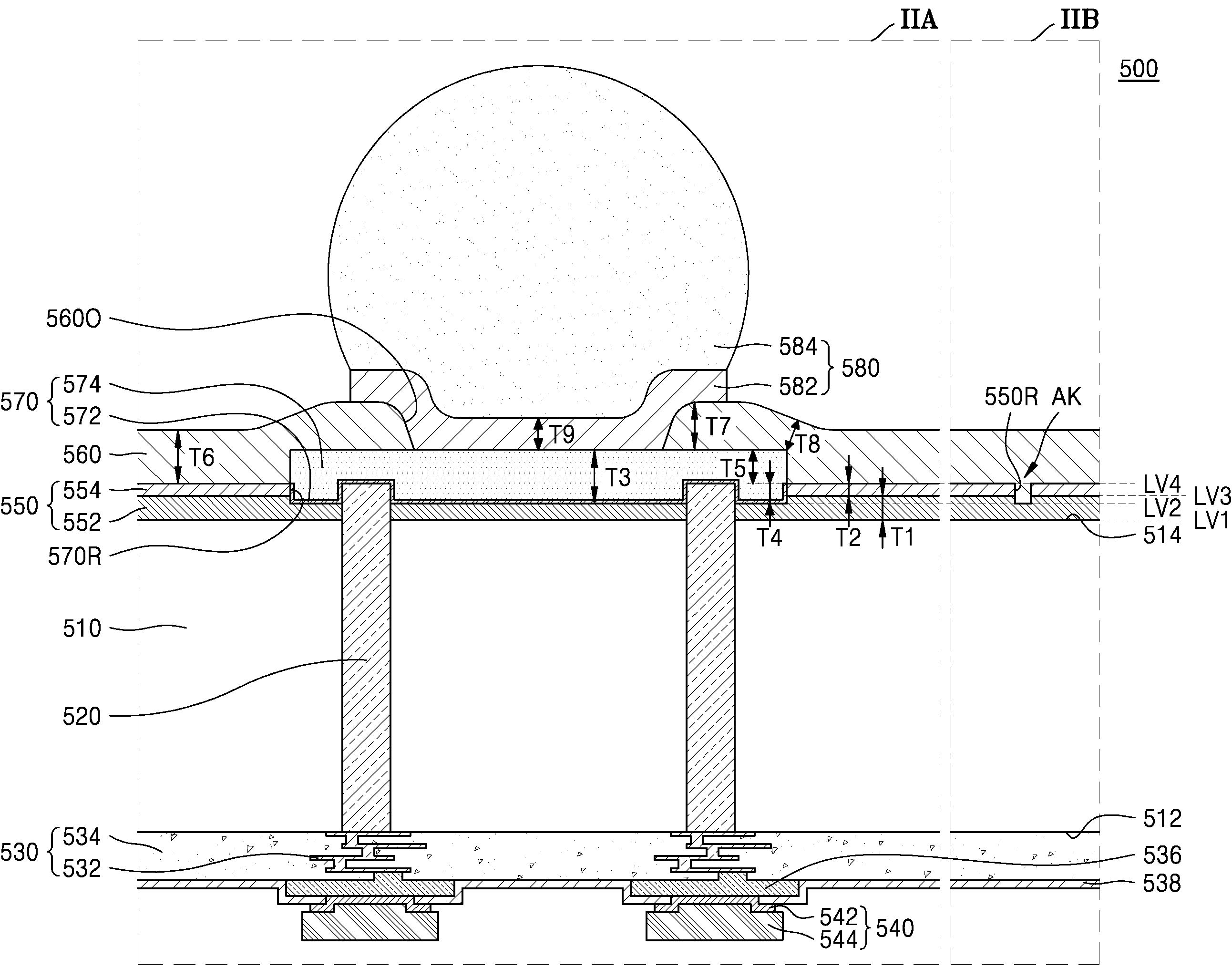
도 2는 본 발명의 일 실시 예에 따른 인터포저의 일부분들을 나타내는 확대 단면도이다. 구체적으로 도 2는 도 1의 IIA 및 IIB 부분을 나타내는 확대 단면도이다. 2 is an enlarged cross-sectional view illustrating portions of an interposer according to an embodiment of the present invention. Specifically, FIG. 2 is an enlarged cross-sectional view illustrating portions IIA and IIB of FIG. 1 .
도 1 및 도 2를 함께 참조하면, 인터포저(500)는 베이스층(510), 복수의 인터포저 관통 전극(520), 배선 구조물(530), 복수의 마이크로 패드(540), 인터포저 보호층(550), 복수의 인터포저 패드(570), 및 후면 배선 보호층(560)을 포함한다. 1 and 2 together, the
배선 구조물(530)은 배선 도전층(532) 및 배선 도전층(532)을 감싸는 배선간 절연층(534)을 포함한다. 배선 도전층(532)은 복수의 인터포저 관통 전극(520)과 복수의 마이크로 패드(540)를 전기적으로 연결할 수 있다. 배선 도전층(532)은 알루미늄, 구리 또는 텅스텐과 같은 금속 물질을 포함할 수 있다. 배선간 절연층(534)은 실리콘 산화물을 포함할 수 있다. 일부 실시 예에서, 배선간 절연층(534)은 TEOS(Tetraethyl orthosilicate)로 이루어질 수 있다. 다른 일부 실시 예에서, 배선간 절연층(534)은 실리콘 산화물보다 유전율이 낮은 절연물질, 예를 들면, 약 2.2∼2.4의 초저유전상수(ultra low dielectric constant K)를 가지는 ULK(Ultra Low k) 막으로 이루어질 수 있다.The
배선 도전층(532)은 복수의 배선 레이어를 구성하는 복수의 배선 패턴 및 서로 다른 배선 레이어들에 배치되는 배선 패턴들 사이를 연결하는 복수의 배선 비아로 이루어질 수 있다. 배선 레이어란, 평면상으로 연장되는 전기적 경로를 형성할 수 있는 곳을 의미하며, 서로 다른 배선 레이어들이란, 서로 다른 수직 레벨 각각에서 평면상으로 연장되는 전기적 경로를 형성할 수 있는 곳들을 의미한다. The wiring
배선 도전층(532)과 복수의 마이크로 패드(540) 사이에는 배선 도전층(532)과 연결되며 배선 구조물(530) 상에 배치되는 복수의 패드 배선 패턴(536)이 개재될 수 있다. 예를 들면, 복수의 패드 배선 패턴(536)은 구리, 니켈, 또는 구리 합금을 포함할 수 있다. 전면 배선 보호층(538)은, 복수의 패드 배선 패턴(536)의 일부분을 노출시키며 배선 구조물(530) 및 복수의 패드 배선 패턴(536)을 덮을 수 있다. 전면 배선 보호층(538)은 에폭시(epoxy) 또는 폴리이미드(polyimide)를 포함할 수 있다. A plurality of
복수의 마이크로 패드(540) 각각은 패드 배선 패턴(536)과 접하는 전면 UBM(Under Bump Metallurgy)층(542) 및 전면 UBM층(542)과 접하는 칩 연결 단자(544)로 이루어질 수 있다. 복수의 마이크로 패드(540)는 도전성 재질 예컨대, 구리(Cu), 알루미늄(Al), 은(Ag), 주석(Tin), 금(Au) 또는 솔더(solder) 등으로 형성될 수 있으나, 이에 한정되는 것은 아니다. Each of the plurality of
인터포저 보호층(550)은 베이스층(510)의 제2 면(514)을 덮는 하부 인터포저 보호층(552) 및 하부 인터포저 보호층(552)을 덮는 상부 인터포저 보호층(554)으로 이루어질 수 있다. 인터포저 보호층(550)은 무기질 물질로 이루어질 수 있다. 예를 들면, 인터포저 보호층(550)은 실리콘 산화물, 실리콘 질화물, 또는 실리콘 산화물과 실리콘 질화물의 적층 구조로 이루어질 수 있다. 예를 들면, 하부 인터포저 보호층(552)은 산화물로 이루어지고, 상부 인터포저 보호층(554)은 질화물로 이루어질 수 있다. 일부 실시 예에서, 하부 인터포저 보호층(552)은 실리콘 산화물로 이루어지고, 상부 인터포저 보호층(554)은 실리콘 질화물로 이루어질 수 있다. The
인터포저 보호층(550)은 상부 인터포저 보호층(554)의 상면으로부터 베이스층(510)을 향하여 연장되는 패드 리세스(570R)를 가질 수 있다. 패드 리세스(570R)의 저면에는 하부 인터포저 보호층(552)의 부분이 노출될 수 있다. 패드 리세스(570R)는 상부 인터포저 보호층(554)의 상면으로부터 베이스층(510)을 향하여 연장되되, 인터포저 보호층(550)을 완전히 관통하지 않을 수 있다. 일부 실시 예에서, 패드 리세스(570R)는 상부 인터포저 보호층(554)을 관통하되, 하부 인터포저 보호층(552)의 상측 일부분을 관통하고 하측 일부분을 관통하지 않을 수 있다. The
하부 인터포저 보호층(552) 및 상부 인터포저 보호층(554) 각각은 최대 두께로 제1 두께(T1) 및 제2 두께(T2)를 가질 수 있다. 예를 들면, 하부 인터포저 보호층(552) 및 상부 인터포저 보호층(554) 각각은 복수의 패드 리세스(570R) 및 복수의 인터포저 패드(570)와 수직 방향으로 중첩되지 않는 부분에서, 대체로 일정한 제1 두께(T1)와 제2 두께(T2)를 가질 수 있다. 일부 실시 예에서, 제1 두께(T1)는 제2 두께(T2)보다 큰 값을 가질 수 있다. 예를 들면, 제2 두께(T2)는 약 0.5㎛ 내지 약 1.5㎛일 수 있고, 제1 두께(T1)는 제2 두께(T2)보다 크되, 약 2.5㎛ 이하일 수 있다. Each of the lower
하부 인터포저 보호층(552)은 하면이 제1 수직 레벨(LV1)에 위치할 수 있고, 패드 리세스(570R)는 저면이 제1 수직 레벨(LV1)보다 높은 제2 수직 레벨(LV2)에 위치할 수 있다. 하부 인터포저 보호층(552)의 상면과 상부 인터포저 보호층(554)의 하면은 제2 수직 레벨(LV2)보다 높은 제3 수직 레벨(LV3)에서 접할 수 있다. 상부 인터포저 보호층(554)은 상면이 제3 수직 레벨(LV3)보다 높은 제4 수직 레벨(LV4)에 위치할 수 있다. The lower
복수의 인터포저 패드(570) 각각은 패드 리세스(570R)의 저면 및 측면, 즉 패드 리세스(570R) 내에 노출되는 인터포저 보호층(550)의 표면을 덮는 시드층(572) 및 시드층(572) 상에 도전 패드층(574)으로 이루어질 수 있다. 시드층(572)은 패드 리세스(570R)의 저면 및 측면을 컨포멀(conformal)하게 덮을 수 있다. 패드 리세스(570R)의 측면에서 시드층(572)의 최상단은 제4 수직 레벨(LV4)에 위치할 수 있다. Each of the plurality of
복수의 인터포저 패드(570) 각각은 패드 리세스(570R)를 채우고, 인터포저 보호층(550)의 상면, 즉 상부 인터포저 보호층(554)의 상면보다 외측으로 더 돌출될 수 있다. 즉, 복수의 인터포저 패드(570)의 상면은 제4 수직 레벨(LV4)보다 높은 수직 레벨에 위치할 수 있다. 복수의 인터포저 패드(570)의 하면은 제2 수직 레벨(LV2)에 위치할 수 있다. Each of the plurality of
복수의 인터포저 관통 전극(520)은 복수의 인터포저 패드(570) 내로 연장될 수 있다. 복수의 인터포저 관통 전극(520)의 상면은 제4 수직 레벨(LV4)에 위치할 수 있다. 즉, 복수의 인터포저 관통 전극(520)의 상면과 상부 인터포저 보호층(554)의 상면은 동일한 수직 레벨인 제4 수직 레벨(LV4)에 위치할 수 있다. The plurality of interposer through
복수의 인터포저 패드(570)의 하면 중 복수의 인터포저 관통 전극(520)과 접하는 부분을 제외한 부분인 복수의 인터포저 패드(570)의 최하면은 모두 하부 인터포저 보호층(552)과 접할 수 있다. 즉, 복수의 인터포저 패드(570)의 하면은 복수의 인터포저 관통 전극(520) 및 하부 인터포저 보호층(552)에 의하여 모두 덮일 수 있다. Among the lower surfaces of the plurality of
복수의 인터포저 관통 전극(520) 중 베이스층(510)의 상면이 위치하는 제1 수직 레벨(LV1)보다 상측 부분은 하부 인터포저 보호층(552) 및 복수의 인터포저 패드(570)에 의하여 포위될 수 있다. 복수의 인터포저 관통 전극(520) 중 베이스층(510)의 상면보다 상측 부분 중 최상측 부분의 상면 및 측면은 복수의 인터포저 패드(570)에 의하여 포위되고, 나머지 부분의 측면은 하부 인터포저 보호층(552)에 의하여 포위될 수 있다. Among the plurality of interposer through
복수의 인터포저 패드(570) 각각은 최대 두께로 제3 두께(T3)를 가질 수 있다. 제3 두께(T3)는 약 2㎛ 내지 약 7㎛일 수 있다. 복수의 인터포저 패드(570) 중 제4 수직 레벨(LV4) 하측의 부분, 즉 인터포저 보호층(550) 내에 매립되는 부분은 제4 두께(T4)를 가질 수 있고, 제4 수직 레벨(LV4) 상측의 부분, 즉 인터포저 보호층(550) 내에 매립되지 않고 인터포저 보호층(550)의 상면 상으로 돌출되는 부분은 제5 두께(T5)를 가질 수 있다. 복수의 인터포저 패드(570) 중 인터포저 보호층(550) 내에 매립되는 부분은 제1 부분이라 호칭할 수 있고, 인터포저 보호층(550)의 상면 상으로 돌출되는 부분은 제2 부분이라 호칭할 수 있다. 상기 제1 부분과 상기 제2 부분은 일체를 이루를 수 있다. 일부 실시 예에서, 제5 두께(T5)는 제4 두께(T4)보다 큰 값을 가질 수 있다. 예를 들면, 제5 두께(T5)는 제4 두께(T4)보다 큰 값을 가지되, 약 4㎛ 이하의 값을 가질 수 있다. Each of the plurality of
후면 배선 보호층(560)은 복수의 인터포저 패드(570)의 일부분을 노출시키는 단자 오프닝(560O)을 가지며, 복수의 인터포저 패드(570)의 나머지 부분 및 인터포저 보호층(550)을 덮을 수 있다. 후면 배선 보호층(560)은 인터포저 보호층(550)의 상면보다 외측으로 돌출되는 복수의 인터포저 패드(570)의 부분의 측면을 모두 덮고 상면의 일부분을 덮되, 상면의 나머지 부분을 덮지 않고 노출시키는 단자 오프닝(560O)을 가질 수 있다. 후면 배선 보호층(560)은 유기질 물질로 이루어질 수 있다. 예를 들면, 후면 배선 보호층(560)은 고분자 물질로 이루어질 수 있다. 일부 실시 예에서, 후면 배선 보호층(560)은 폴리이미드(polyimide)와 같은 PID(Photo Imageable dielectric)로부터 형성될 수 있다. The rear wiring
후면 배선 보호층(560)은, 인터포저 보호층(550) 상에서 대체로 제6 두께(T6)를 가질 수 있다. 예를 들면, 인터포저 보호층(550) 상에서, 후면 배선 보호층(560)의 최저 두께는 제6 두께(T6)일 수 있으며, 인터포저 보호층(550) 상에서 복수의 인터포저 패드(570)에 인접하는 후면 배선 보호층(560)의 두께는 제6 두께(T6)보다 큰 값을 가질 수 있다. 제6 두께(T6)는 제5 두께(T5)보다 큰 값을 가질 수 있다. 예를 들면, 제6 두께(T6)는 약 3㎛ 내지 약 4.5㎛일 수 있다. 후면 배선 보호층(560)은, 복수의 인터포저 패드(570) 상에서 최고 두께는 제7 두께(T7)일 수 있고, 최저 두께는 제8 두께(T8)일 수 있다. 예를 들면, 제7 두께(T7)는 약 3㎛ 내지 약 4.5㎛일 수 있고, 제8 두께(T8)는 약 1㎛ 내지 약 2.5㎛일 수 있다. The back wiring
복수의 인터포저 연결 단자(580) 각각은 인터포저 패드(570) 상의 후면 UBM 층(582), 및 후면 UBM 층(582) 상의 인터포저 도전성 캡(584)으로 이루어질 수 있다. Each of the plurality of
후면 UBM층(582)은 단자 오프닝(560O)에 의하여 노출되는 인터포저 패드(570)의 상면의 부분, 및 이에 인접하는 후면 배선 보호층(560)의 일부분을 덮을 수 있다. 일부 실시 예에서, 후면 UBM 층(582)은 단자 오프닝(560O)에 의하여 노출되는 인터포저 패드(570)의 상면의 부분, 및 이에 인접하는 후면 배선 보호층(560)의 일부분 상을 제9 두께(T9)를 가지며 컨포멀하게 덮을 수 있다. 제9 두께(T9)는 제7 두께(T7)보다 작은 값을 가질 수 있다. 예를 들면, 제9 두께(T9)는 약 2㎛ 내지 약 3㎛일 수 있다. 후면 UBM층(582)은 단자 오프닝(560O)에 대응되는 오목한 상면을 가질 수 있다. The
인터포저 도전성 캡(584)은 후면 UBM 층(582)의 상면의 전부 또는 대부분을 덮을 수 있다. 일부 실시 예에서, 인터포저 연결 단자(580)는 도전성 재질 예컨대, 구리(Cu), 알루미늄(Al), 은(Ag), 주석(Tin), 금(Au) 또는 솔더(solder) 등으로 형성될 수 있으나, 이에 한정되는 것은 아니다. 인터포저 연결 단자(580)는 다중층 또는 단일층으로 형성될 수 있다. 일부 실시 예에서, 인터포저 도전성 캡(584)은 SnAg로 이루어질 수 있다. The interposer
인터포저 보호층(550)은 상부 인터포저 보호층(554)의 상면으로부터 베이스층(510)을 향하여 연장되는 정렬 리세스(550R)를 더 가질 수 있다. 정렬 리세스(550R)의 저면에는 하부 인터포저 보호층(552)의 부분이 노출될 수 있다. 정렬 리세스(550R)는 상부 인터포저 보호층(554)의 상면으로부터 베이스층(510)을 향하여 연장되되, 인터포저 보호층(550)을 완전히 관통하지 않을 수 있다. 일부 실시 예에서, 정렬 리세스(550R)는 상부 인터포저 보호층(554)을 관통하되, 하부 인터포저 보호층(552)의 상측 일부분만 관통하고 하측 일부분을 관통하지 않을 수 있다. The
정렬 리세스(550R)는 후면 배선 보호층(560)에 의하여 채워질 수 있다. 정렬 리세스(550R)는 패드 리세스(570R)와 이격되도록 배치될 수 있다. 정렬 리세스(550R)는 정렬 키(AK)를 구성할 수 있다. 정렬 키(AK)는 인터포저 보호층(550)과 인터포저 보호층(550) 내로 연장되는 후면 배선 보호층(560)의 계면, 즉 정렬 리세스(550R)의 저면 및 측면에 의하여 구성될 수 있다. 정렬 리세스(550R)의 저면과 패드 리세스(570R)의 저면은 동일한 수직 레벨인 제2 수직 레벨(LV2)에 위치할 수 있다. The
본 발명에 따른 인터포저(500)는 인터포저 보호층(550) 내, 즉 패드 리세스(570R)에 일부분이 매립되는 복수의 인터포저 패드(570)를 가질 수 있다. 따라서 인터포저 보호층(550) 상으로 돌출되는 높이를 상대적으로 낮게 하면서도, 복수의 인터포저 패드(570)를 두껍게 형성할 수 있다. The
따라서 배선 도전층(532)이 상대적으로 많은 수의 배선 레이어를 구성하여, 배선 도전층(532)의 두께 및 인터포저(500)에서 배선 도전층(532)이 차지하는 부피가 증가하는 경우에도 복수의 인터포저 패드(570)의 두께를 증가할 수 있어, 인터포저(500)의 상부와 하부에 배치되는 복수의 인터포저 패드(570)와 배선 도전층(532)의 비율을 조절하여, 인터포저(500)에 휨(warpage) 현상이 발생하는 것을 방지할 수 있다. Accordingly, even when the wiring
도 3은 본 발명의 일 실시 예에 따른 인터포저의 일부분들을 나타내는 확대 단면도이다. 구체적으로 도 3의 IIIA 및 IIIB 각각은 도 1의 IIA 및 IIB 부분에 대응하는 부분을 나타내는 확대 단면도로, 도 1과 동일한 부재 번호는 동일한 구성 요소를 나타내며, 중복되는 내용은 생략할 수 있다.3 is an enlarged cross-sectional view illustrating portions of an interposer according to an embodiment of the present invention. Specifically, each of IIIA and IIIB of FIG. 3 is an enlarged cross-sectional view illustrating a portion corresponding to portions IIA and IIB of FIG. 1 , and the same reference numerals as in FIG. 1 indicate the same components, and overlapping content may be omitted.
도 1 및 도 3을 함께 참조하면, 인터포저(500a)는 베이스층(510), 복수의 인터포저 관통 전극(520), 배선 구조물(530), 복수의 마이크로 패드(540), 인터포저 보호층(550a), 복수의 인터포저 패드(570), 및 후면 배선 보호층(560)을 포함한다. 1 and 3 together, the
인터포저 보호층(550a)은 베이스층(510)의 제2 면(514)을 덮는 하부 인터포저 보호층(552a) 및 하부 인터포저 보호층(552a)을 덮는 상부 인터포저 보호층(554a)으로 이루어질 수 있다. 인터포저 보호층(550a)은 무기질 물질로 이루어질 수 있다. 예를 들면, 하부 인터포저 보호층(552a)은 산화물로 이루어지고, 상부 인터포저 보호층(554a)은 질화물로 이루어질 수 있다. 하부 인터포저 보호층(552a)은 상부 인터포저 보호층(554a)의 하면으로부터 복수의 인터포저 관통 전극(520)의 측면을 포위하며 상측으로 돌출하여, 복수의 인터포저 패드(570)의 하면과 접할 수 있다. The interposer
인터포저 보호층(550a)은 상부 인터포저 보호층(554a)의 상면으로부터 베이스층(510)을 향하여 연장되는 패드 리세스(570Ra)를 가질 수 있다. 패드 리세스(570Ra)의 저면에는 상부 인터포저 보호층(554a)의 부분 및 하부 인터포저 보호층(552a)의 부분이 노출될 수 있다. 패드 리세스(570R)의 저면에 노출되는 하부 인터포저 보호층(552a)의 부분은 복수의 인터포저 관통 전극(520)의 포위할 수 있다. 패드 리세스(570Ra)는 상부 인터포저 보호층(554a)의 상면으로부터 베이스층(510)을 향하여 연장되되, 인터포저 보호층(550a)을 완전히 관통하지 않을 수 있다. 일부 실시 예에서, 패드 리세스(570Ra)는 상부 인터포저 보호층(554a)의 상측 일부분을 관통하고 하측 일부분을 관통하지 않을 수 있다. The
하부 인터포저 보호층(552a)은 상부 인터포저 보호층(554a)의 아래 부분에서 제1 두께(T1a)를 가질 수 있고, 상부 인터포저 보호층(554)은 최대 두께로 제2 두께(T2a)를 가질 수 있다. 일부 실시 예에서, 제1 두께(T1a)는 제2 두께(T2a)보다 작은 값을 가질 수 있다. 예를 들면, 제2 두께(T2a)는 약 0.5㎛ 내지 약 1.5㎛일 수 있고, 제1 두께(T1a)는 제2 두께(T2a)보다 작되, 약 0.3㎛ 이상일 수 있다. The lower
복수의 인터포저 패드(570)의 하면과 접하며 복수의 인터포저 관통 전극(520)의 측면을 포위하는 하부 인터포저 보호층(552a)의 부분은 수직 방향으로 제1 두께(T1a)보다 큰 값 두께를 가질 수 있고, 하부 인터포저 보호층(552a)의 나머지 부분은 수직 방향으로 제1 두께(T1a)를 가질 수 있다. 일부 실시 예에서, 복수의 인터포저 패드(570)의 하면과 접하며 복수의 인터포저 관통 전극(520)의 측면을 포위하는 하부 인터포저 보호층(552a)의 부분은, 복수의 인터포저 관통 전극(520)의 측면 상에서 수평 방향으로 제1 두께(T1a)를 가질 수 있다. A portion of the lower interposer
예를 들면, 하부 인터포저 보호층(552a)은 상부 인터포저 보호층(554a)과 수직 방향으로 중첩되는 부분에서 수직 방향으로 대체로 일정한 제1 두께(T1a)를 가질 수 있고, 상부 인터포저 보호층(554a)은 복수의 패드 리세스(570Ra) 및 복수의 인터포저 패드(570)와 수직 방향으로 중첩되지 않는 부분에서 대체로 일정한 제2 두께(T2a)를 가질 수 있다. 예를 들면, 하부 인터포저 보호층(552a)의 최대 두께는, 복수의 패드 리세스(570Ra) 및 복수의 인터포저 패드(570)와 수직 방향으로 중첩되는 부분에서 상부 인터포저 보호층(554a)의 두께와 제1 두께(T1a)의 합일 수 있다. For example, the lower
하부 인터포저 보호층(552a)은 하면이 제1 수직 레벨(LV1)에 위치할 수 있고, 패드 리세스(570Ra)의 저면은 제1 수직 레벨(LV1)보다 높은 제2 수직 레벨(LV2)에 위치할 수 있다. 상부 인터포저 보호층(554a)의 하면과 접하는 하부 인터포저 보호층(552a)의 상면의 부분은 제2 수직 레벨(LV2)보다 낮은 제3 수직 레벨(LV3a)에 위치할 수 있다. 상부 인터포저 보호층(554a)의 상면은 제2 수직 레벨(LV2)보다 높은 제4 수직 레벨(LV4)에 위치할 수 있다. The lower interposer
복수의 인터포저 관통 전극(520)은 복수의 인터포저 패드(570) 내로 연장될 수 있다. 복수의 인터포저 관통 전극(520)의 상면과 상부 인터포저 보호층(554a)의 상면은 동일한 수직 레벨인 제4 수직 레벨(LV4)에 위치할 수 있다. The plurality of interposer through
복수의 인터포저 패드(570)의 하면 중 복수의 인터포저 관통 전극(520)과 접하는 부분을 제외한 부분인 복수의 인터포저 패드(570)의 최하면은 상부 인터포저 보호층(554a) 및 하부 인터포저 보호층(552a)과 접할 수 있다. 예를 들면, 복수의 인터포저 패드(570)의 최하면 중, 복수의 인터포저 관통 전극(520)에 인접하는 부분은 하부 인터포저 보호층(552a)과 접하고, 나머지 부분은 상부 인터포저 보호층(554a)과 접할 수 있다. 즉, 복수의 인터포저 패드(570)의 하면은 복수의 인터포저 관통 전극(520), 상부 인터포저 보호층(554a), 및 하부 인터포저 보호층(552a)에 의하여 모두 덮일 수 있다. The lowermost surfaces of the plurality of
복수의 인터포저 관통 전극(520) 중 베이스층(510)의 상면이 위치하는 제1 수직 레벨(LV1)보다 상측 부분은 하부 인터포저 보호층(552a) 및 복수의 인터포저 패드(570)에 의하여 포위될 수 있다. 복수의 인터포저 관통 전극(520) 중 베이스층(510)의 상면보다 상측 부분 중 최상측 부분의 상면 및 측면은 복수의 인터포저 패드(570)에 의하여 포위되고, 나머지 부분의 측면은 하부 인터포저 보호층(552a)에 의하여 포위될 수 있다. Among the plurality of interposer through
복수의 인터포저 패드(570) 중 인터포저 보호층(550a) 내에 매립되는 부분은 제4 두께(T4)를 가질 수 있고, 인터포저 보호층(550a) 내에 매립되지 않고, 인터포저 보호층(550a)의 상면 상으로 돌출되는 부분은 제4 두께(T4)보다 큰 값인 제5 두께(T5)를 가질 수 있다. A portion of the plurality of
후면 배선 보호층(560)은 인터포저 보호층(550a)의 상면 상으로 돌출되는 복수의 인터포저 패드(570)의 부분의 측면을 모두 덮고 복수의 인터포저 패드(570)의 상면의 일부분을 덮되, 복수의 인터포저 패드(570)의 상면의 나머지 부분을 덮지 않고 노출시키는 단자 오프닝(560O)을 가질 수 있다. The rear
인터포저 보호층(550a)은 상부 인터포저 보호층(554a)의 상면으로부터 베이스층(510)을 향하여 연장되는 정렬 리세스(550Ra)를 더 가질 수 있다. 정렬 리세스(550Ra)의 저면에는 상부 인터포저 보호층(554a)의 부분이 노출될 수 있다. 정렬 리세스(550Ra)는 상부 인터포저 보호층(554a)의 상면으로부터 베이스층(510)을 향하여 연장되되, 상부 인터포저 보호층(550a)을 완전히 관통하지 않을 수 있다. 일부 실시 예에서, 정렬 리세스(550Ra)는 상부 인터포저 보호층(554a)의 상측 일부분만 관통하고 하측 일부분을 관통하지 않을 수 있다. The
정렬 리세스(550Ra)는 후면 배선 보호층(560)에 의하여 채워질 수 있다. 정렬 리세스(550Ra)는 패드 리세스(570R)와 이격되도록 배치될 수 있다. 정렬 리세스(550Ra)는 정렬 키(AKa)를 구성할 수 있다. 정렬 키(AKa)는 인터포저 보호층(550a)과 인터포저 보호층(550a) 내로 연장되는 후면 배선 보호층(560)의 계면, 즉 정렬 리세스(550Ra)의 저면 및 측면에 의하여 구성될 수 있다. 정렬 리세스(550Ra)의 저면과 패드 리세스(570R)의 저면은 동일한 수직 레벨인 제2 수직 레벨(LV2)에 위치할 수 있다. The alignment recess 550Ra may be filled by the rear
도 4는 본 발명의 일 실시 예에 따른 인터포저의 일부분들을 나타내는 확대 단면도이다. 구체적으로 도 4의 IVA 및 IVB 각각은 도 1의 IIA 및 IIB 부분에 대응하는 부분을 나타내는 확대 단면도로, 도 1과 동일한 부재 번호는 동일한 구성 요소를 나타내며, 중복되는 내용은 생략할 수 있다.4 is an enlarged cross-sectional view illustrating portions of an interposer according to an embodiment of the present invention. Specifically, each of IVA and IVB of FIG. 4 is an enlarged cross-sectional view showing a portion corresponding to the portions IIA and IIB of FIG. 1 , and the same reference numerals as in FIG. 1 indicate the same components, and overlapping content may be omitted.
도 1 및 도 4를 참조하면, 인터포저(500b)는 베이스층(510), 복수의 인터포저 관통 전극(520), 배선 구조물(530), 복수의 마이크로 패드(540), 인터포저 보호층(550b), 복수의 인터포저 패드(570b), 및 후면 배선 보호층(560b)을 포함한다. 1 and 4 , the
인터포저 보호층(550b)은 베이스층(510)의 제2 면(514)을 덮는 하부 인터포저 보호층(552b) 및 하부 인터포저 보호층(552b)을 덮는 상부 인터포저 보호층(554b)으로 이루어질 수 있다. 인터포저 보호층(550b)은 무기질 물질로 이루어질 수 있다. 예를 들면, 인터포저 보호층(550b)은 실리콘 산화물, 실리콘 질화물, 또는 실리콘 산화물과 실리콘 질화물의 적층 구조로 이루어질 수 있다. 예를 들면, 하부 인터포저 보호층(552b)은 산화물로 이루어지고, 상부 인터포저 보호층(554b)은 질화물로 이루어질 수 있다. The
인터포저 보호층(550b)은 상부 인터포저 보호층(554b)의 상면으로부터 베이스층(510b)을 향하여 연장되는 패드 리세스(570Rb)를 가질 수 있다. 패드 리세스(570Rb)의 저면에는 하부 인터포저 보호층(552b)의 부분이 노출될 수 있다.The
하부 인터포저 보호층(552b) 및 상부 인터포저 보호층(554b) 각각은 최대 두께로 제1 두께(T1b) 및 제2 두께(T2b)를 가질 수 있다. 예를 들면, 하부 인터포저 보호층(552b) 및 상부 인터포저 보호층(554b) 각각은 복수의 패드 리세스(570Rb) 및 복수의 인터포저 패드(570b)와 수직 방향으로 중첩되지 않는 부분에서, 대체로 일정한 제1 두께(T1b)와 제2 두께(T2b)를 가질 수 있다. 일부 실시 예에서, 제1 두께(T1b)는 제2 두께(T2b)보다 작은 값을 가질 수 있다. 예를 들면, 제2 두께(T2b)는 약 0.5㎛ 내지 약 1.5㎛일 수 있고, 제1 두께(T1b)는 제2 두께(T2)보다 작되, 약 0.3㎛ 이상일 수 있다. Each of the lower
하부 인터포저 보호층(552b)은 하면이 제1 수직 레벨(LV1)에 위치할 수 있고, 패드 리세스(570Rb)의 저면은 제1 수직 레벨(LV1)보다 높은 제2 수직 레벨(LV2b)에 위치할 수 있다. 하부 인터포저 보호층(552b)의 상면과 상부 인터포저 보호층(554b)의 하면은 제2 수직 레벨(LV2b)보다 높은 제3 수직 레벨(LV3b)에서 접할 수 있다. 상부 인터포저 보호층(554b)의 상면은 제3 수직 레벨(LV3b)보다 높은 제4 수직 레벨(LV4)에 위치할 수 있다. The lower
복수의 인터포저 패드(570b) 각각은 패드 리세스(570Rb)의 저면 및 측면, 즉 패드 리세스(570Rb) 내에 노출되는 인터포저 보호층(550b)의 표면을 덮는 시드층(572b) 및 시드층(572b) 상에 도전 패드층(574b)으로 이루어질 수 있다. 시드층(572b)은 패드 리세스(570Rb)의 저면 및 측면을 컨포멀하게 덮을 수 있다. 패드 리세스(570Rb)의 측면에서 시드층(572b)의 최상단은 제4 수직 레벨(LV4b)에 위치할 수 있다. Each of the plurality of
복수의 인터포저 패드(570b) 각각은 패드 리세스(570Rb)를 채우고, 인터포저 보호층(550b)의 상면, 즉 상부 인터포저 보호층(554b)의 상면보다 외측으로 더 돌출될 수 있다. 즉, 복수의 인터포저 패드(570b)의 상면은 제4 수직 레벨(LV4)보다 높은 수직 레벨에 위치할 수 있다. 복수의 인터포저 패드(570b)의 하면은 제2 수직 레벨(LV2b)에 위치할 수 있다. Each of the plurality of
복수의 인터포저 관통 전극(520)은 복수의 인터포저 패드(570b) 내로 연장될 수 있다. 복수의 인터포저 관통 전극(520)의 상면과 상부 인터포저 보호층(554b)의 상면은 동일한 수직 레벨인 제4 수직 레벨(LV4)에 위치할 수 있다. The plurality of interposer through
복수의 인터포저 패드(570b)의 하면 중 복수의 인터포저 관통 전극(520)과 접하는 부분을 제외한 부분인 복수의 인터포저 패드(570)의 최하면은 모두 하부 인터포저 보호층(552b)과 접할 수 있다. 즉, 복수의 인터포저 패드(570b)의 하면은 복수의 인터포저 관통 전극(520) 및 하부 인터포저 보호층(552b)에 의하여 모두 덮일 수 있다. The lowermost surfaces of the plurality of
복수의 인터포저 관통 전극(520) 중 베이스층(510)의 상면이 위치하는 제1 수직 레벨(LV1)보다 상측 부분은 하부 인터포저 보호층(552b) 및 복수의 인터포저 패드(570b)에 의하여 포위될 수 있다. 복수의 인터포저 관통 전극(520) 중 베이스층(510)의 상면보다 상측 부분 중 최상측 부분의 상면 및 측면은 복수의 인터포저 패드(570b)에 의하여 포위되고, 나머지 부분의 측면은 하부 인터포저 보호층(552b)에 의하여 포위될 수 있다. Among the plurality of interposer through
복수의 인터포저 패드(570b) 각각은 최대 두께로 제3 두께(T3b)를 가질 수 있다. 제3 두께(T3b)는 약 2㎛ 내지 약 7㎛일 수 있다. 복수의 인터포저 패드(570b) 중 제4 수직 레벨(LV4) 하측의 부분, 즉 인터포저 보호층(550b) 내에 매립되는 부분은 제4 두께(T4b)를 가질 수 있고, 제4 수직 레벨(LV4) 상측의 부분, 즉 인터포저 보호층(550b) 내에 매립되지 않고, 인터포저 보호층(550b)의 상면 상으로 돌출되는 부분은 제4 두께(T4b)보다 작은 제5 두께(T5b)를 가질 수 있다. 예를 들면, 제5 두께(T5b)는 제4 두께(T4b)보다 작은 값을 가지되, 약 4㎛ 이하의 값을 가질 수 있다. Each of the plurality of
후면 배선 보호층(560b)은 복수의 인터포저 패드(570b)의 일부분을 노출시키는 단자 오프닝(560Ob)을 가지며, 인터포저 보호층(550b) 및 복수의 인터포저 패드(570b)를 덮을 수 있다. 후면 배선 보호층(560b)은 인터포저 보호층(550b)의 상면 상으로 돌출되는 복수의 인터포저 패드(570b)의 부분의 측면을 모두 덮고 상면의 일부분을 덮되, 상면의 나머지 부분을 덮지 않고 노출시키는 단자 오프닝(560Ob)을 가질 수 있다. 후면 배선 보호층(560b)은 유기질 물질로 이루어질 수 있다. 예를 들면, 후면 배선 보호층(560b)은 고분자 물질로 이루어질 수 있다. The rear wiring
후면 배선 보호층(560b)은, 인터포저 보호층(550b) 상에서 대체로 제6 두께(T6b)를 가질 수 있다. 예를 들면, 인터포저 보호층(550b) 상에서, 후면 배선 보호층(560b)의 최저 두께는 제6 두께(T6b)일 수 있으며, 인터포저 보호층(550b) 상에서 복수의 인터포저 패드(570b)에 인접하는 후면 배선 보호층(560b)의 두께는 제6 두께(T6b)보다 큰 값을 가질 수 있다. 제6 두께(T6b)는 제5 두께(T5b)보다 큰 값을 가질 수 있다. 예를 들면, 제6 두께(T6b)는 약 3㎛ 내지 약 4.5㎛일 수 있다. 후면 배선 보호층(560b)은, 복수의 인터포저 패드(570b) 상에서 최고 두께는 제7 두께(T7b)일 수 있고, 최저 두께는 제8 두께(T8b)일 수 있다. 예를 들면, 제7 두께(T7b)는 약 3㎛ 내지 약 4.5㎛일 수 있고, 제8 두께(T8b)는 약 1㎛ 내지 약 2.5㎛일 수 있다. The rear wiring
후면 UBM층(582)은 단자 오프닝(560Ob)에 의하여 노출되는 인터포저 패드(570b)의 상면의 부분, 및 이에 인접하는 후면 배선 보호층(560b)의 일부분을 컨포멀하게 덮을 수 있다. The
인터포저 보호층(550b)은 상부 인터포저 보호층(554b)의 상면으로부터 베이스층(510)을 향하여 연장되는 정렬 리세스(550Rb)를 더 가질 수 있다. 정렬 리세스(550Rb)의 저면에는 하부 인터포저 보호층(552b)의 부분이 노출될 수 있다. 정렬 리세스(550Rb)는 상부 인터포저 보호층(554b)의 상면으로부터 베이스층(510)을 향하여 연장되되, 인터포저 보호층(550b)을 완전히 관통하지 않을 수 있다. 일부 실시 예에서, 정렬 리세스(550Rb)는 상부 인터포저 보호층(554b)을 관통하되, 하부 인터포저 보호층(552b)의 상측 일부분만 관통하고 하측 일부분을 관통하지 않을 수 있다. The
정렬 리세스(550Rb)는 후면 배선 보호층(560b)에 의하여 채워질 수 있다. 정렬 리세스(550Rb)는 패드 리세스(570Rb)와 이격되도록 배치될 수 있다. 정렬 리세스(550Rb)는 정렬 키(AKb)를 구성할 수 있다. 정렬 키(AKb)는 인터포저 보호층(550b)과 인터포저 보호층(550b) 내로 연장되는 후면 배선 보호층(560b)의 계면, 즉 정렬 리세스(550Rb)의 저면 및 측면에 의하여 구성될 수 있다. 정렬 리세스(550Rb)의 저면과 패드 리세스(570Rb)의 저면은 동일한 수직 레벨인 제2 수직 레벨(LV2b)에 위치할 수 있다. The alignment recess 550Rb may be filled by the rear
도 5는 본 발명의 일 실시 예에 따른 인터포저의 일부분들을 나타내는 확대 단면도이다. 구체적으로 도 5의 VA 및 VB 각각은 도 1의 IIA 및 IIB 부분에 대응하는 부분을 나타내는 확대 단면도로, 도 1과 동일한 부재 번호는 동일한 구성 요소를 나타내며, 중복되는 내용은 생략할 수 있다.5 is an enlarged cross-sectional view illustrating parts of an interposer according to an embodiment of the present invention. Specifically, each of VA and VB of FIG. 5 is an enlarged cross-sectional view illustrating a portion corresponding to portions IIA and IIB of FIG. 1 , and the same reference numerals as in FIG. 1 indicate the same components, and overlapping content may be omitted.
도 1 및 도 5를 참조하면, 인터포저(500c)는 베이스층(510), 복수의 인터포저 관통 전극(520), 배선 구조물(530), 복수의 마이크로 패드(540), 인터포저 보호층(550c), 복수의 인터포저 패드(570b), 및 후면 배선 보호층(560b)을 포함한다. 1 and 5 , the
인터포저 보호층(550c)은 베이스층(510)의 제2 면(514)을 덮는 하부 인터포저 보호층(552c) 및 하부 인터포저 보호층(552c)을 덮는 상부 인터포저 보호층(554c)으로 이루어질 수 있다. 인터포저 보호층(550c)은 무기질 물질로 이루어질 수 있다. 예를 들면, 하부 인터포저 보호층(552c)은 산화물로 이루어지고, 상부 인터포저 보호층(554c)은 질화물로 이루어질 수 있다. 하부 인터포저 보호층(552c)은 상부 인터포저 보호층(554c)의 하면으로부터 복수의 인터포저 관통 전극(520)의 측면을 포위하며 상측으로 돌출하여, 복수의 인터포저 패드(570b)의 하면과 접할 수 있다. The
인터포저 보호층(550c)은 상부 인터포저 보호층(554c)의 상면으로부터 베이스층(510)을 향하여 연장되는 패드 리세스(570Rc)를 가질 수 있다. 패드 리세스(570Rc)의 저면에는 상부 인터포저 보호층(554c)의 부분 및 하부 인터포저 보호층(552c)의 부분이 노출될 수 있다. 패드 리세스(570Rc)의 저면에 노출되는 하부 인터포저 보호층(552c)의 부분은 복수의 인터포저 관통 전극(520)을 포위할 수 있다. The
하부 인터포저 보호층(552c)은 상부 인터포저 보호층(554c)의 아래 부분에서 제1 두께(T1c)를 가질 수 있고, 상부 인터포저 보호층(554)은 최대 두께로 제2 두께(T2c)를 가질 수 있다. 복수의 인터포저 패드(570b)의 하면과 접하며 복수의 인터포저 관통 전극(520)의 측면을 포위하는 하부 인터포저 보호층(552c)의 부분은 수직 방향으로 제1 두께(T1c)보다 큰 값 두께를 가질 수 있고, 하부 인터포저 보호층(552c)의 나머지 부분은 수직 방향으로 제1 두께(T1c)를 가질 수 있다. 일부 실시 예에서, 복수의 인터포저 패드(570b)의 하면과 접하며 복수의 인터포저 관통 전극(520)의 측면을 포위하는 하부 인터포저 보호층(552c)의 부분은, 복수의 인터포저 관통 전극(520)의 측면 상에서 수평 방향으로 제1 두께(T1c)를 가질 수 있다. The lower
예를 들면, 하부 인터포저 보호층(552c)은 상부 인터포저 보호층(554c)과 수직 방향으로 중첩되는 부분에서 수직 방향으로 대체로 일정한 제1 두께(T1c)를 가질 수 있고, 상부 인터포저 보호층(554c)은 복수의 패드 리세스(570Rc) 및 복수의 인터포저 패드(570b)와 수직 방향으로 중첩되지 않는 부분에서 대체로 일정한 제2 두께(T2c)를 가질 수 있다. 예를 들면, 하부 인터포저 보호층(552c)의 최대 두께는, 복수의 패드 리세스(570Rc) 및 복수의 인터포저 패드(570b)와 수직 방향으로 중첩되는 부분에서 상부 인터포저 보호층(554c)의 두께와 제1 두께(T1c)의 합일 수 있다. 일부 실시 예에서, 제1 두께(T1c)는 제2 두께(T2c)보다 작은 값을 가질 수 있다. 예를 들면, 제2 두께(T2c)는 약 0.5㎛ 내지 약 1.5㎛일 수 있고, 제1 두께(T1c)는 제2 두께(T2c)보다 작되, 약 0.3㎛ 이상일 수 있다. For example, the lower
하부 인터포저 보호층(552c)은 하면이 제1 수직 레벨(LV1)에 위치할 수 있고, 패드 리세스(570Rc)의 저면은 제1 수직 레벨(LV1)보다 높은 제2 수직 레벨(LV2b)에 위치할 수 있다. 상부 인터포저 보호층(554c)의 하면과 접하는 하부 인터포저 보호층(552c)의 상면의 부분은 제2 수직 레벨(LV2b)보다 낮은 제3 수직 레벨(LV3c)에 위치할 수 있다. 상부 인터포저 보호층(554c)의 상면은 제2 수직 레벨(LV2b)보다 높은 제4 수직 레벨(LV4)에 위치할 수 있다. The lower interposer
복수의 인터포저 패드(570b) 각각은 패드 리세스(570Rc)의 저면 및 측면, 즉 패드 리세스(570Rc) 내에 노출되는 인터포저 보호층(550c)의 표면을 덮는 시드층(572b) 및 시드층(572b) 상에 도전 패드층(574b)으로 이루어질 수 있다. Each of the plurality of
복수의 인터포저 패드(570b) 각각은 패드 리세스(570Rc)를 채우고, 인터포저 보호층(550c)의 상면, 즉 상부 인터포저 보호층(554c)의 상면보다 외측으로 더 돌출될 수 있다. 즉, 복수의 인터포저 패드(570b)의 상면은 제4 수직 레벨(LV4)보다 높은 수직 레벨에 위치할 수 있다. 복수의 인터포저 패드(570b)의 하면은 제2 수직 레벨(LV2b)에 위치할 수 있다. Each of the plurality of
복수의 인터포저 패드(570b) 중 인터포저 보호층(550c) 내에 매립되는 부분은 제4 두께(T4b)를 가질 수 있고, 인터포저 보호층(550c) 내에 매립되지 않고 인터포저 보호층(550c)의 상면 상으로 돌출되는 부분은 제4 두께(T5b)보다 작은 제5 두께(T5b)를 가질 수 있다. A portion of the plurality of
복수의 인터포저 관통 전극(520)은 복수의 인터포저 패드(570b) 내로 연장될 수 있다. 복수의 인터포저 관통 전극(520)의 상면과 상부 인터포저 보호층(554c)의 상면은 동일한 수직 레벨인 제4 수직 레벨(LV4)에 위치할 수 있다. The plurality of interposer through
복수의 인터포저 패드(570b)의 하면 중 복수의 인터포저 관통 전극(520)과 접하는 부분을 제외한 부분인 복수의 인터포저 패드(570b)의 최하면은 상부 인터포저 보호층(554c) 및 하부 인터포저 보호층(552c)과 접할 수 있다. 예를 들면, 복수의 인터포저 패드(570b)의 최하면 중, 복수의 인터포저 관통 전극(520)에 인접하는 부분은 하부 인터포저 보호층(552c)과 접하고, 나머지 부분은 상부 인터포저 보호층(554c)과 접할 수 있다. 즉, 복수의 인터포저 패드(570b)의 하면은 복수의 인터포저 관통 전극(520), 상부 인터포저 보호층(554c), 및 하부 인터포저 보호층(552c)에 의하여 모두 덮일 수 있다. The lowermost surfaces of the plurality of
복수의 인터포저 관통 전극(520) 중 베이스층(510)의 상면이 위치하는 제1 수직 레벨(LV1)보다 상측 부분은 하부 인터포저 보호층(552c) 및 복수의 인터포저 패드(570b)에 의하여 포위될 수 있다. 복수의 인터포저 관통 전극(520) 중 베이스층(510)의 상면보다 상측 부분 중 최상측 부분의 상면 및 측면은 복수의 인터포저 패드(570b)에 의하여 포위되고, 나머지 부분의 측면은 하부 인터포저 보호층(552c)에 의하여 포위될 수 있다. Among the plurality of interposer through
후면 배선 보호층(560b)은 복수의 인터포저 패드(570b)의 일부분을 노출시키는 단자 오프닝(560Ob)을 가지며, 인터포저 보호층(550c) 및 복수의 인터포저 패드(570b)를 덮을 수 있다. The rear wiring
인터포저 보호층(550c)은 상부 인터포저 보호층(554c)의 상면으로부터 베이스층(510)을 향하여 연장되는 정렬 리세스(550Rc)를 더 가질 수 있다. 정렬 리세스(550Rc)의 저면에는 상부 인터포저 보호층(554c)의 부분이 노출될 수 있다. 정렬 리세스(550Rc)는 상부 인터포저 보호층(554c)의 상면으로부터 베이스층(510)을 향하여 연장되되, 상부 인터포저 보호층(550c)을 완전히 관통하지 않을 수 있다. 일부 실시 예에서, 정렬 리세스(550Rc)는 상부 인터포저 보호층(554c)의 상측 일부분만 관통하고 하측 일부분을 관통하지 않을 수 있다. The
정렬 리세스(550Rc)는 후면 배선 보호층(560b)에 의하여 채워질 수 있다. 정렬 리세스(550Rc)는 패드 리세스(570Rc)와 이격되도록 배치될 수 있다. 정렬 리세스(550Rc)는 정렬 키(AKc)를 구성할 수 있다. 정렬 키(AKc)는 인터포저 보호층(550c)과 인터포저 보호층(550c) 내로 연장되는 후면 배선 보호층(560b)의 계면, 즉 정렬 리세스(550Rc)의 저면 및 측면에 의하여 구성될 수 있다. 정렬 리세스(550Rc)의 저면과 패드 리세스(570Rb)의 저면은 동일한 수직 레벨인 제2 수직 레벨(LV2b)에 위치할 수 있다. The alignment recess 550Rc may be filled by the back
도 6a 내지 도 6g는 본 발명의 일 실시 예에 따른 인터포저를 제조하는 방법을 단계적으로 나타내는 단면도들이다. 구체적으로 도 6a 내지 도 6g는 도 1 및 도 2에 보인 인터포저를 제조하는 방법을 단계적으로 나타내는 단면도들이다.6A to 6G are cross-sectional views illustrating a method of manufacturing an interposer according to an embodiment of the present invention in stages. Specifically, FIGS. 6A to 6G are cross-sectional views illustrating a method of manufacturing the interposer shown in FIGS. 1 and 2 in stages.
도 6a를 참조하면, 베이스층(510)을 준비한 후, 베이스층(510)의 제1 면(512)과 제2 면(514) 사이를 연결하는 복수의 인터포저 관통 전극(520), 베이스층(510)의 제1 면(512)에 배치되는 배선 구조물(530), 및 베이스층(510)의 제1 면(512) 상에서 배선 구조물(530)과 전기적으로 연결되는 복수의 마이크로 패드(540)를 형성한다. Referring to FIG. 6A , after preparing the
복수의 인터포저 관통 전극(520), 배선 구조물(530), 및 복수의 마이크로 패드(540)가 형성된 베이스층(510)은 제1 면(512)이 지지 기판을 향하도록, 상기 지지 기판에 부착시킬 수 있다. 베이스층(510)은 이형 접착 필름을 사이에 가지며 상기 지지 기판에 부착될 수 있다. 베이스층(510)을 상기 지지 기판에 부착한 후, 베이스층(510)의 제1 면(512)에 반대되는 일부분을 제거하여, 복수의 인터포저 관통 전극(520)이 베이스층(510)의 제2 면(514)으로부터 외측으로 돌출되도록 형성할 수 있다. The
베이스층(510)의 제2 면(514) 상에, 베이스층(510)의 제2 면(514) 및 베이스층(510)의 제2 면(514)으로부터 외측으로 돌출되는 복수의 인터포저 관통 전극(520)의 측면 및 상면을 컨포멀하게 덮는 예비 하부 인터포저 보호층(552P), 예비 상부 인터포저 보호층(554P), 및 커버 인터포저 보호층(556P)을 순차적으로 형성하여, 예비 하부 인터포저 보호층(552P), 예비 상부 인터포저 보호층(554P), 및 커버 인터포저 보호층(556P)으로 이루어지는 예비 인터포저 보호층(550P)을 형성한다. 예비 하부 인터포저 보호층(552P)은 제1 두께(T1)를 가지도록 형성될 수 있고, 예비 상부 인터포저 보호층(554P)은 제2 두께(도 6b의 T2)보다 큰 값의 두께를 가지도록 형성될 수 있다.On the
예비 하부 인터포저 보호층(552P), 예비 상부 인터포저 보호층(554P), 및 커버 인터포저 보호층(556P) 각각은 무기질 물질로 이루어질 수 있다. 예를 들면, 예비 하부 인터포저 보호층(552P), 예비 상부 인터포저 보호층(554P), 및 커버 인터포저 보호층(556P) 각각은 실리콘 산화물, 실리콘 질화물, 및 실리콘 산화물로 이루어질 수 있다. Each of the preliminary lower
도 6a 및 도 6b를 함께 참조하면, 커버 인터포저 보호층(556P)이 모두 제거되고 예비 상부 인터포저 보호층(554P)의 두께가 제2 두께(T2)가 될 때까지, 예비 인터포저 보호층(550P) 및 복수의 인터포저 관통 전극(520)의 상측 일부분을 제거하는 평탄화 공정을 수행한다.6A and 6B together, the preliminary interposer protection layer until all of the cover
도 6b 및 도 6c를 함께 참조하면, 예비 인터포저 보호층(550P)의 일부분을 덮고, 복수의 인터포저 관통 전극(520)을 덮지 않는 제1 마스크 패턴(MK1)을 형성한 후, 제1 마스크 패턴(MK1)을 식각 마스크로, 예비 인터포저 보호층(550P)의 일부분을 제거하여, 서로 이격되는 패드 리세스(570R) 및 정렬 리세스(550R)를 가지며, 하부 인터포저 보호층(552) 및 상부 인터포저 보호층(554)으로 이루어지는 인터포저 보호층(550)을 형성한다. 인터포저 보호층(550)은, 패드 리세스(570R) 및 정렬 리세스(550R) 각각의 저면에 하부 인터포저 보호층(552)의 부분이 노출되도록 형성될 수 있다. 6B and 6C together, after a first mask pattern MK1 covering a portion of the preliminary
하부 인터포저 보호층(552)은 하면이 제1 수직 레벨(LV1)에 위치할 수 있고, 패드 리세스(570R)는 저면이 제1 수직 레벨(LV1)보다 높은 제2 수직 레벨(LV2)에 위치하도록 형성될 수 있다. 하부 인터포저 보호층(552)의 상면과 상부 인터포저 보호층(554)의 하면은 제2 수직 레벨(LV2)보다 높은 제3 수직 레벨(LV3)에서 접할 수 있다. 상부 인터포저 보호층(554) 및 복수의 인터포저 관통 전극(520)은 각각의 상면은 제3 수직 레벨(LV3)보다 높은 제4 수직 레벨(LV4)에 위치하도록 형성될 수 있다. The lower
패드 리세스(570R) 및 정렬 리세스(550R)를 인터포저 보호층(550)을 형성한 후, 제1 마스크 패턴(MK1)은 제거될 수 있다. After the interposer
도 6d를 참조하면, 인터포저 보호층(550) 및 복수의 인터포저 관통 전극(520)의 노출된 표면을 컨포멀하게 덮는 예비 시드층(572P)을 형성한다. 예비 시드층(572P)은 인터포저 보호층(550)의 최상면, 패드 리세스(570R) 및 정렬 리세스(550R) 각각의 저면 및 측면, 그리고 패드 리세스(570R) 내에 노출되는 복수의 인터포저 관통 전극(520)의 상면 및 측면을 컨포멀하게 덮도록 형성될 수 있다.Referring to FIG. 6D , a
도 6e를 참조하면, 예비 시드층(572P)을 덮는 제2 마스크 패턴(MK2)을 형성한 다. 제2 마스크 패턴(MK2)은 패드 리세스(570R)와 수직 방향으로 중첩되는 예비 시드층(572P)의 부분을 덮지 않고, 정렬 리세스(550R)와 수직 방향으로 중첩되는 예비 시드층(572P)의 부분을 포함하는, 예비 시드층(572P)의 나머지 부분을 덮도록 형성될 수 있다. Referring to FIG. 6E , a second mask pattern MK2 covering the
이후, 제2 마스크 패턴(MK2)에 의하여 덮이지 않고 노출되는 예비 시드층(572P) 상에 도전 패드층(574)을 형성한다. 도전 패드층(574)은 예비 시드층(572P)을 시드로 사용하는 도금 방법을 사용하여 형성할 수 있다. 일부 실시 예에서, 도전 패드층(574)은 예비 시드층(572P)을 시드로 사용하는 전해 도금 방법을 사용하여 형성할 수 있다. 도전 패드층(574)은 상면이 제4 수직 레벨(LV4)보다 높은 수직 레벨에 위치하도록 형성할 수 있다. Thereafter, a
도 6e 및 도 6f를 함께 참조하면, 제2 마스크 패턴(MK2)을 제거한 후, 도전 패드층(574)에 의하여 덮이지 않고 노출되는 예비 시드층(572P)의 부분을 제거하여, 시드층(572) 및 도전 패드층(574)으로 이루어지는 인터포저 패드(570)를 형성한다. 인터포저 패드(570)는 최대 두께로 제3 두께(T3)를 가지도록 형성할 수 있다. 6E and 6F , after the second mask pattern MK2 is removed, a portion of the
인터포저 패드(570) 중 제4 수직 레벨(LV4) 하측의 부분, 즉 인터포저 보호층(550) 내에 매립되는 부분은 제4 두께(T4)를 가지도록 형성할 수 있고, 제4 수직 레벨(LV4) 상측의 부분, 즉 인터포저 보호층(550) 내에 매립되지 않고 인터포저 보호층(550)의 상면 상으로 돌출되는 부분은 제4 두께(T4)보다 큰 값의 제5 두께(T5)를 가지도록 형성할 수 있다. A portion of the
도 6g를 참조하면, 복수의 인터포저 패드(570)의 일부분을 노출시키는 단자 오프닝(560O)을 가지며, 복수의 인터포저 패드(570)의 나머지 부분 및 인터포저 보호층(550)을 덮는 후면 배선 보호층(560)을 형성한다. 후면 배선 보호층(560)은 인터포저 보호층(550)의 상면보다 외측으로 돌출되는 복수의 인터포저 패드(570)의 부분의 측면을 모두 덮고 상면의 일부분을 덮되, 상면의 나머지 부분을 덮지 않고 노출시키는 단자 오프닝(560O)을 가지도록 형성할 수 있다. Referring to FIG. 6G , the rear wiring has a
후면 배선 보호층(560)은, 인터포저 보호층(550) 상에서 대체로 제6 두께(T6)를 가지도록 형성할 수 있다. 예를 들면, 후면 배선 보호층(560)은, 인터포저 보호층(550) 상에서 최저 두께로 제5 두께(T5)보다 큰 값의 제6 두께(T6)를 가지고, 인터포저 보호층(550) 상에서 복수의 인터포저 패드(570)에 인접하는 부분은 제6 두께(T6)보다 큰 값을 가지도록 형성할 수 있다. 후면 배선 보호층(560)은, 복수의 인터포저 패드(570) 상에서 최고 두께로 제7 두께(T7)를 가지고, 최저 두께로 제8 두께(T8)를 가지도록 형성할 수 있다. The rear wiring
정렬 리세스(550R)는 후면 배선 보호층(560)에 의하여 채워져서, 인터포저 보호층(550)과 인터포저 보호층(550) 내로 연장되는 후면 배선 보호층(560)의 계면, 즉 정렬 리세스(550R)의 저면 및 측면에 의하여 구성되는 정렬 키(AK)를 구성할 수 있다. The
이후, 도 1 및 도 2에 보인 것과 같이, 인터포저 패드(570) 상의 후면 UBM 층(582), 및 후면 UBM 층(582) 상의 인터포저 도전성 캡(584)으로 이루어지는 인터포저 연결 단자(580)를 형성하여, 인터포저(500)를 형성할 수 있다. Thereafter, as shown in FIGS. 1 and 2 , an
도 1, 도 2, 및 도 6a 내지 도 6g를 함께 참조하면, 본 발명에 따른 인터포저(500)는 인터포저 패드(570)의 하측 일부분이 패드 리세스(570R)를 채우도록 형성되므로, 인터포저(500)에 휨(warpage) 현상이 발생하는 것을 방지하기 위하여, 인터포저 패드(570)의 두께를 증가시킬 수 있다. 또한, 본 발명에 따른 인터포저(500)의 제조 방법은, 정렬 키(AK)를 형성하기 위한 별도의 공정을 수행하지 않으므로, 공정 단계를 감소시켜 제조비용을 절감할 수 있다. 1, 2, and 6A to 6G together, the
도 7a 내지 도 7d는 본 발명의 일 실시 예에 따른 인터포저를 제조하는 방법을 단계적으로 나타내는 단면도들이다. 구체적으로 도 7a 내지 도 7d는 도 3에 보인 인터포저를 제조하는 방법을 단계적으로 나타내는 단면도들이다. 도 7a 내지 도 7d에 대한 설명 중, 도 6a 내지 도 6g에 대한 설명과 중복되는 내용은 생략할 수 있다.7A to 7D are cross-sectional views illustrating in stages a method of manufacturing an interposer according to an embodiment of the present invention. Specifically, FIGS. 7A to 7D are cross-sectional views illustrating a method of manufacturing the interposer shown in FIG. 3 in stages. In the description of FIGS. 7A to 7D , the content overlapping with the description of FIGS. 6A to 6G may be omitted.
도 7a를 참조하면, 베이스층(510)의 제2 면(514) 상에, 베이스층(510)의 제2 면(514) 및 베이스층(510)의 제2 면(514)으로부터 외측으로 돌출되는 복수의 인터포저 관통 전극(520)의 측면 및 상면을 컨포멀하게 덮는 예비 하부 인터포저 보호층(552Pa), 예비 상부 인터포저 보호층(554Pa), 및 커버 인터포저 보호층(556Pa)을 순차적으로 형성하여, 예비 하부 인터포저 보호층(552aP), 예비 상부 인터포저 보호층(554Pa), 및 커버 인터포저 보호층(556Pa)으로 이루어지는 예비 인터포저 보호층(550Pa)을 형성한다. 예비 하부 인터포저 보호층(552Pa)은 제1 두께(T1a)를 가지도록 형성될 수 있고, 예비 상부 인터포저 보호층(554Pa)은 제2 두께(도 7b의 T2a)보다 큰 값의 두께를 가지도록 형성될 수 있다.Referring to FIG. 7A , on the
도 7a 및 도 7b를 함께 참조하면, 커버 인터포저 보호층(556Pa)이 모두 제거되고 예비 상부 인터포저 보호층(554Pa)의 두께가 제2 두께(T2a)가 될 때까지, 예비 인터포저 보호층(550Pa) 및 복수의 인터포저 관통 전극(520a)의 상측 일부분을 제거하는 평탄화 공정을 수행한다.7A and 7B together, the preliminary interposer protection layer is removed until all of the cover interposer protection layer 556Pa is removed and the thickness of the preliminary upper interposer protection layer 554Pa becomes the second thickness T2a. (550Pa) and a planarization process of removing upper portions of the plurality of interposer through-electrodes 520a is performed.
도 7b 및 도 7c를 함께 참조하면, 예비 인터포저 보호층(550Pa)의 일부분을 제거하여, 서로 이격되는 패드 리세스(570Ra) 및 정렬 리세스(550Ra)를 가지며, 하부 인터포저 보호층(552a) 및 상부 인터포저 보호층(554a)으로 이루어지는 인터포저 보호층(550a)을 형성한다. 인터포저 보호층(550a)은, 패드 리세스(570Ra) 및 정렬 리세스(550Ra) 각각의 저면에 상부 인터포저 보호층(554a)의 부분이 노출되도록 형성될 수 있다. 7B and 7C together, a portion of the preliminary interposer passivation layer 550Pa is removed to have a pad recess 570Ra and an alignment recess 550Ra spaced apart from each other, and a lower
하부 인터포저 보호층(552a)은 하면이 제1 수직 레벨(LV1)에 위치할 수 있고, 패드 리세스(570Ra)는 저면이 제1 수직 레벨(LV1)보다 높은 제2 수직 레벨(LV2)에 위치하도록 형성될 수 있다. 하부 인터포저 보호층(552a)의 상면과 상부 인터포저 보호층(554a)의 하면은 제2 수직 레벨(LV2)보다 낮은 제3 수직 레벨(LV3a)에서 접할 수 있다. 상부 인터포저 보호층(554a) 및 복수의 인터포저 관통 전극(520)은 각각의 상면은 제2 수직 레벨(LV2)보다 높은 제4 수직 레벨(LV4)에 위치하도록 형성될 수 있다. The lower interposer
도 7d를 참조하면, 도 6d 내지 도 6f를 통하여 설명한 것을 참조하며, 시드층(572) 및 도전 패드층(574)으로 이루어지는 인터포저 패드(570)를 형성한다. Referring to FIG. 7D , referring to FIGS. 6D to 6F , an
인터포저 패드(570)는 최대 두께로 제3 두께(T3)를 가지도록 형성할 수 있고, 인터포저 패드(570) 중 제4 수직 레벨(LV4) 하측의 부분, 즉 인터포저 보호층(550a) 내에 매립되는 부분은 제4 두께(T4)를 가질 수 있고, 제4 수직 레벨(LV4) 상측의 부분, 즉 인터포저 보호층(550a) 내에 매립되지 않고 인터포저 보호층(550a)의 상면 상으로 돌출되는 부분은 제4 두께(T4)보다 큰 값의 제5 두께(T5)를 가질 수 있다. 일부 실시 예에서, 제5 두께(T5)는 제4 두께(T4)보다 큰 값을 가질 수 있다. The
이후, 도 3에 보인 것과 같이, 후면 배선 보호층(560), 및 인터포저 연결 단자(580)를 형성하여, 인터포저(500a)를 형성할 수 있다. Thereafter, as shown in FIG. 3 , the
도 4에 보인 인터포저(500b) 및 도 5b에 보인 인터포저(500c)는, 도 6a 내지 도 7d를 통하여 설명한 도 2의 패드 리세스(570R) 및 도 3의 패드 리세스(570Ra)의 깊이보다, 도 4에 보인 패드 리세스(570Rb) 및 도 4에 보인 패드 리세스(570Rc)의 깊이를 상대적으로 깊게 형성함으로 형성할 수 있는 바, 자세한 설명은 생략하도록 한다. The
도 8은 본 발명의 일 실시 예들에 따른 인터포저를 가지는 반도체 패키지를 나타내는 단면도이다. 8 is a cross-sectional view illustrating a semiconductor package having an interposer according to an embodiment of the present invention.
도 8을 참조하면, 반도체 패키지(1000)는 인터포저(500)가 실장되는 메인 보드(600), 인터포저(500)에 부착되는 적어도 하나의 서브 반도체 패키지(10) 및 제3 반도체 칩(400)을 포함할 수 있다. 적어도 하나의 서브 반도체 패키지(10) 및 제3 반도체 칩(400)은 인터포저(500) 상에 수평 방향으로 서로 이격되며 실장될 수 있다. Referring to FIG. 8 , the
적어도 하나의 서브 반도체 패키지(10) 및 제3 반도체 칩(400)은 복수의 마이크로 패드(540)에 의하여 인터포저(500)와 전기적으로 연결될 수 있다. 적어도 하나의 서브 반도체 패키지(10)는 복수의 제1 상면 연결 패드(122)를 가질 수 있고, 제3 반도체 칩(400)은 복수의 제2 상면 연결 패드(420)를 가질 수 있다. 복수의 마이크로 패드(540)는 복수의 제1 상면 연결 패드(122) 및 복수의 제2 상면 연결 패드(420)와 연결될 수 있다. 일부 실시 예에서, 복수의 마이크로 패드(540)는 칩 연결 범프를 사이에 가지며, 복수의 제1 상면 연결 패드(122) 및 복수의 제2 상면 연결 패드(420)와 전기적으로 연결될 수 있다. At least one
서브 반도체 패키지(10)는 제1 반도체 칩(100) 및 복수의 제2 반도체 칩(200)을 포함한다. 도 8에는 서브 반도체 패키지(10)가 4개의 제2 반도체 칩(200)을 포함하는 것으로 도시되었으나, 이에 한정되지 않는다. 예를 들면, 서브 반도체 패키지(10)는 2개 이상의 제2 반도체 칩(200)을 포함할 수 있다. 일부 실시 예에서, 서브 반도체 패키지(10)는 4의 배수 개의 제2 반도체 칩(200)을 포함할 수 있다. 복수의 제2 반도체 칩(200)은 제1 반도체 칩(100) 상에 수직 방향을 따라서 순차적으로 적층될 수 있다. 제1 반도체 칩(100) 및 복수의 제2 반도체 칩(200) 각각은 활성면이 하측을 향하면서 순차적으로 적층될 수 있다. The
제1 반도체 칩(100)은 활성면에 제1 반도체 소자가 형성된 제1 반도체 기판(110), 제1 반도체 기판(110)의 활성면과 비활성면에 각각 배치되는 제1 상면 연결 패드(122)와 제1 하면 연결 패드(124), 및 제1 반도체 기판(110)의 적어도 일부분을 관통하여 제1 상면 연결 패드(122)와 제1 하면 연결 패드(124)를 전기적으로 연결하는 제1 관통 전극(130)을 포함한다. The
제1 반도체 기판(110)은 예를 들면, 실리콘(Si, silicon)과 같은 반도체 물질을 포함할 수 있다. 또는 제1 반도체 기판(110)은 저머늄(Ge, germanium)과 같은 반도체 원소, 또는 SiC (silicon carbide), GaAs(gallium arsenide), InAs (indium arsenide), 및 InP (indium phosphide)와 같은 화합물 반도체를 포함할 수 있다. 제1 반도체 기판(110)은 도전 영역, 예를 들면 불순물이 도핑된 웰 (well)을 포함할 수 있다. 제1 반도체 기판(110)은 STI (shallow trench isolation) 구조와 같은 다양한 소자 분리 구조를 가질 수 있다. The
본 명세서에서 제1 반도체 기판(110)과 같은 반도체 기판의 상면 및 하면은, 각각 반도체 기판의 활성면 측 및 비활성면 측을 지칭한다. 즉, 최종 제품에서 반도체 기판의 활성면이 비활성면보다 하측에 위치하는 경우에도, 본 명세서에서는 반도체 기판의 활성면 측을 반도체 기판의 상면이라 지칭하고, 반도체 기판의 비활성면 측을 하면이라 지칭한다. 또한, 반도체 기판의 활성면에 배치되는 구성 요소 및 비활성면에 배치되는 구성 요소 각각에도 상면 및 하면이라는 용어가 사용될 수 있다. In this specification, the upper surface and the lower surface of a semiconductor substrate such as the
제1 반도체 기판(110)의 상기 활성면에는 다양한 종류의 복수의 개별 소자(individual devices)를 포함하는 상기 제1 반도체 소자가 형성될 수 있다. The first semiconductor device including a plurality of individual devices of various types may be formed on the active surface of the
제2 반도체 칩(200)은 활성면에 제2 반도체 소자가 형성된 제2 반도체 기판(210), 제2 반도체 기판(210)의 활성면과 비활성면에 각각 배치되는 내부 상면 연결 패드(222)와 내부 하면 연결 패드(224), 및 제2 반도체 기판(210)의 적어도 일부분을 관통하여 내부 상면 연결 패드(222)와 내부 하면 연결 패드(224)를 전기적으로 연결하는 제2 관통 전극(230)을 포함한다. The
제2 반도체 기판(210), 내부 상면 연결 패드(222), 내부 하면 연결 패드(224), 및 제2 관통 전극(230) 각각은, 제1 반도체 기판(110), 제1 상면 연결 패드(122), 제1 하면 연결 패드(124), 및 제1 관통 전극(130) 각각과 대체로 동일한 바, 자세한 설명은 생략하도록 한다. Each of the
복수의 제2 반도체 칩(200) 각각의 내부 상면 연결 패드(222) 상에는 내부 연결 단자(240)가 부착될 수 있다. 내부 연결 단자(240)는, 제1 반도체 칩(100)의 제1 하면 연결 패드(124)와 복수의 제2 반도체 칩(200)의 내부 상면 연결 패드(222) 사이, 및 복수의 제2 반도체 칩(200) 각각의 내부 하면 연결 패드(224)와 내부 상면 연결 패드(222) 사이를 전기적으로 연결할 수 있다. An
일부 실시 예에서, 제1 반도체 칩(100)은 직렬-병렬 변환 회로(serial-parallel conversion circuit)를 포함하며 DRAM 반도체 칩의 제어를 위한 버퍼 칩일 수 있다. 일부 실시 예에서, 제2 반도체 칩(200)은 DRAM 반도체 칩일 수 있다. 제1 반도체 칩(100)은 마스터 칩이라 호칭하고, 제2 반도체 칩(200)은 슬레이브 칩이라 호칭할 수 있고, 제1 반도체 칩(100) 및 복수의 제2 반도체 칩(200)을 포함하는 서브 반도체 패키지(10)는 HBM DRAM이라고 호칭할 수 있다. In some embodiments, the
제1 반도체 칩(100) 및 복수의 제2 반도체 칩(200) 각각의 사이에는 절연성 접착층(350)이 개재될 수 있다. 절연성 접착층(350)은 비전도성 필름(Non Conductive Film, NCF), 비전도성 페이스트(Non Conductive Paste, NCP), 절연성 폴리머 또는 에폭시 수지를 포함할 수 있다. 절연성 접착층(350)은, 내부 연결 단자(240)를 감싸며 제1 반도체 칩(100) 및 복수의 제2 반도체 칩(200) 각각의 사이를 채울 수 있다. An insulating
일부 실시 예에서, 복수의 제2 반도체 칩(200) 중, 제1 반도체 칩(100)부터 가장 멀리 배치되는 최상단에 위치하는 제2 반도체 칩(200)은 내부 하면 연결 패드(224)와 제2 관통 전극(230)을 포함하지 않을 수 있다. 일부 실시 예에서, 복수의 제2 반도체 칩(200) 중, 제1 반도체 칩(100)부터 가장 멀리 배치되는 최상단에 위치하는 제2 반도체 칩(200)의 두께는, 나머지 제2 반도체 칩(200)의 두께보다 큰 값을 가질 수 있다. In some embodiments, among the plurality of
제1 반도체 칩(100)의 폭 및 넓이는 복수의 제2 반도체 칩(200) 각각의 폭 및 넓이보다 큰 값을 가질 수 있다. 서브 반도체 패키지(10)는, 제1 반도체 칩(100) 상에서 복수의 제2 반도체 칩(200)의 측면 및 절연성 접착층(350)의 측면을 둘러싸는 몰딩층(300)을 더 포함할 수 있다. 몰딩층(300)은 예를 들면, 에폭시 몰드 컴파운드(epoxy mold compound, EMC)를 포함할 수 있다.The width and width of the
제3 반도체 칩(400)은 제3 반도체 기판(410), 및 제2 상면 연결 패드(420)를 포함할 수 있다. 제3 반도체 기판(410), 및 제2 상면 연결 패드(420) 각각은 제1 반도체 기판(110), 및 제1 상면 연결 패드(122) 각각과 대체로 유사한 구성 요소이거나, 제2 반도체 기판(120), 및 내부 상면 연결 패드(222) 각각과 대체로 유사한 구성 요소인 바, 자세한 설명은 생략하도록 한다. The
제3 반도체 칩(400)은 예를 들면, 중앙 처리 장치(CPU) 칩, 그래픽 처리 장치(GPU) 칩, 또는 어플리케이션 프로세서(AP) 칩일 수 있다. The
인터포저(500)는 베이스층(510), 복수의 인터포저 관통 전극(520), 배선 구조물(530), 복수의 마이크로 패드(540), 인터포저 보호층(550), 복수의 인터포저 패드(570), 및 후면 배선 보호층(560)을 포함한다. The
일부 실시 예에서, 반도체 패키지(1000)는 인터포저(500) 대신에, 도 3 내지 도 5를 통하여 설명한 인터포저(500a, 500b, 500c) 중 어느 하나를 포함할 수 있다. 인터포저(500, 500a, 500b, 500c)에 대해서는 도 1 내지 도 7d를 통하여 자세히 설명한 바, 중복되는 내용은 생략하도록 한다. In some embodiments, the
서브 반도체 패키지(10)와 인터포저(500) 사이에는 제1 언더필층(380)이 개재될 수 있고, 제3 반도체 칩(400)과 인터포저(500) 사이에는 제2 언더필층(480)이 개재될 수 있다. A
반도체 패키지(1000)는 인터포저(500) 상에서 서브 반도체 패키지(10) 및 제3 반도체 칩(400)의 측면을 둘러싸는 패키지 몰딩층(900)을 더 포함할 수 있다. 패키지 몰딩층(900)은 예를 들면, 에폭시 몰드 컴파운드(EMC)를 포함할 수 있다.The
일부 실시 예에서 패키지 몰딩층(900)은 인터포저(500)의 상면, 및 서브 반도체 패키지(10)와 제3 반도체 칩(400) 각각의 측면을 덮되, 서브 반도체 패키지(10)와 제3 반도체 칩(400)의 상면을 덮지 않을 수 있으며, 반도체 패키지(1000)는 서브 반도체 패키지(10) 및 제3 반도체 칩(400)의 상면을 덮는 방열 부재를 더 포함할 수 있다. 상기 방열 부재는 히트 슬러그(heat slug) 또는 히트 싱크(heat sink)와 같은 방열판을 포함할 수 있다. 일부 실시 예에서, 상기 방열 부재는 패키지 베이스 기판(600)의 상면 상에서, 서브 반도체 패키지(10), 제3 반도체 칩(400), 및 인터포저(500)를 포위할 수 있다. In some embodiments, the
복수의 인터포저 패드(570) 상에는 복수의 인터포저 연결 단자(580)가 부착될 수 있다. 복수의 인터포저 연결 단자(580)는 인터포저(500)와 패키지 베이스 기판(600)을 전기적으로 연결할 수 있다. A plurality of
패키지 베이스 기판(600)은 베이스 보드층(610), 베이스 보드층(610)의 상면 및 하면에 각각 배치되는 보드 상면 패드(622) 및 보드 하면 패드(624), 그리고 베이스 보드층(610) 내에서 보드 상면 패드(622)와 보드 하면 패드(624) 사이를 전기적으로 연결하는 보드 배선층(630)을 포함할 수 있다. 일부 실시 예에서, 패키지 베이스 기판(600)은 인쇄회로기판(Printed Circuit Board)일 수 있다. 예를 들면, 패키지 베이스 기판(600)은 멀티 레이어 인쇄 회로 기판(multi-layer Printed Circuit Board)일 수 있다. 베이스 보드층(610)은 페놀 수지, 에폭시 수지, 폴리이미드 중에서 선택되는 적어도 하나의 물질로 이루어질 수 있다. The package base substrate 600 includes a
베이스 보드층(610)의 상면과 하면 각각에는, 보드 상면 패드(622) 및 보드 하면 패드(624)를 노출시키는 솔더 레지스트층(미도시)이 형성될 수 있다. 보드 상면 패드(622)에는 인터포저 연결 단자(580)가 연결되고, 보드 하면 패드(624)에는 패키지 연결 단자(650)가 연결될 수 있다. 인터포저 연결 단자(540)는 복수의 패드 배선층(524)과 보드 상면 패드(622) 사이를 전기적으로 연결할 수 있다. 보드 하면 패드(624)에 연결되는 패키지 연결 단자(650)는 반도체 패키지(1000)를 외부와 연결할 수 있다. A solder resist layer (not shown) exposing the board
본 발명에 따른 반도체 패키지(1)는, 휨(warpage) 현상이 발생하는 것을 방지할 수 있는 인터포저(500)를 포함하므로, 서브 반도체 패키지(10) 및 제3 반도체 칩(400)과 인터포저(500) 사이에 전기적인 연결 신뢰성이 향상되어, 반도체 패키지(1)의 동작 신뢰성이 향상될 수 있다. Since the
이상, 본 발명을 바람직한 실시예를 들어 상세하게 설명하였으나, 본 발명은 상기 실시예에 한정되지 않고, 본 발명의 기술적 사상 및 범위 내에서 당 분야에서 통상의 지식을 가진 자에 의하여 여러가지 변형 및 변경이 가능하다. In the above, the present invention has been described in detail with reference to preferred embodiments, but the present invention is not limited to the above embodiments, and various modifications and changes by those skilled in the art within the technical spirit and scope of the present invention This is possible.
100 : 제1 반도체 칩, 200 : 제2 반도체 칩, 300 : 몰딩층, 400 : 제2 반도체 칩, 500, 500a, 500b, 500c : 인터포저, 510 : 베이스층, 520 : 인터포저 관통 전극, 530 : 배선 구조물, 540 : 마이크로 패드, 550, 550a, 550b, 550c : 인터포저 보호층, 550R, 550Ra, 550Rb, 550Rc : 정렬 리세스, 560, 560b : 후면 배선 보호층, 570, 570b : 인터포저 패드, 570R, 570Ra, 570Rb, 570Rc : 패드 리세스, 580 : 인터포저 연결 단자, 600 : 패키지 베이스 기판, 1000 : 반도체 패키지, AK, AKa : 정렬 키100: first semiconductor chip, 200: second semiconductor chip, 300: molding layer, 400: second semiconductor chip, 500, 500a, 500b, 500c: interposer, 510: base layer, 520: interposer through electrode, 530 : wiring structure, 540: micro pad, 550, 550a, 550b, 550c: interposer protective layer, 550R, 550Ra, 550Rb, 550Rc: alignment recess, 560, 560b: rear wiring protective layer, 570, 570b: interposer pad , 570R, 570Ra, 570Rb, 570Rc: pad recess, 580: interposer connection terminal, 600: package base board, 1000: semiconductor package, AK, AKa: alignment key
Claims (10)
상기 베이스층의 상기 제1 면 상의 배선 구조물;
상기 베이스층의 상기 제2 면 상에 배치되고, 제1 수직 레벨에 위치하는 하면, 및 상기 제1 수직 레벨보다 높은 제2 수직 레벨에 위치하는 저면을 가지는 패드 리세스를 가지는 인터포저 보호층;
일부분이 상기 인터포저 보호층의 상기 패드 리세스를 채우고, 나머지 부분이 상기 인터포저 보호층의 외측으로 돌출되는 인터포저 패드; 및
상기 베이스층 및 상기 인터포저 보호층을 관통하여 상기 인터포저 패드 내로 연장되고, 배선 구조물과 상기 인터포저 패드를 전기적으로 연결하는 인터포저 관통 전극;을 포함하는 인터포저.a base layer having a first surface and a second surface opposite to each other;
a wiring structure on the first side of the base layer;
an interposer protective layer disposed on the second surface of the base layer, the interposer protective layer having a lower surface positioned at a first vertical level, and a pad recess having a bottom surface positioned at a second vertical level higher than the first vertical level;
an interposer pad, a portion of which fills the pad recess of the interposer passivation layer, and the remaining portion protrudes outside the interposer passivation layer; and
and an interposer through-electrode extending into the interposer pad through the base layer and the interposer protective layer and electrically connecting the interconnection structure and the interposer pad.
상기 인터포저 보호층은, 상기 제2 수직 레벨에 위치하는 저면을 가지며 정렬 키를 구성하는 정렬 리세스;를 가지는 것을 특징으로 하는 인터포저.The method of claim 1,
The interposer protection layer has a bottom surface positioned at the second vertical level, and an alignment recess constituting an alignment key. Interposer, characterized in that it has.
상기 인터포저 보호층은,
상기 베이스층의 상기 제2 면을 덮는 하부 인터포저 보호층, 및
상기 하부 인터포저 보호층과 다른 물질로 이루어지며, 제3 수직 레벨에서 상기 하부 인터포저 보호층과 접하는 하면과 제3 수직 레벨보다 높은 제4 수직 레벨에 위치하는 상면을 가지는 상부 인터포저 보호층;으로 이루어지며,
상기 인터포저 관통 전극은, 상기 인터포저 패드 내로 상기 제4 수직 레벨까지 연장되는 것을 특징으로 하는 인터포저.The method of claim 1,
The interposer protective layer,
a lower interposer protective layer covering the second surface of the base layer; and
an upper interposer protective layer made of a material different from that of the lower interposer protective layer, the upper interposer protective layer having a lower surface in contact with the lower interposer protective layer at a third vertical level and an upper surface positioned at a fourth vertical level higher than the third vertical level; is made up of
The interposer through electrode extends into the interposer pad to the fourth vertical level.
상기 베이스층의 상기 제1 면 상의 배선 구조물;
상기 베이스층의 상기 제2 면을 덮는 하부 인터포저 보호층;
상기 하부 인터포저 보호층을 덮는 상부 인터포저 보호층;
상기 상부 인터포저 보호층의 상면으로부터 상기 하부 인터포저 보호층 내로 연장되는 패드 리세스를 채우는 제1 부분과 상기 상부 인터포저 보호층의 외측으로 돌출되는 제2 부분이 일체를 이루는 인터포저 패드;
상기 베이스층 및 상기 하부 인터포저 보호층을 관통하여 상기 상부 인터포저 보호층의 상면과 동일한 수직 레벨까지 상기 인터포저 패드 내로 연장되고, 배선 구조물과 상기 인터포저 패드를 전기적으로 연결하는 인터포저 관통 전극; 및
상기 상부 인터포저 보호층을 관통하고, 상기 하부 인터포저 보호층 내로 연장되는 정렬 리세스에 의하여 구성되는 정렬 키;를 포함하는 인터포저.a base layer having a first surface and a second surface opposite to each other;
a wiring structure on the first side of the base layer;
a lower interposer protective layer covering the second surface of the base layer;
an upper interposer protective layer covering the lower interposer protective layer;
an interposer pad in which a first portion filling a pad recess extending from an upper surface of the upper interposer passivation layer into the lower interposer passivation layer and a second portion protruding outward of the upper interposer passivation layer are integrally formed;
An interposer through electrode passing through the base layer and the lower interposer protective layer and extending into the interposer pad to the same vertical level as the upper surface of the upper interposer protective layer, and electrically connecting the wiring structure and the interposer pad ; and
and an alignment key passing through the upper interposer protection layer and configured by an alignment recess extending into the lower interposer protection layer.
상기 패드 리세스의 저면과 상기 정렬 리세스의 저면은 동일 수직 레벨에 위치하는 것을 특징으로 하는 인터포저. 5. The method of claim 4,
The interposer, characterized in that the lower surface of the pad recess and the lower surface of the alignment recess are positioned at the same vertical level.
상기 베이스층의 제1 면 상에 실장되어 상기 복수의 마이크로 패드 중 일부개와 연결되고, 순차적으로 적층되는 제1 반도체 칩과 복수의 제2 반도체 칩으로 이루어지는 적어도 하나의 서브 반도체 패키지; 및
상기 적어도 하나의 서브 반도체 패키지와 수평 방향으로 서로 이격되며 상기 베이스층의 제1 면 상에 실장되어 상기 복수의 마이크로 패드 중 다른 일부개와 연결되는 제3 반도체 칩;을 포함하는 반도체 패키지.A base layer having a first surface and a second surface opposite to each other, an inter-wire insulating layer disposed on the first surface of the base layer and surrounding the wire conductive layer and the wire conductive layer, and a plurality of connected to the wire conductive layer a plurality of interconnects each comprising a micro pad of an interposer including a poser pad and a plurality of interposer through electrodes electrically connecting the wire conductive layer and the plurality of interposer pads;
at least one sub-semiconductor package mounted on the first surface of the base layer, connected to some of the plurality of micro-pads, and including a first semiconductor chip and a plurality of second semiconductor chips sequentially stacked; and
and a third semiconductor chip spaced apart from each other in a horizontal direction from the at least one sub-semiconductor package and mounted on the first surface of the base layer to be connected to some other of the plurality of micro-pads.
상기 인터포저 보호층은, 상기 복수의 인터포저 패드의 상기 제1 부분의 하면과 동일한 수직 레벨의 저면을 가지고, 정렬 키를 구성하는 정렬 리세스를 가지는 것을 특징으로 하는 반도체 패키지.7. The method of claim 6,
The interposer protective layer has a bottom surface at the same vertical level as that of the first portion of the plurality of interposer pads, and has an alignment recess constituting an alignment key.
상기 베이스층의 상기 제2 면 상을 덮으며, 상기 인터포저의 상면과 동일 수직 레벨의 상면을 가지는 인터포저 보호층을 형성하는 단계;
상기 인터포저 보호층의 일부분을 제거하여, 상기 인터포저 관통 전극의 상측 일부분이 노출되고 저면에 상기 인터포저 보호층의 부분이 노출되는 패드 리세스를 형성하는 단계;
상기 인터포저 보호층의 상기 패드 리세스를 채우며, 상기 인터포저 보호층의 외측으로 돌출되는 인터포저 패드를 형성하는 단계; 및
상기 인터포저 패드의 일부분을 노출시키는 단자 오프닝을 가지며, 상기 인터포저 패드의 나머지 부분 및 상기 인터포저 보호층을 덮는 후면 배선 보호층을 형성하는 단계;를 포함하는 인터포저의 제조 방법.preparing a base layer having a first surface and a second surface opposite to each other, and an interposer through-electrode penetrating the base layer and protruding outward from the second surface of the base layer;
forming an interposer protective layer covering the second surface of the base layer and having an upper surface at the same vertical level as that of the interposer;
removing a portion of the interposer passivation layer to form a pad recess in which an upper portion of the interposer through electrode is exposed and a portion of the interposer passivation layer is exposed on a bottom surface;
forming an interposer pad that fills the pad recess of the interposer passivation layer and protrudes outside the interposer passivation layer; and
and forming a rear wiring protective layer having a terminal opening exposing a portion of the interposer pad and covering the remaining portion of the interposer pad and the interposer protective layer.
상기 패드 리세스를 형성하는 단계는, 상기 패드 리세스와 이격되며 저면에 상기 인터포저의 보호층의 부분이 노출되는 정렬 리세스를 함께 형성하되, 상기 패드 리세스의 저면과 상기 정렬 리세스의 저면이 동일 수직 레벨에 위치하도록 하고,
상기 후면 배선 보호층을 형성하는 단계는,
상기 후면 배선 보호층이 상기 정렬 리세스를 채우도록 하는 것을 특징으로 하는 인터포저의 제조 방법. 9. The method of claim 8,
The forming of the pad recess may include forming an alignment recess spaced apart from the pad recess and exposing a portion of the protective layer of the interposer on a bottom surface thereof together with a bottom surface of the pad recess and a bottom surface of the alignment recess. to be located on the same vertical level,
The step of forming the rear wiring protective layer comprises:
and the rear wiring protective layer fills the alignment recess.
상기 인터포저 패드를 형성하는 단계는,
상기 인터포저 패드가, 상기 패드 리세스 내에 노출되는 상기 인터포저 관통 전극의 상측 일부분을 모두 감싸도록 하는 것을 특징으로 하는 인터포저의 제조 방법.9. The method of claim 8,
The step of forming the interposer pad,
The method of manufacturing an interposer, characterized in that the interposer pad covers all of the upper portion of the interposer through electrode exposed in the pad recess.
Priority Applications (3)
| Application Number | Priority Date | Filing Date | Title |
|---|---|---|---|
| KR1020210034855A KR20220129924A (en) | 2021-03-17 | 2021-03-17 | Interposer, method for fabricating the same, and semiconductor package having the same |
| US17/528,954 US11984415B2 (en) | 2021-03-17 | 2021-11-17 | Interposer, method for fabricating the same, and semiconductor package having the same |
| US18/643,474 US12417988B2 (en) | 2021-03-17 | 2024-04-23 | Interposer, method for fabricating the same, and semiconductor package having the same |
Applications Claiming Priority (1)
| Application Number | Priority Date | Filing Date | Title |
|---|---|---|---|
| KR1020210034855A KR20220129924A (en) | 2021-03-17 | 2021-03-17 | Interposer, method for fabricating the same, and semiconductor package having the same |
Publications (1)
| Publication Number | Publication Date |
|---|---|
| KR20220129924A true KR20220129924A (en) | 2022-09-26 |
Family
ID=83284209
Family Applications (1)
| Application Number | Title | Priority Date | Filing Date |
|---|---|---|---|
| KR1020210034855A Pending KR20220129924A (en) | 2021-03-17 | 2021-03-17 | Interposer, method for fabricating the same, and semiconductor package having the same |
Country Status (2)
| Country | Link |
|---|---|
| US (2) | US11984415B2 (en) |
| KR (1) | KR20220129924A (en) |
Cited By (2)
| Publication number | Priority date | Publication date | Assignee | Title |
|---|---|---|---|---|
| WO2025014275A1 (en) * | 2023-07-10 | 2025-01-16 | 엘지이노텍 주식회사 | Circuit board and semiconductor package comprising same |
| KR102835633B1 (en) | 2024-03-06 | 2025-07-23 | 주식회사 비에스테크닉스 | Method of manufacturing injection molded interpose |
Families Citing this family (3)
| Publication number | Priority date | Publication date | Assignee | Title |
|---|---|---|---|---|
| KR20230077790A (en) * | 2021-11-25 | 2023-06-02 | 삼성전자주식회사 | Semiconductor package |
| US20240290882A1 (en) * | 2023-02-23 | 2024-08-29 | Infineon Technologies Austria Ag | Semiconductor device having silicon plugs for trench and/or mesa segmentation |
| CN119181692B (en) * | 2024-11-25 | 2025-03-25 | 北京怀柔实验室 | Chip components |
Family Cites Families (13)
| Publication number | Priority date | Publication date | Assignee | Title |
|---|---|---|---|---|
| KR20010056822A (en) | 1999-12-17 | 2001-07-04 | 박종섭 | Conductive line and interconnection thereof in semiconductor device and fabricating method thereof |
| US8791549B2 (en) | 2009-09-22 | 2014-07-29 | Taiwan Semiconductor Manufacturing Company, Ltd. | Wafer backside interconnect structure connected to TSVs |
| EP2428828B1 (en) * | 2010-09-13 | 2016-06-29 | Tyco Electronics Svenska Holdings AB | Miniaturized high speed optical module |
| KR101697573B1 (en) | 2010-11-29 | 2017-01-19 | 삼성전자 주식회사 | Semiconductor device, fabricating method thereof, and semiconductor package comprising the semiconductor device |
| KR101780423B1 (en) | 2011-03-18 | 2017-09-22 | 삼성전자주식회사 | Semiconductor device and method of forming the same |
| US8872345B2 (en) | 2011-07-07 | 2014-10-28 | Taiwan Semiconductor Manufacturing Company, Ltd. | Forming grounded through-silicon vias in a semiconductor substrate |
| WO2013062593A1 (en) | 2011-10-28 | 2013-05-02 | Intel Corporation | 3d interconnect structure comprising fine pitch single damascene backside metal redistribution lines combined with through-silicon vias |
| KR20140024674A (en) | 2012-08-20 | 2014-03-03 | 삼성전자주식회사 | Semiconductor device having tsv and redistribution structure |
| EP3373329B1 (en) | 2014-02-28 | 2023-04-05 | LFoundry S.r.l. | Integrated circuit comprising a laterally diffused mos field effect transistor |
| KR101624851B1 (en) | 2014-05-09 | 2016-05-27 | 앰코 테크놀로지 코리아 주식회사 | Semiconductor device having embedded redistribution layer and method for manufacturing the same |
| US9651749B1 (en) * | 2016-03-31 | 2017-05-16 | Tyco Electronics Svenska Holdings Ab | Interposer with opaque substrate |
| KR102406573B1 (en) | 2017-04-28 | 2022-06-09 | 삼성전자주식회사 | Semiconductor device and method for manufacturing the same |
| KR102545168B1 (en) | 2019-03-26 | 2023-06-19 | 삼성전자주식회사 | Interposer and semiconductor package including the same |
-
2021
- 2021-03-17 KR KR1020210034855A patent/KR20220129924A/en active Pending
- 2021-11-17 US US17/528,954 patent/US11984415B2/en active Active
-
2024
- 2024-04-23 US US18/643,474 patent/US12417988B2/en active Active
Cited By (3)
| Publication number | Priority date | Publication date | Assignee | Title |
|---|---|---|---|---|
| WO2025014275A1 (en) * | 2023-07-10 | 2025-01-16 | 엘지이노텍 주식회사 | Circuit board and semiconductor package comprising same |
| KR102835633B1 (en) | 2024-03-06 | 2025-07-23 | 주식회사 비에스테크닉스 | Method of manufacturing injection molded interpose |
| KR20250135694A (en) | 2024-03-06 | 2025-09-15 | 주식회사 비에스테크닉스 | Injection molding interpose and apparatus for bonding the injection molding interpose |
Also Published As
| Publication number | Publication date |
|---|---|
| US12417988B2 (en) | 2025-09-16 |
| US20220302053A1 (en) | 2022-09-22 |
| US20240274553A1 (en) | 2024-08-15 |
| US11984415B2 (en) | 2024-05-14 |
Similar Documents
| Publication | Publication Date | Title |
|---|---|---|
| KR102099744B1 (en) | Packages with si-substrate-free interposer and method forming same | |
| KR20220129924A (en) | Interposer, method for fabricating the same, and semiconductor package having the same | |
| KR102904475B1 (en) | Fan out semiconductor package having a under-bump metal | |
| US12494454B2 (en) | Semiconductor package and method of manufacturing the same | |
| TW202238756A (en) | Package structure and method of fabricating the same | |
| US11587859B2 (en) | Wiring protection layer on an interposer with a through electrode | |
| KR20230027367A (en) | Semiconductor package | |
| KR102834550B1 (en) | Integrated circuit device and semiconductor package including the same | |
| CN114725025A (en) | Packaging structure and manufacturing method thereof | |
| KR20210051536A (en) | Semiconductor chip and semiconductor having the same | |
| KR20220008088A (en) | Semiconductor package | |
| KR20230057648A (en) | Semiconductor device, semiconductor package, and method of fabricating semiconductor package | |
| TW202407907A (en) | Semiconductor package | |
| KR20250086857A (en) | Semiconductor package | |
| KR20250107313A (en) | Semiconductor package and method of manufacturing the same | |
| CN117476565A (en) | Semiconductor packages | |
| KR20240103156A (en) | Semiconductor package | |
| KR20250077242A (en) | Interposer, method for fabricating the same, and semiconductor package having the same | |
| US20250125293A1 (en) | Semiconductor package having improved thermal characteristics | |
| US20250192082A1 (en) | Semiconductor package including stacked chips | |
| KR102920462B1 (en) | Interposer and semiconductor package having the same | |
| KR20250011814A (en) | Semiconductor package and method for manufacturing the same | |
| KR20250019924A (en) | Wiring Substrate and semiconductor package including the same | |
| KR20250109272A (en) | Semiconductor package | |
| KR20240080228A (en) | Semiconductor package and method for manufacturing the same |
Legal Events
| Date | Code | Title | Description |
|---|---|---|---|
| PA0109 | Patent application |
St.27 status event code: A-0-1-A10-A12-nap-PA0109 |
|
| PG1501 | Laying open of application |
St.27 status event code: A-1-1-Q10-Q12-nap-PG1501 |
|
| A201 | Request for examination | ||
| PA0201 | Request for examination |
St.27 status event code: A-1-2-D10-D11-exm-PA0201 |
|
| D13-X000 | Search requested |
St.27 status event code: A-1-2-D10-D13-srh-X000 |
|
| E902 | Notification of reason for refusal | ||
| PE0902 | Notice of grounds for rejection |
St.27 status event code: A-1-2-D10-D21-exm-PE0902 |
|
| E13 | Pre-grant limitation requested |
Free format text: ST27 STATUS EVENT CODE: A-2-3-E10-E13-LIM-X000 (AS PROVIDED BY THE NATIONAL OFFICE) |
|
| E13-X000 | Pre-grant limitation requested |
St.27 status event code: A-2-3-E10-E13-lim-X000 |
|
| P11 | Amendment of application requested |
Free format text: ST27 STATUS EVENT CODE: A-2-2-P10-P11-NAP-X000 (AS PROVIDED BY THE NATIONAL OFFICE) |
|
| P11-X000 | Amendment of application requested |
St.27 status event code: A-2-2-P10-P11-nap-X000 |
|
| P13 | Application amended |
Free format text: ST27 STATUS EVENT CODE: A-2-2-P10-P13-NAP-X000 (AS PROVIDED BY THE NATIONAL OFFICE) |
|
| P13-X000 | Application amended |
St.27 status event code: A-2-2-P10-P13-nap-X000 |
|
| D22 | Grant of ip right intended |
Free format text: ST27 STATUS EVENT CODE: A-1-2-D10-D22-EXM-PE0701 (AS PROVIDED BY THE NATIONAL OFFICE) |
|
| PE0701 | Decision of registration |
St.27 status event code: A-1-2-D10-D22-exm-PE0701 |
|
| P22-X000 | Classification modified |
St.27 status event code: A-2-2-P10-P22-nap-X000 |