KR20220120554A - cigarette rolling machine - Google Patents
cigarette rolling machine Download PDFInfo
- Publication number
- KR20220120554A KR20220120554A KR1020227016439A KR20227016439A KR20220120554A KR 20220120554 A KR20220120554 A KR 20220120554A KR 1020227016439 A KR1020227016439 A KR 1020227016439A KR 20227016439 A KR20227016439 A KR 20227016439A KR 20220120554 A KR20220120554 A KR 20220120554A
- Authority
- KR
- South Korea
- Prior art keywords
- arbor
- platen
- cigarette
- belt
- forming belt
- Prior art date
- Legal status (The legal status is an assumption and is not a legal conclusion. Google has not performed a legal analysis and makes no representation as to the accuracy of the status listed.)
- Withdrawn
Links
Images


Classifications
-
- A—HUMAN NECESSITIES
- A24—TOBACCO; CIGARS; CIGARETTES; SIMULATED SMOKING DEVICES; SMOKERS' REQUISITES
- A24C—MACHINES FOR MAKING CIGARS OR CIGARETTES
- A24C5/00—Making cigarettes; Making tipping materials for, or attaching filters or mouthpieces to, cigars or cigarettes
- A24C5/14—Machines of the continuous-rod type
- A24C5/18—Forming the rod
-
- A—HUMAN NECESSITIES
- A24—TOBACCO; CIGARS; CIGARETTES; SIMULATED SMOKING DEVICES; SMOKERS' REQUISITES
- A24C—MACHINES FOR MAKING CIGARS OR CIGARETTES
- A24C5/00—Making cigarettes; Making tipping materials for, or attaching filters or mouthpieces to, cigars or cigarettes
- A24C5/08—Machines with aprons and tables for wrapping
-
- A—HUMAN NECESSITIES
- A24—TOBACCO; CIGARS; CIGARETTES; SIMULATED SMOKING DEVICES; SMOKERS' REQUISITES
- A24C—MACHINES FOR MAKING CIGARS OR CIGARETTES
- A24C5/00—Making cigarettes; Making tipping materials for, or attaching filters or mouthpieces to, cigars or cigarettes
- A24C5/10—Machines with wrapping rollers
-
- A—HUMAN NECESSITIES
- A24—TOBACCO; CIGARS; CIGARETTES; SIMULATED SMOKING DEVICES; SMOKERS' REQUISITES
- A24C—MACHINES FOR MAKING CIGARS OR CIGARETTES
- A24C5/00—Making cigarettes; Making tipping materials for, or attaching filters or mouthpieces to, cigars or cigarettes
- A24C5/12—Cutting the ends of filled and rolled cigarettes
-
- A—HUMAN NECESSITIES
- A24—TOBACCO; CIGARS; CIGARETTES; SIMULATED SMOKING DEVICES; SMOKERS' REQUISITES
- A24C—MACHINES FOR MAKING CIGARS OR CIGARETTES
- A24C5/00—Making cigarettes; Making tipping materials for, or attaching filters or mouthpieces to, cigars or cigarettes
- A24C5/14—Machines of the continuous-rod type
- A24C5/18—Forming the rod
- A24C5/1807—Forming the rod with compressing means, e.g. garniture
-
- A—HUMAN NECESSITIES
- A24—TOBACCO; CIGARS; CIGARETTES; SIMULATED SMOKING DEVICES; SMOKERS' REQUISITES
- A24C—MACHINES FOR MAKING CIGARS OR CIGARETTES
- A24C5/00—Making cigarettes; Making tipping materials for, or attaching filters or mouthpieces to, cigars or cigarettes
- A24C5/40—Hand-driven apparatus for making cigarettes
- A24C5/44—Pocket cigarette-rollers
-
- A—HUMAN NECESSITIES
- A24—TOBACCO; CIGARS; CIGARETTES; SIMULATED SMOKING DEVICES; SMOKERS' REQUISITES
- A24C—MACHINES FOR MAKING CIGARS OR CIGARETTES
- A24C5/00—Making cigarettes; Making tipping materials for, or attaching filters or mouthpieces to, cigars or cigarettes
- A24C5/46—Making paper tubes for cigarettes
-
- A—HUMAN NECESSITIES
- A24—TOBACCO; CIGARS; CIGARETTES; SIMULATED SMOKING DEVICES; SMOKERS' REQUISITES
- A24C—MACHINES FOR MAKING CIGARS OR CIGARETTES
- A24C5/00—Making cigarettes; Making tipping materials for, or attaching filters or mouthpieces to, cigars or cigarettes
- A24C5/47—Attaching filters or mouthpieces to cigars or cigarettes, e.g. inserting filters into cigarettes or their mouthpieces
-
- A—HUMAN NECESSITIES
- A24—TOBACCO; CIGARS; CIGARETTES; SIMULATED SMOKING DEVICES; SMOKERS' REQUISITES
- A24C—MACHINES FOR MAKING CIGARS OR CIGARETTES
- A24C5/00—Making cigarettes; Making tipping materials for, or attaching filters or mouthpieces to, cigars or cigarettes
- A24C5/39—Tobacco feeding devices
-
- G—PHYSICS
- G01—MEASURING; TESTING
- G01G—WEIGHING
- G01G13/00—Weighing apparatus with automatic feed or discharge for weighing-out batches of material
- G01G13/003—Details; specially adapted accessories
- G01G13/006—Container supply or discharge mechanism
-
- G—PHYSICS
- G01—MEASURING; TESTING
- G01G—WEIGHING
- G01G13/00—Weighing apparatus with automatic feed or discharge for weighing-out batches of material
- G01G13/16—Means for automatically discharging weigh receptacles under control of the weighing mechanism
- G01G13/22—Means for automatically discharging weigh receptacles under control of the weighing mechanism by tilting or rotating the weigh receptacle
-
- G—PHYSICS
- G01—MEASURING; TESTING
- G01G—WEIGHING
- G01G13/00—Weighing apparatus with automatic feed or discharge for weighing-out batches of material
- G01G13/24—Weighing mechanism control arrangements for automatic feed or discharge
- G01G13/28—Weighing mechanism control arrangements for automatic feed or discharge involving variation of an electrical variable which is used to control loading or discharge of the receptacle
Landscapes
- Physics & Mathematics (AREA)
- General Physics & Mathematics (AREA)
- Manufacturing Of Cigar And Cigarette Tobacco (AREA)
- Weight Measurement For Supplying Or Discharging Of Specified Amounts Of Material (AREA)
- Metal Rolling (AREA)
- Cigarettes, Filters, And Manufacturing Of Filters (AREA)
- Replacement Of Web Rolls (AREA)
Abstract
궐련 롤링기는 대량 공급부로부터 분배될 때 벨트에 형성된 트로프로 균일하게 계량된 훈연 물질 충전물을 적층시킨다. 2개의 궐련의 합친 길이에 충분한 길이의 훈연지가 가동 플래튼 상의 벨트 근처에 배치된다. 플래튼이 이동함에 따라, 벨트는 고정된 아버와 적어도 하나의 다른 가동 아버 위로 미끄러지고, 벨트는 바이트(bight)를 형성하여, 물질을 원통형 체적으로 롤링한다. 필터들이 체적의 단부들로 전달되고 이에 인접하게 되며, 훈연지는 훈연 물질와 필터들을 둘러싸기 위해 바이트 내로 혼입된다. 훈연지의 선단을 따르는 미리 습윤된 접착제가 후단에 원형 우로보로스(ouroboros)로서 접착되고 튜브를 형성한다. 그 후, 쌍으로 된 궐련 쌍이 절단기 나이프를 가로질러 2개의 개별 궐련으로 분리된다.The cigarette rolling machine deposits a uniformly metered charge of smoking material into a trough formed on the belt as it is dispensed from the bulk supply. A piece of smoking paper of a length sufficient for the combined length of the two cigarettes is placed near the belt on the movable platen. As the platen moves, the belt slides over the stationary arbor and at least one other movable arbor, the belt forming a bite, rolling the material into a cylindrical volume. Filters are delivered to and adjacent to the ends of the volume, and fumes are entrained into the bite to enclose the fuming material and filters. A pre-wetted adhesive along the leading edge of the smoky paper is adhered to the trailing edge as a circular ouroboros and forms a tube. The pair of cigarettes is then separated into two separate cigarettes across a cutter knife.
Description
저작권 기술copyright technology
본 특허 문서의 개시 내용의 일부는 저작권 보호를 받는 자료를 포함한다. 본 저작권자는 특허청 특허 파일들 또는 기록들에서 나타나는 바와 같이, 특허 문서 또는 특허 공개 중 임의의 것에 의한 복제에 이의가 없지만, 그 외 모든 저작권들은 본 저작권자에 있다. Portions of the disclosure of this patent document contain copyrighted material. This copyright holder has no objection to reproduction by any of the patent documents or patent publications as it appears in the Patent Office patent files or records, but all other copyrights remain with this copyright holder.
관련 출원에 대한 상호참조CROSS-REFERENCE TO RELATED APPLICATIONS
본 출원은 "Cigarette Rolling Machine"이라는 명칭으로 2020년 10월 19일에 출원된 미국 가특허 출원 제62/923,510호의 이익을 주장한다. "Cigarette Rolling Machine"이라는 명칭으로 2020년 10월 19일에 출원된 가특허 출원 제62/923,510호의 전체 내용은 이에 의해 본원에 참조로서 원용된다. This application claims the benefit of U.S. Provisional Patent Application No. 62/923,510, filed October 19, 2020, entitled "Cigarette Rolling Machine." The entire contents of Provisional Patent Application No. 62/923,510, filed on October 19, 2020, entitled "Cigarette Rolling Machine" are hereby incorporated by reference herein.
기술분야technical field
본 발명은 튜브의 일 단부에 필터 요소를 선택적으로 포함하는 편리한 종이 튜브 내로 훈연 물질(smoking material)을 포집하기 위한 기계에 관한 것이다. The present invention relates to a machine for collecting smoking material into a convenient paper tube optionally comprising a filter element at one end of the tube.
담배 및 다른 합법 훈연 물질을 흡연하는 사람들은 선택적으로 튜브의 일 단부에 설치된 필터 요소를 포함하여, 궐련으로서 종이 튜브에 봉입되어 제공되는 물질을 즐겨 피운다. 엽궐련 및 궐련의 롤링은 노동 집약적이고 때때로 정교한 활동인데, 이는 특히 흡연자들이 궐련 세트가 동일한 직경 및 길이로 형성되는 것을 선호하기 때문이다. 궐련 형성 공정에서 일부 또는 많은 단계들을 용이하게 하거나 자동화하기 위한 기계의 발명자들은 종이 튜브 궐련을 정확한 직경 및 길이 치수로 생산하기 위한 효과적인 수단 및 제어 가능한 공정을 창출해야 하는 과제에 직면해 있다. People who smoke cigarettes and other legal smoking materials prefer to smoke the provided material enclosed in a paper tube as a cigarette, optionally including a filter element installed at one end of the tube. Cigarettes and rolling of cigarettes is a labor intensive and sometimes sophisticated activity, especially since smokers prefer that sets of cigarettes are formed of the same diameter and length. Inventors of machines for facilitating or automating some or many of the steps in the cigarette forming process are challenged to create effective means and controllable processes for producing paper tube cigarettes to exact diameter and length dimensions.
본 발명의 주요 목적은 훈연 물질의 균일한 충전물을 계량하고, 훈연 물질을 튜브의 일 단부에 통합된 필터를 선택적으로 포함하는 종이 튜브들에 봉입하기 위한 자동화된 기계 작동식 방법을 제공하는 것이다. 본 발명의 필연적인 목적은 종이 튜브 궐련을 정확하고 균일한 직경 및 길이 치수로 반복적으로 제조하는 것이고, 또 다른 필연적인 목적은 이들 치수가 생산 범위 내에서 각각 조절가능하다는 것이다.It is a primary object of the present invention to provide an automated, machine-operated method for metering a uniform fill of fumigation material and enclosing the fumigation material into paper tubes optionally comprising a filter integrated at one end of the tube. It is an essential object of the present invention to repeatedly manufacture paper tube cigarettes with precise and uniform diameter and length dimensions, yet another inevitable object is that these dimensions are each adjustable within the production range.
본 발명의 또 다른 필연적인 목적은 보다 비용이 많이 들고 기계에 의해 조작하기가 보다 어려운 개별 포장지를 핸들링하는 것이 아니라, 종이 스트립의 저비용 벌크 공급 또는 스풀로부터 종이 튜브들을 생산하는 것이다. Another inevitable object of the present invention is to produce paper tubes from a low cost bulk supply or spool of paper strips, rather than to handle individual wrappers which are more expensive and more difficult to manipulate by machines.
특정 실시예들의 본질 및 이점들의 추가적인 이해는 명세서 및 도면들의 나머지 부분들을 참조하여 실현될 수 있으며, 여기서 유사한 참조 번호들은 유사한 구성요소들을 지칭하기 위해 사용된다. 기존의 서브라벨에 대한 명세 없이 참조 번호가 참조될 때, 그것은 모든 그러한 다수의 유사한 구성요소들을 지칭하는 것으로 의도된다.
도 1a는 본 발명에 따른 궐련 롤링기의 실시예의 상부 좌측 전방 등각도를 도시한다.
도 1b는 도 1a의 궐련 롤링기의 실시예의 상부, 우측, 전방 등각도를 도시한다.
도 1c는 도 1a의 궐련 롤링기의 실시예의 정면도를 도시한다.
도 2a는 본 발명에 따른 궐련 롤링기의 실시예의 궐련 롤링 서브조립체의 구성요소들을 도시한다.
도 2b는 트로프(trough)를 형성하는 압자(indenter)와 훈연 물질이 전달되는 도 2a의 궐련 롤링 서브조립체를 도시한다.
도 2c는 훈연 물질이 벨트에 형성된 트로프에 전달되고, 궐련지가 벨트의 다공성 섹션에 전달되는 도 2a의 궐련 롤링 서브조립체를 도시한다.
도 2d는 벨트에서의 트로프가 핀치 오프되어 실질적으로 원통형의 롤링 체적을 형성하도록 플래튼 및 다른 구성요소들이 움직이는 도 2a의 궐련 롤링 서브조립체를 도시한다.
도 2e는 플래튼이 롤링 체적 아래를 통과하고 그 상부 표면을 따라 활주하도록 상향으로 변위되는 도 2a의 궐련 롤링 서브조립체를 도시한다.
도 2f는 궐련지가 롤링 체적 내로 유도되도록 플래튼 및 벨트가 계속해서 병진 이동하는 도 2a의 궐련 롤링 서브조립체를 도시한다.
도 2g는 벨트가 롤링 체적을 개방하고 쌍을 이루는 궐련이 슬릿형 캐치 베이슨(catch basin) 내로 떨어지도록 플래튼 및 벨트가 계속해서 병진 이동하는 도 2a의 궐련 롤링 서브조립체를 도시한다.
도 2h는 플래튼 및 이의 부착 구성요소들이 초기 위치로 복귀하는 도 2a의 궐련 롤링 서브조립체를 도시한다.
도 3a는 도 2d에 도시된 롤링 체적의 핀치 오프가 설정될 때까지 벨트에 트로프를 유지하는 추가적인 흡인 트로프를 포함하는 도 2c에 도시된 궐련 롤링 서브조립체의 실시예의 변형예를 도시한다.
도 3b는 롤링 체적으로부터 빠져나올 수 있는 훈연 물질의 잘못된 입자들을 포집하기 위한 벨트 스크래퍼를 포함하는 도 2d에 도시된 궐련 롤링 서브조립체의 실시예의 변형예를 도시한다.
도 3c는 벨트 내에 트로프를 형성하기 위한 대안적인 메커니즘을 도시한다.
도 4a는 2개의 궐련에 충분한 훈연 물질의 충전물이 원통형 롤링 체적 내로 형성되는 생산 단계를 도시한다.
도 4b는 이전 단계에서 원통형 롤링 체적 내로 형성된 2개의 궐련에 충분한 훈연 물질의 충전물에 필터들이 첨부되는 생산 단계를 도시한다.
도 4c는 도 4b에 도시된 단계의 롤링 체적에 앞에 본 발명의 성형 벨트(미도시) 상으로 궐련지를 전달하는 생산 단계를 도시한다.
도 4d는 도 4c의 궐련지를 롤링 체적 내로 혼입하는 생산 단계를 도시하며, 여기서 이것이 원통형 체적의 훈연 물질을 둘러싸고 그 단부들 각각에 필터 요소를 통합하는 종이 튜브로 형성된다.
도 4e는 쌍을 이루는 궐련을 실질적으로 동일한 치수의 2개의 개별 궐련으로 분리하는 생산 단계를 도시한다.
도 5a는 본 발명에 따른 궐련 롤링기의 실시예의 종이 픽 앤 플레이스(pick and place) 서브조립체의 사시도를 도시한다.
도 5b는 도 5a에 도시된 궐련 롤링기의 실시예의 종이 픽 앤 플레이스 서브조립체를 대안적인 사시도로부터 도시한다.
도 5c는 이송 패드를 습윤 또는 보습시키기 위해 위치되는 도 5a에 도시된 궐련 롤링기의 실시예의 종이 픽 앤 플레이스 서브조립체의 일부 구성요소들의 움직임을 도시한다.
도 5d는 습윤 궐련지를 성형 벨트 상의 위치로 전달하기 위해 위치되는 도 5c의 구성요소들을 도시한다.
도 5e는 플래튼에 의해 지지되는 성형 벨트의 천공된 섹션 상으로 수분 활성화 궐련지를 전달할 때 위치되는 도 5c의 구성요소들을 도시한다.
도 5f는 개별 궐련에 적합한 길이로 궐련지를 분리하기 위해 절단 휠이 설치될 수 있는 픽 아암 또는 플래튼 상의 선택적인 위치들을 도시한다.
도 6a는 본 발명에 따른 궐련 롤링기의 대안적인 실시예의 상부 전방 우측 사시도를 도시한다.
도 6b는 도어들 및 패널들 중 일부가 특정 서브조립체들을 드러내도록 제거된 도 6a의 궐련 롤링기의 상부 전방 좌측 사시도를 도시한다.
도 6c는 더 많은 인클로저 구성요소들이 제거된 도 6a의 궐련 롤링기의 또 다른 상부 전방 좌측 사시도를 도시한다.
도 6d는 이중 슈트(chute) 진동 공급기 서브조립체, 칭량 및 압입 서브조립체 및 쌍을 이루는 궐련에 필터를 전달하는 진동 보울을 식별하는 도 6a의 궐련 롤링기의 정면도를 도시한다.
도 7은 본 발명에 따른 이중 슈트 진동 공급기 서브조립체의 일 실시예의 정면 단면도를 도시한다.
도 8은 본 발명에 따른 칭량 및 압입 서브조립체 및 진동 보울 시스템을 도시한다.
도 9는 본 발명에 따른 팁핑 트레이, 네스트 호퍼, 압입 서브조립체 및 필터 전달 구성요소들의 실시예들을 도시한다.
도 10은 본 발명에 따른 압입 서브조립체 및 필터 전달 구성요소들의 좌측 부분 단면도를 도시한다.
도 11은 본 발명에 따른 기조식(air assist) 포트의 구성요소들을 도시한다.
도 12는 도 10에 도시된 세부 부분(160)의 확대도를 도시한다.
도 13은 본 발명에 따른 궐련 롤링기용 요크 서브조립체를 도시한다.
도 14는 본 발명에 따른 생산 단계 동안의 도 10의 부분 단면의 구성요소들을 도시한다.
도 15는 본 발명에 따른 또 다른 생산 단계 동안의 도 10의 부분 단면의 구성요소들을 도시한다.A further understanding of the nature and advantages of specific embodiments may be realized by reference to the remainder of the specification and drawings, wherein like reference numbers are used to refer to like elements. When reference is made to a reference number without the specification of an existing sublabel, it is intended to refer to all such multiple similar elements.
1A shows an upper left front isometric view of an embodiment of a cigarette rolling machine according to the present invention;
1B shows a top, right, front isometric view of the embodiment of the cigarette rolling machine of FIG. 1A;
Fig. 1C shows a front view of the embodiment of the cigarette rolling machine of Fig. 1A;
Figure 2a shows the components of a cigarette rolling subassembly of an embodiment of a cigarette rolling machine according to the present invention;
FIG. 2B shows the cigarette rolling subassembly of FIG. 2A through which the smoking material and an indenter forming a trough are delivered.
FIG. 2C shows the cigarette rolling subassembly of FIG. 2A in which smoking material is delivered to a trough formed in a belt and cigarette paper is delivered to a porous section of the belt.
FIG. 2D shows the cigarette rolling subassembly of FIG. 2A in which the platen and other components are moved such that a trough in the belt is pinched off to form a substantially cylindrical rolling volume;
FIG. 2E shows the cigarette rolling subassembly of FIG. 2A with the platen displaced upwardly such that it passes under the rolling volume and slides along its top surface.
FIG. 2F shows the cigarette rolling subassembly of FIG. 2A with the platen and belt continuously translated such that the cigarette paper is guided into the rolling volume.
FIG. 2G depicts the cigarette rolling subassembly of FIG. 2A with the platen and belt continuing to translate such that the belt opens the rolling volume and the paired cigarette falls into a slit-like catch basin.
2H shows the cigarette rolling subassembly of FIG. 2A with the platen and its attachment components returned to their initial position.
3A shows a variant of the embodiment of the cigarette rolling subassembly shown in FIG. 2C that includes an additional suction trough that holds the trough to the belt until a pinch off of the rolling volume shown in FIG. 2D is established; FIG.
3B shows a variant of the embodiment of the cigarette rolling subassembly shown in FIG. 2D that includes a belt scraper for trapping errant particles of smoking material that may escape from the rolling volume.
3C shows an alternative mechanism for forming a trough in a belt.
Figure 4a shows the production stage in which a fill of smoking material sufficient for two cigarettes is formed into a cylindrical rolling volume.
Figure 4b shows a production stage in which filters are attached to a fill of smoking material sufficient for two cigarettes formed into a cylindrical rolling volume in a previous stage.
Fig. 4c shows the production stage of conveying the cigarette paper onto a forming belt (not shown) of the present invention prior to the rolling volume of the stage shown in Fig. 4b.
FIG. 4D shows the production step of incorporating the cigarette paper of FIG. 4C into a rolling volume, where it is formed into a paper tube that surrounds a cylindrical volume of smoking material and incorporates a filter element at each of its ends.
FIG. 4E depicts a production step in which a pair of cigarettes is separated into two individual cigarettes of substantially equal dimensions.
5A shows a perspective view of a paper pick and place subassembly of an embodiment of a cigarette rolling machine according to the present invention;
FIG. 5B shows the paper pick and place subassembly of the embodiment of the cigarette rolling machine shown in FIG. 5A from an alternative perspective view;
5C illustrates movement of some components of the paper pick and place subassembly of the embodiment of the cigarette rolling machine shown in FIG. 5A positioned to wet or moisten the transfer pad.
FIG. 5D shows the components of FIG. 5C positioned to deliver wet cigarette paper to a location on a forming belt.
5E shows the components of FIG. 5C positioned when delivering moisture activated cigarette paper onto a perforated section of a forming belt supported by a platen.
5F shows optional positions on the pick arm or platen where a cut-off wheel may be installed to separate the cigarette paper into lengths suitable for individual cigarettes.
6a shows a top front right perspective view of an alternative embodiment of a cigarette rolling machine according to the present invention;
6B shows a top front left perspective view of the cigarette rolling machine of FIG. 6A with some of the doors and panels removed to reveal certain subassemblies;
6C shows another top front left perspective view of the cigarette rolling machine of FIG. 6A with more enclosure components removed.
6D shows a front view of the cigarette rolling machine of FIG. 6A identifying the dual chute vibrating feeder subassembly, the weighing and press-fitting subassembly, and the vibrating bowl conveying the filter to the paired cigarette.
7 shows a cross-sectional front view of one embodiment of a dual chute vibrating feeder subassembly in accordance with the present invention.
8 shows a weighing and press fit subassembly and vibrating bowl system in accordance with the present invention.
9 illustrates embodiments of a tipping tray, nest hopper, press-fit subassembly and filter delivery components in accordance with the present invention.
Fig. 10 shows a left partial cross-sectional view of a press-fit subassembly and filter delivery components in accordance with the present invention;
11 shows the components of an air assist port according to the present invention.
FIG. 12 shows an enlarged view of the
13 shows a yoke subassembly for a cigarette rolling machine according to the present invention.
Fig. 14 shows the components of the partial cross section of Fig. 10 during a production phase according to the invention;
Fig. 15 shows the components of the partial cross section of Fig. 10 during another production stage according to the invention;
특정 실시예들의 다양한 양태들 및 특징들이 위에서 요약되었지만, 다음의 상세한 설명은 당업자가 이러한 실시예들을 실시할 수 있도록 몇몇 예시적인 실시예들을 더 상세히 예시한다. 설명되는 실시예들은 예시적인 목적으로 제공되며, 본 발명의 범위를 제한하려는 것은 아니다.While various aspects and features of specific embodiments have been summarized above, the following detailed description further exemplifies several exemplary embodiments to enable those skilled in the art to practice such embodiments. The described embodiments are provided for illustrative purposes and are not intended to limit the scope of the present invention.
이하의 설명에서, 설명의 목적을 위해, 설명되는 실시예들의 완전한 이해를 제공하기 위해 다수의 특정 상세가 설명된다. 그러나, 본 발명의 다른 실시예들은 이러한 특정 상세들 중 일부 없이도 실시될 수 있다는 것이 당업자에게 명백할 것이다. 몇몇 실시예들이 본 명세서에 기술되고, 다양한 특징들이 상이한 실시예들에 기인하지만, 일 실시예에 관하여 기술된 특징들은 다른 실시예들과도 통합될 수 있다는 것이 인식되어야 한다. 그러나, 같은 이유로, 본 발명의 다른 실시예들은 이러한 특징들을 생략할 수 있기 때문에, 임의의 설명된 실시예의 어떠한 단일 특징 또는 특징들도 본 발명의 모든 실시예에 필수적인 것으로 고려되지 않아야 한다.In the following description, for purposes of explanation, numerous specific details are set forth in order to provide a thorough understanding of the described embodiments. It will be apparent, however, to one skilled in the art, that other embodiments of the invention may be practiced without some of these specific details. While some embodiments are described herein, and various features are attributable to different embodiments, it should be appreciated that features described with respect to one embodiment may be incorporated with other embodiments. However, for the same reason, no single feature or features of any described embodiment should be considered essential to every embodiment of the invention, as other embodiments of the invention may omit these features.
본 출원에서 단수의 사용은 구체적으로 달리 언급되지 않는 한 복수를 포함하고, 용어 "및" 및 "또는"의 사용은 달리 나타내지 않는 한 "비배타적 또는"으로 또한 지칭되는 "및/또는"과 동등하다. 또한, "포함하는"이라는 용어뿐만 아니라 "포함한다" 및 "포함된"과 같은 다른 형태의 사용은 비배타적인 것으로 간주되어야 한다. 또한, "요소" 또는 "구성요소"와 같은 용어는 달리 구체적으로 언급되지 않는 한, 하나의 단위를 포함하는 요소 및 구성요소 및 하나 초과의 단위를 포함하는 요소 및 구성요소 양자를 포괄한다. 또한, 본 명세서에서, 단어 "실질적으로"는 상대적인 각도 배향을 나타내는 단어를 수정할 때, 예를 들어 "A는 B에 실질적으로 수직하다"는 A가 B에 대해 이론적인 수직 방향의 15° 이내라는 것을 의미할 것이다. 스칼라 또는 선형 치수 또는 확장을 수정하는 경우, "C는 D와 실질적으로 동일한 길이"와 같은 예문구는 길이 D가 길이 C의 83% 이상이고 길이 C의 117% 이하임을 의미한다. The use of the singular in this application includes the plural unless specifically stated otherwise, and the use of the terms "and" and "or" is equivalent to "and/or," also referred to as "non-exclusive or", unless otherwise indicated. do. Also, use of the term "comprising" as well as other forms such as "comprises" and "included" should be considered non-exclusive. Also, terms such as "element" or "component" encompass both elements and components comprising one unit and elements and components comprising more than one unit, unless specifically stated otherwise. Also, in this specification, when the word "substantially" modifies a word indicating a relative angular orientation, for example, "A is substantially perpendicular to B" means that A is within 15° of the theoretical perpendicular to B. would mean When modifying a scalar or linear dimension or extension, an example phrase such as "C is a length substantially equal to D" means that length D is at least 83% of length C and not more than 117% of length C.
본 발명은 대량 공급부로부터 분배될 때 벨트에 형성된 트로프 내로 균일하게 계량된 훈연 물질 충전물을 적층시키는 궐련 롤링기에 관한 것이다. 균일한 계량은 체적 또는 질량에 의해 제어될 수 있다. 2개의 궐련의 합친 길이에 충분한 길이의 훈연지가 가동 플래튼 상의 벨트 상에 인접하게 적층된다. 플래튼이 이동함에 따라, 벨트는 고정된 아버(arbor) 및 적어도 2개의 가동 아버들 위로 미끄러지고, 벨트가 바이트(bight)를 형성하여, 물질을 원통형 체적으로 롤링한다. 필터들이 체적의 단부들로 전달되고 이에 인접하게 되며, 훈연지는 훈연 물질 및 필터들을 둘러싸기 위해 바이트 내로 혼입된다. 훈연지의 선단을 따르는 미리 습윤된 접착제가 후단에 원형 우로보로스(ouroboros)로서 접착되고 튜브를 형성한다. 그 후, 쌍으로 된 궐련 쌍은 절단기 나이프를 가로질러 2개의 개별 궐련으로 분리된다. 요약하면, 본 발명은 칭량된 양의 대마를 취하는 단계, 그 후 이를 롤링 움직임으로 반경 방향으로 압축하는 단계, 그 후 훈연 물질의 롤링된 질량체의 단부들에 필터들을 추가하는 단계, 궐련지를 질량체 및 필터들 주위로 롤링하여 쌍을 이루는 궐련을 형성하는 단계, 및 그 후 쌍으로 된 쌍을 2개의 피스들로 절단하는 단계를 포함하는 궐련 제조 방법을 포함한다. The present invention relates to a cigarette rolling machine that, when dispensed from a bulk supply, deposits a uniformly metered charge of smoking material into a trough formed in a belt. Uniform metering can be controlled by volume or mass. Smoking paper of a length sufficient for the combined length of two cigarettes is laminated adjacently on a belt on a movable platen. As the platen moves, the belt slides over a fixed arbor and at least two movable arbors, and the belt forms a bite, rolling the material into a cylindrical volume. The filters are delivered to and adjacent to the ends of the volume, and fumes are incorporated into the bite to enclose the fuming material and filters. A pre-wetted adhesive along the leading edge of the smoky paper is adhered to the trailing edge as a circular ouroboros and forms a tube. The pair of cigarettes is then separated into two separate cigarettes across a cutter knife. In summary, the present invention comprises the steps of taking a weighed amount of hemp, then compressing it radially in a rolling motion, then adding filters to the ends of the rolled mass of smoking material, the cigarette paper mass and a method of making a cigarette comprising rolling around the filters to form a paired cigarette, and then cutting the paired pair into two pieces.
본 명세서에서 설명되는 바와 같은 궐련 롤링기의 실시예를 사용하여, 궐련 쌍을 형성하기 위한 바람직한 방법은:Using an embodiment of a cigarette rolling machine as described herein, a preferred method for forming a cigarette pair is:
a. 수평 제1 아버를 지지하는 고정 프레임, 제1 아버에 수직인 횡측 병진 이동(lateral translation)을 위해 구성된 가동 프레임, 가동 프레임에 부착되고 제1 아버 밑에 배치된 플래튼 - 플래튼은 제2 에지의 반대편에 있는 제1 에지를 갖는 표면을 가짐 -, 플래튼의 제1 에지에서 플래튼에 고정된 제1 단부를 갖는 성형 벨트를 갖는 궐련 성형기를 제공하는 단계를 포함한다. 성형 벨트는 제1 아버 위를 통과하고, 가동 프레임에 장착되고 제1 아버로부터 횡측으로 이격된 제2 아버에 고정된 제2 단부를 가지며, 제1 아버와 플래튼의 제2 에지 사이에 성형 벨트 압자가 배치된다.a. A stationary frame supporting a horizontal first arbor, a movable frame configured for lateral translation perpendicular to the first arbor, a platen attached to the movable frame and disposed below the first arbor, the platen being of a second edge providing a cigarette former having a forming belt having a surface having an opposing first edge, the forming belt having a first end secured to the platen at a first edge of the platen. The forming belt passes over the first arbor and has a second end mounted to the movable frame and secured to a second arbor laterally spaced from the first arbor, the forming belt between the first arbor and a second edge of the platen. The indenter is placed.
b. 그 후, 성형 벨트 압자가 제1 아버와 플래튼의 제2 에지 사이에서 하강하고 통과할 때 성형 벨트에서 트로프가 형성되도록 가동 프레임이 병진 이동한다.b. The movable frame is then translated such that a trough is formed in the forming belt as the forming belt indenter lowers and passes between the first arbor and the second edge of the platen.
c. 그 후, 2개의 궐련에 충분한 양의 훈연 재료가 트로프로 적층된다.c. Thereafter, an amount of smoking material sufficient for two cigarettes is laminated into a trough.
d. 그 후, 압자가 플래튼에서 제거되게 상승한다. d. The indenter is then raised to be removed from the platen.
e. 그 후, 플래튼의 제2 에지가 제1 아버 밑을 통과하고 성형 벨트에서의 트로프가 핀칭(pinching)되고, 성형 벨트가 훈연 재료에 대한 롤링 체적을 형성하도록 가동 프레임이 병진 이동한다.e. The second edge of the platen then passes under the first arbor and the troughs in the forming belt are pinched and the movable frame is translated such that the forming belt forms a rolling volume for the smoking material.
f. 그 후, 궐련지가 성형 벨트 상으로 적층되며, 궐련지는 완성된 궐련의 원주보다 넓고 완성된 궐련 길이의 적어도 2배와 동일한 길이를 갖는다.f. Cigarette paper is then laminated onto the forming belt, the paper being wider than the circumference of the finished cigarette and having a length equal to at least twice the length of the finished cigarette.
g. 마지막으로, 제2 아버가 제1 아버 밑을 통과하도록 가동 프레임이 다시 병진 이동한다. 벨트의 핀치 오프된 섹션은 개방되고 쌍으로 된 궐련을 방출한다. g. Finally, the movable frame is again translated so that the second arbor passes under the first arbor. A pinched-off section of the belt opens and releases a pair of cigarettes.
이에 도면을 참조하면, 도 1a는 본 발명에 따른 궐련 롤링기(1)의 실시예의 상부 좌측 전방 등각도를 도시한다. 궐련 롤링기는 상태 디스플레이를 갖는 제어 패널(2), 일정하고 반복 가능한 질량체의 충전물로 계량될 다량의 훈연 물질을 수용하기 위한 호퍼(20), 완성된 궐련을 수집하기 위한 호퍼(5)를 포함하고, 또한 각 궐련의 일 단부로 통합될 필터들을 선택적으로 전달하기 위한 2개의 필터 전달 튜브(51), 및 생산 작업 공간에 기계를 이송시키거나 위치시키기 위한 2개의 운반 핸들(9) 중 하나가 보인다. 도 1b는 도 1a의 궐련 롤링기(1)의 실시예의 상부, 우측, 전방 등각도를 도시한다.Referring to the drawings, FIG. 1a shows an upper left front isometric view of an embodiment of a cigarette rolling machine 1 according to the present invention. The cigarette rolling machine comprises a control panel (2) with a status display, a hopper (20) for receiving a quantity of smoking material to be metered into a fill of constant and repeatable mass, a hopper (5) for collecting finished cigarettes and , also shown are two
도 1c는 도 1a의 궐련 롤링기의 실시예의 정면도를 도시한다. 본 실시예에서 궐련 롤링기는 기계의 메인 엔클로저의 종방향 단부면들 상에 위치된 2개의 운반 핸들(9)을 갖지만, 대안적인 실시예들에서 이들 핸들은 생략되거나 기계의 다른 표면들 상에 위치될 수 있고 핸들의 개수는 2개로 제한되지 않는다. 또한, 여기서 위에서 및 본 명세서의 다른 곳에서 언급된 바와 같이 2개의 필터 전달 튜브(51)가 보여진다. 이 도면은 또한 기계에서의 2개의 다른 서브조립체를 식별하며, 이들은 분배기 서브조립체(10) 및 궐련지 픽 조립체(60)이며, 이들은 각각 아래에서 상세히 설명될 것이다. 컴퓨터 제어 스테퍼 모터(11)는 벨트(12) 또는 체인 또는 사일런트 체인(silent chain)을 구동하여 플래튼 및 다른 구성요소들을 병진 이동시키며, 이는 또한 아래에서 설명될 것이다. 대안적으로, 이 모터는 직접적으로 또는 기어 박스를 통해 나사형 로드 또는 파워 스크류에 결합될 수 있고, 플래튼과 함께 이동하는 구성요소들은 그룹으로서 축방향 병진을 위해 나사형 파워 스크류와 결합될 수 있다. Fig. 1C shows a front view of the embodiment of the cigarette rolling machine of Fig. 1A; The cigarette rolling machine in this embodiment has two carrying
도 2a 내지 도 4c에 도시된 개략도들은 특정 구성요소들의 현실적인 사진들이 아니라 다소 추상적인 그래픽 심볼들로서 시스템들의 다양한 요소들을 도시하고, 개략도가 전달하도록 의도되는 키 정보와 덜 관련되는 일부 세부사항들을 생략한다. 이와 같이, 이들은 특정 필수 정보를 파악하기 쉽게 하기 위해 과단순화된 요소들을 포함할 수 있다. 그렇게 함에 있어서, 이들 도면들은 다양한 개별 요소들의 기능들 및 이들 사이의 상호연결들을 강조하면서 이들의 특정 물리적 세부 부분들은 숨긴다. The schematic diagrams shown in Figures 2a-4c show the various elements of the systems as rather abstract graphic symbols rather than realistic pictures of specific components, some details less relevant to the key information the schematic diagram is intended to convey. omit As such, they may include elements that are oversimplified to make certain essential information easier to understand. In doing so, these drawings emphasize the functions of the various individual elements and the interconnections therebetween while hiding certain physical details thereof.
또한, 본 명세서에서, 도 2a 내지 도 3b에 대해, "전방" 또는 "진행", 또는 "앞에"와 같은 용어들은 이들 도면에서 좌측으로 향하는 모션 또는 방향을 나타내고, "정면" 또는"선단"은 다양한 구성요소들 상의 좌측 에지들 또는 특징부들을 의미하기 위해 사용된다. 유사하게, "후부", "후미", "후방", 및 "뒤에"는 다양한 구성요소들 상의 우측 움직임들 및 방향들 또는 우측 에지들 또는 특징부들을 의미한다. Also, in this specification, with respect to FIGS. 2A to 3B, terms such as "forward" or "advance", or "in front" indicate a leftward-facing motion or direction in these figures, and "front" or "leading" means Used to mean left edges or features on various components. Similarly, "rear", "aft", "rear", and "behind" mean right movements and directions or right edges or features on the various components.
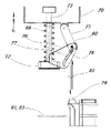
도 2a는 본 발명에 따른 궐련 롤링기의 실시예의 궐련 롤링 서브조립체(20)의 구성요소들을 도시한다. 이들 요소들은 특정 고체 물질 구성요소들의 구체적인 도시들보다는 개략도 요소들로서 도시된다. 성형 벨트(21)는 제1 핀칭 스핀들(25)을 지나고 플래튼 스핀들(26)에서 끝나는 인장 스핀들(24) 사이에서 연장된다. 선택적인 제2 핀칭 스핀들(25')은 성형 벨트에 대한 추가적인 제어를 위해 제1 핀칭 스핀들 위에 또는 제1 핀칭 스핀들에 바로 인접하여 위치될 수 있다. 도시된 실시예에 따르면, 벨트는 제1 및 제2 핀칭 스핀들 사이를 통과하지만, 바람직한 실시예에서 벨트는 가상선으로 도시된 벨트 경로(21')의 대안적인 섹션에 따라 2개의 핀칭 스핀들의 상부 위를 통과할 수 있다.Figure 2a shows the components of a
플래튼 스핀들은 중공형이거나 또는 우세한 대기압 미만의 진공으로 유지되는 내부 공동을 포함하는 플래튼(28)의 맨 끝단에 부착된다. 플래튼은 플래튼 표면으로부터 이러한 내부 공동까지 연통하는 적어도 하나의 천공을 포함한다. 진공 펌프 및 플래튼에서의 공동에 대한 진공 펌프의 피팅 및 연결은 이들 도면에 명시적으로 도시되어 있지 않다. 컴퓨터 제어식 스테퍼 모터와 같은 선택적인 인장 모터(27)는 벨트 인장 센서들로부터의 컴퓨터 커맨드들이 인장 스핀들 둘레에 벨트를 권취되거나 궐련 롤링 공정 동안 다양한 간격 및 지속기간으로 유지 토크를 인가하기 위해 사용될 수 있도록 인장 스핀들을 구동한다. 성형 벨트는 그 진공 공동과 연통하는 플래튼에서의 천공(23)과 상호 작용하는 천공 섹션(22)을 포함한다. 천공은 궐련지 보유 수단으로서 기능하기 위해 정확하게 합동이거나 상보적일 필요는 없다. 테플론 코팅된 직물이 성형 벨트에 바람직한 물질이다. 대안적으로, 궐련지는 궐련이 형성될 때까지 궐련지를 가볍게 제지하는 전용 코너 또는 에지 클립들과 같은 다른 기계적 수단을 사용하여 벨트 상으로 아래로 유지될 수 있다. 에지 클립은 롤링지의 에지의 일부 또는 전체 길이를 제한할 수 있다. The platen spindle is attached to the far end of the
궐련들이 성형 벨트에 의해 감기고 배출될 때, 쌍을 이루는 궐련을 수용하기 위해 슬릿형 캐치 베이슨(35)이 플래튼의 후미에 부착된다. 분리 나이프(36)는 슬릿과 정렬하도록 위치되어, 캐치 베이슨이 병진 이동하고 분리될 나이프 에지 위로 쌍을 이루는 궐련 쌍을 당길 때, 캐치 베이슨 내로 적층된 쌍을 이루는 궐련이 둘로 분리될 수 있다. 마지막으로, 이 도면에서, 제1 아버와 플래튼의 선단 사이에 성형 벨트 압자(29)가 훈연 물질의 충전물을 수용하기 위한 준비로 벨트에 트로프를 형성하는 생산 단계에서 핀칭 스핀들과 플래튼의 선단 사이에서 하강할 수 있도록 위치된다.As the cigarettes are wound and discharged by the forming belt, a slit-shaped
도 2b는 압자(29)가 하강하여 트로프를 형성하고, 소정 질량의 훈연 물질(420)이 트로프 내로 적층되도록 칭량된 도 2a의 궐련 롤링 서브조립체를 도시한다. 트로프에 의해 소비되는 벨트 길이는 벨트의 길이의 나머지를 증가된 장력으로 팽팽하게 끌어당겨서, 벨트의 천공된 섹션(22)이 진공 공동과 연통하는 플래튼 내의 천공들(23)과 정렬 및 협동하도록 아래로 끌어당겨진다. 도 2c는 훈연 물질이 벨트에 형성된 트로프에 전달되고, 궐련지(30)가 벨트의 다공성 섹션에 전달되는 도 2a의 궐련 롤링 서브조립체(420)를 도시한다. 또한, 도 3c에 도시된 바와 같이, 벨트의 슬랙 섹션이 트로프를 생성하기 위해 중공 내로 아래로 흡인될 수 있도록 배기되고 천공된 트로프형 중공 블록에 의해 트로프 형성 스테이지를 통합하는 것이 가능하다. 벨트 내의 견인가능한 물질을 견인하는 트로프 내의 자석 또는 점착성으로 트로프를 라이닝하는 것과 같은 다른 수단들이 플래튼의 트로프 부분의 프로파일에 벨트를 일시적으로 일치시키기 위해 채용될 수 있다.FIG. 2B shows the cigarette rolling subassembly of FIG. 2A , with the
또한, 제조 작업의 시점에서 압입된 벨트 내에 필터들을 적층하는 것도 가능하다. 바람직한 방법이 공기 퍼프들에 의해 구동되는 튜브들을 통해 트로프의 벨리(belly) 내로 필터들을 축방향으로 전달하지만, 픽 앤 플레이스 디바이스 또는 진공 픽 앤 플레이스 디바이스를 사용하여 위로부터 제 위치에 필터들을 적층하는 것도 가능하다.It is also possible to stack the filters in the press-fitted belt at the point of the manufacturing operation. While the preferred method is to deliver the filters axially into the belly of the trough through tubes driven by air puffs, stacking the filters in place from above using a pick and place device or a vacuum pick and place device. It is also possible
도 2d는 플래튼 및 다른 구성요소들이 도면에서 좌측을 가리키는 굵은 선 화살표들로 도시된 바와 같이 움직이는 도 2a의 궐련 롤링 서브조립체를 도시한다. 플래튼의 선단은 실질적으로 원통형의 롤링 체적(31)을 규정하기 위해 핀치 오프되도록 벨트에서의 트로프에 충돌한다. 인장 스핀들(24), 인장 모터, 플래튼, 플래튼 스핀들(26) 및 캐치 베이신은 모두 기계적으로 서로 부착되고 그룹으로서 좌측 및 우측으로 이동한다. 이전의 구성요소들이 이 도면에서 좌측으로 이동하는 동안 핀칭 스핀들(25)은 정지 상태로 유지된다. 플래튼의 상부 표면과 핀칭 스핀들(또는 제1 아버) 사이의 수직 거리는 바람직하게는 성형 벨트의 두께의 2배보다 약간 크다. 인장 모터는 이 단계 동안 구동되어 토크(T)를 인장 스핀들(즉, 제2 아버)에 인가하여 벨트 장력을 발생 또는 증가시켜 롤링 체적 및 그 내부의 훈연 물질의 직경을 제어 또는 감소시킬 수 있다. 기계의 제2 아버를 권취하는 것은 벨트 장력을 증가시키고 훈연 물질의 체적을 감소시킨다. 도 2a에서 설명된 제2 핀치 롤러(25') 및 대안적인 벨트 경로(21)는 벨트의 최상측 좌측으로 이동하는 섹션이 롤링 체적을 규정하는 바이트의 우측으로 이동하는 상부 섹션에 대해 마찰되지 않도록 벨트의 상부가 위로 상승될 수 있다는 것을 나타내기 위해 여기에 도시된다. 벨트의 이들 2개의 반대 방향으로 이동하는 섹션들이 서로 접촉하지 않게 하는 것은 바람직하게는 마찰 및 기계를 작동시키는 데 사용되는 동력의 총량을 감소시킨다. 제2 핀치 롤러는 기계의 고정 프레임에 장착되고, 또한 본 발명의 제3 아버로 칭해질 수 있다. 이 아버는 또한 바람직하게는 성형 벨트의 두께의 2배보다 적어도 약간 더 큰 거리에서 플래튼 표면 위에 위치된다.FIG. 2D shows the cigarette rolling subassembly of FIG. 2A with the platen and other components moving as shown by bold line arrows pointing to the left in the figure. The tip of the platen impinges on a trough in the belt to be pinched off to define a substantially cylindrical rolling
도 2e는 플래튼(28)이 롤링 체적(31) 아래를 통과하고 그 상부 표면을 따라 활주하도록 상향으로 변위되는 도 2a의 궐련 롤링 서브조립체를 도시한다. 벨트는 롤링 체적의 하측으로 진입하고, 인장 스핀들에 의해 좌측으로 당겨질 때 벨트 자체의 상부에 놓이기 전에 핀칭 스핀들(25) 주위에서 작동한다. 굵은 선 화살표들은 인장 스핀들 및 인장 모터, 및 플래튼, 플래튼 스핀들, 및 캐치 베이슨의 움직임을 도시한다. 얇은 파선 화살표들은 롤링 체적의 부근의 벨트의 움직임을 도시한다. 인장 모터에 의해 인가되는 토크(T)는 훈연 물질의 충전물을 압축하고 롤링 체적의 직경을 감소시키도록 증가될 수 있다. 플래튼 내의 공동에 의해 흡인되는 진공은 성형 벨트에 형성된 트로프 또는 벨리에 의해 규정되는 롤링 체적에 접근함할 때 궐련지를 유지시킨다.FIG. 2E shows the cigarette rolling subassembly of FIG. 2A with the
도 2f는 플래튼(28) 및 벨트가 벨트의 천공된 섹션(22)이 롤링 체적 아래를 통과하고 플래튼 내의 천공들(23)로부터 상승함에 따라, 궐련지(30)가 롤링 체적 내로 유도되고, 그 후 원통형 체적의 주연부 주위로 흡인되고 훈연 물질(420)을 종이 튜브로 봉입하도록 계속해서 병진 이동하는 도 2a의 궐련 롤링 서브조립체를 도시한다. 선택적인 필터 요소들은 이 도면에 도시된 단계가 시작되기 직전에 원통형의 훈연 물질의 축방향 단부들에 위치된다.2F shows the
도 2g는 벨트가 롤링 체적을 개방하고 쌍을 이루는 궐련(30, 420)이 슬릿형 캐치 베이슨(35) 내로 떨어지도록 플래튼(28) 및 벨트가 계속해서 병진 이동하는 도 2a의 궐련 롤링 서브조립체를 도시한다. 벨트에서의 트로프는 플래튼 스핀들(26)이 핀칭 스핀들(25)의 아래 및 좌측을 통과한 후에 개방되어, 트로프를 역전시켜 쌍을 이루는 궐련을 방출하기 위해 하방으로 개방된다.FIG. 2G shows the cigarette rolling sub of FIG. 2A in which the
도 2h는 플래튼 및 이의 부착 구성요소들, 인장 스핀들(24), 플래튼 스핀들(26) 및 궐련 캐치 베이슨(35)이 그룹으로서 초기 또는 "홈" 위치로 복귀하는 도 2a의 궐련 롤링 서브조립체를 도시한다. 성형 벨트(21)는 반드시 이 단계에서 제어될 필요는 없으며, 인장 스핀들의 임의의 이전의 권취는 이 단계 동안 권출될 수 있다. 핀칭 스핀들(25)은 이동하는 구성요소들의 그룹에 대해 정지 상태로 유지된다. 플래튼 및 슬릿형 캐치 베이신은 이동하는캐치 베이슨에서의 슬릿이 고정 분리 나이프(36)에 걸리고 쌍을 이루는 궐련이 분리 나이프의 경사진 절단 에지 위로 당겨지도록 계속해서 우측을 향한다. 분리 나이프는 그 절단면에서 쌍을 이루는 궐련 쌍을 절개하고, 쌍을 이루는 궐련 쌍을 2개의 별개의 개별 궐련으로 양분한다. 대안적으로, 정지 상태의 경사진 에지 대신에, 분리 나이프가 원형 블레이드와 같은 회전 블레이드를 포함할 수 있으며, 이에 의해 쌍을 이루는 궐련 쌍이 원형 블레이드 위에 위치되고 회전되어, 절개부가 종이 튜브의 전체 둘레 주위로 진행하여 결합된 궐련 쌍을 분리하게 된다. 선택적으로, 롤링기는 비고정 나이프가 절단면에서 쌍을 이루는 궐련 쌍을 분리하도록 이동하는 동안 쌍을 이루는 궐련 쌍을 제 위치에 유지시킬 수 있다. 쌍을 이루는 궐련 쌍은 또한 동시에 벨트 내에서 회전할 수 있다. 2H shows the cigarette rolling sub of FIG. 2A with the platen and its attachment components,
본 발명에 따른 실시예를 개술하는 또 다른 방법은 궐련 롤링 조립체가 수평의 제1 아버(25)를 지지하는 고정 프레임, (도 2d 내지 도 2h의 화살표들과 같은) 제1아버에 수직인 횡측 병진 이동을 위해 구성된 가동 프레임을 포함한다는 것이다. 제1 아버 아래의 가동 프레임에 부착된 플래튼(28)은 도면들에서 좌측 및 우측 에지들인 제2 에지의 반대편에 있는 제1 에지를 갖는 표면을 포함한다. 두께 및 플래튼의 제1 에지에 고정된 제1 단부를 갖는 성형 벨트를 가진다. 성형 벨트는 제1 아버 위를 통과하고, 가동 프레임에 장착되고 제1 아버로부터 횡측으로 이격된 제2 아버에 고정된 제2 단부를 가진다. 제2 아버는 바람직하게는 궐련이 형성될 때 벨트 장력이 조정되고 제어될 수 있도록, 컴퓨터 제어 하의 모터 또는 프로그램가능 제어기에 의해 회전 가능하다. Another way of outlining an embodiment according to the present invention is that the cigarette rolling assembly is a stationary frame supporting a horizontal
도 3a는 도 2d에 도시된 롤링 체적의 핀치 오프가 설정될 때까지 벨트에 트로프(32)를 유지하는 추가적인 흡안 트로프를 포함하는 도 2c에 도시된 궐련 롤링 서브조립체의 실시예의 변형예를 도시한다. 흡인 트로프는 플래튼 내의 내부 캐비티와 연통하는 포트들(23')을 포함할 수 있다. 이 도면에서 압자는 성형 벨트에 트로프를 형성하도록 하강되었고, 이 도면에서 궐련지(30)는 벨트의 다공성 섹션으로 전달되었다. 선택적으로 그리고 바람직하게는, 성형 벨트는 플래튼의 단부에서 아버에 고정되는 대신에, 도시된 바와 같이 (3)에서 단부에 고정될 수 있다. 그 단부는 플래튼의 후단 또는 제2 에지이고, 그 반대쪽 에지는 플래튼의 선단 또는 제1 에지이다.3A shows a variation of the embodiment of the cigarette rolling subassembly shown in FIG. 2C that includes an additional suction trough that holds the
도 3b는 움직임 동안 성형 벨트에 고착됨으로써 롤링 체적으로부터 빠져나올 수 있는 훈연 물질의 잘못된 입자들을 포집하기 위해 제1 아버 위에 배치되는 벨트 스크래퍼(37)를 포함하는 도 2d에 도시된 궐련 롤링 서브조립체의 실시예의 변형예를 도시한다. 이러한 입자들은 스크래핑되고 롤링 체적에 진입하고 있는 벨트의 일부분의 업스트림의 벨트 상으로 떨어지므로, 이들은 롤링 체적 상으로 재도입된다. 이들 입자의 낙하 움직임은 화살표(38)로 표시된다. 인장 스핀들(24), 인장 모터, 플래튼, 플래튼 스핀들(26), 벨트 스크래퍼 및 캐치 베이신은 모두 기계적으로 서로 부착되고 그룹으로서 좌측 및 우측으로 이동한다. 이전의 구성요소들이 이 도면에서 좌측으로 이동하는 동안 제1 아버 스핀들(25)은 정지 상태로 유지된다. 벨트 스크패퍼는 바람직하게는 벨트의 두께와 적어도 대략 동일한 거리만큼 제1 아버 위에 위치된다.3B is a view of the cigarette rolling subassembly shown in FIG. 2D including a
도 3c는 벨트 내에 트로프를 형성하기 위한 대안적인 메커니즘을 도시한다. 플래튼 또는 또 다른 구성요소는 압자보다는, 궐련지를 유지하기 위해 사용되는 플래튼의 다른 곳의 천공들과 유사한 진공 포트들(23')로 채워진 트로프를 포함할 수 있다. 도시된 이 실시예에서, 트로프 및 이의 포트들은 압자를 필요로 하지 않고 벨트에서의 트로프를 흡인하고 형성하기에 충분하다. 벨트가 트로프에 일시적으로 부착되게 하는 다른 수단들은 벨트에 통합되는 자기적으로 견인 가능한 물질을 견인하는 트로프에서의 자석 또는 전자석, 및 트로프에 그리고 벨트의 후면에 통합되는 후크 앤 루프(hook-and-loop) 직물을 포함한다. 3C shows an alternative mechanism for forming a trough in a belt. The platen or another component may comprise, rather than an indenter, a trough filled with vacuum ports 23' similar to perforations elsewhere in the platen used to hold cigarette paper. In this embodiment shown, the trough and its ports are sufficient to draw and form the trough in the belt without the need for an indenter. Other means of allowing the belt to temporarily attach to the trough include magnets or electromagnets in the trough that attract magnetically retractable material incorporated into the belt, and hook-and-loop integrated into the trough and at the back of the belt. loop) fabrics.
도 4a는 2개의 궐련에 충분한 훈연 물질(420)의 충전물이 원통형 롤링 체적(40) 내로 형성되는 생산 단계를 도시한다. 도 4b는 이전 단계에서 원통형 롤링 체적 내로 형성된 2개의 궐련에 충분한 훈연 물질의 충전물의 일 단부 또는 양 단부 주위에 필터들(42)이 첨부되는 생산 단계를 도시한다. 필터들은 공기 압력에 의해 튜브들을 통해 전달될 수 있거나, 또는 롤링 체적을 형성하기 위해 핀치 오프되기 전에 벨트 트로프에 기계적으로 적층될 수 있다. 피스톤들 또는 다른 공압 또는 기계적 보조구들이 또한 훈연 물질의 원통형 질량체의 단부들 상으로 필터들을 축방향으로 압축하기 위해 사용될 수 있다. 다른 공압 보조구들이 필터 전달 튜브들로부터 축방향으로 전달되는 강제 공기 퍼프들을 포함할 수 있다. 암나사를 갖는 고정된 구성요소와 맞물리는 동안 튜브 내에서 회전하는 나사형 로드는 또한 튜브 내에서 필터들을 밀기 위한 축방향 램으로서 작용할 수 있다. 반대로, 나사형 로드는 이를테면 고정된 핀과 맞물리는 종방향 홈을 포함함으로써 회전으로부터 고정될 수 있고, 또한 회전하는 암나사형 구성요소와 맞물려 또한 필터들을 가압하기 위한 램으로서 작용하도록 종방향으로 신축될 수 있다.FIG. 4A shows a production stage in which a fill of
도 4c는 도 4b에 도시된 단계의 롤링 체적에 앞에 본 발명의 성형 벨트(미도시) 상으로 궐련지(30)를 전달하는 생산 단계를 도시한다. 궐련지는 성형 벨트 상으로 전달 시 습윤 또는 달리 활성화되거나 대안적으로 그 직후에 활성화될 수 있는 수분 활성화 접착제와 같은 접착제를 포함한다. 본 발명의 범위 내의 또 다른 대안적인 실시예에 따르면, 궐련지는 흡인이 그것을 제 위치에 유지할 수 있는 벨트의 천공된 섹션 상에 배치되고, 접착제가 실질적으로 횡방향 에지에 도포된다. 접착제(33)는 플래튼 및 성형 벨트의 움직임 방향에 실질적으로 횡단하거나 실질적으로 수직이고 롤링 체적의 회전축에 실질적으로 평행한 궐련지의 에지를 따라 적층된다. 바람직하게는, 궐련지는 궐련 롤링기의 인클로저 내에 장착되거나 궐련지 픽 조립체에 의한 접근을 위해 근처에 위치된 대량 저장소로부터 전달될 수 있다. 대량 저장소는 미리 절단된 궐련지의 스택 또는 바람직하게는 스트립 물질의 롤 또는 스풀(34) - 이는 궐련지 픽 조립체에 의해 또는 궐련지 픽 조립체 부근에 위치된 절단기에 의해 길이로 절단될 수 있음 - 을 포함하는 박스를 포함할 수 있다.Fig. 4c shows the production stage of conveying the
도 4d는 도 4c의 궐련지(30)를 롤링 체적 내로 혼입하는 생산 단계를 도시하며, 여기서 이것이 원통형 체적의 훈연 물질을 둘러싸고 그 단부들 각각에 필터 요소(42)를 통합하는 종이 튜브로 형성된다. 종이의 횡단 선단은 궐련지의 횡단 후단 상의 준비된 접착제(33)와 만날 때까지 롤링 체적의 주연 주위를 지나가게 되어, 선단 및 후단이 서로 접착되어 훈연 물질 및 튜브의 양 단부들의 선택적인 필터들을 포함하는 종이 튜브를 완성한다.FIG. 4D shows the production stage of incorporating the
도 4e는 쌍을 이루는 궐련(39)을 실질적으로 동일한 치수의 2개의 개별 궐련(39a, 39b)으로 분리하는 생산 단계를 도시한다. 경사진 에지를 갖는 나이프(36)를 가로질러 쌍을 이루는 궐련 쌍을 당기는 것 외에, 절단 휠 위에서 쌍을 이루는 궐련 쌍을 회전시키는 것은 쌍을 이루는 궐련쌍을 개별 궐련으로 분리하는 또 다른 방법이다. 쌍을 이루는 궐련은 원(d)에서 종이 튜브와 교차하는 절단면(D)을 규정한다. 절단면의 배향은 제1 아버에 의해 규정되는 축에 수직하게 정의될 수 있으며, 절단 나이프는 절단면과 동일 평면에 있다.Figure 4e shows the production stage of separating the paired
절단 나이프의 평면이 절단면에서 쌍을 이루는 궐련을 양분하는 것이 가장 바람직하거나, 또는 대안적으로 원형 블레이드 나이프가 사용되는 경우에는, 나이프의 절단 경로가 2개의 개별 궐련이 서로 분리될 때까지 쌍을 이루는 궐련 쌍이 회전됨에 따라 원(d)을 따르는 것이 가장 바람직하다. 필터들이 제공된다면, 각 궐련은 이의 종이 튜브의 일 단부에 필터(42)를 가질 것이다.It is most preferred that the plane of the cutting knife bisects the paired cigarette at the cutting plane, or alternatively, if a circular blade knife is used, the cutting path of the knife will bisect the pairing until the two individual cigarettes are separated from each other. It is most preferred to follow circle (d) as the cigarette pair is rotated. If filters are provided, each cigarette will have a
또한, 원(d')에서 종이 튜브와 교차하는 쌍을 이루는 궐련 쌍의 중심 평면으로부터 오프셋되게 절단면(D)을 위치시키는 것이 가능하다. 이러한 제조 옵션은 담배 궐련에서 100mm, 110mm, 및 120mm 제공물과 같은 별개의 생산 라인들로서, 장기 연소 궐련 및 단기 연소 궐련을 제조하는데 사용될 수 있거나, 또는 이들은 "점심 휴식을 위한 전체 크기" 및 "짧은 오후 휴식 체이서" 쌍과 같은 짧고 긴 쌍 세트로 포장되고 판매될 수 있다. 다른 대안으로서, 쌍을 이루는 궐련은 최종 소비자들이 제품을 원하는 크기로 절단할 수 있도록, 형성된 그대로 판매되고 분리되지 않을 수 있다. 이에 따라, 본 명세서에서 쌍을 이루는 궐련은 동일한 길이로 절단되는지 여부에 관계없이 2개의 결합된 유닛들을 나타낸다.It is also possible to position the cut plane D offset from the center plane of the pair of cigarettes that intersect the paper tube in the circle d'. This manufacturing option could be used to manufacture long-burning cigarettes and short-burning cigarettes as separate production lines, such as the 100mm, 110mm, and 120mm offerings in tobacco cigarettes, or they could be "full size for lunch break" and "short" May be packaged and sold in sets of short and long pairs, such as "afternoon break chasers" pairs. Alternatively, the pair of cigarettes may be sold as formed and not separated so that the end consumer can cut the product to the desired size. Accordingly, a pair of cigarettes herein refers to two combined units, whether or not cut to the same length.
도 5a는 본 발명에 따른 궐련 롤링기의 실시예의 종이 픽 앤 플레이스(pick and place) 서브조립체의 사시도를 도시한다. 일부 구성요소들은 명확성을 위해 생략된다. 대량 종이 스트립은 모터 구동 프레임 플레이트 쌍(64) 사이에 현수되고 스풀 후크들(65) 상에 놓이는 롤(34)로 제공된다. 프레임 플레이트들은 복수의 스트럿들(63)에 의해 이격되어 유지된다. 종이 구동 모터(67)는 바람직하게는 종이가 효과적으로 접착될 수 있는 폴리우레탄 또는 또 다른 물질로 제조될 수 있는 롤러(62)를 구동한다.5A shows a perspective view of a paper pick and place subassembly of an embodiment of a cigarette rolling machine according to the present invention; Some components are omitted for clarity. The bulk paper strip is provided as a
유체 저장조(69)는 물, 또는 접착제 활성화 유체, 또는 부분적으로 증발한 후 접착제로서 작용하는 유체 또는 심지 리테이너(68)에 보유된 심지(79) 내로 전달되는 점액을 포함한다. 본 명세서에서, 저장조의 유체 내용물은 "습윤 유체(moistening fluid)"라고 지칭할 것이고, 접착제가 활성화되어 종이 튜브 내로 결합할 준비가 된 궐련지는 "습윤지(moisten paper)"라고 지칭한다. 심지를 저장조 내로 아래로 압축하면 펌프 메커니즘이 작동하여 리테이너의 심지에 습윤 오일을 전달한다.The
수직 변위 스트럿들(71) 상에 장착된 픽 아암(70)은 중공 플래튼과 같이 중공형인 픽 매니폴드(72)를 상승 및 하강시키, 매니폴드는 성형 벨트의 천공 섹션 상으로의 배치를 위해 궐련지를 픽업하고 그 하부 표면 상에 궐련지를 유지할 수 있도록 진공 라인에 연결된다. A
픽 매니폴드는 수직으로 변위가능한 픽 매니폴드 스트럿들(73)에 의해 픽 아암에 대해 상승 및 하강될 수 있다. 이들은 단지 천공된 위치에서 성형 벨트 상에 습윤지를 적층할 때 픽 아암에 대해 이동된다. 2개의 픽 매니폴드 스트럿들은 타이 바(tie bar)(74)에 의한 결합된 병진 이동을 위해 연결된다. 이송 패드는 픽 매니폴드에 부착된 가이드 플레이트(76)의 구불구불한 홈(77) 내에서 활주 가능한 스터드를 각각 갖는 스윙 아암 쌍(75)으로부터 스윙한다. 이송 패드는 침지되거나 습윤될 때 수분 또는 유체를 흡수하고 다른 건조 객체들에 의해 접촉할 때 수분을 부여하는 스펀지 패드 또는 다른 흡수성, 다공성 또는 해면 물질이다. 픽 매니폴드 스트럿들이 픽 아암에 대해 픽 매니폴드를 상승시킬 때, 스터드는 가이드 플레이트들 내의 홈들의 경로를 따르고, 픽 매니폴드에 인접한 위치로 이송 패드를 스윙시킨다. 픽 매니폴드 스트럿들이 픽 아암에 대해 픽 매니폴드를 하강시킬 때, 스터드는 가이드 플레이트들 내의 홈들의 경로를 따르고, 픽 매니폴드로부터 이격된 위치로 스펀지 패드를 스윙시킨다.The pick manifold can be raised and lowered relative to the pick arm by means of vertically displaceable pick manifold struts 73 . They are only moved relative to the pick arm when laminating the wet paper onto the forming belt in the perforated position. The two pick manifold struts are connected for combined translation by a
도 5b는 도 5a에 도시된 궐련 롤링기의 실시예의 종이 픽 앤 플레이스 서브조립체를 대안적인 사시도로부터 도시한다. 수직 변위 스트럿들(71)은 픽 매니폴드가 션후되는 픽 아암을 상승 및 하강시킨다. 2개의 스윙 아암들(75)은 픽 매니폴드에 인접한 제1 위치와 픽 매니폴드로부터 이격된 제2 위치 사이에서 이송 패드(78)를 스윙시키기 위해 픽 아암의 하측에 피닝된다. 적어도 하나의 가이드 플레이트(76)가 픽 매니폴드에 부착되고, 구불구불한 홈(77)을 가져서, 스윙 아암으로부터 연장되는 스터드가 스터드에 대한 가이드 플레이트의 상대적인 움직임 동안 구불구불한 홈 내에 놓일 수 있다.FIG. 5B shows the paper pick and place subassembly of the embodiment of the cigarette rolling machine shown in FIG. 5A from an alternative perspective view; Vertical displacement struts 71 raise and lower the pick arm to which the pick manifold is shunted. Two
흡인 패드(81)는 모터 구동 롤러(62)와 아이들링 핀치 롤러(61) 사이에 핀치된 흡인 패드로 전달된 후에 대량 스풀로부터 소정 길이로 절단된 소정 길이의 종이를 수용한다. 흡인 패드의 둘레는 인 패드로 전달된 종이가 제 위치에 안전하게 유지되도록 진공 라인에 연결된 복수의 애퍼처들(82)을 포함한다. 흡인 패드의 둘레 내의 추가적인 흡인 구멍들이 필요할 수 있으며, 종이 공급부는 평탄화될 바람직하지 않은 컬을 갖는다. 자체 세트의 진공 애퍼처들을 갖는 스테이징 패드(83)는 대량 스풀로부터 나오는 종이 스트립의 선단을 유지시킨다. 쌍을 이루는 궐련을 형성하기에 충분한 궐련지가 되도록 스풀로부터 일정 길이의 종이를 분리하는 것은 흡인 패드와 스테이징 패드 사이의 접합부에서 일어난다. The
도 5c는 이송 패드(78)를 습윤 또는 보습시키기 위해 위치되는 도 5a에 도시된 궐련 롤링기의 실시예의 종이 픽 앤 플레이스 서브조립체의 일부 구성요소들의 움직임을 도시한다. 치수(h)는 픽 매니폴드 스트럿(73)이 픽 아암(70)에 대해 하강된 픽 매니폴드(72)의 하강 위치를 나타낸다. 스윙 아암(75)의 스터드(80)는 이송 패드가 이송 패드로부터 각을 이루어 외접되고 유체 저장조의 심지 리테이너에 유지되는 심지(79) 위에 위치되도록 가이드 플레이트(76)의 구불구불한 홈(77)을 따른다. 심지는 전달 패드의 수분 수용 표면과 심지의 습윤 표면이 실질적으로 평행하도록 스윙 아암의 스윙 각도에 상보적인 각도로 배향된다. 저장조 및 그 심지에 대한 픽 아암의 상향 및 하향 편위는 반화살표 쌍(85)으로 표현되고 픽 아암 스트럿 스프링(66)에 의해 보조된다. 픽 아암은 습윤 유체를 이송 패드로 전달하기 위해 이송 패드를 심지 상으로 하강시킨다. 픽 아암 스트럿 스프링은 이송 패드를 심지 상에 정합시키는 것을 돕는다. 흡인 패드 및 스테이징 패드(81, 83)는 여기서 이송 패드 아래의 위치 기준으로서 도시된다. 5C illustrates movement of some components of the paper pick and place subassembly of the embodiment of the cigarette rolling machine shown in FIG. 5A positioned to wet or moisten the
도 5d는 습윤 궐련지를 성형 벨트 상의 위치로 전달하기 위해 위치되는 도 5c의 구성요소들을 도시한다. 궐련지(30)는 흡인 패드(81)로 전달된다. 궐련지는 스풀과 같은 대량 공급부로부터 제공될 수 있고, 그것의 가장자리들(33) 중 하나를 따라 수분 활성화 접착제를 제공받을 수 있고, 이송 패드에 의해 전달되는 수분에 의해 활성화될 수 있거나, 대안적으로 저장소 내의 유체는 활성 상태에서 궐련지의 가장자리에 전달되는 접착제 유체일 수 있다.FIG. 5D shows the components of FIG. 5C positioned to deliver wet cigarette paper to a location on a forming belt. The
픽 아암은 이송 패드가 저장조 상의 심지에 대해 압축되고 이에 의해 습윤 유체를 획득하도록 그 스트럿들 상에서 상승 및 하강한다. 픽 아암 및 이의 구성요소들의 이러한 상승 및 하강 움직임은 수직 반화살표(86)로 표시되고 픽 아암 스트럿 스프링(66)에 의해 보조된다. 픽 매니폴드 스트럿들(73)이 픽 아암(70)에 대한 치수(H)에 의해 표시된 상승 위치로 상승할 때, 가이드 플레이트(76)는 또한 가이드 플레이트의 구불구불한 홈(77) 내의 스윙 아암들(75) 중 적어도 하나의 스윙 아암 상의 스터드(80)가 추종하도록 픽 매니폴드와 함께 상승하고, 스윙 아암들을 스윙시켜 이송 패드(78)를 픽 매니폴드(72)에 인접한 위치로 이동시킨다. The pick arm rises and lowers on its struts such that the transfer pad is compressed against the wick on the reservoir and thereby obtains a wetting fluid. This upward and downward movement of the pick arm and its components is indicated by a vertical half-
픽 매니폴드에 인접하고 접착제 또는 습윤 유체로 충전된 이송 패드에 의해, 픽 아암은 궐련지 상에서 하강하고, 진공이 픽 매니폴드 내에서 흡인된다. 여기서, 픽 아암 스트럿 스프링은 픽 매니폴드 어드레스를 돕고 궐련지를 획득한다. 습윤된 이송 패드는 이 공정 단계 동안 픽 매니폴드에 인접하게 놓이기 때문에, 궐련지의 에지(33)는 이제 이송 패드로부터 습윤 유체를 얻는다. 그 후, 픽 아암은 성형 벨트의 천공된 섹션이 픽 매니폴드에 의해 유지되는 궐련지 아래에 있도록 플래튼(28)이 활주할 수 있도록 충분히 높게 상승한다.With a transfer pad adjacent the pick manifold and filled with adhesive or wetting fluid, the pick arm is lowered onto the cigarette paper and a vacuum is drawn within the pick manifold. Here, the pick arm strut spring helps the pick manifold address and acquires the cigarette paper. Since the wet transfer pad is placed adjacent to the pick manifold during this process step, the
플래튼의 횡측 편위는 수평 반화살표들(87)로 나타내어진다. 그 후, 픽 아암은 하나의 에지(33')를 따라 활성화된 접착제를 갖는 궐련지(30')를 적층시킨다. 공정의 이 단계에서, 픽 아암 스트럿 스프링은 픽 매니폴드 배치하고 성형 벨트의 천공 섹션 상에 궐련지를 정합시키는 것을 돕는다. 진공은 플래튼의 천공된 섹션에 의해 흡인되고, 진공은 픽 매니폴드에서 중단되어, 이들이 분리될 때, 하나의 에지(33')를 따라 그의 활성화된 접착제를 갖는 궐련지는 이제 성형 벨트에 접착되고 플래튼 및 성형 벨트 상에서 그와 함께 지지된다.The lateral deviation of the platen is indicated by horizontal half-
도 5e는 플래튼(28)에 의해 지지되는 성형 벨트의 천공된 섹션 상으로 수분 활성화 궐련지(30', 33')를 전달할 때 위치되는 도 5c의 구성요소들을 도시한다. 이송 패드(78)는 픽 매니폴드(72)에 인접하고, 이들 구성요소 양자는 궐련지를 배치하고 습윤시키도록 협력한다. 흡인 패드(81)는 참조만을 위해 이 도면에 도시되어 있다.FIG. 5E shows the components of FIG. 5C positioned when delivering moisture activated cigarette paper 30', 33' onto a perforated section of a forming belt supported by
도 5f는 궐련지를 분리하기 위해 절단 휠이 설치될 수 있는 픽 아암 또는 플래튼 상의 선택적인 위치들을 도시한다. 절단 휠(89)은 휠의 하측 에지가 흡인 패드(81) 상에 유지되는 궐련지(30)의 이중 길이 섹션 위로 롤링될 수 있도록 하는 높이로 플래튼(28)의 단부 상에 설치될 수 있어서, 종이는 개별 궐련에 적합한 2개의 길이로 분리된다. 대안적으로, 커팅 휠(89')은 수직 반화살표들(88)에 의해 표시된 방향들로 픽 아암으로부터 상승 및 하강될 수 있는 연장가능한 스트럿으로부터 현수될 수 있다. 이러한 종류의 실시예를 사용하여, 픽 매니폴드가 습윤된 종이를 성형 벨트의 천공된 섹션으로 이송한 후에, 절단 휠은 종이의 일 에지에서 벨트 상으로 하강될 수 있어서, 플래튼의 횡측 움직임은 절단 휠 아래에서 종이를 끌어당겨서 개별 궐련에 대해 2개의 길이들로 절단 휠을 분리한다.5F shows optional locations on the pick arm or platen where a cut-off wheel may be installed to separate the cigarette paper. The cut-
본 발명의 범위 내의 다른 실시예에 따르면, 도 2h 또는 도 4e에 도시된 바와 같은 강성 나이프 블레이드(36)가 또한 이 도면에 도시된 위치에 설치될 수 있다. 플래튼의 밑면에 설치되는 경우, 흡인 패드 상에 위치된 이중 길이 궐련지는 흡인 패드 상의 진공에 의해 제 위치에 유지되는 동안 나이프가 그것을 가로질러 당기는 것을 허용함으로써 개별 궐련에 적합한 2개의 길이로 슬라이스될 수 있다. 대안적으로, 픽 아암으로부터 하강하는 별개의 상승 및 하강 스트럿 상의 강성 나이프 블레이드가 성형 벨트 상에 위치된 이중 길이 궐련지 상으로 하강될 수 있다. 나이프 에지가 궐련지 부분을 개별 궐련에 적합한 2개의 길이로 가압하는 동안 플래튼을 횡측으로 이동시킨다.According to another embodiment within the scope of the present invention, a
도 6a는 본 발명에 따른 궐련 롤링기의 대안적인 실시예의 상부 전방 우측 사시도를 도시한다. 도 6b는 도어들 및 패널들 중 일부가 특정 서브조립체들을 드러내도록 제거된 도 6a의 궐련 롤링기의 상부 전방 좌측 사시도를 도시한다. 훈연 물질의 대량 매스는 투입 호퍼(20)로 공급되고, 생산 작업에서 사용되는 경우, 궐련 필터는 진동 보울 공급기들(101)로 대량 로딩된다. 진동 보울에서 기하학적 형상을 정렬하는 것은 필터를 필터 전달 튜브(104) 내로 단부 방향으로 배향시킨다. 완성된 제품은 슈트(129)로부터 분배된다. 6a shows a top front right perspective view of an alternative embodiment of a cigarette rolling machine according to the present invention; 6B shows a top front left perspective view of the cigarette rolling machine of FIG. 6A with some of the doors and panels removed to reveal certain subassemblies; The bulk mass of smoking material is fed into the
도 6c는 더 많은 인클로저 구성요소들이 제거된 도 6a의 궐련 롤링기의 또 다른 상부 전방 좌측 사시도를 도시한다. 궐련 필터를 위한 입력 호퍼(20), 진동 보울 공급기(101), 및 필터 전달 튜브(104)가 상당히 보인다. 6C shows another top front left perspective view of the cigarette rolling machine of FIG. 6A with more enclosure components removed. The
도 6d는 이중 슈트 진동 공급기 서브조립체(140), 계량 및 압입 서브조립체들(130), 궐련들의 쌍을 이룬 쌍들에 필터들을 전달하는 진동 보울들, 및 완성된 제품들이 나오는 슈트(129)를 식별하는 도 6a의 궐련 롤링기의 정면도를 도시한다. 분배기 서브조립체의 상승 및 하강 움직임은 호퍼 상승 스트럿(53)의 움직임에 의해 구동된다. 6D identifies dual chute vibrating
도 6d는 이중 슈트(chute) 진동 공급기 서브조립체(140), 칭량 및 압입 서브조립체emf(130) 및 쌍을 이루는 궐련에 필터를 전달하는 진동 보울, 및 완성된 제품들이 나타나는 슈트(129)을 식별하는 도 6a의 궐련 롤링기의 정면도를 도시한다. 교반기(141)는 3개 또는 적절한 수의 수직 로드(142)가 하강하는 회전 플레이트를 포함한다. 이들은 투입 호퍼의 하부 출구 근처에서 회전하여 훈연 물질의 대량 질량체를 교반하고(420), 이에 따라 경사진 리프 스프링들(147) 상에 장착된 2개의 장형 수평 채널들 또는 슈트들 중 제1의 것(137)으로 떨어지게 된다. 진동 액추에이터들(149)은 경사진 판 스프링들의 자유 가요성 길이에 의해 설정된 반경(r)의 호(arc)에서 움직임들로 제한되는 슈트들을 여기시킨다. 상부 슈트에서의 물질 이동은 회전하는 레이크 샤프트(144) 및 레이크 타인 방사상 어레이들(145)에 의해 보조된다. 시스템은 대량 호퍼로부터 나중에 설명되는 계량 트레이로 물질을 이동시킨다. 공정 제어기는 칸반 전달 체제의 일부로서 계량 트레이 및 분배 서브조립체의 사이클링의 요구에 따라 상부 및 하부 슈트 진동 액추에이터를 통전시키기 위해 사용될 수 있다. 대안적으로, 레이크는 비회전, 저속 회전, 또는 역행 회전에 의한 훈연 물질의 전달을 지연시키기 위해 사용될 수 있다. 6D identifies a dual chute
제1 슈트는 더 느린 공급 속도로 작동하는 반면, 제2 슈트(138)는 버킷으로부터의 요구에 따라 간헐적으로 작동하여, 하부 트레이 및 계량 트레이로부터의 요구의 간헐적 특성을 버퍼링함으로써 이송 요구를 더 상류로 평활화한다. 진동 공급 트레이의 작동 및 정지는 제품이 계량 버킷에 축적될 때 제품의 계량 모니터링에 의해 제어된다. 슈트 내의 물질의 횡측 움직임은 입자가 캔틸레버식 굴곡으로 판 스프링의 반경에 의해 구속되는 슈트의 배출 방향을 따라 상향으로(Sa) 던져지는 염석에 의해 발생하고, 그 후 중력에 의해 하강한다(Sb). 이들 움직임의 수평 성분은 슈트의 배출 방향을 따라 물질을 전파하도록 조합된다. 양 슈트 및 그 진동 기구는 진동 흡수 스터드(151)에 의해 기계의 메인 프레임에 부착되는 슈트 프레임(150)에 고정된다. The first chute operates at a slower feed rate, while the
도 8은 본 발명에 따른 칭량 및 압입 서브조립체 및 진동 보울 시스템(130)을 도시한다. 필터 전달 튜브(104)는 진동 보울(101)로부터 분배기 서브조립체로 하강한다. 공기 보조 매니폴드(166)는 이송 튜브의 하류에 필터를 밀고 또한 벤츄리 효과에 의해 상류 필터를 동반하는 이송 튜브 내에 공기 퍼프를 주입한다. 이들 보조 매니폴드와 분배기 서브조립체 사이의 튜브 연결 섹션은 필터 스택 튜브(104')로 지칭된다. 계량 서브조립체는 호퍼 지지 브래킷(54)으로 불리는 주 횡단 스트럿에 장착되는 제2 분배 깔때기(136) 내에 안착되는 제1 고정 깔때기(135) 위에 포이즈되는 팁 가능한 계량 트레이(131)를 포함한다. 분배기 서브조립체는 성형 벨트 압자 특징부(29)가 전술한 바와 같이 성형 벨트에 트로프를 형성하도록 상승 및 하강한다. 분배기 서브조립체의 상승 및 하강 움직임은 호퍼 상승 스트럿(53)의 움직임에 의해 구동된다. 2개의 필터 포지셔너는 분배 깔때기의 측면에 부착되고, 이들은 각각 필터 스택 튜브에 의해 전달된 필터를 공급하는 필터 튜브 플랜지(56)에 의해 캡핑된다. 8 shows a weighing and press fit subassembly and vibrating
도 9는 본 발명에 따른 팁핑 트레이(131), 네스트 호퍼(135 및 136), 압입 서브조립체 및 필터 전달 구성요소들의 실시예들을 도시한다. 정밀하고 정확한 칭량은 바람직하게는 4개의 스트레인 게이지 및 휘트스톤 브릿지를 갖는 빔형 로드 셀을 사용하여 달성될 수 있다. 로드 셀 증폭기는 빈 버킷의 교정을 위해 신호들을 전송한다. 프로세스 제어기 내에 프로그래밍된 세트 포인트는 인덴트 및 롤-업 사이클이 시작될 준비가 되었음을 시그널링한다. 중량 센서는 팁 가능한 트레이 및 상부 깔때기가 완전히 비워졌고 점착성 물질이 축적되지 않거나 뒤에 남아있지 않다는 것을 확인하는데 사용될 수 있고, 이에 따라 완전한 2회 투여량(전형적으로 약 1 그램)의 훈연 물질이 전달되는 것을 보장한다. 칭량 센서는 로드 셀의 감도를 보존하기 위해 그들 자신의 진동 절연체 상에 장착된다. 팁핑 플레이트는 성형 벨트 내로 압입된 트로프 내로 훈연 물질의 측정된 충전물을 침전시킬 팁핑된 위치에 도시된다. 티핑은 티핑 모터(132)에 의해 실현된다. 고정식 깔때기는 분배 서브조립체의 깔때기와 접촉하지 않는다. 9 shows embodiments of tipping
분배 서브조립체는 호퍼 지지 브래킷(54) 상에 장착된 호퍼(136) 및 분배 깔때기를 횡측으로 최상화하는 2개의 필터 포지셔너(58)를 포함한다. 필터 스택 튜브(104')는 필터 튜브 플랜지에 의해 각 필터 포지셔너에 연결된다. 필터 포지셔너 각각은 트로프 압자 특징부(29) 및 정지면(139)을 포함한다. 일단 필터 포지셔너가 성형 벨트의 트로프 내로 하강하면, 필터는 필터 튜브 플랜지(56)를 지나 진입하여 정지면과 충돌하고 분배 서브조립체가 트로프로부터 후퇴한 후에 트로프 내에 유지된다. 호스 클램프(162)는 필터 스택 튜브를 그들의 플랜지에 유지한다. The dispensing subassembly includes a
도 10은 호퍼 지지 브라킷(54)에 고정된 본 발명에 따른 압입 서브조립체 및 필터 전달 구성요소들의 좌측 부분 단면도를 도시한다. 이 도면의 세부 부분(160)은 아래의 추가 도면들에서 설명된다. 공기 보조 포트(166)는 필터 스택 튜브(104') 내의 필터의 재고가 스택 튜브의 전체를 충전하기 위해 축적되었음을 검출하는데 사용될 수 있는 광검출기(164)를 포함한다. 필터 스택 튜브는 호스 클램프(162)로 필터 튜브 플랜지(56)에 고정된다. 필터 포지셔너에 위치된 제2 광검출기(164')는 설치될 준비가 된 최소 하나의 필터를 검출한다. 칸반 시그널링 시스템은 적어도 공기 보조 포트 내의 광검출기에 의해 표시된 레벨까지 고갈된 필터 스택 튜브를 보충하기 위해 진동 보울 피더들을 턴온하는데 사용될 수 있다. 필터 포지셔너(58)는 분배 깔때기(136) 또는 호퍼의 양 측면에 설치된다. FIG. 10 shows a left partial cross-sectional view of a press-fit subassembly and filter delivery components in accordance with the present invention secured to a
도 11은 본 발명에 따른 기조식 포트(166)의 구성요소들을 도시한다. 공기 보조 포트는 필터가 통과하는 중앙 통로(171)를 갖는다. 광검출기(164)는 신호를 전송하기 위한 전기 접촉부(165)와, 광 검출기를 향하는 광원을 포함한다. 공기 보조 포트의 본체는 필터가 중앙 통로의 그 부분 내에 존재할 때 광학적으로 차단되는 뷰포트(174)를 포함한다. 절결부(168)는 그 센서 및 광원이 공기 보조 포트의 본체 내의 뷰 포트와 정렬되도록 광검출기를 수용한다. 공기 입구(172)는 입구 오리피스(173)를 통해 예각으로 중앙 통로로 향하는 고압 공기를 수용한다. 일정한 압력 또는 간헐적 퍼프의 공기는 필터 전달 튜브 및 필터 스택 튜브를 따라 필터를 하강시킨다. 예각의 주입 각도는 또한 벤츄리 효과에 의해 필터 스택 튜브 내로 상류 필터들을 동반할 수 있다. 11 shows the components of an air-assisted
도 12는 도 10에 도시된 세부 부분(160)의 확대도를 도시한다. 필터 포지셔너 및 호퍼(136)는 로퍼 장착 브래킷(54)에 장착된다. 필터 스택 튜브(104')는 호스 클램프(162)로 필터 튜브 플랜지(56)에 부착된다. 필터 포지셔너에 위치된 제2 광검출기(164)는 설치될 준비가 된 최소 하나의 필터를 검출한다. 필터 튜브 플랜지는 정지 표면(139)으로 끝나는 통로를 갖는 필터 포지셔너(58)의 매니폴드와 정렬된 내부 통로를 갖는다. 통로는 압자(29)로서 작용하는 포지셔너의 하부 프로파일과 정렬된다. 필터 디테이너 요크(180)는 솔레노이드(169)에 의해 상승 및 하강되어, 필터 튜브 플랜지 및 필터 포지셔너의 통로 내로 디스테이너 특징부를 도입 및 제거한다. 2개의 디테이너 중 두 번째는 통로를 차단함으로써 또는 유연하거나 프리로딩된 스프링 메커니즘(182)으로 필터에 순응적으로 충돌함으로써 필터를 정지시킬 수 있는 포고 핀(121)을 포함한다. 상기 디테이너는 입구 오리피스(173)를 통해 유입되는 공기 퍼프가 한 번에 하나의 필터만을 전진시키도록 통로 내에서 궐련 필터의 이동을 간헐적으로 억제하도록 협동한다. 수용된 필터는 정지면과 충돌하여 정지할 때까지 필터 튜브 플랜지 및 필터 포지셔너의 통로 내에서 이동한다. 과량의 공기는 필터 포지셔너의 매니폴드 및 통로 내로 절단된 경사 또는 횡단 슬롯(188)을 통해 필터 주위로 빠져나간다. FIG. 12 shows an enlarged view of the
도 13은 본 발명에 따른 궐련 롤링기용 필터 구속 요크 서브조립체를 도시한다. 솔레노이드(168)는 제1 및 제2 디테이너를 갖는 요크(180)를 승강시킨다. 제1 디테이너는 필터를 통과시키기에 충분히 큰 개구(184)를 갖는 게이트 피쳐를 포함한다. 제2 디테이너는 통로를 차단함으로써 또는 컴플라이언트 또는 프리로딩된 스프링 메커니즘(182)으로 필터에 컴플라이언트하게 충돌함으로써 필터를 정지시킬 수 있는 포고 핀(121)을 포함한다. 게이트가 통로 내로 부분적으로 도입될 때, 게이트가 필터의 통과를 차단하지만, 더 가압될 때, 개구는 통로와 정렬되고 필터가 통과하게 한다. "L" 또는 "J" 형상과 같은 다른 형상이 또한 본 발명의 범위 내에서 사용되어, 부분 삽입시 필터의 통과를 차단하지만 추가 삽입시 통과를 허용하여 차단부를 통로에서 벗어나게 이동시키는 활주가능한 게이트로서 작용할 수 있다. 대안적으로, 요크는 공압 또는 유압 실린더, 또는 파워 스레드 메커니즘, 3-바 링키지, 또는 가위 연장 및 수축 메커니즘과 같은 다른 수단에 의해 상승 및 하강될 수 있다. 13 shows a filter constraining yoke subassembly for a cigarette rolling machine according to the present invention. The
도 14는 본 발명에 따른 생산 단계 동안의 도 10의 부분 단면의 구성요소들을 도시한다. 요크(180)가 상승된 위치에 있는 상태에서, 게이트(184)는 필터 포지셔너(58) 및 필터 튜브 플랜지(56)의 정렬된 통로와 정렬되지 않는 그 개구로 유지된다. 포고 핀은 또한 통로를 벗어나 상승되어, 중력 또는 공기 보조는 필터(42a, 42b, 42c)의 최전방이 차단 위치에서 게이트에 의해 보유될 때까지 일련의 필터가 전진할 수 있게 한다. Fig. 14 shows the components of the partial cross section of Fig. 10 during a production phase according to the invention; With the
도 15는 본 발명에 따른 또 다른 생산 단계 동안의 도 10의 부분 단면의 구성요소들을 도시한다. 요크(180)는 이제 하강되어, 제1 디테이너인 게이트(184)가슬라이딩주하여 그 개구가 통로와 정렬되는 동안, 제2 디테인너인 포고 핀도 하강하여 제2 필터(42b)에 일렬로 충돌한다. 포고 핀의 횡측 힘은 마찰에 의해 필터를 제 위치에 유지한다. 대안적으로, 필터의 길이 또는 제1 및 제2 디테이너 사이의 분리에 따라, 제2 데테이너는 제2 필터에 충돌하기보다는 제2 필터 앞의 통로를 차단할 수 있다. Fig. 15 shows the components of the partial cross section of Fig. 10 during another production stage according to the invention; The
이와 같이 얻어진 제2 필터 아래에, 공기 입구 오리피스(도 14의 (173)이지만 이 도면에서 필터(42b)에 의해 폐색됨)로부터의 공기(186)의 퍼프는 필터 포지셔너의 매니폴드에 진입하고 그 정지 특징부(139)에서 정지하도록 최전방 필터(42a)를 전진시키기 위해 사용된다. 중력 또는 기조식 포트로부터의 어시스트(도 10의 166)는 필터들의 연속(42c)(42d) 등을 전진시키며, 이들 모두는 유지 필터(42b) 뒤에 정렬된다. 분배 조립체가 트로프 밖으로 상승할 때, 분배 조립체는 측정된 양의 훈연 물질 및 성형 벨트의 트로프에 적층된 필터를 남기고, 본 명세서에 설명된 제조 수단 및 방법에 의해 한 쌍의 궐련으로 핀치 오프되고 롤링될 준비가 된다. 대안적으로, 필터는 푸시 로드 또는 견인 구동 또는 이송 벨트, 또는 일련의 롤러와 같은 다른 기계적 수단에 의해 통로 내에서 전진될 수 있다.Below the thus obtained second filter, a puff of
특정 특징들 및 양태들이 예시적인 실시예들에 관하여 설명되었지만, 당업자는 다수의 수정들이 가능하다는 것을 인식할 것이다. 또한, 본 명세서에 설명된 다양한 방법들 및 프로세스들이 설명의 용이함을 위해 특정 구조적 및/또는 기능적 구성요소들에 대해 설명될 수 있지만, 다양한 실시예들에 의해 제공되는 방법들은 임의의 특정 구조적 그리고/또는 기능 아키텍처에 제한되지 않는다. 본 명세서에 청구된 장치들 및 방법들의 허가되지 않은 인스턴스들은 세계에서 그들이 광고, 판매, 판매를 위해 제공, 사용, 소유 또는 수행되더라도, 침해하는 것으로 고려되어야 한다.While certain features and aspects have been described with respect to exemplary embodiments, those skilled in the art will recognize that many modifications are possible. Further, while the various methods and processes described herein may be described with respect to specific structural and/or functional components for ease of description, the methods provided by the various embodiments may not be applied to any specific structural and/or functional component. or not limited to a functional architecture. Unauthorized instances of the devices and methods claimed herein should be considered infringing, even if they are advertised, sold, offered, used, owned or performed for sale in the world.
본 개시는 다양한 양상들의 예시들로서 의도되는 본 출원에서 설명되는 특정 실시예들의 관점에서 제한되지 않는다. 많은 수정 및 변형이 본 발명의 사상 및 범위로부터 벗어나지 않고 이루어질 수 있다. 본 명세서에 열거된 것들에 더하여, 본 개시의 범위 내의 기능적으로 동등한 방법들 및 장치들이 전술한 설명으로부터 가능하다. 이러한 수정들 및 변형들은 첨부된 청구항들의 범위 내에 속하도록 의도된다. 본 개시는 첨부된 청구항들의 용어들에 의해서만 제한되며, 이러한 청구항들이 권리를 갖는 등가물들의 전체 범위와 함께 제한된다.This disclosure is not limited in terms of the specific embodiments described herein, which are intended as illustrations of various aspects. Many modifications and variations can be made without departing from the spirit and scope of the present invention. In addition to those listed herein, functionally equivalent methods and apparatuses within the scope of the present disclosure are possible from the foregoing description. Such modifications and variations are intended to fall within the scope of the appended claims. This disclosure is limited only by the terms of the appended claims, along with the full scope of equivalents to which such claims are entitled.
상황은 다양한 실시예들이 설명의 용이함을 위해 그리고 그러한 실시예들의 예시적인 양상들을 예시하기 위해 특정 특징들과 함께 또는 특정 특징들 없이 설명되지만, 특정 실시예에 대해 본원에 설명된 다양한 구성요소들 및/또는 특징들은 문맥이 달리 지시하지 않는 한, 다른 설명된 실시예들 중에서 대체, 추가, 및/ 또는 감산될 수 있다. 결과적으로, 몇몇 예시적인 실시예가 상술되었지만, 본 발명은 다음의 청구항의 범위 내에서 모든 수정 및 등가물을 커버하도록 의도된다는 것이 이해될 것이다.The context is that, although various embodiments are described with or without specific features for ease of description and to illustrate exemplary aspects of such embodiments, the various components described herein with respect to a specific embodiment and /or features may be substituted, added, and/or subtracted from among other described embodiments, unless the context dictates otherwise. Consequently, while several exemplary embodiments have been described above, it will be understood that the invention is intended to cover all modifications and equivalents within the scope of the following claims.
Claims (18)
수평 제1 아버(arbor)를 지지하는 고정 프레임,
상기 제1 아버에 수직인 횡측 병진 이동(lateral translation)을 위해 구성된 가동 프레임,
상기 제1 아버 밑에 상기 가동 프레임에 부착된 플래튼(platen) - 상기 플래튼은 제2 에지의 반대편에 있는 제1 에지를 갖는 표면을 포함함 -,
두께 및 상기 플래튼의 상기 제1 에지에 고정된 제1 단부를 갖는 성형 벨트(forming belt)를 포함하며,
상기 성형 벨트는 상기 제1 아버 위를 통과하고, 상기 가동 프레임에 장착되고 상기 제1 아버로부터 횡측으로 이격된 제2 아버에 고정된 제2 단부를 갖는 것인, 궐련 롤링 조립체. A cigarette rolling assembly comprising:
a fixed frame supporting a horizontal first arbor;
a movable frame configured for lateral translation perpendicular to the first arbor;
a platen attached to the movable frame under the first arbor, the platen including a surface having a first edge opposite a second edge;
a forming belt having a thickness and a first end secured to the first edge of the platen;
wherein the forming belt passes over the first arbor and has a second end mounted to the movable frame and secured to a second arbor laterally spaced from the first arbor.
a. 궐련 성형기를 제공하는 단계 - 상기 성형기는
수평 제1 아버(arbor)를 지지하는 고정 프레임,
상기 제1 아버에 수직인 횡측 병진 이동을 위해 구성된 가동 프레임,
상기 가동 프레임에 부착되고 상기 제1 아버 밑에 배치된 플래튼 - 상기 플래튼은 제2 에지의 반대편에 있는 제1 에지를 갖는 표면을 포함함 -,
상기 플래튼의 상기 제1 에지에서 상기 플래튼에 고정된 제1 단부를 갖는 성형 벨트를 포함하며,
상기 성형 벨트는 상기 제1 아버 위를 통과하고, 상기 가동 프레임에 장착되고 상기 제1 아버로부터 횡측으로 이격된 제2 아버에 고정된 제2 단부를 갖고,
상기 제1 아버와 상기 플래튼의 상기 제2 에지 사이에 배치된 성형 벨트 압자를 포함함 -;
b. 상기 성형 벨트 압자가 상기 제1 아버와 상기 플래튼의 상기 제2 에지 사이에서 하강하고 통과할 때 상기 성형 벨트에서 트로프가 형성되도록 상기 가동 프레임을 병진 이동시키는 단계;
c. 2개의 궐련에 충분한 양의 훈연 물질을 상기 트로프로 적층시키는 단계;
d. 상기 압자를 상기 플래튼에서 제거되게 상승시키는 단계;
e. 상기 플래튼의 상기 제2 에지가 상기 제1 아버 밑을 통과하고 상기 성형 벨트에서의 상기 트로프가 핀칭(pinching)되고, 상기 성형 벨트가 상기 훈연 물질에 대한 롤링 체적을 형성하도록 상기 가동 프레임을 병진 이동시키는 단계;
f. 궐련지를 상기 성형 벨트 상으로 적층시키는 단계 - 상기 궐련지는 완성된 궐련의 원주보다 큰 폭을 갖고 완성된 궐련 길이의 적어도 2배와 동일한 길이를 가짐 -; 및
g. 상기 제2 아버가 상기 제1 아버 밑을 통과하도록 상기 가동 프레임을 병진 이동시키는 단계를 포함하는, 방법. A method of forming a cigarette pair, comprising:
a. providing a cigarette former, said molding machine
a fixed frame supporting a horizontal first arbor;
a movable frame configured for lateral translation perpendicular to the first arbor;
a platen attached to the movable frame and disposed under the first arbor, the platen including a surface having a first edge opposite a second edge;
a forming belt having a first end secured to said platen at said first edge of said platen;
wherein the forming belt passes over the first arbor and has a second end mounted to the movable frame and secured to a second arbor laterally spaced from the first arbor;
a forming belt indenter disposed between said first arbor and said second edge of said platen;
b. translating the movable frame to form a trough in the forming belt as the forming belt indenter lowers and passes between the first arbor and the second edge of the platen;
c. laminating a sufficient amount of smoking material to the troughs for two cigarettes;
d. raising the indenter to be removed from the platen;
e. The second edge of the platen passes under the first arbor and the trough in the forming belt is pinched, translating the movable frame such that the forming belt forms a rolling volume for the fuming material. moving;
f. laminating cigarette paper onto the forming belt, wherein the cigarette paper has a width greater than the circumference of the finished cigarette and a length equal to at least twice the length of the finished cigarette; and
g. translating the movable frame such that the second arbor passes under the first arbor.
h. 상기 롤링 체적으로부터 쌍으로 된 궐련 쌍을 배출하는 단계 - 상기 쌍으로 된 궐련 쌍은 축, 및 상기 축에 수직인 절단면을 규정함 -; 및
i. 상기 쌍으로 된 궐련 쌍을 절개하는 단계를 더 포함하는, 방법. 13. The method of claim 12, wherein after step 'g',
h. discharging the pair of cigarettes from the rolling volume, the pair of cigarettes defining an axis and a cut plane perpendicular to the axis; and
i. The method further comprising the step of cutting the pair of cigarettes.
Applications Claiming Priority (3)
| Application Number | Priority Date | Filing Date | Title |
|---|---|---|---|
| US201962923510P | 2019-10-19 | 2019-10-19 | |
| US62/923,510 | 2019-10-19 | ||
| PCT/US2020/055961 WO2021076877A1 (en) | 2019-10-19 | 2020-10-16 | Cigarette rolling machine |
Publications (1)
| Publication Number | Publication Date |
|---|---|
| KR20220120554A true KR20220120554A (en) | 2022-08-30 |
Family
ID=75537574
Family Applications (1)
| Application Number | Title | Priority Date | Filing Date |
|---|---|---|---|
| KR1020227016439A Withdrawn KR20220120554A (en) | 2019-10-19 | 2020-10-16 | cigarette rolling machine |
Country Status (10)
| Country | Link |
|---|---|
| US (4) | US11129407B2 (en) |
| EP (1) | EP4003065B1 (en) |
| JP (1) | JP2022551755A (en) |
| KR (1) | KR20220120554A (en) |
| CN (2) | CN115135176A (en) |
| CA (1) | CA3152376A1 (en) |
| CO (1) | CO2022003348A2 (en) |
| IL (1) | IL292308B2 (en) |
| MX (1) | MX2022004568A (en) |
| WO (1) | WO2021076877A1 (en) |
Families Citing this family (6)
| Publication number | Priority date | Publication date | Assignee | Title |
|---|---|---|---|---|
| KR20220120554A (en) * | 2019-10-19 | 2022-08-30 | 카일 럭스 | cigarette rolling machine |
| US20220264934A1 (en) * | 2021-02-19 | 2022-08-25 | Jason Kang | Rosin core rolled smoking product method and devices |
| CN113424984B (en) * | 2021-06-16 | 2023-03-21 | 张家口卷烟厂有限责任公司 | Transition wheel of cigarette assembler |
| CN117750891B (en) * | 2021-08-04 | 2025-11-18 | 日本烟草产业株式会社 | Filler rod winding machine and winding method |
| CN115783720B (en) * | 2022-12-30 | 2023-06-09 | 广州三拓识别技术有限公司 | Material storage device |
| CN116530722B (en) * | 2023-05-26 | 2025-08-12 | 帕斯卡(东莞)电子科技有限公司 | Automatic tobacco filling machine |
Family Cites Families (45)
| Publication number | Priority date | Publication date | Assignee | Title |
|---|---|---|---|---|
| US411919A (en) * | 1889-10-01 | Oigae bunching machine | ||
| US2100315A (en) * | 1935-05-27 | 1937-11-30 | Elmer E Harper | Weighing feeder |
| US2269432A (en) * | 1937-07-26 | 1942-01-13 | William J Beck | Feeding and dispensing device |
| CH231247A (en) * | 1942-03-03 | 1944-03-15 | Wasser Otto | Manual device for rolling cigarettes. |
| BE446651A (en) * | 1942-07-30 | 1942-08-31 | CIGARETTE ROLLING APPLIANCE | |
| US2436015A (en) * | 1945-12-21 | 1948-02-17 | Joseph M Morris | Cigarette rolling device |
| FR934651A (en) * | 1946-10-04 | 1948-05-28 | Advanced device for making cigarettes | |
| US2572193A (en) * | 1948-06-01 | 1951-10-23 | Clarence W Phillips | Cigarette rolling machine |
| GB691988A (en) * | 1950-12-14 | 1953-05-27 | Imp Tobacco Co Ltd | Improvements in or relating to continuous rod cigarette making machines |
| US2740408A (en) * | 1952-11-28 | 1956-04-03 | Master Ltd V | Cigarette makers |
| BE756514A (en) * | 1969-10-06 | 1971-03-01 | Kastner Arnold | MACHINE FOR MANUFACTURING TUBES FOR CIGARETTES |
| GB1273686A (en) * | 1970-03-31 | 1972-05-10 | Cons Cigar Corp | Machine and method for making cigarettes |
| US3828796A (en) * | 1972-12-20 | 1974-08-13 | Brown & Williamson Tobacco Corp | Cigarette cutoff and filter tip attachment registration apparatus |
| US3911933A (en) * | 1973-10-11 | 1975-10-14 | Rizla Ltd | Manual cigarette rolling machines |
| US4164229A (en) * | 1977-03-18 | 1979-08-14 | Hurt James S | Portable cigarette making machine |
| GB1582657A (en) * | 1977-12-22 | 1981-01-14 | Choyce David P | Intraocular anterior chamber implants |
| DE2915042A1 (en) * | 1979-04-12 | 1980-10-23 | Gizeh Werk Gmbh | DEVICE FOR ROLLING CIGARETTES |
| US4867180A (en) * | 1988-05-04 | 1989-09-19 | Rothmans, Benson & Hedges Inc. | Cigarette making machine hopper |
| US4971077A (en) * | 1989-08-02 | 1990-11-20 | R. J. Reynolds Tobacco Company | On-line tobacco evaluation system and method |
| GB2240459A (en) * | 1990-01-31 | 1991-08-07 | Karel Hrboticky | Tobacco feed system |
| US5513697A (en) * | 1991-04-17 | 1996-05-07 | Gudmundsson; Bjorn | Method and device for transfer of heat |
| JP2773007B2 (en) * | 1992-05-15 | 1998-07-09 | 株式会社東京機械製作所 | Paper storage and web supply system |
| US5513597A (en) * | 1993-01-15 | 1996-05-07 | Grain Systems, Inc. | Feed conveying apparatus |
| UA68391C2 (en) * | 1998-09-18 | 2004-08-16 | Philip Morris Prod | Cigarette manufacturing apparatus (variants) and a method to control making the cigarettes on the apparatus |
| EP1426292A4 (en) * | 2001-08-06 | 2006-04-12 | Bay City Service Ltd | High-speed fluid sorting and charging device |
| US7341170B2 (en) * | 2002-03-07 | 2008-03-11 | Georgia-Pacific Consumer Operations Llc | Apparatus and methods usable in connection with dispensing flexible sheet material from a roll |
| GB0404324D0 (en) * | 2004-02-27 | 2004-03-31 | British American Tobacco Co | Smoking article and apparatus and process for manufacturing a smoking article |
| US7638008B2 (en) * | 2004-05-25 | 2009-12-29 | New Spirit Backing Llc | Polyurethane roller coating process for carpet backing |
| US7479098B2 (en) * | 2005-09-23 | 2009-01-20 | R. J. Reynolds Tobacco Company | Equipment for insertion of objects into smoking articles |
| US7677251B2 (en) * | 2006-07-07 | 2010-03-16 | R.J. Reynolds Tobacco Company | Apparatus and methods for manufacturing cigarettes |
| US8550523B2 (en) * | 2007-06-22 | 2013-10-08 | Data I/O Corporation | Pick and place system |
| CN201384058Y (en) * | 2009-04-30 | 2010-01-20 | 青岛理工大学 | Cigarette rolling device |
| EP2737813A1 (en) * | 2012-12-03 | 2014-06-04 | David Prevost | Cigarette rolling and forming devices |
| US9038641B2 (en) * | 2013-01-30 | 2015-05-26 | Larry E. Moser | Device for filling a cigarette tube with a metered amount of tobacco |
| CN104305520A (en) * | 2013-11-06 | 2015-01-28 | 伍以炳 | Simple domestic cigarette-rolling machine |
| US10850874B2 (en) * | 2014-03-21 | 2020-12-01 | G.D Societa' Per Azioni | Machine and method for producing electronic-cigarette cartridges |
| CN104323421A (en) * | 2014-03-30 | 2015-02-04 | 李林 | Bothway manual cigarette making machine |
| CN105901763B (en) * | 2016-06-20 | 2017-10-03 | 陈淑梅 | A kind of Manually-driving cigarette maker |
| CN106115295B (en) * | 2016-06-27 | 2018-03-23 | 温州市日电电器有限公司 | A kind of automatic ration feed arrangement for solid material addition |
| CN207383518U (en) * | 2017-09-28 | 2018-05-22 | 常德长岭烟草机械配件有限公司 | A kind of PT2-2 cigarette machines paper tape guider |
| WO2019095040A1 (en) * | 2017-11-16 | 2019-05-23 | Almeida Danny | Foldable cigarette rolling device |
| KR20220120554A (en) * | 2019-10-19 | 2022-08-30 | 카일 럭스 | cigarette rolling machine |
| US11059683B1 (en) * | 2020-06-15 | 2021-07-13 | New Vision Co-Op | Systems and methods for bulk material load out |
| US20220264934A1 (en) * | 2021-02-19 | 2022-08-25 | Jason Kang | Rosin core rolled smoking product method and devices |
| CN219939695U (en) * | 2023-03-20 | 2023-11-03 | 朱锦 | Cigarette device |
-
2020
- 2020-10-16 KR KR1020227016439A patent/KR20220120554A/en not_active Withdrawn
- 2020-10-16 WO PCT/US2020/055961 patent/WO2021076877A1/en not_active Ceased
- 2020-10-16 CA CA3152376A patent/CA3152376A1/en active Pending
- 2020-10-16 EP EP20876837.4A patent/EP4003065B1/en active Active
- 2020-10-16 JP JP2022522650A patent/JP2022551755A/en active Pending
- 2020-10-16 MX MX2022004568A patent/MX2022004568A/en unknown
- 2020-10-16 CN CN202080072322.0A patent/CN115135176A/en active Pending
- 2020-10-16 CN CN202410271347.3A patent/CN118303661A/en active Pending
- 2020-10-16 IL IL292308A patent/IL292308B2/en unknown
-
2021
- 2021-03-22 US US17/208,556 patent/US11129407B2/en active Active
- 2021-09-07 US US17/468,566 patent/US12035743B2/en active Active
-
2022
- 2022-03-23 CO CONC2022/0003348A patent/CO2022003348A2/en unknown
-
2024
- 2024-07-01 US US18/760,301 patent/US12419342B2/en active Active
-
2025
- 2025-08-22 US US19/307,290 patent/US20250374953A1/en active Pending
Also Published As
| Publication number | Publication date |
|---|---|
| US20250374953A1 (en) | 2025-12-11 |
| US20240349777A1 (en) | 2024-10-24 |
| IL292308B1 (en) | 2025-01-01 |
| US11129407B2 (en) | 2021-09-28 |
| US20210204592A1 (en) | 2021-07-08 |
| US20210404859A1 (en) | 2021-12-30 |
| MX2022004568A (en) | 2022-05-06 |
| US12035743B2 (en) | 2024-07-16 |
| EP4003065A4 (en) | 2023-08-23 |
| WO2021076877A1 (en) | 2021-04-22 |
| CN118303661A (en) | 2024-07-09 |
| JP2022551755A (en) | 2022-12-13 |
| EP4003065A1 (en) | 2022-06-01 |
| EP4003065B1 (en) | 2024-08-21 |
| CN115135176A (en) | 2022-09-30 |
| CO2022003348A2 (en) | 2022-04-19 |
| IL292308B2 (en) | 2025-05-01 |
| US12419342B2 (en) | 2025-09-23 |
| CA3152376A1 (en) | 2021-04-22 |
| IL292308A (en) | 2022-06-01 |
Similar Documents
| Publication | Publication Date | Title |
|---|---|---|
| KR20220120554A (en) | cigarette rolling machine | |
| US4111491A (en) | Method and apparatus for feeding bristles in brush making machines | |
| CN1913791B (en) | Filter making machine | |
| DE3345608A1 (en) | METHOD AND DEVICE FOR MAKING ROD-SHAPED ITEMS OF THE TOBACCO-PROCESSING INDUSTRY | |
| CN102317185A (en) | Gluing device for logs of wound web-like material | |
| KR101025107B1 (en) | Improved Rewinding Machine to Form Web Material Rolls | |
| GB2035966A (en) | Apparatus for continuously supplying web rolls to web splicing devices | |
| JP4431284B2 (en) | Method and apparatus for manufacturing particle-supported filter rods | |
| CN110480822B (en) | Paper surface gypsum board edge sealing device | |
| US7571798B2 (en) | Method and device for controlled filling of a feed channel supplying tobacco articles | |
| CN112140297A (en) | Device for sealing edges of thistle board | |
| KR102184216B1 (en) | Cover sheet step transfer device in automatic packager for cosmetic pack | |
| CN113233156A (en) | Resistor feeding system | |
| CN114176250B (en) | Machine for winding smokable material, feeding device and smokable product | |
| WO2017187501A1 (en) | Filter segment feeder | |
| JPS6151861B2 (en) | ||
| CN208725663U (en) | A kind of floor mop head plant hair equipment | |
| CN205345393U (en) | A kind of automatic packing equipment for ointment base | |
| JP2014226141A (en) | Material entry in filter tow | |
| CN119873014B (en) | A kind of fragrance card pillow packaging machine and packaging method thereof | |
| US3414207A (en) | Winding apparatus | |
| US4671719A (en) | Method and apparatus for manufacturing printed tablets | |
| HK40069335B (en) | Machine for wrapping a smokable material, a feeding device and a smokable product | |
| JP2016108316A (en) | Method and apparatus for controlled delivery of particles | |
| CN118833444A (en) | Ginkgo ketone ester dispersible tablet partial shipment device convenient to control ejection of compact speed |
Legal Events
| Date | Code | Title | Description |
|---|---|---|---|
| PA0105 | International application |
St.27 status event code: A-0-1-A10-A15-nap-PA0105 |
|
| P11-X000 | Amendment of application requested |
St.27 status event code: A-2-2-P10-P11-nap-X000 |
|
| P13-X000 | Application amended |
St.27 status event code: A-2-2-P10-P13-nap-X000 |
|
| PG1501 | Laying open of application |
St.27 status event code: A-1-1-Q10-Q12-nap-PG1501 |
|
| PC1203 | Withdrawal of no request for examination |
St.27 status event code: N-1-6-B10-B12-nap-PC1203 |