KR20220098197A - Electrochromic aperture, manufacturing method thereof, and lens module including same - Google Patents
Electrochromic aperture, manufacturing method thereof, and lens module including same Download PDFInfo
- Publication number
- KR20220098197A KR20220098197A KR1020227019308A KR20227019308A KR20220098197A KR 20220098197 A KR20220098197 A KR 20220098197A KR 1020227019308 A KR1020227019308 A KR 1020227019308A KR 20227019308 A KR20227019308 A KR 20227019308A KR 20220098197 A KR20220098197 A KR 20220098197A
- Authority
- KR
- South Korea
- Prior art keywords
- electrochromic
- layer
- transparent conductive
- diaphragm
- polymer
- Prior art date
- Legal status (The legal status is an assumption and is not a legal conclusion. Google has not performed a legal analysis and makes no representation as to the accuracy of the status listed.)
- Granted
Links
Images


Classifications
-
- G—PHYSICS
- G02—OPTICS
- G02B—OPTICAL ELEMENTS, SYSTEMS OR APPARATUS
- G02B5/00—Optical elements other than lenses
- G02B5/005—Diaphragms
-
- G—PHYSICS
- G03—PHOTOGRAPHY; CINEMATOGRAPHY; ANALOGOUS TECHNIQUES USING WAVES OTHER THAN OPTICAL WAVES; ELECTROGRAPHY; HOLOGRAPHY
- G03B—APPARATUS OR ARRANGEMENTS FOR TAKING PHOTOGRAPHS OR FOR PROJECTING OR VIEWING THEM; APPARATUS OR ARRANGEMENTS EMPLOYING ANALOGOUS TECHNIQUES USING WAVES OTHER THAN OPTICAL WAVES; ACCESSORIES THEREFOR
- G03B9/00—Exposure-making shutters; Diaphragms
- G03B9/02—Diaphragms
-
- G—PHYSICS
- G02—OPTICS
- G02B—OPTICAL ELEMENTS, SYSTEMS OR APPARATUS
- G02B7/00—Mountings, adjusting means, or light-tight connections, for optical elements
- G02B7/02—Mountings, adjusting means, or light-tight connections, for optical elements for lenses
-
- G—PHYSICS
- G02—OPTICS
- G02F—OPTICAL DEVICES OR ARRANGEMENTS FOR THE CONTROL OF LIGHT BY MODIFICATION OF THE OPTICAL PROPERTIES OF THE MEDIA OF THE ELEMENTS INVOLVED THEREIN; NON-LINEAR OPTICS; FREQUENCY-CHANGING OF LIGHT; OPTICAL LOGIC ELEMENTS; OPTICAL ANALOGUE/DIGITAL CONVERTERS
- G02F1/00—Devices or arrangements for the control of the intensity, colour, phase, polarisation or direction of light arriving from an independent light source, e.g. switching, gating or modulating; Non-linear optics
- G02F1/01—Devices or arrangements for the control of the intensity, colour, phase, polarisation or direction of light arriving from an independent light source, e.g. switching, gating or modulating; Non-linear optics for the control of the intensity, phase, polarisation or colour
- G02F1/15—Devices or arrangements for the control of the intensity, colour, phase, polarisation or direction of light arriving from an independent light source, e.g. switching, gating or modulating; Non-linear optics for the control of the intensity, phase, polarisation or colour based on an electrochromic effect
- G02F1/153—Constructional details
- G02F1/1533—Constructional details structural features not otherwise provided for
-
- G—PHYSICS
- G02—OPTICS
- G02F—OPTICAL DEVICES OR ARRANGEMENTS FOR THE CONTROL OF LIGHT BY MODIFICATION OF THE OPTICAL PROPERTIES OF THE MEDIA OF THE ELEMENTS INVOLVED THEREIN; NON-LINEAR OPTICS; FREQUENCY-CHANGING OF LIGHT; OPTICAL LOGIC ELEMENTS; OPTICAL ANALOGUE/DIGITAL CONVERTERS
- G02F1/00—Devices or arrangements for the control of the intensity, colour, phase, polarisation or direction of light arriving from an independent light source, e.g. switching, gating or modulating; Non-linear optics
- G02F1/01—Devices or arrangements for the control of the intensity, colour, phase, polarisation or direction of light arriving from an independent light source, e.g. switching, gating or modulating; Non-linear optics for the control of the intensity, phase, polarisation or colour
- G02F1/15—Devices or arrangements for the control of the intensity, colour, phase, polarisation or direction of light arriving from an independent light source, e.g. switching, gating or modulating; Non-linear optics for the control of the intensity, phase, polarisation or colour based on an electrochromic effect
- G02F1/153—Constructional details
- G02F1/155—Electrodes
-
- G—PHYSICS
- G02—OPTICS
- G02F—OPTICAL DEVICES OR ARRANGEMENTS FOR THE CONTROL OF LIGHT BY MODIFICATION OF THE OPTICAL PROPERTIES OF THE MEDIA OF THE ELEMENTS INVOLVED THEREIN; NON-LINEAR OPTICS; FREQUENCY-CHANGING OF LIGHT; OPTICAL LOGIC ELEMENTS; OPTICAL ANALOGUE/DIGITAL CONVERTERS
- G02F1/00—Devices or arrangements for the control of the intensity, colour, phase, polarisation or direction of light arriving from an independent light source, e.g. switching, gating or modulating; Non-linear optics
- G02F1/01—Devices or arrangements for the control of the intensity, colour, phase, polarisation or direction of light arriving from an independent light source, e.g. switching, gating or modulating; Non-linear optics for the control of the intensity, phase, polarisation or colour
- G02F1/15—Devices or arrangements for the control of the intensity, colour, phase, polarisation or direction of light arriving from an independent light source, e.g. switching, gating or modulating; Non-linear optics for the control of the intensity, phase, polarisation or colour based on an electrochromic effect
- G02F1/163—Operation of electrochromic cells, e.g. electrodeposition cells; Circuit arrangements therefor
-
- G—PHYSICS
- G03—PHOTOGRAPHY; CINEMATOGRAPHY; ANALOGOUS TECHNIQUES USING WAVES OTHER THAN OPTICAL WAVES; ELECTROGRAPHY; HOLOGRAPHY
- G03B—APPARATUS OR ARRANGEMENTS FOR TAKING PHOTOGRAPHS OR FOR PROJECTING OR VIEWING THEM; APPARATUS OR ARRANGEMENTS EMPLOYING ANALOGOUS TECHNIQUES USING WAVES OTHER THAN OPTICAL WAVES; ACCESSORIES THEREFOR
- G03B30/00—Camera modules comprising integrated lens units and imaging units, specially adapted for being embedded in other devices, e.g. mobile phones or vehicles
-
- H—ELECTRICITY
- H04—ELECTRIC COMMUNICATION TECHNIQUE
- H04N—PICTORIAL COMMUNICATION, e.g. TELEVISION
- H04N23/00—Cameras or camera modules comprising electronic image sensors; Control thereof
- H04N23/70—Circuitry for compensating brightness variation in the scene
- H04N23/71—Circuitry for evaluating the brightness variation
-
- H—ELECTRICITY
- H04—ELECTRIC COMMUNICATION TECHNIQUE
- H04N—PICTORIAL COMMUNICATION, e.g. TELEVISION
- H04N23/00—Cameras or camera modules comprising electronic image sensors; Control thereof
- H04N23/70—Circuitry for compensating brightness variation in the scene
- H04N23/72—Combination of two or more compensation controls
-
- C—CHEMISTRY; METALLURGY
- C03—GLASS; MINERAL OR SLAG WOOL
- C03C—CHEMICAL COMPOSITION OF GLASSES, GLAZES OR VITREOUS ENAMELS; SURFACE TREATMENT OF GLASS; SURFACE TREATMENT OF FIBRES OR FILAMENTS MADE FROM GLASS, MINERALS OR SLAGS; JOINING GLASS TO GLASS OR OTHER MATERIALS
- C03C15/00—Surface treatment of glass, not in the form of fibres or filaments, by etching
-
- C—CHEMISTRY; METALLURGY
- C03—GLASS; MINERAL OR SLAG WOOL
- C03C—CHEMICAL COMPOSITION OF GLASSES, GLAZES OR VITREOUS ENAMELS; SURFACE TREATMENT OF GLASS; SURFACE TREATMENT OF FIBRES OR FILAMENTS MADE FROM GLASS, MINERALS OR SLAGS; JOINING GLASS TO GLASS OR OTHER MATERIALS
- C03C17/00—Surface treatment of glass, not in the form of fibres or filaments, by coating
- C03C17/34—Surface treatment of glass, not in the form of fibres or filaments, by coating with at least two coatings having different compositions
- C03C17/42—Surface treatment of glass, not in the form of fibres or filaments, by coating with at least two coatings having different compositions at least one coating of an organic material and at least one non-metal coating
-
- C—CHEMISTRY; METALLURGY
- C03—GLASS; MINERAL OR SLAG WOOL
- C03C—CHEMICAL COMPOSITION OF GLASSES, GLAZES OR VITREOUS ENAMELS; SURFACE TREATMENT OF GLASS; SURFACE TREATMENT OF FIBRES OR FILAMENTS MADE FROM GLASS, MINERALS OR SLAGS; JOINING GLASS TO GLASS OR OTHER MATERIALS
- C03C2217/00—Coatings on glass
- C03C2217/20—Materials for coating a single layer on glass
- C03C2217/21—Oxides
- C03C2217/23—Mixtures
- C03C2217/231—In2O3/SnO2
-
- C—CHEMISTRY; METALLURGY
- C03—GLASS; MINERAL OR SLAG WOOL
- C03C—CHEMICAL COMPOSITION OF GLASSES, GLAZES OR VITREOUS ENAMELS; SURFACE TREATMENT OF GLASS; SURFACE TREATMENT OF FIBRES OR FILAMENTS MADE FROM GLASS, MINERALS OR SLAGS; JOINING GLASS TO GLASS OR OTHER MATERIALS
- C03C2217/00—Coatings on glass
- C03C2217/90—Other aspects of coatings
- C03C2217/94—Transparent conductive oxide layers [TCO] being part of a multilayer coating
- C03C2217/948—Layers comprising indium tin oxide [ITO]
-
- C—CHEMISTRY; METALLURGY
- C03—GLASS; MINERAL OR SLAG WOOL
- C03C—CHEMICAL COMPOSITION OF GLASSES, GLAZES OR VITREOUS ENAMELS; SURFACE TREATMENT OF GLASS; SURFACE TREATMENT OF FIBRES OR FILAMENTS MADE FROM GLASS, MINERALS OR SLAGS; JOINING GLASS TO GLASS OR OTHER MATERIALS
- C03C2218/00—Methods for coating glass
- C03C2218/10—Deposition methods
- C03C2218/11—Deposition methods from solutions or suspensions
- C03C2218/116—Deposition methods from solutions or suspensions by spin-coating, centrifugation
-
- G—PHYSICS
- G02—OPTICS
- G02F—OPTICAL DEVICES OR ARRANGEMENTS FOR THE CONTROL OF LIGHT BY MODIFICATION OF THE OPTICAL PROPERTIES OF THE MEDIA OF THE ELEMENTS INVOLVED THEREIN; NON-LINEAR OPTICS; FREQUENCY-CHANGING OF LIGHT; OPTICAL LOGIC ELEMENTS; OPTICAL ANALOGUE/DIGITAL CONVERTERS
- G02F1/00—Devices or arrangements for the control of the intensity, colour, phase, polarisation or direction of light arriving from an independent light source, e.g. switching, gating or modulating; Non-linear optics
- G02F1/01—Devices or arrangements for the control of the intensity, colour, phase, polarisation or direction of light arriving from an independent light source, e.g. switching, gating or modulating; Non-linear optics for the control of the intensity, phase, polarisation or colour
- G02F1/15—Devices or arrangements for the control of the intensity, colour, phase, polarisation or direction of light arriving from an independent light source, e.g. switching, gating or modulating; Non-linear optics for the control of the intensity, phase, polarisation or colour based on an electrochromic effect
- G02F1/1514—Devices or arrangements for the control of the intensity, colour, phase, polarisation or direction of light arriving from an independent light source, e.g. switching, gating or modulating; Non-linear optics for the control of the intensity, phase, polarisation or colour based on an electrochromic effect characterised by the electrochromic material, e.g. by the electrodeposited material
- G02F1/1523—Devices or arrangements for the control of the intensity, colour, phase, polarisation or direction of light arriving from an independent light source, e.g. switching, gating or modulating; Non-linear optics for the control of the intensity, phase, polarisation or colour based on an electrochromic effect characterised by the electrochromic material, e.g. by the electrodeposited material comprising inorganic material
- G02F1/1525—Devices or arrangements for the control of the intensity, colour, phase, polarisation or direction of light arriving from an independent light source, e.g. switching, gating or modulating; Non-linear optics for the control of the intensity, phase, polarisation or colour based on an electrochromic effect characterised by the electrochromic material, e.g. by the electrodeposited material comprising inorganic material characterised by a particular ion transporting layer, e.g. electrolyte
-
- G—PHYSICS
- G02—OPTICS
- G02F—OPTICAL DEVICES OR ARRANGEMENTS FOR THE CONTROL OF LIGHT BY MODIFICATION OF THE OPTICAL PROPERTIES OF THE MEDIA OF THE ELEMENTS INVOLVED THEREIN; NON-LINEAR OPTICS; FREQUENCY-CHANGING OF LIGHT; OPTICAL LOGIC ELEMENTS; OPTICAL ANALOGUE/DIGITAL CONVERTERS
- G02F1/00—Devices or arrangements for the control of the intensity, colour, phase, polarisation or direction of light arriving from an independent light source, e.g. switching, gating or modulating; Non-linear optics
- G02F1/01—Devices or arrangements for the control of the intensity, colour, phase, polarisation or direction of light arriving from an independent light source, e.g. switching, gating or modulating; Non-linear optics for the control of the intensity, phase, polarisation or colour
- G02F1/15—Devices or arrangements for the control of the intensity, colour, phase, polarisation or direction of light arriving from an independent light source, e.g. switching, gating or modulating; Non-linear optics for the control of the intensity, phase, polarisation or colour based on an electrochromic effect
- G02F1/153—Constructional details
- G02F1/157—Structural association of cells with optical devices, e.g. reflectors or illuminating devices
-
- G—PHYSICS
- G02—OPTICS
- G02F—OPTICAL DEVICES OR ARRANGEMENTS FOR THE CONTROL OF LIGHT BY MODIFICATION OF THE OPTICAL PROPERTIES OF THE MEDIA OF THE ELEMENTS INVOLVED THEREIN; NON-LINEAR OPTICS; FREQUENCY-CHANGING OF LIGHT; OPTICAL LOGIC ELEMENTS; OPTICAL ANALOGUE/DIGITAL CONVERTERS
- G02F1/00—Devices or arrangements for the control of the intensity, colour, phase, polarisation or direction of light arriving from an independent light source, e.g. switching, gating or modulating; Non-linear optics
- G02F1/01—Devices or arrangements for the control of the intensity, colour, phase, polarisation or direction of light arriving from an independent light source, e.g. switching, gating or modulating; Non-linear optics for the control of the intensity, phase, polarisation or colour
- G02F1/15—Devices or arrangements for the control of the intensity, colour, phase, polarisation or direction of light arriving from an independent light source, e.g. switching, gating or modulating; Non-linear optics for the control of the intensity, phase, polarisation or colour based on an electrochromic effect
- G02F2001/1502—Devices or arrangements for the control of the intensity, colour, phase, polarisation or direction of light arriving from an independent light source, e.g. switching, gating or modulating; Non-linear optics for the control of the intensity, phase, polarisation or colour based on an electrochromic effect complementary cell
-
- G—PHYSICS
- G02—OPTICS
- G02F—OPTICAL DEVICES OR ARRANGEMENTS FOR THE CONTROL OF LIGHT BY MODIFICATION OF THE OPTICAL PROPERTIES OF THE MEDIA OF THE ELEMENTS INVOLVED THEREIN; NON-LINEAR OPTICS; FREQUENCY-CHANGING OF LIGHT; OPTICAL LOGIC ELEMENTS; OPTICAL ANALOGUE/DIGITAL CONVERTERS
- G02F1/00—Devices or arrangements for the control of the intensity, colour, phase, polarisation or direction of light arriving from an independent light source, e.g. switching, gating or modulating; Non-linear optics
- G02F1/01—Devices or arrangements for the control of the intensity, colour, phase, polarisation or direction of light arriving from an independent light source, e.g. switching, gating or modulating; Non-linear optics for the control of the intensity, phase, polarisation or colour
- G02F1/15—Devices or arrangements for the control of the intensity, colour, phase, polarisation or direction of light arriving from an independent light source, e.g. switching, gating or modulating; Non-linear optics for the control of the intensity, phase, polarisation or colour based on an electrochromic effect
- G02F2001/164—Devices or arrangements for the control of the intensity, colour, phase, polarisation or direction of light arriving from an independent light source, e.g. switching, gating or modulating; Non-linear optics for the control of the intensity, phase, polarisation or colour based on an electrochromic effect the electrolyte is made of polymers
-
- G—PHYSICS
- G02—OPTICS
- G02F—OPTICAL DEVICES OR ARRANGEMENTS FOR THE CONTROL OF LIGHT BY MODIFICATION OF THE OPTICAL PROPERTIES OF THE MEDIA OF THE ELEMENTS INVOLVED THEREIN; NON-LINEAR OPTICS; FREQUENCY-CHANGING OF LIGHT; OPTICAL LOGIC ELEMENTS; OPTICAL ANALOGUE/DIGITAL CONVERTERS
- G02F2201/00—Constructional arrangements not provided for in groups G02F1/00 - G02F7/00
- G02F2201/56—Substrates having a particular shape, e.g. non-rectangular
-
- G—PHYSICS
- G02—OPTICS
- G02F—OPTICAL DEVICES OR ARRANGEMENTS FOR THE CONTROL OF LIGHT BY MODIFICATION OF THE OPTICAL PROPERTIES OF THE MEDIA OF THE ELEMENTS INVOLVED THEREIN; NON-LINEAR OPTICS; FREQUENCY-CHANGING OF LIGHT; OPTICAL LOGIC ELEMENTS; OPTICAL ANALOGUE/DIGITAL CONVERTERS
- G02F2202/00—Materials and properties
- G02F2202/16—Materials and properties conductive
Landscapes
- Physics & Mathematics (AREA)
- Nonlinear Science (AREA)
- General Physics & Mathematics (AREA)
- Optics & Photonics (AREA)
- Engineering & Computer Science (AREA)
- Multimedia (AREA)
- Signal Processing (AREA)
- Electrochromic Elements, Electrophoresis, Or Variable Reflection Or Absorption Elements (AREA)
- Diaphragms For Cameras (AREA)
- Blocking Light For Cameras (AREA)
Abstract
본 출원은 일렉트로크로믹 조리개를 제공하고, 해당 일렉트로크로믹 조리개는 순차적으로 적층된 제1 투명기판(11), 제1 투명도전층(12), 이온 저장층(13), 이온 전달층(14), 일렉트로크로믹층(15), 제2 투명도전층(16) 및 제2 투명기판(17)을 포함하며, 여기서 이온 전달층(14)은 고체 전해질층이다. 본 출원은 이러한 일렉트로크로믹 조리개의 제조방법을 더 제공하고, 해당 방법은 이온 저장층(13) 및 일렉트로크로믹층(15)을 코팅한 후 에칭 작업을 진행한다. 본 출원은 이러한 일렉트로크로믹 조리개를 포함하는 렌즈 모듈을 더 제공한다.The present application provides an electrochromic diaphragm, wherein the electrochromic diaphragm is sequentially stacked on a first transparent substrate 11 , a first transparent conductive layer 12 , an ion storage layer 13 , and an ion transport layer 14 . , an electrochromic layer 15 , a second transparent conductive layer 16 , and a second transparent substrate 17 , wherein the ion transport layer 14 is a solid electrolyte layer. The present application further provides a method of manufacturing such an electrochromic stop, in which the ion storage layer 13 and the electrochromic layer 15 are coated and then the etching operation is performed. The present application further provides a lens module including such an electrochromic diaphragm.
Description
본 출원은 변색 조리개 기술분야에 속하고, 구체적으로 일렉트로크로믹 조리개, 그의 제조방법 및 이를 포함하는 렌즈 모듈에 관한 것이다.The present application pertains to the field of discoloration diaphragm technology, and specifically relates to an electrochromic diaphragm, a manufacturing method thereof, and a lens module including the same.
휴대폰, 태블릿 컴퓨터 등 모바일 단말의 기술이 발전함에 따라, 대부분의 모바일 단말에는 렌즈 모듈이 설치되어 있다. 렌즈 모듈은 조리개 고정식과 조리개 조절식 등 두 개의 유형으로 나누어질 수 있다. 조리개 조절식 렌즈 모듈은 일반적으로 기계식 조리개를 구비하고, 구조가 복잡한 조리개 조절 소자를 설치해야 하므로, 렌즈 모듈의 부피가 커지고, 제작 및 조립 공정에 대한 요구가 모두 높다. 조리개 고정식 렌즈 모듈은 구조가 간단한 이점이 있고, 모바일 단말은 크기의 제한으로 인해 일반적으로 조리개 고정식 렌즈 모듈을 사용한다. 그러나 조리개 고정식 렌즈 모듈은 투과되는 빛의 양이 일정하기 때문에, 강한 광 및 약한 광에서는 사진의 선명도에 매우 나쁜 영향을 미치고, 피사계 심도를 효과적으로 제어하지 못하며, 배경이 흐릿한 효과를 줄 수 없다.As the technology of mobile terminals such as mobile phones and tablet computers develops, most mobile terminals have a lens module installed. The lens module can be divided into two types: a fixed aperture type and an aperture control type. Aperture-controllable lens module generally has a mechanical diaphragm, and since it is necessary to install an iris control element having a complex structure, the volume of the lens module is increased, and demands for both manufacturing and assembly processes are high. A fixed aperture lens module has the advantage of a simple structure, and mobile terminals generally use a fixed aperture lens module due to a size limitation. However, since the fixed aperture lens module has a constant amount of transmitted light, it has a very bad effect on the sharpness of the picture in strong light and weak light, does not effectively control the depth of field, and cannot give the effect of blurring the background.
CN104903788A에서는 전자 광학 조리개를 개시하였고, 전자 광학 조리개는 전방의 투명 전도체 매체, 전해질 매체, 능동 전기 변색 매체, 및 후방의 투명 전도체 매체를 포함하는 적층체를 갖고, 여기서, 전방 및 후방의 투명 전도체 매체들은 이미징 경로 내에 위치되는 전도성 섹션에 의해 서로 직접 접속된다. CN108519657A에서는 렌즈 모듈 및 모바일 단말을 개시하였고, 여기서, 렌즈 모듈은 전압 인가 소자를 포함하며, 전압 인가 소자는 일렉트로크로믹 필름과 전기적으로 연결되고, 일렉트로크로믹 필름은 광투과 기판에 순차적으로 배치된 제1 광투과 도전층, 이온 저장층, 이온 전달층, 일렉트로크로믹층 및 제2 광투과 도전층을 포함한다. 상기 전자 광학 조리개 또는 일렉트로크로믹 필름은 외부로부터 인가된 전기장의 차이에 따라 광투과율을 변경시켜, 광투과량을 조절할 수 있고; 두께가 비교적 얇아, 렌즈 모듈의 Z축 높이가 현저하게 증가되지 않으므로, 휴대용 가전 제품의 카메라 모듈에 사용하기 적합하다.CN104903788A discloses an electro-optic diaphragm, the electro-optic diaphragm having a laminate comprising a front transparent conductor medium, an electrolyte medium, an active electrochromic medium, and a rear transparent conductor medium, wherein the front and rear transparent conductor media They are directly connected to each other by conductive sections positioned within the imaging path. CN108519657A discloses a lens module and a mobile terminal, wherein the lens module includes a voltage applying element, the voltage applying element is electrically connected to the electrochromic film, and the electrochromic film is sequentially disposed on a light transmitting substrate It includes a first light-transmitting conductive layer, an ion storage layer, an ion transport layer, an electrochromic layer, and a second light-transmitting conductive layer. the electro-optic diaphragm or the electrochromic film may adjust light transmittance by changing light transmittance according to a difference in an electric field applied from the outside; Since the thickness is relatively thin, the Z-axis height of the lens module is not significantly increased, it is suitable for use in a camera module of a portable home appliance.
그러나 기존의 일렉트로크로믹 조리개는 여전히 많은 단점이 있다. 예를 들어 멀티레벨(multi-level) 제어가 가능한 조리개의 경우, 그의 도전층에는 일반적으로 요홈이 에칭되어 있기 때문에, 도전층에 코팅된 일렉트로크로믹층 또는 이온 저장층이 평평하지 않아, 조리개의 변색이 균일하지 못하게 되고; 요홈 영역이 변색되지 않는 영역이기 때문에, 빛샘 또는 불투명이 발생되어 이미지 형성 품질에 영향을 미치게 되며; 조리개의 내부에서 외부로의 변색 범위가 동일하기에, 조리개의 제어가 가능한 광속 레벨 넘버(luminous flux level number)의 차이도 현저하지 않고; 조리개의 두께가 비교적 크기 때문에, 휴대용 가전 제품의 카메라 모듈에서의 조리개의 응용을 제한하게 되는 단점이 있으므로, 추가로 해결해야 한다.However, the conventional electrochromic aperture still has many disadvantages. For example, in the case of a multi-level controllable diaphragm, since the conductive layer is generally etched with grooves, the electrochromic layer or the ion storage layer coated on the conductive layer is not flat, so discoloration of the diaphragm This becomes non-uniform; Since the recessed area is a non-discolored area, light leakage or opacity may occur, which will affect the image formation quality; Since the discoloration range from the inside to the outside of the diaphragm is the same, the difference in the luminous flux level number at which the diaphragm can be controlled is not significant; Since the thickness of the diaphragm is relatively large, there is a disadvantage of limiting the application of the diaphragm in a camera module of a portable home appliance, and thus it should be further solved.
본 출원은 일렉트로크로믹 조리개, 그의 제조방법 및 이를 포함하는 렌즈 모듈을 제공한다. 본 출원에서 제공하는 제조방법은 조리개가 멀티레벨 제어를 구현하는 것을 보장하는 동시에, 전통적인 에칭 방법으로 인한 변색이 균일하지 않은 문제를 효과적으로 방지할 수 있다. 본 출원에서 제공하는 구조가 서로 다른 일렉트로크로믹 조리개는 조리개의 멀티레벨 제어를 구현하는 동시에, 요홈의 에칭으로 인한 빛샘 또는 불투명 문제를 방지하거나, 보다 큰 차이의 조리개 광속 레벨 넘버 조절을 구현할 수 있고, 곡면 구조의 일렉트로크로믹 조리개는 아크로매틱 렌즈 조합과 결합되어, 렌즈 모듈의 두께를 줄일 수 있다.The present application provides an electrochromic diaphragm, a manufacturing method thereof, and a lens module including the same. The manufacturing method provided in the present application ensures that the diaphragm realizes multi-level control, and at the same time can effectively prevent the problem of uneven discoloration due to the traditional etching method. Electrochromic diaphragms with different structures provided in the present application can implement multi-level control of the diaphragm, prevent light leakage or opacity problems due to etching of grooves, or implement a larger difference diaphragm luminous flux level number control, , the electrochromic diaphragm of the curved surface structure can be combined with the achromatic lens combination to reduce the thickness of the lens module.
기존의 일렉트로크로믹 조리개는 일반적으로 투명도전층에 환형 요홈이 에칭되어, 내부에서 외부로 여러 영역으로 분할되고, 각 영역은 일렉트로크로믹 조리개의 멀티레벨 제어를 구현하기 위해, 독립적으로 전압이 인가되도록 제어될 수 있으며; 이온 저장층 및 일렉트로크로믹층은 투명도전층이 에칭된 후에 코팅된다. 그러나 이로 인해 이온 저장층과 일렉트로크로믹층이 요홈측에서 평평하지 못하게 되어, 조리개의 변색이 균일하지 않게 되므로, 이미지 형성 품질에 영향을 미치게 된다. 설명해야 할 것은, 본 출원에서 "내부에서 외부로"라는 것은 필름층의 중심에서 가장자리로의 반경 방향을 의미한다.Conventional electrochromic diaphragms are generally divided into several regions from the inside to the outside by etching annular grooves on the transparent conductive layer, and each region is independently energized to realize multi-level control of the electrochromic diaphragm. can be controlled; The ion storage layer and the electrochromic layer are coated after the transparent conductive layer is etched. However, due to this, the ion storage layer and the electrochromic layer are not flat on the groove side, and the discoloration of the stop is not uniform, which affects the image formation quality. It should be noted that, in the present application, "inside to outside" means the radial direction from the center to the edge of the film layer.
제1 측면에서, 본 출원은 일렉트로크로믹 조리개를 제공한다. 해당 일렉트로크로믹 조리개의 구조는 순차적으로 적층된 제1 투명기판, 제1 투명도전층, 이온 저장층, 이온 전달층, 일렉트로크로믹층, 제2 투명도전층 및 제2 투명기판을 포함하고, 여기서 상기 이온 전달층은 고체 전해질층이다.In a first aspect, the present application provides an electrochromic stop. The structure of the electrochromic diaphragm includes a sequentially stacked first transparent substrate, a first transparent conductive layer, an ion storage layer, an ion transport layer, an electrochromic layer, a second transparent conductive layer, and a second transparent substrate, wherein the ions The transport layer is a solid electrolyte layer.
하나의 바람직한 실시방안에서, 상기 이온 저장층과 제1 투명도전층, 및/또는 상기 일렉트로크로믹층과 제2 투명도전층에는 상기 일렉트로크로믹 조리개의 중심축을 중심으로 복수 개의 환형 요홈이 에칭된다.In one preferred embodiment, a plurality of annular grooves are etched in the ion storage layer and the first transparent conductive layer, and/or the electrochromic layer and the second transparent conductive layer about the central axis of the electrochromic stop.
다른 바람직한 실시방안에서, 상기 제1 투명기판과 제1 투명도전층을 포함하는 2 개의 층, 또는 제1 투명기판, 제1 투명도전층 및 이온 저장층을 포함하는 3 개의 층에는 상기 일렉트로크로믹 조리개의 중심축을 중심으로 복수 개의 환형 요홈이 에칭되고; 및/또는, 상기 제2 투명기판과 제2 투명도전층을 포함하는 2 개의 층, 또는 제2 투명기판, 제2 투명도전층 및 일렉트로크로믹층을 포함하는 3 개의 층에는 상기 일렉트로크로믹 조리개의 중심축을 중심으로 복수 개의 환형 요홈이 에칭된다.In another preferred embodiment, two layers including the first transparent substrate and the first transparent conductive layer, or three layers including the first transparent substrate, the first transparent conductive layer and the ion storage layer, include the electrochromic diaphragm. a plurality of annular grooves are etched about the central axis; And/or, in two layers including the second transparent substrate and the second transparent conductive layer, or in three layers including the second transparent substrate, the second transparent conductive layer and the electrochromic layer, the central axis of the electrochromic diaphragm is formed. A plurality of annular grooves are etched at the center.
본 출원의 구체적인 실시형태에서, 상기 제1 투명도전층과 이온 저장층에는 상기 일렉트로크로믹 조리개의 중심축을 중심으로 복수 개의 환형 요홈이 에칭된다. 본 출원의 다른 구체적인 실시형태에서, 상기 제2 투명도전층과 일렉트로크로믹층에는 상기 일렉트로크로믹 조리개의 중심축을 중심으로 복수 개의 환형 요홈이 에칭된다. 본 출원의 다른 구체적인 실시형태에서, 상기 제1 투명기판과 제1 투명도전층에는 상기 일렉트로크로믹 조리개의 중심축을 중심으로 복수 개의 환형 요홈이 에칭된다. 본 출원의 다른 구체적인 실시형태에서, 상기 제2 투명기판과 제2 투명도전층에는 상기 일렉트로크로믹 조리개의 중심축을 중심으로 복수 개의 환형 요홈이 에칭된다. 본 출원의 다른 구체적인 실시형태에서, 상기 제1 투명기판, 제1 투명도전층 및 이온 저장층에는 상기 일렉트로크로믹 조리개의 중심축을 중심으로 복수 개의 환형 요홈이 에칭된다. 본 출원의 다른 구체적인 실시형태에서, 상기 제2 투명기판, 제2 투명도전층 및 일렉트로크로믹층에는 상기 일렉트로크로믹 조리개의 중심축을 중심으로 복수 개의 환형 요홈이 에칭된다.In a specific embodiment of the present application, a plurality of annular grooves are etched about the central axis of the electrochromic stop in the first transparent conductive layer and the ion storage layer. In another specific embodiment of the present application, a plurality of annular grooves are etched in the second transparent conductive layer and the electrochromic layer about the central axis of the electrochromic stop. In another specific embodiment of the present application, a plurality of annular grooves are etched on the first transparent substrate and the first transparent conductive layer about the central axis of the electrochromic stop. In another specific embodiment of the present application, a plurality of annular grooves are etched on the second transparent substrate and the second transparent conductive layer about the central axis of the electrochromic stop. In another specific embodiment of the present application, a plurality of annular grooves are etched on the first transparent substrate, the first transparent conductive layer, and the ion storage layer about the central axis of the electrochromic stop. In another specific embodiment of the present application, a plurality of annular grooves are etched in the second transparent substrate, the second transparent conductive layer, and the electrochromic layer about the central axis of the electrochromic stop.
제2 측면에서, 본 출원은 제1 측면의 일렉트로크로믹 조리개의 제조방법을 제공하고, 해당 제조방법은,In a second aspect, the present application provides a method for manufacturing the electrochromic stopper of the first aspect, the manufacturing method comprising:
(1) 제1 투명기판에 제1 투명도전층을 형성하고, 제2 투명기판에 제2 투명도전층을 형성하는 단계;(1) forming a first transparent conductive layer on a first transparent substrate and forming a second transparent conductive layer on a second transparent substrate;
(2) 상기 제1 투명도전층에 이온 저장층을 형성하고, 상기 제2 투명도전층에 일렉트로크로믹층을 형성하는 단계;(2) forming an ion storage layer on the first transparent conductive layer and forming an electrochromic layer on the second transparent conductive layer;
(3) 상기 이온 저장층과 제1 투명도전층, 및/또는 상기 일렉트로크로믹층과 제2 투명도전층에 상기 일렉트로크로믹 조리개의 중심축을 중심으로 복수 개의 환형 요홈을 에칭하는 단계;(3) etching a plurality of annular grooves in the ion storage layer and the first transparent conductive layer, and/or the electrochromic layer and the second transparent conductive layer about the central axis of the electrochromic stop;
(4) 상기 이온 저장층 및 일렉트로크로믹층을 이온 전달층에 결합하여, 상기 이온 전달층이 상기 이온 저장층과 일렉트로크로믹층 사이에 배치되도록 함으로써, 상기 일렉트로크로믹 조리개를 획득하는 단계; 를 포함하고, 또는(4) coupling the ion storage layer and the electrochromic layer to an ion transport layer such that the ion transport layer is disposed between the ion storage layer and the electrochromic layer, thereby obtaining the electrochromic stop; comprising, or
(1) 제1 투명기판에 제1 투명도전층을 형성하고, 제2 투명기판에 제2 투명도전층을 형성하는 단계;(1) forming a first transparent conductive layer on a first transparent substrate and forming a second transparent conductive layer on a second transparent substrate;
(2) 상기 제1 투명도전층에 이온 저장층을 형성하고, 상기 제2 투명도전층에 일렉트로크로믹층을 형성하는 단계;(2) forming an ion storage layer on the first transparent conductive layer and forming an electrochromic layer on the second transparent conductive layer;
(3) 상기 이온 저장층 및 일렉트로크로믹층을 이온 전달층에 결합하여, 상기 이온 전달층이 상기 이온 저장층과 일렉트로크로믹층 사이에 배치되도록 하는 단계;(3) bonding the ion storage layer and the electrochromic layer to the ion transport layer, such that the ion transport layer is disposed between the ion storage layer and the electrochromic layer;
(4) 상기 제1 투명기판측으로부터 에칭을 진행하고, 상기 제1 투명기판과 제1 투명도전층을 포함하는 2 개의 층, 또는 제1 투명기판, 제1 투명도전층 및 이온 저장층을 포함하는 3 개의 층에 상기 일렉트로크로믹 조리개의 중심축을 중심으로 복수 개의 환형 요홈을 에칭하는 단계;(4) etching is performed from the first transparent substrate side, and two layers including the first transparent substrate and the first transparent conductive layer, or 3 including the first transparent substrate, the first transparent conductive layer and the ion storage layer etching a plurality of annular grooves about the central axis of the electrochromic diaphragm in the layers;
및/또는, 상기 제2 투명기판측으로부터 에칭을 진행하고, 상기 제2 투명기판과 제2 투명도전층을 포함하는 2 개의 층, 또는 제2 투명기판, 제2 투명도전층 및 일렉트로크로믹층을 포함하는 3 개의 층에 상기 일렉트로크로믹 조리개의 중심축을 중심으로 복수 개의 환형 요홈을 에칭하는 단계; 를 포함한다.And/or, etching is performed from the second transparent substrate side, and two layers including the second transparent substrate and the second transparent conductive layer, or a second transparent substrate, a second transparent conductive layer and an electrochromic layer. etching a plurality of annular grooves about the central axis of the electrochromic stop in three layers; includes
본 출원은 에칭 방법에 대해 특별히 제한하지 않고, 예시적으로 레이저 에칭을 사용할 수 있다.The present application does not specifically limit the etching method, and laser etching may be used as an example.
해당 방법은 이온 저장층 및 일렉트로크로믹층을 코팅한 후 에칭 작업을 진행하기 때문에, 조리개가 멀티레벨 제어를 구현할 수 있는 것을 보장하는 동시에, 전통적인 에칭 방법으로 인한 변색이 균일하지 않은 문제를 효과적으로 방지한다.Since the method proceeds with the etching operation after coating the ion storage layer and the electrochromic layer, it ensures that the diaphragm can realize multi-level control, while effectively preventing the problem of uneven discoloration caused by the traditional etching method. .
제2 측면에 따른 제조방법은 전통적인 에칭 방법으로 인한 변색의 균일성 등 문제를 효과적으로 방지하였지만, 요홈을 에칭하는 방법을 채택하였기 때문에, 일렉트로크로믹 조리개의 멀티 레벨 변색을 구현하는 동시에, 요홈 영역에 변색되지 않는 영역이 생성되므로, 빛샘 또는 불투명이 발생되어, 이미지 형성 품질에 영향을 미친다. 따라서 여전히 추가로 개선할 필요가 있다.Although the manufacturing method according to the second aspect effectively prevented problems such as uniformity of discoloration due to the traditional etching method, since the method of etching the groove is adopted, multi-level discoloration of the electrochromic diaphragm is realized and at the same time, in the groove area As a non-discolored area is created, light leakage or opacity occurs, which affects the image formation quality. Therefore, there is still a need for further improvement.
해당 문제를 해결하기 위해, 본 출원은 하기 제3 측면의 일렉트로크로믹 조리개를 제공하고, 해당 일렉트로크로믹 조리개의 상이한 일렉트로크로믹 유닛의 일렉트로크로믹층은 일렉트로크로믹 조리개의 중심축 방향을 따른 투영이 심리스하게(seamlessly) 연결된 것이고, 상이한 일렉트로크로믹 유닛의 변색 과정은 독립적으로 제어될 수 있기에, 조리개의 멀티레벨 제어를 구현하는 동시에, 요홈의 에칭으로 인한 빛샘 또는 불투명 문제를 방지한다.To solve the problem, the present application provides an electrochromic diaphragm of the third aspect, wherein the electrochromic layers of different electrochromic units of the electrochromic diaphragm are projected along the central axis direction of the electrochromic diaphragm This seamlessly connected, discoloration process of different electrochromic units can be controlled independently, realizing multi-level control of the diaphragm, while preventing light leakage or opacity problems due to etching of grooves.
제3 측면에서, 본 출원은 일렉트로크로믹 조리개를 제공하고, 상기 일렉트로크로믹 조리개는 적어도 2 개의 적층되고 서로 독립적인 일렉트로크로믹 유닛을 포함하며, 여기서 각 일렉트로크로믹 유닛은 순차적으로 적층된 제1 투명도전층, 이온 저장층, 이온 전달층, 일렉트로크로믹층 및 제2 투명도전층을 포함하고; 인접한 상기 일렉트로크로믹 유닛은 투명기판에 의해 이격되며;In a third aspect, the present application provides an electrochromic stop, wherein the electrochromic stop comprises at least two stacked and independent electrochromic units, wherein each electrochromic unit comprises sequentially stacked first 1 comprises a transparent conductive layer, an ion storage layer, an ion transport layer, an electrochromic layer, and a second transparent conductive layer; the adjacent electrochromic units are spaced apart by a transparent substrate;
상기 일렉트로크로믹층과 이온 저장층의 형상은 상기 일렉트로크로믹 조리개의 중심축을 중심으로 하는 원형 또는 환형이고, 동일한 일렉트로크로믹 유닛의 이온 저장층과 일렉트로크로믹층은 서로 정렬되며, 상이한 일렉트로크로믹 유닛의 일렉트로크로믹층은 상기 일렉트로크로믹 조리개의 중심축 방향을 따른 투영이 중첩되지 않고 경계가 서로 정렬된다.The shapes of the electrochromic layer and the ion storage layer are circular or annular with respect to the central axis of the electrochromic diaphragm, and the ion storage layer and the electrochromic layer of the same electrochromic unit are aligned with each other, and different electrochromic units The electrochromic layers of the electrochromic diaphragm do not overlap the projections along the central axis direction of the electrochromic diaphragm, and the boundaries are aligned with each other.
설명해야 할 것은, 본 출원에서 "동일한 일렉트로크로믹 유닛의 이온 저장층과 일렉트로크로믹층은 서로 정렬된다"는 것은 동일한 일렉트로크로믹 유닛에서, 이온 저장층과 일렉트로크로믹층은 일렉트로크로믹 조리개의 중심축 방향을 따른 투영이 서로 중첩된다는 것을 의미한다.It should be explained that in the present application, "the ion storage layer and the electrochromic layer of the same electrochromic unit are aligned with each other" means that in the same electrochromic unit, the ion storage layer and the electrochromic layer are the center of the electrochromic diaphragm. This means that projections along the axial direction overlap each other.
본 출원은 상기 형상의 이온 저장층과 일렉트로크로믹층을 제조하는 방법에 대해 특별히 제한하지 않고, 예시적으로 아래의 두 가지 방법을 예로 들 수 있다.The present application does not specifically limit the method for manufacturing the ion storage layer and the electrochromic layer having the above shape, and may exemplify the following two methods.
1. 먼저 중공화된 환형의 마스크 기재를 사용하여 투명도전층의 상방을 커버하고, 투명도전층의 상방에 일렉트로크로믹층 또는 이온 저장층을 코팅하며, 마스크 기재를 제거하면 환형의 일렉트로크로믹층 또는 이온 저장층을 얻을 수 있다.1. First, a hollow annular mask substrate is used to cover the upper part of the transparent conductive layer, an electrochromic layer or an ion storage layer is coated on the transparent conductive layer, and when the mask substrate is removed, the annular electrochromic layer or ion storage layer can be obtained.
2. 일렉트로크로믹층 또는 이온 저장층이 코팅된 투명도전층에서 레이저 에칭, 화학적 에칭 또는 물리적 스크러빙을 통해 환형의 일렉트로크로믹층 또는 이온 저장층을 얻는다.2. On the transparent conductive layer coated with the electrochromic layer or the ion storage layer, an annular electrochromic layer or ion storage layer is obtained through laser etching, chemical etching or physical scrubbing.
요홈의 에칭으로 인한 빛샘 또는 불투명 문제를 해결하기 위해, 본 출원은 하기 제4 측면의 일렉트로크로믹 조리개를 제공한다. 일렉트로크로믹 조리개가 내부에서 외부로 3 개의 영역으로 분할되고, 밝기 시작하는 전압이 각각 0.4V, 0.8V, 1.2V인 경우를 예로 들며, 전압이 0.4V∼0.8V 사이일 때, 가장 안쪽 링의 영역만 밝기 시작하고; 전압이 0.8V∼1.2V 사이일 때, 가장 안쪽 링과 중간의 영역이 밝기 시작하며; 전압이 1.2V보다 크면, 가장 안쪽 링, 중간 및 가장 바깥쪽 링의 영역이 모두 밝기 시작한다. 조리개가 어두워지기 시작하는 전압이 내부에서 외부로 점차 감소될 때, 역전압을 인가하면, 조리개의 바깥쪽 링이 안쪽 링보다 먼저 어두워지게 될 수 있다. 조리개는 내부에서 외부로의 각 영역이 연속적이기 때문에, 조리개의 멀티레벨 제어를 구현하는 동시에, 요홈의 에칭으로 인한 빛샘 또는 불투명 문제를 방지한다.In order to solve the problem of light leakage or opacity due to the etching of the groove, the present application provides an electrochromic stop of the fourth aspect. For example, when the electrochromic diaphragm is divided into three regions from the inside to the outside, and the starting voltage is 0.4V, 0.8V, and 1.2V, respectively, when the voltage is between 0.4V and 0.8V, the innermost ring Only the area of starts bright; When the voltage is between 0.8V and 1.2V, the innermost ring and the middle region start to brighten; When the voltage is greater than 1.2V, the regions of the innermost ring, the middle and the outermost ring all start to brighten. When the voltage at which the diaphragm starts to darken gradually decreases from the inside to the outside, applying a reverse voltage may cause the outer ring of the diaphragm to darken before the inner ring. Since each area from the inside to the outside of the diaphragm is continuous, multi-level control of the diaphragm is realized while preventing light leakage or opacity problems due to the etching of the groove.
제4 측면에서, 본 출원은 일렉트로크로믹 조리개를 제공하고, 해당 일렉트로크로믹 조리개는 순차적으로 적층된 제1 투명기판, 제1 투명도전층, 이온 저장층, 이온 전달층, 일렉트로크로믹층, 제2 투명도전층 및 제2 투명기판을 포함하고, In a fourth aspect, the present application provides an electrochromic diaphragm, wherein the electrochromic diaphragm is sequentially stacked on a first transparent substrate, a first transparent conductive layer, an ion storage layer, an ion transport layer, an electrochromic layer, and a second It includes a transparent conductive layer and a second transparent substrate,
여기서, 상기 일렉트로크로믹 조리개가 밝기 시작하는 전압이 내부에서 외부로 점차 증가되거나 어두워지기 시작하는 전압이 내부에서 외부로 점차 감소된다.Here, the voltage at which the electrochromic diaphragm starts to brighten is gradually increased from the inside to the outside, or the voltage at which the electrochromic diaphragm starts to become dark is gradually decreased from the inside to the outside.
본 출원은 "일렉트로크로믹 조리개가 밝기 시작하는 전압이 내부에서 외부로 점차 증가되거나 어두워지기 시작하는 전압이 내부에서 외부로 점차 감소된다"를 구현하는 방법에 대해 특별히 제한하지 않고, 예시적으로 아래의 두 가지 방법을 예로 들 수 있다.The present application does not specifically limit the method for implementing "the voltage at which the electrochromic diaphragm starts to brighten gradually increases from the inside to the outside, or the voltage at which it starts to darken gradually decreases from inside to the outside". can be exemplified in two ways.
1. 이온 전달층에 대한 자외선 경화를 진행하기 전에, 자외선 투과율이 상이한 물질로 상이한 영역을 마스킹하여, 이온 전달층의 가교정도가 내부에서 외부로 점차 증가되도록 한다.1. Before UV curing of the ion transport layer, different areas are masked with a material having a different UV transmittance, so that the degree of crosslinking of the ion transport layer is gradually increased from the inside to the outside.
2. 투명도전층에 밝기 시작하거나 어두워지기 시작하는 전압이 상이한 일렉트로크로믹 재료를 코팅하여, 내부에서 외부로 일렉트로크로믹 재료가 밝기 시작하는 전압이 점차 증가되거나 어두워지기 시작하는 전압이 점차 감소되도록 보장한다.2. The transparent conductive layer is coated with an electrochromic material with different voltages starting to brighten or darken to ensure that the voltage at which the electrochromic material starts to brighten from the inside to the outside is gradually increased or the voltage at which it starts to darken is gradually decreased do.
요홈의 에칭으로 인한 빛샘 또는 불투명 문제를 해결하기 위해, 본 출원은 하기 제5 측면의 일렉트로크로믹 조리개를 제공한다. 제5 측면에 따른 일렉트로크로믹 조리개를 사용하여, 그의 중심측에 고전압을 인가하고, 가장자리측에 저전압을 인가함으로써, 조리개의 전압이 내부에서 외부로 점차 감소되도록 할 수 있다. 조리개에 요홈이 에칭되지 않고, 조리개의 어느 한 점의 투과율과 해당 점의 전압이 관련되기에, 조리개의 전압이 내부에서 외부로 점차 감소될 때, 그의 투과율도 내부에서 외부로 점차 감소되며, 전압을 변경하여 조리개의 상이한 투과율의 변화를 제어할 수 있어, 조리개의 멀티레벨 제어를 구현하는 동시에, 요홈의 에칭으로 인한 빛샘 또는 불투명 문제를 방지한다.In order to solve the problem of light leakage or opacity due to etching of the grooves, the present application provides an electrochromic stopper of the fifth aspect. Using the electrochromic diaphragm according to the fifth aspect, by applying a high voltage to its center side and a low voltage to its edge side, it is possible to cause the voltage of the diaphragm to gradually decrease from the inside to the outside. Since the groove is not etched in the diaphragm, and the transmittance of a point of the diaphragm is related to the voltage at that point, when the voltage of the diaphragm is gradually decreased from the inside to the outside, its transmittance is also gradually decreased from the inside to the outside, and the voltage can control the change of different transmittance of the diaphragm by changing
제5 측면에서, 본 출원은 일렉트로크로믹 조리개를 제공하고, 해당 일렉트로크로믹 조리개는 순차적으로 적층된 제1 투명기판, 제1 투명도전층, 이온 저장층, 이온 전달층, 일렉트로크로믹층, 제2 투명도전층 및 제2 투명기판을 포함하며, In a fifth aspect, the present application provides an electrochromic stop, wherein the electrochromic stop is sequentially stacked on a first transparent substrate, a first transparent conductive layer, an ion storage layer, an ion transport layer, an electrochromic layer, and a second It includes a transparent conductive layer and a second transparent substrate,
여기서, 상기 일렉트로크로믹 조리개의 내부에서 외부로의 재질은 동일하고, 상기 일렉트로크로믹 조리개에는 요홈이 없다.Here, the material from the inside to the outside of the electrochromic diaphragm is the same, and there is no groove in the electrochromic diaphragm.
제6 측면에서, 본 출원은 제5 측면에 따른 일렉트로크로믹 조리개에 대한 멀티레벨 제어를 수행하는 방법을 제공하고, 상기 방법은 제5 측면에 따른 일렉트로크로믹 조리개를 사용하며, 상기 일렉트로크로믹 조리개의 중심측과 가장자리측에 상이한 전압을 인가하되, 중심측의 전압을 가장자리측의 전압보다 크게 함으로써, 멀티레벨 제어를 구현한다.In a sixth aspect, the present application provides a method for performing multilevel control for an electrochromic diaphragm according to the fifth aspect, the method using the electrochromic diaphragm according to the fifth aspect, wherein the electrochromic diaphragm By applying different voltages to the center side and the edge side of the diaphragm, and making the voltage at the center higher than the voltage at the edge, multi-level control is implemented.
설명해야 할 것은, 본 출원에서 조리개에 인가한 전압은 일렉트로크로믹층과 이온 저장층 사이의 전위차를 의미하고, 해당 전위차가 양(positive)이면, 인가된 전압은 양전압이며, 해당 전위차가 음(negative)이면, 인가된 전압은 음전압이다. "중심측의 전압이 가장자리측의 전압보다 크다"는 것은 중심측의 전압값이 가장자리측의 전압값보다 크다는 것을 의미하고, 예를 들어, 중심측은 양전압이고, 가장자리측은 음전압이며; 또는 중심측과 가장자리측이 모두 양전압이고, 중심측 전압의 절대치가 가장자리측 전압의 절대치보다 크며; 또는 중심측과 가장자리측이 모두 음전압이고, 중심측 전압의 절대치가 가장자리측 전압의 절대치보다 작은 것일 수 있다.It should be explained that in the present application, the voltage applied to the stop means the potential difference between the electrochromic layer and the ion storage layer, and if the potential difference is positive, the applied voltage is a positive voltage, and the potential difference is negative ( negative), the applied voltage is a negative voltage. "The voltage on the center side is greater than the voltage on the edge side" means that the voltage value on the center side is greater than the voltage value on the edge side, for example, the center side is a positive voltage and the edge side is a negative voltage; or both the center side and the edge side are positive voltages, and the absolute value of the center side voltage is greater than the absolute value of the edge side voltage; Alternatively, both the center side and the edge side are negative voltages, and the absolute value of the center side voltage may be smaller than the absolute value of the edge side voltage.
조리개의 과도하게 큰 두께는 항상 휴대용 가전 제품의 카메라 모듈에서의 조리개의 응용을 제한하는 원인이고, 본 출원의 제7 측면 및 제8 측면에서 제공하는 일렉트로크로믹 조리개는 각 층의 재료를 선택하여, 굽힘 가능한 연성 특징을 갖도록 하기 때문에, 조리개를 아크로매틱 렌즈 조합의 볼록 렌즈 또는 오목 렌즈와 동일한 곡률을 갖는 곡면 구조로 설계할 수 있고, 조리개를 아크로매틱 렌즈 조합의 오목 렌즈 또는 볼록 렌즈의 표면에 부착하여, 렌즈 모듈에서 조리개와 렌즈의 결합을 구현함으로써, 렌즈 모듈의 두께를 추가로 줄일 수 있다. 또는 조리개를 아크로매틱 렌즈 조합의 오목 렌즈 또는 볼록 렌즈와 동일한 형상을 갖는 구조로 설계하여, 오목 렌즈 또는 볼록 렌즈를 대체하여, 렌즈 모듈에서 조리개와 렌즈의 결합을 구현함으로써, 렌즈 모듈의 두께를 추가로 줄일 수도 있다. 일렉트로크로믹 조리개는 변색 과정에서 굴절률의 변화가 매우 작기에, 아크로매틱 기능에 영향을 미치지 않는다.The excessively large thickness of the diaphragm is always a cause of limiting the application of the diaphragm in the camera module of a portable home appliance, and the electrochromic diaphragm provided in the seventh and eighth aspects of the present application can be obtained by selecting the material of each layer. , since it has a flexible characteristic that can be bent, the diaphragm can be designed as a curved structure having the same curvature as the convex or concave lens of the achromatic lens combination, and the diaphragm is attached to the surface of the concave or convex lens of the achromatic lens combination to , by implementing the combination of the aperture and the lens in the lens module, it is possible to further reduce the thickness of the lens module. Alternatively, by designing the diaphragm in a structure having the same shape as the concave or convex lens of the achromatic lens combination, replacing the concave or convex lens, and implementing the combination of the diaphragm and the lens in the lens module, the thickness of the lens module is additionally increased may be reduced The electrochromic diaphragm does not affect the achromatic function because the change in refractive index during the discoloration process is very small.
제7 측면에서, 본 출원은 일렉트로크로믹 조리개를 제공하고, 해당 일렉트로크로믹 조리개는 순차적으로 적층된 제1 투명기판, 제1 투명도전층, 이온 저장층, 이온 전달층, 일렉트로크로믹층, 제2 투명도전층 및 제2 투명기판을 포함하며;In a seventh aspect, the present application provides an electrochromic stop, wherein the electrochromic stop is sequentially stacked on a first transparent substrate, a first transparent conductive layer, an ion storage layer, an ion transport layer, an electrochromic layer, and a second a transparent conductive layer and a second transparent substrate;
여기서, 상기 일렉트로크로믹 조리개는 곡면 구조이고, 곡률은 아크로매틱 렌즈 조합의 오목 렌즈 또는 볼록 렌즈의 표면의 곡률과 동일하다.Here, the electrochromic diaphragm has a curved structure, and the curvature is the same as the curvature of the surface of the concave lens or the convex lens of the achromatic lens combination.
제8 측면에서, 본 출원은 일렉트로크로믹 조리개를 제공하고, 해당 일렉트로크로믹 조리개는 순차적으로 적층된 제1 투명기판, 제1 투명도전층, 이온 저장층, 이온 전달층, 일렉트로크로믹층, 제2 투명도전층 및 제2 투명기판을 포함하며;In an eighth aspect, the present application provides an electrochromic stop, wherein the electrochromic stop is sequentially stacked on a first transparent substrate, a first transparent conductive layer, an ion storage layer, an ion transport layer, an electrochromic layer, and a second a transparent conductive layer and a second transparent substrate;
여기서, 상기 일렉트로크로믹 조리개의 형상은 아크로매틱 렌즈 조합의 오목 렌즈 또는 볼록 렌즈의 형상과 동일하다.Here, the shape of the electrochromic diaphragm is the same as the shape of the concave lens or the convex lens of the achromatic lens combination.
기존의 일렉트로크로믹 조리개에는 기본적으로 2-레벨 제어, 즉 2 개의 조리개 광속 레벨 넘버의 변화만 있고, 3-레벨을 만들 수 있더라고, 3 개의 링의 변색 범위가 일치하면(각 링의 변색 범위를 20-90%로 가정함), 이의 최소 동공의 전체 투과율이 여전히 크므로, 이미지 형성 품질에 영향을 미칠 뿐만 아니라, 조리개의 제어 가능한 광속 레벨 넘버의 차이도 현저하지 않으며, 즉 최대 동공의 투과율 대 최소 동공의 투과율의 비율이 비교적 작기 때문에, 개선할 필요가 있다.Although the conventional electrochromic aperture basically has two-level control, that is, there are only two aperture luminous flux level number changes, and three-level can be made, if the discoloration range of the three rings matches (the discoloration range of each ring is 20-90%), the overall transmittance of its minimum pupil is still large, so not only does it affect the image formation quality, but also the difference in the number of controllable luminous flux levels of the diaphragm is not significant, i.e. the transmittance of the maximum pupil vs. Since the ratio of the transmittance of the minimum pupil is relatively small, there is a need for improvement.
이러한 문제에 대하여, 본 출원은 하기 제9 측면의 일렉트로크로믹 조리개를 제공한다. 상이한 영역의 일렉트로크로믹층의 두께를 변경하여, 각 영역의 변색 범위를 변경함으로써(예를 들어 내부에서 외부로 일렉트로크로믹층을 3 개의 영역으로 분할하고, 각 영역의 변색 범위는 순차적으로 20∼90%, 10∼80%, 5∼70%임), 최대 동공의 투과율 대 최소 동공의 투과율의 비율을 대폭 증가시키므로, 보다 큰 차이의 조리개 광속 레벨 넘버 조절을 구현하고, 다양한 촬영 시나리오의 요구를 충족시킬 수 있다.In response to this problem, the present application provides an electrochromic diaphragm of the ninth aspect below. By changing the thickness of the electrochromic layer in different regions, and changing the discoloration range of each region (for example, dividing the electrochromic layer from the inside to the outside into three regions, the discoloration range of each region is sequentially 20 to 90 %, 10 to 80%, 5 to 70%), greatly increasing the ratio of transmittance of the maximum pupil to the transmittance of the minimum pupil, so as to realize a larger difference in diaphragm luminous flux level number adjustment, and meet the needs of various shooting scenarios can do it
제9 측면에서, 본 출원은 일렉트로크로믹 조리개를 제공하고, 이의 구조는 본 출원의 제1 측면, 제3 측면, 제4 측면, 제5 측면, 제7 측면, 제8 측면에 따른 일렉트로크로믹 조리개의 기초상에서, 상기 일렉트로크로믹층, 또는 상기 일렉트로크로믹층과 이온 저장층의 두께를 내부에서 외부로 점차 증가되도록 추가로 설정한 것이다.In a ninth aspect, the present application provides an electrochromic stop, the structure of which is electrochromic according to the first aspect, the third aspect, the fourth aspect, the fifth aspect, the seventh aspect, the eighth aspect of the present application On the basis of the diaphragm, the thickness of the electrochromic layer or the electrochromic layer and the ion storage layer is additionally set to gradually increase from the inside to the outside.
이의 가장자리측과 중심측의 두께 비율은 1.1∼10:1일 수 있고, 예를 들어 1.1:1, 2:1, 3:1, 4:1, 5:1, 6:1, 7:1, 8:1, 9:1, 10:1 등일 수 있다.The thickness ratio of the edge side and the center side thereof may be 1.1 to 10:1, for example, 1.1:1, 2:1, 3:1, 4:1, 5:1, 6:1, 7:1, 8:1, 9:1, 10:1, etc.
설명해야 할 것은, 이온 전달층의 두께는 마이크론급이고, 일렉트로크로믹층의 두께 변화는 나노급이기 때문에, 실제로 발생되는 이온 전달층의 두께 변화를 무시할 수 있다.What should be explained is that, since the thickness of the ion transport layer is micron-level and the thickness change of the electrochromic layer is nano-scale, the actually occurring change in thickness of the ion transport layer can be ignored.
본 출원은 일렉트로크로믹층의 두께를 내부에서 외부로 점차 증가되도록 설정하여, 조리개가 내부에서 외부로 상이한 변색 범위를 갖도록 함으로써, 보다 큰 차이의 조리개 광속 레벨 넘버 조절을 구현하고, 다양한 촬영 시나리오의 요구를 충족시킨다.The present application sets the thickness of the electrochromic layer to gradually increase from the inside to the outside, so that the diaphragm has a different discoloration range from the inside to the outside, thereby realizing a larger difference in the diaphragm luminous flux level number control, and the requirements of various shooting scenarios satisfy the
본 출원은 상기 두께 변화를 구현하는 방법에 대해 특별히 제한하지 않고, 예시적으로, 먼저 두께가 균일한 필름층을 제조한 다음 레이저 에칭을 수행하거나; 필름층을 제조할 때 필름층의 두께를 제어할 수 있다(예를 들어 층상 코팅 방식으로 제어함).The present application does not specifically limit the method for implementing the thickness change, and by way of example, a film layer having a uniform thickness is first prepared and then laser etching is performed; When preparing the film layer, the thickness of the film layer can be controlled (eg controlled by a layered coating method).
본 출원의 실시형태에서, 상기 제1 투명도전층 및 상기 제2 투명도전층의 재료는 각각 독립적으로 ITO(indium-tin oxide, 인듐주석산화물), AZO(aluminum zinc oxide, 산화알루미늄아연), FTO(fluorine doped tin oxide, 불소가 도핑된 주석산화물), 은나노선, 그래핀, 탄소나노튜브, 메탈 메쉬 또는 은나노입자로 형성된다.In the embodiment of the present application, the materials of the first transparent conductive layer and the second transparent conductive layer are each independently ITO (indium-tin oxide), AZO (aluminum zinc oxide, aluminum zinc oxide), FTO (fluorine) It is formed of doped tin oxide, fluorine-doped tin oxide), silver nanowires, graphene, carbon nanotubes, metal mesh or silver nanoparticles.
본 출원의 실시형태에서, 상기 제1 투명도전층 및 상기 제2 투명도전층의 두께는 각각 독립적으로 1∼1000nm이고, 예를 들어 1nm, 3nm, 5nm, 10nm, 20nm, 50nm, 80nm, 100nm, 200nm, 300nm, 400nm, 500nm, 600nm, 800nm 또는 1000nm 등일 수 있다.In the embodiment of the present application, the thickness of the first transparent conductive layer and the second transparent conductive layer is each independently 1 to 1000 nm, for example, 1 nm, 3 nm, 5 nm, 10 nm, 20 nm, 50 nm, 80 nm, 100 nm, 200 nm, 300 nm, 400 nm, 500 nm, 600 nm, 800 nm or 1000 nm, and the like.
제1 투명도전층 및 제2 투명도전층은 일렉트로크로믹 조리개의 전극이고, 실제 응용에서, 리드선을 연결하여 전극을 인출할 수 있다.The first transparent conductive layer and the second transparent conductive layer are electrodes of an electrochromic stop, and in practical applications, the electrodes can be drawn out by connecting a lead wire.
본 출원의 실시형태에서, 상기 이온 저장층의 재료는 제IIIB, IVB, VB, VIB, VIIB, VIII, IB 및 IIB족의 금속 원소로 형성된 전기화학 반응에서 이온을 저장할 수 있는 산화물 또는 착물 중 하나 또는 적어도 2 개의 조합이다. 예를 들어, 어느 하나의 금속 산화물, 또는 2 개 이상의 금속 산화물의 조합, 또는 어느 하나의 금속 착물, 또는 2 개 이상의 금속 착물의 조합, 또는 금속 착물과 금속 산화물의 조합일 수 있다. 2 개 이상의 금속 산화물을 선택하는 경우는 예를 들어 5wt% TiO2가 도핑된 Nb2O5와 같은 도핑 형태를 의미한다.In an embodiment of the present application, the material of the ion storage layer is one of oxides or complexes capable of storing ions in an electrochemical reaction formed with metal elements of groups IIIB, IVB, VB, VIB, VIIB, VIII, IB and IIB or a combination of at least two. For example, it may be any one metal oxide, or a combination of two or more metal oxides, or any one metal complex, or a combination of two or more metal complexes, or a combination of a metal complex and a metal oxide. When two or more metal oxides are selected, for example, a doping type such as Nb 2 O 5 doped with 5 wt% TiO 2 means.
바람직하게는, 상기 금속은 Ti, V, Nb, Ta, Cr, Mo, W, Mn, Fe, Co, Ir, Ni, Cu 및 Zn으로부터 선택된다.Preferably, the metal is selected from Ti, V, Nb, Ta, Cr, Mo, W, Mn, Fe, Co, Ir, Ni, Cu and Zn.
바람직하게는, 상기 착물은 프러시안 그린, 프러시안 화이트, 프러시안 브라운, 프러시안 블루, KFeFe(CN)6, FeNiHCF, FeHCF, NiHCF 또는 철화합물 XmYn{Fe(CN)6} 중 하나 또는 적어도 2 개의 조합으로부터 선택되고, 여기서, X는 Na+ 또는 K+ 또는 기타 문헌에서 언급한 금속이온이며, Y는 Fe3+, Co3+, Ni+, Mn2+, Zn2+ 또는 Cu2+이거나, 또는 기타 문헌에서 언급한 금속이온이다.Preferably, the complex is one of Prussian green, Prussian white, Prussian brown, Prussian blue, KFeFe(CN) 6 , FeNiHCF, FeHCF, NiHCF or iron compound X m Y n {Fe(CN) 6 } or a combination of at least two, wherein X is Na + or K + or a metal ion mentioned elsewhere in the literature, and Y is Fe 3+ , Co 3+ , Ni + , Mn 2+ , Zn 2+ or Cu 2+ , or a metal ion mentioned in other literature.
바람직하게는, 상기 이온 저장층의 재료는 산화환원 활성을 갖는 고분자를 더 포함한다.Preferably, the material of the ion storage layer further includes a polymer having redox activity.
상기 산화환원 활성을 갖는 고분자는 피롤 및 피롤 유도체로 형성된 중합체, 티오펜 및 티오펜 유도체로 형성된 중합체, TEMPO(테트라메틸 피페리딘 나이트록사이드) 및 이의 유도체를 함유한 중합체, 비올로겐 및 이의 유도체를 함유한 중합체 등일 수 있다.The polymer having redox activity includes a polymer formed of pyrrole and pyrrole derivatives, a polymer formed of thiophene and thiophene derivatives, a polymer containing TEMPO (tetramethyl piperidine nitroxide) and derivatives thereof, viologen and its derivatives. It may be a polymer containing a derivative, or the like.
본 출원의 실시형태에서, 이온 저장층은 전이금속 착물과 금속 산화물의 혼합계, 전이금속 착물과 산화환원 활성을 갖는 고분자의 혼합계, 또는 금속 산화물과 산화환원 활성을 갖는 고분자의 혼합계 등일 수 있다. In the embodiment of the present application, the ion storage layer may be a mixed system of a transition metal complex and a metal oxide, a mixed system of a transition metal complex and a polymer having redox activity, or a mixed system of a metal oxide and a polymer having redox activity, etc. have.
본 출원의 실시형태에서, 상기 이온 저장층의 두께는 1∼10000nm이고, 예를 들어 1nm, 3nm, 5nm, 10nm, 20nm, 50nm, 80nm, 100nm, 200nm, 300nm, 400nm, 500nm, 600nm, 800nm, 1000nm, 2000nm, 5000nm, 8000 nm 또는 10000nm 등일 수 있다.In the embodiment of the present application, the thickness of the ion storage layer is 1 to 10000 nm, for example, 1 nm, 3 nm, 5 nm, 10 nm, 20 nm, 50 nm, 80 nm, 100 nm, 200 nm, 300 nm, 400 nm, 500 nm, 600 nm, 800 nm, 1000 nm, 2000 nm, 5000 nm, 8000 nm or 10000 nm, and the like.
이온 저장층은 주로 이온을 저장하는데 사용되고, 전류가 인가되면 이온 저장층의 이온은 일렉트로크로믹층으로 이동하고, 일렉트로크로믹층은 이러한 이온을 흡수하여 변색하게 된다.The ion storage layer is mainly used to store ions, and when an electric current is applied, the ions of the ion storage layer move to the electrochromic layer, and the electrochromic layer absorbs these ions and changes color.
본 출원의 실시형태에서, 상기 이온 전달층은 고체 연성 전해질층이다. In an embodiment of the present application, the ion transport layer is a solid flexible electrolyte layer.
본 출원의 실시형태에서, 상기 이온 전달층에 포함된 중성 유기 소분자의 중량 백분율은 30wt% 이하이고, 예를 들어 25wt%, 20wt%, 15wt%, 10wt%, 5wt% 등이며, 상기 중성 유기 소분자의 분자량은 3000 이하이고, 예를 들어 2500, 2000, 1500, 1000, 500 등이다.In an embodiment of the present application, the weight percentage of small neutral organic molecules included in the ion transport layer is 30 wt% or less, for example, 25 wt%, 20 wt%, 15 wt%, 10 wt%, 5 wt%, etc., and the neutral organic small molecule The molecular weight is 3000 or less, for example, 2500, 2000, 1500, 1000, 500, etc.
본 출원의 실시형태에서, 상기 고체 전해질층의 중합체는 고체 전해질 중합체이고, 상기 고체 전해질 중합체는 공유결합으로 연결된 가소화된 그룹을 갖는다.In the embodiment of the present application, the polymer of the solid electrolyte layer is a solid electrolyte polymer, and the solid electrolyte polymer has plasticized groups connected by covalent bonds.
본 출원의 실시형태에서, 상기 고체 전해질 중합체는 단량체 또는 올리고머와 이온 전도성 중합체의 공중합체이고, 상기 단량체 또는 올리고머의 측쇄에는 가소성 그룹이 있으며, 추가로, 상기 고체 전해질층의 조성성분은 측쇄에 가교 그룹이 있는 단량체 또는 올리고머 단편을 더 포함한다.In the embodiment of the present application, the solid electrolyte polymer is a copolymer of a monomer or oligomer and an ion conductive polymer, and a side chain of the monomer or oligomer has a plastic group, and in addition, the component of the solid electrolyte layer is crosslinked in the side chain It further includes monomeric or oligomeric fragments with groups.
본 출원에서 "추가로"는 상기 제한에 있어서 상기 고체 전해질층의 조성성분이 단량체 또는 올리고머와 이온 전도성 중합체의 공중합체를 포함하는 전제하에, 상기 공중합체가 측쇄에 가교 그룹이 있는 단량체 또는 올리고머 단편을 더 포함하는 것이 바람직함을 의미하고; 하기 "추가로"도 동일하게 해석된다.In the present application, “further” means, in the above limitation, on the premise that the composition of the solid electrolyte layer includes a copolymer of a monomer or an oligomer and an ion conductive polymer, wherein the copolymer has a crosslinking group in the side chain. means that it is preferable to further include; The following "further" is also interpreted in the same way.
상기 가소화된 그룹 및 가소성 그룹은 고분자 간의 상호작용을 약화시키고, 고분자의 결정성을 감소시킬 수 있는 그룹을 의미한다.The plasticized group and the plastic group mean a group capable of weakening the interaction between polymers and reducing the crystallinity of the polymer.
본 출원의 실시형태에서, 상기 고체 전해질 중합체는 가소화된 선형 중합체 및 이온 전도성 중합체이고, 양자는 화학결합으로 연결되며, 상기 가소화된 선형 중합체의 유리전이온도는 -20℃보다 낮고, 추가로, 상기 고체 전해질층의 조성성분은 측쇄에 가교 그룹이 있는 단량체 또는 중합체를 더 포함하며, 상기 측쇄에 가교 그룹이 있는 단량체 또는 중합체, 상기 가소화된 선형 중합체 및 이온 전도성 중합체, 이 셋은 화학결합으로 연결된다.In an embodiment of the present application, the solid electrolyte polymer is a plasticized linear polymer and an ion conductive polymer, both of which are linked by a chemical bond, and the glass transition temperature of the plasticized linear polymer is lower than -20°C, and further , the component of the solid electrolyte layer further comprises a monomer or polymer having a crosslinking group in the side chain, the monomer or polymer having a crosslinking group in the side chain, the plasticized linear polymer and the ion conductive polymer, these three are chemically bonded is connected to
본 출원의 실시형태에서, 상기 고체 전해질 중합체는 측쇄에 가소화된 그룹이 있고 유리전이온도가 -20℃보다 낮은 중합체 및 이온 전도성 중합체이고, 양자는 화학결합으로 연결되며, 추가로, 상기 고체 전해질층의 조성성분은 측쇄에 가교 그룹이 있는 단량체 또는 중합체를 더 포함하고, 상기 측쇄에 가교 그룹이 있는 단량체 또는 중합체, 상기 측쇄에 가소화된 그룹이 있고 유리전이온도가 -20℃보다 낮은 중합체 및 이온 전도성 중합체, 이 셋은 화학결합으로 연결된다.In an embodiment of the present application, the solid electrolyte polymer is a polymer and an ion conductive polymer having a plasticized group in a side chain and having a glass transition temperature lower than -20°C, both of which are connected by a chemical bond, and further, the solid electrolyte The composition component of the layer further includes a monomer or polymer having a crosslinking group in the side chain, a monomer or polymer having a crosslinking group in the side chain, a polymer having a plasticized group in the side chain and a glass transition temperature lower than -20°C, and An ion-conducting polymer, the three are linked by a chemical bond.
본 출원의 실시형태에서, 상기 고체 전해질 중합체는 브러쉬 중합체이고, 상기 브러쉬 중합체는 연성 중합체 주쇄, 이온 전도성 측쇄 및 비혼화성 상 측쇄(immiscible phase side chain)를 가지며, 추가로, 상기 고체 전해질층의 조성성분은 측쇄에 가교 그룹이 있는 단량체 또는 올리고머를 더 포함하고, 상기 측쇄에 가교 그룹이 있는 단량체 또는 올리고머는 블록 공중합 형태로 상기 브러쉬 중합체와 화학결합으로 연결된다.In an embodiment of the present application, the solid electrolyte polymer is a brush polymer, and the brush polymer has a soft polymer main chain, an ion conductive side chain and an immiscible phase side chain, and further, the composition of the solid electrolyte layer The component further includes a monomer or oligomer having a crosslinking group in a side chain, and the monomer or oligomer having a crosslinking group in the side chain is chemically linked to the brush polymer in the form of a block copolymer.
본 출원의 비혼화성 상 측쇄는 기타 측쇄 또는 고분자와 성질 차이가 크고, 효과적으로 블렌딩될 수 없는 측쇄를 의미하며, 본 출원에서 제공하는 브러쉬 중합체는 고분자의 주쇄가 연성 고분자이고 측쇄는 아래와 같은 2 개의 측쇄를 갖는 중합체를 의미하고, 여기서 하나의 측쇄는 이온 전도에 사용되며, 다른 하나의 측쇄는 이온 전도성 측쇄와 성능 차이가 크고, 효과적으로 블렌딩될 수 없는 기타 종류의 측쇄이다. 본 출원은 이러한 비혼화성 측쇄를 도입하여 고분자의 결정화도를 감소시키고, 고분자가 랜덤 상태에 있도록 할 수 있으며, 나아가 고분자의 전체적인 이온 전도 능력 및 투명도를 향상시킨다.The immiscible phase side chain of the present application means a side chain that has a large difference in properties from other side chains or polymers and cannot be effectively blended. means a polymer having a, wherein one side chain is used for ion conduction, and the other side chain has a large performance difference from the ion conductive side chain and is other kinds of side chains that cannot be effectively blended. The present application reduces the crystallinity of the polymer by introducing such immiscible side chains, allows the polymer to be in a random state, and further improves the overall ion conduction ability and transparency of the polymer.
본 출원의 실시형태에서, 상기 이온 전달층은 고체 연성 전해질층이다. 상기 고체 연성 전해질층의 중합체는 아래 4 가지 종류의 중합체로부터 선택될 수 있다. In an embodiment of the present application, the ion transport layer is a solid flexible electrolyte layer. The polymer of the solid flexible electrolyte layer may be selected from the following four types of polymers.
하나의 구체적인 실시방안에서, x, y 및 z는 각각 독립적으로 0보다 큰 정수로부터 선택된다. 식에서 직사각형은 이온 전도 작용을 하는 중합체 블록(이온 전도성 중합체 블록)을 나타내고, 타원형은 PR(가소화된 그룹), CL(가교 그룹), NM(비혼화성 그룹) 또는 IC(이온 전도성 그룹) 등 이러한 측쇄를 갖는 단량체 또는 중합체를 나타낸다.In one specific embodiment, x, y and z are each independently selected from an integer greater than zero. In the formula, the rectangle represents a polymer block with an ion-conducting action (ion-conducting polymer block), and the oval represents a PR (plasticized group), CL (cross-linking group), NM (immiscible group) or IC (ion-conducting group) block, etc. Represents a monomer or polymer having a side chain.
(1)
PEGPRCL 또는 PEGPRPEGPRCL or PEGPR
이온 전도 작용을 하는 중합체 블록y(예를 들어 폴리에틸렌글리콜 또는 문헌에 보고된 기타 재료), 측쇄에 가소화된 그룹(PR)이 있는 단량체 또는 중합체 블록x 및 측쇄에 가교 그룹(CL)이 있는 단량체 또는 중합체 블록z를 공중합하여 블록 공중합체(PEGPRCL로 표시함)를 형성한다. 또는 이온 전도 작용을 하는 중합체 블록y(예를 들어 폴리에틸렌글리콜 또는 문헌에 보고된 기타 재료) 및 측쇄에 가소화된 그룹(PR)이 있는 단량체 또는 중합체 블록x를 공중합하여 블록 공중합체(PEGPR로 표시함)를 형성한다.A polymer block y having an ion-conducting action (eg polyethylene glycol or other materials reported in literature), a monomer or polymer block x having a plasticized group (PR) in the side chain, and a monomer having a cross-linking group (CL) in the side chain Alternatively, polymer block z is copolymerized to form a block copolymer (denoted PEGPRCL). or a block copolymer (denoted as PEGPR) by copolymerizing a polymer block y (e.g. polyethylene glycol or other materials reported in literature) with an ion-conducting action and a monomer or polymer block x having a plasticized group (PR) in the side chain. ) is formed.
(2) 
PEGSPCL 또는 PEGSPPEGSPCL or PEGSP
이온 전도 작용을 하는 중합체 블록y(예를 들어 폴리에틸렌글리콜 또는 문헌에 보고된 기타 재료), 유리전이온도가 -20℃보다 낮은 가소화된 선형 중합체(SP) 블록x(예를 들어, 폴리에틸렌, 폴리부텐, 폴리이소부텐, 실록산 또는 문헌에 보고된 기타 재료 등) 및 측쇄에 가교 그룹(CL)이 있는 단량체 또는 중합체 블록z를 공중합하여 블록 공중합체(PEGSPCL로 표시함)를 형성한다. 또는 이온 전도 작용을 하는 중합체 블록y(예를 들어 폴리에틸렌글리콜 또는 문헌에 보고된 기타 재료) 및 유리전이온도가 -20℃보다 낮은 가소화된 선형 중합체(SP) 블록x(예를 들어, 폴리에틸렌, 폴리부텐, 폴리이소부텐, 실록산 또는 문헌에 보고된 기타 재료 등)를 화학반응을 통해 연결하여 블록 공중합체(PEGSP로 표시함)를 형성한다.Blocks of polymers with ion-conducting action (e.g. polyethylene glycol or other materials reported in the literature), plasticized linear polymers (SP) blocks with a glass transition temperature lower than -20 °C x (e.g. polyethylene, poly Butene, polyisobutene, siloxane or other materials reported in the literature, etc.) and a monomer or polymer block z having a crosslinking group (CL) in the side chain are copolymerized to form a block copolymer (denoted as PEGSPCL). or a polymer block y with an ion-conducting action (e.g. polyethylene glycol or other materials reported in the literature) and a plasticized linear polymer (SP) block x with a glass transition temperature lower than -20 °C (e.g. polyethylene, Polybutene, polyisobutene, siloxane, or other materials reported in the literature, etc.) are linked through a chemical reaction to form a block copolymer (referred to as PEGSP).
(3) 
PEGSP-PRCL 또는 PEGSP-PRPEGSP-PRCL or PEGSP-PR
이온 전도성을 갖는 고분자 블록y(예를 들어 폴리에틸렌글리콜 또는 문헌에 보고된 기타 재료) 및 가소화된 측쇄를 갖는 가소화된 고분자(SP-PR) 블록x를 화학반응을 통해 연결하고, 다음 측쇄에 가교 그룹이 있는 단량체 또는 올리고머(CL) 블록z와 공중합하여 블록 공중합체(PEGSP-PRCL로 표시함)를 형성한다. 또는 이온 전도성을 갖는 고분자 블록y(예를 들어 폴리에틸렌글리콜 또는 문헌에 보고된 기타 재료) 및 가소화된 측쇄를 갖는 가소화된 고분자(SP-PR) 블록x를 화학반응을 통해 연결하여 블록 공중합체(PEGSP-PR로 표시함)를 형성한다.A polymer block y having ion conductivity (for example, polyethylene glycol or other materials reported in the literature) and a plasticized polymer (SP-PR) block x having a plasticized side chain are linked through a chemical reaction, and the next side chain is A block copolymer (denoted as PEGSP-PRCL) is formed by copolymerization with a block z of a monomer or oligomer (CL) having a crosslinking group. Or a block copolymer by linking a polymer block y having ion conductivity (for example, polyethylene glycol or other materials reported in the literature) and a plasticized polymer (SP-PR) block x having plasticized side chains through a chemical reaction (denoted as PEGSP-PR).
(4) 
ICNMCL 또는 ICNMICNMCL or ICNM
이온 전도 작용을 하는 올리고머 또는 고분자(예를 들어 폴리에틸렌글리콜 또는 문헌에 보고된 기타 재료)를 측쇄로 하는 연성 고분자 블록x 및 이온 전도성 고분자와 블렌딩되지 않는 측쇄(예를 들어 알킬계, 알릴계 또는 알킬-알릴 혼합 유형 측쇄)를 갖는 연성 고분자 블록y를 화학반응을 통해 연결하고, 다음 측쇄에 가교 그룹이 있는 단량체 또는 올리고머(CL) 블록z와 공중합하여 빗살형 블록 공중합체(ICNMCL)를 형성한다. 또는 이온 전도 작용을 하는 올리고머 또는 고분자(예를 들어 폴리에틸렌글리콜 또는 문헌에 보고된 기타 재료)를 측쇄로 하는 연성 고분자 블록x 및 이온 전도성 고분자와 블렌딩되지 않는 측쇄(예를 들어 알킬계, 알릴계 또는 알킬-알릴 혼합 유형 측쇄)를 갖는 연성 고분자 블록y를 화학반응을 통해 연결하여 빗살형 블록 공중합체(ICNM)를 형성한다.Soft polymer blocks x side chains of oligomers or polymers with an ion-conducting action (e.g. polyethylene glycol or other materials reported in the literature) and side chains that are not blended with ion-conducting polymers (e.g. alkyl, allyl or alkyl -Allyl mixed type side chain) is linked through a chemical reaction, and then copolymerized with a monomer or oligomer (CL) block z having a crosslinking group in the side chain to form a comb block copolymer (ICNMCL). or a soft polymer block x with an oligomer or polymer having an ion conducting action (e.g. polyethylene glycol or other materials reported in the literature) as a side chain and a side chain that is not blended with the ion conducting polymer (e.g., alkyl, allyl or The soft polymer block y having an alkyl-allyl mixed type side chain) is linked through a chemical reaction to form a comb block copolymer (ICNM).
상술한 이온 전달층에 사용되는 고분자 재료는 전해질 전구체를 형성하기 위해 일정량의 유기염 및/또는 무기염과 추가로 블렌딩되어야 한다. 상기 무기염은 리튬염, 나트륨염, 칼륨염, 마그네슘염, 칼슘염 및 알루미늄염을 포함하지만 이에 한정되지 않고, 상기 유기염은 예를 들어 EMITFSI 및 EMIOTF와 같은 이온성 액체를 포함하지만 이에 한정되지 않는다. 때로는 개시제를 도입하여 블렌딩함으로써 전해질 전구체를 형성해야 하고, 전해질 전구체는 가열, 광개시 등 방법으로 가교되어 최종 전고체 전해질을 형성한다.The polymer material used for the above-described ion transport layer must be further blended with a certain amount of an organic salt and/or an inorganic salt to form an electrolyte precursor. The inorganic salts include, but are not limited to, lithium salts, sodium salts, potassium salts, magnesium salts, calcium salts and aluminum salts, and the organic salts include, but are not limited to, ionic liquids such as EMITFSI and EMIOTF. does not Sometimes an initiator is introduced and blended to form an electrolyte precursor, and the electrolyte precursor is crosslinked by heating, photoinitiation, etc. to form a final all-solid electrolyte.
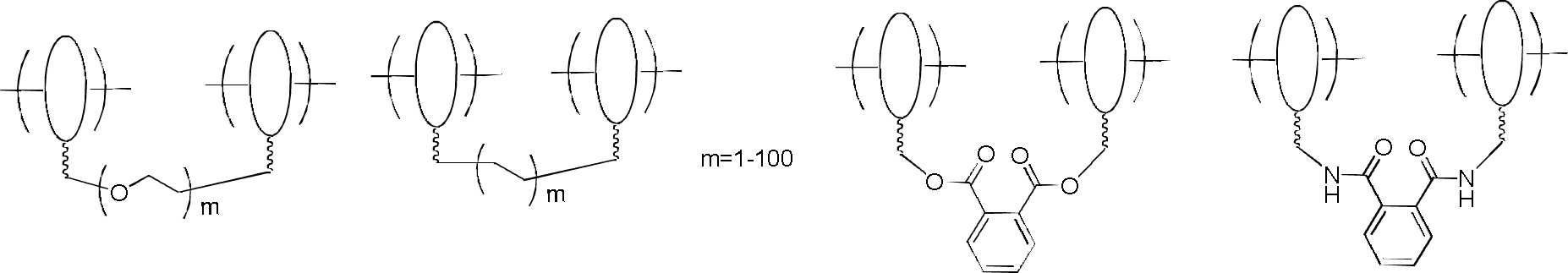
본 출원에서 가소화된 그룹(PR)은 다음 구조를 포함하지만 이에 한정되지 않는다:Plasticized groups (PR) in this application include, but are not limited to, the following structures:

가교 그룹(CL)은 다음 구조를 포함하지만 이에 한정되지 않는다:A bridging group (CL) includes, but is not limited to, the following structures:
빗살형 블록 공중합체의 주쇄는 다음 구조를 포함하지만 이에 한정되지 않는다:The backbone of the comb block copolymer includes, but is not limited to, the following structures:

이온 전도성 그룹(IC)은 다음 구조를 포함하지만 이에 한정되지 않는다:Ion conductive groups (ICs) include, but are not limited to, the following structures:

본 출원의 실시형태에서, 상기 이온 전달층의 두께는 0.1∼200㎛이고, 예를 들어 0.1㎛, 0.2㎛, 0.5㎛, 0.8㎛, 1㎛, 2㎛, 5㎛, 8㎛, 10㎛, 20㎛, 30㎛, 40㎛, 50㎛, 60㎛, 70㎛, 80㎛, 90㎛, 100㎛, 110㎛, 120㎛, 130㎛, 150㎛, 160㎛, 180㎛ 또는 200㎛ 등일 수 있다. 이온 전달층은 이온의 전달 통로이다.In the embodiment of the present application, the thickness of the ion transport layer is 0.1 to 200 μm, for example, 0.1 μm, 0.2 μm, 0.5 μm, 0.8 μm, 1 μm, 2 μm, 5 μm, 8 μm, 10 μm, 20 μm, 30 μm, 40 μm, 50 μm, 60 μm, 70 μm, 80 μm, 90 μm, 100 μm, 110 μm, 120 μm, 130 μm, 150 μm, 160 μm, 180 μm or 200 μm, etc. . The ion transport layer is a transport channel for ions.
본 출원의 실시형태에서, 상기 일렉트로크로믹층의 재료는 산화텅스텐과 같은 일렉트로크로믹 금속 산화물, 폴리데실 비올로겐 및 그의 유도체, 폴리아닐린 및 그의 유도체, 폴리피롤 및 그의 유도체, 폴리티오펜 및 그의 유도체, 폴리(3,4-에틸렌디옥시티오펜) 및 그의 유도체, 폴리티에노[3,4-b][1,4]디옥세판 및 그의 유도체, 폴리퓨란 및 그의 유도체, 폴리플루오렌 및 그의 유도체, 폴리카바졸 및 그의 유도체 중 하나 또는 적어도 2 개의 조합, 및/또는 상기 중합체의 단량체 또는 올리고머와 전자 결핍 단량체로 형성된 공중합체로부터 선택된다.In the embodiment of the present application, the material of the electrochromic layer is an electrochromic metal oxide such as tungsten oxide, polydecyl viologen and its derivatives, polyaniline and its derivatives, polypyrrole and its derivatives, polythiophene and its derivatives, Poly(3,4-ethylenedioxythiophene) and its derivatives, polythieno[3,4-b][1,4]dioxepane and its derivatives, polyfuran and its derivatives, polyfluorene and its derivatives, poly one or a combination of at least two of carbazole and its derivatives, and/or copolymers formed of a monomer or oligomer of said polymer with an electron deficient monomer.
본 출원의 실시형태에서, 전자 결핍 단량체는 벤조티아디아졸, 벤조셀레나디아졸, 벤족사졸, 벤조트리아졸, 벤조이미다졸, 퀴녹살린 및 디케토피롤로피롤 중 하나 또는 적어도 2 개의 조합을 포함하지만 이에 한정되지 않는다.In an embodiment of the present application, the electron deficient monomer comprises one or a combination of at least two of benzothiadiazole, benzoselenadiazole, benzoxazole, benzotriazole, benzoimidazole, quinoxaline, and diketopyrrolopyrrole. not limited
일렉트로크로믹층의 변색은 일렉트로크로믹 재료의 종류에 따라 조절될 수 있고, 예를 들어 블랙과 투명 간의 변화, 블랙과 레드 간의 변화, 블랙과 옐로우 간의 변화 등일 수 있다.The discoloration of the electrochromic layer may be adjusted according to the type of the electrochromic material, and may be, for example, a change between black and transparent, a change between black and red, and a change between black and yellow.
본 출원의 실시형태에서, 상기 일렉트로크로믹층의 두께는 1∼10000nm이고; 예를 들어 1nm, 3nm, 5nm, 10nm, 20nm, 50nm, 80nm, 100nm, 200nm, 300nm, 400nm, 500nm, 600nm, 800nm, 1000nm, 2000nm, 5000nm, 8000 nm 또는 10000 nm 등일 수 있다.In the embodiment of the present application, the thickness of the electrochromic layer is 1 to 10000 nm; For example, it may be 1 nm, 3 nm, 5 nm, 10 nm, 20 nm, 50 nm, 80 nm, 100 nm, 200 nm, 300 nm, 400 nm, 500 nm, 600 nm, 800 nm, 1000 nm, 2000 nm, 5000 nm, 8000 nm or 10000 nm.
본 출원의 실시형태에서, 상기 제1 투명기판과 제2 투명기판의 재료는 각각 독립적으로 유리 또는 연성 기판 재료이다.In the embodiment of the present application, the materials of the first transparent substrate and the second transparent substrate are each independently glass or a flexible substrate material.
상기 연성 기판 재료는 PET, 사이클로올레핀공중합체, 트리아세틸셀룰로오스 등을 포함하지만 이에 한정되지 않는다.The flexible substrate material includes, but is not limited to, PET, cycloolefin copolymer, triacetyl cellulose, and the like.
본 출원의 실시형태에서, 상기 일렉트로크로믹 조리개의 총 두께는 1mm 이하이다.In the embodiment of the present application, the total thickness of the electrochromic diaphragm is 1 mm or less.
본 출원에서 제공하는 일렉트로크로믹 조리개의 총 두께는 5mm 이하로 제어될 수 있고, 낮은 두께(또는 Z축 높이)는 카메라의 줌 및 조절에 유리하다.The total thickness of the electrochromic aperture provided in the present application can be controlled to 5 mm or less, and the low thickness (or Z-axis height) is advantageous for zooming and adjusting the camera.
제10 측면에서, 본 출원은 조리개 렌즈 조합을 제공하고, 해당 조리개 렌즈 조합은,In a tenth aspect, the present application provides an aperture lens combination, the aperture lens combination comprising:
색지움에 사용되는 오목 렌즈와 볼록 렌즈의 조합 및 상기 오목 렌즈 또는 볼록 렌즈의 표면에 부착된 제7 측면에 따른 일렉트로크로믹 조리개를 포함하고;a combination of a concave lens and a convex lens used for ablation and an electrochromic stop according to the seventh aspect attached to a surface of the concave or convex lens;
또는 상기 조리개 렌즈 조합은,Or the aperture lens combination is,
색지움에 사용되는 오목 렌즈와 볼록 렌즈의 조합을 포함하고, 여기서 상기 오목 렌즈는 제8 측면에 따른 일렉트로크로믹 조리개이다.A combination of a concave lens and a convex lens used for ablation, wherein the concave lens is an electrochromic stop according to the eighth aspect.
제11 측면에서, 본 출원은 렌즈 모듈을 제공하고, 해당 렌즈 모듈은,In an eleventh aspect, the present application provides a lens module, the lens module comprising:
아크로매틱 렌즈 조합, 본 출원의 제2 측면, 제3 측면, 제4 측면, 제5 측면, 제7 측면, 제8 측면 또는 제9 측면에 따른 일렉트로크로믹 조리개, 노광 컨트롤러, 이미지 센서, 펄스 전압 컨트롤러, 광도센서, 감광소자, 회로기판 및 칩을 포함하고, Achromatic lens combination, electrochromic diaphragm according to the second, third, fourth, fifth, seventh, eighth or ninth aspect of the present application, exposure controller, image sensor, pulse voltage controller , including a light sensor, a photosensitive element, a circuit board and a chip,
여기서, 상기 아크로매틱 렌즈 조합, 일렉트로크로믹 조리개, 노광 컨트롤러 및 이미지 센서의 중심은 동일한 광축에 있으며;wherein the centers of the achromatic lens combination, the electrochromic iris, the exposure controller and the image sensor are on the same optical axis;
또는,or,
제10 측면에 따른 조리개 렌즈 조합, 노광 컨트롤러, 이미지 센서, 펄스 전압 컨트롤러, 광도센서, 감광소자, 회로기판 및 칩을 포함하고, A diaphragm lens combination according to the tenth aspect, including an exposure controller, an image sensor, a pulse voltage controller, a light intensity sensor, a photosensitive element, a circuit board and a chip,
여기서, 상기 조리개 렌즈 조합, 일렉트로크로믹 조리개, 노광 컨트롤러 및 이미지 센서의 중심은 동일한 광축에 있다.Here, the center of the diaphragm lens combination, the electrochromic diaphragm, the exposure controller, and the image sensor is on the same optical axis.
하나의 구체적인 실시방안에서, 아크로매틱 렌즈 조합은 전방 렌즈 및 후방 렌즈를 포함하고, 전방 렌즈와 및 후방 렌즈는 각각 독립적으로 하나 또는 복수 개의 렌즈를 포함한다. 렌즈 재료는 예시로서 자외선 경화, 열경화 또는 상온 경화 등 방식으로 가공될 수 있는 하나 또는 복수 개의 수지, 예를 들어 폴리카보네이트, 폴리에스터 또는 폴리우레탄 등이다. 전방 렌즈와 후방 렌즈의 조합은 주로 색지움(achromatism)에 사용된다.In one specific embodiment, the achromatic lens combination includes a front lens and a rear lens, and the front lens and the rear lens each independently include one or a plurality of lenses. The lens material is, for example, one or a plurality of resins, for example polycarbonate, polyester or polyurethane, which can be processed in a manner such as UV curing, thermal curing or room temperature curing. The combination of anterior and posterior lenses is mainly used for achromatism.
일렉트로크로믹 조리개는 주로 빛이 통과할 수 있는 다이어프램의 크기를 조절하여 렌즈 모듈을 투과하는 빛의 양을 조절하는데 사용된다.The electrochromic diaphragm is mainly used to control the amount of light passing through the lens module by adjusting the size of the diaphragm through which light can pass.
펄스 전압 컨트롤러는 주로 일렉트로크로믹 조리개에 작용되도록 펄스 전압을 인가하여, 일렉트로크로믹 조리개의 광투과율을 변경하는데 사용된다. 펄스 전압 컨트롤러는 광도센서, 노광 컨트롤러, 렌즈 이동 버튼 등의 영향을 받는다.The pulse voltage controller is mainly used to change the light transmittance of the electrochromic diaphragm by applying a pulse voltage to act on the electrochromic diaphragm. The pulse voltage controller is affected by the light intensity sensor, exposure controller, and lens shift button.
이미지 센서는 환경 파라미터를 통해 펄스 전압 컨트롤러를 제어하여 일렉트로크로믹 조리개의 다이어프램을 조절하고, 노광 컨트롤러를 제어하여 노광 파라미터 및 노광 시간을 제어한다. 환경 파라미터는 픽셀 적분시간, 환경 조도, 플래시 및 플래시 사용 가능 여부 등 요소를 포함한다. 이미지 센서는 예를 들어 상보형 금속산화 반도체(CMOS) 센서 칩과 같은 포커스된 광학 이미지를 캡처할 수 있는 임의의 기존 고체 이미징 센서일 수 있다.The image sensor controls the pulse voltage controller through the environmental parameters to adjust the diaphragm of the electrochromic diaphragm, and controls the exposure controller to control the exposure parameters and exposure time. The environmental parameters include factors such as pixel integration time, ambient illuminance, flash and flash availability. The image sensor may be any conventional solid-state imaging sensor capable of capturing a focused optical image, such as, for example, a complementary metal oxide semiconductor (CMOS) sensor chip.
감광소자는 광선을 전하로 변환시킬 수 있고, 아날로그-디지털 변환기 칩을 통해 디지털 신호로 변환시킬 수 있으며, 디지털 신호는 압축된 후 카메라 내부의 플래시 메모리 또는 내장 하드디스크(전하 결합 소자(CCD), 상보형 금속산화 반도체(CMOS)를 포함함)에 저장된다.The photosensitive element can convert light rays into electric charges, and can convert them into digital signals through an analog-to-digital converter chip, and after the digital signals are compressed, the flash memory or built-in hard disk (charge coupled device (CCD)) inside the camera; It is stored in a complementary metal oxide semiconductor (CMOS).
본 출원에서, 투과되는 빛의 양과 촬영 효과를 조절하기 위한 렌즈 모듈의 전체 제조 과정은 다음 단계로 요약될 수 있다.In the present application, the entire manufacturing process of the lens module for adjusting the amount of transmitted light and the photographing effect can be summarized as the following steps.
(1) 일렉트로크로믹 조리개를 제조하고;(1) preparing an electrochromic stop;
(2) 아크로매틱 렌즈 조합을 성형 및 경화하고, 일렉트로크로믹 조리개와 결합하여 일렉트로크로믹 조리개 렌즈를 조성하며;(2) shaping and curing the achromatic lens combination, combining with the electrochromic aperture to form an electrochromic aperture lens;
(3) 이미지 센서, 펄스 전압 컨트롤러, 감광소자를 커미셔닝 및 장착하고;(3) commissioning and mounting the image sensor, the pulse voltage controller, and the photosensitive element;
정밀한 커미셔닝을 통해, 일렉트로크로믹 조리개, 아크로매틱 렌즈 조합 및 이미지 센서가 동일한 광축에 위치하도록 제어하고, 이미지 센서는 환경의 조도를 감지하여, 전기 신호로 변환시킨 후 제어 칩에 출력하며, 나아가 펄스 전압 컨트롤러를 조절하여 상응하는 전류를 출력하여 일렉트로크로믹 조리개의 광투과율을 변경하고, 아울러 보이스 코일 모터는 최적의 촬영 파라미터를 달성하도록 상응하는 초점거리를 변경하며, 다음, 노광 컨트롤러는 노광을 제어하고, 이미지 신호는 CCD에 의해 전기 신호로 변환된 후 처리되어 이미지로 출력되며;Through precise commissioning, the electrochromic iris, the achromatic lens combination and the image sensor are controlled to be positioned on the same optical axis, and the image sensor detects the illuminance of the environment, converts it into an electrical signal, and outputs it to the control chip, furthermore, the pulse voltage Adjust the controller to output a corresponding current to change the light transmittance of the electrochromic diaphragm, and the voice coil motor to change the corresponding focal length to achieve the optimal shooting parameters, then the exposure controller controls the exposure and , the image signal is converted into an electrical signal by the CCD and then processed and output as an image;
(4) 일렉트로크로믹 조리개 렌즈와 기타 부재를 조합하여 렌즈 모듈을 형성하고,(4) combining the electrochromic aperture lens and other members to form a lens module;
일렉트로크로믹 조리개 렌즈와 기타 부재, 예를 들어 노광 컨트롤러, CCD, 보이스 코일 모터 등을 정밀하게 커미셔닝한 후 함께 장착하여, 렌즈 모듈을 형성한다.An electrochromic diaphragm lens and other members, for example, an exposure controller, CCD, voice coil motor, etc. are precisely commissioned and then mounted together to form a lens module.
기존의 기술과 비교하면, 본 출원은 다음과 같은 유익한 효과를 갖는다.Compared with the existing technology, the present application has the following advantageous effects.
본 출원의 제1 측면에서 제공하는 일렉트로크로믹 조리개의 제조방법은 조리개가 멀티레벨 제어를 구현할 수 있는 것을 보장하는 동시에, 전통적인 에칭 방법으로 인한 변색이 균일하지 않은 문제를 효과적으로 방지한다.The manufacturing method of the electrochromic diaphragm provided in the first aspect of the present application ensures that the diaphragm can implement multi-level control, and at the same time effectively prevents the problem of non-uniform discoloration due to the traditional etching method.
본 출원의 제3 측면 및 제4 측면에서 제공하는 일렉트로크로믹 조리개는 조리개의 멀티레벨 제어를 구현하는 동시에, 요홈의 에칭으로 인한 빛샘 또는 불투명 문제를 방지한다.The electrochromic diaphragm provided in the third and fourth aspects of the present application implements multi-level control of the diaphragm, and at the same time prevents light leakage or opacity caused by etching of the groove.
본 출원의 제5 측면에서 제공하는 일렉트로크로믹 조리개 및 제6 측면에서 제공하는 일렉트로크로믹 조리개에 대한 멀티레벨 제어를 수행하는 방법은 조리개의 멀티레벨 제어를 구현하는 동시에, 요홈의 에칭으로 인한 빛샘 또는 불투명 문제를 방지한다.The method for performing multilevel control of the electrochromic diaphragm provided in the fifth aspect of the present application and the electrochromic diaphragm provided in the sixth aspect of the present application implements multilevel control of the diaphragm, and at the same time, light leakage due to the etching of the groove Or avoid opacity issues.
본 출원의 제7 측면에서 제공하는 일렉트로크로믹 조리개는 곡면 구조이고, 곡률은 아크로매틱 렌즈 조합의 오목 렌즈 또는 볼록 렌즈의 표면의 곡률과 동일하며, 아크로매틱 렌즈 조합의 오목 렌즈 또는 볼록 렌즈의 표면에 부착되어, 렌즈 모듈에서 조리개와 렌즈의 결합을 구현함으로써, 렌즈 모듈의 두께를 추가로 줄일 수 있다.The electrochromic diaphragm provided in the seventh aspect of the present application has a curved structure, the curvature is the same as the curvature of the surface of the concave or convex lens of the achromatic lens combination, and is attached to the surface of the concave or convex lens of the achromatic lens combination Thus, by implementing the combination of the aperture and the lens in the lens module, it is possible to further reduce the thickness of the lens module.
본 출원의 제8 측면에서 제공하는 일렉트로크로믹 조리개는 곡면 구조이고, 형상은 아크로매틱 렌즈 조합의 오목 렌즈 또는 볼록 렌즈의 형상과 동일하기 때문에, 아크로매틱 렌즈 조합의 오목 렌즈 또는 볼록 렌즈를 대체하여, 렌즈 모듈에서 조리개와 렌즈의 결합을 구현함으로써, 렌즈 모듈의 두께를 추가로 줄일 수 있다.Since the electrochromic diaphragm provided in the eighth aspect of the present application has a curved structure, and the shape is the same as the shape of the concave lens or the convex lens of the achromatic lens combination, the lens replaces the concave or convex lens of the achromatic lens combination. By implementing the combination of the aperture and the lens in the module, it is possible to further reduce the thickness of the lens module.
본 출원의 제9 측면에서 제공하는 일렉트로크로믹 조리개는 내부에서 외부로 상이한 변색 범위를 가짐으로써, 보다 큰 차이의 조리개 광속 레벨 넘버 조절을 구현하고, 다양한 촬영 시나리오의 요구를 충족시킬 수 있다.The electrochromic diaphragm provided in the ninth aspect of the present application has a different discoloration range from the inside to the outside, thereby realizing a larger difference in the diaphragm luminous flux level number control and meeting the needs of various shooting scenarios.
도 1은 본 출원의 실시예 1-1에서 제공하는 일렉트로크로믹 조리개의 단면 구조 개략도이고,
여기서, 11은 제1 투명기판이고, 12는 제1 투명도전층이며, 13은 이온 저장층이고, 14는 이온 전달층이며, 15는 일렉트로크로믹층이고, 16은 제2 투명도전층이며, 17은 제2 투명기판이다.
도 2는 본 출원의 실시예 1-2에서 제공하는 일렉트로크로믹 조리개의 단면 구조 개략도이고,
여기서, 21은 제1 투명기판이고, 22는 제1 투명도전층이며, 23은 이온 저장층이고, 24는 이온 전달층이며, 25는 일렉트로크로믹층이고, 26은 제2 투명도전층이며, 27은 제2 투명기판이다.
도 3은 본 출원의 실시예 1-3에서 제공하는 일렉트로크로믹 조리개의 단면 구조 개략도이고,
여기서, 31은 제1 투명기판이고, 32는 제1 투명도전층이며, 33은 이온 저장층이고, 34는 이온 전달층이며, 35는 일렉트로크로믹층이고, 36은 제2 투명도전층이며, 37은 제2 투명기판이다.
도 4는 본 출원의 실시예 1-4에서 제공하는 일렉트로크로믹 조리개의 단면 구조 개략도이고,
여기서, 41은 제1 투명기판이고, 42는 제1 투명도전층이며, 43은 이온 저장층이고, 44는 이온 전달층이며, 45는 일렉트로크로믹층이고, 46은 제2 투명도전층이며, 47은 제2 투명기판이다.
도 5는 본 출원의 실시예 1-5에서 제공하는 일렉트로크로믹 조리개의 단면 구조 개략도이고,
여기서, 51은 제1 투명기판이고, 52는 제1 투명도전층이며, 53은 이온 저장층이고, 54는 이온 전달층이며, 55는 일렉트로크로믹층이고, 56은 제2 투명도전층이며, 57은 제2 투명기판이다.
도 6은 본 출원의 실시예 2에서 제공하는 일렉트로크로믹 조리개의 단면 구조 개략도이고,
여기서, 61, 62, 63은 투명기판이고, 61-1, 61-5, 62-1, 62-5는 투명도전층이며, 61-2, 62-2는 이온 저장층이고, 61-3, 62-3은 이온 전달층이며, 61-4, 62-4는 일렉트로크로믹층이다.
도 7은 본 출원의 실시예 3-1에서 제공하는 일렉트로크로믹 조리개의 단면 구조 개략도이고,
여기서, 71은 제1 투명기판이고, 72는 제1 투명도전층이며, 73은 이온 저장층이고, 74는 이온 전달층이며, 75는 일렉트로크로믹층이고, 76은 제2 투명도전층이며, 77은 제2 투명기판이다.
도 8은 본 출원의 실시예 3-2에서 제공하는 일렉트로크로믹 조리개의 단면 구조 개략도이고,
여기서, 81은 제1 투명기판이고, 82는 제1 투명도전층이며, 83은 이온 저장층이고, 84는 이온 전달층이며, 85는 일렉트로크로믹층이고, 86은 제2 투명도전층이며, 87은 제2 투명기판이다.
도 9는 본 출원의 실시예 4에 따른 일렉트로크로믹 조리개에 대한 멀티레벨 제어를 수행하는 방법의 개략도이다.
도 10은 본 출원의 실시예 5-1에서 제공하는 일렉트로크로믹 조리개의 단면 구조 개략도이고,
여기서, 101은 제1 투명기판이고, 102는 제1 투명도전층이며, 103은 이온 저장층이고, 104는 이온 전달층이며, 105는 일렉트로크로믹층이고, 106은 제2 투명도전층이며, 107은 제2 투명기판이다.
도 11은 본 출원의 실시예 5-2에서 제공하는 일렉트로크로믹 조리개의 단면 구조 개략도이고,
여기서, 111은 제1 투명기판이고, 112는 제1 투명도전층이며, 113은 이온 저장층이고, 114는 이온 전달층이며, 115는 일렉트로크로믹층이고, 116은 제2 투명도전층이며, 117은 제2 투명기판이다.
도 12는 본 출원의 실시예 6-1에서 제공하는 곡면 일렉트로크로믹 조리개의 단면 구조 개략도이고,
여기서, 121은 제1 투명기판이고, 122는 제1 투명도전층이며, 123은 이온 저장층이고, 124는 이온 전달층이며, 125는 일렉트로크로믹층이고, 126은 제2 투명도전층이며, 127은 제2 투명기판이다.
도 13은 본 출원의 실시예 6-1에서 제공하는 조리개 렌즈 조합의 구조 개략도이고,
여기서, 131은 볼록 렌즈이고, 132는 실시예 6-1에서 제공하는 곡면 일렉트로크로믹 조리개이며, 133은 오목 렌즈이다.
도 14는 본 출원의 실시예 6-2에서 제공하는 조리개 렌즈 조합의 구조 개략도이고,
여기서, 141은 볼록 렌즈이고, 142는 실시예 6-2에서 제공하는 곡면 일렉트로크로믹 조리개이며, 143은 오목 렌즈이다.
도 15는 본 출원의 실시예 6-3에서 제공하는 조리개 렌즈 조합의 구조 개략도이고,
여기서, 151은 볼록 렌즈이고, 152는 실시예 6-3에서 제공하는 곡면 일렉트로크로믹 조리개이며, 153은 홀더이다.
도 16은 본 출원의 실시예 6-4에서 제공하는 조리개 렌즈 조합의 구조 개략도이고,
여기서, 161은 홀더이고, 162는 실시예 6-4에서 제공하는 곡면 일렉트로크로믹 조리개이며, 163은 오목 렌즈이다.1 is a cross-sectional structural schematic diagram of an electrochromic stop provided in Example 1-1 of the present application;
where 11 is a first transparent substrate, 12 is a first transparent conductive layer, 13 is an ion storage layer, 14 is an ion transport layer, 15 is an electrochromic layer, 16 is a second transparent conductive layer, and 17 is a second transparent conductive layer. 2 It is a transparent substrate.
Figure 2 is a schematic cross-sectional structure of the electrochromic diaphragm provided in Example 1-2 of the present application,
Here, 21 is a first transparent substrate, 22 is a first transparent conductive layer, 23 is an ion storage layer, 24 is an ion transport layer, 25 is an electrochromic layer, 26 is a second transparent conductive layer, 27 is a second 2 It is a transparent substrate.
3 is a schematic cross-sectional view of the electrochromic aperture provided in Examples 1-3 of the present application;
where 31 is a first transparent substrate, 32 is a first transparent conductive layer, 33 is an ion storage layer, 34 is an ion transport layer, 35 is an electrochromic layer, 36 is a second transparent conductive layer, and 37 is a second transparent conductive layer. 2 It is a transparent substrate.
Figure 4 is a schematic cross-sectional structure of the electrochromic stop provided in Examples 1-4 of the present application,
where 41 is a first transparent substrate, 42 is a first transparent conductive layer, 43 is an ion storage layer, 44 is an ion transport layer, 45 is an electrochromic layer, 46 is a second transparent conductive layer, and 47 is a second transparent conductive layer. 2 It is a transparent substrate.
5 is a schematic cross-sectional structure of an electrochromic stop provided in Examples 1-5 of the present application;
where 51 is a first transparent substrate, 52 is a first transparent conductive layer, 53 is an ion storage layer, 54 is an ion transport layer, 55 is an electrochromic layer, 56 is a second transparent conductive layer, and 57 is a second transparent conductive layer. 2 It is a transparent substrate.
Figure 6 is a schematic cross-sectional structure of the electrochromic stop provided in Example 2 of the present application,
Here, 61, 62, 63 are transparent substrates, 61-1, 61-5, 62-1, 62-5 are transparent conductive layers, 61-2, 62-2 are ion storage layers, 61-3, 62 -3 is an ion transport layer, and 61-4 and 62-4 are electrochromic layers.
7 is a schematic cross-sectional structure of the electrochromic stop provided in Example 3-1 of the present application;
where 71 is a first transparent substrate, 72 is a first transparent conductive layer, 73 is an ion storage layer, 74 is an ion transport layer, 75 is an electrochromic layer, 76 is a second transparent conductive layer, and 77 is a second transparent conductive layer. 2 It is a transparent substrate.
8 is a schematic cross-sectional view of the electrochromic stop provided in Example 3-2 of the present application;
where 81 is a first transparent substrate, 82 is a first transparent conductive layer, 83 is an ion storage layer, 84 is an ion transport layer, 85 is an electrochromic layer, 86 is a second transparent conductive layer, and 87 is a second transparent conductive layer. 2 It is a transparent substrate.
9 is a schematic diagram of a method of performing multi-level control on an electrochromic diaphragm according to Embodiment 4 of the present application.
10 is a schematic cross-sectional structure of an electrochromic stop provided in Example 5-1 of the present application;
where 101 is a first transparent substrate, 102 is a first transparent conductive layer, 103 is an ion storage layer, 104 is an ion transport layer, 105 is an electrochromic layer, 106 is a second transparent conductive layer, and 107 is a second transparent conductive layer. 2 It is a transparent substrate.
11 is a schematic cross-sectional structure of an electrochromic stop provided in Example 5-2 of the present application;
where 111 is a first transparent substrate, 112 is a first transparent conductive layer, 113 is an ion storage layer, 114 is an ion transport layer, 115 is an electrochromic layer, 116 is a second transparent conductive layer, and 117 is a second transparent conductive layer. 2 It is a transparent substrate.
12 is a schematic cross-sectional structure of a curved electrochromic diaphragm provided in Example 6-1 of the present application;
Here, 121 is a first transparent substrate, 122 is a first transparent conductive layer, 123 is an ion storage layer, 124 is an ion transport layer, 125 is an electrochromic layer, 126 is a second transparent conductive layer, and 127 is a second transparent conductive layer. 2 It is a transparent substrate.
13 is a structural schematic diagram of a diaphragm lens combination provided in Example 6-1 of the present application;
Here, 131 is a convex lens, 132 is a curved electrochromic diaphragm provided in Example 6-1, and 133 is a concave lens.
14 is a structural schematic diagram of an aperture lens combination provided in Example 6-2 of the present application;
Here, 141 is a convex lens, 142 is a curved electrochromic diaphragm provided in Example 6-2, and 143 is a concave lens.
15 is a structural schematic diagram of an aperture lens combination provided in Example 6-3 of the present application;
Here, 151 is a convex lens, 152 is a curved electrochromic diaphragm provided in Example 6-3, and 153 is a holder.
16 is a structural schematic diagram of an aperture lens combination provided in Example 6-4 of the present application;
Here, 161 is a holder, 162 is a curved electrochromic diaphragm provided in Example 6-4, and 163 is a concave lens.
이하, 첨부된 도면과 구체적인 실시형태를 결합하여 본 출원의 기술방안을 추가로 설명하도록 한다. 본 분야의 당업자라면 상기 구체적인 실시형태는 단지 본 출원의 이해를 돕기 위한 것일 뿐, 본 출원에 대한 구체적인 한정으로 간주되어서는 안된다는 점을 이해할 것이다.Hereinafter, the technical solution of the present application will be further described by combining the accompanying drawings and specific embodiments. Those skilled in the art will understand that the above specific embodiments are merely for helping the understanding of the present application and should not be regarded as specific limitations on the present application.
본 출원의 실시예에서, 고분자A(PEGPRCL에 속하는 하나의 고체 전해질 중합체)의 제조방법은 다음과 같다.In the examples of the present application, the preparation method of polymer A (one solid electrolyte polymer belonging to PEGPRCL) is as follows.

적합한 유기용매에 브로모이소부티르산으로 말단캡핑된 PEG(폴리에틸렌글리콜), 가소화된 그룹을 갖는 아크릴레이트, 2 개의 아크릴산을 갖는 가교 그룹, 1가 구리 촉매, PMDETA(N,N,N',N",N"-펜타메틸디에틸렌트리아민) 리간드를 첨가한다. 해당 혼합 용액(용매를 첨가하지 않은 해당 혼합물은 소자 제조에 직접 사용되는 전해질 전구체로 사용될 수도 있음)을 100℃에서 12시간 동안 반응시키고, 셀라이트를 통해 여과 및 감압하여 용매를 제거함으로써 고분자A를 얻는다.PEG (polyethylene glycol) endcapped with bromoisobutyric acid in a suitable organic solvent, acrylate with plasticized groups, bridging groups with two acrylic acids, monovalent copper catalyst, PMDETA (N,N,N',N ",N"-pentamethyldiethylenetriamine) ligand is added. Polymer A was obtained by reacting the mixed solution (the mixture without adding a solvent can also be used as an electrolyte precursor used directly for device manufacturing) at 100° C. for 12 hours, filtering through Celite and removing the solvent under reduced pressure. get
고분자B(PEGPR에 속하는 하나의 고체 전해질 중합체)의 제조방법은 다음과 같다:Polymer B (one solid electrolyte polymer belonging to PEGPR) was prepared as follows:

적합한 유기용매에 PEG 디아민(폴리에틸렌글리콜 디아민) 및 프탈로일 클로라이드를 첨가하고, 알칼리성 조건에서 직접 중합하여 고분자 전해질을 얻는다(용매를 첨가하지 않은 해당 혼합물은 소자 제조에 직접 사용되는 전해질 전구체로 사용될 수도 있음). 수세척, 분액, 건조 및 용매 제거를 거쳐 고분자B를 얻는다.PEG diamine (polyethylene glycol diamine) and phthaloyl chloride are added to a suitable organic solvent and polymerized directly under alkaline conditions to obtain a polyelectrolyte (the mixture without the addition of a solvent may be used as an electrolyte precursor directly used for device manufacturing) has exist). Polymer B is obtained through water washing, liquid separation, drying and solvent removal.
고분자C(PEGSPCL에 속하는 하나의 고체 전해질 중합체)의 제조방법은 다음과 같다.The preparation method of polymer C (one solid electrolyte polymer belonging to PEGSPCL) is as follows.

적합한 유기용매에 PEG(폴리에틸렌글리콜), 폴리실록산 디아민, 테트라아민 가교제, CDI(카르보닐 디이미다졸) 축합제를 첨가한다(용매를 첨가하지 않은 해당 혼합물은 소자 제조에 직접 사용되는 전해질 전구체로 사용될 수도 있음). 90℃에서 반응시켜 중합체를 얻는다. 수세척, 분액, 건조 및 용매 제거를 거쳐 고분자C를 얻는다.In a suitable organic solvent, add PEG (polyethylene glycol), polysiloxane diamine, tetraamine crosslinking agent, and CDI (carbonyl diimidazole) condensing agent (the mixture without the addition of solvent can also be used as an electrolyte precursor directly used in device fabrication) has exist). A polymer is obtained by reacting at 90°C. Polymer C is obtained through washing with water, separation, drying and solvent removal.
고분자D(PEGSP에 속하는 하나의 고체 전해질 중합체)의 제조방법은 다음과 같다.The preparation method of polymer D (one solid electrolyte polymer belonging to PEGSP) is as follows.

적합한 유기용매에 PEG(폴리에틸렌글리콜), 폴리실록산 디아민, CDI(카르보닐 디이미다졸) 축합제를 첨가한다(용매를 첨가하지 않은 해당 혼합물은 소자 제조에 직접 사용되는 전해질 전구체로 사용될 수도 있음). 120℃에서 반응시켜 중합체를 얻고, 수세척, 분액, 건조 및 용매 제거를 거쳐 고분자D를 얻는다.In a suitable organic solvent, add PEG (polyethylene glycol), polysiloxane diamine, and CDI (carbonyl diimidazole) condensing agent (the mixture without the addition of solvent can also be used as an electrolyte precursor used directly in device fabrication). A polymer is obtained by reaction at 120° C., and polymer D is obtained through washing with water, separation, drying and solvent removal.
고분자E(PEGSP-PRCL에 속하는 하나의 고체 전해질 중합체)의 제조방법은 다음과 같다.Polymer E (one solid electrolyte polymer belonging to PEGSP-PRCL) is prepared as follows.
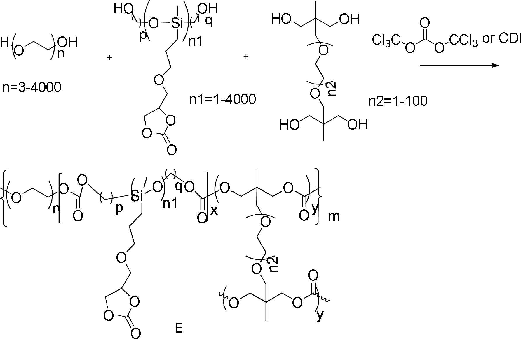
적합한 유기용매에 PEG(폴리에틸렌글리콜), 폴리실록산디올, 테트라올 가교제, CDI(카르보닐 디이미다졸) 축합제를 첨가하고(용매를 첨가하지 않은 해당 혼합물은 소자 제조에 직접 사용되는 전해질 전구체로 사용될 수도 있음), 100℃에서 반응시켜 중합체를 얻는다. 수세척, 분액, 건조 및 용매 제거를 거쳐 고분자E를 얻는다.PEG (polyethylene glycol), polysiloxanediol, tetraol crosslinking agent, and CDI (carbonyl diimidazole) condensing agent are added to a suitable organic solvent (the mixture without the addition of a solvent can be used as an electrolyte precursor directly used for device manufacturing) ), and reacted at 100° C. to obtain a polymer. Polymer E is obtained through washing with water, separation, drying and solvent removal.
고분자F(PEGSP-PR에 속하는 하나의 고체 전해질 중합체)의 제조방법은 다음과 같다.The preparation method of polymer F (one solid electrolyte polymer belonging to PEGSP-PR) is as follows.

적합한 유기용매에 PEG(폴리에틸렌글리콜), 폴리실록산디올, CDI(카르보닐 디이미다졸) 축합제를 첨가한다(용매를 첨가하지 않은 해당 혼합물은 소자 제조에 직접 사용되는 전해질 전구체로 사용될 수도 있음). 100℃에서 반응시켜 중합체를 얻는다. 수세척, 분액, 건조 및 용매 제거를 거쳐 고분자F를 얻는다.In a suitable organic solvent, add PEG (polyethylene glycol), polysiloxanediol, and CDI (carbonyl diimidazole) condensing agent (the mixture without the addition of solvent can also be used as an electrolyte precursor used directly in device fabrication). A polymer is obtained by reacting at 100°C. Polymer F is obtained through water washing, liquid separation, drying and solvent removal.
고분자G(ICNMCL에 속하는 하나의 고체 전해질 중합체)의 제조방법은 다음과 같다.The manufacturing method of polymer G (one solid electrolyte polymer belonging to ICNMCL) is as follows.

적합한 유기용매에 알킬아크릴레이트, 폴리에틸렌글리콜 아크릴레이트, 에틸렌글리콜 디아크릴레이트, AIBN(아조비스이소부티로니트릴)을 첨가한다(용매를 첨가하지 않은 해당 혼합물은 소자 제조에 직접 사용되는 전해질 전구체로 사용될 수도 있음). 광반응을 통해 중합체를 얻는다. 수세척, 분액, 건조 및 용매 제거를 거쳐 고분자G를 얻는다.Alkyl acrylate, polyethylene glycol acrylate, ethylene glycol diacrylate and AIBN (azobisisobutyronitrile) are added to a suitable organic solvent (the mixture without the addition of a solvent can be used as an electrolyte precursor directly used for device fabrication) may be). A polymer is obtained through a photoreaction. Polymer G is obtained through washing with water, separation, drying and solvent removal.
고분자H(ICNM에 속하는 하나의 고체 전해질 중합체)의 제조방법은 다음과 같다:Polymer H (one solid electrolyte polymer belonging to ICNM) was prepared as follows:

적합한 유기용매에 알킬아크릴레이트, 폴리에틸렌글리콜 아크릴레이트, AIBN(아조비스이소부티로니트릴)을 첨가한다(용매를 첨가하지 않은 해당 혼합물은 소자 제조에 직접 사용되는 전해질 전구체로 사용될 수도 있음). 광반응을 통해 중합체를 얻는다. 수세척, 분액, 건조 및 용매 제거를 거쳐 고분자H를 얻는다.Alkyl acrylate, polyethylene glycol acrylate and AIBN (azobisisobutyronitrile) are added in a suitable organic solvent (the mixture without addition of solvent can also be used as an electrolyte precursor used directly in device fabrication). A polymer is obtained through a photoreaction. Polymer H is obtained through washing with water, separation, drying and solvent removal.
실시예 1-1Example 1-1
본 실시예는 파티션(partition)을 통해 멀티레벨 제어를 구현하는 일렉트로크로믹 조리개 및 그의 제조방법을 제공한다.The present embodiment provides an electrochromic diaphragm for implementing multi-level control through a partition and a method for manufacturing the same.
일렉트로크로믹 조리개의 구조는 도 1에 도시된 바와 같이 순차적으로 적층된 제1 투명기판(11), 제1 투명도전층(12), 이온 저장층(13), 이온 전달층(14), 일렉트로크로믹층(15), 제2 투명도전층(16) 및 제2 투명기판(17)을 포함하고,The structure of the electrochromic stop is as shown in FIG. 1 , a first
여기서, 일렉트로크로믹층(15) 및 제2 투명도전층(16)에는 상기 일렉트로크로믹 조리개의 중심축을 중심으로 복수 개의 환형 요홈이 에칭된다.Here, a plurality of annular grooves are etched in the
본 실시예에서 일렉트로크로믹 조리개의 제조방법은 다음과 같다:The manufacturing method of the electrochromic diaphragm in this embodiment is as follows:
(1) 일렉트로크로믹층(15)의 제조:(1) Preparation of the electrochromic layer 15:
500mg의 폴리(3-헥실티오펜)(P3HT)를 10ml의 o-자일렌에 용해하고, 10h 동안 자력을 통해 교반한 다음 얻어진 용액을 유리기판(제2 투명기판(17))에 도금된 ITO층(제2 투명도전층(16))에 적하하며, 스핀코팅을 통해 P3HT 코팅층을 형성하고, 도 1에 도시된 구조에 따라, P3HT 코팅층과 제2 투명도전층에 레이저로 복수 개의 환형 요홈을 에칭하여 일렉트로크로믹층(15)을 얻는다.500 mg of poly(3-hexylthiophene) (P3HT) was dissolved in 10 ml of o-xylene, stirred through magnetic force for 10 h, and then the resulting solution was applied to a glass substrate (second transparent substrate 17) with plated ITO It is dropped on the layer (the second transparent conductive layer 16), a P3HT coating layer is formed through spin coating, and a plurality of annular grooves are etched with a laser in the P3HT coating layer and the second transparent conductive layer according to the structure shown in FIG. An
(2) 이온 저장층(13)의 제조:(2) Preparation of the ion storage layer 13:
500mg의 삼산화텅스텐을 20ml의 탈이온수에 용해하고, 교반 및 여과를 거친 후, 얻어진 용액을 유리기판(제1 투명기판(11))에 도금된 ITO층(제1 투명도전층(12))에 적하하며, 스핀코팅을 통해 삼산화텅스텐 코팅층을 형성하여 이온 저장층(13)을 얻는다.500 mg of tungsten trioxide is dissolved in 20 ml of deionized water, stirred and filtered, and the resulting solution is dropped onto the ITO layer (first transparent conductive layer 12) plated on a glass substrate (first transparent substrate 11). Then, a tungsten trioxide coating layer is formed through spin coating to obtain an
(3) 일렉트로크로믹 조리개의 제조:(3) Preparation of the electrochromic aperture:
과염소산리튬 10wt%, 고분자H의 전구체 89.9wt% 및 페라조비스이소 부티로니트릴 0.1wt%를 혼합하여 상기 이온 저장층(13)에 코팅함으로써 전해질 코팅층을 형성하고; 다음 상기 일렉트로크로믹층(15)(ITO층 및 유리기판과 함께)을 전해질 코팅층에 커버하며, 자외선 경화를 통해 전해질 코팅층에 전고체 고분자 전해질층(이온 전달층(14))을 형성하여 일렉트로크로믹 조리개를 얻는다.forming an electrolyte coating layer by mixing 10 wt% of lithium perchlorate, 89.9 wt% of a polymer H precursor, and 0.1 wt% of perazobisisobutyronitrile and coating the
실시예 1-2Example 1-2
본 실시예는 파티션을 통해 멀티레벨 제어를 구현하는 일렉트로크로믹 조리개 및 그의 제조방법을 제공한다.The present embodiment provides an electrochromic diaphragm for implementing multi-level control through a partition and a method for manufacturing the same.
일렉트로크로믹 조리개의 구조는 도 2에 도시된 바와 같이 순차적으로 적층된 제1 투명기판(21), 제1 투명도전층(22), 이온 저장층(23), 이온 전달층(24), 일렉트로크로믹층(25), 제2 투명도전층(26) 및 제2 투명기판(27)을 포함하고,As shown in FIG. 2, the structure of the electrochromic diaphragm is sequentially stacked on a first
여기서, 이온 저장층(23) 및 제1 투명도전층(22)에는 상기 일렉트로크로믹 조리개의 중심축을 중심으로 복수 개의 환형 요홈이 동시에 에칭된다.Here, the
본 실시예에서 일렉트로크로믹 조리개의 제조방법은 이온 저장층(23)을 코팅한 후, 이온 저장층(23) 및 제1 투명도전층(22)에 대한 레이저 에칭을 진행하는 점에서 실시예 1-1과 차이가 있다.In the present embodiment, the method of manufacturing the electrochromic diaphragm is in that the
실시예 1-3Examples 1-3
본 실시예는 파티션을 통해 멀티레벨 제어를 구현하는 일렉트로크로믹 조리개 및 그의 제조방법을 제공한다.The present embodiment provides an electrochromic diaphragm for implementing multi-level control through a partition and a method for manufacturing the same.
일렉트로크로믹 조리개의 구조는 도 3에 도시된 바와 같이 순차적으로 적층된 제1 투명기판(31), 제1 투명도전층(32), 이온 저장층(33), 이온 전달층(34), 일렉트로크로믹층(35), 제2 투명도전층(36) 및 제2 투명기판(37)을 포함하고,As shown in FIG. 3, the structure of the electrochromic stopper is sequentially stacked on a first
여기서, 제2 투명기판(37), 제2 투명도전층(36) 및 일렉트로크로믹층(35)에는 상기 일렉트로크로믹 조리개의 중심축을 중심으로 복수 개의 환형 요홈이 에칭된다.Here, a plurality of annular grooves are etched in the second
본 실시예에서 일렉트로크로믹 조리개의 제조방법은 단계(3)에서 이온 전달층의 자외선 경화가 완성된 후 레이저 에칭 작업을 진행하고, 제2 투명기판(37)측으로부터 에칭을 진행하며, 제2 투명기판(37), 제2 투명도전층(36) 및 일렉트로크로믹층(35) 등 3 개의 층에 환형 요홈을 동시에 에칭하는 점에서 실시예 1-1과 차이가 있다.In the method of manufacturing the electrochromic diaphragm in this embodiment, after UV curing of the ion transport layer is completed in step (3), laser etching is performed, etching is performed from the second
실시예 1-4Examples 1-4
본 실시예는 파티션을 통해 멀티레벨 제어를 구현하는 일렉트로크로믹 조리개 및 그의 제조방법을 제공한다.The present embodiment provides an electrochromic diaphragm for implementing multi-level control through a partition and a method for manufacturing the same.
일렉트로크로믹 조리개의 구조는 도 4에 도시된 바와 같이 순차적으로 적층된 제1 투명기판(41), 제1 투명도전층(42), 이온 저장층(43), 이온 전달층(44), 일렉트로크로믹층(45), 제2 투명도전층(46) 및 제2 투명기판(47)을 포함하고,The structure of the electrochromic diaphragm has a first
여기서, 제1 투명기판(41), 제1 투명도전층(42) 및 이온 저장층(43)에는 상기 일렉트로크로믹 조리개의 중심축을 중심으로 복수 개의 환형 요홈이 에칭된다.Here, a plurality of annular grooves are etched in the first
본 실시예에서 일렉트로크로믹 조리개의 제조방법은 단계(3)에서 이온 전달층의 자외선 경화가 완성된 후 레이저 에칭 작업을 진행하고, 제1 투명기판(41)측으로부터 에칭을 진행하며, 제1 투명기판(41), 제1 투명도전층(42) 및 이온 저장층(43) 등 3 개의 층에 환형 요홈을 동시에 에칭하는 점에서 실시예 1-1과 차이가 있다.In the method of manufacturing the electrochromic diaphragm in this embodiment, after UV curing of the ion transport layer is completed in step (3), laser etching is performed, etching is performed from the first
실시예 1-5Examples 1-5
본 실시예는 파티션을 통해 멀티레벨 제어를 구현하는 일렉트로크로믹 조리개 및 그의 제조방법을 제공한다.The present embodiment provides an electrochromic diaphragm for implementing multi-level control through a partition and a method for manufacturing the same.
일렉트로크로믹 조리개의 구조는 도 5에 도시된 바와 같이 순차적으로 적층된 제1 투명기판(51), 제1 투명도전층(52), 이온 저장층(53), 이온 전달층(54), 일렉트로크로믹층(55), 제2 투명도전층(56) 및 제2 투명기판(57)을 포함하고,The structure of the electrochromic diaphragm is as shown in FIG. 5 , the sequentially stacked first
여기서, 제2 투명기판(57) 및 제2 투명도전층(56)에는 상기 일렉트로크로믹 조리개의 중심축을 중심으로 복수 개의 환형 요홈이 에칭된다.Here, a plurality of annular grooves are etched on the second transparent substrate 57 and the second transparent conductive layer 56 about the central axis of the electrochromic stop.
본 실시예에서 일렉트로크로믹 조리개의 제조방법은 단계(3)에서 이온 전달층의 자외선 경화가 완성된 후 레이저 에칭 작업을 진행하고, 제2 투명기판(57)측으로부터 에칭을 진행하며, 제2 투명기판(57) 및 제2 투명도전층(56) 등 2 개의 층에 환형 요홈을 동시에 에칭하는 점에서 실시예 1-1과 차이가 있다.In the method of manufacturing the electrochromic diaphragm in this embodiment, after UV curing of the ion transport layer is completed in step (3), laser etching is performed, etching is performed from the second transparent substrate 57 side, and the second It is different from Example 1-1 in that annular grooves are simultaneously etched on two layers, such as the transparent substrate 57 and the second transparent conductive layer 56 .
실시예 1-1 내지 실시예 1-5에서 사용한 제조방법은 이온 저장층 및 일렉트로크로믹층을 코팅한 후 에칭 작업을 진행하기 때문에, 조리개가 멀티레벨 제어를 구현할 수 있는 것을 보장하는 동시에, 전통적인 에칭 방법으로 인한 변색이 균일하지 않은 문제를 효과적으로 방지한다. Since the manufacturing method used in Examples 1-1 to 1-5 performs the etching operation after coating the ion storage layer and the electrochromic layer, it ensures that the diaphragm can implement multi-level control, while at the same time ensuring that the conventional etching process is performed. It effectively prevents the problem of uneven discoloration due to the method.
실시예 2Example 2
본 실시예는 다층 일렉트로크로믹 유닛을 적층하여 멀티레벨 제어를 구현하는 일렉트로크로믹 조리개를 제공하고, 도 6에 도시된 바와 같이, 독립적인 2 개의 일렉트로크로믹 유닛이 적층되어 형성되며, 순차적으로 적층된 투명기판(61), 투명도전층(61-1), 이온 저장층(61-2), 이온 전달층(61-3), 일렉트로크로믹층(61-4), 투명도전층(61-5), 투명기판(62), 투명도전층(62-1), 이온 저장층(62-2), 이온 전달층(62-3), 일렉트로크로믹층(62-4), 투명도전층(62-5), 및 투명기판(63)을 포함하고,This embodiment provides an electrochromic diaphragm that implements multilevel control by stacking multilayer electrochromic units, and as shown in FIG. 6 , two independent electrochromic units are stacked and formed, sequentially Stacked
여기서, 이온 저장층(61-2, 62-2)과 일렉트로크로믹층(61-4, 62-4)의 형상은 일렉트로크로믹 조리개의 중심축을 중심으로 하는 환형이고; 이온 저장층(61-2)과 일렉트로크로믹층(61-4)의 형상은 동일하고 서로 정렬되며; 이온 저장층(62-2)과 일렉트로크로믹층(62-4)의 형상은 동일하고 서로 정렬되며; 일렉트로크로믹층(61-4)의 외경과 일렉트로크로믹층(62-4)의 내경은 동일하다.Here, the shapes of the ion storage layers 61-2 and 62-2 and the electrochromic layers 61-4 and 62-4 are annular around the central axis of the electrochromic stop; The shapes of the ion storage layer 61-2 and the electrochromic layer 61-4 are identical and aligned with each other; The shapes of the ion storage layer 62-2 and the electrochromic layer 62-4 are the same and are aligned with each other; The outer diameter of the electrochromic layer 61-4 and the inner diameter of the electrochromic layer 62-4 are the same.
본 실시예에서, 일렉트로크로믹층(61-4)과 일렉트로크로믹층(62-4)은 일렉트로크로믹 조리개의 중심축 방향을 따른 투영이 심리스하게 연결되기 때문에, 조리개의 멀티레벨 제어를 구현하는 동시에, 요홈의 에칭으로 인한 빛샘 또는 불투명 문제를 방지한다.In this embodiment, since the electrochromic layer 61-4 and the electrochromic layer 62-4 are seamlessly connected in projection along the central axis direction of the electrochromic diaphragm, multi-level control of the diaphragm is realized and at the same time. , to prevent light leakage or opacity problems due to etching of grooves.
본 실시예에서 환형 일렉트로크로믹층과 환형 이온 저장층을 제조하는 방법에는 두 가지 방법이 있다. 방법1: 먼저 중공화된 환형의 마스크 기재를 사용하여 투명도전층의 상방을 커버하고, 투명도전층의 상방에 일렉트로크로믹층 또는 이온 저장층을 코팅하며, 마스크 기재를 제거하면 환형의 일렉트로크로믹층 또는 이온 저장층을 얻을 수 있다. 방법2: 일렉트로크로믹층 또는 이온 저장층이 코팅된 투명도전층에서 레이저 에칭, 화학적 에칭 또는 물리적 스크러빙을 통해 환형의 일렉트로크로믹층 및 이온 저장층을 얻는다.In this embodiment, there are two methods for manufacturing the annular electrochromic layer and the annular ion storage layer. Method 1: First, a hollow annular mask substrate is used to cover the upper portion of the transparent conductive layer, an electrochromic layer or an ion storage layer is coated on the transparent conductive layer, and when the mask substrate is removed, the annular electrochromic layer or ions storage layer can be obtained. Method 2: A circular electrochromic layer and an ion storage layer are obtained through laser etching, chemical etching or physical scrubbing on the transparent conductive layer coated with the electrochromic layer or the ion storage layer.
각 층의 적층 방법: 먼저 3 개의 투명기판에 상응하는 투명도전층을 코팅하고, 투명도전층을 커버하는 환형의 일렉트로크로믹층 및 환형의 이온 저장층을 제조하며, 다음 이온 전달층 재료를 코팅하고 복합한 후 자외선 경화를 진행한다. 여기서, 각 층의 재료는 실시예 1과 동일하다.Lamination method of each layer: First, a transparent conductive layer corresponding to three transparent substrates is coated, an annular electrochromic layer covering the transparent conductive layer and an annular ion storage layer are prepared, and then the ion transport layer material is coated and composited. Then proceed with UV curing. Here, the material of each layer is the same as that of Example 1.
실시예 3-1Example 3-1
본 실시예는 변색하기 시작하는 전압을 제어하여 멀티레벨 제어를 구현하는 일렉트로크로믹 조리개를 제공하고, 해당 일렉트로크로믹 조리개는 도 7에 도시된 바와 같이 순차적으로 적층된 제1 투명기판(71), 제1 투명도전층(72), 이온 저장층(73), 가교정도가 상이한 이온 전달층(74), 일렉트로크로믹층(75), 제2 투명도전층(76) 및 제2 투명기판(77)을 포함하며,The present embodiment provides an electrochromic diaphragm that implements multi-level control by controlling the voltage that starts to change color, and the electrochromic diaphragm is a first
여기서, 이온 전달층(74)은 내부에서 외부로 일렉트로크로믹 조리개의 중심축을 중심으로 하는 3 개의 원형 또는 환형 영역으로 분할되고, 이온 전달층(74)의 가교정도는 내부에서 외부로 점차 증가된다.Here, the
구체적인 구현방법: 이온 전달층에 대한 자외선 경화를 진행하기 전에, 자외선 투과율이 상이한 물질로 상이한 영역을 마스킹하여, 상이한 영역의 이온 전달층 재료의 가교정도가 일치하지 않도록 함으로써, 상이한 층의 밝기 시작하거나 어두워지기 시작하는 전압이 다르게 된다. 구체적인 단계는 다음과 같다.Specific implementation method: Before proceeding with UV curing of the ion transport layer, different regions are masked with a material having a different UV transmittance so that the degree of crosslinking of the ion transport layer materials in different regions does not match, so that the brightness of different layers starts or The voltage that starts to darken becomes different. The specific steps are as follows.
(1) 일렉트로크로믹층(75)의 제조:(1) Preparation of the electrochromic layer 75:
500mg의 폴리(3-헥실티오펜)(P3HT)를 10ml의 o-자일렌에 용해하고, 10h 동안 자력을 통해 교반한 다음 얻어진 용액을 유리기판(제2 투명기판(77))에 도금된 ITO층(제2 투명도전층(76))에 적하하며, 스핀코팅을 통해 P3HT 코팅층을 형성하여 일렉트로크로믹층을 얻는다.500 mg of poly(3-hexylthiophene) (P3HT) was dissolved in 10 ml of o-xylene, stirred through a magnetic force for 10 h, and then the resulting solution was mixed with ITO plated on a glass substrate (second transparent substrate 77) It is dripped on the layer (the second transparent conductive layer 76), and a P3HT coating layer is formed through spin coating to obtain an electrochromic layer.
(2) 이온 저장층(73)의 제조:(2) Preparation of the ion storage layer 73:
500mg의 삼산화텅스텐을 20ml의 탈이온수에 용해하고, 교반 및 여과를 거친 후, 얻어진 용액을 유리기판(제1 투명기판(71))에 도금된 ITO층(제1 투명도전층(72))에 적하하며, 스핀코팅을 통해 삼산화텅스텐 코팅층을 형성하여 이온 저장층(73)을 얻는다.500 mg of tungsten trioxide is dissolved in 20 ml of deionized water, stirred and filtered, and the resulting solution is dropped onto the ITO layer (first transparent conductive layer 72) plated on a glass substrate (first transparent substrate 71). Then, a tungsten trioxide coating layer is formed through spin coating to obtain an
(3) 일렉트로크로믹 조리개의 제조:(3) Preparation of the electrochromic aperture:
리튬 비스트리플루오로메탄설포닐이미드 10wt%, 고분자G의 전구체 89.9wt% 및 페라조비스이소 부티로니트릴 0.1wt%를 혼합하여 상기 이온 저장층에 코팅함으로써 전해질 코팅층을 형성하고; 다음 상기 일렉트로크로믹층(75)(ITO층 및 유리기판과 함께)을 전해질 코팅층에 커버하며, 투명기판의 외측에서부터, 이온 전달층(74)의 가장 바깥쪽 환형과 일치한 자외선 투과율이 10%인 표면이 코팅된 PET박막을 사용하여 이온 전달층(74)의 가장 바깥쪽 링을 마스킹하고; 중간 링과 일치한 자외선 투과율이 50%인 표면이 코팅된 PET박막을 사용하여 이온 전달층(74)의 중간 링을 마스킹하며; 가장 안쪽 환형과 일치한 자외선 투과율이 90%인 PET박막을 사용하여 이온 전달층(74)의 가장 안쪽 링을 마스킹하고, 가열 경화 후 일렉트로크로믹 조리개를 얻는다.10 wt% of lithium bistrifluoromethanesulfonylimide, 89.9 wt% of polymer G precursor, and 0.1 wt% of perazobisisobutyronitrile are mixed and coated on the ion storage layer to form an electrolyte coating layer; Then, the electrochromic layer 75 (along with the ITO layer and the glass substrate) is covered with the electrolyte coating layer, and from the outside of the transparent substrate, the ultraviolet transmittance corresponding to the outermost annular shape of the
이온 전달층 재료의 가교도가 내부에서 외부로 점차 증가되어, 밝기 시작하는 전압이 내부에서 외부로 점차 증가되기 때문에, 양의 전압을 인가하는 경우, 조리개의 안쪽 링은 바깥쪽 링보다 먼저 밝아진다. 조리개의 내부에서 외부로의 각 영역은 연속적이기 때문에, 조리개의 멀티레벨 제어를 구현하는 동시에, 요홈의 에칭으로 인한 빛샘 또는 불투명 문제를 방지한다.Since the degree of crosslinking of the ion transport layer material is gradually increased from the inside to the outside, so that the voltage that starts to brighten is gradually increased from the inside to the outside, when a positive voltage is applied, the inner ring of the diaphragm becomes brighter before the outer ring. Since each area from the inside to the outside of the aperture is continuous, multi-level control of the aperture is realized while preventing light leakage or opacity problems due to etching of the recess.
실시예 3-2Example 3-2
본 실시예는 변색하기 시작하는 전압을 제어하여 멀티레벨 제어를 구현하는 일렉트로크로믹 조리개를 제공하고, 해당 일렉트로크로믹 조리개는 도 8에 도시된 바와 같이 순차적으로 적층된 제1 투명기판(81), 제1 투명도전층(82), 이온 저장층(83), 이온 전달층(84), 일렉트로크로믹층(85), 제2 투명도전층(86) 및 제2 투명기판(87)을 포함하며;The present embodiment provides an electrochromic diaphragm that implements multi-level control by controlling the voltage that starts to change color, and the electrochromic diaphragm is sequentially stacked on the first
여기서, 일렉트로크로믹층(85)은 내부에서 외부로 일렉트로크로믹 조리개의 중심축을 중심으로 하는 3 개의 원형 또는 환형 영역으로 분할되고, 각 영역의 일렉트로크로믹 재료는 상이하며, 내부에서 외부로 일렉트로크로믹 재료가 밝기 시작하는 전압은 점차 증가되고, 어두워지기 시작하는 전압은 점차 감소된다.Here, the
구체적인 구현방법: 투명도전층에 밝기 시작하거나 어두워지기 시작하는 전압이 상이한 일렉트로크로믹 재료, 예를 들어 WO3 폴리데실 비올로겐 및 그의 유도체, 폴리아닐린 및 그의 유도체, 폴리(3-헥실티오펜) 및 그의 유도체, 폴리(3,4-에틸렌디옥시티오펜) 및 그의 유도체, 폴리티에노[3,4-b][1,4]디옥세판 및 그의 유도체를 코팅하기 때문에, 상이한 층의 밝기 시작하거나 어두워지기 시작하는 전압이 다르게 된다. 구체적인 단계는 다음과 같다.Specific implementation method: Electrochromic materials having different voltages starting to brighten or darken in the transparent conductive layer, for example WO 3 polydecyl viologen and derivatives thereof, polyaniline and derivatives thereof, poly(3-hexylthiophene) and Since coating its derivatives, poly(3,4-ethylenedioxythiophene) and its derivatives, polythieno[3,4-b][1,4]dioxepane and its derivatives, the brightness of different layers starts or darkens The voltage that starts to drop is different. The specific steps are as follows.
(1) 일렉트로크로믹층(85)의 제조:(1) Preparation of the electrochromic layer 85:
500mg의 알킬 측쇄 에틸헥실을 갖는 폴리(3,4-에틸렌디옥시티오펜)을 10ml의 클로로포름에 용해하고, 10h 동안 자력을 통해 교반하며; 500mg의 알킬 측쇄 에틸헥실을 갖는 폴리티에노[3,4-b][1,4]디옥세판을 클로로벤젠에 용해하고, 10h 동안 자력을 통해 교반하며; 500mg의 폴리(3-헥실티오펜)(P3HT)를 10ml의 o-자일렌에 용해하고, 10h 동안 자력을 통해 교반한다. 잉크젯 프린팅을 통해 폴리(3,4-에틸렌디옥시티오펜) 용액을 유리기판(제2 투명기판(87))에 도금된 ITO층(제2 투명도전층(86))에 프린팅하여, 가장 안쪽 링의 폴리(3,4-에틸렌디옥시티오펜) 코팅층을 형성하고; 잉크젯 프린팅을 통해 폴리티에노[3,4-b][1,4]디옥세판 용액을 유리기판(제2 투명기판(87))에 도금된 ITO층(제2 투명도전층(86))에 프린팅하여, 제2 링의 폴리티에노[3,4-b][1,4]디옥세판 코팅층을 형성하며; 잉크젯 프린팅을 통해 폴리(3-헥실티오펜) 용액을 유리기판(제2 투명기판(87))에 도금된 ITO층(제2 투명도전층(86))에 프린트하여, 가장 바깥쪽 링의 폴리(3-헥실티오펜) 코팅층을 형성함으로써, 일렉트로크로믹층(85)의 제조를 완성한다.500 mg of poly(3,4-ethylenedioxythiophene) having an alkyl branched chain ethylhexyl was dissolved in 10 ml of chloroform, and stirred with magnetic force for 10 h; 500 mg of polythieno[3,4-b][1,4]dioxepane having an alkyl branched chain ethylhexyl was dissolved in chlorobenzene, and stirred through magnetic force for 10 h; 500 mg of poly(3-hexylthiophene) (P3HT) is dissolved in 10 ml of o-xylene and stirred through magnetic force for 10 h. By printing a poly(3,4-ethylenedioxythiophene) solution on the ITO layer (the second transparent conductive layer 86) plated on the glass substrate (the second transparent substrate 87) through inkjet printing, the innermost ring forming a poly(3,4-ethylenedioxythiophene) coating layer; Printing a polythieno[3,4-b][1,4]dioxepane solution on an ITO layer (second transparent conductive layer 86) plated on a glass substrate (second transparent substrate 87) through inkjet printing thereby forming a polythieno[3,4-b][1,4]dioxepane coating layer of the second ring; By printing a poly(3-hexylthiophene) solution on the ITO layer (second transparent conductive layer 86) plated on a glass substrate (the second transparent substrate 87) through inkjet printing, the poly(3-hexylthiophene) solution of the outermost ring By forming the 3-hexylthiophene) coating layer, the manufacture of the
(2) 이온 저장층(83)의 제조:(2) Preparation of the ion storage layer 83:
500mg의 삼산화텅스텐을 20ml의 탈이온수에 용해하고, 교반 및 여과를 거친 후, 얻어진 용액을 유리기판(제1 투명기판(81))에 도금된 ITO층(제1 투명도전층(82))에 적하하며, 스핀코팅을 통해 삼산화텅스텐 코팅층을 형성하여 이온 저장층(83)을 얻는다.500 mg of tungsten trioxide is dissolved in 20 ml of deionized water, stirred and filtered, and the resulting solution is dropped onto the ITO layer (first transparent conductive layer 82) plated on a glass substrate (first transparent substrate 81). Then, a tungsten trioxide coating layer is formed through spin coating to obtain an
(3) 일렉트로크로믹 조리개의 제조:(3) Preparation of the electrochromic aperture:
과염소산리튬 10wt%, 고분자G의 전구체 79.9wt% 및 페라조비스이소 부티로니트릴 0.1wt%를 혼합하여 상기 이온 저장층에 코팅함으로써 전해질 코팅층을 형성하고; 다음 상기 일렉트로크로믹층(85)(ITO층 및 유리기판과 함께)을 전해질 코팅층에 커버하며, 80℃에서 가열 경화 후 일렉트로크로믹 조리개를 얻는다.forming an electrolyte coating layer by mixing 10 wt% of lithium perchlorate, 79.9 wt% of a polymer G precursor, and 0.1 wt% of Ferrazobisisobutyronitrile and coating the ion storage layer; Next, the electrochromic layer 85 (together with the ITO layer and the glass substrate) is covered with the electrolyte coating layer, and after heat curing at 80° C., an electrochromic stop is obtained.
상기 일렉트로크로믹층(85)의 3층 재료의 경우, 밝기 시작하는 전압은 내부에서 외부로 점차 증가되지만, 어두워지기 시작하는 전압도 내부에서 외부로 점차 증가된다. 양의 전압을 인가하는 경우, 조리개의 안쪽 링은 바깥쪽 링보다 먼저 밝아진다. 조리개의 내부에서 외부로의 각 영역은 연속적이기 때문에, 조리개가 밝아질 때의 멀티레벨 제어를 구현하는 동시에, 요홈의 에칭으로 인한 빛샘 또는 불투명 문제를 방지한다. 여기서, 어두워지게 할 때에는, 두 층의 투명도전층을 단락시키거나 절대치가 2V보다 작은 음의 전압을 인가하여 3층 재료가 동시에 어두운 상태로 돌아갈 수 있도록 하고, 어두워질 때의 멀티레벨 제어는 없지만, 조리개의 요구를 충시킬 수 있다.In the case of the three-layer material of the
실시예 4Example 4
본 실시예는 일렉트로크로믹 조리개 및 해당 일렉트로크로믹 조리개에 대한 멀티레벨 제어를 수행하는 방법을 제공한다. The present embodiment provides an electrochromic diaphragm and a method for performing multilevel control on the electrochromic diaphragm.
여기서, 일렉트로크로믹 조리개는 순차적으로 적층된 제1 투명기판, 제1 투명도전층, 이온 저장층, 이온 전달층, 일렉트로크로믹층, 제2 투명도전층 및 제2 투명기판을 포함하고, Here, the electrochromic stop includes a sequentially stacked first transparent substrate, a first transparent conductive layer, an ion storage layer, an ion transport layer, an electrochromic layer, a second transparent conductive layer and a second transparent substrate,
상기 일렉트로크로믹 조리개의 내부에서 외부로의 재질은 동일하며, 상기 일렉트로크로믹 조리개에는 요홈이 없다.The material from the inside to the outside of the electrochromic diaphragm is the same, and there is no groove in the electrochromic diaphragm.
멀티레벨 제어 방법: 본 실시예에서 제공하는 일렉트로크로믹 조리개를 사용하여, 그의 중심측과 가장자리측에 상이한 전압을 인가하되, 중심측의 전압을 가장자리측의 전압보다 크게 함으로써, 멀티레벨 제어를 구현한다.Multi-level control method: using the electrochromic diaphragm provided in this embodiment, applying different voltages to the center side and the edge side thereof, but by making the voltage at the center side larger than the voltage at the edge side, multi-level control is implemented do.
도 9는 본 실시예에 따른 일렉트로크로믹 조리개에 대한 멀티레벨 제어를 수행하는 방법의 개략도이다(일렉트로크로믹층은 위쪽에 위치하고, 이온 저장층은 아래쪽에 위치함). 도 9에 도시된 바와 같이, 중심측의 전압은 +2V이고, 가장자리측의 전압은 -2V이며, 해당 전압의 작용하에서, 중심에서 가장자리로의 전압이 자발적으로 점차 변화되게 분포되기 때문에, 전압이 내부에서 외부로 점차 감소되는 분포를 형성한다. 중심측과 가장자리측의 전압을 변경하면 조리개의 상이한 투과율의 변화에 대한 제어를 구현할 수 있다. 조리개는 내부에서 외부로 연속적이기 때문에, 조리개의 멀티레벨 제어를 구현하는 동시에, 요홈의 에칭으로 인한 빛샘 또는 불투명 문제를 방지한다.9 is a schematic diagram of a method of performing multi-level control for an electrochromic diaphragm according to the present embodiment (the electrochromic layer is located on the upper side, and the ion storage layer is located on the lower side). As shown in Fig. 9, the voltage on the center side is +2V and the voltage on the edge side is -2V, and under the action of the voltage, the voltage from the center to the edge is distributed spontaneously and gradually changed, so that the voltage is It forms a gradually decreasing distribution from the inside to the outside. By changing the voltage on the center side and the edge side, it is possible to implement control for the change of the different transmittance of the diaphragm. Since the diaphragm is continuous from the inside to the outside, multi-level control of the diaphragm is achieved while preventing light leakage or opacity problems due to the etching of the grooves.
실시예 5-1Example 5-1
본 실시예는 두께가 변화되는 일렉트로크로믹층을 통해 멀티레벨 제어를 구현하는 일렉트로크로믹 조리개를 제공하고, 도 10에 도시된 바와 같이, 해당 일렉트로크로믹 조리개는 순차적으로 적층된 제1 투명기판(101), 제1 투명도전층(102), 이온 저장층(103), 이온 전달층(104), 일렉트로크로믹층(105), 제2 투명도전층(106) 및 제2 투명기판(107)을 포함하며,This embodiment provides an electrochromic diaphragm that implements multi-level control through an electrochromic layer of varying thickness, and as shown in FIG. 10 , the electrochromic diaphragm is sequentially stacked on a first transparent substrate ( 101), a first transparent
여기서, 제2 투명도전층(106)에는 일렉트로크로믹 조리개의 중심축을 중심으로 복수 개의 환형 요홈이 에칭되고, 일렉트로크로믹층(105)과 이온 저장층(103)의 두께는 내부에서 외부로 점차 증가된다(가장자리측과 중심측의 두께 비율은 1.1:1임).Here, a plurality of annular grooves are etched in the second transparent
본 실시예에서 제공하는 일렉트로크로믹 조리개의 일렉트로크로믹층의 두께가 내부에서 외부로 점차 증가되므로, 조리개는 내부에서 외부로 상이한 변색 범위를 갖게 되고, 내부에서 외부로 일렉트로크로믹층의 두께가 변화되지 않는 조리개와 비교하면, 본 실시예에서 제공하는 일렉트로크로믹 조리개는 보다 큰 차이의 조리개 광속 레벨 넘버 조절을 구현하며, 다양한 촬영 시나리오의 요구를 충족시킬 수 있다.Since the thickness of the electrochromic layer of the electrochromic diaphragm provided in this embodiment is gradually increased from the inside to the outside, the diaphragm has a different discoloration range from the inside to the outside, and the thickness of the electrochromic layer does not change from the inside to the outside Compared with the non-diaphragm diaphragm, the electrochromic diaphragm provided in this embodiment realizes a larger difference in diaphragm luminous flux level number adjustment, and can meet the needs of various shooting scenarios.
제조방법:Manufacturing method:
실시예 1-1과의 차이점은 아래와 같다. 일렉트로크로믹층을 코팅한 후, 먼저 일렉트로크로믹층에 대한 레이저 에칭을 진행하여, 그의 두께가 내부에서 외부로 점차 증가되도록 하고, 다음 제2 투명도전층에 일렉트로크로믹 조리개의 중심축을 중심으로 복수 개의 환형 요홈을 에칭하며; 이온 저장층을 코팅한 후, 이온 저장층에 대한 레이저 에칭을 진행하여, 그의 두께가 내부에서 외부로 점차 증가되도록 한다(이온 전달층의 두께는 마이크론급이고, 일렉트로크로믹층과 이온 저장층의 두께 변화는 나노급이기 때문에, 실제로 발생되는 이온 전달층의 두께 변화를 무시할 수 있음).The difference from Example 1-1 is as follows. After coating the electrochromic layer, laser etching is first performed on the electrochromic layer so that the thickness thereof is gradually increased from the inside to the outside, and then a plurality of annular rings about the central axis of the electrochromic stop are applied to the second transparent conductive layer. etching the grooves; After coating the ion storage layer, laser etching is performed on the ion storage layer so that its thickness is gradually increased from the inside to the outside (the thickness of the ion transport layer is microns, and the thickness of the electrochromic layer and the ion storage layer) Since the change is nanoscale, the actual change in the thickness of the ion transport layer can be neglected).
실시예 5-2Example 5-2
본 실시예는 두께가 변화되는 일렉트로크로믹층을 통해 멀티레벨 제어를 구현하는 일렉트로크로믹 조리개를 제공하고, 도 11에 도시된 바와 같이, 해당 일렉트로크로믹 조리개는 순차적으로 적층된 제1 투명기판(111), 제1 투명도전층(112), 이온 저장층(113), 이온 전달층(114), 일렉트로크로믹층(115), 제2 투명도전층(116) 및 제2 투명기판(117)을 포함하며,This embodiment provides an electrochromic diaphragm that implements multi-level control through an electrochromic layer of varying thickness, and as shown in FIG. 11 , the electrochromic diaphragm is sequentially stacked on a first transparent substrate ( 111), a first transparent
여기서, 제2 투명도전층(116)에는 일렉트로크로믹 조리개의 중심축을 중심으로 복수 개의 환형 요홈이 에칭되고, 일렉트로크로믹층(115)의 두께는 내부에서 외부로 점차 증가된다(가장자리측과 중심측의 두께 비율은 1.1:1임).Here, a plurality of annular grooves are etched in the second transparent
본 실시예에서 제공하는 일렉트로크로믹 조리개의 일렉트로크로믹층의 두께가 내부에서 외부로 점차 증가되므로, 조리개는 내부에서 외부로 상이한 변색 범위를 갖게 되고, 내부에서 외부로 일렉트로크로믹층의 두께가 변화되지 않는 조리개와 비교하면, 본 실시예에서 제공하는 일렉트로크로믹 조리개는 보다 큰 차이의 조리개 광속 레벨 넘버 조절을 구현하며, 다양한 촬영 시나리오의 요구를 충족시킬 수 있다.Since the thickness of the electrochromic layer of the electrochromic diaphragm provided in this embodiment is gradually increased from the inside to the outside, the diaphragm has a different discoloration range from the inside to the outside, and the thickness of the electrochromic layer does not change from the inside to the outside Compared with the non-diaphragm diaphragm, the electrochromic diaphragm provided in this embodiment realizes a larger difference in diaphragm luminous flux level number adjustment, and can meet the needs of various shooting scenarios.
제조방법:Manufacturing method:
실시예 1-1과의 차이점은 아래와 같다. 일렉트로크로믹층을 코팅한 후, 먼저 일렉트로크로믹층에 대한 레이저 에칭을 진행하여, 그의 두께가 내부에서 외부로 점차 증가되도록 하고, 다음 제2 투명도전층에 일렉트로크로믹 조리개의 중심축을 중심으로 복수 개의 환형 요홈을 에칭한다(이온 전달층의 두께는 마이크론급이고, 일렉트로크로믹층의 두께 변화는 나노급이기 때문에, 실제로 발생되는 이온 전달층의 두께 변화를 무시할 수 있음).The difference from Example 1-1 is as follows. After coating the electrochromic layer, laser etching is first performed on the electrochromic layer so that the thickness thereof is gradually increased from the inside to the outside, and then a plurality of annular rings about the central axis of the electrochromic stop are applied to the second transparent conductive layer. The grooves are etched (the thickness of the ion transport layer is micron-level and the thickness change of the electrochromic layer is nano-scale, so the actually occurring change in the thickness of the ion transport layer is negligible).
실시예 6-1Example 6-1
본 실시예는 곡면 일렉트로크로믹 조리개 및 조리개 렌즈 조합을 제공한다.This embodiment provides a curved electrochromic aperture and aperture lens combination.
여기서, 곡면 일렉트로크로믹 조리개의 구조는 도 12에 도시된 바와 같이 순차적으로 적층된 제1 투명기판(121), 제1 투명도전층(122), 이온 저장층(123), 이온 전달층(124), 일렉트로크로믹층(125), 제2 투명도전층(126) 및 제2 투명기판(127)을 포함하고,Here, the structure of the curved electrochromic stop is as shown in FIG. 12 , the sequentially stacked first
해당 일렉트로크로믹 조리개의 곡률은 아크로매틱 렌즈 조합의 볼록 렌즈의 표면의 곡률과 동일하고, 제2 투명도전층(126)에는 일렉트로크로믹 조리개의 중심축을 중심으로 복수 개의 환형 요홈이 에칭되며, 일렉트로크로믹층(125)의 두께는 내부에서 외부로 점차 증가된다.The curvature of the electrochromic diaphragm is the same as the curvature of the surface of the convex lens of the achromatic lens combination, and a plurality of annular grooves are etched in the second transparent
조리개 렌즈 조합의 구조는 도 13에 도시된 바와 같이 아크로매틱 렌즈 조합 및 본 실시예에서 제공하는 곡면 일렉트로크로믹 조리개(132)를 포함하고, 아크로매틱 렌즈 조합은 볼록 렌즈(131) 및 오목 렌즈(133)를 포함하며, 곡면 일렉트로크로믹 조리개(132)는 OCA, LOCA 등 광학 접착제를 통해 볼록 렌즈(131)의 표면에 부착된다.The structure of the aperture lens combination includes an achromatic lens combination and a curved
본 실시예에서 곡면 일렉트로크로믹 조리개의 제조방법은 다음과 같다:The manufacturing method of the curved electrochromic diaphragm in this embodiment is as follows:
(1) 일렉트로크로믹층(125)의 제조:(1) Preparation of the electrochromic layer 125:
500mg의 폴리(3-도데실)티오펜(PDT)을 10ml의 o-자일렌에 용해하고, 10h 동안 자력을 통해 교반한 다음 얻어진 용액을 PET 기판(제2 투명기판(127))에 도금된 ITO층(제2 투명도전층(126))에 적하하며, 스핀코팅을 통해 PDT 코팅층(일렉트로크로믹층(125))을 형성하고, 레이저로 일렉트로크로믹층(125)을 에칭하며, 에칭정도는 내부에서 외부로 점차 감소되기 때문에, 두께가 내부에서 외부로 점차 증가되는 구조를 형성하고; 다음 레이저로 일렉트로크로믹층(125)과 제2 투명도전층(126)에 일렉트로크로믹 조리개의 중심축을 중심으로 9 개의 환형 요홈을 에칭한다.500 mg of poly(3-dodecyl)thiophene (PDT) was dissolved in 10 ml of o-xylene, stirred through magnetic force for 10 h, and then the resulting solution was plated on a PET substrate (second transparent substrate 127). It is dropped on the ITO layer (second transparent conductive layer 126), a PDT coating layer (electrochromic layer 125) is formed through spin coating, and the
(2) 이온 저장층(123)의 제조: (2) Preparation of the ion storage layer 123:
500mg의 삼산화텅스텐을 20ml의 탈이온수에 용해하고, 교반 및 여과를 거친 후, 얻어진 용액을 PET(제1 투명기판(121))에 도금된 ITO층(제1 투명도전층(122))에 적하하며, 스핀코팅을 통해 삼산화텅스텐 코팅층, 즉 이온 저장층(123)을 형성한다.500 mg of tungsten trioxide is dissolved in 20 ml of deionized water, and after stirring and filtration, the resulting solution is dropped onto the ITO layer (first transparent conductive layer 122) plated on PET (first transparent substrate 121). , a tungsten trioxide coating layer, that is, an
(3) 일렉트로크로믹 조리개의 제조:(3) Preparation of the electrochromic aperture:
과염소산리튬 5wt%, 고분자G 94.9wt% 및 tert-부틸 퍼옥시네오데카노에이트 0.1wt%를 혼합하여 상기 이온 저장층(13)에 코팅함으로써 전해질 코팅층을 형성하고; 다음 상기 일렉트로크로믹층(125)(ITO층 및 유리기판과 함께)을 전해질 코팅층에 커버하며, 자외선 경화를 통해 전해질 코팅층에 전고체 고분자 전해질(이온 전달층(124))을 형성하여 일렉트로크로믹 조리개를 얻는다.5 wt% of lithium perchlorate, 94.9 wt% of polymer G, and 0.1 wt% of tert-butyl peroxyneodecanoate were mixed and coated on the
(4) 곡면 일렉트로크로믹 조리개의 제조:(4) Preparation of curved electrochromic aperture:
볼록 렌즈의 표면에 한 층의 OCA를 부착한 다음 일렉트로크로믹 조리개를 OCA에 부착하여 고정함으로써 곡면 일렉트로크로믹 조리개를 얻는다.A curved electrochromic diaphragm is obtained by attaching a layer of OCA to the surface of a convex lens and then attaching and fixing the electrochromic diaphragm to the OCA.
본 실시예에서 제공하는 일렉트로크로믹 조리개는 굽힘 가능한 연성 특징을 갖기 때문에, 아크로매틱 렌즈 조합의 볼록 렌즈와 동일한 곡률을 갖는 곡면 구조로 설계될 수 있어, 렌즈 모듈에서 조리개와 렌즈의 결합을 구현함으로써, 렌즈 모듈의 두께를 줄인다.Since the electrochromic diaphragm provided in this embodiment has a flexible feature that can be bent, it can be designed as a curved structure having the same curvature as the convex lens of the achromatic lens combination. Reduce the thickness of the lens module.
실시예 6-2Example 6-2
본 실시예는 곡면 일렉트로크로믹 조리개 및 조리개 렌즈 조합을 제공한다.This embodiment provides a curved electrochromic aperture and aperture lens combination.
여기서, 곡면 일렉트로크로믹 조리개는 그의 곡률이 아크로매틱 렌즈 조합의 오목 렌즈의 표면의 곡률과 동일하다는 점에서 실시예 6-1과 차이가 있고, 제조방법은 단계(4)에서 일렉트로크로믹 조리개를 OCA가 있는 오목 렌즈의 표면에 부착하여 곡면 일렉트로크로믹 조리개를 얻는다는 점에서 실시예 6-1과 차이가 있다.Here, the curved electrochromic diaphragm is different from Example 6-1 in that its curvature is the same as the curvature of the surface of the concave lens of the achromatic lens combination, and the manufacturing method is the electrochromic diaphragm in step (4) OCA It is different from Example 6-1 in that a curved electrochromic diaphragm is obtained by attaching it to the surface of a concave lens with .
조리개 렌즈 조합의 구조는 도 14에 도시된 바와 같이 아크로매틱 렌즈 조합 및 본 실시예에서 제공하는 곡면 일렉트로크로믹 조리개(142)를 포함하고, 아크로매틱 렌즈 조합은 볼록 렌즈(141) 및 오목 렌즈(143)를 포함하며, 곡면 일렉트로크로믹 조리개(142)는 OCA 등 광학 접착제를 통해 오목 렌즈(143)의 표면에 부착된다.The structure of the aperture lens combination includes an achromatic lens combination and a curved
본 실시예에서 제공하는 일렉트로크로믹 조리개는 굽힘 가능한 연성 특징을 갖기 때문에, 아크로매틱 렌즈 조합의 오목 렌즈와 동일한 곡률을 갖는 곡면 구조로 설계될 수 있어, 렌즈 모듈에서 조리개와 렌즈의 결합을 구현함으로써, 렌즈 모듈의 두께를 줄인다.Since the electrochromic diaphragm provided in this embodiment has a bendable soft feature, it can be designed as a curved structure having the same curvature as the concave lens of the achromatic lens combination. Reduce the thickness of the lens module.
실시예 6-3Example 6-3
본 실시예는 곡면 일렉트로크로믹 조리개 및 조리개 렌즈 조합을 제공한다.This embodiment provides a curved electrochromic aperture and aperture lens combination.
여기서, 곡면 일렉트로크로믹 조리개는 그의 형상이 아크로매틱 렌즈 조합의 오목 렌즈의 형상과 동일하다는 점에서 실시예 6-1과 차이가 있다.Here, the curved electrochromic stop is different from Example 6-1 in that its shape is the same as that of the concave lens of the achromatic lens combination.
조리개 렌즈 조합의 구조는 도 15에 도시된 바와 같이 색지움에 사용되는 볼록 렌즈(151)와 오목 렌즈(152)의 조합 및 홀더(153)를 포함하고, 오목 렌즈(152)는 홀더(153)에 끼움 설치되며, 오목 렌즈(152)는 본 실시예에서 제공하는 곡면 일렉트로크로믹 조리개이다.The structure of the diaphragm lens combination includes a combination of a
본 실시예에서 제공하는 일렉트로크로믹 조리개는 굽힘 가능한 연성 특징을 갖기 때문에, 아크로매틱 렌즈 조합의 오목 렌즈와 동일한 형상으로 설계될 수 있고, 아크로매틱 렌즈 조합의 오목 렌즈를 대체하여, 렌즈 모듈에서 조리개와 렌즈의 결합을 구현함으로써, 렌즈 모듈의 두께를 줄인다.Since the electrochromic diaphragm provided in this embodiment has a flexible feature that can be bent, it can be designed in the same shape as the concave lens of the achromatic lens combination, and replace the concave lens of the achromatic lens combination, so that the diaphragm and the lens in the lens module By implementing the combination of , the thickness of the lens module is reduced.
실시예 6-4Example 6-4
본 실시예는 곡면 일렉트로크로믹 조리개 및 조리개 렌즈 조합을 제공한다.This embodiment provides a curved electrochromic aperture and aperture lens combination.
여기서, 곡면 일렉트로크로믹 조리개는 그의 형상이 아크로매틱 렌즈 조합의 볼록 렌즈의 형상과 동일하다는 점에서 실시예 6-1과 차이가 있다.Here, the curved electrochromic stop is different from Example 6-1 in that its shape is the same as that of the convex lens of the achromatic lens combination.
조리개 렌즈 조합의 구조는 도 15에 도시된 바와 같이 색지움에 사용되는 볼록 렌즈(162)와 오목 렌즈(163)의 조합 및 홀더(161)를 포함하고, 볼록 렌즈(162)는 홀더(161)에 끼움 설치되며, 볼록 렌즈(162)는 본 실시예에서 제공하는 곡면 일렉트로크로믹 조리개이다.The structure of the diaphragm lens combination includes a combination of a
본 실시예에서 제공하는 일렉트로크로믹 조리개는 굽힘 가능한 연성 특징을 갖기 때문에, 아크로매틱 렌즈 조합의 볼록 렌즈와 동일한 형상으로 설계될 수 있고, 아크로매틱 렌즈 조합의 볼록 렌즈를 대체하여, 렌즈 모듈에서 조리개와 렌즈의 결합을 구현함으로써, 렌즈 모듈의 두께를 줄인다.Since the electrochromic diaphragm provided in this embodiment has a flexible feature that can be bent, it can be designed in the same shape as the convex lens of the achromatic lens combination, and replace the convex lens of the achromatic lens combination, and the diaphragm and the lens in the lens module By implementing the combination of , the thickness of the lens module is reduced.
설명해야 할 것은, 본 출원의 도면의 전압 드라이버는 구동 전압을 제공하는 작용을 하고, 이는 단지 일렉트로크로믹 조리개의 작동 원리를 쉽게 설명하기 위한 것일 뿐, 일렉트로크로믹 조리개의 구성부분으로 이해되어서는 아니될 것이다. It should be explained that the voltage driver in the drawings of the present application serves to provide a driving voltage, which is only for easy explanation of the operating principle of the electrochromic diaphragm, and should not be understood as a constituent part of the electrochromic diaphragm. it won't be
출원인은, 상술한 내용은 단지 본 출원의 구체적인 실시형태일 뿐, 본 출원의 보호범위를 한정하지 않음을 성명한다. 본 분야의 당업자에게 있어서, 본 출원에서 개시한 기술 범위 내에서 쉽게 생각할 수 있는 변경 또는 대체가 모두 본 출원의 보호 범위 및 공개 범위 내에 포함되어 있음은 자명한 것이다.The applicant declares that the above description is only a specific embodiment of the present application, and does not limit the protection scope of the present application. For those skilled in the art, it is obvious that all changes or replacements easily conceivable within the technical scope disclosed in the present application are included within the protection scope and disclosure scope of the present application.
Claims (11)
상기 일렉트로크로믹 조리개가 밝기 시작하는 전압이 내부에서 외부로 점차 증가되거나 어두워지기 시작하는 전압이 내부에서 외부로 점차 감소되는 것을 특징으로 하는 일렉트로크로믹 조리개.The method of claim 1,
Electrochromic diaphragm, characterized in that the voltage at which the electrochromic diaphragm starts to brighten gradually increases from the inside to the outside, or the voltage at which it starts to darken gradually decreases from the inside to the outside.
상기 이온 전달층의 가교도는 내부에서 외부로 점차 증가되고; 또는 내부에서 외부로 상기 일렉트로크로믹층의 일렉트로크로믹 재료가 밝기 시작하는 전압이 점차 증가되거나 어두워지기 시작하는 전압이 점차 감소되는 것을 특징으로 하는 일렉트로크로믹 조리개.3. The method of claim 2,
the degree of crosslinking of the ion transport layer is gradually increased from the inside to the outside; or an electrochromic diaphragm, characterized in that the voltage at which the electrochromic material of the electrochromic layer starts to brighten gradually increases from the inside to the outside, or the voltage at which the electrochromic material starts to darken gradually decreases.
a) 상기 이온 저장층과 제1 투명도전층, 및/또는 상기 일렉트로크로믹층과 제2 투명도전층에는 상기 일렉트로크로믹 조리개의 중심축을 중심으로 복수 개의 환형 요홈이 에칭되고; 또는,
b) 상기 제1 투명기판과 제1 투명도전층을 포함하는 2 개의 층, 또는 제1 투명기판, 제1 투명도전층 및 이온 저장층을 포함하는 3 개의 층에는 상기 일렉트로크로믹 조리개의 중심축을 중심으로 복수 개의 환형 요홈이 에칭되고; 및/또는,
상기 제2 투명기판과 제2 투명도전층을 포함하는 2 개의 층, 또는 제2 투명기판, 제2 투명도전층 및 일렉트로크로믹층을 포함하는 3 개의 층에는 상기 일렉트로크로믹 조리개의 중심축을 중심으로 복수 개의 환형 요홈이 에칭되는 것을 특징으로 하는 일렉트로크로믹 조리개.The method of claim 1,
a) the ion storage layer and the first transparent conductive layer and/or the electrochromic layer and the second transparent conductive layer are etched with a plurality of annular grooves about the central axis of the electrochromic stop; or,
b) two layers including the first transparent substrate and the first transparent conductive layer, or three layers including the first transparent substrate, the first transparent conductive layer, and the ion storage layer, about the central axis of the electrochromic stop the plurality of annular grooves are etched; and/or;
The two layers including the second transparent substrate and the second transparent conductive layer, or the three layers including the second transparent substrate, the second transparent conductive layer and the electrochromic layer, have a plurality of layers with respect to the central axis of the electrochromic diaphragm. Electrochromic aperture, characterized in that the annular groove is etched.
상기 일렉트로크로믹 조리개의 내부에서 외부로의 재질은 동일하고, 상기 일렉트로크로믹 조리개에는 요홈이 없으며,
상기 일렉트로크로믹 조리개의 중심측과 가장자리측에 상이한 전압을 인가하되, 중심측의 전압을 가장자리측의 전압보다 크게 함으로써, 멀티레벨 제어를 구현하게 되는 방법으로 상기 일렉트로크로믹 조리개에 대한 멀티레벨 제어를 수행하는 것을 특징으로 하는 일렉트로크로믹 조리개.The method of claim 1,
The material from the inside to the outside of the electrochromic diaphragm is the same, and there is no groove in the electrochromic diaphragm,
Multi-level control of the electrochromic diaphragm in a method that implements multilevel control by applying different voltages to the center side and the edge side of the electrochromic diaphragm, but making the center voltage higher than the edge voltage Electrochromic aperture, characterized in that performing.
상기 일렉트로크로믹 조리개는 곡면 구조이고, 곡률은 아크로매틱 렌즈 조합의 오목 렌즈 또는 볼록 렌즈의 표면의 곡률과 동일하며; 또는 상기 일렉트로크로믹 조리개의 형상은 아크로매틱 렌즈 조합의 오목 렌즈 또는 볼록 렌즈의 형상과 동일한 것을 특징으로 하는 일렉트로크로믹 조리개.The method of claim 1,
the electrochromic diaphragm has a curved structure, and the curvature is equal to the curvature of the surface of the concave lens or the convex lens of the achromatic lens combination; or the shape of the electrochromic diaphragm is the same as that of the concave lens or the convex lens of the achromatic lens combination.
상기 일렉트로크로믹층, 또는 상기 일렉트로크로믹층과 이온 저장층의 두께는 내부에서 외부로 점차 증가되는 것을 특징으로 하는 일렉트로크로믹 조리개.7. The method according to any one of claims 1 to 6,
The electrochromic diaphragm, characterized in that the thickness of the electrochromic layer or the electrochromic layer and the ion storage layer gradually increases from the inside to the outside.
상기 제1 투명도전층 및 상기 제2 투명도전층은 각각 독립적으로 인듐주석산화물, 산화알루미늄아연, 불소가 도핑된 주석산화물, 은나노선, 그래핀, 탄소나노튜브, 메탈 메쉬 투명 전도성 전극 또는 은나노입자로 형성되고;
바람직하게는, 상기 제1 투명도전층 및 상기 제2 투명도전층의 두께는 각각 독립적으로 1∼1000nm이고;
바람직하게는, 상기 이온 저장층의 재료는 제IIIB, IVB, VB, VIB, VIIB, VIII, IB 및 IIB족의 금속 원소로 형성된 전기화학 반응에서 이온을 저장할 수 있는 산화물 또는 착물 중 하나 또는 적어도 2 개의 조합이며;
바람직하게는, 상기 금속은 Ti, V, Nb, Ta, Cr, Mo, W, Mn, Fe, Co, Ir, Ni, Cu 및 Zn으로부터 선택되고;
바람직하게는, 상기 착물은 프러시안 그린, 프러시안 화이트, 프러시안 브라운, 프러시안 블루, KFeFe(CN)6, FeNiHCF, FeHCF, NiHCF 또는 철화합물 XmYn{Fe(CN)6} 중 하나 또는 적어도 2 개의 조합으로부터 선택되고, 여기서, X는 Na+ 또는 K+이며, Y는 Fe3+, Co3+, Ni+, Mn2+, Zn2+ 또는 Cu2+이고;
바람직하게는, 상기 이온 저장층의 재료는 산화환원 활성을 갖는 고분자를 더 포함하고;
바람직하게는, 상기 이온 저장층의 두께는 1∼10000nm이며;
바람직하게는, 상기 이온 전달층의 조성성분은 유기염 및/또는 무기염 및 중합체를 포함하고;
바람직하게는, 상기 무기염은 리튬염, 나트륨염, 칼륨염, 마그네슘염, 칼슘염 및 알루미늄염 중 하나 또는 적어도 2 개의의 조합으로부터 선택되며;
바람직하게는, 상기 유기염은 이온성 액체이고;
바람직하게는, 상기 이온 전달층은 고체 연성 전해질층이며;
바람직하게는, 상기 이온 전달층에 포함된 중성 유기 소분자의 중량 백분율은 30wt% 이하이고, 상기 중성 유기 소분자의 분자량은 3000 이하이며;
바람직하게는, 상기 고체 전해질층의 중합체는 고체 전해질 중합체이고, 상기 고체 전해질 중합체는 공유결합으로 연결된 가소화된 그룹을 가지며;
바람직하게는, 상기 고체 전해질 중합체는 단량체 또는 올리고머와 이온 전도성 중합체의 공중합체이고, 상기 단량체 또는 올리고머의 측쇄에는 가소성 그룹이 있으며, 추가로, 상기 고체 전해질층의 조성성분은 측쇄에 가교 그룹이 있는 단량체 또는 올리고머 단편을 더 포함하고;
바람직하게는, 상기 고체 전해질 중합체는 가소화된 선형 중합체 및 이온 전도성 중합체이고, 양자는 화학결합으로 연결되며, 상기 가소화된 선형 중합체의 유리전이온도는 -20℃보다 낮고, 추가로, 상기 고체 전해질층의 조성성분은 측쇄에 가교 그룹이 있는 단량체 또는 중합체를 더 포함하며, 상기 측쇄에 가교 그룹이 있는 단량체 또는 중합체, 상기 가소화된 선형 중합체 및 이온 전도성 중합체, 이 셋은 화학결합으로 연결되고;
바람직하게는, 상기 고체 전해질 중합체는 측쇄에 가소화된 그룹이 있고 유리전이온도가 -20℃보다 낮은 중합체 및 이온 전도성 중합체이고, 양자는 화학결합으로 연결되며, 추가로, 상기 고체 전해질층의 조성성분은 측쇄에 가교 그룹이 있는 단량체 또는 중합체를 더 포함하고, 상기 측쇄에 가교 그룹이 있는 단량체 또는 중합체, 상기 측쇄에 가소화된 그룹이 있고 유리전이온도가 -20℃보다 낮은 중합체 및 이온 전도성 중합체, 이 셋은 화학결합으로 연결되며;
바람직하게는, 상기 고체 전해질 중합체는 브러쉬 중합체이고, 상기 브러쉬 중합체는 연성 중합체 주쇄, 이온 전도성 측쇄 및 비혼화성 상 측쇄를 가지며, 추가로, 상기 고체 전해질층의 조성성분은 측쇄에 가교 그룹이 있는 단량체 또는 올리고머를 더 포함하고, 상기 측쇄에 가교 그룹이 있는 단량체 또는 올리고머는 블록 공중합 형태로 상기 브러쉬 중합체와 화학결합으로 연결되며;
바람직하게는, 상기 이온 전달층의 두께는 0.1∼200㎛이고;
바람직하게는, 상기 일렉트로크로믹층의 재료는 일렉트로크로믹 금속 산화물, 폴리데실 비올로겐 및 그의 유도체, 폴리아닐린 및 그의 유도체, 폴리피롤 및 그의 유도체, 폴리티오펜 및 그의 유도체, 폴리(3,4-에틸렌디옥시티오펜) 및 그의 유도체, 폴리티에노[3,4-b][1,4]디옥세판 및 그의 유도체, 폴리퓨란 및 그의 유도체, 폴리플루오렌 및 그의 유도체, 폴리카바졸 및 그의 유도체 중 하나 또는 적어도 2 개의 조합, 및/또는 상기 중합체의 단량체 또는 올리고머와 전자 결핍 단량체로 형성된 공중합체로부터 선택되며;
바람직하게는, 전자 결핍 그룹을 갖는 상기 단량체는 벤조티아디아졸, 벤조셀레나디아졸, 벤족사졸, 벤조트리아졸, 벤조이미다졸, 퀴녹살린 및 디케토피롤로피롤 중 하나 또는 적어도 2 개의 조합으로부터 선택되고;
바람직하게는, 상기 일렉트로크로믹층의 두께는 1∼10000nm이며;
바람직하게는, 상기 제1 투명기판과 제2 투명기판의 재료는 각각 독립적으로 유리 또는 연성 기판 재료이고;
바람직하게는, 상기 연성 기판 재료는 PET, 사이클로올레핀공중합체 또는 트리아세틸셀룰로오스이며;
바람직하게는, 상기 일렉트로크로믹 조리개의 총 두께는 5mm 이하인 것을 특징으로 하는 일렉트로크로믹 조리개.8. The method according to any one of claims 1 to 7,
The first transparent conductive layer and the second transparent conductive layer are each independently formed of indium tin oxide, aluminum zinc oxide, fluorine-doped tin oxide, silver nanowires, graphene, carbon nanotubes, metal mesh transparent conductive electrodes or silver nanoparticles become;
Preferably, the thickness of the first transparent conductive layer and the second transparent conductive layer are each independently 1 to 1000 nm;
Preferably, the material of the ion storage layer is one or at least two of oxides or complexes capable of storing ions in an electrochemical reaction formed with metal elements of groups IIIB, IVB, VB, VIB, VIIB, VIII, IB and IIB. a combination of dogs;
Preferably, the metal is selected from Ti, V, Nb, Ta, Cr, Mo, W, Mn, Fe, Co, Ir, Ni, Cu and Zn;
Preferably, the complex is one of Prussian green, Prussian white, Prussian brown, Prussian blue, KFeFe(CN) 6 , FeNiHCF, FeHCF, NiHCF or iron compound X m Y n {Fe(CN) 6 } or a combination of at least two, wherein X is Na + or K + and Y is Fe 3+ , Co 3+ , Ni + , Mn 2+ , Zn 2+ or Cu 2+ ;
Preferably, the material of the ion storage layer further comprises a polymer having redox activity;
Preferably, the thickness of the ion storage layer is from 1 to 10000 nm;
Preferably, the composition of the ion transport layer includes an organic salt and/or an inorganic salt and a polymer;
Preferably, the inorganic salt is selected from one or a combination of at least two of lithium salt, sodium salt, potassium salt, magnesium salt, calcium salt and aluminum salt;
Preferably, the organic salt is an ionic liquid;
Preferably, the ion transport layer is a solid flexible electrolyte layer;
Preferably, the weight percentage of small neutral organic molecules included in the ion transport layer is 30 wt% or less, and the molecular weight of the small neutral organic molecules is 3000 or less;
Preferably, the polymer of the solid electrolyte layer is a solid electrolyte polymer, and the solid electrolyte polymer has covalently linked plasticized groups;
Preferably, the solid electrolyte polymer is a copolymer of a monomer or oligomer and an ion conductive polymer, and a side chain of the monomer or oligomer has a plastic group, and further, the composition of the solid electrolyte layer has a crosslinking group in the side chain. further comprising monomeric or oligomeric fragments;
Preferably, the solid electrolyte polymer is a plasticized linear polymer and an ionically conductive polymer, both of which are linked by a chemical bond, and the glass transition temperature of the plasticized linear polymer is lower than -20°C, further, the solid The composition component of the electrolyte layer further includes a monomer or polymer having a crosslinking group in the side chain, the monomer or polymer having a crosslinking group in the side chain, the plasticized linear polymer and the ion conductive polymer, these three being connected by a chemical bond, ;
Preferably, the solid electrolyte polymer is a polymer and an ion conductive polymer having a plasticized group in the side chain and having a glass transition temperature lower than -20°C, both of which are linked by a chemical bond, and further, the composition of the solid electrolyte layer The component further comprises a monomer or polymer having a crosslinking group in the side chain, a monomer or polymer having a crosslinking group in the side chain, a polymer having a plasticized group in the side chain and a glass transition temperature lower than -20°C, and an ion conductive polymer , the three are linked by a chemical bond;
Preferably, the solid electrolyte polymer is a brush polymer, the brush polymer has a soft polymer main chain, an ion conductive side chain and an immiscible phase side chain, and further, the composition of the solid electrolyte layer is a monomer having a crosslinking group in the side chain or an oligomer, wherein the monomer or oligomer having a crosslinking group in the side chain is chemically linked to the brush polymer in the form of a block copolymer;
Preferably, the thickness of the ion transport layer is 0.1-200 μm;
Preferably, the material of the electrochromic layer is an electrochromic metal oxide, polydecyl viologen and its derivatives, polyaniline and its derivatives, polypyrrole and its derivatives, polythiophene and its derivatives, and poly(3,4-ethylene). deoxythiophene) and its derivatives, polythieno[3,4-b][1,4]dioxepane and its derivatives, polyfuran and its derivatives, polyfluorene and its derivatives, polycarbazole and one of its derivatives or a combination of at least two, and/or a copolymer formed of a monomer or oligomer of said polymer and an electron deficient monomer;
Preferably, said monomer having an electron deficient group is selected from one or a combination of at least two of benzothiadiazole, benzoselenadiazole, benzoxazole, benzotriazole, benzoimidazole, quinoxaline and diketopyrrolopyrrole; ;
Preferably, the thickness of the electrochromic layer is 1 to 10000 nm;
Preferably, the materials of the first transparent substrate and the second transparent substrate are each independently glass or a flexible substrate material;
Preferably, the flexible substrate material is PET, a cycloolefin copolymer or triacetyl cellulose;
Preferably, the total thickness of the electrochromic diaphragm is 5 mm or less.
색지움에 사용되는 오목 렌즈와 볼록 렌즈의 조합을 포함하고, 여기서 상기 오목 렌즈 또는 볼록 렌즈는 제 6 항 내지 제 8 항 중 어느 한 항에 따른 일렉트로크로믹 조리개인 것을 특징으로 하는 조리개 렌즈 조합.a combination of a concave lens and a convex lens used for ablation and the electrochromic stop according to any one of claims 6 to 8 attached to a surface of the concave or convex lens; or,
A diaphragm lens combination comprising a combination of a concave lens and a convex lens used for ablation, wherein the concave or convex lens is the electrochromic diaphragm according to any one of claims 6 to 8.
여기서, 상기 아크로매틱 렌즈 조합, 일렉트로크로믹 조리개, 노광 컨트롤러 및 이미지 센서의 중심은 동일한 광축에 있으며;
또는,
제 9 항에 따른 조리개 렌즈 조합, 노광 컨트롤러, 이미지 센서, 펄스 전압 컨트롤러, 광도센서, 감광소자, 회로기판 및 칩을 포함하고,
여기서, 상기 조리개 렌즈 조합, 일렉트로크로믹 조리개, 노광 컨트롤러 및 이미지 센서의 중심은 동일한 광축에 있는 것을 특징으로 하는 렌즈 모듈.Achromatic lens combination, the electrochromic diaphragm according to any one of claims 2 to 5, 7 and 8, an exposure controller, an image sensor, a pulse voltage controller, a light intensity sensor, a photosensitive element, a circuit board and a chip including,
Here, the centers of the achromatic lens combination, the electrochromic iris, the exposure controller and the image sensor are on the same optical axis;
or,
The diaphragm lens combination according to claim 9, an exposure controller, an image sensor, a pulse voltage controller, a light intensity sensor, a photosensitive element, a circuit board and a chip,
Here, the lens module, characterized in that the center of the diaphragm lens combination, the electrochromic diaphragm, the exposure controller and the image sensor is on the same optical axis.
(1) 제1 투명기판에 제1 투명도전층을 형성하고, 제2 투명기판에 제2 투명도전층을 형성하는 단계;
(2) 상기 제1 투명도전층에 이온 저장층을 형성하고, 상기 제2 투명도전층에 일렉트로크로믹층을 형성하는 단계;
(3) 상기 이온 저장층과 제1 투명도전층, 및/또는 상기 일렉트로크로믹층과 제2 투명도전층에 상기 일렉트로크로믹 조리개의 중심축을 중심으로 복수 개의 환형 요홈을 에칭하는 단계;
(4) 상기 이온 저장층 및 일렉트로크로믹층을 이온 전달층에 결합하여, 상기 이온 전달층이 상기 이온 저장층과 일렉트로크로믹층 사이에 배치되도록 함으로써, 상기 일렉트로크로믹 조리개를 획득하는 단계; 를 포함하고, 또는,
(1) 제1 투명기판에 제1 투명도전층을 형성하고, 제2 투명기판에 제2 투명도전층을 형성하는 단계;
(2) 상기 제1 투명도전층에 이온 저장층을 형성하고, 상기 제2 투명도전층에 일렉트로크로믹층을 형성하는 단계;
(3) 상기 이온 저장층 및 일렉트로크로믹층을 이온 전달층에 결합하여, 상기 이온 전달층이 상기 이온 저장층과 일렉트로크로믹층 사이에 배치되도록 하는 단계;
(4) 상기 제1 투명기판측으로부터 에칭을 진행하고, 상기 제1 투명기판과 제1 투명도전층을 포함하는 2 개의 층, 또는 제1 투명기판, 제1 투명도전층 및 이온 저장층을 포함하는 3 개의 층에 상기 일렉트로크로믹 조리개의 중심축을 중심으로 복수 개의 환형 요홈을 에칭하는 단계;
및/또는, 상기 제2 투명기판측으로부터 에칭을 진행하고, 상기 제2 투명기판과 제2 투명도전층을 포함하는 2 개의 층, 또는 제2 투명기판, 제2 투명도전층 및 일렉트로크로믹층을 포함하는 3 개의 층에 상기 일렉트로크로믹 조리개의 중심축을 중심으로 복수 개의 환형 요홈을 에칭하는 단계; 를 포함하는 것을 특징으로 하는 일렉트로크로믹 조리개의 제조방법.The method for manufacturing the electrochromic diaphragm according to claim 1, comprising:
(1) forming a first transparent conductive layer on a first transparent substrate and forming a second transparent conductive layer on a second transparent substrate;
(2) forming an ion storage layer on the first transparent conductive layer and forming an electrochromic layer on the second transparent conductive layer;
(3) etching a plurality of annular grooves in the ion storage layer and the first transparent conductive layer, and/or the electrochromic layer and the second transparent conductive layer about the central axis of the electrochromic stop;
(4) coupling the ion storage layer and the electrochromic layer to an ion transport layer such that the ion transport layer is disposed between the ion storage layer and the electrochromic layer, thereby obtaining the electrochromic stop; comprising, or
(1) forming a first transparent conductive layer on a first transparent substrate and forming a second transparent conductive layer on a second transparent substrate;
(2) forming an ion storage layer on the first transparent conductive layer and forming an electrochromic layer on the second transparent conductive layer;
(3) bonding the ion storage layer and the electrochromic layer to the ion transport layer, such that the ion transport layer is disposed between the ion storage layer and the electrochromic layer;
(4) etching is performed from the first transparent substrate side, and two layers including the first transparent substrate and the first transparent conductive layer, or 3 including the first transparent substrate, the first transparent conductive layer and the ion storage layer etching a plurality of annular grooves about the central axis of the electrochromic diaphragm in the layers;
And/or, etching is performed from the second transparent substrate side, and two layers including the second transparent substrate and the second transparent conductive layer, or a second transparent substrate, a second transparent conductive layer and an electrochromic layer. etching a plurality of annular grooves about the central axis of the electrochromic stop in three layers; A method of manufacturing an electrochromic diaphragm comprising a.
Applications Claiming Priority (3)
| Application Number | Priority Date | Filing Date | Title |
|---|---|---|---|
| CN201911205739.5 | 2019-11-29 | ||
| CN201911205739.5A CN110873989B (en) | 2019-11-29 | 2019-11-29 | Electrochromic diaphragm, preparation method thereof and lens module comprising electrochromic diaphragm |
| PCT/CN2020/132138 WO2021104426A1 (en) | 2019-11-29 | 2020-11-27 | Electrochromic aperture and manufacturing method therefor, and lens module having electrochromic aperture |
Publications (2)
| Publication Number | Publication Date |
|---|---|
| KR20220098197A true KR20220098197A (en) | 2022-07-11 |
| KR102901172B1 KR102901172B1 (en) | 2025-12-16 |
Family
ID=69718363
Family Applications (1)
| Application Number | Title | Priority Date | Filing Date |
|---|---|---|---|
| KR1020227019308A Active KR102901172B1 (en) | 2019-11-29 | 2020-11-27 | Electrochromic aperture, method for manufacturing the same, and lens module including the same |
Country Status (6)
| Country | Link |
|---|---|
| US (1) | US12386240B2 (en) |
| EP (1) | EP4067991A4 (en) |
| JP (2) | JP7407481B2 (en) |
| KR (1) | KR102901172B1 (en) |
| CN (2) | CN113406840B (en) |
| WO (1) | WO2021104426A1 (en) |
Cited By (1)
| Publication number | Priority date | Publication date | Assignee | Title |
|---|---|---|---|---|
| KR20250060500A (en) * | 2023-10-26 | 2025-05-07 | 한국기술교육대학교 산학협력단 | Color correction lens using electrochromism |
Families Citing this family (12)
| Publication number | Priority date | Publication date | Assignee | Title |
|---|---|---|---|---|
| CN113406840B (en) | 2019-11-29 | 2025-03-25 | 深圳市光羿科技有限公司 | An electrochromic aperture, a preparation method thereof and a lens module containing the same |
| US11243443B2 (en) | 2020-04-08 | 2022-02-08 | The Boeing Company | Electric iris |
| CN111487830B (en) * | 2020-05-25 | 2026-01-13 | 深圳市光羿科技有限公司 | Filtering device, camera and luminous light source |
| CN112558371B (en) | 2020-12-08 | 2022-12-16 | 深圳市光羿科技有限公司 | Color changing device and control method thereof |
| CN114637150B (en) * | 2020-12-16 | 2023-10-20 | 深圳市光羿科技有限公司 | An electrochromic device |
| CN115145083B (en) * | 2021-03-30 | 2024-04-30 | 北京小米移动软件有限公司 | Filter and mobile terminal |
| CN113359365A (en) * | 2021-07-02 | 2021-09-07 | 业成科技(成都)有限公司 | Optical lens, manufacturing method thereof, imaging device and electronic device |
| CN115808829B (en) * | 2021-09-13 | 2025-12-12 | 荣耀终端股份有限公司 | Aperture, aperture adjustment method, lens system, shooting device and mobile device |
| CN113928093A (en) * | 2021-09-23 | 2022-01-14 | 信利半导体有限公司 | Vehicle-mounted sun shield cosmetic mirror with electrochromic function |
| CN114189620B (en) * | 2022-02-16 | 2022-07-08 | 荣耀终端有限公司 | Camera module and electronic equipment |
| CN118660919A (en) | 2022-02-16 | 2024-09-17 | 金泰克斯公司 | Electrochromic block copolymers and devices made with such copolymers |
| CN114637429B (en) * | 2022-03-31 | 2023-05-05 | 业成科技(成都)有限公司 | Embedded touch transparent display device |
Citations (9)
| Publication number | Priority date | Publication date | Assignee | Title |
|---|---|---|---|---|
| US20030227664A1 (en) * | 2000-05-24 | 2003-12-11 | Anoop Agrawal | Electrochromic devices |
| US7518776B2 (en) * | 2005-10-14 | 2009-04-14 | Hon Hai Precision Industry Co., Ltd. | Portable electronic device with multifunctional coating |
| JP2012098322A (en) * | 2010-10-29 | 2012-05-24 | Sony Corp | Imaging apparatus |
| US20140192257A1 (en) * | 2013-01-04 | 2014-07-10 | Apple Inc. | Electro-optic aperture device |
| US20150241751A1 (en) * | 2014-02-21 | 2015-08-27 | Apple Inc. | Electro-optic variable aperture lens |
| JP2016033689A (en) * | 2014-01-24 | 2016-03-10 | 大日本印刷株式会社 | Light control sheet and light control plate |
| US9759984B1 (en) * | 2016-05-31 | 2017-09-12 | Apple Inc. | Adjustable solid film camera aperture |
| CN108519657A (en) * | 2018-04-16 | 2018-09-11 | 维沃移动通信有限公司 | A kind of camera lens module and mobile terminal |
| CN110161769A (en) * | 2019-05-20 | 2019-08-23 | Oppo广东移动通信有限公司 | Aperture structure, camera and electronic device |
Family Cites Families (32)
| Publication number | Priority date | Publication date | Assignee | Title |
|---|---|---|---|---|
| JPH06317815A (en) | 1993-04-14 | 1994-11-15 | Fuji Photo Film Co Ltd | Stop plate and film unit with lens using the same |
| US6774988B2 (en) * | 2002-07-30 | 2004-08-10 | Gentex Corporation | Light source detection and categorization system for automatic vehicle exterior light control and method of manufacturing |
| US6426492B1 (en) * | 1999-05-24 | 2002-07-30 | Donnelly Corporation | Electro-optic aperture for vehicular imaging system |
| US6963437B2 (en) * | 2000-10-03 | 2005-11-08 | Gentex Corporation | Devices incorporating electrochromic elements and optical sensors |
| JP2006163168A (en) | 2004-12-09 | 2006-06-22 | Canon Inc | Light amount adjusting device, optical device equipped with light amount adjusting device, method of connecting physical element for adjusting light amount and external substrate |
| JP2009116258A (en) * | 2007-11-09 | 2009-05-28 | Olympus Corp | Diaphragm device |
| JP2009169229A (en) * | 2008-01-18 | 2009-07-30 | Mitsui Chemicals Inc | Electrochromic device and manufacturing method thereof |
| AU2008201373B1 (en) * | 2008-03-26 | 2009-07-23 | University Of South Australia | Processes for producing electrochromic substrates and electrochromic articles made therefrom |
| EP2279450B1 (en) * | 2008-04-24 | 2018-06-27 | ChromoGenics AB | Electrolytes for electrochromic devices |
| US8270059B2 (en) * | 2010-08-05 | 2012-09-18 | Soladigm, Inc. | Multi-pane electrochromic windows |
| JP2012128457A (en) * | 2012-03-23 | 2012-07-05 | Stanley Electric Co Ltd | Aperture optical element for camera and manufacturing method thereof |
| JP6171637B2 (en) * | 2013-07-08 | 2017-08-02 | 株式会社リコー | Electrochromic light control lens, electrochromic light control glasses, and manufacturing method thereof |
| CN104238223A (en) * | 2014-07-09 | 2014-12-24 | 京东方科技集团股份有限公司 | Electrochromic grating, preparing method of electrochromic grating and 3D (three-dimensional) display device |
| US10025154B2 (en) * | 2014-09-25 | 2018-07-17 | Apple Inc. | Camera lens filter |
| WO2016063849A1 (en) * | 2014-10-21 | 2016-04-28 | 旭硝子株式会社 | Optical element and image pickup device |
| US9817213B2 (en) * | 2015-04-23 | 2017-11-14 | Apple Inc. | Camera lens system with five lens components |
| CN104834146B (en) * | 2015-05-25 | 2018-05-01 | 京东方科技集团股份有限公司 | A kind of display device, its production method, its driving method and display device |
| JP2017026750A (en) | 2015-07-21 | 2017-02-02 | 株式会社リコー | Electrochromic device, light control glasses, and method for manufacturing the electrochromic device |
| CN105131489A (en) * | 2015-09-16 | 2015-12-09 | 深圳市友联亨达光电有限公司 | Ion transmission material as well as preparation method and application thereof |
| JP6662021B2 (en) * | 2015-12-18 | 2020-03-11 | 株式会社リコー | ELECTROCHROMIC DISPLAY ELEMENT AND ITS MANUFACTURING METHOD, DISPLAY DEVICE, INFORMATION DEVICE, AND ELECTROCHROMIC LIGHT CONTROL LENS |
| CN105467711B (en) * | 2015-12-18 | 2019-03-19 | 杭州福斯特应用材料股份有限公司 | A kind of all-solid-state electrochromic device with controllable color changing area and preparation method thereof |
| US9998681B2 (en) | 2016-06-28 | 2018-06-12 | Gopro, Inc. | Electronic iris for a camera |
| TWI605154B (en) * | 2016-09-13 | 2017-11-11 | 行政院原子能委員會核能硏究所 | Electrochromic element and method of manufacturing same |
| CN106997134A (en) * | 2017-03-31 | 2017-08-01 | 中国航发北京航空材料研究院 | A kind of intelligent distant control self energizing electrochromic and preparation method thereof |
| JP7056166B2 (en) * | 2018-01-22 | 2022-04-19 | 株式会社リコー | Electrochromic element |
| US10907091B2 (en) * | 2018-02-06 | 2021-02-02 | Canon Kabushiki Kaisha | Organic compound and electrochromic element |
| JP7223242B2 (en) * | 2018-03-19 | 2023-02-16 | 株式会社リコー | ELECTROCHROMIC DEVICE AND ELECTRONIC DEVICE USING THE SAME |
| CN110007539B (en) * | 2019-05-22 | 2021-09-21 | 江苏铁锚玻璃股份有限公司 | Efficient and uniform color-changing curved surface electrochromic transparent device and preparation method thereof |
| CN110133935A (en) * | 2019-06-06 | 2019-08-16 | 深圳市光羿科技有限公司 | A kind of patterning electrochromic device, electrochomeric glass and application |
| CN212322035U (en) * | 2019-06-25 | 2021-01-08 | 深圳市光羿科技有限公司 | Electrochromic skylight |
| CN110502115B (en) * | 2019-08-19 | 2021-08-13 | Oppo广东移动通信有限公司 | Interaction method, headset and storage medium |
| CN113406840B (en) | 2019-11-29 | 2025-03-25 | 深圳市光羿科技有限公司 | An electrochromic aperture, a preparation method thereof and a lens module containing the same |
-
2019
- 2019-11-29 CN CN202110702555.0A patent/CN113406840B/en active Active
- 2019-11-29 CN CN201911205739.5A patent/CN110873989B/en active Active
-
2020
- 2020-11-27 JP JP2022531408A patent/JP7407481B2/en active Active
- 2020-11-27 KR KR1020227019308A patent/KR102901172B1/en active Active
- 2020-11-27 US US17/780,942 patent/US12386240B2/en active Active
- 2020-11-27 WO PCT/CN2020/132138 patent/WO2021104426A1/en not_active Ceased
- 2020-11-27 EP EP20894437.1A patent/EP4067991A4/en active Pending
-
2023
- 2023-11-09 JP JP2023191480A patent/JP7730183B2/en active Active
Patent Citations (10)
| Publication number | Priority date | Publication date | Assignee | Title |
|---|---|---|---|---|
| US20030227664A1 (en) * | 2000-05-24 | 2003-12-11 | Anoop Agrawal | Electrochromic devices |
| US7518776B2 (en) * | 2005-10-14 | 2009-04-14 | Hon Hai Precision Industry Co., Ltd. | Portable electronic device with multifunctional coating |
| JP2012098322A (en) * | 2010-10-29 | 2012-05-24 | Sony Corp | Imaging apparatus |
| US20140192257A1 (en) * | 2013-01-04 | 2014-07-10 | Apple Inc. | Electro-optic aperture device |
| KR20150104150A (en) * | 2013-01-04 | 2015-09-14 | 애플 인크. | Electro-optic aperture device |
| JP2016033689A (en) * | 2014-01-24 | 2016-03-10 | 大日本印刷株式会社 | Light control sheet and light control plate |
| US20150241751A1 (en) * | 2014-02-21 | 2015-08-27 | Apple Inc. | Electro-optic variable aperture lens |
| US9759984B1 (en) * | 2016-05-31 | 2017-09-12 | Apple Inc. | Adjustable solid film camera aperture |
| CN108519657A (en) * | 2018-04-16 | 2018-09-11 | 维沃移动通信有限公司 | A kind of camera lens module and mobile terminal |
| CN110161769A (en) * | 2019-05-20 | 2019-08-23 | Oppo广东移动通信有限公司 | Aperture structure, camera and electronic device |
Cited By (1)
| Publication number | Priority date | Publication date | Assignee | Title |
|---|---|---|---|---|
| KR20250060500A (en) * | 2023-10-26 | 2025-05-07 | 한국기술교육대학교 산학협력단 | Color correction lens using electrochromism |
Also Published As
| Publication number | Publication date |
|---|---|
| WO2021104426A1 (en) | 2021-06-03 |
| US12386240B2 (en) | 2025-08-12 |
| KR102901172B1 (en) | 2025-12-16 |
| JP2024020337A (en) | 2024-02-14 |
| CN110873989B (en) | 2021-08-10 |
| JP7407481B2 (en) | 2024-01-04 |
| CN113406840A (en) | 2021-09-17 |
| EP4067991A1 (en) | 2022-10-05 |
| US20230040208A1 (en) | 2023-02-09 |
| JP2023507253A (en) | 2023-02-22 |
| EP4067991A4 (en) | 2024-03-20 |
| CN110873989A (en) | 2020-03-10 |
| CN113406840B (en) | 2025-03-25 |
| JP7730183B2 (en) | 2025-08-27 |
Similar Documents
| Publication | Publication Date | Title |
|---|---|---|
| KR102901172B1 (en) | Electrochromic aperture, method for manufacturing the same, and lens module including the same | |
| US7746533B2 (en) | Electrochromic devices utilizing very low band gap conjugated counter electrodes: preparation and use | |
| CN107111196B (en) | Electrochromic device and method of making the same | |
| CN113495392A (en) | Electrochromic device and color changing method thereof | |
| CN111103737B (en) | An electrochromic device and its application | |
| WO2016161351A1 (en) | Optical apparatus with conductive polymeric composition | |
| KR20190135217A (en) | Near-Infrared Absorbing COMPOSITION, Near-Infrared Absorbing COMPOSITION Film, AND CAMERA MODULE AND ECTRONIC DEVICE COMPRISING THE SAME | |
| US20230041311A1 (en) | Electrochromic element | |
| US20160299400A1 (en) | Electrochromic element, lens unit, imaging device, and window member | |
| CN212675329U (en) | Electrochromic device and display device | |
| JP6884512B2 (en) | Electrochromic elements, optical filters, lens units, imaging devices and window materials | |
| US20230126380A1 (en) | Electrochromic device, lens unit, imaging device, window member, and method of driving electrochromic element | |
| JP2020197569A (en) | Method of driving electrochromic element, electrochromic device, and image capturing device | |
| KR102811553B1 (en) | Near-Infrared Absorbing COMPOSITION, Near-Infrared Absorbing COMPOSITION Film, AND CAMERA MODULE AND ECTRONIC DEVICE COMPRISING THE SAME | |
| KR20190071996A (en) | Electrochromic device and fabricating method of the same, and electrolyte of the same | |
| US20250284167A1 (en) | Electrochromic element and method for manufacturing the same | |
| JP2017151176A (en) | Light selective transmission filter | |
| US20260036859A1 (en) | Electrochromic element, method for manufacturing the same, and devices including the electrochromic element | |
| JP2022124678A (en) | Electrochromic device, and lens unit and imaging apparatus having the same | |
| CN115280233B (en) | Optical device | |
| CN216905069U (en) | Liquid lens, camera module and mobile communication terminal | |
| JP2020148993A (en) | Electrochromic element | |
| JP2024157246A (en) | Electrochromic element, its manufacturing method, and device using said electrochromic element | |
| JP2021144103A (en) | Electrochromic element, lens unit, imaging device | |
| JP2024141604A (en) | Electrochromic element and device using same |
Legal Events
| Date | Code | Title | Description |
|---|---|---|---|
| PA0105 | International application |
St.27 status event code: A-0-1-A10-A15-nap-PA0105 |
|
| PA0201 | Request for examination |
St.27 status event code: A-1-2-D10-D11-exm-PA0201 |
|
| PG1501 | Laying open of application |
St.27 status event code: A-1-1-Q10-Q12-nap-PG1501 |
|
| D13-X000 | Search requested |
St.27 status event code: A-1-2-D10-D13-srh-X000 |
|
| D14-X000 | Search report completed |
St.27 status event code: A-1-2-D10-D14-srh-X000 |
|
| E902 | Notification of reason for refusal | ||
| PE0902 | Notice of grounds for rejection |
St.27 status event code: A-1-2-D10-D21-exm-PE0902 |
|
| E13-X000 | Pre-grant limitation requested |
St.27 status event code: A-2-3-E10-E13-lim-X000 |
|
| P11-X000 | Amendment of application requested |
St.27 status event code: A-2-2-P10-P11-nap-X000 |
|
| P13-X000 | Application amended |
St.27 status event code: A-2-2-P10-P13-nap-X000 |
|
| E90F | Notification of reason for final refusal | ||
| PE0902 | Notice of grounds for rejection |
St.27 status event code: A-1-2-D10-D21-exm-PE0902 |
|
| P11-X000 | Amendment of application requested |
St.27 status event code: A-2-2-P10-P11-nap-X000 |
|
| D22 | Grant of ip right intended |
Free format text: ST27 STATUS EVENT CODE: A-1-2-D10-D22-EXM-PE0701 (AS PROVIDED BY THE NATIONAL OFFICE) |
|
| PE0701 | Decision of registration |
St.27 status event code: A-1-2-D10-D22-exm-PE0701 |
|
| F11 | Ip right granted following substantive examination |
Free format text: ST27 STATUS EVENT CODE: A-2-4-F10-F11-EXM-PR0701 (AS PROVIDED BY THE NATIONAL OFFICE) |
|
| PR0701 | Registration of establishment |
St.27 status event code: A-2-4-F10-F11-exm-PR0701 |
|
| PR1002 | Payment of registration fee |
St.27 status event code: A-2-2-U10-U12-oth-PR1002 Fee payment year number: 1 |
|
| U12 | Designation fee paid |
Free format text: ST27 STATUS EVENT CODE: A-2-2-U10-U12-OTH-PR1002 (AS PROVIDED BY THE NATIONAL OFFICE) Year of fee payment: 1 |
|
| PG1601 | Publication of registration |
St.27 status event code: A-4-4-Q10-Q13-nap-PG1601 |
|
| Q13 | Ip right document published |
Free format text: ST27 STATUS EVENT CODE: A-4-4-Q10-Q13-NAP-PG1601 (AS PROVIDED BY THE NATIONAL OFFICE) |