KR20220064649A - Method for setting a reception beam in electronic device and electronic device - Google Patents
Method for setting a reception beam in electronic device and electronic device Download PDFInfo
- Publication number
- KR20220064649A KR20220064649A KR1020200150966A KR20200150966A KR20220064649A KR 20220064649 A KR20220064649 A KR 20220064649A KR 1020200150966 A KR1020200150966 A KR 1020200150966A KR 20200150966 A KR20200150966 A KR 20200150966A KR 20220064649 A KR20220064649 A KR 20220064649A
- Authority
- KR
- South Korea
- Prior art keywords
- electronic device
- reception
- various embodiments
- state
- value
- Prior art date
- Legal status (The legal status is an assumption and is not a legal conclusion. Google has not performed a legal analysis and makes no representation as to the accuracy of the status listed.)
- Pending
Links
Images


Classifications
-
- H—ELECTRICITY
- H04—ELECTRIC COMMUNICATION TECHNIQUE
- H04B—TRANSMISSION
- H04B7/00—Radio transmission systems, i.e. using radiation field
- H04B7/02—Diversity systems; Multi-antenna system, i.e. transmission or reception using multiple antennas
- H04B7/04—Diversity systems; Multi-antenna system, i.e. transmission or reception using multiple antennas using two or more spaced independent antennas
- H04B7/08—Diversity systems; Multi-antenna system, i.e. transmission or reception using multiple antennas using two or more spaced independent antennas at the receiving station
- H04B7/0837—Diversity systems; Multi-antenna system, i.e. transmission or reception using multiple antennas using two or more spaced independent antennas at the receiving station using pre-detection combining
- H04B7/0842—Weighted combining
- H04B7/086—Weighted combining using weights depending on external parameters, e.g. direction of arrival [DOA], predetermined weights or beamforming
-
- H—ELECTRICITY
- H04—ELECTRIC COMMUNICATION TECHNIQUE
- H04B—TRANSMISSION
- H04B7/00—Radio transmission systems, i.e. using radiation field
- H04B7/02—Diversity systems; Multi-antenna system, i.e. transmission or reception using multiple antennas
- H04B7/04—Diversity systems; Multi-antenna system, i.e. transmission or reception using multiple antennas using two or more spaced independent antennas
- H04B7/08—Diversity systems; Multi-antenna system, i.e. transmission or reception using multiple antennas using two or more spaced independent antennas at the receiving station
- H04B7/0837—Diversity systems; Multi-antenna system, i.e. transmission or reception using multiple antennas using two or more spaced independent antennas at the receiving station using pre-detection combining
- H04B7/084—Equal gain combining, only phase adjustments
-
- H—ELECTRICITY
- H04—ELECTRIC COMMUNICATION TECHNIQUE
- H04B—TRANSMISSION
- H04B7/00—Radio transmission systems, i.e. using radiation field
- H04B7/02—Diversity systems; Multi-antenna system, i.e. transmission or reception using multiple antennas
- H04B7/04—Diversity systems; Multi-antenna system, i.e. transmission or reception using multiple antennas using two or more spaced independent antennas
- H04B7/08—Diversity systems; Multi-antenna system, i.e. transmission or reception using multiple antennas using two or more spaced independent antennas at the receiving station
- H04B7/0837—Diversity systems; Multi-antenna system, i.e. transmission or reception using multiple antennas using two or more spaced independent antennas at the receiving station using pre-detection combining
- H04B7/0842—Weighted combining
- H04B7/0848—Joint weighting
- H04B7/0857—Joint weighting using maximum ratio combining techniques, e.g. signal-to- interference ratio [SIR], received signal strenght indication [RSS]
-
- H—ELECTRICITY
- H04—ELECTRIC COMMUNICATION TECHNIQUE
- H04B—TRANSMISSION
- H04B7/00—Radio transmission systems, i.e. using radiation field
- H04B7/02—Diversity systems; Multi-antenna system, i.e. transmission or reception using multiple antennas
- H04B7/04—Diversity systems; Multi-antenna system, i.e. transmission or reception using multiple antennas using two or more spaced independent antennas
- H04B7/08—Diversity systems; Multi-antenna system, i.e. transmission or reception using multiple antennas using two or more spaced independent antennas at the receiving station
- H04B7/0868—Hybrid systems, i.e. switching and combining
- H04B7/088—Hybrid systems, i.e. switching and combining using beam selection
Landscapes
- Engineering & Computer Science (AREA)
- Computer Networks & Wireless Communication (AREA)
- Signal Processing (AREA)
- Mobile Radio Communication Systems (AREA)
Abstract
다양한 실시예에 따라서, 전자 장치는, 안테나 모듈, 상기 전자 장치와 관련된 제1 상태에서의 빔포밍(beamforming)에 대응하는 제1 설정 값 및 제2 상태에서의 빔포밍에 대응하는 제2 설정 값, 및 상기 제1 상태에 대응하는 제1 빔 세트 정보 및 상기 제2 상태에 대응하는 다른 제2 빔 세트 정보를 저장하는 메모리, 및 상기 제1 상태에서, 상기 안테나 모듈을 통해, 상기 제1 빔 세트 정보에 기반하여 제1 빔포밍을 수행하고, 상기 제2 설정 값 및 상기 수행된 제1 빔포밍에 의해 측정된 측정 값에 기반하여, 상기 제1 상태로부터 상기 제2 상태로의 변경을 확인하고, 상기 확인에 따라, 상기 제2 빔 세트 정보에 기반하여 제2 빔포밍을 수행하도록 설정된, 프로세서를 포함할 수 있다. 그 밖의 다양한 실시예가 가능하다.According to various embodiments, the electronic device includes an antenna module, a first set value corresponding to beamforming in a first state related to the electronic device, and a second set value corresponding to beamforming in a second state and a memory for storing first beam set information corresponding to the first state and other second beam set information corresponding to the second state, and in the first state, through the antenna module, the first beam A first beamforming is performed based on set information, and a change from the first state to the second state is confirmed based on the second set value and a measurement value measured by the performed first beamforming. and, according to the confirmation, a processor configured to perform second beamforming based on the second beam set information. Various other embodiments are possible.
Description
본 개시의 다양한 실시예는 빔포밍을 지원하는 전자 장치에서의 수신 빔 설정 방법 및 전자 장치에 관한 것이다.Various embodiments of the present disclosure relate to a method of setting a receive beam in an electronic device supporting beamforming and an electronic device.
4G(4th-Generation) 통신 시스템 상용화 이후 증가 추세에 있는 무선 데이터 트래픽 수요를 충족시키기 위해, 개선된 5G(5th-Generation) 통신 시스템 또는 pre-5G 통신 시스템을 개발하기 위한 노력이 이루어지고 있다. 이러한 이유로, 5G 통신 시스템 또는 pre-5G 통신 시스템은 4G 네트워크 이후 (beyond 4G network) 통신 시스템 또는 LTE 시스템 이후 (post LTE)의 시스템이라 불리고 있다.Efforts are being made to develop an improved 5G ( 5th - Generation ) communication system or pre-5G communication system to meet the increasing demand for wireless data traffic after commercialization of the 4G (4th-Generation) communication system. . For this reason, the 5G communication system or the pre-5G communication system is called a system after the 4G network (beyond 4G network) or the LTE system (post LTE).
높은 데이터 전송률을 달성하기 위해, 5G 통신 시스템은 더 높은 주파수 대역(예를 들어, 6~60GHz 대역, mmWave 대역)에서의 구현이 고려되고 있다. mmWave 대역에서 전파의 경로 손실 완화 및 전파의 전달 거리를 증가시키기 위해, 5G 통신 시스템에서는 빔포밍(beamforming), 거대 배열 다중 입출력(massive MIMO), 전차원 다중입출력(full dimensional MIMO; FD-MIMO), 어레이 안테나(array antenna), 아날로그 빔형성(analog beam-forming), 및 대규모 안테나(large scale antenna) 기술들이 논의되고 있다.In order to achieve high data rates, 5G communication systems are being considered for implementation in higher frequency bands (eg, 6-60 GHz bands, mmWave bands). In order to mitigate the path loss of radio waves and increase the propagation distance of radio waves in the mmWave band, in the 5G communication system, beamforming, massive MIMO, and full dimensional MIMO (FD-MIMO) are used. , array antenna, analog beam-forming, and large scale antenna technologies are being discussed.
예를 들어, 5G 무선 통신 시스템에서는 mmWave 주파수(예: above 6GHz, FR2) 대역에서 신호를 송수신하는 경우 높은 신호 감쇠를 극복하기 위하여 다중 안테나 기반의 빔포밍(beamforming) 기술이 사용될 수 있다. 빔포밍은 안테나별 위상 조정을 통해 지향하고자 하는 방향으로의 신호 송수신 이득이 최대가 되도록 하는 방법이다.For example, in the 5G wireless communication system, when transmitting and receiving signals in the mmWave frequency (eg, above 6GHz, FR2) band, a multi-antenna-based beamforming technology may be used to overcome high signal attenuation. Beamforming is a method of maximizing a signal transmission/reception gain in a desired direction through phase adjustment for each antenna.
다양한 실시예에 따라, 상기 5G 무선 통신 시스템에서 전자 장치는 최적의 신호 송수신이 가능한 안테나 모듈 및/또는 송수신 빔을 선택하여 데이터를 송수신할 수 있다. 상기 전자 장치의 송신 빔 또는 수신 빔을 선택하기 위해 다양한 파라미터들(예컨대, 빔 이득, 빔 형태, 빔 개수)이 설정될 수 있다. 상기 송신 빔 또는 수신 빔의 선택과 관련된 다양한 파라미터들을 고정된 값으로 사용할 경우 사용자의 영향 또는 전자 장치들 간의 편차로 인해 빔포밍의 성능이 저하될 수 있다.According to various embodiments, in the 5G wireless communication system, the electronic device may transmit/receive data by selecting an antenna module and/or a transmission/reception beam capable of optimal signal transmission/reception. In order to select a transmission beam or a reception beam of the electronic device, various parameters (eg, a beam gain, a beam shape, and the number of beams) may be set. When various parameters related to selection of the transmission beam or reception beam are used as fixed values, the performance of beamforming may be deteriorated due to user influence or deviation between electronic devices.
다양한 실시예에 따라, 전자 장치는 빔 패턴 변화 여부를 판단하여, 변화된 패턴에 적합하게 수신 빔의 설정을 변경함으로써 빔포밍의 성능을 향상시킬 수 있다.According to various embodiments, the electronic device may improve beamforming performance by determining whether a beam pattern has changed, and changing a reception beam setting to suit the changed pattern.
다양한 실시예에 따라서, 전자 장치는, 안테나 모듈, 상기 전자 장치와 관련된 제1 상태에서의 빔포밍(beamforming)에 대응하는 제1 설정 값 및 제2 상태에서의 빔포밍에 대응하는 제2 설정 값, 및 상기 제1 상태에 대응하는 제1 빔 세트 정보 및 상기 제2 상태에 대응하는 다른 제2 빔 세트 정보를 저장하는 메모리, 및 상기 제1 상태에서, 상기 안테나 모듈을 통해, 상기 제1 빔 세트 정보에 기반하여 제1 빔포밍을 수행하고, 상기 제2 설정 값 및 상기 수행된 제1 빔포밍에 의해 측정된 측정 값에 기반하여, 상기 제1 상태로부터 상기 제2 상태로의 변경을 확인하고, 상기 확인에 따라, 상기 제2 빔 세트 정보에 기반하여 제2 빔포밍을 수행하도록 설정된, 프로세서를 포함할 수 있다.According to various embodiments, the electronic device includes an antenna module, a first set value corresponding to beamforming in a first state related to the electronic device, and a second set value corresponding to beamforming in a second state and a memory for storing first beam set information corresponding to the first state and other second beam set information corresponding to the second state, and in the first state, through the antenna module, the first beam A first beamforming is performed based on set information, and a change from the first state to the second state is confirmed based on the second set value and a measurement value measured by the performed first beamforming. and, according to the confirmation, a processor configured to perform second beamforming based on the second beam set information.
다양한 실시예에 따라서, 전자 장치의 수신 빔 설정 방법은, 메모리에 저장된 복수의 빔 세트 정보들 중 상기 전자 장치와 관련된 제1 상태에 대응하는 제1 빔 세트 정보를 확인하는 동작, 상기 제1 상태에서, 안테나 모듈을 통해, 상기 확인된 제1 빔 세트 정보에 기반하여 제1 빔포밍(beamforming)을 수행하는 동작, 상기 메모리에 저장된 복수의 빔 세트 정보들 중 상기 전자 장치와 관련된 제2 상태에 대응하는 제2 빔 세트 정보에 대해 설정된 제2 설정 값 및 상기 수행된 제1 빔포밍에 의해 측정된 측정 값에 기반하여, 상기 제1 상태로부터 상기 제2 상태로의 변경을 확인하는 동작, 및 상기 확인에 따라, 상기 제2 빔 세트 정보에 기반하여 제2 빔포밍을 수행하는 동작을 포함할 수 있다.According to various embodiments of the present disclosure, a method for setting a reception beam of an electronic device includes checking first beam set information corresponding to a first state related to the electronic device from among a plurality of beam set information stored in a memory, the first state in an operation of performing a first beamforming based on the identified first beam set information through an antenna module, and a second state related to the electronic device among a plurality of beam set information stored in the memory. Confirming a change from the first state to the second state based on a second set value set for the corresponding second beam set information and a measurement value measured by the performed first beamforming, and According to the confirmation, the method may include performing second beamforming based on the second beam set information.
다양한 실시예에 따라서, 전자 장치는, 안테나 모듈, 메모리, 및 상기 메모리에 저장된 복수의 빔 세트들 중 제1 빔 세트를 확인하고, 상기 안테나 모듈을 통해, 상기 확인된 제1 빔 세트에 기반하여 빔포밍(beamforming)을 수행하고, 상기 제1 빔 세트에 대응하여 설정된 수신 신호 세기의 예측 값 및 상기 안테나 모듈을 통해 수신된 신호의 측정된 값에 적어도 기반하여, 빔 패턴의 변화 여부를 판단하고, 상기 판단 결과, 상기 빔 패턴이 변화된 것으로 판단되면, 수신 빔과 관련된 설정을 변경하도록 제어하는, 프로세서를 포함할 수 있다.According to various embodiments, the electronic device identifies a first beam set among a plurality of beam sets stored in an antenna module, a memory, and the memory, and through the antenna module, based on the identified first beam set performing beamforming, and determining whether a beam pattern is changed based on at least a predicted value of a received signal strength set corresponding to the first beam set and a measured value of a signal received through the antenna module, , when it is determined that the beam pattern is changed as a result of the determination, the processor controls to change a setting related to the reception beam.
다양한 실시예에 따라서, 전자 장치의 수신 빔 설정 방법은, 메모리에 저장된 복수의 빔 세트들 중 제1 빔 세트를 확인하는 동작, 안테나 모듈을 통해, 상기 확인된 제1 빔 세트에 기반하여 빔포밍(beamforming)을 수행하는 동작, 상기 제1 빔 세트에 대응하여 설정된 수신 신호 세기의 예측 값 및 상기 안테나 모듈을 통해 수신된 신호의 측정된 값에 적어도 기반하여, 빔 패턴의 변화 여부를 판단하는 동작, 및 상기 판단 결과, 상기 빔 패턴이 변화된 것으로 판단되면, 수신 빔의 설정을 변경하는 동작을 포함할 수 있다.According to various embodiments of the present disclosure, a method for setting a reception beam of an electronic device includes an operation of identifying a first beam set among a plurality of beam sets stored in a memory, and beamforming based on the identified first beam set through an antenna module An operation of performing (beamforming), an operation of determining whether a beam pattern is changed based on at least a predicted value of a received signal strength set corresponding to the first beam set and a measured value of a signal received through the antenna module , and when it is determined that the beam pattern is changed as a result of the determination, changing the reception beam setting.
다양한 실시예에 따라, 전자 장치에서의 빔 패턴 변화 여부 또는 전자 장치와 관련된 상태 변경 여부를 판단하여, 변화된 패턴에 적합하게 수신 빔의 설정을 변경함으로써 빔포밍의 성능을 향상시킬 수 있다.According to various embodiments, it is possible to improve beamforming performance by determining whether a beam pattern in the electronic device has changed or whether a state related to the electronic device has changed, and changing a reception beam setting to suit the changed pattern.
다양한 실시예에 따라, 전자 장치에서의 빔 패턴 변화 여부 또는 전자 장치와 관련된 상태 변경 여부를 판단하여, 빔 세트를 변경하거나, 빔 변경과 관련된 설정(또는 파라미터)를 조정함으로써 빔 운영 알고리즘에 대한 성능 저하를 줄일 수 있다.According to various embodiments, the performance of the beam operation algorithm is determined by determining whether a beam pattern in the electronic device is changed or a state related to the electronic device is changed, and the beam set is changed or a setting (or parameter) related to the beam change is adjusted. degradation can be reduced.
도 1은 다양한 실시예들에 따른, 네트워크 환경 내의 전자 장치의 블록도이다.
도 2a는 다양한 실시예들에 따른, 레거시 네트워크 통신 및 5G 네트워크 통신을 지원하기 위한 전자 장치의 블록도이다.
도 2b는 다양한 실시예들에 따른, 레거시 네트워크 통신 및 5G 네트워크 통신을 지원하기 위한 전자 장치의 블록도이다.
도 3은 다양한 실시예들에 따른, 기지국과 전자 장치 간의 무선 통신 연결을 위한 동작을 나타내는 도면이다.
도 4는 다양한 실시예들에 따른, 빔포밍을 수행하는 전자 장치의 블록도이다.
도 5는 다양한 실시예들에 따른, 안테나 모듈의 구조를 나타내는 도면들이다.
도 6은 다양한 실시예들에 따른, 전자 장치에서 수신 빔 생성을 위한 안테나 모듈의 구조를 나타내는 도면이다.
도 7은 다양한 실시예들에 따른, 전자 장치에서 수신 빔을 선택하는 방법을 나타내는 도면이다.
도 8은 다양한 실시예들에 따른, 기지국에서 전송되는 SSB의 구조를 나타내는 도면이다.
도 9는 다양한 실시예에 따른 전자 장치의 동작 방법을 설명하기 위한 흐름도를 도시한다.
도 10은 다양한 실시예에 따른 전자 장치의 동작 방법을 설명하기 위한 흐름도를 도시한다.
도 11은 다양한 실시예에 따른 전자 장치의 동작 방법을 설명하기 위한 흐름도를 도시한다.
도 12는 다양한 실시예에 따른 전자 장치의 동작 방법을 설명하기 위한 흐름도를 도시한다.
도 13a는 다양한 실시예들에 따른, LOS 환경에서 측정된 수신 신호 세기의 분포를 나타내는 그래프이다.
도 13b는 다양한 실시예들에 따른, non-LOS 환경에서 측정된 수신 신호 세기의 분포를 나타내는 그래프이다.
도 14는 다양한 실시예들에 따른, 빔 세트별 수신 신호 세기의 분포를 나타내는 그래프이다.
도 15는 다양한 실시예들에 따른, 수신 빔 변경과 관련된 설정 정보들의 그룹화 및 우선 순위 설정을 나타내는 도면이다.
도 16a는 다양한 실시예들에 따른, 넓은 빔에 대해 측정된 수신 신호 세기를 나타내는 그래프이다.
도 16b는 다양한 실시예들에 따른, 좁은 빔에 대해 측정된 수신 신호 세기를 나타내는 그래프이다.
도 16c는 다양한 실시예들에 따른, 넓은 빔과 좁은 빔 간에 설정된 계층적 구조를 나타내는 도면이다.
도 17a는 다양한 실시예들에 따른, 넓은 빔에 대해 측정된 수신 신호 세기를 나타내는 그래프이다.
도 17b는 다양한 실시예들에 따른, 좁은 빔에 대해 측정된 수신 신호 세기를 나타내는 그래프이다.
도 17c는 다양한 실시예들에 따른, 넓은 빔과 좁은 빔 간에 설정된 계층적 구조를 나타내는 도면이다.
도 18은 다양한 실시예들에 따른, 넓은 빔들과 좁은 빔들 간의 계층적 구조의 갱신을 나타내는 도면이다.
도 19a는 다양한 실시예들에 따른, 넓은 빔에 대해 설정된 빔의 형태를 나타내는 도면이다.
도 19b는 다양한 실시예들에 따른, 넓은 빔에 대해 변경된 수신 신호 세기를 나타내는 도면이다.
도 19c는 다양한 실시예들에 따른, 넓은 빔에 대한 최적 빔 선택 비율을 나타내는 그래프이다.
도 20은 다양한 실시예들에 따른, 수신 빔과 관련된 설정의 변경을 나타내는 도면이다.
도 21은 다양한 실시예들에 따른, 좁은 빔에 대해 측정된 수신 신호 세기의 분포를 나타내는 그래프이다.1 is a block diagram of an electronic device in a network environment, according to various embodiments of the present disclosure;
2A is a block diagram of an electronic device for supporting legacy network communication and 5G network communication, according to various embodiments of the present disclosure;
2B is a block diagram of an electronic device for supporting legacy network communication and 5G network communication, according to various embodiments of the present disclosure;
3 is a diagram illustrating an operation for wireless communication connection between a base station and an electronic device, according to various embodiments of the present disclosure;
4 is a block diagram of an electronic device that performs beamforming, according to various embodiments of the present disclosure;
5 is a diagram illustrating a structure of an antenna module according to various embodiments of the present disclosure;
6 is a diagram illustrating a structure of an antenna module for generating a reception beam in an electronic device, according to various embodiments of the present disclosure;
7 is a diagram illustrating a method of selecting a reception beam in an electronic device, according to various embodiments of the present disclosure;
8 is a diagram illustrating a structure of an SSB transmitted from a base station according to various embodiments.
9 is a flowchart illustrating a method of operating an electronic device according to various embodiments of the present disclosure;
10 is a flowchart illustrating a method of operating an electronic device according to various embodiments of the present disclosure;
11 is a flowchart illustrating a method of operating an electronic device according to various embodiments of the present disclosure;
12 is a flowchart illustrating a method of operating an electronic device according to various embodiments of the present disclosure;
13A is a graph illustrating a distribution of received signal strength measured in a LOS environment, according to various embodiments of the present disclosure;
13B is a graph illustrating a distribution of received signal strength measured in a non-LOS environment, according to various embodiments of the present disclosure;
14 is a graph illustrating a distribution of received signal strength for each beam set according to various embodiments of the present disclosure;
15 is a diagram illustrating grouping and priority setting of configuration information related to a reception beam change according to various embodiments of the present disclosure;
16A is a graph illustrating a received signal strength measured for a wide beam according to various embodiments of the present disclosure;
16B is a graph illustrating a received signal strength measured with respect to a narrow beam according to various embodiments of the present disclosure;
16C is a diagram illustrating a hierarchical structure established between a wide beam and a narrow beam according to various embodiments of the present disclosure;
17A is a graph illustrating a received signal strength measured for a wide beam according to various embodiments of the present disclosure;
17B is a graph illustrating a received signal strength measured with respect to a narrow beam according to various embodiments of the present disclosure;
17C is a diagram illustrating a hierarchical structure established between a wide beam and a narrow beam according to various embodiments of the present disclosure;
18 is a diagram illustrating an update of a hierarchical structure between wide beams and narrow beams, according to various embodiments.
19A is a diagram illustrating a shape of a beam set for a wide beam, according to various embodiments of the present disclosure;
19B is a diagram illustrating a received signal strength changed with respect to a wide beam, according to various embodiments of the present disclosure;
19C is a graph illustrating an optimal beam selection ratio for a wide beam according to various embodiments of the present disclosure;
20 is a diagram illustrating a change of a configuration related to a reception beam according to various embodiments of the present disclosure;
21 is a graph illustrating a distribution of received signal strength measured with respect to a narrow beam according to various embodiments of the present disclosure;
도 1은, 다양한 실시예들에 따른, 네트워크 환경(100) 내의 전자 장치(101)의 블록도이다. 도 1을 참조하면, 네트워크 환경(100)에서 전자 장치(101)는 제1 네트워크(198)(예: 근거리 무선 통신 네트워크)를 통하여 전자 장치(102)와 통신하거나, 또는 제2 네트워크(199)(예: 원거리 무선 통신 네트워크)를 통하여 전자 장치(104) 또는 서버(108)와 통신할 수 있다. 일실시예에 따르면, 전자 장치(101)는 서버(108)를 통하여 전자 장치(104)와 통신할 수 있다. 일실시예에 따르면, 전자 장치(101)는 프로세서(120), 메모리(130), 입력 모듈(150), 음향 출력 모듈(155), 디스플레이 모듈(160), 오디오 모듈(170), 센서 모듈(176), 인터페이스(177), 연결 단자(178), 햅틱 모듈(179), 카메라 모듈(180), 전력 관리 모듈(188), 배터리(189), 통신 모듈(190), 가입자 식별 모듈(196), 또는 안테나 모듈(197)을 포함할 수 있다. 어떤 실시예에서는, 전자 장치(101)에는, 이 구성요소들 중 적어도 하나(예: 연결 단자(178))가 생략되거나, 하나 이상의 다른 구성요소가 추가될 수 있다. 어떤 실시예에서는, 이 구성요소들 중 일부들(예: 센서 모듈(176), 카메라 모듈(180), 또는 안테나 모듈(197))은 하나의 구성요소(예: 디스플레이 모듈(160))로 통합될 수 있다.1 is a block diagram of an
프로세서(120)는, 예를 들면, 소프트웨어(예: 프로그램(140))를 실행하여 프로세서(120)에 연결된 전자 장치(101)의 적어도 하나의 다른 구성요소(예: 하드웨어 또는 소프트웨어 구성요소)를 제어할 수 있고, 다양한 데이터 처리 또는 연산을 수행할 수 있다. 일실시예에 따르면, 데이터 처리 또는 연산의 적어도 일부로서, 프로세서(120)는 다른 구성요소(예: 센서 모듈(176) 또는 통신 모듈(190))로부터 수신된 명령 또는 데이터를 휘발성 메모리(132)에 저장하고, 휘발성 메모리(132)에 저장된 명령 또는 데이터를 처리하고, 결과 데이터를 비휘발성 메모리(134)에 저장할 수 있다. 일실시예에 따르면, 프로세서(120)는 메인 프로세서(121)(예: 중앙 처리 장치 또는 어플리케이션 프로세서) 또는 이와는 독립적으로 또는 함께 운영 가능한 보조 프로세서(123)(예: 그래픽 처리 장치, 신경망 처리 장치(NPU: neural processing unit), 이미지 시그널 프로세서, 센서 허브 프로세서, 또는 커뮤니케이션 프로세서)를 포함할 수 있다. 예를 들어, 전자 장치(101)가 메인 프로세서(121) 및 보조 프로세서(123)를 포함하는 경우, 보조 프로세서(123)는 메인 프로세서(121)보다 저전력을 사용하거나, 지정된 기능에 특화되도록 설정될 수 있다. 보조 프로세서(123)는 메인 프로세서(121)와 별개로, 또는 그 일부로서 구현될 수 있다.The
보조 프로세서(123)는, 예를 들면, 메인 프로세서(121)가 인액티브(예: 슬립) 상태에 있는 동안 메인 프로세서(121)를 대신하여, 또는 메인 프로세서(121)가 액티브(예: 어플리케이션 실행) 상태에 있는 동안 메인 프로세서(121)와 함께, 전자 장치(101)의 구성요소들 중 적어도 하나의 구성요소(예: 디스플레이 모듈(160), 센서 모듈(176), 또는 통신 모듈(190))와 관련된 기능 또는 상태들의 적어도 일부를 제어할 수 있다. 일실시예에 따르면, 보조 프로세서(123)(예: 이미지 시그널 프로세서 또는 커뮤니케이션 프로세서)는 기능적으로 관련 있는 다른 구성요소(예: 카메라 모듈(180) 또는 통신 모듈(190))의 일부로서 구현될 수 있다. 일실시예에 따르면, 보조 프로세서(123)(예: 신경망 처리 장치)는 인공지능 모델의 처리에 특화된 하드웨어 구조를 포함할 수 있다. 인공지능 모델은 기계 학습을 통해 생성될 수 있다. 이러한 학습은, 예를 들어, 인공지능이 수행되는 전자 장치(101) 자체에서 수행될 수 있고, 별도의 서버(예: 서버(108))를 통해 수행될 수도 있다. 학습 알고리즘은, 예를 들어, 지도형 학습(supervised learning), 비지도형 학습(unsupervised learning), 준지도형 학습(semi-supervised learning) 또는 강화 학습(reinforcement learning)을 포함할 수 있으나, 전술한 예에 한정되지 않는다. 인공지능 모델은, 복수의 인공 신경망 레이어들을 포함할 수 있다. 인공 신경망은 심층 신경망(DNN: deep neural network), CNN(convolutional neural network), RNN(recurrent neural network), RBM(restricted boltzmann machine), DBN(deep belief network), BRDNN(bidirectional recurrent deep neural network), 심층 Q-네트워크(deep Q-networks) 또는 상기 중 둘 이상의 조합 중 하나일 수 있으나, 전술한 예에 한정되지 않는다. 인공지능 모델은 하드웨어 구조 이외에, 추가적으로 또는 대체적으로, 소프트웨어 구조를 포함할 수 있다. The
메모리(130)는, 전자 장치(101)의 적어도 하나의 구성요소(예: 프로세서(120) 또는 센서 모듈(176))에 의해 사용되는 다양한 데이터를 저장할 수 있다. 데이터는, 예를 들어, 소프트웨어(예: 프로그램(140)) 및, 이와 관련된 명령에 대한 입력 데이터 또는 출력 데이터를 포함할 수 있다. 메모리(130)는, 휘발성 메모리(132) 또는 비휘발성 메모리(134)를 포함할 수 있다. The
프로그램(140)은 메모리(130)에 소프트웨어로서 저장될 수 있으며, 예를 들면, 운영 체제(142), 미들 웨어(144) 또는 어플리케이션(146)을 포함할 수 있다. The
입력 모듈(150)은, 전자 장치(101)의 구성요소(예: 프로세서(120))에 사용될 명령 또는 데이터를 전자 장치(101)의 외부(예: 사용자)로부터 수신할 수 있다. 입력 모듈(150)은, 예를 들면, 마이크, 마우스, 키보드, 키(예: 버튼), 또는 디지털 펜(예: 스타일러스 펜)을 포함할 수 있다. The
음향 출력 모듈(155)은 음향 신호를 전자 장치(101)의 외부로 출력할 수 있다. 음향 출력 모듈(155)은, 예를 들면, 스피커 또는 리시버를 포함할 수 있다. 스피커는 멀티미디어 재생 또는 녹음 재생과 같이 일반적인 용도로 사용될 수 있다. 리시버는 착신 전화를 수신하기 위해 사용될 수 있다. 일실시예에 따르면, 리시버는 스피커와 별개로, 또는 그 일부로서 구현될 수 있다.The
디스플레이 모듈(160)은 전자 장치(101)의 외부(예: 사용자)로 정보를 시각적으로 제공할 수 있다. 디스플레이 모듈(160)은, 예를 들면, 디스플레이, 홀로그램 장치, 또는 프로젝터 및 해당 장치를 제어하기 위한 제어 회로를 포함할 수 있다. 일실시예에 따르면, 디스플레이 모듈(160)은 터치를 감지하도록 설정된 터치 센서, 또는 상기 터치에 의해 발생되는 힘의 세기를 측정하도록 설정된 압력 센서를 포함할 수 있다. The
오디오 모듈(170)은 소리를 전기 신호로 변환시키거나, 반대로 전기 신호를 소리로 변환시킬 수 있다. 일실시예에 따르면, 오디오 모듈(170)은, 입력 모듈(150)을 통해 소리를 획득하거나, 음향 출력 모듈(155), 또는 전자 장치(101)와 직접 또는 무선으로 연결된 외부 전자 장치(예: 전자 장치(102))(예: 스피커 또는 헤드폰)를 통해 소리를 출력할 수 있다.The
센서 모듈(176)은 전자 장치(101)의 작동 상태(예: 전력 또는 온도), 또는 외부의 환경 상태(예: 사용자 상태)를 감지하고, 감지된 상태에 대응하는 전기 신호 또는 데이터 값을 생성할 수 있다. 일실시예에 따르면, 센서 모듈(176)은, 예를 들면, 제스처 센서, 자이로 센서, 기압 센서, 마그네틱 센서, 가속도 센서, 그립 센서, 근접 센서, 컬러 센서, IR(infrared) 센서, 생체 센서, 온도 센서, 습도 센서, 또는 조도 센서를 포함할 수 있다. The
인터페이스(177)는 전자 장치(101)가 외부 전자 장치(예: 전자 장치(102))와 직접 또는 무선으로 연결되기 위해 사용될 수 있는 하나 이상의 지정된 프로토콜들을 지원할 수 있다. 일실시예에 따르면, 인터페이스(177)는, 예를 들면, HDMI(high definition multimedia interface), USB(universal serial bus) 인터페이스, SD카드 인터페이스, 또는 오디오 인터페이스를 포함할 수 있다.The
연결 단자(178)는, 그를 통해서 전자 장치(101)가 외부 전자 장치(예: 전자 장치(102))와 물리적으로 연결될 수 있는 커넥터를 포함할 수 있다. 일실시예에 따르면, 연결 단자(178)는, 예를 들면, HDMI 커넥터, USB 커넥터, SD 카드 커넥터, 또는 오디오 커넥터(예: 헤드폰 커넥터)를 포함할 수 있다.The
햅틱 모듈(179)은 전기적 신호를 사용자가 촉각 또는 운동 감각을 통해서 인지할 수 있는 기계적인 자극(예: 진동 또는 움직임) 또는 전기적인 자극으로 변환할 수 있다. 일실시예에 따르면, 햅틱 모듈(179)은, 예를 들면, 모터, 압전 소자, 또는 전기 자극 장치를 포함할 수 있다.The
카메라 모듈(180)은 정지 영상 및 동영상을 촬영할 수 있다. 일실시예에 따르면, 카메라 모듈(180)은 하나 이상의 렌즈들, 이미지 센서들, 이미지 시그널 프로세서들, 또는 플래시들을 포함할 수 있다.The
전력 관리 모듈(188)은 전자 장치(101)에 공급되는 전력을 관리할 수 있다. 일실시예에 따르면, 전력 관리 모듈(188)은, 예를 들면, PMIC(power management integrated circuit)의 적어도 일부로서 구현될 수 있다.The
배터리(189)는 전자 장치(101)의 적어도 하나의 구성요소에 전력을 공급할 수 있다. 일실시예에 따르면, 배터리(189)는, 예를 들면, 재충전 불가능한 1차 전지, 재충전 가능한 2차 전지 또는 연료 전지를 포함할 수 있다.The
통신 모듈(190)은 전자 장치(101)와 외부 전자 장치(예: 전자 장치(102), 전자 장치(104), 또는 서버(108)) 간의 직접(예: 유선) 통신 채널 또는 무선 통신 채널의 수립, 및 수립된 통신 채널을 통한 통신 수행을 지원할 수 있다. 통신 모듈(190)은 프로세서(120)(예: 어플리케이션 프로세서)와 독립적으로 운영되고, 직접(예: 유선) 통신 또는 무선 통신을 지원하는 하나 이상의 커뮤니케이션 프로세서를 포함할 수 있다. 일실시예에 따르면, 통신 모듈(190)은 무선 통신 모듈(192)(예: 셀룰러 통신 모듈, 근거리 무선 통신 모듈, 또는 GNSS(global navigation satellite system) 통신 모듈) 또는 유선 통신 모듈(194)(예: LAN(local area network) 통신 모듈, 또는 전력선 통신 모듈)을 포함할 수 있다. 이들 통신 모듈 중 해당하는 통신 모듈은 제1 네트워크(198)(예: 블루투스, WiFi(wireless fidelity) direct 또는 IrDA(infrared data association)와 같은 근거리 통신 네트워크) 또는 제2 네트워크(199)(예: 레거시 셀룰러 네트워크, 5G 네트워크, 차세대 통신 네트워크, 인터넷, 또는 컴퓨터 네트워크(예: LAN 또는 WAN)와 같은 원거리 통신 네트워크)를 통하여 외부의 전자 장치(104)와 통신할 수 있다. 이런 여러 종류의 통신 모듈들은 하나의 구성요소(예: 단일 칩)로 통합되거나, 또는 서로 별도의 복수의 구성요소들(예: 복수 칩들)로 구현될 수 있다. 무선 통신 모듈(192)은 가입자 식별 모듈(196)에 저장된 가입자 정보(예: 국제 모바일 가입자 식별자(IMSI))를 이용하여 제1 네트워크(198) 또는 제2 네트워크(199)와 같은 통신 네트워크 내에서 전자 장치(101)를 확인 또는 인증할 수 있다. The
무선 통신 모듈(192)은 4G 네트워크 이후의 5G 네트워크 및 차세대 통신 기술, 예를 들어, NR 접속 기술(new radio access technology)을 지원할 수 있다. NR 접속 기술은 고용량 데이터의 고속 전송(eMBB(enhanced mobile broadband)), 단말 전력 최소화와 다수 단말의 접속(mMTC(massive machine type communications)), 또는 고신뢰도와 저지연(URLLC(ultra-reliable and low-latency communications))을 지원할 수 있다. 무선 통신 모듈(192)은, 예를 들어, 높은 데이터 전송률 달성을 위해, 고주파 대역(예: mmWave 대역)을 지원할 수 있다. 무선 통신 모듈(192)은 고주파 대역에서의 성능 확보를 위한 다양한 기술들, 예를 들어, 빔포밍(beamforming), 거대 배열 다중 입출력(massive MIMO(multiple-input and multiple-output)), 전차원 다중입출력(FD-MIMO: full dimensional MIMO), 어레이 안테나(array antenna), 아날로그 빔형성(analog beam-forming), 또는 대규모 안테나(large scale antenna)와 같은 기술들을 지원할 수 있다. 무선 통신 모듈(192)은 전자 장치(101), 외부 전자 장치(예: 전자 장치(104)) 또는 네트워크 시스템(예: 제2 네트워크(199))에 규정되는 다양한 요구사항을 지원할 수 있다. 일실시예에 따르면, 무선 통신 모듈(192)은 eMBB 실현을 위한 Peak data rate(예: 20Gbps 이상), mMTC 실현을 위한 손실 Coverage(예: 164dB 이하), 또는 URLLC 실현을 위한 U-plane latency(예: 다운링크(DL) 및 업링크(UL) 각각 0.5ms 이하, 또는 라운드 트립 1ms 이하)를 지원할 수 있다.The
안테나 모듈(197)은 신호 또는 전력을 외부(예: 외부의 전자 장치)로 송신하거나 외부로부터 수신할 수 있다. 일실시예에 따르면, 안테나 모듈(197)은 서브스트레이트(예: PCB) 위에 형성된 도전체 또는 도전성 패턴으로 이루어진 방사체를 포함하는 안테나를 포함할 수 있다. 일실시예에 따르면, 안테나 모듈(197)은 복수의 안테나들(예: 어레이 안테나)을 포함할 수 있다. 이런 경우, 제1 네트워크(198) 또는 제2 네트워크(199)와 같은 통신 네트워크에서 사용되는 통신 방식에 적합한 적어도 하나의 안테나가, 예를 들면, 통신 모듈(190)에 의하여 상기 복수의 안테나들로부터 선택될 수 있다. 신호 또는 전력은 상기 선택된 적어도 하나의 안테나를 통하여 통신 모듈(190)과 외부의 전자 장치 간에 송신되거나 수신될 수 있다. 어떤 실시예에 따르면, 방사체 이외에 다른 부품(예: RFIC(radio frequency integrated circuit))이 추가로 안테나 모듈(197)의 일부로 형성될 수 있다.
The
다양한 실시예에 따르면, 안테나 모듈(197)은 mmWave 안테나 모듈을 형성할 수 있다. 일실시예에 따르면, mmWave 안테나 모듈은 인쇄 회로 기판, 상기 인쇄 회로 기판의 제1 면(예: 아래 면)에 또는 그에 인접하여 배치되고 지정된 고주파 대역(예: mmWave 대역)을 지원할 수 있는 RFIC, 및 상기 인쇄 회로 기판의 제2 면(예: 윗 면 또는 측 면)에 또는 그에 인접하여 배치되고 상기 지정된 고주파 대역의 신호를 송신 또는 수신할 수 있는 복수의 안테나들(예: 어레이 안테나)을 포함할 수 있다.According to various embodiments, the
상기 구성요소들 중 적어도 일부는 주변 기기들간 통신 방식(예: 버스, GPIO(general purpose input and output), SPI(serial peripheral interface), 또는 MIPI(mobile industry processor interface))을 통해 서로 연결되고 신호(예: 명령 또는 데이터)를 상호간에 교환할 수 있다.At least some of the components are connected to each other through a communication method between peripheral devices (eg, a bus, general purpose input and output (GPIO), serial peripheral interface (SPI), or mobile industry processor interface (MIPI)) and a signal ( eg commands or data) can be exchanged with each other.
일실시예에 따르면, 명령 또는 데이터는 제2 네트워크(199)에 연결된 서버(108)를 통해서 전자 장치(101)와 외부의 전자 장치(104)간에 송신 또는 수신될 수 있다. 외부의 전자 장치(102, 또는 104) 각각은 전자 장치(101)와 동일한 또는 다른 종류의 장치일 수 있다. 일실시예에 따르면, 전자 장치(101)에서 실행되는 동작들의 전부 또는 일부는 외부의 전자 장치들(102, 104, 또는 108) 중 하나 이상의 외부의 전자 장치들에서 실행될 수 있다. 예를 들면, 전자 장치(101)가 어떤 기능이나 서비스를 자동으로, 또는 사용자 또는 다른 장치로부터의 요청에 반응하여 수행해야 할 경우에, 전자 장치(101)는 기능 또는 서비스를 자체적으로 실행시키는 대신에 또는 추가적으로, 하나 이상의 외부의 전자 장치들에게 그 기능 또는 그 서비스의 적어도 일부를 수행하라고 요청할 수 있다. 상기 요청을 수신한 하나 이상의 외부의 전자 장치들은 요청된 기능 또는 서비스의 적어도 일부, 또는 상기 요청과 관련된 추가 기능 또는 서비스를 실행하고, 그 실행의 결과를 전자 장치(101)로 전달할 수 있다. 전자 장치(101)는 상기 결과를, 그대로 또는 추가적으로 처리하여, 상기 요청에 대한 응답의 적어도 일부로서 제공할 수 있다. 이를 위하여, 예를 들면, 클라우드 컴퓨팅, 분산 컴퓨팅, 모바일 에지 컴퓨팅(MEC: mobile edge computing), 또는 클라이언트-서버 컴퓨팅 기술이 이용될 수 있다. 전자 장치(101)는, 예를 들어, 분산 컴퓨팅 또는 모바일 에지 컴퓨팅을 이용하여 초저지연 서비스를 제공할 수 있다. 다른 실시예에 있어서, 외부의 전자 장치(104)는 IoT(internet of things) 기기를 포함할 수 있다. 서버(108)는 기계 학습 및/또는 신경망을 이용한 지능형 서버일 수 있다. 일실시예에 따르면, 외부의 전자 장치(104) 또는 서버(108)는 제2 네트워크(199) 내에 포함될 수 있다. 전자 장치(101)는 5G 통신 기술 및 IoT 관련 기술을 기반으로 지능형 서비스(예: 스마트 홈, 스마트 시티, 스마트 카, 또는 헬스 케어)에 적용될 수 있다. According to an embodiment, the command or data may be transmitted or received between the
도 2a는 다양한 실시예들에 따른, 레거시 네트워크 통신 및 5G 네트워크 통신을 지원하기 위한 전자 장치(101)의 블록도(200)이다. 도 2a를 참조하면, 전자 장치(101)는 제1 커뮤니케이션 프로세서(212), 제2 커뮤니케이션 프로세서(214), 제1 radio frequency integrated circuit(RFIC)(222), 제2 RFIC(224), 제3 RFIC(226), 제4 RFIC(228), 제1 radio frequency front end(RFFE)(232), 제2 RFFE(234), 제1 안테나 모듈(242), 제2 안테나 모듈(244), 제3 안테나 모듈(246) 및 안테나들(248)을 포함할 수 있다. 전자 장치(101)는 프로세서(120) 및 메모리(130)를 더 포함할 수 있다. 제2 네트워크(199)는 제1 셀룰러 네트워크(292)와 제2 셀룰러 네트워크(294)를 포함할 수 있다. 다른 실시예에 따르면, 전자 장치(101)는 도 1에 기재된 부품들 중 적어도 하나의 부품을 더 포함할 수 있고, 제2 네트워크(199)는 적어도 하나의 다른 네트워크를 더 포함할 수 있다. 일실시예에 따르면, 제1 커뮤니케이션 프로세서(212), 제2 커뮤니케이션 프로세서(214), 제1 RFIC(222), 제2 RFIC(224), 제4 RFIC(228), 제1 RFFE(232), 및 제2 RFFE(234)는 무선 통신 모듈(192)의 적어도 일부를 형성할 수 있다. 다른 실시예에 따르면, 제4 RFIC(228)는 생략되거나, 제3 RFIC(226)의 일부로서 포함될 수 있다.2A is a block diagram 200 of an
제1 커뮤니케이션 프로세서(212)는 제1 셀룰러 네트워크(292)와의 무선 통신에 사용될 대역의 통신 채널의 수립, 및 수립된 통신 채널을 통한 레거시 네트워크 통신을 지원할 수 있다. 다양한 실시예들에 따르면, 제1 셀룰러 네트워크는 2세대(2G), 3G, 4G, 또는 long term evolution(LTE) 네트워크를 포함하는 레거시 네트워크일 수 있다. 제2 커뮤니케이션 프로세서(214)는 제2 셀룰러 네트워크(294)와의 무선 통신에 사용될 대역 중 지정된 대역(예: 약 6GHz ~ 약 60GHz)에 대응하는 통신 채널의 수립, 및 수립된 통신 채널을 통한 5G 네트워크 통신을 지원할 수 있다. 다양한 실시예들에 따르면, 제2 셀룰러 네트워크(294)는 3GPP에서 정의하는 5G 네트워크일 수 있다. 추가적으로, 일실시예에 따르면, 제1 커뮤니케이션 프로세서(212) 또는 제2 커뮤니케이션 프로세서(214)는 제2 셀룰러 네트워크(294)와의 무선 통신에 사용될 대역 중 다른 지정된 대역(예: 약 6GHz 이하)에 대응하는 통신 채널의 수립, 및 수립된 통신 채널을 통한 5G 네트워크 통신을 지원할 수 있다.The
제1 커뮤니케이션 프로세서(212)는, 제2 커뮤니케이션 프로세서(214)와 데이터를 송수신할 수 있다. 예를 들어, 제2 셀룰러 네트워크(294)를 통하여 송신되기로 분류되었던 데이터가, 제1 셀룰러 네트워크(292)를 통하여 송신되는 것으로 변경될 수 있다. 이 경우, 제1 커뮤니케이션 프로세서(212)는 제2 커뮤니케이션 프로세서(214)로부터 송신 데이터를 전달받을 수 있다. 예를 들어, 제1 커뮤니케이션 프로세서(212)는 제2 커뮤니케이션 프로세서(214)와 프로세서간 인터페이스(213)를 통하여 데이터를 송수신할 수 있다. 상기 프로세서간 인터페이스(213)는, 예를 들어 UART(universal asynchronous receiver/transmitter)(예: HS-UART(high speed-UART) 또는 PCIe(peripheral component interconnect bus express) 인터페이스로 구현될 수 있으나, 그 종류에는 제한이 없다. 또는, 제1 커뮤니케이션 프로세서(212)와 제2 커뮤니케이션 프로세서(214)는, 예를 들어 공유 메모리(shared memory)를 이용하여 제어 정보와 패킷 데이터 정보를 교환할 수 있다. 제1 커뮤니케이션 프로세서(212)는, 제2 커뮤니케이션 프로세서(214)와, 센싱 정보, 출력 세기에 대한 정보, RB(resource block) 할당 정보와 같은 다양한 정보를 송수신할 수 있다.The
구현에 따라, 제1 커뮤니케이션 프로세서(212)는 제2 커뮤니케이션 프로세서(214)와 직접 연결되지 않을 수도 있다. 이 경우, 제1 커뮤니케이션 프로세서(212)는 제2 커뮤니케이션 프로세서(214)와, 프로세서(120)(예: application processor)를 통하여 데이터를 송수신할 수도 있다. 예를 들어, 제1 커뮤니케이션 프로세서(212) 및 제2 커뮤니케이션 프로세서(214)는, 프로세서(120)(예: application processor)와 HS-UART 인터페이스 또는 PCIe 인터페이스를 통하여 데이터를 송수신할 수 있으나, 인터페이스의 종류에는 제한이 없다. 또는, 제1 커뮤니케이션 프로세서(212) 및 제2 커뮤니케이션 프로세서(214)는, 프로세서(120)(예: application processor)와 공유 메모리(shared memory)를 이용하여 컨트롤 정보와 패킷 데이터 정보를 교환할 수 있다.Depending on the implementation, the
일실시예에 따르면, 제1 커뮤니케이션 프로세서(212)와 제2 커뮤니케이션 프로세서(214)는 단일(single) 칩 또는 단일 패키지 내에 구현될 수 있다. 다양한 실시예들에 따르면, 제1 커뮤니케이션 프로세서(212) 또는 제2 커뮤니케이션 프로세서(214)는 프로세서(120), 보조 프로세서(123), 또는 통신 모듈(190)과 단일 칩 또는 단일 패키지 내에 형성될 수 있다. 예를 들어, 도 2b에서와 같이, 통합 커뮤니케이션 프로세서(260)는, 제1 셀룰러 네트워크(292), 및 제2 셀룰러 네트워크(294)와의 통신을 위한 기능을 모두 지원할 수 있다.According to one embodiment, the
제1 RFIC(222)는, 송신 시에, 제1 커뮤니케이션 프로세서(212)에 의해 생성된 기저대역(baseband) 신호를 제1 셀룰러 네트워크(292)(예: 레거시 네트워크)에 사용되는 약 700MHz 내지 약 3GHz의 무선 주파수(RF) 신호로 변환할 수 있다. 수신 시에는, RF 신호가 안테나(예: 제1 안테나 모듈(242))를 통해 제1 네트워크(292)(예: 레거시 네트워크)로부터 획득되고, RFFE(예: 제1 RFFE(232))를 통해 전처리(preprocess)될 수 있다. 제1 RFIC(222)는 전처리된 RF 신호를 제1 커뮤니케이션 프로세서(212)에 의해 처리될 수 있도록 기저대역 신호로 변환할 수 있다.The
제2 RFIC(224)는, 송신 시에, 제1 커뮤니케이션 프로세서(212) 또는 제2 커뮤니케이션 프로세서(214)에 의해 생성된 기저대역 신호를 제2 셀룰러 네트워크(294)(예: 5G 네트워크)에 사용되는 Sub6 대역(예: 약 6GHz 이하)의 RF 신호(이하, 5G Sub6 RF 신호)로 변환할 수 있다. 수신 시에는, 5G Sub6 RF 신호가 안테나(예: 제2 안테나 모듈(244))를 통해 제2 셀룰러 네트워크(294)(예: 5G 네트워크)로부터 획득되고, RFFE(예: 제2 RFFE(234))를 통해 전처리될 수 있다. 제2 RFIC(224)는 전처리된 5G Sub6 RF 신호를 제1 커뮤니케이션 프로세서(212) 또는 제2 커뮤니케이션 프로세서(214) 중 대응하는 커뮤니케이션 프로세서에 의해 처리될 수 있도록 기저대역 신호로 변환할 수 있다.The
제3 RFIC(226)는 제2 커뮤니케이션 프로세서(214)에 의해 생성된 기저대역 신호를 제2 셀룰러 네트워크(294)(예: 5G 네트워크)에서 사용될 5G Above6 대역(예: 약 6GHz ~ 약 60GHz)의 RF 신호(이하, 5G Above6 RF 신호)로 변환할 수 있다. 수신 시에는, 5G Above6 RF 신호가 안테나(예: 안테나(248))를 통해 제2 셀룰러 네트워크(294)(예: 5G 네트워크)로부터 획득되고 제3 RFFE(236)를 통해 전처리될 수 있다. 제3 RFIC(226)는 전처리된 5G Above6 RF 신호를 제2 커뮤니케이션 프로세서(214)에 의해 처리될 수 있도록 기저대역 신호로 변환할 수 있다. 일실시예에 따르면, 제3 RFFE(236)는 제3 RFIC(226)의 일부로서 형성될 수 있다.The
전자 장치(101)는, 일실시예에 따르면, 제3 RFIC(226)와 별개로 또는 적어도 그 일부로서, 제4 RFIC(228)를 포함할 수 있다. 이런 경우, 제4 RFIC(228)는 제2 커뮤니케이션 프로세서(214)에 의해 생성된 기저대역 신호를 중간(intermediate) 주파수 대역(예: 약 9GHz ~ 약 11GHz)의 RF 신호(이하, IF 신호)로 변환한 뒤, 상기 IF 신호를 제3 RFIC(226)로 전달할 수 있다. 제3 RFIC(226)는 IF 신호를 5G Above6 RF 신호로 변환할 수 있다. 수신 시에, 5G Above6 RF 신호가 안테나(예: 안테나(248))를 통해 제2 셀룰러 네트워크(294)(예: 5G 네트워크)로부터 수신되고 제3 RFIC(226)에 의해 IF 신호로 변환될 수 있다. 제4 RFIC(228)는 IF 신호를 제2 커뮤니케이션 프로세서(214)가 처리할 수 있도록 기저대역 신호로 변환할 수 있다.According to an embodiment, the
일실시예에 따르면, 제1 RFIC(222)와 제2 RFIC(224)는 단일 칩 또는 단일 패키지의 적어도 일부로 구현될 수 있다. 다양한 실시예에 따라, 도 2a 또는 도 2b에서 제1 RFIC(222)와 제2 RFIC(224)가 단일 칩 또는 단일 패키지로 구현될 경우, 통합 RFIC로 구현될 수 있다. 이 경우 상기 통합 RFIC가 제1 RFFE(232)와 제2 RFFE(234)에 연결되어 기저대역 신호를 제1 RFFE(232) 및/또는 제2 RFFE(234)가 지원하는 대역의 신호로 변환하고, 상기 변환된 신호를 제1 RFFE(232) 및 제2 RFFE(234) 중 하나로 전송할 수 있다. 일시예에 따르면, 제1 안테나 모듈(242) 또는 제2 안테나 모듈(244)중 적어도 하나의 안테나 모듈은 생략되거나 다른 안테나 모듈과 결합되어 대응하는 복수의 대역들의 RF 신호들을 처리할 수 있다.According to an embodiment, the
일실시예에 따르면, 제3 RFIC(226)와 안테나(248)는 동일한 서브스트레이트에 배치되어 제3 안테나 모듈(246)을 형성할 수 있다. 예를 들어, 무선 통신 모듈(192) 또는 프로세서(120)가 제1 서브스트레이트(예: main PCB)에 배치될 수 있다. 이런 경우, 제1 서브스트레이트와 별도의 제2 서브스트레이트(예: sub PCB)의 일부 영역(예: 하면)에 제3 RFIC(226)가, 다른 일부 영역(예: 상면)에 안테나(248)가 배치되어, 제3 안테나 모듈(246)이 형성될 수 있다. 제3 RFIC(226)와 안테나(248)를 동일한 서브스트레이트에 배치함으로써 그 사이의 전송 선로의 길이를 줄이는 것이 가능하다. 이는, 예를 들면, 5G 네트워크 통신에 사용되는 고주파 대역(예: 약 6GHz ~ 약 60GHz)의 신호가 전송 선로에 의해 손실(예: 감쇄)되는 것을 줄일 수 있다. 이로 인해, 전자 장치(101)는 제2 네트워크(294)(예: 5G 네트워크)와의 통신의 품질 또는 속도를 향상시킬 수 있다.According to an embodiment, the
일시예에 따르면, 안테나(248)는 빔포밍에 사용될 수 있는 복수개의 안테나 엘리먼트들을 포함하는 안테나 어레이로 형성될 수 있다. 이런 경우, 제3 RFIC(226)는, 예를 들면, 제3 RFFE(236)의 일부로서, 복수개의 안테나 엘리먼트들에 대응하는 복수개의 위상 변환기(phase shifter)(238)들을 포함할 수 있다. 송신 시에, 복수개의 위상 변환기(238)들 각각은 대응하는 안테나 엘리먼트를 통해 전자 장치(101)의 외부(예: 5G 네트워크의 베이스 스테이션)로 송신될 5G Above6 RF 신호의 위상을 변환할 수 있다. 수신 시에, 복수개의 위상 변환기(238)들 각각은 대응하는 안테나 엘리먼트를 통해 상기 외부로부터 수신된 5G Above6 RF 신호의 위상을 동일한 또는 실질적으로 동일한 위상으로 변환할 수 있다. 이것은 전자 장치(101)와 상기 외부 간의 빔포밍을 통한 송신 또는 수신을 가능하게 한다.According to an example, the
제2 셀룰러 네트워크(294)(예: 5G 네트워크)는 제1 셀룰러 네트워크(292)(예: 레거시 네트워크)와 독립적으로 운영되거나(예: Stand-Alone(SA)), 연결되어 운영될 수 있다(예: Non-Stand Alone(NSA)). 예를 들면, 5G 네트워크에는 액세스 네트워크(예: 5G radio access network(RAN) 또는 next generation RAN(NG RAN))만 있고, 코어 네트워크(예: next generation core(NGC))는 없을 수 있다. 이런 경우, 전자 장치(101)는 5G 네트워크의 액세스 네트워크에 액세스한 후, 레거시 네트워크의 코어 네트워크(예: evolved packed core(EPC))의 제어 하에 외부 네트워크(예: 인터넷)에 액세스할 수 있다. 레거시 네트워크와 통신을 위한 프로토콜 정보(예: LTE 프로토콜 정보) 또는 5G 네트워크와 통신을 위한 프로토콜 정보(예: New Radio(NR) 프로토콜 정보)는 메모리(230)에 저장되어, 다른 부품(예: 프로세서(120), 제1 커뮤니케이션 프로세서(212), 또는 제2 커뮤니케이션 프로세서(214))에 의해 액세스될 수 있다.The second cellular network 294 (eg, 5G network) may be operated independently (eg, Stand-Alone (SA)) or connected to the first cellular network 292 (eg, legacy network). Example: Non-Stand Alone (NSA)). For example, the 5G network may have only an access network (eg, a 5G radio access network (RAN) or a next generation RAN (NG RAN)), and may not have a core network (eg, a next generation core (NGC)). In this case, after accessing the access network of the 5G network, the
도 3은, 무선 연결을 위하여 방향성 빔을 사용하는, 도 2a 또는 도 2b의 제2 네트워크(294)(예를 들어, 5G 네트워크)에서, 기지국(320)과 전자 장치(101) 간의 무선 통신 연결을 위한 동작의 일 실시예를 도시한다. 먼저, 상기 기지국(gNB(gNodeB), TRP(transmission reception point))(320)은, 상기 무선 통신 연결을 위하여, 전자 장치(101)와 빔 디텍션(beam detection) 동작을 수행할 수 있다. 도시된 실시예에서, 빔 디텍션을 위하여, 상기 기지국(320)은, 복수의 송신 빔들, 예를 들어, 방향이 상이한 제1 내지 제5 송신 빔들(335-1 내지 335-5)을 순차적으로 송신함으로써, 적어도 한번의 송신 빔 스위핑(330)을 수행할 수 있다.3 is a wireless communication connection between the
상기 제1 내지 제5 송신 빔들(335-1 내지 335-5)은 적어도 하나의 SSB(synchronization signal block)(예컨대, SS/PBCH Block(synchronization sequences(SS)/physical broadcast channel(PBCH) Block))을 포함할 수 있다. 상기 SS/PBCH Block 은, 주기적으로 전자 장치(101)의 채널, 또는 빔 세기를 측정하는데 이용될 수 있다.The first to fifth transmission beams 335-1 to 335-5 include at least one synchronization signal block (SSB) (eg, synchronization sequences (SS)/physical broadcast channel (PBCH) Block (SS/PBCH Block))) may include The SS/PBCH Block may be used to periodically measure the channel or beam intensity of the
또 다른 실시예에서, 제1 내지 제5 송신 빔들(335-1 내지 335-5)은 적어도 하나의 CSI-RS(channel state information-reference signal)를 포함할 수 있다. CSI-RS는 기지국(320)이 유동적(flexible)으로 설정할 수 있는 기준/참조 신호로서 주기적(periodic)/반주기적(semi-persistent) 또는 비주기적(aperiodic)으로 전송될 수 있다. 상기 전자 장치(101)는 상기 CSI-RS를 이용하여 채널, 빔 세기를 측정할 수 있다. In another embodiment, the first to fifth transmission beams 335-1 to 335-5 may include at least one channel state information-reference signal (CSI-RS). The CSI-RS is a reference/reference signal that the
상기 송신 빔들은 선택된 빔 폭을 가지는 방사 패턴을 형성할 수 있다. 예를 들어, 상기 송신 빔들은 제1 빔 폭을 가지는 넓은(broad) 방사 패턴, 또는 상기 제1 빔 폭보다 좁은 제2 빔 폭을 가지는 좁은(sharp) 방사 패턴을 가질 수 있다. 예를 들면, SS/PBCH Block을 포함하는 송신 빔들은 CSI-RS를 포함하는 송신 빔 보다 넓은 방사 패턴을 가질 수 있다.The transmission beams may form a radiation pattern having a selected beam width. For example, the transmission beams may have a broad radiation pattern having a first beam width or a sharp radiation pattern having a second beam width narrower than the first beam width. For example, the transmission beams including the SS/PBCH block may have a wider radiation pattern than the transmission beams including the CSI-RS.
상기 전자 장치(101)는, 상기 기지국(320)이 송신 빔 스위핑(330)을 하는 동안, 수신 빔 스위핑(340)을 할 수 있다. 예를 들면, 전자 장치(101)는 기지국(320)이 첫 번째 송신 빔 스위핑(330)을 수행하는 동안, 제1 수신 빔(345-1)을 제1 방향으로 고정하여 상기 제1 내지 제5 송신 빔들(335-1 내지 335-5) 중 적어도 하나에서 전송되는 SS/PBCH Block의 신호를 수신할 수 있다. 전자 장치(101)는 기지국(320)이 두 번째 송신 빔 스위핑(330)을 수행하는 동안, 제2 수신 빔(345-2)을 제2 방향으로 고정하여 제1 내지 제5 송신 빔들(335-1 내지 335-5)에서 전송되는 SS/PBCH Block의 신호를 수신할 수 있다. 이와 같이, 전자 장치(101)는 수신 빔 스위핑(340)을 통한 신호 수신 동작 결과에 기반하여, 통신 가능한 수신 빔(예: 제2 수신 빔(345-2))과 송신 빔(예: 제3 송신 빔(335-3))을 선택할 수 있다. 상기 선택된 통신 가능한 수신 빔(예: 제2 수신 빔(345-2))과 송신 빔(예: 제3 송신 빔(335-3))은 빔 페어(beam pair)로 지칭될 수 있다.The
위와 같이, 통신 가능한 송수신 빔들이 결정된 후, 기지국(320)과 전자 장치(101)는 셀 설정을 위한 기본적인 정보들을 송신 및/또는 수신하고, 이를 기반으로 추가적인 빔 운용을 위한 정보를 설정할 수 있다. 예를 들면, 상기 빔 운용 정보는, 설정된 빔에 대한 상세 정보, SS/PBCH Block, CSI-RS 또는 추가적인 기준 신호에 대한 설정 정보를 포함할 수 있다.As described above, after communicable transmit/receive beams are determined, the
또한, 전자 장치(101)는 송신 빔에 포함된 SS/PBCH Block, CSI-RS 중 적어도 하나를 이용하여 채널 및 빔의 세기를 지속적으로 모니터링 할 수 있다. 전자 장치(101)는 상기 모니터링 동작을 이용하여 빔 퀄리티가 좋은 빔을 적응적으로 선택할 수 있다. 선택적으로, 전자 장치(101)의 이동 또는 빔의 차단이 발생하여 통신 연결이 해제되면, 위의 빔 스위핑 동작을 재수행하여 통신 가능한 빔을 결정할 수 있다.Also, the
도 4는, 일 실시예에 따른, 5G 네트워크 통신을 위한 전자 장치(101)의 블록도이다. 상기 전자 장치(101)는, 도 2a 또는 도 2b에 도시된 다양한 부품을 포함할 수 있으나, 도 4에서는, 간략한 설명을 위하여, 프로세서(120), 제2 커뮤니케이션 프로세서(214), 제4 RFIC(228), 적어도 하나의 제3 안테나 모듈(246)을 포함하는 것으로 도시되었다.4 is a block diagram of an
도시된 실시예에서, 상기 제3 안테나 모듈(246)은 제1 내지 제4 위상 변환기들(413-1내지 413-4)(예: 도 2a 또는 도 2b의 위상 변환기(238)) 및/또는 제1 내지 제4 안테나 엘리먼트들(417-1 내지 417-4)(예: 도 2a 또는 도 2b의 안테나(248))을 포함할 수 있다. 상기 제1 내지 제4 안테나 엘리먼트들(417-1 내지 417-4)의 각 하나는 제1 내지 제4 위상 변환기들(413-1 내지 413-4) 중 개별적인 하나에 전기적으로 연결될 수 있다. 상기 제1 내지 제4 안테나 엘리먼트들(417-1 내지 417-4)은 적어도 하나의 안테나 어레이(415)를 형성할 수 있다.In the illustrated embodiment, the
상기 제2 커뮤니케이션 프로세서(214)는 제1 내지 제4 위상 변환기들(413-1내지 413-4)을 제어함에 의하여, 제1 내지 제4 안테나 엘리먼트들(417-1 내지 417-4)을 통하여 송신 및/또는 수신된 신호들의 위상을 제어할 수 있고, 이에 따라 선택된 방향으로 송신 빔 및/또는 수신 빔을 생성할 수 있다.The
일 실시 예에 따르면, 제3 안테나 모듈(246)은 사용되는, 안테나 엘리먼트의 수에 따라 위에 언급된 넓은 방사 패턴의 빔(451)(이하 "넓은 빔") 또는 좁은 방사 패턴의 빔(452)(이하 "좁은 빔")을 형성할 수 있다. 예를 들어, 제3 안테나 모듈(246)은, 제1 내지 제4 안테나 엘리먼트들(417-1 내지 417-4)을 모두 사용할 경우 좁은 빔(452)을 형성할 수 있고, 제1 안테나 엘리먼트(417-1)와 제 2 안테나 엘리먼트(417-2) 만을 사용할 경우 넓은 빔(451)을 형성할 수 있다. 상기 넓은 빔(451)은 좁은 빔(452)보다 넓은 커버리지(coverage)를 가지나, 적은 안테나 이득(antenna gain)을 가지므로 빔 탐색 시 더 효과적일 수 있다. 반면에, 좁은 빔(452)은 넓은 빔(451) 보다 좁은 커버리지를 가지나 안테나 이득이 더 높아서 통신 성능을 향상시킬 수 있다.According to one embodiment, the
일 실시예에 따르면, 상기 제2 커뮤니케이션 프로세서(214)는 센서 모듈(176)(예: 9축 센서, 그립 센서(grip sensor), 또는 GPS)을 빔 탐색에 활용할 수 있다. 예를 들면, 전자 장치(101)는 센서 모듈(176)을 이용하여 전자 장치(101)의 위치 및/또는 움직임을 기반으로 빔의 탐색 위치 및/또는 빔 탐색 주기를 조절할 수 있다. 또 다른 예로, 전자 장치(101)가 사용자에게 파지되는 경우, 그립 센서를 이용하여, 사용자의 파지 부분을 파악함으로써, 복수의 제3 안테나 모듈(246) 들 중 통신 성능이 상대적으로 좋은 안테나 모듈을 선택할 수 있다. According to an embodiment, the
도 5는, 예를 들어, 도 2를 참조하여 설명된 제3 안테나 모듈(246)의 구조의 일실시예를 도시한다. 도 5의 (a)는, 상기 제3 안테나 모듈(246)을 일측에서 바라본 사시도이고, 도 5의 (b)는 상기 제3 안테나 모듈(246)을 다른 측에서 바라본 사시도이다. 도 5의 (c)는 상기 제3 안테나 모듈(246)의 A-A'에 대한 단면도이다.FIG. 5 shows, for example, one embodiment of the structure of the
도 5를 참조하면, 일실시예에서, 제3 안테나 모듈(246)은 인쇄회로기판(510), 안테나 어레이(530), RFIC(radio frequency integrate circuit)(552), PMIC(power manage integrate circuit)(554)를 포함할 수 있다. 선택적으로, 제3 안테나 모듈(246)은 차폐 부재(590)를 더 포함할 수 있다. 다른 실시예들에서는, 상기 언급된 부품들 중 적어도 하나가 생략되거나, 상기 부품들 중 적어도 두 개가 일체로 형성될 수도 있다.Referring to FIG. 5 , in one embodiment, the
인쇄회로기판(510)은 복수의 도전성 레이어들, 및 상기 도전성 레이어들과 교번하여 적층된 복수의 비도전성 레이어들을 포함할 수 있다. 상기 인쇄회로기판(510)은, 상기 도전성 레이어에 형성된 배선들 및 도전성 비아들을 이용하여 인쇄회로기판(510) 및/또는 외부에 배치된 다양한 전자 부품들 간 전기적 연결을 제공할 수 있다.The printed
안테나 어레이(530)(예를 들어, 도 2의 248)는, 방향성 빔을 형성하도록 배치된 복수의 안테나 엘리먼트들(532, 534, 536, 또는 538)을 포함할 수 있다. 상기 안테나 엘리먼트들은, 도시된 바와 같이 인쇄회로기판(510)의 제1 면에 형성될 수 있다. 다른 실시예에 따르면, 안테나 어레이(530)는 인쇄회로기판(510)의 내부에 형성될 수 있다. 실시예들에 따르면, 안테나 어레이(530)는, 동일 또는 상이한 형상 또는 종류의 복수의 안테나 어레이들(예: 다이폴 안테나 어레이, 및/또는 패치 안테나 어레이)을 포함할 수 있다.Antenna array 530 (eg, 248 of FIG. 2 ) may include a plurality of
RFIC(552)(예를 들어, 도 2의 226)는, 상기 안테나 어레이와 이격된, 인쇄회로기판(510)의 다른 영역(예: 상기 제1 면의 반대쪽인 제2 면)에 배치될 수 있다. 상기 RFIC(552)는, 안테나 어레이(530)를 통해 송/수신되는, 선택된 주파수 대역의 신호를 처리할 수 있도록 구성될 수 있다. 일실시예에 따르면, RFIC(552)는, 송신 시에, 통신 프로세서(예: 제2 커뮤니케이션 프로세서(214))로부터 획득된 기저대역 신호를 지정된 대역의 RF 신호로 변환할 수 있다. 상기 RFIC(552)는, 수신 시에, 안테나 어레이(552)를 통해 수신된 RF 신호를, 기저대역 신호로 변환하여 통신 프로세서에 전달할 수 있다.The RFIC 552 (eg, 226 in FIG. 2 ) may be disposed in another area of the printed circuit board 510 (eg, a second side opposite the first side) that is spaced apart from the antenna array. there is. The
다른 실시예에 따르면, RFIC(552)는, 송신 시에, IFIC(intermediate frequency integrate circuit)(예를 들어, 도 2의 제4 RFIC(228))로부터 획득된 IF 신호(예: 약 9GHz ~ 약 11GHz) 를 선택된 대역의 RF 신호로 업 컨버트 할 수 있다. 상기 RFIC(552)는, 수신 시에, 안테나 어레이(552)를 통해 획득된 RF 신호를 다운 컨버트하여 IF 신호로 변환하여 상기 IFIC(예: 도 2의 제4 RFIC(228))에 전달할 수 있다.According to another embodiment, the
PMIC(554)는, 상기 안테나 어레이와 이격된, 인쇄회로기판(510)의 다른 일부 영역(예: 상기 제2 면)에 배치될 수 있다. PMIC는 메인 PCB(미도시)로부터 전압을 공급받아서, 안테나 모듈 상의 다양한 부품(예를 들어, RFIC(552))에 필요한 전원을 제공할 수 있다.The
차폐 부재(590)는 RFIC(552) 또는 PMIC(554) 중 적어도 하나를 전자기적으로 차폐하도록 상기 인쇄회로기판(510)의 일부(예를 들어, 상기 제2 면)에 배치될 수 있다. 일실시예에 따르면, 차폐 부재(590)는 쉴드캔을 포함할 수 있다.The shielding
도시되지 않았으나, 다양한 실시예들에서, 제3 안테나 모듈(246)은, 모듈 인터페이스를 통해 다른 인쇄회로기판(예: 주 회로기판)과 전기적으로 연결될 수 있다. 상기 모듈 인터페이스는, 연결 부재, 예를 들어, 동축 케이블 커넥터, board to board 커넥터, 인터포저, 또는 FPCB(flexible printed circuit board)를 포함할 수 있다. 상기 연결 부재를 통하여, 상기 안테나 모듈의 RFIC(552) 및/또는 PMIC(554)가 상기 인쇄회로기판과 전기적으로 연결될 수 있다.Although not shown, in various embodiments, the
도 6은 다양한 실시예들에 따른, 전자 장치에서 수신 빔 생성을 위한 안테나 모듈의 구조를 나타내는 도면이다. 다양한 실시예에 따라, 도 6은 수신 빔뿐만 아니라 송신 빔 생성을 위해서도 동일 또는 유사하게 이용될 수 있다. 도 6을 참조하면, 다양한 실시예에 따라, 전자 장치(601)(예: 전자 장치(101))는 DAC(digital to analog converter)/ADC(analog to digital converter)(610), 합성기(mixer)(620), 결합/분배기(combiner/divider)(630), 위상 변환기(phase shifter)(640-1 내지 604-N), 수신 신호 처리 회로(650-1 내지 650-N), 안테나 엘리먼트(660-1 내지 660-N), 메모리(670) 또는 커뮤니케이션 프로세서(680)를 포함할 수 있다. 상기 커뮤니케이션 프로세서(680)는 빔 설정 모듈(681) 또는 위상 제어기(682)를 포함할 수 있다. 도 6에서 상기 메모리(670)는 커뮤니케이션 프로세서(680)와 별도의 구성으로 도시되어 있으나, 상기 커뮤니케이션 프로세서(680) 내에 또는 동일한 패키지 내에 포함될 수도 있다.6 is a diagram illustrating a structure of an antenna module for generating a reception beam in an electronic device, according to various embodiments of the present disclosure; According to various embodiments, FIG. 6 may be used in the same or similar manner to generate a transmit beam as well as a receive beam. Referring to FIG. 6 , according to various embodiments, an electronic device 601 (eg, the electronic device 101 ) includes a digital to analog converter (DAC)/analog to digital converter (ADC) 610 and a mixer. 620 , combiner/
다양한 실시예에 따라, 상기 위상 제어기(682)는 상기 도 4의 프로세서(120) 또는 제2 커뮤니케이션 프로세서(214) 내에 포함될 수 있다. 다양한 실시예에 따라, 상기 DAC/ADC(610)는 도 4의 제2 커뮤니케이션 프로세서(214) 또는 제4 RFIC(228)에 포함될 수 있다. 다양한 실시예에 따라, 상기 합성기(620)는 제4 RFIC(228)에 포함될 수 있으며, 상기 결합/분배기(630)는 제4 RFIC(228) 또는 제3 안테나 모듈(246)에 포함될 수 있다. 다양한 실시예에 따라, 상기 위상 변환기(640-1 내지 604-N) 및 수신 신호 처리 회로(650-1 내지 650-N)는 제3 안테나 모듈(246)에 포함될 수 있다. 상기 위상 변환기(640-1 내지 604-N)는 도 4의 위상 변환기들(413-1 내지 413-4)에 대응할 수 있으며, 상기 안테나 엘리먼트(660-1 내지 660-N)는 도 4의 안테나 엘리먼트(417-1 내지 417-4)들에 대응할 수 있다.According to various embodiments, the
다양한 실시예에 따라, 전자 장치에서 기지국으로 전송하는 송신(Tx) 신호(예컨대, 상향 링크 신호(uplink signal))는 DAC/ADC(610)를 통해 디지털 신호에서 아날로그 신호로 변환되고, 혼합기(620)에서 반송 주파수(carrier frequency)(fc)와 혼합되어 주파수 변조될 수 있다. 상기 반송 주파수로 변조된 송신 신호는 결합/분배기(630)를 통해 안테나 엘리먼트(660-1 내지 660-N)의 개수(예컨대, N 개)만큼 분배될 수 있다.According to various embodiments, a transmission (Tx) signal (eg, an uplink signal) transmitted from the electronic device to the base station is converted from a digital signal to an analog signal through the DAC/
다양한 실시예에 따라, 결합/분배기(630)를 통해 분배된 송신 신호는 각 안테나 엘리먼트별 송신 경로를 따라 신호 처리되어 전송될 수 있다. 예컨대, 제1 안테나 엘리먼트(660-1)로 전송될 신호는 상기 결합/분배기(630)에서 분배된 신호로부터 제1 위상 변환기(640-1)를 통해 위상 변환되고, 제1 송수신 신호 처리 회로(650-1)를 통해 송신 신호 처리된 후, 상기 제1 안테나 엘리먼트(660-1)를 통해 전송 처리될 수 있다. 상기 제1 송수신 신호 처리 회로(650-1)는 PA(power amplifier)/LNA(low noise amplifier)(651-1) 및 TL(transmission line)(652-1)을 포함할 수 있다. 다양한 실시예에 따라, 상기 제1 위상 변환기(640-1)를 통해 위상 변환된 신호는 상기 PA(power amplifier)/LNA(low noise amplifier)(651-1)를 통해 설정된 크기의 신호로 증폭된 후 TL(652-1)을 통해 제1 안테나 엘리먼트(660-1)로 전송될 수 있다.According to various embodiments, the transmission signal distributed through the combiner/
다양한 실시예에 따라, 제2 안테나 엘리먼트(660-2)로 전송될 신호는 상기 결합/분배기(630)에서 분배된 신호로부터 제2 위상 변환기(640-2)를 통해 위상 변환되고, 제2 송수신 신호 처리 회로(650-2)를 통해 송신 신호 처리된 후, 상기 제2 안테나 엘리먼트(660-2)를 통해 전송 처리될 수 있다. 상기 제2 송수신 신호 처리 회로(650-2)는 PA(power amplifier)/LNA(low noise amplifier)(651-2) 및 TL(transmission line)(652-2)을 포함할 수 있다. 다양한 실시예에 따라, 상기 제2 위상 변환기(640-2)를 통해 위상 변환된 신호는 상기 PA(power amplifier)/LNA(low noise amplifier)(651-2)를 통해 설정된 크기의 신호로 증폭된 후 TL(652-2)을 통해 제2 안테나 엘리먼트(660-2)로 전송될 수 있다.According to various embodiments, the signal to be transmitted to the second antenna element 660-2 is phase-transformed from the signal distributed by the combiner/
다양한 실시예에 따라, 제N 안테나 엘리먼트(660-N)로 전송될 신호는 상기 결합/분배기(630)에서 분배된 신호로부터 제N 위상 변환기(640-N)를 통해 위상 변환되고, 제N 송수신 신호 처리 회로(650-N)를 통해 송신 신호 처리된 후, 상기 제N 안테나 엘리먼트(660-N)를 통해 전송 처리될 수 있다. 상기 제N 송수신 신호 처리 회로(650-N)는 PA(power amplifier)/LNA(low noise amplifier)(651-N) 및 TL(transmission line)(652-N)을 포함할 수 있다. 다양한 실시예에 따라, 상기 제N 위상 변환기(640-N)를 통해 위상 변환된 신호는 상기 PA(power amplifier)/LNA(low noise amplifier)(651-N)를 통해 설정된 크기의 신호로 증폭된 후 TL(652-N)을 통해 제N 안테나 엘리먼트(660-N)로 전송될 수 있다.According to various embodiments, the signal to be transmitted to the N-th antenna element 660-N is phase-transformed from the signal distributed by the combiner/
상기 제1 위상 변환기(640-1) 내지 제N 위상 변환기(640-N)는 각각 위상 제어기(690)로부터 위상 변환과 관련된 제어 신호를 수신하고, 결합/분배기(630)에서 분배된 신호를 상기 수신된 제어 신호에 따라 각기 상이한 위상 값으로 변환시킬 수 있다. 상기 각 안테나 엘리먼트(660-1 내지 660-N)로 전송되는 신호에 대해 안테나 엘리먼트 별 위상 조정을 함으로써, 지향하고자 하는 방향으로의 신호 송수신 이득이 최대가 되도록 할 수 있다.Each of the first phase shifters 640-1 to Nth phase shifters 640-N receives a control signal related to a phase shift from the phase controller 690, and receives the signal distributed by the combiner/
다양한 실시예에 따라, 5G 무선 통신 시스템에서는 mmWave 주파수(예: above 6GHz) 대역에서 신호를 송수신하는 경우 높은 신호 감쇠를 극복하기 위하여 도 6에 도시된 바와 같이 다중 안테나 기반의 빔포밍 기술이 사용될 수 있다. 상기 빔포밍 기술에 따라 상기 각 안테나 엘리먼트(660-1 내지 660-N) 별 위상 조정을 통해 지향하고자 하는 방향으로의 신호 송수신 이득이 최대가 되도록 할 수 있다. 상기 전자 장치는 기지국과 신호 송수신 시 빔 관리(beam management) 동작을 통하여 현재의 무선 채널 상황에 따라 가장 적합한 빔을 동적으로 선택하여 빔포밍에 사용할 수 있다.According to various embodiments, in the 5G wireless communication system, when transmitting and receiving signals in the mmWave frequency (eg, above 6GHz) band, a multi-antenna-based beamforming technology may be used as shown in FIG. 6 to overcome high signal attenuation. there is. According to the beamforming technique, a signal transmission/reception gain in a desired direction may be maximized through phase adjustment for each antenna element 660-1 to 660-N. The electronic device may dynamically select the most suitable beam according to the current radio channel condition through a beam management operation during signal transmission/reception with the base station and use it for beamforming.
다양한 실시예에 따라, 상기 메모리(670)에는 복수의 빔 세트 정보들(예컨대, 제1 빔 세트 정보(671), 제2 빔 세트 정보(672))을 저장할 수 있다. 상기 도 6에는 2 개의 빔 세트 정보들이 도시되어 있으나 3 이상의 빔 세트 정보들을 더 포함할 수도 있다. 예컨대, 상기 복수의 빔 세트 정보들 중 각 빔 세트 정보는 하기 <표 1>과 같은 테이블의 형태로 저장될 수도 있다. According to various embodiments, a plurality of pieces of beam set information (eg, first beam set
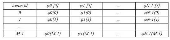
상기 <표 1>을 참조하면, 각 빔 세트 정보는 복수의 수신 빔들(예컨대, M 개의 수신 빔들)에 대한 정보들을 포함할 수 있다. 예컨대, 상기 각 빔 세트 정보는 상기 복수의 수신 빔들의 각 수신 빔에 대해 빔 식별자(beam id), 복수의 위상 변환기들(예컨대, N 개의 위상 변환기들) 각각에 대한 위상 설정 값들을 포함할 수 있다.Referring to <Table 1>, each beam set information may include information on a plurality of reception beams (eg, M reception beams). For example, each of the beam set information may include a beam identifier (beam id) for each reception beam of the plurality of reception beams, and phase setting values for each of a plurality of phase shifters (eg, N phase shifters). there is.
다양한 실시예에 따라, 제1 빔 세트 정보(671) 및 제2 빔 세트 정보(672)는 각각 상기 <표 1>과 동일 또는 유사한 형태로 구성될 수 있으며, 각 빔 세트 정보 내의 위상 설정 값들은 서로 상이할 수 있다. 다양한 실시예에 따라, 상기 빔 세트 정보는 빔 북(beam book) 또는 코드 북(code book)으로 지칭될 수도 있다. 다양한 실시예에 따라, 상기 제1 빔 세트 정보(671)는 상기 전자 장치(601)와 관련된 제1 상태(예컨대, 전자 장치(601)에 케이스가 미장착된 상태)에서의 빔포밍에 대응하는 제1 설정 값을 포함할 수 있으며, 상기 제2 빔 세트 정보(672)는 상기 전자 장치(601)와 관련된 제2 상태(예컨대, 전자 장치(601)에 케이스가 장착된 상태, 사용자가 전자 장치(601)를 손으로 파지한 상태, 전자 장치(601)에 포함된 안테나에 이상이 발생한 상태)에서의 빔포밍에 대응하는 제2 설정 값을 포함할 수 있다. 다양한 실시예에 따라, 상기 제1 설정 값은 상기 전자 장치(601)가 출시되기 전 상기 제1 빔 세트 정보(671)에 기반하여 빔포밍을 수행하여 실시한 검사 또는 검증을 통해 확인된 측정값 또는 측정값에 기반하여 생성된 기본 설정값(예컨대, 디폴트(default) 설정값)에 해당할 수 있다. 다양한 실시예에 따라, 상기 제2 설정 값은 상기 제2 빔 세트 정보(672)에 기반하여 빔포밍을 수행하여 확인된 측정값 또는 측정값에 기반하여 생성된 설정값에 해당할 수 있다. 다양한 실시예에 따라, 상기 제1 설정 값 및/또는 상기 제2 설정 값은 전자 장치(601)의 사용에 따라 새로운 측정값에 기반하여 변경될 수 있다. 다양한 실시예에 따라, 커뮤니케이션 프로세서(680)의 빔 설정 모듈(681)은 제1 빔 세트 정보(671)에 기반하여 빔포밍(beamforming)을 수행하도록 위상 제어기(682)를 제어할 수 있다. 다양한 실시예에 따라, 상기 제1 빔 세트 정보(671)는 복수의 빔 세트 정보들 중에서 상기 전자 장치(101)에 대해 기본적으로 설정되거나 초기에 설정된 빔 세트 정보(예컨대, 디폴트(default) 빔 세트 정보)에 해당할 수 있다. 상기 위상 제어기(682)는 상기 빔 설정 모듈(681)로부터 각 위상 변환기들(640-1 내지 604-N)을 제어하기 위한 제어 신호 또는 제어 데이터를 수신하고, 상기 수신된 제어 신호 또는 제어 데이터에 기반하여 각 위상 변환기들(640-1 내지 604-N)의 위상 값을 제어함으로써 설정된 형태의 수신 빔 또는 송신 빔에 의해 데이터를 수신 또는 송신할 수 있다.According to various embodiments, the first beam set
다양한 실시예에 따라, 커뮤니케이션 프로세서(680)의 빔 설정 모듈(681)은 상기 제1 빔 세트 정보(671)에 기반하여 수행된 빔포밍에 의해 측정된 측정값(예컨대, 상기 안테나 엘리먼트(660-1 내지 660-N)를 통해 수신된 신호의 측정된 값) 및 상기 제2 빔 세트 정보(672)에 포함된 상기 제2 설정 값에 적어도 일부 기반하여, 전자 장치(601)의 빔 패턴의 변화 여부(또는 전자 장치(601)와 관련된 상태 변경 여부)를 판단할 수 있다. 다양한 실시예에 따라, 상기 빔 패턴은 각 수신 빔에 대한 빔의 방향, 빔 폭, 이득(gain), 빔 형태(예컨대, 빔의 왜곡), 빔 개수(예컨대, 사이드 로브(side lobe)의 개수), 또는 위상 조정 여부 중 적어도 하나를 포함할 수 있다.According to various embodiments, the
상기 판단 결과, 빔 패턴이 변화된 것으로 판단(또는 전자 장치(601)와 관련된 상태가 변경된 것으로 판단)되면, 상기 빔 설정 모듈(681)은 수신 빔의 설정을 변경하고, 변경된 설정에 따라 메모리(673) 내에 저장된 빔 설정 정보(673)를 갱신할 수 있다. 예컨대, 상기 빔 설정 모듈(681)은 수신 빔의 설정 변경의 방법으로서 빔 세트를 변경(예컨대, 제1 빔 세트에서 제2 빔 세트로 변경)하거나, 해당 빔 세트에 적용될 수신 빔의 변경과 관련된 적어도 하나의 설정 정보(또는 파라미터)를 조정할 수 있다. 상기 빔 설정 정보(673)는, 예를 들어, 현재 사용되는 빔 세트 정보, 또는 각 빔 세트에 대해 적용될 수신 빔의 변경과 관련된 설정 정보(또는 파라미터)를 포함할 수 있다.As a result of the determination, if it is determined that the beam pattern has changed (or it is determined that the state related to the
다양한 실시예에 따라, 상기 빔 패턴이 변화된 것으로 판단(또는 전자 장치(601)와 관련된 상태가 제1 상태에서 제2 상태로 변경된 것으로 판단)되면, 상기 빔 설정 모듈(681)은 복수의 빔 세트 정보들 중 사용할 빔 세트를 제1 빔 세트에서 제2 빔 세트로 변경하고, 상기 변경된 제2 빔 세트를 빔 설정 정보(673)에 현재 사용할 빔 세트로 설정할 수 있다. 상기 전자 장치(601)는 상기 사용할 빔 세트를 제2 빔 세트로 변경함에 따라, 상기 제2 빔 세트(672) 정보에 기반하여 빔포밍을 수행할 수 있다.According to various embodiments, when it is determined that the beam pattern has changed (or it is determined that the state related to the
다양한 실시예에 따라, 상기 빔 패턴이 변화된 것으로 판단(또는 전자 장치(601)와 관련된 상태가 변경된 것으로 판단)되면, 상기 빔 설정 모듈(681)은 수신 빔의 변경과 관련된 적어도 하나의 설정 정보(또는 파라미터)(예컨대, 빔 개수, 안테나 모듈 개수, 빔 이득(gain), 빔 세트 구조, 빔 변경 임계값, 빔 변경 카운트, 모듈 모니터링 임계값, 모듈 변경 임계값, 모듈 변경 카운트, 또는 상황 변경 임계값)를 조정할 수 있다. 상기 빔 설정 모듈(681)에서 빔 패턴의 변화를 판단(또는 전자 장치와 관련된 상태 변경을 판단)하는 구체적인 실시예들과 수신 빔의 설정을 변경하는 구체적인 실시예들은 도 9, 도 10, 도 11, 및 도 12의 설명에서 상세히 설명하기로 한다.According to various embodiments, when it is determined that the beam pattern has changed (or it is determined that the state related to the
도 7은 다양한 실시예들에 따른, 전자 장치(예: 도 1의 전자 장치(101))에서 수신 빔을 선택하는 방법을 나타내는 도면이다. 도 7을 참조하면, 기지국은 참조 신호(reference signal)(예컨대, SSB(synchronization signal block)를 주기적으로 전송할 수 있다. 다양한 실시예에 따라, 기지국은 20ms 주기마다 5ms 구간 내에서 적어도 하나의 SSB를 전송할 수 있다. 상기 5ms 구간 내에서 SSB를 전송하는 횟수 또는 심볼 길이는 주파수 대역 및/또는 서브캐리어 스페이싱(subcarrier spacing; SCS)에 따라 상이하게 설정될 수 있다.7 is a diagram illustrating a method of selecting a reception beam in an electronic device (eg, the
다양한 실시예에 따라, 기지국은 제1 SS/PBCH block(s)(이하 SSB) 전송 구간(701)(예를 들어, SMTC(SSB measurement time configuration) duration 구간)에서 각기 다른 송신 방향을 갖는 복수의 송신 빔(예컨대, 64개의 송신 빔)을 통해 SSB를 순차적으로 송신할 수 있다. 전자 장치는 상기 제1 SSB 전송 구간(701)에서, 상기 각기 다른 송신 방향을 갖는 복수의 송신 빔(예컨대, 64개의 송신 빔)을 통해 전송된 SSB를 상기 전자 장치의 제1 수신 빔을 통해 순차적으로 수신할 수 있다. 기지국은 제2 SSB 전송 구간(702)에서 각기 다른 송신 방향을 갖는 복수의 송신 빔(예컨대, 64개의 송신 빔)을 통해 SSB를 순차적으로 송신할 수 있다. 전자 장치는 상기 제2 SSB 전송 구간(702)에서, 상기 각기 다른 송신 방향을 갖는 복수의 송신 빔(예컨대, 64개의 송신 빔)을 통해 전송된 SSB를 상기 전자 장치의 제2 수신 빔을 통해 순차적으로 수신할 수 있다. 기지국은 제3 SSB 전송 구간(703)에서 각기 다른 송신 방향을 갖는 복수의 송신 빔(예컨대, 64개의 송신 빔)을 통해 SSB를 순차적으로 송신할 수 있다. 전자 장치는 상기 제3 SSB 전송 구간(703)에서, 상기 각기 다른 송신 방향을 갖는 복수의 송신 빔(예컨대, 64개의 송신 빔)을 통해 전송된 SSB를 상기 전자 장치의 제3 수신 빔을 통해 순차적으로 수신할 수 있다. 기지국은 제4 SSB 전송 구간(704)에서 각기 다른 송신 방향을 갖는 복수의 송신 빔(예컨대, 64개의 송신 빔)을 통해 SSB를 순차적으로 송신할 수 있다. 전자 장치는 상기 제4 SSB 전송 구간(704)에서, 상기 각기 다른 송신 방향을 갖는 복수의 송신 빔(예컨대, 64개의 송신 빔)을 통해 전송된 SSB를 상기 전자 장치의 제4 수신 빔을 통해 순차적으로 수신할 수 있다. 상기 도 7에서는 전자 장치가 4개의 수신 빔을 이용하여 각각 복수의 송신 빔들을 통해 전송된 SSB를 수신하는 것으로 설명하고 있으나, 상기 전자 장치에서 설정 가능한 수신 빔의 개수는 상기 개수로 제한되지 않고 다양하게 설정될 수 있다.According to various embodiments, the base station has a plurality of transmission directions having different transmission directions in the first SS/PBCH block(s) (hereinafter referred to as SSB) transmission period 701 (eg, SSB measurement time configuration (SMTC) duration period). The SSB may be sequentially transmitted through the transmission beams (eg, 64 transmission beams). In the first
전자 장치(예컨대, 전자 장치(101))는 상기 기지국의 송신 빔들(예컨대, 64개의 송신 빔들)과 전자 장치의 수신 빔들(예컨대, 10개의 수신 빔들)의 각 조합에 대한 수신 신호 세기들을 측정한 후 현재 상태에서 가장 수신 신호 세기가 큰 조합을 현재 데이터의 송수신을 위해 사용할 빔 페어(beam pair)로 설정할 수 있다.The electronic device (eg, the electronic device 101) measures reception signal strengths for each combination of the transmission beams (eg, 64 transmission beams) of the base station and the reception beams (eg, 10 reception beams) of the electronic device. Afterwards, a combination having the greatest received signal strength in the current state may be set as a beam pair to be used for current data transmission/reception.
도 8은 다양한 실시예들에 따른, 기지국에서 전송되는 SSB의 구조를 나타내는 도면이다. 도 8을 참조하면, 다양한 실시예에 따라서, 기지국은 주기적으로 SSB를 송신할 수 있다. 예를 들어, 기지국은, 도 8에 도시된 바와 같이, SSB들(811, 812, 813, 814, 815, 816, 817, 818, 819, 820)을 송신할 수 있다. 예를 들어, 도 8의 예시에서는, 기지국은 하나의 슬롯(slot), 예를 들어 14개의 심볼(symbol)들 내에서, 2개의 SSB를 송신하는 것과 같이 도시되어 있지만, 하나의 슬롯 내의 SSB의 개수에는 제한이 없음을 당업자는 이해할 것이다. 기지국은 L개의 SSB를 송신할 수 있으며, L개의 SSB를 SSB 버스트 셋(burst set)으로 명명할 수 있다. SSB 버스트 셋의 길이는 5ms일 수 있으며, SSB 버스트 셋의 전송 주기는 20ms일 수 있으나 제한은 없다. 기지국은 SSB 버스트 셋의 L개의 SSB를 각각 상이한 빔으로 형성할 수 있으며, 이를 기지국이 빔-스위핑(beam-sweeping)을 수행한다고 표현할 수도 있다. 기지국은, 디지털 빔 포밍 및/또는 아날로그 빔 포밍에 기반하여, SSB 버스트 셋의 SSB를 각각 상이한 방향으로 형성할 수 있다. 기지국의 빔 스위핑을 통하여, SSB의 전송 커버리지가 증가할 수 있다.8 is a diagram illustrating a structure of an SSB transmitted from a base station according to various embodiments. Referring to FIG. 8 , according to various embodiments, a base station may periodically transmit an SSB. For example, the base station may transmit the
다양한 실시예에 따라, SSB(811)의 제1 심볼(821)에는 PSS(primary synchronization signal)(831)가 포함되며, 제2 심볼(822)에는 PBCH(physical broadcast channel)의 제1 일부(832)가 포함되며, 제3 심볼(823)에는 PBCH의 제2 일부(833), SSS(secondary synchronization signal)(834), PBCH의 제3 일부(835)가 포함되며, 제4 심볼(824)에는 PBCH의 제4 일부(836)가 포함될 수 있다.According to various embodiments, the
다양한 실시예에 따라서, 전자 장치(101)(예를 들어, 프로세서(120), 제1 커뮤니케이션 프로세서(212), 제2 커뮤니케이션 프로세서(214), 통합 커뮤니케이션 프로세서(260), 또는 통합 SoC 중 적어도 하나)는, 최적의 SSB를 선택할 수 있다. 예를 들어, 전자 장치(101)는, 기지국에 의하여 형성되는 SSB들(811, 812, 813, 814, 815, 816, 817, 818, 819, 820) 각각의 수신 세기를 측정할 수 있다. SSB들(811, 812, 813, 814, 815, 816, 817, 818, 819, 820) 각각이, 상이한 빔으로서 형성됨에 따라서, 전자 장치(101)가 측정하는 세기들이 상이할 수 있다. 전자 장치(101)는, 예를 들어 최대의 수신 세기를 가지는 SSB를 선택할 수 있다. 전자 장치(101)는, 예를 들어 최대의 수신 세기로 측정된 SSB 인덱스(index)를 확인할 수 있으며, SSB 인덱스는 빔 인덱스로 혼용될 수도 있다. 전자 장치(101)는, 선택된 빔 인덱스에 대한 정보를 기지국으로 보고할 수 있다.According to various embodiments, the electronic device 101 (eg, at least one of the
도 9는 다양한 실시예에 따른 전자 장치의 동작 방법을 설명하기 위한 흐름도를 도시한다. 도 9를 참조하면, 전자 장치(101)는 동작 910에서 통신 네트워크(예컨대, 기지국)에 연결하고, 동작 920에서 복수의 빔 세트 정보들(예: 도 6의 제1 빔 세트 정보(671) 및 제2 빔 세트 정보(672)) 중 제1 빔 세트 정보에 기반하여 설정된 수신 빔을 통해 데이터를 수신할 수 있다. 다양한 실시예에 따라, 전자 장치(101)는, 동작 930에서, 수신 빔에 대한 빔 패턴의 변화 여부(또는 전자 장치(101)와 관련된 상태 변경 여부)를 판단할 수 있다. 다양한 실시예에 따라, 상기 빔 패턴은 각 수신 빔에 대한 빔의 방향, 빔 폭, 이득(gain), 빔 형태(예컨대, 빔의 왜곡), 빔 개수(예컨대, 사이드 로브(side lobe)의 개수), 또는 위상 조정 여부 중 적어도 하나를 포함할 수 있다. 다양한 실시예에 따라, 상기 빔 패턴의 변화 여부는 상기 제1 빔 세트 정보에 대응하여 설정된 제1 설정 값 및 상기 제1 빔 세트 정보에 기반하여 수행된 빔포밍에 의해 측정된 측정값에 적어도 기반하여 판단할 수 있다. 다양한 실시예에 따라, 상기 제1 설정 값은 상기 전자 장치(101)가 출시되기 전 상기 제1 빔 세트 정보에 기반하여 빔포밍을 수행하여 실시한 검사 또는 검증을 통해 확인된 측정값 또는 측정값에 기반하여 생성된 기본 설정값(예컨대, 디폴트(default) 설정값)에 해당할 수 있다. 예컨대, 전자 장치(101)는 상기 제1 설정 값과 현재 안테나 모듈을 통해 수신된 신호의 측정값을 비교하고, 설정된 임계값 이상 차이가 나는 경우 빔 패턴이 변화된 것으로 판단할 수 있다. 상기 빔 패턴의 변화 여부 판단은 현재 선택된 수신 빔에 대해 적어도 한 번 수행할 수도 있으며, 해당 빔 세트 내에 포함된 복수의 수신 빔들에 대해 수행할 수도 있다.9 is a flowchart illustrating a method of operating an electronic device according to various embodiments of the present disclosure; Referring to FIG. 9 , the
다양한 실시예에 따라, 전자 장치(101)는 적어도 하나의 센서(예컨대, 그립 센서(grip sensor))에 의해 측정된 값에 기반하여 빔 패턴이 변화된 것으로 판단하거나 전자 장치와 관련된 상태가 변경된 것으로 판단할 수 있다. 예를 들어, 전자 장치(101)는 그립 센서에 의해 측정된 그립 위치 및/또는 그립 세기 중 적어도 일부에 기반하여 빔 패턴이 변화된 것으로 판단하거나 전자 장치와 관련된 상태가 변경된 것으로 판단할 수 있다.According to various embodiments, the
다양한 실시예에 따라, 전자 장치(101)는, 동작 940에서 빔 패턴이 변화되지 않은 것으로 판단(또는, 전자 장치(101)와 관련된 상태가 변경되지 않은 것으로 판단)되면(동작 940-아니오), 동작 920에서 현재 설정된 제1 빔 세트 정보에 기반하여 설정된 수신 빔을 통해 데이터를 수신할 수 있다.According to various embodiments, when it is determined in
다양한 실시예에 따라, 전자 장치(101)는, 동작 940에서 빔 패턴이 변화된 것으로 판단(또는, 전자 장치(101)와 관련된 상태가 변경된 것으로 판단)되면(동작 940-예), 동작 950에서 수신 빔의 설정을 변경할 수 있다.According to various embodiments, when it is determined in
다양한 실시예에 따라, 상기 동작 940에서, 빔 패턴이 변화된 것으로 판단(또는, 전자 장치(101)와 관련된 상태가 변경된 것으로 판단)되면, 전자 장치(101)(예컨대, 커뮤니케이션 프로세서(680))는 복수의 빔 세트 정보들 중 제1 빔 세트 정보(671)에서 제2 빔 세트 정보(672)로 사용할 빔 세트 정보를 변경할 수 있다. 다양한 실시예에 따라, 상기 빔 패턴이 변화된 것으로 판단(또는, 전자 장치(101)와 관련된 상태가 변경된 것으로 판단)되면, 전자 장치(101)는 수신 빔의 변경과 관련된 적어도 하나의 설정 정보(또는 파라미터)(예컨대, 빔 개수, 안테나 모듈 개수, 빔 이득(gain), 빔 세트 구조, 빔 변경 임계값, 빔 변경 카운트, 모듈 모니터링 임계값, 모듈 변경 임계값, 모듈 변경 카운트, 또는 상황 변경 임계값)를 조정할 수 있다. 상기 전자 장치(101)에서 수신 빔과 관련된 설정을 변경하는 구체적인 실시예들은 도 11 및 도 12의 설명에서 상세히 설명하기로 한다.According to various embodiments, when it is determined that the beam pattern is changed (or that the state related to the
다양한 실시예에 따라, 전자 장치(101)는 전자 장치들 간의 편차를 반영하기 위해 전자 장치가 최초 실행될 때 상기 도 9에 도시된 동작들 중 적어도 하나의 동작을 수행할 수도 있다. 예컨대, 전자 장치(101)는 최초 실행 시 상기 동작 940에서 빔 패턴 변화가 감지되지 않더라도 동작 950의 수신 빔 설정 변경 동작을 수행할 수 있다.According to various embodiments, the
도 10은 다양한 실시예에 따른 전자 장치의 동작 방법을 설명하기 위한 흐름도를 도시한다. 도 10을 참조하면, 전자 장치(101)(예컨대, 커뮤니케이션 프로세서(680))는 동작 1010에서 통신 네트워크(예컨대, 기지국)에 연결하고, 동작 1020에서 복수의 빔 세트 정보들(예: 도 6의 제1 빔 세트 정보(671) 및 제2 빔 세트 정보(672)) 중 제1 빔 세트 정보에 기반하여 설정된 수신 빔을 통해 데이터를 수신할 수 있다.10 is a flowchart illustrating a method of operating an electronic device according to various embodiments of the present disclosure; Referring to FIG. 10 , the electronic device 101 (eg, the communication processor 680 ) connects to a communication network (eg, a base station) in
다양한 실시예에 따라, 전자 장치(101)는, 동작 1030에서 수신 빔에 대한 빔 패턴의 변화 여부(또는, 전자 장치(101)와 관련된 상태 변경 여부)를 판단할 수 있다. 다양한 실시예에 따라, 상기 빔 패턴은 각 수신 빔에 대한 빔의 방향, 빔 폭, 이득(gain), 빔 형태(예컨대, 빔의 왜곡), 빔 개수(예컨대, 사이드 로브(side lobe)의 개수), 또는 위상 조정 여부 중 적어도 하나를 포함할 수 있다. 다양한 실시예에 따라, 상기 빔 패턴의 변화 여부는 상기 제1 빔 세트 정보에 대응하여 설정된 제1 설정 값 및 상기 제1 빔 세트 정보에 기반하여 수행된 빔포밍에 의해 측정된 측정값에 적어도 기반하여 판단할 수 있다. 다양한 실시예에 따라, 상기 제1 설정 값은 상기 전자 장치(101)가 출시되기 전 상기 제1 빔 세트 정보에 기반하여 빔포밍을 수행하여 실시한 검사 또는 검증을 통해 확인된 측정값 또는 측정값에 기반하여 생성된 기본 설정값(예컨대, 디폴트(default) 설정값)에 해당할 수 있다. 예컨대, 전자 장치(101)는 상기 제1 설정 값과 현재 안테나 모듈을 통해 수신된 신호의 측정값을 비교하고, 설정된 임계값 이상 차이가 나는 경우 빔 패턴이 변화된 것으로 판단할 수 있다. 상기 빔 패턴의 변화 여부 판단은 현재 선택된 수신 빔에 대해 적어도 한 번 수행할 수도 있으며, 해당 빔 세트 내에 포함된 복수의 수신 빔들에 대해 수행할 수도 있다.According to various embodiments of the present disclosure, in
다양한 실시예에 따라, 전자 장치(101)는 적어도 하나의 센서(예컨대, 그립 센서(grip sensor))에 의해 측정된 값에 기반하여 빔 패턴이 변화된 것으로 판단하거나 전자 장치와 관련된 상태가 변경된 것으로 판단할 수 있다. 예를 들어, 전자 장치(101)는 그립 센서에 의해 측정된 그립 위치 및/또는 그립 세기 중 적어도 일부에 기반하여 빔 패턴이 변화된 것으로 판단하거나 전자 장치와 관련된 상태가 변경된 것으로 판단할 수 있다.According to various embodiments, the
다양한 실시예에 따라, 전자 장치(101)는, 동작 1040에서 빔 패턴이 변화되지 않은 것으로 판단(또는, 전자 장치(101)와 관련된 상태가 변경되지 않은 것으로 판단)되면(동작 1040-아니오), 동작 1020에서 현재 설정된 제1 빔 세트 정보에 기반하여 설정된 수신 빔을 통해 데이터를 수신할 수 있다.According to various embodiments, when it is determined that the beam pattern is not changed (or it is determined that the state related to the
다양한 실시예에 따라, 전자 장치(101)는, 동작 1040에서 빔 패턴이 변화된 것으로 판단(또는, 전자 장치(101)와 관련된 상태가 변경된 것으로 판단)되면(동작 1040-예), 동작 1050에서 업데이트 동작 수행 조건을 만족하는지 여부를 판단할 수 있다.According to various embodiments, when it is determined that the beam pattern is changed in operation 1040 (or it is determined that the state related to the
다양한 실시예에 따라, 상기 업데이트 동작 수행 조건을 만족하는지 여부는, 수신 신호 세기(예컨대, RSRP(reference signal received power), SINR(signal to interference plus noise ratio), RSRQ(reference signal received quality)), 상기 수신 신호 세기의 분포 및/또는 변화량(예컨대, 표준편차, 최대-최소 차이, 간섭량), 센서로부터 측정된 값) 중 적어도 하나를 통해 판단할 수 있다.According to various embodiments, whether the update operation performance condition is satisfied may be determined by the received signal strength (eg, reference signal received power (RSRP), signal to interference plus noise ratio (SINR), reference signal received quality (RSRQ)), It may be determined based on at least one of distribution and/or variation (eg, standard deviation, maximum-minimum difference, interference amount) of the received signal strength, and a value measured by a sensor.
다양한 실시예에 따라, 상기 업데이트 동작 수행 조건을 만족하는지 여부는, 전자 장치(101)가 LOS(line of sight) 환경인지 non-LOS 환경인지에 따라 판단할 수도 있다. 도 13a는 다양한 실시예들에 따른, LOS 환경에서 측정된 수신 신호 세기의 분포를 나타내는 그래프이고, 도 13b는 다양한 실시예들에 따른, non-LOS 환경에서 측정된 수신 신호 세기의 분포를 나타내는 그래프이다.According to various embodiments, whether the update operation performance condition is satisfied may be determined according to whether the
도 13a를 참조하면, LOS 환경에서 현재의 수신 빔을 이용하여 수신 신호들의 세기를 복수 회 측정한 결과, -65dBm이 3%, -66dBm이 73%, -67dBm이 24%의 비율로 분포됨을 확인할 수 있다. 도 13b를 참조하면, non-LOS 환경에서 현재의 수신 빔을 이용하여 수신 신호들의 세기를 복수 회 측정한 결과, -77dBm으로부터 -90dBm까지 다양하게 분포됨을 확인할 수 있다. 예컨대, LOS 환경에서는 수신 신호 세기의 변화가 크지 않은 반면 Non-LOS의 경우(예컨대, 블록킹(blocking) 상황의 경우) 수신 신호 세기의 변화가 상대적으로 크게 나타날 수 있다. 다양한 실시예에 따라, 전자 장치(101)는 수신 신호 세기의 측정 결과 도 13a에 도시된 바와 같이 현재 상태가 LOS 환경으로 판단될 경우 상기 동작 1050에서 업데이트 동작 수행 조건을 만족하는 것으로 판단할 수 있다. 예컨대, 전자 장치(101)는 상기 수신 신호 세기의 분포를 수치화하여(예컨대, 수신 신호 세기의 표준 편차를 산출하여), 설정된 조건을 만족하는 경우 현재 상태를 LOS 환경의 상태로 추정하고 업데이트 동작 수행 조건을 만족하는 것으로 판단할 수 있다.Referring to FIG. 13a, as a result of measuring the strength of the received signals using the current reception beam in the LOS environment a plurality of times, it can be confirmed that -65 dBm is 3%, -66 dBm is 73%, and -67 dBm is distributed at a rate of 24%. can Referring to FIG. 13B , as a result of measuring the strength of received signals using the current reception beam in a non-LOS environment a plurality of times, it can be confirmed that the received signals are variously distributed from -77 dBm to -90 dBm. For example, in the LOS environment, the change in the received signal strength is not large, but in the case of the non-LOS (eg, in the case of a blocking situation), the change in the received signal strength may appear relatively large. According to various embodiments, when it is determined that the current state is the LOS environment as illustrated in FIG. 13A as a result of measuring the received signal strength, the
다양한 실시예에 따라, 전자 장치(101)는, 동작 1050에서 업데이트 동작 수행 조건을 만족하는 것으로 판단할 경우(동작 1050-예), 동작 1060에서 수신 빔의 설정을 변경할 수 있다. 다양한 실시예에 따라, 상기 동작 1050에서, 업데이트 동작 수행 조건을 만족하는 것으로 판단되면, 전자 장치(101)(예컨대, 커뮤니케이션 프로세서(680))는 복수의 빔 세트 정보들 중 제1 빔 세트 정보(671)에서 제2 빔 세트 정보(672)로 사용할 빔 세트 정보를 변경할 수 있다. 다양한 실시예에 따라, 상기 업데이트 동작 수행 조건을 만족하는 것으로 판단되면, 전자 장치(101)는 수신 빔의 변경과 관련된 적어도 하나의 설정 정보(또는 파라미터)(예컨대, 빔 개수, 안테나 모듈 개수, 빔 이득(gain), 빔 세트 구조, 빔 변경 임계값, 빔 변경 카운트, 모듈 모니터링 임계값, 모듈 변경 임계값, 모듈 변경 카운트, 또는 상황 변경 임계값)를 조정할 수 있다. 상기 전자 장치(101)에서 수신 빔과 관련된 설정을 변경하는 구체적인 실시예들은 도 11 및 도 12의 설명에서 상세히 설명하기로 한다. According to various embodiments, when determining that the update operation performance condition is satisfied in operation 1050 (operation 1050 - Yes), the
다양한 실시예에 따라, 전자 장치(101)는, 동작 1050에서 업데이트 동작 수행 조건을 만족하지 않는 것으로 판단할 경우(동작 1050-아니오), 동작 1020에서 현재 설정된 빔 세트 및/또는 수신 빔의 설정 기반하여 데이터를 수신할 수 있다.According to various embodiments, when determining that the update operation performance condition is not satisfied in operation 1050 (operation 1050 - NO), in
도 11은 다양한 실시예에 따른 전자 장치의 동작 방법을 설명하기 위한 흐름도를 도시한다. 도 11을 참조하면, 전자 장치(101)(예컨대, 커뮤니케이션 프로세서(680))는 동작 1110에서 통신 네트워크(예컨대, 기지국)에 연결하고, 동작 1120에서 복수의 빔 세트 정보들(예: 도 6의 제1 빔 세트 정보(671) 및 제2 빔 세트 정보(672)) 중 제1 빔 세트 정보에 기반하여 설정된 수신 빔을 통해 데이터를 수신할 수 있다.11 is a flowchart illustrating a method of operating an electronic device according to various embodiments of the present disclosure; Referring to FIG. 11 , the electronic device 101 (eg, the communication processor 680 ) connects to a communication network (eg, a base station) in
다양한 실시예에 따라, 전자 장치(101) 는, 동작 1130에서 전자 장치(101)와 관련된 상태 변경 여부를 판단할 수 있다. 다양한 실시예에 따라, 전자 장치(101)는 상기 제1 빔 세트 정보(671)에 기반하여 수행된 빔포밍에 의해 측정된 측정값 및 상기 제2 빔 세트 정보(672)에 포함된 제2 설정 값에 적어도 일부 기반하여, 전자 장치(101)와 관련된 상태 변경 여부를 판단할 수 있다. 예컨대, 상기 제1 빔 세트 정보(671)에 기반하여 수행된 빔포밍에 의해 측정된 측정값이 상기 제1 빔 세트 정보(671)에 포함된 제1 설정값보다 상기 제2 빔 세트 정보(672)에 포함된 제2 설정값에 더 가까운 경우, 전자 장치(101)의 상태가 제1 상태에서 제2 상태로 변경된 것으로 판단할 수 있다.According to various embodiments, the
다양한 실시예에 따라, 전자 장치(101)는 적어도 하나의 센서(예컨대, 그립 센서(grip sensor))에 의해 측정된 값에 기반하여 전자 장치(101)와 관련된 상태가 변경된 것으로 판단할 수 있다.According to various embodiments, the
다양한 실시예에 따라, 전자 장치(101)는, 동작 1140에서 전자 장치(101)와 관련된 상태가 변경되지 않은 것으로 판단되면(동작 1140-아니오), 동작 1120에서 현재 설정된 제1 빔 세트 정보에 기반하여 설정된 수신 빔을 통해 데이터를 수신할 수 있다.According to various embodiments, when it is determined that the state related to the
다양한 실시예에 따라, 전자 장치(101)는, 동작 1140에서 전자 장치(101)와 관련된 상태가 변경된 것으로 판단되면(동작 1140-예), 동작 1150에서 복수의 빔 세트 정보들 중 상기 제2 상태에 대응하는 제2 빔 세트 정보에 기반하여 설정된 수신 빔을 통해 데이터를 수신할 수 있다.According to various embodiments, if it is determined that the state related to the
다양한 실시예에 따라, 전자 장치(101)는 상기 제2 빔 세트 정보에 대응하는 적어도 하나의 수신 빔을 통해 수신 신호 세기를 측정할 수 있다. 다양한 실시예에 따라, 전자 장치(101)는 상기 제2 빔 세트 정보에 대응하는 수신 빔의 수신 신호 세기와 현재 설정된 제1 빔 세트 정보에 대응하는 수신 빔의 수신 신호 세기를 비교하여 빔 세트 변경 여부를 판단할 수 있다. 예컨대, 제2 빔 세트 정보에 대응하는 수신 빔의 수신 신호 세기가 제1 빔 세트 정보에 대응하는 수신 빔의 수신 신호 세기보다 큰 경우, 전자 장치(101)는 빔 세트 정보를 변경하기로 판단하고, 상기 제2 빔 세트 정보에 기반하여 설정된 수신 빔을 통해 데이터를 수신할 수 있다. 반면, 제2 빔 세트 정보에 대응하는 수신 빔의 수신 신호 세기가 제1 빔 세트 정보에 대응하는 수신 빔의 수신 신호 세기보다 작은 경우, 전자 장치(101)는 빔 세트를 변경하지 않기로 판단 현재 설정된 제1 빔 세트 정보에 기반하여 설정된 수신 빔을 통해 데이터를 수신할 수 있다.According to various embodiments, the
다양한 실시예에 따라, 상기 빔 세트 정보의 변경 여부를 결정할 때, 빔 세트들 간의 성능을 비교하는 방법은 각 빔 세트 내에 포함된 복수의 수신 빔들 중 가장 수신 신호 세기가 큰 값들 간에 비교할 수도 있고, 상기 각 빔 세트 내에 포함된 복수의 수신 빔들 전체의 수신 신호 세기들의 평균값을 서로 비교할 수도 있다.According to various embodiments, when determining whether to change the beam set information, the method of comparing performance between beam sets may compare values with the highest received signal strength among a plurality of receive beams included in each beam set, An average value of received signal strengths of all reception beams included in each beam set may be compared with each other.
다양한 실시예에 따라, 상기 빔 세트들 간의 성능 비교는 현재 사용하는 빔 세트 정보(예컨대, 제1 빔 세트 정보)로 측정된 수신 신호 세기의 분포와 다른 사용 가능한 빔 세트 정보(예컨대, 제2 빔 세트 정보)로 측정된 수신 신호 세기의 분포를 이용할 수 있다.According to various embodiments, the performance comparison between the beam sets includes a distribution of received signal strength measured with currently used beam set information (eg, first beam set information) and other available beam set information (eg, second beam information). The distribution of the received signal strength measured as set information) may be used.
도 14는 다양한 실시예들에 따른, 빔 세트별 수신 신호 세기의 분포를 나타내는 그래프이다. 도 14를 참조하면, 제1 빔 세트(Beam Set #1)를 이용하여 수신 신호들의 세기를 복수 회 측정한 결과, -72dBm이 50%, -73dBm이 50%의 비율로 분포됨을 확인할 수 있다. 제2 빔 세트(Beam Set #2)를 이용하여 수신 신호들의 세기를 복수 회 측정한 결과, -70dBm이 20%, -71dBm이 20%, -72dBm이 10%, -73dBm이 10%, -74dBm이 20%, -75dBm이 10%, -76dBm이 10%의 비율로 분포됨을 확인할 수 있다. 14 is a graph illustrating a distribution of received signal strength for each beam set according to various embodiments of the present disclosure; Referring to FIG. 14 , as a result of measuring the strength of received signals using the first
상기 도 14의 그래프에 따르면, 제1 빔 세트는 제2 빔 세트에 비해 상대적으로 수신 신호 세기가 안정적임을 확인할 수 있다. 예컨대, 전자 장치는 상대적으로 안정적인 데이터 송수신을 원할 경우, 제1 빔 세트를 선택할 수 있으며, 상대적으로 안정적이지는 않으나 높은 수신 신호 세기로 데이터를 송수신하고자 하는 경우 제2 빔 세트를 선택할 수 있다.According to the graph of FIG. 14 , it can be confirmed that the received signal strength of the first beam set is relatively stable compared to that of the second beam set. For example, the electronic device may select the first beam set when relatively stable data transmission/reception is desired, and may select the second beam set when data transmission/reception is not relatively stable but with high reception signal strength.
다양한 실시예에 따라, 제2 빔 세트는 제1 빔 세트보다 더 높은 신호 수신 세기로 데이터를 수신할 가능성이 있으나 수신 신호의 변화 범위가 더 넓음을 확인할 수 있다. 상기 도 14의 경우, 제2 빔 세트를 사용하면, 제1 빔 세트를 사용할 때보다 더 높은 신호 수신 세기를 가질 확률과 더 낮은 신호 수신 세기를 가질 확률이 동일하기 때문에 전자 장치의 사용 조건 또는 적용하고 있는 빔 운영 알고리즘(예컨대, 수신 빔의 변경과 관련된 설정 정보)에 따라 제1 빔 세트 또는 제2 빔 세트를 선택할 수 있다.According to various embodiments, it may be confirmed that the second beam set may receive data with a higher signal reception strength than the first beam set, but the change range of the received signal is wider. In the case of FIG. 14 , when the second beam set is used, the probability of having a higher signal reception strength and a probability of having a lower signal reception strength are the same than when the first beam set is used, so the conditions or application of the electronic device The first beam set or the second beam set may be selected according to the current beam operation algorithm (eg, configuration information related to the change of the reception beam).
도 12는 다양한 실시예에 따른 전자 장치의 동작 방법을 설명하기 위한 흐름도를 도시한다. 도 12를 참조하면, 전자 장치(101)는 동작 1210에서 통신 네트워크(예컨대, 기지국)에 연결하고, 동작 1220에서 복수의 빔 세트 정보들(예: 도 6의 제1 빔 세트 정보(671) 및 제2 빔 세트 정보(672)) 중 제1 빔 세트 정보에 기반하여 설정된 수신 빔을 통해 데이터를 수신할 수 있다.12 is a flowchart illustrating a method of operating an electronic device according to various embodiments of the present disclosure; Referring to FIG. 12 , the
다양한 실시예에 따라, 전자 장치(101)(예컨대, 커뮤니케이션 프로세서(680))는, 동작 1230에서 수신 빔에 대한 빔 패턴 변화 여부(또는 전자 장치(101)와 관련된 상태 변경 여부)를 판단할 수 있다. 다양한 실시예에 따라, 상기 빔 패턴은 각 수신 빔에 대한 빔의 방향, 빔 폭, 이득(gain), 빔 형태(예컨대, 빔의 왜곡), 빔 개수(예컨대, 사이드 로브(side lobe)의 개수), 또는 위상 조정 여부 중 적어도 하나를 포함할 수 있다. 다양한 실시예에 따라, 상기 빔 패턴의 변화 여부는 상기 제1 빔 세트 정보에 대응하여 설정된 제1 설정 값 및 상기 제1 빔 세트 정보에 기반하여 수행된 빔포밍에 의해 측정된 측정값에 적어도 기반하여 판단할 수 있다.According to various embodiments, the electronic device 101 (eg, the communication processor 680 ) may determine whether a beam pattern with respect to the reception beam is changed (or whether a state related to the
다양한 실시예에 따라, 전자 장치(101)는 적어도 하나의 센서(예컨대, 그립 센서(grip sensor))에 의해 측정된 값에 기반하여 빔 패턴이 변화된 것으로 판단하거나 전자 장치와 관련된 상태가 변경된 것으로 판단할 수 있다. 예를 들어, 전자 장치(101)는 그립 센서에 의해 측정된 그립 위치 및/또는 그립 세기 중 적어도 일부에 기반하여 빔 패턴이 변화된 것으로 판단하거나 전자 장치와 관련된 상태가 변경된 것으로 판단할 수 있다.According to various embodiments, the
다양한 실시예에 따라, 전자 장치(101)는, 동작 1240에서 빔 패턴이 변화되지 않은 것으로 판단(또는, 전자 장치(101)와 관련된 상태가 변경되지 않은 것으로 판단)되면(동작 1240-아니오), 동작 1220에서 현재 설정된 제1 빔 세트 정보에 기반하여 설정된 수신 빔을 통해 데이터를 수신할 수 있다.According to various embodiments, when it is determined that the beam pattern is not changed in operation 1240 (or it is determined that the state related to the
다양한 실시예에 따라, 전자 장치(101)는, 동작 1240에서 빔 패턴이 변화된 것으로 판단(또는, 전자 장치(101)와 관련된 상태가 변경된 것으로 판단)되면(동작 1240-예), 동작 1250에서 수신 빔의 변경과 관련된 설정 정보(또는, 파라미터)를 조정할 수 있다. 예컨대, 상기 수신 빔의 변경과 관련된 적어도 하나의 설정 정보(또는 파라미터)는, 하기 <표 2>와 같이 빔 개수, 안테나 모듈 개수, 빔 이득(gain), 빔 세트 구조, 빔 변경 임계값, 빔 변경 카운트, 모듈 모니터링 임계값, 모듈 변경 임계값, 모듈 변경 카운트, 또는 상황 변경 임계값 중 적어도 하나를 포함할 수 있다.According to various embodiments, when it is determined that the beam pattern is changed in operation 1240 (or it is determined that the state related to the
상기 <표 2>를 참조하면, 빔 개수는 현재 사용 중인 빔 세트 내에 포함된 수신 빔의 개수를 나타내며, 각 수신 빔은 <표 1>에서 상술한 바와 같이 빔 식별자(beam id)로 구분될 수 있다. 다양한 실시예에 따라, 해당 빔 세트가 넓은 빔(wide beam)과 좁은 빔(narrow beam)이 매핑되는 계층적 구조를 형성할 경우 상기 <표 2> 및 도 16c에 예시된 바와 같이 넓은 빔은 3개, 좁은 빔은 7개로 설정될 수 있다. 안테나 모듈 개수는 전자 장치(101)에 구비된 안테나 모듈의 개수를 나타내며, 1개, 2개, 또는 3개 이상을 포함할 수 있다. 다양한 실시예에 따라, 빔 세트 및/또는 수신 빔은 각 안테나 모듈마다 상이하게 설정될 수도 있다. 빔 세트 구조는 계층적 구조의 적용 여부를 나타낼 수 있다. 상기 빔 세트 구조가 계층적 구조를 적용하는 것으로 설정되면, 도 16c에 도시된 바와 같이 복수 개의 넓은 빔이 설정되고, 각 넓은 빔에 적어도 하나의 좁은 빔이 매핑되도록 설정될 수 있다. 빔 이득(gain)은 넓은 빔 또는 좁은 빔에 대해 설정될 수 있으며, 기설정된 빔 이득과 실제 측정된 수신 신호의 세기 간의 차이에 기반하여 최적의 수신 빔을 검색할 수 있다. 빔 변경 임계값(threshold)은 서빙 빔의 변경을 위한 임계값을 의미하며, 상기 빔 변경 임계값이 3dB로 설정되면 현재 사용 중인 수신 빔(예컨대, 서빙 빔(serving beam))의 수신 세기보다 다른 수신 빔의 수신 세기가 3dB이상 큰 경우에 서빙 빔의 변경을 수행할 수 있다. 빔 변경 카운트(count)는 상기 빔 변경 임계값을 설정된 횟수만큼 연속으로 초과하는 경우 현재 사용 중인 수신 빔을 다른 빔으로 변경하도록 동작하기 위한 값을 의미할 수 있다. 모듈 모니터링 임계값은 현재 사용 중인 안테나 모듈이 아닌 다른 안테나 모듈을 모니터링하기 위해 설정된 값을 의미할 수 있다. 예컨대, 상기 모듈 모니터링 임계값이 -90dBm으로 설정된 경우, 현재 사용 중인 안테나 모듈을 통해 수신된 신호의 신호 세기가 상기 -90dBm 이하인 경우 다른 안테나 모듈을 모니터링하도록 동작할 수 있다. 모듈 변경 임계값은 안테나 모듈의 변경을 위한 임계값을 의미하며, 상기 모듈 변경 임계값이 5dB로 설정되면 현재 사용 중인 안테나 모듈에서의 수신 세기보다 다른 안테나 모듈에서의 수신 세기가 5dB이상 큰 경우에 안테나 모듈의 변경을 수행할 수 있다. 모듈 변경 카운트(count)는 상기 모듈 변경 임계값을 설정된 횟수만큼 연속으로 초과하는 경우 현재 사용 중인 안테나 모듈을 다른 안테나 모듈로 변경하도록 동작하기 위한 값을 의미할 수 있다. 상황 변경 임계값은 전자 장치(101)의 상태가 설정된 값 이상 변하여 기존의 수신 빔을 사용하여 측정된 결과를 사용하기 어려운 경우를 판단하기 위한 값을 의미할 수 있다.Referring to <Table 2>, the number of beams indicates the number of reception beams included in the currently used beam set, and each reception beam can be identified by a beam id as described above in <Table 1>. there is. According to various embodiments, when a corresponding beam set forms a hierarchical structure in which a wide beam and a narrow beam are mapped, as illustrated in Table 2 and FIG. 16C, the wide beam is 3 The number of narrow beams may be set to seven. The number of antenna modules indicates the number of antenna modules provided in the
다양한 실시예에 따라, 상기 복수의 수신 빔 변경과 관련된 설정 정보(또는 파라미터)들은 그룹화 및/또는 우선 순위화하여 적용될 수 있다.According to various embodiments, the configuration information (or parameters) related to the plurality of reception beam changes may be applied by grouping and/or prioritizing them.
도 15는 다양한 실시예들에 따른, 수신 빔 변경과 관련된 설정 정보(또는, 파라미터)들의 그룹화 및 우선 순위 설정을 나타내는 도면이다. 도 15를 참조하면, 수신 빔의 변경과 관련된 설정 정보(또는, 파라미터)들은 빔 이득, 빔 개수, 빔 세트 구조(예컨대, 넓은 빔과 좁은 빔의 계층적 구조), 빔 변경 임계값, 안테나 모듈 개수, 모듈 모니터링 임계값, 모듈 변경 카운트, 모듈 변경 임계값 중 적어도 하나를 포함할 수 있다.15 is a diagram illustrating grouping and priority setting of configuration information (or parameters) related to a reception beam change according to various embodiments of the present disclosure; Referring to FIG. 15 , configuration information (or parameters) related to a change of a reception beam includes a beam gain, the number of beams, a beam set structure (eg, a hierarchical structure of a wide beam and a narrow beam), a beam change threshold, and an antenna module. It may include at least one of a number, a module monitoring threshold, a module change count, and a module change threshold.
다양한 실시예에 따라, 전자 장치(101)는, 상기 복수의 설정 정보(또는, 파라미터)들 중 적어도 두 개의 설정 정보들을 그룹화할 수 있다. 예컨대, 도 15에 도시된 바와 같이 빔 이득, 빔 세트 구조, 안테나 모듈 개수, 모듈 모니터링 임계값은 하나의 그룹으로 그룹화하여 적용할 수 있다. 상기 그룹화의 조건은 다양하게 설정될 수 있다. 예컨대, 빔 세트 구조를 다시 확인하기 위해 복수의 넓은 빔(wide beam; WB)들과 복수의 좁은 빔(narrow beam; NB)들의 수신 신호 세기를 모두 측정할 수 있다. 상기 빔 세트 구조를 확인하는 동작에서 WB과 NB의 빔 이득 크기 값들도 동시에 확인할 수 있으므로, 상기 빔 세트 구조와 빔 이득의 설정 정보(또는, 파라미터)들은 그룹화될 수 있다.According to various embodiments, the
다양한 실시예에 따라, 상기 그룹화된 설정 정보(또는, 파라미터)들은 우선 순위에 따라 정렬될 수 있으며, 상기 정렬된 우선 순위에 따라 순차적으로 각 설정 정보(또는, 파라미터)를 조정할 수 있다. 예컨대, 도 15에 도시된 바와 같이 빔 세트 구조, 빔 이득, 모듈 모니터링 임계값, 안테나 모듈 개수의 순으로 우선 순위를 설정할 수 있다. 다양한 실시예에 따라, 상기 우선 순위는 전자 장치(101)에 적용되는 설정 정보의 종류에 따라 상이할 수 있다. 예컨대, 현재 전자 장치에 적용된 설정 정보가 빔 세트 구조로서 계층적 구조가 적용된 경우, 복수의 설정 정보(또는, 파라미터)들 중 상기 빔 세트 구조의 우선 순위가 가장 높게 설정될 수 있다.According to various embodiments, the grouped setting information (or parameters) may be sorted according to priorities, and each setting information (or parameters) may be sequentially adjusted according to the sorted priorities. For example, as shown in FIG. 15 , priorities may be set in the order of a beam set structure, a beam gain, a module monitoring threshold, and the number of antenna modules. According to various embodiments, the priority may be different according to the type of setting information applied to the
다양한 실시예에 따라, 전자 장치에 적용된 수신빔의 변경과 관련된 설정 정보의 우선 순위는 빔 패턴에 따라 상이하게 설정될 수 있다. 예컨대, 빔 개수가 많고 좁은 영역을 커버하는 빔이라면 최적의 빔과 그 외의 빔의 수신 신호 세기 차이가 커서 빔 변경 임계값은 상대적으로 민감하지 않을 수 있다. 예를 들어 LOS 환경에서 최적 빔의 수신 신호 세기가 -70dBm인 경우 그 외의 빔의 수신 신호 세기는 -75dBm 이상으로 값의 차이가 큰 경우들이 나타날 수 있다. 이때에는 빔 변경 임계값은 우선 순위가 상대적으로 낮게 설정될 수 있다. 반면, 빔 개수가 적고 넓은 범위를 커버할 때, 최적의 빔과 그 외의 빔의 수신 신호 세기 차이가 크지 않는 경우, 상기 빔 변경 임계값은 우선 순위가 상대적으로 높게 설정될 수 있다.According to various embodiments, the priority of the setting information related to the change of the reception beam applied to the electronic device may be set differently according to the beam pattern. For example, if the number of beams is large and the beam covers a narrow area, the received signal strength difference between the optimal beam and other beams is large, so the beam change threshold may be relatively insensitive. For example, when the received signal strength of the optimal beam is -70 dBm in the LOS environment, the received signal strength of the other beams is -75 dBm or more. In this case, the priority of the beam change threshold may be set to be relatively low. On the other hand, when the number of beams is small and the received signal strength difference between the optimal beam and the other beams is not large when the number of beams is small and covers a wide range, the beam change threshold value may be set to have a relatively high priority.
다양한 실시예에 따라, 상기 파라미터들을 그룹화하고 우선 순위가 설정되면 전자 장치(101)는 측정할 빔 순서, 횟수, 주기 중 적어도 하나를 결정할 수 있다. 예컨대, 전자 장치는 주기적으로 수신되는 참조 신호(예컨대, SSB)의 수신 신호 세기를 측정하고, 측정 결과에 기반하여 전술한 복수의 설정 정보(또는, 파라미터)들 중 적어도 하나의 값을 조정할 수 있다.According to various embodiments, when the parameters are grouped and priorities are set, the
다양한 실시예에 따라, 전술한 바와 같이 각 빔 세트에 포함된 복수의 수신 빔들은 복수의 넓은 빔들과 복수의 좁은 빔들을 계층적으로 구조화되도록 설정할 수 있다. 예컨대, 도 16a, 도 16b, 도 16c는 제1 시점에서 측정된 넓은 빔들 및 좁은 빔들의 측정 관계를 나타내는 도면들이며, 도 17a, 도 17b, 도 17c는 상기 제1 시점 이후 제2 시점에서 측정된 넓은 빔들 및 좁은 빔들의 측정 관계를 나타내는 도면들이다.According to various embodiments, as described above, the plurality of reception beams included in each beam set may be configured such that a plurality of wide beams and a plurality of narrow beams are hierarchically structured. For example, FIGS. 16A, 16B, and 16C are diagrams illustrating a measurement relationship between wide beams and narrow beams measured at a first time point, and FIGS. 17A, 17B and 17C are views measured at a second time point after the first time point. It is a figure which shows the measurement relationship of wide beams and narrow beams.
도 16a는 다양한 실시예들에 따른, 넓은 빔에 대해 측정된 수신 신호 세기를 나타내는 그래프이며, 도 16b는 다양한 실시예들에 따른, 좁은 빔에 대해 측정된 수신 신호 세기를 나타내는 그래프이다. 도 16c는 다양한 실시예들에 따른, 넓은 빔과 좁은 빔 간에 설정된 계층적 구조를 나타내는 도면이다.16A is a graph illustrating received signal strength measured with respect to a wide beam according to various embodiments, and FIG. 16B is a graph illustrating received signal strength measured with respect to a narrow beam, according to various embodiments. 16C is a diagram illustrating a hierarchical structure established between a wide beam and a narrow beam according to various embodiments of the present disclosure;
다양한 실시예에 따라, 상기 도 16a 및 도 16b에서 가로축은 가로축은 기지국과 단말 사이의 각도를 의미하고 세로 측은 특정 빔으로 측정된 수신 신호 세기의 RSRP 값을 나타낸다. 도 16c는 도 16a와 같이 측정된 넓은 빔들과 도 16b와 같이 측정된 좁은 빔들의 빔 형태에 기반하여 설정된 계층적 구조를 나타낸다.According to various embodiments, in FIGS. 16A and 16B , the horizontal axis indicates the angle between the base station and the terminal, and the vertical axis indicates the RSRP value of the received signal strength measured with a specific beam. FIG. 16C shows a hierarchical structure set based on beam shapes of wide beams measured as shown in FIG. 16A and narrow beams measured as shown in FIG. 16B.
예컨대, 도 16c를 참조하면, 전자 장치(101)는 제1 넓은 빔(WB #0)에 대해 제1 좁은 빔(NB #0), 제2 좁은 빔(NB #1), 제3 좁은 빔(NB #2)을 하위 계층으로 설정할 수 있으며, 제2 넓은 빔(WB #1)에 대해 제3 좁은 빔(NB #2), 제4 좁은 빔(NB #3), 제5 좁은 빔(NB #4)을 하위 계층으로 설정할 수 있으며, 제3 넓은 빔(WB #2)에 대해 제5 좁은 빔(NB #4), 제6 좁은 빔(NB #5), 제7 좁은 빔(NB #6)을 하위 계층으로 설정할 수 있다.For example, referring to FIG. 16C , the
상기 제1 시점이 경과 한 이후, 제2 시점에서 각 수신 빔의 세기를 측정하면, 도 17a, 도 17b와 같이 측정될 수 있다. 도 17a는 다양한 실시예들에 따른, 넓은 빔에 대해 측정된 수신 신호 세기를 나타내는 그래프이며, 도 17b는 다양한 실시예들에 따른, 좁은 빔에 대해 측정된 수신 신호 세기를 나타내는 그래프이다. 도 17c는 다양한 실시예들에 따른, 넓은 빔과 좁은 빔 간에 설정된 계층적 구조를 나타내는 도면이다.When the intensity of each reception beam is measured at the second time point after the first time point has elapsed, it may be measured as shown in FIGS. 17A and 17B . 17A is a graph illustrating a received signal strength measured for a wide beam according to various embodiments, and FIG. 17B is a graph illustrating a received signal strength measured for a narrow beam according to various embodiments. 17C is a diagram illustrating a hierarchical structure established between a wide beam and a narrow beam according to various embodiments of the present disclosure;
도 17a 및 도 17b를 참조하면, 도 16a 및 도 16b와 비교하여 각 넓은 빔 및 좁은 빔의 형태가 변경되었음을 확인할 수 있다. 다양한 실시예에 따라, 전자 장치(101)는 상기 변경된 수신 빔의 형태에 따라 도 17c와 같이 빔의 계층적 구조를 갱신할 수 있다. 다양한 실시예에 따라, 전자 장치(101)는 상기 도 17c의 갱신된 계층적 구조에 기반하여 수신 빔 서치를 수행할 수 있다. 예컨대, 넓은 빔들의 수신 세기를 비교한 결과, 제1 넓은 빔(WB #0)의 수신 세기가 가장 큰 경우, 전자 장치(101)는 상기 제1 넓은 빔(WB #0)의 하위 계층으로 이전 설정된 제1 좁은 빔(NB #0), 제2 좁은 빔(NB #1), 제3 좁은 빔(NB #2)뿐만 아니라, 상기 갱신된 결과에 따라 제4 좁은 빔(NB #3)에 대해서도 수신 신호를 측정할 수 있다.Referring to FIGS. 17A and 17B , it can be seen that the shapes of the wide beam and the narrow beam are changed compared to FIGS. 16A and 16B . According to various embodiments, the
다양한 실시예에 따라, 상기와 같이 계층적 구조에 기반하여 빔을 최적의 빔을 선택하도록 함으로써 상대적으로 적은 횟수의 수신 신호 세기 측정으로도 최적의 좁은 빔을 선택할 수 있다.According to various embodiments, by selecting the optimal beam based on the hierarchical structure as described above, it is possible to select the optimal narrow beam even with a relatively small number of reception signal strength measurements.
도 18은 다양한 실시예들에 따른, 넓은 빔들과 좁은 빔들 간의 계층적 구조(예: 빔 세트 구조)의 갱신을 나타내는 도면이다. 도 19a는 다양한 실시예들에 따른, 넓은 빔에 대해 설정된 빔의 형태를 나타내는 도면이다. 도 19b는 다양한 실시예들에 따른, 넓은 빔에 대해 변경된 수신 신호 세기를 나타내는 도면이다. 도 19c는 다양한 실시예들에 따른, 넓은 빔에 대한 최적 빔 선택 비율을 나타내는 그래프이다.18 is a diagram illustrating an update of a hierarchical structure (eg, a beam set structure) between wide beams and narrow beams according to various embodiments of the present disclosure; 19A is a diagram illustrating a shape of a beam set for a wide beam, according to various embodiments of the present disclosure; 19B is a diagram illustrating a received signal strength changed with respect to a wide beam, according to various embodiments of the present disclosure; 19C is a graph illustrating an optimal beam selection ratio for a wide beam according to various embodiments of the present disclosure;
도 18, 도 19a, 도 19b, 및 도 19c를 참조하면, 제3 좁은 빔(NB #2)이 최적의 수신 빔으로 선택된 상태에서 검색 모드(search mode) 구간 동안 제1 넓은 빔, 제2 넓은 빔, 제3 넓은 빔의 수신 신호 세기를 측정하여 빔의 형태를 확인할 수 있다. 상기 넓은 빔들의 형태를 확인함으로써 현재 빔의 계층적 구조가 적절한지 여부를 확인할 수 있다. 예컨대, 전자 장치(101)가 빔 패턴의 변화를 확인한 경우 좁은 빔과 넓은 빔 간의 계층적 구조의 적절성 판단을 위한 동작으로 현재 수신 신호 세기를 통해 최적인 좁은 빔과 넓은 빔을 확인하고, 수신 신호 세기의 차이가 설정된 값 이하이면 두 빔을 계층적 구조로 설정할 수 있다.18, 19A, 19B, and 19C , in a state in which the third narrow
다양한 실시예에 따라, 전자 장치(101)에서 측정된 빔 패턴은 도 19a에서 도 19b로 변화될 수 있다. 전자 장치(101)는 상기 빔 패턴의 변화 후 사용되는 빔의 유효성 여부를 확인하기 위해 수신 신호 세기를 확인할 수 있다. 예컨대, 전자 장치(101)는 최적인 수신 빔들을 카운트하여, 도 19c에 도시된 바와 같이 설정된 시간 동안의 최적의 수신 빔들의 분포를 확인할 수 있다. 도 19c를 참조하면, 상기 최적의 수신 빔들의 분포에 따라 제2 넓은 빔(WB #1)은 최적의 수신 빔으로 선택된 비율이 낮으므로, 전자 장치(101)는 상기 제2 넓은 빔의 수신 신호 세기를 측정하는 빈도 수를 줄이거나 수신 신호 세기를 측정하지 않도록 제어할 수 있다.According to various embodiments, the beam pattern measured by the
다양한 실시예에 따라, 빔 패턴 변화 후 사용하는 빔 변경 임계값과 빔 변경 카운트 값을 확인하고 필요에 따라 갱신 및 조정하기 위해 도 20의 동작을 수행할 수 있다.According to various embodiments, the operation of FIG. 20 may be performed to check a beam change threshold value and a beam change count value used after a beam pattern change, and to update and adjust as necessary.
도 20은 다양한 실시예들에 따른, 수신 빔과 관련된 설정의 변경을 나타내는 도면이다.20 is a diagram illustrating a change of a configuration related to a reception beam according to various embodiments of the present disclosure;
도 20을 참조하면, 현재 최적의 좁은 빔이 NB #2이고 두 번째로 좋은 좁은 빔이 NB #0인 경우 해당 빔들에 대한 신호 세기를 복수 회 측정할 수 있다. 상기 측정된 값이 NB #2에 대해 -70dBm, -72dBm, -73dBm, -69dBm, -71dBm 이고 NB #0에 대해 -72dBm, -71dBm, -72dBm, 73dBm, 74dBm 일 경우 만약 빔 변경 임계값이 1dB이고 빔 변경 카운트 값이 2일 경우 최적 빔이 NB #2에서 NB #0로 변경 된 이후 다시 NB #2로 재변경되는 경우가 발생할 수 있다. 다양한 실시예에 따라, 일정 시간 이내에 핑퐁 현상이 발생하지 않도록 운영하기 위해서 상기 빔 변경 임계값을 2dB로 변경하거나 빔 변경 카운트를 3으로 변경할 수 있다. 해당 동작은 여러 번 측정된 신호 세기의 분포를 이용하는 것도 가능하다.Referring to FIG. 20 , when the currently optimal narrow beam is
도 21은 다양한 실시예들에 따른, 좁은 빔에 대해 측정된 수신 신호 세기의 분포를 나타내는 그래프이다.21 is a graph illustrating a distribution of received signal strength measured with respect to a narrow beam according to various embodiments of the present disclosure;
도 21을 참조하면, NB #2로 측정한 수신 신호 세기가 -70dBm, -71dBm, -72dBm, -73dBm이 동일한 비율로 분포되어 있고, NB #0의 경우 -71dBm, -75dBm이 동일한 비율로 분포됨을 확인할 수 있다. 다양한 실시예에 따라, 빔 변경 임계값과 빔 변경 카운트가 각각 1dB와 1로 설정되어 있다면 NB #0로 변경될 확률이 25%가 되어 빔 변경이 자주 일어날 수 있다. 예컨대, NB #2 측정 신호 세기가 -71dBm보다 작을 확률이 0.5이고 NB#0 측정 신호 세기가 -71dBm일 확률이 0.5이므로 둘을 곱하면 0.25가 될 수 있다. 이에 따라, 상기 빔 변경 확률을 특정 값 이하로 만들기 위해, 상기 빔 변경 임계값과 빔 변경 카운트를 조정할 수 있다. 예를 들면, 빔 변경 확률을 0%로 만들기 위해서는 상기 빔 변경 임계값을 3dB로 조정할 수 있으며, 빔 변경 카운트를 2로 조정할 경우 빔 변경 확률을 10% 이하로 만들 수 있다.Referring to Figure 21, the received signal strength measured by
전술한 실시예들은 하향링크에 대해 설명되었으나, 다양한 실시예에 따라 상향링크에도 동일하거나 유사하게 적용될 수 있다.Although the above-described embodiments have been described with respect to the downlink, the same or similar application to the uplink may be applied according to various embodiments.
다양한 실시예 중 어느 하나에 따른 전자 장치(101)는, 안테나 모듈, 상기 전자 장치와 관련된 제1 상태에서의 빔포밍(beamforming)에 대응하는 제1 설정 값 및 제2 상태에서의 빔포밍에 대응하는 제2 설정 값, 및 상기 제1 상태에 대응하는 제1 빔 세트 정보 및 상기 제2 상태에 대응하는 다른 제2 빔 세트 정보를 저장하는 메모리, 및 상기 제1 상태에서, 상기 안테나 모듈을 통해, 상기 제1 빔 세트 정보에 기반하여 제1 빔포밍을 수행하고, 상기 제2 설정 값 및 상기 수행된 제1 빔포밍에 의해 측정된 측정 값에 기반하여, 상기 제1 상태로부터 상기 제2 상태로의 변경을 확인하고, 상기 확인에 따라, 상기 제2 빔 세트 정보에 기반하여 제2 빔포밍을 수행하도록 설정된, 프로세서를 포함할 수 있다.The
다양한 실시예에 따라, 상기 제1 설정 값은, 상기 제1 빔 세트 정보에 기반하여 빔포밍을 수행할 때, 수신된 신호로부터 측정된 측정값에 기반하여 설정된 값일 수 있다.According to various embodiments, the first set value may be a value set based on a measurement value measured from a received signal when beamforming is performed based on the first beam set information.
다양한 실시예에 따라, 상기 제1 설정 값은, 상기 전자 장치에 케이스가 장착되지 않은 상태에 대응하여 설정된 값일 수 있다.According to various embodiments, the first set value may be a value set corresponding to a state in which a case is not mounted on the electronic device.
다양한 실시예에 따라, 상기 제2 설정 값은, 상기 전자 장치에 케이스가 장착된 상태, 상기 전자 장치를 사용자가 손으로 파지한 상태, 상기 전자 장치에 포함된 안테나에 이상이 발생한 상태 중 적어도 하나의 상태에 대응하도록 설정된 값일 수 있다.According to various embodiments, the second set value may be at least one of a state in which a case is mounted on the electronic device, a state in which a user holds the electronic device by hand, and a state in which an abnormality occurs in an antenna included in the electronic device. It may be a value set to correspond to the state of
다양한 실시예에 따라, 상기 제2 빔 세트 정보는, 상기 제1 빔 세트 정보에 포함된 적어도 하나의 수신 빔에 대한 정보 중 적어도 일부가 변경된 정보를 포함할 수 있다.According to various embodiments, the second beam set information may include information in which at least a portion of information on at least one reception beam included in the first beam set information is changed.
다양한 실시예에 따라, 상기 프로세서는, 상기 확인에 따라, 상기 제1 빔 세트 정보에 포함된 복수의 수신 빔들 간의 계층적 구조를 변경하도록 제어할 수 있다.According to various embodiments, the processor may control to change a hierarchical structure among a plurality of reception beams included in the first beam set information according to the confirmation.
다양한 실시예에 따라, 상기 계층적 구조는, 복수의 넓은 빔들과 복수의 좁은 빔들 간의 계층적 구조를 포함할 수 있다.According to various embodiments, the hierarchical structure may include a hierarchical structure between a plurality of wide beams and a plurality of narrow beams.
다양한 실시예에 따라, 상기 프로세서는, 상기 복수의 넓은 빔들 중 최적의 수신 빔으로 선택된 비율이 설정된 값 미만인 수신 빔을 포함하는 넓은 빔을 상기 계층적 구조에서 제외하도록 제어할 수 있다.According to various embodiments, the processor may control a wide beam including a reception beam in which a ratio selected as an optimal reception beam among the plurality of wide beams is less than a set value to be excluded from the hierarchical structure.
다양한 실시예에 따라, 상기 프로세서는, 상기 복수의 넓은 빔들 중 최적의 수신 빔으로 선택된 비율이 설정된 값 미만인 수신 빔을 포함하는 넓은 빔에 대해 최적의 수신 빔을 검색하기 위한 수신 신호 세기의 측정 빈도를 줄이도록 제어할 수 있다.According to various embodiments, the processor may be configured to measure a reception signal strength for searching for an optimal reception beam for a wide beam including a reception beam in which a ratio selected as an optimal reception beam among the plurality of wide beams is less than a set value. can be controlled to reduce
다양한 실시예에 따라, 상기 프로세서는, 상기 확인에 따라, 수신 빔의 변경 확률이 설정 값 이하가 되도록 빔 변경 임계값 또는 빔 변경 카운트를 조정할 수 있다.According to various embodiments, the processor may adjust the beam change threshold or the beam change count so that the reception beam change probability is equal to or less than a set value according to the confirmation.
다양한 실시예 중 어느 하나에 따른 전자 장치의 수신 빔 설정 방법은, 메모리에 저장된 복수의 빔 세트 정보들 중 상기 전자 장치와 관련된 제1 상태에 대응하는 제1 빔 세트 정보를 확인하는 동작, 상기 제1 상태에서, 안테나 모듈을 통해, 상기 확인된 제1 빔 세트 정보에 기반하여 제1 빔포밍(beamforming)을 수행하는 동작, 상기 메모리에 저장된 복수의 빔 세트 정보들 중 상기 전자 장치와 관련된 제2 상태에 대응하는 제2 빔 세트 정보에 대해 설정된 제2 설정 값 및 상기 수행된 제1 빔포밍에 의해 측정된 측정 값에 기반하여, 상기 제1 상태로부터 상기 제2 상태로의 변경을 확인하는 동작, 및 상기 확인에 따라, 상기 제2 빔 세트 정보에 기반하여 제2 빔포밍을 수행하는 동작을 포함할 수 있다.The method for setting a reception beam of an electronic device according to any one of various embodiments may include: identifying first beam set information corresponding to a first state related to the electronic device from among a plurality of beam set information stored in a memory; In the first state, an operation of performing first beamforming based on the checked first beam set information through the antenna module, and a second associated with the electronic device among a plurality of beam set information stored in the memory Confirming a change from the first state to the second state based on a second set value set for second beam set information corresponding to the state and a measurement value measured by the performed first beamforming , and according to the confirmation, performing second beamforming based on the second beam set information.
다양한 실시예에 따라, 상기 제1 설정 값은, 상기 제1 빔 세트 정보에 기반하여 빔포밍을 수행할 때, 수신된 신호로부터 측정된 측정값에 기반하여 설정된 값일 수 있다.According to various embodiments, the first set value may be a value set based on a measurement value measured from a received signal when beamforming is performed based on the first beam set information.
다양한 실시예에 따라, 상기 제1 설정 값은, 상기 전자 장치에 케이스가 장착되지 않은 상태에 대응하여 설정된 값일 수 있다.According to various embodiments, the first set value may be a value set corresponding to a state in which a case is not mounted on the electronic device.
다양한 실시예에 따라, 상기 제2 설정 값은, 상기 전자 장치에 케이스가 장착된 상태, 상기 전자 장치를 사용자가 손으로 파지한 상태, 상기 전자 장치에 포함된 안테나에 이상이 발생한 상태 중 적어도 하나의 상태에 대응하도록 설정된 값일 수 있다.According to various embodiments, the second set value may be at least one of a state in which a case is mounted on the electronic device, a state in which a user holds the electronic device by hand, and a state in which an abnormality occurs in an antenna included in the electronic device. It may be a value set to correspond to the state of
다양한 실시예에 따라, 상기 제2 빔 세트 정보는, 상기 제1 빔 세트 정보에 포함된 적어도 하나의 수신 빔에 대한 정보 중 적어도 일부가 변경된 정보를 포함할 수 있다.According to various embodiments, the second beam set information may include information in which at least a portion of information on at least one reception beam included in the first beam set information is changed.
다양한 실시예에 따라, 상기 방법은, 상기 확인에 따라, 상기 제1 빔 세트 정보에 포함된 복수의 수신 빔들 간의 계층적 구조를 변경하도록 제어하는 동작을 더 포함할 수 있다.According to various embodiments, the method may further include controlling to change a hierarchical structure among a plurality of reception beams included in the first beam set information according to the confirmation.
다양한 실시예에 따라, 상기 계층적 구조는, 복수의 넓은 빔들과 복수의 좁은 빔들 간의 계층적 구조를 포함할 수 있다.According to various embodiments, the hierarchical structure may include a hierarchical structure between a plurality of wide beams and a plurality of narrow beams.
다양한 실시예에 따라, 상기 방법은, 상기 복수의 넓은 빔들 중 최적의 수신 빔으로 선택된 비율이 설정된 값 미만인 수신 빔을 포함하는 넓은 빔을 상기 계층적 구조에서 제외하도록 설정하는 동작을 더 포함할 수 있다.According to various embodiments, the method may further include setting a wide beam including a reception beam in which a ratio selected as an optimal reception beam among the plurality of wide beams is less than a set value to be excluded from the hierarchical structure. there is.
다양한 실시예에 따라, 상기 방법은, 상기 복수의 넓은 빔들 중 최적의 수신 빔으로 선택된 비율이 설정된 값 미만인 수신 빔을 포함하는 넓은 빔에 대해 최적의 수신 빔을 검색하기 위한 수신 신호 세기의 측정 빈도를 줄이도록 설정하는 동작을 더 포함할 수 있다.According to various embodiments of the present disclosure, the method includes measuring frequency of reception signal strength for searching for an optimal reception beam for a wide beam including a reception beam in which a ratio selected as an optimal reception beam among the plurality of wide beams is less than a set value. It may further include an operation of setting to reduce .
다양한 실시예에 따라, 상기 방법은, 상기 확인에 따라, 수신 빔의 변경 확률이 설정 값 이하가 되도록 빔 변경 임계값 또는 빔 변경 카운트를 조정하는 동작을 더 포함할 수 있다.According to various embodiments of the present disclosure, the method may further include adjusting a beam change threshold or a beam change count so that the reception beam change probability is equal to or less than a set value according to the confirmation.
다양한 실시예 중 어느 하나에 따른 전자 장치(101)는, 안테나 모듈, 메모리, 및 상기 메모리에 저장된 복수의 빔 세트들 중 제1 빔 세트를 확인하고, 상기 안테나 모듈을 통해, 상기 확인된 제1 빔 세트에 기반하여 빔포밍(beamforming)을 수행하고, 상기 제1 빔 세트에 대응하여 설정된 수신 신호 세기의 예측 값 및 상기 안테나 모듈을 통해 수신된 신호의 측정된 값에 적어도 기반하여, 빔 패턴의 변화 여부를 판단하고, 상기 판단 결과, 상기 빔 패턴이 변화된 것으로 판단되면, 수신 빔과 관련된 설정을 변경하도록 제어할 수 있다.The
다양한 실시예에 따라, 상기 프로세서는, 상기 빔 패턴이 변화된 것으로 판단되면, 상기 수신 빔과 관련된 설정의 업데이트 조건이 만족하는지 확인하고, 상기 확인 결과, 업데이트 조건이 만족하면, 상기 수신 빔과 관련된 설정을 변경하도록 제어할 수 있다.According to various embodiments, when it is determined that the beam pattern has been changed, the processor checks whether an update condition of the configuration related to the reception beam is satisfied, and as a result of the check, if the update condition is satisfied, the configuration related to the reception beam can be controlled to change
다양한 실시예에 따라, 상기 업데이트 조건의 만족 여부 판단은, 복수의 빔 세트들 중 각 빔 세트에 대응하는 수신 신호 세기의 분포에 기반하여 판단할 수 있다.According to various embodiments, the determination of whether the update condition is satisfied may be determined based on a distribution of received signal strength corresponding to each beam set among a plurality of beam sets.
다양한 실시예에 따라, 상기 수신 빔과 관련된 설정의 변경은, 상기 제1 빔 세트에서 제2 빔 세트로의 변경을 포함할 수 있다.According to various embodiments, changing the configuration related to the reception beam may include changing the first beam set to the second beam set.
다양한 실시예에 따라, 상기 수신 빔과 관련된 설정의 변경은, 수신 빔의 변경과 관련된 설정의 조정을 포함할 수 있다.According to various embodiments, the change of the configuration related to the reception beam may include adjustment of the configuration related to the change of the reception beam.
다양한 실시예에 따라, 상기 수신 빔의 변경과 관련된 설정은, 사용되는 빔 개수, 사용되는 안테나 모듈 개수, 빔의 계층적 구조, 빔 변경 임계값, 빔 변경 카운트, 안테나 모듈의 모니터링 임계값, 안테나 모듈의 변경 임계값, 안테나 모듈의 변경 카운트, 또는 상황 변경 임계값 중 적어도 하나를 포함할 수 있다.According to various embodiments, the settings related to the change of the reception beam include the number of beams used, the number of antenna modules used, a hierarchical structure of a beam, a beam change threshold, a beam change count, a monitoring threshold value of an antenna module, and an antenna. It may include at least one of a change threshold value of the module, a change count of the antenna module, or a condition change threshold value.
다양한 실시예에 따라, 상기 빔의 계층적 구조는, 복수의 넓은 빔들과 복수의 좁은 빔들 간의 계층적 구조를 포함할 수 있다.According to various embodiments, the hierarchical structure of the beam may include a hierarchical structure between a plurality of wide beams and a plurality of narrow beams.
다양한 실시예에 따라, 상기 수신 빔의 변경과 관련된 설정은, 최적의 수신 빔으로 선택된 비율이 설정된 값 미만인 수신 빔에 대해 사용되는 빔에서 제외하는 것을 포함할 수 있다.According to various embodiments, the configuration related to the change of the reception beam may include excluding from the beam used for the reception beam in which the ratio selected as the optimal reception beam is less than a set value.
다양한 실시예에 따라, 상기 수신 빔의 변경과 관련된 설정은, 최적의 수신 빔으로 선택된 비율이 설정된 값 미만인 수신 빔에 대해 최적의 수신 빔을 검색하기 위한 수신 신호 세기의 측정 빈도를 줄이도록 설정하는 것을 포함할 수 있다.According to various embodiments, the setting related to the change of the reception beam is set to reduce the measurement frequency of the reception signal strength for searching for the optimal reception beam for the reception beam in which the ratio selected as the optimal reception beam is less than a set value may include
다양한 실시예에 따라, 상기 수신 빔의 변경과 관련된 설정은, 빔 변경 확률이 설정 값 이하가 되도록 빔 변경 임계값 또는 빔 변경 카운트를 조정하는 것을 포함할 수 있다.According to various embodiments, the setting related to the change of the reception beam may include adjusting the beam change threshold or the beam change count so that the beam change probability is equal to or less than the set value.
다양한 실시예 중 어느 하나에 따른 전자 장치의 수신 빔 설정 방법은, 메모리에 저장된 복수의 빔 세트들 중 제1 빔 세트를 확인하는 동작, 안테나 모듈을 통해, 상기 확인된 제1 빔 세트에 기반하여 빔포밍(beamforming)을 수행하는 동작, 상기 제1 빔 세트에 대응하여 설정된 수신 신호 세기의 예측 값 및 상기 안테나 모듈을 통해 수신된 신호의 측정된 값에 적어도 기반하여, 빔 패턴의 변화 여부를 판단하는 동작, 및 상기 판단 결과, 상기 빔 패턴이 변화된 것으로 판단되면, 수신 빔과 관련된 설정을 변경하는 동작을 포함할 수 있다.A reception beam setting method of an electronic device, according to any one of various embodiments, includes an operation of identifying a first beam set among a plurality of beam sets stored in a memory, and an antenna module based on the identified first beam set Determining whether a beam pattern is changed based on at least an operation of performing beamforming, a predicted value of a received signal strength set corresponding to the first beam set, and a measured value of a signal received through the antenna module and, if it is determined that the beam pattern is changed as a result of the determination, changing a setting related to the reception beam.
다양한 실시예에 따라, 상기 방법은, 상기 빔 패턴이 변화된 것으로 판단되면, 상기 수신 빔과 관련된 설정의 업데이트 조건이 만족하는지 확인하는 동작, 및 상기 확인 결과, 업데이트 조건이 만족하면, 상기 수신 빔과 관련된 설정을 변경하는 동작을 포함할 수 있다.According to various embodiments, the method includes, when it is determined that the beam pattern has changed, checking whether an update condition of a setting related to the reception beam is satisfied, and, as a result of the check, if the update condition is satisfied, the reception beam and It may include an operation of changing related settings.
다양한 실시예에 따라, 상기 업데이트 조건의 만족 여부 판단은, 복수의 빔 세트들 중 각 빔 세트에 대응하는 수신 신호 세기의 분포에 기반하여 판단할 수 있다.According to various embodiments, the determination of whether the update condition is satisfied may be determined based on a distribution of received signal strength corresponding to each beam set among a plurality of beam sets.
다양한 실시예에 따라, 상기 수신 빔과 관련된 설정의 변경은, 상기 제1 빔 세트에서 제2 빔 세트로의 변경을 포함할 수 있다.According to various embodiments, changing the configuration related to the reception beam may include changing the first beam set to the second beam set.
다양한 실시예에 따라, 상기 수신 빔과 관련된 설정의 변경은, 수신 빔의 변경과 관련된 설정의 조정을 포함할 수 있다.According to various embodiments, the change of the configuration related to the reception beam may include adjustment of the configuration related to the change of the reception beam.
다양한 실시예에 따라, 상기 수신 빔의 변경과 관련된 설정은, 사용되는 빔 개수, 사용되는 안테나 모듈 개수, 빔의 계층적 구조, 빔 변경 임계값, 빔 변경 카운트, 안테나 모듈의 모니터링 임계값, 안테나 모듈의 변경 임계값, 안테나 모듈의 변경 카운트, 또는 상황 변경 임계값 중 적어도 하나를 포함할 수 있다.According to various embodiments, the settings related to the change of the reception beam include the number of beams used, the number of antenna modules used, a hierarchical structure of a beam, a beam change threshold, a beam change count, a monitoring threshold value of an antenna module, and an antenna. It may include at least one of a change threshold value of the module, a change count of the antenna module, or a condition change threshold value.
다양한 실시예에 따라, 상기 빔의 계층적 구조는, 복수의 넓은 빔들과 복수의 좁은 빔들 간의 계층적 구조를 포함할 수 있다.According to various embodiments, the hierarchical structure of the beam may include a hierarchical structure between a plurality of wide beams and a plurality of narrow beams.
다양한 실시예에 따라, 상기 수신 빔의 변경과 관련된 설정은, 최적의 수신 빔으로 선택된 비율이 설정된 값 미만인 수신 빔에 대해 사용되는 빔에서 제외하는 것을 포함할 수 있다.According to various embodiments, the configuration related to the change of the reception beam may include excluding from the beam used for the reception beam in which the ratio selected as the optimal reception beam is less than a set value.
다양한 실시예에 따라, 상기 수신 빔의 변경과 관련된 설정은, 최적의 수신 빔으로 선택된 비율이 설정된 값 미만인 수신 빔에 대해 최적의 수신 빔을 검색하기 위한 수신 신호 세기의 측정 빈도를 줄이도록 설정하는 것을 포함할 수 있다.According to various embodiments, the setting related to the change of the reception beam is set to reduce the measurement frequency of the reception signal strength for searching for the optimal reception beam for the reception beam in which the ratio selected as the optimal reception beam is less than a set value may include
다양한 실시예에 따라, 상기 수신 빔의 변경과 관련된 설정은, 빔 변경 확률이 설정 값 이하가 되도록 빔 변경 임계값 또는 빔 변경 카운트를 조정하는 것을 포함할 수 있다.According to various embodiments, the setting related to the change of the reception beam may include adjusting the beam change threshold or the beam change count so that the beam change probability is equal to or less than the set value.
본 문서에 개시된 다양한 실시예들에 따른 전자 장치는 다양한 형태의 장치가 될 수 있다. 전자 장치는, 예를 들면, 컴퓨터 장치, 휴대용 통신 장치 (예: 스마트폰), 휴대용 멀티미디어 장치, 휴대용 의료 기기, 카메라, 웨어러블 장치, 또는 가전 장치를 포함할 수 있다. 본 문서의 실시예에 따른 전자 장치는 전술한 기기들에 한정되지 않는다.The electronic device according to various embodiments disclosed in this document may have various types of devices. The electronic device may include, for example, a computer device, a portable communication device (eg, a smartphone), a portable multimedia device, a portable medical device, a camera, a wearable device, or a home appliance device. The electronic device according to the embodiment of the present document is not limited to the above-described devices.
본 문서의 다양한 실시예들 및 이에 사용된 용어들은 본 문서에 기재된 기술적 특징들을 특정한 실시예들로 한정하려는 것이 아니며, 해당 실시예의 다양한 변경, 균등물, 또는 대체물을 포함하는 것으로 이해되어야 한다. 도면의 설명과 관련하여, 유사한 또는 관련된 구성요소에 대해서는 유사한 참조 부호가 사용될 수 있다. 아이템에 대응하는 명사의 단수 형은 관련된 문맥상 명백하게 다르게 지시하지 않는 한, 상기 아이템 한 개 또는 복수 개를 포함할 수 있다. 본 문서에서, "A 또는 B", "A 및 B 중 적어도 하나",“A 또는 B 중 적어도 하나,”"A, B 또는 C," "A, B 및 C 중 적어도 하나,”및 “A, B, 또는 C 중 적어도 하나"와 같은 문구들 각각은 그 문구들 중 해당하는 문구에 함께 나열된 항목들 중 어느 하나, 또는 그들의 모든 가능한 조합을 포함할 수 있다. "제1", "제2", 또는 "첫째" 또는 "둘째"와 같은 용어들은 단순히 해당 구성요소를 다른 해당 구성요소와 구분하기 위해 사용될 수 있으며, 해당 구성요소들을 다른 측면(예: 중요성 또는 순서)에서 한정하지 않는다. 어떤(예: 제1) 구성요소가 다른(예: 제2) 구성요소에, “기능적으로” 또는 “통신적으로”라는 용어와 함께 또는 이런 용어 없이, “커플드” 또는 “커넥티드”라고 언급된 경우, 그것은 상기 어떤 구성요소가 상기 다른 구성요소에 직접적으로(예: 유선으로), 무선으로, 또는 제3 구성요소를 통하여 연결될 수 있다는 것을 의미한다.The various embodiments of this document and the terms used therein are not intended to limit the technical features described in this document to specific embodiments, but it should be understood to include various modifications, equivalents, or substitutions of the embodiments. In connection with the description of the drawings, like reference numerals may be used for similar or related components. The singular form of the noun corresponding to the item may include one or more of the item, unless the relevant context clearly dictates otherwise. As used herein, “A or B”, “at least one of A and B”, “at least one of A or B,” “A, B or C,” “at least one of A, B and C,” and “A , B, or C" each may include any one of the items listed together in the corresponding one of the phrases, or all possible combinations thereof. Terms such as “first”, “second”, or “first” or “second” may simply be used to distinguish the component from other components in question, and may refer to components in other aspects (e.g., importance or order) is not limited. that one (eg first) component is “coupled” or “connected” to another (eg, second) component with or without the terms “functionally” or “communicatively” When referenced, it means that one component can be connected to the other component directly (eg by wire), wirelessly, or through a third component.
본 문서에서 사용된 용어 "모듈"은 하드웨어, 소프트웨어 또는 펌웨어로 구현된 유닛을 포함할 수 있으며, 예를 들면, 로직, 논리 블록, 부품, 또는 회로 등의 용어와 상호 호환적으로 사용될 수 있다. 모듈은, 일체로 구성된 부품 또는 하나 또는 그 이상의 기능을 수행하는, 상기 부품의 최소 단위 또는 그 일부가 될 수 있다. 예를 들면, 일실시예에 따르면, 모듈은 ASIC(application-specific integrated circuit)의 형태로 구현될 수 있다. As used herein, the term “module” may include a unit implemented in hardware, software, or firmware, and may be used interchangeably with terms such as, for example, logic, logic block, component, or circuit. A module may be an integrally formed part or a minimum unit or a part of the part that performs one or more functions. For example, according to an embodiment, the module may be implemented in the form of an application-specific integrated circuit (ASIC).
본 문서의 다양한 실시예들은 기기(machine)(예: 마스터 장치 또는 태스크 수행 장치) 의해 읽을 수 있는 저장 매체(storage medium)(예: 내장 메모리 또는 외장 메모리)에 저장된 하나 이상의 명령어들을 포함하는 소프트웨어(예: 프로그램)로서 구현될 수 있다. 예를 들면, 기기(예: 마스터 장치 또는 태스크 수행 장치)의 프로세서는, 저장 매체로부터 저장된 하나 이상의 명령어들 중 적어도 하나의 명령을 호출하고, 그것을 실행할 수 있다. 이것은 기기가 상기 호출된 적어도 하나의 명령어에 따라 적어도 하나의 기능을 수행하도록 운영되는 것을 가능하게 한다. 상기 하나 이상의 명령어들은 컴파일러에 의해 생성된 코드 또는 인터프리터에 의해 실행될 수 있는 코드를 포함할 수 있다. 기기로 읽을 수 있는 저장매체 는, 비일시적(non-transitory) 저장매체의 형태로 제공될 수 있다. 여기서, '비일시적'은 저장매체가 실재(tangible)하는 장치이고, 신호(signal)(예: 전자기파)를 포함하지 않는다는 것을 의미할 뿐이며, 이 용어는 데이터가 저장매체에 반영구적으로 저장되는 경우와 임시적으로 저장되는 경우를 구분하지 않는다.Various embodiments of the present document include software (eg, one or more instructions stored in a storage medium (eg, internal memory or external memory) readable by a machine (eg, a master device or a task performing device)) For example, it can be implemented as a program). For example, a processor of a device (eg, a master device or a task performing device) may call at least one of one or more instructions stored from a storage medium and execute it. This makes it possible for the device to be operated to perform at least one function according to the called at least one command. The one or more instructions may include code generated by a compiler or code executable by an interpreter. The device-readable storage medium may be provided in the form of a non-transitory storage medium. Here, 'non-transitory' only means that the storage medium is a tangible device and does not contain a signal (eg, electromagnetic wave), and this term is used in cases where data is semi-permanently stored in the storage medium and It does not distinguish between temporary storage cases.
일실시예에 따르면, 본 문서에 개시된 다양한 실시예들에 따른 방법은 컴퓨터 프로그램 제품(computer program product)에 포함되어 제공될 수 있다. 컴퓨터 프로그램 제품은 상품으로서 판매자 및 구매자 간에 거래될 수 있다. 컴퓨터 프로그램 제품은 기기로 읽을 수 있는 저장 매체(예: compact disc read only memory (CD-ROM))의 형태로 배포되거나, 또는 어플리케이션 스토어(예: 플레이 스토어TM)를 통해 또는 두개의 사용자 장치들(예: 스마트폰들) 간에 직접, 온라인으로 배포(예: 다운로드 또는 업로드)될 수 있다. 온라인 배포의 경우에, 컴퓨터 프로그램 제품의 적어도 일부는 제조사의 서버, 어플리케이션 스토어의 서버, 또는 중계 서버의 메모리와 같은 기기로 읽을 수 있는 저장 매체에 적어도 일시 저장되거나, 임시적으로 생성될 수 있다.According to one embodiment, the method according to various embodiments disclosed in this document may be provided as included in a computer program product. Computer program products may be traded between sellers and buyers as commodities. The computer program product is distributed in the form of a device-readable storage medium (eg compact disc read only memory (CD-ROM)), or through an application store (eg Play Store™) or on two user devices (eg, It can be distributed (eg downloaded or uploaded) directly or online between smartphones (eg: smartphones). In the case of online distribution, at least a part of the computer program product may be temporarily stored or temporarily generated in a machine-readable storage medium such as a memory of a server of a manufacturer, a server of an application store, or a relay server.
다양한 실시예들에 따르면, 상기 기술한 구성요소들의 각각의 구성요소(예: 모듈 또는 프로그램)는 단수 또는 복수의 개체를 포함할 수 있다. 다양한 실시예들에 따르면, 전술한 해당 구성요소들 중 하나 이상의 구성요소들 또는 동작들이 생략되거나, 또는 하나 이상의 다른 구성요소들 또는 동작들이 추가될 수 있다. 대체적으로 또는 추가적으로, 복수의 구성요소들(예: 모듈 또는 프로그램)은 하나의 구성요소로 통합될 수 있다. 이런 경우, 통합된 구성요소는 상기 복수의 구성요소들 각각의 구성요소의 하나 이상의 기능들을 상기 통합 이전에 상기 복수의 구성요소들 중 해당 구성요소에 의해 수행되는 것과 동일 또는 유사하게 수행할 수 있다. 다양한 실시예들에 따르면, 모듈, 프로그램 또는 다른 구성요소에 의해 수행되는 동작들은 순차적으로, 병렬적으로, 반복적으로, 또는 휴리스틱하게 실행되거나, 상기 동작들 중 하나 이상이 다른 순서로 실행되거나, 생략되거나, 또는 하나 이상의 다른 동작들이 추가될 수 있다.According to various embodiments, each component (eg, a module or a program) of the above-described components may include a singular or a plurality of entities. According to various embodiments, one or more components or operations among the above-described corresponding components may be omitted, or one or more other components or operations may be added. Alternatively or additionally, a plurality of components (eg, a module or a program) may be integrated into one component. In this case, the integrated component may perform one or more functions of each component of the plurality of components identically or similarly to those performed by the corresponding component among the plurality of components prior to the integration. . According to various embodiments, operations performed by a module, program, or other component are executed sequentially, in parallel, repeatedly, or heuristically, or one or more of the operations are executed in a different order, or omitted. or one or more other operations may be added.
101 : 전자 장치 120 : 프로세서
130 : 메모리 190 : 통신 모듈
197 : 안테나 모듈 212 : 제1 커뮤니케이션 프로세서
214 : 제2 커뮤니케이션 프로세서 222 : 제1 RFIC
224 : 제2 RFIC 226 : 제3 RFIC
232 : 제1 RFFE 234 : 제2 RFFE
236 : 제3 RFFE 238 : 위상 변환기
238 : 제4 RFIC 242 : 제1 안테나 모듈
244 : 제2 안테나 모듈 260 : 통합 커뮤니케이션 프로세서101
130: memory 190: communication module
197: antenna module 212: first communication processor
214: second communication processor 222: first RFIC
224: second RFIC 226: third RFIC
232: first RFFE 234: second RFFE
236: third RFFE 238: phase converter
238: fourth RFIC 242: first antenna module
244: second antenna module 260: unified communication processor
Claims (20)
안테나 모듈;
상기 전자 장치와 관련된 제1 상태에서의 빔포밍(beamforming)에 대응하는 제1 설정 값 및 제2 상태에서의 빔포밍에 대응하는 제2 설정 값, 및 상기 제1 상태에 대응하는 제1 빔 세트 정보 및 상기 제2 상태에 대응하는 다른 제2 빔 세트 정보를 저장하는 메모리; 및
상기 제1 상태에서, 상기 안테나 모듈을 통해, 상기 제1 빔 세트 정보에 기반하여 제1 빔포밍을 수행하고,
상기 제2 설정 값 및 상기 수행된 제1 빔포밍에 의해 측정된 측정 값에 기반하여, 상기 제1 상태로부터 상기 제2 상태로의 변경을 확인하고,
상기 확인에 따라, 상기 제2 빔 세트 정보에 기반하여 제2 빔포밍을 수행하도록 설정된, 프로세서;를 포함하는, 전자 장치.
In an electronic device,
antenna module;
A first set value corresponding to beamforming in a first state related to the electronic device, a second set value corresponding to beamforming in a second state, and a first beam set corresponding to the first state a memory for storing information and other second beam set information corresponding to the second state; and
In the first state, through the antenna module, performing a first beamforming based on the first beam set information,
Confirm a change from the first state to the second state based on the second set value and the measured value measured by the performed first beamforming,
and a processor configured to perform second beamforming based on the second beam set information according to the confirmation.
상기 제1 빔 세트 정보에 기반하여 빔포밍을 수행할 때, 수신된 신호로부터 측정된 측정값에 기반하여 설정된 값인, 전자 장치.
According to claim 1, wherein the first set value,
The electronic device is a value set based on a measurement value measured from a received signal when beamforming is performed based on the first beam set information.
상기 전자 장치에 케이스가 장착되지 않은 상태에 대응하여 설정된 값인, 전자 장치.
According to claim 2, wherein the first set value,
The electronic device is a value set corresponding to a state in which the case is not mounted on the electronic device.
상기 전자 장치에 케이스가 장착된 상태, 상기 전자 장치를 사용자가 손으로 파지한 상태, 상기 전자 장치에 포함된 안테나에 이상이 발생한 상태 중 적어도 하나의 상태에 대응하도록 설정된 값인, 전자 장치.
According to claim 1, wherein the second set value,
The electronic device is a value set to correspond to at least one of a state in which a case is mounted on the electronic device, a state in which a user holds the electronic device by hand, and a state in which an abnormality occurs in an antenna included in the electronic device.
상기 제1 빔 세트 정보에 포함된 적어도 하나의 수신 빔에 대한 정보 중 적어도 일부가 변경된 정보를 포함하는, 전자 장치.
According to claim 1, wherein the second beam set information,
The electronic device comprising information in which at least a portion of information on at least one reception beam included in the first beam set information is changed.
상기 확인에 따라, 상기 제1 빔 세트 정보에 포함된 복수의 수신 빔들 간의 계층적 구조를 변경하도록 제어하는, 전자 장치.
The method of claim 1, wherein the processor comprises:
and controlling to change a hierarchical structure among a plurality of reception beams included in the first beam set information according to the confirmation.
복수의 넓은 빔들과 복수의 좁은 빔들 간의 계층적 구조를 포함하는, 전자 장치.
According to claim 6, The hierarchical structure,
An electronic device comprising a hierarchical structure between a plurality of wide beams and a plurality of narrow beams.
상기 복수의 넓은 빔들 중 최적의 수신 빔으로 선택된 비율이 설정된 값 미만인 수신 빔을 포함하는 넓은 빔을 상기 계층적 구조에서 제외하도록 제어하는, 전자 장치.
The method of claim 7, wherein the processor,
and controlling a wide beam including a reception beam in which a ratio selected as an optimal reception beam among the plurality of wide beams is less than a set value to be excluded from the hierarchical structure.
상기 복수의 넓은 빔들 중 최적의 수신 빔으로 선택된 비율이 설정된 값 미만인 수신 빔을 포함하는 넓은 빔에 대해 최적의 수신 빔을 검색하기 위한 수신 신호 세기의 측정 빈도를 줄이도록 제어하는, 전자 장치.
The method of claim 7, wherein the processor,
For a wide beam including a reception beam in which a ratio selected as an optimal reception beam among the plurality of wide beams is less than a set value, the electronic device controls to reduce a measurement frequency of a reception signal strength for searching for an optimal reception beam.
상기 확인에 따라, 수신 빔의 변경 확률이 설정 값 이하가 되도록 빔 변경 임계값 또는 빔 변경 카운트를 조정하는, 전자 장치.
The method of claim 1, wherein the processor comprises:
and adjusting a beam change threshold or a beam change count so that a change probability of a reception beam becomes less than or equal to a set value according to the confirmation.
메모리에 저장된 복수의 빔 세트 정보들 중 상기 전자 장치와 관련된 제1 상태에 대응하는 제1 빔 세트 정보를 확인하는 동작;
상기 제1 상태에서, 안테나 모듈을 통해, 상기 확인된 제1 빔 세트 정보에 기반하여 제1 빔포밍(beamforming)을 수행하는 동작;
상기 메모리에 저장된 복수의 빔 세트 정보들 중 상기 전자 장치와 관련된 제2 상태에 대응하는 제2 빔 세트 정보에 대해 설정된 제2 설정 값 및 상기 수행된 제1 빔포밍에 의해 측정된 측정 값에 기반하여, 상기 제1 상태로부터 상기 제2 상태로의 변경을 확인하는 동작; 및
상기 확인에 따라, 상기 제2 빔 세트 정보에 기반하여 제2 빔포밍을 수행하는 동작을 포함하는, 전자 장치의 수신 빔 설정 방법.
A method for setting a reception beam of an electronic device, the method comprising:
checking first beam set information corresponding to a first state related to the electronic device from among a plurality of beam set information stored in a memory;
performing first beamforming based on the checked first beam set information through the antenna module in the first state;
Based on a second set value set for second beam set information corresponding to a second state related to the electronic device among the plurality of beam set information stored in the memory and a measurement value measured by the performed first beamforming to confirm a change from the first state to the second state; and
and performing second beamforming based on the second beam set information according to the confirmation.
상기 제1 빔 세트 정보에 기반하여 빔포밍을 수행할 때, 수신된 신호로부터 측정된 측정값에 기반하여 설정된 값인, 전자 장치의 수신 빔 설정 방법.
The method of claim 11, wherein the first set value,
When beamforming is performed based on the first beam set information, the received beam setting method of the electronic device is a value set based on a measurement value measured from a received signal.
상기 전자 장치에 케이스가 장착되지 않은 상태에 대응하여 설정된 값인, 전자 장치의 수신 빔 설정 방법.
The method of claim 12, wherein the first set value,
The reception beam setting method of the electronic device, which is a value set corresponding to a state in which the case is not mounted on the electronic device.
상기 전자 장치에 케이스가 장착된 상태, 상기 전자 장치를 사용자가 손으로 파지한 상태, 상기 전자 장치에 포함된 안테나에 이상이 발생한 상태 중 적어도 하나의 상태에 대응하도록 설정된 값인, 전자 장치의 수신 빔 설정 방법.
The method of claim 11, wherein the second set value,
The reception beam of the electronic device, which is a value set to correspond to at least one of a state in which a case is mounted on the electronic device, a state in which a user holds the electronic device by hand, and a state in which an abnormality occurs in an antenna included in the electronic device How to set up.
상기 제1 빔 세트 정보에 포함된 적어도 하나의 수신 빔에 대한 정보 중 적어도 일부가 변경된 정보를 포함하는, 전자 장치의 수신 빔 설정 방법.
The method of claim 11, wherein the second beam set information comprises:
The reception beam setting method of an electronic device, comprising information in which at least a part of information on at least one reception beam included in the first beam set information is changed.
상기 확인에 따라, 상기 제1 빔 세트 정보에 포함된 복수의 수신 빔들 간의 계층적 구조를 변경하도록 제어하는 동작을 더 포함하는, 전자 장치의 수신 빔 설정 방법.
12. The method of claim 11, wherein the method comprises:
The method of claim 1, further comprising: controlling to change a hierarchical structure among the plurality of reception beams included in the first beam set information according to the confirmation.
복수의 넓은 빔들과 복수의 좁은 빔들 간의 계층적 구조를 포함하는, 전자 장치의 수신 빔 설정 방법.
The method of claim 16, wherein the hierarchical structure,
A method for setting a reception beam of an electronic device, comprising a hierarchical structure between a plurality of wide beams and a plurality of narrow beams.
상기 복수의 넓은 빔들 중 최적의 수신 빔으로 선택된 비율이 설정된 값 미만인 수신 빔을 포함하는 넓은 빔을 상기 계층적 구조에서 제외하도록 설정하는 동작을 더 포함하는, 전자 장치의 수신 빔 설정 방법.
18. The method of claim 17, wherein the method comprises:
and setting a wide beam including a reception beam having a ratio selected as an optimal reception beam from among the plurality of wide beams less than a set value to be excluded from the hierarchical structure.
상기 복수의 넓은 빔들 중 최적의 수신 빔으로 선택된 비율이 설정된 값 미만인 수신 빔을 포함하는 넓은 빔에 대해 최적의 수신 빔을 검색하기 위한 수신 신호 세기의 측정 빈도를 줄이도록 설정하는 동작을 더 포함하는, 전자 장치의 수신 빔 설정 방법.
18. The method of claim 17, wherein the method comprises:
The method further comprising the operation of setting to reduce the measurement frequency of the reception signal strength for searching for an optimal reception beam for a wide beam including a reception beam in which a ratio selected as an optimum reception beam among the plurality of wide beams is less than a set value , a method for setting a receive beam in an electronic device.
상기 확인에 따라, 수신 빔의 변경 확률이 설정 값 이하가 되도록 빔 변경 임계값 또는 빔 변경 카운트를 조정하는 동작을 더 포함하는, 전자 장치의 수신 빔 설정 방법.12. The method of claim 11, wherein the method comprises:
The method of claim 1, further comprising: adjusting a beam change threshold or a beam change count so that a change probability of a receive beam becomes equal to or less than a set value according to the confirmation.
Priority Applications (3)
| Application Number | Priority Date | Filing Date | Title |
|---|---|---|---|
| KR1020200150966A KR20220064649A (en) | 2020-11-12 | 2020-11-12 | Method for setting a reception beam in electronic device and electronic device |
| PCT/KR2021/016362 WO2022103157A1 (en) | 2020-11-12 | 2021-11-10 | Method for setting reception beam of electronic device, and electronic device |
| US17/525,085 US11764837B2 (en) | 2020-11-12 | 2021-11-12 | Method for setting reception beam in electronic device, and electronic device |
Applications Claiming Priority (1)
| Application Number | Priority Date | Filing Date | Title |
|---|---|---|---|
| KR1020200150966A KR20220064649A (en) | 2020-11-12 | 2020-11-12 | Method for setting a reception beam in electronic device and electronic device |
Publications (1)
| Publication Number | Publication Date |
|---|---|
| KR20220064649A true KR20220064649A (en) | 2022-05-19 |
Family
ID=81607376
Family Applications (1)
| Application Number | Title | Priority Date | Filing Date |
|---|---|---|---|
| KR1020200150966A Pending KR20220064649A (en) | 2020-11-12 | 2020-11-12 | Method for setting a reception beam in electronic device and electronic device |
Country Status (2)
| Country | Link |
|---|---|
| KR (1) | KR20220064649A (en) |
| WO (1) | WO2022103157A1 (en) |
Family Cites Families (4)
| Publication number | Priority date | Publication date | Assignee | Title |
|---|---|---|---|---|
| US10700757B2 (en) * | 2016-04-18 | 2020-06-30 | Intel Corporation | Selection of beamforming directions based on learned performance |
| JP7101328B2 (en) * | 2016-07-20 | 2022-07-15 | アイピーエルエー ホールディングス インコーポレイテッド | Decentralized mobility for wireless devices |
| KR20180023515A (en) * | 2016-08-26 | 2018-03-07 | 삼성전자주식회사 | Electronic device and method for controlling beam |
| US11362712B2 (en) * | 2017-01-10 | 2022-06-14 | Telefonaktiebolaget Lm Ericsson (Publ) | Adaptive numerology for beamforming training |
-
2020
- 2020-11-12 KR KR1020200150966A patent/KR20220064649A/en active Pending
-
2021
- 2021-11-10 WO PCT/KR2021/016362 patent/WO2022103157A1/en not_active Ceased
Also Published As
| Publication number | Publication date |
|---|---|
| WO2022103157A1 (en) | 2022-05-19 |
Similar Documents
| Publication | Publication Date | Title |
|---|---|---|
| KR102566509B1 (en) | Method for mitigating interference between cells in dynamic time division duplex environment and electronic device thereof | |
| US20230083784A1 (en) | Electronic device and method for controlling setting of antenna in electronic device including multiple antennas | |
| US11924787B2 (en) | Electronic device for performing beamforming-based communication, and method therefor | |
| US11764837B2 (en) | Method for setting reception beam in electronic device, and electronic device | |
| US12143194B2 (en) | Method for selecting reception beam in electronic device, and electronic device | |
| US11943023B2 (en) | Method for controlling plurality of antenna modules, and electronic device therefor | |
| US20250246821A1 (en) | Electronic device and method for identifying polarized wave | |
| KR20210027983A (en) | Method for forming a beam in electronic device and electronic device | |
| KR20230037416A (en) | Electronic device, method, and computer readable storage medium for obtaining information related to base station | |
| KR20220147418A (en) | Antenna structure and method for improving radiation performance | |
| US12452793B2 (en) | Electronic device and method for controlling transmit power | |
| EP4376322A1 (en) | Reception beam configuration method by which electronic device receives signals transmitted from plurality of transmission and reception points, and electronic device | |
| KR102900718B1 (en) | Electronic device for reducing harmonic interference and operating method thereof | |
| KR20240041791A (en) | Electric device supporting multi-link operation and operating method thereof | |
| KR20220064649A (en) | Method for setting a reception beam in electronic device and electronic device | |
| KR20240043020A (en) | Method for controlling setting of antenna in electronic device comprising plurality of antennas and electronic device supporting the same | |
| KR20230023220A (en) | Electroni device and method for congrilling tramsmission power of antenna thereof | |
| KR20220036560A (en) | Electronic device and method for transmitting a reference signal in the electronic device | |
| KR20210029046A (en) | Method for measuring a beam in electronic device and electronic device | |
| US12057907B2 (en) | Electronic device and method for controlling antennas facing different directions | |
| KR102823483B1 (en) | Electronic device for selecting antenna module and/or beam and operating mehtod thereof | |
| EP4376544A1 (en) | Electronic device, method, and computer-readable storage medium for obtaining information about base station | |
| KR20250035971A (en) | Method and apparatus for beam selection in a wireless communication system | |
| KR20230056510A (en) | Electronic device and method for controlling antennas facing different directions | |
| KR20240130566A (en) | Electronic device for performing wireless communication and operating method thereof |
Legal Events
| Date | Code | Title | Description |
|---|---|---|---|
| PA0109 | Patent application |
St.27 status event code: A-0-1-A10-A12-nap-PA0109 |
|
| PG1501 | Laying open of application |
St.27 status event code: A-1-1-Q10-Q12-nap-PG1501 |
|
| E13-X000 | Pre-grant limitation requested |
St.27 status event code: A-2-3-E10-E13-lim-X000 |
|
| P11-X000 | Amendment of application requested |
St.27 status event code: A-2-2-P10-P11-nap-X000 |
|
| P13-X000 | Application amended |
St.27 status event code: A-2-2-P10-P13-nap-X000 |
|
| PA0201 | Request for examination |
St.27 status event code: A-1-2-D10-D11-exm-PA0201 |
|
| D21 | Rejection of application intended |
Free format text: ST27 STATUS EVENT CODE: A-1-2-D10-D21-EXM-PE0902 (AS PROVIDED BY THE NATIONAL OFFICE) |
|
| PE0902 | Notice of grounds for rejection |
St.27 status event code: A-1-2-D10-D21-exm-PE0902 |
|
| E13 | Pre-grant limitation requested |
Free format text: ST27 STATUS EVENT CODE: A-2-3-E10-E13-LIM-X000 (AS PROVIDED BY THE NATIONAL OFFICE) |
|
| E13-X000 | Pre-grant limitation requested |
St.27 status event code: A-2-3-E10-E13-lim-X000 |
|
| P11 | Amendment of application requested |
Free format text: ST27 STATUS EVENT CODE: A-2-2-P10-P11-NAP-X000 (AS PROVIDED BY THE NATIONAL OFFICE) |
|
| P11-X000 | Amendment of application requested |
St.27 status event code: A-2-2-P10-P11-nap-X000 |