KR20220002004U - Acupressure slipper - Google Patents
Acupressure slipper Download PDFInfo
- Publication number
- KR20220002004U KR20220002004U KR2020210000418U KR20210000418U KR20220002004U KR 20220002004 U KR20220002004 U KR 20220002004U KR 2020210000418 U KR2020210000418 U KR 2020210000418U KR 20210000418 U KR20210000418 U KR 20210000418U KR 20220002004 U KR20220002004 U KR 20220002004U
- Authority
- KR
- South Korea
- Prior art keywords
- sole
- acupressure
- base plate
- protrusion
- slippers
- Prior art date
- Legal status (The legal status is an assumption and is not a legal conclusion. Google has not performed a legal analysis and makes no representation as to the accuracy of the status listed.)
- Abandoned
Links
Images


Classifications
-
- A—HUMAN NECESSITIES
- A43—FOOTWEAR
- A43B—CHARACTERISTIC FEATURES OF FOOTWEAR; PARTS OF FOOTWEAR
- A43B3/00—Footwear characterised by the shape or the use
- A43B3/10—Low shoes, e.g. comprising only a front strap; Slippers
- A43B3/101—Slippers, e.g. flip-flops or thong sandals
-
- A—HUMAN NECESSITIES
- A43—FOOTWEAR
- A43B—CHARACTERISTIC FEATURES OF FOOTWEAR; PARTS OF FOOTWEAR
- A43B3/00—Footwear characterised by the shape or the use
- A43B3/10—Low shoes, e.g. comprising only a front strap; Slippers
- A43B3/108—Low shoes, e.g. comprising only a front strap; Slippers characterised by the sole
-
- A—HUMAN NECESSITIES
- A43—FOOTWEAR
- A43B—CHARACTERISTIC FEATURES OF FOOTWEAR; PARTS OF FOOTWEAR
- A43B7/00—Footwear with health or hygienic arrangements
- A43B7/14—Footwear with health or hygienic arrangements with foot-supporting parts
- A43B7/1405—Footwear with health or hygienic arrangements with foot-supporting parts with pads or holes on one or more locations, or having an anatomical or curved form
- A43B7/1455—Footwear with health or hygienic arrangements with foot-supporting parts with pads or holes on one or more locations, or having an anatomical or curved form with special properties
- A43B7/146—Footwear with health or hygienic arrangements with foot-supporting parts with pads or holes on one or more locations, or having an anatomical or curved form with special properties provided with acupressure points or means for foot massage
Landscapes
- Health & Medical Sciences (AREA)
- Epidemiology (AREA)
- General Health & Medical Sciences (AREA)
- Public Health (AREA)
- Footwear And Its Accessory, Manufacturing Method And Apparatuses (AREA)
Abstract
본 고안의 일 실시에 따른 지압 슬리퍼는, 발바닥에 대응하는 면적을 갖는 밑창과, 밑창의 상측에 구비되어 발등을 감싸는 발등 커버를 포함하는 지압 슬리퍼로서, 상기 밑창 중 전방 영역과 후방 영역에는 각각 복수의 관통홀이 상기 밑창을 상하 방향으로 관통하도록 형성되어 있고, 상기 전방 영역과 후방 영역의 하방에는 각각 수용 공간이 형성되어 있어 전방 영역과 후방 영역에서의 밑창 두께가 나머지보다 얕으며, 상기 수용 공간에 대응하는 베이스판, 및 상기 베이스판과 연결된 복수의 돌기부를 포함하는 두 개의 지압판을 더 포함하고, 상기 복수의 돌기부는 각각 상기 복수의 관통홀에 일대일 대응하며, 각각의 돌기부는 상기 베이스판과 연결되고 베이스판의 상방으로 융기된 돌기 본체, 상기 돌기 본체 상단에 볼록하게 형성된 상부 볼록부, 상기 돌기 본체의 하단에 형성되고 상기 베이스판의 하방으로 돌출된 하부 돌출단을 포함하며, 상기 두 개의 지압판은 전방의 수용 공간과 후방의 수용 공간에 각각 배치되고, 상기 돌기부는 각각 대응하는 관통홀에 삽입되며, 돌기부의 하부 돌출단은 상기 밑창의 하면 아래로 돌출되도록 배치되는 것을 특징으로 한다.Acupressure slippers according to an embodiment of the present invention are acupressure slippers comprising a sole having an area corresponding to the sole and an instep cover provided on the upper side of the sole to cover the instep, wherein a front region and a rear region of the sole have a plurality of each. is formed to penetrate the sole in the vertical direction, and accommodating spaces are respectively formed below the front region and the rear region so that the thickness of the sole in the front region and the rear region is shallower than the rest, and the accommodating space Further comprising a base plate corresponding to, and two acupressure plates comprising a plurality of protrusions connected to the base plate, wherein the plurality of protrusions respectively correspond to the plurality of through-holes one-to-one, and each protrusion includes the base plate and the A protrusion body connected and protruding upward of the base plate, an upper convex portion convexly formed on the upper end of the protrusion body, and a lower protrusion end formed at the lower end of the protrusion body and protruding downward of the base plate, wherein the two The acupressure plate is respectively disposed in the receiving space of the front and the receiving space of the rear, the protrusions are respectively inserted into the corresponding through holes, and the lower protruding ends of the protrusions are arranged to protrude below the lower surface of the sole.
Description
본 고안은 지압 슬리퍼에 관한 것으로서, 특히 보행시 슬리퍼가 지면에 닿으면 지압 돌기가 상방으로 융기하여 발바닥을 지압하는 지압 슬리퍼에 관한 것이다.The present invention relates to acupressure slippers, and in particular, to acupressure slippers in which acupressure protrusions protrude upward when the slippers touch the ground while walking, thereby providing acupressure on the soles of the feet.
슬리퍼(slipper)는 발등에 닿는 덮개를 제외한 나머지 부분이 개방되고 촉감과 쿠션이 부드러운 소재를 사용하여 신고 벗기 쉽도록 만든 신발의 한 종류로서, 시중에 다양한 기능이 구비된 슬리퍼 상품이 존재한다. 그 중, 발바닥이 접촉되는 안창 바닥면에 다수의 돌기를 형성하여 슬리퍼를 착용한 상태에서 보행을 할 때 체중이 가해지는 발바닥이 돌기에 접촉되면서 지압 자극을 가하게 설계한 슬리퍼가 있다. 이러한 지압 슬리퍼의 일 예로, 실용신안등록 제20-0203562호는, 슬리퍼의 안창부에 다수개의 삽입부를 구성하고, 상기 삽입부에 옥지압 돌기를 삽입 설치함으로써, 옥지압 돌기에 의해 지압자극과 더불어 원적외선의 작용에 의해 혈액순환을 촉진시키는 효과를 가져오는 지압용 슬리퍼가 있다.A slipper is a type of shoe made to be easy to put on and take off by using a material that is open except for the cover that touches the instep and has a soft feel and cushion. There are slippers products with various functions on the market. Among them, there is a slipper designed to form a plurality of protrusions on the bottom surface of the insole where the soles of the feet are in contact, so that when walking while wearing the slippers, the soles on which the weight is applied come into contact with the protrusions to apply acupressure stimulation. As an example of such acupressure slippers, Utility Model Registration No. 20-0203562, constitutes a plurality of inserts in the insole of the slippers, and inserts and installs acupressure protrusions in the inserting part, thereby providing acupressure stimulation with acupressure protrusions. There are acupressure slippers that promote blood circulation by the action of far-infrared rays.
그러나, 종래의 지압 슬리퍼는 돌기가 안창 상면으로부터 돌출된 상태로 고정되어 있고 발바닥 전체에 일률적으로 지압을 가하도록 설계되어 있기 때문에, 지압 효과가 떨어지는 문제가 있었고, 또한, 보행시 뿐만 아니라 정지 상태에서도 지압이 이루어지기 때문에 착용시 불편함을 주는 문제가 있었다.However, the conventional acupressure slippers have a problem in that the acupressure effect is lowered because the protrusions are fixed in a state protruding from the upper surface of the insole and are designed to apply acupressure uniformly to the entire sole of the foot. Because acupressure is performed, there was a problem of giving discomfort when worn.
본 고안은 상술한 문제점을 해결하기 위해 창작된 것으로서, 본 고안의 목적은, 슬리퍼의 전체 면적 중 보행시 지면과의 접촉에 의해 압력이 인가되는 일부 국소 부위에서 발바닥을 지압하는 것이 가능한 지압 슬리퍼를 제공하는 것이다. The present invention was created to solve the above problems, and the object of the present invention is to provide acupressure slippers capable of acupressure on the soles of the feet in some local areas where pressure is applied by contact with the ground during walking among the total area of the slippers. will provide
상술한 목적을 달성하기 위한 본 고안의 일 실시에 따른 지압 슬리퍼는, 발바닥에 대응하는 면적을 갖는 밑창과, 밑창의 상측에 구비되어 발등을 감싸는 발등 커버를 포함하는 지압 슬리퍼로서, 상기 밑창 중 전방 영역과 후방 영역에는 각각 복수의 관통홀이 상기 밑창을 상하 방향으로 관통하도록 형성되어 있고, 상기 전방 영역과 후방 영역의 하방에는 각각 수용 공간이 형성되어 있어 전방 영역과 후방 영역에서의 밑창 두께가 나머지보다 얕으며, 상기 수용 공간에 대응하는 베이스판, 및 상기 베이스판과 연결된 복수의 돌기부를 포함하는 두 개의 지압판을 더 포함하고, 상기 복수의 돌기부는 각각 상기 복수의 관통홀에 일대일 대응하며, 각각의 돌기부는 상기 베이스판과 연결되고 베이스판의 상방으로 융기된 돌기 본체, 상기 돌기 본체 상단에 볼록하게 형성된 상부 볼록부, 상기 돌기 본체의 하단에 형성되고 상기 베이스판의 하방으로 돌출된 하부 돌출단을 포함하며, 상기 두 개의 지압판은 전방의 수용 공간과 후방의 수용 공간에 각각 배치되고, 상기 돌기부는 각각 대응하는 관통홀에 삽입되며, 돌기부의 하부 돌출단은 상기 밑창의 하면 아래로 돌출되도록 배치되는 것을 특징으로 한다.Acupressure slippers according to an embodiment of the present invention for achieving the above object, as acupressure slippers comprising a sole having an area corresponding to the sole and an instep cover provided on the upper side of the sole to cover the back of the foot, the front of the sole A plurality of through holes are formed in the region and the rear region to penetrate the sole in the vertical direction, respectively, and accommodating spaces are formed below the front region and the rear region, respectively, so that the thickness of the sole in the front region and the rear region remains the same. It is shallower and further includes two acupressure plates including a base plate corresponding to the accommodating space, and a plurality of protrusions connected to the base plate, wherein the plurality of protrusions correspond to the plurality of through-holes one-to-one, each The protrusion of the protrusion is connected to the base plate and protrudes upward of the base plate, the upper convex part is convexly formed on the upper end of the protrusion body, and the lower protrusion end is formed at the lower end of the protrusion body and protrudes downward of the base plate. including, wherein the two acupressure plates are respectively disposed in the receiving space of the front and the receiving space of the rear, the protrusions are respectively inserted into the corresponding through holes, and the lower protruding ends of the protrusions are disposed to protrude below the lower surface of the sole characterized by being
또한, 상기 돌기 본체는 단면이 원형인 기둥 형상이고 측면 둘레를 따라 외측으로 연장된 탄성 다이어프램을 통해 상기 베이스판에 연결되며, 상기 탄성 다이어프램은 복원력에 의해 상기 돌기 본체를 하방으로 구속하여 상기 돌기 본체의 상단을 상기 밑창과 동일선상에 위치시키고 상부 볼록부가 상기 밑창의 상방으로 노출되도록 설계될 수 있다.In addition, the protrusion body has a circular cross section and is connected to the base plate through an elastic diaphragm extending outward along the periphery of the side, and the elastic diaphragm constrains the protrusion body downward by a restoring force, thereby constraining the protrusion body It may be designed such that the upper end of the rib is positioned on the same line as the sole and the upper convex part is exposed upward of the sole.
또한, 상기 하부 돌출단이 가압에 의해 상기 수용 공간으로 진입하면, 상기 돌기 본체가 가압에 의해 융기되어 밑창의 상면 위로 노출됨에 따라 상부 볼록부가 더욱 융기될 수 있다.In addition, when the lower protruding end enters the receiving space by pressing, the upper convex portion may further protrude as the protruding body is raised by the pressing and exposed over the upper surface of the sole.
또한, 상기 관통홀의 하단에는 둘레를 따라 리세스가 형성되고, 상기 돌기 본체가 융기할 때 상기 탄성 다이어프램이 돌기 본체를 따라 상방으로 탄발적으로 연장되면서 상기 리세스에 진입하되, 상기 리세스에 의해 상방 이동이 제한될 수 있다.In addition, a recess is formed along the periphery at the lower end of the through hole, and when the protrusion body protrudes, the elastic diaphragm enters the recess while elastically extending upward along the protrusion body, but by the recess Upward movement may be restricted.
또한, 상기 밑창에는 상기 관통홀의 상단 둘레에 도넛 형상으로 볼록하게 융기된 융기부가 형성되고, 상기 융기부의 높이는 상기 상부 볼록부의 높이보다 낮을 수 있다.In addition, a raised portion convexly raised in a donut shape is formed around the upper end of the through hole in the sole, and the height of the raised portion may be lower than the height of the upper convex portion.
또한, 상기 밑창 중 상기 전방 영역과 후방 영역의 하면에는 좌우 방향으로 연장된 복수의 배수홈을 구비하여, 지압판과 밑창 사이의 물을 배수할 수 있다.In addition, a plurality of drain grooves extending in the left and right directions may be provided on lower surfaces of the front region and the rear region of the sole to drain water between the acupressure plate and the sole.
본 고안의 일 실시예에 따르면, 지압 슬리퍼의 전체 영역에서 일괄적으로 지압되는 방식이 아니라, 지압 슬리퍼의 전체 면적 중 체중에 의해 압력이 발생하는 영역에서만 돌기부에 의한 지압이 이루어지는 지압 슬리퍼를 제공할 수 있다.According to an embodiment of the present invention, not a method of collectively acupressure in the entire area of the acupressure slipper, but acupressure slippers in which acupressure by the protrusion is performed only in the area where pressure is generated by the weight of the total area of the acupressure slipper. can
도 1은 본 고안의 일 실시예에 따른 지압 슬리퍼의 사시도이다.
도 2는 도 1의 지압 슬리퍼에서 발등 커버를 삭제한 단면도이다.
도 3은 도 1의 지압 슬리퍼에서 발등 커버를 삭제한 분해 단면도이다.
도 4a는 지면에 가압되지 않은 상태에서 돌기부와 관통홀의 위치를 설명하는 도면이다.
도 4b는 지면에 가압된 상태에서 관통홀 내에서 돌기부의 위치 변화를 설명하는 도면이다. 1 is a perspective view of acupressure slippers according to an embodiment of the present invention.
Figure 2 is a cross-sectional view in which the instep cover is removed from the acupressure slippers of Figure 1;
Figure 3 is an exploded cross-sectional view in which the instep cover is removed from the acupressure slippers of Figure 1;
4A is a view for explaining the positions of the protrusions and the through-holes in a state where the pressure is not applied to the ground.
4B is a view for explaining a change in the position of the protrusion within the through hole in a state pressed to the ground.
이하, 첨부된 도면을 참조하여 본 고안의 바람직한 실시예를 상세히 설명하기로 한다. 본 고안의 실시예들은 당해 기술 분야에서 통상의 지식을 가진 자에게 본 고안을 더욱 완전하게 설명하기 위하여 제공되는 것이며, 하기 실시예는 여러 가지 다른 형태로 변형될 수 있으며, 본 고안의 범위가 하기 실시예에 한정되는 것은 아니다. 오히려, 이들 실시예는 본 개시를 더욱 충실하고 완전하게 하고, 당업자에게 본 고안의 사상을 완전하게 전달하기 위하여 제공되는 것이다.Hereinafter, preferred embodiments of the present invention will be described in detail with reference to the accompanying drawings. The embodiments of the present invention are provided to more completely explain the present invention to those of ordinary skill in the art, and the following examples may be modified in various other forms, and the scope of the present invention is as follows It is not limited to an Example. Rather, these embodiments are provided so as to more fully and complete the present disclosure, and to fully convey the spirit of the present invention to those skilled in the art.
또한, 이하의 도면에서 각 층의 두께나 크기는 설명의 편의 및 명확성을 위하여 과장된 것이며, 도면상에서 동일 부호는 동일한 요소를 지칭한다. 본 명세서에서 사용된 바와 같이, 용어 "및/또는"은 해당 열거된 항목 중 어느 하나 및 하나 이상의 모든 조합을 포함한다. 또한, 본 명세서에서 "연결된다"라는 의미는 A 부재와 B 부재가 직접 연결되는 경우뿐만 아니라, A 부재와 B 부재의 사이에 C 부재가 개재되어 A 부재와 B 부재가 간접 연결되는 경우도 의미한다. 본 명세서에서 사용된 용어는 특정 실시예를 설명하기 위하여 사용되며, 본 고안을 제한하기 위한 것이 아니다. 본 명세서에서 사용된 바와 같이, 단수 형태는 문맥상 다른 경우를 분명히 지적하는 것이 아니라면, 복수의 형태를 포함할 수 있다. 또한, 본 명세서에서 사용되는 경우 "포함한다(comprise, include)" 및/또는 "포함하는(comprising, including)"은 언급한 형상들, 숫자, 단계, 동작, 부재, 요소 및/또는 이들 그룹의 존재를 특정하는 것이며, 하나 이상의 다른 형상, 숫자, 동작, 부재, 요소 및/또는 그룹들의 존재 또는 부가를 배제하는 것이 아니다.In addition, in the following drawings, the thickness or size of each layer is exaggerated for convenience and clarity of description, and the same reference numerals in the drawings refer to the same elements. As used herein, the term “and/or” includes any one and any combination of one or more of those listed items. In addition, in the present specification, "connected" means not only when member A and member B are directly connected, but also when member A and member B are indirectly connected by interposing member C between member A and member B. do. The terminology used herein is used to describe specific embodiments, and is not intended to limit the present invention. As used herein, the singular form may include the plural form unless the context clearly dictates otherwise. Also, as used herein, “comprise, include” and/or “comprising, including” refer to the referenced shapes, numbers, steps, actions, members, elements and/or groups thereof. It specifies the presence and does not exclude the presence or addition of one or more other shapes, numbers, movements, members, elements and/or groups.
본 명세서에서 제1, 제2 등의 용어가 다양한 부재, 부품, 영역, 층들 및/또는 부분들을 설명하기 위하여 사용되지만, 이들 부재, 부품, 영역, 층들 및/또는 부분들은 이들 용어에 의해 한정되어서는 안 됨은 자명하다. 이들 용어는 하나의 부재, 부품, 영역, 층 또는 부분을 다른 영역, 층 또는 부분과 구별하기 위하여만 사용된다. 따라서, 이하 상술할 제1부재, 부품, 영역, 층 또는 부분은 본 고안의 가르침으로부터 벗어나지 않고서도 제2부재, 부품, 영역, 층 또는 부분을 지칭할 수 있다.Although the terms first, second, etc. are used herein to describe various members, parts, regions, layers and/or parts, these members, parts, regions, layers, and/or parts are limited by these terms, so that It is self-evident that These terms are used only to distinguish one member, component, region, layer or portion from another region, layer or portion. Accordingly, the first member, component, region, layer or portion to be described hereinafter may refer to the second member, component, region, layer or portion without departing from the teachings of the present invention.
"하부(beneath)", "아래(below)", "낮은(lower)", "상부(above)", "위(upper)"와 같은 공간에 관련된 용어가 도면에 도시된 한 요소 또는 특징과 다른 요소 또는 특징의 용이한 이해를 위해 이용될 수 있다. 이러한 공간에 관련된 용어는 본 고안의 다양한 공정 상태 또는 사용 상태에 따라 본 고안의 용이한 이해를 위한 것이며, 본고안을 한정하기 위한 것은 아니다. 예를 들어, 도면의 요소 또는 특징이 뒤집어지면, "하부" 또는 "아래"로 설명된 요소 또는 특징은 "상부" 또는 "위에"로 된다. 따라서, "아래"는 "상부" 또는 "아래"를 포괄하는 개념이다.Space-related terms such as “beneath”, “below”, “lower”, “above”, and “upper” refer to an element or feature shown in the drawings and It may be used to facilitate understanding of other elements or features. These space-related terms are for easy understanding of the present invention according to various process conditions or usage conditions of the present invention, and are not intended to limit the present invention. For example, if an element or feature in a figure is turned over, an element or feature described as "below" or "below" becomes "above" or "above". Accordingly, "below" is a concept encompassing "above" or "below".
도 1은 본 고안의 일 실시예에 따른 지압 슬리퍼의 사시도, 도 2는 도 1의 지압 슬리퍼에서 발등 커버를 삭제한 단면도, 도 3은 도 1의 지압 슬리퍼에서 발등 커버를 삭제한 분해 단면도, 도 4a는 지면에 가압되지 않은 상태에서 돌기부와 관통홀의 위치를 설명하는 도면, 도 4b는 지면에 가압된 상태에서 관통홀 내에서 돌기부의 위치 변화를 설명하는 도면이다. 이하에서는 본 고안의 일 실시예에 따른 지압 슬리퍼(100)에 대하여 설명한다. 1 is a perspective view of acupressure slippers according to an embodiment of the present invention, FIG. 2 is a cross-sectional view with the instep cover removed from the acupressure slippers of FIG. 1, FIG. 3 is an exploded cross-sectional view with the instep cover removed from the acupressure slippers of FIG. 4a is a view for explaining the position of the protrusion and the through-hole in a state that is not pressed to the ground, FIG. 4b is a view for explaining a change in the position of the protrusion within the through-hole in a state where the pressure is applied to the ground. Hereinafter, acupressure slippers 100 according to an embodiment of the present invention will be described.
본 고안의 지압 슬리퍼(100)는 발바닥에 대응하는 면적을 갖는 밑창(110)과, 밑창(110)의 상측에 구비되어 발등을 감싸는 발등 커버를 포함한다. 일반적으로 신발이나 슬리퍼는 지면과 접하는 아웃솔, 아웃솔 위에 위치하는 미드솔이 접합되어 밑창(110)을 구성하나, 본 고안의 지압 슬리퍼(100)는 미드솔과 아웃솔의 구분없이 일체로 형성되며, 이를 밑창(110)으로 명명한다. 밑창(110)은 연질의 합성 수지재, 고탄성의 고무 재질로 이루어질 수 있다. 특히, 밑창(110)에는 향균 처리한 무취의 EVA 소재를 적용하여 가볍고 미끄럼 방지 기능을 구현할 수 있다. 밑창(110)은 전단부와 후단부에서 상방으로 만곡된 형상으로 구현될 수 있다. 예컨대 경사각은 0도 초과 45도 미만이 될 수 있다. 이에 따라, 착용시 사용자에게 편안함을 제공한다. 특히, 후술하는 바와 같이, 밑창(110)에 하부에는 두 개의 지압판(120)이 밑창(110) 중 전방 영역(110A)과 후방 영역(110B)에 각각 부착되는데, 지압 슬리퍼(100)의 앞부분은 밑창(110)과 지압판(120)이 모두 상방으로 만곡되어 있기 때문에, 지압판(120)에 의해 밑창(110)의 만곡 상태가 모다 견고하게 유지될 수 있다. 이로써 슬리퍼 앞부분의 꺾임 문제를 방지하여, 보다 안전한 지압 슬리퍼(100)를 제공하는 이점이 있다. 발등 커버는 좌측과 우측의 연결단이 밑창(110)의 측면에 접합 고정될 수도 있고, 발등커버가 밑창(110)의 측면으로부터 연장되어 밑창(110)과 일체로 형성될 수도 있다. The
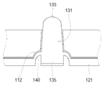
밑창(110)의 구조적인 특징을 살펴보면, 도면에 도시된 바와 같이, 밑창(110)은 전방 영역(110A)과 후방 영역(110B)으로 구분될 수 있다. 전방 영역(110A)은 발의 앞꿈치가 놓이는 미리 결정된 면적을 갖는 영역으로 정의할 수 있고, 후방 영역(110B)은 발의 뒷꿈치가 놓이는 미리 결정된 면적을 갖는 영역으로 정의할 수 있다. 이때, 전방 영역(110A)과 후방 영역(110B)에는 그 하방에 각각 수용 공간(S)이 형성되어 있다. 이로 인해 전방 영역(110A)과 후방 영역(110B)에서의 밑창(110) 두께는 그 이외의 나머지 영역의 밑창(110) 두께보다 얕다. 그리고, 밑창(110) 중 전방 영역(110A)과 후방 영역(110B)에는 각각 복수의 관통홀(111)이 밑창(110)을 상하 방향으로 관통하도록 형성되어 있다. 예컨대, 도 1의 실시예의 지압 슬리퍼(100)에는, 전방 영역(110A)에 21개의 관통홀(111)이, 후방 영역(110B)에 11개의 관통홀(111)이 형성되어 있다. 이때, 관통홀(111)은 단면이 원형일 수 있고, 밑창(110) 상부로 갈수록 내경이 감소하는 원뿔대 형상의 공간일 수 있다. 이는 후술하는 돌기부(123)가 관통홀(111) 내부에 삽입된 후 외부 가압에 의해 돌기부(123)가 융기하더라도 관통홀(111)을 이탈하지 않도록 하기 위함이다. 한편, 밑창(110)의 상면에는 각각의 관통홀(111)의 상단 둘레에 도넛 형상으로 볼록하게 융기된 융기부(113)가 형성될 수 있다. 후술하는 바와 같이, 지압판(120)의 상부 볼록부(133)가 밑창(110)의 상면 위로 돌출되는데, 상부 볼록부(133)보다 높이가 낮은 융기부(113)를 관통홀(111) 둘레에 형성함으로써 밑창(110) 상면과 상부 볼록부(133)의 높이 차이를 보완한다.Looking at the structural characteristics of the sole 110 , as shown in the drawings, the sole 110 may be divided into a
한편, 본 고안의 지압 슬리퍼(100)는 전방 영역(110A)의 수용 공간(S)과 후방 영역(110B)의 수용 공간(S)에 배치되는 두 개의 지압판(120)을 더 포함한다. 지압판(120)은 수용 공간(S)에 대응하는 사이즈로 되어 수용 공간(S) 내에 배치되는 베이스판(121)과, 베이스판(121)과 연결된 복수의 돌기부(123)를 포함한다. 베이스판(121)의 높이는 수용 공간(S)의 높이와 실질적으로 동일할 수 있다. 한편, 돌기부(123)는 밑창(110) 위로 융기하여 사용자의 발바닥을 지압하기 위한 구성으로서, 각 지압판(120)에 복수로 구비된다. 그리고, 이들 돌기부(123)는 관통홀(111)을 통과하여 밑창(110) 위로 융기하는바, 각각 복수의 관통홀(111)에 일대일 대응하도록 위치된다. 구체적으로 각각의 돌기부(123)는, 베이스판(121)과 연결되고 베이스판(121)의 상방으로 융기된 돌기 본체(131), 돌기 본체(131) 상단에 볼록하게 형성된 상부 볼록부(133), 돌기 본체(131)의 하단에 형성되고 베이스판(121)의 하방으로 돌출된 하부 돌출단(135)을 포함하여 구성된다. On the other hand, the
먼저, 돌기 본체(131)는 도시된 바와 같이, 단면이 원형인 기둥 형상이다. 특히, 단면의 직경이 위로 갈수록 줄어드는 원뿔대 형상일 수 있으며, 돌기 본체(131)의 외부 형상은 관통홀(111)의 내부 형상에 대응하도록 구성된다. 본 고안의 돌기부(123)는 돌기 본체(131)가 그 측면 둘레를 따라 외측으로 연장된 탄성 다이어프램(140)을 통해 베이스판(121)에 연결된다. 탄성 다이어프램(140)은 돌기부(123)를 베이스판(121)에 연결하여 돌기부(123)의 이탈을 방지하는 연결 요소이며, 동시에 돌기 본체(131)가 융기한 이후에 다시 원위치로 복귀될 수 있도록 돌기 본체(131)를 하방 구속하는 기능을 수행한다. 따라서, 탄성 다이어프램(140)은 탄성 재질로 형성된다. 탄성 다이어프램(140)은 베이스판(121) 보다 얇을 수 있고 그 두께가 예컨대 2mm이며, 베이스판(121) 및 돌기 본체(131)의 재질과 동일한 재질로 형성될 수 있다. 이러한 탄성 다이어프램(140)은 돌기 본체(131)에 대하여 복원력을 갖는다. 즉, 본 고안에 따른 지압 슬리퍼(100)는 복수의 돌기부(123) 중 지면과의 압착시 체중에 의해 가압이 이루어지는 영역에서만 발바닥을 지압하는 슬리퍼이며, 이에 따라 미사용시 또는 가압이 이루어지지 않은 영역에서는 돌기부(123)가 융기하지 않고 관통홀(111) 내에 리세스되어야 한다. 이러한 상태는 탄성 다이어프램(140)이 복원력에 의해 돌기 본체(131)를 하방으로 구속하는 작용에 의해 이루어질 수 있다. 도 2에 도시된 바와 같이, 지압판(120)이 밑창(110)에 결합하였을 때, 본 고안의 지압 슬리퍼(100)는 탄성 다이어프램(140)이 돌기 본체(131)를 하방 구속하고 특히, 이때 돌기 본체(131)의 상단을 밑창(110)의 상면과 동일선상에 위치시키도록 설계되어 있다. 이에 따라, 돌기 본체(131)가 밑창(110)의 상면 위로 돌출되지 않으며, 그 상단의 상부 볼록부(133)가 밑창(110)의 상면 위로 노출되도록 설계된다. 그리고, 이 상태에서 하부 돌출단(135)은 밑창(110)의 하면 아래로 돌출되도록 배치된다. 참고로, 상부 볼록부(133)는 돌기 본체(131)의 상단에 볼록하게 솟은 반구의 일부분의 형상을 가지며, 실제로 후술하는 바와 같이 돌기부(123)가 융기하면 사람의 발바닥과 접촉하는 부분은 상부 볼록부(133)이다.First, the
한편, 본 고안에 따른 지압 슬리퍼(100)의 지압 메커니즘을 설명한다. 전술한 바와 같이, 외부로부터 가압되지 않는 상태의 지압 슬리퍼(100)는 그 단면이 도 2에 도시된 바와 같다. 즉, 밑창(110) 상면에는 상부 볼록부(133)가 노출되어 있고 돌기 본체(131)는 관통홀(111)에 리세스된 상태이며, 밑창(110) 하부에는 하부 돌출단(135)이 돌출되어 있다. 이러한 상태에서 사용자가 지압 슬리퍼(100)를 착용하고 보행하거나 달릴 때, 체중의 이동에 의해 발 뒤꿈치에서부터 발 앞꿈치로 순차적으로 가압 지점이 옮겨간다. 발 뒤꿈치가 가압될 때에는 후방 영역(110B)의 일부분을 제외하고는 하부 돌출단(135)이 가압되지 않고, 발 앞꿈치가 가압될 때에는 전방 영역(110A)의 일부분을 제외하고는 하부 돌출단(135)이 가압되지 않는다. 어느 영역의 하부 돌출단(135)이 가압되든, 그 형태의 변화는 도 4a 및 도 4에 도시된 바와 같다. On the other hand, the acupressure mechanism of the
도 4a는 지면에 가압되지 않은 상태에서 돌기부(123)와 관통홀(111)의 위치를 설명하는 도면이다. 이때에는 전술한 바와 같이, 하부 돌출단(135)이 밑창(110) 아래로 돌출된 상태를 유지하기 때문에, 밑창(110) 상면의 발바닥에는 상부 볼록부(133)를 제외하고 돌기부(123)에 의한 가압이 이루어지지 않는다. 4A is a view for explaining the positions of the
이어서, 도 4b는 지면에 가압된 상태에서 관통홀(111) 내에서 돌기부(123)의 위치 변화를 설명하는 도면이다. 이때에는 하부 돌출단(135)이 가압에 의해 수용 공간(S)으로 진입한다. 이어서, 돌기 본체(131)가 가압에 의해 융기되어 밑창(110)의 상면 위로 노출되는데, 돌기 본체(131)는 하부 돌출단(135)의 높이만큼 융기된다. 이때, 탄성 다이어프램(140)은 융기하는 돌출 본체를 따라서 탄성적으로 상방으로 인발될 수 있다. 이어서 돌기 본체(131)가 융기함에 따라 그 상단의 상부 볼록부(133)가 밑창(110) 상면으로부터 더욱 융기되어 발바닥을 가압한다. 한편, 도시된 바와 같이, 관통홀(111)의 하단에는 둘레를 따라 리세스(112)가 형성된다. 리세스(112)는 탄성 다이어프램(140)을 수용하는 공간인데, 구체적으로, 앞서 설명한 바와 같이 돌기 본체(131)가 융기할 때 탄성 다이어프램(140)이 돌기 본체(131)를 따라 상방으로 탄발적으로 연장되면서 리세스(112)에 진입한다. 즉, 리세스(112)는 돌기 본체(131)의 융기 시 탄성 다이어프램(140)이 자유롭게 이동할 수 있는 공간을 제공하는 것이다. 뿐만 아니라, 이러한 리세스(112) 공간은 탄성 다이어프램(140)의 상방 이동을 제한하는 기능도 함께 수행한다. Next, FIG. 4B is a view for explaining a change in the position of the
다음, 지면과 접촉이 사라진 이후에는 탄성 다이어프램(140)의 복원력에 의해 다시 도 4a에 도시된 상태로 복귀한다. 융기된 돌기 본체(131)는 복원력에 의해 다시 하방으로 복귀하여 관통홀(111) 내부로 안착하고 착용자의 발바닥은 더 이상 돌기 본체(131)에 의한 지압을 느끼지 않는다. Next, after the contact with the ground disappears, it returns to the state shown in FIG. 4A again by the restoring force of the
이와 같은 구조에 따라, 본 고안은 지압 슬리퍼(100)의 전체 면적 중 보행시 체중에 의해 압력이 인가되는 일부 국소 부위에서만 발바닥을 지압하는 것이 가능하다. According to this structure, according to the present invention, it is possible to apply pressure to the sole of the foot only in some local areas where pressure is applied by the body weight during walking among the total area of the
한편, 본 고안의 일 실시예에 따른 지압 슬리퍼(100)는 밑창(110) 중 전방 영역(110A)과 후방 영역(110B)의 하면에 좌우 방향으로 연장된 복수의 배수홈(150)을 구비할 수 있다. 두 개의 지압판(120)이 수용 공간(S)에서 밑창(110)과 결합되어 구성되는데, 지압판(120)과 밑창(110) 사이에 물이 스며들었을 때, 배수홈(150)을 통해 물이 용이하게 배수될 수 있다.On the other hand, the
이상에서 설명한 것은 본 고안에 따른 지압 슬리퍼를 실시하기 위한 하나의 실시예에 불과한 것으로서, 본 고안은 상기한 실시예에 한정되지 않고, 이하의 특허청구범위에서 청구하는 바와 같이 본 고안의 요지를 벗어남이 없이 당해 고안이 속하는 분야에서 통상의 지식을 가진 자라면 누구든지 다양한 변경 실시가 가능한 범위까지 본 고안의 기술적 정신이 있다고 할 것이다.What has been described above is only one embodiment for implementing acupressure slippers according to the present invention, and the present invention is not limited to the above-described embodiment, and as claimed in the claims below, it deviates from the gist of the present invention. Without this, anyone with ordinary knowledge in the field to which the present invention belongs will say that the technical spirit of the present invention exists to the extent that various modifications can be made.
100: 지압 슬리퍼
110: 밑창
111: 관통홀
112: 리세스
120: 지압판
121: 베이스판
123: 돌기부
131: 돌기 본체
133: 상부 볼록부
135: 하부 돌출단
140: 탄성 다이어프램
150: 배수홈100: acupressure slippers 110: sole
111: through hole 112: recess
120: acupressure plate 121: base plate
123: protrusion 131: protrusion body
133: upper convex portion 135: lower protruding end
140: elastic diaphragm 150: drain groove
Claims (6)
상기 밑창 중 전방 영역과 후방 영역에는 각각 복수의 관통홀이 상기 밑창을 상하 방향으로 관통하도록 형성되어 있고, 상기 전방 영역과 후방 영역의 하방에는 각각 수용 공간이 형성되어 있어 전방 영역과 후방 영역에서의 밑창 두께가 나머지보다 얕으며,
상기 수용 공간에 대응하는 베이스판, 및 상기 베이스판과 연결된 복수의 돌기부를 포함하는 두 개의 지압판을 더 포함하고,
상기 복수의 돌기부는 각각 상기 복수의 관통홀에 일대일 대응하며, 각각의 돌기부는 상기 베이스판과 연결되고 베이스판의 상방으로 융기된 돌기 본체, 상기 돌기 본체 상단에 볼록하게 형성된 상부 볼록부, 상기 돌기 본체의 하단에 형성되고 상기 베이스판의 하방으로 돌출된 하부 돌출단을 포함하며,
상기 두 개의 지압판은 전방의 수용 공간과 후방의 수용 공간에 각각 배치되고, 상기 돌기부는 각각 대응하는 관통홀에 삽입되며, 돌기부의 하부 돌출단은 상기 밑창의 하면 아래로 돌출되도록 배치되는 것을 특징으로 하는,
지압 슬리퍼.Acupressure slippers comprising a sole having an area corresponding to the sole, and an instep cover provided on the upper side of the sole to wrap the instep,
A plurality of through holes are respectively formed in the front region and the rear region of the sole to pass through the sole in the vertical direction, and accommodation spaces are respectively formed below the front region and the rear region, so that the The thickness of the sole is shallower than the rest,
Further comprising a base plate corresponding to the accommodation space, and two acupressure plates comprising a plurality of protrusions connected to the base plate,
Each of the plurality of protrusions corresponds to the plurality of through-holes one-to-one, and each protrusion is connected to the base plate and protrudes upward of the base plate; It is formed at the lower end of the main body and includes a lower protruding end protruding downward of the base plate,
The two acupressure plates are respectively disposed in the receiving space of the front and the receiving space of the rear, the protrusions are respectively inserted into the corresponding through holes, and the lower protruding ends of the protrusions are disposed to protrude below the lower surface of the sole. doing,
acupressure slippers.
상기 돌기 본체는 단면이 원형인 기둥 형상이고 측면 둘레를 따라 외측으로 연장된 탄성 다이어프램을 통해 상기 베이스판에 연결되며,
상기 탄성 다이어프램은 복원력에 의해 상기 돌기 본체를 하방으로 구속하여 상기 돌기 본체의 상단을 상기 밑창과 동일선상에 위치시키고 상부 볼록부가 상기 밑창의 상방으로 노출되도록 설계된 것을 특징으로 하는,
지압 슬리퍼.According to claim 1,
The protrusion body has a circular cross section and is connected to the base plate through an elastic diaphragm extending outward along the periphery of the side surface,
The elastic diaphragm is designed to constrain the protrusion body downward by restoring force so that the upper end of the protrusion body is positioned on the same line with the sole and the upper convex part is exposed upward of the sole,
acupressure slippers.
상기 하부 돌출단이 가압에 의해 상기 수용 공간으로 진입하면, 상기 돌기 본체가 가압에 의해 융기되어 밑창의 상면 위로 노출됨에 따라 상부 볼록부가 더욱 융기되는 것을 특징으로 하는,
지압 슬리퍼.3. The method of claim 2,
When the lower protruding end enters the receiving space by pressing, the upper convex portion is further raised as the protruding body is raised by pressing and exposed over the upper surface of the sole,
acupressure slippers.
상기 관통홀의 하단에는 둘레를 따라 리세스가 형성되고,
상기 돌기 본체가 융기할 때 상기 탄성 다이어프램이 돌기 본체를 따라 상방으로 탄발적으로 연장되면서 상기 리세스에 진입하되, 상기 리세스에 의해 상방 이동이 제한되는 것을 특징으로 하는,
지압 슬리퍼.4. The method of claim 3,
A recess is formed along the periphery at the lower end of the through hole,
When the protrusion body protrudes, the elastic diaphragm enters the recess while elastically extending upward along the protrusion body, characterized in that the upward movement is restricted by the recess,
acupressure slippers.
상기 밑창에는 상기 관통홀의 상단 둘레에 도넛 형상으로 볼록하게 융기된 융기부가 형성되고, 상기 융기부의 높이는 상기 상부 볼록부의 높이보다 낮은 것인,
지압 슬리퍼.According to claim 1,
A raised portion convexly raised in a donut shape is formed around the upper end of the through hole in the sole, and the height of the raised portion is lower than the height of the upper convex portion,
acupressure slippers.
상기 밑창 중 상기 전방 영역과 후방 영역의 하면에는 좌우 방향으로 연장된 복수의 배수홈을 구비하여, 지압판과 밑창 사이의 물을 배수하는 것을 특징으로 하는,
지압 슬리퍼.According to claim 1,
A plurality of drain grooves extending in the left and right directions are provided on lower surfaces of the front area and the rear area of the sole to drain water between the acupressure plate and the sole,
acupressure slippers.
Priority Applications (1)
| Application Number | Priority Date | Filing Date | Title |
|---|---|---|---|
| KR2020210000418U KR20220002004U (en) | 2021-02-08 | 2021-02-08 | Acupressure slipper |
Applications Claiming Priority (1)
| Application Number | Priority Date | Filing Date | Title |
|---|---|---|---|
| KR2020210000418U KR20220002004U (en) | 2021-02-08 | 2021-02-08 | Acupressure slipper |
Publications (1)
| Publication Number | Publication Date |
|---|---|
| KR20220002004U true KR20220002004U (en) | 2022-08-17 |
Family
ID=83062066
Family Applications (1)
| Application Number | Title | Priority Date | Filing Date |
|---|---|---|---|
| KR2020210000418U Abandoned KR20220002004U (en) | 2021-02-08 | 2021-02-08 | Acupressure slipper |
Country Status (1)
| Country | Link |
|---|---|
| KR (1) | KR20220002004U (en) |
Cited By (2)
| Publication number | Priority date | Publication date | Assignee | Title |
|---|---|---|---|---|
| KR102484342B1 (en) | 2022-11-04 | 2023-01-04 | 주식회사 바크 | Slippers |
| KR102724817B1 (en) * | 2023-10-16 | 2024-10-31 | 유위상 | Non-adhesive production method of foam urethane slippers |
-
2021
- 2021-02-08 KR KR2020210000418U patent/KR20220002004U/en not_active Abandoned
Cited By (2)
| Publication number | Priority date | Publication date | Assignee | Title |
|---|---|---|---|---|
| KR102484342B1 (en) | 2022-11-04 | 2023-01-04 | 주식회사 바크 | Slippers |
| KR102724817B1 (en) * | 2023-10-16 | 2024-10-31 | 유위상 | Non-adhesive production method of foam urethane slippers |
Similar Documents
| Publication | Publication Date | Title |
|---|---|---|
| US6782641B2 (en) | Heel construction for footwear | |
| CN107581708B (en) | Insole assembly, bottom part, article of footwear, assembly method and kit | |
| EP2591693B1 (en) | Inner sole including an air bag | |
| US20120030969A1 (en) | Insole for a shoe having a movable massaging member | |
| US20110126422A1 (en) | Shoe sole with compressible protruding element | |
| KR20220002004U (en) | Acupressure slipper | |
| US20130318817A1 (en) | Footwear with integrated energy wave sockliner | |
| US12302987B2 (en) | Shoe insole | |
| KR20120079434A (en) | Footwear sole and footwear with the function of massage | |
| KR20190010983A (en) | The insole for shoes, the sole of shoes and the manufacturing method | |
| KR20130001950U (en) | Insole with detachable arch surpport | |
| KR20110056581A (en) | Sole with Shiatsu function | |
| JP2005185675A (en) | Footwear | |
| KR20090006030U (en) | Shoe sole | |
| KR102130728B1 (en) | High heels for impact soffening and prevention for ankle break and disease occurrence | |
| CA2822618A1 (en) | Footwear with integrated energy wave sockliner | |
| KR101261375B1 (en) | Accupressurable slipper | |
| CN214904224U (en) | Shoe-pad with massage function | |
| KR20160105012A (en) | Insole for preventing deformation of foot | |
| KR200326252Y1 (en) | A shoes for power walking | |
| KR20100122975A (en) | The shoes which has a shocking absorption and a geostatic function | |
| KR200352369Y1 (en) | A house shoes with a floor stopping plate | |
| JP3626175B1 (en) | Shoe insole pads and shoes | |
| JP3026127U (en) | Sandals stand | |
| KR200362024Y1 (en) | Footwear sole |
Legal Events
| Date | Code | Title | Description |
|---|---|---|---|
| UA0108 | Application for utility model registration |
St.27 status event code: A-0-1-A10-A12-nap-UA0108 |
|
| UA0201 | Request for examination |
St.27 status event code: A-1-2-D10-D11-exm-UA0201 |
|
| D13-X000 | Search requested |
St.27 status event code: A-1-2-D10-D13-srh-X000 |
|
| D14-X000 | Search report completed |
St.27 status event code: A-1-2-D10-D14-srh-X000 |
|
| UE0902 | Notice of grounds for rejection |
St.27 status event code: A-1-2-D10-D21-exm-UE0902 |
|
| T11-X000 | Administrative time limit extension requested |
St.27 status event code: U-3-3-T10-T11-oth-X000 |
|
| T11-X000 | Administrative time limit extension requested |
St.27 status event code: U-3-3-T10-T11-oth-X000 |
|
| T11-X000 | Administrative time limit extension requested |
St.27 status event code: U-3-3-T10-T11-oth-X000 |
|
| E13-X000 | Pre-grant limitation requested |
St.27 status event code: A-2-3-E10-E13-lim-X000 |
|
| P11-X000 | Amendment of application requested |
St.27 status event code: A-2-2-P10-P11-nap-X000 |
|
| P13-X000 | Application amended |
St.27 status event code: A-2-2-P10-P13-nap-X000 |
|
| E701 | Decision to grant or registration of patent right | ||
| UE0701 | Decision of registration |
St.27 status event code: A-1-2-D10-D22-exm-UE0701 |
|
| UG1501 | Laying open of application |
St.27 status event code: A-1-1-Q10-Q12-nap-UG1501 |
|
| UC1904 | Unpaid initial registration fee |
St.27 status event code: A-2-2-U10-U13-oth-UC1904 St.27 status event code: N-2-6-B10-B12-nap-UC1904 |
|
| R18-X000 | Changes to party contact information recorded |
St.27 status event code: A-3-3-R10-R18-oth-X000 |
|
| R18 | Changes to party contact information recorded |
Free format text: ST27 STATUS EVENT CODE: A-3-3-R10-R18-OTH-X000 (AS PROVIDED BY THE NATIONAL OFFICE) |
|
| R18-X000 | Changes to party contact information recorded |
St.27 status event code: A-3-3-R10-R18-oth-X000 |