KR20210142778A - magnetic omni-wheel - Google Patents
magnetic omni-wheel Download PDFInfo
- Publication number
- KR20210142778A KR20210142778A KR1020217037733A KR20217037733A KR20210142778A KR 20210142778 A KR20210142778 A KR 20210142778A KR 1020217037733 A KR1020217037733 A KR 1020217037733A KR 20217037733 A KR20217037733 A KR 20217037733A KR 20210142778 A KR20210142778 A KR 20210142778A
- Authority
- KR
- South Korea
- Prior art keywords
- hub
- wheel
- magnet
- rollers
- magnetically
- Prior art date
- Legal status (The legal status is an assumption and is not a legal conclusion. Google has not performed a legal analysis and makes no representation as to the accuracy of the status listed.)
- Withdrawn
Links
- 230000001939 inductive effect Effects 0.000 claims abstract description 41
- 230000004907 flux Effects 0.000 claims abstract description 21
- 239000000463 material Substances 0.000 claims abstract description 19
- CWYNVVGOOAEACU-UHFFFAOYSA-N Fe2+ Chemical compound [Fe+2] CWYNVVGOOAEACU-UHFFFAOYSA-N 0.000 claims description 13
- 230000006698 induction Effects 0.000 claims 1
- 230000001568 sexual effect Effects 0.000 claims 1
- 239000012141 concentrate Substances 0.000 abstract description 3
- 125000006850 spacer group Chemical group 0.000 description 8
- 238000003491 array Methods 0.000 description 5
- 230000007704 transition Effects 0.000 description 5
- XEEYBQQBJWHFJM-UHFFFAOYSA-N Iron Chemical compound [Fe] XEEYBQQBJWHFJM-UHFFFAOYSA-N 0.000 description 4
- 229910000831 Steel Inorganic materials 0.000 description 3
- 238000007689 inspection Methods 0.000 description 3
- 239000002184 metal Substances 0.000 description 3
- 229910052751 metal Inorganic materials 0.000 description 3
- 239000010959 steel Substances 0.000 description 3
- 230000008878 coupling Effects 0.000 description 2
- 238000010168 coupling process Methods 0.000 description 2
- 238000005859 coupling reaction Methods 0.000 description 2
- 230000002708 enhancing effect Effects 0.000 description 2
- 229910052742 iron Inorganic materials 0.000 description 2
- 230000005540 biological transmission Effects 0.000 description 1
- 230000015556 catabolic process Effects 0.000 description 1
- 239000011248 coating agent Substances 0.000 description 1
- 238000000576 coating method Methods 0.000 description 1
- 230000007797 corrosion Effects 0.000 description 1
- 238000005260 corrosion Methods 0.000 description 1
- 238000006731 degradation reaction Methods 0.000 description 1
- 230000001419 dependent effect Effects 0.000 description 1
- 238000006073 displacement reaction Methods 0.000 description 1
- 238000012986 modification Methods 0.000 description 1
- 230000004048 modification Effects 0.000 description 1
- 230000010287 polarization Effects 0.000 description 1
- 238000005096 rolling process Methods 0.000 description 1
Images


Classifications
-
- B—PERFORMING OPERATIONS; TRANSPORTING
- B60—VEHICLES IN GENERAL
- B60B—VEHICLE WHEELS; CASTORS; AXLES FOR WHEELS OR CASTORS; INCREASING WHEEL ADHESION
- B60B19/00—Wheels not otherwise provided for or having characteristics specified in one of the subgroups of this group
- B60B19/006—Magnetic wheels
-
- B—PERFORMING OPERATIONS; TRANSPORTING
- B60—VEHICLES IN GENERAL
- B60B—VEHICLE WHEELS; CASTORS; AXLES FOR WHEELS OR CASTORS; INCREASING WHEEL ADHESION
- B60B19/00—Wheels not otherwise provided for or having characteristics specified in one of the subgroups of this group
- B60B19/003—Multidirectional wheels
-
- B—PERFORMING OPERATIONS; TRANSPORTING
- B60—VEHICLES IN GENERAL
- B60B—VEHICLE WHEELS; CASTORS; AXLES FOR WHEELS OR CASTORS; INCREASING WHEEL ADHESION
- B60B19/00—Wheels not otherwise provided for or having characteristics specified in one of the subgroups of this group
- B60B19/12—Roller-type wheels
-
- B—PERFORMING OPERATIONS; TRANSPORTING
- B60—VEHICLES IN GENERAL
- B60B—VEHICLE WHEELS; CASTORS; AXLES FOR WHEELS OR CASTORS; INCREASING WHEEL ADHESION
- B60B2900/00—Purpose of invention
- B60B2900/30—Increase in
- B60B2900/351—Increase in versatility, e.g. usable for different purposes or different arrangements
-
- B—PERFORMING OPERATIONS; TRANSPORTING
- B60—VEHICLES IN GENERAL
- B60B—VEHICLE WHEELS; CASTORS; AXLES FOR WHEELS OR CASTORS; INCREASING WHEEL ADHESION
- B60B2900/00—Purpose of invention
- B60B2900/90—Providing or changing
- B60B2900/931—Magnetic effects
Landscapes
- Engineering & Computer Science (AREA)
- Mechanical Engineering (AREA)
- Rolling Contact Bearings (AREA)
- Arrangement Or Mounting Of Propulsion Units For Vehicles (AREA)
- Rolls And Other Rotary Bodies (AREA)
- Dynamo-Electric Clutches, Dynamo-Electric Brakes (AREA)
- Motorcycle And Bicycle Frame (AREA)
- Rollers For Roller Conveyors For Transfer (AREA)
Abstract
적어도 하나의 허브를 포함하는 표면 횡단용 다방향 휠이 제공된다. 허브는 제1 회전 축방향을 갖는다. 다수의 롤러가 허브의 외주 둘레에 배치된다. 롤러는 상기 제1 축방향과 각도를 이루는 제2 축방향으로 회전하도록 장착된다. 휠은 허브에 장착되는 적어도 하나의 자석을 포함한다. 허브는 적어도 하나의 자석의 자속을, 횡단될 표면을 향해 집중시키는 자기 유도성 재료로 제조된다.A multi-directional wheel for traversing a surface is provided comprising at least one hub. The hub has a first axis of rotation. A plurality of rollers are disposed around the periphery of the hub. The roller is mounted to rotate in a second axial direction at an angle with the first axial direction. The wheel includes at least one magnet mounted to the hub. The hub is made of a magnetically inducible material that concentrates the magnetic flux of at least one magnet towards the surface to be traversed.
Description
본 발명은 자기 휠(magnetic wheel) 및 옴니-휠(omni-wheel)에 관한 것이다.The present invention relates to a magnetic wheel and an omni-wheel.
상이한 디자인을 갖는 다른 휠이 다양한 문헌에 알려져 있으며, 그 중에서도 발명의 명칭이 "벨트 전동기구를 구비한 옴니-휠 기반 구동 장치"인 미국 특허 제8,308,604호, 발명의 명칭이 "역학적으로 평형인 인-라인(in-line) 휠 차량"인 미국 특허공개 제2008/0295595호, 발명의 명칭이 "차량용 자기 휠"인 미국 특허 제7,233,221호, 발명의 명칭이 "자기 휠"인 미국 특허공개 제2012/0200380호, 및 "오일 탱커용 CAS 의 검사를 위한 연례회의 2008 의 전방향(omnidirectional) 모바일 로봇에 기초한 부식 상태의 인식"으로 명명된 이 승휘(Lee, Seung heui) 등에 의한 논문을 포함하고 있다. 이들 문헌에 기재된 휠 및 차량의 특정한 디자인과 특징은 그 각각의 기재를 참조하면 가장 잘 이해될 수 있다. Other wheels with different designs are known in the various literatures, among others US Pat. No. 8,308,604 entitled "Omni-Wheel Based Drive with Belt Transmission"; - U.S. Patent Publication No. 2008/0295595 entitled "In-line Wheel Vehicle", U.S. Patent Publication No. 7,233,221 entitled "Magnetic Wheel for Vehicle", and U.S. Patent Publication No. 2012 entitled "Magnetic Wheel" /0200380, and a paper by Lee, Seung heui et al. entitled "Recognition of Corrosion Conditions Based on Omnidirectional Mobile Robots of the Annual Meeting 2008 for Inspection of CAS for Oil Tankers". . The specific designs and features of the wheels and vehicles described in these documents may best be understood with reference to their respective descriptions.
본 발명의 양태에 따라, 표면을 횡단하기 위한 다방향(multidirectional) 휠이 제공된다. 상기 휠은 적어도 하나의 허브(hub)를 포함하며, 상기 적어도 하나의 허브는 제1 회전 축방향을 형성한다. 상기 적어도 하나의 허브의 외주 둘레에 다수의 롤러가 배치되며, 상기 롤러는 상기 제1 축방향과 각도를 이루는 제2 축방향으로 회전하도록 장착된다. 휠은 적어도 하나의 자석을 포함하며, 상기 적어도 하나의 자석은 적어도 하나의 허브에 장착된다. 허브는 횡단될 표면을 향해 적어도 하나의 자석의 자속을 집중시키는, 자기 유도성 재료로 제조된다. According to an aspect of the present invention, a multidirectional wheel for traversing a surface is provided. The wheel includes at least one hub, the at least one hub defining a first axis of rotation. A plurality of rollers are disposed around the periphery of the at least one hub, and the rollers are mounted to rotate in a second axial direction at an angle to the first axial direction. The wheel includes at least one magnet, the at least one magnet being mounted to the at least one hub. The hub is made of a magnetically inducing material, which concentrates the magnetic flux of the at least one magnet towards the surface to be traversed.
다른 양태에 따라, 적어도 하나의 자석은 허브와 함께 회전하도록 장착된다.According to another aspect, the at least one magnet is mounted for rotation with the hub.
또 다른 양태에 따라, 다수의 자석이 각각의 스포크(spoke)에 각각 연결되며, 상기 스포크는 제1 축방향을 따라 배치되는 차축에 대해 자유회전하도록 장착된다.According to yet another aspect, a plurality of magnets are each coupled to a respective spoke, the spoke mounted for free rotation about an axle disposed along a first axial direction.
또 다른 양태에 따라, 롤러의 개수, 크기, 및 이격은 휠이 표면을 횡단할 때 완벽한 원형 회전에 근사하도록 형성된다.According to another aspect, the number, size, and spacing of the rollers are configured to approximate a perfect circular rotation as the wheel traverses the surface.
또 다른 양태에 따라, 각각의 롤러는 3개의 세그먼트형 부재를 포함하며, 상기 세그먼트형 부재는 휠이 표면을 횡단할 때 완벽한 원형 회전에 근사하도록 크기 및 형상을 갖는다.According to another aspect, each roller comprises three segmented members, the segmented members being sized and shaped to approximate a perfect circular rotation as the wheel traverses the surface.
또 다른 양태에 따라, 적어도 하나의 허브는 제거 가능하게 연결되는 제1 부분 및 제2 부분을 포함하며, 상기 제1 부분 및 제2 부분은 롤러를 수용하기 위한 오목부를 형성한다. According to another aspect, the at least one hub comprises a first portion and a second portion removably connected, the first portion and the second portion defining a recess for receiving the roller.
또 다른 양태에 따라, 롤러를 적어도 하나의 허브에 연결하기 위한 다수의 쐐기형 장착부가 제공된다. According to another aspect, a plurality of wedge-shaped mounts are provided for connecting a roller to at least one hub.
또 다른 양태에 따라, 상기 적어도 하나의 자석은 고온 자석이다. According to another aspect, the at least one magnet is a high temperature magnet.
다른 양태에 따라, 상기 적어도 하나의 자석은 영구자석이다. According to another aspect, the at least one magnet is a permanent magnet.
또 다른 양태에 따라, 상기 적어도 하나의 자석은 전자석이다. According to another aspect, said at least one magnet is an electromagnet.
다른 양태에 따라, 롤러는 자속 집중을 개선시키는 자기 유도성 재료로 제조된다.According to another aspect, the roller is made of a magnetically inducing material that improves magnetic flux concentration.
다른 양태에 따라, 롤러는 마찰을 증가시키도록 수정된다.According to another aspect, the roller is modified to increase friction.
다른 양태에 따라, 자석은 비-자기 유도성 링에 의해 덮인다.According to another aspect, the magnet is covered by a non-magnetically inductive ring.
다른 양태에 따라, 제1 축선을 따라 제1 축방향에 대해 회전하도록 장착되는 적어도 2개의 자기 유도성 본체를 포함하는 표면 횡단용 전방향 휠이 제공된다. 하나 또는 그 이상의 자석이 제1 축선에 대해 동심으로 배치되며, 상기 자석은 폴(pole)을 가지며, 또한 상기 자석은 그 폴이 제1 축방향을 따라 배향되도록 배향되고 또한 동일한 방향으로 마주하고 있으며, 상기 하나 또는 그 이상의 자석은 적어도 2개의 자기 유도성 본체들 사이에 장착된다. 다수의 롤러가 각각의 자기 유도성 본체의 외주 둘레에 배치되고, 상기 롤러는 회전을 위해 제1 축방향과 각도를 이루는 제2 축방향으로 회전하도록 장착된다. 상기 자기 유도성 본체는 횡단될 표면을 향해 하나 또는 그 이상의 자석의 자속을 집중시킨다.According to another aspect, there is provided an omnidirectional wheel for traversing a surface comprising at least two magnetically inducible bodies mounted for rotation about a first axial direction along a first axis. one or more magnets disposed concentrically with respect to a first axis, the magnets having poles, and wherein the magnets are oriented such that the poles are oriented along the first axis direction and facing in the same direction; , the one or more magnets are mounted between at least two magnetically inducible bodies. A plurality of rollers are disposed around the periphery of each magnetically inducible body, and the rollers are mounted for rotation in a second axial direction at an angle with the first axial direction for rotation. The magnetically inducible body focuses the magnetic flux of one or more magnets towards the surface to be traversed.
다른 양태에 따라, 상기 하나 또는 그 이상의 자석은 원형의 디스크 형상이다.According to another aspect, the one or more magnets are in the shape of a circular disk.
또 다른 양태에 따라, 상기 하나 또는 그 이상의 자석은 링 형상이다.According to another aspect, the one or more magnets are ring-shaped.
또 다른 양태에 따라, 상기 하나 또는 그 이상의 자석은 제1 축선에 대해 동심으로 배치되고, 또한 이로부터 방사방향으로 이격된다.According to another aspect, the one or more magnets are arranged concentrically with respect to the first axis and are also radially spaced therefrom.
또 다른 양태에 따라, 상기 하나 또는 그 이상의 자석은 적어도 2개의 자기 유도성 본체에 대해 회전하도록 장착된다.According to another aspect, the one or more magnets are mounted for rotation relative to the at least two magnetically inducible bodies.
다른 양태에 따라, 상기 적어도 2개의 자기 유도성 본체는, 2개의 자기 유도성 본체 사이의 거리 및 이동면이 롤러와 이동면 사이의 접촉원(contact circle)을 가로지르지 않고 최소화되도록, 크기 및 형상을 가지며 또한 롤러가 그 위에 배치된다.According to another aspect, the at least two magnetically inducible bodies are sized and shaped such that the distance between the two magnetically inducing bodies and the moving surface are minimized without crossing a contact circle between the roller and the moving surface, A roller is also placed thereon.
또 다른 양태에 따라, 상기 적어도 2개의 자기 유도성 본체는 제거 가능하게 연결되며, 또한 적어도 2개의 자기 유도성 본체는 롤러를 수용하기 위한 오목부를 형성한다. According to another aspect, the at least two magnetically inducible bodies are removably connected, and the at least two magnetically inducible bodies define a recess for receiving the rollers.
또 다른 양태에 따라, 롤러를 적어도 2개의 자기 유도성 본체에 연결하기 위한 다수의 쐐기형 장착부가 제공되며, 상기 쐐기형 장착부는 자기 유도성이다.According to another aspect, a plurality of wedge-shaped mounts are provided for connecting a roller to at least two magnetically inducible bodies, said wedge-shaped mounts being magnetically inducing.
다른 양태에 따라, 횡단될 표면을 향해 하나 또는 그 이상의 자석의 자속을 추가로 집중시키는, 자기 유도성 재료의 하나 또는 그 이상의 집중기(concentrator) 부재가 포함된다.According to another aspect, one or more concentrator members of magnetically inducible material are included to further concentrate the magnetic flux of the one or more magnets towards the surface to be traversed.
다른 양태에 따라, 상기 하나 또는 그 이상의 자석은 고온 자석이다.According to another aspect, the one or more magnets are high temperature magnets.
또 다른 양태에 따라, 상기 하나 또는 그 이상의 자석은 영구자석이다.According to another aspect, the one or more magnets are permanent magnets.
다른 양태에 따라, 롤러는 자속 집중을 개선시키는 자기 유도성 재료로 제조된다.According to another aspect, the roller is made of a magnetically inducing material that improves magnetic flux concentration.
다른 양태에 따라, 롤러는 마찰을 증가시키도록 수정된다.According to another aspect, the roller is modified to increase friction.
다른 양태에 따라, 자석은 비-자기 유도성 링으로 덮인다.According to another aspect, the magnet is covered with a non-magnetically inductive ring.
다른 양태에 따라, 2개의 본체는 전방향 휠의 분해 중 자석을 본체로부터 분리시키는데 사용되는 적어도 하나의 나사형 구멍을 갖는다.According to another aspect, the two bodies have at least one threaded hole used to separate the magnet from the body during disassembly of the omni-directional wheel.
본 발명에 따르면, 롤러는 자기 유도성 재료로 제조될 수도 있고, 또한 마찰 강화 처리물을 포함할 수도 있다. 따라서 자석에 의해 요구되는 힘이 감소될 수 있으며, 이는 차량이 상부-상향(right-side-up) 배향으로 이동할 때 효율을 증가시킨다. According to the present invention, the roller may be made of a magnetically inducing material, and may also include a friction enhancing treatment. The force required by the magnet can thus be reduced, which increases the efficiency when the vehicle is moving in the right-side-up orientation.
또한, 간단한 디자인을 유지하면서도, 차량의 구동력 및 견인력이 증가될 수 있다. In addition, while maintaining a simple design, the driving force and traction force of the vehicle can be increased.
도 1a는 제1 배치에 따른 분해도에서 자기 옴니-휠을 도시하고 있다.
도 1b는 도 1a의 자기 옴니-휠의 조립된 모습을 도시하고 있다.
도 1c는 제2 배치에 따라 조립된 모습의 자기 옴니-휠을 도시하고 있다.
도 1d는 도 1c의 자기 옴니-휠의 분해도를 도시하고 있다.
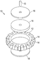
도 2는 제3 배치에 따른 자기 옴니-휠을 도시하고 있다.
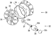
도 3a-3c는 제4 배치에 따른 자기 옴니-휠을 도시하고 있다.
도 4a는 제5 배치에 따른 자기 옴니-휠의 정면도이다.
도 4b는 도 4a의 옴니-휠의 제1 자석 구성을 도시하고 있다.
도 4c는 도 4a의 옴니-휠의 제2 자석 구성을 도시하고 있다.
도 4d는 도 4a의 자기 옴니-휠의 등각도이다.
도 4e는 도 4a의 자기 옴니-휠의 분해도이다.
도 4f는 제6 배치에 따른 자기 휠의 분해도이다.
도 4g는 도 4f의 자기 휠의 조립된 모습이다.
도 5a-5c는 제7 배치에 따른 자기 옴니-휠을 도시하고 있다.
도 6a 및 6b는 제8 배치에 따른 자기 옴니-휠을 도시하고 있다.
도 7a-7d는 제9 배치에 따른 자기 옴니-휠을 도시하고 있다.
도 8a는 자기 옴니-휠을 포함하는 차량을 도시하고 있다.
도 8b는 자기 옴니-휠을 포함하는 제2 차량을 도시하고 있다. 1a shows a magnetic omni-wheel in an exploded view according to a first arrangement;
Figure 1b shows an assembled view of the magnetic omni-wheel of Figure 1a.
1c shows the magnetic omni-wheel assembled according to a second arrangement.
1D shows an exploded view of the magnetic omni-wheel of FIG. 1C .
2 shows a magnetic omni-wheel according to a third arrangement.
3a-3c show a magnetic omni-wheel according to a fourth arrangement.
Fig. 4a is a front view of a magnetic omni-wheel according to a fifth arrangement;
Fig. 4b shows a first magnet configuration of the omni-wheel of Fig. 4a.
Fig. 4c shows a second magnet configuration of the omni-wheel of Fig. 4a.
Fig. 4D is an isometric view of the magnetic omni-wheel of Fig. 4A;
FIG. 4E is an exploded view of the magnetic omni-wheel of FIG. 4A ;
4f is an exploded view of a magnetic wheel according to a sixth arrangement;
Fig. 4G is an assembled view of the magnetic wheel of Fig. 4F;
5a-5c show a magnetic omni-wheel according to a seventh arrangement.
6a and 6b show a magnetic omni-wheel according to an eighth arrangement.
7a-7d show a magnetic omni-wheel according to a ninth arrangement.
8a shows a vehicle comprising a magnetic omni-wheel.
8b shows a second vehicle comprising a magnetic omni-wheel.
도 1a 및 1b를 참조하면, 자기 옴니-휠(10)이 도시되어 있다. 옴니-휠(10)은 허브(12), 및 상기 허브(12)의 외주 둘레에 배치되는 다수의 롤러(14)를 포함한다. 상기 롤러는 허브(12)의 축방향 회전의 방향과 직교하도록 배치된다. 허브(12)는 차축(13)으로의 장착을 위해 허브의 중심을 향해 연장하는, 스포크 또는 다른 구조물(예를 들어, 재료의 원형 웨브)을 포함할 수 있다. 상기 롤러(14) 및 이하에 기재되는 롤러는 핀, 돌출부, 차축, 또는 롤러가 회전하는 것을 허용하는 다른 적절한 구조물을 통해, 허브(12)에 장착될 수 있다. 이하에 더욱 상세히 기재되는 바와 같이, 롤러가 휠이 견인력(traction)을 제공하기에 충분한 마찰계수를 제공할 수 있어서, 차량의 중량이 자석(16)에 의해 제공되는 수직력에 대응할 때 롤러가 차량을 수직 및/또는 역전(upside-down) 배향으로 운전/조향할 수 있도록, 롤러는 표면 텍스처(예를 들어, 고무, 연질 플라스틱, 또는 표면 텍스처형 강, 등) 재료로 제조되거나 이를 가질 수 있으며, 또는 너얼링되거나 표면 코팅을 가질 수 있다. 롤러는 자기 유도성 재료로 제조될 수도 있고, 또한 마찰 강화 처리물을 포함할 수도 있다. 따라서 자석에 의해 요구되는 힘이 감소될 수 있으며, 이는 차량이 상부-상향(right-side-up) 배향으로 이동할 때 효율을 증가시킨다. 1A and 1B , a magnetic omni-
허브(12)는 제1 축방향을 정의한, 차축(13)에 대해 화살표("A")에 의해 표시되는 방향으로, 회전을 허용한다. 롤러(14)는 상기 제1 축방향과 직교하는 제2 축방향인, 화살표("B")에 의해 표시된 방향으로 회전을 허용한다[대안적으로, 그 대신에 메카넌 타입(Mecanun type) 휠이 사용될 수 있으며, 이 경우 롤러는 허브에 대해 45°로 장착된다]. 따라서 옴니-휠은 2°의 자유도를 갖는 회전을 허용한다. 이런 배치는 파이프, 탱크, 및 다른 금속 구조물을 검사하는데 사용되는 로봇식 차량처럼 엄격한 범위로 작동해야만 하는 차량에 특히 유용하다.
자기 디스크(16)는 허브(12) 내에 위치된다. 상기 자기 디스크(16)는 허브에 대해 자유회전하도록 허브에 장착될 수 있다. 자기 디스크(16)는 자속력(magnetic flux force)을 제공하며, 또한 자기(들)의 재료, 크기/개수, 및 강도는 철 표면(ferrous surface) 재료[예를 들어, 강재 탱크(steel tank) 또는 파이프 벽]와 접촉하는 옴니-휠을 보유하도록 선택된다. 또한, 철제 디스크(ferrous disk)(8)는, 자기 디스크(16)로부터의 자속력을 철 표면을 향해 추가로 지향시키기 위해, 자기 디스크(16)의 측부 상에 위치될 수 있으며, 이에 따라 디스크와 표면 사이의 인력(引力)(attractive force)을 증가시킨다. 이런 배치는 휠의 더욱 강한 보유력으로 나타난다. 허브, 디스크, 및/또는 이동면 사이에서 자속 누설 "단락"을 피할 동안 자석이 환경에 노출되는 것을 보호하기 위해, 비-자기 유도성 링(예를 들어, 비-자기 유도성 플라스틱 링)이 자석 둘레에 배치될 수 있다. 또한, 자석 및 디스크/허브를 함께 회전시키도록 강제하는 디스크 및/또는 허브의 회전을 로킹하기 위해, 링을 사용하는 것도 가능하다.A
강(또는 다른 자기 편광성/자기 유도성 재료)으로 제조될 수 있는 디스크(18)는 허브(12)의 내측 섹션을 둘러싸며, 따라서 허브(12)의 각각의 측부 상에 자속을 연결한다. 따라서 휠(10)은 휠이 자석(16) 및 디스크(18)를 통해 이동하는 금속면의 방향으로 인장력(pull force)을 제공하며, 동시에 허브(12) 및 롤러(14)의 회전을 통해 표면을 따라 2°의 휠 이동자유도를 허용한다.A
철제 디스크(18)는 허브(12)에 부착될 수 있으며, 또한 차축(13)으로의 부착을 위해 축 장착구멍(19)을 포함할 수 있다. 디스크(18)와 차축(13) 사이의 부착은, 예를 들어 옴니-휠(10)이 로봇식 차량에 연결될 때처럼, 차축(13)이 옴니-휠(10)을 구동시키는데 사용될 수 있도록, 고정될 수 있다. 대안적으로, 예를 들어 옴니-휠(10)이 다른 수단에 의해 구동되는 로봇 차량의 수동형 종동자-휠일 때처럼, 옴니-휠이 차축(13)에 대해 자유롭게 회전할 수 있도록, 디스크(18)는 회전 연결을 통해 차축(13)에 연결될 수 있다. 또한, 자기 디스크(16)는 차축과 함께 회전하거나 또는 차축에 대해 자유롭게 각각 회전할 수 있도록, 차축(13)에 고정 가능하게 부착되거나 또는 회전 가능하게 부착될 수 있다. 더욱이, 자기 디스크(16)와 함께 또는 자기 디스크(16)의 대안으로서, 자기 링 또는 다수의 자석의 어레이가 허브(12) 내에 위치될 수 있다. 자석(들)(예를 들어, 디스크, 어레이, 등)은 그(그들의) 편광이 자기적으로 반대인 바와 같이 휠(10)의 반대쪽 면에 대해서도 지속적이도록 정렬된다. 따라서 예를 들어, 자석 모두는 모든 자석이 휠의 일면에 S극을 제공하고 그리고 휠의 타면에 N극을 제공하도록 정렬될 수 있다. 자석은 휠의 축선에 대해 동심으로 배치되며, 또한 상기 축선으로부터 방사방향으로 이격된다. 자석은 고온 자석(예를 들어, 자장 강도의 용인 불가능한 열화 없이 고온에 견딜 수 있는 자석)일 수 있다. 또한, 자석은 영구자석, 전자석, 또는 그 조합일 수 있다. The
자석의 크기, 강도, 및 개수는 어느 한쪽을 위해 자기 디스크, 링, 또는 어레이를 교체함으로써, 및/또는 자기 디스크, 링, 또는 어레이를 높은 자속, 낮은 자속, 또는 의도된 작동 조건에 적절한 원하는 양을 갖는(예를 들어, 자석의 크기 및/또는 재료를 변경함으로써) 디스크/링/어레이를 구비한 동일한 구조적 배치로 대체함으로써, 휠과 표면 사이의 인력을 제어하도록 변경될 수 있다. 자속 강도 및 필드 형상이 의도한 용도에 맞을 수 있도록, 허브는 이들 자기 형상들, 즉 디스크, 링, 또는 어레이 중 임의의 하나 또는 전부를 단독으로 또는 조합하여 장착하기 위한 공동을 제공하는 구조를 포함할 수 있다. 이는 원하는 용도를 위해 특정하게 선택된 자속을 제공할 때 확장성 및 융통성을 제공한다. 따라서 휠(들)이 예를 들어 비교적 무거운 로봇식 검사 차량에 연결되는 그런 경우에, 자기력이 증가될 수 있다. 휠, 그 허브, 롤러, 및 자석의 크기는 매우 작은 로봇식 차량으로부터 대형 승용차까지 다양한 용도에 기초하여 정해질 수 있다. 더욱이, 허브에 위치되는 자기 디스크, 링, 또는 자석의 어레이는 롤러 자체가 자성인 디자인에 대해 상당한 이점을 제안한다. 본 디자인은 자기 간섭 및 필드 변화(changing field)를 감소시키며, 이는 표면으로의 인력 및 전자 설비와의 잠재적 손상이나 간섭을 완화시킨다. 또한, 본 디자인은 허브(12)의 주변 둘레에 2세트의 롤러를 사용할 수 있게 한다.The size, strength, and number of magnets can be adjusted by replacing the magnetic disks, rings, or arrays for either side, and/or by changing the magnetic disks, rings, or arrays to the desired high flux, low flux, or desired amount appropriate for the intended operating conditions. can be altered to control the attractive force between the wheel and the surface by replacing it with the same structural arrangement with disks/rings/arrays having (eg, changing the size and/or material of the magnets). In order for the magnetic flux strength and field shape to be tailored to the intended use, the hub includes a structure that provides a cavity for mounting any one or all of these magnetic shapes, i.e., disks, rings, or arrays, alone or in combination. can do. This provides scalability and flexibility when providing a magnetic flux that is specifically selected for a desired application. The magnetic force can thus be increased in those cases where the wheel(s) is connected to, for example, a relatively heavy robotic inspection vehicle. Wheels, their hubs, rollers, and magnets can be sized based on a variety of applications, from very small robotic vehicles to large passenger cars. Moreover, an array of magnetic disks, rings, or magnets positioned on the hub offers significant advantages over designs in which the rollers themselves are magnetic. This design reduces magnetic interference and changing field, which mitigates potential damage or interference with attractive forces to the surface and electronic equipment. This design also allows the use of two sets of rollers around the perimeter of the
이런 배치는 파이프와 탱크 등과 같이 철 재료로 제조되는 3차원 구조물을 횡단할 것을 요구하는 용도에 특히 유용하다. 자석이 휠과 표면 사이의 접촉을 이들 방향으로 유지하기에 충분한 인력을 제공하기 때문에, 자기 옴니-휠은 역전 이동뿐만 아니라 수직면 상에서의 이동을 허용한다. 자기 옴니-휠은 예를 들어 공장의 창고에서 상품의 이동을 위한 롤러 시스템의 부분과 같은, 다른 이송 형태로 사용될 수도 있다. This arrangement is particularly useful for applications that require crossing three-dimensional structures made of ferrous materials, such as pipes and tanks. Because the magnets provide enough attractive force to maintain contact between the wheel and the surface in these directions, the magnetic omni-wheel allows for reverse movement as well as movement on a vertical plane. Magnetic omni-wheels may also be used in other transport forms, for example as part of a roller system for moving goods in a warehouse of a factory.
도 1c 및 1d를 참조하면, 철제 디스크(18a)가 직경이 큰 점을 제외하고는, 도 1a 및 1b에 도시된 옴니-휠(10)과 유사한 옴니-휠(10a)이 도시되어 있다. 도 1c에 가장 잘 도시된 바와 같이, 철제 디스크(18a)는, 그 직경이 휠의 허브 둘레에 배치된 롤러(14a)의 원주 직경 보다 약간 작은 크기를 갖도록, 크기를 갖는다. 따라서 철제 디스크(18a)는 휠이 횡단하는 표면에 더 가깝다. 이 구조적인 배치는, 휠과 표면 사이의 인력을 증가시키기 위해, 표면을 향한 자속의 방향을 개선시킨다. 달리 특정하게 언급한 바를 제외하고는, 전술한 실시예의 많은 특성 및 특징은 아래의 실시예에 적용될 수 있다. 1C and 1D, there is shown an omni-
도 2를 참조하면, 2세트의 허브 및 롤러(21, 22)를 포함하는 옴니-휠(20)이 공통 유닛 내에 함께 장착된다. 이 실시예에서 알 수 있는 바와 같이, 롤러(22)의 개수, 크기, 형상, 및 이격은 옴니-휠이 거의 완벽한 원형 프로필을 갖도록, 허브(21)의 직경과 관련하여 변할 수 있다. 이런 구성은 휠의 형상으로 인한 범프(bump), 진동, 스톨 포인트(stall point), 및 구동력 변화를 제거하는 기능적으로 완벽한 원형 회전 프로필에 접근하는 것으로 나타난다. 따라서 허브가 회전하고 하나의 롤러가 이동면과의 접촉을 벗어나 이동할 때, 다음 롤러가 연속해서 상기 표면과 접촉한다. 따라서 개별적인 롤러의 표면 접촉 지점들은 함께 원을 형성한다. 이런 배치는, 예를 들어 롤러들이 너무 멀리 이격되었다면 연속한 롤러들 사이의 "갭(gap)" 내로 낙하하는 휠에 의해 달리 유발될 수 있는 휠의 이동에 "범프"를 제거한다. 비-제한적인 일 실시예로서, 허브의 직경이 증가함에 따라, 허브의 둘레에 배치된 롤러의 개수는 허브 회전 시 롤러가 표면과의 매끄러운 접촉을 유지하도록, 증가된다. 더욱이, 거의 완벽한 접촉원은 휠의 회전도와 이동한 거리 사이에 선형 관계가 있다는 것을 의미하며, 따라서 위치 제어 및 정확도를 개선시킨다.Referring to FIG. 2 , an omni-
도 3a, 3b, 및 3c에는, 허브 둘레에 거의 완벽한 원형을 형성하고 또한 휠의 이동 시 범프도 제거하는 타원형의 3부분형 세그먼트형 형상을 갖는 롤러(32)를 구비한 옴니-휠(30)이 도시되어 있다. 휠(30)은 휠의 각각의 측부 상에 2개의 허브(34)를 포함할 수 있다. 각각의 허브(34)는 롤러(32)를 장착하기 위한 장착 브래킷(36)을 포함한다. 롤러는 타원 형상의 부분을 형성하도록 형성되는 3개의 세그먼트(32a, 32b, 32c)로 구성되어 있다. 롤러는 브래킷의 장착 구멍에 의해 지지되는 핀(37) 및 베어링(38)을 통해 장착된다. 2개의 허브 사이에 공동을 형성하는 스페이서 링(39)이 상기 2개의 허브(34) 사이에 위치될 수 있다. 2개의 허브 사이의 공동에 자석이 위치될 수 있다. 3a, 3b, and 3c, an omni-
휠(30)의 "거의 완벽한 원형" 디자인은, 차축의 진동을 유발시킬 수 있고 이는 다시 상기 차축에 부착된 차량의 진동을 유발시킬 수 있는, 범프를 제거한다. 이런 진동은 그 차량의 작동과 간섭하고 및/또는 예를 들어 검사 로봇처럼 그 차량 상에 장착된 임의의 센서나 기구를 방해할 수 있으며, 또한 여기에 기재된 실시예의 구조에 의해 최소화된다. 또한, 거의 완벽한 원형 디자인은, 불완전한 휠이 연속한 롤러들 사이의 계곡(valley) 내로 낙하할 수 있기 때문에, 달리 발생할 수도 있는 스톨 포인트를 제거한다. 일단 이런 하나의 불완전한 휠이 계곡들 중 하나 내로 낙하하면, 그 계곡을 벗어나서 다음 롤러로 휠을 회전시키기 위해 추가적인 토크 힘을 취할 것이다. 또한, 상기 불완전한 휠이 정지되었다면, 휠은 롤러 사이의 계곡들 중 하나에 안착할 때까지 계속 회전하려는 경향을 가질 것이다. 이는, 다음 계곡으로 회전하려는 휠의 자연적인 경향 때문에, 차량의 작동과 간섭하여, 차량을 정확한 위치에 정지시키는 것을 어렵게 할 것이다. 더욱이, 거의 완벽한 원형 구성은 이와는 달리 이러한 문제점 및 다른 문제점을 제거하지 않는다면, 이를 최소화하기 위해 연속적인 자속을 유지하는 것을 돕는다. The "nearly perfect round" design of the
도 4a-4g를 참조하면, 옴니-휠(40)은 롤러(44)를 각각 갖는 2개의 허브(42) 사이에 위치되는, 자석(41)의 어레이를 포함한다. 자석(41)은 장착 조립체(46)에 장착될 수 있다. 장착 조립체(46)는, 조립체가 차축(A)에 장착될 수 있도록, 조립체(46)의 중심을 향해 연장하는 구조물(예를 들어, 스포크, 원형 웨브, 등)을 포함할 수 있으며, 상기 차축 위의 조립체(46) 및 자석(41)은 차축에 대해 또한 허브 및 롤러(42, 44)에 대해 자유롭게 회전할 수 있다. 도 4c에 도시된 바와 같이, 장착 조립체(46)는 캐리지(47)를 포함한다. 자석(41)은 각각의 캐리지(47) 내로 삽입되어, 캐리지에 의해 지지된다. 각각의 캐리지(47)의 상부 부분은 차축(A) 둘레에 배치되는 컬러(collar)를 향해 각도를 이루는 연결 부분을 포함한다. 상기 연결 부분의 각도는, 캐리지가 원형의 차축 둘레로 균등하게 이격되도록, 지지될 자석의 개수에 기초하여 선택될 수 있다. 대안적으로, 2개의 허브(42)는 2개의 허브를 연결하는 원통형 연장부를 갖는 일체형 구조물의 부분일 수 있으며, 이 경우 조립체(46)는 상기 원통형 연장부에 대해 자유롭게 회전하는 크기 및 형상을 가질 수 있다. 도 4f 및 4g에서 알 수 있는 바와 같이, 캐리지 장착형 자석은 롤러를 포함하지 않는 휠에 사용될 수도 있다.4A-4G , omni-
자석들(41)은 조립체(46) 둘레에 배치되며, 또한 서로에 대해 상이한 각도로 배향된다. 배향 각도는 예를 들어 20°, 30°, 45°, 60°, 90°, 120°또는 다른 적절한 각도를 포함할 수 있다. 도 4b는 장착 조립체(46)(여기에는 장착 디스크로서 도시된) 상에 장착되고 또한 서로에 대해 90°로 배향되는 자석을 도시하고 있다. 따라서 휠이 표면을 횡단하고, 예를 들어 금속 탱크의 바닥(43)과 벽(45) 사이의 접합부와 같은, 표면들 사이의 접합부와 만남에 따라, 자석들 중 하나(41a)는 바닥면을 향해 제1 각도로 배향될 수 있으며, 또한 상이한 각도로 장착되는 자석들 중 다른 하나(41b)는 벽면(45)을 향해 배향될 수 있다. 따라서 2개의 상이한 자석은 2개의 상이한 표면들 사이에 유지 인력(引力)을 동시에 제공할 수 있다. 이런 구조적 배치는, 2개의 표면 사이의 인력이 항상 유지되기 때문에, 제1 면을 따라 제2 면으로(예를 들어, 바닥으로부터 벽으로) 이동하는 사이의 전이에 대해 옴니-휠의 능력을 강화시킨다. 또한, 휠이 다음 표면으로 전이함에 따라, 새로운 표면에 인력을 제공한 자석(41)은 표면과의 자기 퍼처스(magnetic purchase)를 유지하고, 그리고 옴니-휠에 대해 자유롭게 회전한다. 따라서 벽이 새로운 "바닥"으로 됨에 따라, 벽과 결합된 어레이의 자석은 전방 배향을 갖는 것으로부터 하방 배향을 갖는 것으로 회전하며, 이제 하방 배향을 갖는 자기는 후방 배향을 갖는다. 이런 자유롭게 회전하는 배치는, 휠이 표면들 사이에서 전이함에 따라, 하나의 자기가 인력을 제공하는 것을 "인수(take over)"할 필요가 없기 때문에, 옴니-휠이 표면과 분리될 기회를 감소시킨다. 표면들 사이에서의 전이의 초기에 인력을 제공하였던 동일한 자석은, 전이가 완료된 후 그 힘을 유지시킨다. 대안적으로, 도 4c에 도시된 바와 같이, 자석이 차축 및 옴니-휠에 대해 자유롭게 회전할 뿐만 아니라 서로에 대해서도 자유롭게 회전할 수 있도록, 자석(41)은 독립적인 옵셋 스포크(48) 상에 장착될 수 있다. 이런 배치에 있어서, 자석(40)은 접합부에서의 표면들 사이에 최대 자기 인력을 갖는 위치로 배향되도록 회전할 수 있다. 예를 들어, 접합부에서의 표면이 서로에 대해 이상한 각도로, 즉 85°로 배향되었다면, 자유롭게 회전하는 자석 중 일부는 제1 표면을 향해 배향된 상태로 존재할 수 있으며, 다른 일부의 자석은 다른 표면을 향해 85°의 각도로 배향하도록 자유롭게 회전할 수 있다. 바람직하게도, 장착 조립체(46) 및 스포크(48)의 직경은 자석의 표면이 롤러를 지나서 연장하지 않도록 선택된다. 이 방법으로, 자석은 표면과 접촉하여 마찰을 생성하지 않고 자기 결합을 제공하기 위해, 표면에 충분히 밀착된 상태로 유지될 수 있다.
도 5a-5c를 참조하면, 2부분형 허브(52)를 구비한 옴니-휠(50)이 도시되어 있다. 각각의 허브(52)는 베이스(52a)와 커버(52b)로 구성되는 2개의 절반부(half)를 포함한다. 상기 베이스(52a)와 커버(52b)는, 롤러(54)를 수용하기 위해 다수의 오목부(53)를 각각 포함한다. 베이스(52a)와 커버(52b)는, 커버(52b)가 베이스(52a)에 연결될 때, 롤러 차축(56)을 수용하는 크기 및 형상을 구비하는 구멍(55)을 포함한다. 이런 구성은 허브(52)의 용이한 조립을 허용한다. 베이스(52a)로부터 분리되는 커버(52)에 의해, 롤러(54)는 그 각각의 오목부(53)에 위치될 수 있다. 제 위치의 롤러에 의해, 커버(52b)는 예를 들어 파스너(예를 들어, 나사 또는 볼트)를 통해 베이스(52a)에 부착될 수 있다. 일단 각각의 허브(52)가 조립되었다면, 2개의 허브(52)는 2개의 허브 사이에 배치되는 스페이서 링(57)과 함께 연결될 수 있다. 상기 스페이서 링(57)은 자석(58)이 삽입될 수 있는 공동을 형성한다. 스페이서 링(57)의 크기는 대형 자석이나 소형 자석을 수용하도록 변화될 수 있으며, 이에 따라 특별한 용도에 기초하여 자기력의 조정을 허용한다. 또한, 허브(52) 및 스페이서 링(57)은 대응하는 인덱싱(indexing) 노치(59)를 포함할 수 있다. 상기 인덱싱 노치(59)는 각각의 허브(52)가 다른 허브에 대해 적절한 원형 배향으로 부착되는 것을 보장한다. 도 5c에서 알 수 있는 바와 같이, 허브(52)는, 하나의 허브의 롤러(54)가 다른 허브의 롤러들 사이의 갭과 정렬되도록, 위상-변위된 배향으로 부착된다. 롤러의 위상-변위는, 휠이 표면 상에서 회전함에 따라, 범프를 감소시키는 것을 돕는다. Referring to FIGS. 5A-5C , an omni-
도 6a 및 6b를 참조하면, 2부분형 허브(62)를 갖는 옴니-휠(60)이 도시되어 있다. 롤러를 장착하기 위해 옴니-휠(60) 및 옴니-휠(50) 모두가 베이스 및 커버를 갖는다는 점에서, 옴니-휠(60)은 옴니-휠(50)과 유사하다. 옴니-휠(60)에 대해, 각각의 허브의 베이스(62a)는 오목부(64)를 포함한다. 각각의 오목부는 자석이 삽입될 수 있는 공동을 형성한다. 따라서 오목부가 자석을 수용하기 때문에, 스페이서 링이 요구되지 않는다. 허브는 다방향 휠의 분해 중 본체로부터 자석을 분리하는데 사용되는 적어도 하나의 나사형 구멍을 가질 수 있다. 6A and 6B , an omni-
도 7a-7d를 참조하면, 장착 쐐기(76)를 포함하는 옴니-휠(70)이 도시되어 있다. 옴니-휠(70)은 2개의 허브(72) 및 상기 2개의 허브 사이에 배치되는 스페이서 링(73)을 포함하며, 상기 스페이서 링(73)은 자석(74)을 수용하기 위해 공동을 형성한다. 각각의 허브(72)는 장착 쐐기(76)를 통해 허브에 부착되는 다수의 롤러(75)를 포함한다. 허브(72)는, 쐐기가 (예를 들어, 나사, 볼트, 리벳, 핀, 등과 같은 파스너를 통해) 허브에 연결될 수 있도록, 각각의 쐐기(76) 상의 장착 구멍(77b)에 대응하는 다수의 장착 구멍(77a)을 포함한다. 각각의 쐐기는 차축(79)을 수용하는 크기 및 형상을 구비한 차축 장착 구멍(78)을 포함한다. 알 수 있는 바와 같이, 롤러(75)는 쐐기(76)의 차축 장착 구멍(78)에 지지되는 차축(79) 상에 장착된다. 쐐기(76)는 장착 구멍(77a, 77b)을 통해 허브(72)에 부착된다. 이런 배치에서는 휠이 용이하게 조립 및 분해될 수 있다. 또한, 쐐기(76)는 자속 집중기로서 작용하는 자기 유도성 재료(예를 들어, 철 재료)로 제조될 수 있다. 쐐기의 엣지와 표면 사이의 거리(D)가 감소되어, 휠과 표면 사이의 자기 인력의 증가로 나타나도록, 쐐기의 크기 및 형상이 변할 수 있다. 상기 거리(D)는, 롤러가 표면과 접촉하여 회전함에 따라, 롤러에 의해 형성되는 경계부(boundary)까지 감소될 수 있다. 이런 접촉 경계부는 특성 상 원형이며, 또한 전술한 바와 같이 개별적인 롤러의 면 접촉지점에 의해 함께 형성된다. 허브가 이를 가로지르지 않고 원형 경계부까지 연장하도록, 허브 또는 그 부품(예를 들어, 쐐기)의 크기 및 형상을 갖는 것이 바람직하다. 원형 경계부를 가로지르면 허브와 표면 사이에 마찰 접촉을 생성하여, 롤러의 롤링과 간섭할 수 있다.Referring to FIGS. 7A-7D , an omni-
도 8a를 참조하면, 로봇식 차량을 위한 구동 시스템(80)이 도시되어 있다. 상기 구동 시스템(80)은 자기 옴니-휠(82) 및 구동 휠(84)을 포함한다. 자기 옴니-휠(82)은 구동 시스템(80)의 섀시에 부착되어, 제1 축방향을 따라 배향된다. 구동 휠(84)은 구동 시스템(80)의 섀시(85)에 부착되어, 상기 제1 축방향과 직교하는 제2 축방향을 따라 배향된다. 구동 휠(84)은 구동 시스템(80)의 전방 및 역전 이동을 제공하도록 구동된다(예를 들어, 모터 및 기어 조립체를 통해). 옴니-휠(82)이 구동 휠(84)과 직교하더라도, 옴니-휠 상의 롤러(86)는 구동 휠(84)과 정렬되며, 따라서 구동 시스템(80)은 옴니-휠 자체에 의해 유도되는 비교적 작은 마찰로도 표면을 횡단할 수 있다. 옴니-휠은, 옴니-휠(82)이 구동 휠(84)과 직교하여 장착되기 때문에, 옴니-휠을 회전시켜 구동 시스템(80)을 피봇시키도록, (예를 들어, 모터 또는 기어 조립체를 통해) 구동될 수도 있다. 따라서 구동 휠(84) 및 옴니-휠(82)의 회전을 각각 제어함으로써, 차량이 간단한 방식으로 구동 및 조향될 수 있다. 옴니-휠(82)은 여기에 기재되는 옴니-휠 구성요소들 중 임의의 하나일 수 있다. 도 8b는 옴니-휠(82)과 구동 휠(84) 모두를 포함하는 구동 시스템(80)이 오직 구동 휠만을 포함하는 구동 시스템(88)에 링크되는, 체인형 장치를 도시하고 있다. 따라서 간단한 디자인을 유지하면서도, 차량의 구동력 및 견인력이 증가될 수 있다. Referring to FIG. 8A , a
전술한 본 발명은 단지 예로서만 제공될 뿐이며, 제한하는 것으로는 해석되지 않는다. 도시되고 기재되는 이하의 예시적인 실시예 및 적용에 따르지 않고, 또한 이하의 청구범위에 기재되는 본 발명의 진정한 정신 및 범주로부터의 일탈 없이, 여기에 기재된 발명에 다양한 수정 및 변경이 이루어질 수 있다. The invention described above is provided by way of example only and should not be construed as limiting. Various modifications and changes may be made to the invention described herein without complying with the following exemplary embodiments and applications shown and described, and without departing from the true spirit and scope of the invention as set forth in the claims below.
Claims (20)
제1 회전 축방향을 갖는 허브;
상기 허브의 외주 주변에 배치되고, 상기 제1 축방향과 각도를 이루는 제2 축방향으로 회전하도록 장착되는 다수의 롤러; 및
상기 허브에 장착되는 적어도 하나의 자석을 포함하며,
상기 허브는 상기 적어도 하나의 자석의 자속을 횡단되는 상기 표면을 향해 집중시켜, 상기 휠과 상기 표면 사이의 인력이 증가될 수 있도록 크기, 형상, 및 위치가 결정된 자기 유도성 재료로 이루어지는, 다방향 휠. A multidirectional wheel for traversing a surface, comprising:
a hub having a first axis of rotation;
a plurality of rollers disposed around the outer periphery of the hub and mounted to rotate in a second axial direction forming an angle with the first axial direction; and
at least one magnet mounted to the hub;
wherein the hub is made of a magnetically inductive material sized, shaped, and positioned such that the magnetic flux of the at least one magnet can be focused towards the traversed surface, thereby increasing the attractive force between the wheel and the surface. wheel.
상기 적어도 하나의 자석은 상기 허브 내에 장착되는, 다방향 휠.The method of claim 1,
and the at least one magnet is mounted within the hub.
상기 허브는 각각의 상기 자석을 상기 허브 내에 장착하기 위한 적어도 하나의 공동을 정의하고, 상기 자석 중 적어도 하나는 특정 자기장 형상을 정의하기 위해 원형 디스크 형상, 링 형상, 또는 어레이(array) 형상화되는, 다방향 휠.According to claim 1,
wherein the hub defines at least one cavity for mounting each of the magnets within the hub, wherein at least one of the magnets is shaped like a circular disk, a ring, or an array to define a specific magnetic field shape; multidirectional wheel.
상기 하나 이상의 자석은 상기 제1 축에 대해 동심으로 배열되고 이로부터 방사상으로 이격되는, 다방향 휠.According to claim 1,
wherein the one or more magnets are arranged concentrically with respect to the first axis and are radially spaced therefrom.
상기 적어도 하나의 자석은 상기 허브에 대해 자유 회전하게 장착되는, 다방향 휠. According to claim 1,
and the at least one magnet is mounted rotatably relative to the hub.
상기 적어도 하나의 자석은 폴(poles)을 갖고 상기 적어도 하나의 자석은 상기 제1 축방향과 정렬되는 상기 폴(poles)과 함께 상기 허브에 장착되는, 다방향 휠.According to claim 1,
wherein the at least one magnet has poles and the at least one magnet is mounted to the hub with the poles aligned with the first axial direction.
상기 자석 주위에 비-자기 유도성 링을 더 포함하는, 다방향 휠.According to claim 1,
and a non-magnetic inductive ring around the magnet.
상기 허브 내에 장착되는 상기 자석 상에 적어도 하나의 자기 유도성 디스크를 더 포함하는, 다방향 휠.According to claim 1,
and at least one magnetically inductive disk on the magnet mounted within the hub.
상기 롤러는 자기 유도성 재료로 이루어지는, 다방향 휠.According to claim 1,
wherein the roller is made of a magnetically inducing material.
상기 허브는 상기 다수의 롤러 중 각각의 롤러를 수용하기 위해 다수의 오목부를 포함하는, 다방향 휠.According to claim 1,
and the hub includes a plurality of recesses for receiving each one of the plurality of rollers.
상기 휠은, 공동을 갖는 허브, 상기 허브의 상기 공동 내의 적어도 하나의 자석, 상기 허브의 외주 주위에 배치되는 다수의 롤러를 포함하고,
상기 허브는, 제1 회전 축방향을 갖고 상기 적어도 하나의 자석의 자속을 상기 허브를 통해 그리고 횡단되는 상기 자기 유도성 표면을 향해 집중시키고 그것에 의해 상기 휠과 상기 표면 사이에 인력을 증가시키도록 크기, 형상, 및 위치화되는 자기 유도성 재료로 이루어지고,
상기 롤러는, 상기 제1 축방향과 각도를 이루는 제2 축방향으로 회전을 위해 장착되며, 상기 다수의 롤러의 적어도 제1 롤러는 상기 자기 유도성 표면의 제1 부분과 접촉하는 반면 상기 다수의 롤러의 제2 롤러는 상기 자기 유도성 표면과 접촉하지 않고,
상기 제1 회전 축방향을 따라 상기 휠의 상기 허브를 회전시키는 단계; 및
상기 허브의 주변에 대해 배치되는 상기 제1 롤러가 상기 자기 유도성 표면의 제1 부분과 접촉 없이 이동하게 하고 상기 다수의 롤러에서 상기 허브의 주변에 대해 배치되는 상기 제2 롤러가 상기 자기 유도성 표면의 제2 부분과 접촉하도록 하기 위해 상기 휠의 상기 허브의 회전을 지속하는 단계를 포함하며,
상기 다수의 롤러 중에서 적어도 하나의 롤러는 상기 휠의 회전의 전체에 걸쳐 상기 자기 유도성 표면과 접촉하고,
상기 적어도 하나의 자석의 상기 자속은 상기 휠의 회전의 전체에 걸쳐 상기 다수의 롤러 중 하나 이상에 인접하여 횡단되는 상기 표면의 부분을 향하여 집중되는, 방법. A method for traversing a magnetically inducible surface using a multidirectional wheel, the method comprising: providing a vehicle having the multidirectional wheel;
wherein the wheel comprises a hub having a cavity, at least one magnet in the cavity of the hub, and a plurality of rollers disposed around an periphery of the hub;
The hub has a first axial direction of rotation and is sized to focus the magnetic flux of the at least one magnet through the hub and towards the traversed magnetically inducible surface thereby increasing the attractive force between the wheel and the surface. , shaped, and positioned of a magnetically inducible material,
The rollers are mounted for rotation in a second axial direction at an angle with the first axial direction, wherein at least a first roller of the plurality of rollers is in contact with a first portion of the magnetically inducible surface while the plurality of the second roller of the roller is not in contact with the magnetically inducing surface,
rotating the hub of the wheel along the first axis of rotation; and
wherein the first roller disposed relative to the periphery of the hub moves without contacting the first portion of the magnetically inducing surface and the second roller disposed relative to the periphery of the hub in the plurality of rollers is the magnetically inducing continuing rotation of the hub of the wheel to bring it into contact with a second portion of the surface;
at least one of the plurality of rollers is in contact with the magnetically inducible surface throughout rotation of the wheel;
and the magnetic flux of the at least one magnet is focused towards a portion of the surface traversed adjacent to one or more of the plurality of rollers throughout the rotation of the wheel.
상기 허브의 상기 주변에 대해 배치되는 상기 제2 롤러가 상기 자기 유도성 표면의 제2 부분과 접촉 없이 이동하게 하고 상기 다수의 롤러에서 상기 허브의 상기 주변에 대해 배치되는 제3 롤러가 상기 자기 유도성 표면의 제3 부분과 접촉하도록 하기 위해 상기 휠의 상기 허브의 회전을 지속하는 단계를 더 포함하며,
상기 자기 유도성 표면의 상기 제3 부분은 상기 자기 유도성 표면의 상기 제2 부분으로부터 각도를 이루는, 방법. 12. The method of claim 11,
causing the second roller disposed relative to the perimeter of the hub to move without contact with the second portion of the magnetically inducing surface and a third roller disposed relative to the perimeter of the hub in the plurality of rollers to cause the magnetic induction continuing rotation of the hub of the wheel to bring it into contact with a third portion of the sexual surface;
and the third portion of the magnetically inducible surface is angled from the second portion of the magnetically inducible surface.
상기 자기 유도성 표면의 상기 제2 부분과 상기 제3 부분 사이의 상기 각도는 직각인, 방법. 13. The method of claim 12,
and the angle between the second portion and the third portion of the magnetically inducible surface is a right angle.
상기 차량은 구동 시스템을 더 포함하며, 상기 휠의 상기 허브를 회전시키는 단계는 상기 구동 시스템을 이용하는, 방법.12. The method of claim 11,
The vehicle further comprises a drive system, and wherein rotating the hub of the wheel utilizes the drive system.
상기 허브 내에 장착되는 상기 자석 상에 적어도 하나의 철제 디스크를 배열하는 단계를 더 포함하는, 방법.12. The method of claim 11,
and arranging at least one ferrous disk on the magnet mounted within the hub.
상기 자석 자속력을 상기 자석으로부터 멀리 그리고 상기 철제 디스크를 향하여 지향시키는 단계를 더 포함하는, 방법.16. The method of claim 15,
directing the magnetic flux force away from the magnet and towards the ferrous disk.
상기 자석을 환경으로부터 보호하는 단계를 더 포함하는, 방법.12. The method of claim 11,
and protecting the magnet from the environment.
비-자기 유도성 링을 상기 자석 주위에 배치하는 단계, 및
상기 철제 디스크 또는 허브의 회전을 잠금시키는 단계를 더 포함하는, 방법.16. The method of claim 15,
disposing a non-magnetic inductive ring around the magnet; and
and locking rotation of the ferrous disk or hub.
적어도 하나의 철제 디스크를 상기 허브에 부착시키는 단계;
차축을 상기 철제 디스크에 형성된 축방향 장착 홀에 연결시키는 단계; 및
상기 차축과 함께 상기 다방향 휠을 구동시키는 단계를 더 포함하는, 방법.12. The method of claim 11,
attaching at least one ferrous disk to the hub;
connecting the axle to an axial mounting hole formed in the ferrous disk; and
and driving the multidirectional wheel with the axle.
상기 연결 단계는 상기 차축과 상기 적어도 하나의 철제 디스크 사이의 회전 연결을 포함하는, 방법.20. The method of claim 19,
wherein the connecting step comprises a rotational connection between the axle and the at least one ferrous disk.
Applications Claiming Priority (4)
| Application Number | Priority Date | Filing Date | Title |
|---|---|---|---|
| US201361910320P | 2013-11-30 | 2013-11-30 | |
| US61/910,320 | 2013-11-30 | ||
| PCT/US2014/067152 WO2015081020A1 (en) | 2013-11-30 | 2014-11-24 | Magnetic omni-wheel |
| KR1020167016801A KR102330848B1 (en) | 2013-11-30 | 2014-11-24 | Magnetic omni-wheel |
Related Parent Applications (1)
| Application Number | Title | Priority Date | Filing Date |
|---|---|---|---|
| KR1020167016801A Division KR102330848B1 (en) | 2013-11-30 | 2014-11-24 | Magnetic omni-wheel |
Publications (1)
| Publication Number | Publication Date |
|---|---|
| KR20210142778A true KR20210142778A (en) | 2021-11-25 |
Family
ID=52144877
Family Applications (2)
| Application Number | Title | Priority Date | Filing Date |
|---|---|---|---|
| KR1020217037733A Withdrawn KR20210142778A (en) | 2013-11-30 | 2014-11-24 | magnetic omni-wheel |
| KR1020167016801A Expired - Fee Related KR102330848B1 (en) | 2013-11-30 | 2014-11-24 | Magnetic omni-wheel |
Family Applications After (1)
| Application Number | Title | Priority Date | Filing Date |
|---|---|---|---|
| KR1020167016801A Expired - Fee Related KR102330848B1 (en) | 2013-11-30 | 2014-11-24 | Magnetic omni-wheel |
Country Status (9)
| Country | Link |
|---|---|
| US (3) | US9579927B2 (en) |
| EP (2) | EP3693183A1 (en) |
| JP (1) | JP6465887B2 (en) |
| KR (2) | KR20210142778A (en) |
| CN (2) | CN109249751A (en) |
| ES (1) | ES2788379T3 (en) |
| SA (1) | SA516371224B1 (en) |
| SG (3) | SG11201604612QA (en) |
| WO (1) | WO2015081020A1 (en) |
Families Citing this family (51)
| Publication number | Priority date | Publication date | Assignee | Title |
|---|---|---|---|---|
| US11093722B2 (en) | 2011-12-05 | 2021-08-17 | Adasa Inc. | Holonomic RFID reader |
| US10846497B2 (en) | 2011-12-05 | 2020-11-24 | Adasa Inc. | Holonomic RFID reader |
| CA2813399C (en) * | 2013-04-09 | 2020-03-24 | William Liddiard | Omnidirectional wheel |
| US9321306B2 (en) * | 2013-11-30 | 2016-04-26 | Saudi Arabian Oil Company | Hinged vehicle chassis |
| CN105992900B (en) * | 2013-11-30 | 2018-03-20 | 沙特阿拉伯石油公司 | Systems and methods for computing orientation of a device |
| EP3034324A1 (en) * | 2014-12-16 | 2016-06-22 | Omniroll AG | Mecanum wheel vehicle |
| KR101548609B1 (en) * | 2014-12-23 | 2015-09-01 | 주식회사 타스글로벌 | Magnetic wheel |
| WO2016109867A1 (en) * | 2015-01-06 | 2016-07-14 | Rotacaster Wheel Limited | Wheel frame component |
| CN105584290B (en) * | 2016-01-15 | 2018-03-13 | 京东方科技集团股份有限公司 | The control method of omni-directional wheel, telecontrol equipment and telecontrol equipment |
| DK3437082T3 (en) | 2016-02-02 | 2020-12-07 | Deka Products Lp | MODULAR ELECTROMECHANICAL AGENT |
| US10518576B1 (en) * | 2016-03-03 | 2019-12-31 | Al Incorporated | Expandable wheel |
| US11829148B1 (en) | 2016-03-03 | 2023-11-28 | AI Incorporated | Cleaning robot and operation thereof |
| US10214050B1 (en) | 2016-03-03 | 2019-02-26 | Al Incorporated | Robotic floor cleaning device with expandable wheels |
| US10239347B2 (en) * | 2016-05-18 | 2019-03-26 | Saudi Arabian Oil Company | Magnetic omni-wheel with roller bracket |
| CN106004230B (en) * | 2016-05-30 | 2018-05-25 | 哈工大机器人集团有限公司 | A kind of flexible magnets wheel for ascending male and fomale(M&F) |
| JP6715462B2 (en) * | 2016-06-02 | 2020-07-01 | パナソニックIpマネジメント株式会社 | Mobile robot |
| US10843506B2 (en) * | 2016-06-07 | 2020-11-24 | Tohoku University | Omni-directional rotational drive mechanism and moving body |
| USD824971S1 (en) | 2016-07-27 | 2018-08-07 | Deka Products Limited Partnership | Gear |
| US10766501B2 (en) * | 2016-12-02 | 2020-09-08 | Tong Li | Magnetic elevated wheel |
| US12358141B2 (en) | 2016-12-23 | 2025-07-15 | Gecko Robotics, Inc. | Systems, methods, and apparatus for providing interactive inspection map for inspection robot |
| US11307063B2 (en) | 2016-12-23 | 2022-04-19 | Gtc Law Group Pc & Affiliates | Inspection robot for horizontal tube inspection having vertically positionable sensor carriage |
| US10698412B2 (en) | 2016-12-23 | 2020-06-30 | Gecko Robotics, Inc. | Inspection robot with couplant chamber disposed within sled for acoustic coupling |
| CN106515942B (en) * | 2016-12-23 | 2022-01-07 | 桂林电子科技大学 | Wheelbarrow mechanism capable of moving in all directions |
| US12162160B2 (en) | 2016-12-23 | 2024-12-10 | Gecko Robotics, Inc. | System, apparatus and method for improved location identification with prism |
| USD829627S1 (en) * | 2017-01-30 | 2018-10-02 | Deka Products Limited Partnership | Wheel |
| US10451222B2 (en) * | 2017-07-12 | 2019-10-22 | Saudi Arabian Oil Company | Magnetic crawler vehicle with passive rear-facing apparatus |
| CN107719015B (en) * | 2017-11-17 | 2024-06-04 | 南昌大学 | Novel all-round structure wheel device of electromechanical integral type |
| US11577794B2 (en) | 2017-11-22 | 2023-02-14 | Sector Industries, Inc. | Apparatus and related method for coating an irregular surface |
| US11312435B2 (en) * | 2018-07-18 | 2022-04-26 | General Electric Company | Motorized apparatus including articulated body |
| CN108894482A (en) * | 2018-07-19 | 2018-11-27 | 浙江升浙建设集团有限公司 | A kind of novel construction scaffold |
| JP7037184B2 (en) * | 2018-10-12 | 2022-03-16 | 白山工業株式会社 | Vibration devices including omnidirectional wheels and omnidirectional moving vehicles using omnidirectional wheels and seismic motion simulators, and how to use them. |
| EP3873624A1 (en) * | 2018-11-01 | 2021-09-08 | Vestas Wind Systems A/S | Wind turbine tower evacuation method and tool |
| US20220072698A1 (en) * | 2018-11-05 | 2022-03-10 | Magswitch Technology Worldwide Pty Lt. | Magnetic base for robotic arm |
| US11097796B2 (en) * | 2018-11-29 | 2021-08-24 | Saudi Arabian Oil Company | Articulated magnet-bearing legs for UAV landing on curved surfaces |
| AU2019416797B2 (en) * | 2018-12-28 | 2025-11-13 | Petróleo Brasileiro S.A. - Petrobras | Mecanum wheels applied to the system for moving a suspended mobile platform on vertical and horizontal flat surfaces |
| CA3126283A1 (en) | 2019-03-08 | 2020-09-17 | Gecko Robotics, Inc. | Inspection robot |
| US11267283B2 (en) | 2019-04-05 | 2022-03-08 | Honda Motor Co., Ltd. | Omni-direction wheel system and methods for controlling the omni-direction wheel system |
| CN110015350B (en) * | 2019-04-19 | 2020-11-17 | 武汉理工大学 | Metal wall surface self-adaptive climbing robot |
| CN110155202A (en) * | 2019-06-03 | 2019-08-23 | 洛阳圣瑞智能机器人有限公司 | A walking chassis device for a wall-climbing magnetic adsorption robot on a transitional surface |
| USD928680S1 (en) * | 2019-12-27 | 2021-08-24 | Rotacaster Wheel Pty Ltd. | Multiple directional wheel rim |
| DE102020102951A1 (en) * | 2020-02-05 | 2021-08-05 | Rosen Swiss Ag | Inspection device and inspection unit |
| US20210343184A1 (en) * | 2020-04-29 | 2021-11-04 | Paul Garrett Boswell | Mechanical analog of electronics |
| CA3173116A1 (en) | 2021-04-20 | 2022-10-20 | Edward A. Bryner | Flexible inspection robot |
| WO2022226222A1 (en) | 2021-04-22 | 2022-10-27 | Gecko Robotics, Inc. | Systems, methods, and apparatus for ultra-sonic inspection of a surface |
| CN114771642B (en) * | 2022-03-29 | 2023-06-09 | 北京航空航天大学 | A Steering Wheel Structure for an Omnidirectional Mobile Robot Chassis |
| US12459293B2 (en) * | 2022-04-25 | 2025-11-04 | Saudi Arabian Oil Company | System and method for actuation to control magnetic wheel adhesion |
| US12397582B2 (en) * | 2022-05-04 | 2025-08-26 | Saudi Arabian Oil Company | System and method using internal cancellation magnets to control magnetic wheel adhesion |
| US12447771B2 (en) * | 2022-05-09 | 2025-10-21 | Saudi Arabian Oil Company | System and method using rotating air gaps to control magnetic wheel adhesion |
| US12459294B2 (en) | 2022-05-11 | 2025-11-04 | Saudi Arabian Oil Company | System and method using a magnetic cancellation loop to control magnetic wheel adhesion |
| US12472769B2 (en) | 2022-05-12 | 2025-11-18 | Saudi Arabian Oil Company | System and method using internal short-circuit conductors to control magnetic wheel adhesion |
| USD1103234S1 (en) * | 2023-08-18 | 2025-11-25 | Shenzhen Huadian Lighting Co., Ltd. | Gear |
Family Cites Families (69)
| Publication number | Priority date | Publication date | Assignee | Title |
|---|---|---|---|---|
| US1305535A (en) | 1919-06-03 | Vehicle-wheei | ||
| US2694164A (en) * | 1952-02-07 | 1954-11-09 | Walter A Geppelt | Magnetic wheel |
| SE311552B (en) | 1963-03-08 | 1969-06-16 | Siemens Ag | |
| US3363735A (en) | 1966-03-16 | 1968-01-16 | Lockheed Aircraft Corp | Roller |
| FR1528040A (en) | 1967-04-27 | 1968-06-07 | Poclain Sa | Special governing body vehicle |
| NL181805B (en) | 1968-12-09 | Formenti Spa | BENZOPYRON DERIVATIVE WITH ANTI-CONVULSIVE ACTION, METHOD FOR PREPARING THIS COMPOUND, AND A PHARMACEUTICAL PREPARATION FOR THE TREATMENT OF CONVULSIVE SYNDROMES CONTAINING THIS COMPOUND. | |
| YU35048B (en) | 1971-05-13 | 1980-06-30 | Snam Progetti | Self-propelled and self-adjustable carriage capable of moving along the track of a non-linear line, e.g.pipeline |
| US3789947A (en) * | 1972-04-17 | 1974-02-05 | Nasa | Omnidirectional wheel |
| US3882885A (en) | 1973-07-25 | 1975-05-13 | Continental Oil Co | Method of handling a large diameter slurry hose system |
| US4223753A (en) | 1977-12-19 | 1980-09-23 | Bradbury Harold M | Omni-directional transport device |
| US4237990A (en) | 1979-01-02 | 1980-12-09 | Hau T | Omnidirectional vehicle |
| US4335899A (en) | 1979-05-18 | 1982-06-22 | Hiscock Roger F | Wheel for toy vehicle |
| US4823900A (en) | 1984-05-01 | 1989-04-25 | Jeffrey Farnam | Four-wheel drive wheel-chair with compound wheels |
| NO851590L (en) | 1984-05-14 | 1985-11-15 | Kraftwerk Union Ag | SELF-DRIVE INSPECTION AND SUPERVISOR TOY. |
| JPH0162101U (en) * | 1987-10-15 | 1989-04-20 | ||
| JP2502349B2 (en) | 1988-10-28 | 1996-05-29 | 大阪瓦斯 株式会社 | In-service truck |
| US4981203A (en) | 1989-02-03 | 1991-01-01 | Kornylak Corporation | Multi directional conveyor wheel |
| KR940009860B1 (en) | 1989-12-08 | 1994-10-18 | 가부시끼가이샤 히다찌세이사꾸쇼 | Self-propelled vehicles |
| US5284096A (en) | 1991-08-06 | 1994-02-08 | Osaka Gas Company, Limited | Vehicle for use in pipes |
| DE69223941T2 (en) | 1991-08-08 | 1998-07-30 | Homma Science Corp | COMPOSITE WHEEL DEVICE |
| US5323867A (en) | 1992-03-06 | 1994-06-28 | Eric J. Allard | Robot transport platform with multi-directional wheels |
| JPH05286466A (en) * | 1992-04-07 | 1993-11-02 | Ishikawajima Inspection & Instrumentation Co | Magnet wheel |
| US5246238A (en) | 1992-06-30 | 1993-09-21 | Brown Nathaniel R | Roller skate wheel |
| JPH07251603A (en) * | 1994-03-16 | 1995-10-03 | Osaka Gas Co Ltd | Magnetic attraction wheel |
| US5404984A (en) | 1994-07-15 | 1995-04-11 | Hagman; Erland L. | Multi-directional roller |
| US5551349A (en) | 1995-06-29 | 1996-09-03 | The United States Of America As Represented By The Secretary Of The Navy | Internal conduit vehicle |
| JPH09267604A (en) * | 1996-04-02 | 1997-10-14 | Jishaku Yuso Syst Kaihatsu Kk | Magnet wheel |
| US6125955A (en) * | 1999-03-11 | 2000-10-03 | Aqua Dynamics, Inc. | Magnetic wheel |
| AUPQ446699A0 (en) * | 1999-12-06 | 2000-01-06 | Kocijan, Franz | Switchable (variable) permanent magnet device |
| US7566102B2 (en) | 2000-09-21 | 2009-07-28 | Innowheel Pty Ltd. | Multiple roller wheel |
| US6672413B2 (en) * | 2000-11-28 | 2004-01-06 | Siemens Westinghouse Power Corporation | Remote controlled inspection vehicle utilizing magnetic adhesion to traverse nonhorizontal, nonflat, ferromagnetic surfaces |
| JP2003063202A (en) | 2001-08-24 | 2003-03-05 | Kyosho Corp | Traveling body wheels |
| US7182025B2 (en) | 2001-10-17 | 2007-02-27 | William Marsh Rice University | Autonomous robotic crawler for in-pipe inspection |
| AU2002356817A1 (en) | 2001-10-17 | 2003-04-28 | William Marsh Rice University | Autonomous robotic crawler for in-pipe inspection |
| KR100520272B1 (en) | 2002-02-15 | 2005-10-11 | 주식회사 비에스텍 | Omni-directional toy vehicle |
| ES2219169B1 (en) | 2003-02-19 | 2005-10-01 | Soluziona Calidad Y Medio Ambiente, S.L. | MAGNETIC WHEEL FOR VEHICLES. |
| CN1702008A (en) * | 2005-06-14 | 2005-11-30 | 胡广怀 | Magnetizing walking wheel unit for magnetic adsorption type wall-climbing device |
| JP4003082B2 (en) * | 2005-07-15 | 2007-11-07 | 株式会社相愛 | Omni-directional wheel and omni-directional moving device |
| CA2642888C (en) * | 2006-03-13 | 2015-06-30 | Magswitch-Technology Worldwide Pty Ltd | Magnetic wheel |
| US7520356B2 (en) | 2006-04-07 | 2009-04-21 | Research Foundation Of The City University Of New York | Modular wall climbing robot with transition capability |
| US7730978B2 (en) | 2006-06-30 | 2010-06-08 | Donald Dixon | All-terrain robotic omni-directional drive assembly |
| ES2334186B1 (en) | 2006-08-11 | 2010-12-28 | Ventol España S.L. | ROBOT TREPADOR CLEANER. |
| US7949437B2 (en) | 2007-03-12 | 2011-05-24 | Tamkang University | Omnidirectional movement control system |
| WO2008150448A1 (en) | 2007-05-31 | 2008-12-11 | Twill Tech., Inc. | Dynamically balanced in-line wheel vehicle |
| ITBS20070154A1 (en) | 2007-10-11 | 2009-04-12 | Tecnomac Srl | MOBILE ROBOT WITH MAGNETIC ANCHORING |
| KR101075578B1 (en) * | 2007-11-20 | 2011-10-20 | 대지종건(주) | Apparatus for Movement On Surface of Steel Structure Using Magnetic Force |
| NO328066B1 (en) * | 2008-01-25 | 2009-11-23 | Helix Technologies As | A vehicle |
| KR101380269B1 (en) * | 2008-08-22 | 2014-04-01 | 무라다기카이가부시끼가이샤 | Self-controlling movement device |
| US8342281B2 (en) | 2008-11-21 | 2013-01-01 | Raytheon Company | Hull robot steering system |
| DE112009003512B4 (en) * | 2008-12-05 | 2019-01-03 | Honda Motor Co., Ltd. | Wheel and friction drive device and omnidirectional vehicle using these |
| US20100243342A1 (en) | 2009-03-25 | 2010-09-30 | Chia-Wen Wu | Omni-wheel based drive mechanism |
| US7980335B2 (en) | 2009-01-26 | 2011-07-19 | Foster-Miller, Inc. | Omni-directional wheel |
| KR20100120324A (en) * | 2009-05-06 | 2010-11-16 | (주)로멕스테크놀로지 | Magnetic wheel |
| US8393421B2 (en) | 2009-10-14 | 2013-03-12 | Raytheon Company | Hull robot drive system |
| KR101012719B1 (en) * | 2010-01-15 | 2011-02-09 | (주)엔티렉스 | Mecanum Electric Wheelchairs |
| US8269447B2 (en) | 2010-03-17 | 2012-09-18 | Disney Enterprises, Inc. | Magnetic spherical balancing robot drive |
| CH702955A1 (en) | 2010-04-14 | 2011-10-14 | Alstom Technology Ltd | DRIVE UNIT FOR AN IN PIPE SYSTEMS, OR THE LIKE CAVITIES BY TYPE OF ROBOT applicable VEHICLE AND VEHICLE WITH SUCH A DRIVE UNIT. |
| US20110272998A1 (en) * | 2010-05-10 | 2011-11-10 | Tsongli Lee | Omni-directional transport device |
| JP2012030735A (en) * | 2010-08-02 | 2012-02-16 | Panasonic Corp | Omnidirectional wheel and moving device |
| US8879639B2 (en) * | 2011-01-31 | 2014-11-04 | Hand Held Products, Inc. | Adaptive video capture decode system |
| CN202115264U (en) * | 2011-04-22 | 2012-01-18 | 成都航发液压工程有限公司 | Omnidirectional wheel |
| CN202011305U (en) * | 2011-04-22 | 2011-10-19 | 成都航发液压工程有限公司 | Novel omni-directional wheel |
| DE102011053903A1 (en) * | 2011-09-23 | 2013-03-28 | Zdenek Spindler | Mecanumrad as well as Mecanumradfahrzeug |
| JP5687174B2 (en) | 2011-11-24 | 2015-03-18 | 本田技研工業株式会社 | Traveling wheel, friction type driving device and omnidirectional moving device for omnidirectional moving device |
| US8960339B2 (en) * | 2012-05-03 | 2015-02-24 | Helical Robotics, Llc | Mecanum wheel |
| CN202622792U (en) * | 2012-06-07 | 2012-12-26 | 中国东方电气集团有限公司 | Novel differential drive composite adsorption type wall-climbing robot |
| CN102689296B (en) * | 2012-06-07 | 2015-02-11 | 中国东方电气集团有限公司 | Novel differentially driven composite attraction type wall climbing robot |
| JP6116106B2 (en) | 2012-11-15 | 2017-04-19 | 株式会社ハイボット | In-pipe traveling device and traveling body |
| US20140152803A1 (en) | 2012-11-16 | 2014-06-05 | Northeast Gas Association | System, method & apparatus for remote pipe inspection |
-
2014
- 2014-11-24 KR KR1020217037733A patent/KR20210142778A/en not_active Withdrawn
- 2014-11-24 WO PCT/US2014/067152 patent/WO2015081020A1/en not_active Ceased
- 2014-11-24 EP EP20163441.7A patent/EP3693183A1/en not_active Withdrawn
- 2014-11-24 KR KR1020167016801A patent/KR102330848B1/en not_active Expired - Fee Related
- 2014-11-24 SG SG11201604612QA patent/SG11201604612QA/en unknown
- 2014-11-24 SG SG10201807619WA patent/SG10201807619WA/en unknown
- 2014-11-24 CN CN201811066352.1A patent/CN109249751A/en active Pending
- 2014-11-24 JP JP2016535171A patent/JP6465887B2/en not_active Expired - Fee Related
- 2014-11-24 EP EP14816506.1A patent/EP3074241B1/en active Active
- 2014-11-24 SG SG10201901776VA patent/SG10201901776VA/en unknown
- 2014-11-24 US US14/552,010 patent/US9579927B2/en active Active
- 2014-11-24 ES ES14816506T patent/ES2788379T3/en active Active
- 2014-11-24 CN CN201480072184.0A patent/CN106061754B/en not_active Expired - Fee Related
-
2016
- 2016-05-29 SA SA516371224A patent/SA516371224B1/en unknown
-
2017
- 2017-02-17 US US15/436,368 patent/US9849722B2/en active Active
- 2017-07-05 US US15/642,050 patent/US10532609B2/en active Active
Also Published As
| Publication number | Publication date |
|---|---|
| KR102330848B1 (en) | 2021-11-25 |
| US9849722B2 (en) | 2017-12-26 |
| EP3074241B1 (en) | 2020-04-01 |
| US20170166004A1 (en) | 2017-06-15 |
| JP2017502869A (en) | 2017-01-26 |
| US10532609B2 (en) | 2020-01-14 |
| CN106061754A (en) | 2016-10-26 |
| SA516371224B1 (en) | 2020-08-05 |
| CN109249751A (en) | 2019-01-22 |
| US20170297366A1 (en) | 2017-10-19 |
| WO2015081020A1 (en) | 2015-06-04 |
| EP3074241A1 (en) | 2016-10-05 |
| US9579927B2 (en) | 2017-02-28 |
| EP3693183A1 (en) | 2020-08-12 |
| US20150151572A1 (en) | 2015-06-04 |
| JP6465887B2 (en) | 2019-02-06 |
| SG11201604612QA (en) | 2016-07-28 |
| KR20160103992A (en) | 2016-09-02 |
| CN106061754B (en) | 2018-10-09 |
| SG10201807619WA (en) | 2018-10-30 |
| SG10201901776VA (en) | 2019-03-28 |
| ES2788379T3 (en) | 2020-10-21 |
Similar Documents
| Publication | Publication Date | Title |
|---|---|---|
| KR102330848B1 (en) | Magnetic omni-wheel | |
| JP6773801B2 (en) | Magnetic omnidirectional moving wheel with roller bracket | |
| JP5849907B2 (en) | Wheel for magnetic body moving vehicle and magnetic body moving vehicle | |
| JP2017502869A5 (en) | ||
| US20150115756A1 (en) | Axial-loading megnetic reluctance device | |
| US20180273212A1 (en) | Magnetic-fluid momentum sphere | |
| CN102673673A (en) | Novel universal rolling magnet-wheel device for magnetic adsorption climbing robot | |
| CN104410241A (en) | Magnetic levitation spherical motor | |
| US9997986B2 (en) | Magnetic coupling | |
| CN205059789U (en) | Robot of marcing of qxcomm technology | |
| US6356000B1 (en) | Magnetically augmented rotation system | |
| US10377231B2 (en) | Magnet-assisted ball drive | |
| JP2005076792A5 (en) | ||
| JP7412776B2 (en) | magnetic support device | |
| CN113135068A (en) | Array type permanent magnetic adsorption wheel for magnetic conduction wall surface | |
| CN106926639B (en) | Omnidirectional wheel and omnidirectional wheel mechanism | |
| US20110109182A1 (en) | Magnetic transmission | |
| CN120156210A (en) | A hub-type electric omnidirectional wheel | |
| JP2004212151A (en) | Encoder, hub bearing assembly with encoder, and method of manufacturing encoder |
Legal Events
| Date | Code | Title | Description |
|---|---|---|---|
| A107 | Divisional application of patent | ||
| PA0104 | Divisional application for international application |
Comment text: Divisional Application for International Patent Patent event code: PA01041R01D Patent event date: 20211118 Application number text: 1020167016801 Filing date: 20160623 |
|
| PA0201 | Request for examination | ||
| PG1501 | Laying open of application | ||
| E902 | Notification of reason for refusal | ||
| PE0902 | Notice of grounds for rejection |
Comment text: Notification of reason for refusal Patent event date: 20211221 Patent event code: PE09021S01D |
|
| PC1202 | Submission of document of withdrawal before decision of registration |
Comment text: [Withdrawal of Procedure relating to Patent, etc.] Withdrawal (Abandonment) Patent event code: PC12021R01D Patent event date: 20220203 |