KR20210133687A - Apparatus for transmitting data based on mimi-auto encoder - Google Patents
Apparatus for transmitting data based on mimi-auto encoder Download PDFInfo
- Publication number
- KR20210133687A KR20210133687A KR1020200052621A KR20200052621A KR20210133687A KR 20210133687 A KR20210133687 A KR 20210133687A KR 1020200052621 A KR1020200052621 A KR 1020200052621A KR 20200052621 A KR20200052621 A KR 20200052621A KR 20210133687 A KR20210133687 A KR 20210133687A
- Authority
- KR
- South Korea
- Prior art keywords
- signal
- learning
- hot
- output
- present disclosure
- Prior art date
- Legal status (The legal status is an assumption and is not a legal conclusion. Google has not performed a legal analysis and makes no representation as to the accuracy of the status listed.)
- Withdrawn
Links
Images


Classifications
-
- H—ELECTRICITY
- H04—ELECTRIC COMMUNICATION TECHNIQUE
- H04L—TRANSMISSION OF DIGITAL INFORMATION, e.g. TELEGRAPHIC COMMUNICATION
- H04L1/00—Arrangements for detecting or preventing errors in the information received
- H04L1/004—Arrangements for detecting or preventing errors in the information received by using forward error control
- H04L1/0041—Arrangements at the transmitter end
- H04L1/0042—Encoding specially adapted to other signal generation operation, e.g. in order to reduce transmit distortions, jitter, or to improve signal shape
-
- H—ELECTRICITY
- H04—ELECTRIC COMMUNICATION TECHNIQUE
- H04B—TRANSMISSION
- H04B7/00—Radio transmission systems, i.e. using radiation field
- H04B7/02—Diversity systems; Multi-antenna system, i.e. transmission or reception using multiple antennas
- H04B7/04—Diversity systems; Multi-antenna system, i.e. transmission or reception using multiple antennas using two or more spaced independent antennas
- H04B7/0413—MIMO systems
-
- H—ELECTRICITY
- H04—ELECTRIC COMMUNICATION TECHNIQUE
- H04L—TRANSMISSION OF DIGITAL INFORMATION, e.g. TELEGRAPHIC COMMUNICATION
- H04L1/00—Arrangements for detecting or preventing errors in the information received
- H04L1/004—Arrangements for detecting or preventing errors in the information received by using forward error control
- H04L1/0045—Arrangements at the receiver end
- H04L1/0047—Decoding adapted to other signal detection operation
- H04L1/0048—Decoding adapted to other signal detection operation in conjunction with detection of multiuser or interfering signals, e.g. iteration between CDMA or MIMO detector and FEC decoder
-
- H—ELECTRICITY
- H04—ELECTRIC COMMUNICATION TECHNIQUE
- H04L—TRANSMISSION OF DIGITAL INFORMATION, e.g. TELEGRAPHIC COMMUNICATION
- H04L1/00—Arrangements for detecting or preventing errors in the information received
- H04L1/004—Arrangements for detecting or preventing errors in the information received by using forward error control
- H04L1/0056—Systems characterized by the type of code used
- H04L1/0057—Block codes
Landscapes
- Engineering & Computer Science (AREA)
- Computer Networks & Wireless Communication (AREA)
- Signal Processing (AREA)
- Radio Transmission System (AREA)
Abstract
Description
본 개시는 MIMO 기반의 통신 기술에 관한 것이며, 보다 구체적으로는 기계학습을 사용하여 MIMO 통신을 수행하는 방법 및 장치에 대한 것이다.The present disclosure relates to MIMO-based communication technology, and more particularly, to a method and apparatus for performing MIMO communication using machine learning.
통신 환경, 특히, 무선의 통신 환경에서의 전송 속도를 높이기 위해서는 전송 대역폭을 넓이거나, 높은 차수의 변조를 수행하는 방식이 사용된다. In order to increase the transmission speed in a communication environment, particularly, in a wireless communication environment, a method of widening a transmission bandwidth or performing high-order modulation is used.
전송 대역폭을 넓일 경우, 간단하게 전송 속도를 높일 수 있지만, 기존 방식과의 호환성 문제가 있고, 가용 채널수의 감소로 인한 네트워크 용량 감소가 발생할 수 있다. 반면, 높은 차수의 변조를 수행할 경우, 변조의 차수에 비례하여 전송 속도가 증가하지 않고, 차수가 증가할수록 구현상의 문제가 심해지며, 커버리지가 좁아지는 등의 문제가 발생될 수 있다.When the transmission bandwidth is widened, the transmission speed can be simply increased, but there is a compatibility problem with the existing method, and a decrease in network capacity may occur due to a decrease in the number of available channels. On the other hand, when high-order modulation is performed, the transmission rate does not increase in proportion to the modulation order, and as the order increases, problems in implementation become severe, and the coverage becomes narrow.
나아가, 전송률을 높이기 위한 기술로, 다중 안테나를 이용하여 공간 다중화 (SDM: Spatial Division Multiplexing)를 실현하기도 하지만, SDM 기술은 병렬 전송된 데이터를 분리하여 검출하는 동작의 복잡도가 높은 문제가 있다. Furthermore, although spatial division multiplexing (SDM) is realized using multiple antennas as a technique for increasing the data rate, the SDM technique has a problem in that the complexity of an operation of separating and detecting parallel transmitted data is high.
SDM 시스템에서, ML(maximum likelihood) 검출 방식이나, OSIC (Ordered Successive Interference Cancelation) 검출 방식이 사용되기는 하지만, ML 검출 방식이나, OSIC 검출 방식 역시 시스템 환경에 따라 복잡도가 증가하거나, 검출 효율 등에서 문제가 발생될 수 있다. In the SDM system, although the ML (maximum likelihood) detection method and the OSIC (Ordered Successive Interference Cancelation) detection method are used, the ML detection method and the OSIC detection method also increase in complexity depending on the system environment or have problems in detection efficiency, etc. can occur.
최근, 기계학습 기술의 보급이 활발해지면서, 무선 통신 시스템에 기계학습 기술을 적용하여 신호를 변도 또는 복조하는 시도가 이루어지고 있다. 그러나, 무선 통신 시스템에 적용되는 기술은 단순히 신호의 변조 또는 복조 방식에 기계학습을 적용하는 연구가 주를 이루고 있다. In recent years, as machine learning technology has become more popular, attempts have been made to transform or demodulate a signal by applying machine learning technology to a wireless communication system. However, in the technology applied to the wireless communication system, the study of simply applying machine learning to the modulation or demodulation method of the signal is mainly made.
그러나, 통신 시스템은 채널 부호화기(복호화기) 및 변조기(복조기)를 모두 고려하여 신호의 송수신이 이루어지므로, 단순히 변조(복조) 방식에만 기계학습 방식을 적용할 경우, 실제 채널의 최적화를 실현하기 어려운 문제가 있다. However, since the communication system transmits and receives signals in consideration of both the channel encoder (decoder) and the modulator (demodulator), it is difficult to realize the actual channel optimization when the machine learning method is applied only to the modulation (demodulation) method. there is a problem.
본 개시의 기술적 과제는 다중 신호 송수신이 가능한 기계학습 기반의 MIMO Auto Encoder를 적용하므로써, 단순한 시스템 변경만으로 최적의 성능을 실현할 수 있는 무선 통신 시스템 및 방법을 구축하는데 있다.The technical task of the present disclosure is to establish a wireless communication system and method that can realize optimal performance by simply changing the system by applying a machine learning-based MIMO Auto Encoder capable of transmitting and receiving multiple signals.
본 개시의 다른 기술적 과제는 MIMO Auto Encoder의 출력이 LDPC 복호화기에 적합하도록 비트 확율값을 변경하는 방법 및 장치를 제공하는 것이다. Another technical object of the present disclosure is to provide a method and apparatus for changing a bit probability value so that an output of a MIMO Auto Encoder is suitable for an LDPC decoder.
본 개시에서 이루고자 하는 기술적 과제들은 이상에서 언급한 기술적 과제들로 제한되지 않으며, 언급하지 않은 또 다른 기술적 과제들은 아래의 기재로부터 본 개시가 속하는 기술분야에서 통상의 지식을 가진 자에게 명확하게 이해될 수 있을 것이다.The technical problems to be achieved in the present disclosure are not limited to the technical problems mentioned above, and other technical problems not mentioned will be clearly understood by those of ordinary skill in the art to which the present disclosure belongs from the description below. will be able
본 개시의 일 양상에 따르면 MIMO-Auto Encoder 기반의 데이터 전송 장치가 제공될 수 있다. 상기 장치는 입력되는 신호를 LDPC(Low Density Parity Check) 방식에 기초하여 부호화하는 채널 부호화기와, LDPC 부호화된 비트신호를 One-hot 인코딩 처리하여 One-hot 벡터를 출력하는 One-Hot 인코더와, 상기 One-hot 벡터를 입력으로 하고 변조 신호를 출력으로 하는 전송신호 학습모델을 사용하여, 상기 One-hot 벡터에 대응되는 변조 신호를 출력하는 학습기반 변조기와, 상기 변조 신호를 복소수 포맷으로 맵핑하여 MIMO 기반의 전송 신호를 출력하는 복소수 맵핑부를 포함할 수 있다.According to an aspect of the present disclosure, a MIMO-Auto Encoder-based data transmission apparatus may be provided. The apparatus comprises: a channel encoder for encoding an input signal based on a low density parity check (LDPC) method; a one-hot encoder for outputting a one-hot vector by one-hot encoding the LDPC-encoded bit signal; A learning-based modulator that outputs a modulated signal corresponding to the one-hot vector using a transmission signal learning model with a one-hot vector as an input and a modulated signal as an output, and MIMO by mapping the modulated signal into a complex format It may include a complex number mapping unit for outputting a base transmission signal.
본 개시에 대하여 위에서 간략하게 요약된 특징들은 후술하는 본 개시의 상세한 설명의 예시적인 양상일 뿐이며, 본 개시의 범위를 제한하는 것은 아니다.The features briefly summarized above with respect to the present disclosure are merely exemplary aspects of the detailed description of the present disclosure that follows, and do not limit the scope of the present disclosure.
본 개시에 따르면, 다중 신호 송수신이 가능한 기계학습 기반의 MIMO Auto Encoder를 포함하는 무선 통신 시스템 및 방법이 제공될 수 있다.According to the present disclosure, a wireless communication system and method including a machine learning-based MIMO Auto Encoder capable of transmitting and receiving multiple signals may be provided.
또한, 본 개시에 따르면, MIMO Auto Encoder의 출력이 LDPC 복호화기에 적합하도록 비트 확율값을 변경하는 방법 및 장치가 제공될 수 있다.Also, according to the present disclosure, a method and apparatus for changing a bit probability value so that an output of a MIMO Auto Encoder is suitable for an LDPC decoder may be provided.
본 개시에서 얻을 수 있는 효과는 이상에서 언급한 효과들로 제한되지 않으며, 언급하지 않은 또 다른 효과들은 아래의 기재로부터 본 개시가 속하는 기술분야에서 통상의 지식을 가진 자에게 명확하게 이해될 수 있을 것이다.Effects obtainable in the present disclosure are not limited to the above-mentioned effects, and other effects not mentioned may be clearly understood by those of ordinary skill in the art to which the present disclosure belongs from the description below. will be.
도 1은 본 개시의 일 실시예에 따른 MIMO-Auto Encoder 기반의 통신 시스템의 구성을 예시하는 블록도이다.
도 2는 본 개시의 일 실시예에 따른 MIMO-Auto Encoder 기반의 통신 시스템에서 One-hot 인코딩 동작을 예시하는 도면이다. 1 is a block diagram illustrating a configuration of a MIMO-Auto Encoder based communication system according to an embodiment of the present disclosure.
2 is a diagram illustrating a one-hot encoding operation in a MIMO-Auto Encoder-based communication system according to an embodiment of the present disclosure.
이하에서는 첨부한 도면을 참고로 하여 본 개시의 실시 예에 대하여 본 개시가 속하는 기술 분야에서 통상의 지식을 가진 자가 용이하게 실시할 수 있도록 상세히 설명한다. 그러나, 본 개시는 여러 가지 상이한 형태로 구현될 수 있으며 여기에서 설명하는 실시 예에 한정되지 않는다. Hereinafter, embodiments of the present disclosure will be described in detail with reference to the accompanying drawings so that those of ordinary skill in the art to which the present disclosure pertains can easily implement them. However, the present disclosure may be implemented in several different forms and is not limited to the embodiments described herein.
본 개시의 실시 예를 설명함에 있어서 공지 구성 또는 기능에 대한 구체적인 설명이 본 개시의 요지를 흐릴 수 있다고 판단되는 경우에는 그에 대한 상세한 설명은 생략한다. 그리고, 도면에서 본 개시에 대한 설명과 관계없는 부분은 생략하였으며, 유사한 부분에 대해서는 유사한 도면 부호를 붙였다.In describing an embodiment of the present disclosure, if it is determined that a detailed description of a well-known configuration or function may obscure the gist of the present disclosure, a detailed description thereof will be omitted. And, in the drawings, parts not related to the description of the present disclosure are omitted, and similar reference numerals are attached to similar parts.
본 개시에 있어서, 어떤 구성요소가 다른 구성요소와 "연결", "결합" 또는 "접속"되어 있다고 할 때, 이는 직접적인 연결관계뿐만 아니라, 그 중간에 또 다른 구성요소가 존재하는 간접적인 연결관계도 포함할 수 있다. 또한 어떤 구성요소가 다른 구성요소를 "포함한다" 또는 "가진다"고 할 때, 이는 특별히 반대되는 기재가 없는 한 다른 구성요소를 배제하는 것이 아니라 또 다른 구성요소를 더 포함할 수 있는 것을 의미한다.In the present disclosure, when it is said that a component is "connected", "coupled" or "connected" with another component, it is not only a direct connection relationship, but also an indirect connection relationship in which another component exists in the middle. may also include. In addition, when a component is said to "include" or "have" another component, it means that another component may be further included without excluding other components unless otherwise stated. .
본 개시에 있어서, 서로 구별되는 구성요소들은 각각의 특징을 명확하게 설명하기 위함이며, 구성요소들이 반드시 분리되는 것을 의미하지는 않는다. 즉, 복수의 구성요소가 통합되어 하나의 하드웨어 또는 소프트웨어 단위로 이루어질 수도 있고, 하나의 구성요소가 분산되어 복수의 하드웨어 또는 소프트웨어 단위로 이루어질 수도 있다. 따라서, 별도로 언급하지 않더라도 이와 같이 통합된 또는 분산된 실시 예도 본 개시의 범위에 포함된다. In the present disclosure, components that are distinguished from each other are for clearly explaining each characteristic, and do not necessarily mean that the components are separated. That is, a plurality of components may be integrated to form one hardware or software unit, or one component may be distributed to form a plurality of hardware or software units. Accordingly, even if not specifically mentioned, such integrated or distributed embodiments are also included in the scope of the present disclosure.
본 개시에 있어서, 다양한 실시 예에서 설명하는 구성요소들이 반드시 필수적인 구성요소들은 의미하는 것은 아니며, 일부는 선택적인 구성요소일 수 있다. 따라서, 일 실시 예에서 설명하는 구성요소들의 부분집합으로 구성되는 실시 예도 본 개시의 범위에 포함된다. 또한, 다양한 실시 예에서 설명하는 구성요소들에 추가적으로 다른 구성요소를 포함하는 실시 예도 본 개시의 범위에 포함된다. In the present disclosure, components described in various embodiments do not necessarily mean essential components, and some may be optional components. Accordingly, an embodiment composed of a subset of components described in an embodiment is also included in the scope of the present disclosure. In addition, embodiments including other components in addition to components described in various embodiments are also included in the scope of the present disclosure.
이하, 첨부한 도면을 참조하여 본 개시의 실시 예들에 대해서 설명한다.Hereinafter, embodiments of the present disclosure will be described with reference to the accompanying drawings.
도 1은 본 개시의 일 실시예에 따른 MIMO-Auto Encoder 기반의 통신 시스템의 구성을 예시하는 블록도이다. 1 is a block diagram illustrating a configuration of a MIMO-Auto Encoder based communication system according to an embodiment of the present disclosure.
도 1을 참조하면, 본 개시의 일 실시예에 따른 MIMO-Auto Encoder 기반의 통신 시스템은, LDPC부호화기가 적용된 Auto Encoder를 사용하여 다중신호 생성 및 매핑 기능을 수행하는 전송장치(110)와, 다중 채널을 통해 수신된 신호를 검출 및 복조하는 수신장치(150)를 포함할 수 있다. 나아가, 전송장치(110)와 수신장치(150) 사이에는 다중 송수신 채널이 존재할 수 있으며, T개의 전송 안테나와 R개의 수신 안테나를 포함하는 MIMO 환경에서 신호의 송수신이 처리될 수 있다. Referring to FIG. 1 , a MIMO-Auto Encoder-based communication system according to an embodiment of the present disclosure uses an Auto Encoder to which an LDPC encoder is applied to perform a multi-signal generation and mapping function. It may include a
이하, 전송장치(110)와 수신장치(150)의 상세 구성을 설명한다.Hereinafter, detailed configurations of the
우선, 전송장치(110)는 채널 부호화기(111), One-Hot 인코더(112), 학습기반 변조기(113), 및 복소수 맵핑부(114)를 포함할 수 있다.First, the
채널 부호화기(111)는 입력되는 신호를 LDPC(Low Density Parity Check) 방식에 기초하여 부호화하여, LDPC 부호화된 비트 신호를 출력할 수 있다. 이때, LDPC 부호화된 비트 신호는 2진 비트 포맷으로 구성될 수 있다.The channel encoder 111 may encode an input signal based on a Low Density Parity Check (LDPC) method to output an LDPC-encoded bit signal. In this case, the LDPC-encoded bit signal may be configured in a binary bit format.
One-Hot 인코더(112)는, LDPC 부호화된 비트신호를 One-hot 인코딩 처리하여, One-hot 벡터로 변경된 결과를 출력할 수 있다. One-hot 인코딩 처리의 구체적인 동작은 하기의 도 2를 동해 상세히 설명한다.The one-hot encoder 112 may perform one-hot encoding processing on the LDPC-encoded bit signal, and output a changed result into a one-hot vector. A specific operation of the one-hot encoding process will be described in detail with reference to FIG. 2 below.
학습기반 변조기(113)는 전송신호 학습모델을 포함할 수 있으며, 전송신호 학습모델은 DNN(Deep Neural Network) 기능을 포함하는 Fully Connected Network와 비선형의 Activation 함수를 포함하여 구성될 수 있다. 이때, Activation 함수는 비선형 함수를 포함할 수 있다. 예컨대, Activation 함수는 ReLU, tanh, sigmoid 등을 포함할 수 있다. 나아가, 학습기반 변조기(113)는 ![]()
![]()
특히, 학습기반 변조기(113)는 전송신호 학습모델에 대한 학습을 수행할 수 있는데, 전송신호 학습모델의 입력을 One-hot 벡터로 설정하고, 레이블 데이터로서 변조 신호를 설정할 수 있다. 학습기반 변조기(113)는 전송신호 학습모델을 통해 추정되는 변조신호 추정값과 상기 레이블 데이터(변조 신호) 사이의 차이값이 최소화되도록 학습모델의 학습을 제어할 수 있다.In particular, the learning-based
복소수 맵핑부(114)는 학습기반 변조기(113)에서 출력되는 ![]()
![]()
![]()
![]()
![]()
![]()
![]()
![]()
나아가, 복소수 맵핑부(114)는 ![]()
![]()
전술한 전송장치(110)에서 출력되는 신호는 무선 통신망(130)을 통해 수신장치(150)로 전달될 수 있다. The signal output from the above-described
한편, 수신장치(150)는, I/Q분리부(151), 학습기반 복조기(152), 분류기(Classification)(153), One-Hot기반 LLR(Log Likelihood Ratio) 처리부(154), 및 채널 복호화기(155)를 포함할 수 있다. On the other hand, the
I/Q분리부(151)는 학습기반 복조기(152)의 구조에 맞도록 I/Q 분리 동작을 수행할 수 있다. I/Q분리 동작은 하나의 복소수를 두 개의 실수로 분리하는 동작일 수 있다. 일반적으로 기계학습 기반의 함수들은 복소수 처리가 어려우므로, 복소수형태의 데이터를 실수 형태로 변환힐 필요가 있다. 따라서, I/Q분리부(151)는 각각의 복소수 데이터 입력에 대응하여 두개의 실수로 변환된 데이터를 출력할 수 있으며, 이에 따라, R개의 수신 안테나를 통해 입력된 R개의 복소수를 2R개의 실수벡터로 변환하여 출력할 수 있다. The I/Q separation unit 151 may perform an I/Q separation operation to fit the structure of the learning-based
학습기반 복조기(152)는 전송장치(110)의 학습기반 변조기(113)에 대응되는 구성부로서, 수신신호 학습모델을 구비할 수 있다. 이때, 수신신호 학습모델은 Fully Connected Network로 구성된 다수개의 Neural Network와, Activation 함수를 포함하여 구성될 수 있다. The learning-based
나아가, 학습기반 복조기(152)는 수신신호 학습모델의 학습을 제어할 수 있다. 즉, 학습기반 복조기(152)는 수신신호 학습모델의 Fully Connected Network가, 전송장치(110)에서 전송된 신호와 수신장치(150)에서 복조한 신호와의 차이를 줄일 수 있도록 학습될 수 있다. 이때, 두 신호(전송된 신호 및 복조한 신호) 사이의 차이값은 분류기(153)에 의해 산출될 수 있으며, 예컨대, Cross-Entropy 연산에 기초하여 계산될 수 있다. 이때, Cross-Entropy 연산은 하기의 수학식 1과 같이 예시할 수 있다.Furthermore, the learning-based

위의 식에서 ![]()
![]()
![]()
![]()
수신장치(150)를 통해 출력되는 데이터는, 전송장치(110)의 One-Hot 인코더(112)에서 구성한 One-hot 벡터와 동일한 길이의 Softmax 출력으로 구성될 수 있다. 이를 고려하여, One-Hot기반 LLR 처리부(154)는, 분류기(153)에서 제공되는 데이터를, 채널 복호화기(155)의 입력에 적합하도록 Log-Likelihood Ratio 변환 처리할 수 있다. Data output through the
채널 복호화기(155)는 LDPC 디코딩하여 최종적으로 채널 복호화된 비트의 데이터를 출력할 수 있다. The channel decoder 155 may perform LDPC decoding and finally output channel-decoded bit data.
이하, 전술한 MIMO-Auto Encoder 기반의 통신 시스템의 세부 동작을 연산 처리 동작을 중심으로 설명한다.Hereinafter, detailed operations of the above-described MIMO-Auto Encoder-based communication system will be described with a focus on the operation processing operation.
우선, 채널 부호화기(111)는 입력되는 신호를 LDPC(Low Density Parity Check) 방식에 기초하여 부호화한 후, LDPC 부호화된 이진 비트로 출력한다. 이렇게 출력된 이진 비트는 One-Hot 인코더(112)로 입력된다. One-Hot 인코더(112)는 이진 비트를 T개의 전송 안테나를 통해 전송할 수 있는 정보를 가진 One-Hot 벡터로 변환한다. 예를 들어, QPSK 변조를 사용하는 2개의 전송 안테나를 갖는 전송 시스템과 동일한 전송효율을 고려하면, One-Hot 벡터의 길이는 ![]()
![]()
one-hot 벡터는 학습기반 변조기(113)에 입력될 수 있으며, 학습기반 변조기(113)는 Fully Connected Neural Network와 Activation 함수를 포함할 수 있으며, 하기의 수학식 2에 예시되는 포맷의 데이터를 출력할 수 있다.The one-hot vector may be input to the learning-based

여기서, ![]()
![]()
![]()
![]()
![]()
![]()
![]()
![]()
학습기반 변조기(113)에서 출력되는 신호, 예컨대, ![]()
![]()

여기서, ![]()
![]()
![]()
![]()
![]()
![]()
![]()
![]()
나아가, 복소수 맵핑부(114)는 매핑 처리된 결과를 정규화하여(Normalization), 기저대역 (Baseband)에서 전송 심볼의 파워를 제어할 수 있다. 전송 심볼의 파워 제어는 하기의 수학식 4의 연산을 통해 수행할 수 있다.Furthermore, the complex

본 개시의 일 실시예에서, 복소수 맵핑부(114)가 수학식 4의 연산을 통해 전송 심볼의 파워를 제어하는 것을 예시하였으나, 본 개시가 이를 한정하는 것은 아니며, 기술분야에서 통상의 지식을 가진자에 의해 다양하게 변경될 수 있다.In an embodiment of the present disclosure, it has been exemplified that the complex
복소수 맵핑부(114)를 통해 출력되는 신호는 MIMO 채널 및 AWGN 채널을 통해 수신장치(150)에 전달될 수 있는데, 이때, 수신장치(150)는 R개의 수신 안테나를 구비함을 예시하고, T개의 전송심볼이 전술한 채널들을 통해 R개의 수신단에 입력될 수 있다. 전술한 환경에서 수신장치(150)에 전달되는 신호는 하기의 수학식 5와 같이 나타낼 수 있다.Signal output from the

여기서, ![]()
![]()
![]()
![]()
수신장치(150)가 수신한 신호, 즉, ![]()
![]()

수학식 6에서 ![]()
![]()
![]()
![]()
![]()
![]()
학습기반 복조기(152)는 I/Q분리부(151)가 출력하는 데이터를 입력 데이터로 사용하여 기계학습 기반의 복조를 수행한다. 이때, 각 Neuron에 해당하는 연산은 Fully Connected(FC) 함수로 표현 가능하며 Neuron출력을 비선형 함수로 처리하기 위해 Activation 함수 연산을 수행한다. Activation 함수는 기존의 다양한 함수를 사용하는 것이 가능하다. 예를 들어, Activation 함수를 위해 ReLU, tanh, sigmoid 등의 기존 함수의 사용이 가능하다. 이와 같은 절차는 하기의 수학식 7과 같이 나타낼 수 있다.The learning-based
![]()
![]()
![]()
![]()
![]()
![]()
![]()
![]()
전술한 바를 고려하여, 학습기반 복조기(152)는 수신신호 학습모델을 통해, one-hot 벡터를 추정한다. 수신신호 학습모델의 학습과정에서는, 추정된 학습모델을 통해 출력값 ![]()
![]()
![]()
![]()
Auto Encoder기반 다중송수신 시스템에서는 계산된 cost를 줄이는 방향으로 기계학습 함수의 계수인 ![]()
![]()
![]()
![]()
![]()
![]()
![]()
![]()
또한, 최종 도출된 결과는 입력 One-Hot 벡터와 길이가 동일한 Softmax 함수의 출력값이다. Softmax 함수의 출력값은 하기의 수학식 8과 같이 나타낼 수 있다.In addition, the final derived result is the output value of the Softmax function having the same length as the input One-Hot vector. The output value of the Softmax function can be expressed as Equation 8 below.

![]()
![]()
![]()
![]()

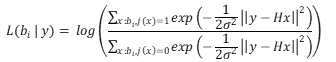
Softmax 출력값이 네거티브 Log-Likelihood 값이므로, One-Hot기반 LLR 처리부(154)는 Softmax 출력값을 그대로 활용하여 하기의 수학식 11의 연산을 통해 LLR값을 상출할 수도 있다.Since the Softmax output value is a negative Log-Likelihood value, the One-Hot-based LLR processing unit 154 may use the Softmax output value as it is to generate the LLR value through the operation of Equation 11 below.

이후, 채널 복호화기(155)는 LDPC 디코딩하여 최종적으로 채널 복호화된 비트의 데이터를 출력할 수 있다. Thereafter, the channel decoder 155 may perform LDPC decoding to finally output channel-decoded bit data.
본 명세서에 개시된 실시예들과 관련하여 설명된 방법 또는 알고리즘의 단계는 프로세서에 의해 실행되는 하드웨어, 소프트웨어 모듈, 또는 그 2 개의 결합으로 직접 구현될 수 있다. 소프트웨어 모듈은 RAM 메모리, 플래시 메모리, ROM 메모리, EPROM 메모리, EEPROM 메모리, 레지스터, 하드 디스크, 착탈형 디스크, CD-ROM과 같은 저장 매체(즉, 메모리 및/또는 스토리지)에 상주할 수도 있다. 예시적인 저장 매체는 프로세서에 커플링되며, 그 프로세서는 저장 매체로부터 정보를 판독할 수 있고 저장 매체에 정보를 기입할 수 있다. 다른 방법으로, 저장 매체는 프로세서와 일체형일 수도 있다. 프로세서 및 저장 매체는 주문형 집적회로(ASIC) 내에 상주할 수도 있다. ASIC는 사용자 단말기 내에 상주할 수도 있다. 다른 방법으로, 프로세서 및 저장 매체는 사용자 단말기 내에 개별 컴포넌트로서 상주할 수도 있다.The steps of a method or algorithm described in connection with the embodiments disclosed herein may be directly implemented in hardware, a software module executed by a processor, or a combination of the two. A software module may reside in a storage medium (ie, memory and/or storage) such as RAM memory, flash memory, ROM memory, EPROM memory, EEPROM memory, registers, hard disk, a removable disk, a CD-ROM. An exemplary storage medium is coupled to the processor, the processor capable of reading information from, and writing information to, the storage medium. Alternatively, the storage medium may be integral with the processor. The processor and storage medium may reside within an application specific integrated circuit (ASIC). The ASIC may reside within the user terminal. Alternatively, the processor and storage medium may reside as separate components within the user terminal.
본 개시의 예시적인 방법들은 설명의 명확성을 위해서 동작의 시리즈로 표현되어 있지만, 이는 단계가 수행되는 순서를 제한하기 위한 것은 아니며, 필요한 경우에는 각각의 단계가 동시에 또는 상이한 순서로 수행될 수도 있다. 본 개시에 따른 방법을 구현하기 위해서, 예시하는 단계에 추가적으로 다른 단계를 포함하거나, 일부의 단계를 제외하고 나머지 단계를 포함하거나, 또는 일부의 단계를 제외하고 추가적인 다른 단계를 포함할 수도 있다.Example methods of the present disclosure are expressed as a series of operations for clarity of description, but this is not intended to limit the order in which the steps are performed, and if necessary, each step may be performed simultaneously or in a different order. In order to implement the method according to the present disclosure, other steps may be included in addition to the illustrated steps, steps may be excluded from some steps, and/or other steps may be included except for some steps.
본 개시의 다양한 실시 예는 모든 가능한 조합을 나열한 것이 아니고 본 개시의 대표적인 양상을 설명하기 위한 것이며, 다양한 실시 예에서 설명하는 사항들은 독립적으로 적용되거나 또는 둘 이상의 조합으로 적용될 수도 있다.Various embodiments of the present disclosure do not list all possible combinations, but are intended to describe representative aspects of the present disclosure, and the details described in various embodiments may be applied independently or in combination of two or more.
또한, 본 개시의 다양한 실시 예는 하드웨어, 펌웨어(firmware), 소프트웨어, 또는 그들의 결합 등에 의해 구현될 수 있다. 하드웨어에 의한 구현의 경우, 하나 또는 그 이상의 ASICs(Application Specific Integrated Circuits), DSPs(Digital Signal Processors), DSPDs(Digital Signal Processing Devices), PLDs(Programmable Logic Devices), FPGAs(Field Programmable Gate Arrays), 범용 프로세서(general processor), 컨트롤러, 마이크로 컨트롤러, 마이크로 프로세서 등에 의해 구현될 수 있다. In addition, various embodiments of the present disclosure may be implemented by hardware, firmware, software, or a combination thereof. For implementation by hardware, one or more Application Specific Integrated Circuits (ASICs), Digital Signal Processors (DSPs), Digital Signal Processing Devices (DSPDs), Programmable Logic Devices (PLDs), Field Programmable Gate Arrays (FPGAs), general purpose It may be implemented by a processor (general processor), a controller, a microcontroller, a microprocessor, and the like.
본 개시의 범위는 다양한 실시 예의 방법에 따른 동작이 장치 또는 컴퓨터 상에서 실행되도록 하는 소프트웨어 또는 머신-실행가능한 명령들(예를 들어, 운영체제, 애플리케이션, 펌웨어(firmware), 프로그램 등), 및 이러한 소프트웨어 또는 명령 등이 저장되어 장치 또는 컴퓨터 상에서 실행 가능한 비-일시적 컴퓨터-판독가능 매체(non-transitory computer-readable medium)를 포함한다. The scope of the present disclosure includes software or machine-executable instructions (eg, operating system, application, firmware, program, etc.) that cause an operation according to the method of various embodiments to be executed on a device or computer, and such software or and non-transitory computer-readable media in which instructions and the like are stored and executed on a device or computer.
Claims (1)
입력되는 신호를 LDPC(Low Density Parity Check) 방식에 기초하여 부호화하는 채널 부호화기와,
LDPC 부호화된 비트신호를 One-hot 인코딩 처리하여 One-hot 벡터를 출력하는 One-Hot 인코더와,
상기 One-hot 벡터를 입력으로 하고 변조 신호를 출력으로 하는 전송신호 학습모델을 사용하여, 상기 One-hot 벡터에 대응되는 변조 신호를 출력하는 학습기반 변조기와,
상기 변조 신호를 복소수 포맷으로 맵핑하여 MIMO 기반의 전송 신호를 출력하는 복소수 맵핑부를 포함하는 MIMO-Auto Encoder 기반의 데이터 전송 장치.In the MIMO-based data transmission device,
A channel encoder for encoding an input signal based on a Low Density Parity Check (LDPC) method;
One-hot encoder that outputs one-hot vector by one-hot encoding processing of LDPC-encoded bit signal;
a learning-based modulator for outputting a modulated signal corresponding to the one-hot vector by using a transmission signal learning model with the one-hot vector as an input and a modulated signal as an output;
and a complex number mapping unit that maps the modulated signal to a complex format and outputs a MIMO-based transmission signal.
Priority Applications (1)
| Application Number | Priority Date | Filing Date | Title |
|---|---|---|---|
| KR1020200052621A KR20210133687A (en) | 2020-04-29 | 2020-04-29 | Apparatus for transmitting data based on mimi-auto encoder |
Applications Claiming Priority (1)
| Application Number | Priority Date | Filing Date | Title |
|---|---|---|---|
| KR1020200052621A KR20210133687A (en) | 2020-04-29 | 2020-04-29 | Apparatus for transmitting data based on mimi-auto encoder |
Publications (1)
| Publication Number | Publication Date |
|---|---|
| KR20210133687A true KR20210133687A (en) | 2021-11-08 |
Family
ID=78485770
Family Applications (1)
| Application Number | Title | Priority Date | Filing Date |
|---|---|---|---|
| KR1020200052621A Withdrawn KR20210133687A (en) | 2020-04-29 | 2020-04-29 | Apparatus for transmitting data based on mimi-auto encoder |
Country Status (1)
| Country | Link |
|---|---|
| KR (1) | KR20210133687A (en) |
Cited By (1)
| Publication number | Priority date | Publication date | Assignee | Title |
|---|---|---|---|---|
| CN119814223A (en) * | 2024-11-27 | 2025-04-11 | 北京邮电大学 | Wireless communication secure transmission method, device and equipment based on deep learning |
-
2020
- 2020-04-29 KR KR1020200052621A patent/KR20210133687A/en not_active Withdrawn
Cited By (1)
| Publication number | Priority date | Publication date | Assignee | Title |
|---|---|---|---|---|
| CN119814223A (en) * | 2024-11-27 | 2025-04-11 | 北京邮电大学 | Wireless communication secure transmission method, device and equipment based on deep learning |
Similar Documents
| Publication | Publication Date | Title |
|---|---|---|
| CN114337911A (en) | Communication method based on neural network and related device | |
| CN109194425B (en) | An end-to-end information transmission system and method based on artificial intelligence | |
| EP3300547B1 (en) | Method and apparatus for low-complexity quasi-reduced state soft-output equalizer | |
| CN110753937A (en) | Data transfer network configuration | |
| CN113169752B (en) | Learning in a communication system | |
| KR20220019828A (en) | Transmission system with channel estimation based on neural networks | |
| CN114051701A (en) | Apparatus and method for machine learning assisted precoding | |
| CN114745230A (en) | OTFS signal receiving and recovering method based on deep neural network structure | |
| JP5854694B2 (en) | Receiving device, receiving method, and receiving program | |
| CN113971430A (en) | Signal detection and model training method, device, equipment and storage medium | |
| Zhao et al. | Link adaptation in underwater wireless optical communications based on deep learning | |
| CN104935370A (en) | A space-time joint modulation transmission scheme for MIMO communication system | |
| CN118041401A (en) | MIMO signal detection method, device, electronic device and storage medium | |
| CN106301496A (en) | Based on sky line options and the spatial modulation system of precoding | |
| CN106487446B (en) | It is suitable for the light space-time grid code encoding method of intensity modulated/direct-detecting mode | |
| CN116708094A (en) | Detection method, device, device and medium of multiple-input multiple-output system | |
| KR20210133687A (en) | Apparatus for transmitting data based on mimi-auto encoder | |
| CN113114603B (en) | A kind of information recovery method and device of MIMO-OFDM system | |
| US8578229B1 (en) | High-throughput pipelined and scalable architecture for a K-Best MIMO detector | |
| WO2021151477A1 (en) | A receiver for a communication system | |
| CN115694518A (en) | Convolutional code decoding method and system based on GMM-HMM | |
| US9059828B1 (en) | Full search MIMO detector for recovering single or multiple data stream in a multiple antenna receiver | |
| CN115664893A (en) | Deep learning-based symbol detection method in MIMO communication system | |
| CN115941002B (en) | Artificial intelligence assisted MIMO detection method | |
| JP7136028B2 (en) | Wireless communication system, repeater and receiver |
Legal Events
| Date | Code | Title | Description |
|---|---|---|---|
| PA0109 | Patent application |
St.27 status event code: A-0-1-A10-A12-nap-PA0109 |
|
| PG1501 | Laying open of application |
St.27 status event code: A-1-1-Q10-Q12-nap-PG1501 |
|
| R17-X000 | Change to representative recorded |
St.27 status event code: A-3-3-R10-R17-oth-X000 |
|
| PC1203 | Withdrawal of no request for examination |
St.27 status event code: N-1-6-B10-B12-nap-PC1203 |