KR20210118768A - Method of processing a video and device therefor - Google Patents
Method of processing a video and device therefor Download PDFInfo
- Publication number
- KR20210118768A KR20210118768A KR1020210037489A KR20210037489A KR20210118768A KR 20210118768 A KR20210118768 A KR 20210118768A KR 1020210037489 A KR1020210037489 A KR 1020210037489A KR 20210037489 A KR20210037489 A KR 20210037489A KR 20210118768 A KR20210118768 A KR 20210118768A
- Authority
- KR
- South Korea
- Prior art keywords
- filter
- block
- information
- adaptive loop
- unit
- Prior art date
- Legal status (The legal status is an assumption and is not a legal conclusion. Google has not performed a legal analysis and makes no representation as to the accuracy of the status listed.)
- Ceased
Links
- 238000000034 method Methods 0.000 title claims abstract description 154
- 238000012545 processing Methods 0.000 title description 39
- 230000003044 adaptive effect Effects 0.000 claims abstract description 89
- 238000001914 filtration Methods 0.000 claims abstract description 31
- 238000013507 mapping Methods 0.000 claims description 10
- 230000009466 transformation Effects 0.000 description 33
- 230000006870 function Effects 0.000 description 18
- 238000009795 derivation Methods 0.000 description 17
- 238000010586 diagram Methods 0.000 description 15
- 238000013139 quantization Methods 0.000 description 10
- 229910003460 diamond Inorganic materials 0.000 description 7
- 239000010432 diamond Substances 0.000 description 7
- 230000008569 process Effects 0.000 description 7
- 208000037170 Delayed Emergence from Anesthesia Diseases 0.000 description 5
- 238000012937 correction Methods 0.000 description 5
- 230000008859 change Effects 0.000 description 4
- 230000011664 signaling Effects 0.000 description 4
- 230000006835 compression Effects 0.000 description 3
- 238000007906 compression Methods 0.000 description 3
- 238000009499 grossing Methods 0.000 description 3
- 230000008707 rearrangement Effects 0.000 description 3
- 238000005070 sampling Methods 0.000 description 3
- 241000023320 Luma <angiosperm> Species 0.000 description 2
- 230000005540 biological transmission Effects 0.000 description 2
- 239000000470 constituent Substances 0.000 description 2
- 230000000694 effects Effects 0.000 description 2
- 230000006872 improvement Effects 0.000 description 2
- 239000003550 marker Substances 0.000 description 2
- OSWPMRLSEDHDFF-UHFFFAOYSA-N methyl salicylate Chemical compound COC(=O)C1=CC=CC=C1O OSWPMRLSEDHDFF-UHFFFAOYSA-N 0.000 description 2
- 238000005192 partition Methods 0.000 description 2
- 230000011218 segmentation Effects 0.000 description 2
- 238000006243 chemical reaction Methods 0.000 description 1
- 230000007423 decrease Effects 0.000 description 1
- 230000003247 decreasing effect Effects 0.000 description 1
- 238000012423 maintenance Methods 0.000 description 1
- 238000012986 modification Methods 0.000 description 1
- 230000004048 modification Effects 0.000 description 1
- 230000036651 mood Effects 0.000 description 1
- 230000003287 optical effect Effects 0.000 description 1
- 238000005457 optimization Methods 0.000 description 1
- 230000001151 other effect Effects 0.000 description 1
- 238000003672 processing method Methods 0.000 description 1
- 238000010845 search algorithm Methods 0.000 description 1
Images


Classifications
-
- H—ELECTRICITY
- H04—ELECTRIC COMMUNICATION TECHNIQUE
- H04N—PICTORIAL COMMUNICATION, e.g. TELEVISION
- H04N19/00—Methods or arrangements for coding, decoding, compressing or decompressing digital video signals
- H04N19/10—Methods or arrangements for coding, decoding, compressing or decompressing digital video signals using adaptive coding
- H04N19/102—Methods or arrangements for coding, decoding, compressing or decompressing digital video signals using adaptive coding characterised by the element, parameter or selection affected or controlled by the adaptive coding
- H04N19/117—Filters, e.g. for pre-processing or post-processing
-
- H—ELECTRICITY
- H04—ELECTRIC COMMUNICATION TECHNIQUE
- H04N—PICTORIAL COMMUNICATION, e.g. TELEVISION
- H04N19/00—Methods or arrangements for coding, decoding, compressing or decompressing digital video signals
- H04N19/10—Methods or arrangements for coding, decoding, compressing or decompressing digital video signals using adaptive coding
- H04N19/102—Methods or arrangements for coding, decoding, compressing or decompressing digital video signals using adaptive coding characterised by the element, parameter or selection affected or controlled by the adaptive coding
- H04N19/132—Sampling, masking or truncation of coding units, e.g. adaptive resampling, frame skipping, frame interpolation or high-frequency transform coefficient masking
-
- H—ELECTRICITY
- H04—ELECTRIC COMMUNICATION TECHNIQUE
- H04N—PICTORIAL COMMUNICATION, e.g. TELEVISION
- H04N19/00—Methods or arrangements for coding, decoding, compressing or decompressing digital video signals
- H04N19/10—Methods or arrangements for coding, decoding, compressing or decompressing digital video signals using adaptive coding
- H04N19/169—Methods or arrangements for coding, decoding, compressing or decompressing digital video signals using adaptive coding characterised by the coding unit, i.e. the structural portion or semantic portion of the video signal being the object or the subject of the adaptive coding
- H04N19/17—Methods or arrangements for coding, decoding, compressing or decompressing digital video signals using adaptive coding characterised by the coding unit, i.e. the structural portion or semantic portion of the video signal being the object or the subject of the adaptive coding the unit being an image region, e.g. an object
- H04N19/176—Methods or arrangements for coding, decoding, compressing or decompressing digital video signals using adaptive coding characterised by the coding unit, i.e. the structural portion or semantic portion of the video signal being the object or the subject of the adaptive coding the unit being an image region, e.g. an object the region being a block, e.g. a macroblock
-
- H—ELECTRICITY
- H04—ELECTRIC COMMUNICATION TECHNIQUE
- H04N—PICTORIAL COMMUNICATION, e.g. TELEVISION
- H04N19/00—Methods or arrangements for coding, decoding, compressing or decompressing digital video signals
- H04N19/80—Details of filtering operations specially adapted for video compression, e.g. for pixel interpolation
- H04N19/82—Details of filtering operations specially adapted for video compression, e.g. for pixel interpolation involving filtering within a prediction loop
-
- H—ELECTRICITY
- H04—ELECTRIC COMMUNICATION TECHNIQUE
- H04N—PICTORIAL COMMUNICATION, e.g. TELEVISION
- H04N19/00—Methods or arrangements for coding, decoding, compressing or decompressing digital video signals
- H04N19/85—Methods or arrangements for coding, decoding, compressing or decompressing digital video signals using pre-processing or post-processing specially adapted for video compression
Landscapes
- Engineering & Computer Science (AREA)
- Multimedia (AREA)
- Signal Processing (AREA)
- Compression Or Coding Systems Of Tv Signals (AREA)
Abstract
본 개시에 따른 영상 복호화 방법은, 현재 블록에 적응적 루프 필터를 적용할 것인지 여부를 결정하는 단계, 상기 적응적 루프 필터가 적용되는 경우, 상기 적응적 루프 필터가 선형성을 갖는지 또는 비선형성을 갖는지 여부를 결정하는 단계, 상기 적응적 루프 필터의 필터 계수 세트를 결정하는 단계, 및 상기 필터 계수 세트를 이용하여, 상기 현재 블록 내 복원 샘플을 필터링하는 단계를 포함한다.An image decoding method according to the present disclosure includes determining whether to apply an adaptive loop filter to a current block, and when the adaptive loop filter is applied, whether the adaptive loop filter has linearity or nonlinearity determining whether or not there is, determining a filter coefficient set of the adaptive loop filter, and filtering reconstructed samples in the current block by using the filter coefficient set.
Description
본 개시는 비디오 신호 처리 방법 및 장치에 관한 것이다.The present disclosure relates to a video signal processing method and apparatus.
최근 HD(High Definition) 영상 및 UHD(Ultra High Definition) 영상과 같은 고해상도, 고품질의 영상에 대한 수요가 다양한 응용 분야에서 증가하고 있다. 영상 데이터가 고해상도, 고품질이 될수록 기존의 영상 데이터에 비해 상대적으로 데이터량이 증가하기 때문에 기존의 유무선 광대역 회선과 같은 매체를 이용하여 영상 데이터를 전송하거나 기존의 저장 매체를 이용해 저장하는 경우, 전송 비용과 저장 비용이 증가하게 된다. 영상 데이터가 고해상도, 고품질화 됨에 따라 발생하는 이러한 문제들을 해결하기 위해서는 고효율의 영상 압축 기술들이 활용될 수 있다.Recently, demand for high-resolution and high-quality images such as HD (High Definition) images and UHD (Ultra High Definition) images is increasing in various application fields. As the image data becomes higher resolution and higher quality, the amount of data relatively increases compared to the existing image data. storage costs will increase. High-efficiency image compression techniques can be used to solve these problems that occur as image data becomes high-resolution and high-quality.
영상 압축 기술로 현재 픽쳐의 이전 또는 이후 픽쳐로부터 현재 픽쳐에 포함된 화소값을 예측하는 화면 간 예측 기술, 현재 픽쳐 내의 화소 정보를 이용하여 현재 픽쳐에 포함된 화소값을 예측하는 화면 내 예측 기술, 출현 빈도가 높은 값에 짧은 부호를 할당하고 출현 빈도가 낮은 값에 긴 부호를 할당하는 엔트로피 부호화 기술 등 다양한 기술이 존재하고 이러한 영상 압축 기술을 이용해 영상 데이터를 효과적으로 압축하여 전송 또는 저장할 수 있다.Inter-screen prediction technology that predicts pixel values included in the current picture from pictures before or after the current picture with image compression technology, intra-picture prediction technology that predicts pixel values included in the current picture using pixel information in the current picture, Various techniques exist, such as entropy encoding technology in which a short code is assigned to a value with a high frequency of occurrence and a long code is assigned to a value with a low frequency of occurrence.
한편, 고해상도 영상에 대한 수요가 증가함과 함께, 새로운 영상 서비스로서 입체 영상 컨텐츠에 대한 수요도 함께 증가하고 있다. 고해상도 및 초고해상도의 입체 영상 콘텐츠를 효과적으로 제공하기 위한 비디오 압축 기술에 대하여 논의가 진행되고 있다.Meanwhile, as the demand for high-resolution images increases, the demand for stereoscopic image content as a new image service is also increasing. A video compression technique for effectively providing high-resolution and ultra-high-resolution stereoscopic image content is being discussed.
본 개시는 비디오 신호를 부호화/복호화함에 있어서, 인루프 필터를 적용하는 방법 및 이를 위한 장치를 제공하는 것을 목적으로 한다. An object of the present disclosure is to provide a method and an apparatus for applying an in-loop filter in encoding/decoding a video signal.
본 개시는 비디오 신호를 부호화/복호화함에 있어서, 비선형 적응적 루프 필터를 적용하는 방법 및 이를 위한 장치를 제공하는 것을 목적으로 한다. An object of the present disclosure is to provide a method and an apparatus for applying a nonlinear adaptive loop filter in encoding/decoding a video signal.
본 개시는 비디오 신호를 부호화/복호화함에 있어서, 다양한 적응적 루프 필터의 적용 방법들을 제공하는 한편, 각 적응적 루프 필터 적용 방법 하에서 필터 계수들을 결정하는 방법 및 이를 위한 장치를 제공하는 것을 목적으로 한다.An object of the present disclosure is to provide a method of applying various adaptive loop filters in encoding/decoding a video signal, and a method for determining filter coefficients under each adaptive loop filter application method and an apparatus therefor. .
본 개시에서 이루고자 하는 기술적 과제들은 이상에서 언급한 기술적 과제들로 제한되지 않으며, 언급하지 않은 또 다른 기술적 과제들은 아래의 기재로부터 본 개시가 속하는 기술분야에서 통상의 지식을 가진 자에게 명확하게 이해될 수 있을 것이다.The technical problems to be achieved in the present disclosure are not limited to the technical problems mentioned above, and other technical problems not mentioned will be clearly understood by those of ordinary skill in the art to which the present disclosure belongs from the description below. will be able
본 개시에 따른 비디오 신호 복호화 방법은, 현재 블록에 적응적 루프 필터를 적용할 것인지 여부를 결정하는 단계, 상기 적응적 루프 필터가 적용되는 경우, 상기 적응적 루프 필터가 선형성을 갖는지 또는 비선형성을 갖는지 여부를 결정하는 단계, 상기 적응적 루프 필터의 필터 계수 세트를 결정하는 단계, 및 상기 필터 계수 세트를 이용하여, 상기 현재 블록 내 복원 샘플을 필터링하는 단계를 포함한다.A video signal decoding method according to the present disclosure includes determining whether to apply an adaptive loop filter to a current block, and determining whether the adaptive loop filter has linearity or nonlinearity when the adaptive loop filter is applied. determining whether or not there is a filter coefficient set of the adaptive loop filter, and filtering reconstructed samples in the current block by using the filter coefficient set.
본 개시에 따른 비디오 신호 부호화 방법은, 현재 블록에 적응적 루프 필터를 적용할 것인지 여부를 결정하는 단계, 상기 적응적 루프 필터가 적용되는 경우, 상기 적응적 루프 필터가 선형성을 갖는지 또는 비선형성을 갖는지 여부를 결정하는 단계, 상기 적응적 루프 필터의 필터 계수 세트를 결정하는 단계, 및 상기 필터 계수 세트를 이용하여, 상기 현재 블록 내 복원 샘플을 필터링하는 단계를 포함한다.A video signal encoding method according to the present disclosure includes determining whether to apply an adaptive loop filter to a current block, and determining whether the adaptive loop filter has linearity or nonlinearity when the adaptive loop filter is applied. determining whether or not there is, determining a filter coefficient set of the adaptive loop filter, and filtering reconstructed samples in the current block by using the filter coefficient set.
본 개시에 따른 비디오 신호 복호화 방법에 있어서, 상기 적응적 루프 필터가 비선형성을 갖는 것으로 결정되는 경우, 상기 필터링은, 상기 복원 샘플과 주변 복원 샘플 사이의 차분에 클리핑 함수를 적용하여 수행되고, 상기 클리핑 함수 적용을 위한 클리핑 값은 복수의 클리핑 값 후보들 중 하나를 특정하는 인덱스에 의해 결정될 수 있다. In the video signal decoding method according to the present disclosure, when it is determined that the adaptive loop filter has nonlinearity, the filtering is performed by applying a clipping function to a difference between the reconstructed sample and a neighboring reconstructed sample, A clipping value for applying a clipping function may be determined by an index specifying one of a plurality of clipping value candidates.
본 개시에 따른 비디오 신호 복호화 방법에 있어서, 상기 인덱스는, 비트스트림으로부터 복호화되는 1비트의 플래그에 의해 결정될 수 있다.In the video signal decoding method according to the present disclosure, the index may be determined by a 1-bit flag decoded from a bitstream.
본 개시에 따른 비디오 신호 복호화 방법에 있어서, 상기 클리핑 값 후보들의 개수는, 컬러 성분, 컬러 포맷 또는 비트 뎁스 중 적어도 하나에 기초하여 적응적으로 결정될 수 있다.In the video signal decoding method according to the present disclosure, the number of clipping value candidates may be adaptively determined based on at least one of a color component, a color format, and a bit depth.
본 개시에 따른 비디오 신호 복호화 방법에 있어서, 비트 뎁스와 클리핑 값 후보들 사이의 매핑 관계를 정의한 복수의 룩업 테이블들 중 하나로부터, 상기 복수의 클리핑 값 후보들이 유도될 수 있다.In the video signal decoding method according to the present disclosure, the plurality of clipping value candidates may be derived from one of a plurality of lookup tables defining a mapping relationship between bit depth and clipping value candidates.
본 개시에 따른 비디오 신호 복호화 방법에 있어서, 비트스트림으로부터 파싱되는 인덱스 정보에 의해 상기 복수의 룩업 테이블들 중 하나가 선택될 수 있다.In the video signal decoding method according to the present disclosure, one of the plurality of lookup tables may be selected by index information parsed from a bitstream.
본 개시에 따른 비디오 신호 복호화 방법에 있어서, 상기 현재 블록 내 복원 샘플들 중 기 정의된 필터 계수가 적용되는 위치에 대해서만, 상기 플래그가 복호화될 수 있다.In the video signal decoding method according to the present disclosure, the flag may be decoded only for positions to which a predefined filter coefficient is applied among the reconstructed samples in the current block.
본 개시에 따른 비디오 신호 복호화 방법에 있어서, 상기 기 정의된 필터 계수가 적용되는 위치에서만, 상기 클리핑 함수가 적용될 수 있다.In the video signal decoding method according to the present disclosure, the clipping function may be applied only at a position where the predefined filter coefficient is applied.
본 개시에 대하여 위에서 간략하게 요약된 특징들은 후술하는 본 개시의 상세한 설명의 예시적인 양상일 뿐이며, 본 개시의 범위를 제한하는 것은 아니다.The features briefly summarized above with respect to the present disclosure are merely exemplary aspects of the detailed description of the present disclosure that follows, and do not limit the scope of the present disclosure.
본 개시에 의하면, 인루프 필터를 적용함으로써, 복원 에러를 감소시킬 수 있다. According to the present disclosure, by applying the in-loop filter, it is possible to reduce the restoration error.
본 개시에 의하면, 비선형 적응적 루프 필터를 적용하는 방법을 제공함으로써, 복원 에러를 감소시킬 수 있다. According to the present disclosure, by providing a method of applying a nonlinear adaptive loop filter, it is possible to reduce a reconstruction error.
본 개시에 의하면, 다양한 적응적 루프 필터의 적용 방법들이 제공되는 한편, 각 적응적 루프 필터 적용 방법 하에서 필터 계수들을 결정하는 방법이 제공된다.According to the present disclosure, while various methods of applying an adaptive loop filter are provided, a method of determining filter coefficients under each method of applying an adaptive loop filter is provided.
본 개시에서 얻을 수 있는 효과는 이상에서 언급한 효과들로 제한되지 않으며, 언급하지 않은 또 다른 효과들은 아래의 기재로부터 본 개시가 속하는 기술분야에서 통상의 지식을 가진 자에게 명확하게 이해될 수 있을 것이다.Effects obtainable in the present disclosure are not limited to the above-mentioned effects, and other effects not mentioned may be clearly understood by those of ordinary skill in the art to which the present disclosure belongs from the description below. will be.
도 1은 본 개시의 일실시예에 따른 영상 부호화 장치를 나타낸 블록도이다.
도 2는 본 개시의 일실시예에 따른 영상 복호화 장치를 나타낸 블록도이다.
도 3은 본 개시의 일 실시예에 따른, 적응적 루프 필터의 적용 방법의 흐름도이다.
도 4는 다이아몬드형 필터의 크기를 정의한 예를 나타낸 것이다.
도 5는 사각 형태의 적응적 루프 필터가 적용되는 예를 나타낸다.
도 6은 블록 및 필터 계수 유도 영역을 예시한 도면이다.
도 7은 블록 경사도를 유도하기 위해 이용되는 샘플들의 개수를 감소시킨 예를 나타낸 도면이다.
도 8은 기하학적 변환 타입들의 예를 나타낸다.
도 9는 복원 영상이 복수의 영역들로 분할된 예를 나타낸다.
도 10는 필터가 영역의 경계를 벗어나는 경우, 필터의 적용 양상을 설명하기 위한 예시도이다.
도 11은 필터 계수들 중 일부에 대해서만 인덱스가 부호화되는 예를 나타낸다.
도 12는 블록 기반 필터 적용 방법 하에서, 계수 머징이 적용되는 예를 설명하기 위한 도면이다.
도 13은 일부 클래스에 대해, 인덱스 정보의 부호화가 생략되는 예를 나타낸 것이다.
도 14는 영역 기반 필터 적용 방법 하에서, 계수 머징이 적용되는 예를 설명하기 위한 도면이다.1 is a block diagram illustrating an image encoding apparatus according to an embodiment of the present disclosure.
2 is a block diagram illustrating an image decoding apparatus according to an embodiment of the present disclosure.
3 is a flowchart of a method of applying an adaptive loop filter according to an embodiment of the present disclosure.
4 shows an example in which the size of a diamond-shaped filter is defined.
5 shows an example in which a rectangular adaptive loop filter is applied.
6 is a diagram illustrating a block and filter coefficient derivation region.
7 is a diagram illustrating an example in which the number of samples used to derive a block gradient is reduced.
8 shows an example of geometric transformation types.
9 shows an example in which a reconstructed image is divided into a plurality of regions.
10 is an exemplary diagram for explaining an application aspect of the filter when the filter deviates from the boundary of the region.
11 shows an example in which indexes are coded for only some of filter coefficients.
12 is a diagram for explaining an example in which coefficient merging is applied under a block-based filter application method.
13 illustrates an example in which encoding of index information is omitted for some classes.
14 is a diagram for explaining an example in which coefficient merging is applied under a method of applying a region-based filter.
본 개시는 다양한 변경을 가할 수 있고 여러 가지 실시예를 가질 수 있는 바, 특정 실시예들을 도면에 예시하고 상세한 설명에 상세하게 설명하고자 한다. 그러나, 이는 본 개시를 특정한 실시 형태에 대해 한정하려는 것이 아니며, 본 개시의 사상 및 기술 범위에 포함되는 모든 변경, 균등물 내지 대체물을 포함하는 것으로 이해되어야 한다. 각 도면을 설명하면서 유사한 참조부호를 유사한 구성요소에 대해 사용하였다.Since the present disclosure can make various changes and can have various embodiments, specific embodiments are illustrated in the drawings and described in detail in the detailed description. However, this is not intended to limit the present disclosure to specific embodiments, and should be understood to include all modifications, equivalents and substitutes included in the spirit and scope of the present disclosure. In describing each figure, like reference numerals have been used for like elements.
제1, 제2 등의 용어는 다양한 구성요소들을 설명하는데 사용될 수 있지만, 상기 구성요소들은 상기 용어들에 의해 한정되어서는 안 된다. 상기 용어들은 하나의 구성요소를 다른 구성요소로부터 구별하는 목적으로만 사용된다. 예를 들어, 본 개시의 권리 범위를 벗어나지 않으면서 제1 구성요소는 제2 구성요소로 명명될 수 있고, 유사하게 제2 구성요소도 제1 구성요소로 명명될 수 있다. 및/또는 이라는 용어는 복수의 관련된 기재된 항목들의 조합 또는 복수의 관련된 기재된 항목들 중의 어느 항목을 포함한다.Terms such as first, second, etc. may be used to describe various elements, but the elements should not be limited by the terms. The above terms are used only for the purpose of distinguishing one component from another. For example, without departing from the scope of the present disclosure, a first component may be referred to as a second component, and similarly, a second component may also be referred to as a first component. and/or includes a combination of a plurality of related listed items or any of a plurality of related listed items.
어떤 구성요소가 다른 구성요소에 "연결되어" 있다거나 "접속되어"있다고 언급된 때에는, 그 다른 구성요소에 직접적으로 연결되어 있거나 또는 접속되어 있을 수도 있지만, 중간에 다른 구성요소가 존재할 수도 있다고 이해되어야 할 것이다. 반면에, 어떤 구성요소가 다른 구성요소에 "직접 연결되어"있다거나 "직접 접속되어"있다고 언급된 때에는, 중간에 다른 구성요소가 존재하지 않는 것으로 이해되어야 할 것이다.When a component is referred to as being “connected” or “connected” to another component, it is understood that the other component may be directly connected or connected to the other component, but other components may exist in between. it should be On the other hand, when it is said that a certain element is "directly connected" or "directly connected" to another element, it should be understood that no other element is present in the middle.
본 출원에서 사용한 용어는 단지 특정한 실시예를 설명하기 위해 사용된 것으로, 본 개시를 한정하려는 의도가 아니다. 단수의 표현은 문맥상 명백하게 다르게 뜻하지 않는 한, 복수의 표현을 포함한다. 본 출원에서, "포함하다" 또는 "가지다" 등의 용어는 명세서상에 기재된 특징, 숫자, 단계, 동작, 구성요소, 부품 또는 이들을 조합한 것이 존재함을 지정하려는 것이지, 하나 또는 그 이상의 다른 특징들이나 숫자, 단계, 동작, 구성요소, 부품 또는 이들을 조합한 것들의 존재 또는 부가 가능성을 미리 배제하지 않는 것으로 이해되어야 한다.The terms used in the present application are used only to describe specific embodiments, and are not intended to limit the present disclosure. The singular expression includes the plural expression unless the context clearly dictates otherwise. In the present application, terms such as “comprise” or “have” are intended to designate that a feature, number, step, operation, component, part, or combination thereof described in the specification exists, but one or more other features It should be understood that this does not preclude the existence or addition of numbers, steps, operations, components, parts, or combinations thereof.
이하, 첨부한 도면들을 참조하여, 본 개시의 바람직한 실시예를 보다 상세하게 설명하고자 한다. 이하, 도면상의 동일한 구성요소에 대해서는 동일한 참조부호를 사용하고 동일한 구성요소에 대해서 중복된 설명은 생략한다.Hereinafter, preferred embodiments of the present disclosure will be described in more detail with reference to the accompanying drawings. Hereinafter, the same reference numerals are used for the same components in the drawings, and repeated descriptions of the same components are omitted.
도 1은 본 개시의 일실시예에 따른 영상 부호화 장치를 나타낸 블록도이다. 1 is a block diagram illustrating an image encoding apparatus according to an embodiment of the present disclosure.
도 1을 참조하면, 영상 부호화 장치(100)는 픽쳐 분할부(110), 예측부(120, 125), 변환부(130), 양자화부(135), 재정렬부(160), 엔트로피 부호화부(165), 역양자화부(140), 역변환부(145), 필터부(150) 및 메모리(155)를 포함할 수 있다.Referring to FIG. 1 , the image encoding apparatus 100 includes a
도 1에 나타난 각 구성부들은 영상 부호화 장치에서 서로 다른 특징적인 기능들을 나타내기 위해 독립적으로 도시한 것으로, 각 구성부들이 분리된 하드웨어나 하나의 소프트웨어 구성단위로 이루어짐을 의미하지 않는다. 즉, 각 구성부는 설명의 편의상 각각의 구성부로 나열하여 포함한 것으로 각 구성부 중 적어도 두 개의 구성부가 합쳐져 하나의 구성부로 이루어지거나, 하나의 구성부가 복수개의 구성부로 나뉘어져 기능을 수행할 수 있고 이러한 각 구성부의 통합된 실시예 및 분리된 실시예도 본 개시의 본질에서 벗어나지 않는 한 본 개시의 권리범위에 포함된다.Each of the constituent units shown in FIG. 1 is independently illustrated to represent different characteristic functions in the image encoding apparatus, and does not mean that each constituent unit is composed of separate hardware or one software constituent unit. That is, each component is listed as each component for convenience of description, and at least two components of each component are combined to form one component, or one component can be divided into a plurality of components to perform a function, and each Integrated embodiments and separate embodiments of the components are also included in the scope of the present disclosure without departing from the essence of the present disclosure.
또한, 일부의 구성 요소는 본 개시에서 본질적인 기능을 수행하는 필수적인 구성 요소는 아니고 단지 성능을 향상시키기 위한 선택적 구성 요소일 수 있다. 본 개시는 단지 성능 향상을 위해 사용되는 구성 요소를 제외한 본 개시의 본질을 구현하는데 필수적인 구성부만을 포함하여 구현될 수 있고, 단지 성능 향상을 위해 사용되는 선택적 구성 요소를 제외한 필수 구성 요소만을 포함한 구조도 본 개시의 권리범위에 포함된다.In addition, some components are not essential components to perform an essential function in the present disclosure, but may be optional components for merely improving performance. The present disclosure may be implemented by including only essential components to implement the essence of the present disclosure, except for components used for performance improvement, and a structure including only essential components excluding optional components used for performance improvement Also included in the scope of the present disclosure.
픽쳐 분할부(110)는 입력된 픽쳐를 적어도 하나의 처리 단위로 분할할 수 있다. 이때, 처리 단위는 예측 단위(Prediction Unit: PU)일 수도 있고, 변환 단위(Transform Unit: TU)일 수도 있으며, 부호화 단위(Coding Unit: CU)일 수도 있다. 픽쳐 분할부(110)에서는 하나의 픽쳐에 대해 복수의 부호화 단위, 예측 단위 및 변환 단위의 조합으로 분할하고 소정의 기준(예를 들어, 비용 함수)으로 하나의 부호화 단위, 예측 단위 및 변환 단위 조합을 선택하여 픽쳐를 부호화 할 수 있다.The
예를 들어, 하나의 픽쳐는 복수개의 부호화 단위로 분할될 수 있다. 픽쳐에서 부호화 단위를 분할하기 위해서는 쿼드 트리(Quad Tree), 터너리 트리 (Ternary Tree), 또는 바이너리 트리(Binary Tree) 와 같은 재귀적인 트리 구조를 사용할 수 있는데 하나의 영상 또는 최대 크기 부호화 단위(largest coding unit)를 루트로 하여 다른 부호화 단위로 분할되는 부호화 유닛은 분할된 부호화 단위의 개수만큼의 자식 노드를 가지고 분할될 수 있다. 일정한 제한에 따라 더 이상 분할되지 않는 부호화 단위는 리프 노드가 된다. 일 예로, 하나의 코딩 유닛에 대해 쿼드 트리 분할이 적용되는 것으로 가정하는 경우, 하나의 부호화 단위는 최대 4개의 다른 부호화 단위로 분할될 수 있다.For example, one picture may be divided into a plurality of coding units. In order to split a coding unit in a picture, a recursive tree structure such as a quad tree, a ternary tree, or a binary tree may be used. A coding unit divided into other coding units with the coding unit as a root may be divided having as many child nodes as the number of the divided coding units. A coding unit that is no longer split according to certain restrictions becomes a leaf node. For example, when it is assumed that quad tree splitting is applied to one coding unit, one coding unit may be split into up to four different coding units.
이하, 본 개시의 실시예에서는 부호화 단위는 부호화를 수행하는 단위의 의미로 사용할 수도 있고, 복호화를 수행하는 단위의 의미로 사용할 수도 있다.Hereinafter, in an embodiment of the present disclosure, a coding unit may be used as a unit for performing encoding or may be used as a meaning for a unit for performing decoding.
예측 단위는 하나의 부호화 단위 내에서 동일한 크기의 적어도 하나의 정사각형 또는 직사각형 등의 형태를 가지고 분할된 것일 수도 있고, 하나의 부호화 단위 내에서 분할된 예측 단위 중 어느 하나의 예측 단위가 다른 하나의 예측 단위와 상이한 형태 및/또는 크기를 가지도록 분할된 것일 수도 있다.A prediction unit may be split in the form of at least one square or rectangle of the same size within one coding unit, and one prediction unit among the split prediction units within one coding unit is a prediction of another. It may be divided to have a shape and/or size different from that of the unit.
인트라 예측시, 변환 단위와 예측 단위가 동일하게 설정될 수 있다. 이때, 부호화 유닛을 복수의 변환 단위들로 분할한 뒤, 각 변환 단위마다 인트라 예측을 수행할 수도 있다. 부호화 유닛은, 수평 방향 또는 수직 방향으로 분할될 수 있다. 부호화 단위를 분할하여 생성되는 변환 단위들의 개수는 부호화 단위의 크기에 따라, 2개 또는 4개일 수 있다.In intra prediction, the transformation unit and the prediction unit may be set to be the same. In this case, after dividing the coding unit into a plurality of transform units, intra prediction may be performed for each transform unit. A coding unit may be divided in a horizontal direction or a vertical direction. The number of transformation units generated by dividing the coding unit may be 2 or 4 according to the size of the coding unit.
예측부(120, 125)는 인터 예측을 수행하는 인터 예측부(120)와 인트라 예측을 수행하는 인트라 예측부(125)를 포함할 수 있다. 부호화 단위에 대해 인터 예측을 사용할 것인지 또는 인트라 예측을 수행할 것인지를 결정하고, 각 예측 방법에 따른 구체적인 정보(예컨대, 인트라 예측 모드, 모션 벡터, 참조 픽쳐 등)를 결정할 수 있다. 이때, 예측이 수행되는 처리 단위와 예측 방법 및 구체적인 내용이 정해지는 처리 단위는 다를 수 있다. 예컨대, 예측의 방법과 예측 모드 등은 부호화 단위로 결정되고, 예측의 수행은 예측 단위 또는 변환 단위로 수행될 수도 있다. 생성된 예측 블록과 원본 블록 사이의 잔차값(잔차 블록)은 변환부(130)로 입력될 수 있다. 또한, 예측을 위해 사용한 예측 모드 정보, 모션 벡터 정보 등은 잔차값과 함께 엔트로피 부호화부(165)에서 부호화되어 복호화 장치에 전달될 수 있다. 특정한 부호화 모드를 사용할 경우, 예측부(120, 125)를 통해 예측 블록을 생성하지 않고, 원본 블록을 그대로 부호화하여 복호화부에 전송하는 것도 가능하다.The
인터 예측부(120)는 현재 픽쳐의 이전 픽쳐 또는 이후 픽쳐 중 적어도 하나의 픽쳐의 정보를 기초로 예측 단위를 예측할 수도 있고, 경우에 따라서는 현재 픽쳐 내의 부호화가 완료된 일부 영역의 정보를 기초로 예측 단위를 예측할 수도 있다. 인터 예측부(120)는 참조 픽쳐 보간부, 모션 예측부, 움직임 보상부를 포함할 수 있다. The
참조 픽쳐 보간부에서는 메모리(155)로부터 참조 픽쳐 정보를 제공받고 참조 픽쳐에서 정수 화소 이하의 화소 정보를 생성할 수 있다. 휘도 화소의 경우, 1/4 화소 단위로 정수 화소 이하의 화소 정보를 생성하기 위해 필터 계수를 달리하는 DCT 기반의 8탭 보간 필터(DCT-based Interpolation Filter)가 사용될 수 있다. 색차 신호의 경우 1/8 화소 단위로 정수 화소 이하의 화소 정보를 생성하기 위해 필터 계수를 달리하는 DCT 기반의 4탭 보간 필터(DCT-based Interpolation Filter)가 사용될 수 있다.The reference picture interpolator may receive reference picture information from the
모션 예측부는 참조 픽쳐 보간부에 의해 보간된 참조 픽쳐를 기초로 모션 예측을 수행할 수 있다. 모션 벡터를 산출하기 위한 방법으로 FBMA(Full search-based Block Matching Algorithm), TSS(Three Step Search), NTS(New Three-Step Search Algorithm) 등 다양한 방법이 사용될 수 있다. 모션 벡터는 보간된 화소를 기초로 1/2 또는 1/4 화소 단위의 모션 벡터값을 가질 수 있다. 모션 예측부에서는 모션 예측 방법을 다르게 하여 현재 예측 단위를 예측할 수 있다. 모션 예측 방법으로 스킵(Skip) 방법, 머지(Merge) 방법, AMVP(Advanced Motion Vector Prediction) 방법, 인트라 블록 카피(Intra Block Copy) 방법 등 다양한 방법이 사용될 수 있다.The motion prediction unit may perform motion prediction based on the reference picture interpolated by the reference picture interpolator. As a method for calculating the motion vector, various methods such as Full search-based Block Matching Algorithm (FBMA), Three Step Search (TSS), and New Three-Step Search Algorithm (NTS) may be used. The motion vector may have a motion vector value of 1/2 or 1/4 pixel unit based on the interpolated pixel. The motion prediction unit may predict the current prediction unit by using a different motion prediction method. Various methods, such as a skip method, a merge method, an AMVP (Advanced Motion Vector Prediction) method, an intra block copy method, etc., may be used as the motion prediction method.
인트라 예측부(125)는 현재 픽쳐 내의 화소 정보인 참조 픽셀 정보를 기초로 예측 블록을 생성할 수 있다. 복수의 참조 픽셀 라인들 중 선택된 하나로부터 참조 픽셀 정보를 유도할 수 있다. 복수의 참조 픽셀 라인들 중 N번째 참조 픽셀 라인은, 현재 블록 내 좌상단 픽셀과의 x축 차분이 N인 좌측 픽셀들 및 상기 좌상단 픽셀과의 y축 차분이 N인 상단 픽셀들을 포함할 수 있다. 현재 블록이 선택할 수 있는 참조 픽셀 라인들의 개수는, 1개, 2개, 3개 또는 4개일 수 있다.The
현재 예측 단위의 주변 블록이 인터 예측을 수행한 블록이어서, 참조 픽셀이 인터 예측을 수행한 픽셀일 경우, 인터 예측을 수행한 블록에 포함되는 참조 픽셀을 주변의 인트라 예측을 수행한 블록의 참조 픽셀 정보로 대체하여 사용할 수 있다. 즉, 참조 픽셀이 가용하지 않는 경우, 가용하지 않은 참조 픽셀 정보를 가용한 참조 픽셀들 중 적어도 하나의 정보로 대체하여 사용할 수 있다.When a neighboring block of the current prediction unit is a block on which inter prediction is performed, and thus a reference pixel is a pixel on which inter prediction is performed, a reference pixel included in the block on which inter prediction is performed is a reference pixel of the block on which intra prediction has been performed. information can be used instead. That is, when the reference pixel is not available, the unavailable reference pixel information may be replaced with information of at least one of the available reference pixels.
인트라 예측에서 예측 모드는 참조 픽셀 정보를 예측 방향에 따라 사용하는 방향성 예측 모드와 예측을 수행시 방향성 정보를 사용하지 않는 비방향성 모드를 가질 수 있다. 휘도 정보를 예측하기 위한 모드와 색차 정보를 예측하기 위한 모드가 상이할 수 있고, 색차 정보를 예측하기 위해 휘도 정보를 예측하기 위해 사용된 인트라 예측 모드 정보 또는 예측된 휘도 신호 정보를 활용할 수 있다.In intra prediction, the prediction mode may have a directional prediction mode in which reference pixel information is used according to a prediction direction and a non-directional mode in which directional information is not used when prediction is performed. A mode for predicting luminance information and a mode for predicting chrominance information may be different, and intra prediction mode information used for predicting luminance information or predicted luminance signal information may be utilized to predict chrominance information.
인트라 예측을 수행할 때 예측 단위의 크기와 변환 단위의 크기가 동일할 경우, 예측 단위의 좌측에 존재하는 픽셀, 좌측 상단에 존재하는 픽셀, 상단에 존재하는 픽셀을 기초로 예측 단위에 대한 인트라 예측을 수행할 수 있다. When intra prediction is performed, if the size of the prediction unit and the size of the transformation unit are the same, intra prediction for the prediction unit based on the pixel present on the left side, the pixel present on the upper left side, and the pixel present on the upper side of the prediction unit can be performed.
인트라 예측 방법은 예측 모드에 따라 참조 화소에 스무딩(Smoothing) 필터를 적용한 후 예측 블록을 생성할 수 있다. 선택된 참조 픽셀 라인에 따라, 스무딩 필터의 적용 여부가 결정될 수 있다. The intra prediction method may generate a prediction block after applying a smoothing filter to a reference pixel according to a prediction mode. Whether to apply the smoothing filter may be determined according to the selected reference pixel line.
인트라 예측 방법을 수행하기 위해 현재 예측 단위의 인트라 예측 모드는 현재 예측 단위의 주변에 존재하는 예측 단위의 인트라 예측 모드로부터 예측할 수 있다. 주변 예측 단위로부터 예측된 모드 정보를 이용하여 현재 예측 단위의 예측 모드를 예측하는 경우, 현재 예측 단위와 주변 예측 단위의 인트라 예측 모드가 동일하면 소정의 플래그 정보를 이용하여 현재 예측 단위와 주변 예측 단위의 예측 모드가 동일하다는 정보를 전송할 수 있고, 만약 현재 예측 단위와 주변 예측 단위의 예측 모드가 상이하면 엔트로피 부호화를 수행하여 현재 블록의 예측 모드 정보를 부호화할 수 있다.In order to perform the intra prediction method, the intra prediction mode of the current prediction unit may be predicted from the intra prediction mode of the prediction unit existing around the current prediction unit. When the prediction mode of the current prediction unit is predicted using the mode information predicted from the neighboring prediction unit, if the intra prediction mode of the current prediction unit and the neighboring prediction unit are the same, the current prediction unit and the neighboring prediction unit are used using predetermined flag information It is possible to transmit information that the prediction modes of . , and if the prediction modes of the current prediction unit and the neighboring prediction units are different from each other, entropy encoding may be performed to encode prediction mode information of the current block.
또한, 예측부(120, 125)에서 생성된 예측 단위를 기초로 예측을 수행한 예측 단위와 예측 단위의 원본 블록과 차이값인 잔차값(Residual) 정보를 포함하는 잔차 블록이 생성될 수 있다. 생성된 잔차 블록은 변환부(130)로 입력될 수 있다. In addition, a residual block including residual information, which is a difference value between a prediction unit and an original block of the prediction unit, in which prediction is performed based on the prediction unit generated by the
변환부(130)에서는 원본 블록과 예측부(120, 125)를 통해 생성된 예측 단위의 잔차값(residual)정보를 포함한 잔차 블록을 DCT(Discrete Cosine Transform), DST(Discrete Sine Transform), KLT와 같은 변환 방법을 사용하여 변환시킬 수 있다. 잔차 블록을 변환하기 위해 DCT를 적용할지, DST를 적용할지 또는 KLT를 적용할지는, 변환 단위의 크기, 변환 단위의 형태, 예측 단위의 예측 모드 또는 예측 단위의 인트라 예측 모드 정보 중 적어도 하나를 기초로 결정할 수 있다. The
양자화부(135)는 변환부(130)에서 주파수 영역으로 변환된 값들을 양자화할 수 있다. 블록에 따라 또는 영상의 중요도에 따라 양자화 계수는 변할 수 있다. 양자화부(135)에서 산출된 값은 역양자화부(140)와 재정렬부(160)에 제공될 수 있다.The
재정렬부(160)는 양자화된 잔차값에 대해 계수값의 재정렬을 수행할 수 있다.The
재정렬부(160)는 계수 스캐닝(Coefficient Scanning) 방법을 통해 2차원의 블록 형태 계수를 1차원의 벡터 형태로 변경할 수 있다. 예를 들어, 재정렬부(160)에서는 지그-재그 스캔(Zig-Zag Scan)방법을 이용하여 DC 계수부터 고주파수 영역의 계수까지 스캔하여 1차원 벡터 형태로 변경시킬 수 있다. 변환 단위의 크기 및 인트라 예측 모드에 따라 지그-재그 스캔 대신 2차원의 블록 형태 계수를 열 방향으로 스캔하는 수직 스캔, 2차원의 블록 형태 계수를 행 방향으로 스캔하는 수평 스캔, 또는 2차원의 블록 형태 계수를 대각 방향으로 스캔하는 대각 스캔이 사용될 수도 있다. 즉, 변환 단위의 크기 및 인트라 예측 모드에 따라 지그-재그 스캔, 수직 방향 스캔, 수평 방향 스캔 또는 대각 스캔 중 어떠한 스캔 방법이 사용될지 여부를 결정할 수 있다.The
엔트로피 부호화부(165)는 재정렬부(160)에 의해 산출된 값들을 기초로 엔트로피 부호화를 수행할 수 있다. 엔트로피 부호화는 예를 들어, 지수 골롬(Exponential Golomb), CAVLC(Context-Adaptive Variable Length Coding), CABAC(Context-Adaptive Binary Arithmetic Coding)과 같은 다양한 부호화 방법을 사용할 수 있다. The
엔트로피 부호화부(165)는 재정렬부(160) 및 예측부(120, 125)로부터 부호화 단위의 잔차값 계수 정보 및 블록 타입 정보, 예측 모드 정보, 분할 단위 정보, 예측 단위 정보 및 전송 단위 정보, 모션 벡터 정보, 참조 프레임 정보, 블록의 보간 정보, 필터링 정보 등 다양한 정보를 부호화할 수 있다. The
엔트로피 부호화부(165)에서는 재정렬부(160)에서 입력된 부호화 단위의 계수값을 엔트로피 부호화할 수 있다.The
역양자화부(140) 및 역변환부(145)에서는 양자화부(135)에서 양자화된 값들을 역양자화하고 변환부(130)에서 변환된 값들을 역변환한다. 역양자화부(140) 및 역변환부(145)에서 생성된 잔차값(Residual)은 예측부(120, 125)에 포함된 움직임 추정부, 움직임 보상부 및 인트라 예측부를 통해서 예측된 예측 단위와 합쳐져 복원 블록(Reconstructed Block)을 생성할 수 있다. The
필터부(150)는 디블록킹 필터, 오프셋 보정부, ALF(Adaptive Loop Filter)중 적어도 하나를 포함할 수 있다.The
디블록킹 필터는 복원된 픽쳐에서 블록간의 경계로 인해 생긴 블록 왜곡을 제거할 수 있다. 디블록킹을 수행할지 여부를 판단하기 위해 블록에 포함된 몇 개의 열 또는 행에 포함된 픽셀을 기초로 현재 블록에 디블록킹 필터 적용할지 여부를 판단할 수 있다. 블록에 디블록킹 필터를 적용하는 경우 필요한 디블록킹 필터링 강도에 따라 강한 필터(Strong Filter) 또는 약한 필터(Weak Filter)를 적용할 수 있다. 또한 디블록킹 필터를 적용함에 있어 수직 필터링 및 수평 필터링 수행시 수평 방향 필터링 및 수직 방향 필터링이 병행 처리되도록 할 수 있다.The deblocking filter may remove block distortion caused by the boundary between blocks in the reconstructed picture. In order to determine whether to perform deblocking, it may be determined whether to apply the deblocking filter to the current block based on pixels included in several columns or rows included in the block. When a deblocking filter is applied to a block, a strong filter or a weak filter can be applied according to the required deblocking filtering strength. In addition, in applying the deblocking filter, horizontal filtering and vertical filtering may be concurrently processed when performing vertical filtering and horizontal filtering.
오프셋 보정부는 디블록킹을 수행한 영상에 대해 픽셀 단위로 원본 영상과의 오프셋을 보정할 수 있다. 특정 픽쳐에 대한 오프셋 보정을 수행하기 위해 영상에 포함된 픽셀을 일정한 수의 영역으로 구분한 후 오프셋을 수행할 영역을 결정하고 해당 영역에 오프셋을 적용하는 방법 또는 각 픽셀의 에지 정보를 고려하여 오프셋을 적용하는 방법을 사용할 수 있다.The offset correcting unit may correct an offset from the original image in units of pixels with respect to the image on which the deblocking has been performed. In order to perform offset correction on a specific picture, a method of dividing pixels included in an image into a certain number of regions, determining the region to be offset and applying the offset to the region, or taking edge information of each pixel into consideration can be used to apply
ALF(Adaptive Loop Filtering)는 필터링한 복원 영상과 원래의 영상을 비교한 값을 기초로 수행될 수 있다. 영상에 포함된 픽셀을 소정의 그룹으로 나눈 후 해당 그룹에 적용될 하나의 필터를 결정하여 그룹마다 차별적으로 필터링을 수행할 수 있다. ALF를 적용할지 여부에 관련된 정보는 휘도 신호는 부호화 단위(Coding Unit, CU) 별로 전송될 수 있고, 각각의 블록에 따라 적용될 ALF 필터의 모양 및 필터 계수는 달라질 수 있다. 또한, 적용 대상 블록의 특성에 상관없이 동일한 형태(고정된 형태)의 ALF 필터가 적용될 수도 있다. Adaptive loop filtering (ALF) may be performed based on a value obtained by comparing the filtered reconstructed image and the original image. After dividing the pixels included in the image into a predetermined group, one filter to be applied to the corresponding group is determined, and filtering can be performed differentially for each group. As for information on whether to apply ALF, the luminance signal may be transmitted for each coding unit (CU), and the shape and filter coefficients of the ALF filter to be applied may vary according to each block. In addition, the ALF filter of the same type (fixed type) may be applied regardless of the characteristics of the target block.
메모리(155)는 필터부(150)를 통해 산출된 복원 블록 또는 픽쳐를 저장할 수 있고, 저장된 복원 블록 또는 픽쳐는 인터 예측을 수행 시 예측부(120, 125)에 제공될 수 있다.The
도 2는 본 개시의 일실시예에 따른 영상 복호화 장치를 나타낸 블록도이다.2 is a block diagram illustrating an image decoding apparatus according to an embodiment of the present disclosure.
도 2를 참조하면, 영상 복호화 장치(200)는 엔트로피 복호화부(210), 재정렬부(215), 역양자화부(220), 역변환부(225), 예측부(230, 235), 필터부(240), 메모리(245)가 포함될 수 있다.Referring to FIG. 2 , the image decoding apparatus 200 includes an
영상 부호화 장치에서 영상 비트스트림이 입력된 경우, 입력된 비트스트림은 영상 부호화 장치와 반대의 절차로 복호화될 수 있다.When an image bitstream is input by the image encoding apparatus, the input bitstream may be decoded by a procedure opposite to that of the image encoding apparatus.
엔트로피 복호화부(210)는 영상 부호화 장치의 엔트로피 부호화부에서 엔트로피 부호화를 수행한 것과 반대의 절차로 엔트로피 복호화를 수행할 수 있다. 예를 들어, 영상 부호화 장치에서 수행된 방법에 대응하여 지수 골롬(Exponential Golomb), CAVLC(Context-Adaptive Variable Length Coding), CABAC(Context-Adaptive Binary Arithmetic Coding)과 같은 다양한 방법이 적용될 수 있다. The
엔트로피 복호화부(210)에서는 부호화 장치에서 수행된 인트라 예측 및 인터 예측에 관련된 정보를 복호화할 수 있다.The
재정렬부(215)는 엔트로피 복호화부(210)에서 엔트로피 복호화된 비트스트림을 부호화부에서 재정렬한 방법을 기초로 재정렬을 수행할 수 있다. 1차원 벡터 형태로 표현된 계수들을 다시 2차원의 블록 형태의 계수로 복원하여 재정렬할 수 있다. 재정렬부(215)에서는 부호화부에서 수행된 계수 스캐닝에 관련된 정보를 제공받고 해당 부호화부에서 수행된 스캐닝 순서에 기초하여 역으로 스캐닝하는 방법을 통해 재정렬을 수행할 수 있다.The
역양자화부(220)는 부호화 장치에서 제공된 양자화 파라미터와 재정렬된 블록의 계수값을 기초로 역양자화를 수행할 수 있다. The
역변환부(225)는 영상 부호화 장치에서 수행한 양자화 결과에 대해 변환부에서 수행한 변환 즉, DCT, DST, 및 KLT에 대해 역변환 즉, 역 DCT, 역 DST 및 역 KLT를 수행할 수 있다. 역변환은 영상 부호화 장치에서 결정된 전송 단위를 기초로 수행될 수 있다. 영상 복호화 장치의 역변환부(225)에서는 예측 방법, 현재 블록의 크기, 형태, 예측 모드 및 인트라 예측 방향 등 복수의 정보에 따라 변환 기법(예를 들어, DCT, DST, KLT)이 선택적으로 수행될 수 있다.The
예측부(230, 235)는 엔트로피 복호화부(210)에서 제공된 예측 블록 생성 관련 정보와 메모리(245)에서 제공된 이전에 복호화된 블록 또는 픽쳐 정보를 기초로 예측 블록을 생성할 수 있다. The
전술한 바와 같이 영상 부호화 장치에서의 동작과 동일하게 인트라 예측을 수행시 예측 단위의 크기와 변환 단위의 크기가 동일할 경우, 예측 단위의 좌측에 존재하는 픽셀, 좌측 상단에 존재하는 픽셀, 상단에 존재하는 픽셀을 기초로 예측 단위에 대한 인트라 예측을 수행하지만, 인트라 예측을 수행시 예측 단위의 크기와 변환 단위의 크기가 상이할 경우, 변환 단위를 기초로 한 참조 픽셀을 이용하여 인트라 예측을 수행할 수 있다. 또한, 최소 부호화 단위에 대해서만 NxN 분할을 사용하는 인트라 예측을 사용할 수도 있다.As described above, when intra prediction is performed in the same manner as in the operation in the image encoding apparatus, when the size of the prediction unit and the size of the transformation unit are the same, the pixel present on the left side of the prediction unit, the pixel present on the upper left side, and the upper Intra prediction is performed on the prediction unit based on the existing pixel, but when the size of the prediction unit and the size of the transformation unit are different when performing intra prediction, intra prediction is performed using the reference pixel based on the transformation unit can do. Also, intra prediction using NxN splitting may be used only for the smallest coding unit.
예측부(230, 235)는 예측 단위 판별부, 인터 예측부 및 인트라 예측부를 포함할 수 있다. 예측 단위 판별부는 엔트로피 복호화부(210)에서 입력되는 예측 단위 정보, 인트라 예측 방법의 예측 모드 정보, 인터 예측 방법의 모션 예측 관련 정보 등 다양한 정보를 입력 받고 현재 부호화 단위에서 예측 단위를 구분하고, 예측 단위가 인터 예측을 수행하는지 아니면 인트라 예측을 수행하는지 여부를 판별할 수 있다. 인터 예측부(230)는 영상 부호화 장치에서 제공된 현재 예측 단위의 인터 예측에 필요한 정보를 이용해 현재 예측 단위가 포함된 현재 픽쳐의 이전 픽쳐 또는 이후 픽쳐 중 적어도 하나의 픽쳐에 포함된 정보를 기초로 현재 예측 단위에 대한 인터 예측을 수행할 수 있다. 또는, 현재 예측 단위가 포함된 현재 픽쳐 내에서 기-복원된 일부 영역의 정보를 기초로 인터 예측을 수행할 수도 있다.The
인터 예측을 수행하기 위해 부호화 단위를 기준으로 해당 부호화 단위에 포함된 예측 단위의 모션 예측 방법이 스킵 모드(Skip Mode), 머지 모드(Merge 모드), AMVP 모드(AMVP Mode), 인트라 블록 카피 모드 중 어떠한 방법인지 여부를 판단할 수 있다.In order to perform inter prediction, a motion prediction method of a prediction unit included in a corresponding coding unit based on a coding unit is selected from among skip mode, merge mode, AMVP mode, and intra block copy mode. You can decide which way to go.
인트라 예측부(235)는 현재 픽쳐 내의 화소 정보를 기초로 예측 블록을 생성할 수 있다. 예측 단위가 인트라 예측을 수행한 예측 단위인 경우, 영상 부호화 장치에서 제공된 예측 단위의 인트라 예측 모드 정보를 기초로 인트라 예측을 수행할 수 있다. 인트라 예측부(235)에는 AIS(Adaptive Intra Smoothing) 필터, 참조 화소 보간부, DC 필터를 포함할 수 있다. AIS 필터는 현재 블록의 참조 화소에 필터링을 수행하는 부분으로써 현재 예측 단위의 예측 모드에 따라 필터의 적용 여부를 결정하여 적용할 수 있다. 영상 부호화 장치에서 제공된 예측 단위의 예측 모드 및 AIS 필터 정보를 이용하여 현재 블록의 참조 화소에 AIS 필터링을 수행할 수 있다. 현재 블록의 예측 모드가 AIS 필터링을 수행하지 않는 모드일 경우, AIS 필터는 적용되지 않을 수 있다.The
참조 화소 보간부는 예측 단위의 예측 모드가 참조 화소를 보간한 화소값을 기초로 인트라 예측을 수행하는 예측 단위일 경우, 참조 화소를 보간하여 정수값 이하의 화소 단위의 참조 화소를 생성할 수 있다. 현재 예측 단위의 예측 모드가 참조 화소를 보간하지 않고 예측 블록을 생성하는 예측 모드일 경우 참조 화소는 보간되지 않을 수 있다. DC 필터는 현재 블록의 예측 모드가 DC 모드일 경우 필터링을 통해서 예측 블록을 생성할 수 있다.When the prediction mode of the prediction unit is a prediction unit in which intra prediction is performed based on a pixel value obtained by interpolating the reference pixel, the reference pixel interpolator may interpolate the reference pixel to generate a reference pixel of a pixel unit having an integer value or less. When the prediction mode of the current prediction unit is a prediction mode that generates a prediction block without interpolating the reference pixel, the reference pixel may not be interpolated. The DC filter may generate the prediction block through filtering when the prediction mode of the current block is the DC mode.
복원된 블록 또는 픽쳐는 필터부(240)로 제공될 수 있다. 필터부(240)는 디블록킹 필터, 오프셋 보정부, ALF를 포함할 수 있다.The reconstructed block or picture may be provided to the
영상 부호화 장치로부터 해당 블록 또는 픽쳐에 디블록킹 필터를 적용하였는지 여부에 대한 정보 및 디블록킹 필터를 적용하였을 경우, 강한 필터를 적용하였는지 또는 약한 필터를 적용하였는지에 대한 정보를 제공받을 수 있다. 영상 복호화 장치의 디블록킹 필터에서는 영상 부호화 장치에서 제공된 디블록킹 필터 관련 정보를 제공받고 영상 복호화 장치에서 해당 블록에 대한 디블록킹 필터링을 수행할 수 있다. Information on whether a deblocking filter is applied to a corresponding block or picture and information on whether a strong filter or a weak filter is applied when the deblocking filter is applied may be provided from the image encoding apparatus. The deblocking filter of the image decoding apparatus may receive deblocking filter-related information provided from the image encoding apparatus, and the image decoding apparatus may perform deblocking filtering on the corresponding block.
오프셋 보정부는 부호화시 영상에 적용된 오프셋 보정의 종류 및 오프셋 값 정보 등을 기초로 복원된 영상에 오프셋 보정을 수행할 수 있다.The offset correction unit may perform offset correction on the reconstructed image based on the type of offset correction applied to the image during encoding, information on the offset value, and the like.
ALF는 부호화 장치로부터 제공된 ALF 적용 여부 정보, ALF 계수 정보 등을 기초로 부호화 단위에 적용될 수 있다. 이러한 ALF 정보는 특정한 파라메터 셋에 포함되어 제공될 수 있다.ALF may be applied to a coding unit based on information on whether ALF is applied, ALF coefficient information, etc. provided from the encoding apparatus. Such ALF information may be provided by being included in a specific parameter set.
메모리(245)는 복원된 픽쳐 또는 블록을 저장하여 참조 픽쳐 또는 참조 블록으로 사용할 수 있도록 할 수 있고 또한 복원된 픽쳐를 출력부로 제공할 수 있다. The
전술한 바와 같이 이하, 본 개시의 실시예에서는 설명의 편의상 코딩 유닛(Coding Unit)을 부호화 단위라는 용어로 사용하지만, 부호화뿐만 아니라 복호화를 수행하는 단위가 될 수도 있다.As described above, hereinafter, in the embodiments of the present disclosure, a coding unit is used as a term for a coding unit for convenience of description, but may also be a unit for performing decoding as well as coding.
또한, 현재 블록은, 부호화/복호화 대상 블록을 나타내는 것으로, 부호화/복호화 단계에 따라, 코딩 트리 블록(또는 코딩 트리 유닛), 부호화 블록(또는 부호화 유닛), 변환 블록(또는 변환 유닛), 예측 블록(또는 예측 유닛) 또는 인루프 필터의 적용 대상인 블록 등을 나타내는 것일 수 있다. 본 명세서에서, '유닛'은 특정 부호화/복호화 프로세스를 수행하기 위한 기본 단위를 나타내고, '블록'은 소정 크기의 화소 어레이를 나타낼 수 있다. 별도의 구분이 없는 한, '블록'과 '유닛'은 동등한 의미로 사용될 수 있다. 예컨대, 후술되는 실시예에서, 부호화 블록(코딩 블록) 및 부호화 유닛(코딩 유닛)은 상호 동등한 의미인 것으로 이해될 수 있다. In addition, the current block indicates a block to be encoded/decoded, and according to the encoding/decoding step, a coding tree block (or coding tree unit), a coding block (or a coding unit), a transform block (or a transform unit), and a prediction block (or a prediction unit) or a block to which an in-loop filter is applied. In this specification, a 'unit' may indicate a basic unit for performing a specific encoding/decoding process, and a 'block' may indicate a pixel array of a predetermined size. Unless otherwise specified, 'block' and 'unit' may be used interchangeably. For example, in the embodiments to be described below, it may be understood that the coding block (coding block) and the coding unit (coding unit) are mutually equivalent.
손실 부호화(Lossy Coding) 방식 하에서는, 복원 영역에 복원 에러가 발생하게 된다. 위와 같은, 복원 에러를 감쇄하기 위해, 복원 블록에 인루프 필터를 적용할 수 있다. 구체적으로, 디블록킹 필터(Deblocking Filter), 샘플 적응적 오프셋 필터(Sample Adaptive Offset (SAO) Filter) 또는 적응적 루프 필터 중 적어도 하나가 복원 블록에 적용될 수 있다. Under the lossy coding scheme, a restoration error occurs in the restoration area. In order to attenuate the above reconstruction error, an in-loop filter may be applied to the reconstruction block. Specifically, at least one of a deblocking filter, a sample adaptive offset filter (SAO) filter, and an adaptive loop filter may be applied to the reconstruction block.
기 정의된 순서에 따라, 인루프 필터들을 적용할 수 있다. 일 예로, 디블록킹 필터, 샘플 적응적 오프셋 필터 및 적응적 루프 필터의 순으로 필터들을 적용할 수 있다. In-loop filters may be applied according to a predefined order. As an example, the filters may be applied in the order of a deblocking filter, a sample adaptive offset filter, and an adaptive loop filter.
이때, 각 필터의 적용 여부는 독립적으로 결정될 수 있다. 일 예로, 디블록킹 필터 또는 샘플 적응적 오프셋 필터가 적용되지 않더라도, 적응적 루프 필터를 복원 블록에 적용할 수 있다.In this case, whether to apply each filter may be independently determined. For example, even if the deblocking filter or the sample adaptive offset filter is not applied, the adaptive loop filter may be applied to the reconstruction block.
또는, 필터들간 종속성을 갖도록 설정할 수도 있다. 일 예로, 복원 블록에 디블록킹 필터 또는 샘플 적응적 오프셋 필터가 적용된 경우에만, 적응적 루프 필터가 적용되도록 설정될 수 있다.Alternatively, it may be set to have dependencies between filters. As an example, the adaptive loop filter may be set to be applied only when the deblocking filter or the sample adaptive offset filter is applied to the reconstruction block.
열거된 인루프 필터들 중 적응적 루프 필터의 적용 양상에 대해 상세히 살펴보기로 한다.An application aspect of the adaptive loop filter among the listed in-loop filters will be described in detail.
도 3은 본 개시의 일 실시예에 따른, 적응적 루프 필터의 적용 방법의 흐름도이다.3 is a flowchart of a method of applying an adaptive loop filter according to an embodiment of the present disclosure.
적응적 루프 필터는, 다각 형태의 필터를 복원 블록에 적용하는 방식을 의미한다. 이하, 적응적 루프 필터의 적용 여부 결정 대상인 블록을 현재 블록이라 호칭한다.The adaptive loop filter refers to a method of applying a polygonal type filter to a reconstruction block. Hereinafter, a block to be determined whether or not to apply the adaptive loop filter is referred to as a current block.
도 3을 참조하면, 먼저, 적응적 루프 필터를 현재 블록에 적용할 것인지 여부를 결정할 수 있다(S301). 적응적 루프 필터가 적용되는지 여부를 나타내는 플래그가 부호화되어 시그날링될 수 있다. 일 예로, alf_ctb_flag는 현재 블록에 적응적 루프 필터가 적용되는지 여부를 나타낸다.Referring to FIG. 3 , first, it may be determined whether or not to apply the adaptive loop filter to the current block ( S301 ). A flag indicating whether the adaptive loop filter is applied may be encoded and signaled. As an example, alf_ctb_flag indicates whether the adaptive loop filter is applied to the current block.
적응적 루프 필터를 적용할 것인지 여부는, 코딩 트리 유닛, 코딩 유닛 또는 변환 유닛 단위로 결정될 수 있다. Whether to apply the adaptive loop filter may be determined in units of a coding tree, a coding unit, or a transform unit.
또는, 적응적 루프 필터의 적용 여부를 판단하는 블록(이하, 기준 블록)의 크기를 나타내는 정보가 비트스트림을 통해 시그날링될 수 있다. 일 예로, 상기 정보는, 슬라이스, 픽처 또는 시퀀스 레벨에서 시그날링될 수 있다. 일 예로, 상기 정보는, 코딩 트리 유닛의 크기와 기준 블록의 크기 간의 차분을 나타낼 수 있다. 일 예로, 상기 차분 정보는, 코딩 트리 유닛의 크기에 Log_2를 취한 값과, 기준 블록의 크기에 Log_2를 취한 값 사이의 차분을 나타낼 수 있다. 일 예로, 코딩 트리 유닛이 128x128 이고, 기준 블록이 32x32인 경우, 상기 차분 정보는, 2 (Log2 (132/32))로 설정될 수 있다. Alternatively, information indicating the size of a block (hereinafter, a reference block) for determining whether an adaptive loop filter is applied may be signaled through a bitstream. For example, the information may be signaled at a slice, picture, or sequence level. As an example, the information may indicate a difference between the size of the coding tree unit and the size of the reference block. For example, the difference information may indicate a difference between a value obtained by taking Log_2 as the size of a coding tree unit and a value obtained by taking Log_2 as the size of a reference block. For example, when the coding tree unit is 128x128 and the reference block is 32x32, the difference information may be set to 2 (Log 2 (132/32)).
또는, 기분 블록의 크기가 부호화기 및 복호화기에서 기 정의되어 있을 수도 있다. 일 예로, 기준 블록은 64x64로 고정된 크기를 가질 수 있다. Alternatively, the size of the mood block may be predefined in the encoder and the decoder. For example, the reference block may have a fixed size of 64x64.
적응적 루프 필터가 적용되는지 여부는 컬러 성분 마다 독립적으로 결정될 수 있다. 여기서, 컬러 성분은 휘도(Luma) 성분 또는 색차(Cb, Cr) 성분을 나타낸다. 일 예로, 상기 alf_ctb_flag가 컬러 성분 마다 부호화되어 시그날링될 수 있다.Whether the adaptive loop filter is applied may be independently determined for each color component. Here, the color component represents a luminance (Luma) component or a color difference (Cb, Cr) component. For example, the alf_ctb_flag may be encoded and signaled for each color component.
또는, 컬러 포맷에 따라, 적응적 루프 필터의 적용 여부를 컬러 성분 마다 독립적으로 결정할 것인지 여부가 결정될 수 있다. 여기서, 컬러 포맷은, 휘도 성분 및 색차 성분의 구성비(예컨대, 4:4:4, 4:2:2, 4:2:0)을 나타낸다. 예컨대, 컬러 포맷이 4:4:4인 경우, 휘도 성분 및 컬러 성분 각각에 대해 독립적으로 적응적 루프 필터의 적용 여부를 결정할 수 있다. 반면, 컬러 포맷이 4:2:2 또는 4:2:0인 경우, 휘도 성분에 대한 적응적 루프 필터의 적용 여부에 대한 결정 결과를 그대로 색차 성분에 적용할 수 있다. Alternatively, whether to independently determine whether to apply the adaptive loop filter for each color component may be determined according to a color format. Here, the color format indicates a composition ratio of a luminance component and a chrominance component (eg, 4:4:4, 4:2:2, 4:2:0). For example, when the color format is 4:4:4, it is possible to independently determine whether to apply the adaptive loop filter to each of the luminance component and the color component. On the other hand, when the color format is 4:2:2 or 4:2:0, the result of determining whether to apply the adaptive loop filter to the luminance component may be directly applied to the chrominance component.
적응적 루프 필터를 적용하기로 결정한 경우, 현재 블록에 적용할 필터를 결정할 수 있다(S302). 필터의 결정은, 필터 형태, 필터 계수 또는 필터 크기 중 적어도 하나를 결정하는 것을 나타낸다.When it is decided to apply the adaptive loop filter, a filter to be applied to the current block may be determined (S302). Determining the filter refers to determining at least one of a filter type, filter coefficients, or filter size.
필터 형태는, 다각 형태일 수 있다. 일 예로, 적응적 루프 필터는, 정방형, 비정방형, 다이아몬드형, 사다리꼴형, 마름모형 또는 십자형을 띨 수 있다.The filter shape may be a polygonal shape. For example, the adaptive loop filter may have a square shape, a non-square shape, a diamond shape, a trapezoid shape, a rhombus shape, or a cross shape.
적응적 루프 필터의 형태는 부호화기 및 복호화기에서 기 정의되어 있을 수 있다. 또는, 적응적 루프 필터의 형태를 특정하기 위한 정보가 비트스트림을 통해 시그날링될 수 있다. 일 예로, 복수개의 필터 형태 중 하나를 지시하는 인덱스 정보가 비트스트림을 통해 시그날링될 수 있다. The form of the adaptive loop filter may be predefined in the encoder and the decoder. Alternatively, information for specifying the type of the adaptive loop filter may be signaled through the bitstream. For example, index information indicating one of a plurality of filter types may be signaled through a bitstream.
또는, 컬러 성분, 컬러 포맷 또는 비트 심도 중 적어도 하나에 기초하여 필터 형태가 결정될 수 있다. Alternatively, the filter type may be determined based on at least one of a color component, a color format, or a bit depth.
일 예로, 휘도 성분 및 색차 성분에 모두 다이아몬드형 필터를 고정적으로 적용할 수 있다. 또는, 컬러 포맷이 4:4:4 또는 4:2:0인 경우에는, 휘도 성분 및 색차 성분에 모두 다이아몬드형 필터를 적용하고, 컬러 포맷이 4:2:2인 경우에는, 휘도 성분에는 다이아몬드형 필터를, 색차 성분에는 비-다이아몬드형 필터(예컨대, 사각형 필터)를 적용할 수 있다.For example, the diamond filter may be fixedly applied to both the luminance component and the chrominance component. Alternatively, when the color format is 4:4:4 or 4:2:0, diamond-shaped filters are applied to both the luminance component and the chrominance component, and when the color format is 4:2:2, diamond is applied to the luminance component. A type filter may be applied, and a non-diamond type filter (eg, a square filter) may be applied to the color difference component.
부호화기에서는, 복원 에러를 최소화하는 필터 계수들을 유도할 수 있다. 그리고, 최적의 효율을 나타내는 필터 계수들에 대한 정보를 부호화하여 복호화기로 시그날링할 수 있다. In the encoder, filter coefficients that minimize the reconstruction error can be derived. In addition, information on filter coefficients indicating optimal efficiency may be encoded and signaled to a decoder.
필터의 크기는, 필터의 수평 방향의 탭수 및 수직 방향의 탭수 중 적어도 하나에 의해 정의될 수 있다. The size of the filter may be defined by at least one of the number of taps in the horizontal direction and the number of taps in the vertical direction of the filter.
도 4는 다이아몬드형 필터의 크기를 정의한 예를 나타낸 것이다. 4 shows an example in which the size of a diamond-shaped filter is defined.
다이아몬드형 필터의 크기는, 수평 방향에 대한 최대 길이(최대 탭 수) 및 수직 방향에 대한 최대 길이(최대 탭수)로 정의될 수 있다. 일 예로, 7x7 크기의 다이아몬드형 필터는, 수평 방향에 대한 최대 길이 및 수직 방향에 대한 최대 길이가 각각 7임을 나타낸다. The size of the diamond-shaped filter may be defined as a maximum length (maximum number of taps) in a horizontal direction and a maximum length (maximum number of taps) in a vertical direction. For example, a diamond filter having a size of 7x7 indicates that the maximum length in the horizontal direction and the maximum length in the vertical direction are 7, respectively.
도 4에서는, 다이아몬드형 필터의 수평 방향의 최대 길이 및 수직 방향의 최대 길이가 동일한 것으로 예시되었다. 도시된 예와 달리, 수평 방향의 최대 길이 및 수직 방향의 최대 길이가 상이한 다이아몬드형 필터를 이용할 수도 있다.In FIG. 4 , it is illustrated that the maximum length in the horizontal direction and the maximum length in the vertical direction of the diamond-shaped filter are the same. Unlike the illustrated example, a diamond-shaped filter having a different maximum length in a horizontal direction and a maximum length in a vertical direction may be used.
컬러 성분 별로, 필터 크기를 상이하게 설정할 수 있다. 일 예로, 휘도 성분에 대해서는 7x7 크기의 다이아몬드형 필터를 이용하고, 색차 성분에 대해서는 5x5 크기의 다이아몬드형 필터를 이용할 수 있다. A filter size may be set differently for each color component. For example, a diamond-shaped filter having a size of 7x7 may be used for the luminance component and a diamond-shaped filter having a size of 5x5 may be used for the chrominance component.
또는, 컬러 포맷을 고려하여, 색차 성분에 적용되는 필터의 크기를 결정할 수 있다. 일 예로, 컬러 포맷이 4:2:0인 경우, 도 4의 (b)에 도시된 5x5 크기의 다이아몬드형 필터가 색차 성분에 적용될 수 있다. 반면, 컬러 포맷이 4:4:4인 경우, 휘도 성분과 동일한 크기의 필터, 예컨대, 도 4의 (a)에 도시된 7x7 크기의 다이아몬드형 필터가 색차 성분에 적용될 수 있다. Alternatively, the size of the filter applied to the color difference component may be determined in consideration of the color format. For example, when the color format is 4:2:0, the diamond filter of 5x5 size shown in FIG. 4B may be applied to the color difference component. On the other hand, when the color format is 4:4:4, a filter having the same size as the luminance component, for example, a 7x7 diamond filter shown in FIG. 4A may be applied to the chrominance component.
컬러 포맷이 4:2:2인 경우에도, 휘도 성분과 동일한 크기의 필터가 색차 성분에 적용될 수 있다. 또는, 컬러 포맷이 4:2:2인 경우, 휘도 성분에 적용되는 필터보다 수평 방향의 최대 길이 또는 수직 방향의 최대 길이 중 적어도 하나가 짧은 필터가 색차 성분에 적용될 수 있다. Even when the color format is 4:2:2, a filter having the same size as the luminance component may be applied to the chrominance component. Alternatively, when the color format is 4:2:2, a filter having at least one of a maximum length in a horizontal direction and a maximum length in a vertical direction shorter than a filter applied to the luminance component may be applied to the color difference component.
설명한 예와 같이, 컬러 포맷에 따라, 휘도 성분 및 색차 성분에 대해 동일한 크기의 필터를 적용할 것인지 여부가 결정될 수 있다. As in the described example, whether to apply the same size filter to the luminance component and the chrominance component may be determined according to the color format.
필터가 결정되면, 결정된 필터를 이용하여, 복원 샘플을 필터링할 수 있다(S303). 구체적으로, 복원 샘플 주변의 복원 샘플들을 이용하여, 복원 샘플을 필터링할 수 있다. 이때, 주변 복원 샘플들의 위치 및 개수는 필터 형태에 의해 결정될 수 있다. When the filter is determined, the reconstructed sample may be filtered using the determined filter (S303). Specifically, the reconstructed sample may be filtered using reconstructed samples around the reconstructed sample. In this case, the position and the number of neighboring reconstructed samples may be determined by the filter type.
도 5는 사각 형태의 적응적 루프 필터가 적용되는 예를 나타낸다.5 shows an example in which a rectangular adaptive loop filter is applied.
도 5의 예에서, I(x, y)는 적응적 루프 필터가 적용되기 전 샘플의 값을 나타내고, O(x, y)는 루프 필터가 적용된 이후 샘플의 값을 나타낸다. 다음의 수학식 1은, 도 5에 도시된 적응적 루프 필터의 적용 양상을 수식으로 나타낸 것이다.In the example of FIG. 5 , I(x, y) represents a value of a sample before the adaptive loop filter is applied, and O(x, y) represents a value of a sample after the loop filter is applied.
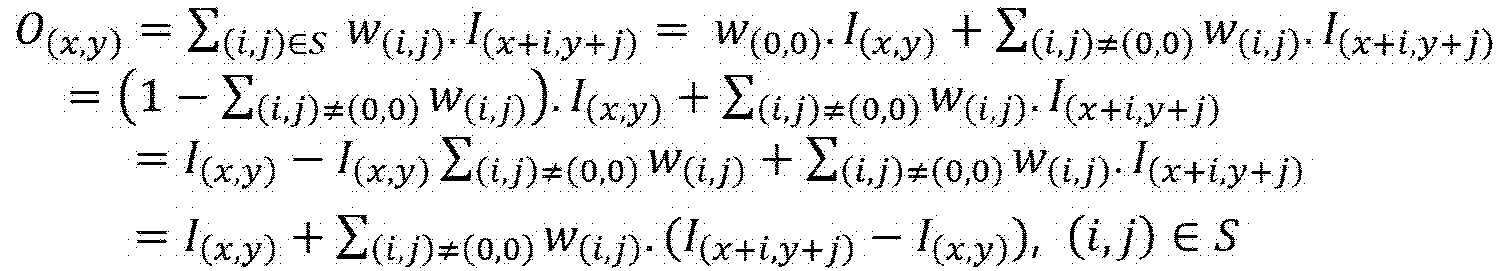
코딩 트리 유닛 단위로 적응적 루프 필터의 적용 여부가 적용되는 경우, 수학식 1에서, (x, y)는 코딩 트리 유닛 내 샘플의 좌표를 나타내고, (i, j)는 필터 형태에 따른 좌표를 나타낸다. 일 예로, 필터의 중앙 위치를 (0, 0)이라 가정하여, i 및 j의 값이 결정될 수 있다. 예컨대, 도 5에 도시된 예에서와 같이, 3x3 크기의 사각 형태 필터가 적용되는 경우, i 및 j는 각각 -1 부터 1 사이의 정수로 설정될 수 있다. 필터의 형태에 따라, i 및 j의 값의 범위가 상이할 수 있다.When whether or not the adaptive loop filter is applied in units of coding tree units, in
상기 수학식 1에서, 필터 계수들의 합(예컨대, ![]()
![]()
![]()
![]()
도 4에서는, 필터 계수들 w(i,j)를 1차원 형태의 변수 f[n]으로 표현하였다. 일 예로, 도 4의 (a)에서는, 필터 중앙 위치에 마크된 f[12]가 w(0, 0)을 나타내고, 도 4의 (b)에서는, 필터 중앙 위치에 마크된 f[6]이 w(0, 0)을 나타낸다. In FIG. 4 , filter coefficients w(i,j) are expressed as a one-dimensional variable f[n]. For example, in FIG. 4(a), f[12] marked at the filter center position represents w (0, 0) , and in FIG. 4(b), f[6] marked at the filter center position is w (0, 0) is represented.
도 4에 도시된 예에서와 같이, 하나의 필터 계수가 복수 위치에 적용될 수도 있다. 일 예로, 필터 내 필터 계수들이 대칭 형태로 분포될 수 있다. 필터 내 모든 위치에서가 아닌, 일부 위치에 대해서만, 필터 계수들을 유도할 수 있다. 필터의 대칭성을 이용하여, 잔여 위치의 필터 계수들이 유도될 수 있다. As in the example shown in FIG. 4 , one filter coefficient may be applied to a plurality of positions. As an example, filter coefficients in the filter may be distributed in a symmetrical form. It is possible to derive the filter coefficients only for some, but not all, positions in the filter. Using the symmetry of the filter, the filter coefficients of the residual position can be derived.
적응적 루프 필터 적용시, 블록 기반 필터 적용 방법 또는 영역 기반 필터 적용 방법 중 하나가 적용될 수 있다. When applying the adaptive loop filter, either a block-based filter application method or a region-based filter application method may be applied.
위 두개의 필터 적용 방법들 중 어느 것을 사용할 것인지가 부호화기 및/또는 복호화기에서 기 정의되어 있을 수 있다. 또는, 위 두개의 필터 적용 방법들 중 하나를 특정하는 정보가 부호화되어 시그날링될 수 있다. 일 예로, 상기 정보는, 슬라이스, 픽처 또는 시퀀스 등 상위 헤더를 통해 부호화될 수 있다. Which one of the above two filter application methods is to be used may be predefined in the encoder and/or the decoder. Alternatively, information specifying one of the above two filter application methods may be encoded and signaled. For example, the information may be encoded through a higher header such as a slice, a picture, or a sequence.
또는, 상기 정보는 소정 크기의 블록별(예컨대, 코딩 트리 유닛별, 코딩 블록별, 변환 블록별 또는 기준 블록별)로 부호화될 수 있다. 이 경우, 소정 크기의 블록 마다 상이한 필터 적용 방법이 적용될 수 있다.Alternatively, the information may be encoded for each block of a predetermined size (eg, for each coding tree unit, for each coding block, for each transform block, or for each reference block). In this case, a different filter application method may be applied to each block of a predetermined size.
또는, 타 인루프 필터가 적용되었는지 여부에 따라, 필터 적용 방법이 적응적으로 결정될 수 있다. 일 예로, 디블록킹 필터가 적용되었는지 여부 또는 샘플 적응적 오프셋 필터가 적용되었는지 여부 중 적어도 하나에 기초하여, 필터 적용 방법이 결정될 수 있다. Alternatively, the filter application method may be adaptively determined according to whether another in-loop filter is applied. As an example, the filter application method may be determined based on at least one of whether a deblocking filter is applied or whether a sample adaptive offset filter is applied.
블록 기반 필터 적용 방법이 적용되는 경우, 소정 크기의 블록 단위로, 필터 계수가 결정될 수 있다. 일 예로, 코딩 트리 유닛 내 기 정의된 크기(예컨대, 4x4) 크기의 블록 단위로, 필터 계수들이 결정될 수 있다. 이때, 각 블록의 필터 계수들은, 복수의 클래스 후보들 중 어느 하나와 대응하는 필터 계수 세트를 기반으로 결정될 수 있다. 블록 기반 필터 적용 방법이 적용되는 경우, 소정 크기의 블록 마다, 필터 계수 세트를 식별하기 위한 클래스가 획득될 수 있다.When the block-based filter application method is applied, filter coefficients may be determined in units of blocks of a predetermined size. As an example, filter coefficients may be determined in units of blocks having a predefined size (eg, 4x4) in the coding tree unit. In this case, the filter coefficients of each block may be determined based on a filter coefficient set corresponding to any one of the plurality of class candidates. When the block-based filter application method is applied, a class for identifying a filter coefficient set may be obtained for each block of a predetermined size.
반면, 영역 기반 필터 적용 방법이 적용되는 경우, 영역 마다 필터 계수가 결정될 수 있다. 여기서, 영역은, 코딩 트리 유닛을 나타낼 수 있다. 이 경우, 코딩 트리 유닛에 대해 하나의 필터 계수 세트가 적용될 수 있다.On the other hand, when the region-based filter application method is applied, filter coefficients may be determined for each region. Here, the region may represent a coding tree unit. In this case, one set of filter coefficients may be applied to the coding tree unit.
또는, 영역을, 타일, 슬라이스 또는 서브 픽처 등으로 정의하거나, 상술한 처리 단위들과 상이한 처리 단위로 정의할 수 있다. 이 경우, 영역에 대해 하나의 필터 계수 세트가 적용되고, 하나의 영역에 포함된 복수개의 블록들에 상기 필터 계수 세트가 공통으로 적용될 수 있다.Alternatively, the region may be defined as a tile, a slice, a sub picture, or the like, or may be defined as a processing unit different from the above-described processing units. In this case, one filter coefficient set may be applied to a region, and the filter coefficient set may be commonly applied to a plurality of blocks included in one region.
각각의 필터 적용 방법에 대해 상세히 살펴보기로 한다.Each filter application method will be described in detail.
블록 기반 필터 적용 방법이 적용되는 경우, 복원 영상을 복수개의 블록들로 분할할 수 있다. When the block-based filter application method is applied, the reconstructed image may be divided into a plurality of blocks.
이때, 블록의 크기를 나타내는 정보가 비트스트림을 통해 시그날링될 수 있다. 상기 정보는, 블록의 너비 또는 높이 중 적어도 하나를 포함할 수 있다. 블록이 정방형인 경우에는, 블록의 너비 정보 또는 블록의 높이 정보 중 하나만 부호화되어 시그날링될 수 있다. 반면, 블록이 비정방형인 경우에는, 블록의 너비 정비 및 블록의 높이 정보가 각각 부호화되어 시그날링될 수 있다. 상기 정보는, 슬라이스, 픽처 또는 시퀀스 레벨에서 부호화되어 시그날링될 수 있다. In this case, information indicating the size of the block may be signaled through the bitstream. The information may include at least one of a width or a height of a block. When the block is a square, only one of the block width information and the block height information may be encoded and signaled. On the other hand, when the block is non-square, width maintenance of the block and height information of the block may be encoded and signaled, respectively. The information may be encoded and signaled at a slice, picture, or sequence level.
블록의 형태는 부호화기 및 복호화기에서 기정의되어 있을 수 있다. 또는, 블록의 형태를 나타내는 정보가 부호화되어 시그날링될 수 있다. 일 예로, 블록의 형태가 정방형인지 또는 비정방형인지 여부를 나타내는 플래그가 부호화되어 시그날링될 수 있다.The block type may be predefined in the encoder and the decoder. Alternatively, information indicating the shape of a block may be encoded and signaled. For example, a flag indicating whether the shape of the block is a square or a non-square may be encoded and signaled.
또는, 디블록킹 필터가 적용되었는지 여부 또는 샘플 적응적 오프셋 필터가 적용되었는지 여부 중 적어도 하나에 기초하여, 블록의 크기 또는 형태 중 적어도 하나를 결정할 수도 있다. Alternatively, at least one of a size or a shape of a block may be determined based on at least one of whether a deblocking filter is applied or whether a sample adaptive offset filter is applied.
또는, 블록의 형태 또는 크기 중 적어도 하나가 부호화기 및 복호화기에 기 정의되어 있을 수도 있다. 일 예로, 필터 계수 유도를 위해, 복원 영상을, 4x4 크기의 블록들로 분할하도록 설정할 수 있다.Alternatively, at least one of the block shape and size may be predefined in the encoder and the decoder. For example, in order to derive the filter coefficients, the reconstructed image may be set to be divided into 4x4 blocks.
복원 영상을 복수개의 블록들로 분할한 뒤, 각 블록을 중심으로 필터 계수 유도 영역을 설정할 수 있다. 필터 계수 유도 영역은, 블록 및 블록 주변 N개의 라인으로 구성될 수 있다. 여기서, 라인은 행 또는 열을 나타낸다.After dividing the reconstructed image into a plurality of blocks, a filter coefficient derivation region may be set around each block. The filter coefficient derivation region may be composed of a block and N lines around the block. Here, a line represents a row or column.
일 예로, 블록의 크기가 4x4인 경우, 8x8 크기로 필터 계수 유도 영역을 정의할 수 있다. 여기서, 필터 계수 유도 영역은, 블록 및 상기 블록의 각 경계 주변의 2개의 라인을 포함할 수 있다. For example, when the size of the block is 4x4, the filter coefficient derivation region may be defined with the size of 8x8. Here, the filter coefficient derivation region may include a block and two lines around each boundary of the block.
필터 계수 유도 영역의 크기에 대한 정보가 비트스트림을 통해 시그날링될 수 있다. 일 예로, 상기 정보는, 필터 계수 유도 영역이 포함하는 블록 주변 라인의 개수(N)을 가리킬 수 있다.Information on the size of the filter coefficient derivation region may be signaled through a bitstream. For example, the information may indicate the number (N) of lines surrounding the block included in the filter coefficient derivation region.
또는, 컬러 성분, 컬러 포맷 또는 블록 크기 중 적어도 하나에 기초하여, 블록 주변 라인의 개수(N)가 적응적으로 결정될 수도 있다.Alternatively, based on at least one of a color component, a color format, or a block size, the number N of lines around the block may be adaptively determined.
도 6은 블록 및 필터 계수 유도 영역을 예시한 도면이다.6 is a diagram illustrating a block and filter coefficient derivation region.
도 6에서는, 필터 계수 유도 영역이, 4x4 크기의 블록 및 상기 블록의 경계들 각각에 인접하는 2개의 라인을 포함하는 것으로 도시되었다. 후술되는 실시예에서는, 도시된 예에서와 같이, 블록의 크기가 4x4 이고, 필터 계수 유도 영역의 크기가 8x8인 것으로 가정한다.In FIG. 6 , the filter coefficient derivation region is illustrated as including a 4×4 block and two lines adjacent to each of the boundaries of the block. In the embodiment to be described later, it is assumed that the size of the block is 4x4 and the size of the filter coefficient derivation region is 8x8, as in the illustrated example.
필터 계수 유도 영역이 결정되면, 필터 계수 유도 영역 내 블록 경사도(Gradient)를 계산할 수 있다. 구체적으로, 수평 방향, 수직 방향, 우상단 대각 방향 또는 좌상단 대각 방향 중 적어도 하나에 대한 블록 경사도를 계산할 수 있다.When the filter coefficient derivation region is determined, a gradient of a block within the filter coefficient derivation region may be calculated. Specifically, the block inclination in at least one of a horizontal direction, a vertical direction, an upper right diagonal direction, or an upper left diagonal direction may be calculated.
다음의 수학식 2는 필터 계수 유도 영역 내 경사도를 계산하는 예를 나타낸 것이다.

상기 수학식 2에서 gv는 수직 방향 블록 경사도, gh는 수평 방향 블록 경사도, gd1은 우상단 대각 방향 블록 경사도, gd2는 좌상단 대각 방향 블록 경사도를 나타낸다. In
상기 수학식 2에 나타난 예에서와 같이, 블록 경사도는, 필터 계수 유도 영역 내 샘플들 각각의 경사도를 합산하여 유도될 수 있다. 여기서, 샘플 경사도는, 복원 샘플 및 상기 복원 샘플의 인접 샘플들을 기초로 유도될 수 있다. 여기서, 인접 샘플들의 위치는 획득하고자 하는 경사도 방향에 의해 결정될 수 있다. 일 예로, 수직 방향에 대한 샘플 경사도는, 복원 샘플(수학식 2의 R(k, l)), 하단 이웃 복원 샘플(수학식 2의 R(k, l-1)) 및 상단 이웃 복원 샘플(수학식 2의 R(k, l+1))을 기초로 유도될 수 있다. 수평 방향에 대한 샘플 경사도는, 복원 샘플(수학식 2의 R(k, l)), 좌측 이웃 복원 샘플(수학식 2의 R(k-1, l)) 및 우측 이웃 복원 샘플(수학식 2의 R(k+1, l))을 기초로 유도될 수 있다.As in the example shown in
수학식 2에서, (i, j)는 블록 내 좌상단 샘플의 위치를 나타내고, R(k, l)은 (k, l)위치의 복원 샘플을 나타낸다. |x|는 x의 절대값을 나타낸다. In
이후, 블록 경사도에 기초하여, 블록의 클래스(Class)를 결정할 수 있다. 복수의 클래스 후보들 중 하나가 블록의 클래스로 선택될 수 있다. Thereafter, a class of the block may be determined based on the block gradient. One of the plurality of class candidates may be selected as the class of the block.
클래스 후보들의 개수는 부호화기 및 복호화기에서 기 정의되어 있을 수 있다. 또는, 클래스 후보들의 개수를 나타내는 정보가 부호화되어 시그날링될 수 있다. The number of class candidates may be predefined in the encoder and decoder. Alternatively, information indicating the number of class candidates may be encoded and signaled.
블록의 클래스는, 복수 방향에 대한 블록 경사도들 중 최대값, 최소값, 중간값 또는 이들의 평균값 중 적어도 하나를 기초로 결정될 수 있다. 일 예로, 수평 방향 블록 경사도 및 수직 방향 블록 경사도에 대한 크고 작음을 판단하고, 우상단 대각 방향 블록 경사도 및 좌상단 대각 방향 블록 경사도에 대한 크고 작음을 판단할 수 있다. 이후, 위 판단 결과를 참조하여 블록의 클래스를 결정할 수 있다. 이하, 설명의 편의를 위해, 수평 방향 및 수직 방향을 제1 그룹 방향이라 호칭하고, 우상단 대각 방향 및 좌상단 대각 방향을 제2 그룹 방향이라 호칭하기로 한다.The class of the block may be determined based on at least one of a maximum value, a minimum value, a median value, or an average value thereof among block gradients in a plurality of directions. As an example, it is possible to determine whether a block slope is large or small with respect to a horizontal block slope and a vertical direction block slope, and large or small with respect to an upper right diagonal block slope and an upper left diagonal block slope may be determined. Thereafter, the class of the block may be determined with reference to the above determination result. Hereinafter, for convenience of description, a horizontal direction and a vertical direction will be referred to as a first group direction, and an upper right diagonal direction and an upper left diagonal direction will be referred to as a second group direction.
하기 수학식 3은, 제1 그룹 방향의 경사도들에 대한 최소값 및 최대값을 결정하는 예를 나타낸다.
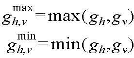
gmax h,v 는 gh 및 gv 중 큰 값을 나타내고, gmin h,v 는 gh 및 gv 중 작은 값을 나타낸다. g max h,v represents a larger value among g h and g v , and g min h,v represents a smaller value among g h and g v.
또한, 수평 방향 블록 경사도 및 수직 방향 블록 경사도를 비교하여, 제1 그룹 방향에 대한 경향성을 나타내는 변수 DirHV를 유도할 수 있다. 일 예로, 수직 방향 블록 경사도 gv가 수평 방향 블록 경사도 gh보다 큰 경우, 상기 변수 DirHV는 1로 설정될 수 있다. 반면, 수평 방향 블록 경사도 gh가 수직 방향 블록 경사도 gv보다 큰 경우, 상기 변수 DirHV은 3으로 설정될 수 있다. In addition, by comparing the horizontal block gradient and the vertical block gradient, a variable DirHV indicating a tendency toward the first group direction may be derived. For example, when the vertical block gradient g v is greater than the horizontal block gradient g h , the variable DirHV may be set to 1. On the other hand, when the horizontal block gradient g h is greater than the vertical block gradient g v , the variable DirHV may be set to 3 .
하기 수학식 4는 제2 그룹 방향의 경사도들에 대한 최소값 및 최대값을 결정하는 예를 나타낸다.
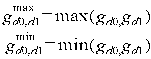
gmax d0,d1 은 gd0 및 gd1 중 큰 값을 나타내고, gmin d0,d1 은 gd0 및 gd1 중 작은 값을 나타낸다.g max d0,d1 represents a larger value among g d0 and g d1 , and g min d0,d1 represents a smaller value among g d0 and g d1 .
또한, 수평 방향 블록 경사도 및 수직 방향 블록 경사도를 비교하여, 제2 그룹 방향에 대한 경향성을 나타내는 변수 DirD를 유도할 수 있다. 일 예로, 우상단 대각 방향 블록 경사도 gd0가 수평 방향 블록 경사도 gh보다 큰 경우, 상기 변수 DirHV는 1로 설정될 수 있다. 반면, 수평 방향 블록 경사도 gh가 수직 방향 블록 경사도 gv보다 큰 경우, 상기 변수 DirHV은 3으로 설정될 수 있다. In addition, by comparing the horizontal block gradient and the vertical block gradient, a variable DirD indicating a tendency toward the second group direction may be derived. For example, when the upper right diagonal block gradient gd0 is greater than the horizontal block gradient g h , the variable DirHV may be set to 1. On the other hand, when the horizontal block gradient g h is greater than the vertical block gradient g v , the variable DirHV may be set to 3 .
각각의 블록 경사도들을 이용하여 유도된 최소값(예컨대, gmin h,v, gmin d0,d1) 및 최대값(예컨대, gmin h,v, gmin d0,d1)을 이용하여, 블록의 클래스를 결정하기 위한 변수들을 유도할 수 있다. Using the minimum (eg g min h,v , g min d0,d1 ) and maximum (eg g min h,v , g min d0,d1 ) derived using the respective block gradients, the class of the block Variables can be derived to determine
수학식 5는 블록의 클래스를 결정하기 위한 변수들을 유도하는 예를 나타낸 것이다.

상기 수학식 5에 예시된 것과 같이, 제1 그룹 방향 경사도들 중 최대값 및 제2 그룹 방향 경사도들 중 최소값을 곱한 값과, 제1 그룹 방향 경사도들 중 최소값 및 제2 그룹 방향 경사도들 중 최대값을 곱한 값을 비교하여, 변수 hvd1, hvd0, dir1 및 dir2를 유도할 수 있다. 이때, 변수 hvd0 및 hvd1은, 블록의 경사도들 중 하나와 동일하게 설정되는 변수이고, 변수 dir1 및 dir2는, 블록의 경향성과 동일하게 설정되는 변수이다. As illustrated in
수학식 5를 통해 유도된 변수들을 이용하여, 블록 전반에 걸쳐 강하게 나타나는 경향성의 방향을 나타내는 변수 dirS를 유도할 수 있다. 일 예로, 변수 dirS는 다음의 수학식 6을 기초로 유도될 수 있다.Using the variables derived through
![]()
![]()
변수 dirS가 유도되면, 이를 이용하여, 블록의 클래스를 나타내는 인덱스 ClassIdx를 유도할 수 있다. 일 예로, 변수 ClassIdx는 다음의 수학식 7을 기초로 유도될 수 있다.When the variable dirS is derived, the index ClassIdx indicating the class of the block can be derived using this. As an example, the variable ClassIdx may be derived based on
![]()
![]()
상기 수학식 7에서, Q[gh+gv]는 수평 방향의 경사도 gh 및 수직 방향의 경사도 gv의 합을 양자화하여 유도되는 값을 나타낸다. 일 예로, Q[gh+gv]는 0부터 4 사이의 값으로 출력될 수 있다.In
변수 ClassIdx는 복수의 클래스 후보들 중 하나를 지시할 수 있다. 일 예로, 블록의 클래스가 25개의 클래스 후보들 중 하나를 지시하는 경우, 변수 ClassIdx는 0부터 24사이의 값으로 설정될 수 있다. The variable ClassIdx may indicate one of a plurality of class candidates. For example, when the class of the block indicates one of 25 class candidates, the variable ClassIdx may be set to a value between 0 and 24.
블록의 클래스 결정의 간소화를 위해, 블록의 경사도 유도시 이용되는 샘플들의 범위(예컨대, 개수)를 조절할 수 있다. 일 예로, 서브 샘플링 또는 블록 경계 영역 주변 라인의 개수(N)를 감축하는 것을 통해, 블록 경사도 유도시 이용되는 샘플들의 개수를 감소시킬 수 있다.In order to simplify the determination of the class of the block, the range (eg, the number) of samples used when the gradient of the block is derived may be adjusted. As an example, the number of samples used in deriving the block gradient may be reduced by reducing the number N of lines around the sub-sampling or block boundary region.
도 7은 블록 경사도를 유도하기 위해 이용되는 샘플들의 개수를 감소시킨 예를 나타낸 도면이다. 7 is a diagram illustrating an example in which the number of samples used to derive a block gradient is reduced.
도 7에서, 마커가 표시된 샘플들은, 서브 샘플링을 통해 획득되는 샘플을 나타낸다. 마커가 표시된 샘플들만이 블록 경사도를 유도하는데 이용될 수 있다. 즉, 블록 경사도는 마커가 표시된 샘플들의 경사도를 합하여 유도될 수 있다. In FIG. 7 , samples marked with markers indicate samples obtained through subsampling. Only samples marked with a marker can be used to derive the block slope. That is, the block gradient may be derived by adding the gradients of samples marked with the marker.
일 예로, 도 7의 (a)에 도시된 예에서와 같이, 필터 계수 유도 영역 내 x좌표 및 y좌표가 모두 짝수인 샘플들 및 x좌표 및 y좌표가 모두 홀수인 샘플들만을 이용하여 블록 경사도를 유도할 수 있다. For example, as in the example shown in (a) of FIG. 7 , the block gradient using only samples in which both the x and y coordinates are even and samples in which both the x and y coordinates are odd numbers in the filter coefficient derivation region. can induce
또는, 도 7의 (b)에 도시된 예에서와 같이, 필터 계수 유도 영역이 아닌 블록의 내측에 포함된 샘플들만을 이용하여 블록 경사도를 유도할 수 있다.Alternatively, as in the example shown in FIG. 7B , the block gradient may be derived using only samples included inside the block, not the filter coefficient derivation region.
또는, 도 7의 (c)에 도시된 예에서와 같이, 블록 내 x좌표 및 y좌표가 모두 짝수인 샘플들 및 x좌표 및 y좌표가 모두 홀수인 샘플들만을 이용하여 블록 경사도를 유도할 수 있다.Alternatively, as in the example shown in (c) of FIG. 7 , the block gradient can be derived using only samples in which both the x and y coordinates are even and samples in which both the x and y coordinates are odd numbers. have.
또는, 도 7의 (d)에 도시된 예에서와 같이, 블록 내 중앙 위치의 샘플들 만을 이용하여 블록 경사도를 유도할 수 있다.Alternatively, as in the example shown in (d) of FIG. 7 , the block gradient may be derived using only samples at a central position within the block.
복수개의 간소화 방법들이 존재하는 경우, 복수개의 간소화 방법들 중 하나를 특정하는 정보가 부호화되어 시그날링될 수 있다. 이때, 상기 정보는, 시퀀스, 픽처 또는 슬라이스 등 상위 헤더를 통해 부호화될 수 있다.When there are a plurality of simplification methods, information specifying one of the plurality of simplification methods may be encoded and signaled. In this case, the information may be encoded through an upper header such as a sequence, a picture, or a slice.
또는, 서브 샘플링을 위한 샘플링 레이트를 나타내는 정보가 부호화되어 시그날링될 수 있다.Alternatively, information indicating a sampling rate for subsampling may be encoded and signaled.
또는, 컬러 성분, 컬러 포맷 또는 블록 크기에 따라 적응적으로 샘플링 레이트가 결정될 수도 있다. Alternatively, the sampling rate may be adaptively determined according to a color component, a color format, or a block size.
필터 계수 유도의 간소화를 위해, 제1 그룹 방향의 경사도들만을 이용하여 블록의 클래스를 유도하거나, 제2 그룹 방향의 경사도들만을 이용하여 블록의 클래스를 유도할 수도 있다. In order to simplify the derivation of the filter coefficients, the class of the block may be derived using only the gradients in the first group direction or the class of the block may be derived using only the gradients in the second group direction.
이때, 블록의 크기, 형태, 디블록킹 필터가 적용되었는지 여부 또는 샘플 적응적 오프셋 필터가 적용되었는지 여부 중 적어도 하나에 기초하여, 제1 그룹 방향의 경사도들만을 이용할 것인지 혹은 제2 그룹 방향의 경사도들만을 이용할 것인지 여부가 결정될 수 있다. At this time, based on at least one of the size and shape of the block, whether a deblocking filter is applied, or whether a sample adaptive offset filter is applied, whether to use only gradients in the first group direction or only gradients in the second group direction It can be decided whether or not to use
또는, 제1 그룹 방향 및 제2 그룹 방향 중 적어도 하나를 특정하는 정보가 부호화되어 시그날링될 수 있다. 상기 정보는, 제1 그룹 방향, 제2 그룹 방향 또는 제1 및 제2 그룹 방향 중 하나를 지시할 수 있다. 상기 정보에 의해 선택된 그룹 방향의 경사도들만이 블록의 클래스를 유도하는데 이용될 수 있다. Alternatively, information specifying at least one of the first group direction and the second group direction may be encoded and signaled. The information may indicate a first group direction, a second group direction, or one of the first and second group directions. Only the gradients in the group direction selected by the above information can be used to derive the class of the block.
다른 예로, 복원 영상 내 기 정의된 영역 별로, 블록 경사도를 유도하는데 이용되는 샘플들의 범위 또는 블록 클래스를 유도하는데 이용되는 방향들이 결정될 수도 있다. 여기서, 기 정의된 영역들은, 상호간 병렬 처리가 가능한 영역들을 나타낼 수 있다. 일 예로, 기 정의된 영역은, 타일, 슬라이스 또는 서브 픽처를 나타낼 수 있다.As another example, a range of samples used to derive a block gradient or directions used to derive a block class may be determined for each predefined region in the reconstructed image. Here, the predefined regions may indicate regions in which mutually parallel processing is possible. For example, the predefined region may indicate a tile, a slice, or a sub-picture.
일 예로, 기 정의된 영역 마다, 블록 클래스를 유도하는데 이용되는 방향들을 특정하는 정보가 부호화되어 시그날링될 수 있다. 이에 따라, 기 정의된 영역마다 블록 클래스를 유도하는데 이용되는 방향들이 상이할 수 있다. 일 예로, 픽처 내 첫번째 타일에서는, 제1 그룹 방향 및 제2 그룹 방향의 경사도들을 이용하여 블록 클래스가 유도되는 방면, 두번째 타일에서는, 제2 그룹 방향의 경사도들만을 이용하여 블록 클래스가 유도될 수 있다. For example, for each predefined region, information specifying directions used to derive a block class may be encoded and signaled. Accordingly, directions used to derive the block class may be different for each predefined region. For example, in the first tile in the picture, the block class is derived using gradients in the first group direction and the second group direction, and in the second tile, the block class is derived using only gradients in the second group direction. have.
블록의 클래스가 결정되면, 결정된 클래스에 대응하는 필터 계수 세트를 호출하고, 호출된 필터 계수 세트에 대한 기하학적 변환 타입을 선택할 수 있다. 구체적으로, M개의 기하학적 변환 타입들 중 하나를 선택하여, 현재 블록에 대한 필터 계수들을 유도할 수 있다.When the class of the block is determined, a filter coefficient set corresponding to the determined class may be called, and a geometric transformation type for the called filter coefficient set may be selected. Specifically, filter coefficients for the current block may be derived by selecting one of M geometric transformation types.
기하학적 변환 타입들의 개수 M을 결정하기 위한 정보가 부호화되어 시그날링될 수 있다. 상기 정보는, 슬라이스, 픽처 또는 시퀀스 등 상위 헤더를 통해 시그날링될 수 있다. 또는, 부호화기 및 복호화기에서 이용 가능한 기하학적 변환 타입들의 개수가 기 정의되어 있을 수 있다. Information for determining the number M of geometric transformation types may be encoded and signaled. The information may be signaled through an upper header such as a slice, a picture, or a sequence. Alternatively, the number of geometric transformation types usable in the encoder and the decoder may be predefined.
기하학적 변환 타입들은, 비-변환, 수직 변환, 수평 변환, 대각 변환 또는 회전 중 적어도 하나를 포함할 수 있다. 기하학 변환 타입이 선택되면, 선택된 기하학 변환 타입에서의 필터 계수 배열 순서를 따라, 필터 계수 세트에 포함된 필터 계수들을 할당할 수 있다.The geometric transformation types may include at least one of a non-transformation, a vertical transformation, a horizontal transformation, a diagonal transformation, or a rotation. When a geometric transformation type is selected, filter coefficients included in the filter coefficient set may be allocated according to an arrangement order of filter coefficients in the selected geometric transformation type.
도 8은 기하학적 변환 타입들의 예를 나타낸다.8 shows an example of geometric transformation types.
도 8에 도시된 예에서, 수직 변환 타입이 선택된 경우, 비-변환 타입 하의 필터 계수들의 위치가 수평 방향의 중심 축(예컨대, 비-변환 타입의 f9-f9)을 중심으로 반전될 수 있다.In the example shown in FIG. 8 , when the vertical transformation type is selected, the positions of filter coefficients under the non-transform type may be inverted around a central axis in the horizontal direction (eg, f9-f9 of the non-transform type).
대각 방향 변환 타입이 선택된 경우, 비-변환 타입 하의 필터 계수들의 위치가 대각 방향의 중심축(예컨대, 비-변환 타입의 f7-f7 또는 f5-f5)을 중심으로 반전될 수 있다.When the diagonal transformation type is selected, the positions of filter coefficients under the non-transform type may be inverted about a central axis in the diagonal direction (eg, f7-f7 or f5-f5 of the non-transform type).
회전 타입이 선택된 경우, 비-변환 타입 하의 필터 계수들의 위치가 시계 방향 또는 반시계 방향으로 소정 각도(예컨대, 90도)만큼 회전 배치될 수 있다.When the rotation type is selected, the positions of the filter coefficients under the non-transform type may be rotated by a predetermined angle (eg, 90 degrees) in a clockwise or counterclockwise direction.
도시되지는 않았지만, 수평 변환 타입이 선택된 경우, 비-변환 타입 하의 필터 계수들의 위치가 수직 방향의 중심축(예컨대, 비-변환 타입의 f0-f0)을 중심으로 반전될 수 있다.Although not shown, when the horizontal transform type is selected, the positions of filter coefficients under the non-transform type may be inverted around a central axis in the vertical direction (eg, f0-f0 of the non-transform type).
설명의 편의를 위해, 후술되는 실시예에서는, 이용 가능한 기하학적 변환 타입들의 개수가, 도 8의 예에 도시된 4개인 것으로 가정한다. For convenience of description, it is assumed that the number of available geometric transformation types is four shown in the example of FIG. 8 in the embodiments described below.
블록 경사도들에 기초하여 유도된 변수 dir1 및 dir2를 이용하여, 현재 블록의 기하학적 변환 타입을 결정할 수 있다. 표 1은 변수 dir1 및 dir2에 의해 기하학적 변환 타입이 결정되는 예를 나타낸 것이다.By using the variables dir1 and dir2 derived based on the block gradients, the geometric transformation type of the current block may be determined. Table 1 shows an example in which the geometric transformation type is determined by the variables dir1 and dir2.
블록 경사도들에 기초하여 유도된 변수 dir1 및 dir2를 이용하여, 현재 블록의 기하학적 변환 타입을 결정할 수 있다. 표 1은 변수 dir1 및 dir2에 의해 기하학적 변환 타입이 결정되는 예를 나타낸 것이다.제1 그룹 방향의 경사도들 또는 제2 그룹 방향의 경사도들만이 이용된 경우에는, 표 1과 상이하게 정의된 룩업 테이블이 이용될 수 있다.By using the variables dir1 and dir2 derived based on the block gradients, the geometric transformation type of the current block may be determined. Table 1 shows an example in which the geometric transformation type is determined by the variables dir1 and dir2. When only gradients in the first group direction or gradients in the second group direction are used, a lookup table defined differently from Table 1 This can be used.
또는, 부호화기 및 복호화기에 복수의 룩업 테이블들이 기 정의되어 있을 수 있다. 부호화기는, 복수의 룩업 테이블 중 하나를 특정하는 정보를 부호화하여 시그날링할 수 있다. 각각의 룩업 테이블은, 블록 경사도들(예컨대, gh, gv, gd1 또는 gd2 중 적어도 하나) 또는 상기 블록 경사도들로부터 유도되는 변수(예컨대, dir1 또는 dir2 중 적어도 하나)과 기하학적 변환 타입 사이의 대응 관계를 포함할 수 있다.Alternatively, a plurality of lookup tables may be predefined in the encoder and the decoder. The encoder may encode and signal information specifying one of a plurality of lookup tables. Each lookup table contains block gradients (eg, at least one of g h , g v , g d1 or g d2 ) or a variable derived from the block gradients (eg, at least one of dir1 or dir2 ) and a geometric transformation type. It may contain correspondences between
또는, 현재 블록의 크기, 형태, 블록 경사도들 중 최대값, 최소값, 중간값 또는 이들의 평균값, 현재 블록에 디블록킹 필터가 적용되었는지 여부 또는 현재 블록에 샘플 적응적 오프셋 필터가 적용되었는지 여부 중 적어도 하나를 고려하여, 복수개의 룩업 테이블들 중 하나가 선택될 수 있다.Or, at least among the size, shape, and block gradients of the current block, the maximum value, the minimum value, the median value, or their average value, whether the deblocking filter is applied to the current block, or whether the sample adaptive offset filter is applied to the current block Considering one, one of the plurality of lookup tables may be selected.
필터 계수 세트들은 부호화기 및 복호화기에 기 정의되어 있을 수 있다. Filter coefficient sets may be predefined in the encoder and decoder.
또는, 필수 계수 세트들 각각의 구성 정보가 비트스트림을 통해 시그날링될 수 있다. 여기서, 구성 정보는, 필터 계수 세트가 포함하는 필터 계수의 개수(즉, 필터 탭 수) 또는 필터 계수의 값 중 적어도 하나를 포함할 수 있다.Alternatively, configuration information of each of the essential coefficient sets may be signaled through a bitstream. Here, the configuration information may include at least one of the number of filter coefficients included in the filter coefficient set (ie, the number of filter taps) or the value of the filter coefficients.
이때, 기 정의된 영역 단위로, 필터 계수 세트들을 독립적으로 정의할 수 있다. 여기서, 기 정의된 영역들은 병렬 처리가 가능한 영역들을 나타낼 수 있다. 예컨대, 기 정의된 영역은, 타일, 슬라이스 또는 서브 픽처일 수 있다.In this case, filter coefficient sets may be independently defined in units of predefined regions. Here, the predefined regions may indicate regions in which parallel processing is possible. For example, the predefined region may be a tile, a slice, or a sub-picture.
일 예로, 픽처 내 타일들 각각에 대해, 필터 계수 세트들이 개별적으로 정의될 수 있다. 예컨대, 픽처가 4개의 타일들을 포함하고, 각 타일마다 25개의 클래스가 정의되어 있을 경우, 총 100개의 필터 계수 세트들에 대한 구성 정보가 상위 헤더를 통해 전송될 수 있다. 이 경우, 특정 타일에 속한 블록은 해당 타일에 대해 정의된 필터 계수 세트들 중 하나를 이용할 수 있다. As an example, for each of the tiles in the picture, filter coefficient sets may be individually defined. For example, when a picture includes 4 tiles and 25 classes are defined for each tile, configuration information for a total of 100 filter coefficient sets may be transmitted through an upper header. In this case, a block belonging to a specific tile may use one of the filter coefficient sets defined for the corresponding tile.
다음으로, 영역 기반 필터 적용 방법에 대해 살펴보기로 한다. Next, an area-based filter application method will be described.
영역 기반 필터 적용 방법이 적용되는 경우, 복원 영상을 복수개의 영역들로 분할하고, 영역 마다 필터를 결정할 수 있다. 구체적으로, 복수의 영역 각각에 대해, 필터 형태, 필터 계수 또는 필터 크기 중 적어도 하나를 결정할 수 있다.When the region-based filter application method is applied, the reconstructed image may be divided into a plurality of regions, and a filter may be determined for each region. Specifically, for each of the plurality of regions, at least one of a filter shape, a filter coefficient, or a filter size may be determined.
필터를 결정하기 위한 정보가 비트스트림을 통해 시그날링될 수 있다. 구체적으로, 필터의 형태, 필터 계수 또는 필터 크기 중 적어도 하나에 대한 정보가 부호화되어 시그날링될 수 있다. Information for determining a filter may be signaled through a bitstream. Specifically, information on at least one of a filter shape, filter coefficients, and filter size may be encoded and signaled.
영역 기반 필터 적용 방법이 적용되는 경우, 복원 영상의 분할 정보가 비트스트림을 통해 부호화되어 시그날링될 수 있다. 상기 정보는, 복원 영상이 포함하는 영역들의 개수, 영역들이 균일한 크기로 분할되는지 여부 또는 영역들의 크기 중 적어도 하나를 가리킬 수 있다. When the region-based filter application method is applied, segmentation information of a reconstructed image may be encoded and signaled through a bitstream. The information may indicate at least one of the number of regions included in the reconstructed image, whether the regions are divided into uniform sizes, or sizes of the regions.
또는, 영역들의 개수, 영역들이 균일한 크기로 분할되는지 여부 또는 영역들의 크기 중 적어도 하나가 부호화기 및 복호화기에 기 정의되어 있을 수 있다.Alternatively, at least one of the number of regions, whether regions are divided into uniform sizes, or sizes of regions may be predefined in the encoder and decoder.
또는, 픽처 해상도, 컬러 성분, 컬러 포맷 또는 HDR 영상인지 여부 중 적어도 하나에 기초하여, 영역들의 개수, 영역들이 균일한 크기로 분할되는지 여부 또는 영역들의 크기 중 적어도 하나가 적응적으로 결정될 수 있다. Alternatively, at least one of the number of regions, whether the regions are divided into uniform sizes, or sizes of the regions may be adaptively determined based on at least one of a picture resolution, a color component, a color format, or an HDR image.
또는, 픽처 내 임의 처리 단위들 각각을 하나의 영역으로 설정할 수 있다. 여기서, 처리 단위는, 타일, 슬라이스 또는 서브 픽처일 수 있다. 픽처 내 임의 처리 단위들 각각이 하나의 영역으로 설정되는 경우, 영역에 대한 분할 정보의 부호화가 생략될 수 있다.Alternatively, each of the arbitrary processing units in the picture may be set as one area. Here, the processing unit may be a tile, a slice, or a sub-picture. When each of the arbitrary processing units in the picture is set as one region, encoding of partition information for the region may be omitted.
또는, 처리 단위들 각각이 하나의 영역으로 설정되는지 여부를 나타내는 정보가 부호화되어 시그날링될 수 있다. 일 예로, 상기 정보는 1비트의 플래그일 수 있다. 상기 플래그가 1(True)인 것은, 처리 단위들 각각이 하나의 영역으로 설정됨을 나타낸다. 이 경우, 영역에 대한 분할 정보의 부호화가 생략될 수 있다. 상기 플래그가 0(False)인 것은, 처리 단위들 각각이 반드시 하나의 영역으로 설정되는 것은 아님을 나타낸다. 이 경우, 영역에 대한 분할 정보가 추가 부호화될 수 있다. Alternatively, information indicating whether each of the processing units is set as one region may be encoded and signaled. For example, the information may be a 1-bit flag. When the flag is 1 (True), it indicates that each of the processing units is set to one area. In this case, encoding of partition information for a region may be omitted. The flag being 0 (False) indicates that each of the processing units is not necessarily set to one area. In this case, segmentation information for the region may be additionally encoded.
영역의 경계가, 하나의 처리 단위를 복수개로 분할하지 않도록 설정할 수 있다. 일 예로, 적어도 하나의 코딩 트리 유닛들의 집합이 하나의 영역으로 정의될 수 있다.The boundary of the region may be set so that one processing unit is not divided into a plurality of units. As an example, a set of at least one coding tree unit may be defined as one region.
도 9는 복원 영상이 복수의 영역들로 분할된 예를 나타낸다. 9 shows an example in which a reconstructed image is divided into a plurality of regions.
영역들이 균일한 크기로 분할되는 경우, 영역들이 구성하는 행의 개수를 나타내는 정보, 영역들이 구성하는 열의 개수를 나타내는 정보 또는 영역의 크기(예컨대, 너비 또는 높이 중 적어도 하나)를 나타내는 정보 중 적어도 하나가 부호화되어 시그날링될 수 있다. When regions are divided into uniform sizes, at least one of information indicating the number of rows constituting the regions, information indicating the number of columns constituting regions, or information indicating the size (eg, at least one of width or height) of regions may be encoded and signaled.
반면, 영역들이 균일한 크기로 분할되지 않는 경우, 영역들이 구성하는 열의 개수를 나타내는 정보, 영역들이 구성하는 행의 개수를 나타내는 정보, 각 열의 너비를 나타내는 정보 또는 각 행의 높이를 나타내는 정보 중 적어도 하나가 부호화되어 시그날링될 수 있다. On the other hand, when the regions are not divided into uniform sizes, at least information indicating the number of columns constituting the regions, information indicating the number of rows constituting the regions, information indicating the width of each column, or information indicating the height of each row One may be encoded and signaled.
일 예로, 도 9에서는, 복원 영상이 균일하지 않은 크기의 영역들로 분할된 것으로 예시되었고, 복원 영상이 3개의 열 및 3개의 행으로 분할된 것으로 예시되었다. 이에 따라, 복원 영상이 균일한 크기의 영역들로 분할되었는지 여부를 나타내는 정보(예컨대, 플래그)의 값은 거짓(false)로 설정되어 부호화될 수 있다. 또한, 복원 영상이 포함하는 열의 개수는 3을 나타내도록 설정되어 부호화되고, 복원 영상이 포함하는 행의 개수는 3을 나타내도록 설정되어 부호화될 수 있다.As an example, in FIG. 9 , it is exemplified that the reconstructed image is divided into regions of non-uniform size, and the reconstructed image is exemplified as divided into three columns and three rows. Accordingly, the value of information (eg, flag) indicating whether the reconstructed image is divided into regions of uniform size may be set to false and encoded. Also, the number of columns included in the reconstructed image may be set to represent 3 and encoded, and the number of rows included in the reconstructed image may be set to represent 3 and encoded.
또한, 각 열의 너비 및 각 행의 높이에 대한 정보가 부호화되어 시그날링될 수 있다. 여기서, 열의 너비는, 해당 열에 포함된 소정의 처리 단위 열의 개수를 나타내고, 열의 높이는, 해당 열에 포함된 소정의 처리 단위 행의 개수를 나타낸다. 처리 단위가 코딩 트리 유닛인 경우, 도 9에 도시된 예에서, 첫번째 열의 너비 및 첫번째 행의 높이는 각기 4 및 3으로 설정될 수 있다.In addition, information on the width of each column and the height of each row may be encoded and signaled. Here, the column width indicates the number of predetermined processing unit columns included in the corresponding column, and the column height indicates the number of predetermined processing unit rows included in the corresponding column. When the processing unit is a coding tree unit, in the example shown in FIG. 9 , the width of the first column and the height of the first row may be set to 4 and 3, respectively.
또한, 복원 영상 내 마지막 열에 대해서는, 너비 정보의 부호화를 생략하고, 복원 영상 내 마지막 행에 대해서는, 높이 정보의 부호화를 생략할 수도 있다. Also, encoding of width information may be omitted for the last column in the reconstructed image, and encoding of height information may be omitted for the last row in the reconstructed image.
하드웨어 구현의 편의 및 메모리 절약을 위해, 영역들 간 경계에서 필터를 적용하는 것에 제약을 적용할 수 있다. 일 예로, 필터가 영역의 경계를 벗어나는 경우, 영역의 경계를 벗어나는 위치의 샘플 및/또는 이에 대칭인 위치의 샘플을 제외하고 필터링을 수행할 수 있다. For convenience of hardware implementation and memory saving, restrictions may be applied to applying a filter at the boundary between regions. As an example, when the filter is out of the boundary of the region, filtering may be performed except for a sample at a position outside the boundary of the region and/or a sample at a position symmetrical thereto.
도 10는 필터가 영역의 경계를 벗어나는 경우, 필터의 적용 양상을 설명하기 위한 예시도이다. 10 is an exemplary diagram for explaining an application aspect of the filter when the filter deviates from the boundary of the region.
도 10에 도시된 예에서, 필터 적용 대상 샘플은, 필터의 중심 위치(예컨대, f[12])에 위치한다. 이때, 상기 필터 적용 대상 샘플을 필터링하기 위한 주변 샘플이, 영역의 경계를 벗어나는 경우, 해당 주변 샘플은 이용 불가능한 것으로 설정될 수 있다.In the example shown in FIG. 10 , the sample to be applied with the filter is located at the center position of the filter (eg, f[12]). In this case, when the neighboring sample for filtering the filter application target sample is out of the boundary of the region, the neighboring sample may be set to be unavailable.
일 예로, 도 10의 (a)에 도시된 예에서, 영역의 상단 경계를 벗어나는 위치(예컨대, f[0]~f[8])의 샘플들은 필터 적용 대상 샘플을 필터링하는데 이용 불가능한 것으로 설정될 수 있다. For example, in the example shown in (a) of FIG. 10 , samples at locations (eg, f[0] to f[8]) outside the upper boundary of the region are set to be unavailable for filtering the sample to be applied. can
또한, 위 이용 불가능한 샘플과 대칭 위치의 샘플도 이용 불가능한 것으로 설정될 수 있다.In addition, the above unavailable samples and samples at symmetric positions may also be set as unavailable.
이에 따라, 도 10의 (a)에 도시된 예에서, 필터 적용 대상 샘플은, 상기 필터 적용 대상 샘플과 동일한 행에 속하는 샘플들(예컨대, f[9]~f[11] 만을 이용하여, 필터링될 수 있다.Accordingly, in the example shown in (a) of FIG. 10 , the filter application target sample is filtered using only samples belonging to the same row as the filter application target sample (eg, f[9] to f[11]). can be
또는, 이용 불가능한 샘플의 값을 디폴트값(예컨대, 0)으로 설정하거나, 이용 불가능한 샘플에 대한 필터 계수를 0으로 변환하여, 필터링을 수행할 수도 있다.Alternatively, filtering may be performed by setting a value of an unavailable sample to a default value (eg, 0) or converting a filter coefficient for an unavailable sample to 0.
도 10의 (b)에 도시된 예에서, 영역의 하단 경계를 벗어나는 위치(예컨대, f[0]~f[8])의 샘플들은 필터 적용 대상 샘플을 필터링하는데 이용 불가능한 것으로 설정될 수 있다. In the example shown in (b) of FIG. 10 , samples at positions (eg, f[0] to f[8]) outside the lower boundary of the region may be set to be unavailable for filtering the sample to be applied to the filter.
또한, 위 이용 불가능한 샘플과 대칭 위치의 샘플도 이용 불가능한 것으로 설정될 수 있다.In addition, the above unavailable samples and samples at symmetric positions may also be set as unavailable.
이에 따라, 도 10의 (b)에 도시된 예에서, 필터 적용 대상 샘플은, 상기 필터 적용 대상 샘플과 동일한 행에 속하는 샘플들(예컨대, f[9]~f[11]) 만을 이용하여, 필터링될 수 있다.Accordingly, in the example shown in (b) of FIG. 10 , the filter application target sample uses only samples belonging to the same row as the filter application target sample (eg, f[9] to f[11]), can be filtered.
또는, 이용 불가능한 샘플의 값을 디폴트값(예컨대, 0)으로 설정하거나, 이용 불가능한 샘플에 대한 필터 계수를 0으로 변환하여, 필터링을 수행할 수도 있다.Alternatively, filtering may be performed by setting a value of an unavailable sample to a default value (eg, 0) or converting a filter coefficient for an unavailable sample to 0.
영역의 상단 및 하단 경계에서는, 필터의 수평 축을 중심으로 대칭 위치의 샘플을 결정하고, 영역의 좌측 및 우측 경계에서는, 필터의 수직 축을 중심으로 대칭 위치의 샘플을 결정할 수 있다. At the upper and lower boundaries of the region, samples at a symmetric position about the horizontal axis of the filter may be determined, and at the left and right boundaries of the region, samples at a symmetric position about the vertical axis of the filter may be determined.
영역들 간 경계에서, 상술한 제약이 적용되는지 여부를 나타내는 정보가 부호화되어 시그날링될 수 있다. 일 예로, 상술한 제약이 적용되는지 여부를 나타내는 플래그가 부호화되어 시그날링될 수 있다. At the boundary between regions, information indicating whether the above-described constraint is applied may be encoded and signaled. For example, a flag indicating whether the above-described constraint is applied may be encoded and signaled.
이때, 상기 플래그는 영역 마다 개별적으로 부호화될 수 있다.In this case, the flag may be individually encoded for each region.
또는, 영위보다 큰 상위 레벨에서 상기 플래그가 부호화될 수 있다. 일 예로, 슬라이스, 픽처 또는 시퀀스 등 상위 헤더를 통해 상기 플래그가 시그날링될 수 있다. 이 경우, 동일한 상위 헤더를 참조하는 영역들에 대해서는, 상술한 제약이 적용되는지 여부가 공통으로 결정될 수 있다.Alternatively, the flag may be encoded at a higher level than zero. For example, the flag may be signaled through an upper header such as a slice, a picture, or a sequence. In this case, with respect to regions referring to the same higher header, whether the above-described restriction is applied may be determined in common.
또는, 상술한 제약이 적용되는지 여부를 나타내는 변수를 정의하고, 상기 변수에 의해 영역마다 상술한 제약이 적용되는지 여부를 결정할 수도 있다. 예컨대, 변수 ResFlag는, 제약의 적용 여부를 나타낼 수 있다. 상기 변수 ResFlag의 값은 상술한 플래그 값을 기초로 결정될 수 있다. 또는, 영역의 크기, 영역들의 개수, 영역의 위치, 컬러 성분 또는 컬러 포맷 중 적어도 하나에 기초하여 변수 ResFlag의 값이 적응적으로 결정될 수 있다. 또는, 부호화기 및 복호화기에서 변수 ResFlag의 값이 기 정의되어 있을 수 있다. Alternatively, a variable indicating whether the above-described constraint is applied or not may be defined, and whether the above-described constraint is applied to each region may be determined by the variable. For example, the variable ResFlag may indicate whether a constraint is applied. The value of the variable ResFlag may be determined based on the above-described flag value. Alternatively, the value of the variable ResFlag may be adaptively determined based on at least one of a size of a region, the number of regions, a position of the region, a color component, or a color format. Alternatively, the value of the variable ResFlag may be predefined in the encoder and the decoder.
상술한 제약이 적용되지 않는 경우(예컨대, 변수 ResFlag가 0인 경우), 영역의 경계를 벗어나는 샘플도, 필터링에 이용될 수 있다. When the above-mentioned constraint does not apply (eg, when the variable ResFlag is 0), samples outside the boundary of the region may also be used for filtering.
또한, 이용 불가능한 샘플과 대칭 위치에 존재하는 샘플도 이용 불가능한 것으로 설정할 것인지 여부를 나타내는 정보가 부호화되어 시그날링될 수 있다. 상기 정보는 영역별로 시그날링될 수 있다. 일 예로, 이용 불가능한 샘플과 대칭 위치인 샘플도 이용 불가능한 것으로 설정할 것인지 여부를 나타내는 플래그가 시그날링될 수 있다.In addition, information indicating whether to set the unavailable sample and the sample present at a symmetric position as unavailable may be encoded and signaled. The information may be signaled for each area. As an example, a flag indicating whether to set an unavailable sample and a sample having a symmetric position to be unavailable may be signaled.
또는, 이용 불가능한 샘플과 대칭 위치에 존재하는 샘플도 이용 불가능한 것으로 설정할 것인지 여부가 부호화기 및 복호화기에서 기 정의되어 있을 수 있다. Alternatively, whether to set the unavailable sample and the sample present in a symmetric position to be unavailable may be predefined in the encoder and the decoder.
또는, 필터 형태, 필터 크기 또는 이용 불가능한 샘플의 개수(예컨대, 영역 경계를 벗어나는 샘플의 개수) 중 적어도 하나를 고려하여, 대칭 위치에 존재하는 샘플도 이용 불가능한 것으로 설정할 것인지 여부를 결정할 수도 있다.Alternatively, it may be determined whether or not to set the samples present in the symmetric position as unavailable by considering at least one of the filter type, the filter size, or the number of unavailable samples (eg, the number of samples outside the region boundary).
필터링시 이용 불가능한 샘플을 제외하는 대신, 이용 불가능한 샘플 위치에 패딩을 수행한 뒤, 패딩된 샘플을 이용하여 필터링을 수행할 수도 있다. 패딩은, 이용 불가능한 샘플과 대칭 위치인 화소 또는 이용 불가능한 샘플에 적용되는 필터 계수와 동일한 필터 계수가 적용되는 화소를 복사함으로써 수행될 수 있다. 또는, 패딩은, 이용 불가능한 샘플에 인접하는 이용 가능한 화소를 복사함으로써 수행될 수 있다.Instead of excluding unusable samples during filtering, padding may be performed on an unavailable sample position, and then filtering may be performed using the padded sample. Padding can be performed by copying pixels that are symmetric with the unavailable samples or to which the same filter coefficients are applied to the unavailable samples. Alternatively, padding may be performed by copying available pixels adjacent to unavailable samples.
상술한 예에서는, 영역 기반 필터 적용 방법 적용 시, 픽처를 복수의 영역들로 분할하는 것으로 설명하였다. 다른 예로, 병렬 처리가 수행되는 처리 단위별로, 영역 기반 필터 적용 방법을 적용할 수 있다. 여기서, 처리 단위는, 슬라이스, 타일 또는 서브 픽처를 나타낼 수 있다. 즉, 각 처리 단위별 독립적으로 영역 분할이 수행될 수 있다. In the above example, it has been described that the picture is divided into a plurality of regions when the region-based filter application method is applied. As another example, an area-based filter application method may be applied to each processing unit in which parallel processing is performed. Here, the processing unit may represent a slice, a tile, or a subpicture. That is, region division may be performed independently for each processing unit.
다른 예로, 블록 내 샘플 위치, 또는 블록의 위치에 따라, 필터의 크기 또는 형태 중 적어도 하나를 적응적으로 결정할 수도 있다. As another example, at least one of a size or a shape of a filter may be adaptively determined according to a location of a sample within a block or a location of a block.
적응적 루프 필터가 적용되는 경우, 복원 샘플 및 주변 복원 샘플들을 이용하여, 복원 샘플을 필터링할 수 있다. 일 예로, 하기 수학식 8 및 수학식 9는 필터링된 복원 샘플이 획득되는 과정을 나타낸 예시이다.When the adaptive loop filter is applied, the reconstructed sample may be filtered using the reconstructed sample and neighboring reconstructed samples. As an example,
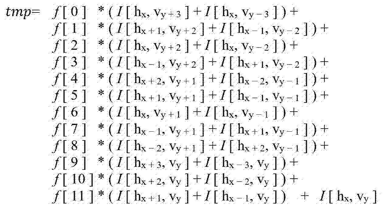
![]()
![]()
수학식 8에서, f[n]은 필터 계수를 의미한다. I는 입력 복원 샘플을 나타낸다. hx는 수평 방향(즉, x축) 좌표가 x인 것을 나타내고, vy는 수직 방향(즉, y축) 좌표가 y인 것을 나타낸다. 즉, I[hx, vy]는, (x, y)위치의 복원 샘플을 나타낸다.In
수학식 9에서 O(x, y)는 필터링된 복원 샘플을 나타낸다.In
수학식 8 및 수학식 9에 나타난 예에서와 같이, 각 복원 샘플에 필터 계수를 곱하여 유도된 값들을 합산하여 획득된 임시값 tmp을 시프팅 파라미터 shift를 기초로 시프팅하여, 필터링된 복원 샘플 O(x, y)가 획득될 수 있다.As in the examples shown in
여기서, 시프팅 파라미터는 부호화기 및 복호화기에 기 정의되어 있을 수 있다. 일 예로, 시프팅 파라미터 shift는 7로 고정되어 있을 수 있다.Here, the shifting parameter may be predefined in the encoder and the decoder. As an example, the shifting parameter shift may be fixed to 7.
또는, 시프팅 파라미터를 결정하기 위한 정보가 비트스트림을 통해 시그날링될 수 있다. 상기 정보는, 슬라이스, 타일 또는 서브 픽처 등 상위 헤더를 통해 부호화될 수 있다.Alternatively, information for determining a shifting parameter may be signaled through a bitstream. The information may be encoded through an upper header such as a slice, a tile, or a sub picture.
또는, 현재 블록의 크기, 필터 타입, 필터 크기, 비트 뎁스, 컬러 성분 또는 컬러 포맷 중 적어도 하나에 기초하여, 시프팅 파라미터가 적응적으로 결정될 수 있다.Alternatively, the shifting parameter may be adaptively determined based on at least one of a size of a current block, a filter type, a filter size, a bit depth, a color component, or a color format.
상술한 실시예들은, 선형 적응적 루프 필터의 적용과 관련된다. 설명한 것과 달리, 적응적 루프 필터 적용시, 비선형성(non- Linearity)을 적용할 수도 있다. 비선형 적응적 루프 필터를 적용하는 경우, 클립(Clip) 함수를 적용하여, 필터링된 샘플을 출력할 수 있다. 일 예로, 비선형 적응적 루프 필터가 적용되는 경우, 수학식 1은 다음의 수학식 10과 같이 변경될 수 있다.The embodiments described above relate to the application of a linear adaptive loop filter. Contrary to the description, non-linearity may be applied when the adaptive loop filter is applied. When a nonlinear adaptive loop filter is applied, a filtered sample may be output by applying a Clip function. For example, when a nonlinear adaptive loop filter is applied,
![]()
![]()
클립함수는 다음의 수학식 11과 같이 정의될 수 있다.The clip function may be defined as in
![]()
![]()
또한, 비선형 적응적 루프 필터가 적용되는 상세 과정은, 다음의 수학식 12와 같이 표현될 수 있다. In addition, a detailed process to which the nonlinear adaptive loop filter is applied can be expressed as
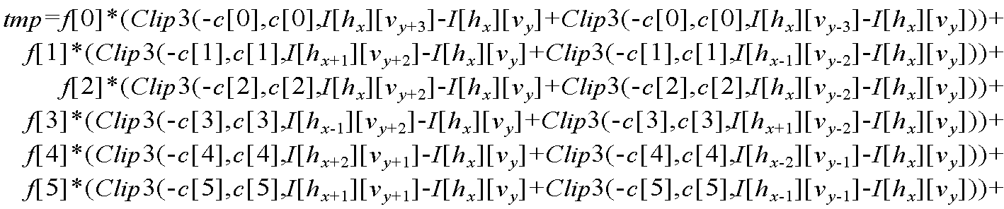

수학식 12에서, c[n]은 클리핑 값 k(i, j)를 1차원으로 표현한 것이다. In
수학식 12를 통해 임시값 tmp가 유도되면, 수학식 9를 통해, 필터링된 복원 샘플을 획득할 수 있다.When the temporary value tmp is derived through
비선형 적응적 루프 필터가 적용되는지 여부를 나타내는 정보가 부호화되어 시그날링될 수 있다. 일 예로, 비선형 적응적 루프 필터가 적용되는지 여부를 나타내는 1비트 플래그가 부호화되어 시그날링될 수 있다.Information indicating whether the nonlinear adaptive loop filter is applied may be encoded and signaled. For example, a 1-bit flag indicating whether a nonlinear adaptive loop filter is applied may be encoded and signaled.
컬러 성분별로 비선형 적응적 루프 필터가 적용되는지 여부를 나타내는 정보를 부호화할 수도 있다.Information indicating whether a nonlinear adaptive loop filter is applied to each color component may be encoded.
비선형 적응적 루프 필터가 적용되는 경우, 필터 계수에 대응하는 클리핑 값을 결정하기 위한 정보가 부호화되어 시그날링될 수 있다. 일 예로, 필터 계수 f[n]에 대응하는 클리핑 값 c[n]을 나타내는 정보가 부호화될 수 있다.When a nonlinear adaptive loop filter is applied, information for determining a clipping value corresponding to a filter coefficient may be encoded and signaled. As an example, information indicating a clipping value c[n] corresponding to the filter coefficient f[n] may be encoded.
이때, 복수의 클리핑 값들을 후보들로 설정한 뒤, 복수의 클리핑 값 후보들 중, 필터 계수에 대응하는 클리핑 값을 특정하는 인덱스를 필터 계수별로 부호화하여 시그날링할 수 있다.In this case, after setting a plurality of clipping values as candidates, an index specifying a clipping value corresponding to the filter coefficient among the plurality of clipping value candidates may be encoded and signaled for each filter coefficient.
표 2는 각 클리핑 값 후보에 상이한 클리핑 인덱스가 할당되는 예를 나타낸다.Table 2 shows an example in which different clipping indices are assigned to each clipping value candidate.
표 2에서, Bitdepth는 영상의 비트 뎁스를 나타내고, clipIdx는 클리핑 값 후보에 할당되는 클리핑 인덱스를 나타낸다.클리핑 값 후보들의 구성은, 비트 뎁스에 따라 상이할 수 있다. 여기서, 일 예로, 비트 뎁스에 따라, 후보들의 개수 또는 후보들의 값 중 적어도 하나가 상이할 수 있다. 표 2에서는, 비트 뎁스에 따라, 클리핑 값 후보들의 값이 상이하게 설정되는 것으로 예시되었다.In Table 2, Bitdepth indicates a bit depth of an image, and clipIdx indicates a clipping index assigned to a clipping value candidate. The configuration of clipping value candidates may be different depending on the bit depth. Here, for example, according to the bit depth, at least one of the number of candidates or the values of the candidates may be different. In Table 2, it is exemplified that the values of the clipping value candidates are set differently according to the bit depth.
또는, 픽처 해상도, 컬러 성분 또는 컬러 포맷 중 적어도 하나에 기초하여, 클리핑 값 후보들의 구성이 결정될 수 있다. 일 예로, 픽처 해상도, 컬러 성분 또는 컬러 포맷에 따라, 후보들의 개수 또는 후보들의 값 중 적어도 하나가 상이할 수 있다. Alternatively, a configuration of clipping value candidates may be determined based on at least one of a picture resolution, a color component, or a color format. For example, according to a picture resolution, a color component, or a color format, at least one of the number of candidates or the value of the candidates may be different.
클리핑 값을 식별하는 인덱스의 비트 렝스를 줄이기 위해, 표 2에 예시된 것 보다 더 적은 개수의 후보들을 이용할 수도 있다. 일 예로, 비트 뎁스 별로 2개의 클리핑 값 후보들만을 정의할 수도 있다. 2개의 클리핑 값 후보들이 정의되어 있을 경우, 1비트의 플래그를 이용하여, 클리핑 값을 결정할 수 있다.To reduce the bit length of the index identifying the clipping value, a smaller number of candidates than illustrated in Table 2 may be used. For example, only two clipping value candidates may be defined for each bit depth. When two clipping value candidates are defined, a clipping value may be determined using a 1-bit flag.
표 3 내지 표 5는, 간소화된 룩업 테이블을 예시한 것이다.Tables 3 to 5 illustrate simplified lookup tables.
복수의 룩업 테이블들이 기-저장된 경우, 복수의 룩업 테이블들 중 하나를 식별하는 정보를 부호화하여 시그날링할 수 있다. 일 예로, 표 2 내지 표 5에 도시된 룩업 테이블들 중 하나를 특정하는 인덱스가 부호화되어 시그날링될 수 있다. 또는, 비트 뎁스, 컬러 성분 또는 컬러 포맷 중 적어도 하나에 기초하여, 룩업 테이블이 적응적으로 선택될 수 있다. 다른 예로, 메모리 점유율을 낮추기 위해, 룩업 테이블을 이용하는 대신, 수식을 이용하여, 클리핑 값을 결정할 수도 있다. 수학식 13은 비트 뎁스 및 클리핑 인덱스에 의해 클리핑 값이 결정되는 예를 나타낸다.When a plurality of lookup tables are pre-stored, information identifying one of the plurality of lookup tables may be encoded and signaled. As an example, an index specifying one of the lookup tables shown in Tables 2 to 5 may be encoded and signaled. Alternatively, the lookup table may be adaptively selected based on at least one of a bit depth, a color component, or a color format. As another example, in order to reduce memory occupancy, a clipping value may be determined using a formula instead of using a lookup table. Equation 13 shows an example in which a clipping value is determined by a bit depth and a clipping index.
![]()
![]()
상기 수학식 13에서, 변수 clipIdx는 비트스트림을 통해 시그날링되는 인덱스에 의해 결정될 수 있다. In Equation 13, the variable clipIdx may be determined by an index signaled through a bitstream.
다른 예로, 수학식 12보다, 클리핑 함수의 적용 횟수를 더욱 감소시킬 수도 있다. 일 예로, 수학식 14는 임시값 tmp가 유도되는 다른 예를 나타낸다.As another example, the number of times of application of the clipping function may be further reduced than in Equation (12). As an example, Equation 14 shows another example in which the temporary value tmp is derived.

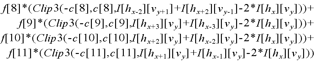
수학식 12에서는, 하나의 필터 계수에 대해 2회의 클리핑 함수가 적용되는 것으로 예시되었으나, 수학식 14에서는, 하나의 필터 계수에 대해 1회의 클리핑 함수가 적용되는 것으로 예시되었다.In
클리핑 함수의 적용 횟수가 감소하더라도, 클리핑 값은 변경되지 않을 수 있다. 일 예로, 수학식 12에 의해 임시값 tmp를 유도하는 경우 및 수학식 14에 의해 임시값 tmp를 유도하는 경우에 있어서, c[n]값은 동일할 수 있다.Even if the number of times of application of the clipping function is decreased, the clipping value may not be changed. For example, in the case of deriving the temporary value tmp by
또는, 클리핑 함수의 적용 횟수가 감소하는 경우, 클리핑 값을 변경할 수 있다. 일 예로, 수학식 14에 의해 임시값 tmp를 유도하는 경우의 클리핑 값 c[n]은, 수학식 12에 의해 임시값 tmp를 유도하는 경우의 클리핑 값 c[n]의 2배일 수 있다.Alternatively, when the number of times of application of the clipping function decreases, the clipping value may be changed. For example, the clipping value c[n] in the case of deriving the temporary value tmp by Equation 14 may be twice the clipping value c[n] in the case of deriving the temporary value tmp by
상술한 예에서는, 필터 계수마다 클리핑 값을 결정하기 위한 인덱스가 부호화되는 것으로 예시되었다. In the above-described example, it is exemplified that an index for determining a clipping value is encoded for each filter coefficient.
다른 예로, 기 설정된 위치의 필터 계수에 대해서만 인덱스를 부호화할 수도 있다. As another example, indexes may be coded only for filter coefficients at preset positions.
도 11은 필터 계수들 중 일부에 대해서만 인덱스가 부호화되는 예를 나타낸다.11 shows an example in which indexes are coded for only some of filter coefficients.
도 11의 (a)에서는, f[0], f[1], f[3], f[4], f[8] 및 f[9]에 대해서만, 인덱스가 부호화되는 것으로 예시되었다. In (a) of FIG. 11 , it is exemplified that indexes are encoded only for f[0], f[1], f[3], f[4], f[8], and f[9].
도 11의 (b)에서는, f[2], f[5], f[7] 및 f[10]에 대해서만, 인덱스가 부호화되는 것으로 예시되었다.In (b) of FIG. 11 , it is exemplified that indexes are encoded only for f[2], f[5], f[7], and f[10].
도 11의 (c)에서는, f[6] 및 f[11]에 대해서만, 인덱스가 부호화되는 것으로 예시되었다.In (c) of FIG. 11 , it is exemplified that indexes are encoded only for f[6] and f[11].
인덱스가 부호화되지 않는 필터 계수에 대해서는, 고정된 클리핑 값을 사용하거나, 인접 위치 필터 계수의 클리핑 값을 사용할 수 있다. 여기서, 인접 위치는, 상단, 하단, 좌측 또는 우측 중 적어도 하나를 가리킨다. 기하학적 변환 타입에 따라, 인접 위치가 적응적으로 결정될 수도 있다.For filter coefficients whose index is not encoded, a fixed clipping value may be used or a clipping value of an adjacent position filter coefficient may be used. Here, the adjacent position refers to at least one of the upper end, the lower end, the left side, or the right side. Depending on the geometric transformation type, the adjacent position may be adaptively determined.
또는, 인덱스가 부호화되는 위치에서만 클리핑 함수를 적용할 수도 있다. 즉, 인덱스가 부호화되지 않는 위치에서는, 클리핑 함수를 적용하지 않을 수 있다. 일 예로, 도 11의 (c)에 도시된 예에서, f[6] 및 f[11]이 적용되는 위치에서는 클리핑 함수가 적용되는 한편, f[6] 및 f[11]이 적용되는 위치를 제외한 잔여 위치에서는 클리핑 함수가 적용되지 않을 수 있다. Alternatively, the clipping function may be applied only at the position where the index is encoded. That is, the clipping function may not be applied at a position where the index is not coded. As an example, in the example shown in (c) of FIG. 11 , the clipping function is applied at the position to which f[6] and f[11] are applied, while the position to which f[6] and f[11] are applied. The clipping function may not be applied to the remaining positions excepted.
적응적 루프 필터와 관련한 정보가 상위 헤더를 통해 부호화되어 시그날링될 수 있다. 여기서, 상위 헤더는, 적응적 루프 필터의 적용 여부가 결정되는 복수의 블록(예컨대, 코딩 트리 유닛, 코딩 유닛 또는 변환 유닛)들이 공통으로 참조하는 파라미터 세트를 나타낸다. 특히, 적응적 루프 필터와 관련한 정보가 부호화된 상위 헤더를 필터 헤더라 정의할 수 있다. Information related to the adaptive loop filter may be encoded and signaled through an upper header. Here, the upper header indicates a parameter set commonly referenced by a plurality of blocks (eg, a coding tree unit, a coding unit, or a transform unit) for which application of the adaptive loop filter is determined. In particular, an upper header in which information related to the adaptive loop filter is encoded may be defined as a filter header.
필터 헤더를 통해, 필터 계수 세트에 관한 정보 또는 각 필터 계수 세트의 구성 정보 중 적어도 하나가 시그날링될 수 있다. 일 예로, 필터 헤더는, 블록 기반 필터 적용 방법을 위한, 복수의 클래스들 각각에 대응하는 필터 계수 세트에 대한 정보, 또는 영역 기반 필터 적용 방법을 위한, 각 영역별 필터 계수 세트에 대한 정보 중 적어도 하나를 포함할 수 있다. At least one of information about a filter coefficient set or configuration information of each filter coefficient set may be signaled through the filter header. For example, the filter header may include at least one of information on a filter coefficient set corresponding to each of a plurality of classes for a block-based filter application method, or information on a filter coefficient set for each region for an area-based filter application method may contain one.
일 예로, 블록 기반 필터 적용 방법 하에서는 25개의 클래스를 이용하고, 영역 기반 필터 적용 방법 하에서는 복원 픽처를 20개의 영역으로 분할하도록 설정된 경우라면, 필터 헤더를 통해 25개 클래스 각각에 대응하는 필터 계수 세트 또는 20개 영역 각각에 대응하는 필터 계수 세트 중 적어도 하나가 부호화되어 시그날링될 수 있다. For example, if 25 classes are used under the block-based filter application method and the reconstructed picture is set to be divided into 20 regions under the area-based filter application method, a filter coefficient set corresponding to each of the 25 classes through the filter header or At least one of the filter coefficient sets corresponding to each of the 20 regions may be encoded and signaled.
필터 헤더가 블록 기반 필터 적용 방법에 이용되는 필터 계수 세트들의 정보를 포함하는지 또는 영역 기반 필터 적용 방법에 이용되는 필터 계수 세트들의 정보를 포함하는지 여부를 나타내는 정보가 부호화될 수 있다.Information indicating whether the filter header includes information on filter coefficient sets used in the block-based filter application method or filter coefficient sets used in the region-based filter application method may be encoded.
복수의 필터 헤더들이 부호화되어 시그날링될 수 있다. 이때, 각 필터 헤드에는 상이한 식별자(ID, Identifier)가 할당될 수 있다.A plurality of filter headers may be encoded and signaled. In this case, a different identifier (ID, Identifier) may be assigned to each filter head.
영상 별 필터 헤더의 개수를 나타내는 정보를 부호화하여 시그날링할 수 있다. 일 예로, 상기 개수 정보는, 픽처 또는 시퀀스 등 상위 헤더를 통해 시그날링될 수 있다. 상기 개수 정보는, 필터 헤더의 총 개수에서 1을 차분한 값을 나타낼 수 있다. Information indicating the number of filter headers for each image may be encoded and signaled. For example, the number information may be signaled through a higher header such as a picture or a sequence. The number information may represent a value obtained by subtracting 1 from the total number of filter headers.
컬러 성분별로, 상이한 필터 헤더가 선택될 수 있다. 일 예로, 휘도 성분(예컨대, y)에 대해서는, 식별자(ID)가 0인 필터 헤더가 이용되는 한편, 제1 색차 성분(예컨대, u 또는 cb)에 대해서는, 식별자가 1인 필터 헤더가 이용되고, 제2 색차 성분(예컨대, v 또는 cr)에 대해서는, 식별자가 2인 필터 헤더가 이용될 수 있다.For each color component, a different filter header may be selected. As an example, for a luminance component (eg, y), a filter header with an identifier (ID) of 0 is used, while for a first chrominance component (eg, u or cb), a filter header with an identifier of 1 is used , for the second chrominance component (eg, v or cr), a filter header having an identifier of 2 may be used.
색차 성분 각각이 상이한 필터 헤더를 이용하는 대신, 하나의 필터 헤더를 색차 성분들에 공통적으로 적용할 수도 있다. 일 예로, 휘도 성분에 대해서는, 식별자가 0인 필터 헤더가 이용되는 한편, 제1 색차 성분 및 제2 색차 성분에 대해서는, 식별자가 1인 필터 헤더가 이용될 수 있다. Instead of using a different filter header for each color difference component, one filter header may be commonly applied to the color difference components. For example, a filter header having an identifier of 0 may be used for the luminance component, while a filter header having an identifier of 1 may be used for the first chrominance component and the second chrominance component.
또는, 하나의 필터 헤더를 공통적으로 모든 컬러 성분들에 대해 공통적으로 적용할 수도 있다. Alternatively, one filter header may be commonly applied to all color components.
컬러 성분별 또는 색차 성분별 개별적으로 필터 헤더가 결정되는지 여부를 나타내는 정보가 부호화될 수 있다. 상기 정보에 기초하여, 컬러 성분별 또는 색차 성분별로 복수의 필터 헤더들 중 하나를 가리키는 인덱스가 시그날링되는지 여부가 결정될 수 있다. Information indicating whether the filter header is individually determined for each color component or for each color difference component may be encoded. Based on the information, it may be determined whether an index indicating one of a plurality of filter headers is signaled for each color component or for each color difference component.
하나의 필터 헤더가 복수 컬러 성분들에 공통적으로 적용되는 경우, 상기 필터 헤더는, 복수 컬러 성분들 각각에 대한 필터 계수 세트 정보를 포함할 수 있다. 이 경우, 필터 헤더 내 필터 계수 세트가 어떠한 컬러 성분에 관한 것인지 여부를 나타내는 정보가 추가로 부호화되어 시그날링될 수 있다.When one filter header is commonly applied to a plurality of color components, the filter header may include filter coefficient set information for each of the plurality of color components. In this case, information indicating which color component the filter coefficient set in the filter header relates to may be further encoded and signaled.
일 예로, 하나의 필터 헤더가 모든 컬러 성분에 대해 공통적으로 적용되는 경우, 필터 헤더 내 필터 계수 세트가 휘도 성분(Y)에 관한 것인지, 제1 색차 성분(예컨대, Cb)에 관한 것인지 또는, 제2 색차 성분(예컨대, Cr)에 관한 것인지 여부를 나타내는 정보가 추가적으로 부호화되어 시그날링될 수 있다.For example, when one filter header is commonly applied to all color components, the filter coefficient set in the filter header relates to the luminance component (Y), the first chrominance component (eg, Cb), or the second Information indicating whether or not it relates to two color difference components (eg, Cr) may be additionally encoded and signaled.
블록 기반 필터 적용 방법을 위한 필터 계수 세트들을 저장하는 필터 헤더와 영역 기반 필터 적용 방법을 위한 필터 계수 세트들을 저장하는 필터 헤더가 독립적으로 부호화되어 시그날링될 수 있다. A filter header storing filter coefficient sets for the block-based filter application method and a filter header storing filter coefficient sets for the region-based filter application method may be independently encoded and signaled.
또는, 하나의 필터 헤더가, 블록 기반 필터 적용 방법을 위한 필터 계수 세트들 및 영역 기반 필터 적용 방법을 위한 필터 계수 세트들이 하나의 필터 헤더에 포함될 수도 있다. 이 경우, 필터 헤더 내 필터 계수 세트가, 블록 기반 필터 적용 방법을 위한 것인지 또는 영역 기반 필터 적용 방법을 위한 것인지 여부를 나타내는 정보가 추가적으로 부호화되어 시그날링될 수 있다.Alternatively, one filter header may include filter coefficient sets for the block-based filter application method and filter coefficient sets for the region-based filter application method in one filter header. In this case, information indicating whether the filter coefficient set in the filter header is for the block-based filter application method or the region-based filter application method may be additionally encoded and signaled.
다른 예로, 컬러 성분별로, 필터 계수 적용 방법을 고정적으로 설정할 수 있다. 일 예로, 루마 성분에 대해서는, 블록 기반 필터 적용 방법을 고정적으로 적용하는 한편, 색차 성분에 대해서는, 영역 기반 필터 적용 방법을 고정적으로 적용할 수 있다. 이 경우, 컬러 성분 각각의 필터 적용 방법을 참고하여, 필터 헤더가 선택될 수 있다. As another example, the filter coefficient application method may be fixedly set for each color component. As an example, the block-based filter application method may be fixedly applied to the luma component, while the region-based filter application method may be fixedly applied to the chrominance component. In this case, a filter header may be selected with reference to a filter application method of each color component.
필터 계수 세트들 간 계수 병합(Coefficient Merge)가 수행될 수 있다. 계수 병합을 통해, 복수 클래스들 또는 복수 영역들 중 일부에 대해서만, 필터 계수 세트에 대한 정보를 부호화할 수 있다. 필터 계수 세트가 부호화되지 않는 클래스 또는 필터 계수 세트가 부호화되지 않는 영역은, 타 클래스 또는 타 영역의 필터 계수 세트를 이용하도록 설정될 수 있다. Coefficient merging between filter coefficient sets may be performed. Through coefficient merging, information on a filter coefficient set may be encoded only for a part of a plurality of classes or a plurality of regions. A class in which the filter coefficient set is not coded or a region in which the filter coefficient set is not coded may be set to use a filter coefficient set of another class or another region.
도 12는 블록 기반 필터 적용 방법 하에서, 계수 머징이 적용되는 예를 설명하기 위한 도면이다.12 is a diagram for explaining an example in which coefficient merging is applied under a block-based filter application method.
도 12의 (a)는 계수 머징이 적용되지 않는 경우의 실시예이고, 도 12의 (b)는 계수 머징이 적용되는 경우의 실시예이다.Fig. 12 (a) is an embodiment in which coefficient merging is not applied, and Fig. 12 (b) is an embodiment in which coefficient merging is applied.
계수 머징이 적용되지 않는 경우, 클래스들 각각에 대한 필터 계수 세트가 부호화되어 시그날링될 수 있다. 일 예로, 25개의 클래스들이 존재하는 경우, 도 12의 (a)에 도시된 예에서와 같이, 25개의 클래스들 각각에 대해 필터 계수 세트가 부호화될 수 있다.When coefficient merging is not applied, a filter coefficient set for each of the classes may be encoded and signaled. For example, when there are 25 classes, a filter coefficient set may be encoded for each of the 25 classes, as in the example shown in FIG. 12A .
계수 머징이 적용되지 않는 경우, 클래스들의 개수만큼 필터 계수 세트들이 부호화되어 시그날링될 수 있다.When coefficient merging is not applied, filter coefficient sets as many as the number of classes may be encoded and signaled.
계수 머징이 적용되는 경우, 클래스들 개수보다 적은 개수의 필터 계수 세트들이 부호화되어 시그날링될 수 있다. 이때, 복수의 클래스들에 하나의 필터 계수 세트가 할당될 수 있다. 일 예로, 도 12의 (b)에 도시된 예에서와 같이, 클래스 1 내지 3에 필터 계수 세트 1이 할당될 수 있다. When coefficient merging is applied, a number of filter coefficient sets less than the number of classes may be encoded and signaled. In this case, one filter coefficient set may be allocated to a plurality of classes. As an example, as in the example shown in FIG. 12B , filter coefficient set 1 may be allocated to
계수 머징이 적용되는 경우, 부호화해야하는 필터 계수 세트의 개수가 감소하므로, RDO(Rate-Distortion Optimization) 관점에서, 부호화 효율이 향상될 수 있다. 즉, 필터 계수 세트에 대한 시느날링 오버헤드가 감소될 수 있다. When coefficient merging is applied, since the number of filter coefficient sets to be encoded is reduced, from the viewpoint of Rate-Distortion Optimization (RDO), encoding efficiency may be improved. That is, the signaling overhead for the filter coefficient set can be reduced.
클래스들 각각에 대해 필터 계수 세트가 정의되어 있는 경우, 클래스와 필터 계수 세트간 매핑 관계를 나타내는 정보가 불필요하다. 즉, 클래스의 개수 만큼 및 필터 계수 세트가 전송되므로(즉, 클래스 및 필터 계수 세트간 1:1 매핑), 블록의 클래스가 N으로 결정된 경우, 필터 계수 세트 N이 이용되는 것으로 결정될 수 있다.When a filter coefficient set is defined for each of the classes, information indicating a mapping relationship between the class and the filter coefficient set is unnecessary. That is, since the number of classes and filter coefficient sets are transmitted (ie, 1:1 mapping between classes and filter coefficient sets), when the class of the block is determined to be N, it may be determined that the filter coefficient set N is used.
반면, 클래스들의 개수보다 필터 계수 세트들의 개수가 적은 경우, 클래스와 필터 계수 세트간 매핑 관계를 나타내는 정보가 추가로 요구된다. 일 예로, 도 12의 (b)에 도시된 예에서, 클래스 2에는 필터 계수 세트 2가 아닌 필터 계수 세트 1이 할당되므로, 클래스 2에 필터 계수 세트 1이 할당되어 있음을 나타내는 매핑 정보가 추가로 요구된다. 상기 매핑 정보는, 클래스와 매핑 관계인 필터 계수 세트를 식별하는 인덱스일 수 있다. On the other hand, when the number of filter coefficient sets is smaller than the number of classes, information indicating a mapping relationship between classes and filter coefficient sets is additionally required. For example, in the example shown in (b) of FIG. 12 , since filter coefficient set 1 rather than filter coefficient set 2 is assigned to
계수 머징이 적용되는 경우, 필터 계수 세트들의 개수를 나타내는 정보가 추가 부호화되어 시그날링될 수 있다. 일 예로, 도 12의 (b)에 도시된 예에서는, 총 5개의 필터 계수 세트들이 부호화되어 시그날링된다. 이에 따라, 필터 계수 세트들의 개수가 5개임을 나타내는 개수 정보가 부호화되어 시그날링될 수 있다.When coefficient merging is applied, information indicating the number of filter coefficient sets may be further encoded and signaled. For example, in the example shown in (b) of FIG. 12 , a total of five filter coefficient sets are encoded and signaled. Accordingly, number information indicating that the number of filter coefficient sets is five may be encoded and signaled.
일 예로, 필터 계수 세트들의 개수에서 소정의 상수값을 차분하여 유도되는 개수 정보가 부호화될 수 있다. 여기서, 상수값은, 1 또는 2와 같은 자연수일 수 있다. As an example, number information derived by differentiating a predetermined constant value from the number of filter coefficient sets may be encoded. Here, the constant value may be a natural number such as 1 or 2.
또는, 클래스들의 개수와 필터 계수 세트들간의 차분값을 기초로 유도되는 개수 정보가 부호화될 수 있다. Alternatively, number information derived based on the difference between the number of classes and filter coefficient sets may be encoded.
클래스마다, 매핑 관계인 필터 계수 세트를 식별하기 위한 인덱스 정보가 부호화되어 시그날링될 수 있다. 일 예로, 도 12의 (b)에 도시된 예에서는, 총 5개의 필터 계수 세트들이 존재하므로, 각각의 클래스들에 대해 0 내지 4 중 하나의 값을 나타내는 인덱스 정보가 부호화되어 시그날링될 수 있다.For each class, index information for identifying a filter coefficient set that is a mapping relationship may be encoded and signaled. For example, in the example shown in (b) of FIG. 12 , since there are a total of five filter coefficient sets, index information indicating a value of 0 to 4 for each class may be encoded and signaled. .
이때, 인덱스 정보는, 클래스에 할당되는 필터 계수 세트의 인덱스를 나타낼 수 있다.In this case, the index information may indicate an index of a filter coefficient set assigned to a class.
또는, 차분 코딩(DPCM, Differential Pulse Coded Modulation)에 기초하여, 각 클래스의 인덱스 정보를 부호화할 수 있다. 일 예로, 클래스 N에 대해, 클래스 N에 할당된 필터 계수 세트의 인덱스와 이전 클래스 (예컨대, 클래스 N-1) 또는 다음 클래스(예컨대, 클래스 N+1)에 할당된 필터 계수 세트의 인덱스 사이의 차분을 나타내는 인덱스 차분을 인덱스 정보로 부호화할 수 있다. Alternatively, index information of each class may be encoded based on differential coding (DPCM). For example, for class N, between the index of the filter coefficient set assigned to class N and the index of the filter coefficient set assigned to the previous class (eg, class N-1) or the next class (eg, class N+1) The index difference indicating the difference may be encoded as index information.
또는, 클래스에 할당된 필터 계수 세트가 이전 클래스 또는 다음 클래스와 동일한지 여부를 나타내는 플래그가 부호화되어 시그날링될 수 있다. 상기 플래그가 1(True)인 경우, 해당 클래스에 대해서는 인덱스 정보의 부호화가 생략될 수 있다. 반면, 상기 플래그가 0(False)인 경우, 해당 클래스에 대해 인덱스 정보가 부호화될 수 있다. Alternatively, a flag indicating whether the filter coefficient set assigned to the class is the same as the previous class or the next class may be encoded and signaled. When the flag is 1 (True), encoding of index information for a corresponding class may be omitted. On the other hand, when the flag is 0 (False), index information may be encoded for a corresponding class.
클래스에 할당되는 필터 계수 세트 인덱스가, 이전 클래스에 할당되는 필터 계수 세트의 인덱스보다 작은 값을 갖는 것은 허용되지 않도록 설정할 수 있다. 이 경우, 일부 클래스에 대해서는, 인덱스 정보의 부호화가 생략될 수 있다.It may be set so that the filter coefficient set index assigned to the class is not allowed to have a value smaller than the index of the filter coefficient set assigned to the previous class. In this case, for some classes, encoding of index information may be omitted.
도 13은 일부 클래스에 대해, 인덱스 정보의 부호화가 생략되는 예를 나타낸 것이다.13 illustrates an example in which encoding of index information is omitted for some classes.
도 13의 (a)는, 각각의 클래스들에 할당된 필터 계수 세트를 나타낸다. 도시된 예에서와 같이, 클래스 N에 할당되는 필터 계수 세트의 인덱스가 이전 클래스(즉, 클래스 N-1)에 할당되는 필터 계수 세트의 인덱스와 같거나 큰 값을 갖도록 강제할 수 있다. 이 경우, 첫번째 클래스(클래스 0)에는 항상 가장 작은 인덱스를 갖는 필터 계수 세트가 할당되고, 마지막 클래스(클래스 24)에는 항상 가장 큰 인덱스를 갖는 필터 계수 세트가 할당된다. 13A shows a filter coefficient set assigned to each class. As in the illustrated example, the index of the filter coefficient set allocated to class N may be forced to have a value equal to or greater than the index of the filter coefficient set allocated to the previous class (ie, class N-1). In this case, the filter coefficient set having the smallest index is always allocated to the first class (class 0), and the filter coefficient set having the largest index is always allocated to the last class (class 24).
이에 따라, 첫번째 클래스 및 마지막 클래스에 대해서는, 인덱스 정보의 부호화가 생략될 수 있다.Accordingly, with respect to the first class and the last class, encoding of index information may be omitted.
도 13의 (b)는 인덱스 정보의 부호화 양상을 나타낸 것이다. 도시된 예에서와 같이, 첫번째 클래스(클래스 0) 및 마지막 클래스(클래스 24)에 대해서는, 인덱스 정보의 부호화를 생략할 수 있다. 첫번째 클래스 및 마지막 클래스를 제외한 잔여 클래스들에 대해서만, 인덱스 정보가 부호화되어 시그날링될 수 있다. 13 (b) shows an encoding aspect of index information. As in the illustrated example, encoding of index information may be omitted for the first class (class 0) and the last class (class 24). Only for the remaining classes except for the first class and the last class, index information may be encoded and signaled.
인덱스 정보의 시그날링이 생략된 경우, 복호화기에서는, 클래스가 첫번째 혹은 마지막인지 여부에 따라, 해당 클래스에 할당되는 필터 계수 세트를 결정할 수 있다. 일 예로, 인덱스 정보의 시그날링이 생략된 클래스가, 첫번째 클래스인 경우, 첫번째 필터 계수 세트가 선택된 것으로 간주(infer)할 수 있다. 반면, 인덱스 정보의 시그날링이 생략된 클래스가, 마지막 클래인 경우, 마지막 필터 계수 세트가 선택된 것으로 간주할 수 있다.When the signaling of the index information is omitted, the decoder may determine the filter coefficient set assigned to the corresponding class according to whether the class is the first or the last. For example, when a class in which signaling of index information is omitted is the first class, it may be inferred that the first filter coefficient set is selected. On the other hand, when the class in which the signaling of index information is omitted is the last class, it may be considered that the last filter coefficient set is selected.
상술한 필터 계수 병합과 관련한 실시예는, 블록 기반 필터 적용 방법에서 뿐만 아니라, 영역 기반 필터 적용 방법에도 적용될 수 있다. The above-described embodiment related to merging filter coefficients may be applied not only to the block-based filter application method but also to the region-based filter application method.
도 14는 영역 기반 필터 적용 방법 하에서, 계수 머징이 적용되는 예를 설명하기 위한 도면이다.14 is a diagram for explaining an example in which coefficient merging is applied under a method of applying a region-based filter.
도 14의 (a)는 계수 머징이 적용되지 않는 경우의 실시예이고, 도 14의 (b)는 계수 머징이 적용되는 경우의 실시예이다.Fig. 14 (a) is an embodiment in which coefficient merging is not applied, and Fig. 14 (b) is an embodiment in which coefficient merging is applied.
계수 머징이 적용되지 않는 경우, 영역들 각각에 대한 필터 계수 세트가 부호화되어 시그날링될 수 있다. 일 예로, 25개의 영역들이 존재하는 경우, 도 14의 (a)에 도시된 예에서와 같이, 25개의 영역들 각각에 대해 필터 계수 세트가 부호화될 수 있다.When coefficient merging is not applied, a filter coefficient set for each of the regions may be encoded and signaled. For example, when there are 25 regions, a filter coefficient set may be encoded for each of the 25 regions, as in the example shown in FIG. 14A .
계수 머징이 적용되지 않는 경우, 영역들의 개수만큼 필터 계수 세트들이 부호화되어 시그날링될 수 있다.When coefficient merging is not applied, filter coefficient sets as many as the number of regions may be encoded and signaled.
계수 머징이 적용되는 경우, 영역들 개수보다 적은 개수의 필터 계수 세트들이 부호화되어 시그날링될 수 있다. 이때, 복수의 영역들에 하나의 필터 계수 세트가 할당될 수 있다. 일 예로, 도 14의 (b)에 도시된 예에서와 같이, 영역 1 내지 3에 필터 계수 세트 1이 할당될 수 있다. When coefficient merging is applied, a number of filter coefficient sets less than the number of regions may be encoded and signaled. In this case, one filter coefficient set may be allocated to a plurality of regions. As an example, as in the example shown in (b) of FIG. 14 , the filter coefficient set 1 may be allocated to
계수 머징 방법이 적용되는 경우, 각 영역에 할당되는 필터 계수 세트를 특정하기 위한 정보가 부호화되어 시그날링될 수 있다. 이때, 각 영역의 인덱스 정보의 부호화 방법은, 상술한 블록 기반 필터 적용 방법과 동일한 바, 이에 대한 상세한 설명은 생략하기로 한다. When the coefficient merging method is applied, information for specifying a filter coefficient set allocated to each region may be encoded and signaled. In this case, since the method of encoding the index information of each region is the same as the above-described block-based filter application method, a detailed description thereof will be omitted.
필터 계수 세트를 구성하는 필터 계수들에 대한 정보를 부호화하여 시그날링할 수 있다. 도 4의 예를 참고하면, 휘도 성분에 대해서는 13개의 필터 계수들(f[0]~f[12])의 값이 부호화되어 시그날링되고, 색차 성분에 대해서는 7개의 필터 계수들(f[0]~f[6])의 값이 부호화되어 시그날링될 수 있다. Information on filter coefficients constituting the filter coefficient set may be encoded and signaled. Referring to the example of FIG. 4 , values of 13 filter coefficients (f[0] to f[12]) are coded and signaled for a luminance component, and 7 filter coefficients (f[0] to f[0]) are signaled for a chrominance component. ] to f[6]) may be encoded and signaled.
이때, 필터 중앙 위치의 필터 계수에 대해서는 부호화가 생략될 수 잇다. 일 예로, 도 4의 예에서, 휘도 성분에 대한 필터의 중앙 위치인 f[12]에 대한 부호화가 생략되고, 색차 성분에 대한 필터의 중앙 위치인 f[6]에 대한 부호화가 생략될 수 있다.In this case, encoding may be omitted for the filter coefficients at the filter center position. For example, in the example of FIG. 4 , encoding of f[12], which is the central position of the filter for the luminance component, may be omitted, and encoding of f[6], which is the central position of the filter for the chrominance component, may be omitted. .
중앙 위치의 필터 계수는, 소정의 상수값에서 잔여 필터 계수들의 합을 차분하여 유도될 수 있다. 일 예로, 휘도 성분에 대한 필터 계수 f[12] 및 색차 성분에 대한 필터 계수 f[6]은 다음의 수학식 15와 같이 유도될 수 있다.The filter coefficient at the center position may be derived by differentiating the sum of the remaining filter coefficients from a predetermined constant value. As an example, the filter coefficient f[12] for the luminance component and the filter coefficient f[6] for the chrominance component may be derived as shown in Equation 15 below.
![]()
![]()
필터 계수에 대한 정보는, 필터 계수의 절대값 정보 또는 필터 계수의 부호 정보 중 적어도 하나를 포함할 수 있다.The information on the filter coefficients may include at least one of absolute value information of the filter coefficients and sign information of the filter coefficients.
다른 예로, 필터 계수 f[n]을 2의 지수승으로 양자화하여 필터를 적용할 수도 있다. 이 경우, 필터 계수 절대값 정보 대신, 필터 계수의 인덱스를 부호화하여 시그날링할 수 있다. 인덱스는 2의 지수승으로 표현되는 값들 중 하나를 나타낼 수 있다. 일 예로, 필터 계수 절대값이 0 부터 64 사이의 값을 갖고, 필터 계수를 2의 지수승으로 표현되는 값으로 양자화하는 것으로 가정하면, 필터 계수의 절대값은, 다음의 세트에 포함된 값들 중 하나로 결정된다.As another example, the filter may be applied by quantizing the filter coefficient f[n] to the power of 2. In this case, instead of the filter coefficient absolute value information, an index of the filter coefficient may be encoded and signaled. The index may represent one of the values expressed as an exponential power of 2. For example, assuming that the absolute value of the filter coefficient has a value between 0 and 64 and that the filter coefficient is quantized to a value expressed by the power of 2, the absolute value of the filter coefficient is one of the values included in the following set. determined by one
{0, 1, 2, 4, 8, 16, 32, 64}{0, 1, 2, 4, 8, 16, 32, 64}
이에, 위 세트에 포함된 값들 중 하나를 특정하는 인덱스를 부호화할 수 있다. 일 예로, 인덱스 0는 절대값 0을 나타내고, 인덱스 7은 절대값 64를 나타낼 수 있다.Accordingly, an index specifying one of the values included in the above set may be encoded. For example,
필터 계수의 값을 2의 지수승으로 양자화하는 대신, 양자화되는 값들 각각이 등차 또는 등비를 갖도록 설정할 수도 있다. 일 예로, {0, 9, 18, 27, 36, 45, 54, 64}와 같이 등차 수열들 중 하나가 되도록 필터 계수를 양자화할 수 있다. Instead of quantizing the values of the filter coefficients to the power of 2, each of the quantized values may be set to have an equivalence or an equal ratio. For example, the filter coefficients may be quantized to be one of the arithmetic sequences such as {0, 9, 18, 27, 36, 45, 54, 64}.
필터 계수의 절대값을 나타내는 인덱스의 부호화시, 단항 이진화(Truncated Unary Binarization) 방식을 적용할 수 있다. When encoding an index indicating an absolute value of a filter coefficient, a truncated unary binarization method may be applied.
다른 예로, 필터 계수의 절대값을 나타내는 인덱스의 부호화시, 고정 길이(Fixed Length) 방식을 적용할 수 있다. 일 예로, 총 8개의 값들 중 하나를 나타내는 인덱스를 부호화하는 경우라면, 000 내지 111 사이의 값을 갖는 인덱스를 부호화하여 시그날링할 수 있다. As another example, when encoding an index indicating an absolute value of a filter coefficient, a fixed length method may be applied. For example, if an index indicating one of a total of eight values is encoded, an index having a value between 000 and 111 may be encoded and signaled.
필터 계수의 절대값이 0이 아닌 경우에는, 필터 계수 부호 정보를 추가 부호화하여 시그날링할 수 있다. 부호 정보는, 필터 계수가 양수인지 또는 음수인지를 나타내는 플래그일 수 있다.When the absolute value of the filter coefficient is not 0, the signal may be signaled by additionally encoding filter coefficient sign information. The sign information may be a flag indicating whether the filter coefficients are positive or negative.
필터 계수의 절대값의 범위는, 부호화기 및 복호화기에서 기 정의되어 있을 수 있다.The range of the absolute value of the filter coefficient may be predefined in the encoder and the decoder.
다른 예로, 필터 계수의 절대값의 범위를 나타내는 정보가 비트스트림을 통해 시그날링될 수 있다. 상기 정보는 슬라이스, 픽처, 시퀀스 또는 필터 헤더 등 상위 헤더를 통해 시그날링될 수 있다. 상기 정보는, 범위의 최소값 또는 최대값 중 적어도 하나를 나타낼 수 있다. 일 예로, 범위의 최대값이 2N으로 표현될 경우, 상기 N을 특정하기 위한 정보를 부호화하여 시그날링할 수 있다.As another example, information indicating a range of absolute values of filter coefficients may be signaled through a bitstream. The information may be signaled through an upper header such as a slice, picture, sequence, or filter header. The information may indicate at least one of a minimum value or a maximum value of the range. For example, when the maximum value of the range is expressed as 2 N , information for specifying the N may be encoded and signaled.
다른 예로, 컬러 성분, 컬러 포맷, 필터 크기, 필터 형태 또는 필터 적용 방법 중 적어도 하나에 기초하여, 범위가 적응적으로 결정될 수 있다. As another example, the range may be adaptively determined based on at least one of a color component, a color format, a filter size, a filter type, or a filter application method.
복수의 필터 헤더들이 존재하는 경우, 기 정의된 레벨의 처리 단위 별로, 필터 헤더들 중 하나를 식별하는 식별 정보를 시그날링할 수 있다. 일 예로, 슬라이스, 서브 픽처 또는 타일별로, 복수의 필터 헤더들 중 하나를 나타내는 식별 정보를 부호화하여 시그날링할 수 있다. 기 정의된 레벨의 처리 단위에 속한 블록들은, 상기 처리 단위 레벨에서 결정된 필터 헤더를 이용할 수 있다. When a plurality of filter headers exist, identification information for identifying one of the filter headers may be signaled for each processing unit of a predefined level. For example, identification information indicating one of a plurality of filter headers may be encoded and signaled for each slice, subpicture, or tile. Blocks belonging to a processing unit of a predefined level may use the filter header determined at the processing unit level.
다른 예로, 소정 레벨의 처리 단위 별로, 필터 헤더를 결정한 뒤, 상기 처리 단위에 속한 서브 처리 단위 각각에 대해, 상기 처리 단위 레벨에서 결정된 필터 헤더를 그대로 사용할 것인지 여부를 나타내는 정보를 부호화하여 시그날링할 수 있다. 상기 정보는 1비트의 플래그일 수 있다. 일 예로, 상기 플래그가 1(True)인 경우, 처리 단위 레벨에서 결정된 필터 헤더를 그대로 사용할 수 있다. 반면, 상기 플래그가 0(False)인 경우, 서브 처리 단위에서 사용할 필터 헤더를 식별하는 식별 정보가 추가 부호화될 수 있다. 상기 식별 정보는, 처리 단위 레벨에서 결정된 필터 헤더를 제외한 잔여 필터 헤더들 중 하나를 특정할 수 있다. As another example, after a filter header is determined for each processing unit of a predetermined level, information indicating whether to use the filter header determined at the processing unit level as it is for each sub processing unit belonging to the processing unit is encoded and signaled. can The information may be a 1-bit flag. For example, when the flag is 1 (True), the filter header determined at the processing unit level may be used as it is. On the other hand, when the flag is 0 (False), identification information for identifying a filter header to be used in a sub-processing unit may be additionally encoded. The identification information may specify one of the remaining filter headers excluding the filter header determined at the processing unit level.
일 예로, 처리 단위들 간 종속 관계가 다음을 따른다고 가정한다. As an example, it is assumed that the dependency relationship between processing units follows.
슬라이스⊆타일⊆서브픽쳐⊆픽쳐Slice ⊆ Tile ⊆ Sub Picture ⊆ Picture
이 경우, 필터 헤더가 결정되는 처리 단위는, 타일, 서브 픽처 또는 픽처 중 어느 하나이고, 서브 처리 단위는, 슬라이스, 타일 또는 서브 픽처 중 어느 하나일 수 있다. In this case, the processing unit for which the filter header is determined may be any one of a tile, a subpicture, or a picture, and the subprocessing unit may be any one of a slice, a tile, or a subpicture.
다른 예로, 슬라이스의 결정 방법에 따라 필터 헤더의 식별 정보가 부호화되는 처리 단위를 적응적으로 결정할 수 있다. 여기서, 슬라이스의 결정 방법은 래스터 스캔 슬라이스 결정 방법 또는 사각 슬라이스 결정 방법 중 하나일 수 있다. As another example, a processing unit in which identification information of a filter header is encoded may be adaptively determined according to a method of determining a slice. Here, the slice determination method may be one of a raster scan slice determination method or a square slice determination method.
래스터 스캔 슬라이스 결정 방법은 래스터 스캔 순서를 따를 때, 연속하는 타일들을 하나의 슬라이스로 결정하는 방법을 나타낸다. 사각 형태 슬라이스 결정 방법은, 사각 형태를 갖는 슬라이스만을 허용하는 결정 방법을 나타낸다. 사각 형태 슬라이스 결정 방법이 적용되는 경우, 사각형의 꼭지점에 위치하는 타일은 다른 꼭지점에 위치하는 타일과 동일한 행 및/또는 동일한 열에 속할 수 있다.The raster scan slice determination method refers to a method of determining successive tiles as one slice when the raster scan order is followed. The rectangular shape slice determination method refers to a determination method that allows only slices having a rectangular shape. When the rectangular slice determination method is applied, a tile located at a vertex of the rectangle may belong to the same row and/or the same column as a tile located at another vertex.
일 예로, 래스터 스캔 슬라이스 결정 방법이 적용되는 경우, 슬라이스 별로 필터 헤더의 식별 정보를 부호화할 수 있다. 반면, 사각 형태 슬라이스 결정 방법이 적용되는 경우, 타일 별로 필터 헤더의 식별 정보를 부호화할 수 있다. For example, when the raster scan slice determining method is applied, identification information of a filter header may be encoded for each slice. On the other hand, when the rectangular slice determination method is applied, identification information of the filter header may be encoded for each tile.
또는, 위와 반대로, 래스터 스캔 슬라이스 결정 방법이 적용되는 경우, 타일 별로 필터 헤더의 식별 정보를 부호화하고, 사각 형태 슬라이스 결정 방법이 적용되는 경우, 슬라이스 별로 필터 헤더의 식별 정보를 부호화할 수도 있다.Alternatively, in contrast to the above, when the raster scan slice determining method is applied, identification information of the filter header is encoded for each tile, and when the rectangular slice determining method is applied, the identification information of the filter header can be encoded for each slice.
다른 예로, 병렬 처리 대상 영역들 각각에 대해 독립적으로 필터 헤더를 부호화할 수도 있다. 일 예로, 타일 별 병렬 처리가 수행되는 경우, 타일들 각각에 대해 필터 헤더를 부호화할 수 있다. 일 예로, 픽처가 2개의 타일들로 구성된 경우, 제1 타일에 대해 3개의 필터 헤더들을 부호화하고, 제2 타일에 대해 2개의 필터 헤더들을 부호화할 수 있다. 이에 따라, 현재 픽처에 대해서는 총 5개의 필터 헤더들이 부호화될 수 있다. As another example, the filter header may be independently encoded for each of the parallel processing target regions. For example, when parallel processing for each tile is performed, a filter header may be encoded for each of the tiles. As an example, when a picture consists of two tiles, three filter headers may be encoded for a first tile and two filter headers may be encoded for a second tile. Accordingly, a total of five filter headers may be encoded for the current picture.
이때, 하나의 필터 헤더가 복수의 타일들을 위해 중복 부호화될 수도 있다.In this case, one filter header may be redundantly coded for a plurality of tiles.
타일 별 필터 헤더들의 개수 또는 타일들 각각에 할당되는 필터 헤더의 식별자 정보 중 적어도 하나가 더 부호화되어 시그날링될 수도 있다. At least one of the number of filter headers for each tile or identifier information of a filter header allocated to each of the tiles may be further encoded and signaled.
다른 예로, 블록별로 필터 헤더를 식별하는 정보를 부호화하여 시그날링할 수도 있다. 일 예로, 현재 코딩 트리 유닛에 대해 적응적 루프 필터가 적용되는 것으로 결정된 경우, 현재 코딩 트리 유닛에 적용되는 필터 헤더를 식별하기 위한 정보가 추가 부호화되어 시그날링될 수 있다. As another example, information for identifying a filter header for each block may be encoded and signaled. For example, when it is determined that the adaptive loop filter is applied to the current coding tree unit, information for identifying a filter header applied to the current coding tree unit may be further encoded and signaled.
상술한 예에서는, 적응적 루프 필터의 적용 방법을 나타내는 정보가 부호화되어 시그날링되는 것으로 예시되었다. 다른 예로, 선택된 필터 헤더에 따라, 적응적 루프 필터의 적용 방법이 결정될 수도 있다. 일 예로, 블록 기반 필터 적용 방법을 위한 필터 계수 세트들만으로 구성된 필터 헤더가 선택된 경우, 현재 블록에는 블록 기반 필터 적용 방법이 적용될 수 있다. 반면, 영역 기반 필터 적용 방법을 위한 필터 계수 세트들만으로 구성된 필터 헤더가 선택된 경우, 현재 블록에는 영역 기반 필터 적용 방법이 적용될 수 있다. In the above-described example, it has been exemplified that information indicating a method of applying the adaptive loop filter is encoded and signaled. As another example, a method of applying the adaptive loop filter may be determined according to the selected filter header. For example, when a filter header including only filter coefficient sets for the block-based filter application method is selected, the block-based filter application method may be applied to the current block. On the other hand, when a filter header including only filter coefficient sets for the region-based filter application method is selected, the region-based filter application method may be applied to the current block.
컬러 성분별로 고정된 필터 적용 방법을 적용할 수도 있다. 일 예로, 휘도 성분에 대해서는 상시 블록 기반 필터 적용 방법을 적용하고, 색차 성분에 대해서는 상시 영역 기반 필터 적용 방법을 적용할 수 있다. 이 경우, 휘도 성분 블록에 대해서는, 블록 기반 필터 적용 방법을 위한 필터 헤더들 중 하나를 식별하는 정보를 추가 부호화하여 시그날링할 수 있다. 또한, 색차 성분 영역에 대해서는, 영역 기반 필터 적용 방법을 위한 필터 헤더들 중 현재 하나를 식별하는 정보를 추가 부호화하여 시그날링할 수 있다. A fixed filter application method for each color component may be applied. For example, a block-based filter application method may be always applied to a luminance component, and a region-based filter application method may be always applied to a chrominance component. In this case, with respect to the luminance component block, information for identifying one of the filter headers for the block-based filter application method may be additionally encoded and signaled. Also, with respect to the chrominance component region, information for identifying a current one of filter headers for the region-based filter application method may be additionally encoded and signaled.
영역 기반 필터 적용 방법이 적용되는 한편, 픽처에 하나의 영역만이 포함된 경우, 상기 단일 영역을 위해 복수의 필터 계수 세트 후보들을 구성할 수도 있다. 이 경우, 상기 단일 영역을 위한 필터 계수 세트를 결정하기 위해, 상기 복수의 필터 계수 세트 후보들 중 하나를 식별하는 인덱스 정보가 부호화되어 시그날링될 수 있다. 이 경우, 인덱스 정보는 블록 단위(예컨대, 코딩 트리 유닛)로 부호화되어 시그날링될 수 있다. 즉, 영역 기반 필터 적용 방법이 적용되는 경우에도, 블록별로 상이한 필터 계수 세트를 이용할 수 있다. While the region-based filter application method is applied, when a picture includes only one region, a plurality of filter coefficient set candidates may be configured for the single region. In this case, in order to determine the filter coefficient set for the single region, index information for identifying one of the plurality of filter coefficient set candidates may be encoded and signaled. In this case, the index information may be encoded and signaled in units of blocks (eg, coding tree units). That is, even when the region-based filter application method is applied, different filter coefficient sets may be used for each block.
컬러 성분별로 독립적으로 필터 헤더를 결정할 수 있다.A filter header can be determined independently for each color component.
또는, 컬러 성분들이 동일한 필터 헤더를 사용하도록 설정할 수도 있다. 이 경우, 필터 헤더는, 휘도 성분에 대한 필터 계수 세트들의 정보 및 색차 성분에 대한 필터 계수 세트들의 정보를 모두 포함할 수 있다. 또한, 휘도 성분에 대해서는, 복수의 필터 헤더들 중 하나를 식별하는 정보를 부호화하고, 색차 성분에 대해서는, 상기 정보의 부호화를 생략할 수 있다. Alternatively, color components may be set to use the same filter header. In this case, the filter header may include both information on filter coefficient sets for a luminance component and information on filter coefficient sets for a chrominance component. Also, for the luminance component, information identifying one of the plurality of filter headers may be encoded, and for the color difference component, the encoding of the information may be omitted.
상술한 실시예들에서 사용된 신택스들의 명칭은, 설명의 편의를 위해 명명된 것에 불과하다.The names of syntaxes used in the above-described embodiments are merely named for convenience of description.
복호화 과정 또는 부호화 과정을 중심으로 설명된 실시예들을, 부호화 과정 또는 복호화 과정에 적용하는 것은, 본 개시의 범주에 포함되는 것이다. 소정의 순서로 설명된 실시예들을, 설명된 것과 상이한 순서로 변경하는 것 역시, 본 개시의 범주에 포함되는 것이다.Applying the decoding process or the embodiments described based on the encoding process to the encoding process or the decoding process is included in the scope of the present disclosure. It is also within the scope of the present disclosure to change the embodiments described in a certain order in an order different from that described.
상술한 실시예는 일련의 단계 또는 순서도를 기초로 설명되고 있으나, 이는 발명의 시계열적 순서를 한정한 것은 아니며, 필요에 따라 동시에 수행되거나 다른 순서로 수행될 수 있다. 또한, 상술한 실시예에서 블록도를 구성하는 구성요소(예를 들어, 유닛, 모듈 등) 각각은 하드웨어 장치 또는 소프트웨어로 구현될 수도 있고, 복수의 구성요소가 결합하여 하나의 하드웨어 장치 또는 소프트웨어로 구현될 수도 있다. 상술한 실시예는 다양한 컴퓨터 구성요소를 통하여 수행될 수 있는 프로그램 명령어의 형태로 구현되어 컴퓨터 판독 가능한 기록 매체에 기록될 수 있다. 상기 컴퓨터 판독 가능한 기록 매체는 프로그램 명령어, 데이터 파일, 데이터 구조 등을 단독으로 또는 조합하여 포함할 수 있다. 컴퓨터 판독 가능한 기록 매체의 예에는, 하드 디스크, 플로피 디스크 및 자기 테이프와 같은 자기 매체, CD-ROM, DVD와 같은 광기록 매체, 플롭티컬 디스크(floptical disk)와 같은 자기-광 매체(magneto-optical media), 및 ROM, RAM, 플래시 메모리 등과 같은 프로그램 명령어를 저장하고 수행하도록 특별히 구성된 하드웨어 장치가 포함된다. 상기 하드웨어 장치는 본 개시에 따른 처리를 수행하기 위해 하나 이상의 소프트웨어 모듈로서 작동하도록 구성될 수 있으며, 그 역도 마찬가지이다.Although the above-described embodiment has been described based on a series of steps or a flowchart, this does not limit the time-series order of the invention, and may be performed simultaneously or in a different order, if necessary. In addition, each of the components (eg, unit, module, etc.) constituting the block diagram in the above-described embodiment may be implemented as a hardware device or software, or a plurality of components may be combined to form one hardware device or software. may be implemented. The above-described embodiment may be implemented in the form of program instructions that can be executed through various computer components and recorded in a computer-readable recording medium. The computer-readable recording medium may include program instructions, data files, data structures, etc. alone or in combination. Examples of the computer-readable recording medium include a hard disk, a magnetic medium such as a floppy disk and a magnetic tape, an optical recording medium such as a CD-ROM, a DVD, and a magneto-optical medium such as a floppy disk. media), and hardware devices specially configured to store and execute program instructions, such as ROM, RAM, flash memory, and the like. The hardware device may be configured to operate as one or more software modules to perform processing according to the present disclosure, and vice versa.
Claims (15)
상기 적응적 루프 필터가 적용되는 경우, 상기 적응적 루프 필터가 선형성을 갖는지 또는 비선형성을 갖는지 여부를 결정하는 단계;
상기 적응적 루프 필터의 필터 계수 세트를 결정하는 단계; 및
상기 필터 계수 세트를 이용하여, 상기 현재 블록 내 복원 샘플을 필터링하는 단계를 포함하는, 영상 복호화 방법.determining whether to apply an adaptive loop filter to the current block;
when the adaptive loop filter is applied, determining whether the adaptive loop filter has linearity or nonlinearity;
determining a filter coefficient set of the adaptive loop filter; and
and filtering the reconstructed samples in the current block by using the filter coefficient set.
상기 적응적 루프 필터가 비선형성을 갖는 것으로 결정되는 경우,
상기 필터링은, 상기 복원 샘플과 주변 복원 샘플 사이의 차분에 클리핑 함수를 적용하여 수행되고,
상기 클리핑 함수 적용을 위한 클리핑 값은 복수의 클리핑 값 후보들 중 하나를 특정하는 인덱스에 의해 결정되는 것을 특징으로 하는, 영상 복호화 방법.According to claim 1,
When it is determined that the adaptive loop filter has nonlinearity,
The filtering is performed by applying a clipping function to the difference between the reconstructed sample and the surrounding reconstructed sample,
The clipping value for applying the clipping function is determined by an index specifying one of a plurality of clipping value candidates.
상기 인덱스는, 비트스트림으로부터 복호화되는 1비트의 플래그에 의해 결정되는 것을 특징으로 하는, 영상 복호화 방법.3. The method of claim 2,
The index is determined by a 1-bit flag decoded from the bitstream, the video decoding method.
상기 클리핑 값 후보들의 개수는, 컬러 성분, 컬러 포맷 또는 비트 뎁스 중 적어도 하나에 기초하여 적응적으로 결정되는 것을 특징으로 하는, 영상 복호화 방법.3. The method of claim 2,
The number of clipping value candidates is adaptively determined based on at least one of a color component, a color format, and a bit depth.
비트 뎁스와 클리핑 값 후보들 사이의 매핑 관계를 정의한 복수의 룩업 테이블들 중 하나로부터, 상기 복수의 클리핑 값 후보들이 유도되는 것을 특징으로 하는, 영상 복호화 방법.3. The method of claim 2,
An image decoding method, characterized in that the plurality of clipping value candidates are derived from one of a plurality of lookup tables defining a mapping relationship between bit depth and clipping value candidates.
비트스트림으로부터 파싱되는 인덱스 정보에 의해 상기 복수의 룩업 테이블들 중 하나가 선택되는 것을 특징으로 하는, 영상 복호화 방법.6. The method of claim 5,
An image decoding method, characterized in that one of the plurality of lookup tables is selected according to index information parsed from a bitstream.
상기 현재 블록 내 복원 샘플들 중 기 정의된 필터 계수가 적용되는 위치에 대해서만, 상기 플래그가 복호화되는 것을 특징으로 하는, 영상 복호화 방법. 4. The method of claim 3,
The image decoding method, characterized in that the flag is decoded only for a position to which a predefined filter coefficient is applied among the reconstructed samples in the current block.
상기 기 정의된 필터 계수가 적용되는 위치에서만, 상기 클리핑 함수가 적용되는 것을 특징으로 하는, 영상 복호화 방법. 8. The method of claim 7,
An image decoding method, characterized in that the clipping function is applied only at a position where the predefined filter coefficient is applied.
상기 적응적 루프 필터가 적용되는 경우, 상기 적응적 루프 필터가 선형성을 갖는지 또는 비선형성을 갖는지 여부를 결정하는 단계;
상기 적응적 루프 필터의 필터 계수 세트를 결정하는 단계; 및
상기 필터 계수 세트를 이용하여, 상기 현재 블록 내 복원 샘플을 필터링하는 단계를 포함하는, 영상 부호화 방법.determining whether to apply an adaptive loop filter to the current block;
when the adaptive loop filter is applied, determining whether the adaptive loop filter has linearity or nonlinearity;
determining a filter coefficient set of the adaptive loop filter; and
and filtering the reconstructed samples in the current block by using the filter coefficient set.
상기 적응적 루프 필터가 비선형성을 갖는 것으로 결정되는 경우,
상기 필터링은, 상기 복원 샘플과 주변 복원 샘플 사이의 차분에 클리핑 함수를 적용하여 수행되고,
상기 클리핑 함수 적용을 위한 클리핑 값은 복수의 클리핑 값 후보들 중 하나를 특정하는 인덱스에 의해 결정되는 것을 특징으로 하는, 영상 부호화 방법.10. The method of claim 9,
When it is determined that the adaptive loop filter has nonlinearity,
The filtering is performed by applying a clipping function to the difference between the reconstructed sample and the surrounding reconstructed sample,
The clipping value for applying the clipping function is determined by an index specifying one of a plurality of clipping value candidates.
상기 인덱스를 나타내는 1비트의 플래그가 비트스트림에 부호하되는 것을 특징으로 하는, 영상 부호화 방법.11. The method of claim 10,
A video encoding method, characterized in that a 1-bit flag indicating the index is encoded in a bitstream.
상기 클리핑 값 후보들의 개수는, 컬러 성분, 컬러 포맷 또는 비트 뎁스 중 적어도 하나에 기초하여 적응적으로 결정되는 것을 특징으로 하는, 영상 부호화 방법.11. The method of claim 10,
The number of clipping value candidates is adaptively determined based on at least one of a color component, a color format, and a bit depth.
비트 뎁스와 클리핑 값 후보들 사이의 매핑 관계를 정의한 복수의 룩업 테이블들 중 하나로부터, 상기 복수의 클리핑 값 후보들이 유도되는 것을 특징으로 하는, 영상 부호화 방법.11. The method of claim 10,
The video encoding method, characterized in that the plurality of clipping value candidates are derived from one of a plurality of lookup tables defining a mapping relationship between bit depth and clipping value candidates.
상기 복수의 룩업 테이블들 중 하나를 특정하는 인덱스가 비트스트림에 부호화되는 것을 특징으로 하는, 영상 부호화 방법.14. The method of claim 13,
An index specifying one of the plurality of lookup tables is encoded in a bitstream.
상기 적응적 루프 필터가 적용되는 경우, 상기 적응적 루프 필터가 선형성을 갖는지 또는 비선형성을 갖는지 여부를 결정하는 단계;
상기 적응적 루프 필터의 필터 계수 세트를 결정하는 단계; 및
상기 필터 계수 세트를 이용하여, 상기 현재 블록 내 복원 샘플을 필터링하는 단계를 포함하는, 영상 부호화 방법에 의해 부호화된 비트스트림을 저장하는, 컴퓨터로 판독 가능한 기록 매체.determining whether to apply an adaptive loop filter to the current block;
when the adaptive loop filter is applied, determining whether the adaptive loop filter has linearity or nonlinearity;
determining a filter coefficient set of the adaptive loop filter; and
and filtering the reconstructed sample in the current block by using the filter coefficient set.
Applications Claiming Priority (4)
| Application Number | Priority Date | Filing Date | Title |
|---|---|---|---|
| KR1020200035242 | 2020-03-23 | ||
| KR1020200035241 | 2020-03-23 | ||
| KR20200035242 | 2020-03-23 | ||
| KR20200035241 | 2020-03-23 |
Publications (1)
| Publication Number | Publication Date |
|---|---|
| KR20210118768A true KR20210118768A (en) | 2021-10-01 |
Family
ID=77892416
Family Applications (1)
| Application Number | Title | Priority Date | Filing Date |
|---|---|---|---|
| KR1020210037489A Ceased KR20210118768A (en) | 2020-03-23 | 2021-03-23 | Method of processing a video and device therefor |
Country Status (2)
| Country | Link |
|---|---|
| KR (1) | KR20210118768A (en) |
| WO (1) | WO2021194222A1 (en) |
Families Citing this family (2)
| Publication number | Priority date | Publication date | Assignee | Title |
|---|---|---|---|---|
| CN120345240A (en) * | 2022-12-15 | 2025-07-18 | 抖音视界有限公司 | Method, device and medium for video processing |
| WO2025185711A1 (en) * | 2024-03-07 | 2025-09-12 | Mediatek Inc. | Method and device of alternative clipping in adaptive loop filter |
Family Cites Families (4)
| Publication number | Priority date | Publication date | Assignee | Title |
|---|---|---|---|---|
| KR101567467B1 (en) * | 2011-05-10 | 2015-11-09 | 미디어텍 인크. | Method and apparatus for reduction of in-loop filter buffer |
| US11064195B2 (en) * | 2016-02-15 | 2021-07-13 | Qualcomm Incorporated | Merging filters for multiple classes of blocks for video coding |
| US10506230B2 (en) * | 2017-01-04 | 2019-12-10 | Qualcomm Incorporated | Modified adaptive loop filter temporal prediction for temporal scalability support |
| KR20190057910A (en) * | 2017-11-21 | 2019-05-29 | 디지털인사이트 주식회사 | Video coding method and apparatus using adaptive loop filter |
-
2021
- 2021-03-23 KR KR1020210037489A patent/KR20210118768A/en not_active Ceased
- 2021-03-23 WO PCT/KR2021/003581 patent/WO2021194222A1/en not_active Ceased
Also Published As
| Publication number | Publication date |
|---|---|
| WO2021194222A1 (en) | 2021-09-30 |
Similar Documents
| Publication | Publication Date | Title |
|---|---|---|
| KR102617439B1 (en) | Method for encoding/decoidng video signal and apparatus therefor | |
| KR102424419B1 (en) | Method and apparatus for processing a video signal | |
| KR102365964B1 (en) | Video signal processing method and apparatus | |
| KR102383104B1 (en) | Method and apparatus for processing a video signal | |
| KR102402045B1 (en) | Video signal processing method and apparatus | |
| KR102540995B1 (en) | Intra prediction method of chrominance block using luminance sample, and apparatus using same | |
| KR102435000B1 (en) | Method and apparatus for processing a video signal | |
| JP2022505874A (en) | Video signal coding / decoding method and equipment for the above method | |
| KR20200041810A (en) | Method for encodign/decodign video signal and apparatus therefor | |
| KR20170026276A (en) | Method and apparatus for processing a video signal | |
| KR20170108367A (en) | Method and apparatus for processing a video signal based on intra prediction | |
| KR20180126384A (en) | Method and apparatus for processing a video signal | |
| KR20200078391A (en) | Method for encodign/decodign video signal and apparatus therefor | |
| KR20180033030A (en) | Method and apparatus for processing a video signal based on adaptive block patitioning | |
| KR20230134995A (en) | Method and apparatus for encoding/decoding image | |
| KR20200122254A (en) | Method for encoding/decoidng video signal and apparatus therefor | |
| KR20230063322A (en) | Method for encoding/decoding a video signal and recording medium storing a bitsteram generated based on the method | |
| KR102378803B1 (en) | A method of decoding a video signal and an apparatus having the same | |
| KR20210118768A (en) | Method of processing a video and device therefor | |
| KR101455183B1 (en) | Methods of derivation of temporal motion vector predictor and appratuses using the same | |
| KR101743665B1 (en) | Method and apparatus for processing a video signal based on intra prediction | |
| KR20240024755A (en) | Method for encoding/decoding a video signal and recording medium storing a bitsteram generated based on the method | |
| KR20230063314A (en) | Method for encoding/decoding a video signal and recording medium storing a bitsteram generated based on the method | |
| KR20220134476A (en) | Method for encoding/decoding a video signal and recording medium storing a bitsteram generated based on the method | |
| KR102410326B1 (en) | Method and apparatus for encoding/decoding a video signal |
Legal Events
| Date | Code | Title | Description |
|---|---|---|---|
| PA0109 | Patent application |
Patent event code: PA01091R01D Comment text: Patent Application Patent event date: 20210323 |
|
| PG1501 | Laying open of application | ||
| A201 | Request for examination | ||
| PA0201 | Request for examination |
Patent event code: PA02012R01D Patent event date: 20230216 Comment text: Request for Examination of Application Patent event code: PA02011R01I Patent event date: 20210323 Comment text: Patent Application |
|
| E902 | Notification of reason for refusal | ||
| PE0902 | Notice of grounds for rejection |
Comment text: Notification of reason for refusal Patent event date: 20231219 Patent event code: PE09021S01D |
|
| E90F | Notification of reason for final refusal | ||
| PE0902 | Notice of grounds for rejection |
Comment text: Final Notice of Reason for Refusal Patent event date: 20240611 Patent event code: PE09021S02D |
|
| E601 | Decision to refuse application | ||
| PE0601 | Decision on rejection of patent |
Patent event date: 20240826 Comment text: Decision to Refuse Application Patent event code: PE06012S01D |