KR20210024164A - System and method for signaling a picture order count value for a picture included in a coded video - Google Patents
System and method for signaling a picture order count value for a picture included in a coded video Download PDFInfo
- Publication number
- KR20210024164A KR20210024164A KR1020217003070A KR20217003070A KR20210024164A KR 20210024164 A KR20210024164 A KR 20210024164A KR 1020217003070 A KR1020217003070 A KR 1020217003070A KR 20217003070 A KR20217003070 A KR 20217003070A KR 20210024164 A KR20210024164 A KR 20210024164A
- Authority
- KR
- South Korea
- Prior art keywords
- picture
- order
- pic
- slice
- cnt
- Prior art date
- Legal status (The legal status is an assumption and is not a legal conclusion. Google has not performed a legal analysis and makes no representation as to the accuracy of the status listed.)
- Pending
Links
Images


Classifications
-
- H—ELECTRICITY
- H04—ELECTRIC COMMUNICATION TECHNIQUE
- H04N—PICTORIAL COMMUNICATION, e.g. TELEVISION
- H04N19/00—Methods or arrangements for coding, decoding, compressing or decompressing digital video signals
- H04N19/70—Methods or arrangements for coding, decoding, compressing or decompressing digital video signals characterised by syntax aspects related to video coding, e.g. related to compression standards
-
- H—ELECTRICITY
- H04—ELECTRIC COMMUNICATION TECHNIQUE
- H04N—PICTORIAL COMMUNICATION, e.g. TELEVISION
- H04N19/00—Methods or arrangements for coding, decoding, compressing or decompressing digital video signals
- H04N19/46—Embedding additional information in the video signal during the compression process
-
- H—ELECTRICITY
- H04—ELECTRIC COMMUNICATION TECHNIQUE
- H04N—PICTORIAL COMMUNICATION, e.g. TELEVISION
- H04N19/00—Methods or arrangements for coding, decoding, compressing or decompressing digital video signals
- H04N19/10—Methods or arrangements for coding, decoding, compressing or decompressing digital video signals using adaptive coding
- H04N19/102—Methods or arrangements for coding, decoding, compressing or decompressing digital video signals using adaptive coding characterised by the element, parameter or selection affected or controlled by the adaptive coding
- H04N19/124—Quantisation
-
- H—ELECTRICITY
- H04—ELECTRIC COMMUNICATION TECHNIQUE
- H04N—PICTORIAL COMMUNICATION, e.g. TELEVISION
- H04N19/00—Methods or arrangements for coding, decoding, compressing or decompressing digital video signals
- H04N19/10—Methods or arrangements for coding, decoding, compressing or decompressing digital video signals using adaptive coding
- H04N19/102—Methods or arrangements for coding, decoding, compressing or decompressing digital video signals using adaptive coding characterised by the element, parameter or selection affected or controlled by the adaptive coding
- H04N19/127—Prioritisation of hardware or computational resources
-
- H—ELECTRICITY
- H04—ELECTRIC COMMUNICATION TECHNIQUE
- H04N—PICTORIAL COMMUNICATION, e.g. TELEVISION
- H04N19/00—Methods or arrangements for coding, decoding, compressing or decompressing digital video signals
- H04N19/10—Methods or arrangements for coding, decoding, compressing or decompressing digital video signals using adaptive coding
- H04N19/102—Methods or arrangements for coding, decoding, compressing or decompressing digital video signals using adaptive coding characterised by the element, parameter or selection affected or controlled by the adaptive coding
- H04N19/13—Adaptive entropy coding, e.g. adaptive variable length coding [AVLC] or context adaptive binary arithmetic coding [CABAC]
-
- H—ELECTRICITY
- H04—ELECTRIC COMMUNICATION TECHNIQUE
- H04N—PICTORIAL COMMUNICATION, e.g. TELEVISION
- H04N19/00—Methods or arrangements for coding, decoding, compressing or decompressing digital video signals
- H04N19/10—Methods or arrangements for coding, decoding, compressing or decompressing digital video signals using adaptive coding
- H04N19/169—Methods or arrangements for coding, decoding, compressing or decompressing digital video signals using adaptive coding characterised by the coding unit, i.e. the structural portion or semantic portion of the video signal being the object or the subject of the adaptive coding
- H04N19/17—Methods or arrangements for coding, decoding, compressing or decompressing digital video signals using adaptive coding characterised by the coding unit, i.e. the structural portion or semantic portion of the video signal being the object or the subject of the adaptive coding the unit being an image region, e.g. an object
- H04N19/172—Methods or arrangements for coding, decoding, compressing or decompressing digital video signals using adaptive coding characterised by the coding unit, i.e. the structural portion or semantic portion of the video signal being the object or the subject of the adaptive coding the unit being an image region, e.g. an object the region being a picture, frame or field
-
- H—ELECTRICITY
- H04—ELECTRIC COMMUNICATION TECHNIQUE
- H04N—PICTORIAL COMMUNICATION, e.g. TELEVISION
- H04N19/00—Methods or arrangements for coding, decoding, compressing or decompressing digital video signals
- H04N19/10—Methods or arrangements for coding, decoding, compressing or decompressing digital video signals using adaptive coding
- H04N19/169—Methods or arrangements for coding, decoding, compressing or decompressing digital video signals using adaptive coding characterised by the coding unit, i.e. the structural portion or semantic portion of the video signal being the object or the subject of the adaptive coding
- H04N19/17—Methods or arrangements for coding, decoding, compressing or decompressing digital video signals using adaptive coding characterised by the coding unit, i.e. the structural portion or semantic portion of the video signal being the object or the subject of the adaptive coding the unit being an image region, e.g. an object
- H04N19/176—Methods or arrangements for coding, decoding, compressing or decompressing digital video signals using adaptive coding characterised by the coding unit, i.e. the structural portion or semantic portion of the video signal being the object or the subject of the adaptive coding the unit being an image region, e.g. an object the region being a block, e.g. a macroblock
-
- H—ELECTRICITY
- H04—ELECTRIC COMMUNICATION TECHNIQUE
- H04N—PICTORIAL COMMUNICATION, e.g. TELEVISION
- H04N19/00—Methods or arrangements for coding, decoding, compressing or decompressing digital video signals
- H04N19/10—Methods or arrangements for coding, decoding, compressing or decompressing digital video signals using adaptive coding
- H04N19/169—Methods or arrangements for coding, decoding, compressing or decompressing digital video signals using adaptive coding characterised by the coding unit, i.e. the structural portion or semantic portion of the video signal being the object or the subject of the adaptive coding
- H04N19/184—Methods or arrangements for coding, decoding, compressing or decompressing digital video signals using adaptive coding characterised by the coding unit, i.e. the structural portion or semantic portion of the video signal being the object or the subject of the adaptive coding the unit being bits, e.g. of the compressed video stream
-
- H—ELECTRICITY
- H04—ELECTRIC COMMUNICATION TECHNIQUE
- H04N—PICTORIAL COMMUNICATION, e.g. TELEVISION
- H04N19/00—Methods or arrangements for coding, decoding, compressing or decompressing digital video signals
- H04N19/44—Decoders specially adapted therefor, e.g. video decoders which are asymmetric with respect to the encoder
-
- H—ELECTRICITY
- H04—ELECTRIC COMMUNICATION TECHNIQUE
- H04N—PICTORIAL COMMUNICATION, e.g. TELEVISION
- H04N19/00—Methods or arrangements for coding, decoding, compressing or decompressing digital video signals
- H04N19/60—Methods or arrangements for coding, decoding, compressing or decompressing digital video signals using transform coding
- H04N19/63—Methods or arrangements for coding, decoding, compressing or decompressing digital video signals using transform coding using sub-band based transform, e.g. wavelets
- H04N19/64—Methods or arrangements for coding, decoding, compressing or decompressing digital video signals using transform coding using sub-band based transform, e.g. wavelets characterised by ordering of coefficients or of bits for transmission
- H04N19/647—Methods or arrangements for coding, decoding, compressing or decompressing digital video signals using transform coding using sub-band based transform, e.g. wavelets characterised by ordering of coefficients or of bits for transmission using significance based coding, e.g. Embedded Zerotrees of Wavelets [EZW] or Set Partitioning in Hierarchical Trees [SPIHT]
Landscapes
- Engineering & Computer Science (AREA)
- Multimedia (AREA)
- Signal Processing (AREA)
- Computing Systems (AREA)
- Theoretical Computer Science (AREA)
- Compression Or Coding Systems Of Tv Signals (AREA)
- Compression, Expansion, Code Conversion, And Decoders (AREA)
Abstract
픽처 카운트 정보를 시그널링하는 방법이 개시된다. 픽처 순서 카운트 최상위 비트 존재 플래그 및 픽처 순서 카운트 최상위 비트 사이클 요소가 전송된다. 픽처 순서 카운트 최상위 비트 존재 플래그는 픽처 순서 카운트 최상위 비트 사이클 요소가 존재하는지를 나타낸다. 픽처 순서 카운트 최상위 비트 사이클 요소는 픽처 순서 카운트 최상위 비트 존재 플래그의 값이 1과 동일한 경우 픽처 순서 카운트 최상위 비트 사이클의 값을 지정한다. 픽처 순서 카운트 최상위 비트 사이클 요소의 최대값은 최대 픽처 순서 카운트 최하위 비트 - 4 요소를 사용하여 설정된다.A method of signaling picture count information is disclosed. The picture order count most significant bit presence flag and the picture order count most significant bit cycle element are transmitted. The picture order count most significant bit presence flag indicates whether a picture order count most significant bit cycle element is present. The picture order count most significant bit cycle element designates a value of the picture order count most significant bit cycle when the value of the picture order count most significant bit presence flag is equal to 1. The maximum value of the picture order count most significant bit cycle element is set using the maximum picture order count least significant bit-4 elements.
Description
본 개시는 비디오 코딩에 관한 것이며, 보다 구체적으로는 코딩된 비디오에서의 픽처 순서 카운트 값을 시그널링하기 위한 기법에 관한 것이다.This disclosure relates to video coding, and more particularly, to a technique for signaling a picture order count value in coded video.
디지털 비디오 능력은 디지털 텔레비전, 랩톱 또는 데스크톱 컴퓨터, 태블릿 컴퓨터, 디지털 레코딩 디바이스, 디지털 미디어 플레이어, 비디오 게이밍 디바이스, 소위 스마트 폰을 포함한 셀룰러 폰, 의료 이미징 디바이스 등을 포함한 광범위한 디바이스들에 통합될 수 있다. 디지털 비디오는 비디오 코딩 표준에 따라 코딩될 수 있다. 비디오 코딩 표준들은 비디오 압축 기법들을 포함할 수 있다. 비디오 코딩 표준들의 예는 ISO/IEC MPEG-4 Visual 및 ITU-T H.264(ISO/IEC MPEG-4 AVC로도 알려짐) 및 HEVC(High-Efficiency Video Coding)를 포함한다. HEVC는 참고로 포함되는 문헌[High Efficiency Video Coding (HEVC), Rec. ITU-T H.265, December 2016]에 기술되어 있으며, 본 명세서에서 ITU-T H.265로 지칭된다. 차세대 비디오 코딩 표준들의 개발을 위해 ITU-T H.265에 대한 확장 및 개선이 현재 고려되고 있다. 예를 들어, ITU-T VCEG(Video Coding Experts Group) 및 ISO/IEC(MPEG(Moving Picture Experts Group)(집합적으로 JVET(Joint Video Exploration Team)로 지칭됨))는 현재 HEVC 표준의 압축 능력을 현저히 초과하는 압축 능력을 가진 미래 비디오 코딩 기술의 표준화에 대한 잠재적 필요성을 연구하고 있다. 본 명세서에 참고로 포함되는 문헌[The Joint Exploration Model 7 (JEM 7), Algorithm Description of Joint Exploration Test Model 7 (JEM 7), ISO/IEC JTC1/SC29/WG11 Document: JVET-G1001, July 2017, Torino, IT]은 JVET에 의한 공동 테스트 모델 연구하의 코딩 피처들을, ITU-T H.265의 능력들을 능가하여 비디오 코딩 기술을 잠재적으로 향상시키는 것으로서 기술하고 있다. JEM 7의 코딩 피처들은 JEM 레퍼런스 소프트웨어로 구현된다는 점에 유의해야 한다. 본 명세서에서 사용된 바와 같이, 용어 JEM은 JEM 7에 포함된 알고리즘들 및 JEM 레퍼런스 소프트웨어의 구현들을 집합적으로 지칭할 수 있다. 또한, VCEG 및 MPEG에 의해 공동 발행된 문헌["Joint Call for Proposals on Video Compression with Capabilities beyond HEVC"]에 응답하여, 미국 캘리포니아주 샌디에이고에서 2018년 4월 16일 - 20일에 열린 ISO/IEC JTC1/SC29/WG11의 10차 회의에서 다양한 그룹들에 의해 비디오 코딩의 다수의 디스크립션이 제안되었다. 비디오 코딩의 다수의 디스크립션의 결과로서, 비디오 코딩 사양의 드래프트 텍스트가 "Versatile Video Coding (Draft 1)", 미국 캘리포니아주 샌디에이고에서 2018년 4월 16일 - 20일에 열린 ISO/IEC JTC1/SC29/WG11의 10차 회의, 문헌 JVET-J1001-v2(이는 본 명세서에 참고로 포함되고, JVET-J1001로 지칭됨)에 기술되어 있다.Digital video capabilities can be integrated into a wide range of devices including digital televisions, laptop or desktop computers, tablet computers, digital recording devices, digital media players, video gaming devices, cellular phones including so-called smart phones, medical imaging devices, and the like. Digital video can be coded according to video coding standards. Video coding standards may include video compression techniques. Examples of video coding standards include ISO/IEC MPEG-4 Visual and ITU-T H.264 (also known as ISO/IEC MPEG-4 AVC) and High-Efficiency Video Coding (HEVC). HEVC is described in High Efficiency Video Coding (HEVC), Rec. ITU-T H.265, December 2016] and referred to herein as ITU-T H.265. Expansion and improvement of ITU-T H.265 are currently being considered for the development of next-generation video coding standards. For example, ITU-T Video Coding Experts Group (VCEG) and ISO/IEC (Moving Picture Experts Group (MPEG) (collectively referred to as JVET (Joint Video Exploration Team))) represent the compression capabilities of the current HEVC standard. We are studying the potential need for standardization of future video coding technologies with significantly exceeding compression capabilities. Documents incorporated herein by reference [The Joint Exploration Model 7 (JEM 7), Algorithm Description of Joint Exploration Test Model 7 (JEM 7), ISO/IEC JTC1/SC29/WG11 Document: JVET-G1001, July 2017, Torino , IT] describes the coding features under the joint test model study by JVET as potentially improving video coding technology beyond the capabilities of ITU-T H.265. It should be noted that the coding features of JEM 7 are implemented with JEM reference software. As used herein, the term JEM may collectively refer to algorithms included in JEM 7 and implementations of JEM reference software. In addition, in response to a document jointly published by VCEG and MPEG ["Joint Call for Proposals on Video Compression with Capabilities beyond HEVC"], ISO/IEC JTC1 held on April 16-20, 2018 in San Diego, CA, USA At the 10th conference of /SC29/WG11, a number of descriptions of video coding were proposed by various groups. As a result of multiple descriptions of video coding, the draft text of the video coding specification is "Versatile Video Coding (Draft 1)", ISO/IEC JTC1/SC29/ held on April 16-20, 2018 in San Diego, CA, USA. Described in the 10th meeting of WG11, document JVET-J1001-v2, which is incorporated herein by reference and referred to as JVET-J1001.
비디오 압축 기법은 비디오 시퀀스에서 고유 리던던시를 활용함으로써 비디오 데이터를 저장하고 송신하기 위한 데이터 요건을 감소시킨다. 비디오 압축 기법은 비디오 시퀀스를 연속적으로 더 작은 부분들(즉, 비디오 시퀀스 내의 프레임들의 그룹들, 프레임들의 그룹 내의 프레임, 프레임 내의 슬라이스들, 슬라이스 내의 코딩 트리 유닛들(예컨대, 매크로블록들), 코딩 트리 유닛 내의 코딩 블록들 등)로 세분할 수 있다. 인트라 예측 코딩 기법(intra prediction coding technique)(예컨대, 인트라-픽처(공간적)) 및 인터 예측 기법(inter prediction technique)(즉, 인터-픽처(시간적))은 코딩될 비디오 데이터의 유닛과 비디오 데이터의 기준 유닛 사이의 차이 값들을 생성하는 데 사용될 수 있다. 차이 값들은 잔차 데이터로 지칭될 수 있다. 잔차 데이터는 양자화된 변환 계수들로서 코딩될 수 있다. 신택스 요소(syntax element)들은 잔차 데이터와 기준 코딩 유닛(예컨대, 인트라-예측 모드 인덱스들, 모션 벡터들, 및 블록 벡터들)을 관련시킬 수 있다. 잔차 데이터 및 신택스 요소들은 엔트로피 코딩될 수 있다. 엔트로피 인코딩된 잔차 데이터 및 신택스 요소들은 컴플라이언트 비트스트림 내에 포함될 수 있다. 컴플라이언트 비트스트림 및 연관된 메타데이터가 데이터 구조에 따라 포맷될 수 있다.Video compression techniques reduce data requirements for storing and transmitting video data by utilizing inherent redundancy in video sequences. The video compression technique converts a video sequence into successively smaller portions (i.e., groups of frames within a video sequence, frames within a group of frames, slices within a frame, coding tree units within a slice (e.g. macroblocks), It can be subdivided into coding blocks within a tree unit, etc. Intra prediction coding technique (e.g., intra-picture (spatial)) and inter prediction technique (i.e., inter-picture (temporal)) It can be used to generate difference values between reference units. The difference values may be referred to as residual data. The residual data can be coded as quantized transform coefficients. Syntax elements may associate residual data with a reference coding unit (eg, intra-prediction mode indices, motion vectors, and block vectors). The residual data and syntax elements can be entropy coded. Entropy-encoded residual data and syntax elements may be included in a compliant bitstream. The compliant bitstream and associated metadata can be formatted according to the data structure.
일례에서, 픽처 카운트 정보를 시그널링하는 방법으로서,In one example, as a method of signaling picture count information,
픽처 순서 카운트 최상위 비트 사이클 요소가 존재하는지를 나타내는 픽처 순서 카운트 최상위 비트 존재 플래그를 전송하는 단계; 및 픽처 순서 카운트 최상위 비트 존재 플래그의 값이 1과 동일한 경우 픽처 순서 카운트 최상위 비트 사이클의 값을 지정하는 픽처 순서 카운트 최상위 비트 사이클 요소를 전송하는 단계를 포함하며, 픽처 순서 카운트 최상위 비트 사이클 요소의 최대값은 최대 픽처 순서 카운트 최하위 비트 - 4 요소를 사용하여 설정되는, 방법.Transmitting a picture order count most significant bit presence flag indicating whether a picture order count most significant bit cycle element is present; And transmitting a picture order count most significant bit cycle element specifying a value of the picture order count most significant bit cycle when the value of the picture order count most significant bit presence flag is equal to 1, wherein the picture order count is a maximum of the most significant bit cycle elements. The value is set using 4 elements-the least significant bit for the maximum picture order count.
일례에서, 비디오 데이터를 디코딩하는 방법으로서, 픽처 순서 카운트 최상위 비트 사이클 요소가 존재하는지를 나타내는 픽처 순서 카운트 최상위 비트 존재 플래그를 디코딩하는 단계; 및 픽처 순서 카운트 최상위 비트 존재 플래그의 값이 1과 동일한 경우 픽처 순서 카운트 최상위 비트 사이클의 값을 지정하는 픽처 순서 카운트 최상위 비트 사이클 요소를 디코딩하는 단계를 포함하며, 픽처 순서 카운트 최상위 비트 사이클 요소의 최대값은 최대 픽처 순서 카운트 최하위 비트 - 4 요소를 사용하여 설정되는, 방법.In one example, a method of decoding video data, comprising: decoding a picture order count most significant bit present flag indicating whether a picture order count most significant bit cycle element is present; And decoding a picture order count most significant bit cycle element specifying a value of the picture order count most significant bit cycle when the value of the picture order count most significant bit presence flag is equal to 1, wherein the picture order count is a maximum of the most significant bit cycle elements. The value is set using 4 elements-the least significant bit for the maximum picture order count.
도 1은 본 개시의 하나 이상의 기법에 따라 비디오 데이터를 인코딩 및 디코딩하도록 구성될 수 있는 시스템의 예를 예시하는 블록도이다.
도 2는 본 개시의 하나 이상의 기법에 따른 코딩된 비디오 데이터 및 대응하는 데이터 구조를 예시하는 개념도이다.
도 3은 본 개시의 하나 이상의 기법에 따른 코딩된 비디오 데이터 및 대응하는 메타데이터를 캡슐화하는 데이터 구조를 예시하는 개념도이다.
도 4는 본 개시의 하나 이상의 기법에 따라 비디오 데이터를 인코딩 및 디코딩하도록 구성될 수 있는 시스템의 구현에 포함될 수 있는 컴포넌트들의 예를 예시하는 개념도이다.
도 5는 본 개시의 하나 이상의 기법에 따라 비디오 데이터를 인코딩하도록 구성될 수 있는 비디오 인코더의 예를 예시하는 블록도이다.
도 6은 본 개시의 하나 이상의 기법에 따라 비디오 데이터를 디코딩하도록 구성될 수 있는 비디오 디코더의 예를 예시하는 블록도이다.1 is a block diagram illustrating an example of a system that may be configured to encode and decode video data in accordance with one or more techniques of this disclosure.
2 is a conceptual diagram illustrating coded video data and a corresponding data structure in accordance with one or more techniques of this disclosure.
3 is a conceptual diagram illustrating a data structure encapsulating coded video data and corresponding metadata in accordance with one or more techniques of this disclosure.
4 is a conceptual diagram illustrating an example of components that may be included in an implementation of a system that may be configured to encode and decode video data in accordance with one or more techniques of this disclosure.
5 is a block diagram illustrating an example of a video encoder that may be configured to encode video data in accordance with one or more techniques of this disclosure.
6 is a block diagram illustrating an example of a video decoder that may be configured to decode video data in accordance with one or more techniques of this disclosure.
일반적으로, 본 개시는 비디오 데이터를 코딩하기 위한 다양한 기법들을 기술한다. 특히, 본 개시는 코딩된 비디오의 픽처 타입들의 시그널링을 위한 기법들을 기술한다. 본 명세서에 기술된 기법들에 따른 픽처 타입들의 시그널링은 송신 대역폭을 낮추고/낮추거나 비디오 인코더 및/또는 디코더의 병렬화를 용이하게 함으로써 비디오 분배 시스템 성능을 개선하는 데 특히 유용할 수 있다. 본 개시의 기법들이 ITU-T H.264, ITU-T H.265, 및 JVET-J1001에 대하여 기술되지만, 본 개시의 기법들은 일반적으로 비디오 코딩에 적용 가능하다는 것에 유의해야 한다. 예를 들어, 본 명세서에 기술되는 코딩 기법은 블록 구조, 인트라 예측 기법, 인터 예측 기법, 변환 기법, 필터링 기법, 및/또는 ITU-T H.265에 포함된 것들 이외의 엔트로피 코딩 기법을 포함하는 비디오 코딩 시스템(미래 비디오 코딩 표준에 기초한 비디오 코딩 시스템들을 포함함)에 통합될 수 있다. 따라서, ITU-T H.264, ITU-T H.265, 및 JVET-J1001에 대한 언급은 설명 목적을 위한 것이며 본 명세서에 기술된 기법들의 범위를 제한하는 것으로 해석되어서는 안 된다. 또한, 본 명세서에 문헌을 참고로 포함시키는 것은 본 명세서에서 사용된 용어들에 대하여 모호함을 제한하거나 생성하는 것으로 해석되어서는 안 된다는 것에 유의해야 한다. 예를 들어, 포함되는 참고 문헌이 다른 포함되는 참고 문헌과는 상이한 정의의 용어를 제공하는 경우 그리고/또는 그 용어가 본 명세서에서 사용될 때, 그 용어는 각자의 정의 각각을 폭넓게 포함하는 방식으로 그리고/또는 대안에서 특정 정의들 각각을 포함하는 방식으로 해석되어야 한다.In general, this disclosure describes various techniques for coding video data. In particular, this disclosure describes techniques for signaling picture types of coded video. Signaling of picture types according to the techniques described herein may be particularly useful for improving video distribution system performance by lowering the transmission bandwidth and/or facilitating parallelization of the video encoder and/or decoder. Although the techniques of this disclosure are described for ITU-T H.264, ITU-T H.265, and JVET-J1001, it should be noted that the techniques of this disclosure are generally applicable to video coding. For example, the coding techniques described herein include block structures, intra prediction techniques, inter prediction techniques, transform techniques, filtering techniques, and/or entropy coding techniques other than those included in ITU-T H.265. It can be integrated into a video coding system (including video coding systems based on future video coding standards). Accordingly, references to ITU-T H.264, ITU-T H.265, and JVET-J1001 are for illustrative purposes and should not be construed as limiting the scope of the techniques described herein. In addition, it should be noted that incorporation of documents into the present specification by reference should not be construed as limiting or creating ambiguity with respect to terms used herein. For example, when an included reference provides a term of a different definition than another included reference and/or when the term is used herein, the term is in a manner that broadly encompasses each of its respective definitions, and /Or should be interpreted in such a way as to include each of the specific definitions in the alternative
일례에서, 픽처 카운트 정보를 시그널링하는 방법은 픽처 순서 카운트 최상위 비트 사이클 값을 결정하는 단계, 픽처 순서 카운트 최상위 비트 사이클 값을 나타내는 슬라이스 헤더 내의 신택스의 존재를 나타내는 파라미터 세트 내의 플래그를 시그널링하는 단계, 및 픽처 순서 카운트 최상위 비트 사이클 값을 나타내는 슬라이스 헤더 내의 신택스 요소들에 대한 값들을 시그널링하는 단계를 포함한다.In one example, a method of signaling picture count information includes determining a picture order count most significant bit cycle value, signaling a flag in a parameter set indicating the presence of a syntax in a slice header indicating a picture order count most significant bit cycle value, and And signaling values for syntax elements in a slice header indicating a picture order count most significant bit cycle value.
일례에서, 디바이스는 픽처 순서 카운트 최상위 비트 사이클 값을 결정하고, 픽처 순서 카운트 최상위 비트 사이클 값을 나타내는 슬라이스 헤더 내의 신택스의 존재를 나타내는 파라미터 세트 내의 플래그를 시그널링하고, 픽처 순서 카운트 최상위 비트 사이클 값을 나타내는 슬라이스 헤더 내의 신택스 요소들에 대한 값들을 시그널링하도록 구성된 하나 이상의 프로세서를 포함한다.In one example, the device determines a picture order count most significant bit cycle value, signals a flag in a parameter set indicating the presence of a syntax in a slice header indicating a picture order count most significant bit cycle value, and indicates a picture order count most significant bit cycle value. And one or more processors configured to signal values for syntax elements in the slice header.
일례에서, 비일시적 컴퓨터 판독 가능 저장 매체는, 실행될 때, 디바이스의 하나 이상의 프로세서로 하여금 픽처 순서 카운트 최상위 비트 사이클 값을 결정하고, 픽처 순서 카운트 최상위 비트 사이클 값을 나타내는 슬라이스 헤더 내의 신택스의 존재를 나타내는 파라미터 세트 내의 플래그를 시그널링하고, 픽처 순서 카운트 최상위 비트 사이클 값을 나타내는 슬라이스 헤더 내의 신택스 요소들에 대한 값들을 시그널링하게 하는 그에 저장된 명령어들을 포함한다.In one example, a non-transitory computer-readable storage medium, when executed, causes one or more processors of the device to determine a picture order count most significant bit cycle value and indicate the presence of a syntax in a slice header indicating a picture order count most significant bit cycle value. It signals a flag in the parameter set and contains instructions stored therein that cause it to signal values for syntax elements in the slice header indicating the picture order count most significant bit cycle value.
일례에서, 장치는 픽처 순서 카운트 최상위 비트 사이클 값을 결정하기 위한 수단, 픽처 순서 카운트 최상위 비트 사이클 값을 나타내는 슬라이스 헤더 내의 신택스의 존재를 나타내는 파라미터 세트 내의 플래그를 시그널링하기 위한 수단, 및 픽처 순서 카운트 최상위 비트 사이클 값을 나타내는 슬라이스 헤더 내의 신택스 요소들에 대한 값들을 시그널링하기 위한 수단을 포함한다.In one example, the apparatus includes means for determining a picture order count most significant bit cycle value, means for signaling a flag in a parameter set indicating the presence of a syntax in a slice header indicating a picture order count most significant bit cycle value, and a picture order count highest bit cycle value. Means for signaling values for syntax elements in the slice header indicating the bit cycle value.
일례에서, 비디오 데이터를 디코딩하는 방법은 픽처 순서 카운트 최상위 비트 사이클 값을 나타내는 슬라이스 헤더 내의 신택스의 존재를 나타내는 파라미터 세트 내의 플래그를 파싱하는 단계, 파라미터 세트 내의 플래그의 값에 기초하여 픽처 순서 카운트 최상위 비트 사이클 값을 나타내는 슬라이스 헤더 내의 신택스 요소들에 대한 값들을 조건부로 파싱하는 단계, 및 픽처 순서 카운트 최상위 비트 사이클 값을 결정하는 단계를 포함한다.In one example, a method of decoding video data comprises parsing a flag in a parameter set indicating the presence of a syntax in a slice header indicating a picture order count most significant bit cycle value, the picture order count most significant bit based on the value of the flag in the parameter set. And conditionally parsing values for syntax elements in a slice header indicating a cycle value, and determining a picture order count most significant bit cycle value.
일례에서, 디바이스는 픽처 순서 카운트 최상위 비트 사이클 값을 나타내는 슬라이스 헤더 내의 신택스의 존재를 나타내는 파라미터 세트 내의 플래그를 파싱하고, 파라미터 세트 내의 플래그의 값에 기초하여 픽처 순서 카운트 최상위 비트 사이클 값을 나타내는 슬라이스 헤더 내의 신택스 요소들에 대한 값들을 조건부로 파싱하고, 픽처 순서 카운트 최상위 비트 사이클 값을 결정하도록 구성된 하나 이상의 프로세서를 포함한다.In one example, the device parses a flag in a parameter set indicating the presence of a syntax in a slice header indicating a picture order count most significant bit cycle value, and a slice header indicating a picture order count most significant bit cycle value based on the value of the flag in the parameter set. And one or more processors configured to conditionally parse values for syntax elements within and determine a picture order count most significant bit cycle value.
일례에서, 비일시적 컴퓨터 판독 가능 저장 매체는, 실행될 때, 디바이스의 하나 이상의 프로세서로 하여금 픽처 순서 카운트 최상위 비트 사이클 값을 나타내는 슬라이스 헤더 내의 신택스의 존재를 나타내는 파라미터 세트 내의 플래그를 파싱하고, 파라미터 세트 내의 플래그의 값에 기초하여 픽처 순서 카운트 최상위 비트 사이클 값을 나타내는 슬라이스 헤더 내의 신택스 요소들에 대한 값들을 조건부로 파싱하고, 픽처 순서 카운트 최상위 비트 사이클 값을 결정하게 하는 그에 저장된 명령어들을 포함한다.In one example, a non-transitory computer-readable storage medium, when executed, causes one or more processors of the device to parse a flag in a parameter set indicating the presence of a syntax in a slice header indicating a picture order count most significant bit cycle value, and And instructions stored therein that conditionally parse values for syntax elements in a slice header indicating a picture order count most significant bit cycle value based on the value of the flag, and determine a picture order count most significant bit cycle value.
일례에서, 장치는 픽처 순서 카운트 최상위 비트 사이클 값을 나타내는 슬라이스 헤더 내의 신택스의 존재를 나타내는 파라미터 세트 내의 플래그를 파싱하기 위한 수단, 파라미터 세트 내의 플래그의 값에 기초하여 픽처 순서 카운트 최상위 비트 사이클 값을 나타내는 슬라이스 헤더 내의 신택스 요소들에 대한 값들을 조건부로 파싱하기 위한 수단, 및 픽처 순서 카운트 최상위 비트 사이클 값을 결정하기 위한 수단을 포함한다.In one example, the apparatus includes means for parsing a flag in a parameter set indicating the presence of a syntax in a slice header indicating a picture order count most significant bit cycle value, indicating a picture order count most significant bit cycle value based on the value of the flag in the parameter set. Means for conditionally parsing values for syntax elements in the slice header, and means for determining a picture order count most significant bit cycle value.
하나 이상의 예의 상세 사항들이 첨부 도면들 및 아래의 설명에 기재된다. 다른 특징들, 목적들 및 이점들이 설명 및 도면들로부터, 그리고 청구범위로부터 명백할 것이다.Details of one or more examples are set forth in the accompanying drawings and the description below. Other features, objects and advantages will be apparent from the description and drawings, and from the claims.
비디오 콘텐츠는 전형적으로 일련의 프레임들로 구성된 비디오 시퀀스들을 포함한다. 일련의 프레임들은 또한 GOP(group of pictures)로 지칭될 수 있다. 각각의 비디오 프레임 또는 픽처는 하나 이상의 슬라이스를 포함할 수 있으며, 여기서 슬라이스는 복수의 비디오 블록들을 포함한다. 비디오 블록은 예측 코딩될 수 있는 픽셀 값들(샘플들로도 지칭됨)의 어레이를 포함한다. 비디오 블록들은 스캔 패턴(예컨대, 래스터 스캔)에 따라 순서화될 수 있다. 비디오 인코더가 비디오 블록들 및 그의 서브-디비전들에 대해 예측 인코딩을 수행한다. ITU-T H.264는 16x16개 루마 샘플들을 포함하는 매크로블록을 지정한다. ITU-T H.265는 (최대 코딩 유닛(Largest Coding Unit, LCU)으로 지칭될 수 있는) 유사한 코딩 트리 유닛(Coding Tree Unit, CTU) 구조를 지정하는데, 여기서 픽처가 동일한 크기의 CTU들로 분할될 수 있고 각각의 CTU는 16x16, 32x32, 또는 64x64개 루마 샘플들을 갖는 코딩 트리 블록(Coding Tree Block, CTB)들을 포함할 수 있다. 본 명세서에 사용된 바와 같이, 용어 비디오 블록은 일반적으로 픽처의 영역을 지칭할 수 있거나, 보다 구체적으로는 예측 코딩될 수 있는 픽셀 값들의 최대 어레이, 그의 서브-디비전들, 및/또는 대응하는 구조들을 지칭할 수 있다. 또한, ITU-T H.265에 따르면, 각각의 비디오 프레임 또는 픽처는 하나 이상의 타일을 포함하도록 분할될 수 있으며, 여기서 타일은 픽처의 직사각형 영역에 대응하는 코딩 트리 유닛들의 시퀀스이다.Video content typically includes video sequences made up of a series of frames. The series of frames may also be referred to as a group of pictures (GOP). Each video frame or picture may include one or more slices, where the slice includes a plurality of video blocks. A video block contains an array of pixel values (also referred to as samples) that can be predictively coded. Video blocks may be ordered according to a scan pattern (eg, raster scan). A video encoder performs predictive encoding on the video blocks and their sub-divisions. ITU-T H.264 designates a macroblock containing 16x16 luma samples. ITU-T H.265 specifies a similar Coding Tree Unit (CTU) structure (which may be referred to as a Largest Coding Unit (LCU)), where a picture is divided into CTUs of the same size. And each CTU may include Coding Tree Blocks (CTBs) having 16x16, 32x32, or 64x64 luma samples. As used herein, the term video block may generally refer to a region of a picture, or more specifically, a maximum array of pixel values that can be predictively coded, its sub-divisions, and/or a corresponding structure. Can refer to. Further, according to ITU-T H.265, each video frame or picture can be divided to include one or more tiles, where a tile is a sequence of coding tree units corresponding to a rectangular region of the picture.
ITU-T H.265에서, CTU는 비디오 데이터의 각각의 성분(예컨대, 루마(Y) 및 크로마(Cb 및 Cr))에 대한 각자의 CTB들로 구성된다. 또한, ITU-T H.265에서, CTU는 쿼드트리(quadtree, QT) 분할 구조에 따라 분할될 수 있으며, 이는 CTU의 CTB들이 코딩 블록(Coding Block, CB)들로 분할되는 결과를 가져온다. 즉, ITU-T H.265에서, CTU는 쿼드트리 리프 노드(quadtree leaf node)들로 분할될 수 있다. ITU-T H.265에 따르면, 2개의 대응하는 크로마 CB들 및 연관된 신택스 요소들과 함께 하나의 루마 CB는 코딩 유닛(coding unit, CU)으로 지칭된다. ITU-T H.265에서, CB의 최소 허용 크기가 시그널링될 수 있다. ITU-T H.265에서, 루마 CB의 가장 작은 최소 허용 크기는 8x8개 루마 샘플들이다. ITU-T H.265에서, 인트라 예측 또는 인터 예측을 사용하여 픽처 영역을 코딩하는 결정이 CU 레벨에서 이루어진다.In ITU-T H.265, a CTU is composed of respective CTBs for each component of video data (eg, luma (Y) and chroma (Cb and Cr)). In addition, in ITU-T H.265, the CTU may be partitioned according to a quadtree (QT) partition structure, which results in the CTBs of the CTU being partitioned into coding blocks (CBs). That is, in ITU-T H.265, the CTU may be divided into quadtree leaf nodes. According to ITU-T H.265, one luma CB with two corresponding chroma CBs and associated syntax elements is referred to as a coding unit (CU). In ITU-T H.265, the minimum allowable size of CB can be signaled. In ITU-T H.265, the smallest minimum allowable size of luma CB is 8x8 luma samples. In ITU-T H.265, a decision to code a picture region using intra prediction or inter prediction is made at the CU level.
ITU-T H.265에서, CU가 CU에서 그의 루트(root)를 갖는 예측 유닛(prediction unit, PU) 구조와 연관된다. ITU-T H.265에서, PU 구조들은 루마 및 크로마 CB들이 대응하는 기준 샘플들을 생성할 목적으로 분할될 수 있게 한다. 즉, ITU-T H.265에서, 루마 및 크로마 CB들은 각자의 루마 및 크로마 예측 블록(PB)들로 분할될 수 있으며, 여기서 PB는 동일한 예측이 그에 대해 적용되는 샘플 값들의 블록을 포함한다. ITU-T H.265에서, CB는 1개, 2개 또는 4개의 PB로 분할될 수 있다. ITU-T H.265는 64x64개 샘플들로부터 4x4개 샘플들에 이르기까지의 PB 크기들을 지원한다. ITU-T H.265에서, 정사각형 PB들이 인트라 예측을 위해 지원되며, 여기서 CB가 PB를 형성할 수 있거나 CB는 4개의 정사각형 PB들로 분할될 수 있다(즉, 인트라 예측 PB 크기들 타입은 MxM 또는 M/2xM/2을 포함하며, 여기서 M은 정사각형 CB의 높이 및 폭이다). ITU-T H.265에서, 정사각형 PB들에 더하여, 직사각형 PB들이 인터 예측을 위해 지원되며, 여기서 CB가 수직으로 또는 수평으로 반분되어 PB들을 형성할 수 있다(즉, 인터 예측 PB 타입들은 MxM, M/2xM/2, M/2xM, 또는 MxM/2을 포함한다). 또한, ITU-T H.265에서, 인터 예측을 위해, 4개의 비대칭 PB 파티션들이 지원되며, 여기서 CB는 CB의 높이(상부 또는 하부에서) 또는 폭(좌측 또는 우측에서)의 1/4에서 2개의 PB들로 분할된다(즉, 비대칭 파티션들은 M/4xM 좌측, M/4xM 우측, MxM/4 상부, 및 MxM/4 하부를 포함한다)는 것에 유의해야 한다. PB에 대응하는 인트라 예측 데이터(예컨대, 인트라 예측 모드 신택스 요소들) 또는 인터 예측 데이터(예컨대, 모션 데이터 신택스 요소들)가 PB에 대한 기준 및/또는 예측된 샘플 값들을 생성하는 데 사용된다.In ITU-T H.265, a CU is associated with a prediction unit (PU) structure that has its root in the CU. In ITU-T H.265, PU structures allow luma and chroma CBs to be partitioned for the purpose of generating corresponding reference samples. That is, in ITU-T H.265, luma and chroma CBs can be divided into respective luma and chroma prediction blocks (PBs), where PB contains a block of sample values for which the same prediction is applied. In ITU-T H.265, the CB can be divided into 1, 2 or 4 PBs. ITU-T H.265 supports PB sizes from 64x64 samples to 4x4 samples. In ITU-T H.265, square PBs are supported for intra prediction, where a CB may form a PB or a CB may be divided into four square PBs (i.e., the intra prediction PB sizes type is MxM. Or M/2xM/2, where M is the height and width of the square CB). In ITU-T H.265, in addition to square PBs, rectangular PBs are supported for inter prediction, where CB can be halved vertically or horizontally to form PBs (i.e., inter prediction PB types are MxM, M/2xM/2, M/2xM, or MxM/2). Also, in ITU-T H.265, for inter prediction, four asymmetric PB partitions are supported, where CB is 2 to 1/4 of the height (from the top or bottom) or width (from the left or right) of the CB. It should be noted that it is divided into two PBs (i.e., asymmetric partitions include M/4xM left, M/4xM right, MxM/4 top, and MxM/4 bottom). Intra prediction data (eg, intra prediction mode syntax elements) or inter prediction data (eg, motion data syntax elements) corresponding to the PB are used to generate reference and/or predicted sample values for the PB.
JEM은 최대 크기가 256x256개 루마 샘플들인 CTU를 지정한다. JEM은 쿼드트리 플러스 이진 트리(quadtree plus binary tree, QTBT) 블록 구조를 지정한다. JEM에서, QTBT 구조는 쿼드트리 리프 노드들이 이진 트리(binary tree, BT) 구조에 의해 추가로 분할될 수 있게 한다. 즉, JEM에서, 이진 트리 구조는 쿼드트리 리프 노드들이 수직으로 또는 수평으로 재귀적으로 분할될 수 있게 한다. 따라서, JEM에서의 이진 트리 구조는 정사각형 및 직사각형 리프 노드들을 가능하게 하며, 여기서 각각의 리프 노드는 CB를 포함한다. 도 2에 예시된 바와 같이, GOP에 포함된 픽처는 슬라이스들을 포함할 수 있으며, 여기서 각각의 슬라이스는 CTU들의 시퀀스를 포함하고 각각의 CTU는 QTBT 구조에 따라 분할될 수 있다. JEM에서, CB들은 임의의 추가 분할 없이 예측에 사용된다. 즉, JEM에서, CB는 동일한 예측이 그에 적용되는 샘플 값들의 블록일 수 있다. 따라서, JEM QTBT 리프 노드는 ITU-T H.265에서의 PB와 유사할 수 있다.JEM specifies a CTU with a maximum size of 256x256 luma samples. JEM specifies the quadtree plus binary tree (QTBT) block structure. In JEM, the QTBT structure allows quadtree leaf nodes to be further divided by a binary tree (BT) structure. That is, in JEM, the binary tree structure allows quadtree leaf nodes to be split vertically or recursively horizontally. Thus, the binary tree structure in JEM enables square and rectangular leaf nodes, where each leaf node contains a CB. As illustrated in FIG. 2, a picture included in a GOP may include slices, where each slice includes a sequence of CTUs and each CTU may be divided according to a QTBT structure. In JEM, CBs are used for prediction without any further division. That is, in JEM, CB may be a block of sample values to which the same prediction is applied. Thus, the JEM QTBT leaf node can be similar to the PB in ITU-T H.265.
인트라 예측 데이터(예컨대, 인트라 예측 모드 신택스 요소들) 또는 인터 예측 데이터(예컨대, 모션 데이터 신택스 요소들)는 PU들을 대응하는 기준 샘플들과 연관시킬 수 있다. 잔차 데이터는 비디오 데이터의 각각의 성분(예컨대, 루마(Y) 및 크로마(Cb 및 Cr))에 대응하는 차이 값들의 각자의 어레이들을 포함할 수 있다. 잔차 데이터는 픽셀 도메인에 있을 수 있다. 이산 코사인 변환(discrete cosine transform, DCT), 이산 사인 변환(discrete sine transform, DST), 정수 변환(integer transform), 웨이블릿 변환(wavelet transform), 또는 개념적으로 유사한 변환과 같은 변환이 픽셀 차이 값들에 적용되어 변환 계수들을 생성할 수 있다. ITU-T H.265, CU들은 변환 유닛(Transform Unit, TU)들로 추가로 세분될 수 있다는 것에 유의해야 한다. 즉, 픽셀 차이 값들의 어레이는 변환 계수들을 생성할 목적으로 세분될 수 있고(예컨대, 4개의 8x8 변환이 16x16 루마 CB에 대응하는 잔차 값들의 16x16 어레이에 적용될 수 있음), 그러한 서브-디비전들은 변환 블록(Transform Block, TB)들로 지칭될 수 있다. 변환 계수들은 양자화 파라미터(quantization parameter, QP)에 따라 양자화될 수 있다. 양자화된 변환 계수들(레벨 값들로 지칭될 수 있음)은 엔트로피 인코딩 기법(예컨대, CAVLC(content adaptive variable length coding), CABAC(context adaptive binary arithmetic coding), PIPE(probability interval partitioning entropy coding) 등)에 따라 엔트로피 코딩될 수 있다. 또한, 예측 모드를 나타내는 신택스 요소와 같은 신택스 요소들이 또한 엔트로피 코딩될 수 있다. 엔트로피 인코딩된 양자화된 변환 계수들 및 대응하는 엔트로피 인코딩된 신택스 요소들은 비디오 데이터를 재생하는 데 사용될 수 있는 컴플라이언트 비트스트림을 형성할 수 있다. 이진화 프로세스가 엔트로피 코딩 프로세스의 일부로서 신택스 요소들에 대해 수행될 수 있다. 이진화는 신택스 값을 일련의 하나 이상의 비트로 변환하는 프로세스를 지칭한다. 이러한 비트들은 "빈(bin)"들로 지칭될 수 있다.Intra prediction data (eg, intra prediction mode syntax elements) or inter prediction data (eg, motion data syntax elements) may associate PUs with corresponding reference samples. The residual data may include respective arrays of difference values corresponding to each component of the video data (eg, luma (Y) and chroma (Cb and Cr)). The residual data may be in the pixel domain. Transformations such as discrete cosine transform (DCT), discrete sine transform (DST), integer transform, wavelet transform, or conceptually similar transform are applied to pixel difference values. Can be used to generate transform coefficients. It should be noted that ITU-T H.265, CUs can be further subdivided into Transform Units (TUs). That is, the array of pixel difference values can be subdivided for the purpose of generating transform coefficients (e.g., four 8x8 transforms can be applied to a 16x16 array of residual values corresponding to 16x16 luma CB), and such sub-divisions can be transformed into It may be referred to as a block (Transform Block, TB). The transform coefficients may be quantized according to a quantization parameter (QP). Quantized transform coefficients (which may be referred to as level values) are based on an entropy encoding technique (e.g., content adaptive variable length coding (CAVLC), context adaptive binary arithmetic coding (CABAC), probability interval partitioning entropy coding (PIPE), etc.)). It can be entropy coded accordingly. In addition, syntax elements such as syntax elements indicating a prediction mode may also be entropy coded. Entropy-encoded quantized transform coefficients and corresponding entropy-encoded syntax elements can form a compliant bitstream that can be used to reproduce video data. The binarization process can be performed on syntax elements as part of the entropy coding process. Binarization refers to the process of converting a syntax value into a series of one or more bits. These bits may be referred to as “bins”.
전술된 바와 같이, 인트라 예측 데이터 또는 인터 예측 데이터는 샘플 값들의 블록에 대한 기준 샘플 값들을 생성하는 데 사용된다. 현재 PU 또는 다른 타입의 픽처 영역 구조에 포함된 샘플 값들과, 연관된 기준 샘플들(예컨대, 예측을 사용하여 생성된 것들) 사이의 차이는 잔차 데이터로 지칭될 수 있다. 전술된 바와 같이, 인트라 예측 데이터 또는 인터 예측 데이터는 픽처(예컨대, PB 또는 CB)의 영역을 대응하는 기준 샘플들과 연관시킬 수 있다. 인트라 예측 코딩에 대해, 인트라 예측 모드는 픽처 내의 기준 샘플들의 위치를 지정할 수 있다. ITU-T H.265에서, 정의된 가능한 인트라 예측 모드들은 평면(즉, 표면 피팅) 예측 모드(predMode: 0), DC(즉, 플랫 오버올 에버리징(flat overall averaging)) 예측 모드(predMode: 1), 및 33개의 각도 예측 모드들(predMode: 2-34)을 포함한다. JEM에서, 정의된 가능한 인트라 예측 모드들은 평면 예측 모드(predMode: 0), DC 예측 모드(predMode: 1), 및 65개의 각도 예측 모드들(predMode: 2-66)을 포함한다. 평면 및 DC 예측 모드들은 비-방향성 예측 모드들로 지칭될 수 있고 각도 예측 모드들은 방향성 예측 모드들로 지칭될 수 있다는 것에 유의해야 한다. 본 명세서에서 기술된 기법들은 정의된 가능한 예측 모드들의 수에 무관하게 일반적으로 적용 가능할 수 있다는 것에 유의해야 한다.As described above, intra prediction data or inter prediction data is used to generate reference sample values for a block of sample values. The difference between sample values included in the current PU or other type of picture region structure and associated reference samples (eg, those generated using prediction) may be referred to as residual data. As described above, intra prediction data or inter prediction data may associate a region of a picture (eg, PB or CB) with corresponding reference samples. For intra prediction coding, the intra prediction mode can specify the location of reference samples within a picture. In ITU-T H.265, the defined possible intra prediction modes are a flat (ie, surface fitting) prediction mode (predMode: 0), a DC (ie, flat overall averaging) prediction mode (predMode: 1). ), and 33 angular prediction modes (predMode: 2-34). In JEM, the defined possible intra prediction modes include a planar prediction mode (predMode: 0), a DC prediction mode (predMode: 1), and 65 angular prediction modes (predMode: 2-66). It should be noted that planar and DC prediction modes may be referred to as non-directional prediction modes and angular prediction modes may be referred to as directional prediction modes. It should be noted that the techniques described herein may be generally applicable regardless of the number of defined possible prediction modes.
인터 예측 코딩에 대해, 모션 벡터(motion vector, MV)가 코딩될 비디오 블록의 픽처 이외의 픽처에서 기준 샘플들을 식별하고 그에 의해 비디오에서 시간 리던던시를 활용한다. 예를 들어, 현재 비디오 블록이 이전에 코딩된 프레임(들)에 위치된 기준 블록(들)으로부터 예측될 수 있고 모션 벡터가 기준 블록의 위치를 나타내는 데 사용될 수 있다. 모션 벡터 및 연관된 데이터는, 예를 들어, 모션 벡터의 수평 성분, 모션 벡터의 수직 성분, 모션 벡터에 대한 해상도(예컨대, 1/4 픽셀 정밀도, 1/2 픽셀 정밀도, 1 픽셀 정밀도, 2 픽셀 정밀도, 4 픽셀 정밀도), 예측 방향 및/또는 기준 픽처 인덱스 값을 설명할 수 있다. 또한, 예를 들어 ITU-T H.265와 같은 코딩 표준이 모션 벡터 예측을 지원할 수 있다. 모션 벡터 예측은 모션 벡터가 이웃하는 블록들의 모션 벡터들을 사용하여 지정될 수 있게 한다. 모션 벡터 예측의 예들은 AMVP(advanced motion vector prediction), TMVP(temporal motion vector prediction), 소위 "병합(merge)" 모드, 및 "스킵(skip)" 및 "디렉트(direct)" 모션 추론을 포함한다. 또한, JEM은 진보된 시간 모션 벡터 예측(advanced temporal motion vector prediction, ATMVP), 공간-시간 모션 벡터 예측(Spatial-temporal motion vector prediction, STMVP), 프레임 레이트 상향 변환(Frame-Rate Up Conversion, FRUC) 기법들에 기초한 특수 병합 모드인 패턴 매칭된 모션 벡터 도출(Pattern matched motion vector derivation, PMMVD) 모드, 및 아핀 변환 모션 보상 예측을 지원한다.For inter prediction coding, a motion vector (MV) identifies reference samples in a picture other than the picture of a video block to be coded and thereby utilizes temporal redundancy in the video. For example, the current video block can be predicted from the reference block(s) located in the previously coded frame(s) and a motion vector can be used to indicate the location of the reference block. The motion vector and associated data are, for example, the horizontal component of the motion vector, the vertical component of the motion vector, the resolution for the motion vector (e.g., 1/4 pixel precision, 1/2 pixel precision, 1 pixel precision, 2 pixel precision). , 4 pixel precision), a prediction direction, and/or a reference picture index value. In addition, a coding standard such as ITU-T H.265 may support motion vector prediction. Motion vector prediction allows a motion vector to be specified using motion vectors of neighboring blocks. Examples of motion vector prediction include advanced motion vector prediction (AMVP), temporal motion vector prediction (TMVP), so-called “merge” mode, and “skip” and “direct” motion inference. . In addition, JEM uses advanced temporal motion vector prediction (ATMVP), spatial-temporal motion vector prediction (STMVP), and frame-rate up conversion (FRUC). A pattern matched motion vector derivation (PMMVD) mode, which is a special merge mode based on techniques, and affine transform motion compensation prediction are supported.
잔차 데이터는 비디오 데이터의 각각의 성분에 대응하는 차이 값들의 각자의 어레이들을 포함할 수 있다. 잔차 데이터는 픽셀 도메인에 있을 수 있다. 이산 코사인 변환(DCT), 이산 사인 변환(DST), 정수 변환, 웨이블릿 변환, 또는 개념적으로 유사한 변환과 같은 변환이 차이 값들의 어레이에 적용되어 변환 계수들을 생성할 수 있다. ITU-T H.265에서, CU가 CU 레벨에서 그의 루트를 갖는 변환 유닛(TU) 구조와 연관된다. 즉, ITU-T H.265에서, 전술된 바와 같이, 차이 값들의 어레이가 변환 계수들을 생성할 목적으로 세분될 수 있다(예컨대, 4개의 8x8 변환들이 잔차 값들의 16x16 어레이에 적용될 수 있다). ITU-T H.265에서, TB들이 반드시 PB들과 정렬되지는 않음에 유의해야 한다.The residual data may include respective arrays of difference values corresponding to each component of the video data. The residual data may be in the pixel domain. A transform such as a discrete cosine transform (DCT), a discrete sine transform (DST), an integer transform, a wavelet transform, or a conceptually similar transform may be applied to the array of difference values to generate transform coefficients. In ITU-T H.265, a CU is associated with a transform unit (TU) structure with its root at the CU level. That is, in ITU-T H.265, as described above, an array of difference values can be subdivided for the purpose of generating transform coefficients (eg, four 8x8 transforms can be applied to a 16x16 array of residual values). It should be noted that in ITU-T H.265, TBs are not necessarily aligned with PBs.
JEM에서, CB에 대응하는 잔차 값들이 추가 분할 없이 변환 계수들을 생성하는 데 사용된다는 것에 유의해야 한다. 즉, JEM에서 QTBT 리프 노드는 ITU-T H.265에서의 PB 및 TB 둘 모두와 유사할 수 있다. JEM에서, 코어 변환 및 후속 2차 변환이 변환 계수들을 생성하기 위해 (비디오 인코더에서) 적용될 수 있다는 것에 유의해야 한다. 비디오 디코더에 대해, 변환 순서가 반전된다. 또한, JEM에서, 변환 계수들을 생성하기 위해 2차 변환이 적용되는지의 여부는 예측 모드에 의존할 수 있다.It should be noted that in JEM, residual values corresponding to CB are used to generate transform coefficients without further division. That is, the QTBT leaf node in JEM can be similar to both PB and TB in ITU-T H.265. It should be noted that in JEM, the core transform and subsequent quadratic transform can be applied (in the video encoder) to generate transform coefficients. For the video decoder, the order of conversion is reversed. Also, in JEM, whether or not a quadratic transform is applied to generate transform coefficients may depend on the prediction mode.
양자화 프로세스가 변환 계수들에 대해 수행될 수 있다. 양자화는 지정된 값들의 세트로 제한된 진폭들에 의해 변환 계수들을 근사화한다. 양자화는 변환 계수들의 그룹을 표현하는 데 필요한 데이터의 양을 변경하기 위해 사용될 수 있다. 양자화는 스케일링 팩터 및 (예컨대, 가장 가까운 정수로 반올림하는) 임의의 연관된 반올림 함수들에 의한 변환 계수들의 나눗셈을 통해 실현될 수 있다. 양자화된 변환 계수들은 계수 레벨 값들로 지칭될 수 있다. 역양자화(inverse quantization)(또는 "탈양자화")는 계수 레벨 값들과 스케일링 팩터의 곱셈을 포함할 수 있다. 본 명세서에서 사용된 바와 같이 용어 양자화 프로세스는 몇몇 경우에 레벨 값들을 생성하기 위한 스케일링 팩터에 의한 나눗셈 또는 몇몇 경우에 변환 계수들을 복구하기 위한 스케일링 팩터에 의한 곱셈을 지칭할 수 있다는 것에 유의해야 한다. 즉, 양자화 프로세스는 몇몇 경우에는 양자화를 그리고 몇몇 경우에는 역양자화를 지칭할 수 있다.A quantization process can be performed on the transform coefficients. Quantization approximates the transform coefficients by amplitudes limited to a specified set of values. Quantization can be used to change the amount of data needed to represent a group of transform coefficients. Quantization can be realized through division of transform coefficients by a scaling factor and any associated rounding functions (eg, rounding to the nearest integer). Quantized transform coefficients may be referred to as coefficient level values. Inverse quantization (or “dequantization”) may include multiplying coefficient level values by a scaling factor. It should be noted that the term quantization process as used herein may refer to division by a scaling factor to produce level values in some cases or multiplication by a scaling factor to recover transform coefficients in some cases. That is, the quantization process may refer to quantization in some cases and inverse quantization in some cases.
본 명세서에서 사용된 방정식들에 대하여, 다음의 산술 연산자들이 사용될 수 있다:For the equations used herein, the following arithmetic operators may be used:
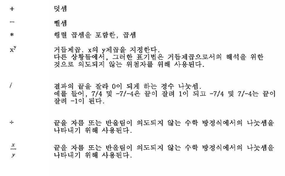
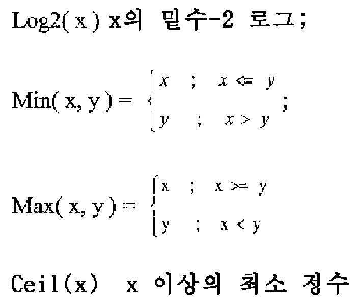
또한, 다음의 수학 함수들이 사용될 수 있다:In addition, the following mathematical functions can be used:
본 명세서에서 사용된 예시적인 신택스에 대하여, 논리 연산자들의 다음의 정의들이 적용될 수 있다:For the exemplary syntax used herein, the following definitions of logical operators may be applied:
x && y x 및 y의 부울 논리 "and"x && y Boolean logic "and" of x and y
x | | y x 및 y의 부울 논리 "or"x | | Boolean logic "or" of y x and y
! 부울 논리 "not"! Boolean logic "not"
x ? y : z x가 참이거나 0과 동일하지 않으면, y의 값으로 평가하고; 그렇지 않으면, z의 값으로 평가한다.x? y: If z x is true or not equal to 0, evaluate to the value of y; Otherwise, it is evaluated as the value of z.
또한, 다음의 관계 연산자들이 적용될 수 있다:In addition, the following relational operators can be applied:

또한, 본 명세서에서 사용된 신택스 디스크립터들에서, 다음의 디스크립터들이 적용될 수 있다는 점에 유의해야 한다:In addition, it should be noted that in the syntax descriptors used in this specification, the following descriptors may be applied:
-f(n): 좌측 비트가 먼저 (좌측에서 우측으로) 기입된 n개의 비트를 사용하는 고정 패턴 비트 스트링. 이 디스크립터에 대한 파싱 프로세스는 함수 read_bits(n)의 반환 값에 의해 지정된다.-f(n): A fixed pattern bit string using n bits with the left bit written first (from left to right). The parsing process for this descriptor is specified by the return value of the function read_bits(n).
-u(n): n개의 비트를 사용하는 부호 없는 정수. n이 신택스 테이블에서 "v"일 때, 비트들의 수는 다른 신택스 요소들의 값에 의존하는 방식으로 변한다. 이 디스크립터에 대한 파싱 프로세스는 최상위 비트가 먼저 기입된 부호 없는 정수의 이진 표현으로 해석되는 함수 read_bits(n)의 반환 값에 의해 지정된다.-u(n): An unsigned integer using n bits. When n is "v" in the syntax table, the number of bits changes in a way that depends on the values of other syntax elements. The parsing process for this descriptor is specified by the return value of the function read_bits(n), which is interpreted as a binary representation of an unsigned integer with the most significant bit written first.
-ue(v): 좌측 비트를 먼저 갖는 부호 없는 정수 0차 Exp-Golomb-코딩된 신택스 요소.-ue(v): An unsigned integer 0th order Exp-Golomb-coded syntax element with the left bit first.
-i(n): n개의 비트를 사용하는 부호 있는 정수. n이 신택스 테이블에서 "v"일 때, 비트들의 수는 다른 신택스 요소들의 값에 의존하는 방식으로 변한다. 이 디스크립터에 대한 파싱 프로세스는 최상위 비트가 먼저 기입된 2의 보수 정수 표현으로 해석되는 함수 read_bits(n)의 반환 값에 의해 지정된다.-i(n): A signed integer using n bits. When n is "v" in the syntax table, the number of bits changes in a way that depends on the values of other syntax elements. The parsing process for this descriptor is specified by the return value of the function read_bits(n), which is interpreted as a two's complement integer representation with the most significant bit written first.
전술된 바와 같이, ITU-T H.265에 따르면, 각각의 비디오 프레임 또는 픽처는 하나 이상의 슬라이스를 포함하도록 분할되고 하나 이상의 타일을 포함하도록 추가로 분할될 수 있다. 도 2는 슬라이스들을 포함하는 픽처들의 그룹의 예를 예시하는 개념도이다. 도 2에 예시된 예에서, Pic 4는 2개의 슬라이스(즉, Slice 1 및 Slice 2)를 포함하는 것으로 예시되며, 여기서 각각의 슬라이스는 (예를 들어, 래스터 스캔 순서로) CTU들의 시퀀스를 포함한다. 슬라이스는 독립 슬라이스 세그먼트로 시작하고 동일한 액세스 유닛 내의 다음 독립 슬라이스 세그먼트(존재하는 경우)에 선행하는 모든 후속 종속 슬라이스 세그먼트들(존재하는 경우)을 포함하는 하나 이상의 슬라이스 세그먼트의 시퀀스이다는 점에 유의해야 한다. 슬라이스 세그먼트는, 슬라이스와 같이, 코딩 트리 유닛들의 시퀀스이다. 본 명세서에 기술된 예들에서, 몇몇 경우에 용어 슬라이스 및 슬라이스 세그먼트는 코딩 트리 유닛들의 시퀀스를 나타내기 위해 상호 교환적으로 사용될 수 있다. ITU-T H.265에서, 타일은 하나 초과의 슬라이스에 포함된 코딩 트리 유닛들로 이루어질 수 있고 슬라이스는 하나 초과의 타일에 포함된 코딩 트리 유닛들로 이루어질 수 있다는 점에 유의해야 한다. 그러나, ITU-T H.265는 다음의 조건들 중 하나 또는 둘 모두가 충족되어야 한다고 규정한다: (1) 슬라이스 내의 모든 코딩 트리 유닛들이 동일한 타일에 속한다; 그리고 (2) 타일 내의 모든 코딩 트리 유닛들이 동일한 슬라이스에 속한다. 타일 세트들은 코딩 의존성들(예를 들어, 인트라-예측 의존성들, 엔트로피 인코딩 의존성들 등)에 대한 경계들을 정의하는 데 사용될 수 있고, 그렇기 때문에 코딩에서 병렬성을 가능하게 할 수 있다.As described above, according to ITU-T H.265, each video frame or picture may be divided to include one or more slices and may be further divided to include one or more tiles. 2 is a conceptual diagram illustrating an example of a group of pictures including slices. In the example illustrated in FIG. 2, Pic 4 is illustrated as comprising two slices (i.e., Slice 1 and Slice 2 ), where each slice contains a sequence of CTUs (e.g., in raster scan order). do. It should be noted that a slice is a sequence of one or more slice segments that starts with an independent slice segment and contains all subsequent dependent slice segments (if any) that precede the next independent slice segment (if any) within the same access unit. do. A slice segment, like a slice, is a sequence of coding tree units. In the examples described herein, in some cases the terms slice and slice segment may be used interchangeably to denote a sequence of coding tree units. It should be noted that in ITU-T H.265, a tile may consist of coding tree units included in more than one slice and a slice may consist of coding tree units included in more than one tile. However, ITU-T H.265 specifies that one or both of the following conditions must be satisfied: (1) All coding tree units in a slice belong to the same tile; And (2) all coding tree units in a tile belong to the same slice. Tile sets can be used to define boundaries for coding dependencies (eg, intra-prediction dependencies, entropy encoding dependencies, etc.), thereby enabling parallelism in coding.
ITU-T H.265에서, 코딩된 비디오 시퀀스(coded video sequence, CVS)가 액세스 유닛들의 시퀀스로서 캡슐화(또는 구조화)될 수 있으며, 여기서 각각의 액세스 유닛은 네트워크 추상화 계층(network abstraction layer, NAL) 유닛들로서 구조화된 비디오 데이터를 포함한다. ITU-T H.265에서, 비트스트림은 하나 이상의 CVS를 형성하는 NAL 유닛들의 시퀀스를 포함하는 것으로 설명된다. ITU-T H.265는 포맷 범위 확장(RExt)들, 확장성(SHVC), 멀티-뷰(MV-HEVC), 및 3-D(3D-HEVC)를 포함한 다층 확장들을 지원한다는 점에 유의해야 한다. 다층 확장들은 비디오 프레젠테이션이 기본 계층 및 하나 이상의 추가적인 향상 계층을 포함할 수 있게 한다. 예를 들어, 기본 계층은 기본 품질 레벨(예를 들어, 고화질 렌더링)을 갖는 비디오 프레젠테이션이 제시될 수 있게 할 수 있고 향상 계층은 향상된 품질 레벨(예를 들어, 초고화질 렌더링)을 갖는 비디오 프레젠테이션이 제시될 수 있게 할 수 있다. ITU-T H.265에서, 향상 계층은 기본 계층을 참조함으로써 코딩될 수 있다. 즉, 예를 들어, 향상 계층 내의 픽처는 기본 계층 내의 하나 이상의 픽처(그의 확장된 버전들을 포함함)를 참조함으로써 (예를 들어, 인터 예측 기법들을 사용하여) 코딩될 수 있다. ITU-T H.265에서, 각각의 NAL 유닛은 NAL 유닛이 그와 연관되는 비디오 데이터의 계층을 나타내는 식별자를 포함할 수 있다. 서브-비트스트림 추출은 컴플라이언트 비트스트림을 수신하는 디바이스가 수신된 비트스트림 내의 데이터를 폐기하고/하거나 수정함으로써 새로운 컴플라이언트 비트스트림을 형성하는 프로세스를 지칭할 수 있다는 점에 유의해야 한다. 예를 들어, 서브-비트스트림 추출은 비디오의 특정 표현(예를 들어, 고품질 표현)에 대응하는 새로운 컴플라이언트 비트스트림을 형성하는 데 사용될 수 있다.In ITU-T H.265, a coded video sequence (CVS) may be encapsulated (or structured) as a sequence of access units, where each access unit is a network abstraction layer (NAL). Contains video data structured as units. In ITU-T H.265, a bitstream is described as containing a sequence of NAL units forming one or more CVS. It should be noted that ITU-T H.265 supports multi-layer extensions including format range extensions (RExts), scalability (SHVC), multi-view (MV-HEVC), and 3-D (3D-HEVC). do. Multi-layer extensions allow a video presentation to include a base layer and one or more additional enhancement layers. For example, a base layer may allow a video presentation with a basic quality level (e.g., high definition rendering) to be presented, and an enhancement layer may allow a video presentation with an enhanced quality level (e.g., ultra-high definition rendering) to be presented. Can be presented. In ITU-T H.265, the enhancement layer can be coded by referring to the base layer. That is, for example, a picture in the enhancement layer can be coded (eg, using inter prediction techniques) by referring to one or more pictures (including extended versions thereof) in the base layer. In ITU-T H.265, each NAL unit may include an identifier indicating a layer of video data to which the NAL unit is associated with it. It should be noted that sub-bitstream extraction may refer to the process of forming a new compliant bitstream by a device receiving a compliant bitstream by discarding and/or modifying data in the received bitstream. For example, sub-bitstream extraction can be used to form a new compliant bitstream that corresponds to a specific representation of the video (eg, a high quality representation).
도 2에 예시된 예를 참조하면, Pic 4에 포함된 비디오 데이터의 각각의 슬라이스(즉, Slice 1 및 Slice 2)는 NAL 유닛에 캡슐화된 것으로 예시되어 있다. ITU-T H.265에서, 비디오 시퀀스, GOP, 픽처, 슬라이스, 및 CTU 각각은 비디오 코딩 특성들을 설명하는 메타데이터와 연관될 수 있다. ITU-T H.265는 비디오 데이터 및/또는 비디오 코딩 특성들을 설명하는 데 사용될 수 있는 파라미터 세트들을 정의한다. ITU-T H.265에서, 파라미터 세트들은 NAL 유닛의 특수한 타입으로서 캡슐화될 수 있거나 메시지로서 시그널링될 수 있다. 코딩된 비디오 데이터(예를 들어, 슬라이스)를 포함하는 NAL 유닛들은 VCL(Video Coding Layer, 비디오 코딩 계층) NAL 유닛들로 지칭될 수 있고 메타데이터(예를 들어, 파라미터 세트들)를 포함하는 NAL 유닛들은 비-VCL NAL 유닛들로 지칭될 수 있다. 또한, ITU-T H.265는 보완 향상 정보(supplemental enhancement information, SEI) 메시지들이 시그널링될 수 있게 한다. ITU-T H.265에서, SEI 메시지들은 디코딩, 디스플레이 또는 다른 목적들과 관련된 프로세스들을 지원하지만, SEI 메시지들은 디코딩 프로세스에 의해 루마 또는 크로마 샘플들을 구성하는 데 필요하지 않을 수 있다. ITU-T H.265에서, SEI 메시지들은 비-VCL NAL 유닛들을 사용하여 비트스트림에서 시그널링될 수 있다. 또한, SEI 메시지들은 비트스트림 내에 존재하는 것 이외의 어떤 수단에 의해 운반될 수 있다(즉, 대역외 시그널링될 수 있다).Referring to the example illustrated in FIG. 2, it is illustrated that each slice (ie, Slice 1 and Slice 2 ) of video data included in Pic 4 is encapsulated in a NAL unit. In ITU-T H.265, each of a video sequence, GOP, picture, slice, and CTU may be associated with metadata describing video coding characteristics. ITU-T H.265 defines parameter sets that can be used to describe video data and/or video coding characteristics. In ITU-T H.265, parameter sets may be encapsulated as a special type of NAL unit or may be signaled as a message. NAL units containing coded video data (e.g., slice) may be referred to as Video Coding Layer (VCL) NAL units and NAL containing metadata (e.g., parameter sets) Units may be referred to as non-VCL NAL units. In addition, ITU-T H.265 enables supplemental enhancement information (SEI) messages to be signaled. In ITU-T H.265, SEI messages support processes related to decoding, display or other purposes, but SEI messages may not be required to construct luma or chroma samples by the decoding process. In ITU-T H.265, SEI messages can be signaled in the bitstream using non-VCL NAL units. In addition, SEI messages may be carried by any means other than those present in the bitstream (ie, they may be signaled out of band).
도 3은 다수의 CVS를 포함하는 비트스트림의 예를 예시하며, 여기서 CVS가 각자의 액세스 유닛에 포함된 NAL 유닛에 의해 표현된다. 도 3에 예시된 예에서, 비-VCL NAL 유닛은 각자의 파라미터 세트 유닛(즉, 비디오 파라미터 세트(Video Parameter Set, VPS), 시퀀스 파라미터 세트(Sequence Parameter Set, SPS), 및 픽처 파라미터 세트(Picture Parameter Set, PPS) 유닛) 및 액세스 유닛 디리미터 NAL 유닛을 포함한다. ITU-T H.265는 NAL 유닛에 포함된 RBSP(Raw Byte Sequence Payload) 데이터 구조의 타입을 지정하는 NAL 유닛 헤더 시맨틱을 정의한다. ITU-T H.265는 디코딩 순서 및/또는 출력 순서에 기초하여 정의된 다양한 픽처 타입들을 제공한다는 점에 유의해야 한다. ITU-T H.265에서, 인트라 랜덤 액세스 포인트(intra random access point, IRAP) 픽처는 그의 디코딩 프로세스에서 인터 예측을 위해 그 자신 이외의 어떠한 픽처도 참조하지 않는 픽처이고, 디코딩 순서에서 비트스트림 내의 첫 번째 픽처는 IRAP 픽처이어야 한다. ITU-T H.265에서, IRAP 픽처들이 아닌, 그의 디코딩 프로세스에서 인터 예측을 위해 그 자신 이외의 어떠한 픽처도 참조하지 않는 비트스트림 내의 픽처들이 있을 수 있다는 점에 유의해야 한다. IRAP 픽처의 예는 순간 디코딩 리프레시(instantaneous decoding refresh, IDR) 픽처를 포함하는데, 이는 그의 디코딩 프로세스에서 인터 예측을 위해 그 자신 이외의 어떠한 픽처도 참조하지 않는 픽처이고 디코딩 순서에서 비트스트림 내의 첫 번째 픽처일 수 있거나, 나중에 비트스트림에 나타날 수 있다. ITU-T H.265는 선두 픽처가 출력 순서에서 연관된 IRAP 픽처에 선행하는 픽처이고 후미 픽처가 출력 순서에서 연관된 IRAP 픽처를 뒤따르는 비-IRAP 픽처인 경우를 제공한다. IRAP 픽처와 연관된 후미 픽처들이 또한 디코딩 순서에서 IRAP 픽처를 뒤따르고 출력 순서에서 연관된 IRAP 픽처를 뒤따르고 디코딩 순서에서 연관된 IRAP 픽처에 선행하는 픽처들은 허용되지 않는다는 점에 유의해야 한다.3 illustrates an example of a bitstream including multiple CVSs, where CVS is represented by a NAL unit included in each access unit. In the example illustrated in FIG. 3, the non-VCL NAL units are each parameter set unit (i.e., a video parameter set (VPS), a sequence parameter set (SPS)), and a picture parameter set (Picture Parameter Set, PPS) unit) and access unit delimiter NAL unit. ITU-T H.265 defines the NAL unit header semantics that designate the type of the RBSP (Raw Byte Sequence Payload) data structure included in the NAL unit. It should be noted that ITU-T H.265 provides various picture types defined based on decoding order and/or output order. In ITU-T H.265, an intra random access point (IRAP) picture is a picture that does not refer to any picture other than itself for inter prediction in its decoding process, and the first in the bitstream in decoding order The first picture must be an IRAP picture. It should be noted that in ITU-T H.265, there may be pictures in the bitstream that are not IRAP pictures, but do not refer to any picture other than themselves for inter prediction in its decoding process. An example of an IRAP picture includes an instantaneous decoding refresh (IDR) picture, which is a picture that does not refer to any picture other than itself for inter prediction in its decoding process, and is the first picture in the bitstream in decoding order. May be, or may appear in the bitstream later. ITU-T H.265 provides a case where the leading picture is a picture preceding the associated IRAP picture in output order and the trailing picture is a non-IRAP picture following the associated IRAP picture in output order. It should be noted that the trailing pictures associated with the IRAP picture also follow the IRAP picture in decoding order and the associated IRAP picture in the output order and pictures preceding the associated IRAP picture in decoding order are not allowed.
ITU-T H.265는 각각의 코딩된 픽처가 PicOrderCntVal로 표시된, 픽처 순서 카운트 변수와 연관되는 경우를 제공한다. ITU-T H.265에서, 픽처 순서 카운트들은 픽처들을 식별하고, 병합 모드 및 모션 벡터 예측에서 모션 파라미터들을 도출하고, 디코더 적합성 검사에 사용된다. ITU-T H.265에서, 하나의 CVS에서, 모든 코딩된 픽처들에 대한 PicOrderCntVal 값들은 고유하다. 또한, ITU-T H.265에서 픽처 순서 카운트들은 CVS에 포함된 (즉, 예를 들어 디스플레이를 위한, 디코딩된 픽처 버퍼로부터의) 픽처들의 상대적 출력 순서를 제공한다(즉, 더 낮은 픽처 순서 카운트들을 갖는 픽처들은 더 높은 픽처 순서 카운트들을 갖는 픽처들 전에 출력된다). ITU-T H.265에서, PicOrderCntVal의 값은 -2 31 내지 2 31 - 1(이들 값 포함)의 범위에 있다. ITU-T H.265에서, 시퀀스 파라미터 세트 신택스는 다음과 같이 픽처 순서 카운트에 대한 디코딩 프로세스에서 사용되는 변수 MaxPicOrderCntLsb의 값을 지정하는 신택스 요소 log2_max_pic_order_cnt_lsb_minus4를 포함한다:ITU-T H.265 provides a case where each coded picture is associated with a picture order count variable, denoted PicOrderCntVal. In ITU-T H.265, picture order counts identify pictures, derive motion parameters in merge mode and motion vector prediction, and are used for decoder conformance check. In ITU-T H.265, in one CVS, PicOrderCntVal values for all coded pictures are unique. In addition, the picture order counts in ITU-T H.265 provide the relative output order of the pictures included in the CVS (i.e., from the decoded picture buffer, for display, i.e., lower picture order count). Pictures with higher picture order counts are output before pictures with higher picture order counts). In ITU-T H.265, the values are PicOrderCntVal -2 31 to 2 31 - in the range of from 1 (included these values). In ITU-T H.265, the sequence parameter set syntax includes a syntax element log2_max_pic_order_cnt_lsb_minus4 that specifies the value of the variable MaxPicOrderCntLsb used in the decoding process for picture order count as follows:
![]()
![]()
여기서, log2_max_pic_order_cnt_lsb_minus4의 값은 0 내지 12(이들 값 포함)의 범위에 있어야 한다.Here, the value of log2_max_pic_order_cnt_lsb_minus4 should be in the range of 0 to 12 (including these values).
ITU-T H.265는 PicOrderCntVal이 PicOrderCntMsb + slice_pic_order_cnt_lsb와 동일한 경우를 제공한다. slice_pic_order_cnt_lsb는 다음과 같이 도출된다:ITU-T H.265 provides a case where PicOrderCntVal is the same as PicOrderCntMsb + slice_pic_order_cnt_lsb. slice_pic_order_cnt_lsb is derived as follows:
현재 픽처가 IRAP 픽처가 아니고 출력될 때, 변수 prevPicOrderCntLsb는 다음과 같이 도출된다:When the current picture is not an IRAP picture and is output, the variable prevPicOrderCntLsb is derived as follows:
- prevTid0Pic를 0과 동일한 TemporalId를 갖고 RASL(random access skipped leading), RADL(random access decodable leading), 또는 SLNR(sub-layer non-reference) 픽처가 아닌 디코딩 순서에서의 이전 픽처라고 한다.-The prevTid0Pic has a TemporalId equal to 0 and is called a previous picture in decoding order, not a random access skipped leading (RASL), random access decodable leading (RADL), or sub-layer non-reference (SLNR) picture.
- 변수 prevPicOrderCntLs는 prevTid0Pic의 slice_pic_order_cnt_lsb와 동일하게 설정된다. -The variable prevPicOrderCntLs is set the same as slice_pic_order_cnt_lsb of prevTid0Pic.
여기서, 신택스 요소 slice_pic_order_cnt_lsb는 픽처가 IRAP 픽처가 아니고 다음의 정의를 가질 때 slice_segment_header() 신택스에 조건부로 포함된다:Here, the syntax element slice_pic_order_cnt_lsb is conditionally included in the slice_segment_header() syntax when the picture is not an IRAP picture and has the following definition:
slice_pic_order_cnt_lsb는 현재 픽처에 대한 픽처 순서 카운트 모듈로 MaxPicOrderCntLsb를 지정한다. slice_pic_order_cnt_lsb 신택스 요소의 길이는 log2_max_pic_order_cnt_lsb_minus4+4 비트이다. slice_pic_order_cnt_lsb의 값은 0 내지 MaxPicOrderCntLsb-1(이들 값 포함)의 범위에 있어야 한다. slice_pic_order_cnt_lsb가 존재하지 않을 때, slice_pic_order_cnt_lsb는 (생성된 픽처 이외의 경우들에 대해) 0과 동일한 것으로 추론된다.slice_pic_order_cnt_lsb designates MaxPicOrderCntLsb as a picture order count module for the current picture. The length of the slice_pic_order_cnt_lsb syntax element is log2_max_pic_order_cnt_lsb_minus4+4 bits. The value of slice_pic_order_cnt_lsb must be in the range of 0 to MaxPicOrderCntLsb-1 (including these values). When slice_pic_order_cnt_lsb does not exist, slice_pic_order_cnt_lsb is inferred to be equal to 0 (for cases other than the generated picture).
ITU-T H.265에서 PicOrderCntMsb는 다음과 같이 도출된다:In ITU-T H.265, PicOrderCntMsb is derived as follows:
현재 픽처가 IRAP 픽처가 아니고 출력될 때, 변수 prevPicOrderCntLsb는 다음과 같이 도출된다:When the current picture is not an IRAP picture and is output, the variable prevPicOrderCntLsb is derived as follows:
- 변수 prevPicOrderCntMsb는 prevTid0Pic의 PicOrderCntMsb와 동일하게 설정된다.-The variable prevPicOrderCntMsb is set the same as PicOrderCntMsb of prevTid0Pic.
- 현재 픽처가 1과 동일한 NoRaslOutputFlag를 갖는 IRAP 픽처이면, PicOrderCntMsb는 0과 동일하게 설정된다.-If the current picture is an IRAP picture with NoRaslOutputFlag equal to 1, PicOrderCntMsb is set equal to 0.
- 그렇지 않으면, PicOrderCntMsb는 다음과 같이 도출된다:-Otherwise, PicOrderCntMsb is derived as follows:
if((slice_pic_order_cnt_lsb < prevPicOrderCntLsb) &&if((slice_pic_order_cnt_lsb <prevPicOrderCntLsb) &&
((prevPicOrderCntLsb - slice_pic_order_cnt_lsb) >=((prevPicOrderCntLsb-slice_pic_order_cnt_lsb) >=
(MaxPicOrderCntLsb / 2)))(MaxPicOrderCntLsb/2)))
PicOrderCntMsb = prevPicOrderCntMsb + MaxPicOrderCntLsbPicOrderCntMsb = prevPicOrderCntMsb + MaxPicOrderCntLsb
else if((slice_pic_order_cnt_lsb - prevPicOrderCntLsb) &&else if((slice_pic_order_cnt_lsb-prevPicOrderCntLsb) &&
((slice_pic_order_cnt_lsb - prevPicOrderCntLsb) >((slice_pic_order_cnt_lsb-prevPicOrderCntLsb)>
(MaxPicOrderCntLsb / 2)))(MaxPicOrderCntLsb/2)))
PicOrderCntMsb = prevPicOrderCntMsb - MaxPicOrderCntLsbPicOrderCntMsb = prevPicOrderCntMsb-MaxPicOrderCntLsb
elseelse
PicOrderCntMsb = prevPicOrderCntMsbPicOrderCntMsb = prevPicOrderCntMsb
ITU-T H.265에서, slice_pic_order_cnt_lsb가 IDR 픽처들에 대해 0인 것으로 추론되고 prevPicOrderCntLsb 및 prevPicOrderCntMsb가 둘 모두 0과 동일하게 설정되므로, 모든 IDR 픽처들은 0과 동일한 PicOrderCntVal을 가질 것이라는 점에 유의해야 한다.In ITU-T H.265, it should be noted that since slice_pic_order_cnt_lsb is inferred to be 0 for IDR pictures and prevPicOrderCntLsb and prevPicOrderCntMsb are both set equal to 0, so all IDR pictures will have PicOrderCntVal equal to 0.
JVET-J1001은 표 1에 예시된 슬라이스 헤드 신택스를 제공한다는 점에 유의해야 한다.It should be noted that JVET-J1001 provides the slice head syntax illustrated in Table 1.
[표 1][Table 1]
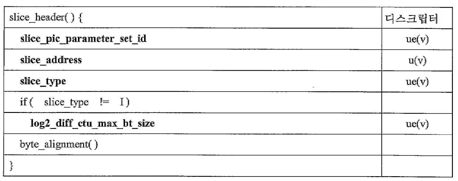
JVET-J1001은 표 1에 예시된 각자의 신택스 요소들에 대해 다음의 정의들을 제공한다.JVET-J1001 provides the following definitions for the respective syntax elements illustrated in Table 1.
slice_pic_parameter_set_id는 사용 중인 PPS에 대한 pps_pic_parameter_set_id의 값을 지정한다. slice_pic_parameter_set_id의 값은 0 내지 63(이들 값 포함)의 범위에 있어야 한다.slice_pic_parameter_set_id specifies the value of pps_pic_parameter_set_id for the PPS in use. The value of slice_pic_parameter_set_id must be in the range of 0 to 63 (including these values).
slice_address는 픽처의 CTB 래스터 스캔에서 슬라이스 내의 첫 번째 CTB의 어드레스를 지정한다. slice_address 신택스 요소의 길이는 Ceil(Log2(PicSizeInCtbY)) 비트이다. slice_address의 값은 0 내지 PicSizeInCtbsY - 1(이들 값 포함)의 범위에 있어야 하고, slice_address의 값은 동일한 코딩된 픽처의 임의의 다른 코딩된 슬라이스 NAL 유닛의 slice_address의 값과 동일하지 않아야 한다. 픽처의 CTB 래스터 스캔에서 CTB 어드레스를 지정하는 변수 CtbAddrInRs는 slice_address와 동일하게 설정된다.slice_address designates the address of the first CTB in the slice in the CTB raster scan of the picture. The length of the slice_address syntax element is Ceil(Log2(PicSizeInCtbY)) bits. The value of slice_address must be in the range of 0 to PicSizeInCtbsY-1 (including these values), and the value of slice_address must not be the same as the value of slice_address of any other coded slice NAL unit of the same coded picture. A variable CtbAddrInRs that designates a CTB address in a CTB raster scan of a picture is set equal to slice_address.
slice_type은 표 2에 따라 슬라이스의 코딩 타입을 지정한다.slice_type designates the coding type of a slice according to Table 2.
[표 2][Table 2]

nal_unit_type이 [결정될](하한 및 상한 값 포함)의 범위에 있는 값을 가질 때, 즉 픽처가 IRAP 픽처일 때, slice_type은 2와 동일해야 한다.When nal_unit_type has a value in the range of [to be determined] (including lower and upper limit values), that is, when the picture is an IRAP picture, slice_type must be equal to 2.
log2_diff_ctu_max_bt_size는 이진 분할을 이용하여 분할될 수 있는 코딩 블록의 최대 루마 크기(폭 또는 높이)와 루마 CTB 크기 사이의 차이를 지정한다. log2_diff_ctu_max_bt_size의 값은 0 내지 CtbLog2SizeY - MinCbLog2SizeY(이들 값 포함)의 범위에 있어야 한다.log2_diff_ctu_max_bt_size specifies the difference between the maximum luma size (width or height) and the luma CTB size of a coding block that can be partitioned using binary partitioning. The value of log2_diff_ctu_max_bt_size must be in the range of 0 to CtbLog2SizeY-MinCbLog2SizeY (including these values).
B 슬라이스는 이중-예측 인터 예측, 단일-예측 인터 예측, 및 인트라 서술이 허용되는 슬라이스를 지칭하고; P 슬라이스는 단일-예측 인터 예측 및 인트라 서술이 허용되는 슬라이스를 지칭하고; I 슬라이스는 인트라 서술만이 허용되는 슬라이스를 지칭한다는 점에 유의해야 한다. 몇몇 경우에 B 및 P 슬라이스들은 집합적으로 인터 슬라이스들로 지칭된다는 점에 유의해야 한다.B slice refers to a slice in which double-prediction inter prediction, single-prediction inter prediction, and intra description are allowed; P slice refers to a slice in which single-prediction inter prediction and intra description are allowed; It should be noted that I slice refers to a slice in which only intra descriptions are allowed. It should be noted that in some cases B and P slices are collectively referred to as inter slices.
본 개시는 픽처 순서 카운트 값들을 시그널링하기 위한 기법들을 기술하며, 이들은 간단하고 ITU-T H.265에 기술된 것에 비해 더 많은 유연성을 제공한다. 본 명세서에 기술된 기법들에 따르면, 비디오 인코더는 본 명세서에 기술된 신택스 및 시맨틱을 사용하여 픽처 순서 카운트 값 등을 시그널링할 수 있다. 비디오 디코더는 본 명세서에 기술된 신택스 및 시맨틱을 사용하는 시그널링을 파싱함으로써 픽처 순서 카운트 값 등을 결정하고 결정된 픽처 순서 카운트 값에 기초하여 비디오 디코딩을 수행하고 픽처를 출력할 수 있다.This disclosure describes techniques for signaling picture order count values, which are simple and provide more flexibility than those described in ITU-T H.265. According to the techniques described herein, a video encoder may signal a picture order count value or the like using the syntax and semantics described herein. The video decoder may determine a picture order count value or the like by parsing signaling using syntax and semantics described herein, perform video decoding based on the determined picture order count value, and output a picture.
도 1은 본 개시의 하나 이상의 기법에 따라 비디오 데이터를 코딩(즉, 인코딩 및/또는 디코딩)하도록 구성될 수 있는 시스템의 예를 예시하는 블록도이다. 시스템(100)은 본 개시의 하나 이상의 기법에 따라 비디오 데이터를 캡슐화할 수 있는 시스템의 예를 나타낸다. 도 1에 예시된 바와 같이, 시스템(100)은 소스 디바이스(102), 통신 매체(110), 및 목적지 디바이스(120)를 포함한다. 도 1에 예시된 예에서, 소스 디바이스(102)는 비디오 데이터를 인코딩하고 인코딩된 비디오 데이터를 통신 매체(110)에 송신하도록 구성된 임의의 디바이스를 포함할 수 있다. 목적지 디바이스(120)는 인코딩된 비디오 데이터를 통신 매체(110)를 통해 수신하도록 그리고 인코딩된 비디오 데이터를 디코딩하도록 구성된 임의의 디바이스를 포함할 수 있다. 소스 디바이스(102) 및/또는 목적지 디바이스(120)는 유선 및/또는 무선 통신들을 위해 갖춰진 컴퓨팅 디바이스를 포함할 수 있고, 예를 들어 셋톱 박스, 디지털 비디오 레코더, 텔레비전, 데스크톱, 랩톱 또는 태블릿 컴퓨터, 게이밍 콘솔, 의료 이미징 디바이스, 및 예를 들어 스마트 폰, 셀룰러 폰, 개인 게이밍 디바이스를 포함하는 모바일 디바이스를 포함할 수 있다.1 is a block diagram illustrating an example of a system that may be configured to code (ie, encode and/or decode) video data in accordance with one or more techniques of this disclosure.
통신 매체(110)는 무선 및 유선 통신 매체, 및/또는 저장 디바이스들의 임의의 조합을 포함할 수 있다. 통신 매체(110)는 동축 케이블, 광섬유 케이블, 트위스티드 페어 케이블, 무선 송신기 및 수신기, 라우터, 스위치, 리피터, 기지국, 또는 다양한 디바이스들과 사이트들 사이의 통신을 용이하게 하는 데 유용할 수 있는 임의의 다른 장비를 포함할 수 있다. 통신 매체(110)는 하나 이상의 네트워크를 포함할 수 있다. 예를 들어, 통신 매체(110)는 월드 와이드 웹, 예를 들어 인터넷에의 액세스를 가능하게 하도록 구성된 네트워크를 포함할 수 있다. 네트워크는 하나 이상의 전기통신 프로토콜의 조합에 따라 동작할 수 있다. 전기통신 프로토콜들은 독점적인 태양들을 포함할 수 있고/있거나 표준화된 전기통신 프로토콜들을 포함할 수 있다. 표준화된 전기통신 프로토콜들의 예들은 DVB(Digital Video Broadcasting) 표준, ATSC(Advanced Television Systems Committee) 표준, ISDB(Integrated Services Digital Broadcasting) 표준, DOCSIS(Data Over Cable Service Interface Specification) 표준, GSM(Global System Mobile Communications) 표준, CDMA(code division multiple access) 표준, 3GPP(3rd Generation Partnership Project) 표준, ETSI(European Telecommunications standards Institute) 표준, IP(Internet Protocol) 표준, WAP(Wireless Application Protocol) 표준, 및 IEEE(Institute of Electrical and Electronics Engineers) 표준을 포함한다.
저장 디바이스들은 데이터를 저장할 수 있는 임의의 타입의 디바이스 또는 저장 매체를 포함할 수 있다. 저장 매체는 유형의(tangible) 또는 비일시적 컴퓨터 판독 가능 매체를 포함할 수 있다. 컴퓨터 판독 가능 매체는 광 디스크, 플래시 메모리, 자기 메모리, 또는 임의의 다른 적합한 디지털 저장 매체들을 포함할 수 있다. 몇몇 예에서, 메모리 디바이스 또는 그의 부분들은 비휘발성 메모리로서 기술될 수 있고 다른 예들에서 메모리 디바이스들의 부분들은 휘발성 메모리로서 기술될 수 있다. 휘발성 메모리들의 예들은 랜덤 액세스 메모리(RAM), 동적 랜덤 액세스 메모리(DRAM), 및 정적 랜덤 액세스 메모리(SRAM)를 포함할 수 있다. 비휘발성 메모리들의 예들은 자기 하드 디스크, 광 디스크, 플로피 디스크, 플래시 메모리, 또는 EPROM(electrically programmable memory) 또는 EEPROM(electrically erasable and programmable memory)의 형태를 포함할 수 있다. 저장 디바이스(들)는 메모리 카드(예컨대, SD(Secure Digital) 메모리 카드), 내부/외부 하드 디스크 드라이브, 및/또는 내부/외부 솔리드 스테이트 드라이브를 포함할 수 있다. 데이터는 정의된 파일 포맷에 따라 저장 디바이스에 저장될 수 있다.Storage devices may include any type of device or storage medium capable of storing data. The storage medium may include a tangible or non-transitory computer-readable medium. Computer-readable media may include optical disks, flash memory, magnetic memory, or any other suitable digital storage media. In some examples, the memory device or portions thereof may be described as non-volatile memory and in other examples portions of the memory devices may be described as volatile memory. Examples of volatile memories may include random access memory (RAM), dynamic random access memory (DRAM), and static random access memory (SRAM). Examples of nonvolatile memories may include a magnetic hard disk, an optical disk, a floppy disk, a flash memory, or in the form of an electrically programmable memory (EPROM) or an electrically erasable and programmable memory (EEPROM). The storage device(s) may include a memory card (eg, a Secure Digital (SD) memory card), an internal/external hard disk drive, and/or an internal/external solid state drive. Data may be stored in the storage device according to the defined file format.
도 4는 시스템(100)의 구현에 포함될 수 있는 컴포넌트들의 예를 예시하는 개념도이다. 도 4에 예시된 예시적인 구현에서, 시스템(100)은 하나 이상의 컴퓨팅 디바이스(402A-402N), 텔레비전 서비스 네트워크(404), 텔레비전 서비스 제공자 사이트(406), 광역 네트워크(408), 근거리 네트워크(410), 및 하나 이상의 콘텐츠 제공자 사이트(412A-412N)를 포함한다. 도 4에 예시된 구현은 예를 들어 영화, 라이브 스포츠 이벤트 등과 같은 디지털 미디어 콘텐츠, 및 데이터 및 애플리케이션들 및 그와 연관된 미디어 프레젠테이션들이 컴퓨팅 디바이스들(402A-402N)과 같은 복수의 컴퓨팅 디바이스에 분배되고 그들에 의해 액세스될 수 있게 하도록 구성될 수 있는 시스템의 예를 나타낸다. 도 4에 예시된 예에서, 컴퓨팅 디바이스들(402A-402N)은 텔레비전 서비스 네트워크(404), 광역 네트워크(408), 및/또는 근거리 네트워크(410) 중 하나 이상으로부터 데이터를 수신하도록 구성된 임의의 디바이스를 포함할 수 있다. 예를 들어, 컴퓨팅 디바이스들(402A-402N)은 유선 및/또는 무선 통신을 위해 갖춰질 수 있고, 하나 이상의 데이터 채널을 통해 서비스를 수신하도록 구성될 수 있고, 소위 스마트 텔레비전을 포함한 텔레비전, 셋톱 박스, 및 디지털 비디오 레코더를 포함할 수 있다. 게다가, 컴퓨팅 디바이스들(402A-402N)은 데스크톱, 랩톱 또는 태블릿 컴퓨터, 게임 콘솔, 예를 들어 "스마트" 폰, 셀룰러 폰, 및 개인 게이밍 디바이스들을 포함한 모바일 디바이스를 포함할 수 있다.4 is a conceptual diagram illustrating an example of components that may be included in the implementation of the
텔레비전 서비스 네트워크(404)는 텔레비전 서비스들을 포함할 수 있는 디지털 미디어 콘텐츠가 분배될 수 있게 하도록 구성된 네트워크의 예이다. 예를 들어, 텔레비전 서비스 네트워크(404)는 공개 공중파 텔레비전 네트워크, 공개 또는 구독 기반 위성 텔레비전 서비스 제공자 네트워크, 및 공개 또는 구독 기반 케이블 텔레비전 제공자 네트워크 및/또는 오버 더 톱(over the top) 또는 인터넷 서비스 제공자를 포함할 수 있다. 몇몇 예에서 텔레비전 서비스 네트워크(404)가 주로 텔레비전 서비스들이 제공될 수 있게 하는 데 사용될 수 있지만, 텔레비전 서비스 네트워크(404)는 또한 본 명세서에서 설명된 전기통신 프로토콜들의 임의의 조합에 따라 다른 타입의 데이터 및 서비스가 제공될 수 있게 할 수 있다는 점에 유의해야 한다. 또한, 몇몇 예에서, 텔레비전 서비스 네트워크(404)는 텔레비전 서비스 제공자 사이트(406)와 컴퓨팅 디바이스들(402A-402N) 중 하나 이상 사이의 쌍방향 통신을 가능하게 할 수 있다는 점에 유의해야 한다. 텔레비전 서비스 네트워크(404)는 무선 및/또는 유선 통신 매체의 임의의 조합을 포함할 수 있다. 텔레비전 서비스 네트워크(404)는 동축 케이블, 광섬유 케이블, 트위스티드 페어 케이블, 무선 송신기 및 수신기, 라우터, 스위치, 리피터, 기지국, 또는 다양한 디바이스들과 사이트들 사이의 통신을 용이하게 하는 데 유용할 수 있는 임의의 다른 장비를 포함할 수 있다. 텔레비전 서비스 네트워크(404)는 하나 이상의 전기통신 프로토콜의 조합에 따라 동작할 수 있다. 전기통신 프로토콜들은 독점적인 태양들을 포함할 수 있고/있거나 표준화된 전기통신 프로토콜들을 포함할 수 있다. 표준화된 전기통신 프로토콜들의 예들은 DVB 표준, ATSC 표준, ISDB 표준, DTMB 표준, DMB 표준, DOCSIS(Data Over Cable Service Interface Specification) 표준, HbbTV 표준, W3C 표준, 및 UPnP 표준을 포함한다.
도 4를 다시 참조하면, 텔레비전 서비스 제공자 사이트(406)는 텔레비전 서비스 네트워크(404)를 통해 텔레비전 서비스를 분배하도록 구성될 수 있다. 예를 들어, 텔레비전 서비스 제공자 사이트(406)는 하나 이상의 방송국, 케이블 텔레비전 제공자, 또는 위성 텔레비전 제공자, 또는 인터넷 기반 텔레비전 제공자를 포함할 수 있다. 예를 들어, 텔레비전 서비스 제공자 사이트(406)는 위성 업링크/다운링크를 통해 텔레비전 프로그래밍을 포함하는 송신을 수신하도록 구성될 수 있다. 또한, 도 4에 예시된 바와 같이, 텔레비전 서비스 제공자 사이트(406)는 광역 네트워크(408)와 통신할 수 있고 콘텐츠 제공자 사이트들(412A-412N)로부터 데이터를 수신하도록 구성될 수 있다. 몇몇 예에서, 텔레비전 서비스 제공자 사이트(406)는 텔레비전 스튜디오를 포함할 수 있고 그로부터 콘텐츠가 비롯될 수 있다는 점에 유의해야 한다.Referring again to FIG. 4, the television service provider site 406 may be configured to distribute television services through the
광역 네트워크(408)는 패킷 기반 네트워크를 포함하고 하나 이상의 전기통신 프로토콜의 조합에 따라 동작할 수 있다. 전기통신 프로토콜들은 독점적인 태양들을 포함할 수 있고/있거나 표준화된 전기통신 프로토콜들을 포함할 수 있다. 표준화된 전기통신 프로토콜들의 예들은 GSM(Global System Mobile Communications) 표준, CDMA(code division multiple access) 표준, 3GPP(3 rd Generation Partnership Project) 표준, ETSI(European Telecommunications Standards Institute) 표준, 유럽 표준(EN), IP 표준, WAP(Wireless Application Protocol) 표준, 및 IEEE(Institute of Electrical and Electronics Engineers) 표준, 이를테면 예를 들어 IEEE 802 표준들 중 하나 이상(예를 들어, Wi-Fi)을 포함한다. 광역 네트워크(408)는 무선 및/또는 유선 통신 매체의 임의의 조합을 포함할 수 있다. 광역 네트워크(408)는 동축 케이블, 광섬유 케이블, 트위스티드 페어 케이블, 이더넷 케이블, 무선 송신기 및 수신기, 라우터, 스위치, 리피터, 기지국, 또는 다양한 디바이스들과 사이트들 사이의 통신을 용이하게 하는 데 유용할 수 있는 임의의 다른 장비를 포함할 수 있다. 일례에서, 광역 네트워크(408)는 인터넷을 포함할 수 있다. 근거리 네트워크(410)는 패킷 기반 네트워크를 포함하고 하나 이상의 전기통신 프로토콜의 조합에 따라 동작할 수 있다. 근거리 네트워크(410)는 액세스 레벨 및/또는 물리적 인프라스트럭처에 기초하여 광역 네트워크(408)와 구별될 수 있다. 예를 들어, 근거리 네트워크(410)는 보안 홈 네트워크를 포함할 수 있다.
다시 도 4를 참조하면, 콘텐츠 제공자 사이트들(412A-412N)은 멀티미디어 콘텐츠를 텔레비전 서비스 제공자 사이트(406) 및/또는 컴퓨팅 디바이스들(402A-402N)에 제공할 수 있는 사이트들의 예를 나타낸다. 예를 들어, 콘텐츠 제공자 사이트는 멀티미디어 파일 및/또는 스트림을 텔레비전 서비스 제공자 사이트(406)에 제공하도록 구성된 하나 이상의 스튜디오 콘텐츠 서버를 갖는 스튜디오를 포함할 수 있다. 일례에서, 콘텐츠 제공자 사이트들(412A-412N)은 IP 스위트(suite)를 이용하여 멀티미디어 콘텐츠를 제공하도록 구성될 수 있다. 예를 들어, 콘텐츠 제공자 사이트는 RTSP(Real Time Streaming Protocol), HTTP 등에 따라 수신기 디바이스에 멀티미디어 콘텐츠를 제공하도록 구성될 수 있다. 또한, 콘텐츠 제공자 사이트들(412A-412N)은 광역 네트워크(408)를 통해 수신기 디바이스들, 컴퓨팅 디바이스들(402A-402N) 및/또는 텔레비전 서비스 제공자 사이트(406) 중 하나 이상에 하이퍼텍스트 기반 콘텐츠 등을 포함한 데이터를 제공하도록 구성될 수 있다. 콘텐츠 제공자 사이트들(412A-412N)은 하나 이상의 웹 서버를 포함할 수 있다. 데이터 제공자 사이트(412A-412N)에 의해 제공되는 데이터는 데이터 포맷들에 따라 정의될 수 있다.Referring again to FIG. 4, content provider sites 412A-412N represent an example of sites that may provide multimedia content to a television service provider site 406 and/or computing devices 402A-402N. For example, a content provider site may include a studio having one or more studio content servers configured to provide multimedia files and/or streams to the television service provider site 406. In one example, content provider sites 412A-412N may be configured to provide multimedia content using an IP suite. For example, the content provider site may be configured to provide multimedia content to a receiver device according to Real Time Streaming Protocol (RTSP), HTTP, or the like. In addition, content provider sites 412A-412N may provide hypertext-based content, etc. to one or more of receiver devices, computing devices 402A-402N and/or television service provider sites 406 via
다시 도 1을 참조하면, 소스 디바이스(102)는 비디오 소스(104), 비디오 인코더(106), 데이터 캡슐화기(107), 및 인터페이스(108)를 포함한다. 비디오 소스(104)는 비디오 데이터를 캡처하고/하거나 저장하도록 구성된 임의의 디바이스를 포함할 수 있다. 예를 들어, 비디오 소스(104)는 비디오 카메라 및 그에 동작 가능하게 결합된 저장 디바이스를 포함할 수 있다. 비디오 인코더(106)는 비디오 데이터를 수신하고 비디오 데이터를 표현하는 컴플라이언트 비트스트림을 생성하도록 구성된 임의의 디바이스를 포함할 수 있다. 컴플라이언트 비트스트림은 비디오 디코더가 그로부터 비디오 데이터를 수신 및 재생할 수 있는 비트스트림을 지칭할 수 있다. 컴플라이언트 비트스트림의 태양들은 비디오 코딩 표준에 따라 정의될 수 있다. 컴플라이언트 비트스트림을 생성할 때 비디오 인코더(106)는 비디오 데이터를 압축할 수 있다. 압축은 손실이 있거나(시청자가 식별 가능하거나 식별 불가능함) 무손실일 수 있다. 도 5는 본 명세서에서 기술된 비디오 데이터를 인코딩하기 위한 기법들을 구현할 수 있는 비디오 인코더(500)의 예를 예시하는 블록도이다. 예시적인 비디오 인코더(500)가 별개의 기능 블록들을 갖는 것으로 예시되어 있지만, 그러한 예시는 설명의 목적을 위한 것이고 비디오 인코더(500) 및/또는 그의 서브-컴포넌트들을 특정 하드웨어 또는 소프트웨어 아키텍처로 제한하지 않는다는 것에 유의해야 한다. 비디오 인코더(500)의 기능들은 하드웨어, 펌웨어, 및/또는 소프트웨어 구현들의 임의의 조합을 이용하여 실현될 수 있다.Referring again to FIG. 1, the
비디오 인코더(500)는 픽처 영역들의 인트라 예측 코딩 및 인터 예측 코딩을 수행할 수 있고, 그렇기 때문에 하이브리드 비디오 인코더로 지칭될 수 있다. 도 5에 예시된 예에서, 비디오 인코더(500)는 소스 비디오 블록들을 수신한다. 몇몇 예에서, 소스 비디오 블록들은 코딩 구조에 따라 분할된 픽처의 영역들을 포함할 수 있다. 예를 들어, 소스 비디오 데이터는 매크로블록들, CTU들, CB들, 그의 서브-디비전들, 및/또는 다른 동등한 코딩 유닛을 포함할 수 있다. 몇몇 예에서, 비디오 인코더(500)는 소스 비디오 블록들의 추가 서브-디비전을 수행하도록 구성될 수 있다. 본 명세서에 기술된 기법은 일반적으로, 인코딩 전에 그리고/또는 인코딩 동안 소스 비디오 데이터가 어떻게 분할되는지에 무관하게, 비디오 코딩에 적용 가능하다는 것에 유의해야 한다. 도 5에 예시된 예에서, 비디오 인코더(500)는 합산기(502), 변환 계수 생성기(504), 계수 양자화 유닛(506), 역양자화 및 변환 계수 처리 유닛(508), 합산기(510), 인트라 예측 처리 유닛(512), 인터 예측 처리 유닛(514), 필터 유닛(516), 및 엔트로피 인코딩 유닛(518)을 포함한다. 도 5에 예시된 바와 같이, 비디오 인코더(500)는 소스 비디오 블록들을 수신하고 비트스트림을 출력한다.The video encoder 500 can perform intra prediction coding and inter prediction coding of picture regions, and thus may be referred to as a hybrid video encoder. In the example illustrated in FIG. 5, video encoder 500 receives source video blocks. In some examples, source video blocks may include regions of a picture divided according to a coding structure. For example, the source video data may include macroblocks, CTUs, CBs, sub-divisions thereof, and/or other equivalent coding unit. In some examples, video encoder 500 may be configured to perform additional sub-divisions of source video blocks. It should be noted that the techniques described herein are generally applicable to video coding, regardless of how the source video data is split before and/or during encoding. In the example illustrated in FIG. 5, the video encoder 500 includes a
도 5에 예시된 예에서, 비디오 인코더(500)는 소스 비디오 블록으로부터 예측 비디오 블록을 감산함으로써 잔차 데이터를 생성할 수 있다. 예측 비디오 블록의 선택은 아래에 상세히 기술된다. 합산기(502)는 이러한 감산 연산을 수행하도록 구성된 컴포넌트를 나타낸다. 일례에서, 비디오 블록들의 감산은 픽셀 도메인에서 발생한다. 변환 계수 생성기(504)는 이산 코사인 변환(DCT), 이산 사인 변환(DST), 또는 개념적으로 유사한 변환과 같은 변환을 잔차 블록 또는 그의 서브-디비전들에 적용하여(예컨대, 4개의 8x8 변환이 잔차 값들의 16x16 어레이에 적용될 수 있음) 잔차 변환 계수들의 세트를 생성한다. 변환 계수 생성기(504)는 그의 근사를 포함한, 이산 삼각 변환(discrete trigonometric transform)의 계열에 포함된 변환들의 임의의 그리고 모든 조합들을 수행하도록 구성될 수 있다. 변환 계수 생성기(504)는 변환 계수들을 계수 양자화 유닛(506)에 출력할 수 있다. 계수 양자화 유닛(506)은 변환 계수들의 양자화를 수행하도록 구성될 수 있다. 양자화 프로세스는 계수들 중 일부 또는 전부와 연관된 비트 깊이를 감소시킬 수 있다. 양자화의 정도는 인코딩된 비디오 데이터의 레이트-왜곡(즉, 비트-레이트 대 비디오 품질)을 변경할 수 있다. 양자화의 정도는 양자화 파라미터(QP)를 조정함으로써 수정될 수 있다. 양자화 파라미터는 슬라이스 레벨 값들 및/또는 CU 레벨 값들(예를 들어, CU 델타 QP 값들)에 기초하여 결정될 수 있다. QP 데이터는 변환 계수들의 특정 세트를 양자화하기 위한 QP를 결정하는 데 사용되는 임의의 데이터를 포함할 수 있다. 도 5에 예시된 바와 같이, 양자화된 변환 계수들(레벨 값들로 지칭될 수 있음)은 역양자화 및 변환 계수 처리 유닛(508)에 출력된다. 역양자화 및 변환 계수 처리 유닛(508)은 재구성된 잔차 데이터를 생성하기 위해 역양자화 및 역변환을 적용하도록 구성될 수 있다. 도 5에 예시된 바와 같이, 합산기(510)에서, 재구성된 잔차 데이터가 예측 비디오 블록에 추가될 수 있다. 이러한 방식으로, 인코딩된 비디오 블록은 재구성될 수 있고 결과적인 재구성된 비디오 블록은 주어진 예측, 변환, 및/또는 양자화에 대한 인코딩 품질을 평가하는 데 사용될 수 있다. 비디오 인코더(500)는 다수의 코딩 패스들을 수행하도록(예컨대, 예측, 변환 파라미터들, 및 양자화 파라미터들 중 하나 이상을 변경하면서 인코딩을 수행하도록) 구성될 수 있다. 비트스트림 또는 다른 시스템 파라미터들의 레이트-왜곡은 재구성된 비디오 블록들의 평가에 기초하여 최적화될 수 있다. 또한, 재구성된 비디오 블록들은 저장되고 후속 블록들을 예측하기 위한 기준으로서 사용될 수 있다.In the example illustrated in FIG. 5, the video encoder 500 may generate residual data by subtracting the predictive video block from the source video block. The selection of predictive video blocks is described in detail below.
다시 도 5를 참조하면, 인트라 예측 처리 유닛(512)은 코딩될 비디오 블록에 대한 인트라 예측 모드를 선택하도록 구성될 수 있다. 인트라 예측 처리 유닛(512)은 프레임을 평가하고 현재 블록을 인코딩하는 데 사용할 인트라 예측 모드를 결정하도록 구성될 수 있다. 전술된 바와 같이, 가능한 인트라 예측 모드들은 평면 예측 모드들, DC 예측 모드들, 및 각도 예측 모드들을 포함할 수 있다. 또한, 몇몇 예에서, 크로마 성분에 대한 예측 모드는 루마 예측 모드에 대한 예측 모드로부터 추론될 수 있다는 점에 유의해야 한다. 인트라 예측 처리 유닛(512)은 하나 이상의 코딩 패스를 수행한 후에 인트라 예측 모드를 선택할 수 있다. 또한, 일례에서, 인트라 예측 처리 유닛(512)은 레이트-왜곡 분석에 기초하여 예측 모드를 선택할 수 있다. 도 5에 예시된 바와 같이, 인트라 예측 처리 유닛(512)은 인트라 예측 데이터(예컨대, 신택스 요소들)를 엔트로피 인코딩 유닛(518) 및 변환 계수 생성기(504)에 출력한다. 전술된 바와 같이, 잔차 데이터에 대해 수행되는 변환은 모드 의존적일 수 있다(예컨대, 2차 변환 행렬이 서술 모드에 기초하여 결정될 수 있다).Referring back to FIG. 5, the intra
다시 도 5를 참조하면, 인터 예측 처리 유닛(514)은 현재 비디오 블록에 대한 인터 예측 코딩을 수행하도록 구성될 수 있다. 인터 예측 처리 유닛(514)은 소스 비디오 블록들을 수신하고 비디오 블록의 PU들에 대한 모션 벡터를 계산하도록 구성될 수 있다. 모션 벡터는 기준 프레임 내의 예측 블록에 대한 현재 비디오 프레임 내의 비디오 블록의 PU의 변위를 나타낼 수 있다. 인터 예측 코딩은 하나 이상의 기준 픽처를 사용할 수 있다. 또한, 모션 예측은 단일-예측(하나의 모션 벡터를 사용) 또는 이중-예측(2개의 모션 벡터를 사용)일 수 있다. 인터 예측 처리 유닛(514)은 예를 들어 절대차의 합(SAD), 제곱차의 합(SSD), 또는 다른 차이 메트릭(metric)들에 의해 결정된 픽셀 차이를 계산함으로써 예측 블록을 선택하도록 구성될 수 있다. 전술된 바와 같이, 모션 벡터는 모션 벡터 예측에 따라 결정 및 지정될 수 있다. 인터 예측 처리 유닛(514)은, 전술된 바와 같이, 모션 벡터 예측을 수행하도록 구성될 수 있다. 인터 예측 처리 유닛(514)은 모션 예측 데이터를 사용하여 예측 블록을 생성하도록 구성될 수 있다. 예를 들어, 인터 예측 처리 유닛(514)은 프레임 버퍼(도 5에 도시되지 않음) 내에 예측 비디오 블록을 위치시킬 수 있다. 인터 예측 처리 유닛(514)은 하나 이상의 보간 필터를 재구성된 잔차 블록에 적용하여 모션 추정에서 사용하기 위한 서브-정수 픽셀 값들을 계산하도록 추가로 구성될 수 있다는 것에 유의해야 한다. 인터 예측 처리 유닛(514)은 계산된 모션 벡터에 대한 모션 예측 데이터를 엔트로피 인코딩 유닛(518)에 출력할 수 있다.Referring back to FIG. 5, the inter prediction processing unit 514 may be configured to perform inter prediction coding on a current video block. Inter prediction processing unit 514 may be configured to receive source video blocks and calculate a motion vector for the PUs of the video block. The motion vector may represent the displacement of the PU of the video block in the current video frame with respect to the prediction block in the reference frame. Inter prediction coding may use one or more reference pictures. Further, motion prediction can be single-prediction (using one motion vector) or double-prediction (using two motion vectors). The inter prediction processing unit 514 may be configured to select a prediction block, for example by calculating a pixel difference determined by a sum of absolute differences (SAD), a sum of square differences (SSD), or other difference metrics I can. As described above, the motion vector may be determined and specified according to motion vector prediction. The inter prediction processing unit 514 may be configured to perform motion vector prediction, as described above. The inter prediction processing unit 514 may be configured to generate a prediction block using motion prediction data. For example, the inter prediction processing unit 514 may place a predictive video block in a frame buffer (not shown in FIG. 5 ). It should be noted that the inter prediction processing unit 514 may be further configured to apply one or more interpolation filters to the reconstructed residual block to calculate sub-integer pixel values for use in motion estimation. The inter prediction processing unit 514 may output motion prediction data for the calculated motion vector to the
다시 도 5를 참조하면, 필터 유닛(516)은 재구성된 비디오 블록들 및 코딩 파라미터들을 수신하고 수정된 재구성된 비디오 데이터를 출력한다. 필터 유닛(516)은 디블록킹 및/또는 SAO(Sample Adaptive Offset) 필터링을 수행하도록 구성될 수 있다. SAO 필터링은 재구성된 비디오 데이터에 오프셋을 추가함으로써 재구성을 개선하는 데 사용될 수 있는 비선형 진폭 매핑이다. 도 5에 예시된 바와 같이, 인트라 예측 처리 유닛(512) 및 인터 예측 처리 유닛(514)은 필터 유닛(216)을 통해 수정된 재구성된 비디오 블록을 수신할 수 있다는 것에 유의해야 한다. 엔트로피 인코딩 유닛(518)은 양자화된 변환 계수들 및 예측 신택스 데이터(즉, 인트라 예측 데이터 및 모션 예측 데이터)를 수신한다. 몇몇 예에서, 계수 양자화 유닛(506)은 계수들이 엔트로피 인코딩 유닛(518)에 출력되기 전에 양자화된 변환 계수들을 포함하는 행렬의 스캔을 수행할 수 있다는 것에 유의해야 한다. 다른 예들에서, 엔트로피 인코딩 유닛(518)이 스캔을 수행할 수 있다. 엔트로피 인코딩 유닛(518)은 본 명세서에 기술된 기법들 중 하나 이상에 따라 엔트로피 인코딩을 수행하도록 구성될 수 있다. 이러한 방식으로, 비디오 인코더(500)는 본 개시의 하나 이상의 기법에 따라 인코딩된 비디오 데이터를 생성하도록 구성된 디바이스의 예를 나타낸다.Referring again to FIG. 5, the
다시 도 1을 참조하면, 데이터 캡슐화기(107)는 인코딩된 비디오 데이터를 수신하고 정의된 데이터 구조에 따라 컴플라이언트 비트스트림, 예를 들어 NAL 유닛들의 시퀀스를 생성할 수 있다. 컴플라이언트 비트스트림을 수신하는 디바이스는 그로부터 비디오 데이터를 재생할 수 있다. 또한, 전술된 바와 같이, 서브-비트스트림 추출은 ITU-T H.265 컴플라이언트 비트스트림을 수신하는 디바이스가 수신된 비트스트림 내의 데이터를 폐기 및/또는 수정함으로써 새로운 ITU-T H.265 컴플라이언트 비트스트림을 형성하는 프로세스를 지칭할 수 있다. 용어 컨포밍 비트스트림이 용어 컴플라이언트 비트스트림 대신에 사용될 수 있다는 점에 유의해야 한다.Referring back to FIG. 1, the
전술된 바와 같이, ITU-T H.265는 시퀀스 파라미터 세트 신택스가 변수 MaxPicOrderCntLsb의 값을 지정하는 신택스 요소 log2_max_pic_order_cnt_lsb_minus4를 포함하는 경우를 제공한다. 본 명세서에서의 기법들에 따르면, 시퀀스 파라미터 세트 신택스는 (예를 들어, log2_max_pic_order_cnt_lsb_minus4에 바로 선행하는 또는 그를 뒤따르는 또는 시퀀스 파라미터 세트 또는 다른 파라미터 세트 내의 어떤 다른 위치에 있는) 신택스 요소 log2_max_pic_order_cnt_msb_cycle_minus1을 추가로 포함할 수 있다. 일례에서, log2_max_pic_order_cnt_msb_cycle_minus1은 다음의 정의에 기초할 수 있다:As described above, ITU-T H.265 provides a case in which the sequence parameter set syntax includes a syntax element log2_max_pic_order_cnt_lsb_minus4 specifying the value of the variable MaxPicOrderCntLsb. According to the techniques herein, the sequence parameter set syntax further includes a syntax element log2_max_pic_order_cnt_msb_cycle_minus1 (e.g., immediately preceding or following log2_max_pic_order_cnt_lsb_minus4 or at some other position in the sequence parameter set or other parameter set). can do. In one example, log2_max_pic_order_cnt_msb_cycle_minus1 may be based on the following definition:
log2_max_pic_order_cnt_msb_cycle_minus1은 픽처 순서 카운트에 대한 디코딩 프로세스에서 사용되는 변수 MaxPicOrderCntMSBCycle의 값을 다음과 같이 지정한다:log2_max_pic_order_cnt_msb_cycle_minus1 specifies the value of the variable MaxPicOrderCntMSBCycle used in the decoding process for picture order count as follows:
MaxPicOrderCntMSBCycle = (log2_max_pic_order_cnt_msb_cycle_minus1 + 1)MaxPicOrderCntMSBCycle = (log2_max_pic_order_cnt_msb_cycle_minus1 + 1)
log2_max_pic_order_cnt_msb_cycle_minus1의 값은 0 내지 15(이들 값 포함)의 범위에 있어야 한다.The value of log2_max_pic_order_cnt_msb_cycle_minus1 must be in the range of 0 to 15 (including these values).
몇몇 예에서, log2_max_pic_order_cnt_msb_cycle_minus1의 값은 다른 범위들(예를 들어, 0 내지 16(이들 값을 포함), 0 내지 28(이들 값을 포함), 0 내지 48(이들 값을 포함) 등) 내에 있을 수 있다는 점에 유의해야 한다.In some examples, the value of log2_max_pic_order_cnt_msb_cycle_minus1 may be within other ranges (e.g., 0 to 16 (including these values), 0 to 28 (including these values), 0 to 48 (including these values), etc.). It should be noted that there is.
일례에서, 슬라이스 헤더는 slice_poc_info() 신택스를 포함할 수 있다. 예를 들어, 표 3은 slice_poc_info() 신택스를 포함하는 슬라이스 헤더의 예를 예시한다. slice_header()에 포함된 신택스 요소는 위에서 제공된 정의에 기초할 수 있다. In one example, the slice header may include slice_poc_info() syntax. For example, Table 3 exemplifies an example of a slice header including the slice_poc_info() syntax. The syntax element included in slice_header() may be based on the definition provided above.
[표 3][Table 3]
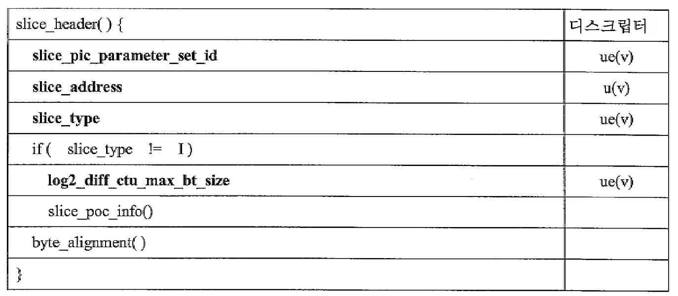
표 4는 slice_poc_info()에 대한 신택스의 예를 제공한다.Table 4 provides examples of syntax for slice_poc_info().
[표 4][Table 4]

표 4에서의 신택스 요소 slice_pic_order_cnt_lsb, slice_pic_order_cnt_msb_cycle_present, 및 slice_pic_order_cnt_msb_cycle은 다음의 예시적인 정의들에 기초할 수 있다:The syntax elements slice_pic_order_cnt_lsb, slice_pic_order_cnt_msb_cycle_present, and slice_pic_order_cnt_msb_cycle in Table 4 may be based on the following exemplary definitions:
slice_pic_order_cnt_lsb는 현재 픽처에 대한 픽처 순서 카운트 모듈로 MaxPicOrderCntLsb를 지정한다. slice_pic_order_cnt_lsb 신택스 요소의 길이는 log2_max_pic_order_cnt_lsb_minus4 + 4 비트이다. slice_pic_order_cnt_lsb의 값은 0 내지 MaxPicOrderCntLsb - 1(이들 값 포함)의 범위에 있어야 한다.slice_pic_order_cnt_lsb designates MaxPicOrderCntLsb as a picture order count module for the current picture. The length of the slice_pic_order_cnt_lsb syntax element is log2_max_pic_order_cnt_lsb_minus4 + 4 bits. The value of slice_pic_order_cnt_lsb must be in the range of 0 to MaxPicOrderCntLsb-1 (including these values).
1과 동일한 slice_pic_order_cnt_msb_cycle_present는 slice_pic_order_cnt_msb_cycle 신택스 요소가 다음에 뒤따른다는 것을 나타낸다. 0과 동일한 slice_pic_order_cnt_msb_cycle_present는 slice_pic_order_cnt_msb_cycle 신택스 요소가 시그널링되지 않음을 나타낸다. 시그널링되지 않을 때, slice_pic_order_cnt_msb_cycle_present는 0과 동일한 것으로 추론된다. 현재 픽처가 IDR 픽처일 때, slice_pic_order_cnt_msb_cycle_present는 0과 동일해야 한다.The slice_pic_order_cnt_msb_cycle_present equal to 1 indicates that the slice_pic_order_cnt_msb_cycle syntax element follows. Slice_pic_order_cnt_msb_cycle_present equal to 0 indicates that the slice_pic_order_cnt_msb_cycle syntax element is not signaled. When not signaled, slice_pic_order_cnt_msb_cycle_present is inferred to be equal to 0. When the current picture is an IDR picture, slice_pic_order_cnt_msb_cycle_present should be equal to 0.
slice_pic_order_cnt_msb_cycle은 픽처 순서 카운트 MSB 사이클 값을 지정한다. slice_pic_order_cnt_msb_cycle 신택스 요소의 길이는 log2_max_pic_order_cnt_msb_cycle_minus1 + 1 비트이다. slice_pic_order_cnt_msb_cycle 값은 0 내지 MaxPicOrderCntMSBCycle - 1(이들 값 포함)의 범위에 있어야 한다.slice_pic_order_cnt_msb_cycle designates a picture order count MSB cycle value. The length of the slice_pic_order_cnt_msb_cycle syntax element is log2_max_pic_order_cnt_msb_cycle_minus1 + 1 bit. The value of slice_pic_order_cnt_msb_cycle must be in the range of 0 to MaxPicOrderCntMSBCycle-1 (including these values).
몇몇 예에서, slice_pic_order_cnt_msb_cycle은 slice_pic_order_cnt_msb_cycle에 대한 음의 값들의 시그널링을 허용하기 위해 i(v)로서 코딩될 수 있다는 점에 유의해야 한다.It should be noted that in some examples, slice_pic_order_cnt_msb_cycle can be coded as i(v) to allow signaling of negative values for slice_pic_order_cnt_msb_cycle.
몇몇 예에서, log2_max_pic_order_cnt_msb_cycle_minus1에 대해 마이너스 1 시그널링이 사용되지 않을 수 있다는 점에 유의해야 한다. 즉, log2_max_pic_order_cnt_msb_cycle_minus1은 다음의 정의에 기초할 수 있는 신택스 요소 log2_max_pic_order_cnt_msb_cycle로 대체될 수 있다:It should be noted that in some examples, minus 1 signaling may not be used for log2_max_pic_order_cnt_msb_cycle_minus1. That is, log2_max_pic_order_cnt_msb_cycle_minus1 may be replaced with a syntax element log2_max_pic_order_cnt_msb_cycle that may be based on the following definition:
log2_max_pic_order_cnt_msb_cycle은 픽처 순서 카운트에 대한 디코딩 프로세스에서 사용되는 변수 MaxPicOrderCntMSBCycle의 값을 다음과 같이 지정한다;log2_max_pic_order_cnt_msb_cycle designates the value of the variable MaxPicOrderCntMSBCycle used in the decoding process for the picture order count as follows;
![]()
![]()
log2_max_pic_order_cnt_msb_cycle의 값은 0 내지 16(이들 값 포함)(또는 0 내지 15(이들 값 포함), 0 내지 28(이들 값 포함), 0 내지 48(이들 값 포함) 등)의 범위에 있어야 한다.The value of log2_max_pic_order_cnt_msb_cycle must be in the range of 0 to 16 (including these values) (or 0 to 15 (including these values), 0 to 28 (including these values), 0 to 48 (including these values), etc.).
log2_max_pic_order_cnt_msb_cycle이 사용될 때 slice_pic_order_cnt_msb_cycle의 정의는 다음과 같이 수정될 수 있다:When log2_max_pic_order_cnt_msb_cycle is used, the definition of slice_pic_order_cnt_msb_cycle can be modified as follows:
slice_pic_order_cnt_msb_cycle은 픽처 순서 카운트 MSB 사이클 값을 지정한다. slice_pic_order_cnt_msb_cycle 신택스 요소의 길이는 log2_max_pic_order_cnt_msb_cycle 비트이다. slice_pic_order_cnt_msb_cycle의 값은 0 내지 MaxPicOrderCntMSBCycle - 1(이들 값 포함)의 범위에 있어야 한다.slice_pic_order_cnt_msb_cycle designates a picture order count MSB cycle value. The length of the slice_pic_order_cnt_msb_cycle syntax element is log2_max_pic_order_cnt_msb_cycle bits. The value of slice_pic_order_cnt_msb_cycle must be in the range of 0 to MaxPicOrderCntMSBCycle-1 (including these values).
몇몇 예에서, log2_max_pic_order_cnt_msb_cycle_minus1은 사용되지 않을 수 있고 그러한 경우들에서 slice_pic_order_cnt_msb_cycle은 u(v) 데이터 타입 대신에 ue(v) 데이터 타입을 사용하여 시그널링될 수 있다는 점에 유의해야 한다.It should be noted that in some examples, log2_max_pic_order_cnt_msb_cycle_minus1 may not be used and in such cases slice_pic_order_cnt_msb_cycle may be signaled using the ue(v) data type instead of the u(v) data type.
일례에서, log2_max_pic_order_cnt_msb_cycle_minus1을 시그널링하는 대신에, MaxPicOrderCntMSBCycle의 값은 미리 정의된 log2_max_pic_order_cnt_lsb_minus4 및 MaxPicOrderCnt의 값으로부터 도출될 수 있다. 일례에서, MaxPicOrderCntMSBCycle은 다음과 같이 도출될 수 있다:In one example, instead of signaling log2_max_pic_order_cnt_msb_cycle_minus1, the value of MaxPicOrderCntMSBCycle may be derived from predefined values of log2_max_pic_order_cnt_lsb_minus4 and MaxPicOrderCnt. In one example, MaxPicOrderCntMSBCycle can be derived as follows:
PicOrderCntBitDepth = Ceil(Log2(MaxPicOrderCnt))PicOrderCntBitDepth = Ceil(Log2(MaxPicOrderCnt))
Log2MaxPicOrderCntMSBCycle - PicOrderCntBitDepth -Log2MaxPicOrderCntMSBCycle-PicOrderCntBitDepth-
(log2_max_pic_order_cnt_lsb_minus4 + 4)(log2_max_pic_order_cnt_lsb_minus4 + 4)
MaxPicOrderCntMSBCycle = 2Log2MaxPicOrderCntMSBCycle MaxPicOrderCntMSBCycle = 2 Log2MaxPicOrderCntMSBCycle
일례에서, log2_max_pic_order_cnt_lsb_minus4를 시그널링하는 대신에, MaxPicOrderCntLsb의 값은 미리 정의된 log2_max_pic_order_cnt_msb_cycle_minus1 및 MaxPicOrderCnt의 값으로부터 도출될 수 있다. 일례에서, MaxPicOrderCntLsb는 다음과 같이 도출될 수 있다:In one example, instead of signaling log2_max_pic_order_cnt_lsb_minus4, the value of MaxPicOrderCntLsb may be derived from predefined values of log2_max_pic_order_cnt_msb_cycle_minus1 and MaxPicOrderCnt. In one example, MaxPicOrderCntLsb can be derived as follows:
![]()
![]()
Log2MaxPicOrderCntLSB = PicOrderCntBitDepth -Log2MaxPicOrderCntLSB = PicOrderCntBitDepth-
(log2_max_pic_order_cnt_msb_minus1 + 1)(log2_max_pic_order_cnt_msb_minus1 + 1)
MaxPicOrderCntLsb = 2Log2MaxPicOrderCntLSB MaxPicOrderCntLsb = 2 Log2MaxPicOrderCntLSB
slice_poc_info() 내에 제공된 신택스 요소들에 따르면, PicOrderCntMsb + slice_pic_order_cnt_lsb와 동일한 PicOrderCntVal은 다음과 같이 도출될 수 있다:According to the syntax elements provided in slice_poc_info(), PicOrderCntVal equal to PicOrderCntMsb + slice_pic_order_cnt_lsb can be derived as follows:
현재 픽처가 IDR 픽처가 아니거나 현재 픽처가 시그널링된 slice_pic_order_cnt_msb_cycle을 갖지 않을 때, 변수 prevPicOrderCntLsb 및 prevPicOrderCntMsb는 다음과 같이 도출된다:When the current picture is not an IDR picture or the current picture does not have a signaled slice_pic_order_cnt_msb_cycle, the variables prevPicOrderCntLsb and prevPicOrderCntMsb are derived as follows:
- prevTid0Pic를 0과 동일한 TemporalId 및 서브-계층 비참조 픽처를 갖는 디코딩 순서에서의 이전 픽처라고 한다.-prevTid0Pic is called a previous picture in decoding order with TemporalId equal to 0 and a sub-layer non-reference picture.
- 변수 prevPicOrderCntLsb는 prevTid0Pic의 slice_pic_order_cnt_lsb와 동일하게 설정된다.-The variable prevPicOrderCntLsb is set the same as slice_pic_order_cnt_lsb of prevTid0Pic.
- 변수 prevPicOrderCntMsb는 prevTid0Pic의 PicOrderCntMsb와 동일하게 설정된다.-The variable prevPicOrderCntMsb is set the same as PicOrderCntMsb of prevTid0Pic.
현재 픽처의 변수 PicOrderCntMsb는 다음과 같이 도출된다:The variable PicOrderCntMsb of the current picture is derived as follows:
- 현재 픽처가 IDR 픽처인 경우 또는 이 슬라이스에 대한 활성 SPS에 대한 log2_max_pic_order_cnt_msb_cycle이 존재하고 0과 동일한 경우, 변수 PicOrderCntMsb는 0과 동일하게 설정된다.-When the current picture is an IDR picture or when log2_max_pic_order_cnt_msb_cycle for the active SPS for this slice exists and is equal to 0, the variable PicOrderCntMsb is set equal to 0.
- 그렇지 않고 현재 픽처의 슬라이스가 시그널링된 slice_pic_order_cnt_msb_cycle을 갖는다면, 변수 PicOrderCntMSB는 slice_pic_order_cnt_msb_cycle에 MaxPicOrderCntLsb를 곱한 것과 동일하게 설정된다.Otherwise, if the slice of the current picture has a signaled slice_pic_order_cnt_msb_cycle, the variable PicOrderCntMSB is set equal to slice_pic_order_cnt_msb_cycle multiplied by MaxPicOrderCntLsb.
- 그렇지 않으면, PicOrderCntMsb는 다음과 같이 도출된다:-Otherwise, PicOrderCntMsb is derived as follows:
if((slice_pic_order_cnt_lsb < prevPicOrderCntLsb) &&if((slice_pic_order_cnt_lsb <prevPicOrderCntLsb) &&
() prevPicOrderCntLsb - slice_pic_order_cnt_lsb) >= (MaxPicOrderCntLsb / 2)))() prevPicOrderCntLsb-slice_pic_order_cnt_lsb) >= (MaxPicOrderCntLsb / 2)))
PicOrderCntMsb = prevPicOrderCntMsb + MaxPicOrderCntLsbPicOrderCntMsb = prevPicOrderCntMsb + MaxPicOrderCntLsb
else if((slice_pic_order_cnt_lsb - prevPicOrderCntLsb) > (MaxPicOrderCntLsb / 2)))else if((slice_pic_order_cnt_lsb-prevPicOrderCntLsb)> (MaxPicOrderCntLsb / 2)))
PicOrderCntMsb = prevPicOrderCntMsb - MaxPicOrderCntLsb PicOrderCntMsb = prevPicOrderCntMsb-MaxPicOrderCntLsb
elseelse
PicOrderCntMsb = prevPicOrderCntMsbPicOrderCntMsb = prevPicOrderCntMsb
PicOrderCntVal은 다음과 같이 도출된다:PicOrderCntVal is derived as follows:
PicOrderCntVal = PicOrderCntMsb + slice_pic_order_cnt_lsbPicOrderCntVal = PicOrderCntMsb + slice_pic_order_cnt_lsb
몇몇 예에서, PicOrderCntVal의 값은 -231 내지 231-1(이들 값 포함)의 범위에 있어야 한다는 점에 유의해야 한다.In some examples, the value of PicOrderCntVal is -2 31 It should be noted that it should be in the range of 2 31-1 (including these values).
다른 예에서, currentPicOrderCntMsb + slice_pic_order_cnt_lsb와 동일한 PicOrderCntVal은 다음과 같이 도출될 수 있다:In another example, a PicOrderCntVal equal to currentPicOrderCntMsb + slice_pic_order_cnt_lsb can be derived as follows:
현재 픽처가 IDR 픽처인 경우, 변수 currentPicOrderCntMsb는 0과 동일하게 설정된다.When the current picture is an IDR picture, the variable currentPicOrderCntMsb is set equal to 0.
그렇지 않고 현재 픽처의 슬라이스가 시그널링된 slice_pic_order_cnt_msb_cycle을 갖는 경우, 변수 currentPicOrderCntMsb는 slice_pic_order_cnt_msb_cycle에 MaxPicOrderCntLsb를 곱한 것과 동일하게 설정된다.Otherwise, if the slice of the current picture has a signaled slice_pic_order_cnt_msb_cycle, the variable currentPicOrderCntMsb is set equal to slice_pic_order_cnt_msb_cycle multiplied by MaxPicOrderCntLsb.
그렇지 않으면, 변수 currentPicOrderCntMSB는 다음과 같이 도출된다.Otherwise, the variable currentPicOrderCntMSB is derived as follows.
- prevPOCMSBPic가 시그널링된 slice_pic_order_cnt_msb_cycle을 갖거나 IDR 픽처인(어느 것이든 디코딩 순서에서 현재 픽처에 더 가까움) 디코딩 순서에서의 이전 픽처라고 한다.-PrevPOCMSBPic has a signaled slice_pic_order_cnt_msb_cycle or is an IDR picture (whichever is closer to the current picture in decoding order) and is said to be a previous picture in decoding order.
- 이어서 변수 currentPicOrderCntMsb는 prevPOCMSBPic가 IDR 픽처인 경우 0과 동일하게 설정되거나, prevPOCMSBPic가 IDR 픽처가 아닌 경우 prevPOCMSBPic 픽처의 slice_pic_order_cnt_msb_cycle에 MaxPicOrderCntLsb를 곱한 것과 동일하게 설정된다.-Next, the variable currentPicOrderCntMsb is set equal to 0 when prevPOCMSBPic is an IDR picture, or equal to slice_pic_order_cnt_msb_cycle of the prevPOCMSBPic picture multiplied by MaxPicOrderCntLsb when prevPOCMSBPic is not an IDR picture.
PicOrderCntVal은 다음과 같이 도출된다:PicOrderCntVal is derived as follows:
PicOrderCntVal = PicOrderCntMsb + slice_pic_order_cnt_lsbPicOrderCntVal = PicOrderCntMsb + slice_pic_order_cnt_lsb
일례에서, 슬라이스 레벨 MSB 픽처 순서 카운트 관련 신택스 요소들의 시그널링을 제어하기 위한 플래그가 파라미터 세트, 예를 들어 VPS, SPS, 또는 PPS에서 시그널링될 수 있다. 표 5는 slice_pic_order_cnt_msb_signaling_present를 포함하는 시퀀스 파라미터 세트의 예를 예시한다.In one example, a flag for controlling signaling of syntax elements related to slice level MSB picture order count may be signaled in a parameter set, for example, VPS, SPS, or PPS. Table 5 exemplifies an example of a sequence parameter set including slice_pic_order_cnt_msb_signaling_present.
[표 5][Table 5]
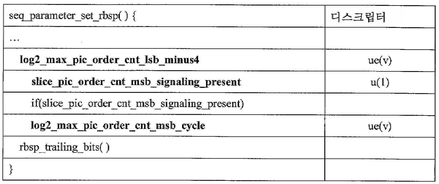
표 5에 대하여 다양한 신택스 요소들의 시맨틱은 다음과 같을 수 있다:For Table 5, the semantics of the various syntax elements can be as follows:
log2_max_pic_order_cnt_lsb_minus4는 픽처 순서 카운트에 대한 디코딩 프로세스에서 사용되는 변수 MaxPicOrderCntLsb의 값을 다음과 같이 지정한다:log2_max_pic_order_cnt_lsb_minus4 specifies the value of the variable MaxPicOrderCntLsb used in the decoding process for picture order count as follows:
MaxPicOrderCntLsb = 2(log2_max_pic_order_cnt_lsb_minus4 + 4) MaxPicOrderCntLsb = 2 (log2_max_pic_order_cnt_lsb_minus4 + 4)
log2_max_pic_order_cnt_lsb_minus4의 값은 0 내지 12(이들 값 포함)의 범위에 있어야 한다.The value of log2_max_pic_order_cnt_lsb_minus4 must be in the range of 0 to 12 (including these values).
다른 예에서, log2_max_pic_order_cnt_lsb_minus4의 값은 0 내지 16(이들 값 포함)의 범위에 있어야 한다. 일반적으로, log2_max_pic_order_cnt_lsb_minus4에 대해 어떤 다른 유효한 값 범위가 선언될 수 있다.In another example, the value of log2_max_pic_order_cnt_lsb_minus4 should be in the range of 0 to 16 (including these values). In general, some other valid range of values can be declared for log2_max_pic_order_cnt_lsb_minus4.
0과 동일한 slice_pic_order_cnt_msb_signaling_present는 픽처 순서 카운트에 대한 POC MSB 관련 정보가 슬라이스 헤더에서 시그널링되지 않음을 나타낸다. 1과 동일한 slice_pic_order_cnt_msb_signaling_present는 POC MSB 관련 정보가 슬라이스 헤더에서 시그널링될 수 있음을 나타낸다.Slice_pic_order_cnt_msb_signaling_present equal to 0 indicates that POC MSB related information for the picture order count is not signaled in the slice header. Slice_pic_order_cnt_msb_signaling_present equal to 1 indicates that POC MSB related information can be signaled in the slice header.
log2_max_pic_order_cnt_msb_cycle은 변수 MaxPicOrderCntMSBCycle의 값을 다음과 같이 지정한다:log2_max_pic_order_cnt_msb_cycle specifies the value of the variable MaxPicOrderCntMSBCycle as follows:
MaxPicOrderCntMSBCycle = 2(log2_max_pic_order_cnt_lsb_msb_cycle) MaxPicOrderCntMSBCycle = 2 (log2_max_pic_order_cnt_lsb_msb_cycle)
log2_max_pic_order_cnt_lsb_cycle의 값은 0 내지 28(이들 값 포함)의 범위에 있어야 한다.The value of log2_max_pic_order_cnt_lsb_cycle must be in the range of 0 to 28 (including these values).
다른 예에서, log2_max_pic_order_cnt_msb_cycle의 값은 0 내지 16(이들 값 포함)의 범위에 있어야 한다. 일반적으로, log2_max_pic_order_cnt_msb_cycle에 대해 어떤 다른 유효한 값 범위가 선언될 수 있다.In another example, the value of log2_max_pic_order_cnt_msb_cycle should be in the range of 0 to 16 (including these values). In general, some other valid value range can be declared for log2_max_pic_order_cnt_msb_cycle.
신택스 요소 slice_pic_order_cnt_msb_signaling_present가 파라미터 세트에 포함될 때, slice_poc_info()는 표 6에 예시된 바와 같을 수 있다.When the syntax element slice_pic_order_cnt_msb_signaling_present is included in the parameter set, slice_poc_info() may be as illustrated in Table 6.
[표 6][Table 6]
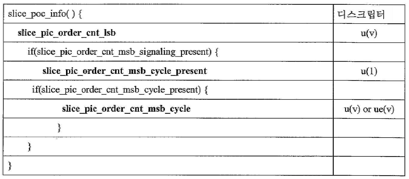
표 6에 대하여 다양한 신택스 요소들의 시맨틱은 다음과 같을 수 있다:For Table 6, the semantics of the various syntax elements can be as follows:
slice_pic_order_cnt_lsb는 현재 픽처에 대한 픽처 순서 카운트 모듈로 MaxPicOrderCntLsb를 지정한다. slice_pic_order_cnt_lsb 신택스 요소의 길이는 log2_max_pic_order_cnt_lsb_minus4 + 4 비트이다. slice_pic_order_cnt_lsb의 값은 0 내지 MaxPicOrderCntLsb - 1(이들 값 포함)의 범위에 있어야 한다.slice_pic_order_cnt_lsb designates MaxPicOrderCntLsb as a picture order count module for the current picture. The length of the slice_pic_order_cnt_lsb syntax element is log2_max_pic_order_cnt_lsb_minus4 + 4 bits. The value of slice_pic_order_cnt_lsb must be in the range of 0 to MaxPicOrderCntLsb-1 (including these values).
표 5 및 표 6에 대하여 예시된 예의 경우에, slice_pic_order_cnt_msb_cycle_present 및 slice_pic_order_cnt_msb_cycle은 다음의 정의에 기초할 수 있다:In the case of the example illustrated for Tables 5 and 6, slice_pic_order_cnt_msb_cycle_present and slice_pic_order_cnt_msb_cycle may be based on the following definition:
1과 동일한 slice_pic_order_cnt_msb_cycle_present는 slice_pic_order_cnt_msb_cycle 신택스 요소가 다음에 뒤따른다는 것을 나타낸다. 0과 동일한 slice_pic_order_cnt_msb_cycle_present는 slice_pic_order_cnt_msb_cycle 신택스 요소가 시그널링되지 않음을 나타낸다. 시그널링되지 않을 때, slice_pic_order_cnt_msb_cycle_present는 0과 동일한 것으로 추론된다. 현재 픽처가 IDR 픽처일 때, slice_pic_order_cnt_msb_cycle_present는 0과 동일해야 한다. log2_max_pic_order_cnt_msb_cycle이 0과 동일할 때, slice_pic_order_cnt_msb_cycle_present는 0과 동일해야 한다.The slice_pic_order_cnt_msb_cycle_present equal to 1 indicates that the slice_pic_order_cnt_msb_cycle syntax element follows. Slice_pic_order_cnt_msb_cycle_present equal to 0 indicates that the slice_pic_order_cnt_msb_cycle syntax element is not signaled. When not signaled, slice_pic_order_cnt_msb_cycle_present is inferred to be equal to 0. When the current picture is an IDR picture, slice_pic_order_cnt_msb_cycle_present should be equal to 0. When log2_max_pic_order_cnt_msb_cycle is equal to 0, slice_pic_order_cnt_msb_cycle_present must be equal to 0.
slice_pic_order_cnt_msb_cycle은 픽처 순서 카운트 MSB 사이클 값을 지정한다. slice_pic_order_cnt_msb_cycle 신택스 요소의 길이는 log2_max_pic_order_cnt_msbcycle 비트이다. slice_pic_order_cnt_msb_cycle의 값은 0 내지 MaxPicOrderCntMSBCycle - 1(이들 값 포함)의 범위에 있어야 한다.slice_pic_order_cnt_msb_cycle designates a picture order count MSB cycle value. The length of the slice_pic_order_cnt_msb_cycle syntax element is log2_max_pic_order_cnt_msbcycle bits. The value of slice_pic_order_cnt_msb_cycle must be in the range of 0 to MaxPicOrderCntMSBCycle-1 (including these values).
일례에서, slice_pic_order_cnt_msb_cycle_present는 파라미터 세트에 포함될 수 있다. 신택스 요소 slice_pic_order_cnt_msb_cycle_present가 파라미터 세트에 포함될 때, slice_poc_info()는 표 7에 예시된 바와 같이 수정될 수 있다.In one example, slice_pic_order_cnt_msb_cycle_present may be included in the parameter set. When the syntax element slice_pic_order_cnt_msb_cycle_present is included in the parameter set, slice_poc_info() may be modified as illustrated in Table 7.
[표 7][Table 7]
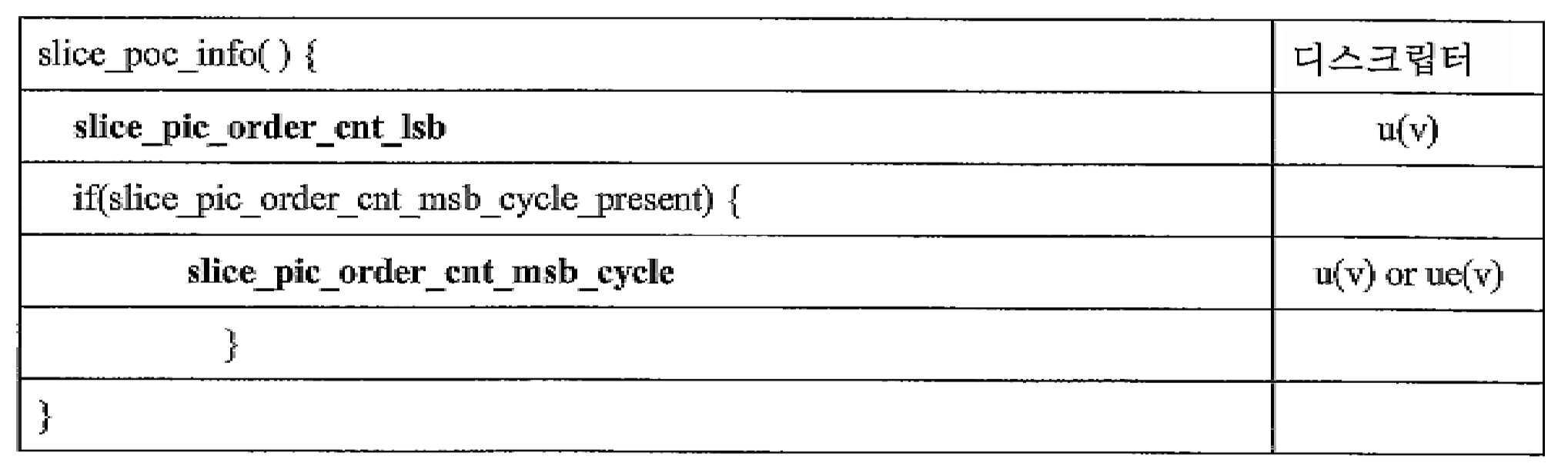
몇몇 예에서, slice_poc_info() 내의 신택스 요소들의 존재는 log2_max_pic_order_cnt_msb_cycle_minus1 또는 log2_max_pic_order_cnt_msb_cycle의 값들에 기초할 수 있다. 예를 들어, 표 8은 slice_pic_order_cnt_msb_cycle_present 및 slice_pic_order_cnt_msb_cycle의 존재가 0과 동일하지 않은 log2_max_pic_order_cnt_msb_cycle을 조건으로 하는 예를 예시한다. 일례에서, log2_max_pic_order_cnt_msb_cycle이 0과 동일하면, slice_pic_order_cnt_msb_cycle_present는 0과 동일하도록 제약되어야 한다.In some examples, the presence of syntax elements in slice_poc_info() may be based on values of log2_max_pic_order_cnt_msb_cycle_minus1 or log2_max_pic_order_cnt_msb_cycle. For example, Table 8 exemplifies an example in which the presence of slice_pic_order_cnt_msb_cycle_present and slice_pic_order_cnt_msb_cycle is not equal to 0 and log2_max_pic_order_cnt_msb_cycle as a condition. In one example, if log2_max_pic_order_cnt_msb_cycle is equal to 0, slice_pic_order_cnt_msb_cycle_present should be constrained to be equal to 0.
[표 8][Table 8]
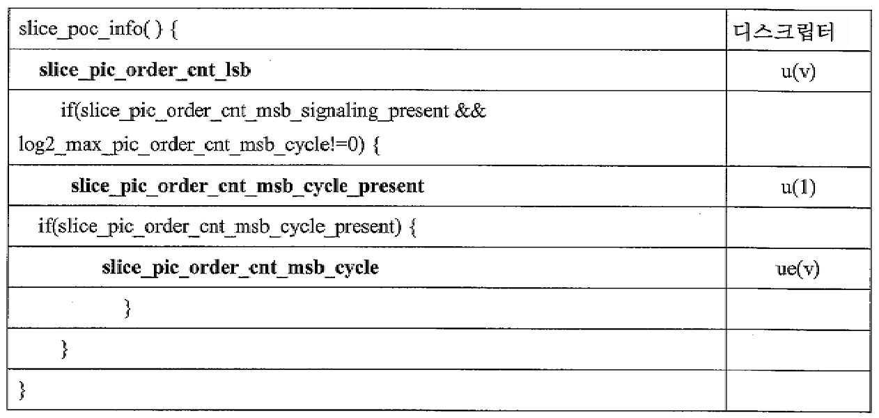
일례에서 slice_pic_order_cnt_msb_cycle을 시그널링하는 대신에, 신택스 요소 slice_pic_order_msb 값이 시그널링될 수 있다. 신택스 요소 slice_pic_order_msb는 ue(v)로서 또는 u(v)로서 코딩될 수 있다. 이 경우에, log2_max_pic_order_cnt_msb_cycle_minus1 대신에, 신택스 요소 log2_max_pic_order_cnt_msb_minus1이 다음과 같이 시맨틱으로 시그널링될 수 있다:In one example, instead of signaling slice_pic_order_cnt_msb_cycle, a value of the syntax element slice_pic_order_msb may be signaled. The syntax element slice_pic_order_msb may be coded as ue(v) or as u(v). In this case, instead of log2_max_pic_order_cnt_msb_cycle_minus1, the syntax element log2_max_pic_order_cnt_msb_minus1 may be signaled semantically as follows:
log2_max_pic_order_cnt_msb_minus1은 픽처 순서 카운트에 대한 디코딩 프로세스에서 사용되는 변수 MaxPicOrderCntMSB의 값을 다음과 같이 지정한다:log2_max_pic_order_cnt_msb_minus1 specifies the value of the variable MaxPicOrderCntMSB used in the decoding process for picture order count as follows:
MaxPicOrderCntMSB = 2(log2_max_pic_order_cnt_minus1 + 1) MaxPicOrderCntMSB = 2 (log2_max_pic_order_cnt_minus1 + 1)
몇몇 예에서, MaxPicOrderCntMSB에 대해 제약이 주어질 수 있다. 또한, 이 경우에, 픽처 순서 카운트에 대한 디코딩 프로세스는 변수 PicOrderCntMSB가 slice_pic_order_msb와 동일하게 설정되도록 수정될 수 있다.In some examples, constraints may be given for MaxPicOrderCntMSB. Also, in this case, the decoding process for the picture order count may be modified so that the variable PicOrderCntMSB is set equal to slice_pic_order_msb.
일례에서 slice_pic_order_cnt_msb_cycle은 slice_pic_order_cnt_lsb가 0과 동일할 때 항상 시그널링될 수 있다. 일례에서, 이것은 추가적인 슬라이스 및/또는 파라미터 세트 레벨 플래그(들)에 의해 추가로 제어될 수 있다. 다른 경우들에서, slice_pic_order_cnt_msb_cycle이 시그널링되는지 및 그의 가능한 값들에 대해 제약이 주어질 수 있다. 다른 예에서, slice_pic_order_cnt_msb_cycle은 TId 0 픽처에 대해 항상 시그널링될 수 있다. 일례에서, 다양한 신택스 요소들에 대해 그리고/또는 슬라이스들 및/또는 파라미터 세트들에 걸쳐 제약들이 주어질 수 있다.In an example, slice_pic_order_cnt_msb_cycle may be always signaled when slice_pic_order_cnt_lsb is equal to 0. In one example, this may be further controlled by additional slice and/or parameter set level flag(s). In other cases, a constraint may be given on whether slice_pic_order_cnt_msb_cycle is signaled and its possible values. In another example, slice_pic_order_cnt_msb_cycle may always be signaled for a TId 0 picture. In one example, constraints may be given for various syntax elements and/or across slices and/or parameter sets.
일례에서, 시퀀스 파라미터 세트는 신택스 요소 slice_pic_order_cnt가 슬라이스 헤더에 존재하는지를 나타내는 플래그를 포함할 수 있다. slice_pic_order_cnt는 비트들을 MSB 및 LSB로 분리함이 없이 픽처 순서 카운트 값의 값을 지정할 수 있고 다음의 정의에 기초할 수 있다.In one example, the sequence parameter set may include a flag indicating whether the syntax element slice_pic_order_cnt is present in the slice header. slice_pic_order_cnt can designate a value of the picture order count value without separating the bits into MSB and LSB, and can be based on the following definition.
slice_pic_order_cnt는 현재 픽처에 대한 픽처 순서 카운트 값을 지정한다. slice_pic_order_cnt의 값은 0 내지 MaxPicOrderCnt(이들 값 포함)의 범위에 있어야 한다.slice_pic_order_cnt designates a picture order count value for the current picture. The value of slice_pic_order_cnt must be in the range of 0 to MaxPicOrderCnt (including these values).
표 9 및 표 10은 플래그 full_pic_order_cnt_signal_flag가 log2_max_pic_order_cnt_lsb_minus4 및 log2_max_pic_order_cnt_msb_cycle_minus1이 시퀀스 파라미터 세트에 존재하는지 그리고 신택스 요소 slice_pic_order_cnt가 슬라이스 헤더에 존재하는지를 나타내는 예를 예시한다.Tables 9 and 10 exemplify an example in which the flags full_pic_order_cnt_signal_flag is present in the slice header, whether log2_max_pic_order_cnt_lsb_minus4 and log2_max_pic_order_cnt_msb_cycle_minus1 are present in the sequence parameter set and the syntax element slice_pic_order_cnt is present in the slice header.
[표 9][Table 9]
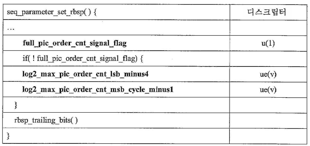
[표 10][Table 10]
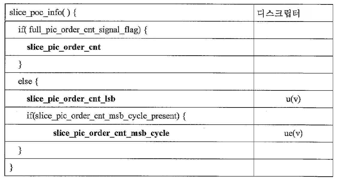
표 9 및 표 10에 대하여 예시된 예의 경우에, PicOrderCntVal은 다음과 같이 도출될 수 있다:In the case of the example illustrated for Tables 9 and 10, PicOrderCntVal can be derived as follows:
if (full_pic_order_cnt_signal_flag)if (full_pic_order_cnt_signal_flag)
PicOrderCntVal = slice_pic_order_cntPicOrderCntVal = slice_pic_order_cnt
elseelse
PicOrderCntVal = PicOrderCntMsb + slice_pic_order_cnt_lsbPicOrderCntVal = PicOrderCntMsb + slice_pic_order_cnt_lsb
표 5 및 표 6에 대하여 예시된 예의 경우에, PicOrderCntVal은 다음과 같이 도출될 수 있다:In the case of the example illustrated for Tables 5 and 6, PicOrderCntVal can be derived as follows:
현재 픽처가 IRAP 픽처가 아니거나 현재 픽처가 시그널링된 slice_pic_order_cnt_msb_cycle을 갖지 않을 때, 변수 prevPicOrderCntLsb 및 prevPicOrderCntMsb는 다음과 같이 도출된다:When the current picture is not an IRAP picture or the current picture does not have a signaled slice_pic_order_cnt_msb_cycle, the variables prevPicOrderCntLsb and prevPicOrderCntMsb are derived as follows:
- prevTid0Pic를 0과 동일한 TemporalId를 갖는 디코딩 순서에서의 이전 픽처라고 한다.-prevTid0Pic is called a previous picture in decoding order with TemporalId equal to 0.
- 변수 prevPicOrderCntLsb는 prevTid0Pic의 slice_pic_order_cnt_lsb와 동일하게 설정된다.-The variable prevPicOrderCntLsb is set the same as slice_pic_order_cnt_lsb of prevTid0Pic.
- 변수 prevPicOrderCntMsb는 prevTid0Pic의 PicOrderCntMsb와 동일하게 설정된다. -The variable prevPicOrderCntMsb is set the same as PicOrderCntMsb of prevTid0Pic.
현재 픽처의 변수 PicOrderCntMsb는 다음과 같이 도출된다:The variable PicOrderCntMsb of the current picture is derived as follows:
- 현재 픽처가 IRAP 픽처인 경우 또는 이 슬라이스에 대한 활성 SPS에 대한 log2_max_pic_order_cnt_msb_cycle이 존재하고 0과 동일한 경우, 변수 PicOrderCntMsb는 0과 동일하게 설정된다.-When the current picture is an IRAP picture or when log2_max_pic_order_cnt_msb_cycle for the active SPS for this slice exists and is equal to 0, the variable PicOrderCntMsb is set equal to 0.
- 그렇지 않고 현재 픽처의 슬라이스가 시그널링된 slice_pic_order_cnt_msb_cycle을 가지면, 변수 PicOrderCntMsb는 slice_pic_order_cnt_msb_cycle에 PicOrderCntMsb를 곱한 것과 동일하게 설정된다.Otherwise, if the slice of the current picture has a signaled slice_pic_order_cnt_msb_cycle, the variable PicOrderCntMsb is set equal to slice_pic_order_cnt_msb_cycle multiplied by PicOrderCntMsb.
- 그렇지 않으면, PicOrderCntMsb는 다음과 같이 도출된다:-Otherwise, PicOrderCntMsb is derived as follows:
if((slice_pic_order_cnt_lsb < prevPicOrderCntLsb) &&if((slice_pic_order_cnt_lsb <prevPicOrderCntLsb) &&
((prevPicOrderCntLsb - slice_pic_order_cnt_lsb)_ >= (MaxPicOrderCntlsb / 2)))((prevPicOrderCntLsb-slice_pic_order_cnt_lsb)_ >= (MaxPicOrderCntlsb / 2)))
PicOrderCntMsb = prevPicOrderCntMsb + MaxPicOrderCntLsb PicOrderCntMsb = prevPicOrderCntMsb + MaxPicOrderCntLsb
else if((slice_pic_order_cnt_lsb > prevPicOrderCntLsb) &&else if((slice_pic_order_cnt_lsb> prevPicOrderCntLsb) &&
((slice_pic_order_cnt_lsb - prePicOrderCntLsb) > (MaxPicOrderCntLsb/ 2)))((slice_pic_order_cnt_lsb-prePicOrderCntLsb)> (MaxPicOrderCntLsb/ 2)))
PicOrderCntMsb = prevPicOrderCntMsb - MaxPicOrderCntLsbPicOrderCntMsb = prevPicOrderCntMsb-MaxPicOrderCntLsb
elseelse
PicOrderCntMsb = prevPicOrderCntMsbPicOrderCntMsb = prevPicOrderCntMsb
PicOrderCntVal은 다음과 같이 도출된다:PicOrderCntVal is derived as follows:
PicOrderCntVal = PicOrderCntMsb + slice_pic_order_cnt_lsbPicOrderCntVal = PicOrderCntMsb + slice_pic_order_cnt_lsb
slice_pic_order_cnt_msb_signing_present가 1과 동일한 경우, PicOrderCntVal의 값은 -2(log2_max_pic_order_cnt_lsb_minus4 + log2_max_pic_order_cnt_msb_cycle + 3) 내지 2(log2_max_pic_order_cnt_lsb_minus4 + log2_max_pic_order_cnt_msb_cycle + 3) -1(이들 값 포함)의 범위에 있어야 한다.When slice_pic_order_cnt_msb_signing_present is equal to 1, the value of PicOrderCntVal should be in the range of -2 (log2_max_pic_order_cnt_lsb_minus4 + log2_max_pic_order_cnt_msb_cycle + 3) to 2 (log2_max_pic_order_cnt_lsb_minus4 + log2_max_msb_order_cnt_lsb_minus4 + value of 3).
그렇지 않으면, PicOrderCntVal의 값은 -231 내지 231 - 1(이들 값 포함)의 범위에 있어야 한다.Otherwise, the value of PicOrderCntVal is -2 31 To 2 31 -Must be in the range of 1 (including these values).
다른 예에서, 코딩된 비디오 시퀀스에서 slice_pic_order_cnt_msb_cycle이 항상 시그널링되면, PicOrderCntVal의 값은 -2 (log2_max_pic_order_cnt_lsb_minus4 + log2_max_pic_order_cnt_msb_cycle + 3) 내지 2 (log2_max_pic_order_cnt_lsb_minus4 + log2_max_pic_order_cnt_msb_cycle + 3) - 1(이들 값 포함)의 범위에 있어야 한다.In another example, if slice_pic_order_cnt_msb_cycle is always signaled in a coded video sequence, the value of PicOrderCntVal should be in the range of -2 (log2_max_pic_order_cnt_lsb_minus4 + log2_max_pic_order_cnt_msb_cycle + 3) to 2 (log2_max_pic_order_cnt_order +cnt_msb_cycle + 1) in the range of -1.
그렇지 않으면 PicOrderCntVal의 값은 -2 31 내지 2 31 - 1(이들 값 포함)의 범위에 있어야 한다.Otherwise, the value of the PicOrderCntVal -2 31 to 2 31 - should be in the range of from 1 (included these values).
또 다른 예에서, 위의 스테이트먼트들의 그렇지 않으면 부분은 2 31의 값과는 상이한 값을 사용할 수 있다. 예를 들어, 2 31은 위의 그렇지 않으면 부분에서 2 48 또는 2 64 또는 2 16 등과 같은 어떤 다른 값으로 대체될 수 있다.In another example, the otherwise part of the above statements may use a value different from the value of 2 31. For example, 2 31 could be replaced by some other value such as 2 48 or 2 64 or 2 16 in the otherwise part above.
또한, 일례에서, 순간 디코딩 리프레시(IDR) 픽처는 그의 디코딩 프로세스에서 인터 예측을 위해 그 자신 이외의 어떠한 픽처도 참조하지 않고 디코딩 순서에서 코딩된 비디오 시퀀스의 첫 번째 픽처인 IRAP 픽처로서 설명될 수 있다.Further, in an example, an instantaneous decoding refresh (IDR) picture may be described as an IRAP picture that is the first picture of a video sequence coded in decoding order without referring to any picture other than itself for inter prediction in its decoding process. .
전술된 바와 같이, 픽처는 슬라이스들 및/또는 타일들로 분할될 수 있으며, 여기서 슬라이스는 래스터 스캔 순서로 CTU들의 시퀀스를 포함하고 타일은 픽처의 직사각형 영역에 대응하는 CTU들의 시퀀스이다. 전술된 바와 같이, 슬라이스는 하나 이상의 타일을 포함할 수 있다. 또한, CTU들의 동일한 그룹(즉, 픽처의 직사각형 영역을 커버하는 그룹 CTU들)이 슬라이스로서 또는 타일로서 분류될 수 있는 경우들이 존재할 수 있다. "Tiles groups for VVC", 중국 마카오에서 2018년 10월 3일 - 12일에 열린 ISO/IEC JTC1/SC29/WG11의 12차 회의, 문헌 JVET-L0415-v1(이는 본 명세서에서 JVET-L0415로 지칭됨)은 슬라이스들이 정수 개의 완전한 CTU들로 이루어지는 대신에 정수 개의 완전한 타일들로 이루어지도록 요구되는 경우를 기술한다. 그렇기 때문에, JVET-L0415에서, 픽처의 직사각형 영역이 아닌 래스터-스캔 CTU 슬라이스들은 더 이상 지원되지 않고 명칭 슬라이스는 타일 그룹으로 변경된다. JVET-L0415는 슬라이스 헤더의 구조를 유지하지만, 그것을 타일 그룹 헤더로 지칭하고, 슬라이스 어드레스를 타일 그룹 헤더 내의 타일 그룹 어드레스로 대체하고, 타일 그룹 내의 타일들의 수를 지정하는 신택스 요소 num_tiles_in_tile_group을 추가하고, end_of_slice_flag 신택스 요소를 제거하며, 대신에 타일 그룹의 끝은 타일 그룹 어드레스 및 num_tiles_in_tile_group에 의해 주어진다. 본 명세서에 기술된 기법들이 슬라이스들에 대하여 전술되었지만, 본 명세서에 기술된 기법들은 슬라이스가 정수 개의 완전한 타일들로 이루어지도록 제한되는 경우들에 적용 가능하다. 즉, 픽처 순서 카운트 값을 나타내기 위한 본 명세서에 기술된 기법들은 슬라이스가 타일 그룹들을 포함하는 기법들에 통합될 수 있다.As described above, a picture can be divided into slices and/or tiles, where a slice contains a sequence of CTUs in raster scan order and a tile is a sequence of CTUs corresponding to a rectangular region of the picture. As described above, a slice may include one or more tiles. In addition, there may be cases in which the same group of CTUs (ie, group CTUs covering a rectangular area of a picture) can be classified as a slice or as a tile. "Tiles groups for VVC", 12th meeting of ISO/IEC JTC1/SC29/WG11 held on October 3-12, 2018 in Macau, China, document JVET-L0415-v1 (which is referred to herein as JVET-L0415 Describes a case where slices are required to consist of an integer number of complete tiles instead of an integer number of complete CTUs. Therefore, in JVET-L0415, raster-scan CTU slices that are not rectangular regions of the picture are no longer supported and the name slice is changed to a tile group. JVET-L0415 maintains the structure of the slice header, but refers to it as a tile group header, replaces the slice address with a tile group address in the tile group header, and adds a syntax element num_tiles_in_tile_group specifying the number of tiles in the tile group, The end_of_slice_flag syntax element is removed, and instead the end of the tile group is given by the tile group address and num_tiles_in_tile_group. Although the techniques described herein have been described above with respect to slices, the techniques described herein are applicable in cases where a slice is limited to consist of an integer number of complete tiles. That is, the techniques described herein for indicating a picture order count value may be incorporated into techniques in which a slice includes tile groups.
예를 들어, 표 11 및 표 12는 본 명세서에서의 기법들에 따른 픽처 순서 카운트 값을 나타내는 타일 그룹 헤더 신택스의 예들을 예시한다.For example, Tables 11 and 12 exemplify examples of tile group header syntax indicating a picture order count value according to techniques herein.
[표 11][Table 11]
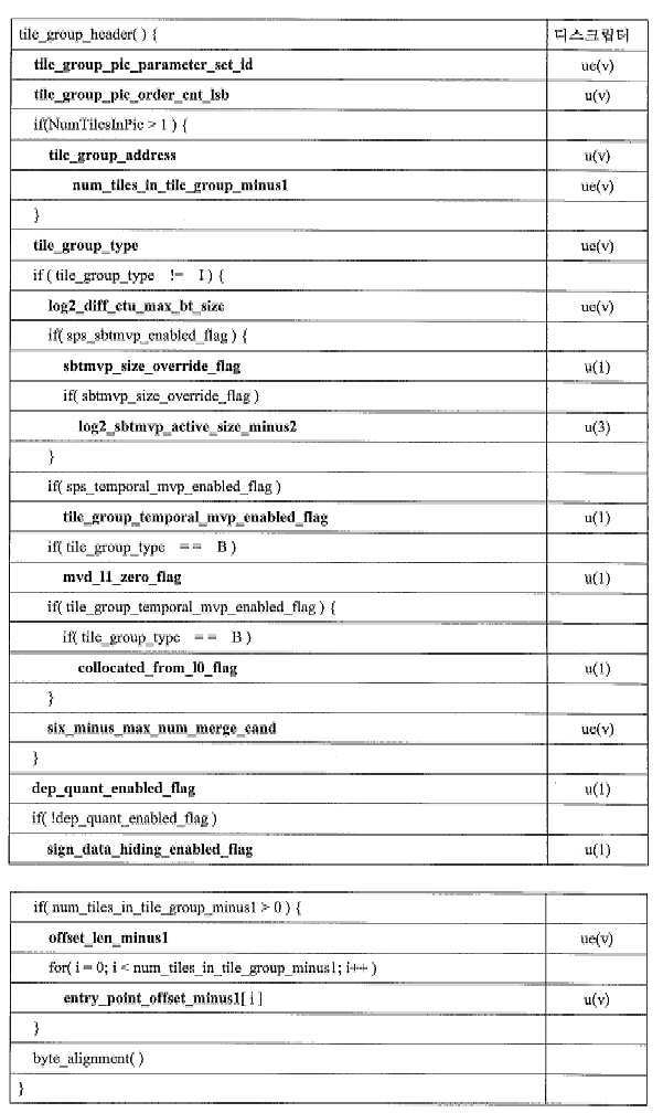
[표 12][Table 12]

표 11 및 표 12에 대하여, 다양한 신택스 요소들의 시맨틱은 다음과 같을 수 있다:For Tables 11 and 12, the semantics of the various syntax elements can be as follows:
존재할 때, 타일 그룹 헤더 신택스 요소 tile_group_pic_parameter_set_id의 값은 코딩된 픽처의 모든 타일 그룹 헤더들에서 동일해야 한다.When present, the value of the tile group header syntax element tile_group_pic_parameter_set_id must be the same in all tile group headers of the coded picture.
tile_group_pic_parameter_set_id는 사용 중인 PPS에 대한 pps_pic_parameter_set_id의 값을 지정한다. tile_group_pic_parameter_set_id의 값은 0 내지 63(이들 값 포함)의 범위에 있어야 한다.tile_group_pic_parameter_set_id specifies the value of pps_pic_parameter_set_id for the PPS in use. The value of tile_group_pic_parameter_set_id must be in the range of 0 to 63 (including these values).
tile_group_pic_order_cnt_lsb는 현재 픽처에 대한 픽처 순서 카운트 모듈로 MaxPicOrderCntLsb를 지정한다. tile_group_pic_order_cnt_lsb 신택스 요소의 길이는 log2_max_pic_order_cnt_lsb_minus4 + 4 비트이다. tile_group_pic_order_cnt_lsb의 값은 0 내지 MaxPicOrderCntLsb -1(이들 값 포함)의 범위에 있어야 한다.tile_group_pic_order_cnt_lsb designates MaxPicOrderCntLsb as a picture order count module for the current picture. The length of the tile_group_pic_order_cnt_lsb syntax element is log2_max_pic_order_cnt_lsb_minus4 + 4 bits. The value of tile_group_pic_order_cnt_lsb must be in the range of 0 to MaxPicOrderCntLsb -1 (including these values).
다른 예에서:In another example:
tile_group_pic_order_cnt_lsb는 이 타일 그룹이 속하는 픽처에 대한 픽처 순서 카운트 모듈로 MaxPicOrderCntLsb를 지정한다. tile_group_pic_order_cnt_lsb 신택스 요소의 길이는 log2_max_pic_order_cnt_lsb_minus4 + 4 비트이다. tile_group_pic_order_cnt_lsb의 값은 0 내지 MaxPicOrderCntLsb - 1(이들 값 포함)의 범위에 있어야 한다.tile_group_pic_order_cnt_lsb designates MaxPicOrderCntLsb as a picture order count module for a picture to which this tile group belongs. The length of the tile_group_pic_order_cnt_lsb syntax element is log2_max_pic_order_cnt_lsb_minus4 + 4 bits. The value of tile_group_pic_order_cnt_lsb must be in the range of 0 to MaxPicOrderCntLsb-1 (including these values).
다른 예에서, tile_group_pic_order_cntl_lsb 신택스 요소는 어떤 다른 명칭으로 지칭될 수 있다. 예를 들어 tile_group_pic_order_cntl_lsb는 pic_order_cnt_lsb로 지칭될 수 있다. 또는 tile_group_pic_order_cnt_lsb는 tile_set_pic_order_cnt_lsb로 지칭될 수 있다. 또는 어떤 다른 명칭이 tile_group_pic_order_cntl_lsb에 대해 사용될 수 있다. In another example, the tile_group_pic_order_cntl_lsb syntax element may be referred to by some other name. For example, tile_group_pic_order_cntl_lsb may be referred to as pic_order_cnt_lsb. Alternatively, tile_group_pic_order_cnt_lsb may be referred to as tile_set_pic_order_cnt_lsb. Or some other name can be used for tile_group_pic_order_cntl_lsb.
tile_group_address는 타일 그룹 내의 첫 번째 타일의 타일 어드레스를 지정한다. tile_group_address의 길이는 Ceil(Log2(NumTilesInPic)) 비트이다. tile_group_address의 값은 0 내지 NumTilesInPic-1(이들 값 포함)의 범위에 있어야 하고, tile_group_address의 값은 동일한 코딩된 픽처의 임의의 다른 코딩된 타일 그룹 NAL 유닛의 tile_group_address의 값과 동일하지 않아야 한다. tile_group_address가 존재하지 않을 때, 그것은 0과 동일한 것으로 추론된다. tile_group_address designates the tile address of the first tile in the tile group. The length of tile_group_address is Ceil(Log2(NumTilesInPic)) bits. The value of tile_group_address should be in the range of 0 to NumTilesInPic-1 (including these values), and the value of tile_group_address should not be the same as the value of tile_group_address of any other coded tile group NAL unit of the same coded picture. When tile_group_address does not exist, it is inferred to be equal to 0.
num_tiles_in_tile_group_minus1 + 1은 타일 그룹 내의 타일들의 수를 지정한다. num_tiles_in_the_group_minus1의 값은 0 내지 NumTilesInPic-1(이들 값 포함)의 범위에 있어야 한다. 존재하지 않을 때, num_tiles_in_tile_group_minus1의 값은 0과 동일한 것으로 추론된다.num_tiles_in_tile_group_minus1 + 1 designates the number of tiles in the tile group. The value of num_tiles_in_the_group_minus1 must be in the range of 0 to NumTilesInPic-1 (including these values). When not present, the value of num_tiles_in_tile_group_minus1 is inferred to be equal to 0.
tile_group_type은 표 13에 따라 타일 그룹의 코딩 타입을 지정한다.tile_group_type designates a coding type of a tile group according to Table 13.
[표 13][Table 13]

nal_unit_type이 IRAP_NUT와 동일할 때, 즉 픽처가 IRAP 픽처일 때, tile_group_type은 2와 동일해야 한다.When nal_unit_type is the same as IRAP_NUT, that is, when the picture is an IRAP picture, tile_group_type should be equal to 2.
log2_diff_ctu_max_bt_size는 이진 분할을 이용하여 분할될 수 있는 코딩 블록의 최대 루마 크기(폭 또는 높이)와 루마 CTB 크기 사이의 차이를 지정한다. log2_diff_ctu_max_bt_size의 값은 0 내지 CtbLog2SizeY - MinCbLog2SizeY(이들 값 포함)의 범위에 있어야 한다.log2_diff_ctu_max_bt_size specifies the difference between the maximum luma size (width or height) and the luma CTB size of a coding block that can be partitioned using binary partitioning. The value of log2_diff_ctu_max_bt_size must be in the range of 0 to CtbLog2SizeY-MinCbLog2SizeY (including these values).
log2_diff_ctu_max_bt_size가 존재하지 않을 때, log2_diff_ctu_max_bt_size의 값은 2와 동일한 것으로 추론된다.When log2_diff_ctu_max_bt_size does not exist, it is inferred that the value of log2_diff_ctu_max_bt_size is equal to 2.
변수 MinQtLog2SizeY, MaxBtLog2SizeY, MinBtLog2SizeY, MaxTtLog2SizeY, MinTtLog2SizeY, MaxBtSizeY, MinBtSizeY, MaxTtSizeY, MinTtSizeY 및 MaxMttDepth는 다음과 같이 도출된다:The variables MinQtLog2SizeY, MaxBtLog2SizeY, MinBtLog2SizeY, MaxTtLog2SizeY, MinTtLog2SizeY, MaxBtSizeY, MinBtSizeY, MaxTtSizeY, MinTtSizeY and MaxMttDepth are derived as follows:
MinQtLog2SizeY = (tile_group_type == I) ?MinQtLog2SizeY = (tile_group_type == I)?
MinQtLog2SizeIntraY : MinQtLog2SizeInterYMinQtLog2SizeIntraY: MinQtLog2SizeInterY
MaxBtLog2SizeY = CtbLog2SizeY - log2_diff_ctu_max_bt_sizeMaxBtLog2SizeY = CtbLog2SizeY-log2_diff_ctu_max_bt_size
MinBtLog2SizeY =MinCbLog2SizeYMinBtLog2SizeY =MinCbLog2SizeY
MaxTtLog2SizeY = (tile_group_type == I) ?MaxTtLog2SizeY = (tile_group_type == I)?
5:65:6
MinTtLog2SizeY = MinCbLog2SizeYMinTtLog2SizeY = MinCbLog2SizeY
MinQtSizeY = 1 << MinQtLog2SizeYMinQtSizeY = 1 << MinQtLog2SizeY
MaxBtSizeY = 1 << MaxBtLog2SizeYMaxBtSizeY = 1 << MaxBtLog2SizeY
MinBtSizeY = 1 << MinBtLog2SizeYMinBtSizeY = 1 << MinBtLog2SizeY
MaxTtSizeY = 1 << MaxTtLog2SizeYMaxTtSizeY = 1 << MaxTtLog2SizeY
MinTtSizeY = 1 << MinTtLog2SizeYMinTtSizeY = 1 << MinTtLog2SizeY
MaxMttDepth = (tile_group_type = = I)?MaxMttDepth = (tile_group_type = = I)?
max_mtt_hierachy_depth_intra_tile_groups:max_mtt_hierachy_depth_intra_tile_groups:
max_mtt_hierarchy_depth_inter_tile_groupsmax_mtt_hierarchy_depth_inter_tile_groups
1과 동일한 sbtmvp_size_override_flag는 현재의 타일 그룹에 대해 신택스 요소 log2_sbtmvp_active_size_minus2가 존재함을 지정한다. 0과 동일한 sbtmvp_size_override_flag는 신택스 요소 log2_atmvp_active_size_minus2가 존재하지 않고 log2_sbtmvp_size_active_minus2가 log2_sbtmvp_default_size_minus2와 동일한 것으로 추론되는 것을 지정한다.The sbtmvp_size_override_flag equal to 1 specifies that the syntax element log2_sbtmvp_active_size_minus2 exists for the current tile group. Sbtmvp_size_override_flag equal to 0 specifies that the syntax element log2_atmvp_active_size_minus2 does not exist and log2_sbtmvp_size_active_minus2 is inferred to be the same as log2_sbtmvp_default_size_minus2.
log2_sbtmvp_active_size_minus2 + 2는 현재 타일 그룹의 서브블록 기반 TMVP에 대한 모션 파라미터들을 도출하기 위해 사용되는 서브블록 크기의 값을 지정한다. log2_sbtmvp_active_size_minus2가 존재하지 않을 때, 그것은 log2_sbtmvp_default_size_minus2와 동일한 것으로 추론된다. 변수는 다음과 같이 도출된다:log2_sbtmvp_active_size_minus2 + 2 designates a value of the subblock size used to derive motion parameters for the subblock-based TMVP of the current tile group. When log2_sbtmvp_active_size_minus2 does not exist, it is inferred to be the same as log2_sbtmvp_default_size_minus2. The variables are derived as follows:
log2sbtmvpSize = log2_sbtmvp_size_active_minus2 + 2log2sbtmvpSize = log2_sbtmvp_size_active_minus2 + 2
tile_group_temporal_mvp_enabled_flag는 시간 모션 벡터 예측자들이 인터 예측에 사용될 수 있는지를 지정한다. tile_group_temporal_mvp_enabled_flag가 0과 동일한 경우, 현재 픽처의 신택스 요소들은 어떠한 시간 모션 벡터 예측자도 현재 픽처의 디코딩에 사용되지 않도록 제약되어야 한다. 그렇지 않으면(tile_group_temporal_mvp_enabled_flag가 1과 동일), 시간 모션 벡터 예측자들이 현재 픽처의 디코딩에 사용될 수 있다. 존재하지 않을 때, tile_group_temporal_mvp_enabled_flag의 값은 0과 동일한 것으로 추론된다. tile_group_temporal_mvp_enabled_flag specifies whether temporal motion vector predictors can be used for inter prediction. When tile_group_temporal_mvp_enabled_flag is equal to 0, syntax elements of the current picture should be constrained so that no temporal motion vector predictor is used for decoding the current picture. Otherwise (tile_group_temporal_mvp_enabled_flag is equal to 1), temporal motion vector predictors can be used for decoding the current picture. When not present, the value of tile_group_temporal_mvp_enabled_flag is inferred to be equal to 0.
1과 동일한 mvd_11_zero_flag는 mvd_coding(x0, y0, 1) 신택스 구조가 파싱되지 않고 compIdx = 0..1에 대해 MvdL1[x0][y0][compIdx]가 0과 동일하게 설정된다는 것을 나타낸다. 0과 동일한 mvd_11_zero_flag는 mvd_coding(x0, y0, 1) 신택스 구조가 파싱된다는 것을 나타낸다. Mvd_11_zero_flag equal to 1 indicates that the mvd_coding(x0, y0, 1) syntax structure is not parsed and MvdL1[x0][y0][compIdx] is set equal to 0 for compIdx = 0..1. The mvd_11_zero_flag equal to 0 indicates that the mvd_coding(x0, y0, 1) syntax structure is parsed.
1과 동일한 collocated_from_10_flag는 시간 모션 벡터 예측에 사용되는 병치된 픽처가 참조 픽처 리스트 0으로부터 도출된다는 것을 지정한다. 0과 동일한 collocated_from_10_flag는 시간 모션 벡터 예측에 사용되는 병치된 픽처가 참조 픽처 리스트 1로부터 도출된다는 것을 지정한다. collocated_from_10_flag가 존재하지 않을 때, 그것은 1과 동일한 것으로 추론된다.The collocated_from_10_flag equal to 1 specifies that the collocated picture used for temporal motion vector prediction is derived from the reference picture list 0. The collocated_from_10_flag equal to 0 specifies that the collocated picture used for temporal motion vector prediction is derived from the reference picture list 1. When collocated_from_10_flag does not exist, it is inferred to be equal to 1.
six_minus_max_num_merge_cand는 6으로부터 감산된 타일 그룹에서 지원되는 병합 모션 벡터 예측(MVP) 후보들의 최대 수를 지정한다. 병합 MVP 후보들의 최대 수, MaxNumMergeCand는 다음과 같이 도출된다:six_minus_max_num_merge_cand designates the maximum number of merge motion vector prediction (MVP) candidates supported in the tile group subtracted from 6. The maximum number of merged MVP candidates, MaxNumMergeCand, is derived as follows:
MaxNumMergeCand = 6 - six_minus_max_num_merge_candMaxNumMergeCand = 6-six_minus_max_num_merge_cand
MaxNumMergeCand의 값은 1 내지 6(이들 값 포함)의 범위에 있어야 한다.The value of MaxNumMergeCand should be in the range of 1 to 6 (including these values).
0과 동일한 dep_quart_enabled_flag는 종속 양자화가 디스에이블된다는 것을 지정한다. 1과 동일한 dep_quart_enabled_flag는 종속 양자화가 인에이블된다는 것을 지정한다.Dep_quart_enabled_flag equal to 0 specifies that dependent quantization is disabled. Dep_quart_enabled_flag equal to 1 specifies that dependent quantization is enabled.
0과 동일한 sign_data_hiding_enabled_flag는 부호 비트 숨김이 디스에이블된다는 것을 지정한다. 1과 동일한 sign_data_hiding_enabled_flag는 부호 비트 숨김이 인에이블된다는 것을 지정한다. sign_data_hiding_enabled_flag가 존재하지 않을 때, 그것은 0과 동일한 것으로 추론된다.Sign_data_hiding_enabled_flag equal to 0 specifies that sign bit hiding is disabled. Sign_data_hiding_enabled_flag equal to 1 specifies that sign bit hiding is enabled. When sign_data_hiding_enabled_flag is not present, it is inferred to be equal to zero.
offset_len_minus1 + 1은 entry_point_offset_minus1[i] 신택스 요소들의 비트 단위의 길이를 지정한다. offset_len_minus1의 값은 0 내지 31(이들 값 포함)의 범위에 있어야 한다.offset_len_minus1 + 1 designates the length of the entry_point_offset_minus1[i] syntax elements in bits. The value of offset_len_minus1 must be in the range of 0 to 31 (including these values).
entry_point_offset_minus1[i] + 1은 바이트 단위의 i번째 엔트리 포인트 오프셋을 지정하고, offset_len_minus1 + 1 비트에 의해 표현된다. 타일 그룹 헤더를 따르는 타일 그룹 데이터는 num_tiles_in_tile_group_minus1+1개의 서브세트로 이루어지며, 서브세트 인덱스 값들은 0 내지 num_tiles_in_tile_group_minus1(이들 값 포함)의 범위이다. 타일 그룹 데이터의 첫 번째 바이트는 바이트 0으로 간주된다. 존재할 때, 코딩된 타일 그룹 NAL 유닛의 타일 그룹 데이터 부분에 나타나는 에뮬레이션 방지 바이트들은 서브세트 식별의 목적을 위해 타일 그룹 데이터의 일부로서 카운트된다. 서브세트 0은 코딩된 타일 그룹 데이터의 바이트 0 내지 entry_point_offset_minus1[0](이들 값 포함)으로 이루어지며, 서브세트 k - k는 1 내지 num_tiles_in_tile_group_minus1-1(이들 값 포함)의 범위임 - 는 다음과 같이 정의된 firstByte[k] 및 lastByte[k]를 갖는 코딩된 타일 그룹 데이터의 바이트 firstByte[k] 내지 lastByte[k](이들 값 포함)로 이루어진다:entry_point_offset_minus1[i] + 1 designates the i-th entry point offset in bytes, and is expressed by offset_len_minus1 + 1 bit. The tile group data following the tile group header consists of num_tiles_in_tile_group_minus1+1 subsets, and the subset index values range from 0 to num_tiles_in_tile_group_minus1 (including these values). The first byte of the tile group data is regarded as byte 0. When present, emulation prevention bytes appearing in the tile group data portion of the coded tile group NAL unit are counted as part of the tile group data for the purpose of subset identification. Subset 0 consists of bytes 0 to entry_point_offset_minus1[0] (including these values) of coded tile group data, and subset k-k is a range from 1 to num_tiles_in_tile_group_minus1-1 (including these values)-as follows: Consists of bytes firstByte[k] to lastByte[k] (including these values) of coded tile group data with defined firstByte[k] and lastByte[k]:

마지막 서브세트(num_tiles_in_tile_group_minus1과 동일한 서브세트 인덱스를 가짐)는 코딩된 타일 그룹 데이터의 나머지 바이트들로 이루어진다.The last subset (having the same subset index as num_tiles_in_tile_group_minus1) consists of the remaining bytes of the coded tile group data.
각각의 서브세트는 동일한 타일 내에 있는 타일 그룹 내의 모든 CTU들의 모든 코딩된 비트들로 이루어져야 한다.Each subset must consist of all coded bits of all CTUs in a tile group within the same tile.
표 11 및 표 12에 대하여 예시된 예의 경우에, PicOrderCntVal은 다음과 같이 도출될 수 있다:In the case of the example illustrated for Tables 11 and 12, PicOrderCntVal can be derived as follows:
이 프로세스의 출력은 현재 픽처의 픽처 순서 카운트인 PicOrderCntVal이다. 각각의 코딩된 픽처는 PicOrderCntVal로 표시된 픽처 순서 카운트 변수와 연관된다.The output of this process is PicOrderCntVal, which is the picture order count of the current picture. Each coded picture is associated with a picture order count variable denoted by PicOrderCntVal.
다른 예에서:In another example:
각각의 타일 그룹은 PicOrderCntVal로 표시된 픽처 순서 카운트 변수와 연관된다.Each tile group is associated with a picture order count variable denoted by PicOrderCntVal.
다른 예에서:In another example:
코딩된 픽처의 각각의 타일 그룹은 PicOrderCntVal로 표시된 픽처 순서 카운트 변수와 연관된다.Each tile group of a coded picture is associated with a picture order count variable denoted by PicOrderCntVal.
현재 픽처가 IRAP 픽처가 아닐 때, 변수 prePicOrderCntLsb 및 prevPicOrderCntMsb는 다음과 같이 도출된다:When the current picture is not an IRAP picture, the variables prePicOrderCntLsb and prevPicOrderCntMsb are derived as follows:
- prevTid0Pic를 0과 동일한 TemporalId를 갖는 디코딩 순서에서의 이전 픽처라고 한다.-prevTid0Pic is called a previous picture in decoding order with TemporalId equal to 0.
- 변수 prevPicOrderCntLsb는 prevTid0Pic의 tile_group_pic_order_cnt_lsb와 동일하게 설정된다.-The variable prevPicOrderCntLsb is set the same as tile_group_pic_order_cnt_lsb of prevTid0Pic.
- 변수 prevPicOrderCntMsb는 prevTid0Pic의 PicOrderCntMsb와 동일하게 설정된다.-The variable prevPicOrderCntMsb is set the same as PicOrderCntMsb of prevTid0Pic.
현재 픽처의 변수 PicOrderCntMsb는 다음과 같이 도출된다:The variable PicOrderCntMsb of the current picture is derived as follows:
- 현재 픽처가 IRAP 픽처인 경우, PicOrderCntMsb는 0과 동일하게 설정된다.-If the current picture is an IRAP picture, PicOrderCntMsb is set equal to 0.
- 그렇지 않으면, PicOrderCntMsb는 다음과 같이 도출된다:-Otherwise, PicOrderCntMsb is derived as follows:
if((tile_group_pic_order_cnt_lsb < prevPicOrderCntLsb) && ((prevPicOrderCntLsb - tile_group_pic_order_cnt_lsb) >= (MaxPicOrderCntLsb / 2)))if((tile_group_pic_order_cnt_lsb <prevPicOrderCntLsb) && ((prevPicOrderCntLsb-tile_group_pic_order_cnt_lsb) >= (MaxPicOrderCntLsb / 2)))
PicOrderCntMsb = prevPicOrderCntMsb + MaxPicOrderCntLsb PicOrderCntMsb = prevPicOrderCntMsb + MaxPicOrderCntLsb
else if((tile_group_pic_order_cnt_lsb > prevPicOrderCntLsb) && ((tile_group_pic_order_cnt_lsb - prevPicOrderCntLsb) > (MaxPicOrderCntLsb / 2)))else if((tile_group_pic_order_cnt_lsb> prevPicOrderCntLsb) && ((tile_group_pic_order_cnt_lsb-prevPicOrderCntLsb)> (MaxPicOrderCntLsb / 2)))
PicOrderCntMsb = prevPicOrderCntMsb - MaxPicOrderCntLsbPicOrderCntMsb = prevPicOrderCntMsb-MaxPicOrderCntLsb
elseelse
PicOrderCntMsb = prevPicOrderCntMsbPicOrderCntMsb = prevPicOrderCntMsb
PicOrderCntVal은 다음과 같이 도출된다:PicOrderCntVal is derived as follows:
PicOrderCntVal = PicOrderCntMsb + tile_group_pic_order_cnt_lsbPicOrderCntVal = PicOrderCntMsb + tile_group_pic_order_cnt_lsb
PicOrderCntVal의 값은 -231 내지 2 31 - 1(이들 값 포함)의 범위에 있어야 한다.The value of PicOrderCntVal is -2 31 To 2 31 -Must be in the range of 1 (including these values).
하나의 CVS에서, 임의의 2개의 코딩된 픽처에 대한 PicOrderCntVal 값들은 동일하지 않아야 한다.In one CVS, the PicOrderCntVal values for any two coded pictures should not be the same.
함수 PicOrderCnt(picX)는 다음과 같이 지정된다:The function PicOrderCnt(picX) is specified as follows:
PicOrderCnt(picX) = 픽처 picX의 PicOrderCntValPicOrderCnt(picX) = PicOrderCntVal of picture picX
함수 DiffPicOrderCnt(picA, picB)는 다음과 같이 지정된다:The function DiffPicOrderCnt(picA, picB) is specified as follows:
DiffPicOrderCnt(picA, picB) = PicOrderCnt(picA) - PicOrderCnt(picB)DiffPicOrderCnt(picA, picB) = PicOrderCnt(picA)-PicOrderCnt(picB)
비트스트림은 -215 내지 2-15 - 1(이들 값 포함)의 범위에 없는, 디코딩 프로세스에서 사용되는 DiffPicOrderCnt(picA, picB)의 값들을 야기하는 데이터를 포함하지 않아야 한다.Bitstream is -2 15 To 2- 15 - 1 must not contain data that results in the value of DiffPicOrderCnt (picA, picB) used in the decoding process is not in the range (including these values).
주 2 - X가 현재 픽처이고 Y 및 Z가 동일한 CVS 내의 2개의 다른 픽처인 것으로 하면, Y 및 Z는 DiffPicOrderCnt(X, Y) 및 DiffPicOrderCnt(X, Z) 둘 모두가 양이거나 둘 모두가 음일 때 X와 동일한 출력 순서 방향에 있는 것으로 간주된다.Note 2-Assuming that X is the current picture and Y and Z are two different pictures in the same CVS, then Y and Z are DiffPicOrderCnt(X, Y) and DiffPicOrderCnt(X, Z) when both are positive or both are negative. It is considered to be in the same output order direction as X.
이러한 방식으로, 소스 디바이스(102)는 픽처 순서 카운트 최상위 비트 사이클 값을 결정하고, 픽처 순서 카운트 최상위 비트 사이클 값을 나타내는 슬라이스 헤더 내의 신택스의 존재를 나타내는 파라미터 세트 내의 플래그를 시그널링하고, 픽처 순서 카운트 최상위 비트 사이클 값을 나타내는 슬라이스 헤더 내의 신택스 요소들에 대한 값들을 시그널링하도록 구성된 디바이스의 예를 나타낸다.In this way, the
다시 도 1을 참조하면, 인터페이스(108)는 데이터 캡슐화기(107)에 의해 생성된 데이터를 수신하고 데이터를 통신 매체에 송신 및/또는 저장하도록 구성된 임의의 디바이스를 포함할 수 있다. 인터페이스(108)는 이더넷 카드와 같은 네트워크 인터페이스 카드를 포함할 수 있고, 광학 송수신기, 무선 주파수 송수신기, 또는 정보를 전송 및/또는 수신할 수 있는 임의의 다른 타입의 디바이스를 포함할 수 있다. 또한, 인터페이스(108)는 파일이 저장 디바이스에 저장되는 것을 가능하게 할 수 있는 컴퓨터 시스템 인터페이스를 포함할 수 있다. 예를 들어, 인터페이스(108)는 PCI(Peripheral Component Interconnect) 및 PCIe(Peripheral Component Interconnect Express) 버스 프로토콜, 독점적인 버스 프로토콜, USB(Universal Serial Bus) 프로토콜, I2C, 또는 피어(peer) 디바이스들을 상호 접속시키는 데 사용될 수 있는 임의의 다른 논리적 및 물리적 구조를 지원하는 칩셋을 포함할 수 있다.Referring back to FIG. 1,
다시 도 1을 참조하면, 목적지 디바이스(120)는 인터페이스(122), 데이터 탈캡슐화기(123), 비디오 디코더(124), 및 디스플레이(126)를 포함한다. 인터페이스(122)는 통신 매체로부터 데이터를 수신하도록 구성된 임의의 디바이스를 포함할 수 있다. 인터페이스(122)는 이더넷 카드와 같은 네트워크 인터페이스 카드를 포함할 수 있고, 광학 송수신기, 무선 주파수 송수신기, 또는 정보를 수신 및/또는 전송할 수 있는 임의의 다른 타입의 디바이스를 포함할 수 있다. 또한, 인터페이스(122)는 컴플라이언트 비디오 비트스트림이 저장 디바이스로부터 검색되는 것을 가능하게 하는 컴퓨터 시스템 인터페이스를 포함할 수 있다. 예를 들어, 인터페이스(122)는 PCI 및 PCIe 버스 프로토콜, 독점적인 버스 프로토콜, USB 프로토콜, I2C, 또는 피어 디바이스들을 상호 접속시키는 데 사용될 수 있는 임의의 다른 논리적 및 물리적 구조를 지원하는 칩셋을 포함할 수 있다. 데이터 탈캡슐화기(123)는 본 명세서에 기술된 예시적인 파라미터 세트들 중 임의의 것을 수신하고 파싱하도록 구성될 수 있다.Referring back to FIG. 1, the destination device 120 includes an
비디오 디코더(124)는 비트스트림(예를 들어, MCTS 서브-비트스트림 추출) 및/또는 그의 수용 가능한 변형들을 수신하고 그로부터 비디오 데이터를 재생하도록 구성된 임의의 디바이스를 포함할 수 있다.The video decoder 124 may comprise any device configured to receive a bitstream (eg, MCTS sub-bitstream extraction) and/or acceptable variations thereof and play video data therefrom.
디스플레이(126)는 비디오 데이터를 디스플레이하도록 구성된 임의의 디바이스를 포함할 수 있다. 디스플레이(126)는 액정 디스플레이(LCD), 플라즈마 디스플레이, 유기 발광 다이오드(OLED) 디스플레이, 또는 다른 타입의 디스플레이와 같은 다양한 디스플레이 디바이스들 중 하나를 포함할 수 있다. 디스플레이(126)는 고화질 디스플레이 또는 초고화질 디스플레이를 포함할 수 있다. 도 1에 예시된 예에서, 비디오 디코더(124)가 디스플레이(126)에 데이터를 출력하는 것으로 기술되지만, 비디오 디코더(124)는 비디오 데이터를 다양한 타입의 디바이스들 및/또는 그의 서브-컴포넌트들에 출력하도록 구성될 수 있다는 것에 유의해야 한다. 예를 들어, 비디오 디코더(124)는, 본 명세서에 기술된 바와 같이, 비디오 데이터를 임의의 통신 매체에 출력하도록 구성될 수 있다.
도 6은 본 개시의 하나 이상의 기법들에 따라 비디오 데이터를 디코딩하도록 구성될 수 있는 비디오 디코더의 예를 예시하는 블록도이다. 일례에서, 비디오 디코더(600)는 변환 데이터를 디코딩하고 디코딩된 변환 데이터에 기초하여 변환 계수들로부터 잔차 데이터를 재구성하도록 구성될 수 있다. 비디오 디코더(600)는 인트라 예측 디코딩 및 인터 예측 디코딩을 수행하도록 구성될 수 있고, 그렇기 때문에 하이브리드 디코더로 지칭될 수 있다. 비디오 디코더(600)는 표 1 내지 표 10에서 전술된 신택스 요소들의 임의의 조합을 파싱하도록 구성될 수 있다. 비디오 디코더(600)는 파싱된 신택스 요소들의 값들에 기초하여 비디오 디코딩을 수행할 수 있다. 예를 들어, 픽처가 특정 타입의 것인지에 기초하여 상이한 비디오 디코딩 기법들이 수행될 수 있다.6 is a block diagram illustrating an example of a video decoder that may be configured to decode video data in accordance with one or more techniques of this disclosure. In one example, video decoder 600 may be configured to decode transform data and reconstruct residual data from transform coefficients based on the decoded transform data. The video decoder 600 may be configured to perform intra prediction decoding and inter prediction decoding, and therefore may be referred to as a hybrid decoder. The video decoder 600 may be configured to parse any combination of syntax elements described above in Tables 1-10. The video decoder 600 may perform video decoding based on values of parsed syntax elements. For example, different video decoding techniques may be performed based on whether the picture is of a specific type.
도 6에 예시된 예에서, 비디오 디코더(600)는 엔트로피 디코딩 유닛(602), 역양자화 유닛 및 변환 계수 처리 유닛(604), 인트라 예측 처리 유닛(606), 인터 예측 처리 유닛(608), 합산기(610), 포스트 필터 유닛(612), 및 기준 버퍼(614)를 포함한다. 비디오 디코더(600)는 비디오 코딩 시스템과 일치하는 방식으로 비디오 데이터를 디코딩하도록 구성될 수 있다. 예시적인 비디오 디코더(600)가 별개의 기능 블록들을 갖는 것으로 예시되지만, 그러한 예시는 설명의 목적을 위한 것이고 비디오 디코더(600) 및/또는 그의 서브-컴포넌트들을 특정 하드웨어 또는 소프트웨어 아키텍처로 제한하지 않는다는 것에 유의해야 한다. 비디오 디코더(600)의 기능들은 하드웨어, 펌웨어, 및/또는 소프트웨어 구현들의 임의의 조합을 이용하여 실현될 수 있다.In the example illustrated in FIG. 6, the video decoder 600 includes an
도 6에 예시된 바와 같이, 엔트로피 디코딩 유닛(602)은 엔트로피 인코딩된 비트스트림을 수신한다. 엔트로피 디코딩 유닛(602)은 엔트로피 인코딩 프로세스에 상반되는 프로세스에 따라 비트스트림으로부터 신택스 요소들 및 양자화된 계수들을 디코딩하도록 구성될 수 있다. 엔트로피 디코딩 유닛(602)은 전술된 엔트로피 코딩 기법들 중 임의의 것에 따라 엔트로피 디코딩을 수행하도록 구성될 수 있다. 엔트로피 디코딩 유닛(602)은 비디오 코딩 표준과 일치하는 방식으로 인코딩된 비트스트림 내의 신택스 요소들에 대한 값들을 결정할 수 있다. 도 6에 예시된 바와 같이, 엔트로피 디코딩 유닛(602)은 비트스트림으로부터 양자화 파라미터, 양자화된 계수 값들, 변환 데이터, 및 서술 데이터를 결정할 수 있다. 도 6에 예시된 예에서, 역양자화 유닛 및 변환 계수 처리 유닛(604)은 엔트로피 디코딩 유닛(602)으로부터 양자화 파라미터, 양자화된 계수 값들, 변환 데이터 및 서술 데이터를 수신하고 재구성된 잔차 데이터를 출력한다.As illustrated in FIG. 6, the
다시 도 6을 참조하면, 재구성된 잔차 데이터는 합산기(610)에 제공될 수 있다. 합산기(610)는 재구성된 잔차 데이터를 예측 비디오 블록에 추가하고 재구성된 비디오 데이터를 생성할 수 있다. 예측 비디오 블록은 예측 비디오 기법(즉, 인트라 예측 및 인터 프레임 예측)에 따라 결정될 수 있다. 인트라 예측 처리 유닛(606)은 인트라 예측 신택스 요소들을 수신하고 기준 버퍼(614)로부터 예측 비디오 블록을 검색하도록 구성될 수 있다. 기준 버퍼(614)는 비디오 데이터의 하나 이상의 프레임을 저장하도록 구성된 메모리 디바이스를 포함할 수 있다. 인트라 예측 신택스 요소들은 전술된 인트라 예측 모드들과 같은 인트라 예측 모드를 식별할 수 있다. 인터 예측 처리 유닛(608)은 인터 예측 신택스 요소들을 수신하고 모션 벡터들을 생성하여 기준 버퍼(616)에 저장된 하나 이상의 기준 프레임들 내의 예측 블록을 식별할 수 있다. 인터 예측 처리 유닛(608)은 모션 보상된 블록들을 생성하여, 가능하게는 보간 필터들에 기초하여 보간을 수행할 수 있다. 서브-픽셀 정밀도로 모션 추정에 사용될 보간 필터들에 대한 식별자들이 신택스 요소들에 포함될 수 있다. 인터 예측 처리 유닛(608)은 보간 필터들을 사용하여 기준 블록의 서브-정수 픽셀들에 대한 보간된 값들을 계산할 수 있다. 포스트 필터 유닛(614)은 재구성된 비디오 데이터에 대해 필터링을 수행하도록 구성될 수 있다. 예를 들어, 포스트 필터 유닛(614)은 예를 들어 비트스트림에서 지정된 파라미터들에 기초하여 디블로킹 및/또는 SAO(Sample Adaptive Offset) 필터링을 수행하도록 구성될 수 있다. 또한, 몇몇 예에서, 포스트 필터 유닛(614)은 독점적 재량 필터링(예를 들어, 모스키토 잡음 감소와 같은 시각적 향상들)을 수행하도록 구성될 수 있다는 점에 유의해야 한다. 도 6에 예시된 바와 같이, 재구성된 비디오 블록은 비디오 디코더(600)에 의해 출력될 수 있다. 이러한 방식으로, 비디오 디코더(600)는 픽처 순서 카운트 최상위 비트 사이클 값을 나타내는 슬라이스 헤더 내의 신택스의 존재를 나타내는 파라미터 세트 내의 플래그를 파싱하고, 파라미터 세트 내의 플래그의 값에 기초하여 픽처 순서 카운트 최상위 비트 사이클 값을 나타내는 슬라이스 헤더 내의 신택스 요소들에 대한 값들을 조건부로 파싱하고, 픽처 순서 카운트 최상위 비트 사이클 값을 결정하도록 구성된 디바이스의 예를 나타낸다.Referring back to FIG. 6, the reconstructed residual data may be provided to the
하나 이상의 예들에서, 기술된 기능들은 하드웨어, 소프트웨어, 펌웨어, 또는 이들의 임의의 조합으로 구현될 수 있다. 소프트웨어로 구현되는 경우, 기능들은 컴퓨터 판독 가능 매체에 하나 이상의 명령어 또는 코드로서 저장되거나 송신되고 하드웨어 기반 처리 유닛에 의해 실행될 수 있다. 컴퓨터 판독 가능 매체는 데이터 저장 매체와 같은 유형의 매체에 대응하는 컴퓨터 판독 가능 저장 매체, 또는 예컨대 통신 프로토콜에 따라 하나의 장소로부터 다른 장소로의 컴퓨터 프로그램의 전송을 용이하게 하는 임의의 매체를 포함한 통신 매체를 포함할 수 있다. 이러한 방식으로, 컴퓨터 판독 가능 매체는 일반적으로 (1) 비일시적인 유형의 컴퓨터 판독 가능 저장 매체 또는 (2) 신호 또는 반송파와 같은 통신 매체에 대응할 수 있다. 데이터 저장 매체는 본 개시에 기술된 기법들의 구현을 위한 명령어들, 코드 및/또는 데이터 구조들을 검색하기 위해 하나 이상의 컴퓨터 또는 하나 이상의 프로세서에 의해 액세스될 수 있는 임의의 이용 가능한 매체일 수 있다. 컴퓨터 프로그램 제품이 컴퓨터 판독 가능 매체를 포함할 수 있다.In one or more examples, the described functions may be implemented in hardware, software, firmware, or any combination thereof. When implemented in software, the functions may be stored or transmitted as one or more instructions or codes on a computer-readable medium and executed by a hardware-based processing unit. A computer-readable medium is a computer-readable storage medium corresponding to a tangible medium such as a data storage medium, or any medium that facilitates transfer of a computer program from one place to another according to, for example, a communication protocol. May include media. In this way, the computer-readable medium may generally correspond to (1) a non-transitory tangible computer-readable storage medium or (2) a communication medium such as a signal or carrier wave. The data storage medium may be any available medium that can be accessed by one or more computers or one or more processors to retrieve instructions, code and/or data structures for implementation of the techniques described in this disclosure. The computer program product may include a computer-readable medium.
제한이 아닌 예로서, 그러한 컴퓨터 판독 가능 저장 매체는 RAM, ROM, EEPROM, CD-ROM 또는 다른 광 디스크 저장소, 자기 디스크 저장소, 또는 다른 자기 저장 디바이스, 플래시 메모리, 또는 명령어들 또는 데이터 구조들의 형태로 원하는 프로그램 코드를 저장하는 데 사용될 수 있고 컴퓨터에 의해 액세스될 수 있는 임의의 다른 매체를 포함할 수 있다. 또한, 임의의 접속이 컴퓨터 판독 가능 매체로 적절히 지칭된다. 예를 들어, 명령어들이 동축 케이블, 광섬유 케이블, 트위스티드 페어, DSL(digital subscriber line), 또는 적외선, 무선, 및 마이크로파와 같은 무선 기술을 이용하여 웹사이트, 서버 또는 다른 원격 소스로부터 송신되는 경우, 동축 케이블, 광섬유 케이블, 트위스티드 페어, DSL, 또는 적외선, 무선, 및 마이크로파와 같은 무선 기술들이 매체의 정의에 포함된다. 그러나, 컴퓨터 판독 가능 저장 매체 및 데이터 저장 매체는 접속, 반송파, 신호, 또는 다른 일시적 매체를 포함하는 것이 아니라, 대신에 비일시적인 유형의 저장 매체에 관한 것이라는 것을 이해해야 한다. 본 명세서에서 사용되는 바와 같은 디스크(disk) 및 디스크(disc)는 콤팩트 디스크(compact disc, CD), 레이저 디스크(laser disc), 광 디스크(optical disc), 디지털 다기능 디스크(digital versatile disc, DVD), 플로피 디스크(floppy disk) 및 블루레이 디스크(Blu-ray disc)를 포함하며, 여기서 디스크(disk)는 통상적으로 자기적으로 데이터를 재생하는 반면, 디스크(disc)는 레이저로 광학적으로 데이터를 재생한다. 상기의 것들의 조합이 또한 컴퓨터 판독 가능 매체의 범위 내에 포함되어야 한다.By way of example, and not limitation, such computer-readable storage media may be in the form of RAM, ROM, EEPROM, CD-ROM or other optical disk storage, magnetic disk storage, or other magnetic storage device, flash memory, or instructions or data structures. It can include any other medium that can be used to store the desired program code and can be accessed by a computer. Also, any connection is properly termed a computer-readable medium. For example, if commands are transmitted from a website, server, or other remote source using wireless technologies such as coaxial cable, fiber optic cable, twisted pair, digital subscriber line (DSL), or infrared, wireless, and microwave, coaxial Wireless technologies such as cable, fiber optic cable, twisted pair, DSL, or infrared, wireless, and microwave are included in the definition of the medium. However, it should be understood that computer-readable storage media and data storage media do not include access, carrier waves, signals, or other transitory media, but instead relate to a non-transitory tangible storage medium. Disks and disks as used herein are compact discs (CDs), laser discs, optical discs, and digital versatile discs (DVDs). , Floppy disks and Blu-ray discs, where disks typically reproduce data magnetically, while disks optically reproduce data with a laser. do. Combinations of the above should also be included within the scope of computer-readable media.
명령어들은 하나 이상의 DSP(digital signal processor), 범용 마이크로프로세서, ASIC(application specific integrated circuit), FPGA(field programmable logic array), 또는 다른 동등한 집적 또는 개별 로직 회로망과 같은 하나 이상의 프로세서에 의해 실행될 수 있다. 따라서, 본 명세서에서 사용된 바와 같은 용어 "프로세서"는 본 명세서에 기술된 기법의 구현에 적합한 전술한 구조 또는 임의의 다른 구조 중 임의의 것을 지칭할 수 있다. 또한, 몇몇 태양에서, 본 명세서에 기술된 기능은 인코딩 및 디코딩을 위해 구성되거나 조합된 코덱에 포함된 전용 하드웨어 및/또는 소프트웨어 모듈들 내에 제공될 수 있다. 또한, 기법들은 하나 이상의 회로 또는 로직 요소로 완전히 구현될 수 있다.The instructions may be executed by one or more processors, such as one or more digital signal processors (DSPs), general purpose microprocessors, application specific integrated circuits (ASICs), field programmable logic arrays (FPGAs), or other equivalent integrated or discrete logic circuitry. Thus, the term “processor” as used herein may refer to any of the foregoing structures or any other structure suitable for implementation of the techniques described herein. Further, in some aspects, the functionality described herein may be provided within dedicated hardware and/or software modules configured for encoding and decoding or included in a combined codec. Also, the techniques may be fully implemented with one or more circuits or logic elements.
본 개시의 기법들은 무선 핸드셋, 집적 회로(IC) 또는 IC들의 세트(예컨대, 칩셋)를 포함한 매우 다양한 디바이스들 또는 장치들로 구현될 수 있다. 다양한 컴포넌트, 모듈, 또는 유닛이 개시된 기법들을 수행하도록 구성된 디바이스들의 기능적 태양들을 강조하기 위해 본 개시에서 설명되지만, 반드시 상이한 하드웨어 유닛들에 의한 실현을 요구하는 것은 아니다. 오히려, 위에 설명된 바와 같이, 다양한 유닛들이 코덱 하드웨어 유닛에서 조합되거나, 적합한 소프트웨어 및/또는 펌웨어와 관련하여, 위에 설명된 바와 같은 하나 이상의 프로세서를 포함한 상호 작용적 하드웨어 유닛들의 집합에 의해 제공될 수 있다.The techniques of this disclosure may be implemented with a wide variety of devices or apparatuses including a wireless handset, an integrated circuit (IC) or a set of ICs (eg, a chipset). While various components, modules, or units are described in this disclosure to highlight functional aspects of devices configured to perform the disclosed techniques, they do not necessarily require realization by different hardware units. Rather, as described above, various units may be combined in a codec hardware unit, or provided by a set of interactive hardware units including one or more processors as described above, in connection with suitable software and/or firmware. have.
더욱이, 전술한 실시예들 각각에서 사용되는 기지국 디바이스 및 단말기 디바이스의 각각의 기능 블록 또는 다양한 특징부는, 전형적으로 집적 회로 또는 복수의 집적 회로인 회로망에 의해 구현되거나 실행될 수 있다. 본 명세서에 기술된 기능들을 실행하도록 설계된 회로망은 범용 프로세서, DSP(digital signal processor), ASIC(application specific or general application integrated circuit), FPGA(field programmable gate array), 또는 다른 프로그래밍가능 로직 디바이스, 이산 게이트 또는 트랜지스터 로직, 또는 이산 하드웨어 컴포넌트, 또는 이들의 조합을 포함할 수 있다. 범용 프로세서는 마이크로프로세서일 수 있거나, 대안적으로, 프로세서는 종래의 프로세서, 컨트롤러, 마이크로컨트롤러 또는 상태 머신일 수 있다. 전술된 범용 프로세서 또는 각각의 회로는 디지털 회로에 의해 구성될 수 있거나 아날로그 회로에 의해 구성될 수 있다. 또한, 반도체 기술의 발전으로 인해 현재의 집적 회로들을 대체하는 집적 회로로 제조하는 기술이 나타날 때, 이러한 기술에 의한 집적 회로가 또한 사용될 수 있다.Moreover, each functional block or various features of the base station device and the terminal device used in each of the above-described embodiments may be implemented or executed by a network, which is typically an integrated circuit or a plurality of integrated circuits. Networks designed to perform the functions described herein include general purpose processors, digital signal processors (DSPs), application specific or general application integrated circuits (ASICs), field programmable gate arrays (FPGAs), or other programmable logic devices, discrete gates. Or transistor logic, or discrete hardware components, or combinations thereof. A general purpose processor may be a microprocessor, or alternatively, the processor may be a conventional processor, controller, microcontroller or state machine. The above-described general purpose processor or each circuit may be configured by a digital circuit or may be configured by an analog circuit. In addition, when a technology for manufacturing an integrated circuit replacing the current integrated circuits appears due to the development of semiconductor technology, an integrated circuit by this technology may also be used.
다양한 예들이 기술되었다. 이들 및 다른 예들은 다음의 청구범위의 범위 내에 있다.Various examples have been described. These and other examples are within the scope of the following claims.
<상호 참조><Mutual reference>
본 정규 출원은 2018년 7월 1일자의 가출원 제62/692,839호, 2018년 9월 28일자의 가출원 제62/739,059호, 2018년 10월 29일자의 가출원 제62/752,226호에 대해 35 U.S.C. § 119하의 우선권을 주장하며, 이들 출원의 전체 내용은 이에 의해 참고로 포함된다.This regular application is for provisional application No. 62/692,839 of July 1, 2018, provisional application No. 62/739,059 of September 28, 2018, and provisional application No. 62/752,226 of October 29, 2018 by 35 U.S.C. Claims priority under § 119, the entire contents of these applications are hereby incorporated by reference.
Claims (7)
픽처 순서 카운트 최상위 비트 사이클 요소가 존재하는지를 나타내는 픽처 순서 카운트 최상위 비트 존재 플래그를 전송하는 단계; 및
상기 픽처 순서 카운트 최상위 비트 존재 플래그의 값이 1과 동일한 경우 픽처 순서 카운트 최상위 비트 사이클의 값을 지정하는 상기 픽처 순서 카운트 최상위 비트 사이클 요소를 전송하는 단계를 포함하며,
상기 픽처 순서 카운트 최상위 비트 사이클 요소의 최대값은 최대 픽처 순서 카운트 최하위 비트 - 4 요소를 사용하여 설정되는, 방법.As a method of signaling picture count information,
Transmitting a picture order count most significant bit presence flag indicating whether a picture order count most significant bit cycle element is present; And
And transmitting the picture order count most significant bit cycle element specifying a value of the picture order count most significant bit cycle when the value of the picture order count most significant bit presence flag is equal to 1,
A maximum value of the picture order count most significant bit cycle element is set using a maximum picture order count least significant bit-4 elements.
픽처 순서 카운트 최상위 비트 사이클 요소가 존재하는지를 나타내는 픽처 순서 카운트 최상위 비트 존재 플래그를 디코딩하는 단계; 및
상기 픽처 순서 카운트 최상위 비트 존재 플래그의 값이 1과 동일한 경우 픽처 순서 카운트 최상위 비트 사이클의 값을 지정하는 상기 픽처 순서 카운트 최상위 비트 사이클 요소를 디코딩하는 단계를 포함하며,
상기 픽처 순서 카운트 최상위 비트 사이클 요소의 최대값은 최대 픽처 순서 카운트 최하위 비트 - 4 요소를 사용하여 설정되는, 방법.As a method of decoding video data,
Decoding a picture order count most significant bit presence flag indicating whether a picture order count most significant bit cycle element is present; And
If the value of the picture order count most significant bit presence flag is equal to 1, decoding the picture order count most significant bit cycle element specifying a value of the picture order count most significant bit cycle,
A maximum value of the picture order count most significant bit cycle element is set using a maximum picture order count least significant bit-4 elements.
Applications Claiming Priority (7)
| Application Number | Priority Date | Filing Date | Title |
|---|---|---|---|
| US201862692839P | 2018-07-01 | 2018-07-01 | |
| US62/692,839 | 2018-07-01 | ||
| US201862739059P | 2018-09-28 | 2018-09-28 | |
| US62/739,059 | 2018-09-28 | ||
| US201862752226P | 2018-10-29 | 2018-10-29 | |
| US62/752,226 | 2018-10-29 | ||
| PCT/JP2019/025981 WO2020009044A1 (en) | 2018-07-01 | 2019-06-28 | Systems and methods for signaling picture order count values for pictures included in coded video |
Publications (1)
| Publication Number | Publication Date |
|---|---|
| KR20210024164A true KR20210024164A (en) | 2021-03-04 |
Family
ID=69060253
Family Applications (1)
| Application Number | Title | Priority Date | Filing Date |
|---|---|---|---|
| KR1020217003070A Pending KR20210024164A (en) | 2018-07-01 | 2019-06-28 | System and method for signaling a picture order count value for a picture included in a coded video |
Country Status (7)
| Country | Link |
|---|---|
| US (2) | US11516492B2 (en) |
| EP (2) | EP3815380A4 (en) |
| KR (1) | KR20210024164A (en) |
| CN (1) | CN112970265B (en) |
| AU (1) | AU2019297829B2 (en) |
| CA (1) | CA3105453A1 (en) |
| WO (1) | WO2020009044A1 (en) |
Families Citing this family (6)
| Publication number | Priority date | Publication date | Assignee | Title |
|---|---|---|---|---|
| KR20210024164A (en) | 2018-07-01 | 2021-03-04 | 샤프 가부시키가이샤 | System and method for signaling a picture order count value for a picture included in a coded video |
| EP3935835A4 (en) * | 2019-03-08 | 2022-12-14 | Telefonaktiebolaget Lm Ericsson (Publ) | METHOD OF PROVIDING ENCODING/DECODING DEPENDENT/INDEPENDENT PARTITIONS AND ASSOCIATED DEVICES |
| US11825121B2 (en) * | 2019-09-23 | 2023-11-21 | Tencent America LLC | Method for access unit delimiter signaling |
| MX2022003449A (en) * | 2019-09-24 | 2022-04-19 | Huawei Tech Co Ltd | Support of mixed irap and non-irap pictures within an access unit in multi-layer video bitstreams. |
| JP7448349B2 (en) * | 2019-12-17 | 2024-03-12 | シャープ株式会社 | Video decoding device |
| US11399188B2 (en) * | 2020-01-01 | 2022-07-26 | Tencent America LLC | Method for mixed NAL unit type support in a coded picture |
Family Cites Families (11)
| Publication number | Priority date | Publication date | Assignee | Title |
|---|---|---|---|---|
| CN103765900B (en) | 2011-06-30 | 2016-12-21 | 瑞典爱立信有限公司 | Absolute or explicit reference picture signalisation |
| CN104025599B (en) * | 2011-11-08 | 2018-12-14 | 诺基亚技术有限公司 | reference picture processing |
| US9648321B2 (en) * | 2011-12-02 | 2017-05-09 | Qualcomm Incorporated | Coding picture order count values identifying long-term reference frames |
| US20130188709A1 (en) | 2012-01-25 | 2013-07-25 | Sachin G. Deshpande | Video decoder for tiles with absolute signaling |
| US9319679B2 (en) * | 2012-06-07 | 2016-04-19 | Qualcomm Incorporated | Signaling data for long term reference pictures for video coding |
| US9491487B2 (en) * | 2012-09-25 | 2016-11-08 | Apple Inc. | Error resilient management of picture order count in predictive coding systems |
| KR102431453B1 (en) | 2012-11-21 | 2022-08-11 | 엘지전자 주식회사 | Image decoding method and apparatus using same |
| US9374581B2 (en) | 2013-01-07 | 2016-06-21 | Qualcomm Incorporated | Signaling of picture order count to timing information relations for video timing in video coding |
| WO2014112354A1 (en) * | 2013-01-15 | 2014-07-24 | Sharp Kabushiki Kaisha | Video decoder with signaling |
| US9912966B2 (en) * | 2014-01-03 | 2018-03-06 | Nokia Technologies Oy | Parameter set coding |
| KR20210024164A (en) | 2018-07-01 | 2021-03-04 | 샤프 가부시키가이샤 | System and method for signaling a picture order count value for a picture included in a coded video |
-
2019
- 2019-06-28 KR KR1020217003070A patent/KR20210024164A/en active Pending
- 2019-06-28 CA CA3105453A patent/CA3105453A1/en active Pending
- 2019-06-28 AU AU2019297829A patent/AU2019297829B2/en active Active
- 2019-06-28 US US17/256,993 patent/US11516492B2/en active Active
- 2019-06-28 CN CN201980056240.4A patent/CN112970265B/en active Active
- 2019-06-28 WO PCT/JP2019/025981 patent/WO2020009044A1/en not_active Ceased
- 2019-06-28 EP EP19830754.8A patent/EP3815380A4/en not_active Ceased
- 2019-06-28 EP EP23198350.3A patent/EP4280607A3/en active Pending
-
2022
- 2022-10-10 US US17/962,740 patent/US11849135B2/en active Active
Also Published As
| Publication number | Publication date |
|---|---|
| EP3815380A1 (en) | 2021-05-05 |
| US20230046741A1 (en) | 2023-02-16 |
| US11516492B2 (en) | 2022-11-29 |
| AU2019297829A1 (en) | 2021-02-25 |
| CN112970265B (en) | 2024-11-08 |
| WO2020009044A1 (en) | 2020-01-09 |
| EP4280607A3 (en) | 2024-02-21 |
| CN112970265A (en) | 2021-06-15 |
| EP3815380A4 (en) | 2022-03-30 |
| US11849135B2 (en) | 2023-12-19 |
| US20210136396A1 (en) | 2021-05-06 |
| EP4280607A2 (en) | 2023-11-22 |
| AU2019297829B2 (en) | 2022-10-06 |
| CA3105453A1 (en) | 2020-01-09 |
Similar Documents
| Publication | Publication Date | Title |
|---|---|---|
| JP7798250B2 (en) | System and method for signaling parameters in video coding | |
| JP7699699B2 (en) | System and method for signaling tile structure for coded video pictures - Patents.com | |
| US11849135B2 (en) | Systems and methods for signaling picture order count values for pictures included in coded video | |
| US12506863B2 (en) | Systems and methods for signaling reference pictures in video coding | |
| US12323628B2 (en) | Systems and methods for signaling reference pictures in video coding | |
| US20250056026A1 (en) | Systems and methods for signaling picture types of pictures included in coded video | |
| WO2020009124A1 (en) | Systems and methods for high-level syntax signaling in video coding |
Legal Events
| Date | Code | Title | Description |
|---|---|---|---|
| PA0105 | International application |
St.27 status event code: A-0-1-A10-A15-nap-PA0105 |
|
| P11-X000 | Amendment of application requested |
St.27 status event code: A-2-2-P10-P11-nap-X000 |
|
| P13-X000 | Application amended |
St.27 status event code: A-2-2-P10-P13-nap-X000 |
|
| PG1501 | Laying open of application |
St.27 status event code: A-1-1-Q10-Q12-nap-PG1501 |
|
| P11-X000 | Amendment of application requested |
St.27 status event code: A-2-2-P10-P11-nap-X000 |
|
| P13-X000 | Application amended |
St.27 status event code: A-2-2-P10-P13-nap-X000 |
|
| PA0201 | Request for examination |
St.27 status event code: A-1-2-D10-D11-exm-PA0201 |
|
| D13-X000 | Search requested |
St.27 status event code: A-1-2-D10-D13-srh-X000 |
|
| D14-X000 | Search report completed |
St.27 status event code: A-1-2-D10-D14-srh-X000 |
|
| PE0902 | Notice of grounds for rejection |
St.27 status event code: A-1-2-D10-D21-exm-PE0902 |
|
| P11-X000 | Amendment of application requested |
St.27 status event code: A-2-2-P10-P11-nap-X000 |
|
| P13-X000 | Application amended |
St.27 status event code: A-2-2-P10-P13-nap-X000 |
|
| PN2301 | Change of applicant |
St.27 status event code: A-3-3-R10-R11-asn-PN2301 |
|
| E601 | Decision to refuse application | ||
| PE0601 | Decision on rejection of patent |
St.27 status event code: N-2-6-B10-B15-exm-PE0601 |
|
| E13-X000 | Pre-grant limitation requested |
St.27 status event code: A-2-3-E10-E13-lim-X000 |
|
| P11-X000 | Amendment of application requested |
St.27 status event code: A-2-2-P10-P11-nap-X000 |
|
| F13 | Ip right granted in full following pre-grant review |
Free format text: ST27 STATUS EVENT CODE: A-3-4-F10-F13-REX-PX0701 (AS PROVIDED BY THE NATIONAL OFFICE) |
|
| PX0701 | Decision of registration after re-examination |
St.27 status event code: A-3-4-F10-F13-rex-PX0701 |