KR20210024113A - Reference sample interpolation method and apparatus for bidirectional intra prediction - Google Patents
Reference sample interpolation method and apparatus for bidirectional intra prediction Download PDFInfo
- Publication number
- KR20210024113A KR20210024113A KR1020217002529A KR20217002529A KR20210024113A KR 20210024113 A KR20210024113 A KR 20210024113A KR 1020217002529 A KR1020217002529 A KR 1020217002529A KR 20217002529 A KR20217002529 A KR 20217002529A KR 20210024113 A KR20210024113 A KR 20210024113A
- Authority
- KR
- South Korea
- Prior art keywords
- block
- sample
- current block
- value
- intra prediction
- Prior art date
- Legal status (The legal status is an assumption and is not a legal conclusion. Google has not performed a legal analysis and makes no representation as to the accuracy of the status listed.)
- Ceased
Links
Images


Classifications
-
- H—ELECTRICITY
- H04—ELECTRIC COMMUNICATION TECHNIQUE
- H04N—PICTORIAL COMMUNICATION, e.g. TELEVISION
- H04N19/00—Methods or arrangements for coding, decoding, compressing or decompressing digital video signals
- H04N19/50—Methods or arrangements for coding, decoding, compressing or decompressing digital video signals using predictive coding
- H04N19/593—Methods or arrangements for coding, decoding, compressing or decompressing digital video signals using predictive coding involving spatial prediction techniques
-
- H—ELECTRICITY
- H04—ELECTRIC COMMUNICATION TECHNIQUE
- H04N—PICTORIAL COMMUNICATION, e.g. TELEVISION
- H04N19/00—Methods or arrangements for coding, decoding, compressing or decompressing digital video signals
- H04N19/10—Methods or arrangements for coding, decoding, compressing or decompressing digital video signals using adaptive coding
- H04N19/102—Methods or arrangements for coding, decoding, compressing or decompressing digital video signals using adaptive coding characterised by the element, parameter or selection affected or controlled by the adaptive coding
- H04N19/103—Selection of coding mode or of prediction mode
- H04N19/105—Selection of the reference unit for prediction within a chosen coding or prediction mode, e.g. adaptive choice of position and number of pixels used for prediction
-
- G—PHYSICS
- G06—COMPUTING OR CALCULATING; COUNTING
- G06F—ELECTRIC DIGITAL DATA PROCESSING
- G06F1/00—Details not covered by groups G06F3/00 - G06F13/00 and G06F21/00
- G06F1/02—Digital function generators
- G06F1/03—Digital function generators working, at least partly, by table look-up
-
- H—ELECTRICITY
- H04—ELECTRIC COMMUNICATION TECHNIQUE
- H04N—PICTORIAL COMMUNICATION, e.g. TELEVISION
- H04N19/00—Methods or arrangements for coding, decoding, compressing or decompressing digital video signals
- H04N19/10—Methods or arrangements for coding, decoding, compressing or decompressing digital video signals using adaptive coding
- H04N19/102—Methods or arrangements for coding, decoding, compressing or decompressing digital video signals using adaptive coding characterised by the element, parameter or selection affected or controlled by the adaptive coding
- H04N19/132—Sampling, masking or truncation of coding units, e.g. adaptive resampling, frame skipping, frame interpolation or high-frequency transform coefficient masking
-
- H—ELECTRICITY
- H04—ELECTRIC COMMUNICATION TECHNIQUE
- H04N—PICTORIAL COMMUNICATION, e.g. TELEVISION
- H04N19/00—Methods or arrangements for coding, decoding, compressing or decompressing digital video signals
- H04N19/10—Methods or arrangements for coding, decoding, compressing or decompressing digital video signals using adaptive coding
- H04N19/134—Methods or arrangements for coding, decoding, compressing or decompressing digital video signals using adaptive coding characterised by the element, parameter or criterion affecting or controlling the adaptive coding
- H04N19/157—Assigned coding mode, i.e. the coding mode being predefined or preselected to be further used for selection of another element or parameter
- H04N19/159—Prediction type, e.g. intra-frame, inter-frame or bidirectional frame prediction
-
- H—ELECTRICITY
- H04—ELECTRIC COMMUNICATION TECHNIQUE
- H04N—PICTORIAL COMMUNICATION, e.g. TELEVISION
- H04N19/00—Methods or arrangements for coding, decoding, compressing or decompressing digital video signals
- H04N19/10—Methods or arrangements for coding, decoding, compressing or decompressing digital video signals using adaptive coding
- H04N19/169—Methods or arrangements for coding, decoding, compressing or decompressing digital video signals using adaptive coding characterised by the coding unit, i.e. the structural portion or semantic portion of the video signal being the object or the subject of the adaptive coding
- H04N19/17—Methods or arrangements for coding, decoding, compressing or decompressing digital video signals using adaptive coding characterised by the coding unit, i.e. the structural portion or semantic portion of the video signal being the object or the subject of the adaptive coding the unit being an image region, e.g. an object
- H04N19/176—Methods or arrangements for coding, decoding, compressing or decompressing digital video signals using adaptive coding characterised by the coding unit, i.e. the structural portion or semantic portion of the video signal being the object or the subject of the adaptive coding the unit being an image region, e.g. an object the region being a block, e.g. a macroblock
Landscapes
- Engineering & Computer Science (AREA)
- Multimedia (AREA)
- Signal Processing (AREA)
- Theoretical Computer Science (AREA)
- Physics & Mathematics (AREA)
- General Engineering & Computer Science (AREA)
- General Physics & Mathematics (AREA)
- Compression Or Coding Systems Of Tv Signals (AREA)
Abstract
본 발명은 알려진 양방향 인터 예측 방법의 개선에 관한 것이다. 본 발명에 따르면, 2차 참조 샘플로부터의 보간 대신에, 인트라 예측에서 샘플을 계산하기 위해 "1차" 참조 샘플 값만을 기반으로 하는 계산이 사용된다. 결과는 적어도 현재 블록 내에서 픽셀(샘플)의 위치에 의존하는 증분을 추가하는 것에 의해 정제되며, 그리고 추가로 블록의 모양과 크기 및 예측 방향에 의존할 수 있지만, 임의의 추가적인 "2차" 참조 샘플 값에 의존하지 않는다. 따라서 본 발명에 따른 처리는 1차 참조 샘플 및 2차 참조 샘플에 대해 두 번 수행하는 대신 단일 보간 절차를 사용하기 때문에 계산적으로 덜 복잡하다.The present invention relates to an improvement of a known bidirectional inter prediction method. According to the present invention, instead of interpolation from the second order reference sample, a calculation based only on the "first order" reference sample value is used to calculate the sample in intra prediction. The result is refined by adding increments that depend at least on the position of the pixel (sample) within the current block, and may further depend on the shape and size of the block and the prediction direction, but see any additional "second order". It does not depend on the sample value. Therefore, the processing according to the present invention is computationally less complex because it uses a single interpolation procedure instead of performing twice on the primary reference sample and the secondary reference sample.
Description
본 개시는 이미지 및/또는 비디오 코딩 및 디코딩의 기술 분야에 관한 것으로, 특히 인트라 예측을 위한 방법 및 장치에 관한 것이다.The present disclosure relates to the technical field of image and/or video coding and decoding, and more particularly to a method and apparatus for intra prediction.
디지털 비디오는 DVD 디스크의 도입 이후 널리 사용되었다. 전송 전에 비디오는 전송 매체를 사용하여 인코딩되고 전송된다. 뷰어(viewer)는 비디오를 수신하고 보기 디바이스(viewing device)를 사용하여 비디오를 디코딩하고 디스플레이한다. 예를 들어, 더 높은 해상도, 색상 심도(color depth) 및 프레임 레이트로 인해 비디오 품질이 수년에 걸쳐 향상되었다. 이는 오늘날 인터넷과 이동 통신 네트워크를 통해 일반적으로 전송되는 더 큰 데이터 스트림으로 이어졌다.Digital video has been widely used since the introduction of DVD discs. Before transmission, the video is encoded and transmitted using the transmission medium. A viewer receives the video and decodes and displays the video using a viewing device. For example, video quality has improved over the years due to higher resolution, color depth and frame rate. This has led to larger streams of data that are commonly transmitted over the Internet and mobile communications networks today.
그러나 고해상도 비디오는 일반적으로 정보가 많기 때문에 더 많은 대역폭을 요구한다. 대역폭 요건(requirement)을 감소시키기 위해 비디오 압축을 포함하는 비디오 코딩 표준이 도입되었다. 비디오가 인코딩될 때 대역폭 요건(또는 스토리지의 경우 해당 메모리 요건)이 감소된다. 종종 이러한 감소는 품질을 희생한다. 따라서, 비디오 코딩 표준은 대역폭 요건과 품질 간의 균형을 찾으려고 한다.However, high-definition video is usually more informative and requires more bandwidth. Video coding standards including video compression have been introduced to reduce bandwidth requirements. When the video is encoded, the bandwidth requirement (or its memory requirement in the case of storage) is reduced. Often this reduction sacrifices quality. Therefore, video coding standards try to find a balance between bandwidth requirements and quality.
고효율 비디오 코딩(High Efficiency Video Coding, HEVC)은 당업자에게 일반적으로 알려진 비디오 코딩 표준의 예이다. HEVC에서 코딩 유닛(coding unit, CU)을 예측 유닛(prediction unit, PU) 또는 변환 유닛(transform unit, TU)으로 분할한다(split). VVC(Versatile Video Coding) 차세대 표준은 ITU-T VCEG(Video Coding Experts Group) 및 ISO/IEC MPEG(Moving Picture Experts Group) 표준화 조직의 가장 최근 공동 비디오 프로젝트로, JVET(Joint Video Exploration Team)로서 알려진 파트너십으로 협력한다. VVC는 ITU-T H.266/VVC(Versatile Video Coding) 표준이라고도 지칭된다. VVC에서, 여러 파티션(partition) 유형의 개념을 제거하며, 즉, 최대 변환 길이에 비해 크기가 너무 큰 CU에 필요한 경우를 제외하고, CU, PU 및 TU 개념의 분리를 제거하고, CU 파티션 모양에 대해 더 많은 유연성을 지원한다.High Efficiency Video Coding (HEVC) is an example of a video coding standard generally known to those skilled in the art. In HEVC, a coding unit (CU) is split into a prediction unit (PU) or a transform unit (TU). The Versatile Video Coding (VVC) next-generation standard is the most recent joint video project of the ITU-T Video Coding Experts Group (VCEG) and ISO/IEC Moving Picture Experts Group (MPEG) standardization organization, a partnership known as the Joint Video Exploration Team (JVET). To cooperate. VVC is also referred to as the ITU-T H.266/VVC (Versatile Video Coding) standard. In VVC, it removes the concept of multiple partition types, i.e., removes the separation of CU, PU and TU concepts, and removes the separation of the CU, PU, and TU concepts, unless necessary for a CU that is too large for the maximum conversion length. Support for more flexibility.
이러한 코딩 유닛(CU)(블록이라고도 지칭됨)의 처리는 크기, 공간 위치 및 인코더에 의해 지정된 코딩 모드에 따라 달라진다. 코딩 모드는 예측 유형에 따라 인트라 예측 모드(intra-prediction mode) 및 인터 예측 모드(inter-prediction mode)의 두 그룹으로 분류될 수 있다. 인트라 예측 모드는 재구성되는 블록의 샘플에 대한 예측 값을 계산하기 위해 동일한 화상(프레임 또는 이미지라고도 함)의 샘플을 사용하여 참조 샘플을 생성한다. 인트라 예측은 공간 예측이라고도 지칭된다. 인터 예측 모드는 시간적 예측(temporal prediction)을 위해 설계되었으며, 이전 화상 또는 다음 화상의 참조 샘플을 사용하여 현재 화상 블록의 샘플을 예측한다.The processing of this coding unit (CU) (also referred to as a block) depends on the size, spatial position and coding mode specified by the encoder. Coding modes may be classified into two groups: an intra-prediction mode and an inter-prediction mode according to a prediction type. In the intra prediction mode, a reference sample is generated by using samples of the same picture (also referred to as a frame or image) to calculate a prediction value for a sample of a reconstructed block. Intra prediction is also referred to as spatial prediction. The inter prediction mode is designed for temporal prediction, and predicts a sample of a current picture block using a reference sample of a previous picture or a next picture.
양방향 인트라 예측(bidirectional intra prediction, BIP)은 일종의 인트라 예측이다. BIP의 계산 절차가 복잡하여 코딩 효율성이 떨어진다.Bidirectional intra prediction (BIP) is a kind of intra prediction. The computational procedure of BIP is complicated and coding efficiency is low.
본 발명은 전술한 문제점을 극복하고, 계산의 복잡도를 감소시키고 인코딩 효율을 개선한 인트라 예측을 위한 장치 및 각각의 방법을 제공하는 것을 목적으로 한다.An object of the present invention is to overcome the above-described problems, to reduce computational complexity, and to provide an apparatus and method for intra prediction in which encoding efficiency is improved.
이것은 독립 청구항의 특징에 의해 달성된다.This is achieved by the features of the independent claims.
본 발명의 제1 측면에 따르면, 화상의 현재 블록의 인트라 예측을 위한 장치가 제공된다. 상기 장치는, 상기 현재 블록의 재구성된 이웃(neighboring) 블록에 위치된 참조 샘플의 참조 샘플 값에 기반하여, 상기 현재 블록의 샘플의 예비 예측(preliminary prediction) 샘플 값을 계산하도록 구성된 처리 회로를 포함한다. 상기 처리 회로는 추가로, 상기 예비 예측 샘플 값에 증분 값(increment value)을 추가하는 것(adding)에 의해 상기 샘플의 최종(final) 예측 샘플 값을 계산하도록 구성되며, 상기 증분 값은 상기 현재 블록에서의 상기 샘플의 위치에 의존한다(depend).According to a first aspect of the present invention, an apparatus for intra prediction of a current block of a picture is provided. The apparatus includes a processing circuit configured to calculate a preliminary prediction sample value of a sample of the current block, based on a reference sample value of a reference sample located in a reconstructed neighboring block of the current block. do. The processing circuit is further configured to calculate a final predicted sample value of the sample by adding an increment value to the preliminary predicted sample value, the increment value being the current It depends on the location of the sample in the block.
본 발명의 제2 측면에 따르면, 화상의 현재 블록의 인트라 예측을 위한 방법이 제공된다. 상기 방법은, 상기 현재 블록의 재구성된 이웃 블록에 위치된 참조 샘플의 참조 샘플 값을 기반으로 상기 현재 블록의 샘플에 대한 예비 예측 샘플 값을 계산하는 단계 및 상기 예비 예측 샘플 값에 증분 값을 추가하는 것에 의해 상기 샘플의 예측 샘플 값을 계산하는 단계를 포함하며, 상기 증분 값은 상기 현재 블록에서 상기 샘플의 위치에 의존한다. According to a second aspect of the present invention, a method for intra prediction of a current block of a picture is provided. The method includes calculating a preliminary prediction sample value for a sample of the current block based on a reference sample value of a reference sample located in a reconstructed neighboring block of the current block, and adding an increment value to the preliminary prediction sample value Calculating a predicted sample value of the sample by doing, wherein the incremental value depends on the position of the sample in the current block.
본 개시에서, "샘플"이라는 용어는 "픽셀(pixel)"과 동의어로 사용된다. 특히, "샘플 값"은 루마(luma) 값 또는 크로마(chroma) 값과 같이 픽셀을 특성화하는 모든 값을 의미한다.In this disclosure, the term “sample” is used synonymously with “pixel”. In particular, "sample value" means any value that characterizes a pixel, such as a luma value or a chroma value.
본 개시에서 "화상"은 모든 종류의 이미지 화상을 의미하며, 특히 비디오 신호의 프레임에 적용된다. 그러나 본 개시는 비디오 인코딩 및 디코딩에 한정되지 않고 인트라 예측을 이용한 모든 종류의 화상 처리에 적용 가능하다.In the present disclosure, "image" means all kinds of image images, and is particularly applied to frames of a video signal. However, the present disclosure is not limited to video encoding and decoding, and is applicable to all types of image processing using intra prediction.
본 발명의 특별한 접근 방식은 현재 보간(interpolation)에 의해 사용할 수 없는 블록에서 "2차(secondary)" 참조 샘플을 추가로 생성할 필요 없이, 이미 재구성된 이웃 블록에서의 참조 샘플, 즉 소위 "1차(primary)" 참조 샘플에 기반해서만 예측을 계산하는 것이다. 본 발명에 따르면, 현재 블록에서 샘플의 위치에 따라 결정되는 증분 값을 추가하는 것에 의해 예비 샘플 값을 향상시킨다. 이 계산은 증분 편집(edition) 방식으로만 수행되며, 자원 소모적인 곱셈 연산의 사용을 방지하여 코딩 효율성을 향상시킨다.The special approach of the present invention is that a reference sample in a neighboring block that has already been reconstructed, i.e., a so-called "1" reference sample, is not required to additionally generate a "secondary" reference sample in a block currently unavailable by interpolation. It computes the prediction based only on the "primary" reference sample. According to the present invention, the preliminary sample value is improved by adding an increment value determined according to the position of the sample in the current block. This calculation is performed only in an incremental editing method and improves coding efficiency by preventing the use of resource-consuming multiplication operations.
실시 예에 따르면, 참조 샘플은 현재 블록 바로 위의 샘플 행과 현재 블록의 왼쪽 또는 오른쪽에 있는 샘플 열에 위치된다. 다르게는, 참조 샘플은 현재 블록 바로 아래의 샘플 행과 현재 블록의 왼쪽 또는 오른쪽에 있는 샘플 열에 위치된다.According to an embodiment, the reference sample is located in a sample row immediately above the current block and a sample column to the left or right of the current block. Alternatively, the reference sample is located in the sample row immediately below the current block and in the sample column to the left or right of the current block.
실시 예에 따르면, 예비 예측 샘플 값은 현재 블록의 샘플에 대한 지향성 인트라 예측에 따라 계산된다.According to an embodiment, the preliminary prediction sample value is calculated according to the directional intra prediction for the sample of the current block.
실시 예에 따르면, 증분 값은 폭에서의 현재 블록의 샘플 수와 높이에서의 현재 블록의 샘플 수를 추가로 고려하는 것에 의해 결정된다.According to an embodiment, the increment value is determined by additionally considering the number of samples of the current block in the width and the number of samples of the current block in the height.
실시 예에 따르면, 증분 값은 2개의 참조 샘플을 사용하여 결정된다. 특정 실시 예에 따르면, 2개의 참조 샘플 중 하나는 현재 블록의 가장 오른쪽 열의 오른쪽 이웃인 열, 예를 들어 오른쪽 상단(top right) 이웃 샘플에 위치하며, 다른 하나는 현재 블록의 가장 낮은 행의 아래 이웃인 행, 예를 들어 왼쪽 하단(bottom left) 이웃 샘플에 위치된다.According to an embodiment, the increment value is determined using two reference samples. According to a specific embodiment, one of the two reference samples is located in a column that is a right neighbor of the rightmost column of the current block, for example, a top right neighboring sample, and the other is located below the lowest row of the current block. It is located in the neighboring row, e.g. the bottom left neighboring sample.
다른 실시 예에서, 2개의 참조 샘플 중 하나는 현재 블록의 가장 왼쪽 열의 왼쪽 이웃인 열, 예를 들어 왼쪽 상단 이웃 샘플에 위치될 수 있고, 다른 하나는 현재 블록의 가장 낮은 행의 아래 이웃인 행, 예를 들어 오른쪽 하단 이웃 샘플에 위치된다.In another embodiment, one of the two reference samples may be located in a column that is a left neighbor of the leftmost column of the current block, for example, an upper-left neighboring sample, and the other is a row that is a neighboring bottom of the lowest row of the current block. , For example, is located in the lower-right neighboring sample.
동일한 실시 예에서, 증분 값은 3개 이상의 참조 샘플을 사용하여 결정된다.In the same embodiment, the increment value is determined using three or more reference samples.
대안적인 실시 예에 따르면, 증분 값은 인트라 예측 모드 인덱스에 의존하여 증분 값의 부분 증분(partial increment) 또는 증분 단계 크기를 지정하는 값인 룩업 테이블을 사용하여 결정되며, 여기서 예를 들어, 룩업 테이블은 각각의 인트라 예측 모드 인덱스에 대해 증분 값의 부분 증분 또는 증분 단계 크기를 제공한다. 본 발명의 일 실시 예에서, 증분 값의 부분 증분 또는 증분 단계 크기는 2개의 수평으로 인접한 샘플 또는 2개의 수직으로 인접한 샘플에 대한 증분 값 간의 차이를 의미한다.According to an alternative embodiment, the increment value is determined using a lookup table, which is a value specifying a partial increment of the incremental value or an incremental step size depending on the intra prediction mode index, where, for example, the lookup table is For each intra prediction mode index, it provides a partial increment or increment step size of the increment value. In an embodiment of the present invention, the partial increment or increment step size of an increment value means a difference between increment values for two horizontally adjacent samples or two vertically adjacent samples.
실시 예에 따르면, 증분 값은 현재 블록에서 예측된 샘플의 행 내의 위치에 선형적으로 의존한다. 그 특정 예는 도 10을 참조하여 아래에 설명된다.According to an embodiment, the increment value linearly depends on the position in the row of the predicted samples in the current block. A specific example thereof is described below with reference to FIG. 10.
대안적인 실시 예에 따르면, 증분 값은 예측된 샘플의 행 및 현재 블록 내의 위치에 부분적 선형적으로(piecewise linearly) 의존한다. 이러한 실시 예의 특정 예가 도 11을 참조하여 아래에 설명된다.According to an alternative embodiment, the increment value depends piecewise linearly on the row of predicted samples and the position within the current block. A specific example of this embodiment is described below with reference to FIG. 11.
실시 예에 따르면, 지향성 인트라 예측을 기반으로 예비 예측 샘플 값을 계산하기 위해 지향성 모드가 사용된다. 여기에는 수평 방향 및 수직 방향뿐만 아니라 수평 및 수직에 대해 기울어진 모든 방향이 포함되지만 DC 및 평면 모드는 포함되지 않는다.According to an embodiment, a directional mode is used to calculate a preliminary prediction sample value based on the directional intra prediction. This includes horizontal and vertical directions, as well as all directions tilted with respect to horizontal and vertical, but does not include DC and planar modes.
실시 예에 따르면, 증분 값은 블록 형상 및/또는 예측 방향을 추가로 고려하는 것에 의해 결정된다.According to an embodiment, the increment value is determined by further considering the block shape and/or the prediction direction.
특히, 실시 예에 따르면, 현재 블록은 블록의 적어도 2개의 영역을 획득하고 상이한 영역에 대해 다르게 증분 값을 결정하기 위해, 적어도 하나의 스큐 라인(skew line)에 의해 분할된다. 보다 구체적으로, 스큐 라인은 사용되는 인트라 예측 모드에 대응하는 기울기(slope)를 갖는다. "스큐 라인"은 수평 방향 및 수직 방향에 대해 기울어진 것으로 이해되기 때문에, 이러한 실시 예에서 인트라 예측 모드는 수직도 수평도 아니다(물론 평면도 DC도 아니다).In particular, according to an embodiment, the current block is divided by at least one skew line in order to obtain at least two regions of the block and determine increment values differently for different regions. More specifically, the skew line has a slope corresponding to the intra prediction mode used. Since the "skew line" is understood to be inclined with respect to the horizontal and vertical directions, the intra prediction mode in this embodiment is neither vertical nor horizontal (and of course not planar DC).
다른 특정 실시 예에 따르면, 현재 블록은 현재 블록의 반대쪽 모서리(corner)를 교차하는 2개의 평행한 스큐 라인에 의해 분할된다. 이에 의해, 3개의 영역이 획득된다. 즉, 블록은 2개의 삼각형 영역과 그 사이에서의 평행 사변형 영역으로 분할된다.According to another specific embodiment, the current block is divided by two parallel skew lines intersecting opposite corners of the current block. Thereby, three areas are obtained. That is, the block is divided into two triangular regions and a parallelogram region between them.
대안적인 특정 실시 예에서, 현재 블록을 분할하기 위해 단일 스큐 라인만을 사용하여 2개의 사다리꼴 영역이 생성된다.In a specific alternative embodiment, two trapezoidal regions are created using only a single skew line to divide the current block.
실시 예에 따르면, 증분 값은 수직 방향으로 블록 경계로부터의 샘플의 거리에 선형적으로 의존하고, 수평 방향으로 블록 경계로부터의 샘플의 거리에 선형적으로 의존한다. 다시 말해서, 블록 경계에 (즉, "행(x)" 또는 "열(y)"방향으로) 평행하게 인접한 2개의 샘플(픽셀)에 적용된 증분 간의 차이는 동일하다.According to an embodiment, the increment value linearly depends on the distance of the sample from the block boundary in the vertical direction and linearly on the distance of the sample from the block boundary in the horizontal direction. In other words, the difference between the increments applied to two samples (pixels) adjacent parallel to the block boundary (ie in the "row(x)" or "column(y)" direction) is the same.
실시 예에 따르면, 증분 값의 추가가 반복 절차에서 수행되며, 부분 증분은 이후 예비 예측에 추가된다. 특히, 부분 증분은 앞 단락에서 소개된 바와 같이 수평 또는 수직으로 인접한 샘플에 적용된 증분 간의 차이를 나타낸다.According to an embodiment, the addition of the increment value is performed in the iterative procedure, and the partial increment is then added to the preliminary prediction. In particular, partial increments represent the difference between increments applied to horizontally or vertically adjacent samples, as introduced in the previous paragraph.
실시 예에 따르면, 샘플 값의 예측은 재구성된 이웃(소위 "1차 샘플") 블록에 위치된 참조 샘플로부터의 참조 샘플 값만을 사용하여 계산된다. 이는, 1차 참조 샘플을 사용하는 보간을 통해 생성된 샘플(소위 "2차 샘플")이 사용되지 않음을 의미한다. 여기에는 예비 예측 계산과 최종 예측 샘플 값 계산이 모두 포함된다.According to an embodiment, the prediction of the sample value is calculated using only reference sample values from reference samples located in the reconstructed neighboring (so-called “primary sample”) block. This means that a sample generated through interpolation using a primary reference sample (so-called “secondary sample”) is not used. This includes both preliminary prediction calculations and final prediction sample value calculations.
본 발명의 제3 측면에 따르면, 화상의 현재 블록을 인코딩하기 위한 인코딩 장치가 제공된다. 상기 인코딩 장치는 상기 현재 블록에 대한 예측된 블록을 제공하기 위한 제1 측면에 따른 인트라 예측을 위한 장치 및 상기 예측된 블록에 기반하여 상기 현재 블록을 인코딩하도록 구성된 처리 회로를 포함한다.According to a third aspect of the present invention, an encoding apparatus for encoding a current block of a picture is provided. The encoding apparatus includes an apparatus for intra prediction according to the first aspect for providing a predicted block for the current block, and a processing circuit configured to encode the current block based on the predicted block.
특히, 상기 처리 회로는 제1 측면에 따라 사용된 것과 동일한 처리 회로일 수 있지만, 또 다른, 특히 전용 처리 회로일 수도 있다.In particular, the processing circuit may be the same processing circuit as used according to the first aspect, but may also be another, in particular, a dedicated processing circuit.
본 발명의 제 4 측면에 따르면, 현재 인코딩된 화상 블록을 디코딩하기 위한 디코딩 장치가 제공된다. 상기 디코딩 장치는 인코딩된 블록에 대한 예측된 블록을 제공하기 위한 본 발명의 제1 측면에 따른 인트라 예측을 위한 장치 및 상기 인코딩된 블록과 상기 예측된 블록에 기반하여 상기 현재 블록을 재구성하도록 구성된 처리 회로를 포함한다.According to a fourth aspect of the present invention, a decoding apparatus for decoding a currently encoded picture block is provided. The decoding apparatus is an apparatus for intra prediction according to the first aspect of the present invention for providing a predicted block for an encoded block, and processing configured to reconstruct the current block based on the encoded block and the predicted block. Includes circuit.
상기 처리 회로는 특히, 제1 측면에 따른 것과 동일할 수 있지만, 별도의 처리 회로일 수도 있다.The processing circuit may in particular be the same as that according to the first aspect, but may also be a separate processing circuit.
본 발명의 제5 측면에 따르면, 화상의 현재 블록을 인코딩하는 방법이 제공된다. 상기 방법은 상기 현재 블록의 샘플에 대해 제2 측면에 따른 방법을 수행하여 상기 현재 블록에 대한 예측된 블록을 제공하는 단계와 상기 예측된 블록에 기반하여 상기 현재 블록을 인코딩하는 단계를 포함한다.According to a fifth aspect of the present invention, a method of encoding a current block of a picture is provided. The method includes providing a predicted block for the current block by performing the method according to the second aspect on a sample of the current block, and encoding the current block based on the predicted block.
본 발명의 제6 측면에 따르면, 현재 인코딩된 화상 블록을 디코딩하는 방법이 제공된다. 상기 방법은 상기 현재 블록의 샘플에 대해 본 발명의 제2 측면에 따른 방법을 수행하여 인코딩된 블록에 대한 예측된 블록을 제공하는 단계와, 상기 인코딩된 블록과 상기 예측된 블록에 기반하여 상기 현재 블록을 재구성하는 단계를 포함한다.According to a sixth aspect of the present invention, a method of decoding a currently encoded picture block is provided. The method includes the steps of providing a predicted block for an encoded block by performing the method according to the second aspect of the present invention on a sample of the current block, and based on the encoded block and the predicted block, the current And reconstructing the block.
본 발명의 제7 측면에 따르면, 프로세서 상에서 실행될 때 상기 프로세서가 본 발명의 제2 측면, 제5 측면 또는 제6 측면에 따른 방법의 모든 단계를 수행하게 하는 명령을 저장하는 컴퓨터가 판독 가능한 매체가 제공된다.According to a seventh aspect of the present invention, there is provided a computer-readable medium storing instructions that, when executed on a processor, cause the processor to perform all steps of the method according to the second, fifth or sixth aspect of the present invention. Is provided.
본 발명의 추가 이점 및 실시 예는 종속 항의 주제이며 아래의 설명에서 설명된다.Further advantages and embodiments of the present invention are the subject of the dependent claims and are described in the description below.
보호 범위는 청구 범위에 의해 정의된다.The scope of protection is defined by the claims.
다음의 실시 예는 첨부된 도면 및 그림을 참조하여 더 상세하게 설명된다.
도 1은 본 발명의 실시 예를 구현하도록 구성된 비디오 코딩 시스템의 예를 도시하는 블록도이다.
도 2는 본 발명의 실시 예를 구현하도록 구성된 비디오 인코더의 예를 도시하는 블록도이다.
도 3은 본 발명의 실시 예를 구현하도록 구성된 비디오 디코더의 예시적인 구조를 도시하는 블록도이다.
도 4는 거리 가중 절차(distance-weighting procedure)를 사용하여 예측된 샘플 값을 획득하는 프로세스의 예를 도시한다.
도 5는 수직 인트라 예측의 예를 도시한다.
도 6은 스큐 지향성 인트라 예측(skew-directional intra prediction)의 예를 도시한다.
도 7은 주어진 행에 대한 열 인덱스에 대한 가중 계수의 의존성(dependence)을 도시한다.
도 8은 다이어발리컬(diabolical) 인트라 예측의 경우에 8×32 블록 내의 샘플 위치에 대해 가중치(weight)가 정의된 예이다.
도 9a는 본 발명의 실시 예에 따른 인트라 예측 프로세스의 데이터 흐름도이다.
도 9b는 본 발명의 다른 실시 예에 따른 인트라 예측 프로세스의 데이터 흐름도이다.
도 10은 본 발명의 실시 예에 따른 예측 샘플의 유도(derivation)를 위한 처리를 예시하는 흐름도이다.
도 11은 본 발명의 다른 실시 예에 따른 예측 샘플의 유도를 위한 처리를 예시하는 흐름도이다.The following embodiments will be described in more detail with reference to the accompanying drawings and drawings.
1 is a block diagram illustrating an example of a video coding system configured to implement an embodiment of the present invention.
2 is a block diagram illustrating an example of a video encoder configured to implement an embodiment of the present invention.
3 is a block diagram showing an exemplary structure of a video decoder configured to implement an embodiment of the present invention.
4 shows an example of a process of obtaining a predicted sample value using a distance-weighting procedure.
5 shows an example of vertical intra prediction.
6 shows an example of skew-directional intra prediction.
7 shows the dependence of the weighting factor on the column index for a given row.
8 is an example in which a weight is defined for a sample position within an 8×32 block in case of diabolical intra prediction.
9A is a data flow diagram of an intra prediction process according to an embodiment of the present invention.
9B is a data flow diagram of an intra prediction process according to another embodiment of the present invention.
10 is a flowchart illustrating a process for derivation of a prediction sample according to an embodiment of the present invention.
11 is a flowchart illustrating a process for deriving a prediction sample according to another embodiment of the present invention.
일반 고려 사항General considerations
다음의 설명에서, 본 개시의 일부를 형성하고, 예시로서 본 발명의 실시 예의 특정 측면 또는 본 발명의 실시 예가 사용될 수 있는 특정 측면을 도시하는 첨부된 도면을 참조한다. 본 발명의 실시 예는 다른 측면에서 사용될 수 있고 도면에 도시되지 않은 구조적 또는 논리적 변화를 포함할 수 있음이 이해된다. 따라서, 다음의 상세한 설명은 제한적인 의미로 받아 들여서는 안되며, 본 발명의 범위는 첨부된 청구 범위에 의해 정의된다.In the following description, reference is made to the accompanying drawings that form part of the present disclosure and illustrate specific aspects of embodiments of the present invention as examples or specific aspects in which embodiments of the present invention may be used. It is understood that embodiments of the present invention may be used in other aspects and may include structural or logical changes not shown in the drawings. Accordingly, the following detailed description should not be taken in a limiting sense, and the scope of the invention is defined by the appended claims.
예를 들어, 설명된 방법과 관련된 개시는 또한 방법을 수행하도록 구성된 대응하는 디바이스 또는 시스템에 대해 유효할(true) 수 있고 그 반대의 경우도 마찬가지인 것으로 이해된다. 예를 들어, 하나 또는 복수의 특정 방법 단계가 설명되면, 비록 그러한 하나 이상의 유닛이 도면에 명시적으로 설명되거나 도시되지 않더라도, 해당 디바이스는 하나 또는 복수의 유닛 예를 들어, 기능 유닛을 포함하여, 설명된 하나 또는 복수의 방법 단계(예: 하나 또는 복수의 단계를 수행하는 하나의 유닛, 또는 복수의 단계 중 하나 이상을 각각 수행하는 복수의 유닛)를 수행할 있다. 반면에, 예를 들어, 특정 장치가 하나 또는 복수의 유닛 예를 들어, 기능 유닛에 기반하여 기술되면, 비록 그러한 하나 또는 복수의 단계가 도면에 명시적으로 설명되거나 도시되지 않더라도, 대응하는 방법은 하나 또는 복수의 유닛의 기능을 수행하는 하나의 단계(예를 들어, 하나 또는 복수의 유닛의 기능을 수행하는 하나의 단계, 또는 각각 하나 또는 복수의 유닛의 기능을 수행하는 복수의 단계)를 포함할 수 있다. 또한, 여기에서 설명된 다양한 예시적인 실시 예들 및/또는 측면들의 특징들은 특별히 달리 언급되지 않는 한 서로 조합될 수 있다는 것이 이해된다.For example, it is understood that a disclosure relating to the described method may also be true for a corresponding device or system configured to perform the method and vice versa. For example, if one or more specific method steps are described, the device may include one or a plurality of units, e.g., functional units, even if such one or more units are not explicitly described or shown in the drawings, One or a plurality of the described method steps (eg, one unit performing one or a plurality of steps, or a plurality of units each performing one or more of a plurality of steps) may be performed. On the other hand, for example, if a particular device is described on the basis of one or a plurality of units, e.g., functional units, even if such one or more steps are not explicitly described or shown in the drawings, the corresponding method is Includes one step of performing the function of one or a plurality of units (e.g., one step of performing the function of one or a plurality of units, or a plurality of steps of each performing the function of one or more units) can do. In addition, it is understood that features of the various exemplary embodiments and/or aspects described herein may be combined with each other unless specifically stated otherwise.
비디오 코딩은 일반적으로 비디오 또는 비디오 시퀀스를 형성하는 화상의 시퀀스를 처리하는 것을 말한다. 화상(pitcure)이라는 용어 대신에, 프레임 또는 이미지라는 용어가 비디오 코딩 분야에서 동의어로 사용될 수 있다. 비디오 코딩은 비디오 인코딩과 비디오 디코딩의 두 부분으로 구성된다. 비디오 인코딩이 소스(source) 측에서 수행되며, (더 효율적인 저장 및/또는 전송을 위해) 비디오 화상을 표현하는 데 필요한 데이터의 양을 감소시키기 위해 원본 비디오 화상을 처리하는 것(예를 들어, 압축에 의해)을 전형적으로 포함한다. 비디오 디코딩은 목적지(destination) 측에서 수행되며, 일반적으로 비디오 화상을 재구성하기 위해 인코더와 비교하여 역 처리를 포함한다. 비디오 화상(또는 후술하는 바와 같이 일반적으로 화상)의 "코딩"을 참조하는 실시 예는 비디오 화상의 "인코딩" 및 "디코딩"모두에 관련되는 것으로 이해되어야 한다. 인코딩 부분과 디코딩 부분의 조합을 CODEC(COding and DECoding)이라고도 지칭된다.Video coding generally refers to processing a video or a sequence of pictures forming a video sequence. Instead of the term pitcure, the term frame or image may be used synonymously in the field of video coding. Video coding consists of two parts: video encoding and video decoding. Video encoding is performed on the source side, and processing the original video picture (e.g., compression) to reduce the amount of data required to represent the video picture (for more efficient storage and/or transmission). By). Video decoding is performed on the destination side, and generally involves inverse processing compared to the encoder to reconstruct the video picture. Embodiments referring to “coding” of a video picture (or picture in general as described below) should be understood to relate to both “encoding” and “decoding” of the video picture. The combination of the encoding part and the decoding part is also referred to as CODEC (COding and DECoding).
무손실(lossless) 비디오 코딩의 경우, 원본 비디오 화상이 재구성될 수 있으며, 즉, 재구성된 비디오 화상은 원본 비디오 화상과 동일한 품질을 갖는다(저장 또는 전송 중에 전송 손실이나 기타 데이터 손실이 없다고 가정). 손실(lossy) 비디오 코딩의 경우, 예를 들어, 양자화에 의해, 추가 압축이 수행되어 비디오 화상을 나타내는 데이터의 양을 감소시키며, 이는 디코더에서 완전히 재구성될 수 없으며, 즉, 재구성된 비디오 화상의 품질이 원본 비디오 화상의 품질에 비해 낮거나 나쁘다.In the case of lossless video coding, the original video picture can be reconstructed, ie the reconstructed video picture has the same quality as the original video picture (assuming no transmission loss or other data loss during storage or transmission). In the case of lossy video coding, for example, by quantization, further compression is performed to reduce the amount of data representing the video picture, which cannot be completely reconstructed in the decoder, i.e. the quality of the reconstructed video picture It is low or bad compared to the quality of the original video picture.
H.261 이후의 여러 비디오 코딩 표준은 "손실 하이브리드 비디오 코덱" 그룹(즉, 샘플 도메인에서의 공간 및 시간 예측과 변환 도메인에서의 양자화를 적용하기 위한 2D 변환 코딩을 조합)에 속한다. 비디오 시퀀스의 각각의 화상은 일반적으로 겹치지 않는 블록의 세트로 파티셔닝되고(partitioning), 코딩은 일반적으로 블록 레벨에서 수행된다. 다시 말해서, 인코더에서 비디오는 일반적으로 블록(비디오 블록) 레벨에서 처리 즉, 예를 들어, 공간(인트라 화상) 예측 및 시간(인터 화상) 예측을 사용하여 예측 블록(prediction block)을 생성하고, 현재 블록(현재 처리/처리될 블록)에서 예측 블록을 감산하여 잔차 블록(residual block)을 획득하며, 잔차 블록을 변환하고 변환 도메인에서의 잔차 블록을 양자화하여 전송될 데이터의 양을 감소시키는 것(압축)에 의해 인코딩되며, 반면, 디코더에서 인코더와 비교하여 역 처리가 인코딩되거나 압축된 블록에 적용되어, 표현을 위해 현재 블록을 재구성한다. 더욱이, 인코더는 디코더 프로세싱 루프(loop)를 복제하므로, 둘 다 동일한 예측(예: 인트라 예측 및 인터 예측) 및/또는 후속 블록을 처리하기 위한 재구성, 즉 코딩을 생성할 것이다.Several video coding standards after H.261 belong to the "lossy hybrid video codec" group (ie, combining spatial and temporal prediction in the sample domain and 2D transform coding to apply quantization in the transform domain). Each picture of a video sequence is typically partitioned into a set of non-overlapping blocks, and coding is usually performed at the block level. In other words, video in an encoder is typically processed at the block (video block) level, i.e., using spatial (intra picture) prediction and temporal (inter picture) prediction to generate a prediction block, and Reducing the amount of data to be transmitted by subtracting the prediction block from the block (the block to be processed/processed) to obtain a residual block, transforming the residual block and quantizing the residual block in the transform domain (compression ), whereas inverse processing is applied to the encoded or compressed block compared to the encoder at the decoder, reconstructing the current block for presentation. Moreover, since the encoder duplicates the decoder processing loop, both will produce the same prediction (eg intra prediction and inter prediction) and/or reconstruction, i.e. coding, to process subsequent blocks.
비디오 화상 처리(동화상 처리라고도 함) 및 정지 화상 처리(코딩을 포함하는 처리)는 다음과 같은 용어 "화상" 또는 "이미지" 에서 많은 개념과 기술 또는 도구를 공유하며, 그리고 동등한 용어 "화상 데이터" 또는 "이미지 데이터"는 필요하지 않은 경우, 비디오 화상과 정지 화상 사이의 불필요한 반복 및 구별을 피하기 위해, (위에 설명된 바와 같이) 비디오 시퀀스의 비디오 화상 및/또는 정지 화상을 지칭하는 데 사용된다. 설명이 정지 화상(또는 정지 이미지)만을 지칭하는 경우, "정지 화상"이라는 용어를 사용한다.Video image processing (also known as moving image processing) and still image processing (processing including coding) share many concepts and techniques or tools in the following terms "image" or "image", and the equivalent term "image data" Or “image data” is used to refer to a video picture and/or a still picture of a video sequence (as described above) in order to avoid unnecessary repetition and distinction between a video picture and a still picture, if not necessary. When the description refers only to a still image (or still image), the term "still image" is used.
다음에 인코더(100), 디코더(200) 및 코딩 시스템(300)의 실시 예가 도 1 내지 도 3에 기반하여 설명된다.Next, embodiments of the
도 1은 코딩 시스템(300), 예를 들어, 화상 코딩 시스템(300)의 실시 예를 예시하는 개념적 또는 개략적인 블록도이며, 여기서 코딩 시스템(300)은 인코딩된 데이터(330), 예를 들어 인코딩된 화상(330)을 인코딩된 데이터(330)를 디코딩하기 위한 목적지 디바이스(320)로 제공하도록 구성된 소스 디바이스(310)를 포함한다.1 is a conceptual or schematic block diagram illustrating an embodiment of a
소스 디바이스(310)는 인코더(100) 또는 인코딩 유닛(100)을 포함하고, 추가적으로, 즉 선택적으로, 화상 소스(312), 전처리(pre-processing) 유닛(314), 예를 들어, 화상 전처리 유닛(314) 그리고 통신 인터페이스 또는 통신 유닛(318)을 포함할 수 있다.The
화상 소스(312)는 예를 들어 현실 세계 화상을 캡처하기 위한 임의의 종류의 화상 캡처 디바이스 및/또는 예를 들어 컴퓨터 애니메이션 화상을 생성하기 위한 컴퓨터 그래픽 프로세서와 같은 임의의 종류의 화상 생성 디바이스, 또는 현실 세계 화상, 컴퓨터 애니메이션 화상(예: 화면 콘텐츠, 가상 현실(virtual reality, VR) 화상) 및/또는 이들의 조합(예: 증강 현실(augmented reality, AR) 화상)을 획득 및/또는 제공하기 위한 임의의 종류의 디바이스일 수 있거나 이들을 포함할 수 있다. 다음에서, 이러한 모든 종류의 화상 또는 이미지 및 기타 모든 종류의 화상 또는 이미지는 특별히 달리 설명하지 않는 한 "화상" "이미지" 또는 "화상 데이터" 또는 "이미지 데이터"로 지칭되며, "비디오 화상" 및 "스틸 화상"을 포함하는 "화상" 또는 "이미지"라는 용어와 관련하여 이전의 설명은 명시적으로 상이하게 지정하지 않는 한 여전히 유효하다.The
(디지털) 화상은 강도(intensity) 값이 있는 2차원 어레이 또는 샘플 행렬로 간주되거나 간주될 수 있다. 어레이의 샘플은 픽셀(화상 엘리먼트의 짧은 형태) 또는 펠(pel)이라고도 한다. 어레이 또는 화상의 수평 및 수직 방향(또는 축)에 있는 샘플 수는 화상의 크기 및/또는 해상도를 정의한다. 색상을 표현하기 위해, 일반적으로 세 가지 색상 컴포넌트(component)가 사용되며, 즉, 화상이 세 개의 샘플 어레이로 표현되거나 이를 포함할 수 있다. RGB 포맷 또는 색 공간에서, 화상은 대응하는 빨강, 녹색 및 파랑 샘플 어레이로 구성된다. 그러나, 비디오 코딩에서 각각의 픽셀은 일반적으로 휘도/색차 포맷 또는 색 공간 예를 들어, YCbCr로 표현되며, 이는 Y로 지시되는(indicated) 휘도 컴포넌트(때로는 대신 L이 사용됨)과 Cb 및 Cr로 지시되는 2개의 색차 컴포넌트로 구성된다. 휘도(또는 간단하게 루마(luma)) 컴포넌트 Y는 밝기 또는 그레이 레벨 강도(예: 그레이 스케일 화상에서와 같이)를 나타내는 반면, 2개의 색차(또는 간단하게 크로마(chroma)) 컴포넌트 Cb 및 Cr은 색도(chromaticity) 또는 색상 정보 컴포넌트를 나타낸다. 따라서, YCbCr 포맷의 화상은 휘도 샘플 값(Y)의 휘도 샘플 어레이와 색차 값(Cb 및 Cr)의 2개의 색차 샘플 어레이로 구성된다. RGB 포맷의 화상은 YCbCr 포맷으로 컨버트되거나(convert) 변환될 수 있으며 그 반대의 경우도 마찬가지이고, 이 프로세스는 색상 변환 또는 색상 컨버전이라고도 한다. 화상이 단색(monochrome)이면, 화상은 휘도 샘플 어레이만 포함할 수 있다.A (digital) picture can be considered or considered as a two-dimensional array or matrix of samples with intensity values. The samples in the array are also referred to as pixels (short forms of image elements) or pels. The number of samples in the horizontal and vertical directions (or axes) of the array or image defines the size and/or resolution of the image. To represent colors, three color components are generally used, that is, an image may be represented by or include three sample arrays. In RGB format or color space, an image consists of a corresponding array of red, green and blue samples. However, in video coding, each pixel is generally expressed in a luminance/color difference format or color space, e.g. YCbCr, which is indicated by a luminance component (indicated by Y) (sometimes L is used instead) and by Cb and Cr. It consists of two color difference components. The luminance (or simply luma) component Y represents the brightness or gray level intensity (e.g. as in a grayscale image), while the two chrominance (or simply chroma) components Cb and Cr are chromaticity. Represents (chromaticity) or color information component. Accordingly, an image in the YCbCr format is composed of a luminance sample array of luminance sample values (Y) and two color difference sample arrays of chrominance values (Cb and Cr). Images in RGB format can be converted to YCbCr format and vice versa, and this process is also referred to as color conversion or color conversion. If the image is monochromatic, the image can contain only an array of luminance samples.
화상 소스(312)는 예를 들어 화상을 캡처하기 위한 카메라, 메모리, 예를 들어 이전에 캡처되거나 생성된 화상을 포함하거나 저장하는 화상 메모리, 및/또는 화상을 획득하거나 수신하기 위한 임의의 종류의 인터페이스(내부 또는 외부)일 수 있다. 카메라는 예를 들어 소스 디바이스에 통합된 로컬 또는 통합 카메라일 수 있으며, 메모리는 예를 들어 소스 디바이스에 통합된 로컬 또는 통합 메모리일 수 있다. 인터페이스는 예를 들어 외부 비디오 소스로부터 화상을 수신하는 외부 인터페이스, 예를 들어 카메라와 같은 외부 화상 캡처 디바이스, 외부 메모리 또는 외부 화상 생성 디바이스, 예를 들어 외부 컴퓨터 그래픽 프로세서, 컴퓨터 또는 서버일 수 있다. 인터페이스는 독점적이거나 표준화된 인터페이스 프로토콜에 따른 모든 종류의 인터페이스, 예를 들어 유선 또는 무선 인터페이스, 광학 인터페이스일 수 있다. 화상 데이터(313)를 획득하기 위한 인터페이스는 통신 인터페이스(318)와 동일한 인터페이스이거나 그 일부일 수 있다.The
각각의 디바이스 내의 유닛 사이의 인터페이스는 케이블 연결, USB 인터페이스, 소스 디바이스(310)와 목적지 디바이스(320) 사이의 통신 인터페이스(318 및 322)를 포함하며, 목적지 디바이스(320)는 케이블 연결, USB 인터페이스, 무선 인터페이스를 포함한다.Interfaces between units in each device include a cable connection, a USB interface, and
전처리 유닛(314) 및 전처리 유닛(314)에 의해 수행되는 처리와는 달리, 화상 또는 화상 데이터(313)는 또한 원시(raw) 화상 또는 원시 화상 데이터(313)로 지칭될 수 있다.Unlike the processing performed by the
전처리 유닛(314)은 (원시) 화상 데이터(313)를 수신하고 화상 데이터(313)에 대해 전처리를 수행하여 전처리된 화상(315) 또는 전처리된 화상 데이터(315)를 획득하도록 구성된다. 전처리 유닛(314)에 의해 수행되는 전처리는, 예를 들어 트리밍(trimming), 색상 포맷 변환(예: RGB에서 YCbCr로), 색상 보정(color correction) 또는 노이즈 제거(de-noising)를 포함할 수 있다.The
인코더(100)는 전처리된 화상 데이터(315)를 수신하고 인코딩된 화상 데이터(171)를 제공하도록 구성된다(더 자세한 사항은 예를 들어, 도 2에 기반하여 설명 될 것이다).The
소스 디바이스(310)의 통신 인터페이스(318)는 인코딩된 화상 데이터(171)를 수신하고 이를 저장 또는 직접 재구성을 위해, 다른 디바이스, 예를 들어, 목적지 디바이스(320) 또는 임의의 다른 디바이스에 직접 전송하거나, 또는 인코딩된 데이터(330)를 저장하기 전에 및/또는 인코딩된 데이터(330)를 다른 디바이스, 예를 들어 목적지 디바이스(320) 또는 디코딩 또는 저장을 위한 임의의 다른 디바이스에 전송하기 전에 인코딩된 화상 데이터(171)를 각각 처리하도록 구성된다.The
목적지 디바이스(320)는 디코더(200) 또는 디코딩 유닛(200)을 포함하고, 추가적으로, 즉 선택적으로, 통신 인터페이스 또는 통신 유닛(322), 후처리(post-processing) 유닛(326) 및 디스플레이 디바이스(328)를 포함할 수 있다.The
목적지 디바이스(320)의 통신 인터페이스(322)는 예를 들어 소스 디바이스(310)로부터 직접 또는 임의의 다른 소스, 예를 들어 메모리, 예를 들어 인코딩된 화상 데이터 메모리로부터, 인코딩된 화상 데이터(171) 또는 인코딩된 데이터(330)를 수신하도록 구성된다.The
통신 인터페이스(318) 및 통신 인터페이스(322)는 소스 디바이스(310)와 목적지 디바이스(320) 사이의 직접 통신 링크, 예를 들어, 광 연결을 포함하는 직접 유선 또는 무선 연결, 또는 임의 종류의 네트워크, 예를 들어, 유선 또는 무선 네트워크 또는 이들의 조합, 또는 모든 종류의 사설 및 공용 네트워크, 또는 이들의 모든 종류의 조합을 통해, 인코딩된 화상 데이터(171) 또는 인코딩된 데이터(330)를 각각 전송 및 수신하도록 구성될 수 있다.The
통신 인터페이스(318)는 예를 들어 인코딩된 화상 데이터(171)를 통신 링크 또는 통신 네트워크를 통한 전송을 위한 적절한 포맷, 예를 들어, 패킷으로 패키징하도록(package) 구성될 수 있으며, 그리고 데이터 손실 보호를 더 포함할 수 있다.The
통신 인터페이스(318)의 대응물(counterpart)을 형성하는 통신 인터페이스(322)는, 예를 들어, 인코딩된 화상 데이터(171)를 획득하기 위해 인코딩된 데이터(330)를 디패키징(de-package)하도록 구성될 수 있고, 추가로 데이터 손실 보호 및 데이터 손실 복구, 예를 들어 오류 은닉(error concealment)을 수행하도록 구성될 수 있다.The
통신 인터페이스(318) 및 통신 인터페이스(322) 모두는 소스 디바이스(310)에서 목적지 디바이스(320)를 가리키는 도 1의 인코딩된 화상 데이터(330)에 대한 화살표에 의해 지시된 바와 같은 단방향 통신 인터페이스 또는 양방향 통신 인터페이스로서 구성될 수 있으며, 그리고 예를 들어 메시지 보내기 및 받기, 예를 들어 연결을 설정하고, 화상 데이터를 포함하는 손실되거나 지연된 데이터를 확인 및/또는 다시 전송하며, 통신 링크 및/또는 데이터 전송, 예를 들어, 인코딩된 화상 데이터 전송과 관련된 기타 정보를 교환하도록 구성된다.Both the
디코더(200)는 인코딩된 화상 데이터(171)를 수신하고 디코딩된 화상 데이터(231) 또는 디코딩된 화상(231)을 제공하도록 구성된다.The
목적지 디바이스(320)의 포스트-프로세서(post-processor)(326)는 디코딩된 화상 데이터(231), 예를 들어 디코딩된 화상(231)을 후처리하여 후처리된 화상 데이터(327) 예를 들어, 후처리된 화상(327)을 획득하도록 구성된다. 후처리 유닛(326)에 의해 수행되는 후처리는 예를 들어, 색상 포맷 변환(예: YCbCr에서 RGB로), 색상 보정, 트리밍 또는 재샘플링 또는 예를 들어, 디스플레이 디바이스(328)에 의한 디스플레이를 위해 디코딩된 화상 데이터(231)를 준비하기 위한, 기타 처리를 포함할 수 있다. The post-processor 326 of the
목적지 디바이스(320)의 디스플레이 디바이스(328)는 화상을 예를 들어 사용자 또는 뷰어에게 디스플레이하기 위해 후처리된 화상 데이터(327)를 수신하도록 구성된다. 디스플레이 디바이스(328)는 재구성된 화상을 나타내기 위한 임의의 종류의 디스플레이, 예를 들어 통합 또는 외부 디스플레이 또는 모니터이거나 이를 포함할 수 있다. 디스플레이는 예를 들어 음극선 관(cathode ray tube, CRT), 액정 디스플레이(liquid crystal display, LCD), 플라즈마 디스플레이, 유기 발광 다이오드(organic light emitting diode, OLED) 디스플레이 또는 프로젝터, 홀로그램 디스플레이, 홀로그램 생성 디바이스와 같은 임의 종류의 디스플레이를 포함할 수 있다. The
도 1이 소스 디바이스(310) 및 목적지 디바이스(320)를 별개의 디바이스로서 도시하지만, 디바이스의 실시 예는 또한 둘 또는 둘 모두의 기능, 소스 디바이스(310) 또는 대응하는 기능 및 목적지 디바이스(320) 또는 대응하는 기능을 포함할 수 있다. 그러한 실시 예에서, 소스 디바이스(310) 또는 대응하는 기능 및 목적지 디바이스(320) 또는 대응하는 기능은 동일한 하드웨어 및/또는 소프트웨어를 사용하거나 또는 별개의 하드웨어 및/또는 소프트웨어 또는 이들의 임의의 조합에 의해 구현될 수 있다.Although FIG. 1 shows the
설명에 기반하여 당업자에게 명백한 바와 같이, 도 1에 도시된 바와 같은 소스 디바이스(310) 및/또는 목적지 디바이스(320) 내의 상이한 유닛의 기능 또는 기능의 존재 및 (정확한) 분할(split)은 실제 디바이스 및 애플리케이션에 따라 달라질 수 있다.As will be apparent to those skilled in the art based on the description, the presence and (exact) splitting of the function or function of different units in the
다음에서, 코딩 시스템(300), 소스 디바이스(310) 및/또는 목적지 디바이스(320)에 대한 몇 가지 비제한적인 예가 제공될 것이다.In the following, some non-limiting examples of
스마트 폰, 태블릿 또는 통합 디스플레이가 있는 핸드헬드(handheld) 카메라와 같은 다양한 전자 제품이 코딩 시스템(300)의 예로서 볼 수 있다. 이들은 디스플레이 디바이스(328)를 포함하고, 대부분은 통합 카메라, 즉 화상 소스(312)를 포함한다. 통합 카메라에 의해 촬영된 화상 데이터가 처리하고 디스플레이된다. 처리는 내부적으로 화상 데이터의 인코딩 및 디코딩을 포함할 수 있다. 또한, 인코딩된 화상 데이터는 통합 메모리에 저장될 수 있다.Various electronic products, such as a smart phone, tablet, or handheld camera with an integrated display, can be seen as examples of the
다르게는, 이러한 전자 제품은 인터넷 또는 외부 카메라와 같은 외부 소스로부터 화상 데이터를 수신하거나 또는 인코딩된 화상 데이터를 외부 디스플레이 또는 저장 유닛으로 전송하기 위한 유선 또는 무선 인터페이스를 가질 수 있다.Alternatively, such electronic products may have a wired or wireless interface for receiving image data from an external source such as the Internet or an external camera, or transmitting encoded image data to an external display or storage unit.
반면, 셋톱 박스는 통합 카메라나 디스플레이를 포함하지 않고, 외부 디스플레이 디바이스 상에 디스플레이하기 위한 수신된 화상 데이터의 화상 처리를 수행한다. 이러한 셋톱 박스는 예를 들어 칩셋으로 구현될 수 있다.On the other hand, the set-top box does not include an integrated camera or display, and performs image processing of received image data for display on an external display device. Such a set-top box can be implemented as a chipset, for example.
다르게는, 셋톱 박스와 유사한 디바이스가 디스플레이가 통합된 TV 세트와 같은 디스플레이 디바이스에 포함될 수 있다.Alternatively, a device similar to a set-top box may be included in a display device such as a TV set with an integrated display.
통합 디스플레이가 없는 감시 카메라가 또 다른 예를 구성한다. 이들은 캡처되고 및 인코딩된 화상 데이터를 외부 디스플레이 디바이스 또는 외부 저장 디바이스로 전송하기 위한 인터페이스가 있는 소스 디바이스를 나타낸다.Surveillance cameras without an integrated display constitute another example. They represent a source device with an interface for transferring the captured and encoded image data to an external display device or an external storage device.
반대로, 예를 들어 AR 또는 VR에 사용되는 스마트 안경 또는 3D 안경과 같은 디바이스는 목적지 디바이스(320)를 나타낸다. 이들은 인코딩된 화상 데이터를 수신하고 이를 디스플레이한다.Conversely, a device such as smart glasses or 3D glasses used for AR or VR represents the
따라서, 도 1에 도시된 소스 디바이스(310) 및 목적지 디바이스(320)는 본 발명의 예시적인 실시 예일 뿐이며, 본 발명의 실시 예는 도 1에 도시된 것에 제한되지 않는다.Accordingly, the
소스 디바이스(310) 및 목적지 디바이스(320)는 임의의 종류의 핸드헬드 또는 고정 디바이스(stationary device), 예를 들어, 노트북 또는 랩톱 컴퓨터, 모바일폰, 스마트 폰, 태블릿 또는 태블릿 컴퓨터, 카메라, 데스크톱 컴퓨터, 셋톱 박스, 텔레비전, 디스플레이 디바이스, 디지털 미디어 플레이어, 비디오 게임 콘솔, 비디오 스트리밍 디바이스, 방송 수신기 디바이스 등을 포함하는 임의의 광범위한 디바이스를 포함할 수 있다. 대규모 전문(large-scale professional) 인코딩 및 디코딩을 위해, 소스 디바이스(310) 및/또는 목적지 디바이스(320)는 대규모 네트워크에 포함될 수 있는 서버 및 워크 스테이션을 추가로 포함할 수 있다. 이러한 디바이스는 운영 체제를 전혀 사용하지 않거나 어떤 종류도 사용할 수 없다.
인코더 및 인코딩 방법Encoder and encoding method
도 2는 인코더(100) 예를 들어 화상 인코더(100)의 실시 예의 개략적/개념적 블록도를 도시하며, 인코더(100)는 입력(102), 잔차 계산(residual calculation) 유닛(104), 변환(transformation) 유닛(106), 양자화 유닛(108), 역 양자화(inverse quantization) 유닛(110) 및 역 변환(inverse transformation) 유닛(112), 재구성(reconstruction) 유닛(114), 버퍼(116), 루프(loop) 필터(120), 디코딩된 화상 버퍼(decoded picture buffer, DPB)(130), 예측 유닛(160) - 이는 인터 추정 유닛(142), 인터 예측 유닛(144), 인트라 추정 유닛(152), 인트라 예측 유닛(154) 및 모드 선택 유닛(162)을 포함함 -, 엔트로피(entropy) 인코딩 유닛(170) 및 출력(172)을 포함한다. 도 8에 도시된 비디오 인코더(100)는 또한 하이브리드(hybrid) 비디오 인코더 또는 하이브리드 비디오 코덱에 따른 비디오 인코더로 지칭될 수 있다. 각각의 유닛은 프로세서와 비 일시적 메모리로 구성되어, 프로세서가 비 일시적 메모리에 저장된 코드를 실행하는 것에 의해 처리 단계를 수행할 수 있다.Fig. 2 shows a schematic/concept block diagram of an embodiment of an
예를 들어, 잔차 계산 유닛(104), 변환 유닛(106), 양자화 유닛(108) 및 엔트로피 인코딩 유닛(170)은 인코더(100)의 순방향 신호 경로(forward signal path)를 형성하고, 예를 들어 역 양자화 유닛(110)는 역 변환 유닛(112), 재구성 유닛(114), 버퍼(116), 루프 필터(120), 디코딩된 화상 버퍼(DPB)(130), 인터 예측 유닛(144) 및 인트라 예측 유닛(154)은 인코더의 역방향 신호 경로(backward signal path)를 형성하며, 여기서 인코더의 역방향 신호 경로는 동일한 재구성 및 예측을 위한 역 처리를 제공하기 위해 디코더의 신호 경로에 대응한다(도 3의 디코더(200) 참조).For example, the residual calculation unit 104, the
인코더는 예를 들어 입력(102)에 의해, 화상(101) 또는 화상(101)의 화상 블록(103), 예를 들어, 비디오 또는 비디오 시퀀스를 형성하는 일련의 화상의 화상을 수신하도록 구성된다. 화상 블록(103)은 또한 코딩될 현재 화상 블록 또는 화상 블록으로 지칭될 수 있고, 화상(101)은 코딩될(특히, 현재 화상을 다른 화상 예를 들어 동일한 비디오 시퀀스의 이전에 인코딩된 및/또는 디코딩된 화상, 즉 현재 화상도 포함하는 비디오 시퀀스와 구별하는 비디오 코딩에서) 현재 화상 또는 화상으로서 지칭될 수 있다.The encoder is configured to receive a picture 101 or a picture block 103 of the picture 101, for example by means of an
파티셔닝Partitioning
인코더(100)의 실시 예는 예를 들어 파티셔닝 유닛(도 2에 도시되지 않음)을 포함할 수 있으며, 예를 들어, 화상 파티셔닝 유닛으로도 지칭될 수 있으며, 이는 화상(103)을 복수의 블록, 예를 들어, 블록(103)과 같은 블록을 일반적으로 복수의 비 중첩 블록으로 파티셔닝하도록 구성된다. 파티셔닝 유닛은 비디오 시퀀스의 모든 화상 및 블록 크기를 정의하는 대응하는 그리드(grid)에 대해 동일한 블록 크기를 사용하거나, 또는 화상들 또는 화상의 서브세트 또는 화상의 그룹 사이의 블록 크기를 변경하고 각각의 화상을 대응하는 블록으로 파티셔닝하도록 구성될 수 있다.An embodiment of the
복수의 블록의 각각의 블록은 정사각형 치수(dimension) 또는 보다 일반적인 직사각형 치수를 가질 수 있다. 직사각형이 아닌 모양의 화상 에어리어(area)인 블록은 나타나지 않을 수 있다.Each block of the plurality of blocks may have a square dimension or a more general rectangular dimension. A block that is an image area of a non-rectangular shape may not appear.
화상(101)과 같이, 블록(103)은 화상(101)보다 작은 치수이지만, 강도 값(샘플 값)을 갖는 2차원 어레이 또는 샘플의 행렬이거나 또는 그로 간주될 수 있다. 다시 말해서, 블록(103)은 예를 들어 하나의 샘플 어레이(예: 단색 화상(101)의 경우 루마 어레이) 또는 3개의 샘플 어레이(예: 컬러 화상(101)의 경우 루마 어레이 및 2개의 크로마 어레이) 또는 적용된 색상 포맷에 의존하는 임의의 다른 수 및/또는 다른 종류의 어레이를 포함할 수 있다. 블록(103)의 수평 방향 및 수직 방향(또는 축)의 샘플 수는 블록(103)의 크기를 정의한다.Like image 101, block 103 is of a smaller dimension than image 101, but may be or be considered a two-dimensional array or matrix of samples having intensity values (sample values). In other words, the block 103 is, for example, one sample array (e.g., a luma array for a monochrome image 101) or a three sample array (e.g., a luma array and two chroma arrays for a color image 101). ) Or any other number and/or other kind of array depending on the color format applied. The number of samples in the horizontal and vertical directions (or axes) of the block 103 defines the size of the block 103.
도 2에 도시된 인코더(100)는 블록별로 화상(101)을 인코딩하도록 구성되며, 예를 들어 인코딩 및 예측이 블록(103)마다 수행된다.The
잔차 계산Residual calculation
잔차 계산 유닛(104)은 샘플 도메인에서 잔차 블록(105)을 획득하기 위해 샘플별로(픽셀별로), 예를 들어, 화상 블록(103)의 샘플 값으로부터 예측 블록(165)의 샘플 값을 감산하는 것에 의해, 화상 블록(103) 및 예측 블록(165)에 기반하여 잔차 블록(105)을 계산하도록 구성된다(예측된 블록(165)에 대한 추가 세부 사항은 나중에 제공됨).The residual calculation unit 104 subtracts the sample value of the prediction block 165 from the sample value of the picture block 103 on a sample-by-sample (pixel-by-pixel) basis to obtain the residual block 105 in the sample domain. By doing so, it is configured to calculate the residual block 105 based on the picture block 103 and the prediction block 165 (additional details of the predicted
변환conversion
변환 유닛(106)은 변환 도메인에서 변환된 계수(transformed coefficient)(107)를 획득하기 위해 잔차 블록(105)의 샘플 값에 대해 변환, 예를 들어, 공간 주파수 변환 또는 선형 공간 변환, 예를 들어, 이산 코사인 변환(discrete cosine transform, DCT) 또는 이산 사인 변환(discrete sine transform, DST)을 적용하도록 구성된다. 변환된 계수(107)는 또한 변환된 잔차 계수로 지칭될 수 있고, 변환 도메인에서 잔차 블록(105)을 나타낼 수 있다.The
변환 유닛(106)은 HEVC/H.265에 대해 지정된 코어 변환과 같은 DCT/DST의 정수 근사(integer approximations)를 적용하도록 구성될 수 있다. 직교 DCT 변환과 비교하면, 이러한 정수 근사는 일반적으로 특정 팩터에 의해 조정된다(scaled). 순방향 변환(forward transformation) 및 역 변환(inverse transformation)에 의해 처리되는 잔차 블록의 놈(norm)을 보존하기 위해, 추가 스케일링 팩터(scaling factor)가 변환 프로세스의 일부로 적용된다. 스케일링 팩터는 일반적으로 시프트 연산을 위한 2의 거듭 제곱인 스케일링 팩터, 변환된 계수의 비트 깊이, 정확도와 구현 비용 간의 트레이드오프(tradeoff) 등 특정 제약 조건을 기반으로 선택된다. 특정 스케일링 팩터가 예를 들어, 디코더(200)에서 역 변환 유닛(212)에 의한 역 변환 (및 예를 들어 인코더(100)에서의 역 변환 유닛(112)에 의한 대응하는 역 변환)에 대해 지정될 수 있으며, 그리고 예를 들어, 인코더(100)에서의 변환 유닛(106)에 의한 순방향 변환을 위한 스케일링 팩터가 그에 따라 지정될 수 있다.The
양자화Quantization
양자화 유닛(108)은 예를 들어 스칼라 양자화 또는 벡터 양자화를 적용하는 것에 의해, 변환된 계수(107)를 양자화하여 양자화된 계수(109)를 획득하도록 구성된다. 양자화된 계수(109)는 또한 양자화된 잔차 계수(109)로 지칭될 수 있다. 예를 들어, 스칼라 양자화의 경우, 더 미세하거나 거친 양자화를 달성하기 위해 상이한 스케일링이 적용될 수 있다. 더 작은 양자화 단계 크기는 더 미세한 양자화에 대응하는 반면, 더 큰 양자화 단계 크기는 더 거친 양자화에 대응한다. 적용 가능한 양자화 단계 크기는 양자화 파라미터(quantization parameter, QP)에 의해 지시될 수 있다. 양자화 파라미터는 예를 들어 적용 가능한 양자화 단계 크기의 미리 정의된 세트에 대한 인덱스일 수 있다. 예를 들어, 작은 양자화 파라미터는 미세(fine) 양자화(작은 양자화 단계 크기)에 대응할 수 있고, 큰 양자화 파라미터는 거친(coarse) 양자화(큰 양자화 단계 크기)에 대응할 수 있으며, 또는 그 반대일 수 있다. 양자화는 양자화 단계 크기에 의한 나눗셈(division)을 포함할 수 있으며, 그리고, 대응하는 양자화 또는 예를 들어, 역 양자화(inverse quantization)(110)에 의한 역 역양자화(inverse dequantization)는 양자화 단계 크기에 의한 곱셈(multiplication)을 포함할 수 있다. HEVC(High-Efficiency Video Coding)에 따른 실시 예는 양자화 파라미터를 사용하여 양자화 단계 크기를 결정하도록 구성될 수 있다. 일반적으로 양자화 단계 크기는 나눗셈을 포함하는 수식의 고정 소수점 근사를 사용하여 양자화 파라미터를 기반으로 계산될 수 있다. 추가 스케일링 팩터가 잔차 블록의 놈을 재구성하기 위해 양자화 및 역양자화(dequantization)에 도입될 수 있으며, 이는 양자화 단계 크기 및 양자화 파라미터에 대한 수식의 고정 소수점 근사에 사용되는 스케일링으로 인해 수정될 수 있다. 하나의 예시적인 구현에서, 역 변환 및 역양자화의 스케일링이 조합될 수 있다. 다르게는, 맞춤형 양자화 테이블이 사용되어 인코더에서 디코더로 예를 들어 비트스트림으로 시그널링될 수 있다. 양자화는 손실 연산이며, 양자화 단계 크기가 증가함에 따라 손실이 증가한다.The
인코더(100)(또는 양자화 유닛(108)의 각각)의 실시 예는 예를 들어 대응하는 양자화 파라미터를 통해, 양자화 방식 및 양자화 단계 크기를 포함하는 양자화 설정(quantization setting)을 출력하도록 구성될 수 있으므로, 디코더(200)는 대응하는 역 양자화를 수신하고 적용할 수 있다. 인코더(100)(또는 양자화 유닛(108))의 실시 예는, 예를 들어, 엔트로피 인코딩 유닛(170) 또는 임의의 다른 엔트로피 코딩 유닛을 통해 직접 또는 엔트로피 인코딩된, 양자화 방식 및 양자화 단계 크기를 출력하도록 구성될 수 있다.An embodiment of the encoder 100 (or each of the quantization units 108) may be configured to output a quantization setting including a quantization method and a quantization step size, for example, through a corresponding quantization parameter. , The
역 양자화 유닛(110)은, 예를 들어 양자화 유닛(108)과 동일한 양자화 단계 크기에 기반하거나 이를 사용하는 양자화 유닛(108)에 의해 적용된 양자화 방식의 역을 적용하는 것에 의해, 양자화된 계수들에 양자화 유닛(108)의 역 양자화를 적용하여 역양자화된 계수(dequantized coefficient)(111)를 획득하도록 구성된다. 역양자화된 계수(111)는 또한 역양자화된 잔차 계수(111)로 지칭될 수 있으며, 일반적으로 양자화에 의한 손실로 인해 변환된 계수와 동일하지는 않지만 변환된 계수(108)에 대응한다.The
역 변환 유닛(112)은 변환 유닛(106)에 의해 적용된 변환의 역 변환, 예를 들어, 역 이산 코사인 변환(discrete cosine transform, DCT) 또는 역 이산 사인 변환(discrete sine transform, DST)을 적용하여, 샘플 도메인에서 역변환된 블록(113)을 획득하도록 구성된다. 역변환된 블록(113)은 또한 역변환된 역양자화된 블록(113) 또는 역변환된 잔차 블록(113)으로 지칭될 수 있다.The
재구성 유닛(114)은 예를 들어 디코딩된 잔차 블록(113)의 샘플 값과 예측 블록(165)의 샘플 값을 샘플 방식으로 추가하는 것에 의해, 역변환된 블록(113) 및 예측 블록(165)을 조합하여 샘플 도메인에서 재구성된 블록(115)을 획득하도록 구성된다.The reconstruction unit 114 generates the inverse transformed block 113 and the
버퍼 유닛(116)(또는 "버퍼"(116)), 예를 들어 라인(line) 버퍼(116)는 예를 들어 인트라 추정 및/또는 인트라 예측을 위해, 재구성된 블록 및 각각의 샘플 값을 버퍼링하거나 저장하도록 구성된다. 추가 실시 예에서, 인코더는 임의의 종류의 추정 및/또는 예측을 위해, 버퍼 유닛(116)에 저장된, 필터링되지 않은 재구성된 블록 및/또는 각각의 샘플 값을 사용하도록 구성될 수 있다.Buffer unit 116 (or “buffer” 116), e.g.,
인코더(100)의 실시 예는 예를 들어, 버퍼 유닛(116)이 인트라 추정(152) 및/또는 인트라 예측(154)을 위해, 재구성된 블록(115)을 저장하기 위해 사용될뿐만 아니라 루프 필터 유닛(120)에 대해서도 사용되도록 및/또는 예를 들면, 버퍼 유닛(116) 및 디코딩된 화상 버퍼 유닛(130)이 하나의 버퍼를 형성하도록 구성될 수 있다. 추가 실시 예는 필터링된 블록(121) 및/또는 디코딩된 화상 버퍼(130)로부터의 블록 또는 샘플을(모두 도 2에 도시되지 않음), 인트라 추정(152) 및/또는 인트라 예측(154)을 위한 입력 또는 기반으로서 사용하도록 구성될 수 있다.An embodiment of the
루프 필터 유닛(120)(또는 "루프 필터"(120))은, 예를 들어 디블로킹(de-blocking) SAO(sample-adaptive offset) 필터 또는 기타 필터, 예를 들어, 선명하게 하는(sharpening) 필터 또는 스무딩(smoothing) 필터 또는 협업 필터(collaborative filter)를 적용하는 것에 의해, 재구성된 블록(115)을 필터링하여 필터링된 블록(121)을 획득하도록 구성된다. 필터링된 블록(121)은 필터링된 재구성된 블록(121)으로도 지칭될 수 있다.The loop filter unit 120 (or "loop filter" 120) is, for example, a de-blocking sample-adaptive offset (SAO) filter or other filter, for example, sharpening. By applying a filter or smoothing filter or a collaborative filter, the
루프 필터 유닛(120)의 실시 예는 필터 분석 유닛 및 실제 필터 유닛을 포함할 수 있으며, 여기서 필터 분석 유닛은 실제 필터에 대한 루프 필터 파라미터를 결정하도록 구성된다. 필터 분석 유닛은 고정된 미리 결정된 필터 파라미터를 실제 루프 필터에 적용하거나, 미리 결정된 필터 파라미터 세트로부터 필터 파라미터를 적응적으로 선택하거나, 실제 루프 필터에 대한 필터 파라미터를 적응적으로 계산하도록 구성될 수 있다.Embodiments of the
루프 필터 유닛(120)의 실시 예는 (도 2에 도시되지 않은) 하나 또는 복수의 필터(루프 필터 컴포넌트 및/또는 서브 필터와 같은), 예를 들어, 하나 이상의 상이한 종류 또는 유형의 필터를 포함하며, 이들은 예를 들어, 직렬로 또는 병렬로 또는 이들의 임의의 조합으로 연결되며, 여기서 각각의 필터는 예를 들어, 이전 단락에서 설명한 바와 같이, 개별적으로 또는 복수의 필터의 다른 필터와 공동으로, 각각의 루프 필터 파라미터를 결정하기 위한 필터 분석 유닛을 포함할 수 있다.Embodiments of the
인코더(100)의 실시 예(각각 루프 필터 유닛(120))는 예를 들어, 디코더(200)가 디코딩을 위해 동일한 루프 필터 파라미터를 수신하고 적용할 수 있도록, 예를 들어, 엔트로피 인코딩 유닛(170) 또는 임의의 다른 엔트로피 코딩 유닛을 통해 직접적으로 또는 엔트로피 인코딩된, 루프 필터 파라미터를 출력하도록 구성될 수 있다.An embodiment of the encoder 100 (each loop filter unit 120), for example, so that the
디코딩된 화상 버퍼(DPB)(130)는 필터링된 블록(121)을 수신하고 저장하도록 구성된다. 디코딩된 화상 버퍼(130)는 추가로, 동일한 현재 화상 또는 상이한 화상예를 들어, 이전에 재구성된 화상의 다른 이전에 필터링된 블록, 예를 들어, 이전에 재구성되고 필터링된 블록(121)을 저장하도록 구성될 수 있으며, 예를 들어, 인터 추정 및/또는 인터 예측을 위해, 이전에 재구성된 완전한, 즉 디코딩된 화상(및 대응하는 참조 블록 및 샘플) 및/또는 부분적으로 재구성된 현재 화상(및 대응하는 참조 블록 및 샘플)을 제공할 수 있다.The decoded picture buffer (DPB) 130 is configured to receive and store the filtered block 121. The decoded picture buffer 130 further stores another previously filtered block of the same current picture or a different picture, e.g., a previously reconstructed picture, e.g., a previously reconstructed and filtered block 121 For example, for inter estimation and/or inter prediction, a previously reconstructed complete, i.e. decoded picture (and corresponding reference blocks and samples) and/or partially reconstructed current picture (and Corresponding reference blocks and samples).
본 발명의 추가 실시 예는 또한 임의의 종류의 추정 또는 예측 예를 들어, 인트라 추정 및 예측뿐만 아니라 인터 추정 및 예측을 위해, 디코딩된 화상 버퍼(130)의 이전에 필터링된 블록 및 대응하는 필터링된 샘플 값을 사용하도록 구성될 수 있다.Further embodiments of the present invention also provide previously filtered blocks of the decoded picture buffer 130 and corresponding filtered blocks for any kind of estimation or prediction, e.g., intra estimation and prediction, as well as inter estimation and prediction. It can be configured to use sample values.
블록 예측 유닛(160)이라고도 하는 예측 유닛(160)은 화상 블록(103)(현재 화상(101)의 현재 화상 블록(103)), 디코딩되거나 또는 적어도 재구성된 화상 데이터, 예를 들어, 버퍼(116)로부터의 동일(현재) 화상의 참조 샘플 및/또는 디코딩된 화상 버퍼(130)로부터의 하나 또는 복수의 이전에 디코딩된 화상으로부터의 디코딩된 화상 데이터(231)를 수신하거나 획득하고, 그리고, 예측을 위해 이러한 데이터를 처리, 즉 인터 예측된 블록(145) 또는 인트라 예측된 블록(155)일 수 있는 예측된 블록(165)을 제공하도록 구성된다.The
모드 선택 유닛(162)은 예측 모드(예: 인트라 예측 모드 또는 인터 예측 모드) 및/또는 잔차 블록(105)의 계산 및 재구성된 블록(115)의 재구성을 위해 예측 블록(165)으로 사용될 대응하는 예측 블록(145 또는 155)을 선택하도록 구성될 수 있다.The
모드 선택 유닛(162)의 실시 예는 (예를 들어, 예측 유닛(160)에 의해 지원되는 것들로부터) 예측 모드를 선택하도록 구성될 수 있으며, 이는 최상의 매칭 또는 다시 말해서, 최소 잔차(최소 잔차는 전송 또는 저장을 위한 더 나은 압축을 의미함), 또는 최소 시그널링 오버 헤드(최소 시그널링 오버 헤드는 전송 또는 저장을 위한 더 나은 압축을 의미함)를 제공하거나, 또는 둘 모두를 고려하거나 균형을 유지한다. 모드 선택 유닛(162)은 레이트 왜곡 최적화(rate distortion optimization, RDO)에 기반하여 예측 모드를 결정하도록, 즉, 최소 레이트 왜곡 최적화를 제공하거나 연관된 레이트 왜곡이 적어도 예측 모드 선택 기준을 충족시키는 예측 모드를 선택하도록 구성될 수 있다.An embodiment of the
다음에서, 예시적인 인코더(100)에 의해 수행되는 예측 처리(예: 예측 유닛(160)) 및 모드 선택(예: 모드 선택 유닛(162)에 의해)이 더 상세히 설명될 것이다.In the following, prediction processing (eg, prediction unit 160) and mode selection (eg, by mode selection unit 162) performed by the
전술한 바와 같이, 인코더(100)는 (미리 결정된) 예측 모드 세트로부터 최상(best) 또는 최적(optimum) 예측 모드를 결정하거나 선택하도록 구성된다. 예측 모드의 세트는 예를 들어, 인트라 예측 모드 및/또는 인터 예측 모드를 포함할 수 있다.As described above, the
인트라 예측 모드 세트는 예를 들어, 32개의 상이한 인트라 예측 모드, 예를 들어, DC(또는 평균) 모드 및 평면 모드와 같은 비 지향성(non-directional) 모드 또는 예를 들어, H.264에 정의되어 있는 바와 같은 지향성 모드를 포함할 수 있거나, 또는 65개의 상이한 인트라 예측 모드, 예를 들어, DC(또는 평균) 모드 및 평면 모드와 같은 비 지향성 모드 또는 예를 들어 H.265에 정의된 바와 같은 지향성 모드를 포함할 수 있다.The set of intra prediction modes is defined for example in 32 different intra prediction modes, eg, a non-directional mode such as a DC (or average) mode and a planar mode, or eg H.264. Or a non-directional mode such as 65 different intra prediction modes, such as a DC (or average) mode and a planar mode, or a directional mode as defined in H.265, for example, as defined in H.265. It may include a mode.
(또는 가능한) 인터 예측 모드의 세트는 이용 가능한 참조 화상(즉, 예를 들어 DPB 230에 저장된, 이전의 적어도 부분적으로 디코딩된 화상) 및 다른 인터 예측 파라미터, 예를 들어, 전체 참조 화상 또는 참조 화상의 일부만, 예를 들어, 현재 블록의 에어리어 주변의 검색 윈도우 에어리어가 최상의 매칭하는 참조 블록을 검색하는 데 사용되는지의 여부, 및/또는 예를 들어, 픽셀 보간, 예를 들어, 하프/세미 펠(half/semi-pel) 및/또는 1/4-펠 보간이 적용되는지의 여부에 따라 달라진다.The set of (or possible) inter prediction modes are available reference pictures (i.e., previously at least partially decoded pictures stored in DPB 230) and other inter prediction parameters, e.g. full reference picture or reference picture. Only part of, for example, whether the search window area around the area of the current block is used to search for the best matching reference block, and/or, for example, pixel interpolation, for example half/semi-pel( half/semi-pel) and/or 1/4-pel interpolation is applied or not.
전술한 예측 모드 외에 스킵 모드(skip mode) 및/또는 직접 모드(direct mode)가 적용될 수 있다.In addition to the above-described prediction mode, a skip mode and/or a direct mode may be applied.
예측 유닛(160)은 추가로, 예를 들어 쿼드 트리 파티셔닝(quad-tree-partitioning, QT), 이진 파티셔닝(binary partitioning, BT) 또는 트리플 트리 파티셔닝(triple-tree-partitioning, TT) 또는 이들의 조합을 반복적으로 사용하는 것에 의해, 블록(103)을 더 작은 블록 파티션 또는 서브 블록으로 파티셔닝하고, 예를 들어, 블록 파티션 또는 서브 블록 각각에 대해 예측을 수행하도록 구성되며, 여기서, 모드 선택은 파티셔닝된 블록(103)의 트리 구조 및 블록 파티션 또는 서브 블록 각각에 적용되는 예측 모드의 선택을 포함한다.The
인터 화상 추정 유닛(142)이라고도 하는 인터 추정 유닛(142)은 인터 추정(또는 "인터 화상 추정")을 위해, 화상 블록(103)(현재 화상(101)의 현재 화상 블록(103)) 및 디코딩된 화상(231) 또는 적어도 하나 또는 복수의 이전에 재구성된 블록, 예를 들어, 하나 또는 복수의 다른/상이한 이전에 디코딩된 화상(231)의 재구성된 블록을 수신하거나 획득하도록 구성된다. 예를 들어, 비디오 시퀀스는 현재 화상 및 이전에 디코딩된 화상(231)를 포함할 수 있거나, 다시 말해서, 현재 화상 및 이전에 디코딩된 화상(231)은 비디오 시퀀스를 형성하는 화상의 시퀀스를 형성하거나 이것의 일부일 수 있다.
인코더(100)는, 예를 들어, 복수의 다른 화상의 동일하거나 상이한 화상의 복수의 참조 블록으로부터 참조 블록을 선택(획득/결정)하고, 참조 화상(또는 참조 화상 인덱스,…) 및/또는 인터 예측 유닛(144)에 대한 인터 추정 파라미터(143)로서 참조 블록의 위치(x, y 좌표)와 현재 블록의 위치 사이의 오프셋(공간 오프셋)을 제공하도록 구성될 수 있다. 이 오프셋은 모션 벡터(motion vector, MV)라고도 한다. 인터 추정은 모션 추정(motion estimation, ME)이라고도 하며, 인터 예측은 모션 예측(motion prediction, MP)이라고도 한다.The
인터 예측 유닛(144)은 인터 예측 파라미터(143)를 획득 예를 들어, 수신하고, 인터 예측 파라미터(143)에 기반하거나 이를 사용하여 인터 예측을 수행하여 인터 예측 블록(145)을 획득하도록 구성된다.The
도 2는 인터 코딩을 위한 2개의 별개의 유닛(또는 단계), 즉 인터 추정(142) 및 인터 예측(152)을 도시하지만, 예를 들어 현재 최상의 인터 예측 모드와 각각의 인터 예측 블록을 저장하면서 가능한 인터 예측 모드의 모든 가능한 또는 미리 결정된 서브 세트를 반복적으로 테스트하고, 다른 시간에 인터 예측(144)을 수행하지 않고 현재 최상의 인터 예측 모드와 각각의 인터 예측 블록을 (최종) 인터 예측 파라미터(143) 및 인터 예측 블록(145)으로 사용하는 것에 의해, 두 기능 모두 하나로서(일반적으로 인터 추정은 (하나/상기) 인터 예측 블록 즉, 상기 또는 하나의 "종류의" 인터 예측(154)을 계산하는 것을 요구하거나/포함함) 수행될 수 있다.Figure 2 shows two separate units (or steps) for inter coding, i.e.
인트라 추정 유닛(152)은 화상 블록(103)(현재 화상 블록) 및 인트라 추정을 위해 동일한 화상의 하나 또는 복수의 이전에 재구성된 블록, 예를 들어, 재구성된 이웃 블록을 획득 예를 들어 수신하도록 구성된다. 인코더(100)는, 예를 들어, 복수의 인트라 예측 모드로부터 인트라 예측 모드를 선택(획득/결정)하고, 인트라 예측 모드를 인트라 예측 파라미터(153)로서 인트라 예측 유닛(154)에 제공하도록 구성될 수 있다.The
인코더(100)의 실시 예는 최적화 기준, 예를 들어, 최소 잔차(예: 현재 화상 블록(103)과 가장 유사한 예측 블록(155)를 제공하는 인트라 예측 모드) 또는 최소 레이트 왜곡에 기반하여 인트라 예측 모드를 선택하도록 구성될 수 있다.An embodiment of the
인트라 예측 유닛(154)은 인트라 예측 파라미터(153), 예를 들어 선택된 인트라 예측 모드(153)에 기반하여 인트라 예측 블록(155)을 결정하도록 구성된다.The
도 2는 인트라 코딩을 위한 2개의 별개의 유닛(또는 단계), 즉 인트라 추정(152) 및 인트라 예측(154)을 도시하지만, 예를 들어 현재 최상의 인트라 예측 모드와 각각의 인트라 예측 블록을 저장하면서 가능한 인트라 예측 모드의 모든 가능한 또는 미리 결정된 서브 세트를 반복적으로 테스트하고, 다른 시간에 인트라 예측(154)을 수행하지 않고 현재 최상의 인트라 예측 모드와 각각의 인트라 예측 블록을 (최종) 인트라 예측 파라미터(153)와 인트라 예측 블록(155)으로서 사용하는 것에 의해, 두 기능 모두 하나로서(일반적으로 인트라 추정은 (하나/상기) 인트라 예측 블록 즉, 상기 또는 하나의 "종류의" 인트라 예측(154)을 계산하는 것을 요구하거나/포함함) 수행될 수 있다.Figure 2 shows two separate units (or steps) for intra coding, i.e. intra
엔트로피 인코딩 유닛(170)은 엔트로피 인코딩 알고리즘 또는 방식(예: 가변 길이 코딩(variable length coding, VLC) 방식, 컨텍스트 적응형 VLC 방식(context adaptive VLC scheme, CALVC), 산술 코딩 방식, 컨텍스트 적응형 이진 산술 코딩(context adaptive binary arithmetic coding, CABAC))을 양자화된 잔차 계수(109), 인터 예측 파라미터(143), 인트라 예측 파라미터(153), 및/또는 루프 필터 파라미터에 대해 개별적으로 또는 공동으로(또는 전혀) 적용하여, 예를 들어, 인코딩된 비트 스트림(171)의 형태로 출력(172)에 의해 출력될 수 있는 인코딩된 화상 데이터(171)를 획득하도록 구성된다.The entropy encoding unit 170 is an entropy encoding algorithm or scheme (e.g., variable length coding (VLC) scheme, context adaptive VLC scheme (CALVC), arithmetic coding scheme, context adaptive binary arithmetic Coding (context adaptive binary arithmetic coding (CABAC)) individually or jointly (or not at all) for quantized residual coefficients 109,
디코더Decoder
도 3은 인코딩된, 예를 들어, 인코더(100)에 의해 인코딩된, 화상 데이터(예: 인코딩된 비트 스트림(171))를 수신하여 디코딩된 화상(231)을 획득하도록 구성된, 예시적인 비디오 디코더(200)를 도시한다.3 is an exemplary video decoder configured to receive encoded, e.g., encoded by
디코더(200)는 입력(202), 엔트로피 디코딩 유닛(204), 역 양자화 유닛(210), 역 변환 유닛(212), 재구성 유닛(214), 버퍼(216), 루프 필터(220), 디코딩된 화상 버퍼(230), 예측 유닛(260) 및 출력(232)을 포함하며, 예측 유닛(260)은 인터 예측 유닛(244), 인트라 예측 유닛(254) 및 모드 선택 유닛(260)을 포함한다.
엔트로피 디코딩 유닛(204)은 인코딩된 화상 데이터(171)에 대해 엔트로피 디코딩을 수행하여, 예를 들어, 양자화된 계수(209) 및/또는 디코딩된 코딩 파라미터(도 3에 도시되지 않음), 예를 들어, (디코딩된) 인터 예측 파라미터(143), 인트라 예측 파라미터(153) 및/또는 루프 필터 파라미터 중 일부 또는 전부를 획득하도록 구성된다.The
디코더(200)의 실시 예에서, 역 양자화 유닛(210), 역변환 유닛(212), 재구성 유닛(214), 버퍼(216), 루프 필터(220), 디코딩된 화상 버퍼(230), 예측 유닛(260) 및 모드 선택 유닛(260)은 인코딩된 화상 데이터(171)를 디코딩하기 위해 인코더(100)(및 각각의 기능 유닛)의 역 처리를 수행하도록 구성된다.In the embodiment of the
특히, 역 양자화 유닛(210)은 역 양자화 유닛(110)과 기능면에서 동일할 수 있고, 역 변환 유닛(212)는 역 변환 유닛(112)과 기능면에서 동일할 수 있으며, 재구성 유닛(214)는 재구성 유닛(114)과 기능면에서 동일할 수 있고, 버퍼(216)는 버퍼(116)와 기능면에서 동일할 수 있으며, 루프 필터(220)는 루프 필터(220)와 기능면에서 동일할 수 있고(루프 필터(220)가 일반적으로 원본 이미지(101) 또는 블록(103)에 기반하여 필터 파라미터를 결정하는 필터 분석 유닛을 포함하지 않지만, 예를 들어, 엔트로피 디코딩 유닛(204)으로부터 인코딩을 위해 사용되는 필터 파라미터를 수신(명시적으로 또는 묵시적으로)하거나 획득하므로 실제 루프 필터와 관련하여), 그리고, 디코딩된 화상 버퍼(230)는 디코딩된 화상 버퍼(130)와 기능면에서 동일할 수 있다.In particular, the
예측 유닛(260)은 인터 예측 유닛(244) 및 인트라 예측 유닛(254)을 포함할 수 있으며, 인터 예측 유닛(244)은 인터 예측 유닛(144)과 기능면에서 동일할 수 있고, 인트라 예측 유닛(254)은 인트라 예측 유닛(154)과 기능면에서 동일할 수 있다. 예측 유닛(260) 및 모드 선택 유닛(262)은 일반적으로 블록 예측을 수행하거나 및/또는 단지 인코딩된 데이터(171)로부터 예측된 블록(265)을 획득하고(원본 이미지(101)에 대한 추가 정보없이), 그리고 예측 파라미터(143 또는 153) 및/또는 선택된 예측 모드에 대한 정보를, 예를 들어 엔트로피 디코딩 유닛(204)으로부터 수신 또는 획득(명시적으로 또는 암시적으로)하도록 구성된다.The prediction unit 260 may include an
디코더(200)는 프리젠테이션 또는 사용자에게 보여주기(viewing)을 위해, 예를 들어 출력(232)을 통해, 디코딩된 화상(231)를 출력하도록 구성된다.The
다시 도 1을 참조하면, 디코더(200)로부터 출력된 디코딩된 화상(231)은 포스트 프로세서(326)에서 후처리될 수 있다. 결과적인 후처리된 화상(post-processed picture)(327)은 내부 또는 외부 디스플레이 디바이스(328)로 전송되어 디스플레이될 수 있다.Referring back to FIG. 1, the decoded
실시 예 및 예의 세부 사항Details of Examples and Examples
HEVC/H.265 표준에 따라 35개의 인트라 예측 모드를 사용할 수 있다. 이 세트는 평면 모드(인트라 예측 모드 인덱스는 0), DC 모드(인트라 예측 모드 인덱스는 1) 그리고 180°범위를 커버하고(cover) 인트라 예측 모드 인덱스 범위가 2 ~ 34인 지향성(각도(angular)) 모드를 포함한다. 내추럴 비디오(natural video)에서 존재하는 임의의 에지(edge) 방향을 캡처하기 위해, 지향성 인트라 모드의 수는 HEVC에서 사용되는 33개에서 65개로 확장될 수 있다. 인트라 예측 모드에서 커버되는 범위는 180°보다 더 넓을 수 있다. 특히, 인덱스 값이 3 ~ 64인 62개의 지향성 모드는 약 230°범위를 커버하며, 즉, 여러 쌍의 모드가 반대 방향을 갖는다. HEVC 참조 모델(Reference Model)(HM) 및 JEM 플랫폼의 경우, 한 쌍의 각도 모드(즉, 모드 2 및 모드 66)만 반대 방향을 갖는다. 예측자(predictor)를 구성하기 위해, 기존 각도 모드는 참조 샘플을 취하고 (필요한 경우) 이를 필터링하여 샘플 예측자를 획득한다. 예측자를 구성하는 데 필요한 참조 샘플의 수는 보간에 사용되는 필터의 길이에 따라 다르다(예: 이중 선형 및 입방형 필터의 길이는 각각 2와 4 임).35 intra prediction modes can be used according to the HEVC/H.265 standard. This set covers planar mode (intra prediction mode index is 0), DC mode (intra prediction mode index is 1), and covers a range of 180°, and has an intra prediction mode index range of 2 to 34 (angular). ) Includes mode. To capture any edge direction present in natural video, the number of directional intra modes can be expanded from 33 to 65 used in HEVC. The range covered in the intra prediction mode may be wider than 180°. In particular, 62 directional modes with an index value of 3 to 64 cover a range of about 230°, that is, several pairs of modes have opposite directions. For the HEVC Reference Model (HM) and JEM platform, only a pair of angular modes (ie,
인트라 예측 단계에서 사용되는 참조 샘플의 가용성을 활용하기 위해 양방향 인트라 예측(bidirectional intra prediction, BIP)이 도입되었다. BIP는 각각의 블록 내에서 두 종류의 인트라 예측 모드를 조합하여 예측값을 생성하는 것에 의해 지향성 예측자를 구성하는 메커니즘이다. DWDIP(Distance-Weighted Direction Intra Prediction)는 BIP의 특정 구현이다. DWDIP는 임의 방향에 대해 2개의 반대 참조 샘플을 사용하는 양방향 인트라 예측의 일반화이다. DWDIP에 의한 예측 변수 생성은 다음 두 단계:Bidirectional intra prediction (BIP) was introduced to utilize the availability of reference samples used in the intra prediction step. BIP is a mechanism for constructing a directional predictor by generating a predicted value by combining two types of intra prediction modes within each block. DWDIP (Distance-Weighted Direction Intra Prediction) is a specific implementation of BIP. DWDIP is a generalization of bidirectional intra prediction using two opposite reference samples for any direction. The generation of predictors by DWDIP is in two steps:
a) 2차 참조 샘플(secondary reference sample)이 생성되는 초기화; 및a) initialization in which a secondary reference sample is generated; And
b) 거리 가중 메커니즘(distance-weighted mechanism)을 사용하여 예측자를 생성b) Generate predictors using a distance-weighted mechanism
를 포함한다. Includes.
b) 단계에서 1차 참조 샘플 및 2차 참조 샘플이 모두 사용될 수 있다. 예측자 내의 샘플은 선택된 예측 방향으로 정의된 참조 샘플의 가중 합계(weighted sum)로 계산되고 반대쪽에 배치된다. 블록의 예측은 아직 재구성되지 않고 예측될 블록의 측면에 위치된 2차 참조 샘플, 즉 알려지지 않은 샘플을 생성하는 단계를 포함할 수 있다. 이러한 2차 참조 샘플의 값은 화상의 이전에 재구성된 부분의 샘플, 즉 알려진 샘플로부터 획득된 1차 참조 샘플에서 유도된다(derive). 이는 1차 참조 샘플이 인접한 재구성된 블록에서 가져옴을 의미한다. 2차 참조 샘플은 1차 참조 샘플을 사용하여 생성된다. 픽셀/샘플은 거리 가중 메커니즘을 사용하여 예측된다.In step b), both the primary reference sample and the secondary reference sample may be used. The samples in the predictor are calculated as the weighted sum of the reference samples defined in the selected prediction direction and placed on the opposite side. The prediction of the block may include generating a secondary reference sample, that is, an unknown sample, which is not yet reconstructed and is located on the side of the block to be predicted. The value of this secondary reference sample is derived from a sample of a previously reconstructed portion of the picture, that is, a primary reference sample obtained from a known sample. This means that the primary reference sample is taken from an adjacent reconstructed block. The secondary reference sample is generated using the primary reference sample. Pixels/samples are predicted using a distance weighting mechanism.
DWDIP가 인에이블되면, 2개의 1차 참조 샘플(해당 참조가 모두 사용 가능한 이웃 블록에 속할 때) 또는 1차 참조 샘플 및 2차 참조 샘플(그렇지 않으면 참조 중 하나가 사용가능하지 않은 이웃 블록에 속할 때)을 사용하는, 양방향 예측이 포함된다.When DWDIP is enabled, two primary reference samples (when all of those references belong to an available neighboring block) or a primary reference sample and a secondary reference sample (otherwise one of the references will belong to an unavailable neighboring block). Time), two-way prediction is included.
도 4는 거리 가중 절차(distance-weighting procedure)를 사용하여 예측 샘플 값을 획득하는 프로세스의 예를 도시한다. 예측된 블록은 선택된 방향을 따라 1차 참조 샘플과 2차 참조 샘플 사이의 차이(![]()
![]()
![]()
![]()
![]()
![]()
도 4에서 예측 샘플은 직접 계산될 수 있으며, 즉, 다음:In Figure 4 the predicted sample can be directly calculated, i.e., the following:

과 같다. Is the same as
2차 참조 샘플 ![]()
![]()
![]()
![]()
![]()
![]()
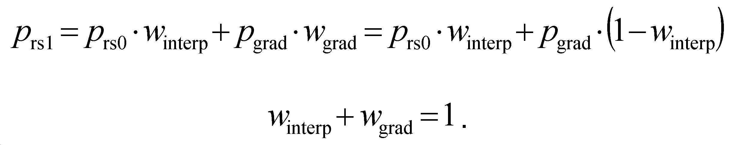
로서 계산된다.Is calculated as
이 수식의 조합은 다음: The combination of these formulas is:

을 제공한다. Provides.
후자의 수식은 ![]()
![]()
![]()
![]()
과 같이 단순화될 수 있다.It can be simplified as
따라서, DWDIP를 사용하여 예측된 픽셀 값은 다음: Thus, the predicted pixel values using DWDIP are:
![]()
![]()
과 같이 계산된다.It is calculated as
여기서 변수 i와 j는 도 4에서 사용된 x와 y에 대응하는 열/행 인덱스이다. 거리 비율(distance ratio)을 나타내는 가중치 w(i, j) = drs0/D는 표로 작성된 값에서 유도되며, 여기서 ![]()
![]()
따라서, ![]()
![]()
![]()
![]()
과 같다. Is the same as
예측될 블록 내 픽셀의 위치, 즉 선택된 방향을 따라 양쪽 참조 측면(reference sides)(블록 경계)까지의 거리에 의존하는 가중 계수 w(i, j)를 계산하려면 상당한 계산 복잡성이 필요한다. 계산을 단순화하기 위해, 거리의 간단한 계산(straightforward calculation)은 픽셀의 열 인덱스 또는/및 행 인덱스를 사용하여 거리의 암시적 추정으로 대체된다. 미국 특허 출원 US 2014/0092980 A1 "지향성 인트라 예측 방법 및 장치"에서 제안된 바와 같이, 경사 수평 예측 방향(slant horizontal prediction direction)에 대한 현재 픽셀의 예측 방향 및 열 인덱스 j에 따라 가중 계수 값이 선택된다.Considerable computational complexity is required to calculate the weighting factor w(i, j) that depends on the position of the pixel in the block to be predicted, i.e. the distance to both reference sides (block boundaries) along the selected direction. To simplify the calculation, a straightforward calculation of the distance is replaced with an implicit estimate of the distance using the column index or/and row index of the pixel. As proposed in US patent application US 2014/0092980 A1 "Directional intra prediction method and apparatus", a weighting factor value is selected according to the prediction direction of the current pixel and the column index j for the slant horizontal prediction direction. do.
DWDIP의 예에서, 인트라 예측 기술에 중요한 너무 높은 계산 복잡성 없이 충분히 높은 정확도를 달성할 수 있도록 부분 선형 근사(piecewise linear approximation)를 사용했다. 근사 프로세스에 대한 자세한 내용은 다음과 같다.In the DWDIP example, a piecewise linear approximation was used to achieve sufficiently high accuracy without the too high computational complexity critical for intra prediction techniques. Details of the approximation process are as follows.
인트라 예측의 수직 방향에 대해 가중 계수 w = drs0/D 는 행의 모든 열에 대해 동일한 값을 가질 것이며, 즉, 열 인덱스 i에 의존하지 않는다.For the vertical direction of intra prediction, the weighting factor w = d rs0 /D will have the same value for all columns of the row, i.e. it does not depend on the column index i.
도 5는 수직 인트라 예측의 예를 예시한다. 도 5에서 원은 샘플 위치의 중심을 나타낸다. 구체적으로, 크로스 해칭된(cross-hatched) 것(510)은 1차 참조 샘플의 위치를 표시하고, 대각선으로 해칭된 것(610)은 2차 참조 샘플의 위치를 표시하며, 개방된(open) 것(530)은 예측된 픽셀의 위치를 표시한다. 본 개시에서 "샘플"이라는 용어는 샘플, 픽셀, 서브 픽셀 등을 포함하도록 사용되지만 이에 제한되지 않는다. 수직 예측의 경우, 계수 ![]()
![]()
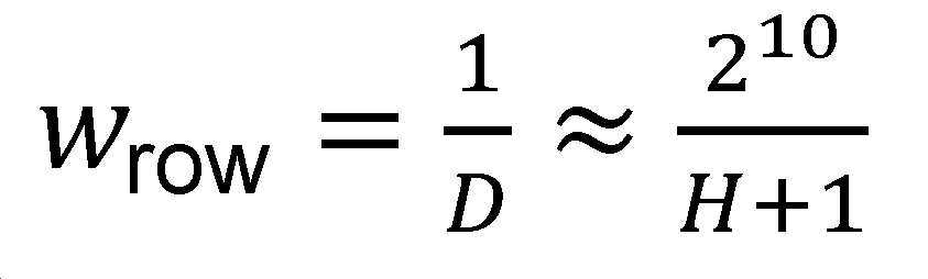
를 사용하여 맨 위 행(topmost row)에서 맨 아래 행(bottommost row)으로 점진적으로 변경된다.To change gradually from the topmost row to the bottommost row.
이 수식에서, D는 1차 참조 픽셀/샘플과 2차 참조 픽셀/샘플 사이의 거리이며; ![]()
![]()
![]()
![]()
수직 인트라 예측 모드의 경우 예측된 픽셀 값은 다음:For vertical intra prediction mode, the predicted pixel values are:
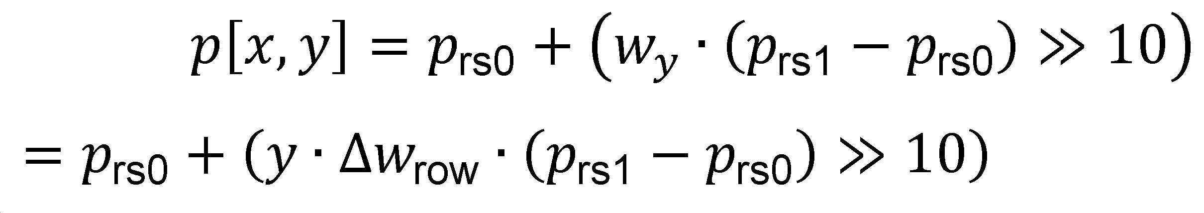
과 같이 계산된다. 여기서 ![]()
![]()
![]()
![]()
![]()
![]()
![]()
![]()
![]()
![]()
도 6은 스큐 지향성 인트라 예측(skew-directional intra prediction)의 예이다. 스큐 모드는 수평 모드 및 수직 모드를 제외한 각도 인트라 예측 모드의 세트를 포함한다. 스큐 지향성 인트라 예측 모드는 부분적으로 유사한 가중 계수 계산 메커니즘을 사용한다. 가중 계수의 값은 동일하게 유지되지만, 열 범위 내에서만 가능한다. 이 범위는 경계 사각형(도 6 참조)의 왼쪽 상단 모서리 및 오른쪽 하단 모서리를 가로 지르고, 사용 중인 인트라 예측 모드의 쌍(dx, dy)에 의해 지정된 기울기(slope)를 갖는 2개의 라인(500)으로 정의된다.6 is an example of skew-directional intra prediction. The skew mode includes a set of angular intra prediction modes excluding the horizontal mode and the vertical mode. The skew directional intra prediction mode uses a partially similar weighting factor calculation mechanism. The value of the weighting factor remains the same, but only within the thermal range. This range crosses the upper left and lower right corners of the bounding rectangle (see Fig. 6) and is represented by two
이러한 스큐 라인(skew line)은 예측된 블록의 경계 사각형을 2개의 동일한 삼각형(A, C)과 하나의 평행 사변형(B)의 세 영역으로 분할한다. 평행 사변형 내 위치를 갖는 샘플은 수직 인트라 예측을 위한 수식의 가중치를 사용하여 예측되며, 이는 도 5를 참조하여 위에서 설명한 바와 같이, 열 인덱스(i)와 독립적이다. 나머지 샘플의 예측은 열 인덱스에 따라 점진적으로 변경되는 가중 계수를 사용하여 수행된다. 주어진 행에 대해, 가중치는 도 7과 같이 샘플의 위치에 의존한다. 스큐 라인은 수직 라인 및 수평 라인을 제외한 라인이다. 다시 말해서, 스큐 라인은 수직이 아닌 라인 또는 수평이 아닌 라인이다.This skew line divides the bounding rectangle of the predicted block into three regions: two identical triangles (A, C) and one parallelogram (B). A sample having a position in the parallelogram is predicted using the weight of an equation for vertical intra prediction, which is independent of the column index (i), as described above with reference to FIG. 5. The prediction of the remaining samples is performed using a weighting factor that gradually changes according to the column index. For a given row, the weight depends on the location of the sample as shown in FIG. 7. Skew lines are lines excluding vertical lines and horizontal lines. In other words, the skew line is a non-vertical line or a non-horizontal line.
평행 사변형 내 첫 번째 행의 샘플에 대한 가중 계수는 평행 사변형 내 첫 번째 행의 다른 샘플에 대한 가중 계수와 동일하다. 행 계수 차이 ![]()
![]()
도 7은 주어진 행에 대한 열 인덱스에 대한 가중 계수의 의존성(dependence)을 나타낸 도이다. 평행 사변형 내의 왼쪽과 오른쪽은 각각 ![]()
![]()
![]()
![]()
![]()
![]()
![]()
![]()
![]()
![]()
![]()
![]()
![]()
![]()
![]()
![]()
![]()
![]()
![]()
![]()

과 같이 획득될 수 있다.Can be obtained as
예측 각도 ![]()

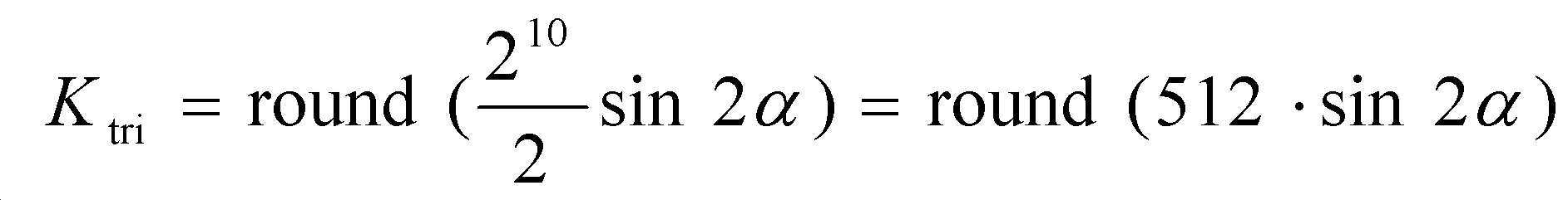
![]()
따라서,therefore,
![]()
![]()
이며, 여기서 "<<" 및 " >>" 는 각각 왼쪽 이진 시프트 연산자 및 오른쪽 이진 시프트 연산자이다.Where "<<" and ">>" are left binary shift operators and right binary shift operators, respectively.
가중 계수 차이 ![]()
![]()
![]()
![]()
![]()
![]()
![]()
![]()
![]()
![]()
![]()
![]()
도 7은 예이다. 다른 예로서, 주어진 열에 대한 행 인덱스에 대한 가중 계수의 의존성이 제공될 수 있다. 여기서 ![]()
![]()
위의 예의 측면은 기여 문서 CE3.7.2 "DWDIP(Distance-Weighted Directional Intra Prediction)"에 설명되어 있으며, 이 문서는 A. Filippov, V. Rufitskiy, 및 J. Chen에 의해, 2018년 7월 슬로베니아(Slovenia) 르뷸라냐(Ljubljana)에서의 ITU-T SG 16 WP 3 및 ISO/IEC JTC 1/SC 29/WG 11의 JVET(Joint Video Experts Team)의 11번째 미팅에서 기여되었다(http://phenix.it-sudparis.eu/jvet/doc_end_user/documents/11_Ljubljana/wg11/JVET-K0045-v2.zip).Aspects of the above example are described in the contributing document CE3.7.2 "Distance-Weighted Directional Intra Prediction (DWDIP)", which is by A. Filippov, V. Rufitskiy, and J. Chen, Slovenia, July 2018 ( Slovenia) contributed at the 11th meeting of the Joint Video Experts Team (JVET) of ITU-T SG 16 WP 3 and ISO/
도 8은 인트라 예측 방향이 대각선이고 예측 각도가 블록의 상단 왼쪽 모서리에 관련하여 45°인 경우, 폭이 8개 샘플과 동일하고 높이가 32개 샘플과 동일한 블록에 대한 두 번째 참조 샘플과 관련된 가중치를 도시한다. 여기서 가장 어두운 톤(tone)은 낮은 가중치에 대응하고, 밝은 톤은 더 큰 가중치 값에 대응한다. 가중치 최소값과 가중치 최대값은 각각 블록의 왼쪽과 오른쪽에 위치된다.FIG. 8 shows the weights associated with the second reference sample for a block equal to 8 samples in width and equal to 32 samples in height when the intra prediction direction is diagonal and the prediction angle is 45° with respect to the upper left corner of the block. Shows. Here, the darkest tones correspond to lower weights, and the lightest tones correspond to larger weights. The minimum weight value and the maximum weight value are located on the left and right sides of the block, respectively.
위의 예에서 적절한 1차 참조 샘플 값과 2차 참조 샘플 값의 가중 합계를 기반으로 하는 인트라 예측을 사용하면, 보간에 의한 2차 참조 샘플 값을 생성하기 위해 여전히 복잡한 계산이 필요하다.Using intra prediction based on the weighted sum of the appropriate primary and secondary reference sample values in the above example, it still requires complex calculations to generate secondary reference sample values by interpolation.
반면에, 2차 참조 샘플 값 prs1은 선형 보간된 부분만 포함하기 때문에, 보간(특히 멀티탭된 것(multi-tapped one)) 및 가중치의 사용이 중복된다. prs1으로부터 예측된 샘플도 점차적으로 변경된다. 따라서 예측될 블록의 오른쪽 상단(pTR) 모서리 및 왼쪽 하단(pBL) 모서리 근처의 재구성된 이웃 블록에 위치된 1차 참조 샘플만을 사용하여, prs1을 명시적으로 계산하지 않고도 수직 방향 및 수평 방향에서의 증분 값들을 계산할 수 있다.On the other hand, since the secondary reference sample value p rs1 includes only the linearly interpolated portion, interpolation (especially multi-tapped one) and use of weights are redundant. The sample predicted from p rs1 is also gradually changed. Therefore, using only the primary reference samples located in the reconstructed neighboring block near the top right (p TR ) edge and bottom left (p BL ) edge of the block to be predicted, the vertical and horizontal directions without explicitly calculating p rs1 Incremental values in the direction can be calculated.
본 발명에서는 예측될 블록 내에서 주어진 위치(X, Y)에 대한 증분 값을 계산하고, 1차 참조 샘플로부터 보간이 완료된 직후에 해당 증분을 적용하는 것을 제안한다.In the present invention, it is proposed to calculate an increment value for a given position (X, Y) in a block to be predicted, and apply the increment immediately after interpolation is completed from the primary reference sample.
다시 말해서, 본 발명은 보간을 포함하는 2차 참조 샘플을 계산할 필요성을 완전히 피하고, 대신에 적어도 현재 블록에서 예측된 픽셀의 위치에 의존하는 증분 값을 추가하는 것에 의해 현재 블록에서 픽셀 값의 예측을 생성한다. 특히, 이것은 반복적인 루프에서 반복적으로 더하기 연산(addition operation)을 포함할 수 있다. 실시 예의 세부 사항은 도 9 내지 도 11을 참조하여 이하에서 설명될 것이다.In other words, the present invention completely avoids the need to compute a secondary reference sample including interpolation, but instead makes prediction of a pixel value in the current block by adding an incremental value that depends at least on the predicted pixel's position in the current block. Generate. In particular, this may involve an iterative addition operation in an iterative loop. Details of the embodiment will be described below with reference to FIGS. 9 to 11.
본 발명의 실시 예에 따른 예측 샘플의 데프리베이션(deprivation)을 위한 전체 처리 흐름의 두 가지 변형(variant)이 도 9a 및 도 9b에 도시되어 있다. 이러한 변형은 점진적 컴포넌트에 대한 증분을 계산하는 단계에 대한 입력에 따라 서로 다르다. 도 9a에서의 처리는 필터링되지 않은 이웃 샘플을 사용하는 반면, 도 9b는 필터링된 샘플을 사용한다.Two variants of the overall processing flow for deprivation of a predicted sample according to an embodiment of the present invention are shown in FIGS. 9A and 9B. These transformations depend on the input to the step that computes the increment for the incremental component. The processing in Fig. 9A uses unfiltered neighboring samples, while Fig. 9B uses filtered samples.
보다 구체적으로, 도 9a에 예시된 처리에 따라, 참조 샘플 값(여기서는 Sp로 요약됨)은 단계(900)에서 참조 샘플 필터링을 거친다. 위에 지시된 바와 같이, 이 단계는 선택 사항이다. 본 발명의 실시 예에서, 이 단계는 생략될 수 있고, 이웃하는 "1차" 참조 샘플 값이 다음 단계(910)를 위해 직접 사용될 수 있다. 단계(910)에서, 픽셀 값의 예비 예측이 재구성된 이웃 블록 Sp로부터의 (선택적으로 필터링된) 참조 샘플 값에 기반하여 계산된다. 이 프로세스와 선택적 필터링 프로세스는 각각의 기존 프로세스에 비해 수정되지 않는다. 특히, 이러한 처리 단계는 기존 비디오 코딩 표준(예: H.264, HEVC 등)에서 잘 알려져 있다. 이 처리의 결과는 여기에서 Sref로 요약된다.More specifically, according to the processing illustrated in FIG. 9A, the reference sample value (here summarized as S p ) is subjected to reference sample filtering in
병렬로, 이웃 블록으로부터의 알려진 참조 샘플 값은 단계(920)에서 점진적 증분 컴포넌트를 계산하는 데 사용된다. 계산된 점진적 증분 컴포넌트 값, gx 및 gy는 특히 도 10과 도 11을 참조하여 아래에서 더 자세히 설명될 반복적인 절차에서 사용되는 "부분 증분(partial increment)"을 나타낼 수 있다.In parallel, known reference sample values from neighboring blocks are used in
여기에서 설명된 예시적인 실시 예들에 따르면, 값 gx 및 gy는 다음과 같이 계산될 수 있다: 폭에서 tbW개의 샘플을 가지고 높이에서 tbH 샘플을 가지는 예측될 블록의 경우, 점진적 컴포넌트의 증분은 다음 수식:According to the exemplary embodiments described herein, the values g x and g y may be calculated as follows: For a block to be predicted having tbW samples in width and tbH samples in height, the increment of the incremental component is The following formula:

을 사용하여 계산될 수 있다.Can be calculated using
위에 지시된 바와 같이, pBL 및 pTR은 현재 블록의 오른쪽 상단 모서리 및 왼쪽 하단 모서리의 근처(그러나 재구성된 이웃 블록 내)의 위치에서 ("1차") 참조 샘플 값을 나타낸다. 이러한 위치는 도 5에 지시되어 있다.As indicated above, p BL and p TR represent ("primary") reference sample values at locations near the upper right and lower left corners of the current block (but within the reconstructed neighboring block). These locations are indicated in FIG. 5.
결과적으로, 본 발명의 일 실시 예에 따른 증분 값은 현재 블록의 크기 파라미터(폭 및 높이)뿐만 아니라 사용 가능한 즉 알려진(재구성된) 이웃 블록으로부터의 2개의 고정된 참조 샘플 값에만 의존한다. 임의의 추가적인 "1차" 참조 샘플 값에 의존하지 않는다.As a result, the increment value according to an embodiment of the present invention depends only on the size parameters (width and height) of the current block as well as the two fixed reference sample values from available, that is, known (reconstructed) neighboring blocks. It does not depend on any additional "primary" reference sample values.
다음 단계(930)에서, (최종) 예측 샘플 값은 예비 예측 샘플 값과 계산된 증분 값 모두에 기반하여 계산된다. 이 단계는 도 10 및 도 11을 참조하여 아래에서 상세히 설명된다.In a
도 9b에 예시된 대안적인 처리는 부분 증분 값이 필터링된 참조 샘플 값에 기반하여 생성된다는 점에서 도 9a의 처리와 다르다. 따라서, 각각의 단계는 상이한 참조 번호 920'으로 지정되었다. 유사하게, 증분 값에 기반하여 단계(920')에서 결정되는 (최종) 예측 샘플의 유도(derivation)의 최종 단계는 도 9b의 각 단계와 구별되도록 참조 번호 930'이 주어졌다.The alternative processing illustrated in FIG. 9B differs from the processing in FIG. 9A in that partial incremental values are generated based on filtered reference sample values. Thus, each step has been designated a different reference number 920'. Similarly, the final step of the derivation of the (final) prediction sample determined in step 920' based on the incremental value is given the reference numeral 930' to distinguish it from each step of FIG. 9B.
본 발명의 실시 예에 따라 예측 샘플을 유도하기 위한 가능한 프로세스가 도 10에 도시되어 있다.A possible process for deriving a predictive sample according to an embodiment of the present invention is shown in FIG. 10.
이에 따라, (x, y) 위치에서 샘플에 대한 최종 예측값을 생성하는 반복 절차가 설명된다.Accordingly, an iterative procedure for generating a final predicted value for a sample at the (x, y) position is described.
처리 흐름은 단계(1000)에서 시작되며, 여기서 증분의 초기 값이 제공된다. 이것은 위에 정의된 값 gx 및 gy가 증분 계산의 초기 값으로 사용된다.The processing flow begins at
다음 단계(1010)에서, 그 합계가 형성되고, 파라미터 grow 로 지정된다.In the
단계(1020)는 첫 번째("외부") 반복 루프의 시작 단계로, 높이 방향에서 즉, 본 개시에서 채택된 협약(convention)에 따른 "y"축에 따라, 각각의 (정수) 샘플 위치에 대해 수행된다.
본 개시에서, 협약은 는 다음과 같은 표시(denotation): for x ∈ [x0; x1) 에 따라 사용되며, 이는 x의 값이 x0에서 시작하여 x1로 끝나며, 1씩 증가함을 지시한다. 대괄호 유형(Type of bracket)은 범위 경계 값이 루프 범위 내에 있는지 아니면 밖에 있는지를 나타낸다. 직사각형 대괄호 "[" 및 "]"는 해당 범위 경계 값이 루프 범위에 있으며 이 루프 내에서 처리되어야 함을 의미한다. 괄호(Parentheses) "(" 및 ")"는 해당 범위 경계 값이 범위를 벗어 났으며, 지정된 범위를 반복할 때 건너 뛰어야 함을 나타낸다. 이 유형의 다른 표시에도 동일하게 준용(mutatis mutandis) 된다.In this disclosure, the convention is denotation as follows: for x ∈ [x 0 ; It is used according to x 1 ), which indicates that the value of x starts at x 0 and ends at x 1 , increasing by 1. The type of bracket indicates whether the value of the range boundary is within or outside the range of the loop. The rectangular brackets "[" and "]" mean that the range boundary value is in the loop range and must be processed within this loop. Parentheses "(" and ")" indicate that the range boundary value is out of range and should be skipped when iterating over the specified range. The same applies mutatis mutandis to other indications of this type.
다음 단계(1030)에서, 증분 값 g은 값 grow 으로 초기화된다.In the
후속 단계(1040)은 두 번째("내부") 반복 루프의 시작 단계이며, 폭 방향에서 즉, 본 개시에서 채택된 협약에 따른 "x"축에 따라, 각각의 (정수) 샘플 위치에 대해 수행된다.The
다음 단계(1050)에서, 사용 가능한( "1차") 참조 샘플 값만을 기반으로 예비 예측 샘플의 유도가 수행된다. 상술한 바와 같이, 이는 통상적인 방식으로 이루어지므로 여기서는 상세한 설명을 생략한다. 따라서, 이 단계는 도 9의 단계(910)에 대응한다.In a
증분 값 g는 다음 단계(1060)에서, 여기서 predSamples[x, y]로 지정된 예비 예측 샘플 값에 추가된다.The increment value g is added in a
후속 단계(1070)에서, 증분 값은 부분 증분 값 gx만큼 증가되고, x축을 따라, 즉 폭 방향에서 다음 반복에 대한 입력으로 사용된다. 유사한 방식으로, 폭 방향의 모든 샘플 위치가 설명된 방식으로 처리된 후, 파라미터 grow가 단계(1080)에서 부분 증분 값 gy만큼 증가된다.In a
따라서, 각각의 반복에서, 즉 수직(y) 방향 또는 수평(x) 방향으로 하나의 정수 값으로 예측될 샘플 위치의 각 변경에 대해, 동일한 값이 증분에 추가됨이 보장된다. 따라서, 전체 증분은 경계(각각 x = 0 및 y = 0)로부터의 수직 거리 및 수평 거리에 선형적으로 의존한다.Thus, it is ensured that at each iteration, that is, for each change of the sample position to be predicted as one integer value in the vertical (y) direction or the horizontal (x) direction, the same value is added to the increment. Thus, the total increment depends linearly on the vertical and horizontal distances from the boundary (x = 0 and y = 0, respectively).
대안적인 구현에 따르면, 본 발명은 또한 도 6 및 도 7을 참조하여 위에서 설명한 것과 동일한 방식으로 현재 블록을 영역으로 세분화하는 것에 의해, 블록 형태 및 인트라 예측 방향을 고려할 수 있다. 이러한 처리의 예가 도 11에 예시되어 있다.According to an alternative implementation, the present invention may also take into account the block shape and intra prediction direction by subdividing the current block into regions in the same manner as described above with reference to FIGS. 6 and 7. An example of such processing is illustrated in FIG. 11.
여기서, 블록은 도 6에 도시된 바와 같이 2개의 스큐 라인(500)에 의해 3개의 영역으로 세분된다고 가정한다. 픽셀 행 xleft 및 xright을 갖는 분할 스큐 라인(500)의 교차 위치는 일반적으로 분수(fractional)이기 때문에, 서브 픽셀 정밀도(subpixel precision) "prec"를 갖는다. 실제 구현에서, prec는 2k이고 car는 자연수(양의 정수)이다. 도 11의 흐름도에서, 분수 값 xleft 및 xright 는 다음: Here, it is assumed that the block is subdivided into three regions by two
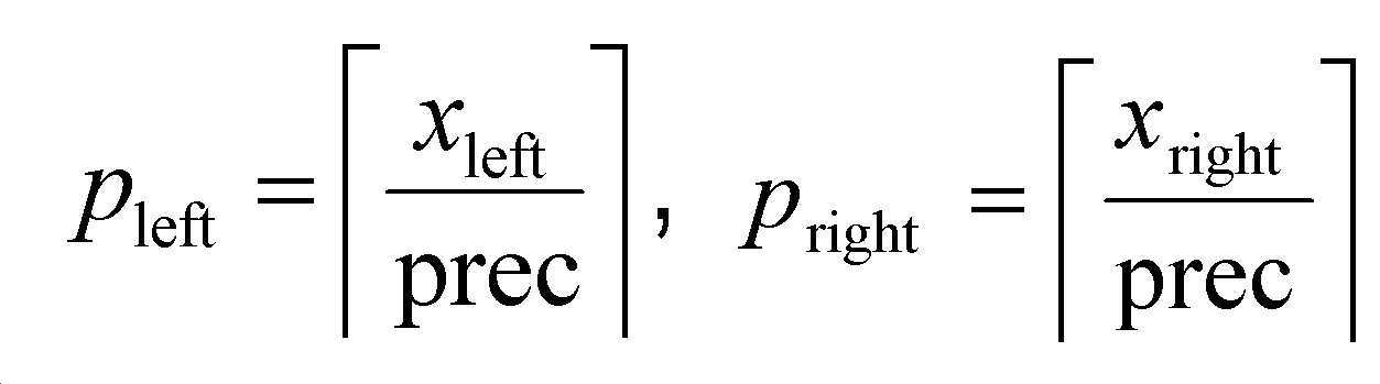
과 같은 정수 값 pleft 및 pright에 의해 근사화된다.It is approximated by integer values p left and p right equal to.
흐름도에서, 예측된 샘플의 행은 세 개의 영역, 즉 왼쪽의 삼각형 영역 A, 중간의 평행 사변형 영역 B, 그리고 오른쪽의 삼각형 영역 C로 분할하는 것에 의해 처리된다. 이 처리는 각각 "내부" 루프를 포함하는 도 11의 하단에 예시된 세 개의 병렬 분기(branch)에 대응한다. 보다 구체적으로, x = 0에서 pleft로 이어지는 왼쪽 측(left-hand side)의 분기는 도 6의 왼쪽 영역 A에 대응한다. pleft에서 pright로 이어지는 오른쪽 측의 분기는 중간 영역 B의 처리에 대응한다. pright에서 tbW까지 x- 값에 걸치는 중간의 분기는 오른쪽 영역 C의 처리에 대응한다. 아래에서 볼 수 있듯이, 이러한 각각의 영역은 자체 미리 계산된 증분 값을 사용한다.In the flowchart, a row of predicted samples is processed by dividing into three regions: a triangular region A on the left, a parallelogram region B on the middle, and a triangular region C on the right. This process corresponds to the three parallel branches illustrated at the bottom of Fig. 11, each comprising an "inner" loop. More specifically, a branch on the left-hand side from x = 0 to p left corresponds to the left region A of FIG. 6. The branch on the right side from p left to p right corresponds to the processing of the middle area B. The middle branch spanning the x- value from p right to tbW corresponds to the processing of the right area C. As can be seen below, each of these areas uses its own pre-computed increment value.
이를 위해 초기화 단계(1100)에서, gx 및 gy 외에 추가 값인 gx_tri가 초기화된다.To this end, in the
![]()
![]()
![]()
![]()
![]()
![]()

과 같이 획득된다.Is obtained as.
부동 소수점 연산 및 사인 함수 계산을 방지하기 위해, 룩업 테이블(lookup table)이 사용될 수 있다. 다음을 가정하는 다음 예제로 설명할 수 있다.To avoid floating point arithmetic and sine function computation, a lookup table can be used. This can be explained with the following example, which assumes the following:
- 인트라 예측 모드 인덱스는 65개의 지향성 인트라 예측 모드의 경우 VVC/BMS 소프트웨어에 정의된 대로 예측 방향 각도에 매핑된다.In the case of 65 directional intra prediction modes, the intra prediction mode index is mapped to the prediction direction angle as defined in the VVC/BMS software.
- ![]()
![]()
sin2a_half [16] = {512, 510, 502, 490, 473, 452, 426, 396, 362, 325, 284, 241, 196, 149, 100, 50, 0}sin2a_half [16] = {512, 510, 502, 490, 473, 452, 426, 396, 362, 325, 284, 241, 196, 149, 100, 50, 0}
과 같이 정의된다. Is defined as
위에서 언급된 가정의 경우, ![]()
![]()
![]()
![]()
과 같이 유도될 수 있다. Can be derived as
이 수식에서, ![]()
![]()
![]()
![]()
![]()
![]()
![]()
![]()
![]()
![]()
흐름도에서, 파라미터 grow는 도 10의 흐름도와 같은 방식으로 초기화되고 증가된다. 또한, 높이(y) 방향에서 "외부" 루프의 처리는 도 10과 동일하다. 따라서, 각각의 처리 단계(1010, 1020 및 1080)는 도 10에서와 동일한 참조 번호로 지정되었으며, 그 설명의 반복은 여기서 생략된다.In the flowchart, the parameter g row is initialized and incremented in the same manner as the flowchart of FIG. 10. Further, the processing of the "outer" loop in the height (y) direction is the same as in FIG. 10. Accordingly, each of the
폭(x) 방향에서 "내부" 루프에서의 처리 간의 차이점은 먼저 병렬로 지시된 각 루프 버전이 각각의 영역에서만 수행된다는 점이다. 이것은 시작 단계(1140, 1145 및 1147)에서 각각의 간격(interval)으로 지시된다.The difference between the processing in the "inner" loop in the width (x) direction is that each loop version, first indicated in parallel, is performed only in its respective area. This is indicated at each interval in the starting
또한, 실제 증분 값 g는 "로컬"로 정의된다. 이는 분기 중 하나에서 값을 수정해도 다른 분기에서 사용되는 변수 g의 각각의 값에 영향을 주지 않음을 의미한다.Also, the actual increment value g is defined as "local". This means that modifying the value in one of the branches does not affect each value of the variable g used in the other branch.
이는 루프가 시작되기 전의 각각의 초기 단계와 변수 값 g가 증분되는 초기 루프의 마지막 단계에서 볼 수 있다. 평행 사변형 영역 B에서 사용되는 오른쪽 분기에서, 각각의 처리는 도 10과 동일한 방식으로 수행된다. 따라서, 단계를 지시하는 각 참조 번호 1030, 1050, 1060 및 1070은 변경되지 않는다.This can be seen in each initial step before the loop starts and the last step in the initial loop where the variable value g is incremented. In the right branch used in the parallelogram region B, each processing is performed in the same manner as in FIG. 10. Thus,
2개의 삼각형 영역의 왼쪽 및 중간 분기에서, 파라미터 g의 초기화 단계가 상이하다. 즉, 위에서 소개된 파라미터 gx_tri를 사용하여 인트라 예측 방향의 각도를 고려한다. 이것은 도 11의 각 단계(1130 및 1135)의 공식(formulae)으로 지시된다. 결과적으로, 이러한 2개의 분기에서, 값 g를 증가시키는 단계(1070)는 단계(1170)로 대체되고, 여기서 파라미터 g는 각 반복에 대해 gx_tri만큼 증가된다. 나머지 단계(1050 및 1060)는 도 10과 관련하여 위에서 설명한 것과 동일하다.In the left and middle branches of the two triangular regions, the initialization steps of parameter g are different. That is, the angle of the intra prediction direction is considered using the parameter g x_tri introduced above. This is indicated by the formula of each
본 개시에 설명된 주제 및 동작의 구현은 디지털 전자 회로, 또는 컴퓨터 소프트웨어, 펌웨어, 또는 본 개시에 개시된 구조 및 그 구조적 등가물을 포함하는 하드웨어에서, 또는 하나 이상의 조합으로 구현될 수 있다. 본 개시에 설명된 주제의 구현은 하나 이상의 컴퓨터 프로그램, 즉, 데이터 처리 장치에 의해 실행되거나 데이터 처리 장치의 동작을 제어하기 위해 컴퓨터 저장 매체 상에 인코딩된 컴퓨터 프로그램 명령의 하나 이상의 모듈로서 구현될 수 있다. 다르게는 또는 추가로, 프로그램 명령은 인공적으로 생성된 전파 신호, 예를 들어 데이터 처리 장치에 의한 실행을 위해 적절한 수신기 장치로의 전송을 위해 정보를 인코딩하도록 생성된 기계 생성 전기적, 또는 광학 또는 전자기 신호에 대해 인코딩될 수 있다. 컴퓨터 저장 매체, 예를 들어 컴퓨터가 판독 가능한 매체는 컴퓨터 판독 가능 저장 디바이스, 컴퓨터 판독 가능 저장 기판, 랜덤 또는 직렬 액세스 메모리 어레이 또는 디바이스, 또는 그들 중 하나 이상의 조합일 수 있거나 그것에 포함될 수 있다. 더욱이, 컴퓨터 저장 매체는 전파된 신호가 아니지만, 컴퓨터 저장 매체는 인위적으로 생성된 전파 신호로 인코딩된 컴퓨터 프로그램 명령의 소스 또는 목적지일 수 있다. 컴퓨터 저장 매체는 또한 하나 이상의 별개의 물리적 및/또는 비 일시적 컴포넌트 또는 매체(예를 들어, 다수의 CD, 디스크 또는 기타 저장 디바이스)일 수 있거나 그것에 포함될 수 있다.Implementations of the subject matter and operations described in this disclosure may be implemented in digital electronic circuitry, or in computer software, firmware, or hardware including the structures and structural equivalents disclosed in this disclosure, or in a combination of one or more. An implementation of the subject matter described in this disclosure may be implemented as one or more computer programs, i.e., one or more modules of computer program instructions executed by the data processing device or encoded on a computer storage medium to control the operation of the data processing device. have. Alternatively or additionally, program instructions may be artificially generated radio signals, e.g., machine-generated electrical, or optical or electromagnetic signals generated to encode information for transmission to a suitable receiver device for execution by a data processing device. Can be encoded for. A computer storage medium, for example a computer readable medium, may be or be included in a computer readable storage device, a computer readable storage substrate, a random or serial access memory array or device, or a combination of one or more of them. Moreover, although the computer storage medium is not a propagated signal, the computer storage medium may be a source or destination of computer program instructions encoded with an artificially generated propagated signal. Computer storage media may also be or be included in one or more separate physical and/or non-transitory components or media (eg, multiple CDs, disks or other storage devices).
전술한 특정 예는 단지 예시를 위해 제공되며, 첨부된 청구 범위에 의해 정의된 본 발명은 이러한 예에 결코 제한되지 않는다는 것이 강조된다. 예를 들어, 실시 예들에 따르면, 수평 방향 및 수직 방향이 교환될 때, 즉 "외부" 루프가 x 방향을 따라 수행되고 "내부" 루프가 y 방향을 따라 수행될 때 처리가 유사하게 수행될 수 있다. 첨부된 청구항의 범위 내에서 추가 수정이 가능하다.It is emphasized that the specific examples described above are provided by way of example only, and that the invention as defined by the appended claims is in no way limited to these examples. For example, according to embodiments, when the horizontal direction and the vertical direction are exchanged, that is, when the "outer" loop is performed along the x direction and the "inner" loop is performed along the y direction, the processing can be similarly performed. have. Further modifications are possible within the scope of the appended claims.
요약하면, 본 발명은 알려진 양방향 인터 예측 방법의 개선에 관한 것이다. 본 발명에 따르면, 2차 참조 샘플로부터의 보간 대신, 인트라 예측에서 샘플을 계산하기 위해, "1차" 참조 샘플 값만을 기반으로 하는 계산이 사용된다. 결과는 적어도 현재 블록 내에서 픽셀(샘플)의 위치에 의존하며 그리고 블록의 모양과 크기 및 예측 방향에 의존할 수 있지만 추가적인 " 2차" 참조 샘플 값에 의존하지 않는 증분을 추가하는 것에 의해 정제(refine)될 수 있다. 따라서, 본 발명에 따른 처리는 1차 참조 샘플 및 2차 참조 샘플에 대해 두 번 수행하는 대신에 단일 보간 절차를 사용하기 때문에 계산적으로 덜 복잡하다.In summary, the present invention relates to an improvement of a known bidirectional inter prediction method. According to the present invention, instead of interpolation from a second order reference sample, to calculate a sample in intra prediction, a calculation based only on the "first order" reference sample value is used. The result depends at least on the position of the pixel (sample) within the current block, and may depend on the shape and size of the block and the prediction direction, but refined by adding increments that do not depend on the value of an additional "secondary" reference sample. can be refined. Therefore, the processing according to the present invention is computationally less complex because it uses a single interpolation procedure instead of performing twice on the primary reference sample and the secondary reference sample.
이 명세서는 화상(프레임)에 대한 설명을 제공하지만, 인터레이스(nterlace) 화상 신호의 경우 필드(filed)가 화상으로 대체된다.This specification provides a description of the picture (frame), but in the case of an interlace picture signal, the field (filed) is replaced by the picture.
본 발명의 실시 예가 주로 비디오 코딩에 기반하여 설명되었지만, 인코더(100) 및 디코더(200)(및 대응하는 시스템(300))의 실시 예는 또한 정지 화상 처리 또는 코딩, 즉. 비디오 코딩에서와 같이 임의의 선행 화상 또는 연속 화상에 독립적인 개별 화상의 처리 또는 코딩을 위해 구성될 수 있다는 점에 유의해야 한다. 일반적으로, 화상 처리 코딩이 단일 화상(101)로 제한되는 경우에는 인터 추정(142), 인터 예측(144, 242)만이 이용 가능하지 않다. 비디오 인코더(100) 및 비디오 디코더(200)의 모든 다른 기능(도구 또는 기술이라고도 함)은 아니지만 대부분은 예를 들어, 파티셔닝, 변환(스케일링)(106), 양자화(108), 역 양자화(110), 역 변환(112), 인트라 추정(142), 인트라 예측(154, 254) 및/또는 루프 필터링(120, 220) 및 엔트로피 코딩(170) 및 엔트로피 디코딩(204)은 정지 화상에 동일하게 사용될 수 있다.Although embodiments of the present invention have been described primarily based on video coding, embodiments of
실시 예 및 설명이 "메모리"라는 용어를 참조하는 경우, "메모리"라는 용어는 별도로 명시하지 않는 한, 자기 디스크, 광 디스크, 솔리드 스테이트 드라이브(solid state drive, SSD), 읽기 전용 메모리(Read-Only Memory, ROM), 랜덤 액세스 메모리(Random Access Memory, RAM), USB 플래시 드라이브 또는 기타 적절한 종류의 메모리를 포함함을 이해해야 한다.When the embodiment and description refer to the term "memory", the term "memory" is magnetic disk, optical disk, solid state drive (SSD), read-only memory (Read-only memory), unless otherwise specified. It should be understood that this includes only Memory (ROM), Random Access Memory (RAM), USB flash drive, or any other suitable type of memory.
실시 예 및 설명이 "네트워크"라는 용어를 참조하는 경우, "네트워크"라는 용어는 별도로 명시하지 않는 한, LAN(Local Area Network), WLAN(Wireless LAN), WAN(Wide Area Network), 이더넷, 인터넷, 모바일 네트워크 등과 같은 임의 종류의 무선 또는 유선 네트워크를 포함해야 한다.When the embodiments and description refer to the term "network", the term "network" is, unless otherwise specified, LAN (Local Area Network), WLAN (Wireless LAN), WAN (Wide Area Network), Ethernet, Internet , Mobile networks, and the like.
당업자는 다양한 도면(방법 및 장치)의 "블록"("유닛" 또는 "모듈")이 본 발명의 실시 예의 기능(반드시 하드웨어 또는 소프트웨어에서 개별 "유닛"이 아닌)을 나타내거나 설명하며, 따라서 장치 실시 예 및 방법 실시 예의 기능 또는 특징(유닛 = 단계)을 동일하게 설명함을 이해할 것이다Those skilled in the art will describe or describe the "blocks" ("units" or "modules") of the various figures (methods and apparatuses) of the embodiments of the present invention (not necessarily individual "units" in hardware or software), and thus device Embodiments and Methods It will be understood that the functions or features (unit = step) of the embodiment are described identically.
"유닛"이라는 용어는 인코더/디코더의 실시 예의 기능의 예시적인 목적으로만 사용되며, 본 개시를 제한하려는 의도는 아니다. The term "unit" is used only for illustrative purposes of the functionality of an embodiment of an encoder/decoder, and is not intended to limit the present disclosure.
본 출원에서 제공된 여러 실시 예에서, 개시된 시스템, 장치 및 방법은 다른 방식으로 구현될 수 있다는 것을 이해해야 한다. 예를 들어, 설명된 장치 실시 예는 단지 예시일 뿐이다. 예를 들어, 유닛 구분(unit division)은 단순히 논리적 기능 구분이며 실제 구현에서는 또 다른 구분일 수 있다. 예를 들어, 복수의 유닛 또는 컴포넌트가 다른 시스템에 조합되거나 통합될 수 있거나, 일부 기능이 무시되거나 수행되지 않을 수 있다. 또한, 디스플레이되거나 논의된 상호 결합(coupling) 또는 직접 결합 또는 통신 연결은 일부 인터페이스를 사용하여 구현될 수 있다. 장치 또는 유닛 간의 간접 결합 또는 통신 연결은 전자적, 기계적 또는 다른 형태로 구현될 수 있다.It is to be understood that in the various embodiments provided in this application, the disclosed systems, devices, and methods may be implemented in different ways. For example, the device embodiments described are only examples. For example, unit division is simply a logical functional division and may be another division in actual implementation. For example, a plurality of units or components may be combined or integrated into another system, or some functions may be ignored or not performed. In addition, the displayed or discussed mutual coupling or direct coupling or communication connection may be implemented using some interfaces. Indirect couplings or communication connections between devices or units may be implemented electronically, mechanically or in other forms.
분리된 부분으로 기술된 유닛은 물리적으로 분리되거나 분리되지 않을 수 있으며, 유닛으로 디스플레되는 부분은 물리적 유닛일 수도 있고 아닐 수도 있고, 한 위치에 위치될 수도 있고, 복수의 네트워크 유닛에 분산될 수도 있다. 유닛의 일부 또는 전부는 실시 예의 솔루션의 목적을 달성하기 위해 실제 필요에 따라 선택될 수 있다.A unit described as a separate part may or may not be physically separated, and a part displayed as a unit may or may not be a physical unit, may be located in one location, or may be distributed over a plurality of network units. . Some or all of the units may be selected according to actual needs to achieve the purpose of the solution of the embodiment.
또한, 본 발명의 실시 예에서의 기능 유닛은 하나의 처리 유닛으로 통합될 수 있거나, 각각의 유닛이 물리적으로 단독으로 존재할 수 있거나, 둘 이상의 유닛이 하나의 유닛으로 통합될 수 있다.In addition, the functional units in the embodiment of the present invention may be integrated into one processing unit, each unit may exist physically alone, or two or more units may be integrated into one unit.
본 발명의 실시 예는 장치, 예를 들어, 인코더 및/또는 디코더를 더 포함할 수 있으며, 장치는 여기에 설명된 방법 및/또는 프로세스 중 임의의 것을 수행하도록 구성된 처리 회로를 포함한다.Embodiments of the present invention may further include an apparatus, for example an encoder and/or decoder, the apparatus comprising processing circuitry configured to perform any of the methods and/or processes described herein.
인코더(100) 및/또는 디코더(200)의 실시 예는 하드웨어, 펌웨어, 소프트웨어 또는 이들의 임의의 조합으로 구현될 수 있다. 예를 들어, 인코더/인코딩 또는 디코더/디코딩의 기능은 펌웨어 또는 소프트웨어가 있거나 없는 처리 회로, 예를 들어, 프로세서, 마이크로컨트롤러, 디지털 신호 프로세서(digital signal processor, DSP), FPGA(Field Programmable Gate Array), ASIC(application-specific integrated circuit) 등에 의해 수행될 수 있다.An embodiment of the
인코더(100)(및 대응하는 인코딩 방법(100)) 및/또는 디코더(200)(및 대응하는 디코딩 방법(200))의 기능은 컴퓨터가 판독 가능한 매체에 저장된 프로그램 명령에 의해 구현될 수 있다. 프로그램 명령은 실행될 때 처리 회로, 컴퓨터, 프로세서 등이 인코딩 및/또는 디코딩 방법의 단계를 수행하게 한다. 컴퓨터가 판독 가능한 매체는 블루레이 디스크(Blu ray disc), DVD, CD, USB(플래시) 드라이브, 하드 디스크, 네트워크를 통해 사용 가능한 서버 저장소 등과 같이 프로그램이 저장된 비 일시적 저장 매체를 포함한 모든 매체일 수 있다.The functions of the encoder 100 (and the corresponding encoding method 100) and/or the decoder 200 (and the corresponding decoding method 200) may be implemented by program instructions stored in a computer-readable medium. The program instructions, when executed, cause a processing circuit, a computer, a processor, or the like to perform steps of the encoding and/or decoding method. Computer-readable media can be any media including non-transitory storage media on which programs are stored, such as Blu-ray discs, DVDs, CDs, USB (flash) drives, hard disks, and server storage available over the network. have.
본 발명의 실시 예는 컴퓨터상에서 실행될 때 여기에 설명된 방법 중 임의의 것을 수행하기 위한 프로그램 코드를 포함하는 컴퓨터 프로그램이거나 이를 포함한다.An embodiment of the present invention is or includes a computer program including program code for performing any of the methods described herein when executed on a computer.
본 발명의 실시 예는 프로세서에 의해 실행될 때 컴퓨터 시스템이 여기에 설명된 방법 중 임의의 것을 수행하게 하는 프로그램 코드를 포함하는 컴퓨터가 판독 가능한 매체이거나, 이를 포함한다.An embodiment of the present invention is or includes a computer-readable medium containing program code that, when executed by a processor, causes a computer system to perform any of the methods described herein.
본 발명의 실시 예는 여기에 설명된 임의의 방법을 수행하는 칩셋이거나 이를 포함한다.An embodiment of the present invention is or includes a chipset that performs any of the methods described herein.
Claims (22)
상기 장치는,
상기 현재 블록(520)의 재구성된 이웃 블록에 위치된 참조 샘플(510)의 참조 샘플 값(prs0)을 기반으로, 상기 현재 블록(520)의 샘플(400, 530)의 예비 예측 샘플 값을 계산하고; 그리고
상기 예비 예측 샘플 값에 증분 값(increment value)을 추가하는 것에 의해 상기 샘플의 최종 예측 샘플 값을 계산하도록 - 상기 증분 값은 상기 현재 블록(520)에서 상기 샘플(400, 530)의 위치에 의존함(depend) - 구성된 처리 회로
를 포함하는 장치.An apparatus for intra prediction of a current block 520 of a picture,
The device,
Based on the reference sample value (p rs0 ) of the reference sample 510 located in the reconstructed neighboring block of the current block 520, the preliminary prediction sample value of the samples 400 and 530 of the current block 520 Calculate; And
To calculate the final predicted sample value of the sample by adding an increment value to the preliminary predicted sample value-the increment value depends on the position of the sample (400, 530) in the current block (520) Depend-configured processing circuit
Device comprising a.
상기 참조 샘플(510)은 상기 현재 블록(520) 바로 위의 샘플의 행 및 상기 현재 블록의 왼쪽 또는 오른쪽에 있는 샘플의 열에 위치되거나, 또는 상기 참조 샘플(510)은 상기 현재 블록 바로 아래의 샘플의 행 및 상기 현재 블록(520)의 왼쪽 또는 오른쪽에 있는 샘플의 열에 위치되는, 장치. The method of claim 1,
The reference sample 510 is located in a row of samples immediately above the current block 520 and a column of samples to the left or right of the current block, or the reference sample 510 is a sample immediately below the current block A row of and a column of samples to the left or right of the current block (520).
상기 예비 예측 샘플 값은 상기 현재 블록(520)의 샘플의 지향성 인트라 예측에 따라 계산되는, 장치. The method according to claim 1 or 2,
The preliminary prediction sample value is calculated according to the directional intra prediction of the sample of the current block (520).
상기 증분 값은 폭(width)에서의 상기 현재 블록(520)의 샘플 수(tbW) 및 높이에서의 상기 현재 블록(520)의 샘플 수(tbH)를 추가로 고려하는 것에 의해 결정되는, 장치.The method according to any one of claims 1 to 3,
The increment value is determined by further considering the number of samples (tbW) of the current block 520 in width and the number of samples (tbH) of the current block 520 in height.
상기 증분 값은 2개의 참조 샘플을 사용하여 결정되며, 상기 2개의 참조 샘플 중 하나는 상기 현재 블록(520)의 가장 오른쪽 열의 오른쪽 이웃인 열 예를 들어, 오른쪽 상단(top right) 이웃 샘플(pTR)에 위치되며, 그리고 다른 하나는 상기 현재 블록(520)의 가장 낮은 행의 아래 이웃인 열 예를 들어, 왼쪽 하단(bottom left) 이웃 샘플(pBL)에 위치되는, 장치. The method according to any one of claims 1 to 4,
The increment value is determined using two reference samples, and one of the two reference samples is a column that is a right neighbor of the rightmost column of the current block 520, for example, a top right neighbor sample (p TR ), and the other is located in a column that is the bottom neighbor of the lowest row of the current block 520, e.g., in the bottom left neighboring sample (p BL ).
상기 증분 값은 상기 인트라 예측 모드 인덱스에 의존하는 상기 증분 값의 부분 증분(partial increment)을 지정하는 값을 갖는 룩업 테이블(lookup-table)을 사용하여 결정되고, 여기서, 예를 들어, 상기 룩업 테이블은 각각의 인트라 예측 모드 인덱스에 대해 상기 증분 값의 부분 증분을 제공하는, 장치.The method according to any one of claims 1 to 4,
The increment value is determined using a lookup-table having a value specifying a partial increment of the increment value depending on the intra prediction mode index, where, for example, the lookup table Provides a partial increment of the increment value for each intra prediction mode index.
상기 증분 값은 상기 현재 블록(520)에서 예측된 샘플의 행 내의 위치(x)에 선형적으로 의존하는, 장치. The method according to any one of claims 1 to 6,
Wherein the increment value is linearly dependent on the position (x) in the row of samples predicted in the current block (520).
상기 증분 값은 상기 현재 블록(520)에서 예측된 샘플의 행(x) 내의 위치에 부분적 선형적으로(piecewise-linearly) 의존하는, 장치. The method according to any one of claims 1 to 6,
Wherein the increment value depends piecewise-linearly on the position in the row (x) of the predicted sample at the current block (520).
상기 장치는 지향성 인트라 예측에 기반하여 상기 예비 예측 샘플 값을 계산하는 지향성 모드를 사용하도록 구성되는, 장치.The method according to any one of claims 1 to 8,
Wherein the apparatus is configured to use a directional mode to calculate the preliminary prediction sample value based on directional intra prediction.
상기 증분 값은 블록 형상 및/또는 예측 방향을 추가로 고려하는 것에 의해 결정되는, 장치. The method according to any one of claims 1 to 9,
Wherein the increment value is determined by further considering block shape and/or prediction direction.
상기 처리 회로는 추가로,
상기 현재 블록(520)을 적어도 하나의 스큐 라인(skew line)(500)으로 분할하여(split) 상기 블록의 적어도 2개의 영역을 획득하고, 그리고
상이한 영역에 대해 상기 증가 값을 상이하게 결정하도록 구성되는, 장치. The method according to any one of claims 1 to 10,
The processing circuit further,
Splitting the current block 520 into at least one skew line 500 to obtain at least two regions of the block, and
Configured to determine the increment value differently for different regions.
상기 스큐 라인(500)은 사용되는 인트라 예측 모드에 대응하는 기울기(slope)를 갖는, 장치. The method of claim 11,
The apparatus, wherein the skew line 500 has a slope corresponding to the intra prediction mode used.
상기 현재 블록(520)은 3개의 영역(A, B, C)을 획득하기 위해, 상기 현재 블록의 반대쪽 모서리를 교차하는 2개의 평행한 스큐 라인(500)에 의해 분할되는, 장치. The method of claim 11 or 12,
The device, wherein the current block (520) is divided by two parallel skew lines (500) intersecting opposite corners of the current block to obtain three regions (A, B, C).
상기 증분 값은 수직 방향에서 블록 경계(block boundary)로부터의 상기 샘플의 거리(y)에 선형적으로 의존하고, 수평 방향에서 블록 경계로부터의 상기 샘플의 거리(x)에 선형적으로 의존하는, 장치. The method according to any one of claims 1 to 13,
The incremental value linearly depends on the distance (y) of the sample from the block boundary in the vertical direction, and linearly on the distance (x) of the sample from the block boundary in the horizontal direction, Device.
상기 증분 값의 추가(adding)는 반복 절차에서 수행되고, 부분 증분이 후속적으로 상기 예비 예측에 추가되는, 장치. The method according to any one of claims 1 to 14,
Wherein the addition of the incremental value is performed in an iterative procedure, and a partial increment is subsequently added to the preliminary prediction.
상기 샘플 값의 예측은 재구성된 이웃 블록에 위치된 참조 샘플(510)으로부터의 참조 샘플 값만을 사용하여 계산되는, 장치. The method according to any one of claims 1 to 15,
Wherein the prediction of the sample value is calculated using only reference sample values from reference samples (510) located in reconstructed neighboring blocks.
상기 인코딩 장치는,
상기 현재 블록에 대한 예측된 블록을 제공하기 위한 전술한 청구항 중 어느 한 항에 따른 인트라 예측을 위한 장치(154); 및
상기 예측된 블록에 기반하여 상기 현재 블록(520)을 인코딩하도록 구성된 처리 회로(104, 106, 108, 170)
를 포함하는 인코딩 장치. An encoding device for encoding a current block of a picture, comprising:
The encoding device,
An apparatus (154) for intra prediction according to any one of the preceding claims for providing a predicted block for the current block; And
Processing circuitry 104, 106, 108, 170 configured to encode the current block 520 based on the predicted block
Encoding device comprising a.
상기 디코딩 장치는,
상기 인코딩된 블록에 대한 예측된 블록을 제공하기 위한 제1항 내지 제16항 중 어느 한 항에 따른 인트라 예측을 위한 장치(254); 및
상기 인코딩된 블록 및 상기 예측된 블록을 기반으로 현재 블록(520)을 재구성하도록 구성된 처리 회로(204, 210, 212, 214)
를 포함하는 디코딩 장치. A decoding device for decoding a currently encoded block of a picture, comprising:
The decoding device,
An apparatus (254) for intra prediction according to any one of claims 1 to 16 for providing a predicted block for the encoded block; And
Processing circuitry (204, 210, 212, 214) configured to reconstruct a current block (520) based on the encoded block and the predicted block.
Decoding device comprising a.
상기 방법은,
상기 현재 블록(520)의 재구성된 이웃 블록에 위치된 참조 샘플(510)의 참조 샘플 값(prs0)을 기반으로 상기 현재 블록의 샘플(400, 530)의 예비 예측 샘플 값을 계산하는 단계(910, 1050); 및
상기 예비 예측 샘플 값에 증분 값을 추가하는 것에 의해 상기 샘플의 최종 예측 샘플 값을 계산하는 단계(920, 930, 920', 930', 1060, 1070, 1170, 1080, 1170) - 상기 증분 값은 상기 현재 블록(520)에서 상기 샘플(400, 530)의 위치에 의존함 -
를 포함하는 방법. A method for intra prediction of a current block of a picture, comprising:
The above method,
Calculating a preliminary prediction sample value of the samples 400 and 530 of the current block based on the reference sample value p rs0 of the reference sample 510 located in the reconstructed neighboring block of the current block 520 ( 910, 1050); And
Calculating a final predicted sample value of the sample by adding an increment value to the preliminary predicted sample value (920, 930, 920', 930', 1060, 1070, 1170, 1080, 1170)-The increment value is Depends on the location of the samples 400 and 530 in the current block 520-
How to include.
상기 방법은
상기 현재 블록(520)의 샘플에 대해 제19항의 방법을 수행하는 것에 의해 상기 현재 블록(520)에 대한 예측된 블록을 제공하는 단계; 및
상기 예측된 블록을 기반으로 상기 현재 블록을 인코딩하는 단계(520)
를 포함하는 방법. A method of encoding a current block of a picture, comprising:
The above method is
Providing a predicted block for the current block (520) by performing the method of claim 19 on the samples of the current block (520); And
Encoding the current block based on the predicted block (520)
How to include.
상기 방법은,
현재 블록의 샘플에 대해 제19항의 방법을 수행하는 것에 의해 상기 인코딩된 블록에 대한 예측된 블록을 제공하는 단계; 및
상기 인코딩된 블록 및 상기 예측된 블록을 기반으로 상기 현재 블록(520)을 재구성하는 단계
를 포함하는 방법. A method of decoding a currently encoded block of a picture, comprising:
The above method,
Providing a predicted block for the encoded block by performing the method of claim 19 on a sample of the current block; And
Reconstructing the current block 520 based on the encoded block and the predicted block
How to include.
프로세서상에서 실행될 때 상기 프로세서로 하여금 제19항 내지 제21항 중 어느 한 항에 따른 방법의 모든 단계를 수행하게 하는 명령을 저장하는, 컴퓨터가 판독 가능한 매체.As a computer-readable medium,
A computer-readable medium storing instructions that, when executed on a processor, cause the processor to perform all steps of the method according to any one of claims 19-21.
Applications Claiming Priority (1)
| Application Number | Priority Date | Filing Date | Title |
|---|---|---|---|
| PCT/EP2018/069849 WO2020015841A1 (en) | 2018-07-20 | 2018-07-20 | Method and apparatus of reference sample interpolation for bidirectional intra prediction |
Publications (1)
| Publication Number | Publication Date |
|---|---|
| KR20210024113A true KR20210024113A (en) | 2021-03-04 |
Family
ID=63013026
Family Applications (1)
| Application Number | Title | Priority Date | Filing Date |
|---|---|---|---|
| KR1020217002529A Ceased KR20210024113A (en) | 2018-07-20 | 2018-07-20 | Reference sample interpolation method and apparatus for bidirectional intra prediction |
Country Status (6)
| Country | Link |
|---|---|
| US (1) | US20210144365A1 (en) |
| EP (1) | EP3808091A1 (en) |
| KR (1) | KR20210024113A (en) |
| CN (1) | CN112385232B (en) |
| BR (1) | BR112021000569A2 (en) |
| WO (1) | WO2020015841A1 (en) |
Cited By (1)
| Publication number | Priority date | Publication date | Assignee | Title |
|---|---|---|---|---|
| WO2023101524A1 (en) * | 2021-12-02 | 2023-06-08 | 현대자동차주식회사 | Video encoding/decoding method and device using bi-directional intra prediction mode |
Families Citing this family (1)
| Publication number | Priority date | Publication date | Assignee | Title |
|---|---|---|---|---|
| CN112204984B (en) * | 2018-06-27 | 2024-11-26 | 株式会社Kt | Method and apparatus for processing a video signal |
Family Cites Families (6)
| Publication number | Priority date | Publication date | Assignee | Title |
|---|---|---|---|---|
| US9008173B2 (en) * | 2007-10-15 | 2015-04-14 | Nippon Telegraph And Telephone Corporation | Image encoding and decoding apparatuses, image encoding and decoding methods, programs thereof, and recording media recorded with the programs |
| KR101204385B1 (en) * | 2011-04-01 | 2012-11-29 | 주식회사 아이벡스피티홀딩스 | Method of decoding moving pictures in intra prediction |
| EP2721827A4 (en) | 2011-06-20 | 2016-03-02 | Mediatek Singapore Pte Ltd | METHOD AND APPARATUS FOR DIRECTIONAL INTRAPEDICTION |
| KR20130105114A (en) * | 2012-03-16 | 2013-09-25 | 주식회사 아이벡스피티홀딩스 | Method of decoding moving pictures in intra prediction |
| JP5841670B2 (en) * | 2012-09-28 | 2016-01-13 | 日本電信電話株式会社 | Intra-prediction encoding method, intra-prediction decoding method, intra-prediction encoding device, intra-prediction decoding device, their program, and recording medium recording the program |
| CN107925759B (en) * | 2015-06-05 | 2022-06-03 | 杜比实验室特许公司 | Method and apparatus for encoding and decoding intra prediction |
-
2018
- 2018-07-20 KR KR1020217002529A patent/KR20210024113A/en not_active Ceased
- 2018-07-20 CN CN201880095452.9A patent/CN112385232B/en active Active
- 2018-07-20 WO PCT/EP2018/069849 patent/WO2020015841A1/en not_active Ceased
- 2018-07-20 EP EP18745568.8A patent/EP3808091A1/en not_active Withdrawn
- 2018-07-20 BR BR112021000569-2A patent/BR112021000569A2/en unknown
-
2021
- 2021-01-19 US US17/152,341 patent/US20210144365A1/en not_active Abandoned
Cited By (1)
| Publication number | Priority date | Publication date | Assignee | Title |
|---|---|---|---|---|
| WO2023101524A1 (en) * | 2021-12-02 | 2023-06-08 | 현대자동차주식회사 | Video encoding/decoding method and device using bi-directional intra prediction mode |
Also Published As
| Publication number | Publication date |
|---|---|
| CN112385232A (en) | 2021-02-19 |
| CN112385232B (en) | 2024-05-17 |
| BR112021000569A2 (en) | 2021-04-06 |
| EP3808091A1 (en) | 2021-04-21 |
| WO2020015841A1 (en) | 2020-01-23 |
| US20210144365A1 (en) | 2021-05-13 |
Similar Documents
| Publication | Publication Date | Title |
|---|---|---|
| US11575908B2 (en) | Method and apparatus of history-based intra mode coding | |
| US11265535B2 (en) | Method and apparatus for harmonizing multiple sign bit hiding and residual sign prediction | |
| KR102524915B1 (en) | Multi-tree depth extension for picture boundary processing | |
| AU2023214322B2 (en) | Method and apparatus for image filtering with adaptive multiplier coefficients | |
| US20200404339A1 (en) | Loop filter apparatus and method for video coding | |
| AU2023201715B2 (en) | Device and method for intra-prediction | |
| US20210144365A1 (en) | Method and apparatus of reference sample interpolation for bidirectional intra prediction | |
| WO2020005092A1 (en) | Device and method for intra-prediction of a prediction block of a video image | |
| US11259054B2 (en) | In-loop deblocking filter apparatus and method for video coding |
Legal Events
| Date | Code | Title | Description |
|---|---|---|---|
| A201 | Request for examination | ||
| PA0105 | International application |
Patent event date: 20210126 Patent event code: PA01051R01D Comment text: International Patent Application |
|
| PA0201 | Request for examination |
Patent event code: PA02012R01D Patent event date: 20210126 Comment text: Request for Examination of Application |
|
| PG1501 | Laying open of application | ||
| E902 | Notification of reason for refusal | ||
| PE0902 | Notice of grounds for rejection |
Comment text: Notification of reason for refusal Patent event date: 20220110 Patent event code: PE09021S01D |
|
| E601 | Decision to refuse application | ||
| PE0601 | Decision on rejection of patent |
Patent event date: 20220725 Comment text: Decision to Refuse Application Patent event code: PE06012S01D Patent event date: 20220110 Comment text: Notification of reason for refusal Patent event code: PE06011S01I |