KR20210016418A - Hydrogen production by steam methane reforming - Google Patents
Hydrogen production by steam methane reforming Download PDFInfo
- Publication number
- KR20210016418A KR20210016418A KR1020207037585A KR20207037585A KR20210016418A KR 20210016418 A KR20210016418 A KR 20210016418A KR 1020207037585 A KR1020207037585 A KR 1020207037585A KR 20207037585 A KR20207037585 A KR 20207037585A KR 20210016418 A KR20210016418 A KR 20210016418A
- Authority
- KR
- South Korea
- Prior art keywords
- gas
- reactor system
- catalyst
- structured catalyst
- reforming reactor
- Prior art date
- Legal status (The legal status is an assumption and is not a legal conclusion. Google has not performed a legal analysis and makes no representation as to the accuracy of the status listed.)
- Pending
Links
Images


Classifications
-
- C—CHEMISTRY; METALLURGY
- C01—INORGANIC CHEMISTRY
- C01B—NON-METALLIC ELEMENTS; COMPOUNDS THEREOF; METALLOIDS OR COMPOUNDS THEREOF NOT COVERED BY SUBCLASS C01C
- C01B3/00—Hydrogen; Gaseous mixtures containing hydrogen; Separation of hydrogen from mixtures containing it; Purification of hydrogen
- C01B3/02—Production of hydrogen or of gaseous mixtures containing a substantial proportion of hydrogen
- C01B3/32—Production of hydrogen or of gaseous mixtures containing a substantial proportion of hydrogen by reaction of gaseous or liquid organic compounds with gasifying agents, e.g. water, carbon dioxide, air
- C01B3/34—Production of hydrogen or of gaseous mixtures containing a substantial proportion of hydrogen by reaction of gaseous or liquid organic compounds with gasifying agents, e.g. water, carbon dioxide, air by reaction of hydrocarbons with gasifying agents
- C01B3/38—Production of hydrogen or of gaseous mixtures containing a substantial proportion of hydrogen by reaction of gaseous or liquid organic compounds with gasifying agents, e.g. water, carbon dioxide, air by reaction of hydrocarbons with gasifying agents using catalysts
- C01B3/384—Production of hydrogen or of gaseous mixtures containing a substantial proportion of hydrogen by reaction of gaseous or liquid organic compounds with gasifying agents, e.g. water, carbon dioxide, air by reaction of hydrocarbons with gasifying agents using catalysts the catalyst being continuously externally heated
-
- B—PERFORMING OPERATIONS; TRANSPORTING
- B01—PHYSICAL OR CHEMICAL PROCESSES OR APPARATUS IN GENERAL
- B01D—SEPARATION
- B01D53/00—Separation of gases or vapours; Recovering vapours of volatile solvents from gases; Chemical or biological purification of waste gases, e.g. engine exhaust gases, smoke, fumes, flue gases, aerosols
- B01D53/26—Drying gases or vapours
- B01D53/265—Drying gases or vapours by refrigeration (condensation)
-
- B—PERFORMING OPERATIONS; TRANSPORTING
- B01—PHYSICAL OR CHEMICAL PROCESSES OR APPARATUS IN GENERAL
- B01J—CHEMICAL OR PHYSICAL PROCESSES, e.g. CATALYSIS OR COLLOID CHEMISTRY; THEIR RELEVANT APPARATUS
- B01J12/00—Chemical processes in general for reacting gaseous media with gaseous media; Apparatus specially adapted therefor
- B01J12/007—Chemical processes in general for reacting gaseous media with gaseous media; Apparatus specially adapted therefor in the presence of catalytically active bodies, e.g. porous plates
-
- B—PERFORMING OPERATIONS; TRANSPORTING
- B01—PHYSICAL OR CHEMICAL PROCESSES OR APPARATUS IN GENERAL
- B01J—CHEMICAL OR PHYSICAL PROCESSES, e.g. CATALYSIS OR COLLOID CHEMISTRY; THEIR RELEVANT APPARATUS
- B01J15/00—Chemical processes in general for reacting gaseous media with non-particulate solids, e.g. sheet material; Apparatus specially adapted therefor
- B01J15/005—Chemical processes in general for reacting gaseous media with non-particulate solids, e.g. sheet material; Apparatus specially adapted therefor in the presence of catalytically active bodies, e.g. porous plates
-
- B—PERFORMING OPERATIONS; TRANSPORTING
- B01—PHYSICAL OR CHEMICAL PROCESSES OR APPARATUS IN GENERAL
- B01J—CHEMICAL OR PHYSICAL PROCESSES, e.g. CATALYSIS OR COLLOID CHEMISTRY; THEIR RELEVANT APPARATUS
- B01J19/00—Chemical, physical or physico-chemical processes in general; Their relevant apparatus
- B01J19/0006—Controlling or regulating processes
- B01J19/0013—Controlling the temperature of the process
-
- B—PERFORMING OPERATIONS; TRANSPORTING
- B01—PHYSICAL OR CHEMICAL PROCESSES OR APPARATUS IN GENERAL
- B01J—CHEMICAL OR PHYSICAL PROCESSES, e.g. CATALYSIS OR COLLOID CHEMISTRY; THEIR RELEVANT APPARATUS
- B01J19/00—Chemical, physical or physico-chemical processes in general; Their relevant apparatus
- B01J19/24—Stationary reactors without moving elements inside
- B01J19/248—Reactors comprising multiple separated flow channels
- B01J19/2485—Monolithic reactors
-
- B—PERFORMING OPERATIONS; TRANSPORTING
- B01—PHYSICAL OR CHEMICAL PROCESSES OR APPARATUS IN GENERAL
- B01J—CHEMICAL OR PHYSICAL PROCESSES, e.g. CATALYSIS OR COLLOID CHEMISTRY; THEIR RELEVANT APPARATUS
- B01J35/00—Catalysts, in general, characterised by their form or physical properties
- B01J35/30—Catalysts, in general, characterised by their form or physical properties characterised by their physical properties
- B01J35/33—Electric or magnetic properties
-
- B—PERFORMING OPERATIONS; TRANSPORTING
- B01—PHYSICAL OR CHEMICAL PROCESSES OR APPARATUS IN GENERAL
- B01J—CHEMICAL OR PHYSICAL PROCESSES, e.g. CATALYSIS OR COLLOID CHEMISTRY; THEIR RELEVANT APPARATUS
- B01J35/00—Catalysts, in general, characterised by their form or physical properties
- B01J35/50—Catalysts, in general, characterised by their form or physical properties characterised by their shape or configuration
- B01J35/56—Foraminous structures having flow-through passages or channels, e.g. grids or three-dimensional monoliths
-
- C—CHEMISTRY; METALLURGY
- C01—INORGANIC CHEMISTRY
- C01B—NON-METALLIC ELEMENTS; COMPOUNDS THEREOF; METALLOIDS OR COMPOUNDS THEREOF NOT COVERED BY SUBCLASS C01C
- C01B3/00—Hydrogen; Gaseous mixtures containing hydrogen; Separation of hydrogen from mixtures containing it; Purification of hydrogen
- C01B3/02—Production of hydrogen or of gaseous mixtures containing a substantial proportion of hydrogen
- C01B3/32—Production of hydrogen or of gaseous mixtures containing a substantial proportion of hydrogen by reaction of gaseous or liquid organic compounds with gasifying agents, e.g. water, carbon dioxide, air
- C01B3/34—Production of hydrogen or of gaseous mixtures containing a substantial proportion of hydrogen by reaction of gaseous or liquid organic compounds with gasifying agents, e.g. water, carbon dioxide, air by reaction of hydrocarbons with gasifying agents
- C01B3/38—Production of hydrogen or of gaseous mixtures containing a substantial proportion of hydrogen by reaction of gaseous or liquid organic compounds with gasifying agents, e.g. water, carbon dioxide, air by reaction of hydrocarbons with gasifying agents using catalysts
- C01B3/40—Production of hydrogen or of gaseous mixtures containing a substantial proportion of hydrogen by reaction of gaseous or liquid organic compounds with gasifying agents, e.g. water, carbon dioxide, air by reaction of hydrocarbons with gasifying agents using catalysts characterised by the catalyst
-
- C—CHEMISTRY; METALLURGY
- C01—INORGANIC CHEMISTRY
- C01B—NON-METALLIC ELEMENTS; COMPOUNDS THEREOF; METALLOIDS OR COMPOUNDS THEREOF NOT COVERED BY SUBCLASS C01C
- C01B3/00—Hydrogen; Gaseous mixtures containing hydrogen; Separation of hydrogen from mixtures containing it; Purification of hydrogen
- C01B3/50—Separation of hydrogen or hydrogen containing gases from gaseous mixtures, e.g. purification
- C01B3/501—Separation of hydrogen or hydrogen containing gases from gaseous mixtures, e.g. purification by diffusion
- C01B3/503—Separation of hydrogen or hydrogen containing gases from gaseous mixtures, e.g. purification by diffusion characterised by the membrane
-
- C—CHEMISTRY; METALLURGY
- C01—INORGANIC CHEMISTRY
- C01B—NON-METALLIC ELEMENTS; COMPOUNDS THEREOF; METALLOIDS OR COMPOUNDS THEREOF NOT COVERED BY SUBCLASS C01C
- C01B3/00—Hydrogen; Gaseous mixtures containing hydrogen; Separation of hydrogen from mixtures containing it; Purification of hydrogen
- C01B3/50—Separation of hydrogen or hydrogen containing gases from gaseous mixtures, e.g. purification
- C01B3/506—Separation of hydrogen or hydrogen containing gases from gaseous mixtures, e.g. purification at low temperatures
-
- B—PERFORMING OPERATIONS; TRANSPORTING
- B01—PHYSICAL OR CHEMICAL PROCESSES OR APPARATUS IN GENERAL
- B01D—SEPARATION
- B01D2252/00—Absorbents, i.e. solvents and liquid materials for gas absorption
- B01D2252/20—Organic absorbents
- B01D2252/204—Amines
-
- B—PERFORMING OPERATIONS; TRANSPORTING
- B01—PHYSICAL OR CHEMICAL PROCESSES OR APPARATUS IN GENERAL
- B01D—SEPARATION
- B01D53/00—Separation of gases or vapours; Recovering vapours of volatile solvents from gases; Chemical or biological purification of waste gases, e.g. engine exhaust gases, smoke, fumes, flue gases, aerosols
- B01D53/02—Separation of gases or vapours; Recovering vapours of volatile solvents from gases; Chemical or biological purification of waste gases, e.g. engine exhaust gases, smoke, fumes, flue gases, aerosols by adsorption, e.g. preparative gas chromatography
- B01D53/04—Separation of gases or vapours; Recovering vapours of volatile solvents from gases; Chemical or biological purification of waste gases, e.g. engine exhaust gases, smoke, fumes, flue gases, aerosols by adsorption, e.g. preparative gas chromatography with stationary adsorbents
- B01D53/047—Pressure swing adsorption
-
- B—PERFORMING OPERATIONS; TRANSPORTING
- B01—PHYSICAL OR CHEMICAL PROCESSES OR APPARATUS IN GENERAL
- B01D—SEPARATION
- B01D53/00—Separation of gases or vapours; Recovering vapours of volatile solvents from gases; Chemical or biological purification of waste gases, e.g. engine exhaust gases, smoke, fumes, flue gases, aerosols
- B01D53/14—Separation of gases or vapours; Recovering vapours of volatile solvents from gases; Chemical or biological purification of waste gases, e.g. engine exhaust gases, smoke, fumes, flue gases, aerosols by absorption
- B01D53/1456—Removing acid components
- B01D53/1475—Removing carbon dioxide
-
- B—PERFORMING OPERATIONS; TRANSPORTING
- B01—PHYSICAL OR CHEMICAL PROCESSES OR APPARATUS IN GENERAL
- B01D—SEPARATION
- B01D53/00—Separation of gases or vapours; Recovering vapours of volatile solvents from gases; Chemical or biological purification of waste gases, e.g. engine exhaust gases, smoke, fumes, flue gases, aerosols
- B01D53/22—Separation of gases or vapours; Recovering vapours of volatile solvents from gases; Chemical or biological purification of waste gases, e.g. engine exhaust gases, smoke, fumes, flue gases, aerosols by diffusion
- B01D53/228—Separation of gases or vapours; Recovering vapours of volatile solvents from gases; Chemical or biological purification of waste gases, e.g. engine exhaust gases, smoke, fumes, flue gases, aerosols by diffusion characterised by specific membranes
-
- B—PERFORMING OPERATIONS; TRANSPORTING
- B01—PHYSICAL OR CHEMICAL PROCESSES OR APPARATUS IN GENERAL
- B01J—CHEMICAL OR PHYSICAL PROCESSES, e.g. CATALYSIS OR COLLOID CHEMISTRY; THEIR RELEVANT APPARATUS
- B01J2219/00—Chemical, physical or physico-chemical processes in general; Their relevant apparatus
- B01J2219/00049—Controlling or regulating processes
- B01J2219/00051—Controlling the temperature
- B01J2219/00132—Controlling the temperature using electric heating or cooling elements
- B01J2219/00135—Electric resistance heaters
-
- B—PERFORMING OPERATIONS; TRANSPORTING
- B01—PHYSICAL OR CHEMICAL PROCESSES OR APPARATUS IN GENERAL
- B01J—CHEMICAL OR PHYSICAL PROCESSES, e.g. CATALYSIS OR COLLOID CHEMISTRY; THEIR RELEVANT APPARATUS
- B01J2219/00—Chemical, physical or physico-chemical processes in general; Their relevant apparatus
- B01J2219/00049—Controlling or regulating processes
- B01J2219/00051—Controlling the temperature
- B01J2219/0015—Controlling the temperature by thermal insulation means
- B01J2219/00155—Controlling the temperature by thermal insulation means using insulating materials or refractories
-
- B—PERFORMING OPERATIONS; TRANSPORTING
- B01—PHYSICAL OR CHEMICAL PROCESSES OR APPARATUS IN GENERAL
- B01J—CHEMICAL OR PHYSICAL PROCESSES, e.g. CATALYSIS OR COLLOID CHEMISTRY; THEIR RELEVANT APPARATUS
- B01J2219/00—Chemical, physical or physico-chemical processes in general; Their relevant apparatus
- B01J2219/00049—Controlling or regulating processes
- B01J2219/00186—Controlling or regulating processes controlling the composition of the reactive mixture
-
- B—PERFORMING OPERATIONS; TRANSPORTING
- B01—PHYSICAL OR CHEMICAL PROCESSES OR APPARATUS IN GENERAL
- B01J—CHEMICAL OR PHYSICAL PROCESSES, e.g. CATALYSIS OR COLLOID CHEMISTRY; THEIR RELEVANT APPARATUS
- B01J2219/00—Chemical, physical or physico-chemical processes in general; Their relevant apparatus
- B01J2219/08—Processes employing the direct application of electric or wave energy, or particle radiation; Apparatus therefor
- B01J2219/0871—Heating or cooling of the reactor
-
- B—PERFORMING OPERATIONS; TRANSPORTING
- B01—PHYSICAL OR CHEMICAL PROCESSES OR APPARATUS IN GENERAL
- B01J—CHEMICAL OR PHYSICAL PROCESSES, e.g. CATALYSIS OR COLLOID CHEMISTRY; THEIR RELEVANT APPARATUS
- B01J2219/00—Chemical, physical or physico-chemical processes in general; Their relevant apparatus
- B01J2219/24—Stationary reactors without moving elements inside
- B01J2219/2401—Reactors comprising multiple separate flow channels
- B01J2219/2402—Monolithic-type reactors
- B01J2219/2403—Geometry of the channels
- B01J2219/2407—Square
-
- B—PERFORMING OPERATIONS; TRANSPORTING
- B01—PHYSICAL OR CHEMICAL PROCESSES OR APPARATUS IN GENERAL
- B01J—CHEMICAL OR PHYSICAL PROCESSES, e.g. CATALYSIS OR COLLOID CHEMISTRY; THEIR RELEVANT APPARATUS
- B01J2219/00—Chemical, physical or physico-chemical processes in general; Their relevant apparatus
- B01J2219/24—Stationary reactors without moving elements inside
- B01J2219/2401—Reactors comprising multiple separate flow channels
- B01J2219/2402—Monolithic-type reactors
- B01J2219/2409—Heat exchange aspects
- B01J2219/2416—Additional heat exchange means, e.g. electric resistance heater, coils
-
- B—PERFORMING OPERATIONS; TRANSPORTING
- B01—PHYSICAL OR CHEMICAL PROCESSES OR APPARATUS IN GENERAL
- B01J—CHEMICAL OR PHYSICAL PROCESSES, e.g. CATALYSIS OR COLLOID CHEMISTRY; THEIR RELEVANT APPARATUS
- B01J2219/00—Chemical, physical or physico-chemical processes in general; Their relevant apparatus
- B01J2219/24—Stationary reactors without moving elements inside
- B01J2219/2401—Reactors comprising multiple separate flow channels
- B01J2219/2402—Monolithic-type reactors
- B01J2219/2425—Construction materials
- B01J2219/2427—Catalysts
- B01J2219/2428—Catalysts coated on the surface of the monolith channels
-
- B—PERFORMING OPERATIONS; TRANSPORTING
- B01—PHYSICAL OR CHEMICAL PROCESSES OR APPARATUS IN GENERAL
- B01J—CHEMICAL OR PHYSICAL PROCESSES, e.g. CATALYSIS OR COLLOID CHEMISTRY; THEIR RELEVANT APPARATUS
- B01J2219/00—Chemical, physical or physico-chemical processes in general; Their relevant apparatus
- B01J2219/24—Stationary reactors without moving elements inside
- B01J2219/2401—Reactors comprising multiple separate flow channels
- B01J2219/2402—Monolithic-type reactors
- B01J2219/2425—Construction materials
- B01J2219/2427—Catalysts
- B01J2219/2432—Monoliths having catalytic activity on its own
-
- B—PERFORMING OPERATIONS; TRANSPORTING
- B01—PHYSICAL OR CHEMICAL PROCESSES OR APPARATUS IN GENERAL
- B01J—CHEMICAL OR PHYSICAL PROCESSES, e.g. CATALYSIS OR COLLOID CHEMISTRY; THEIR RELEVANT APPARATUS
- B01J2219/00—Chemical, physical or physico-chemical processes in general; Their relevant apparatus
- B01J2219/24—Stationary reactors without moving elements inside
- B01J2219/2401—Reactors comprising multiple separate flow channels
- B01J2219/2402—Monolithic-type reactors
- B01J2219/2425—Construction materials
- B01J2219/2433—Construction materials of the monoliths
- B01J2219/2438—Ceramics
-
- B—PERFORMING OPERATIONS; TRANSPORTING
- B01—PHYSICAL OR CHEMICAL PROCESSES OR APPARATUS IN GENERAL
- B01J—CHEMICAL OR PHYSICAL PROCESSES, e.g. CATALYSIS OR COLLOID CHEMISTRY; THEIR RELEVANT APPARATUS
- B01J2219/00—Chemical, physical or physico-chemical processes in general; Their relevant apparatus
- B01J2219/24—Stationary reactors without moving elements inside
- B01J2219/2401—Reactors comprising multiple separate flow channels
- B01J2219/2402—Monolithic-type reactors
- B01J2219/2441—Other constructional details
- B01J2219/2443—Assembling means of monolith modules
-
- B—PERFORMING OPERATIONS; TRANSPORTING
- B01—PHYSICAL OR CHEMICAL PROCESSES OR APPARATUS IN GENERAL
- B01J—CHEMICAL OR PHYSICAL PROCESSES, e.g. CATALYSIS OR COLLOID CHEMISTRY; THEIR RELEVANT APPARATUS
- B01J2219/00—Chemical, physical or physico-chemical processes in general; Their relevant apparatus
- B01J2219/24—Stationary reactors without moving elements inside
- B01J2219/2401—Reactors comprising multiple separate flow channels
- B01J2219/2402—Monolithic-type reactors
- B01J2219/2441—Other constructional details
- B01J2219/2444—Size aspects
- B01J2219/2445—Sizes
-
- C—CHEMISTRY; METALLURGY
- C01—INORGANIC CHEMISTRY
- C01B—NON-METALLIC ELEMENTS; COMPOUNDS THEREOF; METALLOIDS OR COMPOUNDS THEREOF NOT COVERED BY SUBCLASS C01C
- C01B2203/00—Integrated processes for the production of hydrogen or synthesis gas
- C01B2203/02—Processes for making hydrogen or synthesis gas
- C01B2203/0205—Processes for making hydrogen or synthesis gas containing a reforming step
- C01B2203/0227—Processes for making hydrogen or synthesis gas containing a reforming step containing a catalytic reforming step
- C01B2203/0233—Processes for making hydrogen or synthesis gas containing a reforming step containing a catalytic reforming step the reforming step being a steam reforming step
-
- C—CHEMISTRY; METALLURGY
- C01—INORGANIC CHEMISTRY
- C01B—NON-METALLIC ELEMENTS; COMPOUNDS THEREOF; METALLOIDS OR COMPOUNDS THEREOF NOT COVERED BY SUBCLASS C01C
- C01B2203/00—Integrated processes for the production of hydrogen or synthesis gas
- C01B2203/02—Processes for making hydrogen or synthesis gas
- C01B2203/0283—Processes for making hydrogen or synthesis gas containing a CO-shift step, i.e. a water gas shift step
-
- C—CHEMISTRY; METALLURGY
- C01—INORGANIC CHEMISTRY
- C01B—NON-METALLIC ELEMENTS; COMPOUNDS THEREOF; METALLOIDS OR COMPOUNDS THEREOF NOT COVERED BY SUBCLASS C01C
- C01B2203/00—Integrated processes for the production of hydrogen or synthesis gas
- C01B2203/04—Integrated processes for the production of hydrogen or synthesis gas containing a purification step for the hydrogen or the synthesis gas
- C01B2203/0405—Purification by membrane separation
-
- C—CHEMISTRY; METALLURGY
- C01—INORGANIC CHEMISTRY
- C01B—NON-METALLIC ELEMENTS; COMPOUNDS THEREOF; METALLOIDS OR COMPOUNDS THEREOF NOT COVERED BY SUBCLASS C01C
- C01B2203/00—Integrated processes for the production of hydrogen or synthesis gas
- C01B2203/04—Integrated processes for the production of hydrogen or synthesis gas containing a purification step for the hydrogen or the synthesis gas
- C01B2203/046—Purification by cryogenic separation
-
- C—CHEMISTRY; METALLURGY
- C01—INORGANIC CHEMISTRY
- C01B—NON-METALLIC ELEMENTS; COMPOUNDS THEREOF; METALLOIDS OR COMPOUNDS THEREOF NOT COVERED BY SUBCLASS C01C
- C01B2203/00—Integrated processes for the production of hydrogen or synthesis gas
- C01B2203/08—Methods of heating or cooling
- C01B2203/0805—Methods of heating the process for making hydrogen or synthesis gas
- C01B2203/085—Methods of heating the process for making hydrogen or synthesis gas by electric heating
-
- C—CHEMISTRY; METALLURGY
- C01—INORGANIC CHEMISTRY
- C01B—NON-METALLIC ELEMENTS; COMPOUNDS THEREOF; METALLOIDS OR COMPOUNDS THEREOF NOT COVERED BY SUBCLASS C01C
- C01B2203/00—Integrated processes for the production of hydrogen or synthesis gas
- C01B2203/08—Methods of heating or cooling
- C01B2203/0872—Methods of cooling
- C01B2203/0883—Methods of cooling by indirect heat exchange
-
- C—CHEMISTRY; METALLURGY
- C01—INORGANIC CHEMISTRY
- C01B—NON-METALLIC ELEMENTS; COMPOUNDS THEREOF; METALLOIDS OR COMPOUNDS THEREOF NOT COVERED BY SUBCLASS C01C
- C01B2203/00—Integrated processes for the production of hydrogen or synthesis gas
- C01B2203/10—Catalysts for performing the hydrogen forming reactions
- C01B2203/1005—Arrangement or shape of catalyst
- C01B2203/1023—Catalysts in the form of a monolith or honeycomb
-
- C—CHEMISTRY; METALLURGY
- C01—INORGANIC CHEMISTRY
- C01B—NON-METALLIC ELEMENTS; COMPOUNDS THEREOF; METALLOIDS OR COMPOUNDS THEREOF NOT COVERED BY SUBCLASS C01C
- C01B2203/00—Integrated processes for the production of hydrogen or synthesis gas
- C01B2203/10—Catalysts for performing the hydrogen forming reactions
- C01B2203/1041—Composition of the catalyst
- C01B2203/1047—Group VIII metal catalysts
- C01B2203/1052—Nickel or cobalt catalysts
- C01B2203/1058—Nickel catalysts
-
- C—CHEMISTRY; METALLURGY
- C01—INORGANIC CHEMISTRY
- C01B—NON-METALLIC ELEMENTS; COMPOUNDS THEREOF; METALLOIDS OR COMPOUNDS THEREOF NOT COVERED BY SUBCLASS C01C
- C01B2203/00—Integrated processes for the production of hydrogen or synthesis gas
- C01B2203/12—Feeding the process for making hydrogen or synthesis gas
- C01B2203/1258—Pre-treatment of the feed
- C01B2203/1264—Catalytic pre-treatment of the feed
-
- C—CHEMISTRY; METALLURGY
- C01—INORGANIC CHEMISTRY
- C01B—NON-METALLIC ELEMENTS; COMPOUNDS THEREOF; METALLOIDS OR COMPOUNDS THEREOF NOT COVERED BY SUBCLASS C01C
- C01B2203/00—Integrated processes for the production of hydrogen or synthesis gas
- C01B2203/14—Details of the flowsheet
- C01B2203/141—At least two reforming, decomposition or partial oxidation steps in parallel
Landscapes
- Chemical & Material Sciences (AREA)
- Chemical Kinetics & Catalysis (AREA)
- Organic Chemistry (AREA)
- Engineering & Computer Science (AREA)
- Combustion & Propulsion (AREA)
- Inorganic Chemistry (AREA)
- Health & Medical Sciences (AREA)
- General Health & Medical Sciences (AREA)
- Materials Engineering (AREA)
- Physics & Mathematics (AREA)
- Thermal Sciences (AREA)
- Analytical Chemistry (AREA)
- General Chemical & Material Sciences (AREA)
- Oil, Petroleum & Natural Gas (AREA)
- Hydrogen, Water And Hydrids (AREA)
- Organic Low-Molecular-Weight Compounds And Preparation Thereof (AREA)
Abstract
본 발명은 수소를 제조하기 위한 수소 플랜트에 관한 것이며, 이것은
- 전기 전도성 물질 및 촉매 활성 물질을 포함하는 제1 촉매층, 제1 촉매층과 압력 쉘 사이의 단열층, 및 전기 전도성 물질과 압력 쉘의 외부에 위치된 전기 전원에 전기적으로 연결된 적어도 2개의 컨덕터를 포함하는 개질 반응기 시스템으로서, 전기 전원은 전기 전도성 물질을 통해 전기 전류를 통과시킴으로써 제1 촉매층의 적어도 일부분을 적어도 500℃의 온도로 가열할 수 있는 치수이며, 압력 쉘은 5 내지 200 bar, 바람직하게 30 내지 200 bar, 더 바람직하게 80 내지 180 bar의 설계 압력을 가지는 개질 반응기 시스템,
- 개질 반응기 시스템 하류의 수성 가스 전환 유닛, 및
- 수성 가스 전환 유닛 하류의 가스 분리 유닛
을 포함한다. 또한, 본 발명은 탄화수소를 포함하는 원료 가스로부터 수소를 생성하기 위한 방법에 관한 것이다.The present invention relates to a hydrogen plant for producing hydrogen, which
-A first catalyst layer comprising an electrically conductive material and a catalytically active material, an insulating layer between the first catalyst layer and the pressure shell, and at least two conductors electrically connected to the electrically conductive material and an electric power source located outside the pressure shell. As a reforming reactor system, the electric power source is dimensioned to heat at least a portion of the first catalyst bed to a temperature of at least 500° C. by passing an electric current through the electrically conductive material, and the pressure shell is 5 to 200 bar, preferably 30 to A reforming reactor system having a design pressure of 200 bar, more preferably 80 to 180 bar,
-A water gas conversion unit downstream of the reforming reactor system, and
-Gas separation unit downstream of the water gas conversion unit
Includes. Further, the present invention relates to a method for producing hydrogen from a source gas containing a hydrocarbon.

Description
본 발명은 탄화수소를 포함하는 원료 가스의 스팀 메탄 개질에 의해 수소를 생성하는 수소 플랜트 및 방법에 관한 것이다. 본 발명은 특히 스팀 메탄 개질을 위한 열이 저항 가열에 의해 제공되는, 수소를 생성하는 수소 플랜트 및 방법에 관한 것이다.The present invention relates to a hydrogen plant and method for producing hydrogen by steam methane reforming of a raw material gas containing hydrocarbons. The invention relates in particular to a hydrogen plant and method for producing hydrogen, in which heat for steam methane reforming is provided by resistance heating.
스팀 개질 반응은 종종 반응기 유닛 내에서 촉매층의 반응 구역에 열이 전달될 수 있는 효율적인 방법에서 난관에 부딪힌다. 대류, 전도 및/또는 복사 가열에 의한 종래의 열 전달은 느릴 수 있고, 종종 많은 구성형태에서 큰 저항을 만날 것이다. 이런 난관은 스팀 개질 플랜트의 관형 개질기에서 예시될 수 있는데, 이것은 실제로 열 전달이 속도 제한 단계인 대형 열 교환기라고 간주될 수 있다. 관형 개질기의 관에서 최내부의 온도는 관의 벽을 통한 열 전달 속도 및 관 내부의 촉매로 인해, 그리고 스팀 개질 반응의 흡열 성질로 인해 관 외부의 온도보다 다소 낮다.Steam reforming reactions often run into challenges in an efficient way in which heat can be transferred to the reaction zone of the catalyst bed within the reactor unit. Conventional heat transfer by convection, conduction and/or radiative heating can be slow and will often encounter large resistances in many configurations. This challenge can be exemplified in a tubular reformer of a steam reforming plant, which in practice can be considered a large heat exchanger in which the heat transfer is a rate limiting step. The temperature inside the tube of the tubular reformer is somewhat lower than the temperature outside the tube due to the heat transfer rate through the tube wall and the catalyst inside the tube, and due to the endothermic nature of the steam reforming reaction.
촉매를 수납하고 있는 관 외부 대신 촉매 내부에 열을 공급하는 한 가지 방식은 전기 저항 가열에 의한 것이다. DE102013226126은 물리 에너지 개척에 따른 동일온도 메탄 개질 과정을 설명하며, 여기서 메탄은 이산화탄소에 의해 일산화탄소와 수소로 구성되는 합성 가스로 개질된다. 출발 가스인 CH4와 CO2는 전기 전도성 촉매 입자로 구성되는 고정층 반응기에서 수행되며, 이것은 약 1000K의 온도로 전기적으로 가열된다. 반응물 가스의 전환 및 생성된 합성 가스의 열 발생은 고정층 반응기에서 일어난다.One way to supply heat to the inside of the catalyst instead of outside the tube containing the catalyst is by electric resistance heating. DE102013226126 describes the process of reforming methane at the same temperature by pioneering physical energy, where methane is reformed by carbon dioxide into a synthetic gas composed of carbon monoxide and hydrogen. The starting gases CH 4 and CO 2 are carried out in a fixed bed reactor composed of electrically conductive catalyst particles, which are electrically heated to a temperature of about 1000 K. The conversion of the reactant gas and heat generation of the resulting synthesis gas takes place in a fixed bed reactor.
본 발명의 목적은 수소 제조 플랜트의 대안적 구성형태를 제공하는 것이다.It is an object of the present invention to provide an alternative configuration of a hydrogen production plant.
또한, 본 발명의 목적은 열 공급과 촉매를 통합한 개질 반응기 시스템을 가진 수소 플랜트를 제공하는 것이다.It is also an object of the present invention to provide a hydrogen plant with a reforming reactor system incorporating heat supply and catalyst.
본 발명의 또 다른 목적은 스팀 개질에 의해 수소를 생성하는 방법을 제공하는 것이며, 이때 전체적인 에너지 소비는 산업 규모 스팀 개질의 기준인 측면 연소 또는 상부 연소 스팀 개질기(SMR)와 같은 외부 가열 반응기를 가진 시스템과 비교하여 감소된다. 전기 가열을 이용함으로써 연소식 SMR(fired SMR)의 고온 연도 가스가 회피되고, 따라서 전기적으로 가열되는 반응기의 개질 구역에서 더 적은 에너지가 요구된다.Another object of the present invention is to provide a method of generating hydrogen by steam reforming, wherein the overall energy consumption is the standard for industrial scale steam reforming, having an external heating reactor such as a side combustion or top combustion steam reformer (SMR). It is reduced compared to the system. The use of electric heating avoids the hot flue gases of fired SMR (fired SMR), and thus less energy is required in the reforming zone of the electrically heated reactor.
본 발명의 다른 목적은 스팀 개질에 의해 수소 가스를 생성하는 수소 플랜트 및 방법을 제공하는 것이며, 이때 촉매의 양 및 수소 플랜트의 개질 반응기 시스템의 크기는 SMR과 비교하여 감소된다. 또한, 본 발명의 목적은 맞춤제작 가능성 및 그에 따라 스팀 개질 반응의 제어된 반응 프론트를 유지한 상태로 수소 플랜트 내에서 촉매 활성 물질의 양의 감소를 제공하는 것이다.Another object of the present invention is to provide a hydrogen plant and method for producing hydrogen gas by steam reforming, wherein the amount of catalyst and the size of the reforming reactor system of the hydrogen plant are reduced compared to SMR. It is also an object of the present invention to provide a customizable possibility and thus a reduction in the amount of catalytically active substances in the hydrogen plant while maintaining a controlled reaction front of the steam reforming reaction.
또한, 본 발명의 목적은 스팀 메탄 개질 유닛 하류에서 압축 요건이 상당히 감소된 고압 수소의 제조를 위한 플랜트의 구성형태 및 방법을 제공하는 것이다.It is also an object of the present invention to provide a configuration and method of a plant for the production of high-pressure hydrogen downstream of a steam methane reforming unit with a significantly reduced compression requirement.
따라서, 본 발명의 목적은 수소 플랜트의 사용에 의한 수소 제조 방법을 제공하는 것이며, 이때 수소 플랜트로부터 유출된 수소 가스는 상대적으로 고온이며 상대적으로 고압이다. 특히, 수소 플랜트의 개질 반응기 시스템으로부터의 생성물 가스의 온도가 약 900℃ 내지 1100℃ 또는 심지어 최대 1300℃이고, 수소 플랜트의 개질 반응기 시스템으로부터 유출된 생성물 가스의 압력이 약 30 bar 내지 약 200 bar인 것이 바람직하다. 본 발명은 개질 반응기 시스템으로부터 유출된 생성물 가스의 온도의 정확한 제어를 위한 것이다.Accordingly, it is an object of the present invention to provide a method for producing hydrogen by use of a hydrogen plant, wherein the hydrogen gas discharged from the hydrogen plant is relatively high temperature and relatively high pressure. In particular, the temperature of the product gas from the reforming reactor system of the hydrogen plant is about 900°C to 1100°C or even at most 1300°C, and the pressure of the product gas discharged from the reforming reactor system of the hydrogen plant is about 30 bar to about 200 bar. It is desirable. The present invention is for precise control of the temperature of the product gas exiting the reforming reactor system.
본 발명의 이점은, 특히 수소 플랜트의 개질 반응기 시스템 및 다른 가능한 유닛들에 사용된 전력이 재생가능한 에너지 자원에서 유래한다면 이산화탄소 및 기후에 유해한 다른 배출물들의 전체적인 배출이 상당히 감소될 수 있다는 것이다.An advantage of the present invention is that the overall emissions of carbon dioxide and other emissions harmful to the climate can be significantly reduced, especially if the power used in the reforming reactor system and other possible units of the hydrogen plant comes from renewable energy sources.
본 발명의 구체예는 일반적으로 수소 제조를 위한 수소 플랜트에 관한 것이며, 상기 수소 플랜트는 전기 전도성 물질 및 촉매 활성 물질을 포함하며, 촉매 활성 물질이 탄화수소를 포함하는 원료 가스의 스팀 개질을 촉매하도록 배열된 제1 촉매층을 포함하는 개질 반응기 시스템, 제1 촉매층을 수납하고 있는 압력 쉘, 제1 촉매층과 압력 쉘 사이의 단열층, 및 전기 전도성 물질 및 압력 쉘의 외부에 위치된 전기 전원에 전기적으로 연결된 적어도 2개의 컨덕터를 포함하고, 상기 전기 전원은 전기 전도성 물질에 전류를 통과시킴으로써 제1 촉매층의 적어도 일부분을 적어도 500℃의 온도로 가열할 수 있는 치수이고, 상기 압력 쉘은 5 내지 200 bar, 바람직하게 30 내지 200 bar, 더 바람직하게 80 내지 180 bar의 설계 압력을 가진다. 수소 플랜트는 개질 반응기 시스템 하류의 수성 가스 전환 유닛, 및 수성 가스 전환 유닛 하류의 가스 분리 유닛을 더 포함한다. 압력 쉘이 30 내지 200 bar, 예컨대 80 내지 180 bar, 예컨대 예를 들어 30 bar, 50 bar, 800 bar, 100 bar, 120 bar 또는 150 bar의 설계 압력을 가지는 경우, 수소 플랜트는 고압 수소를 생성하도록 배열된다.Embodiments of the present invention generally relate to a hydrogen plant for the production of hydrogen, the hydrogen plant comprising an electrically conductive material and a catalytically active material, wherein the catalytically active material is arranged to catalyze the steam reforming of a raw material gas comprising a hydrocarbon. At least a reforming reactor system comprising a first catalyst layer, a pressure shell containing the first catalyst layer, an insulating layer between the first catalyst layer and the pressure shell, and an electrically conductive material and an electrical power source located outside the pressure shell. Comprising two conductors, the electrical power source being dimensioned to heat at least a portion of the first catalyst layer to a temperature of at least 500° C. by passing an electric current through the electrically conductive material, the pressure shell being 5 to 200 bar, preferably It has a design pressure of 30 to 200 bar, more preferably 80 to 180 bar. The hydrogen plant further comprises a water gas conversion unit downstream of the reforming reactor system and a gas separation unit downstream of the water gas conversion unit. If the pressure shell has a design pressure of 30 to 200 bar, such as 80 to 180 bar, such as for example 30 bar, 50 bar, 800 bar, 100 bar, 120 bar or 150 bar, the hydrogen plant is to produce high pressure hydrogen. Are arranged.
수소 플랜트의 개질 반응기 시스템의 레이아웃은 입구에서 개질 반응기 시스템에 가압된 원료 가스를 공급하고 이 가스를 개질 반응기 시스템의 압력 쉘로 보내는 것을 허용한다. 압력 쉘 내부에서 단열층과 비활성 물질의 구성형태는 원료 가스를 제1 촉매층을 통과해서 보내도록 배열되며, 여기서 그것은 담지된 촉매 활성 물질과 접촉하게 되고, 촉매 활성 물질은 스팀 개질 반응을 촉진할 것이다. 전기 전도성 물질의 가열은 흡열 반응에 필요한 열을 공급할 것이다. 제1 촉매층으로부터의 생성물 가스는 개질 반응기 시스템 출구로 인도되고, 거기서부터 수성 가스 전환 유닛으로 인도되며, 이어서 가스 분리 유닛으로 인도된다. 가스 분리 유닛은 생성물 가스로부터 CO2를 제거하도록 배열된다.The layout of the reforming reactor system of the hydrogen plant allows supplying pressurized feed gas to the reforming reactor system at the inlet and directing this gas to the pressure shell of the reforming reactor system. Inside the pressure shell, the configuration of the insulating layer and the inert material is arranged to direct the raw material gas through the first catalyst bed, where it comes into contact with the supported catalytically active material, and the catalytically active material will promote the steam reforming reaction. Heating the electrically conductive material will supply the heat required for the endothermic reaction. The product gas from the first catalyst bed is directed to the reforming reactor system outlet, from there to the water gas conversion unit, and then to the gas separation unit. The gas separation unit is arranged to remove CO 2 from the product gas.
따라서, 가열 저항 과정의 중요한 특징은 외부 열원으로부터 열 전도, 대류 및 복사를 통해, 예를 들어 촉매 관을 통해서 공급되는 대신, 개질 반응기 시스템 내부에 에너지가 공급된다는 것이다. 또한, 개질 반응기 시스템의 가장 뜨거운 부분은 개질 반응기 시스템의 압력 쉘 내부가 될 것이다. 바람직하게, 전기 전원 및 제1 촉매층은 전기 전도성 물질의 적어도 일부분이 850℃, 바람직하게 900℃, 더 바람직하게 1000℃ 또는 더욱더 바람직하게 1100℃의 온도에 도달하도록 하는 치수이다.Thus, an important feature of the heating resistance process is that energy is supplied inside the reforming reactor system instead of being supplied from an external heat source through heat conduction, convection and radiation, for example through a catalyst tube. Also, the hottest part of the reforming reactor system will be inside the pressure shell of the reforming reactor system. Preferably, the electric power source and the first catalyst layer are dimensioned such that at least a portion of the electrically conductive material reaches a temperature of 850°C, preferably 900°C, more preferably 1000°C or even more preferably 1100°C.
본 발명의 수소 플랜트는 유익하게 개질 반응기 시스템의 상류에 하나 이상의 압축기 및/또는 펌프를 포함할 수 있다. 압축기/펌프는 개질 반응기 시스템의 상류에서 원료 가스를 5 내지 200 bar, 바람직하게 30 내지 200 bar의 압력으로 압축하도록 배열된다. 원료의 구성성분들, 즉 스팀, 수소 및 탄화수소 원료 가스는 개별적으로 압축되고 개질 반응기 시스템에 개별적으로 공급될 수 있다. 본 발명의 개질 반응기 시스템의 상류에서 원료가 가압되고, 개질 반응기 시스템이 5 내지 200 bar의 설계 압력을 가진 압력 쉘을 포함할 때, 본 발명의 개질 반응기 시스템의 하류에서는 압축이 더 간단해질 수 있거나 또는 완전히 회피될 수 있다. 수소 플랜트가 수소 생성물이 수소처리(hydrotreating)에 사용되는 리파이너리 플랜트에 통합된 경우, 개질 반응기 시스템으로부터의 생성물 가스가 약 150-200 bar의 출구 압력을 가진다면 수소처리장치(hydrotreater)로의 수소 압축기가 회피될 수 있다.The hydrogen plant of the present invention may advantageously include one or more compressors and/or pumps upstream of the reforming reactor system. The compressor/pump is arranged to compress the feed gas upstream of the reforming reactor system to a pressure of 5 to 200 bar, preferably 30 to 200 bar. The constituents of the raw material, ie steam, hydrogen and hydrocarbon raw gas, can be compressed separately and supplied individually to the reforming reactor system. When the raw material is pressurized upstream of the reforming reactor system of the present invention, and the reforming reactor system comprises a pressure shell with a design pressure of 5 to 200 bar, compression may be made simpler downstream of the reforming reactor system of the present invention, or Or it can be completely avoided. If the hydrogen plant is integrated into a refinery plant in which the hydrogen product is used for hydrotreating, the hydrogen compressor to the hydrotreater is reduced if the product gas from the reforming reactor system has an outlet pressure of about 150-200 bar. Can be avoided.
이와 관련하여, 용어 "탄화수소를 포함하는 원료 가스"는 하나 이상의 탄화수소와 가능한 다른 구성성분들을 가진 가스를 의미한다. 따라서, 전형적으로 탄화수소를 포함하는 원료 가스는 CH4와 같은 탄화수소 가스 및 선택적으로 또한 상대적으로 소량의 고급 탄화수소를 소량의 다른 가스들과 함께 포함한다. 고급 탄화수소는 에탄 및 프로판과 같은 2개 이상의 탄소 원자를 가진 성분이다. "탄화수소 가스"의 예들은 천연가스, 도시가스, 나프타 또는 메탄과 고급 탄화수소의 혼합물일 수 있다. 탄화수소는 또한 옥시게네이트와 같은 탄소 및 수소 이외의 다른 원자를 가진 성분일 수 있다. 용어 "탄화수소를 포함하는 원료 가스"는 스팀, 수소 및 가능한 다른 구성성분들, 예컨대 일산화탄소, 이산화탄소, 및 질소 및 아르곤과 혼합된 하나 이상의 탄화수소를 가진 탄화수소 가스를 포함하는 원료 가스를 의미한다. 전형적으로, 개질 반응기 시스템으로 들어간 원료 가스는 탄화수소 가스, 스팀 및 수소, 및 잠재적으로 또한 이산화탄소를 정해진 비율로 가진다.In this context, the term “raw gas comprising hydrocarbons” means a gas having one or more hydrocarbons and possibly other constituents. Thus, the feed gas typically comprising hydrocarbons comprises a hydrocarbon gas such as CH 4 and optionally also a relatively small amount of higher hydrocarbons along with small amounts of other gases. Higher hydrocarbons are components with two or more carbon atoms such as ethane and propane. Examples of “hydrocarbon gas” may be natural gas, city gas, naphtha, or a mixture of methane and higher hydrocarbons. Hydrocarbons can also be components with atoms other than carbon and hydrogen, such as oxygenates. The term “raw gas comprising hydrocarbons” means a feed gas comprising steam, hydrogen and a hydrocarbon gas having one or more hydrocarbons mixed with possible other constituents such as carbon monoxide, carbon dioxide, and nitrogen and argon. Typically, the feed gas entering the reforming reactor system has hydrocarbon gases, steam and hydrogen, and potentially also carbon dioxide in a defined proportion.
또한, 용어 "스팀 개질"은 아래의 반응 중 하나 이상에 따른 개질 반응을 의미한다:In addition, the term "steam modification" means a modification reaction according to one or more of the following reactions:
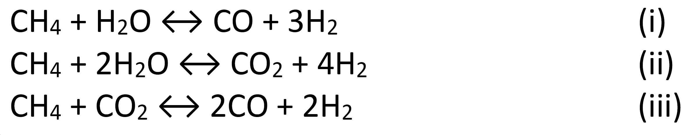
반응 (i) 및 (ii)는 스팀 메탄 개질 반응이고, 반응 (iii)은 건조 메탄 개질 반응이다.Reactions (i) and (ii) are steam methane reforming reactions, and reaction (iii) is dry methane reforming reactions.
고급 탄화수소, 즉 CnHm(여기서 n≥2, m≥4)의 경우, 식 (i)가 다음과 같이 일반화된다:For higher hydrocarbons, i.e. CnHm (where n≥2, m≥4), equation (i) is generalized as follows:
![]()
![]()
전형적으로, 스팀 개질은 수성 가스 전환 반응 (v)을 수반한다:Typically, steam reforming involves a water gas shift reaction (v):
![]()
![]()
용어 "스팀 메탄 개질"은 반응 (i)과 (ii)를 포괄하여 의미하고, 용어 "스팀 개질"은 반응 (i), (ii) 및 (iv)을 포괄하여 의미하며, 용어 "메탄화"는 반응 (i)의 역 반응을 포괄한다. 대부분의 경우, 이들 반응 (i)-(v)은 전부 개질 반응기 시스템의 출구에서 평형에 있거나 또는 평형 근처에 있다. 용어 "예비개질"은 주로 반응 (iv)에 따른 고급 탄화수소의 촉매 전환을 포괄하기 위해 사용된다. 예비개질은 전형적으로 스팀 개질 및/또는 메탄화(가스 조성 및 작동 조건에 따라) 및 수성 가스 전환 반응을 수반한다. 예비개질은 주로 단열 반응기에서 수행되지만, 가열된 반응기에서 일어날 수도 있다.The term "steam methane reforming" means inclusive of reactions (i) and (ii), the term "steam reforming" means inclusive of reactions (i), (ii) and (iv), and the term "methanization" Covers the reverse reaction of reaction (i). In most cases, all of these reactions (i)-(v) are at or near equilibrium at the outlet of the reforming reactor system. The term "pre-modification" is mainly used to cover the catalytic conversion of higher hydrocarbons following reaction (iv). Pre-reforming typically involves steam reforming and/or methanation (depending on gas composition and operating conditions) and water gas shift reactions. The pre-reforming is mainly carried out in an adiabatic reactor, but may also take place in a heated reactor.
스팀 개질 반응은 매우 흡열성이다. 원료에서 메탄의 허용가능한 전환율에 도달하기 위해 전형적으로 800-850℃를 초과하는 고온이 필요하다. 전형적인 SMR은 노 내부에 위치된 촉매 펠릿으로 충전된 다수의 관으로 구성된다. 관은 전형적으로 10-13m 길이이고, 전형적으로 80 내지 160mm의 내경을 가질 것이다. 노에 위치된 버너가 연료 가스의 연소에 의해 반응에 필요한 열을 제공한다. 내부 관 표면의 80000-90000 kcal/h/m2의 최대 평균 열 유속(heat flux)이 통상적이다. 얻을 수 있는 열 유속은 일반적으로 기계적 제한으로 인해 한계가 있으며, 따라서 용량은 관의 수와 노 크기를 증가시킴으로써 증가된다. SMR 타입 개질 반응기 시스템에 대한 상세한 내용은, 예를 들어 "Synthesis gas production for FT synthesis"; Chapter 4, p.258-352, 2004에서 찾을 수 있다. 여기 사용된 약자 "SMR"은 상기 설명된 것과 같은 외부 연소 관형 스팀 메탄 개질기를 의미한다.The steam reforming reaction is very endothermic. High temperatures typically exceeding 800-850° C. are required to reach acceptable conversion of methane in the raw material. A typical SMR consists of a number of tubes filled with catalyst pellets placed inside a furnace. The tube is typically 10-13 m long and will typically have an inner diameter of 80 to 160 mm. A burner located in the furnace provides the heat necessary for the reaction by combustion of the fuel gas. A maximum average heat flux of 80000-90000 kcal/h/m 2 on the inner tube surface is typical. The heat flux achievable is usually limited due to mechanical limitations, so the capacity is increased by increasing the number of tubes and furnace size. For details of the SMR type reforming reactor system, see, for example, "Synthesis gas production for FT synthesis"; It can be found in
전형적으로, 원료 가스는 그 안의 황을 제거하기 위해 탈황을 거칠 것이며, 이로써 개질 반응기 시스템으로 유입되기 전에, 이 과정에서 촉매의 비활성화가 회피된다.Typically, the feed gas will undergo desulfurization to remove the sulfur therein, thereby avoiding deactivation of the catalyst in this process before entering the reforming reactor system.
선택적으로, 탄화수소 가스는 스팀, 및 잠재적으로 또한 수소 및/또는 이산화탄소와 같은 다른 성분들과 함께일 것이고, 또한 과정의 초기 단계로서 고급 탄화수소를 전환하기 위해 약 350-550℃의 온도 범위에서 반응 (iv)에 따른 예비개질을 거치는데, 이것은 통상 탈황 단계의 하류에서 일어난다. 이것은 후속 과정 단계에서 촉매 상에 고급 탄화수소로부터의 탄소 형성 위험을 제거한다. 선택적으로, 원료 가스를 형성하기 위해 이산화탄소 또는 다른 성분들이 또한 예비개질 단계를 떠나는 가스와 혼합될 수 있다.Optionally, the hydrocarbon gas will be steam, and potentially also with other components such as hydrogen and/or carbon dioxide, and also react in a temperature range of about 350-550° C. to convert higher hydrocarbons as an initial step in the process ( It undergoes preliminary reforming according to iv), which usually takes place downstream of the desulfurization stage. This eliminates the risk of carbon formation from higher hydrocarbons on the catalyst in subsequent process steps. Optionally, carbon dioxide or other components may also be mixed with the gas leaving the pre-reforming step to form the source gas.
전형적으로, 반응기 시스템으로 들어가는 원료 가스는 예열되었다. 그러나, 구조화된 촉매에 의해 제공될 수 있는 열 유속으로 인해, 반응기 시스템으로 들어가는 원료 가스는 상대적으로 냉각될 수 있다. 따라서, 원료 가스를 약 200 내지 약 450℃의 온도로 예열하는 것이 충분할 수 있다.Typically, the feed gas entering the reactor system has been preheated. However, due to the heat flux that can be provided by the structured catalyst, the feed gas entering the reactor system can be relatively cooled. Therefore, it may be sufficient to preheat the source gas to a temperature of about 200 to about 450°C.
용어 "전기 전도성"은 20℃에서 10-5 내지 10-8 Ω·m 범위의 전기 저항율을 가진 물질을 의미한다. 따라서, 전기 전도성인 물질은, 예를 들어 구리, 은, 알루미늄, 크롬, 철, 니켈 등의 금속, 또는 금속의 합금이다. 또한, 용어 "전기 절연성"은 20℃에서 10 Ω·m을 초과하는, 예를 들어 20℃에서 109 내지 1025 Ω·m 범위의 전기 저항율을 가진 물질을 의미한다.The term “electrical conductivity” means a material having an electrical resistivity in the range of 10 -5 to 10 -8 Ω·m at 20°C. Thus, the electrically conductive material is, for example, a metal such as copper, silver, aluminum, chromium, iron, nickel, or an alloy of metals. Further, the term "electrical insulating" means a material having an electrical resistivity exceeding 10 Ω·m at 20°C, for example in the range of 10 9 to 10 25 Ω·m at 20°C.
용어 "제1 촉매층"은 광범위하게 해석되어야 한다. 따라서, 제1 촉매층은, 전형적으로 고 면적 담지체(support) 상에 담지된 촉매 활성 물질 형태의, 촉매 입자들, 예를 들어 펠릿들의 층일 수 있다. 그러나, 용어 "제1 촉매층"은 또한 예를 들어 촉매 모노리스 형태의, 촉매로 코팅된 거시적 구조를 포괄하는 의미이다.The term "first catalyst bed" should be interpreted broadly. Thus, the first catalyst layer may be a layer of catalyst particles, for example pellets, typically in the form of a catalytically active material supported on a high area support. However, the term "first catalyst layer" is also meant to encompass macroscopic structures coated with a catalyst, for example in the form of a catalyst monolith.
용어 "합성 가스"는 수소, 일산화탄소 및 또한 가능한 이산화탄소와 아르곤, 질소, 메탄 등과 같은 소량의 다른 가스들을 포함하는 가스를 의미한다.The term "synthetic gas" means a gas comprising hydrogen, carbon monoxide and also possible carbon dioxide and small amounts of other gases such as argon, nitrogen, methane and the like.
개질 반응기 시스템이 제1 촉매층과 압력 쉘 사이에 단열층을 포함할 때, 제1 촉매층과 압력 쉘 사이에 적절한 단열 및 전기 절연이 얻어진다. 압력 쉘과 제1 촉매층 사이에 단열층의 존재는 압력 쉘의 과도한 가열을 회피하는데 도움이 되고, 주변으로의 열 손실을 감소시키는데 도움이 된다. 제1 촉매층의 온도는 적어도 그것의 일부 부분에서 최대 약 1300℃에 이를 수 있지만, 제1 촉매층과 압력 쉘 사이에 단열층을 사용함으로써 압력 쉘의 온도가 500℃ 또는 심지어 200℃의 현저히 더 낮은 온도로 유지될 수 있고, 이것은 전형적 구성인 스틸 재료가 전형적으로 1000℃를 넘는 것과 같은 고온에서 압력 보유 용도에 부적합하기 때문에 유익하다. 또한, 압력 쉘과 제1 촉매층 사이의 단열층은, 단열층이 전기 절연성이기도 하므로, 개질 반응기 시스템 내에서 전기 전류의 제어에 도움이 된다. 단열층은 세라믹, 비활성 물질, 내화성 물질과 같은 고체 물질의 하나 이상의 층 또는 기체 장벽 또는 이들의 조합일 수 있다. 따라서, 퍼지 가스나 제한된 가스가 단열층의 일부를 구성하거나 형성하는 것도 가능하다.When the reforming reactor system includes a heat insulating layer between the first catalyst layer and the pressure shell, adequate heat insulation and electrical insulation are obtained between the first catalyst layer and the pressure shell. The presence of a heat insulating layer between the pressure shell and the first catalyst layer helps to avoid excessive heating of the pressure shell, and helps to reduce heat loss to the surroundings. The temperature of the first catalyst bed can reach a maximum of about 1300°C, at least in part of it, but by using an insulating layer between the first catalyst bed and the pressure shell, the temperature of the pressure shell can be brought to a significantly lower temperature of 500°C or even 200°C. Can be maintained, which is beneficial because the steel material, which is a typical construction, is typically unsuitable for pressure holding applications at high temperatures such as above 1000°C. In addition, the heat insulating layer between the pressure shell and the first catalyst layer is helpful in controlling the electric current in the reforming reactor system because the heat insulating layer is also electrically insulating. The insulating layer may be one or more layers of solid materials such as ceramics, inert materials, refractory materials, or gas barriers or combinations thereof. Accordingly, it is also possible for a purge gas or a limited gas to form or form part of the heat insulating layer.
개질 반응기 시스템의 가장 뜨거운 부분이 제1 촉매층, 특히 그것의 전기 전도성 물질이고, 이것은 개질 반응기 시스템의 압력 쉘 내부에서 단열층에 의해 둘러싸여 있을 것이므로, 압력 쉘의 온도는 최대 공정 온도보다 현저히 더 낮게 유지될 수 있다. 이것은 900℃ 또는 심지어 1100℃ 또는 심지어 최대 1300℃의 최대 공정 온도에서, 예를 들어 압력 쉘의 700℃ 또는 500℃ 또는 바람직하게 300℃ 또는 200℃인 압력 쉘의 비교적 낮은 설계 온도를 허용한다. 재료 강도는 이들 온도 중 더 낮은 온도(상기 나타낸 대로 압력 쉘의 설계 온도에 해당하는)에서 더 높은데, 이것은 상부 연소 또는 측면 연소 SMR과 같은 외부 가열 스팀 메탄 개질 반응기와 반대로, 본 발명의 개질 반응기 시스템은 (더) 높은 압력 작동을 위해 설계될 수 있음을 의미한다. 표준 SMR에서 최대 관 벽 온도는 약 1000℃로 제한될 수 있다. 또 다른 이점은 표준 SMR과 비교하여 더 낮은 설계 온도가 일부 경우 압력 쉘의 두께가 감소될 수 있음을 의미하며, 따라서 비용이 절감된다는 것이다.Since the hottest part of the reforming reactor system is the first catalyst bed, in particular its electrically conductive material, which will be surrounded by an insulating layer inside the pressure shell of the reforming reactor system, the temperature of the pressure shell will be kept significantly lower than the maximum process temperature. I can. This allows for a relatively low design temperature of the pressure shell at a maximum process temperature of 900°C or even 1100°C or even up to 1300°C, for example 700°C or 500°C or preferably 300°C or 200°C of the pressure shell. The material strength is higher at the lower of these temperatures (corresponding to the design temperature of the pressure shell as indicated above), as opposed to externally heated steam methane reforming reactors such as top combustion or side combustion SMR, the reforming reactor system of the present invention. Means it can be designed for (more) higher pressure operation. In standard SMR the maximum tube wall temperature can be limited to about 1000°C. Another advantage is that the lower design temperature compared to standard SMR means that in some cases the thickness of the pressure shell can be reduced, thus reducing cost.
또한, 용어 "단열 물질"은 약 10 W·m-1·K-1 이하의 열 전도율을 가진 물질을 의미한다. 단열 물질의 예들은 세라믹, 내화성 물질, 알루미나 기반 물질, 지르코니아 기반 물질 및 유사한 물질들이다.In addition, the term "insulating material" refers to a material having a thermal conductivity of about 10 W·m -1 ·K -1 or less. Examples of insulating materials are ceramics, refractory materials, alumina based materials, zirconia based materials and similar materials.
한 구체예에서, 제1 촉매층은, 거시적 구조가 세라믹 코팅을 담지하고 세라믹 코팅이 촉매 활성 물질을 담지하는, 전기 전도성 물질의 거시적 구조를 포함한다.In one embodiment, the first catalyst layer comprises a macroscopic structure of an electrically conductive material, wherein the macroscopic structure carries the ceramic coating and the ceramic coating carries the catalytically active material.
따라서, 수소 플랜트의 작동 동안, 전기 전류가 거시적 구조를 통과하고, 이로써 거시적 구조 및 거기 담지된 촉매 활성 물질을 가열한다. 촉매 활성 물질과 거시적 구조의 근접성이 저항 가열된 거시적 구조로부터의 고체 물질 열 전도에 의해 촉매 활성 물질의 효율적인 가열을 가능하게 한다. 촉매 활성 물질의 양 및 조성은 주어진 작동 조건에서 스팀 개질 반응에 맞게 맞춤제작될 수 있다.Thus, during the operation of the hydrogen plant, an electric current passes through the macroscopic structure, thereby heating the macroscopic structure and the catalytically active material supported thereon. The proximity of the catalytically active material to the macroscopic structure allows efficient heating of the catalytically active material by heat conduction of the solid material from the resistance heated macroscopic structure. The amount and composition of the catalytically active material can be tailored to the steam reforming reaction under given operating conditions.
따라서, 저항 가열 과정의 중요한 특징은 열 전도, 대류 및 복사를 통해 외부 열원으로부터 공급되는 대신 에너지가 물체 자체 내부에 공급된다는 것이다. 또한, 반응기 시스템의 가장 뜨거운 부분이 반응기 시스템의 압력 쉘 내에 있게 될 것이다. 바람직하게, 전기 전원 및 전기 전도성 물질은 전기 전도성 물질의 적어도 일부분이 850℃, 바람직하게 900℃, 더 바람직하게 1000℃ 또는 더욱더 바람직하게 1100℃의 온도에 도달하게 되는 치수이다. 촉매 활성 물질의 양 및 조성은 주어진 작동 조건에서 스팀 개질 반응에 맞게 맞춤제작될 수 있다. 전기 전도성 물질의 표면적, 세라믹 코팅으로 코팅된 전기 전도성 물질의 비율, 세라믹 코팅의 타입 및 구조, 및 촉매 활성 촉매 물질의 양 및 조성은 주어진 작동 조건에서 스팀 개질 반응에 맞게 맞춤제작될 수 있다. 그러나, 전기 전도성 물질의 실질적으로 전체 표면이 세라믹 코팅으로 코팅되고, 바람직하게 세라믹 코팅의 전부 또는 대부분이 촉매 활성 물질을 담지하는 것이 유익하다는 것이 주지되어야 한다. 바람직하게, 컨덕터와 연결된 전기 전도성 물질의 부분에만 세라믹 코팅이 제공되지 않는다. 촉매 활성 물질을 담지한 세라믹 코팅은 아래 반응에 따른 탄소 형성을 위험을 감소시키거나 방지한다:Thus, an important feature of the resistive heating process is that energy is supplied inside the object itself instead of being supplied from an external heat source through heat conduction, convection and radiation. Also, the hottest part of the reactor system will be in the pressure shell of the reactor system. Preferably, the electrical power source and the electrically conductive material are dimensioned such that at least a portion of the electrically conductive material reaches a temperature of 850°C, preferably 900°C, more preferably 1000°C or even more preferably 1100°C. The amount and composition of the catalytically active material can be tailored to the steam reforming reaction under given operating conditions. The surface area of the electrically conductive material, the proportion of the electrically conductive material coated with the ceramic coating, the type and structure of the ceramic coating, and the amount and composition of the catalytically active catalyst material can be tailored to the steam reforming reaction under a given operating condition. However, it should be noted that it is advantageous that substantially the entire surface of the electrically conductive material is coated with a ceramic coating, preferably all or most of the ceramic coating carrying the catalytically active material. Preferably, only the portion of the electrically conductive material connected to the conductor is not provided with a ceramic coating. Ceramic coatings with catalytically active substances reduce or prevent the risk of carbon formation from the following reactions:
![]()
![]()
촉매 활성 물질을 담지한 세라믹 코팅에 의한 전기 전도성 물질의 피복은 전기 전도성 물질의 금속상이 밀착성 산화물 층에 의해 피복되는 것을 보장하며, 이것은 탄소 형성 반응에 대해 더 적은 잠재력을 가진다. 또한, 산화물 상의 촉매 활성 물질은 스팀 개질 반응에 촉매작용하고, 반응물 가스가 열역학적 평형 상태를 향해 가도록 하거나, 또는 그것에 가깝게 만들 것이다. 이것은 수소의 부분 압력을 증가시키고 메탄의 부분 압력을 감소시킴으로써 상기 반응 (A)에 따른 탄소 형성에 대한 열역학적 잠재력을 감소시키거나 또는 많은 경우 제거한다.The coating of the electrically conductive material by means of a ceramic coating carrying the catalytically active material ensures that the metallic phase of the electrically conductive material is covered by an adhesive oxide layer, which has less potential for the carbon forming reaction. In addition, the catalytically active material on the oxide will catalyze the steam reforming reaction and cause the reactant gas to go towards, or close to, a thermodynamic equilibrium. This reduces or in many cases eliminates the thermodynamic potential for carbon formation according to reaction (A) above by increasing the partial pressure of hydrogen and reducing the partial pressure of methane.
거시적 구조의 표면적, 세라믹 코팅으로 코팅된 거시적 구조의 비율, 세라믹 코팅의 타입 및 구조, 및 촉매 활성 물질의 양 및 조성은 주어진 작동 조건에서 스팀 개질 반응에 맞게 맞춤제작될 수 있다.The surface area of the macroscopic structure, the proportion of the macroscopic structure coated with the ceramic coating, the type and structure of the ceramic coating, and the amount and composition of the catalytically active material can be tailored to the steam reforming reaction under a given operating condition.
거시적 구조의 물리적 치수는 임의의 적절한 치수일 수 있다; 따라서, 거시적 구조의 높이가 너비보다 더 작을 수 있거나 또는 그 반대일 수 있다.The physical dimensions of the macroscopic structure can be any suitable dimension; Thus, the height of the macroscopic structure may be less than the width or vice versa.
한 구체예에서, 개질 반응기 시스템 내의 구조화된 촉매에서 구조화된 촉매를 통한 수평 단면의 면적 등가 직경과 구조화된 촉매의 높이 사이의 비율은 0.1 내지 2.0의 범위이다. 개질 반응기 시스템을 통한 단면의 면적 등가 직경은 단면의 면적과 등가인 면적을 가진 원의 직경으로 정의된다. 구조화된 촉매의 면적 등가 직경과 높이 사이의 비율은 0.1 내지 2.0이고, 구조화된 촉매를 수납하고 있는 압력 쉘은 현재 SMR과 비교하여 상대적으로 작을 수 있다. 각 개질 반응기 시스템은 SMR의 1개 관에 가능한 것보다 더 많은 양의 원료 가스를 처리할 수 있다. 따라서, 개질 반응기 시스템으로 가는 외부 배관의 양이 현재 SMR과 비교하여 감소될 수 있고, 이러한 배관의 비용도 감소된다. 전형적으로, 가스는 상향류 또는 하향류 방향으로 개질 반응기 시스템을 통해서 유동하며, 이로써 가스는 구조화된 촉매에 있는 채널을 통해서 그것의 높이를 따라 유동하게 된다. 구조화된 촉매가 다수의 거시적 구조 또는 거시적 구조의 어레이를 포함할 때, 어레이 내의 개별 거시적 구조는 나란히, 서로의 위에 또는 이들의 조합으로 위치될 수 있다. 구조화된 촉매가 둘 이상의 거시적 구조를 포함할 때, 구조화된 촉매의 치수는 둘 이상의 거시적 구조의 치수임이 강조된다. 따라서, 예로서, 전체 구조화된 촉매가 2개의 거시적 구조를 포함하고, 각각은 높이 h를 가지며 서로의 위에 놓인다면, 구조화된 촉매의 높이는 2h이다.In one embodiment, the ratio between the area equivalent diameter of the horizontal cross-section through the structured catalyst in the structured catalyst in the reforming reactor system and the height of the structured catalyst ranges from 0.1 to 2.0. The area equivalent diameter of the cross section through the reforming reactor system is defined as the diameter of a circle having an area equivalent to the area of the cross section. The ratio between the area equivalent diameter and the height of the structured catalyst is 0.1 to 2.0, and the pressure shell containing the structured catalyst may be relatively small compared to the current SMR. Each reforming reactor system is capable of handling larger amounts of raw gas than is possible in one tube of SMR. Thus, the amount of external piping going to the reforming reactor system can be reduced compared to the current SMR, and the cost of such piping is also reduced. Typically, the gas flows through the reforming reactor system in an upward or downward flow direction, whereby the gas flows along its height through channels in the structured catalyst. When the structured catalyst comprises a plurality of macroscopic structures or arrays of macroscopic structures, the individual macroscopic structures within the array can be placed side by side, on top of each other, or in a combination thereof. When the structured catalyst comprises two or more macroscopic structures, it is emphasized that the dimensions of the structured catalyst are those of two or more macroscopic structures. Thus, as an example, if the entire structured catalyst comprises two macroscopic structures, each of which has a height h and is placed on top of each other, the height of the structured catalyst is 2h.
구조화된 촉매의 부피는 평형에 대한 바람직한 접근 및/또는 온도 및/또는 탄화수소 전환율 및/또는 생성물 가스에서 탄화수소의 건조 몰 농도 및/또는 거시적 구조의 열발생 용량과 상관된 개질 반응기 시스템을 벗어난 온도를 고려하여 및/또는 생성물 가스에서 탄화수소의 건조 몰 농도가 정해진 범위 내에 있는 것을 보장하도록 및/또는 스팀 메탄 개질 반응(반응 (i))의 평형에 대한 접근이 정해진 범위 내에 있는 것을 보장하도록 선택된다.The volume of the structured catalyst is the preferred approach to equilibrium and/or temperature and/or hydrocarbon conversion and/or the temperature outside the reforming reactor system correlated with the dry molar concentration of hydrocarbons in the product gas and/or the heat generation capacity of the macroscopic structure. It is taken into account and/or selected to ensure that the dry molar concentration of hydrocarbons in the product gas is within a defined range and/or that the access to the equilibrium of the steam methane reforming reaction (reaction (i)) is within a defined range.
한 구체예에서, 개질 반응기 시스템의 높이는 0.5 내지 7m, 더 바람직하게 0.5 내지 3m이다. 개질 반응기 시스템의 높이의 예시적인 값은 5m 미만, 바람직하게 2m 미만 또는 심지어 1m의 높이이다. 개질 반응기 시스템은 제1 촉매층, 압력 쉘, 단열층뿐만 아니라 2개의 컨덕터를 포함한다. 따라서, 개질 반응기 시스템의 높이는 개질 반응기 시스템의 바닥부터 그것의 상부까지의 거리이며, 이것은 전형적으로 압력 쉘의 바닥부터 그것의 상부까지의 거리이다; 그러나, 압력 쉘 내외로의 컨덕터 및/또는 배관이 압력 쉘의 바닥이나 상부로부터 연장된 경우, 이들 부분이 개질 반응기 시스템의 높이에 기여하는 것으로 간주될 수 있다. 개질 반응기 시스템과 개질 반응기 시스템 내의 구조화된 촉매의 치수는 상관된다; 물론, 압력 쉘과 단열층은 개질 반응기 시스템을 구조화된 촉매 자체보다 다소 더 크게 만든다. 비교를 위해, 산업 규모 SMR은 관의 외부 표면적을 최대화하기 위해 전형적으로 10m 이상의 높이를 가진 촉매 관으로 구성된다. 본 발명은 개질 반응기 시스템의 설계에서 이러한 제약이 필요치 않다는 점이 이점이다.In one embodiment, the height of the reforming reactor system is 0.5 to 7 m, more preferably 0.5 to 3 m. An exemplary value for the height of the reforming reactor system is a height of less than 5 m, preferably less than 2 m or even 1 m. The reforming reactor system comprises a first catalyst bed, a pressure shell, an adiabatic bed, as well as two conductors. Thus, the height of the reforming reactor system is the distance from the bottom of the reforming reactor system to its top, which is typically the distance from the bottom of the pressure shell to its top; However, when conductors and/or piping into and out of the pressure shell extend from the bottom or top of the pressure shell, these portions can be considered to contribute to the height of the reforming reactor system. The reforming reactor system and the dimensions of the structured catalyst in the reforming reactor system are correlated; Of course, the pressure shell and the insulating layer make the reforming reactor system somewhat larger than the structured catalyst itself. For comparison, industrial scale SMR consists of a catalyst tube typically having a height of 10 m or more in order to maximize the outer surface area of the tube. The present invention is an advantage in that this restriction is not required in the design of the reforming reactor system.
여기 사용된 용어 "구조화된 촉매를 포함하는 개질 반응기 시스템"은 단일 거시적 구조를 가진 개질 반응기 시스템에 제한되지 않는다. 실제로, 이 용어는 거시적 구조, 세라믹 코팅 및 촉매 활성 물질, 뿐만 아니라 이러한 거시적 구조의 어레이를 가진 구조화된 촉매를 모두 포괄하는 의미이다.The term “reformed reactor system comprising a structured catalyst” as used herein is not limited to a reforming reactor system having a single macroscopic structure. Indeed, the term is meant to encompass all macroscopic structures, ceramic coatings and catalytically active materials, as well as structured catalysts having an array of such macroscopic structures.
용어 "세라믹 코팅을 담지한 거시적 구조"는 거시적 구조가 거시적 구조의 표면의 적어도 일부분에서 세라믹 코팅에 의해 코팅된다는 것을 의미한다. 따라서, 이 용어는 거시적 구조의 전체 표면이 세라믹 코팅에 의해 코팅된다는 것을 의미하지는 않는다; 특히, 적어도 컨덕터 및 전기 전원에 전기적으로 연결된 거시적 구조의 부분은 코팅을 갖지 않는다. 코팅은 구조에 기공(pore)을 가진 세라믹 물질이며, 이것은 코팅 위와 내부에 촉매 활성 물질을 담지하는 것을 허용한다. 유익하게, 촉매 활성 물질은 약 5nm 내지 약 250nm 범위의 크기를 가진 촉매 활성 입자를 포함한다.The term “macroscopic structure carrying a ceramic coating” means that the macroscopic structure is coated by a ceramic coating on at least a portion of the surface of the macroscopic structure. Thus, this term does not mean that the entire surface of the macroscopic structure is coated by a ceramic coating; In particular, at least the part of the macroscopic structure that is electrically connected to the conductor and the electric power source does not have a coating. The coating is a ceramic material with pores in its structure, which allows the catalytically active material to be supported on and inside the coating. Advantageously, the catalytically active material comprises catalytically active particles having a size in the range of about 5 nm to about 250 nm.
여기 사용된 용어 "거시적 구조"는 확대 장치 없이 육안으로 볼 수 있을 만큼 충분히 큰 구조를 의미한다. 거시적 구조의 치수는 전형적으로 센티미터 또는 심지어 미터의 범위이다. 거시적 구조의 치수는 유익하게 구조화된 촉매를 수납하고 있는 압력 쉘의 내부 치수에 적어도 부분적으로 상응하도록 되며, 이로써 단열층 및 컨덕터를 위한 공간이 확보된다. 거시적 구조의 치수는 전형적으로 수 십 센티미터 또는 심지어 미터의 범위이다. 0.5m, 1m, 2m 또는 5m와 같은 미터 범위의 외경 중 적어도 하나를 가진 거시적 구조의 어레이를 제공하기 위해 2개 이상의 거시적 구조가 연결될 수 있다. 이러한 2개 이상의 거시적 구조는 "거시적 구조의 어레이"라고 표시될 수 있다.The term "macroscopic structure" as used herein means a structure large enough to be visible to the naked eye without a magnifying device. The dimensions of the macroscopic structure are typically in the range of centimeters or even meters. The dimensions of the macroscopic structure are advantageously such that they correspond at least in part to the internal dimensions of the pressure shell containing the structured catalyst, thereby freeing up space for the thermal insulation layer and conductor. The dimensions of the macroscopic structure are typically in the range of several tens of centimeters or even meters. Two or more macroscopic structures may be connected to provide an array of macroscopic structures having at least one of an outer diameter in the metric range, such as 0.5m, 1m, 2m or 5m. These two or more macroscopic structures may be denoted as “an array of macroscopic structures”.
유익하게, 구조화된 촉매, 단열층, 압력 쉘, 및/또는 개질 반응기 시스템 내부의 임의의 다른 구성요소들 사이의 임의의 관련된 간극은, 예를 들어 비활성 펠릿 형태의 비활성 물질로 충전된다. 이러한 간극은, 예를 들어 구조화된 촉매의 하부 측면과 압력 쉘의 바닥 사이의 간극 및 구조화된 촉매의 측면과 압력 쉘의 내부 측면을 피복한 절연층 사이의 간극이다. 비활성 물질은, 예를 들어 펠릿 또는 타일 형태의 세라믹 물질일 수 있다. 비활성 물질은 개질 반응기 시스템을 통한 가스 분포를 제어하고 구조화된 촉매를 통한 가스의 유동을 제어하는데 도움이 된다. 또한, 비활성 물질은 전형적으로 단열 효과를 가진다.Advantageously, the structured catalyst, the insulating layer, the pressure shell, and/or any associated gaps between any other components within the reforming reactor system are filled with an inert material, for example in the form of inert pellets. These gaps are, for example, gaps between the lower side of the structured catalyst and the bottom of the pressure shell and between the side of the structured catalyst and the insulating layer covering the inner side of the pressure shell. The inert material may be a ceramic material in the form of pellets or tiles, for example. The inert material helps to control the gas distribution through the reforming reactor system and to control the flow of gas through the structured catalyst. In addition, inert materials typically have an insulating effect.
개질 반응기 시스템 내에 구조화된 촉매를 사용하는 것의 또 다른 이점은 거시적 구조를 포함하는 구조화된 촉매로 인해 구조화된 촉매를 통한 가스 유동이 상향류일 수 있다는 것이다. 또는 달리, 구조화된 촉매를 통한 유동은 수평 방향 또는 임의의 다른 적절한 방향일 수 있다. 이것은 반응기가 펠릿을 함유하는 경우에는 펠릿의 유동화, 분쇄, 및 소실의 위험으로 인해 더욱 어렵다. 따라서, 실질적인 양의 배관이 회피될 수 있고, 플랜트 비용이 감소한다. 또한, 상향류 또는 수평류의 가능성은 플랜트 설계의 유연성을 증가시킨다.Another advantage of using a structured catalyst in a reforming reactor system is that the flow of gas through the structured catalyst can be upstream due to the structured catalyst comprising the macroscopic structure. Or, alternatively, the flow through the structured catalyst may be in a horizontal direction or any other suitable direction. This is even more difficult if the reactor contains pellets due to the risk of fluidization, grinding, and loss of the pellets. Thus, a substantial amount of piping can be avoided, and the plant cost is reduced. In addition, the possibility of upstream or horizontal flow increases the flexibility of the plant design.
도면에 도시된 대로, 구조화된 촉매를 통한 가스 유동은 구조화된 촉매의 축 방향 또는 길이와 동축 방향 또는 z-축 방향이다. 도면은 구조화된 촉매의 z-축이 수직인 것을 도시하지만, 반응기는 임의의 적합한 방식으로 위치될 수 있다는 것이 주지되어야 하며, 따라서 구조화된 촉매와 그것을 통한 가스 유동은, 예를 들어 수평 방향, 도면과 비교하여 역전된 방향, 또는 예를 들어 수평에 대해 45°의 각도의 방향일 수 있다.As shown in the figure, the gas flow through the structured catalyst is in the axial or length and coaxial or z-axis direction of the structured catalyst. Although the figure shows that the z-axis of the structured catalyst is vertical, it should be noted that the reactor can be positioned in any suitable manner, so that the structured catalyst and the gas flow through it are, for example, horizontally It may be a direction reversed compared to, or, for example, a direction at an angle of 45° to the horizontal.
한 구체예에서, 압력 쉘은 원료 가스를 유입하기 위한 입구 및 생성물 가스를 내보내기 위한 출구를 포함하며, 이때 입구는 압력 쉘의 제1 단부에 가까이 위치되고, 출구는 압력 쉘의 제2 단부에 가까이 위치되며, 적어도 2개의 컨덕터는 둘 다 출구보다 입구에 더 가까이 있는 구조화된 촉매 상의 위치에서 구조화된 촉매에 연결된다. 이로써, 적어도 2개의 컨덕터는 유입된 가스가 생성물 가스보다 더 낮은 온도를 가지게 되므로 개질 반응기 시스템의 실질적으로 더 차가운 부분에 위치될 수 있으며, 구조화된 촉매는 화학 반응의 진행에 따라 소비된 열로 인해 구조의 최상류 부분에 있는 냉각기에서 더 차가워질 것이고, 입구를 통해 인도되어 공급된 원료 가스는 구조화된 촉매를 통한 가스의 경로를 따라 더 구조화된 촉매에 의해 가열되기 전에 적어도 2개의 컨덕터를 냉각시킬 것이다. 컨덕터와 구조화된 촉매 사이의 연결을 보호하기 위해 거시적 구조를 제외한 모든 전기 전도 요소의 온도가 낮게 유지된다는 이점이 있다. 거시적 구조를 제외한 다른 전기 전도 요소 및 컨덕터의 온도가 상대적으로 낮을 때, 거시적 구조를 제외한 다른 전기 전도 요소 및 컨덕터에 적합한 물질에 대한 제한이 더 적어진다. 전기 전도 요소의 온도가 증가할 때 그것의 저항율도 증가한다; 따라서, 개질 반응기 시스템 내에서 거시적 구조 이외의 모든 다른 부분들의 불필요한 가열을 회피하는 것이 바람직하다. 용어 "거시적 구조를 제외한 전기 전도 요소"는 전원과 구조화된 촉매를 연결하도록 배열된 상대적인 전기 전도 요소를 포괄하는 의미이다. 다른 구체예에서, 개질 반응기 시스템의 2개의 컨덕터는 구조화된 촉매의 상이한 단부에 제공될 수 있다.In one embodiment, the pressure shell comprises an inlet for introducing a source gas and an outlet for discharging product gas, wherein the inlet is located close to the first end of the pressure shell, and the outlet is close to the second end of the pressure shell. And at least two conductors are both connected to the structured catalyst at a location on the structured catalyst closer to the inlet than the outlet. Thereby, at least two conductors can be placed in a substantially cooler part of the reforming reactor system since the introduced gas has a lower temperature than the product gas, and the structured catalyst is structured due to the heat consumed as the chemical reaction proceeds. It will be cooler in the cooler at the top of the inlet, and the feed gas fed through the inlet will cool at least two conductors before being heated by the more structured catalyst along the path of the gas through the structured catalyst. The advantage is that the temperature of all electrically conducting elements except for the macroscopic structure is kept low to protect the connection between the conductor and the structured catalyst. When the temperature of the conductive elements and conductors other than the macroscopic structure is relatively low, there are less restrictions on materials suitable for the conductive elements and conductors other than the macro structure. When the temperature of an electrically conductive element increases, its resistivity also increases; Therefore, it is desirable to avoid unnecessary heating of all other parts of the reforming reactor system other than the macroscopic structure. The term "electrically conducting elements other than macroscopic structures" is meant to encompass relative electrically conducting elements arranged to connect a power source and a structured catalyst. In other embodiments, the two conductors of the reforming reactor system can be provided at different ends of the structured catalyst.
본 발명의 수소 플랜트는 임의의 적절한 수의 전원 및 전원/전원들과 구조화된 촉매의 거시적 구조(들)을 연결하는 임의의 적절한 수의 컨덕터를 포함할 수 있다.The hydrogen plant of the present invention may comprise any suitable number of power sources and any suitable number of conductors connecting the power sources/power sources to the macroscopic structure(s) of the structured catalyst.
한 구체예에서, 구조화된 촉매는 제1 열 유속을 생성하도록 배열된 제1 부분 및 제2 열 유속을 생성하도록 배열된 제2 부분을 포함하며, 이때 제1 열 유속은 제2 열 유속보다 적고, 제1 부분은 제2 부분의 상류이다. 여기서 용어 "제1 부분은 제2 부분의 상류이다"는 개질 반응기 시스템에 공급되는 가스는 이 가스가 제2 부분에 도달하기 전에 제1 부분에 도달한다는 것을 의미한다. 구조화된 촉매의 제1 부분 및 제2 부분은 촉매 활성 물질을 담지한 세라믹 코팅을 담지한 2개의 상이한 거시적 구조일 수 있으며, 이때 2개의 상이한 거시적 구조는 주어진 전기 전류 및 전압에서 상이한 열 유속을 생성하도록 배열될 수 있다. 예를 들어, 구조화된 촉매의 제1 부분은 큰 표면적을 가질 수 있고, 구조화된 촉매의 제2 부분은 더 작은 표면적을 가진다. 이것은 제1 부분의 단면적보다 더 작은 단면적을 가진 제2 부분에 구조화된 촉매를 제공함으로써 달성될 수 있다. 또는 달리, 구조화된 촉매의 제1 부분을 통한 전류 경로는 구조화된 촉매의 제2 부분을 통한 전류 경로보다 더 직선일 수 있고, 따라서 구조화된 촉매의 제1 부분을 통해서보다 제2 부분을 통해서 전류가 더 꼬이고 감기게 되며, 이로써 제1 부분에서보다 구조화된 촉매의 제2 부분에서 전류가 더 많은 열을 생성한다. 거시적 구조에 있는 슬릿 또는 컷이 거시적 구조를 통한 전류 경로를 지그재그 형태로 만들 수 있다. 상이한 열 유속을 공급할 수 있게 하기 위해 구조화된 촉매의 제1 및 제2 부분은 상이한 전기 전류 및 전압을 경험할 수 있다는 것이 주지되어야 한다. 그러나, 상기 나타낸 대로 제1 및 제2 부분의 상이한 물리적 특성으로 인해 제1 및 제2 부분의 상이한 열 유속은 제1 및 제2 부분을 통해서/거쳐서 동일한 전기 전류 및 전압을 공급함으로써 달성될 수도 있다.In one embodiment, the structured catalyst comprises a first portion arranged to produce a first heat flow rate and a second portion arranged to produce a second heat flow rate, wherein the first heat flow rate is less than the second heat flow rate and , The first part is upstream of the second part. The term "first part is upstream of the second part" here means that the gas supplied to the reforming reactor system reaches the first part before this gas reaches the second part. The first part and the second part of the structured catalyst may be of two different macroscopic structures carrying a ceramic coating carrying a catalytically active material, wherein the two different macroscopic structures produce different heat fluxes at a given electric current and voltage. Can be arranged to For example, a first portion of the structured catalyst can have a large surface area, and a second portion of the structured catalyst has a smaller surface area. This can be achieved by providing a structured catalyst in the second portion having a cross-sectional area smaller than that of the first portion. Or, alternatively, the current path through the first portion of the structured catalyst may be more straightforward than the current path through the second portion of the structured catalyst, and thus current through the second portion rather than through the first portion of the structured catalyst. Is more twisted and coiled, whereby the current produces more heat in the second portion of the structured catalyst than in the first portion. Slits or cuts in the macroscopic structure can zigzag the current path through the macroscopic structure. It should be noted that the first and second portions of the structured catalyst may experience different electrical currents and voltages in order to be able to supply different heat flow rates. However, due to the different physical properties of the first and second parts as indicated above, different heat fluxes of the first and second parts may also be achieved by supplying the same electric current and voltage through/through the first and second parts. .
한 구체예에서, 구조화된 촉매는 컨덕터 사이의 전류 경로를 구조화된 촉매의 최대 치수보다 더 큰 길이로 증가시키도록 배열된 전기 절연부를 가진다. 구조화된 촉매의 최대 치수보다 더 큰 컨덕터 사이의 전류 경로의 제공은 컨덕터 사이에 위치된 전기 절연부를 제공하고 구조화된 촉매의 일부 부분을 통해 전류가 지나가는 것을 방지함으로써 이루어질 수 있다. 이러한 전기 절연부는 전류 경로를 증가시키고, 따라서 구조화된 촉매를 통한 저항을 증가시키도록 배열된다. 한 구체예에서, 적어도 하나의 전기 절연부는 컨덕터 사이의 최소 전류 경로가 거시적 구조의 최대 치수보다 더 크게 되는 것을 보장하도록 배열된 길이를 가진다.In one embodiment, the structured catalyst has electrical insulation arranged to increase the current path between the conductors to a length greater than the maximum dimension of the structured catalyst. Providing a current path between conductors that is larger than the maximum dimension of the structured catalyst can be achieved by providing electrical insulation located between the conductors and preventing current from passing through some portions of the structured catalyst. These electrical insulations are arranged to increase the current path and thus increase the resistance through the structured catalyst. In one embodiment, the at least one electrical isolator has a length arranged to ensure that the minimum current path between the conductors is greater than the maximum dimension of the macroscopic structure.
이러한 절연부의 비제한적 예들은 구조에 있는 컷, 슬릿, 또는 홀이다. 선택적으로, 구조에 있는 컷 또는 슬릿에 세라믹과 같은 고체 절연 물질이 사용될 수 있다. 고체 절연 물질이 다공성 세라믹 물질인 경우, 유익하게 촉매 활성 물질은, 예를 들어 함침에 의해 기공에 통합될 수 있다. 컷 또는 슬릿 내의 고체 절연 물질은 서로로부터 컷 또는 슬릿의 측면에 구조화된 촉매의 부분을 유지하는데 도움이 된다. 여기 사용된 용어 "구조화된 촉매의 최대 치수"는 구조화된 촉매에 의해 취해진 기하 형태의 최대 내부 치수를 의미한다. 구조화된 촉매가 상자 형태라면, 최대 치수는 한 모서리부터 가장 먼 모서리까지의 대각선일 수 있고, 이것은 공간 대각선이라고도 표시된다.Non-limiting examples of such insulation are cuts, slits, or holes in the structure. Optionally, a solid insulating material such as ceramic may be used for the cuts or slits in the structure. If the solid insulating material is a porous ceramic material, advantageously the catalytically active material can be incorporated into the pores, for example by impregnation. The solid insulating material in the cut or slit helps to keep the portion of the structured catalyst on the side of the cut or slit from each other. The term “maximum dimension of a structured catalyst” as used herein means the maximum internal dimension of the geometry taken by the structured catalyst. If the structured catalyst is in the form of a box, the maximum dimension can be a diagonal line from one corner to the farthest corner, which is also indicated as the spatial diagonal.
구조화된 촉매를 통한 전류는 전류 경로를 증가시키도록 배열된 전기 절연부로 인해 구조화된 촉매를 통한 경로가 꼬이거나 감기도록 배열될 수 있지만, 개질 반응기 시스템을 통과한 가스는 개질 반응기 시스템의 한쪽 단부에서 유입되며, 개질 반응기 시스템으로부터 유출되기 전에 일단 구조화된 촉매를 통과한다. 개질 반응기 시스템 내의 가스가 구조화된 촉매와 담지된 촉매 활성 물질을 통과하는 것을 보장하기 위해 유익하게 비활성 물질이 구조화된 촉매와 개질 반응기 시스템의 나머지 부분 사이의 관련된 간극에 존재한다.The current through the structured catalyst can be arranged such that the path through the structured catalyst is twisted or wound due to the electrical insulation arranged to increase the current path, but the gas that has passed through the reforming reactor system is at one end of the reforming reactor system. It enters and passes through the structured catalyst once before exiting the reforming reactor system. In order to ensure that gases in the reforming reactor system pass through the structured catalyst and the supported catalytically active material, an inert material is advantageously present in the associated gap between the structured catalyst and the rest of the reforming reactor system.
한 구체예에서, 구조화된 촉매를 통한 가스 통로의 길이는 하나의 컨덕터로부터 구조화된 촉매를 통과해서 다음 번 컨덕터까지의 전류의 통로의 길이보다 작다. 전류 통로의 길이에 대한 가스 통로의 길이의 비율은 0.6 미만, 또는 0.3, 0.1, 또는 심지어 최하 0.002일 수 있다.In one embodiment, the length of the gas passage through the structured catalyst is less than the length of the passage of current from one conductor through the structured catalyst to the next. The ratio of the length of the gas passage to the length of the current passage may be less than 0.6, or 0.3, 0.1, or even at least 0.002.
한 구체예에서, 구조화된 촉매는 구조화된 촉매를 통한 전류 경로가 지그재그 경로가 되도록 배열된 전기 절연부를 가진다. 여기서 용어 "지그재그 경로" 및 "지그재그 루트"는 하나의 컨덕터부터 다른 컨덕터까지의 경로를 쫓는 다양한 각도에 모서리를 가진 경로를 의미한다. 지그재그 경로는, 예를 들어 위를 향해 가고, 방향을 전환하고, 이어서 아래를 향해 가는 경로이다. 지그재그 경로는 많은 방향전환을 가질 수 있고, 구조화된 촉매를 통해서 여러 번 위를 향해 간 다음 아래를 향해 갈 수 있지만, 한 번의 방향전환이면 지그재그 경로를 만드는데 충분하다.In one embodiment, the structured catalyst has electrical insulation arranged such that the current path through the structured catalyst is a zigzag path. Here, the terms "zigzag path" and "zigzag path" mean paths having corners at various angles following the path from one conductor to another conductor. A zigzag path is, for example, a path going upward, turning, and then going downward. A zigzag path can have many turns, and through a structured catalyst it can go up and then down several times, but one shift is enough to create a zigzag path.
전류 경로를 증가시키도록 배열된 절연부는 거시적 구조 상의 세라믹 코팅과 반드시 관련되지는 않는다는 것이 주지되어야 한다; 이 세라믹 코팅 역시 전기 절연성이라고 간주되지만, 거시적 구조에 연결된 컨덕터 사이의 전류 경로의 길이를 변화시키지는 않는다.It should be noted that the insulation arranged to increase the current path is not necessarily associated with the ceramic coating on the macroscopic structure; This ceramic coating is also considered electrically insulating, but does not change the length of the current path between the conductors connected to the macroscopic structure.
세라믹 코팅은 촉매 활성 물질이 있던 없던 워시 코팅에 의해 금속 표면에 직접 첨가될 수 있다. 금속 표면의 워시 코팅은 잘 알려진 과정이다; 예를 들어, Cybulski, A., and Moulijn, J. A., Structured catalysts and reactors, Marcel Dekker, Inc, New York, 1998, Chapter 3, 및 참고문헌들에 설명된다. 세라믹 코팅이 거시적 구조의 표면에 첨가될 수 있고, 이어서 촉매 활성 물질이 첨가될 수 있다; 또는 달리, 촉매 활성 물질을 포함하는 세라믹 코트가 거시적 구조에 첨가된다.Ceramic coatings can be added directly to the metal surface by wash coating, with or without catalytically active substances. Wash coating of metal surfaces is a well-known process; For example, Cybulski, A., and Moulijn, J. A., Structured catalysts and reactors, Marcel Dekker, Inc, New York, 1998,
한 구체예에서, 제1 촉매층은 거시적 구조의 어레이를 포함한다. 따라서, 2m 또는 5m와 같은 미터 범위의 외부 치수 중 적어도 하나를 가진 거시적 구조의 어레이를 제공하기 위해 2개 이상의 거시적 구조가 연결될 수 있다. 이러한 2개 이상의 거시적 구조가 "거시적 구조의 어레이"라고 표시될 수 있다. 이 경우, 거시적 구조의 어레이의 치수는 유익하게 구조화된 촉매를 수납하고 있는 압력 쉘의 내부 치수에 적어도 부분적으로 상응하도록 된다(절연층을 위한 공간을 확보). 거시적 구조의 가능한 어레이는 0.1 내지 10m3의 부피 또는 심지어 더 큰 부피를 취할 수 있다. "구조화된 촉매"는 단일 거시적 구조 또는 거시적 구조의 어레이를 포함할 수 있으며, 이때 거시적 구조(들)는 촉매 활성 물질을 담지한 세라믹 코팅을 담지한다.In one embodiment, the first catalyst layer comprises an array of macroscopic structures. Thus, two or more macroscopic structures can be connected to provide an array of macroscopic structures having at least one of external dimensions in the metric range, such as 2m or 5m. These two or more macroscopic structures may be referred to as “an array of macroscopic structures”. In this case, the dimensions of the macroscopic array are advantageously such that they correspond at least in part to the internal dimensions of the pressure shell containing the structured catalyst (reserving space for the insulating layer). Possible arrays of macroscopic structures can take on volumes of 0.1 to 10 m 3 or even larger. A "structured catalyst" may comprise a single macroscopic structure or an array of macroscopic structures, wherein the macroscopic structure(s) carries a ceramic coating carrying the catalytically active material.
한 구체예에서, 거시적 구조의 어레이에서 거시적 구조는 서로 전기적으로 연결될 수 있다. 2개 이상의 거시적 구조 사이의 연결은 기계적 연결, 클램핑, 납땜, 용접 또는 이들 연결 방법의 임의의 조합에 의한 것일 수 있다. 전기적 연결을 용이하게 하기 위해 각 거시적 구조는 단자를 포함할 수 있다. 2개 이상의 거시적 구조는 직렬 또는 병렬 연결로 전원에 연결될 수 있다. 유익하게 2개 이상의 거시적 구조 사이의 전기적 연결은 2개 이상의 거시적 구조 사이의 연결면을 따라 균일하며 밀착되고, 이로써 2개 이상의 거시적 구조는 단일의 밀착된 또는 일정하게 내부-연결된 물질로서 작용한다; 따라서, 2개 이상의 거시적 구조를 통틀어 균일한 전기 전도성이 용이해진다. 또는 달리, 또는 추가로, 구조화된 촉매는 서로 전기적으로 연결되지 않은 거시적 구조의 어레이를 포함할 수 있다. 대신, 2개 이상의 거시적 구조는 서로 전기적으로 연결되지 않은 상태에서 압력 쉘 내에 함께 위치된다. 이 경우, 구조화된 촉매는 전원에 병렬 연결된 거시적 구조들을 포함한다.In one embodiment, the macroscopic structures in an array of macroscopic structures can be electrically connected to each other. The connection between two or more macroscopic structures can be by mechanical connection, clamping, soldering, welding or any combination of these connection methods. Each macroscopic structure may include a terminal to facilitate electrical connection. Two or more macroscopic structures can be connected to the power source in series or parallel connection. Advantageously, the electrical connection between two or more macroscopic structures is uniform and tight along the connection surface between the two or more macroscopic structures, whereby the two or more macroscopic structures act as a single tight or uniformly inter-connected material; Thus, uniform electrical conductivity across two or more macroscopic structures is facilitated. Or alternatively, or in addition, the structured catalysts may comprise an array of macroscopic structures that are not electrically connected to each other. Instead, two or more macroscopic structures are placed together within a pressure shell without being electrically connected to each other. In this case, the structured catalyst comprises macroscopic structures connected in parallel to the power source.
한 구체예에서, 거시적 구조(들)는 복수의 평행한 채널, 복수의 비-평행 채널 및/또는 복수의 미로형 채널을 가진다. 채널은 채널을 한정하는 벽을 가진다. 가스에 노출되는 구조화된 촉매의 표면적이 가능한 크기만 하면 거시적 구조의 몇몇 상이한 형태 및 모양이 사용될 수 있다. 바람직한 구체예에서, 거시적 구조는 평행한 채널들을 가지며, 이러한 평행한 채널은 구조화된 촉매의 압력 강하를 매우 적게 한다. 바람직한 구체예에서, 평행한 세로방향 채널은 거시적 구조의 세로 방향으로 비스듬히 있다. 이 방식에서, 거시적 구조를 통해서 유동하는 가스의 분자는 대부분 벽과 필히 접촉하지 않으면서 채널을 통해 직선으로 유동하는 대신 채널 내부의 벽에 부딪히는 경향을 가질 것이다. 채널의 치수는 거시적 구조에 충분한 저항율을 제공하기에 적절해야 한다. 예를 들어, 채널은 정방형일 수 있고(채널에 수직인 단면에서 볼 때), 1 내지 3mm의 정사각형의 측면 길이를 가진다; 그러나, 최대 약 4cm의 단면 최대 범위를 가진 채널도 가능하다. 또한, 벽의 두께는 상대적으로 큰 전기 저항을 제공하기에 충분히 작고 충분한 기계적 강도를 제공하기에 충분히 커야 한다. 벽은, 예를 들어 0.2 내지 2mm, 예컨대 약 0.5mm의 두께를 가질 수 있으며, 벽에 의해 담지된 세라믹 코팅은 10μm 내지 500μm, 예컨대 50μm 내지 200μm, 예컨대 100μm의 두께를 가진다. 다른 구체예에서, 구조화된 촉매의 거시적 구조는 십자-파형(cross-corrugated)이다. 일반적으로, 거시적 구조가 평행한 채널들을 가질 때, 표준 SMR과 같은 촉매 물질이 펠릿 형태인 반응기와 비교하여 개질 반응기 시스템의 입구부터 출구까지의 압력 강하가 상당히 감소될 수 있다.In one embodiment, the macroscopic structure(s) has a plurality of parallel channels, a plurality of non-parallel channels and/or a plurality of maze-like channels. The channels have walls defining the channels. Several different shapes and shapes of macroscopic structure can be used as long as the surface area of the structured catalyst exposed to the gas is as large as possible. In a preferred embodiment, the macroscopic structure has parallel channels, which parallel channels make the pressure drop of the structured catalyst very small. In a preferred embodiment, the parallel longitudinal channels are at an angle in the longitudinal direction of the macroscopic structure. In this way, most of the molecules of the gas flowing through the macroscopic structure will tend to hit the wall inside the channel instead of flowing straight through the channel without necessarily contacting the wall. The dimensions of the channel should be adequate to provide sufficient resistivity for the macroscopic structure. For example, the channel may be square (viewed in a cross section perpendicular to the channel) and have a square side length of 1 to 3 mm; However, channels with a maximum cross-sectional range of up to about 4 cm are also possible. In addition, the thickness of the wall must be small enough to provide a relatively large electrical resistance and large enough to provide sufficient mechanical strength. The wall can have a thickness of, for example, 0.2 to 2 mm, such as about 0.5 mm, and the ceramic coating carried by the wall has a thickness of 10 μm to 500 μm, such as 50 μm to 200 μm, such as 100 μm. In another embodiment, the macroscopic structure of the structured catalyst is cross-corrugated. In general, when the macroscopic structure has parallel channels, the pressure drop from the inlet to the outlet of the reforming reactor system can be significantly reduced compared to a reactor in which catalytic material such as standard SMR is in pellet form.
한 구체예에서, 거시적 구조(들)는 압출되고 소결된 구조이다. 또는 달리, 거시적 구조(들)는 3D 프린트된 구조(들)이다. 3D 프린트된 구조는 후속 소결되어 또는 후속 소결 없이 제공될 수 있다. 거시적 구조를 압출하거나 3D 프린트하고, 선택적으로 그것을 후속 소결함으로써 균일하게 밀착되어 성형된 거시적 구조가 얻어지며, 이것은 이후 세라믹 코팅으로 코팅될 수 있다.In one embodiment, the macroscopic structure(s) are extruded and sintered structures. Or, alternatively, the macroscopic structure(s) are 3D printed structure(s). The 3D printed structure can be provided with or without subsequent sintering. By extruding or 3D printing the macroscopic structure, and optionally subsequent sintering it, a uniformly tightly shaped macroscopic structure is obtained, which can then be coated with a ceramic coating.
바람직하게, 거시적 구조는 분말화된 금속 입자와 바인더의 혼합물을 압출된 구조로 3D 프린팅하거나 압출하고, 이어서 압출된 구조를 소결하는 것에 의해 제조되었으며, 이로써 부피당 높은 기하 표면적을 가진 재료가 제공된다. 바람직하게, 거시적 구조를 제공하기 위해 3D 프린트된 압출된 구조가 환원 분위기에서 소결된다. 또는 달리, 거시적 구조는 후속 소결이 필요하지 않은 금속 첨가제 제조 용융 과정, 즉 분말층 융합 또는 직접 에너지 증착 과정과 같은 3D 프린팅 과정에 의해 3D 프린트된다. 이러한 분말층 융합 또는 직접 에너지 증착 과정의 예들은 레이저 빔, 전자 빔 또는 플라즈마 3D 프린팅 과정이다. 다른 대안으로서, 거시적 구조는 바인더-기반 금속 첨가제 제조 과정에 의해 3D 금속 구조로서 제조되고, 이어서 제1 온도 T1(여기서 T1 > 1000℃)에서 비-산화 분위기에서 소결될 수 있으며, 이로써 거시적 구조가 제공된다.Preferably, the macroscopic structure is produced by 3D printing or extruding a mixture of powdered metal particles and a binder into an extruded structure, followed by sintering the extruded structure, thereby providing a material with a high geometric surface area per volume. Preferably, the 3D printed extruded structure is sintered in a reducing atmosphere to provide a macroscopic structure. Alternatively, the macroscopic structure is 3D printed by a 3D printing process such as a metal additive manufacturing melting process that does not require subsequent sintering, that is, a powder layer fusion or direct energy deposition process. Examples of such powder layer fusion or direct energy deposition processes are laser beams, electron beams or plasma 3D printing processes. As another alternative, the macroscopic structure can be produced as a 3D metal structure by a binder-based metal additive manufacturing process and then sintered in a non-oxidizing atmosphere at a first temperature T 1 (where T 1 >1000° C.), whereby the macroscopic structure Structure is provided.
촉매 활성 물질을 함유할 수 있는 세라믹 코팅이 거시적 구조 위에 제공된 후 산화 분위기에서 2차 소결되며, 이로써 세라믹 코팅과 거시적 구조 사이에 화학 결합이 형성된다. 또는 달리, 촉매 활성 물질은 2차 소결 후 세라믹 코팅 위에 함침될 수 있다. 세라믹 코팅과 거시적 구조 사이에 화학 결합이 형성될 때, 전기적으로 가열된 거시적 구조와 세라믹 코팅에 의해 담지된 촉매 활성 물질 사이에 특히 높은 열 전도율이 가능하며, 구조화된 촉매의 촉매 활성 물질과 열원 사이에 밀접하고 거의 직접적인 접촉이 제공된다. 열원과 촉매 활성 물질 사이의 근접성으로 인해 열 전달이 효과적이며, 이로써 구조화된 촉매가 매우 효율적으로 가열될 수 있다. 따라서, 개질 반응기 시스템 부피당 가스 처리 측면에서 컴팩트한 개질 반응기 시스템이 가능하며, 따라서 구조화된 촉매를 수납하고 있는 개질 반응기 시스템이 컴팩트해질 수 있다. 본 발명의 개질 반응기 시스템은 노가 필요하지 않으며, 이것은 전체 반응기 크기를 상당히 감소시킨다. 또한, 공지된 관형 스팀 개질기와 비교하여 단일 압력 쉘에서 생성된 합성 가스의 양이 상당히 증가된다는 이점이 있다. 표준 관형 스팀 개질기에서, 관형 스팀 개질기의 단일 관에서 생성된 합성 가스의 양은 최대 500 Nm3/h이다. 비교를 위해, 본 발명의 반응기 시스템은 단일 압력 쉘 내에서 2000 Nm3/h 이상, 예를 들어 심지어 10000 Nm3/h 이상을 생성하도록 배열된다. 이것은 원료 가스에 O2의 부재하에 행해질 수 있고, 생성된 합성 가스에서 메탄은 10% 미만이다. 단일 압력 쉘이 촉매를 수납하고 최대 10000 Nm3/h 합성 가스를 생성할 때, 복수의 압력 쉘 또는 복수의 압력 쉘에서 각 압력 쉘에 원료 가스를 분배하기 위한 수단은 더 이상 필요하지 않다.A ceramic coating, which may contain a catalytically active material, is provided over the macroscopic structure and then secondary sintered in an oxidizing atmosphere, whereby a chemical bond is formed between the ceramic coating and the macroscopic structure. Alternatively, the catalytically active material may be impregnated onto the ceramic coating after secondary sintering. When a chemical bond is formed between the ceramic coating and the macroscopic structure, a particularly high thermal conductivity is possible between the electrically heated macroscopic structure and the catalytically active material supported by the ceramic coating, and between the catalytically active material and the heat source of the structured catalyst. Intimate and almost direct contact is provided. Heat transfer is effective due to the proximity between the heat source and the catalytically active material, whereby the structured catalyst can be heated very efficiently. Accordingly, a compact reforming reactor system is possible in terms of gas treatment per volume of the reforming reactor system, and thus the reforming reactor system containing the structured catalyst can be compact. The reforming reactor system of the present invention does not require a furnace, which significantly reduces the overall reactor size. There is also the advantage that the amount of syngas produced in a single pressure shell is significantly increased compared to known tubular steam reformers. In a standard tubular steam reformer, the amount of syngas produced in a single tube of the tubular steam reformer is up to 500 Nm 3 /h. For comparison, the reactor system of the present invention is arranged to produce more than 2000 Nm 3 /h, for example even more than 10000 Nm 3 /h in a single pressure shell. This can be done in the absence of O 2 in the source gas, and methane is less than 10% in the resulting synthesis gas. When a single pressure shell holds the catalyst and produces up to 10000 Nm 3 /h syngas, means for distributing the raw gas from a plurality of pressure shells or from a plurality of pressure shells to each pressure shell is no longer necessary.
본원에서 사용된 용어 "3D 프린트" 및 "3D 프린팅"은 금속 첨가제 제조 과정을 의미한다. 이러한 금속 첨가제 제조 과정은 컴퓨터 제어하에 물질이 어떤 구조로 합쳐져서 3-차원 물체를 생성하는 3D 프린팅 과정을 포괄하며, 이때 상기 구조는 거시적 구조를 제공하기 위해, 예를 들어 소결에 의해 고화되어야 한다. 또한, 이러한 금속 첨가제 제조 과정은 분말층 융합 또는 직접 에너지 증착 과정과 같은 후속 소결이 필요하지 않은 3D 프린팅 과정을 포괄한다. 이러한 분말층 융합 또는 직접 에너지 증착 과정의 예들은 레이저 빔, 전자 빔 또는 플라즈마 3D 프린팅 과정이다.As used herein, the terms “3D printing” and “3D printing” refer to the process of making metal additives. This metal additive manufacturing process encompasses a 3D printing process in which materials are combined into a structure under computer control to create a three-dimensional object, where the structure must be solidified, for example by sintering, to provide a macroscopic structure. In addition, this metal additive manufacturing process encompasses a 3D printing process that does not require subsequent sintering, such as powder layer fusion or direct energy deposition process. Examples of such powder layer fusion or direct energy deposition processes are laser beams, electron beams or plasma 3D printing processes.
바람직하게, 거시적 구조는 Fe, Cr, Al 또는 이들의 합금을 포함한다. 이러한 합금은 Si, Mn, Y, Zr, C, Co 또는 이들의 조합과 같은 추가의 원소를 포함할 수 있다. 바람직하게, 촉매 활성 물질은 5nm 내지 250nm의 크기를 가진 입자이다. 촉매 활성 물질은, 예를 들어 니켈, 루테늄, 로듐, 이리듐, 백금, 코발트, 또는 이들의 조합을 포함할 수 있다. 따라서, 한 가지 가능한 촉매 활성 물질은 니켈과 로듐의 조합 및 니켈과 이리듐의 또 다른 조합이다. 세라믹 코팅은, 예를 들어 Al, Zr, Mg, Ce 및/또는 Ca를 포함하는 산화물일 수 있다. 예시적인 코팅은 칼슘 알루미네이트 또는 마그네슘 알루미늄 스피넬이다. 이러한 세라믹 코팅은 La, Y, Ti, K 또는 이들의 조합과 같은 추가의 원소를 포함할 수 있다. 바람직하게, 컨덕터는 거시적 구조와 상이한 물질로 제조된다. 컨덕터는, 예를 들어 철, 니켈, 알루미늄, 구리, 은 또는 이들의 합금일 수 있다. 세라믹 코팅은 전기 절연 물질이며, 전형적으로 약 100μm, 예를 들어 약 10-500μm 범위의 두께를 가질 것이다.Preferably, the macroscopic structure comprises Fe, Cr, Al or alloys thereof. These alloys may contain additional elements such as Si, Mn, Y, Zr, C, Co or combinations thereof. Preferably, the catalytically active material is a particle having a size of 5 nm to 250 nm. The catalytically active material may include, for example, nickel, ruthenium, rhodium, iridium, platinum, cobalt, or combinations thereof. Thus, one possible catalytically active material is a combination of nickel and rhodium and another combination of nickel and iridium. The ceramic coating can be an oxide comprising Al, Zr, Mg, Ce and/or Ca, for example. An exemplary coating is calcium aluminate or magnesium aluminum spinel. Such ceramic coatings may contain additional elements such as La, Y, Ti, K or combinations thereof. Preferably, the conductor is made of a material different from the macroscopic structure. The conductor can be, for example, iron, nickel, aluminum, copper, silver or an alloy thereof. The ceramic coating is an electrically insulating material and will typically have a thickness in the range of about 100 μm, for example about 10-500 μm.
거시적 구조는 유익하게 밀착된 또는 일정하게 내부-연결된 물질이며, 이로써 거시적 구조를 통틀어 전기 전도성이 달성되고, 이로써 구조화된 촉매를 통틀어 열 전도율이 달성되며, 특히 거시적 구조에 의해 담지된 촉매 활성 물질의 가열이 제공된다. 밀착된 또는 일정하게 내부-연결된 물질에 의해 거시적 구조 내에 전류의 균일한 분배와 그에 따라 구조화된 촉매 내에 열의 균일한 분배를 보장하는 것이 가능하다. 본 명세서 전체에서 용어 "밀착성"은 응집성과 동의어이므로, 일정하게 내부-연결된 또는 일정하게 결합된 물질을 말한다. 밀착되거나 일정하게 내부-연결된 물질인 구조화된 촉매의 효과는 구조화된 촉매의 물질 내에서 연결성에 대한 제어가 얻어지고, 따라서 거시적 구조의 전도율에 대한 제어가 얻어진다는 것이다. 거시적 구조의 일부분 내에 슬릿의 제공 또는 거시적 구조 내에 절연 물질의 함침 등, 거시적 구조의 추가의 변형이 수행된 경우라도, 거시적 구조는 여전히 밀착된 또는 일정하게 내부-연결된 물질로 표시된다는 것이 주지되어야 한다.The macroscopic structure is a material that is advantageously tightly attached or constantly inter-connected, whereby electrical conductivity is achieved throughout the macroscopic structure, whereby thermal conductivity is achieved throughout the structured catalyst, in particular of the catalytically active material supported by the macroscopic structure. Heating is provided. It is possible to ensure a uniform distribution of the current within the macroscopic structure and thus the uniform distribution of heat within the structured catalyst by means of tightly or constantly inter-connected materials. Throughout this specification, the term "adhesion" is synonymous with cohesiveness, and thus refers to a material that is constantly inter-connected or constantly bonded. The effect of a structured catalyst, which is a tightly or constantly interlinked material, is that control over the connectivity within the material of the structured catalyst is obtained, and thus control over the conductivity of the macroscopic structure. It should be noted that even when further modifications of the macroscopic structure have been carried out, such as the provision of slits within a part of the macroscopic structure or impregnation of an insulating material within the macroscopic structure, the macroscopic structure is still represented by a tightly or constantly inter-connected material. .
한 구체예에서, 거시적 구조의 저항율은 10-5 Ω·m 내지 10-7 Ω·m이다. 이 범위의 저항율을 가진 물질은 전원에 의해 전력이 제공되었을 때 구조화된 촉매의 효율적인 가열을 제공한다. 흑연은 20℃에서 약 10-5 Ω·m의 저항율을 가지고, 칸탈(Kanthal)은 20℃에서 약 10-6 Ω·m의 저항율을 가지며, 스테인리스 강은 20℃에서 약 10-7 Ω·m의 저항율을 가진다. 칸탈은 철-크롬-알루미늄(FeCrAl) 합금 패밀리의 상표명이다. 거시적 구조는, 예를 들어 20℃에서 약 1.5·10-6 Ω·m의 저항율을 가진 FeCrAlloy로 제조될 수 있다.In one embodiment, the resistivity of the macroscopic structure is between 10 -5 Ω·m and 10 -7 Ω·m. Materials with resistivity in this range provide efficient heating of the structured catalyst when powered by a power source. Graphite has a resistivity of about 10 -5 Ω·m at 20°C, Kantal has a resistivity of about 10 -6 Ω·m at 20°C, and stainless steel has a resistivity of about 10 -7 Ω·m at 20°C. Has a resistivity of Kanthal is a trade name for the family of iron-chromium-aluminum (FeCrAl) alloys. The macroscopic structure can be made, for example, of FeCrAlloy with a resistivity of about 1.5·10 -6 Ω·m at 20°C.
한 구체예에서, 거시적 구조의 물질은 500 W/m2 내지 50000 W/m2의 열 유속을 가열 저항에 의해 공급하도록 배열된 물질로서 선택된다. 바람직하게, 물질의 가열 저항은 5 kW/m2 내지 12 kW/m2, 예를 들어 8 kW/m2 내지 10 kW/m2의 열 유속을 공급한다. 열 유속은 가스에 노출된 표면의 기하 표면적 당 열로서 주어진다. 한 구체예에서, 거시적 구조의 기하 표면적은 100 내지 3000 m2/m3, 예컨대 500 내지 1100 m2/m3이다. 물질로부터의 열 유속은 유익하게 촉매 활성 물질의 반응성과 일치하도록 선택된다. 열 유속은 전기 전도성 물질을 통해서 흐르는 전류에 의해 생성된다는 것이 이해된다. 기하구조의 조합 및 물질 선택뿐만 아니라 거시적 구조를 통한 전류 및 전류의 전압이 거시적 구조에 의해 공급되는 열을 결정한다.In one embodiment, the macroscopically structured material is selected as a material arranged to supply a heat flux of 500 W/m 2 to 50000 W/m 2 by means of a heating resistor. Preferably, the heating resistance of the material supplies a heat flux of 5 kW/m 2 to 12 kW/m 2 , for example 8 kW/m 2 to 10 kW/m 2 . The heat flux is given as heat per geometric surface area of the surface exposed to the gas. In one embodiment, the geometric surface area of the macroscopic structure is 100 to 3000 m 2 /m 3 , such as 500 to 1100 m 2 /m 3 . The heat flux from the material is advantageously selected to match the reactivity of the catalytically active material. It is understood that the heat flux is created by the current flowing through the electrically conductive material. The combination of geometry and material selection, as well as the current and voltage of the current through the macroscopic structure determine the heat supplied by the macroscopic structure.
한 구체예에서, 구조화된 촉매와 적어도 2개의 컨덕터 사이의 연결은 기계적 연결, 용접된 연결, 납땜된 연결 또는 이들의 조합이다. 구조화된 촉매의 거시적 구조와 적어도 2개의 컨덕터 사이의 전기적 연결을 용이하게 하기 위해 구조화된 촉매는 구조화된 촉매에 물리적 및 전기적으로 연결된 단자를 포함할 수 있다. 용어 "기계적 연결"은 구성요소들 사이에 전류가 흐를 수 있도록 2개의 구성요소가, 예컨대 나사 연결 또는 클램핑에 의해 기계적으로 함께 고정된 연결을 의미한다.In one embodiment, the connection between the structured catalyst and the at least two conductors is a mechanical connection, a welded connection, a soldered connection, or a combination thereof. To facilitate the electrical connection between the at least two conductors and the macroscopic structure of the structured catalyst, the structured catalyst may comprise terminals physically and electrically connected to the structured catalyst. The term "mechanical connection" means a connection in which two components are mechanically fixed together, for example by screw connection or clamping, so that an electric current can flow between the components.
한 구체예에서, 탄화수소를 포함하는 원료 가스는 제1 단부에서 구조화된 촉매로 들어가고, 제2 단부에서 생성물 가스가 구조화된 촉매를 빠져나오며, 적어도 2개의 컨덕터는 제2 단부보다 제1 단부에 더 가까운 위치에서 구조화된 촉매에 연결된다.In one embodiment, a source gas comprising a hydrocarbon enters the structured catalyst at a first end, and a product gas exits the structured catalyst at a second end, and at least two conductors are more at the first end than at the second end. It is connected to the structured catalyst in close proximity.
용어 "구조화된 촉매의 제1 단부"는 원료 가스가 구조화된 촉매로 들어가는 구조화된 촉매의 단부를 의미하고, 용어 "구조화된 촉매의 제2 단부"는 가스가 구조화된 촉매를 빠져나오는 구조화된 촉매의 단부를 의미한다. 또한, 용어 "적어도 2개의 컨덕터는 구조화된 촉매의 제2 단부보다 구조화된 촉매의 제1 단부에 더 가까이 있는 구조화된 촉매 상의 위치에서 구조화된 촉매에 연결된다"는 적어도 2개의 컨덕터 둘 다/모두가 제2 단부보다 구조화된 촉매의 제1 단부에 더 가까이 연결된다는 것을 의미한다는 것이 주지되어야 한다. 바람직하게, 적어도 2개의 컨덕터는 구조화된 촉매의 제1 단부에 연결되거나, 또는 제1 단부에 가장 가까운 거시적 구조의 길이의 4/1 내에서 연결된다.The term “first end of the structured catalyst” refers to the end of the structured catalyst through which the source gas enters the structured catalyst, and the term “second end of the structured catalyst” refers to the structured catalyst where the gas exits the structured catalyst. Means the end of. In addition, the term "at least two conductors are connected to the structured catalyst at a location on the structured catalyst that is closer to the first end of the structured catalyst than to the second end of the structured catalyst" means that both/all of the at least two conductors It should be noted that is connected closer to the first end of the structured catalyst than to the second end. Preferably, at least two conductors are connected to the first end of the structured catalyst, or within 4/1 of the length of the macroscopic structure closest to the first end.
압력 쉘이 원료 가스를 들여보내기 위한 입구 및 생성물 가스를 내보내기 위한 출구를 포함할 때, 원료 가스가 구조화된 촉매의 제1 단부에서 구조화된 촉매로 들어가고, 생성물 가스가 구조화된 촉매의 제2 단부로부터 구조화된 촉매를 빠져나가도록 입구가 위치되며, 적어도 2개의 컨덕터는 둘 다 출구보다 입구에 더 가까이 있는 구조화된 촉매 상의 위치에서 구조화된 촉매에 연결될 때, 적어도 2개의 컨덕터는 반응기 시스템의 상대적으로 더 차가운 부분에 위치될 수 있다. 구조화된 촉매의 제1 단부는 아래와 같은 이유로 인해 구조화된 촉매의 제2 단부보다 더 낮은 온도를 가진다:When the pressure shell includes an inlet for introducing the source gas and an outlet for discharging the product gas, the source gas enters the structured catalyst at the first end of the structured catalyst, and the product gas is passed from the second end of the structured catalyst. The inlet is positioned to exit the structured catalyst, and when at least two conductors are both connected to the structured catalyst at a location on the structured catalyst that is closer to the inlet than the outlet, at least two conductors are It can be placed in the cold area. The first end of the structured catalyst has a lower temperature than the second end of the structured catalyst for the following reasons:
- 입구를 통해서 인도되어 공급된 원료 가스는 구조화된 촉매를 통한 가스의 경로를 따라 더 구조화된 촉매에 의해 가열되기 전에 적어도 2개의 컨덕터를 냉각시킬 수 있다;-The raw material gas fed through the inlet can cool at least two conductors before being heated by the more structured catalyst along the path of the gas through the structured catalyst;
- 구조화된 촉매의 제1 단부로 유입된 입구 원료 가스는, 전기적으로 구조화된 촉매에 공급된 열로 인해, 구조화된 촉매의 제2 단부를 떠나는 생성물 가스보다 더 낮은 온도를 가질 것이다;-The inlet feed gas flowing into the first end of the structured catalyst will have a lower temperature than the product gas leaving the second end of the structured catalyst due to the heat supplied to the electrically structured catalyst;
- 스팀 개질 반응의 흡열 성질이 열을 흡수한다;-The endothermic nature of the steam reforming reaction absorbs heat;
- 구조화된 촉매는 하나의 컨덕터로부터 실질적으로 구조화된 촉매의 제2 단부로 흘러서 적어도 2개의 컨덕터 중 두 번째 것으로 되돌아가도록 전기 전류를 보내도록 구성된다.The structured catalyst is configured to direct an electric current to flow from one conductor to a second end of the structured catalyst substantially and return to the second of the at least two conductors.
따라서, 구조화된 촉매의 온도 프로파일은 구조화된 촉매를 통한 원료 가스의 경로를 따라 실질적으로 계속 증가하는 온도에 상응할 것이다. 이것은 원료 가스의 메탄이 수소 및 일산화탄소로 전환되는 실질적으로 증가하는 전환율에 상응한다.Thus, the temperature profile of the structured catalyst will correspond to a substantially continuously increasing temperature along the path of the source gas through the structured catalyst. This corresponds to a substantially increasing conversion rate of the methane of the source gas to hydrogen and carbon monoxide.
이로써, 전류는 상대적으로 차가운 제1 단부에 위치된 전극을 통해서 거시적 구조로 인도되고 거시적 구조를 빠져나온다. 컨덕터와 구조화된 촉매 사이의 연결을 보호하기 위해 거시적 구조를 제외한 모든 전기 전도 요소의 온도가 낮게 유지된다는 이점이 있다. 거시적 구조를 제외한 다른 전기 전도 요소 및 컨덕터의 온도가 상대적으로 낮을 때, 거시적 구조를 제외한 다른 전기 전도 요소 및 컨덕터에 적합한 물질에 대한 제한이 더 적어진다. 전기 전도 요소의 온도가 증가할 때 그것의 저항율도 증가한다; 따라서, 반응기 시스템 내에서 거시적 구조 이외의 모든 다른 부분들의 불필요한 가열을 회피하는 것이 바람직하다. 용어 "거시적 구조를 제외한 전기 전도 요소"는 전원과 구조화된 촉매를 연결하도록 배열된 상대적인 전기 전도 요소 및 거시적 구조와 구조화된 촉매 사이의 잠재적 연결을 포괄하는 의미이다.Thereby, the current is guided to the macroscopic structure through an electrode located at the relatively cold first end and exits the macroscopic structure. The advantage is that the temperature of all electrically conducting elements except for the macroscopic structure is kept low to protect the connection between the conductor and the structured catalyst. When the temperature of the conductive elements and conductors other than the macroscopic structure is relatively low, there are less restrictions on materials suitable for the conductive elements and conductors other than the macro structure. When the temperature of an electrically conductive element increases, its resistivity also increases; Therefore, it is desirable to avoid unnecessary heating of all other parts of the reactor system other than the macroscopic structure. The term “electrically conducting elements other than macroscopic structures” is meant to encompass relative electrically conducting elements arranged to connect the power source and the structured catalyst and potential connections between the macroscopic structure and the structured catalyst.
구조화된 촉매를 통한 원료 가스의 경로를 따라 구조화된 촉매의 실질적으로 계속 증가하는 온도 프로파일과 구조화된 촉매로부터의 제어가능한 열 유속의 조합은, 화학 반응의 반응 프론트의 제어가 달성될 수 있다.The combination of a substantially continuously increasing temperature profile of the structured catalyst along the path of the source gas through the structured catalyst and a controllable heat flow rate from the structured catalyst can achieve control of the reaction front of the chemical reaction.
한 구체예에서, 구조화된 촉매는 전기 전류가 하나의 컨덕터로부터 실질적으로 구조화된 촉매의 제2 단부로 흘러서 적어도 2개의 컨덕터 중 두 번째 것으로 되돌아가도록 전기 전류를 보내도록 구성된다.In one embodiment, the structured catalyst is configured to direct an electric current such that an electric current flows from one conductor to a second end of the structured catalyst substantially and back to the second of the at least two conductors.
반응기 시스템의 한 구체예에서, 구조화된 촉매는 적어도 2개의 컨덕터 사이의 주 전류 경로의 길이를 구조화된 촉매의 최대 치수보다 더 큰 길이로 증가시키도록 배열된 전기 절연부를 가진다. 이러한 전기 절연부는 전류 경로를 증가시키고, 그에 따라 구조화된 촉매를 통한 저항을 증가시키도록 배열된다. 이로써, 구조화된 촉매를 통한 전류 경로는, 예를 들어 구조화된 촉매의 최대 치수보다 50%, 100%, 200%, 1000% 또는 심지어 10000%를 초과하여 더 길게 될 수 있다. 상기 설명된 대로, 이것은 구조화된 촉매의 온도 프로파일이 구조화된 촉매를 통한 원료 가스의 경로를 따라 실질적으로 계속 증가하는 온도에 상응하는 것을 보장하는데 도움이 된다.In one embodiment of the reactor system, the structured catalyst has electrical insulation arranged to increase the length of the main current path between at least two conductors to a length greater than the largest dimension of the structured catalyst. These electrical insulations are arranged to increase the current path and thus increase the resistance through the structured catalyst. Thereby, the current path through the structured catalyst can be made longer than the maximum dimension of the structured catalyst, for example by 50%, 100%, 200%, 1000% or even more than 10000%. As explained above, this helps to ensure that the temperature profile of the structured catalyst corresponds to a substantially continuously increasing temperature along the path of the source gas through the structured catalyst.
또한, 이러한 전기 절연부는 제2 단부보다 구조화된 촉매의 제1 단부에 더 가까운 하나의 컨덕터로부터 구조화된 촉매의 제2 단부를 향해서 전류를 보낸 다음 제2 단부보다 구조화된 촉매의 제1 단부에 더 가까운 제2 컨덕터로 전류를 다시 보내도록 배열된다. 바람직하게, 전류는 구조화된 촉매의 제1 단부로부터 제2 단부로 흐른 다음 다시 제1 단부로 흐르도록 배열된다. 도면에서 보이는 대로, 구조화된 촉매의 제1 단부는 그것의 상단부이다. 도 2a, 2b, 3, 6, 7a 및 7b에서 "z"로 표시된 화살표는 구조화된 촉매의 길이를 따른 z-축을 나타낸다. 구조화된 촉매를 통틀어 주 전류 경로는 전류 경로의 길이의 대부분을 따라 동반된 전류 밀도 벡터의 z-좌표에서 양의 값 또는 음의 값을 가질 것이다. 주 전류 경로는 최고 전류 밀도를 가진 구조화된 촉매의 거시적 구조를 통한 전자의 경로를 의미한다. 주 전류 경로는 또한 구조화된 촉매의 거시적 구조를 통과하는 최소 길이를 가진 경로로서 이해될 수 있다. 기하적으로 볼 때, 주 전류 경로는 거시적 구조의 밀착된 구간의 가스 흐름 방향에 수직인 면 내에서 최대 전류 밀도 벡터로서 정량될 수 있다. 도면에 도시된 대로, 구조화된 촉매의 바닥에서 전류는 방향전환될 것이고, 동반된 전류 밀도 벡터의 z-축은 0이 될 것이다.In addition, this electrical insulating portion directs a current from one conductor closer to the first end of the structured catalyst to the second end of the structured catalyst than to the second end and then more at the first end of the structured catalyst than at the second end. It is arranged to direct current back to the nearby second conductor. Preferably, the current is arranged to flow from the first end to the second end of the structured catalyst and then back to the first end. As seen in the figure, the first end of the structured catalyst is its upper end. The arrows marked "z" in Figures 2a, 2b, 3, 6, 7a and 7b represent the z-axis along the length of the structured catalyst. Throughout the structured catalyst, the main current path will have a positive or negative value in the z-coordinate of the accompanying current density vector along most of the length of the current path. The main current path refers to the path of electrons through the macroscopic structure of the structured catalyst with the highest current density. The main current path can also be understood as the path with the smallest length through the macroscopic structure of the structured catalyst. Geometrically, the main current path can be quantified as the maximum current density vector in the plane perpendicular to the gas flow direction in the close section of the macroscopic structure. As shown in the figure, the current at the bottom of the structured catalyst will be diverted and the z-axis of the accompanying current density vector will be zero.
여기 사용된 용어 "밀착된 구간"은 밀착된 구간의 모든 벽이 동일한 면 내에서 밀착된 구간의 하나 이상의 다른 벽에 기하적으로 연결된 거시적 구조의 단면적을 의미한다.The term "closed section" as used herein means a cross-sectional area of a macroscopic structure in which all the walls of the contacting section are geometrically connected to one or more other walls of the contacting section within the same plane.
반응기 시스템의 한 구체예에서, 구조화된 촉매의 길이의 적어도 70%에서 주 전류 경로의 전류 밀도 벡터가 구조화된 촉매의 길이에 평행한 비-제로(non-zero) 성분 값을 갖는 것을 보장하기 위해 구조화된 촉매는 구조화된 촉매를 통해서 전류를 보내도록 배열된 전기 절연부를 가진다. 따라서, 구조화된 촉매의 길이의 적어도 70%에서, 전류 밀도 벡터는 구조화된 촉매의 길이에 평행한 양 또는 음의 성분 값을 가질 것이다. 따라서, 구조화된 촉매의 길이의 적어도 70%, 예를 들어 90% 또는 95%에서, 즉 도 1-5 또는 6a에서 볼 때 구조화된 촉매의 z-축을 따라, 주 전류 경로의 전류 밀도 벡터는 z-축을 따라 양 또는 음의 값을 가질 것이다. 이것은 전류가 구조화된 촉매의 제1 단부로부터 제2 단부를 향해서 추동되고, 이어서 다시 제1 단부를 향해서 추동된다는 것을 의미한다. 구조화된 촉매의 제1 단부로 들어가는 가스의 온도 및 구조화된 촉매에서 일어나는 흡열 스팀 개질 반응은 구조화된 촉매로부터 열을 흡수한다. 이런 이유 때문에 구조화된 촉매의 제1 단부는 제2 단부보다 더 차가운 상태를 유지하며, 주 전류 경로의 전류 밀도 벡터가 구조화된 촉매의 길이에 평행한 비-제로 성분 값을 갖는 것을 보장함으로써, 이것은 실질적으로 계속 증가하는 온도 프로파일 하에 일어나게 되고, 이로써 제어가능한 반응 프론트를 제공한다. 한 구체예에서, 전류 밀도 벡터는 구조화된 촉매의 길이의 70%, 바람직하게 80%, 더 바람직하게 90%, 및 더욱더 바람직하게 95%에서 구조화된 촉매의 길이에 평행한 비-제로 성분 값을 가진다. 용어 "구조화된 촉매의 길이"는 구조화된 촉매를 수납하고 있는 반응기 유닛에서 가스 유동 방향의 구조화된 촉매의 치수를 의미한다. 도면에 도시된 것과 같은 구조화된 촉매에서, 길이는 그것의 세로 방향, 즉 최장 치수이다. 이것은 도면 일부에서 z로 표시된 화살표에 의해 표시된다.In one embodiment of the reactor system, to ensure that the current density vector of the main current path at at least 70% of the length of the structured catalyst has a non-zero component value parallel to the length of the structured catalyst. The structured catalyst has electrical insulation arranged to direct current through the structured catalyst. Thus, at at least 70% of the length of the structured catalyst, the current density vector will have a positive or negative component value parallel to the length of the structured catalyst. Thus, at at least 70%, for example 90% or 95% of the length of the structured catalyst, i.e. along the z-axis of the structured catalyst as seen in FIGS. 1-5 or 6A, the current density vector of the main current path is z It will have a positive or negative value along the -axis. This means that the current is driven from the first end to the second end of the structured catalyst and then again toward the first end. The temperature of the gas entering the first end of the structured catalyst and the endothermic steam reforming reaction occurring in the structured catalyst absorbs heat from the structured catalyst. For this reason, the first end of the structured catalyst remains cooler than the second end, and by ensuring that the current density vector of the main current path has a non-zero component value parallel to the length of the structured catalyst, this It takes place under a substantially ever-increasing temperature profile, thereby providing a controllable reaction front. In one embodiment, the current density vector provides a non-zero component value parallel to the length of the structured catalyst at 70%, preferably 80%, more preferably 90%, and even more preferably 95% of the length of the structured catalyst. Have. The term "length of structured catalyst" means the dimension of the structured catalyst in the direction of gas flow in the reactor unit containing the structured catalyst. In a structured catalyst as shown in the figure, the length is its longitudinal direction, ie its longest dimension. This is indicated by the arrow marked z in some of the figures.
개질 반응기 시스템의 한 구체예에 따라서, 적어도 2개의 컨덕터는 각각 적어도 2개의 컨덕터가 압력 쉘로부터 전기 절연되도록 핏팅(fitting) 내에서 압력 쉘을 통해서 인도된다. 핏팅은 부분적으로 플라스틱 및/또는 세라믹 물질로 이루어질 수 있다. 용어 "핏팅"은 압력 보유 구성형태에서 2개의 하드웨어 부재의 기계적 연결을 허용하는 장치를 의미한다. 따라서, 압력 쉘 내의 압력은 적어도 2개의 컨덕터가 그것을 통해서 인도되는 경우라도 유지될 수 있다. 핏팅의 비제한적 예들은 전기 절연 핏팅, 유전체 핏팅, 힘 압축 시일, 압축 핏팅 또는 플랜지일 수 있다. 압력 쉘은 전형적으로 측벽, 말단벽, 플랜지 및 가능한 다른 부분들을 포함한다. 용어 "압력 쉘"은 이들 구성요소들 중 어느 것을 포괄하는 의미이다.According to one embodiment of the reforming reactor system, at least two conductors are each led through a pressure shell in a fitting so that at least two conductors are electrically insulated from the pressure shell. The fitting may partly be made of plastic and/or ceramic materials. The term “fitting” refers to a device that allows mechanical connection of two hardware members in a pressure holding configuration. Thus, the pressure in the pressure shell can be maintained even if at least two conductors are guided through it. Non-limiting examples of fittings may be electrical insulating fittings, dielectric fittings, force compression seals, compression fittings or flanges. The pressure shell typically includes a side wall, an end wall, a flange and possibly other parts. The term “pressure shell” is meant to encompass any of these components.
제1 촉매층이 구조화된 촉매를 포함하는 경우, 핏팅은 그것의 제1 단부와 연계되어 위치된다. 예를 들어, 핏팅은 원료 가스의 방향에서 볼 때 거시적 구조의 제1 단부의 상류에 위치된다. 제1 촉매층이 구조화된 촉매를 포함하지 않는 경우, 핏팅은 바람직하게 원료 가스 방향으로부터 볼 때 제1 촉매층의 상단부에 위치된다. 이로써, 핏팅 자체의 온도가 상대적으로 차갑게 유지될 것이다. 압력 쉘의 상대적으로 차가운 단부에 있는 핏팅과 단열의 조합은, 압력 쉘의 벽을 통한 핏팅 및 구조화된 촉매의 최대 온도가 약 950℃에 이를 수 있다는 사실에도 불구하고, 압력 쉘 내에 5 bar를 초과하는 압력을 제공하는 것을 가능하게 한다. 핏팅이 상대적으로 차갑게 유지되지 않았다면, 변형과 같은 기계적 오차의 위험이 있을 수 있고, 압력 쉘로부터 가스가 누출될 가능성이 있다. 또한, 적어도 2개의 컨덕터와 압력 쉘 사이의 전기적 연결이 회피되어야 한다. 이를 위해, 과도한 핏팅 온도를 회피하는 것이 중요하다. 예로서, 핏팅은 중합체뿐만 아니라 압축 핏팅을 포함할 수 있다.When the first catalyst layer comprises a structured catalyst, the fitting is positioned in connection with its first end. For example, the fitting is located upstream of the first end of the macroscopic structure when viewed in the direction of the source gas. If the first catalyst layer does not contain a structured catalyst, the fitting is preferably located at the upper end of the first catalyst layer when viewed from the source gas direction. This will keep the temperature of the fitting itself relatively cool. The combination of fitting and insulation at the relatively cold end of the pressure shell exceeds 5 bar in the pressure shell, despite the fact that the maximum temperature of the structured catalyst and fitting through the wall of the pressure shell can reach about 950°C. Makes it possible to provide the pressure to do. If the fitting is not kept relatively cool, there may be a risk of mechanical errors such as deformation, and there is a possibility of gas leakage from the pressure shell. In addition, electrical connections between at least two conductors and the pressure shell must be avoided. For this, it is important to avoid excessive fitting temperatures. By way of example, fittings may include polymers as well as compression fittings.
한 구체예에서, 압력 쉘 내에서 적어도 하나의 컨덕터를 거쳐서, 근처에, 가까이에 또는 내부에 냉각 가스가 유동하는 것을 허용하기 위해 압력 쉘은 핏팅 중 적어도 하나와 조합하여 또는 가까이에 하나 이상의 입구를 더 포함한다. 이로써, 컨덕터가 냉각되고, 따라서 핏팅이 경험하는 온도가 낮게 유지된다. 냉각 가스가 사용되지 않는다면, 컨덕터는 개질 반응기 시스템으로의 원료 가스, 인가된 전류로 인한 컨덕터의 저항 가열, 및/또는 구조화된 촉매로부터의 열 전도에 의해 가열될 수 있다. 냉각 가스는, 예를 들어 수소, 질소, 스팀, 이산화탄소 또는 이들의 혼합물일 수 있다. 압력 쉘로 들어갈 때 냉각 가스의 온도는, 예를 들어 약 100℃ 또는 200℃ 또는 250℃일 수 있다. 한 구체예에서, 컨덕터(들)는 중공이며, 이로써 냉각 가스는 컨덕터(들)를 통해서 흐르고 내부로부터 그것을 냉각시킬 수 있다. 핏팅의 온도를 낮게, 예를 들어 약 100-200℃에서 유지함으로써 누출 밀봉 구성형태를 갖는 것이 더 쉬워진다. 한 구체예에서, 이산화탄소 및/또는 스팀과 같은 원료 가스의 일부가 냉각 가스로서 압력 쉘에 공급된다. 다른 구체예에서, 원료 가스의 일부 또는 원료 가스와 동일한 조성을 가진 가스가 냉각 가스로서 사용된다. 원료 가스는 높은 입구 온도를 가지므로 컨덕터의 적어도 일부분에 가열 효과를 가질 수 있지만, 이 경우 원료 가스는 여전히 가스 흐름을 핏팅으로부터 멀리 추동시킴으로써 생성물 가스인 더 뜨거운 가스가 핏팅과 접촉하지 않는 것을 보장한다는 것이 주목된다.In one embodiment, the pressure shell has one or more inlets in combination with or close to at least one of the fittings to allow the flow of cooling gas within, near, or within the pressure shell via at least one conductor. Include more. Thereby, the conductor is cooled and thus the temperature experienced by the fitting is kept low. If no cooling gas is used, the conductor can be heated by source gas to the reforming reactor system, resistance heating of the conductor due to an applied current, and/or heat conduction from the structured catalyst. The cooling gas can be, for example, hydrogen, nitrogen, steam, carbon dioxide or mixtures thereof. The temperature of the cooling gas when entering the pressure shell may be, for example, about 100°C or 200°C or 250°C. In one embodiment, the conductor(s) are hollow, so that cooling gas can flow through the conductor(s) and cool it from the inside. It is easier to have a leak-tight configuration by keeping the temperature of the fitting low, for example at about 100-200°C. In one embodiment, a portion of the source gas such as carbon dioxide and/or steam is supplied to the pressure shell as a cooling gas. In another embodiment, a portion of the source gas or a gas having the same composition as the source gas is used as the cooling gas. Since the source gas has a high inlet temperature, it can have a heating effect on at least a portion of the conductor, but in this case the source gas still drives the gas flow away from the fitting, ensuring that the product gas, the hotter gas, does not come into contact with the fitting. It is noted.
한 구체예에서, 제1 촉매층의 전기 전도성 물질은 촉매 물질에 매립된 레지스터를 포함한다. 이 매립된 레지스터는 판, 나선, 막대 또는 유사한 것들의 임이의 적절한 형태일 수 있으며, 이때 촉매 활성 물질을 가진 촉매 펠릿은 매립된 레지스터를 둘러싸도록, 또는 다른 방식으로 매립된 레지스터와 밀접 접촉한 상태가 되도록 위치된다. 다시, 본 발명의 수소 플랜트는 임의의 적절한 수의 전원 및 전원과 전기 전도성 물질, 즉 매립된 레지스터를 연결하는 임의의 적절한 수의 컨덕터를 포함할 수 있다. 촉매 물질은 담지체 물질과 촉매 활성 물질을 포함하는 촉매 펠릿, 압출체 또는 과립일 수 있다. 촉매 물질은 흡열 반응을 촉진하도록 촉매 담지체와 촉매 활성 물질 또는 촉매 활성 상의 적절한 조합을 포함할 수 있다.In one embodiment, the electrically conductive material of the first catalyst layer includes a resistor embedded in the catalyst material. This embedded resistor may be of any suitable shape of a plate, helix, rod or the like, wherein the catalyst pellets with the catalytically active material surround the embedded resistor, or otherwise in close contact with the embedded resistor. Is positioned to be. Again, the hydrogen plant of the present invention may include any suitable number of power sources and any suitable number of conductors connecting the power source and the electrically conductive material, ie the embedded resistor. The catalyst material may be catalyst pellets, extruded bodies, or granules containing a support material and a catalytically active material. The catalyst material may include a catalyst support and a catalytically active material or an appropriate combination of a catalytically active phase to promote an endothermic reaction.
한 구체예에서, 매립된 레지스터는 세라믹 코팅을 담지하고, 세라믹 코팅은 촉매 활성 물질을 담지한다. 따라서, 매립된 레지스터는, 거시적 담지체와 유사하게, 세라믹 코팅으로 코팅될 수 있으며, 이로써 촉매 물질에 여전히 매립된 상태에서 촉매 활성 상을 직접 담지할 수 있다. 이 구체예에서, 촉매 물질은 매립된 레지스터를 둘러싸고, 제1 촉매층은 촉매 활성 물질을 가진 촉매 펠릿, 압출체 또는 과립을 포함한다.In one embodiment, the embedded resistor carries a ceramic coating and the ceramic coating carries a catalytically active material. Thus, the embedded resist can be coated with a ceramic coating, similar to a macroscopic carrier, thereby directly supporting the catalytically active phase while still embedded in the catalyst material. In this embodiment, the catalytic material surrounds the embedded resist, and the first catalytic layer comprises catalyst pellets, extrudates or granules with the catalytically active material.
한 구체예에서, 개질 반응기 시스템은 압력 쉘 내에서 제1 촉매층의 상류에 제2 촉매 물질의 제2 층을 더 포함한다. 여기서 용어 "상류"는 원료 가스의 유동 방향으로부터 본 것이다. 따라서, 용어 "상류"는 원료 가스가 제1 촉매층에 도달하기 전에 제2 촉매 물질의 층을 통해서 보내지는 것을 의미한다. 이것은 제2 촉매 물질이 (상기 반응 (iv)에 따라서) 원료 가스의 예비개질을 위해 배열될 수 있는 상황을 제공하며, 이로써 개질 반응기 시스템은 하나의 합력 쉘 내에서 예비개질과 스팀 개질을 제공한다. 이것은 또한 원료 가스 중의 탄화수소가 제2 촉매 물질 위에서 스팀 및/또는 CO2와 반응하는 상황을 제공할 수 있으며(예컨대 상기 반응 (i)-(v)에 따라서), 이후 제1 촉매층으로의 공정 가스는 제2 촉매 물질로의 원료 가스보다 더 낮은 탄화수소 함량을 가지게 된다. 또는 달리, 또는 추가로, 제2 촉매는 원료 가스 중의 황 화합물을 또한 포착하도록 배열된 촉매일 수 있다. 제2 촉매 물질의 층에 특정한 가열이 제공될 필요는 없다; 그러나, 제2 촉매 물질의 층은 그것이 구조화된 촉매에 근접하여 있다면 간접적으로 가열될 수 있다. 또는 달리, 제2 촉매 물질은 가열될 수 있다. 제2 촉매 물질의 층과 제1 촉매층은 둘 다 압력 쉘 내에 수납된다는 것이 주지된다.In one embodiment, the reforming reactor system further comprises a second layer of second catalyst material upstream of the first catalyst bed within the pressure shell. The term "upstream" here is viewed from the flow direction of the source gas. Thus, the term "upstream" means that the source gas is sent through the bed of the second catalyst material before reaching the first catalyst bed. This provides a situation in which the second catalytic material can be arranged for the pre-reformation of the raw gas (according to reaction (iv) above), whereby the reforming reactor system provides pre-reformation and steam reforming in one resultant shell. . This can also provide a situation in which the hydrocarbons in the source gas react with steam and/or CO 2 on the second catalyst material (e.g. according to reactions (i)-(v) above), and then the process gas to the first catalyst bed. Will have a lower hydrocarbon content than the feed gas to the second catalyst material. Alternatively, or in addition, the second catalyst may be a catalyst arranged to also capture sulfur compounds in the source gas. It is not necessary to provide specific heating to the layer of the second catalyst material; However, the layer of the second catalytic material can be heated indirectly if it is in close proximity to the structured catalyst. Alternatively, the second catalyst material can be heated. It is noted that both the layer of the second catalyst material and the first catalyst layer are contained within the pressure shell.
한 구체예에서, 제1 촉매층이 구조화된 촉매를 포함하는 경우, 개질 반응기 시스템은 구조화된 촉매의 채널에 로딩된 촉매 펠릿, 압출체 또는 과립 형태의 제3 촉매 물질을 더 포함한다. 이 구체예에서, 개질 반응기 시스템은 거시적 구조의 코팅에 촉매 활성 물질을 가질 뿐만 아니라 구조화된 촉매의 채널 내에 촉매 펠릿, 압출체 또는 과립 형태의 제2 촉매 물질을 가질 것이다. 이것은 구조화된 촉매의 채널, 또는 그것의 단편 내에서 촉매 반응성의 강화를 허용한다. 여기 사용된 용어를 명확히 하기 위해, 용어 "구조화된 촉매"는 제2 및/또는 제3 및/또는 제4 촉매 물질과의 구별을 위해 "제1 촉매 물질"을 나타낼 수 있다는 것이 주지된다.In one embodiment, when the first catalyst layer comprises a structured catalyst, the reforming reactor system further comprises a third catalyst material in the form of catalyst pellets, extrudates or granules loaded into the channels of the structured catalyst. In this embodiment, the reforming reactor system will not only have the catalytically active material in the macroscopically structured coating, but will also have a second catalyst material in the form of catalyst pellets, extrudates or granules within the channels of the structured catalyst. This allows enhancement of catalytic reactivity within the channels of the structured catalyst, or fragments thereof. For clarity of the term used herein, it is noted that the term “structured catalyst” may refer to “first catalyst material” to distinguish it from the second and/or third and/or fourth catalyst material.
펠릿은, 예를 들어 채널의 크기와 느슨하게 일치하는 치수로 제조되며, 이로써 거시적 구조의 채널 내에서 서로의 위에 적층된 한 줄의 펠릿이 형성된다. 또는 달리, 펠릿, 압출체 또는 과립은 각 채널 내부에 충진층을 형성하기 위해 채널 크기보다 현저히 더 작은 치수로 제조될 수 있다. 여기 사용된 용어 "펠릿"은 밀리미터 또는 센티미터 범위의 최대 외부 치수를 가진 임의의 잘-한정된 구조를 의미하며, "압출체" 및 "과립"은 어떤 범위 내에 한정된 최대 외부 치수를 가진 촉매 물질을 정의한다.The pellets are made, for example, with dimensions loosely matched to the size of the channel, thereby forming a row of pellets stacked on top of each other in the channel of the macroscopic structure. Alternatively, pellets, extrudates or granules can be made with dimensions significantly smaller than the channel size to form a fill layer inside each channel. As used herein, the term "pellet" means any well-defined structure with a maximum external dimension in the range of millimeters or centimeters, and "extrusion" and "granulate" define a catalytic material with a maximum external dimension defined within a certain range. do.
한 구체예에서, 제4 촉매 물질의 층은 압력 쉘 내에서 구조화된 촉매의 하류에 위치된다. 이러한 제4 촉매 물질은 촉매 펠릿, 압출체 또는 과립의 형태일 수 있다. 따라서, 제4 촉매 물질은 스팀 개질 반응의 위 단열 평형을 만들어서 구조화된 촉매를 떠나는 가스의 평형에 대한 접근을 저하시키도록 배열될 수 있다.In one embodiment, the layer of fourth catalyst material is located downstream of the structured catalyst within the pressure shell. This fourth catalyst material may be in the form of catalyst pellets, extrudates or granules. Thus, the fourth catalytic material can be arranged to create a gaseous adiabatic equilibrium of the steam reforming reaction thereby reducing access to the equilibrium of gases leaving the structured catalyst.
한 구체예에서, 제2, 제3, 및 제4 촉매 물질은 스팀 개질 반응, 예비개질 반응, 또는 수성 가스 전환 반응에 적합한 촉매 물질이다. 관련된 이러한 촉매의 예들은 Ni/MgAl2O4, Ni/CaAl2O4, Ni/Al2O4, Fe2O3/Cr2O3/MgO, 및 Cu/Zn/Al2O3이다. 제2, 제3, 및 제4 촉매 물질의 조합이 개질 반응기 시스템에 포함된 구성형태에서, 각 촉매 물질의 촉매는 상이할 수 있다.In one embodiment, the second, third, and fourth catalyst materials are suitable catalyst materials for steam reforming reactions, prereforming reactions, or water gas shift reactions. Examples of such catalysts involved are Ni/MgAl 2 O 4 , Ni/CaAl 2 O 4 , Ni/Al 2 O 4 , Fe 2 O 3 /Cr 2 O 3 /MgO, and Cu/Zn/Al 2 O 3 . In the configuration in which the combination of the second, third, and fourth catalyst materials is included in the reforming reactor system, the catalyst of each catalyst material may be different.
한 구체예에서, 제1 촉매층의 촉매 물질은 스팀 개질 촉매이다. 스팀 개질 촉매의 예는 Ni/MgAl2O4, Ni/Al2O3, Ni/CaAl2O4, Ru/MgAl2O4, Rh/MgAl2O4, Ir/MgAl2O4, Mo2C, Wo2C, CeO2, Al2O3 담체 상의 귀금속이지만, 개질에 적합한 다른 촉매들도 가능하다.In one embodiment, the catalytic material of the first catalyst bed is a steam reforming catalyst. Examples of steam reforming catalysts are Ni/MgAl 2 O 4 , Ni/Al 2 O 3 , Ni/CaAl 2 O 4 , Ru/MgAl 2 O 4 , Rh/MgAl 2 O 4 , Ir/MgAl 2 O 4 , Mo 2 C, Wo 2 C, CeO 2 , Al 2 O 3 Although noble metals on the carrier, other catalysts suitable for modification are also possible.
한 구체예에서, 가스 분리 유닛은 플래시 분리 유닛, CO2 세척 유닛, 압력 스윙 흡착 유닛, 막, 및/또는 극저온 분리 유닛 중 하나 이상을 포함한다. 플래시 분리는 상 분리 유닛을 의미하며, 이 경우 스트림이 주어진 온도에서 열역학적 상 평형에서 또는 근처에서 액체상과 기체상으로 분할된다.In one embodiment, the gas separation unit comprises one or more of a flash separation unit, a CO 2 cleaning unit, a pressure swing adsorption unit, a membrane, and/or a cryogenic separation unit. Flash separation means a phase separation unit, in which case the stream is divided into liquid and gaseous phases at or near thermodynamic phase equilibrium at a given temperature.
CO2 세척은 공정 가스로부터 CO2를 제거하기 위해 화학적 흡수와 같은 과정을 이용하는 유닛을 의미한다. 화학적 흡수에서 CO2 함유 가스는 CO2와 반응하는 용매를 지나가면서 그것과 결합한다. 화학 용매는 대부분 모노에탄올아민(MEA) 및 디글리콜아민(DGA)인 1차 아민, 디에탄올아민(DEA) 및 디이소프로판올아민(DIPA)인 2차 아민, 또는 트리에탄올아민(TEA) 및 메틸디에탄올아민(MDEA)인 3차 아민으로 분류되는 아민이지만, 암모니아 및 K2CO3 및 NaCO3과 같은 액체 알칼리 탄산염도 사용될 수 있다.CO 2 cleaning refers to a unit that uses a process such as chemical absorption to remove CO 2 from the process gas. In chemical absorption, the CO 2 containing gas passes through a solvent that reacts with CO 2 and binds with it. Chemical solvents are mostly monoethanolamine (MEA) and diglycolamine (DGA), primary amine, diethanolamine (DEA) and diisopropanolamine (DIPA) secondary amine, or triethanolamine (TEA) and methyldiethanol Although amines are classified as tertiary amines, which are amines (MDEA), ammonia and liquid alkali carbonates such as K 2 CO 3 and NaCO 3 may also be used.
스윙 흡착은 선택된 화합물을 흡착하는 유닛을 의미한다. 이 타입의 장비에서 흡착 물질을 지나면서 가스 분자의 흡착과 탈착 사이의 동적 평형이 확립된다. 가스 분자의 흡착은 입체적, 동력학적, 또는 평형 효과에 의해 야기될 수 있다. 정확한 메커니즘은 사용된 흡착제에 의해 결정될 것이고, 평형 포화는 온도 및 압력에 따를 것이다. 전형적으로, 흡착제 물질은 가장 거대한 화합물이 거의 포화될 때까지 혼합된 가스에서 처리되고, 이어서 재생이 필요할 것이다. 재생은 압력이나 온도를 변화시킴으로써 행해질 수 있다. 실제로 이것은 적어도 두 반응기 과정이 사용된다는 것을 의미하는데, 하나의 반응기에서 처음에 고압 또는 저온에서 흡착제를 포화시키고, 다음에 전환 반응기에서 이제 압력을 감소시키거나 온도를 증가시킴으로써 동일한 반응기로부터 흡착된 분자를 탈착시킨다. 유닛이 압력 변화와 함께 작동할 때는 압력 스윙 흡착 유닛이라고 칭해지고, 유닛이 온도 변화와 함께 작동할 때는 온도 스윙 흡착 유닛이라고 칭해진다. 압력 스윙 흡착은 99.9% 이상의 수소 순도를 생성할 수 있다.Swing adsorption refers to a unit that adsorbs a selected compound. In this type of equipment, a dynamic equilibrium between adsorption and desorption of gas molecules is established as they pass through the adsorbent material. Adsorption of gas molecules can be caused by steric, kinetic, or equilibrium effects. The exact mechanism will depend on the adsorbent used, and the equilibrium saturation will depend on temperature and pressure. Typically, the adsorbent material is treated in a mixed gas until the largest compound is nearly saturated, and then regeneration will be required. Regeneration can be done by changing pressure or temperature. In practice this means that at least two reactor processes are used, first saturating the adsorbent at high pressure or low temperature in one reactor, then in the conversion reactor now reducing the pressure or increasing the temperature to remove the adsorbed molecules from the same reactor. Desorption. When the unit operates with a change in pressure, it is called a pressure swing adsorption unit, and when the unit works with a change in temperature, it is called a temperature swing adsorption unit. Pressure swing adsorption can produce hydrogen purity above 99.9%.
막은 중합체와 같은 적어도 부분적으로 고체인 장벽 위에서의 분리를 의미하며, 이 경우 개별 가스 종들의 수송은 그것의 투과성에 의해 정해지는 상이한 속도로 일어난다. 이것은 막의 투석유물에서 성분의 농축, 또는 희석을 허용한다. 극저온 분리는 온도를 제어함으로써 가스 혼합물로부터 개별 성분을 분리하기 위해 가스 중의 상이한 종들의 상 변화를 이용하는 과정을 의미한다.Membrane refers to the separation on an at least partially solid barrier such as a polymer, in which case the transport of individual gaseous species takes place at different rates determined by their permeability. This allows for concentration, or dilution of the components in the dialysis oil of the membrane. Cryogenic separation refers to the process of using the phase change of different species in a gas to separate individual components from a gas mixture by controlling the temperature.
한 구체예에서, 수소 플랜트는 2개 이상의 수성 가스 전환 유닛을 포함한다. 이러한 수성 가스 전환 유닛은, 예를 들어 고온 수성 가스 전환 유닛, 중간 온도 수성 가스 전환 유닛 또는 저온 수성 가스 전환 유닛이다.In one embodiment, the hydrogen plant comprises two or more water gas conversion units. Such a water gas conversion unit is, for example, a high temperature water gas conversion unit, a medium temperature water gas conversion unit or a low temperature water gas conversion unit.
한 구체예에서, 수소 플랜트는 개질 반응기 시스템의 상류에서 원료 가스를 가열하기 위한 가열기 유닛을 더 포함한다. 가열기는 연소식 가열기 또는 전기 가열식 가열기일 수 있다. 연소식 가열기의 경우, 그것은 분리 과정으로부터의 오프가스에 의해 적어도 부분적으로 구동될 수 있다.In one embodiment, the hydrogen plant further comprises a heater unit for heating the source gas upstream of the reforming reactor system. The heater may be a combustion type heater or an electric heating type heater. In the case of a combustion heater, it can be driven at least partially by off-gases from the separation process.
한 구체예에서, 수소 플랜트는 개질 반응기 시스템의 상류에 가스 정제 유닛 및/또는 예비개질 유닛을 더 포함한다. 가스 정제 유닛은, 예를 들어 탈황 유닛, 예컨대 수소화탈황 유닛이다.In one embodiment, the hydrogen plant further comprises a gas purification unit and/or a prereforming unit upstream of the reforming reactor system. The gas purification unit is, for example, a desulfurization unit, such as a hydrodesulfurization unit.
한 구체예에서, 개질 반응기 시스템은 전기 전원을 제어하도록 배열된 제어 시스템을 더 포함하며, 이로써 압력 쉘을 빠져나오는 가스의 온도가 정해진 범위 내에 있는 것을 보장하고 및/또는 원료 가스 중 탄화수소의 전환율이 정해진 범위 내에 있는 것을 보장하고 및/또는 메탄의 건조 몰 농도가 정해진 범위 내에 있는 것을 보장하고 및/또는 스팀 개질 반응의 평형에 대한 접근이 정해진 범위에 있는 것을 보장한다. 전형적으로, 가스의 최대 온도는 500℃ 내지 1000℃, 예컨대 850℃ 내지 1000℃, 예컨대 약 950℃이지만, 예를 들어 최대 1300℃의 더 높은 온도도 가능하다. 그러나, 개질 반응기 시스템을 빠져나오는 가스의 최대 온도는, 예를 들어 개질 반응기 시스템이 바요넷(bayonet) 타입인 경우, 500℃ 정도로 낮을 수도 있다. 가스의 최대 온도는 원료 가스의 유동 방향에서 봤을 때 제1 촉매층의 최하류 부분에 가까이에서 달성될 수 있다.In one embodiment, the reforming reactor system further comprises a control system arranged to control the electrical power source, thereby ensuring that the temperature of the gas exiting the pressure shell is within a defined range and/or the conversion rate of hydrocarbons in the source gas is Ensure that it is within a defined range and/or that the dry molar concentration of methane is within the defined range and/or that the access to the equilibrium of the steam reforming reaction is within the defined range. Typically, the maximum temperature of the gas is 500° C. to 1000° C., such as 850° C. to 1000° C., such as about 950° C., although higher temperatures of up to 1300° C. are possible, for example. However, the maximum temperature of the gas exiting the reforming reactor system may be as low as 500° C., for example when the reforming reactor system is of a bayonet type. The maximum temperature of the gas can be achieved close to the most downstream portion of the first catalyst bed when viewed in the flow direction of the source gas.
전기 전원의 제어는 전원으로부터 나오는 전기 출력의 제어이다. 전기 전원의 제어는, 예를 들어 전기 전원으로부터 나오는 전압 및/또는 전류의 제어, 전기 전원을 켜거나 끄는 것의 제어, 또는 이들의 조합으로서 수행될 수 있다. 제1 촉매층의 전기 전도성 물질에 공급된 전력은 교류 또는 직류의 형태일 수 있다. 한 구체예에서, 거시적 구조에 전달된 에너지는 1 내지 50 kW/m2의 범위이다. 이들 숫자는 단지 예시이며, 구조화된 촉매의 치수에 따른다. 그러나, 전형적으로 산업적으로 이용가능한 전류, 전압 및 주파수가 구조화된 촉매를 가열하기에 충분할 것이다. 교류가 사용된다면 적합한 주파수는 50-60 Hz의 범위일 수 있다. 적어도 2개 전극 사이의 전압은 원하는 열 유속을 제공하도록 배열된 임의의 적절한 전압일 수 있다. 전압이 너무 낮으면 열 유속이 너무 낮게 될 수 있고, 전압이 너무 높으면 전호(electric arcs)의 위험이 증가된다. 예시적인 값은, 예를 들어 50 내지 4000 V, 예컨대 100 내지 1000 V의 전압이다. 이러한 값은 컴팩트한 거시적 구조를 만들 것이며, 따라서 반응기 시스템의 컴팩트화도 가능해진다. 또한, 거시적 구조를 통해서 전극 사이를 흐르는 전류는 임의의 적절한 전류일 수 있고, 이것은 선택된 전압과 함께 원하는 열 유속을 제공할 것이다. 전류는, 예를 들어 100 내지 2000 A, 예컨대 200 내지 1500 A일 수 있다.Control of the electric power source is the control of the electric output from the power source. Control of the electric power source can be performed, for example, as control of the voltage and/or current from the electric power source, control of turning the electric power on or off, or a combination thereof. The power supplied to the electrically conductive material of the first catalyst layer may be in the form of alternating current or direct current. In one embodiment, the energy delivered to the macroscopic structure ranges from 1 to 50 kW/m 2 . These numbers are exemplary only and depend on the dimensions of the structured catalyst. However, typically industrially available current, voltage and frequency will be sufficient to heat the structured catalyst. If alternating current is used, a suitable frequency may be in the range of 50-60 Hz. The voltage between the at least two electrodes can be any suitable voltage arranged to provide the desired heat flux. If the voltage is too low, the heat flux can be too low, and too high a voltage increases the risk of electric arcs. Exemplary values are, for example, voltages of 50 to 4000 V, such as 100 to 1000 V. These values will result in a compact macroscopic structure, thus making it possible to compact the reactor system. Also, the current flowing between the electrodes through the macroscopic structure can be any suitable current, which will provide the desired heat flux with the selected voltage. The current may be, for example, 100 to 2000 A, for example 200 to 1500 A.
압력 쉘/개질 반응기 시스템을 빠져나오는 가스의 정해진 온도 범위는 바람직하게 500 내지 1300℃의 범위, 바람직하게 800℃ 내지 1150℃의 범위, 예컨대 900℃ 내지 1000℃의 범위이다. 바람직하게, 스팀 메탄 개질 반응의 평형에 대한 접근의 범위는 1 내지 60℃, 더 바람직하게 5 내지 30℃, 가장 바람직하게 5 내지 20℃이다.The specified temperature range of the gas exiting the pressure shell/reformer reactor system is preferably in the range of 500 to 1300°C, preferably in the range of 800°C to 1150°C, for example in the range of 900°C to 1000°C. Preferably, the range of access to the equilibrium of the steam methane reforming reaction is 1 to 60°C, more preferably 5 to 30°C, most preferably 5 to 20°C.
반응의 온도를 제어하기 위해, 개질 반응기 시스템에/으로부터 첨가되는/제거되는 열은 화학 반응에 의해 소비되는/생성되는 열과 균형을 이루어야 한다. 열의 첨가/제거는 반응 속도 및 특히 β에 의해 정의되는 평형에 대한 접근과 균형을 이루어야 하며, 여기서 β는 반응 지수(reaction quotient)와 반응의 평형 상수 사이의 비이다. β 값이 1에 접근하는 것은 반응 혼합물이 평형에 가깝다는 것을 의미하고, 0에 접근하는 값은 반응 혼합물이 평형에서 멀리 있는 것을 의미한다. 일반적으로, 에너지 수요의 균형을 맞춤으로써 병행하여 온도가 충분히 제어될 수 있는 한, 가능한 높은 반응 속도를 갖는 것이 바람직하며, 이것은 낮은 β에서 달성된다.To control the temperature of the reaction, the heat added/removed to/from the reforming reactor system must be balanced with the heat consumed/generated by the chemical reaction. Heat addition / removal and yirueoya access the balance of the equilibrium, which is defined by the reaction rate and especially β, where β is the ratio between the reaction factor (reaction quotient) and the equilibrium constant of the reaction. A value of β approaching 1 means that the reaction mixture is close to equilibrium, and a value approaching 0 means that the reaction mixture is far from equilibrium. In general, it is desirable to have a reaction rate as high as possible, as long as the temperature can be sufficiently controlled in parallel by balancing the energy demand, which is achieved at low β .
흡열 스팀 메탄 개질 반응의 경우, 반응이 계속 진행되는 것을 보장하기 위해 열이 첨가되어야 하며, 그렇지 않다면 반응은 평형을 이루게 되고 β 값이 1에 근접하며 반응이 지체될 것이다. 그러나, 다른 측면에서, 반응 속도보다 더 빨리 온도가 증가하는 것은 바람직하지 않은데, 미전환 탄화수소가 고온에 노출됨으로써 탄소 형성을 가져올 수 있기 때문이다. 평형에 대한 접근이 이런 거동을 추적하는 좋은 방법이다. 스팀 개질 반응의 평형에 대한 접근은 아래 주어진 대로 가스의 반응 지수(Q)를 초기에 계산함으로써 판명된다.In the case of an endothermic steam methane reforming reaction, heat must be added to ensure that the reaction proceeds, otherwise the reaction will be in equilibrium and the β value will approach 1 and the reaction will be delayed. However, in another aspect, it is not desirable to increase the temperature faster than the reaction rate, since exposure of unconverted hydrocarbons to high temperatures can lead to carbon formation. An approach to equilibrium is a good way to track this behavior. The approach to the equilibrium of the steam reforming reaction is verified by initially calculating the reaction index (Q) of the gas as given below.

여기서 y j 는 화합물 j의 몰 분율이고, P는 bar 단위의 전체 압력이다. 이것은 주어진 반응 지수가 평형 상수와 같아지는 평형 온도(T eq )를 결정하는데 사용된다:Where y j is the mole fraction of compound j and P is the total pressure in bar. It is used to determine the equilibrium temperature ( T eq ) at which a given reaction index equals the equilibrium constant:
![]()
![]()
여기서 K SMR은 스팀 메탄 개질 반응의 열역학적 평형 상수이다. 다음에, 스팀 메탄 개질(ΔT app,SMR ) 반응의 평형에 대한 접근은 아래와 같이 정의된다:Where K SMR is the thermodynamic equilibrium constant of the steam methane reforming reaction. Next, the approach to the equilibrium of the steam methane reforming (Δ T app,SMR ) reaction is defined as follows:
![]()
![]()
여기서 T는 구조화된 촉매와 같은 사용된 촉매 물질을 둘러싸고 있는 가스의 벌크 온도이다.Where T is the bulk temperature of the gas surrounding the used catalyst material, such as a structured catalyst.
스팀 개질 촉매의 우수한 성능을 보장하기 위해, 촉매는 ΔT app,SMR 을 감소시키는 쪽을 향해서 계속 작동하는 것이 바람직하다. 전통적으로 대규모 산업용 SMR은 그것의 출구에서 5-20℃의 평형에 대한 접근을 얻도록 설계되었다.In order to ensure the excellent performance of the steam reforming catalyst, it is preferable that the catalyst continues to operate toward the reduction of Δ T app,SMR . Traditionally, large-scale industrial SMRs have been designed to gain access to an equilibrium of 5-20°C at its outlet.
본 발명에 의해 열 유속을 제어하고 이것을 구조화된 촉매의 동력학적 성능과 직접 일치시키는 것이 가능하며, 이들은 어느 정도는 독립적이다.By means of the present invention it is possible to control the heat flux and to match it directly with the kinetic performance of the structured catalyst, which are to some extent independent.
본 발명의 다른 양태는 수소 플랜트에서 탄화수소를 포함하는 원료 가스로부터 수소를 생성하는 방법에 관한 것이다. 수소 플랜트는 제1 촉매층을 수납하고 있는 압력 쉘을 가진 개질 반응기 시스템을 포함하며, 여기서 제1 촉매층은 전기 전도성 물질 및 촉매 활성 물질을 포함한다. 촉매 활성 물질은 탄화수소를 포함하는 원료 가스의 스팀 개질에 촉매작용하도록 배열된다. 개질 반응기 시스템에는 제1 촉매층과 압력 쉘 사이에 단열이 제공된다. 상기 방법은 아래의 단계를 포함한다:Another aspect of the invention relates to a method of producing hydrogen from a source gas comprising hydrocarbons in a hydrogen plant. The hydrogen plant comprises a reforming reactor system having a pressure shell containing a first catalyst bed, wherein the first catalyst bed comprises an electrically conductive material and a catalytically active material. The catalytically active material is arranged to catalyze the steam reforming of a source gas comprising hydrocarbons. The reforming reactor system is provided with thermal insulation between the first catalyst bed and the pressure shell. The method includes the following steps:
- 원료 가스를 5 내지 200 bar, 바람직하게 30 내지 200 bar, 더 바람직하게 80 내지 180 bar의 압력으로 가압하는 단계,-Pressurizing the raw material gas to a pressure of 5 to 200 bar, preferably 30 to 200 bar, more preferably 80 to 180 bar,
- 가압된 원료 가스를 개질 반응기 시스템에 공급하는 단계,-Supplying the pressurized raw material gas to the reforming reactor system,
- 원료 가스가 제1 촉매층을 지나면서 스팀 개질 반응을 겪는 것을 허용하고 고압의 생성물 가스를 개질 반응기 시스템으로부터 내보내는 단계,-Allowing the raw material gas to undergo a steam reforming reaction as it passes through the first catalyst bed and discharging the high pressure product gas from the reforming reactor system,
- 전기 전도성 물질에 압력 쉘 외부에 위치된 전기 전원을 연결하는 전기 컨덕터를 통해서 전력을 공급함으로써 촉매 활성 물질을 가열하는 단계로서, 이로써 전류가 전기 전도성 물질을 통해 흐르는 것을 허용함으로써 제1 촉매층의 적어도 일부분을 적어도 500℃의 온도로 가열하는 단계,-Heating the catalytically active material by supplying power to the electrically conductive material through an electrical conductor connecting an electrical power source located outside the pressure shell, whereby current is allowed to flow through the electrically conductive material at least of the first catalyst layer. Heating a portion to a temperature of at least 500° C.,
- 생성물 가스를 개질 반응기 시스템 하류의 수성 가스 전환 유닛으로 들여보냄으로써 수성 가스 전환된 생성물 가스를 생성하는 단계,-Producing a water gas converted product gas by introducing the product gas into a water gas conversion unit downstream of the reforming reactor system,
- 수성 가스 전환된 생성물 가스에서 물을 응축시키고 이 물을 플래시 분리 단계에서 물을 분리함으로써 건조된 수성 가스 전환된 생성물 가스를 제공하는 단계, 및-Condensing water in the water gas converted product gas and separating the water in a flash separation step to provide a dried water gas converted product gas, and
- 수성 가스 전환 유닛 하류의 가스 분리 유닛에서 건조된 수성 가스 전환된 생성물 가스로부터 적어도 CO2를 제거하는 단계.-Removing at least CO 2 from the dried water gas converted product gas in a gas separation unit downstream of the water gas conversion unit.
상기 방법에 의해 제공된 가스는 수성 가스 전환된 생성물 가스로부터 CO2를 제거하는 단계로부터 만들어진 수소 가스이다. 원료 가스는 스팀, 탄화수소 가스, 이산화탄소 및 수소와 같은 개별 원료 가스들을 포함할 수 있고, 원료 가스를 가압하는 단계는 개별 원료 가스를 개별적으로 가압하는 것을 포함할 수 있다는 것이 주지되어야 한다. 바람직한 구체예에서, 개별 원료 가스의 실질적으로 전부가 개질 반응기 시스템의 상류에서 가압된다.The gas provided by the method is hydrogen gas produced from the step of removing CO 2 from the water gas converted product gas. It should be noted that the source gas may include individual source gases such as steam, hydrocarbon gas, carbon dioxide and hydrogen, and pressurizing the source gas may include individually pressurizing the individual source gas. In a preferred embodiment, substantially all of the individual source gases are pressurized upstream of the reforming reactor system.
상기 방법은 개질 반응기 시스템에 대해 개괄된 것들과 유사한 이점을 제공한다. 상기 방법은 최종 수소 가스를 제공하기 위해 추가의 정제, 가압, 가열, 냉각 등과 같은 개질 반응기 시스템의 상류 또는 하류에서 수행되는 추가의 단계들을 포함할 수 있다는 것이 주지되어야 한다.This method provides advantages similar to those outlined for the reforming reactor system. It should be noted that the method may include additional steps performed upstream or downstream of the reforming reactor system, such as further purification, pressurization, heating, cooling, etc. to provide the final hydrogen gas.
또한, 방법의 단계들이 쓰여진 순서가 반드시 방법 단계들이 일어나는 순서인 것은 아니라는 것이 주지되어야 하며, 둘 이상의 단계가 동시에 일어날 수도 있고, 또는 상기 나타낸 것과 순서가 상이할 수도 있다.It should also be noted that the order in which the steps of the method are written is not necessarily the order in which the method steps occur, two or more steps may occur simultaneously, or the order may be different from that indicated above.
공정 가스로부터 물을 분리하는 단계는, 예를 들어 수성 가스 전환된 생성물 가스에서 물을 응축하고 이것을 플래시 분리 단계에서 분리하는 단계이며, 이로써 건조된 수성 가스 전환된 생성물 가스가 제공된다.Separating the water from the process gas is, for example, condensing the water in the water gas converted product gas and separating it in a flash separation step, thereby providing a dried water gas converted product gas.
한 구체예에서, 원료 가스는 개질 반응기 시스템의 상류에서 80 내지 180 bar로 가압된다. 따라서, 개질 반응기 시스템을 빠져나오는 수소 가스는 많은 경우 압축기의 사용 없이 직접 사용될 수 있거나, 또는 보다 소수의 및/또는 더 적은 복합 압축기를 사용하여 사용될 수 있다. 예를 들어, 수소 플랜트를 빠져나오는 수소 가스는 추가의 가압 없이 암모니아 플랜트 또는 리파이너리 플랜트의 수소처리장치로 유입되기에 적합한 압력으로 미리 가압된다. 따라서, 개질 반응기 시스템의 하류에 압축기가 존재하지 않을 것이다. 이것은 본 발명의 개질 반응기 시스템을 가진 플랜트의 전체적인 비용을 감소시킨다.In one embodiment, the source gas is pressurized to 80 to 180 bar upstream of the reforming reactor system. Thus, the hydrogen gas exiting the reforming reactor system may in many cases be used directly without the use of a compressor, or may be used with fewer and/or fewer combined compressors. For example, the hydrogen gas exiting the hydrogen plant is pre-pressurized to a pressure suitable for entering the hydrotreater of the ammonia plant or refinery plant without further pressurization. Thus, there will be no compressors downstream of the reforming reactor system. This reduces the overall cost of the plant with the reforming reactor system of the present invention.
한 구체예에서, 상기 방법은 개질 반응기 시스템으로 들어간 원료 가스를 200℃ 내지 700℃로 가열하는 단계를 포함한다. 외부 가열 SMR의 경우, 원료 가스의 온도는 일반적으로 450℃ 내지 650℃의 온도로 가열될 것이다; 그러나, 상기 방법에서 사용된 개질 반응기 시스템은 내부 가열 개질 반응기 시스템이므로, 원료 가스의 온도가 200℃ 정도로 낮아질 수 있다. 그러나, 모든 구체예에서 원료 가스의 온도 및 압력은 원료 가스가 이슬점 위에 있는 것을 보장하도록 조정된다.In one embodiment, the method includes heating the raw material gas entering the reforming reactor system to 200°C to 700°C. In the case of external heating SMR, the temperature of the source gas will generally be heated to a temperature of 450°C to 650°C; However, since the reforming reactor system used in the above method is an internal heating reforming reactor system, the temperature of the raw material gas may be lowered to about 200°C. However, in all embodiments the temperature and pressure of the source gas are adjusted to ensure that the source gas is above the dew point.
본 발명의 방법의 한 구체예에서, 제1 촉매층은 전기 전도성 물질의 거시적 구조를 포함하는 구조화된 촉매를 포함하며, 여기서 거시적 구조는 세라믹 코팅을 담지하고, 세라믹 코팅은 촉매 활성 물질을 담지한다. 거시적 구조는 거시적 구조를 통해서 전기 전류를 인도함으로써 가열되고, 이로써 거시적 구조의 최대 온도는 500℃ 내지 1300℃가 된다. 바람직하게, 구조화된 촉매의 최대 온도는 700℃ 내지 1100℃, 예컨대 900℃ 내지 1000℃가 된다. 구조화된 촉매의 최대 온도는 거시적 구조의 물질에 따른다; 따라서, 거시적 구조가 1380℃ 내지 1490℃의 온도에서 용융하는(실제 합금에 따라) FeCrAlloy로 이루어지면, 최대 온도는 용융점보다 다소 아래여야 하는데, 예컨대 거시적 구조의 용융점이 약 1400℃이면 약 1300℃여야 하며, 용융점에 접근했을 때 이 물질은 연질이며 연성이 될 것이다. 최대 온도는 추가로 코팅 및 촉매 활성 물질의 연성에 의해 제한될 수 있다.In one embodiment of the method of the present invention, the first catalyst layer comprises a structured catalyst comprising a macroscopic structure of an electrically conductive material, wherein the macroscopic structure supports a ceramic coating and the ceramic coating supports a catalytically active material. The macroscopic structure is heated by directing an electric current through the macroscopic structure, whereby the maximum temperature of the macroscopic structure is 500°C to 1300°C. Preferably, the maximum temperature of the structured catalyst is between 700°C and 1100°C, such as between 900°C and 1000°C. The maximum temperature of the structured catalyst depends on the material of the macroscopic structure; Therefore, if the macroscopic structure is made of FeCrAlloy that melts at a temperature of 1380°C to 1490°C (depending on the actual alloy), the maximum temperature should be slightly below the melting point, for example, about 1300°C if the melting point of the macroscopic structure is about 1400°C. When the melting point is approached, the material will be soft and ductile. The maximum temperature may further be limited by the softness of the coating and catalytically active material.
한 구체예에서, 본 발명에 따른 방법은 압력 쉘을 통한 입구를 통해서 냉각 가스를 들여보내는 단계를 더 포함하며, 이로써 적어도 하나의 컨덕터 주변의 영역 또는 구역을 냉각하기 위해 냉각 가스가 적어도 하나의 컨덕터 및/또는 핏팅을 지나면서 흐르는 것을 허용한다. 냉각 가스는 임의의 적절한 가스일 수 있다; 이러한 가스의 예들은 수소, 질소, 스팀, 이산화탄소 또는 이들의 혼합물이다. 냉각 가스는 컨덕터(들)를 통해서 흐르고 내부로부터 그것을(그들을) 냉각시킬 수 있다; 이 경우, 컨덕터(들)는 그 내부를 흐르는 냉각 가스를 수용하기 위해 중공일 필요가 있다. 원료 가스 또는 원료 가스와 동일한 조성을 가진 가스의 일부가 냉각 가스로서 사용될 수 있다.In one embodiment, the method according to the invention further comprises the step of introducing a cooling gas through an inlet through the pressure shell, whereby the cooling gas is used to cool the area or zone around the at least one conductor. And/or allowing it to flow through the fitting. The cooling gas can be any suitable gas; Examples of such gases are hydrogen, nitrogen, steam, carbon dioxide or mixtures thereof. The cooling gas can flow through the conductor(s) and cool it (they) from the inside; In this case, the conductor(s) need to be hollow to accommodate the cooling gas flowing therein. The source gas or a part of the gas having the same composition as the source gas may be used as the cooling gas.
상기 방법의 한 구체예에서, 구조화된 촉매의 기하 표면적에 대한 가스의 흐름으로서 평가되는, 가스의 공간 속도는 0.6 내지 60 Nm3/m2/h, 예컨대 3 내지 17 Nm3/m2/h, 또는 예컨대 9 내지 14 Nm3/m2/h이다. 구조화된 촉매의 점유 부피에 대하여 주어지면, 공간 속도는 700 Nm3/m2/h 내지 70000 Nm3/m2/h, 예컨대 3500 Nm3/m2/h 내지 20000 Nm3/m2/h, 또는 예컨대 11000 Nm3/m2/h 내지 16000 Nm3/m2/h이다. 활성 촉매의 부피, 즉 세라믹 코트의 부피에 대한 공간 속도로서 주어지면, 그것은 6000 Nm3/m2/h 내지 1200000 Nm3/m2/h이다. 이들 범위 내의 공간 속도에서 작동은 원하는 전환율을 허용한다. 가스의 공간 속도는 반응기 시스템으로 들어가는 가스, 즉 원료 가스와 냉각 가스 둘 다의 공간 속도를 의미한다는 것이 주지되어야 한다.In one embodiment of the method, the space velocity of the gas, assessed as the flow of gas relative to the geometric surface area of the structured catalyst, is 0.6 to 60 Nm 3 /m 2 /h, such as 3 to 17 Nm 3 /m 2 /h , Or for example 9 to 14 Nm 3 /m 2 /h. Given the occupied volume of the structured catalyst, the space velocity is from 700 Nm 3 /m 2 /h to 70000 Nm 3 /m 2 /h, e.g. from 3500 Nm 3 /m 2 /h to 20000 Nm 3 /m 2 /h , Or, for example, from 11000 Nm 3 /m 2 /h to 16000 Nm 3 /m 2 /h. Given as the space velocity relative to the volume of the active catalyst, i.e. the volume of the ceramic coat, it is from 6000 Nm 3 /m 2 /h to 1200000 Nm 3 /m 2 /h. Operation at space velocities within these ranges allows for the desired conversion rate. It should be noted that the space velocity of the gas refers to the space velocity of the gas entering the reactor system, i.e. both the source gas and the cooling gas.
다음은 첨부한 도면에 묘사된 본 발명의 구체예들의 상세한 설명이다. 구체예들은 실시예이며, 이러한 상세한 내용으로 본 발명을 명확히 전달하기 위한 것이다. 그러나, 제공된 상세한 내용은 구체예의 예상되는 변화를 제한하지는 않는다; 오히려 본 발명은 첨부된 청구항에 의해 한정된 본 발명의 사상 및 범위 내에 들어가는 모든 변형, 등가물, 및 대안을 포괄한다.The following is a detailed description of specific examples of the present invention depicted in the accompanying drawings. Specific examples are examples, and are intended to clearly convey the present invention with these details. However, the details provided do not limit the expected variations of the embodiments; Rather, the invention encompasses all modifications, equivalents, and alternatives falling within the spirit and scope of the invention as defined by the appended claims.
도 1은 본 발명의 한 구체예에 따른 수소 플랜트를 도시한다.
도 2a는 단면에서 본 거시적 구조의 어레이를 포함하는 구조화된 촉매를 가진 본 발명의 개질 반응기 시스템의 구체예의 단면을 도시한다.
도 2b는 압력 쉘과 단열층의 일부분이 제거된 상태의 도 2a의 개질 반응기 시스템을 도시한다.
도 3은 개질 반응기 시스템의 일부분의 확대도이다.
도 4는 구조화된 촉매를 포함하는 개질 반응기 시스템의 구체예의 모식적 단면을 도시한다.
도 5 및 6은 각각 위와 옆에서 본 거시적 구조의 어레이를 가진 구조화된 촉매의 구체예를 도시한다.
도 7a는 본 발명의 구조화된 촉매의 구체예를 도시한다.
도 7b는 전기 절연부를 가진 구조화된 촉매의 단면의 모식도이다.
도 8a는 본 발명의 반응기 시스템에서 사용하기 위한 구조화된 촉매의 구체예를 도시한다.
도 8b는 구조화된 촉매에 전달된 전기적 효과의 함수로서 도 6a에 도시된 구조화된 촉매의 전류 밀도 온도 프로파일을 도시한다.
도 9a 및 9b는 구조화된 촉매에 전달된 전기적 효과의 함수로서 온도 및 전환율 프로파일을 도시한다.
도 10a 및 10b는 구조화된 촉매의 길이를 따른 온도 및 가스 조성에 대한 시뮬레이션 결과를 도시한다.
도면 전체에서 유사한 참조 번호는 유사한 요소를 나타낸다.1 shows a hydrogen plant according to one embodiment of the invention.
2A shows a cross-section of an embodiment of a reforming reactor system of the present invention with a structured catalyst comprising an array of macroscopic structures viewed in cross section.
2B shows the reforming reactor system of FIG. 2A with the pressure shell and a portion of the insulating layer removed.
3 is an enlarged view of a portion of a reforming reactor system.
4 shows a schematic cross-section of an embodiment of a reforming reactor system comprising a structured catalyst.
Figures 5 and 6 show embodiments of structured catalysts with an array of macroscopic structures viewed from above and from the side, respectively.
7A shows an embodiment of the structured catalyst of the present invention.
7B is a schematic diagram of a cross-section of a structured catalyst having an electrical insulation portion.
8A shows an embodiment of a structured catalyst for use in the reactor system of the present invention.
8B shows the current density temperature profile of the structured catalyst shown in FIG. 6A as a function of the electrical effect delivered to the structured catalyst.
9A and 9B show temperature and conversion profiles as a function of the electrical effect delivered to the structured catalyst.
10A and 10B show simulation results for temperature and gas composition along the length of the structured catalyst.
Like reference numbers throughout the drawings indicate like elements.
도 1은 본 발명의 한 구체예에 따른 고압 수소를 제조하기 위한 수소 플랜트(1000)를 도시한다. 수소 플랜트(1000)는 탄화수소를 포함하는 원료 가스로부터 합성 가스를 생성하기 위한 개질 반응기 시스템(100)을 포함한다. 탄화수소 가스(3)는 압축기 유닛(106)에서 압축된 탄화수소 가스(5)로 압축된다. 전형적으로, 탄화수소 가스(3)는 CH4를 포함하고, 선택적으로 또한 상대적으로 소량의 고급 탄화수소를 포함하며, 일산화탄소, 이산화탄소 및 또한 가능한 일부 질소 및 아르곤과 같은 소량의 다른 가스들도 더해진다. 따라서, 탄화수소 가스(3)의 주 구성성분은 천연가스, 도시가스, 나프타 또는 메탄과 고급 탄화수소의 혼합물일 수 있다.1 shows a
탄화수소 및 수소를 포함하는 제1 원료 가스(8)를 얻기 위해 수소(H2)가 압축된 탄화수소 가스(5)에 첨가된다. 전형적으로, 첨가된 수소는 압축된 탄화수소 가스(5)에 첨가되기 전에 압축된다(도 1에는 도시되지 않음). 또는 달리, 수소는 압축기 유닛(106)의 상류에서 첨가되며, 따라서 압축기 유닛(106)에서 압축된다.Hydrogen (H 2 ) is added to the compressed
제1 원료 가스(8)는 5 내지 200 bar의 압력으로 가압되고, 적합한 공정 온도로 가열되었다(도 1에는 도시되지 않음). 제1 원료 가스(8)는 선택적인 가스 정제 유닛(110)으로 인도된다. 선택적인 가스 정제 유닛(110)은, 예를 들어 황 제거 유닛이며, 예를 들어 황 흡수 유닛과 조합된 수소화탈황 유닛의 형태이다. 정제된 가스(9)는 선택적인 가스 정제 유닛(110)을 빠져나가고, 열 교환기(115)에서 가열된 정제된 가스(9')로 가열된다. 스팀(H2O)이 가열된 정제된 가스(9')에 첨가됨으로써 제2 원료 가스(9'')가 형성되고, 이것은 선택적인 예비개질 유닛(120)으로 인도된다. 또는 달리, 스팀(H2O)은 선택적인 가스 정제 유닛(110)의 하류에서 직접 첨가되며, 이어서 열 교환기(120)에서 가열된다.The
스팀(H2O)은 또한 가열된 정제된 가스(9')에 첨가되기 전에 가압된다(도 1에는 도시되지 않음). 따라서, 제2 원료 가스(9'')는 스팀, 수소 및 가능한 다른 구성성분들과 혼합된 하나 이상의 탄화수소를 가진 탄화수소 가스를 포함하는 가스이다. 전형적으로, 제2 원료 가스(9'')는 탄화수소 가스, 스팀 및 수소, 및 잠재적으로 또한 이산화탄소를 정해진 비율로 가진다.Steam H2O is also pressurized before being added to the heated purified gas 9'(not shown in Fig. 1). Thus, the
예비개질 유닛(120)에서, 제2 원료 가스(9'') 중의 고급 탄화수소는 스팀과 반응하고, 고압 수소를 생성하는 과정에서 초기 단계로서 CH4, H2, CO, CO2 및 H2O의 혼합물로 전환된다. 예비개질 유닛(120)을 떠나는 예비개질된 가스(11)의 압력은 예비개질 유닛(120)으로 들어가는 가스(9'')의 압력과 실질적으로 동등하다. 예비개질 유닛(120)으로부터의 예비개질된 가스(11)는 열 교환기(125)에서 열 교환에 의해 적합한 공정 온도로 가열되며, 이로써 제3 원료 가스(11')가 만들어지고, 이것이 개질 반응기 시스템(100)으로 인도된다.In the
개질 반응기 시스템(100)은 전기 전도성 물질 및 촉매 활성 물질을 포함하는 제1 촉매층(도 1에는 도시되지 않음), 제1 촉매층을 수납하고 있는 압력 쉘(도 1에는 도시되지 않음), 제1 촉매층과 압력 쉘 사이의 단열층(도 1에는 도시되지 않음), 및 전기 전도성 물질과 압력 쉘의 외부에 위치된 전기 전원(도 1에는 도시되지 않음)에 전기적으로 연결된 적어도 2개의 컨덕터(도 1에는 도시되지 않음)를 포함하며, 여기서 촉매 활성 물질은 탄화수소를 포함하는 원료 가스의 스팀 개질에 촉매작용하도록 배열된다. 전기 전원은 전기 전도성 물질을 통해 전기 전류를 통과시킴으로써 제1 촉매층의 적어도 일부분을 적어도 500℃의 온도로 가열할 수 있는 치수이다. 압력 쉘은 5 내지 200 bar, 바람직하게 80 내지 180 bar의 설계 압력을 가진다. 개질 반응기 시스템(100)의 내부에서 제3 원료 가스(11'')는 스팀 메탄 개질을 겪고, 그 결과 합성 가스 형태의 생성물 가스(12)가 얻어진다. 생성물 가스(12)는 열 교환기(135)에서 적합한 공정 온도를 가진 냉각된 생성물 가스(12')로 냉각되고, 이어서 열 교환기(145)에서 중간 온도 조절하에 2개의 수성 가스 전환 유닛(130a, 130b)으로 인도된다. 도 1에 2개의 수성 가스 전환 유닛(130a, 130b), 예를 들어 고온 수성 가스 전환 유닛(130a)과 저온 수성 가스 전환 유닛(130b)이 도시되지만, 수소 플랜트(1000)는 단지 하나의 수성 가스 전환 유닛 또는 3개 이상의 수성 전환 유닛을 포함할 수도 있다. 수성 가스 전환 유닛(130a, 130b)은 수성 가스 전환 반응을 수행하도록 배열되며, 이로써 냉각된 생성물 가스(12') 중의 H2O 및 CO가 H2 및 CO2로 전환된다. 이것은 고온 수성 전환 유닛(130a)으로부터 수성 가스 전환된 생성물 가스(13)를 가져온다; 수성 가스 전환된 생성물 가스(13)는 이어서 냉각된 수성 가스 전환된 생성물 가스(13')로 냉각되고, 이것은 저온 수성 가스 전환 유닛(130b)으로 보내진다. 저온 수성 가스 전환 유닛(130b)을 빠져나오는 수성 가스 전환된 생성물 가스(14)가 열 교환기(155)에서 냉각됨으로써 공정 가스에서 물이 응축되고, 결과의 스트림(14')은 이어서 플래시 분리장치(140)에서 기체상(15)과 액체상(18)으로 분할된다. 기체상(15)은 가스 분리 유닛(150)으로 인도되며, 이것은 압력 스윙 흡수 유닛, CO2 세척, 막, 극저온 분리 유닛, 이들의 조합, 또는 CO2, CH4, CO, N2 및 Ar을 포함할 수 있는 잔류 가스 또는 오프-가스(17)로부터 H2를 분리하도록 배열된 임의의 다른 적절한 유닛일 수 있다. 가스 분리 유닛(150)을 빠져나오는 가스는 고압 수소 가스(16) 및 오프-가스(17)이다. 오프-가스(17)는 전형적으로 CO2로 부화될 것이다.The reforming
제1 원료 가스(8)는 선택적인 가스 정제 유닛(110)으로 들여보내지기 전에 가압되고, 가스(9, 9', 9'', 11, 11', 12, 12', 13, 13', 14 및 14', 15 및 16)는 제1 원료 가스(8)와 실질적으로 동일한 압력으로 압축된다. 그러나, 수소 플랜트(1000)를 통해서 미량의 압력 손실이 일어난다는 것이 예견되어야 하며, 이로써 고압 수소 가스(16)의 압력은 제1 원료 가스(8)의 압력보다 최대 약 5% 더 낮다. 따라서, 수소 가스(16)의 압력이 약 100 bar가 되어야 한다면, 제1 원료 가스(8)의 압력은 바람직하게 약 105 bar여야 한다.The
수소 플랜트(1000) 내의 가스를 가열하기 위해 수소 플랜트(1000)는 또한 다른 가열 수단, 예컨대 추가의 열 교환기 및/또는 연소식 가열기를 포함할 수 있다. 고압에서 원료 가스를 제공하기 위해, 반응기 유닛(100)의 상류에서, 바람직하게 가스 정제 유닛(110)의 상류에서 수소 플랜트에 하나 이상의 압축기가 존재할 수 있다. 이러한 압축기 중 유일한 압축기(106)가 도 1에 도시된다; 그러나, 예를 들어 수소(H2) 및 H2O의 입구 스트림을 압축하기 위해 추가의 압축기가 존재할 수 있다는 것이 이해된다.In order to heat the gas in the
도 2a는 본 발명에 따른 개질 반응기 시스템(100)의 구체예를 통한 단면을 도시한다. 개질 반응기 시스템(100)은 거시적 구조(5)의 어레이로서 배열된, 구조화된 촉매(10)를 포함한다. 어레이의 각 거시적 촉매(5)는 촉매 활성 물질로 함침된 세라믹 코팅으로 코팅된다. 또한, 개질 반응기 시스템(100)은 전원(도면에는 도시되지 않음) 및 구조화된 촉매(10), 즉 거시적 구조(5)의 어레이에 연결된 컨덕터(40, 40')를 포함한다. 컨덕터(40, 40')는 구조화된 촉매를 수납하고 있는 압력 쉘(20)을 통해서 그리고 핏팅(50)을 통해, 압력 쉘 내부의 절연 물질(30)을 통해서 인도된다. 컨덕터(40')는 컨덕터 접촉 레일(41)에 의해 거시적 구조의 어레이에 연결된다.2A shows a cross-section through an embodiment of a reforming
한 구체예에서, 전기 전원은 26 V의 전압 및 1200 A의 전류를 공급한다. 다른 구체예에서, 전기 전원은 5 V의 전압 및 240 A의 전류를 공급한다. 전류는 전기 컨덕터(40, 40')를 통해서 컨덕터 접촉 레일(41)로 인도되며, 전류는 구조화된 촉매(10)를 통해서 하나의 컨덕터 접촉 레일(41)로부터, 예를 들어 도 2a에서 왼쪽에 있는 컨덕터 접촉 레일로부터 나머지 하나의 컨덕터 접촉 레일(41)로, 예를 들어 도 2a에서 오른쪽에 있는 컨덕터 접촉 레일로 흐른다. 전류는 양쪽 다 교류일 수 있으며, 예를 들어 양 방향에서 교대로 흐르거나, 또는 직류여서 두 방향 중 어느 한 방향으로 흐를 수 있다.In one embodiment, the electrical power source supplies a voltage of 26 V and a current of 1200 A. In another embodiment, the electric power source supplies a voltage of 5 V and a current of 240 A. The current is guided through
거시적 구조(5)는 전기 전도성 물질로 제조된다. 특히 바람직한 것은 알루미늄, 철 및 크롬으로 구성된 합금인 켄탈이다. 구조화된 촉매(5) 위에 코팅된 세라믹 코팅, 예를 들어 산화물은 촉매 활성 물질로 함침된다. 컨덕터(40, 40')는 철, 알루미늄, 니켈, 구리 또는 이들의 합금과 같은 물질로 제조된다.The
작동 동안, 제3 원료 가스(11')가 상부 화살표에 의해 나타낸 대로 위에서부터 개질 반응기 시스템(100)으로 들어가고, 생성물 가스(12)는 하부 화살표에 의해 나타낸 대로 바닥에서부터 개질 반응기 시스템을 빠져나간다.During operation, the third source gas 11' enters the reforming
도 2b는 압력 쉘(20) 및 단열층(30)의 일부분이 제거된 도 2a의 개질 반응기 시스템(100)을 도시하고, 도 3은 개질 반응기 시스템(100)의 일부분의 확대도이다. 도 2b 및 3에서 컨덕터(40')와 컨덕터 접촉 레일(41) 사이의 연결은 도 2a에 보다 명확히 도시된다. 또한, 컨덕터(40)가 핏팅(50)에서 압력 쉘의 벽을 통해서 인도되고, 하나의 컨덕터(40)가 압력 쉘 내에서 3개의 컨덕터(30')로 분할된다는 것을 알 수 있다. 컨덕터(40')의 수는 3개 미만 또는 3개 초과 등, 임의의 적절한 갯수일 수 있다는 것이 주지되어야 한다.FIG. 2B shows the reforming
도 2a, 2b 및 3에 도시된 개질 반응기 시스템(100)에서 컨덕터(40, 40')는 구조화된 촉매를 수납하고 있는 압력 쉘(20)의 벽을 통해서 그리고 핏팅(50)을 통해, 압력 쉘 내부의 절연 물질(30)을 통해서 인도된다. 스팀 개질을 위한 제3 원료 가스(11')는 참조 번호 11'에 의해 나타낸 대로 개질 반응기 시스템(100)의 상부 측에서 입구를 통해 개질 반응기 시스템(100)으로 유입되고, 생성물 가스(12)는 개질된 가스의 형태로 참조 번호 12에 의해 나타낸 대로 개질 반응기 시스템(100)의 바닥에서 출구를 통해 개질 반응기 시스템(100)을 빠져나간다. 또한, 하나 이상의 추가의 입구(도 2a 내지 3에는 도시되지 않음)가 유익하게 핏팅(50)에 근접해서 또는 조합하여 존재한다. 이러한 추가의 입구는 냉각 가스가 압력 쉘 내의 적어도 하나의 컨덕터를 거쳐서, 근처에, 가까이에 또는 내부에 유동하는 것을 허용하며, 이로써 핏팅의 가열을 감소시킨다. 냉각 가스는, 예를 들어 수소, 질소, 스팀, 이산화탄소 또는 이들의 혼합물일 수 있다. 압력 쉘로 들어갈 때 냉각 가스의 온도는, 예를 들어 약 100℃일 수 있다.In the reforming
도 2a 내지 3에 도시된 개질 반응기 시스템(100)에서 비활성 물질(도 2a-3에는 도시되지 않음)은 유익하게 구조화된 촉매(10)의 하부 측과 압력 쉘의 바닥 사이에 존재한다. 더욱이, 비활성 물질은 유익하게 거시적 구조(5)의 구조화된 촉매(10)의 외부와 절연 물질(30) 사이에 존재한다. 따라서, 절연 물질(30)의 한 측면은 압력 쉘(20)의 내부와 마주하고, 절연 물질(30)의 나머지 한 측면은 비활성 물질과 마주한다. 비활성 물질은, 예를 들어 세라믹 물질이고, 펠릿의 형태일 수 있다. 비활성 물질은 개질 반응기 시스템(100)을 가로지른 압력 강하를 제어하는데 그리고 개질 반응기 시스템(100)을 통한 가스의 유동을 제어하는데 도움이 되며, 이로써 가스는 구조화된 촉매(10)의 표면을 지나면서 유동한다.In the reforming
도 4는 본 발명에 따른 수소 플랜트의 개질 반응기 시스템(100')의 다른 구체예를 통한 모식적 단면이다. 개질 반응기 시스템(100')은 촉매 펠릿, 압출체 또는 과립으로 구성되는 제1 촉매층(10')을 포함한다. 개질 반응기 시스템(100')은 압력 쉘(20) 및 제1 촉매층(10')과 압력 쉘(20) 사이의 단열층(80)을 포함한다. 비활성 물질(90)은 제1 촉매층(10')과 단열층(80) 또는 압력 쉘(20) 사이의 간극을 채우는데 사용될 수 있다. 도 4에서 비활성 물질(90)은 수평 해치 영역으로 표시된다; 비활성 물질(90)은 임의의 적절한 형태, 예를 들어 비활성 펠릿의 형태일 수 있고, 그것은 예를 들어 세라믹 물질이다. 비활성 물질(90)은 개질 반응기 시스템을 통한 압력 강하를 제어하는데 그리고 개질 반응기 시스템을 통한 가스의 유동을 제어하는데 도움이 된다. 또한, 비활성 물질은 전형적으로 단열 효과를 가진다.4 is a schematic cross-sectional view through another embodiment of a reforming reactor system 100' of a hydrogen plant according to the present invention. The reforming
또한, 도 4의 개질 반응기 시스템(100')은 제1 촉매층(10')에 매립된, 매립된 레지스터(95)의 형태로 전기 전도성 물질을 포함한다. 이 매립된 레지스터는 촉매 물질 내에 또는 기대어 위치된, 판, 나선, 막대, 또는 유사한 것들의 임의의 적절한 형태일 수 있다. 한 구체예에서, 매립된 레지스터(95)는 세라믹 코팅을 담지하고, 세라믹 코팅은 촉매 활성 물질을 담지한다. 따라서, 매립된 레지스터는, 거시적 담지체와 유사하게, 제1 촉매층에 여전히 매립된 상태에서 촉매 활성 상을 직접 담지하기 위해 세라믹 코팅으로 코팅될 수 있다. 따라서, 이 구체예에서, 제1 촉매층은 매립된 레지스터를 둘러싼다. 흡열 반응을 촉진하기 위해 제1 촉매층의 촉매 물질은 촉매 담지체와 촉매 활성 상의 적절한 조합을 포함할 수 있다.In addition, the reforming
도 5 및 6은 각각 위와 측면에서 봤을 때 거시적 구조의 어레이를 포함하는 구조화된 촉매의 구체예를 도시한다. 도 5는 위에서, 즉 도 2a 및 2b에서 화살표(11')로부터 봤을 때 거시적 구조(5)의 어레이를 포함하는 구조화된 촉매(10)를 도시한다. 이 어레이는 5개의 거시적 구조의 6개 열, 즉 1a, 1b, 1c, 1d, 1e 및 1f를 가진다. 각 열의 거시적 구조(5)는 같은 열의 이웃한 거시적 구조(들)에 연결되며, 각 열에서 2개의 최외각 거시적 구조는 컨덕터 접촉 레일(41)에 연결된다. 거시적 구조의 열에서 이웃한 거시적 구조(5)는 연결 부재(3)에 의해 서로 연결된다.5 and 6 show embodiments of a structured catalyst comprising an array of macroscopic structures, respectively, when viewed from above and from the side. FIG. 5 shows a
도 6은 측면에서 본 도 5의 거시적 구조(5)의 어레이를 가진 구조화된 촉매(10)를 도시한다. 도 6으로부터 각 거시적 구조(5)가 도 5에서 봤을 때 단면에 세로방향으로 수직 연장된다는 것을 알 수 있다. 각 거시적 구조(5)는 세로 방향을 따라 절단된 슬릿(60)을 가진다(도 6 참조). 따라서, 전원에 의해 전력을 얻었을 때, 컨덕터 접촉 레일(41)을 통해서 거시적 구조(5)의 어레이로 전류가 들어가고, 슬릿(60)의 하한까지 아래쪽으로 제1 거시적 구조(5)를 통해서 인도되며, 이어서 연결 부재(3) 및 이웃한 거시적 구조(5)를 향해서 위쪽으로 인도된다. 따라서, 전류는 어레이(10)에서 거시적 구조(5)의 각 열(1a-1f)에 있는 각 거시적 구조(5)를 통해서 아래쪽과 위쪽으로 상응하는 지그재그 경로를 통해 인도된다. 이 구성형태는 유익하게 구조화된 촉매(10)에 걸친 저항을 증가시킨다.6 shows a
도 7a는 본 발명의 수소 플랜트에서 사용하기 위한 구조화된 촉매(10)의 구체예의 투시도를 도시한다. 구조화된 촉매(10)는 촉매 활성 물질로 함침된 세라믹 코팅으로 코팅된 거시적 구조를 포함한다. 구조화된 촉매 내에 거시적 구조(5)의 세로 방향(도 7a에서 'h'로 표시된 화살표로 표시됨)을 따라 연장된 채널(70)이 있다; 채널은 벽(75)에 의해 한정된다. 도 7a에 도시된 대로, 벽(75)은 화살표(12)에 의해 나타낸 대로 유동 방향에서 봤을 때 다수의 평행한 정사각형 채널(70)을 한정한다. 구조화된 촉매(10)는 위에서 봤을 때 실질적으로 정사각형인 외주부를 가지며, 이것은 가장자리 길이(e1 및 e2)에 의해 한정된다. 그러나, 외주부는 원형이거나 다른 모양일 수도 있다.7A shows a perspective view of an embodiment of a
구조화된 촉매(10)의 벽(75)은 거시적 구조 위에 코팅된 세라믹 코팅, 예를 들어 산화물로 코팅된 압출된 또는 3D 프린트된 물질로 이루어진다. 도면에는 세라믹 코팅이 도시되지 않는다. 세라믹 코팅은 촉매 활성 물질로 함침된다. 세라믹 코팅과 촉매 활성 물질은 구조화된 촉매(10) 내의 모든 벽에 존재하며, 그 위로 작동 동안 가스가 유동하고 구조화된 촉매의 가열된 표면 및 촉매 활성 물질과 상호작용한다.The
따라서, 스팀 개질을 위해 개질 반응기 시스템(100)에서 사용하는 동안, 탄화수소 원료 가스는 채널(70)을 통해서 유동하고 구조화된 촉매의 가열된 표면 및 세라믹 코팅에 의해 담지된 촉매 활성 물질과 상호작용한다.Thus, during use in the reforming
도 7a에 도시된 구조화된 촉매(10)에 슬릿(60)이 절단되었다. 이 슬릿(60)은 전류가 지그재그 루트를 취하도록 추동시키며, 이 예에서는 거시적 구조 내에서 아래쪽으로 그리고 이어서 위쪽으로 전류를 추동시킴으로써 전류 경로, 저항 및 결론적으로 거시적 구조 내에 소산되는 열을 증가시킨다. 슬릿(60)의 횡단 방향으로 전류가 흐르지 않도록 보장하기 위해 거시적 구조 내에서 슬릿(60)에 매립된 절연 물질이 제공될 수 있다.The
구조화된 촉매(5)에서 채널(70)은 양 단부에서 개방된다. 개질 반응기 시스템에 구조화된 촉매의 사용시 탄화수소 원료 가스는 도 2a 및 2b에서 화살표(11' 및 12)에 의해 표시된 방향으로 이 유닛을 통해서 유동하고, 채널(70)의 벽(75)과의 접촉을 통해서 그리고 열 복사에 의해서 가열된다. 열은 원하는 스팀 개질 과정을 개시한다. 채널(70)의 벽(75)은, 예를 들어 0.5mm의 두께를 가질 수 있고, 벽(75) 위에 코팅된 세라믹 코팅은, 예를 들어 0.1mm의 두께를 가질 수 있다. 화살표(11' 및 12)(도 2a 및 2b 참조)는 탄화수소 원료 가스의 유동이 하향류인 것을 표시하지만, 반대 방향 유동, 즉 상향류도 가능하다.In the
도 7b는 전기 절연부(60')가 있는 본 발명의 구조화된 촉매(10')를 통한 단면의 모식도이다. 전기 절연부는 도 7b에서 해치 부분으로서 도시된다. 도 7b에 도시된 구체예에서, 전기 절연부(60')의 3개 부재는 그것의 세로 방향 대부분에서 구조화된 촉매(10')와 교차한다. 컨덕터 또는 커넥터(7)는 도 7b에서 보이는 대로 구조화된 촉매(10')의 상부 측에 연결된다. 구조화된 촉매(10')의 사용 동안, 컨덕터(7)는 전원에 연결되고, 탄화수소 원료 가스가 구조화된 촉매(10')와 접촉하게 된다. 따라서, 전류는 제1 컨덕터로부터 지그재그 방향으로 구조화된 촉매(10')를 통해서, 즉 제1 컨덕터로부터 아래쪽으로 그리고 제1 전기 절연부(60')의 하부 측 근처로, 이어서 위쪽으로 그리고 중간 전기 절연부(60') 근처로, 다음에 다시 아래쪽으로 그리고 제3 전기 절연부(60')의 하부 측 근처로, 마지막으로 위쪽으로 제2 컨덕터(7)로 흐른다. 전기 절연부(60')의 임의의 적절한 수가 가능하다는 것이 주지되어야 한다. 전기 절연부(60')는 고체이며, 전기 절연 물질, 예를 들어 유리로 이루어지고, 이들은 거시적 구조에서 컷 또는 슬릿에 제공된다. 전기 절연부(60')는 전기 절연부(60') 측면에서 거시적 구조의 일부분이 서로 떨어져 유지되는 것을 보장한다. 모든 구체예에서, 가스의 유동 방향은 구조화된 촉매를 통한 전류의 방향과 동일할 수 있거나, 또는 상이할 수 있다는 것이 주지되어야 한다. 도 7b의 구체예에서, 가스의 유동 방향은, 예를 들어 구조화된 촉매(10')의 상부 측으로부터 구조화된 촉매(10')의 바닥을 향한다; 따라서, 전류의 흐름은 단지 구조화된 촉매(10')의 일부 부분으로서 가스의 유동 방향과 동일하지만, 전류의 방향은 일부 부분에서는 가스의 유동 방향에 대해 횡단 방향이고 일부 부분에서는 대향하는(위쪽) 방향이다.7B is a schematic diagram of a cross section through the structured catalyst 10' of the present invention with an electrical insulation portion 60'. The electrical insulation is shown as a hatch portion in Fig. 7b. In the embodiment shown in Fig. 7B, the three members of the electrical insulation 60' intersect the structured catalyst 10' in most of its longitudinal direction. A conductor or
도 8a는 본 발명의 반응기 시스템에서 사용하기 위한 구조화된 촉매(10'')의 구체예를 도시한다. 도 8a는 구조화된 촉매(10'')의 투시도를 도시한다. 구조화된 촉매(10'')가 도 8a에 도시된 대로 촉매(10'')의 세로방향 축을 따라 단일 수직 슬릿(60)을 가진다는 것을 볼 수 있다. 단일 수직 슬릿(60)은 구조화된 촉매 길이의 약 90%를 따라, 구조화된 촉매(10'')의 상부로부터 그것의 바닥을 향해서 연장된다. 단일 수직 슬릿(60)은 구조화된 촉매(10'')를 2개의 절반으로 나눈다는 것을 알 수 있다. 이들 2개의 절반의 각각은 5개의 수평 슬릿(65)을 가진다. 수직 슬릿(60)과 수평 슬릿(65)은 구조화된 촉매를 통해서 지그재그 루트로 전류를 보내는 기능을 한다.8A shows an embodiment of a structured catalyst 10'' for use in the reactor system of the present invention. 8A shows a perspective view of a structured catalyst 10''. It can be seen that the
도 8b는 구조화된 촉매(10'')에 전달되는 전기적 효과의 함수로서 도 8a에 도시된 구조화된 촉매(10'')의 전류 밀도를 도시한다. 도 8b는 도 8a의 구조의 전류 분포에 대한 Comsol 소프트웨어에서 행해진 다중물리 컴퓨터 유체 역학 시뮬레이션의 결과이다. 도 8b에는 구조화된 촉매(10'')가 측면으로부터 도시된다. 2개의 전극(도 8b에는 도시되지 않음)은 구조화된 촉매(10'')의 좌측에서 상단부에 연결된다. 전류 밀도의 강도에 의해 표시된 대로, 도 8b의 오른쪽 부분의 눈금값에 묘사된 바, 전류는 상단부에서부터 수평 슬릿으로 인해 지그재그 형태로 구조화된 촉매(10'')의 바닥으로, 그것의 뒤로, 즉 도 8b에서 봤을 때 종이 안으로, 계속해서 지그재그 형태로 위쪽으로 제2 전극을 향해서 흐른다. 구조화된 촉매(10'')의 온도는 구조화된 촉매(10'') 전체의 전류 밀도에 따른다. 도 8b에서 전류 밀도가 구조화된 촉매(10'')로의 수평 슬릿(65)의 말단 지점에서 최고라는 것을 알 수 있다. 이들 지점은 전류 경로가 방향을 전환하는 지점, 즉 구조화된 촉매(10'')를 통과하는 전류가 다른 방향으로 보내지거나 추동되는 지점이다. 또한, 주 전류 경로의 전류 밀도 벡터가 구조의 80%를 초과하는 부분에서 구조화된 촉매의 길이에 평행한 비-제로 성분 값을 가진다는 것이 추론될 수 있다. 결론적으로, 도 8b로부터 주 전류 경로는 구조화된 촉매에서 제어될 수 있다는 것이 명백하다. 이런 특징은 구조화된 촉매 내부에서 온도 프로파일의 제어를 제공한다.8B shows the current density of the structured catalyst 10'' shown in FIG. 8A as a function of the electrical effect delivered to the structured catalyst 10''. 8B is the result of a multiphysics computer fluid dynamics simulation done in Comsol software for the current distribution of the structure of FIG. In Fig. 8b the structured catalyst 10'' is shown from the side. Two electrodes (not shown in Fig. 8b) are connected to the upper left side of the structured catalyst 10''. As indicated by the intensity of the current density, as depicted on the scale value of the right part of Fig. 8b, the current is from the top to the bottom of the catalyst 10'' structured in a zigzag form due to horizontal slits, i. As seen in Fig. 8B, it flows into the paper, and continues in a zigzag pattern upward toward the second electrode. The temperature of the structured catalyst 10'' depends on the current density of the structured catalyst 10'' as a whole. It can be seen from Figure 8b that the current density is highest at the end of the
도면에 도시된 구조화된 촉매는 z-축에 수직으로 봤을 때 정사각형 단면을 가진 채널을 가진 것으로서 도시되지만, 채널의 단면의 임의의 적절한 모양도 가능하다. 따라서, 구조화된 촉매의 채널은, 대안으로서 예를 들어 삼각형, 육각형, 팔각형, 또는 원형일 수 있고, 삼각형, 정사각형, 및 육각형 모양이 바람직하다.The structured catalyst shown in the figures is shown as having channels with square cross-sections when viewed perpendicular to the z-axis, although any suitable shape of the cross-section of the channels is possible. Thus, the channels of the structured catalyst can alternatively be triangular, hexagonal, octagonal, or circular, for example, triangular, square, and hexagonal shapes are preferred.
도 9a 및 9b는 구조화된 촉매로 전달되는 전기적 효과의 함수로서 온도 및 전환율 프로파일을 도시한다. 도 7a는 외벽/측면에 의해 한정된 구조화된 촉매의 길이 12cm 및 부피 108cm3를 가지고 도 1에 묘사된 구성형태를 가진 벤치 스케일 반응기 시스템의 실험실 테스트의 결과이며, 여기서 Cu 컨덕터가 제1 단부에서 대향하는 측면들에 있는 모노리스의 처음 2cm에 용접되었다. 압력 쉘의 압력은 3.5 bar였고, 반응기 시스템으로 유입된 원료 가스의 온도는 약 200℃였다. 원료 가스의 조성은 31.8% CH4, 2.4% H2, 65.8% H2O였고, 전체 유량은 102.2 Nl/h였다. 도 9a의 그래프로부터 에너지 균형은 소규모 실험 조건보다 더 큰 규모에서 실질적으로 더 좋다는 것이 주지되어야 하며, 이런 상대적인 소규모에서 에너지 손실이 높기 때문이다. 그러나, 도 9a로부터 전력 증가와 함께 메탄의 전환율과 온도가 둘 다 증가한다는 것이 명백하다. 온도는 900℃를 넘는 값에 도달하고, 메탄 전환율은 98%를 넘는 값에 도달한다.9A and 9B show temperature and conversion profiles as a function of the electrical effect delivered to the structured catalyst. Figure 7a is the result of a laboratory test of a bench scale reactor system with the configuration depicted in Figure 1 with a length of 12 cm and a volume of 108 cm 3 of structured catalyst defined by an outer wall/side, where the Cu conductors are opposite at the first end. It was welded to the first 2 cm of the monolith on the sides. The pressure of the pressure shell was 3.5 bar, and the temperature of the raw material gas introduced into the reactor system was about 200°C. The composition of the raw material gas was 31.8% CH 4 , 2.4% H 2 , 65.8% H 2 O, and the total flow rate was 102.2 Nl/h. It should be noted from the graph of Fig. 9A that the energy balance is substantially better on a larger scale than on a small scale experimental condition, since the energy loss is high at this relatively small scale. However, it is clear from Fig. 9a that both the conversion rate and temperature of methane increase with increasing power. The temperature reaches values above 900°C, and the methane conversion rate reaches values above 98%.
도 9b는 상기 설명된 것과 유사한 실험을 도시하며 압력은 21 bar이다. 다시, 도 9b로부터 전력 증가와 함께 메탄의 전환율과 온도가 증가한다는 것이 명백하다. 온도는 1060℃를 넘는 값에 도달하고, 메탄 전환율은 95%를 넘는 값에 도달한다.9B shows an experiment similar to that described above and the pressure is 21 bar. Again, it is clear from Fig. 9b that the conversion rate and temperature of methane increase with increasing power. The temperature reaches values above 1060° C., and the methane conversion rate reaches values above 95%.
도 10a 및 10b는 구조화된 촉매의 길이를 따른 온도 및 가스 조성에 대한 시뮬레이션 결과를 도시한다. 구조화된 촉매의 단일 채널이 시뮬레이션된다. 이 시뮬레이션에서 구조화된 촉매의 길이, 및 단일 채널의 길이는 10cm이다. 압력 쉘/구조화된 촉매/채널 내의 조건은 다음과 같다:10A and 10B show simulation results for temperature and gas composition along the length of the structured catalyst. A single channel of structured catalyst is simulated. In this simulation the length of the structured catalyst, and the length of a single channel, is 10 cm. The conditions in the pressure shell/structured catalyst/channel are as follows:
- 압력: 29 barg-Pressure: 29 barg
- T 입구: 466℃-T inlet: 466℃
- 전체 유량: 30 Nl/h-Total flow: 30 Nl/h
- 반응기/채널로 유입되는 원료 가스의 조성: 31.8% 메탄, 8.8% 수소, 2.3% 이산화탄소, 및 57.1% 스팀.-Composition of raw material gas entering the reactor/channel: 31.8% methane, 8.8% hydrogen, 2.3% carbon dioxide, and 57.1% steam.
도 10a에서 채널 벽의 온도는 Tw로 표시되고, 채널 중앙의 온도는 Tc로 표시된다. Tw 및 Tc는 그래프의 눈금값에서부터 오른쪽으로 읽는다. 메탄 전환율은 Cc로 표시되고, 그래프의 눈금값에서부터 왼쪽으로 읽는다.In FIG. 10A, the temperature of the channel wall is indicated by Tw, and the temperature at the center of the channel is indicated by Tc. Tw and Tc are read from the scale value of the graph to the right. The methane conversion rate is expressed in Cc and read from the scale value on the graph to the left.
도 10a로부터 구조화된 촉매에서 채널 벽의 온도는 구조화된 촉매 길이의 거의 전체를 따라 계속 증가한다. 이 온도는 구조화된 촉매의 제1 단부(z = 0cm)에서 약 480℃이고, 구조화된 촉매의 제2 단부(z = 10cm)에서 약 1020℃이다. 온도의 증가는 구조화된 촉매의 처음 10%에서 가장 가파르고, 구조화된 촉매 길이의 마지막 몇 퍼센트에서는 온도가 많이 변하지 않는다. 따라서, 구조화된 촉매의 제2 단부에서 전류가 방향을 전환할 때, 도 2a, 2b, 3, 6, 7a, 7b 및 8a에서 아래쪽에서 위쪽으로, 구조화된 촉매의 채널 벽의 온도는 z-값의 증가를 위해 실질적으로 변화하지 않는다. 그러나, 도 10a는 또한 채널의 중앙에서 온도는 구조화된 촉매의 전체 길이를 따라 계속 증가한다. 그렇지만 채널의 중앙에서 온도는 구조화된 촉매 길이의 처음 5-7%에서 실질적으로 일정하게 유지된다는 것이 주지되어야 한다. 이것은 구조화된 촉매로 유입되는 가스가 제1 단부의 근처에서 구조화된 촉매를 냉각시킨다는 사실과 벽에서부터 채널의 중앙으로 열 에너지 전달 지연 때문이다.The temperature of the channel walls in the structured catalyst from FIG. 10A continues to increase along almost the entire length of the structured catalyst. This temperature is about 480° C. at the first end of the structured catalyst (z = 0 cm) and about 1020° C. at the second end of the structured catalyst (z = 10 cm). The increase in temperature is steepest in the first 10% of the structured catalyst, and the temperature does not change much in the last few percent of the structured catalyst length. Thus, when the current changes direction at the second end of the structured catalyst, the temperature of the channel wall of the structured catalyst is z-value from bottom to top in Figs. 2a, 2b, 3, 6, 7a, 7b and 8a. Does not change substantially for the increase of. However, Figure 10a also shows that the temperature in the center of the channel continues to increase along the entire length of the structured catalyst. However, it should be noted that the temperature in the center of the channel remains substantially constant in the first 5-7% of the structured catalyst length. This is due to the fact that the gas entering the structured catalyst cools the structured catalyst near the first end and the delay in the transfer of heat energy from the wall to the center of the channel.
도 10a에는 구조화된 촉매의 채널 중앙에서 메탄의 전환이 또한 도시된다. 채널 길이의 처음 10-12%에서는 전환이 0에 가깝고, 이후 전환이 꾸준히 증가하여 약 85%의 값에 도달한다는 것을 볼 수 있다. 상기 주지된 대로, 소규모 반응기 및 그것의 시뮬레이션은 최적 수치보다 적은 값을 제공하며, 실제 규모의 반응기 시스템에서는 상당히 더 높은 전환이 달성될 수 있다. 그러나, 이 시뮬레이션은 구조화된 촉매 전체적으로 전환율 및 온도의 경향에 대한 정보를 제공한다.In FIG. 10a the conversion of methane in the center of the channel of the structured catalyst is also shown. It can be seen that in the first 10-12% of the channel length, the transition is close to zero, and then the transition increases steadily, reaching a value of about 85%. As noted above, small-scale reactors and their simulations give less than optimal values, and considerably higher conversions can be achieved in full scale reactor systems. However, this simulation provides information on trends in conversion and temperature across the structured catalyst.
도 10b는 도 10a의 구조화된 촉매의 채널 내에서 주 활성 가스의 부분 압력을 도시한다. 도 10b로부터 스팀과 메탄의 부분 압력은 구조화된 촉매의 채널 길이를 따라 상당히 감쇠하지만 수소와 일산화탄소의 부분 압력을 상당히 증가한다는 것이 명백하다. 또한, 이산화탄소의 부분 압력은 구조화된 촉매의 길이를 따라 약간 증가하지만, 역 수성 가스 전환 반응이 열역학적으로 유리한 경우 최고 온도를 향해 감소한다.Figure 10b shows the partial pressure of the main active gas in the channel of the structured catalyst of Figure 10a. It is clear from FIG. 10b that the partial pressures of steam and methane decay significantly along the channel length of the structured catalyst, but increase the partial pressures of hydrogen and carbon monoxide significantly. In addition, the partial pressure of carbon dioxide increases slightly along the length of the structured catalyst, but decreases towards the highest temperature when the reverse water gas shift reaction is thermodynamically advantageous.
실시예Example
본 발명은 다양한 구체예 및 실시예의 설명에 의해 예시되었고 이들 구체예 및 실시예는 상당히 상세히 설명되었지만, 출원인은 이러한 상세한 내용에 첨부된 청구항의 범위를 어떤 식으로든 제한하는 것을 의도하지 않는다. 추가의 이점 및 변형이 당업자에게 쉽게 인정될 것이다. 따라서, 본 발명은 그것의 광범한 양태에서 구체적인 상세한 내용, 대표적인 방법, 및 도시되고 설명된 예시적인 실시예에 제한되지 않는다. 따라서, 출원인의 일반적인 발명의 개념의 사상 또는 범위를 벗어나지 않고 이러한 상세한 내용으로부터 벗어날 수 있다.While the present invention has been illustrated by the description of various embodiments and examples and these embodiments and examples have been described in considerable detail, the applicant is not intended to limit the scope of the claims appended to these details in any way. Further advantages and variations will be readily recognized by those skilled in the art. Accordingly, the invention is not limited to the specific details, representative methods, and exemplary embodiments shown and described in its broad aspect. Accordingly, it is possible to depart from these details without departing from the spirit or scope of the general inventive concept of the applicant.
아래 설명된 실시예는 구조화된 촉매를 포함하는 개질 반응기 시스템을 가진 수소 플랜트에 관한 것이다. 이러한 개질 반응기 시스템은 컴팩트한 개질 반응기 시스템이며, 컴팩트한 거시적 담지체는 전원에 의해 전력을 얻었을 때 높은 열 유속을 가진다. 또한, 구조화된 촉매의 치수는 비교적 자유롭게 선택될 수 있고, 이로써 구조화된 촉매는 외부 모양이 거의 입방체일 수 있거나 또는 높이보다 더 넓을 수 있다는 것이 주지되어야 한다.The examples described below relate to a hydrogen plant with a reforming reactor system comprising a structured catalyst. This reforming reactor system is a compact reforming reactor system, and the compact macroscopic carrier has a high heat flow rate when power is obtained by a power source. It should also be noted that the dimensions of the structured catalyst can be chosen relatively freely, whereby the structured catalyst can be almost cubic in outer shape or wider than its height.
실시예는 모두 28 bar 내지 182 bar 범위의 고압하의 작동 조건을 설명한다. 수소 플랜트 내에서 이러한 고압은 아마도 개질 반응기 시스템(100)의 구성형태에 의해 만들어지는데, 개질 반응기 시스템(100) 내의 구조화된 촉매가 전원에 의해 전력을 얻었을 때 높은 열 유속을 가지고, 압력 쉘로부터 어느 정도 단열되며, 개질 반응기 시스템(100)을 통한 압력 강하가 SMR과 비교하여 매우 낮기 때문이다. 전기 전도성 물질의 거시적 구조는 개질 반응기 시스템(100) 내에서 최고 온도를 획득할 것이고, 압력 쉘은 구조화된 촉매와 압력 쉘 사이의 단열로 인해 유의하게 더 낮은 온도를 가질 것이다. 이상적으로 압력 쉘의 온도는 500℃를 초과하지 않을 것이다. 30 bar 이상과 같은 고압의 생성물 가스가 필요할 때, 개질 반응기 시스템을 빠져나오는 생성물 가스가 많은 경우 압축기의 사용 없이 직접 사용될 수 있다. 이것은 개질 반응기 시스템의 상류에서 원료 가스를 가압할 가능성으로 인한 것이다. 스팀 개질 반응은 분자의 순 생성을 가지므로 원료 가스의 부피가 생성물 가스의 부피보다 더 적기 때문에 원료 가스의 가압은 생성물 가스보다 더 적은 에너지를 요구할 것이다. 따라서, 원료 가스 구성성분 중 하나가 펌프될 수 있고, 이것은 가스 압축과 비교하여 유의하게 더 적은 에너지를 필요로 한다.The examples all describe operating conditions under high pressure ranging from 28 bar to 182 bar. This high pressure in the hydrogen plant is probably created by the configuration of the reforming
아래 설명된 모든 실시예에서, 원료 가스는 개질 반응기 시스템으로 들어가고 그 안에 수납된 구조화된 촉매를 통해서 흐른다. 개질 반응기 시스템의 단열층이 단열 물질일 때, 이 단열 물질은 전형적으로 압력 쉘의 벽을 따라 압력 쉘과 구조화된 촉매 사이의 공간의 대부분을 구성하며, 이로써 원료 가스는 압력 쉘을 통과해 가면서 거시적 구조의 벽을 따라 흐르도록 추동된다.In all of the examples described below, the source gas enters the reforming reactor system and flows through the structured catalyst contained therein. When the insulating layer of the reforming reactor system is an insulating material, this insulating material typically makes up most of the space between the pressure shell and the structured catalyst along the wall of the pressure shell, whereby the raw material gas passes through the pressure shell and causes the macroscopic structure. It is driven to flow along the walls of.
아래 실시예에서, 이들 실시예에 설명된 구조화된 촉매는 하나 이상의 거시적 구조를 포함한다. 아래 실시예의 하나 이상의 거시적 구조는 모두 촉매 활성 물질을 담지한 세라믹 코팅을 담지한다. 유익하게, 거시적 구조의 실질적으로 전체 표면이 촉매 활성 물질을 담지한 세라믹 코팅을 담지한다; 그러나, 연결 지점, 예를 들어 두 인접한 거시적 구조 사이의 또는 거시적 구조와 컨덕터 사이의 연결 지점에서는, 컨덕터와 거시적 구조 사이의 연결을 용이하게 하기 위해 거시적 구조가 세라믹 코팅을 갖지 않을 수 있다.In the examples below, the structured catalysts described in these examples comprise one or more macroscopic structures. One or more macroscopic structures of the examples below all support ceramic coatings carrying a catalytically active material. Advantageously, substantially the entire surface of the macroscopic structure carries the ceramic coating carrying the catalytically active material; However, at the point of connection, e.g., between two adjacent macro structures or between a macro structure and a conductor, the macro structure may not have a ceramic coating to facilitate the connection between the conductor and the macro structure.
실시예 1:Example 1:
본 발명의 과정에 대한 예시적인 계산이 아래 표 1에 주어진다. 개질 반응기 시스템(100)으로 들어가는 제3 원료 가스(11')의 조성이 아래 표 1에 주어진다. 개질 반응기 시스템(100)으로 들어가는 제3 원료 가스(11')는 예비개질된 가스이다. 이것은 28 bar, 즉 28 kg/cm2·g의 압력으로 가압되고, 500℃의 온도를 가진다.An exemplary calculation for the process of the present invention is given in Table 1 below. The composition of the
개질 반응기 시스템(100)의 내부에 정사각형 단면을 가진 9개의 거시적 구조를 포함하는 구조화된 촉매가 어레이 형태로 위치되며, 각 거시적 구조는 0.53 x 0.53 x 2.3미터의 크기를 가진다. 각 거시적 구조는 추가로 0.32cm의 측면 또는 가장자리 길이를 가진 정사각형 단면을 가진 17778개의 채널을 가진다. 각 거시적 구조는 그것의 세로 방향에 평행한 슬릿을 가지며, 이로써 5 x 5 채널의 클러스터가 형성된다. 이 클러스터는 끝의 것을 제외하고 이웃한 클러스터로부터 개별적으로 절연되고, 이로써 거시적 구조를 통한 전류 경로가 지그재그 경로가 된다. 200 A의 전류 및 약 5.5 kV의 전압이 본 발명의 개질 반응기 시스템의 각 거시적 구조에 인가되며, 이로써 9899 kW의 구조화된 촉매에 공급된 전력에 상응하여, 구조화된 촉매를 가열하고, 구조화된 촉매를 통과하는 가스를 가열한다. 바람직하다면, 9개의 거시적 구조는 9개를 전부 직렬 연결하는 대신 3개씩 그룹으로 병렬 연결될 수 있고, 이것은 전압을 약 1.8 kV로 감소시킬 것이며, 또는 개별 모노리스로서 병렬 연결될 수도 있는데, 이것은 약 0.6 kV의 전압을 필요로 할 것이다. 이것은 연계된 전원의 가장 적합한 구성형태에 따라서 선택되어야 한다.Inside the reforming
이 구성형태의 개질 반응기 시스템(100)은 개질 반응기 시스템(100)이 구형 헤드를 가진 원통형 반응기 시스템으로서 제조된 때 3.2m의 개질 반응기 시스템의 전체 내경 및 5.5m의 총 내부 높이를 가진다. 이 구체적인 구성형태에서, 거시적 구조는 2.3m의 대각선 길이를 가진 정사각 배향으로 위치된다. 비교예를 제외한 여기 설명된 모든 실시예에서, 압력 쉘에 인접하여, 절연 물질까지의 간극을 메우기 위해 구조화된 촉매 주변에 비활성 물질이 위치된다. 실시예 1에서 절연 물질은 2.5m의 내경 및 0.35m의 두께를 가진 원통형 형태를 가진다.The reforming
개질 반응기 시스템(100)을 통해서 제3 원료 가스(11')가 통과하는 동안 제3 원료 가스(11')는 구조화된 촉매에 의해 가열되고, 963℃의 출구 온도를 가진 생성물 가스(12)로 스팀 개질된다.While the third source gas 11' passes through the reforming

실시예 2:Example 2:
본 발명의 과정에 대한 예시적인 계산이 아래 표 2에 주어진다. 개질 반응기 시스템(100)으로 들어가는 제3 원료 가스(11')의 조성이 표 2에 주어진다. 개질 반응기 시스템(100)으로 들어가는 제3 원료 가스(11')는 예비개질된 가스이다. 이것은 28 bar, 즉 28 kg/cm2·g의 압력으로 가압되고, 500℃의 온도를 가진다.An exemplary calculation for the process of the present invention is given in Table 2 below. The composition of the
개질 반응기 시스템(100)의 내부에 정사각형 단면을 가진 1개의 거시적 구조를 포함하는 구조화된 촉매가 위치되며, 이것은 0.4 x 0.4 x 0.35미터의 크기를 가진다. 이 거시적 구조는 추가로 0.32cm의 측면 또는 가장자리 길이를 가진 정사각형 단면을 가진 10000개의 채널을 가진다. 거시적 구조는 그것의 세로 방향에 평행한 슬릿을 가지며, 이로써 5 x 5 채널의 클러스터가 형성된다. 이 클러스터는 끝의 것을 제외하고 이웃한 클러스터로부터 개별적으로 절연되고, 이로써 거시적 구조를 통한 전류 경로가 지그재그 경로가 된다. 200 A의 전류 및 약 500 V의 전압이 본 발명의 개질 반응기 시스템의 거시적 구조에 인가되며, 이로써 99 kW의 구조화된 촉매에 제공된 전력에 상응하여, 구조화된 촉매를 가열하고, 구조화된 촉매를 통과하는 가스를 가열한다. Inside the reforming
이 구성형태의 개질 반응기 시스템(100)은 개질 반응기 시스템이 구형 헤드를 가진 원통형 반응기 시스템으로서 제조된 때 1.2m의 개질 반응기 시스템의 전체 내경 및 1.5m의 총 내부 높이를 가진다. 이 구체적인 구성형태에서, 구조화된 촉매는 0.6m의 대각선 길이를 가진다. 절연 물질까지의 간극을 메우기 위해 구조화된 촉매 주변에 비활성 물질이 위치되며, 절연 물질은 0.6m의 내경 및 0.3m의 두께를 가진다.The reforming
개질 반응기 시스템(100)을 통해서 제3 원료 가스(11')가 통과하는 동안 제3 원료 가스(11')는 구조화된 촉매에 의해 가열되고, 963℃의 출구 온도를 가진 생성물 가스(12)로 스팀 개질된다.While the third source gas 11' passes through the reforming
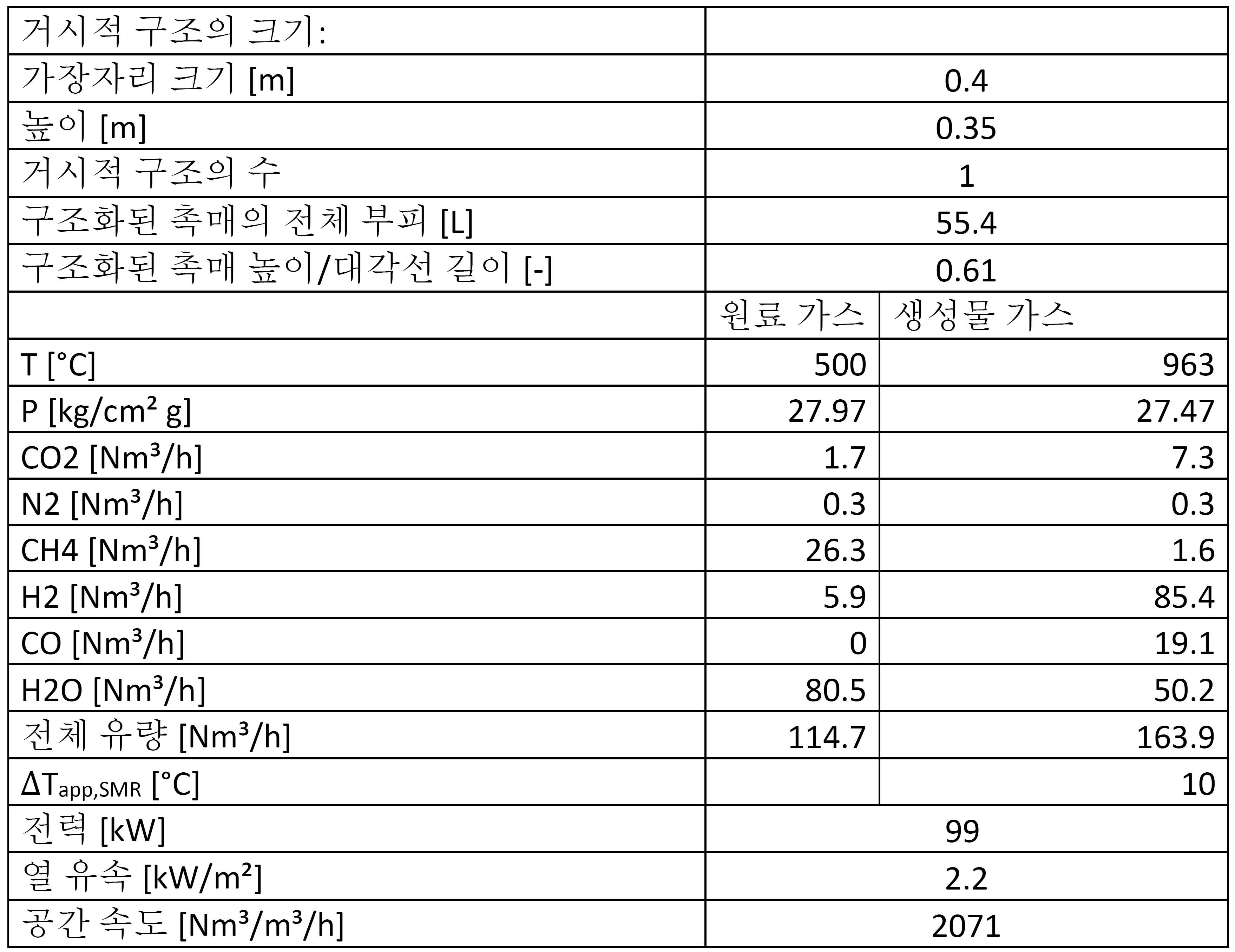
실시예 3:Example 3:
수소 플랜트의 개질 반응기 시스템 내에서 본 발명의 과정에 대한 예시적인 계산이 아래 표 3에 주어진다. 개질 반응기 시스템(100)으로 들어가는 제3 원료 가스(11')는 예비개질된 가스일 수 있다. 이것은 97 bar, 즉 97 kg/cm2·g의 압력으로 가압되고, 500℃의 온도를 가진다.An exemplary calculation for the process of the present invention in a reforming reactor system of a hydrogen plant is given in Table 3 below. The
개질 반응기 시스템(100)의 내부에 정사각형 단면을 가진 9개의 거시적 구조를 포함하는 구조화된 촉매가 어레이 형태로 위치되며, 각 거시적 구조는 0.53 x 0.53 x 2.3미터의 크기를 가진다. 각 거시적 구조는 추가로 0.32cm의 측면 또는 가장자리 길이를 가진 정사각형 단면을 가진 17778개의 채널을 가진다. 각 거시적 구조는 그것의 세로 방향에 평행한 슬릿을 가지며, 이로써 5 x 5 채널의 클러스터가 형성된다. 이 클러스터는 끝의 것을 제외하고 이웃한 클러스터로부터 개별적으로 절연되고, 이로써 거시적 구조를 통한 전류 경로가 지그재그 경로가 된다. 200 A의 전류 및 약 5.5 kV의 전압이 본 발명의 개질 반응기 시스템의 각 거시적 구조에 인가되며, 이로써 9899 kW의 구조화된 촉매에 제공된 전력에 상응하여, 구조화된 촉매를 가열하고, 구조화된 촉매를 통과하는 가스를 가열한다. 바람직하다면, 9개의 거시적 구조는 9개를 전부 직렬 연결하는 대신 3개씩 그룹으로 병렬 연결될 수 있고, 이것은 전압을 약 1.8 kV로 감소시킬 것이며, 또는 개별 모노리스로서 병렬 연결될 수도 있는데, 이것은 약 0.6 kV의 전압을 필요로 할 것이다. 이것은 연계된 전원의 가장 적합한 구성형태에 따라서 선택되어야 한다.Inside the reforming
이 구성형태의 개질 반응기 시스템(100)은 개질 반응기 시스템(100)이 구형 헤드를 가진 원통형 개질 반응기 시스템으로서 제조된 때 3.2m의 개질 반응기 시스템의 전체 내경 및 5.5m의 총 내부 높이를 가질 수 있다. 이 구체적인 구성형태에서, 거시적 구조(5)는 2.3m의 대각선 길이를 가진 정사각 배향으로 위치된다. 절연 물질까지의 간극을 메우기 위해 구조화된 촉매 주변에 비활성 물질이 위치되며, 절연 물질은 2.5m의 내경 및 0.35m의 두께를 가진다.The reforming
개질 반응기 시스템(100)을 통해서 가스(11')가 통과하는 동안 가스(11')는 구조화된 촉매에 의해 가열되고, 1115℃의 출구 온도를 가진 생성물 가스(12)로 스팀 개질된다.While the gas 11' passes through the reforming
개질 반응기 시스템을 빠져나오는 생성물 가스(12)는 97 bar의 압력으로 가압되므로, 약 100 bar 이하의 압력을 가진 고압 생성물 가스가 요구될 때 개질 반응기 시스템(100)의 하류에 압축기가 필요하지 않을 것이다. 이것은 스팀 개질 유닛의 하류에 압축기를 가진 표준 플랜트와 비교하여 본 발명의 플랜트의 전체적인 비용을 감소시킨다.Since the

실시예 4:Example 4:
본 발명의 수소 플랜트(1000)의 개질 반응기 시스템(100) 내에서 본 발명의 과정에 대한 예시적인 계산이 아래 표 4에 주어진다. 개질 반응기 시스템(100)으로 들어가는 가스(11')는 예비개질된 가스일 수 있다. 이것은 180.5 bar의 압력으로 가압되고, 500℃의 온도를 가진다.An exemplary calculation for the process of the present invention within the reforming
개질 반응기 시스템(100)의 내부에 정사각형 단면을 가진 9개의 거시적 구조(5)를 포함하는 구조화된 촉매(10)가 어레이 형태로 위치되며, 각 거시적 구조는 0.53 x 0.53 x 2.3미터의 크기를 가진다. 각 거시적 구조는 추가로 0.32cm의 측면 또는 가장자리 길이를 가진 정사각형 단면을 가진 17778개의 채널을 가진다. 각 거시적 구조(5)는 그것의 세로 방향에 평행한 슬릿을 가지며, 이로써 5 x 5 채널의 클러스터가 형성된다. 이 클러스터는 끝의 것을 제외하고 이웃한 클러스터로부터 개별적으로 절연되고, 이로써 거시적 구조를 통한 전류 경로가 지그재그 경로를 가지게 된다. 200 A의 전류 및 약 5.5 kV의 전압이 본 발명의 개질 반응기 시스템(100)의 각 거시적 구조(5)에 인가되며, 이로써 9899 kW의 구조화된 촉매에 제공된 전력에 상응하여, 구조화된 촉매를 가열하고, 구조화된 촉매를 통과하는 가스를 가열한다. 바람직하다면, 9개의 거시적 구조는 9개를 전부 직렬 연결하는 대신 3개씩 그룹으로 병렬 연결될 수 있고, 이것은 전압을 약 1.8 kV로 감소시킬 것이며, 또는 개별 모노리스로서 병렬 연결될 수도 있는데, 이것은 약 0.6 kV의 전압을 필요로 할 것이다. 이것은 연계된 전원의 가장 적합한 구성형태에 따라서 선택되어야 한다.Inside the reforming
이 구성형태의 개질 반응기 시스템(100)은 개질 반응기 시스템(100)이 구형 헤드를 가진 원통형 개질 반응기 시스템으로서 제조된 때 3.2m의 개질 반응기 시스템의 전체 내경 및 5.5m의 총 내부 높이를 가질 수 있다. 이 구체적인 구성형태에서, 거시적 구조는 2.3m의 대각선 길이를 가진 정사각 배향으로 위치된다. 절연 물질까지의 간극을 메우기 위해 구조화된 촉매 주변에 비활성 물질이 위치되며, 절연 물질은 2.5m의 내경 및 0.35m의 두께를 가진다.The reforming
개질 반응기 시스템(100)을 통해서 가스(11')가 통과하는 동안 가스(11')는 구조화된 촉매에 의해 가열되고, 1236℃의 출구 온도를 가진 생성물 가스(12)로 스팀 개질된다. 가스(11')와 생성물 가스(12)의 전체 유량은 실시예 3에서의 가스의 전체 유량보다 적다.While the gas 11' passes through the reforming
개질 반응기 시스템을 빠져나오는 생성물 가스(12)는 181 bar의 압력으로 이미 가압되므로, 예를 들어 추가의 가압 없이 리파이너리 플랜트의 수소처리장치에 유입되기에 적합하다. 따라서, 개질 반응기 시스템과 리파이너리 플랜트의 수소처리장치 사이에 압축기가 필요하지 않을 것이다. 이것은 본 발명의 개질 반응기 시스템을 가진 플랜트의 전체적인 비용을 감소시킨다.The
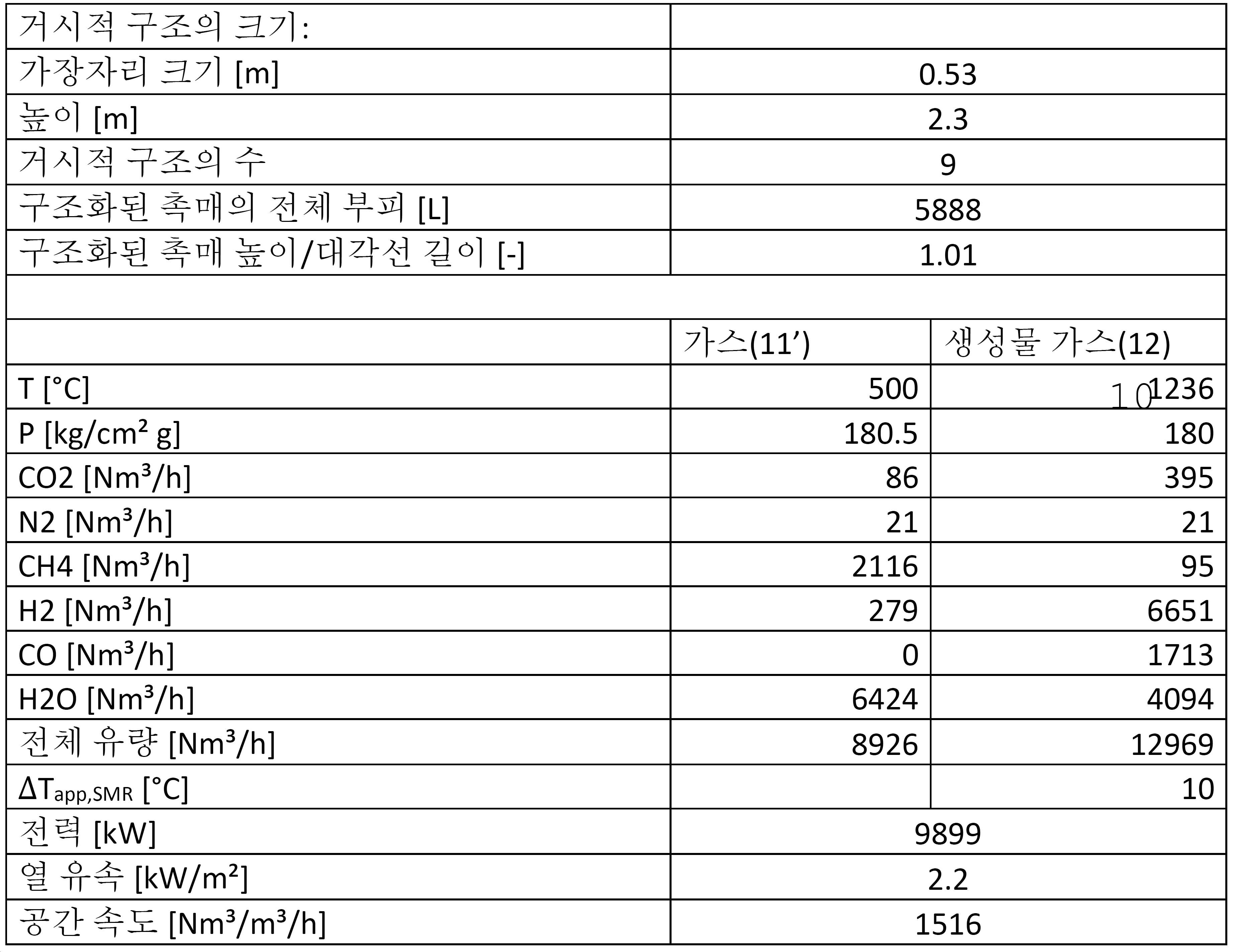
실시예 5:Example 5:
수소 플랜트의 예가 표 5에 주어지며, 이것은 화학 플랜트에서 관련된 장소의 가스 조성을 보여준다. 이 계산은 전기 가열 개질 반응기 시스템의 고압 및 온도 내구성에 의해 높은 개질 온도와 결과적으로 고압에서 높은 메탄 전환율이 가능하게 되는 방식을 예시한다. 예열, 탈황, 냉각, 열 교환기, 및 상 분리를 포함하는, 표 5에 나타낸 것들에 더하여 몇 가지 유닛 작동이 사용된다. 개질 플랜트 설계 분야의 당업자는 필요에 따라 이들을 삽입할 수 있을 것이다. 아래 표 5는 2개의 수성 가스 전환 유닛(130a, 130b) 및 개질 반응기 시스템(100)과 제1 수성 가스 전환 유닛(130a) 사이에 가스 냉각을 갖춘 수소 플랜트(1000)에 관한 것이다.An example of a hydrogen plant is given in Table 5, which shows the gas composition of the relevant sites in the chemical plant. This calculation illustrates how the high pressure and temperature tolerance of the electric heating reforming reactor system enables high reforming temperatures and consequently high methane conversion rates at high pressure. Several unit operations are used in addition to those shown in Table 5, including preheating, desulfurization, cooling, heat exchanger, and phase separation. Those skilled in the art of reforming plant design will be able to insert them as needed. Table 5 below relates to a
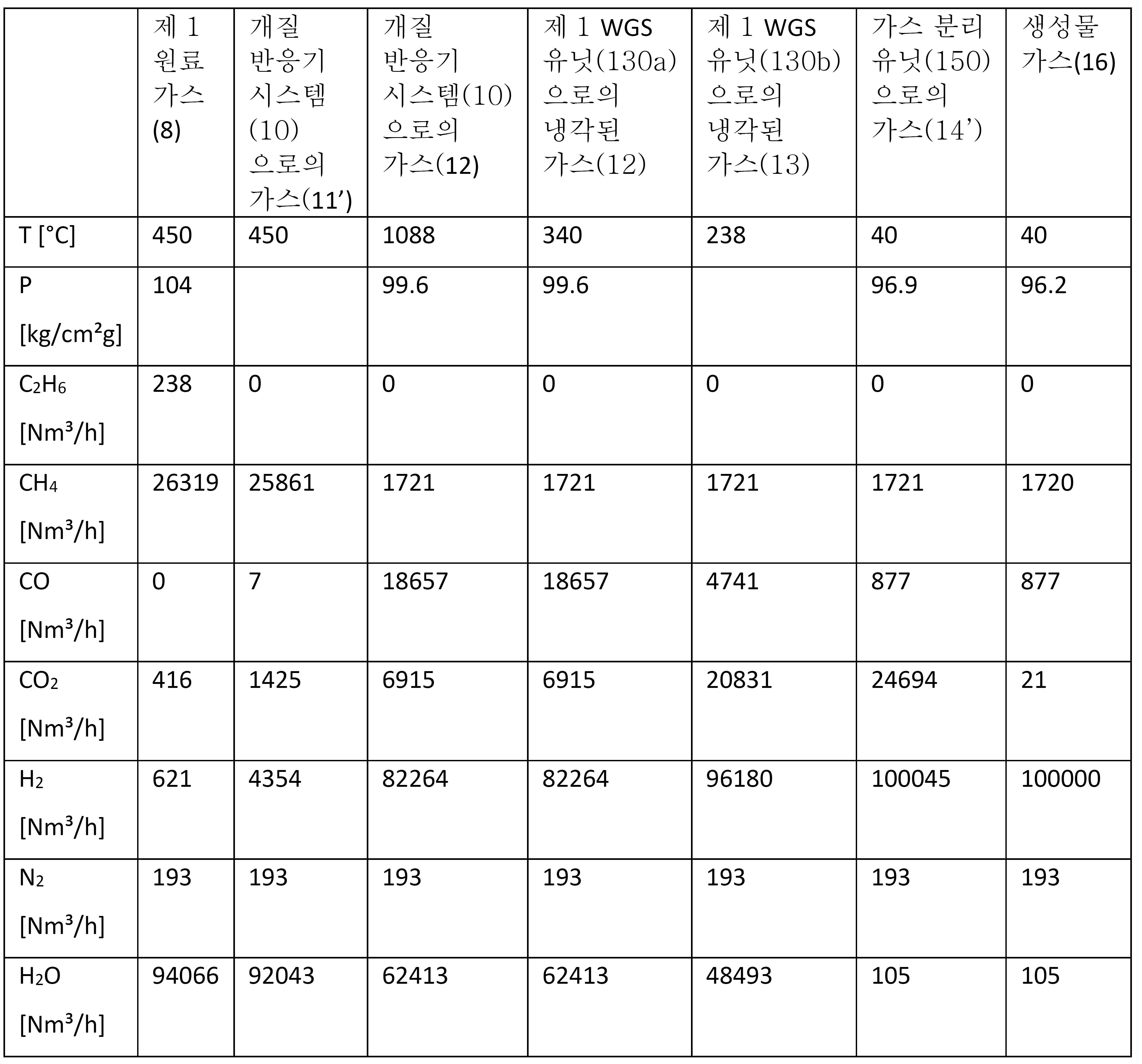
Claims (25)
- 전기 전도성 물질 및 탄화수소를 포함하는 원료 가스의 스팀 개질에 촉매작용하도록 배열된 촉매 활성 물질을 포함하는 제1 촉매층, 상기 제1 촉매층을 수납하고 있는 압력 쉘, 상기 제1 촉매층과 상기 압력 쉘 사이의 단열층, 및 상기 전기 전도성 물질과 상기 압력 쉘의 외부에 위치된 전기 전원에 전기적으로 연결된 적어도 2개의 컨덕터를 포함하는 개질 반응기 시스템으로서, 상기 전기 전원은 상기 전기 전도성 물질을 통해 전기 전류를 통과시킴으로써 상기 제1 촉매층의 적어도 일부분을 적어도 500℃의 온도로 가열할 수 있는 치수이며, 상기 압력 쉘은 5 내지 200 bar, 바람직하게 30 내지 200 bar, 더 바람직하게 80 내지 180 bar의 설계 압력을 가지는 개질 반응기 시스템,
- 개질 반응기 시스템 하류의 수성 가스 전환 유닛, 및
- 수성 가스 전환 유닛 하류의 가스 분리 유닛
을 포함하는 수소 플랜트.As a hydrogen plant for producing hydrogen,
-A first catalyst layer comprising a catalytically active material arranged to catalyze the steam reforming of a raw material gas containing an electrically conductive material and a hydrocarbon, a pressure shell accommodating the first catalyst layer, and between the first catalyst layer and the pressure shell A reforming reactor system comprising a heat insulating layer of, and at least two conductors electrically connected to the electrically conductive material and an electrical power source located outside the pressure shell, wherein the electrical power source passes an electrical current through the electrically conductive material. It is a dimension capable of heating at least a portion of the first catalyst layer to a temperature of at least 500°C, and the pressure shell has a design pressure of 5 to 200 bar, preferably 30 to 200 bar, more preferably 80 to 180 bar. Reactor system,
-A water gas conversion unit downstream of the reforming reactor system, and
-Gas separation unit downstream of the water gas conversion unit
Hydrogen plant comprising a.
- 상기 원료 가스를 5 내지 200 bar의 압력으로 가압하는 단계,
- 상기 가압된 원료 가스를 개질 반응기 시스템에 공급하는 단계,
- 상기 원료 가스가 제1 촉매층을 지나면서 스팀 개질 반응을 겪도록 허용하고 생성물 가스를 개질 반응기 시스템으로부터 내보내는 단계,
- 상기 전기 전도성 물질에 상기 압력 쉘의 외부에 위치된 전기 전원을 연결하는 전기 컨덕터를 통해서 전력을 공급함으로써 상기 촉매 활성 물질을 가열하고, 전기 전류가 상기 전기 전도성 물질을 통해 흐르도록 허용하고, 이로써 제1 촉매층의 적어도 일부분을 적어도 500℃의 온도로 가열하는 단계,
- 생성물 가스를 개질 반응기 시스템 하류의 수성 가스 전환 유닛으로 들여보냄으로써 수성 가스 전환된 생성물 가스를 생성하는 단계,
- 수성 가스 전환된 생성물 가스에서 물을 응축시키고 이 물을 플래시 분리 단계에서 분리함으로써 건조된 수성 가스 전환된 생성물 가스를 제공하는 단계, 및
- 수성 가스 전환 유닛 하류의 가스 분리 유닛에서 건조된 수성 가스 전환된 생성물 가스로부터 적어도 CO2를 제거하는 단계
를 포함하는 방법.A method of producing hydrogen from a source gas containing hydrocarbons in a hydrogen plant, wherein the hydrogen plant includes a reforming reactor system having a pressure shell housing a first catalyst layer, and the first catalyst layer is an electrically conductive material and a catalytic activity. A material, wherein the catalytically active material is arranged to catalyze steam reforming of a source gas comprising hydrocarbons, and the reforming reactor system is provided with thermal insulation between the first catalyst bed and the pressure shell; The method is:
-Pressurizing the raw material gas at a pressure of 5 to 200 bar,
-Supplying the pressurized raw material gas to a reforming reactor system,
-Allowing the source gas to undergo a steam reforming reaction as it passes through the first catalyst bed and expelling the product gas from the reforming reactor system,
-Heating the catalytically active material by supplying power to the electrically conductive material through an electrical conductor connecting an electrical power source located outside of the pressure shell, allowing an electrical current to flow through the electrically conductive material, thereby Heating at least a portion of the first catalyst layer to a temperature of at least 500° C.,
-Producing a water gas converted product gas by introducing the product gas into a water gas conversion unit downstream of the reforming reactor system,
-Condensing water in the water gas converted product gas and separating this water in a flash separation step to provide a dried water gas converted product gas, and
-Removing at least CO 2 from the dried water gas converted product gas in a gas separation unit downstream of the water gas conversion unit
How to include.
The method according to any one of claims 22 to 24, wherein the first catalyst layer comprises a structured catalyst comprising a macroscopic structure of an electrically conductive material, the macroscopic structure carrying a ceramic coating, and the ceramic coating is catalytically active. A method, characterized in that carrying a material, wherein the macroscopic structure is heated by directing an electric current through the macroscopic structure, whereby the maximum temperature of the macroscopic structure is between 500°C and 1300°C.
Applications Claiming Priority (7)
| Application Number | Priority Date | Filing Date | Title |
|---|---|---|---|
| EP18175366.6A EP3574991A1 (en) | 2018-05-31 | 2018-05-31 | Steam reforming heated by resistance heating |
| EP18175366.6 | 2018-05-31 | ||
| DKPA201800249 | 2018-05-31 | ||
| DKPA201800249 | 2018-05-31 | ||
| DKPA201800636 | 2018-09-25 | ||
| DKPA201800636 | 2018-09-25 | ||
| PCT/EP2019/062420 WO2019228796A1 (en) | 2018-05-31 | 2019-05-15 | Hydrogen production by steam methane reforming |
Publications (1)
| Publication Number | Publication Date |
|---|---|
| KR20210016418A true KR20210016418A (en) | 2021-02-15 |
Family
ID=66484084
Family Applications (1)
| Application Number | Title | Priority Date | Filing Date |
|---|---|---|---|
| KR1020207037585A Pending KR20210016418A (en) | 2018-05-31 | 2019-05-15 | Hydrogen production by steam methane reforming |
Country Status (8)
| Country | Link |
|---|---|
| US (1) | US11591215B2 (en) |
| EP (1) | EP3802413B1 (en) |
| KR (1) | KR20210016418A (en) |
| AU (1) | AU2019275849B2 (en) |
| CA (1) | CA3099617C (en) |
| ES (1) | ES2951672T3 (en) |
| FI (1) | FI3802413T3 (en) |
| WO (1) | WO2019228796A1 (en) |
Cited By (1)
| Publication number | Priority date | Publication date | Assignee | Title |
|---|---|---|---|---|
| KR20230116121A (en) * | 2022-01-27 | 2023-08-04 | (주)바이오프랜즈 | Method for producing hydrogen from flammable waste plastic and hydrogen production system using the same method |
Families Citing this family (37)
| Publication number | Priority date | Publication date | Assignee | Title |
|---|---|---|---|---|
| JP7365341B2 (en) * | 2017-12-08 | 2023-10-19 | トプソー・アクチエゼルスカベット | Plants and methods for producing synthesis gas |
| UA127416C2 (en) | 2017-12-08 | 2023-08-16 | Хальдор Топсьое А/С | Process and system for producing synthesis gas |
| FI3720810T3 (en) | 2017-12-08 | 2025-09-03 | Topsoe As | A process and system for reforming a hydrocarbon gas |
| EP3574991A1 (en) | 2018-05-31 | 2019-12-04 | Haldor Topsøe A/S | Steam reforming heated by resistance heating |
| WO2019228798A1 (en) | 2018-05-31 | 2019-12-05 | Haldor Topsøe A/S | Endothermic reactions heated by resistance heating |
| FR3101075B1 (en) * | 2019-09-19 | 2022-07-29 | Commissariat Energie Atomique | : Catalytic fixed-bed reactor incorporating an electric heating element, Hydrogen production unit by steam reforming comprising such a reactor and an electric steam generator, associated operating method. |
| JP2022550814A (en) | 2019-10-01 | 2022-12-05 | トプソー・アクチエゼルスカベット | Hydrogen on demand from methanol |
| US12246298B2 (en) | 2019-10-01 | 2025-03-11 | Haldor Topsøe A/S | Offshore reforming installation or vessel |
| KR20220075347A (en) | 2019-10-01 | 2022-06-08 | 할도르 토프쉐 에이/에스 | Customized hydrogen from ammonia |
| WO2021063799A1 (en) | 2019-10-01 | 2021-04-08 | Haldor Topsøe A/S | Cyanide on demand |
| CN114466694A (en) | 2019-10-01 | 2022-05-10 | 托普索公司 | On-demand production of synthesis gas |
| CN119660676A (en) | 2019-10-01 | 2025-03-21 | 托普索公司 | On demand production of synthesis gas from methanol |
| US12246299B2 (en) | 2019-11-12 | 2025-03-11 | Haldor Topsøe A/S | Electric steam cracker |
| KR20220104736A (en) | 2019-12-04 | 2022-07-26 | 토프쉐 에이/에스 | Electric Heating Carbon Monoxide Reactor |
| CA3163744A1 (en) | 2019-12-04 | 2021-06-10 | Haldor Topsoe A/S | Gas heater |
| ES2992777T3 (en) * | 2020-06-26 | 2024-12-18 | Topsoe As | A structured catalyst |
| WO2022049147A1 (en) * | 2020-09-02 | 2022-03-10 | Haldor Topsøe A/S | Production of syntehsis gas in a plant comprising an electric steam reformer downstream of fired reformer |
| WO2022049148A1 (en) * | 2020-09-02 | 2022-03-10 | Haldor Topsøe A/S | Production of synthesis gas in a plant comprising an electric steam reformer downstream of a heat exchange reformer |
| KR20220052099A (en) * | 2020-10-20 | 2022-04-27 | 한국화학연구원 | High Efficiency Ni-based Catalyst for Steam Methane Reforming and Steam Methane Reforming Reaction using the Same |
| EP4237137A1 (en) | 2020-10-30 | 2023-09-06 | Gas Technology Institute | Electrically heated reforming reactor for reforming of methane and other hydrocarbons |
| CN117693486A (en) | 2021-04-15 | 2024-03-12 | 利迪恩实验室公司 | Electrically driven chemical reactor using modular catalytic heating system |
| US20240343567A1 (en) | 2021-08-04 | 2024-10-17 | Nextchem Tech S.P.A. | Method for hydrogen production coupled with co2 capture |
| IT202100026456A1 (en) | 2021-10-15 | 2023-04-15 | Milano Politecnico | REACTOR WITH ELECTRICALLY HEATED THERMO-CONDUCTIVE STRUCTURE FOR ENDOTHERMAL CATALYTIC PROCESSES |
| US12162757B2 (en) | 2021-11-11 | 2024-12-10 | Pcc Hydrogen Inc. | Oxidative reforming and electrolysis system and process for hydrogen generation |
| KR102802606B1 (en) * | 2022-07-29 | 2025-05-07 | 주식회사 플랜텍 | Double heating type hydrogen generator |
| US20250345769A1 (en) * | 2022-10-19 | 2025-11-13 | Lydian Labs, Inc. | Systems and methods for chemical catalytic processing |
| TWI863311B (en) * | 2023-05-26 | 2024-11-21 | 韋文誠 | Gas reforming catalyst assembly |
| US12337290B2 (en) | 2023-06-30 | 2025-06-24 | Lydian Labs, Inc. | Electrical coupler for resistively heated reactor systems |
| US20250092325A1 (en) * | 2023-09-20 | 2025-03-20 | Infinium Technology, Llc | Isothermal Reverse Water Gas Shift Reactor System |
| SE2450903A1 (en) * | 2023-09-29 | 2025-03-30 | Hydrogen Energy Scandinavia Ab | Composition |
| US12060269B1 (en) | 2023-10-13 | 2024-08-13 | Pcc Hydrogen Inc. | Reactor for conversion of hydrocarbons and oxygenates to syngas and hydrogen |
| WO2025125974A1 (en) * | 2023-12-13 | 2025-06-19 | Universidade Do Porto | Catalyst and reactor for intermediate-temperature catalytic methane splitting and methods thereof |
| WO2025125973A1 (en) * | 2023-12-13 | 2025-06-19 | Universidade Do Porto | Reactor for low-temperature methane splitting and solid catalyst to use therein and methods thereof |
| WO2025125278A1 (en) * | 2023-12-15 | 2025-06-19 | Topsoe A/S | Electrical connection to an assembly |
| EP4585558A1 (en) * | 2024-01-12 | 2025-07-16 | Linde GmbH | Method and installation for producing a process product |
| US12509352B2 (en) | 2024-01-25 | 2025-12-30 | Lydian Labs, Inc. | Reactor systems for endothermic reactions |
| WO2026013443A1 (en) * | 2024-07-09 | 2026-01-15 | Universidade Do Porto | Catalytic alloys to promote intermediate temperature methane splitting and methods thereof |
Family Cites Families (19)
| Publication number | Priority date | Publication date | Assignee | Title |
|---|---|---|---|---|
| JPH11130405A (en) | 1997-10-28 | 1999-05-18 | Ngk Insulators Ltd | Reforming reaction device, catalytic device, exothermic catalytic body used for the same and operation of reforming reaction device |
| JP2000007301A (en) | 1998-06-29 | 2000-01-11 | Ngk Insulators Ltd | Reforming reactor |
| DE19841993B4 (en) | 1998-09-04 | 2005-02-17 | P21 - Power For The 21St Century Gmbh | Microstructure reactor |
| US6746650B1 (en) | 1999-06-14 | 2004-06-08 | Utc Fuel Cells, Llc | Compact, light weight methanol fuel gas autothermal reformer assembly |
| DE10104601A1 (en) * | 2001-02-02 | 2002-08-14 | Xcellsis Gmbh | Reactor for a fuel cell system |
| US20020108307A1 (en) | 2001-02-12 | 2002-08-15 | Gene Lightner | Hydrogen devoid of carbon monoxide from a reformer |
| US20040213732A1 (en) | 2002-02-04 | 2004-10-28 | Lightner Gene E. | Reforming vapor obtained from a biomass |
| EP1413547A1 (en) * | 2002-09-26 | 2004-04-28 | Haldor Topsoe A/S | Process for the production of synthesis gas |
| CA2410927A1 (en) | 2002-11-05 | 2004-05-05 | Michel Petitclerc | Electrically heated reactor for reforming in gaseous phase |
| DE10317197A1 (en) | 2003-04-15 | 2004-11-04 | Degussa Ag | Electrically heated reactor and method for carrying out gas reactions at high temperature using this reactor |
| US7722854B2 (en) * | 2003-06-25 | 2010-05-25 | Velocy's | Steam reforming methods and catalysts |
| EP1890802A2 (en) | 2005-05-25 | 2008-02-27 | Velocys, Inc. | Support for use in microchannel processing |
| US7918906B2 (en) | 2007-05-20 | 2011-04-05 | Pioneer Energy Inc. | Compact natural gas steam reformer with linear countercurrent heat exchanger |
| US8061120B2 (en) | 2007-07-30 | 2011-11-22 | Herng Shinn Hwang | Catalytic EGR oxidizer for IC engines and gas turbines |
| KR100953859B1 (en) | 2007-12-24 | 2010-04-20 | 조선대학교산학협력단 | Fast Start Plasma Reformer for Home Fuel Cell Systems |
| US20090184293A1 (en) * | 2008-01-18 | 2009-07-23 | Han Pat A | Process for reforming hydrocarbons |
| JP5121080B2 (en) * | 2009-05-12 | 2013-01-16 | パナソニック株式会社 | Fuel cell system |
| EP2864244A2 (en) * | 2012-06-21 | 2015-04-29 | Saudi Basic Industries Corporation | Process for producing a synthesis gas mixture |
| DE102013226126A1 (en) | 2013-12-16 | 2015-06-18 | Technische Universität Bergakademie Freiberg | All-thermic methane reforming with physical energy recovery |
-
2019
- 2019-05-15 KR KR1020207037585A patent/KR20210016418A/en active Pending
- 2019-05-15 WO PCT/EP2019/062420 patent/WO2019228796A1/en not_active Ceased
- 2019-05-15 EP EP19723428.9A patent/EP3802413B1/en active Active
- 2019-05-15 US US17/049,040 patent/US11591215B2/en active Active
- 2019-05-15 AU AU2019275849A patent/AU2019275849B2/en active Active
- 2019-05-15 FI FIEP19723428.9T patent/FI3802413T3/en active
- 2019-05-15 ES ES19723428T patent/ES2951672T3/en active Active
- 2019-05-15 CA CA3099617A patent/CA3099617C/en active Active
Cited By (1)
| Publication number | Priority date | Publication date | Assignee | Title |
|---|---|---|---|---|
| KR20230116121A (en) * | 2022-01-27 | 2023-08-04 | (주)바이오프랜즈 | Method for producing hydrogen from flammable waste plastic and hydrogen production system using the same method |
Also Published As
| Publication number | Publication date |
|---|---|
| EP3802413A1 (en) | 2021-04-14 |
| US20210238035A1 (en) | 2021-08-05 |
| CA3099617C (en) | 2025-02-11 |
| ES2951672T3 (en) | 2023-10-24 |
| WO2019228796A1 (en) | 2019-12-05 |
| CA3099617A1 (en) | 2019-12-05 |
| US11591215B2 (en) | 2023-02-28 |
| AU2019275849A1 (en) | 2020-11-26 |
| EP3802413B1 (en) | 2023-07-05 |
| FI3802413T3 (en) | 2023-08-11 |
| AU2019275849B2 (en) | 2025-03-06 |
Similar Documents
| Publication | Publication Date | Title |
|---|---|---|
| US11591215B2 (en) | Hydrogen production by steam methane reforming | |
| KR102778663B1 (en) | Steam reforming heated by resistance heating | |
| JP7741803B2 (en) | Electrically Heated Carbon Monoxide Reactor | |
| CN112203757A (en) | Heated endothermic reaction by resistive heating | |
| JP2022550813A (en) | Hydrogen on demand from ammonia | |
| JP7644104B2 (en) | On-Demand Syngas from Methanol | |
| CN114555219A (en) | Offshore reformer or vessel | |
| KR20220074922A (en) | Customized hydrogen from methanol | |
| JP2022552134A (en) | cyanide on demand |
Legal Events
| Date | Code | Title | Description |
|---|---|---|---|
| PA0105 | International application |
St.27 status event code: A-0-1-A10-A15-nap-PA0105 |
|
| PG1501 | Laying open of application |
St.27 status event code: A-1-1-Q10-Q12-nap-PG1501 |
|
| PA0201 | Request for examination |
St.27 status event code: A-1-2-D10-D11-exm-PA0201 |
|
| PN2301 | Change of applicant |
St.27 status event code: A-3-3-R10-R13-asn-PN2301 St.27 status event code: A-3-3-R10-R11-asn-PN2301 |
|
| D13-X000 | Search requested |
St.27 status event code: A-1-2-D10-D13-srh-X000 |
|
| D14-X000 | Search report completed |
St.27 status event code: A-1-2-D10-D14-srh-X000 |
|
| E902 | Notification of reason for refusal | ||
| PE0902 | Notice of grounds for rejection |
St.27 status event code: A-1-2-D10-D21-exm-PE0902 |
|
| T11-X000 | Administrative time limit extension requested |
St.27 status event code: U-3-3-T10-T11-oth-X000 |
|
| P11-X000 | Amendment of application requested |
St.27 status event code: A-2-2-P10-P11-nap-X000 |
|
| P13-X000 | Application amended |
St.27 status event code: A-2-2-P10-P13-nap-X000 |
|
| E90F | Notification of reason for final refusal | ||
| PE0902 | Notice of grounds for rejection |
St.27 status event code: A-1-2-D10-D21-exm-PE0902 |
|
| T11-X000 | Administrative time limit extension requested |
St.27 status event code: U-3-3-T10-T11-oth-X000 |
|
| P11 | Amendment of application requested |
Free format text: ST27 STATUS EVENT CODE: A-2-2-P10-P11-NAP-X000 (AS PROVIDED BY THE NATIONAL OFFICE) |
|
| P11-X000 | Amendment of application requested |
St.27 status event code: A-2-2-P10-P11-nap-X000 |