KR20200103505A - Apparatus for stabilizating of pwer system - Google Patents
Apparatus for stabilizating of pwer system Download PDFInfo
- Publication number
- KR20200103505A KR20200103505A KR1020190022114A KR20190022114A KR20200103505A KR 20200103505 A KR20200103505 A KR 20200103505A KR 1020190022114 A KR1020190022114 A KR 1020190022114A KR 20190022114 A KR20190022114 A KR 20190022114A KR 20200103505 A KR20200103505 A KR 20200103505A
- Authority
- KR
- South Korea
- Prior art keywords
- section
- lcc
- ess
- line
- renewable energy
- Prior art date
- Legal status (The legal status is an assumption and is not a legal conclusion. Google has not performed a legal analysis and makes no representation as to the accuracy of the status listed.)
- Granted
Links
Images


Classifications
-
- H—ELECTRICITY
- H02—GENERATION; CONVERSION OR DISTRIBUTION OF ELECTRIC POWER
- H02J—CIRCUIT ARRANGEMENTS OR SYSTEMS FOR SUPPLYING OR DISTRIBUTING ELECTRIC POWER; SYSTEMS FOR STORING ELECTRIC ENERGY
- H02J3/00—Circuit arrangements for AC mains or AC distribution networks
- H02J3/18—Arrangements for adjusting, eliminating or compensating reactive power in networks
-
- H—ELECTRICITY
- H02—GENERATION; CONVERSION OR DISTRIBUTION OF ELECTRIC POWER
- H02J—CIRCUIT ARRANGEMENTS OR SYSTEMS FOR SUPPLYING OR DISTRIBUTING ELECTRIC POWER; SYSTEMS FOR STORING ELECTRIC ENERGY
- H02J3/00—Circuit arrangements for AC mains or AC distribution networks
- H02J3/28—Arrangements for balancing of the load in a network by storage of energy
- H02J3/32—Arrangements for balancing of the load in a network by storage of energy using batteries with converting means
-
- H—ELECTRICITY
- H02—GENERATION; CONVERSION OR DISTRIBUTION OF ELECTRIC POWER
- H02J—CIRCUIT ARRANGEMENTS OR SYSTEMS FOR SUPPLYING OR DISTRIBUTING ELECTRIC POWER; SYSTEMS FOR STORING ELECTRIC ENERGY
- H02J3/00—Circuit arrangements for AC mains or AC distribution networks
- H02J3/38—Arrangements for parallely feeding a single network by two or more generators, converters or transformers
- H02J3/381—Dispersed generators
-
- H02J3/383—
-
- H02J2101/24—
-
- Y—GENERAL TAGGING OF NEW TECHNOLOGICAL DEVELOPMENTS; GENERAL TAGGING OF CROSS-SECTIONAL TECHNOLOGIES SPANNING OVER SEVERAL SECTIONS OF THE IPC; TECHNICAL SUBJECTS COVERED BY FORMER USPC CROSS-REFERENCE ART COLLECTIONS [XRACs] AND DIGESTS
- Y02—TECHNOLOGIES OR APPLICATIONS FOR MITIGATION OR ADAPTATION AGAINST CLIMATE CHANGE
- Y02E—REDUCTION OF GREENHOUSE GAS [GHG] EMISSIONS, RELATED TO ENERGY GENERATION, TRANSMISSION OR DISTRIBUTION
- Y02E10/00—Energy generation through renewable energy sources
- Y02E10/50—Photovoltaic [PV] energy
- Y02E10/56—Power conversion systems, e.g. maximum power point trackers
-
- Y—GENERAL TAGGING OF NEW TECHNOLOGICAL DEVELOPMENTS; GENERAL TAGGING OF CROSS-SECTIONAL TECHNOLOGIES SPANNING OVER SEVERAL SECTIONS OF THE IPC; TECHNICAL SUBJECTS COVERED BY FORMER USPC CROSS-REFERENCE ART COLLECTIONS [XRACs] AND DIGESTS
- Y02—TECHNOLOGIES OR APPLICATIONS FOR MITIGATION OR ADAPTATION AGAINST CLIMATE CHANGE
- Y02E—REDUCTION OF GREENHOUSE GAS [GHG] EMISSIONS, RELATED TO ENERGY GENERATION, TRANSMISSION OR DISTRIBUTION
- Y02E40/00—Technologies for an efficient electrical power generation, transmission or distribution
- Y02E40/10—Flexible AC transmission systems [FACTS]
-
- Y—GENERAL TAGGING OF NEW TECHNOLOGICAL DEVELOPMENTS; GENERAL TAGGING OF CROSS-SECTIONAL TECHNOLOGIES SPANNING OVER SEVERAL SECTIONS OF THE IPC; TECHNICAL SUBJECTS COVERED BY FORMER USPC CROSS-REFERENCE ART COLLECTIONS [XRACs] AND DIGESTS
- Y02—TECHNOLOGIES OR APPLICATIONS FOR MITIGATION OR ADAPTATION AGAINST CLIMATE CHANGE
- Y02E—REDUCTION OF GREENHOUSE GAS [GHG] EMISSIONS, RELATED TO ENERGY GENERATION, TRANSMISSION OR DISTRIBUTION
- Y02E40/00—Technologies for an efficient electrical power generation, transmission or distribution
- Y02E40/30—Reactive power compensation
-
- Y—GENERAL TAGGING OF NEW TECHNOLOGICAL DEVELOPMENTS; GENERAL TAGGING OF CROSS-SECTIONAL TECHNOLOGIES SPANNING OVER SEVERAL SECTIONS OF THE IPC; TECHNICAL SUBJECTS COVERED BY FORMER USPC CROSS-REFERENCE ART COLLECTIONS [XRACs] AND DIGESTS
- Y02—TECHNOLOGIES OR APPLICATIONS FOR MITIGATION OR ADAPTATION AGAINST CLIMATE CHANGE
- Y02E—REDUCTION OF GREENHOUSE GAS [GHG] EMISSIONS, RELATED TO ENERGY GENERATION, TRANSMISSION OR DISTRIBUTION
- Y02E70/00—Other energy conversion or management systems reducing GHG emissions
- Y02E70/30—Systems combining energy storage with energy generation of non-fossil origin
-
- Y—GENERAL TAGGING OF NEW TECHNOLOGICAL DEVELOPMENTS; GENERAL TAGGING OF CROSS-SECTIONAL TECHNOLOGIES SPANNING OVER SEVERAL SECTIONS OF THE IPC; TECHNICAL SUBJECTS COVERED BY FORMER USPC CROSS-REFERENCE ART COLLECTIONS [XRACs] AND DIGESTS
- Y04—INFORMATION OR COMMUNICATION TECHNOLOGIES HAVING AN IMPACT ON OTHER TECHNOLOGY AREAS
- Y04S—SYSTEMS INTEGRATING TECHNOLOGIES RELATED TO POWER NETWORK OPERATION, COMMUNICATION OR INFORMATION TECHNOLOGIES FOR IMPROVING THE ELECTRICAL POWER GENERATION, TRANSMISSION, DISTRIBUTION, MANAGEMENT OR USAGE, i.e. SMART GRIDS
- Y04S10/00—Systems supporting electrical power generation, transmission or distribution
- Y04S10/12—Monitoring or controlling equipment for energy generation units, e.g. distributed energy generation [DER] or load-side generation
- Y04S10/123—Monitoring or controlling equipment for energy generation units, e.g. distributed energy generation [DER] or load-side generation the energy generation units being or involving renewable energy sources
-
- Y—GENERAL TAGGING OF NEW TECHNOLOGICAL DEVELOPMENTS; GENERAL TAGGING OF CROSS-SECTIONAL TECHNOLOGIES SPANNING OVER SEVERAL SECTIONS OF THE IPC; TECHNICAL SUBJECTS COVERED BY FORMER USPC CROSS-REFERENCE ART COLLECTIONS [XRACs] AND DIGESTS
- Y04—INFORMATION OR COMMUNICATION TECHNOLOGIES HAVING AN IMPACT ON OTHER TECHNOLOGY AREAS
- Y04S—SYSTEMS INTEGRATING TECHNOLOGIES RELATED TO POWER NETWORK OPERATION, COMMUNICATION OR INFORMATION TECHNOLOGIES FOR IMPROVING THE ELECTRICAL POWER GENERATION, TRANSMISSION, DISTRIBUTION, MANAGEMENT OR USAGE, i.e. SMART GRIDS
- Y04S10/00—Systems supporting electrical power generation, transmission or distribution
- Y04S10/14—Energy storage units
Landscapes
- Engineering & Computer Science (AREA)
- Power Engineering (AREA)
- Supply And Distribution Of Alternating Current (AREA)
Abstract
Description
본 발명은 지역 제어 방법을 이용한 계통 안정화 장치에 관한 것이다.The present invention relates to a system stabilization apparatus using a local control method.
도 1은 종래 기술에 따른 계통 장치를 개략적으로 설명하기 위하여 도시한 도면으로, 도 1을 참조하면, 종래의 경우 태양광, ESS(energy storage system) 등이 개별로 제어되어 계통 전압을 안정적으로 운영하기 어려웠다. 대부분의 PV(photovoltaics system, 태양광 발전 시스템), ESS 등 계통에 전력을 공급하는 설비가 개인 사유 재산으로 제어가 불가능하였다. 때문에, 계통에 유입되는 전력의 댐퍼 역할을 하는 ESS가 개별로 동작하여 충/방전에 대한 제어가 산발적으로 이루어 지고 있다. 이로 인하여, ESS 용량이 부족한 경우가 발생하고 있다. 이러한 경우 PV 등 신재생 에너지원에서 유입되는 전력으로 인하여 계통전압이 불안정해지는 한계점을 지니고 있다. 또한 SG(smart grid), MG(micro grid)의 방식을 이용할 경우 부하, 발전원에 대하여 계측 장비 설치가 필수적이어서, 계통운영 비용의 증가가 불가피하다.1 is a diagram schematically illustrating a system device according to the prior art. Referring to FIG. 1, in the conventional case, solar light, energy storage system (ESS), etc. are individually controlled to stably operate the system voltage. It was difficult to do. Most of the facilities that supply power to the grid, such as photovoltaics systems (PVs) and ESS, were private property and could not be controlled. Therefore, the ESS, which acts as a damper for electric power flowing into the system, operates separately, and thus, control over charging/discharging is sporadically performed. For this reason, there are cases in which the ESS capacity is insufficient. In this case, there is a limitation in that the grid voltage becomes unstable due to power flowing from renewable energy sources such as PV. In addition, when the SG (smart grid) and MG (micro grid) methods are used, it is necessary to install measurement equipment for the load and power generation source, which inevitably increases the system operation cost.
전술한 배경기술은 발명자가 본 발명의 도출을 위해 보유하고 있었거나, 본 발명의 도출 과정에서 습득한 기술 정보로서, 반드시 본 발명의 출원 전에 일반 공중에게 공개된 공지기술이라 할 수는 없다.The above-described background technology is technical information possessed by the inventor for derivation of the present invention or acquired in the derivation process of the present invention, and is not necessarily known to be known to the public prior to filing the present invention.
본 발명은 전술한 문제점 및/또는 한계를 해결하기 위해 안출된 것으로, 일 측면에 따른 본 발명의 목적은 LCC(local control center)에서 운영하는 ESS의 수전단 전압을 계측하여 제어함으로써 계측장비의 설치 수량을 줄이는데 있다.The present invention was conceived to solve the above-described problems and/or limitations, and an object of the present invention according to an aspect is to measure and control the receiving and shear voltage of an ESS operated in a local control center (LCC) to install a measuring device. It is to reduce the quantity.
다른 측면에 따른 본 발명의 목적은 전압 제어 방식을 이용하여 배전단에서 선로의 신뢰성을 확보하는데 있다.An object of the present invention according to another aspect is to secure the reliability of a line at a distribution end by using a voltage control method.
또 다른 측면에 따른 본 발명의 목적은 LCC에 설치되어 있는 ESS를 활용하여 선로 용량의 증설 없이 PV 등 신재생 에너지의 연계를 가능하게 하는데 있다.An object of the present invention according to another aspect is to enable connection of new and renewable energy such as PV without increasing the line capacity by utilizing the ESS installed in the LCC.
본 발명의 일 실시 예에 따른 계통 안정화 장치는, 선로를 부하, ESS(energy storage system) 및 대규모 사업자에 포함되는 신재생 에너지 발전원에 따라 하나 이상으로 나누어진 섹션(section); 및 변전소 단위로 운영하여, 상기 섹션 각각의 전압을 제어하는 LCC(local control center);를 포함하며, 상기 LCC는, 상기 섹션 별 선로 용량 및 상기 ESS의 SOC(state of charge)를 파악하고, 상기 선로의 전압 제어를 통한 상기 섹션간 조류를 제어하는 섹션 제어부; 상기 섹션에 포함된 섹션 제어기에서 제어하는 상기 ESS의 충전 및 방전 용량을 제어하고, 상기 ESS에 설치되어 있는 PCS(power conditioning system)를 활용한 상기 선로의 역률을 제어하는 ESS 제어부; 및 상기 신재생 에너지 발전원의 계통 연계를 제어하고, 상기 신재생 에너지 사업자에 설치된 PCS를 활용한 상기 선로의 역률을 제어하는 신재생 에너지 사업자 제어부;를 포함할 수 있다.The system stabilization apparatus according to an embodiment of the present invention includes a line divided into one or more sections according to a load, an ESS (energy storage system), and a renewable energy power generation source included in a large-scale operator; And an LCC (local control center) operating in a substation unit and controlling the voltage of each of the sections, wherein the LCC determines the line capacity of each section and the state of charge (SOC) of the ESS, and the A section controller for controlling the flow between the sections through voltage control of the line; An ESS control unit controlling the charging and discharging capacity of the ESS controlled by a section controller included in the section, and controlling a power factor of the line using a power conditioning system (PCS) installed in the ESS; And a new and renewable energy provider control unit controlling the system linkage of the renewable energy power generation source and controlling the power factor of the line using the PCS installed in the renewable energy provider.
상기 LCC는, 상기 LCC에 설치되어 있는 상기 ESS의 SOC, 상기 신재생 에너지원의 발전량, 상기 부하의 변동량 및 상기 선로의 용량 중 하나 이상을 고려하여 타 LCC와의 연계를 수행하는 타 LCC 연계부;를 더 포함할 수 있다.The LCC includes another LCC linking unit that performs linkage with another LCC in consideration of at least one of the SOC of the ESS installed in the LCC, the amount of generation of the renewable energy source, the amount of change in the load, and the capacity of the line; It may further include.
상기 장치는, 상기 LCC와 상기 타 LCC는 OLTC(on load tap changer) 및 백 투 백 STATCOM(static synchronous compensator) 중 하나 이상을 이용하여 서로 연계하며, 상기 ESS의 잔존용량이 부족하거나 상기 선로의 용량이 부족하다고 판단되는 LCC가 그렇지 않은 LCC로부터 부족한 용량을 공급 받을 수 있다.In the device, the LCC and the other LCC are connected to each other using one or more of an on load tap changer (OLTC) and a static synchronous compensator (STATCOM), and the remaining capacity of the ESS is insufficient or the capacity of the line LCCs judged to be insufficient can receive insufficient capacity from LCCs that do not.
상기 장치는, 상기 섹션 중 상기 선로 용량에 영향이 큰 요소로서의 상기 신재생 에너지 발전원에만 구비되어 상기 선로의 정보를 취득하는 센서;를 더 포함할 수 있다.The apparatus may further include a sensor provided only in the renewable energy generation source as an element having a large influence on the line capacity among the sections to obtain information on the line.
상기 섹션은, 상기 LCC에 의해 상기 섹션의 동작을 제어하고, 상기 섹션의 상태를 LCC로 전송하는 섹션 제어기;를 더 포함할 수 있다.The section may further include a section controller that controls the operation of the section by the LCC and transmits a state of the section to the LCC.
상기 섹션 제어기는, 상기 섹션의 선로 용량과 관계되어 있는 데이터를 취득하여 상기 LCC로 전송하고, 상기 ESS의 용량을 파악하고 상기 LCC의 지령에 따라 상기 ESS의 충전 및 방전을 제어하며, 상기 LCC의 지령에 따라 상기 ESS에 설치되어 있는 PCS를 활용하여 상기 선로의 역률을 제어하는 ESS 제어기; 상기 신재생 에너지의 발전량을 예측하고, 상기 섹션 제어기의 지령에 따라 상기 대규모 사업자에 설치되어 있는 PCS를 활용하여 역률을 제어하는 대규모 사업자 제어기; 및 기상 데이터를 이용하여 상기 대규모 사업자의 발전량을 예측하고, 빅 데이터를 이용하여 부하 변동률을 예측하는 데이터 처리기;를 포함할 수 있다.The section controller acquires data related to the line capacity of the section and transmits it to the LCC, determines the capacity of the ESS, and controls the charging and discharging of the ESS according to the command of the LCC. An ESS controller that controls the power factor of the line by using the PCS installed in the ESS according to a command; A large-scale operator controller that predicts the generation amount of the new and renewable energy and controls a power factor by using a PCS installed in the large-scale operator according to a command of the section controller; And a data processor that predicts the amount of power generation of the large-scale operator using meteorological data and predicts a load fluctuation rate using big data.
전술한 것 외의 다른 측면, 특징, 이점이 이하의 도면, 특허청구범위 및 발명의 상세한 설명으로부터 명확해질 것이다.Other aspects, features, and advantages other than those described above will become apparent from the following drawings, claims, and detailed description of the invention.
실시 예들에 따르면, 종래기술의 경우 부하, 신재생 에너지원 등 계통에 연결된 모든 부분에 계측장비를 설치해야 했으나, 본 실시 예의 경우 LCC에서 운영하는 ESS의 수전단 전압을 계측하여 제어함으로써 기존의 방법 보다 계측장비의 설치 수량을 줄일 수 있어 보다 경제적이다.According to embodiments, in the case of the prior art, measurement equipment had to be installed in all parts connected to the system, such as a load and a renewable energy source, but in this embodiment, the conventional method by measuring and controlling the receiving voltage of the ESS operated by the LCC. It is more economical because it can reduce the number of measurement equipment installed.
또한, 전압 제어 방식을 이용하기 때문에 선로에 달려있는 변압기의 탭(tap)을 변동시킬 필요가 없어 배전단에서 선로의 신뢰성을 확보하기가 기존보다 수월하다.In addition, since the voltage control method is used, it is not necessary to change the tap of the transformer on the line, so it is easier to secure the reliability of the line at the distribution stage than before.
또한, LCC에 설치되어 있는 ESS를 활용하여 선로 용량의 증설 없이 PV 등 신재생 에너지의 연계가 가능하다.In addition, by using the ESS installed in the LCC, it is possible to connect new and renewable energy such as PV without increasing the line capacity.
본 발명의 효과는 이상에서 언급된 것들에 한정되지 않으며, 언급되지 아니한 다른 효과들은 아래의 기재로부터 당업자에게 명확하게 이해될 수 있을 것이다.The effects of the present invention are not limited to those mentioned above, and other effects that are not mentioned will be clearly understood by those skilled in the art from the following description.
도 1은 종래 기술에 따른 계통 장치를 개략적으로 설명하기 위하여 도시한 도면이다.
도 2는 본 발명의 일 실시 예에 따른 계통 안정화 장치를 개략적으로 설명하기 위하여 도시한 도면이다.
도 3은 도 1에 도시된 계통 안정화 장치에서 LCC 간 연계 개념 및 통신 개념을 개략적으로 설명하기 위하여 도시한 도면이다.
도 4는 도 1에 도시된 전압 안정화 장치의 상세 구성을 개략적으로 설명하기 위하여 도시한 도면이다.
도 5 및 도 6은 도 1 및 도 3에 도시된 전압 안정화 장치의 제어 제어 방법을 개략적으로 설명하기 위하여 도시한 도면이다.1 is a diagram schematically illustrating a system device according to the prior art.
2 is a diagram schematically illustrating a system stabilization apparatus according to an embodiment of the present invention.
3 is a diagram schematically illustrating a connection concept and a communication concept between LCCs in the system stabilization apparatus shown in FIG. 1.
FIG. 4 is a diagram schematically illustrating a detailed configuration of the voltage stabilizing device shown in FIG. 1.
5 and 6 are diagrams schematically illustrating a control method of the voltage stabilizing apparatus shown in FIGS. 1 and 3.
본 발명의 이점 및 특징, 그리고 그것들을 달성하는 방법은 첨부되는 도면과 함께 상세하게 설명되는 실시 예들을 참조하면 명확해질 것이다. 그러나 본 발명은 아래에서 제시되는 실시 예들로 한정되는 것이 아니라, 서로 다른 다양한 형태로 구현될 수 있고, 본 발명의 사상 및 기술 범위에 포함되는 모든 변환, 균등물 내지 대체물을 포함하는 것으로 이해되어야 한다. 아래에 제시되는 실시 예들은 본 발명의 개시가 완전하도록 하며, 본 발명이 속하는 기술분야에서 통상의 지식을 가진 자에게 발명의 범주를 완전하게 알려주기 위해 제공되는 것이다. 본 발명을 설명함에 있어서 관련된 공지 기술에 대한 구체적인 설명이 본 발명의 요지를 흐릴 수 있다고 판단되는 경우 그 상세한 설명을 생략한다.Advantages and features of the present invention, and a method of achieving them will become apparent with reference to embodiments described in detail together with the accompanying drawings. However, it should be understood that the present invention is not limited to the embodiments presented below, but may be implemented in a variety of different forms, and includes all transformations, equivalents, or substitutes included in the spirit and scope of the present invention. . The embodiments presented below are provided to complete the disclosure of the present invention, and to fully inform a person of ordinary skill in the art to which the present invention belongs. In describing the present invention, when it is determined that a detailed description of a related known technology may obscure the subject matter of the present invention, a detailed description thereof will be omitted.
본 출원에서 사용한 용어는 단지 특정한 실시 예를 설명하기 위해 사용된 것으로, 본 발명을 한정하려는 의도가 아니다. 단수의 표현은 문맥상 명백하게 다르게 뜻하지 않는 한, 복수의 표현을 포함한다. 본 출원에서, "포함하다" 또는 "가지다" 등의 용어는 명세서상에 기재된 특징, 숫자, 단계, 동작, 구성요소, 부품 또는 이들을 조합한 것이 존재함을 지정하려는 것이지, 하나 또는 그 이상의 다른 특징들이나 숫자, 단계, 동작, 구성요소, 부품 또는 이들을 조합한 것들의 존재 또는 부가 가능성을 미리 배제하지 않는 것으로 이해되어야 한다. 제1, 제2 등의 용어는 다양한 구성요소들을 설명하는데 사용될 수 있지만, 구성요소들은 상기 용어들에 의해 한정되어서는 안 된다. 상기 용어들은 하나의 구성요소를 다른 구성요소로부터 구별하는 목적으로만 사용된다.The terms used in the present application are used only to describe specific embodiments, and are not intended to limit the present invention. Singular expressions include plural expressions unless the context clearly indicates otherwise. In the present application, terms such as "comprise" or "have" are intended to designate the presence of features, numbers, steps, actions, components, parts, or combinations thereof described in the specification, but one or more other features. It is to be understood that the presence or addition of elements or numbers, steps, actions, components, parts, or combinations thereof, does not preclude in advance. Terms such as first and second may be used to describe various elements, but the elements should not be limited by the terms. These terms are used only for the purpose of distinguishing one component from another component.
이하, 본 발명에 따른 실시 예들을 첨부된 도면을 참조하여 상세히 설명하기로 하며, 첨부 도면을 참조하여 설명함에 있어, 동일하거나 대응하는 구성 요소는 동일한 도면번호를 부여하고 이에 대한 중복되는 설명은 생략하기로 한다.Hereinafter, embodiments according to the present invention will be described in detail with reference to the accompanying drawings, and in the description with reference to the accompanying drawings, identical or corresponding components are assigned the same reference numbers, and redundant descriptions thereof are omitted. I will do it.
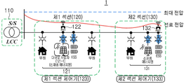
도 2는 본 발명의 일 실시 예에 따른 계통 안정화 장치를 개략적으로 설명하기 위하여 도시한 도면이다. 도 2를 참조하면, 계통 안정화 장치(1)는 변전소(S/S) 단위에 LCC(local control center, 110)를 운영하여 선로를 하나 이상의 부하, ESS 및 신재생 에너지 발전원에 따라 섹션으로 나누어 전압을 제어하는 방식이다. 본 실시 예에서 섹션이 제1 섹션(120) 및 제2 섹션(130)으로 나누어져 있으나, 이에 한정되지 않고, 제1 섹션 내지 제N 섹션으로 확장될 수 있다. 또한 각 섹션(제1 섹션(120), 제2 섹션(130))은 하나 이상의 부하, 신재생 에너지원, ESS를 포함하고, 신재생 에너지원과 같인 대규모 사업자(12-1)의 선로 정보를 취득하는 센서(122, 123), 해당 LCC(110)에 의해 해당 섹션의 동작을 제어하고, 해당 섹션의 상태를 LCC(110)로 전송하는 섹션 제어기(제1 섹션 제어기(123), 제2 섹션 제어기(133))를 더 포함할 수 있다.2 is a diagram schematically illustrating a system stabilization apparatus according to an embodiment of the present invention. 2, the
선로의 정보를 취득하는 센서(제1 PMU(phasor measurement unit) 센서(122), 제2 PMU 센서(132))의 경우, 기존의 각 부하 및 전력원(121, 131)에 전부 설치하여 초기 설비 투자 비용이 매우 높을 수 밖에 없었으나, 본 실시 예의 경우 주요 부하(대용량 고객) 및 대규모 발전 사업자(121-1)와 같이 선로 용량에 영향이 큰 요소들에만 센서(제1 PMU 센서(122), 제2 PMU 센서(132))를 설치하여 초기 비용을 줄일 수 있다. 또한, DR(demand response, 수요 반응), ESS 및 대규모 태양광 발전 사업자들과의 정보 교환을 통하여 센서(제1 PMU 센서(122), 제2 PMU 센서(132))의 설치 대수를 줄일 수 있다.In the case of a sensor that acquires information of a line (the first PMU (phasor measurement unit)
도 3은 도 1에 도시된 LCC 간 연계 개념 및 통신 개념을 개략적으로 설명하기 위하여 도시한 도면이다. 도 3을 참조하면, 제1 섹션(120) 및 제2 섹션(130)을 포함하는 제1 LCC(110)는 제1 섹션(220) 및 제2 섹션(230)을 포함하는 제2 LCC(210)와 연계할 수 있다.FIG. 3 is a diagram schematically illustrating a connection concept and a communication concept between LCCs shown in FIG. 1. Referring to FIG. 3, a
제1 LCC(110)는 제1 섹션(120) 또는 제2 섹션(130)에 설치된 ESS의 잔존용량을 지속적으로 확인하여, ESS의 잔존용량이 부족하거나 선로의 용량이 부족하다고 판단되는 경우 OLTC(on load tap changer, 변압기 부하시 탭 변환장치) 및 백 투 백 STATCOM(static synchronous compensator)(310) 중 하나 이상을 이용하여 제2 LCC(210)와 연계하여 부족한 용량을 공급 받을 수 있다. 즉, ESS의 잔존용량이 부족하거나 선로의 용량이 부족하다고 판단되는 LCC가 그렇지 않은 LCC로부터 부족한 용량을 공급 받을 수 있다.The first LCC 110 continuously checks the remaining capacity of the ESS installed in the first section 120 or the second section 130, and if it is determined that the remaining capacity of the ESS is insufficient or the capacity of the line is insufficient, the OLTC ( The insufficient capacity may be supplied in connection with the
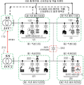
도 4는 도 1에 도시된 전압 안정화 장치의 상세 구성을 개략적으로 설명하기 위하여 도시한 도면이다. 도 4를 참조하면 전압 안정화 장치는 LCC(110), 섹션 제어기(123, 또는 133, 이하, 123이라 표기함) 및 대규모 사업자(121-1)을 포함할 수 있다. 본 실시 예에서, LCC(110)는 섹션 제어부(111), ESS 제어부(112), 대규모 사업자 제어부(113), 타 LCC 연계부(114) 및 데이터 처리부(115)를 포함할 수 있고, 섹션 제어기(123)는 ESS 제어기(123-1), 대규모 사업자 제어기(123-2) 및 데이터 처리기(123-3)를 포함할 수 있다. FIG. 4 is a diagram schematically illustrating a detailed configuration of the voltage stabilizing device shown in FIG. 1. Referring to FIG. 4, the voltage stabilization device may include an
섹션 제어부(111)는 섹션(제1 섹션(120), 제2 섹션(130)) 별로 선로 용량 및 ESS의 SOC(state of charge)를 파악할 수 있고, 선로 전압 제어를 통한 섹션(제1 섹션(120), 제2 섹션(130)) 간 조류를 제어할 수 있다.The
ESS 제어부(112)는 섹션 제어기(123)에서 제어하는 ESS의 충/방전 용량을 제어하고, ESS에 설치되어 있는 PCS(power conditioning system)를 활용한 선로의 역률을 제어할 수 있다.The ESS control unit 112 may control the charging/discharging capacity of the ESS controlled by the
대규모 사업자 제어부(113)는 대규모 사업자(121-1)의 계통을 연계 제어할 수 있고, 대규모 사업자(121-1)에 설치되어 있는 PCS(power conditioning system)를 활용한 선로의 역률을 제어할 수 있다. 본 실시 예에서 대규모 사업자는 신재생 에너지원 사업자와 유사한 의미로 해석되거나 신재생 에너지원 사업자를 포함하는 것으로 해석될 수 있다.The large-scale operator control unit 113 can link and control the system of the large-scale operator 121-1, and control the power factor of the line using a power conditioning system (PCS) installed in the large-scale operator 121-1. have. In this embodiment, a large-scale business operator may be interpreted as having a similar meaning to a renewable energy source business operator or may be interpreted as including a renewable energy source business entity.
타 LCC 연계부(114)는 제어하는 LCC에 설치되어 있는 ESS의 SOC, 신재생 에너지 발전량, 부하 변동량, 선로 용량을 고려하여 타 LCC(예를 들어, 도 3의 제2 LCC(210))와 연계를 수행하며, OLTC, STATCOM 등의 전력 설비를 이용하여 타 LCC 와 연계할 수 있다.The other
데이터 처리부(115)는 제1 섹션 제어기(123)로부터 수신한 데이터를 저장하고, 제1 섹션 제어기(123)로부터 수신한 데이터를 이용하여 발전, 부하 변동량을 예측할 수 있다.The data processing unit 115 may store data received from the
섹션 제어기(123)에 포함되는 ESS 제어기(123-1)는 제어하는 섹션에 대한 부하, 발전량 등 선로 용량과 관계되어 있는 데이터를 취득하여 LCC(110)로 전송할 수 있다. ESS 제어기(123-1)는 ESS의 용량을 파악하고 LCC(110)의 지령에 따라 ESS의 충/방전을 제어할 수 있다. ESS 제어기(123-1)는 LCC(110)의 지령에 따라 ESS에 설치되어 있는 PCS를 활용한 선로의 역률을 제어할 수 있다.The ESS controller 123-1 included in the
섹션 제어기(123)에 포함되는 대규모 사업자 제어기(123-2)는 신재생 에너지의 발전량을 예측하고, 섹션 제어기(123)의 지령에 따라 대규모 사업자(121-1)에 설치되어 있는 PCS를 활용하여 역률을 제어할 수 있다.The large-scale operator controller 123-2 included in the
섹션 제어기(123)에 포함되는 데이터 처리기(123-3)는 기상 데이터를 활용하여 신재생 에너지 즉, 대규모 사업자(121-1)의 발전량을 예측하고, 빅 데이터를 이용하여 부하 변동률을 예측할 수 있다.The data processor 123-3 included in the
대규모 사업자(121-1)는 섹션 제어기(123)의 지령에 의해 신재생 에너지 발전량을 제어하고, PCS를 이용하여 역률을 제어할 수 있다.The large-scale operator 121-1 may control the amount of renewable energy generated by the command of the
계통에 영향을 미치는 주요 인자와 제어하는 방법을 다음 표 1과 같이 나타낼 수 있다.The main factors affecting the system and the control method can be shown in Table 1 below.
도 5는 도 1에 도시된 전압 안정화 장치의 일 실시 예에 따른 제어 제어 방법을 개략적으로 설명하기 위하여 도시한 도면이다. 도 5a를 참조하면, LCC(110)에서 운영 중인 ESS의 용량이 충분한 경우, 신재생 에너지원에서 발전된 전력의 유입으로 인한 선로의 전압이 상승하며, 각 섹션 제어기(제1 섹션 제어기(123), 제2 섹션 제어기(133))에 달려있는 센서(제1 PMU(phasor measurement unit) 센서(122), 제2 PMU 센서(132))를 통하여 선로 전압 상승을 계측하고, ESS 충전 명령을 전달한다. 도 5b를 참조하면, ESS 충전 명령을 수신한 각 섹션 제어기(제1 섹션 제어기(123), 제2 섹션 제어기(133))는 각 섹션(제1 섹션(120), 제2 섹션(130))에 설치되어 있는 ESS의 충전을 시작하여 선로 전압을 조절한다.5 is a diagram schematically illustrating a control control method according to an embodiment of the voltage stabilizing apparatus shown in FIG. 1. 5A, when the capacity of the ESS operated by the
도 6은 도 3에 도시된 전압 안정화 장치의 일 실시 예에 따른 제어 제어 방법을 개략적으로 설명하기 위하여 도시한 도면이다. 도 6a를 참조하면, 제1 LCC(110)에서 운영 중인 ESS에 용량이 부족한 경우 계통으로 유입되는 신재생 에너지를 충분히 저장하지 못하여 제2 LCC(210)에서 관리하는 선로의 선로 전압이 상승하게 된다. 이러한 경우 도 6b에 도시되 바와 같이 주변에 선로 용량이 여유가 있는 제2 LCC(210)가 제1 LCC(110)에 OLTC 및 백 투 백 STATCOM(310) 등을 이용하여 전력을 전송하고, 전력을 유입 받은 제1 LCC(110)에서는 선로 전압을 유지하기 위하여 충전 용량에 여유가 있는 ESS에 전력을 충전한다.FIG. 6 is a diagram schematically illustrating a control control method according to an embodiment of the voltage stabilizing apparatus illustrated in FIG. 3. Referring to FIG. 6A, when the ESS operated by the
이상 설명된 본 발명에 따른 실시 예는 컴퓨터 상에서 다양한 구성요소를 통하여 실행될 수 있는 컴퓨터 프로그램의 형태로 구현될 수 있으며, 이와 같은 컴퓨터 프로그램은 컴퓨터로 판독 가능한 매체에 기록될 수 있다. 이때, 매체는 하드 디스크, 플로피 디스크 및 자기 테이프와 같은 자기 매체, CD-ROM 및 DVD와 같은 광기록 매체, 플롭티컬 디스크(floptical disk)와 같은 자기-광 매체(magneto-optical medium), 및 ROM, RAM, 플래시 메모리 등과 같은, 프로그램 명령어를 저장하고 실행하도록 특별히 구성된 하드웨어 장치를 포함할 수 있다.The embodiment according to the present invention described above may be implemented in the form of a computer program that can be executed through various components on a computer, and such a computer program may be recorded in a computer-readable medium. In this case, the medium is a magnetic medium such as a hard disk, a floppy disk, and a magnetic tape, an optical recording medium such as a CD-ROM and a DVD, a magneto-optical medium such as a floptical disk, and a ROM. A hardware device specially configured to store and execute program instructions, such as, RAM, flash memory, and the like.
한편, 상기 컴퓨터 프로그램은 본 발명을 위하여 특별히 설계되고 구성된 것이거나 컴퓨터 소프트웨어 분야의 당업자에게 공지되어 사용 가능한 것일 수 있다. 컴퓨터 프로그램의 예에는, 컴파일러에 의하여 만들어지는 것과 같은 기계어 코드뿐만 아니라 인터프리터 등을 사용하여 컴퓨터에 의해서 실행될 수 있는 고급 언어 코드도 포함될 수 있다.Meanwhile, the computer program may be specially designed and configured for the present invention, or may be known and usable to those skilled in the computer software field. Examples of the computer program may include not only machine language codes produced by a compiler but also high-level language codes that can be executed by a computer using an interpreter or the like.
본 발명의 명세서(특히 특허청구범위에서)에서 "상기"의 용어 및 이와 유사한 지시 용어의 사용은 단수 및 복수 모두에 해당하는 것일 수 있다. 또한, 본 발명에서 범위(range)를 기재한 경우 상기 범위에 속하는 개별적인 값을 적용한 발명을 포함하는 것으로서(이에 반하는 기재가 없다면), 발명의 상세한 설명에 상기 범위를 구성하는 각 개별적인 값을 기재한 것과 같다. In the specification of the present invention (especially in the claims), the use of the term "above" and a similar reference term may correspond to both the singular and the plural. In addition, when a range is described in the present invention, the invention to which an individual value falling within the range is applied (unless otherwise stated), and each individual value constituting the range is described in the detailed description of the invention. Same as
본 발명에 따른 방법을 구성하는 단계들에 대하여 명백하게 순서를 기재하거나 반하는 기재가 없다면, 상기 단계들은 적당한 순서로 행해질 수 있다. 반드시 상기 단계들의 기재 순서에 따라 본 발명이 한정되는 것은 아니다. 본 발명에서 모든 예들 또는 예시적인 용어(예들 들어, 등등)의 사용은 단순히 본 발명을 상세히 설명하기 위한 것으로서 특허청구범위에 의해 한정되지 않는 이상 상기 예들 또는 예시적인 용어로 인해 본 발명의 범위가 한정되는 것은 아니다. 또한, 당업자는 다양한 수정, 조합 및 변경이 부가된 특허청구범위 또는 그 균등물의 범주 내에서 설계 조건 및 팩터에 따라 구성될 수 있음을 알 수 있다.If there is no explicit order or contradictory description of the steps constituting the method according to the present invention, the steps may be performed in an appropriate order. The present invention is not necessarily limited according to the order of description of the steps. The use of all examples or illustrative terms (for example, etc.) in the present invention is merely for describing the present invention in detail, and the scope of the present invention is limited by the above examples or illustrative terms unless limited by the claims. It does not become. In addition, those skilled in the art can recognize that various modifications, combinations, and changes may be configured according to design conditions and factors within the scope of the appended claims or their equivalents.
따라서, 본 발명의 사상은 상기 설명된 실시 예에 국한되어 정해져서는 아니 되며, 후술하는 특허청구범위뿐만 아니라 이 특허청구범위와 균등한 또는 이로부터 등가적으로 변경된 모든 범위는 본 발명의 사상의 범주에 속한다고 할 것이다.Therefore, the spirit of the present invention is limited to the above-described embodiments and should not be determined, and all ranges equivalent to or equivalently changed from the claims to be described later as well as the claims to be described later are the scope of the spirit of the present invention. It will be said to belong to.
1: 계통 안정화 장치
110, 210: LCC
120, 220: 제1 섹션
130, 230: 제2 섹션
122, 132: PMU
123, 223: 제1 섹션 제어기
133, 233: 제2 섹션 제어기1: system stabilization device
110, 210: LCC
120, 220: first section
130, 230: second section
122, 132: PMU
123, 223: first section controller
133, 233: second section controller
Claims (6)
변전소 단위로 운영하여, 상기 섹션 각각의 전압을 제어하는 LCC(local control center);를 포함하며,
상기 LCC는,
상기 섹션 별 선로 용량 및 상기 ESS의 SOC(state of charge)를 파악하고, 상기 선로의 전압 제어를 통한 상기 섹션간 조류를 제어하는 섹션 제어부;
상기 섹션에 포함된 섹션 제어기에서 제어하는 상기 ESS의 충전 및 방전 용량을 제어하고, 상기 ESS에 설치되어 있는 PCS(power conditioning system)를 활용한 상기 선로의 역률을 제어하는 ESS 제어부; 및
상기 신재생 에너지 발전원의 계통 연계를 제어하고, 상기 신재생 에너지 사업자에 설치된 PCS를 활용한 상기 선로의 역률을 제어하는 신재생 에너지 사업자 제어부;를 포함하는, 계통 안정화 장치.A section divided into one or more lines according to a load, an ESS (energy storage system), and a renewable energy generation source included in a large-scale operator; And
Including; LCC (local control center) operating in a substation unit to control the voltage of each of the sections,
The LCC,
A section control unit that determines the line capacity of each section and the state of charge (SOC) of the ESS, and controls the current between the sections through voltage control of the line;
An ESS control unit controlling the charging and discharging capacity of the ESS controlled by a section controller included in the section, and controlling a power factor of the line using a power conditioning system (PCS) installed in the ESS; And
Containing, a system stabilization device comprising; a renewable energy business control unit for controlling the system linkage of the renewable energy generation source and controlling the power factor of the line using the PCS installed in the renewable energy business.
상기 LCC에 설치되어 있는 상기 ESS의 SOC, 상기 신재생 에너지원의 발전량, 상기 부하의 변동량 및 상기 선로의 용량 중 하나 이상을 고려하여 타 LCC와의 연계를 수행하는 타 LCC 연계부;를 더 포함하는, 계통 안정화 장치.The method of claim 1, wherein the LCC,
Another LCC linking unit that performs linkage with another LCC in consideration of at least one of the SOC of the ESS installed in the LCC, the amount of generation of the renewable energy source, the amount of change in the load, and the capacity of the line; further comprising , System stabilization device.
상기 LCC와 상기 타 LCC는 OLTC(on load tap changer) 및 백 투 백 STATCOM(static synchronous compensator) 중 하나 이상을 이용하여 서로 연계하며, 상기 ESS의 잔존용량이 부족하거나 상기 선로의 용량이 부족하다고 판단되는 LCC가 그렇지 않은 LCC로부터 부족한 용량을 공급 받는, 계통 안정화 장치.The method of claim 2,
The LCC and the other LCC are linked to each other using one or more of an on load tap changer (OLTC) and a static synchronous compensator (STATCOM), and determine that the remaining capacity of the ESS is insufficient or the capacity of the line is insufficient. System stabilization device in which the LCC that is being supplied receives insufficient capacity from the LCC that does not.
상기 섹션 중 상기 선로 용량에 영향이 큰 요소로서의 상기 신재생 에너지 발전원에만 구비되어 상기 선로의 정보를 취득하는 센서;를 더 포함하는, 계통 안정화 장치.The method of claim 1,
The system stabilization apparatus further comprises a sensor provided only in the renewable energy generation source as an element having a large influence on the line capacity of the section to obtain information on the line.
상기 LCC에 의해 상기 섹션의 동작을 제어하고, 상기 섹션의 상태를 LCC로 전송하는 섹션 제어기;를 더 포함하는, 계통 안정화 장치.The method of claim 1, wherein the section,
Controlling the operation of the section by the LCC, and a section controller for transmitting the state of the section to the LCC; further comprising, system stabilization device.
상기 섹션의 선로 용량과 관계되어 있는 데이터를 취득하여 상기 LCC로 전송하고, 상기 ESS의 용량을 파악하고 상기 LCC의 지령에 따라 상기 ESS의 충전 및 방전을 제어하며, 상기 LCC의 지령에 따라 상기 ESS에 설치되어 있는 PCS를 활용하여 상기 선로의 역률을 제어하는 ESS 제어기;
상기 신재생 에너지의 발전량을 예측하고, 상기 섹션 제어기의 지령에 따라 상기 대규모 사업자에 설치되어 있는 PCS를 활용하여 역률을 제어하는 대규모 사업자 제어기; 및
기상 데이터를 이용하여 상기 대규모 사업자의 발전량을 예측하고, 빅 데이터를 이용하여 부하 변동률을 예측하는 데이터 처리기;를 포함하는 계통 안정화 장치.The method of claim 5, wherein the section controller,
Acquires data related to the line capacity of the section and transmits it to the LCC, determines the capacity of the ESS, controls charging and discharging of the ESS according to the command of the LCC, and controls the ESS according to the command of the LCC. ESS controller for controlling the power factor of the line by using the PCS installed in the;
A large-scale operator controller that predicts the generation amount of the new and renewable energy and controls a power factor by using a PCS installed in the large-scale operator according to a command of the section controller; And
System stabilization apparatus comprising a; data processor for predicting the amount of power generation of the large-scale operator using meteorological data and predicting a load fluctuation rate using big data.
Priority Applications (1)
| Application Number | Priority Date | Filing Date | Title |
|---|---|---|---|
| KR1020190022114A KR102624817B1 (en) | 2019-02-25 | 2019-02-25 | Apparatus for stabilizating of pwer system |
Applications Claiming Priority (1)
| Application Number | Priority Date | Filing Date | Title |
|---|---|---|---|
| KR1020190022114A KR102624817B1 (en) | 2019-02-25 | 2019-02-25 | Apparatus for stabilizating of pwer system |
Publications (2)
| Publication Number | Publication Date |
|---|---|
| KR20200103505A true KR20200103505A (en) | 2020-09-02 |
| KR102624817B1 KR102624817B1 (en) | 2024-01-15 |
Family
ID=72469345
Family Applications (1)
| Application Number | Title | Priority Date | Filing Date |
|---|---|---|---|
| KR1020190022114A Active KR102624817B1 (en) | 2019-02-25 | 2019-02-25 | Apparatus for stabilizating of pwer system |
Country Status (1)
| Country | Link |
|---|---|
| KR (1) | KR102624817B1 (en) |
Cited By (1)
| Publication number | Priority date | Publication date | Assignee | Title |
|---|---|---|---|---|
| JP2024116111A (en) * | 2023-02-15 | 2024-08-27 | イーエヌ テクノロジーズ インク. | Energy management system and method of operation thereof |
Citations (5)
| Publication number | Priority date | Publication date | Assignee | Title |
|---|---|---|---|---|
| KR20150004477A (en) * | 2013-07-02 | 2015-01-13 | 현대중공업 주식회사 | Power supply control system and method |
| KR20160036883A (en) * | 2014-09-26 | 2016-04-05 | 한국전력공사 | Device for voltage stabilization of power distribution systems |
| KR20160071954A (en) * | 2014-12-12 | 2016-06-22 | 서봉주 | System and method for charging and discharging using idle power |
| KR20180124182A (en) | 2017-05-10 | 2018-11-21 | (재)한국건설생활환경시험연구원 | Multi-inverter PV monitoring system |
| KR20180134826A (en) * | 2018-12-12 | 2018-12-19 | 엘에스산전 주식회사 | Hierarchical type power control system |
-
2019
- 2019-02-25 KR KR1020190022114A patent/KR102624817B1/en active Active
Patent Citations (5)
| Publication number | Priority date | Publication date | Assignee | Title |
|---|---|---|---|---|
| KR20150004477A (en) * | 2013-07-02 | 2015-01-13 | 현대중공업 주식회사 | Power supply control system and method |
| KR20160036883A (en) * | 2014-09-26 | 2016-04-05 | 한국전력공사 | Device for voltage stabilization of power distribution systems |
| KR20160071954A (en) * | 2014-12-12 | 2016-06-22 | 서봉주 | System and method for charging and discharging using idle power |
| KR20180124182A (en) | 2017-05-10 | 2018-11-21 | (재)한국건설생활환경시험연구원 | Multi-inverter PV monitoring system |
| KR20180134826A (en) * | 2018-12-12 | 2018-12-19 | 엘에스산전 주식회사 | Hierarchical type power control system |
Cited By (1)
| Publication number | Priority date | Publication date | Assignee | Title |
|---|---|---|---|---|
| JP2024116111A (en) * | 2023-02-15 | 2024-08-27 | イーエヌ テクノロジーズ インク. | Energy management system and method of operation thereof |
Also Published As
| Publication number | Publication date |
|---|---|
| KR102624817B1 (en) | 2024-01-15 |
Similar Documents
| Publication | Publication Date | Title |
|---|---|---|
| Juamperez et al. | Voltage regulation in LV grids by coordinated volt-var control strategies | |
| US10680438B2 (en) | Optimizing voltage and VAR on the electric grid using distributed VAR sources | |
| CN103975496B (en) | Devices for decentralized coordinated voltage and reactive power control (CVVC) | |
| Chen et al. | Ancillary service for transmission systems by tap stagger operation in distribution networks | |
| Sami et al. | A virtual energy storage system for voltage control of distribution networks | |
| KR102234711B1 (en) | Control method to autonomously control voltage of distributed energy resources | |
| US20210143644A1 (en) | Method and apparatus for minimizing circulating currents in microgrids | |
| KR20180032480A (en) | Power compensation apparatus and method of controlling the same | |
| US20250079839A1 (en) | Resilient on-site microgrid system | |
| US9871377B2 (en) | Device and method for cooperation control of EMS and DMS | |
| KR20200103505A (en) | Apparatus for stabilizating of pwer system | |
| Oh et al. | Operation method for hybrid UPS with energy storage system function | |
| Zheng et al. | Frequency domain‐based configuration and power follow‐up control for power sources in a grid‐connected microgrid | |
| WO2014167830A1 (en) | Power control system | |
| Rambabu et al. | Improvement of voltage profile and reduce power system losses by using multi type facts devices | |
| CN114080742B (en) | Device and method for improving power generation efficiency of distributed power generation equipment | |
| KR20240085981A (en) | Reactive power adjustment system and method in connection with retention voltage reduction | |
| KR102369643B1 (en) | Reactive power compensation device and operation test control method thereof | |
| Zehir et al. | Identification and comparison of power and energy management capabilities of distributed energy resources | |
| Laamim et al. | Enhancing microgrid voltage stability through an advanced volt-VAR control strategy using hardware-in-the-loop simulations | |
| Kimiai Asadi et al. | A new controlled superconducting magnetic energy storage for dynamic stabilization of distributed generation in islanding mode of operation | |
| Condon et al. | Application of low voltage statcom to correct voltage issues caused by inverter energy systems | |
| Kueck et al. | Tapping Distributed Energy Resources | |
| Ibrahimi et al. | Impact of distributed capacitors on voltage profile and power losses in real low voltage distribution networks | |
| Kelm et al. | Effectiveness of Energy Storage Application for improving the quality of supply in Low Voltage Networks with Distributed Generation |
Legal Events
| Date | Code | Title | Description |
|---|---|---|---|
| PA0109 | Patent application |
Patent event code: PA01091R01D Comment text: Patent Application Patent event date: 20190225 |
|
| PG1501 | Laying open of application | ||
| A201 | Request for examination | ||
| PA0201 | Request for examination |
Patent event code: PA02012R01D Patent event date: 20220124 Comment text: Request for Examination of Application Patent event code: PA02011R01I Patent event date: 20190225 Comment text: Patent Application |
|
| E902 | Notification of reason for refusal | ||
| PE0902 | Notice of grounds for rejection |
Comment text: Notification of reason for refusal Patent event date: 20230905 Patent event code: PE09021S01D |
|
| E701 | Decision to grant or registration of patent right | ||
| PE0701 | Decision of registration |
Patent event code: PE07011S01D Comment text: Decision to Grant Registration Patent event date: 20240109 |
|
| GRNT | Written decision to grant | ||
| PR0701 | Registration of establishment |
Comment text: Registration of Establishment Patent event date: 20240110 Patent event code: PR07011E01D |
|
| PR1002 | Payment of registration fee |
Payment date: 20240111 End annual number: 3 Start annual number: 1 |
|
| PG1601 | Publication of registration |