KR20200063538A - Method for self-diagnosing localization status and autonomous mobile robot carrying out the same - Google Patents
Method for self-diagnosing localization status and autonomous mobile robot carrying out the same Download PDFInfo
- Publication number
- KR20200063538A KR20200063538A KR1020180149336A KR20180149336A KR20200063538A KR 20200063538 A KR20200063538 A KR 20200063538A KR 1020180149336 A KR1020180149336 A KR 1020180149336A KR 20180149336 A KR20180149336 A KR 20180149336A KR 20200063538 A KR20200063538 A KR 20200063538A
- Authority
- KR
- South Korea
- Prior art keywords
- direction angle
- distance
- error
- time
- current position
- Prior art date
- Legal status (The legal status is an assumption and is not a legal conclusion. Google has not performed a legal analysis and makes no representation as to the accuracy of the status listed.)
- Granted
Links
- 238000000034 method Methods 0.000 title claims abstract description 39
- 230000004807 localization Effects 0.000 title description 6
- 238000005259 measurement Methods 0.000 claims abstract description 64
- 238000010801 machine learning Methods 0.000 claims abstract description 33
- 238000004422 calculation algorithm Methods 0.000 claims abstract description 31
- 238000002405 diagnostic procedure Methods 0.000 claims description 7
- 238000004092 self-diagnosis Methods 0.000 claims description 6
- 238000007635 classification algorithm Methods 0.000 claims description 5
- 230000008569 process Effects 0.000 description 14
- 230000007613 environmental effect Effects 0.000 description 5
- 238000007477 logistic regression Methods 0.000 description 4
- 238000004364 calculation method Methods 0.000 description 3
- 230000007423 decrease Effects 0.000 description 3
- 238000013461 design Methods 0.000 description 3
- 238000005516 engineering process Methods 0.000 description 3
- 238000001514 detection method Methods 0.000 description 2
- 230000006870 function Effects 0.000 description 2
- 239000003550 marker Substances 0.000 description 2
- 230000003068 static effect Effects 0.000 description 2
- PEDCQBHIVMGVHV-UHFFFAOYSA-N Glycerine Chemical compound OCC(O)CO PEDCQBHIVMGVHV-UHFFFAOYSA-N 0.000 description 1
- 230000002159 abnormal effect Effects 0.000 description 1
- 238000013459 approach Methods 0.000 description 1
- 230000006399 behavior Effects 0.000 description 1
- 230000008859 change Effects 0.000 description 1
- 230000001419 dependent effect Effects 0.000 description 1
- 238000003745 diagnosis Methods 0.000 description 1
- 238000006073 displacement reaction Methods 0.000 description 1
- 238000000605 extraction Methods 0.000 description 1
- 238000012986 modification Methods 0.000 description 1
- 230000004048 modification Effects 0.000 description 1
- 238000011084 recovery Methods 0.000 description 1
- 235000002020 sage Nutrition 0.000 description 1
- 238000012706 support-vector machine Methods 0.000 description 1
- 238000012549 training Methods 0.000 description 1
Images


Classifications
-
- B—PERFORMING OPERATIONS; TRANSPORTING
- B25—HAND TOOLS; PORTABLE POWER-DRIVEN TOOLS; MANIPULATORS
- B25J—MANIPULATORS; CHAMBERS PROVIDED WITH MANIPULATION DEVICES
- B25J13/00—Controls for manipulators
- B25J13/08—Controls for manipulators by means of sensing devices, e.g. viewing or touching devices
-
- B—PERFORMING OPERATIONS; TRANSPORTING
- B25—HAND TOOLS; PORTABLE POWER-DRIVEN TOOLS; MANIPULATORS
- B25J—MANIPULATORS; CHAMBERS PROVIDED WITH MANIPULATION DEVICES
- B25J19/00—Accessories fitted to manipulators, e.g. for monitoring, for viewing; Safety devices combined with or specially adapted for use in connection with manipulators
- B25J19/02—Sensing devices
-
- B—PERFORMING OPERATIONS; TRANSPORTING
- B25—HAND TOOLS; PORTABLE POWER-DRIVEN TOOLS; MANIPULATORS
- B25J—MANIPULATORS; CHAMBERS PROVIDED WITH MANIPULATION DEVICES
- B25J9/00—Programme-controlled manipulators
- B25J9/16—Programme controls
- B25J9/1656—Programme controls characterised by programming, planning systems for manipulators
- B25J9/1664—Programme controls characterised by programming, planning systems for manipulators characterised by motion, path, trajectory planning
-
- B—PERFORMING OPERATIONS; TRANSPORTING
- B60—VEHICLES IN GENERAL
- B60W—CONJOINT CONTROL OF VEHICLE SUB-UNITS OF DIFFERENT TYPE OR DIFFERENT FUNCTION; CONTROL SYSTEMS SPECIALLY ADAPTED FOR HYBRID VEHICLES; ROAD VEHICLE DRIVE CONTROL SYSTEMS FOR PURPOSES NOT RELATED TO THE CONTROL OF A PARTICULAR SUB-UNIT
- B60W20/00—Control systems specially adapted for hybrid vehicles
- B60W20/10—Controlling the power contribution of each of the prime movers to meet required power demand
- B60W20/12—Controlling the power contribution of each of the prime movers to meet required power demand using control strategies taking into account route information
-
- G—PHYSICS
- G05—CONTROLLING; REGULATING
- G05D—SYSTEMS FOR CONTROLLING OR REGULATING NON-ELECTRIC VARIABLES
- G05D1/00—Control of position, course, altitude or attitude of land, water, air or space vehicles, e.g. using automatic pilots
- G05D1/02—Control of position or course in two dimensions
- G05D1/021—Control of position or course in two dimensions specially adapted to land vehicles
Landscapes
- Engineering & Computer Science (AREA)
- Mechanical Engineering (AREA)
- Robotics (AREA)
- Human Computer Interaction (AREA)
- Automation & Control Theory (AREA)
- Aviation & Aerospace Engineering (AREA)
- Radar, Positioning & Navigation (AREA)
- Remote Sensing (AREA)
- Physics & Mathematics (AREA)
- General Physics & Mathematics (AREA)
- Transportation (AREA)
- Control Of Position, Course, Altitude, Or Attitude Of Moving Bodies (AREA)
Abstract
본 발명은 위치 추정 상태 자가 진단 방법에 관한 것으로, (a) 거리 오차 지표와, 방향각 오차 지표, 및 상기 거리 오차 지표 및 상기 방향각 오차 지표에 대한 위치 추정 성공 여부가 기 등록된 기계 학습 알고리즘의 학습 데이터로 등록되어 학습되는 단계와, (b) 자율주행로봇의 현 위치에서 복수의 거리 측정값이 측정되는 단계와, (c) 상기 자율주행로봇의 현 위치에서의 추정 방향각이 추정되는 단계와, (d) 복수의 상기 거리 측정값에 기초하여 현 위치에서의 거리 오차 지표가 산출되는 단계와, (e) 상기 추정 방향각에 기초하여 현 위치에서의 방향각 오차 지표가 산출되는 단계와, (f) 상기 (d) 단계 및 상기 (e) 단계에서 각각 산출된 상기 거리 오차 지표 및 상기 방향각 오차 지표가 상기 기계 학습 알고리즘에 입력되어 현 위치에서의 위치 추정 성공 여부가 출력되는 단계를 포함하며; 상기 (a) 단계 및 상기 (d) 단계에서 상기 거리 오차 지표는 현 위치에서 측정된 복수의 거리 측정값 중 신뢰성이 높은 상위 n %의 거리 측정값들의 오차 평균값에 기초하여 산출되고, 상기 (a) 단계 및 상기 (e) 단계에서 상기 방향각 오차 지표는 현 위치에서 추정된 추정 방향각과 현 위치에서의 허용 방향각 범위에 기초하여 산출되는 것을 특징으로 한다.The present invention relates to a method for self-diagnosing a position estimation state, (a) a distance error index, a direction angle error index, and a machine learning algorithm in which position estimation success for the distance error index and the direction angle error index is pre-registered. (B) measuring a plurality of distance measurements at the current position of the autonomous driving robot, and (c) estimating an estimated direction angle at the current position of the autonomous driving robot. Step, (d) calculating a distance error index at the current position based on the plurality of distance measurement values, and (e) calculating a direction angle error index at the current position based on the estimated direction angle. W, (f) The distance error index and the direction angle error index calculated in steps (d) and (e), respectively, are input to the machine learning algorithm to output whether the position estimation at the current position is successful. It includes; In the steps (a) and (d), the distance error index is calculated based on an error average value of the upper n% distance measurement values having high reliability among a plurality of distance measurement values measured at the current location, and the (a) ) And in the step (e), the direction angle error index is calculated based on the estimated direction angle estimated at the current position and the allowable direction angle range at the current position.
Description
본 발명은 위치 추정 상태 진단 방법 및 이를 수행하는 자율주행로봇에 관한 것으로서, 보다 상세하게는 자율주행로봇의 주행시 자신의 위치 추정 상태가 성공인지 실패인지를 자가 진단할 수 있는 위치 추정 상태 진단 방법 및 이를 수행하는 자율주행로봇에 관한 것이다.The present invention relates to a method for diagnosing a position estimation state and an autonomous driving robot performing the same, and more specifically, a method for diagnosing a position estimation state capable of self-diagnosing whether the position estimation state of the autonomous driving robot is successful or failed when driving. It relates to an autonomous driving robot that performs this.
신뢰성 있는 위치 추정기술은 자율주행로봇의 자율주행을 위해 필수적이다. 자율주행로봇은 출발 위치로부터 목표 위치까지 위치 추정 결과를 바탕으로 주행한다. 따라서, 성공적인 경로생성과 운동제어를 위해 신뢰성 있는 위치 추정 결과가 제공되어야 한다.Reliable position estimation technology is essential for autonomous driving robots. The autonomous driving robot travels from the starting position to the target position based on the position estimation result. Therefore, reliable location estimation results must be provided for successful path creation and motion control.
지금까지 많은 연구는 위치 추정 성능을 주로 위치 추정 오차에 근거하여 평가해왔다. 하지만 위치 추정 오차가 어느 정도 수준 이하로 유지만 된다면, 많은 경우에 위치 추정 오차는 자율주행의 성능에 큰 영향을 미치지 않는다. 예를 들어, 자율주행로봇의 상대 좌표계에서 근접 장애물 또는 위험 지형을 정확히 감지할 수 있다면, 위치 추정 오차가 다소 부정확할지라도 적절한 운동제어가 가능하다.So far, many studies have evaluated location estimation performance mainly based on location estimation error. However, if the position estimation error is maintained to a certain level or less, in many cases, the position estimation error does not significantly affect the performance of autonomous driving. For example, if the relative coordinate system of the autonomous driving robot can accurately detect an obstacle or a dangerous terrain, proper motion control is possible even if the position estimation error is somewhat inaccurate.
실제 활용에 있어서는, 현재 추정된 자율주행로봇의 포즈, 즉 위치와 방향각이 믿을 만한지 아닌지를 판단하는 것이 더욱 중요하다. 다시 말해서, 위치 추정 상태를 판단하는 것이 중요하다. 만약, 추정된 포즈가 믿을 만하지 않다면, 추정된 포즈는 자율주행로봇의 주행 행동 결정에 활용되지 않아야 한다. 그렇지 않으면, 자율주행로봇은 임무에 실패하거나, 비정상적인 행동을 할지도 모른다.In actual use, it is more important to judge whether the currently estimated pose of the autonomous driving robot, that is, whether the position and the direction angle is reliable or not. In other words, it is important to judge the position estimation status. If the estimated pose is not reliable, the estimated pose should not be used to determine the driving behavior of the autonomous driving robot. Otherwise, the self-driving robot may fail the mission or behave abnormally.
한편, 라이다 센서와 같은 거리 센서를 이용한 위치 추정 기술은 많은 환경에서 강인하고 신뢰성 있는 위치 추정 결과를 보여왔다. 그럼에도 불구하고, 위치 센서 기반의 위치 추정기술을 이용할 때 위치 추정 실패가 때때로 발생한다. 위치 추정 실패는 다양한 원인에 의해 발생하는데, 극심한 환경 변화, 불충분한 자연표식, 바퀴의 미끄러짐은 위치 추정 실패의 주요 원인들이다.On the other hand, position estimation technology using a distance sensor such as a lidar sensor has shown robust and reliable position estimation results in many environments. Nevertheless, location estimation failures sometimes occur when using location sensor based location estimation techniques. Positioning failures are caused by a variety of causes, such as extreme environmental changes, insufficient natural markings, and slippage of the wheels.
모든 상황과 환경에서 강인하게 동작하는 위치 추정 기술을 개발하기는 어렵다. 따라서 자율주행로봇 스스로 현재 위치 추정 상태를 진단할 수 있는 기술의 개발이 요구되고 있는 실정이다.It is difficult to develop a location estimation technique that works robustly in all situations and environments. Therefore, there is a need to develop a technology capable of diagnosing the current position estimation state of the autonomous driving robot itself.
위치 추정 상태의 진단과 관련된 다양한 연구들이 있었다. Moon 등의 논문 "Observation likelihood model design and failure recovery scheme toward reliable localization of mobile robots (Int. J. Adv. Robot. Syst., vol. 7, no. 4, pp. 113??122, 2010.)"에서는 바퀴의 미끄러짐에 의한 위치 추정 실패를 감지하기 위해 매칭 오차를 이용하였다. 슬라이딩 윈도우 기법을 이용하여 현재 매칭 오차가 과거 매칭 오차의 분포로부터 일정 범위를 초과하면, 위치 추정 상태는 실패로 분류된다. 이와 같은 방법은 바퀴가 미끄러졌을 때 매칭 오차가 순간적으로 크게 증가하는 특성을 고려한 것이다.There have been various studies related to the diagnosis of the position estimation status. Moon et al. "Observation likelihood model design and failure recovery scheme toward reliable localization of mobile robots (Int. J. Adv. Robot. Syst., vol. 7, no. 4, pp. 113??122, 2010.)" Estimation used a matching error to detect the failure to estimate the position due to wheel slip. If the current matching error exceeds a certain range from the distribution of past matching errors using the sliding window technique, the position estimation state is classified as failed. This method takes into account the property that the matching error increases momentarily when the wheel is slipped.
Lee 등의 논문 "Discrete-status-based localization for indoor service robots (IEEE Trans. Ind. Electron., vol. 53, no. 5, pp. 1737??1746, 2006.)"에서는 10% 이상의 오차를 가지는 거리 측정값을 잘못된 측정값으로 정의하고, 잘못된 거리 측정값의 비율을 바탕으로 위치 추정의 신뢰성을 정의하였다. 이러한 신뢰성이 한계치 이하인 경우 추정된 포즈를 믿을 만한 것이 아닌 것으로 간주하고, 이를 업데이트 과정에 반영하지 않는다.Lee et al., “Discrete-status-based localization for indoor service robots (IEEE Trans. Ind. Electron., vol. 53, no. 5, pp. 1737??1746, 2006.)” has an error of 10% or more. The distance measurement value was defined as an erroneous measurement value, and the reliability of the position estimation was defined based on the ratio of the erroneous distance measurement value. If the reliability is below the limit, the estimated pose is considered unreliable and is not reflected in the update process.
Zhang 등의 논문 "Self-adaptive Monte Carlo Localization for Mobile Robots Using Range Finders (Robotica, vol. 30, no. 2, pp. 229-244, 2012.)"에서는 샘플들의 최대 확률에 근거하여 위치 추정 실패를 감지한다. 샘플들의 최대 확률이 한계치 이하일 경우 로컬 샘플의 일부가 글로벌 샘플로 변환된다.In Zhang et al.'s "Self-adaptive Monte Carlo Localization for Mobile Robots Using Range Finders (Robotica, vol. 30, no. 2, pp. 229-244, 2012.)" Detect. When the maximum probability of samples is below a threshold, a part of the local sample is converted into a global sample.
Fujii 등의 논문 "Detection of localization failure using logistic regression (Proc. IEEE Int. Conf. Intell. Robots Syst., 2015.)"에서는 샘플들의 최대 확률과 표준편차를 이용한 로지스틱 회귀에 의해 위치 추정 실패를 분류하였다. 또한, 로지스틱 함수에 의해 계산된 위치 추정 실패 확률을 이용한 하이브리드 위치 추정기술을 제시하였다.In Fujii et al.'s paper "Detection of localization failure using logistic regression (Proc. IEEE Int. Conf. Intell. Robots Syst., 2015.)", location estimation failure was classified by logistic regression using the maximum probability and standard deviation of samples. . In addition, a hybrid position estimation technique using the probability of position estimation failure calculated by the logistic function is presented.
위치 추정 상태는 지도를 업데이트하기 위한 목적으로도 진단되었는데, 일 예로 Sun 등의 논문 "Towards Effective Localization in Dynamic Environments (Proc. IEEE Int. Conf. Intell. Robots Syst.,2016.)"에서는 매칭 점수(Matching score)를 이용하여 위치 추정 상태를 진단하였다. 매칭 점수가 한계치를 초과할 때 지도가 업데이트된다.The location estimation status was also diagnosed for the purpose of updating the map. For example, in Sun et al.'s paper "Towards Effective Localization in Dynamic Environments (Proc. IEEE Int. Conf. Intell. Robots Syst., 2016.)" Matching score) was used to diagnose location estimation. The map is updated when the matching score exceeds the limit.
상기와 같이, 기존의 연구들은 각자의 지표를 이용해서 목표 위치 추정 상태를 성공적으로 진단했다. 하지만, 기존의 지표들은 위치 추정 알고리즘에 크게 의존적일 수 있다. 예를 들어, Moon 등의 논문에서 정의된 매칭 오차와, Sun 등의 논문에서 정의된 매칭 점수는 각 위치 추정 알고리즘의 결과로서 얻을 수 있는 지표이다. 뿐만 아니라, 샘플의 최대 확률 또는 공분산의 크기는 센서 모델의 설계 전략 또는 환경조건에 따라 위치 추정 결과와 적은 관련성이 있을 수 있다.As described above, the existing studies have successfully diagnosed the target position estimation state using respective indicators. However, existing indicators can be highly dependent on the location estimation algorithm. For example, the matching error defined in a paper such as Moon and the matching score defined in a paper such as Sun are indicators that can be obtained as a result of each position estimation algorithm. In addition, the maximum probability or the size of the covariance of the sample may be less related to the position estimation result depending on the design strategy or environmental conditions of the sensor model.
따라서, 센서 모델의 설계 전략이나 환경 조건, 그리고 위치 추정 알고리즘의 종류와 무관하게 자율주행로봇이 자신의 위치 추정 상태가 성공인지 실패인지 여부를 자가 진단할 수 있다면, 보다 정확한 주행을 보장할 수 있어 바람직할 것이다.Therefore, if the autonomous driving robot can self-diagnose whether its position estimation status is success or failure, regardless of the design strategy of the sensor model, environmental conditions, and the type of location estimation algorithm, it can guarantee a more accurate driving. Would be desirable.
이에 본 발명은 상기와 같은 문제점을 해소하기 위해 안출된 것으로써, 자율주행로봇의 주행시 자신의 위치 추정 상태가 성공인지 실패인지를 자가 진단할 수 있는 위치 추정 상태 진단 방법 및 이를 수행하는 자율주행로봇을 제공하는데 그 목적이 있다.Accordingly, the present invention was devised to solve the above problems, a method for diagnosing a position estimation state capable of self-diagnosing whether a position estimation state of a self-driving robot is a success or failure and an autonomous driving robot performing the same. The purpose is to provide.
상기 목적은 본 발명에 따라, 위치 추정 상태 자가 진단 방법에 있어서, (a) 거리 오차 지표와, 방향각 오차 지표, 및 상기 거리 오차 지표 및 상기 방향각 오차 지표에 대한 위치 추정 성공 여부가 기 등록된 기계 학습 알고리즘의 학습 데이터로 등록되어 학습되는 단계와, (b) 자율주행로봇의 현 위치에서 복수의 거리 측정값이 측정되는 단계와, (c) 상기 자율주행로봇의 현 위치에서의 추정 방향각이 추정되는 단계와, (d) 복수의 상기 거리 측정값에 기초하여 현 위치에서의 거리 오차 지표가 산출되는 단계와, (e) 상기 추정 방향각에 기초하여 현 위치에서의 방향각 오차 지표가 산출되는 단계와, (f) 상기 (d) 단계 및 상기 (e) 단계에서 각각 산출된 상기 거리 오차 지표 및 상기 방향각 오차 지표가 상기 기계 학습 알고리즘에 입력되어 현 위치에서의 위치 추정 성공 여부가 출력되는 단계를 포함하며; 상기 (a) 단계 및 상기 (d) 단계에서 상기 거리 오차 지표는 현 위치에서 측정된 복수의 거리 측정값 중 신뢰성이 높은 상위 n %의 거리 측정값들의 오차 평균값에 기초하여 산출되고, 상기 (a) 단계 및 상기 (e) 단계에서 상기 방향각 오차 지표는 현 위치에서 추정된 추정 방향각과 현 위치에서의 허용 방향각 범위에 기초하여 산출되는 것을 특징으로 하는 자율주행로봇의 위치 추정 상태 자가 진단 방법에 의해서 달성된다.In accordance with the present invention, in the self-diagnostic method of position estimation state, (a) the distance error indicator, the direction angle error indicator, and the success or failure of the position estimation for the distance error indicator and the direction angle error indicator are registered Registered and learned as learning data of the machine learning algorithm, (b) measuring a plurality of distance measurements at the current position of the autonomous driving robot, and (c) the estimated direction at the current position of the autonomous driving robot. The step of estimating the angle, and (d) calculating the distance error index at the current position based on the plurality of distance measurements, and (e) the direction angle error index at the current position based on the estimated direction angle. Is calculated, and (f) the distance error index and the direction angle error index calculated in steps (d) and (e), respectively, are input to the machine learning algorithm, and the position estimation at the current position is successful. It includes a step of outputting; In the steps (a) and (d), the distance error index is calculated based on the error average value of the high n% reliable distance measurement values among the plurality of distance measurement values measured at the current location, and the (a) The self-diagnosing method of the position estimation state of the autonomous driving robot, characterized in that the direction angle error index is calculated based on the estimated direction angle estimated at the current position and the allowable direction angle range at the current position in steps (e) and (e). Is achieved by.
또한, 상기 목적은 본 발명의 다른 실시 형태에 따라, 위치 추정 상태 자가 진단을 수행하는 자율주행로봇에 있어서, 거리 센서와, 상기 거리 센서에 의해 측정된 거리 측정값에 기초하여 주행을 제어하고, 기계 학습 알고리즘이 기 등록된 메인 프로세서를 포함하며; (a) 상기 메인 프로세서에 거리 오차 지표와, 방향각 오차 지표, 및 상기 거리 오차 지표 및 상기 방향각 오차 지표에 대한 위치 추정 성공 여부가 상기 기계 학습 알고리즘의 학습 데이터로 등록되어 학습되는 단계와, (b) 상기 거리 센서에 의해 현 위치에서 복수의 거리 측정값이 측정되는 단계와, (c) 상기 메인 프로세서에 의해 현 위치에서의 추정 방향각이 추정되는 단계와, (d) 상기 메인 프로세서에 의해 복수의 상기 거리 측정값에 기초하여 현 위치에서의 거리 오차 지표가 산출되는 단계와, (e) 상기 메인 프로세서에 의해 상기 추정 방향각에 기초하여 현 위치에서의 방향각 오차 지표가 산출되는 단계와, (f) 상기 메인 프로세서에 의해 상기 (d) 단계 및 상기 (e) 단계에서 각각 산출된 상기 거리 오차 지표 및 상기 방향각 오차 지표가 상기 기계 학습 알고리즘에 입력되어 현 위치에서의 위치 추정 성공 여부가 출력되는 단계가 수행되어, 위치 추정 상태가 자가 진단되며; 상기 메인 프로세서는 상기 (a) 단계 및 상기 (d) 단계에서 상기 거리 오차 지표를 현 위치에서 측정된 복수의 거리 측정값 중 신뢰성이 높은 상위 n %의 거리 측정값들의 오차 평균값에 기초하여 산출하고, 상기 (a) 단계 및 상기 (e) 단계에서 상기 방향각 오차 지표를 현 위치에서 추정된 추정 방향각과 현 위치에서의 허용 방향각 범위에 기초하여 산출하는 것을 특징으로 하는 위치 추정 상태 자가 진단을 수행하는 자율주행로봇에 의해서도 달성될 수 있다.In addition, the above object, in accordance with another embodiment of the present invention, in the self-driving robot performing a self-diagnosis position estimation state, and controls the driving based on the distance sensor and the distance measurement value measured by the distance sensor, The machine learning algorithm includes a pre-registered main processor; (a) registering and learning whether a distance error indicator, a direction angle error indicator, and a position error success for the distance error indicator and the direction angle error indicator are registered in the main processor as learning data of the machine learning algorithm; (b) measuring a plurality of distance measurements at the current position by the distance sensor, (c) estimating an estimated direction angle at the current position by the main processor, and (d) at the main processor. Calculating a distance error index at the current position based on a plurality of the distance measurement values, and (e) calculating a direction angle error index at the current position based on the estimated direction angle by the main processor. Wow, (f) the distance error index and the direction angle error index respectively calculated in the steps (d) and (e) by the main processor are input to the machine learning algorithm to successfully estimate the position at the current position. Whether or not a step of outputting is performed, the position estimation state is self-diagnosed; The main processor calculates the distance error index in steps (a) and (d) based on the error average value of the high n% reliable distance measurement values among the plurality of distance measurement values measured at the current location. In step (a) and (e), the position estimation state self-diagnosis is characterized by calculating the direction angle error index based on the estimated direction angle estimated at the current position and the allowable direction angle range at the current position. It can also be achieved by performing autonomous driving robots.
여기서, 상기 거리 오차 지표는 수학식Here, the distance error index is an equation

(여기서, ![]()
![]()

![]()
![]()
![]()
![]()
![]()
![]()
![]()
![]()
![]()
![]()
![]()
![]()
![]()
![]()
또한, 상기 방향각 오차 지표는 수학식In addition, the direction angle error index is an equation

(여기서, ![]()
![]()
![]()
![]()

(여기서, ![]()
![]()
![]()
![]()
![]()
![]()
![]()
![]()
![]()
![]()
여기서, 상기 최대 방향각은 수학식 ![]()
![]()
![]()
![]()
![]()
![]()
![]()
![]()
![]()
![]()
![]()
![]()
![]()
![]()
그리고, 상기 기계 학습 알고리즘은 지도학습이 적용된 이진 분류 알고리즘을 포함할 수 있다.In addition, the machine learning algorithm may include a binary classification algorithm to which supervised learning is applied.
상기 구성에 따라 본 발명에 따르면, 자율주행로봇의 주행시 자신의 위치 추정 상태가 성공인지 실패인지를 자가 진단할 수 있는 위치 추정 상태 진단 방법 및 이를 수행하는 자율주행로봇이 제공된다.According to the present invention according to the above configuration, there is provided a method for diagnosing a position estimation state capable of self-diagnosing whether a position estimation state of a self-driving robot is a success or failure and an autonomous driving robot performing the same.
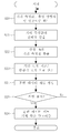
도 1은 본 발명에 따른 자율주행로봇의 구성을 설명하기 위한 도면이고,
도 2은 본 발명에 따른 자율주행로봇의 위치 추정 상태 자가 진단 방법의 흐름도이고,
도 3는 도 2의 기계 학습 과정을 설명하기 위한 흐름도이고,
도 4 내지 도 7은 본 발명에 따른 자율주행로봇의 위치 추정 상태 자가 진단 방법을 설명하기 위한 도면이다.1 is a view for explaining the configuration of an autonomous driving robot according to the present invention,
2 is a flowchart of a method for self-diagnosing a position estimation state of an autonomous driving robot according to the present invention,
3 is a flowchart for explaining the machine learning process of FIG. 2,
4 to 7 are views for explaining a method for self-diagnosing a position estimation state of an autonomous driving robot according to the present invention.
이하에서는 첨부된 도면들을 참조하여 본 발명에 따른 실시예에 대해 상세히 설명한다.Hereinafter, embodiments according to the present invention will be described in detail with reference to the accompanying drawings.
도 1은 본 발명에 따른 자율주행로봇(100)의 구성을 설명하기 위한 도면이다. 도 1을 참조하여 설명하면, 본 발명에 따른 자율주행로봇(100)은 휠 구동부(130), 휠 감지부(140), 거리 센서(120), 및 메인 프로세서(110)를 포함한다. 여기서, 전원 공급부(150)는 자율주행로봇(100)의 구동을 위한 전원을 휠 구동부(130), 휠 감지부(140), 거리 센서(120), 및 메인 프로세서(110)를 포함한 구성요소들에 공급한다.1 is a view for explaining the configuration of the
휠 구동부(130)는 자율주행로봇(100))의 주행을 위해 설치된 휠을 회전시킨다. 본 발명에 따른 자율주행로봇(100))이 2륜 차동 방식이 적용되는 경우, 각각의 휠의 회전수나 회전 여부에 의해 속도 및 회전각의 제어가 가능하게 된다.The
휠 감지부(140)는 각각의 휠의 회전수를 감지하게 도는데, 메인 프로세서(110)는 휠 감지부(140)에 의해 감지된 각 휠의 회전수를 이용하여 이동 거리 및 회전각을 산출하고, 이를 통해 자율주행로봇(100)의 오도메트리 상의 위치를 추정하게 된다.The
거리 센서(120)는 주변 환경이나 장애물 등과의 거리를 측정한다. 본 발명에서는 거리 센서(120)로 레이저 거리 센서(120)가 적용되는 것을 예로 하며, 현재 위치에서 일정 각도 범위, 예컨대, 1ㅀ단위로 회전하면서 각각의 각도에서의 거리 측정값을 측정할 수 있다.The
메인 프로세서(110)는 휠 감지부(140) 및 거리 센서(120)의 측정값들에 기초하여 자율주행로봇(100))이 경로를 따라 이동하도록 휠 구동부(130)를 제어한다. 본 발명에서는 메인 프로세서(110)에 위치 추정 상태 자가 진단에 적용되는 기계 학습 알고리즘이 등록되는데 이에 대한 상세한 설명은 후술한다.The
이하에서는 도 2를 참조하여 본 발명에 따른 자율주행로봇(100)의 메인 프로세서(110)에 의해 수행되는 위치 추정 상태 자가 진단 방법에 대해 상세히 설명한다.Hereinafter, a method for self-diagnosing a position estimation state performed by the
도 2를 참조하여 설명하면, 본 발명의 실시예에 따른 자율주행로봇(100)의 위치 추정 상태 자가 진단 방법에서는, 거리 오차 지표, 방향각 오차 지표 그리고 위치 추정 성공 여부가 메인 프로세서(110)의 기계 학습 알고리즘의 학습 데이터로 등록되어 기계 학습된다(S10).Referring to FIG. 2, in the self-diagnostic method of the position estimation state of the
여기서, 거리 오차 지표는 현 위치에서 거리 센서(120)에 의해 측정된 복수의 거리 측정값 중 신뢰성이 높은 상위 n%의 거리 측정값의 오차 평균값에 기초하여 산출되고, 방향각 오차 지표는 현 위치에서 추정된 추정 방향각과 현 위치에서의 허용 방향각 범위에 기초하여 산출된다.Here, the distance error index is calculated based on the error average value of the distance measurement value of the upper n% having high reliability among the plurality of distance measurement values measured by the
이하에서는, 본 발명에 따른 자율주행로봇(100)의 위치 추정 상태 자가 진단 방법에서 기계 학습 알고리즘를 통한 기계 학습 과정에 대해 상세히 설명한다.Hereinafter, the machine learning process through the machine learning algorithm in the self-diagnostic method of the position estimation state of the
먼저, 자율주행로봇(100)의 주행 환경, 예를 들어 도 4에 도시된 주차장에서 자율주행로봇(100)이 주행하는 과정에서 각 시간에서의 거리 측정값, 추정 방향각 및 위치 추정 성공 여부가 획득된다(S20). 도 4은 자율주행로봇(100)의 주행 환경으로 주차장의 실제 예를 나타낸 도면으로, 위치 추정 성공 여부는 주차장의 각 위치에 설치된 인공 표식(Reflector)을 기준으로 판단할 수 있다. 즉, 자율주행로봇(100)이 주행하는 과정에서 획득된 거리 측정값에 따른 위치와 추정된 방향각은 주차장에 설치된 인공 표식을 기준으로 위치 추정의 성공과 실패 여부를 확인할 수 있다.First, in the driving environment of the
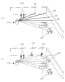
다시 도 3를 참조하여 설명하면, 자율주행로봇(100)의 주행 과정에서 현 위치에서의 거리 측정값들이 획득되면, 거리 측정값의 신뢰성이 산출된다(S21). 도 5를 참조하여 설명하면, 도 5의 (a)의 원으로 표시된 부분(RD)은 상대적으로 신뢰성이 높은 거리 측정값들을 나타내고 있다. 사람과 같은 동적 장애물(210)이나 상자와 같은 알려지지 않은 정적 장애물(220)에 의해 점선으로 나타낸 길이는 해당 거리 측정값에 대한 거리 오차가 된다. 도 5의 (a)에서는 전체 거리 측정값들에 대해서는 큰 거리 오차가 발생할지라도 상대적으로 신뢰성이 높은 거리 측정값들에 대한 거리 오차는 작다. 즉, 상대적으로 신뢰성이 높은 거리 측정값들은 정확하기 때문에 위치 추정이 성공적으로 수행될 수 있다.Referring again to FIG. 3, when distance measurement values at the current position are obtained during the driving process of the
반면, 도 5의 (b)에 도시된 바와 같이, 상대적으로 신뢰성이 높은 거리 측정값들에 대해서도 거리 오차가 크게 나타날 수 있는데, 이러한 결과로, 위치 추정 결과를 신뢰할 수 없게 된다.On the other hand, as shown in (b) of FIG. 5, the distance error may be large even for relatively reliable distance measurement values. As a result, the position estimation result becomes unreliable.
이에, 본 발명에서는 전체 거리 측정값들 중 신뢰성이 상대적으로 높은 거리 측정값들에 대한 오차 평균값을 이용하여 거리 오차 지표를 산출하게 되며, 거리 측정값들 중 신뢰성이 높은 상위 n%의 거리 측정값들을 추출하고(S22), 이를 이용하여 오차 평균값을 산출하는 것을 예로 한다. 여기서, 오차 평균값이 작으면 위치 추정이 성공적으로 수행되었다고 가정할 수 있으며, 반대의 경우에는 위치 추정이 실패한 것으로 가정할 수 있다. 본 발명에서 오차 평균값은 [수학식 1]과 같이 나타낼 수 있다.Accordingly, in the present invention, a distance error index is calculated using an error average value for distance measurement values having a relatively high reliability among all distance measurement values, and a distance measurement value of a top n% having high reliability among the distance measurement values For example, extracting them (S22) and calculating an error average value using the same. Here, if the error average value is small, it can be assumed that the position estimation has been successfully performed, and in the opposite case, it can be assumed that the position estimation has failed. In the present invention, the error average value can be expressed as [Equation 1].
[수학식 1][Equation 1]

[수학식 1]에서 ![]()
![]()
![]()
![]()
![]()
![]()
![]()
![]()
![]()
![]()
![]()
![]()
여기서, n 값이 크면 다수의 거리 측정값에 대한 오차가 계산된다. 그 결과, 실제로 위치 추정 오차가 증가하지 않는 상황에서 위치 추정 오차가 증가한다고 판단될 가능성이 증가한다. 반대로, n 값이 작아지면 실제로 위치 추정 오차가 증가하는 상황에 둔감해진다. 본 발명에서는 n 값으로 경험적으로 20%로 설정하는 것을 예로 한다.Here, if the value of n is large, errors for a number of distance measurements are calculated. As a result, the possibility that it is determined that the position estimation error increases in a situation in which the position estimation error does not actually increase increases. Conversely, when the value of n decreases, it becomes insensitive to the situation where the position estimation error actually increases. In the present invention, it is assumed that the value is set to 20% empirically.
본 발명에 따른 신뢰성 산출 방법은 본원 출원인에 의해 출원되어 등록된 한국등록특허공보 제10-1888295호에 개시된 "레이저 거리 센서(120)의 측정 거리에 대해 추정된 거리 유형의 신뢰성을 평가하는 방법 및 이를 이용한 이동 로봇의 위치 추정 방법"을 이용하여 산출하는 것을 예로 하는 바, 그 상세한 설명은 생략한다.The reliability calculation method according to the present invention is a method for evaluating the reliability of the estimated distance type with respect to the measured distance of the "
여기서, 위치 추정 오차는 누적되어 증가하기 때문에, 오차 평균값 ![]()
![]()
![]()
![]()
![]()
![]()
[수학식 2][Equation 2]

[수학식 2]에서 시간 t에서의 ![]()
![]()
![]()
![]()
이하에서는 본 발명에 따른 자율주행로봇(100)의 위치 추정 상태 자가 진단 방법에서 방향각 오차 지표를 산출(S23)하는 방법에 대해 설명한다. 본 발명에서는 방향각 오차 지표가 현 위치에서 추정된 추정 방향각과, 현 위치에서의 허용 방향각 범위에 기초하여 산출된다.Hereinafter, a method of calculating the direction angle error index in the self-diagnostic method of the position estimation state of the
보다 구체적으로 설명하면, 자율주행로봇(100)의 운동 불확실성과 오도메트리 각변위의 고려 하에 허용 가능한 자율주행로봇(100)의 방향각인 허용 방향각 범위가 산출될 수 있다. 만약, 추정된 방향각이 허용 가능한 범위를 벗어난다면, 비정상적인 위치 추정이 발생했을 가능성이 높다. 본 발명에서는 [수학식 3]을 통해 방향각 오차 지표를 산출하는 것을 예로 한다.In more detail, an allowable direction angle range that is an allowable direction angle of the
[수학식 3][Equation 3]

[수학식 3]에서 ![]()
![]()
![]()
![]()
![]()
![]()
![]()
![]()
[수학식 4][Equation 4]

여기서, ![]()
![]()
![]()
![]()
![]()
![]()
그리고, 최대 방향각과, 최소 방향각은 각각 [수학식 5] 및 [수학식 6]에 의해 산출된다.Then, the maximum direction angle and the minimum direction angle are calculated by [Equation 5] and [Equation 6], respectively.
[수학식 5][Equation 5]
![]()
![]()
[수학식 6][Equation 6]
![]()
![]()
[수학식 5] 및 [수학식 6]에서 ![]()
![]()
![]()
![]()
![]()
![]()
![]()
![]()
![]()
![]()
다시, 도 3를 참조하여 설명하면, 상기와 같이 현 위치에서의 거리 오차 지표와 방향각 오차 지표가 산출되면(S23), 산출된 거리 오차 지표, 방향각 오차 지표, 그리고 현 위치에서의 위치 추정 성공 여부를 기계 학습 알고리즘의 학습 데이터 세트로 생성하여(S24) 기계 학습 알고리즘에 등록한다(S26). 여기서, 학습 데이터 세트를 구성하는 거리 오차 지표와 방향각 오차 지표가 기계 학습 알고리즘의 입력 데이터로, 위치 추정 성공 여부가 출력 데이터로 등록된다.Referring again to FIG. 3, when the distance error index and the direction angle error index at the current position are calculated as described above (S23), the calculated distance error index, the direction angle error index, and the position estimation at the current position Success is generated as a learning data set of a machine learning algorithm (S24) and registered in the machine learning algorithm (S26). Here, the distance error index and the direction angle error index constituting the learning data set are registered as input data of the machine learning algorithm, and whether the position estimation is successful is registered as the output data.
상기와 같은 학습 데이터 세트 생성 과정은 자율주행로봇(100)의 주행 과정에서 지속적으로 생성되어 등록되며, 시간의 경과에 따른 주행 환경의 변화가 반영될 수 있도록 시간대별로 주행 과정을 반복하며 생성하는 것을 예로 한다. 도 7은 도 4에 도시된 주차장 환경에서 시간에 따른 환경 변화의 예를 나타내고 있다. 주차장 환경의 경우, 주차 구역에 주차된 차량이 시간이나 요일별로 다르기 때문에 환경 변화를 잘 반영할 수 있게 된다.The process of generating the learning data set as described above is continuously generated and registered in the driving process of the
상기와 같은 과정을 통해 학습 데이터 세트가 생성되고 기계 학습 알고리즘에 등록되면, 기계 학습 과정이 진행된다(S10). 본 발명에서는 기계 학습 알고리즘으로 지도학습(Supervised learning)이 적용된 이진 분류 알고리즘에 적용되는 것을 예로 한다.When the learning data set is generated through the above process and registered in the machine learning algorithm, the machine learning process proceeds (S10). In the present invention, an example is applied to a binary classification algorithm to which supervised learning is applied as a machine learning algorithm.
지도학습은 레이블이 주어진 데이터를 이용하는 기계 학습 알고리즘이다. 즉, 지도학습에서 각각의 학습 데이터는 입력 값과 원하는 출력의 쌍이다. 지도학습의 목적은 입력 값으로부터 출력 값을 맵핑하는 함수를 찾는 것이다.Supervised learning is a machine learning algorithm that uses labeled data. That is, in supervised learning, each learning data is a pair of an input value and a desired output. The purpose of supervised learning is to find a function that maps input values to output values.
본 발명은 위치 오차 지표와 방향각 오차 지표를 이용하여 위치 추정 상태, 즉 위치 추정 성공 여부를 성공과 실패로 분류하는 것이므로, 지도학습의 회기(Regression) 문제와 분류(Classificaton) 문제 중 분류 문제로 접근한다.Since the present invention classifies the position estimation status, that is, whether the position estimation is successful or not, by using the position error indicator and the direction angle error indicator, as a classification problem among regression problems and classification problems in supervised learning Approach.
실제 위치 추정 상태에 따라 위치 오차 지표와 방향각 오차 지표를 범주화시키기 위해서 실제 위치 추정 상태를 분류하기 위한 규칙이 요구되며, 본 발명에서는 위치 추정 상태를 분류하기 위한 규칙을 다음과 같이 정의한다.In order to categorize the position error indicator and the direction angle error indicator according to the actual position estimation state, a rule for classifying the actual position estimation state is required, and in the present invention, the rules for classifying the position estimation state are defined as follows.
- 위치 오차 지표와 방향각 오차 지표가 정해진 한계치를 초과하면, 위치 추정은 '실패'로 분류한다.-If the position error index and the direction angle error index exceed the prescribed limit, the position estimation is classified as'failure'.
- 실패가 아닌 모든 과정은 성공으로 분류한다.-All non-failure processes are classified as success.
즉, 위치 추정 오차가 일정 수준 이하일 때, 많은 경우에 위치 추정 오차는 자율주행 성능에 큰 영향을 미치지 않는다. 따라서, 위치 추정 오차가 정해진 한계치를 초과할 때만, 위치 추정 상태가 '실패'로 분류된다. 위치추정 오차의 한계치는 주행 목적 또는 임무에 따라 결정될 수 있다.That is, when the position estimation error is below a certain level, in many cases, the position estimation error does not significantly affect autonomous driving performance. Therefore, only when the position estimation error exceeds a predetermined threshold, the position estimation state is classified as'failed'. The limit value of the positioning error can be determined according to the driving purpose or task.
본 발명에서 위치추정 상태는 성공과 실패로 분류된다. 따라서, 도 3에 도시된 바와 같은 방법으로 생성 및 등록되는 위치추정 성공상태와 위치추정 실패상태에서 수집된 위치 오차 지표와 방향각 오차 지표가 기계 학습 알고리즘의 학습 데이터로 사용된다.In the present invention, the location estimation status is classified into success and failure. Accordingly, the position error index and the direction angle error index collected in the position estimation success state and the position estimation failure state generated and registered in the method as shown in FIG. 3 are used as learning data of the machine learning algorithm.
상술한 바와 같이, 본 발명에 따른 기계 학습 알고리즘은 지도학습을 이용한 이진 분류 알고리즘이 적용되며, Altman의 저서 "An Introduction to Kernel and Nearest-Neighbor Nonparametric Regression (The American Statistician, vol. 46, no. 3, pp. 175-185, 1992.)"에 개시된 KNN 알고리즘, Pampel의 저서 "Logistic regression (a primer, Sage Publication, 2000.)"에 개시된 logistic regression 알고리즘, Cristianini 등의 논문 "An introduction to support vector machines and other kernel-based learning methods (Cambridge University Press, 2000.)"에 개시된 SVM 알고리즘이 적용될 수 있다.As described above, in the machine learning algorithm according to the present invention, a binary classification algorithm using supervised learning is applied, and Altman's book "An Introduction to Kernel and Nearest-Neighbor Nonparametric Regression (The American Statistician, vol. 46, no. 3 , pp. 175-185, 1992.), the logistic regression algorithm disclosed in Pampel's book "Logistic regression (a primer, Sage Publication, 2000.)", a paper by Cristianini et al. "An introduction to support vector machines and other kernel-based learning methods (Cambridge University Press, 2000.).
다시, 도 2을 참조하여 설명하면, 상기와 같은 과정을 통해 기계 학습이 완료된 상태에서(S10), 자율주행로봇(100)이 주행 환경을 주행하는 과정에서 거리 센서(120)에 의해 현 위치에서의 거리 측정값들이 측정된다(S11). 그리고, 현 위치에서의 추정 방향각이 추정된다(S12).Referring again to FIG. 2, in the state where the machine learning is completed through the above-described process (S10), the
그런 다음, 거리 측정값들에 대한 신뢰성이 산출되고(S13), 산출된 신뢰성을 기준으로 상위 n%의 거리 측정값이 추출된다(S14). 여기서, 신뢰성 산출과 상위 n%의 거리 측정값 추출은 상술한 기계 학습 과정에 대응하는 바, 그 상세한 설명은 생략한다.Then, the reliability of the distance measurement values is calculated (S13), and the upper n% distance measurement value is extracted based on the calculated reliability (S14). Here, the reliability calculation and extraction of the upper n% distance measurement value correspond to the above-described machine learning process, and detailed description thereof will be omitted.
그런 다음, 추출된 거리 측정값과 추정 방향각을 이용하여, 상술한 바와 같이, 거리 오차 지표와 방향각 오차 지표를 산출하고(S15), 산출된 거리 오차 지표와 방향각 오차 지표를 기계 학습 알고리즘에 입력하여 성공과 실패 중 어느 하나가 출력됨으로써(S16), 현재 추정된 자율주행로봇(100)의 포즈, 즉 위치와 방향각의 추정이 성공인지 실패인지 판단된다.Then, using the extracted distance measurement value and the estimated direction angle, as described above, the distance error index and the direction angle error index are calculated (S15), and the calculated distance error index and the direction angle error index are machine learning algorithms. By inputting to either one of success and failure is output (S16), it is determined whether the estimation of the current
이상에서 본 발명의 바람직한 실시예에 대하여 상세하게 설명하였지만 본 발명의 권리범위는 이에 한정되는 것은 아니고 다음의 청구범위에서 정의하고 있는 본 발명의 기본 개념을 이용한 당업자의 여러 변형 및 개량 형태 또한 본 발명의 권리범위에 속하는 것이다.Although the preferred embodiments of the present invention have been described in detail above, the scope of the present invention is not limited thereto, and various modifications and improvements of those skilled in the art using the basic concepts of the present invention defined in the following claims are also provided. It belongs to the scope of rights.
100 : 자율주행 로봇 110 : 메인 프로세서
120 : 거리 센서 130 : 휠 구동부
140 : 휠 감지부 150 : 전원 공급부
210 : 동적 장애물 220 : 정적 장애물100: autonomous driving robot 110: main processor
120: distance sensor 130: wheel drive
140: wheel detection unit 150: power supply
210: dynamic obstacle 220: static obstacle
Claims (10)
(a) 거리 오차 지표와, 방향각 오차 지표, 및 상기 거리 오차 지표 및 상기 방향각 오차 지표에 대한 위치 추정 성공 여부가 기 등록된 기계 학습 알고리즘의 학습 데이터로 등록되어 학습되는 단계와,
(b) 자율주행로봇의 현 위치에서 복수의 거리 측정값이 측정되는 단계와,
(c) 상기 자율주행로봇의 현 위치에서의 추정 방향각이 추정되는 단계와,
(d) 복수의 상기 거리 측정값에 기초하여 현 위치에서의 거리 오차 지표가 산출되는 단계와,
(e) 상기 추정 방향각에 기초하여 현 위치에서의 방향각 오차 지표가 산출되는 단계와,
(f) 상기 (d) 단계 및 상기 (e) 단계에서 각각 산출된 상기 거리 오차 지표 및 상기 방향각 오차 지표가 상기 기계 학습 알고리즘에 입력되어 현 위치에서의 위치 추정 성공 여부가 출력되는 단계를 포함하며;
상기 (a) 단계 및 상기 (d) 단계에서 상기 거리 오차 지표는 현 위치에서 측정된 복수의 거리 측정값 중 신뢰성이 높은 상위 n %의 거리 측정값들의 오차 평균값에 기초하여 산출되고,
상기 (a) 단계 및 상기 (e) 단계에서 상기 방향각 오차 지표는 현 위치에서 추정된 추정 방향각과 현 위치에서의 허용 방향각 범위에 기초하여 산출되는 것을 특징으로 하는 위치 추정 상태 자가 진단 방법.In the position estimation state self-diagnostic method,
(a) the distance error indicator, the direction angle error indicator, and the distance error indicator and the position estimation success with respect to the direction angle error indicator are registered and learned as learning data of a pre-registered machine learning algorithm,
(b) measuring a plurality of distance measurement values at the current position of the autonomous driving robot,
(c) estimating the estimated direction angle at the current position of the autonomous driving robot,
(d) calculating a distance error index at the current position based on the plurality of distance measurements;
(e) calculating a direction angle error index at the current position based on the estimated direction angle;
(f) the distance error index and the direction angle error index calculated in steps (d) and (e) are input to the machine learning algorithm, and outputting whether or not the position estimation is successful at the current position is output. And;
In the steps (a) and (d), the distance error index is calculated based on an error average value of the upper n% distance measurement values having high reliability among a plurality of distance measurement values measured at the current location,
In the step (a) and the step (e), the direction angle error indicator is calculated based on the estimated direction angle estimated at the current position and the allowable direction angle range at the current position.
상기 거리 오차 지표는 수학식

(여기서,

The distance error index is an equation
(here,
상기 방향각 오차 지표는 수학식

(여기서,

(여기서,
The direction angle error index is an equation
(here,
(here,
상기 최대 방향각은 수학식
상기 최소 방향각은 수학식
The maximum direction angle is equation
The minimum direction angle is an equation
상기 기계 학습 알고리즘은 지도학습이 적용된 이진 분류 알고리즘을 포함하는 것을 특징으로 하는 위치 추정 상태 자가 진단 방법.According to claim 1,
The machine learning algorithm includes a binary classification algorithm to which supervised learning is applied.
거리 센서와,
상기 거리 센서에 의해 측정된 거리 측정값에 기초하여 주행을 제어하고, 기계 학습 알고리즘이 기 등록된 메인 프로세서를 포함하며;
(a) 상기 메인 프로세서에 거리 오차 지표와, 방향각 오차 지표, 및 상기 거리 오차 지표 및 상기 방향각 오차 지표에 대한 위치 추정 성공 여부가 상기 기계 학습 알고리즘의 학습 데이터로 등록되어 학습되는 단계와,
(b) 상기 거리 센서에 의해 현 위치에서 복수의 거리 측정값이 측정되는 단계와,
(c) 상기 메인 프로세서에 의해 현 위치에서의 추정 방향각이 추정되는 단계와,
(d) 상기 메인 프로세서에 의해 복수의 상기 거리 측정값에 기초하여 현 위치에서의 거리 오차 지표가 산출되는 단계와,
(e) 상기 메인 프로세서에 의해 상기 추정 방향각에 기초하여 현 위치에서의 방향각 오차 지표가 산출되는 단계와,
(f) 상기 메인 프로세서에 의해 상기 (d) 단계 및 상기 (e) 단계에서 각각 산출된 상기 거리 오차 지표 및 상기 방향각 오차 지표가 상기 기계 학습 알고리즘에 입력되어 현 위치에서의 위치 추정 성공 여부가 출력되는 단계가 수행되어, 위치 추정 상태가 자가 진단되며;
상기 메인 프로세서는
상기 (a) 단계 및 상기 (d) 단계에서 상기 거리 오차 지표를 현 위치에서 측정된 복수의 거리 측정값 중 신뢰성이 높은 상위 n %의 거리 측정값들의 오차 평균값에 기초하여 산출하고,
상기 (a) 단계 및 상기 (e) 단계에서 상기 방향각 오차 지표를 현 위치에서 추정된 추정 방향각과 현 위치에서의 허용 방향각 범위에 기초하여 산출하는 것을 특징으로 하는 위치 추정 상태 자가 진단을 수행하는 자율주행로봇.In the self-driving robot performing a self-diagnosis position estimation state,
Distance sensor,
Controlling a driving based on the distance measurement value measured by the distance sensor, the machine learning algorithm includes a pre-registered main processor;
(a) registering and learning whether a distance error indicator, a direction angle error indicator, and a position error success for the distance error indicator and the direction angle error indicator are registered in the main processor as learning data of the machine learning algorithm;
(b) measuring a plurality of distance measurements at the current position by the distance sensor;
(c) estimating an estimated direction angle at the current position by the main processor,
(d) calculating, by the main processor, a distance error index at the current location based on the plurality of distance measurements;
(e) calculating, by the main processor, a direction angle error index at the current position based on the estimated direction angle;
(f) The distance error index and the direction angle error index respectively calculated in steps (d) and (e) by the main processor are input to the machine learning algorithm to determine whether the position estimation at the current position is successful. The outputting step is performed, and the position estimation status is self-diagnosed;
The main processor
In the steps (a) and (d), the distance error index is calculated based on an error average value of the upper n% distance measurement values having high reliability among a plurality of distance measurement values measured at the current position,
Position estimation state self-diagnosis is performed in steps (a) and (e), wherein the direction angle error index is calculated based on the estimated direction angle estimated at the current position and the allowable direction angle range at the current position. Self-driving robot.
상기 거리 오차 지표는 수학식

(여기서,

The distance error index is an equation
(here,
상기 방향각 오차 지표는 수학식

(여기서,

(여기서,
The direction angle error index is an equation
(here,
(here,
상기 최대 방향각은 수학식
상기 최소 방향각은 수학식
The maximum direction angle is equation
The minimum direction angle is an equation
상기 기계 학습 알고리즘은 지도학습이 적용된 이진 분류 알고리즘을 포함하는 것을 특징으로 하는 위치 추정 상태 자가 진단을 수행하는 자율주행로봇.The method of claim 6,
The machine learning algorithm includes a binary classification algorithm to which supervised learning is applied.
Priority Applications (1)
| Application Number | Priority Date | Filing Date | Title |
|---|---|---|---|
| KR1020180149336A KR102193914B1 (en) | 2018-11-28 | 2018-11-28 | Method for self-diagnosing localization status and autonomous mobile robot carrying out the same |
Applications Claiming Priority (1)
| Application Number | Priority Date | Filing Date | Title |
|---|---|---|---|
| KR1020180149336A KR102193914B1 (en) | 2018-11-28 | 2018-11-28 | Method for self-diagnosing localization status and autonomous mobile robot carrying out the same |
Publications (2)
| Publication Number | Publication Date |
|---|---|
| KR20200063538A true KR20200063538A (en) | 2020-06-05 |
| KR102193914B1 KR102193914B1 (en) | 2020-12-22 |
Family
ID=71089356
Family Applications (1)
| Application Number | Title | Priority Date | Filing Date |
|---|---|---|---|
| KR1020180149336A Active KR102193914B1 (en) | 2018-11-28 | 2018-11-28 | Method for self-diagnosing localization status and autonomous mobile robot carrying out the same |
Country Status (1)
| Country | Link |
|---|---|
| KR (1) | KR102193914B1 (en) |
Cited By (5)
| Publication number | Priority date | Publication date | Assignee | Title |
|---|---|---|---|---|
| EP3974221A1 (en) * | 2020-09-24 | 2022-03-30 | Toyota Jidosha Kabushiki Kaisha | Control device and control method of hybrid vehicle |
| CN114639163A (en) * | 2022-02-25 | 2022-06-17 | 纯米科技(上海)股份有限公司 | Walking program scoring method, system, electronic device and storage medium |
| CN116482982A (en) * | 2023-05-24 | 2023-07-25 | 常州大学 | A Complementary Filter Gain Adjustment Method Based on KNN Classifier |
| JP2024022545A (en) * | 2022-08-03 | 2024-02-16 | ローベルト ボツシユ ゲゼルシヤフト ミツト ベシユレンクテル ハフツング | Device and method for controlling a robot |
| KR20250070448A (en) * | 2023-11-13 | 2025-05-20 | 주식회사 현대케피코 | Robotic arm driving apparatus and method for combination with vehicle charging gun |
Families Citing this family (3)
| Publication number | Priority date | Publication date | Assignee | Title |
|---|---|---|---|---|
| KR20250086091A (en) | 2023-12-06 | 2025-06-13 | 오창연 | Method and device for tracking location using Ultra Wide Band |
| KR20250086090A (en) | 2023-12-06 | 2025-06-13 | 오창연 | Method and device for controlling a self-driving robot using Ultra Wide Band |
| KR20250087100A (en) | 2023-12-07 | 2025-06-16 | 주식회사 클로봇 | One-way driving system and method for mobile robots |
Citations (2)
| Publication number | Priority date | Publication date | Assignee | Title |
|---|---|---|---|---|
| KR0161042B1 (en) * | 1994-06-07 | 1999-01-15 | 김광호 | Moving control device and method of robot |
| KR20120025839A (en) * | 2010-09-08 | 2012-03-16 | 고려대학교 산학협력단 | Calibrating method of odometry error of 2-wheel mobile robot |
-
2018
- 2018-11-28 KR KR1020180149336A patent/KR102193914B1/en active Active
Patent Citations (2)
| Publication number | Priority date | Publication date | Assignee | Title |
|---|---|---|---|---|
| KR0161042B1 (en) * | 1994-06-07 | 1999-01-15 | 김광호 | Moving control device and method of robot |
| KR20120025839A (en) * | 2010-09-08 | 2012-03-16 | 고려대학교 산학협력단 | Calibrating method of odometry error of 2-wheel mobile robot |
Cited By (6)
| Publication number | Priority date | Publication date | Assignee | Title |
|---|---|---|---|---|
| EP3974221A1 (en) * | 2020-09-24 | 2022-03-30 | Toyota Jidosha Kabushiki Kaisha | Control device and control method of hybrid vehicle |
| CN114639163A (en) * | 2022-02-25 | 2022-06-17 | 纯米科技(上海)股份有限公司 | Walking program scoring method, system, electronic device and storage medium |
| CN114639163B (en) * | 2022-02-25 | 2024-06-07 | 纯米科技(上海)股份有限公司 | Scoring method and scoring system for walking program, electronic device and storage medium |
| JP2024022545A (en) * | 2022-08-03 | 2024-02-16 | ローベルト ボツシユ ゲゼルシヤフト ミツト ベシユレンクテル ハフツング | Device and method for controlling a robot |
| CN116482982A (en) * | 2023-05-24 | 2023-07-25 | 常州大学 | A Complementary Filter Gain Adjustment Method Based on KNN Classifier |
| KR20250070448A (en) * | 2023-11-13 | 2025-05-20 | 주식회사 현대케피코 | Robotic arm driving apparatus and method for combination with vehicle charging gun |
Also Published As
| Publication number | Publication date |
|---|---|
| KR102193914B1 (en) | 2020-12-22 |
Similar Documents
| Publication | Publication Date | Title |
|---|---|---|
| KR102193914B1 (en) | Method for self-diagnosing localization status and autonomous mobile robot carrying out the same | |
| Fang et al. | A fault detection and diagnosis system for autonomous vehicles based on hybrid approaches | |
| EP3358303B1 (en) | An apparatus and associated methods for use in updating map data | |
| US11493930B2 (en) | Determining changes in marker setups for robot localization | |
| CN113933858B (en) | Abnormality detection method, device and terminal equipment of positioning sensor | |
| US20160217627A1 (en) | Sensor fault detection and diagnosis for autonomous systems | |
| CN113454487B (en) | Information processing device and mobile robot | |
| Huang et al. | Design of a fault detection and isolation system for intelligent vehicle navigation system | |
| Khalastchi et al. | A sensor-based approach for fault detection and diagnosis for robotic systems | |
| JP2019207177A (en) | Self-position estimation apparatus | |
| KR20200068258A (en) | Apparatus and method for predicting sensor fusion target in vehicle and vehicle including the same | |
| US11899750B2 (en) | Quantile neural network | |
| Lu et al. | Fault detection and data-driven optimal adaptive fault-tolerant control for autonomous driving using learning-based SMPC | |
| KR102261155B1 (en) | Method and apparatus for controlling a vehicle using two virtual sensors | |
| Sun et al. | Real-sap: Real-time evidence aware liable safety assessment for perception in autonomous driving | |
| CN112783133A (en) | AGV running state prediction method | |
| US10572802B1 (en) | Learning state-dependent sensor measurement models for localization | |
| KR102477587B1 (en) | Method and apparatus for monitoring unmanned ground vehicle | |
| CN111497939B (en) | Method and device for autonomous driving vehicle | |
| Ellis et al. | A mapping of assurance techniques for learning enabled autonomous systems to the systems engineering lifecycle | |
| US12387098B2 (en) | Multi-task learning | |
| CN118466438A (en) | Method, device, equipment and storage medium for detecting faults of automatic driving vehicle | |
| Shen et al. | An integrated localization system with fault detection, isolation and recovery for autonomous vehicles | |
| US12221120B2 (en) | Method and device for monitoring operations of an automated driving system of a vehicle | |
| US12025984B2 (en) | Imperfect sensing based analysis of agents deployed in environments for traversal task execution |
Legal Events
| Date | Code | Title | Description |
|---|---|---|---|
| PA0109 | Patent application |
Patent event code: PA01091R01D Comment text: Patent Application Patent event date: 20181128 |
|
| PA0201 | Request for examination | ||
| PE0902 | Notice of grounds for rejection |
Comment text: Notification of reason for refusal Patent event date: 20200314 Patent event code: PE09021S01D |
|
| PG1501 | Laying open of application | ||
| E701 | Decision to grant or registration of patent right | ||
| PE0701 | Decision of registration |
Patent event code: PE07011S01D Comment text: Decision to Grant Registration Patent event date: 20200922 |
|
| GRNT | Written decision to grant | ||
| PR0701 | Registration of establishment |
Comment text: Registration of Establishment Patent event date: 20201216 Patent event code: PR07011E01D |
|
| PR1002 | Payment of registration fee |
Payment date: 20201216 End annual number: 3 Start annual number: 1 |
|
| PG1601 | Publication of registration | ||
| PR1001 | Payment of annual fee |
Payment date: 20231023 Start annual number: 4 End annual number: 4 |
|
| PR1001 | Payment of annual fee |
Payment date: 20241210 Start annual number: 5 End annual number: 5 |