KR20200057727A - Augmented reality display with waveguide configured to capture images of the eye and / or environment - Google Patents
Augmented reality display with waveguide configured to capture images of the eye and / or environment Download PDFInfo
- Publication number
- KR20200057727A KR20200057727A KR1020207010603A KR20207010603A KR20200057727A KR 20200057727 A KR20200057727 A KR 20200057727A KR 1020207010603 A KR1020207010603 A KR 1020207010603A KR 20207010603 A KR20207010603 A KR 20207010603A KR 20200057727 A KR20200057727 A KR 20200057727A
- Authority
- KR
- South Korea
- Prior art keywords
- light
- waveguide
- optical element
- eye
- user
- Prior art date
- Legal status (The legal status is an assumption and is not a legal conclusion. Google has not performed a legal analysis and makes no representation as to the accuracy of the status listed.)
- Granted
Links
Images


Classifications
-
- G—PHYSICS
- G02—OPTICS
- G02B—OPTICAL ELEMENTS, SYSTEMS OR APPARATUS
- G02B27/00—Optical systems or apparatus not provided for by any of the groups G02B1/00 - G02B26/00, G02B30/00
- G02B27/01—Head-up displays
- G02B27/017—Head mounted
- G02B27/0172—Head mounted characterised by optical features
-
- G—PHYSICS
- G02—OPTICS
- G02B—OPTICAL ELEMENTS, SYSTEMS OR APPARATUS
- G02B27/00—Optical systems or apparatus not provided for by any of the groups G02B1/00 - G02B26/00, G02B30/00
- G02B27/0081—Optical systems or apparatus not provided for by any of the groups G02B1/00 - G02B26/00, G02B30/00 with means for altering, e.g. enlarging, the entrance or exit pupil
-
- G—PHYSICS
- G02—OPTICS
- G02B—OPTICAL ELEMENTS, SYSTEMS OR APPARATUS
- G02B27/00—Optical systems or apparatus not provided for by any of the groups G02B1/00 - G02B26/00, G02B30/00
- G02B27/0093—Optical systems or apparatus not provided for by any of the groups G02B1/00 - G02B26/00, G02B30/00 with means for monitoring data relating to the user, e.g. head-tracking, eye-tracking
-
- G—PHYSICS
- G02—OPTICS
- G02B—OPTICAL ELEMENTS, SYSTEMS OR APPARATUS
- G02B27/00—Optical systems or apparatus not provided for by any of the groups G02B1/00 - G02B26/00, G02B30/00
- G02B27/28—Optical systems or apparatus not provided for by any of the groups G02B1/00 - G02B26/00, G02B30/00 for polarising
- G02B27/283—Optical systems or apparatus not provided for by any of the groups G02B1/00 - G02B26/00, G02B30/00 for polarising used for beam splitting or combining
-
- G—PHYSICS
- G06—COMPUTING OR CALCULATING; COUNTING
- G06F—ELECTRIC DIGITAL DATA PROCESSING
- G06F3/00—Input arrangements for transferring data to be processed into a form capable of being handled by the computer; Output arrangements for transferring data from processing unit to output unit, e.g. interface arrangements
- G06F3/01—Input arrangements or combined input and output arrangements for interaction between user and computer
- G06F3/011—Arrangements for interaction with the human body, e.g. for user immersion in virtual reality
- G06F3/013—Eye tracking input arrangements
-
- G—PHYSICS
- G06—COMPUTING OR CALCULATING; COUNTING
- G06T—IMAGE DATA PROCESSING OR GENERATION, IN GENERAL
- G06T19/00—Manipulating 3D models or images for computer graphics
- G06T19/006—Mixed reality
-
- G—PHYSICS
- G02—OPTICS
- G02B—OPTICAL ELEMENTS, SYSTEMS OR APPARATUS
- G02B27/00—Optical systems or apparatus not provided for by any of the groups G02B1/00 - G02B26/00, G02B30/00
- G02B27/01—Head-up displays
- G02B27/0101—Head-up displays characterised by optical features
- G02B2027/0123—Head-up displays characterised by optical features comprising devices increasing the field of view
- G02B2027/0125—Field-of-view increase by wavefront division
-
- G—PHYSICS
- G02—OPTICS
- G02B—OPTICAL ELEMENTS, SYSTEMS OR APPARATUS
- G02B27/00—Optical systems or apparatus not provided for by any of the groups G02B1/00 - G02B26/00, G02B30/00
- G02B27/01—Head-up displays
- G02B27/0101—Head-up displays characterised by optical features
- G02B2027/0138—Head-up displays characterised by optical features comprising image capture systems, e.g. camera
-
- G—PHYSICS
- G02—OPTICS
- G02B—OPTICAL ELEMENTS, SYSTEMS OR APPARATUS
- G02B27/00—Optical systems or apparatus not provided for by any of the groups G02B1/00 - G02B26/00, G02B30/00
- G02B27/01—Head-up displays
- G02B27/0101—Head-up displays characterised by optical features
- G02B2027/014—Head-up displays characterised by optical features comprising information/image processing systems
-
- G—PHYSICS
- G02—OPTICS
- G02B—OPTICAL ELEMENTS, SYSTEMS OR APPARATUS
- G02B27/00—Optical systems or apparatus not provided for by any of the groups G02B1/00 - G02B26/00, G02B30/00
- G02B27/01—Head-up displays
- G02B27/017—Head mounted
- G02B2027/0178—Eyeglass type
-
- G—PHYSICS
- G02—OPTICS
- G02B—OPTICAL ELEMENTS, SYSTEMS OR APPARATUS
- G02B27/00—Optical systems or apparatus not provided for by any of the groups G02B1/00 - G02B26/00, G02B30/00
- G02B27/01—Head-up displays
- G02B27/0179—Display position adjusting means not related to the information to be displayed
- G02B2027/0185—Displaying image at variable distance
Landscapes
- Physics & Mathematics (AREA)
- General Physics & Mathematics (AREA)
- Engineering & Computer Science (AREA)
- Optics & Photonics (AREA)
- Theoretical Computer Science (AREA)
- General Engineering & Computer Science (AREA)
- Human Computer Interaction (AREA)
- Computer Graphics (AREA)
- Computer Hardware Design (AREA)
- Software Systems (AREA)
- Diffracting Gratings Or Hologram Optical Elements (AREA)
- Optical Elements Other Than Lenses (AREA)
- Optical Couplings Of Light Guides (AREA)
Abstract
머리 장착 디스플레이 시스템은 카메라, 적어도 하나의 도파관, 광이 상기 도파관에 커플링되어 상기 도파관 안으로 안내되도록 구성되는 적어도 하나의 커플링 광학 엘리먼트, 및 적어도 하나의 아웃커플링 광학 엘리먼트를 포함할 수 있다. 적어도 하나의 아웃커플링 광학 엘리먼트는 상기 도파관 내로 안내되는 광을 상기 도파관에서 아웃커플링하고 상기 광을 상기 카메라로 지향시키도록 구성될 수 있다. 카메라는, 커플링 엘리먼트를 통해 상기 도파관에 커플링되어 상기 도파관 안으로 안내되고, 이미지들이 상기 카메라에 의해 캡처될 수 있게 상기 적어도 하나의 아웃커플링 광학 엘리먼트에 의해 상기 도파관으로부터 아웃커플링되는 광의 적어도 일부를 수신하도록 상기 아웃커플링 광학 엘리먼트에 대한 광학 경로에 배치될 수 있다.The head mounted display system may include a camera, at least one waveguide, at least one coupling optical element configured to be coupled to the waveguide and guided into the waveguide, and at least one outcoupling optical element. The at least one outcoupling optical element can be configured to outcouple light guided into the waveguide at the waveguide and direct the light to the camera. A camera is coupled to the waveguide through a coupling element and is guided into the waveguide, at least of the light being outcoupled from the waveguide by the at least one outcoupling optical element so that images can be captured by the camera It can be placed in an optical path to the outcoupling optical element to receive a portion.
Description
[0001] 본 출원은 "AUGMENTED REALITY DISPLAY WITH EYEPIECE CONFIGURED TO CAPTURE IMAGES OF EYE AND ENVIRONMENT"라는 명칭으로 2017년 9월 21일자 출원된 미국 가출원 제62/561645호에 대한 우선권의 이익을 35 U.S.C. § 119(e) 하에서 주장하며, 이로써 이 출원은 그 전체가 인용에 의해 본 명세서에 포함된다.[0001] This application claims the benefit of priority to U.S. Provisional Application No. 62/561645 filed on September 21, 2017 under the name "AUGMENTED REALITY DISPLAY WITH EYEPIECE CONFIGURED TO CAPTURE IMAGES OF EYE AND ENVIRONMENT" 35 U.S.C. Claimed under § 119 (e), whereby this application is hereby incorporated by reference in its entirety.
[0002] 본 개시내용은 증강 현실 이미징 및 시각화 시스템들을 포함하는 광학 디바이스들에 관한 것이다.[0002] This disclosure relates to optical devices including augmented reality imaging and visualization systems.
[0003] 현대 컴퓨팅 및 디스플레이 기술들은 소위 "가상 현실" 또는 "증강 현실" 경험들을 위한 시스템들의 개발을 가능하게 했으며, 여기서 디지털 방식으로 재생된 이미지들 또는 그 이미지들의 부분들은, 이들이 실제인 것으로 보이거나, 실제로서 지각될 수 있는 방식으로 사용자에게 제시된다. 가상 현실 또는 "VR" 시나리오는 통상적으로 다른 실제 실세계 시각 입력에 대한 투명도(transparency) 없이 디지털 또는 가상 이미지 정보의 프리젠테이션(presentation)을 수반하고; 증강 현실 또는 "AR" 시나리오는 통상적으로 사용자 주위 실제 세계의 시각화에 대한 증강으로서 디지털 또는 가상 이미지 정보의 프리젠테이션을 수반한다. 혼합 현실 또는 "MR" 시나리오는 AR 시나리오의 타입이고 통상적으로, 자연 세계에 통합되고 그에 응답하는 가상 오브젝트들을 수반한다. 예를 들어, MR 시나리오는 실세계의 오브젝트들에 의해 차단되는 것으로 나타나거나 아니면 실세계의 오브젝트들과 상호 작용하는 것으로 지각되는 AR 이미지 콘텐츠를 포함할 수 있다.[0003] Modern computing and display technologies have enabled the development of systems for so-called "virtual reality" or "augmented reality" experiences, where digitally reproduced images or parts of those images appear to be real or real It is presented to the user in a manner that can be perceived as. Virtual reality or "VR" scenarios typically involve the presentation of digital or virtual image information without transparency to other real-world visual inputs; Augmented reality or "AR" scenarios typically involve the presentation of digital or virtual image information as an augmentation of the real world visualization around the user. Mixed reality or "MR" scenarios are a type of AR scenario and typically involve virtual objects that are integrated into and respond to the natural world. For example, the MR scenario may include AR image content that appears to be blocked by real-world objects or is perceived to interact with real-world objects.
[0004]
도 1을 참조하면, 증강 현실 장면(10)이 도시된다. AR 기술의 사용자는 배경 내의 사람들, 나무들, 빌딩들 및 콘크리트 플랫폼(30)을 특징으로 하는 실세계 공원형 장소(20)를 본다. 사용자는 또한, 자신이 실세계 플랫폼(30) 위에 서 있는 로봇 동상(40), 및 호박벌의 의인화인 것처럼 보이는 날고 있는 만화형 아바타 캐릭터(50)와 같은 "가상 콘텐츠"를 "본" 것으로 지각한다. 이러한 엘리먼트들(50, 40)은 이들이 실세계에는 존재하지 않는다는 점에서 "가상"이다. 인간의 시각적 지각 시스템은 복잡하기 때문에, 다른 가상 또는 실세계 이미저리 엘리먼트들 사이에서 가상 이미지 엘리먼트들의 편안하고 자연스러운 느낌의 풍부한 프리젠테이션을 가능하게 하는 AR 기술을 생성하는 것은 난제이다.[0004]
1, an augmented
[0005] 본 명세서에서 개시된 시스템들 및 방법들은 AR 및 VR 기술에 관련된 다양한 난제들을 처리한다.[0005] The systems and methods disclosed herein address various challenges related to AR and VR technology.
[0006] 편광 빔 분할기들은 편광을 광 변조기들에 지향시킨 다음, 이 광을 뷰어에 지향시키도록 디스플레이 시스템들에 사용될 수 있다. 디스플레이 시스템들의 크기들을 일반적으로 감소시키는 것에 대한 지속적인 요구가 있고, 그 결과, 편광 빔 분할기들을 이용하는 구성 부품들을 포함하여 디스플레이 시스템들의 구성 부품들의 크기들을 감소시키는 것에 대한 요구가 또한 있다.[0006] Polarization beam splitters can be used in display systems to direct polarization to light modulators and then direct this light to the viewer. There is a continuing need to generally reduce the sizes of display systems, and as a result, there is also a need to reduce the sizes of component parts of display systems, including components using polarizing beam splitters.
[0007] 본 명세서에서 설명되는 다양한 구현들은 눈에 조명 및/또는 이미지 투사를 제공하도록 구성된 디스플레이 시스템들을 포함한다. 추가로 또는 대안으로, 디스플레이 시스템들은 눈 및/또는 환경을 이미징할 수 있다.[0007] Various implementations described herein include display systems configured to provide illumination and / or image projection to the eye. Additionally or alternatively, display systems can image the eye and / or environment.
[0008] 일부 실시예들에서, 머리 장착 디스플레이 시스템은 사용자의 시계 내에 증강 현실 이미지 콘텐츠를 디스플레이하기 위해 상기 사용자의 눈에 광을 투사하도록 구성된다. 머리 장착 디스플레이 시스템은 사용자의 머리에 지지되도록 구성되는 프레임을 포함할 수 있다. 디스플레이 시스템은 또한, 사용자의 시계 내에 이미지 콘텐츠를 디스플레이하기 위해 사용자의 눈에 이미지들을 투사하도록 구성되는 이미지 투사기를 포함할 수 있다. 디스플레이 시스템은 카메라, 적어도 하나의 도파관, 광이 상기 도파관에 커플링되어 상기 도파관 안으로 안내되도록 구성되는 적어도 하나의 커플링 광학 엘리먼트, 및 적어도 하나의 아웃커플링(out-coupling) 광학 엘리먼트를 포함할 수 있다. 적어도 하나의 아웃커플링 엘리먼트는 상기 도파관 내로 안내되는 광을 상기 도파관에서 아웃커플링하고 상기 광을 상기 카메라로 지향시키도록 구성될 수 있다. 카메라는, 커플링 엘리먼트를 통해 상기 도파관에 커플링되어 상기 도파관 안으로 안내되고, 이미지들이 상기 카메라에 의해 캡처될 수 있게 상기 적어도 하나의 아웃커플링 광학 엘리먼트에 의해 상기 도파관으로부터 아웃커플링되는 광의 적어도 일부를 수신하도록 상기 아웃커플링 광학 엘리먼트에 대한 광학 경로에 배치될 수 있다.[0008] In some embodiments, the head mounted display system is configured to project light into the user's eye to display augmented reality image content within the user's watch. The head mounted display system can include a frame configured to be supported on the user's head. The display system can also include an image projector configured to project images to the user's eyes to display image content within the user's field of view. The display system includes a camera, at least one waveguide, at least one coupling optical element configured to be coupled to the waveguide and guided into the waveguide, and at least one out-coupling optical element Can. The at least one outcoupling element can be configured to outcouple light guided into the waveguide at the waveguide and direct the light to the camera. A camera is coupled to the waveguide through a coupling element and is guided into the waveguide, at least of the light being outcoupled from the waveguide by the at least one outcoupling optical element so that images can be captured by the camera It can be placed in an optical path to the outcoupling optical element to receive a portion.
[0009]
도 1은 AR(augmented reality) 디바이스를 통한 AR의 사용자의 뷰를 예시한다.
[0010]
도 2는 웨어러블 디스플레이 시스템의 예를 예시한다.
[0011]
도 3은 사용자에 대한 3차원 이미저리를 시뮬레이팅하기 위한 종래의 디스플레이 시스템을 예시한다.
[0012]
도 4는 다수의 깊이 평면들을 사용하여 3차원 이미저리를 시뮬레이팅하기 위한 접근법의 양상들을 예시한다.
[0013]
도 5a - 도 5c는 곡률 반경과 초점 반경 사이의 관계를 예시한다.
[0014]
도 6은 이미지 정보를 사용자에게 출력하기 위한 도파관 스택의 예를 예시한다.
[0015]
도 7은 도파관에 의해 출력된 출사 빔들의 예를 예시한다.
[0016]
도 8은 각각의 깊이 평면이 다수의 서로 다른 컴포넌트 컬러들을 사용하여 형성된 이미지들을 포함하는 스택형 도파관 어셈블리의 예를 예시한다.
[0017]
도 9a는 인커플링 광학 엘리먼트를 각각 포함하는 스택형 도파관들의 세트의 예의 측단면도를 예시한다. 본 명세서에서 논의된 바와 같이, 도파관의 스택은 접안렌즈를 포함할 수 있다.
[0018]
도 9b는 도 9a의 복수의 스택형 도파관들의 예의 사시도를 예시한다.
[0019]
도 9c는 도 9a 및 도 9b의 복수의 스택형 도파관들의 예의 하향식 평면도를 예시한다.
[0020]
도 10은 접안렌즈, 이미지 투사기, 눈을 조명하기 위한 광원, 및 눈의 이미지를 캡처하기 위한 카메라를 포함하는 예시적인 이미징 시스템의 측단면도를 개략적으로 예시한다.
[0021]
도 11a는 눈을 조명하기 위한 광원 및 이미지들을 눈에 주입하기 위한 이미지 투사기를 개략적으로 예시하는데, 이 둘 모두 접안렌즈의 도파관 상의 인커플링 광학 엘리먼트를 향해 광을 방출한다.
[0022]
도 11b는 광원으로부터 그리고 도파관에 커플링된 이미지 투사기로부터 투사된 광을 개략적으로 예시한다.
[0023]
도 11c는 인커플링된 광이 내부 전반사에 의해 도파관을 통해 어떻게 전파할 수 있는지를 개략적으로 예시한다.
[0024]
도 11d는 광원으로부터 그리고 이미지 투사기로부터의 광이 접안렌즈에서 아웃커플링되는 것을 개략적으로 예시한다.
[0025]
도 11e는 적어도 커플링 광학 엘리먼트의 전체 디멘션을 따라(예컨대, x 방향을 따라) 인커플링된 광을 전파하도록 구성된 도파관 및 커플링 광학 엘리먼트를 개략적으로 예시한다. 눈에 들어가는 광은 확장된 소스로부터 보여진다(예컨대, 이미징 광이 망막의 영역을 캡처할 것이다).
[0026]
도 12a는 망막으로부터 반사된 광이 눈에서 출사하여 접안렌즈에 입사되는 것을 개략적으로 도시하는 단면도이다.
[0027]
도 12b는 접안렌즈의 도파관에 커플링된 예시적인 광을 개략적으로 예시한다.
[0028]
도 12c는 눈으로부터의 시준된 인커플링된 광이 도파관을 통해 이미징 디바이스를 향해 전파하는 것을 개략적으로 예시한다.
[0029]
도 12d는 눈으로부터의 인커플링된 광이 하나 이상의 아웃커플링 광학 엘리먼트들로 전파하는 것을 개략적으로 도시한다.
[0030]
도 12e는 눈(예컨대, 망막)의 이미지가 카메라에 의해 캡처될 수 있도록 눈으로부터의 광이 아웃커플링 광학 엘리먼트에 의해 도파관에서 아웃커플링되어 카메라에 지향되는 것을 개략적으로 예시한다.
[0031]
도 13a는 이미징 시스템이 눈의, 예를 들어 망막의 다양한 부분들을 어떻게 이미징할 수 있는지를 개략적으로 예시하는데, 이는 눈의 배향이 결정되고 눈 포지션이 추적되는 것을 가능하게 할 수 있다.
[0032]
도 13b는 망막이 이미징되는 동안 다양한 서로 다른 방향들로 눈이 지향되게 하는 데 사용되는, 순차적으로 디스플레이되는 응시 타깃들의 패턴을 예시한다. 결과적인 이미지들은 망막의 동일하지 않은 부분들에 대응한다. 예를 들어, 눈이 디스플레이 상의 서로 다르게 위치된 응시 타깃들을 보기 위해 다양한 방향으로 지향될 때, 카메라에 의해 캡처된 이미지들은 망막의 서로 다른 부분들을 포함한다. 이러한 이미지들은 망막의 더 큰 맵 또는 합성 이미지를 형성하도록 조립될 수 있다.
[0033]
도 14a는 접안렌즈 및 접안렌즈 전방의 환경으로부터 광을 수집하기 위한 카메라를 포함하는 이미징 시스템의 단면도를 개략적으로 예시한다. 환경으로부터의 광은 환경 내의 하나 이상의 물리적 오브젝트들에서 반사 또는 방출되는 것으로 도시된다. 접안렌즈 앞에서 환경 내의 오브젝트들로부터의 광의 수집은 환경의 이미지들이 캡처되는 것을 가능하게 할 수 있다.
[0034]
도 14b는 환경으로부터의 광이 커플링 광학 엘리먼트에 의해 접안렌즈의 도파관으로 커플링되는 것을 개략적으로 예시한다.
[0035]
도 14c는 배율 광학 엘리먼트, 이를테면 접안렌즈 전방의 굴절 광학 엘리먼트(예컨대, 광시야 렌즈와 같은 렌즈)를 사용하여 환경으로부터 광을 수집하기 위한 이미징 시스템을 개략적으로 예시한다.
[0036]
도 15a는 조명원으로부터 광을 수신하여 광을 접안렌즈의 도파관으로 커플링하기 위한 편광 선택 인커플링 광학 엘리먼트를 포함하는 예시적인 이미징 시스템을 개략적으로 예시한다. 접안렌즈는 도파관에서 광을 아웃커플링하기 위한 편광 선택 광 커플링 엘리먼트를 더 포함한다. 조명원으로부터의 광을 편광시키는 데 편광기가 사용될 수 있고, 편광 선택 인커플링 광학 엘리먼트에 의해 도파관으로 터닝되도록 선형으로 편광된 광의 배향을 회전시키는 데 반파장 리타더(half wave retarder)가 사용될 수 있다.
[0037]
도 15b는 눈으로부터의(예컨대, 조명원으로부터의 적외선 광으로 조명된 망막으로부터의) 광이 이미지 캡처를 위해 도파관으로 다시 커플링되고 카메라에 지향되는 것을 개략적으로 예시한다.
[0038]
도 16은 눈의 전방 부분(예컨대, 각막)을 이미징하도록 구성된 이미징 시스템을 개략적으로 예시한다. 이미징 시스템은 이를테면, 앞서 설명한 접안렌즈를 포함한다. 이미징 시스템은 이미지 캡처를 위해 광학 커플링 엘리먼트를 통해 도파관으로 커플링하고 카메라로 전파하기 위해 눈의 전방 부분으로부터 수집된 광을 시준하기 위한 볼록 렌즈(positive lens)를 더 포함한다. 시스템은 볼록 렌즈에 의해 유도된 양의 배율을 상쇄시키기 위한 그리고 다른 경우라면 볼록 렌즈에 의해 야기될 접안렌즈 앞의 환경의 이미지들의 반전을 방지하기 위한 오목 렌즈(negative lens)를 더 포함한다.
[0039]
도 17은 눈의 전방 부분(예컨대, 각막)을 이미징하도록 구성된 다른 예시적인 이미징 시스템을 개략적으로 예시한다. 이미징 시스템은 이미지 캡처를 위해 광학 커플링 엘리먼트를 통해 도파관으로 커플링하고 카메라로 전파하기 위해 눈의 전방 부분으로부터 광을 시준하는 곡면형 파장 선택적 반사기를 포함한다. 파장 선택적 반사기는 눈으로부터 반사된 적외선 광에 대한 반사시 그리고 사용자 앞에서 환경으로부터의 가시광에 대한 투과시 작동할 수 있다.
[0040]
도 18은 이미지 캡처를 위해 광학 커플링 엘리먼트를 통해 도파관으로 커플링하고 카메라로 전파하기 위해 눈의 전방 부분으로부터 광을 시준하는 곡면형 파장 선택적 반사기를 또한 포함하는 예시적인 이미징 시스템을 개략적으로 예시한다. 눈으로부터 반사된 광의 경로를 제어하는 데 도움을 주기 위해 편광 선택도가 이용될 수 있다. 도 18에 도시된 바와 같이, 도파관과 눈 사이에 복수의 광원 대신에 도파관을 통해 눈의 조명이 제공된다.
[0041]
도 19는 잡음을 제거하기 위한 프로시저를 지원하기 위한 셔터를 포함하는 이미징 시스템을 개략적으로 예시한다.
[0042]
도 20a - 도 20e는 곡면형 파장 선택적 반사기와 함께 파장 변조를 사용하여 잡음을 제거하기 위한 다른 프로시저를 개략적으로 예시한다.
[0043]
도 21은 사용자의 눈에 동시에 광을 투사하여, 사용자의 눈의 또는 사용자 앞의 환경의 이미지 데이터를 수신하는 동안 사용자에게 이미지 콘텐츠를 제공하는 데 사용될 수 있는 예시적인 접안렌즈를 도시한다.
[0044]
도 22는 복수의 균일한 키랄(chiral) 구조들을 갖는 CLCG(cholesteric liquid crystal diffraction grating)의 예의 측단면도를 예시한다.
[0045]
도 23은 CLC(cholesteric liquid crystal) 오프-축(off-axis) 미러를 사용하여 착용자의 눈을 이미징하도록 구성된 전면(forward-facing) 카메라를 포함하는 이미징 시스템의 예를 예시한다.
[0046]
도면들은 예시적인 실시예들을 예시하기 위해 제공되며 본 개시내용의 범위를 제한하려는 의도는 아니다. 유사한 참조 번호들이 전체에 걸쳐 유사한 부분들을 나타낸다.1 illustrates a view of a user of AR through an augmented reality (AR) device.
2 illustrates an example of a wearable display system.
3 illustrates a conventional display system for simulating a three-dimensional image for a user.
[0012] FIG. 4 illustrates aspects of an approach for simulating a three-dimensional image using multiple depth planes.
5A-5C illustrate the relationship between the radius of curvature and the radius of focus.
6 illustrates an example of a waveguide stack for outputting image information to a user.
7 illustrates an example of exit beams output by a waveguide.
8 illustrates an example of a stacked waveguide assembly, wherein each depth plane includes images formed using a number of different component colors.
9A illustrates a cross-sectional side view of an example of a set of stacked waveguides each including an incoupling optical element. As discussed herein, the stack of waveguides can include an eyepiece.
9B illustrates a perspective view of an example of a plurality of stacked waveguides of FIG. 9A.
9C illustrates a top-down plan view of an example of a plurality of stacked waveguides of FIGS. 9A and 9B.
10 schematically illustrates a cross-sectional side view of an exemplary imaging system that includes an eyepiece, an image projector, a light source for illuminating the eye, and a camera for capturing an image of the eye.
11A schematically illustrates a light source for illuminating the eye and an image projector for injecting images into the eye, both of which emit light towards an incoupling optical element on the waveguide of the eyepiece.
[0022] FIG. 11B schematically illustrates light projected from a light source and from an image projector coupled to a waveguide.
11C schematically illustrates how incoupled light can propagate through the waveguide by total internal reflection.
11D schematically illustrates that the light from the light source and from the image projector is outcoupled in the eyepiece.
11E schematically illustrates a waveguide and a coupling optical element configured to propagate incoupled light at least along the entire dimension of the coupling optical element (eg, along the x direction). Light entering the eye is seen from an extended source (eg, imaging light will capture an area of the retina).
12A is a cross-sectional view schematically showing that light reflected from the retina is emitted from the eye and is incident on the eyepiece.
12B schematically illustrates exemplary light coupled to the waveguide of the eyepiece.
12C schematically illustrates collimated incoupled light from the eye propagating through the waveguide towards the imaging device.
12D schematically illustrates the incoupling light from the eye propagating to one or more outcoupling optical elements.
12E schematically illustrates that light from the eye is outcoupled in the waveguide by an outcoupling optical element and directed to the camera so that an image of the eye (eg, retina) can be captured by the camera.
13A schematically illustrates how the imaging system can image various parts of the eye, eg, the retina, which may enable the orientation of the eye to be determined and the eye position to be tracked.
13B illustrates a pattern of gaze targets displayed sequentially, used to direct the eye in various different directions while the retina is being imaged. The resulting images correspond to unequal parts of the retina. For example, when the eye is directed in various directions to view differently positioned gaze targets on the display, the images captured by the camera include different parts of the retina. These images can be assembled to form a larger map or composite image of the retina.
14A schematically illustrates a cross-sectional view of an imaging system that includes an eyepiece and a camera for collecting light from the environment in front of the eyepiece. Light from the environment is shown reflected or emitted from one or more physical objects within the environment. The collection of light from objects in the environment in front of the eyepiece may enable images of the environment to be captured.
14B schematically illustrates that light from the environment is coupled to the waveguide of the eyepiece by a coupling optical element.
14C schematically illustrates an imaging system for collecting light from the environment using a magnification optical element, such as a refractive optical element in front of the eyepiece (eg, a lens such as a wide field of view lens).
15A schematically illustrates an exemplary imaging system comprising a polarization selective incoupling optical element for receiving light from an illumination source and coupling the light to the waveguide of the eyepiece. The eyepiece further includes a polarization selective optical coupling element for outcoupling light in the waveguide. A polarizer can be used to polarize the light from the illumination source, and a half wave retarder can be used to rotate the orientation of the linearly polarized light to turn into a waveguide by a polarization selective incoupling optical element. have.
15B schematically illustrates that light from the eye (eg, from the retina illuminated with infrared light from an illumination source) is coupled back to the waveguide for image capture and directed to the camera.
16 schematically illustrates an imaging system configured to image the anterior portion of the eye (eg, the cornea). The imaging system includes, for example, the eyepiece described above. The imaging system further includes a positive lens for collimating the light collected from the anterior portion of the eye to couple to the waveguide through the optical coupling element for image capture and propagate to the camera. The system further includes a negative lens for canceling the amount of magnification induced by the convex lens and in other cases preventing reversal of the images of the environment in front of the eyepiece caused by the convex lens.
17 schematically illustrates another exemplary imaging system configured to image the anterior portion of the eye (eg, the cornea). The imaging system includes a curved wavelength selective reflector that collimates light from the anterior portion of the eye to couple to the waveguide and propagate to the camera through an optical coupling element for image capture. The wavelength selective reflector can operate upon reflection of infrared light reflected from the eye and transmission of visible light from the environment in front of the user.
18 schematically illustrates an exemplary imaging system that also includes a curved wavelength selective reflector that collimates light from the anterior portion of the eye to couple to the waveguide and propagate to the camera through an optical coupling element for image capture. As illustrated. Polarization selectivity can be used to help control the path of light reflected from the eye. 18, illumination of the eye is provided through the waveguide instead of a plurality of light sources between the waveguide and the eye.
19 schematically illustrates an imaging system including a shutter to support a procedure for removing noise.
20A-20E schematically illustrate another procedure for removing noise using wavelength modulation with a curved wavelength selective reflector.
[0043] FIG. 21 shows an exemplary eyepiece that can be used to provide image content to a user while simultaneously projecting light to the user's eye, while receiving image data of the user's eye or environment in front of the user. .
22 illustrates a side cross-sectional view of an example of a cholesteric liquid crystal diffraction grating (CLCG) having a plurality of uniform chiral structures.
23 illustrates an example of an imaging system that includes a forward-facing camera configured to image the wearer's eye using a cholesteric liquid crystal (CLC) off-axis mirror.
The drawings are provided to illustrate exemplary embodiments and are not intended to limit the scope of the present disclosure. Similar reference numbers indicate similar parts throughout.
[0047] 이제 전체에 걸쳐 유사한 참조 번호들이 유사한 부분들을 나타내는 도면들이 참조될 것이다.[0047] Reference will now be made to the drawings throughout which like reference numbers indicate similar parts.
[0048]
도 2는 웨어러블 디스플레이 시스템(60)의 예를 예시한다. 디스플레이 시스템(60)은 디스플레이(70), 및 그 디스플레이(70)의 기능을 지원하기 위한 다양한 기계 및 전자 모듈들 및 시스템들을 포함한다. 디스플레이(70)는 디스플레이 시스템 사용자 또는 뷰어(90)에 의해 착용 가능한 그리고 사용자(90)의 눈들 앞에 디스플레이(70)를 포지셔닝하도록 구성되는 프레임(80)에 커플링될 수 있다. 일부 실시예들에서, 디스플레이(70)는 안경류로 간주될 수 있다. 일부 실시예들에서, 스피커(100)는 프레임(80)에 커플링되고, 사용자(90)의 외이도에 인접하게 포지셔닝되도록 구성된다(일부 실시예들에서는, 도시되지 않은 다른 스피커가 입체/성형 가능 사운드 제어를 제공하기 위해 사용자의 다른 외이도에 인접하게 선택적으로 포지셔닝될 수 있다). 디스플레이 시스템은 또한 사운드를 검출하기 위한 하나 이상의 마이크로폰들(110) 또는 다른 디바이스들을 포함할 수 있다. 일부 실시예들에서, 마이크로폰은 사용자가 시스템(60)에 입력들 또는 커맨드들(예컨대, 음성 메뉴 커맨드들의 선택, 자연어 질문들 등)을 제공할 수 있게 하도록 구성되고, 그리고/또는 다른 사람들과의(예컨대, 유사한 디스플레이 시스템들의 다른 사용자들과의) 오디오 통신을 가능하게 할 수 있다. 마이크로폰은 추가로, 오디오 데이터(예컨대, 사용자 및/또는 환경으로부터의 사운드들)를 수집하기 위한 주변 센서로서 구성될 수 있다. 일부 실시예들에서, 디스플레이 시스템은 또한, 프레임(80)과 별개이고 사용자(90)의 신체에(예컨대, 사용자(90)의 머리, 몸통, 사지(extremity) 등에) 부착될 수 있는 주변 센서(120a)를 포함할 수 있다. 주변 센서(120a)는 일부 실시예들에서, 사용자(90)의 생리적 상태를 특징화하는 데이터를 획득하도록 구성될 수 있다. 예를 들어, 센서(120a)는 전극일 수 있다.[0048]
2 illustrates an example of a
[0049]
도 2를 계속 참조하면, 디스플레이(70)는, 다양한 구성들로 장착될 수 있는, 이를테면 프레임(80)에 고정적으로 부착되거나, 사용자에 의해 착용되는 헬멧 또는 모자에 고정적으로 부착되거나, 헤드폰들에 임베딩되거나, 아니면 (예컨대, 백팩(backpack)-스타일 구성으로, 벨트-커플링 스타일 구성으로) 사용자(90)에게 제거 가능하게 부착될 수 있는 로컬 프로세싱 및 데이터 모듈(140)에 통신 링크(130)에 의해, 이를테면 유선 리드 또는 무선 연결성에 의해 동작 가능하게 커플링된다. 마찬가지로, 센서(120a)는 통신 링크(120b), 예컨대 유선 리드 또는 무선 연결성에 의해 로컬 프로세싱 및 데이터 모듈(140)에 동작 가능하게 커플링될 수 있다. 로컬 프로세싱 및 데이터 모듈(140)은 하드웨어 프로세서뿐만 아니라, 디지털 메모리, 이를테면 비-휘발성 메모리(예컨대, 플래시 메모리 또는 하드 디스크 드라이브들)를 포함할 수 있는데, 이 둘 모두는 데이터의 프로세싱, 캐싱(caching) 및 저장을 보조하는 데 이용될 수 있다. 데이터는 a) (예컨대, 프레임(80)에 동작 가능하게 커플링되거나 아니면 사용자(90)에게 부착될 수 있는) 센서들, 이를테면 (카메라들과 같은) 이미지 캡처 디바이스들, 마이크로폰들, 관성 측정 유닛들, 가속도계들, 컴퍼스(compass)들, GPS 유닛들, 라디오 디바이스들, 자이로(gyro)들 및/또는 본 명세서에 개시된 다른 센서들로부터 캡처되고; 그리고/또는 b) 원격 프로세싱 모듈(150) 및/또는 (가상 콘텐츠에 관련된 데이터를 포함하는) 원격 데이터 저장소(160)를 사용하여 획득 및/또는 프로세싱되는, 가능하게는 이러한 프로세싱 또는 리트리벌(retrieval) 후 디스플레이(70)에 전달하기 위한 데이터를 포함한다. 로컬 프로세싱 및 데이터 모듈(140)은 통신 링크들(170, 180)에 의해, 이를테면 유선 또는 무선 통신 링크들을 통해 원격 프로세싱 모듈(150) 및 원격 데이터 저장소(160)에 동작 가능하게 커플링될 수 있어, 이러한 원격 모듈들(150, 160)은 서로 동작 가능하게 커플링되고, 로컬 프로세싱 및 데이터 모듈(140)에 대한 자원들로서 이용 가능하다. 일부 실시예들에서, 로컬 프로세싱 및 데이터 모듈(140)은 이미지 캡처 디바이스들, 마이크로폰들, 관성 측정 유닛들, 가속도계들, 컴퍼스들, GPS 유닛들, 라디오 디바이스들 및/또는 자이로들 중 하나 이상을 포함할 수 있다. 일부 다른 실시예들에서, 이러한 센서들 중 하나 이상은 프레임(80)에 부착될 수 있거나, 유선 또는 무선 통신 경로들에 의해 로컬 프로세싱 및 데이터 모듈(140)과 통신하는 독립형 구조들일 수 있다.[0049]
With continued reference to FIG. 2, the
[0050]
도 2를 계속해서 참조하면, 일부 실시예들에서, 원격 프로세싱 모듈(150)은 데이터 및/또는 이미지 정보를 분석하고 프로세싱하도록 구성된 하나 이상의 프로세서들을 포함할 수 있다. 일부 실시예들에서, 원격 데이터 저장소(160)는 "클라우드" 자원 구성으로 인터넷 또는 다른 네트워킹 구성을 통해 이용 가능할 수 있는 디지털 데이터 저장 설비를 포함할 수 있다. 일부 실시예들에서, 원격 데이터 저장소(160)는 정보, 예컨대 증강 현실 콘텐츠를 생성하기 위한 정보를 로컬 프로세싱 및 데이터 모듈(140) 및/또는 원격 프로세싱 모듈(150)에 제공하는 하나 이상의 원격 서버들을 포함할 수 있다. 일부 실시예들에서, 로컬 프로세싱 및 데이터 모듈에서 모든 데이터가 저장되고 모든 계산들이 수행되어, 원격 모듈로부터 완전히 자율적인 사용을 가능하게 한다.[0050]
With continued reference to FIG. 2, in some embodiments,
[0051]
이제 도 3을 참조하면, 뷰어의 각각의 눈으로 이미지의 약간 서로 다른 프리젠테이션들을 제공함으로써 "3차원" 또는 "3D"인 것으로서의 이미지의 지각이 달성될 수 있다. 도 3은 사용자에 대한 3차원 이미저리를 시뮬레이팅하기 위한 종래의 디스플레이 시스템을 예시한다. 2개의 별개의 이미지들(190, 200)―각각의 눈(210, 220)에 대해 하나씩―이 사용자에게 출력된다. 이미지들(190, 200)은 뷰어의 시선에 평행한 광학 또는 z-축을 따라 거리(230)만큼 눈들(210, 220)로부터 이격된다. 이미지들(190, 200)은 편평하고 눈들(210, 220)은 단일 원근조절된 상태를 가정함으로써 이미지들에 초점을 맞출 수 있다. 이러한 3D 디스플레이 시스템들은 이미지들(190, 200)을 조합하여 조합된 이미지에 대한 깊이 및/또는 스케일의 지각을 제공하도록 인간 시각적 시스템에 의존한다.[0051]
Referring now to FIG. 3, perception of the image as being “three-dimensional” or “3D” can be achieved by providing slightly different presentations of the image with each eye of the viewer. 3 illustrates a conventional display system for simulating a three-dimensional image for a user. Two
[0052] 그러나 인간 시각적 시스템은 더 복잡하고 깊이의 현실적 지각을 제공하는 것은 더 난제시되고 있다고 인지될 것이다. 예를 들어, 종래의 "3D" 디스플레이 시스템들의 많은 뷰어들은 그러한 시스템들이 불편하다는 것을 발견하거나 깊이감을 전혀 지각하지 못할 수 있다. 이론에 의해 제한되지 않으면서, 오브젝트의 뷰어들이 이접운동과 원근조절의 조합으로 인해 오브젝트를 3차원인 것으로 지각할 수 있다고 여겨진다. 서로에 대한 2개의 눈들의 이접운동 움직임들(즉, 오브젝트를 응시하도록 눈들의 시선들을 수렴시키기 위해 동공들이 서로를 향해 또는 서로부터 멀어지게 이동하도록 눈들의 회전)은 눈들의 렌즈들 및 동공들의 초점 맞춤(또는 "원근조절")과 밀접하게 연관된다. 정상 조건들 하에서, 하나의 오브젝트로부터 서로 다른 거리에서의 다른 오브젝트로 초점을 변경하기 위해, 눈들의 렌즈들의 초점을 변경하거나, 눈들을 원근조절하는 것은 동공 확장 또는 수축뿐만 아니라, "원근조절-이접운동 반사작용"으로 알려진 관계 하에서, 동일한 거리에 대한 이접운동의 매칭 변화를 자동으로 야기할 것이다. 마찬가지로, 이접운동의 변화는 정상 조건들 하에서 렌즈 형상 및 동공 크기의 원근조절의 매칭 변화를 트리거할 것이다. 본 명세서에서 언급되는 바와 같이, 많은 입체 또는 "3D" 디스플레이 시스템들은 인간의 시각 시스템에 의해 3차원 원근감이 지각되도록 약간 서로 다른 프리젠테이션들(및 그래서 약간 서로 다른 이미지들)을 사용하는 장면을 각각의 눈에 디스플레이한다. 그러나 이러한 시스템들은 무엇보다도 단순히 장면의 서로 다른 프리젠테이션들을 제공하지만 눈들은 단일 원근조절된 상태로 모든 이미지 정보를 보고, "원근조절-이접운동 반사작용"에 불리하게 작용하기 때문에, 이러한 시스템들은 많은 뷰어들에게 불편하다. 원근조절과 이접운동 간의 더 양호한 매치를 제공하는 디스플레이 시스템들은 3차원 이미저리의 보다 현실적이고 편안한 시뮬레이션들을 형성할 수 있다.[0052] However, it will be appreciated that the human visual system is more complex and providing a more realistic perception of depth is becoming more challenging. For example, many viewers of conventional “3D” display systems may find that such systems are inconvenient or may not perceive depth at all. Without being limited by theory, it is believed that the viewers of the object can perceive the object as three-dimensional due to the combination of tangent motion and perspective control. The zygomatic movements of the two eyes relative to each other (ie, the rotation of the eyes so that the pupils move toward or away from each other to converge the eyes' gaze to stare at the object) are the focus of the lenses and pupils of the eyes Fit (or "perspective control") is closely related. Under normal conditions, to change the focus of the lenses of the eyes, or perspective the eyes, to change the focus from one object to another at different distances, as well as pupil dilation or contraction, “perspective-joint Under a relationship known as "kinetic reflexes," it will automatically cause matching changes in tangent motion for the same distance. Likewise, changes in tangent motion will trigger matching changes in lens shape and pupil size perspective control under normal conditions. As mentioned herein, many stereoscopic or "3D" display systems each use a scene that uses slightly different presentations (and thus slightly different images) so that the 3D perspective is perceived by the human visual system. Display in your eyes. However, these systems, among other things, simply provide different presentations of the scene, but because the eyes see all the image information in a single perspective, and adversely affect the "perspective-tangential reflex", these systems It is inconvenient for viewers. Display systems that provide a better match between perspective control and tangent motion can form more realistic and comfortable simulations of a three-dimensional image.
[0053]
도 4는 다수의 깊이 평면들을 사용하여 3차원 이미저리를 시뮬레이팅하기 위한 접근법의 양상들을 예시한다. 도 4를 참조하면, z-축 상에서 눈들(210, 220)로부터 다양한 거리들에 있는 오브젝트들은, 그러한 오브젝트들이 초점이 맞춰지도록 눈들(210, 220)에 의해 원근조절된다. 눈들(210, 220)은 z-축을 따라 서로 다른 거리들에 있는 오브젝트들에 초점을 맞추게 하는 특정 원근조절된 상태들을 취한다고 가정한다. 결과적으로, 특정 원근조절된 상태는 깊이 평면들(240) 중 연관된 초점 거리를 갖는 특정한 하나의 깊이 평면과 연관된다고 할 수 있어, 특정 깊이 평면 내의 오브젝트들 또는 오브젝트들의 부분들은 눈이 해당 깊이 평면에 대해 원근조절된 상태에 있을 때 초점을 맞추게 된다. 일부 실시예들에서, 3차원 이미저리는 눈들(210, 220) 각각에 대해 이미지의 서로 다른 프리젠테이션들을 제공함으로써, 그리고 또한 깊이 평면들 각각에 대응하는 이미지의 서로 다른 프리젠테이션들을 제공함으로써 시뮬레이팅될 수 있다. 예시의 명확성을 위해 별개인 것으로 도시되지만, 눈들(210, 220)의 시야들은 예를 들어, z-축을 따라 거리가 증가함에 따라 오버랩할 수 있다고 인식될 것이다. 또한, 예시의 편의상 평탄한 것으로 도시되지만, 특정 원근조절된 상태에서 깊이 평면 내의 모든 피처들이 눈과 초점이 맞춰지도록, 깊이 평면의 윤곽들이 물리적 공간에서 만곡될 수 있다고 인식될 것이다.[0053]
4 illustrates aspects of an approach for simulating a three-dimensional image using multiple depth planes. 4, objects at various distances from the
[0054]
오브젝트와 눈(210 또는 220) 사이의 거리는 또한, 그 눈으로 볼 때, 그 오브젝트로부터의 광의 발산량을 변화시킬 수 있다. 도 5a - 도 5c는 거리와 광선들의 발산 사이의 관계들을 예시한다. 오브젝트와 눈(210) 사이의 거리는 거리가 감소하는 순서로 R1, R2 및 R3으로 표현된다. 도 5a - 도 5c에 도시된 바와 같이, 광선들은 오브젝트까지의 거리가 감소함에 따라 더 많이 발산하게 된다. 거리가 증가함에 따라, 광선들은 더욱 시준된다. 다른 말로 하면, 포인트(오브젝트 또는 오브젝트의 부분)에 의해 생성된 광 필드는 포인트가 사용자의 눈으로부터 얼마나 멀리 떨어져 있는지의 함수인 구형 파면 곡률을 갖는다고 할 수 있다. 곡률은 오브젝트와 눈(210) 사이의 거리가 감소함에 따라 증가한다. 결과적으로, 서로 다른 깊이 평면들에서는 광선들의 발산도도 또한 서로 다르고, 깊이 평면들과 뷰어의 눈(210) 사이의 거리가 감소함에 따라 발산도가 증가한다. 도 5a 내지 도 5c 및 본 명세서의 다른 도면들에서는 예시의 명확성을 위해 단 하나의 눈(210)만이 예시되지만, 눈(210)에 대한 논의들이 뷰어의 양쪽 눈들(210, 220)에 적용될 수 있다고 인식될 것이다.[0054]
The distance between the object and the
[0055] 이론에 의해 제한되지 않으면서, 인간의 눈이 통상적으로 깊이 지각을 제공하기 위해 유한 수의 깊이 평면들을 해석할 수 있다고 여겨진다. 결과적으로, 지각된 깊이의 매우 실감나는 시뮬레이션은 이러한 제한된 수의 깊이 평면들 각각에 대응하는 이미지의 서로 다른 프리젠테이션들을 눈에 제공함으로써 달성될 수 있다. 서로 다른 프리젠테이션들은 뷰어의 눈들에 의해 개별적으로 초점이 맞춰질 수 있고, 이로써 서로 다른 깊이 평면 상에 위치된 장면에 대한 서로 다른 이미지 피처들에 초점을 맞추는 데 필요한 눈의 원근조절에 기초하여 그리고/또는 서로 다른 깊이 평면들 상의 서로 다른 이미지 피처들이 초점이 맞지 않는 것을 관찰하는 것에 기초하여 사용자에게 깊이 큐(cue)들을 제공하는 것을 도울 수 있다.[0055] Without being bound by theory, it is believed that the human eye can typically interpret a finite number of depth planes to provide depth perception. Consequently, a very realistic simulation of perceived depth can be achieved by providing the eye with different presentations of the image corresponding to each of these limited numbers of depth planes. Different presentations can be individually focused by the viewer's eyes, thereby based on the eye's perspective adjustment needed to focus on different image features for the scene located on different depth planes and / or Or it can help provide depth cues to the user based on observing that different image features on different depth planes are out of focus.
[0056]
도 6은 이미지 정보를 사용자에게 출력하기 위한 도파관 스택의 예를 예시한다. 디스플레이 시스템(250)은 복수의 도파관들(270, 280, 290, 300, 310)을 사용하여 눈/뇌에 3차원 지각을 제공하는 데 이용될 수 있는 도파관들의 스택, 또는 스택된 도파관 어셈블리(260)를 포함한다. 일부 실시예들에서, 디스플레이 시스템(250)은 도 2의 시스템(60)이고, 도 6은 그 시스템(60)의 일부 부분들을 더 상세히 개략적으로 도시한다. 예를 들어, 도파관 어셈블리(260)는 도 2의 디스플레이(70)의 일부일 수 있다. 일부 실시예들에서, 디스플레이 시스템(250)은 광 필드 디스플레이로 간주될 수 있다고 인식될 것이다. 추가로, 도파관 어셈블리(260)는 또한 접안렌즈로도 지칭될 수 있다.[0056]
6 illustrates an example of a waveguide stack for outputting image information to a user. The
[0057]
계속해서 도 6을 참조하면, 도파관 어셈블리(260)는 또한 도파관들 사이에 복수의 피처들(320, 330, 340, 350)을 포함할 수 있다. 일부 실시예들에서, 피처들(320, 330, 340, 350)은 하나 이상의 렌즈들일 수 있다. 도파관들(270, 280, 290, 300, 310) 및/또는 복수의 렌즈들(320, 330, 340, 350)은 다양한 레벨들의 파면 곡률 또는 광선 발산으로 이미지 정보를 눈에 전송하도록 구성될 수 있다. 각각의 도파관 레벨은 특정 깊이 평면과 연관될 수 있고 그 깊이 평면에 대응하는 이미지 정보를 출력하도록 구성될 수 있다. 이미지 주입 디바이스들(360, 370, 380, 390, 400)은 도파관들에 대한 광원으로서 기능할 수 있고, 이미지 정보를 도파관들(270, 280, 290, 300, 310)에 주입하는 데 이용될 수 있으며, 도파관들 각각은 본 명세서에 설명되는 바와 같이, 눈(210)을 향해 출력하기 위해 각각의 개별 도파관에 걸쳐 인입 광을 분산시키도록 구성될 수 있다. 광은 이미지 주입 디바이스들(360, 370, 380, 390, 400)의 출력 표면(410, 420, 430, 440, 450)에서 출사하여 도파관들(270, 280, 290, 300, 310)의 대응하는 입력 표면(460, 470, 480, 490, 500)에 주입된다. 일부 실시예들에서, 입력 표면들(460, 470, 480, 490, 500) 각각은 대응하는 도파관의 에지일 수 있거나, 대응하는 도파관의 주 표면(즉, 도파관 표면들 중 직접적으로 세계(510) 또는 뷰어의 눈(210)을 향하는 도파관 표면)의 일부일 수 있다. 일부 실시예들에서, 단일 광 빔(예컨대, 시준된 빔)이 각각의 도파관으로 주입되어, 특정 도파관과 연관된 깊이 평면에 대응하는 특정 각도들(및 발산량들)로 눈(210)을 향해 지향되는 복제된 시준된 빔(cloned collimated beam)들의 전체 필드를 출력할 수 있다. 일부 실시예들에서, 이미지 주입 디바이스들(360, 370, 380, 390, 400) 중 단 하나만이 복수(예컨대, 3개)의 도파관들(270, 280, 290, 300, 310)과 연관되고 그에 광을 주입할 수 있다.[0057]
With continued reference to FIG. 6, the
[0058]
일부 실시예들에서, 이미지 주입 디바이스들(360, 370, 380, 390, 400)은 대응하는 도파관(270, 280, 290, 300, 310)에 각각 주입하기 위한 이미지 정보를 각각 생성하는 이산 디스플레이들이다. 일부 다른 실시예들에서, 이미지 주입 디바이스들(360, 370, 380, 390, 400)은 예컨대, 이미지 정보를 (광섬유 케이블들과 같은) 하나 이상의 광학 도관들을 통해 이미지 주입 디바이스들(360, 370, 380, 390, 400) 각각에 파이핑(pipe)할 수 있는 단일 멀티플렉싱된 디스플레이의 출력 단부들이다. 이미지 주입 디바이스들(360, 370, 380, 390, 400)에 의해 제공되는 이미지 정보는 서로 다른 파장들 또는 컬러들(예컨대, 본 명세서에서 논의되는 바와 같은 서로 다른 컴포넌트 컬러들)의 광을 포함할 수 있다고 인식될 것이다.[0058]
In some embodiments, the
[0059]
일부 실시예들에서, 도파관들(270, 280, 290, 300, 310)로 주입된 광은 LED(light emitting diode)와 같은 광 방출기를 포함할 수 있는 광 모듈(540)을 포함하는 광 투사기 시스템(520)에 의해 제공된다. 광 모듈(540)로부터의 광은 빔 분할기(550)를 통해 광 변조기(530), 예컨대 공간 광 변조기에 지향되고 그에 의해 수정될 수 있다. 광 변조기(530)는 도파관들(270, 280, 290, 300, 310)로 주입되는 광의 지각된 세기를 변화시키도록 구성될 수 있다. 공간 광 변조기들의 예들은 LCOS(liquid crystal on silicon) 디스플레이들을 포함하는 LCD(liquid crystal display)들을 포함한다. 이미지 주입 디바이스들(360, 370, 380, 390, 400)이 개략적으로 예시되고, 일부 실시예들에서 이러한 이미지 주입 디바이스들은 도파관들(270, 280, 290, 300, 310) 중 연관된 도파관들로 광을 출력하도록 구성된 공통 투사 시스템에서 서로 다른 광학 경로들 및 위치들을 표현할 수 있다고 인식될 것이다.[0059]
In some embodiments, light injected into the
[0060]
일부 실시예들에서, 디스플레이 시스템(250)은 광을 다양한 패턴들(예컨대, 래스터 스캔, 나선형 스캔, 리사주(Lissajous) 패턴들 등)로 하나 이상의 도파관들(270, 280, 290, 300, 310)로 그리고 궁극적으로는 뷰어의 눈(210)으로 투사하도록 구성된 하나 이상의 스캐닝 섬유들을 포함하는 스캐닝 섬유 디스플레이일 수 있다. 일부 실시예들에서, 예시된 이미지 주입 디바이스들(360, 370, 380, 390, 400)은 하나 또는 복수의 도파관들(270, 280, 290, 300, 310)로 광을 주입하도록 구성된 단일 스캐닝 섬유 또는 스캐닝 섬유들의 번들(bundle)을 개략적으로 표현할 수 있다. 일부 다른 실시예들에서, 예시된 이미지 주입 디바이스들(360, 370, 380, 390, 400)은 복수의 스캐닝 섬유들 또는 스캐닝 섬유들의 복수의 번들들을 개략적으로 표현할 수 있으며, 이들 각각은 도파관들(270, 280, 290, 300, 310) 중 연관된 도파관으로 광을 주입하도록 구성된다. 하나 이상의 광섬유들이 광 모듈(540)로부터 하나 이상의 도파관들(270, 280, 290, 300, 310)로 광을 송신하도록 구성될 수 있다고 인식될 것이다. 예컨대, 스캐닝 섬유에서 출사되는 광을 하나 이상의 도파관들(270, 280, 290, 300, 310)로 재지향시키도록, 스캐닝 섬유 또는 섬유들과 하나 이상의 도파관들(270, 280, 290, 300, 310) 사이에 하나 이상의 중간 광학 구조들이 제공될 수 있다고 인식될 것이다.[0060]
In some embodiments,
[0061]
제어기(560)는 이미지 주입 디바이스들(360, 370, 380, 390, 400), 광원(540) 및 광 변조기(530)의 동작을 포함하여, 스택형 도파관 어셈블리(260)의 동작을 제어한다. 일부 실시예들에서, 제어기(560)는 로컬 프로세싱 및 데이터 모듈(140)의 일부이다. 제어기(560)는 예컨대, 본 명세서에 개시된 다양한 방식들 중 임의의 방식에 따라 도파관들(270, 280, 290, 300, 310)로의 이미지 정보의 타이밍 및 제공을 조절하는 프로그래밍(예컨대, 비-일시적 매체의 명령들)을 포함한다. 일부 실시예들에서, 제어기는 단일 통합 디바이스, 또는 유선 또는 무선 통신 채널들에 의해 연결되는 분산 시스템일 수 있다. 제어기(560)는 일부 실시예들에서, 프로세싱 모듈들(140 또는 150)(도 2)의 일부일 수 있다.[0061]
The
[0062]
계속해서 도 6을 참조하면, 도파관들(270, 280, 290, 300, 310)은 TIR(total internal reflection)에 의해 각각의 개별 도파관 내에서 광을 전파하도록 구성될 수 있다. 도파관들(270, 280, 290, 300, 310)은 각각 평면형이거나 주 최상부 표면 및 최하부 표면 그리고 이러한 주 최상부 표면과 최하부 표면 사이로 연장되는 에지들을 갖는 다른 형상(예컨대, 곡면형)을 가질 수 있다. 예시된 구성에서, 도파관들(270, 280, 290, 300, 310)은 이미지 정보를 눈(210)으로 출력하기 위해 각각의 개별 도파관 내에서 전파되는 광을 도파관 밖으로 재지향시킴으로써 도파관으로부터 광을 추출하도록 구성되는 아웃커플링 광학 엘리먼트들(570, 580, 590, 600, 610)을 각각 포함할 수 있다. 추출된 광은 아웃커플링된 광으로도 또한 지칭될 수 있고, 아웃커플링 광학 엘리먼트들은 또한 광 추출 광학 엘리먼트들로도 또한 지칭될 수 있다. 추출된 광 빔은 도파관 내에서 전파되는 광이 광 추출 광학 엘리먼트에 부딪치는 위치들에서 도파관에 의해 출력될 수 있다. 아웃커플링 광학 엘리먼트들(570, 580, 590, 600, 610)은 예를 들어, 본 명세서에서 추가로 논의되는 바와 같이, 회절 광학 피처들을 포함하는 격자들일 수 있다. 설명의 편의 및 도면 명확성을 위해 도파관들(270, 280, 290, 300, 310)의 최하부 주 표면들에 배치된 것으로 예시되지만, 일부 실시예들에서 아웃커플링 광학 엘리먼트들(570, 580, 590, 600, 610)은 본 명세서에서 추가로 논의되는 바와 같이, 최상부 및/또는 최하부 주 표면들에 배치될 수 있고, 그리고/또는 도파관들(270, 280, 290, 300, 310)의 볼륨에 직접 배치될 수 있다. 일부 실시예들에서, 아웃커플링 광학 엘리먼트들(570, 580, 590, 600, 610)은 투명 기판에 부착되어 도파관들(270, 280, 290, 300, 310)을 형성하는 재료 층에 형성될 수 있다. 일부 다른 실시예들에서, 도파관들(270, 280, 290, 300, 310)은 재료의 모놀리식 피스(piece)일 수 있고 아웃커플링 광학 엘리먼트들(570, 580, 590, 600, 610)은 재료의 해당 피스의 표면 상에 그리고/또는 그 내부에 형성될 수 있다.[0062]
With continued reference to FIG. 6, the
[0063]
계속해서 도 6을 참조하면, 본 명세서에 논의되는 바와 같이, 각각의 도파관(270, 280, 290, 300, 310)은 특정 깊이 평면에 대응하는 이미지를 형성하기 위해 광을 출력하도록 구성된다. 예를 들어, 눈에 가장 가까운 도파관(270)은 (그러한 도파관(270)에 주입된) 시준된 광을 눈(210)에 전달하도록 구성될 수 있다. 시준된 광은 광학 무한대 초점 평면을 나타낼 수 있다. 위의 다음 도파관(280)은 시준된 광을 전송하도록 구성될 수 있으며, 시준된 광은 눈(210)에 도달할 수 있기 전에 제1 렌즈(350)(예컨대, 오목 렌즈)를 통과하고; 그러한 제1 렌즈(350)는 약간 볼록한 파면 곡률을 생성하도록 구성될 수 있어, 눈/뇌는 그 위의 다음 도파관(280)으로부터 오는 광을, 광학적 무한대로부터 눈(210)을 향해 안쪽으로 더 가까운 제1 초점 평면으로부터 오는 것으로 해석한다. 마찬가지로, 위의 세 번째 도파관(290)은 자신의 출력 광을 눈(210)에 도달하기 전에 제1 렌즈(350)와 제2 렌즈(340) 모두를 통과시키고; 제1 렌즈(350)와 제2 렌즈(340)의 조합된 광학 배율(optical power)은 다른 증분 양의 파면 곡률을 생성하도록 구성될 수 있어, 눈/뇌가 세 번째 도파관(290)으로부터 오는 광을, 위의 다음 도파관(280)으로부터의 광보다는 광학적 무한대로부터 사람을 향해 안쪽으로 훨씬 더 가까운 제2 초점 평면으로부터 오는 것으로 해석한다.[0063]
With continued reference to FIG. 6, as discussed herein, each
[0064]
다른 도파관 층들(300, 310) 및 렌즈들(330, 320)은 비슷하게 구성되는데, 스택에서 가장 높은 도파관(310)은 자신의 출력을, 사람에 가장 가까운 초점 평면을 나타내는 집계 초점력에 대해 자신과 눈 사이의 모든 렌즈들을 통해 전송한다. 스택형 도파관 어셈블리(260)의 다른 측 상에서 세계(510)로부터 오는 광을 볼 때/해석할 때 렌즈들(320, 330, 340, 350)의 스택을 보상하기 위해, 아래의 렌즈 스택(320, 330, 340, 350)의 집계력을 보상하기 위해 보상 렌즈 층(620)이 스택의 최상부에 배치될 수 있다. 이러한 구성은 이용 가능한 도파관/렌즈 쌍들이 존재하는 만큼 많은 지각된 초점 평면들을 제공한다. 도파관들의 아웃커플링 광학 엘리먼트들과 렌즈들의 초점 양상들 모두가 정적일(즉, 동적이거나 전기 활성이 아닐) 수 있다. 일부 대안적인 실시예들에서, 어느 하나 또는 둘 다는 전기 활성 피처들을 사용하여 동적일 수 있다.[0064]
The
[0065]
일부 실시예들에서, 도파관들(270, 280, 290, 300, 310) 중 2개 이상은 동일한 연관된 깊이 평면을 가질 수 있다. 예를 들어, 다수의 도파관들(270, 280, 290, 300, 310)은 동일한 깊이 평면으로 세팅된 이미지들을 출력하도록 구성될 수 있거나, 도파관들(270, 280, 290, 300, 310)의 다수의 서브세트들은 각각의 깊이 평면에 대해 하나씩 세팅하여 동일한 복수의 깊이 평면들로 세팅된 이미지들을 출력하도록 구성될 수 있다. 이는 그러한 깊이 평면들에서 확장된 시야를 제공하도록 타일 이미지(tiled image)를 형성하는 이점들을 제공할 수 있다.[0065]
In some embodiments, two or more of the
[0066]
계속해서 도 6을 참조하면, 아웃커플링 광학 엘리먼트들(570, 580, 590, 600, 610)은 이들 각자의 도파관들 밖으로 광을 재지향시키고 그리고 또한, 도파관과 연관된 특정 깊이 평면에 대해 적절한 양의 발산 또는 시준으로 이 광을 출력하도록 구성될 수 있다. 그 결과, 서로 다른 연관된 깊이 평면들을 갖는 도파관들은 서로 다른 구성들의 아웃커플링 광학 엘리먼트들(570, 580, 590, 600, 610)을 가질 수 있고, 이러한 아웃커플링 광학 엘리먼트들(570, 580, 590, 600, 610)은 연관된 깊이 평면에 따라 서로 다른 양의 발산으로 광을 출력한다. 일부 실시예들에서, 광 추출 광학 엘리먼트들(570, 580, 590, 600, 610)은 특정 각도들로 광을 출력하도록 구성될 수 있는 볼류메트릭(volumetric) 또는 표면 피처들일 수 있다. 예를 들어, 광 추출 광학 엘리먼트들(570, 580, 590, 600, 610)은 볼륨 홀로그램들, 표면 홀로그램들 및/또는 회절 격자들일 수 있다. 일부 실시예들에서, 피처들(320, 330, 340, 350)은 렌즈들이 아닐 수 있고; 오히려, 이들은 단순히 스페이서들(예컨대, 공극들을 형성하기 위한 클래딩(cladding) 층들 및/또는 구조들)일 수 있다.[0066]
With continued reference to FIG. 6, the outcoupling
[0067]
일부 실시예들에서, 아웃커플링 광학 엘리먼트들(570, 580, 590, 600, 610)은 회절 패턴을 형성하는 회절 피처들 또는 (본 명세서에서는 "DOE"로도 또한 지칭되는) "회절 광학 엘리먼트"이다. 바람직하게는, DOE들은 충분히 낮은 회절 효율성을 가져, DOE의 각각의 교차로 인해 빔의 광의 일부만이 눈(210)을 향해 편향되는 한편, 나머지는 TIR을 통해 도파관을 거쳐 계속 이동한다. 따라서 이미지 정보를 전달하는 광은 다수의 위치들에서 도파관을 나가는 다수의 관련된 출사 빔들로 분할되고, 그 결과는 도파관 내에서 이리저리 바운싱하는 이러한 특정 시준된 빔에 대해 눈(210)을 향하는 상당히 균일한 출사 방출 패턴이다.[0067]
In some embodiments, the outcoupling
[0068] 일부 실시예들에서, 하나 이상의 DOE들은 이들이 활발하게 회절하는 "온" 상태들과 이들이 크게 회절하지 않는 "오프" 상태들 간에 전환 가능할 수 있다. 예컨대, 전환 가능 DOE는 중합체 분산형 액정 층을 포함할 수 있는데, 여기서는 미세액적(microdroplet)들이 호스트 매질에서 회절 패턴을 포함하고, 미세액적들의 굴절률은 호스트 재료의 굴절률에 실질적으로 매칭하도록 전환될 수 있거나(이 경우에 패턴은 입사 광을 현저하게 회절시키지 않음) 미세액적은 호스트 매질의 굴절률에 매칭하지 않는 굴절률로 전환될 수 있다(이 경우에 패턴은 입사 광을 활발하게 회절시킴).[0068] In some embodiments, one or more DOEs may be switchable between “on” states where they are actively diffracting and “off” states where they are not significantly diffracting. For example, the switchable DOE may include a polymer dispersed liquid crystal layer, where the microdroplets are converted to a diffraction pattern in the host medium, and the refractive index of the microdroplets is converted to substantially match the refractive index of the host material. Can be (in this case the pattern does not significantly diffract the incident light) or the microdroplets can be converted to a refractive index that does not match the refractive index of the host medium (the pattern in this case actively diffracts the incident light).
[0069]
일부 실시예들에서, 예컨대 사용자 입력들을 검출하고 그리고/또는 사용자의 생리적 상태를 모니터링하기 위해 눈(210) 및/또는 눈(210) 주위 조직의 이미지들을 캡처하도록 카메라 어셈블리(630)(예컨대, 가시 광 및 적외선 광 카메라들을 포함하는 디지털 카메라)가 제공될 수 있다. 본 명세서에서 사용된 바와 같이, 카메라는 임의의 이미지 캡처 디바이스일 수 있다. 일부 실시예들에서, 카메라 어셈블리(630)는 이미지 캡처 디바이스 및 눈에 광(예컨대, 적외선)을 투사하기 위한 광원을 포함할 수 있으며, 이 광은 이후에 눈에 의해 반사되고 이미지 캡처 디바이스에 의해 검출될 수 있다. 일부 실시예들에서, 카메라 어셈블리(630)는 프레임(80)(도 2)에 부착될 수 있고, 카메라 어셈블리(630)로부터의 이미지 정보를 프로세싱할 수 있는 프로세싱 모듈들(140 및/또는 150)과 전기 통신할 수 있다. 일부 실시예들에서, 하나의 카메라 어셈블리(630)가 각각의 눈을 개별적으로 모니터링하도록 각각의 눈에 대해 이용될 수 있다.[0069]
In some embodiments, a camera assembly 630 (eg, visible) to capture images of the
[0070]
이제 도 7을 참조하면, 도파관에 의해 출력된 출사 빔들의 예가 도시된다. 하나의 도파관이 예시되지만, 도파관 어셈블리(260)(도 6) 내의 다른 도파관들이 비슷하게 기능할 수 있다고 인식될 것이며, 여기서 도파관 어셈블리(260)는 다수의 도파관들을 포함한다. 광(640)은 도파관(270)의 입력 표면(460)에서 도파관(270)에 주입되고 TIR에 의해 도파관(270) 내에서 전파된다. 광(640)이 DOE(570)에 충돌하는 포인트들에서, 광의 일부는 출사 빔들(650)로서 도파관에서 출사된다. 출사 빔들(650)은 실질적으로 평행한 것으로 예시되지만, 본 명세서에서 논의된 바와 같이, 이러한 출사 빔들은 또한 도파관(270)과 연관된 깊이 평면에 따라, (예컨대, 발산하는 출사 빔들을 형성하는) 일정 각도로 눈(210)으로 전파되도록 재지향될 수 있다. 실질적으로 평행한 출사 빔들은 눈(210)으로부터 먼 거리(예컨대, 광학적 무한대)에 있는 깊이 평면 상에 세팅된 것처럼 보이는 이미지들을 형성하도록 광을 아웃커플링하는 아웃커플링 광학 엘리먼트들을 갖는 도파관을 나타낼 수 있다고 인식될 것이다. 다른 도파관들 또는 아웃커플링 광학 엘리먼트들의 다른 세트들은 더 많이 발산하는 출사 빔 패턴을 출력할 수 있고, 이는 눈(210)이 망막 상에 초점을 맞추게 하기 위해 더 가까운 거리로 원근조절하는 것을 요구할 것이고 광학적 무한대보다 눈(210)에 더 가까운 거리로부터의 광으로서 뇌에 의해 해석될 것이다.[0070]
Referring now to FIG. 7, an example of exit beams output by the waveguide is shown. Although one waveguide is illustrated, it will be appreciated that other waveguides in waveguide assembly 260 (Figure 6) can function similarly, where
[0071] 일부 실시예들에서, 풀(full) 컬러 이미지는 컴포넌트 컬러들, 예컨대 3개 이상의 컴포넌트 컬러들 각각에 이미지들을 오버레이함으로써 각각의 깊이 평면에 형성될 수 있다. 도 8은 각각의 깊이 평면이 다수의 서로 다른 컴포넌트 컬러들을 사용하여 형성된 이미지들을 포함하는 스택형 도파관 어셈블리의 예를 예시한다. 예시된 실시예는 깊이 평면들(240a-240f)을 도시하지만, 더 많은 또는 더 적은 깊이들이 또한 고려된다. 각각의 깊이 평면은 제1 컬러(G)의 제1 이미지; 제2 컬러(R)의 제2 이미지; 및 제3 컬러(B)의 제3 이미지를 포함하여, 각각의 깊이 평면과 연관된 3개 이상의 컴포넌트 컬러 이미지들을 가질 수 있다. 서로 다른 깊이 평면들은 G, R 및 B 문자들 다음에 오는 dpt(diopters)에 대한 서로 다른 숫자들로 도면에 표시된다. 단지 예들로서, 이러한 문자들 각각 다음에 오는 숫자들은 디옵터(1/m) 또는 뷰어로부터의 깊이 평면의 역 거리(inverse distance)를 표시하며, 도면들 내의 각각의 박스는 개별 컴포넌트 컬러 이미지를 나타낸다. 일부 실시예들에서, 서로 다른 파장들의 광의 눈의 초점에서의 차이를 감안하도록, 서로 다른 컴포넌트 컬러들에 대한 깊이 평면들의 정확한 배치는 달라질 수 있다. 예를 들어, 주어진 깊이 평면에 대한 서로 다른 컴포넌트 컬러 이미지들이 사용자로부터의 서로 다른 거리들에 대응하는 깊이 평면들 상에 배치될 수 있다. 이러한 배열은 시력 및 사용자의 편안함을 향상시킬 수 있고 그리고/또는 색수차들을 감소시킬 수 있다.[0071] In some embodiments, a full color image can be formed in each depth plane by overlaying the images with component colors, such as each of three or more component colors. 8 illustrates an example of a stacked waveguide assembly where each depth plane includes images formed using a number of different component colors. Although the illustrated embodiment shows depth planes 240a-240f, more or less depths are also contemplated. Each depth plane includes a first image of the first color G; A second image of the second color R; And a third image of the third color (B), may have three or more component color images associated with each depth plane. Different depth planes are indicated in the figure with different numbers for dpts (diopters) following the G, R and B letters. By way of example only, the numbers following each of these characters indicate the diopter (1 / m) or inverse distance of the depth plane from the viewer, with each box in the figures representing a separate component color image. In some embodiments, the precise placement of depth planes for different component colors can be varied to account for differences in the focus of the eye of light of different wavelengths. For example, different component color images for a given depth plane can be placed on depth planes corresponding to different distances from the user. This arrangement can improve vision and user comfort and / or reduce chromatic aberrations.
[0072] 일부 실시예들에서, 각각의 컴포넌트 컬러의 광은 단일 전용 도파관에 의해 출력될 수 있고, 결과적으로 각각의 깊이 평면은 그와 연관된 다수의 도파관들을 가질 수 있다. 이러한 실시예들에서, G, R 또는 B 문자들을 포함하는 도면들 내의 각각의 박스는 개별 도파관을 나타내는 것으로 이해될 수 있고, 깊이 평면마다 3개의 도파관들이 제공될 수 있으며, 여기서 깊이 평면마다 3개의 컴포넌트 컬러 이미지들이 제공된다. 각각의 깊이 평면과 연관된 도파관들은 설명의 편의상 이 도면에서 서로 인접한 것으로 도시되지만, 물리적 디바이스에서 도파관들은 모두 레벨마다 하나의 도파관을 갖는 스택으로 배열될 수 있다고 인식될 것이다. 일부 다른 실시예들에서, 다수의 컴포넌트 컬러들이 동일한 도파관에 의해 출력될 수 있어, 예컨대 단지 단일 도파관이만이 깊이 평면마다 제공될 수 있다.[0072] In some embodiments, the light of each component color can be output by a single dedicated waveguide, so that each depth plane can have multiple waveguides associated with it. In these embodiments, each box in the figures containing the letters G, R or B can be understood to represent a separate waveguide, where three waveguides per depth plane can be provided, where three per depth plane Component color images are provided. Although the waveguides associated with each depth plane are shown as adjacent to each other in this figure for convenience of description, it will be appreciated that the waveguides in a physical device can all be arranged in a stack with one waveguide per level. In some other embodiments, multiple component colors can be output by the same waveguide, such that only a single waveguide can be provided per depth plane.
[0073] 도 8을 계속 참조하면, 일부 실시예들에서, G는 녹색 컬러이고, R은 적색 컬러이고, B는 청색 컬러이다. 일부 다른 실시예들에서, 마젠타 및 시안을 포함하는, 다른 파장들의 광과 연관된 다른 컬러들이 적색, 녹색 또는 청색 중 하나 이상을 대체할 수 있거나, 또는 이에 추가로 사용될 수 있다.[0073] 8, in some embodiments, G is a green color, R is a red color, and B is a blue color. In some other embodiments, other colors associated with light of different wavelengths, including magenta and cyan, can replace one or more of red, green, or blue, or can be used in addition thereto.
[0074] 본 개시내용 전반에 걸쳐 주어진 컬러의 광에 대한 참조들은 주어진 해당 컬러인 것으로서 뷰어에 의해 지각되는 광의 파장들의 범위 내의 하나 이상의 파장들의 광을 포함하는 것으로 이해될 것이고 인식될 것이다. 예컨대, 적색 광은 약 620-780㎚ 범위의 하나 이상의 파장들의 광을 포함할 수 있고, 녹색 광은 약 492-577㎚ 범위의 하나 이상의 파장들의 광을 포함할 수 있으며, 청색 광은 약 435-493㎚ 범위의 하나 이상의 파장들의 광을 포함할 수 있다.[0074] It will be understood and appreciated that references to light of a given color throughout this disclosure will include light of one or more wavelengths within the range of wavelengths of light perceived by the viewer as being a given corresponding color. For example, red light may include light of one or more wavelengths in the range of about 620-780 nm, green light may include light of one or more wavelengths in the range of about 492-577 nm, and blue light may be about 435- And light of one or more wavelengths in the 493 nm range.
[0075]
일부 실시예들에서, 광원(540)(도 6)은 뷰어의 시각적 지각 범위 밖의 하나 이상의 파장들, 예컨대 적외선 및/또는 자외선 파장들의 광을 방출하도록 구성될 수 있다. 또한, 디스플레이(250)의 도파관들의 인커플링, 아웃커플링 및 다른 광 재지향 구조들은 예컨대, 이미징 및/또는 사용자 자극 애플리케이션들을 위해 사용자의 눈(210)을 향해 디스플레이 밖으로 이 광을 지향시키고 방출하도록 구성될 수 있다.[0075]
In some embodiments, light source 540 (FIG. 6) may be configured to emit light of one or more wavelengths, such as infrared and / or ultraviolet wavelengths, outside the viewer's visual perception range. In addition, the incoupling, outcoupling, and other light redirecting structures of the waveguides of the
[0076]
이제 도 9a를 참조하면, 일부 실시예들에서, 도파관에 충돌하는 광은 그 광을 도파관으로 인커플링하기 위해 재지향될 필요가 있을 수 있다. 인커플링 광학 엘리먼트는 광을 그의 대응하는 도파관으로 재지향시키고 인커플링하는 데 사용될 수 있다. 도 9a는 인커플링 광학 엘리먼트를 각각 포함하는 복수의 스택형 도파관들 또는 스택형 도파관들의 세트(660)의 예의 측단면도를 예시한다. 도파관들은 각각 하나 이상의 서로 다른 파장들, 또는 하나 이상의 서로 다른 파장 범위들의 광을 출력하도록 구성될 수 있다. 스택(660)은 스택(260)(도 6)에 대응할 수 있고, 스택(660)의 예시된 도파관들은, 이미지 주입 디바이스들(360, 370, 380, 390, 400) 중 하나 이상으로부터의 광이 인커플링을 위해 광이 재지향되도록 요구하는 포지션으로부터 도파관들로 주입되는 것을 제외하면, 복수의 도파관들(270, 280, 290, 300, 310)의 부분에 대응할 수 있다고 인식될 것이다.[0076]
Referring now to FIG. 9A, in some embodiments, light impinging on the waveguide may need to be redirected to incouple the light into the waveguide. The incoupling optical element can be used to redirect and incouple light to its corresponding waveguide. 9A illustrates a cross-sectional side view of an example of a plurality of stacked waveguides or a set of stacked
[0077]
스택형 도파관들의 예시된 세트(660)는 도파관들(670, 680, 690)을 포함한다. 각각의 도파관은 (도파관 상의 광 입력 영역으로도 또한 지칭될 수 있는) 연관된 인커플링 광학 엘리먼트를 포함하며, 예컨대 인커플링 광학 엘리먼트(700)는 도파관(670)의 주 표면(예컨대, 상부 주 표면) 상에 배치되고, 인커플링 광학 엘리먼트(710)는 도파관(680)의 주 표면(예컨대, 상부 주 표면) 상에 배치되며, 인커플링 광학 엘리먼트(720)는 도파관(690)의 주 표면(예컨대, 상부 주 표면) 상에 배치된다. 일부 실시예들에서, 인커플링 광학 엘리먼트들(700, 710, 720) 중 하나 이상은 (특히, 여기서 하나 이상의 인커플링 광학 엘리먼트들이 반사성 편향 광학 엘리먼트들인 경우) 각각의 도파관(670, 680, 690)의 최하부 주 표면 상에 배치될 수 있다. 예시된 바와 같이, 인커플링 광학 엘리먼트들(700, 710, 720)은 특히, 그러한 인커플링 광학 엘리먼트들이 투과성 편향 광학 엘리먼트들인 경우, 이들 각자의 도파관(670, 680, 690)의 상부 주 표면(또는 다음 하위 도파관의 최상부) 상에 배치될 수 있다. 일부 실시예들에서, 인커플링 광학 엘리먼트들(700, 710, 720)은 각각의 도파관(670, 680, 690)의 바디에 배치될 수 있다. 일부 실시예들에서는, 본 명세서에서 논의된 바와 같이, 인커플링 광학 엘리먼트들(700, 710, 720)은 파장 선택적이어서, 이들은 하나 이상의 광 파장들을 선택적으로 재지향시키는 한편, 다른 광 파장들을 투과시킨다. 이들 각자의 도파관(670, 680, 690)의 한 면 또는 코너 상에 예시되지만, 인커플링 광학 엘리먼트들(700, 710, 720)은 일부 실시예들에서, 이들 각자의 도파관(670, 680, 690)의 다른 영역들에 배치될 수 있다고 인식될 것이다.[0077]
The illustrated set of stacked
[0078]
예시된 바와 같이, 인커플링 광학 엘리먼트들(700, 710, 720)은 서로 측방향으로 오프셋될 수 있다. 일부 실시예들에서, 각각의 인커플링 광학 엘리먼트는 광이 다른 인커플링 광학 엘리먼트를 통과하지 않고 각각의 인커플링 광학 엘리먼트가 해당 광을 수신하도록 오프셋될 수 있다. 예컨대, 각각의 인커플링 광학 엘리먼트(700, 710, 720)는 도 6에 도시된 바와 같이 서로 다른 이미지 주입 디바이스(360, 370, 380, 390, 400)로부터 광을 수신하도록 구성될 수 있고, 각각의 인커플링 광학 엘리먼트(700, 710, 720)가 인커플링 광학 엘리먼트들(700, 710, 720) 중 다른 인커플링 광학 엘리먼트들로부터의 광을 실질적으로 수신하지 않도록 다른 인커플링 광학 엘리먼트들(700, 710, 720)로부터 분리(예컨대, 측방향으로 이격)될 수 있다.[0078]
As illustrated, the incoupling
[0079]
각각의 도파관은 또한 연관된 광 분배 엘리먼트들을 포함하며, 예컨대 광 분배 엘리먼트들(730)은 도파관(670)의 주 표면(예컨대, 최상부 주 표면) 상에 배치되고, 광 분배 엘리먼트들(740)은 도파관(680)의 주 표면(예컨대, 최상부 주 표면) 상에 배치되며, 광 분배 엘리먼트들(750)은 도파관(690)의 주 표면(예컨대, 최상부 주 표면) 상에 배치된다. 일부 다른 실시예들에서, 광 분배 엘리먼트들(730, 740, 750)은 연관된 도파관들(670, 680, 690)의 최하부 주 표면 상에 각각 배치될 수 있다. 일부 다른 실시예들에서, 광 분배 엘리먼트들(730, 740, 750)은 연관된 도파관들(670, 680, 690)의 최상부 및 최하부 주 표면 둘 다에 각각 배치될 수 있거나; 광 분배 엘리먼트들(730, 740, 750)은 서로 다른 연관된 도파관들(670, 680, 690)의 최상부 및 최하부 주 표면들 중 서로 다른 주 표면들 상에 각각 배치될 수 있다.[0079]
Each waveguide also includes associated light distribution elements, such as
[0080]
도파관들(670, 680, 690)은 예컨대, 기체, 액체 및/또는 고체 재료 층들에 의해 이격되고 분리될 수 있다. 예를 들어, 예시된 바와 같이, 층(760a)은 도파관들(670, 680)을 분리할 수 있고; 층(760b)은 도파관들(680, 690)을 분리할 수 있다. 일부 실시예들에서, 층들(760a, 760b)은 저 굴절률 재료들(즉, 도파관들(670, 680, 690) 중 바로 인접한 도파관을 형성하는 재료보다 더 낮은 굴절률을 갖는 재료들)로 형성된다. 바람직하게는, 층들(760a, 760b)을 형성하는 재료의 굴절률은 도파관들(670, 680, 690)을 형성하는 재료의 굴절률보다 0.05 이상으로 크거나 0.10 이하로 작다. 유리하게는, 더 낮은 굴절률 층들(760a, 760b)은 도파관들(670, 680, 690)을 통한 광의 TIR(total internal reflection)(예컨대, 각각의 도파관의 최상부 주 표면과 최하부 주 표면 사이의 TIR)을 가능하게 하는 클래딩 층들로서 기능할 수 있다. 일부 실시예들에서, 층들(760a, 760b)은 공기로 형성된다. 예시되진 않았지만, 예시된 도파관들의 세트(660)의 최상부 및 최하부는 바로 이웃하는 클래딩 층들을 포함할 수 있다고 인식될 것이다.[0080]
The
[0081]
바람직하게는, 제조의 편의상 그리고 다른 고려사항들을 위해, 도파관들(670, 680, 690)을 형성하는 재료는 유사하거나 동일하며, 층들(760a, 760b)을 형성하는 재료는 유사하거나 동일하다. 일부 실시예들에서, 도파관들(670, 680, 690)을 형성하는 재료는 하나 이상의 도파관들 간에 상이할 수 있고, 그리고/또는 층들(760a, 760b)을 형성하는 재료는 상이할 수 있지만, 여전히 위에서 언급한 다양한 굴절률 관계들을 유지할 수 있다.[0081]
Preferably, for convenience of manufacture and for other considerations, the material forming the
[0082]
계속해서 도 9a를 참조하면, 광선들(770, 780, 790)이 도파관들의 세트(660) 상에 입사된다. 광선들(770, 780, 790)은 하나 이상의 이미지 주입 디바이스들(360, 370, 380, 390, 400)(도 6)에 의해 도파관들(670, 680, 690)로 주입될 수 있다고 인식될 것이다.[0082]
With continued reference to FIG. 9A, rays 770, 780, 790 are incident on the set of
[0083]
일부 실시예들에서, 광선들(770, 780, 790)은 서로 다른 특성들, 예컨대 서로 다른 컬러들에 대응할 수 있는 서로 다른 파장들 또는 서로 다른 파장들의 범위들을 갖는다. 인커플링 광학 엘리먼트들(700, 710, 720)은 각각, 입사 광이 TIR에 의해 도파관들(670, 680, 690) 중 각각의 도파관을 통해 전파되도록 광을 편향시킨다. 일부 실시예들에서, 인커플링 광학 엘리먼트들(700, 710, 720)은 각각, 하나 이상의 특정 광 파장들을 선택적으로 편향시키는 한편, 다른 파장들을 하부 도파관 및 연관된 인커플링 광학 엘리먼트로 투과시킨다.[0083]
In some embodiments, the
[0084]
예를 들어, 인커플링 광학 엘리먼트(700)는 제1 파장 또는 파장들의 범위를 갖는 광선(770)을 편향시키는 한편, 상이한 제2 및 제3 파장들 또는 파장들의 범위들을 각각 갖는 광선들(780, 790)을 투과시키도록 구성될 수 있다. 투과된 광선(780)은 제2 파장 또는 파장들의 범위의 광을 편향시키도록 구성되는 인커플링 광학 엘리먼트(710)에 충돌하고 그에 의해 편향된다. 광선(790)은 제3 파장 또는 파장들의 범위의 광을 선택적으로 편향시키도록 구성되는 인커플링 광학 엘리먼트(720)에 의해 편향된다.[0084]
For example, the incoupling
[0085]
계속해서 도 9a를 참조하면, 편향된 광선들(770, 780, 790)은 이들이 대응하는 도파관(670, 680, 690)을 통해 전파되도록 편향되는데; 즉, 각각의 도파관의 인커플링 광학 엘리먼트들(700, 710, 720)은 해당 대응하는 도파관(670, 680, 690)으로 광을 편향시켜 해당 대응하는 도파관으로 광을 인커플링한다. 광선들(770, 780, 790)은 광이 TIR에 의해 각각의 도파관(670, 680, 690)을 통해 전파되게 하는 각도들로 편향된다. 광선들(770, 780, 790)은 도파관의 대응하는 광 분배 엘리먼트들(730, 740, 750)에 충돌할 때까지 TIR에 의해 각각의 도파관(670, 680, 690)을 통해 전파된다.[0085]
With continued reference to FIG. 9A, the deflected
[0086]
이제 도 9b를 참조하면, 도 9a의 복수의 스택형 도파관들의 예의 사시도가 예시된다. 위에서 언급한 바와 같이, 인커플링된 광선들(770, 780, 790)은 인커플링 광학 엘리먼트들(700, 710, 720)에 의해 각각 편향되고, 그 후 도파관들(670, 680, 690) 내에서 TIR에 의해 각각 전파된다. 그 다음, 광선들(770, 780, 790)은 광 분배 엘리먼트들(730, 740, 750)에 각각 충돌한다. 광 분배 엘리먼트들(730, 740, 750)은 광선들(770, 780, 790)이 아웃커플링 광학 엘리먼트들(800, 810, 820)을 향해 각각 전파되도록 이러한 광선들을 편향시킨다.[0086]
Referring now to FIG. 9B, a perspective view of an example of a plurality of stacked waveguides of FIG. 9A is illustrated. As mentioned above, the incoupled rays 770, 780, 790 are deflected by the incoupling
[0087]
일부 실시예들에서, 광 분배 엘리먼트들(730, 740, 750)은 OPE(orthogonal pupil expander)들이다. 일부 실시예들에서, OPE들은 아웃커플링 광학 엘리먼트들(800, 810, 820)로 광을 편향시키거나 분배하고, 일부 실시예들에서는 광이 아웃커플링 광학 엘리먼트들로 전파될 때 이 광의 빔 또는 스폿 크기를 또한 증가시킬 수 있다. 일부 실시예들에서, 광 분배 엘리먼트들(730, 740, 750)은 생략될 수 있고, 인커플링 광학 엘리먼트들(700, 710, 720)은 아웃커플링 광학 엘리먼트들(800, 810, 820)에 광을 직접 편향시키도록 구성될 수 있다. 예컨대, 도 9a를 참조하면, 광 분배 엘리먼트들(730, 740, 750)은 아웃커플링 광학 엘리먼트(800, 810, 820)로 각각 대체될 수 있다. 일부 실시예들에서, 아웃커플링 광학 엘리먼트들(800, 810, 820)은 뷰어의 눈(210)(도 7)에 광을 지향시키는 EP(exit pupil)들 또는 EPE(exit pupil expander)들이다. OPE들은 적어도 하나의 축에서 아이 박스(eye box)의 치수들을 증가시키도록 구성될 수 있고, EPE들은 OPE들의 축을 가로지르는, 예컨대 그와 직교하는 축에서 아이 박스를 증가시키기 위한 것일 수 있다고 인식될 것이다. 예를 들어, 각각의 OPE는 OPE에 부딪치는 광의 일부를 동일한 도파관의 EPE로 재지향시키는 한편, 광의 나머지 부분이 도파관 아래로 계속 전파될 수 있게 하도록 구성될 수 있다. OPE에 다시 충돌할 때, 나머지 광의 다른 부분은 EPE로 재지향되고, 그 부분의 나머지 부분은 도파관 아래로 추가로 계속 전파되는 식이다. 마찬가지로, EPE에 부딪치면, 충돌하는 광의 일부는 도파관으로부터 사용자를 향해 지향되고, 그 광의 나머지 부분은 그 부분이 EP에 다시 부딪칠 때까지 도파관을 통해 계속 전파되며, 이때 충돌하는 광의 다른 부분은 도파관 밖으로 지향되는 식이다. 결과적으로, 인커플링된 광의 단일 빔은 그 광의 일부가 OPE 또는 EPE에 의해 재지향될 때마다 "복제"될 수 있으며, 이로써 도 6에 도시된 바와 같이 복제된 광 빔들의 필드를 형성한다. 일부 실시예들에서, OPE 및/또는 EPE는 광 빔들의 크기를 수정하도록 구성될 수 있다.[0087]
In some embodiments, the
[0088]
이에 따라, 도 9a 및 도 9b를 참조하면, 일부 실시예들에서, 도파관들의 세트(660)는 각각의 컴포넌트 컬러에 대해 도파관들(670, 680, 690)); 인커플링 광학 엘리먼트들(700, 710, 720); 광 분배 엘리먼트(예컨대, OPE들)(730, 740, 750); 및 아웃커플링 광학 엘리먼트들(예컨대, EP들)(800, 810, 820)을 포함한다. 도파관들(670, 680, 690)은 각각의 도파관 사이의 공극/클래딩 층과 함께 스택될 수 있다. 인커플링 광학 엘리먼트들(700, 710, 720)은 (서로 다른 인커플링 광학 엘리먼트들이 서로 다른 파장들의 광을 수신하여) 입사 광을 자신의 도파관으로 재지향 또는 편향시킨다. 그 후, 광은 각각의 도파관(670, 680, 690) 내에서 TIR을 야기할 각도로 전파된다. 도시된 예에서, 광선(770)(예컨대, 청색 광)은 제1 인커플링 광학 엘리먼트(700)에 의해 편향되고, 그 후 도파관 아래로 계속 바운싱하여, 앞서 설명한 방식으로, 광 분배 엘리먼트(예컨대, OPE들)(730) 그리고 그 후에 아웃커플링 광학 엘리먼트(예컨대, EP들)(800)와 상호 작용한다. 광선들(780, 790)(예컨대, 각각 녹색 및 적색 광)은 도파관(670)을 통과할 것이고, 광선(780)은 인커플링 광학 엘리먼트(710)에 충돌하고 그에 의해 편향된다. 그 후, 광선(780)은 TIR을 통해 도파관(680) 아래로 바운싱하여, 도파관(680)의 광 분배 엘리먼트(예컨대, OPE들)(740)로 그리고 그 후 아웃커플링 광학 엘리먼트(예컨대, EP들)(810)로 진행한다. 마지막으로, 광선(790)(예컨대, 적색 광)은 도파관(690)을 통과하여 도파관(690)의 광 인커플링 광학 엘리먼트들(720)에 충돌한다. 광 인커플링 광학 엘리먼트들(720)은, 광선(790)이 TIR에 의해 광 분배 엘리먼트(예컨대, OPE들)(750)로, 그리고 그 후 TIR에 의해 아웃커플링 광학 엘리먼트(예컨대, EP들)(820)로 전파되도록 그 광선을 편향시킨다. 그 후, 아웃커플링 광학 엘리먼트(820)는 마지막으로 광선(790)을 뷰어에 아웃커플링하며, 이 뷰어는 또한 다른 도파관들(670, 680)로부터 아웃커플링된 광을 수신한다.[0088]
Accordingly, referring to FIGS. 9A and 9B, in some embodiments, the set of
[0089]
도 9c는 도 9a 및 도 9b의 복수의 스택형 도파관들의 예의 하향식 평면도를 예시한다. 예시된 바와 같이, 도파관들(670, 680, 690)은 각각의 도파관의 연관된 광 분배 엘리먼트(730, 740, 750) 및 연관된 아웃커플링 광학 엘리먼트(800, 810, 820)와 함께 수직으로 정렬될 수 있다. 그러나 본 명세서에서 논의되는 바와 같이, 인커플링 광학 엘리먼트들(700, 710, 720)은 수직으로 정렬되지 않고; 오히려, 인커플링 광학 엘리먼트들은 바람직하게는, 중첩되지 않는다(예컨대, 하향식 도면에 도시된 바와 같이 측방향으로 이격된다). 본 명세서에서 추가로 논의되는 바와 같이, 이러한 중첩되지 않는 공간 배열은 일대일 단위로 서로 다른 자원들로부터 서로 다른 도파관들로의 광의 주입을 가능하게 하고, 이로써 특정 광원이 특정 도파관에 고유하게 커플링될 수 있게 한다. 일부 실시예들에서, 중첩되지 않는 공간적으로 분리된 인커플링 광학 엘리먼트들을 포함하는 배열들은 시프트된 동공 시스템으로 지칭될 수 있고, 이러한 배열들의 인커플링 광학 엘리먼트들은 서브 동공들에 대응할 수 있다.[0089]
9C illustrates a top-down plan view of an example of a plurality of stacked waveguides of FIGS. 9A and 9B. As illustrated,
눈 이미징 및 환경 이미징Eye imaging and environmental imaging
[0090] 앞서 논의한 바와 같이, 머리 장착 디스플레이들은 착용자 앞에 있는 세계의 뷰와 통합된, 그와 함께 그리고/또는 그 위에 포개진 이미지 콘텐츠를 사용자에게 제공하는 데 사용될 수 있다. 이러한 머리 장착 디스플레이 시스템들은 증강 현실 이미지 콘텐츠를 형성할 뿐만 아니라 사용자 앞의 환경으로부터 사용자에게 광을 송신하기 위해 사용자의 눈에 광을 투사하도록 구성될 수 있다. 머리 장착 디스플레이 시스템은 환경 및/또는 사용자의 눈을 이미징하기 위한 하나 이상의 카메라들을 포함할 수 있다. 외향 카메라들은 예를 들어, 환경 내의 오브젝트들에 대해 증강 현실 이미지 콘텐츠를 어디에 배치할지를 결정하도록 환경을 직접 이미징하기 위해 사용될 수 있다. 예를 들어, 환경을 이미징하는 것은 머리 장착 디스플레이가 테이블 위에 또는 테이블 내가 아닌 테이블 옆에 서 있는 사람의 이미지를 렌더링할 수 있도록 테이블의 위치를 제공할 수 있다. 내향 카메라들은 이를테면, 눈 추적을 위해 눈을 직접 이미징하기 위해 사용될 수 있다. 본 명세서에서는 눈 및/또는 환경을 이미징하도록 또한 구성될 수 있는 머리 장착 디스플레이 시스템들 및/또는 이미징 시스템들의 예들이 개시된다. 일부 설계들에서, 시스템들은 눈 및/또는 환경을 각각 직접 이미징하기 위한 내향 및/또는 외향 카메라들을 필요로 하지 않는다. 이러한 시스템들은 접안렌즈, 이를테면 하나 이상의 카메라들과 광통신하는, 접안렌즈의 하나 이상의 도파관들을 통해 눈/환경으로부터 광을 수신하도록 구성되는 하나 이상의 카메라들을 이용할 수 있다. 도파관(들)에 의해 광이 수집되면, 하나 이상의 카메라들은 사용자 앞의 환경 및/또는 눈의 이미지들을 생성할 수 있다. 눈 및/또는 환경을 이미징하기 위해 도파관을 사용하여 광을 수집하는 것은 머리 장착 디스플레이의 폼 팩터(form factor)를 잠재적으로 감소시켜, 머리 장착 디스플레이를 가능하게는 더욱 소형화하고 그리고/또는 심미적으로 바람직하게 만들 수 있다.[0090] As discussed above, head-mounted displays can be used to provide the user with image content superimposed thereon and / or on top of, integrated with a view of the world in front of the wearer. These head mounted display systems can be configured to project light into the user's eyes to not only form augmented reality image content, but also transmit light from the environment in front of the user to the user. The head mounted display system can include one or more cameras for imaging the environment and / or the user's eye. Outward facing cameras can be used, for example, to directly image the environment to determine where to place augmented reality image content for objects in the environment. For example, imaging the environment can provide the position of the table so that the head mounted display can render an image of a person standing on the table or next to the table rather than inside the table. Inward cameras can be used to directly image the eye, such as for eye tracking. Disclosed herein are examples of head mounted display systems and / or imaging systems that may also be configured to image the eye and / or environment. In some designs, systems do not require inward and / or outward cameras to directly image the eye and / or environment, respectively. These systems may utilize one or more cameras configured to receive light from the eye / environment through one or more waveguides of the eyepiece, such as in optical communication with one or more cameras. When light is collected by the waveguide (s), one or more cameras can generate images of the environment and / or the eye in front of the user. Collecting light using waveguides to image the eye and / or environment potentially reduces the form factor of the head mounted display, possibly making the head mounted display more compact and / or aesthetically desirable. Can be made.
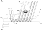
[0091]
도 10은 머리 장착 디스플레이에 사용될 수 있는 접안렌즈(950)와 통합되는 눈을 이미징하도록 구성된 예시적인 이미징 시스템(900)을 예시한다. 사용자의 눈(210) 앞에 배치될 수 있는 접안렌즈(950)는 이미지 콘텐츠를 눈에 주입할 뿐만 아니라 눈을 이미징하는 데에도 사용될 수 있다. 도 10은 하나의 눈(210) 앞에 하나의 접안렌즈(950)를 도시한다. 이를테면, 도 2에 도시된 다양한 머리 장착 디스플레이 시스템들은 각각의 왼쪽 및 오른쪽 눈들(210) 앞에 배치된 한 쌍의 접안렌즈들(950) 및 연관된 컴포넌트들을 포함할 수 있다. 도 10에는 단일 도파관(940)이 도시되어 있지만, 도파관(940)은 하나, 둘, 셋, 넷, 여섯, 일곱, 여덟 또는 그 이상의 도파관들(예컨대, 도파관들의 하나 이상의 스택들)을 포함할 수 있다.[0091]
10 illustrates an
[0092]
이미징 시스템(900)은 이미지 캡처를 가능하게 하도록 눈을 조명하는 광원 또는 조명원(960), 내부로 광을 전파시키도록 구성된 도파관(940)을 포함하는 접안렌즈(950), 및/또는 이미지 캡처를 위한 카메라와 같은 이미징 디바이스(920)를 포함할 수 있다. 접안렌즈(950)를 통해 눈에 주입될 수 있는 이미지를 생성하기 위한 이미지 투사기(930)가 또한 도시된다. 접안렌즈(950)는 조명원(960) 및/또는 이미지 투사기(930)로부터의 광을 눈으로 전송하도록 그리고 눈으로부터의 광을 카메라(920)로 전송하도록 구성된 하나 이상의 도파관들(940)을 포함할 수 있다. 접안렌즈(950)는 눈을 조명하기 위해 그리고 이미지 주입을 위해 도파관(940)에서 광을 아웃커플링하여 눈에 커플링하기 위한 그리고/또는 이미지 캡처를 위해 눈으로부터 그리고 도파관으로 광을 커플링하기 위한 하나 이상의 커플링 광학 엘리먼트들(944)을 더 포함할 수 있다. 접안렌즈(950)는 조명원(960) 및/또는 이미지 투사기(930)로부터의 광을 도파관들(940)로 커플링하기 위한 하나 이상의 인커플링 광학 엘리먼트들(942)뿐만 아니라 도파관으로부터의 광을 카메라(920)에 아웃커플링하기 위한 하나 이상의 아웃커플링 광학 엘리먼트들(952)을 추가로 포함할 수 있다.[0092]
The
[0093]
접안렌즈(950)는 머리에 착용 가능한 프레임 상에 배치될 수 있다. 접안렌즈(950)는 눈(210) 앞에 배치될 수 있다. 접안렌즈(950)는 착용자의 코에 더 가까운 내측(medial) 또는 비측(nasal) 면 및 관자놀이(temple)들에 더 가깝고 착용자의 코에서 더 먼 대향 측방 또는 관자놀이측 면을 가질 수 있다. 도 10에서, 커플링 광학 엘리먼트(944)는 (커플링 광학 엘리먼트들(944)에 대해 측방 또는 관자놀이측에 있는) 인커플링(942) 및 아웃커플링(952) 광학 엘리먼트들에 대해 내측 또는 비측에 있다. 조명원(960)은 또한 이미지 투사기(930)에 대해 더 내측 또는 비측에 있다(또는 이미지 투사기가 조명원보다 더 측방 또는 관자놀이측에 있다). 그러나 상대적인 포지션들은 서로 다를 수 있다. 예를 들어, 조명원(960)은 일부 설계들에서 이미지 투사기(930)보다 더 측방 또는 관자놀이측에 있을 수 있다.[0093]
The
[0094]
도파관(940)은 서로 대향하여 배치된 가장 넓은 표면 영역들을 갖는 2개의 주 표면들(전방 및 후방 표면)의 시트 또는 층을 포함할 수 있다. 사용자가 머리 장착 디스플레이 시스템을 착용할 때 전방 표면은 사용자의 눈(210)에서 더 멀 수 있고(착용자 앞의 환경에 더 가까울 수 있고) 후방 표면은 사용자의 눈에 더 가까울 수 있다(그리고 착용자 앞의 환경에서 더 멀 수 있다). 도파관(940)은 주 표면들 사이의 내부 전반사에 의해 광이 도파관 내부로 안내될 수 있도록 1.0보다 더 큰 굴절률을 갖는 투명 재료(예컨대, 유리, 플라스틱)를 포함할 수 있다. 동일한 번호들을 갖는 엘리먼트들은 본 명세서에서 설명되는 실시예들 중 하나 이상에 대해 동일한 기능을 가질 수 있다.[0094]
The
[0095]
도파관들(940)로부터 눈(210)으로 그리고/또는 도파관으로부터 눈으로 광을 커플링하기 위한 커플링 광학 엘리먼트(944)가 도파관(940) 상에 또는 도파관(940) 내에 배치될 수 있다. 도 10에 도시된 바와 같이, 커플링 광학 엘리먼트(944)를 통해 도파관(940)으로부터 커플링된 광이 (예를 들어, 눈을 조명하기 위해 그리고/또는 이미지 주입을 위해) 사용자의 눈(210)에 입사될 수 있도록, 커플링 광학 엘리먼트(944)는 광학 경로에서 사용자의 눈(210)과 도파관(940) 사이에 배치될 수 있다. 커플링 광학 엘리먼트(944)는 도파관 내에서 안내되는 광을 도파관 밖으로 터닝하거나 커플링 광학 엘리먼트(944)에 일정 각도로 입사된 광을 도파관으로 터닝하여 내부 전반사에 의해 도파관 내로 안내되게 하도록 구성된 복수의 터닝 피처들을 포함할 수 있다. 커플링 광학 엘리먼트(944)와 터닝 피처들은 도파관(940)과 물리적으로 맞물릴 수 있다. 예를 들어, 커플링 광학 엘리먼트(944)는 도파관(940) 내에 또는 도파관(940) 상에 패터닝된(예컨대, 에칭된) 홀로그래픽 또는 회절 광학 엘리먼트(예컨대, 표면 릴리프(relief) 격자)를 포함할 수 있다. 커플링 광학 엘리먼트(944)는 도파관(940) 상에 배치된 층을 포함할 수 있거나 도파관(940)에 형성될 수 있다. 예를 들어, 볼륨 홀로그래픽 또는 다른 회절 광학 엘리먼트는 도파관 또는 그 위에 배치된 층을 포함하는 재료의 굴절률을 변경함으로써 형성될 수 있다. 이에 따라, 커플링 광학 엘리먼트(944)는 도파관(940)의 볼륨 내에 또는 그 위에 배치된 층으로서 배치될 수 있다.[0095]
A coupling
[0096]
설계에 따라, 커플링 광학 엘리먼트(944)는 투과성 또는 반사성일 수 있으며, 투과 또는 반사시 동작할 수 있다. 예를 들어, 커플링 광학 엘리먼트(944)는 각각 투과 또는 반사시 동작하는 투과성 또는 반사성 회절 광학 엘리먼트(예컨대, 격자) 또는 홀로그래픽 광학 엘리먼트를 포함할 수 있는데, 예컨대 이를 통해 투과되는 또는 그로부터 반사되는 광을 터닝한다. 커플링 광학 엘리먼트(944)는 편광 선택적 터닝 엘리먼트(예컨대, 편광기)와 같은 편광 광학 엘리먼트를 포함할 수 있다. 편광 선택적 터닝 엘리먼트는 하나 이상의 편광 격자들, 회절 광학 엘리먼트들 및/또는 홀로그래픽 광학 엘리먼트들을 포함할 수 있고, 액정 편광 격자들과 같은 액정 구조들을 포함할 수 있다. 커플링 광학 엘리먼트(944)는 TIR(total internal reflection)에 의해 도파관(940) 내로 안내되는 이미지 투사기(930) 및/또는 광원(960)으로부터의 광을, 도파관으로부터 눈으로 방출되도록 임계 각도 미만의(예컨대, 더 수직인) 각도로 사용자의 눈(210)으로 지향시키도록 구성될 수 있다. 추가로 또는 대안으로, 커플링 광학 엘리먼트(944)는 눈(210)으로부터의 광을, 내부 전반사에 의해 도파관(940) 안에서 카메라(920)에 안내되도록 임계 각도보다 더 큰(예컨대, 덜 수직인) 각도로 커플링하도록 구성될 수 있다.[0096]
Depending on the design, the coupling
[0097]
도 10에 도시된 바와 같이, 조명원(960) 및/또는 이미지 투사기(930)로부터의 광을 도파관(940)으로 커플링하기 위한 인커플링 광학 엘리먼트(942)가 도파관(940) 상에 또는 도파관(940) 내에 배치될 수 있다. 인커플링 광학 엘리먼트(942)는, 인커플링 광학 엘리먼트(942)를 통해 광원(960)으로부터 커플링된 광이 도파관(940) 내로 안내되도록 광학 경로에서 광원(960)과 도파관(940) 사이에 배치된다. 인커플링 광학 엘리먼트(942)는 예를 들어, 그에 일정 각도로 입사된 광을 도파관으로 터닝하여 내부 전반사에 의해 도파관 내로 안내되게 하도록 구성된 복수의 터닝 피처들을 포함할 수 있다. 인커플링 광학 엘리먼트(942)는 액정 편광 격자들과 같은 액정 구조들을 포함할 수 있다. 추가로 또는 대안으로, 인커플링 광학 엘리먼트(942)는 블레이즈드(blazed) 격자를 포함할 수 있다. 인커플링 광학 엘리먼트(942)는 도파관(940) 상에 배치된 층을 포함할 수 있거나 도파관(940) 상에 또는 도파관(940) 내에 형성(예컨대, 패터닝)될 수 있거나, 그 내부에 다른 식으로 제조될 수 있다. 예를 들어, 표면 홀로그래픽 또는 회절 광학 엘리먼트(예컨대, 표면 릴리프 격자)는 도파관 또는 그 위에 층의 표면을 패터닝(예컨대, 에칭)함으로써 제작될 수 있다. 볼륨 홀로그래픽 또는 회절 광학 엘리먼트는 또한, 도파관 또는 그 위에 배치된 층을 포함하는 재료의 굴절률을 변경함으로써 형성될 수 있다. 이에 따라, 인커플링 광학 엘리먼트(942)는 도파관(940)의 볼륨 또는 그 위에 배치된 층 내에 배치될 수 있다. 설계에 따라, 인커플링 광학 엘리먼트(942)는 투과성 또는 반사성일 수 있으며, 투과 또는 반사시 동작할 수 있다. 예를 들어, 인커플링 광학 엘리먼트(942)는 각각 투과 또는 반사시 동작하는 투과성 또는 반사성 회절 광학 엘리먼트(예컨대, 격자) 또는 홀로그래픽 광학 엘리먼트를 포함할 수 있는데, 예컨대 이를 통해 투과되는 또는 그로부터 반사되는 광을 터닝한다.[0097]
10, an incoupling
[0098]
인커플링 광학 엘리먼트(942)는 반사 광학 엘리먼트(예컨대, 미러)를 포함할 수 있다. 예를 들어, 인커플링 광학 엘리먼트(942)는 오프-축 반사기를 포함할 수 있다. 추가로 또는 대안으로, 인커플링 광학 엘리먼트(942) 및/또는 커플링 광학 엘리먼트(944)는 편광 선택적 터닝 엘리먼트(예컨대, 편광기)와 같은 편광 광학 엘리먼트를 포함할 수 있다. 편광 선택적 터닝 엘리먼트는 하나 이상의 편광 격자들, 회절 광학 엘리먼트들 및/또는 홀로그래픽 광학 엘리먼트들을 포함할 수 있고, 액정 편광 격자들과 같은 액정 구조들을 포함할 수 있다. 예를 들어, 인커플링 광학 엘리먼트(942) 및/또는 커플링 광학 엘리먼트(944) 중 하나 또는 둘 다는 LCPG(liquid crystal polarization grating)들을 포함할 수 있다. LCPG들은 잠재적으로 넓은 파장들에서 고효율 회절을 제공할 수 있다. 이에 따라, LCPG들은 인커플링 광학 엘리먼트들(942) 및/또는 커플링 광학 엘리먼트(944)에 유용할 수 있다. LCPG는 편광 의존적일 수 있다. LCPG 또는 다른 타입의 액정 격자, 회절 광학 엘리먼트 또는 광학 엘리먼트는 하나 이상의 기능들을 제공하도록, 이를테면 광을 도파관 내로 또는 도파관 밖으로 터닝하도록 구성된 액정 분자들의 패턴 또는 배열을 포함할 수 있다. 이에 따라, 인커플링 광학 엘리먼트(942) 및/또는 커플링 광학 엘리먼트(944)는 편광 격자들을 포함할 수 있다. 추가로 또는 대안으로, 인커플링 광학 엘리먼트(942) 및/또는 커플링 광학 엘리먼트(944)는 액정을 포함할 수 있으며, 따라서 일부 구현들에서는 이들 중 하나 또는 둘 다가 액정 격자들 또는 액정 회절 광학 엘리먼트들일 수 있다. 추가로 또는 대안으로, 인커플링 광학 엘리먼트(942) 및/또는 커플링 광학 엘리먼트(944) 중 하나 또는 둘 다는 블레이즈드 격자를 포함할 수 있다. 일부 설계들에서, 인커플링 광학 엘리먼트(942)는 콜레스테릭 액정 반사 렌즈(예컨대, 반사성 액정 회절 렌즈, 브래그 반사(Bragg-reflective) 구조, 반사성 액정 회절 격자 등)와 같은 액정 반사기를 포함한다. 액정 격자들, 액정 편광 격자들 및 다른 액정 광학 엘리먼트들의 일부 비제한적인 예들은 다음의 공개된 출원들에서 논의되는데, 이러한 출원들 각각은 이로써 그 전체가 모든 목적을 위해 본 명세서에 참조로 포함된다: "MULTILAYER LIQUID CRYSTAL DIFFRACTIVE GRATINGS FOR REDIRECTING LIGHT OF WIDE INCIDENT ANGLE RANGES"라는 명칭으로 2017년 11월 16일자 출원된 미국 공보 제2018/0143438호; "SPATIALLY VARIABLE LIQUID CRYSTAL DIFFRACTION GRATINGS"라는 명칭으로 2017년 11월 16일자 출원된 미국 공보 제2018/0143485호; "WAVEGUIDE LIGHT MULTIPLEXER USING CROSSED GRATINGS"라는 명칭으로 2017년 11월 16일자 출원된 미국 공보 제2018/0143509호; "DISPLAY SYSTEM WITH VARIABLE POWER REFLECTOR"라는 명칭으로 2018년 2월 22일자 출원된 미국 공보 제2018/0239147호; "VARIABLE-FOCUS VIRTUAL IMAGE DEVICES BASED ON POLARIZATION CONVERSION"이라는 명칭으로 2018년 2월 22일자 출원된 미국 공보 제2018/0239177호; 및 "DIFFRACTIVE DEVICES BASED ON CHOLESTERIC LIQUID CRYSTAL"이라는 명칭으로 2017년 12월 7일자 출원된 미국 공보 제2018/0164627호. 그러나 인커플링 광학 엘리먼트(942) 및/또는 커플링 광학 엘리먼트(944)의 설계들은 이들로 제한되지 않으며, 다른 타입들의 광학 엘리먼트들, 회절 광학 엘리먼트, 액정 광학 엘리먼트, 액정 격자들 및 액정 편광 격자들을 포함할 수 있다. 반사기들과 같은 콜레스테릭 액정 구조들의 예들에 대한 추가 정보는 또한 아래의 "콜레스테릭 액정 미러"라는 명칭의 섹션에서 확인될 수 있다. 앞서 논의한 바와 같이, 다른 액정 광학 엘리먼트들뿐만 아니라 다른 비-액정 광학 엘리먼트들도 사용될 수 있다. 이에 따라, 본 명세서에서 설명되는 것들뿐만 아니라 일반적으로 다른 타입들의 격자들, 회절 광학 엘리먼트들, 액정 엘리먼트들 및 광학 엘리먼트들 모두인 많은 타입들의 커플링 광학 엘리먼트들(예컨대 인커플링 광학 엘리먼트(942) 및/또는 커플링 광학 엘리먼트(944)), 회절 광학 엘리먼트, 격자들, 편광 격자들 등이 사용될 수 있다. 다양한 구현들에서, 인커플링 광학 엘리먼트(942)는 이미지 투사기(930) 및/또는 광원(960)으로부터의 광을, 도파관(940) 내에서 내부 전반사에 의해 사용자의 눈(210)으로 안내되도록 임계 각도보다 더 큰 각도로 도파관에 커플링하도록 구성될 수 있다.[0098]
The incoupling
[0099]
도파관(940)은 하나 이상의 도파관들을 포함할 수 있다. 일부 구현들에서, 하나 이상의 도파관들(940)은 도파관들의 스택을 포함한다. 일부 설계들에서, 예를 들어, 도파관들의 스택의 서로 다른 도파관들은 마치 사용자의 눈으로부터의 서로 다른 거리들로부터 투사된 것처럼 서로 다른 파면 발산으로 광을 출력하도록 구성된다. 예를 들어, 제1 도파관 또는 도파관들의 그룹은 마치 제1 깊이로부터 투사된 것처럼 시준되거나 제1 발산을 갖는 광을 출력하도록 구성될 수 있고, 제2 도파관 또는 도파관들의 그룹은 마치 제1 깊이보다 더 가까운 제2 깊이로부터 투사된 것처럼 발산하고 있거나(시준되지 않음) (제1 발산보다 더 큰) 제2 발산에 있는 광을 출력하도록 구성될 수 있다. 일부 설계들에서, 서로 다른 도파관들은 서로 다른 연관된 컬러들을 갖는 광을 출력하도록 구성될 수 있다. 예를 들어, 제1 도파관은 적색 광을 출력하도록 구성될 수 있고, 제2 도파관은 녹색 광을 출력하도록 구성될 수 있으며, 제3 도파관은 청색 광을 출력하도록 구성될 수 있다. 제4 도파관은 적외선 광을 출력 및/또는 입력하도록 구성될 수 있다.[0099]
The
[0100]
도파관(940)으로부터의 광을 카메라(920)에 커플링하기 위한, 이를테면 도 10에 도시된 아웃커플링 광학 엘리먼트(952)는 예를 들어, 입사되는 광이 도파관 내에서 안내되지 않고 도파관으로부터 카메라로 터닝되도록 그러한 광을 일정 각도로 터닝하도록 구성된 복수의 터닝 피처들을 포함할 수 있다. 아웃커플링 광학 엘리먼트(952)는 도파관(940)의 내부 내에 배치될 수 있거나 도파관(940)의 표면(예컨대, 주 표면) 내에 또는 그 표면 상에 패터닝(예컨대, 에칭)될 수 있다. 예를 들어, 표면 홀로그래픽 또는 회절 광학 엘리먼트(예컨대, 표면 릴리프 격자)는 도파관 또는 그 위에 층의 표면을 패터닝(예컨대, 에칭)함으로써 제작될 수 있다. 볼륨 홀로그래픽 또는 회절 광학 엘리먼트는 또한, 도파관 또는 그 위에 배치된 층을 포함하는 재료의 굴절률을 변경함으로써 형성될 수 있다. 설계에 따라 아웃커플링 광학 엘리먼트(952)는 투과성 또는 반사성일 수 있으며, 투과 또는 반사시 동작할 수 있다. 예를 들어, 아웃커플링 광학 엘리먼트(952)는 각각 투과 또는 반사시 동작하는 투과성 또는 반사성 회절 광학 엘리먼트(예컨대, 격자) 또는 홀로그래픽 광학 엘리먼트를 포함할 수 있는데, 예컨대 이를 통해 투과되는 또는 그로부터 반사되는 광을 터닝한다.[0100]
For coupling light from the
[0101]
아웃커플링 광학 엘리먼트(952)는 반사 광학 엘리먼트(예컨대, 미러)를 포함할 수 있다. 예를 들어, 아웃커플링 광학 엘리먼트(952)는 오프-축 반사기를 포함할 수 있다. 일부 설계들에서, 아웃커플링 광학 엘리먼트(952)는 편광 선택적 터닝 엘리먼트(예컨대, 편광기)와 같은 편광 광학 엘리먼트를 포함할 수 있다. 이에 따라, 편광 선택적 터닝 엘리먼트는 하나 이상의 편광 격자들, 회절 광학 엘리먼트들 및/또는 홀로그래픽 광학 엘리먼트들을 포함할 수 있고, 액정 편광 격자들과 같은 액정 구조들을 포함할 수 있다. 일부 구현들에서, 예를 들어, 아웃커플링 광학 엘리먼트(952)는 LCPG(liquid crystal polarization grating)들을 포함할 수 있다. LCPG들은 잠재적으로 넓은 파장들에서 고효율 회절을 제공할 수 있다. 마찬가지로, LCPG들은 아웃커플링 광학 엘리먼트(952)에 유용할 수 있다. LCPG는 편광 의존적일 수 있다. LCPG 또는 다른 타입들의 액정 격자들은 하나 이상의 기능들을 제공하도록, 이를테면 광을 도파관 내로 또는 도파관 밖으로 터닝하도록 구성된 액정 분자들의 패턴 또는 배열을 포함할 수 있다. 이에 따라, 아웃커플링 광학 엘리먼트(952)는 편광 격자들을 포함할 수 있다. 추가로 또는 대안으로, 아웃커플링 광학 엘리먼트(952)는 액정을 포함할 수 있고, 따라서 일부 구현들에서 액정 격자들 또는 다른 액정 광학 엘리먼트, 이를테면 액정 회절 광학 엘리먼트들일 수 있다. 추가로 또는 대안으로, 아웃커플링 광학 엘리먼트(952)는 블레이즈드(blazed) 격자를 포함할 수 있다. 일부 설계들에서, 아웃커플링 광학 엘리먼트(952)는 콜레스테릭 액정 반사 렌즈(예컨대, 반사성 액정 회절 렌즈, 브래그 반사 구조, 반사성 액정 회절 격자 등)와 같은 액정 반사기를 포함한다. 액정 격자들, 액정 편광 격자들 및 다른 액정 광학 엘리먼트들의 일부 비제한적인 예들은 다음의 공개된 출원들에서 논의되는데, 이러한 출원들 각각은 이로써 그 전체가 모든 목적을 위해 본 명세서에 참조로 포함된다: "MULTILAYER LIQUID CRYSTAL DIFFRACTIVE GRATINGS FOR REDIRECTING LIGHT OF WIDE INCIDENT ANGLE RANGES"라는 명칭으로 2017년 11월 16일자 출원된 미국 공보 제2018/0143438호; "SPATIALLY VARIABLE LIQUID CRYSTAL DIFFRACTION GRATINGS"라는 명칭으로 2017년 11월 16일자 출원된 미국 공보 제2018/0143485호; "WAVEGUIDE LIGHT MULTIPLEXER USING CROSSED GRATINGS"라는 명칭으로 2017년 11월 16일자 출원된 미국 공보 제2018/0143509호; "DISPLAY SYSTEM WITH VARIABLE POWER REFLECTOR"라는 명칭으로 2018년 2월 22일자 출원된 미국 공보 제2018/0239147호; "VARIABLE-FOCUS VIRTUAL IMAGE DEVICES BASED ON POLARIZATION CONVERSION"이라는 명칭으로 2018년 2월 22일자 출원된 미국 공보 제2018/0239177호; 및 "DIFFRACTIVE DEVICES BASED ON CHOLESTERIC LIQUID CRYSTAL"이라는 명칭으로 2017년 12월 7일자 출원된 미국 공보 제2018/0164627호. 그러나 아웃커플링 광학 엘리먼트(952)의 설계들은 이들로 제한되지 않으며, 다른 타입들의 광학 엘리먼트들, 회절 광학 엘리먼트, 액정 광학 엘리먼트, 액정 격자들 및 액정 편광 격자들을 포함할 수 있다. 반사기들과 같은 콜레스테릭 액정 구조들의 예들에 대한 추가 정보는 또한 아래의 "콜레스테릭 액정 미러"라는 명칭의 섹션에서 확인될 수 있다. 앞서 논의한 바와 같이, 다른 액정 광학 엘리먼트들뿐만 아니라 다른 비-액정 광학 엘리먼트들도 사용될 수 있다. 이에 따라, 본 명세서에서 설명되는 것들뿐만 아니라 일반적으로 다른 타입들의 격자들, 회절 광학 엘리먼트들, 액정 엘리먼트들 또는 광학 엘리먼트들 모두인 많은 타입들의 커플링 광학 엘리먼트들(예컨대 아웃커플링 광학 엘리먼트(952)), 회절 광학 엘리먼트, 격자들, 편광 격자들 등이 사용될 수 있다. 위에서 언급한 바와 같이, 아웃커플링 광학 엘리먼트(952)는 도파관(940) 내에서 안내되는 광을, 내부 전반사에 의해 도파관 내에서 안내되는 것이 아니라 카메라(920)로 방출되도록 임계 각도 미만인 각도로 재지향하도록 구성될 수 있다.[0101]
The outcoupling
[0102]
다양한 설계들에서, 커플링 광학 엘리먼트(944)는 사용자가 사용자 앞의 환경에 대해 접안렌즈(950) 및 커플링 광학 엘리먼트(944)를 통해 볼 수 있도록 가시 스펙트럼에 투명할 수 있다. 인커플링 광학 엘리먼트(942)는 또한 예를 들어, 인커플링 광학 엘리먼트가 이미지 투사기(930)로부터 광을 수신하는 데 사용된다면 그리고/또는 조명원(960)이 가시광을 출력하여 가시광으로 눈(210)을 조명하도록 구성된다면, 가시 스펙트럼에서 광을 터닝할 수 있다. 일부 실시예들에서, 인커플링 광학 엘리먼트(942)는 예를 들어, 조명원(960)이 적외선 광을 출력하여 적외선 광으로 눈(210)을 조명하도록 구성된다면, 적외선 광을 터닝하도록 구성된다. 이를테면, 도 10에 도시된 일부 설계들에서, 인커플링 광학 엘리먼트(942)는 아웃커플링 광학 엘리먼트(952)보다 더 내측 또는 비측일 수 있다. 그러나 다른 설계들에서, 인커플링 광학 엘리먼트(942)는 아웃커플링 광학 엘리먼트(952)보다 더 측방이거나 관자놀이측일 수 있다. 이를테면, 도 10에 도시된 특정 구현들에서는, 인접하지 않은 포지셔닝이 가능하더라도, 아웃커플링 광학 엘리먼트(952)는 인커플링 광학 엘리먼트(942)에 인접할 수 있다.[0102]
In various designs, the coupling
[0103]
도 10에 도시된 바와 같이, 조명원(960)은 눈(210)과 동일한 접안렌즈(950) 측(예컨대, 후방 또는 근단(proximal) 측)에 배치될 수 있다. (근단은 눈(210)에 가장 가까운 측을 의미할 수 있다.) 대안으로, 조명원(960)은 눈(210) 반대 측(예컨대, 전방 또는 원단(distal) 측)에 배치될 수 있다. 조명원(960)은 인커플링 광학 엘리먼트(942)를 통해 도파관(940)의 주 표면들 중 적어도 하나로 광을 지향시키도록 구성될 수 있다. 광원(960)은 비가시광(예컨대, 적외선)을 방출하도록 구성될 수 있다. 광원(960)은 하나 이상의 LED들을 포함할 수 있다. LED들은 적외선 LED들을 포함할 수 있다. 광원(960)은 코히어런트 광을 방출하도록 구성될 수 있다. 일부 설계들에서, 광원(960)은 레이저(예컨대, 적외선 레이저)를 포함한다. 일부 설계들에서, 광원(960)은 펄스 광을 방출한다. 예를 들어, 카메라(920)는 이미지를 주기적으로 캡처하도록 구성될 수 있다. 이에 따라, 조명원(960)은 카메라가 이미지를 획득하는 기간과 일치하도록 펄스화될 수 있다. 조명원(960)으로부터 출력되는 세기는 카메라가 이미지를 획득하지 않고 있을 때 감소될 수 있다. 짧은 시간에 조명의 총 에너지를 집중시킴으로써, 눈(210)을 안전하지 않은 세기 레벨들에 노출시키지 않으면서 증가된 신호대 잡음비가 얻어질 수 있다. 일부 경우들에, 예를 들어, 카메라(920)는 30 밀리초마다 하나의 이미지를 캡처하고 카메라의 노출 시간은 수 밀리초이다. 조명원(960)은 카메라(920)의 펄스들과 매칭하도록 유사한 주기 및 지속기간을 갖는 펄스들을 출력하도록 구성될 수 있다.[0103]
As illustrated in FIG. 10, the
[0104] 일부 구현들에서, 아래에서 논의되는 바와 같이, 서로 다른 시점들에 서로 다른 파장의 조명을 제공하도록 서로 다른 파장들을 갖는 서로 다른 광원들이 교대로 펄스화된다.[0104] In some implementations, as discussed below, different light sources with different wavelengths are alternately pulsed to provide different wavelengths of illumination at different times.
[0105]
인커플링 광학 엘리먼트(942)는 예를 들어, 이미지 투사기(930) 및/또는 광원(960)으로부터의 광을 내부에 안내하도록, 상기 이미지 투사기(930) 및/또는 조명원(960)과 직접 광통신할 수 있다. 예를 들어, 광원(960)에 의해 방출된 광은 커플링 광학 엘리먼트(944) 및/또는 아웃커플링 광학 엘리먼트(952)와 광학적으로 상호 작용하기 전에 인커플링 광학 엘리먼트(942)에 입사될 수 있다.[0105]
The incoupling
[0106]
도 11a - 도 11e에 도시된 바와 같이, 이미지 투사기(930)로부터 투사된 광(902)은 망막에 이미지를 형성할 수 있다. 이미지 투사기(930)는 광원, 변조기 및/또는 투사 광학기를 포함할 수 있다. 이미지 투사기(930)에 대한 광원은 하나 이상의 LED들, 레이저들 또는 다른 광원들을 포함할 수 있고, 하나 이상의 가시광원들을 포함할 수 있다. 변조기는 액정 공간 광 변조기와 같은 공간 광 변조기를 포함할 수 있다. 이러한 공간 광 변조기는 예를 들어, 서로 다른 공간 위치들에서 광의 세기를 변조하도록 구성될 수 있다. 투사 광학기는 하나 이상의 렌즈들을 포함할 수 있다. 이미지들을 투사 및/또는 형성할 수 있는 다른 타입들의 이미지 투사기들(930)이 이용될 수 있다. 예를 들어, 이미지 투사기(930)는 스캐닝 광섬유를 포함할 수 있다.[0106]
11A-11E, light 902 projected from the
[0107]
이미지 투사기(930) 및 인커플링 광학 엘리먼트(942)는 서로 직접 광통신할 수 있다. 이미지 투사기(930)는 예를 들어, 이미지 투사기(930)로부터의 광이 지향되는 인커플링 광학 엘리먼트(942)와 정렬될 수 있다. 일부 경우들에, 이미지 투사기(930)는 대응하는 인커플링 광학 엘리먼트(942) 및/또는 도파관(940)에 인접하게 배치된다. 이미지 투사기(930)는 또한 인커플링 광학 엘리먼트(942), 커플링 광학 엘리먼트(944) 및 눈(210)을 포함하는 광학 경로에 배치될 수 있다.[0107]
The
[0108]
도 10뿐만 아니라 도 11a - 도 11e에 도시된 바와 같이, 이미지 투사기(930)는 조명원(960)과는 별개인 엘리먼트일 수 있다. 그러나 일부 경우들에는, 이미지 투사기(930)가 조명원으로서 사용될 수 있다. 예를 들어, 이미지들을 눈(210)에 주입하는 것뿐만 아니라, 이미지 투사기(930)는 이미지 캡처를 위해 눈을 조명하도록 가시 및/또는 적외선 광을 눈으로 지향시키는 데 사용될 수 있다. 그러나 대안으로, 하나 이상의 개별 광원들(960)이 이미지 캡처를 위해 눈(210)을 조명하는 데 사용될 수 있다.[0108]
11A to 11E as well as FIG. 10, the
[0109]
조명원(960)에 의해 방출되는 광은 예를 들어, 비가시광과 같은 특정 파장 범위의 광을 포함할 수 있다. 조명원(960)은 눈(210)의 하나 이상의 부분들(예컨대, 각막, 망막)을 이미징하기 위해 눈(210) 상으로/안으로 비가시(예컨대, 적외선) 광을 투사하도록 구성될 수 있다. 특정 예시적인 구현들에서, 광원(960)은 약 850㎚ 내지 940㎚ 범위의 광을 방출하도록 구성될 수 있다. 광원(960)은 적어도 약 20㎚의 파장 범위에 걸쳐 연장되는 광을 방출하도록 구성될 수 있다. 다른 범위들도 또한 가능하다. 방출되는 파장 범위는 5㎚, 10㎚, 15㎚, 50㎚, 75㎚, 100㎚, 150㎚, 200㎚, 또는 이러한 값들 중 임의의 값 사이의 임의의 범위일 수 있다. 광원(960)은 적외선 스펙트럼 내의 임의의 범위와 같은 광대역의 파장들에 걸쳐 광을 방출하도록 구성될 수 있다.[0109]
The light emitted by the
[0110]
카메라를 포함할 수 있는 이미징 디바이스(920)는 검출기 어레이 및 가능하게는 이미징 광학기를 포함할 수 있다. 검출기 어레이는 예를 들어, CCD 또는 CMOS 검출기 어레이를 포함할 수 있고, 이미징 광학기는 하나 이상의 렌즈들을 포함할 수 있다. 하나 이상의 렌즈들은 양의 광학 배율 및 연관된 초점 길이를 가질 수 있다. 특정 설계들에서, 카메라(920)는 무한대에 초점이 맞춰진다. 예를 들어, 광학기는 초점 길이(f)를 가질 수 있고, 검출기 어레이는 넓은 거리의 오브젝트들이 검출기 어레이 상으로 이미징되도록 광학기로부터 초점 길이에 대응하는 거리를 두고 배치될 수 있다. 마찬가지로, 시준되는 환경에서 눈 또는 오브젝트들로부터의 광은 검출기 어레이에 초점이 맞춰져 그 위에 눈 또는 오브젝트의 이미지를 형성할 것이다.[0110]
[0111]
이미징 디바이스(920)는 조명원(960) 및/또는 눈(210)과 도파관(940)의 반대 측에 배치될 수 있다. 일부 설계들에서, 이미징 디바이스(920)는 광원(960) 및/또는 눈(210)과 도파관(940)의 동일 측에 배치될 수 있다. 도 10에 도시된 바와 같이, 이미징 디바이스(920)는 다른 위치들이 가능하지만 접안렌즈(950)의 측방 또는 관자놀이측 에지 근처에 배치될 수 있다.[0111]
[0112]
도 11a - 도 11e는 도 10의 예시적인 이미징 시스템(900)의 동작을 예시한다. 도 11a는 도파관(940) 상의 인커플링 광학 엘리먼트(942)를 향해 광(902)을 방출하는 조명원(960)을 도시한다. 도시된 바와 같이, 다른 각도들이 가능하지만 광(902)은 일반적으로 수직 입사로 접안렌즈(950)에 지향될 수 있다. 일부 설계들에서, 광원(960)은 시준된 광을 접안렌즈(950)로 방출하도록 구성된다. 도 11b에 도시된 바와 같이, 조명 광(902)은 인커플링 광학 엘리먼트(942)를 통해 도파관(940)에 커플링될 수 있다. 인커플링 광학 엘리먼트(942)가 회절 광학 엘리먼트(예컨대, 격자, 홀로그래픽 엘리먼트)를 포함하는 일부 설계들에서, 그 위에 입사된 광이 도파관의 임계 각도보다 더 큰 각도로 회절되어, 인커플링된 광(904)이 TIR(total internal reflection)에 의해 접안렌즈(950) 내로 안내되게 한다. 일부 설계들에서, 인커플링 광학 엘리먼트(942)는 커플링 광학 엘리먼트(944)를 향해 광을 지향시키도록 구성될 수 있다. 인커플링 광학 엘리먼트(942)는 편광 선택적일 수 있다. 예를 들어, 인커플링 광학 엘리먼트(942)는 편광 선택적 터닝 엘리먼트, 이를테면 액정 편광 격자와 같은 편광 격자를 포함할 수 있다. 도 11c는 인커플링된 광(904)이 TIR에 의해 어떻게 도파관(940)을 통해 전파되는지를 도시한다.[0112]
11A-11E illustrate the operation of the
[0113]
도 11d는 접안렌즈(950)에서 광을 아웃커플링하는 예시적인 이미징 시스템(900)을 예시한다. 인커플링된 광(904)이 도파관(940)을 통해 전파될 때, 광의 일부가 커플링 광학 엘리먼트(944)에 입사될 수 있다. 커플링 광학 엘리먼트(944)는 인커플링된 광(904)을 사용자의 눈(210)을 향해 접안렌즈(950)에서 아웃커플링하도록 구성될 수 있다. 커플링 광학 엘리먼트(944)는 광을 시준된 광으로서 눈(210)을 향해 커플링하도록 구성될 수 있다. 커플링 광학 엘리먼트(944)는 특정 파장 범위의 광으로 튜닝될 수 있다. 예를 들어, 커플링 광학 엘리먼트(944)는 도파관(940)에서 적외선 광(예컨대, 약 700㎚ 내지 15000㎚)을 아웃커플링하도록 구성될 수 있다. 일부 설계들에서, 커플링 광학 엘리먼트(944)는 다수의 광 파장들을 접안렌즈(950)에서 아웃커플링하도록 구성될 수 있다. 예를 들어, 커플링 광학 엘리먼트(944)는 적외선과 가시광 모두에 대해 튜닝될 수 있다. 커플링 광학 엘리먼트(944)는 또한 아래에서 더 상세히 설명되는 바와 같이 광을 도파관(940)에 커플링하도록 구성될 수 있다.[0113]
11D illustrates an
[0114]
커플링 광학 엘리먼트(944)는 사용자에 대한 아이 박스의 하나 이상의 치수들을 증가시키도록 구성될 수 있다. 예를 들어, 하나 이상의 치수들은 제1 축(예컨대, x 축)을 따라 측정될 수 있다. 접안렌즈(950)는 OPE(orthogonal pupil expander)를 더 포함할 수 있다. OPE는 도파관 상에 또는 도파관 내에(예컨대, 주 표면들 중 하나 상에) 배치된 적어도 하나의 광 재지향 엘리먼트를 가질 수 있거나 OPE가 도파관(940) 내에 배치될 수 있다. OPE는 위의 광 분배 엘리먼트들(730, 740, 750)에 대해 앞서 설명한 것들과 유사한 또는 동일한 특징들을 포함할 수 있다. 일부 구현들에서, 광 재지향 엘리먼트는 회절 광학 엘리먼트를 포함할 수 있다. OPE는 제1 축에 직교하는 제2 축(예컨대, y 축)을 따라 아이 박스의 치수를 증가시키도록 구성될 수 있다.[0114]
Coupling
[0115]
도 11d는 광의 일부가 접안렌즈(950)에서 사용자의 눈(210)을 향해 출사하는 것을 도시한다. 일부 설계들에서, 커플링 광학 엘리먼트(944)는, (예컨대, x 축에 평행한) 제1 축을 따라 커플링 광학 엘리먼트(944)의 다양한 부분들에서 커플링 광학 엘리먼트(944)에 입사되는 인커플링된 광(904)이 제1 축을 따라 커플링 광학 엘리먼트(944)의 각각의 부분에서 접안렌즈(950)에서 출사되도록 구성된다. 이는 서로 다른 눈 포지션들 또는 위치들에 대해 이미지들을 투사하거나 눈을 조명하기 위한 광을 사용자에게 제공할 수 있다.[0115]
11D shows that a portion of the light exits the
[0116]
도 11d - 도 11e에 도시된 바와 같이, 커플링 광학 엘리먼트(944)는 인커플링된 광(904)을 시준된 광으로서 접안렌즈(950)에서 아웃커플링하도록 구성될 수 있다. 이 광은 또한 접안렌즈(950) 및/또는 도파관(940)의 주 표면에 대해 일반적으로 거의 수직으로 지향될 수 있다. 시준된 광은 눈으로 지향되고 눈(예컨대, 눈의 각막 및 수정체)에 의해 망막에 초점을 맞출 수 있다. 망막에 입사되는 이 광(908)은 망막을 이미징하고 그리고/또는 눈에 이미지 콘텐츠를 제공하기 위한 조명을 제공할 수 있다. 예를 들어, 이 광(908)의 일부는 망막에서 반사되거나 산란되어, 눈에서 출사되고, 캡처될 망막의 이미지들을 제공할 수 있다. 광원(960)은 광이 망막의 영역을 조명하도록 확장된 광원일 수 있다.[0116]
11D-11E, the coupling
[0117]
도 12a - 도 12e는 도 11a - 도 11e의 이미징 시스템(900)이 추가로 또는 대안으로 눈(210)의 이미지 수집에 어떻게 사용될 수 있는지를 예시한다. 도 12a는 망막으로부터 반사된 광(910)이 눈(210)에서 출사되는 것을 도시한다. 도시된 바와 같이, 망막으로부터 산란 또는 반사되어 눈의 수정체, 눈의 동공 및 각막을 통과하는 광(910)이 시준될 수 있다. 이 광은 또한 수직 입사로(예컨대, 커플링 광학 엘리먼트(944) 및/또는 도파관(940)의 주 표면에 직각으로) 접안렌즈(950)에 입사될 수 있다. 커플링 광학 엘리먼트(944)는 망막으로부터 반사된 광(910)을 도파관(940)에 커플링하도록 구성될 수 있다.[0117]
12A-12E illustrate how the
[0118]
도 12b는 예시적인 이미징 시스템(900)을 예시하는데, 그 시스템이 접안렌즈(950)에 광을 커플링할 때를 예시한다. 커플링 광학 엘리먼트(944)는 회절 광학 엘리먼트, 또는 도파관(940) 내로 안내되도록 임계 각도보다 더 큰 각도로 광을 재지향하는 다른 구조들과 같은 터닝 피처를 포함할 수 있다. 커플링 광학 엘리먼트(944)는 일반적으로, 인커플링된 광(914)을 광원(960) 및/또는 이미징 디바이스(920)를 향해 지향시키도록 구성될 수 있다. 커플링 광학 엘리먼트(944)는 카메라(920)를 향해 전파되는 이 광의 일부 미만을 다시 도파관(940)에서 아웃커플링하도록 구성될 수 있다. 예를 들어, 커플링 광학 엘리먼트(944)가 배치되는 도파관(940)의 부분들을 따라 도파관(940)으로부터의 인커플링된 광(914)의 누설을 감소시키면서 인커플링된 광(914)의 일부가 내부 전반사에 의해 도파관(940) 내에서 계속 전파하도록 도파관(940) 상에 또는 도파관(940) 내에 부분 반사성 엘리먼트(예컨대, 반투명 미러)가 배치될 수 있다. 누설되지 않는 광의 부분은 0과 1 사이의 임의의 분수일 수 있다. 예를 들어, 그 부분은 0.90일 수 있으며, 여기서 커플링 광학 엘리먼트(944)를 따라 도파관(940)을 통해 전파되는 광선들의 90%가 광선들의 각각의 반사시 도파관(940) 내에 유지된다. 다른 부분들(예컨대, 0.10, 0.20, 0.30, 0.40, 0.50, 0.60, 0.70, 0.80, 또는 이러한 값들 중 임의의 값 사이의 임의의 범위)이 가능하다. 이러한 부분 반사성 엘리먼트(들)는 아래에서 설명되는 구현들에서 유사하게 사용될 수 있다.[0118]
12B illustrates an
[0119]
도 12c에 도시된 바와 같이, 시준된 인커플링된 광(914)은 이미징 디바이스(920)를 향해 도파관(940)을 통해 계속 전파할 수 있다. 도 12d는 인커플링된 광(914)의 일부가 하나 이상의 아웃커플링 광학 엘리먼트들(952)에 입사될 때까지 어떻게 계속 전파될 수 있는지를 도시한다. 인커플링 광학 엘리먼트(942)로부터의 인커플링된 광(914)의 누설량을 감소시키기 위해, 인커플링 광학 엘리먼트(942)는 카메라(920)를 향해 전파되는 이 광을 다시 도파관에서 거의 아웃커플링하지 않도록 구성될 수 있다. 예를 들어, 인커플링 광학 엘리먼트(942)가 배치되는 도파관(940)의 부분들을 따라 도파관(940)으로부터의 인커플링된 광(914)의 누설을 감소시키면서 인커플링된 광(914)의 일부가 내부 전반사에 의해 도파관(940) 내에서 계속 전파하도록 도파관(940) 상에 또는 도파관(940) 내에 부분 반사성 엘리먼트(예컨대, 반투명 미러)가 배치될 수 있다. 누설되지 않는 광의 부분은 0과 1 사이의 임의의 분수일 수 있다. 예를 들어, 그 부분은 0.90일 수 있으며, 여기서 커플링 광학 엘리먼트(944)를 따라 도파관(940)을 통해 전파되는 광선들의 90%가 광선들의 각각의 반사시 도파관(940) 내에 유지된다. 다른 부분(예컨대, 0.10, 0.20, 0.30, 0.40, 0.50, 0.60, 0.70, 0.80, 또는 이러한 값들 중 임의의 값 사이의 임의의 범위)이 가능할 수 있다. 이러한 부분 반사성 엘리먼트(들)는 아래에서 설명되는 구현들에서 유사하게 사용될 수 있다.[0119]
As shown in FIG. 12C, collimated incoupled light 914 can continue to propagate through
[0120]
도 12e에 도시된 바와 같이, 아웃커플링 광학 엘리먼트(952)는 도파관(940) 내에서 안내된 광을 도파관(940)에서 아웃커플링하고 이미징 디바이스(920)에 커플링하도록 구성될 수 있다. 그 결과, 도파관(940)에서 전파되어, 아웃커플링 엘리먼트(952)에 입사되는 광은 도파관(940)으로부터, 예를 들어 도파관(940)의 주 표면(예컨대, 도파관(940)의 전방 또는 후방 측)으로부터 방출되어 이미징 디바이스(920)에 지향되도록 재지향될 수 있다. 아웃커플링 광학 엘리먼트(952)는 도파관(940)의 주 표면에 직각(예컨대, 수직)으로 도파관(940)에서 출사되게 광(926)을 지향시키도록 구성될 수 있다. 일부 설계들에서, 아웃커플링 광학 엘리먼트(952)는 시준된 광(924)을 이미징 디바이스(920)의 광 감지 부분에 대한 수직 입사로 이미징 디바이스(920)에 지향시키도록 구성된다. 앞서 논의한 바와 같이, 카메라(920)는 무한대로 초점이 맞춰질 수 있는데, 예를 들어 이미징 광학기는 시준된 광을 검출기 어레이에 초점을 맞추도록 구성될 수 있다.[0120]
12E, the outcoupling
[0121]
이에 따라, 도파관(940)은 사용자의 눈(210)의 적어도 일부의 이미지를 캡처하기 위해 사용자의 눈(210)으로부터 도파관(940)으로 커플링된 광을 이미징 디바이스(920)(예컨대, 카메라)에 의해 수신되게 안내하도록 구성될 수 있다. 이미지 투사기(930)로부터의 광이 사용자의 눈(210)으로 지향될 수 있어 이미지 투사기(930)로부터의 이미지가 사용자의 시계 내에 있게 이미지 투사기(930)로부터 커플링된 광을 안내하도록 동일한 도파관(940)이 구성될 수 있다. 일부 구현들에서, 조명원으로부터의 광이 눈을 조명하도록 사용자의 눈(210)에 지향될 수 있어 눈의 이미지가 카메라(920)에 의해 캡처될 수 있게 동일한 도파관이 조명원(960)으로부터 커플링된 광을 안내하도록 구성된다.[0121]
Accordingly, the
[0122]
일부 구현들에서, 동일한 커플링 광학 엘리먼트(944)는 (ⅰ) 사용자의 눈(210)으로부터의 광을 도파관(940)에 커플링하여 이미징 디바이스(920)에 의해 수신되게 하고 (ⅱ) 이미지 투사기(930)로부터의 광을 도파관(940)으로부터 사용자의 눈(210)으로 아웃커플링하여 이미지 콘텐츠를 사용자의 시야에 투사하도록 구성될 수 있다. 일부 구현들에서, 동일한 커플링 광학 엘리먼트(944)는 조명원으로부터의 광이 눈을 조명할 수 있도록 조명원(960)으로부터의 광을 도파관으로부터 사용자의 눈(210)으로 아웃커플링하도록 구성될 수 있다.[0122]
In some implementations, the same coupling optical element 944 (i) couples light from the user's
[0123]
다른 설계들에서는, 상이한 도파관들이 사용될 수 있고 그리고/또는 상이한 커플링 광학 엘리먼트들(944)이 사용될 수 있다. 예를 들어, 일부 설계들에서, 제1 도파관(940)은 사용자의 눈(210)의 적어도 일부의 이미지를 캡처하기 위해 사용자의 눈(210)으로부터 커플링된 광을 카메라(920)에 의해 수신되게 안내하도록 구성될 수 있고, 제2 도파관은 이미지 투사기(930)로부터의 광이 사용자의 눈(210)으로 지향될 수 있게 이미지 투사기(930)로부터 커플링된 광을 안내하도록 구성될 수 있다. 제1 도파관과 제2 도파관은 서로의 상부에 스택될 수 있다. 다른 도파관은 추가로 또는 대안으로, 조명원으로부터의 광이 눈을 조명하도록 사용자의 눈(210)에 지향될 수 있게 조명원(960)으로부터 커플링된 광을 안내하도록 구성될 수 있다.[0123]
In other designs, different waveguides can be used and / or different coupling
[0124]
또한, 일부 구현들에서, 제1 커플링 광학 엘리먼트(944)는 (ⅰ) 사용자의 눈(210)으로부터의 광을 도파관(940)에 커플링하여 이미징 디바이스(920)에 의해 수신되게 하고 (ⅱ) 이미지 투사기(930)로부터의 광을 도파관(940)으로부터 사용자의 눈(210)으로 아웃커플링하여 이미지 콘텐츠를 사용자의 시야에 투사하도록 구성될 수 있다. 다른 커플링 광학 엘리먼트는 추가로 또는 대안으로, 조명원으로부터의 광이 눈을 조명할 수 있도록 조명원(960)으로부터의 광을 도파관으로부터 사용자의 눈(210)으로 아웃커플링하도록 구성될 수 있다.[0124]
Further, in some implementations, the first coupling optical element 944 (i) couples light from the user's
[0125]
일부 설계들에서, 커플링 광학 엘리먼트(944)는 복수의 DOE(diffractive optical element)들을 포함할 수 있다. 예를 들어, 제1 DOE는 이미징 디바이스(920)에 의해 수신되게 사용자의 눈(210)으로부터의 광을 도파관(940)에 커플링하도록 구성될 수 있다. 제2 DOE는 이미지 투사기(930)로부터의 광을 도파관(940)에서 사용자의 눈(210)으로 아웃커플링하여 이미지 콘텐츠를 사용자의 시야에 투사하도록 구성될 수 있다. 선택적으로, 제3 DOE는 광원(960)으로부터의 광을 도파관(940)에서 사용자의 눈(210)으로 아웃커플링하여 눈을 조명하도록 구성될 수 있다. 제1 DOE 및 제2 DOE(그리고 가능하게는 제3 DOE)는 예컨대, 일부 구현들에서, 사용자 앞의 환경으로부터의 광이 제1 DOE를 통과한 다음 제2 DOE에 입사된 후 제3 DOE에 입사되고 사용자의 눈에 입사되도록 스택될 수 있다. 그러나 그 순서는 다를 수 있다.[0125]
In some designs, the coupling
[0126]
일부 설계들에서, 제1 DOE 및 제2 DOE는 도파관(940)의 단일 엘리먼트 또는 볼륨에 통합된다. 일부 구현들에서, 예를 들어, 제1 DOE와 제2 DOE 모두가 도파관(2102) 내에서 서로 위에 포개진다(예컨대, 동일한 또는 거의 동일한 볼륨을 점유한다). 예를 들어, 제1 DOE 및 제2 DOE는 동일한 매체에 기록될 수 있다.[0126]
In some designs, the first DOE and the second DOE are integrated into a single element or volume of
[0127]
앞서 설명한 바와 같이, 눈의, 예컨대 망막의 이미지 캡처는 눈 추적을 가능하게 할 수 있다. 예를 들어, 도 13a는 예를 들어, 눈이 서로 다른 포지션들에 있을 때 서로 다른 시점들에 눈(210)의 다양한 부분들(예컨대, 망막)을 이미징하도록 구성된 이미징 시스템(900)을 예시한다. 스테이지 A 및 스테이지 B는 눈의 서로 다른 배향들 동안의 눈(210)의 이미지들을 의미할 수 있다. 도 13a는 스테이지 A 이미징과 스테이지 B 이미징 모두 동안의 눈(210)의 이미징 및 이들의 결과들을 도시한다.[0127]
As previously described, image capture of the eye, such as the retina, may enable eye tracking. For example, FIG. 13A illustrates an
[0128]
일부 구현들에서, (예컨대, 이를테면 앞서 설명한 조명원(960)으로부터의 또는 서로 다르게 구성 및/또는 위치된 하나 이상의 조명원들로부터의) 광 방출(928)은 도 13a에 의해 도시된 바와 같이, 망막(962)의 하나 이상의 이미지들을 획득하는 데 사용될 수 있다. 망막(962)의 이미지는 눈(210)의 서로 다른 배향들 동안 이미징되는 하나 이상의 영역들(964, 966)을 포함할 수 있다. 도 13a는 망막(962)의 이미지의 2개의 영역들(964, 966)을 도시한다. 예를 들어, 눈(210)이 도파관(940)에 수직인 각도로 지향되는 동안 스테이지 A에서 이미징된 망막의 영역(964)이 이미징될 수 있다. 눈(210)이 도파관(940)과 예각으로 배향되는 동안 스테이지 B에서 이미징된 망막의 영역(966)에 대한 이미지 데이터가 획득될 수 있다. 하나 이상의 이미징 스테이지들 동안 눈(210)의 하나 이상의 배향들을 사용하여, 망막(962)의 합성 이미지 또는 맵이 획득될 수 있다. 프로세싱 전자장치 또는 프로세서, 이를테면 데이터 모듈(140)(도 2 참조)이 2개의 이웃하는 영역들 사이에서 오버랩하는 이미지 데이터를 찾는 데 사용될 수 있다. 오버랩하는 영역 이미지 데이터를 사용하여, 망막(962)의 합성 이미지 또는 맵이 결정될 수 있다. 사용자 망막의 더 큰 크기(예컨대, 전체 크기)의 합성 이미지 또는 맵이 저장될 수 있다.[0128]
In some implementations, the light emission 928 (eg, from one or more light sources configured and / or positioned differently from the
[0129] 본 명세서에서 설명되는 바와 같이, 머리 장착 디스플레이는 사용자의 눈이 지향되는 방향에 기초하여 사용자의 눈의 망막을 매핑하는 데 사용될 수 있다. 눈의 시선을 사용하여 사용자의 환경에서 오브젝트들과 현실적이고 직관적인 상호 작용을 제공하기 위해 그리고/또는 머리 장착 디스플레이 디바이스의 착용자를 식별하기 위해, 머리 장착 디스플레이 시스템은 망막 매핑을 사용하여, 눈 측정에 어떤 영향을 줄 수 있는 사용자의 눈 특징들 및 다른 조건들의 고유성을 통합할 수 있다. 예를 들어, 이미지들은 대응하는 망막 이미지에서 혈관들의 포지션들에 기초하여 식별될 수 있다.[0129] As described herein, a head mounted display can be used to map the retina of the user's eye based on the direction the user's eye is directed. To provide realistic and intuitive interaction with objects in the user's environment using the eye's gaze and / or to identify the wearer of the head mounted display device, the head mounted display system uses retina mapping to measure the eye. It can incorporate the uniqueness of the user's eye features and other conditions that can have some effect on it. For example, images can be identified based on the positions of blood vessels in the corresponding retinal image.
[0130] 망막 매핑은 (예컨대, 망막 이미지들에서 식별되는) 사용자의 눈의 시선을 2D 또는 3D 공간 내의 시선 포인트들과 어떻게 연관시키는지를 컴퓨팅 디바이스가 배울 수 있게 하기 위한 프로세스를 수반할 수 있다. 눈의 시선은 2D 또는 3D 공간 내의 단일 포인트와 연관될 수 있다. 눈의 시선은 또한 공간 내의 다수의 포인트들과 연관될 수 있으며, 이는 가상 오브젝트의 움직임(예컨대, 일련의 포인트들, 움직이는 이미지의 위치)을 설명할 수 있다.[0130] Retinal mapping can involve a process for allowing a computing device to learn how to associate a user's eye gaze (eg, identified in retinal images) with gaze points in 2D or 3D space. The eye's gaze can be associated with a single point in 2D or 3D space. The eye's gaze can also be associated with multiple points in space, which can describe the movement of a virtual object (eg, a series of points, the location of a moving image).
[0131] 머리 장착 디스플레이 시스템은 망막 이미지들에 기초하여 사용자의 눈의 시선을 결정할 수 있다. 머리 장착 디스플레이 시스템은 센서들(예컨대, 이미징 디바이스(920)와 같은 눈 카메라들)을 사용하여 망막 이미지를 얻을 수 있다. 머리 장착 디스플레이 시스템은 (예컨대, 사용자가 이동 또는 시프트하는 교정 타깃 또는 응시 타깃을 따르도록 둘러보고 있을 때와 같이) 사용자가 자신의 눈 시선들을 변경하는 동안 사용자의 한쪽 또는 양쪽 눈들을 이미징할 수 있다. 사용자의 망막을 매핑하기 위해, 머리 장착 디스플레이 시스템은 해당 사용자가 보도록 가상 타깃, 예컨대 응시 타깃을 제시할 수 있다. 가상 타깃은 2D 또는 3D 공간에서 하나 이상의 알려진 시선 포인트들과 연관될 수 있다. 사용자가 타깃을 보고 있는 동안, 머리 장착 디스플레이 시스템은 망막 이미지(들)를 획득하고 이미지(들)를 시선 포인트(들)와 연관시킬 수 있다. 머리 장착 디스플레이 시스템은 타깃과 연관된 각각의 망막 이미지들과 시선 포인트들의 연관성들에 기초하여 매핑 매트릭스를 계산 및/또는 생성할 수 있다.[0131] The head mounted display system can determine the gaze of the user's eye based on the retinal images. The head mounted display system can obtain retinal images using sensors (eg, eye cameras such as imaging device 920). The head mounted display system can image one or both eyes of the user while the user changes his or her eye gazes (eg, when the user is looking around to follow a moving or shifting calibration target or gaze target). . To map the user's retina, the head mounted display system can present a virtual target, such as a gaze target, for the user to see. The virtual target can be associated with one or more known gaze points in 2D or 3D space. While the user is viewing the target, the head mounted display system can acquire the retinal image (s) and associate the image (s) with gaze point (s). The head mounted display system can calculate and / or generate a mapping matrix based on associations of gaze points with respective retinal images associated with the target.
[0132] 망막 매핑 결과는 각각의 사람의 눈들에 고유성을 반영할 수 있다. 예를 들어, 머리 장착 디스플레이 시스템은 특정 개인의 한쪽 또는 양쪽 눈들에 맞춤화된 매핑 매트릭스를 생성할 수 있다. 예를 들어, 사용자들은 특정 타깃에 대한 응답으로 서로 다른 양들의 눈 움직임들 또는 눈 시선들을 가질 수 있다. 추가로 또는 대안으로, 사용자는 망막에서 혈관들의 서로 다른 포지션, 크기, 형상 및/또는 배향을 가질 수 있다. 그 결과, 개별 사용자에게 특정한 교정 결과를 생성함으로써, 머리 장착 디스플레이 시스템은 눈 시선들과의 보다 정확한 사용자 상호 작용들을 가능하게 할 수 있고 그리고/또는 특정 사용자의 식별을 가능하게 할 수 있다.[0132] Retinal mapping results can reflect uniqueness in each human eye. For example, a head-mounted display system can generate a mapping matrix tailored to one or both eyes of a particular individual. For example, users may have different amounts of eye movements or eye gazes in response to a specific target. Additionally or alternatively, the user can have different positions, sizes, shapes and / or orientations of blood vessels in the retina. As a result, by generating calibration results specific to an individual user, the head mounted display system may enable more accurate user interactions with eye gazes and / or enable identification of a specific user.
[0133] 이에 따라, 사용자가 머리 장착 디스플레이 디바이스를 착용할 때, 시스템은 사용자가 이전 사용자인지 아니면 새로운 사용자인지를 검출할 수 있다. 시스템 메모리에 저장된 특정 눈 시선 이미지에 대한 스코어가 현재 사용자의 대응하는 이미지와 비교되는 혼동 매트릭스(confusion matrix)가 계산될 수 있다. 혼동 매트릭스는 복수의 눈 시선들 및 연관된 망막 이미지들에 대한 비교 스코어를 포함할 수 있다. 비교 스코어들에 기초하여, 시스템은 사용자의 신원(예컨대, 사용자가 저장된 망막 이미지들 또는 합성 맵이 연관되는 개인과 동일한지 여부)에 관한 결정을 하고 그리고/또는 그 결정에 대한 신뢰 수준을 결정하는 것이 가능할 수 있다. 신뢰 수준은 예를 들어, 신원 계수를 포함할 수 있다. 저장된 이미지들, 예를 들어 합성 이미지 또는 맵은 현재 사용자에 대해 획득된 순간 또는 실시간 이미지들로 지칭되는 나중에 획득되는 이미지들과 비교될 수 있다. 시스템은 시스템이 사용자가 새로운 사용자임을 검출한다면 경고를 제공할 수 있거나 다른 조치를 취할 수 있다.[0133] Accordingly, when the user wears the head mounted display device, the system can detect whether the user is an old user or a new user. A confusion matrix can be calculated in which the score for a particular eye gaze image stored in the system memory is compared to the current user's corresponding image. The confusion matrix can include a comparison score for multiple eye gazes and associated retinal images. Based on the comparison scores, the system makes a determination regarding the user's identity (eg, whether the user is stored with the retinal images stored or the composite map is the same as the associated individual) and / or determines a confidence level for the determination. It may be possible. The level of confidence may include, for example, an identity factor. The stored images, for example a composite image or map, can be compared to images obtained later, referred to as real-time images acquired for the current user. The system can provide a warning if the system detects that the user is a new user, or can take other action.
[0134] 시스템은 카메라로 캡처된 망막의 이미지들에 디지털 필터링 또는 이미지 프로세싱과 같은 필터링을 적용할 수 있다. 이러한 필터링 또는 이미징 프로세싱은 예를 들어, 식별, 스티칭, 합성 이미지들의 조립, 눈 추적 등에 사용될 수 있는 피처들을 강화할 수 있다. 이러한 필터링 또는 이미지 프로세싱은 에지 강화를 포함할 수 있다. 이러한 필터는 예를 들어, 프랭기(Frangi) 필터를 포함할 수 있지만, 다른 타입들의 필터들이 사용될 수 있다. 이러한 필터 또는 프로세싱(예컨대, 에지 강화 또는 프랭기 필터)은 망막 이미지들에서 혈관들 또는 관형 구조들 또는 섬유들과 같은 이미지 피처들을 강화하고 그리고/또는 검출하는 데 사용될 수 있다.[0134] The system can apply filtering such as digital filtering or image processing to images of the retina captured by the camera. Such filtering or imaging processing can enhance features that can be used, for example, for identification, stitching, assembly of composite images, eye tracking, and the like. Such filtering or image processing may include edge enhancement. Such a filter may include, for example, a Frangi filter, but other types of filters may be used. This filter or processing (eg, edge enhancement or fringe filter) can be used to enhance and / or detect image features such as blood vessels or tubular structures or fibers in retinal images.
[0135] 도 13b는 망막 매핑 프로세스에서 사용될 수 있는, 순차적으로 디스플레이되는 응시 타깃들의 패턴을 예시한다. 사용자의 눈이 이들의 시선을 향하게 할 이러한 가상 타깃들은 눈의 시선을 망막이 이미징될 수 있는 다양한 서로 다른 방향들로 재지향되게 할 수 있다. 서로 다른 시선 방향들과 연관된 결과적인 이미지들은 망막의 동일하지 않은 부분들에 대응한다. 앞서 논의한 바와 같이, 눈이 디스플레이 상의 서로 다르게 위치된 응시 타깃들을 보기 위해 서로 다른 방향으로 응시하고 있을 때, 카메라에 의해 캡처된 이미지들은 망막의 서로 다른 부분들을 포함한다. 이러한 이미지들은 망막의 더 큰 맵 또는 합성 이미지를 형성하도록 조립될 수 있다.[0135] 13B illustrates a pattern of gaze targets displayed sequentially, which can be used in the retinal mapping process. These virtual targets, which will direct the user's eye to their gaze, can redirect the eye's gaze in a variety of different directions in which the retina can be imaged. The resulting images associated with different gaze directions correspond to unequal parts of the retina. As previously discussed, when the eye is staring in different directions to view differently positioned gaze targets on the display, the images captured by the camera include different parts of the retina. These images can be assembled to form a larger map or composite image of the retina.
[0136]
도 13b는 사용자의 FOV(field of view)(1200) 내의 16개의 서로 다른 위치에 가상 타깃을 도시한다. 다양한 구현들에서, 가상 타깃은 주어진 시점에 주어진 위치에 제시될 것이다. 가상 타깃이 그 특정 위치에서 사용자에게 제시되는 시간 동안 하나 이상의 망막 이미지들이 획득될 것이다. 이 이미지 또는 이러한 이미지들은 해당 타깃 포지션 및/또는 대응하는 시선 방향과 연관될 수 있다. 더 큰 또는 더 작은 타깃 위치들이 사용될 수 있다. 도 13b에 도시된 예에서, 16개의 타깃 위치들(1202a - 1202p)이 도시된다. 더 많은 또는 더 적은 타깃 위치들이 사용될 수 있다. 타깃 위치들은 또한 서로 다를 수 있다. 타깃들이 서로 다른 위치들에 제시되는 순서는 다를 수 있다. 예를 들어, 타깃은 시야를 가로질러 각각의 측방 통과와 함께 시야에서 타깃의 포지션을 낮추면서, 사용자의 시야의 왼쪽에서 오른쪽으로, 다시 오른쪽에서 왼쪽으로, 그리고 다시 왼쪽에서 오른쪽으로 래스터 패턴으로 이동할 수 있다. 그러나 다른 패턴들 및 접근 방식들이 가능하다. 마찬가지로, 타깃은 서로 다른 위치들에서 동일하게 또는 서로 다르게 렌더링될 수 있다. 예를 들어, 렌더링된 타깃은 서로 다른 크기들, 형상들, 컬러들 등일 수 있다. 타깃들은 눈 추적 교정 프로세스 동안 사용자에게 순차적으로 렌더링될 수 있다. 예를 들어, 앞서 논의한 바와 같이, 머리 장착 디스플레이 시스템은 구불구불한(serpentine) 패턴으로 타깃을 렌더링할 수 있다. 예를 들어, 타깃(1202a) 다음에 1202b, 그 다음에 1202c, 그 다음에 1202d, 그 다음에 1202h, 그 다음에 1202g 등이 이어질 수 있다. 다른 패턴들이 가능하다. 예를 들어, 타깃은 보다 랜덤한 또는 비순차적인 패턴들로 디스플레이될 수 있다. 일부 실시예들에서는, 단일 타깃이 사용자에게 디스플레이되고, 타깃은 사용자의 시야 주위에서 이동한다(예컨대, 타깃의 이동 중에 포지션들(1202a-1202p)에서 일시적으로 정지 또는 통과함). 머리 장착 디스플레이 시스템은 사용자가 이러한 타깃들을 보고 있는 동안 사용자의 망막(들)의 이미지를 획득할 수 있다. 예를 들어, 머리 장착 디스플레이 시스템은 사용자가 제1 위치(1202a)의 타깃을 보고 있을 때 제1 이미지를 획득할 수 있는 한편, 사용자가 제2 위치(1202b)의 타깃을 보고 있을 때는 제2 이미지를 그리고 사용자가 제3 위치(1202c)의 타깃을 보고 있을 때는 제3 이미지를 획득할 수 있는 식이다. 웨어러블 시스템은 제1 이미지를 제1 포지션(1202a)에 연관시키고 제2 이미지를 제2 포지션(1202b)에 연관시키고, 제3 이미지를 제3 포지션(1202c)에 연관시킬 수 있는 식이다. 이웃하는 이미지들은 데이터베이스에서 함께 스티칭되어 전체 또는 부분 망막 맵을 생성할 수 있다. 예를 들어, 2개의 이미지가 다수의 이미지들에 공통인 특징들 또는 특징들의 부분들(예컨대, 혈관들 또는 이들의 부분들)을 사용하여 적절한 등록으로 함께 스티칭될 수 있다. 다양한 구현들에서, 인접한 타깃 포지션들은 함께 등록되고 스티칭될 수 있는 오버랩하는 이미지들을 생성할 것이다. 예를 들어, 타깃 포지션(1202a)과 타깃 포지션(1202b)뿐만 아니라 타깃 포지션(1202b)과 타깃 포지션(1202c)이 서로 스티칭될 수 있는, 오버랩하고 인접한 망막 이미지들을 생성할 수 있다. 이에 따라, 망막의 더 큰 이미지(예컨대, 합성 이미지 또는 맵)를 조립하기 위해 서로 다른 눈 시선들로 다수의 서로 다른 망막 이미지들이 획득될 수 있다.[0136]
FIG. 13B shows virtual targets at 16 different locations within the user's field of view (FOV) 1200. In various implementations, the virtual target will be presented at a given location at a given point in time. One or more retinal images will be acquired during the time the virtual target is presented to the user at that particular location. This image or these images can be associated with a corresponding target position and / or a corresponding gaze direction. Larger or smaller target positions can be used. In the example shown in FIG. 13B, 16
[0137] 앞서 논의한 바와 같이, 눈 추적은 합성 망막 이미지 또는 맵을 사용하여 수행될 수 있다. 예를 들어, 타깃이 더는 디스플레이되지 않은 이후에, 사용자가 사용자 및 머리 장착 디스플레이 또는 머리 장착 디스플레이에 의해 디스플레이되는 증강 현실(가상) 이미지 콘텐츠 앞의 서로 다른 실제 오브젝트들을 볼 때 사용자는 자신의 눈 시선을 이리저리 움직일 수 있다. 이러한 시점들에 하나 이상의 망막 이미지들이 획득될 수 있다. "순간" 또는 "실시간" 이미지들이라는 용어는 본 명세서에서 눈 추적(또는 생체인식 데이터의 획득과 같은 다른 목적)에 사용될 수 있는, 교정 이후에 획득된 이러한 이미지들을 설명하는 데 사용될 수 있다. 이러한 "순간" 또는 "실시간" 이미지들은 합성 망막 이미지 또는 맵의 일부에 필시 대응한다. 시스템은 이 "순간" 또는 "실시간" 망막 이미지를 합성 망막 이미지 또는 망막 맵의 일부와 충분히 매칭시키도록 구성될 수 있다. 이러한 매칭은 "순간" 또는 "실시간" 망막 이미지 및 합성 망막 이미지 또는 맵의 일부 모두에 공통인 특징들 또는 특징들의 부분들(혈관들 또는 이들의 부분들)에 기초할 수 있다. 이 "순간" 또는 "실시간" 망막 이미지가 일치하는 합성 망막 이미지 또는 맵의 일부의 위치에 기초하여, 시선 방향이 추론될 수 있다. 서로 다른 시선 방향들은 망막 맵의 서로 다른 부분들에 대응하는 망막 이미지들을 야기할 것이다. 이에 따라, 합성 망막 이미지 또는 맵 상의 "순간" 또는 "실시간" 망막 이미지의 위치를 식별하는 것은 사용자의 시선 방향에 관한 정보를 제공할 것이다. 눈 추적, 예를 들어 눈의 움직임 및 눈 시선의 변화를 추적하는 것은 그러한 또는 유사한 방법들을 사용하여 수행될 수 있다. 앞서 논의한 바와 같이, 에지 강화, 에지 검출, 또는 다른 디지털 필터링 및/또는 프로세싱이 서로 다른 이미지들의 피처들을 강화하고 그리고/또는 이들을 합성 망막 이미지 또는 망막 맵과 상관시키는 데 사용될 수 있다.[0137] As previously discussed, eye tracking can be performed using a synthetic retinal image or map. For example, after the target is no longer displayed, when the user sees different real objects in front of the user and the head-mounted display or augmented reality (virtual) image content displayed by the head-mounted display, the user sees his or her eyes. You can move your eyes around. One or more retinal images may be obtained at these time points. The term "instantaneous" or "real-time" images can be used herein to describe these images obtained after correction, which can be used for eye tracking (or other purposes such as obtaining biometric data). These "instantaneous" or "real-time" images necessarily correspond to a portion of the synthetic retinal image or map. The system can be configured to sufficiently match this “instantaneous” or “real-time” retinal image with a portion of a synthetic retinal image or retinal map. Such matching may be based on features or portions of features (blood vessels or portions thereof) common to both a “instantaneous” or “real time” retinal image and a portion of a synthetic retinal image or map. Based on the location of a portion of the map or synthetic retina image where this “instantaneous” or “real time” retinal image matches, the gaze direction can be inferred. Different gaze directions will result in retinal images corresponding to different parts of the retina map. Accordingly, identifying the location of a “instantaneous” or “real-time” retinal image on a synthetic retinal image or map will provide information regarding the user's gaze direction. Eye tracking, for example tracking eye movements and changes in eye gaze, can be performed using such or similar methods. As discussed above, edge enhancement, edge detection, or other digital filtering and / or processing can be used to enhance features of different images and / or correlate them with a synthetic retinal image or retinal map.
[0138] 다양한 구현들에서, 합성 망막 이미지 또는 맵을 조립하기 위해 가상 타깃 또는 응시 타깃이 (예컨대, 복수의 위치들에) 디스플레이되는 초기 교정 프로세스의 완료 후, 합성 망막 이미지 또는 맵은 여전히 개량(refine)될 수 있다. 예를 들어, 추가 망막 이미지들이 얻어질 때, 합성 망막 이미지 또는 맵은 추가 이미지들을 사용하여 더 개량 또는 개선될 수 있다. 이에 따라, 예를 들어 눈 추적을 제공하기 위해 추가 "순간" 또는 "실시간" 망막 이미지들이 획득될 때, "순간" 또는 "실시간"을 사용하여 합성 망막 이미지 또는 맵이 추가로 개량 또는 개선될 수 있다. 사용자가 (교정 타깃의 보조로 또는 보조 없이) 디스플레이 내의 다양한 포지션들을 계속 볼 때, 가상 타깃 또는 응시 타깃이 디스플레이된 초기 교정 이후에 획득된 추가 이미지들을 사용하여 망막 합성 이미지 또는 맵이 추가로 개량될 수 있다. 따라서 합성 망막 이미지 또는 맵의 품질이 향상될 수 있다.[0138] In various implementations, after completion of the initial calibration process in which a virtual target or gaze target is displayed (eg, in multiple locations) to assemble a synthetic retinal image or map, the synthetic retinal image or map may still be refined. You can. For example, when additional retinal images are obtained, a synthetic retinal image or map can be further improved or improved using additional images. Thus, when additional “instantaneous” or “realtime” retinal images are obtained, for example to provide eye tracking, a synthetic retinal image or map may be further refined or improved using “instantaneous” or “realtime”. have. When the user continues to view various positions in the display (with or without the aid of a calibration target), the retinal composite image or map may be further refined using additional images obtained after the initial calibration in which the virtual target or gaze target is displayed. You can. Therefore, the quality of the synthetic retinal image or map can be improved.
[0139] 눈 추적이 어떻게 달성될 수 있는지 그리고/또는 합성 망막 이미지 또는 맵이 어떻게 생성될 수 있는지 그리고 망막 이미지들이 어떻게 사용될 수 있는지의 추가 비제한적인 예들이, "EYE IMAGE COLLECTION"이라는 명칭으로 2017년 1월 17일자 제출된 미국 공보 제2017/0205875호에서 기술되며, 그 개시내용은 이로써 그 전체가 인용에 의해 본 명세서에 포함된다.[0139] Additional non-limiting examples of how eye tracking can be achieved and / or how a synthetic retinal image or map can be generated and how retinal images can be used, January 2017 under the name "EYE IMAGE COLLECTION" United States Publication No. 2017/0205875, filed on the 17th, the disclosure of which is hereby incorporated by reference in its entirety.
[0140]
이에 따라, 앞서 논의한 바와 같이, 이를테면, 본 명세서에서 설명되는 이미징 시스템들을 사용하여 눈의 망막 이미지들 및/또는 다른 이미지들을 획득함으로써 망막의 더 큰 부분들이 기록되고 매핑될 수 있으며, 이러한 이미지들은 눈 추적을 가능하게 할 수 있다. 예를 들어, 도 13a에 도시된 눈(210)의 이미지는 눈이 임의의 포지션에 있을 때 캡처될 수 있다. 프로세싱 전자장치 또는 프로세서(이를테면, 합성 이미지를 형성하는 것으로 위에서 설명한 것과 동일한 또는 상이한 것)는 다음에, 실시간으로 사용자의 망막의 캡처된 이미지들을 사용자의 망막의 저장된 합성 또는 더 큰 크기(예컨대, 전체 크기)의 이미지와 비교하여 눈의 움직임을 추적할 수 있다. 실시간으로 캡처된 사용자의 망막의 주어진 이미지는 사용자의 망막의 특정 부분을 보여줄 수 있다. 앞서 설명한 바와 같이, 사용자가 사용자의 망막의 더 큰 부분을 매핑하는 저장된 이미지와 이러한 캡처된 이미지를 비교함으로써, 시스템은 사용자의 망막의 어느 부분이 캡처된 이미지에 도시되는지를 결정할 수 있고, 이로써 그러한 이미지를 생성할 눈의 포지션/배향을 결정할 수 있다. 예를 들어, 눈이 2개의 서로 다른 포지션들 및/또는 배향들에 있을 때 생성되는 망막 부분들의 2개의 서로 다른 이미지들을 도시하는 도 13a를 참조한다. 이에 따라, 망막의 서로 다른 이미지들을 캡처하고 망막의 어느 부분이 가시적인지를 결정함으로써 눈의 포지션 및/또는 배향이 결정될 수 있다. 합성 이미지가 형성되는 것이 아니라 그보다는 서로 다른 눈 포지션들/배향들에 대한 망막의 다수의 이미지들이 기록되어 데이터베이스에 저장되더라도 이러한 결정이 수행될 수 있다. 망막의 차후 이미지가 획득될 때, 그 이미지는 저장된 이미지들의 데이터베이스 내의 이미지들과 비교되어 데이터베이스 내의 어떤 이미지가 최근에 획득된 눈의 이미지와 유사한지를 결정할 수 있다. 최근 이미지를 데이터베이스에서 연관된 포지션들 및/또는 이들과 연관된 배향들을 갖는 이미지들 중 하나 이상에 매칭시키는 것은 더 최근 이미지의 배향 및/또는 포지션의 결정을 가능하게 할 수 있다. 본 명세서에서 설명되는 설계들을 사용하여 캡처된 이미지들에 기초하여 눈 추적에 대한 다른 접근 방식들이 사용될 수 있다.[0140]
Accordingly, larger portions of the retina can be recorded and mapped, such as by obtaining retinal images and / or other images of the eye using imaging systems described herein, such as those discussed above, such images Tracking can be enabled. For example, the image of the
[0141] 본 명세서에서 설명되는 바와 같이, 망막 이미지들은 다른 목적들로도 역시 이용될 수 있다. 예를 들어, 망막 이미지들은 사용자가 합성 망막 이미지 또는 맵이 획득된 동일한 사용자임을 검증하는 데 사용될 수 있다. 사용자가 머리 장착 디스플레이 시스템을 착용하고 있을 때(예컨대, 교정 프로세스 동안 그리고/또는 나중에 사용하는 동안) 획득되는 망막의 이미지는 저장된, (예컨대, 머리 장착 디스플레이가 이전에 부팅되었을 때 또는 이전에 생성된) 이전에 획득된 합성 망막 이미지 또는 맵과 비교될 수 있다. 최근에 획득된 망막 이미지가 합성 망막 이미지 또는 맵의 일부와 필요한 만큼 충분히 매칭하지 않는다면, 현재 사용자가 (예컨대, 합성 가상 이미지 또는 맵이 생성된) 이전 사용자와 다르다는 결론이 내려질 수 있다. 이러한 방법들은 보안을 위해, 예컨대 머리 장착 디스플레이 디바이스의 현재 사용자가 디바이스의 소유자 또는 통상의 사용자임을 검증하는 데 사용될 수 있다. 이에 따라, 망막 이미징을 통해 획득된 생체인식 데이터는 보안 목적들로 사용될 수 있다.[0141] As described herein, retinal images may also be used for other purposes. For example, retinal images can be used to verify that the user is the same user from whom a synthetic retinal image or map was obtained. The image of the retina obtained when the user is wearing the head mounted display system (eg, during the calibration process and / or later use) is stored, eg, when the head mounted display was previously booted or previously created ) Can be compared to a previously obtained synthetic retinal image or map. If the recently obtained retinal image does not sufficiently match a portion of the synthetic retinal image or map as needed, it can be concluded that the current user is different from the previous user (eg, a synthetic virtual image or map was created). These methods can be used for security, for example, to verify that the current user of the head mounted display device is the owner or ordinary user of the device. Accordingly, biometric data obtained through retinal imaging may be used for security purposes.
[0142] 망막 이미징은 사용자의 건강을 모니터링하기 위한 생체인식 데이터를 수집하는 데에도 역시 사용될 수 있다. 의학적으로 관련된 데이터는 망막 이미지들로부터 획득될 수 있다. 이러한 의료 데이터는 사용자의 건강을 모니터링하는 데 유용할 수 있다.[0142] Retinal imaging can also be used to collect biometric data to monitor a user's health. Medically relevant data can be obtained from retinal images. Such medical data can be useful for monitoring a user's health.
[0143] 본 명세서에서는 망막 이미지와 관련하여 건강 모니터링을 위한 그리고 보안을 위한 생체인식 데이터의 수집, 눈 추적과 같은 눈 이미징의 다양한 애플리케이션들이 논의되지만, 사용자의, 예를 들어 사용자의 눈의 다른 부분들을 이미징하는 것은 이러한 그리고 다른 목적들에 이용될 수 있다.[0143] Various applications of eye imaging, such as the collection of biometric data for health monitoring and for security and eye tracking, are discussed herein with respect to retinal images, but imaging different parts of the user's eye, such as the user It can be used for these and other purposes.
[0144]
접안렌즈(950)는 눈의 이미징을 가능하게 하는 데 이용될 수 있는 것으로 위에서 설명되지만, 접안렌즈는 또한 사용자 앞에 세계를 이미징하는 데 사용될 수 있다. 예를 들어, 도 14a - 도 14b는 사용자 앞의 환경의 일부 및/또는 그 환경의 일부 내의 오브젝트들을 이미징하는 데 사용될 수 있는 예시적인 이미징 시스템(900)을 예시한다. 사용된 이미징 시스템(900)은, 접안렌즈(950)에 의해 접안렌즈 및 사용자 전방의 환경으로부터 광이 수집되는 것을 제외하고는 도 11a - 도 11e에 대해 그리고/또는 도 12a - 도 12e에 대해 설명된 것과 유사한 시스템일 수 있다. 예를 들어, 도 14a는 환경으로부터의 광(970)을 예시하는데, 이 광은 사용자 및 접안렌즈(950) 전방의 환경에서 하나 이상의 물리적 오브젝트들(972)로부터 반사되고 그리고/또는 이들에 의해 방출된다. 도시된 바와 같이, 환경으로부터의 광(970)은 대략적으로 (예컨대, 무한대로) 시준될 수 있는데, 이는 예를 들어, 환경의 물리적 오브젝트(972)가 이미징 시스템(900)에 도달하는 광선들이 시준 또는 대략적으로 시준되도록 이미징 시스템(900)으로부터 충분히 먼 거리에 위치될 수 있기 때문이다. 일부 구현들에서, 이미징 시스템(900)은 이미징 시스템(900)에서 광학 배율을 갖는 어떠한 광학 엘리먼트들(예컨대, 렌즈들, 미러들)의 사용도 없이 환경 및/또는 환경 내의 오브젝트들을 이미징하도록 구성될 수 있다.[0144]
Although the
[0145]
도 14a 및 도 14b에 도시된 이미징 시스템(900)은 앞서 설명한 이미징 시스템과 유사하다. 이미징 시스템은 (도시되지 않은) 이미지 투사기(930)로부터의 광을 눈(210)으로 지향시켜 그 안에 이미지를 형성하도록 구성된 커플링 광학 엘리먼트(944)를 포함하는 하나 이상의 도파관들(940)을 포함하는 접안렌즈(950)를 포함한다. 하나 이상의 도파관들은 복수의 대응하는 컬러들/파장들을 인커플링/아웃커플링하도록 구성된 복수의 도파관들(예컨대, 도파관들의 스택)을 포함할 수 있다. 도파관들의 스택 내의 각각의 도파관은 특정 컬러(예컨대, 적색, 녹색, 청색)의 광을 지향시키도록 구성될 수 있다. 예를 들어, 최원단 도파관(예컨대, 도파관들의 스택)은 도파관이 동일한 파장(들)의 가시광(예컨대, 적색, 청색, 녹색)을 인커플링 및 아웃커플링하도록 가시광에 대해 구성될 수 있다. 추가로 또는 대안으로, 비가시(예컨대, 적외선) 광을 인커플링 및 아웃커플링하도록 구성된 도파관이 눈(210)의 근단에 배치될 수 있다. 도파관(940)에 대응하는 이러한 복수의 도파관들은 본 명세서에서 설명되는 임의의 다른 구현에 사용될 수 있다. 이미징 시스템(900)은 또한 이미징 디바이스(예컨대, 카메라)(920), 및 도파관(940) 내에서 전파되는, 눈(210)으로부터 반사된 광을 카메라로 터닝하도록 구성된 아웃커플링 광학 엘리먼트(952)를 포함할 수 있다. 도 14a 및 도 14b에서, 사용자 앞의 환경을 이미징하는 데 조명원이 필요하지 않기 때문에 조명원(960)은 배제된다. 그러나 특정 설계들에서는 조명원(예컨대, 앞서 설명한 광원(960))이 사용될 수 있다.[0145]
The
[0146]
접안렌즈(950), 도파관(940), 커플링 광학 엘리먼트(944), 아웃커플링 광학 엘리먼트(952) 및 카메라(920)는 앞서 설명한 것과 동일하거나 유사할 수 있다. 예를 들어, 커플링 광학 엘리먼트(944)는 도파관(940)과 물리적으로 맞물릴 수 있다. 예를 들어, 커플링 광학 엘리먼트(944) 및/또는 아웃커플링 광학 엘리먼트(952)는, 환경으로부터의 광이 커플링 광학 엘리먼트(944)를 통해 도파관(940)에 커플링되고 아웃커플링 광학 엘리먼트를 통해 도파관에서 아웃커플링되어 카메라(210)에 입사되도록(예컨대, 환경의 적어도 일부의 이미지를 형성하도록) 광학 경로에서 접안렌즈(950) 앞의 환경과 카메라(920) 사이에 배치될 수 있다. 커플링 광학 엘리먼트(944)는 도파관 내에서 안내되는 광을 도파관 밖으로 터닝하거나 커플링 광학 엘리먼트(944)에 일정 각도로 입사된 광을 도파관으로 터닝하여 내부 전반사에 의해 도파관 내로 안내되게 하도록 구성된 복수의 터닝 피처들을 포함할 수 있다. 아웃커플링 광학 엘리먼트(952)는, 광이 내부 전반사에 의해 도파관 내로 안내되는 것이 아니라 카메라를 향해 밖으로 지향되도록 일정 각도로 도파관 내에서 안내되는 (환경으로부터의) 광을 터닝하도록 구성된 복수의 터닝 피처들을 포함할 수 있다. 커플링 광학 엘리먼트(944), 아웃커플링 광학 엘리먼트(952) 및 서로 연관된 터닝 피처들은 도파관(940)과 물리적으로 맞물릴 수 있다. 예를 들어, 커플링 광학 엘리먼트(944) 및/또는 아웃커플링 광학 엘리먼트(952)는 도파관(940) 내에 또는 도파관(940) 상에 패터닝된(예컨대, 에칭된) 하나 이상의 홀로그래픽 또는 회절 광학 엘리먼트들(예컨대, 표면 릴리프 격자들)을 포함할 수 있다. 커플링 광학 엘리먼트(944) 및/또는 아웃커플링 광학 엘리먼트(952)는 도파관(940) 상에 배치된 층을 포함할 수 있거나 도파관(940)에 형성될 수 있다. 예를 들어, 볼륨 홀로그래픽 또는 회절 광학 엘리먼트는 도파관 또는 그 위에 배치된 층을 포함하는 재료의 굴절률을 변경함으로써 형성될 수 있다. 이에 따라, 커플링 광학 엘리먼트(944) 및/또는 아웃커플링 광학 엘리먼트(952)는 도파관(940)의 볼륨 또는 그 위에 배치된 층 내에 배치될 수 있다. 설계에 따라, 커플링 광학 엘리먼트(944) 및/또는 아웃커플링 광학 엘리먼트(952)는 투과성 또는 반사성일 수 있으며, 투과 또는 반사시 동작할 수 있다. 예를 들어, 커플링 광학 엘리먼트(944) 및/또는 아웃커플링 광학 엘리먼트(952)는 각각 투과 또는 반사시 동작하는 투과성 또는 반사성 회절 광학 엘리먼트(예컨대, 격자) 또는 홀로그래픽 광학 엘리먼트를 포함할 수 있는데, 예컨대 이를 통해 투과되는 또는 그로부터 반사되는 광을 터닝한다. 커플링 광학 엘리먼트(944) 및/또는 아웃커플링 광학 엘리먼트(952)는 편광 선택적 터닝 엘리먼트(예컨대, 편광기)와 같은 편광 광학 엘리먼트를 포함할 수 있다. 편광 선택적 터닝 엘리먼트는 하나 이상의 편광 격자들, 회절 광학 엘리먼트들 및/또는 홀로그래픽 광학 엘리먼트들을 포함할 수 있고, 액정 편광 격자들과 같은 액정 구조들을 포함할 수 있다. 일부 구현들에서, 반사 광학 엘리먼트는 반사기(예컨대, 미러)를 포함할 수 있다. 예를 들어, 도파관(940)과 같은 다른 엘리먼트들은 앞서 설명한 것과 또한 유사할 수 있다.[0146]
The
[0147]
도 14b는 도 14a에 도시된 이미징 시스템(900)의 동작을 예시한다. 환경으로부터의 광(970)은 커플링 광학 엘리먼트(944)에 의해 도파관(940)으로 커플링된다. 커플링 광학 엘리먼트(944)는, 시준된 광을 도파관(940)의 임계 각도보다 더 큰 각도로 터닝하여 이 시준된 광의 적어도 일부가 도파관 내에서 내부 전반사에 의해 카메라(920)를 향해 안내되도록 구성될 수 있다. 아웃커플링 광학 엘리먼트(952)는 사용자 앞의 환경으로부터 광의 적어도 일부를 수신하도록 구성될 수 있는데, 이 광은 커플링 광학 엘리먼트(944)를 통해 도파관(940)에 커플링되고 그 안에서 안내된다. 아웃커플링 광학 엘리먼트(952)는 환경의 이미지들이 카메라(920)에 의해 캡처될 수 있게 도파관(940)으로부터의 인커플링된 광을 카메라(920)로 커플링하도록 구성될 수 있다. 환경의 이미지들은 데이터 모듈(140)(도 2 참조)과 같은 프로세싱 전자장치(예컨대, 하나 이상의 프로세서들)로 전달될 수 있다. 데이터 모듈(140)은 증강 현실 콘텍스트에서 환경의 수정된 이미지를 재생하도록 구성될 수 있다. 프로세싱 전자장치는 유선 또는 무선 전자 신호를 통해 카메라(920)와 통신할 수 있다. 추가로 또는 대안으로, 프로세싱 전자장치는 하나 이상의 원격 수신기들을 사용하여 카메라(920)와 통신할 수 있다. 프로세싱 전자장치는 원격에 상주할 수 있다(예컨대, 클라우드 컴퓨팅 디바이스들, 원격 서버 등).[0147]
14B illustrates the operation of the
[0148]
따라서 이 이미징 시스템(900)은 직접 환경을 이미징하기 위해 사용될 수 있는데, 이는 다양한 이유들로 유용할 수 있다. 예를 들어, 환경 내의 오브젝트들에 대해 증강 현실 이미지 콘텐츠를 어디에 배치할지를 결정하기 위해 환경을 이미징하는 것이 사용될 수 있다. 예를 들어, 환경을 이미징하는 것은 머리 장착 디스플레이가 테이블 위에 또는 테이블 내가 아닌 테이블 옆에 서 있는 사람의 이미지를 렌더링할 수 있도록 테이블의 위치를 제공할 수 있다. 환경을 이미징하기 위해 설명된 이미징 시스템(900)은 또한 도 10, 도 11a - 도 11e 및/또는 도 12a - 도 12e에 대해 설명된 것과 같이 눈(210)을 이미징하는 데 사용될 수 있다.[0148]
Thus, this
[0149]
이미징 시스템(900)을 사용하여 환경의 넓은 시야를 이미징하는 것이 바람직할 수 있다. 도 14c는 배율 광학 엘리먼트 또는 렌즈, 이를테면 접안렌즈 전방의 굴절 광학 엘리먼트(980)(예컨대, 광시야 렌즈)를 사용하여 환경으로부터 광을 수집하기 위한 이미징 시스템(900)을 개략적으로 예시한다. 굴절 광학 엘리먼트(980)는 양의 광학 배율을 가질 수 있다. 굴절 광학 엘리먼트(980)(예컨대, 볼록 렌즈)는 환경으로부터 시준된 광(970)을 도파관(940)을 향해 수렴시킨다. 도 14c에 도시된 렌즈 이외의 다른 타입들의 렌즈들이 이용될 수 있다. 투과되는(도시되지 않은) 광은 굴절 광학 엘리먼트(980)와 동일하고 반대인 음의 배율로 구성되는 굴절 광학 엘리먼트(990)(예컨대, 오목 렌즈)와 같은 배율 광학 엘리먼트 또는 렌즈를 통과할 수 있다. 오목 렌즈(990)는 볼록 렌즈(980) 또는 그 일부의 광학 배율을 상쇄시키거나 감쇄시키도록 볼록 렌즈와 유사한 또는 동일한 광학 배율을 가질 수 있다. 이런 식으로, 환경(예컨대, 도파관(940)의 원단)으로부터의 광은 오목 렌즈(990), 접안렌즈(950) 및 볼록 렌즈(980)를 통과할 수 있는데, 이러한 두 렌즈들에 의해 눈에 유도된 광학 배율의 순 변화는 실질적으로 없다. 오목 렌즈(990)는 접안렌즈(950) 앞의 환경을 볼 때 사용자가 볼록 렌즈의 배율을 경험하지 않도록 볼록 렌즈(980)의 광학 배율을 상쇄시키거나 감쇄시키도록 구성될 수 있다. 오목 렌즈(990)는 또한 착용자 앞의 환경의 오브젝트의 이미지들을 반전시키는 볼록 렌즈(980)의 효과를 감쇄시킬 것이다. 환경으로부터의 일부 광(970)은 광선들의 일부가 수렴하고 있음에도 불구하고, 커플링 광학 엘리먼트(944)에 의해 도파관(940)으로 인커플링될 수 있다. 아웃커플링 광학 엘리먼트(952)에 입사된 인커플링된 광이 도파관(940)으로부터 방출될 수 있다.[0149]
It may be desirable to image the wide field of view of the environment using the
[0150]
구현들(예컨대, 도 14a - 도 14c에 의해 설명된 구현들)은 증강 현실 콘텍스트 밖에서 사용될 수 있다. 예를 들어, 환경을 이미징하도록 구성된 이미징 시스템(900)은 예를 들어, (무전원 안경을 포함하는) 안경 또는 이중 초점 안경과 같은 웨어러블 디바이스 내에서 구현되는 것으로 의도된다. 이러한 이미징 시스템(900)은 이미지 투사기(930) 및/또는 광원(960)을 필요로 하지 않을 수 있다. 추가로 또는 대안으로, 이러한 이미징 시스템(900)은 대응하는 이미지 투사기(930) 및/또는 광원(960)을 위해 구성된 인커플링 광학 엘리먼트를 필요로 하지 않을 수 있다.[0150]
Implementations (eg, implementations described by FIGS. 14A-14C) may be used outside the augmented reality context. For example,
[0151]
핸드헬드 디바이스(예컨대, 휴대 전화, 태블릿)와 같은 뷰잉 스크린(예컨대, 텔레비전 스크린, 컴퓨터 스크린) 상에 환경을 이미징하기 위한 그러한 이미징 시스템(900)을 구현하는 것이 유리할 수 있다. 이미징 시스템(900)은 비디오 채팅 능력들을 향상시킬 수 있다. 예를 들어, 스크린에서 채팅 파트너 모습을 보고 있는 뷰어는 뷰어를 직접 보고 있는 것으로 나타날 수 있다. 이미징 시스템(900)에 의해 캡처된 광선들이 사용자가 보고 있는 동일한 영역에서 캡처(예컨대, 스크린을 보는 것과는 반대이지만 서로 다른 위치에 포지셔닝된 별도의 외향 카메라에 의해 광선들이 캡처되게 함)될 것이므로 이것이 가능할 것이다.[0151]
It may be advantageous to implement such an
[0152]
도 14c의 이미징 시스템(900)이 눈(210)을 이미징하는 데 또한 사용되는 구현들에서, 광원(960) 및/또는 이미지 투사기(930)는 도파관(940)으로 광을 주입하도록 구성될 수 있다. 도파관에 인커플링되는, 눈으로부터 반사된 광은 굴절 광학 엘리먼트(990)(예컨대, 오목 렌즈)를 통과할 것이므로, 양의 배율의 굴절 광학 엘리먼트는 광원(960) 및/또는 이미지 투사기(930)와 도파관(940) 사이에 배치될 수 있다. 볼록 렌즈는 광원 및/또는 광 투사기로부터의 인커플링된 광이 눈(210)에 입사하기 전에 굴절 광학 엘리먼트(990)에 의해 제공되는 임의의 광학 배율을 상쇄시키거나 감쇄시키도록 구성될 수 있다. 도 14c에 도시된 것 이외의 다른 타입들의 렌즈들이 광학 엘리먼트(990)로서 사용될 수 있다. 대안으로 또는 추가로, 광원 및/또는 이미지 투사기와 통신하는 프로세싱 전자장치는, 광이 굴절 광학 엘리먼트(990)를 통과한 후에 사용자에게 왜곡되지 않은 이미지를 제시하기에 충분하게 이미지를 변경하도록 구성될 수 있다. 대응하는 인커플링 광학 엘리먼트, 아웃커플링 광학 엘리먼트 및/또는 커플링 광학 엘리먼트는 일부 설계들에서는 시준되지 않은 광(예컨대, 발산, 수렴 광)에 대해 동작하도록 구성될 수 있다.[0152]
In implementations where the
[0153]
다양한 구현들에서, (ⅰ) 접안렌즈(950) 및 사용자 앞의 환경으로부터의 광을 카메라(920)로 전파하고 (ⅱ) 이미지 투사기(930)로부터의 광을 눈(210)에 전파하여 그 안에 이미지 콘텐츠를 형성하기 위해 동일한 도파관(940)이 사용될 수 있다. 동일한 도파관(940)을 사용하는 것은 시스템 및/또는 접안렌즈를 단순화할 수 있고, 시스템 및/또는 접안렌즈를 더 소형화하여, 가능하게는 감소된 폼 팩터를 제공할 수 있다. 도파관(940)의 수를 감소시킴으로써 접안렌즈(950)의 두께를 감소시키는 것은 다른 이유들로도 유리할 수 있다. 더 낮은 비용 및 더 간단한 제조 프로세스가 이러한 일부 이점들일 수 있다.[0153]
In various implementations, (i) propagating light from the
[0154]
또한, 다양한 설계들에서, 눈으로부터의 광을 접안렌즈(950)의 도파관을 통해 예를 들어, 앞서 설명한 바와 같이 카메라(920)에 전파시킴으로써 눈을 이미징하기 위해 동일한 또는 서로 다른 이미징 시스템이 동일한 머리 장착 디스플레이에 사용될 수 있다. 이러한 시스템들은 또한 눈을 조명하기 위해 접안렌즈를 사용하여 조명원으로부터의 광을 눈(210)으로 전달할 수 있다. 일부 설계들에서, 접안렌즈는 이미지 투사기(930)로부터의 광을 눈(210)으로 전파하여 그 안에 이미지 콘텐츠를 형성하는 데 추가로 사용될 수 있다. 접안렌즈를 사용하여 환경의 이미징 및 눈의 이미징을 보조하는 것(그리고 가능하게는 눈을 조명하는 것)은 시스템을 단순화할 수 있고 그리고/또는 시스템을 보다 소형화하여, 가능하게는 감소된 폼 팩터를 제공할 수 있다.[0154]
In addition, in various designs, the same or different imaging systems have the same head to image the eye by propagating light from the eye through the waveguide of the
[0155]
더욱이, 일부 구현들에서는, (ⅰ) 접안렌즈(950) 앞의 환경으로부터의 광을 카메라(920)로 전파하고 (ⅱ) 눈(210)으로부터의 광을 카메라에 전파하여 눈의 이미지들을 캡처하기 위해 동일한 도파관(940)이 사용될 수 있다. 이미지 투사기(930)로부터의 광을 눈(210)으로 전파하여 그 안에 이미지 콘텐츠를 형성하기 위해 그리고/또는 조명원(960)으로부터의 광을 눈(210)으로 전파하여 이미지 캡처를 위해 눈을 조명하기 위해 동일한 도파관이 사용될 수 있다. 동일한 도파관(940)을 사용하는 것은 시스템 및/또는 접안렌즈를 단순화할 수 있고, 시스템 및/또는 접안렌즈를 더 소형화하여, 가능하게는 감소된 폼 팩터를 제공할 수 있다. 도파관(940)의 수를 감소시킴으로써 접안렌즈(950)의 두께를 감소시키는 것은 다른 이유들로도 이점일 수 있다. 더 낮은 비용 및 더 간단한 제조 프로세스가 이러한 일부 이점들일 수 있다.[0155]
Moreover, in some implementations, (i) propagating light from the environment in front of the
[0156]
마찬가지로, 환경으로부터의 광을 도파관(940)에 커플링하는 것 외에도, 동일한 커플링 광학 엘리먼트(944)는 이미지 투사기(930)로부터의 광을 눈(210)으로 지향시켜 그 안에 이미지 콘텐츠를 형성하도록 그리고/또는 눈으로부터의 광을 그 내부에서 카메라(920)로 안내되게 도파관(940)으로 지향시키도록 구성될 수 있다. 추가로 또는 대안으로, 동일한 커플링 광학 엘리먼트(944)는 도파관(940) 내에서 안내되는 조명원(960)으로부터의 광을 도파관에서 아웃커플링하여 사용자의 눈(210)에 커플링하도록 구성될 수 있다.[0156]
Similarly, in addition to coupling light from the environment to the
[0157]
앞서 논의한 바와 같이, 커플링 광학 엘리먼트(944), 인커플링 광학 엘리먼트(942) 또는 아웃커플링 광학 엘리먼트(952) 중 하나 이상은 편광 선택 커플링 엘리먼트들을 포함할 수 있다. 이에 따라, 다양한 설계들에서, 접안렌즈(950) 또는 도파관(940)으로 입력된 광은 편광 선택적 터닝 엘리먼트들에 의해 적절하게 작용되도록 편광된다.[0157]
As previously discussed, one or more of the coupling
[0158]
이에 따라, 일부 실시예들에서 조명원(960)은 편광 선택 커플링/터닝 엘리먼트들에 의해 적절하게 작용될 적절한 편광의 편광 광원을 포함한다.[0158]
Accordingly, in some embodiments,
[0159]
이미지 투사기(930) 및/또는 광원(960)이 도파관(940)을 통해 서로 직접 대향하게 배치되는 것들 것 같은 다양한 이미징 시스템들(900)에 하나 이상의 편광 특정 광학 필터들 및 편광 수정 엘리먼트들이 포함될 수 있다. 예를 들어, 편광 민감 엘리먼트들이 동일한 측방 포지션에서 도파관(940)의 대향 면들 상에 정렬되는 구성들에서, 이미징 디바이스(920)로의 직접 광 방출을 감소시키는 데 그리고/또는 이미징 디바이스(920)의 포화를 감소시키는 데 이러한 엘리먼트들이 도움이 될 수 있다. 도 15a - 도 15b는 이러한 구성을 보여준다. 이를테면, 도 15a에 도시된 광원(960)은 편광기(예컨대, 선형 편광기)와 같은 편광 특정 광학 필터(982)를 통해 그리고/또는 입사 광의 편광 상태를 변경하도록 구성된 편광 수정 엘리먼트(986), 이를테면 편광 회전기를 통해 광을 지향시키도록 구성될 수 있다. 반파장 리타더와 같은 리타더는 예를 들어, 선형 편광을 회전시킬 수 있다. 이에 따라, 적절하게 배향된 반파장 리타더 또는 반파장판이 s 편광된 광을 p 편광된 광으로 또는 그 반대로 회전시킬 수 있다. 이에 따라, 다양한 구현들에서, 편광 특정 광학 필터(982) 및/또는 편광 수정 엘리먼트(986)는 적절하게 배향된 편광을 인커플링 광학 엘리먼트에 제공하도록 광학 경로에서 광원(960)과 인커플링 광학 엘리먼트(942) 사이에 배치된다. 일부 구현들에서, 이미징 시스템(900)은 편광 수정 엘리먼트들을 포함하는 것이 아니라 편광기들과 같은 적절하게 배향된 편광 광학 필터들을 포함한다.[0159]
One or more polarization specific optical filters and polarization correction elements may be included in
[0160]
광원(960)에 의해 방출된 광은 광학 엘리먼트들의 배열을 특정 순서로 통과할 수 있다. 예를 들어, 도 15a에 도시된 바와 같이, 광은 먼저 광원(960)으로부터 편광 특정 광학 필터(982)(예컨대, 편광기)를 통과한 다음 편광 수정 엘리먼트(986)(예컨대 회전기)를 통과할 수 있다. 광이 편광 수정 엘리먼트(986)를 통과한 후, 광은 인커플링 광학 엘리먼트(942)에 입사될 수 있으며, 이는 광을 도파관(940)으로 지향시켜 그 안에서 안내되게 할 수 있다.[0160]
The light emitted by the
[0161]
예를 들어, 광원(960)은 혼합 편광(예컨대, s 편광 및 p 편광)의 광을 방출하도록 구성될 수 있다. 편광 특정 광학 필터(982)는 제1 편광 상태(예컨대, p 편광)의 광만을 투과시키도록 구성될 수 있다. 광이 계속될 때, 편광 수정 엘리먼트(986)는 광의 편광 상태를 (예컨대, p 편광에서 s 편광으로) 변경하도록 구성될 수 있다. 인커플링 광학 엘리먼트는 s 편광된 광이 도파관 내에서 안내되게, s 편광된 광을 도파관의 임계 각도보다 더 큰 각도로 터닝하도록 구성될 수 있다. 인커플링된 광(904)이 도파관(940)을 통해 전파될 때 이 광은 실질적으로 제2 편광(s 편광)으로 편광될 수 있다. 커플링 광학 엘리먼트(944)는 제2 편광 상태(s 편광)의 광만을 터닝하도록 구성될 수 있다. 커플링 광학 엘리먼트(944)는 이미지 캡처를 위한 조명을 제공하기 위해 인커플링된 광(904)을 도파관(940)에서 아웃커플링하여 눈(210)에 커플링하도록 구성될 수 있다.[0161]
For example, the
[0162]
이미징 디바이스(920)의 직접 조명(예컨대, 포화)을 방지하기 위해, 편광 수정 엘리먼트(958) 및/또는 편광 특정 광학 필터(984)는, 특정 편광 상태의(예컨대, p 편광된) 광만이 편광 특정 광학 필터(984)를 통과하여 이미징 디바이스(920)로 전달되도록 도파관(940) 내에 또는 도파관(940) 상에 배치될 수 있다. 편광 수정 엘리먼트(958)(예컨대, 반파장판)는 편광의 상태를 (예컨대, s 편광에서 p 편광으로) 변경하도록 구성될 수 있다. 편광 특정 광학 필터(984)는 이를 통해 특정 편광의 광(예컨대, p 편광된 광)만을 투과시키도록 구성될 수 있다. 이런 식으로, 편광 특정 광학 필터(982)를 통과하는 광은 편광 특정 광학 필터(984)를 통해 직접 투과하도록 구성되지 않을 것이다. 도 10, 도 11a - 도 11e 및 도 12a - 도 12e에서와 같은 위의 구현들 중 (예컨대, 이미지 투사기(930) 및/또는 광원(960)이 도 15a에 도시된 것과 동일한 광학 축 상에 있는) 임의의 구현에서, 편광 특정 광학 필터(982), 편광 수정 엘리먼트(986), 인커플링 광학 엘리먼트(942), 편광 수정 엘리먼트(958) 및/또는 편광 특정 광학 필터(984)의 구성은 도 15a의 설계에 따라 구현될 수 있다. 편광 특정 광학 필터(984)는 제1 편광의 광을 투과시키도록 그리고 제1 편광과는 다른 제2 편광의 광을 재지향 또는 반사시키도록 구성된 투과성-반사성 편광기(예컨대, 편광기 빔 분할기들)일 수 있다.[0162]
To prevent direct illumination (eg, saturation) of the
[0163]
인커플링된 광(904)을 이미징 디바이스(920)로 터닝하도록 부분 반사성 엘리먼트(예컨대, 반투명 미러)가 포함될 수 있다. 부분 반사성 엘리먼트는, 도파관(940)으로부터의 인커플링된 광(914)의 누설을 감소시키면서, 인커플링된 광(914)의 일부가 이미징 디바이스(920)를 향해 반사되도록 인커플링 광학 엘리먼트(942)와 편광 수정 엘리먼트(986) 사이에 배치될 수 있다. 누설되지 않는 광의 부분은 0과 1 사이의 임의의 분수일 수 있다. 예를 들어, 그 부분은 0.90일 수 있으며, 여기서 커플링 광학 엘리먼트(944)를 따라 도파관(940)을 통해 전파되는 광선들의 90%가 광선들의 각각의 반사시 도파관(940) 내에 유지된다. 다른 부분들(예컨대, 0.10, 0.20, 0.30, 0.40, 0.50, 0.60, 0.70, 0.80, 또는 이러한 값들 간의 범위 내의 임의의 값)이 가능하다.[0163]
A partially reflective element (eg, a translucent mirror) can be included to turn the incoupled light 904 to the
[0164]
도 15b는 망막으로부터 반사 또는 산란된 광의 전파를 예시한다. 제2 편광(s 편광)을 갖는 커플링 광학 엘리먼트(944)에 입사되는, 망막으로부터 반사된 광(910)의 일부는 도파관(940)의 임계 각도보다 더 큰 각도로 커플링 광학 엘리먼트(944)에 의해 터닝되고, 따라서 그 안으로 안내될 수 있다. 광의 일부는 도파관(940)에 커플링되지 않을 수 있고, 이를 통해 비-인커플링된 광(912)으로서 투과될 것이다. 인커플링된 광(904)은 도파관(940)을 통해 카메라를 향해 전파할 수 있다.[0164]
15B illustrates propagation of light reflected or scattered from the retina. A portion of the light 910 reflected from the retina, incident on the coupling
[0165] 다른 구현들은 광원 및 카메라 근위의 편광 선택 엘리먼트들의 사용으로부터 이익을 얻을 수 있다. 예를 들어, 다양한 시스템들은 제1 편광을 갖는 조명을 제공하고 다른 편광을 갖는 광을 사용하여 카메라로 이미지들을 캡처하도록 구성될 수 있다. 예를 들어, 이러한 구성은 이를테면, 망막을 이미징할 때 각막으로부터의 원치 않는 반사들을 감소시키는 데 사용될 수 있다. 각막으로부터의 반사는 정반사일 것이다. 이에 따라, 제1 편광의 광이 각막에 입사된다면, 각막으로부터 반사된 광은 그 제1 편광을 유지할 것이다. 이에 반해, 망막은 확산성이다. 제1 편광의 광이 망막에 입사된다면, 망막으로부터 반사된 광은 제1 편광만을 유지하지 않는다. 확산 반사는 편광되지 않은 광을 야기할 가능성이 높다. 이에 따라, 반사된 광에는 제1 편광과 다른 제2 편광이 존재할 것이다. 마찬가지로, 제1 편광으로 조명하고 다른 제2 편광으로 이미징함으로써, 망막은 각막으로부터의 섬광이 감소되게 이미징될 수 있다.[0165] Other implementations can benefit from the use of polarization selection elements proximal to the light source and camera. For example, various systems can be configured to provide illumination with a first polarization and capture images with a camera using light with a different polarization. For example, this configuration can be used to reduce unwanted reflections from the cornea, such as when imaging the retina. The reflection from the cornea will be specular reflection. Accordingly, if light of the first polarization is incident on the cornea, light reflected from the cornea will maintain the first polarization. In contrast, the retina is diffuse. If light of the first polarization is incident on the retina, light reflected from the retina does not maintain only the first polarization. Diffuse reflection is likely to cause unpolarized light. Accordingly, the reflected light will have a second polarization different from the first polarization. Likewise, by illuminating with the first polarization and imaging with another second polarization, the retina can be imaged with reduced glare from the cornea.
[0166]
이에 따라, 다양한 구현들에서, 눈(210)으로부터의(예컨대, 각막으로부터의) 원치 않는 반사 광을 감소시키기 위해 편광 특정 광학 필터들(982, 984)이 함께 사용될 수 있다. 예를 들어, 원치 않는 광, 섬광 또는 반짝임이 각막으로부터 반사될 수 있으며, 이는 이미징 디바이스(920)에 의해 캡처된 이미지를 포화시킬 수 있다. 각막으로부터 반사된 광은 정반사일 수 있고 이 광의 편광을 유지할 수 있다. 이에 반해, 망막으로부터 반사된 광은 보다 확산하여 반사될 수 있고 덜 균질하게 편광될 수 있다. 마찬가지로, 원치 않는 반사된 광의 일부 또는 대부분을 제거하기 위해 편광기들의 조합이 사용될 수 있다. 초기에 편광된 광은 눈(210)을 조명하기 위해 사용될 수 있다. 일부 설계들에서는, 편광된 조명원(예컨대, 광원(960))이 사용될 수 있다. 추가로 또는 대안으로, 제1 편광기(예컨대, 편광 특정 광학 필터(982))는 조명원의 광학 경로의 시작에 포지셔닝되어 광의 초기 편광을 제공할 수 있다. 광이 이미징 디바이스(920)에 들어가기 전에 제2 편광기(예컨대, 편광 특정 광학 필터(984))가 광학 경로에 포지셔닝될 수 있다. 제2 편광기는 제1 편광기로부터 90°로 회전될 수 있다(예컨대, 편광기들(982, 984)이 "교차"될 수 있다. 그 결과, 눈은 제1 편광으로 조명될 것이며, 제1 편광의 일부 광은 각막으로부터 반사된다. 이 광은 카메라 근위의 편광기(984)를 통과하지 않을 것이다. 그러나 망막으로부터 반사된 광은 제2 편광을 포함할 것이다. 마찬가지로, 망막으로부터 확산 반사된 광은 카메라 근위의 편광기(984)를 통과할 것이고, 망막의 이미지가 카메라에 의해 캡처될 수 있게 할 것이다. 따라서 이러한 구성에서는, 눈으로부터(예컨대, 각막으로부터) 수신되어 이미징 디바이스(920)로 들어가는 원치 않는 광이 감소 또는 제거될 수 있다. 다른 구성들이 가능하다. 예를 들어, 광원(960)으로부터의 광을 도파관(940)으로 커플링하기 위한 편광 선택 인커플링 광학 엘리먼트(942) 및 도파관에서 카메라(920)로 광을 아웃커플링하기 위한 편광 선택 아웃커플링 광학 엘리먼트가 서로 다른 편광 선택도 특성들을 갖고 이용될 수 있다. 예를 들어, 편광 선택 인커플링 광학 엘리먼트는 제1 편광을 갖는 조명원으로부터의 광을 도파관으로 선택적으로 터닝할 수 있는 한편, 아웃커플링 광학 엘리먼트는 도파관으로부터의 다른 제2 편광의 광을 카메라로 선택적으로 터닝할 수 있다. 효과는 또한, 이미징 디바이스(920)에 들어가기 전에 눈으로부터(예컨대, 각막으로부터) 수신된 원치 않는 광을 다시 감소시키거나 제거하는 것일 수 있다.[0166]
Accordingly, in various implementations, polarization specific
[0167]
망막을 이미징하기 위해 접안렌즈(950)를 사용하여 광을 수집할 수 있는 다양한 이미징 시스템들(900)이 본 명세서에서 논의된다. 그러나 이미징 시스템들(900)은 눈의 전방 부분들과 같은 눈의 다른 부분들을 이미징하도록 구성될 수 있다. 도 16은 이미징 시스템(900)이 눈(210)의 전방 부분(예컨대, 각막)을 이미징하기 위해 어떻게 사용될 수 있는지를 예시한다. 이미징 시스템(900)은 앞서 설명한 예시적인 이미징 시스템들(900)의 하나 이상의 엘리먼트들을 포함할 수 있다. 추가로, 예시적인 이미징 시스템(900)은 하나 이상의 배율 광학 엘리먼트들 또는 렌즈들, 이를테면 광학 배율을 갖는 배율 굴절 광학 엘리먼트들(980, 990)을 포함할 수 있다. 예를 들어, 양의 배율 렌즈 또는 볼록 렌즈(980)는 접안렌즈(950)의 (예컨대, 눈(210)에 더 가까운) 근위 측에서 눈(210)과 접안렌즈 사이에 배치될 수 있다. 음의 배율 렌즈 또는 오목 렌즈(990)는 접안렌즈(950)의 원단 측에 접안렌즈와 사용자 전방의 환경 사이에 배치될 수 있다. 렌즈들(980, 990) 중 하나 또는 둘 모두는 가변 초점 엘리먼트들(예컨대, 가변 초점 렌즈들)일 수 있고 그리고/또는 액정 엘리먼트를 포함할 수 있다. 일부 설계들에서, 렌즈들(980, 990) 중 하나 또는 둘 모두는 프레넬(Fresnel) 렌즈를 포함한다. 렌즈들(980, 990)은 액정들을 통합하여 프레넬 렌즈 기능을 생성할 수 있다. 이러한 기능은 렌즈들(980, 990) 중 하나 또는 둘 다의 가변 초점을 가능하게 할 수 있다. 일부 설계들에서, 렌즈들(980, 990) 중 하나 이상은 접안렌즈(950)와 집적될 수 있고 그리고/또는 접안렌즈(950) 상에 또는 접안렌즈(950)에 제조(예컨대, 형성)될 수 있다.[0167]
[0168]
다양한 실시예들에서, 커플링 광학 엘리먼트(944)는 눈(210)으로부터 반사된 시준된 광을 광 가이드로 터닝하여 그 안에서 안내되게 하도록 구성된다. 이에 따라, 볼록 렌즈(980)는 눈(210), 이를테면 눈의 전방 부분(예컨대, 각막)으로부터 반사된 광을 시준하도록 구성될 수 있다. 따라서 볼록 렌즈(980)는 이미징될 눈(210)의 부분, 예컨대 각막까지의 렌즈의 거리와 동일한 또는 실질적으로 동일한 초점 길이를 가질 수 있다.[0168]
In various embodiments, the coupling
[0169]
오목 렌즈(990)는 볼록 렌즈(980)의 광학 배율을 상쇄시키거나 감쇄시키도록 볼록 렌즈와 유사한 또는 동일한 광학 배율을 가질 수 있다. 이런 식으로, 환경(예컨대, 도파관(940)의 원단)으로부터의 광은 오목 렌즈(990), 접안렌즈(950) 및 볼록 렌즈(980)를 통과할 수 있는데, 이러한 두 렌즈들에 의해 유도된 광학 배율의 순 변화는 실질적으로 없다. 따라서 오목 렌즈(990)는, 사용자가 접안렌즈(950) 앞의 환경을 볼 때 볼록 렌즈(980)의 배율을 경험하지 않도록 볼록 렌즈의 광학 배율을 상쇄시키거나 제거하도록 구성될 수 있다. 오목 렌즈(990)는 또한 착용자 앞의 환경의 오브젝트의 이미지들을 반전시키는 볼록 렌즈(980)의 효과를 감쇄시킬 것이다.[0169]
The
[0170]
도 16은 각막에 입사되어 그로부터 산란되는 광(928)을 예시한다. 이미징 시스템(900)은 각막으로부터 반사된 이 광(988)을 캡처하도록 구성될 수 있다. 예를 들어, 볼록 렌즈(980)는 각막으로부터 산란된 광(988)의 일부를 수집하고 이 광(988)을 시준할 수 있다. 볼록 렌즈(980)에 의해 시준된 이 광(988)은 커플링 광학 엘리먼트(944)에 입사되며, 커플링 광학 엘리먼트(944)는 시준된 광을 도파관(940)의 임계 각도보다 더 큰 각도로 도파관으로 터닝하여, TIR에 의해 그 내부로 광이 안내되게 하도록 구성된다. 커플링 광학 엘리먼트(944), 아웃커플링 광학 엘리먼트(952) 및/또는 도파관(940)은 앞서 설명한 바와 같을 수 있다. 결과적인 아웃커플링된 광(906)은 아웃커플링 광학 엘리먼트(952)에 의해 도파관(940)으로부터 (도시되지 않은) 카메라로 지향될 수 있다.[0170]
16 illustrates light 928 incident on the cornea and scattered therefrom.
[0171]
도 16은 시준된 광과 같은 광(928)을 도시하는데, 이는 이를테면, 앞서 설명한 접안렌즈(950)로부터 나올 수 있다. 조명원(960)은 광을 도파관(940)에 커플링할 수 있고, 커플링 엘리먼트(944)는 조명원(960)으로부터의 이 광을 도파관에서 아웃커플링할 수 있다. 커플링 엘리먼트(944)는 광을 시준된 광으로서 도파관(940)에서 아웃커플링하도록 구성될 수 있다. 이 광은 눈의 전방 부분(예컨대, 각막)을 조명하고 그 부분으로부터 산란된다. 앞서 논의한 바와 같이, 이 산란된 광(988)은 볼록 렌즈(980) 및 이미징 시스템(900)에 의해 수집되어 눈(210)의 전방 부분의 이미지를 형성할 수 있다. 또한, 앞서 논의한 바와 같이, 눈(210)으로 지향되는 이러한 조명(928)은 비가시(예컨대, 적외선) 광일 수 있다.[0171]
16 shows
[0172]
도 16은 또한, 눈(210)을 조명하기 위한 대안적인 배열을 도시한다. 일부 설계들에서, 도파관(940)을 통해 TIR에 의해 안내되어 눈(210)으로 지향되지 않고 눈(210)에 광을 지향시키도록 눈(210)에 대해 LED들 또는 방출기들과 같은 하나 이상의 광원들(934)이 배치될 수 있다. 일부 구현들에서, 접안렌즈(950) 또는 도파관(940)은 하나 이상의 광원(934)과 눈(210) 사이의 광학 경로에 있지 않다. 일부 설계들에서, 복수의 이러한 광원들(934)은 눈 근처 그리고/또는 주위에 패턴(예컨대, 원형 또는 링형 패턴)으로 배열될 수 있다. 일부 설계들에서, 광원들(934)의 패턴은 하나 이상의 렌즈들(980, 990)의 광학 축과 평행한(예컨대, 동축인) 조명 축을 정의할 수 있다. 하나 이상의 광원들(934)은 앞서 설명한 하나 이상의 광원들(960)과 유사할 수 있고, 예를 들어 펄스화될 수 있다. 마찬가지로, 하나 이상의 광원들(934)은 적외선 LED들 또는 다른 타입의 비가시광과 같은 적외선 광원들을 포함할 수 있다. 대안으로, 하나 이상의 광원들은 가시광을 방출하는 가시광원들을 포함할 수 있다. 또는 하나 이상의 광원들은 가시 및 비가시(예컨대, 적외선) 광 모두를 방출할 수 있다.[0172]
16 also shows an alternative arrangement for illuminating the
[0173]
도 17은 눈의 전방 부분(예컨대, 각막)과 같은 눈(210)의 일부를 이미징하도록 구성된 다른 예시적인 이미징 시스템(900)을 예시한다. 도 17에 도시된 이미징 시스템(900)은 도 16에 도시된 투과성 광학 엘리먼트(렌즈)(980)와는 달리, 눈으로부터의 광을 시준하도록 구성된 반사 광학 엘리먼트(996)를 이용한다. 색수차는 일반적으로 도 17에 도시된 반사기(996)와 같은 반사 광학 엘리먼트들에 적용 가능하지 않기 때문에, 반사 광학 엘리먼트는 투과성 광학 엘리먼트보다 더 적은 수차를 가질 것이다. 이에 따라, 눈(210)으로부터 광을 수집하는 데 반사 표면을 사용함으로써, 눈의 캡처된 이미지에 더 적은 (예컨대, 색) 수차가 도입된다.[0173]
17 illustrates another
[0174]
도 17은 예를 들어, 파장 의존성 반사 코팅(998)을 갖는 곡면형 투과성 광학 엘리먼트(996)를 포함하는 이미징 시스템(900)을 예시한다. 곡면형 투과성 광학 엘리먼트(996)는 (접안렌즈(950)의 환경 측에서) 도파관(940)의 원단에 배치될 수 있다. 이에 따라, 곡면형 투과성 광학 엘리먼트(996)는 착용자 전방의 환경과 도파관(940) 및/또는 커플링 광학 엘리먼트(944) 사이에 배치될 수 있다. 마찬가지로, 도파관(940) 및/또는 커플링 광학 엘리먼트(944)는 곡면형 투과성 광학 엘리먼트(996)와 눈(210) 사이에 배치될 수 있다.[0174]
17 illustrates an
[0175]
파장 의존성 반사 코팅(998)은 특정 파장 또는 특정 범위의 파장들의 광을 반사시키도록 구성될 수 있다. 일부 구현들에서, 예를 들어, 파장 의존성 반사 코팅(998)은 특정 범위의 파장 내에서 비가시광(예컨대, 적외선 광)을 반사하도록 구성될 수 있는 한편, 파장 의존성 반사 코팅(998)은 가시광을 투과시키도록 구성될 수 있다. 파장 의존성 반사 코팅(998)은 일부 경우들에 곡면형 투과성 광학 엘리먼트(996)의 표면 상에 배치될 수 있다.[0175]
The wavelength dependent
[0176]
앞서 논의한 바와 같이, 다양한 설계들에서, 커플링 광학 엘리먼트(944)는 눈(210)으로부터 반사된 시준된 광을 도파관(940)으로 터닝하여 그 안에서 안내되게 하도록 구성된다. 이에 따라, 반사 광학 엘리먼트(996)는 눈(210), 이를테면 눈의 전방 부분(예컨대, 각막)으로부터 반사된 광을 시준하도록 구성될 수 있다. 따라서 곡면형 반사 광학 엘리먼트(996)는 그 근위 측으로 입사되어 파장 의존성 반사 코팅(998)으로부터 반사되는 광에 대해 양의 광학 배율을 가질 수 있다. 특히, 다양한 설계들에서, 반사 광학 엘리먼트(994)는 반사 광학 엘리먼트(996)로부터, 이미징될 눈(210)의 부분, 예컨대 각막, 홍채 등까지의 거리와 동일한 또는 실질적으로 동일한 초점 길이를 가질 수 있다. 초점 길이들의 예시적인 값들은 예를 들어, 2㎝ 내지 8㎝일 수 있다. 일부 구현들에서, 초점 길이는 4㎝ 내지 6㎝이다. 일부 설계들에서, 초점 길이는 약 5㎝이다. 초점 길이는 이러한 값들 중 임의의 값에 의해 형성된 임의의 범위에 있을 수 있거나 다른 설계들에서는 그러한 범위들 밖에 있을 수 있다.[0176]
As previously discussed, in various designs, the coupling
[0177]
다양한 구현들에서, 반사 광학 엘리먼트(996)는 접안렌즈(950) 전방에서 접안렌즈의 원단 측에 배치된다. 이에 따라, 반사 광학 엘리먼트(996)는 접안렌즈(950)와 사용자 전방의 환경 사이에 배치된다. 마찬가지로, 접안렌즈(950)는 반사 광학 엘리먼트(996)와 눈(210) 사이에 배치된다.[0177]
In various implementations, the reflective
[0178]
곡면형 투과성 광학 엘리먼트(996)는 임의의 형상의 곡률을 갖는 곡면형 반사 표면을 가질 수 있다. 일부 구현들에서, 표면은 회전 대칭이다. 일부 구현들에서, 표면은 구형 또는 비구형(예컨대, 포물선)일 수 있다. 비-회전 대칭 형상들도 또한 가능하다. 그러나 다양한 설계들에서, 반사 표면은 양의 광학 배율을 갖는다. 반사 광학 엘리먼트(996)는 예를 들어, 적어도 일부 파장들 및/또는 편광들에 대해 오목 미러를 포함할 수 있다.[0178]
The curved transmissive
[0179]
곡면형 투과성 광학 엘리먼트(996)는 투과시 무시해도 될 정도의 배율을 갖도록 구성될 수 있다. 마찬가지로, 곡면형 투과성 광학 엘리먼트(996)는 수렴 또는 발산을 유도하지 않고 광을 투과시키도록 구성될 수 있다. 일례로, 곡면형 투과성 광학 엘리먼트(996)는 외측 반경의 곡률과 실질적으로 동일한 내측 반경의 곡률을 가질 수 있다. 얇은 광학 엘리먼트(996)가 예를 들어, 이를 통해 투과되는 광에 대한 광 수차를 감소시킬 수 있고, 더 가벼울 수 있으며 그리고/또는 더 소형일 수 있다.[0179]
The curved transmissive
[0180]
다양한 설계들에서, 반사 광학 엘리먼트(996)는 사용자가 착용자 앞의 환경을 볼 수 있도록 가시광에 투과성 있는 재료를 포함한다. 일부 경우들에는, 투과를 향상시키기 위해, 곡면형 투과성 광학 엘리먼트(996)가 반사 방지 코팅으로 외측 표면(예컨대, 원단 표면) 상에 코팅될 수 있다. 반사 방지 코팅은 예를 들어, 적색, 녹색 및/또는 청색 광과 같은 가시광의 반사를 감소시키도록 구성될 수 있다. 그러나 반사 광학 엘리먼트(996)는 눈(210)으로부터 산란된 광의 일부를 반사하여 눈의 이미지를 형성하도록 구성될 수 있다. 이에 따라, 반사 광학 엘리먼트(996)는 서로 다른 광에 대해 서로 다르게 작동할 수 있다. 예를 들어, 반사 광학 엘리먼트(996)는 서로 다른 파장들에 대해 서로 다르게 작동할 수 있다. 반사 광학 엘리먼트(996)는 적외선 광을 반사하고 가시광을 투과시키도록 구성될 수 있다.[0180]
In various designs, the reflective
[0181]
앞서 논의한 바와 같이, 하나 이상의 광원들(934)은 적외선 광으로 눈(210)을 조명하도록 구성될 수 있다. 눈(210)(예컨대, 각막)으로부터 반사된 결과적인 광(988)은 도 17에 개략적으로 예시된 바와 같이 발산될 수 있다. 곡면형 투과성 광학 엘리먼트(996)는 눈(예컨대, 각막, 홍채)으로부터 반사된 이 광(988)을 수신하도록 배치될 수 있다. 파장 의존성 반사 코팅(998)은, 눈을 조명하는 데 사용되는 파장 조명이 곡면형 투과성 광학 엘리먼트(996) 상의 반사 코팅에 의해 반사되는 동일한 파장(예컨대, 850㎚)이기 때문에 눈으로부터 반사된 광(988)을 반사시키도록 구성될 수 있다. 예를 들어, 눈은 적외선 광(예컨대, 850㎚)으로 조명될 수 있고, 곡면형 투과성 광학 엘리먼트(996)는 적외선 광(예컨대, 850㎚)을 반사하고 가시광을 통과시키도록 구성될 수 있다. 곡면형 투과성 광학 엘리먼트(996)의 형상은 또한 눈으로부터 반사된 광(988)을 시준하고 광을 커플링 광학 엘리먼트(944)로 반사시키도록 구성될 수 있으며, 커플링 광학 엘리먼트(944)는 시준된 광을 도파관(940)으로 터닝하여 TIR에 의해 그 안에서 안내되게 한다.[0181]
As discussed above, the one or more
[0182]
다른 일부 설계에서와 같이 도 17에서는, 도파관(940)을 통해 TIR에 의해 안내되어 눈(210)으로 지향되지 않고 눈(210)에 광을 지향시키도록 눈(210)에 대해 LED들 또는 방출기들과 같은 하나 이상의 광원들(934)이 배치될 수 있다. 일부 구현들에서, 접안렌즈(950) 또는 도파관(940)은 하나 이상의 광원(934)과 눈(210) 사이의 광학 경로에 있지 않다. 일부 설계들에서, 복수의 이러한 광원들(934)은 눈 근처 그리고/또는 주위에 패턴(예컨대, 원형 또는 링형 패턴)으로 배열될 수 있다. 일부 설계들에서, 광원들(934)의 패턴은 하나 이상의 렌즈들(980, 990)의 광학 축과 평행한(예컨대, 동축인) 조명 축을 정의할 수 있다. 하나 이상의 광원들(934)은 앞서 설명한 하나 이상의 광원들(960)과 유사할 수 있고, 예를 들어 펄스화될 수 있다. 마찬가지로, 하나 이상의 광원들(934)은 적외선 LED들 또는 다른 타입의 비가시광과 같은 적외선 광원들을 포함할 수 있다. 그러나 다른 타입들의 광원들이 사용될 수 있다.[0182]
In FIG. 17, as in some other designs, LEDs or emitters for the
[0183]
도 18은 눈의 전방 부분(예컨대, 각막)과 같은 눈(210)의 일부를 이미징하도록 구성된 다른 예시적인 이미징 시스템(900)을 예시한다. 도 18에 도시된 구현에서는, 눈으로부터 반사된 광의 경로를 제어하는 데 도움을 주기 위해 편광 선택도가 이용된다. 특히, 다양한 설계들에서, 커플링 광학 엘리먼트(944)는 편광 선택적이다. 예를 들어, 제1 편광을 갖는 광이 커플링 광학 엘리먼트(944)를 통해 투과되는 한편, 다른 제2 편광의 광은 커플링 광학 엘리먼트(944)에 의해 도파관(940)으로 터닝되어 TIR에 의해 도파관(940)에 커플링될 수 있다. 이에 따라, 다양한 구현들에서, 도파관에 입사되는 눈으로부터의 광이 편광되도록 눈과 도파관(940) 사이에 (도시되지 않은) 편광기가 배치되거나 편광된 광으로 눈(210)이 조명된다. 예를 들어, 눈(210)이 편광된 광으로 조명되도록 방출기들(934) 앞에 편광기가 배치되거나 방출기들(934)이 편광된 광을 방출할 수 있다. 이에 따라, 다양한 설계들에서, 눈(210)에 입사되고 그리고/또는 그로부터 반사되어 광학 커플링 엘리먼트(944)에 의해 수신되는 편광된 광의 편광은 상기 광이 반사기(996)로 지향되도록 제1 편광일 수 있다.[0183]
18 illustrates another
[0184]
마찬가지로, 다양한 구현들에서, 커플링 광학 엘리먼트(944)(및/또는 아웃커플링 광학 엘리먼트(952))는 제1 선형, 원형 또는 타원형 편광 상태(예컨대, p 편광, 좌회전 원형 또는 타원형 편광 등)와 같은 제1 편광 상태의 광을 투과시키고 제2 선형, 원형 또는 타원형(예컨대, s 편광, 우회전 원형 또는 타원형 편광 등)과 같은 제2 편광 상태의 광을 각각 도파관 내로 그리고/또는 도파관 밖으로 터닝하도록 구성된다. 일부 구현들에서, 눈 조명기들(934)은 제1 편광(예컨대, p 편광)만을 또는 이를 주로 방출하거나 제1 편광 상태(예컨대, p 편광)의 광만을 투과시키도록 구성된 편광 수정 엘리먼트(예컨대, 편광기)를 더 포함할 수 있다. 추가로, 커플링 광학 엘리먼트(944) 및/또는 아웃커플링 광학 엘리먼트(952)는 제2 편광(예컨대, s 편광)의 광을 각각 도파관 내로 그리고/또는 도파관 밖으로 터닝하도록 구성될 수 있다.[0184]
Similarly, in various implementations, the coupling optical element 944 (and / or the outcoupling optical element 952) has a first linear, circular or elliptical polarization state (eg, p polarization, left rotation circular or elliptical polarization, etc.) To transmit light in a first polarization state such as and to turn light in a second polarization state, such as a second linear, circular or elliptical (eg, s polarized, right rotating circular or elliptical polarized light) into and / or out of the waveguide, respectively. It is composed. In some implementations, the
[0185]
도 17에 도시된 이미징 시스템(900)과 유사하게, 도 18에 도시된 이미징 시스템(900)은 파장 의존성 반사 코팅(998)을 갖는 곡면형 투과성 광학 엘리먼트(996)를 포함한다. 파장 의존성 반사 코팅(998)은 특정 파장 또는 특정 범위의 파장들의 광을 반사시키도록 구성될 수 있다. 일부 구현들에서, 예를 들어, 파장 의존성 반사 코팅(998)은 특정 범위의 파장 내에서 비가시광(예컨대, 적외선 광)을 반사하도록 구성될 수 있는 한편, 파장 의존성 반사 코팅(998)은 가시광을 투과시키도록 구성될 수 있다. 파장 의존성 반사 코팅(998)은 일부 경우들에 곡면형 투과성 광학 엘리먼트(996)의 표면 상에 배치될 수 있다.[0185]
Similar to the
[0186]
다양한 구현들에서, 곡면형 투과성 광학 엘리먼트(996)는 접안렌즈(950) 전방에서 접안렌즈의 원단 측에 배치된다. 이에 따라, 반사 광학 엘리먼트(996)는 접안렌즈(950)와 사용자 전방의 환경 사이에 배치된다. 마찬가지로, 접안렌즈(950)는 반사 광학 엘리먼트(996)와 눈(210) 사이에 배치된다.[0186]
In various implementations, the curved transmissive
[0187]
이에 따라, 눈(210)으로부터의 제1 편광(예컨대, P 편광)을 갖는 광이 커플링 광학 엘리먼트(944)에 입사되고 이를 통해 곡면형 투과성 광학 엘리먼트(996)로 전달된다. 이미징 시스템(900)은 리타더(예컨대, 1/4 파장 리타더)와 같은 편광 수정 광학 엘리먼트(978)를 더 포함한다. 이 리타더(978)는 투과성이며 이를 통해 투과된 광에 1/4 파장의 지연을 부여한다. 이 광은 곡면형 투과성 광학 엘리먼트(996)에 입사하여 그로부터 반사된다. 파장 의존성 반사 코팅(998)은 눈으로부터 반사된 광의 파장을 반사하도록 구성될 수 있다. 결과적으로, 이 광은 곡면형 투과성 광학 엘리먼트(996)의 곡면으로부터 반사되어 시준된다. 이 시준된 광은 리타더(978)를 다시 통과함으로써, 이를 통해 투과된 광에 다른 1/4 파장의 지연을 부여한다. 이러한 두 번의 리타더 통과들에 유도된 지연(예컨대, 전체 파장의 지연)은 편광을 회전시킨다. 이에 따라, 첫 번째 통과시 편광 선택 커플링 광학 엘리먼트(944)를 통해 투과된 제1 편광(예컨대, p 편광)은 제2 편광(s 편광)으로 변환되고, 도파관(940)으로 터닝되어 TIR에 의해 카메라(920)로 안내된다. 앞서 논의한 바와 같이, 다양한 설계들에서, 커플링 광학 엘리먼트(944)는 눈(210)으로부터 반사된 시준된 광을 도파관(940)으로 터닝하여 그 안에서 안내되게 하도록 구성된다. 이에 따라, 반사 광학 엘리먼트(996)는 눈(210), 이를테면 눈의 전방 부분(예컨대, 각막)으로부터 반사된 광을 시준하도록 구성될 수 있다. 따라서 곡면형 반사 광학 엘리먼트(996)는 양의 광학 배율을 가질 수 있다. 특히, 다양한 설계들에서, 반사 광학 엘리먼트(994)는 반사 광학 엘리먼트(996)로부터, 이미징될 눈(210)의 부분, 예컨대 각막, 홍채 등까지의 거리와 동일한 또는 실질적으로 동일한 초점 길이를 가질 수 있다. 초점 길이들의 예시적인 값들은 예를 들어, 2㎝ 내지 8㎝일 수 있다. 일부 구현들에서, 초점 길이는 4㎝ 내지 6㎝이다. 일부 설계들에서, 초점 길이는 약 5㎝이다.[0187]
Accordingly, light having first polarization (eg, P polarization) from the
[0188]
다양한 설계들에서, 반사 광학 엘리먼트(996)는 광을 반사하도록 구성되는 곡면을 포함할 수 있다. 곡면은 특정 경우들에는 구형 또는 회전 대칭일 수 있다. 반사 광학 엘리먼트(996)는 예를 들어, 적어도 일부 파장들 및/또는 편광들에 대해 오목 미러를 포함할 수 있다.[0188]
In various designs, the reflective
[0189]
다양한 설계들에서, 반사 광학 엘리먼트(996)는 사용자가 착용자 앞의 환경을 볼 수 있도록 가시광에 투과성 있는 재료를 포함한다. 따라서 곡면형 투과성 광학 엘리먼트(996)의 표면 상에 배치된 파장 의존성 반사 코팅(998)은 가시광 또는 적어도 특정 파장의 가시광에 대해 투과성일 수 있다. 곡면형 투과성 광학 엘리먼트(996)는 또한 반사 방지 코팅으로 외측 표면(예컨대, 원단 표면) 상에 코팅될 수 있다. 반사 방지 코팅은 적색, 녹색 및/또는 청색 광의 반사를 감소시키도록 구성될 수 있다. 그러나 반사 광학 엘리먼트(994)는 눈(210)으로부터 산란된 광의 일부를 반사하여 눈의 이미지를 형성하도록 구성될 수 있다. 이에 따라, 반사 광학 엘리먼트(996)는 서로 다른 광에 대해 서로 다르게 작동할 수 있다. 예를 들어, 반사 광학 엘리먼트(996)는 서로 다른 편광 상태들(및/또는 파장들)의 광에 대해 서로 다르게 작동할 수 있다. 반사 광학 엘리먼트(996)는 가시광을 투과시키고 적외선 광을 반사하도록 구성될 수 있다.[0189]
In various designs, the reflective
[0190]
도 17에 도시된 바와 같이, 도파관(940)을 통해 TIR에 의해 안내되어 눈(210)으로 지향되지 않고 눈(210)에 광을 지향시키도록 눈(210)에 대해 도 18의 LED들 또는 방출기들과 같은 하나 이상의 광원들(934)이 배치될 수 있다. 이에 따라, 일부 구현들에서, 접안렌즈(950) 또는 도파관(940)은 하나 이상의 광원들(934)과 눈(210) 사이의 광학 경로에 있지 않다. 일부 설계들에서, 복수의 이러한 광원들(934)은 눈 근처 그리고/또는 주위에 패턴(예컨대, 원형 또는 링형 패턴)으로 배열될 수 있다. 하나 이상의 광원들(934)은 앞서 설명한 하나 이상의 광원들(960)과 유사할 수 있고, 예를 들어 펄스화될 수 있다. 마찬가지로, 하나 이상의 광원들(934)은 적외선 LED들 또는 다른 타입의 비가시광과 같은 적외선 광원들을 포함할 수 있다. 특히, 다양한 구현들에서, 광원들(934)은 파장 의존성 반사 코팅(998) 및/또는 곡면형 투과성 광학 엘리먼트(996)에 의해 반사되는 광을 방출할 수 있다. 그러나 다른 타입들의 광원들이 사용될 수 있다.[0190]
17, the LEDs or emitters of FIG. 18 relative to the
[0191]
편광 선택 커플링 광학 엘리먼트(944)는 그에 입사되는 선형 편광의 타입에 따라 편광 선택적이 되도록 구성되지만, 서로 다른 타입들의 원형 또는 타원형 편광과 같은 다른 타입들의 편광 상태들에 다른 편광 선택 커플링 광학 엘리먼트들이 편광 선택적일 수 있다. 편광 선택 커플링 광학 엘리먼트(944)는 예를 들어, 제1 원형 또는 타원형 편광(예컨대, 좌회전 편광 또는 LHP 편광)과 같은 제1 편광이 편광 선택 커플링 광학 엘리먼트(944)를 통해 투과되고 제2 원형 또는 타원형 편광(예컨대, 우회전 편광 또는 RHP)과 같은 제2 편광이 광 가이드로 튜닝되도록 또는 그 반대도 마찬가지가 되도록 구성될 수 있다. 이러한 편광 선택 커플링 광학 엘리먼트(944)는 콜레스테릭 액정과 같은 액정을 포함할 수 있다. 일부 액정 광학 엘리먼트들의 예들은 아래 "콜레스테릭 액정 미러"라는 명칭의 섹션에서, "DIFFRACTIVE DEVICES BASED ON CHOLESTERIC LIQUID CRYSTAL"이라는 명칭으로 2017년 12월 7일자 출원된 미국 공보 제2018/0164627호에서; "DISPLAY SYSTEM WITH VARIABLE POWER REFLECTOR"라는 명칭으로 2018년 2월 22일자 출원된 미국 공보 제2018/0239147호에서; "VARIABLE-FOCUS VIRTUAL IMAGE DEVICES BASED ON POLARIZATION CONVERSION"이라는 명칭으로 2018년 2월 22일자 출원된 미국 공보 제2018/0239177호에서 논의되며; 이러한 출원들 각각은 이로써 그 전체가 모든 목적을 위해 본 명세서에 참조로 포함된다.[0191]
The polarization selective coupling
[0192]
원형 편광기와 같은 편광 수정 엘리먼트 또는 리타더가 눈과 편광 선택 커플링 광학 엘리먼트(944) 사이에 배치되어, 눈으로부터 반사된 광을 제1 편광(예컨대, LHP)으로 변환할 수 있다. LHP 광은 편광 선택 커플링 광학 엘리먼트(944)를 통과하고, 반사기(996)로부터 반사되고, 편광을 RHP로 변경하고, 편광 선택 커플링 광학 엘리먼트(944)에 의해 카메라에 대해 도파관으로 터닝될 것이다.[0192]
A polarization modifying element or retarder, such as a circular polarizer, may be disposed between the eye and the polarization selective coupling
[0193]
일부 구현들에서, 특정 편광 상태의 광만이 반사되도록 그리고/또는 다른 편광 상태의 광이 투과되도록, 반사기(996)는 그 반사율이 편광 선택적일 수 있다. 이러한 광학 엘리먼트는 콜레스테릭 액정과 같은 액정을 포함할 수 있다. 이러한 광학 엘리먼트들의 예들은 아래 "콜레스테릭 액정 미러"라는 명칭의 섹션에서, "DIFFRACTIVE DEVICES BASED ON CHOLESTERIC LIQUID CRYSTAL"이라는 명칭으로 2017년 12월 7일자 출원된 미국 공보 제2018/0164627호에서; "DISPLAY SYSTEM WITH VARIABLE POWER REFLECTOR"라는 명칭으로 2018년 2월 22일자 출원된 미국 공보 제2018/0239147호에서; "VARIABLE-FOCUS VIRTUAL IMAGE DEVICES BASED ON POLARIZATION CONVERSION"이라는 명칭으로 2018년 2월 22일자 출원된 미국 공보 제2018/0239177호에서 논의되며; 이러한 출원들 각각은 이로써 그 전체가 모든 목적을 위해 본 명세서에 참조로 포함된다. 이러한 광학 엘리먼트들은 제1 원형 또는 타원형 편광 상태(좌회전 원형 또는 타원형 편광)와 같은 제1 편광 상태의 광을 반사하고 제2 원형 또는 타원형 편광 상태(예컨대, 우회전 원형 또는 타원형 편광)와 같은 제2 편광 상태의 광을 투과시킬 수 있거나 그 반대도 마찬가지일 수 있다. 일부 실시예들에서, 액정은 반사시 반사기(996)가 양의 광학 배율과 같은 광학 배율을 갖도록 반사기의 곡면 상에 배치된다. 다양한 다른 구현들에서, 액정 광학 엘리먼트는 편평하거나 평면일 수 있다. 예를 들어, 액정은 편평하거나 평면인 기판 또는 층 상에 배치될 수 있다. 편평함에도 불구하고, 광학 배율은 액정 광학 엘리먼트에 포함될 수 있다. 이러한 엘리먼트는 콜레스테릭 액정 반사 렌즈로 지칭될 수 있다. 이에 따라, 눈으로부터의 광이 시준되어 커플링 광학 엘리먼트(944)로 반사될 수 있다. 예를 들어, 반사기는 제1 편광 상태(예컨대, 좌회전 원형 또는 타원형)의 광을 반사하고 제2 편광(예컨대, 우회전 원형 또는 타원형 편광)의 광을 투과시킬 수 있다. 이에 따라, 눈(210)은 좌회전 원형의 편광된 광으로 조명되거나, 눈으로부터 반사된 광은 제1 편광을 갖는 광(예컨대, 좌회전 원형 또는 타원형의 편광된 광)을 투과시키는 편광기(예컨대, 원형 또는 타원형 편광기)를 통해 투과된다. 커플링 광학 엘리먼트(944)는 또한 편광 선택적일 수 있고, LHP 광을 투과시키고 RHP 광을 도파관으로 터닝할 수 있다. 눈으로부터의 LHP 광은 커플링 광학 엘리먼트(944)를 통과한다. 이 투과된 LHP 광은 또한 파장 선택적 액정 반사기(996)에 입사되어 그로부터 반사된다. 특정 설계들에서, 파장 선택적 액정 반사기(996)는 반사시 제1 편광 상태(예컨대, LHP)를 제2 편광 상태(예컨대, RHP)로 변환한다. 제2 편광 상태의 이 광(예컨대, RHP 광)은 커플링 광학 엘리먼트(944)로 지향되고, 커플링 광학 엘리먼트(944)는 제2 편광 상태(RHP)의 광을 카메라(920)에 대해 도파관(940)으로 터닝된다.[0193]
In some implementations, the
[0194]
일부 설계들에서, 커플링 광학 엘리먼트(944)는 액정 격자를 포함하는 것이 아니라, 대신에 예를 들어, 표면 릴리프 회절 격자 또는 홀로그래픽 격자를 포함한다. 앞서 논의한 바와 같이, 콜레스테릭 액정을 포함하지 않는 이러한 커플링 광학 엘리먼트(944)는 또한 볼륨 회절 또는 홀로그래픽 광학 엘리먼트들 또는 격자를 포함할 수 있다.[0194]
In some designs, the coupling
[0195]
이에 따라, 눈으로부터 산란된 광은 커플링 엘리먼트(944)에 의해 도파관(940)으로 커플링하도록 반사 광학 엘리먼트(996)에 의해 다시 도파관으로 반사된다. 그러나 이에 반해, 제2 편광 상태(예컨대, RHP)에 대응하는, 착용자 앞의 환경으로부터의 편광되지 않은 광의 일부는 반사 광학 엘리먼트(996)를 통해 투과될 것이다. 따라서 착용자는 반사 광학 엘리먼트(996)를 통해 오브젝트들을 볼 수 있다.[0195]
Accordingly, light scattered from the eye is reflected back to the waveguide by the reflective
[0196]
그러나 다양한 설계들에서, 반사 광학 엘리먼트(996)는 투과시 무시해도 될 정도의 배율을 가질 것이다. 예를 들어, 반사 광학 엘리먼트(996)는 광학 엘리먼트의 양면 상에 동일한 곡률을 갖는 곡면들을 가질 수 있어, 이를 통해 투과된 광에 대한 광학 엘리먼트의 집계 배율은 무시해도 될 정도일 것이다.[0196]
However, in various designs, the reflective
[0197]
앞서 논의한 바와 같이, 다양한 구현들에서, 반사 광학 엘리먼트(996)는 이를테면, 아래 "콜레스테릭 액정 미러"라는 명칭의 섹션에서, "DIFFRACTIVE DEVICES BASED ON CHOLESTERIC LIQUID CRYSTAL"이라는 명칭으로 2017년 12월 7일자 출원된 미국 공보 제2018/0164627호에서; "DISPLAY SYSTEM WITH VARIABLE POWER REFLECTOR"라는 명칭으로 2018년 2월 22일자 출원된 미국 공보 제2018/0239147호에서; "VARIABLE-FOCUS VIRTUAL IMAGE DEVICES BASED ON POLARIZATION CONVERSION"이라는 명칭으로 2018년 2월 22일자 출원된 미국 공보 제2018/0239177호에서 논의되는 콜레스테릭 액정 반사 렌즈, 콜레스테릭 액정 반사성 엘리먼트를 포함하며; 이러한 출원들 각각은 이로써 그 전체가 모든 목적을 위해 본 명세서에 참조로 포함된다. 이러한 광학 엘리먼트는 특정 파장 또는 파장 범위에 대해 작동할 수 있다. 이에 따라, 눈으로부터 반사되는 적외선 광과 같은 광이 콜레스테릭 액정 반사성 엘리먼트에 의해 작용될 수 있다. 그러나 환경으로부터의 가시광과 같은 해당 파장 범위에 있지 않은 광은 콜레스테릭 액정 반사성 엘리먼트에 의해 작동되지 않고 콜레스테릭 액정 반사성 엘리먼트를 통과하게 될 수 있다. 이에 따라, 콜레스테릭 액정 반사성 엘리먼트는 이를 통과하는 환경으로부터 이 가시광에 대해 무시해도 될 정도의 배율을 가질 수 있다.[0197]
As discussed above, in various implementations, the reflective
[0198]
앞서 논의한 바와 같이, 특정 구현들에서, 조명원(960)은 도파관(940)에 광을 커플링하며, 이 광은 눈(210)을 조명하도록 도파관으로부터 터닝된다. 이러한 실시예들에서, 커플링 광학 엘리먼트(944)는 편광 선택적일 수 있다. 예를 들어, 커플링 광학 엘리먼트(944)는 제1 편광(p 편광)을 투과하고 제2 편광(s 편광)을 투과할 수 있다.[0198]
As previously discussed, in certain implementations,
[0199]
이에 따라, 조명원(960)으로부터의 광이 도파관(940)을 통해 전파되고 커플링 광학 엘리먼트(944)에 의해 터닝된다면, 이 조명은 s 편광일 것이다. 눈으로부터 반사된 편광된 광의 회전을 야기하도록 도파관(940)과 눈(210) 사이에 편광 수정 광학 엘리먼트(예컨대, 1/4 파장 리타더)가 배치될 수 있다. 눈(210)으로부터 반사되는 광원(960)으로부터의 광은 1/4 파장 리타더를 2회 통과할 것이고, 그 결과 눈을 조명하도록 커플링 엘리먼트(944)에 의해 도파관으로부터 방출된 s 편광된 광은 p 편광된 광으로 변환될 것이다.[0199]
Accordingly, if light from
[0200]
이 p 편광된 광은 커플링 광학 엘리먼트(944) 및 도파관을 통해 투과되고 반사 광학 엘리먼트(996)에 입사될 것이다.[0200]
This p-polarized light will be transmitted through the coupling
[0201]
이미징 시스템(900)은 예를 들어, 앞서 논의한 바와 같은 리타더 또는 파장판을 포함할 수 있는 제2 편광 수정 엘리먼트(978)를 더 포함할 수 있다. 이 리타더는 예를 들어, 1/4 파장 리타더를 포함할 수 있다. 제2 편광 수정 엘리먼트(978)는 도파관(940)과 반사기(996) 사이에서 도파관의 원단에 배치될 수 있다. 제2 편광 수정 엘리먼트(978)는 또한 커플링 광학 엘리먼트(944)와 반사기(996) 사이에 배치될 수 있다. 커플링 광학 엘리먼트(944)를 통해 투과되는 눈(210)으로부터의 (p 편향된) 광은 제2 편광 수정 엘리먼트(978)를 통과하여 원형 편광으로 변환된다. 반사기(996)가 원형의 편광된 광을 반사한다면, 이 광은 편광 수정 엘리먼트(978)를 다시 통과한 후에 도파관(940)으로 다시 반사될 것이다. 이러한 편광 수정 엘리먼트(예컨대, 1/4 파장 리타더)(978)를 두 번 통과하는 것은 광이 s 편광된 광으로 변환되게 할 것이고, s 편광된 광은 커플링 엘리먼트(944)에 의해 도파관으로 터닝되어 그 안에서 (도시되지 않은) 카메라로 안내될 것이다.[0201]
[0202]
도 18에 예시된 바와 같이, 눈(210)으로부터 반사된 광(988)이 발산하고 있다. 이 광은 곡면형이거나 아니면 양의 광학 배율을 갖는 반사기(996)에 입사되며, 이로써 시준될 수 있다. 따라서 시준된 광을 도파관(940)으로 터닝하도록 구성되는 커플링 광학 엘리먼트(944)는 이러한 시준된 광을 곡면형 반사 광학 엘리먼트(996)로부터 (도시되지 않은) 이미징 디바이스(920)를 향해 지향시킬 것이다. 이에 따라, 곡면형 반사 광학 엘리먼트(996)에 의해 시준되는, 눈(210)으로부터 반사된 광은 도파관(940)에 커플링되어 그 안에서 아웃커플링 광학 엘리먼트(952)를 향해 안내된다. 아웃커플링 광학 엘리먼트(952)는 접안렌즈(950)로부터의 광을 (도시되지 않은) 카메라에 지향시키도록 구성될 수 있다.[0202]
As illustrated in FIG. 18, light 988 reflected from the
[0203]
이미징 시스템의 구성들에서 매우 다양한 변형들이 가능하다. 서로 다른 타입들의 반사기들(996) 및 커플링 엘리먼트들(944)이 이용될 수 있다. 반사기들(996) 및 커플링 엘리먼트들(944)은 예를 들어, 선형의 편광된 광 또는 원형 또는 타원형의 편광된 광에 대해 작동하도록 구성될 수 있다. 논의한 바와 같이, 반사기들(996)은 광학 배율을 갖는다. 반사기들(996) 및 커플링 엘리먼트들(944)은 광학 배율을 갖는 또는 광학 배율이 없는 콜레스테릭 액정 격자 반사기들 및/또는 렌즈들을 포함할 수 있다. 리타더들과 같은 편광 수정 엘리먼트들(978)은 커플링 엘리먼트들(944)과 반사기 사이에 그리고/또는 커플링 엘리먼트들(944)과 눈 사이에 포함될 수 있다. 일부 실시예들에서, 원형 편광기 또는 선형 편광기와 같은 편광기가 눈과 커플링 엘리먼트들(944) 사이에 배치될 수 있다. 예를 들어, 편광되지 않은 광이 눈으로부터 반사된다면, 편광기(예컨대, 원형 편광기 또는 선형 편광기)가 눈과 커플링 엘리먼트들(944) 사이에 배치될 수 있다. 이러한 일부 경우들에, 커플링 엘리먼트들(944)은 편광 선택적이다.[0203]
A wide variety of variations are possible in the configurations of the imaging system. Different types of
[0204]
눈으로부터 반사된 광이 도파관(940)을 통해 곡면형 반사 광학 엘리먼트(996)로 전달되어 시준되고 다시 도파관으로 재지향되는, 이를테면 도 17 및 도 18에 도시된 구성들에서는, 배경 잡음이 유도된다. 이 배경 잡음은 초기에 눈으로부터 커플링 광학 엘리먼트(944)를 통과하는 광에 기인한다. 앞서 논의한 바와 같이, 커플링 광학 엘리먼트(944)는 시준된 광을 도파관(940)으로 터닝하여 그 안에서, 이미지가 형성되는 카메라(920)로 안내되게 하도록 구성될 수 있다. 그러나 커플링 광학 엘리먼트(944)는 그에 입사되는 일부 시준되지 않은 광을 터닝할 것이다. 이에 따라, 커플링 광학 엘리먼트(944) 및 도파관(940)을 통해 곡면형 반사 광학 엘리먼트(996)로의 초기 통과시, 눈으로부터 반사된 시준되지 않은(발산하는) 광의 일부는 커플링 광학 엘리먼트(944)에 의해 도파관으로 커플링될 것이며, 카메라(920)에 의해 형성된, 눈의 이미지에 대한 배경 잡음의 원인이 될 것이다. 이 잡음은 곡면형 반사 광학 엘리먼트(996)에 의해 재귀 반사(retro-reflect)되는 시준된 광에 의해 형성된 이미지에 중첩될 것이며, 이 시준된 광은 커플링 광학 엘리먼트(944)에 의해 도파관에 커플링되어 그 안에서 카메라(920)로 안내된다.[0204]
In the configurations shown in FIGS. 17 and 18, where background light is induced, light reflected from the eye is transmitted through the
[0205]
특정 설계들에서, 이 잡음은 이미지로부터 제외될 수 있다. 신호로부터 잡음을 제외시키기 위한 프로세스는 (a) 커플링 광학 엘리먼트(944)를 통해 곡면형 반사 광학 엘리먼트(996)로의 초기 통과시 커플링 광학 엘리먼트(944)에 의해 커플링되어, 터닝되고 카메라(920)에 도달하는 광의 (N으로 지칭되는) 양을 측정하는 것, 그리고 (b) 광이 커플링 광학 엘리먼트(944) 및 도파관(940)을 통해 곡면형 반사 광학 엘리먼트(996)로 전달되어 시준되고, 다시 커플링 광학 엘리먼트로 반사되어 카메라(920)로 터닝될 때 카메라에서의 전체 신호를 측정하는 것을 수반할 수 있다. 눈으로부터 반사된 시준되지 않은 광이 커플링 광학 엘리먼트(944)를 통과하여 곡면형 반사 광학 엘리먼트(996)에 도달했을 것이고 따라서 시준되지 않은 광의 일부가 커플링 광학 엘리먼트(944)에 의해 카메라(920)로 터닝될 것이므로, 이 전체 신호는 또한 일부 잡음(N)을 포함할 것이다. 눈의 이미지 위에 중첩된 잡음을 포함하는 전체 신호(T)로부터 잡음(N)이 개별적으로 측정될 수 있다면, 아래 공식으로 표현되는 바와 같이, 전체 신호(T)에서 잡음(N)이 제외될 수 있으며:[0205]
In certain designs, this noise can be excluded from the image. The process to exclude noise from the signal is (a) coupled by the coupling
I = T - N I = T-N
여기서 I는 잡음 성분(N)이 제거된 이미지를 나타낸다.Here, I represents an image in which the noise component N is removed.
[0206]
위의 2개의 측정들 (a) 및 (b)는 다양한 방식들로 획득될 수 있다. 예를 들어, 도 19에 도시된 바와 같이, 곡면형 반사 광학 엘리먼트(996)와 도파관(940) 및 커플링 광학 엘리먼트(944) 사이에 셔터(936)가 배치될 수 있다. 이 셔터(936)는 셔터가 제1 상태일 때는 광을 차단하도록 그리고 셔터가 제2 상태일 때는 광을 투과시키도록 구성될 수 있다. 이 셔터(936)는 예를 들어 액정 셔터를 포함할 수 있다.[0206]
The above two measurements (a) and (b) can be obtained in various ways. For example, as shown in FIG. 19, a
[0207]
이에 따라, 셔터(936)가 눈(210)으로부터 반사된 광이 커플링 광학 엘리먼트(944)에 입사하여, 이를 통해 곡면형 반사 광학 엘리먼트(996) 쪽으로 전달되지만, 폐쇄된 셔터에 의해 곡면형 반사 광학 엘리먼트에 도달하는 것이 방지되는 제1 상태일 때, 잡음 성분(N)이 측정될 수 있다. 앞서 논의한 바와 같이, 눈(210)으로부터 반사된 광의 일부는 주로 시준되지 않지만, 커플링 광학 엘리먼트(944)에 커플링되어 도파관으로 터닝되고 그 안에서 카메라(920)로 안내된다. 위에서 언급한 바와 같이, 이 광은 이미지의 형성에 기여하는 것이 아니라 배경 잡음이 될 것이다. 카메라(920)는 셔터(936)가 닫힐 때 이 잡음(N)을 기록할 수 있다.[0207]
Accordingly, the light reflected by the
[0208]
셔터(936)가 열린 제2 상태에 셔터가 있을 때, 잡음(N)과 이미지 모두를 포함하는 전체 신호(T)가 측정될 수 있다. 눈(210)으로부터 반사된 광은 다시 커플링 광학 엘리먼트(944)에 입사된다. 눈(210)으로부터 반사된 이 광의 일부는 주로 시준되지 않지만, 커플링 광학 엘리먼트(944)에 커플링되어 도파관으로 터닝되고 그 안에서 카메라(920)로 안내된다. 그러나 눈(210)으로부터 반사된 이 광의 대부분은 커플링 광학 엘리먼트(944)를 통과하고, 개방된 셔터(936)를 통과하여 곡면형 반사 광학 엘리먼트(996)로 전달된다. 곡면형 반사 광학 엘리먼트(996)는 이 광의 적어도 일부를 시준하고 다시 커플링 광학 엘리먼트(944)로 반사하며, 커플링 광학 엘리먼트(944)는 이 시준된 광을 카메라(920)로 안내되도록 도파관(940)으로 터닝하여 눈(210)의 이미지를 형성한다. 카메라(920)는 눈(210)의 이 이미지를 캡처할 수 있다.[0208]
When there is a shutter in the second state in which the
[0209]
카메라(920)와 통신하는 (프로세싱 전자장치(140)와 같은) 프로세싱 전자장치는, 셔터(936)가 처음 폐쇄된 상태였을 때 측정된 잡음 성분(N)뿐만 아니라, 셔터가 두 번째로 개방 상태였을 때 측정된 전체 신호(T)를 수신할 수 있고, 이 둘의 뺄셈을 할 수 있다(T-N). 이런 식으로, 초기 통과시 커플링 광학 엘리먼트(944)에 커플링되는, 눈(210)으로부터 반사된 시준되지 않은 광이 원인이 되는 잡음(N)이 전체 이미지 신호(T)로부터 빠질 수 있다. 프로세싱 전자장치는 유선 전자 신호를 통해 카메라(920)와 통신할 수 있다. 추가로 또는 대안으로, 프로세싱 전자장치는 하나 이상의 원격 수신기들을 사용하여 카메라(920)와 통신할 수 있다. 프로세싱 전자장치는 원격에 상주할 수 있다(예컨대, 클라우드 컴퓨팅 디바이스들, 원격 서버 등).[0209]
The processing electronics (such as the processing electronics 140) that communicate with the
[0210]
(a) 및 (b)의 측정을 수행하여 N과 T를 얻고 T에서 N을 빼는 데 다른 방식들이 이용될 수 있다. 예를 들어, 곡면형 반사 광학 엘리먼트(996)가 도 18에 도시된 것과 같이 파장 선택적이라면, 눈은 서로 다른 시점들에 서로 다른 파장의 광으로 조명될 수 있다. 예를 들어, 측정(a)을 수행하고 잡음(N)을 정량화하기 위해, 곡면형 반사 광학 엘리먼트(996)에 의해 반사되지 않는 파장으로 눈이 조명될 수 있다. 그러나 측정(b)을 수행하고 전체 신호(T)를 정량화하기 위해, 곡면형 반사 광학 엘리먼트(996)에 의해 반사되는 파장으로 눈이 조명될 수 있다. 그 다음, 앞서 논의한 바와 같이 잡음(N)이 전체 신호(T)로부터 빠질 수 있다(예컨대, T-N).[0210]
Other methods can be used to perform measurements of (a) and (b) to obtain N and T and subtract N from T. For example, if the curved reflective
[0211]
도 20a - 도 20e는 앞서 논의한 바와 같이, 파장 변조를 사용하여 잡음 성분(N)을 측정하고 제외시키도록 구성된 예시적인 이미징 시스템(900)을 예시한다. 도 20a - 도 20e의 이미징 시스템(900)은 파장 선택적인(이를테면, 위의 도 17 및 도 18을 참조하여 설명된) 곡면형 투과성 광학 엘리먼트(996)를 포함한다. 예를 들어, 곡면형 투과성 광학 엘리먼트(996)는 그 곡면 상에 파장 의존성 반사 코팅(998)을 갖는다. 이미징 시스템(900)은 또한 눈(210)을 조명하도록 구성된 (도시되지 않은) 하나 이상의 광원들 또는 조명원들을 포함할 수 있다. 하나 이상의 광원들은 적외선 광을 방출하도록 구성될 수 있다. 그러나 하나 이상의 광원들은 서로 다른 시점들에 서로 다른 컬러 또는 파장의 광을 방출하도록 구성될 수 있다. 이러한 파장 변조는 전체 신호(T)로부터 제외되도록 N의 측정을 개별적으로 가능하게 할 수 있다.[0211]
20A-20E illustrate an
[0212]
다양한 구현들에서, 예를 들어, 하나 이상의 조명원들(960, 934)은 제1 상태에서는 곡면형 반사 광학 엘리먼트에 의해 반사되는 하나 이상의 파장들(λReflect)을 그리고 제2 상태에서는 반사되지 않는 하나 이상의 파장들(λNot Reflect)을 방출하도록 구성될 수 있다. 제2 상태에서는, 곡면형 반사 광학 엘리먼트에 의해 반사되는, 단지 무시해도 될 정도의 양들의 파장들(λReflect)이 방출된다. 마찬가지로, 제1 상태에서, 반사되지 않는 단지 무시해도 될 정도의 양들의 파장들(λNot Reflect)이 방출된다.[0212] In various implementations, for example, the one or
[0213]
일부 예들에서, 반사된 파장(들)(λReflect)은 약 800㎚ 내지 950㎚일 수 있다. 반사된 파장(들)(λReflect)은 약 835㎚ 내지 915㎚일 수 있다. 반사된 파장(들)(λReflect)은 약 840㎚ 내지 870㎚일 수 있다. 일부 설계들에서, 반사된 파장(λReflect)은 약 850㎚이다. 하나 이상의 광원들(960)로부터의 광 방출(928)이 눈을 조명할 수 있다.[0213] In some examples, the reflected wavelength (s) (λ Reflect ) may be between about 800 nm and 950 nm. The reflected wavelength (s) (λ Reflect ) may be about 835 nm to 915 nm. The reflected wavelength (s) (λ Reflect ) may be about 840 nm to 870 nm. In some designs, the reflected wavelength (λ Reflect ) is about 850 nm.
[0214]
도 20b에 도시된 바와 같이, 곡면형 반사 광학 엘리먼트(944)에 의해 반사되지 않는 파장(들)(λNot Reflect)을 갖는 광(988)(그리고 곡면형 반사 광학 엘리먼트(944)에 의해 반사되는 단지 무시해도 될 정도의 양들의 광(λReflect))이 눈(210)의 일부(예컨대, 각막)로부터 반사된다. 이 광은 곡면형 반사 광학 엘리먼트(944)에 의해 반사되지 않는 파장(들)(λNot Reflect)을 포함하기 때문에, 광선들(916)은 곡면형 반사 광학 엘리먼트(996)를 통해 사용자 전방의 환경으로 전파되는 것으로 도시된다.20B, to the light 988 (and the curved reflective optical element 944) having wavelength (s) (λ Not Reflect ) that is not reflected by the curved reflective
[0215]
커플링 광학 엘리먼트(944)에 입사되는 광(988)이 시준되지 않더라도, 커플링 광학 엘리먼트는 그럼에도, 적어도 일부 광(914)을 카메라(920)에 안내되도록 도파관(940)에 커플링한다. 이에 따라, 카메라(920)는 잡음 성분(N)에 대응하는 이미지(이미지 #1)를 캡처할 수 있는데, 이는 초기 통과시 커플링 광학 엘리먼트(944)에 의해 곡면형 반사 광학 엘리먼트(996)로 터닝되는 시준되지 않은 광에 기인한다. 이 이미지(이미지 #1)는 배경 잡음이고 눈의 인식 가능한 이미지가 아니다. 프로세싱 전자장치(140)는 이 제1 이미지(이미지 #1)를 수신하는 것으로 도시된다.[0215]
Even if the light 988 incident on the coupling
[0216] 도 20c - 도 20e에서, (도시되지 않은) 조명원들은 곡면형 반사 광학 엘리먼트에 의해 반사되는 하나 이상의 파장들(λReflect) 및 반사되지 않는 단지 무시해도 될 정도의 양들의 파장들(λNot Reflect)을 방출한다. 이 파장(λReflect)은 예를 들어, 850㎚일 수 있다.In FIGS. 20C-20E, the illumination sources (not shown) are one or more wavelengths (λ Reflect ) reflected by the curved reflective optical element and only negligible amounts of wavelengths that are not reflected ( λ Not Reflect ). This wavelength (λ Reflect ) may be, for example, 850 nm.
[0217]
도 20c에 도시된 바와 같이, 커플링 광학 엘리먼트(944)를 통한 첫 번째 통과시 커플링 광학 엘리먼트(944)에 입사되는, 눈(210)으로부터 반사된 광(988)의 일부는 (도 20b에서와 같이) 커플링 광학 엘리먼트(944)에 의해 도파관(940)에 커플링되어 카메라(920)를 향해 지향된다. 추가로, 파장(λReflect)의 광을 선택적으로 반사하는 곡면형 투과성 광학 엘리먼트(996)는 곡면형 투과성 광학 엘리먼트에 입사되는, 눈(210)으로부터 반사된 비-인커플링된 광(918)을 반사하고 시준한다. 도 20e에 예시된 바와 같이, 커플링 광학 엘리먼트(944)는 이 시준된 반사된 광을 카메라(920)를 향해 도파관(940)으로 터닝하여 커플링한다. 도 20e는 눈(210)으로부터 반사되어, 커플링 광학 엘리먼트(944)를 통한 첫 번째 통과시 커플링 광학 엘리먼트(944)에 입사되고 커플링 광학 엘리먼트에 의해 도파관(940)으로 커플링되는 광(988) 그리고 곡면형 투과성 광학 엘리먼트(996)에 의해 반사되고 시준되어, 커플링 광학 엘리먼트에 의해 도파관으로 커플링되는 광인 두 컴포넌트들 모두가 카메라(920)에 도달하는 것을 도시한다. 카메라(920)는 이 전체 이미지 컴포넌트(T)에 대응하는 이미지(이미지 #2)를 캡처할 수 있다. 프로세싱 전자장치(140)는 이 제2 이미지(이미지 #2)를 수신하는 것으로 도시된다.20C, a portion of the light 988 reflected from the
[0218]
앞서 논의한 바와 같이, 프로세싱 전자장치는 이미지에서 잡음을 뺄 수 있다(T-N). 이 예에서는, 이미지 #1이 이미지 #2에서 빠질 수 있다. 이에 따라, 프로세싱 전자장치(140)는 제1 이미지에 기초하여 제2 이미지를 수정하도록 구성될 수 있다. 그러나 다른 접근 방식들이 가능하다. 예를 들어, 프로세싱 전자장치(140)는 광학 잡음이 감소된 제2 이미지의 버전을 나타내는 새로운 이미지를 생성하도록 구성될 수 있다. 이미지로부터 잡음을 빼기 위한 구현들이 앞서 설명한 구현들에서 사용될 수 있다. 예를 들어, 도 10, 도 11a - 도 11e 및/또는 도 12a - 도 12e에 도시된 구현들은 비-인커플링된 광(912)을 선택적으로 반사하도록 그리고 광을 이미징 디바이스(920)로 지향시키도록 구성된 파장 의존성 반사 코팅(998)을 갖는 곡면형 투과성 광학 엘리먼트(996) 및/또는 셔터(936)를 포함할 수 있다.[0218]
As previously discussed, the processing electronics can subtract noise from the image (T-N). In this example,
[0219]
앞서 논의한 바와 같이, 이미지 #1은 곡면형 반사 광학 엘리먼트에 의해 반사되지 않는 하나 이상의 파장들(λNot Reflect) 및 반사되는 단지 무시해도 될 정도의 양들의 파장들(λReflect)을 갖는 광이 조명된 경우에 획득되었다. 이미지 #2는 곡면형 반사 광학 엘리먼트에 의해 반사되는 하나 이상의 파장들(λReflect) 및 반사되지 않는 단지 무시해도 될 정도의 양들의 파장들(λNot Reflect)을 갖는 광이 조명된 경우에 획득되었다. 이에 따라, 하나 이상의 조명원들(960, 934)은 파장을 변조하도록 구성될 수 있다. 예를 들어, 특정 설계들에서, 하나 이상의 조명원들(960, 934)은 곡면형 반사 광학 엘리먼트에 의해 반사되지 않은 하나 이상의 파장들(λNot Reflect) 및 반사되는 단지 무시해도 될 정도의 양들의 파장들(λReflect)을 출력하도록 구성된 제1 조명원을 포함할 수 있다. 하나 이상의 조명원들은 곡면형 반사 광학 엘리먼트에 의해 반사되는 하나 이상의 파장들(λReflect) 및 반사되지 않는 단지 무시해도 될 정도의 양들의 파장들(λNot Reflect)을 출력하도록 구성된 제2 조명원을 더 포함할 수 있다. 제1 조명원 및 제2 조명원의 세기는 교대로 증가 및 감소되고, 턴 온 및 턴 오프되고, 감쇠되고 감쇠되지 않고, 통과 및 차단되어, 눈을 조명하는 광의 파장의 변조를 제공할 수 있다. 예를 들어, 제1 시간 간격 동안, 제1 조명원은 차단될 수 있는 한편, 제2 조명원은 차단되지 않는다. 후속하는 제2 시간 간격 동안, 제2 조명원은 차단될 수 있는 한편, 제1 조명원은 차단되지 않는다. 이 프로세스는 반복되어, 눈을 조명하는 광의 파장의 변조를 제공할 수 있다. 다른 설계들에서, 광원의 파장은 λReflect와 λNot Reflect 간에 파장을 앞뒤로 시프트하도록 튜닝 및 디튜닝(detune)될 수 있다. 다른 배열들이 가능하다.As discussed above,
[0220]
앞서 설명한 바와 같이, 이미징 시스템들(900)은 접안렌즈(950)로 광을 수집함으로써 눈을 이미징하는 능력을 추가로 제공하는 증강 현실 디스플레이들과 같은 머리 장착 디스플레이들에 포함될 수 있다. 이러한 이미징 시스템들(900)이 눈 추적에 사용될 수 있다. 눈의 전방 부분 또는 망막의 다수의 이미지들이 획득될 수 있다. 이러한 이미지들로부터 눈의 움직임 및/또는 재포지셔닝이 확인되어 눈의 포지션 및/또는 배향을 추적할 수 있다. 이러한 이미징 시스템은 또한 생체인식 이미징을 위해 그리고/또는 사용자를 식별하기 위해 사용될 수 있다. 예를 들어, 사용자의 눈의, 이를테면 망막 또는 홍채의 이미지가 획득되고 기록될 수 있다. 나중에 착용자의 눈(예컨대, 망막 또는 홍채)의 후속 이미지가 획득될 수 있다. 그 나중 예시의 착용자가 처음 예시의 착용자였는지 여부를 결정하기 위해 2개의 이미지들이 비교될 수 있다. 그러나 이미징 시스템들에 대한 다른 용도들이 가능하다.[0220]
As previously described,
[0221] 조명 시스템들은 도파관에 기반하며 하나 이상의 도파관들을 포함하는 것으로 위에서 설명될 수 있지만, 도파관 대신 다른 타입들의 광 터닝 광학 엘리먼트들이 이용될 수 있다. 이러한 광 터닝 광학 엘리먼트들은 광 터닝 광학 엘리먼트로부터, 예를 들어 공간 광 변조기 상으로 광을 방출하기 위한 터닝 피처들을 포함할 수 있다. 이에 따라, 본 명세서에서 설명되는 예들 중 임의의 예뿐만 아니라 아래의 예들 중 임의의 예에서, 도파관에 대한 임의의 참조는 도파관 대신 광 터닝 광학 엘리먼트로 대체될 수 있다. 이러한 광 터닝 광학 엘리먼트는 예를 들어, 편광 빔 분할 프리즘과 같은 편광 빔 분할기를 포함할 수 있다.[0221] Lighting systems are based on waveguides and can be described above as including one or more waveguides, but other types of optical turning optical elements may be used instead of waveguides. Such optical turning optical elements can include turning features for emitting light from the optical turning optical element, for example onto a spatial light modulator. Accordingly, in any of the examples described herein, as well as in any of the examples below, any reference to the waveguide may be replaced by an optical turning optical element instead of the waveguide. Such an optical turning optical element may include a polarizing beam splitter, for example, a polarizing beam splitting prism.
[0222] 앞서 논의한 바와 같이, 본 명세서에서 설명되는 시스템들은 생체인식 데이터 및/또는 생체인식 식별의 집합을 가능하게 할 수 있다. 예를 들어, 이러한 생체인식 데이터 및/또는 생체인식 식별을 제공하기 위해 눈 또는 눈의 부분들(예컨대, 망막)이 이미징될 수 있다. 망막과 같은 눈의 이미지들은 머리 장착 디스플레이 시스템이 사용자, 추측상 동일한 사용자에 의해 착용되고 있는 다양한 시점들에 획득될 수 있다. 이러한 이미지들의 집합은 예를 들어, 데이터베이스에 기록될 수 있다. 이러한 이미지들이 분석되어 생체인식 데이터를 수집할 수 있다. 이러한 생체인식 데이터는 사용자의 건강 또는 의료 상태를 모니터링하는 데 유용할 수 있다. 환자, 예를 들어 환자 눈(예컨대, 망막)을 이미징함으로써 서로 다른 의료 파라미터들이 모니터링될 수 있다. 의료 파라미터들은 기록되어, 사용자가 머리 장착 디스플레이 시스템을 착용하고 있을 때 획득된 후속 측정들과 비교될 수 있다.[0222] As discussed above, the systems described herein can enable a set of biometric data and / or biometric identification. For example, the eye or parts of the eye (eg, retina) can be imaged to provide such biometric data and / or biometric identification. Images of the eye, such as the retina, can be acquired at various times when the head mounted display system is being worn by the user, speculatively the same user. This set of images can be recorded in a database, for example. These images can be analyzed to collect biometric data. Such biometric data can be useful for monitoring a user's health or medical condition. Different medical parameters can be monitored by imaging a patient, eg a patient's eye (eg, retina). Medical parameters can be recorded and compared to subsequent measurements obtained when the user is wearing a head mounted display system.
[0223] 추가로, 사람이 머리 장착 디스플레이 시스템을 착용하기 시작하고 데이터베이스에 저장된 이미지들과 매칭하지 않는, 사용자의 눈의 이미지가 캡처된다면, 현재 머리 장착 디스플레이 시스템을 착용하고 있는 사람이 이전 사용자와 다르다는 결론이 도출될 수 있다. 이는 의도된 사용자가 헤드셋을 착용하고 있는지 여부 또는 헤드셋이 새로운 사용자에 의해 착용되어 있는지를 결정하는 데 유용할 수 있다. 이러한 특징은 특정 의료, 보안 및/또는 사용시 편의 애플리케이션들 또는 기능을 가능하게 할 수 있다. 예를 들어, 머리 장착 디스플레이는 착용자의 눈의 특성들에 기초하여 착용자를 식별하도록 구성될 수 있다. 예를 들어, 시스템은 착용자의 망막의 특징들(예컨대, 혈관들), 각막 또는 다른 눈 특징들에 기초하여 개인을 결정하도록 구성될 수 있다. 예를 들어, 일부 구현들에서, 일련의 마커들이 특정 착용자에 대해 결정될 수 있다. 일련의 마커들에 기초하여, 시스템은 이전 사용자가 헤드셋을 착용하고 있음을, 또는 대안으로 다른 사용자가 헤드셋을 착용하고 있음을 결정하는 것이 가능할 수 있다. 마커들은 사용자의 각막의 형상 또는 중심, 사용자의 망막에서 혈관들의 구성, 각막으로부터의 광의 반사의 세기 및/또는 포지션, 눈의 한 양상의 형상 및/또는 임의의 다른 생체인식 마커를 포함할 수 있다. 특정 구현들에서는, 혼동 매트릭스가 결정될 수 있다. 예를 들어, 다양한 위치에서 가상/응시 타깃을 사용하여 망막 맵을 개발하는 것에 대한 논의에서 앞서 논의한 바와 같이(예컨대, 도 13b 참조), 시스템은 사용자가 한 세트의 미리 결정된 방향들 또는 눈 포즈들을 보게 할 수 있고, 각각의 방향 또는 눈 포즈와 연관된 눈 또는 눈의 일부(예컨대, 각막, 망막 등)의 특성들의 매트릭스를 개발할 수 있다. 이러한 매트릭스를 사용하여, 시스템은 개인의 신원을 결정할 수 있다. 다른 방법들이 가능하다.[0223] Additionally, if a person starts wearing the head mounted display system and an image of the user's eye is captured that does not match the images stored in the database, the conclusion that the person currently wearing the head mounted display system is different from the previous user Can be derived. This can be useful to determine whether the intended user is wearing a headset or whether the headset is worn by a new user. Such features may enable convenience applications or functionality in certain medical, security and / or use. For example, the head-mounted display can be configured to identify the wearer based on the characteristics of the wearer's eyes. For example, the system can be configured to determine an individual based on characteristics of the wearer's retina (eg, blood vessels), cornea or other eye characteristics. For example, in some implementations, a series of markers can be determined for a particular wearer. Based on a series of markers, the system may be able to determine whether a previous user is wearing a headset, or alternatively, another user is wearing a headset. The markers may include the shape or center of the user's cornea, the composition of blood vessels in the user's retina, the intensity and / or position of the reflection of light from the cornea, the shape of an aspect of the eye, and / or any other biometric marker. . In certain implementations, a confusion matrix can be determined. For example, as discussed earlier in the discussion of developing a retinal map using a virtual / gaze target at various locations (eg, see FIG. 13B), the system allows the user to set a set of predetermined directions or eye poses. You can see and develop a matrix of properties of the eye or part of the eye (eg, cornea, retina, etc.) associated with each orientation or eye pose. Using this matrix, the system can determine the identity of the individual. Other methods are possible.
[0224]
마찬가지로, 앞서 논의한 바와 같이, 시스템의 매우 다양한 구성들이 가능하다. 예를 들어, 도 21은 사용자의 눈을 이미징하는 동안 사용자의 눈에 동시에 광을 투사하는 데 사용될 수 있는 예시적인 접안렌즈(900)를 도시한다. 도시된 접안렌즈(900)는 커플링 광학 엘리먼트(2112)의 대향 측들에 인커플링 광학 엘리먼트(2104), 광 분배 광학 엘리먼트(2108), 그리고 광 통합 엘리먼트(2116) 및 아웃커플링 광학 엘리먼트(2120)를 포함한다. 이러한 광학 엘리먼트들 각각은 도파관(2102) 내에 또는 도파관(2102) 상에 배치될 수 있다. 도파관(2102)은 예를 들어, 본 명세서에서 설명되는 도파관들(670, 680, 690)(예컨대, 도 9a - 도 9c 참조) 중 하나에 대응할 수 있다. 인커플링 광학 엘리먼트(2104)는 본 명세서에서 설명되는 인커플링 광학 엘리먼트들(700, 710, 720) 중 하나에 그리고/또는 인커플링 광학 엘리먼트(942)(예컨대, 도 10 참조)에 대응할 수 있고, 투사기로부터의 이미지 콘텐츠를 광원(960)으로부터의 조명 및/또는 도파관으로 주입하도록 구성될 수 있다. 광 분배 엘리먼트(2108)는 본 명세서에서 설명되는 광 분배 엘리먼트들(730, 740, 750)(예컨대, 도 9a - 도 9c 참조) 중 하나에 대응할 수 있고, 광을 주어진 방향으로 확산시키고 인커플링 광학 엘리먼트(2104)로부터의 광을 커플링 광학 엘리먼트(2112)로 재지향시키는 데 사용될 수 있다. 커플링 광학 엘리먼트(2112)는 본 명세서에서 설명되는 커플링 광학 엘리먼트(944)(예컨대, 도 10 참조)에 대응할 수 있다. 일부 설계들에서, 커플링 광학 엘리먼트(2112)는 아웃커플링 광학 엘리먼트들(800, 810, 820)(도 9a - 도 9c 참조)과 관련하여 본 명세서에서 설명된 기능을 포함한다. 광 통합 엘리먼트(2116)는 커플링 광학 엘리먼트(2112)로부터 수신된 광의 측방 공간 범위를 감소시키고 상기 광을 아웃커플링 광학 엘리먼트(2120)를 향해 재지향시키도록 구성될 수 있다. 아웃커플링 광학 엘리먼트(2120)는 본 명세서에서 설명되는 아웃커플링 광학 엘리먼트(952)(예컨대, 도 10 참조)에 대응할 수 있다.[0224]
Likewise, as discussed above, a wide variety of configurations of the system are possible. For example, FIG. 21 shows an
[0225]
인커플링 광학 엘리먼트(2104)는 이를테면, 투사기(예컨대, 이미지 투사기(930)) 및/또는 조명기(예컨대, 광원(960))로부터 광을 수신하도록 도파관(2102) 내에 또는 도파관(2102) 상에 배치될 수 있다. 광은 도파관(2102)을 통해 연관된 광 분배 광학 엘리먼트(2108)로 전달될 수 있다. 인커플링 광학 엘리먼트(2104), 광 분배 광학 엘리먼트(2108) 또는 커플링 광학 엘리먼트(2112) 중 임의의 엘리먼트가 도파관의 주 표면 상에(예컨대, 최상부 또는 최하부 표면 상에) 또는 도파관 내에 배치될 수 있다. 마찬가지로, 광 통합 엘리먼트(2116) 및/또는 아웃커플링 광학 엘리먼트(2120) 중 임의의 엘리먼트 또는 이들의 조합이 도파관(2102)의 주 표면(예컨대, 최상부 또는 두 주 표면 모두) 또는 도파관 내에 배치될 수 있다.[0225]
The incoupling
[0226]
커플링 광학 엘리먼트(2112)는 (예컨대, TIR을 통해) 광 분배 엘리먼트(2108)로부터 광을 수신하고 사용자의 눈에 들어갈 광을 확장할 수 있다. 따라서 커플링 광학 엘리먼트(2112)는 사용자의 눈 앞에 배치되고 그 안에 이미지 콘텐츠를 투사할 수 있다. 추가로 또는 대안으로, 커플링 광학 엘리먼트(2112)는 사용자의 눈 상에 그리고/또는 사용자의 눈 내에 조명 광을 제공하도록 구성될 수 있다.[0226]
The coupling
[0227]
눈으로부터 반사되는 광(예컨대, 조명원으로부터의 조명 광)이 반사되어 커플링 광학 엘리먼트(2112)에 의해 캡처될 수 있다. 따라서 일부 실시예들에서, 커플링 광학 엘리먼트(2112)는 광 분배 엘리먼트(2108)로부터 수신된 광을 아웃커플링하는 것과 눈으로부터 수신된 광을 도파관(2102)으로 인커플링하는 것 모두의 역할을 할 수 있다.[0227]
Light reflected from the eye (eg, illumination light from an illumination source) can be reflected and captured by the coupling
[0228]
일부 실시예들에서, 커플링 광학 엘리먼트(2112)는 커플링 광학 엘리먼트(2112)가 이중 기능을 갖도록 하나 이상의 DOE(diffractive optical element)들을 포함할 수 있다. 제1 DOE(예컨대, 격자, 홀로그램 영역)는 광을 아웃커플링하도록 구성될 수 있을 뿐만 아니라, 제2 DOE는 눈으로부터의 반사된 광을 도파관(2102)으로 인커플링하도록 구성될 수 있다. 일부 실시예들에서, 제1 DOE와 제2 DOE 모두가 도파관(2102) 내에서 포개진다(예컨대, 동일한 또는 거의 동일한 볼륨을 점유한다).[0228]
In some embodiments, the coupling
[0229]
대안으로, 일부 실시예들에서, 커플링 광학 엘리먼트(2112)는 적어도 2개의 DOE들을 포함하는데, 이 두 DOE들은 서로의 위에 또는 서로의 앞에 스택된다. 예를 들어, 도 21을 참조하면, 커플링 광학 엘리먼트(2112)의 제1 DOE가 위에 배치될 수 있는 반면, 제2 회절 엘리먼트가 제1 DOE 아래에 배치될 수 있다. 다른 구현들에서는 각각의 DOE의 순서가 반전될 수 있다.[0229]
Alternatively, in some embodiments, coupling
콜레스테릭 액정 미러Cholesteric liquid crystal mirror
[0230] 일부 액정들이 키랄 상(phase) 또는 콜레스테릭 상으로 지칭되는 상에 있다. 콜레스테릭 상에서, 액정들은 디렉터(director)에 수직인 축을 따라 분자들의 비틀림을 나타낼 수 있으며, 여기서 분자 축은 디렉터에 평행하다. 본 명세서에서 설명되는 바와 같이, CLC(cholesteric liquid crystal) 층은 방향, 예컨대 층 깊이 방향과 같이 디렉터에 수직인 방향으로 연장되고 연속적으로 회전 방향으로, 예컨대 시계 방향 또는 반시계 방향으로 회전되거나 비틀리는 콜레스테릭 상의 복수의 액정 분자들을 포함한다. 키랄 구조의 액정 분자들의 디렉터들은 제1 회전 방향으로의 완전한 1회 회전에 의한 키랄 구조들의 액정 분자들의 순 회전 각도에 대응하는 층 깊이 방향의 길이에 대응하는 나선형 피치(p)를 갖는 나선으로서 특성화될 수 있다. 즉, 나선형 피치는 액정 분자들이 완전히 360° 비틀어지는 거리를 의미한다. 키랄성(chirality)을 디스플레이하는 액정들은 또한 예를 들어, 층 법선 방향으로 연속하는 액정 분자들 사이의 상대 방위각 회전을 나타낼 수 있는 비틀림 각도 또는 회전 각도(φ)를 갖는 것으로, 그리고 예를 들어, 특정 길이, 예컨대 키랄 구조의 길이 또는 액정 층의 두께에 걸쳐 가장 높은 액정 분자와 가장 낮은 액정 분자 사이의 상대 방위각 회전을 의미할 수 있는 순 비틀림 각도 또는 순 회전 각도를 갖는 것으로 기술될 수 있다. 본 명세서에서 설명되는 바와 같이, 키랄 구조는 방향, 예컨대 층 깊이 방향과 같이 디렉터에 수직인 방향으로 연장되고 연속적으로 회전 방향으로, 예컨대 시계 방향 또는 반시계 방향으로 회전되거나 비틀리는 콜레스테릭 상의 복수의 액정 분자들을 의미한다. 일 양상에서, 키랄 구조의 액정 분자들의 디렉터들은 나선형 피치를 갖는 나선으로서 특성화될 수 있다.[0230] Some liquid crystals are in a phase referred to as a chiral phase or cholesteric phase. On cholesteric, liquid crystals can exhibit the twisting of molecules along an axis perpendicular to the director, where the molecular axis is parallel to the director. As described herein, the cholesteric liquid crystal (CLC) layer extends in a direction perpendicular to the director, such as in the direction of the layer depth, and is continuously rotated or twisted in a rotational direction, such as clockwise or counterclockwise. It contains a plurality of liquid crystal molecules on the cholesteric phase. The directors of the chiral-structured liquid crystal molecules are characterized as spirals having a helical pitch p corresponding to the length of the layer depth direction corresponding to the net rotational angle of the liquid crystal molecules of the chiral structures by one complete rotation in the first rotation direction Can be. That is, the spiral pitch means the distance at which the liquid crystal molecules are completely 360 ° twisted. Liquid crystals displaying chirality also have, for example, a twist angle or rotation angle φ that can indicate relative azimuthal rotation between successive liquid crystal molecules in the layer normal direction, and for example, It can be described as having a net twist angle or a net rotation angle which can mean a relative azimuthal rotation between the highest liquid crystal molecule and the lowest liquid crystal molecule over a length, such as the length of a chiral structure or the thickness of a liquid crystal layer. As described herein, a chiral structure extends in a direction perpendicular to the director, such as in the direction of a layer depth and continuously rotates or twists a plurality of cholesteric phases, such as clockwise or counterclockwise. Means liquid crystal molecules. In one aspect, directors of chiral structured liquid crystal molecules can be characterized as spirals with a helical pitch.
[0231]
도 22는 실시예들에 따라 균일한 복수의 키랄 구조들을 포함하는 CLC(cholesteric liquid crystal) 층(1004)의 측단면도를 예시한다. CLC 층(1004)에서, 측방향, 예컨대 x 방향으로 인접한 키랄 구조들은 유사하게 배열된 액정 분자들을 갖는다. 예시된 실시예에서, 키랄 구조들(1012-1, 1012-2, … , 1012-i)은 대략 동일한 깊이의 서로 다른 키랄 구조들의 액정 분자들, 예컨대 광 입사면(1004S)에 가장 가까운 액정 분자들이 동일한 회전 각도뿐만 아니라, 대략 동일한 깊이의 연속하는 액정 분자들의 연속하는 회전 각도들은 물론, 각각의 키랄 구조의 액정 분자들의 순 회전 각도를 갖도록 유사하게 구성된다.[0231]
22 illustrates a cross-sectional side view of a cholesteric liquid crystal (CLC)
[0232]
CLC(1004)는 복수의 키랄 구조들(1012-1, 1012-2, … , 1012-i)로서 배열된 액정 분자들을 포함하는 CLC 층(1008)을 포함하며, 각각의 키랄 구조는 복수의 액정 분자들을 포함하고, 여기서 i는 2보다 더 큰 임의의 적당한 정수이다. 동작시, 좌회전 원형 편광을 갖는 광 빔들과 우회전 원형 편광을 갖는 광 빔들의 조합을 갖는 입사 광이 브래그 반사에 의해 CLC 층(1008)의 표면(1004S) 상에 입사될 때, 원형 편광 좌우상(handedness) 중 하나를 갖는 광은 CLC 층(1004)에 의해 반사되는 한편, 대향 편광 좌우상을 갖는 광은 실질적인 간섭 없이 CLC 층(1008)을 통해 투과된다. 본 명세서에서 그리고 본 개시내용 전반에 걸쳐 설명되는 바와 같이, 좌우상은 전파 방향에서 보이는 것으로 정의된다. 실시예들에 따르면, 광 빔들(1016-L, 1016-R)의 편광 방향 또는 편광의 좌우상이 키랄 구조들(1012-1, 1012-2, … , 1012-i)의 액정 분자들과 동일한 회전 방향을 갖도록 매칭될 때, 입사광이 반사된다. 예시된 바와 같이, 표면(1004S) 상에 좌회전 원형 편광을 갖는 광 빔들(1016-L) 및 우회전 원형 편광을 갖는 광 빔들(1016-R)이 입사된다. 예시된 실시예에서, 키랄 구조들(1012-1, 1012-2, … , 1012-i)의 액정 분자들은 입사 광 빔들(1016-L, 1016-R)이 이동하는 방향, 즉 우회전 원형 편광을 갖는 광 빔들(1016-R)과 동일한 회전 방향인 양의 x 방향으로 시계 방향으로 연속적으로 회전된다. 그 결과, 우회전 원형 편광을 갖는 광 빔들(1016-R)은 실질적으로 반사되는 반면, 좌회전 원형 편광을 갖는 광 빔들(1016-L)은 CLC 층(1004)을 통해 실질적으로 투과된다.[0232]
[0233] 앞서 설명한 바와 같이, CLC 층의 키랄 구조들의 액정 분자들과 같은 회전 방향을 갖는 타원형으로 또는 원형으로 편광된 입사 광의 편광의 좌우상을 매칭시킴으로써, CLC 층은 브래그 반사기로서 구성될 수 있다. 더욱이, 서로 다른 나선형 피치들을 갖는 하나 이상의 CLC 층들은 높은 대역폭을 갖는 파장 선택적 브래그 반사기로서 구성될 수 있다. 다양한 실시예들과 관련하여 본 명세서에서 설명되는 개념들에 기초하여, CLC 층들은 제1 범위의 파장들, 예를 들어 적외선 파장들(예컨대, 근적외선)을 선택적으로 반사하는 한편, 다른 범위의 파장들, 예컨대 가시 파장들을 투과시키도록 구성된 오프-축 또는 온-축 미러로서 구성될 수 있다.[0233] As described above, by matching the left and right images of the polarization of incident light polarized in an elliptical or circular shape with the same rotational direction as the liquid crystal molecules of the chiral structures of the CLC layer, the CLC layer can be configured as a Bragg reflector. Moreover, one or more CLC layers with different helical pitches can be configured as a wavelength selective Bragg reflector with high bandwidth. Based on the concepts described herein in connection with various embodiments, CLC layers selectively reflect a first range of wavelengths, eg, infrared wavelengths (eg, near infrared), while other ranges of wavelengths Can be configured as an off-axis or on-axis mirror configured to transmit visible wavelengths, for example.
[0234]
도 23은 다양한 실시예들에 따라, CLCR(cholesteric liquid crystal reflector), 예컨대 뷰어의 눈(302)을 이미징하도록 구성된 파장 선택적 CLCR(1150)을 이용하는 눈 추적 시스템(2300)의 일례를 예시한다. 도 22와 관련하여 앞서 설명한 CLC 층(1004)과 달리, 측 방향, 예컨대 x 방향으로 인접한 파장 선택적 CLCR(1150)의 키랄 구조들은 서로 다르게 배열된 액정 분자들을 갖는다. 즉, 키랄 구조들은 대략 동일한 깊이에 있는 서로 다른 키랄 구조들의 액정 분자들, 예컨대 광 입사면(1004S)에 가장 가까운 액정 분자들이 서로 다른 회전 각도를 갖도록 구성된다. 그 결과, CLCR(1150)에 입사되는 광은 눈 추적 시스템(2300)과 관련하여 아래에 추가 설명되는 바와 같이 층 깊이 방향에 대한 각도(θR)로 반사된다.23 illustrates an example of an
[0235]
눈 추적은 다른 애플리케이션들 중에서 가상/증강/혼합 현실 디스플레이 애플리케이션들에 대해, 명세서의 다른 곳에서 설명된 웨어러블 디스플레이 시스템들을 포함하는 상호 작용 비전 또는 제어 시스템들의 유용한 특징일 수 있다. 효과적인 눈 추적을 달성하기 위해, 낮은 원근 각도에서 눈(302)의 이미지들을 얻는 것이 바람직할 수 있는데, 이는 결국 눈 추적 카메라(702b)를 뷰어의 눈들의 중앙 포지션 근처에 배치하는 것이 바람직할 수 있다. 그러나 카메라(702b)의 이러한 포지션은 사용자의 뷰에 간섭할 수 있다. 대안으로, 눈 추적 카메라(702b)는 하부 포지션 또는 측면에 배치될 수 있다. 그러나 카메라의 이러한 포지션은 눈 이미지들이 더 가파른 각도로 캡처되기 때문에 강력하고 정확한 눈 추적을 얻는 어려움을 증가시킬 수 있다. 세계로부터의 가시광(2304)을 투과시키면서 눈(302)으로부터의 (예컨대, 850㎚의 파장을 갖는) IR(infrared) 광(2308)을 선택적으로 반사하도록 CLCR(1150)을 구성함으로써, 카메라(702b)는 눈 이미지들을 정상 또는 낮은 원근 각도들로 캡처하는 동안 사용자의 뷰로부터 멀리 배치될 수 있다. 가시광이 반사되지 않기 때문에 이러한 구성은 사용자의 뷰에 간섭하지 않는다. 동일한 CLCR(1150)은 또한 예시된 바와 같이, IR 소스, 예컨대 IR LED로부터의 IR 광을 눈(302)으로 반사시킴으로써 IR 조명원(2320)으로서 구성될 수 있다. IR 조명기의 낮은 원근 각도는 예컨대, 속눈썹들로부터의 보다 적은 폐색을 야기할 수 있는데, 이러한 구성은 현대 눈 추적 시스템들에서 유용한 특징일 수 있는 정반사들의 보다 강력한 검출을 가능하게 한다.[0235]
Eye tracking can be a useful feature of interactive vision or control systems, including wearable display systems described elsewhere in the specification, for virtual / augmented / mixed reality display applications, among other applications. To achieve effective eye tracking, it may be desirable to obtain images of the
[0236]
여전히 도 23을 참조하면, 다양한 실시예들에 따라, CLCR(1150)은 복수의 키랄 구조들을 각각 포함하는 하나 이상의 CLC(cholesteric liquid crystal) 층들을 포함하며, 여기서 각각의 키랄 구조는 앞서 설명한 바와 같이, 층 깊이 방향(예컨대, z 방향)으로 연장되며 제1 회전 방향으로 연속하여 회전되는 복수의 액정 분자들을 포함한다. 키랄 구조들의 액정 분자들의 배열들은, 하나 이상의 CLC 층들이 제1 파장(λ1)을 갖는 제1 입사 광을 실질적으로 브래그 반사하는 한편, 제2 파장(λ2)을 갖는 제2 입사 광을 실질적으로 투과시키도록 층 깊이 방향에 수직인 측방향으로 주기적으로 변화한다. 앞서 설명한 바와 같이, 하나 이상의 CLC 층들 각각은 층 깊이 방향으로 볼 때, 제1 회전 방향과 매칭되는 편광의 좌우상을 갖는 타원형으로 또는 원형으로 편광된 제1 및 제2 입사 광을 실질적으로 브래그 반사하도록 구성되는 한편, 층 깊이 방향으로 볼 때, 제1 회전 방향과 반대인 편광의 좌우상을 갖는 타원형으로 또는 원형으로 편광된 제1 및 제2 입사 광을 실질적으로 투과시키도록 구성된다. 실시예들에 따르면, 측방향으로 주기적으로 변화하는 액정 분자들의 배열들은 제1 파장과 주기 간의 비가 약 0.5 내지 약 2.0이 되게 측방향으로 주기를 갖도록 배열된다. 실시예들에 따르면, 본 명세서의 다른 곳에 기술된 바와 같이 제1 파장은 약 600㎚ 내지 약 1.4㎛의 근적외선 범위 내, 예컨대 약 850㎚이고, 제2 파장은 하나 이상의 컬러들을 갖는 가시 범위 내에 있다. 다양한 실시예들에 따르면, 키랄 구조들의 액정 분자들은 층 깊이 방향에 수직인 방향에 대해 미리 기울어진다. 구성된 바와 같이, 하나 이상의 CLC 층들은 제1 입사 광이 층 깊이 방향(z 방향)에 대해 약 50°, 약 60°, 약 70° 또는 약 80°를 초과하는, 층 깊이 방향에 대한 각도(θR)로 반사되도록 구성된다.[0236] Still referring to FIG. 23, according to various embodiments,
[0237]
이와 같이 구성되면, 파장 선택적 CLCR(1150)은, 층 깊이 방향으로 연장되며 제1 회전 방향으로 연속하여 회전되는 복수의 액정 분자들을 각각 포함하는 하나 이상의 CLC(cholesteric liquid crystal) 층들을 포함하고, 여기서 키랄 구조들의 액정 분자들의 배열들은, 하나 이상의 CLC 층들이 제1 파장, 예컨대 IR 파장을 갖는 제1 입사 광을 실질적으로 브래그 반사하는 한편, 제2 파장, 예컨대 가시 파장을 갖는 제2 입사 광을 실질적으로 투과시키게 구성되도록 층 깊이 방향에 수직인 측방향으로 주기적으로 변화한다.[0237]
When configured in this way, the wavelength
[0238]
유사한 액정 층들 및 구조들이 도 17 - 도 20e와 관련하여 앞서 설명한 반사기(996) 및 코팅(998)에 사용될 수 있다. 코팅(998)은 예를 들어 액정 코팅을 포함할 수 있고 특정 구현들에서 파장 및/또는 편광 선택적일 수 있다. 그러나 다른 타입들의 코팅들(998) 및 반사기들(996)이 이용될 수 있다.[0238]
Similar liquid crystal layers and structures can be used in the
[0239] 상기한 명세서에서, 본 발명은 이들의 특정한 실시예들을 참조로 설명되었다. 그러나 본 발명의 보다 넓은 사상 및 범위를 벗어나지 않으면서 이에 대해 다양한 수정들 및 변경들이 이루어질 수 있음이 명백할 것이다. 명세서 및 도면들은 이에 따라, 제한적인 의미보다는 예시적인 의미로 여겨져야 한다.[0239] In the above specification, the present invention has been described with reference to specific embodiments thereof. However, it will be apparent that various modifications and changes can be made thereto without departing from the broader spirit and scope of the invention. The specification and drawings are, therefore, to be regarded as illustrative rather than restrictive.
[0240] 실제로, 본 개시내용의 시스템들 및 방법들은 각각 여러 개의 혁신적인 양상들을 가지며, 그 양상들 중 어떠한 단일 양상도 본 명세서에서 개시된 바람직한 속성들을 단독으로 담당하거나 그에 요구되지는 않는다고 인식될 것이다. 위에서 설명된 다양한 특징들 및 프로세스들은 서로 독립적으로 사용될 수 있거나, 다양한 방식들로 조합될 수 있다. 모든 가능한 조합들 및 하위 조합들은 본 개시내용의 범위 내에 속하는 것으로 의도된다.[0240] Indeed, it will be appreciated that the systems and methods of the present disclosure each have several innovative aspects, and no single one of those aspects is solely responsible for or required for the desirable attributes disclosed herein. The various features and processes described above can be used independently of each other or can be combined in various ways. All possible combinations and subcombinations are intended to fall within the scope of this disclosure.
[0241] 개별 실시예들과 관련하여 본 명세서에 설명되는 특정 특징들은 또한 단일 실시예로 조합하여 구현될 수 있다. 반대로, 단일 실시예와 관련하여 설명되는 다양한 특징들은 또한 다수의 실시예들로 개별적으로 또는 임의의 적절한 하위 조합으로 구현될 수 있다. 아울러, 특징들이 특정한 조합들로 작용하는 것으로 앞서 설명되고 심지어 초기에 이와 같이 예시될 수 있다 하더라도, 어떤 경우들에는 예시된 조합으로부터의 하나 이상의 특징들이 그 조합으로부터 삭제될 수 있고, 예시된 조합은 하위 조합 또는 하위 조합의 변형에 관련될 수 있다. 단일 특징 또는 특징들의 그룹이 각각의 그리고 모든 각각의 실시예에 필요하거나 필수적인 것은 아니다.[0241] Certain features that are described in this specification in the context of separate embodiments can also be implemented in combination in a single embodiment. Conversely, various features that are described in the context of a single embodiment can also be implemented in multiple embodiments individually or in any suitable subcombination. In addition, even if the features have been previously described as acting in particular combinations and may even be initially illustrated as such, in some cases one or more features from the illustrated combination can be deleted from the combination, and the illustrated combination is It may relate to subcombinations or variations of subcombinations. A single feature or group of features is not necessary or necessary for each and every individual embodiment.
[0242] 구체적으로 달리 언급되지 않거나 사용된 맥락 내에서 달리 이해되지 않는다면, 본 명세서에서 사용된 조건부 언어, 이를테면 무엇보다도, "할 수 있다(can, could, might, may)", "예컨대" 등은 일반적으로, 특정 실시예들은 특정 특징들, 엘리먼트들 및/또는 단계들을 포함하지만 다른 실시예들은 이들을 포함하지 않는다는 것을 전달하는 것으로 의도된다고 인식될 것이다. 따라서 그러한 조건부 언어는 일반적으로, 특징들, 엘리먼트들 및/또는 단계들이 하나 이상의 실시예들을 위해 어떤 식으로든 요구된다는 것을, 또는 하나 이상의 실시예들이 저자 입력 또는 프롬프팅(prompting)을 이용하거나 이를 이용하지 않고, 이러한 특징들, 엘리먼트들 및/또는 단계들이 임의의 특정 실시예에 포함되는지 또는 임의의 특정 실시예에서 수행되어야 하는지를 판단하기 위한 로직을 반드시 포함한다는 것을 암시하는 것으로 의도되진 않는다. "포함하는(comprising, including)", "갖는(having)" 등의 용어들은 동의어이며, 제한이 없는 방식으로 포괄적으로 사용되며, 추가 엘리먼트들, 특징들, 작용들, 동작들 등을 배제하지 않는다. 또한, "또는"이라는 용어가 예를 들어, 엘리먼트들의 리스트를 연결하기 위해 사용될 때, 리스트 내의 엘리먼트들 중 하나, 일부, 또는 전부를 의미하도록 "또는"이라는 용어는 (이 용어의 배타적인 의미가 아니라) 이 용어의 포괄적인 의미로 사용된다. 추가로, 본 출원 및 첨부된 예들에서 사용되는 단수 표현들은 달리 명시되지 않는 한 "하나 이상" 또는 "적어도 하나"를 의미하는 것으로 해석되어야 한다. 마찬가지로, 동작들이 특정 순서로 도면들에 도시되지만, 바람직한 결과들을 달성하기 위해 이러한 동작들이 도시된 특정 순서로 또는 순차적인 순서로 수행될 필요는 없다고, 또는 예시된 모든 동작들이 수행될 필요는 없다고 인식되어야 한다. 또한, 도면들은 흐름도의 형태로 하나 이상의 예시적인 프로세스들을 개략적으로 도시할 수 있다. 그러나 도시되지 않은 다른 동작들이 개략적으로 예시된 예시적인 방법들 및 프로세스들에 통합될 수 있다. 예를 들어, 예시된 동작들 중 임의의 동작 전, 후, 그와 동시에 또는 그 사이에서 하나 이상의 추가 동작들이 수행될 수 있다. 추가로, 동작들은 다른 실시예들에서 재배열되거나 재정렬될 수 있다. 특정 상황들에서는, 다중 작업 및 병렬 처리가 유리할 수 있다. 더욱이, 앞서 설명한 실시예들에서 다양한 시스템 컴포넌트들의 분리는 모든 실시예들에서 이러한 분리를 필요로 하는 것으로 이해되지 않아야 하며, 설명한 프로그램 컴포넌트들 및 시스템들은 일반적으로 단일 소프트웨어 제품으로 함께 통합되거나 다수의 소프트웨어 제품들로 패키지화될 수 있다고 이해되어야 한다. 추가로, 다른 실시예들이 다음의 예들의 범위 내에 있다. 어떤 경우들에, 예들에서 언급되는 동작들은 다른 순서로 수행되며 여전히 바람직한 결과들을 달성할 수 있다.[0242] Unless specifically stated otherwise or otherwise understood within the context in which it is used, the conditional languages used herein, such as, among other things, "can, could, might, may", "e.g." , It will be appreciated that certain embodiments include specific features, elements and / or steps, but other embodiments are intended to convey that they do not. Thus, such a conditional language is generally that features, elements and / or steps are required in some way for one or more embodiments, or that one or more embodiments use or use author input or prompting. Rather, it is not intended to imply that these features, elements, and / or steps necessarily include logic to determine whether they are included in any particular embodiment or should be performed in any particular embodiment. Terms such as "comprising, including" and "having" are synonymous and used in a non-restrictive manner, and do not exclude additional elements, features, actions, actions, etc. . Also, when the term "or" is used, for example, to link a list of elements, the term "or" to mean one, some, or all of the elements in the list (the exclusive meaning of this term is No) It is used in the generic sense of this term. Additionally, singular expressions used in the present application and the attached examples should be construed to mean "one or more" or "at least one", unless specified otherwise. Likewise, although the operations are shown in the drawings in a particular order, it is recognized that these operations need not be performed in the specific order shown or in a sequential order, or all illustrated operations need not be performed in order to achieve desirable results. Should be. Also, the drawings may schematically depict one or more example processes in the form of a flow chart. However, other acts not shown can be incorporated in the example methods and processes schematically illustrated. For example, one or more additional operations may be performed before, after, simultaneously with or between any of the illustrated operations. Additionally, operations may be rearranged or rearranged in other embodiments. In certain situations, multiple tasks and parallel processing may be advantageous. Moreover, the separation of various system components in the embodiments described above should not be understood as requiring such separation in all embodiments, and the described program components and systems are generally integrated together into a single software product or multiple software It should be understood that it can be packaged into products. Additionally, other embodiments are within the scope of the following examples. In some cases, the operations recited in the examples are performed in a different order and still achieve desirable results.
[0243] 이에 따라, 본 개시내용은 본 명세서에 도시된 실시예들로 한정되는 것으로 의도되는 것이 아니라, 본 명세서에 개시된 이러한 개시내용, 원리들 및 신규한 특징들에 부합하는 가장 넓은 범위에 따르는 것이다. 다양한 예시적인 시스템들 및 방법들이 아래에 제공된다.[0243] Accordingly, the present disclosure is not intended to be limited to the embodiments shown herein, but is to be in accordance with the widest scope consistent with these disclosures, principles and novel features disclosed herein. Various exemplary systems and methods are provided below.
예들Examples
예시 섹션 ⅠExample Section Ⅰ
1. 사용자의 시계 내에 증강 현실 이미지 콘텐츠를 디스플레이하기 위해 상기 사용자의 눈에 광을 투사하도록 구성된 머리 장착 디스플레이 시스템으로서, 상기 머리 장착 디스플레이 시스템은:One. A head mounted display system configured to project light to the user's eyes to display augmented reality image content within a user's watch, the head mounted display system comprising:
사용자의 머리에 지지되도록 구성된 프레임;A frame configured to be supported by the user's head;
사용자의 시계 내에 이미지 콘텐츠를 디스플레이하기 위해 사용자의 눈에 이미지들을 투사하도록 구성된 이미지 투사기;An image projector configured to project images to the user's eyes to display image content within the user's watch;
카메라;camera;
적어도 하나의 도파관;At least one waveguide;
광이 상기 도파관에 커플링되어 상기 도파관 안으로 안내되도록 구성된 적어도 하나의 커플링 광학 엘리먼트; 및At least one coupling optical element configured to couple light to the waveguide and guide it into the waveguide; And
상기 도파관 내로 안내된 광을 상기 도파관에서 아웃커플링하고 상기 광을 상기 카메라로 지향시키도록 구성된 적어도 하나의 아웃커플링 광학 엘리먼트를 포함하며,And at least one outcoupling optical element configured to outcouple the light guided into the waveguide at the waveguide and direct the light to the camera,
카메라는, 커플링 엘리먼트를 통해 상기 도파관에 커플링되어 상기 도파관 안으로 안내되고, 이미지들이 상기 카메라에 의해 캡처될 수 있게 상기 적어도 하나의 아웃커플링 광학 엘리먼트에 의해 상기 도파관으로부터 아웃커플링되는 광의 적어도 일부를 수신하도록 상기 아웃커플링 광학 엘리먼트에 대한 광학 경로에 배치된다.A camera is coupled to the waveguide through a coupling element and guided into the waveguide, at least of light being outcoupled from the waveguide by the at least one outcoupling optical element so that images can be captured by the camera It is placed in an optical path to the outcoupling optical element to receive a portion.
2. 예 1의 시스템에서, 상기 적어도 하나의 커플링 광학 엘리먼트는, 머리 장착 디스플레이 시스템을 착용하고 있는 사용자 앞의 환경으로부터의 광이 상기 적어도 하나의 도파관에 커플링되고 도파관 안으로 안내되어 상기 환경의 이미지들이 상기 카메라에 의해 캡처될 수 있도록 구성된다.2. In the system of Example 1, the at least one coupling optical element is configured such that light from an environment in front of a user wearing a head mounted display system is coupled to the at least one waveguide and guided into the waveguide to image the environment. It is configured to be captured by the camera.
3. 상기 예들 중 어느 한 예의 시스템에서, 상기 적어도 하나의 커플링 광학 엘리먼트는, 머리 장착 디스플레이 시스템을 착용하고 있는 사용자의 눈으로부터 반사된 광이 상기 적어도 하나의 도파관에 커플링되고 도파관 안으로 안내되어 상기 눈의 이미지들이 상기 카메라에 의해 캡처될 수 있도록 구성된다.3. In the system of any of the above examples, the at least one coupling optical element is configured such that light reflected from the eyes of a user wearing a head mounted display system is coupled to the at least one waveguide and guided into the waveguide. It is configured so that the images of can be captured by the camera.
4. 상기 예들 중 어느 한 예의 시스템에서, 상기 적어도 하나의 커플링 광학 엘리먼트는, 머리 장착 디스플레이 시스템을 착용하고 있는 사용자의 눈으로부터 반사된 광이 상기 도파관에 커플링되고 도파관 안으로 안내되어 상기 눈의 이미지들이 상기 카메라에 의해 캡처될 수 있도록 구성되고, 상기 시스템은 상기 눈의 전방 부분을 이미징하도록 구성된다.4. In the system of any one of the above examples, the at least one coupling optical element is configured such that light reflected from the eyes of a user wearing a head mounted display system is coupled to the waveguide and guided into the waveguide, resulting in images of the eye. It is configured to be captured by the camera, and the system is configured to image the anterior portion of the eye.
5. 상기 예들 중 어느 한 예의 시스템에서, 상기 적어도 하나의 커플링 광학 엘리먼트는, 머리 장착 디스플레이 시스템을 착용하고 있는 사용자의 눈으로부터 반사된 광이 상기 도파관에 커플링되고 도파관 안으로 안내되어 상기 눈의 이미지들이 상기 카메라에 의해 캡처될 수 있도록 구성되고, 상기 시스템은 상기 눈의 각막 표면을 이미징하도록 구성된다.5. In the system of any one of the above examples, the at least one coupling optical element is configured such that light reflected from the eye of a user wearing a head mounted display system is coupled to the waveguide and guided into the waveguide, resulting in images of the eye. It is configured to be captured by the camera, and the system is configured to image the corneal surface of the eye.
6. 상기 예들 중 어느 한 예의 시스템에서, 상기 적어도 하나의 커플링 광학 엘리먼트는, 머리 장착 디스플레이 시스템을 착용하고 있는 사용자의 눈으로부터 반사된 광이 상기 도파관에 커플링되고 도파관 안으로 안내되어 상기 눈의 이미지들이 상기 카메라에 의해 캡처될 수 있도록 구성되고, 상기 시스템은 상기 사용자의 눈의 망막을 이미징하도록 구성된다.6. In the system of any one of the above examples, the at least one coupling optical element is configured such that light reflected from the eye of a user wearing a head mounted display system is coupled to the waveguide and guided into the waveguide, resulting in images of the eye. It is configured to be captured by the camera, and the system is configured to image the retina of the user's eye.
7. 상기 예들 중 어느 한 예의 시스템은, 프레임 상에 배치되는 접안렌즈를 더 포함하며, 상기 접안렌즈는 사용자의 시계에 증강 현실 이미지 콘텐츠를 디스플레이하기 위해 상기 사용자의 눈으로 광을 지향시키도록 구성되고, 상기 접안렌즈의 적어도 일부는 투명하고, 사용자가 상기 머리 장착 디스플레이 시스템을 착용할 때 사용자의 눈 앞의 위치에 배치되어, 상기 투명한 일부가 사용자 앞의 환경으로부터의 광을 사용자의 눈에 투과시켜 사용자 앞의 환경의 뷰를 제공한다.7. The system of any one of the examples further includes an eyepiece disposed on a frame, the eyepiece configured to direct light to the user's eye to display augmented reality image content on the user's watch, At least a portion of the eyepiece is transparent, and is disposed at a position in front of the user's eyes when the user wears the head mounted display system, so that the transparent portion transmits light from the environment in front of the user to the user's eyes Provides a view of the previous environment.
8. 예 7의 시스템에서, 상기 접안렌즈는 상기 이미지 투사기로부터 광을 수신하도록 그리고 상기 광을 상기 사용자의 눈으로 지향시켜 사용자의 시계에 증강 현실 이미지 콘텐츠를 디스플레이하도록 구성된다.8. In the system of example 7, the eyepiece is configured to receive light from the image projector and direct the light to the user's eye to display augmented reality image content on the user's watch.
9. 예 7 또는 예 8의 시스템에서, 상기 접안렌즈는 상기 적어도 하나의 도파관을 포함한다.9. In the system of Examples 7 or 8, the eyepiece includes the at least one waveguide.
10. 예 7 내지 예 9 중 어느 한 예의 시스템에서, 상기 이미지 투사기는 상기 접안렌즈의 에지로 광을 지향시키도록 구성된다.10. In the system of any of Examples 7-9, the image projector is configured to direct light to the edge of the eyepiece.
11. 예 9 또는 예 10의 시스템에서, 상기 이미지 투사기는 상기 적어도 하나의 도파관의 에지로 광을 지향시키도록 구성된다.11. In the system of Examples 9 or 10, the image projector is configured to direct light to the edge of the at least one waveguide.
12. 상기 예들 중 어느 한 예의 시스템은, 상기 이미지 콘텐츠를 상기 사용자의 눈에 제공하도록 상기 이미지 투사기로부터의 광을 안내하기 위해 상기 이미지 투사기로부터의 광을 상기 적어도 하나의 도파관에 인커플링하도록 구성된 적어도 하나의 인커플링 광학 엘리먼트를 더 포함한다.12. A system of any one of the above examples, at least one configured to incoup light from the image projector to the at least one waveguide to guide light from the image projector to provide the image content to the user's eye. It further comprises an incoupling optical element.
13. 상기 예들 중 어느 한 예의 시스템에서, 상기 적어도 하나의 커플링 광학 엘리먼트는 또한, 이미지 콘텐츠가 사용자의 눈에 보일 수 있게 상기 도파관 내에서 안내되는 상기 이미지 투사기로부터의 광을 상기 적어도 하나의 도파관에서 아웃커플링하도록 구성된다.13. In the system of any of the above examples, the at least one coupling optical element also outputs light from the image projector guided within the waveguide so that image content is visible to the user's eye. It is configured to couple.
14. 상기 예들 중 어느 한 예의 시스템에서, 동일한 커플링 광학 엘리먼트는, 이미지 콘텐츠가 사용자의 눈에 보일 수 있게 상기 도파관 내에서 안내되는 상기 이미지 투사기로부터의 광을 상기 도파관에서 아웃커플링하도록 그리고 상기 적어도 하나의 도파관 내에서 상기 카메라로 안내되게 도파관에 광을 커플링하도록 구성된다.14. In the system of any one of the above examples, the same coupling optical element is configured to outcouple the light from the image projector guided within the waveguide so that image content is visible to the user and the at least one It is configured to couple light to the waveguide to be guided to the camera within the waveguide.
15. 예 1 내지 예 12 중 어느 한 예의 시스템은, 이미지 콘텐츠가 사용자의 눈에 보일 수 있게 상기 도파관 내에서 안내되는 상기 이미지 투사기로부터의 광을 상기 적어도 하나의 도파관에서 아웃커플링하도록 구성된 적어도 하나의 이미지 콘텐츠 아웃커플링 광학 엘리먼트를 더 포함한다.15. The system of any one of Examples 1-12, at least one image configured to outcouple light from the image projector guided within the waveguide such that image content is visible to a user's eye It further includes a content outcoupling optical element.
16. 상기 예들 중 어느 한 예의 시스템에서, 상기 적어도 하나의 커플링 광학 엘리먼트는 머리 장착 이미징 시스템을 착용하고 있는 사용자의 눈으로부터 광을 수신하도록 상기 눈을 향한다.16. In the system of any of the above examples, the at least one coupling optical element is directed to the eye to receive light from the eye of a user wearing a head mounted imaging system.
17. 상기 예들 중 어느 한 예의 시스템에서, 상기 적어도 하나의 커플링 광학 엘리먼트는, 머리 장착 이미징 시스템을 착용하고 있는 사용자 앞의 환경으로부터의 광이 상기 적어도 하나의 도파관에 커플링되고 도파관 안으로 안내되어 상기 환경의 이미지들이 상기 카메라에 의해 캡처될 수 있도록 구성된다.17. In the system of any of the above examples, the at least one coupling optical element is configured such that light from an environment in front of a user wearing a head mounted imaging system is coupled to the at least one waveguide and guided into the waveguide. It is configured so that the images of can be captured by the camera.
18. 상기 예들 중 어느 한 예의 시스템에서, 상기 적어도 하나의 커플링 광학 엘리먼트는 머리 장착 이미징 시스템을 착용하고 있는 사용자 앞의 환경으로부터 광을 수신하도록 상기 환경을 향한다.18. In the system of any of the above examples, the at least one coupling optical element is directed to the environment to receive light from an environment in front of a user wearing a head mounted imaging system.
19. 예 15의 시스템에서, 상기 도파관 내에서 안내되는 상기 이미지 투사기로부터의 광을 상기 적어도 하나의 도파관에서 아웃커플링하도록 구성된 상기 적어도 하나의 이미지 콘텐츠 아웃커플링 광학 엘리먼트와, 광이 상기 도파관에 커플링되어 상기 도파관 안에서 상기 카메라로 안내되도록 구성된 상기 적어도 하나의 커플링 광학 엘리먼트는 서로 중첩된다.19. In the system of example 15, the at least one image content outcoupling optical element configured to outcouple light from the image projector guided within the waveguide at the at least one waveguide, and light coupling to the waveguide The at least one coupling optical element configured to be guided to the camera within the waveguide overlaps each other.
20. 예 15의 시스템에서, 상기 도파관 내에서 안내되는 상기 이미지 투사기로부터의 광을 상기 적어도 하나의 도파관에서 아웃커플링하도록 구성된 상기 적어도 하나의 이미지 콘텐츠 아웃커플링 광학 엘리먼트와, 광이 상기 도파관에 커플링되어 상기 도파관 안에서 상기 카메라로 안내되도록 구성된 상기 적어도 하나의 커플링 광학 엘리먼트는 다른 광학 엘리먼트 위에 스택된다.20. In the system of example 15, the at least one image content outcoupling optical element configured to outcouple light from the image projector guided within the waveguide at the at least one waveguide, and light coupling to the waveguide The at least one coupling optical element configured to be guided to the camera within the waveguide is stacked over the other optical element.
21. 예 15의 시스템에서, 상기 도파관 내에서 안내되는 상기 이미지 투사기로부터의 광을 상기 적어도 하나의 도파관에서 아웃커플링하도록 구성된 상기 적어도 하나의 이미지 콘텐츠 아웃커플링 광학 엘리먼트와, 광이 상기 도파관에 커플링되어 상기 도파관 안에서 상기 카메라로 안내되도록 구성된 상기 적어도 하나의 커플링 광학 엘리먼트는 동일한 회절 광학 엘리먼트로 집적된다.21. In the system of example 15, the at least one image content outcoupling optical element configured to outcouple light from the image projector guided within the waveguide at the at least one waveguide, and light coupling to the waveguide The at least one coupling optical element configured to be guided to the camera within the waveguide is integrated into the same diffractive optical element.
22. 예 15의 시스템에서, 상기 적어도 하나의 커플링 광학 엘리먼트는, 광이 제1 도파관에 커플링되어 제1 도파관 안에서 상기 카메라로 안내되도록 구성되고, 상기 적어도 하나의 이미지 콘텐츠 아웃커플링 광학 엘리먼트는, 제2 도파관 내에서 안내되는 상기 이미지 투사기로부터의 광을 상기 제2 도파관에서 아웃커플링하도록 구성된다.22. In the system of Example 15, the at least one coupling optical element is configured such that light is coupled to the first waveguide and guided to the camera within the first waveguide, wherein the at least one image content outcoupling optical element is: And configured to outcouple light from the image projector guided within the second waveguide at the second waveguide.
23. 상기 예들 중 어느 한 예의 시스템에서, 상기 적어도 하나의 커플링 광학 엘리먼트는, 광이 제1 도파관에 커플링되어 제1 도파관 안에서 상기 카메라로 안내되도록 구성되고, 상기 이미지 투사기는 광을 제2 도파관에 커플링하여 상기 눈에 이미지 콘텐츠를 제공하도록 구성된다.23. In the system of any of the above examples, the at least one coupling optical element is configured such that light is coupled to the first waveguide and is guided to the camera within the first waveguide, and the image projector projects light to the second waveguide. And configured to provide image content to the eye by coupling.
24. 상기 예들 중 어느 한 예의 시스템에서, 상기 이미지 투사기는 광원, 변조기 및 투사 광학기를 포함한다.24. In the system of any one of the above examples, the image projector includes a light source, a modulator, and projection optics.
25. 상기 예들 중 어느 한 예의 시스템에서, 이미지 투사기는 스캐닝 광섬유를 포함한다.25. In the system of any one of the above examples, the image projector includes a scanning optical fiber.
26. 예 24 또는 예 25의 시스템에서, 변조기는 광 변조기를 포함한다.26. In the system of Example 24 or Example 25, the modulator includes an optical modulator.
27. 예 26의 시스템에서, 광 변조기는 공간 광 변조기를 포함한다.27. In the system of example 26, the light modulator includes a spatial light modulator.
28. 상기 예들 중 어느 한 예의 시스템에서, 상기 카메라는 검출기 어레이 및 이미징 광학기를 포함한다.28. In the system of any of the above examples, the camera includes a detector array and imaging optics.
29. 예 28의 시스템에서, 상기 이미징 광학기는 시준된 광을 상기 검출기 어레이에 초점을 맞추도록 구성된다.29. In the system of Example 28, the imaging optics is configured to focus collimated light to the detector array.
30. 상기 예들 중 어느 한 예의 시스템에서, 상기 적어도 하나의 도파관은 내부 전반사에 의해 상기 도파관에서 광을 안내하기에 충분한 굴절률을 갖는 가시광에 대해 투명한 재료를 포함한다.30. In the system of any of the above examples, the at least one waveguide comprises a material that is transparent to visible light having a refractive index sufficient to guide light in the waveguide by total internal reflection.
31. 상기 예들 중 어느 한 예의 시스템에서, 상기 적어도 하나의 도파관은 도파관들의 스택을 포함한다.31. In the system of any of the above examples, the at least one waveguide comprises a stack of waveguides.
32. 예 31의 시스템에서, 도파관들의 스택의 서로 다른 도파관들은 마치 사용자의 눈으로부터의 서로 다른 거리들로부터 투사된 것처럼 서로 다른 파면 발산으로 광을 출력하도록 구성된다.32. In the system of Example 31, different waveguides in the stack of waveguides are configured to output light with different wavefront divergence as if projected from different distances from the user's eye.
33. 예 31 또는 예 32의 시스템에서, 도파관들의 스택의 서로 다른 도파관들은 서로 다른 컬러들로 광을 출력하도록 구성된다.33. In the system of example 31 or example 32, different waveguides of the stack of waveguides are configured to output light in different colors.
34. 예 31 내지 예 33 중 어느 한 예의 시스템에서, 서로 다른 도파관들은 제1 도파관, 제2 도파관 및 제3 도파관을 포함하고, 상기 시스템은 제1 도파관은 적색 광에 대한 것이고, 제2 도파관은 녹색 광에 대한 것이며, 제3 도파관은 청색 광에 대한 것이 되도록 구성된다.34. In the system of any one of Examples 31-33, different waveguides include a first waveguide, a second waveguide and a third waveguide, wherein the first waveguide is for red light and the second waveguide is for green light And the third waveguide is configured to be for blue light.
35. 예 12 내지 예 34 중 어느 한 예의 시스템에서, 인커플링 광학 엘리먼트는 회절 광학 엘리먼트 또는 반사기를 포함한다.35. In the system of any of Examples 12-34, the incoupling optical element includes a diffractive optical element or reflector.
36. 예 12 내지 예 34 중 어느 한 예의 시스템에서, 인커플링 광학 엘리먼트는 회절 광학 엘리먼트를 포함한다.36. In the system of any of Examples 12-34, the incoupling optical element includes a diffractive optical element.
37. 상기 예들 중 어느 한 예의 시스템에서, 커플링 광학 엘리먼트는 회절 광학 엘리먼트를 포함한다.37. In the system of any one of the above examples, the coupling optical element includes a diffractive optical element.
38. 상기 예들 중 어느 한 예의 시스템에서, 커플링 광학 엘리먼트는 액정을 포함한다.38. In the system of any one of the above examples, the coupling optical element comprises liquid crystal.
39. 상기 예들 중 어느 한 예의 시스템에서, 커플링 광학 엘리먼트는 액정 편광 격자를 포함한다.39. In the system of any of the above examples, the coupling optical element includes a liquid crystal polarization grating.
40. 상기 예들 중 어느 한 예의 시스템에서, 아웃커플링 광학 엘리먼트는 회절 광학 엘리먼트를 포함한다.40. In the system of any one of the above examples, the outcoupling optical element includes a diffractive optical element.
41. 상기 예들 중 어느 한 예의 시스템에서, 아웃커플링 광학 엘리먼트는 액정을 포함한다.41. In the system of any of the above examples, the outcoupling optical element includes liquid crystal.
42. 상기 예들 중 어느 한 예의 시스템에서, 아웃커플링 광학 엘리먼트는 액정 편광 격자를 포함한다.42. In the system of any one of the above examples, the outcoupling optical element includes a liquid crystal polarization grating.
43. 상기 예들 중 어느 한 예의 시스템에서, 커플링 엘리먼트는 적어도 하나의 축을 따라 아이 박스의 치수를 증가시키도록 구성된다.43. In the system of any of the above examples, the coupling element is configured to increase the dimension of the eye box along at least one axis.
44. 예 43의 시스템은, 적어도 하나의 축에 직교하는 축을 따라 아이 박스의 치수를 증가시키도록 구성된 상기 적어도 하나의 도파관 내에 또는 위에 적어도 하나의 광 재지향 엘리먼트를 포함하는 직교 동공 확장기를 더 포함한다.44. The system of Example 43 further includes an orthogonal pupil expander comprising at least one light redirecting element in or on the at least one waveguide configured to increase the dimension of the eye box along an axis orthogonal to the at least one axis.
45. 예 44의 시스템에서, 상기 적어도 하나의 광 재지향 엘리먼트는 회절 광학 엘리먼트를 포함한다.45. In the system of Example 44, the at least one light redirecting element includes a diffractive optical element.
46. 상기 예들 중 어느 한 예의 시스템에서, 동일한 커플링 엘리먼트는 (a) 상기 카메라에 의해 수신되게 상기 적어도 하나의 도파관에 광을 커플링하도록 그리고 (b) 상기 이미지 투사기로부터의 광을 상기 적어도 하나의 도파관으로부터 상기 사용자의 눈으로 아웃커플링하도록 구성된다.46. In the system of any of the above examples, the same coupling element may be configured to (a) couple light to the at least one waveguide to be received by the camera and (b) to receive light from the image projector from the at least one waveguide. It is configured to outcouple from the user's eyes.
47. 상기 예들 중 어느 한 예의 시스템에서, 동일한 커플링 엘리먼트는 (a) 상기 카메라에 의해 수신되게 상기 환경으로부터의 광을 상기 적어도 하나의 도파관으로 커플링하도록 그리고 (b) 상기 이미지 투사기로부터의 광을 상기 적어도 하나의 도파관으로부터 상기 사용자의 눈으로 아웃커플링하도록 구성된다.47. In the system of any one of the above examples, the same coupling element may (a) couple light from the environment to the at least one waveguide to be received by the camera and (b) to receive light from the image projector. And configured to outcouple from at least one waveguide to the user's eye.
48. 상기 예들 중 어느 한 예의 시스템에서, 동일한 커플링 엘리먼트는 (a) 상기 카메라에 의해 수신되게 상기 눈으로부터의 광을 상기 적어도 하나의 도파관에 커플링하도록 그리고 (b) 상기 이미지 투사기로부터의 광을 상기 적어도 하나의 도파관으로부터 상기 사용자의 눈으로 아웃커플링하도록 구성된다.48. In the system of any one of the above examples, the same coupling element may (a) couple light from the eye to the at least one waveguide to be received by the camera, and (b) receive light from the image projector. And configured to outcouple from at least one waveguide to the user's eye.
49. 상기 예들 중 어느 한 예의 시스템은, 사용자의 눈으로부터 반사되어 상기 접안렌즈를 통과하는 광을 수신하도록 그리고 상기 광을 다시 상기 접안렌즈로 지향시키도록 배치된 광학 배율을 갖는 반사 표면을 더 포함한다.49. The system of any one of the above examples further includes a reflective surface having an optical magnification that is disposed to receive light reflected from the user's eye and passing through the eyepiece, and to direct the light back to the eyepiece.
50. 예 49의 시스템에서, 상기 적어도 하나의 커플링 엘리먼트는, 적어도 하나의 도파관을 통과하여 반사 표면으로부터 다시 적어도 하나의 도파관으로 반사되는 사용자의 눈으로부터의 광이 상기 적어도 하나의 도파관에 커플링되어 그 안에서 안내되도록 구성된다.50. In the system of example 49, the at least one coupling element is coupled to the at least one waveguide such that light from the user's eye that passes through the at least one waveguide and is reflected back from the reflective surface to the at least one waveguide is It is configured to be guided inside.
51. 예 49 내지 예 50 중 어느 한 예의 시스템에서, 카메라는, 반사 표면으로부터 반사되고 커플링 엘리먼트를 통해 상기 도파관에 커플링되어 그 안에서 안내되며 상기 적어도 하나의 아웃커플링 광학 엘리먼트에 의해 상기 도파관으로부터 아웃커플링되는 사용자의 눈으로부터의 광의 적어도 일부를 수신하도록 상기 아웃커플링 광학 엘리먼트에 대한 광학 경로에 배치된다.51. In the system of any one of Examples 49-50, a camera is reflected from a reflective surface and coupled through the coupling element to the waveguide and guided therein and out of the waveguide by the at least one outcoupling optical element It is arranged in an optical path to the outcoupling optical element to receive at least a portion of the light from the coupled user's eye.
52. 예 49 내지 예 51 중 어느 한 예의 시스템에서, 반사 표면은 적외선 광을 반사하지만 가시광을 투과시킨다.52. In the system of any one of Examples 49-51, the reflective surface reflects infrared light but transmits visible light.
53. 예 49 내지 예 52 중 어느 한 예의 시스템에서, 반사 표면은 곡면형이다.53. In the system of any of Examples 49-52, the reflective surface is curved.
54. 예 49 내지 예 53 중 어느 한 예의 시스템에서, 반사 표면은 곡면형 광학 엘리먼트 상에 배치된다.54. In the system of any of Examples 49-53, the reflective surface is disposed on the curved optical element.
55. 예 49 내지 예 54 중 어느 한 예의 시스템에서, 반사 표면은 오목 미러 상에 배치된다.55. In the system of any of Examples 49-54, the reflective surface is disposed on a concave mirror.
56. 예 49 내지 예 55 중 어느 한 예의 시스템에서, 반사 표면은 반사시 양의 광학 배율 및 투과시 무시해도 될 정도의 광학 배율을 갖는다.56. In the system of any of Examples 49-55, the reflective surface has a positive optical magnification upon reflection and negligible optical magnification upon transmission.
57. 예 49 내지 예 56 중 어느 한 예의 시스템에서, 반사 표면은 사용자의 눈으로부터의 광을 시준하도록 구성된다.57. In the system of any of Examples 49-56, the reflective surface is configured to collimate light from the user's eye.
58. 예 49 내지 예 57 중 어느 한 예의 시스템에서, 반사 표면은 사용자의 눈의 망막으로부터의 광을 시준하도록 구성된다.58. In the system of any of Examples 49-57, the reflective surface is configured to collimate light from the retina of the user's eye.
59. 예 49 내지 예 58 중 어느 한 예의 시스템에서, 반사 표면은 사용자의 눈의 전방 영역으로부터의 광을 시준하도록 구성된다.59. In the system of any of Examples 49-58, the reflective surface is configured to collimate light from the anterior region of the user's eye.
60. 예 49 내지 예 59 중 어느 한 예의 시스템에서, 반사 표면은 사용자의 눈의 각막으로부터의 광을 시준하도록 구성된다.60. In the system of any of Examples 49-59, the reflective surface is configured to collimate light from the cornea of the user's eye.
61. 예 49 내지 예 60 중 어느 한 예의 시스템에서, 반사 표면은 곡면형 광학 엘리먼트 상에 형성되고 적외선 반사 코팅을 포함한다.61. In the system of any one of Examples 49-60, the reflective surface is formed on the curved optical element and includes an infrared reflective coating.
62. 예 61의 시스템에서, 곡면형 광학 엘리먼트는 이를 통해 투과된 광에 대해 무시해도 될 정도의 배율을 갖는다.62. In the system of Example 61, the curved optical element has negligible magnification for light transmitted through it.
63. 예 61 또는 예 62의 시스템에서, 곡면형 광학 엘리먼트는 곡면형 광학 엘리먼트의 대향 측들에 제1 곡면 및 제2 곡면을 가지며, 상기 제1 곡면 및 제2 곡면은 동일한 곡률을 갖는다.63. In the system of Examples 61 or 62, the curved optical element has first and second curved surfaces on opposite sides of the curved optical element, and the first curved surface and the second curved surface have the same curvature.
64. 예 49 내지 예 63 중 어느 한 예의 시스템은, 적어도 하나의 도파관을 통과하여 반사 표면으로부터 반사된 광의 편광을 적어도 하나의 도파관 및 커플링 광학 엘리먼트로 다시 회전시키도록 반사 표면 및 커플링 광학 엘리먼트에 대해 배치된 리타더를 더 포함한다.64. The system of any one of Examples 49-63, relative to the reflective surface and the coupling optical element to rotate the polarization of light reflected from the reflective surface through the at least one waveguide back to the at least one waveguide and the coupling optical element The retarder is further disposed.
65. 상기 예들 중 어느 한 예의 시스템에서, 적어도 하나의 커플링 엘리먼트는 편광 선택적 터닝 엘리먼트를 포함한다.65. In the system of any of the above examples, the at least one coupling element includes a polarization selective turning element.
66. 상기 예들 중 어느 한 예의 시스템에서, 적어도 하나의 커플링 엘리먼트는 편광 격자를 포함한다.66. In the system of any of the above examples, at least one coupling element includes a polarization grating.
67. 상기 예들 중 어느 한 예의 시스템에서, 적어도 하나의 커플링 엘리먼트는 적어도 하나의 도파관으로부터 도파관 내에서 안내된 광을 사용자의 눈으로 지향된 시준된 광으로서 눈으로 터닝하도록 구성된다.67. In the system of any of the above examples, the at least one coupling element is configured to turn the light guided within the waveguide from the at least one waveguide into the eye as collimated light directed to the user's eye.
68. 상기 예들 중 어느 한 예의 시스템에서, 적어도 하나의 커플링 엘리먼트는 반사 표면으로부터의 시준된 광을 적어도 하나의 도파관으로 터닝하도록 구성된다.68. In the system of any of the above examples, the at least one coupling element is configured to turn collimated light from the reflective surface into at least one waveguide.
69. 상기 예들 중 어느 한 예의 시스템에서, 적어도 하나의 아웃커플링 엘리먼트는 오프-축 반사기를 포함한다.69. In the system of any of the above examples, at least one outcoupling element includes an off-axis reflector.
70. 상기 예들 중 어느 한 예의 시스템에서, 적어도 하나의 아웃커플링 엘리먼트는 편광 선택적 터닝 엘리먼트를 포함한다.70. In the system of any of the above examples, at least one outcoupling element includes a polarization selective turning element.
71. 상기 예들 중 어느 한 예의 시스템에서, 적어도 하나의 아웃커플링 엘리먼트는 편광 격자를 포함한다.71. In the system of any one of the above examples, the at least one outcoupling element includes a polarization grating.
72. 상기 예들 중 어느 한 예의 시스템에서, 적어도 하나의 아웃커플링 엘리먼트는 액정을 포함한다.72. In the system of any one of the above examples, at least one outcoupling element comprises liquid crystal.
73. 상기 예들 중 어느 한 예의 시스템에서, 적어도 하나의 아웃커플링 엘리먼트는 액정 편광 격자를 포함한다.73. In the system of any one of the above examples, the at least one outcoupling element includes a liquid crystal polarization grating.
74. 상기 예들 중 어느 한 예의 시스템은, 원형 편광기를 더 포함한다.74. The system of any one of the above examples further includes a circular polarizer.
75. 상기 예들 중 어느 한 예의 시스템에서, 인커플링 엘리먼트는 편광 선택적 터닝 엘리먼트를 포함한다.75. In the system of any of the above examples, the incoupling element includes a polarization selective turning element.
76. 상기 예들 중 어느 한 예의 시스템에서, 인커플링 엘리먼트는 편광 격자를 포함한다.76. In the system of any one of the above examples, the incoupling element includes a polarization grating.
77. 상기 예들 중 어느 한 예의 시스템에서, 적어도 하나의 인커플링 엘리먼트는 회절 광학 엘리먼트를 포함한다.77. In the system of any of the above examples, at least one incoupling element comprises a diffractive optical element.
78. 상기 예들 중 어느 한 예의 시스템에서, 적어도 하나의 인커플링 엘리먼트는 회절 격자를 포함한다.78. In the system of any of the above examples, at least one incoupling element includes a diffraction grating.
79. 상기 예들 중 어느 한 예의 시스템에서, 인커플링 엘리먼트는 오프-축 반사기를 포함한다.79. In the system of any of the above examples, the incoupling element includes an off-axis reflector.
80. 예 49 내지 예 79 중 어느 한 예의 시스템에서, 반사성 표면은 액정 반사기를 포함한다.80. In the system of any of Examples 49-79, the reflective surface includes a liquid crystal reflector.
81. 예 49 내지 예 80 중 어느 한 예의 시스템에서, 반사성 표면은 콜레스테릭 액정 반사 렌즈를 포함한다.81. In the system of any of Examples 49-80, the reflective surface includes a cholesteric liquid crystal reflective lens.
82. 상기 예들 중 어느 한 예의 시스템에서, 동일한 도파관은 (a) 사용자의 눈의 적어도 일부의 이미지를 캡처하기 위해 사용자의 눈으로부터 커플링된 광을 상기 카메라에 의해 수신되도록 상기 적어도 하나의 도파관에 안내하고, (b) 상기 투사기로부터의 광이 상기 사용자의 눈으로 지향될 수 있어 상기 이미지 투사기로부터의 상기 이미지가 상기 사용자의 시계 내에 있도록 상기 이미지 투사기로부터 커플링된 광을 안내한다.82. In the system of any of the above examples, the same waveguide (a) guides the at least one waveguide to be coupled by the camera to receive light coupled from the user's eye to capture an image of at least a portion of the user's eye , (b) light from the projector can be directed to the user's eye, guiding light coupled from the image projector such that the image from the image projector is within the user's field of view.
83. 상기 예들 중 어느 한 예의 시스템에서, 동일한 커플링 엘리먼트는 (a) 상기 사용자의 눈으로부터의 광을 상기 카메라에 의해 수신되도록 상기 적어도 하나의 도파관에 커플링하고 그리고 (b) 상기 이미지 투사기로부터의 광을 상기 적어도 하나의 도파관으로부터 상기 사용자의 눈으로 아웃커플링한다.83. In the system of any of the above examples, the same coupling element (a) couples light from the user's eye to the at least one waveguide to be received by the camera, and (b) light from the image projector. Outcoupling from the at least one waveguide to the user's eye.
84. 예 49 내지 예 83 중 어느 한 예의 시스템은, 반사 표면으로부터 반사된 광이 차단될 때 카메라가 제1 이미지를 캡처하게 하도록 구성된 전자장치를 더 포함한다.84. The system of any one of Examples 49-83, further comprising electronics configured to cause the camera to capture the first image when light reflected from the reflective surface is blocked.
85. 예 84의 시스템에서, 상기 전자장치는 반사 표면으로부터 반사된 광이 차단되지 않을 때 카메라가 제2 이미지를 캡처하게 하도록 구성된다.85. In the system of example 84, the electronics are configured to cause the camera to capture the second image when light reflected from the reflective surface is not blocked.
86. 예 85의 시스템에서, 상기 전자장치는 제1 이미지를 사용하여 제2 이미지를 수정하도록 구성된다.86. In the system of example 85, the electronic device is configured to modify the second image using the first image.
87. 예 85 또는 예 86의 시스템에서, 상기 전자장치는 제1 이미지에 기초하여 제2 이미지로부터 빼도록 구성된다.87. In the system of Examples 85 or 86, the electronic device is configured to subtract from the second image based on the first image.
88. 상기 예들 중 어느 한 예의 시스템에서, 상기 시스템은 상기 눈의 이미지들에 기초하여 눈 추적을 수행하도록 구성된다.88. In the system of any of the above examples, the system is configured to perform eye tracking based on images of the eye.
89. 예 88의 시스템에서, 상기 눈의 상기 이미지들에 기초하여 눈 추적을 수행하는 것은, 상기 눈의 망막의 이미지를 저장하는 것을 포함한다.89. In the system of Example 88, performing eye tracking based on the images of the eye includes storing an image of the retina of the eye.
90. 상기 예들 중 임의의 예의 시스템에서, 상기 시스템은:90. In the system of any of the above examples, the system:
상기 카메라를 사용하여 상기 눈의 상기 망막의 일부의 이미지를 획득하고;Acquire an image of a portion of the retina of the eye using the camera;
상기 망막의 하나 이상의 저장된 이미지들을 상기 망막의 상기 일부의 이미지와 비교하고; 그리고Compare one or more stored images of the retina with images of the portion of the retina; And
하나 이상의 저장된 이미지들과 카메라로부터 획득된 망막의 부분의 이미지의 비교에 기초하여 사용자의 시선을 결정하도록 구성된다.And determine a user's gaze based on a comparison of one or more stored images with an image of a portion of the retina obtained from the camera.
91. 예 90의 시스템에서, 사용자의 시선을 결정하는 것은, 망막의 어느 부분이 망막의 상기 부분의 이미지에 대응하는지를 결정하는 것을 포함한다.91. In the system of example 90, determining the user's gaze includes determining which portion of the retina corresponds to an image of the portion of the retina.
92. 예 90 또는 예 91의 시스템에서, 사용자의 시선을 결정하는 것은, 눈의 배향을 결정하는 것을 포함한다.92. In the system of Examples 90 or 91, determining the user's gaze includes determining the orientation of the eye.
93. 상기 예들 중 어느 한 예의 시스템에서, 상기 시스템은 상기 카메라로 획득된 사용자의 눈의 하나 이상의 이미지들에 기초하여 생체인식 데이터를 획득하도록 구성된다.93. In the system of any one of the above examples, the system is configured to obtain biometric data based on one or more images of the user's eye obtained with the camera.
94. 상기 예들 중 어느 한 예의 시스템에서, 상기 시스템은 상기 카메라로 획득된 상기 눈의 하나 이상의 이미지들에 기초하여 생체인식 감지를 통해 사용자를 식별하도록 구성된다.94. In the system of any one of the examples, the system is configured to identify the user through biometric sensing based on one or more images of the eye obtained with the camera.
95. 상기 예들 중 어느 한 예의 시스템에서, 상기 시스템은 제1 편광의 조명을 제공하도록 그리고 상기 제1 편광과는 다른 제2 편광의 광을 사용하여 상기 카메라로 이미지들을 우선적으로 캡처하도록 구성된다.95. In the system of any of the above examples, the system is configured to provide illumination of a first polarization and to preferentially capture images with the camera using light of a second polarization different from the first polarization.
96. 상기 예들 중 어느 한 예의 시스템에서, 상기 시스템은 제1 편광의 광으로 상기 사용자의 눈을 조명하도록 그리고 상기 제1 편광과는 다른 제2 편광의 광을 사용하여 상기 카메라로 상기 사용자의 눈의 이미지들을 우선적으로 캡처하도록 구성된다.96. In the system of any one of the above examples, the system images the user's eye with the camera to illuminate the user's eye with light of a first polarization and using light of a second polarization different from the first polarization. It is configured to capture them preferentially.
97. 예 95 또는 예 96의 시스템에서, 상기 제1 편광과 제2 편광은 직교한다.97. In the system of Examples 95 or 96, the first polarization and the second polarization are orthogonal.
98. 상기 예들 중 어느 한 예의 시스템은, 상기 카메라로 이미지들을 캡처하기 위해 조명을 제공하도록 배치된 광원을 더 포함한다.98. The system of any of the above examples further includes a light source arranged to provide illumination to capture images with the camera.
99. 상기 예들 중 어느 한 예의 시스템은, 사용자의 눈을 조명하도록 배치된 광원을 더 포함한다.99. The system of any one of the above examples further includes a light source arranged to illuminate the user's eye.
100. 예 98 또는 예 99의 시스템에서, 상기 광원은 하나 이상의 적외선 광원들을 포함한다.100. In the system of Examples 98 or 99, the light source comprises one or more infrared light sources.
101. 예 98 내지 예 100 중 어느 한 예의 시스템에서, 상기 광원은 하나 이상의 적외선 하나 이상의 적외선 LED(light emitting diode)들을 포함한다.101. In the system of any of Examples 98-100, the light source includes one or more infrared one or more infrared light emitting diodes (LEDs).
102. 예 98 내지 예 101 중 어느 한 예의 시스템에서, 상기 광원은 펄스화된다.102. In the system of any of Examples 98-101, the light source is pulsed.
103. 예 98 내지 예 102 중 어느 한 예의 시스템은, 상기 광원으로부터 광을 수신하고 상기 광으로 상기 사용자의 눈을 조명하도록 배치된 오프-축 반사기를 더 포함한다.103. The system of any of Examples 98-102 further includes an off-axis reflector disposed to receive light from the light source and illuminate the user's eye with the light.
104. 예 98 내지 예 103 중 어느 한 예의 시스템에서, 상기 광원은 상기 조명을 제공하기 위해 도파관에 광을 입력하도록 구성된다.104. In the system of any of Examples 98-103, the light source is configured to input light into the waveguide to provide the illumination.
105. 예 98 내지 예 104 중 어느 한 예의 시스템에서, 상기 광원은 상기 눈에 조명을 제공하기 위해 상기 눈에 대해 배치된 도파관에 광을 입력하도록 구성된다.105. In the system of any of Examples 98-104, the light source is configured to input light into a waveguide disposed relative to the eye to provide illumination to the eye.
106. 예 104 또는 예 105의 시스템은, 상기 광원으로부터의 광을 상기 도파관으로 커플링하도록 구성된 조명 인커플링 광학 엘리먼트를 더 포함한다.106. The system of Examples 104 or 105 further includes an illumination incoupling optical element configured to couple light from the light source to the waveguide.
107. 예 98 내지 예 103 중 어느 한 예의 시스템에서, 상기 광원은 조명을 제공하기 위해 상기 적어도 하나의 도파관에 광을 입력하도록 구성된다.107. In the system of any of Examples 98-103, the light source is configured to input light to the at least one waveguide to provide illumination.
108. 예 107의 시스템에서, 조명을 제공하기 위해 상기 광원으로부터의 광을 상기 적어도 하나의 도파관으로 커플링하도록 구성된 조명 인커플링 광학 엘리먼트를 더 포함한다.108. In the system of Example 107, further comprising an illumination incoupling optical element configured to couple light from the light source to the at least one waveguide to provide illumination.
109. 예 98 내지 예 103 중 어느 한 예의 시스템에서, 상기 광원은 이미지 콘텐츠를 사용자의 눈에 투사하는 데 사용된 것과 동일한 도파관에 광을 입력하도록 구성된다.109. In the system of any of Examples 98-103, the light source is configured to input light into the same waveguide used to project image content into the user's eye.
110. 예 98 내지 예 104 중 어느 한 예의 시스템에서, 상기 광원은 사용자의 눈에 조명을 제공하여, 광을 카메라로 안내하는 데 사용된 것과 동일한 도파관에 광을 입력하도록 구성된다.110. In the system of any one of Examples 98-104, the light source is configured to provide illumination to the user's eye and input light into the same waveguide used to direct the light to the camera.
111. 예 98 내지 예 105 중 어느 한 예의 시스템에서, 상기 광원은 사용자의 눈으로부터의 광을 카메라로 안내하는 데 사용되는 것과 동일한 도파관에 광을 입력하도록 구성된다.111. In the system of any of Examples 98-105, the light source is configured to input light into the same waveguide used to direct light from the user's eye to the camera.
112. 예 109 내지 예 111 중 어느 한 예의 시스템은, 상기 광원으로부터의 광을 상기 도파관으로 커플링하도록 구성된 조명 인커플링 광학 엘리먼트를 더 포함한다.112. The system of any one of Examples 109 to 111 further includes an illumination incoupling optical element configured to couple light from the light source to the waveguide.
113. 예 106, 예 108 또는 예 112 중 어느 한 예의 시스템에서, 상기 조명 인커플링 광학 엘리먼트는 제1 편광의 편광 선택 인커플링 광이다.113. In the system of any of Examples 106, 108 or 112, the illumination incoupling optical element is polarization selective incoupling light of a first polarization.
114. 예 98 내지 예 113의 시스템에서, 상기 광원은 제1 편광을 갖는 편광된 광을 출력하도록 구성된 편광된 광원이다.114. In the systems of Examples 98-113, the light source is a polarized light source configured to output polarized light having a first polarization.
115. 예 98 내지 예 114 중 어느 한 예의 시스템에서, 상기 광원은 제1 편광을 갖는 편광된 광을 상기 눈으로 지향시키도록 구성된다.115. In the system of any of Examples 98-114, the light source is configured to direct polarized light having first polarization to the eye.
116. 예 98 내지 예 115의 시스템의 시스템은, 상기 눈으로 지향된 광을 편광시키기 위해 상기 광원과 상기 눈 사이의 광학 경로에 배치된 제1 편광을 갖는 조명 편광기를 더 포함한다.116. The system of the systems of Examples 98-115 further includes an illumination polarizer having a first polarization disposed in an optical path between the light source and the eye to polarize light directed to the eye.
117. 예 116의 시스템에서, 조명 편광기는 조명을 제공하도록 구성된 상기 도파관과 상기 광원 사이의 광학 경로에 배치된다.117. In the system of Example 116, an illumination polarizer is disposed in the optical path between the light source and the waveguide configured to provide illumination.
118. 예 98 내지 예 117 중 어느 한 예의 시스템에서, 상기 눈과 상기 카메라 사이의 광학 경로에 이미지 획득 편광기를 더 포함한다.118. In the system of any of Examples 98-117, an image acquisition polarizer is further included in an optical path between the eye and the camera.
119. 예 118의 시스템에서, 상기 이미지 획득 편광기는 상기 카메라의 근위에 있다.119. In the system of example 118, the image acquisition polarizer is proximal to the camera.
120. 예 118 또는 예 119의 시스템에서, 상기 이미지 획득 편광기는 (a) 상기 카메라로 광을 안내하도록 구성된 상기 적어도 하나의 도파관과 (b) 상기 카메라 사이의 광학 경로에 배치된다.120. In the system of example 118 or example 119, the image acquisition polarizer is disposed in an optical path between (a) the at least one waveguide configured to direct light to the camera and (b) the camera.
121. 예 118 내지 예 120 중 어느 한 예의 시스템에서, 상기 이미지 획득 편광기는 상기 카메라에 도달하는 상기 제1 편광의 광량을 감소시킨다.121. In the system of any one of Examples 118-120, the image acquisition polarizer reduces the amount of light of the first polarization reaching the camera.
122. 예 118 내지 예 121의 시스템에서, 상기 이미지 획득 편광기는 상기 제1 편광과는 다른 제2 편광의 광을 상기 카메라에 선택적으로 커플링하도록 구성된 편광기를 포함한다.122. In the systems of Examples 118-121, the image acquisition polarizer includes a polarizer configured to selectively couple light of a second polarization different from the first polarization to the camera.
123. 상기 예들 중 어느 한 예의 시스템은, 상기 적어도 하나의 아웃커플링 광학 엘리먼트에 도달하기 전에 상기 적어도 하나의 커플링 엘리먼트로부터의 광의 측방 공간 범위를 감소시키도록 상기 적어도 하나의 커플링 엘리먼트와 상기 적어도 하나의 아웃커플링 광학 엘리먼트 사이의 광학 경로에 배치된 적어도 하나의 광 통합 엘리먼트를 더 포함한다.123. The system of any one of the above examples may include the at least one coupling element and the at least one to reduce the lateral space range of light from the at least one coupling element before reaching the at least one outcoupling optical element. It further comprises at least one light integration element disposed in the optical path between the outcoupling optical elements of.
124. 상기 예들 중 어느 한 예의 시스템에서, 상기 적어도 하나의 광 통합 엘리먼트는 회절 광학 엘리먼트를 포함한다.124. In the system of any of the above examples, the at least one light integration element includes a diffractive optical element.
125. 상기 예들 중 어느 한 예의 시스템에서, 상기 적어도 하나의 광 통합 엘리먼트는 홀로그램 또는 회절 격자를 포함한다.125. In the system of any one of the above examples, the at least one light integration element includes a hologram or diffraction grating.
126. 상기 예들 중 어느 한 예의 시스템에서, 상기 적어도 하나의 도파관은 내부 전반사에 의해 상기 도파관에서 적외선 광을 안내하기에 충분한 굴절률을 갖는 적외선 광에 대해 투명한 재료를 포함한다.126. In the system of any one of the above examples, the at least one waveguide comprises a material that is transparent to infrared light having a refractive index sufficient to guide infrared light in the waveguide by total internal reflection.
127. 상기 예들 중 어느 한 예의 시스템에서, 상기 적어도 하나의 커플링 광학 엘리먼트는 출사 동공 확장기를 포함한다.127. In the system of any of the above examples, the at least one coupling optical element includes an exit pupil expander.
128. 상기 예들 중 어느 한 예의 시스템에서, 시스템은 도파관에 커플링되어 카메라로 안내되는, 눈으로부터 반사된 광의 시준을 증가시키기 위한 광학 배율을 포함한다.128. In the system of any of the above examples, the system includes an optical magnification to increase collimation of light reflected from the eye, coupled to the waveguide and guided to the camera.
129. 상기 예들 중 어느 한 예의 시스템에서, 시스템은 도파관에 커플링되어 카메라로 안내되는, 눈의 전방 부분으로부터 반사된 광의 시준을 증가시키기 위한 광학 배율을 포함한다.129. In the system of any of the above examples, the system includes an optical magnification to increase collimation of light reflected from the anterior portion of the eye, coupled to the waveguide and guided to the camera.
130. 상기 예들 중 어느 한 예의 시스템에서, 시스템은 도파관에 커플링되어 카메라로 안내되는, 눈의 각막으로부터 반사된 광의 시준을 증가시키기 위한 광학 배율을 포함한다.130. In the system of any of the above examples, the system includes an optical magnification to increase collimation of light reflected from the cornea of the eye, coupled to the waveguide and guided to the camera.
131. 예 128 내지 예 130 중 어느 한 예의 시스템에서, 광학 배율은 양의 광학 배율을 포함한다.131. In the system of any one of Examples 128-130, the optical magnification includes a positive optical magnification.
132. 예 128 내지 예 131 중 어느 한 예의 시스템에서, 광학 배율은 렌즈에 의해 제공된다.132. In the system of any one of Examples 128-131, the optical magnification is provided by a lens.
133. 예 88 내지 예 132 중 어느 한 예의 시스템에서, 눈의 망막의 하나 이상의 저장된 이미지들은 눈의 망막의 서로 다른 부분들의 복수의 이미지들을 사용하여 생성된 눈의 망막의 합성 이미지를 포함한다.133. In the system of any of Examples 88-132, the one or more stored images of the retina of the eye include a composite image of the retina of the eye created using a plurality of images of different parts of the retina of the eye.
134. 예 88 내지 예 133 중 어느 한 예의 시스템에서, 망막의 합성 이미지는 함께 스티칭된 망막의 복수의 이미지들을 포함한다.134. In the system of any of Examples 88-133, the composite image of the retina includes multiple images of the retina stitched together.
135. 예 88 내지 예 134 중 어느 한 예의 시스템에서, 함께 스티칭된 망막의 복수의 이미지들은 응시 타깃이 다양한 위치들에서 사용자의 시계에 각각 디스플레이될 때 획득된 이미지들을 포함한다.135. In the system of any one of Examples 88-134, a plurality of images of the retina stitched together include images obtained when the gaze target is respectively displayed on the user's watch at various locations.
136. 예 88 내지 예 135 중 어느 한 예의 시스템에서, 망막의 하나 이상의 저장된 이미지들은 응시 타깃이 다양한 위치들에서 사용자의 시계에 각각 디스플레이될 때 획득된 이미지들을 포함한다.136. In the system of any one of Examples 88-135, one or more stored images of the retina include images obtained when the gaze target is respectively displayed on the user's watch at various locations.
137. 예 88 내지 예 136 중 어느 한 예의 시스템에서, 시스템은 눈의 망막의 일부의 획득된 이미지를 사용하여 합성 이미지를 업데이트하도록 추가로 구성된다.137. In the system of any one of Examples 88-136, the system is further configured to update the composite image using the acquired image of a portion of the retina of the eye.
138. 예 88 내지 예 137 중 어느 한 예의 시스템에서, 망막의 일부의 획득된 이미지를 사용하여 망막의 합성 이미지를 업데이트하는 것은, 획득된 이미지를 획득된 이미지에 도시된 망막의 일부에 대응하는 합성 이미지의 섹션으로 스티칭하는 것을 포함한다.138. In the system of any one of Examples 88-137, updating the composite image of the retina using the acquired image of a portion of the retina is such that the obtained image is of a composite image corresponding to a portion of the retina shown in the acquired image. It includes stitching into sections.
139. 예 88 내지 예 138 중 어느 한 예의 시스템에서, 시스템은 눈의 망막의 일부의 획득된 이미지에 디지털 필터를 적용하여 망막의 일부의 필터링된 이미지를 획득하도록 추가로 구성된다.139. In the system of any of Examples 88-138, the system is further configured to apply a digital filter to the acquired image of a portion of the retina of the eye to obtain a filtered image of a portion of the retina.
140. 예 139의 시스템에서, 시스템은 망막의 하나 이상의 저장된 이미지들을 망막의 일부의 필터링된 이미지와 비교하도록 추가로 구성된다.140. In the system of example 139, the system is further configured to compare one or more stored images of the retina to a filtered image of a portion of the retina.
141. 예 139 또는 예 140의 시스템에서, 디지털 필터는 프랭기 필터를 포함한다.141. In the system of example 139 or example 140, the digital filter includes a Frangipani filter.
142. 예 88 내지 예 139 중 어느 한 예의 시스템에서, 시스템은 망막의 일부의 획득된 이미지에 에지 강화를 적용하도록 구성된다.142. In the system of any of Examples 88-139, the system is configured to apply edge enhancement to the acquired image of a portion of the retina.
143. 상기 예들 중 어느 한 예의 시스템에서, 상기 시스템은 망막의 이미지들을 사용하여 사용자 식별 검증을 수행하도록 구성된다.143. In the system of any of the above examples, the system is configured to perform user identification verification using images of the retina.
144. 상기 예들 중 임의의 예의 시스템에서, 상기 시스템은:144. In the system of any of the above examples, the system:
상기 카메라를 사용하여 상기 눈의 상기 망막의 일부의 이미지를 획득하고;Acquire an image of a portion of the retina of the eye using the camera;
상기 망막의 하나 이상의 저장된 이미지들을 상기 망막의 상기 일부의 이미지와 비교하도록 구성된다.And configured to compare one or more stored images of the retina with images of the portion of the retina.
145. 예 144의 시스템에서, 눈의 망막의 하나 이상의 저장된 이미지들은 눈의 망막의 서로 다른 부분들의 복수의 이미지들을 사용하여 생성된 눈의 망막의 합성 이미지를 포함한다.145. In the system of example 144, one or more stored images of the retina of the eye include a composite image of the retina of the eye created using a plurality of images of different parts of the retina of the eye.
146. 예 144 내지 예 145 중 어느 한 예의 시스템에서, 망막의 합성 이미지는 함께 스티칭된 망막의 복수의 이미지들을 포함한다.146. In the system of any one of Examples 144-145, the composite image of the retina includes multiple images of the retina stitched together.
147. 예 144 내지 예 146 중 어느 한 예의 시스템에서, 함께 스티칭된 망막의 복수의 이미지들은 응시 타깃이 다양한 위치들에서 사용자의 시계에 각각 디스플레이될 때 획득된 이미지들을 포함한다.147. In the system of any one of Examples 144-146, multiple images of the retina stitched together include images obtained when the gaze target is respectively displayed on the user's watch at various locations.
148. 예 144 내지 예 146 중 어느 한 예의 시스템에서, 망막의 하나 이상의 저장된 이미지들은 응시 타깃이 다양한 위치들에서 사용자의 시계에 각각 디스플레이될 때 획득된 이미지들을 포함한다.148. In the system of any one of Examples 144-146, one or more stored images of the retina include images obtained when the gaze target is respectively displayed on the user's watch at various locations.
149. 예 144 내지 예 148 중 어느 한 예의 시스템에서, 시스템은 눈의 망막의 일부의 획득된 이미지를 사용하여 합성 이미지를 업데이트하도록 추가로 구성된다.149. In the system of any one of Examples 144-148, the system is further configured to update the composite image using the acquired image of a portion of the retina of the eye.
150. 예 144 내지 예 149 중 어느 한 예의 시스템에서, 망막의 일부의 획득된 이미지를 사용하여 망막의 합성 이미지를 업데이트하는 것은, 획득된 이미지를 획득된 이미지에 도시된 망막의 일부에 대응하는 합성 이미지의 섹션으로 스티칭하는 것을 포함한다.150. In the system of any one of Examples 144 to 149, updating the composite image of the retina using the acquired image of a portion of the retina is such that the obtained image is of a composite image corresponding to a portion of the retina shown in the acquired image. It includes stitching into sections.
151. 예 144 내지 예 150 중 어느 한 예의 시스템에서, 시스템은 눈의 망막의 일부의 획득된 이미지에 디지털 필터를 적용하여 망막의 일부의 필터링된 이미지를 획득하도록 추가로 구성된다.151. In the system of any of Examples 144-150, the system is further configured to apply a digital filter to the acquired image of a portion of the retina of the eye to obtain a filtered image of a portion of the retina.
152. 예 151의 시스템에서, 시스템은 망막의 하나 이상의 저장된 이미지들을 망막의 일부의 필터링된 이미지와 비교하도록 추가로 구성된다.152. In the system of example 151, the system is further configured to compare one or more stored images of the retina to a filtered image of a portion of the retina.
153. 예 144 또는 예 152의 시스템에서, 디지털 필터는 프랭기 필터를 포함한다.153. In the system of Examples 144 or 152, the digital filter includes a Frangipani filter.
154. 예 144 내지 예 153 중 어느 한 예의 시스템에서, 시스템은 망막의 일부의 획득된 이미지에 에지 강화를 적용하도록 구성된다.154. In the system of any of Examples 144-153, the system is configured to apply edge enhancement to the acquired image of a portion of the retina.
예시 섹션 ⅡExample Section Ⅱ
1. 머리 장착 디스플레이 시스템은 사용자의 시계 내에 증강 현실 이미지 콘텐츠를 디스플레이하기 위해 상기 사용자의 눈에 광을 투사하도록 그리고 머리 장착 디스플레이 시스템을 착용하고 있는 사용자 앞의 환경의 적어도 일부를 이미징하도록 구성되며, 상기 머리 장착 디스플레이 시스템은:One. The head mounted display system is configured to project light to the user's eyes to display augmented reality image content within the user's watch and to image at least a portion of the environment in front of the user wearing the head mounted display system, wherein the head Equipped display system:
사용자의 머리에 지지되도록 구성된 프레임;A frame configured to be supported by the user's head;
이미지를 투사하도록 구성된 이미지 투사기;An image projector configured to project an image;
카메라; 및camera; And
프레임 상에 배치되는 접안렌즈를 포함하며, 상기 접안렌즈는 사용자의 시계에 증강 현실 이미지 콘텐츠를 디스플레이하기 위해 상기 사용자의 눈으로 광을 지향시키도록 구성되고, 상기 접안렌즈의 적어도 일부는 투명하고, 사용자가 상기 머리 장착 디스플레이 시스템을 착용할 때 사용자의 눈 앞의 위치에 배치되어, 상기 투명한 일부가 사용자 앞의 환경으로부터의 광을 사용자의 눈에 투과시켜 사용자 앞의 환경의 뷰를 제공하며, 상기 접안렌즈는:And an eyepiece disposed on a frame, wherein the eyepiece is configured to direct light to the user's eye to display augmented reality image content on the user's watch, wherein at least a portion of the eyepiece is transparent, When the user wears the head-mounted display system, it is disposed at a position in front of the user's eyes, and the transparent portion transmits light from the environment in front of the user to the user's eyes to provide a view of the environment in front of the user. Eyepiece:
(a) 적어도 하나의 도파관; (a) At least one waveguide;
(b) 상기 이미지 투사기로부터의 광을 상기 적어도 하나의 도파관 내에서 안내하기 위해 상기 이미지 투사기로부터의 광을 상기 적어도 하나의 도파관에 인커플링하도록 구성된 적어도 하나의 인커플링 광학 엘리먼트; (b) At least one incoupling optical element configured to incoup light from the image projector to the at least one waveguide to guide light from the image projector within the at least one waveguide;
(c) 상기 도파관 내로 안내된 상기 이미지 투사기로부터의 광을 상기 도파관에서 아웃커플링하고 상기 광을 사용자의 눈으로 지향시키도록 구성된 적어도 하나의 커플링 광학 엘리먼트; 및 (c) At least one coupling optical element configured to outcouple the light from the image projector guided into the waveguide at the waveguide and direct the light to a user's eye; And
(d) 상기 도파관 내의 광을 상기 도파관에서 아웃커플링하고 상기 광을 상기 카메라로 지향시키도록 구성된 적어도 하나의 아웃커플링 광학 엘리먼트를 포함하며, (d) And at least one outcoupling optical element configured to outcouple the light in the waveguide from the waveguide and direct the light to the camera,
이미지 투사기는 상기 이미지 투사기로부터의 광이 상기 적어도 하나의 커플링 엘리먼트에 의해 상기 도파관으로부터 아웃커플링되어 상기 투사기로부터의 상기 이미지가 상기 사용자의 시계 내에 있게 상기 광을 상기 도파관에 커플링하여 그 안에서 안내되도록 상기 적어도 하나의 인커플링 광학 엘리먼트에 대해 광학 경로에 배치되고,An image projector couples the light to the waveguide so that light from the image projector is outcoupled from the waveguide by the at least one coupling element so that the image from the projector is within the user's field of view. Disposed in the optical path for the at least one incoupling optical element to be guided,
상기 커플링 엘리먼트는, 머리 장착 디스플레이 시스템을 착용하고 있는 사용자 앞의 환경으로부터의 광이 상기 도파관에 커플링되고 도파관 안으로 안내되도록 구성되며,The coupling element is configured such that light from the environment in front of the user wearing the head mounted display system is coupled to the waveguide and guided into the waveguide,
카메라는, 커플링 엘리먼트를 통해 상기 도파관에 커플링되어 상기 도파관 안으로 안내되고, 사용자 앞의 환경의 이미지들이 상기 카메라에 의해 캡처될 수 있게 상기 적어도 하나의 아웃커플링 광학 엘리먼트에 의해 상기 도파관으로부터 아웃커플링되는 상기 환경으로부터의 광의 적어도 일부를 수신하도록 상기 아웃커플링 광학 엘리먼트에 대한 광학 경로에 배치되고,A camera is coupled to the waveguide through a coupling element and guided into the waveguide, out of the waveguide by the at least one outcoupling optical element so that images of the environment in front of the user can be captured by the camera Disposed in an optical path to the outcoupling optical element to receive at least a portion of light from the environment to be coupled,
동일한 도파관은 (a) 사용자 앞의 환경의 적어도 일부의 이미지를 캡처하기 위해 상기 환경으로부터 커플링된 광을 상기 카메라에 의해 수신되도록 상기 도파관에 안내하고, (b) 상기 투사기로부터의 광이 상기 사용자의 눈으로 지향될 수 있어 상기 투사기로부터의 상기 이미지가 상기 사용자의 시계 내에 있도록 상기 투사기로부터 커플링된 광을 안내한다.The same waveguide guides (a) the light coupled from the environment to the waveguide to be received by the camera to capture an image of at least a portion of the environment in front of the user, and (b) the light from the projector to the user It can be directed to the eye of the eye to guide the light coupled from the projector such that the image from the projector is within the user's field of view.
2. 예 1의 시스템에서, 상기 이미지 투사기는 광원, 변조기 및 투사 광학기를 포함한다.2. In the system of Example 1, the image projector includes a light source, a modulator, and projection optics.
3. 예 1 또는 예 2의 시스템에서, 이미지 투사기는 스캐닝 광섬유를 포함한다.3. In the system of example 1 or example 2, the image projector includes a scanning optical fiber.
4. 예 2 또는 예 3의 시스템에서, 변조기는 광 변조기를 포함한다.4. In the system of Example 2 or Example 3, the modulator includes an optical modulator.
5. 예 4의 시스템에서, 광 변조기는 공간 광 변조기를 포함한다.5. In the system of Example 4, the light modulator includes a spatial light modulator.
6. 상기 예들 중 어느 한 예의 시스템에서, 상기 카메라는 검출기 어레이 및 이미징 광학기를 포함한다.6. In the system of any of the above examples, the camera includes a detector array and imaging optics.
7. 예 6의 시스템에서, 상기 이미징 광학기는 시준된 광을 상기 검출기 어레이에 초점을 맞추도록 구성된다.7. In the system of Example 6, the imaging optics are configured to focus collimated light to the detector array.
8. 상기 예들 중 어느 한 예의 시스템에서, 상기 적어도 하나의 도파관은 내부 전반사에 의해 상기 도파관에서 광을 안내하기에 충분한 굴절률을 갖는 가시광에 대해 투명한 재료를 포함한다.8. In the system of any of the above examples, the at least one waveguide comprises a material that is transparent to visible light having a refractive index sufficient to guide light in the waveguide by total internal reflection.
9. 상기 예들 중 어느 한 예의 시스템에서, 상기 적어도 하나의 도파관은 도파관들의 스택을 포함한다.9. In the system of any of the above examples, the at least one waveguide comprises a stack of waveguides.
10. 예 9의 시스템에서, 도파관들의 스택의 서로 다른 도파관들은 마치 사용자의 눈으로부터의 서로 다른 거리들로부터 투사된 것처럼 서로 다른 파면 발산으로 광을 출력하도록 구성된다.10. In the system of Example 9, different waveguides in the stack of waveguides are configured to output light with different wavefront divergence as if projected from different distances from the user's eye.
11. 예 9 또는 예 10의 시스템에서, 도파관들의 스택의 서로 다른 도파관들은 서로 다른 컬러들로 광을 출력하도록 구성된다.11. In the system of example 9 or example 10, different waveguides of the stack of waveguides are configured to output light in different colors.
12. 예 9 내지 예 11 중 어느 한 예의 시스템에서, 서로 다른 도파관들은 제1 도파관, 제2 도파관 및 제3 도파관을 포함하고, 상기 시스템은 제1 도파관은 적색 광에 대한 것이고, 제2 도파관은 녹색 광에 대한 것이며, 제3 도파관은 청색 광에 대한 것이 되도록 구성된다.12. In the system of any one of Examples 9-11, different waveguides include a first waveguide, a second waveguide and a third waveguide, wherein the first waveguide is for red light and the second waveguide is for green light And the third waveguide is configured to be for blue light.
13. 상기 예들 중 어느 한 예의 시스템에서, 인커플링 광학 엘리먼트는 회절 광학 엘리먼트 또는 반사기를 포함한다.13. In the system of any of the above examples, the incoupling optical element includes a diffractive optical element or reflector.
14. 상기 예들 중 어느 한 예의 시스템에서, 커플링 광학 엘리먼트는 회절 광학 엘리먼트를 포함한다.14. In the system of any one of the above examples, the coupling optical element includes a diffractive optical element.
15. 상기 예들 중 어느 한 예의 시스템에서, 아웃커플링 광학 엘리먼트는 회절 광학 엘리먼트를 포함한다.15. In the system of any one of the above examples, the outcoupling optical element includes a diffractive optical element.
16. 상기 예들 중 어느 한 예의 시스템에서, 커플링 엘리먼트는 적어도 하나의 축을 따라 아이 박스의 치수를 증가시키도록 구성된다.16. In the system of any of the above examples, the coupling element is configured to increase the dimension of the eye box along at least one axis.
17. 예 16의 시스템은, 적어도 하나의 축에 직교하는 축을 따라 아이 박스의 치수를 증가시키도록 구성된 상기 적어도 하나의 도파관 내에 또는 위에 적어도 하나의 광 재지향 엘리먼트를 포함하는 직교 동공 확장기를 더 포함한다.17. The system of Example 16 further includes an orthogonal pupil expander comprising at least one light redirecting element in or on the at least one waveguide configured to increase the dimension of the eye box along an axis orthogonal to the at least one axis.
18. 예 17의 시스템에서, 상기 적어도 하나의 광 재지향 엘리먼트는 회절 광학 엘리먼트를 포함한다.18. In the system of example 17, the at least one light redirecting element includes a diffractive optical element.
19. 상기 예들 중 어느 한 예의 시스템에서, 동일한 커플링 엘리먼트는 (a) 상기 환경으로부터의 광을 상기 카메라에 의해 수신되도록 상기 적어도 하나의 도파관에 커플링하고 그리고 (b) 상기 이미지 투사기로부터의 광을 상기 적어도 하나의 도파관으로부터 상기 사용자의 눈으로 아웃커플링한다.19. In the system of any of the above examples, the same coupling element (a) couples the light from the environment to the at least one waveguide to be received by the camera and (b) the light from the image projector to the Outcoupling from at least one waveguide to the user's eye.
20. 상기 예들 중 어느 한 예의 시스템은, 사용자의 눈으로부터 반사되어 상기 접안렌즈를 통과하는 광을 수신하도록 그리고 상기 광을 다시 상기 접안렌즈로 지향시키도록 배치된 광학 배율을 갖는 반사 표면을 더 포함한다.20. The system of any one of the above examples further includes a reflective surface having an optical magnification that is disposed to receive light reflected from the user's eye and passing through the eyepiece, and to direct the light back to the eyepiece.
21. 예 20의 시스템에서, 상기 적어도 하나의 커플링 엘리먼트는, 접안렌즈를 통과하여 반사 표면으로부터 다시 접안렌즈로 반사되는 사용자의 눈으로부터의 광이 상기 도파관에 커플링되어 그 안에서 안내되도록 구성된다.21. In the system of example 20, the at least one coupling element is configured such that light from the user's eye passing through the eyepiece and reflected back from the reflective surface to the eyepiece is coupled to the waveguide and guided therein.
22. 예 20 내지 예 21 중 어느 한 예의 시스템에서, 카메라는, 반사 표면으로부터 반사되고 커플링 엘리먼트를 통해 상기 도파관에 커플링되어 그 안에서 안내되며 상기 적어도 하나의 아웃커플링 광학 엘리먼트에 의해 상기 도파관으로부터 아웃커플링되는 사용자의 눈으로부터의 광의 적어도 일부를 수신하도록 상기 아웃커플링 광학 엘리먼트에 대한 광학 경로에 배치된다.22. In the system of any one of Examples 20-21, a camera is reflected from a reflective surface and coupled through the coupling element to the waveguide and guided therein and out of the waveguide by the at least one outcoupling optical element It is arranged in an optical path to the outcoupling optical element to receive at least a portion of the light from the coupled user's eye.
23. 예 20 내지 예 22 중 어느 한 예의 시스템에서, 반사 표면은 적외선 광을 반사하지만 가시광을 투과시킨다.23. In the system of any one of Examples 20-22, the reflective surface reflects infrared light but transmits visible light.
24. 예 20 내지 예 23 중 어느 한 예의 시스템에서, 반사 표면은 곡면형이다.24. In the system of any of Examples 20-23, the reflective surface is curved.
25. 예 20 내지 예 24 중 어느 한 예의 시스템에서, 반사 표면은 곡면형 광학 엘리먼트 상에 배치된다.25. In the system of any of Examples 20-24, the reflective surface is disposed on a curved optical element.
26. 예 20 내지 예 25 중 어느 한 예의 시스템에서, 반사 표면은 오목 미러 상에 배치된다.26. In the system of any of Examples 20-25, the reflective surface is disposed on the concave mirror.
27. 예 20 내지 예 26 중 어느 한 예의 시스템에서, 반사 표면은 반사시 양의 광학 배율 및 투과시 무시해도 될 정도의 광학 배율을 갖는다.27. In the system of any of Examples 20-26, the reflective surface has a positive optical magnification upon reflection and negligible optical magnification upon transmission.
28. 예 20 내지 예 27 중 어느 한 예의 시스템에서, 반사 표면은 사용자의 눈으로부터의 광을 시준하도록 구성된다.28. In the system of any of Examples 20-27, the reflective surface is configured to collimate light from the user's eye.
29. 예 20 내지 예 28 중 어느 한 예의 시스템에서, 반사 표면은 사용자의 눈의 망막으로부터의 광을 시준하도록 구성된다.29. In the system of any one of Examples 20-28, the reflective surface is configured to collimate light from the retina of the user's eye.
30. 예 20 내지 예 29 중 어느 한 예의 시스템에서, 반사 표면은 사용자의 눈의 전방 영역으로부터의 광을 시준하도록 구성된다.30. In the system of any of Examples 20-29, the reflective surface is configured to collimate light from the front region of the user's eye.
31. 예 20 내지 예 30 중 어느 한 예의 시스템에서, 반사 표면은 사용자의 눈의 각막으로부터의 광을 시준하도록 구성된다.31. In the system of any of Examples 20-30, the reflective surface is configured to collimate light from the cornea of the user's eye.
32. 예 20 내지 예 31 중 어느 한 예의 시스템에서, 반사 표면은 상기 반사 표면 상에 적외선 반사 코팅을 갖는 곡면형 광학 엘리먼트 상에 형성된다.32. In the system of any of Examples 20-31, a reflective surface is formed on a curved optical element with an infrared reflective coating on the reflective surface.
33. 예 33의 시스템에서, 곡면형 광학 엘리먼트는 이를 통해 투과된 광에 대해 무시해도 될 정도의 배율을 갖는다.33. In the system of Example 33, the curved optical element has negligible magnification for light transmitted through it.
34. 예 32 또는 예 33의 시스템에서, 곡면형 광학 엘리먼트는 곡면형 광학 엘리먼트의 대향 측들에 제1 곡면 및 제2 곡면을 가지며, 상기 제1 곡면 및 제2 곡면은 동일한 곡률을 갖는다.34. In the system of Examples 32 or 33, the curved optical element has a first curved surface and a second curved surface on opposite sides of the curved optical element, and the first curved surface and the second curved surface have the same curvature.
35. 상기 예들 중 어느 한 예의 시스템은, 접안렌즈를 통과하여 반사 표면으로부터 반사된 광의 편광을 접안렌즈 및 커플링 광학 엘리먼트로 다시 회전시키도록 반사 표면 및 커플링 광학 엘리먼트에 대해 배치된 리타더를 더 포함한다.35. The system of any one of the above examples further includes a retarder disposed relative to the reflective surface and the coupling optical element to rotate the polarization of light reflected from the reflective surface through the eyepiece back to the eyepiece and the coupling optical element. do.
36. 상기 예들 중 어느 한 예의 시스템에서, 적어도 하나의 커플링 엘리먼트는 편광 선택적 터닝 엘리먼트를 포함한다.36. In the system of any of the above examples, the at least one coupling element includes a polarization selective turning element.
37. 상기 예들 중 어느 한 예의 시스템에서, 적어도 하나의 커플링 엘리먼트는 편광 격자를 포함한다.37. In the system of any of the above examples, at least one coupling element includes a polarization grating.
38. 상기 예들 중 어느 한 예의 시스템에서, 적어도 하나의 커플링 엘리먼트는 적어도 하나의 도파관으로부터 도파관 내에서 안내된 광을 사용자의 눈으로 지향된 시준된 광으로서 눈으로 터닝하도록 구성된다.38. In the system of any of the above examples, the at least one coupling element is configured to turn the light guided within the waveguide from the at least one waveguide into the eye as collimated light directed to the user's eye.
39. 상기 예들 중 어느 한 예의 시스템에서, 적어도 하나의 커플링 엘리먼트는 반사 표면으로부터의 시준된 광을 적어도 하나의 도파관으로 터닝하도록 구성된다.39. In the system of any of the above examples, the at least one coupling element is configured to turn collimated light from the reflective surface into at least one waveguide.
40. 상기 예들 중 어느 한 예의 시스템에서, 적어도 하나의 아웃커플링 엘리먼트는 오프-축 반사기를 포함한다.40. In the system of any of the above examples, at least one outcoupling element includes an off-axis reflector.
41. 상기 예들 중 어느 한 예의 시스템에서, 적어도 하나의 아웃커플링 엘리먼트는 편광 선택적 터닝 엘리먼트를 포함한다.41. In the system of any of the above examples, at least one outcoupling element includes a polarization selective turning element.
42. 상기 예들 중 어느 한 예의 시스템에서, 적어도 하나의 아웃커플링 엘리먼트는 편광 격자를 포함한다.42. In the system of any one of the above examples, the at least one outcoupling element includes a polarization grating.
43. 상기 예들 중 어느 한 예의 시스템은, 원형 편광기를 더 포함한다.43. The system of any one of the above examples further includes a circular polarizer.
44. 상기 예들 중 어느 한 예의 시스템에서, 인커플링 엘리먼트는 편광 선택적 터닝 엘리먼트를 포함한다.44. In the system of any of the above examples, the incoupling element includes a polarization selective turning element.
45. 상기 예들 중 어느 한 예의 시스템에서, 인커플링 엘리먼트는 편광 격자를 포함한다.45. In the system of any one of the above examples, the incoupling element includes a polarization grating.
46. 상기 예들 중 어느 한 예의 시스템에서, 인커플링 엘리먼트는 오프-축 반사기를 포함한다.46. In the system of any of the above examples, the incoupling element includes an off-axis reflector.
47. 예 20 내지 예 34 중 어느 한 예의 시스템에서, 반사성 표면은 액정 반사기를 포함한다.47. In the system of any of Examples 20-34, the reflective surface includes a liquid crystal reflector.
48. 예 20 내지 예 34 또는 예 47 중 어느 한 예의 시스템에서, 반사성 표면은 콜레스테릭 액정 반사 렌즈를 포함한다.48. In the system of any of Examples 20-34 or 47, the reflective surface comprises a cholesteric liquid crystal reflective lens.
49. 상기 예들 중 어느 한 예의 시스템에서, 동일한 도파관은 (a) 사용자의 눈의 적어도 일부의 이미지를 캡처하기 위해 사용자의 눈으로부터 커플링된 광을 상기 카메라에 의해 수신되도록 상기 적어도 하나의 도파관에 안내하고, (b) 상기 투사기로부터의 광이 상기 사용자의 눈으로 지향될 수 있어 상기 이미지 투사기로부터의 상기 이미지가 상기 사용자의 시계 내에 있도록 상기 이미지 투사기로부터 커플링된 광을 안내한다.49. In the system of any of the above examples, the same waveguide (a) guides the at least one waveguide to be coupled by the camera to receive light coupled from the user's eye to capture an image of at least a portion of the user's eye , (b) light from the projector can be directed to the user's eye, guiding light coupled from the image projector such that the image from the image projector is within the user's field of view.
50. 상기 예들 중 어느 한 예의 시스템에서, 동일한 커플링 엘리먼트는 (a) 상기 사용자의 눈으로부터의 광을 상기 카메라에 의해 수신되도록 상기 적어도 하나의 도파관에 커플링하고 그리고 (b) 상기 이미지 투사기로부터의 광을 상기 적어도 하나의 도파관으로부터 상기 사용자의 눈으로 아웃커플링한다.50. In the system of any of the above examples, the same coupling element (a) couples light from the user's eye to the at least one waveguide to be received by the camera, and (b) light from the image projector. Outcoupling from the at least one waveguide to the user's eye.
51. 상기 예들 중 어느 한 예의 시스템은, 반사 표면으로부터 반사된 광이 차단될 때 카메라가 제1 이미지를 캡처하게 하도록 구성된 전자장치를 더 포함한다.51. The system of any one of the above examples further includes an electronic device configured to cause the camera to capture the first image when light reflected from the reflective surface is blocked.
52. 예 51의 시스템에서, 상기 전자장치는 반사 표면으로부터 반사된 광이 차단되지 않을 때 카메라가 제2 이미지를 캡처하게 하도록 구성된다.52. In the system of example 51, the electronics are configured to cause the camera to capture the second image when light reflected from the reflective surface is not blocked.
53. 예 52의 시스템에서, 상기 전자장치는 제1 이미지를 사용하여 제2 이미지를 수정하도록 구성된다.53. In the system of example 52, the electronic device is configured to modify the second image using the first image.
54. 예 53의 시스템에서, 상기 전자장치는 제1 이미지에 기초하여 제2 이미지로부터 빼도록 구성된다.54. In the system of Example 53, the electronic device is configured to subtract from the second image based on the first image.
55. 상기 예들 중 어느 한 예의 시스템에서, 상기 시스템은 상기 눈의 상기 이미지에 기초하여 눈 추적을 수행하도록 구성된다.55. In the system of any of the above examples, the system is configured to perform eye tracking based on the image of the eye.
56. 예 55의 시스템에서, 상기 눈의 상기 이미지에 기초하여 눈 추적을 수행하는 것은, 상기 눈의 망막의 이미지를 저장하는 것을 포함한다.56. In the system of Example 55, performing eye tracking based on the image of the eye includes storing an image of the retina of the eye.
57. 상기 예들 중 임의의 예의 시스템에서, 상기 시스템은:57. In the system of any of the above examples, the system:
상기 눈의 망막의 이미지를 저장하고;Store an image of the retina of the eye;
상기 눈의 상기 망막의 일부의 이미지를 캡처하고;Capture an image of a portion of the retina of the eye;
상기 망막의 저장된 이미지를 상기 망막의 상기 일부의 이미지와 비교하고; 그리고Compare the stored image of the retina with the image of the portion of the retina; And
저장된 이미지와 망막의 부분의 이미지의 비교에 기초하여 사용자의 시선을 결정하도록 구성된다.It is configured to determine a user's gaze based on a comparison of a stored image with an image of a portion of the retina.
58. 예 57의 시스템에서, 사용자의 시선을 결정하는 것은, 망막의 어느 부분이 망막의 상기 부분의 이미지에 대응하는지를 결정하는 것을 포함한다.58. In the system of example 57, determining the user's gaze includes determining which portion of the retina corresponds to an image of the portion of the retina.
59. 예 57 또는 예 58의 시스템에서, 사용자의 시선을 결정하는 것은, 눈의 배향을 결정하는 것을 포함한다.59. In the systems of Examples 57 or 58, determining the user's gaze includes determining the orientation of the eye.
60. 상기 예들 중 어느 한 예의 시스템은, 사용자의 눈을 조명하도록 배치된 광원을 더 포함한다.60. The system of any one of the above examples further includes a light source arranged to illuminate the user's eye.
61. 예 60의 시스템에서, 상기 광원은 적외선 광을 사용자의 눈으로 지향시키도록 구성된 하나 이상의 적외선 광원들을 포함한다.61. In the system of example 60, the light source includes one or more infrared light sources configured to direct infrared light to the user's eye.
62. 예 60 또는 예 61의 시스템에서, 상기 광원은 하나 이상의 적외선 하나 이상의 적외선 LED(light emitting diode)들을 포함한다.62. In the system of example 60 or example 61, the light source comprises one or more infrared one or more infrared light emitting diodes (LEDs).
63. 예 60 내지 예 62 중 어느 한 예의 시스템에서, 상기 광원은 펄스화된다.63. In the system of any of Examples 60-62, the light source is pulsed.
64. 상기 예들 중 어느 한 예의 시스템은, 상기 광원으로부터 광을 수신하고 상기 광으로 상기 눈을 조명하도록 배치된 오프-축 반사기를 더 포함한다.64. The system of any of the above examples further includes an off-axis reflector arranged to receive light from the light source and illuminate the eye with the light.
65. 머리 장착 이미징 시스템은 머리 장착 이미징 시스템을 착용하고 있는 사용자 앞의 환경의 적어도 일부를 이미징하도록 구성되며, 상기 머리 장착 이미징 시스템은:65. The head mounted imaging system is configured to image at least a portion of the environment in front of the user wearing the head mounted imaging system, the head mounted imaging system comprising:
사용자의 머리에 지지되도록 구성된 프레임;A frame configured to be supported by the user's head;
카메라; 및camera; And
프레임 상에 배치되는 접안렌즈를 포함하며, 상기 접안렌즈의 적어도 일부는 투명하고, 사용자가 상기 머리 장착 이미징 시스템을 착용할 때 사용자의 눈 앞의 위치에 배치되어, 상기 투명한 일부가 사용자 앞의 환경으로부터의 광을 사용자의 눈에 투과시켜 사용자 앞의 환경의 뷰를 제공하며, 상기 접안렌즈는:It includes an eyepiece disposed on a frame, wherein at least a portion of the eyepiece is transparent, and is disposed at a position in front of the user's eyes when the user wears the head mounted imaging system, such that the transparent portion is in front of the user. Transmitting light from the user's eyes to provide a view of the environment in front of the user, the eyepiece comprising:
(a) 적어도 하나의 도파관; (a) At least one waveguide;
(b) 머리 장착 이미징 시스템을 착용하고 있는 사용자 앞의 환경으로부터의 광이 상기 도파관에 커플링되어 도파관 안으로 안내되도록 구성된 적어도 하나의 커플링 광학 엘리먼트; 및 (b) At least one coupling optical element configured to cause light from an environment in front of the user wearing the head mounted imaging system to be coupled to the waveguide and guided into the waveguide; And
(c) 상기 도파관 내의 광을 상기 도파관에서 아웃커플링하고 상기 광을 상기 카메라로 지향시키도록 구성된 적어도 하나의 아웃커플링 광학 엘리먼트를 포함하고, (c) And at least one outcoupling optical element configured to outcouple the light in the waveguide from the waveguide and direct the light to the camera,
카메라는, 커플링 엘리먼트를 통해 상기 도파관에 커플링되어 상기 도파관 안으로 안내되고, 사용자 앞의 환경의 이미지들이 상기 카메라에 의해 캡처될 수 있게 상기 적어도 하나의 아웃커플링 광학 엘리먼트에 의해 상기 도파관으로부터 아웃커플링되는 상기 환경으로부터의 광의 적어도 일부를 수신하도록 상기 아웃커플링 광학 엘리먼트에 대한 광학 경로에 배치된다.A camera is coupled to the waveguide through a coupling element and guided into the waveguide, out of the waveguide by the at least one outcoupling optical element so that images of the environment in front of the user can be captured by the camera Placed in an optical path to the outcoupling optical element to receive at least a portion of the light from the environment to be coupled.
66. 예 65의 시스템에서, 상기 카메라는 검출기 어레이 및 이미징 광학기를 포함한다.66. In the system of Example 65, the camera includes a detector array and imaging optics.
67. 예 66의 시스템에서, 상기 이미징 광학기는 시준된 광을 상기 검출기 어레이에 초점을 맞추도록 구성된다.67. In the system of example 66, the imaging optics is configured to focus collimated light to the detector array.
68. 예 65 내지 예 67 중 어느 한 예의 시스템에서, 상기 적어도 하나의 도파관은 내부 전반사에 의해 상기 도파관에서 광을 안내하기에 충분한 굴절률을 갖는 가시광에 대해 투명한 재료를 포함한다.68. In the system of any one of Examples 65-67, the at least one waveguide comprises a material that is transparent to visible light having a refractive index sufficient to guide light in the waveguide by total internal reflection.
69. 예 65 내지 예 68 중 어느 한 예의 시스템에서, 상기 적어도 하나의 도파관은 도파관들의 스택을 포함한다.69. In the system of any one of Examples 65-68, the at least one waveguide comprises a stack of waveguides.
70. 예 69의 시스템에서, 도파관들의 스택의 서로 다른 도파관들은 마치 사용자의 눈으로부터의 서로 다른 거리들로부터 투사된 것처럼 서로 다른 파면 발산으로 광을 출력하도록 구성된다.70. In the system of example 69, different waveguides in the stack of waveguides are configured to output light with different wavefront divergence as if projected from different distances from the user's eye.
71. 예 69 또는 예 70의 시스템에서, 도파관들의 스택의 서로 다른 도파관들은 서로 다른 컬러들로 광을 출력하도록 구성된다.71. In the system of Examples 69 or 70, different waveguides of the stack of waveguides are configured to output light in different colors.
72. 예 69 내지 예 71 중 어느 한 예의 시스템에서, 서로 다른 도파관들은 제1 도파관, 제2 도파관 및 제3 도파관을 포함하고, 상기 시스템은 제1 도파관은 적색 광에 대한 것이고, 제2 도파관은 녹색 광에 대한 것이며, 제3 도파관은 청색 광에 대한 것이 되도록 구성된다.72. In the system of any one of Examples 69-71, different waveguides include a first waveguide, a second waveguide and a third waveguide, wherein the first waveguide is for red light and the second waveguide is for green light And the third waveguide is configured to be for blue light.
73. 예 65 내지 예 72 중 어느 한 예의 시스템에서, 커플링 광학 엘리먼트는 회절 광학 엘리먼트를 포함한다.73. In the system of any of Examples 65-72, the coupling optical element includes a diffractive optical element.
74. 예 65 내지 예 73 중 어느 한 예의 시스템에서, 아웃커플링 광학 엘리먼트는 회절 광학 엘리먼트를 포함한다.74. In the system of any of Examples 65-73, the outcoupling optical element includes a diffractive optical element.
75. 예 65 내지 예 74 중 어느 한 예의 시스템에서, 커플링 엘리먼트는 적어도 하나의 축을 따라 아이 박스의 치수를 증가시키도록 구성된다.75. In the system of any of Examples 65-74, the coupling element is configured to increase the dimension of the eye box along at least one axis.
76. 예 75의 시스템은, 적어도 하나의 축에 직교하는 축을 따라 아이 박스의 치수를 증가시키도록 구성된 상기 적어도 하나의 도파관 내에 또는 위에 적어도 하나의 광 재지향 엘리먼트를 포함하는 직교 동공 확장기를 더 포함한다.76. The system of Example 75 further includes an orthogonal pupil expander comprising at least one light redirecting element in or on the at least one waveguide configured to increase the dimension of the eye box along an axis orthogonal to the at least one axis.
77. 예 76의 시스템에서, 상기 적어도 하나의 광 재지향 엘리먼트는 회절 광학 엘리먼트를 포함한다.77. In the system of example 76, the at least one light redirecting element includes a diffractive optical element.
예시 섹션 ⅢExample Section III
1. 머리 장착 디스플레이 시스템은 사용자의 시계 내에 증강 현실 이미지 콘텐츠를 디스플레이하기 위해 상기 사용자의 눈에 광을 투사하도록 그리고 머리 장착 디스플레이 시스템을 착용하고 있는 사용자의 눈의 적어도 일부를 이미징하도록 구성되며, 상기 머리 장착 디스플레이 시스템은:One. The head mounted display system is configured to project light to the user's eye to display augmented reality image content within the user's watch and to image at least a portion of the user's eye wearing the head mounted display system, wherein the head mounted display system Display system:
사용자의 머리에 지지되도록 구성된 프레임;A frame configured to be supported by the user's head;
이미지를 투사하도록 구성된 이미지 투사기;An image projector configured to project an image;
카메라;camera;
프레임 상에 배치되는 접안렌즈 ― 상기 접안렌즈는 사용자의 시계에 증강 현실 이미지 콘텐츠를 디스플레이하기 위해 상기 사용자의 눈으로 광을 지향시키도록 구성되고, 상기 접안렌즈의 적어도 일부는 투명하고, 사용자가 상기 머리 장착 디스플레이 시스템을 착용할 때 사용자의 눈 앞의 위치에 배치되어, 상기 투명한 일부가 사용자 앞의 환경으로부터의 광을 사용자의 눈에 투과시켜 사용자 앞의 환경의 뷰를 제공하며, 상기 접안렌즈는:An eyepiece disposed on a frame, the eyepiece is configured to direct light to the user's eye to display augmented reality image content on the user's watch, wherein at least a portion of the eyepiece is transparent, and the user When the head mounted display system is worn, it is disposed at a position in front of the user's eyes, and the transparent portion transmits light from the environment in front of the user to the user's eyes to provide a view of the environment in front of the user, wherein the eyepiece :
(a) 적어도 하나의 도파관; (a) At least one waveguide;
(b) 상기 이미지 투사기로부터의 광을 상기 적어도 하나의 도파관 내에서 안내하기 위해 상기 이미지 투사기로부터의 광을 상기 적어도 하나의 도파관에 인커플링하도록 구성된 적어도 하나의 인커플링 광학 엘리먼트; (b) At least one incoupling optical element configured to incoup light from the image projector to the at least one waveguide to guide light from the image projector within the at least one waveguide;
(c) 상기 도파관 내로 안내된 상기 이미지 투사기로부터의 광을 상기 도파관에서 아웃커플링하고 상기 광을 사용자의 눈으로 지향시키도록 구성된 적어도 하나의 커플링 광학 엘리먼트; 및 (c) At least one coupling optical element configured to outcouple the light from the image projector guided into the waveguide at the waveguide and direct the light to a user's eye; And
(d) 상기 도파관 내로 안내된 상기 광을 상기 도파관에서 아웃커플링하고 상기 광을 상기 카메라로 지향시키도록 구성된 적어도 하나의 아웃커플링 광학 엘리먼트를 포함함 ―; 및 (d) And at least one outcoupling optical element configured to outcouple the light guided into the waveguide at the waveguide and direct the light to the camera; And
사용자의 눈으로부터 반사되어 상기 접안렌즈를 통과하는 광을 수신하도록 그리고 상기 광을 다시 상기 접안렌즈로 지향시키도록 배치된 광학 배율을 갖는 반사 표면을 포함하고;A reflective surface having an optical magnification arranged to receive light passing through the eyepiece reflected from a user's eye and directing the light back to the eyepiece;
이미지 투사기는 상기 이미지 투사기로부터의 광이 상기 적어도 하나의 커플링 엘리먼트에 의해 상기 도파관으로부터 아웃커플링되어 상기 투사기로부터의 상기 이미지가 상기 사용자의 시계 내에 있게 상기 광을 상기 도파관에 인커플링하여 그 안에서 안내되도록 상기 적어도 하나의 인커플링 광학 엘리먼트에 대해 광학 경로에 배치되고,An image projector is configured by incoupling the light to the waveguide such that light from the image projector is outcoupled from the waveguide by the at least one coupling element so that the image from the projector is within the user's field of view. Disposed in the optical path for the at least one incoupling optical element to be guided in,
상기 적어도 하나의 커플링 엘리먼트는, 접안렌즈를 통과하여 반사 표면으로부터 다시 접안렌즈로 반사되는 사용자의 눈으로부터의 광이 상기 도파관에 커플링되어 그 안에서 안내되도록 구성되며,The at least one coupling element is configured such that light from a user's eye passing through the eyepiece and reflected from the reflective surface back to the eyepiece is coupled to the waveguide and guided therein,
카메라는, 반사 표면으로부터 반사되고 커플링 엘리먼트를 통해 상기 도파관에 커플링되어 그 안에서 안내되며 상기 적어도 하나의 아웃커플링 광학 엘리먼트에 의해 상기 도파관으로부터 아웃커플링되는 사용자의 눈으로부터의 광의 적어도 일부를 수신하도록 상기 아웃커플링 광학 엘리먼트에 대한 광학 경로에 배치된다.The camera reflects at least a portion of light from a user's eye that is reflected from a reflective surface and coupled through the coupling element to the waveguide and guided therein and is outcoupled from the waveguide by the at least one outcoupling optical element. Placed in the optical path to the outcoupling optical element to receive.
2. 예 1의 시스템은, 사용자의 눈을 조명하도록 배치된 광원을 더 포함한다.2. The system of Example 1 further includes a light source arranged to illuminate the user's eye.
3. 예 2의 시스템에서, 상기 광원은 적외선 광을 사용자의 눈으로 지향시키도록 구성된 하나 이상의 적외선 광원들을 포함한다.3. In the system of Example 2, the light source includes one or more infrared light sources configured to direct infrared light to the user's eye.
4. 예 2 또는 예 3의 시스템에서, 상기 광원은 하나 이상의 적외선 하나 이상의 적외선 LED(light emitting diode)들을 포함한다.4. In the system of example 2 or example 3, the light source comprises one or more infrared one or more infrared light emitting diodes (LEDs).
5. 예 2 내지 예 4 중 어느 한 예의 시스템에서, 상기 광원은 펄스화된다.5. In the system of any of Examples 2-4, the light source is pulsed.
6. 상기 예들 중 어느 한 예의 시스템은, 상기 광원으로부터 광을 수신하고 상기 광으로 상기 눈을 조명하도록 배치된 오프-축 반사기를 더 포함한다.6. The system of any of the above examples further includes an off-axis reflector arranged to receive light from the light source and illuminate the eye with the light.
7. 상기 예들 중 어느 한 예의 시스템에서, 반사 표면은 적외선 광을 반사하지만 가시광을 투과시킨다.7. In the system of any one of the above examples, the reflective surface reflects infrared light but transmits visible light.
8. 상기 예들 중 어느 한 예의 시스템에서, 반사 표면은 곡면형이다.8. In the system of any of the above examples, the reflective surface is curved.
9. 상기 예들 중 어느 한 예의 시스템에서, 반사 표면은 곡면형 광학 엘리먼트 상에 배치된다.9. In the system of any of the above examples, the reflective surface is disposed on the curved optical element.
10. 상기 예들 중 어느 한 예의 시스템에서, 반사 표면은 오목 미러 상에 배치된다.10. In the system of any of the above examples, the reflective surface is disposed on the concave mirror.
11. 상기 예들 중 어느 한 예의 시스템에서, 반사 표면은 반사시 양의 광학 배율 및 투과시 무시해도 될 정도의 광학 배율을 갖는다.11. In the system of any of the above examples, the reflective surface has a positive optical magnification upon reflection and negligible optical magnification upon transmission.
12. 상기 예들 중 어느 한 예의 시스템에서, 반사 표면은 사용자의 눈으로부터의 광을 시준하도록 구성된다.12. In the system of any of the above examples, the reflective surface is configured to collimate light from the user's eye.
13. 상기 예들 중 어느 한 예의 시스템에서, 반사 표면은 사용자의 눈의 망막으로부터의 광을 시준하도록 구성된다.13. In the system of any of the above examples, the reflective surface is configured to collimate light from the retina of the user's eye.
14. 상기 예들 중 어느 한 예의 시스템에서, 반사 표면은 사용자의 눈의 전방 영역으로부터의 광을 시준하도록 구성된다.14. In the system of any of the above examples, the reflective surface is configured to collimate light from the front region of the user's eye.
15. 상기 예들 중 어느 한 예의 시스템에서, 반사 표면은 사용자의 눈의 각막으로부터의 광을 시준하도록 구성된다.15. In the system of any of the above examples, the reflective surface is configured to collimate light from the cornea of the user's eye.
16. 상기 예들 중 어느 한 예의 시스템에서, 반사 표면은 상기 반사 표면 상에 적외선 반사 코팅을 갖는 곡면형 광학 엘리먼트 상에 형성된다.16. In the system of any of the above examples, a reflective surface is formed on a curved optical element with an infrared reflective coating on the reflective surface.
17. 예 9 또는 예 16의 시스템에서, 곡면형 광학 엘리먼트는 이를 통해 투과된 광에 대해 무시해도 될 정도의 배율을 갖는다.17. In the system of Examples 9 or 16, the curved optical element has negligible magnification for light transmitted through it.
18. 예 9 또는 예 16 또는 예 17 중 어느 한 예의 시스템에서, 곡면형 광학 엘리먼트는 곡면형 광학 엘리먼트의 대향 측들에 제1 곡면 및 제2 곡면을 가지며, 상기 제1 곡면 및 제2 곡면은 동일한 곡률을 갖는다.18. In the system of any one of Examples 9 or 16 or 17, the curved optical element has a first curved surface and a second curved surface on opposite sides of the curved optical element, wherein the first curved surface and the second curved surface have the same curvature. Have
19. 상기 예들 중 어느 한 예의 시스템은, 접안렌즈를 통과하여 반사 표면으로부터 반사된 광의 편광을 접안렌즈 및 커플링 광학 엘리먼트로 다시 회전시키도록 반사 표면 및 커플링 광학 엘리먼트에 대해 배치된 리타더를 더 포함한다.19. The system of any one of the above examples further includes a retarder disposed relative to the reflective surface and the coupling optical element to rotate the polarization of light reflected from the reflective surface through the eyepiece back to the eyepiece and the coupling optical element. do.
20. 상기 예들 중 어느 한 예의 시스템에서, 적어도 하나의 커플링 엘리먼트는 편광 선택적 터닝 엘리먼트를 포함한다.20. In the system of any of the above examples, the at least one coupling element includes a polarization selective turning element.
21. 상기 예들 중 어느 한 예의 시스템에서, 적어도 하나의 커플링 엘리먼트는 편광 격자를 포함한다.21. In the system of any of the above examples, at least one coupling element includes a polarization grating.
22. 상기 예들 중 어느 한 예의 시스템에서, 적어도 하나의 커플링 엘리먼트는 적어도 하나의 도파관으로부터 도파관 내에서 안내된 광을 사용자의 눈으로 지향된 시준된 광으로서 눈으로 터닝하도록 구성된다.22. In the system of any of the above examples, the at least one coupling element is configured to turn the light guided within the waveguide from the at least one waveguide into the eye as collimated light directed to the user's eye.
23. 상기 예들 중 어느 한 예의 시스템에서, 적어도 하나의 커플링 엘리먼트는 반사 표면으로부터의 시준된 광을 적어도 하나의 도파관으로 터닝하도록 구성된다.23. In the system of any of the above examples, the at least one coupling element is configured to turn collimated light from the reflective surface into at least one waveguide.
24. 상기 예들 중 어느 한 예의 시스템에서, 적어도 하나의 아웃커플링 엘리먼트는 오프-축 반사기를 포함한다.24. In the system of any of the above examples, at least one outcoupling element includes an off-axis reflector.
25. 상기 예들 중 어느 한 예의 시스템에서, 적어도 하나의 아웃커플링 엘리먼트는 편광 선택적 터닝 엘리먼트를 포함한다.25. In the system of any of the above examples, at least one outcoupling element includes a polarization selective turning element.
26. 상기 예들 중 어느 한 예의 시스템에서, 적어도 하나의 아웃커플링 엘리먼트는 편광 격자를 포함한다.26. In the system of any one of the above examples, the at least one outcoupling element includes a polarization grating.
27. 상기 예들 중 어느 한 예의 시스템은, 원형 편광기를 더 포함한다.27. The system of any one of the above examples further includes a circular polarizer.
28. 상기 예들 중 어느 한 예의 시스템에서, 인커플링 엘리먼트는 편광 선택적 터닝 엘리먼트를 포함한다.28. In the system of any of the above examples, the incoupling element includes a polarization selective turning element.
29. 상기 예들 중 어느 한 예의 시스템에서, 인커플링 엘리먼트는 편광 격자를 포함한다.29. In the system of any one of the above examples, the incoupling element includes a polarization grating.
30. 상기 예들 중 어느 한 예의 시스템에서, 인커플링 엘리먼트는 오프-축 반사기를 포함한다.30. In the system of any of the above examples, the incoupling element includes an off-axis reflector.
31. 상기 예들 중 어느 한 예의 시스템에서, 반사 표면은 액정 반사기를 포함한다.31. In the system of any one of the above examples, the reflective surface includes a liquid crystal reflector.
32. 상기 예들 중 어느 한 예의 시스템에서, 반사 표면은 콜레스테릭 액정 반사 렌즈를 포함한다.32. In the system of any of the above examples, the reflective surface comprises a cholesteric liquid crystal reflective lens.
33. 상기 예들 중 어느 한 예의 시스템에서, 상기 이미지 투사기는 광원, 변조기 및 투사 광학기를 포함한다.33. In the system of any one of the above examples, the image projector includes a light source, a modulator, and projection optics.
34. 상기 예들 중 어느 한 예의 시스템에서, 이미지 투사기는 스캐닝 광섬유를 포함한다.34. In the system of any one of the above examples, the image projector includes a scanning optical fiber.
35. 상기 예들 중 어느 한 예의 시스템에서, 변조기는 광 변조기를 포함한다.35. In the system of any of the above examples, the modulator includes an optical modulator.
36. 예 34의 시스템에서, 광 변조기는 공간 광 변조기를 포함한다.36. In the system of Example 34, the light modulator includes a spatial light modulator.
37. 상기 예들 중 어느 한 예의 시스템에서, 상기 카메라는 검출기 어레이 및 이미징 광학기를 포함한다.37. In the system of any of the above examples, the camera includes a detector array and imaging optics.
38. 예 36의 시스템에서, 상기 이미징 광학기는 시준된 광을 검출기 어레이에 초점을 맞추도록 구성된다.38. In the system of example 36, the imaging optics is configured to focus collimated light to the detector array.
39. 상기 예들 중 어느 한 예의 시스템에서, 상기 적어도 하나의 도파관은 내부 전반사에 의해 상기 도파관에서 광을 안내하기에 충분한 굴절률을 갖는 가시광에 대해 투명한 재료를 포함한다.39. In the system of any of the above examples, the at least one waveguide comprises a material that is transparent to visible light having a refractive index sufficient to guide light in the waveguide by total internal reflection.
40. 상기 예들 중 어느 한 예의 시스템에서, 상기 적어도 하나의 도파관은 도파관들의 스택을 포함한다.40. In the system of any of the above examples, the at least one waveguide comprises a stack of waveguides.
41. 예 40의 시스템에서, 도파관들의 스택의 서로 다른 도파관들은 마치 사용자의 눈으로부터의 서로 다른 거리들로부터 투사된 것처럼 서로 다른 파면 발산으로 광을 출력하도록 구성된다.41. In the system of Example 40, different waveguides in the stack of waveguides are configured to output light with different wavefront divergence as if projected from different distances from the user's eye.
42. 예 40 또는 예 41의 시스템에서, 도파관들의 스택의 서로 다른 도파관들은 서로 다른 컬러들로 광을 출력하도록 구성된다.42. In the system of example 40 or example 41, different waveguides of the stack of waveguides are configured to output light in different colors.
43. 예 40 내지 예 42 중 어느 한 예의 시스템에서, 서로 다른 도파관들은 제1 도파관, 제2 도파관 및 제3 도파관을 포함하고, 상기 시스템은 상기 제1 도파관은 적색 광에 대한 것이고, 제2 도파관은 녹색 광에 대한 것이며, 제3 도파관은 청색 광에 대한 것이 되도록 구성된다.43. In the system of any one of Examples 40-42, different waveguides include a first waveguide, a second waveguide and a third waveguide, wherein the first waveguide is for red light and the second waveguide is green For light, the third waveguide is configured to be for blue light.
44. 상기 예들 중 어느 한 예의 시스템에서, 인커플링 광학 엘리먼트는 회절 광학 엘리먼트 또는 반사기를 포함한다.44. In the system of any of the above examples, the incoupling optical element includes a diffractive optical element or reflector.
45. 상기 예들 중 어느 한 예의 시스템에서, 커플링 광학 엘리먼트는 회절 광학 엘리먼트를 포함한다.45. In the system of any one of the above examples, the coupling optical element includes a diffractive optical element.
46. 상기 예들 중 어느 한 예의 시스템에서, 아웃커플링 광학 엘리먼트는 회절 광학 엘리먼트를 포함한다.46. In the system of any one of the above examples, the outcoupling optical element includes a diffractive optical element.
47. 상기 예들 중 어느 한 예의 시스템에서, 커플링 엘리먼트는 적어도 하나의 축을 따라 아이 박스의 치수들을 증가시키도록 구성된다.47. In the system of any of the above examples, the coupling element is configured to increase the dimensions of the eye box along at least one axis.
48. 예 47의 시스템은, 적어도 하나의 축에 직교하는 축을 따라 아이 박스의 치수를 증가시키도록 구성된 상기 적어도 하나의 도파관 내에 또는 위에 적어도 하나의 광 재지향 엘리먼트를 포함하는 직교 동공 확장기를 더 포함한다.48. The system of Example 47 further includes an orthogonal pupil expander comprising at least one light redirecting element in or on the at least one waveguide configured to increase the dimension of the eye box along an axis orthogonal to the at least one axis.
49. 예 48의 시스템에서, 상기 적어도 하나의 광 재지향 엘리먼트는 회절 광학 엘리먼트를 포함한다.49. In the system of Example 48, the at least one light redirecting element includes a diffractive optical element.
50. 상기 예들 중 어느 한 예의 시스템에서, 동일한 도파관은 (a) 사용자의 눈의 적어도 일부의 이미지를 캡처하기 위해 사용자의 눈으로부터 커플링된 광을 상기 카메라에 의해 수신되도록 상기 적어도 하나의 도파관에 안내하고, (b) 상기 투사기로부터의 광이 상기 사용자의 눈으로 지향될 수 있어 상기 이미지 투사기로부터의 상기 이미지가 상기 사용자의 시계 내에 있도록 상기 이미지 투사기로부터 커플링된 광을 안내한다.50. In the system of any of the above examples, the same waveguide (a) guides the at least one waveguide to be coupled by the camera to receive light coupled from the user's eye to capture an image of at least a portion of the user's eye , (b) light from the projector can be directed to the user's eye, guiding light coupled from the image projector such that the image from the image projector is within the user's field of view.
51. 상기 예들 중 어느 한 예의 시스템에서, 동일한 커플링 엘리먼트는 (a) 상기 사용자의 눈으로부터의 광을 상기 카메라에 의해 수신되도록 상기 적어도 하나의 도파관에 커플링하고 그리고 (b) 상기 이미지 투사기로부터의 광을 상기 적어도 하나의 도파관으로부터 상기 사용자의 눈으로 아웃커플링한다.51. In the system of any of the above examples, the same coupling element (a) couples light from the user's eye to the at least one waveguide to be received by the camera, and (b) light from the image projector. Outcoupling from the at least one waveguide to the user's eye.
52. 상기 예들 중 어느 한 예의 시스템은, 반사 표면으로부터 반사된 광이 차단될 때 카메라가 제1 이미지를 캡처하게 하도록 구성된 전자장치를 더 포함한다.52. The system of any one of the above examples further includes an electronic device configured to cause the camera to capture the first image when light reflected from the reflective surface is blocked.
53. 예 52의 시스템에서, 상기 전자장치는 반사 표면으로부터 반사된 광이 차단되지 않을 때 카메라가 제2 이미지를 캡처하게 하도록 구성된다.53. In the system of Example 52, the electronics are configured to cause the camera to capture the second image when light reflected from the reflective surface is not blocked.
54. 예 53의 시스템에서, 상기 전자장치는 제1 이미지를 사용하여 제2 이미지를 수정하도록 구성된다.54. In the system of Example 53, the electronic device is configured to modify the second image using the first image.
55. 예 54의 시스템에서, 상기 전자장치는 제1 이미지에 기초하여 제2 이미지로부터 빼도록 구성된다.55. In the system of example 54, the electronic device is configured to subtract from the second image based on the first image.
56. 상기 예들 중 어느 한 예의 시스템에서, 상기 시스템은 상기 눈의 상기 이미지에 기초하여 눈 추적을 수행하도록 구성된다.56. In the system of any of the above examples, the system is configured to perform eye tracking based on the image of the eye.
57. 예 56의 시스템에서, 상기 눈의 상기 이미지에 기초하여 눈 추적을 수행하는 것은, 상기 눈의 망막의 이미지를 저장하는 것을 포함한다.57. In the system of example 56, performing eye tracking based on the image of the eye includes storing an image of the retina of the eye.
58. 상기 예들 중 임의의 예의 시스템에서, 상기 시스템은:58. In the system of any of the above examples, the system:
상기 눈의 망막의 이미지를 저장하고;Store an image of the retina of the eye;
상기 눈의 상기 망막의 일부의 이미지를 캡처하고;Capture an image of a portion of the retina of the eye;
상기 망막의 저장된 이미지를 상기 망막의 상기 일부의 이미지와 비교하고; 그리고Compare the stored image of the retina with the image of the portion of the retina; And
저장된 이미지와 망막의 부분의 이미지의 비교에 기초하여 사용자의 시선을 결정하도록 구성된다.It is configured to determine a user's gaze based on a comparison of a stored image with an image of a portion of the retina.
59. 예 58의 시스템에서, 사용자의 시선을 결정하는 것은, 망막의 어느 부분이 망막의 상기 부분의 이미지에 대응하는지를 결정하는 것을 포함한다.59. In the system of example 58, determining the user's gaze includes determining which portion of the retina corresponds to an image of the portion of the retina.
60. 예 58 또는 예 59의 시스템에서, 사용자의 시선을 결정하는 것은, 눈의 배향을 결정하는 것을 포함한다.60. In the system of Examples 58 or 59, determining the user's gaze includes determining the orientation of the eye.
61. 상기 예들 중 어느 한 예의 시스템에서, 상기 커플링 엘리먼트는, 머리 장착 디스플레이 시스템을 착용하고 있는 사용자 앞의 환경으로부터의 광이 상기 도파관에 커플링되고 도파관 안으로 안내되도록 구성된다.61. In the system of any of the above examples, the coupling element is configured such that light from the environment in front of the user wearing the head mounted display system is coupled to and guided into the waveguide.
62. 상기 예들 중 어느 한 예의 시스템에서, 카메라는, 커플링 엘리먼트를 통해 상기 도파관에 커플링되어 상기 도파관 안으로 안내되고, 사용자 앞의 환경의 이미지들이 상기 카메라에 의해 캡처될 수 있게 상기 적어도 하나의 아웃커플링 광학 엘리먼트에 의해 상기 도파관으로부터 아웃커플링되는 상기 환경으로부터의 광의 적어도 일부를 수신하도록 상기 아웃커플링 광학 엘리먼트에 대한 광학 경로에 배치된다.62. In the system of any one of the above examples, a camera is coupled to the waveguide through a coupling element and guided into the waveguide, and the at least one outcoupler allows images of the environment in front of the user to be captured by the camera. Disposed in an optical path to the outcoupling optical element to receive at least a portion of light from the environment that is outcoupled from the waveguide by a ring optical element.
63. 상기 예들 중 어느 한 예의 시스템에서, 동일한 도파관은 (a) 사용자 앞의 환경의 적어도 일부의 이미지를 캡처하기 위해 상기 환경으로부터 커플링된 광을 상기 카메라에 의해 수신되도록 상기 도파관에 안내하고, (b) 상기 투사기로부터의 광이 상기 사용자의 눈으로 지향될 수 있어 상기 투사기로부터의 상기 이미지가 상기 사용자의 시계 내에 있도록 상기 투사기로부터 커플링된 광을 안내한다.63. In the system of any one of the above examples, the same waveguide (a) guides the waveguide coupled to light from the environment to be received by the camera to capture an image of at least a portion of the environment in front of the user, and (b ) Light from the projector can be directed to the user's eye to guide the light coupled from the projector such that the image from the projector is within the user's field of view.
64. 상기 예들 중 어느 한 예의 시스템에서, 동일한 커플링 엘리먼트는 (a) 상기 카메라에 의해 수신되도록 상기 환경으로부터의 광을 상기 적어도 하나의 도파관으로 커플링하고 (b) 상기 이미지 투사기로부터의 광을 상기 적어도 하나의 도파관으로부터 상기 사용자의 눈으로 아웃커플링한다.64. In the system of any one of the above examples, the same coupling element (a) couples the light from the environment to the at least one waveguide to be received by the camera and (b) the light from the image projector to the at least Out-coupling from one waveguide to the user's eye.
65. 머리 장착 디스플레이 시스템은 사용자의 시계 내에 증강 현실 이미지 콘텐츠를 디스플레이하기 위해 상기 사용자의 눈에 광을 투사하도록 그리고 머리 장착 디스플레이 시스템을 착용하고 있는 사용자의 눈의 적어도 일부를 이미징하도록 구성되며, 상기 머리 장착 디스플레이 시스템은:65. The head mounted display system is configured to project light to the user's eye to display augmented reality image content within the user's watch and to image at least a portion of the user's eye wearing the head mounted display system, wherein the head mounted display system Display system:
사용자의 머리에 지지되도록 구성된 프레임;A frame configured to be supported by the user's head;
이미지를 투사하도록 구성된 이미지 투사기;An image projector configured to project an image;
카메라;camera;
프레임 상에 배치되는 접안렌즈 ― 상기 접안렌즈는 사용자의 시계에 증강 현실 이미지 콘텐츠를 디스플레이하기 위해 상기 사용자의 눈으로 광을 지향시키도록 구성되고, 상기 접안렌즈의 적어도 일부는 투명하고, 사용자가 상기 머리 장착 디스플레이 시스템을 착용할 때 사용자의 눈 앞의 위치에 배치되어, 상기 투명한 일부가 사용자 앞의 환경으로부터의 광을 사용자의 눈에 투과시켜 사용자 앞의 환경의 뷰를 제공하며, 상기 접안렌즈는:An eyepiece disposed on a frame, the eyepiece is configured to direct light to the user's eye to display augmented reality image content on the user's watch, wherein at least a portion of the eyepiece is transparent, and the user When the head mounted display system is worn, it is disposed at a position in front of the user's eyes, and the transparent portion transmits light from the environment in front of the user to the user's eyes to provide a view of the environment in front of the user, wherein the eyepiece :
(a) 적어도 하나의 도파관; (a) At least one waveguide;
(b) 상기 이미지 투사기로부터의 광을 상기 적어도 하나의 도파관 내에서 안내하기 위해 상기 이미지 투사기로부터의 광을 상기 적어도 하나의 도파관에 인커플링하도록 구성된 적어도 하나의 인커플링 광학 엘리먼트; (b) At least one incoupling optical element configured to incoup light from the image projector to the at least one waveguide to guide light from the image projector within the at least one waveguide;
(c) 상기 도파관 내로 안내된 상기 이미지 투사기로부터의 광을 상기 도파관에서 아웃커플링하고 상기 광을 사용자의 눈으로 지향시키도록 구성된 적어도 하나의 커플링 광학 엘리먼트; 및 (c) At least one coupling optical element configured to outcouple the light from the image projector guided into the waveguide at the waveguide and direct the light to a user's eye; And
(d) 상기 도파관 내로 안내된 상기 광을 상기 도파관에서 아웃커플링하고 상기 광을 상기 카메라로 지향시키도록 구성된 적어도 하나의 아웃커플링 광학 엘리먼트를 포함함 ―; 및 (d) And at least one outcoupling optical element configured to outcouple the light guided into the waveguide at the waveguide and direct the light to the camera; And
사용자의 눈과 상기 접안렌즈 사이의 광학 경로에 배치된, 양의 광학 배율을 갖는 볼록 렌즈 ― 사용자의 눈으로부터 반사된 광이 상기 렌즈를 통해 상기 접안렌즈로 전달됨 ―; 및A convex lens having a positive optical magnification, disposed in an optical path between the user's eye and the eyepiece, wherein light reflected from the user's eye is transmitted through the lens to the eyepiece; And
사용자 앞의 환경으로부터의 광에 대한 상기 볼록 렌즈의 배율을 상쇄시키도록 볼록 렌즈와는 다른 접안렌즈 측에 배치된, 음의 광학 배율을 갖는 오목 렌즈를 포함하고,A concave lens having a negative optical magnification, disposed on the eyepiece side different from the convex lens to cancel the magnification of the convex lens with respect to light from the environment in front of the user,
이미지 투사기는 상기 이미지 투사기로부터의 광이 상기 적어도 하나의 커플링 엘리먼트에 의해 상기 도파관으로부터 아웃커플링되어 상기 이미지 투사기로부터의 상기 이미지가 상기 사용자의 시계 내에 있게 상기 광을 상기 도파관에 커플링하여 그 안에서 안내되도록 상기 적어도 하나의 인커플링 광학 엘리먼트에 대해 광학 경로에 배치되며,An image projector couples the light to the waveguide so that light from the image projector is outcoupled from the waveguide by the at least one coupling element so that the image from the image projector is within the user's field of view. Disposed in the optical path for the at least one incoupling optical element to be guided therein,
상기 적어도 하나의 커플링 엘리먼트는, 렌즈를 통해 접안렌즈로 전달되는 사용자의 눈으로부터의 광이 상기 도파관에 커플링되어 그 안에서 안내되도록 구성되고,The at least one coupling element is configured such that light from a user's eye transmitted through the lens to the eyepiece is coupled to the waveguide and guided therein,
카메라는, 반사 표면으로부터 반사되고 커플링 엘리먼트를 통해 상기 도파관에 커플링되어 그 안에서 안내되며 상기 적어도 하나의 아웃커플링 광학 엘리먼트에 의해 상기 도파관으로부터 아웃커플링되는 사용자의 눈으로부터의 광의 적어도 일부를 수신하도록 상기 아웃커플링 광학 엘리먼트에 대한 광학 경로에 배치된다.The camera reflects at least a portion of light from a user's eye that is reflected from a reflective surface and coupled through the coupling element to the waveguide and guided therein and is outcoupled from the waveguide by the at least one outcoupling optical element. Placed in the optical path to the outcoupling optical element to receive.
66. 예 65의 시스템에서, 상기 볼록 렌즈는 프레넬 렌즈를 포함한다.66. In the system of Example 65, the convex lens comprises a Fresnel lens.
67. 예 65 또는 예 66의 시스템에서, 상기 볼록 렌즈는 상기 사용자의 눈의 전방 영역으로부터의 광을 시준하도록 구성된다.67. In the system of Examples 65 or 66, the convex lens is configured to collimate light from the front region of the user's eye.
68. 예 65 내지 예 67 중 어느 한 예의 시스템에서, 상기 볼록 렌즈는 상기 사용자의 눈의 각막으로부터의 광을 시준하도록 구성된다.68. In the system of any one of Examples 65-67, the convex lens is configured to collimate light from the cornea of the user's eye.
69. 예 65 내지 예 68 중 어느 한 예의 시스템에서, 상기 시스템은 상기 눈의 상기 이미지에 기초하여 눈 추적을 수행하도록 구성된다.69. In the system of any of Examples 65-68, the system is configured to perform eye tracking based on the image of the eye.
70. 예 65 내지 예 69 중 어느 한 예의 시스템은, 사용자의 눈을 조명하도록 배치된 광원을 더 포함한다.70. The system of any of Examples 65-69 further includes a light source arranged to illuminate the user's eye.
71. 예 70의 시스템에서, 상기 광원은 적외선 광을 사용자의 눈으로 지향시키도록 구성된 하나 이상의 적외선 광원들을 포함한다.71. In the system of example 70, the light source comprises one or more infrared light sources configured to direct infrared light to the user's eye.
72. 예 70 또는 예 71의 시스템에서, 상기 광원은 하나 이상의 적외선 하나 이상의 적외선 LED(light emitting diode)들을 포함한다.72. In the system of example 70 or example 71, the light source comprises one or more infrared one or more infrared light emitting diodes (LEDs).
73. 상기 예들 중 어느 한 예의 시스템에서, 상기 시스템은 상기 눈의 상기 이미지에 기초하여 생체인식 감지를 통해 사용자를 식별하도록 구성된다.73. In the system of any of the above examples, the system is configured to identify the user through biometric sensing based on the image of the eye.
Claims (20)
상기 사용자의 머리에 지지되도록 구성된 프레임;
상기 사용자의 시계 내에 이미지 콘텐츠를 디스플레이하기 위해 상기 사용자의 눈에 이미지들을 투사하도록 구성된 이미지 투사기;
카메라;
적어도 하나의 도파관;
광이 상기 도파관에 커플링되어 상기 도파관 안으로 안내되도록 구성된 적어도 하나의 커플링 광학 엘리먼트; 및
상기 도파관 내로 안내된 광을 상기 도파관에서 아웃커플링하고 상기 광을 상기 카메라로 지향시키도록 구성된 적어도 하나의 아웃커플링 광학 엘리먼트를 포함하며,
상기 카메라는, 상기 커플링 엘리먼트를 통해 상기 도파관에 커플링되어 상기 도파관 안으로 안내되고, 이미지들이 상기 카메라에 의해 캡처될 수 있게 상기 적어도 하나의 아웃커플링 광학 엘리먼트에 의해 상기 도파관으로부터 아웃커플링되는, 상기 광의 적어도 일부를 수신하도록 상기 아웃커플링 광학 엘리먼트에 대한 광학 경로에 배치되는,
머리 장착 디스플레이 시스템.A head mounted display system configured to project light to the user's eye to display augmented reality image content within a user's watch,
A frame configured to be supported by the user's head;
An image projector configured to project images to the user's eyes to display image content within the user's watch;
camera;
At least one waveguide;
At least one coupling optical element configured to couple light to the waveguide and guide it into the waveguide; And
And at least one outcoupling optical element configured to outcouple the light guided into the waveguide at the waveguide and direct the light to the camera,
The camera is coupled to the waveguide through the coupling element and guided into the waveguide, being outcoupled from the waveguide by the at least one outcoupling optical element so that images can be captured by the camera. , Disposed in an optical path to the outcoupling optical element to receive at least a portion of the light,
Head mounted display system.
상기 적어도 하나의 커플링 광학 엘리먼트는, 상기 머리 장착 디스플레이 시스템을 착용하고 있는 사용자 앞의 환경으로부터의 광이 상기 적어도 하나의 도파관에 커플링되고 상기 도파관 안으로 안내되어 상기 환경의 이미지들이 상기 카메라에 의해 캡처될 수 있도록 구성되는,
머리 장착 디스플레이 시스템.According to claim 1,
In the at least one coupling optical element, light from an environment in front of a user wearing the head mounted display system is coupled to the at least one waveguide and guided into the waveguide so that images of the environment are captured by the camera. Configured to be captured,
Head mounted display system.
상기 적어도 하나의 커플링 광학 엘리먼트는, 상기 머리 장착 디스플레이 시스템을 착용하고 있는 사용자의 눈으로부터 반사된 광이 상기 적어도 하나의 도파관에 커플링되고 상기 도파관 안으로 안내되어 상기 눈의 이미지들이 상기 카메라에 의해 캡처될 수 있도록 구성되는,
머리 장착 디스플레이 시스템.According to claim 1,
In the at least one coupling optical element, light reflected from the eyes of a user wearing the head mounted display system is coupled to the at least one waveguide and guided into the waveguide, whereby images of the eye are captured by the camera. Configured to be captured,
Head mounted display system.
상기 적어도 하나의 커플링 광학 엘리먼트는, 상기 머리 장착 디스플레이 시스템을 착용하고 있는 사용자의 눈으로부터 반사된 광이 상기 도파관에 커플링되고 상기 도파관 안으로 안내되어 상기 눈의 이미지들이 상기 카메라에 의해 캡처될 수 있도록 구성되고,
상기 시스템은 상기 눈의 전방 부분을 이미징하도록 구성되는,
머리 장착 디스플레이 시스템.According to claim 1,
In the at least one coupling optical element, light reflected from a user's eye wearing the head mounted display system is coupled to the waveguide and guided into the waveguide so that images of the eye can be captured by the camera. Is configured to
The system is configured to image the anterior portion of the eye,
Head mounted display system.
상기 적어도 하나의 커플링 광학 엘리먼트는, 상기 머리 장착 디스플레이 시스템을 착용하고 있는 사용자의 눈으로부터 반사된 광이 상기 도파관에 커플링되고 상기 도파관 안으로 안내되어 상기 눈의 이미지들이 상기 카메라에 의해 캡처될 수 있도록 구성되고,
상기 시스템은 상기 눈의 각막 표면을 이미징하도록 구성되는,
머리 장착 디스플레이 시스템.According to claim 1,
In the at least one coupling optical element, light reflected from a user's eye wearing the head mounted display system is coupled to the waveguide and guided into the waveguide so that images of the eye can be captured by the camera. Is configured to
The system is configured to image the corneal surface of the eye,
Head mounted display system.
상기 적어도 하나의 커플링 광학 엘리먼트는, 상기 머리 장착 디스플레이 시스템을 착용하고 있는 사용자의 눈으로부터 반사된 광이 상기 도파관에 커플링되고 상기 도파관 안으로 안내되어 상기 눈의 이미지들이 상기 카메라에 의해 캡처될 수 있도록 구성되고,
상기 시스템은 상기 사용자의 눈의 망막을 이미징하도록 구성되는,
머리 장착 디스플레이 시스템.According to claim 1,
In the at least one coupling optical element, light reflected from a user's eye wearing the head mounted display system is coupled to the waveguide and guided into the waveguide so that images of the eye can be captured by the camera. Is configured to
The system is configured to image the retina of the user's eye,
Head mounted display system.
상기 프레임 상에 배치되는 접안렌즈를 더 포함하며,
상기 접안렌즈는 상기 사용자의 시계에 증강 현실 이미지 콘텐츠를 디스플레이하기 위해 상기 사용자의 눈으로 광을 지향시키도록 구성되고,
상기 접안렌즈의 적어도 일부는 투명하고, 상기 사용자가 상기 머리 장착 디스플레이 시스템을 착용할 때 상기 사용자의 눈 앞의 위치에 배치되어, 상기 투명한 일부가 상기 사용자 앞의 환경으로부터의 광을 상기 사용자의 눈에 투과시켜 상기 사용자 앞의 환경의 뷰를 제공하는,
머리 장착 디스플레이 시스템.According to claim 1,
Further comprising an eyepiece disposed on the frame,
The eyepiece is configured to direct light to the user's eye to display augmented reality image content on the user's watch,
At least a portion of the eyepiece is transparent, and is disposed in a position in front of the user's eyes when the user wears the head-mounted display system, such that the transparent portions receive light from the environment in front of the user Transmitting to provide a view of the environment in front of the user,
Head mounted display system.
상기 접안렌즈는 상기 이미지 투사기로부터 광을 수신하도록 그리고 상기 광을 상기 사용자의 눈으로 지향시켜 상기 사용자의 시계에 증강 현실 이미지 콘텐츠를 디스플레이하도록 구성되는,
머리 장착 디스플레이 시스템.The method of claim 7,
The eyepiece is configured to receive light from the image projector and direct the light to the user's eye to display augmented reality image content on the user's watch,
Head mounted display system.
상기 접안렌즈는 상기 적어도 하나의 도파관을 포함하는,
머리 장착 디스플레이 시스템.The method of claim 7,
The eyepiece includes the at least one waveguide,
Head mounted display system.
상기 이미지 투사기는 상기 접안렌즈의 에지로 광을 지향시키도록 구성되는,
머리 장착 디스플레이 시스템.The method of claim 7,
The image projector is configured to direct light to the edge of the eyepiece,
Head mounted display system.
상기 이미지 투사기는 상기 적어도 하나의 도파관의 에지로 광을 지향시키도록 구성되는,
머리 장착 디스플레이 시스템.The method of claim 9,
The image projector is configured to direct light to the edge of the at least one waveguide,
Head mounted display system.
상기 이미지 콘텐츠를 상기 사용자의 눈에 제공하도록 상기 이미지 투사기로부터의 광을 안내하기 위해 상기 이미지 투사기로부터의 광을 상기 적어도 하나의 도파관에 인커플링하도록 구성된 적어도 하나의 인커플링 광학 엘리먼트를 더 포함하는,
머리 장착 디스플레이 시스템.According to claim 1,
And at least one incoupling optical element configured to incoup light from the image projector to the at least one waveguide to guide light from the image projector to provide the image content to the user's eye. doing,
Head mounted display system.
상기 적어도 하나의 커플링 광학 엘리먼트는 또한, 이미지 콘텐츠가 상기 사용자의 눈에 보일 수 있게 상기 도파관 내에서 안내되는 상기 이미지 투사기로부터의 광을 상기 적어도 하나의 도파관에서 아웃커플링하도록 구성되는,
머리 장착 디스플레이 시스템.According to claim 1,
The at least one coupling optical element is further configured to outcouple the light from the image projector guided within the waveguide so that image content is visible to the user, in the at least one waveguide,
Head mounted display system.
상기 커플링 광학 엘리먼트는, 이미지 콘텐츠가 상기 사용자의 눈에 보일 수 있게 상기 도파관 내에서 안내되는 상기 이미지 투사기로부터의 광을 상기 도파관에서 아웃커플링하도록 그리고 상기 적어도 하나의 도파관 내에서 상기 카메라로 안내되게 상기 도파관에 광을 커플링하도록 구성되는,
머리 장착 디스플레이 시스템.According to claim 1,
The coupling optical element guides the light from the image projector guided in the waveguide outcoupling from the waveguide so that image content is visible to the user and guides the camera within the at least one waveguide. Configured to couple light to the waveguide,
Head mounted display system.
이미지 콘텐츠가 상기 사용자의 눈에 보일 수 있게 상기 도파관 내에서 안내되는 상기 이미지 투사기로부터의 광을 상기 적어도 하나의 도파관에서 아웃커플링하도록 구성된 적어도 하나의 이미지 콘텐츠 아웃커플링 광학 엘리먼트를 더 포함하는,
머리 장착 디스플레이 시스템.According to claim 1,
Further comprising at least one image content outcoupling optical element configured to outcouple light from the image projector guided within the waveguide so that image content is visible to the user's eye, in the at least one waveguide;
Head mounted display system.
상기 적어도 하나의 커플링 광학 엘리먼트는 머리 장착 이미징 시스템을 착용하고 있는 사용자의 눈으로부터 광을 수신하도록 상기 눈을 향하는,
머리 장착 디스플레이 시스템.According to claim 1,
The at least one coupling optical element facing the eye to receive light from the eye of a user wearing a head mounted imaging system,
Head mounted display system.
상기 적어도 하나의 커플링 광학 엘리먼트는, 머리 장착 이미징 시스템을 착용하고 있는 사용자 앞의 환경으로부터의 광이 상기 적어도 하나의 도파관에 커플링되고 상기 도파관 안으로 안내되어 상기 환경의 이미지들이 상기 카메라에 의해 캡처될 수 있도록 구성되는,
머리 장착 디스플레이 시스템.According to claim 1,
In the at least one coupling optical element, light from an environment in front of a user wearing a head-mounted imaging system is coupled to the at least one waveguide and guided into the waveguide to capture images of the environment by the camera. Configured to be,
Head mounted display system.
상기 적어도 하나의 커플링 광학 엘리먼트는 머리 장착 이미징 시스템을 착용하고 있는 사용자 앞의 환경으로부터 광을 수신하도록 상기 환경을 향하는,
머리 장착 디스플레이 시스템.According to claim 1,
The at least one coupling optical element facing the environment to receive light from an environment in front of a user wearing a head mounted imaging system,
Head mounted display system.
상기 도파관 내에서 안내되는 상기 이미지 투사기로부터의 광을 상기 적어도 하나의 도파관에서 아웃커플링하도록 구성된 상기 적어도 하나의 이미지 콘텐츠 아웃커플링 광학 엘리먼트와, 광이 상기 도파관에 커플링되어 상기 도파관 안에서 상기 카메라로 안내되도록 구성된 상기 적어도 하나의 커플링 광학 엘리먼트는 서로 중첩되는,
머리 장착 디스플레이 시스템.The method of claim 15,
The at least one image content outcoupling optical element configured to outcouple the light from the image projector guided within the waveguide in the at least one waveguide, and light coupled to the waveguide to cause the camera to be within the waveguide The at least one coupling optical element configured to be guided to overlap each other,
Head mounted display system.
상기 도파관 내에서 안내되는 상기 이미지 투사기로부터의 광을 상기 적어도 하나의 도파관에서 아웃커플링하도록 구성된 상기 적어도 하나의 이미지 콘텐츠 아웃커플링 광학 엘리먼트와, 광이 상기 도파관에 커플링되어 상기 도파관 안에서 상기 카메라로 안내되도록 구성된 상기 적어도 하나의 커플링 광학 엘리먼트는 다른 광학 엘리먼트 위에 스택되는,
머리 장착 디스플레이 시스템.The method of claim 15,
The at least one image content outcoupling optical element configured to outcouple the light from the image projector guided within the waveguide in the at least one waveguide, and light coupled to the waveguide to cause the camera to be within the waveguide The at least one coupling optical element configured to be guided to is stacked over the other optical element,
Head mounted display system.
Applications Claiming Priority (3)
| Application Number | Priority Date | Filing Date | Title |
|---|---|---|---|
| US201762561645P | 2017-09-21 | 2017-09-21 | |
| US62/561,645 | 2017-09-21 | ||
| PCT/US2018/052241 WO2019060741A1 (en) | 2017-09-21 | 2018-09-21 | Augmented reality display with waveguide configured to capture images of eye and/or environment |
Publications (2)
| Publication Number | Publication Date |
|---|---|
| KR20200057727A true KR20200057727A (en) | 2020-05-26 |
| KR102736358B1 KR102736358B1 (en) | 2024-11-28 |
Family
ID=65721054
Family Applications (1)
| Application Number | Title | Priority Date | Filing Date |
|---|---|---|---|
| KR1020207010603A Active KR102736358B1 (en) | 2017-09-21 | 2018-09-21 | Augmented reality display having a waveguide configured to capture images of the eye and/or the environment |
Country Status (9)
| Country | Link |
|---|---|
| US (3) | US11841481B2 (en) |
| EP (2) | EP3685215B1 (en) |
| JP (3) | JP7280250B2 (en) |
| KR (1) | KR102736358B1 (en) |
| CN (2) | CN111316153B (en) |
| AU (1) | AU2018338222A1 (en) |
| CA (1) | CA3075096A1 (en) |
| IL (2) | IL273397B2 (en) |
| WO (1) | WO2019060741A1 (en) |
Cited By (4)
| Publication number | Priority date | Publication date | Assignee | Title |
|---|---|---|---|---|
| EP3875771A1 (en) | 2020-03-04 | 2021-09-08 | LG Electronics Inc. | Blower |
| WO2023055157A1 (en) * | 2021-09-30 | 2023-04-06 | 주식회사 엘지화학 | Waveguide display device |
| KR20240024739A (en) * | 2022-08-17 | 2024-02-26 | 투-식스 델라웨어, 인코포레이티드 | Display system with optical device |
| WO2025230197A1 (en) * | 2024-04-30 | 2025-11-06 | 삼성전자 주식회사 | Head-mounted device including display module |
Families Citing this family (133)
| Publication number | Priority date | Publication date | Assignee | Title |
|---|---|---|---|---|
| KR102630754B1 (en) | 2015-03-16 | 2024-01-26 | 매직 립, 인코포레이티드 | Augmented Reality Pulse Oximetry |
| KR102449800B1 (en) | 2015-06-15 | 2022-09-29 | 매직 립, 인코포레이티드 | Virtual and augmented reality systems and methods |
| WO2017176898A1 (en) | 2016-04-08 | 2017-10-12 | Magic Leap, Inc. | Augmented reality systems and methods with variable focus lens elements |
| US10828560B2 (en) * | 2016-09-30 | 2020-11-10 | Sony Interactive Entertainment Inc. | Systems and methods for stereoscopic vision with head mounted display |
| US11067860B2 (en) | 2016-11-18 | 2021-07-20 | Magic Leap, Inc. | Liquid crystal diffractive devices with nano-scale pattern and methods of manufacturing the same |
| WO2018094093A1 (en) | 2016-11-18 | 2018-05-24 | Magic Leap, Inc. | Waveguide light multiplexer using crossed gratings |
| EP3542215B1 (en) | 2016-11-18 | 2022-11-02 | Magic Leap, Inc. | Spatially variable liquid crystal diffraction gratings |
| EP4002000B1 (en) | 2016-12-08 | 2025-02-19 | Magic Leap, Inc. | Diffractive devices based on cholesteric liquid crystal |
| KR102550742B1 (en) | 2016-12-14 | 2023-06-30 | 매직 립, 인코포레이티드 | Patterning of liquid crystals using soft-imprint replication of surface alignment patterns |
| US10371896B2 (en) * | 2016-12-22 | 2019-08-06 | Magic Leap, Inc. | Color separation in planar waveguides using dichroic filters |
| WO2018122859A1 (en) | 2016-12-31 | 2018-07-05 | Lumus Ltd. | Eye tracker based on retinal imaging via light-guide optical element |
| CN110462460B (en) | 2017-01-23 | 2022-10-14 | 奇跃公司 | Eyepiece for virtual, augmented or mixed reality systems |
| CN110431467B (en) | 2017-01-28 | 2025-10-28 | 鲁姆斯有限公司 | Augmented reality imaging system |
| US10904514B2 (en) | 2017-02-09 | 2021-01-26 | Facebook Technologies, Llc | Polarization illumination using acousto-optic structured light in 3D depth sensing |
| KR102574219B1 (en) | 2017-02-23 | 2023-09-01 | 매직 립, 인코포레이티드 | Variable-focus virtual image devices based on polarization conversion |
| US11054581B2 (en) * | 2017-03-01 | 2021-07-06 | Akonia Holographics Llc | Ducted pupil expansion |
| AU2018239264B2 (en) | 2017-03-21 | 2023-05-18 | Magic Leap, Inc. | Eye-imaging apparatus using diffractive optical elements |
| CN117930510A (en) * | 2017-04-17 | 2024-04-26 | 阿科尼亚全息有限责任公司 | Imaging assisted by oblique mirror |
| US10930710B2 (en) * | 2017-05-04 | 2021-02-23 | Apple Inc. | Display with nanostructure angle-of-view adjustment structures |
| US10613413B1 (en) | 2017-05-31 | 2020-04-07 | Facebook Technologies, Llc | Ultra-wide field-of-view scanning devices for depth sensing |
| WO2018235392A1 (en) * | 2017-06-19 | 2018-12-27 | ソニー株式会社 | Image projection device, image processing device, methods therefor and image projection system |
| US10181200B1 (en) | 2017-06-28 | 2019-01-15 | Facebook Technologies, Llc | Circularly polarized illumination and detection for depth sensing |
| US10574973B2 (en) | 2017-09-06 | 2020-02-25 | Facebook Technologies, Llc | Non-mechanical beam steering for depth sensing |
| IL273397B2 (en) | 2017-09-21 | 2024-09-01 | Magic Leap Inc | Augmented reality display with waveguide configured to capture images of eye and/or environment |
| KR102695589B1 (en) | 2017-10-22 | 2024-08-14 | 루머스 리미티드 | Head-mounted augmented reality device using an optical bench |
| AU2018386296B2 (en) | 2017-12-15 | 2023-11-23 | Magic Leap, Inc. | Eyepieces for augmented reality display system |
| US11092808B1 (en) * | 2018-03-20 | 2021-08-17 | Facebook Technologies, Llc | Waveguide with multilayer waveplate |
| CN108459416B (en) * | 2018-04-12 | 2021-08-06 | 京东方科技集团股份有限公司 | Lighting device, display equipment and near-eye display system |
| CN108592865A (en) * | 2018-04-28 | 2018-09-28 | 京东方科技集团股份有限公司 | Geometric measurement method and its device, AR equipment based on AR equipment |
| IL259518B2 (en) | 2018-05-22 | 2023-04-01 | Lumus Ltd | Optical system and method for improvement of light field uniformity |
| US12147038B2 (en) * | 2018-09-24 | 2024-11-19 | Apple Inc. | Optical systems with interleaved light redirectors |
| US11733523B2 (en) | 2018-09-26 | 2023-08-22 | Magic Leap, Inc. | Diffractive optical elements with optical power |
| CN109188700B (en) * | 2018-10-30 | 2021-05-11 | 京东方科技集团股份有限公司 | Optical display system and AR/VR display device |
| WO2020106824A1 (en) | 2018-11-20 | 2020-05-28 | Magic Leap, Inc. | Eyepieces for augmented reality display system |
| CN113168016B (en) * | 2018-12-11 | 2023-06-09 | 富士胶片株式会社 | Light guide element, image display device and sensor device |
| US10634907B1 (en) * | 2018-12-19 | 2020-04-28 | Facebook Technologies, Llc | Eye tracking based on polarization volume grating |
| CN113260299A (en) | 2019-01-03 | 2021-08-13 | 伊梅里斯有限责任公司 | System and method for eye tracking |
| DE102019102604A1 (en) * | 2019-02-01 | 2020-08-06 | Carl Zeiss Jena Gmbh | Functionalized waveguide for a detector system |
| JP2022517796A (en) * | 2019-02-22 | 2022-03-10 | 株式会社Nttドコモ | Imaging equipment with a small homogenizer |
| US10928631B1 (en) * | 2019-03-05 | 2021-02-23 | Facebook Technologies, Llc | Waveguide display with structured light for eye and face tracking |
| US10860851B2 (en) * | 2019-03-05 | 2020-12-08 | Htc Corporation | Head mounted display apparatus and eye-tracking apparatus thereof |
| WO2020191170A1 (en) | 2019-03-20 | 2020-09-24 | Magic Leap, Inc. | System for providing illumination of the eye |
| CN113841005A (en) | 2019-03-20 | 2021-12-24 | 奇跃公司 | system for collecting light |
| CN111751987B (en) * | 2019-03-29 | 2023-04-14 | 托比股份公司 | Holographic eye imaging apparatus |
| US12293607B2 (en) * | 2019-03-29 | 2025-05-06 | Tobii Ab | Holographic eye imaging device |
| MY209593A (en) | 2019-04-15 | 2025-07-23 | Lumus Ltd | Method of fabricating a light-guide optical element |
| US20220091420A1 (en) * | 2019-04-23 | 2022-03-24 | Directional Systems Tracking Limited | Augmented reality system |
| US10659772B1 (en) * | 2019-04-23 | 2020-05-19 | Disney Enterprises, Inc. | Augmented reality system for layering depth on head-mounted displays using external stereo screens |
| US10990816B1 (en) * | 2019-05-01 | 2021-04-27 | Facebook Technologies, Llc | Apparatuses, systems, and methods for mapping corneal curvature |
| DE102019206364A1 (en) * | 2019-05-03 | 2020-11-05 | Audi Ag | Acquisition device with an image acquisition device and a carrier medium and acquisition system with such a acquisition device and a device with a screen |
| US11209775B2 (en) * | 2019-05-20 | 2021-12-28 | Facebook Technologies, Llc | Optical system with polarization volume hologram |
| US11467370B2 (en) | 2019-05-27 | 2022-10-11 | Samsung Electronics Co., Ltd. | Augmented reality device for adjusting focus region according to direction of user's view and operating method of the same |
| KR102858205B1 (en) * | 2019-05-27 | 2025-09-09 | 삼성전자주식회사 | Augmented reality device for adjusting a focus region according to a direction of an user's view and method for operating the same |
| US11022790B2 (en) | 2019-06-14 | 2021-06-01 | Magic Leap, Inc. | Optical eyepiece using single-sided patterning of grating couplers |
| CN114286962A (en) | 2019-06-20 | 2022-04-05 | 奇跃公司 | Eyepiece for augmented reality display system |
| JP7634277B2 (en) | 2019-06-27 | 2025-02-21 | ルーマス リミテッド | Apparatus and method for eye tracking based on imaging of the eye through light guide optics - Patents.com |
| CN114144717A (en) * | 2019-07-08 | 2022-03-04 | 脸谱科技有限责任公司 | Apodized optical element for reducing optical artifacts |
| US11099309B2 (en) * | 2019-08-23 | 2021-08-24 | Facebook Technologies, Llc | Outward coupling suppression in waveguide display |
| DE102019212989B3 (en) * | 2019-08-29 | 2021-01-14 | Audi Ag | Camera device for generating spatial image data of an environment |
| CN112444969B (en) * | 2019-08-30 | 2022-10-18 | 成都理想境界科技有限公司 | Large-view-field double-layer-depth AR waveguide |
| US11835722B2 (en) * | 2019-09-17 | 2023-12-05 | Meta Platforms Technologies, Llc | Display device with transparent emissive display and see-through lens assembly |
| WO2021092314A1 (en) | 2019-11-06 | 2021-05-14 | Hes Ip Holdings, Llc | System and method for displaying an object with depths |
| US11662581B2 (en) * | 2019-11-13 | 2023-05-30 | Google Llc | Head mounted display with lightguide and holographic element |
| WO2021106749A1 (en) * | 2019-11-26 | 2021-06-03 | 富士フイルム株式会社 | Optical member and image display device |
| WO2021106766A1 (en) * | 2019-11-26 | 2021-06-03 | 富士フイルム株式会社 | Optical member and image display device |
| BR112022009872A2 (en) | 2019-12-05 | 2022-08-09 | Lumus Ltd | OPTICAL DEVICE AND METHOD TO MANUFACTURE AN OPTICAL DEVICE |
| DE112020006065T5 (en) * | 2019-12-10 | 2022-12-22 | Sony Group Corporation | EYE INFORMATION DETECTING DEVICE AND IMAGE DISPLAY DEVICE |
| CN114787687B (en) | 2019-12-25 | 2024-07-30 | 鲁姆斯有限公司 | Systems and methods for eye tracking based on redirection of light from the eye using an optical arrangement associated with a light guide optical element |
| US11415805B2 (en) * | 2019-12-30 | 2022-08-16 | Meta Platforms Technologies, Llc | Optical system and method for providing compressed eyebox |
| US11294184B2 (en) * | 2020-01-06 | 2022-04-05 | Facebook Technologies, Llc | Foveated display system |
| US11402561B2 (en) * | 2020-01-10 | 2022-08-02 | Google Llc | Optical elements for displays |
| EP4094425A1 (en) * | 2020-01-23 | 2022-11-30 | Volvo Truck Corporation | A method for adapting to a driver position an image displayed on a monitor in a vehicle cab |
| JP7343623B2 (en) * | 2020-02-04 | 2023-09-12 | 富士フイルム株式会社 | Optical elements and image display devices |
| JP7360481B2 (en) * | 2020-02-04 | 2023-10-12 | 富士フイルム株式会社 | Optical elements and image display devices |
| WO2021188926A1 (en) * | 2020-03-20 | 2021-09-23 | Magic Leap, Inc. | Systems and methods for retinal imaging and tracking |
| US11740465B2 (en) * | 2020-03-27 | 2023-08-29 | Apple Inc. | Optical systems with authentication and privacy capabilities |
| CN113302548B (en) * | 2020-03-27 | 2023-12-12 | 苹果公司 | Optical system with authentication and privacy capabilities |
| DE102020113579B4 (en) | 2020-05-19 | 2025-11-06 | Audi Aktiengesellschaft | Camera device for generating an image of an environment and headlight arrangement |
| WO2021237115A1 (en) * | 2020-05-22 | 2021-11-25 | Magic Leap, Inc. | Augmented and virtual reality display systems with correlated in-coupling and out-coupling optical regions |
| TWI893122B (en) | 2020-05-24 | 2025-08-11 | 以色列商魯姆斯有限公司 | Compound light-guide optical elements |
| KR102223621B1 (en) * | 2020-07-01 | 2021-03-05 | 부경대학교 산학협력단 | Augmented reality glasses with auto coregistration of invisible field on visible reality |
| GB2600109B (en) * | 2020-10-20 | 2024-08-07 | Envisics Ltd | Display system and method |
| JP7545296B2 (en) * | 2020-11-05 | 2024-09-04 | 富士フイルム株式会社 | Image Display System |
| US11885967B2 (en) * | 2020-11-05 | 2024-01-30 | Meta Platforms Technologies, Llc | Phase structure on volume Bragg grating-based waveguide display |
| TWI831075B (en) * | 2020-11-09 | 2024-02-01 | 宏達國際電子股份有限公司 | Waveguide device and optical engine |
| CN116670625A (en) * | 2020-12-17 | 2023-08-29 | 鲁姆斯有限公司 | Optical system and method for eye tracking based on imaging an eye via a collimating element and a photoconductive optical element |
| KR20220091160A (en) * | 2020-12-23 | 2022-06-30 | 삼성전자주식회사 | Augmented reality device and method for operating the same |
| CN114938418B (en) * | 2021-02-04 | 2025-02-25 | 佳能株式会社 | Viewfinder unit, camera device and attached accessories with line-of-sight detection function |
| GB2613086B (en) * | 2021-02-05 | 2023-08-23 | Envisics Ltd | Image projection |
| EP4268008A1 (en) | 2021-02-11 | 2023-11-01 | Apple Inc. | Waveguide display with gaze tracking |
| EP4462172A3 (en) | 2021-03-01 | 2025-01-22 | Lumus Ltd. | Optical system with compact coupling from a projector into a waveguide |
| US11669159B2 (en) * | 2021-03-22 | 2023-06-06 | Microsoft Technology Licensing, Llc | Eye tracker illumination through a waveguide |
| US12092820B2 (en) * | 2021-04-16 | 2024-09-17 | Nvidia Corporation | Holographic virtual reality display |
| WO2022234402A1 (en) * | 2021-05-07 | 2022-11-10 | 株式会社半導体エネルギー研究所 | Electronic device |
| CN116783539B (en) | 2021-05-19 | 2024-10-25 | 鲁姆斯有限公司 | Active optical engine |
| JP7800551B2 (en) * | 2021-08-18 | 2026-01-16 | ソニーグループ株式会社 | Eyeball information detection device, display device, eyeball information detection method and display method |
| US11853473B2 (en) * | 2021-08-18 | 2023-12-26 | Meta Platforms Technologies, Llc | Differential illumination for corneal glint detection |
| EP4530697A3 (en) | 2021-08-23 | 2025-06-04 | Lumus Ltd. | Methods of fabrication of compound light-guide optical elements having embedded coupling-in reflectors |
| JP7677435B2 (en) * | 2021-09-03 | 2025-05-15 | 株式会社ニデック | Ophthalmic information processing system, ophthalmic imaging device, and control method |
| WO2023044394A1 (en) * | 2021-09-16 | 2023-03-23 | Magic Leap, Inc. | Uv and visible light exit grating for eyepiece fabrication and operation |
| WO2023048924A1 (en) * | 2021-09-21 | 2023-03-30 | Chinook Labs Llc | Waveguide-based eye illumination |
| EP4381340A4 (en) * | 2021-09-22 | 2024-11-20 | Samsung Electronics Co., Ltd. | AUGMENTED REALITY DEVICE BASED ON A VARIABLE CURVATURE WAVEGUIDE, METHOD OF OPERATING THE AUGMENTED REALITY DEVICE, AUGMENTED REALITY GLASSES, OPTICAL COMPENSATOR |
| US12111469B2 (en) * | 2021-09-22 | 2024-10-08 | GM Global Technology Operations LLC | Polarization adaptive waveguide HUD |
| KR102677544B1 (en) * | 2021-12-06 | 2024-06-25 | 고려대학교 세종산학협력단 | Super multi-view augmented reality display for 3d object representation, and operating method of the same |
| US20230176377A1 (en) | 2021-12-06 | 2023-06-08 | Facebook Technologies, Llc | Directional illuminator and display apparatus with switchable diffuser |
| US11662525B1 (en) | 2021-12-09 | 2023-05-30 | Visera Technologies Company Ltd. | Optical system |
| US12372797B2 (en) | 2021-12-16 | 2025-07-29 | Meta Platforms Technologies, Llc | Liquid crystal polarization hologram (LCPH) based eye tracking for AR/VR |
| US20250053011A1 (en) * | 2021-12-23 | 2025-02-13 | Vuzix Corporation | Multi-input image light guide system |
| TW202331357A (en) * | 2021-12-28 | 2023-08-01 | 美商元平台技術有限公司 | Waveguide imaging system for eye tracking |
| US12360371B2 (en) * | 2021-12-28 | 2025-07-15 | Meta Platforms Technologies, Llc | Wavelength multiplexed waveguide system for eye tracking |
| US20230205312A1 (en) * | 2021-12-28 | 2023-06-29 | Meta Platforms Technologies, Llc | Waveguide imaging system for eye tracking |
| CN114236819B (en) * | 2021-12-29 | 2022-09-27 | 东南大学 | Waveguide display two-dimensional pupil expanding method based on polarizer holographic grating |
| US12535682B2 (en) * | 2022-01-11 | 2026-01-27 | Meta Platforms Technologies, Llc | Transmissive optical element based on reflective volumetric gratings |
| US11822086B2 (en) * | 2022-02-08 | 2023-11-21 | Meta Platforms Technologies, Llc | Lightguide based illuminator for reflective display panel |
| US20230258950A1 (en) * | 2022-02-15 | 2023-08-17 | Meta Platforms Technologies, Llc | Light guide illumination assembly for providing increased contrast |
| US12002290B2 (en) * | 2022-02-25 | 2024-06-04 | Eyetech Digital Systems, Inc. | Systems and methods for hybrid edge/cloud processing of eye-tracking image data |
| US12417591B2 (en) | 2022-04-01 | 2025-09-16 | Meta Platforms Technologies, Llc | Smart glasses with enhanced optical structures for augmented reality applications |
| WO2023192656A1 (en) * | 2022-04-01 | 2023-10-05 | Meta Platforms Technologies, Llc | Smart glasses with enhanced optical structures for augmented reality applications |
| US11912429B2 (en) * | 2022-04-05 | 2024-02-27 | Gulfstream Aerospace Corporation | System and methodology to provide an augmented view of an environment below an obstructing structure of an aircraft |
| CN114815035B (en) * | 2022-05-11 | 2023-10-31 | 武汉华星光电技术有限公司 | Display panels and display devices |
| US12061343B2 (en) | 2022-05-12 | 2024-08-13 | Meta Platforms Technologies, Llc | Field of view expansion by image light redirection |
| US12429651B2 (en) | 2022-05-12 | 2025-09-30 | Meta Platforms Technologies, Llc | Waveguide with tunable bulk reflectors |
| US20230401296A1 (en) * | 2022-06-08 | 2023-12-14 | Hewlett-Packard Development Company, L.P. | Hologram pattern content deconstruction |
| US20240094541A1 (en) * | 2022-09-15 | 2024-03-21 | Google Ellc | Polymer aerogel optical waveguide |
| JPWO2024071224A1 (en) * | 2022-09-30 | 2024-04-04 | ||
| WO2024073089A1 (en) * | 2022-09-30 | 2024-04-04 | Vuzix Corporation | Image light guide system with aligned blocking features |
| US12449614B1 (en) | 2022-12-22 | 2025-10-21 | Apple Inc. | Optical systems with one dimensional eye tracking |
| KR20240170401A (en) * | 2023-05-25 | 2024-12-03 | 주식회사 레티널 | Hud system including plurality of optical elment for providing augmented reality content to plurliaty of passaenger in vehicle |
| US20250220290A1 (en) * | 2023-12-29 | 2025-07-03 | Mitutoyo Corporation | System with lighting control including grouped channels |
| WO2025148022A1 (en) * | 2024-01-12 | 2025-07-17 | 深圳市逸文科技有限公司 | Smart glasses |
| US12395750B1 (en) * | 2024-03-27 | 2025-08-19 | Eagle Technology, Llc | Quantum-inspired adaptive computational 3D imager |
| WO2025244631A1 (en) * | 2024-05-20 | 2025-11-27 | Magic Leap, Inc. | Method and system for eye-tracking using an off-axis mirror with distortion correction |
| CN119535801A (en) * | 2024-12-26 | 2025-02-28 | 清华大学 | Augmented reality system and electronic device with integrated display and eye tracking |
Citations (4)
| Publication number | Priority date | Publication date | Assignee | Title |
|---|---|---|---|---|
| US20150035745A1 (en) * | 2013-07-30 | 2015-02-05 | National Chiao Tung University | Head-mount eye tracking system |
| US20160018639A1 (en) * | 2014-07-17 | 2016-01-21 | Google Inc. | Heads-up display with integrated display and imaging system |
| US20160085300A1 (en) * | 2014-09-24 | 2016-03-24 | Steven Robbins | Waveguide eye tracking employing switchable diffraction gratings |
| KR20170047195A (en) * | 2014-05-09 | 2017-05-04 | 아이플루언스, 인크. | Systems and methods for discerning eye signals and continuous biometric identification |
Family Cites Families (253)
| Publication number | Priority date | Publication date | Assignee | Title |
|---|---|---|---|---|
| US4693544A (en) | 1982-12-14 | 1987-09-15 | Nippon Sheet Glass Co., Ltd. | Optical branching device with internal waveguide |
| GB8318863D0 (en) | 1983-07-12 | 1983-08-10 | Secr Defence | Thermochromic liquid crystal displays |
| JPS62269174A (en) | 1986-05-18 | 1987-11-21 | Ricoh Co Ltd | Optical path splitting and color separating optical device in color copying machine |
| JPH0239628A (en) | 1988-07-28 | 1990-02-08 | Fujitsu Ten Ltd | Radio receiver |
| US4991924A (en) | 1989-05-19 | 1991-02-12 | Cornell Research Foundation, Inc. | Optical switches using cholesteric or chiral nematic liquid crystals and method of using same |
| US5082354A (en) | 1989-08-29 | 1992-01-21 | Kaiser Aerospace And Electronics Corporation | Optical switch and color selection assembly |
| JPH0384516A (en) | 1989-08-29 | 1991-04-10 | Fujitsu Ltd | Three-dimensional display device |
| GB2249387B (en) | 1990-10-11 | 1995-01-25 | Holtronic Technologies Ltd | Apparatus for and a method of transverse position measurement in proximity lithographic systems |
| US5473455A (en) | 1991-12-20 | 1995-12-05 | Fujitsu Limited | Domain divided liquid crystal display device with particular pretilt angles and directions in each domain |
| US6222525B1 (en) | 1992-03-05 | 2001-04-24 | Brad A. Armstrong | Image controllers with sheet connected sensors |
| US6219015B1 (en) | 1992-04-28 | 2001-04-17 | The Board Of Directors Of The Leland Stanford, Junior University | Method and apparatus for using an array of grating light valves to produce multicolor optical images |
| FR2707781B1 (en) | 1993-07-16 | 1995-09-01 | Idmatic Sa | Flexible card equipped with a validity control device. |
| US5544268A (en) | 1994-09-09 | 1996-08-06 | Deacon Research | Display panel with electrically-controlled waveguide-routing |
| WO1996027148A1 (en) | 1995-02-28 | 1996-09-06 | Philips Electronics N.V. | Electro-optical device |
| US5825448A (en) | 1995-05-19 | 1998-10-20 | Kent State University | Reflective optically active diffractive device |
| US5670988A (en) | 1995-09-05 | 1997-09-23 | Interlink Electronics, Inc. | Trigger operated electronic device |
| JPH102215A (en) | 1996-06-14 | 1998-01-06 | Nissan Motor Co Ltd | Self-diagnosis device for exhaust gas purification device of internal combustion engine |
| JP3649818B2 (en) | 1996-09-19 | 2005-05-18 | 富士通ディスプレイテクノロジーズ株式会社 | Liquid crystal display |
| US5915051A (en) | 1997-01-21 | 1999-06-22 | Massascusetts Institute Of Technology | Wavelength-selective optical add/drop switch |
| JPH10239628A (en) | 1997-02-28 | 1998-09-11 | Canon Inc | Composite display |
| IL121067A0 (en) | 1997-06-12 | 1997-11-20 | Yeda Res & Dev | Compact planar optical correlator |
| US6181393B1 (en) | 1997-12-26 | 2001-01-30 | Kabushiki Kaisha Toshiba | Liquid crystal display device and method of manufacturing the same |
| JP3393072B2 (en) | 1998-08-27 | 2003-04-07 | 日本電信電話株式会社 | Display device |
| US6690845B1 (en) | 1998-10-09 | 2004-02-10 | Fujitsu Limited | Three-dimensional opto-electronic modules with electrical and optical interconnections and methods for making |
| US6785447B2 (en) | 1998-10-09 | 2004-08-31 | Fujitsu Limited | Single and multilayer waveguides and fabrication process |
| US6334960B1 (en) | 1999-03-11 | 2002-01-01 | Board Of Regents, The University Of Texas System | Step and flash imprint lithography |
| US6723396B1 (en) | 1999-08-17 | 2004-04-20 | Western Washington University | Liquid crystal imprinting |
| JP2001091715A (en) | 1999-09-27 | 2001-04-06 | Nippon Mitsubishi Oil Corp | Compound diffraction element |
| US6873087B1 (en) | 1999-10-29 | 2005-03-29 | Board Of Regents, The University Of Texas System | High precision orientation alignment and gap control stages for imprint lithography processes |
| GB9928126D0 (en) | 1999-11-30 | 2000-01-26 | Secr Defence | Bistable nematic liquid crystal device |
| US7460200B2 (en) | 2000-03-27 | 2008-12-02 | Helwett-Packard Development Company, L.P. | Liquid crystal alignment |
| EP1306715B1 (en) | 2000-07-05 | 2008-05-14 | Sony Corporation | Image display element, and image display device |
| IL137625A0 (en) | 2000-08-01 | 2001-10-31 | Sensis Ltd | Detector for an electrophoresis apparatus |
| JP2005506555A (en) | 2000-11-03 | 2005-03-03 | アクチュアリティー システムズ, インク. | 3D display system |
| US6795138B2 (en) | 2001-01-11 | 2004-09-21 | Sipix Imaging, Inc. | Transmissive or reflective liquid crystal display and novel process for its manufacture |
| EP1227347A1 (en) | 2001-01-29 | 2002-07-31 | Rolic AG | Optical device and method for manufacturing same |
| US6735224B2 (en) | 2001-03-01 | 2004-05-11 | Applied Optoelectronics, Inc. | Planar lightwave circuit for conditioning tunable laser output |
| GB2374081B (en) | 2001-04-06 | 2004-06-09 | Central Research Lab Ltd | A method of forming a liquid crystal polymer layer |
| KR100701442B1 (en) | 2001-05-10 | 2007-03-30 | 엘지.필립스 엘시디 주식회사 | Inkjet liquid crystal coating method |
| US6542671B1 (en) | 2001-12-12 | 2003-04-01 | Super Light Wave Corp. | Integrated 3-dimensional multi-layer thin-film optical couplers and attenuators |
| DE10160843B4 (en) * | 2001-12-12 | 2005-12-29 | Daimlerchrysler Ag | Biometric recognition system |
| US6998196B2 (en) | 2001-12-28 | 2006-02-14 | Wavefront Technology | Diffractive optical element and method of manufacture |
| GB0201132D0 (en) | 2002-01-18 | 2002-03-06 | Epigem Ltd | Method of making patterned retarder |
| JP3768901B2 (en) | 2002-02-28 | 2006-04-19 | 松下電器産業株式会社 | Manufacturing method of three-dimensional optical waveguide |
| JP4029662B2 (en) | 2002-05-17 | 2008-01-09 | ソニー株式会社 | Image display device |
| GB0215153D0 (en) | 2002-07-01 | 2002-08-07 | Univ Hull | Luminescent compositions |
| US6900881B2 (en) | 2002-07-11 | 2005-05-31 | Molecular Imprints, Inc. | Step and repeat imprint lithography systems |
| US7070405B2 (en) | 2002-08-01 | 2006-07-04 | Molecular Imprints, Inc. | Alignment systems for imprint lithography |
| US6982818B2 (en) | 2002-10-10 | 2006-01-03 | Nuonics, Inc. | Electronically tunable optical filtering modules |
| WO2004036302A1 (en) | 2002-10-17 | 2004-04-29 | Zbd Displays Ltd. | Liquid crystal alignment layer |
| JP3551187B2 (en) | 2002-11-28 | 2004-08-04 | セイコーエプソン株式会社 | Optical element, illumination device, and projection display device |
| TW556031B (en) | 2003-01-17 | 2003-10-01 | Chunghwa Picture Tubes Ltd | Non-rubbing liquid crystal alignment method |
| JP2004247947A (en) | 2003-02-13 | 2004-09-02 | Olympus Corp | Optical apparatus |
| US7341348B2 (en) | 2003-03-25 | 2008-03-11 | Bausch & Lomb Incorporated | Moiré aberrometer |
| EP2280260B1 (en) | 2003-06-06 | 2017-03-08 | The General Hospital Corporation | Process and apparatus for a wavelength tuned light source |
| US7400447B2 (en) | 2003-09-03 | 2008-07-15 | Canon Kabushiki Kaisha | Stereoscopic image display device |
| US7058261B2 (en) | 2003-09-04 | 2006-06-06 | Sioptical, Inc. | Interfacing multiple wavelength sources to thin optical waveguides utilizing evanescent coupling |
| JP2007508596A (en) | 2003-10-17 | 2007-04-05 | エクスプレイ リミテッド | Optical system and method for use in a projection system |
| US7122482B2 (en) | 2003-10-27 | 2006-10-17 | Molecular Imprints, Inc. | Methods for fabricating patterned features utilizing imprint lithography |
| ATE445860T1 (en) | 2003-11-27 | 2009-10-15 | Asahi Glass Co Ltd | OPTICAL ELEMENT COMPRISING A LIQUID CRYSTAL WITH OPTICAL ISOTROPY |
| US7385660B2 (en) | 2003-12-08 | 2008-06-10 | Sharp Kabushiki Kaisha | Liquid crystal display device for transflector having opening in a first electrode for forming a liquid crystal domain and openings at first and second corners of the domain on a second electrode |
| US7430355B2 (en) | 2003-12-08 | 2008-09-30 | University Of Cincinnati | Light emissive signage devices based on lightwave coupling |
| US8076386B2 (en) | 2004-02-23 | 2011-12-13 | Molecular Imprints, Inc. | Materials for imprint lithography |
| GB2411735A (en) | 2004-03-06 | 2005-09-07 | Sharp Kk | Control of liquid crystal alignment in an optical device |
| JP4218553B2 (en) | 2004-03-08 | 2009-02-04 | ソニー株式会社 | Image display device |
| US20050232530A1 (en) | 2004-04-01 | 2005-10-20 | Jason Kekas | Electronically controlled volume phase grating devices, systems and fabrication methods |
| US7140861B2 (en) | 2004-04-27 | 2006-11-28 | Molecular Imprints, Inc. | Compliant hard template for UV imprinting |
| JP4631308B2 (en) | 2004-04-30 | 2011-02-16 | ソニー株式会社 | Image display device |
| JP2005316314A (en) | 2004-04-30 | 2005-11-10 | Casio Comput Co Ltd | Imaging device |
| WO2005120834A2 (en) | 2004-06-03 | 2005-12-22 | Molecular Imprints, Inc. | Fluid dispensing and drop-on-demand dispensing for nano-scale manufacturing |
| USD514570S1 (en) | 2004-06-24 | 2006-02-07 | Microsoft Corporation | Region of a fingerprint scanning device with an illuminated ring |
| WO2006017771A1 (en) | 2004-08-06 | 2006-02-16 | University Of Washington | Variable fixation viewing distance scanned light displays |
| JP4720424B2 (en) | 2004-12-03 | 2011-07-13 | コニカミノルタホールディングス株式会社 | Optical device manufacturing method |
| CN101076747B (en) | 2004-12-13 | 2012-07-04 | 诺基亚公司 | System and method for beam expansion with near focus in display device |
| US7206107B2 (en) | 2004-12-13 | 2007-04-17 | Nokia Corporation | Method and system for beam expansion in a display device |
| US7585424B2 (en) | 2005-01-18 | 2009-09-08 | Hewlett-Packard Development Company, L.P. | Pattern reversal process for self aligned imprint lithography and device |
| US8537310B2 (en) | 2005-03-01 | 2013-09-17 | North Carolina State University | Polarization-independent liquid crystal display devices including multiple polarization grating arrangements and related devices |
| CN101133348B (en) | 2005-03-01 | 2010-09-08 | 荷兰聚合物研究所 | Polarization Gratings in Mesogenic Films |
| US7573640B2 (en) | 2005-04-04 | 2009-08-11 | Mirage Innovations Ltd. | Multi-plane optical apparatus |
| GB0512179D0 (en) | 2005-06-15 | 2005-07-20 | Light Blue Optics Ltd | Holographic dispaly devices |
| US20080043334A1 (en) | 2006-08-18 | 2008-02-21 | Mirage Innovations Ltd. | Diffractive optical relay and method for manufacturing the same |
| US20070081123A1 (en) | 2005-10-07 | 2007-04-12 | Lewis Scott W | Digital eyewear |
| US8696113B2 (en) | 2005-10-07 | 2014-04-15 | Percept Technologies Inc. | Enhanced optical and perceptual digital eyewear |
| US11428937B2 (en) | 2005-10-07 | 2022-08-30 | Percept Technologies | Enhanced optical and perceptual digital eyewear |
| JP2007265581A (en) | 2006-03-30 | 2007-10-11 | Fujinon Sano Kk | Diffraction element |
| ITTO20060303A1 (en) | 2006-04-26 | 2007-10-27 | Consiglio Nazionale Ricerche | LETTER OF ASSIGNMENT FOLLOWS |
| US20080043166A1 (en) | 2006-07-28 | 2008-02-21 | Hewlett-Packard Development Company Lp | Multi-level layer |
| DE102006055480A1 (en) | 2006-11-24 | 2008-05-29 | Bayer Innovation Gmbh | Coding method, decoding method, codec and data carrier for holographic storage |
| WO2008071830A1 (en) | 2006-12-14 | 2008-06-19 | Nokia Corporation | Display device having two operating modes |
| US20110002143A1 (en) | 2006-12-28 | 2011-01-06 | Nokia Corporation | Light guide plate and a method of manufacturing thereof |
| WO2008081070A1 (en) | 2006-12-28 | 2008-07-10 | Nokia Corporation | Device for expanding an exit pupil in two dimensions |
| CN101222009A (en) | 2007-01-12 | 2008-07-16 | 清华大学 | led |
| US7394841B1 (en) | 2007-01-18 | 2008-07-01 | Epicrystals Oy | Light emitting device for visual applications |
| JP4765962B2 (en) | 2007-02-27 | 2011-09-07 | セイコーエプソン株式会社 | Manufacturing method of liquid crystal device |
| WO2008130555A1 (en) | 2007-04-16 | 2008-10-30 | North Carolina State University | Low-twist chiral liquid crystal polarization gratings and related fabrication methods |
| JP5306323B2 (en) | 2007-04-16 | 2013-10-02 | ノース・キャロライナ・ステイト・ユニヴァーシティ | Multilayer achromatic liquid crystal polarization gratings and related fabrication methods |
| US8314819B2 (en) | 2007-06-14 | 2012-11-20 | Nokia Corporation | Displays with integrated backlighting |
| US20140300695A1 (en) | 2007-08-11 | 2014-10-09 | Massachusetts Institute Of Technology | Full-Parallax Acousto-Optic/Electro-Optic Holographic Video Display |
| AU2008313502A1 (en) | 2007-10-18 | 2009-04-23 | Bae Systems Plc | Improvements in or relating to head mounted display systems |
| JP4395802B2 (en) | 2007-11-29 | 2010-01-13 | ソニー株式会社 | Image display device |
| US8508848B2 (en) | 2007-12-18 | 2013-08-13 | Nokia Corporation | Exit pupil expanders with wide field-of-view |
| US8757812B2 (en) | 2008-05-19 | 2014-06-24 | University of Washington UW TechTransfer—Invention Licensing | Scanning laser projection display devices and methods for projecting one or more images onto a surface with a light-scanning optical fiber |
| JP4518193B2 (en) | 2008-06-10 | 2010-08-04 | ソニー株式会社 | Optical device and virtual image display device |
| GB2461294B (en) | 2008-06-26 | 2011-04-06 | Light Blue Optics Ltd | Holographic image display systems |
| JP5295714B2 (en) | 2008-10-27 | 2013-09-18 | 株式会社ソニー・コンピュータエンタテインメント | Display device, image processing method, and computer program |
| US10274660B2 (en) | 2008-11-17 | 2019-04-30 | Luminit, Llc | Holographic substrate-guided wave-based see-through display |
| EP2373924B2 (en) | 2008-12-12 | 2022-01-05 | BAE Systems PLC | Improvements in or relating to waveguides |
| CA2758633C (en) | 2009-04-14 | 2017-09-26 | Bae Systems Plc | Optical waveguide and display device |
| JP2010271565A (en) | 2009-05-22 | 2010-12-02 | Seiko Epson Corp | Head-mounted display device |
| US8178011B2 (en) | 2009-07-29 | 2012-05-15 | Empire Technology Development Llc | Self-assembled nano-lithographic imprint masks |
| EP2462480A2 (en) | 2009-08-07 | 2012-06-13 | Light Blue Optics Ltd. | Head up displays |
| JP2011071500A (en) | 2009-08-31 | 2011-04-07 | Fujifilm Corp | Pattern transfer apparatus and pattern forming method |
| US11320571B2 (en) | 2012-11-16 | 2022-05-03 | Rockwell Collins, Inc. | Transparent waveguide display providing upper and lower fields of view with uniform light extraction |
| US8233204B1 (en) | 2009-09-30 | 2012-07-31 | Rockwell Collins, Inc. | Optical displays |
| JP5059079B2 (en) | 2009-10-21 | 2012-10-24 | キヤノン株式会社 | Laminated diffractive optical element and optical system |
| US20120206485A1 (en) | 2010-02-28 | 2012-08-16 | Osterhout Group, Inc. | Ar glasses with event and sensor triggered user movement control of ar eyepiece facilities |
| US20120249797A1 (en) | 2010-02-28 | 2012-10-04 | Osterhout Group, Inc. | Head-worn adaptive display |
| US8467133B2 (en) | 2010-02-28 | 2013-06-18 | Osterhout Group, Inc. | See-through display with an optical assembly including a wedge-shaped illumination system |
| US20110213664A1 (en) | 2010-02-28 | 2011-09-01 | Osterhout Group, Inc. | Local advertising content on an interactive head-mounted eyepiece |
| JP5631776B2 (en) | 2010-03-03 | 2014-11-26 | 株式会社東芝 | LIGHTING DEVICE AND LIQUID CRYSTAL DISPLAY DEVICE HAVING THE SAME |
| US9753297B2 (en) | 2010-03-04 | 2017-09-05 | Nokia Corporation | Optical apparatus and method for expanding an exit pupil |
| NL2006747A (en) | 2010-07-26 | 2012-01-30 | Asml Netherlands Bv | Imprint lithography alignment method and apparatus. |
| US20120069232A1 (en) | 2010-09-16 | 2012-03-22 | Qualcomm Mems Technologies, Inc. | Curvilinear camera lens as monitor cover plate |
| US20130194244A1 (en) * | 2010-10-12 | 2013-08-01 | Zeev Tamir | Methods and apparatuses of eye adaptation support |
| WO2012062681A1 (en) | 2010-11-08 | 2012-05-18 | Seereal Technologies S.A. | Display device, in particular a head-mounted display, based on temporal and spatial multiplexing of hologram tiles |
| US9304319B2 (en) | 2010-11-18 | 2016-04-05 | Microsoft Technology Licensing, Llc | Automatic focus improvement for augmented reality displays |
| US10156722B2 (en) | 2010-12-24 | 2018-12-18 | Magic Leap, Inc. | Methods and systems for displaying stereoscopy with a freeform optical system with addressable focus for virtual and augmented reality |
| CA2822978C (en) | 2010-12-24 | 2019-02-19 | Hong Hua | An ergonomic head mounted display device and optical system |
| TWI552848B (en) | 2011-01-14 | 2016-10-11 | Jx Nippon Oil & Energy Corp | Method for manufacturing a mold for fine pattern transfer and a method for manufacturing a diffraction for the same, and a method of manufacturing an organic electroluminescent device having the diffraction |
| WO2012111558A1 (en) | 2011-02-15 | 2012-08-23 | シャープ株式会社 | Liquid crystal display device |
| WO2012137879A1 (en) | 2011-04-08 | 2012-10-11 | シャープ株式会社 | Display device |
| EP2705435B8 (en) | 2011-05-06 | 2017-08-23 | Magic Leap, Inc. | Massive simultaneous remote digital presence world |
| US8548290B2 (en) | 2011-08-23 | 2013-10-01 | Vuzix Corporation | Dynamic apertured waveguide for near-eye display |
| US8998414B2 (en) * | 2011-09-26 | 2015-04-07 | Microsoft Technology Licensing, Llc | Integrated eye tracking and display system |
| US10795448B2 (en) | 2011-09-29 | 2020-10-06 | Magic Leap, Inc. | Tactile glove for human-computer interaction |
| GB201117480D0 (en) | 2011-10-10 | 2011-11-23 | Palikaras George | Filter |
| US8885161B2 (en) | 2011-10-12 | 2014-11-11 | Spectroclick, Inc. | Energy dispersion device |
| CN104011788B (en) | 2011-10-28 | 2016-11-16 | 奇跃公司 | Systems and methods for augmented and virtual reality |
| WO2013066306A1 (en) | 2011-10-31 | 2013-05-10 | Hewlett-Packard Development Company, L.P. | Luminescent stacked waveguide display |
| CN104067316B (en) | 2011-11-23 | 2017-10-27 | 奇跃公司 | 3D virtual and augmented reality display system |
| US9575366B2 (en) | 2011-12-29 | 2017-02-21 | The Hong Kong University Of Science And Technology | Fast switchable and high diffraction efficiency grating ferroelectric liquid crystal cell |
| US8913789B1 (en) * | 2012-01-06 | 2014-12-16 | Google Inc. | Input methods and systems for eye positioning using plural glints |
| US9001030B2 (en) * | 2012-02-15 | 2015-04-07 | Google Inc. | Heads up display |
| JP5957972B2 (en) | 2012-03-07 | 2016-07-27 | セイコーエプソン株式会社 | Virtual image display device |
| US9239415B2 (en) * | 2012-03-08 | 2016-01-19 | Google Inc. | Near-to-eye display with an integrated out-looking camera |
| US8848289B2 (en) | 2012-03-15 | 2014-09-30 | Google Inc. | Near-to-eye display with diffractive lens |
| WO2013144898A2 (en) | 2012-03-29 | 2013-10-03 | Ecole Polytechnique Federale De Lausanne (Epfl) | Methods and apparatus for imaging with multimode optical fibers |
| CA3111134A1 (en) | 2012-04-05 | 2013-10-10 | Magic Leap, Inc. | Wide-field of view (fov) imaging devices with active foveation capability |
| JP6238965B2 (en) | 2012-04-25 | 2017-11-29 | ロックウェル・コリンズ・インコーポレーテッド | Holographic wide-angle display |
| CN102683803B (en) | 2012-04-28 | 2015-04-22 | 深圳光启高等理工研究院 | Commercial liquid crystal display screen based on metamaterial satellite antenna |
| WO2013167864A1 (en) * | 2012-05-11 | 2013-11-14 | Milan Momcilo Popovich | Apparatus for eye tracking |
| US20130314765A1 (en) | 2012-05-25 | 2013-11-28 | The Trustees Of Boston College | Metamaterial Devices with Environmentally Responsive Materials |
| US8989535B2 (en) | 2012-06-04 | 2015-03-24 | Microsoft Technology Licensing, Llc | Multiple waveguide imaging structure |
| US9671566B2 (en) | 2012-06-11 | 2017-06-06 | Magic Leap, Inc. | Planar waveguide apparatus with diffraction element(s) and system employing same |
| EP2859403B1 (en) | 2012-06-11 | 2022-10-19 | Magic Leap, Inc. | Multiple depth plane three-dimensional display using a wave guide reflector array projector |
| US10578946B2 (en) | 2012-07-27 | 2020-03-03 | Seereal Technologies S.A. | Polarization gratings for oblique incidence angles |
| US8911080B2 (en) | 2012-08-27 | 2014-12-16 | Johnson & Johnson Vision Care, Inc. | Usage compliance indicator for contact lenses |
| US8885997B2 (en) | 2012-08-31 | 2014-11-11 | Microsoft Corporation | NED polarization system for wavelength pass-through |
| WO2014037036A1 (en) | 2012-09-05 | 2014-03-13 | Seereal Technologies S.A. | Controllable diffraction device for a light modulator device |
| IL221863A (en) * | 2012-09-10 | 2014-01-30 | Elbit Systems Ltd | Digital system for surgical video capturing and display |
| EP2895910A4 (en) | 2012-09-11 | 2016-04-20 | Magic Leap Inc | ERGONOMIC DISPLAY DEVICE MOUNTED ON THE HEAD (HMD) AND OPTICAL SYSTEM |
| WO2014043142A1 (en) | 2012-09-11 | 2014-03-20 | Augmented Vision, Inc. | Compact eye imaging and eye tracking apparatus |
| US9933684B2 (en) | 2012-11-16 | 2018-04-03 | Rockwell Collins, Inc. | Transparent waveguide display providing upper and lower fields of view having a specific light output aperture configuration |
| US9671538B2 (en) | 2012-11-19 | 2017-06-06 | The Arizona Board Of Regents On Behalf Of The University Of Arizona | Optical elements comprising cholesteric liquid crystal polymers |
| WO2014080155A1 (en) | 2012-11-20 | 2014-05-30 | Milan Momcilo Popovich | Waveguide device for homogenizing illumination light |
| EP2929378A1 (en) | 2012-12-10 | 2015-10-14 | BAE Systems PLC | Display comprising an optical waveguide and switchable diffraction gratings and method of producing the same |
| US10151875B2 (en) | 2013-01-15 | 2018-12-11 | Magic Leap, Inc. | Ultra-high resolution scanning fiber display |
| US8873149B2 (en) | 2013-01-28 | 2014-10-28 | David D. Bohn | Projection optical system for coupling image light to a near-eye display |
| KR102067759B1 (en) | 2013-02-15 | 2020-01-17 | 삼성전자주식회사 | Fiber scanning projector |
| IL313175A (en) | 2013-03-11 | 2024-07-01 | Magic Leap Inc | System and method for augmentation and virtual reality |
| NZ751593A (en) | 2013-03-15 | 2020-01-31 | Magic Leap Inc | Display system and method |
| US9392129B2 (en) | 2013-03-15 | 2016-07-12 | John Castle Simmons | Light management for image and data control |
| KR20150136601A (en) * | 2013-03-25 | 2015-12-07 | 에꼴 뽈리떼끄닉 뻬데랄 드 로잔느 (으뻬에프엘) | Method for displaying an image projected from a head-worn display with multiple exit pupils |
| JP6241762B2 (en) | 2013-03-28 | 2017-12-06 | パナソニックIpマネジメント株式会社 | Image display device |
| WO2014172252A1 (en) | 2013-04-15 | 2014-10-23 | Kent State University | Patterned liquid crystal alignment using ink-jet printed nanoparticles and use thereof to produce patterned, electro-optically addressable devices; ink-jet printable compositions |
| CN103297702B (en) * | 2013-05-06 | 2016-04-06 | 中航华东光电有限公司 | For image processing apparatus and the method thereof of airborne helmet positioning system |
| JP2014224846A (en) | 2013-05-15 | 2014-12-04 | セイコーエプソン株式会社 | Display device |
| WO2014188149A1 (en) | 2013-05-20 | 2014-11-27 | Milan Momcilo Popovich | Holographic waveguide eye tracker |
| DE102013105246B4 (en) | 2013-05-22 | 2017-03-23 | Leonhard Kurz Stiftung & Co. Kg | Optically variable element |
| US10262462B2 (en) | 2014-04-18 | 2019-04-16 | Magic Leap, Inc. | Systems and methods for augmented and virtual reality |
| US9874749B2 (en) | 2013-11-27 | 2018-01-23 | Magic Leap, Inc. | Virtual and augmented reality systems and methods |
| US9664905B2 (en) | 2013-06-28 | 2017-05-30 | Microsoft Technology Licensing, Llc | Display efficiency optimization by color filtering |
| US10295338B2 (en) | 2013-07-12 | 2019-05-21 | Magic Leap, Inc. | Method and system for generating map data from an image |
| KR102089661B1 (en) | 2013-08-27 | 2020-03-17 | 삼성전자주식회사 | Wire grid polarizer and liquid crystal display panel and liquid crystal display device having the same |
| EP3042312B1 (en) | 2013-09-03 | 2021-06-09 | Seeing Machines Limited | Low power eye tracking system and method |
| WO2015038160A1 (en) * | 2013-09-16 | 2015-03-19 | Intel Corporation | Camera and light source synchronization for object tracking |
| KR102462848B1 (en) | 2013-10-16 | 2022-11-03 | 매직 립, 인코포레이티드 | Virtual or augmented reality headsets having adjustable interpupillary distance |
| JP6268941B2 (en) | 2013-11-06 | 2018-01-31 | 凸版印刷株式会社 | Device for preventing forgery and method for manufacturing the same |
| KR102067229B1 (en) | 2013-11-27 | 2020-02-12 | 엘지디스플레이 주식회사 | Liquid crystal display apparatus and manufacturing method of the same |
| US10175478B2 (en) | 2014-05-30 | 2019-01-08 | Magic Leap, Inc. | Methods and systems for generating virtual content display with a virtual or augmented reality apparatus |
| US9857591B2 (en) | 2014-05-30 | 2018-01-02 | Magic Leap, Inc. | Methods and system for creating focal planes in virtual and augmented reality |
| CN107329260B (en) | 2013-11-27 | 2021-07-16 | 奇跃公司 | Virtual and Augmented Reality Systems and Methods |
| ES2704700T3 (en) | 2013-12-19 | 2019-03-19 | Bae Systems Plc | Improvements in waveguides and in relation to them |
| US9459451B2 (en) | 2013-12-26 | 2016-10-04 | Microsoft Technology Licensing, Llc | Eye tracking apparatus, method and system |
| US9474902B2 (en) | 2013-12-31 | 2016-10-25 | Nano Retina Ltd. | Wearable apparatus for delivery of power to a retinal prosthesis |
| US9836122B2 (en) | 2014-01-21 | 2017-12-05 | Osterhout Group, Inc. | Eye glint imaging in see-through computer display systems |
| KR102177133B1 (en) | 2014-01-31 | 2020-11-10 | 매직 립, 인코포레이티드 | Multi-focal display system and method |
| WO2015117039A1 (en) | 2014-01-31 | 2015-08-06 | Magic Leap, Inc. | Multi-focal display system and method |
| JP6341270B2 (en) * | 2014-02-21 | 2018-06-13 | 旭硝子株式会社 | Light guide element and video display device |
| US10203762B2 (en) | 2014-03-11 | 2019-02-12 | Magic Leap, Inc. | Methods and systems for creating virtual and augmented reality |
| US9465215B2 (en) | 2014-03-28 | 2016-10-11 | Google Inc. | Lightguide with multiple in-coupling holograms for head wearable display |
| JP2015194549A (en) | 2014-03-31 | 2015-11-05 | セイコーエプソン株式会社 | Optical device, image projection apparatus, and electronic apparatus |
| US9753193B2 (en) | 2014-04-16 | 2017-09-05 | Beam Engineering For Advanced Measurements Co. | Methods and apparatus for human vision correction using diffractive waveplate lenses |
| USD759657S1 (en) | 2014-05-19 | 2016-06-21 | Microsoft Corporation | Connector with illumination region |
| USD752529S1 (en) | 2014-06-09 | 2016-03-29 | Comcast Cable Communications, Llc | Electronic housing with illuminated region |
| JP6726110B2 (en) | 2014-07-31 | 2020-07-22 | イマジンオプティクス・コーポレイション | Optical element and diffractive optical element |
| US10746994B2 (en) | 2014-08-07 | 2020-08-18 | Microsoft Technology Licensing, Llc | Spherical mirror having a decoupled aspheric |
| KR102213662B1 (en) | 2014-08-22 | 2021-02-08 | 삼성전자주식회사 | Acousto-optic element array |
| US20160077338A1 (en) | 2014-09-16 | 2016-03-17 | Steven John Robbins | Compact Projection Light Engine For A Diffractive Waveguide Display |
| US10067561B2 (en) * | 2014-09-22 | 2018-09-04 | Facebook, Inc. | Display visibility based on eye convergence |
| AU2015323940B2 (en) | 2014-09-29 | 2021-05-20 | Magic Leap, Inc. | Architectures and methods for outputting different wavelength light out of waveguides |
| US20160097930A1 (en) | 2014-10-06 | 2016-04-07 | Steven John Robbins | Microdisplay optical system having two microlens arrays |
| EP3224673B1 (en) | 2014-11-24 | 2021-04-28 | LensVector Inc. | Liquid crystal beam control device with improved zone transition and method of manufacture thereof |
| EP3245551B1 (en) | 2015-01-12 | 2019-09-18 | DigiLens Inc. | Waveguide light field displays |
| JP2016142887A (en) | 2015-02-02 | 2016-08-08 | セイコーエプソン株式会社 | Head-mounted display device, control method therefor, and computer program |
| EP3062142B1 (en) | 2015-02-26 | 2018-10-03 | Nokia Technologies OY | Apparatus for a near-eye display |
| KR102630754B1 (en) * | 2015-03-16 | 2024-01-26 | 매직 립, 인코포레이티드 | Augmented Reality Pulse Oximetry |
| US10591869B2 (en) | 2015-03-24 | 2020-03-17 | Light Field Lab, Inc. | Tileable, coplanar, flat-panel 3-D display with tactile and audio interfaces |
| CN107771297B (en) | 2015-04-02 | 2021-04-06 | 罗切斯特大学 | Freeform Nanostructured Surfaces for Virtual and Augmented Reality Near-Eye Displays |
| USD758367S1 (en) | 2015-05-14 | 2016-06-07 | Magic Leap, Inc. | Virtual reality headset |
| KR102449800B1 (en) | 2015-06-15 | 2022-09-29 | 매직 립, 인코포레이티드 | Virtual and augmented reality systems and methods |
| KR102390375B1 (en) | 2015-08-26 | 2022-04-25 | 삼성전자주식회사 | Backlight unit and 3D image display apparatus |
| CN118584664A (en) * | 2015-09-23 | 2024-09-03 | 奇跃公司 | Eye imaging using off-axis imagers |
| US10110883B2 (en) | 2015-09-30 | 2018-10-23 | Daqri, Llc | Bidirectional holographic lens |
| AU2016349891B9 (en) | 2015-11-04 | 2021-05-06 | Magic Leap, Inc. | Dynamic display calibration based on eye-tracking |
| KR102404944B1 (en) | 2015-11-06 | 2022-06-08 | 삼성디스플레이 주식회사 | Display substrate and liquid crystal display comprising the same |
| DE102015122055B4 (en) | 2015-12-17 | 2018-08-30 | Carl Zeiss Ag | Optical system and method for transmitting a source image |
| EP3405829A4 (en) | 2016-01-19 | 2019-09-18 | Magic Leap, Inc. | COLLECTION, SELECTION AND COMBINATION OF EYE IMAGES |
| WO2017134412A1 (en) * | 2016-02-04 | 2017-08-10 | Milan Momcilo Popovich | Holographic waveguide optical tracker |
| USD805734S1 (en) | 2016-03-04 | 2017-12-26 | Nike, Inc. | Shirt |
| USD794288S1 (en) | 2016-03-11 | 2017-08-15 | Nike, Inc. | Shoe with illuminable sole light sequence |
| US20170373459A1 (en) | 2016-06-27 | 2017-12-28 | University Of Central Florida Research Foundation, Inc. | Volume polarization grating, methods of making, and applications |
| JP2018004950A (en) | 2016-07-01 | 2018-01-11 | フォーブ インコーポレーテッド | Video display system, video display method, and video display program |
| US10732414B2 (en) | 2016-08-17 | 2020-08-04 | Microsoft Technology Licensing, Llc | Scanning in optical systems |
| US10551622B2 (en) | 2016-10-26 | 2020-02-04 | Microsoft Technology Licensing, Llc | Field of view tiling in waveguide-based near-eye displays |
| EP3542215B1 (en) | 2016-11-18 | 2022-11-02 | Magic Leap, Inc. | Spatially variable liquid crystal diffraction gratings |
| US10908423B2 (en) | 2016-11-18 | 2021-02-02 | Magic Leap, Inc. | Multilayer liquid crystal diffractive gratings for redirecting light of wide incident angle ranges |
| US11067860B2 (en) | 2016-11-18 | 2021-07-20 | Magic Leap, Inc. | Liquid crystal diffractive devices with nano-scale pattern and methods of manufacturing the same |
| WO2018094093A1 (en) | 2016-11-18 | 2018-05-24 | Magic Leap, Inc. | Waveguide light multiplexer using crossed gratings |
| EP4002000B1 (en) | 2016-12-08 | 2025-02-19 | Magic Leap, Inc. | Diffractive devices based on cholesteric liquid crystal |
| KR102550742B1 (en) | 2016-12-14 | 2023-06-30 | 매직 립, 인코포레이티드 | Patterning of liquid crystals using soft-imprint replication of surface alignment patterns |
| US10746999B2 (en) | 2016-12-28 | 2020-08-18 | Magic Leap, Inc. | Dual depth exit pupil expander |
| US10545346B2 (en) | 2017-01-05 | 2020-01-28 | Digilens Inc. | Wearable heads up displays |
| KR20240066186A (en) | 2017-01-27 | 2024-05-14 | 매직 립, 인코포레이티드 | Antireflection coatings for metasurfaces |
| US11243450B2 (en) | 2017-01-30 | 2022-02-08 | The Charles Stark Draper Laboratory, Inc. | Saw modulator having optical power component for extended angular redirection of light |
| US10222620B2 (en) | 2017-02-15 | 2019-03-05 | Microsoft Technology Licensing, Llc | Pupil-expansion optic with offset entry apertures |
| KR102574219B1 (en) | 2017-02-23 | 2023-09-01 | 매직 립, 인코포레이티드 | Variable-focus virtual image devices based on polarization conversion |
| AU2018240181A1 (en) | 2017-03-21 | 2019-09-26 | Magic Leap, Inc. | Stacked waveguides having different diffraction gratings for combined field of view |
| AU2018239264B2 (en) | 2017-03-21 | 2023-05-18 | Magic Leap, Inc. | Eye-imaging apparatus using diffractive optical elements |
| US10409074B2 (en) * | 2017-05-03 | 2019-09-10 | Microsoft Technology Licensing, Llc | Near-to-eye display with steerable phased arrays |
| US10546518B2 (en) * | 2017-05-15 | 2020-01-28 | Google Llc | Near-eye display with extended effective eyebox via eye tracking |
| IL273397B2 (en) | 2017-09-21 | 2024-09-01 | Magic Leap Inc | Augmented reality display with waveguide configured to capture images of eye and/or environment |
| US11733523B2 (en) | 2018-09-26 | 2023-08-22 | Magic Leap, Inc. | Diffractive optical elements with optical power |
-
2018
- 2018-09-21 IL IL273397A patent/IL273397B2/en unknown
- 2018-09-21 EP EP18858535.0A patent/EP3685215B1/en active Active
- 2018-09-21 US US16/138,228 patent/US11841481B2/en active Active
- 2018-09-21 AU AU2018338222A patent/AU2018338222A1/en not_active Abandoned
- 2018-09-21 EP EP23208769.2A patent/EP4296753A3/en active Pending
- 2018-09-21 KR KR1020207010603A patent/KR102736358B1/en active Active
- 2018-09-21 WO PCT/US2018/052241 patent/WO2019060741A1/en not_active Ceased
- 2018-09-21 CN CN201880072523.3A patent/CN111316153B/en active Active
- 2018-09-21 CN CN202510260879.1A patent/CN120161619A/en active Pending
- 2018-09-21 JP JP2020516716A patent/JP7280250B2/en active Active
- 2018-09-21 CA CA3075096A patent/CA3075096A1/en active Pending
- 2018-09-21 IL IL311996A patent/IL311996A/en unknown
-
2022
- 2022-10-17 JP JP2022166137A patent/JP7535087B2/en active Active
-
2023
- 2023-10-24 US US18/493,429 patent/US12298517B2/en active Active
-
2024
- 2024-01-23 JP JP2024007934A patent/JP7785818B2/en active Active
-
2025
- 2025-01-17 US US19/028,214 patent/US20250155722A1/en active Pending
Patent Citations (4)
| Publication number | Priority date | Publication date | Assignee | Title |
|---|---|---|---|---|
| US20150035745A1 (en) * | 2013-07-30 | 2015-02-05 | National Chiao Tung University | Head-mount eye tracking system |
| KR20170047195A (en) * | 2014-05-09 | 2017-05-04 | 아이플루언스, 인크. | Systems and methods for discerning eye signals and continuous biometric identification |
| US20160018639A1 (en) * | 2014-07-17 | 2016-01-21 | Google Inc. | Heads-up display with integrated display and imaging system |
| US20160085300A1 (en) * | 2014-09-24 | 2016-03-24 | Steven Robbins | Waveguide eye tracking employing switchable diffraction gratings |
Cited By (5)
| Publication number | Priority date | Publication date | Assignee | Title |
|---|---|---|---|---|
| EP3875771A1 (en) | 2020-03-04 | 2021-09-08 | LG Electronics Inc. | Blower |
| EP4184014A1 (en) | 2020-03-04 | 2023-05-24 | LG Electronics, Inc. | Blower |
| WO2023055157A1 (en) * | 2021-09-30 | 2023-04-06 | 주식회사 엘지화학 | Waveguide display device |
| KR20240024739A (en) * | 2022-08-17 | 2024-02-26 | 투-식스 델라웨어, 인코포레이티드 | Display system with optical device |
| WO2025230197A1 (en) * | 2024-04-30 | 2025-11-06 | 삼성전자 주식회사 | Head-mounted device including display module |
Also Published As
| Publication number | Publication date |
|---|---|
| US20250155722A1 (en) | 2025-05-15 |
| JP2024036393A (en) | 2024-03-15 |
| EP3685215B1 (en) | 2024-01-03 |
| CN111316153B (en) | 2025-03-18 |
| US20240126090A1 (en) | 2024-04-18 |
| EP4296753A3 (en) | 2024-06-12 |
| JP7785818B2 (en) | 2025-12-15 |
| JP2023011663A (en) | 2023-01-24 |
| US12298517B2 (en) | 2025-05-13 |
| IL273397B2 (en) | 2024-09-01 |
| JP2020534584A (en) | 2020-11-26 |
| WO2019060741A1 (en) | 2019-03-28 |
| IL273397A (en) | 2020-05-31 |
| IL273397B1 (en) | 2024-05-01 |
| AU2018338222A1 (en) | 2020-03-19 |
| EP3685215A4 (en) | 2021-06-16 |
| CA3075096A1 (en) | 2019-03-28 |
| CN111316153A (en) | 2020-06-19 |
| US11841481B2 (en) | 2023-12-12 |
| EP4296753A2 (en) | 2023-12-27 |
| US20190086674A1 (en) | 2019-03-21 |
| KR102736358B1 (en) | 2024-11-28 |
| IL311996A (en) | 2024-06-01 |
| JP7280250B2 (en) | 2023-05-23 |
| EP3685215A1 (en) | 2020-07-29 |
| JP7535087B2 (en) | 2024-08-15 |
| CN120161619A (en) | 2025-06-17 |
Similar Documents
| Publication | Publication Date | Title |
|---|---|---|
| JP7535087B2 (en) | Augmented reality display with a waveguide configured to capture images of the eye and/or the environment - Patents.com | |
| US12306409B2 (en) | Diffractive optical elements with optical power | |
| US12332451B2 (en) | Eyewear with pinhole and slit cameras | |
| US20250237873A1 (en) | System for providing illumination of the eye | |
| JPWO2020069037A5 (en) |
Legal Events
| Date | Code | Title | Description |
|---|---|---|---|
| PA0105 | International application |
Patent event date: 20200413 Patent event code: PA01051R01D Comment text: International Patent Application |
|
| PG1501 | Laying open of application | ||
| PA0201 | Request for examination |
Patent event code: PA02012R01D Patent event date: 20210917 Comment text: Request for Examination of Application |
|
| E902 | Notification of reason for refusal | ||
| PE0902 | Notice of grounds for rejection |
Comment text: Notification of reason for refusal Patent event date: 20230703 Patent event code: PE09021S01D |
|
| E90F | Notification of reason for final refusal | ||
| PE0902 | Notice of grounds for rejection |
Comment text: Final Notice of Reason for Refusal Patent event date: 20231222 Patent event code: PE09021S02D |
|
| E701 | Decision to grant or registration of patent right | ||
| PE0701 | Decision of registration |
Patent event code: PE07011S01D Comment text: Decision to Grant Registration Patent event date: 20240826 |
|
| GRNT | Written decision to grant | ||
| PR0701 | Registration of establishment |
Comment text: Registration of Establishment Patent event date: 20241126 Patent event code: PR07011E01D |
|
| PR1002 | Payment of registration fee |
Payment date: 20241126 End annual number: 3 Start annual number: 1 |
|
| PG1601 | Publication of registration |