KR20200035675A - Apparatus for irradiating ultraviolet light - Google Patents
Apparatus for irradiating ultraviolet light Download PDFInfo
- Publication number
- KR20200035675A KR20200035675A KR1020180115063A KR20180115063A KR20200035675A KR 20200035675 A KR20200035675 A KR 20200035675A KR 1020180115063 A KR1020180115063 A KR 1020180115063A KR 20180115063 A KR20180115063 A KR 20180115063A KR 20200035675 A KR20200035675 A KR 20200035675A
- Authority
- KR
- South Korea
- Prior art keywords
- unit
- light irradiation
- distance
- amount
- ultraviolet light
- Prior art date
- Legal status (The legal status is an assumption and is not a legal conclusion. Google has not performed a legal analysis and makes no representation as to the accuracy of the status listed.)
- Granted
Links
- 230000001678 irradiating effect Effects 0.000 title description 2
- 238000001514 detection method Methods 0.000 claims abstract description 17
- 230000005540 biological transmission Effects 0.000 claims description 16
- 238000005286 illumination Methods 0.000 claims description 6
- 238000000034 method Methods 0.000 claims description 4
- 230000007423 decrease Effects 0.000 claims description 2
- 230000017525 heat dissipation Effects 0.000 description 38
- 238000001816 cooling Methods 0.000 description 13
- 239000000758 substrate Substances 0.000 description 10
- 230000005855 radiation Effects 0.000 description 9
- 239000000463 material Substances 0.000 description 8
- 230000008901 benefit Effects 0.000 description 4
- 230000000694 effects Effects 0.000 description 4
- 238000004364 calculation method Methods 0.000 description 3
- 230000008859 change Effects 0.000 description 3
- 239000010453 quartz Substances 0.000 description 3
- VYPSYNLAJGMNEJ-UHFFFAOYSA-N silicon dioxide Inorganic materials O=[Si]=O VYPSYNLAJGMNEJ-UHFFFAOYSA-N 0.000 description 3
- 239000000428 dust Substances 0.000 description 2
- 239000011521 glass Substances 0.000 description 2
- 239000007769 metal material Substances 0.000 description 2
- 230000003287 optical effect Effects 0.000 description 2
- 230000004044 response Effects 0.000 description 2
- RYGMFSIKBFXOCR-UHFFFAOYSA-N Copper Chemical compound [Cu] RYGMFSIKBFXOCR-UHFFFAOYSA-N 0.000 description 1
- 239000000853 adhesive Substances 0.000 description 1
- 230000001070 adhesive effect Effects 0.000 description 1
- 229910052782 aluminium Inorganic materials 0.000 description 1
- XAGFODPZIPBFFR-UHFFFAOYSA-N aluminium Chemical compound [Al] XAGFODPZIPBFFR-UHFFFAOYSA-N 0.000 description 1
- 238000003491 array Methods 0.000 description 1
- 230000009286 beneficial effect Effects 0.000 description 1
- 229910052802 copper Inorganic materials 0.000 description 1
- 239000010949 copper Substances 0.000 description 1
- 238000010586 diagram Methods 0.000 description 1
- 238000005516 engineering process Methods 0.000 description 1
- 230000004907 flux Effects 0.000 description 1
- 230000006870 function Effects 0.000 description 1
- 229910052736 halogen Inorganic materials 0.000 description 1
- 150000002367 halogens Chemical class 0.000 description 1
- 210000004185 liver Anatomy 0.000 description 1
- 238000004519 manufacturing process Methods 0.000 description 1
- QSHDDOUJBYECFT-UHFFFAOYSA-N mercury Chemical compound [Hg] QSHDDOUJBYECFT-UHFFFAOYSA-N 0.000 description 1
- 229910052753 mercury Inorganic materials 0.000 description 1
- 229910052751 metal Inorganic materials 0.000 description 1
- 239000002184 metal Substances 0.000 description 1
- 238000012986 modification Methods 0.000 description 1
- 230000004048 modification Effects 0.000 description 1
- 239000003973 paint Substances 0.000 description 1
- 239000011347 resin Substances 0.000 description 1
- 229920005989 resin Polymers 0.000 description 1
- 238000000926 separation method Methods 0.000 description 1
- 230000003068 static effect Effects 0.000 description 1
- 238000006467 substitution reaction Methods 0.000 description 1
- 230000003746 surface roughness Effects 0.000 description 1
- 238000002834 transmittance Methods 0.000 description 1
Images


Classifications
-
- F—MECHANICAL ENGINEERING; LIGHTING; HEATING; WEAPONS; BLASTING
- F21—LIGHTING
- F21V—FUNCTIONAL FEATURES OR DETAILS OF LIGHTING DEVICES OR SYSTEMS THEREOF; STRUCTURAL COMBINATIONS OF LIGHTING DEVICES WITH OTHER ARTICLES, NOT OTHERWISE PROVIDED FOR
- F21V23/00—Arrangement of electric circuit elements in or on lighting devices
- F21V23/04—Arrangement of electric circuit elements in or on lighting devices the elements being switches
- F21V23/0442—Arrangement of electric circuit elements in or on lighting devices the elements being switches activated by means of a sensor, e.g. motion or photodetectors
- F21V23/0471—Arrangement of electric circuit elements in or on lighting devices the elements being switches activated by means of a sensor, e.g. motion or photodetectors the sensor detecting the proximity, the presence or the movement of an object or a person
-
- B—PERFORMING OPERATIONS; TRANSPORTING
- B05—SPRAYING OR ATOMISING IN GENERAL; APPLYING FLUENT MATERIALS TO SURFACES, IN GENERAL
- B05D—PROCESSES FOR APPLYING FLUENT MATERIALS TO SURFACES, IN GENERAL
- B05D3/00—Pretreatment of surfaces to which liquids or other fluent materials are to be applied; After-treatment of applied coatings, e.g. intermediate treating of an applied coating preparatory to subsequent applications of liquids or other fluent materials
- B05D3/06—Pretreatment of surfaces to which liquids or other fluent materials are to be applied; After-treatment of applied coatings, e.g. intermediate treating of an applied coating preparatory to subsequent applications of liquids or other fluent materials by exposure to radiation
- B05D3/061—Pretreatment of surfaces to which liquids or other fluent materials are to be applied; After-treatment of applied coatings, e.g. intermediate treating of an applied coating preparatory to subsequent applications of liquids or other fluent materials by exposure to radiation using U.V.
- B05D3/065—After-treatment
- B05D3/067—Curing or cross-linking the coating
-
- H—ELECTRICITY
- H05—ELECTRIC TECHNIQUES NOT OTHERWISE PROVIDED FOR
- H05B—ELECTRIC HEATING; ELECTRIC LIGHT SOURCES NOT OTHERWISE PROVIDED FOR; CIRCUIT ARRANGEMENTS FOR ELECTRIC LIGHT SOURCES, IN GENERAL
- H05B45/00—Circuit arrangements for operating light-emitting diodes [LED]
- H05B45/10—Controlling the intensity of the light
-
- H—ELECTRICITY
- H05—ELECTRIC TECHNIQUES NOT OTHERWISE PROVIDED FOR
- H05B—ELECTRIC HEATING; ELECTRIC LIGHT SOURCES NOT OTHERWISE PROVIDED FOR; CIRCUIT ARRANGEMENTS FOR ELECTRIC LIGHT SOURCES, IN GENERAL
- H05B47/00—Circuit arrangements for operating light sources in general, i.e. where the type of light source is not relevant
- H05B47/10—Controlling the light source
- H05B47/105—Controlling the light source in response to determined parameters
- H05B47/11—Controlling the light source in response to determined parameters by determining the brightness or colour temperature of ambient light
Landscapes
- Engineering & Computer Science (AREA)
- Physics & Mathematics (AREA)
- Plasma & Fusion (AREA)
- General Engineering & Computer Science (AREA)
- Physical Or Chemical Processes And Apparatus (AREA)
Abstract
실시 예는 광 조사부; 상기 광 조사부를 구동하는 구동부; 대상체와의 거리를 산출하는 검출부; 대상체와 광 조사부의 거리, 상기 광 조사부의 조사량, 및 조도량를 저장하는 메모리; 및 상기 광 조사부, 구동부 및 검출부와 통신하는 제어부를 포함하고, 상기 제어부는 상기 대상체와 광 조사부의 거리가 변경되면 기설정된 조도량을 유지하도록 상기 광 조사부의 조사량을 가변하도록 상기 구동부에 제어신호를 출력하는 자외선 광 조사 장치를 개시한다.Examples include a light irradiation unit; A driving unit driving the light irradiation unit; A detector for calculating a distance from the object; A memory for storing the distance between the object and the light irradiation unit, the irradiation amount of the light irradiation unit, and the illuminance amount; And a control unit communicating with the light irradiation unit, the driving unit, and the detection unit, and the control unit sends a control signal to the driving unit to vary the irradiation amount of the light irradiation unit to maintain a predetermined illuminance when the distance between the object and the light irradiation unit is changed. Disclosed is an ultraviolet light irradiation device for output.
Description
실시 예는 자외선 광 조사 장치에 관한 것이다.The embodiment relates to an ultraviolet light irradiation device.
일반적으로 경화 대상에 자외선을 조사하여 경화 또는 접착시키는 장치를 자외선 경화 장치라 한다. 이때 경화 대상은 자외선에 의하여 경화될 수 있는 도료 또는 접착제이거나, 또는 불투명한 소재일 수 있다.In general, a device that irradiates ultraviolet rays on a curing object to cure or bond it is called an ultraviolet curing device. At this time, the object to be cured may be a paint or adhesive that can be cured by ultraviolet light, or an opaque material.
이러한 자외선 경화 장치의 자외선 발생의 광원으로는 수은 자외선 램프, 또는 할로겐 램프 등이 이용될 수 있는데, 이러한 램프들은 효율이 떨어지고, 고가인 문제가 있다.A mercury ultraviolet lamp, a halogen lamp, or the like may be used as a light source for generating ultraviolet rays of the ultraviolet curing device, but these lamps have a problem of low efficiency and high cost.
또한, 경화 대상이 영역에 따라 경화도가 변하는 문제가 존재한다.In addition, there is a problem in that the degree of curing varies depending on the region of the object to be cured.
실시 예는 발광소자를 이용한 자외선 광 조사 장치를 제공한다.An embodiment provides an ultraviolet light irradiation device using a light emitting device.
또한, 방열 성능이 우수한 자외선 광 조사 장치를 제공한다.In addition, an ultraviolet light irradiation device having excellent heat dissipation performance is provided.
또한, 균일한 경화도를 제공하는 광 조사 장치를 제공한다.In addition, it provides a light irradiation device that provides a uniform degree of curing.
실시 예에서 해결하고자 하는 과제는 이에 한정되는 것은 아니며, 아래에서 설명하는 과제의 해결수단이나 실시 형태로부터 파악될 수 있는 목적이나 효과도 포함된다고 할 것이다.The problem to be solved in the embodiment is not limited to this, and it will be said that the object or effect that can be grasped from the solution means or embodiment of the problem described below is also included.
실시예에 따른 자외선 광 조사 장치는 광 조사부; 상기 광 조사부를 구동하는 구동부; 대상체와의 거리를 산출하는 검출부; 대상체와 광 조사부의 거리, 상기 광 조사부의 조사량, 및 조도량를 저장하는 메모리; 및 상기 광 조사부, 구동부 및 검출부와 통신하는 제어부를 포함하고, 상기 제어부는 상기 대상체와 광 조사부의 거리가 변경되면 기설정된 조도량을 유지하도록 상기 광 조사부의 조사량을 가변하도록 상기 구동부에 제어신호를 출력한다.The ultraviolet light irradiation device according to the embodiment includes a light irradiation unit; A driving unit driving the light irradiation unit; A detector for calculating a distance from the object; A memory for storing the distance between the object and the light irradiation unit, the irradiation amount of the light irradiation unit, and the illuminance; And a control unit communicating with the light irradiation unit, the driving unit, and the detection unit, and the control unit sends a control signal to the driving unit to vary the irradiation amount of the light irradiation unit to maintain a predetermined illuminance when the distance between the object and the light irradiation unit is changed. Output.
상기 검출부는, 대상체를 향해 송신신호를 제공하는 송신부; 상기 대상체로부터 수신신호를 수신하는 수신부; 및 상기 송신신호와 상기 수신신호의 간의 시간정보를 이용하여 상기 대상체와의 거리를 산출하는 거리산출부;를 포함하고, 상기 수신신호는 상기 대상체에서 반사된 송신신호일 수 있다.The detection unit includes: a transmission unit providing a transmission signal toward an object; A receiver configured to receive a received signal from the object; And a distance calculator configured to calculate a distance from the object by using time information between the transmission signal and the received signal. The received signal may be a transmission signal reflected from the object.
상기 송신부 및 상기 수신부는 상기 광 조사부에 인접하게 배치될 수 있다.The transmitting unit and the receiving unit may be disposed adjacent to the light irradiation unit.
상기 광 조사부는 복수 개의 영역으로 구획되고,The light irradiation unit is divided into a plurality of regions,
상기 송신부는 상기 복수 개의 영역에 각각 배치되고,The transmitters are respectively disposed in the plurality of regions,
상기 검출부는 상기 복수 개의 영역 각각에서 상기 대상체와의 거리를 산출할 수 있다.The detection unit may calculate a distance from the object in each of the plurality of regions.
상기 제어부는 상기 복수 개의 영역의 광 조사부의 조사량을 산출하고, 상기 산출된 상기 복수 개의 영역의 광 조사부의 조사량에 따라 상기 구동부를 제어할 수 있다.The control unit may calculate the irradiation amount of the light irradiation unit of the plurality of regions, and control the driving unit according to the calculated irradiation amount of the light irradiation unit of the plurality of regions.
상기 제어부는 상기 기설정된 조도량을 상기 광 조사부의 조사량 및 상기 대상체와의 거리에 대응하여 산출할 수 있다.The control unit may calculate the preset illuminance amount in correspondence to the irradiation amount of the light irradiation unit and the distance to the object.
상기 산출된 대상체와의 거리가 변경되면 상기 광 조사부의 조사량이 변경될 수 있다.When the distance to the calculated object is changed, the irradiation amount of the light irradiation unit may be changed.
상기 산출된 대상체와의 거리가 증가하면 상기 광 조사부의 조사량이 감소할 수 있다.When the distance to the calculated object increases, the irradiation amount of the light irradiation unit may decrease.
상기 광 조사부는 복수 개의 자외선 발광소자를 포함할 수 있다.The light irradiation unit may include a plurality of ultraviolet light emitting elements.
상기 제어부는 상기 조도량 및 상기 대상체와의 거리를 변수로 반영한 회귀식을 이용하여 상기 광 조사부의 조사량을 산출할 수 있다.The control unit may calculate the irradiation amount of the light irradiation unit using a regression equation reflecting the illuminance amount and the distance to the object as variables.
본 발명의 일 실시 예에 따르면, 자외선 광 조사 장치의 경화도를 균일하게 제공할 수 있다.According to an embodiment of the present invention, it is possible to uniformly provide the curing degree of the ultraviolet light irradiation device.
또한, 효율적인 경화 작업이 이루어질 수 있다.In addition, an efficient curing operation can be made.
또한, 자외선 광 조사 장치의 조립 및 회로기판의 교체가 간편해질 수 있다.In addition, assembly of the ultraviolet light irradiation device and replacement of the circuit board can be simplified.
본 발명의 다양하면서도 유익한 장점과 효과는 상술한 내용에 한정되지 않으며, 본 발명의 구체적인 실시형태를 설명하는 과정에서 보다 쉽게 이해될 수 있을 것이다.The various and beneficial advantages and effects of the present invention are not limited to the above, and will be more readily understood in the course of describing specific embodiments of the present invention.
도 1은 본 발명의 일 실시 예에 따른 자외선 광 조사 장치의 구성도이고,
도 2는 본 발명의 일 실시 예에 따른 자외선 광 조사 장치의 사시도이고,
도 3은 제1회로기판을 도시한 도면이고,
도 4는 본 발명의 일 실시예에 따른 자외선 광 조사 방법의 순서도이고,
도 5는 내지 도 6은 본 발명의 일실시예에 따른 자외선 광 조사 장치의 동작을 설명하는 도면이고,
도 7은 다른 실시예에 따른 자외선 광 조사 장치의 동작을 설명하는 도면이고,
도 8는 광가이드부 및 커버를 보여주는 도면이고,
도 9는 커버를 다른 각도에서 본 도면이고,
도 10은 본 발명의 일 실시 예에 따른 자외선 광 조사 장치의 단면도이고,
도 11은 방열블록과 전원연결부를 일 방향에서 본 도면이고,
도 12은 방열블록과 전원연결부를 다른 방향에서 본 도면이고,
도 13는 본 발명의 일 실시 예에 따른 자외선 광 조사 장치의 평면도이다.1 is a configuration diagram of an ultraviolet light irradiation device according to an embodiment of the present invention,
2 is a perspective view of an ultraviolet light irradiation device according to an embodiment of the present invention,
3 is a view showing a first circuit board,
4 is a flowchart of an ultraviolet light irradiation method according to an embodiment of the present invention,
5 to 6 are views for explaining the operation of the ultraviolet light irradiation device according to an embodiment of the present invention,
7 is a view for explaining the operation of the ultraviolet light irradiation device according to another embodiment,
8 is a view showing a light guide portion and a cover,
9 is a view of the cover from a different angle,
10 is a cross-sectional view of an ultraviolet light irradiation device according to an embodiment of the present invention,
11 is a view of the heat dissipation block and the power connection in one direction,
12 is a view of the heat dissipation block and the power connection from different directions,
13 is a plan view of an ultraviolet light irradiation device according to an embodiment of the present invention.
이하, 첨부된 도면을 참조하여 본 발명의 바람직한 실시예를 상세히 설명한다.Hereinafter, preferred embodiments of the present invention will be described in detail with reference to the accompanying drawings.
다만, 본 발명의 기술 사상은 설명되는 일부 실시 예에 한정되는 것이 아니라 서로 다른 다양한 형태로 구현될 수 있고, 본 발명의 기술 사상 범위 내에서라면, 실시 예들간 그 구성 요소들 중 하나 이상을 선택적으로 결합, 치환하여 사용할 수 있다.However, the technical spirit of the present invention is not limited to some embodiments described, but may be implemented in various different forms, and within the scope of the technical spirit of the present invention, one or more of its components between embodiments may be selectively selected. It can be used by bonding and substitution.
또한, 본 발명의 실시 예에서 사용되는 용어(기술 및 과학적 용어를 포함)는, 명백하게 특별히 정의되어 기술되지 않는 한, 본 발명이 속하는 기술분야에서 통상의 지식을 가진 자에게 일반적으로 이해될 수 있는 의미로 해석될 수 있으며, 사전에 정의된 용어와 같이 일반적으로 사용되는 용어들은 관련 기술의 문맥상의 의미를 고려하여 그 의미를 해석할 수 있을 것이다.In addition, terms (including technical and scientific terms) used in the embodiments of the present invention, unless specifically defined and described, can be generally understood by those skilled in the art to which the present invention pertains. It can be interpreted as a meaning, and terms that are commonly used, such as predefined terms, may be interpreted by considering the contextual meaning of the related technology.
또한, 본 발명의 실시 예에서 사용된 용어는 실시 예들을 설명하기 위한 것이며 본 발명을 제한하고자 하는 것은 아니다.In addition, the terms used in the embodiments of the present invention are for describing the embodiments and are not intended to limit the present invention.
본 명세서에서, 단수형은 문구에서 특별히 언급하지 않는 한 복수형도 포함할 수 있고, "A 및(와) B, C 중 적어도 하나(또는 한 개 이상)"로 기재되는 경우 A, B, C로 조합할 수 있는 모든 조합 중 하나 이상을 포함할 수 있다.In the present specification, a singular form may also include a plural form unless specifically stated in the phrase, and is combined with A, B, C when described as "at least one (or more than one) of A and B, C". It can contain one or more of all possible combinations.
또한, 본 발명의 실시 예의 구성 요소를 설명하는 데 있어서, 제1, 제2, A, B, (a), (b) 등의 용어를 사용할 수 있다.In addition, in describing the components of the embodiments of the present invention, terms such as first, second, A, B, (a), and (b) may be used.
이러한 용어는 그 구성 요소를 다른 구성 요소와 구별하기 위한 것일 뿐, 그 용어에 의해 해당 구성 요소의 본질이나 차례 또는 순서 등으로 한정되지 않는다.These terms are only for distinguishing the component from other components, and the term is not limited to the nature, order, or order of the component.
그리고, 어떤 구성 요소가 다른 구성요소에 '연결', '결합' 또는 '접속'된다고 기재된 경우, 그 구성 요소는 그 다른 구성 요소에 직접적으로 연결, 결합 또는 접속되는 경우뿐만 아니라, 그 구성 요소와 그 다른 구성 요소 사이에 있는 또 다른 구성 요소로 인해 '연결', '결합' 또는 '접속' 되는 경우도 포함할 수 있다.And, when a component is described as being 'connected', 'coupled' or 'connected' to another component, the component is not only directly connected, coupled or connected to the other component, but also to the component It may also include the case of 'connected', 'coupled' or 'connected' due to another component between the other components.
또한, 각 구성 요소의 "상(위) 또는 하(아래)"에 형성 또는 배치되는 것으로 기재되는 경우, 상(위) 또는 하(아래)는 두 개의 구성 요소들이 서로 직접 접촉되는 경우뿐만 아니라, 하나 이상의 또 다른 구성 요소가 두 개의 구성 요소들 사이에 형성 또는 배치되는 경우도 포함한다. 또한, "상(위) 또는 하(아래)"로 표현되는 경우 하나의 구성 요소를 기준으로 위쪽 방향뿐만 아니라 아래쪽 방향의 의미도 포함할 수 있다.Further, when described as being formed or disposed in the "top (top) or bottom (bottom)" of each component, the top (top) or bottom (bottom) is not only when the two components are in direct contact with each other, Also included is the case where one or more other components are formed or disposed between the two components. In addition, when expressed as "up (up) or down (down)", it may include the meaning of the downward direction as well as the upward direction based on one component.
도 1 은 본 발명의 일 실시 예에 따른 자외선 광 조사 장치의 분해 사시도이고, 도 2는 본 발명의 일 실시 예에 따른 자외선 광 조사 장치의 사시도이다.1 is an exploded perspective view of an ultraviolet light irradiation device according to an embodiment of the present invention, and FIG. 2 is a perspective view of an ultraviolet light irradiation device according to an embodiment of the present invention.
도 1 및 도 2를 참조하면, 본 발명의 일 실시 예에 따른 자외선 광 조사 장치(10)는 광 조사부(100), 구동부(200), 제어부(300), 검출부(400) 및 메모리(600)를 포함할 수 있다.1 and 2, the ultraviolet
또한, 일실시예에 따른 자외선 광 조사 장치(10)는 하우징(610), 방열블록(620), 방열블록(620)의 일 측에 배치되는 제1회로기판(630), 방열블록(620)의 타 측에 배치되는 냉각팬(670), 방열블록(620)과 냉각팬(670) 사이에 배치되는 전원연결부(660), 제1회로기판(630)의 전방에 배치되는 커버(640), 및 광 가이드부(650)를 더 포함할 수 있다. 이에 대해서는 후술한다.In addition, the ultraviolet
먼저, 광 조사부(100)는 복수 개의 발광소자(700)를 포함하여 광을 방출할 수 있다. 예를 들어, 광 조사부(100)는 대상물을 향해 광을 조사할 수 있다. 이로 인해, 대상물은 경화될 수 있다. First, the
이 때, 광 조사부(100)는 상술한 바와 같이 발광소자(700)를 포함하므로 후술하는 제1회로기판(630) 내에 배치될 수 있다.At this time, since the
구동부(200)는 광 조사부(100)와 연결되어 광 조사부(100)의 구동할 수 있다. 즉, 구동부(200)는 광 조사부(100)의 발광 소자(700)로 전원을 공급하여 발광 소자(700)를 온/오프(on/off)할 수 있다. 예컨대, 구동부(200)는 후술하는 제어부(300)로부터 전달된 제어 신호에 의한 전류량을 광 조사부(100)로 공급할 수 있다. 이에 따라, 광 조사부(100)에서 대상체를 향해 방출된 광의 조도가 변경될 수 있다. 여기서, 대상체는 자외선 광 조사 장치(10)에 의해 경화가 이루어지는 상술한 경화 대상으로, 광 조사부(100)로부터 방출된 광이 조사되는 대상이다.The driving unit 200 may be connected to the
제어부(300)는 후술하는 메모리(500)로부터 상기 대상체와 광조사부 간의 거리, 상기 광 조사부의 조사량 및 조도량을 기초로 기설정된 조도량 및 상기 산출된 대상체와의 거리에 대응하는 상기 광 조사부의 조사량을 산출할 수 있다. 그리고 산출된 광 조사부의 조사량에 따라 상기 광 조사부(100)의 조사량을 제어하는 제어 신호를 구동부(200)로 전송할 수 있다. 이로써, 광 조사부(100)에서 자외선 광의 조사량이 제어될 수 있다. 이에 대해서는 도 4 이하에서 설명한다.The control unit 300 is the light irradiation unit corresponding to the distance between the object and the light irradiation unit from the
그리고 제어부(300)는 는 ASICs (application specific integrated circuits), DSPs (digital signal processors), DSPDs (digital signal processing devices), PLDs (programmable logic devices), FPGAs (field programmable gate arrays, 프로세서(processors), 제어기(controllers), 마이크로컨트롤러(microcontrollers), 마이크로 프로세서(microprocessors), 기타 기능 수행을 위한 전기적인 유닛 중 적어도 하나를 이용할 수 있다. 다만, 이러한 종류에 한정되는 것은 아니다.In addition, the controller 300 includes application specific integrated circuits (ASICs), digital signal processors (DSPs), digital signal processing devices (DSPDs), programmable logic devices (PLDs), field programmable gate arrays (FPGAs), processors, and controllers. At least one of (controllers), microcontrollers, microprocessors, and electrical units for performing other functions may be used, but is not limited to this type.
검출부(400)는 대상체와의 거리를 측정할 수 있다. 일예로, 검출부(400)는 송신신호를 대상체를 향해 제공하는 송신부(410, 도 3 참조), 대상체에서 반사된 송신신호(이하 수신신호)를 수신하는 수신부(420, 도 3 참조), 송신신호와 수신신호의 시간차를 이용하여 대상체와의 거리를 산출하는 거리산출부(430)를 포함할 수 있다. 그리고 검출부(400)는 산출된 거리를 제어부(300)로 전송할 수 있다. 이에 대한 자세한 설명은 도 3 이하에서 후술한다.The detector 400 may measure a distance from the object. In one example, the detector 400 includes a transmitter 410 (see FIG. 3) that provides a transmission signal toward an object, a receiver 420 (refer to FIG. 3) that receives a transmission signal (hereinafter, a reception signal) reflected from the object, and a transmission signal. And a
그리고 검출부(400)는 광 조사부(100)에 인접하게 배치될 수 있다. 이에 따라, 상술한 바와 마찬가지로 제1회로기판(630) 상에 배치될 수 있다. 다만, 이러한 위치에 한정되는 것은 아니다.In addition, the detection unit 400 may be disposed adjacent to the
메모리(500)는 대상체와의 거리 및 상기 광 조사부의 조사량에 따른 조도량 정보가 저장될 수 있다. 이에 대한 자세한 설명은 도 4 이하에서 자세히 설명한다.The
메모리(500)는 플래시 메모리 타입(Flash Memory Type), 하드 디스크 타입(Hard Disk Type), 멀티미디어 카드 마이크로 타입(Multimedia Card Micro Type), 카드 타입의 메모리(예를 들면, SD 또는 XD 메모리등), 자기 메모리, 자기 디스크, 광디스크, 램(Random Access Memory: RAM), SRAM(Static Random Access Memory), 롬(Read-Only Memory: ROM), EEPROM(Electrically Erasable Programmable Read-Only Memory), PROM(Programmable Read-Only Memory) 중 적어도 하나의 저장매체를 포함할 수 있다.The
상술한 구동부(200), 제어부(300), 메모리(500)는 제1회로기판(630) 상에 배치될 수 있으나, 이에 한정되는 것은 아니며, 자외선 광 조사 장치(10) 내에 어느 위치에 배치될 수 있다.The above-described driving unit 200, the control unit 300, and the
그리고 하우징(610)은 복수 개의 부품을 수용하는 공간을 가질 수 있다. 하우징(610)의 재질은 특별히 한정하지 않는다. 예시적으로 하우징(610)은 방열 성능이 우수한 금속 재질로 제작될 수 있다. 하우징(610)은 4개의 측면(611, 112, 113, 114)을 가질 수 있으며, 후면(617)은 냉각팬(670)이 외부로 공기를 배출할 수 있도록 개구부가 형성될 수 있다. 하우징(610)은 전체적으로 사각 형상을 가질 수 있으나 반드시 이에 한정하지 않는다.In addition, the
방열블록(620)은 복수 개의 단위 블록(621)을 포함할 수 있다. 방열블록(620)은 복수 개의 단위 블록(621)이 결합하여 일방향으로 연장될 수 있다. 실시 예에서는 2개의 단위 블록이 배치된 것을 예시하였으나 단위 블록의 개수는 경화기의 크기에 따라 조절될 수 있다. The
방열블록(620)의 후면에는 복수 개의 방열핀(622)이 배치될 수 있다. 복수 개의 방열핀(622)은 방열블록(620)과 일체로 제작될 수 있으나 반드시 이에 한정하지 않는다. 복수 개의 방열핀(622)은 별도로 제작되어 방열블록(620)의 후면에 고정될 수도 있다. 이 경우 방열블록(620)의 제작이 용이한 장점이 있다.A plurality of
방열블록(620)의 재질은 특별히 한정하지 않는다. 방열블록(620)은 열전도율이 우수한 금속 재질을 포함할 수 있다. 예시적으로 방열블록은 구리 또는 알루미늄일 수 있으나 이에 한정하지 않는다. 방열핀(622)은 방열블록(620)과 동일한 재질로 제작될 수 있으나 반드시 이에 한정하지 않는다.The material of the
방열블록(620)의 측면에는 제1회로기판(630)의 패드부(미도시)와 대응되는 복수 개의 리세스(621a)가 배치될 수 있다. 리세스(621a)에는 제1회로기판(630)의 후면에 배치된 소켓부(미도시)가 노출될 수도 있다. A plurality of
방열블록(620)의 타 측에는 냉각팬(670)이 배치될 수 있다. 냉각팬(670)은 방열블록(620)에서 방출된 열을 신속히 외부로 배출시킬 수 있다. 냉각팬(670)은 복수 개가 일방향으로 배치될 수 있다. 냉각팬(670)의 개수는 방열블록(620)의 길이에 따라 적절히 조절될 수 있다.A cooling
방열블록(620)과 냉각팬(670) 사이에는 전원연결부(660)가 배치될 수 있다. 전원연결부(660)는 제2회로기판(661), 제2회로기판(661)과 수직 방향으로 이격된 플레이트(662), 및 제2회로기판(661)과 플레이트(662) 사이에 배치되는 복수 개의 지지부재(663)를 포함할 수 있다.A
제2회로기판(661)은 커넥터(미도시)에 의해 제1회로기판(630)과 전기적으로 연결될 수 있다. 플레이트(662)는 커넥터의 와이어를 고정하는 역할을 수행할 수 있다. The
실시 예에 따르면, 방열블록(620)과 냉각팬(670) 사이에 이격 공간을 형성하여 열 방출이 용이한 장점이 있으며, 이격 공간에 전원연결부(660)를 배치함으로써 내부를 콤팩트하게 배치할 수 있는 장점이 있다.According to an embodiment, the space between the
전원연결부(660)의 제2회로기판(661)과 플레이트(662)는 복수 개의 지지부재(663)에 의해 수직 방향으로 이격되므로 방열블록(620)에서 방출된 열은 냉각팬(670)에 의해 외부로 배출될 수 있다. 만약, 전원연결부(660)가 방열블록(620)과 냉각팬(670) 사이를 차단하도록 배치되면 방열블록(620)의 열 방출이 어려워질 수 있다. 또한, 제2회로기판(661)의 온도가 상승하여 전기적 신뢰성이 저하될 수 있다.Since the
제1필터(681)는 방열블록(620)의 상부에 배치되고, 제2필터(682)는 방열블록(620)의 하부에 배치될 수 있다. 하우징(610)에는 방열핀(622)을 노출시키는 홀(615a)이 형성될 수 있다. 이때, 제1필터(681)와 제2필터(682)는 홀(615a)을 통해 외부 먼지 등이 유입되는 것을 차단할 수 있다.The
제1필터(681)와 제2필터(682)는 다공성 필터일 수 있으나 반드시 이에 한정하지 않는다. 제1필터(681)와 제2필터(682)는 일반적인 먼지 필터가 모두 포함될 수 있다.The
제1회로기판(630)은 방열블록(620)의 전방에 배치될 수 있다. 제1회로기판(630)은 복수 개의 단위 기판이 결합하여 일방향으로 연장될 수 있다. 각각의 단위 기판에는 복수 개의 자외선 발광소자(700)가 배치될 수 있다. 제1회로기판(630)은 인쇄회로기판(Printed Circuit Board, PCB), 또는 메탈 PCB일수있으나, 이에 한정되는 것은 아니다.The
커버(640)는 제1회로기판(630)의 전방에 배치될 수 있다. 커버(640)는 제1고정틀(641)과 제2고정틀(642) 및 투광판(643)을 포함할 수 있다. 투광판(643)은 자외선 광을 투과시킬 수 있는 재질을 포함할 수 있다. The
투광판(643)은 투광성 유리(glass) 또는 석영(쿼츠)으로 이루어질 수 있으나, 이에 한정되는 것은 아니다. 투광판(643)은 90% ~ 99%의 자외선 투과율을 가질 수 있으나, 이에 한정되는 것은 아니다.The light-transmitting
광 가이드부(650)는 커버(640)의 전방에 배치되어 커버(640)를 보호하고, 자외선 광의 지향각을 제어할 수 있다. 광 가이드부(650)의 제1면(651)과 제2면(652)은 경사지게 형성되는 것에 반해, 제3면(653)과 제4면(654)은 경사가 없을 수 있다. 이러한 구성에 의하면 세로 방향(Z축 방향)으로 지향각을 넓히는 반면, 가로 방향(Y축 방향)으로는 지향각이 상대적으로 좁아질 수 있다. 그러나, 반드시 이에 한정하는 것은 아니고 제3면(653)과 제4면(654)도 기울어지게 형성될 수도 있다.The
도 3은 제1회로기판 및 자외선 발광소자를 보여주는 도면이다.3 is a view showing a first circuit board and an ultraviolet light emitting device.
도 3을 참조하면, 제1회로기판(630)은 복수 개의 단위기판으로 이루어질 수 있다. 복수 개의 단위기판에는 복수 개의 자외선 발광소자(700)가 배치될 수 있다. 또한, 복수 개의 자외선 발광소자(700)와 전기적으로 연결되는 회로 패턴(미도시) 및 회로 패턴과 전기적으로 연결되는 복수 개의 패드부(P1, P2, P3, P4)를 포함할 수 있다. 도시되지는 않았으나 기판의 후면에는 복수 개의 패드부(P1, P2, P3, P4)와 전기적으로 연결되는 소켓부(S1)가 배치될 수도 있다.Referring to FIG. 3, the
실시 예에서는 예시적으로 1개의 단위 기판에 75개의 자외선 발광소자(700)가 배치된 것으로 도시하였으나 발광소자(700)의 개수는 이에 한정하지 않는다. 각각의 자외선 발광소자(700)는 발광 다이오드가 배치된 패키지부(710) 및 패키지부(710) 상에 배치되는 렌즈(720)를 포함할 수 있다.In the exemplary embodiment, 75 UV
또한, 자외선 발광소자(700)는 모두 동일 파장대의 자외선 광을 출사할 수 있으나 반드시 이에 한정하지 않는다. 예시적으로 자외선 발광소자(700)는 서로 다른 파장의 자외선을 방출하는 복수 개의 제1 발광소자(701) 및 복수 개의 제2 발광소자(702)를 포함할 수 있다. In addition, the ultraviolet
예컨대, 복수 개의 제1 발광소자(701)가 방출하는 빛의 파장은 315nm 이상 375nm 미만의 파장 영역에 포함될 수 있다. 또한 복수 개의 제2 발광소자(702)가 방출하는 빛의 파장은 375nm 이상 420nm 이하의 파장 영역에 포함될 수 있다.For example, the wavelength of light emitted by the plurality of first
또는, 복수 개의 제1 발광소자(701)는 365nm의 파장을 갖는 빛을 방출할 수 있고, 복수 개의 제2 발광소자(702)는 385nm의 파장을 갖는 빛을 방출할 수 있다.Alternatively, the plurality of first
복수 개의 제1 발광소자(701)들 각각이 방출하는 빛의 파장은 서로 동일할 수 있고, 복수 개의 제2 발광소자(702)들 각각이 방출하는 빛의 파장은 서로 동일할 수 있다.The wavelengths of light emitted by each of the plurality of first
복수 개의 제1 발광소자(701)가 방출하는 빛의 파장과 복수 개의 제2 발광소자(702)가 방출하는 빛의 파장이 서로 다르기 때문에, 발광 모듈은 복수의 피크를 갖는 파장을 구현할 수 있다. 이러한 구성에 의하면 멀티 파장을 구현하여 UV 레진의 경화 특성을 개선할 수 있다. 이 외에도 또 다른 파장대의 파장을 갖는 빛을 방출하는 발광소자(700)들을 추가로 배치할 수도 있다.Since the wavelengths of light emitted by the plurality of first
복수 개의 제1 발광소자(701)와 제2 발광소자(702)는 서로 독립적으로 개별 구동될 수 있다. 예컨대, 복수 개의 제1 발광소자(701)는 턴-온되고, 이와 동시에 복수 개의 제2 발광소자(702)는 턴 오프될 수 있다. 또는, 복수 개의 제1 발광소자(701)는 턴 오프되고, 이와 동시에 복수 개의 제2 발광소자(702)는 턴-온 될 수 있다. 또는 복수 개의 제1 및 제2 발광소자(701, 202)들은 동시에 턴-온 및 턴-오프될 수 있다.The plurality of first
또한, 제1 발광소자(701)는 열 또는 행으로 나란히 배치될 수 있다. 마찬가지로, 제2 발광소자(702)는 열 또는 행으로 나란히 배치될 수 있다. 뿐만 아니라, 제1 발광소자(701)와 제2 발광소자(702)는 열 또는 행으로 교번하여 배치될 수도 있다.Also, the first
또한, 상술한 바와 같이, 단위 기판에 대응하여 광 조사부도 단위 조사부로 이루어질 수 있다.In addition, as described above, the light irradiation unit may also be formed as a unit irradiation unit corresponding to the unit substrate.
그리고 상술한 바와 같이 송신부(410), 수신부(420) 및 거리산출부(430)는 제1회로기판(630) 상에 배치될 수 있으나, 이에 한정되지 않는다. 다만, 보다 정확한 거리 산출을 위하여 송신부(410)와 수신부(420)는 광 조사부의 위치에 대응하여 배치될 수 있다. 예컨대, 광 조사부의 위치가 변경되는 경우에, 송신부(410)와 수신부(420)의 위치도 변경될 수 있다. And, as described above, the
먼저, 송신부(410)는 대상체를 향해 송신신호를 제공할 수 있다. 예를 들어, 송신부(410)는 대상체로 광을 조사할 수 있다. 이 때, 송신부(410)로부터 방출된 광은 광 조사부에서 방출되는 광과 특성이 상이할 수 있다. 예컨대, 송신부(410)로부터 방출된 광은 광 조사부에서 방출되는 광과 파장이 상이할 수 있다. 이로써, 수신부(420)가 광 조사부에서 방출되는 광과 별개로 수신된 광 신호를 수신하여 거리산출부(430)에서 보다 거리 산출이 정확하게 이루어질 수 있다.First, the
송신부(410)는 다수의 레이저 다이오드를 포함할 수 있다. 그리고 실시예에 따른 자외선 광 조사 장치는 레이저 다이오드를 이용함으로써, 발광 다이오드 대비 동일한 전류 대비 상대적으로 강한 파워, 향상된 탐지 거리 및 외부 등에 대한 높은 강인성을 제공할 수 있다.The
다만, 송신부(410)는 이러한 종류에 한정되는 것은 아니며 초음파 발생기(ultrasound generator) 등 다양한 신호 발생기를 포함할 수 있다.However, the
수신부(420)는 대상체에서 반사된 신호를 수신할 수 있다. 예컨대, 수신부(420)는 송신부(410)가 상술한 광신호를 생성하는 소자인 경우 수광 소자, 예컨대, 포토 다이오드를 포함할 수 있다.The
그리고 거리산출부(430)는 송신부(410)를 통해 송신된 송신신호와 대상체에서 반사되어 수신부(420)에서 수신된 수신신호 간에 시간정보를 이용하여 대상체와의 거리를 산출할 수 있다. 보다 구체적으로, 거리산출부(430)는 송신신호와 수신신호 간의 비행 시간(time of flight, TOF)을 이용하여 대상체와의 거리가 산출될 수 있다. 여기서, 대상체와의 거리는 광 조사부와 대상체 사이의 거리일 수 있다. In addition, the
또한, 대상체와의 거리(D)는 하기의 수학식 1을 통해 산출될 수 있다.Further, the distance D from the object may be calculated through Equation 1 below.

여기서, C는 광속(3×10⁸m/s)이며, TOF(Time of Flight)는 비행 시간(s)이다. 상술한 바와 같이 검출부(400)는 대상체와의 거리를 산출할 수 있고, 산출된 대상체와의 거리에 대한 정보는 제어부로 전송될 수 있다.Here, C is the luminous flux (3 × 10 8 m / s), and TOF (Time of Flight) is the flight time (s). As described above, the detection unit 400 may calculate a distance from the object, and information on the calculated distance from the object may be transmitted to the control unit.
도 4는 본 발명의 일 실시예에 따른 자외선 광 조사 방법의 순서도이고, 도 5는 내지 도 6은 본 발명의 일실시예에 따른 자외선 광 조사 장치의 동작을 설명하는 도면이다.4 is a flowchart of a method for irradiating ultraviolet light according to an embodiment of the present invention, and FIGS. 5 to 6 are views for explaining the operation of the ultraviolet light irradiation device according to an embodiment of the present invention.
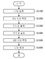
도 4 및 도 5를 참조하면, 먼저, 디밍 설정이 수행될 수 있다(S1100). 디밍 설정은 구동부에서 광 조사부(100)로 주입되는 전원 공급량(%)으로 광 조사부(100)의 조사량일 수 있다. 예컨대, 광 조사부(100)로 주입되는 최대 전류가 5A인 경우에, 구동부에서 광 조사부(100)로 0.5A의 전류가 공급되는 경우 디밍은 10%로 설정된다. 그리고 디밍 설정에 따라 광 조사부(100)에서 방출되는 광의 조사량이 변경될 수 있다. 이 때, 디밍 설정은 입력부(미도시됨) 등을 통해 사용자에 의해 설정될 수 있다. 4 and 5, first, a dimming setting may be performed (S1100). The dimming setting may be an irradiation amount of the
그리고 디밍 설정은 경화 등의 대상인 대상체(SB)의 종류에 따라 다양하게 변경될 수 있다. 동일한 대상체(SB)에 대해서는 조사량이 동일하게 설정될 수 있다. 뿐만 아니라, 종류가 상이한 대상체(SB)에 대해서도 조사량이 동일하게 설정될 수도 있으나, 이에 한정되는 것은 아니다.In addition, the dimming setting may be variously changed according to the type of the target object SB, such as curing. The irradiation amount may be set to be the same for the same object SB. In addition, the irradiation amount may be set to the same for the objects SB having different types, but is not limited thereto.
그리고 검출부는 대상체(SB)와의 거리인 제1 거리를 산출할 수 있다(S1200). 즉, 디밍 설정에 따른 전류에 대응하여 광 조사부(100)에서 광이 방출되고, 대상체와의 거리(제1 거리)가 검출부에 의해 산출될 수 있다. 이러한 제1 거리 산출은 디밍 설정 이후에 이루어질 수 있다. 그리고 검출부에서 산출된 제1 거리는 제어부로 전송될 수 있다.In addition, the detection unit may calculate a first distance that is a distance from the object SB (S1200). That is, light is emitted from the
또한, 송신부(410), 수신부(420)는 광 조사부(100)에 배치될 수 있다. 그리고 광 조사부(100)는 복수 개의 단위 조사부로 구획될 수 있다. 예컨대, 광 조사부(100)는 제1 단위 조사부(100-1), 제2 단위 조사부(100-2), 제3 단위 조사부(100-3) 및 제4 단위 조사부(100-4)를 포함할 수 있다. 이는 제1 회로기판이 복수 개의 단위기판으로 이루어진 경우, 단위기판의 개수에 대응될 수 있다. 예컨대, 복수 개의 단위기판이 4개인 경우, 단위 조사부도 4개일 수 있다. 그리고 송신부(410) 및 수신부(420)도 이에 대응하여 4개일 수 있다. 이 때, 거리산출부(430)는 대상체(SB)와의 거리(h)는 각 송신부(410) 및 수신부(420)를 통해 수신한 신호의 시간 정보를 이용하여 산출할 수 있다. 예컨대, 거리산출부(430)는 각 송신부(410) 및 수신부(420)에 의한 송신신호와 수신신호 간의 비행 시간에 대한 평균값을 이용하여 대상체와의 거리를 산출할 수 있다.Also, the
그리고 제어부는 조도값 출력(S1300)을 수행할 수 있다. 상술한 바와 같이, 제어부는 구동부로 디밍 설정에 따른 제어 신호를 구동부로 전송하고 광 조사부(100)는 이에 상응하는 광 조사량으로 광을 출력될 수 있다. 또한, 제어부는 메모리로를 기초로 상술한 디밍 설정 정보와 제1 거리에 대응하는 대상체(SB)에서 조도량(irradiation)을 출력할 수 있다. In addition, the control unit may perform the illuminance value output (S1300). As described above, the control unit may transmit a control signal according to the dimming setting to the driving unit to the driving unit, and the
메모리는 상술한 바와 같이 대상체와의 거리, 광 조사부의 조사량 및 조도량 정보를 저장할 수 있으며, 이는 이하 표 1에서 나타낸다.As described above, the memory may store distance to the object, irradiation amount and illuminance information of the light irradiation unit, as shown in Table 1 below.
디밍(%) 설정Distance to object (mm)
Dimming (%) setting
표 1을 참조하면, 표 1은 대상체와의 거리(mm) 및 디밍(%) 설정에 따른 조도량을 나타낸다. 조도량은 전술한 바와 같이 대상체에서의 방사조도값이다. 그리고 예를 들어, 디밍이 10%로 설정되고, 제1 거리가 40mm인 경우 조도량(irradiation)은 84(mW/cm2)이다. 즉, 조도값은 84(mW/cm2)으로 출력된다. 그리고 제어부는 출력된 조도값을 기준 조도값으로 설정할 수 있다(S1400).예컨대, 디밍 10% 및 제1 거리가 40mm인 경우로 설정되면, 이후 조도값에 대한 설정이 없는 경우에 조도량은 84(mW/cm2)로 설정되고 유지될 수 있다.Referring to Table 1, Table 1 shows the amount of illuminance according to the distance (mm) and dimming (%) of the object. The illuminance amount is the irradiance value in the object as described above. And, for example, when the dimming is set to 10% and the first distance is 40 mm, the irradiance is 84 (mW / cm 2 ). That is, the illuminance value is output as 84 (mW / cm 2 ). In addition, the control unit may set the output illuminance value as a reference illuminance value (S1400). For example, when the dimming 10% and the first distance are set to 40 mm, the illuminance amount is 84 when there is no setting for the illuminance value thereafter. It can be set and maintained at (mW / cm 2 ).
그리고 대상체(SB)에 대한 거리('제2 거리')를 산출할 수 있다. 이 때, 대상체(SB)는 운송 기기(B)에 의해 이동할 수 있다. 즉, 제1 거리를 산출하는 단계에서의 대상체와 상기 제2 거리를 산출하는 단계에서의 대상체는 상이할 수 있다.In addition, a distance ('second distance') to the object SB may be calculated. At this time, the object SB may be moved by the transportation device B. That is, the object in the step of calculating the first distance and the object in the step of calculating the second distance may be different.
제2 거리는 상술한 제1 거리를 산출하는 단계(S1200)와 동일하게 검출부(400)에 의해 산출될 수 있다. The second distance may be calculated by the detector 400 in the same manner as in step S1200 of calculating the first distance.
그리고 제어부는 디밍을 제어할 수 있다(S1600). 보다 구체적으로, 제어부는 메모리의 대상체와의 거리, 광 조사부(100)의 조사량 및 조도량 정보를 기초로 제2 거리 및 상기 설정된 대상체에서 조도량을 이용하여 디밍 제어값을 산출하고 이에 대응하는 제어 신호를 구동부로 송신할 수 있다. 이러한 구성에 의하여, 대상체(SB)의 이동, 변경(두께 등의 변경)에도 대상체(SB)에 경화가 원활히 이루어지는 조도량이 제공될 수 있다. 이로써, 균일한 경화 작업이 이루어질 수 있다.In addition, the controller may control dimming (S1600). More specifically, the control unit calculates a dimming control value using the second distance and the illuminance amount from the set object based on the distance to the object in the memory, the irradiation amount and the illuminance amount information of the
도 6을 참조하면, 운송 기기(B) 상의 제1 대상체(SB)에 대해 광이 조사될 수 있다. 예컨대, 사용자는 디밍을 50%로 설정하여 제1 대상체(SB)에 광을 조사할 수 있다. 그리고 검출부는 제1 대상체(SB1)와의 제1 거리(h1)를 산출할 수 있다. 그리고 해당 제1 거리(h1)와 디밍(광 조사부의 조사량)에 따라 제1 대상체(SB)에서 조도량을 출력하고 설정할 수 있다. 예컨대, 제1 거리(h1)가 20mm로 측정되는 경우, 제1 대상체(SB1)에서 조사량이 814(mW/cm2)로 설정될 수 있다.Referring to FIG. 6, light may be irradiated to the first object SB on the transportation device B. For example, the user may set the dimming to 50% to irradiate light to the first object SB. In addition, the detection unit may calculate a first distance h1 from the first object SB1. In addition, the illuminance amount may be output and set in the first object SB according to the corresponding first distance h1 and dimming (irradiation amount of the light irradiation unit). For example, when the first distance h1 is measured to be 20 mm, the irradiation amount may be set to 814 (mW / cm 2 ) in the first object SB1.
그리고 운송 기기(B)에 의해 제2 대상체(SB2)가 광 조사부(100)에 의해 광이 조사되는 영역에 위치할 수 있다. 제2 대상체(SB2)는 두께(T2)가 제1 대상체(SB1)의 두께(T1)보다 클 수 있다. 이러한 경우에, 제1 대상체(SB1)와 제2 대상체(SB2)는 경화 대상으로 동일 물질인 경우, (동일한 디밍 설정하에서) 두께 차에 의해 조도량이 상이할 수 있다. 이에 따라, 제어부는 제2 대상체(SB2)에 대한 디밍 제어를 수행할 수 있다. 먼저, 검출부(400)를 통해 제2 대상체(SB2)와의 거리(제2 거리(h2))를 산출할 수 있다. 그리고 제어부는 설정된 조도량(예, 814(mW/cm2))을 기초로 산출된 제2 거리(h2)를 적용할 수 있다. 그리고 디밍값(광 조사부의 조사량)을 산출할 수 있다.In addition, the second object SB2 may be positioned in the region where the light is irradiated by the
이 때, 메모리에서 설정된 조도량에 대응하는 대상체와의 거리 및 광 조사부의 조사량 정보가 없는 경우에 제어부는 회귀식을 이용하여 디밍값을 산출할 수 있다. 예컨대, 제어부는 하기 수학식 2 및 수학식 3 중 어느 하나의 회귀식을 통해 이용할 수 있다.At this time, if there is no distance from the object corresponding to the illumination amount set in the memory and the irradiation amount information of the light irradiation unit, the controller may calculate a dimming value using a regression equation. For example, the control unit may be used through any one of Equation 2 and
![]()
![]()
![]()
![]()
여기서, Irradiance는 (대상체에서) 조도량이고, WD는 대상체와의 거리, Dimming은 디밍값(%)을 의미한다.Here, Irradiance is the amount of illuminance (on the object), WD is the distance from the object, and Dimming means the dimming value (%).
상기 수학식 2 및 수학식 3는 메모리에 저장된 조도량, 대상체와의 거리 및 디밍값(광 조사부의 조사량) 정보를 변수로 도출한 회귀식이다. 상기 수학식 2 및 수학식 3 이외에도 변수에 따라 회귀식이 변경될 수 있다.Equation 2 and
이 때, 제어부는 도출된 복수 개의 회귀식의 평균값을 통해 조도량, 대상체와의 거리 및 조사량을 도출할 수 있다. 이러한 구성에 의하여, 실제 조도량이 대상체의 변경에도 균일하게 이루어질 수 있다.At this time, the control unit may derive the illuminance amount, the distance to the object, and the irradiation amount through the average values of the derived multiple regression equations. By such a configuration, the actual illuminance amount can be made uniform even when the object is changed.
도 7은 다른 실시예에 따른 자외선 광 조사 장치의 동작을 설명하는 도면이다.7 is a view for explaining the operation of the ultraviolet light irradiation device according to another embodiment.
도 7을 참조하면, 광 조사부(100)는 복수 개의 단위 조사부로 구획될 수 있다. 예컨대, 광 조사부(100)는 운송 기기(B) 상의 제3 대상체(SB3)의 이동 방향으로 순서대로 제1 단위 조사부(100-1), 제2 단위 조사부(100-2), 제3 단위 조사부(100-3) 및 제4 단위 조사부(100-4)를 포함할 수 있다.Referring to FIG. 7, the
그리고 제1 회로기판은 제1 단위 조사부(100-1), 제2 단위 조사부(100-2), 제3 단위 조사부(100-3) 및 제4 단위 조사부(100-4) 각각을 포함하는 제1 영역(S1) 내지 제4 영역(S4)으로 구획될 수 있다. 제1 영역(S1) 내지 제4 영역(S4)는 상술한 단위 모듈에 대응될 수 있다.The first circuit board includes a first unit irradiation unit 100-1, a second unit irradiation unit 100-2, a third unit irradiation unit 100-3, and a fourth unit irradiation unit 100-4, respectively. It may be divided into 1 region S1 to 4th region S4. The first area S1 to the fourth area S4 may correspond to the above-described unit module.
그리고 제1 영역(S1) 내지 제4 영역(S4)은 각각 제1 수신부(410-1) 내지 제4 수신부(410-4)를 포함할 수 있다. 이에 따라, 각 영역별로 제3 대상체(SB3)와의 거리가 산출될 수 있다. 예컨대, 제3 대상체(SB3)는 제1 영역(S1) 및 제2 영역(S2)에 대응하는 위치에서 두께(T3)가 동일하고, 제3 영역(S3) 및 제4 영역(S4)에 대응하는 위치에서 두께(T4)가 동일할 수 있다. 그리고 제1 영역(S1) 및 제2 영역(S2)에 대응하는 위치에서 두께(T3)가 제3 영역(S3) 및 제4 영역(S4)에 대응하는 위치에서 두께(T4)와 상이할 수 있다. (예로, T4>T3)In addition, the first areas S1 to the fourth areas S4 may include first reception units 410-1 to fourth reception units 410-4, respectively. Accordingly, a distance from the third object SB3 for each region may be calculated. For example, the third object SB3 has the same thickness T3 at positions corresponding to the first region S1 and the second region S2, and corresponds to the third region S3 and the fourth region S4. The thickness (T4) may be the same at the location. In addition, the thickness T3 may be different from the thickness T4 at positions corresponding to the third area S3 and the fourth area S4 at positions corresponding to the first area S1 and the second area S2. have. (Eg, T4> T3)
이 때, 제1 영역(S1) 및 제2 영역(S2)에서 제3 대상체(SB3)와의 거리(h3)는 제3 영역(S3) 및 제4 영역(S4)에서 제3 대상체(SB3)와의 거리(h4)보다 클 수 있다. 이에 따라,At this time, the distance h3 from the first area S1 and the second area S2 to the third object SB3 is equal to the third object SB3 from the third area S3 and the fourth area S4. It may be larger than the distance h4. Accordingly,
이 때, 광 조사 장치는 조도량이 설정된 경우, 제3 대상체(SB3)로 상기 설정된 조도량을 유지하도록 광 조사부의 디밍값을 변경하여 광 조사부의 조사량을 제어할 수 있다. 즉, 제어부는 제3 대상체(SB3)에서 설정된 조도량이 유지되어야 하므로, 제1 단위 조사부(100-1), 제2 단위 조사부(100-2), 제3 단위 조사부(100-3) 및 제4 단위 조사부(100-4)의 조사량을 변경하도록 구동부에 제어 신호를 송신할 수 있고, 구동부는 제어 신호에 대응하여 각 단위 조사부의 전원을 공급하여 각 단위 조사부의 조사량을 제어할 수 있다.At this time, when the illuminance amount is set, the dimming value of the light irradiation unit may be changed to control the irradiation amount of the light irradiation unit to maintain the set illuminance amount as the third object SB3. That is, since the control unit should maintain the illuminance amount set in the third object SB3, the first unit irradiation unit 100-1, the second unit irradiation unit 100-2, the third unit irradiation unit 100-3, and the fourth unit A control signal may be transmitted to the driving unit so as to change the irradiation amount of the unit irradiation unit 100-4, and the driving unit may control the irradiation amount of each unit irradiation unit by supplying power to each unit irradiation unit in response to the control signal.
이 때, 제1 영역(S1) 및 제2 영역(S2)에서 제3 대상체(Sb3)와의 거리(h3)가 동일하므로, 제1 단위 조사부(100-1)의 조사량과 제2 단위 조사부(100-2)의 조사량은 동일할 수 있다. 또한, 제3 영역(S3) 및 제4 영역(S4)에서 제3 대상체(Sb3)와의 거리(h4)가 동일하므로, 제3 단위 조사부(100-3)의 조사량과 제4 단위 조사부(100-4)의 조사량은 동일할 수 있다.At this time, since the distance h3 from the first area S1 and the second area S2 to the third object Sb3 is the same, the irradiation amount of the first unit irradiation unit 100-1 and the second
다만, 상술한 바와 같이 제1 영역(S1) 및 제2 영역(S2)에서 제3 대상체(SB3)와의 거리(h3)는 제3 영역(S3) 및 제4 영역(S4)에서 제3 대상체(SB3)와의 거리(h4)보다 크므로, 제1 단위 조사부(100-1) 및 제2 단위 조사부(100-2)와 제3 단위 조사부(100-3) 및 제4 단위 조사부(100-4) 간의 조사량은 상이할 수 있다. 예컨대, 제1 영역(S1) 및 제2 영역(S2)에서 제3 대상체(SB3)와의 거리(h3)는 제3 영역(S3) 및 제4 영역(S4)에서 제3 대상체(SB3)와의 거리(h4)보다 크므로, 제1 단위 조사부(100-1) 및 제2 단위 조사부(100-2)의 조사량은 제3 단위 조사부(100-3) 및 제4 단위 조사부(100-4)의 조사량보다 클 수 있다.However, as described above, the distance h3 from the first area S1 and the second area S2 to the third object SB3 is the third object S3 from the third area S3 and the fourth area S4. Since it is greater than the distance h4 from SB3), the first unit irradiation unit 100-1 and the second unit irradiation unit 100-2, the third unit irradiation unit 100-3, and the fourth unit irradiation unit 100-4 The dose of liver may be different. For example, the distance h3 between the third object SB3 in the first area S1 and the second area S2 is the distance from the third object SB3 in the third area S3 and the fourth area S4. Since it is larger than (h4), the irradiation amount of the first unit irradiation unit 100-1 and the second unit irradiation unit 100-2 is the irradiation amount of the third unit irradiation unit 100-3 and the fourth unit irradiation unit 100-4 Can be greater.
이와 같이, 다른 실시예에 따른 광 조사 장치는 광 조사부의 각 영역에서 대상체와의 거리에 대응하여 광 조사부의 각 영역의 광 조사량이 변경될 수 있다. 이로서, 광 조사 장치는 대상체의 표면 거칠기, 형상 등에 따라 대상체의 경화가 영역별로 상이해지는 것을 방지할 수 있다. 즉, 대상체 내에서 경화도에 대한 균일성을 개선할 수 있다.As such, in the light irradiation apparatus according to another embodiment, the light irradiation amount of each region of the light irradiation unit may be changed in correspondence to the distance from the object in each region of the light irradiation unit. As a result, the light irradiation device can prevent the curing of the object from being different for each region depending on the surface roughness, shape, or the like of the object. That is, it is possible to improve the uniformity of the degree of hardening in the object.
도 8는 광 가이드부 및 커버를 보여주는 도면이고, 도 9는 커버를 다른 각도에서 본 도면이고, 도 10은 본 발명의 일 실시 예에 따른 자외선 광 조사 장치의 단면도이다.8 is a view showing a light guide portion and a cover, FIG. 9 is a view of the cover from different angles, and FIG. 10 is a cross-sectional view of an ultraviolet light irradiation device according to an embodiment of the present invention.
도 8 및 도 9를 참조하면, 커버(640)는 제1고정틀(641)과 제2고정틀(642) 및 투광판(643)을 포함할 수 있다. 투광판(643)은 자외선 광을 투과시킬 수 있는 재질을 포함할 수 있다. 예시적으로 투광판(643)은 글라스 또는 석영 재질일 수 있으나 반드시 이에 한정하지 않는다. 제1고정틀(641)과 제2고정틀(642)은 열팽창계수가 투광판(643)보다 우수한 재질로 제작될 수 있다.8 and 9, the
제1고정틀(641) 및 제2고정틀(642)은 방열블록(620)의 측면에 배치되는 제1고정턱(641b, 142b) 및 방열블록(620)의 일면에 배치되는 제2고정턱(641a, 142a)을 포함할 수 있다. 이때, 제1고정턱(641b, 142b)은 제2고정턱(641a, 142a)보다 후방으로 더 돌출될 수 있다. 제1고정턱(641b, 142b)과 제2고정턱(641a, 142a)은 커버(640)의 길이방향으로 연장될 수 있다.The
광 가이드부(650)는 커버(640)의 전방에 배치되어 자외선 광의 지향각을 제어할 수 있다. 광 가이드부(650)의 제1면(651)과 제2면(652)은 경사지게 형성된 것에 반해, 제3면(653)과 제4면(654)은 경사가 없을 수 있다. 즉, 제1면(651)과 제2면(652) 사이의 간격은 제1회로기판(630)에서 멀어지는 방향으로 커지고, 제3면(653)과 제4면(654) 사이의 간격은 제1회로기판(630)에서 멀어지는 방향으로 일정할 수 있다. 이러한 구성에 의하면 세로 방향으로 지향각을 넓히는 반면, 가로 방향으로는 지향각이 상대적으로 좁아질 수 있다. 그러나, 반드시 이에 한정하는 것은 아니고 제3면(653)과 제4면(654)도 기울어지게 형성될 수도 있다. 이때, 제1면(651)과 제2면(652)은 제3면(653)과 제4면(654)보다 길 수 있다.The
도 10을 참조하면, 제1회로기판(630)은 일면에 배치되어 제2고정턱(641a, 142a)이 삽입되는 지지홈(631)을 포함할 수 있다. 따라서, 제1고정틀(641)과 제2고정틀(642)이 제1회로기판(630)에 안정적으로 지지되므로 제1고정틀(641)과 제2고정틀(642)에 고정된 투광판(643)이 충격에 의해 파손되는 문제를 개선할 수 있다.Referring to FIG. 10, the
하우징(610)의 제1덮개부(615)는 제1필터(681)의 상부에 배치되고, 제2덮개부(616)는 제2필터(682)의 하부에 배치될 수 있다. 하우징은 제1덮개부의 끝단이 결합되는 단차부(610a)를 포함할 수 있다. 제1, 제2덮개부(615, 116)는 복수 개의 홀이 형성되어 방열핀(622)의 열이 외부로 신속히 배출될 수 있도록 할 수 있다.The
전원연결부(660)는 방열블록(620)과 냉각팬(670) 사이의 이격 영역(SA)에 배치될 수 있다. 하우징(610)의 제4면(614)에는 내측으로 복수 개의 돌기(614a)가 배치되어 제2회로기판(661)을 안정적으로 지지할 수 있다. 따라서, 제2회로기판(661)에 발생한 열이 제2회로기판(661)의 상면과 하면으로 신속히 방출될 수 있다. 제2회로기판(661)은 전원공급부(669)와 전기적으로 연결될 수 있다.The
도 11은 방열블록과 전원연결부를 일 방향에서 본 도면이고, 도 12은 방열블록과 전원연결부를 다른 방향에서 본 도면이고, 도 13는 본 발명의 일 실시 예에 따른 자외선 광 조사 장치의 평면도이다.11 is a view of the heat radiation block and the power connection from one direction, FIG. 12 is a view of the heat radiation block and the power connection from another direction, and FIG. 13 is a plan view of an ultraviolet light irradiation device according to an embodiment of the present invention .
도 11 및 도 12을 참조하면, 복수 개의 커넥터(664)는 제1회로기판(630)와 제2회로기판(661)을 전기적으로 연결할 수 있다. 즉, 전원공급부(669)로 공급된 전원은 제2회로기판(661)과 커넥터(664)를 통해 제1회로기판(630)에 인가될 수 있다.11 and 12, the plurality of
각각의 커넥터(664)는 제1회로기판(630)과 전기적으로 연결되는 제1접속부(664a), 제2회로기판(661)과 전기적으로 연결되는 제2접속부(664c), 및 제1접속부(664a)와 제2접속부(664c)를 연결하는 와이어(664b)를 포함할 수 있다.Each
이때, 제1회로기판(630)이 제1접속부(664a)와 연결되는 부분은 방열블록(620)의 리세스(621a)에 의해 노출될 수 있다. 예시적으로, 방열블록(620)의 리세스(621a)로 노출된 소켓부에 커넥터(664)의 제1접속부(664a)가 삽입되어 전기적으로 연결될 수 있다. 따라서, 제1접속부(664a)는 방열블록(620)의 리세스(621a) 내에 배치될 수 있다.At this time, the portion where the
그러나, 커넥터(664)가 제1회로기판(630)과 연결되는 방법은 반드시 이에 한정하지 않는다. 예시적으로 제1회로기판(630)의 측면에 제1접속부(664a)가 삽입되어 제1회로기판(630)의 패드부(도 3의 P1 내지 P4)와 전기적으로 연결될 수도 있다. 이때, 방열블록(620)에 형성된 리세스(621a)에 의해 제1회로기판(630)과 커넥터(664)의 연결이 용이해질 수 있다.However, the method in which the
제1회로기판(630)과 연결된 커넥터(664)는 제2회로기판(661)과 전기적으로 연결될 수 있다. 구체적으로 제2회로기판(661)에 배치된 소켓부(661a)에 제2접속부(664c)가 삽입될 수 있다.The
플레이트(662)는 제1방향으로 연장되는 제1플레이트(662a) 및 제1플레이트(662a)에서 제1방향과 수직한 제2방향으로 돌출되는 제2플레이트(662b)를 포함할 수 있다. The
복수 개의 지지부재(663)는 제1플레이트(662a)와 제2회로기판(661) 사이에 배치되는 복수 개의 제1지지부재(663), 및 제2플레이트(662b)와 제2회로기판(661) 사이에 배치되는 복수 개의 제2지지부재(663)를 포함할 수 있다. The plurality of
도 13를 참조하면, 플레이트(662)에는 복수 개의 홀(662c)이 배치될 수 있다. 커넥터(664)의 와이어는 복수 개의 홀(662c)에 배치된 별도의 고정부재(666)에 의해 고정될 수 있다. 따라서, 외부 충격시 커넥터(654)의 와이어가 파손되거나 접속부가 빠지는 문제를 방지할 수 있다. 고정부재(666)는 와이어를 고정하는 플라스틱 재질의 클립일 수 있으나 반드시 이에 한정하지 않는다.Referring to FIG. 13, a plurality of
또한, 제2회로기판(661)에는 냉각팬(670)과 연결되는 제2커넥터(665)가 배치될 수 있다. 제2커넥터(665)의 와이어 역시 복수 개의 홀(662c)에 배치된 별도의 고정부재(666)에 의해 고정될 수 있다. 따라서, 외부 충격시 와이어가 파손되거나 접속부가 빠지는 문제를 방지할 수 있다.Further, a
이상에서 실시 예들에 설명된 특징, 구조, 효과 등은 본 발명의 적어도 하나의 실시 예에 포함되며, 반드시 하나의 실시 예에만 한정되는 것은 아니다. 나아가, 각 실시 예에서 예시된 특징, 구조, 효과 등은 실시 예들이 속하는 분야의 통상의 지식을 가지는 자에 의해 다른 실시 예들에 대해서도 조합 또는 변형되어 실시 가능하다. 따라서 이러한 조합과 변형에 관계된 내용들은 본 발명의 범위에 포함되는 것으로 해석되어야 할 것이다.Features, structures, effects, etc. described in the above embodiments are included in at least one embodiment of the present invention, and are not necessarily limited to only one embodiment. Furthermore, features, structures, effects, and the like exemplified in each embodiment may be combined or modified for other embodiments by a person having ordinary knowledge in the field to which the embodiments belong. Therefore, the contents related to such combinations and modifications should be interpreted as being included in the scope of the present invention.
Claims (10)
상기 광 조사부를 구동하는 구동부;
대상체와의 거리를 산출하는 검출부;
대상체와 광 조사부의 거리, 상기 광 조사부의 조사량, 및 조도량를 저장하는 메모리; 및
상기 광 조사부, 구동부 및 검출부와 통신하는 제어부를 포함하고,
상기 제어부는 상기 대상체와 광 조사부의 거리가 변경되면 기설정된 조도량을 유지하도록 상기 광 조사부의 조사량을 가변하도록 상기 구동부에 제어신호를 출력하는 자외선 광 조사 장치.
Light irradiation unit;
A driving unit driving the light irradiation unit;
A detector for calculating a distance from the object;
A memory for storing the distance between the object and the light irradiation unit, the irradiation amount of the light irradiation unit, and the illuminance amount; And
And a control unit communicating with the light irradiation unit, the driving unit and the detection unit,
The control unit is an ultraviolet light irradiation device for outputting a control signal to the driving unit to vary the irradiation amount of the light irradiation unit to maintain a predetermined amount of illumination when the distance between the object and the light irradiation unit is changed.
상기 검출부는,
대상체를 향해 송신신호를 제공하는 송신부;
상기 대상체로부터 수신신호를 수신하는 수신부; 및
상기 송신신호와 상기 수신신호의 간의 시간정보를 이용하여 상기 대상체와의 거리를 산출하는 거리산출부;를 포함하고,
상기 수신신호는 상기 대상체에서 반사된 송신신호인 자외선 광 조사 장치.
According to claim 1,
The detection unit,
A transmitter that provides a transmission signal toward an object;
A receiver configured to receive a received signal from the object; And
It includes; a distance calculating unit for calculating a distance from the object using the time information between the transmission signal and the received signal;
The received signal is an ultraviolet light irradiation device that is a transmission signal reflected from the object.
상기 송신부 및 상기 수신부는 상기 광 조사부에 인접하게 배치되는 자외선 광 조사 장치.
According to claim 2,
The transmitting unit and the receiving unit are ultraviolet light irradiation device disposed adjacent to the light irradiation unit.
상기 광 조사부는 복수 개의 영역으로 구획되고,
상기 송신부는 상기 복수 개의 영역에 각각 배치되고,
상기 검출부는 상기 복수 개의 영역 각각에서 상기 대상체와의 거리를 산출하는 자외선 광 조사 장치.
According to claim 2,
The light irradiation unit is divided into a plurality of regions,
The transmitters are respectively disposed in the plurality of regions,
The detection unit is an ultraviolet light irradiation device for calculating the distance to the object in each of the plurality of regions.
상기 제어부는 상기 복수 개의 영역의 광 조사부의 조사량을 산출하고, 상기 산출된 상기 복수 개의 영역의 광 조사부의 조사량에 따라 상기 구동부를 제어하는 자외선 광 조사 장치.
According to claim 4,
The control unit calculates the irradiation amount of the light irradiation portion of the plurality of regions, and the ultraviolet light irradiation apparatus for controlling the driving unit according to the calculated irradiation amount of the light irradiation portion of the plurality of regions.
상기 제어부는 상기 기설정된 조도량을 상기 광 조사부의 조사량 및 상기 대상체와의 거리에 대응하여 산출하는 자외선 광 조사 장치.
According to claim 1,
The control unit is an ultraviolet light irradiation device for calculating the predetermined amount of illuminance corresponding to the irradiation amount of the light irradiation unit and the distance to the object.
상기 산출된 대상체와의 거리가 변경되면 상기 광 조사부의 조사량이 변경되는 자외선 광 조사 장치.
According to claim 1,
An ultraviolet light irradiation device in which the irradiation amount of the light irradiation unit is changed when the calculated distance to the object is changed.
상기 산출된 대상체와의 거리가 증가하면 상기 광 조사부의 조사량이 감소하는 자외선 광 조사 장치.
The method of claim 7,
An ultraviolet light irradiation device in which the irradiation amount of the light irradiation unit decreases when the calculated distance to the object increases.
상기 광 조사부는 복수 개의 자외선 발광소자를 포함하는 자외선 광 조사 장치.
According to claim 1,
The light irradiation unit ultraviolet light irradiation device comprising a plurality of ultraviolet light emitting elements.
상기 제어부는 상기 조도량 및 상기 대상체와의 거리를 변수로 반영한 회귀식을 이용하여 상기 광 조사부의 조사량을 산출하는 자외선 광 조사 장치.According to claim 1,
The control unit is an ultraviolet light irradiation device for calculating the irradiation amount of the light irradiation unit using a regression equation reflecting the distance to the object and the illuminance amount as variables.
Priority Applications (1)
| Application Number | Priority Date | Filing Date | Title |
|---|---|---|---|
| KR1020180115063A KR102569367B1 (en) | 2018-09-27 | 2018-09-27 | Apparatus for irradiating ultraviolet light |
Applications Claiming Priority (1)
| Application Number | Priority Date | Filing Date | Title |
|---|---|---|---|
| KR1020180115063A KR102569367B1 (en) | 2018-09-27 | 2018-09-27 | Apparatus for irradiating ultraviolet light |
Publications (2)
| Publication Number | Publication Date |
|---|---|
| KR20200035675A true KR20200035675A (en) | 2020-04-06 |
| KR102569367B1 KR102569367B1 (en) | 2023-08-22 |
Family
ID=70281804
Family Applications (1)
| Application Number | Title | Priority Date | Filing Date |
|---|---|---|---|
| KR1020180115063A Active KR102569367B1 (en) | 2018-09-27 | 2018-09-27 | Apparatus for irradiating ultraviolet light |
Country Status (1)
| Country | Link |
|---|---|
| KR (1) | KR102569367B1 (en) |
Citations (5)
| Publication number | Priority date | Publication date | Assignee | Title |
|---|---|---|---|---|
| JP2014064996A (en) * | 2012-09-26 | 2014-04-17 | Iwasaki Electric Co Ltd | Light irradiation device |
| KR20140114470A (en) * | 2013-03-13 | 2014-09-29 | 에프엔에스테크 주식회사 | Curing system using ultraviolet |
| KR101680488B1 (en) * | 2015-11-10 | 2016-11-28 | 한국광기술원 | Lighting device with therapy and method for controlling the same |
| KR20170123412A (en) * | 2016-04-28 | 2017-11-08 | 한국광기술원 | Shower head having photo therapy |
| KR20180085979A (en) * | 2017-01-20 | 2018-07-30 | 엘지이노텍 주식회사 | Ultraviolet curing apparatus |
-
2018
- 2018-09-27 KR KR1020180115063A patent/KR102569367B1/en active Active
Patent Citations (5)
| Publication number | Priority date | Publication date | Assignee | Title |
|---|---|---|---|---|
| JP2014064996A (en) * | 2012-09-26 | 2014-04-17 | Iwasaki Electric Co Ltd | Light irradiation device |
| KR20140114470A (en) * | 2013-03-13 | 2014-09-29 | 에프엔에스테크 주식회사 | Curing system using ultraviolet |
| KR101680488B1 (en) * | 2015-11-10 | 2016-11-28 | 한국광기술원 | Lighting device with therapy and method for controlling the same |
| KR20170123412A (en) * | 2016-04-28 | 2017-11-08 | 한국광기술원 | Shower head having photo therapy |
| KR20180085979A (en) * | 2017-01-20 | 2018-07-30 | 엘지이노텍 주식회사 | Ultraviolet curing apparatus |
Also Published As
| Publication number | Publication date |
|---|---|
| KR102569367B1 (en) | 2023-08-22 |
Similar Documents
| Publication | Publication Date | Title |
|---|---|---|
| JP6505677B2 (en) | Internal deflection ventilation | |
| JP6126644B2 (en) | Light irradiation device | |
| TWI740892B (en) | Light irradiation device | |
| CN1653297B (en) | High-efficiency solid-state light source and method of use and manufacture thereof | |
| US9170013B2 (en) | Air deflectors for heat management in a lighting module | |
| CN204240088U (en) | Light source and illuminator | |
| TWI657937B (en) | Method and system for emitting offset illumination for reduced stray light | |
| CA2332190A1 (en) | Addressable semiconductor array light source for localized radiation delivery | |
| JP2018523923A (en) | Ultraviolet irradiation assembly for radiation curing | |
| CN204516760U (en) | Light supply apparatus and ultraviolet lamp | |
| US9335010B2 (en) | Edge weighted spacing of LEDs for improved uniformity range | |
| CN101922629A (en) | Liquid-cooled LED light source and solar cell evaluation device equipped with liquid-cooled LED light source | |
| JP6069382B2 (en) | Light irradiation device | |
| KR102569367B1 (en) | Apparatus for irradiating ultraviolet light | |
| CN204704627U (en) | Light irradiation module | |
| US20140185306A1 (en) | Wrap-around window for lighting module | |
| CN103427010A (en) | UV irradiation apparatus and ultraviolet irradiation head | |
| CN109073167B (en) | Method and system for irradiation curing using narrow-width radiation | |
| KR20220019720A (en) | light source device | |
| KR102624468B1 (en) | Apparatus for irradiating ultraviolet light | |
| CN115884879B (en) | Light irradiation device | |
| JP6533507B2 (en) | Light irradiation device | |
| CN111167684A (en) | UV curing equipment | |
| KR20160143176A (en) | Light emitting diode module and light emitting apparatus | |
| KR20200087577A (en) | Inspecting apparatus |
Legal Events
| Date | Code | Title | Description |
|---|---|---|---|
| PA0109 | Patent application |
Patent event code: PA01091R01D Comment text: Patent Application Patent event date: 20180927 |
|
| PG1501 | Laying open of application | ||
| PA0201 | Request for examination |
Patent event code: PA02012R01D Patent event date: 20210910 Comment text: Request for Examination of Application Patent event code: PA02011R01I Patent event date: 20180927 Comment text: Patent Application |
|
| E902 | Notification of reason for refusal | ||
| PE0902 | Notice of grounds for rejection |
Comment text: Notification of reason for refusal Patent event date: 20230113 Patent event code: PE09021S01D |
|
| E701 | Decision to grant or registration of patent right | ||
| PE0701 | Decision of registration |
Patent event code: PE07011S01D Comment text: Decision to Grant Registration Patent event date: 20230517 |
|
| GRNT | Written decision to grant | ||
| PR0701 | Registration of establishment |
Comment text: Registration of Establishment Patent event date: 20230817 Patent event code: PR07011E01D |
|
| PR1002 | Payment of registration fee |
Payment date: 20230818 End annual number: 3 Start annual number: 1 |
|
| PG1601 | Publication of registration |