KR20200034413A - Apparatus for stabilizing supply of gas - Google Patents
Apparatus for stabilizing supply of gas Download PDFInfo
- Publication number
- KR20200034413A KR20200034413A KR1020180114168A KR20180114168A KR20200034413A KR 20200034413 A KR20200034413 A KR 20200034413A KR 1020180114168 A KR1020180114168 A KR 1020180114168A KR 20180114168 A KR20180114168 A KR 20180114168A KR 20200034413 A KR20200034413 A KR 20200034413A
- Authority
- KR
- South Korea
- Prior art keywords
- gas
- supply
- volume
- flow path
- space
- Prior art date
- Legal status (The legal status is an assumption and is not a legal conclusion. Google has not performed a legal analysis and makes no representation as to the accuracy of the status listed.)
- Granted
Links
Images


Classifications
-
- A—HUMAN NECESSITIES
- A61—MEDICAL OR VETERINARY SCIENCE; HYGIENE
- A61M—DEVICES FOR INTRODUCING MEDIA INTO, OR ONTO, THE BODY; DEVICES FOR TRANSDUCING BODY MEDIA OR FOR TAKING MEDIA FROM THE BODY; DEVICES FOR PRODUCING OR ENDING SLEEP OR STUPOR
- A61M13/00—Insufflators for therapeutic or disinfectant purposes, i.e. devices for blowing a gas, powder or vapour into the body
- A61M13/003—Blowing gases other than for carrying powders, e.g. for inflating, dilating or rinsing
-
- A—HUMAN NECESSITIES
- A61—MEDICAL OR VETERINARY SCIENCE; HYGIENE
- A61B—DIAGNOSIS; SURGERY; IDENTIFICATION
- A61B1/00—Instruments for performing medical examinations of the interior of cavities or tubes of the body by visual or photographical inspection, e.g. endoscopes; Illuminating arrangements therefor
- A61B1/012—Instruments for performing medical examinations of the interior of cavities or tubes of the body by visual or photographical inspection, e.g. endoscopes; Illuminating arrangements therefor characterised by internal passages or accessories therefor
- A61B1/015—Control of fluid supply or evacuation
-
- A—HUMAN NECESSITIES
- A61—MEDICAL OR VETERINARY SCIENCE; HYGIENE
- A61B—DIAGNOSIS; SURGERY; IDENTIFICATION
- A61B17/00—Surgical instruments, devices or methods
- A61B17/34—Trocars; Puncturing needles
-
- A—HUMAN NECESSITIES
- A61—MEDICAL OR VETERINARY SCIENCE; HYGIENE
- A61B—DIAGNOSIS; SURGERY; IDENTIFICATION
- A61B17/00—Surgical instruments, devices or methods
- A61B17/34—Trocars; Puncturing needles
- A61B17/3474—Insufflating needles, e.g. Veress needles
-
- A—HUMAN NECESSITIES
- A61—MEDICAL OR VETERINARY SCIENCE; HYGIENE
- A61M—DEVICES FOR INTRODUCING MEDIA INTO, OR ONTO, THE BODY; DEVICES FOR TRANSDUCING BODY MEDIA OR FOR TAKING MEDIA FROM THE BODY; DEVICES FOR PRODUCING OR ENDING SLEEP OR STUPOR
- A61M2202/00—Special media to be introduced, removed or treated
- A61M2202/02—Gases
- A61M2202/0225—Carbon oxides, e.g. Carbon dioxide
-
- A—HUMAN NECESSITIES
- A61—MEDICAL OR VETERINARY SCIENCE; HYGIENE
- A61M—DEVICES FOR INTRODUCING MEDIA INTO, OR ONTO, THE BODY; DEVICES FOR TRANSDUCING BODY MEDIA OR FOR TAKING MEDIA FROM THE BODY; DEVICES FOR PRODUCING OR ENDING SLEEP OR STUPOR
- A61M2205/00—General characteristics of the apparatus
- A61M2205/33—Controlling, regulating or measuring
- A61M2205/3331—Pressure; Flow
- A61M2205/3341—Pressure; Flow stabilising pressure or flow to avoid excessive variation
-
- A—HUMAN NECESSITIES
- A61—MEDICAL OR VETERINARY SCIENCE; HYGIENE
- A61M—DEVICES FOR INTRODUCING MEDIA INTO, OR ONTO, THE BODY; DEVICES FOR TRANSDUCING BODY MEDIA OR FOR TAKING MEDIA FROM THE BODY; DEVICES FOR PRODUCING OR ENDING SLEEP OR STUPOR
- A61M2205/00—General characteristics of the apparatus
- A61M2205/33—Controlling, regulating or measuring
- A61M2205/3331—Pressure; Flow
- A61M2205/3344—Measuring or controlling pressure at the body treatment site
Landscapes
- Health & Medical Sciences (AREA)
- Life Sciences & Earth Sciences (AREA)
- Surgery (AREA)
- Animal Behavior & Ethology (AREA)
- General Health & Medical Sciences (AREA)
- Engineering & Computer Science (AREA)
- Biomedical Technology (AREA)
- Heart & Thoracic Surgery (AREA)
- Veterinary Medicine (AREA)
- Public Health (AREA)
- Medical Informatics (AREA)
- Pathology (AREA)
- Molecular Biology (AREA)
- Nuclear Medicine, Radiotherapy & Molecular Imaging (AREA)
- Anesthesiology (AREA)
- Hematology (AREA)
- Physics & Mathematics (AREA)
- Biophysics (AREA)
- Optics & Photonics (AREA)
- Radiology & Medical Imaging (AREA)
- Surgical Instruments (AREA)
Abstract
Description
본 발명은 수술 시 공간 확보를 위해 주입되는 기체의 압력 변화를 안정화시키기 위한 기체주입 안정화 장치에 관한 것이다.The present invention relates to a gas injection stabilization device for stabilizing the pressure change of the injected gas to ensure space during surgery.
최소침습술은 피부에 0.5-1.5 cm의 크기로 3~4 군데의 피부를 절개해 구멍을 낸 뒤, 특수 카메라가 장착된 내시경과 수술기구를 넣어 속을 들여다보며 수술하는 방식으로, 시야의 확보가 중요하다.Minimally invasive surgery is a method of incising and cutting 3-4 skins with a size of 0.5-1.5 cm on the skin, and then inserting an endoscope and surgical instruments equipped with a special camera into the skin to look inside, and to secure the field of view. Is important.
이를 위해 신체 내부에 이산화탄소 등의 기체를 주입하는데, 신체 내 좁은 공간에서 수술이 이루어지는 경우 종래에는 일정한 압력 유지가 어려워 안정적인 수술을 진행하는데 어려운 문제가 있었다.To this end, gas such as carbon dioxide is injected into the body, and in the case where surgery is performed in a narrow space in the body, it is difficult to maintain a constant pressure.
따라서 이러한 수술 시, 신체 내부에서 안정적인 압력 유지를 위한 장치가 요구된다.Therefore, a device for maintaining a stable pressure inside the body is required during such surgery.
본 발명은 수술 공간 내에서의 기체 압력변화를 안정화시키기 위한 기체주입 안정화 장치를 제공하는 것을 목적으로 한다. An object of the present invention is to provide a gas injection stabilization device for stabilizing gas pressure changes in a surgical space.
상기 본 발명의 목적은, 수술 시 공간 확보를 위해 체내에 주입되는 기체의 압력 변화를 감소시키기 위한 기체주입 안정화 장치에 있어서, 부피가 고정된 제1기체공간을 가지고 있는 부피고정부, 부피고정부와 연통되어 있으며, 부피고정부에 입출하는 기체에 의해 부피가 가변하며, 제1기체공간과 연결되어있는 제2기체공간을 가지는 적어도 하나의 부피가변부, 부피고정부와 연결되어 있으며, 외부의 기체공급장치로부터 기체를 공급받는 기체공급부; 및 부피고정부와 연결되어 있으며, 외부의 수술 공간으로 기체를 배출하는 기체배출부를 포함하는 것에 의해 달성된다.The object of the present invention, in the gas injection stabilization device for reducing the pressure change of the gas injected into the body to ensure space during surgery, the volume fixing, the volume fixing having a fixed first gas space It is in communication with, and the volume is variable by the gas entering and exiting the volume fixing unit, and at least one volume variable portion having a second gas space connected to the first gas space, connected to the volume fixing unit, and external A gas supply unit that receives gas from a gas supply device; And is connected to the volume fixing, it is achieved by including a gas discharge unit for discharging the gas to the external surgical space.
기체공급부는 기체가 유입되어 이동하는 공급유로 및 유입된 기체가 상기 기체공간으로 유출되는 공급단부를 포함하고, 기체배출부는 제1기체공간의 기체가 유입되는 배출단부 및 기체가 이동하여 부피고정부 외부로 유출되는 배출유로를 포함할 수 있다.The gas supply part includes a supply flow path through which gas flows and a supply end through which the gas flows into the gas space, and the gas discharge part fixes the volume by moving the exhaust end and the gas into which the gas in the first gas space flows. It may include a discharge channel that flows out.
공급유로는, 외부와 연결되는 제1공급유로, 제1공급유로에서 분기되며 공급단부를 가지는 제2공급유로를 포함할 수 있다.The supply passage may include a first supply passage connected to the outside, a second supply passage branched from the first supply passage, and having a supply end.
제2공급유로는, 각각이 공급단부를 가지는 제1서브유로 및 제2서브유로를 포함할 수 있다.The second supply flow path may include a first sub flow path and a second sub flow path, each of which has a supply end.
제1공급유로, 상기 제1서브유로 및 상기 제2서브유로는 V자, Y자 및 T자 형태 중 어느 하나일 수 있다.The first supply flow path, the first sub flow path, and the second sub flow path may be any one of V, Y, and T shapes.
부피가변부는 한 쌍으로 마련되어 부피고정부를 사이에 두고 배치되며, 제1서브유로의 공급단부는 부피가변부 중 어느 하나를 향하고, 제2서브유로의 공급단부는 부피가변부 중 다른 하나를 향해 기체가 배출될 수 있다.The volume variable portion is provided in a pair and is disposed with the volume fixing portion interposed therebetween, and the supply end of the first sub flow path faces any one of the volume variable portions, and the feed end of the second sub flow path faces the other of the volume variable portions. Gas may be exhausted.
부피고정부는 원통형일 수 있다.The bulk fixation may be cylindrical.
본 발명에 따르면 수술 시 안정적인 공간 및 수술 시야 확보를 위해 주입되는 기체의 압력 변화를 안정화시키기 위한 기체주입 안정화 장치가 제공된다.According to the present invention, a gas injection stabilization device is provided for stabilizing the pressure change of the injected gas to secure a stable space and a surgical field of view during surgery.
도 1은 본 발명의 제1실시예에 따른 기체주입 장치를 도시한 것이며,
도 2는 도 1의 II-II’를 따른 부피고정부의 단면도를 도시한 것이고,
도 3a 및 3b는 본 발명의 제1실시예에 따른 기체주입 안정화 장치의 사용을 설명하기 위한 도면이고,
도 4a 내지 4d는 본 발명의 제2 내지 제5실시예에 따른 공급유로를 나타낸 것이고,
도 5a 내지 5e는 본 발명의 제8 내지 제12실시예에 따른 기체공급부 및 기체배출부의 배치에 대한 개략도이고,
도 6a 및 도 6b는 각각 실험 1에서 사용한 기체주입 안정화 장치를 나타낸 것이고,
도 7a, 도 7b는 각각 유동해석에 대한 실험 1의 측정 결과이며,
도 8a 내지 도 8c는 각각 실험 1에서 측정지점에 따른 압력 측정 결과를 도시한 것이고,
도 9a 내지 도 9c는 유동해석에 대한 실험 2의 측정 결과이며,
도 10a 내지 도 10c는 각각 실험 2에서 측정지점의 압력 측정 결과를 도시한 것이고,
도 11a, 도 11b, 도 11c는 유동해석에 대한 실험 3의 측정 결과를 도시한 것이고,
도 12a 내지 도 12c는 각각 실험 3에서 측정지점에 따른 압력 측정 결과를 도시한 것이고,
도 13a 및 도 13b는 각각 실험 4에서 사용한 기체주입 안정화 장치를 나타낸 것이고,
도 14a, 도 14b는 각각 유동해석에 대한 실험 4의 측정결과를 도시한 것이고,
도 15a 내지 도 15c는 각각 실험 4에서 측정지점에 따른 압력 측정 결과를 도시한 것이고,
도 16a 내지 도 16c는 각각 실험 5에서 사용한 기체주입 안정화 장치를 나타낸 것이고,
도 17a 내지 도 17c는 각각 유동해석에 대한 실험 5의 측정결과를 도시한 것이고,
도 18a 내지 도 18c는 각각 실험 5에서 측정지점에 따른 압력 측정 결과를 도시한 것이다.1 shows a gas injection device according to a first embodiment of the present invention,
FIG. 2 is a cross-sectional view of a volume fixing section along II-II 'of FIG. 1,
3a and 3b is a view for explaining the use of the gas injection stabilization device according to the first embodiment of the present invention,
4a to 4d show a supply flow path according to the second to fifth embodiments of the present invention,
5A to 5E are schematic diagrams of arrangements of a gas supply part and a gas discharge part according to
6A and 6B respectively show a gas injection stabilization device used in
7A and 7B are measurement results of
8A to 8C respectively show pressure measurement results according to measurement points in
9A to 9C are measurement results of
10A to 10C show the pressure measurement results at the measurement points in
11A, 11B, and 11C show the measurement results of
12A to 12C show pressure measurement results according to measurement points in
13A and 13B respectively show a gas injection stabilization device used in
14A and 14B show the measurement results of
15A to 15C show pressure measurement results according to measurement points in
16a to 16c respectively show the gas injection stabilization device used in
17A to 17C show the measurement results of
18A to 18C respectively show pressure measurement results according to measurement points in
전술한 실시예들은 본 발명을 설명하기 위한 예시로서, 본 발명이 이에 한정되는 것은 아니다. 본 발명이 속하는 기술 분야에서 통상의 지식을 가진 자라면 이로부터 다양하게 변형하여 본 발명을 실시하는 것이 가능할 것이므로, 본 발명의 기술적 보호 범위는 모든 변형 및 수정도 본 발명의 범위에 속하는 것으로 간주되어야 할 것이다.The above-described embodiments are examples for explaining the present invention, and the present invention is not limited thereto. Any person having ordinary knowledge in the technical field to which the present invention pertains will be able to implement the present invention with various modifications therefrom, and thus the technical protection scope of the present invention should be regarded as belonging to the scope of the present invention. something to do.
이하 도 1 및 도 2를 참조하여 본 발명의 제1실시예에 따른 기체주입 안정화 장치(1)를 더욱 상세히 설명한다.Hereinafter, the gas
도 1은 본 발명의 제1실시예에 따른 기체주입 안정화 장치(1)를 도시한 것이며, 도 2는 도 1의 부피고정부(10)의 II-II’를 따른 단면도를 도시한 것이다. FIG. 1 shows a gas
도시한 바와 같이, 본 발명의 제1실시예에 따른 기체주입 안정화 장치(1)는 부피가 고정된 제1기체공간을 가지고 있는 부피고정부(10), 부피고정부(10)와 연통되어 있으며, 부피고정부(10)에 입출하는 기체에 의해 부피가 가변하며 제1기체공간과 연결되어 있는 제2기체공간을 가지는 부피가변부(20)를 포함한다.As shown, the gas
부피고정부(10)는 플라스틱 소재의 원통형이며, 이에 한정된 것은 아니고 부피가변부(20)에 기체를 잘 공급할 수 있도록 연결되며, 기체 출입에도 부피가 고정될 수 있는 여러 소재 및 형태의 다른 실시예가 가능하다.The
부피가변부(20)는 한 쌍으로 마련되어 부피고정부(10)를 사이에 두고 배치된다. 부피가변부(20)는 고무 소재이며, 부피고정부(10)와 연결되어 부피고정부(10)의 입출하는 기체의 양 등에 따라 다른 소재의 실시예가 가능하다.The
부피고정부(10)는 외부의 기체공급장치로부터 기체를 공급받는 기체공급부(30) 및 부피고정부(10)와 연결되어 있으며 외부의 수술 공간으로 기체를 배출하는 기체배출부(40)를 포함한다. 기체공급부(30)와 기체배출부(40)는 부피고정부(10)의 연장방향과 평행한 직선 상에 배치되어 있다. The
기체공급부(30)는 기체가 유입되어 이동하는 공급유로(301)와, 유입된 기체가 제1기체공간으로 유출되는 공급단부(303)를 포함한다.The
공급유로(301)는 외부와 연결되는 제1공급유로(301a)와, 제1공급유로(301a)에서 분기되며 공급단부(303)를 가지는 제2공급유로(301b)를 포함한다.The
제2공급유로(301b)는 각각의 공급단부(303)를 가지는 제1서브유로(301b′)와 제2서브유로(301b″)를 포함한다.The second
기체배출부(40)는 기체공간의 기체가 유입되는 배출단부(403) 및 기체가 이동하여 부피고정부(10) 외부로 유출되는 배출유로(401)를 포함한다. The
제1서브유로(301b′)와 제2서브유로(301b″)는 각각 서로 다른 부피가변부(20)를 향해 기체를 주입하도록 배치되어 있다.The
제1공급유로(301a), 제1서브유로(301b′)와 제2서브유로(301b″)는 T자 형태이다. 서브유로(301b′, 301b″)의 공급단부(303)를 통해 유출되는 기체가 부피고정부(10)와 부피가변부(20)가 연통되는 면의 중앙으로 향하게 위치한다. 즉 도 2의 d1과 d2의 길이는 동일하게 형성된다. 그러나 이에 한정된 것은 아니고, 기체량, 부피가변부(20)의 종류 등에 따라 다양한 실시예가 가능하다.The
공급단부(303)를 통해 유출되는 기체는 부피고정부(10)와 부피가변부(20)가 연통되는 면의 중앙으로 향하는 경우, 같은 기체량이라도 부피고정부(10)에서 부피가변부(20)로의 전달이 효율적일 수 있으며, 수술 부위의 압력을 감소시키는 효과가 증대될 수 있다. When the gas flowing out through the supply end 303 is directed to the center of the surface where the
제1서브유로(301b′)의 길이(l1)는 제2서브유로(301b″)의 길이(l2)보다 길며, 제2서브유로(301b″)보다 제1서브유로(301b′)의 공급단부(303)가 배출단부(403)에 인접하여 위치한다. 이에 한정된 것은 아니고, 제1서브유로(301b′)의 길이(l1)와 제2서브유로(301b″)의 길이(l2)는 동일(미도시)하거나 유사(미도시)할 수 있다. 제2서브유로(301b″)의 길이(l2)가 길어지게 되면, 길어지는 방향에 위치하는 부피가변부(20)에 전달되는 기체의 압력 분포가 커지는 효과가 있다. The length l1 of the
제1기체공간은 길게 연장되어 있으며, 제2공급유로(301b)는 제1기체공간의 연장방향과 평행하게 배치된다. 제2공급유로(301b)의 기체유로 단면적은 일정(도 2에서 r1= r2)하다. 그러나 이에 한정된 것은 아니고 다양한 실시예가 가능하다. The first gas space is elongated, and the second
이상 설명한 기체주입 안정화 장치(1)의 사용방법을 도 3a 및 도 3b를 참조로 설명한다.The method of using the gas
도 3a 및 3b는 본 발명의 제1실시예에 따른 기체주입 안정화 장치(1)의 사용을 설명하기 위한 도면이다.3A and 3B are diagrams for explaining the use of the gas
사용자(의료진)는 기체공급부(30)를 외부의 기체공급장치와 연결하고, 기체배출부(40)를 수술 부위로 기체를 유입시키는 투관침 등에 연결한다. 사용자는 수술 공간에 기체를 공급하면서(도 3a참고) 수술을 진행한다.The user (medical staff) connects the
이 과정에서 기체공급부(30)로 공급된 기체는 부피가변부(20)로 이동하고, 부피가변부(20)는 일정 정도 부풀어서 제2기체공간을 형성한다. In this process, the gas supplied to the
이 때, 외부의 공급장치의 작동 등에 따라 기체주입 안정화 장치(1)에 기체가 고압(과량)으로 불규칙하게 공급될 수 있는데, 부피가변부(20)는 도 3b에 도시된 바와 같이 더욱 부풀어 오르고 제2기체공간의 부피는 증가하게 된다. 이와 같이, 부피가변부(20)가 팽창 및 수축을 반복하면서 기체의 압력변화를 안정화시키는데, 이렇게 압력 변화가 안정화된 기체는 기체배출부(40)를 통해 배출되어 수술 부위의 공간을 확보하고, 수술 공간에서의 압력 변화를 방지하게 된다. At this time, the gas may be irregularly supplied at high pressure (excess) to the gas
본 발명에 따른 기체주입 안정화 장치(1)은, 버퍼 역할을 하는 부피고정부(10)를 통해 기본 부피를 확보하고, 팽창 및 수축하면서 기체의 압력변화를 안정화시키는 부피가변부(20)를 통해 수술 공간의 압력 변화를 감소시킬 수 있는 효과가 있다. The gas
도 4a 내지 4d는 본 발명의 제2 내지 제5실시예에 따른 공급유로(301)의 형태를 도시한 것이다.4A to 4D show the shape of the
도 4a 내지 도 4b에 도시된 바와 같이 제1공급유로(301a), 제1서브유로(301b′)와 제2서브유로(301b″)는 각각 Y자, V자 형태인 제2실시예 및 제3실시예가 가능하다. 또한, 도 3c 내지 도 3d에 도시된 바와 같이 각각 제1서브유로(301b′)로만 형성된 제4실시예, 제2공급유로(301b)가 없는 제5실시예가 가능하다.4A to 4B, the first
한편 제2공급유로(301b)의 기체유로 단면적은 제2공급유로(301b)가 공급단부(303)로 갈수록 직경이 좁아지는 즉, r1이 r2보다 큰 제6 실시예(미도시), 제2공급유로(301b)가 공급단부(303)로 갈수록 직경이 넓어지는 즉, r1이 r2보다 작은 제7실시예(미도시)가 가능하다. The gas flow path sectional area of the second supply passage (301b) is a second supply channel (301b), the feed end 303 toward that is narrowed in diameter, with r 1 (not shown) large sixth embodiment than r 2, The seventh embodiment (not shown) is possible in which the diameter of the
도 5a 내지 5e는 본 발명의 제8 내지 제12실시예에 따른 기체공급부(30) 및 기체배출부(40)의 배치를 도시한 것이다5A to 5E show the arrangement of the
도 5a 내지 5e에 도시된 바와 같이, 기체공급부(30)와 기체배출부(40)는 부피고정부(10)가 나란히 배치된 본 발명의 제1실시예와는 달리, 서로 마주보며 형성되는 다양한 실시예가 가능하다.5A to 5E, unlike the first embodiment of the present invention, the
이하, 도 6a 내지 도 18c 및 실험예를 통하여 본 발명을 더욱 상세히 설명하고자 한다. 이들 실험예는 오로지 본 발명을 보다 구체적으로 설명하기 위한 것으로, 본 발명의 요지에 따라 본 발명의 범위가 이들 실험예에 의해 제한되지 않는다.Hereinafter, the present invention will be described in more detail through FIGS. 6A to 18C and experimental examples. These experimental examples are only intended to illustrate the present invention in more detail, and according to the gist of the present invention, the scope of the present invention is not limited by these experimental examples.
<실험 1 (실험예 1 내지 실험예 2): 제2공급유로(301b)의 유무에 따른 압력 분포 측정><Experiment 1 (Experimental Example 1 to Experimental Example 2): Measurement of pressure distribution depending on the presence or absence of the second
1) 실험 방법 1) Experiment method
실험예 1은 직경 70mm, 높이 200mm의 플라스틱 소재로 이루어진 원통형 부피고정부(10)에, 제2공급유로(301b)가 형성되어 있는 T자형 기체공급부(30)를 포함하는 본 발명의 제1실시예에 따른 기체주입 안정화 장치(1)을 사용하였고, 구체적인 수치는 도 6a와 같다.Experimental Example 1 is a first implementation of the present invention comprising a T-shaped
실험예 2는 제2공급유로(301b)가 형성되어 있지 않은 본 발명의 제5실시예에 따른 기체주입 안정화 장치(1)을 사용하였고, 구체적인 수치는 도 6b에 도시된 바와 같다. Experimental Example 2 used the gas
각 실험예에 따른 기체주입 안정화 장치(1)의 제1공급유로(301a)에는 CO2 기체가 담긴 용기와 연결된 40L High Flow Insufflator를, 배출유로(401)에는 환자의 복강 대신 Patient’s body pack을 연결하고, Patient’s body pack에 압력 수치 및 변화에 대한 모니터링이 가능한 장치를 연결한다. The 40L High Flow Insufflator connected to the container containing CO 2 gas is connected to the
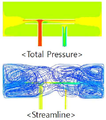
외부 장치의 기체 주입에 따른 압력분포를 컴퓨터 유체 역학(computational Fluid dynamics, cFd)을 통해 유동해석으로 압력분포를 측정하였다. The pressure distribution according to the gas injection of the external device was measured by flow analysis through computational fluid dynamics (cFd).
또한 공급단부(303)에서 배출된 기체가 향하는, 부피고정부(10)와 양쪽 부피가변부(20)가 만나는 면의 중앙인 L(left)과 R(right), 기체가 외부로 배출되는 배출유로의 중앙지점 O(output)에서 각각 유입되는 기체의 압력이 증가하였을 때의 압력을 측정하였다. In addition, L (left) and R (right), the center of the surface where the gas discharged from the supply end 303 faces, and the
2) 결과2) Results
도 7a(제1실시예), 도 7b(제5실시예)는 각각 실험 1의 측정 결과이며, 도 8a 내지 도 8c는 각각 실험 1에서 제1실시예(MODEL T) 및 제5실시예(MODEL I)의 측정지점(L, R, O)에 따른 압력 측정 결과를 도시한 것이다.7A (the first embodiment) and 7B (the fifth embodiment) are the measurement results of
도 7a, 도 7b, 도 8a 내지 도 8c에 도시된 바와 같이 제1실시예는 제5실시예에 비해, 부피고정부(10)에서 부피가변부(30)로의 압력 분포가 효율적으로 이루어지며, L 및 R의 압력이 큰 것을 알 수 있다. 즉, 제5실시예는 외부로 배출되는 Output(측정지점 O)의 기체 압력의 크기 차이는 없어 기체 압력을 효율적으로 조절할 수 있으나, 제2공급유로(301b)가 형성되어 있는 T자형 기체공급부(30)가 있는 제1실시예는 부피가변부(30)의 기체가 효율적으로 전달됨을 알 수 있다.As shown in FIGS. 7A, 7B, and 8A to 8C, in the first embodiment, the pressure distribution from the
<실험 2 (실험예 3 내지 실험예 5): 제2서브유로(301b″)의 길이에 따른 압력 분포 측정><Experiment 2 (Experimental Examples 3 to 5): Measurement of pressure distribution along the length of the second sub-channel (301b ″)>
1) 실험 방법 1) Experiment method
실험예 3은 각각 직경 70mm, 높이 200mm의 플라스틱 소재로 이루어진 원통형 부피고정부(10)에, 각각 제1서브유로(301b′)의 중심으로부터 제2서브유로(301b″)의 길이가 각각 30mm, 실험예 4는 60mm, 실험예 5는 95mm인 기체주입 안정화 장치(1)을 사용하였고, 실험 1과 같은 방법으로 각각의 부피고정부(10)의 압력 분포 및 측정지점(L, R, O)의 압력 크기를 측정하였다.In Experimental Example 3, the length of each of the
2) 결과2) Results
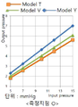
9a 내지 도 9c는 유동해석에 대한 실험 2의 측정 결과를 도시한 것이고, 도 10a 내지 도 10c는 각각 실험 2에서 측정지점(L, R, O)의 압력 측정 결과를 도시한 그래프이다. 9a to 9c show the measurement results of
도시된 바와 같이 측정지점 R에서 제2서브유로(301b″)의 길이가 각각 30mm 보다 60mm, 60mm 보다 95mm의 압력 전달이 효과적이며, 이 이외의 측점지점과 전체적인 압력분포는 유사한 것을 볼 수 있다. 즉, 제2공급유로(301b)의 길이가 길어질수록 부피가변부(20)와의 거리가 가까워져, 기체 이동이 원활해지기 때문에 부피가변부(20)와 가까워지는 만큼 압력전달의 효율을 향상시킬 수 있는 것으로 판단된다.As shown in the figure, the lengths of the
<실험 3 (실험예 6 내지 실험예 8): 공급단부의 형태에 따른 압력 분포 측정><Experiment 3 (
1) 실험 방법1) Experiment method
실험예 6은 각각 제2공급유로(301b)의 기체유로 단면적은 일정(도 2에서 r1= r2)한 본 발명의 제1실시예, 실험예 7은 제2공급유로(301b)가 공급단부(303)로 갈수록 직경이 좁아지는 제6실시예(도 2에서 r1>r2, 미도시) 및 실험예 8은 제2공급유로(301b)가 공급단부(303)로 갈수록 직경이 넓어지는 제7실시예(도 2에서 r1<r2, 미도시)에 따른 기체주입 안정화 장치(1)을 사용하였고, 실험 1과 같은 방법으로 각각의 부피고정부(10)의 압력 분포 및 측정지점(L, R, O)의 압력 크기를 측정하였다.Experimental Example 6 is the first embodiment of the present invention in which the cross-sectional area of the gas flow path of the second
2) 결과2) Results
도 11a 내지 도 11c는 유동해석에 대한 실험 3의 측정 결과를 도시한 것이고, 도 12a 내지 도 12c는 각 측정지점(L, R, O)에 따른 압력 측정에 대한 실험 3의 측정 결과를 도시한 것이다.11A to 11C show measurement results of
도시된 바와 같이 본 발명에 따른 제6 및 제7실시예보다 제1실시예에 비해 압력전달이 효율이 좋은 것으로 확인된다. 제6실시예의 경우, 공급단부(303)가 좁아져 배출되는 기체량이 작아지고, 제7실시예의 경우, 공급단부(303)가 넓어져, 공급되는 기체 대비 배출되는 기체의 압력이 낮아지기 때문인 것으로 판단된다.As shown, it is confirmed that the pressure transmission is more efficient than the first embodiment than the sixth and seventh embodiments according to the present invention. In the case of the sixth embodiment, it is judged that the supply end portion 303 becomes narrow and the amount of gas to be discharged becomes small, and in the case of the seventh embodiment, the supply end portion 303 is widened, and the pressure of the gas discharged compared to the supplied gas is judged to be lower. do.
<실험 4 (실험예 9 내지 실험예 10): 기체배출부(40)의 위치에 따른 압력 분포 측정><Experiment 4 (Experimental Example 9 to Experimental Example 10): Pressure distribution measurement according to the position of the
1) 실험 방법 1) Experiment method
실험예 9는 기체공급부(30)와 기체배출부(40)는 부피고정부(10)에 나란히 배치되어 있는 본 발명의 제1실시예에 따른 기체주입 안정화 장치(1)을 사용하였고, 구체적인 수치는 도 13a와 같다.Experimental Example 9 used the gas
실험예 10은 기체공급부(30)와 기체배출부(40)가 서로 마주보며 배치하는 본 발명의 제8실시예에 따른 기체주입 안정화 장치(1)을 사용하였고, 구체적인 수치는 도 13b와 같다.Experimental Example 10 used the gas
실험 1과 같은 방법으로 각각의 부피고정부(10)의 압력 분포 및 측정지점(L, R, O)의 압력 크기를 측정하였다.In the same manner as in
2) 결과2) Results
도 14a, 도 14b는 각각 유동해석에 대한 실험 4의 측정결과를 도시한 것이고, 도 15a 내지 도 15c는 각각 실험 4에서 측정지점(L, R, O)에 따른 압력 측정 결과를 도시한 것이다.14A and 14B respectively show measurement results of
도 14a, 도 14b, 도 15a 내지 도 15c에 도시된 바와 같이 제1실시예 와 제8실시예는 부피고정부(10)의 압력 분포와 각 측정지점(L, R, O)의 압력의 크기는 차이가 없음을 알 수 있다. 따라서 기체배출부(40)의 위치는 크게 영향을 미치지 않음을 알 수 있다.14A, 14B, and 15A to 15C, the first and eighth embodiments show the pressure distribution of the
<실험 5 (실험예 11 내지 실험예 13): 제2공급유로(301b)의 형태에 따른 압력 분포 측정><Experiment 5 (Experimental Example 11 to Experimental Example 13): Pressure distribution measurement according to the shape of the second
1) 실험 방법 1) Experiment method
실험예 11은 직경 70mm, 높이 200mm의 플라스틱 소재로 이루어진 원통형 부피고정부(10)에, 제2공급유로(301b)가 마주보며 형성되어 있는 T자형 기체공급부(30)를 포함하는 본 발명의 제8실시예에 따른 기체주입 안정화 장치(1)을 사용하였고, 구체적인 수치는 도 16a와 같다.Experimental Example 11 is the invention of the present invention comprising a T-shaped
실험예 12는 V자형 기체공급부(30)를 포함하는 본 발명의 제9실시예에 따른 기체주입 안정화 장치(1)을 사용하였고, 구체적인 수치는 도 16b와 같다.Experimental Example 12 used a gas
실험예 13은 U자형 기체공급부(30)를 포함하는 본 발명의 제10실시예에 따른 기체주입 안정화 장치(1)을 사용하였고, 구체적인 수치는 도 16c와 같다.Experimental Example 13 used a gas
각각은 공급단부(303)를 통해 유출되는 기체가 부피고정부(10)와 부피가변부(20)가 연통되는 면의 중앙으로 향하게 위치하도록 설계하였으며, 실험 1과 같은 방법으로 부피고정부(10)의 압력 분포 및 측정지점(L, R, O)의 압력 크기를 측정하였다.Each is designed such that the gas flowing out through the supply end 303 is positioned toward the center of the surface where the
2) 결과2) Results
도 17a 내지 도 17c는 각각 유동해석에 대한 실험 5의 측정결과를 도시한 것이고, 도 18a 내지 도 18c는 각각 실험 5에서 측정지점에 따른 압력 측정 결과를 도시한 것이다.17A to 17C respectively show measurement results of
도 17a 내지 도 17c, 도 18a 내지 도 18c에 도시된 바와 같이 제8실시예에 비해 제9실시예가, 제9실시예에 비해 제10실시예의 압력 전달이 효과적인 것을 볼 수 있다. 이는 기체의 운동 에너지를 가능한 서서히 방향을 바꿔줌으로서 압력전달의 효율을 향상시킬 수 있는 것으로 판단된다.As shown in FIGS. 17A to 17C and FIGS. 18A to 18C, it can be seen that the ninth embodiment is more effective than the ninth embodiment, and the pressure transmission of the tenth embodiment is more effective than the ninth embodiment. It is thought that the efficiency of pressure transmission can be improved by changing the kinetic energy of the gas as slowly as possible.
본 발명에 따른 기체주입 안정화 장치(1)은, 버퍼 역할을 하는 부피고정부(10)를 통해 기본 부피를 확보하고, 기체량에 따라 부피가 변화하는 부피가변부(20)를 통해 기체량 변화 시에도 수술 부위의 압력을 감소시킬 수 있는 효과가 있다. 이러한 효과는 외부와 연결되는 제1공급유로(301a)에서 분기되고, 제1서브유로(301b′)와 제2서브유로(301b″)를 가진 제2공급유로, 제1서브유로(301b′) 보다 길이가 긴 제2서브유로(301b″), 기체유로의 단면적이 일정한 제2공급유로(301b) 등을 통해 향상되어, 수술 시 신체 내부에서 안정적인 가스 흐름과 지속적이 압력을 유지할 수 있다. The gas
Claims (7)
부피가 고정된 제1기체공간을 가지고 있는 부피고정부;
상기 부피고정부와 연통되어 있으며, 상기 부피고정부에 입출하는 기체에 의해 부피가 가변하며, 상기 제1기체공간과 연결되어있는 제2기체공간을 가지는 적어도 하나의 부피가변부;
상기 부피고정부와 연결되어 있으며, 외부의 기체공급장치로부터 기체를 공급받는 기체공급부; 및
상기 부피고정부와 연결되어 있으며, 외부의 수술 공간으로 기체를 배출하는 기체배출부;를 포함하는 것을 특징으로 하는 기체주입 안정화 장치.In the gas injection stabilization device for reducing the pressure change of the gas injected into the body to ensure space during surgery,
A volume fixing unit having a fixed first gas space;
At least one volume variable portion having a second gas space in communication with the volume fixation, having a variable volume by a gas flowing in and out of the volume fixation, and having a second gas space connected to the first gas space;
A gas supply unit connected to the volume fixing unit and receiving gas from an external gas supply device; And
Gas injection stabilization device, characterized in that it is connected to the volume fixing, gas discharge unit for discharging the gas to the external surgical space.
상기 기체공급부는 기체가 유입되어 이동하는 공급유로; 및 상기 유입된 기체가 상기 기체공간으로 유출되는 공급단부;를 포함하고,
상기 기체배출부는 상기 제1기체공간의 기체가 유입되는 배출단부; 및 상기 기체가 이동하여 상기 부피고정부 외부로 유출되는 배출유로;를 포함하는 것을 특징으로 하는 기체주입 안정화 장치.According to claim 1,
The gas supply unit is a supply flow path through which gas flows; And a supply end through which the introduced gas flows into the gas space.
The gas discharging part is an exhaust end through which gas in the first gas space is introduced; And a discharge flow path through which the gas moves and flows out of the volume fixing unit.
상기 공급유로는,
외부와 연결되는 제1공급유로;
상기 제1공급유로에서 분기되며 상기 공급단부를 가지는 제2공급유로;
를 포함하는 것을 특징으로 하는 기체주입 안정화 장치.According to claim 1,
The supply flow path,
A first supply channel connected to the outside;
A second supply channel branched from the first supply channel and having the supply end;
Gas injection stabilization device comprising a.
상기 제2공급유로는,
각각이 상기 공급단부를 가지는 제1서브유로; 및
제2서브유로;를 포함하는 것을 특징으로 하는 기체주입 안정화 장치.According to claim 3,
The second supply flow path,
A first sub-channel each having the supply end; And
Gas injection stabilization device comprising a; second sub-flow path.
상기 제1공급유로, 상기 제1서브유로 및 상기 제2서브유로는 V자, Y자 및 T자 형태 중 어느 하나인 것을 특징으로 하는 기체주입 안정화 장치.According to claim 4,
The first supply flow path, the first sub-flow path and the second sub-flow path is a gas injection stabilization device, characterized in that any one of the V-shaped, Y-shaped and T-shaped.
상기 부피가변부는 한 쌍으로 마련되어 상기 부피고정부를 사이에 두고 배치되며,
상기 제1서브유로의 공급단부는 상기 부피가변부 중 어느 하나를 향하고, 상기 제2서브유로의 공급단부는 상기 부피가변부 중 다른 하나를 향해 기체가 배출되는 것을 특징으로 하는 기체주입 안정화 장치.According to claim 4,
The volume variable portion is provided in a pair and is disposed with the volume fixing portion therebetween,
Gas supply stabilization device, characterized in that the supply end of the first sub-path is directed to any one of the volume variable portion, and the supply end of the second sub-path is discharged to another one of the volume-variable portion.
상기 부피고정부는 원통형인 것을 특징으로 하는 기체주입 안정화 장치.
According to claim 1,
The volume fixing unit is a gas injection stabilization device, characterized in that the cylindrical.
Priority Applications (3)
| Application Number | Priority Date | Filing Date | Title |
|---|---|---|---|
| KR1020180114168A KR102138120B1 (en) | 2018-09-21 | 2018-09-21 | Apparatus for stabilizing supply of gas |
| PCT/KR2019/011914 WO2020060116A1 (en) | 2018-09-21 | 2019-09-16 | Gas injection stabilization device |
| US17/277,543 US20220031968A1 (en) | 2018-09-21 | 2019-09-16 | Gas injection stabilization device |
Applications Claiming Priority (1)
| Application Number | Priority Date | Filing Date | Title |
|---|---|---|---|
| KR1020180114168A KR102138120B1 (en) | 2018-09-21 | 2018-09-21 | Apparatus for stabilizing supply of gas |
Publications (2)
| Publication Number | Publication Date |
|---|---|
| KR20200034413A true KR20200034413A (en) | 2020-03-31 |
| KR102138120B1 KR102138120B1 (en) | 2020-07-27 |
Family
ID=69887579
Family Applications (1)
| Application Number | Title | Priority Date | Filing Date |
|---|---|---|---|
| KR1020180114168A Active KR102138120B1 (en) | 2018-09-21 | 2018-09-21 | Apparatus for stabilizing supply of gas |
Country Status (3)
| Country | Link |
|---|---|
| US (1) | US20220031968A1 (en) |
| KR (1) | KR102138120B1 (en) |
| WO (1) | WO2020060116A1 (en) |
Families Citing this family (1)
| Publication number | Priority date | Publication date | Assignee | Title |
|---|---|---|---|---|
| CN112057122A (en) * | 2020-09-18 | 2020-12-11 | 西安交通大学医学院第一附属医院 | Automatic inflating device for medical thoracoscope |
Citations (8)
| Publication number | Priority date | Publication date | Assignee | Title |
|---|---|---|---|---|
| EP0426319A2 (en) * | 1989-10-31 | 1991-05-08 | Block Medical, Inc. | Infusion apparatus |
| KR20010026234A (en) * | 1999-09-03 | 2001-04-06 | 한호성 | Sleeve for celoscope surgery |
| JP2009509650A (en) * | 2005-09-26 | 2009-03-12 | アテヌークス・テクノロジーズ・インコーポレーテッド | Pressure damping device |
| KR20100126021A (en) * | 2009-05-22 | 2010-12-01 | 국립암센터 | Drug reservoirs for implantable device |
| US7854724B2 (en) | 2003-04-08 | 2010-12-21 | Surgiquest, Inc. | Trocar assembly with pneumatic sealing |
| KR101118856B1 (en) * | 2010-08-06 | 2012-03-14 | 황선철 | Apparatus for Insufflating Gas Into Human Body |
| KR20150127114A (en) * | 2013-03-15 | 2015-11-16 | 어플라이드 메디컬 리소시스 코포레이션 | Trocar surgical seal |
| KR20180061326A (en) * | 2015-09-30 | 2018-06-07 | 어플라이드 메디컬 리소시스 코포레이션 | Injection stabilization system |
Family Cites Families (7)
| Publication number | Priority date | Publication date | Assignee | Title |
|---|---|---|---|---|
| US6073656A (en) * | 1997-11-24 | 2000-06-13 | Dayco Products, Inc. | Energy attenuation device for a conduit conveying liquid under pressure, system incorporating same, and method of attenuating energy in a conduit |
| JP4573554B2 (en) * | 2004-03-30 | 2010-11-04 | オリンパス株式会社 | Endoscopic surgery system |
| US20140261704A1 (en) * | 2013-03-14 | 2014-09-18 | Nordson Corporation | Gas regulator, control interface module, and methods for surgical applications |
| KR101884921B1 (en) * | 2015-12-17 | 2018-08-02 | 건양대학교 산학협력단 | Gas injection device |
| CN206285137U (en) * | 2016-07-20 | 2017-06-30 | 鼎科医疗技术(苏州)有限公司 | A kind of pressure-adjustable air tourniquet |
| US10905463B2 (en) * | 2017-03-08 | 2021-02-02 | Conmed Corporation | Gas circulation system with single lumen gas sealed access port and single lumen valve sealed access port for use during endoscopic surgical procedures |
| CN207195113U (en) * | 2017-07-12 | 2018-04-06 | 国家电投集团科学技术研究院有限公司 | Prepressing type pulse buffer applied to injecting systems |
-
2018
- 2018-09-21 KR KR1020180114168A patent/KR102138120B1/en active Active
-
2019
- 2019-09-16 US US17/277,543 patent/US20220031968A1/en not_active Abandoned
- 2019-09-16 WO PCT/KR2019/011914 patent/WO2020060116A1/en not_active Ceased
Patent Citations (8)
| Publication number | Priority date | Publication date | Assignee | Title |
|---|---|---|---|---|
| EP0426319A2 (en) * | 1989-10-31 | 1991-05-08 | Block Medical, Inc. | Infusion apparatus |
| KR20010026234A (en) * | 1999-09-03 | 2001-04-06 | 한호성 | Sleeve for celoscope surgery |
| US7854724B2 (en) | 2003-04-08 | 2010-12-21 | Surgiquest, Inc. | Trocar assembly with pneumatic sealing |
| JP2009509650A (en) * | 2005-09-26 | 2009-03-12 | アテヌークス・テクノロジーズ・インコーポレーテッド | Pressure damping device |
| KR20100126021A (en) * | 2009-05-22 | 2010-12-01 | 국립암센터 | Drug reservoirs for implantable device |
| KR101118856B1 (en) * | 2010-08-06 | 2012-03-14 | 황선철 | Apparatus for Insufflating Gas Into Human Body |
| KR20150127114A (en) * | 2013-03-15 | 2015-11-16 | 어플라이드 메디컬 리소시스 코포레이션 | Trocar surgical seal |
| KR20180061326A (en) * | 2015-09-30 | 2018-06-07 | 어플라이드 메디컬 리소시스 코포레이션 | Injection stabilization system |
Also Published As
| Publication number | Publication date |
|---|---|
| WO2020060116A1 (en) | 2020-03-26 |
| KR102138120B1 (en) | 2020-07-27 |
| US20220031968A1 (en) | 2022-02-03 |
Similar Documents
| Publication | Publication Date | Title |
|---|---|---|
| US20160183971A1 (en) | Expanding surgical access port | |
| CO6382096A2 (en) | SURGICAL INSTRUMENTAL TEAM SUITABLE FOR MINI-INVASIVE SURGERY. | |
| ATE398421T1 (en) | ACCESS DEVICE WITH ADJUSTABLE HEIGHT FOR TREATING A PATIENT'S SPINE | |
| KR101037644B1 (en) | Laparoscopic Retractor System | |
| EP1628632A4 (en) | DEVICES, SYSTEMS AND METHODS FOR MAKING MINIMUM INVASIVE SURGERY AT THE THROAT AND OTHER PARTS OF THE MAMMALIAN BODY | |
| CN108992163B (en) | Instrument with multi-stream instrument head for argon plasma coagulation | |
| MX2009012552A (en) | Articulating cavitation device. | |
| GB2509656A (en) | Patient-specific partial knee guides and other instruments | |
| DE602005024391D1 (en) | ACCESSORIES IN ORTHOPEDIC SURGERY | |
| ES2981294T3 (en) | Inflation stabilization system | |
| SG152201A1 (en) | Integrated conduit insertion medical device | |
| KR102138120B1 (en) | Apparatus for stabilizing supply of gas | |
| DE60229626D1 (en) | DEVICE FOR INTRODUCING A MEDICAL DEVICE | |
| US20100022918A1 (en) | Sensing system employing medical manipulator and pressing force measuring device and its program | |
| BR112013002476A2 (en) | "surgical apparatus and method" | |
| US20120078059A1 (en) | Minimally invasive suction retractor | |
| ATE500791T1 (en) | HIGH-FREQUENCY TREATMENT TOOL AND MUCOSIS MEMBRANE ABBOTATION PROCEDURE USING THE HIGH-FREQUENCY TREATMENT TOOL | |
| KR101425636B1 (en) | Nasolacrimal duct tube with lacrimal passage | |
| US20130046353A1 (en) | Oval tunnel dilators | |
| US20160074066A1 (en) | Trocar for thoracoscopic surgery, and port formation kit for thoracoscopic surgical instruments | |
| WO2008125961A3 (en) | Chest drainage tube and apparatus for the insertion thereof | |
| KR200465473Y1 (en) | Thoracic Trocar | |
| CN205729611U (en) | The Inflatable earplug that a kind of otoscope outer with gun-type coordinates | |
| DE60128406D1 (en) | AUXILIARY TONGUE FOR MANUALLY SUPPORTED LAPARASCOPIC SURGERY | |
| CN204765758U (en) | Incision leads out fixer suitable for haplopore chest laparoscopic surgery |
Legal Events
| Date | Code | Title | Description |
|---|---|---|---|
| PA0109 | Patent application |
Patent event code: PA01091R01D Comment text: Patent Application Patent event date: 20180921 |
|
| PA0201 | Request for examination | ||
| PE0902 | Notice of grounds for rejection |
Comment text: Notification of reason for refusal Patent event date: 20200110 Patent event code: PE09021S01D |
|
| PG1501 | Laying open of application | ||
| E701 | Decision to grant or registration of patent right | ||
| PE0701 | Decision of registration |
Patent event code: PE07011S01D Comment text: Decision to Grant Registration Patent event date: 20200717 |
|
| GRNT | Written decision to grant | ||
| PR0701 | Registration of establishment |
Comment text: Registration of Establishment Patent event date: 20200721 Patent event code: PR07011E01D |
|
| PR1002 | Payment of registration fee |
Payment date: 20200722 End annual number: 3 Start annual number: 1 |
|
| PG1601 | Publication of registration | ||
| PR1001 | Payment of annual fee |
Payment date: 20230717 Start annual number: 4 End annual number: 4 |
|
| PR1001 | Payment of annual fee |
Payment date: 20240718 Start annual number: 5 End annual number: 5 |
|
| PR1001 | Payment of annual fee |
Payment date: 20250624 Start annual number: 6 End annual number: 6 |