KR20200001715A - The power unit of wheelchair for change electromotive run - Google Patents
The power unit of wheelchair for change electromotive run Download PDFInfo
- Publication number
- KR20200001715A KR20200001715A KR1020180074538A KR20180074538A KR20200001715A KR 20200001715 A KR20200001715 A KR 20200001715A KR 1020180074538 A KR1020180074538 A KR 1020180074538A KR 20180074538 A KR20180074538 A KR 20180074538A KR 20200001715 A KR20200001715 A KR 20200001715A
- Authority
- KR
- South Korea
- Prior art keywords
- wheelchair
- support
- electric
- hole
- insertion hole
- Prior art date
- Legal status (The legal status is an assumption and is not a legal conclusion. Google has not performed a legal analysis and makes no representation as to the accuracy of the status listed.)
- Granted
Links
Images


Classifications
-
- A—HUMAN NECESSITIES
- A61—MEDICAL OR VETERINARY SCIENCE; HYGIENE
- A61G—TRANSPORT, PERSONAL CONVEYANCES, OR ACCOMMODATION SPECIALLY ADAPTED FOR PATIENTS OR DISABLED PERSONS; OPERATING TABLES OR CHAIRS; CHAIRS FOR DENTISTRY; FUNERAL DEVICES
- A61G5/00—Chairs or personal conveyances specially adapted for patients or disabled persons, e.g. wheelchairs
- A61G5/04—Chairs or personal conveyances specially adapted for patients or disabled persons, e.g. wheelchairs motor-driven
- A61G5/047—Chairs or personal conveyances specially adapted for patients or disabled persons, e.g. wheelchairs motor-driven by a modular detachable drive system
-
- A—HUMAN NECESSITIES
- A61—MEDICAL OR VETERINARY SCIENCE; HYGIENE
- A61G—TRANSPORT, PERSONAL CONVEYANCES, OR ACCOMMODATION SPECIALLY ADAPTED FOR PATIENTS OR DISABLED PERSONS; OPERATING TABLES OR CHAIRS; CHAIRS FOR DENTISTRY; FUNERAL DEVICES
- A61G5/00—Chairs or personal conveyances specially adapted for patients or disabled persons, e.g. wheelchairs
- A61G5/04—Chairs or personal conveyances specially adapted for patients or disabled persons, e.g. wheelchairs motor-driven
- A61G5/041—Chairs or personal conveyances specially adapted for patients or disabled persons, e.g. wheelchairs motor-driven having a specific drive-type
- A61G5/042—Front wheel drive
-
- A—HUMAN NECESSITIES
- A61—MEDICAL OR VETERINARY SCIENCE; HYGIENE
- A61G—TRANSPORT, PERSONAL CONVEYANCES, OR ACCOMMODATION SPECIALLY ADAPTED FOR PATIENTS OR DISABLED PERSONS; OPERATING TABLES OR CHAIRS; CHAIRS FOR DENTISTRY; FUNERAL DEVICES
- A61G5/00—Chairs or personal conveyances specially adapted for patients or disabled persons, e.g. wheelchairs
- A61G5/10—Parts, details or accessories
Landscapes
- Health & Medical Sciences (AREA)
- Life Sciences & Earth Sciences (AREA)
- Animal Behavior & Ethology (AREA)
- General Health & Medical Sciences (AREA)
- Public Health (AREA)
- Veterinary Medicine (AREA)
- Handcart (AREA)
- Automatic Cycles, And Cycles In General (AREA)
Abstract
Description
본 발명은 휠체어 동력장치에 관한 것으로서, 더욱 상세하게는 장애인, 노약자 등 탑승자가 손으로 바퀴를 굴리는 수동식 휠체어에 전동모듈을 착탈식으로 장착함으로써, 수동식 휠체어를 3륜 방식의 전동식 휠체어로 변환시키는 전동주행 전환용 휠체어 동력장치에 관한 것이다.The present invention relates to a wheelchair power device, and more particularly, to an electric drive that converts a manual wheelchair into a three-wheeled electric wheelchair by detachably mounting an electric module on a manual wheelchair in which a passenger, such as a disabled person or an elderly person, rolls a wheel by hand. It relates to a wheelchair power unit for conversion.
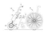
도 1은 본 발명이 속하는 휠체어의 일반적인 사시도이다. 도 1에 도시된 휠체어는 장애인, 노약자 또는 일시적으로 사고를 당한 사람들이 이동 수단으로 사용하는 수동식 휠체어(10)로서, 주행을 담당하는 큰 바퀴가 시트의 양쪽에 장착되고, 방향 전환을 담당하는 작은 바퀴가 360°회전 가능하도록 발 받침대의 측방에 장착되어 4륜 방식으로 구동되도록 이루어진다.1 is a general perspective view of a wheelchair to which the present invention belongs. The wheelchair shown in FIG. 1 is a
도 1에 도시된 수동식 휠체어(10)는 무게가 가볍고, 시트를 중심으로 양쪽 바퀴의 폭을 좁혀 부피를 줄일 수 있으므로, 장거리 이동시 차량에 탑재할 수 있는 장점이 있으나, 몸이 불편한 탑승자가 시트에 앉은 상태에서 바퀴의 테두리를 따라 장착된 구동림(12)을 손으로 잡고 힘으로 구동시키는 방식임을 고려할 때, 수동식 휠체어(10)는 실내에서 사용하거나 근거리 이동시 보조 이동 수단으로 한정되는 문제점이 있다.The
따라서, 본 발명은 상술한 수동식 휠체어의 문제점을 감안하여 이동의 편의성을 증대시키기 위해 창안한 것으로서, 수동식 4륜 방식으로 움직이는 휠체어에 전동식 구동바퀴가 달린 전동모듈을 착탈식으로 장착함으로써, 수동식 4륜 방식의 휠체어를 전동식 3륜 방식의 휠체어로 변환시킬 수 있는 전동주행 전환용 휠체어 동력장치를 제공하고자 한다.Therefore, the present invention was devised to increase the convenience of movement in view of the above-described problems of the manual wheelchair, and by manually attaching the electric module with the electric drive wheel to the wheelchair moving in a manual four-wheel system, manual four-wheel system To provide a wheelchair power conversion device for converting a wheelchair into an electric three-wheeled wheelchair.
또한, 구동바퀴(23)의 좌우 측방에 받침지지대(100) 및 접철대(110)가 장착됨으로써, 휠체어(10)에서 탈거한 전동모듈(20)을 용이하게 세워둘 수 있을 뿐 아니라, 회동되는 접철대(110)로 인해 주행중에 부딪치는 잡석과 같은 외력을 수월하게 통과할 수 있는데다, 전동모듈(20)을 탈거하는 과정에서 접철대(110)가 지면과 맞닿는 간섭 문제가 발생하더라도 접철대(110)의 회동 구성으로 인해, 탈거 작업이 용이하게 이루어지는 전동주행 전환용 휠체어 동력장치를 제공하고자 한다.In addition, by supporting the
본 발명에 따른 전동주행 전환용 휠체어 동력장치의 구체적인 수단은, 인휠모터(24)가 내장된 구동바퀴(23)가 구비되고, 구동바퀴(23)의 직상방에는 조작핸들(21)이 위치되되, 조작핸들(21)은 직하방으로 연결대(22)가 연결되고, 연결대(22)의 직하방에는 조향하우징(80)이 장착되어, 상기 연결대(22)의 일측이 조향하우징(80)의 내부에서 전방 또는 후방으로 움직일 수 있도록 장착되고, 상기 조향하우징(80)의 직하방에는 휠체어(10)의 결합수단과 체결되는 체결유닛(70)이 장착되며, 상기 체결유닛(70)의 전방에는 착탈식 배터리(25)가 장착되고, 상기 구동바퀴(23)의 좌우 측방에는 받침지지대(100) 및 접철대(110)가 장착되는 전동모듈(20)이 상기 체결유닛(70)을 매개체로 수동식 휠체어(10)의 결합수단과 장착됨으로써, 수동식 휠체어가 전동식 휠체어로 전환되는 구성이다.Specific means of the wheelchair driving device for electric driving conversion according to the present invention, the
또한, 상기 받침지지대(100)의 일측은 상기 구동바퀴(23)의 측방에 장착되고, 받침지지대(100)의 타측에는 접철대(110)의 삽입구(111)가 끼워지도록 삽입공(101)이 형성되며, 상기 삽입공(101)의 입구부에는 제1결합공(102)이 형성되고, 상기 받침지지대(100)의 중앙에는 중공부(103)가 형성되며, 상기 중공부(103)의 일측 상부에는 탄성구(106)의 일단을 고정시키기 위한 제1계지구(105)가 형성되고, 중공부(103)의 하부에는 인출공(104)이 형성되며, 상기 일측으로 삽입구(111)가 형성된 접철대(110)는 삽입구(111)의 선단에 탄성구(106)의 타단을 고정시키기 위한 제2계지구(112)가 형성되고, 삽입구(111)의 타측 상부에는 제2결합공(113)이 형성되며, 회동핀(114)이 받침지지대(100)의 제1결합공(102) 및 접철대(110)의 제2결합공(113)에 관통됨으로써, 외력에 의해 접철대(110)가 회동핀(114)을 중심으로 상부로 회전되는 구성이다.In addition, one side of the
본 발명에 따른 전동주행 전환용 휠체어 동력장치를 사용하게 되면, 기존에 사용하고 있는 수동식 휠체어를 전동식 휠체어로 간편하게 변환시킬 수 있으므로, 장애인, 노약자 등 교통 약자에게 이동의 편의성을 제공하여 삶을 윤택하게 조성할 수 있는 유용한 장점이 있다.When using the electric drive switching wheelchair power device according to the present invention, it is possible to easily convert the existing manual wheelchair to an electric wheelchair, providing convenience for transportation to the handicapped, the elderly and the elderly, to make life easier There is a useful advantage that can be formulated.
또한, 고가의 전동식 휠체어를 별도로 구매해야 하는 비용 부담을 경감시켜 주는 부수적인 효과도 있는데다, 장거리 이동시 전동식 휠체어는 자동차 트렁크에 탑재할 수 없었으나, 본 발명은 전동모듈과 수동식 휠체어를 분리한 다음 휠체어를 접어 자동차 트렁크에 탑재할 수 있으므로, 여행지 또는 휴양지에서도 교통 약자에게 이동의 편의성을 계속적으로 제공할 수 있는 장점이 있는 것이다.In addition, there is a side effect of reducing the burden of having to purchase an expensive electric wheelchair separately, the electric wheelchair could not be mounted in the trunk of the car when moving long distance, the present invention is a wheelchair after separating the electric module and the manual wheelchair Because it can be mounted on the trunk of the car folded, there is an advantage that can continue to provide the convenience of movement to the traffic weak even in a travel destination or resort.
한편, 본 발명중 구동바퀴의 좌우에는 받침지지대 및 접철대가 장착됨으로써, 휠체어에서 탈거한 전동모듈을 용이하게 세워둘 수 있을 뿐 아니라, 회동되는 접철대로 인해 주행중에 부딪치는 잡석과 같은 외력을 수월하게 통과할 수 있는데다, 전동모듈을 탈거하는 과정에서 접철대가 지면과 맞닿는 간섭 문제가 발생하더라도 접철대의 회동 구성으로 인해, 탈거 작업이 용이하게 이루어지는 장점이 있는 것이다.On the other hand, the left and right of the drive wheel in the present invention is equipped with a support stand and a folding stand, not only can easily stand the electric module removed from the wheelchair, but also facilitates external force such as rubble hitting the road due to the folding folding table Although it can pass through, even if an interference problem occurs in which the folding table is in contact with the ground in the process of removing the electric module, due to the rotational configuration of the folding table, there is an advantage that the removal operation is easily performed.
도 1은 일반적인 휠체어의 사시도
도 2는 본 발명에 따른 전동모듈이 장착된 휠체어의 사시도
도 3은 본 발명에 따른 전동모듈의 결합 사시도
도 4는 본 발명에 따른 전동모듈의 분리 사시도
도 5는 본 발명중 클램프, 가로지지대 및 결합허브를 설명하기 위한 사시도
도 6은 본 발명중 가로지지대와 세로지지대의 조립을 설명하기 위한 순서 측면도
도 7은 본 발명중 각도설정허브, 세로지지대 및 체결허브를 설명하기 위한 사시도
도 8은 본 발명중 체결유닛을 설명하기 위한 사시도
도 9는 본 발명중 조향하우징 및 조향유닛을 설명하기 위한 분리 사시도
도 10은 본 발명에 따른 전동모듈의 조립을 설명하기 위한 순서 측면도
도 11은 본 발명중 받침지지대 및 접철대를 설명하기 위한 분리 사시도
도 12는 본 발명중 받침지지대 및 접철대를 설명하기 위한 사용상태 사시도
도 13은 본 발명중 받침지지대 및 접철대를 설명하기 위한 사용상태 측면도
도 14는 본 발명에 따른 전동모듈의 결합을 설명하기 위한 측면도1 is a perspective view of a typical wheelchair
2 is a perspective view of a wheelchair equipped with an electric module according to the present invention;
3 is a perspective view of the coupling of the electric module according to the present invention
4 is an exploded perspective view of the electric module according to the present invention;
Figure 5 is a perspective view for explaining the clamp, the horizontal support and the coupling hub of the present invention
Figure 6 is a side view of the order for explaining the assembly of the horizontal support and the vertical support in the present invention
Figure 7 is a perspective view for explaining the angle setting hub, vertical support and fastening hub of the present invention
8 is a perspective view for explaining a fastening unit of the present invention;
Figure 9 is an exploded perspective view for explaining the steering housing and the steering unit of the present invention
Figure 10 is a side view of the order for explaining the assembly of the electric module according to the present invention
Figure 11 is an exploded perspective view for explaining the support base and the folding table in the present invention
Figure 12 is a perspective view of the use state for explaining the support and the folding stand in the present invention
Figure 13 is a side view of the use state for explaining the support and folds in the present invention
14 is a side view for explaining the coupling of the electric module according to the present invention;
이하, 본 발명의 목적을 달성할 수 있는 전동주행 전환용 휠체어 동력장치의 바람직한 실시예를 상세하게 설명하되, 본 발명과 관련된 공지 기능이나 구성 및 시스템에 대한 구체적인 설명이 본 발명의 요지와 부합되지 않는 부연 설명에 지나지 않을 경우 그에 따른 상세한 설명은 생략하기로 한다.Hereinafter, a preferred embodiment of the electric drive switching wheelchair power unit capable of achieving the object of the present invention will be described in detail, but a detailed description of known functions, configurations and systems related to the present invention does not correspond to the gist of the present invention. If only the description is not a detailed description thereof will be omitted.
도 2는 본 발명에 따른 전동모듈(20)이 장착된 휠체어(10)의 사시도이고, 도 3은 본 발명에 따른 전동모듈(20)의 결합 사시도이며, 도 4는 본 발명에 따른 전동모듈(20)의 분리 사시도이다.2 is a perspective view of a
도 2 내지 도 4에서 보듯이 수동식 휠체어(10)의 전방에는 전동모듈(20)이 위치되고, 상기 전동모듈(20)은 휠체어(10)의 시트프레임(11)과 연결되되, 클램프(30), 결합허브(40), 가로지지대(33), 체결허브(60), 세로지지대(54) 등의 구성품을 통해 원터치 방식에 따른 착탈식으로 간단하고 편리하게 결합 되도록 구성된다.2 to 4, the
상기 전동모듈(20)은 인휠모터(24)가 내장된 구동바퀴(23)가 장착되고, 상기 구동바퀴(23)의 작상방에는 탑승자가 손가락으로 파지하거나, 손바닥 또는 손목을 얹혀놓을 수 있는 조작핸들(21)이 위치되며, 상기 조작핸들(21)의 직하방에는 연결대(22)가 연결되되, 상기 연결대(22)는 조향하우징(80)의 내부에서 스프링과 같은 탄성체의 작용으로 인해 전방 또는 후방으로 움직일 수 있도록 설치된다.The
또한, 상기 조향하우징(80)의 직하방에는 체결유닛(70)이 장착되고, 상기 체결유닛(70)의 전방에는 착탈식 배터리(25)가 장착되는바, 상기 체결유닛(70)을 통해 휠체어(10)의 결합수단중 하나인 체결허브(60)와 원터치 방식으로 결합되면서 전동모듈(20)이 휠체어(10)에 용이하게 장착되는 것이다.In addition, a
또한, 상기 구동바퀴(23)의 좌우에는 받침지지대(100) 및 접철대(110)가 장착되어, 휠체어(10)에서 탈거한 전동모듈(20)을 용이하게 세워둘 수 있도록 한다.In addition, the
한편, 상기 접철대(110)는 스프링과 같은 탄성구(106)에 의해 원위치로 복원되도록 받침지지대(100)에 회동 가능하게 장착됨으로써, 전동모듈(20)을 휠체어(10)에서 탈거하는 과정에서 접철대(110)가 지면과 맞닿을지라도, 간섭이 발생하지 않도록 상부로 회전되는 구성이다.On the other hand, the folding table 110 is rotatably mounted on the
또한, 도 3에서와 같이 전동모듈(20)의 일정 개소에는 콘트롤러(26)가 장착되는바, 상기 콘트롤러(26)는 전동모듈(20)의 주행방향, 주행속도 및 제동에 관한 각종 전기적인 프로세서를 제어하게 된다.In addition, as shown in FIG. 3, a
도 5는 본 발명중 클램프(30), 가로지지대(33) 및 결합허브(40)를 설명하기 위한 사시도로서, 도 5의 (a)에 도시한 바와 같이 휠체어(10)의 시트프레임(11)에 장착되도록 클램프(30)가 구비된다. 상기 클램프(30)의 중앙에는 시트프레임(11)의 형태가 통상적으로 환봉 형태임의 감안하여 원형으로 형성하고, 시트프레임(11)의 외경 치수에 관계없이 범용적으로 장착할 수 있도록 분할형으로 형성하는 것이 바람직하다.5 is a perspective view for explaining the
상기 클램프(30)가 도 2에서와 같이 시트프레임(11)의 양쪽에 장착되면, 2개의 클램프(30)를 연결하는 가로지지대(33)가 탑승자가 앉은 상태에서 가로 방향으로 연결되되, 휠체어(10)마다 시트프레임(11)의 간격이 다를 수 있으므로 가로지지대(33)의 양측면에는 간격 조절용 조절공(32)이 다수개 형성되고, 클램프(30)의 일측에는 상기 가로지지대(33)에 삽입되면서 간격 조절이 가능하도록 조절공(32)이 다수개 형성된 클램프조절대(31)가 형성된다.When the
또한, 상기 가로지지대(33)의 중앙 직하방에는 결합허브(40)가 장착된다. 상기 결합허브(40)는 상부에 가로지지대(33)를 안치시키기 위한 안치홈(41)이 형성되고, 하부에는 세로지지대(54)를 끼우기 위한 삽입홈(42)이 형성되며, 상기 삽입홈(42)의 내측에는 지지핀(43)이 위치되고, 전방에는 집게형로크(Lock, 44)가 장착된다.In addition, the
따라서, 도 5의 (b)에서와 같이 세로지지대(54)가 결합허브(40)의 삽입홈(42)으로 끼워지면, 세로지지대(54)가 원터치 방식에 따른 집게형로크(44)에 의하여 가로지지대(33)에 견고하게 장착되는 것이다.Accordingly, when the
도 6을 통해 가로지지대(33)와 세로지지대(54)의 조립을 설명하도록 한다. 도 6은 본 발명중 가로지지대(33)와 세로지지대(54)의 조립을 설명하기 위한 순서 측면도로서, 도 6은 가로지지대(33)와 결합허브(40)가 시트프레임(11)에 장착된 측면을 도시한 것이다.6, the assembly of the
도 6의 (a)에서와 같이 탑승자는 세로지지대(54)를 결합허브(40)의 삽입홈(42)을 향해 ①번 화살표 방향으로 이동시키되, 하방으로 기울인 상태에서 이동시킴으로써 도 6의 (b)에서와 같이 세로지지대(54)의 받침홈(55)이 결합허브(40)의 지지핀(43)에 결합되도록 한다.As shown in (a) of FIG. 6, the occupant moves the
이 상태에서 도 6의 (b)에 도시한 바와 같이, 세로지지대(54)를 ②번 화살표 방향으로 회전시키면, 결합허브(40)의 지지핀(43)을 받침점으로 하여 안정적으로 회전되면서, 결국 도 6의 (b)에 도시한 원내사시도에서와 같이 결합허브(40)의 집게형로크(44)에 세로지지대(54)의 체결공(56)이 자연스럽게 체결된다. 이로써, 세로지지대(54)와 가로지지대(33)는 도 6의 (c)에 도시한 바와 같이 수직하게 결합되는 것이다.In this state, as shown in FIG. 6 (b), when the
도 7은 본 발명중 각도설정허브(50), 세로지지대(54) 및 체결허브(60)를 설명하기 위한 사시도이고, 도 8은 본 발명중 체결유닛(70)을 설명하기 위한 사시도이다. 앞서 설명한 것처럼 상기 가로지지대(33)에 결합되는 세로지지대(54)가 구비되되, 도 7의 (a)에서와 같이 상기 세로지지대(54)의 일단에는 받침홈(55)이 형성되고, 받침홈(55)에서 일정간격 이격된 양측면에는 상기 집게형로크(44)와 결합되는 체결공(56)이 형성되며, 세로지지대(54)의 양측면에는 길이 조절용 조절공(32)이 다수개 형성된다.7 is a perspective view for explaining the
또한, 도 7의 (a)에서와 같이 양측면에 방사형톱니부(51)가 형성된 각도설정허브(50)가 구비되고, 각도설정허브(50)의 일측방에는 각도설정조절대(53)가 형성되며, 상기 각도설정조절대(53)의 양측면에는 길이 조절용 조절공(32)이 다수개 형성되어, 상기 각도설정조절대(53)가 세로지지대(54)에 끼워지는 과정에서 탑승자의 신체 조건에 따라 전동모듈(20)과 탑승자와의 거리가 조절되도록 한다.In addition, as shown in Fig. 7 (a) is provided with an
또한, 도 7의 (a)에서와 같이 전동모듈(20)에 직접적으로 체결되는 체결허브(60)가 구비되고, 상기 체결허브(60)의 상부 후방 양쪽에는 방사형톱니부(51)가 형성되어, 상하부에 방사형톱니부(51)가 형성된 길쭉한 각도설정대(52)를 통해 상기 체결허브(60)와 각도설정허브(50)가 결합되는 것이다.In addition, as shown in Figure 7 (a) is provided with a
즉, 도 7의 (a)에서 보듯이 각도설정대(52)의 하부에 형성된 방사형톱니부(51)는 상기 각도설정허브(50)에 형성된 방사형톱니부(51)에 결합되고, 각도설정대(52)의 상부에 형성된 방사형톱니부(51)는 상기 체결허브(60)에 형성된 방사형톱니부(51)에 결합되면서, 도 7의 (b)와 같이 결합 완료됨으로써, 탑승자의 신체조건에 맞는 가장 편한 주행 자세를 각도 조절 방식에 따라 미세하게 설정할 수 있게 된다.That is, as shown in (a) of FIG. 7, the
한편, 도 8에서 보듯이 상기 체결허브(60)와 결합되는 체결유닛(70)은 도 3, 4에 도시한 바와 같이 전동모듈(20)에 장착되는 것으로서, 전동모듈(20)을 체결허브(60)에 장착하기 위한 매개 수단이다.Meanwhile, as shown in FIG. 8, the
먼저, 체결허브(60)를 조금 더 상세하게 설명하면, 도 7, 8에 도시된 바와 같이 체결허브(60)의 상부 후방 양측에는 방사형톱니부(51)가 형성되고, 체결허브(60)의 상부 전방에는 고리부(61)가 형성되며, 상기 고리부(61)에서 하방으로 경사면(63)이 형성되고, 상기 경사면(63)의 직하방에는 체결부(62)가 형성되되, 상기 체결부(62)의 내부에는 체결수단으로써 스내치로크(Snatch Lock, 64)가 장착되어 체결유닛(70)의 체결핀(72)이 스내치로크(64)에 원터치 방식으로 걸리게 된다.First, the
상기 체결유닛(70)은 도 8에서 보듯이 상부 전방에는 거치핀(71)이 장착되어, 상기 체결허브(60)의 고리부(61)와 결합되고, 거치핀(71)의 직하방에는 체결핀(72)이 장착되어, 상기 체결허브(60)의 체결부(62)에서 스내치로크(64)와 원터치 방식으로 체결되며, 상기 거치핀(71)과 체결핀(72)의 사이에는 상기 체결허브(60)의 경사면(63)에 대응되어 결합되도록 경사대응홈(73)이 형성되고, 체결유닛(70)의 후방에는 전동모듈(20)의 축에 장착할 수 있도록 끼움공(74)이 형성된다.The
도 9는 본 발명중 조향하우징(80) 및 조향유닛(90)을 설명하기 위한 분리 사시도이다. 도 9의 (a)에서 보듯이, 조향하우징(80)은 조립의 용이성을 위해 분할형으로 만들어지며 볼트를 통해 일체화 시킬 수 있는 구성이다.9 is an exploded perspective view illustrating the steering
상기 조향하우징(80)의 내부 중앙부에는 조향유닛(90)이 위치되는 제1장착홈(81)이 형성되고, 제1장착홈(81)의 중앙에는 회동축(82)이 돌출되어 조향유닛(90)의 중앙에 형성된 회동축공(92)에 끼워짐으로써, 조향유닛(90)이 조향하우징(80)의 내부에 장착된 상태에서 전방과 후방으로 일정한 각도내에서 원활한 회전이 가능하게 된다.A first mounting
상기 조향유닛(90)의 좌우 측면에는 탄성구안착홈(91)이 회동축공(92)을 기준으로 전방과 후방에 대칭되도록 형성된다. 상기 탄성구안착홈(91)은 코일스프링(93)을 비롯한 탄성체가 장착되는 공간으로써, 본 발명에서는 탄성체를 코일스프링(93)으로 도시하였으나, 탄성체의 형상과 종류는 한정되지 않는다.On the left and right sides of the
상기 조향유닛(90)은 상부에 조작핸들(21)의 연결대(22)가 장착된 것으로서, 탑승자가 조작핸들(21)을 전방 또는 후방으로 움직이면, 도 9의 (b)에 ①번 왕복 화살표로 표시한 것처럼, 탑승자가 설정한 조향 방향대로 조향유닛(90)이 조향하우징(80)의 내부에서 전방 또는 후방으로 일정 각도로 움직인다.The
이처럼 탑승자의 힘에 의해 작동되는 조향유닛(90)의 움직임에 따라 전동모듈(20)의 주행방향과 속도가 유지되고, 조향유닛(90)을 밀거나 당기는 탑승자의 힘이 제거되면 상기 코일스프링(93)의 복원력으로 인해 조향유닛(90)은 처음 상태 즉, 중립 상태로 복원되면서 전동모듈(20)은 제동 상태가 되는 것이다.As such, the driving direction and the speed of the
한편, 도 9의 (a)에서와 같이 조향하우징(80)에서 제1장착홈(81)의 직하방에는 엔코더(84)가 장착되는 제2장착홈(83)이 형성되고, 상기 엔코더(84)는 조립후에는 도 9의 (b)에서와 같이 상기 조향유닛(90)의 직하방에 위치됨으로써, 조향유닛(90)이 전방 또는 후방으로 회전될 때, 구동바퀴(33)의 회전수를 제어하는 엔코더(84)가 작동됨에 따라, 조향유닛(90)의 회전 각도가 크면 주행속도가 증가 되고, 조향유닛(90)의 회전 각도가 작으면 주행속도가 감소 되며, 조향유닛(90)의 회전 각도가 없는 중립 상태가 되면 정차 상태가 된다.Meanwhile, as shown in FIG. 9A, a second mounting
또한, 도 3을 통해 설명한 바와 같이, 전동모듈(20)의 일정 개소에는 콘트롤러(26)가 장착되는바, 상기 콘트롤러(26)는 엔코더(84)의 작동을 비롯하여 전동모듈(20)의 주행방향, 주행속도 및 제동에 관한 각종 전기적인 프로세서를 제어하게 된다.In addition, as described with reference to FIG. 3, a
이러한 엔코더(84) 및 콘트롤러(26)의 작동에 관한 구체적인 기술 내용은 공지된 기술을 이용하는 것으로서, 본 발명의 요지와 부합되지 않는 부연 설명에 지나지 않아 그에 따른 상세한 설명은 생략하기로 한다.The detailed description of the operation of the
도 10을 통해 체결허브(60)에 전동모듈(20)이 장착되는 순서를 설명하도록 한다. 도 10은 본 발명에 따른 전동모듈(20)의 조립을 설명하기 위한 순서 측면도로서, 도 10의 (a)에서와 같이 탑승자는 시트에 앉은 상태에서 전동모듈(20)의 조작핸들(21)을 잡고 ①번 화살표 방향으로 회전시켜 전동모듈(20)을 경사지게 위치시킨다.10 to be described the order in which the
이후, 도 10의 (b)에서와 같이 경사진 전동모듈(20)을 ②번 화살표 방향으로 탑승자의 가슴쪽으로 끌어 당기면, 도 10의 (b)의 원내확대도에서 보듯이 체결허브(60)의 경사면(63)을 따라 체결유닛(70)의 거치핀(71)이 ③번 화살표 방향으로 이동되면서 고리부(61)에 걸리게 된다.Subsequently, when the inclined
이후, 도 10의 (c)에서와 같이 체결유닛(70)의 거치핀(71)과 체결허브(60)의 고리부(61)가 조립된 상태에서 전동모듈(20)을 ④번 화살표 방향으로 밀어서 회전시키면, 체결유닛(70)의 거치핀(71)을 받침점으로 하여 안정적으로 회전되면서, 도 10의 (c)의 원내확대도에서 보듯이 체결유닛(70)의 체결핀(72)이 체결허브(60)의 체결부(62)에 내장된 스내치로크(64)를 향해 ⑤번 화살표 방향으로 회전되면서 원터치 방식으로 체결되어, 도 10의 (d)와 같이 전동모듈(20)이 체결허브(60)에 간편하게 장착되는 것이다.Thereafter, as shown in (c) of FIG. 10, the mounting
도 11은 본 발명중 받침지지대(100) 및 접철대(110)를 설명하기 위한 분리 사시도이고, 도 12는 본 발명중 받침지지대(100) 및 접철대(110)를 설명하기 위한 사용상태 사시도이다. 도 11에서 보듯이, 구동바퀴(23)의 좌우에는 받침지지대(100) 및 접철대(110)가 조립식으로 장착된다.11 is an exploded perspective view for explaining the
즉, 상기 받침지지대(100)의 일측은 구동바퀴(23)의 측방에 장착되고, 받침지지대(100)의 타측에는 접철대(110)의 삽입구(111)가 끼워지도록 삽입공(101)이 형성되며, 상기 삽입공(101)의 입구부에는 제1결합공(102)이 형성되고, 상기 받침지지대(100)의 중앙에는 탄성구(106) 및 접철대(110)의 삽입구(111)가 위치되도록 중공부(103)가 형성된다.That is, one side of the
상기 중공부(103)의 일측 상부에는 코일 스프링과 같은 탄성구(106)의 일단을 고정시키기 위한 제1계지구(105)가 형성되고, 중공부(103)의 하부에는 인출공(104)이 형성되며, 상기 인출공(104)은 상기 삽입공(101)과 연통되는바, 상기 접철대(110)의 삽입구(111)가 탄성구(106)의 복원력에 의하여 들락거리는 공간이다.One upper portion of the
한편, 상기 접철대(110)는 전동모듈(20)을 직립시킬 때 지면과 맞닿는 구성으로서, 접철대(110)의 일측에는 삽입구(111)가 형성되고, 삽입구(111)의 선단에는 상기 탄성구(106)의 타단을 고정시키기 위한 제2계지구(112)가 형성되며, 삽입구(111)의 타측 상부에는 상기 받침지지대(100)의 제1결합공(102)과 조립되는 제2결합공(113)이 형성됨에 따라, 회동핀(114)이 받침지지대(100)의 제1결합공(102) 및 접철대(110)의 제2결합공(113)을 관통하면서 도 12의 (a)에서와 같이 받침지지대(100)와 접철대(110)가 견고하게 조립되는 것이다.On the other hand, the
도 12의 (a)는 접철대(110)가 받침지지대(100)에 조립된 상태에서 탄성구(106)의 인장력으로 인해 초기 상태가 유지되는 것을 도시한 것이고, 도 12의 (b) 및 도 13의 (b)는 전동모듈(20)이 잡석 등이 있어 노면이 고르지 못한 도로를 주행할 때, 전동모듈(20)의 직립을 위해 장착된 접철대(110)가 잡석과 같은 외력에 부딪치면서 회동핀(114)을 중심으로 ①번 화살표 방향처럼 상부로 잡석의 크기만큼 회전되면서 불규칙한 노면 상태에서도 주행이 원활하게 이루어지는 것을 도시한 것이다.12 (a) shows that the initial state is maintained due to the tensile force of the
도 13은 본 발명중 받침지지대(100) 및 접철대(110)를 설명하기 위한 사용상태 측면도로서, 도 13의 (a)는 휠체어(10)에서 탈거한 전동모듈(20)을 받침지지대(100) 및 접철대(110)를 이용하여 용이하게 직립시킨 상태로서, 탄성구(106)의 인장력에 의하여 받침지지대(100)와 접철대(110)의 조립 초기 상태가 유지된다.Figure 13 is a side view of the use state for explaining the
한편, 도 13의 (c)는 전동모듈(20)을 휠체어(10)에서 탈거할 때, 접철대(110)의 작동을 설명하기 위한 도면으로서, 탑승자는 전동모듈(20)을 탈거하기 위해 조작핸들(21)을 ①번 화살표 방향으로 잡아당긴 다음, ②번 화살표 방향으로 미는 방식으로 전동모듈(20)의 체결유닛(70)을 휠체어(10)의 체결허브(60)에서 빼내도록 한다.On the other hand, Figure 13 (c) is a view for explaining the operation of the folding table 110 when removing the
이러한 탈거 과정에서, 전동모듈(20)의 장착 각도는 지면을 기준으로 점점 작은 예각으로 만들지면서 접철대(110)가 지면과 맞닿게 된다. 이때 지면과 맞닿은 접철대(110)가 회전되지 않으면 간섭으로 인해 전동모듈(20)의 탈거 과정은 장애인, 노약자와 같은 탑승자의 혼자 힘으로는 불가능하게 된다.In this removal process, the mounting angle of the
그러나 본 발명에서는 도 13의 (c)에서와 같이 지면과 맞닿는 외력이 접철대(110)에 발생할 경우, 접철대(110)가 받침지지대(100)의 회동핀(114)을 중심으로 탄성구(106)의 인장력을 극복하면서 탄력적으로 상부로 회전됨으로써, 전동모듈(20) 탈거시에 발생되는 지면과의 간섭문제가 해결되는 것이다.However, in the present invention, when an external force contacting the ground occurs in the folding table 110, as shown in (c) of FIG. 13, the folding table 110 is an elastic sphere (centered around the
도 14는 본 발명에 따른 전동모듈(20)의 결합을 설명하기 위한 측면도이다. 도 14에서 보듯이 받침지지대(100) 및 접철대(110)가 구동바퀴(23)의 좌우에 장착된 전동모듈(20)이 수동식 휠체어(10)에 장착되면, 휠체어(10)에 조립된 360°회전 가능한 작은 바퀴가 지면에서 들어 올려지면서, 수동식 4륜 방식의 휠체어(10)가 전동식 3륜 방식의 휠체어(10)로 간편하게 변환됨으로써, 장애인, 노약자 또는 일시적으로 사고를 당한 사람들에게 이동의 편의성을 제공할 수 있게 된다.14 is a side view for explaining the coupling of the
한편, 본 발명은 착탈 방식임을 고려할 때, 장거리 이동시에는 수동식 휠체어(10)를 접어 자동차에 탑재하고, 전동모듈(20)과 여타 결합수단도 분리하여 자동차에 탑재할 수 있으므로, 원거리 도착지에서도 수동식 4륜 방식의 휠체어(10)를 전동식 3륜 방식의 휠체어(10)로 변환시켜 사용할 수 있음에 따라, 교통 약자에게 이동의 편의성을 제공하여 삶을 윤택하게 조성할 수 있는 유용한 장점이 있다.On the other hand, when considering the detachable method, when the long-distance movement, the manual wheelchair (10) can be folded and mounted on the car, and the
10 : 휠체어
11 : 시트프레임
12 : 구동림
20 : 전동모듈
21 : 조작핸들
22 : 연결대
23 : 구동바퀴
24 : 인휠모터
25 : 배터리
26 : 콘트롤러
30 : 클램프
31 : 클램프조절대
32 : 조절공
33 : 가로지지대
40 : 결합허브
41 : 안치홈
42 : 삽입홈
43 : 지지핀
44 : 집게형로크
50 : 각도설정허브
51 : 방사형톱니부
52 : 각도설정대
53 : 각도설정조절대
54 : 세로지지대
55 : 받침홈
56 : 체결공
60 : 체결허브
61 : 고리부
62 : 체결부
63 : 경사면
64 : 스내치로크
70 : 체결유닛
71 : 거치핀
72 : 체결핀
73 : 경사대응홈
74 : 끼움공
80 : 조향하우징
81 : 제1장착홈
82 : 회동축
83 : 제2장착홈
84 : 엔코더
90 : 조향유닛
91 : 탄성구안착홈
92 : 회동축공
93 : 코일스프링
100 : 받침지지대
101 : 삽입공
102 : 제1결합공
103 : 중공부
104 : 인출공
105 : 제1계지구
106 : 탄성구
110 : 접철대
111 : 삽입구
112 : 제2계지구
113 : 제2결합공
114 : 회동핀10: wheelchair
11: seat frame
12: drive rim
20: electric module
21: operation handle
22: connecting rod
23: driving wheel
24: in-wheel motor
25: battery
26 controller
30: clamp
31: clamp adjuster
32: adjusting hole
33: horizontal support
40: combined hub
41: Settle Home
42: insertion groove
43: support pin
44: clamping lock
50: angle setting hub
51: radial teeth
52: angle setting table
53: angle setting adjuster
54: vertical support
55: support groove
56: fastener
60: fastening hub
61 ring part
62: fastening portion
63: slope
64: Snatch Lock
70: fastening unit
71: mounting pin
72: fastening pin
73: slope corresponding groove
74: fitting ball
80: steering housing
81: first mounting groove
82: rotation shaft
83: second mounting groove
84 encoder
90: steering unit
91: elastic ball seating groove
92: rotating shaft
93: coil spring
100: support base
101: insertion hole
102: the first coupling hole
103: hollow part
104: withdrawal ball
105: First District
106: elastic sphere
110: folding table
111: insertion hole
112: Second Zone
113: second coupling hole
114: rotating pin
Claims (2)
상기 받침지지대(100)의 일측은 상기 구동바퀴(23)의 측방에 장착되고, 받침지지대(100)의 타측에는 접철대(110)의 삽입구(111)가 끼워지도록 삽입공(101)이 형성되며, 상기 삽입공(101)의 입구부에는 제1결합공(102)이 형성되고, 상기 받침지지대(100)의 중앙에는 중공부(103)가 형성되며, 상기 중공부(103)의 일측 상부에는 탄성구(106)의 일단을 고정시키기 위한 제1계지구(105)가 형성되고, 중공부(103)의 하부에는 인출공(104)이 형성되며, 상기 일측으로 삽입구(111)가 형성된 접철대(110)는 삽입구(111)의 선단에 탄성구(106)의 타단을 고정시키기 위한 제2계지구(112)가 형성되고, 삽입구(111)의 타측 상부에는 제2결합공(113)이 형성되며, 회동핀(114)이 받침지지대(100)의 제1결합공(102) 및 접철대(110)의 제2결합공(113)에 관통됨으로써, 외력에 의해 접철대(110)가 회동핀(114)을 중심으로 상부로 회전되는 것을 특징으로 하는 전동주행 전환용 휠체어 동력장치.The method according to claim 1,
One side of the support stand 100 is mounted to the side of the drive wheel 23, the other side of the support support 100 is inserted hole 101 is formed so that the insertion hole 111 of the folding table 110 is fitted. The first coupling hole 102 is formed at the inlet of the insertion hole 101, and a hollow part 103 is formed at the center of the support base 100, and at one side of the hollow part 103. The first locking zone 105 for fixing one end of the elastic sphere 106 is formed, the outlet hole 104 is formed in the lower portion of the hollow portion 103, the folding table formed with the insertion hole 111 to the one side The 110 is formed with a second engaging region 112 for fixing the other end of the elastic sphere 106 at the tip of the insertion hole 111, the second coupling hole 113 is formed in the upper portion of the other side of the insertion hole 111 The pivot pin 114 penetrates through the first coupling hole 102 of the support base 100 and the second coupling hole 113 of the folding stand 110, whereby the folding table 110 is rotated by an external force. Centered 114 Electric driving wheelchair drive device, characterized in that rotated to the top.
Priority Applications (3)
| Application Number | Priority Date | Filing Date | Title |
|---|---|---|---|
| KR1020180074538A KR102158013B1 (en) | 2018-06-28 | 2018-06-28 | The power unit of wheelchair for change electromotive run |
| US16/149,037 US10857046B2 (en) | 2018-06-28 | 2018-10-01 | Wheelchair power apparatus for electronic driving conversion |
| DE102018128803.4A DE102018128803A1 (en) | 2018-06-28 | 2018-11-16 | DRIVE DEVICE FOR A WHEELCHAIR FOR ELECTRICALLY DRIVING DRIVING |
Applications Claiming Priority (1)
| Application Number | Priority Date | Filing Date | Title |
|---|---|---|---|
| KR1020180074538A KR102158013B1 (en) | 2018-06-28 | 2018-06-28 | The power unit of wheelchair for change electromotive run |
Publications (2)
| Publication Number | Publication Date |
|---|---|
| KR20200001715A true KR20200001715A (en) | 2020-01-07 |
| KR102158013B1 KR102158013B1 (en) | 2020-09-21 |
Family
ID=68885911
Family Applications (1)
| Application Number | Title | Priority Date | Filing Date |
|---|---|---|---|
| KR1020180074538A Active KR102158013B1 (en) | 2018-06-28 | 2018-06-28 | The power unit of wheelchair for change electromotive run |
Country Status (3)
| Country | Link |
|---|---|
| US (1) | US10857046B2 (en) |
| KR (1) | KR102158013B1 (en) |
| DE (1) | DE102018128803A1 (en) |
Cited By (2)
| Publication number | Priority date | Publication date | Assignee | Title |
|---|---|---|---|---|
| KR20230037901A (en) * | 2021-09-10 | 2023-03-17 | 한남대학교 산학협력단 | Sickroom bed transfer apparatus using in-wheel motor |
| KR20250030295A (en) * | 2023-08-24 | 2025-03-05 | 백승현 | The coupling device of wheelchair for change three-wheeled system |
Families Citing this family (11)
| Publication number | Priority date | Publication date | Assignee | Title |
|---|---|---|---|---|
| US12090101B2 (en) * | 2018-07-23 | 2024-09-17 | INDIAN INSTITUTE OF TECHNOLOGY MADRAS (IIT Madras) | Extended wheelchair and an attachment device for the wheelchair |
| JP2021030953A (en) * | 2019-08-27 | 2021-03-01 | スズキ株式会社 | Electric vehicle |
| US11980577B2 (en) * | 2020-04-16 | 2024-05-14 | Edward Mauro | Motorized accessory for a wheelchair |
| KR20220042693A (en) * | 2020-09-28 | 2022-04-05 | 현대자동차주식회사 | Traction module of personal mobility, personal mobility including the same, and control method of personal mobility |
| US11793690B2 (en) * | 2021-12-06 | 2023-10-24 | Ford Global Technologies, Llc | Accessible scooters and methods of use |
| US12502320B2 (en) | 2021-12-20 | 2025-12-23 | Permobil, Inc. | System to adjust drive operation and performance in response to detection of a front add-on for a wheelchair |
| US12533272B2 (en) | 2021-12-20 | 2026-01-27 | Permobil, Inc. | Self-aligning collapsible front add-on for a wheelchair |
| KR102731560B1 (en) | 2022-11-29 | 2024-11-19 | 서울대학교산학협력단 | Mecanum wheel based tow robot for autonomous driving of rolling platform and driving control method |
| KR20250051202A (en) | 2023-10-10 | 2025-04-17 | 주식회사 웰에이블 | Wheelchair motorization device |
| IT202300025776A1 (en) * | 2023-12-04 | 2025-06-04 | Dalmi S R L | ATTACHMENT SYSTEM FOR THE WHEEL OF A WHEELCHAIR. |
| ES1309628Y (en) * | 2024-05-23 | 2024-10-23 | Castillo Pablo Alejandro Bach | AUXILIARY PROPULSION DEVICE FOR WHEELCHAIR |
Citations (2)
| Publication number | Priority date | Publication date | Assignee | Title |
|---|---|---|---|---|
| KR200355178Y1 (en) | 2004-01-13 | 2004-07-03 | 삼천리자전거 주식회사 | A double stand for bicycle |
| CN205181650U (en) * | 2015-11-11 | 2016-04-27 | 陈建文 | Electronic round of device of circumscribed and electronic wheelchair |
Family Cites Families (26)
| Publication number | Priority date | Publication date | Assignee | Title |
|---|---|---|---|---|
| US4386672A (en) * | 1981-06-11 | 1983-06-07 | Coker Theodore R | Detachable electric drive unit for wheelchair |
| US4503925A (en) * | 1983-06-13 | 1985-03-12 | Amigo Sales, Inc. | Detachable steerable power unit for occupant-propelled wheelchairs |
| US5016720A (en) * | 1989-06-02 | 1991-05-21 | Coker Theodore R | Detachable electric drive unit for collapsible wheelchair |
| US5050695A (en) * | 1990-07-16 | 1991-09-24 | Kleinwolterink Jr Henry | Power attachment for wheelchair |
| US5651422A (en) * | 1994-04-22 | 1997-07-29 | The Center For Innovative Technology | Universal-fit, quick-connect power drive/steer attachment for wheelchair |
| US5494126A (en) * | 1994-06-02 | 1996-02-27 | Meeker; Galen L. | Apparatus and method for attaching a motorized wheel to a wheelchair |
| US5826670A (en) * | 1996-08-15 | 1998-10-27 | Nan; Huang Shun | Detachable propulsive device for wheelchair |
| GB0103280D0 (en) * | 2001-02-12 | 2001-03-28 | Pdq Mobility Ltd | Wheelchair mobility unit |
| US6883632B2 (en) * | 2001-06-29 | 2005-04-26 | Mchardy Lang J. | Manual-electric wheelchair drive device |
| US20050206115A1 (en) * | 2004-03-22 | 2005-09-22 | Jung-Tien Lee | Wheelchair with a steering/driving device |
| US7174093B2 (en) * | 2004-04-27 | 2007-02-06 | Midamerica Electronics Corporation | Wheel chair drive apparatus and method |
| US7216728B2 (en) * | 2004-07-02 | 2007-05-15 | Chao-Kuo Huang | Motorized apparatus for towing a wheelchair |
| US7694991B2 (en) * | 2004-08-17 | 2010-04-13 | Daniel Mills | Motorized scooter wheelchair attachment device |
| US7306250B1 (en) * | 2004-08-17 | 2007-12-11 | Daniel Mills | Method of attaching a manually operated wheelchair to a motorized scooter |
| US20070096427A1 (en) * | 2005-10-14 | 2007-05-03 | James Knaub | Powered attachment for a wheelchair |
| US20080115982A1 (en) * | 2006-11-16 | 2008-05-22 | Zmi Electronics Ltd. | Auxiliary power device for a wheelchair |
| US20110095508A1 (en) * | 2009-10-26 | 2011-04-28 | Wu's Tech Co., Ltd. | Quick-release mechanism for wheel chair and auxiliary operating lever |
| US7976049B2 (en) * | 2009-11-05 | 2011-07-12 | Wu's Tech Co., Ltd. | Assembly and positioning mechanism for wheelchair and auxiliary operating lever |
| US8684113B1 (en) * | 2012-02-28 | 2014-04-01 | Gregory Edward Laconis | Attachable, powered drive apparatus for wheelchairs |
| ITAN20130103A1 (en) * | 2013-06-04 | 2014-12-05 | Giovanni Conte | REMOVABLE DEVICE FOR MOTORIZATION OF DISABLED WHEELCHAIRS. |
| ES2425316B1 (en) * | 2013-07-08 | 2014-08-05 | Batec Mobility, S.L. | Auxiliary wheelchair mobility system |
| JP6805471B2 (en) * | 2016-02-10 | 2020-12-23 | 豊田鉄工株式会社 | Small electric vehicle |
| ITUA20162334A1 (en) * | 2016-04-06 | 2017-10-06 | Klaxon Mobility Gmbh | CONNECTION GROUP FOR THE COMBINATION OF AN AUXILIARY TRACTION SYSTEM TO A DISABLED WHEELCHAIR |
| US10076457B2 (en) * | 2016-08-01 | 2018-09-18 | Eric Behm | Propulsion attachment for a manual wheelchair |
| US20180140486A1 (en) * | 2016-11-24 | 2018-05-24 | Keren Klein | Wheelchair Electric Mobility Attachment and A Wheelchair having Integrated Electric Mobility Capability |
| IT201600120097A1 (en) * | 2016-11-28 | 2018-05-28 | Giovanni Conte | MOTORIZED WHEELCHAIR FOR DISABLED OR ELDERLY. |
-
2018
- 2018-06-28 KR KR1020180074538A patent/KR102158013B1/en active Active
- 2018-10-01 US US16/149,037 patent/US10857046B2/en not_active Expired - Fee Related
- 2018-11-16 DE DE102018128803.4A patent/DE102018128803A1/en not_active Ceased
Patent Citations (2)
| Publication number | Priority date | Publication date | Assignee | Title |
|---|---|---|---|---|
| KR200355178Y1 (en) | 2004-01-13 | 2004-07-03 | 삼천리자전거 주식회사 | A double stand for bicycle |
| CN205181650U (en) * | 2015-11-11 | 2016-04-27 | 陈建文 | Electronic round of device of circumscribed and electronic wheelchair |
Cited By (2)
| Publication number | Priority date | Publication date | Assignee | Title |
|---|---|---|---|---|
| KR20230037901A (en) * | 2021-09-10 | 2023-03-17 | 한남대학교 산학협력단 | Sickroom bed transfer apparatus using in-wheel motor |
| KR20250030295A (en) * | 2023-08-24 | 2025-03-05 | 백승현 | The coupling device of wheelchair for change three-wheeled system |
Also Published As
| Publication number | Publication date |
|---|---|
| KR102158013B1 (en) | 2020-09-21 |
| US20200000657A1 (en) | 2020-01-02 |
| US10857046B2 (en) | 2020-12-08 |
| DE102018128803A1 (en) | 2020-01-02 |
Similar Documents
| Publication | Publication Date | Title |
|---|---|---|
| KR20200001715A (en) | The power unit of wheelchair for change electromotive run | |
| KR101978667B1 (en) | The power unit of wheelchair for change electromotive run | |
| US10758436B2 (en) | Powered wheelchair, wheelchair powering device and method | |
| US8684113B1 (en) | Attachable, powered drive apparatus for wheelchairs | |
| US10849803B2 (en) | Attaching and detaching type driving device and wheelchair having the same | |
| KR101742247B1 (en) | Auxiliary drives for wheelchairs | |
| EP0403978B1 (en) | An auxiliary drive for vehicles | |
| KR101972799B1 (en) | Attachable wheelchair assistive device that applies the self-energizing effect | |
| KR101715293B1 (en) | Drive auxiliary device of wheelchair | |
| US10130531B1 (en) | Apparatus for constructing variable configurations of an attachable/detachable motorized drive for standard wheelchairs | |
| CN105292361B (en) | A kind of detachable Electric disability vehicle | |
| KR20140101970A (en) | mountable power train system and wheelchair with it | |
| KR101382632B1 (en) | Folding electric walking aid vehicle | |
| KR102043079B1 (en) | The driving method of power unit of wheelchair for change electromotive run | |
| JP2003339782A (en) | Electric driver of wheelchair and electric wheel chair | |
| KR101697761B1 (en) | combination structure of wheelchair and drive unit | |
| JP2003019165A (en) | Post-fitting driving device of human-powered driven wheelchair | |
| CN216124700U (en) | A dismouting structure and seat for car of riding instead of walk | |
| JP3051905U (en) | Wheelchair transport bicycle | |
| CN211633974U (en) | Middle-mounted driving electric wheelchair | |
| JP2009172082A (en) | Auxiliary power unit for wheelchair | |
| JP2014014473A (en) | Electrically driven wheelchair and driving mechanism for the same | |
| KR200498003Y1 (en) | An electric assist device to provide an auxiliary power source for a wheelchair | |
| CN108852673A (en) | A kind of wheel-chair is double to drive driving head | |
| US20260000556A1 (en) | Assistance system for manual wheelchairs |
Legal Events
| Date | Code | Title | Description |
|---|---|---|---|
| A201 | Request for examination | ||
| PA0109 | Patent application |
Patent event code: PA01091R01D Comment text: Patent Application Patent event date: 20180628 |
|
| PA0201 | Request for examination | ||
| PG1501 | Laying open of application | ||
| E902 | Notification of reason for refusal | ||
| PE0902 | Notice of grounds for rejection |
Comment text: Notification of reason for refusal Patent event date: 20200120 Patent event code: PE09021S01D |
|
| E90F | Notification of reason for final refusal | ||
| PE0902 | Notice of grounds for rejection |
Comment text: Final Notice of Reason for Refusal Patent event date: 20200727 Patent event code: PE09021S02D |
|
| E701 | Decision to grant or registration of patent right | ||
| PE0701 | Decision of registration |
Patent event code: PE07011S01D Comment text: Decision to Grant Registration Patent event date: 20200908 |
|
| GRNT | Written decision to grant | ||
| PR0701 | Registration of establishment |
Comment text: Registration of Establishment Patent event date: 20200915 Patent event code: PR07011E01D |
|
| PR1002 | Payment of registration fee |
Payment date: 20200915 End annual number: 3 Start annual number: 1 |
|
| PG1601 | Publication of registration | ||
| PR1001 | Payment of annual fee |
Payment date: 20240910 Start annual number: 5 End annual number: 5 |