KR20190137242A - Temporo-mandibular joint disorder appliance for orthodontic patient - Google Patents
Temporo-mandibular joint disorder appliance for orthodontic patient Download PDFInfo
- Publication number
- KR20190137242A KR20190137242A KR1020180063174A KR20180063174A KR20190137242A KR 20190137242 A KR20190137242 A KR 20190137242A KR 1020180063174 A KR1020180063174 A KR 1020180063174A KR 20180063174 A KR20180063174 A KR 20180063174A KR 20190137242 A KR20190137242 A KR 20190137242A
- Authority
- KR
- South Korea
- Prior art keywords
- formula
- correction device
- cushion portion
- jaw
- group
- Prior art date
- Legal status (The legal status is an assumption and is not a legal conclusion. Google has not performed a legal analysis and makes no representation as to the accuracy of the status listed.)
- Granted
Links
Images


Classifications
-
- A—HUMAN NECESSITIES
- A61—MEDICAL OR VETERINARY SCIENCE; HYGIENE
- A61C—DENTISTRY; APPARATUS OR METHODS FOR ORAL OR DENTAL HYGIENE
- A61C7/00—Orthodontics, i.e. obtaining or maintaining the desired position of teeth, e.g. by straightening, evening, regulating, separating, or by correcting malocclusions
- A61C7/08—Mouthpiece-type retainers or positioners, e.g. for both the lower and upper arch
-
- A—HUMAN NECESSITIES
- A61—MEDICAL OR VETERINARY SCIENCE; HYGIENE
- A61C—DENTISTRY; APPARATUS OR METHODS FOR ORAL OR DENTAL HYGIENE
- A61C5/00—Filling or capping teeth
- A61C5/007—Dental splints; teeth or jaw immobilisation devices; stabilizing retainers bonded to teeth after orthodontic treatments
-
- A—HUMAN NECESSITIES
- A61—MEDICAL OR VETERINARY SCIENCE; HYGIENE
- A61C—DENTISTRY; APPARATUS OR METHODS FOR ORAL OR DENTAL HYGIENE
- A61C7/00—Orthodontics, i.e. obtaining or maintaining the desired position of teeth, e.g. by straightening, evening, regulating, separating, or by correcting malocclusions
- A61C7/36—Devices acting between upper and lower teeth
-
- A—HUMAN NECESSITIES
- A61—MEDICAL OR VETERINARY SCIENCE; HYGIENE
- A61F—FILTERS IMPLANTABLE INTO BLOOD VESSELS; PROSTHESES; DEVICES PROVIDING PATENCY TO, OR PREVENTING COLLAPSING OF, TUBULAR STRUCTURES OF THE BODY, e.g. STENTS; ORTHOPAEDIC, NURSING OR CONTRACEPTIVE DEVICES; FOMENTATION; TREATMENT OR PROTECTION OF EYES OR EARS; BANDAGES, DRESSINGS OR ABSORBENT PADS; FIRST-AID KITS
- A61F5/00—Orthopaedic methods or devices for non-surgical treatment of bones or joints; Nursing devices ; Anti-rape devices
- A61F5/01—Orthopaedic devices, e.g. long-term immobilising or pressure directing devices for treating broken or deformed bones such as splints, casts or braces
- A61F5/04—Devices for stretching or reducing fractured limbs; Devices for distractions; Splints
- A61F5/05—Devices for stretching or reducing fractured limbs; Devices for distractions; Splints for immobilising
- A61F5/058—Splints
- A61F5/05883—Splints for the neck or head
- A61F5/05891—Splints for the neck or head for the head, e.g. jaws, nose
-
- C—CHEMISTRY; METALLURGY
- C08—ORGANIC MACROMOLECULAR COMPOUNDS; THEIR PREPARATION OR CHEMICAL WORKING-UP; COMPOSITIONS BASED THEREON
- C08F—MACROMOLECULAR COMPOUNDS OBTAINED BY REACTIONS ONLY INVOLVING CARBON-TO-CARBON UNSATURATED BONDS
- C08F2/00—Processes of polymerisation
- C08F2/46—Polymerisation initiated by wave energy or particle radiation
- C08F2/48—Polymerisation initiated by wave energy or particle radiation by ultraviolet or visible light
- C08F2/50—Polymerisation initiated by wave energy or particle radiation by ultraviolet or visible light with sensitising agents
-
- C—CHEMISTRY; METALLURGY
- C08—ORGANIC MACROMOLECULAR COMPOUNDS; THEIR PREPARATION OR CHEMICAL WORKING-UP; COMPOSITIONS BASED THEREON
- C08F—MACROMOLECULAR COMPOUNDS OBTAINED BY REACTIONS ONLY INVOLVING CARBON-TO-CARBON UNSATURATED BONDS
- C08F220/00—Copolymers of compounds having one or more unsaturated aliphatic radicals, each having only one carbon-to-carbon double bond, and only one being terminated by only one carboxyl radical or a salt, anhydride ester, amide, imide or nitrile thereof
- C08F220/02—Monocarboxylic acids having less than ten carbon atoms; Derivatives thereof
- C08F220/10—Esters
- C08F220/20—Esters of polyhydric alcohols or phenols, e.g. 2-hydroxyethyl (meth)acrylate or glycerol mono-(meth)acrylate
-
- C—CHEMISTRY; METALLURGY
- C08—ORGANIC MACROMOLECULAR COMPOUNDS; THEIR PREPARATION OR CHEMICAL WORKING-UP; COMPOSITIONS BASED THEREON
- C08F—MACROMOLECULAR COMPOUNDS OBTAINED BY REACTIONS ONLY INVOLVING CARBON-TO-CARBON UNSATURATED BONDS
- C08F220/00—Copolymers of compounds having one or more unsaturated aliphatic radicals, each having only one carbon-to-carbon double bond, and only one being terminated by only one carboxyl radical or a salt, anhydride ester, amide, imide or nitrile thereof
- C08F220/02—Monocarboxylic acids having less than ten carbon atoms; Derivatives thereof
- C08F220/10—Esters
- C08F220/26—Esters containing oxygen in addition to the carboxy oxygen
- C08F220/28—Esters containing oxygen in addition to the carboxy oxygen containing no aromatic rings in the alcohol moiety
-
- C—CHEMISTRY; METALLURGY
- C08—ORGANIC MACROMOLECULAR COMPOUNDS; THEIR PREPARATION OR CHEMICAL WORKING-UP; COMPOSITIONS BASED THEREON
- C08F—MACROMOLECULAR COMPOUNDS OBTAINED BY REACTIONS ONLY INVOLVING CARBON-TO-CARBON UNSATURATED BONDS
- C08F220/00—Copolymers of compounds having one or more unsaturated aliphatic radicals, each having only one carbon-to-carbon double bond, and only one being terminated by only one carboxyl radical or a salt, anhydride ester, amide, imide or nitrile thereof
- C08F220/02—Monocarboxylic acids having less than ten carbon atoms; Derivatives thereof
- C08F220/10—Esters
- C08F220/26—Esters containing oxygen in addition to the carboxy oxygen
- C08F220/30—Esters containing oxygen in addition to the carboxy oxygen containing aromatic rings in the alcohol moiety
-
- C—CHEMISTRY; METALLURGY
- C08—ORGANIC MACROMOLECULAR COMPOUNDS; THEIR PREPARATION OR CHEMICAL WORKING-UP; COMPOSITIONS BASED THEREON
- C08F—MACROMOLECULAR COMPOUNDS OBTAINED BY REACTIONS ONLY INVOLVING CARBON-TO-CARBON UNSATURATED BONDS
- C08F220/00—Copolymers of compounds having one or more unsaturated aliphatic radicals, each having only one carbon-to-carbon double bond, and only one being terminated by only one carboxyl radical or a salt, anhydride ester, amide, imide or nitrile thereof
- C08F220/02—Monocarboxylic acids having less than ten carbon atoms; Derivatives thereof
- C08F220/10—Esters
- C08F220/34—Esters containing nitrogen, e.g. N,N-dimethylaminoethyl (meth)acrylate
-
- C—CHEMISTRY; METALLURGY
- C08—ORGANIC MACROMOLECULAR COMPOUNDS; THEIR PREPARATION OR CHEMICAL WORKING-UP; COMPOSITIONS BASED THEREON
- C08F—MACROMOLECULAR COMPOUNDS OBTAINED BY REACTIONS ONLY INVOLVING CARBON-TO-CARBON UNSATURATED BONDS
- C08F222/00—Copolymers of compounds having one or more unsaturated aliphatic radicals, each having only one carbon-to-carbon double bond, and at least one being terminated by a carboxyl radical and containing at least one other carboxyl radical in the molecule; Salts, anhydrides, esters, amides, imides, or nitriles thereof
- C08F222/10—Esters
- C08F222/1006—Esters of polyhydric alcohols or polyhydric phenols
- C08F222/102—Esters of polyhydric alcohols or polyhydric phenols of dialcohols, e.g. ethylene glycol di(meth)acrylate or 1,4-butanediol dimethacrylate
- C08F222/1025—Esters of polyhydric alcohols or polyhydric phenols of dialcohols, e.g. ethylene glycol di(meth)acrylate or 1,4-butanediol dimethacrylate of aromatic dialcohols
-
- C—CHEMISTRY; METALLURGY
- C08—ORGANIC MACROMOLECULAR COMPOUNDS; THEIR PREPARATION OR CHEMICAL WORKING-UP; COMPOSITIONS BASED THEREON
- C08F—MACROMOLECULAR COMPOUNDS OBTAINED BY REACTIONS ONLY INVOLVING CARBON-TO-CARBON UNSATURATED BONDS
- C08F222/00—Copolymers of compounds having one or more unsaturated aliphatic radicals, each having only one carbon-to-carbon double bond, and at least one being terminated by a carboxyl radical and containing at least one other carboxyl radical in the molecule; Salts, anhydrides, esters, amides, imides, or nitriles thereof
- C08F222/10—Esters
- C08F222/12—Esters of phenols or saturated alcohols
- C08F222/20—Esters containing oxygen in addition to the carboxy oxygen
-
- C—CHEMISTRY; METALLURGY
- C08—ORGANIC MACROMOLECULAR COMPOUNDS; THEIR PREPARATION OR CHEMICAL WORKING-UP; COMPOSITIONS BASED THEREON
- C08F—MACROMOLECULAR COMPOUNDS OBTAINED BY REACTIONS ONLY INVOLVING CARBON-TO-CARBON UNSATURATED BONDS
- C08F222/00—Copolymers of compounds having one or more unsaturated aliphatic radicals, each having only one carbon-to-carbon double bond, and at least one being terminated by a carboxyl radical and containing at least one other carboxyl radical in the molecule; Salts, anhydrides, esters, amides, imides, or nitriles thereof
- C08F222/10—Esters
- C08F222/12—Esters of phenols or saturated alcohols
- C08F222/22—Esters containing nitrogen
-
- C—CHEMISTRY; METALLURGY
- C08—ORGANIC MACROMOLECULAR COMPOUNDS; THEIR PREPARATION OR CHEMICAL WORKING-UP; COMPOSITIONS BASED THEREON
- C08L—COMPOSITIONS OF MACROMOLECULAR COMPOUNDS
- C08L33/00—Compositions of homopolymers or copolymers of compounds having one or more unsaturated aliphatic radicals, each having only one carbon-to-carbon double bond, and only one being terminated by only one carboxyl radical, or of salts, anhydrides, esters, amides, imides or nitriles thereof; Compositions of derivatives of such polymers
- C08L33/04—Homopolymers or copolymers of esters
- C08L33/06—Homopolymers or copolymers of esters of esters containing only carbon, hydrogen and oxygen, which oxygen atoms are present only as part of the carboxyl radical
- C08L33/062—Copolymers with monomers not covered by C08L33/06
- C08L33/066—Copolymers with monomers not covered by C08L33/06 containing -OH groups
-
- C—CHEMISTRY; METALLURGY
- C08—ORGANIC MACROMOLECULAR COMPOUNDS; THEIR PREPARATION OR CHEMICAL WORKING-UP; COMPOSITIONS BASED THEREON
- C08L—COMPOSITIONS OF MACROMOLECULAR COMPOUNDS
- C08L33/00—Compositions of homopolymers or copolymers of compounds having one or more unsaturated aliphatic radicals, each having only one carbon-to-carbon double bond, and only one being terminated by only one carboxyl radical, or of salts, anhydrides, esters, amides, imides or nitriles thereof; Compositions of derivatives of such polymers
- C08L33/04—Homopolymers or copolymers of esters
- C08L33/06—Homopolymers or copolymers of esters of esters containing only carbon, hydrogen and oxygen, which oxygen atoms are present only as part of the carboxyl radical
- C08L33/08—Homopolymers or copolymers of acrylic acid esters
-
- C—CHEMISTRY; METALLURGY
- C08—ORGANIC MACROMOLECULAR COMPOUNDS; THEIR PREPARATION OR CHEMICAL WORKING-UP; COMPOSITIONS BASED THEREON
- C08L—COMPOSITIONS OF MACROMOLECULAR COMPOUNDS
- C08L33/00—Compositions of homopolymers or copolymers of compounds having one or more unsaturated aliphatic radicals, each having only one carbon-to-carbon double bond, and only one being terminated by only one carboxyl radical, or of salts, anhydrides, esters, amides, imides or nitriles thereof; Compositions of derivatives of such polymers
- C08L33/04—Homopolymers or copolymers of esters
- C08L33/14—Homopolymers or copolymers of esters of esters containing halogen, nitrogen, sulfur, or oxygen atoms in addition to the carboxy oxygen
Landscapes
- Health & Medical Sciences (AREA)
- Chemical & Material Sciences (AREA)
- Chemical Kinetics & Catalysis (AREA)
- Medicinal Chemistry (AREA)
- Polymers & Plastics (AREA)
- Organic Chemistry (AREA)
- Animal Behavior & Ethology (AREA)
- Life Sciences & Earth Sciences (AREA)
- General Health & Medical Sciences (AREA)
- Public Health (AREA)
- Veterinary Medicine (AREA)
- Dentistry (AREA)
- Epidemiology (AREA)
- Oral & Maxillofacial Surgery (AREA)
- Otolaryngology (AREA)
- Pulmonology (AREA)
- Nursing (AREA)
- Orthopedic Medicine & Surgery (AREA)
- Engineering & Computer Science (AREA)
- Biomedical Technology (AREA)
- Heart & Thoracic Surgery (AREA)
- Vascular Medicine (AREA)
- Dental Tools And Instruments Or Auxiliary Dental Instruments (AREA)
Abstract
본 발명은 치아교정 속도증가 장치에 관한 발명으로, 왼쪽 어금니의 외면을 따라 형성되는 제1 쿠션부; 오른쪽 어금니의 외면을 따라 형성되는 제2 쿠션부; 및
상기 제1 쿠션부와 상기 제2 쿠션부를 잇되, 치아 형상에 따라 아치형을 이루는 이음부;를 포함하는 것을 특징으로 한다.The present invention relates to a device for increasing orthodontic speed, comprising: a first cushion part formed along an outer surface of a left molars; A second cushion portion formed along an outer surface of the right molar; And
It characterized in that it comprises a; connecting the first cushion portion and the second cushion portion, and forming an arcuate according to the tooth shape.
Description
본 발명은 턱관절 교정장치에 관한 발명으로, 보다 상세하게는 왼쪽 어금니의 외면을 따라 형성되는 제1 쿠션부와 오른쪽 어금니의 외면을 따라 형성되는 제2 쿠션부 사이에 제1 쿠션부와 제2 쿠션부를 잇고, 치아 형상에 따라 아치형을 이루는 와이어부를 포함하는 것을 특징으로 한다.The present invention relates to a jaw arthroplasty device, and more particularly, a first cushion part and a second cushion part between a first cushion part formed along the outer surface of the left molars and a second cushion part formed along the outer surface of the right molars. It is characterized in that it comprises a wire portion connecting the cushion portion, and forming an arc according to the tooth shape.
턱관절의 장애는 외적 충격이나 음식물을 한 편으로만 씹는 편작, 이갈이, 치아교정, 스트레스 등에 의하여 발생하며, 이를 꽉 물거나 침을 삼키는 일상적인 동작에서도 발생할 수 있다.The impairment of the jaw joints is caused by external shock or chewing food on one side, teething, orthodontics, stress, etc., and may also occur in daily motions such as biting or swallowing saliva.
이러한 턱관절의 장애로 인하여 턱 소리, 턱 통증뿐 아니라 두통, 어지럼증, 이명 등의 현상으로 일반적인 생활에 영향을 끼칠 수 있다.These disorders of the jaw joints, as well as jaw sound, jaw pain, headache, dizziness, tinnitus, etc. can affect the general life.
이에 따라, 턱의 통증해소와 턱관절 주변 근육 및 인대의 기능을 회복하기 위하여 턱의 움직임을 이동 시키기 비교적 수월한 밤에 턱관절 교정장치를 착용을 하고 있는 추세이다. Accordingly, the jaw joint correction device is being worn at night, which is relatively easy to move the jaw movement in order to relieve pain of the jaw and restore the function of muscles and ligaments around the jaw joint.
주로, 치아교정 진행 중에 이갈이나 턱관절의 이동을 방지하고자 턱관절 교정장치를 착용하고 있다.Primarily, the jaw correction device is worn in order to prevent teeth and jaw movements during orthodontic treatment.
도 1은 종래의 턱관절 교정장치에 관한 도면이다.1 is a view of a conventional jaw joint correction device.
종래의 턱관절 교정장치는 윗니(1)와 아랫니(2) 사이에 위치되어 전체 치아에 형상에 따라 대응되는 형상이 바람직하다.The conventional jaw joint correcting device is preferably located between the upper teeth (1) and the lower teeth (2) corresponding to the shape of the entire tooth.
또한, 윗니(1)와 아랫니(2)의 형상에 따라 본 떠 제작함으로, 윗니(1)와 아랫니(2) 사이에 동시에 맞닿아 위치된다.In addition, according to the shape of the upper teeth (1) and the lower teeth (2) by making, the contact between the upper teeth (1) and the lower teeth (2) at the same time positioned.
착용 시점은 수면 시에 가장 효과적이고, 수면 시에 종래의 턱관절 교정장치를 착용 함으로써, 턱을 벌리게 되는 구조로 치아 간의 맞닿음으로써 발생하는 압박을 줄여주고 근육긴장을 풀어주어 턱관절이 휴식을 가질 수 있다.Wearing point is most effective during sleep, and by wearing a conventional jaw correction device during sleep, the jaw spread structure reduces the pressure caused by the contact between the teeth and release the muscle tension to relax the jaw joint Can have
그러나, 치아교정 중에 턱관절 및 턱의 이동에 관련하여 교정이 주로 필요함에 따라, 치아교정 중 착용하고 있는 치아교정장치(브라켓, bracket)을 제거하고 종래의 턱관절 교정장치를 착용 해야함으로 사용자의 불편함과 치아교정 진행에 있어 효율성이 떨어지는 문제점이 있다. However, as the correction is mainly related to the movement of the jaw joint and the jaw during orthodontics, it is necessary to remove the orthodontic device (bracket, bracket) that is worn during orthodontics and wear the conventional jaw correction device. Discomfort and efficiency in the progress of orthodontics have a problem.
또한, 종래의 발명 장치의 사용 시에 치아와 턱관절 교정장치 사이의 습기가In addition, the moisture between the teeth and the jaw correction device in the use of the conventional invention device
생겨남으로 답답함 등의 불편함을 느낄 수 있고, 치아가 이동되는 형상에 계속해서 대응되어야 하기 때문에 몇 번씩 장치를 치아 형상에 맞게 본떠서 교체해야 하는 문제점과 사용자가 장치를 본 뜰 때마다 비용을 추가로 부담해야 하는 상황에 있다.It may cause discomfort such as frustration due to spawning, and the problem of having to repeatedly change the device to fit the shape of the tooth several times since the tooth must continue to correspond to the shape in which the tooth moves and additional cost each time the user views the device There is a situation to bear.
따라서, 턱관절 교정장치 형상에 대한 개선 및 변경이 필요한 실정이다.Therefore, it is necessary to improve and change the shape of the jaw correction device.
본 발명은 턱관절 교정장치에 관한 발명으로, 왼쪽 어금니의 외면을 따라 형성되는 제1 쿠션부와 오른쪽 어금니의 외면을 따라 형성되는 제2 쿠션부 사이에 제1 쿠션부와 제2 쿠션부를 잇고, 치아 형상에 따라 아치형을 이루는 와이어부를 포함하여 종래의 사용자가 느끼는 불편함을 개선하고자 한다.The present invention relates to a jaw joint correction device, connecting the first cushion portion and the second cushion portion between the first cushion portion formed along the outer surface of the left molars and the second cushion portion formed along the outer surface of the right molars, Including an arcuate wire part according to the tooth shape is to improve the inconvenience that a conventional user feels.
또한, 본 발명은 턱관절 교정장치를 구성하는 치과용 레진의 물성을 향상시키고, 항균 효과를 추가하여, 사용 시, 안정성을 향상시키고, 세균 발생을 막을 수 있는 턱관절 교정장치를 제공하고자 한다.In addition, the present invention is to improve the physical properties of the dental resin constituting the jaw joint correction apparatus, to add an antimicrobial effect, to improve the stability when in use, to provide a jaw joint correction device that can prevent the occurrence of bacteria.
본 발명의 목적을 달성 시키기 위해 본 발명에 의한 턱관절 교정장치는 왼쪽 어금니의 외면을 따라 형성되는 제1 쿠션부; 오른쪽 어금니의 외면을 따라 형성되는 제2 쿠션부; 및 상기 제1 쿠션부와 상기 제2 쿠션부를 잇되, 치아 형상에 따라 아치형을 이루는 와이어부;를 포함한다.In order to achieve the object of the present invention, the jaw joint correction device according to the present invention comprises a first cushion portion formed along the outer surface of the left molars; A second cushion portion formed along an outer surface of the right molar; And Includes the first cushion portion and the second cushion portion, the wire portion to form an arc according to the tooth shape.
상기 제1 쿠션부는, 상기 왼쪽 어금니에 대응되는 형상으로 삼면을 이루는 것을 특징으로 한다.The first cushion part is characterized by forming three surfaces in a shape corresponding to the left molars.
상기 제2 쿠션부는, 상기 오른쪽 어금니에 대응되는 형상으로 삼면을 이루는 것을 특징으로 한다.The second cushion portion is characterized by forming three surfaces in a shape corresponding to the right molars.
상기 와이어부는, 상기 제1 쿠션부와 상기 제2 쿠션부를 잇되, 상기 제1 쿠션부와 상기 제2 쿠션부의 삼면 중 상면을 관통하여 결합되고, 탈부착이 가능한 것을 특징으로 한다.The wire part may be connected to the first cushion part and the second cushion part by penetrating through an upper surface of three surfaces of the first cushion part and the second cushion part, and may be detachable.
상기 제1 쿠션부 및 제2 쿠션부는 치과용 레진(Resin)으로 구성된다.The first cushion portion and the second cushion portion are composed of dental resins.
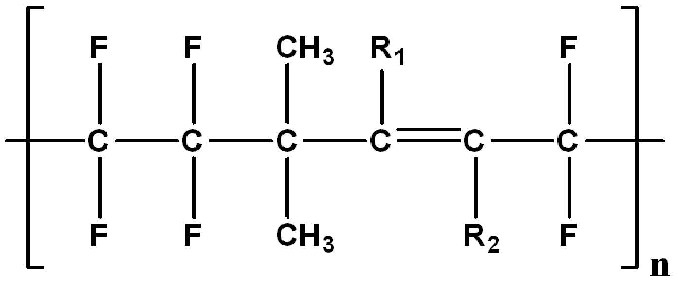
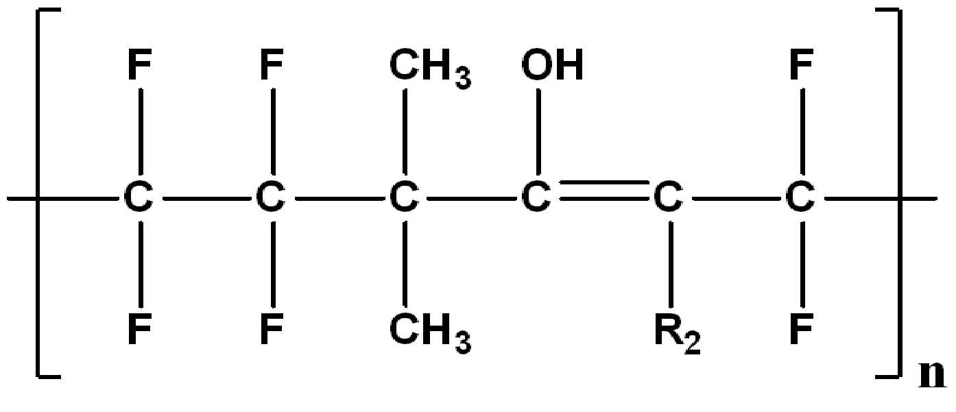
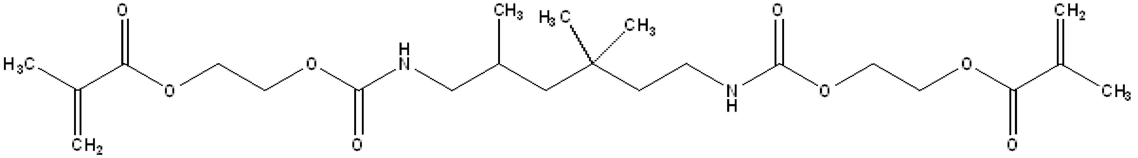
상기 치과용 레진은 하기 화학식 1로 표시되는 아크릴레이트계 수지; 하기 화학식 2로 표시되는 아크릴레이트계 수지; 하기 화학식 3으로 표시되는 아크릴레이트계 수지; 광개시제; 촉진제; 및 억제제를 포함한다:The dental resin is an acrylate resin represented by the formula (1); To acrylate-based resin represented by the formula (2); An acrylate-based resin represented by Formula 3 below; Photoinitiators; accelerant; And inhibitors:
[화학식 1] [Formula 1]
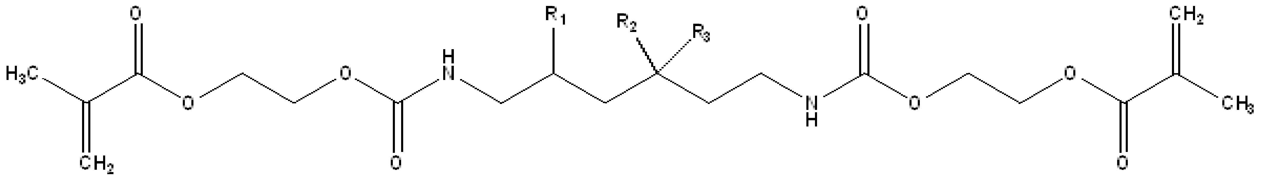
[화학식 2][Formula 2]

[화학식 3][Formula 3]

여기서, R1, R2 및 R3는 서로 동일하거나 상이하며, 각각 독립적으로 수소, 중수소, 하이드록시기, 할로겐기 및 탄소수 1 내지 10의 알킬기로 이루어진 군으로부터 선택된다. Where R 1, R 2 and R 3 are the same as or different from each other, and are each independently selected from the group consisting of hydrogen, deuterium, a hydroxy group, a halogen group and an alkyl group having 1 to 10 carbon atoms.
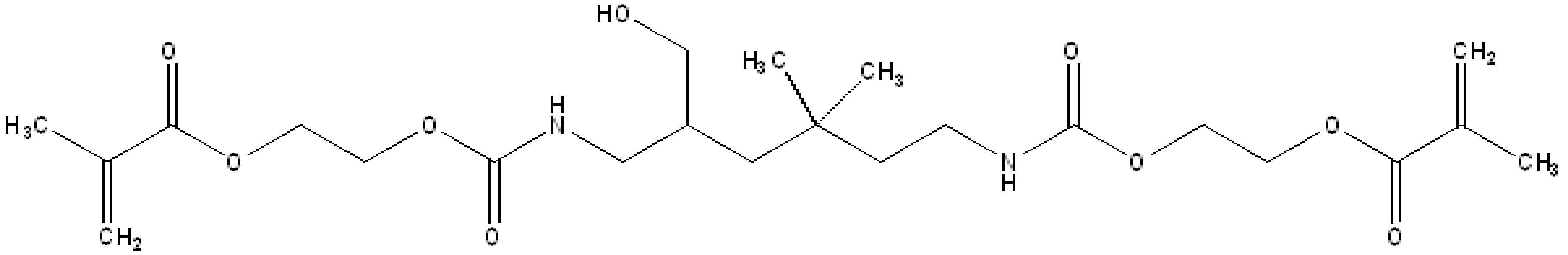
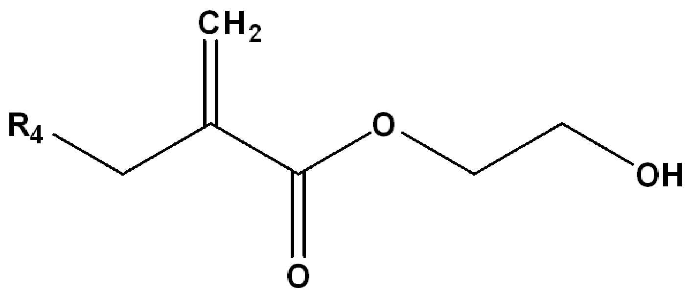
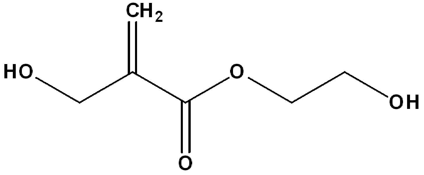
상기 치과용 레진은 하기 화학식 4로 표시되는 아크릴레이트계 수지를 추가로 포함할 수 있다:The dental resin may further include an acrylate-based resin represented by the following formula (4):
[화학식 4][Formula 4]

여기서, R4는 수소, 중수소, 하이드록시기, 할로겐기 및 탄소수 1 내지 10의 알킬기로 이루어진 군으로부터 선택된다. R 4 is selected from the group consisting of hydrogen, deuterium, a hydroxy group, a halogen group and an alkyl group having 1 to 10 carbon atoms.
상기 치과용 레진은 barium-silicate glass, silanated quartz filler, strontium glass filler 및 이들의 혼합물로 이루어진 군으로부터 선택되는 필러를 추가로 포함할 수 있다.The dental resin may further include a filler selected from the group consisting of barium-silicate glass, silanated quartz filler, strontium glass filler, and mixtures thereof.
본 발명에 따른 턱관절 교정장치는 윗 어금니와 아랫 어금니에 따라 대응되는 형상으로 전체 치아에 따라 대응되어 형성되는 종래의 턱관절 교정장치와는 다르게 윗 어금니와 아랫 어금니에만 착용 하는 것을 특징으로 한다.Jaw joint correction device according to the invention is characterized in that it is worn only on the upper molars and lower molar, unlike the conventional jaw correction device formed corresponding to the entire teeth in a shape corresponding to the upper molars and lower molars.
이와 같이, 본 발명인 턱관절 교정장치는 윗 어금니와 아랫 어금니에만 착용할 수 있어 기존에 치아교정장치인 브라켓을 착용하고 있더라도 본 발명인 턱관절 교정장치를 추가로 착용 가능 하여 기존에 진행하고 있던 치아교정장치인 브라켓을 제거하지 않더라도 치아교정 중에 발생하는 턱관절 교정을 진행할 수 있는 장점이 있다.Thus, the present inventors jaw correction device can be worn only on the upper molars and the lower molars, even if wearing the bracket of the orthodontic device, the present invention can be added to the jaw joint correction device to the existing orthodontic Even if the bracket is not removed, there is an advantage that the jaw joint correction can be performed during orthodontic treatment.
또한, 종래의 턱관절 교정장치는 전체 치아를 덮는 구조로 습기가 차는 등의 불편함이 존재하였지만, 본 발명의 턱관절 교정장치는 윗 어금니와 아랫 어금니만 착용하기 때문에 사용자가 착용시에 느끼는 불편함을 일부 해소할 수 있는 장점이 있다.In addition, the conventional jaw correction device has a discomfort, such as the moisture to the structure covering the entire tooth, but the jaw joint correction device of the present invention because the user only wears the upper and lower molar discomfort when the user wears There is an advantage that can be solved some.
아울러, 치아가 이동 할 때마다 형상에 대응되기 위하여 매번 본을 떠야 하는 종래 발명의 불편함도 본 발명의 와이어부의 조절만을 통하여 대응할 수 있어 턱관절 교정장치를 여러 번 제작할 필요 없어 비용감소의 효과를 볼 수 있다.In addition, the inconvenience of the conventional invention, which must open the bone every time to correspond to the shape every time the tooth moves can also be handled only through the adjustment of the wire portion of the present invention, there is no need to manufacture the jaw joint correction device several times to reduce the cost effect can see.
또한, 와이어부의 양 끝단이 제1 상면부의 내부를 길이방향으로 관통하므로In addition, since both ends of the wire portion penetrate the inside of the first upper surface portion in the longitudinal direction.
내구성 및 지지력이 증대되는 장점이 있다.Durability and bearing capacity is increased.
또한, 턱관절 교정장치를 구성하는 치과용 레진의 물성을 향상시키고, 항균 효과를 추가하여, 사용 시, 안정성을 향상시키고, 세균 발생을 막고자 한다.In addition, to improve the physical properties of the dental resin constituting the jaw joint correction device, by adding an antimicrobial effect, to improve the stability in use, and to prevent the development of bacteria.
도 1은 종래의 턱관절 교정장치를 도시한 것이다.
도 2는 본 발명의 턱관절 교정장치의 정면도이다.
도 3은 본 발명의 턱관절 교정장치의 평면도이다.
도 4는 본 발명의 턱관절 교정장치의 사용 실시 예에 따른 착용 후의 평면도이다.
도 5는 본 발명의 턱관절 교정장치의 사용 실시 예에 따른 착용 후의 정면도이다.
도 6는 본 발명의 턱관절 교정장치의 정면 사진이다.
도 7은 본 발명의 턱관절 교정장치의 평면 사진이다.
도 8는 본 발명의 턱관절 교정장치의 사용 실시 예에 따른 착용 후의 평면 사진이다.
도 9는 본 발명의 턱관절 교정장치의 사용 실시 예에 따른 착용 후의 정면 사진이다.Figure 1 shows a conventional jaw joint correction device.
Figure 2 is a front view of the jaw joint correction device of the present invention.
3 is a plan view of the jaw joint correction apparatus of the present invention.
Figure 4 is a plan view after wearing according to an embodiment of the use of the jaw correction device of the present invention.
5 is a front view after wearing according to an embodiment of the use of the jaw joint correction apparatus of the present invention.
Figure 6 is a front photograph of the jaw joint correction device of the present invention.
Figure 7 is a plan view of the jaw joint correction device of the present invention.
8 is a planar photograph after wearing according to an embodiment of the use of the jaw correction device of the present invention.
Figure 9 is a front photograph after wearing according to the embodiment of the use of the jaw correction device of the present invention.
이하, 본 발명의 도면을 참고하여 상세하게 설명한다. 다음에 소개되는 실시예들은 통상의 실시자에게 본 발명의 사상이 충분히 전달될 수 있도록 하기 위해 예로서 제공되는 것이다. 따라서, 본 발명은 이하 설명되는 실시 예들에 한정되지 않고 다른 형태로 구체화될 수도 있다. 그리고, 도면들에 있어서, 장치의 크기 및 두께 등은 편의를 위하여 과장되어 표현될 수도 있다. 명세서 전체에 걸쳐서 동일한 참조 번호들은 동일한 구성요소들을 나타낸다.Hereinafter, with reference to the drawings of the present invention will be described in detail. The following embodiments are provided as examples to ensure that the spirit of the present invention can be sufficiently conveyed to those skilled in the art. Therefore, the present invention is not limited to the embodiments described below and may be embodied in other forms. In the drawings, the size and thickness of the device may be exaggerated for convenience. Like numbers refer to like elements throughout the specification.
본 발명의 이점 및 특징, 그리고 그것들을 달성하는 방법은 첨부되는 도면과 함께 상세하게 후술되어 있는 실시 예들을 참조하면 명확해질 것이다. 그러나, 본 발명은 이하에서 개시되는 실시 예들에 한정되는 것이 아니라 서로 다른 다양한 형태로 구현될 것이며, 단지 본 실시 예들은 본 발명의 개시가 완전하도록 하며, 본 발명이 속하는 기술분야에서 통사의 지식을 가진 자에게 발명의 범주를 완전하게 알려주기 위해 제공되는 것이며, 본 발명은 청구항의 범주에 의해 정의될 뿐이다. 명세서 전체에 걸쳐 동일 참조 부호는 동일 구성요소를 지칭한다. 도면에서 층 및 영역들의 크기 및 상대적인 크기는 설명의 명료성을 위해 과장될 수 있다.Advantages and features of the present invention, and methods for achieving them will be apparent with reference to the embodiments described below in detail in conjunction with the accompanying drawings. However, the present invention is not limited to the embodiments disclosed below, but may be implemented in various forms, only the embodiments of the present invention make the disclosure of the present invention complete, and the common knowledge in the technical field to which the present invention belongs. It is provided to fully convey the scope of the invention to those skilled in the art, and the present invention is defined only by the scope of the claims. Like reference numerals refer to like elements throughout. In the drawings, the size and relative size of layers and regions may be exaggerated for clarity.
본 명세서에서 사용된 용어는 실시 예들을 설명하기 위한 것이며, 따라서 본 발명을 제한하고자 하는 것은 아니다. 본 명세서에서, 단수형은 문구에서 특별히 언급하지 않는 한 복수형도 포함한다. 또한, 포함하다 또는 가지다 등의 용어는 명세서상에 기재된 특징, 또는 구성요소가 존재함을 의미하는 것이고, 하나 이상의 다른 특징들 또는 구성요소가 부가될 가능성을 미리 배제하는 것은 아니다. The terminology used herein is for the purpose of describing particular embodiments only and is not intended to be limiting of the invention. In this specification, the singular also includes the plural unless specifically stated otherwise in the phrase. In addition, the terms including or have means that the features or components described in the specification are present, and does not preclude the possibility of adding one or more other features or components.
이하, 첨부된 도면을 참조하여 본 발명의 실시 예들을 상세히 설명하기로 하며, 이하에서 사용하는 용어의 정의는 다음과 같다. “길이 방향”이란, 도 2를 기준으로 x축 방향이며, “폭 방향”이란, 도 2를 기준으로 y축 방향이다. 또한, “수직 방향”이란, 도 2를 기준으로 z축 방향이다. Hereinafter, embodiments of the present invention will be described in detail with reference to the accompanying drawings, and the definitions of terms used below are as follows. "Length direction" is an x-axis direction with reference to FIG. 2, and a "width direction" is a y-axis direction with reference to FIG. In addition, a "vertical direction" is a z-axis direction with reference to FIG.
도 1은 종래의 턱관절 교정장치를 도시한 것이다. 또한, 도 2는 본 발명의 턱관절 교정장치의 정면도이다. 또한, 도 3은 본 발명의 턱관절 교정장치의 평면도이다. 또한, 도 4는 본 발명의 턱관절 교정장치의 사용 실시 예에 따른 착용 후의 평면도이다. 또한, 도 5는 본 발명의 턱관절 교정장치의 사용 실시 예에 따른 착용 후의 정면도이다.Figure 1 shows a conventional jaw joint correction device. 2 is a front view of the jaw joint correction apparatus of the present invention. 3 is a plan view of the jaw joint correction device of the present invention. 4 is a plan view after wearing according to an embodiment of the use of the jaw correction device of the present invention. In addition, Figure 5 is a front view after wearing according to an embodiment of the use of the jaw correction device of the present invention.
본 발명에 의한 턱관절 교정장치는 제1 쿠션부(100), 제2 쿠션부(200), 와이어부(300)를 포함한다.Jaw joint correction apparatus according to the present invention includes a
본 발명에 의한 턱관절 교정장치는 윗니(1) 및 아랫니(2) 각각의 형상에 따라 대응되는 형상으로 한 쌍을 구비한다.Jaw joint correction device according to the present invention is provided with a pair in a shape corresponding to each of the upper teeth (1) and the lower teeth (2).
예컨대, 윗니(1)의 외측면 및 내측면에 따라 형성되어 장치 하나가 구비되고, 아랫니(2)의 외측면 및 내측면에 따라 형성되어 또 다른 장치가 구비된다.For example, one device is formed along the outer side and the inner side of the
이와 같이, 윗니(1)에 대응되는 형상의 장치 하나와, 아랫니(2)에 대응되는 형상의 장치 하나가 한 쌍으로 구비되는 것이 바람직하다.In this way, it is preferable that one device having a shape corresponding to the
따라서, 도면을 참조하여 비교적 이해하기 쉬운 아랫니(2)를 기준으로 설명하고자 하며, 윗니(1)의 형상에 따라 대응되는 나머지 한 쌍의 상세한 설명은 중복 설명을 방지하기 위해 생략하기로 한다.Therefore, with reference to the drawings will be described with reference to the lower teeth (2), which is relatively easy to understand, and the remaining pair of detailed description corresponding to the shape of the upper teeth (1) will be omitted in order to avoid redundant description.
이하, 도 2를 참조하여 제1 쿠션부(100)와 제2 쿠션부(200)를 설명하도록 한다.Hereinafter, the
제1 쿠션부(100)는 왼쪽 어금니(10)의 외면을 따라 대응되는 형상으로, 왼쪽 어금니(10)의 외면에 맞닿아 삼면을 이루는 것이 바람직하다.The
또한, 제1 쿠션부(100)는 왼쪽 어금니(10)를 본뜨는 방식으로 형성되는 것이 더 바람직하다.In addition, the
이와 마찬가지로, 제1 쿠션부(100)와 대칭되는 제2 쿠션부(200)는 오른쪽 어금니(11)의 외면을 따라 대응되는 형상으로, 오른쪽 어금니(11)의 외면에 맞닿아 삼면을 이루는 것이 바람직하다.Similarly, the
또한, 제2 쿠션부(200)도 마찬가지로 오른쪽 어금니(11)를 본뜨는 방식으로 형성되는 것이 더 바람직하다.In addition, the
이하, 도 3을 참조하여 제1 내측면부(110), 제1 외측면부(120), 제1 상면부(130)를 설명하도록 한다.Hereinafter, the first
제1 쿠션부(100)는 제1 내측면부(110), 제1 외측면부(120), 제1 상면부(130)로 구비된다.The
제1 내측면부(110)는 왼쪽 어금니(10)의 내측의 전체면에 맞닿아 위치되는 단부로, 왼쪽 어금니(10)의 내측면에 대응되는 형상이 바람직하다. The first
또한, 제1 상면부(130)는 왼쪽 어금니(10)의 상부에 따라 대응되는 형상으로, 제1 내측면부(110)와 제1 외측면부(120)를 잇고, 제1 내측면부(110)와 제1 외측면부(120)의 사이에 위치된다.In addition, the first
또한, 제1 외측면부(120)는 왼쪽 어금니(10)의 외측면에 따라 대응되는 형상이 바람직하다.In addition, the first
이때, 제1 외측면부(120)의 수직 방향의 길이는 제1 내측면부(110)의 수직방향의 길이보다 짧은 것이 바람직하다.In this case, the length of the first
이와 같이, 상대적으로 제1 내측면부(110)의 수직방향의 길이보다 짧은 수직방향의 길이로 인해, 사용자가 본 발명의 턱관절 교정장치를 착용하고, 말을 하거나 입을 벌릴 때, 제1 외측면부(120)는 치아 전체를 감싸고 있지 않기 때문에 외관상 심미감을 높여주는 효과가 있다.As such, due to the length of the vertical direction relatively shorter than the length of the vertical direction of the first
따라서, 제1 쿠션부(100)는 내측에 맞닿는 제1 내측면부(110)와, 외측에 맞닿는 제1 외측면부(120)와 왼쪽 어금니(10)의 상부와 맞닿는 제1 상면부(130)로 구비되어 왼쪽 어금니(10)에 끼워 맞춰지는 형상으로 삽입되는 것이 바람직하다. Accordingly, the
또한, 종래의 턱관절 교정장치는 전체 치아에 대응되는 형상으로, 윗니(1)과아랫니(2)에 맞닿아 위치되어 사용자가 치아교정 진행 중에 이갈이, 턱관절 교정을 위해 교정장치인 브라켓(20)을 제거하고 턱관절 교정장치를 사용해야 하는 불편함이 있다. In addition, the conventional jaw joint correcting device is a shape corresponding to the entire teeth, the upper teeth (1) and the lower teeth (2) are positioned in contact with the user during the orthodontic teeth, jaw joint correction orthodontic bracket 20 ) And use of jaw correction device is inconvenient.
그러나, 본 발명의 턱관절 교정장치는 왼쪽 어금니(10)와 오른쪽 어금니(11)의 형상만을 따라 본뜨는 방식이기 때문에 사용자가 치아교정을 위해 브라켓(20)을 착용 중에도 턱관절 교정장치를 추가로 착용할 수 있어 사용자가 브라켓(20)을 탈부착해야 하는 불편함과 치아교정의 진행에 영향을 미치지 않는 효과가 있다.However, the jaw joint correcting apparatus of the present invention is a method of bonding only along the shape of the
제1 쿠션부(100)에 구비되는 제1 내측면부(110), 제1 외측면부(120), 제1 상면부(130)와 동일하게 오른쪽 어금니(11)에 대응되는 형상으로 삽입되는 제2 쿠션부(200)에서 제2 내측면부(210), 제2 외측면부(220), 제2 상면부(230)가 구비되며, 동일한 형상이므로 이와 관련된 설명은 중복 설명을 방지하기 위해 생략하도록 한다.The second
이하, 도 4를 참조하여, 와이어부(300)를 설명하도록 한다.Hereinafter, the
와이어부(300)는 제1 쿠션부(100)와 제2 쿠션부(200)를 잇는 형상으로, 치아 형상에 따라 아치형으로 치아 내부에 위치되는 것이 바람직하다.The
이때, 와이어부(300)는 소정의 두께를 가진 원통형으로 치아 안에서 혀의 움직임에 대하여 라운딩의 효과로 불편함을 최소화 하는 것을 특징으로 한다.At this time, the
상세하게는, 와이어부(300)의 양 끝단은 제1 쿠션부(100)의 제1 상면부(130)와 제2 쿠션부(200)의 제2 상면부(230)의 내부를 길이방향으로 관통하는 형상이 바람직하다.In detail, both ends of the
이로 인해, 제1 내측면부(110)와 제1 외측면부(120)를 잇는 제1 상면부(130)를 관통하게 되므로, 내구성 및 지지력이 증대되는 장점이 있다.As a result, since the first
또한, 종래의 턱관절 교정장치는 윗니(1)와 아랫니(2)의 사이에 맞닿아 결합되는 형상으로, 치아의 이동함에 따라 매번 전체 치아를 본떠 교체를 해야 하는 불편함이 존재했다.In addition, the conventional jaw joint correcting device is in contact with the shape between the upper teeth (1) and the lower teeth (2), there was an inconvenience to replace the entire tooth every time as the teeth move.
그러나, 본 발명인 턱관절 교정장치는 왼쪽 어금니(10)와 오른쪽 어금니(11)의 형상에 따라서만 대응되고, 치아 변형에 따라 치아 내부에 위치되는 와이어부(300)의 아치형 형상 부분의 조절만으로 변경이 가능하기 때문에 재료와 시간이 적게 소요되어 비용감소과 효율성의 증대의 효과를 볼 수 있다.However, the present inventors jaw joint correcting device only corresponds to the shape of the
이하, 도 5를 참조하여 본 발명의 턱관절 교정장치의 실시 예를 설명하도록 한다.Hereinafter, an embodiment of the jaw joint correcting apparatus of the present invention will be described with reference to FIG. 5.
전술한 바와 같이 도 5에서 정면으로 보았을 때, 치아교정을 위해 브라켓(20)을 착용 중에도, 브라켓(20)을 제거 하지 않고 턱관절 교정을 위해 본 발명인 턱관절 교정장치를 착용 가능 함으로써, 브라켓(20)의 탈부착에 관한 사용자의 불편함과 치아교정과 턱관절 교정에 진행에 대한 효율성이 증대되는 효과를 볼 수 있다.As described above, when viewed from the front in Figure 5, even while wearing the
또한, 종래의 턱관절 교정장치는 전체 치아 형상에 따라 맞닿아 형성 되었기 때문에 습기가 차는 답답함 등의 사용자가 느낄 수 있는 불편함이 존재하였다.In addition, since the conventional jaw joint correcting device is formed in contact with the entire tooth shape, there was an inconvenience that the user can feel, such as stuffy moisture.
그러나, 본 발명의 턱관절 교정장치는 왼쪽 어금니(10)와 오른쪽 어금니(11)의 외측면에만 대응되어 맞닿는 형상으로 사용자가 느끼는 답답함 등의 불편함을 일부 해소 할 수 있는 장점이 있다. However, the jaw joint correcting apparatus of the present invention has an advantage of eliminating some inconveniences such as frustration that the user feels in contact with only the outer surface of the
상기 제1 쿠션부(100) 및 제2 쿠션부(200)는 치과용 레진(Resin)으로 구성될 수 있다. 보다 구체적으로,
상기 제1 쿠션부(100)에 구비되는 제1 내측면부(110), 제1 외측면부(120), 제1 상면부(130)와 동일하게 오른쪽 어금니(11)에 대응되는 형상으로 삽입되는 제2 쿠션부(200)에서 제2 내측면부(210), 제2 외측면부(220), 제2 상면부(230)는 치과용 레진으로 구성될 수 있다.The
상기 치과용 레진은 하기 화학식 1로 표시되는 아크릴레이트계 수지; 하기 화학식 2로 표시되는 아크릴레이트계 수지; 하기 화학식 3으로 표시되는 아크릴레이트계 수지; 광개시제; 촉진제; 및 억제제를 포함한다:The dental resin is an acrylate resin represented by the formula (1); To acrylate-based resin represented by the formula (2); An acrylate-based resin represented by Formula 3 below; Photoinitiators; accelerant; And inhibitors:
[화학식 1][Formula 1]

[화학식 2][Formula 2]

[화학식 3][Formula 3]

여기서, here,
R1, R2 및 R3는 서로 동일하거나 상이하며, 각각 독립적으로 수소, 중수소, 하이드록시기, 할로겐기 및 탄소수 1 내지 10의 알킬기로 이루어진 군으로부터 선택된다. R 1, R 2 and R 3 are the same as or different from each other, and are each independently selected from the group consisting of hydrogen, deuterium, a hydroxy group, a halogen group and an alkyl group having 1 to 10 carbon atoms.
상기 치과용 레진은 하기 화학식 4로 표시되는 아크릴레이트계 수지를 추가로 포함할 수 있다:The dental resin may further include an acrylate-based resin represented by the following formula (4):
[화학식 4][Formula 4]

여기서, here,
R4는 수소, 중수소, 하이드록시기, 할로겐기 및 탄소수 1 내지 10의 알킬기로 이루어진 군으로부터 선택된다. R 4 is selected from the group consisting of hydrogen, deuterium, a hydroxy group, a halogen group and an alkyl group having 1 to 10 carbon atoms.
상기 제1 쿠션부(100)는 왼쪽 어금니(10)의 외면을 따라 대응되는 형상으로, 왼쪽 어금니(10)의 외면에 맞닿아 삼면을 이루며, 상기 제1 쿠션부(100)와 대칭되는 제2 쿠션부(200)는 오른쪽 어금니(11)의 외면을 따라 대응되는 형상으로, 오른쪽 어금니(11)의 외면에 맞닿아 삼면을 이루고 있다.The
이러한 사용예에 비추어, 제1 쿠션부(100) 및 제2 쿠션부(200)를 구성하는 치과용 레진은 왼쪽 어금니(10) 및 오른쪽 어금니(11)에 의한 누르는 힘에 의해서도 형태가 변형되지 않을 정도의 파괴 인성을 가져야한다. In view of this use example, the dental resin constituting the
일반적으로 치과용 레진은 교합 응력에 의해 발생되는 파괴 및 마모에 대한 저항성이 낮고 중합수축에 따른 변연 누출 등이 치과용 레진의 문제점으로 지적되고 있다. In general, the dental resin has a low resistance to fracture and abrasion caused by the occlusal stress, and the marginal leakage due to polymerization shrinkage is pointed out as a problem of the dental resin.
이러한 문제를 해결하기 위하여, 기질레진의 조성, 필러의 함량 변화 및 가교제 또는 결합제의 종류를 달리하여 치과용 레진을 제조하고 있다. In order to solve this problem, dental resins are manufactured by varying the composition of the matrix resin, the content of the filler, and the type of crosslinking agent or binder.
따라서, 최근에는 치과용 레진을 제조하기 위하여, 기질레진을 복수의 수지를 조합하여 제조하고 있으며, 본 발명에서도 상기 화학식 1 내지 4의 기질레진을 혼합하여 치과용 레진을 제조하고자 한다. Therefore, in recent years, in order to manufacture a dental resin, a substrate resin is manufactured by combining a plurality of resins, and in the present invention, to prepare a dental resin by mixing the substrate resin of the above formula (1).
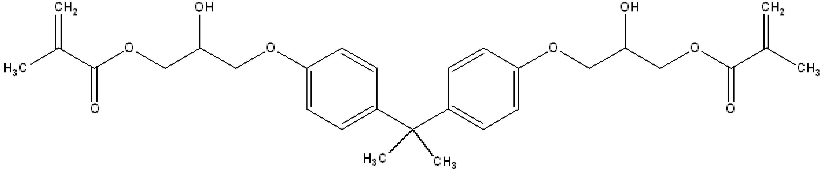
바람직하게 상기 치과용 레진을 구성하는 기질레진은 하기 화학식 2로 표시되는 수지, 화학식 3으로 표시되는 수지, 화학식 5로 표시되는 수지 및 화학식 6으로 표시되는 수지를 포함할 수 있다: Preferably, the substrate resin constituting the dental resin may include a resin represented by
[화학식 2][Formula 2]

[화학식 3][Formula 3]

[화학식 5][Formula 5]
[화학식 6][Formula 6]

바람직하게 상기 치과용 레진을 구성하는 기질레진은 하기 화학식 2로 표시되는 수지, 화학식 3으로 표시되는 수지, 화학식 6로 표시되는 수지 및 화학식 7으로 표시되는 수지를 포함할 수 있다: Preferably, the substrate resin constituting the dental resin may include a resin represented by
[화학식 2][Formula 2]
[화학식 3][Formula 3]
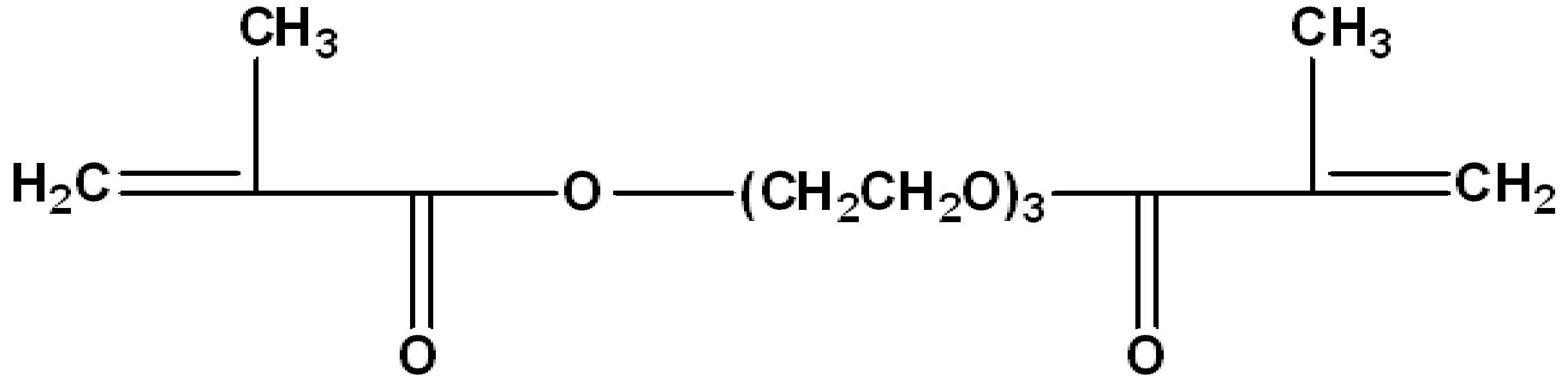
[화학식 6][Formula 6]

[화학식 7][Formula 7]

상기 아크릴레이트계 수지를 4종 혼합하여 사용함에 따라, 강도, 강성 및 마모 저항성을 향상시키고자 한다. By using four kinds of the acrylate-based resin mixture, to improve the strength, rigidity and abrasion resistance.
상기 아크릴레이트계 수지를 1종만 이용하는 경우에 비해, 4종을 혼합하여 사용할 경우, 강도 강성 및 마모 저항성을 향상시켜, 물리적인 특징이 강화된 치과용 레진을 제조할 수 있다. Compared to the case of using only one kind of the acrylate-based resin, when used in combination of four kinds, it is possible to improve the strength rigidity and abrasion resistance, to prepare a dental resin with enhanced physical characteristics.
보다 구체적으로, 상기 화학식 2로 표시되는 기질레진의 경우, 2개의 소수성 기능기를 갖는 단량체로, 휘발성 및 중합 수축이 적고 경화가 빠른 장점이 있으나, 점도가 높고 반응성이 낮아 희석 단량체를 필요로 한다. More specifically, in the case of the substrate resin represented by
상기 화학식 3으로 표시되는 기질레진의 경우, 희석 단량체로 점도가 낮고, 유연성을 지녀, 레진의 반응성을 향상시키고, 보다 많은 필러를 혼합할 수 있으나, 화학식 3으로 표시되는 기질레진을 이용함에 따라, 물리적 성질이 저하되는 문제가 있다. In the case of the substrate resin represented by Chemical Formula 3, the viscosity is low as the diluent monomer, has flexibility, improves the reactivity of the resin, and can be mixed with more fillers, by using the substrate resin represented by Chemical Formula 3, There is a problem that the physical properties are degraded.
이러한 문제를 해결하기 위하여, 상기 화학식 1로 표시되는 기질레진 및 상기 화학식 4로 표시되는 기질레진을 혼합하여 사용한다. In order to solve this problem, a substrate resin represented by
바람직하게, 상기 치과용 레진은 상기 화학식 1로 표시되는 아크릴레이트계 수지; 상기 화학식 2로 표시되는 아크릴레이트계 수지; 상기 화학식 3으로 표시되는 아크릴레이트계 수지; 및 상기 화학식 4로 표시되는 아크릴레이트계 수지를 2:5:1:1 내지 2:7:1:1의 중량 비율로 혼합하여 사용할 수 있다.Preferably, the dental resin is an acrylate resin represented by the formula (1); Acrylate-based resins represented by
상기 범위 미만인 경우에는 물리적 성질이 저하되는 문제가 있고, 상기 범위를 초과하여 포함할 경우, 점도가 높고, 반응성이 낮아지는 문제가 발생한다. If it is less than the above range, there is a problem that the physical properties are lowered, and if it exceeds the above range, there is a problem that the viscosity is high, the reactivity is low.
상기 치과용 레진은 barium-silicate glass, silanated quartz filler, strontium glass filler 및 이들의 혼합물로 이루어진 군으로부터 선택되는 필러를 추가로 포함할 수 있다. The dental resin may further include a filler selected from the group consisting of barium-silicate glass, silanated quartz filler, strontium glass filler, and mixtures thereof.
치과용 레진에 상기 필러를 혼합함에 따라, 레진의 물리적인 성질을 높일 수 있다. 즉, 탄성 계수, 굴곡강도 및 표면 강도에 대한 물리적 성질을 향상시킬 수 있다. By mixing the filler in the dental resin, the physical properties of the resin can be improved. That is, the physical properties of the elastic modulus, the flexural strength and the surface strength can be improved.
바람직하게 상기 필러는 barium-silicate glass, silanated quartz filler 및 strontium glass filler를 혼합하여 사용하는 것으로, 1:1:0.5 내지 1:1:1의 중량비율로 혼합하여 사용할 수 있다. Preferably, the filler is used by mixing barium-silicate glass, silanated quartz filler and strontium glass filler, and may be used by mixing in a weight ratio of 1: 1: 0.5 to 1: 1: 1.
보다 구체적으로, 상기 필러는 평균 직경이 3 내지 5㎛인 입자를 이용할 수 있다. More specifically, the filler may use particles having an average diameter of 3 to 5㎛.
상기 필러는 혼합 중량 범위 내에서 사용하였을 때, 탄성 계수, 굴곡 강도 및 표면 강도의 물리적 성질을 향상시킬 수 있으며, 범위 값 미만이거나, 초과인 경우에는 물리적 성질이 저하되거나, 레진 제조 시에, 점성을 높여 성형성을 낮추는 문제가 발생할 수 있다. The filler can improve the physical properties of elastic modulus, flexural strength and surface strength when used within the mixed weight range, and if less than or greater than the range value, the physical properties are degraded, or when the resin is prepared, the viscosity The problem of lowering the moldability by raising the pressure may occur.
바람직하게 상기 치과용 레진은 하기 화학식 1로 표시되는 아크릴레이트계 수지; 하기 화학식 2로 표시되는 아크릴레이트계 수지; 하기 화학식 3으로 표시되는 아크릴레이트계 수지; 하기 화학식 4로 표시되는 아크릴레이트계 수지; 필러; 광개시제; 촉진제; 및 억제제를 포함한다:Preferably the dental resin is an acrylate resin represented by the formula (1); To acrylate-based resin represented by the formula (2); An acrylate-based resin represented by Formula 3 below; To acrylate-based resin represented by the formula (4); filler; Photoinitiators; accelerant; And inhibitors:
[화학식 1][Formula 1]

[화학식 2][Formula 2]

[화학식 3][Formula 3]

[화학식 4][Formula 4]
여기서, here,
R1, R2, R3 및 R4는 서로 동일하거나 상이하며, 각각 독립적으로 수소, 중수소, 하이드록시기, 할로겐기 및 탄소수 1 내지 10의 알킬기로 이루어진 군으로부터 선택된다. R 1, R 2 , R 3 and R 4 are the same as or different from each other, and are each independently selected from the group consisting of hydrogen, deuterium, a hydroxyl group, a halogen group and an alkyl group having 1 to 10 carbon atoms.
보다 바람직하게, 상기 화학식 1로 표시되는 아크릴레이트계 수지; 상기 화학식 2로 표시되는 아크릴레이트계 수지; 상기 화학식 3으로 표시되는 아크릴레이트계 수지 및 상기 화학식 4로 표시되는 아크릴레이트계 수지를 포함하는 기질레진을 포함하며, More preferably, the acrylate resin represented by the formula (1); Acrylate-based resins represented by
상기 기질레진 100 중량부에 대하여, 필러 40 내지 70 중량부; 광개시제 1 내지 2 중량부; 촉진제 0.5 내지 1 중량부; 및 억제제 0.1 내지 0.5 중량부로 포함할 수 있다. 40 to 70 parts by weight of the filler with respect to 100 parts by weight of the substrate resin; 1 to 2 parts by weight of photoinitiator; 0.5 to 1 parts by weight of accelerator; And 0.1 to 0.5 parts by weight of inhibitor.
상기 범위에 의하는 경우, 본 발명에 따른 제1 쿠션부(100) 및 제2 쿠션부(200)로 사용이 가능한 치과용 레진으로 제공 가능하다.According to the above range, it can be provided as a dental resin that can be used as the
상기 광개시제는 벤조인과 그 알킬에테르류, 아세토페논류, 안트라퀴논류, 티오 크산톤류, 케탈류, 벤조페논류, α-아미노아세토페논류, 아실포스핀옥사이드류, 옥심에스테르류, DEAP (2,2- Diethoxyacetophenone), CQ (camphoroquinone), EDMAB (ethyl (4-dimethyl amino) benzoate), DBMP (6-Ditert-butyl-4-methyl pyridine), DMAEMA (2-dimethylamino ethyl methacrylate), DPIHP (diphenyliodonium hexafluorophosphate) 및 DMPA (N-(2,3-dimercaptopropyl)-phthalamidic acid)로 이루어진 군으로부터 선택될 수 있다. The photoinitiators include benzoin, alkyl ethers thereof, acetophenones, anthraquinones, thioxanthones, ketals, benzophenones, α-aminoacetophenones, acylphosphine oxides, oxime esters, and DEAP (2). , 2- Diethoxyacetophenone), CQ (camphoroquinone), EDMAB (ethyl (4-dimethyl amino) benzoate), DBMP (6-Ditert-butyl-4-methyl pyridine), DMAEMA (2-dimethylamino ethyl methacrylate), DPIHP (diphenyliodonium hexafluorophosphate ) And DMPA (N- (2,3-dimercaptopropyl) -phthalamidic acid).
상기 촉진제는 2-(Dimethylamino)ethyl methacrylate(DEMA)이다. The promoter is 2- (Dimethylamino) ethyl methacrylate (DEMA).
상기 억제제는 Butylated hydroxytoluene(BHT)이다.The inhibitor is Butylated hydroxytoluene (BHT).
본 발명의 턱관절 교정장치는 바람직하게 코팅층을 추가로 포함하는 것을 특징으로 한다. Jaw joint correction device of the present invention is characterized in that it further comprises a coating layer.
본 발명의 턱관절 교정장치는 종래의 턱관절 교정장치와 달리, 윗 어금니 및 아랫 어금니에만 착용하여, 전체 치아를 덮는 구조는 아니지만, 침이 턱관절 교정 장치에 고여, 반복 사용 시에 균이 발생하는 등의 문제가 발생할 수 있다. Unlike the conventional jaw correction device of the present invention, the jaw joint correction device is worn only on the upper molars and the lower molars, but the structure does not cover the entire teeth, but the saliva is accumulated in the jaw correction device, the bacteria are generated when repeated use Problems may occur.
이러한 문제를 방지하기 위하여, 턱관절 교정장치에 코팅층을 형성하여, 항균 효과를 내어, 치아교정 속도증가 장치에서의 균 발생을 방지할 수 있다. In order to prevent such a problem, by forming a coating layer on the jaw joint correction device, it has an antibacterial effect, it can prevent the occurrence of bacteria in the orthodontic speed increasing device.
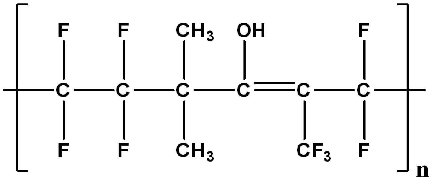
상기 코팅층을 형성하기 위한, 항균 코팅 조성물은 톨루엔(toluene), 메틸에틸케톤(methyl ethyl ketone) 및 이들의 혼합물로 이루어진 군으로부터 선택된 용매를 포함하며, 상기 용매 100 중량부에 대하여, 하기 화학식 8로 표시되는 바인더 5 내지 30 중량부; 충진제 5 내지 10 중량부; 및 항균 물질 1 내지 10 중량부를 포함할 수 있다:To form the coating layer, the antimicrobial coating composition includes a solvent selected from the group consisting of toluene, methyl ethyl ketone, and mixtures thereof, based on 100 parts by weight of the solvent, 5 to 30 parts by weight of the displayed binder; 5 to 10 parts by weight of the filler; And 1 to 10 parts by weight of the antimicrobial material:
[화학식 8][Formula 8]
여기서, here,
n은 2 내지 100의 정수이며, n is an integer from 2 to 100,
R1 및 R2는 서로 동일하거나 상이하며, 각각 독립적으로 수소, 중수소, 할로겐기, 히드록시기, 치환 또는 비치환의 탄소수 1 내지 10의 알킬기, 치환 또는 비치환의 탄소수 2 내지 10의 알케닐기, 치환 또는 비치환의 탄소수 2 내지 10의 알키닐기, 치환 또는 비치환의 탄소수 3 내지 10의 사이클로알킬기 및 치환 또는 비치환의 탄소수 6 내지 30의 아릴기로 이루어진 군으로부터 선택되며, R 1 and R 2 are the same as or different from each other, and each independently hydrogen, deuterium, a halogen group, a hydroxyl group, a substituted or unsubstituted alkyl group having 1 to 10 carbon atoms, a substituted or unsubstituted alkenyl group having 2 to 10 carbon atoms, a substituted or unsubstituted group It is selected from the group consisting of a C2-10 alkynyl group of a ring, a substituted or unsubstituted cycloalkyl group of 3 to 10 carbon atoms, and a substituted or unsubstituted aryl group of 6 to 30 carbon atoms,
상기 치환된 알킬기, 치환된 알케닐기, 치환된 알키닐기, 치환된 사이클로알킬기 및 치환된 아릴기는 중수소, 할로겐기, 시아노기, 니트로기 및 히드록시기로 이루어진 군으로부터 선택된 1개 이상의 치환기로 치환되며, 복수 개의 치환기로 치환되는 경우 이들은 서로 동일하거나 상이하다.The substituted alkyl group, substituted alkenyl group, substituted alkynyl group, substituted cycloalkyl group and substituted aryl group are substituted with one or more substituents selected from the group consisting of deuterium, halogen group, cyano group, nitro group and hydroxy group, and a plurality of When substituted with two substituents, they are the same as or different from each other.
상기 화학식 1로 표시되는 불소계 고분자 화합물은 바람직하게는 하기 화학식 9 또는 화학식 10으로 표시되는 불소계 화합물이지만, 예시에 국한되는 것은 아니다:The fluorine-based polymer compound represented by
[화학식 9][Formula 9]
[화학식 10][Formula 10]

여기서, here,
n은 2 내지 100의 정수이며, n is an integer from 2 to 100,
R2는 할로겐기로 치환된 탄소수 1 내지 10의 알킬기이다.R 2 is an alkyl group having 1 to 10 carbon atoms substituted with a halogen group.
충진제는 코팅층의 물성 및 빛의 반사를 방지하기 위해 포함될 수 있다. 충진제는 모래(Sand), 실리카, 탈크, 알루미나, 탄산칼륨, 탄산칼슘, 수산화 알루미늄, 산화티탄 및 카본블랙으로 이루어진 군으로부터 선택되며, 바람직하게는 실리카이지만, 상기 예시에 국한되는 것은 아니다. 충진제는 바인더와 혼합하여, 치과용 레진으로 구성되는 턱관절 교정장치와의 결합력을 향상시키기 위해 포함되는 것이다. Fillers may be included to prevent reflection of physical properties and light of the coating layer. The filler is selected from the group consisting of sand, silica, talc, alumina, potassium carbonate, calcium carbonate, aluminum hydroxide, titanium oxide and carbon black, preferably silica, but not limited to the above examples. The filler is included to improve the bonding force with the binder, the jaw joint correction device composed of a dental resin.
상기 항균 물질은 이소프로필 메틸페놀(Isopropyl methyl phenol), 페녹시에탄올(Phenoxyethanol), 클로록실레놀(Chloroxylenol), 에틸헥실글리세린(Ethylhexylglycerin), 글리세릴 카프릴레이트(Glyceryl caprylate), 티몰(Thymol), 칼슘 포스페이트-은 화합물 복합체(Calcium phosphate-silver compound complex) 및 은이온-실리케이트 복합체(Silver ion-silicate complex)로 이루어진 군에서 선택될 수 있다. The antimicrobial material is isopropyl methyl phenol (Isopropyl methyl phenol), phenoxyethanol (Phenoxyethanol), chloroxylenol (Chloroxylenol), ethylhexylglycerin (Ethylhexylglycerin), glyceryl caprylate (Thymol) , Calcium phosphate-silver compound complex (Calcium phosphate-silver compound complex) and silver ion-silicate complex (Silver ion-silicate complex) can be selected from the group consisting of.
바람직하게 상기 항균 물질에 천연 항균 물질을 혼합하여, 항균성을 보다 극대화할 수 있다. 상기 천연 항균 물질은 작살나무 추출물(Callicarpa japonica Thunb.0) 및 괴불나무 추출물(Lonicera maackii (Rupr.) Maxim.)을 더 포함할 수 있다.Preferably by mixing a natural antimicrobial material in the antimicrobial material, it is possible to maximize the antimicrobial properties. The natural antibacterial substance may further include a bark extract (Callicarpa japonica Thunb. 0) and a lump extract (Lonicera maackii (Rupr.) Maxim.).
보다 바람직하게 항균 물질로, 칼슘 포스페이트-은 화합물 복합체를 이용할 수 있고, 천연 항균 물질로, 작살나무 추출물 및 괴불나무 추출물을 선택하여 이용할 수 있다. More preferably, as an antimicrobial substance, calcium phosphate-silver compound complex may be used, and as a natural antimicrobial substance, bark extract and camphor extract may be selected and used.
이때, 칼슘 포스페이트-은 화합물 복합체, 작살나무 추출물 및 괴불나무 추출물을 1:0.1:0.1 내지 1:0.5:0.5의 중량 비율로 혼합하여 항균 물질로 이용할 경우, 칼슘 포스페이트-은 화합물 복합체만을 항균 물질로 포함하는 경우이 비해, 천현 항균 물질을 혼합함에 따라, 항균 효과가 증가하고, 천연 항균 물질을 사용함에 따라, 구강 내에서의 사용 시 부작용의 발생 문제가 적어진다고 할 것이다.In this case, when the calcium phosphate-silver compound complex, the harpoon extract and the bulgogi extract are mixed at a weight ratio of 1: 0.1: 0.1 to 1: 0.5: 0.5 to be used as an antimicrobial substance, only the calcium phosphate-silver compound complex is used as an antimicrobial substance. In comparison with the case, the antimicrobial effect is increased by mixing the antimicrobial substance, and the use of natural antimicrobial substance will reduce the problem of occurrence of side effects when used in the oral cavity.
[제조예: 치과용 레진의 제조]Preparation Example: Production of Dental Resin
1. 실시예 1Example 1
하기 화학식 2, 화학식 3, 화학식 5 및 화학식 6으로 표시되는 아크릴레이트계 수지 및 필러를 혼합하여, 기질레진을 제조하였고, 상기 필러는 barium-silicate glass, silanated quartz filler 및 strontium glass filler를 혼합한 혼합 필러를 사용하였다:To the substrate resin was prepared by mixing the acrylate-based resin and the filler represented by the formula (2), (3), (5) and (6), the filler is a mixture of barium-silicate glass, silanated quartz filler and strontium glass filler Fillers were used:
[화학식 2][Formula 2]

[화학식 3][Formula 3]

[화학식 5][Formula 5]

[화학식 6][Formula 6]
이후, 2-dimethylamino ethyl methacrylate(DMAEMA), 2-(Dimethylamino)ethyl methacrylate(DEMA) 및 Butylated hydroxytoluene(BHT)를 넣고 혼합하여 레진 매트릭스를 제조하였다. Then, 2-dimethylamino ethyl methacrylate (DMAEMA), 2- (Dimethylamino) ethyl methacrylate (DEMA) and Butylated hydroxytoluene (BHT) were added and mixed to prepare a resin matrix.
상기 레진 매트릭스를 직사광선이 차단되고, 5 내지 10℃, 습도 70% 미만 조건 하에서 1 내지 2일 동안 보관하여 이갈이 교정유지 장치용 레진을 제조하였다.The resin matrix was blocked by direct sunlight, and stored for 1 to 2 days under conditions of 5 to 10 ° C. and a humidity of less than 70% to prepare a resin for splitting and maintaining the apparatus.
기질레진은 상기 화학식 5, 화학식 2, 화학식 3 및 화학식 6로 표시되는 아크릴레이트계 수지는 2:5:1:1의 중량비율로 혼합하여 사용하였으며, 상기 필러는 2-dimethylamino ethyl methacrylate(DMAEMA), 2-(Dimethylamino)ethyl methacrylate(DEMA) 및 Butylated hydroxytoluene(BHT)를 1:1:0.5의 중량 비율로 혼합한 복합필러를 사용하였다. Substrate resin was used by mixing the acrylate-based resin represented by Formula 5,
상기 기질레진 100 중량부에 대하여, 필러 40 중량부, 2-dimethylamino ethyl methacrylate(DMAEMA) 1 중량부, 2-(Dimethylamino)ethyl methacrylate(DEMA) 1 중량부 및 Butylated hydroxytoluene(BHT) 1 중량부를 포함한다.40 parts by weight of the substrate resin, 1 part by weight of 2-dimethylamino ethyl methacrylate (DMAEMA), 1 part by weight of 2- (dimethylamino) ethyl methacrylate (DEMA) and 1 part by weight of butylated hydroxytoluene (BHT) .
2. 실시예 22. Example 2
상기 기질레진 100 중량부에 대하여, 필러 10 중량부를 포함하는 것을 제외하고 실시예 1과 동일하게 제조하였다.With respect to 100 parts by weight of the substrate resin, it was prepared in the same manner as in Example 1 except that 10 parts by weight of the filler.
3. 실시예 33. Example 3
상기 기질레진 100 중량부에 대하여, 필러 70 중량부를 포함하는 것을 제외하고 실시예 1과 동일하게 제조하였다.With respect to 100 parts by weight of the substrate resin, it was prepared in the same manner as in Example 1 except that 70 parts by weight of the filler.
4. 실시예 44. Example 4
상기 기질레진 100 중량부에 대하여, 필러 100 중량부를 포함하는 것을 제외하고 실시예 1과 동일하게 제조하였다.With respect to 100 parts by weight of the substrate resin, it was prepared in the same manner as in Example 1 except that 100 parts by weight of the filler.
5. 실시예 55. Example 5
기질레진을 상기 화학식 5, 화학식 2, 화학식 3 및 화학식 6로 표시되는 아크릴레이트계 수지는 2:7:1:1의 중량비율로 혼합한 것을 제외하고 실시예 1과 동일하게 제조하였다.Substrate resin was prepared in the same manner as in Example 1 except that the acrylate-based resin represented by Formula 5,
6. 실시예 66. Example 6
상기 필러는 2-dimethylamino ethyl methacrylate(DMAEMA), 2-(Dimethylamino)ethyl methacrylate(DEMA) 및 Butylated hydroxytoluene(BHT)를 1:1:1의 중량 비율로 혼합한 복합필러를 사용한 것을 제외하고 실시예 1과 동일하게 제조하였다. The filler was used in Example 1 except that the composite filler was mixed with 2-dimethylamino ethyl methacrylate (DMAEMA), 2- (dimethylamino) ethyl methacrylate (DEMA), and butylated hydroxytoluene (BHT) in a weight ratio of 1: 1: 1. It was prepared in the same manner.
7. 실시예 77. Example 7
상기 화학식 5의 아크릴레이트계 수지 대신 하기 화학식 7의 아크릴레이트계 수지를 사용한 것을 제외하고 실시예 1과 동일하게 제조하였다:It was prepared in the same manner as in Example 1 except for using the acrylate resin of the formula (7) instead of the acrylate resin of the formula (5):
[화학식 7][Formula 7]

8. 실시예 88. Example 8
상기 화학식 5의 아크릴레이트계 수지 대신 상기 화학식 7의 아크릴레이트계 수지를 사용한 것을 제외하고 실시예 5와 동일하게 제조하였다.It was prepared in the same manner as in Example 5 except for using the acrylate resin of the formula (7) instead of the acrylate resin of the formula (5).
9. 실시예 99. Example 9
상기 화학식 5의 아크릴레이트계 수지 대신 상기 화학식 7의 아크릴레이트계 수지를 사용한 것을 제외하고 실시예 6과 동일하게 제조하였다.It was prepared in the same manner as in Example 6 except for using the acrylate resin of the formula (7) instead of the acrylate resin of the formula (5).
10. 실시예 1010. Example 10
상기 화학식 5의 아크릴레이트계 수지 대신 하기 화학식 11의 아크릴레이트계 수지를 사용한 것을 제외하고 실시예 1과 동일하게 제조하였다:It was prepared in the same manner as in Example 1 except for using the acrylate resin of the following
[화학식 11][Formula 11]
2. 코팅 조성물의 제조2. Preparation of Coating Composition
톨루엔, 하기 화학식 10 또는 화학식 12으로 표시되는 바인더, 실리카, 칼슘 포스페이트-은 화합물 복합체, 작살나무 추출물 및 괴불나무 추출물을 혼합하여 코팅 조성물을 제조하였다:A coating composition was prepared by mixing toluene, a binder represented by the following
[화학식 10] [Formula 10]

[화학식 12][Formula 12]
여기서, here,
n은 2 내지 100의 정수이다.n is an integer from 2 to 100.
보다 구체적인 함량은 하기 표 1과 같다.More specific content is shown in Table 1 below.
(단위 중량부)(Unit weight part)
[실험예 1: 턱관절 교정 장치용 레진의 물리적 특성 평가]Experimental Example 1: Evaluation of Physical Properties of Resin for Mandibular Joint Correction Device
상기 실시예 1 내지 10의 레진을 400 mW/cm2의 광도로 광조사 후, 30 내지 60℃로 가열하고, 물리적 특성을 평가하였다.The resins of Examples 1 to 10 were irradiated with a light of 400 mW / cm 2 , and then heated to 30 to 60 ° C. to evaluate physical properties.
굽힘 특성 측정은 재료 시험기 (Instron 3344, MA, USA)를 이용하여 지점간 거리 20 mm의 치구에 올려놓고 3점 굽힘 시험으로 결정하였다. 1.0 mm/min의 하중속도로 실시 하였다. 3점 굽힘 강도(3-point FS, σ)는 하기 수학식 1, 굽힘 탄성계수 (FM, E)는 하기 수학식 2에 의하여 결정하였다.Bending characteristics measurements were determined by a three-point bend test using a material tester (Instron 3344, MA, USA) mounted on a jig with a point-to-point distance of 20 mm. The loading speed was 1.0 mm / min. Three-point bending strength (3-point FS, σ) was determined by the following equation (1), bending elastic modulus (FM, E) by the following equation (2).
[수학식 1][Equation 1]
S=3PL/4bd2 S = 3PL / 4bd 2
[수학식 2][Equation 2]
E=L3m/4bd3 E = L 3 m / 4bd 3
S는 3점 굽힘 강도이며, P는 최대 부하 압력(the max load applied)이며, L은 지점간 거리, b는 샘플의 넓이이며, d는 샘플의 두께, m은 하중-변형률 관계에서의 직선부 기울기(N/mm)이다.S is the three-point bending strength, P is the max load applied, L is the point-to-point distance, b is the width of the sample, d is the thickness of the sample, and m is the straight portion in the load-strain relationship. Slope (N / mm).
실시예 1 내지 10의 굽힘강도의 측정 결과는 상기 표 1과 같다. 3점 굽힘 강도의 측정 결과가 클수록, 굽힘 탄성 계수의 값은 작아지는 것을 확인하였다. The measurement results of the bending strengths of Examples 1 to 10 are shown in Table 1 above. It was confirmed that the larger the measurement result of the three-point bending strength, the smaller the value of the bending elastic modulus.
[실험예 2: 항균 특성 평가]Experimental Example 2: Evaluation of Antibacterial Properties
상기 실험예 1의 굽힘 특성에서 우수한 평가를 받은 실험예 6에 대해, CT1 내지 CT10의 코팅 조성물에 침지 시키고, 건조하여 코팅층을 형성한 이후, 항균 특성을 평가하였다. For Experimental Example 6, which was excellent in the bending characteristics of Experimental Example 1, after immersed in the coating composition of CT1 to CT10, dried to form a coating layer, the antimicrobial properties were evaluated.
코팅층을 형성한 이후, 대장균을 접종하고 24시간 경과 후 균의 농도를 측정하였고, 그 결과는 하기의 표 3과 같다.After the coating layer was formed, the concentration of the bacteria was measured 24 hours after inoculation of E. coli, and the results are shown in Table 3 below.
(CFU는 균의 수를 개념적으로 표시한 것이다)상기 표 3에 나타낸 바와 같이, CT 2 내지 4, CT 7 내지 9의 코팅 조성물을 이용하여 코팅층을 형성한 경우에는 항균 효과가 우수함을 확인하였다. (CFU is a conceptual representation of the number of bacteria) As shown in Table 3, when the coating layer was formed using the coating composition of
설명한 본 발명의 상세한 설명에서는 본 발명의 바람직한 실시 예를 참조하여 설명하였지만, 해당 기술 분야의 숙련된 당업자 또는 해당 기술분야에 통상의 지식을 갖는 자라면 후술할 특허청구범위에 기재된 본 발명의 사상 및 기술 영역으로부터 벗어나지 않는 범위 내에서 본 발명을 다양하게 수정 및 변경시킬 수 있음을 이해할 수 있을 것이다. 따라서, 본 발명의 기술적 범위는 명세서의 상세한 설명에 기재된 내용으로 한정되는 것이 아니라 특허청구범위에 의해 정하여져야만 할 것이다.Although the detailed description of the present invention has been described with reference to a preferred embodiment of the present invention, those skilled in the art or those skilled in the art having ordinary knowledge in the technical field described in the claims to be described later and It will be appreciated that various modifications and variations can be made in the present invention without departing from the scope of the art. Therefore, the technical scope of the present invention should not be limited to the contents described in the detailed description of the specification but should be defined by the claims.
1:윗니,
2:아랫니,
10:왼쪽 어금니,
11:오른쪽 어금니,
20:브라켓,
30:종래 교합안정장치부,
100:제1 쿠션부,
110:제1 내측면부,
120:제2 외측면부,
130:제1 상면부,
200:제2 쿠션부,
210:제2 내측면부,
220:제2 외측면부,
230:제2 상면부,
300:와이어부. 1: upper teeth, 2: lower teeth,
10: left molars, 11: right molars,
20: bracket, 30: conventional occlusal stabilization unit,
100: first cushion portion, 110: first inner surface portion,
120: a second outer side surface portion, 130: a first upper surface portion,
200: second cushion portion, 210: second inner surface portion,
220: second outer surface portion 230: second upper surface portion,
300: wire part.
Claims (8)
오른쪽 어금니의 외면을 따라 형성되는 제2 쿠션부; 및
상기 제1 쿠션부와 상기 제2 쿠션부를 잇되, 치아 형상에 따라 아치형을 이루는 와이어부;를 포함하는
턱관절 교정장치.
A first cushion portion formed along an outer surface of the left molars;
A second cushion portion formed along an outer surface of the right molar; And
Includes the first cushion portion and the second cushion portion, the wire portion to form an arc according to the tooth shape;
Jaw joint correction device.
상기 제1 쿠션부는,
상기 왼쪽 어금니에 대응되는 형상으로 삼면을 이루는 것을 특징으로 하는
턱관절 교정장치.
The method of claim 1,
The first cushion unit,
Characterized in that the three sides in the shape corresponding to the left molars
Jaw joint correction device.
상기 제2 쿠션부는,
상기 오른쪽 어금니에 대응되는 형상으로 삼면을 이루는 것을 특징으로 하는
턱관절 교정장치.
The method of claim 2,
The second cushion portion,
Characterized in that the three sides form a shape corresponding to the right molars
Jaw joint correction device.
상기 와이어부는,
상기 제1 쿠션부와 상기 제2 쿠션부를 잇되,
상기 제1 쿠션부와 상기 제2 쿠션부의 삼면 중 상면 내부를 따라 관통하여 결합되고, 탈부착이 가능한 것을 특징으로 하는
턱관절 교정장치.
The method of claim 3,
The wire part,
The first cushion portion and the second cushion portion are connected,
It is coupled through the upper surface of the upper surface of the three surfaces of the first cushion portion and the second cushion portion, characterized in that detachable
Jaw joint correction device.
상기 제1 쿠션부 및 제2 쿠션부는 치과용 레진(Resin)으로 구성되는
턱관절 교정장치.
The method of claim 1,
The first cushion portion and the second cushion portion is composed of a dental resin (Resin)
Jaw joint correction device.
상기 치과용 레진은 하기 화학식 1로 표시되는 아크릴레이트계 수지;
하기 화학식 2로 표시되는 아크릴레이트계 수지;
하기 화학식 3으로 표시되는 아크릴레이트계 수지;
광개시제;
촉진제; 및
억제제를 포함하는
턱관절 교정장치:
[화학식 1]

[화학식 2]

[화학식 3]

여기서,
R1, R2 및 R3는 서로 동일하거나 상이하며, 각각 독립적으로 수소, 중수소, 하이드록시기, 할로겐기 및 탄소수 1 내지 10의 알킬기로 이루어진 군으로부터 선택된다.
The method of claim 5,
The dental resin is an acrylate resin represented by the formula (1);
To acrylate-based resin represented by the formula (2);
An acrylate-based resin represented by Formula 3 below;
Photoinitiators;
accelerant; And
Containing inhibitor
Jaw Correction Device:
[Formula 1]
[Formula 2]
[Formula 3]
here,
R 1, R 2 and R 3 are the same as or different from each other, and are each independently selected from the group consisting of hydrogen, deuterium, a hydroxy group, a halogen group and an alkyl group having 1 to 10 carbon atoms.
상기 치과용 레진은 하기 화학식 4로 표시되는 아크릴레이트계 수지를 추가로 포함하는
턱관절 교정장치:
[화학식 4]

여기서,
R4는 수소, 중수소, 하이드록시기, 할로겐기 및 탄소수 1 내지 10의 알킬기로 이루어진 군으로부터 선택된다.
The method of claim 6,
The dental resin further comprises an acrylate resin represented by the following formula (4)
Jaw Correction Device:
[Formula 4]
here,
R 4 is selected from the group consisting of hydrogen, deuterium, a hydroxy group, a halogen group and an alkyl group having 1 to 10 carbon atoms.
상기 치과용 레진은 barium-silicate glass, silanated quartz filler, strontium glass filler 및 이들의 혼합물로 이루어진 군으로부터 선택되는 필러를 추가로 포함하는
턱관절 교정장치.
The method of claim 6,
The dental resin further comprises a filler selected from the group consisting of barium-silicate glass, silanated quartz filler, strontium glass filler, and mixtures thereof.
Jaw joint correction device.
Priority Applications (1)
| Application Number | Priority Date | Filing Date | Title |
|---|---|---|---|
| KR1020180063174A KR102094000B1 (en) | 2018-06-01 | 2018-06-01 | Temporo-mandibular joint disorder appliance for orthodontic patient |
Applications Claiming Priority (1)
| Application Number | Priority Date | Filing Date | Title |
|---|---|---|---|
| KR1020180063174A KR102094000B1 (en) | 2018-06-01 | 2018-06-01 | Temporo-mandibular joint disorder appliance for orthodontic patient |
Publications (2)
| Publication Number | Publication Date |
|---|---|
| KR20190137242A true KR20190137242A (en) | 2019-12-11 |
| KR102094000B1 KR102094000B1 (en) | 2020-03-26 |
Family
ID=69003428
Family Applications (1)
| Application Number | Title | Priority Date | Filing Date |
|---|---|---|---|
| KR1020180063174A Active KR102094000B1 (en) | 2018-06-01 | 2018-06-01 | Temporo-mandibular joint disorder appliance for orthodontic patient |
Country Status (1)
| Country | Link |
|---|---|
| KR (1) | KR102094000B1 (en) |
Citations (8)
| Publication number | Priority date | Publication date | Assignee | Title |
|---|---|---|---|---|
| JP2009000412A (en) * | 2007-06-25 | 2009-01-08 | Nippon Dental Support:Kk | Dental brace |
| US20090130624A1 (en) * | 2007-11-20 | 2009-05-21 | Benjamin Jiemin Sun | Methods and kits for making flexible dental guards |
| KR101381485B1 (en) | 2012-06-08 | 2014-04-04 | 이영준 | Temporomandibular Joint Balancing Appliance for Orthodontic |
| KR20140134160A (en) * | 2013-05-13 | 2014-11-21 | 박영현 | Dental splint with hard palate contacting plate |
| KR101506599B1 (en) * | 2013-09-25 | 2015-03-27 | 경희대학교 산학협력단 | Mouth Guard |
| KR20160055727A (en) * | 2013-04-18 | 2016-05-18 | 덴카, 인크. | Photo-curable resin compositions and method of using the same in three-dimensional printing for manufacturing artificial teeth and denture base |
| KR20170012244A (en) * | 2014-05-23 | 2017-02-02 | 디지털 스마일 게엠베하 | Orthodontic apparatus and method for producing an orthodontic apparatus |
| JP2018000720A (en) * | 2016-07-06 | 2018-01-11 | 株式会社Nn | Dental orthotic |
-
2018
- 2018-06-01 KR KR1020180063174A patent/KR102094000B1/en active Active
Patent Citations (8)
| Publication number | Priority date | Publication date | Assignee | Title |
|---|---|---|---|---|
| JP2009000412A (en) * | 2007-06-25 | 2009-01-08 | Nippon Dental Support:Kk | Dental brace |
| US20090130624A1 (en) * | 2007-11-20 | 2009-05-21 | Benjamin Jiemin Sun | Methods and kits for making flexible dental guards |
| KR101381485B1 (en) | 2012-06-08 | 2014-04-04 | 이영준 | Temporomandibular Joint Balancing Appliance for Orthodontic |
| KR20160055727A (en) * | 2013-04-18 | 2016-05-18 | 덴카, 인크. | Photo-curable resin compositions and method of using the same in three-dimensional printing for manufacturing artificial teeth and denture base |
| KR20140134160A (en) * | 2013-05-13 | 2014-11-21 | 박영현 | Dental splint with hard palate contacting plate |
| KR101506599B1 (en) * | 2013-09-25 | 2015-03-27 | 경희대학교 산학협력단 | Mouth Guard |
| KR20170012244A (en) * | 2014-05-23 | 2017-02-02 | 디지털 스마일 게엠베하 | Orthodontic apparatus and method for producing an orthodontic apparatus |
| JP2018000720A (en) * | 2016-07-06 | 2018-01-11 | 株式会社Nn | Dental orthotic |
Also Published As
| Publication number | Publication date |
|---|---|
| KR102094000B1 (en) | 2020-03-26 |
Similar Documents
| Publication | Publication Date | Title |
|---|---|---|
| Bompolaki et al. | Resin-based composites for direct and indirect restorations: clinical applications, recent advances, and future trends | |
| Van Dijken et al. | Restorations with extensive dentin/enamel‐bonded ceramic coverage. A 5‐year follow‐up | |
| Mannocci et al. | Restoration of endodontically treated teeth | |
| van Dijken et al. | Randomized 3-year clinical evaluation of Class I and II posterior resin restorations placed with a bulk-fill resin composite and a one-step self-etching adhesive | |
| Gomes et al. | Prefabricated composite resin veneers–A clinical review | |
| Celik et al. | Clinical evaluation of resin-based composites in posterior restorations: 12-month results | |
| Wimmer et al. | Fracture load of milled polymeric fixed dental prostheses as a function of connector cross-sectional areas | |
| Loguercio et al. | 3‐Year clinical evaluation of posterior packable composite resin restorations | |
| Schiroky et al. | Triazine compound as copolymerized antibacterial agent in adhesive resins | |
| Radwanski et al. | Mechanical properties of modern restorative “bioactive” dental materials-an in vitro study | |
| Francisconi-dos-Rios et al. | Functional and aesthetic rehabilitation in posterior tooth with bulk-fill resin composite and occlusal matrix | |
| Mustafa et al. | Periodontal evaluation for a new alkasite restorative material in noncarious cervical lesions: a randomized‐controlled clinical trial | |
| KR20190137242A (en) | Temporo-mandibular joint disorder appliance for orthodontic patient | |
| KR102093997B1 (en) | Orthodontic speed increasing device by blocking occlusal force and method for manufacturing the same | |
| Gönülol et al. | Clinical evaluation of a low-shrinkage resin composite in endodontically treated premolars: 3-year follow-up | |
| KR102081691B1 (en) | Orthodintic retainer for preventing Bruxism | |
| Raj et al. | Longevity of posterior composite restorations | |
| KR101921568B1 (en) | Extra denture with shape memory silicon | |
| Rovani et al. | Evaluating the impact of varying post angulations on the fracture resistance of maxillary incisors restored with polyethylene fiber posts | |
| Jardón A et al. | Hyperplastic pulpitis management with Endocrown: a case report | |
| Sadek | The effect of ceramic material and preparation design on the fracture resistance of onlay restorations | |
| Inagaki et al. | Influence of post and core materials on distortion around 4-unit zirconia bridge margins | |
| Tanuja et al. | Evaluation of Mechanical properties of glass ionomer cement incorporated with L-Arginine nanoparticles: An in vitro Study | |
| KR101876853B1 (en) | Implant protector | |
| KR101921587B1 (en) | Dental fixture with shape memory |
Legal Events
| Date | Code | Title | Description |
|---|---|---|---|
| A201 | Request for examination | ||
| PA0109 | Patent application |
Patent event code: PA01091R01D Comment text: Patent Application Patent event date: 20180601 |
|
| PA0201 | Request for examination | ||
| E902 | Notification of reason for refusal | ||
| PE0902 | Notice of grounds for rejection |
Comment text: Notification of reason for refusal Patent event date: 20191111 Patent event code: PE09021S01D |
|
| PG1501 | Laying open of application | ||
| E701 | Decision to grant or registration of patent right | ||
| PE0701 | Decision of registration |
Patent event code: PE07011S01D Comment text: Decision to Grant Registration Patent event date: 20200310 |
|
| PR0701 | Registration of establishment |
Comment text: Registration of Establishment Patent event date: 20200320 Patent event code: PR07011E01D |
|
| PR1002 | Payment of registration fee |
Payment date: 20200320 End annual number: 3 Start annual number: 1 |
|
| PG1601 | Publication of registration | ||
| PR1001 | Payment of annual fee |
Payment date: 20240220 Start annual number: 5 End annual number: 5 |
|
| PR1001 | Payment of annual fee |
Payment date: 20250224 Start annual number: 6 End annual number: 6 |