KR20190075864A - Load cell assembly - Google Patents
Load cell assembly Download PDFInfo
- Publication number
- KR20190075864A KR20190075864A KR1020187027193A KR20187027193A KR20190075864A KR 20190075864 A KR20190075864 A KR 20190075864A KR 1020187027193 A KR1020187027193 A KR 1020187027193A KR 20187027193 A KR20187027193 A KR 20187027193A KR 20190075864 A KR20190075864 A KR 20190075864A
- Authority
- KR
- South Korea
- Prior art keywords
- mounting
- load
- sensor
- load sensing
- sensor cavity
- Prior art date
- Legal status (The legal status is an assumption and is not a legal conclusion. Google has not performed a legal analysis and makes no representation as to the accuracy of the status listed.)
- Granted
Links
Images


Classifications
-
- G—PHYSICS
- G01—MEASURING; TESTING
- G01G—WEIGHING
- G01G19/00—Weighing apparatus or methods adapted for special purposes not provided for in the preceding groups
- G01G19/08—Weighing apparatus or methods adapted for special purposes not provided for in the preceding groups for incorporation in vehicles
- G01G19/12—Weighing apparatus or methods adapted for special purposes not provided for in the preceding groups for incorporation in vehicles having electrical weight-sensitive devices
-
- B—PERFORMING OPERATIONS; TRANSPORTING
- B60—VEHICLES IN GENERAL
- B60D—VEHICLE CONNECTIONS
- B60D1/00—Traction couplings; Hitches; Draw-gear; Towing devices
- B60D1/01—Traction couplings or hitches characterised by their type
- B60D1/015—Fifth wheel couplings
-
- B—PERFORMING OPERATIONS; TRANSPORTING
- B62—LAND VEHICLES FOR TRAVELLING OTHERWISE THAN ON RAILS
- B62D—MOTOR VEHICLES; TRAILERS
- B62D53/00—Tractor-trailer combinations; Road trains
- B62D53/04—Tractor-trailer combinations; Road trains comprising a vehicle carrying an essential part of the other vehicle's load by having supporting means for the front or rear part of the other vehicle
- B62D53/08—Fifth wheel traction couplings
- B62D53/0807—Fifth wheel traction couplings adjustable coupling saddles mounted on sub-frames; Mounting plates therefor
-
- G—PHYSICS
- G01—MEASURING; TESTING
- G01G—WEIGHING
- G01G19/00—Weighing apparatus or methods adapted for special purposes not provided for in the preceding groups
- G01G19/02—Weighing apparatus or methods adapted for special purposes not provided for in the preceding groups for weighing wheeled or rolling bodies, e.g. vehicles
- G01G19/021—Weighing apparatus or methods adapted for special purposes not provided for in the preceding groups for weighing wheeled or rolling bodies, e.g. vehicles having electrical weight-sensitive devices
-
- G—PHYSICS
- G01—MEASURING; TESTING
- G01G—WEIGHING
- G01G3/00—Weighing apparatus characterised by the use of elastically-deformable members, e.g. spring balances
- G01G3/12—Weighing apparatus characterised by the use of elastically-deformable members, e.g. spring balances wherein the weighing element is in the form of a solid body stressed by pressure or tension during weighing
- G01G3/14—Weighing apparatus characterised by the use of elastically-deformable members, e.g. spring balances wherein the weighing element is in the form of a solid body stressed by pressure or tension during weighing measuring variations of electrical resistance
- G01G3/1402—Special supports with preselected places to mount the resistance strain gauges; Mounting of supports
- G01G3/1412—Special supports with preselected places to mount the resistance strain gauges; Mounting of supports the supports being parallelogram shaped
-
- B—PERFORMING OPERATIONS; TRANSPORTING
- B22—CASTING; POWDER METALLURGY
- B22D—CASTING OF METALS; CASTING OF OTHER SUBSTANCES BY THE SAME PROCESSES OR DEVICES
- B22D47/00—Casting plants
- B22D47/02—Casting plants for both moulding and casting
-
- B—PERFORMING OPERATIONS; TRANSPORTING
- B62—LAND VEHICLES FOR TRAVELLING OTHERWISE THAN ON RAILS
- B62D—MOTOR VEHICLES; TRAILERS
- B62D53/00—Tractor-trailer combinations; Road trains
- B62D53/04—Tractor-trailer combinations; Road trains comprising a vehicle carrying an essential part of the other vehicle's load by having supporting means for the front or rear part of the other vehicle
- B62D53/08—Fifth wheel traction couplings
Landscapes
- Physics & Mathematics (AREA)
- General Physics & Mathematics (AREA)
- Engineering & Computer Science (AREA)
- Transportation (AREA)
- Mechanical Engineering (AREA)
- Chemical & Material Sciences (AREA)
- Combustion & Propulsion (AREA)
- Body Structure For Vehicles (AREA)
- Force Measurement Appropriate To Specific Purposes (AREA)
- Vehicle Body Suspensions (AREA)
- Measurement Of Force In General (AREA)
- Hybrid Cells (AREA)
Abstract
캐스트 로드 셀은 제1 마운팅 부분과 일체로 주조되는 로드 감지 부분을 포함한다. 로드 센싱 부분은 플렉셔 갭에 의해 제1 마운팅 부분으로부터 이격된 플렉셔 부분을 가진다. 로드 감지 부분은 플렉셔 갭의 적어도 일부 상에 적어도 하나의 센서 캐비티를 가진다. 제2 마운팅 부분은 플렉셔 갭 상에 로드 감지 부분과 일체로 주조된다. 로드 센서는 로드 센서 부분과 연결되고 플렉셔 갭의 일부 상에 센서 캐비티 내에 배치된다. 제1 마운팅 부분, 로드 감지 부분 및 제2 마운팅 부분은 일체형이며, 낮은 프로파일이고, 무용접형인, 실질적으로 균일한 단일 캐스트 부재를 정의한다.The cast load cell includes a rod sensing portion that is cast integrally with the first mounting portion. The load sensing portion has a flexure portion spaced from the first mounting portion by a flexure gap. The load sensing portion has at least one sensor cavity on at least a portion of the flexure gap. The second mounting portion is cast integrally with the load sensing portion on the flexure gap. The rod sensor is connected to the rod sensor portion and is disposed within the sensor cavity on a portion of the flexure gap. The first mounting portion, the load sensing portion and the second mounting portion are integral, define a substantially uniform single cast member that is low profile, non-wearing.
Description
본 비-임시 출원은 본 명세서에 전체로서 참조로 통합되는 2016년 2월 19일 출원된 로드 셀 어셈블리라는 제목의 미국 임시 특허 출원 제62/297,733호에 대한 우선권을 주장한다.This non-provisional application claims priority to U.S. Provisional Patent Application No. 62 / 297,733 entitled Load Cell Assembly filed on February 19, 2016, which is incorporated herein by reference in its entirety.
본 명세서는 일반적으로 로드 셀에 관한 것으로, 특히 트럭과 트레일러 조합을 포함하는 차량과 함께 사용하기 위한 로드 셀에 관한 것이다.BACKGROUND OF THE INVENTION Field of the Invention [0002] The present disclosure relates generally to load cells, and more particularly to load cells for use with vehicles including truck and trailer combinations.
로드 셀 어셈블리는 종종 트럭 및/또는 트레일러에 의해 전달되는 로드를 측정 및 모니터링하기 위하여 트럭-트레일러 조합을 포함하여 차량과 함께 사용된다. 종래의 로드 셀 어셈블리는 정밀하게 제어되는 스틸 바 또는 플레이트 스톡으로 제작되는 정밀 가공 로드 셀 바디를 포함한다. 이들 정밀 로드 셀은 5륜 트레일러 시스템과 함께 사용될 수 있다. 5륜 로드 셀 바디는 일반적으로 지지 브래킷에 용접되거나 볼트로 고정된다. 이 어셈블리는 그 후 견인 차량의 일부에 장착되는 프레임에 부착된다. 이들 정밀 제어 로드 셀은 노동 집약적이고 상대적으로 제조가 비쌀 수 있다. 나아가, 많은 종래의 5륜 트레일러 구성은 종래의 로드 셀 시스템을 사용하지 못하는데 로드 셀을 5륜 연결 시스템에 통합하는 것은 너무 큰 높이를 연결 구조에 추가하여, 허용 불가능한 5륜 트레일러의 총 높이를 야기하기 때문이다. 예를 들어, 미국 특허 제8,720,931호(본 명세서에 전체로서 참조로 통합)에 기술된 것과 같은 SAF-Holland, Inc. 의 슬라이딩 5륜 장착 시스템은 히치 플레이트에 피봇 식으로 연결되는 트랙-장착된 지지 브래킷을 포함한다. 이 슬라이딩 배열은 전체 장착 시스템에 바람직하지 않은 높이를 추가하지 않고 종래의 로드 셀과 함께 사용하기 적합하지 않다. 그 결과, 이러한 5륜 트레일러 구성은 트럭과 트레일러에 의해 운반되는 로드를 정확하게 측정 및 모니터링하는 로드 셀을 사용하지 않고 구동된다.The load cell assembly is often used with a vehicle, including a truck-trailer combination, to measure and monitor loads carried by trucks and / or trailers. Conventional load cell assemblies include precision-machined load cell bodies fabricated from precisely controlled steel bars or plate stock. These precision load cells can be used with a five-wheel trailer system. The five-wheeled load cell body is typically welded or bolted to a support bracket. This assembly is then attached to a frame mounted on a part of the towing vehicle. These precision control load cells are labor intensive and relatively expensive to manufacture. Furthermore, many conventional five-wheel trailer configurations can not use conventional load cell systems, but incorporating load cells into a five-wheel link system adds too large a height to the link structure, resulting in an unacceptable 5-wheel trailer total height . For example, SAF-Holland, Inc. as described in U.S. Patent No. 8,720,931, incorporated herein by reference in its entirety. The sliding five-wheel mounting system includes a track-mounted support bracket pivotally connected to the hitch plate. This sliding arrangement is not suitable for use with conventional load cells without adding an undesirable height to the overall mounting system. As a result, these five-wheel trailer configurations are driven without the use of load cells that accurately measure and monitor the loads carried by trucks and trailers.
본 발명의 내용 중에 포함되어 있다.Are included in the scope of the present invention.
본 발명의 내용 중에 포함되어 있다.Are included in the scope of the present invention.
본 발명의 내용 중에 포함되어 있다.Are included in the scope of the present invention.
서술되는 다양한 실시예의 보다 나은 이해를 위하여, 참조는 다음 도면과 관련하여 아래의 상세한 설명에 대해 이루어질 것이다. 유사한 도면 부호는 도면과 설명에 걸쳐 대응하는 부분을 지칭한다.
도 1은 선행 기술의 조정 가능한 5륜 장착 시스템의 사시도이다.
도 2는 5륜 장착 시스템의 장착 레일에 부착되는 것으로 도시된 본 명세서의 실시예에 따른 캐스트 로드 셀 어셈블리의 사시도이다.
도 3은 본 명세서의 일실시예에 따른 캐스트 로드 셀 어셈블리의 전방 사시도이다.
도 4는 도 3의 캐스트 로드 셀 어셈블리의 후방 사시도이다.
도 5는 도 3의 캐스트 로드 셀 어셈블리의 측면도이다.
도 6은 실질적으로 도 5의 선 6-6을 따라 취해진 캐스트 로드 셀 어셈블리의 단면도이다.
도 7은 도 3의 캐스트 로드 셀 어셈블리의 등척 단부도이다.
도 8은 도 3의 캐스트 로드 셀 어셈블리의 센서 캐비티 내의 로드 센서의 확대 사시도이다.
도 9는 본 명세서의 다른 실시예에 따른 캐스트 로드 셀 어셈블리의 정면도이다.
도 10은 고정된 5륜 장착 시스템과 함께 사용되기 위한 본 명세서에 따른 캐스트 로드 셀 어셈블리의 다른 실시예의 사시도이다.
도 11은 본 명세서의 일실시예에 따른 캐스트 로드 셀 어셈블리의 다른 실시예의 사시도이다.BRIEF DESCRIPTION OF THE DRAWINGS For a better understanding of the various embodiments described, reference will now be made in detail to the detailed description below, Like reference numerals refer to corresponding parts throughout the drawings and the description.
Figure 1 is a perspective view of a prior art adjustable five wheel mounting system.
Figure 2 is a perspective view of a cast rod cell assembly according to an embodiment of the present disclosure shown attached to a mounting rail of a five wheel mounting system.
3 is a front perspective view of a cast rod cell assembly according to one embodiment of the present disclosure;
Figure 4 is a rear perspective view of the cast rod cell assembly of Figure 3;
Figure 5 is a side view of the cast rod cell assembly of Figure 3;
6 is a cross-sectional view of the cast rod cell assembly taken substantially along line 6-6 of FIG.
Figure 7 is an isometric end view of the cast rod cell assembly of Figure 3;
Figure 8 is an enlarged perspective view of the load sensor in the sensor cavity of the cast rod cell assembly of Figure 3;
9 is a front view of a cast rod cell assembly according to another embodiment of the present disclosure.
10 is a perspective view of another embodiment of a cast rod cell assembly in accordance with the present disclosure for use with a fixed five wheel mounting system.
11 is a perspective view of another embodiment of a cast rod cell assembly according to one embodiment of the present disclosure.
개요summary
견인 차량과 연결 가능한 제1 마운팅부 및 5륜 트레일러와 연결 가능한 제2 마운팅부를 가지는 조정 가능한 또는 고정된 5륜 트레일러 연결 시스템과 함께 사용되기 위한 캐스트 로드 셀 어셈블리가 도시된다. 캐스트 로드 셀 어셈블리는 견인 차량에 연결되는 장착 특징을 가지는 마운팅 플레이트부를 포함한다. 로드 센싱부는 마운팅 플레이트부와 일체로 형성되고 연결된다. 로드 센싱부는 센싱부가 로드 센싱부 상의 로드에 응답하여 마운팅 플레이트에 대해 움직일 수 있게 하기 위하여 사이에 만곡 갭을 정의하기 위하여 마운팅 플레이트와 이격된 만곡부를 가진다. 로드 센싱부는 그 안에 가공된 센서 캐비티를 만곡 갭의 적어도 일부 위에 가진다. 샤프트 마운팅부는 만곡 갭 위의 로드 센싱부와 일체로 형성되고 연결된다. 샤프트 마운팅부는 5륜 연결 시스템의 제2 마운팅부를 피봇 식으로 수용하도록 구성된다. 로드 센서는 로드 센서부와 연결되고 만곡 갭의 일부 위의 센서 캐비티 내에 위치한다. 마운팅 플레이트부, 로드 센싱부 및 샤프트 마운팅부는 센싱 캐비티가 가공되고 로드 센서가 부착되는 일체의, 낮은 프로필의, 용접 없고, 실질적으로 균일한, 단일 캐스트 부재를 정의한다.There is shown a cast load cell assembly for use with an adjustable or fixed five-wheel trailer coupling system having a first mounting portion connectable to a towing vehicle and a second mounting portion connectable to a five-wheel trailer. The cast rod cell assembly includes a mounting plate portion having mounting features coupled to the towing vehicle. The load sensing part is integrally formed with and connected to the mounting plate part. The load sensing portion has a curved portion spaced apart from the mounting plate to define a curved gap therebetween so that the sensing portion can move relative to the mounting plate in response to the load on the load sensing portion. The load sensing portion has the sensor cavity processed therein at least over a portion of the curvature gap. The shaft mounting portion is integrally formed and connected to the load sensing portion on the curved gap. The shaft mounting portion is configured to pivotally receive the second mounting portion of the five-wheel linkage system. The rod sensor is connected to the rod sensor portion and is located in a sensor cavity above a portion of the curvature gap. The mounting plate portion, the load sensing portion and the shaft mounting portion define a single, low profile, weldless, substantially uniform, single cast member in which the sensing cavity is machined and the load sensor is attached.
다른 실시예는 차량 마운팅 시스템의 제1 부분에 연결되도록 구성되는 제1 마운팅부를 포함하는 캐스트 로드 셀 어셈블리를 제공한다. 로드 센싱부는 제1 마운팅부에 일체로 연결된다. 로드 센싱부는 제1 마운팅부와 만곡 갭으로 이격된 만곡부를 가진다. 로드 센싱부는 만곡 갭의 적어도 일부 위에 적어도 하나의 센서 캐비티를 가진다. 차량 마운팅 시스템의 제2 부분에 장착되도록 구성되는 제2 마운팅부는 만곡 갭 위의 로드 센싱부에 연결된다. 로드 센서는 로드 센서부와 연결되고 만곡 갭의 일부 위의 센서 캐비티 내에 위치한다. 제1 마운팅부, 로드 센싱부 및 제2 마운팅부는 일체의, 낮은 프로필의, 용접 없고, 실질적으로 균일한, 단일의 캐스트 부재를 정의한다.Another embodiment provides a cast load cell assembly comprising a first mounting portion configured to be connected to a first portion of a vehicle mounting system. The load sensing part is integrally connected to the first mounting part. The load sensing portion has a first mounting portion and a curved portion spaced apart from the curved gap. The load sensing portion has at least one sensor cavity on at least a portion of the curvature gap. A second mounting portion configured to be mounted to a second portion of the vehicle mounting system is connected to the load sensing portion on the curvature gap. The rod sensor is connected to the rod sensor portion and is located in a sensor cavity above a portion of the curvature gap. The first mounting portion, the load sensing portion and the second mounting portion define a single, low profile, weldless, substantially uniform, single cast member.
다른 실시예는 트럭 및 5륜 트레일러와 함께 사용하기 위한 트럭에 연결 가능한 마운팅 프레임을 포함하는 5륜 로드 셀 시스템을 제공하고, 5륜 마운팅 플레이트는 한 쌍의 마운팅 샤프트를 가지며 5륜 트레일러와 결합 가능하다. 일체 로드 셀을 가지는 한 쌍의 캐스트 로드 셀 어셈블리는 마운팅 프레임 및 5륜 마운팅 플레이트에 연결된다. 각 캐스트 로드 셀 어셈블리는 마운팅 프레임에 연결되는 장착 특징을 가지는 제1 마운팅부를 포함한다. 로드 센싱부는 제1 마운팅부와 일체로 형성되고 연결된다. 로드 센싱부는 제1 마운팅부와 이격되고 사이에 센싱부가 로드 센싱부 상의 로드에 응답하여 제1 마운팅에 대해 움직일 수 있게 하는 만곡 갭을 정의하는 만곡부를 가진다. 로드 센싱부는 그 안에 가공된 센서 캐비티를 만곡 갭의 적어도 일부 위에 가진다. 제2 마운팅부는 만곡 갭 위의 로드 센싱부와 일체로 형성되고 연결된다. 제2 마운팅부는 한 쌍의 마운팅 샤프트 중 각각을 피봇 식으로 수용하도록 구성된다. 로드 센서는 로드 센서부와 연결되고 만곡 갭의 일부 위의 센서 캐비티 내에 위치한다. 제1 마운팅부, 로드 센싱부 및 제2 마운팅부는 센싱 캐비티가 가공되고 로드 센서가 부착되는 일체의, 용접 없는 단일 캐스트 부재를 정의한다.Another embodiment provides a five-wheel load cell system including a mounting frame connectable to a truck for use with a truck and a five-wheel trailer, the five-wheel mounting plate having a pair of mounting shafts and engageable with a five-wheel trailer Do. A pair of cast rod cell assemblies having integral load cells are connected to the mounting frame and the five-wheel mounting plate. Each cast load cell assembly includes a first mounting portion having mounting features connected to the mounting frame. The load sensing part is integrally formed with and connected to the first mounting part. The load sensing portion has a curved portion that defines a curved gap that is spaced apart from the first mounting portion and between which the sensing portion is movable relative to the first mounting in response to a load on the load sensing portion. The load sensing portion has the sensor cavity processed therein at least over a portion of the curvature gap. The second mounting portion is integrally formed and connected to the load sensing portion on the curved gap. The second mounting portion is configured to pivotally receive each of the pair of mounting shafts. The rod sensor is connected to the rod sensor portion and is located in a sensor cavity above a portion of the curvature gap. The first mounting portion, the load sensing portion and the second mounting portion define a single, weldless single cast member in which the sensing cavity is machined and the load sensor is attached.
일반적인 설명General description
도면에 도시된 많은 세부 사항 및 특징은 단지 본 기술의 특정한 실시예의 예시이다. 따라서, 다른 실시예는 본 기술의 사상 및 범위를 벗어나지 않고 다른 세부 사항 및 특징을 가질 수 있다. 나아가, 통상의 기술자라면 후술되는 상세한 설명 없이도 추가 실시예가 실시될 수 있음을 이해할 것이다. 또한, 본 기술의 다양한 실시예는 도면에 도시된 것과 다른 구조를 포함할 수 있고 도면에 도시된 구조로 명백히 한정되지 않는다. 또한, 도면에 도시된 다양한 요소와 특징은 축척대로 도시되지 않을 수 있다. 도면에서, 동일한 참조 번호는 동일하거나 적어도 일반적으로 유사한 요소를 식별한다.Many of the details and features shown in the drawings are merely illustrative of specific embodiments of the present technique. Accordingly, other embodiments may have other details and features without departing from the spirit and scope of the technology. Further, it will be understood by those of ordinary skill in the art that additional embodiments may be practiced without the specific details set forth below. Furthermore, the various embodiments of the present technology may include other structures than those shown in the drawings and are not explicitly limited to the structures shown in the drawings. In addition, the various elements and features illustrated in the figures may not be drawn to scale. In the drawings, like reference numbers identify identical or at least generally similar elements.
도 1은 한 쌍의 트럭이나 다른 차량 프레임 레일(12)에 의해 지지되는 종래의 5륜 지지 슬라이더 어셈블리(10)의 사시도이다. 슬라이더 어셈블리(10)는 히치 플레이트(14)의 종 방향 위치가 프레임 레일(12)에 대해 조정 가능하도록 프레임 레일(12) 위의 5륜 히치 플레이트(14)를 지지한다. 이 종래의 슬라이더 어셈블리(10)는 프레임 레일(12)에 장착되는 한 쌍의 마운팅 플레이트(16)와 조정 트랙(18)을 포함한다. 각 조정 트랙(18)은 트랙(18)의 길이를 따라 점진적으로 이격된 복수의 치(teeth)(20)를 가진다. 한 쌍의 지지 브래킷(22)은 슬라이드 가능하게 조정 트랙(18)에 직접 장착되고, 각 지지 브래킷(22)은 히치 플레이트(14)에 부착된 피봇 샤프트(미도시)를 피봇 식으로 수용한다. 따라서, 히치 플레이트(14)는 지지 브래킷(22)와 조정 트랙(18)에 대해 피봇 식으로 조정 가능하고, 히치 플레이트(14)의 종 방향 위치는 조정 트랙(18)을 따라 종 방향으로 지지 브래킷(22)을 슬라이드함으로써 조정될 수 있다.Figure 1 is a perspective view of a conventional five wheel
하지만 이 종래의 5륜 지지 슬라이더 어셈블리(10)는 로드 셀이나 히치 플레이트(14)에 부착될 때 5륜 트레일러의 로드를 감지하기 위한 다른 로드 측정 센서를 가지지 않는다. 조정 가능한 지지 브래킷(22)은 조정 트랙 피크에 직접 장착되고 슬라이더 어셈블리(10)와 로드 측정 장치의 사용을 허용하지 않는다. 종래의 로드 셀 어셈블리를 통합하기 위한 슬라이더 어셈블리(10)의 수정은 프레임 레일(12)에 대해 히치 플레이트(14)의 전체 높이의 실질적인 증가를 요구로 하고, 프레임 레일(12)에 대한 5륜 트레일러의 실질적인 높이 증가를 야기한다. 이 높이 증가는 다리, 고가 도로, 아치 등과 같은 일반적인 높이의 장애물이 있는 도로나 다른 영역 상에서 트레일러의 사용을 유의미하게 막을 수 있다. 출원인의 캐스트 로드 셀 어셈블리는 선행 기술의 이들 및 다른 단점을 극복한다.However, this conventional five-wheel supporting
도 2는 본 명세서의 일실시예에 따른 캐스트 로드 셀 어셈블리(100)의 사시도이다. 도시된 로드 셀 어셈블리(100)는 상술한 종래의 조정 트랙(18)에 슬라이드 가능하게 장착되도록 구성되는 베이스 플레이트부(102)를 가지는 낮은 프로필의 단일 캐스트 부재이다. 로드 셀 어셈블리(100)는 마운팅 플레이트부(102) 및 종래의 히치 플레이트(14)의 피봇 샤프트 각각을 피봇 가능하게 수용하고 지지하는 샤프트 마운팅부(106)에 일체로 연결되는 로드 센싱부(104)도 가진다. 따라서, 캐스트 로드 셀 어셈블리(100)는 차량의 프레임 레일에 대한 히치 플레이트의 실질적인 높이 증가 없이 종래의 히치 플레이트(14) 및 조정 트랙(18)(도 1)과 함께 사용하기 위한 일체형 로드 센싱 구성을 가지는 단일 어셈블리를 제공한다. 일부 실시예에서, 히치 플레이트의 최종 높이는 5륜 마운팅 시스템을 위한 종래의 지지 브래킷과 비교하면 실제로 감소될 수 있다.2 is a perspective view of a cast
도 3 내지 5는 도 2의 조정 트랙(18)으로부터 제거된 캐스트 로드 셀 어셈블리(100)의 등각도이다. 도시된 실시예의 로드 셀 어셈블리(100)는 주조된 강철 유닛으로서, 베이스 플레이트 부(102), 로드 센싱 부(104) 및 샤프트 마운팅 부(106)는 일체형의 저-프로파일의 용접이 없는(weld-free) 실질적으로 균일한 캐스트 부재(108)와의 주조를 통해 일체로 형성된다. 일실시예로 캐스트 부재(108)는 AISI 8630, 등급 150 캐스트 부재(108)이지만, 다른 실시예들은 서로 다른 재료 및/또는 서로 다른 등급의 캐스트 부재(108)를 사용할 수 있다.3-5 are isometric views of the cast
도시된 실시예의 베이스 플레이트 부(102)는 가령 SAF-Holland® 슬라이딩 ILSTM 제5륜 마운팅 시스템 또는 다른 조정형 마운팅 시스템과 같은 조정형 제5륜 커플링 시스템을 사용하기 위한 윤곽형 하부 부분(110)으로 구성된다. 베이스 플레이트 부(102)의 하부 부분(110)은 상술한 종래 기술의 조정 트랙(18)(도 1)과 같은 조정 트랙 상에 견고하게 그리고 미끄럼 가능하게 고정되도록 성형되고 크기 조정된 트랙 수용 콘센트(112)를 갖는다. 또한, 베이스 플레이트 부(102)는 제5륜 마운팅 시스템의 대향 조정 트랙 상에 2개의 대향하는 캐스트 로드 셀 어셈블리(100)를 상호연결시키는 하나 이상의 교차 브레이스 부재에 고정적으로 부착되는 체결구를 수용하도록 구성된 마운팅 개구(114)를 구비한다. 베이스 플레이트 부(102)는 예컨대 조정 트랙을 따라 선택된 위치에서 캐스트 로드 셀 어셈블리(100)를 고정시키도록 조정 트랙(18)(도 1)의 치형부(20)와 결합하는 잠금 요소를 착탈가능하게 수용하는 중앙 영역에 형성되는 공동을 포함할 수 있다. 도시된 실시예의 베이스 플레이트 부(102)는 조정형 제5륜 마운팅 시스템에서 사용하도록 구성되지만, 다른 실시예들의 베이스 플레이트 부(102)는 고정형 조정 불가능한 제5륜 마운팅 시스템 및/또는 다른 조정형 마운팅 시스템에서 사용하기 위해 구성될 수 있다.The
베이스 플레이트 부(102)는 캐스트 로드 셀 어셈블리(100)의 사용 중에 차량 프레임 레일(12)(도 1)과 대체로 평행한 평면을 정의하는 상부 플레이트 표면(116)을 갖는다. 로드 센싱 부(104)는 하부 부분(118)에서 베이스 플레이트 부(102)와 일체로 부착되고 상부 플레이트 표면(116)으로부터 상방으로 연장된다. 하부 부분(118)의 적어도 일부분은 샤프트 마운팅 부(106)에 가해지는 로드에 응답하여 상부 플레이트 표면에 대해 로드 센싱 부(104)가 약간 구부러지고 움직일 수 있게 하는 굴곡 갭(flexure gap)(120)을 형성하도록 상부 플레이트 표면(116)으로부터 이격된다. 도시된 실시예에서, 굴곡 갭(120)은 주조 공정 중에 형성되고 로드 센싱 부(104)의 전체 폭을 연장한다. 다른 실시예에서, 굴곡 갭(120)은 주조 공정 후에 로드 센싱 부(104) 및/또는 베이스 플레이트 부(102)를 가공함으로써 형성될 수 있다. 도시된 실시예의 굴곡 갭(120)은 작동 중 어셈블리 내의 임의의 과도한 응력 집중을 피하기 위해 둥근 모서리로 형성된다.The
도 4 내지 6에 도시된 바와 같이, 로드 센싱 부(104)는 샤프트 마운팅 부(106)에 가해지는 로드를 측정하는 압력 게이지(124) 또는 다른 로드 센서를 수용하는 적어도 하나의 센서 공동(122)을 가진다. 도시된 실시예에서, 로드 센싱 부(104)는 한 쌍의 이격된 센서 공동(122)을 가지며, 각각의 센서 공동의 적어도 일부는 굴곡 갭(120) 위에 위치한다. 이격된 센서 공동(122)의 중심선은 상부 플레이트 표면(116)의 평면에 실질적으로 평행한 평면을 정의하도록 실질적으로 상부 플레이트 표면(116)으로부터 동일한 거리일 수 있다. 적어도 하나의 실시예에서, 밀봉제는 센서 공동(122)에 부가되고 공동을 폐쇄하여 물, 습기, 먼지, 파편 등이 센서 공동에 들어가는 것을 차단하고 잠재적으로 센서 공동 내 압력 게이지(124) 또는 다른 로드 센서를 오염시키는 것을 방지한다.4 to 6, the
로드 센싱 부(104)는 전단 빔 로드 셀로서 구성될 수 있으며, 센서 공동(122)은 개구를 가로질러 연장하는 웹 부(126)를 갖는 막힌 홀에 의해 형성되고, 압력 게이지(124)는 도 6에 도시된 바와 같이 웹 부(126)에 견고하게 부착되거나 고정된다. 다른 실시예에서, 센서 공동(122)은 로드 센싱 부(104)를 완전히 통과하여 연장하는 홀일 수 있고, 일례로서 하나 이상의 압력 게이지(124)는 로드를 측정하도록 홀의 벽에 부착될 수 있다. 각각의 센서 공동(122)은 각각의 센서 공동(122)를 가로질러 주조된 강철의 비교적 얇은 웹을 형성하기에 충분한 거리로 로드 센싱 부(104)의 면들에 개구를 가공함으로써 주조 공정 후에 형성된다. 또한, 센서 공동(122)을 가공하는 공정은 제조자가 캐스트 로드 센싱 부(104)의 내부 영역을 검사하여 그 영역이 주조된 강철의 적절한 일관성 및 균일성을 가지며 캐스트 로드 셀 어셈블리(100)의 주요 영역 내 과도한 기포, 보이드, 균열, 갭 또는 다른 실질적인 결함을 가지지 않도록 해준다. 다른 실시예에서, 로드 센싱 부(104)는 개구의 벽에 부착된 로드 센서를 갖는 로드 지지 부재를 통해 완전히 연장되는 개구를 포함할 수 있다. 다른 실시예는 가령 휨 빔 로드 셀, 전단 핀 로드 셀 또는 다른 로드 셀 어셈블리와 같은 다른 로드 셀 장치와 함께 사용하도록 구성될 수 있다.The
도 5, 6 및 8에 도시된 바와 같이, 압력 게이지(124)는 웹 부(126)의 중앙 영역에 장착되고, 리드 와이어(136)는 압력 게이지(124)에 부착된다. 로드 센싱 부(104)는 로드 센싱 부(104)의 일단(140)으로부터 센서 공동(122)으로 종방향으로 연장되는 가공되거나 내부에 형성된 연장형 채널(138)을 갖는다. 채널(138)은 채널이 로드 전달 부(104)를 통해 길이방향으로 연장됨에 따라 샤프트 마운팅 부(104) 아래로 연장되도록 구성된다. 리드 와이어(136)는 압력 게이지(124)로부터 연장형 채널(138) 내로 로드 센싱 부(104)의 단부(140)까지 연장된다. 리드 와이어(136)는 가령 미터기, 디스플레이, 수신기, 송신기 및/또는 다른 전자식 주변기기와 같은 다른 전자 부품에 결합되도록 구성된 전기 커넥터(142)(도 7)에 부착된다. 그 결과, 캐스트 로드 셀 어셈블리(100)는 모든 내부 와이어를 가지며 로드 센싱 부(104)의 단부(140)를 지나는 외부 와이어를 갖지 않는다. 도시된 실시예에서, 전기 커넥터(142)는 로드 센싱 부(104)의 단부(140)에 장착된다. 다른 실시예에서, 리드 와이어(136)는 연장형 채널(138)로부터 연장될 수 있고 로드 센싱 부(104)로부터 선택된 거리만큼 이격된 커넥터에 연결할 수 있다.The
다시 도 3 내지 5를 참조하면, 샤프트 마운팅 부(106)는 로드 센싱 부(104)에 일체로 연결되고 베이스 플레이트 부(102)로부터 상향 연장된다. 샤프트 마운팅 부(106)는 관통하여 뻗어있는 연장형 중앙 개구(130)를 가지며, 개구(130)의 중심선은 실질적으로 베이스 플레이트 부(102)의 상부 플레이트 표면(116)과 평행하다. 중앙 개구(130)는 굴곡 갭(120) 위에 위치하고, 히치 플레이트(14)(도 1)의 마운팅 샤프트 각각의 하나를 견고하게 수용하도록 형성되고 크기가 조정된다. 중앙 개구(130)는 마운팅 샤프트의 평평한 표면과 결합하는 평평한 하단부(132)를 가지지만, 중앙 개구(130)는 히치 플레이트의 다른 부분의 마운팅 샤프트와 적절하게 결합하기 위한 다른 형상 또는 크기를 가질 수 있다. 도시된 실시예에서, 샤프트 마운팅 부의 중앙 개구(130)의 적어도 일부분은 로드 전달 부 내의 센서 공동(122)의 부분들 사이에 위치한다. 따라서, 상부 플레이트 표면(116)의 평면과 평행한 평면은 중앙 개구(130)를 통해 그리고 중앙 개구(130)의 대향 측면 상의 센서 공동(122)을 통해 연장된다.3 to 5, the
용접 없이 실질적으로 균일한 일체형 캐스트 부재(108)를 갖는 캐스트 로드 셀 어셈블리(100)는 히치 플레이트에 장착된 5륜 트레일러로부터의 로드를 정확하고 신속하게 측정하고 모니터링할 수 있는 통합 로드 센서를 갖는 저 프로파일 어셈블리를 제공한다. 캐스트 로드 셀 어셈블리(100)는 차량 프레임 레일(12)에 대한 히치 플레이트의 총 높이에 실질적으로 추가되지 않는다. 또한, 이런 캐스트 구성은 컴포넌트를 함께 용접하는 노동 집약적인 프로세스를 제거하여 5륜 로드 셀 어셈블리의 제조에 필요한 비용 및 인력을 줄일 수 있다.A cast
도시된 실시예에서, 로드가 히치 플레이트(14)(도 1)의 마운팅 샤프트를 통해 캐스트 로드 셀 어셈블리(100)에 가해질 때, 결과적인 힘은 작용력 라인 또는 힘 평면을 따라 작용한다. 가령 고정형 5륜 마운팅 시스템과 같은 종래의 로드 셀 시스템에서, 작용력 라인은 부분적으로 시스템의 구성요소들이 어떻게 함께 가공되고 용접되는지로 인해 센서 영역으로부터 의도적으로 이격되어 있다. 본 명세서의 일체형 캐스트 구조는 캐스트 로드 셀 어셈블리가 센서 공동(122)에 더 가까운 작용력 라인을 갖거나 심지어 센서 공동과 부분적으로 겹치도록 허용하면서 압력 게이지가 캐스트 로드 셀 어셈블리(100)에 가해진 로드를 정확하게 검출하고 모니터링하도록 허용한다. 이러한 구성은 콤팩트하고 더 낮은 프로파일의 로드 셀 시스템의 사용으로 이익을 얻을 수 있는 다른 시스템들의 캐스트 로드 셀 어셈블리 설계에 더 큰 유연성을 허용할 수 있다.In the illustrated embodiment, when a load is applied to the cast
도 9는 대안의 실시예의 캐스트 로드 셀 어셈블리(200)의 정면도이다. 이 캐스트 로드 셀 어셈블리는 로드 센싱 부(104)의 단부가 형상 윤곽을 갖지만 전술한 캐스트 로드 셀(100)과 실질적으로 유사하다. 로드 센싱 부(104)의 트레일링 단부(202)는 히치 플레이트(14)(도 1)가 마운팅 샤프트 및 샤프트 마운팅 부(106)의 샤프트 개구(130)에 대해 적어도 한 방향으로 더 큰 범위의 피봇 운동을 가능하게 하는 경사면(204)(도 3-5와 유사)을 가진다. 로드 센싱 부(104)의 선단부(206)는 히트 플레이트(14)(도 1)가 로드 센싱 부에 대해 선택된 위치를 지나 반대 방향으로 회전하는 것을 차단하는 상방으로 돌출하는 일체형 피봇 정지 부(208)를 갖는다. 다른 실시예들은 로드 센싱 부(104), 샤프트 마운팅 부(106) 또는 베이스 플레이트 부(102)와 함께 주조되거나 부착되는 다른 피처들을 가질 수 있다.9 is a front view of a cast
도 10은 고정형 마운팅 시스템에 사용하기 위한 또 다른 실시예의 캐스트 로드 셀 어셈블리(300)의 등각도이다. 예를 들어, 캐스트 로드 셀 어셈블리(300)는 베이스 플레이트 부(302), 로드 센싱 부(104) 및 샤프트 마운팅 부(106)를 갖는 일체형의 단일 캐스트 부재를 갖는다. 베이스 플레이트 부(302)는 마운팅 프레임 시스템에 볼트 결합하도록 구성된 실질적으로 평면인 부재이며, 이에 따라 캐스트 로드 셀 어셈블리(300)는 제 위치에 고정되고 종방향으로 조정 가능하지 않다. 베이스 플레이트 부(302)는 차량 또는 차량에 부착된 프레임이나 크로스 부재에 어셈블리를 부착하기 위해 볼트 또는 다른 고정구를 수용할 수 있는 복수의 마운팅 홀(304)을 갖는다. 다른 실시예들은 5륜 마운팅 시스템 또는 다른 트레일러 마운팅 시스템을 위한 다른 부착 장치를 위해 구성된 베이스 플레이트 부를 가질 수 있다. 10 is an isometric view of a cast
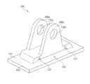
도 11은 후술하는 몇몇 차이점을 제외하고 도 10에 도시된 실시예와 유사한 또 다른 실시예의 캐스트 로드 셀 어셈블리(400)의 등각도이다. 캐스트 로드 셀 어셈블리(400)는 차량의 제1 부분에 장착될 수 있는 베이스 플레이트 부(402)를 갖는 일체형의 단일 캐스트 부재를 갖는다. 베이스 플레이트 부(402)는 샤프트 마운팅 부(106)에 일체로 연결된 로드 센싱 부(104)에 연결되어 지지된다. 샤프트 마운팅 부(106)는 차량의 제1 부분에 대해 이동 가능한 차량의 제2 부분에 연결가능하여, 굴곡 갭(120)이 캐스트 로드 셀 어셈블리(400)에 가해진 로드의 함수로서 구부러질 수 있게 한다. 도시된 실시예에서, 로드 센싱 부(106)는 굴곡 갭(120) 위에 위치하고 로드 센싱 부(104) 및 베이스 플레이트(402)로부터 돌출되어 있는 한 쌍의 이격된 커넥터 플레이트(406a 및 406b)를 포함한다. 커넥터 플레이트(406a 및 406b)는 차량의 제2 부분에 연결되는 가령 로드 또는 다른 적절한 구조와 같은 마운팅 부재를 수용하도록 구성된 동축으로 정렬된 중앙 개구(130a 및 130b)를 각각 갖는다. 커넥터 플레이트(406a 및 406b)는 서로 실질적으로 평행하고 베이스 플레이트 부(402)에 실질적으로 수직일 수 있다. 캐스트 로드 셀 어셈블리(400)는 트레일러 구성을 갖는 차량뿐만 아니라 가령 덤프 트럭, 믹서 트럭, 쓰레기 트럭 또는 다른 차량들과 같은 로드를 운반하도록 구성된 다른 차량들과 함께 사용될 수 있는데, 여기서 차량의 로드에 대한 정보가 측정 및/또는 모니터링될 수 있다. 단순화를 위해, 베이스 플레이트(402)는 평판으로 도시된다. 베이스 부(402)는 또한 기존의 트럭 구조에 적합하도록 구성될 수 있다.11 is an isometric view of a cast
상술한 내용은 설명의 목적으로 특정 실시예를 참조하여 설명되었다. 그러나, 상술한 예시적인 논의는 포괄적이거나 청구항들의 범위를 개시된 정확한 형태로 제한하려는 것은 아니다. 상술한 교시를 고려하여 많은 수정 및 변형이 가능하다. 본 실시예는 청구항들과 그 실제 적용의 근간을 이루는 원리를 가장 잘 설명하기 위해 선택되며, 이로써 당업자가 고려되는 특정 용도에 적합한 다양한 변형으로 실시예들을 가장 잘 이용할 수 있도록 한다.The foregoing has been described with reference to specific embodiments for purposes of illustration. However, the above-described exemplary discussions are not intended to be exhaustive or to limit the scope of the claims to the precise forms disclosed. Many modifications and variations are possible in light of the above teachings. This embodiment is chosen to best explain the principles underlying the claims and their practical application, thereby enabling those skilled in the art to best utilize the embodiments with various modifications as are suited to the particular use contemplated.
Claims (20)
견인 차량에 연결되도록 구성된 마운팅 특징부를 갖는 마운팅 플레이트 부분;
마운팅 플레이트 부분과 일체로 형성되고 마운팅 플레이트 부분에 연결된 로드 센싱 부분;
로드 센싱 부분과 일체로 형성되고 플렉셔 갭(flexure gap) 위의 로드 센싱 부분에 연결된 샤프트 마운팅 부분; 및
로드 센서 부분에 연결되고 플렉셔 갭의 일부 위의 센서 캐비티 내에 배치된 로드 센서를 포함하고,
로드 센싱 부분은 마운팅 플레이트 부분으로부터 이격되고 그 사이에 로드 센싱 부분 상의 로드에 응답하여 센싱 부분이 마운팅 플레이트에 대해 이동하도록 허용하는 플렉셔 갭을 정의하며, 로드 센싱 부분은 플렉셔 갭의 적어도 일부 위에서 내부에 가공되는 센서 캐비티를 가지고,
샤프트 마운팅 부분은 5륜 휠 결합 시스템의 제2 마운팅 부분의 일부를 피봇식으로 수용하도록 구성되며,
마운팅 플레이트 부분, 로드 센싱 부분 및 샤프트 마운팅 부분은, 내부에 센싱 캐비티가 가공되고 로드 센서가 부착되는 일체형이며, 낮은 프로파일이고, 무용접형인, 실질적으로 균일한 단일 캐스트 부재를 정의하는 캐스트 로드 셀.A cast load cell for use with a five-wheel wheel engagement system having a first mounting portion connectable to a towing vehicle and a second mounting portion engageable with a five-wheel wheel trailer,
A mounting plate portion having a mounting feature configured to be connected to the towing vehicle;
A load sensing part integrally formed with the mounting plate part and connected to the mounting plate part;
A shaft mounting portion integrally formed with the load sensing portion and connected to the load sensing portion on the flexure gap; And
And a load sensor connected to the load sensor portion and disposed in a sensor cavity above a portion of the flexure gap,
The load sensing portion defines a flexure gap that is spaced from the mounting plate portion and which, in response to a load on the load sensing portion, allows the sensing portion to move relative to the mounting plate, wherein the load sensing portion is located on at least a portion of the flexure gap With a sensor cavity machined inside,
The shaft mounting portion is configured to pivotally receive a portion of the second mounting portion of the five-wheel wheel engagement system,
Wherein the mounting plate portion, the load sensing portion, and the shaft mounting portion define a substantially uniform single cast member that is integral, low profile, non-wearing, in which a sensing cavity is machined and a load sensor is attached thereto.
마운팅 플레이트 부분은 제1 수평면을 정의하는 상부 표면을 가지고, 샤프트 마운팅 부분은 5륜 휠 결합 시스템의 제2 마운팅 부분의 일부를 피봇식으로 수용하도록 구성된 리셉터클(receptacle)을 가지며, 플렉셔 갭 위에 이격된 제2 수평면은 리셉터클의 적어도 일부 및 센서 캐비티의 적어도 일부를 통과하여 연장되는 캐스트 로드 셀.The method according to claim 1,
The mounting plate portion has a top surface defining a first horizontal surface, the shaft mounting portion having a receptacle configured to pivotally receive a portion of a second mounting portion of the five-wheel wheel engagement system, The second horizontal plane extending through at least a portion of the receptacle and at least a portion of the sensor cavity.
센서 캐비티는 센서 캐비티를 통해 가로질러 연장되는 웹 부분을 가지고, 로드 센서는 웹 부분 상에 장착되는 캐스트 로드 셀.The method according to claim 1,
The sensor cavity has a web portion extending across the sensor cavity and the load sensor is mounted on the web portion.
센서 캐비티는 제1 센서 캐비티이고, 로드 센싱 부분은 샤프트 마운팅 부분의 대향하는 측들 상에서 제1 센서 캐비티로부터 이격되는 제2 센서 캐비티를 가지는 캐스트 로드 셀. The method according to claim 1,
Wherein the sensor cavity is a first sensor cavity and the load sensing portion has a second sensor cavity spaced from the first sensor cavity on opposing sides of the shaft mounting portion.
캐스트 부재는 캐스트 강철 부재인 캐스트 로드 셀.The method according to claim 1,
And the cast member is a cast steel member.
센서는 리드 와이어 및 리드 와이어에 부착된 커넥터를 가지고, 로드 센싱 부분은 로드 센싱 부분을 통해 연장되고 센서 캐비티와 통신하는 리드 채널을 가지며, 커넥터는 센서 캐비티로부터 떨어진 로드 센싱 부분의 일측에 인접하여 배치되는 캐스트 로드 셀.The method according to claim 1,
The sensor has a lead wire and a connector attached to the lead wire, the load sensing portion having a lead channel extending through the load sensing portion and communicating with the sensor cavity, the connector being disposed adjacent to one side of the load sensing portion remote from the sensor cavity Cast load cell.
리드 채널은 센서 캐비티에 실질적으로 수직으로(normal) 배향되는 캐스트 로드 셀.The method according to claim 6,
The lead channel being oriented substantially normal to the sensor cavity.
마운팅 플레이트 부분은 제1 마운팅 부분의 마운팅 트랙을 슬라이드가능하게 수용하도록 구성되는 윤곽화된 트랙-수용 부분을 가지는 캐스트 로드 셀.The method according to claim 1,
The mounting plate portion having a contoured track-receiving portion configured to slidably receive a mounting track of the first mounting portion.
마운팅 플레이트 부분은 마운팅 트랙과 릴리즈가능하게 체결되고 마운팅 트랙 상의 고정된 위치에서 캐스트 부재를 잠그는 잠금 부재를 수용하도록 구성된 잠금-수용 부분을 가지는 캐스트 로드 셀.9. The method of claim 8,
The cast load cell portion has a lock-receiving portion configured to releasably engage the mounting track and to receive a locking member that locks the cast member in a fixed position on the mounting track.
차량의 제1 부분에 결합가능한 제1 마운팅 부분;
제1 마운팅 부분에 연결되고 플렉셔 갭에 의해 제1 마운팅 부분으로부터 이격된 플렉셔 부분을 가지는 로드 센싱 부분;
차량의 제1 부분에 대하여 이동가능한 차량의 제2 부분에 결합가능하고 플렉셔 갭 위의 로드 센싱 부분에 연결된 제2 마운팅 부분; 및
로드 센서 부분에 연결되고 플렉셔 갭의 일부 위의 센서 캐비티 내에 배치된 로드 센서를 포함하고,
제1 마운팅 부분, 로드 센싱 부분 및 제2 마운팅 부분은, 일체형이며, 낮은 프로파일이고, 무용접형인, 실질적으로 균일한 단일 캐스트 부재를 정의하는 캐스트 로드 셀 어셈블리.A cast load cell assembly for use with a vehicle configured to carry a load,
A first mounting portion engageable with a first portion of the vehicle;
A load sensing portion connected to the first mounting portion and having a flexure portion spaced from the first mounting portion by a flexure gap;
A second mounting portion connectable to a second portion of the vehicle movable with respect to the first portion of the vehicle and connected to the load sensing portion above the flexure gap; And
And a load sensor connected to the load sensor portion and disposed in a sensor cavity above a portion of the flexure gap,
Wherein the first mounting portion, the load sensing portion, and the second mounting portion define a substantially uniform single cast member that is integral, low profile, and non-wearing.
제1 마운팅 부분은 제1 수평면을 정의하는 상부 표면을 가지고, 제2 마운팅 부분은 차량의 제2 부분을 피봇식으로 수용하도록 구성된 리셉터클을 가지며, 플렉셔 갭 위에 이격된 제2 수평면은 리셉터클의 적어도 일부 및 센서 캐비티의 적어도 일부를 통과하여 연장되는 캐스트 로드 셀 어셈블리.11. The method of claim 10,
The first mounting portion having a top surface defining a first horizontal surface and the second mounting portion having a receptacle configured to pivotally receive a second portion of the vehicle and a second horizontal surface spaced above the flexure gap, And a cast rod cell assembly extending through at least a portion of the sensor cavity.
센서 캐비티는 센서 캐비티를 통해 가로질러 연장되는 웹 부분을 가지고, 로드 센서는 웹 부분 상에 장착되는 캐스트 로드 셀 어셈블리.11. The method of claim 10,
The sensor cavity has a web portion extending across the sensor cavity and the load sensor is mounted on the web portion.
센서 캐비티는 캐스트 로드 센싱 부분 내로 가공된 적어도 하나의 개구를 포함하는 캐스트 로드 셀 어셈블리.11. The method of claim 10,
Wherein the sensor cavity includes at least one opening machined into the cast load sensing portion.
센서 캐비티는 제1 센서 캐비티이고, 로드 센싱 부분은 플랙셔 갭 위에서 제1 센서 캐비티로부터 이격된 제2 센서 캐비티를 가지는 캐스트 로드 셀 어셈블리.11. The method of claim 10,
Wherein the sensor cavity is a first sensor cavity and the load sensing portion has a second sensor cavity spaced from the first sensor cavity above the flexure gap.
센서는 리드 와이어 및 리드 와이어에 부착된 커넥터를 가지고, 로드 센싱 부분은 로드 센싱 부분을 통해 연장되고 센서 캐비티와 통신하는 채널을 가지며, 커넥터는 센서 캐티티로부터 떨어진 로드 센싱 부분의 일측에 인접하여 배치되는 캐스트 로드 셀 어셈블리.11. The method of claim 10,
The sensor has a connector attached to the lead wire and the lead wire, the load sensing portion having a channel extending through the load sensing portion and communicating with the sensor cavity, the connector being disposed adjacent to one side of the load sensing portion remote from the sensor catheter Cast-rod cell assembly.
제1 마운팅 부분의 하부 부분은 마운팅 트랙을 슬라이드가능하게 수용하도록 구성되는 윤곽화된 트랙-수용 부분을 가지는 캐스트 로드 셀 어셈블리.11. The method of claim 10,
The lower portion of the first mounting portion has a contoured track-receiving portion configured to slidably receive the mounting track.
플렉셔 갭은 단일 캐스트 부재 주조 시에 형성되는 캐스트 로드 셀 어셈블리.11. The method of claim 10,
The flexure gap is formed at the time of casting a single cast member.
트럭에 연결가능한 마운팅 프레임;
5륜 휠 트레일러와 체결가능하고 마운팅 샤프트 쌍을 가지는 5륜 휠 마운팅 플레이트;
일체형 로드 셀을 갖는 캐스트 로드 셀 어셈블리 쌍을 포함하며,
각각의 캐스트 로드 셀 어셈블리는:
마운팅 프레임에 결합된 마운팅 특징부를 갖는 마운팅 플레이트 부분;
마운팅 플레이트 부분과 일체로 형성되고 마운팅 플레이트 부분에 연결된 로드 센싱 부분;
로드 센싱 부분과 일체로 형성되고 플렉셔 갭 위의 로드 센싱 부분에 연결된 샤프트 마운팅 부분; 및
로드 센서 부분에 연결되고 플렉셔 갭의 일부 위의 센서 캐비티 내에 배치된 로드 센서를 포함하고,
로드 센싱 부분은 마운팅 플레이트 부분으로부터 이격되고 그 사이에 로드 센싱 부분 상의 로드에 응답하여 센싱 부분이 마운팅 플레이트에 대해 이동하도록 허용하는 플렉셔 갭을 정의하며, 로드 센싱 부분은 플렉셔 갭의 적어도 일부 위의 로드 센싱 부분 내에 가공되는 센서 캐비티를 가지고,
샤프트 마운팅 부분은 마운팅 샤프트 쌍의 각각의 샤프트를 피봇식으로 수용하도록 구성되며,
마운팅 플레이트 부분, 로드 센싱 부분 및 샤프트 마운팅 부분은, 내부에 센싱 캐비티가 가공되고 로드 센서가 부착되는 일체형이며, 무용접형인 단일 캐스트 부재를 정의하는 5륜 휠 로드 셀 시스템.A five wheel wheel load cell system for use with a truck and a five wheel wheel trailer,
Mounting frame connectable to truck;
A 5-wheel wheel mounting plate with a pair of mounting shafts that can be coupled to a 5-wheel wheel trailer;
A pair of cast rod cell assemblies having integral load cells,
Each cast rod cell assembly includes:
A mounting plate portion having mounting features coupled to the mounting frame;
A load sensing part integrally formed with the mounting plate part and connected to the mounting plate part;
A shaft mounting portion integrally formed with the load sensing portion and connected to the load sensing portion on the flexure gap; And
And a load sensor connected to the load sensor portion and disposed in a sensor cavity above a portion of the flexure gap,
The load sensing portion defines a flexure gap that is spaced from the mounting plate portion and which, in response to a load on the load sensing portion, allows the sensing portion to move relative to the mounting plate, and the load sensing portion defines a portion of the flexure gap Having a sensor cavity that is machined within the load sensing portion of the housing,
The shaft mounting portion is configured to pivotally receive a respective shaft of the pair of mounting shafts,
Wherein the mounting plate portion, the load sensing portion, and the shaft mounting portion define a single cast member that is integral and durable in which a sensing cavity is machined and a load sensor is affixed therein.
마운팅 플레이트 부분은 제1 수평면을 정의하는 상부 표면을 가지고, 트러니언(trunnion) 마운팅 부분은 5륜 휠 결합 시스템의 제2 마운팅 부분의 일부를 피봇식으로 수용하도록 구성된 리셉터클을 가지며, 플렉셔 갭 위에서 이격된 제2 수평면은 리셉터클의 적어도 일부 및 센서 캐비티의 적어도 일부를 통과하여 연장되는 5륜 휠 로드 셀 시스템.19. The method of claim 18,
The mounting plate portion has a top surface defining a first horizontal plane and the trunnion mounting portion has a receptacle configured to pivotally receive a portion of the second mounting portion of the five- Wherein the spaced apart second horizontal surfaces extend through at least a portion of the receptacle and at least a portion of the sensor cavity.
마운팅 플레이트 부분의 하부 부분은 마운팅 프레임의 마운팅 트랙을 슬라이드가능하게 수용하도록 구성되는 윤곽화된 트랙-수용 부분을 가지는 5륜 휠 로드 셀 시스템.19. The method of claim 18,
The lower portion of the mounting plate portion has a contoured track-receiving portion configured to slidably receive a mounting track of the mounting frame.
Applications Claiming Priority (3)
| Application Number | Priority Date | Filing Date | Title |
|---|---|---|---|
| US201662297733P | 2016-02-19 | 2016-02-19 | |
| US62/297,733 | 2016-02-19 | ||
| PCT/US2017/017731 WO2017142844A1 (en) | 2016-02-19 | 2017-02-13 | Load cell assembly |
Publications (2)
| Publication Number | Publication Date |
|---|---|
| KR20190075864A true KR20190075864A (en) | 2019-07-01 |
| KR102211506B1 KR102211506B1 (en) | 2021-02-03 |
Family
ID=58159529
Family Applications (1)
| Application Number | Title | Priority Date | Filing Date |
|---|---|---|---|
| KR1020187027193A Active KR102211506B1 (en) | 2016-02-19 | 2017-02-13 | Load cell assembly |
Country Status (9)
| Country | Link |
|---|---|
| US (3) | US10337908B2 (en) |
| EP (1) | EP3417252B1 (en) |
| KR (1) | KR102211506B1 (en) |
| AU (2) | AU2017219614B2 (en) |
| CA (1) | CA3024835C (en) |
| ES (1) | ES2921984T3 (en) |
| NZ (1) | NZ746436A (en) |
| WO (1) | WO2017142844A1 (en) |
| ZA (1) | ZA201806268B (en) |
Families Citing this family (13)
| Publication number | Priority date | Publication date | Assignee | Title |
|---|---|---|---|---|
| ES2921984T3 (en) | 2016-02-19 | 2022-09-05 | Vishay Transducers Ltd | load cell assembly |
| CA3053325A1 (en) * | 2017-02-14 | 2018-08-23 | Randy Schutt | Fifth wheel mounting bracket with isolation areas assisting in force measurement |
| EP3379222B1 (en) | 2017-03-22 | 2020-12-30 | Methode Electronics Malta Ltd. | Magnetoelastic based sensor assembly |
| US11428589B2 (en) * | 2017-10-16 | 2022-08-30 | Saf-Holland, Inc. | Displacement sensor utilizing ronchi grating interference |
| EP3758959B1 (en) | 2018-02-27 | 2025-11-05 | Methode Electronics, Inc. | Towing systems and methods using magnetic field sensing |
| US11084342B2 (en) | 2018-02-27 | 2021-08-10 | Methode Electronics, Inc. | Towing systems and methods using magnetic field sensing |
| US11014417B2 (en) | 2018-02-27 | 2021-05-25 | Methode Electronics, Inc. | Towing systems and methods using magnetic field sensing |
| US11135882B2 (en) | 2018-02-27 | 2021-10-05 | Methode Electronics, Inc. | Towing systems and methods using magnetic field sensing |
| US11221262B2 (en) | 2018-02-27 | 2022-01-11 | Methode Electronics, Inc. | Towing systems and methods using magnetic field sensing |
| US11491832B2 (en) | 2018-02-27 | 2022-11-08 | Methode Electronics, Inc. | Towing systems and methods using magnetic field sensing |
| WO2020086550A1 (en) * | 2018-10-25 | 2020-04-30 | Amsted Rail Company, Inc. | Load sensing system for a railway truck assembly |
| US12221183B2 (en) | 2020-03-06 | 2025-02-11 | Terry Repp | Trailer and interchangeable modules |
| WO2023023157A1 (en) * | 2021-08-17 | 2023-02-23 | Anamnesis Corporation | Vehicle system and longitudinal vehicle control method |
Citations (3)
| Publication number | Priority date | Publication date | Assignee | Title |
|---|---|---|---|---|
| US3854540A (en) * | 1973-08-03 | 1974-12-17 | G Holmstrom | Vehicle weighing means |
| US6495774B1 (en) * | 1999-04-29 | 2002-12-17 | Brian L. Pederson | Load cell holding means |
| US20110253462A1 (en) * | 2010-04-15 | 2011-10-20 | Keith Reichow | Load cell assemblies for off-center loads and associated methods of use and manufacture |
Family Cites Families (36)
| Publication number | Priority date | Publication date | Assignee | Title |
|---|---|---|---|---|
| US2648544A (en) * | 1949-02-12 | 1953-08-11 | American Steel Foundries | Resiliently mounted fifth wheel member |
| US3602866A (en) * | 1968-12-18 | 1971-08-31 | Erwin J Saxl | Force transducer |
| US3661220A (en) * | 1971-11-01 | 1972-05-09 | Electro Dev Corp | Weighing device for logging trucks or the like |
| US4020911A (en) * | 1973-08-10 | 1977-05-03 | Structural Instrumentation, Inc. | Load cell scale |
| US4042049A (en) * | 1975-09-29 | 1977-08-16 | Structural Instrumentation, Inc. | Vehicle load measuring system |
| US4095659A (en) * | 1976-06-10 | 1978-06-20 | Eldec Corporation | Deflection-restrained load cell for on-board vehicle weighing systems |
| US4364279A (en) * | 1980-12-31 | 1982-12-21 | Allegany Technology, Inc. | Shear beam load cell system |
| US4666003A (en) * | 1985-09-17 | 1987-05-19 | Stress-Tek, Inc. | On-board load cell |
| US4762334A (en) * | 1987-11-03 | 1988-08-09 | Amsted Industries Incorporated | Fifth wheel bracket mounting assembly |
| US4813504A (en) * | 1988-05-27 | 1989-03-21 | Kroll William P | Load cell structure |
| GB8905251D0 (en) * | 1989-03-08 | 1989-04-19 | Lucas Ind Plc | Improvements in braking systems for articulated vehicles |
| DE4142671A1 (en) * | 1991-12-21 | 1993-06-24 | Wabco Westinghouse Fahrzeug | DEVICE FOR MEASURING DEFORM OF A COMPONENT |
| US5391844A (en) * | 1992-04-03 | 1995-02-21 | Weigh-Tronix Inc | Load cell |
| DE4402525C2 (en) * | 1993-02-17 | 1998-10-29 | Fischer Georg Verkehrstechnik | Arrangement of measuring means on a semitrailer vehicle having a tractor unit and a semitrailer |
| DE4402526C2 (en) * | 1993-02-17 | 1998-12-10 | Fischer Georg Verkehrstechnik | Arrangement of measuring means on a semitrailer vehicle having a tractor unit and a semitrailer |
| US5368324A (en) * | 1994-01-10 | 1994-11-29 | Amsted Industries Incorporated | Mounting system for fifth wheels |
| US5765849A (en) * | 1996-04-24 | 1998-06-16 | Fontaine Fifth Wheel Co. | Fifth wheel bracket |
| US6037550A (en) * | 1997-09-30 | 2000-03-14 | Weigh-Tronix, Inc. | On-board vehicle weighing apparatus and method |
| SE516661C2 (en) * | 1999-11-12 | 2002-02-12 | Scania Cv Ab | Coupling device comprising turntable |
| US6302424B1 (en) * | 1999-12-09 | 2001-10-16 | Holland Hitch Company | Force-sensing fifth wheel |
| US7416204B2 (en) * | 2000-06-09 | 2008-08-26 | Saf-Holland, Inc. | Lightweight narrow-span fifth wheel |
| CA2316660A1 (en) * | 2000-08-24 | 2002-02-24 | Paul A. Mckenna | Double-ended load cell and method for mounting same |
| US7009118B2 (en) * | 2003-05-13 | 2006-03-07 | Dynamic Datum Llc | Vehicle load weighing system and load cells for such systems |
| US20060202443A1 (en) * | 2005-03-09 | 2006-09-14 | The Holland Group, Inc. | Fifth wheel slider assembly |
| US7202425B2 (en) * | 2005-04-13 | 2007-04-10 | The Montalvo Corporation | Under-pillow-block load cell |
| US7469920B2 (en) * | 2005-05-25 | 2008-12-30 | Cargo Protectors, Inc. | Kingpin lock |
| US7530589B1 (en) * | 2006-07-07 | 2009-05-12 | Fontaine International | Fifth wheel assembly with removable bearing plate |
| US8720931B2 (en) | 2011-11-02 | 2014-05-13 | Saf-Holland, Inc. | Tilt limiting assembly for fifth wheel hitch assembly |
| US8342558B1 (en) * | 2011-12-27 | 2013-01-01 | Austin Su | Glider hitch for trailer fifth wheel |
| US9464930B2 (en) * | 2013-03-15 | 2016-10-11 | Larry D. Santi | Load cell for a forklift with a first bridge arrangement consisting of strain gages mounted on the top and bottom external surfaces, and a second bridge arrangement consisting of strain gages mounted internal to a central aperture |
| WO2016022294A1 (en) * | 2014-08-05 | 2016-02-11 | Saf-Holland, Inc. | Active fifth wheel repositioning slider |
| AU2015258316A1 (en) * | 2015-11-20 | 2017-06-08 | Elektrika Pty Ltd | Load Measuring Device |
| ES2921984T3 (en) | 2016-02-19 | 2022-09-05 | Vishay Transducers Ltd | load cell assembly |
| CA3053325A1 (en) * | 2017-02-14 | 2018-08-23 | Randy Schutt | Fifth wheel mounting bracket with isolation areas assisting in force measurement |
| US11428589B2 (en) * | 2017-10-16 | 2022-08-30 | Saf-Holland, Inc. | Displacement sensor utilizing ronchi grating interference |
| US10729417B2 (en) * | 2018-11-15 | 2020-08-04 | Little Engine, LLC | Knee flexion and extension gap tensioning and measuring method |
-
2017
- 2017-02-13 ES ES17707155T patent/ES2921984T3/en active Active
- 2017-02-13 CA CA3024835A patent/CA3024835C/en active Active
- 2017-02-13 EP EP17707155.2A patent/EP3417252B1/en active Active
- 2017-02-13 AU AU2017219614A patent/AU2017219614B2/en active Active
- 2017-02-13 NZ NZ746436A patent/NZ746436A/en unknown
- 2017-02-13 US US15/431,677 patent/US10337908B2/en active Active
- 2017-02-13 WO PCT/US2017/017731 patent/WO2017142844A1/en not_active Ceased
- 2017-02-13 KR KR1020187027193A patent/KR102211506B1/en active Active
-
2018
- 2018-09-18 ZA ZA2018/06268A patent/ZA201806268B/en unknown
-
2019
- 2019-07-01 US US16/458,871 patent/US11422022B2/en active Active
- 2019-10-28 AU AU2019257377A patent/AU2019257377B2/en active Active
-
2022
- 2022-08-18 US US17/890,588 patent/US12066317B2/en active Active
Patent Citations (3)
| Publication number | Priority date | Publication date | Assignee | Title |
|---|---|---|---|---|
| US3854540A (en) * | 1973-08-03 | 1974-12-17 | G Holmstrom | Vehicle weighing means |
| US6495774B1 (en) * | 1999-04-29 | 2002-12-17 | Brian L. Pederson | Load cell holding means |
| US20110253462A1 (en) * | 2010-04-15 | 2011-10-20 | Keith Reichow | Load cell assemblies for off-center loads and associated methods of use and manufacture |
Also Published As
| Publication number | Publication date |
|---|---|
| US10337908B2 (en) | 2019-07-02 |
| US12066317B2 (en) | 2024-08-20 |
| AU2017219614A1 (en) | 2018-10-11 |
| EP3417252A1 (en) | 2018-12-26 |
| AU2019257377A1 (en) | 2019-11-14 |
| KR102211506B1 (en) | 2021-02-03 |
| ZA201806268B (en) | 2024-11-27 |
| US20230204406A1 (en) | 2023-06-29 |
| AU2017219614A9 (en) | 2019-08-29 |
| US20200018635A1 (en) | 2020-01-16 |
| CA3024835C (en) | 2020-12-29 |
| US20170241828A1 (en) | 2017-08-24 |
| WO2017142844A1 (en) | 2017-08-24 |
| AU2019257377B2 (en) | 2021-07-22 |
| US11422022B2 (en) | 2022-08-23 |
| EP3417252B1 (en) | 2022-04-06 |
| CA3024835A1 (en) | 2017-08-24 |
| ES2921984T3 (en) | 2022-09-05 |
| NZ746436A (en) | 2019-05-31 |
| AU2017219614B2 (en) | 2019-08-29 |
Similar Documents
| Publication | Publication Date | Title |
|---|---|---|
| US12066317B2 (en) | Load cell assembly for a towing vehicle | |
| US9726535B2 (en) | Load cell assemblies for off-center loads and associated methods of use and manufacture | |
| DE60003037T2 (en) | MONITORING OF RAILWAYS | |
| EP3227130A1 (en) | Trailer coupling comprising a sensor | |
| EP3553483B1 (en) | Measuring device for measuring force and / or moments between a motorized vehicle and a pulled or pushed trailer | |
| DE20119469U1 (en) | Electric braking device for vehicle trailers | |
| DE10304008B4 (en) | Device for measuring the rail load | |
| EP4380832A1 (en) | Method for determining the braking force on vehicles | |
| CN112298383B (en) | Semi-mounted transport vechicle and monitoring devices thereof | |
| EP1378732B1 (en) | Method for measuring the wheel loads of railroad cars and mobile measuring apparatus | |
| DE102014018472B4 (en) | Weighing device and weighing system for vehicle trailers | |
| US12364178B2 (en) | Boom working device and method for detecting loads acting on the boom | |
| DE102021133762A1 (en) | Coupling device for coupling a towing vehicle to a trailer vehicle | |
| CN102574486A (en) | Boarding assistance device for facilitating entry into a vehicle | |
| EP4256284B1 (en) | Axle load determining system, axle system and vehicle with an axle load determining system | |
| WO2004005864A1 (en) | Measuring device for detecting wheel loads | |
| DE102011086759B4 (en) | Method and device for determining wheel loads of rail vehicles | |
| DE20214267U1 (en) | Mobile rail vehicle wheel load measurement unit has adjustable tie bar | |
| DE10356867A1 (en) | Measurement device for diagnosis of wheel sets detects static and dynamic wheel contact surface forces of rail vehicles via material distortion | |
| EP4298415B1 (en) | Tongue weight measurement | |
| CH714330A2 (en) | Drawbar weighing system for mounting on a towing vehicle. | |
| DE20210173U1 (en) | Mobile rail vehicle wheel load measurement unit has floating mount with nulling |
Legal Events
| Date | Code | Title | Description |
|---|---|---|---|
| A201 | Request for examination | ||
| PA0105 | International application |
St.27 status event code: A-0-1-A10-A15-nap-PA0105 |
|
| PA0201 | Request for examination |
St.27 status event code: A-1-2-D10-D11-exm-PA0201 |
|
| T11-X000 | Administrative time limit extension requested |
St.27 status event code: U-3-3-T10-T11-oth-X000 |
|
| T11-X000 | Administrative time limit extension requested |
St.27 status event code: U-3-3-T10-T11-oth-X000 |
|
| T11-X000 | Administrative time limit extension requested |
St.27 status event code: U-3-3-T10-T11-oth-X000 |
|
| T11-X000 | Administrative time limit extension requested |
St.27 status event code: U-3-3-T10-T11-oth-X000 |
|
| T11-X000 | Administrative time limit extension requested |
St.27 status event code: U-3-3-T10-T11-oth-X000 |
|
| N231 | Notification of change of applicant | ||
| P11-X000 | Amendment of application requested |
St.27 status event code: A-2-2-P10-P11-nap-X000 |
|
| P13-X000 | Application amended |
St.27 status event code: A-2-2-P10-P13-nap-X000 |
|
| PN2301 | Change of applicant |
St.27 status event code: A-3-3-R10-R13-asn-PN2301 St.27 status event code: A-3-3-R10-R11-asn-PN2301 |
|
| PG1501 | Laying open of application |
St.27 status event code: A-1-1-Q10-Q12-nap-PG1501 |
|
| E902 | Notification of reason for refusal | ||
| PE0902 | Notice of grounds for rejection |
St.27 status event code: A-1-2-D10-D21-exm-PE0902 |
|
| P11-X000 | Amendment of application requested |
St.27 status event code: A-2-2-P10-P11-nap-X000 |
|
| P13-X000 | Application amended |
St.27 status event code: A-2-2-P10-P13-nap-X000 |
|
| E902 | Notification of reason for refusal | ||
| PE0902 | Notice of grounds for rejection |
St.27 status event code: A-1-2-D10-D21-exm-PE0902 |
|
| E13-X000 | Pre-grant limitation requested |
St.27 status event code: A-2-3-E10-E13-lim-X000 |
|
| P11-X000 | Amendment of application requested |
St.27 status event code: A-2-2-P10-P11-nap-X000 |
|
| P13-X000 | Application amended |
St.27 status event code: A-2-2-P10-P13-nap-X000 |
|
| R17-X000 | Change to representative recorded |
St.27 status event code: A-3-3-R10-R17-oth-X000 |
|
| E701 | Decision to grant or registration of patent right | ||
| PE0701 | Decision of registration |
St.27 status event code: A-1-2-D10-D22-exm-PE0701 |
|
| GRNT | Written decision to grant | ||
| PR0701 | Registration of establishment |
St.27 status event code: A-2-4-F10-F11-exm-PR0701 |
|
| PR1002 | Payment of registration fee |
St.27 status event code: A-2-2-U10-U12-oth-PR1002 Fee payment year number: 1 |
|
| PG1601 | Publication of registration |
St.27 status event code: A-4-4-Q10-Q13-nap-PG1601 |
|
| PR1001 | Payment of annual fee |
St.27 status event code: A-4-4-U10-U11-oth-PR1001 Fee payment year number: 4 |
|
| PR1001 | Payment of annual fee |
St.27 status event code: A-4-4-U10-U11-oth-PR1001 Fee payment year number: 5 |
|
| PR1001 | Payment of annual fee |
St.27 status event code: A-4-4-U10-U11-oth-PR1001 Fee payment year number: 6 |
|
| U11 | Full renewal or maintenance fee paid |
Free format text: ST27 STATUS EVENT CODE: A-4-4-U10-U11-OTH-PR1001 (AS PROVIDED BY THE NATIONAL OFFICE) Year of fee payment: 6 |
|
| P22-X000 | Classification modified |
St.27 status event code: A-4-4-P10-P22-nap-X000 |