KR20190074394A - SELECTIVE CATALYTIC REDUCTION SYSTEM AND NOx REDUCTION METHOD - Google Patents
SELECTIVE CATALYTIC REDUCTION SYSTEM AND NOx REDUCTION METHOD Download PDFInfo
- Publication number
- KR20190074394A KR20190074394A KR1020170175701A KR20170175701A KR20190074394A KR 20190074394 A KR20190074394 A KR 20190074394A KR 1020170175701 A KR1020170175701 A KR 1020170175701A KR 20170175701 A KR20170175701 A KR 20170175701A KR 20190074394 A KR20190074394 A KR 20190074394A
- Authority
- KR
- South Korea
- Prior art keywords
- temperature
- catalyst
- exhaust gas
- regeneration
- temperatures
- Prior art date
- Legal status (The legal status is an assumption and is not a legal conclusion. Google has not performed a legal analysis and makes no representation as to the accuracy of the status listed.)
- Granted
Links
Images


Classifications
-
- F—MECHANICAL ENGINEERING; LIGHTING; HEATING; WEAPONS; BLASTING
- F01—MACHINES OR ENGINES IN GENERAL; ENGINE PLANTS IN GENERAL; STEAM ENGINES
- F01N—GAS-FLOW SILENCERS OR EXHAUST APPARATUS FOR MACHINES OR ENGINES IN GENERAL; GAS-FLOW SILENCERS OR EXHAUST APPARATUS FOR INTERNAL-COMBUSTION ENGINES
- F01N9/00—Electrical control of exhaust gas treating apparatus
- F01N9/002—Electrical control of exhaust gas treating apparatus of filter regeneration
-
- F—MECHANICAL ENGINEERING; LIGHTING; HEATING; WEAPONS; BLASTING
- F01—MACHINES OR ENGINES IN GENERAL; ENGINE PLANTS IN GENERAL; STEAM ENGINES
- F01N—GAS-FLOW SILENCERS OR EXHAUST APPARATUS FOR MACHINES OR ENGINES IN GENERAL; GAS-FLOW SILENCERS OR EXHAUST APPARATUS FOR INTERNAL-COMBUSTION ENGINES
- F01N3/00—Exhaust or silencing apparatus having means for purifying, rendering innocuous, or otherwise treating exhaust
- F01N3/08—Exhaust or silencing apparatus having means for purifying, rendering innocuous, or otherwise treating exhaust for rendering innocuous
- F01N3/10—Exhaust or silencing apparatus having means for purifying, rendering innocuous, or otherwise treating exhaust for rendering innocuous by thermal or catalytic conversion of noxious components of exhaust
- F01N3/18—Exhaust or silencing apparatus having means for purifying, rendering innocuous, or otherwise treating exhaust for rendering innocuous by thermal or catalytic conversion of noxious components of exhaust characterised by methods of operation; Control
- F01N3/20—Exhaust or silencing apparatus having means for purifying, rendering innocuous, or otherwise treating exhaust for rendering innocuous by thermal or catalytic conversion of noxious components of exhaust characterised by methods of operation; Control specially adapted for catalytic conversion
- F01N3/2006—Periodically heating or cooling catalytic reactors, e.g. at cold starting or overheating
-
- F—MECHANICAL ENGINEERING; LIGHTING; HEATING; WEAPONS; BLASTING
- F01—MACHINES OR ENGINES IN GENERAL; ENGINE PLANTS IN GENERAL; STEAM ENGINES
- F01N—GAS-FLOW SILENCERS OR EXHAUST APPARATUS FOR MACHINES OR ENGINES IN GENERAL; GAS-FLOW SILENCERS OR EXHAUST APPARATUS FOR INTERNAL-COMBUSTION ENGINES
- F01N2240/00—Combination or association of two or more different exhaust treating devices, or of at least one such device with an auxiliary device, not covered by indexing codes F01N2230/00 or F01N2250/00, one of the devices being
- F01N2240/14—Combination or association of two or more different exhaust treating devices, or of at least one such device with an auxiliary device, not covered by indexing codes F01N2230/00 or F01N2250/00, one of the devices being a fuel burner
-
- F—MECHANICAL ENGINEERING; LIGHTING; HEATING; WEAPONS; BLASTING
- F01—MACHINES OR ENGINES IN GENERAL; ENGINE PLANTS IN GENERAL; STEAM ENGINES
- F01N—GAS-FLOW SILENCERS OR EXHAUST APPARATUS FOR MACHINES OR ENGINES IN GENERAL; GAS-FLOW SILENCERS OR EXHAUST APPARATUS FOR INTERNAL-COMBUSTION ENGINES
- F01N2240/00—Combination or association of two or more different exhaust treating devices, or of at least one such device with an auxiliary device, not covered by indexing codes F01N2230/00 or F01N2250/00, one of the devices being
- F01N2240/16—Combination or association of two or more different exhaust treating devices, or of at least one such device with an auxiliary device, not covered by indexing codes F01N2230/00 or F01N2250/00, one of the devices being an electric heater, i.e. a resistance heater
-
- F—MECHANICAL ENGINEERING; LIGHTING; HEATING; WEAPONS; BLASTING
- F01—MACHINES OR ENGINES IN GENERAL; ENGINE PLANTS IN GENERAL; STEAM ENGINES
- F01N—GAS-FLOW SILENCERS OR EXHAUST APPARATUS FOR MACHINES OR ENGINES IN GENERAL; GAS-FLOW SILENCERS OR EXHAUST APPARATUS FOR INTERNAL-COMBUSTION ENGINES
- F01N2560/00—Exhaust systems with means for detecting or measuring exhaust gas components or characteristics
- F01N2560/06—Exhaust systems with means for detecting or measuring exhaust gas components or characteristics the means being a temperature sensor
-
- F—MECHANICAL ENGINEERING; LIGHTING; HEATING; WEAPONS; BLASTING
- F01—MACHINES OR ENGINES IN GENERAL; ENGINE PLANTS IN GENERAL; STEAM ENGINES
- F01N—GAS-FLOW SILENCERS OR EXHAUST APPARATUS FOR MACHINES OR ENGINES IN GENERAL; GAS-FLOW SILENCERS OR EXHAUST APPARATUS FOR INTERNAL-COMBUSTION ENGINES
- F01N2900/00—Details of electrical control or of the monitoring of the exhaust gas treating apparatus
- F01N2900/06—Parameters used for exhaust control or diagnosing
- F01N2900/14—Parameters used for exhaust control or diagnosing said parameters being related to the exhaust gas
- F01N2900/1404—Exhaust gas temperature
-
- Y—GENERAL TAGGING OF NEW TECHNOLOGICAL DEVELOPMENTS; GENERAL TAGGING OF CROSS-SECTIONAL TECHNOLOGIES SPANNING OVER SEVERAL SECTIONS OF THE IPC; TECHNICAL SUBJECTS COVERED BY FORMER USPC CROSS-REFERENCE ART COLLECTIONS [XRACs] AND DIGESTS
- Y02—TECHNOLOGIES OR APPLICATIONS FOR MITIGATION OR ADAPTATION AGAINST CLIMATE CHANGE
- Y02A—TECHNOLOGIES FOR ADAPTATION TO CLIMATE CHANGE
- Y02A50/00—TECHNOLOGIES FOR ADAPTATION TO CLIMATE CHANGE in human health protection, e.g. against extreme weather
- Y02A50/20—Air quality improvement or preservation, e.g. vehicle emission control or emission reduction by using catalytic converters
-
- Y—GENERAL TAGGING OF NEW TECHNOLOGICAL DEVELOPMENTS; GENERAL TAGGING OF CROSS-SECTIONAL TECHNOLOGIES SPANNING OVER SEVERAL SECTIONS OF THE IPC; TECHNICAL SUBJECTS COVERED BY FORMER USPC CROSS-REFERENCE ART COLLECTIONS [XRACs] AND DIGESTS
- Y02—TECHNOLOGIES OR APPLICATIONS FOR MITIGATION OR ADAPTATION AGAINST CLIMATE CHANGE
- Y02T—CLIMATE CHANGE MITIGATION TECHNOLOGIES RELATED TO TRANSPORTATION
- Y02T10/00—Road transport of goods or passengers
- Y02T10/10—Internal combustion engine [ICE] based vehicles
- Y02T10/12—Improving ICE efficiencies
-
- Y—GENERAL TAGGING OF NEW TECHNOLOGICAL DEVELOPMENTS; GENERAL TAGGING OF CROSS-SECTIONAL TECHNOLOGIES SPANNING OVER SEVERAL SECTIONS OF THE IPC; TECHNICAL SUBJECTS COVERED BY FORMER USPC CROSS-REFERENCE ART COLLECTIONS [XRACs] AND DIGESTS
- Y02—TECHNOLOGIES OR APPLICATIONS FOR MITIGATION OR ADAPTATION AGAINST CLIMATE CHANGE
- Y02T—CLIMATE CHANGE MITIGATION TECHNOLOGIES RELATED TO TRANSPORTATION
- Y02T10/00—Road transport of goods or passengers
- Y02T10/10—Internal combustion engine [ICE] based vehicles
- Y02T10/40—Engine management systems
Landscapes
- Engineering & Computer Science (AREA)
- Chemical & Material Sciences (AREA)
- Combustion & Propulsion (AREA)
- Mechanical Engineering (AREA)
- General Engineering & Computer Science (AREA)
- Chemical Kinetics & Catalysis (AREA)
- Health & Medical Sciences (AREA)
- Toxicology (AREA)
- Exhaust Gas Treatment By Means Of Catalyst (AREA)
- Exhaust Gas After Treatment (AREA)
Abstract
Description
본 발명은 선택적 촉매 환원 시스템 및 질소산화물 저감 방법에 관한 것으로, 더욱 상세하게는 질소산화물 저감에 사용되는 촉매를 재생시켜 사용하는 선택적 촉매 환원 시스템 및 질소산화물 저감 방법에 관한 것이다.The present invention relates to a selective catalytic reduction system and a nitrogen oxide reduction method, and more particularly, to a selective catalytic reduction system and a nitrogen oxide reduction method for regenerating a catalyst used for reducing nitrogen oxides.
산업화가 급속하게 진전됨에 따라 석유나 석탄과 같은 각종 화석 연료의 사용량이 증가하게 되었다. 이로 인하여 화석 연료의 연소 과정에서 배출되는 각종 유해 가스가 심각한 대기 오염을 야기하고 있다. 대표적인 예로서 스모그(Smog) 현상이나 산성비 등을 들 수 있다.As industrialization has progressed rapidly, the use of various fossil fuels such as petroleum and coal has increased. As a result, various harmful gases emitted from the combustion process of fossil fuels cause serious air pollution. Typical examples are smog phenomenon and acid rain.
대기 오염의 주범으로는 차량 및 선박의 엔진 또는 화력 발전소나 공장 등으로부터 배출되는 배기가스의 황산화물(SOx)이나 질소산화물(NOx)이 있다.The main cause of air pollution is sulfur oxides (SOx) and nitrogen oxides (NOx) of exhaust gas emitted from engines of vehicles and ships, thermal power plants and factories.
근래에는 환경 보존에 대한 인식이 높아짐에 따라 이러한 황산화물과 질소산화물에 대한 배출규제가 도입되고 있다.Recently, as the awareness of environmental conservation has increased, regulations on emission of sulfur oxides and nitrogen oxides have been introduced.
특히, 질소산화물을 저감시키기 위한 대표적인 설비로 선택적 촉매 환원(selective catalytic reduction, SCR) 시스템이 있다. 선택적 촉매 환원 시스템은 촉매가 내부에 설치된 반응기에 배기가스와 환원제를 함께 통과시키면서 배기가스에 함유된 질소산화물과 환원제를 반응시켜 질소와 수증기로 환원 처리한다.In particular, there is a selective catalytic reduction (SCR) system as a typical facility for reducing nitrogen oxides. The selective catalytic reduction system reacts the nitrogen oxides contained in the exhaust gas with the reducing agent while passing the exhaust gas and the reducing agent together in the reactor equipped with the catalyst, thereby reducing the nitrogen and the water vapor.
이러한 선택적 촉매 환원 시스템이 선박에 사용될 경우, 선박용 디젤 엔진에서 배출되는 질소산화물(NOx)의 배출량이 국제 해사 기구(International Maritime Organization)에서 규정한 엔진 국제 대기 오염 방지 3차 규제(IMO Tier-III)를 만족시킬 수 있어야 하므로, 저비용 고효율의 탈질 설비와 함께 효과적인 운용 방법이 요구되고 있다.When this selective catalytic reduction system is used on ships, the emission of NOx from marine diesel engines is controlled by the International Maritime Organization's International Standard for the Prevention of Air Pollution (IMO Tier-III) It is required to use an efficient denitrification system with a low cost and high efficiency.
일반적으로 배기가스에 함유된 질소산화물을 저감시키기 위해 사용되는 촉매는 섭씨 250도 내지 섭씨 500도 범위 내의 활성 온도를 가질 수 있다. 여기서, 활성 온도는 촉매가 피독되지 않고 안정적으로 질소산화물을 환원시킬 수 있는 온도를 말한다. 촉매가 활성 온도 범위 밖에서 반응할 경우, 피독되면서 효율이 저하된다. 구체적으로, 섭씨 250도 미만의 상대적으로 낮은 온도를 갖는 배기 가스가 유입되면, 배기가스의 황산화물(SOx)과 환원제의 암모니아(NH4)가 반응하여 촉매 피독 물질이 생성된다. 촉매 피독 물질은 황산암모늄(Ammonium sulfate, (NH4)2SO4)과 아황산수소암모늄(Ammonium bisulfate, NH4HSO4) 중 하나 이상을 포함할 수 있다. 이와 같은 촉매 피독 물질은 촉매에 흡착되어 촉매의 활성을 저하시키므로, 촉매의 효율을 높이고 유지 보수에 따른 손실을 최소화하기 위해서는 촉매의 온도를 활성 온도 범위 내로 유지하는 것이 요구된다.In general, the catalyst used to reduce the nitrogen oxides contained in the exhaust gas may have an active temperature in the range of 250 degrees Celsius to 500 degrees Celsius. Here, the activation temperature refers to a temperature at which the catalyst can be stably reduced without being poisoned. When the catalyst reacts outside the active temperature range, the efficiency decreases as it is poisoned. Specifically, when the exhaust gas flows having a relatively low temperature of less than 250 ° C, the catalyst poisoning material is generated by the ammonia of sulfur oxides in the exhaust gas (SOx) and a reducing agent (NH 4) response. Catalyst poisoning material may comprise one or more of ammonium sulfate (Ammonium sulfate, (NH4) 2 SO 4) and ammonium bisulfite (Ammonium bisulfate, NH 4 HSO 4 ). Such a catalyst poisoning material is adsorbed on the catalyst to lower the activity of the catalyst. Therefore, in order to increase the efficiency of the catalyst and minimize the loss due to maintenance, it is required to keep the temperature of the catalyst within the active temperature range.
하지만, 선박용 저속 디젤 엔진의 경우, 디젤 엔진의 부하 변동에 따라 배기가스의 배출량이 달라지고, 선박이 운항 중인 기후 환경도 선택적 촉매 환원 반응에 영향을 미치므로, 촉매의 피독을 완벽하게 피하기 어렵다.However, in the case of a low speed diesel engine for ships, it is difficult to completely avoid the poisoning of the catalyst because the emission amount of the exhaust gas changes according to the load change of the diesel engine and the climate environment in which the ship is operating also affects the selective catalytic reduction reaction.
전술한 촉매 피독 물질은 상대적으로 높은 온도, 예를 들어 섭씨 350도 내지 섭씨 450도 범위 내의 온도에서 분해된다. 따라서, 촉매가 피독되면 촉매를 가열하여 피독 물질을 제거하게 되는데, 종래에는 사용자가 입력한 재생 주기에 따라 재생을 실시하였다. 즉, 사용자가 재생 주기를 입력하면 입력된 주기로만 운전과 재생을 반복하게 된다.The aforementioned catalyst poisonous materials are decomposed at relatively high temperatures, for example, temperatures in the range of 350 degrees Celsius to 450 degrees Celsius. Therefore, when the catalyst is poisoned, the catalyst is heated to remove the poisonous substance. In the past, the regeneration was performed according to the regeneration period inputted by the user. That is, when the user inputs the reproduction cycle, the operation and reproduction are repeated only at the inputted cycle.
그런데, 재생 주기를 고정적으로 설정함에 따라 촉매의 활성화를 안정적으로 유지하기 위해 재생 주기를 최악의 상황을 고려하여 가장 짧게 설정 할 수밖에 없었다. 구체적으로, 촉매가 가장 피독 되기 쉬운 조건을 가정하여 재생 주기를 설정 할 수밖에 없다. 이와 같이 짧게 설정된 재생 주기는 빈번한 재생의 실행을 요구하게 되는데, 재생 시에는 많은 연료 및 전력이 사용되므로, 잦은 촉매의 재생은 결국 선택적 촉매 환원 시스템의 전체적인 효율을 저하시키는 원인이 된다.However, in order to stably maintain the activation of the catalyst by setting the regeneration period to be fixed, the regeneration cycle has to be set to the shortest in consideration of the worst case. Specifically, it is inevitable to set a regeneration cycle on the assumption that the catalyst is liable to be most poisoned. Such a short regeneration cycle requires frequent regeneration. Since a large amount of fuel and electric power are used during regeneration, the frequent regeneration of the catalyst eventually causes the overall efficiency of the selective catalytic reduction system to deteriorate.
본 발명의 실시예는 피독된 촉매를 재생시키 위한 재생 주기를 최적으로 설정하여 촉매의 이용 효율을 극대화시킬 수 있는 선택적 촉매 환원 시스템 및 질소산화물 저감 방법을 제공한다.Embodiments of the present invention provide a selective catalytic reduction system and a nitrogen oxide reduction method capable of maximizing utilization efficiency of a catalyst by optimally setting a regeneration cycle for regenerating a poisoned catalyst.
본 발명의 실시예에 따르면, 선택적 촉매 환원(selective catalytic reduction, SCR) 시스템은 질소산화물(NOx)을 함유한 배기가스가 이동하는 배기 유로와, 상기 배기 유로 상에 설치되어 배기가스에 함유된 질소산화물(NOx)을 저감시키기 위한 촉매가 내부에 설치된 반응기와, 상기 촉매를 가열하여 재생시키는 재생 장치와, 상기 반응기에 유입되는 배기가스의 온도를 측정하는 제1 온도 센서와, 상기 반응기에서 배출되는 배기가스의 온도를 측정하는 제2 온도 센서, 그리고 상기 제1 온도 센서와 상기 제2 온도 센서로부터 전달받은 정보로 상기 촉매의 재생 시점을 산출하여 상기 재생 장치를 동작을 제어하는 제어 장치를 포함한다.According to an embodiment of the present invention, a selective catalytic reduction (SCR) system includes an exhaust passage through which exhaust gas containing nitrogen oxides (NOx) moves, a nitrogen passage A regenerator for heating and regenerating the catalyst, a first temperature sensor for measuring the temperature of the exhaust gas flowing into the reactor, and a second temperature sensor for detecting the temperature of the exhaust gas discharged from the reactor A second temperature sensor for measuring the temperature of the exhaust gas and a control device for controlling the operation of the regenerating device by calculating the regeneration point of the catalyst with information received from the first temperature sensor and the second temperature sensor .
상기 재생 장치는 상기 반응기로 향하는 배기가스를 승온시키는 버너 또는 히터일 수 있다.The regeneration device may be a burner or a heater for raising the temperature of the exhaust gas directed to the reactor.
상기 재생 장치는 상기 배기가스를 배출하는 엔진일 수 있다. 그리고 상기 엔진은 상기 제어 장치의 제어에 따라 회전수를 증가시켜 배출되는 상기 배기가스의 온도를 상승시킬 수 있다.The regeneration device may be an engine for exhausting the exhaust gas. The engine may increase the number of revolutions in accordance with the control of the control device to raise the temperature of the exhaust gas discharged.
상기 제어 장치는 상기 제1 온도 센서 및 상기 제2 온도 센서에서 측정된 온도의 평균값을 적산하여 평균 운전 온도를 산출한 후, 상기 평균 운전 온도를 기설정된 재생 주기 함수 그래프에 대입하여 재생 주기를 산출하고, 상기 재생 주기가 도래하면 상기 재생 장치를 가동시킬 수 있다.The control device calculates an average operation temperature by integrating the average value of the temperatures measured by the first temperature sensor and the second temperature sensor and then substitutes the average operation temperature into the predetermined reproduction period function graph to calculate a reproduction period And the reproducing apparatus can be activated when the reproducing period comes.
상기 기설정된 재생 주기 함수 그래프는 상기 촉매의 성능에 따라 최소 운전 온도와 최대 운전 온도를 결정하고, 상기 최소 운전 온도와 상기 최대 운전 온도 사이의 범위에서 복수의 임의 운전 온도를 선택한 후, 상기 복수의 임의 운전 온도마다 사용 시간 경과에 따른 상기 촉매의 효율 변화를 각각 측정하여 산출된 상기 복수의 임의 운전 온도별 재생 시점을 합산하여 도출될 수 있다.Wherein the predetermined regeneration period function graph determines a minimum operation temperature and a maximum operation temperature according to the performance of the catalyst and selects a plurality of optional operation temperatures in a range between the minimum operation temperature and the maximum operation temperature, And may be derived by summing up the regeneration times for each of the plurality of arbitrary operating temperatures calculated by measuring the efficiency change of the catalyst with the elapse of the use time for each arbitrary operating temperature.
상기 임의 운전 온도별 재생 시점을 산출하기 위해 상기 촉매의 한계 효율을 먼저 결정하고, 상기 임의 운전 온도로 운전하였을 때 한계 효율에 도달하는데 걸리는 시간을 재생 시점으로 산출할 수 있다.The limiting efficiency of the catalyst may be determined first to calculate the regeneration time for each of the operating temperatures, and the time required for reaching the limiting efficiency when the catalyst is operated at the optional operating temperature may be calculated as the regeneration time.
상기 복수의 임의 운전 온도별 재생 시점을 산출할 때 상기 최소 운전 온도와 상기 최대 운전 온도에서의 재생 시점도 함께 산출할 수 있다.The minimum operating temperature and the regeneration point at the maximum operating temperature can be calculated together when calculating the plurality of regeneration points for each arbitrary operating temperature.
또한, 본 발명의 실시예에 따르면, 촉매를 사용하여 배기가스에 함유된 질소산화물을 저감시키기 위한 질소산화물 저감 방법은 상기 촉매로 향하는 배기가스와 상기 촉매를 거친 배기가스의 온도를 각각 측정하는 단계와, 각각 측정된 상기 배기가스의 온도의 평균값을 적산하여 평균 운전 온도 산출하는 단계와, 상기 평균 운전 온도를 기설정된 재생 주기 함수 그래프에 대입하여 재생 주기를 산출하는 단계, 그리고 상기 재생 주기가 도래하면 상기 촉매를 재생시키는 단계를 포함한다.According to an embodiment of the present invention, there is provided a method for reducing nitrogen oxides contained in exhaust gas using a catalyst, comprising the steps of: measuring a temperature of an exhaust gas flowing toward the catalyst and an exhaust gas passing through the catalyst, Calculating an average operation temperature by integrating the average value of the temperatures of the exhaust gases measured respectively, calculating a regeneration period by substituting the average operation temperature into a predetermined regeneration period function graph, And regenerating the catalyst.
이때, 상기 촉매로 향하는 배기가스를 승온시킴으로써 상기 촉매를 가열하여 재생할 수 있다.At this time, the catalyst can be heated and regenerated by raising the exhaust gas directed to the catalyst.
또한, 상기 배기가스는 버너 또는 히터를 사용하여 승온시킬 수 있다.Further, the exhaust gas may be heated by using a burner or a heater.
또한, 상기 배기가스는 엔진에서 배출되며, 상기 엔진의 회전수를 증가시켜 배출되는 상기 배기가스의 온도를 상승시킬 수도 있다.In addition, the exhaust gas is discharged from the engine, and the temperature of the exhaust gas discharged may be increased by increasing the number of revolutions of the engine.
상기 재생 주기는 상기 촉매의 재생을 완료한 후 재산출할 수 있다.The regeneration period may be regenerated after completion of regeneration of the catalyst.
상기한 질소산화물 저감 방법은 상기 촉매의 성능에 따라 최소 운전 온도와 최대 운전 온도를 결정하는 단계와, 상기 최소 운전 온도와 상기 최대 운전 온도 사이의 범위에서 복수의 임의 운전 온도를 선택하는 단계와, 상기 복수의 임의 운전 온도마다 사용 시간 경과에 따른 상기 촉매의 효율 변화를 측정하여 상기 복수의 임의 운전 온도별 재생 시점를 산출하는 단계, 그리고 상기 복수의 임의 운전 온도별 재생 시점을 합산하여 상기 재생 주기 함수 그래프를 도출하는 단계를 더 포함할 수 있다.The method for reducing NOx includes the steps of: determining a minimum operation temperature and a maximum operation temperature according to performance of the catalyst; selecting a plurality of optional operation temperatures in a range between the minimum operation temperature and the maximum operation temperature; Measuring a change in efficiency of the catalyst according to an elapsed time of use for each of the plurality of arbitrary operating temperatures to calculate a reproduction time point for each of the plurality of arbitrary operating temperatures; And deriving a graph.
또한, 상기 임의 운전 온도별 재생 시점을 산출하기 위해 상기 촉매의 한계 효율을 먼저 결정하고, 상기 임의 운전 온도로 운전하였을 때 한계 효율에 도달하는데 걸리는 시간을 재생 시점으로 산출할 수 있다.In addition, the limiting efficiency of the catalyst may be determined first to calculate the regeneration point of time according to the arbitrary operating temperature, and the time taken to reach the limiting efficiency may be calculated as the regeneration point.
상기 복수의 임의 운전 온도별 재생 시점을 산출하는 단계에서 상기 최소 운전 온도와 상기 최대 운전 온도에서의 재생 시점도 함께 산출할 수 있다.The minimum operating temperature and the regeneration point at the maximum operating temperature can be calculated at the same time in the step of calculating the plurality of regeneration points for each arbitrary operating temperature.
본 발명의 실시예에 따르면, 선택적 촉매 환원 시스템은 피독된 촉매를 재생시키 위한 재생 주기를 최적으로 설정하여 촉매의 이용 효율을 극대화시킬 수 있다.According to the embodiment of the present invention, the selective catalytic reduction system can optimize the regeneration cycle for regenerating the poisoned catalyst to maximize the utilization efficiency of the catalyst.
또한, 본 발명의 실시예에 따르면, 질소산화물 저감 방법은 피독된 촉매를 재생시키 위한 최적의 재생 주기를 실시간으로 산출하여 촉매의 이용 효율을 극대화시킬 수 있다.Also, according to the embodiment of the present invention, the nitrogen oxide reduction method can maximize the utilization efficiency of the catalyst by calculating an optimal regeneration cycle for regenerating the poisoned catalyst in real time.
도 1은 본 발명의 일 실시예에 따른 선택적 촉매 환원 시스템을 나타낸 구성도이다.
도 2는 본 발명의 일 실시예에 따라 재생 주기를 산출하기 위한 재생 주기 함수 그래프를 도출하는 방법을 나타낸 순서도이다.
도 3은 본 발명의 일 실시예에 따라 재생 주기 함수 그래프를 도출하기 위해 임의 운전 온도별 재생 시점을 산출하기 위한 그래프이다.
도 4는 본 발명의 일 실시예에 따라 도출된 재생 주기 함수 그래프를 나타낸다.
도 5는 본 발명의 일 실시예에 따라 재생 주기 함수 그래프를 사용하여 산출된 재생 주기를 사용하여 촉매를 재생시키는 방법을 나타낸 순서도이다.1 is a block diagram illustrating a selective catalytic reduction system according to an embodiment of the present invention.
2 is a flowchart illustrating a method of deriving a reproduction period function graph for calculating a reproduction period according to an embodiment of the present invention.
3 is a graph for calculating a reproduction time point according to an arbitrary operation temperature to derive a reproduction period function graph according to an embodiment of the present invention.
FIG. 4 is a graph of a playback period function derived according to an embodiment of the present invention.
5 is a flowchart illustrating a method of regenerating a catalyst using a regeneration cycle calculated using a regeneration cycle function graph according to an embodiment of the present invention.
이하, 첨부한 도면을 참고로 하여 본 발명의 실시예에 대하여 본 발명이 속하는 기술 분야에서 통상의 지식을 가진 자가 용이하게 실시할 수 있도록 상세히 설명한다. 본 발명은 여러 가지 상이한 형태로 구현될 수 있으며 여기에서 설명하는 실시예에 한정되지 않는다.Hereinafter, exemplary embodiments of the present invention will be described in detail with reference to the accompanying drawings, which will be readily apparent to those skilled in the art to which the present invention pertains. The present invention may be embodied in many different forms and is not limited to the embodiments described herein.
도면들은 개략적이고 축척에 맞게 도시되지 않았다는 것을 일러둔다. 도면에 있는 부분들의 상대적인 치수 및 비율은 도면에서의 명확성 및 편의를 위해 그 크기에 있어 과장되거나 축소되어 도시되었으며 임의의 치수는 단지 예시적인 것이지 한정적인 것은 아니다. 그리고 둘 이상의 도면에 나타나는 동일한 구조물, 요소 또는 부품에는 동일한 참조 부호가 유사한 특징을 나타내기 위해 사용된다.The drawings are schematic and not drawn to scale. The relative dimensions and ratios of the parts in the figures are exaggerated or reduced in size for clarity and convenience in the figures, and any dimensions are merely illustrative and not restrictive. And to the same structure, element or component appearing in more than one drawing, the same reference numerals are used to denote similar features.
본 발명의 실시예는 본 발명의 이상적인 실시예를 구체적으로 나타낸다. 그 결과, 도해의 다양한 변형이 예상된다. 따라서 실시예는 도시한 영역의 특정 형태에 국한되지 않으며, 예를 들면 제조에 의한 형태의 변형도 포함한다.The embodiments of the present invention specifically illustrate ideal embodiments of the present invention. As a result, various variations of the illustration are expected. Thus, the embodiment is not limited to any particular form of the depicted area, but includes modifications of the form, for example, by manufacture.
이하, 도 1을 참조하여 본 발명의 일 실시예에 따른 선택적 촉매 환원(selective catalytic reduction, SCR) 시스템(101)을 설명한다.Hereinafter, a selective catalytic reduction (SCR)
본 발명의 일 실시예에 따른 선택적 촉매 환원(selective catalytic reduction, SCR) 시스템(101)은 동력 장치에서 배출된 배기가스에 함유된 질소산화물(NOx)를 저감시키는데 사용된다. 일례로, 동력 장치는 선박에 사용되는 사용되는 2행정 저속 또는 4행정 중속 디젤 엔진일 수 있다.A selective catalytic reduction (SCR)
하지만, 본 발명의 제1 실시예가 이에 한정되는 것은 아니다. 동력 장치는 플랜트용 내연기관이거나 차량용 엔진일 수도 있다. 즉, 동력 장치로는 해당 기술분야에서 통상의 지식을 가진 자에게 공지된 다양한 종류의 엔진이 사용될 수 있다.However, the first embodiment of the present invention is not limited thereto. The power unit may be an internal combustion engine for a plant or an automotive engine. That is, various types of engines known to those skilled in the art can be used as the power unit.
또한, 본 발명의 일 실시예에서, 엔진이 배출하는 배기가스는 섭씨 200도 내지 섭씨 500도 범위 내의 온도를 가지며, 경우에 따라서는 섭씨 150도 이상 섭씨 200도 미만으로 낮아질 수도 있다.Further, in one embodiment of the present invention, the exhaust gas discharged by the engine has a temperature within a range of 200 degrees Celsius to 500 degrees Celsius, and may be lowered to 150 degrees Celsius or less and less than 200 degrees Celsius in some cases.
도 1에 도시한 바와 같이, 본 발명의 일 실시예에 따른 선택적 촉매 환원 시스템(101)은 배기 유로(610), 반응기(300), 재생 장치(100), 제1 온도 센서(710), 제2 온도 센서(720), 및 제어 장치(700)를 포함한다.1, the selective
배기 유로(610)는 질소산화물(NOx)을 함유한 배기가스를 이동시킨다. 그리고 배기 유로(610)를 따라 이동하는 배기가스는 후술할 반응기(300)를 거쳐 외부로 배출된다. 일례로, 배기 유로(610)는 엔진의 배기구와 연결되어 엔진에서 배출된 배기가스를 배출시킬 수 있다.The
반응기(300)는 배기 유로(610) 상에 설치된다. 즉, 반응기(300)는 배기 유로(610)를 통해 질소산화물(NOx)을 함유한 배기가스를 전달받는다. 그리고 반응기(300)는 배기가스에 함유된 질소산화물(NOx)을 저감시키기 위한 촉매(350)를 내장한다. 촉매(350)는 배기가스에 함유된 질소산화물(NOx)과 환원제의 반응을 촉진시켜 질소산화물(NOx)을 질소와 수증기로 환원 처리한다.The
또한, 본 발명의 일 실시예에서, 반응기(300)의 내부에 설치되는 촉매(350)는 배기가스의 이동 방향을 기준으로 다층 구조로 배치될 수도 있다. 즉, 촉매(350)가 복수의 촉매 모듈 형태로 마련될 수 있으며, 복수의 촉매 모듈은 배기가스의 이동 방향을 따라 배치될 수 있다.Also, in one embodiment of the present invention, the
촉매(350)는 제올라이트(Zeolite), 바나듐(Vanadium), 및 백금(Platinum) 등과 같이 해당 기술 분야의 종사자에게 공지된 다양한 소재로 만들어질 수 있다. 일례로, 촉매(350)는 섭씨 200도 내지 섭씨 500도 범위 내의 활성 온도를 가질 수 있다. 여기서, 활성 온도는 촉매(350)가 피독되지 않고 안정적으로 질소산화물을 환원시킬 수 있는 온도를 말한다. 촉매(350)가 활성 온도 범위 밖에서 반응하면, 촉매(350)가 피독되면서 효율이 저하된다.
예를 들어, 섭씨 150도 이상 섭씨 250도 미만의 상대적으로 낮은 온도에서 배기가스가 함유한 질소산화물을 저감시키기 위한 환원 반응이 일어나면, 배기가스의 황산화물(SOx)과 암모니아(NH3)가 반응하여 촉매 피독 물질이 생성된다. 구체적으로, 촉매(350)를 피독시키는 피독 물질은 황산암모늄(Ammonium sulfate, (NH4)2SO4)과 아황산수소암모늄(Ammonium bisulfate, NH4HSO4) 중 하나 이상을 포함할 수 있다. 이러한 촉매 피독 물질은 촉매에 흡착되어 촉매(350)의 활성을 저하시킨다. 촉매 피독 물질은 상대적으로 높은 온도, 즉 섭씨 350도 내지 섭씨 450도 범위 내의 온도에서 분해되므로, 반응기(300) 내의 촉매(350)를 승온시켜 피독된 촉매(350)를 재생할 수 있다.For example, occurs the reduction reaction for reducing nitrogen oxide-containing exhaust gas at a relatively low temperature of less than ° C more than 250 ° C, 150, of the exhaust gas sulfur oxides (SOx) and ammonia (NH 3) the reaction Thereby forming a catalyst poisoning substance. Specifically, the poisoning substance that poisons the
또한, 촉매(350)에서 질소산화물과 직접 반응하는 환원제로는 암모니아(NH3)가 사용되는데, 이는 환원제 전구체인 우레아(urea, CO(NH2)2) 수용액의 형태로 공급될 수 있다. 암모니아 자체가 오염 물질로 보관과 운반이 용이하지 않기 때문에 안정적인 우레아 수용액을 사용하는 것이 보편적이다. 우레아(urea, CO(NH2)2) 수용액은 가수분해 또는 열분해되어 암모니아(NH3)와 이소시안산(Isocyanic acid, HNCO)을 생성한다. 그리고 이소시안산(HNCO)은 다시 암모니아(NH3)와 이산화탄소(CO2)로 분해한다. 즉, 우레아를 분해시켜 질소산화물과 반응하는 환원제인 암모니아를 생성하게 된다.Further, ammonia (NH 3 ) is used as a reducing agent that directly reacts with the nitrogen oxide in the
예를 들어, 환원제는 반응기(300) 전방의 배기 유로(610)에 분사되어 배기가스와 혼합될 수 있다. 이하, 본 명세서에서 전방이라 함은 배기가스의 이동 방향을 기준으로 상류 방향을 의미하며, 후방이라 함은 배기가스의 이동 방향을 기준으로 하류 방향을 의미한다.For example, the reducing agent may be injected into the
재생 장치(100)는 촉매(350)를 가열하여 재생시킨다. 본 발명의 일 실시예에서, 재생 장치(100)는 다양한 형태로 실시될 수 있다. 예를 들어, 재생 장치(100)는 촉매(350)로 향하는 배기가스를 승온시킴으로써 촉매(350)를 간접 가열하여 재생시킬 수 있다. 구체적으로, 재생 장치(100)는 버너(burner) 또는 히터(heater)일 수 있다. 버너 또는 히터는 배기 유로(610) 상에 설치되어 배기 유로(610)를 따라 이동하는 배기가스를 승온시킬 수 있다. 또한, 재생 장치(100)는 엔진일 수 있다. 즉, 엔진의 회전수를 증가시켜 배출되는 배기가스의 온도를 상승시킴으로써, 엔진을 재생 장치(100)로 활용할 수도 있다.The
제1 온도 센서(710)는 반응기(300)에 유입되는 배기가스의 온도, 즉 촉매(350)로 향하는 배기가스의 온도를 측정한다.The
제2 온도 센서(720)는 반응기(300)에서 배출되는 배기가스의 온도, 즉 촉매(350)를 거친 배기가스의 온도를 측정한다.The
제어 장치(700)는 제1 온도 센서(710)와 제2 온도 센서(720)로부터 전달받은 정보로 촉매(350)의 재생 시점을 산출하여 재생 장치(100)를 동작을 제어한다. 구체적으로, 제어 장치(700)는 제1 온도 센서(710) 및 제2 온도 센서(720)에서 측정된 온도의 평균값을 적산하여 평균 운전 온도를 산출한 후, 평균 운전 온도를 기설정된 재생 주기 함수 그래프에 대입하여 재생 주기를 산출하고, 재생 주기가 도래하면 재생 장치(100)를 가동시켜 촉매(350)를 재생할 수 있다. 여기서, 기설정된 재생 주기 함수 그래프는 촉매(350)의 성능에 따라 최소 운전 온도와 최대 운전 온도를 결정하고, 최소 운전 온도와 최대 운전 온도 사이의 범위에서 복수의 임의 운전 온도를 선택한 후, 복수의 임의 운전 온도마다 사용 시간 경과에 따른 촉매(350)의 효율 변화를 각각 측정하여 산출된 복수의 임의 운전 온도별 재생 시점을 합산하여 도출될 수 있다. 이때, 최소 운전 온도와 최대 운전 온도에서의 재생 시점도 산출한 후 합산하여 재생 주기 함수 그래프를 도출할 수 있다. 또한, 임의 운전 온도별 재생 시점을 산출하기 위해 촉매의 한계 효율을 먼저 결정하고, 해당 임의 운전 온도로 운전하였을 때 한계 효율에 도달하는데 걸리는 시간을 재생 시점으로 산출할 수 있다. 즉, 질소산화물 저감을 위한 운전을 시작한 후 재생이 필요한 시점까지의 사용 시간이 곧 재생 주기가 될 수 있다. The
또한, 제어 장치(700)는 촉매(350)의 재생을 완료한 후 배기가스에 함유된 질소산화물을 저감시키기 위한 운전이 재가동되면 재생 주기를 재산출할 수 있다. 이와 같이, 제어 장치(700)는 재생 완료 후 질소산화물을 저감시키기 위한 운전이 재가동될 때 마다 실시간으로 재생 주기를 다시 산출하여 재생 주기의 정확성을 향상시킬 수 있다.Further, when the operation for reducing the nitrogen oxide contained in the exhaust gas is restarted after completing the regeneration of the
이와 같은 구성에 의하여, 본 발명의 일 실시예에 따른 선택적 촉매 환원 시스템(101)은 피독된 촉매(350)를 재생시키 위한 재생 주기를 최적으로 설정하여 촉매(350)의 이용 효율을 극대화시킬 수 있다.With this configuration, the selective
이하, 도 2 내지 도 5를 참조하여 본 발명의 일 실시예에 따른 질소산화물 저감 방법을 설명한다. 본 발명의 일 실시예에 따른 질소산화물 저감 방법은 전술한 선택적 촉매 환원 시스템(101)을 통해 구현될 수 있다. 즉, 촉매(350)를 사용하여 배기가스에 함유된 질소산화물을 저감시키기는 선택적 촉매 환원 시스템(101)을 통해 구현될 수 있다.Hereinafter, a nitrogen oxide reduction method according to an embodiment of the present invention will be described with reference to FIGS. 2 to 5. FIG. The nitrogen oxide reduction method according to an embodiment of the present invention can be implemented through the selective
먼저, 도 2 내지 도 4를 참조하여, 재생 주기를 산출하기 위한 재생 주기 함수 그래프를 도출하는 방법을 설명한다.First, a method of deriving a reproduction period function graph for calculating a reproduction period will be described with reference to FIGS. 2 to 4. FIG.
반응기(300) 내 설치된 촉매(350)의 성능에 따라 최소 운전 온도(T1)와 최대 운전 온도(T5)를 결정한다. 이는 촉매(350)의 활성 온도 범위를 의미한다. 그리고 최소 운전 온도(T1)와 최대 운전 온도(T5) 사이의 범위에서 복수의 임의 운전 온도(T2, T3, T4)를 선택한다. 도 3에서는 최소 운전 온도(T1)와 최대 운전 온도(T5) 사이에 3개의 임의 운전 온도(T2, T3, T4)를 선택한 경우를 예로 들어 나타낸다.The minimum operating temperature T1 and the maximum operating temperature T5 are determined according to the performance of the
복수의 임의 운전 온도(T2, T3, T4)마다 각각 사용 시간 경과에 따른 촉매의 효율 변화를 측정하여 복수의 임의 운전 온도(T2, T3, T4)별 재생 시점(P2, P3, P4)를 산출한다. 이때, 최소 운전 온도(T1)와 최대 운전 온도(T5)에서의 재생 시점(P1, P5)도 함께 산출할 수 있다. 즉, 최소 운전 온도(T1)와 최대 운전 온도(T2)에서의 재생 시점(P1, P2)도 산출한 후 임의 운전 온도(T2, T3, T4)별 재생 시점(P2, P3, P4)과 합산하여 재생 주기 함수 그래프를 도출하는데 활용할 수 있다.(P2, P3, and P4) for each of the plurality of arbitrary operating temperatures (T2, T3, and T4) by measuring the change in the efficiency of the catalyst with respect to each of the plurality of arbitrary operating temperatures (T2, T3, and T4) do. At this time, the regeneration times (P1, P5) at the minimum operating temperature (T1) and the maximum operating temperature (T5) can also be calculated. That is, after the reproduction time points P1 and P2 at the minimum operation temperature T1 and the maximum operation temperature T2 are calculated, the reproduction time points P2, P3, and P4 for the arbitrary operation temperatures T2, So that it can be used to derive a reproduction cycle function graph.
또한, 임의 운전 온도(T2, T3, T4)별 재생 시점(P2, P3, P4)과 최소 운전 온도(T1)와 최대 운전 온도(T5)에서의 재생 시점(P1, P5)을 산출하기 위해서, 목표값으로 촉매(350)의 한계 효율을 먼저 결정하고, 해당 운전 온도(T1, T2, T3, T4, T5)로 운전하였을 때 한계 효율에 도달하는데 걸리는 시간을 재생 시점(P1, P2, P3, P4, P5)으로 산출할 수 있다. 즉, 질소산화물 저감을 위한 운전을 시작한 후 재생이 필요한 시점까지의 사용 시간이 곧 재생 주기가 될 수 있다.In order to calculate the reproduction times (P1, P5) at the reproduction temperatures (P2, P3, P4) and the minimum operation temperature (T1) and the maximum operation temperature (T5) The limit efficiency of the
일례로, 촉매의 한계 효율을 70%라고 가정하고, 임의 운전 온도(T2)가 섭씨 300도라고 가정하면, 재생 시점은 P2가 될 수 있다.For example, assuming that the limiting efficiency of the catalyst is 70%, and the optional operating temperature T2 is 300 degrees Celsius, the regeneration point may be P2.
이와 같은 방식으로 각 임의 운전 온도(T2, T3, T4)별 재생 시점(P2, P3, P4)과 최소 운전 온도(T1)와 최대 운전 온도(T5)에서의 재생 시점(P1, P5)을 산출할 수 있다.In this way, the regeneration times (P1, P5) at the minimum operating temperature (T1) and the maximum operating temperature (T5) are calculated for each of the arbitrary operating temperatures (T2, T3, T4) can do.
또한, 도 3을 통하여, 운전 온도가 낮을수록 사용 시간에 따른 촉매(350)의 효율 저하가 빠르게 진행되고, 재생 시점도 빨라지는 것을 확인할 수 있다.3, it can be seen that as the operating temperature is lower, the efficiency of the
다음, 도 4에 도시한 바와 같이, 복수의 임의 운전 온도(T2, T3, T4)별 재생 시점(P2, P3, P4)과 최소 운전 온도(T1)와 최대 운전 온도(T5)에서의 재생 시점(P1, P5)을 합산하여 재생 주기 함수 그래프를 도출할 수 있다.Next, as shown in Fig. 4, the reproduction time points P2, P3, and P4 for the plurality of arbitrary operation temperatures T2, T3, and T4, and the reproduction points at the minimum operation temperature T1 and the maximum operation temperature T5 (P1, P5) can be summed to derive the reproduction period function graph.
예를 들어, X축에 최소 운전 온도(T1)와, 복수의 임의 운전 온도(T2, T3, T4), 그리고 최대 운전 온도(T5)를 설정하고, Y축에 앞서 도 3에서 산출된 최소 운전 온도(T1)와, 복수의 임의 운전 온도(T2, T3, T4), 그리고 최대 운전 온도(T5)별 재생 시점(P1, P2, P3, P4, P5)을 설정한다. 그리고 최소 운전 온도(T1)와, 복수의 임의 운전 온도(T2, T3, T4), 그리고 최대 운전 온도(T5)와 각 재생 시점(P1, P2, P3, P4, P5)이 만나는 지점을 나타내는 점들을 연결하여 재생 주기 함수 그래프를 도출한다. 즉, 임의 운전 온도(T2, T3, T4)의 수를 늘릴수록 재생 주기 함수 그래프는 더욱 정밀해질 수 있다.For example, the minimum operating temperature T1, the plurality of arbitrary operating temperatures T2, T3, and T4, and the maximum operating temperature T5 are set on the X axis and the minimum operating temperature The regeneration times P1, P2, P3, P4, and P5 are set according to the temperature T1, the plurality of optional operation temperatures T2, T3, and T4, and the maximum operation temperature T5. A point representing a point where the minimum operating temperature T1, a plurality of arbitrary operating temperatures T2, T3 and T4 and the maximum operating temperature T5 meet each of the reproduction points P1, P2, P3, P4 and P5 To derive a reproduction cycle function graph. That is, as the number of arbitrary operation temperatures (T2, T3, T4) is increased, the reproduction cycle function graph can be further refined.
전술한 바와 같이, 재생 주기 함수 그래프가 도출되면 이를 선택적 촉매 환원 시스템(101)의 제어 장치(700)에 설정하게 된다.As described above, when the regeneration cycle function graph is derived, it is set in the
다음, 도 4 및 도 5를 참조하여, 재생 주기 함수 그래프를 사용하여 재생 주기를 산출하고 이를 이용해 촉매(350)를 재생시키는 방법을 설명한다.Next, with reference to FIG. 4 and FIG. 5, a method of calculating the regeneration period using the regeneration period function graph and regenerating the
먼저, 배기가스에 함유된 질소산화물을 저감시키기 위한 운전 중에 촉매(350)로 향하는 배기가스와 촉매(350)를 거친 배기가스의 온도를 각각 측정한다. 이를 위하여, 반응기(300)로 유입되는 배기가스의 온도와 반응기(300)에서 배출되는 배기가스의 온도를 제1 온도 센서(710)와 제2 온도 센서(720)를 통해 측정하는 방법을 사용할 수 있다.First, the exhaust gas flowing to the
다음, 각각 측정된 배기가스의 온도의 평균값을 적산하여 평균 운전 온도 산출한다. 일례로, 아래 수학식 1에 따라, 제1 온도 센서(710)와 제2 온도 센서(720)에서 측정된 배기가스의 온도의 평균값을 적산하여 평균 운전 온도를 산출할 수 있다.Next, the average value of the temperatures of the respective exhaust gases is integrated to calculate an average operating temperature. For example, the average operating temperature can be calculated by integrating the average value of the exhaust gas temperatures measured by the
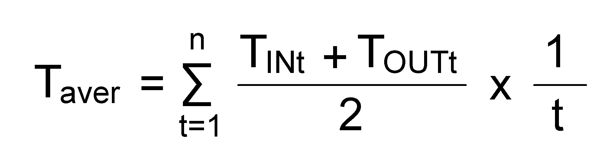
여기서, Taver는 평균 운전 온도이며, TIN은 반응기에 유입되는 배기가스의 온도이고, TOUT은 배기가스에서 배출된 배기가스의 온도이다. 그리고 t는 측정된 횟수를 의미한다.Here, Taver is the average operating temperature, T IN is the temperature of the exhaust gas flowing into the reactor, and T OUT is the temperature of the exhaust gas discharged from the exhaust gas. And t is the number of times measured.
그리고 평균 운전 온도를 기설정된 재생 주기 함수 그래프에 대입하여 재생 주기를 산출한다. 예를 들어, 산출된 평균 운전 온도(Taver)가 섭씨 380도라면, 이를 재생 주기 함수 그래프에 대입하여 재생 주기 선택할 수 있다. 도 4에서 섭씨 380도는 T3과 T4 사이에 위치할 수 있다.Then, the average cycle temperature is substituted into the predetermined cycle function graph to calculate the cycle of regeneration. For example, if the calculated average operating temperature (Taver) is 380 degrees Celsius, it can be substituted into the regeneration period function graph to select the regeneration period. In Figure 4, 380 degrees C can be located between T3 and T4.
다음, 배기가스에 함유된 질소산화물을 저감시키기 위한 운전이 시작된 후 산출된 재생 주기가 도래하면 촉매(350)를 재생시키게 된다. 이때, 촉매(350)의 재생은 버너 또는 히터를 사용하거나 엔진의 회전수를 증가시키는 방법으로 촉매(350)로 향하는 배기가스를 승온시켜 촉매(350)를 간접 가열함으로써 수행될 수 있다.Next, when the regeneration cycle calculated after the start of the operation for reducing the nitrogen oxide contained in the exhaust gas arrives, the
또한, 재생 주기는 촉매(350)의 재생을 완료한 후 배기가스에 함유된 질소산화물을 저감시키기 위한 운전이 재가동되면 다시 산출할 수 있다. 즉, 재생이 완료되면 재생 주기를 산출하는 전술한 바와 같은 동작을 반복해서 수행할 수 있다. 이와 같이, 재생 완료 후 질소산화물을 저감시키기 위한 운전이 재가동될 때 마다 실시간으로 재생 주기를 다시 산출하여 재생 주기의 정확성을 향상시킬 수 있다.Further, the regeneration cycle can be calculated again after the operation for reducing the nitrogen oxide contained in the exhaust gas is restarted after the regeneration of the
이와 같은 방법에 의하여, 본 발명의 일 실시예에 따른 질소산화물 저감 방법은 피독된 촉매(350)를 재생시키 위한 최적의 재생 주기를 실시간으로 산출하여 촉매의 이용 효율을 극대화시킬 수 있다.By this method, the nitrogen oxide reduction method according to an embodiment of the present invention can maximize the utilization efficiency of the catalyst by calculating an optimal regeneration cycle for regenerating the poisoned
이상 첨부된 도면을 참조하여 본 발명의 실시예를 설명하였지만, 본 발명이 속하는 기술분야의 당업자는 본 발명이 그 기술적 사상이나 필수적 특징을 변경하지 않고 다른 구체적인 형태로 실시될 수 있다는 것을 이해할 수 있을 것이다.While the present invention has been particularly shown and described with reference to exemplary embodiments thereof, it is evident that many alternatives, modifications and variations will be apparent to those skilled in the art. will be.
그러므로 이상에서 기술한 실시예는 모든 면에서 예시적인 것이며 한정적인 것이 아닌 것으로서 이해되어야 하고, 본 발명의 범위는 상기 상세한 설명은 후술하는 특허청구범위에 의하여 나타내어지며, 특허청구범위의 의미 및 범위 그리고 그 등가개념으로부터 도출되는 모든 변경 또는 변형된 형태가 본 발명의 범위에 포함되는 것으로 해석되어야 한다.It is therefore to be understood that the embodiments described above are to be considered in all respects only as illustrative and not restrictive, the scope of the invention being indicated by the appended claims, It is intended that all changes and modifications derived from the equivalent concept be included within the scope of the present invention.
100: 재생 장치
101: 선택적 촉매 환원 시스템
300: 반응기
350: 촉매
610: 배기 유로
700: 제어 장치
710: 제1 온도 센서
720: 제2 온도 센서100: playback device
101: Selective Catalytic Reduction System
300: reactor
350: catalyst
610:
700: Control device
710: first temperature sensor
720: second temperature sensor
Claims (15)
상기 배기 유로 상에 설치되어 배기가스에 함유된 질소산화물(NOx)을 저감시키기 위한 촉매가 내부에 설치된 반응기;
상기 촉매를 가열하여 재생시키는 재생 장치;
상기 반응기에 유입되는 배기가스의 온도를 측정하는 제1 온도 센서;
상기 반응기에서 배출되는 배기가스의 온도를 측정하는 제2 온도 센서; 및
상기 제1 온도 센서와 상기 제2 온도 센서로부터 전달받은 정보로 상기 촉매의 재생 시점을 산출하여 상기 재생 장치를 동작을 제어하는 제어 장치
를 포함하는 선택적 촉매 환원 시스템.An exhaust flow path through which exhaust gas containing nitrogen oxides (NOx) moves;
A reactor provided on the exhaust flow path and provided with a catalyst therein for reducing nitrogen oxides (NOx) contained in the exhaust gas;
A regenerator for heating and regenerating the catalyst;
A first temperature sensor for measuring the temperature of the exhaust gas flowing into the reactor;
A second temperature sensor for measuring the temperature of the exhaust gas discharged from the reactor; And
A controller for calculating the regeneration point of the catalyst with the information received from the first temperature sensor and the second temperature sensor and controlling the operation of the regenerator
≪ / RTI >
상기 재생 장치는 상기 반응기로 향하는 배기가스를 승온시키는 버너 또는 히터인 것을 특징으로 하는 선택적 촉매 환원 시스템.The method according to claim 1,
Wherein the regenerator is a burner or a heater for raising the temperature of the exhaust gas toward the reactor.
상기 재생 장치는 상기 배기가스를 배출하는 엔진이며,
상기 엔진은 상기 제어 장치의 제어에 따라 회전수를 증가시켜 배출되는 상기 배기가스의 온도를 상승시키는 것을 특징으로 하는 선택적 촉매 환원 시스템.The method according to claim 1,
Wherein the regeneration device is an engine for exhausting the exhaust gas,
Wherein the engine increases the number of revolutions in accordance with the control of the control device to raise the temperature of the exhaust gas discharged.
상기 제어 장치는 상기 제1 온도 센서 및 상기 제2 온도 센서에서 측정된 온도의 평균값을 적산하여 평균 운전 온도를 산출한 후, 상기 평균 운전 온도를 기설정된 재생 주기 함수 그래프에 대입하여 재생 주기를 산출하고, 상기 재생 주기가 도래하면 상기 재생 장치를 가동시키는 것을 특징으로 하는 선택적 촉매 환원 시스템.4. The method according to any one of claims 1 to 3,
The control device calculates an average operation temperature by integrating the average value of the temperatures measured by the first temperature sensor and the second temperature sensor and then substitutes the average operation temperature into the predetermined reproduction period function graph to calculate a reproduction period And when the regeneration cycle comes, activates the regenerating apparatus.
상기 기설정된 재생 주기 함수 그래프는 상기 촉매의 성능에 따라 최소 운전 온도와 최대 운전 온도를 결정하고, 상기 최소 운전 온도와 상기 최대 운전 온도 사이의 범위에서 복수의 임의 운전 온도를 선택한 후, 상기 복수의 임의 운전 온도마다 사용 시간 경과에 따른 상기 촉매의 효율 변화를 각각 측정하여 산출된 상기 복수의 임의 운전 온도별 재생 시점을 합산하여 도출된 것을 특징으로 하는 선택적 촉매 환원 시스템.5. The method of claim 4,
Wherein the predetermined regeneration period function graph determines a minimum operation temperature and a maximum operation temperature according to the performance of the catalyst and selects a plurality of optional operation temperatures in a range between the minimum operation temperature and the maximum operation temperature, And the regeneration times for the plurality of arbitrary operating temperatures calculated by measuring the efficiency changes of the catalyst with the elapse of use time for each of the arbitrary operating temperatures.
상기 임의 운전 온도별 재생 시점을 산출하기 위해 상기 촉매의 한계 효율을 먼저 결정하고, 상기 임의 운전 온도로 운전하였을 때 한계 효율에 도달하는데 걸리는 시간을 재생 시점으로 산출하는 것을 특징으로 하는 선택적 촉매 환원 시스템.6. The method of claim 5,
Wherein the regeneration time is calculated by first determining a limiting efficiency of the catalyst in order to calculate a regeneration point for each of the optional operating temperatures, .
상기 복수의 임의 운전 온도별 재생 시점을 산출할 때 상기 최소 운전 온도와 상기 최대 운전 온도에서의 재생 시점도 함께 산출하는 것을 특징으로 하는 선택적 촉매 환원 시스템.6. The method of claim 5,
Wherein the minimum operating temperature and the regeneration time at the maximum operating temperature are also calculated when the regeneration time for each of the plurality of optional operating temperatures is calculated.
상기 촉매로 향하는 배기가스와 상기 촉매를 거친 배기가스의 온도를 각각 측정하는 단계;
각각 측정된 상기 배기가스의 온도의 평균값을 적산하여 평균 운전 온도 산출하는 단계;
상기 평균 운전 온도를 기설정된 재생 주기 함수 그래프에 대입하여 재생 주기를 산출하는 단계; 및
상기 재생 주기가 도래하면 상기 촉매를 재생시키는 단계
를 포함하는 질소산화물 저감 방법.A nitrogen oxide reduction method for reducing nitrogen oxide contained in an exhaust gas using a catalyst,
Measuring the temperature of the exhaust gas flowing toward the catalyst and the exhaust gas passing through the catalyst, respectively;
Calculating an average operation temperature by integrating the average value of the temperatures of the exhaust gases measured respectively;
Calculating a reproduction period by substituting the average operation temperature into a predetermined reproduction period function graph; And
Regenerating the catalyst when the regeneration cycle comes
/ RTI >
상기 촉매로 향하는 배기가스를 승온시킴으로써 상기 촉매를 가열하여 재생하는 것을 특징으로 하는 질소산화물 저감 방법.9. The method of claim 8,
Wherein the catalyst is heated and regenerated by raising the temperature of the exhaust gas toward the catalyst.
상기 배기가스는 버너 또는 히터를 사용하여 승온시키는 것을 특징으로 하는 질소산화물 저감 방법.10. The method of claim 9,
Wherein the exhaust gas is heated by using a burner or a heater.
상기 배기가스는 엔진에서 배출되며,
상기 엔진의 회전수를 증가시켜 배출되는 상기 배기가스의 온도를 상승시키는 것을 특징으로 하는 질소산화물 저감 방법.10. The method of claim 9,
The exhaust gas is discharged from the engine,
Wherein the temperature of the exhaust gas discharged is increased by increasing the number of revolutions of the engine.
상기 재생 주기는 상기 촉매의 재생을 완료한 후 재산출하는 것을 특징으로 하는 질소산화물 저감 방법.9. The method of claim 8,
Wherein the regeneration cycle is performed after completion of regeneration of the catalyst.
상기 촉매의 성능에 따라 최소 운전 온도와 최대 운전 온도를 결정하는 단계;
상기 최소 운전 온도와 상기 최대 운전 온도 사이의 범위에서 복수의 임의 운전 온도를 선택하는 단계;
상기 복수의 임의 운전 온도마다 사용 시간 경과에 따른 상기 촉매의 효율 변화를 측정하여 상기 복수의 임의 운전 온도별 재생 시점를 산출하는 단계; 및
상기 복수의 임의 운전 온도별 재생 시점을 합산하여 상기 재생 주기 함수 그래프를 도출하는 단계
를 더 포함하는 것을 특징으로 하는 질소산화물 저감 방법.13. The method according to any one of claims 8 to 12,
Determining a minimum operating temperature and a maximum operating temperature according to the performance of the catalyst;
Selecting a plurality of optional operating temperatures in a range between the minimum operating temperature and the maximum operating temperature;
Measuring a change in efficiency of the catalyst according to the elapsed use time for each of the plurality of arbitrary operating temperatures and calculating a reproduction time point for each of the plurality of arbitrary operating temperatures; And
Deriving the reproduction period function graph by summing the reproduction times of the plurality of arbitrary operating temperatures
Further comprising the step of removing nitrogen oxides.
상기 임의 운전 온도별 재생 시점을 산출하기 위해 상기 촉매의 한계 효율을 먼저 결정하고,
상기 임의 운전 온도로 운전하였을 때 한계 효율에 도달하는데 걸리는 시간을 재생 시점으로 산출하는 것을 특징으로 하는 질소산화물 저감 방법.14. The method of claim 13,
The limiting efficiency of the catalyst is first determined to calculate the regeneration point for each of the operating temperatures,
Wherein the time required for reaching the marginal efficiency is calculated as the regeneration time when the engine is operated at the arbitrary operating temperature.
상기 복수의 임의 운전 온도별 재생 시점을 산출하는 단계에서 상기 최소 운전 온도와 상기 최대 운전 온도에서의 재생 시점도 함께 산출하는 것을 특징으로 하는 질소산화물 저감 방법.14. The method of claim 13,
Wherein the step of calculating the regeneration time for each of the plurality of arbitrary operating temperatures also calculates the minimum operating temperature and the regeneration time at the maximum operating temperature.
Priority Applications (1)
| Application Number | Priority Date | Filing Date | Title |
|---|---|---|---|
| KR1020170175701A KR102506271B1 (en) | 2017-12-20 | 2017-12-20 | SELECTIVE CATALYTIC REDUCTION SYSTEM AND NOx REDUCTION METHOD |
Applications Claiming Priority (1)
| Application Number | Priority Date | Filing Date | Title |
|---|---|---|---|
| KR1020170175701A KR102506271B1 (en) | 2017-12-20 | 2017-12-20 | SELECTIVE CATALYTIC REDUCTION SYSTEM AND NOx REDUCTION METHOD |
Publications (2)
| Publication Number | Publication Date |
|---|---|
| KR20190074394A true KR20190074394A (en) | 2019-06-28 |
| KR102506271B1 KR102506271B1 (en) | 2023-03-07 |
Family
ID=67065962
Family Applications (1)
| Application Number | Title | Priority Date | Filing Date |
|---|---|---|---|
| KR1020170175701A Active KR102506271B1 (en) | 2017-12-20 | 2017-12-20 | SELECTIVE CATALYTIC REDUCTION SYSTEM AND NOx REDUCTION METHOD |
Country Status (1)
| Country | Link |
|---|---|
| KR (1) | KR102506271B1 (en) |
Cited By (3)
| Publication number | Priority date | Publication date | Assignee | Title |
|---|---|---|---|---|
| CN112403259A (en) * | 2020-11-17 | 2021-02-26 | 江苏绿都环境工程有限公司 | An SCR desulfurization method based on intelligent adjustment of flue gas concentration |
| KR20220048720A (en) * | 2020-10-13 | 2022-04-20 | 한국조선해양 주식회사 | Exhaust gas treatment apparatus for ship |
| KR20220048721A (en) * | 2020-10-13 | 2022-04-20 | 한국조선해양 주식회사 | Exhaust gas treatment apparatus for ship |
Citations (2)
| Publication number | Priority date | Publication date | Assignee | Title |
|---|---|---|---|---|
| KR20110064374A (en) * | 2009-12-08 | 2011-06-15 | 대우조선해양 주식회사 | Exhaust gas denitrification system |
| KR101708129B1 (en) * | 2015-10-30 | 2017-02-17 | 두산엔진주식회사 | Power plant with selective catalytic reduction system and control method for the smae |
-
2017
- 2017-12-20 KR KR1020170175701A patent/KR102506271B1/en active Active
Patent Citations (2)
| Publication number | Priority date | Publication date | Assignee | Title |
|---|---|---|---|---|
| KR20110064374A (en) * | 2009-12-08 | 2011-06-15 | 대우조선해양 주식회사 | Exhaust gas denitrification system |
| KR101708129B1 (en) * | 2015-10-30 | 2017-02-17 | 두산엔진주식회사 | Power plant with selective catalytic reduction system and control method for the smae |
Cited By (4)
| Publication number | Priority date | Publication date | Assignee | Title |
|---|---|---|---|---|
| KR20220048720A (en) * | 2020-10-13 | 2022-04-20 | 한국조선해양 주식회사 | Exhaust gas treatment apparatus for ship |
| KR20220048721A (en) * | 2020-10-13 | 2022-04-20 | 한국조선해양 주식회사 | Exhaust gas treatment apparatus for ship |
| CN112403259A (en) * | 2020-11-17 | 2021-02-26 | 江苏绿都环境工程有限公司 | An SCR desulfurization method based on intelligent adjustment of flue gas concentration |
| CN112403259B (en) * | 2020-11-17 | 2022-04-26 | 江苏绿都环境工程有限公司 | An SCR desulfurization method based on intelligent adjustment of flue gas concentration |
Also Published As
| Publication number | Publication date |
|---|---|
| KR102506271B1 (en) | 2023-03-07 |
Similar Documents
| Publication | Publication Date | Title |
|---|---|---|
| US9181835B2 (en) | Supervisory model predictive selective catalytic reduction control method | |
| CN101680332A (en) | NOx purification system and method for controlling NOx purification system | |
| US9228468B2 (en) | Targeted regeneration of a catalyst in an aftertreatment system | |
| US10436089B2 (en) | Radio frequency sensor in an exhaust aftertreatment system | |
| KR102506271B1 (en) | SELECTIVE CATALYTIC REDUCTION SYSTEM AND NOx REDUCTION METHOD | |
| KR102057778B1 (en) | Selective catalytic reduction system | |
| JP4983536B2 (en) | Exhaust gas purification system for internal combustion engine | |
| KR101344123B1 (en) | Selective catalytic reuction system with movable regeneration heater | |
| KR102527191B1 (en) | Selective catalytic reduction system | |
| US11739675B2 (en) | Exhaust gas after-treatment system | |
| KR101708129B1 (en) | Power plant with selective catalytic reduction system and control method for the smae | |
| KR102735619B1 (en) | Selective catalytic reduction system | |
| KR102067851B1 (en) | Selective catalytic reduction system | |
| CN113454315B (en) | Method and device for controlling at least one SCR catalytic converter of a vehicle | |
| KR102447700B1 (en) | Selective catalytic reduction system and nitrogen oxide reduction method | |
| EP2410144A1 (en) | Method of Controlling NOx Emissions in an Internal Combustion Engine | |
| RU2604656C2 (en) | Optimized control over selective catalytic reduction catalyst (scr) by means of particles filter-trap periodic regeneration | |
| US10526947B2 (en) | Exhaust aftertreatment system | |
| KR102451900B1 (en) | Exhaust gas post processing system and control method thereof | |
| KR20210076225A (en) | Selective catalytic reduction system | |
| KR102367285B1 (en) | Selective catalytic reduction system | |
| KR101708125B1 (en) | Power plant with selective catalytic reuction system | |
| KR102539410B1 (en) | Method for Activation of Vehicle Aftertreatment System Using Exhaust Gas Temperature Increase | |
| KR20200058852A (en) | Gas heating system | |
| KR102563490B1 (en) | Regeneration control method for improving durability of exhaust gas purification system |
Legal Events
| Date | Code | Title | Description |
|---|---|---|---|
| PA0109 | Patent application |
Patent event code: PA01091R01D Comment text: Patent Application Patent event date: 20171220 |
|
| PG1501 | Laying open of application | ||
| PA0201 | Request for examination |
Patent event code: PA02012R01D Patent event date: 20201119 Comment text: Request for Examination of Application Patent event code: PA02011R01I Patent event date: 20171220 Comment text: Patent Application |
|
| E902 | Notification of reason for refusal | ||
| PE0902 | Notice of grounds for rejection |
Comment text: Notification of reason for refusal Patent event date: 20220329 Patent event code: PE09021S01D |
|
| AMND | Amendment | ||
| E601 | Decision to refuse application | ||
| PE0601 | Decision on rejection of patent |
Patent event date: 20221027 Comment text: Decision to Refuse Application Patent event code: PE06012S01D Patent event date: 20220329 Comment text: Notification of reason for refusal Patent event code: PE06011S01I |
|
| X091 | Application refused [patent] | ||
| AMND | Amendment | ||
| PX0901 | Re-examination |
Patent event code: PX09011S01I Patent event date: 20221027 Comment text: Decision to Refuse Application Patent event code: PX09012R01I Patent event date: 20220530 Comment text: Amendment to Specification, etc. |
|
| PX0701 | Decision of registration after re-examination |
Patent event date: 20230119 Comment text: Decision to Grant Registration Patent event code: PX07013S01D Patent event date: 20230103 Comment text: Amendment to Specification, etc. Patent event code: PX07012R01I Patent event date: 20221027 Comment text: Decision to Refuse Application Patent event code: PX07011S01I Patent event date: 20220530 Comment text: Amendment to Specification, etc. Patent event code: PX07012R01I |
|
| X701 | Decision to grant (after re-examination) | ||
| GRNT | Written decision to grant | ||
| PR0701 | Registration of establishment |
Comment text: Registration of Establishment Patent event date: 20230228 Patent event code: PR07011E01D |
|
| PR1002 | Payment of registration fee |
Payment date: 20230302 End annual number: 3 Start annual number: 1 |
|
| PG1601 | Publication of registration |