KR20190021336A - Golf club head with self-adjusting weighting system - Google Patents
Golf club head with self-adjusting weighting system Download PDFInfo
- Publication number
- KR20190021336A KR20190021336A KR1020197001486A KR20197001486A KR20190021336A KR 20190021336 A KR20190021336 A KR 20190021336A KR 1020197001486 A KR1020197001486 A KR 1020197001486A KR 20197001486 A KR20197001486 A KR 20197001486A KR 20190021336 A KR20190021336 A KR 20190021336A
- Authority
- KR
- South Korea
- Prior art keywords
- magnet
- weight
- club head
- golf club
- magnets
- Prior art date
- Legal status (The legal status is an assumption and is not a legal conclusion. Google has not performed a legal analysis and makes no representation as to the accuracy of the status listed.)
- Granted
Links
Images


Classifications
-
- A—HUMAN NECESSITIES
- A63—SPORTS; GAMES; AMUSEMENTS
- A63B—APPARATUS FOR PHYSICAL TRAINING, GYMNASTICS, SWIMMING, CLIMBING, OR FENCING; BALL GAMES; TRAINING EQUIPMENT
- A63B60/00—Details or accessories of golf clubs, bats, rackets or the like
- A63B60/02—Ballast means for adjusting the centre of mass
-
- A—HUMAN NECESSITIES
- A63—SPORTS; GAMES; AMUSEMENTS
- A63B—APPARATUS FOR PHYSICAL TRAINING, GYMNASTICS, SWIMMING, CLIMBING, OR FENCING; BALL GAMES; TRAINING EQUIPMENT
- A63B53/00—Golf clubs
- A63B53/04—Heads
- A63B53/0433—Heads with special sole configurations
-
- A—HUMAN NECESSITIES
- A63—SPORTS; GAMES; AMUSEMENTS
- A63B—APPARATUS FOR PHYSICAL TRAINING, GYMNASTICS, SWIMMING, CLIMBING, OR FENCING; BALL GAMES; TRAINING EQUIPMENT
- A63B53/00—Golf clubs
- A63B53/04—Heads
- A63B53/0445—Details of grooves or the like on the impact surface
-
- A—HUMAN NECESSITIES
- A63—SPORTS; GAMES; AMUSEMENTS
- A63B—APPARATUS FOR PHYSICAL TRAINING, GYMNASTICS, SWIMMING, CLIMBING, OR FENCING; BALL GAMES; TRAINING EQUIPMENT
- A63B53/00—Golf clubs
- A63B53/04—Heads
- A63B53/0466—Heads wood-type
-
- A—HUMAN NECESSITIES
- A63—SPORTS; GAMES; AMUSEMENTS
- A63B—APPARATUS FOR PHYSICAL TRAINING, GYMNASTICS, SWIMMING, CLIMBING, OR FENCING; BALL GAMES; TRAINING EQUIPMENT
- A63B53/00—Golf clubs
- A63B53/04—Heads
- A63B53/047—Heads iron-type
-
- A—HUMAN NECESSITIES
- A63—SPORTS; GAMES; AMUSEMENTS
- A63B—APPARATUS FOR PHYSICAL TRAINING, GYMNASTICS, SWIMMING, CLIMBING, OR FENCING; BALL GAMES; TRAINING EQUIPMENT
- A63B53/00—Golf clubs
- A63B53/04—Heads
- A63B53/0487—Heads for putters
-
- A—HUMAN NECESSITIES
- A63—SPORTS; GAMES; AMUSEMENTS
- A63B—APPARATUS FOR PHYSICAL TRAINING, GYMNASTICS, SWIMMING, CLIMBING, OR FENCING; BALL GAMES; TRAINING EQUIPMENT
- A63B53/00—Golf clubs
- A63B53/04—Heads
- A63B53/06—Heads adjustable
-
- A—HUMAN NECESSITIES
- A63—SPORTS; GAMES; AMUSEMENTS
- A63B—APPARATUS FOR PHYSICAL TRAINING, GYMNASTICS, SWIMMING, CLIMBING, OR FENCING; BALL GAMES; TRAINING EQUIPMENT
- A63B53/00—Golf clubs
- A63B53/08—Golf clubs with special arrangements for obtaining a variable impact
-
- A—HUMAN NECESSITIES
- A63—SPORTS; GAMES; AMUSEMENTS
- A63B—APPARATUS FOR PHYSICAL TRAINING, GYMNASTICS, SWIMMING, CLIMBING, OR FENCING; BALL GAMES; TRAINING EQUIPMENT
- A63B60/00—Details or accessories of golf clubs, bats, rackets or the like
- A63B60/02—Ballast means for adjusting the centre of mass
- A63B60/04—Movable ballast means
-
- A—HUMAN NECESSITIES
- A63—SPORTS; GAMES; AMUSEMENTS
- A63B—APPARATUS FOR PHYSICAL TRAINING, GYMNASTICS, SWIMMING, CLIMBING, OR FENCING; BALL GAMES; TRAINING EQUIPMENT
- A63B60/00—Details or accessories of golf clubs, bats, rackets or the like
- A63B60/42—Devices for measuring, verifying, correcting or customising the inherent characteristics of golf clubs, bats, rackets or the like, e.g. measuring the maximum torque a batting shaft can withstand
-
- A63B2053/0433—
-
- A63B2053/0445—
-
- A—HUMAN NECESSITIES
- A63—SPORTS; GAMES; AMUSEMENTS
- A63B—APPARATUS FOR PHYSICAL TRAINING, GYMNASTICS, SWIMMING, CLIMBING, OR FENCING; BALL GAMES; TRAINING EQUIPMENT
- A63B53/00—Golf clubs
- A63B53/04—Heads
- A63B53/047—Heads iron-type
- A63B2053/0479—Wedge-type clubs, details thereof
-
- A—HUMAN NECESSITIES
- A63—SPORTS; GAMES; AMUSEMENTS
- A63B—APPARATUS FOR PHYSICAL TRAINING, GYMNASTICS, SWIMMING, CLIMBING, OR FENCING; BALL GAMES; TRAINING EQUIPMENT
- A63B53/00—Golf clubs
- A63B53/04—Heads
- A63B2053/0491—Heads with added weights, e.g. changeable, replaceable
-
- A—HUMAN NECESSITIES
- A63—SPORTS; GAMES; AMUSEMENTS
- A63B—APPARATUS FOR PHYSICAL TRAINING, GYMNASTICS, SWIMMING, CLIMBING, OR FENCING; BALL GAMES; TRAINING EQUIPMENT
- A63B53/00—Golf clubs
- A63B53/04—Heads
- A63B2053/0491—Heads with added weights, e.g. changeable, replaceable
- A63B2053/0495—Heads with added weights, e.g. changeable, replaceable moving on impact, slidable, spring or otherwise elastically biased
-
- A—HUMAN NECESSITIES
- A63—SPORTS; GAMES; AMUSEMENTS
- A63B—APPARATUS FOR PHYSICAL TRAINING, GYMNASTICS, SWIMMING, CLIMBING, OR FENCING; BALL GAMES; TRAINING EQUIPMENT
- A63B2102/00—Application of clubs, bats, rackets or the like to the sporting activity ; particular sports involving the use of balls and clubs, bats, rackets, or the like
- A63B2102/32—Golf
-
- A—HUMAN NECESSITIES
- A63—SPORTS; GAMES; AMUSEMENTS
- A63B—APPARATUS FOR PHYSICAL TRAINING, GYMNASTICS, SWIMMING, CLIMBING, OR FENCING; BALL GAMES; TRAINING EQUIPMENT
- A63B2209/00—Characteristics of used materials
- A63B2209/08—Characteristics of used materials magnetic
Landscapes
- Health & Medical Sciences (AREA)
- General Health & Medical Sciences (AREA)
- Physical Education & Sports Medicine (AREA)
- Life Sciences & Earth Sciences (AREA)
- Engineering & Computer Science (AREA)
- Wood Science & Technology (AREA)
- Biophysics (AREA)
- Golf Clubs (AREA)
Abstract
골프 클럽 헤드는 소울에 대향하는 크라운, 힐 단부에 대향하는 토오 단부, 후방 단부, 및 호젤(hosel)을 갖는 클럽 바디를 포함한다. 제1 자석이 클럽 바디에 커플링된다. 제2 자석이 제1 자석과 선택적으로 결합하여, 제1 구성에서 제1 자석과 제2 자석은 끌어당기고, 제2 구성에서 제1 자석과 제2 자석은 끌어당기지 않게 되며, 제2 자석은 제1 구성과 제2 구성 간에 제1 자석에 대해 회전하도록 구성된다.The golf club head includes a club body having a crown opposed to the soul, a toe end opposite the heel end, a rear end, and a hosel. The first magnet is coupled to the club body. The second magnet selectively engages with the first magnet such that the first magnet and the second magnet attract in the first configuration and the first magnet and the second magnet do not attract in the second configuration, 1 configuration and the second configuration with respect to the first magnet.
Description
관련 출원의 상호 참조Cross reference of related application
본 출원은 그 내용이 본 명세서에 참조로서 완전히 합체되어 있는, 2017년 5월 3일 출원된 미국 가특허 출원 제62/500,629호, 2016년 10월 28일 출원된 미국 가특허 출원 제62/414,566호, 및 2016년 6월 17일 출원된 미국 가특허 출원 제62/351,804호의 이익을 청구한다.This application claims the benefit of US Provisional Patent Application No. 62 / 500,629, filed May 3, 2017, which is incorporated herein by reference in its entirety, and US Provisional Patent Application No. 62 / 414,566, filed October 28, And U.S. Provisional Patent Application No. 62 / 351,804, filed on June 17, 2016, all of which are incorporated herein by reference.
발명의 분야Field of invention
본 개시내용은 골프 클럽(golf club)에 관한 것으로서, 더 구체적으로는 골프 클럽 헤드로의 웨이트(weight)의 선택적 부착 및 제거를 용이하게 하기 위한 골프 클럽 헤드용 조정 가능 자기 웨이팅 시스템(adjustable magnetic weighting system)에 관한 것이다.The present disclosure relates to a golf club and more particularly to an adjustable magnetic weighting system for a golf club head for facilitating selective attachment and removal of a weight to a golf club head system.
골프 클럽은, 예를 들어, 우드, 하이브리드, 아이언, 웨지, 또는 퍼터와 같은 다양한 형태를 취하고, 이들 클럽은 일반적으로 헤드 형상 및 디자인(예를 들어, 우드와 아이언 사이의 차이 등), 클럽 헤드 재료(들), 샤프트 재료(들), 클럽 길이, 및 클럽 로프트(loft)에 있어서 상이하다.Golf clubs take various forms such as, for example, wood, hybrid, iron, wedge, or putter, and these clubs generally have a head shape and design (e.g., a difference between wood and iron) The material (s), the shaft material (s), the club length, and the club loft.
골프 클럽 헤드의 무게 중심, 관성 모멘트, 및 웨이트 편향(weight bias)은 골프 클럽 헤드의 질량의 분포의 함수이다. 특히, 클럽 헤드의 소울부(sole portion)에 더 근접하게, 클럽 헤드의 타격면(strikeface)에 더 근접하게, 그리고/또는 클럽 헤드의 토오부(toe portion) 및 힐부(heel portion)에 더 근접하게 클럽 헤드의 질량을 분포하는 것은 클럽 헤드의 무게 중심, 관성 모멘트, 및/또는 웨이트 편향을 변경할 수 있다. 클럽 헤드의 무게 중심을 변경하는 것은, 골프공의 론치각(launch angle), 골프공의 스핀 속도(spin rate), 및/또는 골프공의 비행각(flight angle)을 변경할 수 있다. 클럽 헤드의 관성 모멘트를 변경하는 것은 골프 클럽의 관용성(forgiveness), 골프공의 비행 방향, 및/또는 골프공의 비행각을 변경할 수 있다. 골프공의 비행각을 증가시키는 것은 골프공이 진행하는 거리를 증가시킬 수 있다. 골프 클럽의 웨이트 편향을 변경하는 것은 골프공의 공 비행, 및/또는 골프 클럽 헤드 스위트 스팟(sweet spot)의 위치를 조정할 수 있다. 예를 들어, 골프 클럽 헤드의 토오 단부를 향한 더 많은 웨이트는 페이드(fade)[또는 슬라이스(slice)] 편향을 부여할 것이어서, 공이 페이드(또는 슬라이스) 궤적을 갖고 진행하는 가능성을 증가시킨다. 유사하게, 골프 클럽 헤드의 힐 단부를 향한 더 많은 웨이트는 드로우(draw)[또는 훅(hook)] 편향을 부여할 것이어서, 공이 드로우(또는 훅) 궤적을 갖고 진행하는 가능성을 증가시킨다.The center of gravity, the moment of inertia, and the weight bias of the golf club head are a function of the distribution of the mass of the golf club head. In particular, it is more closely located to the sole portion of the club head, closer to the strikeface of the club head, and / or closer to the toe portion and heel portion of the club head The distribution of the mass of the club head may change the center of gravity of the club head, the moment of inertia, and / or the weight deflection. Changing the center of gravity of the club head may change the launch angle of the golf ball, the spin rate of the golf ball, and / or the flight angle of the golf ball. Changing the club head's moment of inertia may change the forgiveness of the golf club, the flight direction of the golf ball, and / or the flight angle of the golf ball. Increasing the flight angle of a golf ball can increase the distance traveled by the golf ball. Changing the weight deflection of the golf club may adjust the position of the ball flight of the golf ball, and / or the golf club head sweet spot. For example, more weight toward the end of the golf club head's head will give fade (or slice) deflection, increasing the likelihood that the ball will advance with a fade (or slice) trajectory. Similarly, more weight towards the heel end of the golf club head will impart draw (or hook) deflection, increasing the likelihood that the ball will advance with a draw (or hook) trajectory.
골프 클럽의 스윙웨이트(swingweight)는 골프 클럽의 웨이트의 분포의 함수이다. 그립 단부에 대한 클럽 헤드 내의 웨이트의 양의 증가는 스윙웨이트의 증가를 야기할 것이다(그리고, 클럽은 스윙 중에 더 무겁게 느껴질 것임). 역으로, 그립 단부에 대한 클럽 헤드 내의 웨이트의 양의 감소는 스윙웨이트의 감소를 야기할 것이다(그리고, 클럽은 스윙 중에 더 가볍게 느껴질 것임).The swing weight of a golf club is a function of the distribution of the weight of the golf club. An increase in the amount of weight in the club head relative to the grip end will cause an increase in swing weight (and the club will feel heavier during the swing). Conversely, a reduction in the amount of weight in the club head relative to the grip end will cause a reduction in the swing weight (and the club will feel lighter during the swing).
골프 클럽은 다양한 공지의 디자인을 갖지만, 웨이트 분포 맞춤화를 향상시키기 위해 골프 클럽 헤드 상의 질량의 분포의 조정 가능성에 대한 요구가 존재한다. 이는 골프 클럽의 관용성, 스핀 속도, 비행각, 비행 궤적, 스윙웨이트, 및/또는 피드백(또는 "클럽 감각")을 조정하기 위해 플레이어가 무게 중심 위치, 관성 모멘트, 웨이트 편향, 웨이트 분포, 및 스윙웨이트 중 하나 이상을 맞춤화하는 것을 허용할 수 있다.Golf clubs have a variety of known designs, but there is a need for adjustability of the distribution of mass on the golf club head to improve weight distribution customization. This allows the player to adjust the center of gravity position, the moment of inertia, the weight deflection, the weight distribution, and the swing (or " club feel ") to adjust the golf club's usability, spin rate, flight angle, flight path, swing weight, We may allow to customize one or more of the weights.
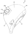
도 1은 골프 클럽 헤드의 실시예의 사시도이다.
도 2는 페이스 플레이트(face plate)를 도시하고 있는, 도 1의 클럽 헤드의 제1 측면도이다.
도 3은 도 1의 클럽 헤드의 평면도(또는 크라운도)이다.
도 4는 자기 조정 가능 웨이팅 시스템의 실시예를 도시하고 있는, 페이스 플레이트를 향해 후방으로부터 본 도 1의 골프 클럽의 소울의 사시도이다.
도 5는 도 4의 소울의 다른 사시도이다.
도 6은 자석들이 끌어당기는 제1 구성에서 제1 자석 및 제2 자석을 도시하고 있는, 도 1의 골프 클럽 헤드에 웨이트를 부착하기 위한 자석 조립체의 사시도이다.
도 7은 자석들이 밀어내는 제2 구성에서 제1 자석 및 제2 자석을 도시하고 있는 도 6의 자석 조립체의 사시도이다.
도 8a, 도 8b, 및 도 8c는 자기 조정 가능 웨이팅 시스템의 다른 실시예를 도시하고 있는, 도 1의 골프 클럽의 소울의 사시도이다.
도 9는 자기 조정 가능 웨이팅 시스템의 또 다른 실시예를 도시하고 있는, 도 1의 골프 클럽의 소울의 사시도이다.
도 10a, 도 10b, 및 도 10c는 자기 조정 가능 웨이팅 시스템의 다른 실시예를 도시하고 있는, 도 1의 골프 클럽 헤드의 소울의 사시도이다.
도 11은 자기 조정 가능 웨이팅 시스템의 다른 실시예를 도시하고 있는, 퍼터 골프 클럽 헤드의 사시도이다.
도 12는 제거된 상태의 웨이트를 도시하고 있는, 도 11의 골프 클럽 헤드의 사시도이다.1 is a perspective view of an embodiment of a golf club head.
Figure 2 is a first side view of the club head of Figure 1 showing a face plate.
3 is a plan view (or crown diagram) of the club head of Fig.
4 is a perspective view of the soul of the golf club of Fig. 1 viewed from the rear toward the face plate, showing an embodiment of a self-adjusting weighting system.
Figure 5 is another perspective view of the soul of Figure 4;
6 is a perspective view of a magnet assembly for attaching a weight to the golf club head of FIG. 1, showing a first magnet and a second magnet in a first configuration in which magnets are pulled.
Figure 7 is a perspective view of the magnet assembly of Figure 6 showing the first magnet and the second magnet in a second configuration in which the magnets push out.
8A, 8B, and 8C are perspective views of the soul of the golf club of Fig. 1 showing another embodiment of a self-adjusting weighting system.
Figure 9 is a perspective view of the soul of the golf club of Figure 1 showing another embodiment of a self-adjusting weighting system.
10A, 10B, and 10C are perspective views of the soul of the golf club head of FIG. 1 showing another embodiment of a self-adjusting weighting system.
11 is a perspective view of a putter golf club head showing another embodiment of a self-adjusting weighting system.
Figure 12 is a perspective view of the golf club head of Figure 11 showing the weight in the removed condition.
프로그램 가능 자석을 포함하는 조정 가능 웨이팅 시스템을 갖는 골프 클럽 헤드의 실시예가 본 명세서에 설명된다. 다수의 실시예는 클럽 헤드 무게 중심 및/또는 관성 모멘트를 변화하기 위해 다양한 질량의 자석 또는 웨이트로 교체되거나 재배치될 수 있는 프로그램 가능 자석의 하나 이상의 세트를 포함한다. 이에 따라, 프로그램 가능 자석을 갖는 조정 가능 웨이팅 시스템은 공 스핀 및/또는 궤적을 변경하기 위해 골퍼에 의해 사용될 수 있다. 또한, 프로그램 가능 자석을 갖는 조정 가능 웨이팅 시스템은 클럽 피팅 중에 공 스핀 및/또는 궤적을 변경하는 데 사용될 수 있다.An embodiment of a golf club head having an adjustable weighting system including a programmable magnet is described herein. Many embodiments include one or more sets of programmable magnets that can be replaced or repositioned with various masses of magnets or weights to vary the club head center of gravity and / or moment of inertia. Accordingly, an adjustable weighting system with a programmable magnet can be used by the golfer to change the ball spin and / or trajectory. In addition, an adjustable weighting system with programmable magnets can be used to alter the ball spin and / or trajectory during club fitting.
하나의 실시예는 소울에 대향하는 크라운, 힐 단부에 대향하는 토오 단부, 후방 단부, 및 호젤(hosel)을 갖는 클럽 바디를 갖는 골프 클럽을 포함한다. 골프 클럽 헤드는 클럽 바디에 커플링되도록 구성된 제1 자석을 또한 포함한다. 제2 자석은 제1 자석과 선택적으로 결합 가능하여, 제1 구성에서 제1 자석과 제2 자석이 끌어당기고, 제2 구성에서 제1 자석과 제2 자석이 끌어당기지 않게 된다. 제2 자석은 제1 구성과 제2 구성 간에 제1 자석에 대해 회전하도록 구성된다.One embodiment includes a golf club having a club body with a crown opposed to the soul, a toe end opposite the heel end, a rear end, and a hosel. The golf club head also includes a first magnet configured to couple to the club body. The second magnet is selectively engageable with the first magnet such that the first magnet and the second magnet are attracted in the first configuration and the first magnet and the second magnet are not attracted in the second configuration. The second magnet is configured to rotate relative to the first magnet between the first and second configurations.
다른 실시예에서, 골프 클럽 헤드는 소울에 대향하는 크라운, 힐 단부에 대향하는 토오 단부, 후방 단부, 및 호젤을 갖는 클럽 바디를 포함한다. 채널이 소울 내에 형성된다. 프로그램된 자석 쌍은 제1 자석 및 제2 자석을 포함한다. 제1 자석은 채널 내에 위치된다. 제2 자석은 제1 자석에 작동적으로 커플링하도록 구성된다. 제1 구성에서, 제1 자석과 제2 자석은 끌어당기고, 제2 구성에서 제1 자석과 제2 자석은 끌어당기지 않는다.In another embodiment, the golf club head includes a club body having a crown opposed to the soul, a toe end opposite the toe end, a back end, and a hosel. The channel is formed in the soul. The programmed magnet pair includes a first magnet and a second magnet. The first magnet is located in the channel. The second magnet is configured to operatively couple to the first magnet. In the first configuration, the first magnet and the second magnet are attracted, and in the second configuration, the first magnet and the second magnet do not attract.
다른 실시예에서, 골프 클럽 헤드는 소울에 대향하는 크라운, 힐 단부에 대향하는 토오 단부, 후방 단부, 및 호젤을 갖는 클럽 바디를 포함한다. 프로그램된 자석 쌍은 제1 자석 및 제2 자석을 포함한다. 제1 자석은 클럽 바디에 커플링되도록 구성되고, 제2 자석은 제1 자석에 선택적으로 커플링하도록 구성된다.In another embodiment, the golf club head includes a club body having a crown opposed to the soul, a toe end opposite the toe end, a back end, and a hosel. The programmed magnet pair includes a first magnet and a second magnet. The first magnet is configured to be coupled to the club body and the second magnet is configured to selectively couple to the first magnet.
또 다른 실시예에서, 골프 클럽 헤드는 소울에 대향하는 크라운, 힐 단부에 대향하는 토오 단부, 후방 단부, 및 호젤을 갖는 클럽 바디를 포함한다. 제1 자석이 클럽 바디에 커플링된다. 제2 자석이 제1 자석에 작동적으로 연결하도록 구성되고, 제3 자석이 제1 자석에 작동적으로 연결하도록 구성된다. 제1 및 제2 자석은 제1 프로그램된 자석 쌍이고, 제1 및 제3 자석은 제2 프로그램된 자석 쌍이다.In another embodiment, the golf club head includes a club body having a crown opposed to the soul, a toe end opposite the toe end, a back end, and a hosel. The first magnet is coupled to the club body. The second magnet is configured to operatively connect to the first magnet, and the third magnet is configured to operatively connect to the first magnet. The first and second magnets are a first programmed magnet pair, and the first and third magnets are a second programmed magnet pair.
용어 골프 클럽의 "로프트" 또는 "로프트각"은 본 명세서에 설명될 때, 임의의 적합한 로프트 및 라이(lie) 기계에 의해 측정된 바와 같은, 클럽 페이스와 샤프트 사이에 형성된 각도를 칭한다.The term "loft" or "loft angle" of a golf club refers to an angle formed between the club face and the shaft, as measured by any suitable loft and lie machine as described herein.
상세한 설명 및 청구범위에서 용어 "제1", "제2", "제3", "제4" 등은 존재하면, 유사한 요소들을 구별하기 위해 사용되고 반드시 특정 순차적 또는 연대적 순서를 기술하기 위한 것은 아니다. 이와 같이 사용된 용어는 적절한 상황 하에서 상호교환 가능하여, 본 명세서에 설명된 실시예가 예를 들어, 본 명세서에 예시되거나 또는 다른 방식으로 설명된 것들 이외의 시퀀스로 동작이 가능하게 된다는 것이 이해되어야 한다. 더욱이, 용어 "포함한다" 및 "구비한다" 및 이들의 임의의 변형은 비배타적인 포함을 커버하도록 의도되어, 요소의 리스트를 포함하는 프로세스, 방법, 시스템, 물품, 디바이스, 또는 장치가 반드시 이들 요소에 한정되는 것은 아니고, 명시적으로 열거되거나 또는 이러한 프로세스, 방법, 시스템, 물품, 디바이스, 또는 장치에 고유하지 않은 다른 요소를 포함할 수도 있다.The terms "first", "second", "third", "fourth", etc., when used in the description and claims, are used to distinguish similar elements and are not necessarily intended to describe a particular sequential or chronological order . It is to be understood that such used terms are interchangeable under appropriate circumstances, so that the embodiments described herein are capable of operating in sequences other than those described herein, for example, or otherwise described herein . Furthermore, the terms " comprise " and " comprise " and any variations thereon are intended to cover a non-exclusive inclusion, such that a process, method, system, article, Elements, elements, or elements that are not expressly listed or inherent to such process, method, system, article, device, or apparatus.
상세한 설명 및 청구범위에서 용어 "좌", "우", "전", "후", "상", "하", "위", "아래" 등이 존재하면, 설명의 목적으로 사용되고 반드시 영구적인 상대 위치를 기술하기 위한 것은 아니다. 이와 같이 사용된 용어는 적절한 상황 하에서 상호교환 가능하여, 본 명세서에 설명된 장치, 방법, 및/또는 제조 물품의 실시예가 예를 들어, 본 명세서에 예시되거나 또는 다른 방식으로 설명된 것들 이외의 다른 배향으로 동작이 가능하게 된다는 것이 이해되어야 한다.It is to be understood that the terms "left", "right", "before", "after", "upper", "lower", "above", "below" Is not intended to describe relative positions. The terms thus used may be interchangeable under appropriate circumstances so that an embodiment of the apparatus, method, and / or article of manufacture described herein may be used, for example, as described herein or otherwise It is to be understood that it is possible to operate in the orientation.
용어 "커플링한다", "커플링된", "커플링하다", "커플링" 등은 광범위하게 이해되어야 하고 2개 이상의 요소를 기계적으로 또는 다른 방식으로 연결하는 것을 칭한다. 커플링(기계적 또는 다른 방식이건간에)은 임의의 시간 길이 동안, 예를 들어 영구 또는 반영구 또는 단지 순간적일 수도 있다.The terms " coupled ", " coupled ", " coupled ", " coupled ", and the like are to be understood broadly and refer to connecting two or more elements mechanically or otherwise. Coupling (whether mechanical or otherwise) may be for any length of time, e.g., permanent or semi-permanent, or only momentary.
다른 특징 및 양태는 이하의 상세한 설명 및 첨부 도면의 고려에 의해 명백해질 것이다. 본 개시내용의 임의의 실시예를 상세히 설명하기 전에, 본 개시내용은 이하의 설명에 설명된 바와 같은 또는 도면에 도시되어 있는 바와 같은 구성요소의 상세 또는 구성 및 배열에 그 용례가 한정되는 것은 아니라는 것이 이해되어야 한다. 본 개시내용은 다른 실시예를 지지하는 것이 가능하고 다양한 방식으로 실시되거나 수행되는 것이 가능하다. 특정 실시예의 설명은 본 개시내용의 사상 및 범주 내에 있는 모든 수정, 등가물 및 대안을 커버하는 것으로부터 본 개시내용을 한정하도록 의도된 것은 아니라는 것이 이해되어야 한다. 또한, 본 명세서에 사용된 구문 및 용어는 설명의 목적이고, 한정으로서 간주되어서는 안된다는 것이 이해되어야 한다.Other features and aspects will be apparent from consideration of the following detailed description and the accompanying drawings. Before describing any embodiments of the present disclosure in detail, it is to be understood that the present disclosure is not limited in its application to the details or construction and arrangement of components as set forth in the following description or illustrated in the drawings It should be understood. The present disclosure is capable of supporting other embodiments and may be practiced or carried out in various ways. It is to be understood that the description of particular embodiments is not intended to limit the present disclosure in any way that would cover all modifications, equivalents, and alternatives falling within the spirit and scope of the disclosure. It is also to be understood that the phraseology and terminology used herein is for the purpose of description and should not be regarded as limiting.
용이한 설명 및 이해를 위해, 그리고 단지 설명의 목적으로, 이하의 상세한 설명은 페어웨이 우드(도 1 내지 도 3), 드라이버(도 4, 도 5 및 도 7 내지 도 9), 및 퍼터(도 10 및 도 11)로서 골프 클럽 헤드(10)를 예시한다. 페어웨이 우드, 드라이버, 및 퍼터는 본 명세서에 개시된 바와 같은 자기 조정 가능 웨이팅 시스템(100, 200, 300, 400, 500)의 하나 이상의 실시예의 예시의 목적으로 제공된 것이라는 것이 이해되어야 한다. 개시된 시스템(100, 200, 300, 400, 500)은, 하나 이상의 웨이트가 골프 클럽 헤드(10) 상에 조정 가능하게 위치될 수 있는 우드, 하이브리드, 아이언, 퍼터, 또는 다른 골프 클럽을 포함하여, 임의의 원하는 골프 클럽 헤드(10) 상에 사용될 수 있다. 예를 들어, 클럽 헤드(10)는 드라이버, 페어웨이 우드, 하이브리드, 1번 아이언, 2번 아이언, 3번 아이언, 4번 아이언, 5번 아이언, 6번 아이언, 7번 아이언, 8번 아이언, 9번 아이언, 피칭 웨지, 갭 웨지, 유틸리티 웨지, 샌드 웨지, 로브 웨지, 및/또는 퍼터를 포함할 수 있지만, 이들에 한정되는 것은 아니다. 게다가, 골프 클럽 헤드(10)는 대략 3도 내지 대략 65도(이들에 한정되는 것은 아니지만, 3, 3.5, 4, 4.5, 5, 5.5, 6, 6.5, 7, 7.5, 8, 8.5, 9, 9.5, 10, 10.5, 11, 11.5, 12, 12.5, 13, 13.5, 14, 14.5, 15, 15.5, 16, 16.5, 17, 17.5, 18, 18.5, 19, 19.5, 20, 20.5, 21, 21.5, 22, 22.5, 23, 23.5, 24, 24.5, 25, 25.5, 26, 26.5, 27, 27.5, 28, 28.5, 29, 29.5, 30, 30.5, 31, 31.5, 32, 32.5 ,33, 33.5, 34, 34.5, 35, 35.5, 36, 36.5, 37, 37.5, 38, 38.5, 39, 39.5, 40, 40.5, 41, 41.5, 42, 42.5, 43, 43.5, 44, 44.5, 45, 45.5, 46, 46.5, 47, 47.5, 48, 48.5, 49, 49.5, 50, 50.5, 51, 51.5, 52, 52.5, 53, 53.5, 54, 54.5, 55, 55.5, 56, 56.5, 57, 57.5, 58, 58.5, 59, 59.5, 60, 60.5, 61, 61.5, 62, 62.5, 63, 63.5, 64, 64.5, 및/또는 65도를 포함함)의 범위일 수 있는 로프트를 가질 수 있다.For ease of explanation and understanding, and for purposes of explanation only, the following detailed description will be read in conjunction with the accompanying drawings, in which: FIG. 1 is a perspective view of a fairway wood (Figs. 1 to 3), a driver (Figs. 4, 5 and 7 to 9) And Fig. 11). It is to be understood that the fairway woods, drivers, and putters are provided for the purpose of illustrating one or more embodiments of the self-adjusting
이제 도면을 참조하면, 도 1 내지 도 3은 본 명세서에 개시된 자기 조정 가능 웨이팅 시스템(100, 200, 300, 400, 500)의 하나 이상의 실시예를 구비하는 골프 클럽 헤드(10)의 실시예를 도시하고 있다. 골프 클럽 헤드(10)는 힐 단부(22)[또는 힐(22)]에 대향하는 토오 단부(18)[또는 토오(18)]를 갖는 클럽 바디(14)[또는 바디(14)]를 포함한다. 바디(14)는 소울(30)[또는 저부(30)]에 대향하는 크라운(26)[또는 상부(26)]을 또한 포함한다. 바디(14)는 타격면(38)을 형성하는 페이스 플레이트(34)[또는 타격 플레이트(34) 또는 클럽 페이스(34)]를 갖는다. 페이스 플레이트(34)는 후부(42)[또는 후방 단부(42) 또는 후방부(42) 또는 후부측(42)](도 1 및 도 3에 도시되어 있음)에 대향하여 위치된다. 복수의 홈(46)(도 2에 도시되어 있음)이 페이스 플레이트(34) 상에 위치될 수 있다. 골프 클럽 헤드(10)는 호젤(50)의 중심을 통해 연장하는 호젤축(54)(도 2에 도시되어 있음)을 갖는 호젤(50)을 또한 포함한다. 호젤(50)은 그립(도시 생략)을 갖는 골프 클럽 샤프트(도시 생략)를 수용하도록 구성된다.Referring now to the drawings, Figures 1-3 illustrate an embodiment of a
이제 도 2 및 도 3을 참조하면, 골프 클럽 헤드(10)는 x-축(62), y-축(66), 및 z-축(70)을 포함하는 좌표계의 원점을 규정하는 무게 중심 또는 CG(58)를 포함한다. x-축(62)(도 3에 도시되어 있음)은 토오 단부(18)로부터 힐 단부(22)로 클럽 헤드(10) 무게 중심(58)을 통해 연장한다. y-축(66)(도 2에 도시되어 있음)은 크라운(26)으로부터 소울(30)로 클럽 헤드(10) 무게 중심(58)을 통해 연장한다. z-축(70)(도 3에 도시되어 있음)은 페이스 플레이트(34)로부터 후부(42)로 클럽 헤드(10)의 무게 중심(58)을 통해 연장한다. 본 명세서의 혁신을 설명하는 데 있어서 부가의 지도를 위해, x-축(62) 및 z-축(70)은 도 3에서 아날로그 시계 상의 숫자와 일치하도록 배열된다. z-축(70)은 12시[페이스 플레이트(34)를 통해 "12"]와 6시[후부(42)를 통해 "6"] 사이에서 연장하고, x-축(62)은 3시[토오 단부(18)를 통해 "3"]와 9시[힐 단부(22)를 통해 "9"] 사이에서 연장한다.Referring now to Figures 2 and 3, the
다양한 골프 클럽 헤드 파라미터는 클럽 헤드 관성 모멘트, 클럽 헤드 무게 중심 위치, 및 클럽 헤드 무게 중심 조정 가능성과 같은, 원하는 성능 특성을 달성하는 데 있어 중요하다. 높은 클럽 헤드 관성 모멘트는 축외 히트(off-center hit)에 대한 증가된 클럽 헤드 관용성을 야기한다. 아래 및 후부에(즉, 클럽 헤드의 소울 및 후방부를 향해) 위치된 클럽 헤드 무게 중심은 유리하게는 관성 모멘트를 증가시키고, 백스핀을 감소시키고, 임팩트시에 골프공의 론치각을 증가시킨다. 클럽 헤드 무게 중심 조정 가능성은 최종 사용자에 의한 클럽 헤드의 원하는 궤적 조절을 허용한다. 이들 파라미터의 각각은 원하는 또는 최적 성능 특성을 달성하기 위해 골프 클럽 디자인에 있어서 중요하다. 그러나, 골프 클럽 헤드 상에 이들 파라미터의 모두를 포함하는 것은, 다수의 현재 무게 중심 조정 가능성 메커니즘이 (1) 클럽 헤드 관성 모멘트를 낮추고 그리고/또는 (2) 내부 및/또는 부피가 큰 웨이트 구조체, 및/또는 비-최적 웨이트 구조체 위치설정에 기인하여 클럽 헤드 무게 중심을 위로 그리고 클럽 헤드의 전방을 향해 시프트하기 때문에, 설계 과제를 제시한다.The various golf club head parameters are important in achieving desired performance characteristics, such as club head inertia moment, club head center of gravity position, and club head center of gravity adjustability. A high clubhead inertia moment results in increased club head tolerance for off-center hits. The club head center of gravity located below and behind (i.e., toward the soul and back of the club head) advantageously increases the moment of inertia, reduces backspin, and increases the launch angle of the golf ball at impact. The ability to adjust the club head center of gravity allows the desired trajectory adjustment of the club head by the end user. Each of these parameters is important in golf club design to achieve desired or optimal performance characteristics. However, including all of these parameters on the golf club head means that a number of current center of gravity adjustability mechanisms are required to (1) lower the club head moment of inertia and / or (2) And / or shifts the club head center of gravity upward and toward the front of the club head due to non-optimal weight structure positioning.
이하에 설명되는 골프 클럽 헤드의 실시예는 클럽 헤드 관성 모멘트를 유지하거나 상당한 감소를 방지하면서 조정 가능한 웨이팅 시스템, 및 하부 및 후부 클럽 헤드 무게 중심 위치설정을 포함한다. 예를 들어, 이하의 다수의 실시예는 공 비행 및/또는 궤적의 사용자 조정 가능성을 제공하면서, 조정 가능 웨이팅 시스템이 없는 클럽 헤드와 유사하게, 높은 클럽 헤드 관성 모멘트 및 낮은 후부의 클럽 헤드 무게 중심 위치를 유지하기 위해 저 프로파일 조정 가능 웨이팅 시스템 및/또는 최적으로 위치설정된 조정 가능 웨이팅 시스템을 설명한다. 클럽 헤드 CG에 대한 높은 클럽 헤드 관성 모멘트를 유지하는 것은 축외 히트에 대한 증가된 관용성을 야기하고, 관성이 호젤축에 대한 것이면 높은 클럽 헤드 모멘트를 유지하는 것은 스윙 중에 증가된 회전 안정성을 야기한다. 또한, 낮은 후부 클럽 헤드 무게 중심을 유지하는 것은 유리하게는 헤드 CG에 대한 클럽 헤드 관성 모멘트를 증가시키고 백스핀을 감소시킨다.Embodiments of the golf club head described below include an adjustable weighting system, and a lower and a rear club head center of gravity positioning, while maintaining a club head moment of inertia or preventing significant reduction. For example, many of the following embodiments provide a high club head inertia moment and a low rear club head center of gravity, similar to a club head without an adjustable weighting system, while providing user adjustability of the ball flight and / A low profile adjustable weighting system and / or an optimally positioned adjustable weighting system to maintain position. Maintaining a high club head inertia moment for the club head CG results in increased tolerance to off-axis heat and maintaining a high club head moment if the inertia is for the hosel axis results in increased rotational stability during swing. Also, maintaining a low rear club head center of gravity advantageously increases club head inertia moment relative to head CG and reduces back spin.
조정 가능 웨이팅 시스템(66)은 클럽 헤드(10) 무게 중심(50) 및/또는 관성 모멘트 및/또는 힐/토오 바이어스를 수정하여 다양한 상황 하에서 원하는 성능 특성(예를 들어, 관용성, 스핀, 궤적)을 달성하기 위해 최종 사용자에 의해 조정 가능하다. 이들 또는 다른 실시예에서, 토오를 향해 헤드 무게 중심을 시프트하는 것은 페이드를 발생하거나 또는 훅을 교정할 수 있다. 역으로, 힐을 향해 헤드 무게 중심을 시프트하는 것은 드로우를 발생하거나 또는 슬라이스를 교정할 수 있다. 이하에 설명되는 자기 조정 가능 웨이팅 시스템의 실시예에서, 0.10 내지 0.30 인치의 거리로 힐과 토오 사이로 연장하는 방향에서 헤드 무게 중심을 시프트하는 것은 4.6 내지 13.9 야드의 샷 굴곡(shot bend)의 변화를 야기할 수 있다.The adjustable weighting system 66 modifies the center of
이하에 설명되는 자기 조정 가능 웨이팅 시스템의 실시예들[즉, 도 4 및 도 5의 자기 조정 가능 웨이팅 시스템(100), 도 8a 내지 도 8c의 자기 조정 가능 웨이팅 시스템(200), 도 9의 자기 조정 가능 웨이팅 시스템(300), 도 10a 내지 도 10c의 자기 조정 가능 웨이팅 시스템(400), 도 11 및 도 12의 자기 조정 가능 웨이팅 시스템(500)]은 프로그램된 자석의 하나 이상의 세트를 포함한다. 도 6 및 도 7을 참조하면, 프로그램된 자석의 각각의 세트는 자석 조립체(128)를 형성하는 제1 자석(120) 및 제2 자석(124)을 포함한다. 몇몇 실시예에서, 제2 자석(124)은 클럽 헤드(10)의 웨이팅을 변경하도록 시프트되거나 교체될 수 있는 웨이트로서 작용한다. 몇몇 실시예에서, 자석 조립체는 골프 클럽 헤드(10)로의 웨이트의 부착을 용이하게 하고, 여기서 웨이트는 클럽 헤드(10)의 웨이팅을 변경하도록 시프트되거나 교체될 수 있다.Embodiments of the self-adjustable weighting system described below (i.e., self-
프로그램된 자석으로서, 제1 및 제2 자석(120, 124)은 상관된 자석 쌍을 형성한다. 게다가, 자석(120, 124)은 응답하도록 코딩된 자석 구조체와 상호작용하도록 프로그램될 수 있다. 더 구체적으로, 자석(120, 124)은 다양한 크기, 장소, 배향, 및/또는 포화도의 다수의 자석 요소[또는 "맥셀(maxel)"이라 칭하는 자기 픽셀]를 포함하는 다중극 구조체를 갖고 프로그램될 수 있다. 맥셀은 맞춤화된 자기장을 발생하기 위해 극성 및/또는 자기장 강도를 변동하도록 정해진 패턴으로 배열될 수 있다. 이는 종래의 자석에 의해 형성된 자기장에 비교할 때 유지력의 증가 및 전단 저항의 증가(예를 들어, 종래의 자석보다 4배 이상의 유지력 또는 전단 저항)를 야기한다. 프로그램된 상관된 자석의 예는 미국 앨라배마주 뉴호프 소재의 Correlated Magnetics Research, LLC에 의해 판매되는 POLYMAGNETS®을 포함한다.As a programmed magnet, the first and
예시된 실시예에서, 상관된 제1 및 제2 자석(120, 124)은 제1 구성(또는 배향)에서 끌어당기고, 제2 구성(또는 배향)에서 끌어당기지 않도록(또는 밀어내도록) 프로그램된다. 도 6은 제1 구성에서 서로에 관하여 배향된 제1 자석(120) 및 제2 자석(124)을 도시하고 있다. 이 제1 구성에서, 제1 자석(120) 및/또는 제2 자석(124) 상에 배열된 패턴은 인력(F1)을 형성하도록(또는 끌어당기도록) 구성된다. 이 구성을 달성하기 위해, 자석(120, 124) 중 하나는 다른 자석(124, 120)에 대해 회전된다. 예를 들어, 제2 자석(124)은 제1 방향(D1)(예를 들어, 시계방향 등)에서 제1 자석(120)에 대해 회전될 수 있다. 일단, 제2 자석(124)이 제1 구성으로 회전되면, 자석(120, 124)들은 끌어당긴다(또는 함께 "잠금됨").In the illustrated embodiment, the correlated first and
제2 방향(D2)(예를 들어, 반시계방향 등)에서 다른 자석(124, 120)에 대해 자석(120, 124) 중 하나를 회전하는 것은 제2 구성을 달성할 수 있다. 도 7은 제2 구성에서 서로에 관하여 배향된 제1 자석(120) 및 제2 자석(124)을 도시하고 있다. 이 제2 구성에서, 제1 자석(120) 및/또는 제2 자석(124) 상에 배열된 패턴은 척력(F2)을 형성하도록(또는 밀어내도록) 구성된다. 제2 구성은 제1 방향(D1)에 대향하는 제2 방향(D2)에서 제1 자석(120)에 대해 제2 자석(124)을 회전함으로써 달성된다(예를 들어, 토크 렌치 또는 다른 적합한 장치에 의해). 일단 제2 구성에서, 자석(120, 124)들은 밀어낸다(또는 "잠금 해제되고" 제거될 수 있음).Rotating one of the
도 6 및 도 7은 각각 잠금된 및 잠금 해제된 거동 기능성을 갖는 자석 조립체(18)를 도시하고 있지만, 다른 실시예에서, 자석 조립체(128)[및 연계된 자석(120 및/또는 124)]는 부가의 또는 대안적인 기능성을 갖도록 프로그램될 수 있다. 예를 들어, 하나 또는 양 자석(120, 124)은 끌어당기거나 밀어내도록 프로그램될 수 있을 뿐만 아니라, 이들은 정렬하고, 래치 결합하고, 그리고/또는 근접도 시스템을 갖도록 프로그램될 수 있다. 예를 들어, 자석(120, 124)의 근접도 시스템은 설정 거리까지 동일한 강도를 갖고 이격하여(예를 들어, 10 밀리미터 이하 이격 등) 끌어당기도록 프로그램될 수 있다. 일단 이격 거리가 초과되면[즉, 자석(120, 124)이 10 밀리미터 초과 이격되는 등], 자석(120, 124)은 서로 밀어내도록 천이한다.6 and 7 illustrate a
자석(120, 124)은 임의의 적합한 크기 또는 형상일 수 있다. 예를 들어, 자석(120, 124)은 대략 0.25 인치 내지 대략 2.00 인치의 직경을 가질 수 있고, 더 구체적으로 대략 0.25 인치 내지 대략 1.50 인치의 직경을 가질 수 있고, 더 구체적으로 대략 0.50 인치 내지 대략 1.25 인치의 직경을 가질 수 있다. 다른 실시예에서, 자석(120, 124)은 적어도 1.00 인치의 직경을 가질 수 있다. 각각의 자석(120, 124)은 동일한 직경을 가질 수 있고, 또는 상이한 직경일 수 있다는 것이 이해되어야 한다.The
자석(120, 124)은 임의의 적합한 중량(또는 질량)을 가질 수 있다. 예를 들어, 제2 자석(124)의 질량은 0.10, 0.25, 0.5, 1.0, 1.5, 2.0, 2.5, 3.0, 3.5, 4.0, 4.5, 5.0, 5.5, 6.0, 6.5, 7.0, 7.5, 8.0, 8.5, 9.0, 9.5, 10.0, 10.5, 11.0, 11.5, 12.0, 12.5, 13.0, 13.5, 14.0, 14.5, 15.0, 15.5, 16.0, 16.5, 17.0, 17.5, 18.0, 18.5, 19.0, 19.5, 20.0, 20.5, 21.0, 21.5, 22.0, 22.5, 23.0, 23.5, 24.0, 24.5, 25.0, 25.5, 30.0, 30.5, 31.0, 31.5, 32.0, 32.5, 33.0, 33.5, 34.0, 34.5, 35.0, 35.5, 36.0, 36.5, 37.0, 37.5, 38.0, 38.5, 39.0, 39.5, 40.0, 40.5, 41.0, 41.5, 42.0, 42.5, 43.0, 43.5, 44.0, 44.5, 45.0, 45.5, 46.0, 46.5, 47.0, 47.5, 48.0, 48.5, 49.0, 49.5, 또는 50.0 그램일 수 있다. 게다가, 제2 자석(124)의 질량은 임의의 적합한 중량의 증분(예를 들어, 0.10 그램, 0.25 그램, 0.50 그램, 0.75 그램 등)을 제공할 수 있다. 몇몇 실시예에서, 제2 자석(124)은 복수의 제2 자석(124) 중 하나일 수 있다. 복수의 제2 자석(124)의 각각은 골프 클럽 헤드(10)의 웨이트 분포를 맞춤화하기 위해 상이한 질량을 가질 수 있다.The
자석(120, 124)은 대략 0.075 인치 내지 대략 1.750 인치, 및 더 구체적으로 0.100 인치 내지 대략 0.1500 인치의 두께를 또한 가질 수 있다. 다른 실시예에서, 자석(120, 124)은 적어도 대략 0.125 인치의 두께를 가질 수 있다.The
각각의 자석(120, 124)은 대략 0.50 cm3 내지 대략 1.30 cm3, 더 구체적으로는 대략 0.75 cm3 내지 대략 1.00 cm3, 더 구체적으로는 적어도 0.90 cm3의 체적을 가질 수 있다. 다른 실시예에서, 각각의 자석(120, 124)은 임의의 적합한 또는 원하는 체적을 가질 수 있다.Each
자석(120, 124)은 대략 10 파운드(10 lbs) 내지 50 파운드(50 lbs), 더 구체적으로는 대략 15 파운드(15 lbs) 내지 30 파운드(30 lbs)의 견인력을 가질 수 있다. 다른 실시예에서, 자석(120, 124)은 대략 15 lbs, 16 lbs, 17 lbs, 18 lbs, 19 lbs, 20 lbs, 21 lbs, 22 lbs, 23 lbs, 24 lbs, 25 lbs, 26 lbs, 27 lbs, 28 lbs, 29 lbs, 또는 30 lbs의 견인력을 가질 수 있다[대략 45 N(뉴턴) 내지 223 N(뉴턴)]. 예시된 실시예에서, 자석(120, 124)은 NdFeB(네오디뮴)으로 제조된다. 자석(120, 124)은 N35 내지 N52의 등급, 더 구체적으로는 N40 내지 N52의 등급을 가질 수 있다. 다른 실시예에서, 자석(120, 124)은 적어도 N40의 등급을 가질 수 있다. 또 다른 실시예에서, 자석(120, 124)은 N40 초과의 등급을 가질 수 있다. 다른 실시예에서, 자석(120, 124)은 철 페라이트, 텅스텐, 알루미늄, 강, 크롬, 니켈, 바나듐, 로메듐, 희토류 금속, 세라믹 또는 전자석과 같은 임의의 적합한 자기 재료로 제조될 수 있다.The
비한정적인 예로서, 각각의 자석(120, 124)은 대략 7.30 g/cm3 내지 7.80 g/cm3의 밀도, 더 구체적으로는 적어도 대략 7.50 g/cm3의 밀도를 갖는 NdFeB(네오디뮴)로 제조될 수 있다. 대략 0.90 m3의 체적을 갖는 이러한 자석(120, 124)은 대략 6.57 그램 내지 대략 7.05 그램의 질량, 더 구체적으로는 적어도 대략 6.75 그램의 질량을 야기한다. 하나 이상의 상이한 재료로 형성된 자석(120, 124)은 상이한 밀도를 가질 수 있다는 것이 이해되어야 한다. 게다가, 자석(120, 124)은 상이한 질량을 야기하는 상이한 크기 및/또는 체적을 가질 수 있다.As a non-limiting example, each of the magnets (120, 124) is a NdFeB (neodymium) has a density of approximately 7.30 g / cm 3 to 7.80 g / cm 3 density, and more specifically at least about 7.50 g / cm 3 of . These
도 6 및 도 7에 대해 전술된 자석, 및 이들의 연계된 파라미터 및 구성은 도 4 및 도 5의 자기 조정 가능 웨이팅 시스템(100), 도 8a 내지 도 8c의 자기 조정 가능 웨이팅 시스템(200), 도 9의 자기 조정 가능 웨이팅 시스템(300), 도 10a 내지 도 10c의 자기 조정 가능 웨이팅 시스템(400), 도 11 및 도 12의 자기 조정 가능 웨이팅 시스템(500)에 적용될 수 있다.The magnets described above with respect to FIGS. 6 and 7, and their associated parameters and configurations, are the same as the magnetically
도 4 및 도 5에 도시되어 있는 바와 같이, 골프 클럽 헤드(10)는 레일(74)[또는 스커트(74)]을 포함할 수 있다. 레일(74)은 크라운(26)(도 1 내지 도 3에 도시되어 있음)과 소울(30) 사이에 전이 영역을 형성한다. 레일(74)은 일반적으로 토오 단부(18)에서 페이스 플레이트(34)(도 5에 도시되어 있음)의 단부로부터 힐 단부(22)에서 호젤(50)까지 골프 클럽 헤드(10)의 바디(14) 주위로 연장한다. 다른 실시예에서, 레일(74)은 일반적으로 토오 단부(18)에서 페이스 플레이트(34)의 단부로부터 힐 단부(22)에서 페이스 플레이트(34)의 단부까지 골프 클럽 헤드(10)의 바디(14) 주위로 연장할 수 있다. 예시된 실시예에서, 레일(74)은 일반적으로 곡선형(또는 아치형) 형상이다. 그러나, 다른 실시예에서, 레일(74)은 임의의 적합한 형상(예를 들어, 각형 등)을 가질 수 있다.4 and 5, the
도 4 및 도 5는 또한 자기 조정 가능 웨이팅 시스템(100)의 실시예를 도시하고 있다. 시스템(100)은 골프 클럽 헤드(10)의 소울(30) 상에 위치된 리세스(104)를 포함한다. 리세스(104)는 토오 단부(18)로부터 힐 단부(22)를 향해 연장할 수 있는 단일의 리세스(104)이다. 예시된 실시예에서, 리세스(104)는 레일(74)의 부분을 따라 연장하는 아치형 리세스이다. 리세스(104)는 페이스 플레이트(34)보다 후방부(42)에 더 근접하여 소울(30) 상에 위치된다. 그러나, 다른 실시예에서, 리세스(104)는 소울(30) 및/또는 레일(74) 상의 임의의 적합한 위치에 위치될 수 있고, 임의의 적합한 형상(예를 들어, 직선 등)일 수 있다.Figures 4 and 5 also illustrate an embodiment of a self
리세스(104)는 적어도 하나의 채널(108), 및 바람직하게는 복수의 채널(108)을 포함할 수 있다. 예시된 리세스(104)는 제1 채널(108a), 제2 채널(108b), 및 제3 채널(108c)을 포함한다. 다른 실시예에서, 리세스(104)는 단일의 채널(108), 2개의 채널(108), 또는 4개 이상의 채널(108)을 포함할 수 있다.The
복수의 웨이트 장착점(112)[또는 웨이트 장착 위치(112)]이 리세스(104) 내에 위치된다. 예시된 실시예에서, 리세스(104)는 6개의 웨이트 장착점(112)을 포함한다. 다른 실시예에서, 리세스(104)는 임의의 적합한 수의 웨이트 장착점(112)(예를 들어, 1개, 2개, 3개, 4개, 5개, 7개, 8개 이상 등)을 포함할 수 있다. 각각의 채널(108a, 108b, 108c)은 적어도 하나의 웨이트 장착점(112)을 포함한다. 제1 채널(108a)은 제1 웨이트 장착점(112a) 및 제2 웨이트 장착점(112b)을 포함한다. 제2 채널(108b)은 제3 웨이트 장착점(112c) 및 제4 웨이트 장착점(112d)을 포함한다. 제3 채널(108c)은 제5 웨이트 장착점(112e)을 포함한다. 제6 웨이트 장착점(112f)이 리세스(104) 내에, 더 구체적으로 제1, 제2, 및 제3 채널(108a, 108b, 108c)을 연결하는 접합부(116) 내에 위치된다. 일반적으로, 각각의 채널(108)은 적어도 하나의 웨이트 장착점(112)을 포함한다. 다른 실시예에서, 하나 이상의 웨이트 장착점(112)은 골프 클럽 헤드(10) 상의 임의의 적합한 장소[예를 들어, 소울(30), 크라운(26), 레일(74), 토오(18), 리세스(104)의 외부 등]에 위치될 수 있다.A plurality of weight mount points 112 (or weight mount locations 112) are located within the
각각의 웨이트 장착점(112)은 제1 자석(120)(도 6에 도시되어 있음)을 포함할 수 있다. 도 4 및 도 5에 도시되어 있는 실시예에서, 각각의 웨이트 장착점(112)은 골프 클럽 헤드(10)의 소울(30)에 커플링된(또는 부착되거나 장착되거나 함께 형성된) 제1 자석(120)이다. 달리 말하면, 각각의 웨이트 장착점(112)은 제1 자석(120)을 형성한다. 다른 실시예에서, 각각의 웨이트 장착점(112)은 제1 자석(120)을 수용하고, 수납하거나, 다른 방식으로 합체할 수 있다[예를 들어, 각각의 웨이트 장착점(112)은 제1 자석(120)을 수용하는 리셉터클 등을 포함할 수 있음]. 제1 자석(120)은 제2 자석(124)에 선택적으로 부착하도록 구성된다.Each weight mount point 112 may include a first magnet 120 (shown in FIG. 6). 4 and 5, each weight mount point 112 includes a first magnet 120 (either attached or attached or formed together) to the
자석(120, 124)은 임의의 적합한 중량(또는 질량), 밀도, 및/또는 체적을 가질 수 있다. 예를 들어, 예시된 실시예에서 제거 가능 자석인 제2 자석(124)은 질량(또는 중량)을 갖는 복수의 제2 자석(124) 중 하나일 수 있다. 제2 자석(124)의 질량은 0.10, 0.25, 0.5, 1.0, 1.5, 2.0, 2.5, 3.0, 3.5, 4.0, 4.5, 5.0, 5.5, 6.0, 6.5, 7.0, 7.5, 8.0, 8.5, 9.0, 9.5, 10.0, 10.5, 11.0, 11.5, 12.0, 12.5, 13.0, 13.5, 14.0, 14.5, 15.0, 15.5, 16.0, 16.5, 17.0, 17.5, 18.0, 18.5, 19.0, 19.5, 20.0, 20.5, 21.0, 21.5, 22.0, 22.5, 23.0, 23.5, 24.0, 24.5, 25.0, 25.5, 30.0, 30.5, 31.0, 31.5, 32.0, 32.5, 33.0, 33.5, 34.0, 34.5, 35.0, 35.5, 36.0, 36.5, 37.0, 37.5, 38.0, 38.5, 39.0, 39.5, 40.0, 40.5, 41.0, 41.5, 42.0, 42.5, 43.0, 43.5, 44.0, 44.5, 45.0, 45.5, 46.0, 46.5, 47.0, 47.5, 48.0, 48.5, 49.0, 49.5, 또는 50.0 그램일 수 있다. 게다가, 제2 자석(124)의 질량은 임의의 적합한 중량의 증분(예를 들어, 0.10 그램, 0.25 그램, 0.50 그램, 0.75 그램 등)을 제공할 수 있다. 복수의 제2 자석(124)은 골프 클럽 헤드(10)의 웨이트 분포를 맞춤화하기 위해 동일한 질량 또는 상이한 질량을 가질 수 있다. 하나 이상의 제2 자석(들)(124)이 하나 이상의 웨이트 장착점(112)과 결합하도록(또는 작동적으로 커플링하고, 작동적으로 연결되고, 선택적으로 결합하고, 선택적으로 커플링하거나, 다른 방식으로 커플링함) 구성된다. 달리 말하면, 적어도 하나의 제2 자석(124)이 웨이트 장착점(112) 중 하나 상에 위치될 수 있다. 게다가, 복수의 제2 자석(124)이 대응하는 복수의 웨이트 장착점(112) 상에 위치될 수 있다. 상이한 질량을 갖는 복수의 제2 자석(124)이 대응하는 복수의 웨이트 장착점(112) 상에 위치될 수 있어 골프 클럽 헤드(10)의 웨이트 분포, 스윙 웨이트, 및/또는 무게 중심(58)을 조정하고 그리고/또는 맞춤화한다. 다른 예시적인 실시예에서, 제2 자석(124)은 개별 질량체(또는 웨이트)에 커플링될 수 있다.The
이제 도 8a 내지 도 8c를 참조하면, 자기 조정 가능 웨이팅 시스템(200)의 다른 실시예가 도시되어 있다. 자기 조정 가능 웨이팅 시스템(200)은 자기 조정 가능 웨이팅 시스템(100)과 유사한 구성요소를 갖고, 유사한 명칭 및/또는 유사한 도면 부호가 유사한 구성요소를 식별한다. 자기 조정 가능 웨이팅 시스템(200)은 리세스로서 도시되어 있는 단일의 웨이트 장착점(204)을 포함한다. 웨이트 장착점(204)은 골프 클럽 헤드(10) 상의 임의의 장소에 위치될 수 있다. 도시되어 있는 바와 같이, 웨이트 장착점(204)은 타격 플레이트(34)보다 후방부(42)에 더 근접하여 소울(30) 상에 위치된다. 다른 실시예에서, 웨이트 장착점(204)은 크라운(26), 소울(30)의 다른 부분, 또는 골프 클럽 헤드(10)의 바디(14) 상의 임의의 다른 장소 상에 위치될 수 있다.Referring now to FIGS. 8A-8C, another embodiment of a self-
도 8a 및 도 8b를 참조하면, 웨이트 장착점(204)은 제1 자석(120)에 커플링된다(또는 포함하거나 수용함). 더 구체적으로, 제1 자석(120)은 웨이트 장착점(204)에 의해 수용된다. 제1 자석(120)은 접착제에 의해 웨이트 장착점(204)의 내부에[또는 골프 클럽 헤드(10)의 바디(14)의 부분에] 커플링된다. 다른 실시예에서, 제1 자석(120)은 임의의 적합한 영구(또는 반영구) 부착부(예를 들어, 에폭시, 아교, 나사, 리벳 등) 또는 이들의 조합에 의해 웨이트 장착점(204)에 커플링될 수 있다. 제1 자석(120)은 웨이트 장착점(204)의 형상에 일반적으로 합치하는 형상을 갖는다. 도 8a 및 도 8b에 도시되어 있는 제1 자석(120)은 웨이트 장착점(204)의 원통형 형상에 수용되도록 구성된 원형 형상을 갖지만, 다른 실시예에서, 제1 자석(120)은 임의의 적합한 형상(예를 들어, 삼각형, 정사각형, 타원형, 다각형 등)일 수 있다.Referring to Figures 8A and 8B, the
예시된 실시예에서, 웨이트 장착점(204)은 연계된 자석(120, 124)보다 약간 더 큰 직경을 갖는다. 더 구체적으로, 각각의 장착점(504)은 자석(120, 124)의 직경보다 대략 0.05 인치 더 크다. 다른 실시예에서, 장착점(204)은 각각의 연계된 자석(120, 124)의 직경(또는 크기)과 동일한 직경(또는 크기)을 가질 수 있다. 또 다른 실시예에서, 장착점(204)은 각각의 연계된 자석(120, 124)의 직경(또는 크기)보다 큰 직경(또는 크기)을 가질 수 있다. 더 구체적으로, 장착점(204)은 각각의 연계된 자석(120, 124)보다 대략 0.01 인치 내지 대략 0.10 인치 더 큰, 더 구체적으로 각각의 연계된 자석(120, 124)보다 대략 0.025 인치 내지 대략 0.075 인치 더 큰, 더 구체적으로 각각의 연계된 자석(120, 124)보다 적어도 0.05 인치 더 큰 직경(또는 크기)을 가질 수 있다. 게다가, 웨이트 장착점(204)은 각각의 연계된 자석(120)의 삽입의 용이성을 향상시키기 위해 테이퍼 또는 경사부 또는 드래프트를 가질 수 있다. 예를 들어, 예시된 실시예에서, 웨이트 장착점(204)은 1.00° 드래프트를 포함한다. 다른 실시예에서, 웨이트 장착점(204)은 대략 0.25° 드래프트 내지 대략 2.00° 드래프트, 더 구체적으로 0.50° 드래프트 내지 대략 1.75° 드래프트, 더 구체적으로 0.75° 드래프트 내지 대략 1.50° 드래프트, 더 구체적으로 적어도 1.00° 드래프트를 포함할 수 있다. 다른 실시예에서, 웨이트 장착점(204)은 드래프트를 포함하지 않을 수 있다(또는 0° 드래프트를 포함함).In the illustrated embodiment, the
제2 자석(124)은 제1 구성으로 배향될 때 제1 자석(120)에 결합하고(또는 커플링하거나 작동적으로 커플링하거나 선택적으로 결합함), 제2 구성으로 배향될 때 제1 자석(120)에서 결합 해제한다(또는 그로부터 제거 가능함). 제2 구성에 있을 때, 제2 자석(124)은 웨이트 장착점(204)으로부터 제거될 수 있다. 상이한 제2 자석(124a)(도시 생략)이 이어서 웨이트 장착점(204)에서 제1 자석(120)에 부착될 수 있다. 제2 자석(124, 124a)은 연계된 질량을 제외하고는 실질적으로 동일하다. 더 구체적으로, 제2 자석(124)은 제1 질량(또는 중량)을 가질 수 있고, 반면에 제2 자석(124a)은 제2 상이한 질량(중량)을 가질 수 있다. 비한정적인 예에서, 제2 자석(124)은 10 그램일 수 있고, 반면에 제2 자석(124a)은 20 그램일 수 있다. 상이한 질량(또는 중량)의 상이한 제2 자석(124, 124a)의 부착은 골프 클럽 헤드(10)의 무게 중심(58)(도 2 및 도 3에 도시되어 있음)의 변화를 용이하게 할 수 있다. 제2 자석(124, 124a)은 임의의 적합한 또는 원하는 질량(또는 중량)일 수 있다는 것이 이해되어야 한다. 게다가, 제2 자석(124, 124a)은 상이한 질량(또는 중량)이다[예를 들어, 제2 자석(124a)은 제2 자석(124)보다 큰 질량 또는 중량을 가질 수 있고, 제2 자석(124a)은 제2 자석(124)보다 작은 질량 또는 중량을 가질 수 있는 등임].The
몇몇 실시예에서, 제2 자석(124)은 사용자에 노출되는 나사 헤드를 또한 포함할 수 있다. 나사 헤드는 웨이트 장착점(204) 내의 제1 자석(140)과 제2 자석의 결합(및 결합 해제)을 용이하게 하기 위해 토크 렌치를 수용하도록 구성된다. 나사 헤드는 별나사 헤드(star screw head)로서 도시되어 있지만, 다른 실시예에서, 웨이트 장착점(204) 내의 제1 자석(120)과 제2 자석(124)의 결합 또는 결합 해제를 용이하게 하기 위해 토크 렌치 또는 다른 디바이스를 수용하기 위해 적합한 임의의 적합한 헤드일 수 있다. 예를 들어, 다른 실시예에서, 제2 자석(124)은 웨이트 장착점(204) 내의 제1 자석(120)과 제2 자석(124)의 결합 또는 결합 해제를 용이하게 하기 위해 도구 상에 나사 헤드 내에 수용되는 것이 가능한 돌출 기하학 형상을 포함할 수 있다.In some embodiments, the
제2 자석(124)은 제1 구성으로 제1 자석(120)에 대해 배향될(또는 재배향됨) 수 있어, 제2 자석(124)이 제1 자석(120)에 부착하게 한다[또는 제1 및 제2 자석(120, 124)은 서로 자기적으로 결합함]. 웨이트 장착점(204)으로부터 제2 자석(124)을 제거하기(또는 탈착하기) 위해, 사용자는 제2 구성으로 제1 자석(120)에 대해 제2 자석(124)을 배향하기 위해 제2 자석(124)을 회전할 수 있다. 제2 구성에서, 웨이트(208)는 웨이트 장착점(204)으로부터 자유롭게 제거된다. 제2 자석(124)의 회전은 토크 렌치(또는 다른 적합한 디바이스)로 수행될 수 있다.The
도 8c는 웨이트(208)를 더 포함하는, 자기 조정 가능 웨이팅 시스템(200)의 다른 예를 도시하고 있다. 웨이트 장착점(204)은 프로그램된 상관된 자석(120, 124)에 의해 대응 웨이트(208)를 수용한다. 더 구체적으로, 제2 자석(124)은 접착제에 의해 웨이트(208)에 커플링된다. 다른 실시예에서, 제2 자석(124)은 임의의 적합한 영구(또는 반영구) 부착부(예를 들어, 에폭시, 아교, 나사, 리벳 등) 또는 이들의 조합에 의해 웨이트(208)에 커플링될 수 있다. 웨이트(208)는 사용자에 노출된 나사 헤드를 또한 포함할 수 있다. 나사 헤드는 웨이트 장착점(204)과 웨이트(208)의 결합(및 결합 해제)을 용이하게 하기 위해 토크 렌치를 수용하도록 구성된다. 나사 헤드는 별나사 헤드로서 도시되어 있지만, 다른 실시예에서, 웨이트 장착점(204)과 웨이트(208)의 결합 또는 결합 해제를 용이하게 하기 위해 토크 렌치 또는 다른 디바이스를 수용하기 위해 적합한 임의의 적합한 헤드일 수 있다. 예를 들어, 다른 실시예에서, 웨이트(508)는 웨이트 장착점(204)과 웨이트(208)의 결합 또는 결합 해제를 용이하게 하기 위해 도구 상에 나사 헤드 내에 수용되는 것이 가능한 돌출 기하학 형상을 포함할 수 있다.8C illustrates another example of a self
웨이트 장착점(204)에 웨이트(208)를 부착하기 위해, 사용자는 웨이트 장착점(204) 내에 웨이트(208)를 위치시킬 수 있다. 제2 자석(124)은 제1 구성으로 제1 자석(120)에 대해 배향되어(또는 재배향됨), 제2 자석(124)이 제1 자석(120)에 부착하게 한다[또는 제1 및 제2 자석(120, 124)은 서로 자기적으로 결합함]. 웨이트 장착점(204)으로부터 웨이트(208)를 제거하기(또는 탈착하기) 위해, 사용자는 제2 구성으로 제1 자석(120)에 대해 제2 자석(124)을 배향하기 위해 웨이트(208)[및 연계된 제2 자석(124)]를 회전할 수 있다. 제2 구성에서, 웨이트(208)는 웨이트 장착점(204)으로부터 자유롭게 제거된다. 웨이트(208)[및 연계된 제2 자석(124)]의 회전은 토크 렌치(또는 다른 적합한 디바이스)로 수행될 수 있다.To attach the
도 9는 자기 조정 가능 웨이팅 시스템(300)의 다른 실시예를 도시하고 있다. 자기 조정 가능 웨이팅 시스템(300)은 자기 조정 가능 웨이팅 시스템(100, 200)과 유사한 구성요소를 갖고, 유사한 명칭 및/또는 유사한 도면 부호가 유사한 구성요소를 식별한다. 자기 조정 가능 웨이팅 시스템(300)은 채널(304)로서 도시되어 있는 웨이트 장착점(304)을 포함한다. 채널(304)은 소울(30) 상에 위치되고 토오(18)와 힐(22) 사이로 연장한다. 또한, 채널(304)은 타격 플레이트(34)보다는 후방부(42)에 더 근접하여 위치된다. 다른 실시예에서, 채널(34)은 후방부(42)로부터 타격 플레이트(34)로 연장하도록, 또는 임의의 다른 적합한 배향으로 배향될 수 있다. 또 다른 실시예에서, 채널(304)은 크라운(26), 소울(30)의 다른 부분, 또는 골프 클럽 헤드(10)의 바디(14) 상의 임의의 다른 장소 상에 위치될 수 있다.FIG. 9 illustrates another embodiment of a self
제1 자석(120)은 채널(304) 내에 위치된다. 더 구체적으로, 제1 자석(120)은 세장형이고 채널(304)의 길이를 따라 연장한다. 다른 실시예에서, 복수의 제1 자석(120)이 채널(304) 내에 그 길이를 따라 위치될 수 있다.The
제2 자석(124)은 채널(304)에 의해 활주 가능하게 수용된다(또는 활주 결합함). 이에 따라, 제2 자석(124)이 제2 구성에 있을 때, 제2 자석(124)은 채널(304) 내에 보유되면서 채널(304)을 따라 활주할 수 있다[즉, 제2 자석(124)은 재배치 중에 채널(304)로부터 제거될 필요가 없음]. 따라서, 제2 자석(124)은 토오(18)에 더 근접하여, 힐(22)에 더 근접하여, 또는 토오(18)와 힐(22) 사이의 중립 위치에서[예를 들어, 토오(18) 및 힐(22)로부터 등간격으로, 토오(18) 또는 힐(22) 중 하나를 향해 균형화되거나 웨이팅되지 않은 채널(304) 내의 소정의 다른 위치 등] 채널에 관하여 활주 가능하게 재배치될 수 있다. 일단 제2 자석(124)이 채널(304) 내의 원하는 위치에서 이동되면, 제2 자석(124)은 제1 구성으로 조정될 수 있다[예를 들어, 제2 자석(124)은 제1 자석(120)에 대해 회전될 수 있는 등임]. 제1 구성에서, 제2 자석(124)과 제1 자석(120)은 끌어당기고, 제2 자석(124)이 제1 자석(120)에 대해 이동하지 않는 점에서 "잠금"된다. 다른 실시예에서, 제2 자석(124)은 채널(304)로부터 제거되어 그 내의 상이한 장소에 재배치될 수 있다.The
이제 도 10a 내지 도 10c를 참조하면, 자기 조정 가능 웨이팅 시스템(400)의 다른 실시예가 도시되어 있다. 자기 조정 가능 웨이팅 시스템(400)은 자기 조정 가능 웨이팅 시스템(100, 200, 300)과 유사한 구성요소를 갖고, 유사한 명칭 및/또는 유사한 도면 부호가 유사한 구성요소를 식별한다. 자기 조정 가능 웨이팅 시스템(400)은 골프 클럽 헤드(10)의 바디(14)와 타격 플레이트(34) 사이에 위치된 채널(404)을 포함한다. 복수의 로드(408)가 타격 플레이트(34)와 바디(14) 사이로 연장한다. 더 구체적으로, 채널(404)의 대향 단부들에 접경하는 2개의 로드(408)가 타격 플레이트(34)와 바디(14) 사이에서 연장한다. 로드(408)는 타격 플레이트(34)에 활주 가능하게 커플링된다. 다른 실시예에서, 하나의 로드(408), 또는 3개 이상의 로드(408)가 타격 플레이트(34)와 바디(34) 사이에서 연장할 수 있다.Referring now to FIGS. 10A-10C, another embodiment of a self-
도 10a를 참조하면, 2개의 쌍의 프로그램된 상관된 자석(120, 124)이 채널(404)의 대향측들에 위치된다. 2개의 제1 자석(120)은 채널(404)의 일측에 위치되고, 반면에 2개의 제2 자석(124)은 채널(404)의 대향측에 위치된다. 예시된 실시예에서, 제1 자석(120)은 바디에 커플링되고, 채널(404)의 바디(14)측에 위치된다. 제2 자석(124)은 타격 플레이트(34)에 커플링되고, 채널(404)의 타격 플레이트(34)측에 위치된다. 다른 실시예에서, 제1 자석(120)은 채널(404)의 타격 플레이트(34)측에 위치될 수 있고, 반면에 제2 자석(124)은 채널(404)의 바디(14)측에 위치될 수 있다. 다른 실시예에서, 적어도 하나의 쌍의 프로그램된 상관된 자석(120, 124)이 채널(404)의 대향측들에 위치된다.Referring to FIG. 10A, two pairs of programmed, correlated
예를 들어, 도 10b 및 도 10c를 참조하면, 단일의 쌍의 프로그램된 상관된 자석(120, 124)이 채널의 대향측들에 위치된다. 자석들은 타격 플레이트(34)에 대해 중앙에 위치된다. 제1 자석(120)은 바디에 커플링되고, 채널(404)의 바디(14)측에 위치된다. 제2 자석(124)은 타격 플레이트(34)에 커플링되고, 제1 자석(120)에 대향하는 채널(404)의 타격 플레이트(34)측에 위치된다. 다른 실시예에서, 제1 자석(120)은 채널(404)의 타격 플레이트(34)측에 위치될 수 있고, 반면에 제2 자석(124)은 채널(404)의 바디(14)측에 위치될 수 있다.For example, referring to FIGS. 10B and 10C, a single pair of programmed, correlated
프로그램된 상관된 자석(120, 124)은 스프링으로서 상호작용하도록 프로그램되고, 또는 자석(120, 124) 사이에 편향력을 갖는다. 상관된 자석(120, 124)의 쌍들의 상호작용에 의해 발생된 이 편향력은 바디(14)로부터 지정된 거리로 타격 플레이트(34)를 유지하여, 골프공과의 임팩트 중에 타격 플레이트(34)의 편향을 제한한다. 달리 말하면, 타격 플레이트(34)는 바디(14)의 전방에서 플로팅할 수 있고, 자석(120, 124)은 바디(14)로부터 이격하여 원하는 거리에(예를 들어, 0.05 인치 내지 1.00 인치) 타격 플레이트(34)를 유지한다. 골프공과의 임팩트 중에, 타격 플레이트(34)는 바디(14)를 향해 편향하거나 만곡할 것이다. 로드(408)는 토크(또는 다른 회전)를 제한하고 바디(14)와 평행한 상태로 타격 플레이트(34)의 위치를 유지하는 것을 보조하기 위해 편향 중에 타격 플레이트(34)를 안내한다. 자석(120, 124)은 자석(120, 124)이 타격 플레이트(34)를 그 원래 비편향 위치로 복귀시키기 전에, 타격 플레이트(34)가 원하는 거리(예를 들어, 0.004 인치 내지 0.390 인치) 편향하게 할 것이다.The programmed correlated
도 11 및 도 12는 자기 조정 가능 웨이팅 시스템(500)의 다른 실시예를 도시하고 있다. 자기 조정 가능 웨이팅 시스템(500)은 자기 조정 가능 웨이팅 시스템(100, 200, 300, 400)과 유사한 구성요소를 갖고, 유사한 명칭 및/또는 유사한 도면 부호가 유사한 구성요소를 식별한다. 자기 조정 가능 웨이팅 시스템(500)은 퍼터형 골프 클럽 헤드(10)와 연계하여 도시되어 있다. 퍼터는 블레이드 스타일(도 11에 도시되어 있음), 말렛 스타일(도시 생략), 또는 임의의 다른 스타일의 퍼터일 수 있다.11 and 12 illustrate another embodiment of a self adjustable weighting system 500. The self- The self adjustable weighting system 500 has components similar to the self
도 11을 특히 참조하면, 자기 조정 가능 웨이팅 시스템(500)은 복수의 웨이팅 장착점(504a, 504b)을 포함한다. 제1 웨이트 장착점(504a)이 힐(22)을 향해 소울(30) 상에 위치되고, 제2 웨이트 장착점(504b)이 토오(18)를 향해 소울(30) 상에 위치된다. 각각의 웨이트 장착점(504a, 504b)은 웨이트(508)를 수용하도록 구성된 리세스이다. 다른 실시예에서, 골프 클럽 헤드(10)는 단일의 웨이트 장착점(504), 또는 3개, 4개, 5개, 또는 6개 이상의 웨이트 장착점(504)을 가질 수 있다. 웨이트 장착점(504)은 소울(30) 상의 그리고/또는 토오(18) 상의, 힐(22) 상의, 후부(42) 상의, 타격 플레이트(34) 상의 상이한 장소에, 또는 바디(14) 상의 임의의 다른 적합한 또는 원하는 장소에 위치될 수 있다.With particular reference to Figure 11, the self adjustable weighting system 500 includes a plurality of
각각의 웨이트 장착점(504)은 프로그램된 상관된 자석(120, 124)의 자석 조립체에 의해 대응 웨이트(508)를 수용한다. 더 구체적으로, 각각의 웨이트 장착점(504)은 제1 자석(120) 및 제2 자석(124)을 포함한다. 도 11 및 도 12를 참조하면, 예시된 실시예에서, 제1 웨이트 장착점(504a)은 제1 자석(120) 및 제2 자석(124)을 포함하는 제1 자석 조립체를 포함한다. 또한, 제2 웨이트 장착점(504b)은 제1 자석(120) 및 제2 자석(124)을 포함하는 제2 자석 조립체를 포함한다. 제1 및 제2 자석 조립체의 제2 자석은 웨이트(508)에 커플링하도록 구성된다.Each weight mount point 504 receives a
다수의 실시예에서, 제1 자석 조립체의 제2 자석(124)은 제1 웨이트에 커플링되고, 제2 자석 조립체의 제2 자석(124)은 제1 웨이트와는 상이한 제2 웨이트에 커플링된다. 다수의 실시예에서, 제1 자석 조립체의 제2 자석(124) 및 제1 웨이트(508), 및 제2 자석 조립체의 제2 자석(124) 및 제2 웨이트(508)는 이들의 각각의 웨이트 장착점(504a, 504b)으로부터 제거되고, 클럽 헤드(10)의 무게 중심 및 궤적 편향을 조정하기 위해 상이한 자석 및/또는 웨이트로 교환되거나 교체될 수 있다.In a number of embodiments, the
도 12에 도시되어 있는 바와 같이, 웨이트 장착점(504a, 504b)은 제1 자석(120)을 포함한다. 더 구체적으로, 제1 자석(120)은 웨이트 장착점(504a, 504b)에 의해 수용된다. 제1 자석(120)은 접착제에 의해 웨이트 장착점(504a, 504b)의 내부에[또는 골프 클럽 헤드(10)의 바디(14)의 부분에] 커플링된다. 다른 실시예에서, 제1 자석(120)은 임의의 적합한 영구(또는 반영구) 부착부(예를 들어, 에폭시, 아교, 나사, 리벳 등) 또는 이들의 조합에 의해 웨이트 장착점(504a, 504b)에 커플링될 수 있다. 제1 자석(120)은 웨이트 장착점(504a, 504b)의 형상에 일반적으로 합치하는 형상을 갖는다. 도 11 및 도 12에 도시되어 있는 제1 자석(120)은 웨이트 장착점(504b)의 원통형 형상에 수용되도록 구성된 원형 형상을 갖지만, 다른 실시예에서, 제1 자석(120)은 임의의 적합한 형상(예를 들어, 삼각형, 정사각형, 타원형, 다각형 등)일 수 있다. 예시된 실시예에서, 각각의 웨이트 장착점(504)은 연계된 자석(120, 124)보다 약간 더 큰 직경을 갖는다. 더 구체적으로, 각각의 장착점(504)은 자석(120, 124)의 직경보다 대략 0.05 인치 더 크다. 다른 실시예에서, 각각의 장착점(504)은 각각의 연계된 자석(120, 124)의 직경(또는 크기)과 동일한 직경(또는 크기)을 가질 수 있다. 또 다른 실시예에서, 각각의 장착점(504)은 각각의 연계된 자석(120, 124)의 직경(또는 크기)보다 큰 직경(또는 크기)을 가질 수 있다. 더 구체적으로, 각각의 장착점(504)은 각각의 연계된 자석(120, 124)보다 대략 0.01 인치 내지 대략 0.10 인치 더 큰, 더 구체적으로 각각의 연계된 자석(120, 124)보다 대략 0.025 인치 내지 대략 0.075 인치 더 큰, 더 구체적으로 각각의 연계된 자석(120, 124)보다 적어도 0.05 인치 더 큰 직경(또는 크기)을 가질 수 있다. 게다가, 각각의 웨이트 장착점(504)은 각각의 연계된 자석(120)의 삽입의 용이성을 향상시키기 위해 테이퍼 또는 경사부 또는 드래프트를 가질 수 있다. 예를 들어, 예시된 실시예에서, 각각의 웨이트 장착점(504)은 1.00° 드래프트를 포함한다. 다른 실시예에서, 각각의 웨이트 장착점(504)은 대략 0.25° 드래프트 내지 대략 2.00° 드래프트, 더 구체적으로 0.50° 드래프트 내지 대략 1.75° 드래프트, 더 구체적으로 0.75° 드래프트 내지 대략 1.50° 드래프트, 더 구체적으로 적어도 1.00° 드래프트를 포함할 수 있다. 다른 실시예에서, 각각의 웨이트 장착점(504)은 드래프트를 포함하지 않을 수 있다(또는 0° 드래프트를 포함함).As shown in Fig. 12, the
제1 및 제2 자석 조립체의 제2 자석(124)은 접착제에 의해 웨이트(508)에 커플링된다. 다른 실시예에서, 제2 자석(124)은 임의의 적합한 영구(또는 반영구) 부착부(예를 들어, 에폭시, 아교, 나사, 리벳 등) 또는 이들의 조합에 의해 웨이트(508)에 커플링될 수 있다. 웨이트(508)는 사용자에 노출된 나사 헤드를 또한 포함할 수 있다. 나사 헤드는 웨이트 장착점(504)과 웨이트(508)의 결합(및 결합 해제)을 용이하게 하기 위해 토크 렌치를 수용하도록 구성된다. 나사 헤드는 별나사 헤드로서 도시되어 있지만, 다른 실시예에서, 웨이트 장착점(504)과 웨이트(508)의 결합 또는 결합 해제를 용이하게 하기 위해 토크 렌치 또는 다른 디바이스를 수용하기 위해 적합한 임의의 적합한 헤드일 수 있다.The
웨이트 장착점(504)에 웨이트(508)를 부착하기 위해, 사용자는 웨이트 장착점(504) 내에 웨이트(508)를 위치시킬 수 있다. 제2 자석(124)은 제1 구성으로 제1 자석(120)에 대해 배향되어(또는 재배향됨), 제2 자석(124)이 제1 자석(120)에 부착하게 한다[또는 제1 및 제2 자석(120, 124)은 서로 자기적으로 결합함]. 웨이트 장착점(504)으로부터 웨이트(508)를 제거하기(또는 탈착하기) 위해, 사용자는 제2 구성으로 제1 자석(120)에 대해 제2 자석(124)을 배향하기 위해 웨이트(508)[및 연계된 제2 자석(124)]를 회전할 수 있다. 제2 구성에서, 웨이트(508)는 웨이트 장착점(504)으로부터 자유롭게 제거된다. 웨이트(508)[및 연계된 제2 자석(124)]의 회전은 토크 렌치(또는 다른 적합한 디바이스)로 수행될 수 있다.To attach the
웨이트(508)는 다양한 질량 또는 중량을 갖는 복수의 웨이트(508)로 포함될 수 있다. 예를 들어, 웨이트(508)는 복수의 쌍의 웨이트(508)(예를 들어, 2개의 5 그램 웨이트, 2개의 10 그램 웨이트, 2개의 15 그램 웨이트, 2개의 20 그램 웨이트 등)를 포함하는 웨이트 키트의 부분일 수 있다. 다른 실시예에서, 웨이트(508)는 0.5 그램 내지 40 그램일 수 있다. 사용자는 웨이트(508) 중 하나 이상을 변경함으로써(예를 들어, 2개의 5 그램 웨이트가 2개의 20 그램 웨이트로 교체될 수 있는 등) 골프 클럽(10)의 스윙 웨이트, 총 중량, 무게 중심(58), 및/또는 관성 모멘트를 변경할 수 있다.The
항 1: 소울에 대향하는 크라운, 힐 단부에 대향하는 토오 단부, 후방 단부, 및 호젤을 갖는 클럽 바디; 클럽 바디에 커플링되도록 구성된 제1 자석; 및 제1 자석과 선택적으로 결합 가능한 제2 자석을 포함하고, 제1 구성에서 제1 자석과 제2 자석은 끌어당기고, 제2 구성에서 제1 자석과 제2 자석은 끌어당기지 않고, 제2 자석은 제1 구성과 제2 구성 간에 제1 자석에 대해 회전하도록 구성되는 것인 골프 클럽 헤드.Item 1: a club body having a crown opposed to the soul, a toe end opposite to the heel end, a rear end, and a hosel; A first magnet configured to couple to the club body; And a second magnet selectively engageable with the first magnet, wherein in the first configuration the first magnet and the second magnet attract, and in the second configuration the first magnet and the second magnet do not attract, Is configured to rotate relative to the first magnet between the first configuration and the second configuration.
항 2: 항 1에 있어서, 제1 자석은 소울에 커플링되는 것인 골프 클럽 헤드.Item 2: The golf club head according to
항 3: 항 1에 있어서, 제1 자석은 웨이트 장착점에 커플링되는 것인 골프 클럽 헤드.Item 3: The golf club head according to
항 4: 항 3에 있어서, 웨이트 장착점은 소울 상에 위치되는 것인 골프 클럽 헤드.Item 4: The golf club head according to item 3, wherein the weight mount point is located on the soul.
항 5: 항 3에 있어서, 웨이트 장착점은 소울 내에 형성된 채널 내에 위치되는 것인 골프 클럽 헤드.Item 5: The golf club head according to item 3, wherein the weight mount point is located in a channel formed in the soul.
항 6: 항 1에 있어서, 제2 자석은 제1 구성을 달성하기 위해 제1 방향으로, 그리고 제2 구성을 달성하기 위해 제2 방향으로 제1 자석에 대해 회전하도록 구성되는 것인 골프 클럽 헤드.Item 6: The golf club head according to
항 7: 항 6에 있어서, 제1 방향은 제2 방향과는 반대인 것인 골프 클럽 헤드.Item 7: The golf club head according to item 6, wherein the first direction is opposite to the second direction.
항 8: 항 6에 있어서, 제1 방향은 제2 방향과 동일한 것인 골프 클럽 헤드.Item 8: The golf club head according to item 6, wherein the first direction is the same as the second direction.
항 9: 항 1에 있어서, 제1 및 제2 자석은 정해진 패턴으로 배열된 다중극 구조체를 갖고 프로그램되는 것인 골프 클럽 헤드.Item 9: The golf club head according to
항 10: 항 1에 있어서, 제2 자석은 웨이트를 포함하는 것인 골프 클럽 헤드.Item 10: The golf club head of
항 11: 항 10에 있어서, 제2 자석은 제1 웨이트를 포함하고, 제3 자석을 더 포함하고, 제3 자석은 제2 웨이트를 포함하고, 제2 및 제3 자석은 제1 자석과 개별적으로 선택적으로 결합하도록 구성되고, 제1 웨이트는 제1 질량을 갖고, 제2 웨이트는 제2 질량을 갖고, 제1 질량은 제2 질량과는 상이한 것인 골프 클럽 헤드.Item 11: The method of
항 12: 소울에 대향하는 크라운, 힐 단부에 대향하는 토오 단부, 후방 단부, 및 호젤을 갖는 클럽 바디; 소울 내에 형성된 채널; 제1 자석 및 제2 자석을 포함하는 프로그램된 자석 쌍을 포함하고, 제1 자석은 채널 내에 위치되고, 제2 자석은 제1 자석에 작동적으로 커플링되도록 구성되고, 제1 구성에서 제1 자석과 제2 자석은 끌어당기고, 제2 구성에서 제1 자석과 제2 자석은 끌어당기지 않는 것인 골프 클럽 헤드.Item 12: a club body having a crown opposed to the soul, a toe end opposite to the heel end, a rear end, and a hosel; A channel formed in the soul; Wherein the first magnet comprises a first magnet and the second magnet comprises a programmed magnet pair comprising a first magnet and a second magnet, the first magnet being located in the channel, the second magnet being configured to be operatively coupled to the first magnet, Wherein the magnet and the second magnet attract, and in the second configuration the first magnet and the second magnet do not attract.
항 13: 항 12에 있어서, 제2 자석은 채널에 의해 활주 가능하게 수용되는 것인 골프 클럽 헤드.Item 13: The golf club head according to
항 14: 항 13에 있어서, 제2 자석은 제2 구성에서 채널에 대해 활주하도록 구성되는 것인 골프 클럽 헤드.[0031] Item 14: The golf club head according to item 13, wherein the second magnet is configured to slide relative to the channel in the second configuration.
항 15: 항 12에 있어서, 채널은 제1 채널이고, 제2 채널을 더 포함하고, 제1 및 제2 채널은 리세스를 함께 형성하는 것인 골프 클럽 헤드.Item 15: The golf club head of
항 16: 항 15에 있어서, 복수의 제1 자석을 더 포함하고, 적어도 하나의 제1 자석이 제1 채널 내에 위치되고, 적어도 하나의 제1 자석은 제2 채널 내에 위치되는 것인 골프 클럽 헤드.Item 16: The golf club head according to item 15, further comprising a plurality of first magnets, wherein at least one first magnet is located in the first channel and at least one first magnet is located in the second channel .
항 17: 항 16에 있어서, 각각의 제1 자석은 웨이트 장착점을 형성하고, 제2 자석은 각각의 웨이트 장착점에서 제1 자석들 중 하나에 부착하도록 구성되는 것인 골프 클럽 헤드.Item 17: The golf club head according to item 16, wherein each first magnet forms a weight mount point, and the second magnet is configured to attach to one of the first magnets at each weight mount point.
항 18: 항 16에 있어서, 리세스를 더 형성하는 제3 채널을 더 포함하고, 적어도 하나의 제1 자석은 제3 채널 내에 위치되는 것인 골프 클럽 헤드.Item 18: The golf club head of Item 16 further comprising a third channel forming a recess, wherein at least one first magnet is located within the third channel.
항 19: 항 12에 있어서, 제2 자석은 제1 구성과 제2 구성 간에 제1 자석에 대해 회전하도록 구성되는 것인 골프 클럽 헤드.[0071] Item 19: The golf club head of
항 20: 항 19에 있어서, 제2 자석은 제1 구성을 달성하기 위해 제1 방향으로, 그리고 제2 구성을 달성하기 위해 제2 방향으로 제1 자석에 대해 회전하도록 구성되는 것인 골프 클럽 헤드.[0072] Item 20: The golf club head according to item 19, wherein the second magnet is configured to rotate about the first magnet in a first direction to achieve a first configuration and in a second direction to achieve a second configuration .
항 21: 소울에 대향하는 크라운, 힐 단부에 대향하는 토오 단부, 후방 단부, 및 호젤을 갖는 클럽 바디; 및 제1 자석 및 제2 자석을 포함하는 프로그램된 자석 쌍을 포함하고, 제1 자석은 클럽 바디에 커플링되도록 구성되고, 제2 자석은 제1 자석에 선택적으로 커플링하도록 구성되는 것인 골프 클럽 헤드.Item 21: a club body having a crown opposed to the soul, a toe end opposite to the heel end, a rear end, and a hosel; And a programmed magnet pair comprising a first magnet and a second magnet, wherein the first magnet is configured to be coupled to the club body and the second magnet is configured to selectively couple to the first magnet, Club head.
항 22: 항 21에 있어서, 제2 자석은 웨이트를 포함하는 것인 골프 클럽 헤드.[0040] Item 22: The golf club head according to item 21, wherein the second magnet comprises a weight.
항 23: 항 21에 있어서, 제2 자석은 웨이트에 커플링되는 것인 골프 클럽 헤드.[0072] Item 23: The golf club head according to item 21, wherein the second magnet is coupled to the weight.
항 24: 항 21에 있어서, 클럽 바디는 리세스를 포함하고, 제1 자석은 리세스에 의해 수용되도록 구성되는 것인 골프 클럽 헤드.Item 24: The golf club head according to item 21, wherein the club body includes a recess and the first magnet is configured to be received by a recess.
항 25: 항 24에 있어서, 제2 자석은 리세스 내에서 제1 자석에 선택적으로 커플링하도록 구성되는 것인 골프 클럽 헤드.Item 25: The golf club head of Item 24, wherein the second magnet is configured to selectively couple to the first magnet within the recess.
항 26: 소울에 대향하는 크라운, 힐 단부에 대향하는 토오 단부, 후방 단부, 및 호젤을 갖는 클럽 바디; 클럽 바디에 커플링된 제1 자석; 제1 자석에 작동적으로 연결되도록 구성된 제2 자석; 및 제1 자석에 작동적으로 연결되도록 구성된 제3 자석을 포함하고, 제1 및 제2 자석은 제1 프로그램된 자석 쌍이고, 제1 및 제3 자석은 제2 프로그램된 자석 쌍인 것인 골프 클럽 헤드.Item 26: A club body having a crown opposed to the soul, a toe end opposite to the heel end, a rear end, and a hosel; A first magnet coupled to the club body; A second magnet configured to be operatively connected to the first magnet; And a third magnet configured to be operatively connected to the first magnet, wherein the first and second magnets are a first programmed magnet pair and the first and third magnets are a second programmed magnet pair, head.
항 27: 항 26에 있어서, 제2 자석은 제1 웨이트를 갖고, 제3 자석은 제2 웨이트를 갖고, 제1 웨이트는 제2 웨이트와는 상이한 것인 골프 클럽 헤드.Item 27: The golf club head according to
항 28: 항 26에 있어서, 제2 자석은 제1 웨이트에 커플링되고, 제3 자석은 제2 웨이트에 커플링되고, 제1 웨이트는 제2 웨이트와는 상이한 것인 골프 클럽 헤드.Item 28: The golf club head according to
항 29: 항 26에 있어서, 클럽 바디는 리세스를 포함하고, 제1 자석은 리세스에 의해 수용되도록 구성되는 것인 골프 클럽 헤드.29. The golf club head according to
항 30: 소울에 대향하는 크라운, 힐 단부에 대향하는 토오 단부, 후방 단부, 및 호젤을 갖는 클럽 바디; 클럽 바디에 커플링된 제1 자석 및 이 제1 자석에 작동적으로 연결되도록 구성된 제2 자석을 갖는 제1 자석 조립체; 클럽 바디에 커플링된 제1 자석 및 이 제1 자석에 작동적으로 연결되도록 구성된 제2 자석을 갖는 제2 자석 조립체를 포함하고; 제1 자석 조립체의 제1 및 제2 자석은 제1 프로그램된 자석 쌍이고, 제2 자석 조립체의 제1 및 제2 자석은 제2 프로그램된 자석 쌍인 것인 골프 클럽 헤드.Item 30: a club body having a crown opposed to the soul, a toe end opposite to the heel end, a rear end, and a hosel; A first magnet assembly having a first magnet coupled to the club body and a second magnet configured to operatively couple to the first magnet; A second magnet assembly having a first magnet coupled to the club body and a second magnet configured to operatively couple to the first magnet; Wherein the first and second magnets of the first magnet assembly are a first programmed magnet pair and the first and second magnets of the second magnet assembly are a second programmed magnet pair.
항 31: 항 30에 있어서, 제1 자석 조립체의 제2 자석은 제1 웨이트를 갖고, 제2 자석 조립체의 제2 자석은 제2 웨이트를 갖고, 제1 웨이트는 제2 웨이트와는 상이한 것인 골프 클럽 헤드.Item 31: A method according to
항 32: 항 30에 있어서, 제1 자석 조립체의 제2 자석은 제1 웨이트에 커플링되고, 제2 자석 조립체의 제2 자석은 제2 웨이트에 커플링되고, 제1 웨이트는 제2 웨이트와는 상이한 것인 골프 클럽 헤드.Item 32: A method according to
항 33: 항 30에 있어서, 클럽 바디는 리세스를 포함하고, 제1 자석은 리세스에 의해 수용되도록 구성되는 것인 골프 클럽 헤드.Item 33: The golf club head according to
하나 이상의 청구된 요소의 교체는 수리가 아니라 재구성을 구성한다. 부가적으로, 이익, 다른 장점, 및 문제점의 해결책은 특정 실시예에 관하여 설명되었다. 그러나, 이익, 장점, 문제점의 해결책, 및 임의의 이익, 장점, 또는 해결책이 발생하게 하거나 더 현저해지게 할 수도 있는 임의의 요소 또는 요소들은, 이러한 이익, 장점, 해결책, 또는 요소들이 이러한 청구항에 명시적으로 언급되지 않으면, 임의의 또는 모든 청구항의 필수적인, 요구된, 또는 본질적인 특징 또는 요소로서 해석되어서는 안된다.Replacement of one or more claimed elements constitutes reconstruction, not repair. Additionally, benefits, other advantages, and solutions to problems have been described with regard to specific embodiments. However, any element or element that may cause or effect any benefit, advantage, solution to problems, and any benefit, advantage, or solution to occur or become more pronounced is not to be construed as an admission that such benefit, advantage, solution, Unless explicitly stated otherwise, should not be construed as an essential, required, or essential feature or element of any or all the claims.
골프의 규칙은 수시로 변경될 수 있기 때문에[예를 들어, 미국 골프 협회(United States Golf Association: USGA), 로열 앤드 에인션트 골프 클럽 오브 세인트 앤드루스(Royal and Ancient Golf Club of St. Andrews: R&A) 등과 같은 골프 표준 기관 및/또는 관리 단체에 의해 새로운 규정이 채택될 수도 있고 또는 오래된 규칙이 제거되거나 수정될 수도 있음], 본 명세서에 설명된 장치, 방법, 및 제조 물품에 관련된 골프 장비는 임의의 특정 시간에 골프의 규칙에 적합하거나 부적합할 수도 있다. 이에 따라, 본 명세서에 설명된 장치, 방법, 및 제조 물품에 관련된 골프 장비는 적합 또는 부적합 골프 장비로서 광고되고, 판매 제안되고(offered for sale), 그리고/또는 시판될 수도 있다. 본 명세서에 설명된 장치, 방법, 및 제조 물품은 이와 관련하여 한정되는 것은 아니다.Because the rules of golf can change from time to time (for example, the United States Golf Association (USGA), the Royal and Ancient Golf Club of St. Andrews (R & A) New regulations may be adopted by the same golf standard authority and / or management body, or old rules may be removed or modified), golf equipment related to the apparatus, methods, and article of manufacture described herein may be any At times, it may or may not be appropriate for the rules of golf. Accordingly, the golf equipment associated with the apparatus, method, and article of manufacture described herein may be advertised, offered for sale, and / or marketed as a suitable or non-compliant golf equipment. The devices, methods, and articles of manufacture described herein are not limited in this regard.
상기 예는 아이언형 골프 클럽과 관련하여 설명될 수도 있지만, 본 명세서에 설명된 장치, 방법, 및 제조 물품은 드라이버 우드형 골프 클럽, 페어웨이 우드형 골프 클럽, 하이브리드형 골프 클럽, 아이언형 골프 클럽, 웨지형 골프 클럽, 또는 퍼터형 골프 클럽과 같은 다른 유형의 골프 클럽에 적용 가능할 수도 있다. 대안적으로, 본 명세서에 설명된 장치, 방법, 및 물품은 하키 스틱, 테니스 라켓, 낚시대, 스키폴 등과 같은 다른 유형의 스포츠 장비에 적용 가능할 수도 있다.While the above examples may be described in the context of an iron-type golf club, the devices, methods, and articles of manufacture described herein may be used in conjunction with a driver wood type golf club, a fairway wood type golf club, a hybrid type golf club, A wedge-shaped golf club, or a putter-type golf club. Alternatively, the devices, methods, and articles described herein may be applicable to other types of sports equipment, such as hockey sticks, tennis rackets, fishing rods,
더욱이, 본 명세서에 개시된 실시예 및 한정은 실시예 및/또는 한정이 (1) 청구범위에 명시적으로 청구되지 않으면; 그리고 (2) 균등론(doctrine of equivalent) 하에서 청구범위의 명시된 요소 및/또는 한정의 등가물 또는 잠재적인 등가물이면, 공중에 대한 기부(doctrine of dedication) 하에서 공중에 기부되지 않는다.Furthermore, the embodiments and limitations set forth herein may be applied to other embodiments where the embodiments and / or limitations are not explicitly claimed in (1) the claims; And (2) the equivalents or potential equivalents of the elements and / or limitations of the claims under the doctrine of equivalents, they are not donated to the public under a doctrine of dedication.
본 개시내용의 다양한 특징 및 장점은 이하의 청구범위에 설명된다.Various features and advantages of the disclosure are set forth in the following claims.
Claims (20)
소울에 대향하는 크라운, 힐 단부에 대향하는 토오 단부, 후방 단부, 및 호젤을 갖는 클럽 바디;
상기 클럽 바디에 커플링되도록 구성된 제1 자석; 및
상기 제1 자석과 선택적으로 결합 가능한 제2 자석
을 포함하며, 제1 구성에서 상기 제1 자석과 제2 자석은 끌어당기고, 제2 구성에서 상기 제1 자석과 제2 자석은 끌어당기지 않고, 상기 제2 자석은 상기 제1 구성과 상기 제2 구성 간에 상기 제1 자석에 대해 회전하도록 구성되는 것인 골프 클럽 헤드.As a golf club head:
A club body having a crown opposed to the soul, a torso end opposite the heel end, a rear end, and a hosel;
A first magnet configured to couple to the club body; And
And a second magnet selectively engageable with the first magnet
Wherein the first magnet and the second magnet attract in a first configuration and the second magnet does not attract the first magnet and the second magnet in a second configuration, And is configured to rotate relative to the first magnet between the configurations.
소울에 대향하는 크라운, 힐 단부에 대향하는 토오 단부, 후방 단부, 및 호젤을 갖는 클럽 바디; 및
제1 자석 및 제2 자석을 포함하는 프로그램된 자석 쌍
을 포함하며, 상기 제1 자석은 상기 클럽 바디에 커플링되도록 구성되고, 상기 제2 자석은 상기 제1 자석에 선택적으로 커플링하도록 구성되는 것인 골프 클럽 헤드.As a golf club head:
A club body having a crown opposed to the soul, a torso end opposite the heel end, a rear end, and a hosel; And
A programmed magnet pair comprising a first magnet and a second magnet
Wherein the first magnet is configured to be coupled to the club body and the second magnet is configured to selectively couple to the first magnet.
소울에 대향하는 크라운, 힐 단부에 대향하는 토오 단부, 후방 단부, 및 호젤을 갖는 클럽 바디;
상기 클럽 바디에 커플링된 제1 자석 및 이 제1 자석에 작동적으로 연결되도록 구성된 제2 자석을 갖는 제1 자석 조립체;
상기 클럽 바디에 커플링된 제1 자석 및 이 제1 자석에 작동적으로 연결되도록 구성된 제2 자석을 갖는 제2 자석 조립체
를 포함하고, 상기 제1 자석 조립체의 제1 및 제2 자석은 제1 프로그램된 자석 쌍이고, 상기 제2 자석 조립체의 제1 및 제2 자석은 제2 프로그램된 자석 쌍인 것인 골프 클럽 헤드.As a golf club head:
A club body having a crown opposed to the soul, a torso end opposite the heel end, a rear end, and a hosel;
A first magnet assembly having a first magnet coupled to the club body and a second magnet configured to operatively couple to the first magnet;
A second magnet assembly having a first magnet coupled to the club body and a second magnet configured to operatively couple to the first magnet,
Wherein the first and second magnets of the first magnet assembly are a first programmed magnet pair and the first and second magnets of the second magnet assembly are a second programmed magnet pair.
Priority Applications (1)
| Application Number | Priority Date | Filing Date | Title |
|---|---|---|---|
| KR1020227030019A KR102582632B1 (en) | 2016-06-17 | 2017-06-16 | Golf club head having a magnetic adjustable weighting system |
Applications Claiming Priority (7)
| Application Number | Priority Date | Filing Date | Title |
|---|---|---|---|
| US201662351804P | 2016-06-17 | 2016-06-17 | |
| US62/351,804 | 2016-06-17 | ||
| US201662414566P | 2016-10-28 | 2016-10-28 | |
| US62/414,566 | 2016-10-28 | ||
| US201762500629P | 2017-05-03 | 2017-05-03 | |
| US62/500,629 | 2017-05-03 | ||
| PCT/US2017/038011 WO2017218980A1 (en) | 2016-06-17 | 2017-06-16 | Golf club head having a magnetic adjustable weighting system |
Related Child Applications (1)
| Application Number | Title | Priority Date | Filing Date |
|---|---|---|---|
| KR1020227030019A Division KR102582632B1 (en) | 2016-06-17 | 2017-06-16 | Golf club head having a magnetic adjustable weighting system |
Publications (2)
| Publication Number | Publication Date |
|---|---|
| KR20190021336A true KR20190021336A (en) | 2019-03-05 |
| KR102439720B1 KR102439720B1 (en) | 2022-09-02 |
Family
ID=60661110
Family Applications (3)
| Application Number | Title | Priority Date | Filing Date |
|---|---|---|---|
| KR1020197001486A Active KR102439720B1 (en) | 2016-06-17 | 2017-06-16 | Golf club head with self-adjustable weighting system |
| KR1020227030019A Active KR102582632B1 (en) | 2016-06-17 | 2017-06-16 | Golf club head having a magnetic adjustable weighting system |
| KR1020237032104A Active KR102733894B1 (en) | 2016-06-17 | 2017-06-16 | Golf club head having a magnetic adjustable weighting system |
Family Applications After (2)
| Application Number | Title | Priority Date | Filing Date |
|---|---|---|---|
| KR1020227030019A Active KR102582632B1 (en) | 2016-06-17 | 2017-06-16 | Golf club head having a magnetic adjustable weighting system |
| KR1020237032104A Active KR102733894B1 (en) | 2016-06-17 | 2017-06-16 | Golf club head having a magnetic adjustable weighting system |
Country Status (5)
| Country | Link |
|---|---|
| US (3) | US10773139B2 (en) |
| JP (2) | JP6974362B2 (en) |
| KR (3) | KR102439720B1 (en) |
| GB (2) | GB2566642B (en) |
| WO (1) | WO2017218980A1 (en) |
Families Citing this family (15)
| Publication number | Priority date | Publication date | Assignee | Title |
|---|---|---|---|---|
| US20160346632A1 (en) * | 2015-05-29 | 2016-12-01 | Nike, Inc. | Golf Club Head or Other Ball Striking Device Having Impact-Influencing Body Features |
| JP6974362B2 (en) | 2016-06-17 | 2021-12-01 | カーステン マニュファクチュアリング コーポレーション | Golf club head with adjustable magnetic weighting system |
| US10207160B2 (en) * | 2016-12-30 | 2019-02-19 | Taylor Made Golf Company, Inc. | Golf club heads |
| JP7104568B2 (en) * | 2018-06-22 | 2022-07-21 | ブリヂストンスポーツ株式会社 | Golf club head |
| US11192005B2 (en) * | 2018-12-13 | 2021-12-07 | Acushnet Company | Golf club head with improved inertia performance |
| US20230233911A1 (en) * | 2018-12-13 | 2023-07-27 | Acushnet Company | Golf club head with improved inertia performance |
| US11090536B2 (en) * | 2019-04-18 | 2021-08-17 | Acushnet Company | Golf club having an adjustable weight assembly |
| US12415120B2 (en) | 2019-04-18 | 2025-09-16 | Acushnet Company | Golf club having an adjustable weight assembly |
| US12472409B2 (en) | 2019-04-18 | 2025-11-18 | Acushnet Company | Golf club having an adjustable weight assembly |
| US20220379180A1 (en) * | 2019-04-18 | 2022-12-01 | Acushnet Company | Golf club having an adjustable weight assembly |
| US12478843B2 (en) | 2019-04-18 | 2025-11-25 | Acushnet Company | Golf club having an adjustable weight assembly |
| US20230347214A1 (en) * | 2019-04-18 | 2023-11-02 | Acushnet Company | Golf club having an adjustable weight assembly |
| US10835791B1 (en) * | 2020-03-02 | 2020-11-17 | Callaway Golf Company | Golf club head with adjustable sole weight |
| JP7540232B2 (en) * | 2020-08-03 | 2024-08-27 | 住友ゴム工業株式会社 | Golf Club Head |
| US12496500B2 (en) | 2024-01-16 | 2025-12-16 | Taylor Made Golf Company, Inc. | Golf club head |
Citations (2)
| Publication number | Priority date | Publication date | Assignee | Title |
|---|---|---|---|---|
| JP2010158316A (en) * | 2009-01-06 | 2010-07-22 | Yokohama Rubber Co Ltd:The | Golf club head |
| JP2012507370A (en) * | 2008-10-31 | 2012-03-29 | ナイキ インターナショナル リミテッド | Wrapping elements for golf clubs |
Family Cites Families (57)
| Publication number | Priority date | Publication date | Assignee | Title |
|---|---|---|---|---|
| US3419275A (en) | 1965-10-23 | 1968-12-31 | Joseph R. Winkleman | Putter head with magnetic weight adjusting means |
| US4017082A (en) * | 1975-04-29 | 1977-04-12 | Charles E. Channing | Means and method for placing a golf ball position marker on a putting green and for removal thereof |
| US4857873A (en) * | 1987-08-14 | 1989-08-15 | Gillings Anthony R | Magnet structure |
| EP0304054B1 (en) * | 1987-08-19 | 1994-06-08 | Mitsubishi Materials Corporation | Rare earth-iron-boron magnet powder and process of producing same |
| US5127970A (en) * | 1991-05-21 | 1992-07-07 | Crucible Materials Corporation | Method for producing rare earth magnet particles of improved coercivity |
| JP2769061B2 (en) * | 1991-12-26 | 1998-06-25 | 川崎製鉄株式会社 | Extremely anisotropically oriented magnet |
| JPH076762U (en) * | 1993-07-06 | 1995-01-31 | 横浜ゴム株式会社 | Golf club head speed measuring tool |
| US5366222A (en) * | 1993-11-23 | 1994-11-22 | Lee Steven P | Golf club head having a weight distributing system |
| US5482282A (en) * | 1994-12-22 | 1996-01-09 | Willis; Samuel C. | Golf club |
| JPH10234889A (en) * | 1997-02-28 | 1998-09-08 | Shinichi Yamagata | Golf club |
| US6015354A (en) * | 1998-03-05 | 2000-01-18 | Ahn; Stephen C. | Golf club with adjustable total weight, center of gravity and balance |
| US6171204B1 (en) * | 1999-03-04 | 2001-01-09 | Frederick B. Starry | Golf club head |
| US6296574B1 (en) * | 1999-03-08 | 2001-10-02 | Alexis G. Kaldis | Golf swing improvement device |
| US6200226B1 (en) * | 1999-04-28 | 2001-03-13 | Kathleen A. Regan | Golf putter |
| US6450903B1 (en) * | 1999-09-13 | 2002-09-17 | John R. Tate | Golf practice aid system |
| US6176792B1 (en) * | 1999-09-13 | 2001-01-23 | John R. Tate | Divot repair tool/golf practice aid |
| AU2001229361A1 (en) * | 2000-01-14 | 2001-07-24 | Stx Llc. | Golf club having replaceable striking surface attachments and method for replacing same |
| US7431662B2 (en) * | 2000-01-14 | 2008-10-07 | Wm. T. Burnett & Company | Golf club having replaceable striking surface attachments |
| US7373696B2 (en) * | 2004-08-16 | 2008-05-20 | Brian Schoening | Apparatus and method for holding garments |
| US20060122004A1 (en) * | 2004-12-06 | 2006-06-08 | Hsin-Hua Chen | Weight adjustable golf club head |
| US20060166754A1 (en) | 2005-01-21 | 2006-07-27 | Kang Ki C | Golf putter with a detachable soft pad utilizing magnets |
| US7166041B2 (en) * | 2005-01-28 | 2007-01-23 | Callaway Golf Company | Golf clubhead with adjustable weighting |
| US7147573B2 (en) * | 2005-02-07 | 2006-12-12 | Callaway Golf Company | Golf club head with adjustable weighting |
| US7604548B2 (en) * | 2005-03-01 | 2009-10-20 | Karsten Manufacturing Corporation | Weighted club heads and methods for forming the same |
| US7070514B1 (en) | 2005-04-05 | 2006-07-04 | Borunda William C | Golf club head having internal impact assembly |
| US9440123B2 (en) * | 2005-04-21 | 2016-09-13 | Cobra Golf Incorporated | Golf club head with accessible interior |
| US20130178306A1 (en) * | 2005-04-21 | 2013-07-11 | Cobra Golf Incorporated | Golf club head with separable component |
| US9421438B2 (en) * | 2005-04-21 | 2016-08-23 | Cobra Golf Incorporated | Golf club head with accessible interior |
| US7396288B2 (en) * | 2005-06-04 | 2008-07-08 | Mclauhglin Terence Kevin Patri | Putting training device |
| US7448959B2 (en) * | 2005-07-21 | 2008-11-11 | Karsten Manufacturing Corporation | Golf club head with a detachable face plate and method of tuning the golf club head |
| US8721472B2 (en) * | 2006-03-03 | 2014-05-13 | Sri Sports Limited | Golf club head |
| US8016694B2 (en) * | 2007-02-12 | 2011-09-13 | Mizuno Usa | Golf club head and golf clubs |
| US9061186B2 (en) * | 2007-06-20 | 2015-06-23 | Nike, Inc. | Golf clubs and golf club heads having adjustable weighting characteristics |
| US7666108B2 (en) * | 2007-11-05 | 2010-02-23 | Karsten Manufacturing Corporation | Golf club head and method of manufacturing |
| US7938739B2 (en) * | 2007-12-12 | 2011-05-10 | Karsten Manufacturing Corporation | Golf club with cavity, and method of manufacture |
| US8174347B2 (en) | 2010-07-12 | 2012-05-08 | Correlated Magnetics Research, Llc | Multilevel correlated magnetic system and method for using the same |
| US7744485B2 (en) * | 2008-04-10 | 2010-06-29 | Karsten Manufacturing Corporation | Golf putter heads and removable putter weights |
| US8033930B2 (en) * | 2008-07-17 | 2011-10-11 | Nike, Inc. | Weight element for a golf club |
| KR101033722B1 (en) * | 2008-09-29 | 2011-05-09 | 군산대학교산학협력단 | Adjustable golf putter head |
| US20100267467A1 (en) * | 2009-04-15 | 2010-10-21 | Nike, Inc. | Golf club head or other ball striking device having face insert |
| JP2011010722A (en) * | 2009-06-30 | 2011-01-20 | Mizuno Corp | Wood type golf club head and wood type golf club |
| JP5321375B2 (en) * | 2009-09-10 | 2013-10-23 | 横浜ゴム株式会社 | Golf club head |
| US8313393B1 (en) * | 2010-08-06 | 2012-11-20 | Citrus County Association for Retarded Citizens, Inc. | Putter with ball marker |
| JP2012061095A (en) * | 2010-09-15 | 2012-03-29 | Bridgestone Sports Co Ltd | Iron golf club head |
| US20130324299A1 (en) * | 2012-06-05 | 2013-12-05 | Cobra Golf Incorporated | Golf club with vertically adjustable center of gravity |
| US9211453B1 (en) * | 2012-11-16 | 2015-12-15 | Callaway Golf Company | Golf club head with adjustable center of gravity |
| US9694256B2 (en) * | 2012-11-16 | 2017-07-04 | Callaway Golf Company | Golf club head with adjustable center of gravity |
| US9636600B2 (en) * | 2013-02-14 | 2017-05-02 | Apex Technologies, Inc. | Tile construction set using plastic magnets |
| US9205311B2 (en) * | 2013-03-04 | 2015-12-08 | Karsten Manufacturing Corporation | Club head with sole mass element and related method |
| US9750991B2 (en) * | 2013-03-07 | 2017-09-05 | Taylor Made Golf Company, Inc. | Golf club head |
| JP5459432B1 (en) * | 2013-08-06 | 2014-04-02 | 横浜ゴム株式会社 | Golf club head |
| US20160001143A1 (en) * | 2014-07-03 | 2016-01-07 | Yeon Yang | Dynamic, multi-impact golf club assist device |
| US20160023059A1 (en) | 2014-07-28 | 2016-01-28 | Travis Miller | Putter with Removable Weights |
| JP6974362B2 (en) * | 2016-06-17 | 2021-12-01 | カーステン マニュファクチュアリング コーポレーション | Golf club head with adjustable magnetic weighting system |
| KR20250171432A (en) * | 2016-06-29 | 2025-12-08 | 카스턴 매뉴팩츄어링 코오포레이숀 | Golf club head having an adjustable weighting system |
| JP6393800B2 (en) * | 2016-07-08 | 2018-09-19 | 株式会社ヒューテック | Golf club head and golf club |
| US10173111B2 (en) * | 2017-04-27 | 2019-01-08 | Arcline Research, Llc | Adjustable weighted golf club head |
-
2017
- 2017-06-16 JP JP2018565736A patent/JP6974362B2/en not_active Expired - Fee Related
- 2017-06-16 KR KR1020197001486A patent/KR102439720B1/en active Active
- 2017-06-16 US US15/625,959 patent/US10773139B2/en not_active Expired - Fee Related
- 2017-06-16 GB GB1900543.8A patent/GB2566642B/en not_active Expired - Fee Related
- 2017-06-16 KR KR1020227030019A patent/KR102582632B1/en active Active
- 2017-06-16 WO PCT/US2017/038011 patent/WO2017218980A1/en not_active Ceased
- 2017-06-16 KR KR1020237032104A patent/KR102733894B1/en active Active
- 2017-06-16 GB GB2105975.3A patent/GB2593305B/en not_active Expired - Fee Related
-
2020
- 2020-09-01 US US17/009,663 patent/US11511170B2/en active Active
-
2021
- 2021-11-04 JP JP2021180644A patent/JP7174135B2/en active Active
-
2022
- 2022-11-29 US US18/059,888 patent/US12201884B2/en active Active
Patent Citations (2)
| Publication number | Priority date | Publication date | Assignee | Title |
|---|---|---|---|---|
| JP2012507370A (en) * | 2008-10-31 | 2012-03-29 | ナイキ インターナショナル リミテッド | Wrapping elements for golf clubs |
| JP2010158316A (en) * | 2009-01-06 | 2010-07-22 | Yokohama Rubber Co Ltd:The | Golf club head |
Also Published As
| Publication number | Publication date |
|---|---|
| JP2022028734A (en) | 2022-02-16 |
| GB2566642A (en) | 2019-03-20 |
| US11511170B2 (en) | 2022-11-29 |
| KR102582632B1 (en) | 2023-09-22 |
| US20230087233A1 (en) | 2023-03-23 |
| KR102733894B1 (en) | 2024-11-25 |
| KR20220123351A (en) | 2022-09-06 |
| US20170361185A1 (en) | 2017-12-21 |
| GB2566642B (en) | 2021-06-16 |
| GB202105975D0 (en) | 2021-06-09 |
| KR20230141898A (en) | 2023-10-10 |
| WO2017218980A1 (en) | 2017-12-21 |
| JP2019517890A (en) | 2019-06-27 |
| KR20240166048A (en) | 2024-11-25 |
| JP7174135B2 (en) | 2022-11-17 |
| US10773139B2 (en) | 2020-09-15 |
| US12201884B2 (en) | 2025-01-21 |
| GB201900543D0 (en) | 2019-03-06 |
| GB2593305B (en) | 2022-02-23 |
| KR102439720B1 (en) | 2022-09-02 |
| JP6974362B2 (en) | 2021-12-01 |
| GB2593305A (en) | 2021-09-22 |
| US20200398129A1 (en) | 2020-12-24 |
Similar Documents
| Publication | Publication Date | Title |
|---|---|---|
| JP7174135B2 (en) | Golf club head with adjustable magnetic weighting system | |
| US10729956B2 (en) | Golf club head or other ball striking device having face deformation limiting member | |
| US11173355B2 (en) | Golf club heads with optimized characteristics and related methods | |
| KR102643928B1 (en) | Golf club head having an adjustable weighting system | |
| EP2240247B1 (en) | Golf clubs and golf club heads with adjustable center of gravity and moment of inertia characteristics | |
| US8747253B2 (en) | Golf club head or other ball striking device having adjustable weighting features | |
| US10857435B2 (en) | Golf club heads with optimized characteristics and related methods | |
| KR102592771B1 (en) | Golf club heads with optimized characteristics and related methods | |
| US9764206B2 (en) | Golf club heads with optimized characteristics and related methods | |
| US20100267466A1 (en) | Golf club head or other ball striking device having multiple face inserts | |
| US20130090182A1 (en) | Golf club head or other ball striking device with adjustable weighting | |
| KR102926661B1 (en) | Golf club head having a magnetic adjustable weighting system |
Legal Events
| Date | Code | Title | Description |
|---|---|---|---|
| PA0105 | International application |
St.27 status event code: A-0-1-A10-A15-nap-PA0105 |
|
| PG1501 | Laying open of application |
St.27 status event code: A-1-1-Q10-Q12-nap-PG1501 |
|
| A201 | Request for examination | ||
| PA0201 | Request for examination |
St.27 status event code: A-1-2-D10-D11-exm-PA0201 |
|
| P22-X000 | Classification modified |
St.27 status event code: A-2-2-P10-P22-nap-X000 |
|
| D13-X000 | Search requested |
St.27 status event code: A-1-2-D10-D13-srh-X000 |
|
| D14-X000 | Search report completed |
St.27 status event code: A-1-2-D10-D14-srh-X000 |
|
| E902 | Notification of reason for refusal | ||
| PE0902 | Notice of grounds for rejection |
St.27 status event code: A-1-2-D10-D21-exm-PE0902 |
|
| T11-X000 | Administrative time limit extension requested |
St.27 status event code: U-3-3-T10-T11-oth-X000 |
|
| T11-X000 | Administrative time limit extension requested |
St.27 status event code: U-3-3-T10-T11-oth-X000 |
|
| E13-X000 | Pre-grant limitation requested |
St.27 status event code: A-2-3-E10-E13-lim-X000 |
|
| P11-X000 | Amendment of application requested |
St.27 status event code: A-2-2-P10-P11-nap-X000 |
|
| P13-X000 | Application amended |
St.27 status event code: A-2-2-P10-P13-nap-X000 |
|
| E701 | Decision to grant or registration of patent right | ||
| PE0701 | Decision of registration |
St.27 status event code: A-1-2-D10-D22-exm-PE0701 |
|
| A107 | Divisional application of patent | ||
| GRNT | Written decision to grant | ||
| PA0104 | Divisional application for international application |
St.27 status event code: A-0-1-A10-A18-div-PA0104 St.27 status event code: A-0-1-A10-A16-div-PA0104 |
|
| PR0701 | Registration of establishment |
St.27 status event code: A-2-4-F10-F11-exm-PR0701 |
|
| PR1002 | Payment of registration fee |
St.27 status event code: A-2-2-U10-U12-oth-PR1002 Fee payment year number: 1 |
|
| PG1601 | Publication of registration |
St.27 status event code: A-4-4-Q10-Q13-nap-PG1601 |
|
| PR1001 | Payment of annual fee |
St.27 status event code: A-4-4-U10-U11-oth-PR1001 Fee payment year number: 4 |
|
| U11 | Full renewal or maintenance fee paid |
Free format text: ST27 STATUS EVENT CODE: A-4-4-U10-U11-OTH-PR1001 (AS PROVIDED BY THE NATIONAL OFFICE) Year of fee payment: 4 |