KR20190013052A - A Cooler for Display Device - Google Patents
A Cooler for Display Device Download PDFInfo
- Publication number
- KR20190013052A KR20190013052A KR1020170097003A KR20170097003A KR20190013052A KR 20190013052 A KR20190013052 A KR 20190013052A KR 1020170097003 A KR1020170097003 A KR 1020170097003A KR 20170097003 A KR20170097003 A KR 20170097003A KR 20190013052 A KR20190013052 A KR 20190013052A
- Authority
- KR
- South Korea
- Prior art keywords
- path
- housing
- display module
- display
- duct
- Prior art date
- Legal status (The legal status is an assumption and is not a legal conclusion. Google has not performed a legal analysis and makes no representation as to the accuracy of the status listed.)
- Granted
Links
Images


Classifications
-
- H—ELECTRICITY
- H05—ELECTRIC TECHNIQUES NOT OTHERWISE PROVIDED FOR
- H05K—PRINTED CIRCUITS; CASINGS OR CONSTRUCTIONAL DETAILS OF ELECTRIC APPARATUS; MANUFACTURE OF ASSEMBLAGES OF ELECTRICAL COMPONENTS
- H05K7/00—Constructional details common to different types of electric apparatus
- H05K7/20—Modifications to facilitate cooling, ventilating, or heating
- H05K7/20954—Modifications to facilitate cooling, ventilating, or heating for display panels
- H05K7/20972—Forced ventilation, e.g. on heat dissipaters coupled to components
-
- H—ELECTRICITY
- H05—ELECTRIC TECHNIQUES NOT OTHERWISE PROVIDED FOR
- H05K—PRINTED CIRCUITS; CASINGS OR CONSTRUCTIONAL DETAILS OF ELECTRIC APPARATUS; MANUFACTURE OF ASSEMBLAGES OF ELECTRICAL COMPONENTS
- H05K7/00—Constructional details common to different types of electric apparatus
- H05K7/20—Modifications to facilitate cooling, ventilating, or heating
- H05K7/20009—Modifications to facilitate cooling, ventilating, or heating using a gaseous coolant in electronic enclosures
- H05K7/20136—Forced ventilation, e.g. by fans
- H05K7/20145—Means for directing air flow, e.g. ducts, deflectors, plenum or guides
Landscapes
- Engineering & Computer Science (AREA)
- Microelectronics & Electronic Packaging (AREA)
- Physics & Mathematics (AREA)
- Thermal Sciences (AREA)
- Devices For Indicating Variable Information By Combining Individual Elements (AREA)
- Cooling Or The Like Of Electrical Apparatus (AREA)
Abstract
본 발명은 디스플레이 냉각장치에 관한 것으로, 상기 디스플레이 냉각 장치는, 전면(35)에 투과면이 마련된 함체(30); 상기 함체(30) 내부에 수용되며, 함체의 전면(35) 및 후면(36)과 이격 배치되는 디스플레이 모듈(10); 상기 함체(30)의 전면과 디스플레이 모듈(10) 전면 사이의 공간에서 공기가 순환하는 제1폐순환경로(50)를 발생시키는 제1팬(51); 상기 함체(30)의 후면과 디스플레이 모듈(10)의 후면 사이의 공간에서 공기가 순환하는 제2폐순환경로(60)를 발생시키는 제2팬(62); 및 상기 함체(30)의 측면에 마련되며, 상기 제1폐순환경로(50) 및 제2폐순환경로(60)의 공기와 열교환을 하기 위한 외부 공기가 유입되어 유동하는 제1개방유동경로(70)를 포함하는 측면 열교환기(40);를 포함한다.The present invention relates to a display cooling apparatus, which comprises: a housing (30) having a front surface (35) with a transmitting surface; A display module 10 housed within the housing 30 and spaced apart from a front surface 35 and a rear surface 36 of the housing; A first fan 51 for generating a first closed loop path 50 through which air circulates in a space between the front surface of the housing 30 and the front surface of the display module 10; A second fan (62) generating a second closed circuit path (60) through which air circulates in a space between a rear surface of the housing (30) and a rear surface of the display module (10); And a first open flow path (70) provided on a side surface of the enclosure (30) and flowing with external air for heat exchange with air in the first closed loop path (50) and the second closed loop path (60) And a side heat exchanger (40).
Description
본 발명은 디스플레이 냉각장치에 관한 것이다.The present invention relates to a display cooling apparatus.
디스플레이로 널리 사용되고 있는 LCD(liquid crystal display)나 OLED(organic light emitting diode)는 평판 형상으로 제작이 가능하며, 대면적화 되어가고 있는 추세이다. 디스플레이의 온도가 상승하면 오동작을 일으켜 화면이 표시되지 않는 등의 오류가 발생할 우려가 있다. 따라서 디스플레이가 작동하는 동안에는 이에 대한 냉각도 함께 이루어지게 된다.Liquid crystal displays (LCDs) and organic light emitting diodes (OLEDs), which are widely used as displays, can be manufactured in a flat plate shape and are becoming larger in size. If the temperature of the display rises, a malfunction may occur and an error such as failure to display the screen may occur. Therefore, during the operation of the display, cooling is also performed.
디스플레이의 온도를 상승시키는 원인은, 주변 환경의 온도, 직사광선, 주변 환경이 밝아 디스플레이를 더 밝게 하면서 생기는 발열 등 다양하다. 특히 디스플레이가 대면적화 되어감에 따라 디스플레이에 대한 효율적인 냉각이 더욱 절실히 요구된다.The causes of the display temperature rise include the temperature of the surrounding environment, direct sunlight, heat generated by brightening the display and brightening the display. Especially as the display becomes larger, efficient cooling of the display is more urgently required.
이러한 점을 감안하여 종래에는 디스플레이 전면과 후면을 순환하는 공기 순환 경로를 만들고, 공기가 순환하면서 외부에 열을 배출하도록 하는 냉각 구조를 적용하였다. 순환하는 공기는 외부로 열을 배출하는 열교환기를 통해 외부로 열을 배출하게 된다. In consideration of this point, conventionally, a cooling structure for circulating air circulating through the front and rear surfaces of the display and discharging heat to the outside is applied. The circulating air discharges heat to the outside through a heat exchanger that discharges heat to the outside.
상술한 순환 공기는 디스플레이 전면(front face)을 지나기 때문에 냉각을 하는 과정에서 순환 공기가 외부의 공기와 섞이게 되면 디스플레이 전면에 이물질이 들어가버린다는 문제가 있다. 따라서 상술한 순환 공기는 외부의 공기와는 혼합되지 않도록 격리된 상태에서 순환하도록 설계된다. 순환 공기가 외부의 공기와 섞이지 않도록 하기 위해서는 열교환기에서 열전도(heat conduction)를 통해 외부로 열을 배출하게 된다. 종래에 디스플레이 모듈의 주변을 순환하는 폐순환경로의 공기는 디스플레이 모듈의 전면과 측면, 그리고 후면을 순환하는 경로를 가지고 있었다.Since the circulating air passes through the front face of the display, if the circulating air is mixed with the outside air in the course of cooling, foreign matter enters the front of the display. Therefore, the above-mentioned circulating air is designed to circulate in an isolated state so as not to mix with outside air. In order to prevent the circulating air from mixing with the outside air, the heat is discharged from the heat exchanger through the heat conduction. Conventionally, the air in the closed circulation path circulating around the display module has a path circulating on the front, side, and rear sides of the display module.
디스플레이 모듈의 주변을 둘러싸는 함체 내부는 다양한 열원에 의해 고온의 환경으로 변화하기 쉽다. 가령 디스플레이의 백라이트 유닛은 주변 환경이 밝을 때 그만큼 밝게 점등되므로, 발열량이 일정하지 않고 주변 환경에 따라 변하게 된다. 또한 디스플레이의 전면(front face) 쪽으로 직사광선이 비추어 들어오는 경우, 디스플레이 모듈을 내장한 함체 내부 온도는 고온으로 상승할 수밖에 없다.The inside of the enclosure surrounding the periphery of the display module is likely to change into a high temperature environment by various heat sources. For example, the backlight unit of the display is illuminated so brightly when the surrounding environment is bright, so the amount of heat generated is not constant and varies depending on the surrounding environment. Also, when direct sunlight shines on the front face of the display, the internal temperature of the enclosure containing the display module is forced to rise to a high temperature.
그런데 종래의 디스플레이 모듈 주변을 순환하는 폐순환경로의 경우, 함체 내부의 공간을 부분적으로 냉각하지 못하고 함체 내부의 공간 전체를 냉각하는 구조로 운용할 수밖에 없다. 가령 함체 내의 다른 구성들은 발열량이 크지 않은 상태에서 백라이트 유닛만 발열량이 큰 경우, 상술한 폐순환경로의 공기가 백라이트 유닛의 열은 함체 내부 전체로 전달해 버린다는 문제가 있다.However, in the case of the closed circulation path circulating around the conventional display module, the space inside the enclosure can not be partially cooled, and it has to be operated with a structure for cooling the entire space inside the enclosure. For example, when the amount of heat generated by the backlight unit is large in a state in which the amount of heat generated by other components in the housing is not large, the air in the closed circulation path described above may transmit the heat of the backlight unit to the entire interior of the enclosure.
또한 디스플레이가 직사광선에 노출되어 디스플레이 모듈의 앞면에 대응하는 함체 내부 공간이 가열된 경우에도, 폐순환경로의 공기가 오히려 이러한 열기를 디스플레이 모듈의 뒷면에 대응하는 함체 내부 공간까지 전달해버린다는 문제가 있었다.Further, even when the display is exposed to direct sunlight and the inner space of the enclosure corresponding to the front surface of the display module is heated, the air in the closed circulation path transmits such heat to the inner space of the enclosure corresponding to the back surface of the display module.
본 발명은 상술한 문제점을 해결하기 위해 안출된 것으로, 디스플레이 주변을 순환하는 순환 공기가 디스플레이 전면과 후면에 각각 대응하는 공간에 독립적으로 순환하도록 함으로써, 함체 내부에서 냉각이 필요한 공간을 각각 독립적으로 냉각 제어할 수 있는 디스플레이 냉각 장치를 제공하는 것을 목적으로 한다.SUMMARY OF THE INVENTION The present invention has been conceived to solve the above-described problems, and it is an object of the present invention to provide a refrigerator which circulates air circulating around a display independently in a space corresponding to a front surface and a rear surface, respectively, And an object thereof is to provide a display cooling apparatus which can control the display apparatus.
또한 본 발명은, 함체 내부의 공간을 독립적으로 냉각하면서도, 이들의 열을 배출하는 경로를 함체 측면에 공유하여 열교환기가 차지하는 체적을 최소화할 수 있는 디스플레이 냉각장치를 제공하는 것을 목적으로 한다.Another object of the present invention is to provide a display cooling device which can minimize the volume occupied by the heat exchanger by sharing the heat discharging path on the side of the enclosure while independently cooling the space inside the enclosure.
상술한 과제를 해결하기 위해 본 발명은, 전면(35)에 투과면이 마련된 함체(30); 상기 함체(30) 내부에 수용되며, 함체의 전면(35) 및 후면(36)과 이격 배치되는 디스플레이 모듈(10); 상기 함체(30)의 전면과 디스플레이 모듈(10) 전면 사이의 공간에서 공기가 순환하는 제1폐순환경로(50)를 발생시키는 제1팬(51); 상기 함체(30)의 후면과 디스플레이 모듈(10)의 후면 사이의 공간에서 공기가 순환하는 제2폐순환경로(60)를 발생시키는 제2팬(62); 및 상기 함체(30)의 측면에 마련되며, 상기 제1폐순환경로(50) 및 제2폐순환경로(60)의 공기와 열교환을 하기 위한 외부 공기가 유입되어 유동하는 제1개방유동경로(70)를 포함하는 측면 열교환기(40);를 포함하는 디스플레이 냉각장치를 제공한다.In order to solve the above-described problems, the present invention provides a connector comprising: a housing (30) having a front surface (35) with a transmitting surface; A
상기 제1팬(51)과 제2팬(52)은 각각 독립적으로 제어될 수 있다.The
상기 제1폐순환경로(50), 상기 제2폐순환경로(60), 및 상기 제1개방유동경로(70)는 함체(30)의 측면 테두리를 따르는 유동을 포함한다.The first closed
상기 측면 열교환기(40)에서 열교환을 하는 제1폐순환경로(50)의 공기 유동과 제1개방유동경로(70)의 공기 유동은 서로 평행하고, 상기 측면 열교환기(40)에서 열교환을 하는 제2폐순환경로(60)의 공기 유동과 제1개방유동경로(70)의 공기 유동은 서로 평행할 수 있다.The air flow of the first closed
상기 함체(30)의 측면에서, 상기 제1폐순환경로(50)와 상기 제2폐순환경로(60)는, 상기 제1개방유동경로(70)보다 디스플레이 모듈(10)에 더 가깝게 배치될 수 있다.The first closed
상기 측면 열교환기(40)는, 상기 함체(30)의 측면의 길이방향을 따라 연장된 복수 개의 제1덕트(41)를 포함하고, 상기 제1개방유동경로(70)는 상기 제1덕트(41) 내로 유동할 수 있다.The side heat exchanger (40) includes a plurality of first ducts (41) extending along the longitudinal direction of a side surface of the housing (30), and the first open flow path (70) 41).
상기 측면 열교환기(40)는, 상기 함체(30)의 측면의 길이방향을 따라 연장된 복수 개의 제2덕트(42)를 포함하고, 상기 제2덕트(42)는 상기 제1덕트(41)와 접하며, 상기 제1폐순환경로(50)와 제2폐순환경로(60)는 상기 제2덕트(42) 내로 유동할 수 있다.The
상기 측면 열교환기(40)는, 상기 함체(30)로부터 외향하며 상기 제1개방유동경로(70)로 노출되는 제1핀(43)을 포함할 수 있다.The side heat exchanger (40) may include a first fin (43) that is outwardly exposed from the enclosure (30) and exposed to the first open flow path (70).
상기 측면 열교환기(40)는, 상기 함체(30)로부터 내향하며 상기 제1폐순환경로(50) 또는 상기 제2폐순환경로(60)로 노출되는 제2핀(44)을 포함할 수 있다.The
상기 제2핀(44)과 상기 제1핀(43)은 함체(30)에 설치된 핀 베이스(46)를 공유할 수 있다. 이와 달리, 상기 제1핀(43)과 제2핀(44)은 한 장의 판을 절곡한 형태로 제작될 수 있다.The
상기 디스플레이 냉각장치는, 상기 함체(30)의 후면(36)에 마련되며, 상기 제2폐순환경로(60)의 공기가 함체(30) 외부의 공기와 접하여 열교환을 하는 후면 열교환기(20);를 더 포함할 수 있다.The display cooling apparatus further includes a rear heat exchanger (20) provided on a rear surface (36) of the housing (30), the air in the second closed circulation path (60) being in contact with air outside the enclosure (30) As shown in FIG.
상기 후면 열교환기(20)를 유동하는 외부 공기의 제2개방유동경로(80)는, 기 후면 열교환기(20)를 유동하는 제2폐순환경로(60)보다 상기 디스플레이 모듈(10)로부터 더 멀리 배치될 수 있다.The second
상기 함체(30)는 제1측면(31), 상기 제1측면과 마주하는 제2측면(32), 상기 제1측면 및 제2측면 사이에 배치되는 제3측면(33), 및 상기 제3측면과 마주하는 제4측면(34)을 포함하고, 상기 제1폐순환경로(50)는, 함체(30) 내부의 제1측면에서 중앙부를 가로질러 제2측면, 제3측면, 및 제1측면의 순서로 유동하는 제1-1폐순환경로(50-1)와, 함체(30) 내부의 제1측면에서 중앙부를 가로질러 제2측면, 제4측면 및 제1측면의 순서로 유동하는 제1-2폐순환경로(50-2)를 포함할 수 있다.The
상기 함체(30)의 측면에서, 상기 제1폐순환경로(50)는, 상기 제1개방유동경로(70)보다 디스플레이 모듈(10)로부터 더 멀리 배치될 수 있다.On the side of the
상기 측면 열교환기(40)는, 상기 함체(30)의 측면의 길이방향을 따라 연장된 제1덕트(41)를 포함하고, 상기 제1개방유동경로(70)는 상기 제1덕트(41)의 유동 경로를 포함할 수 있다.The
상기 측면 열교환기(40)는, 상기 함체(30)의 측면의 길이방향을 따라 연장된 제2덕트(42)를 포함하고, 상기 측면 열교환기(40)는, 상기 제1덕트를 가로지르는 관통부(45)를 구비하며, 상기 제2덕트(42)와 상기 관통부(45)는 서로 연결되고, 상기 제2덕트(42)는 상기 제1덕트(41)와 접하며, 상기 제1폐순환경로(50)는 상기 관통부(45)와 상기 제2덕트(42)를 지나는 경로를 포함할 수 있다.The side heat exchanger (40) includes a second duct (42) extending along the longitudinal direction of the side surface of the housing (30), and the side heat exchanger (40) Wherein the second duct and the penetrating portion are connected to each other and the second duct is in contact with the first duct and the first duct is connected to the first duct, (50) may include a path passing through the penetration portion (45) and the second duct (42).
상기 제1덕트(41)는, 디스플레이 모듈의 측면으로부터 전방으로, 상기 함체(30)의 전면과 디스플레이 모듈(10) 전면 사이의 공간까지 확장된 유동 단면을 가지고, 상기 제2덕트(42)는, 디스플레이 모듈의 측면으로부터 전방으로, 상기 함체(30)의 전면과 디스플레이 모듈(10) 전면 사이의 공간까지 확장된 유동 단면을 가질 수 있다.The
상기 측면 열교환기(40)는 상기 디스플레이 모듈(10)의 측면과 접하여 설치되고, 상기 측면 열교환기(40)와 접하는 상기 디스플레이 모듈(10)의 측면에는 백라이트 유닛(15)이 설치되어 있어서, 상기 백라이트 유닛(15)에서 발생한 열이 상기 측면 열교환기(40)로 전달될 수 있다. The
상기 백라이트 유닛(15)은, 상기 디스플레이 모듈의 측면을 따라 배치되는 LED 어레이와, 상기 LED 어레이를 지지하며 상기 디스플레이 모듈의 강성을 보강하는 하우징(16)을 포함하고, 상기 LED 어레이에서 발생한 열이 상기 하우징(16)을 거쳐 상기 측면 열교환기(40)에 전달될 수 있다.The backlight unit (15) includes an LED array disposed along a side of the display module, and a housing (16) supporting the LED array and reinforcing the rigidity of the display module, wherein heat generated in the LED array And can be transmitted to the side heat exchanger (40) through the housing (16).
또한 본 발명은, 전면(35)에 투과면이 마련된 함체(30); 상기 함체(30) 내부에 수용되며, 함체의 전면(35) 및 후면(36)과 이격 배치되는 디스플레이 모듈(10); 상기 함체(30)의 전면과 디스플레이 모듈(10) 전면 사이의 공간에서 공기가 순환하는 제1폐순환경로(50)를 발생시키는 제1팬(51); 상기 함체(30)의 후면과 디스플레이 모듈(10)의 후면 사이의 공간에서 공기가 순환하는 제2폐순환경로(60)를 발생시키는 제2팬(62); 및 상기 함체(30)의 외부 공기가 유동하며 상기 제1폐순환경로(50) 및 제2폐순환경로(60)의 공기와 인접 하는 개방유동경로(70, 80);를 포함하는 디스플레이 냉각장치를 제공한다.In addition, the present invention is characterized by comprising: a housing (30) having a front surface (35) with a transmitting surface; A
상기 개방유동경로는 적어도 상기 제1폐순환경로(50)와 상기 함체(30)의 측면 부근에서 인접하게 되는 제1개방유동경로(70)를 포함한다. The open flow path includes a first open flow path (70) adjacent at least in the vicinity of the side of the enclosure (30) with the first closed loop path (50).
상기 개방유동경로는 상기 제2폐순환경로(60)와 상기 함체(30)의 후면(36) 부근에서 인접하게 되는 제2개방유동경로(80)를 포함한다. The open flow path includes a second open flow path (80) adjacent to the second closed circuit path (60) and near the rear surface (36) of the enclosure (30).
상기 폐순환경로(50, 60)와 개방유동경로(70, 80)는 상호 교차한다. The closed loop path (50, 60) and the open flow path (70, 80) cross each other.
본 발명의 디스플레이 냉각장치에 따르면, 디스플레이 내부의 공간을 분리하여 독립적으로 냉각함으로써, 디스플레이 내부의 제1 부위에서 발생한 열이 디스플레이 내부의 다른 부위에 전달되는 현상을 최소화할 수 있다.According to the display cooling apparatus of the present invention, the space inside the display is separated and cooled independently, thereby minimizing the phenomenon that the heat generated in the first area inside the display is transferred to other parts of the display.
또한 본 발명에 따르면, 디스플레이 내부의 공간을, 디스플레이 모듈을 기준으로 함체의 전방 공간과 함체의 후방 공간으로 나누어 냉각함으로써, 디스플레이에서 발생할 수 있는 열을 효율적으로 냉각하는 것이 가능하다.Further, according to the present invention, it is possible to efficiently cool the heat that may occur in the display by cooling the space inside the display by dividing the space into the front space of the enclosure and the rear space of the enclosure with respect to the display module.
또한 본 발명에 따르면 발열량이 일정치 않은 부위의 열을 디스플레이 모듈의 측면에 배치된 측면 열교환기를 통해 독립적으로 냉각함으로써, 방열 효과를 높이면서도 냉각장치를 보다 컴팩트하게 설계할 수 있다.Further, according to the present invention, by independently cooling the heat of the portion where the calorific value is not constant through the side heat exchanger disposed on the side of the display module, the cooling device can be designed more compact while enhancing the heat radiating effect.
또한 본 발명에 따르면, 백라이트 유닛을 디스플레이 모듈에 고정하는 하우징을, LED 어레이에서 발생하는 열을 방열하는 열전도 구조(heat spreader)로 활용할 수 있다. 따라서 부품 수의 증가 없이 효율적인 방열 구조를 실현할 수 있다.According to the present invention, the housing for fixing the backlight unit to the display module can be used as a heat spreader for dissipating heat generated in the LED array. Therefore, an efficient heat dissipation structure can be realized without increasing the number of parts.
상술한 효과와 더불어 본 발명의 구체적인 효과는 이하 발명을 실시하기 위한 구체적인 사항을 설명하면서 함께 기술한다.The above and other objects, features and advantages of the present invention will be more apparent from the following detailed description taken in conjunction with the accompanying drawings, in which: FIG.
도 1은 본 발명의 제1실시예에 따른 냉각 장치가 적용된 디스플레이의 제1실시예의 사시도이다.
도 2는 도 1의 디스플레이의 평면 단면도이다.
도 3은 도 1의 디스플레이의 측면 단면도이다.
도 4는 도 3의 도 3의 디스플레이의 변형예이다.
도 5는 본 발명에 따른 제2실시예에 따른 냉각 장치가 적용된 디스플레이의 측면 단면도이다.
도 6은 본 발명에 따른 제3실시예에 따른 냉각 장치가 적용된 디스플레이의 측면 단면도이다.
도 7은 본 발명에 따른 제4실시예에 따른 냉각 장치가 적용된 디스플레이의 정면도이다.
도 8은 도 7의 디스플레이의 일부의 사시도이다.
도 9는 도 7의 디스플레이의 일부의 측면도이다.
도 10은 본 발명에 따른 제5실시예에 따른 냉각 장치가 적용된 디스플레이의 일부의 측면도이다.1 is a perspective view of a first embodiment of a display to which a cooling device according to a first embodiment of the present invention is applied.
Figure 2 is a planar cross-sectional view of the display of Figure 1;
3 is a side cross-sectional view of the display of FIG.
Figure 4 is a variation of the display of Figure 3 of Figure 3;
5 is a side sectional view of a display to which a cooling device according to a second embodiment of the present invention is applied.
6 is a side sectional view of a display to which a cooling device according to a third embodiment of the present invention is applied.
7 is a front view of a display to which a cooling device according to a fourth embodiment of the present invention is applied.
Figure 8 is a perspective view of a portion of the display of Figure 7;
Figure 9 is a side view of a portion of the display of Figure 7;
10 is a side view of a part of a display to which a cooling device according to a fifth embodiment of the present invention is applied.
이하, 본 발명의 바람직한 실시예를 첨부한 도면을 참조로 하여 상세히 설명한다. Hereinafter, preferred embodiments of the present invention will be described in detail with reference to the accompanying drawings.
본 발명은 이하에서 개시되는 실시예에 한정되는 것이 아니라 서로 다른 다양한 형태로 구현될 수 있으며, 단지 본 실시예는 본 발명의 개시가 완전하도록 하며 통상의 지식을 가진 자에게 발명의 범주를 완전하게 알려주기 위하여 제공되는 것이다.It is to be understood that the present invention is not limited to the disclosed embodiments, but may be embodied in many different forms and should not be construed as limited to the embodiments set forth herein. Rather, these embodiments are provided so that this disclosure will be thorough and complete, It is provided to inform.
도면 상 ⊙ 표시는 공기가 도면의 종이를 뚫고 들어가거나 나오는 방향을 표시한 것이다. The symbol ⊙ indicates the direction in which the air penetrates or exits the paper in the drawing.
[디스플레이 모듈][Display Module]
본 발명에 따른 디스플레이에 적용된 디스플레이 모듈(10)은, 화면이 마련되는 전면(11), 상기 전면(11)에 대향하는 후면(12), 그리고 상기 전면(11)과 후면(12) 사이에서 상기 전면과 후면을 연결하는 측면을 포함하는 슬림한 직육면체 형상을 가진다.A
상기 디스플레이 모듈(10)의 측면은 두 장변과 두 단변을 포함한다. 상기 두 장변에는 백라이트 유닛(15)의 일부를 구성하는 LED 어레이가 배치된다. 이하 편의상 두 단변을 제1측면과 제2측면, 그리고 두 장변을 제3측면과 제4측면으로 지칭한다.The side surface of the
백라이트 유닛(15)의 LED 어레이는 하우징(16)에 의해 디스플레이 모듈(10)에 고정 설치된다. 그리고, 상기 하우징(16)은 전체적인 디스플레이 모듈(10)의 강성을 더 확보해 준다.The LED array of the
[함체][Hull]
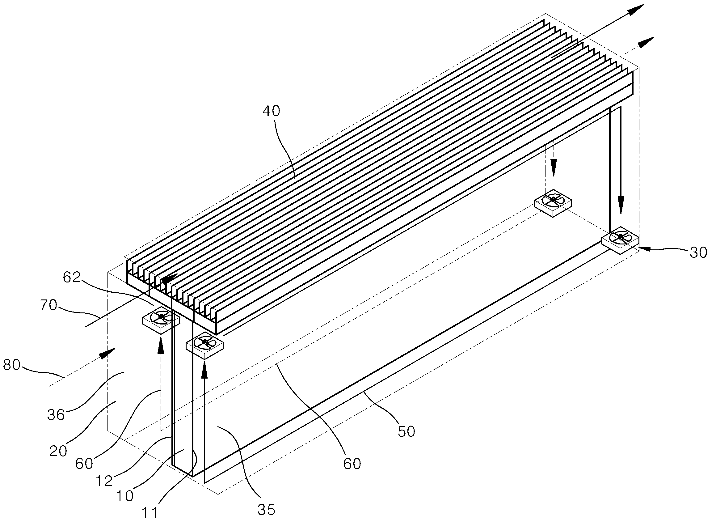
함체(30)는 디스플레이 모듈(10)을 내장하며, 디스플레이 모듈(10)보다 더 체적인 큰 중공의 직육면체 형상일 수 있다. 함체(30)는, 함체의 내부에서 디스플레이 모듈(10)의 주변을 순환하는 공기를 함체의 외부와 격리시킨다. 따라서 함체의 내부의 공기는 함체의 외부의 공기와 섞이지 않고, 이에 따라 외부의 이물질이 함체 내부로 유입되는 것이 방지된다.The
함체(30)의 전면(35)은, 함체의 외부에서 함체 내부에 수용된 디스플레이 모듈의 화면(11)을 볼 수 있는 투과면인 글라스를 포함한다. 상기 함체(30)의 전면(35)과 디스플레이 모듈(10)의 전면(11)은 약간 이격되어 있다. 함체(30)의 후면(36)은 디스플레이 모듈(10)의 후면(12)과 이격 배치되고, 이 공간에 디스플레이 모듈(10)의 제어 및 전원 공급을 위한 PCB 등이 배치된다.The
함체(30)의 측면은 제1측면(31), 상기 제1측면과 마주하는 제2측면(32), 상기 제1측면과 제2측면 사이에 위치하며 서로 마주하는 제3측면(33)과 제4측면(34)을 포함한다. 제1측면(31)과 제2측면(32)은 단변일 수 있고, 제3측면(33)과 제4측면(34)은 장변일 수 있다.The side surface of the
상기 함체(30)의 단변인 제1측면(31) 및 제2측면(32)은 상기 디스플레이 모듈의 단변인 제1측면 및 제2측면과 대응하여 배치될 수 있다. 그리고 함체의 장변인 제3측면(33)과 제4측면(34)은 상기 디스플레이 모듈의 장변인 제3측면 및 제4측면과 대응하여 배치될 수 있다. The
본 발명에 따르면, 함체(30)의 전면(35)과 디스플레이 모듈(10)의 전면(11) 사이의 이격 공간에 마련된 제1폐순환경로(50)로 공기가 순환하고, 함체(30)의 후면(36)과 디스플레이 모듈(10)의 후면 사이의 이격 공간에 마련된 제2폐순환경로(60)로 공기가 순환한다. 그리고 함체(30) 내에서, 상기 제1폐순환경로(50)와 상기 제2폐순환경로(60)는 별도로 마련된다. 즉 제1폐순환경로(50)와 제2폐순환경로(60)는 서로 연결되지 않는다.According to the present invention, the air circulates through the first
따라서 함체(30)의 측면과 디스플레이 모듈(10)의 측면이 폐순환경로를 형성하기 위해 반드시 이격되어야 할 필요는 없다.Therefore, the side surface of the
다만 제1폐순환경로(50)가 함체의 측면에서 함체 외부의 공기와 열교환을 하기 위해, 상기 제1폐순환경로는 함체 내부의 측면을 따라 유동하는 구간이 있을 수 있다. 이는 제2폐순환경로에 대해서도 마찬가지이다. 이러한 점에서, 상기 함체(30)의 측면과 상기 디스플레이 모듈(10)의 측면이 이격될 수도 있다. 다만 이와 같이 함체(30)와 디스플레이 모듈(10)의 측면이 이격되는 것은, 함체 내에서 디스플레이 모듈의 전방, 측방, 후방을 순환하는 하나의 폐순환경로를 구성하기 위한 것이 아니다.However, since the first
물론 상기 제1폐순환경로의 공기와 제2폐순환경로의 공기가 서로 완전히 밀폐되어야 하는 것은 아니며, 이들이 일부 혼합되어도 본 발명의 디스플레이 냉각장치의 기능이나 작동에는 별다른 영향이 없다.Of course, the air in the first closed circulation path and the air in the second closed circulation path do not have to be completely sealed with each other, and even if some of them are mixed, the function or operation of the display cooling apparatus of the present invention is not affected.
[제1실시예][First Embodiment]
이하 도 1 내지 도 3을 참조하여 본 발명에 따른 냉각장치가 적용된 디스플레이의 제1실시예를 설명한다.1 to 3, a first embodiment of a display to which a cooling device according to the present invention is applied will be described.
디스플레이 모듈(10)은 함체(30)의 내부에 설치된다. 디스플레이 모듈(10)의 전면(11) 및 후면(12)은 각각 함체(30)의 전면(35) 및 후면(36)과 이격 설치되어 있다. The
함체의 전면(35)과 디스플레이 모듈의 전면(11) 사이의 공간에는, 제1팬(51)에 의해 공기의 제1폐순환경로(50)가 형성된다. 상기 제1팬은, 함체의 전면(35)과 디스플레이 모듈의 전면(11) 사이의 직육면체의 공간 내에서, 서로 대향하는 코너 부분에 마련되고, 상호 대향하는 방향으로 공기를 가압한다. 따라서 상기 제1폐순환경로(50)는, 디스플레이 모듈(10)의 전방에 마련된 공간에서, 단변인 제1측면, 장변인 제3측면, 단변인 제2측면, 장변인 제4측면을 따라 순환하는 폐루프의 경로를 이룬다. 순환 공기는 도시된 폐순환경로(50)를 따라 이동하며 디스플레이의 전면(11)에서 발생하는 열을 전달받는다.In the space between the
마찬가지로, 함체의 후면(36)과 디스플레이 모듈의 후면(12) 사이의 공간에는, 제2팬(52)에 의해 공기의 제2폐순환경로(60)가 형성된다. 상기 제2팬은, 함체의 후면(36)과 디스플레이 모듈의 후면(12) 사이의 직육면체의 공간 내에서, 서로 대향하는 코너 부분에 마련되고, 상호 대향하는 방향으로 공기를 가압한다. 따라서 상기 제2폐순환경로(60)는, 디스플레이 모듈(10)의 후방에 마련된 공간에서, 단변인 제1측면, 장변인 제3측면, 단변인 제2측면, 장변인 제4측면을 따라 순환하는 폐루프의 경로를 이룬다. 순환 공기는 도시된 폐순환경로(60)를 따라 이동하며 디스플레이의 후면(12)에서 발생하는 열을 전달받는다.Likewise, in the space between the
도 2와 도 3에는 상기 제1폐순환경로와 제2폐순환경로가 디스플레이의 전후방향으로 이동하는 것처럼 도시되어 있으나, 이는 단지, 중첩되는 경로를 도면 상에 모두 시각적으로 도시하기 위해 폐순환경로를 디스플레이의 전후방향으로 이격되도록 표시한 것이다. 즉 제1폐순환경로와 제2폐순환경로의 정확한 경로는 도 1에 도시된 도면부호 50과 60의 경로를 참조하여 이해할 수 있다.2 and 3 illustrate that the first closed circuit and the second closed circuit path move in the anteroposterior direction of the display, And are spaced apart in the forward and backward directions. That is, the exact path of the first closed loop path and the second closed loop path can be understood with reference to the
함체(30)의 측면에는, 상기 폐순환경로(50, 60)를 따라 유동하는 공기의 열을 전달받아 함체 외부로 배출하는 측면 열교환기(40)가 설치된다. 측면 열교환기(40)는 함체 내부의 공간을 향해 돌출 형성되는 제2핀(44)과, 함체 외부의 공간을 향해 돌출 형성되는 제1핀(43)을 구비한다. 제1핀(43)과 제2핀(44)은 함체(30)의 내부 공간과 외부 공간을 구분하는 측면(33,34) 부분에 배치되는 핀 베이스(46)를 공유한다.A side heat exchanger (40) for receiving heat of air flowing along the closed circulation paths (50, 60) and discharging the heat to the outside of the enclosure is provided on a side surface of the enclosure (30). The side heat exchanger (40) has a second pin (44) protruding toward a space inside the housing and a first pin (43) protruding toward a space outside the housing. The
상기 제2핀(44)은 디스플레이의 측면의 길이방향으로 연장되어 있다. 또한 상기 측면 열교환기(40)는, 상기 제2핀(44)을 감싸고 상기 제2핀 주변을 유동하는 폐순환경로(50, 60)의 공기를 안내하는 덕트를 구비한다. 즉 상기 제2핀(44)은 덕트 내부에 마련될 수 있다(물론 덕트 없이, 제1핀과 제2핀이 각각 함체의 외부와 내부로 노출되는 구조 역시 적용 가능하다).The second pin (44) extends in the longitudinal direction of the side of the display. The
상기 제1폐순환경로(50) 및 상기 제2폐순환경로(60)의 구간 중 상기 측면 열교환기가 설치된 제3측면과 제4측면 부분을 지나는 구간의 공기는, 상기 덕트의 내부를 유동할 수 있다. 또한 상기 제2핀(44)을 수용하는 덕트 내지 상기 제2핀(44)은, 함체(30)의 측면에서 상기 디스플레이 모듈(10)의 측면과 접한다.Air in a section passing through the third side surface and the fourth side surface portion of the first closed loop path (50) and the second closed circulation path (60) provided with the side heat exchanger can flow inside the duct. The duct or the
따라서, 덕트 내에 마련된 제2핀(44)들 중 상기 제1폐순환경로(50)의 공기가 유동하는 경로에서 상기 제1폐순환경로의 공기와 접하는 제2핀은, 상기 제1폐순환경로의 공기로부터 열을 전달받으며 상기 제1폐순환경로의 공기를 냉각한다.Therefore, in the path of the air of the first closed circulation path (50) among the second fins (44) provided in the duct, the second fin in contact with the air of the first closed circulation path flows from the air of the first closed circulation path Receives heat and cools the air in the first closed loop path.
또한 덕트 내에 마련된 제2핀(44)들 중 상기 제2폐순환경로(60)의 공기가 유동하는 경로에서 상기 제2폐순환경로의 공기와 접하는 제2핀은, 상기 제2폐순환경로의 공기로부터 열을 전달받으며 상기 제2폐순환경로의 공기를 냉각한다.And a second fin in contact with the air of the second closed circuit path in a path of the air of the second closed circuit path (60) among the second fins (44) provided in the duct is opened from the air of the second closed circuit path And cools the air in the second closed loop path.
또한 덕트 내에 마련된 제2핀(44)들 중 상기 디스플레이 모듈의 측면에 접하는 부분의 제2핀은, 상기 디스플레이 모듈의 측면에 마련된 백라이트 유닛(15) 및 하우징(16)으로부터 열을 전달받으며 상기 백라이트 유닛(15)을 냉각한다. The second pin of the second pin (44) provided in the duct is in contact with the side surface of the display module and receives heat from the backlight unit (15) and the housing (16) provided on the side of the display module, The
그리고 제2핀(44)에 전달된 열은 핀 베이스(46)를 거쳐 상기 제1핀(43)으로 전달된다.The heat transmitted to the
제1핀(43)은 함체(30)의 외부로 노출되며, 상기 제1핀(43)이 노출된 부위에는 제1개방유동경로(70)가 마련된다. 제1개방유동경로(70)는 상기 제1핀(43)을 둘러싸는 덕트 형태일 수 있다. 그리고 상기 덕트의 입구 또는 출구 또는 입구와 출구 모두에는, 외부의 공기가 덕트 내부에서 빠른 유속으로 이동할 수 있도록 공기를 가압하는 제3팬(미도시)이 설치된다. 제3팬은 덕트의 입구에 설치되어 외부 공기를 덕트 내부로 강제로 불어 넣는 방식으로 설치될 수 있다. 또한 제3팬은 덕트의 출구에 설치되어 덕트 내부의 공기를 덕트 외부로 강제 배기하는 방식으로 설치될 수 있다.The
상기 제1개방유동경로(70)는 함체(30)의 측면에서 그 길이방향을 따라 연장되는 형태이다. 제1핀(43) 역시 제2핀과 마찬가지로 함체(30)의 측면의 길이방향을 따라 복수 개가 연장되는 형태이다. 도 1을 참조하면, 상기 제1핀(43)은 함체(30)의 측면에서 돌출되는 형상이며, 함체의 측면과 대향하는 덕트의 대향면에 도달하여 채널을 형성할 수 있다.The first open flow path (70) is shaped to extend along the longitudinal direction at the side of the housing (30). The
상술한 구조에 따르면 제1핀과 제2핀은 서로 나란한 방향으로 연장된다. 즉 상기 제1폐순환경로(50), 상기 제2폐순환경로(60), 및 상기 제1개방유동경로(70)는 함체(30)의 측면 테두리를 따르는 유동을 포함하고, 상기 측면 열교환기(40)에서 열교환을 하는 제1폐순환경로(50)의 공기 유동과 제1개방유동경로(70)의 공기 유동은 서로 평행하며, 상기 측면 열교환기(40)에서 열교환을 하는 제2폐순환경로(60)의 공기 유동과 제1개방유동경로(70)의 공기 유동은 서로 평행하다.According to the above-described structure, the first pin and the second pin extend in directions parallel to each other. The first
아울러 상기 함체(30)의 측면에서, 상기 제1폐순환경로(50)와 상기 제2폐순환경로(60)는, 상기 제1개방유동경로(70)보다 디스플레이 모듈(10)에 더 가깝게 배치된다.The first
또한 제1실시예에서 상기 측면 열교환기는 장변 부분에 구비되는 것이 예시된다. 그러나 측면 열교환기가 반드시 장변 부분에 설치되어야 하는 것은 아니며, 단변 부분에 설치되거나, 장변과 단변 부분 모두에 설치될 수도 있다.In the first embodiment, the side heat exchanger is provided at a long side portion. However, the side heat exchanger is not necessarily installed at the long side, but may be provided at the short side or both the long side and the short side.
상기 제1팬(51)과 제2팬(62)은, 함체 내에서, 각각 상기 디스플레이 모듈의 전방의 공간과 후방의 공간의 공기를 각각 순환시킨다. 제1팬(51)에 의해 발생하는 제1폐순환경로의 공기는, 디스플레이의 화면에서 발생하는 열을 냉각하고, 아울러 직사광선이 함체의 전면(35)을 통해 함체 내부를 가열할 때, 상기 함체 내부를 냉각한다. 그리고 상기 제2팬(62)에 의해 발생하는 제2폐순환경로의 공기는, 상기 디스플레이 모듈의 후면 부근에 배치된 메인보드 등의 기판이나 전자장치에서 발생하는 열을 냉각한다.The first fan (51) and the second fan (62) circulate air in the front space and the space behind the display module, respectively, in the housing. The air in the first closed circuit path generated by the
따라서 상기 제1팬과 제2팬의 동작 제어는, 상기 디스플레이 모듈의 전방 공간의 냉각의 필요성과 후방 공간의 냉각의 필요성에 따라 각각 독립적으로 제어될 수 있다. 가령 직사광선이 강하게 내리쬐는 경우, 상기 제2팬과 독립적으로, 상기 제1팬이 빠르게 회전하여 디스플레이 모듈의 전방 공간의 냉각이 더 이루어지도록 할 수 있다.Accordingly, the operation control of the first fan and the second fan can be independently controlled according to the necessity of cooling the front space of the display module and the necessity of cooling the rear space. For example, when the direct sunlight is irradiated strongly, the first fan rapidly rotates independently of the second fan, so that the front space of the display module can be further cooled.
한편, 상기 디스플레이 모듈(10)의 측면에 마련된 백라이트 유닛의 LED 어레이(15)는 집중 발열 부위이다. 이에 본 발명은, 해당 발열 부위에서 발생한 열은 직접적으로 상기 측면 열교환기(40)에 의해 냉각되도록 한다. 즉 상기 백라이트 유닛(15)은 상기 폐순환경로(50,60)를 거치는 냉각 방식과 별도로 냉각될 수 있다.On the other hand, the
종래에, 백라이트 유닛(15)에서 발생한 열은, 디스플레이 모듈 전후방 및 측면을 감싸며 순환하는 폐순환 경로에 의해 냉각되었기 때문에, 백라이트 유닛에서 발생한 열이 디스플레이 모듈 주변의 모든 공간으로 확산되는 경향이 있었다. 그러나 본 발명에 따르면, 백라이트 유닛(15)에서 발생한 열은, 그와 인접하여 배치된 측면 열교환기(40)를 통해 즉시 함체 외부로 배출될 수 있다.Conventionally, since the heat generated in the
상기 디스플레이 모듈(10)에는 상기 LED 어레이와 접하며 상기 디스플레이 모듈(10)의 외형을 지지하는 하우징(16)이 설치된다. 상기 하우징(16)은 디스플레이 모듈(10)의 강성(stiffness)을 지지하는 구조로서, 금속 재질로 제작되는 것이 바람직하다. 금속 재질의 하우징(16)은 열전도율 역시 뛰어난 재질로 선택할 수 있다. 따라서 본 발명에서는 상기 하우징(16)이 디스플레이 모듈(10)의 측면과 후면 일부를 감싸도록 하여 디스플레이 모듈(10)의 강성을 확보할 수 있다. 또한 이와 함께, 상기 측면 열교환기(40)의 일부분이 상기 디스플레이 모듈(10)의 측면에 배치된 하우징 부분에 접하도록 설치된다. 따라서 상기 하우징 부분은 LED 어레이의 열이 상기 측면 열교환기로 빠르게 전달되도록 하는 열전달 경로가 될 수 있다.The
도 3을 참조하면, 상기 제2핀(44)을 수용하는 덕트의 채널들 중, 상기 디스플레이 모듈(10)의 측면에 접하여 배치되는 채널들에는 상기 제1폐순환경로(50)의 공기가 유동하게 하거나, 상기 제2폐순환경로(60)의 공기가 유동하게 할 수 있으며, 제1개방유동경로(70)의 공기가 유동하게 할 수도 있다.Referring to FIG. 3, among the channels of the duct accommodating the
한편, 상기 함체(30)의 후면에는 함체 외부의 제2개방유동경로(80)의 공기와 상기 제2폐순환경로(60)의 공기 간에 열교환이 이루어질 수 있도록 하는 후면 열교환기(20)가 더 구비될 수 있다. 상기 제2개방유동경로(80)는 제4팬(미도시)에 의해 공기가 강제 유동하는 경로일 수 있다. 제4팬에 의해 공기가 강제 유동하는 방식으로 제2개방유동경로(80)가 형성되도록 할 경우, 도 1 내지 도 3에 도시된 바와 같이 후면 열교환기에서 제2개방유동경로(80)에 대응하는 부분이 덕트 형태를 가지도록 할 수 있다.On the other hand, a rear heat exchanger (20) is provided on the rear surface of the housing (30) so that heat can be exchanged between the air in the second open flow path (80) outside the enclosure and the air in the second closed circuit path . The second
물론 상기 제2개방유동경로(80)는 자연 기류에 의해 형성될 수도 있다. 이 때에는, 자연 기류의 형성이 더 원활하게 이루어지도록 하기 위해, 도 1 내지 도 3에 도시된 바와 달리, 덕트 형태를 가지지 않고, 함체(30)의 후면이 외부 공기에 노출된 형태가 되도록 구성할 수도 있을 것이다. Of course, the second
즉, 도 3에 도시된 상기 후면 열교환기(20)는 추가적으로 구비될 수 있는 것으로, 가령 도 4에 도시된 바와 같이 후면 열교환기(20)가 추가적으로 구비되지 않고 생략된 경우에도, 함체(30)의 후면(36)에 대해 함체(30) 외부의 공기와 함체(30) 내부의 공기가 마주하고 있으므로, 이들 사이에서 함체(30)의 후면을 통해 열교환이 이루어질 수 있다.That is, the
상기 후면 열교환기(20)를 유동하는 외부 공기의 제2개방유동경로(80)는, 기 후면 열교환기(20) 또는 함체의 후면과 접하여 유동하는 제2폐순환경로(60)보다 상기 디스플레이 모듈(10)로부터 더 멀리 배치될 수 있다.The second
[제2실시예] [Second Embodiment]
이하 도 5를 참조하여 본 발명의 제2실시예에 대해 설명한다. 앞서 설명한 실시예와 중복되는 내용에 대해서는 그 설명은 생략한다.Hereinafter, a second embodiment of the present invention will be described with reference to FIG. The description of the contents overlapping with the embodiment described above will be omitted.
제1실시예와 대비하여 제2실시예의 가장 큰 차이점은, 측면 열교환기(40)의 구조가 다르다는 것이다.The main difference of the second embodiment with respect to the first embodiment is that the structure of the
제2실시예에서의 측면 열교환기(40)는 도시된 바와 같이 함체(30)의 측면에 설치되고, 복수 개의 제1덕트(41)를 구비한다. 상기 복수 개의 제1덕트(41)는 각각 제1개방유동경로(70)의 공기가 유동하는 복수 개의 채널을 구성한다. 그리고 상기 제1덕트(41)는 함체의 측면의 길이방향을 따라 연장된다.The
제1폐순환경로(50)의 공기는 상기 함체(30) 내에서 상기 제1덕트(41)와 접하여 유동하며 상기 제1덕트 내부를 유동하는 제1개방유동경로(70)의 공기에 열을 방출한다.The air in the first
제2폐순환경로(60)의 공기도, 상기 함체(30) 내에서 상기 제1덕트(41)와 접하여 유동하며 상기 제1덕트 내부를 유동하는 제1개방유동경로(70)의 공기에 열을 방출한다.The air in the second
아울러 상기 디스플레이 모듈의 측면에 마련된 백라이트 유닛(15)도 하우징(16)을 거쳐 상기 제1덕트(41)와 접하므로, 상기 제1덕트 내부를 유동하는 제1개방유동경로(70)의 공기에 열을 방출한다.Since the
[제3실시예][Third Embodiment]
이하 도 6을 참조하여 본 발명의 제3실시예에 대해 설명한다. 앞서 설명한 실시예들과 중복되는 내용에 대해서는 그 설명을 생략한다.A third embodiment of the present invention will be described below with reference to FIG. The description of the contents overlapping with the above-described embodiments will be omitted.
제2실시예와 대비하여 제3실시예에서는, 상기 측면 열교환기(40)의 제1덕트(41)보다 안쪽에 제1폐순환경로(50)의 공기와 제2폐순환경로(60)의 공기가 유동하는 제2덕트(42)가 더 구비된다는 것이다. 즉 상기 제2덕트(42)는 상기 제1덕트(41)보다 상기 디스플레이 모듈(10)에 더 가까이 배치된다. 상기 제2덕트(42)는 함체(30)의 안쪽에, 그리고 상기 제1덕트(41)는 함체(30)의 바깥쪽에 배치될 수 있다.The air in the first
이처럼 폐순환경로(50,60)가 제1개방유동경로(70)와 열교환하며 유동하는 채널을 형성하면, 열교환 효율이 더 높아질 수 있다.Thus, if the
제3실시예에서 폐순환경로(50,60)와 제1개방유동경로(70)가 각각 제2덕트(42)와 제1덕트(41)를 통과하는 것은, 제1실시예에서 상기 폐순환경로(50,60)와 제1개방유동경로(70)가 각각 제2핀(44)을 수용하는 덕트와 제1핀(43)을 수용하는 덕트를 통과하는 것과 유사하다고 할 수 있다(다만 제1실시예가 제1핀과 제2핀이 덕트 내에 수용되지 않은 구조, 즉 덕트가 생략된 구조로 구현된 경우도 포함함은 앞서 이미 설명한 바 있다).In the third embodiment, the
[제4실시예][Fourth Embodiment]
이하 도 7 내지 도 9를 참조하여 본 발명의 제4실시예에 대해 설명한다. 앞서 설명한 실시예들과 중복되는 내용에 대해서는 그 설명을 생략한다.Hereinafter, a fourth embodiment of the present invention will be described with reference to FIGS. 7 to 9. FIG. The description of the contents overlapping with the above-described embodiments will be omitted.
앞서 제1 내지 제3실시예와 달리, 제4실시예에서는 디스플레이 모듈(10)의 측면이 함체(30)의 측면과 이격되고, 개방유동경로(70)를 구성하는 제1덕트(41)가 함체(30)를 관통하며 상기 디스플레이 모듈(10)의 측면에 접하고 있다는 점에서, 첫 번째 차이가 있다.Unlike the first to third embodiments, in the fourth embodiment, the side surface of the
제4실시예에서는 폐순환경로(50)의 공기가 유동하는 제2덕트(42)가, 상기 디스플레이 모듈(10)로부터 상기 제1덕트(41)보다 더 먼 위치에 배치된다. 즉 상기 제1덕트(41)와 제2덕트(42)는, 상기 디스플레이 모듈(10)의 측면과 상기 함체(30)의 측면 사이에 이격된 공간에 설치된다.In the fourth embodiment, the
그리고 상기 제1덕트(41)의 양단부 부근에는, 상기 디스플레이 모듈(10) 전방의 공간과, 상기 상기 제2덕트(42)의 공간을 연통시키는 관통부(45)가 마련된다. 상기 제1덕트(41)의 내부를 유동하는 제1개방유동경로의 공기와 상기 관통부(45)를 유동하는 제1폐순환경로의 공기는 서로 섞이지 않는다.In the vicinity of both ends of the
다음으로 제4실시예는, 제1폐순환경로(50)가 두 개의 순환경로를 포함하는 점에서, 앞서 설명한 실시예들과 두 번째 차이가 있다.Next, the fourth embodiment differs from the above-described embodiments in a second point in that the first
함체(30) 내에서 디스플레이 모듈(10) 전면(11)의 전방에 마련된 공간에는, 제1팬(51)에 의해 함체의 제1측면(31)에서 함체의 제2측면(32) 쪽으로 공기가 유동하게 된다. 상기 제1팬(51)에 의해 디스플레이 모듈(10)의 전면 부분과 접하며 이동하는 공기는 제2측면(32)에 다다른 후 제3측면(33)과 제4측면(34)으로 분기되고, 상기 제3측면(33)과 제3측면(34)에 각각 마련된 제2덕트(42)를 따라 다시 제1측면(31) 쪽으로 유동하게 된다. 이처럼 제1폐순환경로(50)는 제1-1폐순환경로(50-1)와 제1-2폐순환경로(50-2)를 포함하게 된다.Air is introduced from the
제1폐순환경로(50)가 위와 같이 제1-1폐순환경로(50-1)와 제1-2폐순환경로(50-2)를 포함하면, 제1폐순환경로(50)를 순환하는 공기가 디스플레이 모듈(10)의 전면(11)의 모든 면적과 전체적으로 접하므로, 디스플레이 모듈(10)의 화면 부분에서 냉각되지 않는 부위(소위 dead zone)가 발생할 우려가 없다.If the first
한편 도 9를 참조하면, 앞서 설명한 실시예들과 마찬가지로, 제4실시예에서 상기 디스플레이 모듈(10)의 양측면은 측면 열교환기(40)와 접하게 되고, 상기 제2폐순환경로(60)는 함체의 측면에서 상기 측면 열교환기(40)와 접하고 함체의 후면에서 후면 열교환기(20)와 접하게 된다.9, in the fourth embodiment, both side surfaces of the
[제5실시예][Fifth Embodiment]
이하 도 10을 참조하여 본 발명의 제5실시예에 대해 설명한다. 앞서 설명한 실시예들과 중복되는 내용에 대해서는 그 설명을 생략한다.Hereinafter, a fifth embodiment of the present invention will be described with reference to FIG. The description of the contents overlapping with the above-described embodiments will be omitted.
제5실시예는, 제4실시예와 대비하여, 제2덕트가 디스플레이 모듈(10)의 측면 부분까지 더 확장된 형태라는 점에 차이가 있다. 이는, 제4실시예에서 디스플레이 모듈(10)의 측면에는 제1덕트(41) 부분만이 구비되고, 제2덕트(42) 부분은 디스플레이 모듈(10)의 전면(11)에 있는 공간의 측부에만 형성되어 있었던 것(도 9 참조)과 대비된다.The fifth embodiment differs from the fourth embodiment in that the second duct is in a further extended form to the side portion of the
제5실시예의 구조에 따르면, 제2덕트(42)의 유동 단면적이 더 넓어지므로, 상대적으로 유동 단면적이 좁은 제4실시예의 제2덕트(42)에 비해, 제2덕트를 유동하는 공기의 유속을 완화시킬 수 있고, 아울러 제1-1폐순환경로와 제1-2폐순환경로를 순환하는 공기가 보다 원활하게 순환하도록 할 수 있다.According to the structure of the fifth embodiment, since the flow cross-sectional area of the
앞서 설명한 실시예들에서, 상기 폐순환경로(50, 50-1, 50-2, 60)와 상기 개방유동경로(70, 80)는 서로 인접하며 평행하게 유동하거나 교차 유동하며 상호 열교환이 이루어진다. 그리고 상술한 열교환기(40, 20) 내에서, 상기 두 경로는 인접하여 유동할 수 있다.In the above-described embodiments, the
이상과 같이 본 발명에 대해서 예시한 도면을 참조로 하여 설명하였으나, 본 명세서에 개시된 실시예와 도면에 의해 본 발명이 한정되는 것은 아니며, 본 발명의 기술사상의 범위 내에서 통상의 기술자에 의해 다양한 변형이 이루어질 수 있음은 자명하다. 아울러 앞서 본 발명의 실시예를 설명하면서 본 발명의 구성에 따른 작용 효과를 명시적으로 기재하여 설명하지 않았을 지라도, 해당 구성에 의해 예측 가능한 효과 또한 인정되어야 함은 당연하다.While the present invention has been particularly shown and described with reference to exemplary embodiments thereof, it is to be understood that the scope of the invention is not limited to the disclosed exemplary embodiments. It is obvious that a transformation can be made. Although the embodiments of the present invention have been described in detail above, the effects of the present invention are not explicitly described and described, but it is needless to say that the effects that can be predicted by the configurations should also be recognized.
10: 디스플레이 모듈
11: 전면(화면)
12: 후면
15: 백라이트 유닛(LED 어레이)
16: 하우징
161: 순환공기 통과공
20: 후면 열교환기
30: 함체
31: 제1측면
32: 제2측면
33: 제3측면
34: 제4측면
35: 전면(투과면, 글라스)
36: 후면
40: 측면 열교환기
41: 제1덕트
42: 제2덕트
43: 제1핀(fin)
44: 제2핀
45: 관통부
46: 핀베이스
50: 제1폐순환경로
50-1: 제1-1폐순환경로
50-2: 제1-2폐순환경로
51: 제1팬
60: 제2폐순환경로
62: 제2팬
70: 제1개방유동경로
80: 제2개방유동경로10: Display module
11: Front (screen)
12: Rear
15: Backlight unit (LED array)
16: Housing
161: Circulating air passage ball
20: rear heat exchanger
30: enclosure
31: First aspect
32: second side
33: Third aspect
34: Fourth aspect
35: front (transmission surface, glass)
36: rear
40: Side heat exchanger
41: First duct
42: Second duct
43: first pin (fin)
44: second pin
45:
46: Pin base
50: first pulmonary circulation path
50-1: 1st-1st pulmonary pathway
50-2: the 1-2th pulmonary circulation pathway
51: First fan
60: second pulmonary circulation path
62: Second fan
70: first open flow path
80: second open flow path
Claims (22)
상기 함체(30) 내부에 수용되며, 함체의 전면(35) 및 후면(36)과 이격 배치되는 디스플레이 모듈(10);
상기 함체(30)의 전면과 디스플레이 모듈(10) 전면 사이의 공간에서 공기가 순환하는 제1폐순환경로(50)를 발생시키는 제1팬(51);
상기 함체(30)의 후면과 디스플레이 모듈(10)의 후면 사이의 공간에서 공기가 순환하는 제2폐순환경로(60)를 발생시키는 제2팬(62); 및
상기 함체(30)의 측면에 마련되며, 상기 제1폐순환경로(50) 및 제2폐순환경로(60)의 공기와 열교환을 하기 위한 외부 공기가 유입되어 유동하는 제1개방유동경로(70)를 포함하는 측면 열교환기(40);를 포함하는
디스플레이 냉각장치.
A housing (30) having a front surface (35) with a transmitting surface;
A display module 10 housed within the housing 30 and spaced apart from a front surface 35 and a rear surface 36 of the housing;
A first fan 51 for generating a first closed loop path 50 through which air circulates in a space between the front surface of the housing 30 and the front surface of the display module 10;
A second fan (62) generating a second closed circuit path (60) through which air circulates in a space between a rear surface of the housing (30) and a rear surface of the display module (10); And
A first open flow path 70 provided on a side surface of the housing 30 for flowing outside air for heat exchange with air in the first closed loop path 50 and the second closed loop path 60, And a side heat exchanger (40)
Display cooling device.
상기 제1팬(51)과 제2팬(52)은 각각 독립적으로 제어되는
디스플레이 냉각장치.
The method according to claim 1,
The first fan 51 and the second fan 52 are independently controlled
Display cooling device.
상기 제1폐순환경로(50), 상기 제2폐순환경로(60), 및 상기 제1개방유동경로(70)는 함체(30)의 측면 테두리를 따르는 유동을 포함하는
디스플레이 냉각장치.
The method according to claim 1,
The first closed circuit path (50), the second closed circuit path (60), and the first open flow path (70) include a flow along a side edge of the enclosure (30)
Display cooling device.
상기 측면 열교환기(40)에서 열교환을 하는 제1폐순환경로(50)의 공기 유동과 제1개방유동경로(70)의 공기 유동은 서로 평행하고,
상기 측면 열교환기(40)에서 열교환을 하는 제2폐순환경로(60)의 공기 유동과 제1개방유동경로(70)의 공기 유동은 서로 평행한
디스플레이 냉각장치.
The method according to claim 1,
The air flow of the first closed circulation path (50) and the first open flow path (70), which perform heat exchange in the side heat exchanger (40), are parallel to each other,
The air flows of the second closed circulation path (60) and the first open flow path (70), which perform heat exchange in the side heat exchanger (40), are parallel to each other
Display cooling device.
상기 함체(30)의 측면에서, 상기 제1폐순환경로(50)와 상기 제2폐순환경로(60)는, 상기 제1개방유동경로(70)보다 디스플레이 모듈(10)에 더 가깝게 배치되는
디스플레이 냉각장치.
The method according to claim 1,
On the side of the housing 30, the first closed circuit path 50 and the second closed circuit path 60 are arranged closer to the display module 10 than the first open flow path 70
Display cooling device.
상기 측면 열교환기(40)는, 상기 함체(30)의 측면의 길이방향을 따라 연장된 복수 개의 제1덕트(41)를 포함하고,
상기 제1개방유동경로(70)는 상기 제1덕트(41) 내로 유동하는
디스플레이 냉각장치.
The method according to any one of claims 1 to 5,
The side heat exchanger (40) includes a plurality of first ducts (41) extending along the longitudinal direction of a side surface of the housing (30)
The first open flow path (70) flows into the first duct (41)
Display cooling device.
상기 측면 열교환기(40)는, 상기 함체(30)의 측면의 길이방향을 따라 연장된 복수 개의 제2덕트(42)를 포함하고,
상기 제2덕트(42)는 상기 제1덕트(41)와 접하며,
상기 제1폐순환경로(50)와 제2폐순환경로(60)는 상기 제2덕트(42) 내로 유동하는
디스플레이 냉각장치.
The method of claim 6,
The side heat exchanger (40) includes a plurality of second ducts (42) extending along the longitudinal direction of the side surface of the housing (30)
The second duct (42) is in contact with the first duct (41)
The first closed loop path (50) and the second closed loop path (60) flow into the second duct
Display cooling device.
상기 측면 열교환기(40)는, 상기 함체(30)로부터 외향하며 상기 제1개방유동경로(70)로 노출되는 제1핀(43)을 포함하는
디스플레이 냉각장치.
The method according to any one of claims 1 to 5,
The side heat exchanger (40) includes a first fin (43) that is outwardly exposed from the enclosure (30) and exposed to the first open flow path
Display cooling device.
상기 측면 열교환기(40)는, 상기 함체(30)로부터 내향하며 상기 제1폐순환경로(50) 또는 상기 제2폐순환경로(60)로 노출되는 제2핀(44)을 포함하고,
상기 제2핀(44)과 상기 제1핀(43)은 함체(30)에 설치된 핀 베이스(46)를 공유하는
디스플레이 냉각장치.
The method of claim 8,
The side heat exchanger (40) includes a second fin (44) which is exposed from the enclosure (30) and is exposed to the first closed loop path (50) or the second closed loop path (60)
The second pin (44) and the first pin (43) share a pin base (46) provided on the housing (30)
Display cooling device.
상기 함체(30)의 후면(36)에 마련되며, 상기 제2폐순환경로(60)의 공기가 함체(30) 외부의 공기와 접하여 열교환을 하는 후면 열교환기(20);를 포함하는
디스플레이 냉각장치.
The method according to claim 1,
And a rear heat exchanger (20) provided on a rear surface (36) of the housing (30), the air of the second closed circulation path (60) being in contact with air outside the enclosure (30)
Display cooling device.
상기 후면 열교환기(20)를 유동하는 외부 공기의 제2개방유동경로(80)는, 상기 후면 열교환기(20)를 유동하는 제2폐순환경로(60)보다 상기 디스플레이 모듈(10)로부터 더 멀리 배치되는
디스플레이 냉각장치.
The method of claim 10,
The second open flow path 80 of outside air flowing in the rear heat exchanger 20 is further away from the display module 10 than the second closed path 60 flowing in the rear heat exchanger 20. [ Deployed
Display cooling device.
상기 함체(30)는 제1측면(31), 상기 제1측면과 마주하는 제2측면(32), 상기 제1측면 및 제2측면 사이에 배치되는 제3측면(33), 및 상기 제3측면과 마주하는 제4측면(34)을 포함하고,
상기 제1폐순환경로(50)는, 함체(30) 내부의 제1측면에서 중앙부를 가로질러 제2측면, 제3측면, 및 제1측면의 순서로 유동하는 제1-1폐순환경로(50-1)와, 함체(30) 내부의 제1측면에서 중앙부를 가로질러 제2측면, 제4측면 및 제1측면의 순서로 유동하는 제1-2폐순환경로(50-2)를 포함하는
디스플레이 냉각장치.
The method according to any one of claims 1 to 5, 10, and 11,
The enclosure 30 includes a first side 31, a second side 32 facing the first side, a third side 33 disposed between the first side and the second side, And a fourth side (34) facing the side,
The first closed loop path 50 includes a first closed loop path 50-C flowing in the order of the second side, the third side, and the first side in the order from the first side inside the enclosure 30 across the middle, 1), and a first-second pulmonary path (50-2) flowing in the order of the second side, the fourth side, and the first side across the center on the first side inside the enclosure (30)
Display cooling device.
상기 함체(30)의 측면에서, 상기 제1폐순환경로(50)는, 상기 제1개방유동경로(70)보다 디스플레이 모듈(10)로부터 더 멀리 배치되는
디스플레이 냉각장치.
The method of claim 12,
On the side of the enclosure 30, the first closed circuit path 50 is disposed further from the display module 10 than the first open flow path 70
Display cooling device.
상기 측면 열교환기(40)는, 상기 함체(30)의 측면의 길이방향을 따라 연장된 제1덕트(41)를 포함하고,
상기 제1개방유동경로(70)는 상기 제1덕트(41)의 유동 경로를 포함하는
디스플레이 냉각장치.
14. The method of claim 13,
The side heat exchanger (40) includes a first duct (41) extending along a longitudinal direction of a side surface of the housing (30)
The first open flow path (70) includes a flow path of the first duct (41)
Display cooling device.
상기 측면 열교환기(40)는, 상기 함체(30)의 측면의 길이방향을 따라 연장된 제2덕트(42)를 포함하고,
상기 측면 열교환기(40)는, 상기 제1덕트를 가로지르는 관통부(45)를 구비하며,
상기 제2덕트(42)와 상기 관통부(45)는 서로 연결되고,
상기 제2덕트(42)는 상기 제1덕트(41)와 접하며,
상기 제1폐순환경로(50)는 상기 관통부(45)와 상기 제2덕트(42)를 지나는 경로를 포함하는
디스플레이 냉각장치.
15. The method of claim 14,
The side heat exchanger (40) includes a second duct (42) extending along the longitudinal direction of the side surface of the housing (30)
The side heat exchanger (40) includes a penetrating portion (45) crossing the first duct,
The second duct (42) and the penetrating portion (45) are connected to each other,
The second duct (42) is in contact with the first duct (41)
The first closed loop path (50) includes a path through the penetrating portion (45) and the second duct (42)
Display cooling device.
상기 제1덕트(41)는, 디스플레이 모듈의 측면으로부터 전방으로, 상기 함체(30)의 전면과 디스플레이 모듈(10) 전면 사이의 공간까지 확장된 유동 단면을 가지고,
상기 제2덕트(42)는, 디스플레이 모듈의 측면으로부터 전방으로, 상기 함체(30)의 전면과 디스플레이 모듈(10) 전면 사이의 공간까지 확장된 유동 단면을 가지는
디스플레이 냉각장치.
16. The method of claim 15,
The first duct 41 has a flow cross section extending from the side of the display module to a space between the front surface of the housing 30 and the front surface of the display module 10,
The second duct 42 extends forward from the side of the display module to a space between the front surface of the housing 30 and the front surface of the display module 10,
Display cooling device.
상기 측면 열교환기(40)는 상기 디스플레이 모듈(10)의 측면과 접하여 설치되고,
상기 측면 열교환기(40)와 접하는 상기 디스플레이 모듈(10)의 측면에는 백라이트 유닛(15)이 설치되어 있어서, 상기 백라이트 유닛(15)에서 발생한 열이 상기 측면 열교환기(40)로 전달되는
디스플레이 냉각장치.
The method according to claim 1,
The side heat exchanger (40) is installed in contact with a side surface of the display module (10)
A backlight unit 15 is installed on a side surface of the display module 10 in contact with the side heat exchanger 40 so that heat generated in the backlight unit 15 is transmitted to the side heat exchanger 40
Display cooling device.
상기 백라이트 유닛(15)은, 상기 디스플레이 모듈의 측면을 따라 배치되는 LED 어레이와, 상기 LED 어레이를 지지하며 상기 디스플레이 모듈의 강성을 보강하는 하우징(16)을 포함하고,
상기 LED 어레이에서 발생한 열이 상기 하우징(16)을 거쳐 상기 측면 열교환기(40)에 전달되는
디스플레이 냉각장치.
18. The method of claim 17,
The backlight unit (15) includes an LED array disposed along a side surface of the display module, and a housing (16) supporting the LED array and reinforcing the rigidity of the display module,
Heat generated in the LED array is transmitted to the side heat exchanger 40 via the housing 16
Display cooling device.
상기 함체(30) 내부에 수용되며, 함체의 전면(35) 및 후면(36)과 이격 배치되는 디스플레이 모듈(10);
상기 함체(30)의 전면과 디스플레이 모듈(10) 전면 사이의 공간에서 공기가 순환하는 제1폐순환경로(50)를 발생시키는 제1팬(51);
상기 함체(30)의 후면과 디스플레이 모듈(10)의 후면 사이의 공간에서 공기가 순환하는 제2폐순환경로(60)를 발생시키는 제2팬(62); 및
상기 함체(30)의 외부 공기가 유동하며 상기 제1폐순환경로(50) 및 제2폐순환경로(60)의 공기와 인접하는 개방유동경로(70, 80);를 포함하는
디스플레이 냉각장치.
A housing (30) having a front surface (35) with a transmitting surface;
A display module 10 housed within the housing 30 and spaced apart from a front surface 35 and a rear surface 36 of the housing;
A first fan 51 for generating a first closed loop path 50 through which air circulates in a space between the front surface of the housing 30 and the front surface of the display module 10;
A second fan (62) generating a second closed circuit path (60) through which air circulates in a space between a rear surface of the housing (30) and a rear surface of the display module (10); And
And an open flow path (70, 80) in which the outside air of the enclosure (30) flows and is adjacent to the air of the first closed loop path (50) and the second closed loop path (60)
Display cooling device.
상기 개방유동경로는 적어도 상기 제1폐순환경로(50)와 상기 함체(30)의 측면 부근에서 인접하게 되는 제1개방유동경로(70)를 포함하는
디스플레이 냉각장치.
The method of claim 19,
The open flow path includes a first open flow path (70) adjacent at least in the vicinity of the side of the enclosure (30) with the first closed loop path (50)
Display cooling device.
상기 개방유동경로는 상기 제2폐순환경로(60)와 상기 함체(30)의 후면(36) 부근에서 인접하게 되는 제2개방유동경로(80)를 포함하는
디스플레이 냉각장치.
The method of claim 19,
The open flow path includes a second open flow path (80) adjacent to the second closed circuit path (60) and near the rear surface (36) of the enclosure (30)
Display cooling device.
상기 폐순환경로(50, 60)와 개방유동경로(70, 80)는 상호 교차하는
디스플레이 냉각장치.
The method according to any one of claims 19 to 21,
The closed loop path (50, 60) and the open flow path (70, 80)
Display cooling device.
Priority Applications (1)
| Application Number | Priority Date | Filing Date | Title |
|---|---|---|---|
| KR1020170097003A KR102020536B1 (en) | 2017-07-31 | 2017-07-31 | A Cooler for Display Device |
Applications Claiming Priority (1)
| Application Number | Priority Date | Filing Date | Title |
|---|---|---|---|
| KR1020170097003A KR102020536B1 (en) | 2017-07-31 | 2017-07-31 | A Cooler for Display Device |
Publications (2)
| Publication Number | Publication Date |
|---|---|
| KR20190013052A true KR20190013052A (en) | 2019-02-11 |
| KR102020536B1 KR102020536B1 (en) | 2019-09-10 |
Family
ID=65369940
Family Applications (1)
| Application Number | Title | Priority Date | Filing Date |
|---|---|---|---|
| KR1020170097003A Active KR102020536B1 (en) | 2017-07-31 | 2017-07-31 | A Cooler for Display Device |
Country Status (1)
| Country | Link |
|---|---|
| KR (1) | KR102020536B1 (en) |
Cited By (2)
| Publication number | Priority date | Publication date | Assignee | Title |
|---|---|---|---|---|
| CN115576135A (en) * | 2022-10-28 | 2023-01-06 | 深圳市德智欣科技有限公司 | A TFT liquid crystal display module with heat dissipation structure |
| WO2025147121A1 (en) * | 2024-01-03 | 2025-07-10 | 주식회사 현대아이티 | Power-saving outdoor display apparatus with branched suction fan |
Citations (4)
| Publication number | Priority date | Publication date | Assignee | Title |
|---|---|---|---|---|
| KR20130098881A (en) * | 2010-05-04 | 2013-09-05 | 매뉴팩처링 리소시스 인터내셔널 인코포레이티드 | System for cooling an electronic image assembly |
| KR20150139625A (en) * | 2007-11-16 | 2015-12-11 | 매뉴팩처링 리소시스 인터내셔널 인코포레이티드 | System and method for thermally controlling an electronic display |
| KR20170068798A (en) * | 2015-12-10 | 2017-06-20 | 삼성전자주식회사 | Outdoor display device |
| KR20170118832A (en) * | 2015-02-17 | 2017-10-25 | 매뉴팩처링 리소시스 인터내셔널 인코포레이티드 | Outside ventilation system for electronic display |
-
2017
- 2017-07-31 KR KR1020170097003A patent/KR102020536B1/en active Active
Patent Citations (4)
| Publication number | Priority date | Publication date | Assignee | Title |
|---|---|---|---|---|
| KR20150139625A (en) * | 2007-11-16 | 2015-12-11 | 매뉴팩처링 리소시스 인터내셔널 인코포레이티드 | System and method for thermally controlling an electronic display |
| KR20130098881A (en) * | 2010-05-04 | 2013-09-05 | 매뉴팩처링 리소시스 인터내셔널 인코포레이티드 | System for cooling an electronic image assembly |
| KR20170118832A (en) * | 2015-02-17 | 2017-10-25 | 매뉴팩처링 리소시스 인터내셔널 인코포레이티드 | Outside ventilation system for electronic display |
| KR20170068798A (en) * | 2015-12-10 | 2017-06-20 | 삼성전자주식회사 | Outdoor display device |
Cited By (3)
| Publication number | Priority date | Publication date | Assignee | Title |
|---|---|---|---|---|
| CN115576135A (en) * | 2022-10-28 | 2023-01-06 | 深圳市德智欣科技有限公司 | A TFT liquid crystal display module with heat dissipation structure |
| CN115576135B (en) * | 2022-10-28 | 2024-05-10 | 深圳市德智欣科技有限公司 | A TFT liquid crystal display module with heat dissipation structure |
| WO2025147121A1 (en) * | 2024-01-03 | 2025-07-10 | 주식회사 현대아이티 | Power-saving outdoor display apparatus with branched suction fan |
Also Published As
| Publication number | Publication date |
|---|---|
| KR102020536B1 (en) | 2019-09-10 |
Similar Documents
| Publication | Publication Date | Title |
|---|---|---|
| US10485147B2 (en) | Display device | |
| EP3593606B1 (en) | Display device | |
| US11206750B2 (en) | Display apparatus | |
| US10359659B2 (en) | Cooling system for electronic display | |
| US9837789B2 (en) | Air-cooled laser device having L-shaped heat-transfer member with radiating fins | |
| US20060245214A1 (en) | Liquid crystal display having heat dissipation device | |
| JP2006032890A (en) | Closed loop circulation heat dissipation device and screen module using the same | |
| US10905036B2 (en) | Display cooler and display device using same | |
| KR20190013052A (en) | A Cooler for Display Device | |
| US11083116B2 (en) | Cooler for display, and display device having same | |
| KR102052706B1 (en) | A Cooler for Display Device | |
| KR102021554B1 (en) | A Cooler for Display Device | |
| KR102334505B1 (en) | A Cooler for Display Device | |
| KR102186602B1 (en) | A Cooler for Display Device | |
| KR20180036244A (en) | A cooling apparatus for display and a display device using the same | |
| KR102186603B1 (en) | A Cooler for Display Device | |
| CN112823310A (en) | Liquid crystal display device having a plurality of pixel electrodes | |
| KR20190127154A (en) | Display device | |
| KR102347941B1 (en) | A cooling apparatus for display and a display device using the same | |
| KR102021657B1 (en) | A Cooler for Display Device | |
| KR20190012449A (en) | A Cooler for Display Device | |
| KR102061534B1 (en) | A Cooler for Display Device | |
| KR20180118503A (en) | Display device | |
| HK1222973A1 (en) | Cooling system for computer server rack |
Legal Events
| Date | Code | Title | Description |
|---|---|---|---|
| A201 | Request for examination | ||
| PA0109 | Patent application |
St.27 status event code: A-0-1-A10-A12-nap-PA0109 |
|
| PA0201 | Request for examination |
St.27 status event code: A-1-2-D10-D11-exm-PA0201 |
|
| PG1501 | Laying open of application |
St.27 status event code: A-1-1-Q10-Q12-nap-PG1501 |
|
| E902 | Notification of reason for refusal | ||
| PE0902 | Notice of grounds for rejection |
St.27 status event code: A-1-2-D10-D21-exm-PE0902 |
|
| P11-X000 | Amendment of application requested |
St.27 status event code: A-2-2-P10-P11-nap-X000 |
|
| P13-X000 | Application amended |
St.27 status event code: A-2-2-P10-P13-nap-X000 |
|
| E701 | Decision to grant or registration of patent right | ||
| PE0701 | Decision of registration |
St.27 status event code: A-1-2-D10-D22-exm-PE0701 |
|
| GRNT | Written decision to grant | ||
| PR0701 | Registration of establishment |
St.27 status event code: A-2-4-F10-F11-exm-PR0701 |
|
| PR1002 | Payment of registration fee |
St.27 status event code: A-2-2-U10-U11-oth-PR1002 Fee payment year number: 1 |
|
| PG1601 | Publication of registration |
St.27 status event code: A-4-4-Q10-Q13-nap-PG1601 |
|
| PN2301 | Change of applicant |
St.27 status event code: A-5-5-R10-R13-asn-PN2301 St.27 status event code: A-5-5-R10-R11-asn-PN2301 |
|
| PR1001 | Payment of annual fee |
St.27 status event code: A-4-4-U10-U11-oth-PR1001 Fee payment year number: 4 |
|
| PR1001 | Payment of annual fee |
St.27 status event code: A-4-4-U10-U11-oth-PR1001 Fee payment year number: 5 |
|
| PR1001 | Payment of annual fee |
St.27 status event code: A-4-4-U10-U11-oth-PR1001 Fee payment year number: 6 |
|
| PR1001 | Payment of annual fee |
St.27 status event code: A-4-4-U10-U11-oth-PR1001 Fee payment year number: 7 |
|
| U11 | Full renewal or maintenance fee paid |
Free format text: ST27 STATUS EVENT CODE: A-4-4-U10-U11-OTH-PR1001 (AS PROVIDED BY THE NATIONAL OFFICE) Year of fee payment: 7 |