KR20180075304A - Ship - Google Patents
Ship Download PDFInfo
- Publication number
- KR20180075304A KR20180075304A KR1020160179478A KR20160179478A KR20180075304A KR 20180075304 A KR20180075304 A KR 20180075304A KR 1020160179478 A KR1020160179478 A KR 1020160179478A KR 20160179478 A KR20160179478 A KR 20160179478A KR 20180075304 A KR20180075304 A KR 20180075304A
- Authority
- KR
- South Korea
- Prior art keywords
- steam
- fuel cell
- supplied
- unit
- air
- Prior art date
- Legal status (The legal status is an assumption and is not a legal conclusion. Google has not performed a legal analysis and makes no representation as to the accuracy of the status listed.)
- Ceased
Links
Images


Classifications
-
- B—PERFORMING OPERATIONS; TRANSPORTING
- B63—SHIPS OR OTHER WATERBORNE VESSELS; RELATED EQUIPMENT
- B63B—SHIPS OR OTHER WATERBORNE VESSELS; EQUIPMENT FOR SHIPPING
- B63B35/00—Vessels or similar floating structures specially adapted for specific purposes and not otherwise provided for
- B63B35/44—Floating buildings, stores, drilling platforms, or workshops, e.g. carrying water-oil separating devices
-
- B—PERFORMING OPERATIONS; TRANSPORTING
- B63—SHIPS OR OTHER WATERBORNE VESSELS; RELATED EQUIPMENT
- B63J—AUXILIARIES ON VESSELS
- B63J2/00—Arrangements of ventilation, heating, cooling, or air-conditioning
- B63J2/12—Heating; Cooling
-
- B—PERFORMING OPERATIONS; TRANSPORTING
- B63—SHIPS OR OTHER WATERBORNE VESSELS; RELATED EQUIPMENT
- B63J—AUXILIARIES ON VESSELS
- B63J3/00—Driving of auxiliaries
- B63J3/02—Driving of auxiliaries from propulsion power plant
-
- F—MECHANICAL ENGINEERING; LIGHTING; HEATING; WEAPONS; BLASTING
- F01—MACHINES OR ENGINES IN GENERAL; ENGINE PLANTS IN GENERAL; STEAM ENGINES
- F01D—NON-POSITIVE DISPLACEMENT MACHINES OR ENGINES, e.g. STEAM TURBINES
- F01D15/00—Adaptations of machines or engines for special use; Combinations of engines with devices driven thereby
- F01D15/10—Adaptations for driving, or combinations with, electric generators
-
- H—ELECTRICITY
- H01—ELECTRIC ELEMENTS
- H01M—PROCESSES OR MEANS, e.g. BATTERIES, FOR THE DIRECT CONVERSION OF CHEMICAL ENERGY INTO ELECTRICAL ENERGY
- H01M8/00—Fuel cells; Manufacture thereof
- H01M8/04—Auxiliary arrangements, e.g. for control of pressure or for circulation of fluids
- H01M8/04082—Arrangements for control of reactant parameters, e.g. pressure or concentration
- H01M8/04089—Arrangements for control of reactant parameters, e.g. pressure or concentration of gaseous reactants
-
- H—ELECTRICITY
- H01—ELECTRIC ELEMENTS
- H01M—PROCESSES OR MEANS, e.g. BATTERIES, FOR THE DIRECT CONVERSION OF CHEMICAL ENERGY INTO ELECTRICAL ENERGY
- H01M8/00—Fuel cells; Manufacture thereof
- H01M8/06—Combination of fuel cells with means for production of reactants or for treatment of residues
- H01M8/0606—Combination of fuel cells with means for production of reactants or for treatment of residues with means for production of gaseous reactants
- H01M8/0612—Combination of fuel cells with means for production of reactants or for treatment of residues with means for production of gaseous reactants from carbon-containing material
- H01M8/0618—Reforming processes, e.g. autothermal, partial oxidation or steam reforming
-
- H—ELECTRICITY
- H01—ELECTRIC ELEMENTS
- H01M—PROCESSES OR MEANS, e.g. BATTERIES, FOR THE DIRECT CONVERSION OF CHEMICAL ENERGY INTO ELECTRICAL ENERGY
- H01M8/00—Fuel cells; Manufacture thereof
- H01M8/06—Combination of fuel cells with means for production of reactants or for treatment of residues
- H01M8/0606—Combination of fuel cells with means for production of reactants or for treatment of residues with means for production of gaseous reactants
- H01M8/0612—Combination of fuel cells with means for production of reactants or for treatment of residues with means for production of gaseous reactants from carbon-containing material
- H01M8/0625—Combination of fuel cells with means for production of reactants or for treatment of residues with means for production of gaseous reactants from carbon-containing material in a modular combined reactor/fuel cell structure
- H01M8/0631—Reactor construction specially adapted for combination reactor/fuel cell
-
- B—PERFORMING OPERATIONS; TRANSPORTING
- B63—SHIPS OR OTHER WATERBORNE VESSELS; RELATED EQUIPMENT
- B63B—SHIPS OR OTHER WATERBORNE VESSELS; EQUIPMENT FOR SHIPPING
- B63B35/00—Vessels or similar floating structures specially adapted for specific purposes and not otherwise provided for
- B63B35/44—Floating buildings, stores, drilling platforms, or workshops, e.g. carrying water-oil separating devices
- B63B2035/4433—Floating structures carrying electric power plants
- B63B2035/444—Floating structures carrying electric power plants for converting combustion energy into electric energy
-
- H—ELECTRICITY
- H01—ELECTRIC ELEMENTS
- H01M—PROCESSES OR MEANS, e.g. BATTERIES, FOR THE DIRECT CONVERSION OF CHEMICAL ENERGY INTO ELECTRICAL ENERGY
- H01M8/00—Fuel cells; Manufacture thereof
- H01M8/10—Fuel cells with solid electrolytes
- H01M2008/1095—Fuel cells with polymeric electrolytes
-
- H—ELECTRICITY
- H01—ELECTRIC ELEMENTS
- H01M—PROCESSES OR MEANS, e.g. BATTERIES, FOR THE DIRECT CONVERSION OF CHEMICAL ENERGY INTO ELECTRICAL ENERGY
- H01M2250/00—Fuel cells for particular applications; Specific features of fuel cell system
- H01M2250/20—Fuel cells in motive systems, e.g. vehicle, ship, plane
-
- Y—GENERAL TAGGING OF NEW TECHNOLOGICAL DEVELOPMENTS; GENERAL TAGGING OF CROSS-SECTIONAL TECHNOLOGIES SPANNING OVER SEVERAL SECTIONS OF THE IPC; TECHNICAL SUBJECTS COVERED BY FORMER USPC CROSS-REFERENCE ART COLLECTIONS [XRACs] AND DIGESTS
- Y02—TECHNOLOGIES OR APPLICATIONS FOR MITIGATION OR ADAPTATION AGAINST CLIMATE CHANGE
- Y02E—REDUCTION OF GREENHOUSE GAS [GHG] EMISSIONS, RELATED TO ENERGY GENERATION, TRANSMISSION OR DISTRIBUTION
- Y02E60/00—Enabling technologies; Technologies with a potential or indirect contribution to GHG emissions mitigation
- Y02E60/30—Hydrogen technology
- Y02E60/50—Fuel cells
-
- Y02E60/521—
-
- Y—GENERAL TAGGING OF NEW TECHNOLOGICAL DEVELOPMENTS; GENERAL TAGGING OF CROSS-SECTIONAL TECHNOLOGIES SPANNING OVER SEVERAL SECTIONS OF THE IPC; TECHNICAL SUBJECTS COVERED BY FORMER USPC CROSS-REFERENCE ART COLLECTIONS [XRACs] AND DIGESTS
- Y02—TECHNOLOGIES OR APPLICATIONS FOR MITIGATION OR ADAPTATION AGAINST CLIMATE CHANGE
- Y02P—CLIMATE CHANGE MITIGATION TECHNOLOGIES IN THE PRODUCTION OR PROCESSING OF GOODS
- Y02P70/00—Climate change mitigation technologies in the production process for final industrial or consumer products
- Y02P70/50—Manufacturing or production processes characterised by the final manufactured product
-
- Y—GENERAL TAGGING OF NEW TECHNOLOGICAL DEVELOPMENTS; GENERAL TAGGING OF CROSS-SECTIONAL TECHNOLOGIES SPANNING OVER SEVERAL SECTIONS OF THE IPC; TECHNICAL SUBJECTS COVERED BY FORMER USPC CROSS-REFERENCE ART COLLECTIONS [XRACs] AND DIGESTS
- Y02—TECHNOLOGIES OR APPLICATIONS FOR MITIGATION OR ADAPTATION AGAINST CLIMATE CHANGE
- Y02T—CLIMATE CHANGE MITIGATION TECHNOLOGIES RELATED TO TRANSPORTATION
- Y02T90/00—Enabling technologies or technologies with a potential or indirect contribution to GHG emissions mitigation
- Y02T90/40—Application of hydrogen technology to transportation, e.g. using fuel cells
Landscapes
- Engineering & Computer Science (AREA)
- Chemical & Material Sciences (AREA)
- Mechanical Engineering (AREA)
- General Chemical & Material Sciences (AREA)
- Manufacturing & Machinery (AREA)
- Sustainable Development (AREA)
- Chemical Kinetics & Catalysis (AREA)
- Electrochemistry (AREA)
- Life Sciences & Earth Sciences (AREA)
- Combustion & Propulsion (AREA)
- Sustainable Energy (AREA)
- Ocean & Marine Engineering (AREA)
- Architecture (AREA)
- Civil Engineering (AREA)
- Structural Engineering (AREA)
- General Engineering & Computer Science (AREA)
- Fuel Cell (AREA)
Abstract
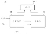
본 발명은 선체에 설치되고 원료를 공급하기 위한 원료공급부, 상기 원료공급부와 이격되게 설치되고 물을 공급하기 위한 원료수공급부, 상기 원료수공급부와 이격되게 설치되고 공기를 공급하기 위해 공기를 압축하는 공기압축기, 공기와 연료를 혼합 연소시키는 엔진에서 배출되는 엔진배기가스를 이용하여 전기를 생산하기 위한 가스터빈, 상기 가스터빈에서 배출되는 엔진배기가스를 열원으로 상기 원료수공급부에서 공급되는 물을 스팀(H2O)으로 상변화시키는 스팀생산부, 상기 스팀생산부가 생산한 스팀(H2O)을 분기시키는 분기부, 상기 분기부에 의해 분기된 스팀(H2O)을 이용하여 전기를 생산하기 위한 스팀터빈, 상기 스팀터빈과 이격되게 설치되고 상기 분기부에 의해 분기된 스팀(H2O)을 공급받아 전기를 생산하는 연료전지시스템, 및 상기 연료전지시스템에서 출력되는 직류전류(DC)를 교류전류(AC)로 변환하는 전력변환부를 포함하고, 상기 연료전지시스템은 상기 원료공급부에서 공급되는 원료를 전처리하는 원료처리부, 상기 원료처리부로부터 공급된 전처리된 연료 및 상기 스팀생산부로부터 공급된 스팀(H2O)을 개질반응시키는 개질기, 및 상기 개질기를 가열하기 위한 연소기를 포함하는 수소생성부, 및 연료극(Anode), 공기극(Cathode), 및 상기 연료극(Anode)과 상기 공기극(Cathode) 사이에 형성되는 전해질을 포함하여 전기를 생산하는 연료전지를 포함하며, 상기 연료전지에서 배출되는 연료전지배기가스는 상기 가스터빈이 공급받는 배기가스의 유량이 증가하도록 상기 가스터빈으로 공급되고, 상기 공기압축기는 상기 가스터빈으로부터 구동력을 제공받아 공기를 압축하며, 상기 개질기는 상기 스팀생산부에서 상기 스팀터빈으로 공급되는 스팀(H2O)을 제외한 나머지 잔여스팀(H2O)을 공급받는 것을 특징으로 하는 선박에 관한 것이다.The present invention relates to a water supply system comprising a raw material supply unit for supplying a raw material to a hull, a raw water supply unit for supplying water to the raw water supply unit, a water supply unit for supplying water to the raw water supply unit, An air compressor, a gas turbine for producing electricity using an engine exhaust gas discharged from an engine for burning air and fuel, a steam generator for generating steam by supplying steam from the raw- (H 2 O) produced by the steam generating unit, a branching unit for branching the steam (H 2 O) produced by the steam producing unit, and steam generated by the branching unit (H 2 O) for steam turbines, installed to be spaced apart from the steam turbine and the fuel cell system to generate electricity when supplied with steam (H 2 O) branched by the branching portion, and the And a power conversion section for converting a direct current (DC) output from the fuel cell system into an alternating current (AC), wherein the fuel cell system includes a raw material processing section for pre-processing a raw material supplied from the raw material supply section, A hydrogen generator including a reformer for reforming the pretreated fuel and steam (H 2 O) supplied from the steam production unit, and a combustor for heating the reformer, and a fuel cell including an anode, a cathode, And a fuel cell that generates electricity by including an electrolyte formed between the anode and the cathode, wherein the fuel cell exhaust gas discharged from the fuel cell is supplied to the fuel cell through the fuel cell, And the air compressor is supplied with a driving force from the gas turbine to compress the air, and the reforming Is directed to a vessel, it characterized in that the remaining residue fed steam (H 2 O) except the steam (H 2 O) supplied to the steam turbine in the steam generation block.
Description
본 발명은 강, 바다와 같은 물에서 사람, 화물 등을 목적지까지 이송하기 위한 선박에 관한 것이다.BACKGROUND OF THE
일반적으로 선박은 동력수단을 이용하여 물에서 이동할 수 있는 수단으로, 승객, 화물 등을 목적지까지 운송하기 위한 운송선, 어패류를 포획하기 위한 어선, 군사 목적으로 만들어진 군함 등 다양한 분야에서 이용된다. 이러한 선박에는 프로펠러와 같은 추진장치를 회전시키기 위한 엔진, 엔진에서 배출되는 배기가스를 이용하여 전기를 생산하기 위한 가스터빈, 및 가스터빈에서 배출되는 배기가스를 이용하여 스팀(H2O)을 생산하기 위한 이코노마이저(Economizer)가 설치된다.In general, ships are used in various fields such as transportation means for transporting passengers and cargoes to destinations, fishing vessels for capturing seafood, military vessels made for military purposes, and the like, which can be moved from water using power means. These vessels produce steam (H 2 O) using an engine for rotating a propulsion device such as a propeller, a gas turbine for producing electricity using the exhaust gas discharged from the engine, and exhaust gas discharged from the gas turbine An economizer is installed.
가스터빈은 관로를 통해 엔진에 연결되도록 설치되어, 엔진에서 배출되는 고압의 배기가스를 공급받는다. 가스터빈으로 공급되는 고압의 배기가스는 가스터빈의 터빈날개를 회전시켜 터빈날개가 결합된 구동축을 회전시킨다. 구동축은 발전기에 연결되게 설치되어 발전기에 구동력을 제공함으로써, 발전기가 전기를 생산하도록 한다.The gas turbine is installed to be connected to the engine through a pipeline, and is supplied with high-pressure exhaust gas discharged from the engine. The high pressure exhaust gas supplied to the gas turbine rotates the turbine blades of the gas turbine to rotate the turbine blades coupled drive shaft. The drive shaft is connected to the generator to provide a driving force to the generator, thereby allowing the generator to produce electricity.
한편, 이코노마이저는 상기 가스터빈에 연결되도록 설치되어, 상기 가스터빈에서 배출되는 배기가스를 열원으로 물을 가열하여 스팀(H2O)을 생산한다. 상기 이코노마이저는 배기가스를 이용하여 스팀(H2O)을 생산하는 배열회수증기발생기(Heat Recovery Steam Generator)에 포함된다. 상기 이코노마이저를 통해 생산된 스팀(H2O)은 난방용, 전기 생산 등 다양한 용도로 사용된다.Meanwhile, the economizer is installed to be connected to the gas turbine, and generates steam (H 2 O) by heating the exhaust gas discharged from the gas turbine with a heat source. The economizer is included in a heat recovery steam generator that produces steam (H 2 O) using exhaust gas. The steam (H 2 O) produced through the economizer is used for various purposes such as heating and electric production.
종래 기술에 따른 선박은 상기 이코노마이저와 같은 배열회수증기발생기(HRSG)가 생산한 스팀(H2O)을 이용하여 전기를 생산하기 위해 구동력을 발생시키는 스팀터빈을 포함한다. 상기 스팀터빈은 발전기와 연결되게 설치됨으로써, 구동력을 발전기에 제공하여 발전기가 전기를 생산하도록 한다.The ship according to the prior art includes a steam turbine generating a driving force to generate electricity using steam (H 2 O) produced by a circulation steam generator (HRSG) such as the economizer. The steam turbine is installed to be connected to a generator, thereby providing a driving force to the generator so that the generator can generate electricity.
이와 같이 종래 기술에 따른 선박은 엔진에서 배출되는 배기가스를 이용하여 선체에 설치된 전기설비들을 작동시키기 위한 전기를 생산한다.Thus, the ship according to the related art produces electricity for operating the electric equipments installed on the hull by using the exhaust gas discharged from the engine.
그러나, 종래 기술에 따른 선박은 상기 가스터빈에 의해 생산되는 전기 생산량 및 상기 스팀터빈에 의해 생산되는 전기 생산량이 부족하여, 다양한 전기설비들을 충분하게 사용하지 못하는 문제가 있다. 또한, 종래 기술에 따른 선박은 항구에 정박하는 경우와 같이 엔진이 가동을 중단하면 배기가스가 배출되지 않으므로 가스터빈이 전기를 생산할 수 없고, 이 경우 스팀터빈이 손상 내지 파손되면 전기 생산이 중단되는 문제가 있다. 따라서, 전기 생산량을 증대시킬 수 있을 뿐만 아니라 정박 시에도 전기 생산이 중단되는 것을 방지할 수 있는 선박의 개발이 절실히 필요하다.However, there is a problem in that the ship according to the prior art can not sufficiently use various electric equipments due to the shortage of the electric production quantity produced by the gas turbine and the electric production quantity produced by the steam turbine. In addition, when a ship according to the prior art is stopped at the port, if the engine stops operating, the exhaust gas is not discharged, so that the gas turbine can not produce electricity. In this case, if the steam turbine is damaged or broken, there is a problem. Therefore, it is urgently necessary to develop a ship capable of not only increasing the electricity production amount but also preventing the electric production from being stopped even when the ship is at a berth.
본 발명은 상술한 바와 같은 문제를 해결하고자 안출된 것으로, 전기 생산량을 증대시킬 수 있을 뿐만 아니라 정박 시 스팀터빈이 손상 내지 파손되더라도 전기 생산이 중단되는 것을 방지할 수 있는 선박을 제공하기 위한 것이다.SUMMARY OF THE INVENTION It is an object of the present invention to provide a ship capable of preventing an interruption of electricity production even if the steam turbine is damaged or damaged at the time of anchorage.
상술한 바와 같은 과제를 해결하기 위해, 본 발명은 하기와 같은 구성을 포함할 수 있다.In order to solve the above-described problems, the present invention can include the following configuration.
본 발명에 따른 선박은 선체에 설치되고, 원료를 공급하기 위한 원료공급부; 상기 원료공급부와 이격되게 설치되고, 물을 공급하기 위한 원료수공급부; 상기 원료수공급부와 이격되게 설치되고, 공기를 공급하기 위해 공기를 압축하는 공기압축기; 공기와 연료를 혼합 연소시키는 엔진에서 배출되는 엔진배기가스를 이용하여 전기를 생산하기 위한 가스터빈; 상기 가스터빈에서 배출되는 엔진배기가스를 열원으로 상기 원료수공급부에서 공급되는 물을 스팀(H2O)으로 상변화시키는 스팀생산부; 상기 스팀생산부가 생산한 스팀(H2O)을 분기시키는 분기부; 상기 분기부에 의해 분기된 스팀(H2O)을 이용하여 전기를 생산하기 위한 스팀터빈; 상기 스팀터빈과 이격되게 설치되고, 상기 분기부에 의해 분기된 스팀(H2O)을 공급받아 전기를 생산하는 연료전지시스템; 및 상기 연료전지시스템에서 출력되는 직류전류(DC)를 교류전류(AC)로 변환하는 전력변환부를 포함할 수 있다. 상기 연료전지시스템은 상기 원료공급부에서 공급되는 원료를 전처리하는 원료처리부, 상기 원료처리부로부터 공급된 전처리된 연료 및 상기 스팀생산부로부터 공급된 스팀(H2O)을 개질반응시키는 개질기, 및 상기 개질기를 가열하기 위한 연소기를 포함하는 수소생성부; 및 연료극(Anode), 공기극(Cathode), 및 상기 연료극(Anode)과 상기 공기극(Cathode) 사이에 형성되는 전해질을 포함하여 전기를 생산하는 연료전지를 포함할 수 있다. 상기 연료전지에서 배출되는 연료전지배기가스는 상기 가스터빈이 공급받는 배기가스의 유량이 증가하도록 상기 가스터빈으로 공급될 수 있다. 상기 공기압축기는 상기 가스터빈으로부터 구동력을 제공받아 공기를 압축할 수 있다. 상기 개질기는 상기 스팀생산부에서 상기 스팀터빈으로 공급되는 스팀(H2O)을 제외한 나머지 잔여스팀(H2O)을 공급받을 수 있다.The ship according to the present invention comprises: a raw material supply unit installed in a hull and supplying raw material; A raw water supply part installed to be spaced apart from the raw material supply part and supplying water; An air compressor installed to be spaced apart from the raw water supply part and compressing air to supply air; A gas turbine for producing electricity by using engine exhaust gas discharged from an engine which mixes and burns air and fuel; A steam production unit for converting the water supplied from the raw water supply unit into steam (H 2 O) by using the engine exhaust gas discharged from the gas turbine as a heat source; A branching portion for branching the steam (H 2 O) produced by the steam production portion; A steam turbine for generating electricity using steam (H 2 O) branched by the branching unit; A fuel cell system installed to be spaced apart from the steam turbine and supplied with steam (H 2 O) branched by the branching section to produce electricity; And a power conversion unit for converting a direct current (DC) output from the fuel cell system into an alternating current (AC). The fuel cell system includes a raw material treatment unit for pre-treating a raw material supplied from the raw material supply unit, a reformer for reforming steam (H 2 O) supplied from the raw material treatment unit and the pretreated fuel supplied from the raw material treatment unit, A hydrogen generator including a combustor for heating; And a fuel cell that generates electricity by including an anode, an anode, and an electrolyte formed between the anode and the cathode. The fuel cell exhaust gas discharged from the fuel cell may be supplied to the gas turbine so that the flow rate of the exhaust gas supplied by the gas turbine is increased. The air compressor may receive a driving force from the gas turbine to compress the air. The reformer may receive residual steam (H 2 O) other than steam (H 2 O) supplied to the steam turbine from the steam production unit.
본 발명에 따른 선박은 상기 공기압축기가 압축한 공기를 상기 연료전지의 공기극(Cathode)으로 공급하기 위해 상기 공기압축기와 상기 연료전지를 연결하는 연결부를 포함할 수 있다.The vessel according to the present invention may include a connection portion connecting the air compressor and the fuel cell to supply air compressed by the air compressor to the cathode of the fuel cell.
본 발명에 따른 선박은 상기 공기압축기에서 상기 공기극(Cathode)으로 공급되는 공기를 가열하도록 상기 연결부에 설치되는 가열부를 포함할 수 있다.The ship according to the present invention may include a heating unit installed in the connection unit to heat the air supplied to the air cathode in the air compressor.
본 발명에 따른 선박은 상기 스팀터빈과 상기 원료수공급부 사이에 위치하도록 설치되고, 상기 스팀터빈에서 배출되는 스팀(H2O)을 물로 응축시키기 위한 응축기를 포함할 수 있다. 상기 응축기에서 응축된 물은 상기 원료수공급부로 공급될 수 있다.The vessel according to the present invention may include a condenser installed to be positioned between the steam turbine and the raw water supply part and condensing steam (H 2 O) discharged from the steam turbine into water. The condensed water in the condenser may be supplied to the raw water supply unit.
본 발명에 따른 연료전지시스템은 원료공급부에서 공급되는 원료를 전처리하는 원료처리부, 상기 원료처리부로부터 공급된 전처리된 연료 및 공기와 연료를 혼합 연소시키는 엔진에서 배출되는 엔진배기가스를 이용하여 전기를 생산하기 위한 가스터빈에서 배출되는 엔진배기가스를 열원으로 원료수공급부에서 공급되는 물을 스팀(H2O)으로 상변화시키는 스팀생산부로부터 공급된 스팀(H2O)을 개질반응시키는 개질기, 및 상기 개질기를 가열하기 위한 연소기를 포함하는 수소생성부; 및 연료극(Anode), 공기극(Cathode), 및 상기 연료극(Anode)과 상기 공기극(Cathode) 사이에 형성되는 전해질을 포함하여 전기를 생산하는 연료전지를 포함할 수 있다. 상기 연료전지에서 배출되는 연료전지배기가스는 상기 가스터빈이 공급받는 배기가스의 유량이 증가하도록 상기 가스터빈으로 공급될 수 있다. 공기를 공급하기 위해 공기를 압축하는 공기압축기는 상기 가스터빈으로부터 구동력을 제공받아 공기를 압축할 수 있다. 상기 개질기는 상기 스팀생산부에서 상기 스팀생산부가 생산한 스팀(H2O)을 분기시키는 분기부에 의해 분기된 스팀(H2O)을 이용하여 전기를 생산하기 위한 스팀터빈으로 공급되는 스팀(H2O)을 제외한 나머지 잔여스팀(H2O)을 공급받을 수 있다.The fuel cell system according to the present invention includes a raw material treatment unit for pre-treating a raw material supplied from a raw material supply unit, a pre-treated fuel supplied from the raw material treatment unit, and an engine exhaust gas discharged from an engine A reformer for reforming steam (H 2 O) supplied from a steam producing unit for converting the engine exhaust gas discharged from the gas turbine into a steam (H 2 O) supplied from a raw water supply unit as a heat source, A hydrogen generator including a combustor for heating the reformer; And a fuel cell that generates electricity by including an anode, an anode, and an electrolyte formed between the anode and the cathode. The fuel cell exhaust gas discharged from the fuel cell may be supplied to the gas turbine so that the flow rate of the exhaust gas supplied by the gas turbine is increased. An air compressor for compressing air to supply air can compress the air by receiving driving force from the gas turbine. The reformer is a steam (H is using the steam (H 2 O) branched by the branching section for branching the steam (H 2 O) by which the steam generation block production supplied to the steam turbine to generate electricity from the steam generation block 2 O) except the rest can be supplied to the remaining steam (H 2 O).
본 발명에 따른 연료전지시스템은 상기 공기압축기가 압축한 공기를 상기 연료전지의 공기극(Cathode)으로 공급하기 위해 상기 공기압축기와 상기 연료전지를 연결하는 연결부를 포함할 수 있다.The fuel cell system according to the present invention may include a connection unit connecting the air compressor and the fuel cell to supply air compressed by the air compressor to the cathode of the fuel cell.
본 발명에 따른 연료전지시스템은 상기 공기압축기에서 상기 공기극(Cathode)으로 공급되는 공기를 가열하도록 상기 연결부에 설치되는 가열부를 포함할 수 있다.The fuel cell system according to the present invention may include a heating unit installed in the connection unit to heat air supplied from the air compressor to the cathode.
본 발명에 따른 연료전지시스템은 상기 스팀터빈과 상기 원료수공급부 사이에 위치하도록 설치되고, 상기 스팀터빈에서 배출되는 스팀(H2O)을 물로 응축시키기 위한 응축기를 포함할 수 있다. 상기 응축기에서 응축된 물은 상기 원료수공급부로 공급될 수 있다.The fuel cell system according to the present invention may include a condenser installed between the steam turbine and the raw water supply unit for condensing steam (H 2 O) discharged from the steam turbine into water. The condensed water in the condenser may be supplied to the raw water supply unit.
본 발명에 따르면, 다음과 같은 효과를 얻을 수 있다.According to the present invention, the following effects can be obtained.
본 발명은 가스터빈에서 배출되는 배기가스를 이용하여 스팀(H2O)을 생산하는 스팀생산부로부터 생산된 스팀(H2O) 중 적어도 일부를 연료전지의 연료 개질에 이용함으로써, 전체적인 전기 생산량을 증가시킬 수 있다.The present invention uses at least a part of steam (H 2 O) produced from a steam producing unit for producing steam (H 2 O) by using exhaust gas discharged from a gas turbine for fuel reforming of a fuel cell, .
본 발명은 연료전지에서 배출되는 배기가스를 가스터빈에 공급하도록 구현됨으로써, 가스터빈에 공급되는 배기가스의 유량을 증가시켜 전기 생산량을 증가시킬 수 있을 뿐만 아니라 정박 시 스팀터빈이 손상 내지 파손되더라도 연료전지를 이용하여 전기를 생산할 수 있으므로 전기 생산이 중단되는 것을 방지할 수 있다.The present invention is embodied to supply the exhaust gas discharged from the fuel cell to the gas turbine so that the flow rate of the exhaust gas supplied to the gas turbine can be increased to increase the amount of electricity produced and also, Since the electricity can be produced using the battery, the electric production can be prevented from being interrupted.
도 1은 본 발명에 따른 선박의 개략적인 블록도
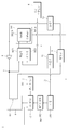
도 2는 본 발명에 따른 전체 시스템의 개념적인 구성도
도 3은 본 발명에 따른 연료전지시스템의 개념적인 구성도
도 4a, 도 4b는 본 발명에 사용되는 연료전지의 동작을 설명하기 위한 예시도로서, 도 4a는 고체산화물 연료전지(SOFC)의 개념적인 구성도
도 4b는 고분자전해질 연료전지(PEMFC)의 개념적인 구성도
도 5는 본 발명의 일실시예에 따른 수소생성부를 설명하기 위한 예시도
도 6은 본 발명에 따른 선박의 개념적인 구성도
도 7은 본 발명에 따른 선박에서 공기압축기 및 연료전지시스템을 설명하기 위한 개략적인 블록도
도 8은 본 발명에 따른 선박에서 연결부를 설명하기 위한 개략적인 블록도
도 9는 본 발명에 따른 선박에서 가열부를 설명하기 위한 개략적인 블록도
도 10은 본 발명에 따른 선박에서 응축기를 설명하기 위한 개략적인 블록도1 is a schematic block diagram of a ship according to the present invention;
2 is a conceptual diagram of an overall system according to the present invention
3 is a conceptual diagram of a fuel cell system according to the present invention.
FIGS. 4A and 4B are diagrams for explaining the operation of the fuel cell used in the present invention. FIG. 4A is a conceptual diagram of a solid oxide fuel cell (SOFC)
4B is a conceptual diagram of a polymer electrolyte fuel cell (PEMFC)
5 is an exemplary diagram illustrating a hydrogen generator according to an embodiment of the present invention.
6 is a conceptual diagram of a ship according to the present invention
7 is a schematic block diagram for explaining an air compressor and a fuel cell system in a ship according to the present invention;
8 is a schematic block diagram for explaining a connecting portion in a ship according to the present invention.
9 is a schematic block diagram for explaining a heating unit in a ship according to the present invention
10 is a schematic block diagram for explaining a condenser in a ship according to the present invention
본 명세서에서 각 도면의 구성요소들에 참조번호를 부가함에 있어서 동일한 구성 요소들에 한해서는 비록 다른 도면상에 표시되더라도 가능한 한 동일한 번호를 가지도록 하고 있음에 유의하여야 한다. It should be noted that, in the specification of the present invention, the same reference numerals as in the drawings denote the same elements, but they are numbered as much as possible even if they are shown in different drawings.
한편, 본 명세서에서 서술되는 용어의 의미는 다음과 같이 이해되어야 할 것이다. Meanwhile, the meaning of the terms described in the present specification should be understood as follows.
단수의 표현은 문맥상 명백하게 다르게 정의하지 않는 한 복수의 표현을 포함하는 것으로 이해되어야 하고, "제1", "제2" 등의 용어는 하나의 구성요소를 다른 구성요소로부터 구별하기 위한 것으로, 이들 용어들에 의해 권리범위가 한정되어서는 아니 된다.The word " first, "" second," and the like, used to distinguish one element from another, are to be understood to include plural representations unless the context clearly dictates otherwise. The scope of the right should not be limited by these terms.
"포함하다" 또는 "가지다" 등의 용어는 하나 또는 그 이상의 다른 특징이나 숫자, 단계, 동작, 구성요소, 부분품 또는 이들을 조합한 것들의 존재 또는 부가 가능성을 미리 배제하지 않는 것으로 이해되어야 한다.It should be understood that the terms "comprises" or "having" does not preclude the presence or addition of one or more other features, integers, steps, operations, elements, components, or combinations thereof.
"적어도 하나"의 용어는 하나 이상의 관련 항목으로부터 제시 가능한 모든 조합을 포함하는 것으로 이해되어야 한다. 예를 들어, "제1항목, 제2항목 및 제3항목 중에서 적어도 하나"의 의미는 제1항목, 제2항목 또는 제3항목 각각 뿐만 아니라 제1항목, 제2항목 및 제3항목 중에서 2개 이상으로부터 제시될 수 있는 모든 항목의 조합을 의미한다.It should be understood that the term "at least one" includes all possible combinations from one or more related items. For example, the meaning of "at least one of the first item, the second item and the third item" means not only the first item, the second item or the third item, but also the second item and the second item among the first item, Means any combination of items that can be presented from more than one.
이하에서는 본 발명에 따른 선박에 관해 첨부된 도면을 참조하여 구체적으로 설명한다.Hereinafter, a ship according to the present invention will be described in detail with reference to the accompanying drawings.
도 1은 본 발명에 따른 선박의 개략적인 블록도, 도 2는 본 발명에 따른 전체 시스템의 개념적인 구성도, 도 3은 본 발명에 따른 연료전지시스템의 개념적인 구성도, 도 4a, 도 4b는 본 발명에 사용되는 연료전지의 동작을 설명하기 위한 예시도로서, 도 4a는 고체산화물 연료전지(SOFC)의 개념적인 구성도, 도 4b는 고분자전해질 연료전지(PEMFC)의 개념적인 구성도, 도 5는 본 발명의 일실시예에 따른 수소생성부를 설명하기 위한 예시도, 도 6은 본 발명에 따른 선박의 개념적인 구성도, 도 7은 본 발명에 따른 선박에서 공기압축기 및 연료전지시스템을 설명하기 위한 개략적인 블록도이다.Fig. 1 is a schematic block diagram of a ship according to the present invention, Fig. 2 is a conceptual diagram of an overall system according to the present invention, Fig. 3 is a conceptual diagram of a fuel cell system according to the present invention, FIG. 4A is a conceptual diagram of a solid oxide fuel cell (SOFC), FIG. 4B is a conceptual diagram of a polymer electrolyte fuel cell (PEMFC), and FIG. FIG. 5 is a diagram illustrating a hydrogen generator according to an embodiment of the present invention. FIG. 6 is a conceptual view of a ship according to the present invention. Fig. 2 is a schematic block diagram for explaining the operation; Fig.
도 1 내지 도 7을 참고하면, 본 발명에 따른 선박(1)은 선체(20)에 발전시스템(30)이 설치된다. 상기 선체(20)는 본 발명에 따른 선박(1)의 전체적인 외관을 이룬다. 상기 발전시스템(30)은 크게 엔진 배기시스템(100) 및 연료전지시스템(10)을 포함한다. 상기 엔진 배기시스템(100)은 엔진(101), 배기리시버(102) 및 가스터빈(3)을 포함할 수 있다. 상기 엔진(101)은 상기 가스터빈(3)에 연결되게 설치된다. 여기서, 상기 엔진 배기시스템(100)의 엔진(101)은 디젤엔진 또는 가스엔진일 수 있다. 상기 연료전지시스템(10)은 크게 연료전지(101) 및 수소생성부(102)를 포함한다. 상기 연료전지시스템(10)은 상기 연료전지(101) 및 상기 수소생성부(102) 등을 포함한 모든 구성의 동작을 제어하는 제어부(103)를 포함하여 구현될 수도 있다.Referring to FIGS. 1 to 7, a
상기 발전시스템(30)은 엔진 배기시스템(100), 공기압축기(2), 원료공급부(4), 원료수공급부(5), 스팀생산부(6), 분기부(7), 스팀터빈(8), 전력변환부(9) 및 본 발명에 따른 연료전지시스템(10)을 포함한다. 본 발명에 따른 연료전지시스템(10)은 상기 수소생성부(102)로부터 연료를 공급받도록 구현된다.The
상기 엔진 배기시스템(100)은 엔진이 디젤엔진일 경우 디젤엔진(101), 배기리시버(102) 및 가스터빈(3)을 포함한다.The
상기 엔진 배기시스템(100)은 엔진을 사용하는 발전시스템에 포함되는 구성으로서, 엔진 연소실 내에서 발생하는 질소산화물(NOx) 등과 같은 환경오염물질을 포함하는 배기가스를 정화시키고 배기가스의 열을 회수하여 외부로 배출하는 장치이다. 상기 엔진 배기시스템(100)은 배기가스에 함유된 질소산화물(NOx) 등을 줄이기 위해 선택적 환원촉매 반응기(Selective Catalytic Reduction, SCR)가 설치될 수 있다. 상기 가스터빈(3)은 엔진(101)에서 배출되는 고압의 엔진배기가스를 이용하여 전기를 생산하기 위해 발전기(미도시)를 포함하여 구현될 수 있다. 상기 가스터빈(3)은 공기압축기(2)에 동력전달축으로 연결됨으로써, 엔진배기가스에 의해 발생된 구동력을 상기 공기압축기(2)에 전달할 수 있다.The
상기 엔진 배기시스템(100)의 엔진(101)은 공기압축기(2)로부터 공기를 공급받고, 상기 원료공급부(4)로부터 연료를 공급받을 수 있다. 이에 따라, 상기 엔진(101)은 공기 및 연료를 혼합하여 연소시킴으로써, 엔진배기가스를 배출시킬 수 있다. 엔진이 디젤엔진(101)일 경우, 상기 디젤엔진(101)은 상기 원료공급부(4)로부터 디젤연료를 공급받을 수 있다. 상기 디젤연료는 해상 가스유(Marine Gas Oil, MGO), 해상 디젤유(Marine Diesel Oil, MDO), 일반 중유(Heavy Fuel Oil, HFO), 메탄올, 디메틸에테르(DME), 및 액화석유가스(LPG) 등이 될 수 있다.The
상기 공기압축기(2)는 선체(20)에 설치되고, 상기 엔진(101)에 공기를 공급하기 위해 공기를 압축한다. 통상적으로 공기는 질소, 산소, 이산화탄소 등을 포함하는 기체를 의미하지만, 본 명세서에서는 공기에서 질소 또는 이산화탄소, 또는 두 기체 등 산소 이외의 모든 기체를 제거한 경우도 포함한다. 상기 공기압축기(2)는 공기 저장탱크와 상기 공기 저장탱크로부터 공기를 공급하는 장치(예컨대, 블로워)를 포함하여 구현될 수 있다. 다른 예로, 공기압축기(2)는 외부공기를 공급받아 압축한 후 압축된 고압의 공기를 공급하거나 상압으로 공급하도록 구현될 수 있다. 상기 공기압축기(2)는 동력전달축으로 상기 가스터빈(3)에 연결됨으로써, 상기 가스터빈(3)으로부터 구동력을 제공받을 수 있다. 이에 따라, 상기 공기압축기(2)는 공기를 압축하기 위한 별도의 동력장치 없이 상기 가스터빈(3)이 제공하는 구동력으로 공기를 압축할 수 있다. 상기 공기압축기(2)는 후술할 연결부(11)를 통해 상기 연료전지(101)에 연결됨으로써, 압축한 공기를 상기 연료전지(101)로 공급할 수도 있다.The air compressor (2) is installed in the hull (20) and compresses air to supply air to the engine (101). Normally, air means a gas including nitrogen, oxygen, carbon dioxide and the like, but also includes the case where all gases other than oxygen such as nitrogen or carbon dioxide, or both gases are removed from the air. The
상기 가스터빈(3)은 상기 엔진(101)에서 배출되는 엔진배기가스를 이용하여 전기를 생산하기 위한 것이다. 상기 가스터빈(3)은 관로를 통해 상기 엔진(101)에 연결될 수 있다. 이에 따라, 상기 가스터빈(3)은 상기 엔진(101)으로부터 엔진배기가스를 공급받을 수 있다. 상기 가스터빈(3)은 다이어프램, 로터, 버켓, 발전기를 포함하여 구현될 수 있다. 상기 다이어프램에는 고정익 구비되고, 상기 버켓에는 회전익이 구비된다. 상기 고정익은 상기 엔진(101)에서 공급되는 엔진배기가스의 방향을 바꾸어 상기 회전익으로 유도하고, 상기 회전익은 상기 고정익으로부터 유도된 엔진배기가스에 의해 회전력을 발생시켜 로터를 회전시킨다. 상기 로터는 발전기에 연결되게 설치된다. 상기 발전기는 로터가 회전함에 따라 전기를 생산할 수 있다. 이에 따라, 상기 가스터빈(3)은 상기 엔진(101)에서 공급되는 엔진배기가스로 전기를 생산할 수 있다. 상기 가스터빈(3)에 의해 생산된 전기는 전기설비 또는 에너지 저장장치, 예를 들어 배터리로 공급될 수 있다. 상기 가스터빈(3)은 상기 엔진(101)에서 공급되는 엔진배기가스의 압력에 따라 전기 생산량이 달라진다. 예컨대, 상기 가스터빈(3)은 상기 엔진(101)에서 공급되는 엔진배기가스의 압력이 높으면 상기 로터가 더 빨리 회전됨으로써 전기 생산량을 증가시킬 수 있다. 상기 가스터빈(3)이 공급받는 배기가스의 압력은 배기가스의 유량이 증가될수록 높아질 수 있다. 본 발명에 따른 선박(1)은 상기 연료전지시스템(10)에서 배출되는 연료전지배기가스를 상기 가스터빈(3)에 공급하도록 구현됨으로써, 상기 가스터빈(3)이 엔진배기가스만 공급받는 경우에 비해 전기 생산량을 더 증가시킬 수 있다. 상기 연료전지시스템(10)에서 배출되는 연료전지배기가스는 상기 가스터빈(3)에 공급되기 전에 엔진배기가스와 합류되어 상기 가스터빈(3)에 공급될 수 있으나, 이에 한정되지 않으며 상기 엔진배기가스와 별도의 관로로 상기 가스터빈(3)에 직접 공급될 수도 있다.The
상기 원료공급부(4)는 원료 저장탱크를 포함하며, 상기 원료 저장탱크로부터 원료를 공급한다. 예를 들어, 원료는 탄화수소 계열의 물질로, NG(천연가스), LNG(액화천연가스), LPG(액화석유가스), 메탄올(CH3OH), 에탄올(C2H5OH), 가솔린, 디메틸에테르, 메탄가스, 수소정제 오프가스, 순수소, 및 해상 가스유(MGO), 해상 디젤유(MDO), 일반 중유(HFO) 등과 같이 상대적으로 높은 분자량을 갖는 액상 원료 등일 수 있다.The raw
일례로, 상기 발전시스템(30)이 자동차에 적용되는 경우, 상기 원료공급부(4)는 가스 저장탱크와 상기 가스 저장탱크로부터 가스를 공급하는 장치(예컨대, 펌프)를 포함하여 구현된다. 다른 예로, 상기 발전시스템(30)이 LNG 운반선에 적용되는 경우, 상기 원료공급부(4)는 LNG 저장탱크와 상기 LNG 저장탱크에서 발생하는 증발가스를 제공하는 장치를 포함하여 구현된다. 또 다른 예로, 상기 발전시스템(30)이 디젤엔진 선박에 적용되는 경우, 상기 원료공급부(4)는 디젤연료 저장탱크와 상기 디젤연료 저장탱크로부터 디젤연료를 공급하는 장치를 포함하여 구현된다.For example, when the
상기 원료수공급부(5)는 원료수 저장탱크와 상기 원료수 저장탱크로부터 원료수를 공급하는 장치(예컨대, 펌프)를 포함하여 구현될 수 있다. 원료수는 예를 들어, 상수(上水), 민물, 또는 해수일 수 있다. 다른 예로, 원료수는 민물, 해수에서 불순물의 제거 처리나 이온제거 처리된 물일 수 있다. 다른 예로, 원료수는 민물, 해수에서 불순물이 제거된 상태의 물일 수 있다. 상기 원료수공급부(5)는 관 또는 파이프와 같은 관로를 통해 스팀생산부(6)에 연결될 수 있다. 이에 따라, 상기 원료수공급부(5)는 상기 스팀생산부(6)에 물을 공급할 수 있다. 상기 관로에는 물을 이동시키기 위한 이송력을 발생시키는 펌프와 같은 이송장치가 설치될 수 있다.The raw
상기 스팀생산부(6)는 상기 가스터빈(3)에서 배출되는 엔진배기가스를 이용하여 스팀(H2O)을 생산하기 위한 것이다. 상기 스팀생산부(6)는 이코노마이저(Economizer)일 수 있다. 상기 스팀생산부(6)는 물을 증발시키기 위한 증발기(61)와 공기를 가열하는 가열기를 포함할 수 있다. 상기 스팀생산부(6)는 상기 물탱크(5)와 상기 스팀터빈(8) 사이에 설치된다. 상기 스팀생산부(6)는 상기 물탱크(5, 도 7에 도시됨)로부터 펌프 등에 의해 물을 공급받을 수 있다. 상기 스팀생산부(6)는 상기 가스터빈(3)으로부터 배출되는 엔진배기가스의 폐열을 열원으로 상기 물탱크(5)에서 공급되는 물을 가열하여 스팀(H2O)으로 상변화시킴으로써, 스팀(H2O)을 생산할 수 있다. 따라서, 상기 스팀생산부(6)는 상기 스팀터빈(8)에 스팀(H20)을 공급할 수 있다. 상기 엔진(101)은 상기 원료공급부(4)에 연결되게 설치되어, 수소를 포함하는 원료를 공급받아 추진력을 발생시킬 수 있다. 이 경우, 상기 수소를 포함하는 원료는 해상 가스유(MGO), 해상 디젤유(MDO), 일반 중유(HFO), 메탄올, 디메틸에테르(DME), 및 액화석유가스(LPG) 등과 같은 원료일 수 있다. 상기 엔진(101)은 상기 스팀생산부(6)에 연결되게 설치되어, 엔진배기가스를 상기 스팀생산부(6)로 배출할 수 있다. 상기 엔진(101)과 상기 스팀생산부(6) 사이에는 배기리시버(102)가 설치될 수 있다. 상기 스팀생산부(6)는 상기 가스터빈(3)과 배기 출구 사이에 설치된다. 상기 배기리시버(102)는 상기 엔진(101)의 엔진배기가스가 배출되는 관로이다. 상기 스팀생산부(6)와 상기 배기리시버(102) 사이에는 가스터빈(3)이 설치될 수 있다. 도시하지 않았지만, 상기 가스터빈(3)의 후단에는 상기 가스터빈(3)으로부터 배출되는 엔진배기가스에 함유된 질소산화물(NOx)을 저감하기 위한 선택적 환원촉매 반응기(Selective Catalytic Reduction, SCR)가 설치될 수 있다. 상기 가스터빈(3)에서 배출되는 엔진배기가스는 상기 스팀생산부(6)을 통해 외부로 배출된다. 상기 스팀생산부(6)는 입구관, 고압 증발기, 중간관, 저압 증발기, 및 출구관을 포함하여 구성된다. 상기 입구관은 상기 가스터빈(3)에 접속되어 상기 엔진(101)으로부터 배출되는 엔진배기가스를 상기 고압 증발기로 안내한다. 상기 중간관은 상기 고압 증발기에서의 열교환 후의 엔진배기가스를 저압 증발기로 안내한다. 상기 출구관은 저압 증발기에서의 열교환 후의 엔진배기가스를 배기 출구로 안내한다. 상기 물탱크(5)에서 공급되는 물은 상기 고압 증발기 및 상기 저압 증발기를 거치면서 상기 엔진(101)에서 배출되는 고온의 엔진배기가스와 열교환된다. 상기 스팀생산부(6)에서 열교환됨에 따라 상변화된 스팀(H20)은 상기 스팀터빈(8)으로 공급된다. 상기 스팀터빈(8)에 공급된 스팀(H20)은 전기를 생산하는데 사용될 수 있다. 상기 스팀생산부(6)와 상기 스팀터빈(8) 사이에는 분기부(7)가 설치될 수 있다.The
상기 분기부(7)는 상기 스팀생산부(6)가 생산한 스팀(H20)을 분기시키기 위한 것이다. 상기 분기부(7)는 상기 스팀생산부(6)가 생산한 스팀(H20)이 상기 스팀터빈(8) 및 상기 개질기(1022)로 각각 공급되도록 상기 스팀생산부(6)가 생산한 스팀(H20)을 분기시킬 수 있다. 예컨대, 상기 분기부(7)는 상기 스팀생산부(6), 상기 스팀터빈(8) 및 상기 개질기(1022)에 각각 관 또는 파이프와 같은 관로를 통해 연결될 수 있다. 상기 분기부(7)는 상기 관로들의 유로를 개방하거나 폐쇄함으로써, 상기 스팀생산부(6)가 생산한 스팀(H20)이 상기 스팀터빈(8) 및 상기 개질기(1022) 중 적어도 한 곳으로 공급되도록 할 수 있다. 상기 분기부(7)는 삼방밸브(Three Way Valve)일 수 있다. 이에 따라, 상기 스팀터빈(8)은 상기 스팀생산부(6)가 생산한 스팀(H20) 중 일부를 공급받을 수 있다. 상기 개질기(1022)는 상기 스팀터빈(8)에 공급되는 스팀(H20)을 제외한 나머지 잔여스팀(H20)을 공급받을 수 있다. 상기 분기부(7)는 상기 스팀터빈(8)이 손상 내지 파손된 경우, 개도를 조절하여 상기 스팀터빈(8)으로 공급되는 스팀(H20)을 차단하고 상기 개질기(1022)로 상기 스팀생산부(6)가 생산한 스팀(H20)이 전부 공급되도록 할 수 있다. 이에 따라, 상기 개질기(1022)는 상기 스팀터빈(8)이 손상 내지 파손되기 전보다 더 많은 양의 스팀(H20)을 공급받음으로써, 상기 연료전지(101)에 공급하기 위한 수소가 포함된 연료를 더 많이 생산할 수 있다. 따라서, 본 발명에 따른 선박(1)은 정박 시 상기 스팀터빈(8)이 손상 내지 파손되는 경우에도 상기 연료전지(101)가 전기를 계속하여 생산할 수 있으므로, 전기 생산이 중단되는 것을 방지할 수 있다.The branching
상기 스팀터빈(8)은 스팀(H20)을 이용하여 전기를 생산하기 위한 것이다. 상기 스팀터빈(8)은 관로를 통해 상기 분기부(7)에 연결될 수 있다. 이에 따라, 상기 스팀터빈(8)은 상기 분기부(7)로부터 스팀(H20)을 공급받을 수 있다. 상기 스팀터빈(8)은 다이어프램, 로터, 버켓, 발전기를 포함하여 구현될 수 있다. 상기 다이어프램에는 고정익 구비되고, 상기 버켓에는 회전익이 구비된다. 상기 고정익은 상기 분기부(7)에서 공급되는 스팀(H20)의 방향을 바꾸어 상기 회전익으로 유도하고, 상기 회전익은 상기 고정익으로부터 유도된 스팀(H20)에 의해 회전력을 발생시켜 로터를 회전시킨다. 상기 로터는 발전기에 연결되게 설치된다. 상기 발전기는 로터가 회전함에 따라 전기를 생산할 수 있다. 이에 따라, 상기 스팀터빈(8)은 상기 분기부(7)에서 공급되는 스팀(H20)으로 전기를 생산할 수 있다. 상기 스팀터빈(8)에서 생산된 전기는 전기설비 또는 에너지 저장장치, 예를 들어 배터리로 공급될 수 있다. 상기 스팀터빈(8)은 상기 분기부(7)에서 공급되는 스팀(H20)의 압력, 즉 증기압에 따라 전기 생산량이 달라진다. 예컨대, 상기 스팀터빈(8)은 상기 분기부(7)에서 공급되는 증기압이 높으면 상기 로터가 더 빨리 회전됨으로써 전기 생산량을 증가시킬 수 있다. 상기 스팀터빈(8)에서 배출되는 스팀(H20)은 상기 물탱크(5)로 공급될 수 있다.The
상기 전력변환부(9)는 본 발명에 따른 연료전지시스템(10)에서 나오는 직류전류(DC)를 교류전류(AC)로 변환한다. 상기 전력변환부(9)는 본 발명에 따른 연료전지시스템(10)에서 나오는 출력전압을 승압 또는 감압하기 위한 DC-DC 컨버터 및 직류전류(DC)를 교류전류(AC)로 변환하는 DC-AC 인버터 등으로 구성될 수 있다. 상기 전력변환부(9)는 본 발명에 따른 연료전지시스템(10)으로부터 공급된 전기를 전력부하로 배출한다. 전력부하는, 예를 들어 선박의 경우 선박의 기본 전기설비 및 화물계통 전기설비 등과 같은 선박 내 전기설비일 수 있다. 도시하지 않았지만, 상기 전력변환부(9)는 에너지 저장장치, 예를 들어 배터리로 전기를 전송하여 저장하도록 구현될 수도 있다.The
본 명세서에서,“선박”이라는 용어는 수상을 항해하는 구조물을 의미하는 것으로 한정되지 않으며, 수상을 항해하는 구조물뿐만 아니라, 수상에서 부유하며 작업을 수행하는 부유식 원유생산저장하역설비(FPSO) 등과 같은 해상 구조물을 포함한다.In this specification, the term " ship " is not limited to a structure for navigating a watercraft, and includes not only a structure for navigating a watercraft, but also a floating oil production storage and unloading facility (FPSO) It includes the same sea structure.
본 발명에 따른 연료전지시스템(10)은 연료, 물(H2O), 및 공기를 이용하여 전기를 생산한다. 본 발명에 따른 연료전지시스템(10)은 가정이나 자동차와 같은 소형 구조물에 사용될 수 있고, 선박 등과 같이 대형 구조물에 사용될 수 있다. 본 발명에 따른 연료전지시스템(10)은 연료의 연소 에너지를 이용하는 디젤엔진, 가스엔진, 증기터빈, 가스터빈, 또는 랭킨 사이클(Rankine Cycle) 시스템과 연동하도록 구현될 수도 있다.The
이하에서는 본 발명에 따른 연료전지시스템(10)에 관해 첨부된 도면을 참조하여 구체적으로 설명한다.Hereinafter, the
도 2 내지 도 7을 참고하면, 본 발명에 따른 연료전지시스템(10)은 연료전지(101), 및 수소생성부(102)를 포함한다. 본 발명에 따른 연료전지시스템(10)은 상기 연료전지(101), 상기 수소생성부(102) 등을 포함한 모든 구성의 동작을 제어하는 제어부(103)를 포함하여 구현될 수도 있다. 본 명세서에서는 수소생성부(102)에 유입되는 것을 원료 및 원료수, 상기 수소생성부(102)에서 생성되어 연료전지(101)로 유입되는 것을 연료로 정의한다.2 to 7, the
상기 연료전지(101)는 상기 수소생성부(102)로부터 수소가 포함된 연료를 공급받아 전기 화학적 반응을 통해 전기를 생산할 수 있다. 예컨대, 상기 연료전지(101)는 개질기(1022)로부터 수소가 포함된 연료를 공급받아 공기공급부(미도시)로부터 공급되는 공기와의 전기 화학적 반응을 통해 전기를 생산할 수 있다. 상기 연료전지(101)는 연료전지 스택(stack)을 포함하여 구현된다. 상기 연료전지 스택은 공기극(cathode)과 연료극(anode) 사이에 전해질(electrolyte)층이 형성되고, 연료극(anode)과 공기극(cathode)에는 수소공급 및 공기공급, 열회수를 위한 분리판(separator)이 설치되어 있는 단위전지 모듈을 필요수량만큼 직렬 연결된 형태로 구성된다.The
상기 연료전지(101)는 온도센서와 온도 유지용 기기. 즉 히터나 공기극 팬과 연료극 팬, 냉각판 등을 포함할 수 있다. 상기 온도센서는 연료전지 스택의 온도, 공기극(cathode)의 온도, 연료극(anode)의 온도를 센싱한다. 상기 히터에 의해 연료전지를 가열하여 운전에 필요한 온도를 유지하도록 할 수 있다. 상기 공기극 팬은 연료전지 스택의 공기극(cathode)에서 발열한 열을 방열시킨다. 상기 연료극 팬은 연료전지 스택의 연료극(anode)에서 발열한 열을 방열시킨다. 상기 공기극 팬 및 연료극 팬은 연료전지 스택에 사용되는 열교환기의 일부 구성으로 구현될 수 있다.The fuel cell (101) is a temperature sensor and a device for maintaining temperature. That is, a heater or a cathode fan, a fuel electrode fan, a cooling plate, or the like. The temperature sensor senses the temperature of the fuel cell stack, the temperature of the cathode, and the temperature of the anode. The heater can heat the fuel cell to maintain the temperature required for the operation. The air cathode fan dissipates heat generated at the cathode of the fuel cell stack. The fuel electrode fan dissipates the heat generated from the anode of the fuel cell stack. The air cathode fan and the anode cathode fan may be implemented as a part of a heat exchanger used in a fuel cell stack.
본 발명에 따른 연료전지시스템(10)이 제어부(103)를 포함하는 경우, 상기 제어부(103)는 온도센서에서 출력되는 신호를 이용하여 히터나 공기극 팬과 연료극 팬을 제어하여 상기 연료전지(101)의 운전온도를 적절하게 유지한다. 예를 들어, 제어부(103)는 인산형 연료전지(PAFC)의 경우 운전온도를 190∼210℃로 유지하며, 용융탄산염 연료전지(MCFC)의 경우 운전온도를 550∼650℃로 유지하며, 고체산화물 연료전지(SOFC)의 경우 운전온도를 650∼1000℃로 유지하며, 고분자전해질 연료전지(PEMFC)의 경우 운전온도를 30∼80℃로 유지하도록 한다.When the
이하, 본 발명에 따른 연료전지시스템(10)에 구비되는 연료전지(101)의 동작을 도 4a, 도 4b를 참조하여 설명하기로 한다. 도 4a는 고체산화물 연료전지(SOFC))의 개념적인 구성도이고, 도 4b는 고분자전해질 연료전지(PEMFC)의 개념적인 구성도이다.Hereinafter, the operation of the
먼저, 도 4a를 참조하면 고체산화물 연료전지(SOFC)(1011)는 공기극(cathode)(1011a)에서 산소의 환원 반응에 의해 생성된 산소이온이 전해질(1011c)을 통해 연료극(anode)(1011b)으로 이동한다. 연료극(anode)(1011b)에서는 수소(H2)를 포함하는 연료가 유입되는데, 전해질(1011c)을 통해 연료극(anode)(1011b)으로 이동한 산소이온(O2-)과 수소(H2)가 전기화학적으로 반응하여 물(H20)과 전자(e-)가 생성된다. 공기극(cathode)(1011a)에서는 전자가 소모되므로 공기극(cathode)(1011a)과 연료극(anode)(1011b)을 서로 연결하면 전기가 흐르게 된다.4A, a solid oxide fuel cell (SOFC) 1011 has a structure in which oxygen ions generated by a reduction reaction of oxygen in a
고체산화물 연료전지(SOFC)(1011)는 연료극(anode)(1011b)에 공급된 연료 중 포함될 수 있는 일산화탄소(CO), 이산화탄소(CO2)와 같은 전기화학 미반응물질과 미반응 수소(H2)와 같은 잔여물질과 반응생성물인 물(액체 혹은 기체상태로서의 H20)을 배출한다. 또한, 고체산화물 연료전지(SOFC)(1011)의 공기극(cathode)(1011a)에서는 미반응 산소 및 질소 등을 배출한다.The
도 4b를 참조하면 고분자전해질 연료전지(PEMFC)(1012)는 연료극(anode)(1012a)에 형성된 촉매층(1012b)에서 수소(H2)가 수소이온(H+)과 전자(e-)로 생성된다. 수소이온(H+)은 고분자 전해질막(Polymer Membrane)(1012c)을 통해 공기극(cathode)(1012d)으로 이동한다. 고분자전해질 연료전지(PEMFC)(1012)는 공기극(cathode)(1012d)에 형성된 촉매층(1012e)에서 수소이온(H+)과 산소(O2)가 반응하여 물(H20)을 생산한다. 연료극(anode)(1012a)에 형성된 촉매층(1012b)과 공기극(cathode)(1012d)에 형성된 촉매층(1012e)을 서로 연결하면 전기가 흐르게 된다.Referring to Figure 4b a polymer electrolyte fuel cell (PEMFC) (1012) is a fuel electrode (anode) (1012a) catalyst layer (1012b) of hydrogen (H 2) is a hydrogen ion (H +) and electrons (e -) in the formed in the generation by do. The hydrogen ion (H + ) moves to the cathode (cathode) 1012d through the polymer electrolyte membrane (Polymer Membrane) 1012c. The polymer electrolyte fuel cell (PEMFC) 1012 reacts with hydrogen ions (H + ) and oxygen (O 2 ) in the
고분자전해질 연료전지(PEMFC)(1012)는 연료극(anode)(1012a)의 촉매층(1012b)에서 미반응 수소(H2)와 같은 잔여물질을 배출한다. 또한, 고분자전해질 연료전지(PEMFC)(1012)는 공기극(cathode)(1012d)에서 미반응 산소와 물(H20)을 배출한다.The polymer electrolyte fuel cell (PEMFC) 1012 discharges residual material such as unreacted hydrogen (H 2 ) from the
그 외에 용융탄산염 연료전지(MCFC)는 연료극(anode)에서 수소(H2)와 탄산이온(CO3 2-)이 반응하여 물(H2O)과 이산화탄소(CO2), 전자(e-)가 생성된다. 생성된 이산화탄소(CO2)는 공기극(cathode)으로 보내지게 되고, 공기극(cathode)에서 이산화탄소(CO2)와 산소(O2)가 반응하여 탄산이온(C03 -2)을 생산한다. 탄산이온(C03 -2)은 전해질을 통해 연료극(anode)으로 이동한다. 용융탄산염 연료전지(MCFC)에서는 전기를 생성하는 과정에서 발생하는 이산화탄소(CO2)를 외부로 배출하지 않고 연료전지 내부에서 순환되도록 구현될 수 있다.Other molten carbonate fuel cell (MCFC) is a fuel electrode (anode) of hydrogen (H 2) and carbonate ions (CO 3 2-) in the reaction water (H 2 O) and carbon dioxide (CO 2), electron (e -) in the Is generated. The generated carbon dioxide (CO 2 ) is sent to the cathode, and carbon dioxide (CO 2 ) and oxygen (O 2 ) react with each other at the cathode to produce carbonate ion (CO 3 -2 ). Carbonate ions (CO 3 -2 ) migrate through the electrolyte to the anode. In a molten carbonate fuel cell (MCFC), carbon dioxide (CO 2 ) generated in the process of generating electricity can be implemented to be circulated in the fuel cell without being discharged to the outside.
도 2 내지 도 7을 참고하면, 상기 수소생성부(102)는 원료를 이용하여 연료전지(101)의 연료극(anode)에 필요한 연료, 즉 수소(H2) 가스를 생성하는 장치를 포함한다. 본 명세서에서는 상기 수소생성부(102)에 유입되는 것을 원료 및 원료수, 상기 수소생성부(102)에서 생성되어 상기 연료전지(101)로 유입되는 것을 연료로 정의한다.2 to 7, the
수소생성부(102)는 연료전지(101)의 종류에 따라 또는 전기 생성 효율 향상을 위해 그 구조가 다양하게 설계될 수 있다. 예를 들어, 상기 연료전지(101)가 인산형 연료전지(PAFC) 또는 고체산화물 연료전지(SOFC)인 경우, 상기 수소생성부(102)는 개질기(Reformer)와 연소기를 포함하여 구현될 수 있다. 다른 예로, 상기 연료전지(101)가 용융탄산염 연료전지(MCFC) 또는 고분자전해질 연료전지(PEMFC)인 경우 상기 수소생성부(102)는 개질기(Reformer)와 연소기 외에도 수성가스화반응기(Water Gas Shift reactor, WGS)를 더 포함하여 구현될 수 있다.The
상기 수성가스화반응기(WGS)는 고온 수성가스화반응기(HTS, High-Temperature Shift Reactor), 중온 수성가스화반응기(MTS, Mid-Temperature Shift Reactor), 저온 수성가스화반응기(LTS, Low-Temperature Shift Reactor), 또는 일산화탄소 제거기를 포함할 수 있다. 상기 일산화탄소 제거기는 일산화탄소(CO)만을 연소시켜 제거하는 선택적산화반응기(Preferential Oxidation, PROX), 또는 일산화탄소(CO)를 수소(H2)와 반응시켜 그 농도를 저감시키는 메탄화반응기를 포함할 수 있다.The water gasification reactor (WGS) may be a high temperature shift reactor (HTS), a mid-temperature shift reactor (MTS), a low-temperature shift reactor (LTS) Or a carbon monoxide remover. The carbon monoxide remover may include a selective oxidation reactor (PROX) for burning and removing only carbon monoxide (CO), or a methanation reactor for reducing carbon monoxide (CO) to hydrogen (H 2 ) .
도 5를 참고하여 본 발명에 따른 연료전지시스템(10)에 있어서, 상기 수소생성부(102)의 일례를 살펴보면, 다음과 같다.Referring to FIG. 5, an example of the
상기 수소생성부(102)는 원료처리부(1021), 개질기(Reformer)(1022), 및 연소기(1023)를 포함하여 구현될 수 있다.The
상기 원료처리부(1021)는 원료 저장탱크를 포함하는 원료공급부(4)로부터 공급되는 원료를 전처리한다. 예를 들어, 상기 원료처리부(1021)는 연료저장탱크에서 공급되는 액화천연가스를 증발시키는 LNG 증발기를 포함하여 구현될 수 있다. 원료가 해상 가스유(Marine Gas Oil, MGO), 해상 디젤유(Marine Diesel Oil, MDO), 일반 중유(Heavy Fuel Oil, HFO) 등과 같이 상대적으로 높은 분자량을 갖는 액상 원료인 경우, 상기 원료처리부(1021)는 해상 가스유(MGO), 해상 디젤유(MDO), 또는 일반 중유(HFO)에 열을 가하는 히터와 상기 가열된 원료를 촉매 반응하여 메탄(CH4)을 생성하는 메탄화기를 포함하여 구현될 수 있다. 또한, 상기 원료처리부(1021)는 원료에 포함된 불순물을 제거하는 필터나 황화물을 제거하는 탈황기를 포함하여 구현될 수 있다.The raw
상기 개질기(Reformer)(1022)는 상기 원료처리부(1021)로부터 공급된 전처리된 연료 및 상기 스팀생산부(6)로부터 공급된 스팀(H20)의 개질반응을 진행하여 수소(H2)를 포함하는 개질가스를 발생시킨다. 이러한 개질반응을 진행함에 있어서, 상기 개질기(1022)는 상기 연소기(1023)에서 제공되는 열 에너지를 이용할 수 있다. 이하 본 명세서에서는 상기 개질기(1022)에서 나오는 개질가스를 연료로 정의한다.The reformer (Reformer) (1022) includes a hydrogen (H 2) to proceed with the reforming reaction of the steam (H 2 0) supplied from the pre-treated fuel, and the steam generation block (6) supplied from the raw
상기 개질기(Reformer)(1022)는 개질반응을 촉발시키는 개질촉매층을 포함하여 구현된다. 개질촉매층은 개질촉매가 담체에 담지된 촉매를 충전한 구조로 이루어진다. 개질촉매는 니켈(Ni), 루테늄(Ru), 백금(Pt) 등으로 이루어지며, 촉매를 담지하는 담체의 형상은, 예컨대 입상, 펠릿형상 및 허니컴형상 등이 될 수 있고, 담체를 구성하는 재료는 세라믹, 내열성금속 등, 예컨대 알루미나(Al2O3)나 티타니아(TiO2) 등이 될 수 있다.The
본 발명에 따른 연료전지시스템(10)에 있어서, 상기 개질기(1022)는 상기 연료전지(101)의 외부에 설치될 수 있다. 이 경우, 상기 연료전지(101)는 외부 개질형으로 구현된다. 본 발명에 따른 연료전지시스템(10)에 있어서, 상기 개질기(1022)는 상기 연료전지(101)의 내부에 개질촉매층의 형태로 설치될 수도 있다. 이 경우, 상기 연료전지(101)는 내부 개질형으로 구현된다.In the
상기 연소기(1023)는 상기 개질기(Reformer)(1022)에서 개질반응이 원활하게 진행되도록 열을 제공한다. 상기 연소기(1023)에 의한 개질기 가열온도가 낮은 경우, 상기 개질기(Reformer)(1022)의 흡열반응에 의한 개질반응이 잘 진행되지 않으며 수분(물방울)이 상기 개질기(Reformer)(1022) 내에 발생한다. 상기 연소기(1023)의 가열온도가 높은 경우 상기 개질기(Reformer)(1022)의 개질촉매층의 촉매활성이 저하될 수 있다.The
상기 연소기(1023)는 시스템 전체의 효율을 향상시키기 위해, 상기 원료처리부(1021)에서 전처리된 원료, 상기 연료전지(101)의 연료전지 스택의 연료극(anode)에서 배출되는 배기가스, 또는 그 둘을 혼합한 것을 연료로 사용할 수 있다. 상기 연소기(1023)는 공기공급부 또는 공기압축기(2)에서 공급되는 공기를 사용할 수 있다. 본 발명에 따른 연료전지시스템(10)에 있어서, 상기 연소기(1023)는 추가로 상기 연료전지(101)의 연료전지 스택의 공기극(cathode)에서 배출되는 공기를 사용할 수 있다.The
도시하지 않았지만, 상기 수소생성부(102)는 하나 이상의 온도센서를 더 포함할 수 있으며, 상기 온도센서는 개질기(Reformer)(1022)의 온도를 검출한다. 상기 개질기(Reformer)(1022)의 온도는 상기 개질기(Reformer)(1022)의 구성 및 상기 원료처리부(1021)에서 전처리된 연료와 스팀(H2O)과의 혼합비율 등의 조건에 의해서 최적 온도 범위가 변화한다. 본 발명의 일실시예에 따른 연료전지시스템(10)이 상기 제어부(103, 도 3에 도시됨)를 포함하는 경우, 상기 제어부(103)는 온도센서에서 출력되는 신호를 이용하여 상기 연소기(1023)의 원료 연소량을 증감시켜 상기 개질기(Reformer)(1022)의 온도를 제어한다. 예를 들어, 상기 제어부(103)는 최적 온도 범위에 대하여 ±20℃ 정도의 범위 내로 제어하도록 구현될 수 있다. Although not shown, the
여기서, 상기 개질기(Reformer)(1022)에서 개질반응을 통해 발생하는 가스에는 수소(H2)뿐 아니라 일산화탄소(CO), 이산화탄소(CO2) 등이 포함된다. 상기 연료전지(101)가 고분자전해질 연료전지(PEMFC)인 경우 일산화탄소(CO)는 고분자전해질 연료전지(PEMFC)의 연료전지 스택의 전극 촉매를 피독하여 연료전지(101)의 수명을 단축시킨다. 이에 일산화탄소(CO)의 농도를 10 ∼ 20 ppm 이하로 줄이기 위해, 상기 수소생성부(102)는 수성가스화반응기(WGS)(1024)를 더 포함할 수 있다.Here, the gas generated through the reforming reaction in the
상기 수성가스화반응기(WGS)(1024)는 일산화탄소(CO)와 스팀(H20)을 반응시켜 이산화탄소(CO2)와 수소(H2)를 생산한다. 상기 수성가스화반응기(WGS)(1024)는 도 5에 도시한 바와 같이 고온 수성가스화반응기(HTS)와 저온 수성가스화반응기(LTS)를 포함하여 구현될 수 있다.The water gasification reactor (WGS) 1024 reacts with carbon monoxide (CO) and steam (H 2 O) to produce carbon dioxide (CO 2 ) and hydrogen (H 2 ). The water gasification reactor (WGS) 1024 may be implemented with a high temperature water gasification reactor (HTS) and a low temperature aqueous gasification reactor (LTS) as shown in FIG.
상기 고온 수성가스화반응기(HTS)와 상기 저온 수성가스화반응기(LTS)의 최적 온도는 사용하는 촉매의 종류에 따라 다르고, 제어온도의 평형에 의해서 배출되는 가스의 조성이 결정된다. 도 5에 도시하지 않았지만, 상기 고온 수성가스화반응기(HTS)와 상기 저온 수성가스화반응기(LTS)에는 각각 냉각기와 온도센서가 설치될 수 있다. 본 발명에 따른 연료전지시스템(10)이 제어부(103, 도 3에 도시됨)를 포함하는 경우, 상기 제어부(103)는 온도센서에서 출력되는 신호를 이용하여 냉각기를 제어함으로써 상기 고온 수성가스화반응기(HTS)와 상기 저온 수성가스화반응기(LTS)의 온도를 제어한다. 예를 들어, 상기 고온 수성가스화반응기(HTS)는 300∼430℃ 범위 내에서 제어되고, 상기 저온 수성가스화반응기(LTS)는 200∼250℃ 범위 내에서 제어된다.The optimum temperature of the high temperature aqueous gasification reactor (HTS) and the low temperature aqueous gasification reactor (LTS) varies depending on the type of the catalyst used and the composition of the gas discharged by the equilibrium of the control temperature is determined. Although not shown in FIG. 5, a cooler and a temperature sensor may be installed in the high temperature aqueous gasification reactor (HTS) and the low temperature aqueous gasification reactor (LTS), respectively. When the
도시되지 않았지만, 상기 수성가스화반응기(WGS)(1024)는 일산화탄소 제거기를 포함할 수 있다. 일산화탄소 제거기는 저온 수성가스화반응기(LTS) 후단에 저온 수성가스화반응기(LTS)에서 완전히 처리되지 않고 남은 극소량의 일산화탄소(CO)를 제거한다. 상기 일산화탄소 제거기는 공기공급부로부터 공기를 공급받아 저온 수성가스화반응기(LTS)에서 배출되는 가스 중 일산화탄소(CO)만을 연소시켜 제거하는 선택적산화반응기(Preferential Oxidation, PROX), 또는 일산화탄소(CO)를 수소(H2)와 반응시켜 그 농도를 저감시키는 메탄화반응기를 포함할 수 있다. Although not shown, the water gasification reactor (WGS) 1024 may include a carbon monoxide remover. The carbon monoxide remover removes a very small amount of carbon monoxide (CO) that is not completely treated in the low temperature aqueous gasification reactor (LTS) at the end of the low temperature water gasification reactor (LTS). The carbon monoxide remover includes a selective oxidation unit (PROX), which receives air from an air supply unit and burns only the carbon monoxide (CO) in the gas discharged from the low temperature aqueous gasification reactor (LTS) H 2 ) to reduce the concentration thereof.
상기 선택적산화반응기(PROX)는 냉각기와 온도센서가 설치된다. 본 발명의 일실시예에 따른 연료전지시스템(10)이 상기 제어부(103, 도 3에 도시됨)를 포함하는 경우, 상기 제어부(103)는 온도센서에서 출력되는 신호를 이용하여 냉각기를 제어함으로써 선택적산화반응기(PROX)의 온도를 제어한다. 예를 들어, 상기 선택적산화반응기(PROX)는 120∼160℃ 범위 내에서 제어된다. 그러나, 상기 선택적산화반응기(PROX)의 최적 온도는 사용하는 촉매의 종류 및 사용방법 등의 조건에 따라 다르게 설정된다.The selective oxidation reactor (PROX) is equipped with a cooler and a temperature sensor. In the case where the
상기 선택적산화반응기(PROX)의 촉매층은 선택적산화촉매를 담지하는 담체가 충전된 구조로 이루어진다. 선택적산화촉매는 백금(Pt) 등으로 이루어지며, 촉매를 담지하는 담체의 형상은, 예컨대 입상, 펠릿형상 및 허니컴형상 등이 될 수 있고, 담체를 구성하는 재료는 예컨대 알루미나(Al2O3), 산화마그네슘(MgO) 등이 될 수 있다.The catalyst layer of the selective oxidation reactor (PROX) is composed of a structure filled with a carrier carrying a selective oxidation catalyst. The selective oxidation catalyst is made of platinum (Pt) or the like, and the shape of the support carrying the catalyst may be, for example, a granular shape, a pellet shape, a honeycomb shape, etc. The material constituting the support may be alumina (Al 2 O 3 ) , Magnesium oxide (MgO), and the like.
이하에서는 본 발명에 따른 선박(1)을 실시예에 따라 첨부된 도면을 참조하여 상세히 설명한다. 본 발명에 따른 연료전지시스템(10)은 본 발명에 따른 선박(1)에 포함되므로, 본 발명에 따른 선박(1)을 설명하면서 함께 설명하기로 한다.Hereinafter, a
도 6은 본 발명에 따른 선박의 개념적인 구성도, 도 7은 본 발명에 따른 선박에서 공기압축기 및 연료전지시스템을 설명하기 위한 개략적인 블록도, 도 8은 본 발명에 따른 선박에서 연결부를 설명하기 위한 개략적인 블록도, 도 9는 본 발명에 따른 선박에서 가열부를 설명하기 위한 개략적인 블록도, 도 10은 본 발명에 따른 선박에서 응축기를 설명하기 위한 개략적인 블록도이다. 여기서, 도 1 내지 도 5와 동일한 구성은 동일한 도면부호를 사용한다.FIG. 6 is a schematic block diagram of a ship according to the present invention, FIG. 7 is a schematic block diagram for explaining an air compressor and a fuel cell system in a ship according to the present invention, and FIG. Fig. 9 is a schematic block diagram for explaining a heating unit in a ship according to the present invention, and Fig. 10 is a schematic block diagram for explaining a condenser in a ship according to the present invention. 1 to 5, the same reference numerals are used.
도 6 및 도 7을 참고하면, 본 발명에 따른 선박(1)은 엔진 배기시스템(100), 공기압축기(2), 연료저장탱크(4), 물탱크(5), 스팀생산부(6), 분기부(7), 스팀터빈(8), 전력변환부(9) 및 본 발명에 따른 연료전지시스템(10)을 포함한다. 상기 엔진 배기시스템(100)은 엔진(101), 배기리시버(102) 및 가스터빈(3)을 포함할 수 있다. 상기 연료전지시스템(10)은 연료전지(101), 수소생성부(102) 및 제어부(103)를 포함할 수 있다. 여기서, 상기 수소생성부(102)는 원료처리부(1021), 개질기(1022) 및 연소기(1023)를 포함할 수 있다. 상기 연료전지(101)는 연료를 공급받는 연료극(anode)(1011b)과 공기를 공급받는 공기극(cathode)(1011a)을 포함할 수 있다. 상기 연료전지(101)에서 배출되는 연료전지배기가스는 상기 가스터빈(3)에 공급될 수 있다. 상기 공기압축기(2)는 상기 가스터빈(3)으로부터 구동력을 제공받아 공기를 압축할 수 있다. 상기 개질기(1022)는 상기 스팀생산부(6)에서 상기 스팀터빈(8)으로 공급되는 스팀(H2O)을 제외한 나머지 잔여스팀(H2O)을 공급받을 수 있다.6 and 7, a
본 발명에 따른 선박(1)에 있어서, 상기 엔진(101), 상기 배기리시버(102), 상기 공기압축기(2), 상기 가스터빈(3), 상기 연료저장탱크(4), 상기 물탱크(5), 상기 스팀생산부(6), 상기 분기부(7), 상기 스팀터빈(8), 상기 전력변환부(9) 및 본 발명에 따른 연료전지시스템(10)에 대한 설명은 전술한 것과 대략적으로 일치하므로 이하에서는 실시예에 따른 구성 및 효과에 대해 설명하기로 한다.In the
도 6 및 도 7을 참고하면, 본 발명에 따른 연료전지시스템(10)에 있어서, 상기 연료전지(101)는 관로를 통해 상기 가스터빈(3)에 연결될 수 있다. 이에 따라, 상기 가스터빈(3)은 상기 연료전지(101)에서 배출되는 연료전지배기가스를 공급받을 수 있다. 이 경우, 상기 연료전지배기가스는 상기 공기극(cathode)(1011a) 및 상기 연료극(anode)(1011b) 중 적어도 하나로부터 배출되는 것일 수 있다. 상기 연료전지(101)에서 배출되는 연료전지배기가스는 상기 가스터빈(3)에 직접 공급될 수 있으나, 이에 한정되지 않으며 상기 가스터빈(3)의 전단에서 상기 가스터빈(3)으로 공급되는 엔진배기가스와 합류된 후 상기 가스터빈(3)으로 공급될 수도 있다. 따라서, 본 발명에 따른 연료전지시스템(10)은 상기 가스터빈(3)에 공급하는 배기가스의 유량을 증가시켜 상기 가스터빈(3)이 상기 연료전지배기가스를 공급받기 전에 비해 더 많은 양의 전기를 생산하도록 할 수 있다.6 and 7, in the
도 6 및 도 7을 참고하면, 본 발명에 따른 연료전지시스템(10)에 있어서, 상기 공기압축기(2)는 상기 가스터빈(3)에 연결되게 설치될 수 있다. 예컨대, 상기 공기압축기(2)는 가스터빈(3)과 동력전달축으로 연결될 수 있다. 이에 따라, 상기 공기압축기(2)는 상기 엔진(101)으로부터 배출되는 엔진배기가스에 의해 가스터빈(3)이 회전하면, 상기 가스터빈(3)으로부터 구동력을 제공받아 공기(Air)를 압축할 수 있다. 상기 공기압축기(2)에서 압축된 공기는 상기 엔진(101)으로 공급될 수 있다. 이에 따라, 본 발명에 따른 연료전지시스템(10)은 상기 엔진(101)에 공기를 공급하는데 있어서 공기를 압축하기 위한 구동력을 발생시키는 구동장치를 별도로 설치할 필요가 없으므로, 구축비용을 절감할 수 있을 뿐만 아니라 선체(20)의 공간 활용도를 증대시킬 수 있다.Referring to FIGS. 6 and 7, in the
도 6 및 도 7을 참고하면, 본 발명에 따른 연료전지시스템(10)에 있어서, 상기 개질기(1022)는 상기 스팀생산부(6)에서 상기 스팀터빈(8)으로 공급되는 스팀(H20)을 제외한 나머지 잔여스팀(H20)을 공급받을 수 있다. 상기 개질기(1022)는 상기 스팀생산부(6)와 상기 스팀터빈(8)을 연결하는 관로에 설치된 분기부(7)를 통해 상기 스팀생산부(6)로부터 스팀(H20)을 공급받을 수 있다. 이에 따라, 본 발명에 따른 연료전지시스템(10)은 상기 개질기(1022)가 상기 스팀생산부(6)가 생산한 스팀(H20) 중 적어도 일부를 공급받을 수 있으므로, 상기 연료전지(101)가 전기를 생산할 수 있다. 따라서, 본 발명에 따른 연료전지시스템(10)은 다음과 같은 작용 효과를 도모할 수 있다.6 and 7, in the
첫째, 본 발명에 따른 연료전지시스템(10)은 상기 개질기(1022)가 상기 스팀생산부(6)로부터 스팀(H20)을 일부 또는 전부 공급받을 수 있으므로, 상기 개질기(1022)에 스팀(H20)을 공급하기 위한 스팀공급장치를 별도로 설치할 필요가 없다. 이에 따라, 본 발명에 따른 연료전지시스템(10)은 전기를 생산하는데 소모되는 구축비용을 절감할 수 있을 뿐만 아니라 공간 활용도를 증대시킬 수 있다.First, the
둘째, 본 발명에 따른 연료전지시스템(10)은 상기 가스터빈(3) 및 상기 스팀터빈(8)과 별도로 상기 연료전지(101)가 전기를 추가로 생산할 수 있으므로, 전체적인 전기 생산량을 증가시킬 수 있다.Secondly, the
셋째, 본 발명에 따른 연료전지시스템(10)은 상기 스팀터빈(8) 및 상기 개질기(1022) 중 적어도 하나가 상기 분기부(7)를 통해 스팀생산부(6)가 생산한 스팀(H20)을 공급받을 수 있다. 이에 따라, 본 발명에 따른 연료전지시스템(10)은 선박(1)이 항구에 정박 시 상기 스팀터빈(8)이 손상 내지 파손되어도 전기를 계속하여 생산할 수 있으므로 전기 생산이 중단되는 것을 방지할 수 있다.Thirdly, at least one of the
도 8을 참고하면, 본 발명에 따른 선박(1)은 연결부(11)를 더 포함할 수 있다.8, the
상기 연결부(11)는 상기 연료전지의 공기극(Cathode)(1011a)에 공기(Air)를 공급하기 위한 것이다. 상기 연결부(11)는 공기가 이동할 수 있도록 관 또는 파이프와 같이 내부에 유로가 형성된 관로일 수 있다. 상기 연결부(11)는 일측이 상기 공기압축기(2)에 연결되고, 타측이 상기 연료전지의 공기극(Cathode)(1011a)에 연결될 수 있다. 상기 연결부(11)는 일측이 상기 공기압축기(2)와 상기 엔진(101)을 연결하는 관로에 연통되도록 연결될 수도 있다. 이에 따라, 상기 연결부(11)는 상기 공기압축기(2)에 의해 압축된 공기가 상기 공기극(Cathode)(1011a)으로 공급되도록 할 수 있다. 따라서, 본 발명에 따른 연료전지시스템(10)은 상기 연결부(11)를 통해 상기 공기압축기(2)가 압축한 공기를 상기 공기극(cathode)(1011a)에 공급할 수 있으므로, 상기 공기극(cathode)(1011a)에 공기를 공급하기 위한 별도의 공기공급장치를 설치할 필요가 없어 전기 생산에 대한 구축비용 및 운영비용을 절감할 수 있다.The connecting
도 9를 참고하면, 본 발명에 따른 선박(1)은 가열부(12)를 더 포함할 수 있다.Referring to FIG. 9, the
상기 가열부(12)는 상기 공기압축기(2)에서 상기 공기극(cathode)(1011a)으로 공급되는 공기(Air)를 가열하기 위한 것이다. 상기 가열부(12)는 상기 공기압축기(2)와 상기 연료전지(101) 사이에 위치하도록 상기 연결부(11)에 설치될 수 있다. 이에 따라, 상기 가열부(12)는 상기 공기압축기(2)로부터 압축된 공기를 공급받아 가열하여, 가열한 공기를 상기 공기극(cathode)(1011a)으로 공급할 수 있다. 상기 가열부(12)는 전기히터 또는 열교환기일 수 있다.The
상기 가열부(12)가 전기히터일 경우, 상기 가열부(12)는 전기를 이용하여 공기를 가열할 수 있다. 예컨대, 상기 가열부(12)는 전기를 이용하여 열선과 같은 전열부재의 온도를 높여 전열부재와 공기를 접촉시킴으로써, 상기 공기극(cathode)(1011a)으로 공급되는 공기를 가열할 수 있다.When the
상기 가열부(12)가 열교환기일 경우, 상기 가열부(12)는 상기 연료전지(101)에서 배출되는 연료전지배기가스를 공급받을 수 있다. 상기 가열부(12)는 상기 연료전지(101)에서 배출되는 연료전지배기가스를 열원으로 상기 공기극(cathode)(1011a)으로 공급되는 공기를 가열할 수 있다. 예컨대, 상기 가열부(12)는 상기 공기압축기(2)와 상기 공기극(cathode)(1011a)을 연결하는 관로, 및 상기 연료전지(101)와 상기 가스터빈(3)을 연결하는 관로를 근접 설치함으로써, 공기와 연료전지배기가스가 서로 열교환하도록 하여 공기를 가열할 수 있다. 상기 가열부(12)는 연소기(1023)에 연결되게 설치됨으로써, 상기 연소기(1023)에서 배출되는 연소배기가스를 열원으로 상기 공기극(cathode)(1011a)으로 공급되는 공기를 가열할 수도 있다.When the
이에 따라, 본 발명에 따른 연료전지시스템(10)은 상기 가열부(12)가 상기 공기극(cathode)(1011a)에 공급되는 공기를 가열할 수 있으므로, 상기 공기극(cathode)(1011a)이 가열되지 않은 공기를 공급받는 경우에 비해 전기를 생산하기 위한 적정 온도에 더 신속하게 도달할 수 있다. 따라서, 본 발명에 따른 연료전지시스템(10)은 정전과 같은 비상 상황 시 신속하게 전기를 생산하여 공급할 수 있다.Accordingly, in the
도 10을 참고하면, 본 발명에 따른 선박(1)은 응축기(13)를 더 포함할 수 있다.Referring to FIG. 10, the
상기 응축기(13)는 상기 스팀터빈(8)에서 배출되는 스팀(H20)을 물로 응축시키기 위한 것이다. 상기 응축기(13)는 상기 스팀터빈(8)과 상기 물탱크(5) 사이에 위치하도록 설치될 수 있다. 예컨대, 상기 응축기(13)는 상기 스팀터빈(8)과 상기 물탱크(5)를 연결하는 관로 상에 설치될 수 있다. 이에 따라, 상기 응축기(13)는 상기 스팀터빈(8)으로부터 스팀(H20)을 공급받아 응축시킬 수 있다. 상기 응축기(13)는 수냉식, 공냉식, 증발식 등의 방법으로 공급받은 스팀(H20)을 냉각시켜 응축시킬 수 있다. 이에 따라, 상기 응축기(13)로 공급된 스팀(H20)은 물로 상변화될 수 있다. 상기 응축기(13)에 의해 응축된 물은 관로를 통해 상기 물탱크(5)로 공급될 수 있다. 따라서, 본 발명에 따른 연료전지시스템(10)은 상기 스팀터빈(8)에서 배출되는 스팀(H20)을 외부로 배출시키지 않고 상기 응축기(13)를 통해 재활용함으로써, 전기 생산에 필요한 물이 낭비되는 것을 방지하여 운영비용을 절감할 수 있다.The
도시되지 않았으나, 본 발명에 따른 선박(1)은 상기 공기압축기(2)와 상기 엔진(101) 사이에 공기를 냉각시키기 위한 냉각부가 설치될 수 있다. 이에 따라, 본 발명에 따른 선박(1)은 상기 냉각부를 통해 엔진(101)에 공급되는 공기의 온도를 낮춤으로써, 상기 엔진(101)이 높은 온도의 공기를 공급받는 경우에 비해 상기 엔진(101)의 연소 효율을 더 향상시킬 수 있다. 따라서, 본 발명에 따른 선박(1)은 상기 엔진(101)으로부터 배출되는 엔진배기가스에 포함된 질소산화물(NOx)과 같은 유해물질의 양을 감소시킴으로써, 환경이 오염되는 것을 방지할 수 있다.Although not shown, a
이상에서 설명한 본 발명은 전술한 실시예 및 첨부된 도면에 한정되는 것이 아니고, 본 발명의 기술적 사상을 벗어나지 않는 범위 내에서 여러 가지 치환, 변형 및 변경이 가능하다는 것이 본 발명이 속하는 기술 분야에서 통상의 지식을 가진 자에게 있어 명백할 것이다.It will be apparent to those skilled in the art that various modifications and variations can be made in the present invention without departing from the spirit or scope of the invention. Will be clear to those who have knowledge of.
1 : 선박
2 : 공기압축기
3 : 가스터빈
4 : 원료공급부
5 : 원료수공급부
6 : 스팀생산부
7 : 분기부
8 : 스팀터빈
9 : 전력변환부
10 : 연료전지시스템
11 : 연결부
12 : 가열부
13 : 응축기
101 : 연료전지
102 : 수소생성부
103 : 제어부1: Ships
2: air compressor 3: gas turbine
4: raw material supply part 5: raw material water supply part
6: steam production part 7:
8: Steam turbine 9: Power conversion section
10: Fuel cell system 11: Connection
12: heating section 13: condenser
101: fuel cell 102: hydrogen generator
103:
Claims (8)
상기 원료공급부와 이격되게 설치되고, 물을 공급하기 위한 원료수공급부;
상기 원료수공급부와 이격되게 설치되고, 공기를 공급하기 위해 공기를 압축하는 공기압축기;
공기와 연료를 혼합 연소시키는 엔진에서 배출되는 엔진배기가스를 이용하여 전기를 생산하기 위한 가스터빈;
상기 가스터빈에서 배출되는 엔진배기가스를 열원으로 상기 원료수공급부에서 공급되는 물을 스팀(H2O)으로 상변화시키는 스팀생산부;
상기 스팀생산부가 생산한 스팀(H2O)을 분기시키는 분기부;
상기 분기부에 의해 분기된 스팀(H2O)을 이용하여 전기를 생산하기 위한 스팀터빈;
상기 스팀터빈과 이격되게 설치되고, 상기 분기부에 의해 분기된 스팀(H2O)을 공급받아 전기를 생산하는 연료전지시스템; 및
상기 연료전지시스템에서 출력되는 직류전류(DC)를 교류전류(AC)로 변환하는 전력변환부를 포함하고,
상기 연료전지시스템은,
상기 원료공급부에서 공급되는 원료를 전처리하는 원료처리부, 상기 원료처리부로부터 공급된 전처리된 연료 및 상기 스팀생산부로부터 공급된 스팀(H2O)을 개질반응시키는 개질기, 및 상기 개질기를 가열하기 위한 연소기를 포함하는 수소생성부; 및
연료극(Anode), 공기극(Cathode), 및 상기 연료극(Anode)과 상기 공기극(Cathode) 사이에 형성되는 전해질을 포함하여 전기를 생산하는 연료전지를 포함하며,
상기 연료전지에서 배출되는 연료전지배기가스는 상기 가스터빈이 공급받는 배기가스의 유량이 증가하도록 상기 가스터빈으로 공급되고,
상기 공기압축기는 상기 가스터빈으로부터 구동력을 제공받아 공기를 압축하며,
상기 개질기는 상기 스팀생산부에서 상기 스팀터빈으로 공급되는 스팀(H2O)을 제외한 나머지 잔여스팀(H2O)을 공급받는 것을 특징으로 하는 선박.A raw material supply unit installed in the hull and supplying the raw material;
A raw water supply part installed to be spaced apart from the raw material supply part and supplying water;
An air compressor installed to be spaced apart from the raw water supply part and compressing air to supply air;
A gas turbine for producing electricity by using engine exhaust gas discharged from an engine which mixes and burns air and fuel;
A steam production unit for converting the water supplied from the raw water supply unit into steam (H 2 O) by using the engine exhaust gas discharged from the gas turbine as a heat source;
A branching portion for branching the steam (H 2 O) produced by the steam production portion;
A steam turbine for generating electricity using steam (H 2 O) branched by the branching unit;
A fuel cell system installed to be spaced apart from the steam turbine and supplied with steam (H 2 O) branched by the branching section to produce electricity; And
And a power conversion unit for converting a direct current (DC) output from the fuel cell system into an alternating current (AC)
The fuel cell system includes:
A reformer for reforming steam (H 2 O) supplied from the steam producing unit, and a combustor for heating the reformer, wherein the reformer further comprises: A hydrogen generating part including the hydrogen generating part; And
A fuel cell including an anode, an anode, a cathode, and an electrolyte formed between the anode and the cathode,
The fuel cell exhaust gas discharged from the fuel cell is supplied to the gas turbine so that the flow rate of the exhaust gas supplied by the gas turbine is increased,
Wherein the air compressor compresses air by receiving driving force from the gas turbine,
Wherein the reformer is supplied with residual steam (H 2 O) other than steam (H 2 O) supplied to the steam turbine from the steam production unit.
상기 공기압축기가 압축한 공기를 상기 연료전지의 공기극(Cathode)으로 공급하기 위해 상기 공기압축기와 상기 연료전지를 연결하는 연결부를 포함하는 선박.The method according to claim 1,
And a connection portion connecting the air compressor and the fuel cell to supply air compressed by the air compressor to a cathode of the fuel cell.
상기 공기압축기에서 상기 공기극(Cathode)으로 공급되는 공기를 가열하도록 상기 연결부에 설치되는 가열부를 포함하는 선박.3. The method of claim 2,
And a heating unit installed in the connection unit to heat air supplied from the air compressor to the cathode.
상기 스팀터빈과 상기 원료수공급부 사이에 위치하도록 설치되고, 상기 스팀터빈에서 배출되는 스팀(H2O)을 물로 응축시키기 위한 응축기를 포함하고,
상기 응축기에서 응축된 물은 상기 원료수공급부로 공급되는 것을 특징으로 하는 선박.The method according to claim 1,
And a condenser installed between the steam turbine and the raw water supply unit for condensing steam (H 2 O) discharged from the steam turbine into water,
And water condensed in the condenser is supplied to the raw water supply unit.
연료극(Anode), 공기극(Cathode), 및 상기 연료극(Anode)과 상기 공기극(Cathode) 사이에 형성되는 전해질을 포함하여 전기를 생산하는 연료전지를 포함하고,
상기 연료전지에서 배출되는 연료전지배기가스는 상기 가스터빈이 공급받는 배기가스의 유량이 증가하도록 상기 가스터빈으로 공급되며,
공기를 공급하기 위해 공기를 압축하는 공기압축기는 상기 가스터빈으로부터 구동력을 제공받아 공기를 압축하고,
상기 개질기는 상기 스팀생산부에서 상기 스팀생산부가 생산한 스팀(H2O)을 분기시키는 분기부에 의해 분기된 스팀(H2O)을 이용하여 전기를 생산하기 위한 스팀터빈으로 공급되는 스팀(H2O)을 제외한 나머지 잔여스팀(H2O)을 공급받는 것을 특징으로 하는 연료전지시스템.A raw material processing section for pre-processing the raw material supplied from the raw material supply section, an engine for discharging the pre-processed fuel supplied from the raw material processing section, and an engine exhausted from a gas turbine for producing electricity by using engine exhaust gas discharged from an engine, A reformer for reforming steam (H 2 O) supplied from a steam producing unit that converts the water supplied from the raw water supply unit into steam (H 2 O) by exhaust gas as a heat source, and a combustor for heating the reformer A hydrogen generator; And
And a fuel cell including an anode, an anode, a cathode, and an electrolyte formed between the anode and the cathode,
The fuel cell exhaust gas discharged from the fuel cell is supplied to the gas turbine so that the flow rate of the exhaust gas supplied by the gas turbine is increased,
An air compressor for compressing air to supply air is provided with a driving force from the gas turbine to compress air,
The reformer is a steam (H is using the steam (H 2 O) branched by the branching section for branching the steam (H 2 O) by which the steam generation block production supplied to the steam turbine to generate electricity from the steam generation block 2 O) with the exception of the remaining steam (the fuel cell system, characterized in that supplied the H 2 O).
상기 공기압축기가 압축한 공기를 상기 연료전지의 공기극(Cathode)으로 공급하기 위해 상기 공기압축기와 상기 연료전지를 연결하는 연결부를 포함하는 연료전지시스템.6. The method of claim 5,
And a connection portion connecting the air compressor and the fuel cell to supply air compressed by the air compressor to a cathode of the fuel cell.
상기 공기압축기에서 상기 공기극(Cathode)으로 공급되는 공기를 가열하도록 상기 연결부에 설치되는 가열부를 포함하는 연료전지시스템.The method according to claim 6,
And a heating unit installed in the connection unit to heat air supplied from the air compressor to the cathode.
상기 스팀터빈과 상기 원료수공급부 사이에 위치하도록 설치되고, 상기 스팀터빈에서 배출되는 스팀(H2O)을 물로 응축시키기 위한 응축기를 포함하고,
상기 응축기에서 응축된 물은 상기 원료수공급부로 공급되는 것을 특징으로 하는 연료전지시스템.6. The method of claim 5,
And a condenser installed between the steam turbine and the raw water supply unit for condensing steam (H 2 O) discharged from the steam turbine into water,
And the condensed water in the condenser is supplied to the raw water supply unit.
Priority Applications (1)
| Application Number | Priority Date | Filing Date | Title |
|---|---|---|---|
| KR1020160179478A KR20180075304A (en) | 2016-12-26 | 2016-12-26 | Ship |
Applications Claiming Priority (1)
| Application Number | Priority Date | Filing Date | Title |
|---|---|---|---|
| KR1020160179478A KR20180075304A (en) | 2016-12-26 | 2016-12-26 | Ship |
Publications (1)
| Publication Number | Publication Date |
|---|---|
| KR20180075304A true KR20180075304A (en) | 2018-07-04 |
Family
ID=62913380
Family Applications (1)
| Application Number | Title | Priority Date | Filing Date |
|---|---|---|---|
| KR1020160179478A Ceased KR20180075304A (en) | 2016-12-26 | 2016-12-26 | Ship |
Country Status (1)
| Country | Link |
|---|---|
| KR (1) | KR20180075304A (en) |
Cited By (1)
| Publication number | Priority date | Publication date | Assignee | Title |
|---|---|---|---|---|
| KR20210140983A (en) * | 2020-05-14 | 2021-11-23 | 한국조선해양 주식회사 | Fuel cell system and marine structure having the same |
-
2016
- 2016-12-26 KR KR1020160179478A patent/KR20180075304A/en not_active Ceased
Cited By (1)
| Publication number | Priority date | Publication date | Assignee | Title |
|---|---|---|---|---|
| KR20210140983A (en) * | 2020-05-14 | 2021-11-23 | 한국조선해양 주식회사 | Fuel cell system and marine structure having the same |
Similar Documents
| Publication | Publication Date | Title |
|---|---|---|
| KR102121288B1 (en) | Ship | |
| KR102238761B1 (en) | Ship | |
| KR102190939B1 (en) | Ship | |
| KR102355412B1 (en) | Fuel cell system and ship having the same | |
| KR102355411B1 (en) | Ship | |
| KR102190938B1 (en) | Ship | |
| KR102190941B1 (en) | Ship | |
| KR20180075263A (en) | Ship | |
| KR20180075304A (en) | Ship | |
| KR102252149B1 (en) | Ship | |
| KR102200361B1 (en) | Ship | |
| KR20170015823A (en) | Fuel cell system and ship having the same | |
| KR102153758B1 (en) | Ship | |
| KR20170080824A (en) | Ship | |
| KR102190936B1 (en) | Ship | |
| KR102190945B1 (en) | Ship | |
| KR102121285B1 (en) | Ship | |
| KR102190937B1 (en) | Ship | |
| KR102153759B1 (en) | Ship | |
| KR102190949B1 (en) | Ship | |
| KR102190934B1 (en) | Ship | |
| KR20180075262A (en) | Ship | |
| KR20180075300A (en) | Ship | |
| KR102190943B1 (en) | Ship | |
| KR102190944B1 (en) | Ship |
Legal Events
| Date | Code | Title | Description |
|---|---|---|---|
| PA0109 | Patent application |
Patent event code: PA01091R01D Comment text: Patent Application Patent event date: 20161226 |
|
| PG1501 | Laying open of application | ||
| A201 | Request for examination | ||
| PA0201 | Request for examination |
Patent event code: PA02012R01D Patent event date: 20181220 Comment text: Request for Examination of Application Patent event code: PA02011R01I Patent event date: 20161226 Comment text: Patent Application |
|
| E902 | Notification of reason for refusal | ||
| PE0902 | Notice of grounds for rejection |
Comment text: Notification of reason for refusal Patent event date: 20191023 Patent event code: PE09021S01D |
|
| E601 | Decision to refuse application | ||
| PE0601 | Decision on rejection of patent |
Patent event date: 20200303 Comment text: Decision to Refuse Application Patent event code: PE06012S01D Patent event date: 20191023 Comment text: Notification of reason for refusal Patent event code: PE06011S01I |