KR20170142753A - Method for a renewable energy storage and manufacturing the utilization equipment of mixed redox flow batteries - Google Patents
Method for a renewable energy storage and manufacturing the utilization equipment of mixed redox flow batteries Download PDFInfo
- Publication number
- KR20170142753A KR20170142753A KR1020160076793A KR20160076793A KR20170142753A KR 20170142753 A KR20170142753 A KR 20170142753A KR 1020160076793 A KR1020160076793 A KR 1020160076793A KR 20160076793 A KR20160076793 A KR 20160076793A KR 20170142753 A KR20170142753 A KR 20170142753A
- Authority
- KR
- South Korea
- Prior art keywords
- battery
- electrode
- redox
- redox flow
- electrolyte
- Prior art date
- Legal status (The legal status is an assumption and is not a legal conclusion. Google has not performed a legal analysis and makes no representation as to the accuracy of the status listed.)
- Ceased
Links
Images


Classifications
-
- H—ELECTRICITY
- H01—ELECTRIC ELEMENTS
- H01M—PROCESSES OR MEANS, e.g. BATTERIES, FOR THE DIRECT CONVERSION OF CHEMICAL ENERGY INTO ELECTRICAL ENERGY
- H01M8/00—Fuel cells; Manufacture thereof
- H01M8/18—Regenerative fuel cells, e.g. redox flow batteries or secondary fuel cells
- H01M8/184—Regeneration by electrochemical means
- H01M8/188—Regeneration by electrochemical means by recharging of redox couples containing fluids; Redox flow type batteries
-
- H—ELECTRICITY
- H01—ELECTRIC ELEMENTS
- H01M—PROCESSES OR MEANS, e.g. BATTERIES, FOR THE DIRECT CONVERSION OF CHEMICAL ENERGY INTO ELECTRICAL ENERGY
- H01M8/00—Fuel cells; Manufacture thereof
- H01M8/16—Biochemical fuel cells, i.e. cells in which microorganisms function as catalysts
-
- Y—GENERAL TAGGING OF NEW TECHNOLOGICAL DEVELOPMENTS; GENERAL TAGGING OF CROSS-SECTIONAL TECHNOLOGIES SPANNING OVER SEVERAL SECTIONS OF THE IPC; TECHNICAL SUBJECTS COVERED BY FORMER USPC CROSS-REFERENCE ART COLLECTIONS [XRACs] AND DIGESTS
- Y02—TECHNOLOGIES OR APPLICATIONS FOR MITIGATION OR ADAPTATION AGAINST CLIMATE CHANGE
- Y02E—REDUCTION OF GREENHOUSE GAS [GHG] EMISSIONS, RELATED TO ENERGY GENERATION, TRANSMISSION OR DISTRIBUTION
- Y02E60/00—Enabling technologies; Technologies with a potential or indirect contribution to GHG emissions mitigation
- Y02E60/30—Hydrogen technology
- Y02E60/50—Fuel cells
-
- Y02E60/527—
-
- Y02E60/528—
Landscapes
- Life Sciences & Earth Sciences (AREA)
- Chemical & Material Sciences (AREA)
- Engineering & Computer Science (AREA)
- Manufacturing & Machinery (AREA)
- Sustainable Development (AREA)
- Sustainable Energy (AREA)
- Chemical Kinetics & Catalysis (AREA)
- Electrochemistry (AREA)
- General Chemical & Material Sciences (AREA)
- Biochemistry (AREA)
- Microbiology (AREA)
- Fuel Cell (AREA)
Abstract
본 발명은 태양광과 같은 신재생 에너지 발전시스템에서 나오는 불규칙적인 전력을 산화환원 흐름 배터리(Redox Flow Battery; RFB)의 대용량 저장 특성과 일단 저장된 전력의 안정된 방전특성을 이용하기 위하여 전력의 획기적인 이용률을 성취하는데 적용할 수 있다. 전력과 에너지의 확장을 위하여는 단위 셀들을 적층으로 쌓아야 하는데 바이폴라 방법을 이용하는 것이 바람직하다. 또한 수용액 계와 비수용액 계에서 전자전달 능력과 같은 전기화학적인 특성이 뛰어난 최소 두 가지 이상의 산화환원 쌍의 환원전위가 낮고 높은 두 그룹의 활물질을 산화전극실과 환원전극실에 함유하여야 하는데 본 발명에서는 산화전극실과 환원전극실에 환원전위의 두 그룹의 구별이 없이 두 가지 쌍 이상의 활물질의 혼합 전해질을 같은 농도로 공히 사용하는 방법을 취하여 고성능을 성취하고 있다. 이렇게 양 전극실에 같은 용액을 사용하게 되면 산화환원 물질들이 전부 용액상태로 존재하는 최선의 조건에서는 확산에 의한 두 전극실의 활물질의 섞임현상을 방지할 수가 있어 전지의 용액교환에 의한 직접 방전을 막아서 가용 전력의 손실을 극소화할 수가 있다. 충전시 산화환원 물질의 결정화에 의한 농도의 변경이 있는 경우에도 방전 물질은 충전 초기의 물질의 액상태를 회복하기 때문에 장기간 방전시에도 섞임 현상을 최소화하는 효과를 볼 수 있다. 본 발명은 이러한 전지 속의 물질전달 메카니즘 자체를 조절을 통하여 전지의 분리막의 사용 가능 경지를 확장하는 결과를 초래하여 산화환원 흐름 배터리의 저렴화, 경량화, 내구화를 가져옴으로써 막대한 경제적 이점의 기회를 모색하였다. 이 혼합 전해질의 사용은 여러가지 산화환원 물질이 혼재한 중금속 폐수까지도 사용할 수 있게 함으로써 자원 이용의 지평을 넓혔다. 전지의 적층에서는 적층을 구성하였을 때 누액현상이 발생하면 전지의 성능과 내구성을 절하하고 전해액의 손실을 일으키는 악재가 되고 있다. 본 발명에서는 오링을 사용하고 적층의 층 재료를 몰딩화함으로써 누액현상을 철저히 막아 고전압과 고전류를 성취하고 나아가 고에너지화를 실현하여 전기에너지의 저장 능력을 획기적으로 개선한 새로운 신재생 에너지 발전 저장 시스템에 관한 것이다.
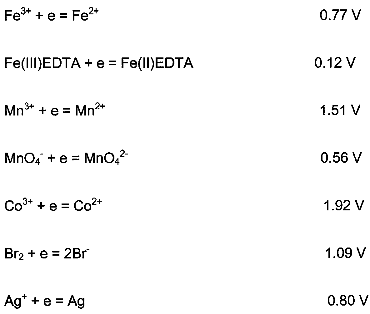
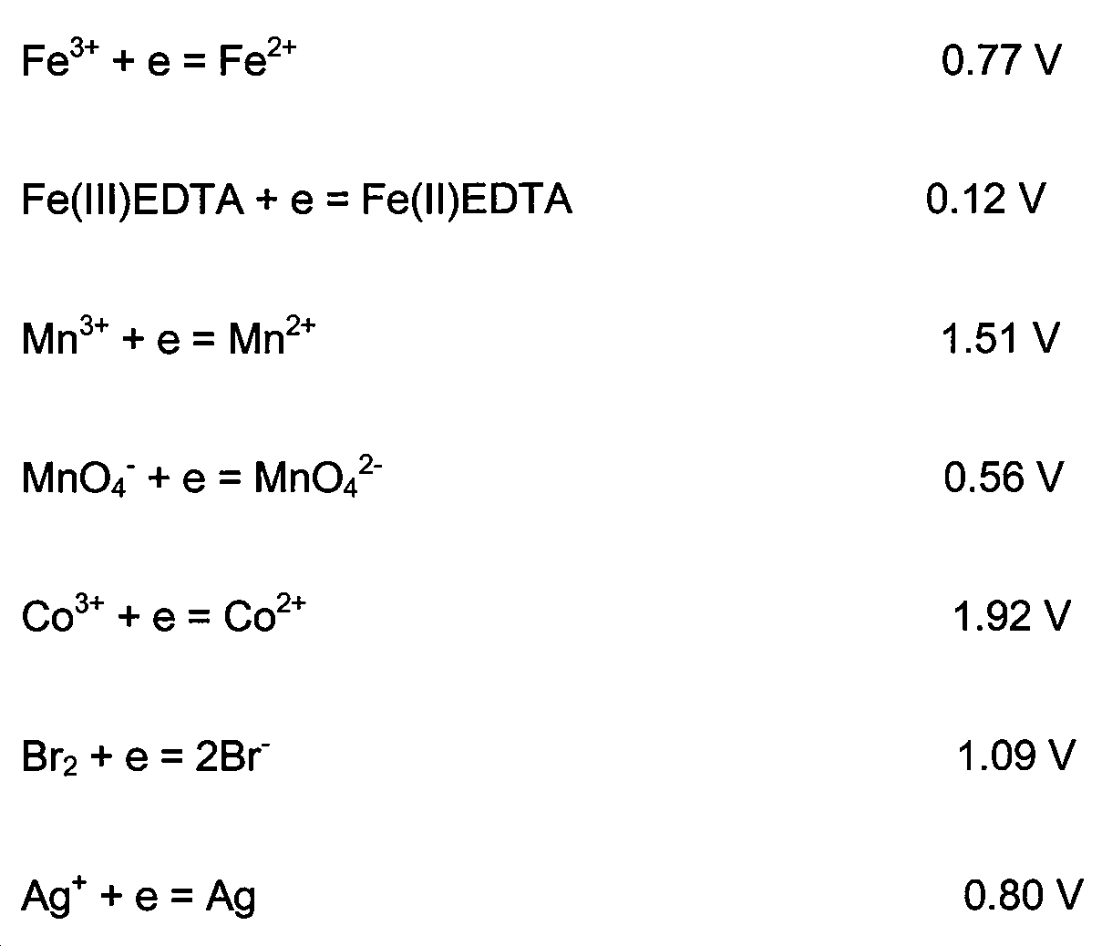
본 발명에 따르면 마이너스 전극실에는 Cr(Ⅲ)EDTA/Cr(Ⅱ)EDTA(-0.9 V), Zn2 +/Zn(-0.76 V), Fe2 +/Fe(-0.44 V), V3+/V2+(-0.26 V), S/S2-(-0.48 V), MV2+/MV+(-0.45 V), 혐기성 미생물(-0.3 V), 플러스 전극실에는Fe3 +/Fe2 +(0.77 V), Fe(Ⅲ)EDTA/Fe(Ⅱ)EDTA(0.12 V), Mn3 +/Mn2 +(1.51 V), MnO4 -/MnO4 2 -(0.56 V), Co3+/Co2+(1.92 V), Br2/2Br-(1.09 V), Ag+/Ag(0.80 V)들과 높로 낮은 환원전압그룹들이 주요 전자전달 작용을 하나 이들은 적당한 혼합 용액으로 목적에 따라 제조할 수 있다. 이들 혼합되어 있는 이온들 중에는 전극에 석출되어 촉매 역할을 하여 전지의 효율을 향상시키는 효과를 기대할 수 있다. 용액에서 전기장 하에서 이온의 이동을 높혀서 전기 전도도를 높이 유지하기 위하여 지지전해질을 사용하고 pH를 일정하게 유지하기 위하여 전해질을 완충액으로 준비한다. 본 발명에서는 pH가 극단적으로 낮아서 전지의 구성 재료들의 부식에 의한 작동 장애를 막을 수 있는 pH의 범위를 사용할 수 있는 조건을 제시했다.
활물질로서 1 M Zn2 +/1 M Fe2 +의 혼합의 0.4 L의 예에서는 이론 최대 전력밀도는 에너지밀도는 2 셀 적층 배터리의 개방회로 전압 4.25 V를 이용하면 227.8 Wh/L로 계산이 되고 20 옴의 방전의 평균 전압 2.02 V를 사용하면 에너지 밀도는 108.3 Wh/L를 얻게 된다. 이론적 용량은 21.4 Ahr으로 계산이 된다. 이는 같은 농도의 경우도 바나듐 산화환원 흐름 배터리와 용량은 같더라도 이론 에너지 밀도는 거의 2 배 이상 높은 것으로 계산이 되기 때문에 같은 농도의 높은 환원전위의 중금속의 선택으로 성능은 획기적으로 향상되었다. 본 발명에서의 이러한 혼합 전해질 형의 새로운 고성능의 산화환원 흐름 배터리(RFB)의 전력저장과 태양광 발전이나 유휴 전력의 저장 시스템 연계 장치는 국내외 발명의 예가 없기 때문에 신재생 에너지 연계 사용의 새로운 패러다임을 제공한다.
한편, 혐기성 미생물을 마이너스 극의 주요 활물질로의 사용은 일반 산화환원 흐름 배터리가 충전과 방전만 가능한 기존 저장 시스템에 비하여 유기물 폐수처리와 함께 전기생산이라는 새로운 장점이 있다. 중금속 재생 시스템과 연계된 미생물 전지의 에너지재생 시스템도 가능하며, 복합 중금속 이온으로 오염된 중금속 폐수도 사용이 가능하다.The present invention relates to a method and apparatus for efficiently utilizing irregular power generated from a renewable energy generation system such as solar power by using a large capacity storage capacity of a redox flow battery (RFB) and a stable discharge characteristic of a stored power, It can be applied to achievement. In order to expand the power and the energy, it is preferable to stack the unit cells by a bipolar method. Also, in the aqueous solution system and the non-aqueous system, two kinds of active materials having low and high reduction potentials of at least two redox pairs having excellent electrochemical characteristics such as electron transporting ability should be contained in the oxidized electrode chamber and the reduced electrode chamber. A high performance is achieved by using a mixed electrolyte of two or more pairs of active materials at the same concentration without discriminating between two groups of the oxidizing electrode chamber and the reducing electrode chamber. If the same solution is used in both electrode chambers, it is possible to prevent the mixing of the active materials in the two electrode chambers due to diffusion under the best conditions in which all the redox materials exist in a solution state. The loss of available power can be minimized. Even when there is a change in the concentration due to the crystallization of the redox substance during charging, the discharging material recovers the liquid state of the initial charging material, thereby minimizing the mixing phenomenon even during long discharge. The present invention expands the usable range of the separator of the battery by controlling the mass transfer mechanism itself in the battery, thereby achieving a reduction in cost, weight, and durability of the redox flow battery, thereby finding an enormous economic advantage . The use of this mixed electrolyte widened the horizon of resource utilization by making it possible to use heavy metal wastewater containing various redox substances. In the lamination of the battery, when the lamination is made, the performance and durability of the battery are degraded and the electrolyte is lost. In the present invention, the use of an O-ring and molding of the layer material of the lamination layer can prevent the leakage phenomenon thoroughly to achieve a high voltage and a high current, realize a high energy and realize a remarkable improvement of the storage capacity of electric energy. .
According to the present invention, Cr is a negative electrode chamber (Ⅲ) EDTA / Cr (Ⅱ ) EDTA (-0.9 V), Zn 2 + /Zn(-0.76 V), Fe 2 + /Fe(-0.44 V), V 3+ / V 2+ (-0.26 V), S / S 2- (-0.48 V), MV 2+ / MV + (-0.45 V), anaerobic bacteria (-0.3 V), positive electrode chamber, the Fe 3 + / Fe 2 + (0.77 V), Fe (ⅲ) EDTA / Fe (ⅱ) EDTA (0.12 V), Mn 3 + / Mn 2 + (1.51 V), MnO 4 - / MnO 4 2 - (0.56 V), Co 3 + / Co 2+ (1.92 V), Br 2 / 2Br - (1.09 V), Ag + / Ag ( 0.80 V) and low and low voltage groups are the main electron transfer functions. Can be manufactured. Among these mixed ions, it is possible to expect the effect of precipitating on the electrode to serve as a catalyst, thereby improving the efficiency of the battery. In order to keep the ion conductivity high in the solution under the electric field to maintain the electric conductivity, the electrolyte is used and the electrolyte is prepared as the buffer to keep the pH constant. In the present invention, the pH is extremely low, thereby providing a condition for using a range of pH that can prevent malfunction due to corrosion of constituent materials of the battery.
In a 0.4 L example of a 1 M Zn 2 + / 1 M Fe 2 + mixture as the active material, the theoretical maximum power density is calculated to be 227.8 Wh / L using an open circuit voltage of 4.25 V for a two cell stacked battery Using an average voltage of 2.02 V at a discharge of 20 ohms, the energy density is 108.3 Wh / L. The theoretical capacity is calculated as 21.4 Ahr. This is because, even at the same concentration, the theoretical energy density is almost twice as high as that of the vanadium redox flow battery, so that the performance is greatly improved by the selection of heavy metals at the same high concentration of reducing potential. In the present invention, there is no example of the invention of the new high performance redox flow battery (RFB) type electric power storage of the mixed electrolyte type and the connection system of solar power generation or idle power storage system in the present invention, so a new paradigm to provide.
On the other hand, the use of the anaerobic microorganism as a main active material of the negative polarity has a new advantage in that the conventional redox flow battery can be treated with organic wastewater and electricity production as compared with existing storage systems capable of only charging and discharging. It is possible to use energy recovery system of microbial cell connected with heavy metal regeneration system, and heavy metal wastewater contaminated with complex heavy metal ions can be used.
Description
본 발명은 태양광 발전과 같은 신재생 에너지의 전력은 산화환원 흐름 배터리에 충전방법으로 저장하고 전력 요구시에 방전하여 송출하기 위하여 저렴한 높은 환원전위와 낮은 환원전위를 가진 다수의 산화환원 물질을 혼합하여 제조하여 분리막을 통한 농도확산을 최소화하여 용액의 섞임을 방지하여 산화환원 플로우 배터리의 자체 방전을 역시 최소화하여 분리막의 선택범위를 확대하고 전지의 내구성을 대폭적으로 증대시키는 방법에 관련된다.The present invention relates to an apparatus and a method for mixing a plurality of redox materials having a low and high reduction potential, which are inexpensive and low in potential, for storing power of a renewable energy such as photovoltaic power generation in a redox flow battery as a charging method, The present invention relates to a method for minimizing diffusion of a solution through a separation membrane to prevent mixing of a solution to minimize the self-discharge of a redox flow battery, thereby enlarging a selection range of the separation membrane and greatly increasing the durability of the battery.
태양광과 풍력과 같은 신재생 에너지원은 종전보다도 최근 대량 설치되고 있다. 그러나 이들 자원은 간헐적이며 예측이 어렵기 때문에 전기수요를 그에 의존하는 데는 한계점이 있고, 더군다나 신속처리할 수 없는 신재생 에너지가 저장 없이 전력생산 용량의 20%를 넘으면 전력망은 불안정화된다. 그러나 많은 전기 설비들은 이 수준의 설치에 접근하는 신재생 항목을 실천하도록 하고 있다. 따라서 전력 저장의 가치 있는 제안이 신재생 자원의 구성, 부하 균형, 기존 전력의 효율적인 이용과 수요에 대한 반응을 통해서 나타나고 송전과 배전의 인프라 스트럭쳐의 개발을 유회하여 전기공급 시설의 융통성을 제공한다. 또한 신재생 에너지 표준을 보완하고 활성화하는 저장 기술에 대한 수요가 증가하고 있다. 미국에서는 에너지 저장기술이 개발되고 개선됨에 따라서 정부 수준의 프로그램은 에너지 저장 설치를 권장하기 위하여 보조금과 여러가지 인센티브를 제공함으로써 경제적인 위험도를 완화해주기 시작했다. 국내에서도 풍력과 같은 신재생 에너지 저장에는 보조금을 제공하거나 인센티브를 제공하기 시작하고 있다. 가격 감소, 인센티브 증가, 수요부응의 증대되는 필요, 에너지 효율 및 구성된 시장의 집중 완화 이 모든 요소들이 상업적인 위험도를 감당하기 쉬운 것으로 만들고 있다.Renewable energy sources such as solar power and wind power have been installed more recently than before. However, these resources are intermittent and difficult to predict, so there is a limit to relying on electricity demand. Moreover, if the renewable energy, which can not be processed quickly, exceeds 20% of the electricity production capacity without storage, the power grid becomes destabilized. However, many electrical appliances are required to implement new and renewable items that approach this level of installation. Thus, valuable proposals for power storage appear through the composition of renewable resources, load balancing, efficient use of existing power and response to demand, and provide flexibility in the electricity supply facility by bypassing the development of transmission and distribution infrastructure. There is also a growing demand for storage technologies that complement and activate renewable energy standards. In the United States, as energy storage technologies are developed and improved, government-level programs have begun to mitigate economic risks by providing subsidies and various incentives to encourage energy storage installations. In Korea, subsidies or incentives are being offered for the storage of renewable energy such as wind power. Reduced prices, increased incentives, the growing need for demand response, energy efficiency, and concentrated market mitigation all make it easier for commercial risks.
전기 에너지를 비수기에 저장하였다가 최고 수요의 시점에서 송출하는 저장장치의 능력은 산화환원 흐름 배터리의 역할로부터 얻을 수 있다. 산화환원 흐름 배터리 기초기술은 개발된지 오래 되었으나 최근 비교적 저렴하고 효과적으로 많은 전기 에너지를 저장하는 능력이 확인 되고있기 때문에 재개발이 활발히 진행되고 있다. 이 전지에는 기본적으로 여러가지 산화환원 쌍을 사용할 수 있으나 바나듐 산화환원 흐름 배터리가 국내외적으로 실용을 위하여 시험 중에 있다. 바나듐 흐름 배터리의 전해질은 바나듐 옥사이드를 2 몰 농도의 황산을 가지고 제조하기 때문에 낮은 pH로 인하여 비싼 펌푸를 사용하여야 하는 등 경제적인 사용에 어려운 점이 있다. 더군다나 얻은 수 있는 개방회로 전압이 약 1.26 V 정도로 높은 전압은 허용하지 않는다. 또한 나피온과 같은 고가의 분리막을 사용하여야 하기 때문에 생산단가를 낮추기가 어렵고 높은 전류를 유도하기 위한 기술이 적용되어야 고에너지를 달성할 수 있다. 본 발명에서는 높은 환원전위와 낮은 환원전위를 가지고 있는 산화환원 쌍들을 다수 사용하여 분리막으로 분리한 마이너스 극실 용액과 플러스 극실 용액을 공통으로 사용하여 확산에 의한 양쪽 극실의 용액이 섞임을 방지하고 충방전시 전자 이동의 균형을 추가적인 적당한 산화환원 물질로 보완하는 방법에 주안점을 두고 있다. 양쪽 극실 용액의 상호 섞임은 이온의 확산과 이동에 의하여 일어날 수 있는데 이동에 의해서는 전극의 분극 극성에 반대되는 이온들이 전기 중성을 이루기 위하여 상호 이동을 하게 되고 확산은 농도 차이가 나게 되면 거리에 대한 농도 구배에 의하여 이동의 원인이 생겨 상호 이동이 있게 된다. 특히 전지의 에너지 효율과 내구성을 갖기 위해서는 전극실의 활물질의 상호 섞임은 제한하여야 하는 요소인데 지지전해질을 높게 사용하고 농도를 양쪽 극실에 같게 하면 이러한 산화환원 활물질의 확산은 최소화할 수 있게 된다. 이러한 확산에 의한 상호 활물질의 상호 섞임의 방지는 이온 교환막에서 비교적 저렴한 다공성 거름막의 사용에 이르기까지 분리막의 선택의 폭을 넓혀 전지의 생산 단가를 낮추는데 공헌할 수 있다.The ability of the storage device to store electrical energy in off-peak hours and then deliver it at peak demand can be derived from the role of the redox flow battery. The redox flow battery base technology has been developed for a long time, but recently redevelopment has been actively carried out because of its ability to store a lot of electric energy relatively cheaply and effectively. Various redox pairs can be used in this battery basically, but vanadium redox flow battery is being tested for practical use both domestically and abroad. The electrolyte of the vanadium-flow battery is difficult to use economically because it requires to use expensive pump due to low pH because vanadium oxide is produced with sulfuric acid of 2 molar concentration. Moreover, the open circuit voltage that can be obtained does not allow a voltage as high as about 1.26 V. Also, because expensive membrane such as Nafion should be used, it is difficult to lower the production cost and high energy can be achieved by applying a technique for inducing a high current. In the present invention, by using a plurality of redox couples having a high reduction potential and a low reduction potential and using a negative solution and a positive solution which are separated into a separation membrane, the solution of the two compartments due to diffusion can be prevented from being mixed, The focus is on how to compensate the balance of electron transport with additional redox materials. The mutual mixing of the two polar solution solutions can be caused by the diffusion and migration of ions. Ions opposite to the polarity of polarity of the electrodes move with each other in order to achieve electrical neutrality. Concentration gradients cause migration and mutual migration. Particularly, in order to have energy efficiency and durability of a battery, intermixing of active materials in the electrode chamber should be restricted. If the electrolyte is used at a high level and the concentration is equalized in both chambers, the diffusion of the redox active material can be minimized. Prevention of mutual mixing of the active materials by such diffusion can contribute to lowering the production cost of the battery by widening the selection of the separator from the ion exchange membrane to the use of the relatively inexpensive porous membrane.
본 발명의 목적은 기존의 태양광 저장 장치에 사용되는 효율이 낮고 대용량화에 어려운 납산 배터리는 특정 시간 동안만 축전이 가능하다는 저장 능력의 한계점이 있다. 이를 개선하는 방책으로 바나듐 산화환원 흐름 배터리와 같은 배터리가 나왔는데 이 또한 강한 산성도에 의한 강한 부식성 때문에 높은 가격의 펌프를 써야 하기 때문에 생산단가를 낮추기 어려운 문제점이 있다. 또한 단위 셀에서 얻을 수 있는 전압이 1.24 V에 지나지 않아서 고 전류의 성취가 아니면 고에너지 배터리 제조에 어려움이 있다. 또한 일반적으로 산화환원 흐름 배터리에서는 분리막을 사이에 두고 활물질의 상호 섞임현상 때문에 배터리의 성능은 물론 내구성에 문제가 있다. 본 발명에서의 주안점은 이러한 기존 산화환원 흐름 배터리의 단점을 개선하여 이의 경제적인 실용화에 있다. 또한 배터리의 조합방법에서 적층의 누액을 막고 단단하게 만드는 방법을 개발하여 실용적인 에너지의 저장 및 재사용의 패러다임을 제공하는 것이다.SUMMARY OF THE INVENTION It is an object of the present invention to provide a storage battery capable of storing electricity for a predetermined period of time, which is low in efficiency and difficult to be used in a conventional solar cell. As a countermeasure to improve this, a battery such as a vanadium redox flow battery has come out, which also has a problem of difficulty in lowering the production cost because it is required to use a high-priced pump due to strong corrosiveness due to strong acidity. Also, since the voltage obtained from the unit cell is 1.24 V, it is difficult to manufacture a high-energy battery unless high current is achieved. In general, in a redox flow battery, there is a problem of durability as well as performance of a battery due to mutual mixing of active materials with a separator interposed therebetween. The main point of the present invention is to improve the disadvantages of such a conventional redox flow battery and economically practical use thereof. In addition, by developing a method of preventing leakage of laminate and making it hard in combination of batteries, it is possible to provide a paradigm of practical energy storage and reuse.
상기 목적을 달성하기 위하여 본 발명에서는 풍력이나 태양광 발전 전력 또는 전력망 전력을 직접 또는 교류/직류 변환기를 사용하여 직류로 변환하여 산화환원 흐름 배터리를 충전하고 이를 방전하여 직류/교류 변환기를 사용하여 성수기에 전력망에 공급하는 체계를 구현한다. 이때 에너지의 효율적인 사용을 위하여 산화환원 흐름 배터리의 사용이 매우 중요하다.In order to achieve the above object, in the present invention, a wind power, a solar power generation power or a power grid power is directly converted into a direct current by using an AC / DC converter, a redox flow battery is charged and discharged, To the power grid. At this time, the use of a redox flow battery is very important for efficient use of energy.
혼합 전해질을 사용하여 산화전극실과 환원전극실 사이에 확산에 의한 혼합을 막는 방법에 의한 산화환원 흐름 배터리의 성능향상Performance improvement of redox flow battery by preventing mixing by diffusion between oxidized electrode chamber and reduced electrode chamber using mixed electrolyte
태양광과 같은 신재생 에너지 발전시스템으로부터 나오는 전력을 값싼 저장시스템에 저장하여 필요한 시간과 조건에서 방전하여 사용하는 산화훤원 흐름형 전지에서는 산화물질과 환원물질의 쌍이 매우 중요하다. 충전시에 마이너스 극인 산화전극실과 플러스극인 환원전극실에 산화물질과 환원물질을 혼합한 동 용액을 사용하여 두 개의 저장통으로 회전하게 하여 충전을 하면 마이너스 극에서는 전해질의 환원반응이 일어나 환원된 물질이 축적되고 플러스 극에서는 산화반응이 일어나 산화된 물질이 축적이 된다. 방전 시에 마이너스 극에서는 충전 시에 축적되었던 물질이 산화되어 마이너스 전극으로 전자가 이동되어 외부 부하로 흐르게 되고 플러스 극에서는 충전 시에 축적되었던 물질이 환원되어 전극으로부터 전자가 용액 속에 있는 환원가능한 충전 시에 축적된 물질로 흡수된다.In an oxidizing gas flow type battery in which power from a renewable energy generation system such as solar energy is stored in an inexpensive storage system and discharged at necessary time and conditions, a pair of an oxidizing substance and a reducing substance is very important. When the battery is charged by using a copper solution in which an oxidizing substance and a reducing substance are mixed in a negative electrode electrode chamber and a positive electrode electrode chamber during charging, the electrolyte is reduced at the negative electrode, and the reduced material In the positive electrode, an oxidation reaction occurs and the oxidized material accumulates. At the negative electrode during discharging, the material accumulated at the time of charging is oxidized and the electrons are moved to the negative electrode to flow to the external load. At the positive electrode, the material accumulated at the time of charging is reduced, Is absorbed by the accumulated substance in the water.
용액에서는 분리막을 통하여 이온의 이동이 일어나 전기적인 회로는 폐회로를 형성하여 전지는 지속적으로 작동이 가능하게 된다. 양쪽 전극실에 같은 용액을 사용하기 때문에 확산에 의한 분리막을 통한 용액 섞임이 일어나지 않는 것이 혼합형 전해질 사용의 특징이다. 따라서 전지에서 이온의 이동은 보장하되 용액의 섞임 방지되는 것이 보장되기 때문에 사용할 수 있는 분리막의 범위가 자유로워져서 음이온 교환막, 양이온 교환막, 미세다공막 등을 사용하여 분리막에 드는 비용을 절감하는 효과가 있다.In the solution, ion movement occurs through the separation membrane, and the electrical circuit forms a closed circuit, so that the battery can be continuously operated. Because the same solution is used in both electrode chambers, the fact that no solution mixing occurs through the membrane due to diffusion is characteristic of the use of mixed electrolyte. Therefore, it is ensured that the migration of ions in the cell is ensured but the solution is prevented from being mixed, so that the range of usable membrane is freed and the cost for membrane is reduced by using anion exchange membrane, cation exchange membrane and microporous membrane have.
비교적 저렴한 아래와 같은 산화환원 쌍들을 사용하여 혼합형 전해질을 형성하는데 사용이 될 수 있다. 전위는 수소 표준전위를 기준으로 표시하였다. 물을 용매로 사용할 경우 저렴하기는 하나 물 자체의 좁은 전위창으로 말미암아 높은 전력생산을 유지하기 위하여 선택할 수 있는 산화환원 쌍들이 많지 않은 단점은 있다. 비수용액 전해질을 제조하면 넓은 전위창을 이용할 수 있다. 이들 산화환원 쌍들을 마이너스 극과 플러스 극에 사용할 수 있도록 좋은 조합을 하여 이차전지를 구성할 수 있다. 구체적인 산화환원 쌍들을 아래와 같이 제시한다.Can be used to form hybrid electrolytes using relatively low cost redox couples such as the following. The potential was expressed based on the hydrogen standard potential. The use of water as a solvent is inexpensive, but it has a disadvantage in that there are not many redox pairs that can be selected to maintain high power production due to the narrow potential window of the water itself. When a non-aqueous electrolyte is prepared, a wide potential window can be used. These redox pairs can be used in negative and positive electrodes to form a secondary battery. Specific redox pairs are presented below.
마이너스 극에서의 반응 산화환원 쌍Reaction Reduction Pair at Minus Poles

플러스 극에서의 반응 산화환원 쌍Reaction Reduction Pair at the Plus Pole
상기 산화환원 쌍들을 적절하게 지지전해질과 함께 혼합하여 전지 전극실 용액의 전해질을 구성하고 양쪽 전극실에 탄소 판 전극을 사용하고 음이온 교환막이나 0.1, 2-5, 15-30 미크론 정도의 미세한 다공성 막을 사용하여 양쪽 전극실 중앙에 분리막으로 삽입하여 만든 전극실에 넣어 전지를 구성한다. 전지의 에너지는 전압과 전류의 곱인 전력이 중요하기 때문에 높은 전기에너지는 높은 전압과 높은 전류를 얻기 위하여 여러가지 수단을 강구하게 된다. 고전압을 성취하기 위한 좋은 방법으로는 전지를 바이폴라 전극을 이용하여 전지간에 도선의 연결이 없이 바로 직렬 연결을 활용하여 적층법(stacking)을 사용하는 것이 바람직하다. 이 방법에 의하여 산화환원 흐름 배터리 단위 셀의 적층을 실현하여 고전압을 실현하면 효율적인 고전력을 얻을 수 있다.The redox pairs are appropriately mixed with the supporting electrolyte to form an electrolyte of the electrode electrode chamber solution, and a carbon plate electrode is used in both electrode chambers and an anion exchange membrane or a fine porous membrane of about 0.1, 2-5, 15-30 microns And the electrode is inserted into the center of both electrode seals as a separation membrane to form a battery. Because the energy of the battery is the product of the voltage and the current, the high electric energy has various means to obtain high voltage and high current. As a good way to achieve high voltage, it is preferable to use a stacking method using a bipolar electrode and a series connection without wires between the cells. By realizing the stacking of the redox flow battery unit cells by this method and realizing a high voltage, an efficient high power can be obtained.
본 발명에 따르면 대용량의 효율적인 산화환원 흐름 배터리의 구현으로 풍력, 태양광, 심야전력 등을 충전하여 재 방전하여 전력을 전력망에 공급하게 되면 신재생 자원의 구성, 부하 균형, 기존 전력의 효율적인 이용과 수요에 대한 반응을 통해서 송전과 배전의 인프라 스트럭쳐의 개발을 유회하여 전기공급 시설의 융통성을 제공한다. 또한 신재생 에너지 표준을 보완하고 활성화하는 저장 기술에 대한 증대되는 수요에 부응하여 막대한 경제적인 이익을 가져올 수 있다.According to the present invention, when an electric power is supplied to a power grid by charging a wind power, a solar battery, a night power, and the like by recharging and discharging the battery with a large-capacity and efficient redox flow battery, It provides the flexibility of the electricity supply facility by bypassing the development of transmission and distribution infrastructure through response to demand. It can also bring tremendous economic benefits to meet the growing demand for storage technologies that complement and activate renewable energy standards.
도 1은 산화환원 흐름 배터리의 적층구조의 개념도이다.
도 2는 150 KW 산화환원 흐름 배터리 시스템의 모듈, 저장통, 충방전 시스템 및 순환펌푸의 배치도이다.
도 3은 5 KW 모듈의 조감도이다.
도 4은 산화환원 흐름 배터리의 적층 성분들의 세부 배열도이다.
도 5는 산화환원 흐름 배터리 용액의 머무는 영역의 공간을 나타낸다.
도 6은 표 1의 조건에서 FeS04 와 ZnCl2 혼합 활물질의 산화환원 흐름 배터리를 정전류 0.1 A 에서 충전(8 시간)에 대한 전원 공급장치 사용에 의한 충전과 20 Ohms 의 외부전압으로 방전 시의 전압곡선과 전력곡선이다.
도 7은 표 1의 조건에서 FeSO4 와 ZnCl2 혼합 활물질의 산화환원 흐름 배터리를 충전한 후에 부하저항을 사용하여 그린 분극곡선이다. 저항은 150 kΩ 에서 10 Ω 로 변화시켰다.
도 8은 0.25 M FeSO4 and 0.25 M ZnCl2 혼합 활물질(pH 2.3)을 이용한 2 셀 적층 산화환원 흐름 배터리를 전원공급장치를 사용하여 0.3 A의 정전류로 충전하고 of 20 Ω 을 부하저항으로 하여 방전한 충방전 곡선을 나타낸다.
도 9는 표 2의 조건 하에서 충전(3 시간)하고 전류밀도에 따른 전압 및 전력 곡선릉 나타낸다. 외부 저항은 150 kΩ 에서 10 Ω 으로 변화시켰다. 극대 전류밀도 42.5 A/m2 에서 극대 전압 88.6 W/m2 을 얻었다.
도 10은 표 3의 조건에서 0.25 M FeSO4 and 0.25 M ZnCl2 혼합 활물질(pH 2.3)을 이용한 2셀 적층 산화환원 흐름 배터리를 전원공급장치를 사용하여 0.3 A의 정전류로 충전(3 시간)하고 of 20 Ω 을 부하저항으로 하여 방전한 충방전 곡선을 나타낸다.
도 11은 표 3의 조건하에서 충전(0.3 A 정전류, 3 시간)하고 전류밀도에 따른 전압 및 전력곡선을 나타내었다. 외부 저항은 150 kΩ 에서 10 Ω 으로 변화시켰다. 극대 전류밀도 42.5 A/m2 에서 극대 전압 88.6 W/m2 을 얻었다.
도 12은 표 4의 조간 하에서 혼합 활물질 1 M FeSO4 and 1 M ZnCl2 과 1 M Na2SO4(pH 2.0)을 산화환원 흐름 전지 2개를 적층으로 묶은 전지의 충전(0.3 A 정전류, 5 시간)과 방전(20 Ω) 시의 시간대 전압곡선과 시간대 전력곡선을 나타낸다.
도 13은 표 4의 조건으로 충전(0.3 A, 5 시간)한 후 시간대 전압곡선과 시간대 전력곡선을 나타내었다. 외부 부하저항은 150 kΩ 에서 10 Ω 으로 변화시켰다.
도 14는 표 5의 조건하에서 혼합 1 M FeSO4 활물질과 1 M Na2SO4 를 지지 전해질(pH 2.0)로 양쪽 전극실에 사용한 2 개의 산화환원 흐름 단위 셀을 적층으로 묶은 전지를 전원공급장치 정전류 0.3 A 로 충전(5 시간)하고 다시 20 Ω 부하저항을 가지고 방전한 시간대 전압곡선과 시간대 전력곡선을 나타낸다.
도 15는 표 5의 조건으로 충전(0.3 A, 5 시간)한 적층 전지의 시간대 전압곡선과 시간대 전력곡선을 나타낸다. 외부 부하저항은 150 kΩ 에서 10 Ω 으로 변화시켰다.1 is a conceptual view of a laminated structure of a redox flow battery.
FIG. 2 is a layout diagram of a module, a reservoir, a charge / discharge system, and a circulation pump of a 150 KW redox flow battery system.
3 is a bird's-eye view of the 5 KW module.
4 is a detailed arrangement of the stacked components of the redox flow battery.
Figure 5 shows the space of the area of the redox flow battery solution.
6 is a voltage at the time of discharging under the conditions shown in Table 1 to FeS0 4 and ZnCl 2 redox flow of the mixed active material, a battery with an external voltage of the charge and 20 Ohms by the power supply used for charging (8 hours) at a constant current 0.1 A Curve and power curve.
7 is a green polarization curve using a load resistance after charging a redox flow battery of FeSO 4 and ZnCl 2 mixed active material under the conditions of Table 1. The resistance was changed from 150 kΩ to 10 Ω.
FIG. 8 is a graph showing the results of charging a 2-cell stacked redox flow battery using 0.25 M FeSO 4 and 0.25 M ZnCl 2 mixed active material (pH 2.3) with a constant current of 0.3 A using a power supply, Discharge curve.
FIG. 9 shows charging and discharging currents according to the current density under the conditions shown in Table 2 (3 hours). The external resistance was changed from 150 kΩ to 10 Ω. A maximum voltage of 88.6 W / m 2 was obtained at a maximum current density of 42.5 A / m 2 .
10 is a graph showing the results of a two-cell laminated oxidation-reduction flow battery using 0.25 M FeSO 4 and 0.25 M ZnCl 2 mixed active material (pH 2.3) under the conditions shown in Table 3 and charging the battery at a constant current of 0.3 A for 3 hours of 20 Ω as a load resistance.
11 shows the voltage and power curves according to the current density after charging under the conditions of Table 3 (0.3 A constant current, 3 hours). The external resistance was changed from 150 kΩ to 10 Ω. A maximum voltage of 88.6 W / m 2 was obtained at a maximum current density of 42.5 A / m 2 .
12 is a graph showing the results of measurement of a mixed active material 1 M FeSO 4 and 1 M ZnCl 2 (0.3 A constant current, 5 hours) and discharge (20 Ω) of 1 M Na 2 SO 4 (pH 2.0) in a stack of two redox flow cells are shown .
FIG. 13 shows the time zone voltage curve and the time zone power curve after charging (0.3 A, 5 hours) under the conditions shown in Table 4. The external load resistance was changed from 150 kΩ to 10 Ω.
FIG. 14 is a graph showing the results of measurement of a cell in which two redox flow unit cells, each having a mixed electrolyte of 1 M FeSO 4 and 1 M Na 2 SO 4 in a supporting electrolyte (pH 2.0) The time curve shows the time-period voltage curve and the time-zone power curve after charging with a constant current of 0.3 A (5 hours) and discharging with a 20 Ω load resistance.
Fig. 15 shows the time zone voltage curve and the time zone power curve of a laminated battery packed under the conditions of Table 5 (0.3 A, 5 hours). The external load resistance was changed from 150 kΩ to 10 Ω.
실시예 1; 산화환원 흐름 배터리의 적층구조Example 1; Laminated structure of redox flow battery
다음의 실시 예는 전지 모듈의 승압을 하기 위하여 산화환원 흐름 배터리의 단위 셀을 적층구조로 연결하여 전지 모듈을 제작하고 외부 전력을 직류로 변환하여 산화환원 흐름 배터리에 인가하여 충전하고 필요 시에 방전하여 외부로 전력을 송출하는 개념도를 표시하고 있다(도 1). 도 2은 더 자세히 중앙에 산화환원 흐름 배터리가 있고 양 옆에는 애노드 전해질 저장통과 캐소드 전해질 저장통이 있고 산화환원 흐름 배터리로는 발전기나 전력회사의 전력이 들어와서 충전이 되고 충전된 전기 에너지는 활물질로서 양 저장통에 저장이 되었다가 필요 시에 방전하여 소비자에게 공급이 되는 모식도를 보여주고 있다. 도 2는 150 KW 산화환원 시스템을 구축하기 위해서 모듈들이 치밀하게 배치되는 양상을 보여주고 있다. 상층에 전지 충방전 관리 시스템이 중앙에 놓이고 양 옆에는 활물질과 전해질의 순환을 원활히 하기 위한 두개의 펌프가 용액 매니폴드와 연결된다. 이들은 충방전과 용액 순환은 전지 조절 시스템을 위한 컴퓨터에 의하여 통제된다. 적층 모듈은 5 KW 적층으로 구성된다(도 3). 외관상 분리막을 중심으로 앞쪽에는 애노드 전해질 입수구와 캐소드 전해질 입수구가 있고 뒤쪽으로는 출수구가 놓이게 된다. 양극단 맨 마지막 바이폴라 판에는 집전체 동판이 접촉하고 이들은 플러스 극과 마이너스 극으로 적용이 된다.In the following embodiment, the unit cells of the redox flow battery are connected in a laminated structure to increase the voltage of the battery module, and the battery module is manufactured. The external power is converted into DC, charged to the redox flow battery, And transmits power to the outside (FIG. 1). FIG. 2 is a graph showing the relationship between an anode and a cathode, and FIG. 2 is a graph showing the relationship between the anode and the cathode. It is stored in both reservoirs and discharged when necessary, showing a schematic diagram of supply to consumers. FIG. 2 shows the manner in which the modules are arranged in a precise manner in order to construct a 150 KW redox system. At the top, a battery charge / discharge management system is located at the center, and two pumps are connected to the solution manifold to smooth the circulation of the active material and the electrolyte. These are controlled by a computer for charge control and charge and discharge cycles. The lamination module is composed of 5 KW lamination (Fig. 3). The anode electrolyte inlet and the cathode electrolyte inlet are located on the front side of the separator, and the outlet is located on the rear side. At the very end of the bipolar plate, the copper plate of the current collector is in contact with the positive bipolar plate and the negative bipolar plate.
도 4는 산화환원 플로우 배터리 단위 셀을 바이폴라 방법으로 복수로 연결하여 고전압을 이루고 전극 면적을 크게 하여 전류를 배증하는 방법을 제시하고 있다. 단위 셀 사이의 연결은 저항이 낮은 바이폴라에 의하여 적층됨을 주목하여야 한다. 도 5는 활물질 용액이 전지의 전해질로 존재하면서 전극 표면에서 전극반응을 일으키고 통과하는 영역으로 일반 전지의 전극실에 해당된다. 이 공간을 주는 판과 전극판 또는 분리막은 누액이 일어나지 말아야 하기 때문에 오링 홈에 고무 오링을 넣어 적층이 되었을 때 밀폐되게 하였다.FIG. 4 shows a method of doubling the current by connecting a plurality of redox flow battery unit cells by a bipolar method to form a high voltage and increasing the electrode area. It should be noted that the connection between the unit cells is laminated by a low-resistance bipolar. FIG. 5 is a region where an active material solution is present as an electrolyte of a battery, causing an electrode reaction at an electrode surface and passing through the electrode, and corresponds to an electrode chamber of a general cell. Since the plate and the electrode plate or the separating membrane which give this space should not leak, the rubber O-ring is put into the O-ring groove to be sealed when laminated.
여기에 그림과 같이 활물질과 전해질의 입수구와 출수구가 위치하게 된다. 이들은 가지고 실험한 모듈은 누액이 없이 고전압과 고전류를 성취할 수 있었다.Here, the inlet and outlet of the active material and the electrolyte are located as shown in the figure. The modules they experimented with were able to achieve high voltage and high current without leakage.
실시예 2: 혼합 전해질을 사용하여 산화전극실과 환원전극실 사이에 확산에 의한 혼합을 막는 방법에 의한 산화환원 흐름 배터리의 성능향상Example 2: Improving the performance of a redox flow battery by a method of preventing mixing by diffusion between an oxidizing electrode chamber and a reducing electrode chamber using a mixed electrolyte
태양광과 같은 신재생 에너지 발전시스템으로부터 나오는 전력을 값싼 저장시스템에 저장하여 필요한 시간과 조건에서 방전하여 사용하는 산화훤원 흐름형 전지에서는 산화물질과 환원물질의 쌍이 매우 중요하다. 충전시에 마이너스 극인 산화전극실과 플러스 극인 환원전극실에 산화물질과 환원물질을 혼합한 동 용액을 사용하여 두 개의 저장통으로 회전하게 하여 충전을 하면 마이너스 극에서는 전해질의 환원반응이 일어나 환원된 물질이 축적되고 플러스 극에서는 산화반응이 일어나 산화된 물질이 축적이 된다. 방전시에 마이너스 극에서는 충전시에 축적되었던 물질이 산화되어 마이너스 전극으로 전자가 이동되어 외부 부하로 흐르게 되고 플러스 극에서는 충전시에 축적되었던 물질이 환원되어 전극으로부터 전자가 용액 속에 있는 환원가능한 충전시에 축적된 물질로 흡수된다. 용액에서는 분리막을 통하여 이온의 이동이 일어나 전기적인 회로는 폐회로를 형성하여 전지는 지속적으로 작동이 가능하게 된다. 양쪽 전극실에 같은 용액을 사용하기 때문에 확산에 의한 분리막을 통한 용액 섞임이 일어나지 않는 것이 혼합형 전해질 사용의 특징이다. 따라서 전지에서 이온의 이동은 보장하되 용액의 섞임 저지되는 것이 보장되기 때문에 사용할 수 있는 분리막의 범위가 자유로워져서 음이온 교환막, 양이온 교환막, 미세 다공막 등을 사용하여 분리막에 드는 비용을 절감하는 효과가 있다.In an oxidizing gas flow type battery in which power from a renewable energy generation system such as solar energy is stored in an inexpensive storage system and discharged at necessary time and conditions, a pair of an oxidizing substance and a reducing substance is very important. When the battery is charged by using a copper solution in which an oxidizing substance and a reducing substance are mixed in a negative electrode electrode chamber and a positive electrode electrode chamber during charging, the electrolyte is reduced at the negative electrode, and the reduced material In the positive electrode, an oxidation reaction occurs and the oxidized material accumulates. At the negative electrode during discharging, the material accumulated at the time of charging is oxidized and the electrons are moved to the negative electrode to flow to the external load. At the positive electrode, the material accumulated at the time of charging is reduced, Is absorbed by the accumulated substance in the water. In the solution, ion movement occurs through the separation membrane, and the electrical circuit forms a closed circuit, so that the battery can be continuously operated. Because the same solution is used in both electrode chambers, the fact that no solution mixing occurs through the membrane due to diffusion is characteristic of the use of mixed electrolyte. Therefore, it is ensured that the transfer of ions in the cell is ensured but the mixing of the solution is prevented, so that the range of the separation membrane that can be used is freed, and the cost for separation membrane is reduced by using anion exchange membrane, cation exchange membrane, and microporous membrane have.
비교적 저렴한 아래와 같은 산화환원 쌍들을 사용하여 혼합형 전해질을 형성하는데 사용이 될 수 있다. 전위는 수소 표준전위를 기준으로 표시하였다. 물을 용매로 사용할 경우 저렴하기는 하나 물 자체의 좁은 전위창으로 말미암아 높은 전력생산을 유지하기 위하여 선택할 수 있는 산화환원 쌍들이 많지 않은 단점은 있다. 비수용액 전해질을 제조하면 넓은 전위창을 이용할 수 있다. 이들 산화환원 쌍들을 마이너스 극과 플러스 극에 사용할 수 있도록 좋은 조합을 하여 이차전지를 구성할 수 있다. 양쪽 극실의 전자전달 반응에서 전기량의 불균혀이 있을 수 있다. 특히 플러스 극에는 마이너스 극에 비하여 전기량이 적은 경우가 많다. 이런 경우에는 Br-와 같은 추가적인 산화환원 쌍을 넣어 균형을 맞추어준다. 구체적인 산화환원 쌍들을 아래와 같이 제시한다.Can be used to form hybrid electrolytes using relatively low cost redox couples such as the following. The potential was expressed based on the hydrogen standard potential. The use of water as a solvent is inexpensive, but it has a disadvantage in that there are not many redox pairs that can be selected to maintain high power production due to the narrow potential window of the water itself. When a non-aqueous electrolyte is prepared, a wide potential window can be used. These redox pairs can be used in negative and positive electrodes to form a secondary battery. There may be asymmetry in the amount of electricity in the electron transfer reaction of both the chambers. In particular, the positive polarity is often less than the negative polarity. In this case, add an additional redox pair such as Br - to balance. Specific redox pairs are presented below.
마이너스 극에서의 반응 산화환원 쌍Reaction Reduction Pair at Minus Poles

플러스 극에서의 반응 산화환원 쌍Reaction Reduction Pair at the Plus Pole
상기 산화환원 쌍들을 적절하게 지지전해질과 함께 혼합하여 전지의 180 mL의 전극실 용액 부피의 전해질을 구성하고 양쪽 전극실에 25 cm 2 면적의 탄소 판 전극을 사용하고 음이온 교환막이나 0.1, 2-5, 15-30 미크론 정도의 미세한 다공성 막을 사용하여 각양쪽 전극실 중앙에 분리막으로 삽입하여 만든 전극실에 넣었다. 전극간 거리는 약 3 cm이었다. 1 M ZnSO4 + 1 M FeSO4 + 1 M Na2SO4 at pH 2의 용액을 음이온 교환막을 사용한 경우, 0.5 A의 정전류로 180분 동안 충전을 하였다. 20 옴의 저항을 가지고 거의 180분 동안 20 옴의 저항을 가지고 거의 180분 동안 2.0 V에서 0.96 V를 유지하며 큰 변동이 없이 전압을 유지하며 방전이 되었다.The redox couples were appropriately mixed with the supporting electrolyte to form an electrolyte having a volume of 180 mL of the electrode chamber solution of the battery, and a carbon plate electrode having an area of 25 cm 2 was formed in both electrode chambers. Anion exchange membranes and 0.1, 2-5 , And a 15-30 micron fine porous membrane was inserted into the electrode chamber formed by inserting it as a separation membrane at the center of both electrode seals. The distance between electrodes was about 3 cm. When a solution of 1 M ZnSO 4 + 1 M FeSO 4 + 1 M Na 2 SO 4 at
1 M FeSO4 + 1 M FeSO4 + 1 M Na2SO4 at pH 2의 용액을 음이온 교환막을 사용하여 각 180 mL의 전극실 용액 부피의 양쪽 전극실 중앙에 분리막으로 삽입하여 만든 전극실에 넣었다. 0.5 A의 정전류로 180분 동안 충전을 하였다. 20옴의 저항을 가지고 거의 180분 동안 1.2 V에서 0.96 V를 유지하며 큰 변동이 없이 전압을 유지하며 방전이 되었다. 1 M Na2S + 1 M FeSO4 + 1 M Na2SO4 at pH 2의 용액을 음이온을 사용하여 각 180 mL의 전극실 용액 부피의 양쪽 전극실 중앙에 분리 막으로 삽입하여 만든 전극실에 넣었다. 0.5 A의 정전류로 180 분 동안 충전을 하였다. 20옴의 저항을 가지고 거의 180 분동안 1.2 V에서 0.96 V를 유지하며 큰 변동이 없이 전압을 유지하며 방전이 되었다.A solution of 1 M FeSO 4 + 1 M FeSO 4 + 1 M Na 2 SO 4 at
2 M V2O5 + 2 M H2SO4 + 1 M Na2SO4의 용액을 음이온 교환막을 사용하여 각 180 mL의 전극실 용액 부피의 양쪽 전극실 중앙에 분리막으로 삽입하여 만든 전극실에 넣었다. 0.5 A의 정전류로 180분 동안 충전을 하였다. 0.5 A의 정전류로 180 분 동안 충전을 하였다. 20 옴의 저항을 가지고 거의 180 분동안 1.2 V에서 0.96 V를 유지하며 큰 변동이 없이 전압을 유지하며 방전이 되었다. 1 M ZnSO4 + 1 M CoSO4 + 1 M Na2SO4 at pH 2의 용액을 음이온 교환막을 사용하여 각 180 mL의 전극실 용액부피의 양쪽 전극실 중앙에 분리막으로 삽입하여 만든 전극실에 넣었다. 0.5 A의 정전류로 180 분 동안 충전을 하였다. 20옴의 저항을 가지고 거의 180분 동안 2.2 V에서 1.5 V를 유지하며 큰 변동이 없이 전압을 유지하며 방전이 되었다. 1 M ZnSO4 + 1 M MnSO4 + 1 M Na2SO4 at pH 2의 용액을 음이온 막을 사용하여 각 180 mL의 전극실 용액부피의 양쪽 전극실 중앙에 분리막으로 삽입하여 만든 전극실에 넣었다. 0.5 A의 정전류로 180 분 동안 충전을 하였다.20 옴의 저항을 가지고 거의 180 분동안 2.2 V에서 1.5 V를 유지하며 큰 변동이 없이 전압을 유지하며 방전이 되었다. 1 M ZnSO4 + 1 M NaBr + 1 M Na2SO4 at pH 2의 용액을 음이온 교환막을 사용하여 각 180 mL의 전극실 용액부피의 양쪽 전극실 중앙에 분리막으로 삽입하여 만든 전극실에 넣었다. 0.5 A의 정전류로 180 분 동안 충전을 하였다.20 옴의 저항을 가지고 거의 180분동안 1.7 V에서 1.2 V를 유지하며 큰 변동이 없이 전압을 유지하며 방전이 되었다. 0.5 M Cr(Ⅲ)EDTA + 0.5 M Fe(Ⅱ)EDTA + 1 M Na2SO4 at pH 5 용액을 양이온 막을 사용하여 각 180 mL의 전극실 용액 부피의 양쪽 전극실 중앙에 분리막으로 삽입하여 만든 전극실에 넣었다. 0.5 A의 정전류로 180 분 동안 충전을 하였다. 20옴의 저항을 가지고 거의 180분 동안 1.5 V에서 1.2 V를 유지하며 큰 변동이 없이 전압을 유지하며 방전이 되었다. 마이너스 극에 유산균 박테리아와 같은 금속 환원 효소를 가지고 있는 박테리아를 사용하고 유기물을 전자공급원으로 하고 플러스 극에는 0.5 M Fe2(SO4)3와 같은 전자를 흡수하는 이온이나 분자를 넣고 양쪽 전극실 사이에 음이온 교환막으로 분리 미생물 연료전지로는 약 1 V의 지속적인 전압을 유지했다.A solution of 2 MV 2 O 5 + 2 MH 2 SO 4 + 1 M Na 2 SO 4 was placed in an electrode chamber made by inserting a separator into the center of both electrode seals of each 180 mL volume of electrode chamber solution using an anion exchange membrane. And charged at a constant current of 0.5 A for 180 minutes. And charged at a constant current of 0.5 A for 180 minutes. With a resistance of 20 ohms, it was maintained at 1.2 V at 0.96 V for almost 180 minutes, and was discharged with no significant fluctuation. A solution of 1 M ZnSO 4 + 1 M CoSO 4 + 1 M Na 2 SO 4 at
실시 예 3: 혼합 용액 사용 단위 셀 전지의 충방전 특성Example 3: Charge-discharge characteristics of unit cell cell using mixed solution
표 1에서와 같은 실험조건으로 양쪽 전극실의 부피가 150 mL와 탄소판 전극을 혼합액에 넣고 충전을 하면 애노드에서는 Fe 금속과 Zn 금속이 전극 표면에 생성되고 캐소드에서는 Fe3 +가 생성된다. 그 충전의 0.1 A 정전류에서 8시간 충전의 과정 중에 전압의 변화가 도 6에 도시되었다. 다음 20 Ohms의 부하저항을 걸고 방전하는 양상을 역시 보여주고 있다. 충전 전력과 방전 전력을 비교하는 내용을 도 6에서 알 수 있다.If the volume of both electrode seals is 150 mL and the carbon plate electrode is charged in the mixed solution under the same conditions as shown in Table 1, Fe metal and Zn metal are generated on the electrode surface and Fe 3 + is generated on the cathode. The change in voltage during the course of charging for 8 hours at 0.1 A constant current of that charge is shown in FIG. It also shows how to discharge the next 20 Ohms load resistance. The contents of comparing the charging power and the discharging power are shown in Fig.

용액은 N2 가스를 불어 넣어 공기의 주입을 차단하였다.The solution was blown with N 2 gas to block the injection of air.
전류효율 ηc=Qd/Qc 는 0.53, 전압효율 ηv=ED/EC 0.33, 에너지 효율 ηe=ηc*ηv 은 0.18 을 얻을 수 있었다. 효율들이 낮은 이유는 충전시간이 단지 8 시간 충전하여 완전 충전량의 0.011% 밖에는 충전이 되지 않아 충분한 충전이 이루어지지 않았기 때문이다. 100%의 충전이 되었다면 효율은 이보다 휠씬 향상될 것이다.The current efficiency η c = Q d / Q c was 0.53, the voltage efficiency η v = E D / E c 0.33, and the energy efficiency η e = η c * η v 0.18. The reason for the low efficiency is that the charging time is only 8 hours, and only 0.011% of the full charging amount is not charged and sufficient charging is not performed. If the charge is 100%, the efficiency will be much better.
도 7은 상기 실험에서 사용한 같은 조건의 용액조건에서 얻은 분극곡선과 전력곡선이다. 그림에서는 외부저항 10 Ohms 에서 단위 셀은 전류밀도 55 A/m2 에서 75 W/m2 가 성취됨을 보였다. 분극곡선에서는 개방회로 전압 2.0 V 에서 부하저항이 걸림과 동시에 전압이 평균전압 1.5 V 가 떨어지지만 매우 높은 전기 특성을 나타내었다.7 is a polarization curves and a power curve obtained under the same solution condition under the same conditions as those used in the above experiment. The figure shows that the unit cell achieves 75 W / m 2 at a current density of 55 A / m 2 at an external resistance of 10 Ohms. In the polarization curves, the load resistance at an open circuit voltage of 2.0 V was applied and the voltage dropped to 1.5 V. However, the electrical characteristics were very high.
실시 예 4: 저농도 혼합 용액 사용 2 셀 스택의 충방전 특성Example 4: Charge-discharge characteristics of a 2-cell stack using a low-concentration mixed solution

도 8에 나타낸 바와 같이 2 셀 스택 전압은 단위 셀의 전압의 두 배인 5 시간 충전 후에 4.0 V 까지 상승하며 20 Ohms 으로 방전 시에 서서히 전압이 감소함을 나타내었다. 이 감소현상은 스택이 완전치 않아 생기는 현상으로 보인다. 충전과 방전의 시간에 따른 전력의 추이는 시간이 감에 따라 방전과 충전 사이의 차이가 많이 벌어졌다. 이 스택에서는 전류효율이 0.88, 전압효율이 0.53 이 나와 에너지 효율이 0.50 정도로 밝혀졌다. 이 또한 완전 충전을 하지 않은 결과로 충분한 효율을 성취하지 못하고 있다. 도 9에 있는 분극곡선 파워곡선을 보면 개방회로 전압은 약 4.3 V 를 가지다가 부하저항을 연결하면 43 시간 후에 2 V 정도로 떨어지나 파워는 꾸준히 상승하여 43 A/m2 에서 89 W/m2 를 유지하였다.As shown in FIG. 8, the 2-cell stack voltage increased to 4.0 V after 5 hours of charging, which is twice the voltage of the unit cell, and gradually decreased at 20 Ohms discharge. This decrease appears to be caused by the inability of the stack to complete. As the time elapsed, the difference between the discharging and the charging varied greatly depending on the charging and discharging time. In this stack, the current efficiency was 0.88, the voltage efficiency was 0.53, and the energy efficiency was found to be about 0.50. This also fails to achieve sufficient efficiency as a result of not fully charging. 9, the open circuit voltage is about 4.3 V, and when the load resistance is connected, it drops to about 2 V after 43 hours, but the power steadily increases to maintain 89 W / m 2 at 43 A / m 2 Respectively.
실시 예 5: 고농도 혼합 용액 사용 2 셀 스택의 충방전 특성Example 5: Charge-discharge characteristics of a 2-cell stack using a high concentration mixed solution
실시 예 4와 유사한 실험조건이나 활물질의 농도가 약 4 배 정도 높은 조건(표 3)에서 정전류 0.3 A로 충전할 때 충전 전압은 4.5 V 에서 시작하여 충전시간 3 시간이 경과함에 따라 5.2 V 로 상승하였다. 20 Ohms 을 가지고 방전 시 평균 전압은 2.0 V 로 떨어졌으나 3시간 동안 별다른 변동이 없이 전압은 일정하게 유지되었다. 충전과 방전을 비교하면 전류효율은 0.33, 전압효율은 0.41, 에너지 효율은 0.13 을 나타내었다(도 10). 이 낮은 효율들은 충전의 깊이가 충분치 않아서 일어나는 현상이라 생각된다.Under the conditions similar to the experimental conditions of Example 4 or the condition of the active material being about 4 times higher (Table 3), the charging voltage starts at 4.5 V at a constant current of 0.3 A and increases to 5.2 V over 3 hours of charging time Respectively. At 20 Ohms, the average voltage dropped to 2.0 V during discharge, but the voltage remained constant for 3 hours without any change. Comparing charging and discharging, the current efficiency was 0.33, the voltage efficiency was 0.41, and the energy efficiency was 0.13 (FIG. 10). These lower efficiencies are believed to be caused by insufficient depth of charge.

도 11은 표 3의 조건에서 분극곡선과 파워곡선이다. 외부 부하저항은 150 kΩ 으로부터 10 Ω 까지 변화시켰다. 극대 전류 34 A/m2 에서 극대 전력 57 W/m2 를 허락하였다.Fig. 11 shows polarization curves and power curves under the conditions of Table 3. Fig. The external load resistance was varied from 150 kΩ to 10 Ω. A maximum power of 57 W / m 2 was allowed at a maximum current of 34 A / m 2 .
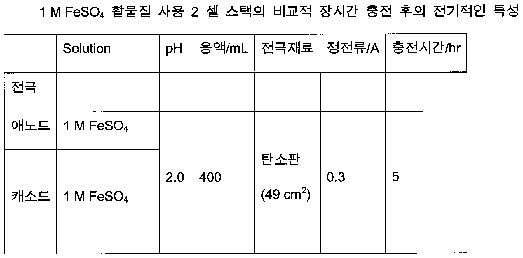
실시 예 6: 고농도 혼합 용액 사용 2 셀 스택의 비교적 장시간 충전 후의 전기적인 특성Example 6: Electrical characteristics of a 2-cell stack using a high-concentration mixed solution after a relatively long charging time
표 4는 실시 예 5의 조건과 유사하나 충전 시간을 약 70% 증가시킨 조건에서의 전기적인 특성을 보여주었다. 충방전 곡선으로부터 충전 전압은 6 V 가까이 올라 가지만 20 Ohms 으로 방전 시의 전압은 약 2 V 로 내려 갔다. 합리적인 비교를 위해서는 방전시간을 더욱 길게 하여야 비교가 가치가 있을 것이다(도 12). 도 12에서 알 수 있듯이 방전은 일정전압을 유지하면서 장시간 방전이 일어나는 추세이었다. 전력곡선은 충전전력과 방전전력의 차이를 전압 강하의 반영으로 보였다. 전류효율은 0.33, 전압효율은 0.35, 에너지 효율은 0.11 을 각각 보여주었다. 도 13의 분극곡선을 보면 전류 증가에 따라 전압은 2.8 V 에서 1.6 V 까지 하강하였으나 전력은 점차 사응하였다. 극대 전류 33 A/m2 에서 극대 전압 53 W/m2 를 나타내어 분극곡선 상에서는 충전시간의 약간의 증가는 전류와 전력의 증가가 크지 않았다.Table 4 shows electrical characteristics under the conditions similar to those of Example 5, but with a charge time increased by about 70%. From the charging / discharging curve, the charging voltage rises to about 6 V, but the discharge voltage drops to about 2 V at 20 Ohms. For a reasonable comparison, the discharge time should be longer to make the comparison worthwhile (FIG. 12). As can be seen from FIG. 12, the discharge has a tendency to occur for a long time while maintaining a constant voltage. The power curve showed that the difference between the charging power and the discharging power reflected the voltage drop. The current efficiency was 0.33, the voltage efficiency was 0.35, and the energy efficiency was 0.11. In the polarization curve of FIG. 13, the voltage dropped from 2.8 V to 1.6 V with increasing current, but the power gradually increased. At maximum current of 33 A / m 2 , the maximum voltage was 53 W / m 2. On the polarization curves, the slight increase in charge time did not increase the current and power.

실시 예 7: 양쪽 극실에 활물질로 Fe2+을 사용한 2 셀 스택Example 7: Two-cell stack using Fe 2+ as an active material in both the aural chambers
1 M FeSO4 활물질을 양쪽 극실에 넣고 표 5의 조건으로 충방전 실험결과를 도 14의 충전시에 전압은 4.1 V 정도에서 20 Ohms 부하저항에서 1.9 V 로 하락했다. 시간에 따른 전력곡선은 방전은 충전 전력의 약 1/6 정도 낮아졌다. 전류효율은 0.28, 전압효율은 0.41, 에너지 효율은 0.11 이었다. 도 15는 분극곡선을 나타내었으며 극대 전류 30.4 A/m2 에서 극대전압 45.4 W/m2 을 나타내었다. 전류가 0 에서 30 A/m2 으로 상승함에 따라 전압은 2.3 V 에서 1.5 V 까지 감소하였으나 전력은 계속적으로 상승하였다.A 1 M FeSO4 active material was charged into both the chambers and the charge and discharge test results under the conditions shown in Table 5 were reduced to 1.9 V at 20 Ohms load resistance at a charging voltage of 4.1 V in Fig. The power curve over time showed that the discharge was about one sixth lower than the charge power. The current efficiency was 0.28, the voltage efficiency was 0.41, and the energy efficiency was 0.11. Fig. 15 shows the polarization curves and showed a maximum voltage of 45.4 W / m < 2 > at a maximum current of 30.4 A / m < 2 >. As the current increased from 0 to 30 A / m2, the voltage decreased from 2.3 V to 1.5 V, but the power continued to rise.
실시 예 8:2 셀 적층을 이용한 승압과 고전류 성취에 의한 고에너지 성취 예측Example 8 Prediction of High Energy Achievement by Boosting and High Current Accumulation Using 2 Cell Lamination
실시 예 4에서 제시한 바이폴라 탄소판과 이온 교환막을 분리막으로 사용한 2 셀 스택 실험을 기본으로 계산한 1 m2 면적의 60셀 탄소판 전극으로 된 스택 모듈로부터 전력생산은 약 4 kW가 예측되었다.The power generation from the stack module consisting of a 60-cell carbon plate electrode of 1 m 2 area based on the 2-cell stack experiment using the bipolar carbon plate and ion exchange membrane as the separator shown in Example 4 was estimated to be about 4 kW.
Claims (9)
Priority Applications (1)
| Application Number | Priority Date | Filing Date | Title |
|---|---|---|---|
| KR1020160076793A KR20170142753A (en) | 2016-06-20 | 2016-06-20 | Method for a renewable energy storage and manufacturing the utilization equipment of mixed redox flow batteries |
Applications Claiming Priority (1)
| Application Number | Priority Date | Filing Date | Title |
|---|---|---|---|
| KR1020160076793A KR20170142753A (en) | 2016-06-20 | 2016-06-20 | Method for a renewable energy storage and manufacturing the utilization equipment of mixed redox flow batteries |
Publications (1)
| Publication Number | Publication Date |
|---|---|
| KR20170142753A true KR20170142753A (en) | 2017-12-28 |
Family
ID=60939545
Family Applications (1)
| Application Number | Title | Priority Date | Filing Date |
|---|---|---|---|
| KR1020160076793A Ceased KR20170142753A (en) | 2016-06-20 | 2016-06-20 | Method for a renewable energy storage and manufacturing the utilization equipment of mixed redox flow batteries |
Country Status (1)
| Country | Link |
|---|---|
| KR (1) | KR20170142753A (en) |
Cited By (6)
| Publication number | Priority date | Publication date | Assignee | Title |
|---|---|---|---|---|
| CN109585891A (en) * | 2018-11-15 | 2019-04-05 | 大连理工大学 | A kind of bottom mud microbe fuel cell by buoyancy automatic adjustment cathode Board position |
| CN112534614A (en) * | 2018-08-13 | 2021-03-19 | 住友电气工业株式会社 | Redox flow battery cell and redox flow battery |
| WO2021075816A1 (en) * | 2019-10-15 | 2021-04-22 | 박용학 | Microbial fuel cell using electron absorber having high reduction potential, and method of generating electric energy using same |
| CN112909301A (en) * | 2021-03-26 | 2021-06-04 | 苏州辉美汽车科技有限公司 | Flow battery and charging regeneration circulating system thereof |
| CN115066773A (en) * | 2019-12-19 | 2022-09-16 | 西门子歌美飒可再生能源有限两合公司 | Energy transmission system and wind farm |
| CN117712410A (en) * | 2023-12-28 | 2024-03-15 | 南京工业大学 | An energy storage battery pack structure with a local heat absorption cavity |
-
2016
- 2016-06-20 KR KR1020160076793A patent/KR20170142753A/en not_active Ceased
Cited By (10)
| Publication number | Priority date | Publication date | Assignee | Title |
|---|---|---|---|---|
| CN112534614A (en) * | 2018-08-13 | 2021-03-19 | 住友电气工业株式会社 | Redox flow battery cell and redox flow battery |
| CN112534614B (en) * | 2018-08-13 | 2023-08-04 | 住友电气工业株式会社 | Redox flow battery monomer and redox flow battery |
| CN109585891A (en) * | 2018-11-15 | 2019-04-05 | 大连理工大学 | A kind of bottom mud microbe fuel cell by buoyancy automatic adjustment cathode Board position |
| WO2021075816A1 (en) * | 2019-10-15 | 2021-04-22 | 박용학 | Microbial fuel cell using electron absorber having high reduction potential, and method of generating electric energy using same |
| KR20210044494A (en) * | 2019-10-15 | 2021-04-23 | 박용학 | Microbial fuel cell using an electron absorber having a high reduction potential and method for producing high electric energy using the same |
| JP2022553931A (en) * | 2019-10-15 | 2022-12-27 | パク,ヨンハク | Microbial fuel cell using electron absorber with high reduction potential and method for producing electric energy using the same |
| US12261336B2 (en) | 2019-10-15 | 2025-03-25 | Yong Hak PARK | Microbial fuel cell using electron absorber having high reduction potential, and method of generating electric energy using same |
| CN115066773A (en) * | 2019-12-19 | 2022-09-16 | 西门子歌美飒可再生能源有限两合公司 | Energy transmission system and wind farm |
| CN112909301A (en) * | 2021-03-26 | 2021-06-04 | 苏州辉美汽车科技有限公司 | Flow battery and charging regeneration circulating system thereof |
| CN117712410A (en) * | 2023-12-28 | 2024-03-15 | 南京工业大学 | An energy storage battery pack structure with a local heat absorption cavity |
Similar Documents
| Publication | Publication Date | Title |
|---|---|---|
| De Leon et al. | Redox flow cells for energy conversion | |
| CN102144321B (en) | Redox flow cell | |
| US20070072067A1 (en) | Vanadium redox battery cell stack | |
| KR20170142753A (en) | Method for a renewable energy storage and manufacturing the utilization equipment of mixed redox flow batteries | |
| CN102479968B (en) | Zinc / polyhalide energy storage cell | |
| KR101394255B1 (en) | Redox flow battery and operration method of the same | |
| CN102136594A (en) | Double-power liquid stream battery electric pile structure and liquid stream battery containing electric pile | |
| US8692517B2 (en) | Non-diffusion liquid energy storage device | |
| EP2869383B1 (en) | Large-capacity power storage device | |
| CN108134141A (en) | A kind of no diaphragm static state zinc-bromine bettery | |
| WO2019066651A1 (en) | Redox flow battery for heat to power conversion | |
| KR101843973B1 (en) | Redox Flow Battery System | |
| CN201956424U (en) | Double power fluid redox cell stack structure | |
| JP4830190B2 (en) | Redox flow battery | |
| JP2020178517A (en) | Storage battery system | |
| WO2020147635A1 (en) | Aqueous hybrid super capacitor | |
| KR102379200B1 (en) | Zinc-bromide flow battery comprising conductive interlayer | |
| Tsuda et al. | Improvement of performance in redox flow batteries for PV systems | |
| US20240194901A1 (en) | Separator for secondary battery and method of fabricating same | |
| CN108134123A (en) | A kind of pile of redox flow batteries | |
| US11955678B2 (en) | Method to improved redox flow battery performance | |
| Tiwari et al. | Vanadium‐Based Redox Flow Batteries | |
| KR101878365B1 (en) | Redox Flow Battery System | |
| CN118970129B (en) | High-performance zinc-bromine double-flow battery and operation method | |
| KR20130055855A (en) | Redox flow battery system for storage of renewable energy |
Legal Events
| Date | Code | Title | Description |
|---|---|---|---|
| A201 | Request for examination | ||
| PA0109 | Patent application |
Patent event code: PA01091R01D Comment text: Patent Application Patent event date: 20160620 |
|
| PA0201 | Request for examination | ||
| E902 | Notification of reason for refusal | ||
| PE0902 | Notice of grounds for rejection |
Comment text: Notification of reason for refusal Patent event date: 20171127 Patent event code: PE09021S01D |
|
| PG1501 | Laying open of application | ||
| E601 | Decision to refuse application | ||
| PE0601 | Decision on rejection of patent |
Patent event date: 20180419 Comment text: Decision to Refuse Application Patent event code: PE06012S01D Patent event date: 20171127 Comment text: Notification of reason for refusal Patent event code: PE06011S01I |
|
| PX0901 | Re-examination |
Patent event code: PX09011S01I Patent event date: 20180419 Comment text: Decision to Refuse Application |
|
| E601 | Decision to refuse application | ||
| E801 | Decision on dismissal of amendment | ||
| PE0601 | Decision on rejection of patent |
Patent event date: 20180628 Comment text: Decision to Refuse Application Patent event code: PE06012S01D Patent event date: 20171127 Comment text: Notification of reason for refusal Patent event code: PE06011S01I |
|
| PE0801 | Dismissal of amendment |
Patent event code: PE08012E01D Comment text: Decision on Dismissal of Amendment Patent event date: 20180628 Patent event code: PE08011R01I Comment text: Amendment to Specification, etc. Patent event date: 20180521 |
|
| E601 | Decision to refuse application | ||
| E801 | Decision on dismissal of amendment | ||
| PE0601 | Decision on rejection of patent |
Patent event date: 20180720 Comment text: Decision to Refuse Application Patent event code: PE06012S01D Patent event date: 20171127 Comment text: Notification of reason for refusal Patent event code: PE06011S01I |
|
| PE0801 | Dismissal of amendment |
Patent event code: PE08012E01D Comment text: Decision on Dismissal of Amendment Patent event date: 20180720 Patent event code: PE08011R01I Comment text: Amendment to Specification, etc. Patent event date: 20180521 |