KR20170107749A - Light Emitting Diode(LED) Driving Apparatus and Lighting Device - Google Patents
Light Emitting Diode(LED) Driving Apparatus and Lighting Device Download PDFInfo
- Publication number
- KR20170107749A KR20170107749A KR1020160031460A KR20160031460A KR20170107749A KR 20170107749 A KR20170107749 A KR 20170107749A KR 1020160031460 A KR1020160031460 A KR 1020160031460A KR 20160031460 A KR20160031460 A KR 20160031460A KR 20170107749 A KR20170107749 A KR 20170107749A
- Authority
- KR
- South Korea
- Prior art keywords
- circuit
- thermoelectric
- thermoelectric elements
- light emitting
- unit
- Prior art date
- Legal status (The legal status is an assumption and is not a legal conclusion. Google has not performed a legal analysis and makes no representation as to the accuracy of the status listed.)
- Granted
Links
Images


Classifications
-
- H—ELECTRICITY
- H05—ELECTRIC TECHNIQUES NOT OTHERWISE PROVIDED FOR
- H05B—ELECTRIC HEATING; ELECTRIC LIGHT SOURCES NOT OTHERWISE PROVIDED FOR; CIRCUIT ARRANGEMENTS FOR ELECTRIC LIGHT SOURCES, IN GENERAL
- H05B45/00—Circuit arrangements for operating light-emitting diodes [LED]
- H05B45/30—Driver circuits
- H05B45/37—Converter circuits
-
- H01L35/32—
-
- H—ELECTRICITY
- H05—ELECTRIC TECHNIQUES NOT OTHERWISE PROVIDED FOR
- H05B—ELECTRIC HEATING; ELECTRIC LIGHT SOURCES NOT OTHERWISE PROVIDED FOR; CIRCUIT ARRANGEMENTS FOR ELECTRIC LIGHT SOURCES, IN GENERAL
- H05B45/00—Circuit arrangements for operating light-emitting diodes [LED]
- H05B45/30—Driver circuits
- H05B45/37—Converter circuits
- H05B45/3725—Switched mode power supply [SMPS]
-
- H01L33/00—
-
- H01L35/04—
-
- H01L35/30—
-
- H01L35/34—
-
- H—ELECTRICITY
- H05—ELECTRIC TECHNIQUES NOT OTHERWISE PROVIDED FOR
- H05B—ELECTRIC HEATING; ELECTRIC LIGHT SOURCES NOT OTHERWISE PROVIDED FOR; CIRCUIT ARRANGEMENTS FOR ELECTRIC LIGHT SOURCES, IN GENERAL
- H05B45/00—Circuit arrangements for operating light-emitting diodes [LED]
- H05B45/30—Driver circuits
- H05B45/37—Converter circuits
- H05B45/3725—Switched mode power supply [SMPS]
- H05B45/382—Switched mode power supply [SMPS] with galvanic isolation between input and output
-
- G—PHYSICS
- G02—OPTICS
- G02F—OPTICAL DEVICES OR ARRANGEMENTS FOR THE CONTROL OF LIGHT BY MODIFICATION OF THE OPTICAL PROPERTIES OF THE MEDIA OF THE ELEMENTS INVOLVED THEREIN; NON-LINEAR OPTICS; FREQUENCY-CHANGING OF LIGHT; OPTICAL LOGIC ELEMENTS; OPTICAL ANALOGUE/DIGITAL CONVERTERS
- G02F1/00—Devices or arrangements for the control of the intensity, colour, phase, polarisation or direction of light arriving from an independent light source, e.g. switching, gating or modulating; Non-linear optics
- G02F1/01—Devices or arrangements for the control of the intensity, colour, phase, polarisation or direction of light arriving from an independent light source, e.g. switching, gating or modulating; Non-linear optics for the control of the intensity, phase, polarisation or colour
- G02F1/13—Devices or arrangements for the control of the intensity, colour, phase, polarisation or direction of light arriving from an independent light source, e.g. switching, gating or modulating; Non-linear optics for the control of the intensity, phase, polarisation or colour based on liquid crystals, e.g. single liquid crystal display cells
- G02F1/133—Constructional arrangements; Operation of liquid crystal cells; Circuit arrangements
- G02F1/1333—Constructional arrangements; Manufacturing methods
- G02F1/1335—Structural association of cells with optical devices, e.g. polarisers or reflectors
- G02F1/1336—Illuminating devices
- G02F1/133602—Direct backlight
- G02F1/133612—Electrical details
-
- H—ELECTRICITY
- H01—ELECTRIC ELEMENTS
- H01L—SEMICONDUCTOR DEVICES NOT COVERED BY CLASS H10
- H01L2924/00—Indexing scheme for arrangements or methods for connecting or disconnecting semiconductor or solid-state bodies as covered by H01L24/00
- H01L2924/10—Details of semiconductor or other solid state devices to be connected
- H01L2924/11—Device type
- H01L2924/12—Passive devices, e.g. 2 terminal devices
- H01L2924/1204—Optical Diode
- H01L2924/12041—LED
-
- H—ELECTRICITY
- H05—ELECTRIC TECHNIQUES NOT OTHERWISE PROVIDED FOR
- H05B—ELECTRIC HEATING; ELECTRIC LIGHT SOURCES NOT OTHERWISE PROVIDED FOR; CIRCUIT ARRANGEMENTS FOR ELECTRIC LIGHT SOURCES, IN GENERAL
- H05B45/00—Circuit arrangements for operating light-emitting diodes [LED]
- H05B45/30—Driver circuits
- H05B45/37—Converter circuits
- H05B45/3725—Switched mode power supply [SMPS]
- H05B45/385—Switched mode power supply [SMPS] using flyback topology
-
- H—ELECTRICITY
- H05—ELECTRIC TECHNIQUES NOT OTHERWISE PROVIDED FOR
- H05B—ELECTRIC HEATING; ELECTRIC LIGHT SOURCES NOT OTHERWISE PROVIDED FOR; CIRCUIT ARRANGEMENTS FOR ELECTRIC LIGHT SOURCES, IN GENERAL
- H05B45/00—Circuit arrangements for operating light-emitting diodes [LED]
- H05B45/30—Driver circuits
- H05B45/37—Converter circuits
- H05B45/3725—Switched mode power supply [SMPS]
- H05B45/39—Circuits containing inverter bridges
-
- Y—GENERAL TAGGING OF NEW TECHNOLOGICAL DEVELOPMENTS; GENERAL TAGGING OF CROSS-SECTIONAL TECHNOLOGIES SPANNING OVER SEVERAL SECTIONS OF THE IPC; TECHNICAL SUBJECTS COVERED BY FORMER USPC CROSS-REFERENCE ART COLLECTIONS [XRACs] AND DIGESTS
- Y02—TECHNOLOGIES OR APPLICATIONS FOR MITIGATION OR ADAPTATION AGAINST CLIMATE CHANGE
- Y02B—CLIMATE CHANGE MITIGATION TECHNOLOGIES RELATED TO BUILDINGS, e.g. HOUSING, HOUSE APPLIANCES OR RELATED END-USER APPLICATIONS
- Y02B20/00—Energy efficient lighting technologies, e.g. halogen lamps or gas discharge lamps
- Y02B20/30—Semiconductor lamps, e.g. solid state lamps [SSL] light emitting diodes [LED] or organic LED [OLED]
Landscapes
- Circuit Arrangement For Electric Light Sources In General (AREA)
- Engineering & Computer Science (AREA)
- Manufacturing & Machinery (AREA)
- General Engineering & Computer Science (AREA)
- Arrangement Of Elements, Cooling, Sealing, Or The Like Of Lighting Devices (AREA)
Abstract
본 발명의 일 실시예에 따른 LED 구동 장치는 변압기 및 스위칭 소자가 실장되고, 상기 변압기를 기준으로 1차측 회로(primary side) 및 2차측 회로(secondary side)를 포함하는 PCB 기판; 상기 PCB 기판 상에 형성되고 상기 변압기 및 스위칭 소자를 덮는 제1 몰딩층; 및 발열되는 위치에 배치되는 복수개의 열전 소자들을 포함하고, 상기 열전 소자들 중 일부는 상기 1차측 회로, 다른 일부는 상기 2차측 회로에 연결되는 것을 특징으로 한다.A LED driving apparatus according to an embodiment of the present invention includes a PCB substrate on which a transformer and a switching device are mounted and includes a primary side and a secondary side with respect to the transformer; A first molding layer formed on the PCB substrate and covering the transformer and the switching device; And a plurality of thermoelectric elements disposed at a position where heat is generated, wherein a part of the thermoelectric elements is connected to the primary circuit and the other part is connected to the secondary circuit.
Description
본 발명의 기술적 사상은 LED 구동 장치 및 발광 장치에 관한 것으로서, 더욱 구체적으로는 높은 효율을 달성할 수 있는 LED 구동 장치 및 발광 장치에 관한 것이다. TECHNICAL FIELD The present invention relates to an LED driving device and a light emitting device, and more particularly, to an LED driving device and a light emitting device capable of achieving high efficiency.
조명에 대한 수요가 많아지고 그 적용분야가 많아짐에 따라, 전체적인 소비전력에 따른 부하는 나날이 늘어가고 있는 실정에 있으므로 전력소비를 감소시키기 위한 노력이 다각적으로 행해지고 있다.As the demand for lighting increases and the number of application areas increases, the load due to the overall power consumption is increasing day by day. Therefore, various efforts are being made to reduce power consumption.
LED(Light Emitting Diode)는 일정 조건의 전류를 흘려 주면 즉시 발광하는 성질을 지니고 있는 반도체이다. LED 광원은 기존 광원에 비해 수명이 길고, 고효율이며 소형 및 경량이고 수은을 사용하지 않아 환경 친화적인 점 등 많은 장점이 있어 기존 광원을 급속히 대체해 나가고 있다.LED (Light Emitting Diode) is a semiconductor that has a property of emitting light immediately when current of a certain condition is flowed. LED light sources are replacing existing light sources because they have many advantages such as long lifetime, high efficiency, small size and light weight, and mercury-free environment friendly compared to conventional light sources.
본 발명의 기술적 사상이 해결하고자 하는 과제는 방출되는 열에너지를 전기에너지로 변환하여 사용할 수 있는 LED 구동 장치 및 발광 장치로 공급함으로써 효율이 높은 LED 구동 장치 및 발광 장치를 제공하는 데 있다.An object of the present invention is to provide an LED driving device and a light emitting device having high efficiency by supplying emitted light to an LED driving device and a light emitting device which can be converted into electric energy and used.
상술한 과제를 해결하기 위하여 본 발명의 기술적 사상의 일 실시예에 의한 LED 구동 장치는 변압기 및 스위칭 소자가 실장되고, 상기 변압기를 기준으로 1차측 회로(primary side) 및 2차측 회로(secondary side)를 포함하는 PCB 기판; 상기 PCB 기판 상에 형성되고 상기 변압기 및 스위칭 소자를 덮는 제1 몰딩층; 및 발열되는 위치에 배치되는 복수개의 열전 소자들을 포함하고, 상기 열전 소자들 중 일부는 상기 1차측 회로, 다른 일부는 상기 2차측 회로에 연결될 수 있다. According to an aspect of the present invention, there is provided an LED driving apparatus including a transformer and a switching device mounted on the primary side and the secondary side of the transformer, A PCB substrate; A first molding layer formed on the PCB substrate and covering the transformer and the switching device; And a plurality of thermoelectric elements arranged in a heat generating position, wherein some of the thermoelectric elements are connected to the primary circuit, and the other thermoelectric elements are connected to the secondary circuit.
본 발명의 기술적 사상의 일 실시예에 있어서, 상기 열전 소자들은 상기 제1 몰딩층 상에 형성될 수 있다.In one embodiment of the present invention, the thermoelectric elements may be formed on the first molding layer.
본 발명의 기술적 사상의 일 실시예에 있어서, 상기 제1 몰딩층 상에 형성된 상기 열전 소자들을 덮는 제2 몰딩층이 더 형성될 수 있다.In an exemplary embodiment of the present invention, a second molding layer may be further formed to cover the thermoelectric elements formed on the first molding layer.
본 발명의 기술적 사상의 일 실시예에 있어서, 상기 열전 소자들은 상기 변압기에 부착될 수 있다. In one embodiment of the inventive concept, the thermoelectric elements can be attached to the transformer.
본 발명의 기술적 사상의 일 실시예에 있어서, 상기 열전 소자들은 상기 스위칭 소자에 부착될 수 있다. In one embodiment of the technical concept of the present invention, the thermoelectric elements can be attached to the switching element.
본 발명의 기술적 사상의 일 실시예에 있어서, 상기 스위칭 소자와 상기 열전 소자들 사이에는 방열판이 개재될 수 있다. In one embodiment of the present invention, a heat sink may be interposed between the switching element and the thermoelectric elements.
본 발명의 기술적 사상의 일 실시예에 있어서, 상기 열전 소자들은 상기 열전 소자들이 연결되는 회로에서 소비되는 전력에 비례하여 상기 PCB 기판과 평행한 면의 면적이 넓게 형성될 수 있다. In an embodiment of the present invention, the thermoelectric elements may have a larger surface area parallel to the PCB substrate in proportion to electric power consumed in the circuit to which the thermoelectric elements are connected.
본 발명의 기술적 사상의 일 실시예에 있어서, 상기 열전 소자들은 상기 열전 소자들이 연결되는 회로에서 소비되는 전력에 비례하여 연결되는 상기 열전 소자들이 수가 증가될 수 있다. In an embodiment of the technical concept of the present invention, the number of thermoelectric elements connected in proportion to electric power consumed in a circuit to which the thermoelectric elements are connected may be increased.
상술한 과제를 해결하기 위하여 본 발명의 기술적 사상의 일 실시에에 의한 발광 장치는 발광 소자에 공급되는 전원을 스위칭 하는 스위칭부 및 적어도 하나의 제1 열전 소자를 포함하는 제1 회로부; 적어도 하나의 제2 열전 소자를 포함하고, 상기 발광 소자와 연결되어 상기 발광 소자를 구동 시키는 제2 회로부; 및 상기 제1 회로부 및 상기 제2 회로부의 전압을 조절하는 변압기;를 포함하고,According to an aspect of the present invention, there is provided a light emitting device including: a first circuit unit including a switching unit for switching a power supplied to a light emitting device and at least one first thermoelectric device; A second circuit part including at least one second thermoelectric element and connected to the light emitting element to drive the light emitting element; And a transformer for adjusting a voltage of the first circuit portion and the second circuit portion,
상기 적어도 하나의 제1 열전 소자는 상기 제1 회로부의 제1 그라운드와 연결되고, 상기 적어도 하나의 제2 열전 소자는 상기 제2 회로부의 제2 그라운드와 연결될 수 있다.The at least one first thermoelectric element may be connected to the first ground of the first circuit part and the at least one second thermoelectric element may be connected to the second ground of the second circuit part.
본 발명의 기술적 사상의 일 실시예에 있어서, 상기 적어도 하나의 제2 열전 소자가 차지하는 전체 면적은 상기 적어도 하나의 제1 열전 소자가 차지하는 전체 면적보다 넓을 수 있다. In one embodiment of the present invention, the total area occupied by the at least one second thermoelectric element may be wider than the total area occupied by the at least one first thermoelectric element.
본 발명의 기술적 사상의 일 실시예에 있어서, 상기 제1 회로부 및 상기 제2 회로부는 각각 정류부를 더 포함할 수 있다. In an embodiment of the technical idea of the present invention, each of the first circuit portion and the second circuit portion may further include a rectifying portion.
본 발명의 기술적 사상의 일 실시예에 있어서, 상기 제1 회로부는 상기 스위칭부의 동작을 제어하는 스위칭 제어부를 더 포함할 수 있다. In one embodiment of the technical idea of the present invention, the first circuit unit may further include a switching control unit for controlling the operation of the switching unit.
본 발명의 기술적 사상의 일 실시예에 있어서, 상기 적어도 하나의 제1 열전 소자 중 일부 또는 전부는 상기 스위칭 제어부에 전력을 공급할 수 있다. In an embodiment of the technical concept of the present invention, some or all of the at least one first thermoelectric elements can supply power to the switching control section.
본 발명의 기술적 사상의 일 실시예에 있어서, 상기 스위칭부, 상기 스위칭 제어부 및 상기 적어도 하나의 제1 열전 소자는 각각 복수로 구성되며, 상기 복수의 제1 열전 소자는 복수로 구성된 상기 스위칭 제어부에 각각 연결되어 전력을 공급할 수 있다. In one embodiment of the present invention, the switching unit, the switching control unit, and the at least one first thermoelectric element are each formed in a plurality of units, and the plurality of first thermoelectric elements are connected to the switching control unit Respectively, to supply power.
본 발명의 기술적 사상의 일 실시예에 있어서, 상기 적어도 하나의 제2 열전 소자 중 일부 또는 전부는 상기 발광 소자에 연결되어, 상기 발광 소자를 점등시키기 위한 전력을 제공할 수 있다.In one embodiment of the present invention, some or all of the at least one second thermoelectric element may be connected to the light emitting element to provide electric power for lighting the light emitting element.
본 발명의 일 실시예들에 따른 LED 구동 장치 및 발광 장치를 이용하면, LED 구동 장치 및 발광 장치 내부의 열전 소자가 제베크 효과(Seebeck effect) 에 의해, 열에너지를 전기에너지로 변환, 생산하여 고효율 달성이 가능하다. 또한, 본 발명의 일 실시예들에 따른 LED 구동 장치 및 발광 장치를 사용하는 이산화탄소 배출이 없고 소음과 진동이 적으며 날씨나 일조량에 영향을 받지 않아 효율적이다.By using the LED driving device and the light emitting device according to the embodiments of the present invention, the LED driving device and the thermoelectric element inside the light emitting device convert and generate heat energy into electric energy by the Seebeck effect, It is possible to achieve. Further, the LED driving device and the light emitting device according to the embodiments of the present invention are free from carbon dioxide emission, noise and vibration are small, and are not affected by the weather or the amount of sunshine.
도 1a는 본 발명의 일 실시예에 따른 LED 구동 장치를 나타낸 측단면도이다.
도 1b는 본 발명의 일 실시예에 따른 LED 구동 장치의 평면도이다.
도 2a는 본 발명의 일 실시예에 따른 LED 구동 장치를 나타낸 측단면도이다.
도 2b는 본 발명의 일 실시예에 따른 LED 구동 장치의 평면도이다.
도 3은 본 발명의 일 실시예에 따른 LED 구동 장치를 나타낸 측단면도이다.
도 4는 본 발명의 일 실시예에 따른 LED 구동 장치를 나타낸 측단면도이다.
도 5는 본 발명의 일 실시예에 따른 발광 장치를 나타내는 블록도이다.
도 6은 본 발명의 일 실시예에 따른 발광 장치를 나타내는 블록도이다.
도 7은 본 발명의 일 실시예에 따른 발광 장치를 나타내는 블록도이다.
도 8은 본 발명의 일 실시예에 따른 발광 장치를 나타내는 블록도로서, 플라이백 컨버터(fly-back converter)가 사용된 발광 장치의 블록도이다.
도 9는 본 발명의 일 실시예에 따른 LED 구동 장치 및 발광 장치를 사용한 디스플레이 장치의 개략적인 분해 사시도이다.
도 10은 본 발명의 일 실시예에 따른 LED 구동 장치 또는 발광 장치를 사용한 평판 조명 장치를 간략하게 나타내는 사시도이다.
도 11은 본 발명의 일 실시예에 따른 LED 구동 장치 또는 발광 장치를 포함하는 조명 장치로서 벌프형 램프를 간략하게 나타내는 분해 사시도이다.
도 12는 본 발명의 일 실시예에 따른 LED 구동 장치 또는 발광 장치를 포함하는 조명 장치로서 바(bar)타입의 램프를 개략적으로 나타내는 분해 사시도이다.FIG. 1A is a side cross-sectional view showing an LED driving apparatus according to an embodiment of the present invention. FIG.
1B is a plan view of an LED driving apparatus according to an embodiment of the present invention.
2A is a side sectional view showing an LED driving apparatus according to an embodiment of the present invention.
2B is a plan view of an LED driving apparatus according to an embodiment of the present invention.
3 is a side sectional view showing an LED driving apparatus according to an embodiment of the present invention.
4 is a side sectional view showing an LED driving apparatus according to an embodiment of the present invention.
5 is a block diagram illustrating a light emitting device according to an embodiment of the present invention.
6 is a block diagram showing a light emitting device according to an embodiment of the present invention.
7 is a block diagram illustrating a light emitting device according to an embodiment of the present invention.
8 is a block diagram showing a light emitting device according to an embodiment of the present invention, and is a block diagram of a light emitting device using a fly-back converter.
9 is a schematic exploded perspective view of a display device using an LED driving apparatus and a light emitting device according to an embodiment of the present invention.
10 is a perspective view briefly showing a flat panel lighting apparatus using an LED driving apparatus or a light emitting apparatus according to an embodiment of the present invention.
11 is an exploded perspective view schematically showing a lamp-type lamp as a lighting device including an LED driving device or a light emitting device according to an embodiment of the present invention.
12 is an exploded perspective view schematically showing a bar type lamp as a lighting device including an LED driving device or a light emitting device according to an embodiment of the present invention.
이하, 첨부된 도면을 참조하여 본 발명의 구체적인 실시예를 상세히 설명하기로 한다. 본 발명의 실시예들은 당해 기술 분야에서 통상의 지식을 가진 자에게 본 발명을 더욱 완전하게 설명하기 위하여 제공되는 것이며, 하기 실시예는 여러 가지 다른 형태로 변형될 수 있으며, 본 발명의 범위가 하기 실시예에 한정되는 것은 아니다. 오히려 이들 실시예들은 본 개시를 더욱 충실하고 완전하게 하고, 당업자에게 본 발명의 사상을 완전하게 전달하기 위하여 제공되는 것이다. 또한, 도면에서 각 층의 두께나 크기는 설명의 편의 및 명확성을 위하여 과장된 것이다.Hereinafter, embodiments of the present invention will be described in detail with reference to the accompanying drawings. The embodiments of the present invention are described in order to more fully explain the present invention to those skilled in the art, and the following embodiments may be modified into various other forms, It is not limited to the embodiment. Rather, these embodiments are provided so that this disclosure will be more thorough and complete, and will fully convey the concept of the invention to those skilled in the art. In the drawings, the thickness and size of each layer are exaggerated for convenience and clarity of explanation.
명세서 전체에 걸쳐서, 막, 영역 또는 웨이퍼(기판) 등과 같은 하나의 구성요소가 다른 구성요소 "상에", "연결되어", 또는 "커플링되어" 위치한다고 언급할 때는, 상술한 하나의 구성요소가 직접적으로 다른 구성요소 "상에", "연결되어", 또는 "커플링되어" 접촉하거나, 그 사이에 개재되는 또 다른 구성요소들이 존재할 수 있다고 해석될 수 있다. 반면에, 하나의 구성요소가 다른 구성요소 "직접적으로 상에", "직접 연결되어", 또는 "직접 커플링되어" 위치한다고 언급할 때는, 그 사이에 개재되는 다른 구성요소들이 존재하지 않는다고 해석된다. 동일한 부호는 동일한 요소를 지칭한다. 본 명세서에서 사용된 바와 같이, 용어 "및/또는"은 해당 열거된 항목 중 어느 하나 및 하나 이상의 모든 조합을 포함한다.It is to be understood that throughout the specification, when an element such as a film, region or wafer (substrate) is referred to as being "on", "connected", or "coupled to" another element, It will be appreciated that elements may be directly "on", "connected", or "coupled" to another element, or there may be other elements intervening therebetween. On the other hand, when one element is referred to as being "directly on", "directly connected", or "directly coupled" to another element, it is interpreted that there are no other components intervening therebetween do. Like numbers refer to like elements. As used herein, the term "and / or" includes any and all combinations of one or more of the listed items.
본 명세서에서 제1, 제2등의 용어가 다양한 부재, 부품, 영역, 층들 및/또는 부분들을 설명하기 위하여 사용되지만, 이들 부재, 부품, 영역, 층들 및/또는 부분들은 이들 용어에 의해 한정되어서는 안됨은 자명하다. 이들 용어는 하나의 부재, 부품, 영역, 층 또는 부분을 다른 영역, 층 또는 부분과 구별하기 위하여만 사용된다. 따라서, 이하 상술할 제1부재, 부품, 영역, 층 또는 부분은 본 발명의 가르침으로부터 벗어나지 않고서도 제2부재, 부품, 영역, 층 또는 부분을 지칭할 수 있다.Although the terms first, second, etc. are used herein to describe various elements, components, regions, layers and / or portions, these members, components, regions, layers and / It is obvious that no. These terms are only used to distinguish one member, component, region, layer or section from another region, layer or section. Thus, a first member, component, region, layer or section described below may refer to a second member, component, region, layer or section without departing from the teachings of the present invention.
또한, "상의" 또는 "위의" 및 "하의" 또는 "아래의"와 같은 상대적인 용어들은 도면들에서 도해되는 것처럼 다른 요소들에 대한 어떤 요소들의 관계를 기술하기 위해 여기에서 사용될 수 있다. 상대적 용어들은 도면들에서 묘사되는 방향에 추가하여 소자의 다른 방향들을 포함하는 것을 의도한다고 이해될 수 있다. 예를 들어, 도면들에서 소자가 뒤집어 진다면(turned over), 다른 요소들의 상부의 면 상에 존재하는 것으로 묘사되는 요소들은 상술한 다른 요소들의 하부의 면 상에 방향을 가지게 된다. 그러므로, 예로써 든 "상의"라는 용어는, 도면의 특정한 방향에 의존하여 "하의" 및 "상의" 방향 모두를 포함할 수 있다. 구성 요소가 다른 방향으로 향한다면(다른 방향에 대하여 90도 회전), 본 명세서에 사용되는 상대적인 설명들은 이에 따라 해석될 수 있다.Also, relative terms such as "top" or "above" and "under" or "below" can be used herein to describe the relationship of certain elements to other elements as illustrated in the Figures. Relative terms are intended to include different orientations of the device in addition to those depicted in the Figures. For example, in the drawings, elements are turned over so that the elements depicted as being on the upper surface of the other elements are oriented on the lower surface of the other elements described above. Thus, the example "top" may include both "under" and "top" directions depending on the particular orientation of the figure. Relative descriptions used herein may be interpreted accordingly if the components are oriented in different directions (rotated 90 degrees with respect to the other direction).
본 명세서에서 사용된 용어는 특정 실시예를 설명하기 위하여 사용되며, 본 발명을 제한하기 위한 것이 아니다. 본 명세서에서 사용된 바와 같이, 단수 형태는 문맥상 다른 경우를 분명히 지적하는 것이 아니라면, 복수의 형태를 포함할 수 있다. 또한, 본 명세서에서 사용되는 경우 "포함한다(comprise)" 및/또는 "포함하는(comprising)"은 언급한 형상들, 숫자, 단계, 동작, 부재, 요소 및/또는 이들 그룹의 존재를 특정하는 것이며, 하나 이상의 다른 형상, 숫자, 동작, 부재, 요소 및/또는 그룹들의 존재 또는 부가를 배제하는 것이 아니다.The terminology used herein is for the purpose of describing particular embodiments only and is not intended to be limiting of the invention. As used herein, the singular forms "a," "an," and "the" include singular forms unless the context clearly dictates otherwise. Also, " comprise "and / or" comprising "when used herein should be interpreted as specifying the presence of stated shapes, numbers, steps, operations, elements, elements, and / And does not preclude the presence or addition of one or more other features, integers, operations, elements, elements, and / or groups.
이하, 본 발명의 실시예들은 본 발명의 이상적인 실시예들을 개략적으로 도시하는 도면들을 참조하여 설명한다. 도면들에 있어서, 예를 들면, 제조 기술 및/또는 공차(tolerance)에 따라, 도시된 형상의 변형들이 예상될 수 있다. 따라서, 본 발명 사상의 실시예는 본 명세서에 도시된 영역의 특정 형상에 제한된 것으로 해석되어서는 아니 되며, 예를 들면 제조상 초래되는 형상의 변화를 포함하여야 한다. 이하 실시예들은 하나 또는 복수개를 조합하여 구성할 수도 있다.Hereinafter, embodiments of the present invention will be described with reference to the drawings schematically showing ideal embodiments of the present invention. In the figures, for example, variations in the shape shown may be expected, depending on manufacturing techniques and / or tolerances. Accordingly, the embodiments of the present invention should not be construed as limited to the particular shapes of the regions shown herein, but should include, for example, changes in shape resulting from manufacturing. The following embodiments may be constructed by combining one or a plurality of embodiments.
이하에서 설명하는 LED 구동 장치 및 발광 장치는 다양한 구성을 가질 수 있고 여기서는 필요한 구성만을 예시적으로 제시하며, 본 발명 내용이 이에 한정되는 것은 아님을 밝혀둔다.It is noted that the LED driving apparatus and the light emitting apparatus described below may have various configurations, and only necessary configurations are exemplarily shown here, and the contents of the present invention are not limited thereto.
도 1a는 본 발명의 일 실시예에 따른 LED 구동 장치를 나타낸 측단면도이다. 도 1b는 본 발명의 일 실시예에 따른 LED 구동 장치의 평면도이다. FIG. 1A is a side cross-sectional view showing an LED driving apparatus according to an embodiment of the present invention. FIG. 1B is a plan view of an LED driving apparatus according to an embodiment of the present invention.
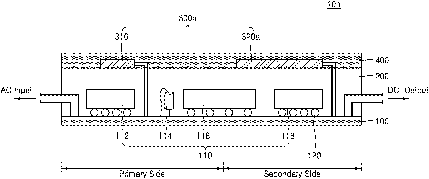
도 1a를 참조하면, 본 발명의 일 실시예에 따른 LED(Light Emitting Diode) 구동 장치(10a)는 회로 소자들(110)이 실장된 PCB 기판(100), 상기 PCB 기판(100) 상에 형성되는 제1 몰딩층(200) 및 복수개의 열전 소자들(300a)을 포함할 수 있다.
1A, an LED (Light Emitting Diode) driving
PCB 기판(100)에는 LED에 적절한 전원을 제공하기 위한 회로 소자들(110)은 플립칩 본딩 방식이나 와이어 본딩 방식으로 실장될 수 있다. 도 1a는 상기 회로 소자들(110)이 범프(120)를 통하여 상기 PCB 기판(100)에 실장된 것을 나타낸 것이다. 상기 회로 소자들(110)은 예컨대, 스위칭 소자(112), 인덕터(114), 변압기(116), 정류기(118) 등을 포함할 수 있다. 상기 회로 소자들(110)은 상기 PCB 기판(100)상에 형성된 회로 패턴을 통해 서로 전기적으로 연결될 수 있다. 상기 회로 소자들(110)의 구조 및 형태는 도 1a에 도시된 것에 한정되는 것은 아니며, 하나의 예시에 해당한다.
The
상기 PCB 기판(100)은 예를 들어, FR-4, CEM-3 등의 재질로 이루어질 수 있으나, 이에 한정되는 것은 아니다. 또한, 상기 회로 패턴은 전도성 물질, 예를들어, 구리(Cu), 알루미늄(Al), 금(Au), 은(Ag)과 같은 금속을 포함 할 수 있다. 이를 통하여 상기 LED 구동 장치(10a)는 교류로 인가되는 전원을 정류하는 정류 기능이나, 직류 전원의 크기를 변경하는 DC/DC 컨버터 기능을 수행할 수 있다.
The
상기 변압기(116)를 기준으로 상기 PCB 기판(100)은 상기 1차측 회로(primary side) 및 2차측 회로(secondary side)를 포함할 수 있다. 상기 1차측 회로 및 상기 2차측 회로는 각각 제1 그라운드, 제2 그라운드에 연결될 수 있다. 상기 LED 구동 장치(10a)가 보조 전원을 포함하는 경우에는 상기 보조 전원은 제3 그라운드와 연결될 수 있다. 즉, 그라운드의 수는 정해진 것이 아니며 회로의 구성에 따라 달라질 수 있다.
The
도 1a에 의하면, 상기 1차측 회로에는 상기 스위칭 소자(112), 인덕터(114)가 전기적으로 연결되어 있고, 상기 2차측 회로에는 정류기(118)가 전기적으로 연결되는 것으로 도시되어 있으나, 이에 한정되는 것은 아니다. 상기 2차측 회로에도 상기 스위칭 소자(112)가 연결될 수 있고, 상기 1차측 회로에도 상기 정류기(118)가 연결될 수 있다.
1A, the
열전 소자들(300a)은 외부의 온도차를 이용하여 전기 에너지로 변환하는 제베크 효과(Seebeck effect)를 이용하여 재생에너지를 형성할 수 있는 소자이다. 따라서 상기 열전 소자들(300a)은 상기 열전 소자들(300a)과 연결되는 다른 소자들에게 전원을 공급할 수 있다. 상기 열전 소자들(300a)은 고온 요소와 저온 요소 사이에 배치될 수 있다. 고온 요소는 저온 요소 보다 상대적으로 온도가 높은 요소를 의미한다. 이러한 고온 요소와 저온 요소는 상기 열전 소자들(300a)이 장착되는 LED 구동 장치를 구성하는 구성 요소의 일부 일 수 있다. 예를 들어, 상기 고온 요소는 열을 발생시키는 변압기일 수 있다.
The
상기 열전 소자들(300a) 중 일부의 열전 소자들(310)은 상기 1차측 회로, 다른 일부의 열전 소자들(320a)은 상기 2차측 회로에 연결될 수 있다. 따라서 다수의 그라운드가 존재하는 경우에 특정 그라운드를 선택하여 상기 열전 소자들(300a)을 연결할 수 있다. 즉, 그라운드 간의 전위차와 무관하게, 상기 열전 소자(300a)에서 생성된 전원을 상기 PCB 기판(100) 상에 실장된 회로 소자들(110)에게 선택적으로 공급할 수 있다.
Some of the
제1 몰딩층(200)은 상기 회로 소자들(110)과 상기 범프(120)를 덮어 외부의 화학적, 물리적 손상 등으로부터 보호하기 위해 형성하는 것이다. 상기 제1 몰딩층(200)은 에폭시 수지, 경화제, 유기/무기 충전재 등을 포함하는 각종 합성 수지류 재질로 제작되어 몰드(mold: 금형) 내부에서 사출 성형될 수 있다. 이러한 상기 제1 몰딩층(200)은 레진과 같은 폴리머로 형성될 수 있다. 예를들어, EMC(Epoxy Molding Compound)로 형성될 수 있다.
The
상기 제1 몰딩층(200)이 상기 재질이나 방법에 한정되는 것은 아니다. 상기 제1 몰딩층(200)은 MUF(Molded Under Fill) 공정을 통해 형성될 수 있다. MUF 공정이란 상기 회로 소자들(110)과 상기 PCB 기판(100) 사이의 공간을 언더 필(under fill)로 채우는 공정을 별도로 수행하지 않고, 상기 제1 몰딩층(200)로 상기 회로 소자들(110)과 상기 PCB 기판(100) 사이의 공간도 함께 채우는 공정을 말한다. MUF 공정으로 상기 제1 몰딩층(200)를 형성하는 경우에, 상기 회로 소자들(110) 외곽을 덮는 부분의 몰딩 부재 재질과 상기 회로 소자들(110)과 상기 PCB 기판(100) 사이의 몰딩 부재 재질이 동일할 수 있다. The
그러나 상기 제1 몰딩층(200)는 MUF 공정을 통하지 않고 형성될 수도 있다. 즉, 먼저 상기 회로 소자들(110)과 상기 PCB 기판(100) 사이를 언더 필로 채우고, 그 후에 상기 회로 소자들(110)의 외곽 부분을 외부 몰딩 부재를 덮는 공정을 수행하여 몰딩할 수도 있다. 이 때 상기 회로 소자들(110)과 상기 PCB 기판(100) 사이를 채우는 언더 필과 상기 회로 소자들(110)의 외곽을 덮는 외부 몰딩 부재는 동일 재질로 형성될 수도 있지만 서로 다른 재질로 형성될 수도 있다.However, the
상기 열전 소자들(300a)은 상기 제1 몰딩층(200) 상에 형성될 수 있다. 이러한 경우 상기 열전 소자들(300a)을 외부의 화학적, 물리적 손상 등으로부터 보호하기 위하여 제2 몰딩층(400)이 상기 열전 소자들(300a)상에 형성될 수 있다. 상기 제2 몰딩층(400)의 물질 및 제조 방법은 전술한 상기 제1 몰딩층(200)의 물질 및 제조 방법과 유사할 수 있다. 다만, 이에 한정되는 것은 아니며 열전 소자들(300a)이 상기 회로 소자들(110)에 부착될 수도 있다. 이에 대해서는 도 3에 대한 설명에서 후술하도록 하겠다.The
도 1b를 참조하면, 상기 열전 소자들(300a)은 상기 열전 소자들(300a)이 연결되는 회로에서 소비되는 전력에 비례하여 상기 PCB 기판(100)과 평행한 면의 면적이 넓도록 형성될 수 있다. 상기 열전 소자들(300a)은 고온 요소와 저온 요소 사이에서 넓은 면적으로 배치될수록 생성할 수 있는 전력이 증가한다. 따라서 소비되는 전력이 많은 회로쪽에 더 많은 전력을 공급하기 위하여, 면적이 상대적으로 넓은 열전 소자들(300a)을 연결할 수 있다. 도 1b에 따르면, 1차측 회로보다 2차측 회로가 전력을 많이 소비한다는 가정하에 상기 2차측 회로에 연결된 상기 열전 소자들(320a)의 면적이 상기 1차측 회로에 연결된 상기 열전 소자들(310)에 비하여 넓은 면적을 차지하는 것으로 나타내었다. 그러나 이에 한정되는 것은 아니며, 경우에 따라서 상기 열전 소자들(300a)의 면적을 다르게 설정할 수 있을 것이다. Referring to FIG. 1B, the
도 2a는 본 발명의 일 실시예에 따른 LED 구동 장치를 나타낸 측단면도이다. 도 2b는 본 발명의 일 실시예에 따른 LED 구동 장치의 평면도이다. 2A is a side sectional view showing an LED driving apparatus according to an embodiment of the present invention. 2B is a plan view of an LED driving apparatus according to an embodiment of the present invention.
도 2a 및 도 2b를 참조하면, 본 발명의 일 실시예에 따른 LED 구동 장치(10b)는 회로 소자들(110)이 실장된 PCB 기판(100), 상기 PCB 기판(100) 상에 형성되는 제1 몰딩층(200) 및 복수개의 열전 소자들(300b)을 포함할 수 있다. 상기 PCB 기판(100)은 변압기(116)를 기준으로 1차측 회로 및 2차측 회로를 포함하고, 상기 열전 소자들(300b) 중 일부의 열전 소자들(310)은 상기 1차측 회로, 다른 일부의 열전 소자들(320b)은 상기 2차측 회로에 연결될 수 있다. 2A and 2B, an
이 때, 상기 열전 소자들(300b)는 상기 열전 소자들(300b)이 연결되는 회로에서 소비되는 전력에 비례하여, 상기 열전 소자들(300b)이 직렬로 연결되는 개수가 증가될 수 있다. 상기 열전 소자들(300b)을 직렬로 연결하면, 각각의 상기 열전 소자들(300b)에서 형성된 전력이 더해지게 되어 총 전력이 증가한다. 따라서 소비되는 전력이 많은 회로쪽에 상대적으로 많은 열전 소자들(300b)을 연결할 수 있다. 도 2b에 따르면, 1차측 회로보다 2차측 회로가 전력을 많이 소비한다는 가정하에, 상기 2차측 회로에 직렬로 연결된 상기 열전 소자들(320b)의 개수가 상기 1차측 회로에 직렬로 연결된 상기 열전 소자들(310)의 개수에 비하여 많은 것으로 나타내었다. 그러나 이에 한정되는 것은 아니며, 경우에 따라서 상기 직렬로 연결되는 열전 소자들(300b)의 수를 다르게 설정할 수 있을 것이다. At this time, the number of the
도 3은 본 발명의 일 실시예에 따른 LED 구동 장치를 나타낸 측단면도이다. 3 is a side sectional view showing an LED driving apparatus according to an embodiment of the present invention.
도 3을 참조하면, 본 발명의 일 실시예에 따른 LED 구동 장치(10c)는 변압기(116) 및 스위칭 소자(112)가 실장된 PCB 기판(100), 상기 PCB 기판(100) 상에 형성되는 제1 몰딩층(200) 및 복수개의 열전 소자들(300c)을 포함할 수 있다. 상기 PCB 기판(100)은 상기 변압기(116)를 기준으로 1차측 회로 및 2차측 회로를 포함하고, 상기 열전 소자들(300c) 중 일부의 열전 소자들(310c)은 상기 1차측 회로, 다른 일부의 열전 소자들(320c)은 상기 2차측 회로에 연결될 수 있다. 3, an
상기 열전 소자들(300c)은 상기 변압기(116)에 부착될 수 있다. 또는, 상기 열전 소자들(300c)은 상기 스위칭 소자(112)에 부착될 수 있다. 도 3에 따르면, 상기 1차측 회로에 연결되는 상기 열전 소자들(310c)은 상기 스위칭 소자(112)에 부착되고, 상기 2차측 회로에 연결되는 상기 열전 소자들(320c)은 변압기(116)에 부착되는 것으로 도시되어 있으나, 이에 한정되는 것은 아니며 회로의 배치에 따라 변형 실시가 가능할 것이다. 일반적으로 변압기(116)의 경우에는 70~85℃ 정도, 스위칭 소자(112)의 경우 50~70℃ 정도의 발열이 발생하므로 열전 소자(300c)를 부착하게 될 경우 효율적으로 전력을 생성할 수 있다. The
도 4는 본 발명의 일 실시예에 따른 LED 구동 장치를 나타낸 측단면도이다. 4 is a side sectional view showing an LED driving apparatus according to an embodiment of the present invention.
도 4를 참조하면, 본 발명의 일 실시예에 따른 LED 구동 장치(10d)는 변압기(116) 및 스위칭 소자(112)가 실장된 PCB 기판(100), 상기 PCB 기판(100) 상에 형성되는 제1 몰딩층(200) 및 복수개의 열전 소자들(300d)을 포함할 수 있다. 상기 PCB 기판(100)은 상기 변압기(116)를 기준으로 1차측 회로 및 2차측 회로를 포함하고, 상기 열전 소자들(300d) 중 일부의 열전 소자들(310d)은 상기 1차측 회로, 다른 일부의 열전 소자들(320d)은 상기 2차측 회로에 연결될 수 있다. 4, an
상기 열전 소자들(300d)은 상기 변압기(116) 또는 상기 스위칭 소자(112)에 부착될 수 있다. 이 때, 상기 스위칭 소자(112)와 상기 열전 소자들(300d) 사이에는 방열판(330)이 개재될 수 있다. 도 4에 따르면, 상기 1차측 회로에 연결되는 상기 열전 소자들(310d)은 상기 방열판(330)을 사이에 두고 상기 스위칭 소자(112)에 부착되지만, 이에 한정되는 것은 아니며 상기 2차측 회로에 스위칭 소자(112)가 연결되는 경우에는, 상기 2차측 회로에 연결된 상기 열전 소자들(320d)이 상기 스위칭 소자(112)에 부착될 수 있다. 즉, 회로의 배치에 따라 변형 실시가 가능하다. 또한, 상기 변압기(116)와 상기 열전 소자들(300d) 사이에도 방열판이 개재될 수 있다. The
상기 방열판(330)은 일정한 두께와 강도를 갖고, 평판 형상을 가질 수 있다. 예를 들면, 상기 방열판(330)는 구리(copper), 구리 합금(copper alloy), 알루미늄(aluminum), 알루미늄 합금(aluminum alloy), 스틸(steel), 스테인레스 스틸(stainless steel) 및 이들의 조합으로 이루어진 고열전도성 물질로 이루어진 그룹에서 선택된 어느 하나의 물질로 이루어질 수 있다. The
도 5는 본 발명의 일 실시예에 따른 발광 장치를 나타내는 블록도이다. 5 is a block diagram illustrating a light emitting device according to an embodiment of the present invention.
도 5를 참조하면, 본 발명의 일 실시예에 따른 발광 장치(50)는 전원부(600), LED 구동부(500) 및 광원부(700)를 포함할 수 있다. 상기 LED 구동 부(500)는 제1 회로부(510), 제2 회로부(520) 및 변압기(530)을 포함할 수 있다. 상기 LED 구동부(500)는 교류로 인가되는 전원을 정류하는 정류 기능이나, 직류 전원의 크기를 변경하는 DC/DC 컨버터 기능을 수행할 수 있다.
5, a
상기 제1 회로부(510)은 제1 그라운드(G1)과 연결되고 상기 제2 회로부(520)은 제2 그라운드(G2)와 연결된다. 상기 변압기(530)는 상기 제1 회로부(510) 및 상기 제2 회로부(520)의 전압을 조절할 수 있다. 상기 제1 그라운드와 상기 제2 그라운드간에는 전위차가 존재할 수 있다. 상기 LED 구동부(500)가 보조 전원을 더 포함하는 경우에는 상기 보조 전원은 제3 그라운드와 연결될 수 있다. 상기 제1 내지 제3 그라운드 간에는 전위차가 존재할 수 있다.The
상기 LED 구동부(500)는 전원부(600)가 생성한 입력 전압을 이용하여 상기 광원부(700)에 포함되는 하나 이상의 LED를 구동할 수 있다. 상기 LED 구동부(500)는 상기 전원부(600)로부터 교류 전원(AC Input)을 인가 받아 상기 광원부(700)로 직류 전원(DC Output)을 인가할 수 있다. 따라서, 상기 LED 구동부(500)는 LED를 구동할 수 있는 LED 전류를 생성하는 구동 회로를 가질 수 있으며, 구동 회로는 DC-DC 컨버터 회로를 포함할 수 있다. 일 실시예로 플라이백(Fly-back) 컨버터, 포워드(Forward) 컨버터, 하프브릿지(Half-Bridge) 인버터, 풀브릿지(Full-Bridge) 인버터, 싱글 스테이지(Single-stage) 컨버터 등 여러 토폴로지(Topology)로 구현할 수 있으며, 구현되는 컨버터의 종류에 따라 회로의 구성이 달라질 수 있다.The
도 6은 본 발명의 일 실시예에 따른 발광 장치를 나타내는 블록도이다.6 is a block diagram showing a light emitting device according to an embodiment of the present invention.
도 6을 참조하면, 본 발명의 일 실시예에 따른 발광 장치(50a)는 전원부(600), LED 구동부(500) 및 광원부(700)를 포함할 수 있다. 상기 LED 구동부(500)는 제1 회로부(510), 제2 회로부(520) 및 변압기(530)을 포함할 수 있다. 도 5에서 상술한 것과 동일하게 적용될 수 있는 부분에 대해서는 설명을 생략하고, 달라진 부분을 중심으로 설명하기로 한다.
Referring to FIG. 6, a
제1 회로부(510)는 스위칭부(514) 및 적어도 하나의 제1 열전 소자(512)를 포함할 수 있다. 상기 스위칭부(514)는 발광 소자를 포함하는 광원부(700)에 공급되는 전원을 스위칭할 수 있다. 상기 적어도 하나의 제1 열전 소자(512)는 제베크 효과를 이용하여 전력을 생성할 수 있는 소자이다. 상기 적어도 하나의 제1 열전 소자(512)는 고온 요소와 저온 요소 사이에 배치될 수 있으며, 이러한 고온 요소와 저온 요소는 상기 LED 구동부(500)를 구성하는 구성 요소의 일부일 수 있다. 상기 적어도 하나의 제1 열전 소자(510)는 제1 그라운드(G1)와 연결될 수 있다.
The
제2 회로부(520)은 적어도 하나의 제2 열전 소자(522)를 포함할 수 있다. 상기 제2 회로부(520)은 상기 발광 소자와 연결되어 상기 발광 소자를 직접 구동 시킬 수 있다. 상기 적어도 하나의 제2 열전 소자(522)는 제2 그라운드(G2)와 연결될 수 있다. 상기 적어도 하나의 제2 열전 소자(522)에 대한 설명은 전술한 상기 적어도 하나의 제1 열전 소자(512)와 설명과 동일하다.
The
상기 제1 회로부(510) 및 상기 제2 회로부(520)는 각각 정류부(518, 528)를 더 포함할 수 있다. 상기 정류부(518, 528)는 AC 전압을 DC 전압으로 정류하는 기능을 할 수 있다. The
도 7은 본 발명의 일 실시예에 따른 발광 장치를 나타내는 블록도이다. 7 is a block diagram illustrating a light emitting device according to an embodiment of the present invention.
도 7을 참조하면, 본 발명의 일 실시예에 따른 발광 장치(50b)는 전원부(600), LED 구동부(500) 및 광원부(700)를 포함할 수 있다. 상기 LED 구동부(500)는 제1 회로부(510), 제2 회로부(520) 및 변압기(530)을 포함할 수 있다. 도 5 및 도 6에서 상술한 것과 동일하게 적용될 수 있는 부분에 대해서는 설명을 생략하고, 달라진 부분을 중심으로 설명하기로 한다.7, a
상기 제1 회로부(510)는 스위칭부(514), 스위칭 제어부(516) 및 적어도 하나의 제1 열전 소자(512)를 포함할 수 있다. 상기 스위칭부(514)는 발광 소자를 포함하는 광원부(700)에 공급되는 전원을 스위칭할 수 있으며, 상기 스위칭 제어부(516)는 상기 스위칭부(514)의 동작을 제어할 수 있다. The
도 8은 본 발명의 일 실시예에 따른 발광 장치를 나타내는 블록도로서, DC-DC 컨버터로 플라이백 컨버터(fly-back converter)가 사용된 발광 장치의 블록도이다.8 is a block diagram showing a light emitting device according to an embodiment of the present invention, and is a block diagram of a light emitting device in which a fly-back converter is used as a DC-DC converter.
도 8을 참조하면, 상기 LED 구동부(500a)는 제1 회로부(510), 제2 회로부(520) 및 변압기(530)을 포함할 수 있다. LED 구동부(500a)는 LED를 구동할 수 있는 LED 전류를 생성하는 구동 회로를 가질 수 있으며, 구동 회로는 DC-DC 컨버터 회로를 포함할 수 있다. 일 실시예로 플라이백(Fly-back) 컨버터가 사용될 수 있다. 그러나 이에 한정되는 것은 아니며, 경우에 따라 DC-DC 컨버터를 선택하여 실시할 수 있다.Referring to FIG. 8, the
상기 제1 회로부(510)는 정류부(518), 스위칭부(514), 스위칭 제어부(516) 및 적어도 하나의 제1 열전 소자(512)를 포함할 수 있다. 상기 제1 회로부(510)은 제1 그라운드(G1)과 연결된다. 따라서 상기 적어도 하나의 제1 열전 소자(510)는 제1 그라운드(G1)와 연결될 수 있다. 상기 스위칭부(514)는 저항(Rs)를 통하여 제1 그라운드(G1)에 연결될 수 있다.The
상기 제2 회로부(520)는 정류부(528) 및 적어도 하나의 제2 열전 소자(522)를 포함할 수 있다. 상기 제2 회로부(520)는 제2 그라운드(G2)와 연결된다. 따라서 상기 적어도 하나의 제2 열전 소자(520)는 제2 그라운드(G2)와 연결될 수 있다. The
상기 변압기(530)는 1차측 코일(Np) 및 2차측 코일(Ns)를 포함할 수 있고, 상기 제1 회로부(510) 및 상기 제2 회로부(520)의 전압을 조절할 수 있다. 경우에 따라 상기 LED 구동부(500a)가 보조 전원을 더 포함하는 경우에는 상기 보조 전원은 제3 그라운드와 연결될 수 있다. 상기 제3 그라운드에 연결되는 적어도 하나의 제3 열전 소자가 존재할 수 있다. 즉, 그라운드의 수는 정해진 것이 아니며 회로의 구성에 따라 달라질 수 있다.The
상기 적어도 하나의 제1 열전 소자(512) 중 일부 또는 전부는 상기 스위칭 제어부(516)에 전력을 공급할 수 있다. 또한, 상기 스위칭부(514), 상기 스위칭 제어부(516) 및 상기 적어도 하나의 제1 열전 소자(512)는 각각 복수로 구성될 수 있다. 이 때, 상기 복수의 제1 열전 소자(512)는 복수로 구성된 상기 스위칭 제어부(516)에 각각 연결되어 전력을 공급할 수 있다. Some or all of the at least one first
상기 적어도 하나의 제2 열전 소자(522) 중 일부 또는 전부는 상기 광원부(700)에 존재하는 발광 소자에 연결되어, 상기 발광 소자를 점등시키기 위한 전력을 공급할 수 있다. 이 때, 상기 적어도 하나의 제2 열전 소자(522)가 차지하는 전체 면적은 상기 적어도 하나의 제1 열전 소자(512)가 차지하는 전체 면적보다 넓을 수 있다. 상기 적어도 하나의 제1 열전소자(512) 및 상기 적어도 하나의 제2 열전 소자(522)는 고온 요소와 저온 요소 사이에서 넓은 면적으로 배치될수록 생성할 수 있는 전력이 증가한다. 또한, 각각의 상기 적어도 하나의 제1 열전 소자(512) 및 상기 적어도 하나의 제2 열전 소자(522)를 직렬로 연결하면, 생성할 수 있는 총 전력이 증가하게 된다. 따라서 소비되는 전력이 많은 쪽에 열전 소자들이 차지하는 전체 면적이 넓도록 배치할 수 있다. 상기 적어도 하나의 제2 열전 소자(522)가 상기 광원부(700)에 존재하는 발광 소자에 연결되는 경우, 상기 발광 소자에서 소비하는 전력이 상대적으로 많으므로 상기 적어도 하나의 제2 열전 소자(522)가 차지하는 전체 면적을 상대적으로 넓게 배치할 수 있다.
Some or all of the at least one second
본 발명의 일 실시예들인 발광 장치(50, 50a, 50b)에서는 본 발명의 다른 일 실시예들인 LED 구동 장치(10a, 10b, 10c, 10d)의 기술적 사상이 적용될 수 있을 것이며, 반대의 경우에도 적용될 수 있을 것이다.
In the
도 9은 본 발명의 일 실시예에 따른 LED 구동 장치 및 발광 장치를 사용한 디스플레이 장치의 개략적인 분해 사시도이다.9 is a schematic exploded perspective view of a display device using an LED driving apparatus and a light emitting device according to an embodiment of the present invention.
도 9을 참조하면, 디스플레이 장치(3000)는, 백라이트 유닛(3100), 광학시트(3200) 및 액정 패널과 같은 화상 표시 패널(3300)을 포함할 수 있다. 9, the
백라이트 유닛(3100)은 바텀케이스(3110), 반사판(3120), 도광판(3140) 및 도광판(3140)의 적어도 일 측면에 제공되는 광원모듈(3130)을 포함할 수 있다. 광원모듈(3130)은 인쇄회로기판(3131) 및 광원(3132)을 포함할 수 있다. 특히, 광원(3105)은 광방출면에 인접한 측면으로 실장된 사이드뷰 타입 발광 소자일 수 있다. 상기 인쇄회로기판(3131)은 본 발명의 일 실시예에 따른 LED 구동 장치(10a, 10b, 10c, 10d)중 적어도 하나의 LED 구동 장치 또는 LED 구동부(500, 500a) 중 적어도 하나의 LED 구동부를 포함할 수 있다.The
광학시트(3200)는 도광판(3140)과 화상 표시 패널(3300)의 사이에 배치될 수 있으며, 확산시트, 프리즘시트 또는 보호시트와 같은 여러 종류의 시트를 포함할 수 있다.
The optical sheet 3200 may be disposed between the
화상 표시 패널(3300)은 광학시트(3200)를 출사한 광을 이용하여 영상을 표시할 수 있다. 화상 표시 패널(3300)은 어레이 기판(3320), 액정층(3330) 및 컬러 필터 기판(3340)을 포함할 수 있다. 어레이 기판(3320)은 매트릭스 형태로 배치된 화소 전극들, 상기 화소 전극에 구동 전압을 인가하는 박막 트랜지스터들 및 상기 박막 트랜지스터들을 작동시키기 위한 신호 라인들을 포함할 수 있다.
The
컬러 필터 기판(3340)은 투명기판, 컬러 필터 및 공통 전극을 포함할 수 있다. 상기 컬러 필터는 백라이트 유닛(3100)으로부터 방출되는 백색광 중 특정 파장의 광을 선택적으로 통과시키기 위한 필터들을 포함할 수 있다. 액정층(3330)은 상기 화소 전극 및 상기 공통 전극 사이에 형성된 전기장에 의해 재배열되어 광투과율을 조절할 수 있다. 광투과율이 조절된 광은 컬러 필터 기판(3340)의 상기 컬러 필터를 통과함으로써 영상을 표시할 수 있다. 화상 표시 패널(3300)은 영상 신호를 처리하는 구동회로 유닛 등을 더 포함할 수 있다.
The
본 실시예의 디스플레이 장치(3000)에 따르면, 상대적으로 작은 반치폭을 가지는 청색광, 녹색광 및 적색광을 방출하는 광원(3132)을 사용하므로, 방출된 광이 컬러 필터 기판(3340)을 통과한 후 높은 색순도의 청색, 녹색 및 적색을 구현할 수 있다. According to the
도 10는 본 발명의 일 실시예에 따른 LED 구동 장치 또는 발광 장치를 사용한 평판 조명 장치를 간략하게 나타내는 사시도이다.10 is a perspective view briefly showing a flat panel lighting apparatus using an LED driving apparatus or a light emitting apparatus according to an embodiment of the present invention.
도 10을 참조하면, 평판 조명 장치(4100)는 광원부(4110), 전원공급장치(4120) 및 하우징(4030)을 포함할 수 있다. 광원부(4110)는 발광 소자 어레이를 광원으로 포함할 수 있다.Referring to FIG. 10, the flat
광원부(4110)는 발광 소자 어레이를 포함할 수 있고, 전체적으로 평면 현상을 이루도록 형성될 수 있다. 발광 소자 어레이는 발광 소자 및 발광 소자의 구동정보를 저장하는 컨트롤러를 포함할 수 있다. 상기 광원부(4110)는 본 발명의 일 실시예에 따른 LED 구동 장치(10a, 10b, 10c, 10d)중 적어도 하나의 LED 구동 장치 또는 LED 구동부(500, 500a) 중 적어도 하나의 LED 구동부를 포함할 수 있다.The
전원공급장치(4120)는 광원부(4110)에 전원을 공급하도록 구성될 수 있다. 하우징(4130)은 광원부(4110) 및 전원공급장치(4120)가 내부에 수용되도록 수용 공간이 형성될 수 있고, 일측면에 개방된 육면체 형상으로 형성되나 이에 한정되는 것은 아니다. 광원부(4110)는 하우징(4130)의 개방된 일측면으로 빛을 발광하도록 배치될 수 있다. The
도 11은 본 발명의 일 실시예에 따른 LED 구동 장치 또는 발광 장치를 포함하는 조명 장치로서 벌프형 램프를 간략하게 나타내는 분해 사시도이다.11 is an exploded perspective view schematically showing a lamp-type lamp as a lighting device including an LED driving device or a light emitting device according to an embodiment of the present invention.
도 11을 참조하면, 본 발명의 일 실시예에 따른 조명 장치(4200)는 소켓(4210), 전원공급부(4220), 방열부(4230), 광원부(4240) 및 광학부(4250)를 포함할 수 있다. 11, The
소켓(4210)은 기존의 조명 장치와 대체 가능하도록 구성될 수 있다. 조명 장치(4200)에 공급되는 전력은 소켓(4210)을 통해서 인가될 수 있다. 도시된 바와 같이, 전원공급부(4220)는 제1 전원부(4221) 및 제2 전원부(4222)로 분리되어 조립될 수 있다. 방열부(4230)는 내부 방열부(4231) 및 외부 방열부(4232)를 포함할 수 있고, 내부 방열부(4231)는 광원부(4240) 및/또는 전원부(4220)와 직접 연결될 수 있고, 이를 통해 외부 방열부(4232)로 열이 전달되게 할 수 있다. 광학부(4250)는 내부 광학부(미도시) 및 외부 광학부(미도시)를 포함할 수 있고, 광원부(4240)가 방출하는 빛을 고르게 분산시키도록 구성될 수 있다. The
광원부(4240)는 전원공급부(4220)로부터 전력을 공급받아 광학부(4250)로 빛을 방출할 수 있다. 광원부(4240)는 하나 이상의 발광 소자(4241), 회로기판(4242) 및 컨트롤러(4243)를 포함할 수 있고, 컨트롤러(4243)는 발광 소자(4241)들의 구동 정보를 저장할 수 있다. 상기 광원부(4240)는 본 발명의 일 실시예에 따른 LED 구동 장치(10a, 10b, 10c, 10d)중 적어도 하나의 LED 구동 장치 또는 LED 구동부(500, 500a) 중 적어도 하나의 LED 구동부를 포함할 수 있다.The
도 12은 본 발명의 일 실시예에 따른 LED 구동 장치 또는 발광 장치를 포함하는 조명 장치로서 바(bar)타입의 램프를 개략적으로 나타내는 분해 사시도이다.12 is an exploded perspective view schematically showing a bar type lamp as a lighting device including an LED driving device or a light emitting device according to an embodiment of the present invention.
도 12를 참조하면, 조명 장치(4400)는 방열 부재(4410), 커버(4420), 광원부(4430), 제1 소켓(4440) 및 제2 소켓(4450)을 포함한다. 방열 부재(4410)의 내부 또는/및 외부 표면에 다수개의 방열 핀(4411, 4412)이 요철 형태로 형성될 수 있으며, 방열 핀(4411, 4412)은 다양한 형상 및 간격을 갖도록 설계될 수 있다. 방열 부재(4410)의 내측에는 돌출 형태의 지지대(4413)가 형성되어 있다. 지지대(4413)에는 광원부(4430)가 고정될 수 있다. 방열 부재(4410)의 양 끝단에는 걸림 턱(4414)이 형성될 수 있다. 12, the
커버(4420)에는 걸림 홈(4421)이 형성되어 있으며, 걸림 홈(4421)에는 방열 부재(4410)의 걸림 턱(4414)이 후크 결합 구조로 결합될 수 있다. 걸림 홈(4421)과 걸림 턱(4414)이 형성되는 위치는 서로 바뀔 수도 있다. The cover 4420 is formed with a latching
광원부(4430)는 발광 소자 어레이를 포함할 수 있다. 광원부(4430)는 인쇄회로기판(4431), 광원(4432) 및 컨트롤러(4433)를 포함할 수 있다. 전술한 바와 같이, 컨트롤러(4433)는 광원(4432)의 구동 정보를 저장할 수 있다. 인쇄회로기판(4431)에는 광원(4432)을 동작시키기 위한 회로 배선들이 형성되어 있다. 또한, 광원(4432)을 동작시키기 위한 구성 요소들이 포함될 수도 있다. 상기 광원부(4330)는 본 발명의 일 실시예에 따른 LED 구동 장치(10a, 10b, 10c, 10d)중 적어도 하나의 LED 구동 장치 또는 LED 구동부(500, 500a) 중 적어도 하나의 LED 구동부를 포함할 수 있다.The light source unit 4430 may include a light emitting device array. The light source unit 4430 may include a printed circuit board 4431, a light source 4432, and a controller 4433. As described above, the controller 4433 can store driving information of the light source 4432. [ Circuit wirings for operating the light source 4432 are formed on the printed circuit board 4431. In addition, components for operating the light source 4432 may be included. The light source unit 4330 includes at least one LED driving unit or
제1, 2 소켓(4440, 4450)은 한 쌍의 소켓으로서 방열 부재(4410) 및 커버(4420)로 구성된 원통형 커버 유닛의 양단에 결합되는 구조를 갖는다. 예를 들어, 제1 소켓(4440)은 전극 단자(4441) 및 전원 장치(4442)를 포함할 수 있고, 제2 소켓(4450)에는 더미 단자(4451)가 배치될 수 있다. 또한, 제1 소켓(4440) 또는 제2 소켓(4450) 중의 어느 하나의 소켓에 광센서 및/또는 통신 모듈이 내장될 수 있다. 예를 들어, 더미 단자(4451)가 배치된 제2 소켓(4450)에 광센서 및/또는 통신 모듈이 내장될 수 있다. 다른 예로서, 전극 단자(4441)가 배치된 제1 소켓(4440)에 광센서 및/또는 통신 모듈이 내장될 수도 있다. The first and second sockets 4440 and 4450 have a structure that is coupled to both ends of a cylindrical cover unit composed of a heat radiation member 4410 and a cover 4420 as a pair of sockets. For example, the first socket 4440 may include an electrode terminal 4441 and a power source device 4442, and the second socket 4450 may be provided with a dummy terminal 4451. Also, the optical sensor and / or the communication module may be embedded in the socket of either the first socket 4440 or the second socket 4450. For example, the optical sensor and / or the communication module may be embedded in the second socket 4450 where the dummy terminal 4451 is disposed. As another example, the optical sensor and / or the communication module may be embedded in the first socket 4440 in which the electrode terminal 4441 is disposed.
지금까지의 설명은 본 발명의 기술적 사상을 예시적으로 설명한 것에 불과한 것으로서, 본 발명이 속하는 기술분야에서 통상의 지식을 가진 자라면 본 발명의 본질적인 특성에서 벗어나지 않는 범위에서 다양한 수정 및 변형이 가능할 것이다. It will be apparent to those skilled in the art that various modifications and variations can be made in the present invention without departing from the spirit or essential characteristics thereof. .
따라서, 본 발명에 개시된 실시예들은 본 발명의 기술적 사상을 한정하기 위한 것이 아니라 설명하기 위한 것이고, 이러한 실시예에 의하여 본 발명의 기술 사상의 범위가 한정되는 것은 아니다. 본 발명의 보호 범위는 아래의 청구범위에 의하여 해석되어야 하며, 그와 동등한 범위 내에 있는 모든 기술적 사상은 본 발명의 권리범위에 포함되는 것으로 해석되어야 할 것이다.Therefore, the embodiments disclosed in the present invention are not intended to limit the technical spirit of the present invention, but are intended to illustrate and not limit the scope of the technical spirit of the present invention. The scope of protection of the present invention should be construed according to the following claims, and all technical ideas which are within the scope of the same should be interpreted as being included in the scope of the present invention.
100: PCB 기판
200: 제1 몰딩층
300: 열전 소자들
400: 제2 몰딩층
330: 방열판
500: LED 구동부
530: 변압기
512: 제1 열전 소자
514: 제2 열전 소자
600: 전원부
700: 광원부100: PCB substrate 200: first molding layer
300: thermoelectric elements 400: second molding layer
330: heat sink 500: LED driver
530: Transformer 512: First thermoelectric element
514: second thermoelectric element 600: power source part
700: light source
Claims (10)
상기 PCB 기판 상에 형성되고 상기 변압기 및 스위칭 소자를 덮는 제1 몰딩층; 및
발열 되는 위치에 배치되는 복수개의 열전 소자들을 포함하고,
상기 열전 소자들 중 일부는 상기 1차측 회로, 다른 일부는 상기 2차측 회로에 연결되는 것을 특징으로 하는 LED(Light Emitting Diode) 구동 장치.A PCB substrate on which a transformer and a switching device are mounted and which includes a primary side and a secondary side with respect to the transformer;
A first molding layer formed on the PCB substrate and covering the transformer and the switching device; And
And a plurality of thermoelectric elements arranged at an exothermic position,
Wherein some of the thermoelectric elements are connected to the primary side circuit and the other part is connected to the secondary side circuit.
상기 열전 소자들은 상기 제1 몰딩층 상에 형성되고 상기 열전 소자들 상에 상기 열전 소자들을 덮는 제2 몰딩층이 더 형성되는 것을 특징으로 하는 LED 구동 장치.The method according to claim 1,
Wherein the thermoelectric elements are formed on the first molding layer and a second molding layer is formed on the thermoelectric elements to cover the thermoelectric elements.
상기 열전 소자들은 상기 변압기에 부착되는 것을 특징으로 하는 LED 구동 장치.The method according to claim 1,
And the thermoelectric elements are attached to the transformer.
상기 열전 소자들은 상기 스위칭 소자에 부착되는 것을 특징으로 하는 LED 구동 장치.The method according to claim 1,
And the thermoelectric elements are attached to the switching element.
상기 열전 소자들은 상기 열전 소자들이 연결되는 회로에서 소비되는 전력에 비례하여 상기 PCB 기판과 평행한 면의 면적이 넓게 형성되는 것을 특징으로 하는 LED 구동 장치.The method according to claim 1,
Wherein the thermoelectric elements are formed to have a large area in a plane parallel to the PCB substrate in proportion to electric power consumed in a circuit to which the thermoelectric elements are connected.
적어도 하나의 제2 열전 소자를 포함하고, 상기 발광 소자와 연결되어 상기 발광 소자를 구동 시키는 제2 회로부; 및
상기 제1 회로부 및 상기 제2 회로부의 전압을 조절하는 변압기;를 포함하고,
상기 적어도 하나의 제1 열전 소자는 상기 제1 회로부의 제1 그라운드와 연결되고, 상기 적어도 하나의 제2 열전 소자는 상기 제2 회로부의 제2 그라운드와 연결되는 것을 특징으로 하는 발광 장치.A first circuit part including a switching part for switching a power source supplied to the light emitting element and at least one first thermoelectric element;
A second circuit part including at least one second thermoelectric element and connected to the light emitting element to drive the light emitting element; And
And a transformer for adjusting a voltage of the first circuit unit and the second circuit unit,
Wherein the at least one first thermoelectric element is connected to the first ground of the first circuit part and the at least one second thermoelectric element is connected to the second ground of the second circuit part.
상기 제1 회로부는 상기 스위칭부의 동작을 제어하는 스위칭 제어부를 더 포함하고, 상기 적어도 하나의 제1 열전 소자 중 일부 또는 전부는 상기 스위칭 제어부에 전력을 공급하는 것을 특징으로 하는 발광 장치.The method according to claim 6,
Wherein the first circuit part further comprises a switching control part for controlling an operation of the switching part, and a part or all of the at least one first thermoelectric element supplies electric power to the switching control part.
상기 스위칭부, 상기 스위칭 제어부 및 상기 적어도 하나의 제1 열전 소자는 각각 복수로 구성되며, 상기 복수의 제1 열전 소자는 복수로 구성된 상기 스위칭 제어부에 각각 연결되어 전력을 공급하는 것을 특징으로 하는 발광 장치. 8. The method of claim 7,
Wherein the switching unit, the switching control unit, and the at least one first thermoelectric element each have a plurality of units, and the plurality of first thermoelectric elements are connected to the switching control units each composed of a plurality of units, Device.
상기 적어도 하나의 제2 열전 소자 중 일부 또는 전부는 상기 발광 소자에 연결되어, 상기 발광 소자를 점등시키기 위한 전력을 제공하는 것을 특징으로 하는 발광 장치.The method according to claim 6,
Wherein at least one of the at least one second thermoelectric elements is connected to the light emitting element to provide electric power for lighting the light emitting element.
상기 적어도 하나의 제2 열전 소자가 차지하는 전체 면적은 상기 적어도 하나의 제1 열전 소자가 차지하는 전체 면적보다 넓은 것을 특징으로 하는 발광 장치.10. The method of claim 9,
Wherein the total area occupied by the at least one second thermoelectric element is wider than the total area occupied by the at least one first thermoelectric element.
Priority Applications (3)
| Application Number | Priority Date | Filing Date | Title |
|---|---|---|---|
| KR1020160031460A KR102365686B1 (en) | 2016-03-16 | 2016-03-16 | Light Emitting Diode(LED) Driving Apparatus and Lighting Device |
| US15/345,676 US9829188B2 (en) | 2016-03-16 | 2016-11-08 | Light-emitting diode driving apparatus and lighting device |
| CN201710094703.9A CN107205294B (en) | 2016-03-16 | 2017-02-21 | LED driver and lighting device |
Applications Claiming Priority (1)
| Application Number | Priority Date | Filing Date | Title |
|---|---|---|---|
| KR1020160031460A KR102365686B1 (en) | 2016-03-16 | 2016-03-16 | Light Emitting Diode(LED) Driving Apparatus and Lighting Device |
Publications (2)
| Publication Number | Publication Date |
|---|---|
| KR20170107749A true KR20170107749A (en) | 2017-09-26 |
| KR102365686B1 KR102365686B1 (en) | 2022-02-21 |
Family
ID=59848321
Family Applications (1)
| Application Number | Title | Priority Date | Filing Date |
|---|---|---|---|
| KR1020160031460A Active KR102365686B1 (en) | 2016-03-16 | 2016-03-16 | Light Emitting Diode(LED) Driving Apparatus and Lighting Device |
Country Status (3)
| Country | Link |
|---|---|
| US (1) | US9829188B2 (en) |
| KR (1) | KR102365686B1 (en) |
| CN (1) | CN107205294B (en) |
Families Citing this family (2)
| Publication number | Priority date | Publication date | Assignee | Title |
|---|---|---|---|---|
| US10986722B1 (en) | 2019-11-15 | 2021-04-20 | Goodrich Corporation | High performance heat sink for double sided printed circuit boards |
| CN114487752A (en) * | 2022-01-26 | 2022-05-13 | 华为技术有限公司 | Light emitting diode driving device and detection device |
Citations (1)
| Publication number | Priority date | Publication date | Assignee | Title |
|---|---|---|---|---|
| KR20080000677U (en) * | 2008-03-05 | 2008-04-24 | 병 암 배 | Light Emitting Diode Lighting Fixture Using Thermoelectric Element as Cooling Device |
Family Cites Families (42)
| Publication number | Priority date | Publication date | Assignee | Title |
|---|---|---|---|---|
| EP0858110B1 (en) | 1996-08-27 | 2006-12-13 | Seiko Epson Corporation | Separating method, method for transferring thin film device, and liquid crystal display device manufactured by using the transferring method |
| USRE38466E1 (en) | 1996-11-12 | 2004-03-16 | Seiko Epson Corporation | Manufacturing method of active matrix substrate, active matrix substrate and liquid crystal display device |
| US7208725B2 (en) | 1998-11-25 | 2007-04-24 | Rohm And Haas Electronic Materials Llc | Optoelectronic component with encapsulant |
| JP3906654B2 (en) | 2000-07-18 | 2007-04-18 | ソニー株式会社 | Semiconductor light emitting device and semiconductor light emitting device |
| JP2002078367A (en) | 2000-08-29 | 2002-03-15 | Makoto Yamazaki | Power generator and lighting apparatus utilizing seebeck effect |
| CN1241272C (en) | 2001-08-22 | 2006-02-08 | 索尼公司 | Nitride semiconductor element and production method for thereof |
| JP2003218034A (en) | 2002-01-17 | 2003-07-31 | Sony Corp | Selective growth method, semiconductor light emitting device and method of manufacturing the same |
| JP3815335B2 (en) | 2002-01-18 | 2006-08-30 | ソニー株式会社 | Semiconductor light emitting device and manufacturing method thereof |
| KR100499129B1 (en) * | 2002-09-02 | 2005-07-04 | 삼성전기주식회사 | Light emitting laser diode and fabricatin method thereof |
| US7002182B2 (en) | 2002-09-06 | 2006-02-21 | Sony Corporation | Semiconductor light emitting device integral type semiconductor light emitting unit image display unit and illuminating unit |
| JP2004296989A (en) | 2003-03-28 | 2004-10-21 | Tanaka Kikinzoku Kogyo Kk | Substrates for light emitting diode devices |
| KR100714639B1 (en) | 2003-10-21 | 2007-05-07 | 삼성전기주식회사 | Light emitting element |
| KR100506740B1 (en) | 2003-12-23 | 2005-08-08 | 삼성전기주식회사 | Nitride semiconductor light emitting device and method of manufacturing the same |
| KR100664985B1 (en) | 2004-10-26 | 2007-01-09 | 삼성전기주식회사 | Nitride-based semiconductor device |
| JP2006294782A (en) * | 2005-04-08 | 2006-10-26 | Hitachi Ltd | Semiconductor light source device |
| KR100671851B1 (en) | 2005-04-27 | 2007-01-19 | 주식회사 미광전자 | Energy Saving LED |
| CN100367522C (en) * | 2005-07-25 | 2008-02-06 | 财团法人工业技术研究院 | Light emitting diode packaging structure with thermoelectric device |
| KR100665222B1 (en) | 2005-07-26 | 2007-01-09 | 삼성전기주식회사 | LED package using diffusion material and manufacturing method thereof |
| KR100661614B1 (en) | 2005-10-07 | 2006-12-26 | 삼성전기주식회사 | Nitride-based semiconductor light emitting device and its manufacturing method |
| KR100723247B1 (en) | 2006-01-10 | 2007-05-29 | 삼성전기주식회사 | Chip coated LED package and manufacturing method thereof |
| KR100735325B1 (en) | 2006-04-17 | 2007-07-04 | 삼성전기주식회사 | Light emitting diode package and its manufacturing method |
| KR100930171B1 (en) | 2006-12-05 | 2009-12-07 | 삼성전기주식회사 | White light emitting device and white light source module using same |
| KR100855065B1 (en) | 2007-04-24 | 2008-08-29 | 삼성전기주식회사 | Light emitting diode package |
| KR100982980B1 (en) | 2007-05-15 | 2010-09-17 | 삼성엘이디 주식회사 | Surface light source device and LCD backlight unit having same |
| KR101164026B1 (en) | 2007-07-12 | 2012-07-18 | 삼성전자주식회사 | Nitride semiconductor light emitting device and fabrication method thereof |
| JP5002408B2 (en) | 2007-10-17 | 2012-08-15 | 株式会社フジクラ | Lighting device |
| KR100891761B1 (en) | 2007-10-19 | 2009-04-07 | 삼성전기주식회사 | Semiconductor light emitting device, manufacturing method thereof and semiconductor light emitting device package using same |
| KR101332794B1 (en) | 2008-08-05 | 2013-11-25 | 삼성전자주식회사 | Light emitting device, light emitting system comprising the same, and fabricating method of the light emitting device and the light emitting system |
| KR20100030470A (en) | 2008-09-10 | 2010-03-18 | 삼성전자주식회사 | Light emitting device and system providing white light with various color temperatures |
| KR101530876B1 (en) | 2008-09-16 | 2015-06-23 | 삼성전자 주식회사 | Light emitting element with increased light emitting amount, light emitting device comprising the same, and fabricating method of the light emitting element and the light emitting device |
| US8008683B2 (en) | 2008-10-22 | 2011-08-30 | Samsung Led Co., Ltd. | Semiconductor light emitting device |
| KR101448654B1 (en) | 2009-08-12 | 2014-10-08 | 엘지전자 주식회사 | Light emitting system |
| JP2011044413A (en) | 2009-08-20 | 2011-03-03 | Osamu Nakamura | Light emitting diode lighting device by temperature difference power generation using high-temperature heat generation of mercury lamp |
| US20110235328A1 (en) | 2010-03-25 | 2011-09-29 | Jian Xu | Energy harvester for led luminaire |
| US8541958B2 (en) | 2010-03-26 | 2013-09-24 | Ilumisys, Inc. | LED light with thermoelectric generator |
| KR101151774B1 (en) | 2011-06-01 | 2012-06-15 | 김명수 | IT convergence LED tunnel lights combined with emergency lights by using waste heat regeneration power |
| EP2780630A4 (en) * | 2011-11-16 | 2016-08-31 | Photon Holding Llc | SYSTEMS, METHODS AND / OR DEVICES FOR PRODUCING LIGHT EMITTING DIODE LIGHTING |
| CN102723899A (en) * | 2012-02-02 | 2012-10-10 | 吴嘉懿 | Electric appliance possessing thermoelectric convertor |
| KR20140052535A (en) | 2012-10-24 | 2014-05-07 | 삼성전자주식회사 | Light source module and illuminating device having the same |
| KR20140073704A (en) | 2012-12-06 | 2014-06-17 | 피티씨 주식회사 | Lighting device of self generating by using waste energy |
| CA2954586C (en) * | 2013-07-11 | 2021-08-17 | Ann MAKOSINSKI | Thermoelectrically powered portable light source |
| KR20150055443A (en) | 2013-11-13 | 2015-05-21 | 동아하이테크 주식회사 | Light emitting diode device |
-
2016
- 2016-03-16 KR KR1020160031460A patent/KR102365686B1/en active Active
- 2016-11-08 US US15/345,676 patent/US9829188B2/en active Active
-
2017
- 2017-02-21 CN CN201710094703.9A patent/CN107205294B/en active Active
Patent Citations (1)
| Publication number | Priority date | Publication date | Assignee | Title |
|---|---|---|---|---|
| KR20080000677U (en) * | 2008-03-05 | 2008-04-24 | 병 암 배 | Light Emitting Diode Lighting Fixture Using Thermoelectric Element as Cooling Device |
Also Published As
| Publication number | Publication date |
|---|---|
| US20170268763A1 (en) | 2017-09-21 |
| CN107205294A (en) | 2017-09-26 |
| KR102365686B1 (en) | 2022-02-21 |
| CN107205294B (en) | 2019-04-05 |
| US9829188B2 (en) | 2017-11-28 |
Similar Documents
| Publication | Publication Date | Title |
|---|---|---|
| JP7050841B2 (en) | Light emitting device | |
| US10509159B2 (en) | Light source module and backlight assembly having the same | |
| KR101230621B1 (en) | Led module and lighting assembly | |
| JP6616065B2 (en) | Light emitting module and lighting device related thereto | |
| US20080123367A1 (en) | Light source unit for use in a backlight module | |
| US20050062059A1 (en) | Light emission diode (LED) | |
| JP6616088B2 (en) | LED assembly and LED bulb using the LED assembly | |
| TW201208025A (en) | Lead frame for chip package, chip package, package module, and illumination apparatus including chip package module | |
| JP2005158957A (en) | Light emitting device | |
| JP2013140823A (en) | Light-emitting device | |
| US8408749B2 (en) | Thermal transfer in solid state light emitting apparatus and methods of manufacturing | |
| KR101508006B1 (en) | Light emitting diode type hybrid power package module | |
| CN106997888A (en) | Light emitting display device | |
| CN204118121U (en) | light emitting device | |
| US11181243B2 (en) | Rugged flexible LED lighting panel | |
| KR20170107749A (en) | Light Emitting Diode(LED) Driving Apparatus and Lighting Device | |
| KR101537798B1 (en) | White light emitting diode package | |
| CN203413588U (en) | LED (Light Emitting Diode) light source board assembly, LED lamp wick and LED lighting device | |
| KR101537794B1 (en) | Backlight unit employing light emitting diode package for ac source operation | |
| KR100866881B1 (en) | Light emitting diode package | |
| JP2012054161A (en) | Light source device | |
| KR20120090896A (en) | Led module and lighting assembly | |
| KR20120048996A (en) | Light emitting apparatus | |
| KR102033763B1 (en) | Heat radiating substrate and lighting module thereof | |
| JP2008072143A (en) | Light-emitting device |
Legal Events
| Date | Code | Title | Description |
|---|---|---|---|
| PA0109 | Patent application |
St.27 status event code: A-0-1-A10-A12-nap-PA0109 |
|
| PG1501 | Laying open of application |
St.27 status event code: A-1-1-Q10-Q12-nap-PG1501 |
|
| A201 | Request for examination | ||
| PA0201 | Request for examination |
St.27 status event code: A-1-2-D10-D11-exm-PA0201 |
|
| E701 | Decision to grant or registration of patent right | ||
| PE0701 | Decision of registration |
St.27 status event code: A-1-2-D10-D22-exm-PE0701 |
|
| GRNT | Written decision to grant | ||
| PR0701 | Registration of establishment |
St.27 status event code: A-2-4-F10-F11-exm-PR0701 |
|
| PR1002 | Payment of registration fee |
St.27 status event code: A-2-2-U10-U11-oth-PR1002 Fee payment year number: 1 |
|
| PG1601 | Publication of registration |
St.27 status event code: A-4-4-Q10-Q13-nap-PG1601 |
|
| P22-X000 | Classification modified |
St.27 status event code: A-4-4-P10-P22-nap-X000 |
|
| P22-X000 | Classification modified |
St.27 status event code: A-4-4-P10-P22-nap-X000 |
|
| P22-X000 | Classification modified |
St.27 status event code: A-4-4-P10-P22-nap-X000 |
|
| PR1001 | Payment of annual fee |
St.27 status event code: A-4-4-U10-U11-oth-PR1001 Fee payment year number: 4 |
|
| PR1001 | Payment of annual fee |
St.27 status event code: A-4-4-U10-U11-oth-PR1001 Fee payment year number: 5 |