KR20170076435A - Accessory apparatus of portable apparatus - Google Patents
Accessory apparatus of portable apparatus Download PDFInfo
- Publication number
- KR20170076435A KR20170076435A KR1020150186697A KR20150186697A KR20170076435A KR 20170076435 A KR20170076435 A KR 20170076435A KR 1020150186697 A KR1020150186697 A KR 1020150186697A KR 20150186697 A KR20150186697 A KR 20150186697A KR 20170076435 A KR20170076435 A KR 20170076435A
- Authority
- KR
- South Korea
- Prior art keywords
- printed circuit
- circuit board
- housing
- portable device
- unit
- Prior art date
- Legal status (The legal status is an assumption and is not a legal conclusion. Google has not performed a legal analysis and makes no representation as to the accuracy of the status listed.)
- Withdrawn
Links
Images


Classifications
-
- H—ELECTRICITY
- H04—ELECTRIC COMMUNICATION TECHNIQUE
- H04M—TELEPHONIC COMMUNICATION
- H04M1/00—Substation equipment, e.g. for use by subscribers
- H04M1/02—Constructional features of telephone sets
- H04M1/0202—Portable telephone sets, e.g. cordless phones, mobile phones or bar type handsets
-
- H—ELECTRICITY
- H04—ELECTRIC COMMUNICATION TECHNIQUE
- H04M—TELEPHONIC COMMUNICATION
- H04M1/00—Substation equipment, e.g. for use by subscribers
- H04M1/02—Constructional features of telephone sets
- H04M1/0202—Portable telephone sets, e.g. cordless phones, mobile phones or bar type handsets
- H04M1/026—Details of the structure or mounting of specific components
- H04M1/0266—Details of the structure or mounting of specific components for a display module assembly
-
- G—PHYSICS
- G02—OPTICS
- G02F—OPTICAL DEVICES OR ARRANGEMENTS FOR THE CONTROL OF LIGHT BY MODIFICATION OF THE OPTICAL PROPERTIES OF THE MEDIA OF THE ELEMENTS INVOLVED THEREIN; NON-LINEAR OPTICS; FREQUENCY-CHANGING OF LIGHT; OPTICAL LOGIC ELEMENTS; OPTICAL ANALOGUE/DIGITAL CONVERTERS
- G02F1/00—Devices or arrangements for the control of the intensity, colour, phase, polarisation or direction of light arriving from an independent light source, e.g. switching, gating or modulating; Non-linear optics
- G02F1/01—Devices or arrangements for the control of the intensity, colour, phase, polarisation or direction of light arriving from an independent light source, e.g. switching, gating or modulating; Non-linear optics for the control of the intensity, phase, polarisation or colour
- G02F1/165—Devices or arrangements for the control of the intensity, colour, phase, polarisation or direction of light arriving from an independent light source, e.g. switching, gating or modulating; Non-linear optics for the control of the intensity, phase, polarisation or colour based on translational movement of particles in a fluid under the influence of an applied field
- G02F1/166—Devices or arrangements for the control of the intensity, colour, phase, polarisation or direction of light arriving from an independent light source, e.g. switching, gating or modulating; Non-linear optics for the control of the intensity, phase, polarisation or colour based on translational movement of particles in a fluid under the influence of an applied field characterised by the electro-optical or magneto-optical effect
- G02F1/167—Devices or arrangements for the control of the intensity, colour, phase, polarisation or direction of light arriving from an independent light source, e.g. switching, gating or modulating; Non-linear optics for the control of the intensity, phase, polarisation or colour based on translational movement of particles in a fluid under the influence of an applied field characterised by the electro-optical or magneto-optical effect by electrophoresis
-
- G—PHYSICS
- G02—OPTICS
- G02F—OPTICAL DEVICES OR ARRANGEMENTS FOR THE CONTROL OF LIGHT BY MODIFICATION OF THE OPTICAL PROPERTIES OF THE MEDIA OF THE ELEMENTS INVOLVED THEREIN; NON-LINEAR OPTICS; FREQUENCY-CHANGING OF LIGHT; OPTICAL LOGIC ELEMENTS; OPTICAL ANALOGUE/DIGITAL CONVERTERS
- G02F1/00—Devices or arrangements for the control of the intensity, colour, phase, polarisation or direction of light arriving from an independent light source, e.g. switching, gating or modulating; Non-linear optics
- G02F1/01—Devices or arrangements for the control of the intensity, colour, phase, polarisation or direction of light arriving from an independent light source, e.g. switching, gating or modulating; Non-linear optics for the control of the intensity, phase, polarisation or colour
- G02F1/165—Devices or arrangements for the control of the intensity, colour, phase, polarisation or direction of light arriving from an independent light source, e.g. switching, gating or modulating; Non-linear optics for the control of the intensity, phase, polarisation or colour based on translational movement of particles in a fluid under the influence of an applied field
- G02F1/1675—Constructional details
- G02F1/16753—Structures for supporting or mounting cells, e.g. frames or bezels
-
- H02J17/00—
-
- H—ELECTRICITY
- H04—ELECTRIC COMMUNICATION TECHNIQUE
- H04B—TRANSMISSION
- H04B1/00—Details of transmission systems, not covered by a single one of groups H04B3/00 - H04B13/00; Details of transmission systems not characterised by the medium used for transmission
- H04B1/38—Transceivers, i.e. devices in which transmitter and receiver form a structural unit and in which at least one part is used for functions of transmitting and receiving
- H04B1/3827—Portable transceivers
- H04B1/3888—Arrangements for carrying or protecting transceivers
-
- H—ELECTRICITY
- H04—ELECTRIC COMMUNICATION TECHNIQUE
- H04M—TELEPHONIC COMMUNICATION
- H04M1/00—Substation equipment, e.g. for use by subscribers
- H04M1/02—Constructional features of telephone sets
- H04M1/0202—Portable telephone sets, e.g. cordless phones, mobile phones or bar type handsets
- H04M1/0254—Portable telephone sets, e.g. cordless phones, mobile phones or bar type handsets comprising one or a plurality of mechanically detachable modules
-
- H—ELECTRICITY
- H04—ELECTRIC COMMUNICATION TECHNIQUE
- H04M—TELEPHONIC COMMUNICATION
- H04M1/00—Substation equipment, e.g. for use by subscribers
- H04M1/02—Constructional features of telephone sets
- H04M1/0202—Portable telephone sets, e.g. cordless phones, mobile phones or bar type handsets
- H04M1/0279—Improving the user comfort or ergonomics
- H04M1/0283—Improving the user comfort or ergonomics for providing a decorative aspect, e.g. customization of casings, exchangeable faceplate
-
- H—ELECTRICITY
- H04—ELECTRIC COMMUNICATION TECHNIQUE
- H04M—TELEPHONIC COMMUNICATION
- H04M1/00—Substation equipment, e.g. for use by subscribers
- H04M1/72—Mobile telephones; Cordless telephones, i.e. devices for establishing wireless links to base stations without route selection
- H04M1/724—User interfaces specially adapted for cordless or mobile telephones
- H04M1/72403—User interfaces specially adapted for cordless or mobile telephones with means for local support of applications that increase the functionality
- H04M1/72409—User interfaces specially adapted for cordless or mobile telephones with means for local support of applications that increase the functionality by interfacing with external accessories
- H04M1/724092—Interfacing with an external cover providing additional functionalities
Landscapes
- Engineering & Computer Science (AREA)
- Physics & Mathematics (AREA)
- Signal Processing (AREA)
- Nonlinear Science (AREA)
- Optics & Photonics (AREA)
- General Physics & Mathematics (AREA)
- Computer Networks & Wireless Communication (AREA)
- Health & Medical Sciences (AREA)
- Life Sciences & Earth Sciences (AREA)
- Chemical & Material Sciences (AREA)
- Chemical Kinetics & Catalysis (AREA)
- Electrochemistry (AREA)
- Molecular Biology (AREA)
- Human Computer Interaction (AREA)
- Telephone Set Structure (AREA)
- Devices For Indicating Variable Information By Combining Individual Elements (AREA)
Abstract
액세서리 장치가 제공된다. 보다 상세하게는 휴대 장치와 전기적으로 연결되고, 무선으로 공급되는 전력으로 구동되는 전기 영동 디스플레이부(electrophoretic display)를 가지는 액세서리 장치가 제공된다. 개시된 실시예 중 일부는 수용된 휴대 장치에서부터 무선으로 전원을 공급받아, 디스플레이부에 데이터를 표시 가능한 슬림 액세서리 장치가 제공된다. An accessory device is provided. More particularly, the present invention relates to an accessory device having an electrophoretic display that is electrically connected to a portable device and is driven by electric power supplied wirelessly. Some of the disclosed embodiments provide a slim accessory device capable of receiving power from a portable device wirelessly and displaying data on a display unit.
Description
아래 실시예들은 휴대 장치의 액세서리 장치에 관한 것으로, 상세하게는 디스플레이부를 가지는 휴대 장치의 액세서리 장치에 관한 것이다.The embodiments described below relate to an accessory device of a portable device, and more particularly to an accessory device of a portable device having a display portion.
최근 스마트폰, 태블릿(Tablet) PC 등과 같은 휴대 장치의 보급의 확대에 따라 다양한 커버, 보호 필름 또는, 보조 배터리 등과 같은 액세서리들의 보급도 확대되고 있다. 2. Description of the Related Art [0002] Recently, with the spread of portable devices such as smart phones, tablet PCs, and the like, various accessories such as covers, protective films, and auxiliary batteries have been spreading.
커버는 외부에서 가해지는 충격 또는 이물질의 침투에서부터 휴대 장치를 보호할 수 있다. 또한, 커버는 휴대 장치의 후면 및 측면 중 적어도 하나를 보호하는 범퍼 타입 커버(이하에서는, '범퍼'라고 한다)와 휴대 장치의 후면, 측면 및 전면을 보호 가능한 플립 타입 커버(이하에서는 '플립 커버'라고 한다)를 포함할 수 있다. The cover can protect the portable device from external shocks or foreign matter penetration. In addition, the cover includes a bumper-type cover (hereinafter referred to as a bumper) for protecting at least one of the rear surface and the side surface of the portable device, and a flip-type cover Quot;). ≪ / RTI >
본 발명의 실시예에 따른 액세서리 장치는, 액세서리 장치에 있어서, 제1 하우징, 제1 개구를 가지고, 상기 제1 하우징과 결합하는 제2 하우징, 상기 제1 개구를 통해 콘텐트를 표시하고, 상단 전극 및 하단 전극을 가지는 디스플레이부, 프로세서를 포함하는 전자 부품을 실장하는 인쇄 회로 기판, 및 상기 인쇄 회로 기판과 전기적으로 연결되고, 장착 구조에 의해 수용되는 휴대 장치에서부터 데이터 및 전력을 수신하는 안테나 유닛을 포함하고, 상기 하단 전극과 상기 인쇄 회로 기판의 제1 면은 상호 접촉하고, 상기 디스플레이부를 구동하는 동작 전압을 상기 인쇄 회로 기판의 상기 제1 면을 통해 공급한다. An accessory device according to an embodiment of the present invention is an accessory device comprising: a first housing, a second housing coupled to the first housing, the first housing having a first opening, And a display unit having a lower electrode, a printed circuit board for mounting an electronic component including a processor, and an antenna unit electrically connected to the printed circuit board and receiving data and power from a portable device accommodated by the mounting structure Wherein the lower electrode and the first surface of the printed circuit board are in contact with each other and supply an operating voltage for driving the display unit through the first surface of the printed circuit board.
본 발명의 다른 실시예에 따른 액세서리 장치는, 전면 커버, 휴대 장치를 수용하는 후면 커버 및 상기 전면 커버 및 상기 후면 커버를 연결하는 연결부를 포함하는 액세서리 장치에 있어서, 상기 전면 커버는, 상기 전면 커버의 외부 면에 위치하는 제1 하우징, 상기 제1 하우징의 아래에 위치하고, 콘텐트를 표시하고, 상단 전극 및 하단 전극을 가지는 디스플레이부, 전자 부품의 일부를 실장하는 제1 인쇄 회로 기판, 및 상기 제1 인쇄 회로 기판을 보호하는 제2 하우징을 포함하고, 상기 후면 커버의 내부 면에 위치하고, 상기 휴대 장치를 수용하는 장착 구조를 가지는 제3 하우징, 안테나 유닛과 연결되고, 상기 전자 부품의 일부를 실장하는 제2 인쇄 회로 기판, 및 상기 제2 인쇄 회로 기판을 보호하는 제4 하우징을 포함한다. According to another aspect of the present invention, there is provided an accessory device including a front cover, a rear cover for accommodating a portable device, and a connection portion connecting the front cover and the rear cover, A display unit having a top electrode and a bottom electrode, a first printed circuit board mounted on a part of the electronic component, and a second printed circuit board disposed below the first housing, A third housing having a mounting structure for accommodating the portable device, the third housing being connected to the antenna unit, the second housing having a second housing for protecting the printed circuit board, A second printed circuit board for protecting the second printed circuit board, and a fourth housing for protecting the second printed circuit board.
본 발명의 다른 실시예에 따른 장치는, 장치에 있어서, 제 1방향으로 향하는 제 1면, 상기 제 1방향과 반대되는 제 2방향으로 향하는 제 2면을 포함하는 하우징, 전면 및 후면을 포함하는 외부 장치에 상기 하우징을 탈부착 가능하게 부착시키도록 구성되고, 상기 제 2면이 상기 외부 장치의 상기 후면을 향하도록 하는 연결 구조, 상기 하우징 내부에 배치되고, 전력 및 적어도 하나의 신호를 상기 외부 장치의 상기 후면을 통해 무선으로 수신하도록 형성된 근거리 무선 통신 회로, 상기 하우징 내부에 배치되고, 상기 통신 회로에 전기적으로 연결된 제어 회로, 및 상기 하우징의 상기 제 1 면에 노출된 적어도 하나의 디스플레이 요소로서, 컨테이너, 상기 컨테이너 내부의 액체, 및 상기 액체 내에 분산된 다수의 파티클들을 포함하는 적어도 하나의 디스플레이 요소를 포함하며, 상기 제어 회로는, 상기 외부 장치로부터 적어도 하나의 신호에 응답하여, 상기 제 1 면 상에 문자 또는 이미지 중 적어도 하나를 표시하기 위해, 상기 복수의 파티클들 중 적어도 일부를 이동시키도록 구성된다. An apparatus according to another embodiment of the present invention is an apparatus comprising: a housing including a first face facing in a first direction, a second face facing in a second direction opposite to the first direction, a front face and a back face, A connection structure configured to detachably attach the housing to an external device such that the second surface faces the rear surface of the external device; a power supply, disposed within the housing, A control circuit disposed within the housing and electrically connected to the communication circuitry and at least one display element exposed on the first side of the housing, At least one display including a container, a liquid inside the container, and a plurality of particles dispersed in the liquid, Wherein the control circuit is operable to move at least a portion of the plurality of particles in response to at least one signal from the external device to display at least one of a character or an image on the first surface, .
본 발명의 일 실시예에 따르면, 상기 장치는 상기 제 1면의 적어도 일부를 형성하는 적어도 부분적으로 투명한 층을 더 포함할 수 있다. According to an embodiment of the invention, the apparatus may further comprise an at least partly transparent layer forming at least part of the first side.
본 발명의 일 실시예에 따르면, 상기 적어도 부분적으로 투명한 층은 그 위에 인쇄되거나 그 내부에 삽입된 이미지 또는 문자를 더 포함할 수 있다. According to one embodiment of the present invention, the at least partially transparent layer may further comprise an image or characters printed thereon or inserted therein.
본 발명의 일 실시예에 따르면, 상기 복수의 파티클들은 서로 동일한 색상을 가질 수 있다. According to an embodiment of the present invention, the plurality of particles may have the same color.
본 발명의 다양한 실시예에 따르면, 휴대 장치와 전기적으로 연결되고, 무선으로 공급되는 전력에 의해 구동되는 전기영동 디스플레이부를 가지는 액세서리 장치가 제공될 수 있다. According to various embodiments of the present invention, there can be provided an accessory device having an electrophoretic display portion electrically connected to a portable device and driven by electric power supplied wirelessly.
휴대 장치와 전기적으로 연결되고, 휴대 장치에서부터 무선으로 전력을 공급받아, 전기영동 디스플레이부에 데이터를 표시 가능한 액세서리 장치가 제공될 수 있다. An accessory device electrically connected to the portable device and capable of receiving power from the portable device wirelessly and displaying data on the electrophoretic display portion can be provided.
휴대 장치와 전기적으로 연결되고, 휴대 장치에서부터 무선으로 전원을 공급받아 구동되는 전기영동 디스플레이부 및 양면 인쇄 회로 기판을 가지는 액세서리 장치가 제공될 수 있다. There can be provided an accessory device having an electrophoretic display unit and a double-sided printed circuit board which are electrically connected to the portable device and are driven to receive power wirelessly from the portable device.
이에 한정되지 않고 본 발명의 다양한 실시예에 따르면, 무선으로 공급되는 전력에 의해 구동되는 전기영동 디스플레이부를 가지는 액세서리 장치가 제공될 수 있다. According to various embodiments of the present invention, not limited thereto, an accessory device having an electrophoretic display portion driven by electric power supplied by radio can be provided.
도 1a는 본 발명의 실시예에 따른 휴대 장치 및 액세서리 장치를 나타내는 개략적인 사시도이다.
도 1b는 본 발명의 다른 실시예에 따른 휴대 장치 및 액세서리 장치를 나타내는 개략적인 사시도이다.
도 1c는 본 발명의 다른 실시예에 따른 휴대 장치 및 액세서리 장치를 나타내는 개략적인 사시도이다.
도 2a 및 도 2b는 본 발명의 다양한 실시예에 따른 휴대 장치 및 액세서리 장치를 나타내는 개략적인 블럭도이다.
도 3a는 본 발명의 실시예에 따른 액세서리 장치를 나타내는 개략적인 분해 사시도이다.
도 3b는 본 발명의 실시예에 따른 액세서리 장치를 나타내는 개략적인 단면도이다.
도 4a는 본 발명의 다른 실시예에 따른 액세서리 장치를 나타내는 개략적인 분해 사시도이다.
도 4b는 본 발명의 다른 실시예에 따른 액세서리 장치를 나타내는 개략적인 단면도이다.
도 5a는 본 발명의 다른 실시예에 따른 액세서리 장치를 나타내는 개략적인 분해 사시도이다.
도 5b는 본 발명의 다른 실시예에 따른 액세서리 장치를 나타내는 개략적인 단면도이다.
도 5c는 본 발명의 다른 실시예에 따른 휴대 장치 및 액세서리 장치의 결합을 나타내는 개략적인 사시도이다.
도 6a는 본 발명의 다른 실시예에 따른 액세서리 장치를 나타내는 개략적인 분해 사시도이다.
도 6b는 본 발명의 다른 실시예에 따른 액세서리 장치의 예를 나타내는 개략적인 도면이다.
도 7은 본 발명의 실시예에 따른 액세서리 장치의 화면 제어방법을 나타내는 개략적인 순서도이다.
도 8a는 본 발명의 다른 실시예에 따른 액세서리 장치를 나타내는 개략적인 분해 사시도이다.
도 8b는 본 발명의 다른 실시예에 따른 액세서리 장치의 예를 나타내는 개략적인 단면도이다. 1A is a schematic perspective view showing a portable device and an accessory device according to an embodiment of the present invention.
1B is a schematic perspective view showing a portable device and an accessory device according to another embodiment of the present invention.
1C is a schematic perspective view illustrating a portable device and an accessory device according to another embodiment of the present invention.
2A and 2B are schematic block diagrams illustrating a portable device and an accessory device according to various embodiments of the present invention.
3A is a schematic exploded perspective view showing an accessory device according to an embodiment of the present invention.
3B is a schematic cross-sectional view illustrating an accessory device according to an embodiment of the present invention.
4A is a schematic exploded perspective view illustrating an accessory device according to another embodiment of the present invention.
4B is a schematic cross-sectional view illustrating an accessory device according to another embodiment of the present invention.
5A is a schematic exploded perspective view illustrating an accessory device according to another embodiment of the present invention.
5B is a schematic cross-sectional view illustrating an accessory device according to another embodiment of the present invention.
5C is a schematic perspective view illustrating the combination of the portable device and the accessory device according to another embodiment of the present invention.
6A is a schematic exploded perspective view showing an accessory device according to another embodiment of the present invention.
6B is a schematic diagram illustrating an example of an accessory device according to another embodiment of the present invention.
7 is a schematic flowchart showing a screen control method of an accessory device according to an embodiment of the present invention.
8A is a schematic exploded perspective view illustrating an accessory device according to another embodiment of the present invention.
8B is a schematic cross-sectional view illustrating an example of an accessory device according to another embodiment of the present invention.
이하, 첨부된 도면들에 기재된 내용들을 참조하여 본 발명에 따른 예시적 실시예를 상세하게 설명한다. 또한, 첨부된 도면들에 기재된 내용들을 참조하여 본 발명을 제조하고 사용하는 방법을 상세히 설명한다. 각 도면에서 제시된 동일한 참조번호 또는 부호는 실질적으로 동일한 기능을 수행하는 부품 또는 구성요소를 나타낸다. Hereinafter, exemplary embodiments according to the present invention will be described in detail with reference to the contents described in the accompanying drawings. In addition, a method of manufacturing and using the present invention will be described in detail with reference to the description of the attached drawings. Like reference numbers or designations in the various drawings indicate components or components that perform substantially the same function.
'제1', '제2' 등과 같이 서수를 포함하는 용어는 다양한 구성 요소들을 설명하는데 사용될 수 있으며, 상술된 구성 요소들은 상술된 용어들에 의해 한정되지 않는다. 상술된 용어들은 하나의 구성 요소를 다른 구성 요소와 구별하는 목적으로 사용될 수 있다. 예를 들어, 본 발명의 권리 범위에서 제1 구성 요소는 제2 구성 요소로 명명될 수 있다. 또한, 제2 구성 요소는 제1 구성 요소로 명명될 수도 있다. '및/또는'이라는 용어는 복수의 기재된 항목들의 조합 또는 복수의 기재된 항목들 중의 어느 항목을 포함한다. Terms including ordinals such as "first", "second", etc. may be used to describe various elements, and the above-described elements are not limited by the above-mentioned terms. The terms described above may be used for the purpose of distinguishing one component from another. For example, in the scope of the present invention, the first component may be referred to as a second component. Also, the second component may be referred to as a first component. The term " and / or " includes any combination of the listed items or any of the listed items.
본 발명의 실시예에 따른 어플리케이션(application)은 컴퓨터용 OS(Operating System) 또는 모바일 OS 위에서 실행되어 사용자가 사용하는 소프트웨어를 의미한다. 예를 들어, 어플리케이션은 웹 브라우저(web browser), 모바일 결제(mobile payment) 어플리케이션, 포토 앨범(photo album) 어플리케이션, 워드 프로세서(word processor), 스프레드 시트(spread sheet), 연락처(contacts) 어플리케이션, 캘린더(calendar) 어플리케이션, 메모(memo) 어플리케이션, 알람(alarm) 어플리케이션, SNS(social network system) 어플리케이션, 게임 장터(game store), 채팅(chatting) 어플리케이션, 지도(map) 어플리케이션, 뮤직 플레이어(music player) 또는 비디오 플레이어(video player) 등을 포함할 수 있다. An application according to an embodiment of the present invention refers to an operating system (OS) for a computer or software that is executed on a mobile OS and used by a user. For example, the application may be a web browser, a mobile payment application, a photo album application, a word processor, a spreadsheet, a contacts application, a calendar application, a calendar application, a memo application, an alarm application, a social network system (SNS) application, a game store, a chatting application, a map application, a music player, A video player, and the like.
본 발명의 실시예에 따른 어플리케이션은 휴대 장치 또는 휴대 장치와 무선 또는 유선으로 연결되는 외부 장치(예를 들어, 서버 등)에서 실행되는 소프트웨어를 의미할 수 있다. 또한, 본 발명의 실시예에 따른 어플리케이션은 수신되는 사용자 입력에 대응하여 휴대 장치에서 실행되는 소프트웨어를 의미할 수 있다. An application according to an embodiment of the present invention may mean software executed in an external device (for example, a server or the like) connected wirelessly or in a wired manner with a portable device or a portable device. In addition, the application according to the embodiment of the present invention may mean software executed in the portable device corresponding to the received user input.
콘텐트(content)는 실행되는 어플리케이션에서 표시될 수 있다. 예를 들어, 어플리케이션 중 하나인 비디오 플레이어에서 재생되는 비디오 파일 또는 오디오 파일, 뮤직 플레이어에서 재생되는 뮤직 파일, 포토 앨범 어플리케이션에서 표시되는 포토 파일, 웹 브라우저에서 표시되는 웹 페이지 파일 또는 모바일 결제 어플리케이션에서 전송되는 결제 정보(예를 들어, 모바일 카드 번호) 등을 포함할 수 있다. The content can be displayed in the application being executed. For example, a video file or an audio file played in a video player, an music file played in a music player, a photo file displayed in a photo album application, a web page file displayed in a web browser, or a mobile payment application (E. G., A mobile card number). ≪ / RTI >
콘텐트는 어플리케이션에서 표시 또는 실행되는 비디오 파일, 오디오 파일, 텍스트 파일, 이미지 파일 또는 웹 페이지를 포함할 수 있다. The content may include a video file, an audio file, a text file, an image file, or a web page displayed or executed in an application.
본 발명의 실시예에서, 콘텐트는 수신되는 사용자 입력에 대응하여 실행되는 비디오 파일, 오디오 파일, 텍스트 파일, 이미지 파일 또는 웹 페이지를 포함할 수 있다. In an embodiment of the present invention, the content may include a video file, an audio file, a text file, an image file, or a web page that is executed in response to a received user input.
콘텐트는 실행되는 어플리케이션 화면 및 어플리케이션 화면을 구성하는 유저 인터페이스(user interface)를 포함할 수 있다. 또한, 콘텐트는 하나의 콘텐트 또는 복수의 콘텐츠(contents)를 포함할 수도 있다. The content may include an application screen to be executed and a user interface constituting an application screen. In addition, the content may include one content or a plurality of contents.
위젯(widget)은 사용자와 어플리케이션 또는 OS와의 상호 작용을 보다 원활하게 지원해주는 그래픽 유저 인터페이스(graphic user interface, GUI) 중 하나인 미니 어플리케이션을 의미한다. 예를 들어, 날씨 위젯, 계산기 위젯, 시계 위젯 등이 있다. A widget is a mini application that is one of a graphical user interface (GUI) that supports the interaction between a user and an application or OS more smoothly. Examples include weather widgets, calculator widgets, and clock widgets.
본 발명의 실시예에서, '사용자 입력'은 예를 들어, 사용자의 버튼(또는 키) 선택, 사용자의 버튼(또는 키)의 눌림, 사용자의 버튼 터치, 사용자의 터치, 사용자의 터치 제스처, 사용자의 음성, 사용자의 출현(presence, 예를 들어, 사용자가 카메라 인식 범위 내 나타남), 또는 사용자의 모션을 포함하는 용어로 사용될 수 있다. 또한, '버튼(또는 키)의 선택'은 버튼(또는 키)의 눌림 또는 버튼(또는 키)의 터치를 의미하는 용어로 사용될 수 있다. In an embodiment of the present invention, 'user input' may include, for example, selecting a user's button (or key), pressing a user's button (or key), touching a user's button, The presence of the user (for example, the user appears within the camera recognition range), or the user's motion. Also, the 'selection of a button (or key)' can be used to refer to the pressing of a button (or a key) or the touch of a button (or a key).
본 발명의 실시예에서, '부(unit)'는 장치(apparatus), 파트(part), 부품(component), 부품(element), 또는, 회로(circuit) 등의 용어와 바꾸어 사용(interchangeably use)될 수 있다. '부'는 일체로 구성된 부품의 최소 단위 또는 그 일부가 될 수 있다. 또한, '부'는 하나 또는 그 이상의 기능을 수행하는 최소 단위 또는 그 일부가 될 수도 있다. In an embodiment of the present invention, 'unit' is used interchangeably with terms such as apparatus, part, component, element, or circuit, . The 'part' can be the smallest unit or a part of an integral part. In addition, 'part' may be a minimum unit or a part thereof performing one or more functions.
본 명세서에서 사용한 용어는 실시예를 설명하기 위해 사용된 것으로, 본 발명을 제한 및/또는 한정하려는 의도가 아니다. 단수의 표현은 문맥상 명백하게 다르게 뜻하지 않는 한, 복수의 표현을 포함한다. 본 명세서에서 '포함하다' 또는 '가지다' 등의 용어는 명세서상에 기재된 특징, 숫자, 단계, 동작, 구성요소, 부품 또는 이들을 조합한 것이 존재함을 지정하려는 것이지, 하나 또는 그 이상의 다른 특징들이나 숫자, 단계, 동작, 구성요소, 부품 또는 이들을 조합한 것들의 존재 또는 부가 가능성을 미리 배제하지 않는 것으로 이해되어야 한다. 각 도면에 제시된 동일한 참조부호는 실질적으로 동일한 기능을 수행하는 부재를 나타낸다. The terminology used herein is for the purpose of describing the embodiments only and is not intended to limit and / or to limit the invention. The singular expressions include plural expressions unless the context clearly dictates otherwise. It is to be understood that the terms such as " comprises " or " having " in this specification are intended to specify the presence of stated features, integers, steps, operations, elements, parts, or combinations thereof, But do not preclude the presence or addition of one or more other features, integers, steps, operations, elements, parts, or combinations thereof. Like reference numerals in the drawings denote members performing substantially the same function.
도 1a은 본 발명의 실시예에 따른 휴대 장치 및 액세서리 장치를 나타내는 개략적인 사시도이다. 1A is a schematic perspective view showing a portable device and an accessory device according to an embodiment of the present invention.
도 1b는 본 발명의 다른 실시예에 따른 휴대 장치 및 액세서리 장치를 나타내는 개략적인 사시도이다. 1B is a schematic perspective view showing a portable device and an accessory device according to another embodiment of the present invention.
도 1c는 본 발명의 다른 실시예에 따른 휴대 장치 및 액세서리 장치를 나타내는 개략적인 사시도이다. 1C is a schematic perspective view illustrating a portable device and an accessory device according to another embodiment of the present invention.
도 1a 내지 도 1c를 참조하면, 휴대 장치(200)는 액세서리 장치(100, 100a, 100b)에 장착될 수 있다. Referring to Figs. 1A to 1C, the
일 실시예에 따르면, 액세서리 장치(100, 100a, 100b)는 휴대 장치(200)에서부터 무선을 통해 전력을 공급받을 수 있다. According to one embodiment, the
액세서리 장치(100)는 예를 들어, 범퍼(bumper, 100, 100a), 또는, 플립 커버(flip cover, 100b)를 포함할 수 있다. 액세서리 장치(100, 100a, 100b)는 전기 소모가 적은 전기영동 디스플레이부(electrophoretic display, 이하에서는 "EPD부"라고 함, 170)를 포함한다. The
도 1a 및 도 1b를 참조하면, 범퍼(100, 100a)는 휴대 장치(200)의 후면 및 측면 중 하나를 보호할 수 있다. 범퍼(100, 100a)는 휴대 장치(200)의 후면의 일부, 또는, 측면의 일부를 보호할 수 있다. 범퍼(100, 100a)는 휴대 장치(200)의 후면 및 측면 전체를 보호할 수 있다. 범퍼(100, 100a)는 휴대 장치(200)의 후면의 일부 및 측면의 일부를 보호할 수도 있다. Referring to FIGS. 1A and 1B, the
일 실시예에 따르면, 범퍼(100, 100a)는 후면(101), 전면(도시되지 아니함), 및 측면(102)으로 구현될 수 있다. 범퍼(100, 100a)의 전면(도시되지 아니함)은 휴대 장치(200)의 후면을 대면하는 면(예를 들어, - z 축 방향)일 수 있다. 예를 들어, 범퍼(100, 100a)의 전면(도시되지 아니함)에 휴대 장치(200)의 후면이 수용될 수 있다. According to one embodiment, the
범퍼(100, 100a)의 후면(101)은 EPD부(170)가 표시되는 방향(예를 들어, + z 축 방향)에 대응되는 면일 수 있다. 범퍼(100, 100a)의 측면(102)은 전면과 함께 장착되는 휴대 장치(200)를 지지할 수 있다. 범퍼(100, 100a)의 측면(102)은 휴대 장치(200)의 측면의 전부 또는 일부를 지지할 수 있다. The
범퍼(100, 100a)의 측면(102)에 위치하는 장착 구조(mounting structure, 102f)를 통해 휴대 장치(200)는 범퍼(100, 100a)에 장착 또는 부착될 수 있다. 범퍼(100, 100a)의 측면(102)에 위치하는 장착 구조(102f)는 휴대 장치(200)를 장착(또는 부착)가능한 구조면 충분할 수 있다. 예를 들어, 장착 구조(102f)와 휴대 장치(200)의 접촉 또는 장착 구조(102f)와 휴대 장치(200)의 일부 접촉을 통해 휴대 장치(200)가 범퍼(100, 100a)에 장착(또는 부착)될 수 있다. The
범퍼(100, 100a)의 후면(101)에 EPD부(170)가 위치할 수 있다. 또한, 범퍼(100, 100a)의 후면(101)과 전면 사이에 EPD부(170)가 위치할 수 있다. EPD부(170)에 데이터(또는 콘텐트)가 표시될 수 있다. 범퍼(100, 100a)의 후면(101)에 휴대 장치(200)의 제2 카메라(252) 및 플래시(253)를 노출시키는 개구가 형성될 수 있다. The
일 실시예에 따르면, 범퍼(100, 100a)의 후면(101)에 위치하는 EPD부(170)의 면적은 범퍼(100, 100a)의 후면(101)의 면적보다 작을 수 있다. 예를 들어, EPD부(170)의 면적은 범퍼(100, 100a)의 후면(101) 면적의 98% 이하일 수 있다. 도 1a를 참조하면, EPD부(170)의 면적은 범퍼(100)의 후면(101) 면적의 75% 이상이고 98 % 이하일 수 있다. 또한, 도 1b를 참조하면, EPD부(170)의 면적은 범퍼(100a)의 후면(101) 면적의 10% 이상이고 35% 이하일 수 있다. According to one embodiment, the area of the
범퍼(100, 100a)의 측면(102)에 에 위치하는 EPD부(도시되지 아니함)의 면적은 범퍼(100, 100a)의 측면(102)의 면적보다 작을 수 있다. The area of the EPD portion (not shown) located on the
도 1c를 참조하면, 플립 커버(100b)는 휴대 장치(200)의 전면, 후면, 및 측면을 보호할 수 있다. 플립 커버(100b)는 휴대 장치(200)의 전면, 후면, 및 측면의 일부를 보호할 수 있다. 또는, 플립 커버(100b)는 휴대 장치(200)의 전면의 일부, 후면의 일부, 및 측면의 일부를 보호할 수도 있다. Referring to FIG. 1C, the
일 실시예에 따르면, 플립 커버(100b)는 전면 커버(105), 후면 커버(106) 및 전면 커버(105)와 후면 커버(106)를 연결하는 플렉시블한 연결부(107)를 포함할 수 있다. 플립 커버(100b)의 후면 커버(106)에 위치하는 장착 구조(106f)에 휴대 장치(200)는 장착 또는 부착될 수 있다. According to one embodiment, the
플립 커버(100b)의 후면 커버(106)에 위치하는 장착 구조(106f)는 휴대 장치(200)를 장착(또는 부착)가능한 구조면 충분할 수 있다. 예를 들어, 장착 구조(106f)와 휴대 장치(200)의 접촉 또는 장착 구조(106f)와 휴대 장치(200)의 일부 접촉을 통해 휴대 장치(200)가 범퍼(100, 100a)에 장착(또는 부착)될 수 있다. The mounting
플립 커버(100b)의 후면 커버(106)는 후면 내부 커버 면(도시되지 아니함), 및 후면 외부 커버 면(도시되지 아니함)을 포함할 수 있다. 플립 커버(100b)의 후면 내부 커버 면(도시되지 아니함)에 휴대 장치(200)가 수용될 수 있다. 또한, 플립 커버(100b)의 후면 외부 커버 면에 제2 카메라(252, 도 2b 참조) 및 플래시(253, 도 2b 참조)이 노출될 수 있다. The
플립 커버(100b)의 전면 커버(105)는 전면 내부 커버면(도시되지 아니함) 및 전면 외부 커버면(105')을 포함할 수 있다. 플립 커버(100b)의 전면 내부 커버면(도시되지 아니함)은 휴대 장치(200)의 터치 스크린(290)과 대면(예를 들어, - z 축 방향)할 수 있다. The
플립 커버(100b)의 전면 외부 커버면(105')에 EPD부(170)가 위치할 수 있다. EPD부(170)에 데이터(또는 콘텐트)가 표시될 수 있다. 플립 커버(100b)의 전면 외부 커버면(105')은 EPD부(170)가 표시되는 방향((예를 들어, + z 축 방향)에 대응되는 면일 수 있다. The
일 실시예에 따르면, EPD부(170)의 면적은 플립 커버(100b)의 전면 외부 커버면(105')의 면적보다 작을 수 있다. 예를 들어, EPD부(170)의 면적은 플립 커버(100b)의 전면 외부 커버면(105')의 면적의 98% 이하일 수 있다. 도 1c를 참조하면, EPD부(170)의 면적은 플립 커버(100b)의 전면 외부 커버면(105')의 75% 이상이고 98% 이하일 수 있다. EPD부(170)의 면적은 플립 커버(100b)의 전면 외부 커버면(105')의 3 % 이상이고 80% 이하일 수 있다. 또는, EPD부(170)의 면적은 플립 커버(200b)의 전면 외부 커버면(105')의 면적의 5% 이상이고 38% 이하일 수 있다. According to one embodiment, the area of the
일 실시예에 따르면, 플립 커버(100b)의 연결부(107)에 EPD부(도시되지 아니함)가 위치할 수 있다. 플립 커버(100b)의 연결부(107)에 위치하는 EPD부(도시되지 아니함)에 데이터(또는 콘텐트)가 표시될 수 있다. 또는, 플립 커버(100b)의 후면 외부 커버면(도시되지 아니함)에 EPD부(도시되지 아니함)가 위치할 수 있다. 플립 커버(100b)의 후면 외부 커버면(도시되지 아니함)에 위치하는 EPD부(도시되지 아니함)에 데이터(또는 콘텐트)가 표시될 수도 있다. 플립 커버(100b)의 연결부(107)는 플립 커버(100b)의 연결부(107)에 위치하는 EPD부(도시되지 아니함)가 표시되는 방향((예를 들어, - x 축 방향)에 대응되는 면일 수 있다. According to one embodiment, an EPD portion (not shown) may be located at the connecting
일 실시예에 따르면, 플립 커버(100b)의 전면 외부 커버면(105'), 연결부(107) 및 후면 외부 커버면(106', 도 5a 참조) 중 하나에 EPD부(170)가 위치할 수 있다. 또는, 플립 커버(100b)의 전면 외부 커버면(105'), 연결부(107) 및 후면 외부 커버면(106')의 조합에 복수의 EPD부(도시되지 아니함)가 위치할 수 있다. 예를 들어, 전면 외부 커버면(105') 및 연결부(107)에 각각 EPD부(도시되지 아니함)가 위치할 수 있다. 전면 외부 커버면(105') 및 후면 외부 커버면(106')에 각각 EPD부(도시되지 아니함)가 위치할 수 있다. 연결부(107) 및 후면 외부 커버면(106')에 각각 EPD부(도시되지 아니함)가 위치할 수 있다. 또는, 플립 커버(100b)의 전면 외부 커버면(105'), 연결부(107) 및 후면 외부 커버면(106') 모두 각각의 EPD부(도시되지 아니함)가 위치할 수도 있다. 각각의 EPD부(도시되지 아니함)에 데이터(또는 콘텐트)가 표시될 수 있다. According to one embodiment, the
본 발명의 일 실시예에서, 상술된 범퍼 및 플립 커버는 액세서리 장치(100)의 하나의 실시예이며, 이에 한정되지 않는다는 것은 당해 기술 분야에서 통상의 지식을 가지는 자에게 용이하게 이해될 수 있다. 액세서리 장치(100)는 EPD부(170)을 가지고, 휴대 장치(200)를 수용하거나 또는 휴대 장치(200)에 장착(또는 부착)가능한 액세서리를 의미할 수 있다. It should be understood by those skilled in the art that the above-described bumper and flip cover are one embodiment of the
도 2a 및 도 2b는 본 발명의 다양한 실시예에 따른 휴대 장치 및 액세서리 장치를 나타내는 개략적인 블럭도이다. 2A and 2B are schematic block diagrams illustrating a portable device and an accessory device according to various embodiments of the present invention.
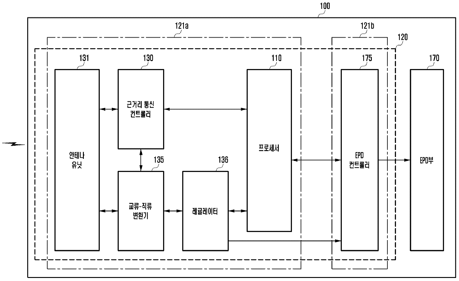
도 2a를 참조하면, 액세서리 장치(100)는 프로세서(110), 근거리 통신 컨트롤러(130), 안테나 유닛(131), 교류-직류 변환기(135), 레귤레이터(136), EPD부(또는 디스플레이부, 170) 및 EPD 컨트롤러(175)를 포함할 수 있다. 본 발명의 실시예에서, 근거리 통신 컨트롤러(130), 안테나 유닛(131), 교류-직류 변환기(135), 레귤레이터(136), EPD부(또는 디스플레이부, 170) 및 EPD 컨트롤러(175)를 액세서리 장치(100)의 '구성 요소'라고 한다. 또한, 근거리 통신 컨트롤러(130), 안테나 유닛(131), 교류-직류 변환기(135), 레귤레이터(136), EPD부(또는 디스플레이부, 170) 및 EPD 컨트롤러(175)를 액세서리 장치(100)의 '전자 부품'이라고 할 수 있다.2A, the
액세서리 장치(100)는 하나 또는 복수의 인쇄 회로 기판을 포함할 수 있다. 예를 들어, 하나의 인쇄 회로 기판(120)에 프로세서(110), 근거리 통신 컨트롤러(130), 안테나 유닛(131), 교류-직류 변환기(135), 레귤레이터(136) 및 EPD 컨트롤러(175)가 실장될 수 있다. The
복수의 인쇄 회로 기판(121a, 121b)은 제1 인쇄 회로 기판(121a) 및 제2 인쇄 회로 기판(121b)일 수 있다. 또한, 복수의 인쇄 회로 기판은 셋 이상의 인쇄 회로 기판을 포함할 수 있다. The plurality of printed
제1 인쇄 회로 기판(121a) 및 제2 인쇄 회로 기판(121b)은 전기적으로 연결(예를 들어, 플렉시블 인쇄 회로 기판(flexible PCB에 의해)될 수 있다. 또한, 제1 인쇄 회로 기판(121a) 및 제2 인쇄 회로 기판(121b)은 무선 통신(예를 들어, 블루투스, 와이파이 등)을 통해 연결될 수 있다. The first printed
복수의 인쇄 회로 기판(121a, 121b)에 프로세서(110), 근거리 통신 컨트롤러(130), 안테나 유닛(131), 교류-직류 변환기(135), 레귤레이터(136) 및 EPD 컨트롤러(175)가 실장될 수 있다. 예를 들어, 제1 인쇄 회로 기판(121a)에 프로세서(110), 근거리 통신 컨트롤러(130), 안테나 유닛(131), 교류-직류 변환기(135), 및 레귤레이터(136)가 실장될 수 있다. 제2 인쇄 회로 기판(121b)에 EPD 컨트롤러(175)가 실장될 수 있다. The
상술된 복수의 인쇄 회로 기판(121a, 121b)에 실장된 구성 요소는 하나의 실시예이며, 이에 한정되지 않는다는 것은 당해 기술 분야에서 통상의 지식을 가지는 자에게 용이하게 이해될 수 있다. 예를 들어, 제1 인쇄 회로 기판(121a)에 있는 구성 요소 중 하나가 제2 인쇄 회로 기판(120b)에 위치할 수도 있다. 또한, 제2 인쇄 회로 기판(121b)에 있는 구성 요소 중 하나가 제1 인쇄 회로 기판(121a)에 위치할 수도 있다. 또한, 구성 요소 중 하나가 제1 인쇄 회로 기판(121a) 및 제2 인쇄 회로 기판(121b)에 각각 위치할 수도 있다. It is easily understood by those skilled in the art that the components mounted on the plurality of printed
프로세서(110)는 근거리 통신 컨트롤러(130), 안테나 유닛(131), 교류-직류 변환기(135), 및 레귤레이터(136) 중 적어도 하나를 제어할 수 있다. 또한, 프로세서(110)는 EPD부(170) 및 EPD 컨트롤러(175)를 제어할 수 있다. The
프로세서(110)는 메모리(도시되지 아니함)를 내장하거나 또는 버스를 통해 별개인 메모리(도시되지 아니함)과 상호 연결될 수 있다. 메모리(도시되지 아니함)는 액세서리 장치(100)의 인증을 위한 인증 프로그램 및 인증 데이터를 저장할 수 있다. 또한, 메모리(도시되지 아니함)는 인증 데이터의 암호화를 위한 암호화 코드를 더 저장할 수 있다. The
예를 들어, 프로세서(110)는 근거리 통신 컨트롤러(130) 및 안테나 유닛(131)을 통해 휴대 장치(200)에서부터 무선 신호를 수신하도록 제어할 수 있다. For example, the
프로세서(110)는 근거리 통신 컨트롤러(130) 및 안테나 유닛(131)을 통해 액세서리 장치(100)에 대한 인증을 수행할 수 있다. The
프로세서(110)는 근거리 통신 컨트롤러(130) 및 안테나 유닛(131)을 통해 휴대 장치(200)에서부터 전력을 수신하도록 제어할 수 있다.The
프로세서(110)는 EPD부(170) 및 EPD 컨트롤러(175)를 이용하여 휴대 장치(200)에서부터 수신되는 하나 또는 복수의 무선 신호에 대응하여 EPD부(170)에 텍스트 및 이미지 중 적어도 하나를 표시하도록 복수의 파티클들 중 적어도 일부를 이동되도록 제어할 수 있다. The
근거리 통신 컨트롤러(130)는 안테나 유닛(131)을 통해 휴대 장치(200)에서부터 전송되는 무선 신호를 수신할 수 있다. 근거리 통신 컨트롤러(130)는 근거리 통신 IC(또는 근거리 통신 칩)를 포함할 수 있다. 예를 들어, 근거리 통신 컨트롤러(130)는 안테나 유닛(131)을 통해 ISO/IEC 14443 표준 또는 ISO/IEC 15693 통신 표준을 따르는 주파수 대역(예를 들어, NFC(near field communication)주파수 대역 또는 RFID(radio frequency identification) 주파수 대역)의 무선 신호를 수신할 수 있다. The short
근거리 통신 컨트롤러(130)는 안테나 유닛(131)을 통해 휴대 장치(200)에서부터 설정된 무선 신호를 수신할 수 있다. 예를 들어, 설정된 무선 신호는 ISO 14443 표준 또는 ISO/IEC 15693 표준에 해당하는 주파수 대역이고, ISO 14443 표준 또는 ISO/IEC 15693 표준에 정의되지 않은 무선 신호일 수도 있다. 또한, 근거리 통신 컨트롤러(130)는 안테나 유닛(131)을 통해 휴대 장치(200)에서부터 설정된 무선 신호로서 비 표준 프로토콜 신호인 REQS(request secure) 신호를 수신할 수도 있다. REQS 신호를 통해 휴대 장치(200)는 액세서리 장치(100)에 인증을 요청할 수 있다. The short
근거리 통신 컨트롤러(130) 및 안테나 유닛(131)을 통해 외부에서 REQS 신호가 수신되는 경우, 프로세서(110)는 수신된 REQS 신호에 대한 응답인 인증 응답 신호(answer to request secure, ATRS)를 근거리 통신 컨트롤러(130) 및 안테나 유닛(131)을 통해 전송하도록 제어할 수 있다. ATRS 신호는 ISO 14443 표준 또는 ISO/IEC 15693 표준에 해당하는 주파수 대역이고 ISO 14443 표준 또는 ISO/IEC 15693 표준에 정의되지 않은 신호로서 휴대 장치(200)와 설정된 신호일 수 있다. ATRS 신호를 휴대 장치(200)로 전송하는 경우, 휴대 장치(200)와 액세서리 장치(100) 사이에 인증이 수행될 수 있다. When an REQS signal is externally received through the short-
근거리 통신 컨트롤러(130) 및 프로세서(110) 중 적어도 하나는 액세서리 장치(100)의 인증을 위한 하나 또는 복수의 암호화 모듈(도시되지 아니함)를 포함할 수 있다. 암호화 모듈(도시되지 아니함)은 RNG(random number generator), MMU(multimedia unit), AES(advanced encryption standard), T-DES(data encryption standard)를 포함할 수 있다.At least one of the short
액세서리 장치(100)는 근거리 통신 컨트롤러(130) 및 프로세서(110)와 별개의 암호화 프로세서(crypto processor)를 포함할 수도 있다. The
안테나 유닛(131)는 외부에서부터 무선 신호를 수신할 수 있다. 안테나 유닛(131)은 외부에서부터 무선으로 전력을 수신할 수 있다. 또한, 안테나 유닛(131)는 데이터를 수신 및 송신할 수 있다. 안테나 유닛(131)은 외부에서부터 수신되는 전력을 교류-직류 변환기(135)로 인가할 수 있다. The
안테나 유닛(131)은 하나 또는 복수의 안테나(도시되지 아니함)를 포함할 수 있다. 안테나가 복수인 경우, 하나의 안테나는 휴대 장치(200)와 무선 신호(또는 데이터, 콘텐트 등)의 송신 또는 수신할 수 있다. 다른 안테나는 휴대 장치(200)에서부터 무선으로 전력을 수신할 수 있다. The
액세서리 장치(100)에서 전력 및 하나 또는 복수의 무선 신호를 외부에서 수신가능한 근거리 통신 컨트롤러(130) 및 안테나 유닛(131)을 근거리 무선 통신 회로라고 칭할 수도 있다. 액세서리 장치(100)는 근거리 무선 통신 회로와 전기적으로 연결되는 제어 회로를 포함할 수 있다. 예를 들어, 제어 회로는 프로세서(110)를 포함하는 의미일 수 있다. The short
교류-직류 변환기(135)는 안테나 유닛(131)에서부터 전달되는 교류를 직류로 변환할 수 있다. 교류-직류 변환기(135)는 프로세서(110)의 제어에 의해 안테나 유닛(131)에서부터 전달되는 교류를 직류로 변환할 수 있다. 또한, 교류-직류 변환기(135)는 별도의 무선 전력 제어 프로세서(도시되지 아니함)에 의해 제어될 수도 있다. The AC-
레귤레이터(136)는 교류-직류 변환기(135)와 연결되고, 액세서리 장치(100)의 다른 구성 요소(예를 들어, 프로세서, EPD 컨트롤러 등)의 구동 가능한 동작 전압으로 변환할 수 있다. 레귤레이터(136)는 동작 전압을 프로세서(110) 및 EPD 컨트롤러(175)로 출력할 수 있다. 또한, 레귤레이터(136)는 동작 전압을 근거리 통신 컨트롤러(130)로 출력할 수 있다. The
EPD부(170)는 EPD 컨트롤러(175)에 의해 컨테이너 내부의 유체(또는 액체) 내에 분포되는 색상 및 전하를 가지는 파티클(particle, 도시되지 아니함)의 위치를 전기장으로 조절하여 선택적으로 색상을 바꿀 수 있다. 또한, EPD부(170) 컨테이너 내부의 유체는 일정한 전하로 코팅된 안료(Pigment), 또는 염료(dye)를 비 유전 용매(dielectric medium)에 균일하게 분산시킨 용액으로 안료 또는 염료의 색을 조절하여 원하는 색상을 구현할 수 있다. 유체는 투명하거나 불투명하거나 또는 색상을 가질 수 있다. 파티클은 안료 및 염료 중 적어도 하나를 포함하는 의미일 수 있다. The
EPD부(170)는 양 전극에 인가되는 전위차를 이용하여 파티클을 이동 시킬 수 있다. 예를 들면, EPD부(170)에서 상단에 위치하는 전극인 ITO(indium tin oxide, 인듐주석산화물)에 +15V 전압(예를 들어, Vref)이 인가되고, 하단에 위치한 전극에 +30 V 전압이 인가되는 경우, +15V인 전위차에 의해 파티클은 하단 전극에 대응되는 EPD부(170)의 바닥에 위치할 수 있다. 또한, 하단에 위치한 전극에 0V 전압이 인가되는 경우, - 15V인 전위차에 의해 파티클은 상단 전극 방향으로 이동할 수 있다. The
EPD 컨트롤러(175)에 의해 양 전극에 전압이 인가되는 인가 시간 및 인가 횟수 중 적어도 하나에 따라 EPD부(170) 내 파티클의 이동 거리가 조절될 수 있다. 파티클의 이동 거리의 조절에 따라 EPD부(170)의 밝기가 조절될 수 있다. 예를 들면, 상단 전극에 +15V 전압이 인가된 상태에서 하단 전극에 0V를 일정 간격으로 수 회(예를 들면 기준 횟수인 5회) 인가하는 경우, 파티클들은 상단 전극 방향으로 이동해서 외부에서 유입되는 빛을 많이 반사할 수 있다. 또한, 하단 간격에 0V를 일정 간격으로 기준 횟수보다 적은 횟 수(예를 들면 기준 횟수 5회인 경우, 3회) 인가하는 경우, 양 전극 사이의 중간 영역으로 이동되는 파티클들은 외부에서 유입되는 빛을 일부만 반사할 수 있다. The moving distance of the particles in the
EPD부(170)는 색상이 다른 유체를 가지고, 독립적으로 구동되는 부분 EDP부(도시되지 아니함)을 포함할 수 있다. 색상을 가지는 유체는 복수의 색상을 가질 수 있다. The
각각의 부분 EPD부(도시되지 아니함)를 상호 연결하는 경우, 복수의 색상을 지닌 액세서리 장치(예를 들어, 복수인 색상의 배경색에 가지고 동일 색상을 표시)로 구현 될 수 있다. 부분 EPD부(도시되지 아니함)의 형태는 특정 형상(예를 들어, 도형 등)의 반복되는 패턴 형태일 수 있고, 또한, 다양한 그림 형태로 구현될 수도 있다. 파티클은 색상을 가지는 유체와 동일한 색상을 가지거나 또는 다른 색상을 가질 수 있다. When interconnecting the respective partial EPD portions (not shown), it may be implemented with an accessory device having a plurality of colors (for example, displaying the same color with a background color of a plurality of colors). The shape of the partial EPD portion (not shown) may be a repetitive pattern form of a specific shape (e.g., a figure or the like), and may also be embodied in various shapes of a figure. Particles can have the same color as a fluid with color or have a different color.
EPD부(170)의 형상은 원형, 타원형, 사각형을 포함하는 다각형, 또는 모서리가 라운드(round)인 다각형을 포함할 수 있다. 도 1b를 참조하면, EPD부(170)의 형상은 사각형이다. EPD부(170)의 노출 형상은 제2 하우징의 개구(예를 들어, 도 3a의 103a1, 또는 도 4a의 104a1)에 의해 결정될 수 있다. 또한, 개구(예를 들어, 도 3a의 103a1, 또는 도 4a의 104a1)의 형상이 원형 또는 타원형이고, EPD부(170)의 형상은 다각형일 수도 있다. The shape of the
EPD 컨트롤러(175)는 프로세서(110)에서 처리된 데이터를 EPD부(170)로 출력할 수 있다. EPD 컨트롤러(175)는 프로세서(110)에서 처리된 데이터를 EPD부(170)에서 출력되게 제어할 수 있다. 또한, EPD부(170)는 EPD 컨트롤러(175)에서부터 수신된 데이터를 표시할 수 있다. EPD부(170)는 EPD 컨트롤러(175)의 제어에 의해 텍스트, 심볼, 패턴 또는 이미지를 표시할 수 있다. The
상술된 액세서리 장치(100)의 구성 요소는 하나의 실시예이며, 이에 한정되지 않는다. 또한, 액세서리 장치(100)의 구성 요소는 액세서리 장치(100)의 기능 및 구조에 따라 추가(예를 들어, 배터리의 추가, 무선 충전용 수신 코일의 추가 등), 변경(예를 들어, EPD부를 이-잉크(e-ink)로 변경) 또는 삭제(예를 들어, 근거리 통신 컨트롤러의 삭제 등)될 수 있다는 것은 당해 기술 분야에서 통상의 지식을 가지는 자에게 용이하게 이해될 수 있다. The components of the above-described
도 1a 내지 도 1c 및 도 2b를 참조하면, 휴대 장치(200)는 이동 통신부(220), 서브 통신부(230) 및 커넥터(265)를 이용하여 다른 장치(예를 들어, 액세서리 장치, 웨어러블 장치(wearable apparatus) 또는 서버 등)와 유선 또는 무선으로 연결될 수 있다. 휴대 장치(200)는 휴대폰(도시되지 아니함), 스마트폰, 태블릿(tablet) 장치(도시되지 아니함), MP3 플레이어(도시되지 아니함), 동영상 플레이어(도시되지 아니함)뿐만 아니라, 액세서리 장치(200)를 장착 또는 부착 가능한 장치를 포함할 수 있다. 휴대 장치(200)는 외부 장치라고 칭해질 수 있다. 1A to 1C and 2B, the
휴대 장치(200)는 터치 스크린(290)을 가지고 통신부(220 또는 230)를 통해 데이터(예를 들어, 콘텐트에 대응되는)를 외부로 송신하거나 또는 외부에서부터 수신할 수 있다. 휴대 장치(200)는 입력 펜(267) 및 터치 스크린(290)을 가지고 통신부(220 또는 230)를 통해 데이터(예를 들어, 콘텐트에 대응되는)를 외부로 송신 또는 외부에서부터 수신할 수 있다. 또한, 휴대 장치(200)는 디스플레이부(예를 들어, 터치 패널 없이 디스플레이 패널만 있는 실시예, 도시되지 아니함)를 가지고 통신부(220 또는 230)를 통해 데이터(예를 들어, 콘텐트에 대응되는)를 외부로 송신 또는 외부에서부터 수신할 수 있다. The
휴대 장치(200)는 제어부(210), 이동 통신부(220), 서브 통신부(230), 멀티미디어부(240), 카메라(250), 위치 정보 수신부(positioning information receiver, 255), 입/출력부(260), 센서부(270), 저장부(275) 및 전원 공급부(280)를 포함할 수 있다. 또한, 휴대 장치(200)는 터치 스크린(290) 및 터치 스크린 컨트롤러(295)를 포함할 수 있다. The
제어부(210)는 프로세서(processor, 211)를 포함할 수 있다. 또한, 제어부(210)는 휴대 장치(200)의 제어를 위한 제어 프로그램이 저장된 롬(ROM, 212) 및 휴대 장치(200)의 외부로부터 입력되는 신호 또는 데이터를 저장하거나, 휴대 장치(200)에서 수행되는 다양한 작업에 대한 저장 영역으로 사용되는 램(RAM, 213)을 더 포함할 수 있다. The
제어부(210)는 휴대 장치(200)의 전반적인 동작 및 휴대 장치(200)의 내부 구성 요소들(220 내지 295)간의 신호 흐름을 제어하고, 데이터를 처리하는 기능을 수행한다. 제어부(210)는 전원 공급부(280)를 이용하여 내부 구성 요소들(220 내지 295)에게 전원 공급을 제어한다. The
프로세서(211)는 그래픽 처리를 위한 GPU(graphic processing unit, 도시되지 아니함)를 포함할 수 있다. 또한, 프로세서(211)는 센서를 제어하는 센서 프로세서(sensor processor, 도시되지 아니함) 또는 통신을 제어하는 통신 프로세서(communication processor, 도시되지 아니함)를 포함할 수 있다The
프로세서(211)는 코어(core, 도시되지 아니함)와 GPU(도시되지 아니함)를 포함하는 SoC(system on chip) 형태로 구현될 수 있다. 프로세서(211)는 싱글 코어, 듀얼 코어, 트리플 코어, 쿼드 코어 및 그 배수의 코어를 포함할 수 있다. 또한, 프로세서(211), 롬(212) 및 램(213)은 버스(bus)로 상호 연결될 수 있다. The
제어부(210)는 이동 통신부(220), 서브 통신부(230), 멀티미디어부(240), 카메라(250), 위치 정보 수신부(255), 입/출력부(260), 센서부(270), 저장부(275), 전원 공급부(280), 터치 스크린(290) 및 터치 스크린 컨트롤러(295)를 제어할 수 있다. The
제어부(210)는 전원 공급부(280) 및 배터리(285)와 연결된 접점을 통해 액세서리 장치(200)로 공급되는 전력의 공급 여부를 제어할 수 있다. The
제어부(210)는 액세서리 장치(100)로 전력 공급 및 액세서리 장치(100)의 EPD부(170)에서 데이터(또는, 콘텐트) 표시 중 적어도 하나에 대응되는 시각 피드백, 청각 피드백 및 촉각 피드백 중 적어도 하나를 사용자에게 제공하도록 제어할 수 있다. The
본 발명의 다양한 실시예에서 '휴대 장치의 제어부'라는 용어는 프로세서(211), 롬(212) 및 램(213)을 포함하는 의미일 수 있다. In various embodiments of the present invention, the term " control unit of the portable device " may be understood to include
이동 통신부(220)는 제어부(210)의 제어에 의해 하나 또는 둘 이상의 안테나를 이용하여 이동 통신망을 통해 다른 장치(예를 들어, 다른 휴대 장치, 웨어러블 장치, 또는 서버 등)와 연결할 수 있다. 이동 통신부(220)는 안테나 유닛(도시되지 아니함)을 포함할 수 있다. 안테나 유닛(도시되지 아니함)는 하나 또는 복수의 안테나를 포함할 수 있다. The
서브 통신부(230)는 제어부(210)의 제어에 의해 무선랜 통신부(231) 및/또는 근거리 통신부(232)를 통해 다른 장치(예를 들어, 다른 휴대 장치, 웨어러블 장치, 또는 서버 등)와 연결할 수 있다. 서브 통신부(230)는 안테나 유닛(도시되지 아니함)을 포함할 수 있다. 안테나 유닛(도시되지 아니함)는 하나 또는 복수의 안테나를 포함할 수 있다. The
무선랜 통신부(231)는 제어부(210)의 제어에 의해 AP(access point)가 설치된 장소에서 무선으로 AP와 연결될 수 있다. 무선랜 통신부(231)는 예를 들어, 와이-파이(Wi-Fi)를 포함할 수 있다. The wireless
근거리 통신부(232)에서 지원하는 근거리 통신은 블루투스(bluetooth) 통신, 블루투스 저 에너지(bluetooth low energy) 통신, 적외선 통신(infrared data association, IrDA), UWB(ultra-wideband) 통신, 마그네틱 보안 전송(magnetic secure transmission, MST) 통신 및/또는 근거리 통신(near field communication, NFC) 통신 등을 포함할 수 있다. The short range communication supported by the short
근거리 통신부(232)는 근거리 통신을 통해 검색된 액세서리 장치(100)와 연결할 수 있다. 근거리 통신부(232)는 제어부(210)의 제어에 의해 연결된 액세서리 장치(100)에 안테나 유닛(도시되지 아니함)를 통해 무선으로 전력을 공급할 수 있다. The short-
제어부(210)는 근거리 통신을 통해 전원 공급된 액세서리 장치(100)로 데이터를 송신하거나 또는 수신할 수 있다. 또한, 제어부(210)는 근거리 통신을 통해 전원 공급된 액세서리 장치(100)에 대한 인증을 수행할 수 있다. The
휴대 장치(200)는 기능 및/또는 성능에 따라 이동 통신부(220), 무선랜 통신부(231), 및 근거리 통신부(232) 중 하나, 또는 이동 통신부(220), 무선랜 통신부(231), 및 근거리 통신부(232)의 조합을 포함할 수 있다. The
본 발명의 다양한 실시예에서 '통신부'라는 용어는 이동 통신부(220) 및/또는 서브 통신부(230)를 포함한다. In various embodiments of the present invention, the term 'communication unit' includes a
멀티미디어부(240)는 제어부(210)의 제어에 의해 외부의 방송을 수신, 오디오 재생 및/또는 동영상을 재생할 수 있다. The
오디오 재생부(241)는 제어부(210)의 제어에 의해 휴대 장치(200)의 저장부(275)에 기 저장되거나 또는 외부에서부터 수신되는 오디오 소스(예를 들어, 오디오 파일)를 오디오 코덱을 이용하여 재생할 수 있다. The
본 발명의 다양한 실시예에 따라 오디오 재생부(241)는 액세서리 장치(100)로 전력 공급 및 액세서리 장치(100)의 EPD부(170)에서 데이터(또는, 콘텐트) 표시 중 적어도 하나에 대응되는 청각 피드백을 재생할 수 있다. 예를 들어, 오디오 재생부(242)는 제어부(210)의 제어에 의해 액세서리 장치(100)로 전력 공급 및 액세서리 장치(100)의 EPD부(170)에서 데이터(또는, 콘텐트) 표시 중 적어도 하나에 에 대응되는 청각 피드백(예를 들어, 저장부(275)에 저장된 오디오 소스의 출력 등)을 오디오 코덱을 통해 재생할 수 있다. According to various embodiments of the present invention, the
동영상 재생부(242)는 제어부(210)의 제어에 의해 휴대 장치(200)의 저장부(275)에 기 저장되거나 또는 외부에서부터 수신되는 디지털 동영상 소스(예를 들어, 비디오 파일)을 비디오 코덱을 이용하여 재생할 수 있다. The moving
본 발명의 다양한 실시예에 따라 동영상 재생부(242)는 액세서리 장치(100)로 전력 공급 및 액세서리 장치(100)의 EPD부(170)에서 데이터(또는, 콘텐트) 표시 중 적어도 하나에 에 대응되는 시각 피드백을 재생할 수 있다. 예를 들어, 시각 피드백(예를 들어, 저장부(275)에 저장된 동영상 소스의 출력 등)은 제어부(210)의 제어에 의해 비디오 코덱을 통해 재생될 수 있다. In accordance with various embodiments of the present invention, the moving
방송 통신부(243)는 제어부(210)의 제어에 의해 안테나(도시되지 아니함)를 통해 외부의 방송국에서부터 송출되는 방송 신호(예를 들어, TV 방송 신호, 라디오 방송 신호 또는 데이터 방송 신호) 및 방송 부가 정보(예를 들어, EPG(electronic program guide) 또는 ESG(electronic service guide))를 수신할 수 있다. The
멀티미디어부(240)는 휴대 장치(200)의 성능 또는 구조에 대응하여 방송 통신부(243)을 제외하고 오디오 재생부(241)과 동영상 재생부(242)를 포함할 수 있다. 또한, 제어부(210)는 멀티미디어부(240)의 오디오 재생부(241) 또는 동영상 재생부(242)를 포함하도록 구현될 수도 있다. The
카메라(250)는 제어부(210)의 제어에 의해 정지 이미지 또는 동영상을 촬영할 수 있다. 카메라(250)는 제1 카메라(251) 및 제2 카메라(252) 중 하나 또는 양자를 모두 포함할 수 있다. The
제1 카메라(251) 및 제2 카메라(252) 중 적어도 하나는 촬영에 필요한 광량을 제공하는 보조 광원(예를 들어, 플래시(253))을 포함할 수 있다. At least one of the
카메라(250)는 전면에 제1 카메라(251) 및 제1 카메라(251)에 인접(예를 들어, 간격은 5 ㎜ 보다 크고 80 ㎜ 보다 작은)한 추가 카메라(예를 들어, 제3 카메라(도시되지 아니함))를 더 포함하거나 또는 제1 카메라(251)와 제3 카메라(도시되지 아니함)를 하나의 유닛(unit)으로 구현된 형태를 포함할 수 있다. The
제어부(210)는 전면의 제1 카메라(251) 및 제3 카메라(도시되지 아니함)를 이용하여 3차원 정지 이미지 또는 3차원 동영상을 촬영하도록 제어할 수 있다. The
카메라(250)는 또한, 후면에 제2 카메라(252) 및 제2 카메라(252)에 인접(예를 들어, 간격은 5 ㎜ 보다 크고 80 ㎜ 보다 작은)한 추가 카메라(예를 들어, 제4 카메라(도시되지 아니함))를 더 포함하거나 또는 제2 카메라(252)와 제4 카메라(도시되지 아니함)를 하나의 유닛(unit)으로 구현된 형태를 포함할 수 있다. The
제어부(210)는 후면의 제2 카메라(251) 및 제4 카메라(도시되지 아니함)를 이용하여 3차원 정지 이미지 또는 3차원 동영상을 촬영하도록 제어할 수 있다. The
카메라(251, 252)는 별도의 어댑터(도시되지 아니함)에 착탈가능한 추가 렌즈(도시되지 아니함)를 이용하여 광각, 망원 및 접사 촬영을 할 수 있다. The
위치 정보 수신부(255)는 지구 궤도상에 있는 복수의 위성(도시되지 아니함)에서부터 주기적으로 신호(예를 들어, GPS 위성의 궤도 정보, 위성의 시간 정보 및 항법 메시지 등)를 수신한다. The position
휴대 장치(200)는 복수의 위성(도시되지 아니함)에서부터 수신되는 신호를 이용하여 각각의 위성(도시되지 아니함)과 휴대 장치(200)의 사이의 위치를 산출하고, 송/수신 시간차를 이용하여 거리를 산출할 수 있다. 삼각 측량을 통해 휴대 장치(200)의 위치, 시간 또는 이동 속도를 산출할 수 있다. 궤도 보정 또는 시간 보정을 위해 추가의 위성이 필요할 수 있다. The
실내의 경우, 휴대 장치(200)는 무선 AP(도시되지 아니함)를 이용하여 휴대 장치(200)의 위치 또는 이동 속도를 검출할 수 있다. 실내에서 휴대 장치(200)의 위치 검출은 셀 아이디(cell-ID) 방식, 강화 셀 아이디(enhanced cell-ID) 방식 또는 AoA(angle of arrival) 방식을 이용할 수 있다. 또한, 휴대 장치(200)는 무선 비컨(beacon, 도시되지 아니함)을 이용하여 실내에 위치하는 휴대 장치(200)의 위치 또는 이동 속도를 검출할 수 있다. In the indoor environment, the
입/출력부(260)는 하나 또는 둘 이상의 버튼(261), 하나 또는 둘 이상의 마이크(262), 하나 또는 둘 이상의 스피커(263), 하나 또는 둘 이상의 진동 모터(264), 커넥터(265), 키패드(266) 및 입력 펜(267) 중 적어도 하나를 포함할 수 있다. The input /
도 1 및 도 2b를 참조하면, 버튼(261)은 휴대 장치(200)의 전면 하부에 있는 홈 버튼(261a), 최근 실행 앱 버튼(261b), 및/또는 돌아가기 버튼(261c)을 포함할 수 있다. 버튼(261)은 휴대 장치(200)의 측면에 적어도 하나의 볼륨 버튼(도시되지 아니함) 및 전원/잠금 버튼(261e)을 포함할 수 있다. 또한, 휴대 장치(200)의 버튼(261)은 홈 버튼(261a), 볼륨 버튼(도시되지 아니함) 및 전원/잠금 버튼(261e)만을 포함할 수 있다. 버튼(261)은 물리 버튼뿐만 아니라 터치 버튼으로 구현될 수 있다. 또한, 휴대 장치(200)의 버튼(261)은 터치 스크린(290) 상에 텍스트, 이미지 또는 아이콘 형태로 표시될 수 있다. 1 and 2B, the
제어부(210)는 사용자 입력에 대응하여 버튼(261)에서부터 전송되는 전기 신호를 수신할 수 있다. 제어부(210)는 수신된 신호(예를 들어, 버튼(261)의 눌림 또는 버튼(261)의 접촉)를 이용하여 사용자의 입력을 검출할 수 있다. The
도 1 및 도 2b에 도시된 버튼(261)의 형태, 위치, 기능, 또는, 명칭 등은 설명을 위한 하나의 예이며, 이에 한정되지 않고 변경, 변형 또는 수정할 수 있는다는 것은 당해 기술 분야의 통상의 지식을 가진 자에게 용이하게 이해될 것이다. The form, position, function, or name of the
마이크(262)는 제어부(210)의 제어에 의해 외부에서부터 음성(voice) 또는 사운드(sound)를 입력 받아 전기적인 신호를 생성한다. 마이크(262)에서 생성된 전기적인 신호는 제어부(210)의 제어에 의해 오디오 코덱에서 변환되어 저장부(275)에 저장되거나 또는 스피커(263)를 통해 출력될 수 있다. The
도 1 및 도 2b를 참조하면, 마이크(262)는 휴대 장치(200)의 전면, 측면 및/또는 후면에 하나 또는 둘 이상 위치할 수 있다. 또한, 휴대 장치(200)의 측면에만 하나 또는 둘 이상의 마이크가 위치할 수도 있다. Referring to FIGS. 1 and 2B, the
스피커(263)는 제어부(210)의 제어에 의해 오디오 코덱에 의해 디코딩 되는 다양한 신호(예를 들어, 무선 신호, 방송 신호, 오디오 소스, 동영상 파일 또는 사진 촬영 등)에 대응되는 사운드를 출력할 수 있다. The
도 1 및 도 2a를 참조하면, 휴대 장치(200)의 전면, 측면 및/또는 후면에 하나 또는 복수의 스피커(263)가 위치할 수 있다. 또한, 휴대 장치(200)의 측면에 복수의 스피커(도시되지 아니함)가 위치할 수 있다. Referring to FIGS. 1 and 2A, one or a plurality of
본 발명의 실시예에 따라 스피커(263)는 액세서리 장치(100)로 전력 공급 및 액세서리 장치(100)의 EPD부(170)에서 데이터(또는, 콘텐트) 표시 중 적어도 하나에 에 대응되는 청각 피드백을 출력할 수 있다. 예를 들어, 스피커(263)는 제어부(210)의 제어에 의해 액세서리 장치(100)로 전력 공급 및 액세서리 장치(100)의 EPD부(170)에서 데이터(또는, 콘텐트) 표시 중 적어도 하나에 에 대응되는 청각 피드백을 출력할 수 있다. The
진동 모터(264)는 제어부(210)의 제어에 의해 전기적 신호를 기계적 진동으로 변환할 수 있다. 진동 모터(264)는 리니어 진동 모터(linear vibration motor), 바 타입 진동 모터(bar type vibration motor), 코인 타입 진동 모터(coin type vibration motor) 또는 압전 소자 진동 모터(piezoelectric element vibration motor)를 포함할 수 있다. The
진동 모터(264)는 휴대 장치(200)에 하나 또는 둘 이상으로 위치할 수 있다. 또한, 진동 모터(264)는 휴대 장치(200) 전체를 진동시키거나 또는 휴대 장치(200)의 일 부분만을 국부적으로(locally) 진동시킬 수도 있다. The
본 발명의 실시예에 따라 진동 모터(264)는 액세서리 장치(100)로 전력 공급 및 액세서리 장치(100)의 EPD부(170)에서 데이터(또는, 콘텐트) 표시 중 적어도 하나에 에 대응되는 촉각 피드백을 출력할 수 있다. 또한, 진동 모터(264)는 제어부(210)의 제어 명령에 기초하여 기 저장되거나 외부에서부터 수신된 다양한 촉각 피드백(예를 들어, 진동의 세기 및 진동 지속 시간)을 제공할 수 있다. The
커넥터(265)는 휴대 장치(200)와 외부 장치(도시되지 아니함) 또는 전원 소스(도시되지 아니함)를 연결하기 위한 인터페이스로 이용될 수 있다. 커넥터(265)는 마이크로 USB 타입 커넥터 또는 USB-C 타입 커넥터를 포함할 수 있다. The
휴대 장치(200)는 제어부(210)의 제어에 의해 커넥터(265)에 연결된 유선 케이블을 통해 저장부(275)에 저장된 데이터(예를 들어, 콘텐트에 대응되는)를 외부로 전송하거나 또는 외부에서부터 데이터(예를 들어, 콘텐트에 대응되는)를 수신할 수 있다. 휴대 장치(200)는 제어부(210)의 제어에 의해 커넥터(265)에 연결된 유선 케이블을 통해 전원 소스(도시되지 아니함)에서부터 전원을 입력 받거나 또는 배터리(도시되지 아니함)를 충전할 수 있다. 또한, 휴대 장치(200)는 커넥터(265)를 통해 액세서리 장치(예를 들어, 플립 커버, 스피커 등))와 연결될 수 있다. The
키패드(266)는 휴대 장치(200)의 제어를 위해 사용자로부터 키 입력을 수신할 수 있다. 키패드(266)는 터치 스크린(290)내 표시되는 가상 키패드(도시되지 아니함) 및 휴대 장치(200)의 전면에 형성되는 물리적인 키패드(도시되지 아니함) 중 하나를 포함할 수 있다. 또한, 키패드(266)는 무선(예를 들어, 근거리 통신을 이용한) 또는 유선으로 연결가능한 별개의 키패드(도시되지 아니함)를 포함할 수 있다. The
입력 펜(267)은 휴대 장치(200)에 인입/인출 가능하고, 사용자에 의해 휴대 장치(200)의 터치 스크린(290) 또는 필기/그리기 어플리케이션에 표시되는 화면(예를 들어, 메모 화면, 노트 패드 화면, 캘린더 화면, 등)에 표시되는(또는, 구성하는) 오브젝트(object, 예를 들어, 메뉴, 텍스트, 이미지, 비디오, 도형, 아이콘 및 단축아이콘) 및/또는 콘텐트(content, 예를 들어, 텍스트 파일, 이미지 파일, 오디오 파일, 비디오 파일 또는 웹 페이지)를 터치(또는, 선택)하거나 필기(handwriting, 또는 그리기(drawing, painting or sketching)할 수 있다. The
센서부(270)는 휴대 장치(200)의 상태 및/또는 휴대 장치(200)의 주변 상태를 검출할 수 있다. 센서부(270)는 하나 또는 복수의 센서를 포함할 수 있다. The
센서부(270)는 사용자의 휴대 장치(200)에 대한 접근 여부를 검출하는 근접 센서(proximity sensor, 271), 휴대 장치(200) 주변의 빛의 양을 검출하는 조도 센서(illuminance sensor, 272), 및/또는 전자 장치(200)의 회전관성을 이용하여 방향을 검출하는 자이로 센서(273)를 포함할 수 있다. 센서부(270)는 가속도 센서(acceleration sensor, 도시되지 아니함), 중력 센서(gravity sensor), 또는 고도계(altimeter)를 포함할 수 있다. 또한, 심박 센서(도시되지 아니함) 또는 지문 센서(도시되지 아니함)를 더 포함할 수 있다.The
센서부(270)에 포함되는 적어도 하나의 센서는 휴대 장치(200)의 상태를 검출하고, 검출에 대응되는 전기적인 신호를 생성하여 제어부(210)로 전송한다. 센서부(270)에 포함되는 센서는 휴대 장치(200)의 성능에 따라 추가, 변경, 또는, 삭제될 수 있다는 것은 당해 기술 분야의 통상의 지식을 가지는 자에게 용이하게 이해될 것이다. At least one sensor included in the
저장부(275)는 제어부(210)의 제어에 의해 이동 통신부(220), 서브 통신부(230), 멀티미디어부(240), 카메라(250), 위치 정보 수신부(255), 입/출력부(260), 센서부(270), 및 터치 스크린(290)의 동작에 대응되게 입/출력되는 신호 또는 데이터를 저장할 수 있다. 저장부(275)는 휴대 장치(200) 또는 제어부(210)의 제어를 위한 제어 프로그램과 제조사에서 제공되거나 외부로부터 다운로드 받은 어플리케이션과 관련된 GUI(graphical user interface), GUI를 제공하기 위한 이미지들, 사용자 정보, 문서, 데이터베이스들 또는 관련 데이터들을 저장할 수 있다.The
저장부(275)는 액세서리 장치(100)로 전력 공급 및 액세서리 장치(100)의 EPD부(170)에서 데이터(또는, 콘텐트) 표시 중 적어도 하나에 대응되는 터치 스크린(290)에 출력되는 사용자가 인지가능한 시각 피드백(예를 들어, 비디오 소스 등), 스피커(263)에서 출력되는 사용자가 인지가능한 청각 피드백(예를 들어, 사운드 소스 등) 및 진동 모터(264)에서 출력되는 사용자가 인지가능한 촉각 피드백(예를 들어, 햅틱 패턴 등)을 저장할 수 있다. The
저장부(275)는 사용자에게 제공되는 피드백의 피드백 제공 시간(예를 들어, 500 ㎳)을 저장할 수 있다. The
본 발명의 실시예에서 '저장부'라는 용어는 저장부(275), 제어부(210) 내 롬(112), 램(113) 또는 휴대 장치(200)에 장착되는 메모리 카드(예를 들어, micro SD 카드, 메모리 스틱 등, 도시되지 아니함)를 포함한다. 저장부(275)는 비휘발성 메모리, 휘발성 메모리, 하드 디스크 드라이브(HDD) 또는 솔리드 스테이트 드라이브(SSD)를 포함할 수 있다. In the embodiment of the present invention, the term 'storage unit' refers to a
전원 공급부(280)는 제어부(210)의 제어에 의해 휴대 장치(200)의 구성 요소(210 내지 295)에게 전원을 공급할 수 있다. 전원 공급부(280)는 제어부(210)의 제어에 의해 커넥터(265)와 연결된 유선 케이블(도시되지 아니함)을 통해 외부의 전원 소스(도시되지 아니함)에서부터 입력되는 전원을 휴대 장치(200)의 각 구성 요소들에게 공급할 수 있다. The
전원 공급부(280)는 제어부(210)의 제어에 의해 하나 또는 둘 이상의 배터리(285)를 충전할 수 있다. The
전원 공급부(280)는 접점(도시되지 아니함)을 통해 유선으로 액세서리 장치(200)에 배터리(285)의 전력을 공급할 수 있다. 또한, 전원 공급부(280)는 제어부(210)의 제어에 의해 배터리(285)와 연결되는 별도의 송신 코일(도시되지 아니함)을 이용하여 액세서리 장치(200) 또는 웨어러블 장치(도시되지 아니함)을 무선으로 충전할 수 있다. 무선 충전 방식은 예를 들어, 자기 공진 방식, 전자기파 방식, 또는 자기 유도 방식을 포함할 수 있다. The
터치 스크린(290)은 사용자에게 다양한 서비스(예를 들어, 음성 통화, 영상 통화, 데이터 전송, 방송 수신, 사진 촬영, 동영상 보기, 또는 어플리케이션 실행)에 대응되는 GUI(graphical user interface)를 제공할 수 있다. 터치 스크린(290)은 터치 입력을 수신하는 터치 패널(도시되지 아니함)과 화면 표시를 위한 디스플레이 패널(도시되지 아니함)을 포함한다. 또한, 터치 스크린(290)은 터치 입력을 수신하는 에지 터치 패널(도시되지 아니함)과 화면 표시를 위한 에지 디스플레이 패널(도시되지 아니함)을 포함할 수 있다. The
터치 스크린(290)은 홈 화면(191) 또는 GUI를 통해 입력되는 싱글 터치 또는 멀티 터치에 대응되는 아날로그 신호를 터치 스크린 컨트롤러(295)로 전송할 수 있다. 터치 스크린(290)은 사용자의 신체(예를 들어, 엄지를 포함하는 손가락) 또는 입력 펜(267)을 통해 싱글 터치 또는 멀티 터치를 입력 받을 수 있다. The
터치 스크린 컨트롤러(295)는 터치 스크린(290)에서부터 수신된 싱글 터치 또는 멀티 터치에 대응되는 아날로그 신호를 디지털 신호로 변환하여 제어부(210)로 전송한다. 제어부(210)는 터치 스크린 컨트롤러(295)에서부터 수신된 디지털 신호를 이용하여 터치 스크린(290)에서 입력되는 터치의 터치 위치에 대응되는 X좌표와 Y좌표를 산출할 수도 있다. The
제어부(210)는 터치 스크린 컨트롤러(295)에서부터 수신된 디지털 신호를 이용하여 터치 스크린(290)을 제어할 수 있다. 예를 들어, 제어부(210)는 입력된 터치에 대응하여 터치 스크린(290)에 표시된 단축 아이콘을 다른 단축 아이콘과 구분되게 표시하거나 또는 선택된 단축 아이콘에 대응되는 어플리케이션(예를 들어, 전화)를 실행하여 터치 스크린(290)에 어플리케이션 화면을 표시할 수 있다. The
도 1a 내지 도 1c 및 도 2b에서 도시된 휴대 장치(200)는 하나의 터치 스크린을 포함되게 도시하였으나, 복수의 터치 스크린을 구비할 수 있다. 각각의 터치 스크린은 각각의 하우징(housing, 도시되지 아니함)에 위치하며 각각의 하우징(도시되지 아니함)은 하나 또는 복수의 힌지(hinge, 도시되지 아니함)에 의해 상호 연결될 수 있다. Although the
하나의 하우징(도시되지 아니함)의 전면에 상/하 또는 좌/우로 배치되는 복수의 터치 스크린이 위치할 수 있다. 복수의 터치 스크린은 하나의 디스플레이 패널과 복수의 터치 패널로 구현될 수 있다. 복수의 터치 스크린은 복수의 디스플레이 패널에 대응되는 터치 패널로 구현될 수 있다. 또한, 복수의 터치 스크린은 복수의 디스플레이 패널에 대응되는 복수의 터치 패널로 구현될 수 있다. A plurality of touch screens may be placed on the front surface of one housing (not shown), arranged up / down or left / right. The plurality of touch screens may be implemented by one display panel and a plurality of touch panels. The plurality of touch screens may be implemented as a touch panel corresponding to a plurality of display panels. The plurality of touch screens may be implemented by a plurality of touch panels corresponding to the plurality of display panels.
도 1a 내지 도 1c 및 도 2b에 도시된 휴대 장치(200)의 구성 요소들은 휴대 장치(200)의 성능에 대응하여 적어도 하나의 구성요소(예를 들어, 점선인 구성 요소)가 추가, 삭제 또는 변경될 수 있다는 것은 당해 기술 분야에서 통상의 지식을 가진 자에게 용이하게 이해될 것이다.The components of the
도 3a는 본 발명의 실시예에 따른 액세서리 장치를 나타내는 개략적인 분해 사시도이다. 3A is a schematic exploded perspective view showing an accessory device according to an embodiment of the present invention.
도 3b는 본 발명의 실시예에 따른 액세서리 장치를 나타내는 개략적인 단면도이다. 도 3b는 도 1a의 A-A'선을 따라 액세서리 장치를 절단한 단면도이다. 3B is a schematic cross-sectional view illustrating an accessory device according to an embodiment of the present invention. FIG. 3B is a cross-sectional view of the accessory device taken along the line A-A 'in FIG. 1A.
도 3a를 참조하면, EPD부(170)의 면적은 제1 하우징(103)의 표면 면적의 98 % 이하일 수 있다. EPD부(170)의 면적은 제1 하우징(103)의 면적의 75 % 이상이고 99.9 % 이하일 수 있다. Referring to FIG. 3A, the area of the
액세서리 장치(예를 들어, 범퍼, 100)는 제1 하우징(103), 제2 하우징(103a), 필름(103b), EPD부(170), 인쇄 회로 기판(120) 및 제3 하우징(103c)을 포함할 수 있다. 액세서리 장치(100)는 상술된 구성 요소 중 변경, 삭제되거나 별도의 구성 요소가 더 추가될 수도 있다. The accessory device (e.g., bumper 100) includes a
제1 하우징(103)은 액세서리 장치(100)의 후면에 대응된다. 제1 하우징(103)은 투명, 불투명하거나 또는 일부분만 투명(또는 불투명)할 수 있다. 또한, 제1 하우징(103)은 일체형으로 구현되거나 또는 복수 개로 분리될 수 있다. The
제1 하우징(103)의 재질은 폴리카보네이트(polycarbonate), 강화 유리 또는 아크릴일 수 있다. 또한, 제1 하우징(103)의 재질은 열 가소성 플라스틱일 수 있다. The material of the
제1 하우징(103)은 사출 성형(injection molding)으로 구현될 수 있다. 제1 하우징(103)은 이중 사출 성형될 수 있다. 예를 들어, 이중 사출 성형에서, EPD부(170)에 대응되는 영역은 투명한 재질이고, EPD부(170)에 대응되지 않는 영역은 불투명 재질로 사출 성형으로 구현될 수 있다. 상술된 사출 성형은 하나의 실시예이며, 사출 성형뿐만 아니라 제1 하우징(103)의 구현을 위한 성형 방법은 제한되지 않는다. The
제1 하우징(103)는 개구(103-1)를 가질 수 있다. 개구(opening, 103-1)를 통해 휴대 장치(200)의 제2 카메라(252) 및 플래시(253) 중 적어도 하나가 외부로 노출될 수 있다. The
제2 하우징(103a)은 제1 하우징(103)과 휴대 장치(200) 사이에 위치한다. 제2 하우징(103a1)은 장착 구조(102f)를 통해 휴대 장치(200)를 수용할 수 있다. The
제2 하우징(103a)은 투명, 불투명하거나 또는 일부분만 투명(또는 불투명)할 수 있다. 또한, 제2 하우징(103a)은 일체형으로 구현되거나 또는 복수 개로 분리될 수 있다. The
제2 하우징(103a)의 재질은 폴리카보네이트(polycarbonate)뿐만 아니라 금속, 목재, 또는, 플라스틱 재질을 포함할 수 있다. The material of the
제2 하우징(103a)은 사출 성형으로 구현될 수 있다. 제2 하우징(103a)는 개구(103a)를 가질 수 있다. 개구(103a1)를 통해 EPD부(170), 제2 카메라(252) 및 플래시(253) 중 하나가 외부로 노출될 수 있다.The
제2 하우징(103a)은 제1 하우징(103)과 결합할 수 있다. 예를 들어, 제1 하우징(103)과 제2 하우징(103a)은 접합, 접착, 또는 끼워 맞춤(fit)으로 결합될 수 있다. 본 발명의 실시예에서, 제2 하우징(103a)과 제1 하우징(103)은 일체형으로 구현될 수 있다. 일체형으로 구현된 제2 하우징(103a)과 제1 하우징(103)의 형상은 제2 하우징(103a)과 제1 하우징(103)의 결합 형상과 유사할 수 있다. The
EPD부(170)의 전면(예를 들어, + z 축 방향)에 필름(103b)이 위치할 수 있다. 필름(103b)은 광학용의 투명한 재질로 형성될 수 있으며, 광학용 시트(sheet)일 수도 있다. 예를 들어, 필름(103b)은 폴리에틸렌 테레프탈레이트(polyethylene terephthalate, PET) 재질을 가질 수 있다. The
필름(103b)의 두께는 EPD부(170)보다는 얇을 수 있다. 예를 들어, 필름(103b)의 두께는 EPD부(170)의 두께의 10 % 이상이고, 75 % 이하일 수 있다. 필름(103b)은 일체형(예를 들어, 개구(103b1)가 없는)이거나 또는 개구(103b1)를 가질 수 있다. The thickness of the
제1 하우징(103)과 필름(103b) 사이에 실리콘 시트(도시되지 아니함)가 위치할 수 있다. 실리콘 시트(도시되지 아니함)는 투과율이 우수하고, 표면 반사를 감소시킬 수 있다. 실리콘 시트(도시되지 아니함)는 제2 하우징(103a) 및 제1 하우징(103) 중 하나에 의해 지지될 수 있다. A silicon sheet (not shown) may be positioned between the
EPD부(170)는 필름(103b)과 인쇄 회로 기판(120)사이에 위치할 수 있다. EPD부(170)는 개구(170-1)를 가질 수 있다. 개구(170-1)를 통해 휴대 장치(200)의 제2 카메라(252) 및 플래시(253) 중 하나가 외부로 노출될 수 있다. The
EPD부(170)는 인쇄 회로 기판(120)에서부터 전원과 데이터를 수신할 수 있다. EPD부(170)의 면적은 제2 하우징(103a)의 크기 및 구조에 대응하여 변경될 수 있다. The
EPD부(170)는 인쇄 회로 기판(120)과 전기적으로 연결될 수 있다. The
인쇄 회로 기판(120)은 양면 인쇄 회로 기판일 수 있다. 또한, 인쇄 회로 기판(120)은 플렉시블 양면 인쇄 회로 기판일 수 있다. 인쇄 회로 기판(120)의 전면(예를 들어, - z 축 방향)에 액세서리 장치(100)의 구성 요소가 실장되고, 인쇄 회로 기판(120)의 배면(120a)에 EPD부(170)의 하부 전극과 연결될 수 있다. The printed
인쇄 회로 기판(120)은 안테나 유닛(131)과 전기적으로 연결될 수 있다. 안테나 유닛(131)은 하나 또는 복수의 안테나를 포함할 수 있다. 안테나 유닛(131)을 통해 외부에서 전력과 무선 신호(또는 데이터)가 수신될 수 있다. The printed
인쇄 회로 기판(120)의 면적이 EPD부(170)의 면적보다 좁은 경우, 인쇄 회로 기판(120)의 배면(예를 들어, 구성 요소가 실장되지 않은, 120a)의 일부는 EPD부(170)의 하단 전극과 연결될 수 있다. 또한, 인쇄 회로 기판(120)의 배면(120a)의 일부는 EPD부(170)의 하단 전극으로 구현될 수도 있다. A portion of the back surface of the printed circuit board 120 (for example, 120a, in which the components are not mounted) is formed in the
인쇄 회로 기판(120)의 면적은 EPD부(170)의 면적과 유사할 수 있다. 예를 들어, 인쇄 회로 기판(120)의 면적은 EPD부(170) 면적의 90 % 이상이고, 99 % 이하일 수 있다. 또한, 인쇄 회로 기판(120)의 면적은 EPD부(170) 면적의 75 % 이상이고, 100 % 이하일 수도 있다. The area of the printed
일 실시예에 따르면, 인쇄 회로 기판(120)의 면적은 EPD부(170)의 면적과 유사한 경우, 인쇄 회로 기판(120)의 배면(120a)과 EPD부(170)의 하단 전극이 결합될 수 있다. 인쇄 회로 기판(120)의 배면(120a)을 통해 EPD부(170)의 하단 전극에 직접 전압이 인가될 수 있다. According to one embodiment, when the area of the printed
인쇄 회로 기판(120)의 전면(도시되지 아니함)에 액세서리 장치(100)의 구성 요소가 실장될 수 있다. 인쇄 회로 기판(120)의 전면(도시되지 아니함)의 아래(예를 들어, - z 축 방향)에 제3 하우징(103c)가 위치할 수 있다. The components of the
제3 하우징(103c)은 커버 부품(cover element)으로, 인쇄 회로 기판(120) 전면의 외부 노출을 방지할 수 있다. 제3 하우징(103c)의 면적은 인쇄 회로 기판(120)의 전면(도시되지 아니함)을 외부에 노출하지 않을 정도의 면적일 수 있다. 예를 들어, 제3 하우징(103c)의 면적은 인쇄 회로 기판(120)의 전면(도시되지 아니함)과 실질적으로 유사(예를 들어, + 10 % 이하의 차이)할 수 있다. 또한, 제3 하우징(103c)의 면적은 EPD부(170)의 면적과 실질적으로 유사(예를 들어, + 10 % 이하의 차이)할 수 있다. The
인쇄 회로 기판(120) 전면의 외부 노출 방지는 제3 하우징(103c)뿐만 아니라 별도의 시트(도시되지 아니함)에 의해 구현될 수도 있다. 예를 들어, 인쇄 회로 기판(120)의 전면을 제3 하우징(103c)으로 덮고, 별도의 시트(도시되지 아니함)로 한번 더 덮을 수 있다. Prevention of external exposure of the front surface of the printed
인쇄 회로 기판(120)의 배면(120a)과 필름(103b)사이에 이물질을 방지하는 실링(sealing, 도시되지 아니함)이 위치할 수 있다. Sealing (not shown) may be placed between the
도 3b를 참조하면, 장착 구조(102f)를 제외한 액세서리 장치(100)의 두께(T1)는 휴대 장치(200)의 두께보다 얇을 수 있다. 장착 구조(102f)를 제외한 액세서리 장치(100)의 두께(T1)는 1.75 ㎜ 이상이고 2.7 ㎜ 이하일 수 있다. 장착 구조(102f)를 제외한 액세서리 장치(100)의 두께(T1)는 2.35 ㎜ 이상이고 2.85 ㎜ 이하일 수 있다. 또한, 장착 구조(102f)를 제외한 액세서리 장치(100)의 두께(T1)는 1.60 ㎜ 이상이고 2.5 ㎜ 이하일 수 있다. Referring to FIG. 3B, the thickness T1 of the
일 실시예에 따르면, 제1 하우징(103)의 두께(t11)는 1.3 ㎜ 일 수 있다. 제1 하우징(103)의 두께(t11)은 710 ㎛ 이상이고 1.1 ㎜ 이하일 수 있다. 또한, 제1 하우징(103)의 두께(t11)은 990 ㎛ 이상이고 1.4 ㎜ 이하일 수도 있다. According to one embodiment, the thickness t11 of the
일 실시예에 따르면, EPD부(170)의 두께(t12)는 200 ㎛ 일 수 있다. 또한, EPD부(170)의 두께(t12)는 100 ㎛ 이상이고, 300 ㎛ 이하일 수 있다. According to one embodiment, the thickness t12 of the
일 실시예에 따르면, 액세서리 장치(100)의 구성 요소가 실장된 인쇄 회로 기판(120)의 두께(t13)는 1.1 ㎜ 일 수 있다. 구성 요소의 최대 두께는 800 ㎛ 일 수 있다. 또한, 구성 요소의 최대 두께는 600 ㎛ 이상이고, 850 ㎛ 이하일 수 있다. 인쇄 회로 기판(120)의 두께는 300 ㎛ 일 수 있다. 또한, 인쇄 회로 기판(120)의 두께는 150 ㎛ 이상이고, 350 ㎛ 이하일 수 있다. According to one embodiment, the thickness t13 of the printed
일 실시예에 따르면, 도 3b에 도시되지 않았지만, 필름(103b), 실리콘 시트(도시되지 아니함) 및 제3 하우징(103c)의 각 두께는 50 ㎛ 이상이고, 300 ㎛ 이하일 수 있다. According to one embodiment, the thickness of each of the
상술된 장착 구조(102f)를 제외한 액세서리 장치(100)의 두께(T1)는 하나의 실시예이며, 이에 한정되는 것은 아니다. 본 발명의 실시예에서, 양면 인쇄 회로 기판으로 구현된 액세서리 장치(100)의 두께는 EPD부(170)와 구성 요소가 실장되고, EPD부(170)와 FPCB로 연결되는 일반적인 인쇄 회로 기판으로 구현된 액세서리 장치의 두께보다 더 얇을 수 있다. 예를 들어, 양면 인쇄 회로 기판으로 구현된 액세서리 장치(100)의 두께는 EPD부(170)와 구성 요소가 실장되고, EPD부(170)와 FPCB로 연결되는 일반적인 인쇄 회로 기판으로 구현된 액세서리 장치의 두께의 70 내지 80% 일 수 있다. The thickness T1 of the
도 4a는 본 발명의 실시예에 따른 액세서리 장치를 나타내는 개략적인 분해 사시도이다. 4A is a schematic exploded perspective view illustrating an accessory device according to an embodiment of the present invention.
도 4b는 본 발명의 실시예에 따른 액세서리 장치를 나타내는 개략적인 단면도이다. 도 4b는 도 1b의 B-B' 선을 따라 액세서리 장치를 절단한 단면도이다.4B is a schematic cross-sectional view illustrating an accessory device according to an embodiment of the present invention. 4B is a cross-sectional view of the accessory device taken along line B-B 'of FIG. 1B.
도 4a를 참조하면, EPD부(170)의 면적은 제1 하우징(104)의 표면 면적의 50 % 이하일 수 있다. EPD부(170)의 면적은 제1 하우징(104)의 표면 면적의 10 % 이상이고 51 % 이하일 수 있다. Referring to FIG. 4A, the area of the
액세서리 장치(예를 들어, 범퍼, 100a)는 제1 하우징(104), 제2 하우징(104a), 필름(104b), 도 3a의 EPD부(170)보다 소형인 EPD부(170a), 인쇄 회로 기판(120-1) 및 제3 하우징(104c)을 포함할 수 있다. 액세서리 장치(100a)는 상술된 구성 요소 중 변경, 삭제되거나 별도의 구성 요소가 더 추가될 수도 있다. The accessory device (e.g.,
일 실시예에 따르면, 제1 하우징(104)은 액세서리 장치(100a)의 후면에 대응된다. 제1 하우징(104)은 투명, 불투명하거나 또는 일부분만 투명(또는 불투명)할 수 있다. 또한, 제1 하우징(104)은 일체형으로 구현되거나 또는 복수 개로 분리될 수 있다. According to one embodiment, the
제1 하우징(104)의 재질은 폴리카보네이트, 강화 유리 또는 아크릴일 수 있다. 또한, 제1 하우징(104)의 재질은 열 가소성 플라스틱일 수 있다. The material of the
제1 하우징(104)은 사출 성형될 수 있다. 제1 하우징(103)은 이중 사출 성형으로 구현될 수 있다. 예를 들어, 이중 사출 성형에서, EPD부(170a)에 대응되는 영역은 투명한 재질이고, EPD부(170a)에 대응되지 않는 영역은 불투명 재질로 사출 성형으로 구현될 수 있다. 상술된 사출 성형은 하나의 실시예이며, 사출 성형뿐만 아니라 제1 하우징(104)의 구현을 위한 성형 방법은 제한되지 않는다. The
제1 하우징(104)는 개구(104-1)를 가질 수 있다. 개구(104-1)를 통해 휴대 장치(200)의 제2 카메라(252) 및 플래시(253) 중 적어도 하나가 외부로 노출될 수 있다. The
일 실시예에 따르면, 제2 하우징(104a)은 제1 하우징(104)과 휴대 장치(200) 사이에 위치한다. 제2 하우징(104a)은 장착 구조(102f)를 통해 휴대 장치(200)를 수용할 수 있다. According to one embodiment, the
제2 하우징(104a)은 투명, 불투명하거나 또는 일부분만 투명(또는 불투명)할 수 있다. 또한, 제2 하우징(104a)은 일체형으로 구현되거나 또는 복수 개로 분리될 수 있다. 제2 하우징(104a)의 재질은 폴리카보네이트뿐만 아니라 금속, 목재, 또는, 플라스틱 재질을 포함할 수 있다. The
제2 하우징(104a)은 사출 성형될 수 있다. 제2 하우징(104a)는 복수의 개구를 가질 수 있다. 예를 들어, 제2 하우징(104a)은 EPD부(170a)에 대응되는 제1 개구(104a1), 제2 카메라(252) 및 플래시(253)에 대응되는 제2 개구(104a2)를 포함할 수 있다. 제1 개구(104a1)을 통해 EPD부(170a)가 노출될 수 있다. 제1 개구(104a1)을 통해 노출되는 EPD부(170a)는 제1 하우징(104)에 의해 외부에 노출되지 않을 수 있다. 또한, 제2 개구(104a2)를 통해 제2 카메라(252) 및 플래시(253) 중 적어도 하나가 외부로 노출될 수 있다. The
제2 하우징(104a)은 제1 하우징(104)과 결합할 수 있다. 예를 들어, 제1 하우징(104)과 제2 하우징(104a)은 접합, 접착, 또는 끼워 맞춤(fit)으로 결합될 수 있다. 본 발명의 일 실시예에서, 제2 하우징(104a)과 제1 하우징(104)은 일체형으로 구현될 수 있다. 일체형으로 구현된 제2 하우징(104a)과 제1 하우징(104)의 형상은 제2 하우징(104a)과 제1 하우징(104)의 결합 형상과 유사할 수 있다. The
EPD부(170a)의 전면(예를 들어, + z 축 방향)에 필름(104b)이 위치할 수 있다. 필름(104b)은 투명한 재질로 구현될 수 있으며, 광학용 시트(sheet)일 수도 있다. 예를 들어, 필름(104b)은 폴리에틸렌 테레프탈레이트(PET) 재질을 가질 수 있다. The
필름(104b)의 두께는 EPD부(170a)보다는 얇을 수 있다. 예를 들어, 필름(104b)의 두께는 EPD부(170a)의 두께의 10 % 이상이고, 75 % 이하일 수 있다. 필름(104b)은 개구가 없는 일체형일 수 있다. The thickness of the
제1 하우징(104)와 필름(104b) 사이에 실리콘 시트(도시되지 아니함)가 위치할 수 있다. 실리콘 시트(도시되지 아니함)는 투과율이 우수하고, 표면 반사를 감소시킬 수 있다. 실리콘 시트(도시되지 아니함)는 제2 하우징(104a) 및 제1 하우징(104) 중 하나에 의해 지지될 수 있다. A silicon sheet (not shown) may be positioned between the
일 실시예에 따르면, EPD부(170a)는 필름(104b)과 인쇄 회로 기판(120-1)사이에 위치할 수 있다. EPD부(170a)는 인쇄 회로 기판(120-1)에서부터 전원과 데이터를 수신할 수 있다. EPD부(170a)의 면적은 제2 하우징(104a)의 크기 및 구조에 대응하여 변경될 수 있다. EPD부(170a)는 인쇄 회로 기판(120-1)과 전기적으로 연결될 수 있다. According to one embodiment, the
일 실시예에 따르면, 인쇄 회로 기판(120-1)은 양면 인쇄 회로 기판일 수 있다. 또한, 인쇄 회로 기판(120-1)은 플렉시블 양면 인쇄 회로 기판일 수 있다. 인쇄 회로 기판(120-1)의 전면에 액세서리 장치(100)의 구성 요소가 실장되고, 인쇄 회로 기판(120-1)의 배면(120-2)에 EPD부(170a)의 하부 전극과 연결될 수 있다. According to one embodiment, the printed circuit board 120-1 may be a double-sided printed circuit board. In addition, the printed circuit board 120-1 may be a flexible double-sided printed circuit board. The component of the
인쇄 회로 기판(120-1)은 안테나 유닛(131)과 전기적으로 연결될 수 있다. 안테나 유닛(131)은 하나 또는 복수의 안테나를 포함할 수 있다. 안테나 유닛(131)을 통해 외부에서 전력과 무선 신호(또는 데이터)가 수신될 수 있다. The printed circuit board 120-1 may be electrically connected to the
일 실시예에 따르면, 인쇄 회로 기판(120-1)의 면적이 EPD부(170a)의 면적과 유사한 경우, 인쇄 회로 기판(120)의 배면(예를 들어, 구성 요소가 실장되지 않은, 120-2)은 EPD부(170a)의 하단 전극과 연결될 수 있다. 또한, 인쇄 회로 기판(120-1)의 배면(120-2)은 EPD부(170a)의 하단 전극으로 구현될 수도 있다. According to one embodiment, when the area of the printed circuit board 120-1 is similar to the area of the
인쇄 회로 기판(120-1)의 전면(도시되지 아니함)은 액세서리 장치(100)의 구성 요소(가 실장될 수 있다. 인쇄 회로 기판(120)의 전면(도시되지 아니함)의 아래(예를 들어, - z 축 방향)에 제3 하우징(104c)가 위치할 수 있다. A front surface (not shown) of the printed circuit board 120-1 may be mounted on a component (not shown) of the
일 실시예에 따르면, 제3 하우징(104c)은 커버 부재로 인쇄 회로 기판(120-1)의 전면의 외부 노출을 방지할 수 있다. 제3 하우징(104c)의 면적은 인쇄 회로 기판(120-1)의 전면(도시되지 아니함)을 외부에 노출하지 않을 정도의 면적일 수 있다. 예를 들어, 제3 하우징(104c)의 면적은 인쇄 회로 기판(120-1)의 전면(도시되지 아니함)과 실질적으로 유사(예를 들어, + 10 % 이하의 차이)할 수 있다. 또한, 제3 하우징(104c)의 면적은 EPD부(170a)의 면적과 실질적으로 유사(예를 들어, + 10 % 이하의 차이)할 수 있다. According to one embodiment, the
일 실시예에 따르면, 인쇄 회로 기판(120-1)의 전면(도시되지 아니함)의 외부 노출 방지는 제3 하우징(104c)뿐만 아니라 별도의 시트(도시되지 아니함)에 의해 구현될 수도 있다. 예를 들어, 인쇄 회로 기판(120-1)의 전면(도시되지 아니함)을 제3 하우징(104c)으로 덮고, 별도의 시트(도시되지 아니함)로 한번 더 덮을 수 있다. According to one embodiment, the prevention of external exposure of the front surface (not shown) of the printed circuit board 120-1 may be realized by a separate seat (not shown) as well as the
인쇄 회로 기판(120-1)의 배면(120-2)과 필름(104b)사이에 이물질을 방지하는 실링(sealing, 도시되지 아니함)이 위치할 수 있다. Sealing (not shown) for preventing foreign matter may be placed between the back surface 120-2 of the printed circuit board 120-1 and the
본 발명의 다양한 실시예에 따른, 도 4b를 참조하면, 장착 구조(102f)를 제외한 액세서리 장치(100a)의 두께(T2)는 휴대 장치(200)의 두께보다 얇을 수 있다. 장착 구조(102f)를 제외한 액세서리 장치(100a)의 두께(T2)는 도 3b에서 장착 구조(102f)를 제외한 액세서리 장치(100)의 두께(T1)와 실질적으로 유사(예를 들어, 액세서리 장치의 차이)하거나 또는 동일할 수 있다. Referring to FIG. 4B, in accordance with various embodiments of the present invention, the thickness T2 of the
일 실시예에 따르면, 제1 하우징(104)의 두께(t21)는 1.3 ㎜ 일 수 있다. 제1 하우징(104)의 두께(t21)는 도 3b에서 제1 하우징(103)의 두께(t11)와 실질적으로 유사(예를 들어, 액세서리 장치의 차이)할 수 있다. According to one embodiment, the thickness t21 of the
일 실시예에 따르면, EPD부(170a)의 두께(t22)는 200 ㎛ 일 수 있다. 소형 EPD부(170a)의 두께(t22)는 도 3b에서 EPD부(170)의 두께(t12)와 실질적으로 유사(예를 들어, 액세서리 장치의 차이)할 수 있다. According to one embodiment, the thickness t22 of the
일 실시예에 따르면, 액세서리 장치(100a)의 구성 요소가 실장된 인쇄 회로 기판(120-1)의 두께(t23)는 1.1 ㎜ 일 수 있다. 액세서리 장치(100a)의 구성 요소가 실장된 인쇄 회로 기판(120-1)의 두께(t23)의 두께는 액세서리 장치(100)의 구성 요소가 실장된 인쇄 회로 기판(120)의 두께(t13)의 두께와 실질적으로 유사(예를 들어, 액세서리 장치의 차이)할 수 있다. According to one embodiment, the thickness t23 of the printed circuit board 120-1 on which the components of the
일 실시예에 따르면, 도 4b에 도시되지는 않지만, 필름(104b), 실리콘 시트(도시되지 아니함) 및 제3 하우징(104c)의 각 두께는 50 ㎛ 이상이고, 300 ㎛ 이하일 수 있다. According to one embodiment, the thickness of each of the
상술된 장착 구조(102f)를 제외한 액세서리 장치(100a)의 두께(T2)는 하나의 실시예이며, 이에 한정되는 것은 아니다. 본 발명의 실시예에서, 양면 인쇄 회로 기판으로 구현된 액세서리 장치(100a)의 두께(T2)는 도 3b에서 장착 구조(102f)를 제외한 액세서리 장치(100)의 두께(T1)와 실질적으로 유사(예를 들어, 액세서리 장치의 차이)할 수 있다. The thickness T2 of the
도 5a는 본 발명의 다른 실시예에 따른 액세서리 장치를 나타내는 개략적인 분해 사시도이다. 5A is a schematic exploded perspective view illustrating an accessory device according to another embodiment of the present invention.
도 5b는 본 발명의 다른 실시예에 따른 액세서리 장치를 나타내는 개략적인 단면도이다. 도 5b는 도 1c의 C-C'선을 따라 액세서리 장치를 절단한 단면도이다. 5B is a schematic cross-sectional view illustrating an accessory device according to another embodiment of the present invention. 5B is a cross-sectional view of the accessory device taken along the line C-C 'in FIG. 1C.
도 5c는 본 발명의 다른 실시예에 따른 휴대 장치 및 액세서리 장치의 결합을 나타내는 개략적인 사시도이다. 5C is a schematic perspective view illustrating the combination of the portable device and the accessory device according to another embodiment of the present invention.
도 5a 내지 도 5c를 참조하면, 액세서리 장치는 플립 커버(100b)일 수 있다. 휴대 장치(200)는 플립 커버(100b)의 후면 커버(106)에 수용될 수 있다. 플립 커버(100b)의 전면 커버(105)는 휴대 장치(200)의 전면을 덮을 수 있도록 후면 커버(106)에 대하여 회동할 수 있다. 5A to 5C, the accessory device may be a
도 5c를 참조하면, 플립 커버(100b)의 후면 커버(106)에 수용된 휴대 장치(200)는 전면 커버(105)를 기준으로 0° 내지 360°로 회동할 수 있다. 또한, 플립 커버(100b)의 전면 커버(105)는 플립 커버(100b)의 후면 커버(106)를 기준으로 0° 내지 360°로 회동할 수 있다. Referring to FIG. 5C, the
일 실시예에 따르면, EPD부(170b)의 면적은 제1 하우징(105a)의 표면 면적의 98 % 이하일 수 있다. EPD부(170b)의 면적은 제1 하우징(105a)의 표면 면적의 75 % 이상이고 99.9 % 이하일 수 있다.According to one embodiment, the area of the
플립 커버(100b)는 전면 커버(105), 후면 커버(106) 및 전면 커버(105)와 후면 커버(106)를 연결하는 플렉시블한 연결부(107)를 포함할 수 있다.The
일 실시예에 따르면, 전면 커버(105)는 제1 하우징(105a), 필름(105b), EPD부(170b), 제2 인쇄 회로 기판(121b) 및 제2 하우징(105c)를 포함할 수 있다. According to one embodiment, the
후면 커버(106)는 제3 하우징(106a), 제1 인쇄 회로 기판(121a) 및 제4 하우징(106b)를 포함할 수 있다. The
제1 하우징(105a)은 액세서리 장치(100b)의 전면에 대응될 수 있다. 제1 하우징(105a)은 투명, 불투명하거나 또는 일부분만 투명(또는 불투명)할 수 있다. 또한, 제1 하우징(105a)은 일체형으로 구현되거나 또는 복수 개로 분리될 수 있다. The
제1 하우징(105a)의 재질은 폴리카보네이트(polycarbonate), 강화 유리 또는 아크릴일 수 있다. 또한, 제1 하우징(105a)의 재질은 열 가소성 플라스틱일 수 있다. The material of the
일 실시예에 따르면, 제1 하우징(105a)은 사출 성형될 수 있다. 또한, 제1 하우징(105a)은 이중 사출 성형으로 구현될 수도 있다. 예를 들어, 이중 사출 성형에서, EPD부(170b)에 대응되는 영역은 투명한 재질이고, EPD부(170b)에 대응되지 않는 영역은 불투명 재질로 사출 성형으로 구현될 수 있다. 상술된 사출 성형은 하나의 실시예이며, 사출 성형뿐만 아니라 제1 하우징(105a)의 구현을 위한 성형 방법은 제한되지 않는다. According to one embodiment, the
제1 하우징(105a)는 개구(105a1)를 가질 수 있다. 개구(105a1)를 통해 휴대 장치(200)의 스피커(263)가 외부로 노출될 수 있다. The
제1 하우징(105a)과 EPD부(170b) 사이에 필름(105b)이 위치할 수 있다. 필름(105b)은 투명한 재질로 구현될 수 있으며, 광학용 시트(sheet)일 수도 있다. 예를 들어, 폴리에틸렌 테레프탈레이트(PET) 재질을 가질 수 있다.The
제1 하우징(105a)와 필름(105b) 사이에 실리콘 시트(도시되지 아니함)가 위치할 수 있다. 실리콘 시트(도시되지 아니함)는 투과율이 우수하고, 표면 반사를 감소시킬 수 있다. 실리콘 시트(도시되지 아니함)는 제1 하우징(105a)에 의해 지지될 수 있다. A silicon sheet (not shown) may be positioned between the
일 실시예에 따르면, EPD부(170b)는 필름(105b)과 제2 인쇄 회로 기판(121b)사이에 위치할 수 있다. EPD부(170b)는 개구(170b1)를 가질 수 있다. 개구(170b1)를 통해 휴대 장치(200)의 스피커(263)가 외부로 노출될 수 있다. EPD부(170b)는 제2 인쇄 회로 기판(121b)에서부터 전원과 데이터를 수신할 수 있다. EPD부(170b)의 면적은 전면 커버(105)의 크기 및 구조에 대응하여 변경될 수 있다. According to one embodiment, the
EPD부(170b)는 제2 인쇄 회로 기판(121b)과 전기적으로 연결될 수 있다. The
일 실시예에 따르면, 제2 인쇄 회로 기판(121b)은 양면 인쇄 회로 기판일 수 있다. 또한, 제2 인쇄 회로 기판(121b)은 플렉시블 양면 인쇄 회로 기판일 수 있다. 제2 인쇄 회로 기판(121b)의 전면에 액세서리 장치(100)의 구성 요소 중 일부가 실장되고, 제2 인쇄 회로 기판(121b)의 배면(121b1)에 EPD부(170b)의 하부 전극과 연결될 수 있다. According to one embodiment, the second printed
제2 인쇄 회로 기판(121b)의 면적이 EPD부(170b)의 면적보다 좁은 경우, 제2 인쇄 회로 기판(121b)의 배면(예를 들어, 121b1)은 EPD부(170b)의 하단 전극과 연결될 수 있다. 또한, 제2 인쇄 회로 기판(121b)의 배면(121b1)은 EPD부(170b)의 하단 전극으로 구현될 수도 있다. When the area of the second printed
제2 인쇄 회로 기판(121b)의 면적은 EPD부(170b)의 면적과 유사할 수 있다. 예를 들어, 제2 인쇄 회로 기판(121b)의 면적은 EPD부(170b) 면적의 90 % 이상이고, 99 % 이하일 수 있다. 또한, 제2 인쇄 회로 기판(121b)의 면적은 EPD부(170b) 면적의 75 % 이상이고, 100 % 이하일 수도 있다. The area of the second printed
제2 인쇄 회로 기판(121b)의 면적은 EPD부(170b)의 면적과 유사한 경우, 제2 인쇄 회로 기판(121b)의 배면(121b1)과 EPD부(170b)의 하단 전극이 결합될 수 있다. 제2 인쇄 회로 기판(121b)의 배면(121b1)을 통해 EPD부(170b)의 하단 전극에 전압이 직접 인가될 수 있다. When the area of the second printed
일 실시예에 따르면, 제2 인쇄 회로 기판(121b)의 전면(도시되지 아니함)에 액세서리 장치(100)의 구성 요소 중 일부(예를 들어, EPD 컨트롤러 등)가 실장될 수 있다. 제2 인쇄 회로 기판(121b)의 전면(도시되지 아니함) 아래(예를 들어, - z 축 방향)에 제2 하우징(105c)이 위치할 수 있다. According to one embodiment, some of the components of the accessory device 100 (e. G., An EPD controller, etc.) may be mounted on a front surface (not shown) of the second printed
일 실시예에 따르면, 제2 하우징(105c)은 커버 부재로 제2 인쇄 회로 기판(121b) 전면의 외부 노출을 방지할 수 있다. 제2 하우징(105c)의 면적은 제2 인쇄 회로 기판(121b)의 전면(도시되지 아니함)을 외부에 노출하지 않을 정도의 면적일 수 있다. According to one embodiment, the second housing 105c can prevent the front surface of the second printed
제2 인쇄 회로 기판(121b)의 전면의 외부 노출 방지는 제2 하우징(105c)뿐만 아니라 별도의 시트(도시되지 아니함)에 의해 구현될 수도 있다. 예를 들어, 제2 인쇄 회로 기판(121b)의 전면을 제2 하우징(105c)으로 덮고, 별도의 시트(도시되지 아니함)로 한번 더 덮을 수 있다. The front surface of the second printed
제2 인쇄 회로 기판(121b)의 배면(121b1)과 필름(105b)사이에 이물질을 방지하는 실링(sealing, 도시되지 아니함)이 위치할 수 있다. Sealing may be placed between the back surface 121b1 of the second printed
일 실시예에 따르면, 후면 커버(106)는 제3 하우징(106a), 제1 인쇄 회로 기판(121a) 및 제4 하우징(106b)를 포함할 수 있다.According to one embodiment, the
제3 하우징(106a)은 장착 구조(106f)를 통해 휴대 장치(200)를 수용할 수 있다. 제3 하우징(106a)은 투명, 불투명하거나 또는 일부분만 투명(또는 불투명)할 수 있다. 또한, 제3 하우징(106a)은 일체형으로 구현되거나 또는 복수 개로 분리될 수 있다. The
제3 하우징(106a)의 재질은 폴리카보네이트(polycarbonate)뿐만 아니라 금속, 목재, 또는, 플라스틱 재질을 포함할 수 있다. The material of the
제3 하우징(106a)은 사출 성형될 수 있다. 제3 하우징(106a)는 하나 또는 복수의 개구를 가질 수 있다. 제1 개구(106a1)를 통해 2 카메라(252) 및 플래시(253) 중 하나가 외부로 노출될 수 있다. 또는 제2 개구(106a2)가 형성된 위치에 제1 인쇄 회로 기판(121a)가 위치할 수 있다. The
제3 하우징(106a)은 후면 내부 커버면(도시되지 아니함)과 결합할 수 있다. 예를 들어, 후면 내부 커버면(도시되지 아니함)과 제3 하우징(106a)은 접합, 접착, 또는 끼워 맞춤(fit)으로 결합될 수 있다. The
일 실시예에 따르면, 제1 인쇄 회로 기판(121a)은 일면 인쇄 회로 기판일 수 있다. 또한, 제1 인쇄 회로 기판(121a)은 플렉시블 일면 인쇄 회로 기판일 수 있다. 제1 인쇄 회로 기판(121a)의 전면(121a1)에 액세서리 장치(100)의 구성 요소 중 일부가 실장될 수 있다. According to one embodiment, the first printed
제1 인쇄 회로 기판(121a)은 안테나 유닛(131)과 전기적으로 연결될 수 있다. 안테나 유닛(131)은 하나 또는 복수의 안테나를 포함할 수 있다. 안테나 유닛(131)을 통해 외부에서 전력과 무선 신호(또는 데이터)가 수신될 수 있다. The first printed
제1 인쇄 회로 기판(121a)는 제2 인쇄 회로 기판(121b)와 FPCB(121c)로 연결될 수 있다. FPCB(121c)를 통해 제1 인쇄 회로 기판(121a)에서부터 제2 인쇄 회로 기판(121b)로 전원 및 처리된 데이터가 전달될 수 있다. The first printed
제1 인쇄 회로 기판(121a)의 배면(도시되지 아니함)에 아래(예를 들어, - z 축 방향)에 제4 하우징(106b)가 위치할 수 있다. The
제4 하우징(106b)은 커버 부재로 제1 인쇄 회로 기판(121a) 배면의 외부 노출을 방지할 수 있다. 제4 하우징(106b)의 면적은 제1 인쇄 회로 기판(121a)의 배면을 외부에 노출하지 않을 정도의 면적일 수 있다. 예를 들어, 제4 하우징(106b)의 면적은 제1 인쇄 회로 기판(121a)의 배면과 실질적으로 유사(예를 들어, + 10 % 이하의 차이)할 수 있다. The
제1 인쇄 회로 기판(121a) 배면의 외부 노출 방지는 제4 하우징(106b)뿐만 아니라 별도의 시트(도시되지 아니함)에 의해 구현될 수도 있다. 예를 들어, 제1 인쇄 회로 기판(121a) 배면을 제4 하우징(106b)으로 덮고, 별도의 시트(도시되지 아니함)로 한번 더 덮을 수 있다. The external exposure of the back surface of the first printed
본 발명의 실시예에서, 제1 인쇄 회로 기판 및 제2 인쇄 회로 기판은 하나의 실시예이며, 이에 한정되는 것은 아니다. 예를 들어, 전면 커버(105)에 위치하는 인쇄 회로 기판을 제1 인쇄 회로 기판이라고 하는 경우, 후면 커버(106)에 위치하는 인쇄 회로 기판은 제2 인쇄 회로 기판일 수도 있다. In the embodiment of the present invention, the first printed circuit board and the second printed circuit board are one embodiment, but are not limited thereto. For example, when the printed circuit board located on the
본 발명의 다양한 실시예에 따른, 도 5b를 참조하면, 액세서리 장치(100b)에서 전면 커버(105)의 두께(T3)는 휴대 장치(200)의 두께보다 얇을 수 있다. 전면 커버(105)의 두께(T3)는 2.8 ㎜ 이상이고 3.6 ㎜ 이하일 수 있다. 전면 커버(105)의 두께(T3)는 3.1 ㎜ 이상이고 4.16 ㎜ 이하일 수 있다. 또한, 전면 커버(105)의 두께(T3)는 2.4 ㎜ 이상이고 3.2 ㎜ 이하일 수 있다. 5B, the thickness T3 of the
일 실시예에 따르면, 제1 하우징(105a)의 두께(t31)는 1.3 ㎜ 일 수 있다. 제1 하우징(105a)의 두께(t31)은 710 ㎛ 이상이고 1.1 ㎜ 이하일 수 있다. 또한, 제1 하우징(105a)의 두께(t31)은 990 ㎛ 이상이고 1.4 ㎜ 이하일 수도 있다. According to one embodiment, the thickness t31 of the
일 실시예에 따르면, EPD부(170b)의 두께(t32)는 200 ㎛ 일 수 있다. 또한, EPD부(170b)의 두께(t32)는 100 ㎛ 이상이고, 300 ㎛ 이하일 수 있다. According to one embodiment, the thickness t32 of the
일 실시예에 따르면, 구성 요소 중 일부가 실장된 제2 인쇄 회로 기판(121b)의 두께(t33)는 1.0 ㎜ 일 수 있다. 구성 요소 중 일부의 최대 두께는 700 ㎛ 일 수 있다. 또한, 구성 요소 중 일부의 최대 두께는 600 ㎛ 이상이고, 850 ㎛ 이하일 수 있다. According to one embodiment, the thickness t33 of the second printed
일 실시예에 따르면, 제2 인쇄 회로 기판(121b)의 두께는 300 ㎛ 일 수 있다. 또한, 제2 인쇄 회로 기판(121b)의 두께는 150 ㎛ 이상이고, 350 ㎛ 이하일 수 있다. According to one embodiment, the thickness of the second printed
일 실시예에 따르면, 전면 커버(105)에서 두께(t34)는 1.0 ㎜ 일 수 있다. 전면 커버(105)에서 두께(t34)는 810 ㎛ 이상이고 1.2 ㎜ 이하일 수 있다. According to one embodiment, the thickness t34 in the
일 실시예에 따르면, 필름(105b), 실리콘 시트(도시되지 아니함) 및 제3 하우징(105c)의 각 두께는 50 ㎛ 이상이고, 300 ㎛ 이하일 수 있다. According to one embodiment, the thickness of each of the
일 실시예에 따르면, 장착 구조(106f)를 제외한 후면 커버(106)의 두께(T4)는 2.1 ㎜ 이상이고 2.4 ㎜ 이하일 수 있다. 후면 커버(106)의 두께(T4)는 1.56 ㎜ 이상이고 3.2 ㎜ 이하일 수 있다. According to one embodiment, the thickness T4 of the
일 실시예에 따르면, 장착 구조(106f)를 제외한 후면 커버(106)에서, 구성 요소 중 일부가 실장된 제1 인쇄 회로 기판(121a)의 두께(t41)의 두께는 1.1 ㎜ 일 수 있다. 구성 요소 중 일부의 최대 두께는 800 ㎛ 일 수 있다. 또한, 구성 요소 중 일부의 최대 두께는 600 ㎛ 이상이고, 850 ㎛ 이하일 수 있다. According to one embodiment, in the
일 실시예에 따르면, 제1 인쇄 회로 기판(121a)의 두께는 300 ㎛ 일 수 있다. 또한, 제1 인쇄 회로 기판(121a)의 두께는 150 ㎛ 이상이고, 350 ㎛ 이하일 수 있다. According to one embodiment, the thickness of the first printed
일 실시예에 따르면, 후면 커버(106)에서 두께(t42)는 1.0 ㎜ 일 수 있다. 후면 커버(106)에서 두께(t42)는 810 ㎛ 이상이고 1.2 ㎜ 이하일 수 있다. According to one embodiment, the thickness t42 in the
상술된 장착 구조(106f)를 제외한 액세서리 장치(100b)의 두께(T3+T4)는 하나의 실시예이며, 이에 한정되지 않는다는 것은 당해 기술 분야에서 통상의 지식을 가지는 자에게 용이하게 이해될 것이다. It will be readily understood by those skilled in the art that the thickness T3 + T4 of the
도 6a는 본 발명의 다른 실시예에 따른 액세서리 장치를 나타내는 개략적인 분해 사시도이다. 6A is a schematic exploded perspective view showing an accessory device according to another embodiment of the present invention.
도 6b는 본 발명의 다른 실시예에 따른 액세서리 장치의 예를 나타내는 개략적인 도면이다. 6B is a schematic diagram illustrating an example of an accessory device according to another embodiment of the present invention.
도 6a 및 도 6b를 참조하면, 액세서리 장치(100c)는 도 4a의 액세서리 장치(100a)와 실질적으로 유사(예를 들어, 그래픽 필름의 유무)하거나 또는 동일할 수 있다. 6A and 6B, the
일 실시예에 따르면, 액세서리 장치(100c)는 제1 하우징(108), 제1 필름(108a), 제2 하우징(108b), 제2 필름(108c), EPD부(170c), 인쇄 회로 기판(122) 및 제3 하우징(108d)을 포함할 수 있다. 액세서리 장치(100c)는 상술된 구성 요소 중 변경, 삭제되거나 별도의 구성 요소가 더 추가될 수도 있다. According to one embodiment, the
제1 하우징(108)은 도 4a의 제1 하우징(104)과 유사하거나 또는 동일할 수 있다. 제2 하우징(108b)은 도 4a의 제2 하우징(104a)과 유사하거나 또는 동일할 수 있다. 제2 필름(108c)은 도 4a의 필름(104b)과 유사하거나 또는 동일할 수 있다. EPD부(170c)는 도 4a의 EPD부(170a)와 유사하거나 또는 동일할 수 있다. 인쇄 회로 기판(122)는 도 4a의 인쇄 회로 기판(120-1)과 유사하거나 또는 동일할 수 있다. 또한, 제3 하우징(108d)은 도 4a의 제3 하우징(104c)와 유사하거나 또는 동일할 수 있다. The
도 6b를 참조하면, 도 6a의 제1 필름(108a)에 시각적 형상(108a1)이 인쇄될 수 있다. 예를 들어, 제1 필름(108a)에흑백의 텍스트, 도형, 심볼, 또는 이미지와 같은 시각적 형상이 인쇄될 수 있다. 제1 필름(108a)의 일면에 흑백의 텍스트, 도형, 심볼, 또는 이미지와 같은 시각적 형상이 인쇄될 수 있다. 또는, 제1 필름(108a)은 컬러인 텍스트, 도형, 심볼, 또는 이미지와 같은 시각적 형상이 인쇄될 수 있다. 제1 필름(108a)의 일면에 컬러인 텍스트, 도형, 심볼, 또는 이미지 이미지와 같은 시각적 형상이 인쇄될 수 있다. Referring to FIG. 6B, a visual feature 108a1 may be printed on the
제1 필름(108a)에 인쇄된 시각적 형상(108a1 내지 108a4)에 의해 액세서리 장치(100c)는 상술된 액세서리 장치(100, 100a 100b)와 구별될 수 있다. The
EPD부(170c)에서 표시되는 데이터는 제1 필름(108a)에 인쇄된 시각적 형상(108a1 내지 108a4)과 구별되게 표시될 수 있다. The data displayed in the
도 6a의 EPD부(170c)의 면적은 하나의 실시예이며, 도 3a의 EPD부(170)와 동일한 면적을 가질 수 있다. 또한, 도 6a의 EPD부(170c)의 면적은 제1 필름(108a)에 인쇄된 시각적 형상(108a1 내지 108a4)에 따라 다를 수 있다. The area of the
도 7은 본 발명의 실시예에 따른 액세서리 장치의 화면 제어방법을 나타내는 개략적인 순서도이다. 7 is a schematic flowchart showing a screen control method of an accessory device according to an embodiment of the present invention.
도 8a는 본 발명의 다른 실시예에 따른 액세서리 장치를 나타내는 개략적인 분해 사시도이다. 8A is a schematic exploded perspective view illustrating an accessory device according to another embodiment of the present invention.
도 8b는 본 발명의 다른 실시예에 따른 액세서리 장치의 예를 나타내는 개략적인 단면도이다.8B is a schematic cross-sectional view illustrating an example of an accessory device according to another embodiment of the present invention.
도 7의 동작(S710)에서, EPD 이벤트가 발생한다. In operation S710 of Fig. 7, an EPD event occurs.
휴대 장치(200)에서 액세서리 장치(200)의 EPD 구동을 위한 EPD 이벤트가 발생할 수 있다. 휴대 장치(200)에서 설치된 어플리케이션 또는 위젯을 통해 EPD 이벤트가 발생될 수 있다. EPD 이벤트는 예를 들어, SMS 수신 이벤트, 전화 수신 이벤트, 또는, 날씨 이벤트 등을 포함할 수 있다. 제어부(210)는 EPD 이벤트에 대응하는 무선 신호를 근거리 통신부(232)를 이용하여 액세서리 장치(100)로 전송할 수 있다. An EPD event for EPD driving of the
EPD 이벤트에 대응하는 무선 신호를 액세서리 장치(100)로 전송하기 전에, 휴대 장치(200)의 제어부(210)는 근거리 통신부(232)를 통해 액세서리 장치(100)의 근거리 통신 신호를 검색할 수 있다. The
도 7의 동작(S720)에서, 액세서리 장치에 무선으로 전력이 공급된다. In operation S720 of FIG. 7, power is supplied to the accessory device wirelessly.
휴대 장치(200)는 근거리 통신부(232)의 안테나 유닛(도시되지 아니함)을 통해 검색된 액세서리 장치(100)에 내장된 안테나 유닛(131)으로 무선 전력을 전송할 수 있다. The
수신된 무선 전력은 교류-직류 변환기(135) 및 레귤레이터(136)를 거쳐 프로세서(110)로 공급될 수 있다. 프로세서(110)는 제공된 전력에 의해 기동될 수 있다. 또한, 수신된 무선 전력은 교류-직류 변환기(135) 및 레귤레이터(136)를 거쳐 EPD 컨트롤러(175)로 공급될 수 있다. 또한, EPD부(170)에 EPD 컨트롤러(175)를 통해 전력이 공급되거나 또는 레귤레이터(136)에서 전원이 공급될 수 있다. The received radio power may be supplied to the
프로세서(110)는 공급되는 전력에 의해 근거리 통신 컨트롤러(130)을 통해 휴대 장치(200)의 근거리 통신부(232)와 무선으로 연결될 수 있다. 또한, 프로세서(110)는 근거리 통신 컨트롤러(130) 및 안테나 유닛(131)을 이용하여 휴대 장치(200)의 근거리 통신부(232)와 무선으로 연결될 수 있다. The
기동된 프로세서(110)는 근거리 통신 컨트롤러(130) 및 안테나 유닛(131)을 통해 휴대 장치(100)에 대한 인증(예를 들어, REQS 신호, ATRS 신호 등)을 수행할 수 있다. 또한, 프로세서(110)는 별개의 암호화 프로세서(crypto processor), 근거리 통신 컨트롤러(130) 및 안테나 유닛(131)을 통해 휴대 장치(100)에 대한 인증(예를 들어, REQS 신호, ATRS 신호 등)을 수행할 수 있다. The activated
도 7의 동작(S730)에서, 조도가 검출된다. In operation S730 of Fig. 7, the illuminance is detected.
액세서리 장치(100)에 무선 전력을 공급하는 경우, 휴대 장치(200)의 제어부(210)는 조도 센서(272)를 이용하여 주변의 조도를 검출할 수 있다. 휴대 장치(200)의 제어부(210)는 주변의 조도를 검출하도록 조도 센서(272)를 제어할 수 있다. 조도 센서(272)는 검출된 조도에 대응되어 조도 신호(예를 들어, 아날로그 조도 센서는 아날로그 신호를 또는 디지털 조도 센서는 디지털 신호를)를 제어부로 출력할 수 있다. 제어부(210)는 수신되는 조도 신호를 이용하여 조도를 산출할 수 있다. 제어부(210)는 산출된 조도를 검출 조도 정보로서 저장부(275)에 저장할 수 있다. 예를 들어, 산출되는 조도는 0 내지 700 룩스(lux) 사이의 값을 가질 수 있다. When wireless power is supplied to the
인공 조명(예를 들어, 스튜디오 조명)의 조도는 1,000 룩스, 대낮 실외의 조도는 10,000 내지 25,000 룩스, 실외에서의 직사 광선 조도는 32,000 내지 130,000 룩스일 수 있다. 일출 또는 일몰의 조도는 400 룩스, 적도 부근의 보름달은 1 룩스일 수 있다. 도 7의 동작(S730)에서, 산출된 조도는 100 룩스일 수 있다. The illuminance of an artificial light (for example, a studio light) may be 1,000 lux, the daytime outdoor illuminance may be 10,000 to 25,000 lux, and the outdoor light illuminance may be 32,000 to 130,000 lux. The illuminance of sunrise or sunset may be 400 lux, and the full moon near the equator may be 1 lux. In operation S730 of FIG. 7, the calculated roughness may be 100 lux.
도 8a는 본 발명의 다른 실시예에 따른 액세서리 장치를 나타내는 개략적인 분해 사시도이다. 8A is a schematic exploded perspective view illustrating an accessory device according to another embodiment of the present invention.
도 8b는 본 발명의 다른 실시예에 따른 액세서리 장치의 예를 나타내는 개략적인 단면도이다. 8B is a schematic cross-sectional view illustrating an example of an accessory device according to another embodiment of the present invention.
도 7의 동작(S740)에서, 플래시가 동작한다. In operation S740 of Fig. 7, the flash operates.
휴대 장치(200)의 제어부(210)는 산출된 조도를 설정된 조도(예를 들어, 200 룩스)와 비교할 수 있다. 설정된 조도보다 산출된 조도가 낮은 경우, 휴대 장치(200)의 제어부(210)는 플래시(253)를 동작시킬 수 잇다. 휴대 장치(200)의 제어부(210)는 전원 공급부(280)를 통해 플래시(253)에 전원을 공급하도록 제어할 수 있다. The
도 8a 및 도 8b를 참조하면, 액세서리 장치(100d)는 광 가이드(light guide, 150)를 포함할 수 있다. 도 8a 및 도 8b의 액세서리 장치(100d)는 도 4a 및 도 4b의 액세서리 장치(100a)와 유사(예를 들어, 광 가이드(150) 차이)하거나 또는 동일하므로 중복되는 설명은 생략된다. Referring to FIGS. 8A and 8B, the
일 실시예에 따르면, 광 가이드(150)는 제2 하우징(104a)의 아래(예를 들어, - z 축 방향)에 위치할 수 있다. 광 가이드(150)는 플래시(253)에서부터 외부로 조사되는 광의 일부를 EPD부(170d)로 가이드 할 수 있다. 광 가이드(150)를 통해 가이드 되는 광의 일부는 EPD부(170d)에 대한 광원으로서 제공될 수 있다. 광 가이드 입력 영역(150a)를 통해 반사되어 입력되는 광의 일부는 광 전달 영역(150b)를 거쳐 광 출력 영역(150c)에서 EPD부(170d)로 출력될 수 있다. According to one embodiment, the
광 가이드(150)의 내부는 광을 잘 반사하는 반사 재질(예를 들어, 은, 크롬 등, 151)로 코팅(예를 들어, 수 ㎛ 내지 수 백 ㎛)되거나 반사 재질인 필름(151)이 부착(또는 접착)될 수 있다. The inside of the
광 가이드(150)에서 반사 재질로 코팅되거나 반사 재질의 필름이 부착(또는 접착)된 내부 단면의 형상은 원형, 타원형, 사각형, 또는 다각형을 포함할 수 있다. The shape of the inner cross-section coated with the reflective material or attached (or adhered) to the reflective material in the
광 가이드(150)의 최대 두께는 제1 하우징(104)보다 얇을 수 있다. 광 가이드(150)의 최대 두께는 제2 하우징(104a)보다 얇을 수 있다. 또한, 광 가이드(150)의 최대 두께는 제1 하우징(104) 및 제2 하우징(104a) 중 하나보다 두꺼울 수 있다. 광 가이드(150)를 포함하는 도 8a의 액세서리 장치(100d)의 두께는 도 4a의 액세서리 장치(100a)의 두께보다 두꺼울 수 있다. The maximum thickness of the
광 가이드(150)는 액세서리 장치(100d)뿐만 아니라, 액세서리 장치(100, 100a, 100b, 100c)에도 구현될 수 있다. 예를 들어, 광 가이드(150)를 포함하는 액세서리 장치(100, 100a, 100b, 100c)의 두께는 광 가이드(150)를 포함하지 않는 에 액세서리 장치(100d)의 두께보다 두꺼울 수 있다. The
광 가이드(150)의 형상은 EPD부(170)의 크기 및 광 가이드 입력 영역(150a)과 광 가이드 출력 영역(150c) 사이의 거리 중 적어도 하나에 따라 변경될 수 있다. 광 가이드(150)의 형상은 EPD부(170)의 크기 및 플래시(253)의 위치 중 적어도 하나에 따라 변경될 수도 있다. The shape of the
도 7의 동작(S750)에서, EPD부에 데이터가 표시된다. In operation S750 of FIG. 7, data is displayed in the EPD section.
플래시(253)가 동작하는 경우, 휴대 장치(200)의 제어부(210)는 근거리 통신부(232)를 통해 데이터를 액세서리 장치(100)로 전송할 수 있다. 휴대 장치(200)에서부터 수신되는 데이터는 EPD 이벤트에 대응되는 데이터(예를 들어, 발신 전화 번호, 전화 수신에 대응되는 텍스트 등) 일 수 있다. The
액세서리 장치(100)의 프로세서(110)는 휴대 장치(200)에서부터 수신된 데이터를 처리하여 EPD부(170)에 표시되도록 제어할 수 있다. The
액세서리 장치(100)는 무선 신호(또는, 데이터) 및 전원뿐만 아니라 콘텐트를 수신할 수 있다. 콘텐트는 EPD부(170)에서 표시 또는 출력되는 비디오 파일, 오디오 파일, 텍스트 파일, 이미지 파일 또는 웹 페이지를 포함할 수 있다. The
EPD부(170)에서 데이터가 표시되는 경우, 액세서리 장치(100)의 화면 제어방법이 종료된다. When data is displayed in the
본 발명의 실시예에 따른 액세서리 장치는, 액세서리 장치에 있어서, 제1 하우징, 제1 개구를 가지고, 상기 제1 하우징과 결합하는 제2 하우징, 상기 제1 개구를 통해 콘텐트를 표시하고, 상단 전극 및 하단 전극을 가지는 디스플레이부, 프로세서를 포함하는 전자 부품을 실장하는 인쇄 회로 기판, 및 상기 인쇄 회로 기판과 전기적으로 연결되고, 장착 구조에 의해 수용되는 휴대 장치에서부터 데이터 및 전력을 수신하는 안테나 유닛을 포함하고, 상기 하단 전극과 상기 인쇄 회로 기판의 제1 면은 상호 접촉하고, 상기 디스플레이부를 구동하는 동작 전압을 상기 인쇄 회로 기판의 상기 제1 면을 통해 공급한다. An accessory device according to an embodiment of the present invention is an accessory device comprising: a first housing, a second housing coupled to the first housing, the first housing having a first opening, And a display unit having a lower electrode, a printed circuit board for mounting an electronic component including a processor, and an antenna unit electrically connected to the printed circuit board and receiving data and power from a portable device accommodated by the mounting structure Wherein the lower electrode and the first surface of the printed circuit board are in contact with each other and supply an operating voltage for driving the display unit through the first surface of the printed circuit board.
본 발명의 일측에 따르면, 상기 전자 부품 중 일부는 상기 인쇄 회로 기판의 제2 면에 실장될 수 있다. According to one aspect of the present invention, some of the electronic components may be mounted on the second side of the printed circuit board.
본 발명의 일측에 따르면, 상기 프로세서는 상기 장착 구조에 수용되는 상기 휴대 장치의 배면에 대면되게 상기 인쇄 회로 기판에 실장될 수 있다. According to one aspect of the present invention, the processor may be mounted on the printed circuit board so as to face the back surface of the portable device accommodated in the mounting structure.
본 발명의 일측에 따르면, 상기 액세서리 장치는 상기 제2 하우징의 아래에 위치하고, 상기 인쇄 회로 기판에서 상기 제2 면을 커버하는 제3 하우징을 더 포함할 수 있다. According to an aspect of the present invention, the accessory device may further include a third housing located below the second housing and covering the second surface at the printed circuit board.
본 발명의 일측에 따르면, 상기 전자 부품은, 상기 액세서리 장치에 수용되는 휴대 장치와 상기 액세서리 장치를 근거리 통신으로 연결하는 통신부, 상기 통신부와 연결되고, 상기 휴대 장치에서부터 무선으로 전력을 수신하는 안테나 유닛, 상기 안테나 유닛에서 인가되는 교류를 직류로 변환하는 교류-직류 변환기, 상기 직류를 상기 전자 부품의 구동 가능한 동작 전압으로 변환하는 레귤레이터, 및 상기 레귤레이터와 연결되고, 상기 디스플레이부를 제어하는 디스플레이 컨트롤러를 포함할 수 있다. According to an aspect of the present invention, there is provided an electronic device, comprising: a portable unit accommodated in the accessory unit; a communication unit connected to the accessory unit via a short distance communication; and an antenna unit connected to the communication unit, An AC-DC converter for converting an AC applied from the antenna unit to DC, a regulator for converting the DC into a driveable operating voltage of the electronic component, and a display controller connected to the regulator and controlling the display unit can do.
본 발명의 일측에 따르면, 상기 제1 개구의 면적은 상기 제1 하우징의 표면 면적보다 좁을 수 있다. According to an aspect of the present invention, the area of the first opening may be narrower than the surface area of the first housing.
본 발명의 일측에 따르면, 상기 액세서리 장치는 상기 제2 하우징에서 상기 제1 개구와 이격되어 위치하고, 상기 휴대 장치의 후면 카메라에 대응되는 위치에 형성되는 제2 개구를 더 포함할 수 있다. According to an aspect of the present invention, the accessory device may further include a second opening, which is located apart from the first opening in the second housing, and is formed at a position corresponding to the rear camera of the portable device.
본 발명의 일측에 따르면, 상기 액세서리 장치는 상기 휴대 장치의 측면 및 후면 중 적어도 하나를 보호하는 범퍼 타입 커버를 포함할 수 있다. According to one aspect of the present invention, the accessory device may include a bumper type cover that protects at least one of the side surface and the back surface of the portable device.
본 발명의 실시예에 따른 액세서리 장치는, 전면 커버, 휴대 장치를 수용하는 후면 커버 및 상기 전면 커버 및 상기 후면 커버를 연결하는 연결부를 포함하는 액세서리 장치에 있어서, 상기 전면 커버는, 상기 전면 커버의 외부 면에 위치하는 제1 하우징, 상기 제1 하우징의 아래에 위치하고, 콘텐트를 표시하고, 상단 전극 및 하단 전극을 가지는 디스플레이부, 전자 부품의 일부를 실장하는 제1 인쇄 회로 기판, 및 상기 제1 인쇄 회로 기판을 보호하는 제2 하우징을 포함하고, 상기 후면 커버는, 상기 후면 커버의 내부 면에 위치하고, 상기 휴대 장치를 수용하는 장착 구조를 가지는 제3 하우징, 안테나 유닛과 연결되고, 상기 전자 부품의 일부를 실장하는 제2 인쇄 회로 기판, 및 상기 제2 인쇄 회로 기판을 보호하는 제4 하우징을 포함한다. An accessory device according to an embodiment of the present invention includes a front cover, a rear cover for accommodating the portable device, and a connection portion connecting the front cover and the rear cover, wherein the front cover includes: A display unit having a top electrode and a bottom electrode, a first printed circuit board mounted on a part of the electronic part, and a second printed circuit board disposed below the first housing, And a second housing for protecting the printed circuit board, wherein the rear cover is connected to the third housing, the antenna unit being located on the inner surface of the rear cover and having a mounting structure for housing the portable device, And a fourth housing for protecting the second printed circuit board.
본 발명의 일측에 따르면, 상기 액세서리 장치는 상기 제2 인쇄 회로 기판과 상기 제1 인쇄 회로기판을 전기적으로 연결하는 플렉시블 인쇄 회로 기판을 더 포함하고, 상기 플렉시블 인쇄 회로 기판은 상기 연결부에 일부가 위치하고 상기 제2 인쇄 회로 기판과 상기 제1 인쇄 회로기판을 연결할 수 있다. According to one aspect of the present invention, the accessory device further includes a flexible printed circuit board that electrically connects the second printed circuit board and the first printed circuit board, wherein the flexible printed circuit board is partially located on the connection portion And the second printed circuit board and the first printed circuit board may be connected to each other.
본 발명의 일측에 따르면, 상기 디스플레이부를 구동하는 동작 전압은 상기 플렉시블 인쇄 회로 기판을 통해 상기 제2 인쇄 회로 기판에서부터 상기 제1 인쇄 회로 기판으로 공급될 수 있다. According to an aspect of the present invention, an operating voltage for driving the display unit may be supplied from the second printed circuit board to the first printed circuit board through the flexible printed circuit board.
본 발명의 일측에 따르면, 상기 제1 하우징은 상기 휴대 장치의 전면에 노출되는 스피커에 대응되는 제1 개구를 포함할 수 있다. According to an aspect of the present invention, the first housing may include a first opening corresponding to a speaker exposed on a front surface of the portable device.
본 발명의 일측에 따르면, 상기 액세서리 장치는 상기 하단 전극과 상기 제1 인쇄 회로 기판의 제1 면은 상호 접촉하고, 상기 디스플레이부를 구동하는 동작 전압을 상기 제1 인쇄 회로 기판의 상기 제1 면을 통해 공급할 수 있다. According to one aspect of the present invention, the accessory device is configured such that the lower electrode and the first surface of the first printed circuit board are in contact with each other, and the operating voltage for driving the display unit is applied to the first surface of the first printed circuit board .
본 발명의 일측에 따르면, 상기 제1 인쇄 회로 기판의 면적은 상기 상기 디스플레이부의 면적보다 좁을 수 있다. According to an aspect of the present invention, the area of the first printed circuit board may be narrower than the area of the display unit.
본 발명의 일측에 따르면, 상기 액세서리 장치는 상기 제1 인쇄 회로 기판에 상기 디스플레이부를 제어하는 전기 영동 디스플레이 컨트롤러가 실장될 수 있다. According to an aspect of the present invention, the accessory device may be provided with an electrophoretic display controller for controlling the display unit on the first printed circuit board.
본 발명의 일측에 따르면, 상기 제3 하우징은 상기 휴대 장치의 후면 카메라에 대응되는 제2 개구 및 상기 제2 개구와 이격되게 위치하고, 상기 제2 인쇄 회로 기판에 대응되는 제3 개구를 더 가질 수 있다. According to one aspect of the present invention, the third housing is further provided with a second opening corresponding to the rear camera of the portable device and a third opening corresponding to the second printed circuit board, have.
본 발명의 일측에 따르면, 상기 액세서리 장치는 상기 제2 인쇄 회로 기판에 상기 액세서리 장치를 제어하는 프로세서 및 근거리 통신 컨트롤러 중 적어도 하나가 실장될 수 있다. According to one aspect of the present invention, the accessory device may be implemented with at least one of a processor and a local communication controller that controls the accessory device on the second printed circuit board.
본 발명의 다른 실시예에 따른 장치는, 장치에 있어서, 제 1방향으로 향하는 제 1면, 상기 제 1방향과 반대되는 제 2방향으로 향하는 제 2면을 포함하는 하우징, 전면 및 후면을 포함하는 외부 장치에 상기 하우징을 탈부착 가능하게 부착시키도록 구성되고, 상기 제 2면이 상기 외부 장치의 상기 후면을 향하도록 하는 연결 구조, 상기 하우징 내부에 배치되고, 전력 및 적어도 하나의 신호를 상기 외부 장치의 상기 후면을 통해 무선으로 수신하도록 형성된 근거리 무선 통신 회로, 상기 하우징 내부에 배치되고, 상기 통신 회로에 전기적으로 연결된 제어 회로, 및 상기 하우징의 상기 제 1 면에 노출된 적어도 하나의 디스플레이 요소로서, 컨테이너, 상기 컨테이너 내부의 액체, 및 상기 액체 내에 분산된 다수의 파티클들을 포함하는 적어도 하나의 디스플레이 요소를 포함하며, 상기 제어 회로는, 상기 외부 장치로부터 적어도 하나의 신호에 응답하여, 상기 제 1 면 상에 문자 또는 이미지 중 적어도 하나를 표시하기 위해, 상기 복수의 파티클들 중 적어도 일부를 이동시키도록 구성된다. An apparatus according to another embodiment of the present invention is an apparatus comprising: a housing including a first face facing in a first direction, a second face facing in a second direction opposite to the first direction, a front face and a back face, A connection structure configured to detachably attach the housing to an external device such that the second surface faces the rear surface of the external device; a power supply, disposed within the housing, A control circuit disposed within the housing and electrically connected to the communication circuitry and at least one display element exposed on the first side of the housing, At least one display including a container, a liquid inside the container, and a plurality of particles dispersed in the liquid, Wherein the control circuit is operable to move at least a portion of the plurality of particles in response to at least one signal from the external device to display at least one of a character or an image on the first surface, .
본 발명의 일측에 따르면, 상기 장치는 상기 제 1면의 적어도 일부를 형성하는 적어도 부분적으로 투명한 층을 더 포함할 수 있다. According to one aspect of the invention, the apparatus may further comprise an at least partially transparent layer forming at least part of the first side.
본 발명의 일측에 따르면, 상기 적어도 부분적으로 투명한 층은 그 위에 인쇄되거나 그 내부에 삽입된 이미지 또는 문자를 더 포함할 수 있다. According to one aspect of the present invention, the at least partially transparent layer may further comprise an image or character printed thereon or intercalated therein.
본 발명의 일측에 따르면, 상기 복수의 파티클들은 서로 동일한 색상을 가질 수 있다.According to an aspect of the present invention, the plurality of particles may have the same color.
본 발명의 예시적 실시예에 따른 방법들은 다양한 컴퓨터 수단을 통하여 수행될 수 있는 프로그램 명령 형태로 구현되어 컴퓨터 판독 가능 매체에 기록될 수 있다. 상기 컴퓨터 판독 가능 매체는 프로그램 명령, 데이터 파일, 데이터 구조 등을 단독으로 또는 조합하여 포함할 수 있다. 예를 들어, 상기 컴퓨터 판독 가능 매체는 삭제 가능 또는 재기록 가능 여부와 상관없이, ROM 등의 저장 장치와 같은 휘발성 또는 비휘발성 저장 장치, 또는 예를 들어, RAM, 메모리 칩, 장치 또는 집적 회로와 같은 메모리, 또는 예를 들어 CD, DVD, 자기 디스크 또는 자기 테이프 등과 같은 광학 또는 자기적으로 기록 가능함과 동시에 기계(예를 들어, 컴퓨터)로 읽을 수 있는 저장 매체에 저장될 수 있다. The methods according to exemplary embodiments of the present invention may be implemented in the form of program instructions that can be executed through various computer means and recorded on a computer readable medium. The computer-readable medium may include program instructions, data files, data structures, and the like, alone or in combination. For example, the computer-readable medium may be volatile or non-volatile storage such as a storage device such as ROM, whether removable or rewritable, or any other suitable storage device such as, for example, a RAM, memory chip, Memory, or a storage medium readable by a machine (e.g., a computer) as well as being optically or magnetically recordable, such as, for example, a CD, DVD, magnetic disk or magnetic tape.
휴대 장치 내에 포함될 수 있는 메모리는 본 발명의 실시 예들을 구현하는 지시들을 포함하는 프로그램 또는 프로그램들을 저장하기에 적합한 기계로 읽을 수 있는 저장 매체의 한 예임을 알 수 있을 것이다. 상기 매체에 기록되는 프로그램 명령은 본 발명을 위하여 특별히 설계되고 구성된 것들이거나 컴퓨터 소프트웨어 당업자에게 공지되어 사용 가능한 것일 수도 있다. It will be appreciated that the memory that may be included in the portable device is an example of a machine-readable storage medium suitable for storing programs or programs containing instructions embodying the embodiments of the present invention. The program instructions recorded on the medium may be those specially designed and configured for the present invention or may be available to those skilled in the art of computer software.
이상과 같이 본 발명은 상술된 예시적 실시예와 도면에 의해 설명되었으나, 본 발명은 상기의 예시적 실시예에 한정되는 것은 아니며, 본 발명이 속하는 분야에서 통상의 지식을 가진 자라면 이러한 기재로부터 다양한 수정 및 변형이 가능하다.While the present invention has been particularly shown and described with reference to exemplary embodiments thereof, it is to be understood that the invention is not limited to the disclosed exemplary embodiments, Various modifications and variations are possible.
그러므로, 본 발명의 범위는 설명된 예시적 실시예에 국한되어 정해져서는 아니 되며, 후술하는 특허청구범위뿐 아니라 이 특허청구범위와 균등한 것들에 의해 정해져야 한다. Therefore, the scope of the present invention should not be limited by the exemplary embodiments described, but should be determined by the equivalents of the claims, as well as the claims.
100: 액세서리 장치
110: 프로세서
130: 근거리 통신 컨트롤러
131: 안테나 유닛
170: EPD부
175: EPD 컨트롤러
200: 휴대 장치
210: 제어부
232: 근거리 통신부
100: accessory device 110: processor
130: Local area communication controller 131: Antenna unit
170: EPD unit 175: EPD controller
200: portable device 210: control unit
232: Local communication section
Claims (21)
제1 하우징;
제1 개구를 가지고, 상기 제1 하우징과 결합하는 제2 하우징;
상기 제1 개구를 통해 콘텐트를 표시하고, 상단 전극 및 하단 전극을 가지는 디스플레이부;
프로세서를 포함하는 전자 부품을 실장하는 인쇄 회로 기판; 및
상기 인쇄 회로 기판과 전기적으로 연결되고, 장착 구조에 의해 수용되는 휴대 장치에서부터 데이터 및 전력을 수신하는 안테나 유닛을 포함하고,
상기 하단 전극과 상기 인쇄 회로 기판의 제1 면은 상호 접촉하고, 상기 디스플레이부를 구동하는 동작 전압을 상기 인쇄 회로 기판의 상기 제1 면을 통해 공급하는 액세서리 장치. In an accessory device,
A first housing;
A second housing having a first opening and engaging the first housing;
A display unit displaying the content through the first opening and having a top electrode and a bottom electrode;
A printed circuit board for mounting an electronic component including a processor; And
And an antenna unit electrically connected to the printed circuit board and receiving data and power from a portable device accommodated by the mounting structure,
Wherein the lower electrode and the first surface of the printed circuit board are in contact with each other and supply an operating voltage for driving the display unit through the first surface of the printed circuit board.
상기 전자 부품 중 일부는 상기 인쇄 회로 기판의 제2 면에 실장되는 액세서리 장치. The method according to claim 1,
Wherein some of said electronic components are mounted on a second side of said printed circuit board.
상기 프로세서는 상기 장착 구조에 수용되는 상기 휴대 장치의 배면에 대면되게 상기 인쇄 회로 기판에 실장되는 액세서리 장치. The method according to claim 1,
Wherein the processor is mounted on the printed circuit board to face the backside of the portable device housed in the mounting structure.
상기 제2 하우징의 아래에 위치하고, 상기 인쇄 회로 기판에서 상기 제2 면을 커버하는 제3 하우징을 더 포함하는 액세서리 장치. The method according to claim 1,
Further comprising a third housing located below said second housing and covering said second side at said printed circuit board.
상기 전자 부품은,
상기 액세서리 장치에 수용되는 휴대 장치와 상기 액세서리 장치를 근거리 통신으로 연결하는 통신부;
상기 통신부와 연결되고, 상기 휴대 장치에서부터 무선으로 전력을 수신하는 안테나 유닛;
상기 안테나 유닛에서 인가되는 교류를 직류로 변환하는 교류-직류 변환기;
상기 직류를 상기 전자 부품의 구동 가능한 동작 전압으로 변환하는 레귤레이터; 및
상기 레귤레이터와 연결되고, 상기 디스플레이부를 제어하는 디스플레이 컨트롤러를 포함하는 액세서리 장치. The method according to claim 1,
The electronic component includes:
A communication unit for connecting the portable device accommodated in the accessory device and the accessory device by short distance communication;
An antenna unit connected to the communication unit and receiving power from the portable device by radio;
An AC-to-DC converter for converting an AC applied from the antenna unit to DC;
A regulator for converting the direct current into an operable operating voltage of the electronic component; And
And a display controller connected to the regulator and controlling the display unit.
상기 제1 개구의 면적은 상기 제1 하우징의 표면 면적보다 좁은 액세서리 장치. The method according to claim 1,
Wherein an area of the first opening is narrower than a surface area of the first housing.
상기 제2 하우징에서 상기 제1 개구와 이격되어 위치하고, 상기 휴대 장치의 후면 카메라에 대응되는 위치에 형성되는 제2 개구를 더 포함하는 액세서리 장치. The method according to claim 1,
Further comprising a second aperture located at a distance from the first aperture in the second housing and being formed in a position corresponding to a rear camera of the portable device.
상기 액세서리 장치는 상기 휴대 장치의 측면 및 후면 중 적어도 하나를 보호하는 범퍼 타입 커버를 포함하는 액세서리 장치. The method according to claim 1,
Wherein the accessory device comprises a bumper-type cover that protects at least one of a side surface and a back surface of the portable device.
상기 전면 커버는,
상기 전면 커버의 외부 면에 위치하는 제1 하우징;
상기 제1 하우징의 아래에 위치하고, 콘텐트를 표시하고, 상단 전극 및 하단 전극을 가지는 디스플레이부;
전자 부품의 일부를 실장하는 제1 인쇄 회로 기판; 및
상기 제1 인쇄 회로 기판을 보호하는 제2 하우징을 포함하고,
상기 후면 커버는,
상기 후면 커버의 내부 면에 위치하고, 상기 휴대 장치를 수용하는 장착 구조를 가지는 제3 하우징;
안테나 유닛과 연결되고, 상기 전자 부품의 일부를 실장하는 제2 인쇄 회로 기판; 및
상기 제2 인쇄 회로 기판을 보호하는 제4 하우징을 포함하는 액세서리 장치. An accessory device comprising a front cover, a rear cover for accommodating a portable device, and a connection portion connecting the front cover and the rear cover,
Wherein the front cover comprises:
A first housing positioned on an outer surface of the front cover;
A display unit positioned below the first housing and displaying the content, the display unit having a top electrode and a bottom electrode;
A first printed circuit board for mounting a part of the electronic part; And
And a second housing for protecting the first printed circuit board,
The back cover
A third housing located on an inner surface of the rear cover and having a mounting structure for accommodating the portable apparatus;
A second printed circuit board connected to the antenna unit and mounting a part of the electronic component; And
And a fourth housing for protecting the second printed circuit board.
상기 제2 인쇄 회로 기판과 상기 제1 인쇄 회로기판을 전기적으로 연결하는 플렉시블 인쇄 회로 기판을 더 포함하고,
상기 플렉시블 인쇄 회로 기판은 상기 연결부에 일부가 위치하고 상기 제2 인쇄 회로 기판과 상기 제1 인쇄 회로기판을 연결하는 액세서리 장치. 10. The method of claim 9,
Further comprising a flexible printed circuit board for electrically connecting the second printed circuit board and the first printed circuit board,
Wherein the flexible printed circuit board is partially located at the connection portion and connects the second printed circuit board and the first printed circuit board.
상기 디스플레이부를 구동하는 동작 전압은 상기 플렉시블 인쇄 회로 기판을 통해 상기 제2 인쇄 회로 기판에서부터 상기 제1 인쇄 회로 기판으로 공급되는 액세서리 장치.11. The method of claim 10,
And an operating voltage for driving the display unit is supplied from the second printed circuit board to the first printed circuit board through the flexible printed circuit board.
상기 제1 하우징은 상기 휴대 장치의 전면에 노출되는 스피커에 대응되는 제1 개구를 포함하는 액세서리 장치. 10. The method of claim 9,
Wherein the first housing includes a first opening corresponding to a speaker exposed on a front surface of the portable device.
상기 하단 전극과 상기 제1 인쇄 회로 기판의 제1 면은 상호 접촉하고, 상기 디스플레이부를 구동하는 동작 전압을 상기 제1 인쇄 회로 기판의 상기 제1 면을 통해 공급하는 액세서리 장치. 10. The method of claim 9,
Wherein the lower electrode and the first surface of the first printed circuit board are in contact with each other and supply an operating voltage for driving the display through the first surface of the first printed circuit board.
상기 제1 인쇄 회로 기판의 면적은 상기 상기 디스플레이부의 면적보다 좁은 액세서리 장치. 10. The method of claim 9,
Wherein an area of the first printed circuit board is smaller than an area of the display unit.
상기 제1 인쇄 회로 기판에 상기 디스플레이부를 제어하는 전기 영동 디스플레이 컨트롤러가 실장되는 액세서리 장치. 10. The method of claim 9,
And an electrophoretic display controller for controlling the display unit is mounted on the first printed circuit board.
상기 제3 하우징은 상기 휴대 장치의 후면 카메라에 대응되는 제2 개구 및 상기 제2 개구와 이격되게 위치하고, 상기 제2 인쇄 회로 기판에 대응되는 제3 개구를 더 가지는 액세서리 장치. 10. The method of claim 9,
Wherein the third housing is spaced apart from the second opening and corresponding to the rear camera of the portable device and further has a third opening corresponding to the second printed circuit board.
상기 제2 인쇄 회로 기판에 상기 액세서리 장치를 제어하는 프로세서 및 근거리 통신 컨트롤러 중 적어도 하나가 실장되는 액세서리 장치. 10. The method of claim 9,
Wherein at least one of a processor and a local communication controller for controlling the accessory device on the second printed circuit board is mounted.
제 1방향으로 향하는 제 1면, 상기 제 1방향과 반대되는 제 2방향으로 향하는 제 2면을 포함하는 하우징;
전면 및 후면을 포함하는 외부 장치에 상기 하우징을 탈부착 가능하게 부착시키도록 구성되고, 상기 제 2면이 상기 외부 장치의 상기 후면을 향하도록 하는 연결 구조;
상기 하우징 내부에 배치되고, 전력 및 적어도 하나의 신호를 상기 외부 장치의 상기 후면을 통해 무선으로 수신하도록 형성된 근거리 무선 통신 회로;
상기 하우징 내부에 배치되고, 상기 통신 회로에 전기적으로 연결된 제어 회로; 및
상기 하우징의 상기 제 1 면에 노출된 적어도 하나의 디스플레이 요소로서, 컨테이너, 상기 컨테이너 내부의 액체, 및 상기 액체 내에 분산된 다수의 파티클들을 포함하는 적어도 하나의 디스플레이 요소를 포함하며,
상기 제어 회로는, 상기 외부 장치로부터 적어도 하나의 신호에 응답하여, 상기 제 1 면 상에 문자 또는 이미지 중 적어도 하나를 표시하기 위해, 상기 복수의 파티클들 중 적어도 일부를 이동시키도록 구성된 것을 특징으로 하는 장치. In the apparatus,
A housing including a first surface facing in a first direction and a second surface facing in a second direction opposite to the first direction;
A connecting structure configured to detachably attach the housing to an external device including a front surface and a rear surface, the second surface facing the rear surface of the external device;
A short range wireless communication circuit disposed within the housing and configured to wirelessly receive power and at least one signal via the rear surface of the external device;
A control circuit disposed inside the housing and electrically connected to the communication circuit; And
At least one display element exposed on the first side of the housing, the display element comprising: a container; a liquid inside the container; and at least one display element comprising a plurality of particles dispersed in the liquid,
Wherein the control circuit is configured to move at least a portion of the plurality of particles to display at least one of a character or an image on the first surface in response to at least one signal from the external device .
상기 제 1면의 적어도 일부를 형성하는 적어도 부분적으로 투명한 층을 더 포함하는 것을 특징으로 하는 장치. 19. The method of claim 18,
Further comprising an at least partially transparent layer forming at least a portion of the first surface.
상기 적어도 부분적으로 투명한 층은 그 위에 인쇄되거나 그 내부에 삽입된 이미지 또는 문자를 더 포함하는 것을 특징으로 하는 장치. 20. The method of claim 19,
Wherein the at least partially transparent layer further comprises an image or character printed thereon or inserted therein.
상기 복수의 파티클들은 서로 동일한 색상을 가지는 것을 특징으로 하는 장치. 19. The method of claim 18,
Wherein the plurality of particles have the same hue.
Priority Applications (5)
| Application Number | Priority Date | Filing Date | Title |
|---|---|---|---|
| KR1020150186697A KR20170076435A (en) | 2015-12-24 | 2015-12-24 | Accessory apparatus of portable apparatus |
| PCT/KR2016/013934 WO2017111336A1 (en) | 2015-12-24 | 2016-11-30 | Accessory device for portable device |
| CN201680075701.9A CN108476249A (en) | 2015-12-24 | 2016-11-30 | Accessories apparatus for mancarried device |
| EP16879203.4A EP3358809A4 (en) | 2015-12-24 | 2016-11-30 | Accessory device for portable device |
| US15/780,305 US20180359343A1 (en) | 2015-12-24 | 2016-11-30 | Accessory device for portable device |
Applications Claiming Priority (1)
| Application Number | Priority Date | Filing Date | Title |
|---|---|---|---|
| KR1020150186697A KR20170076435A (en) | 2015-12-24 | 2015-12-24 | Accessory apparatus of portable apparatus |
Publications (1)
| Publication Number | Publication Date |
|---|---|
| KR20170076435A true KR20170076435A (en) | 2017-07-04 |
Family
ID=59090746
Family Applications (1)
| Application Number | Title | Priority Date | Filing Date |
|---|---|---|---|
| KR1020150186697A Withdrawn KR20170076435A (en) | 2015-12-24 | 2015-12-24 | Accessory apparatus of portable apparatus |
Country Status (5)
| Country | Link |
|---|---|
| US (1) | US20180359343A1 (en) |
| EP (1) | EP3358809A4 (en) |
| KR (1) | KR20170076435A (en) |
| CN (1) | CN108476249A (en) |
| WO (1) | WO2017111336A1 (en) |
Cited By (3)
| Publication number | Priority date | Publication date | Assignee | Title |
|---|---|---|---|---|
| US12107432B2 (en) | 2021-08-04 | 2024-10-01 | Samsung Electronics Co., Ltd. | Electronic device and method for controlling operation of electronic device |
| WO2025028770A1 (en) * | 2023-07-28 | 2025-02-06 | 삼성전자주식회사 | Electronic device and control method therefor |
| US12516873B2 (en) | 2020-11-26 | 2026-01-06 | Samsung Electronics Co., Ltd. | Color changing refrigerator, color changing home appliance, and control method for same |
Families Citing this family (17)
| Publication number | Priority date | Publication date | Assignee | Title |
|---|---|---|---|---|
| US10186100B2 (en) * | 2016-02-09 | 2019-01-22 | Omnicell, Inc. | Relay box |
| US20180065780A1 (en) * | 2016-09-06 | 2018-03-08 | Samsonite Ip Holdings S.Àr.L. | Case with internal graphic |
| CN109788832B (en) * | 2016-09-16 | 2021-08-06 | 厄尔本阿莫吉尔有限公司 | Housing for electronic equipment |
| US10838126B2 (en) | 2016-09-19 | 2020-11-17 | Apple Inc. | Electronic devices with infrared blocking filters |
| KR102613168B1 (en) * | 2017-01-04 | 2023-12-14 | 삼성전자 주식회사 | Cover accessory and electronic device using the same |
| US10541714B2 (en) * | 2017-09-20 | 2020-01-21 | Case-Mate, Inc. | Case with multi-layer encapsulation of design elements |
| JP6770502B2 (en) * | 2017-11-22 | 2020-10-14 | キヤノン株式会社 | Communication devices, display devices, their control methods, programs and display systems |
| US10806676B2 (en) | 2018-01-30 | 2020-10-20 | Omnicell, Inc. | Relay tray |
| US10708403B2 (en) * | 2018-07-23 | 2020-07-07 | Case-Mate, Inc. | Electronic device case with a transparent or translucent back panel |
| WO2020150166A1 (en) * | 2019-01-16 | 2020-07-23 | Crown Electrokinetics Corp. | Applications of an electrokinetic device for an imaging system |
| KR20200101708A (en) * | 2019-02-20 | 2020-08-28 | 삼성전자주식회사 | Cover accessory and electronic deive including the same |
| USD925512S1 (en) * | 2019-04-09 | 2021-07-20 | Shenzhen Guangyipeng Technology Co., Ltd. | Protective case for mobile communication device |
| US10694607B1 (en) | 2019-06-24 | 2020-06-23 | Apple Inc. | Electronic devices with light sensor waveguides |
| USD898728S1 (en) * | 2020-01-15 | 2020-10-13 | Huafa Lin | Case for smartphone |
| USD945990S1 (en) * | 2020-06-15 | 2022-03-15 | Choton Excellent Technology (Shen Zhen) Co., Ltd | Mobile phone protection shell |
| CN112261187B (en) * | 2020-10-23 | 2022-04-12 | 维沃移动通信有限公司 | Electronic device |
| US20240103626A1 (en) * | 2022-09-23 | 2024-03-28 | Meta Platforms Technologies, Llc | Haptic ring |
Family Cites Families (15)
| Publication number | Priority date | Publication date | Assignee | Title |
|---|---|---|---|---|
| US7386325B2 (en) * | 2001-10-01 | 2008-06-10 | Motorola, Inc. | Method and apparatus for a holster having a user interface |
| KR100856206B1 (en) * | 2007-01-31 | 2008-09-03 | 삼성전자주식회사 | Key pad and keypad assembly |
| KR101474418B1 (en) * | 2007-11-09 | 2014-12-19 | 엘지전자 주식회사 | Pouch and portable terminal having th e same |
| KR101593409B1 (en) * | 2009-01-12 | 2016-02-12 | 삼성전자주식회사 | Cover for portable terminal |
| CN101577361A (en) * | 2009-06-01 | 2009-11-11 | 中兴通讯股份有限公司 | Method for manufacturing near field communication (NFC) terminal and antenna thereof |
| KR101859575B1 (en) * | 2012-03-21 | 2018-05-18 | 삼성전자 주식회사 | Antenna device for near field wireless communication and electric device having the same |
| US9042815B2 (en) * | 2012-08-31 | 2015-05-26 | Blackberry Limited | Wireless device for providing notifications associated with a mobile electronic device |
| US20140141838A1 (en) * | 2012-11-16 | 2014-05-22 | UNU Electronics Inc. | Mobile device case with interchangeable display |
| KR20140130006A (en) * | 2013-04-30 | 2014-11-07 | 삼성전자주식회사 | Portable electronic device, flip type cover thereof and method for controlling flip type cover |
| US9391662B2 (en) * | 2013-04-30 | 2016-07-12 | Samsung Electronics Co., Ltd | Portable electronic device, flip-type cover of the portable electronic device, and method for controlling the flip-type cover |
| KR102046353B1 (en) * | 2013-05-21 | 2019-12-02 | 엘지전자 주식회사 | Case for mobile terminal and mobile terminal having the same |
| US9130652B2 (en) * | 2013-06-04 | 2015-09-08 | Cyndy Pierson | Security lock for smartphones |
| KR20150019487A (en) * | 2013-08-14 | 2015-02-25 | 이제구 | Portable device case with electronic ink display |
| TWI532447B (en) * | 2013-12-27 | 2016-05-11 | 元太科技工業股份有限公司 | protective case |
| US9276628B1 (en) * | 2014-11-01 | 2016-03-01 | Ixys Corporation | Photovoltaic cell and E-ink display on the front side of a cell phone case |
-
2015
- 2015-12-24 KR KR1020150186697A patent/KR20170076435A/en not_active Withdrawn
-
2016
- 2016-11-30 WO PCT/KR2016/013934 patent/WO2017111336A1/en not_active Ceased
- 2016-11-30 CN CN201680075701.9A patent/CN108476249A/en active Pending
- 2016-11-30 US US15/780,305 patent/US20180359343A1/en not_active Abandoned
- 2016-11-30 EP EP16879203.4A patent/EP3358809A4/en not_active Withdrawn
Cited By (3)
| Publication number | Priority date | Publication date | Assignee | Title |
|---|---|---|---|---|
| US12516873B2 (en) | 2020-11-26 | 2026-01-06 | Samsung Electronics Co., Ltd. | Color changing refrigerator, color changing home appliance, and control method for same |
| US12107432B2 (en) | 2021-08-04 | 2024-10-01 | Samsung Electronics Co., Ltd. | Electronic device and method for controlling operation of electronic device |
| WO2025028770A1 (en) * | 2023-07-28 | 2025-02-06 | 삼성전자주식회사 | Electronic device and control method therefor |
Also Published As
| Publication number | Publication date |
|---|---|
| CN108476249A (en) | 2018-08-31 |
| US20180359343A1 (en) | 2018-12-13 |
| EP3358809A4 (en) | 2018-11-07 |
| EP3358809A1 (en) | 2018-08-08 |
| WO2017111336A1 (en) | 2017-06-29 |
Similar Documents
| Publication | Publication Date | Title |
|---|---|---|
| KR20170076435A (en) | Accessory apparatus of portable apparatus | |
| KR102521736B1 (en) | Wireless charging accessory apparatus | |
| EP2882171B1 (en) | Mobile terminal and control method for the mobile terminal | |
| US10564675B2 (en) | Mobile terminal and control method therefor | |
| US10666780B2 (en) | Mobile terminal and control method therefor | |
| CN105718134B (en) | Mobile terminal | |
| CN106055944B (en) | Mobile terminal and control method thereof | |
| US20170357473A1 (en) | Mobile device with touch screens and method of controlling the same | |
| CN105718187B (en) | Mobile terminal and method of controlling content of mobile terminal | |
| US9392186B2 (en) | Mobile terminal and control method thereof capturing first and second images with first and second flashes | |
| US8400519B2 (en) | Mobile terminal and method of controlling the operation of the mobile terminal | |
| US10241613B2 (en) | Mobile terminal and method for controlling the same | |
| EP3255967A1 (en) | Mobile terminal | |
| EP2947858A1 (en) | Mobile terminal with rear-surface sensor | |
| KR20160128120A (en) | Watch type terminal and control method thereof | |
| KR20170033062A (en) | Mobile terminal and method for controlling the same | |
| KR20140092722A (en) | Mobile apparatus displaying screen according to type of cover comprising of transparent-section and control method thereof | |
| KR20140095635A (en) | A cover,an electronic device using the same and operating method thereof | |
| KR20170138279A (en) | Mobile terminal and method for controlling the same | |
| KR102434869B1 (en) | Mobile terminal and its control method | |
| KR101717107B1 (en) | Mobile terminal and dispaly module thereof | |
| US20210208721A1 (en) | Mobile terminal and control method therefor | |
| KR20150094358A (en) | Mobile terminal and method for controlling the same | |
| KR101930492B1 (en) | Mobile terminal | |
| CN204481885U (en) | Mobile terminal assembly |
Legal Events
| Date | Code | Title | Description |
|---|---|---|---|
| PA0109 | Patent application |
Patent event code: PA01091R01D Comment text: Patent Application Patent event date: 20151224 |
|
| PG1501 | Laying open of application | ||
| PC1203 | Withdrawal of no request for examination |