KR20170021845A - Systems and methods for model parameter optimization in three dimensional based color mapping - Google Patents
Systems and methods for model parameter optimization in three dimensional based color mapping Download PDFInfo
- Publication number
- KR20170021845A KR20170021845A KR1020177001559A KR20177001559A KR20170021845A KR 20170021845 A KR20170021845 A KR 20170021845A KR 1020177001559 A KR1020177001559 A KR 1020177001559A KR 20177001559 A KR20177001559 A KR 20177001559A KR 20170021845 A KR20170021845 A KR 20170021845A
- Authority
- KR
- South Korea
- Prior art keywords
- value
- prediction residual
- residual value
- delta
- delta value
- Prior art date
- Legal status (The legal status is an assumption and is not a legal conclusion. Google has not performed a legal analysis and makes no representation as to the accuracy of the status listed.)
- Granted
Links
Images


Classifications
-
- H—ELECTRICITY
- H04—ELECTRIC COMMUNICATION TECHNIQUE
- H04N—PICTORIAL COMMUNICATION, e.g. TELEVISION
- H04N19/00—Methods or arrangements for coding, decoding, compressing or decompressing digital video signals
- H04N19/50—Methods or arrangements for coding, decoding, compressing or decompressing digital video signals using predictive coding
- H04N19/597—Methods or arrangements for coding, decoding, compressing or decompressing digital video signals using predictive coding specially adapted for multi-view video sequence encoding
-
- H—ELECTRICITY
- H04—ELECTRIC COMMUNICATION TECHNIQUE
- H04N—PICTORIAL COMMUNICATION, e.g. TELEVISION
- H04N19/00—Methods or arrangements for coding, decoding, compressing or decompressing digital video signals
- H04N19/10—Methods or arrangements for coding, decoding, compressing or decompressing digital video signals using adaptive coding
- H04N19/102—Methods or arrangements for coding, decoding, compressing or decompressing digital video signals using adaptive coding characterised by the element, parameter or selection affected or controlled by the adaptive coding
- H04N19/124—Quantisation
-
- H—ELECTRICITY
- H04—ELECTRIC COMMUNICATION TECHNIQUE
- H04N—PICTORIAL COMMUNICATION, e.g. TELEVISION
- H04N19/00—Methods or arrangements for coding, decoding, compressing or decompressing digital video signals
- H04N19/10—Methods or arrangements for coding, decoding, compressing or decompressing digital video signals using adaptive coding
- H04N19/102—Methods or arrangements for coding, decoding, compressing or decompressing digital video signals using adaptive coding characterised by the element, parameter or selection affected or controlled by the adaptive coding
- H04N19/13—Adaptive entropy coding, e.g. adaptive variable length coding [AVLC] or context adaptive binary arithmetic coding [CABAC]
-
- H—ELECTRICITY
- H04—ELECTRIC COMMUNICATION TECHNIQUE
- H04N—PICTORIAL COMMUNICATION, e.g. TELEVISION
- H04N19/00—Methods or arrangements for coding, decoding, compressing or decompressing digital video signals
- H04N19/10—Methods or arrangements for coding, decoding, compressing or decompressing digital video signals using adaptive coding
- H04N19/134—Methods or arrangements for coding, decoding, compressing or decompressing digital video signals using adaptive coding characterised by the element, parameter or criterion affecting or controlling the adaptive coding
- H04N19/146—Data rate or code amount at the encoder output
- H04N19/147—Data rate or code amount at the encoder output according to rate distortion criteria
-
- H—ELECTRICITY
- H04—ELECTRIC COMMUNICATION TECHNIQUE
- H04N—PICTORIAL COMMUNICATION, e.g. TELEVISION
- H04N19/00—Methods or arrangements for coding, decoding, compressing or decompressing digital video signals
- H04N19/10—Methods or arrangements for coding, decoding, compressing or decompressing digital video signals using adaptive coding
- H04N19/169—Methods or arrangements for coding, decoding, compressing or decompressing digital video signals using adaptive coding characterised by the coding unit, i.e. the structural portion or semantic portion of the video signal being the object or the subject of the adaptive coding
- H04N19/17—Methods or arrangements for coding, decoding, compressing or decompressing digital video signals using adaptive coding characterised by the coding unit, i.e. the structural portion or semantic portion of the video signal being the object or the subject of the adaptive coding the unit being an image region, e.g. an object
- H04N19/176—Methods or arrangements for coding, decoding, compressing or decompressing digital video signals using adaptive coding characterised by the coding unit, i.e. the structural portion or semantic portion of the video signal being the object or the subject of the adaptive coding the unit being an image region, e.g. an object the region being a block, e.g. a macroblock
-
- H—ELECTRICITY
- H04—ELECTRIC COMMUNICATION TECHNIQUE
- H04N—PICTORIAL COMMUNICATION, e.g. TELEVISION
- H04N19/00—Methods or arrangements for coding, decoding, compressing or decompressing digital video signals
- H04N19/10—Methods or arrangements for coding, decoding, compressing or decompressing digital video signals using adaptive coding
- H04N19/169—Methods or arrangements for coding, decoding, compressing or decompressing digital video signals using adaptive coding characterised by the coding unit, i.e. the structural portion or semantic portion of the video signal being the object or the subject of the adaptive coding
- H04N19/184—Methods or arrangements for coding, decoding, compressing or decompressing digital video signals using adaptive coding characterised by the coding unit, i.e. the structural portion or semantic portion of the video signal being the object or the subject of the adaptive coding the unit being bits, e.g. of the compressed video stream
-
- H—ELECTRICITY
- H04—ELECTRIC COMMUNICATION TECHNIQUE
- H04N—PICTORIAL COMMUNICATION, e.g. TELEVISION
- H04N19/00—Methods or arrangements for coding, decoding, compressing or decompressing digital video signals
- H04N19/10—Methods or arrangements for coding, decoding, compressing or decompressing digital video signals using adaptive coding
- H04N19/169—Methods or arrangements for coding, decoding, compressing or decompressing digital video signals using adaptive coding characterised by the coding unit, i.e. the structural portion or semantic portion of the video signal being the object or the subject of the adaptive coding
- H04N19/186—Methods or arrangements for coding, decoding, compressing or decompressing digital video signals using adaptive coding characterised by the coding unit, i.e. the structural portion or semantic portion of the video signal being the object or the subject of the adaptive coding the unit being a colour or a chrominance component
-
- H—ELECTRICITY
- H04—ELECTRIC COMMUNICATION TECHNIQUE
- H04N—PICTORIAL COMMUNICATION, e.g. TELEVISION
- H04N19/00—Methods or arrangements for coding, decoding, compressing or decompressing digital video signals
- H04N19/30—Methods or arrangements for coding, decoding, compressing or decompressing digital video signals using hierarchical techniques, e.g. scalability
-
- H—ELECTRICITY
- H04—ELECTRIC COMMUNICATION TECHNIQUE
- H04N—PICTORIAL COMMUNICATION, e.g. TELEVISION
- H04N19/00—Methods or arrangements for coding, decoding, compressing or decompressing digital video signals
- H04N19/46—Embedding additional information in the video signal during the compression process
- H04N19/463—Embedding additional information in the video signal during the compression process by compressing encoding parameters before transmission
-
- H—ELECTRICITY
- H04—ELECTRIC COMMUNICATION TECHNIQUE
- H04N—PICTORIAL COMMUNICATION, e.g. TELEVISION
- H04N19/00—Methods or arrangements for coding, decoding, compressing or decompressing digital video signals
- H04N19/90—Methods or arrangements for coding, decoding, compressing or decompressing digital video signals using coding techniques not provided for in groups H04N19/10-H04N19/85, e.g. fractals
- H04N19/91—Entropy coding, e.g. variable length coding [VLC] or arithmetic coding
Landscapes
- Engineering & Computer Science (AREA)
- Multimedia (AREA)
- Signal Processing (AREA)
- Compression Or Coding Systems Of Tv Signals (AREA)
- Image Processing (AREA)
- Color Image Communication Systems (AREA)
- Compression, Expansion, Code Conversion, And Decoders (AREA)
Abstract
LUT 파라미터들의 적응적 컬러 공간 변환 및 적응적 엔트로피 인코딩을 수행하기 위한 시스템, 방법, 및 디바이스가 개시된다. 비디오 비트스트림이 수신될 수도 있고 제 1 플래그가 비디오 비트스트림에 기초하여 결정될 수도 있다. 잔차는 제 1 플래그에 응답하여 제 1 컬러 공간에서부터 제 2 컬러 공간으로 변환될 수도 있다. 잔차는 잔차의 최대 유효 비트들 및 최소 유효 비트들에 의해 분리된 두 개의 부분들로 코딩될 수도 있다. 잔차는 또한 그것의 절대 값에 기초하여 코딩될 수도 있다.A system, method, and device for performing adaptive color space transformation and adaptive entropy encoding of LUT parameters are disclosed. A video bitstream may be received and a first flag may be determined based on the video bitstream. The residual may be transformed from the first color space to the second color space in response to the first flag. The residual may be coded into two parts separated by the most significant bits and the least significant bits of the residual. The residual may also be coded based on its absolute value.

Description
<관련 출원들에 대한 상호참조>Cross reference to related applications
본 출원은 2014년 6월 19일자로 출원된 미국 특허 가출원 일련번호 제62/014,610호와, 2014년 6월 26일자로 특허 가출원 일련번호 제62/017,743호를 우선권 주장하며, 이들 각각은 발명의 명칭이 "SYSTEMS AND METHODS FOR MODEL PARAMETER OPTIMIZATION IN THREE DIMENSIONAL BASED COLOR MAPPING"이고 이들 각각은 그 전부가 참조로 본 명세서에 포함된다.This application claims priority from U.S. Provisional Patent Application Serial No. 62 / 014,610, filed June 19, 2014, and Serial No. 62 / 017,743, filed June 26, 2014, each of which is incorporated herein by reference in its entirety. &Quot; SYSTEMS AND METHODS FOR MODEL PARAMETER OPTIMIZATION IN THREE DIMENSIONAL BASED COLOR MAPPING ", each of which is incorporated herein by reference in its entirety.
<배경기술>BACKGROUND ART [0002]
근년에, 무선 기술들은 더 높은 데이터 스루풋 레이트와 낮은 레이턴시를 요구하고 있다. 이 요구를 추진시키는 하나의 공통 애플리케이션이 모바일 디바이스들(또한 "사용자 장비(User Equipment)" 또는 단순히 "UE"라고 지칭됨) 상의 비디오 렌더링이다. 캐리어 집성(carrier aggregation) 및 멀티-RAT(Radio Access Technology) 능력들이, 이러한 애플리케이션들과 대량의 데이터를 사용하는 다른 서비스들에 의해 요구되는 더 높은 데이터 레이트들에 대한 필요를 해결하는데 도움이 되기 위해 도입되었다. 캐리어 집성은 오퍼레이터들이 그들의 데이터 트래픽의 일부를 (예컨대, 보조 성분 캐리어들 상에서 송신되는) 이차 셀들에게 오프로드하는 것을 허용할 수도 있다. 멀티-RAT 기술들의 사용, 이를테면 RAT 집성은, 다수의 RAT들을 통한 수신 및/또는 송신을, 예컨대, 동시에 허용할 수도 있다. 함께 사용될 수도 있는 이러한 RAT들은 광대역 코드 분할 다중 접속(Wideband Code Division Multiple Access, WCDMA)과 함께 사용되는 장기 진화(Long Term Evolution, LTE), WiFi와 함께 사용되는 LTE 등을 포함할 수도 있다. 이러한 집성 접근법들에서 진화형 노드 B(eNB)와 UE가 다수의 병렬 경로들을 통해 통신할 수도 있다.In recent years, wireless technologies are demanding higher data throughput rates and lower latency. One common application that drives this requirement is video rendering on mobile devices (also referred to as "User Equipment" or simply "UE"). Carrier aggregation and multi-RAT (Radio Access Technology) capabilities are needed to help address the need for higher data rates required by these applications and other services that use large amounts of data. . Carrier aggregation may allow operators to offload some of their data traffic to secondary cells ( e.g. , transmitted on auxiliary component carriers). The use of multi-RAT technologies, such as RAT aggregation, may allow reception and / or transmission over multiple RATs, for example , at the same time. These RATs, which may be used together, may include Long Term Evolution (LTE) used with Wideband Code Division Multiple Access (WCDMA), LTE used with WiFi, and the like. In these aggregation approaches, the evolutionary Node B (eNB) and the UE may communicate via multiple parallel paths.
다양한 디지털 비디오 압축 기술들이 효율적인 디지털 비디오 통신, 분배, 및 소비를 지원하기 위해 개발되고 있다. 널리 전개된 표준들은 H.261, H.263, 및 H.264와 같은 국제 전기통신 연합(International Telecommunication Union, ITU) 코딩 표준들, 뿐만 아니라 MPEG-1, MPEG-2, MPEG-4 파트2, 및 MPEG-4 파트10 고급 비디오 코딩(Advanced Video Coding, AVC)과 같은 다른 표준들을 포함한다. 다른 비디오 코딩 표준인 고효율 비디오 코딩(High Efficiency Video Coding, HEVC)이, ITU-T 비디오 코딩 전문가들 그룹(Video Coding Experts Group, VCEG)과 국제 표준화 기구/국제 전기 표준 회의(International Organization for Standardization/International Electrotechnical Commission, ISO/IEC) 동화상 전문가 그룹(Moving Picture Experts Group, MPEG)에 의해 개발되었다. HEVC 표준은 H.264 및 MPEG-4 파트10 AVC를 사용하여 가능한 것보다 두 배의 압축 효율을 성취할 수도 있다. 따라서, 대역폭 활용의 측면에서, HEVC는 H.264 또는 MPEG-4 파트10 AVC의 절반의 비트 레이트를 요구하는 반면, 동일한 또는 유사한 비디오 품질을 제공한다.Various digital video compression techniques are being developed to support efficient digital video communication, distribution, and consumption. The widely deployed standards include the International Telecommunication Union (ITU) coding standards such as H.261, H.263 and H.264, as well as MPEG-1, MPEG-2, MPEG-4 Part 2, And MPEG-4 Part 10 Advanced Video Coding (AVC). Another video coding standard, High Efficiency Video Coding (HEVC), is being developed by the ITU-T Video Coding Experts Group (VCEG) and the International Organization for Standardization / International Electrotechnical Commission (ISO / IEC) Moving Picture Experts Group (MPEG). The HEVC standard may achieve twice the compression efficiency than is possible using H.264 and MPEG-4 Part 10 AVC. Thus, in terms of bandwidth utilization, the HEVC requires half the bit rate of H.264 or MPEG-4 Part 10 AVC, while providing the same or similar video quality.
모바일 디바이스들, 이를테면 스마트폰들, 테블릿들 등의 사용이 증가함에 따라, 무선 네트워크들을 통한 비디오 콘텐츠 및 서비스들에 대한 상응하는 요구도 증가하고 있다. 따라서, 컴퓨팅 파워, 메모리, 스토리지 사이즈, 디스플레이 해상도, 디스플레이 프레임 레이트, 디스플레이 색재현율(color gamut) 등의 측면에서 폭넓게 변하는 능력들의 모바일 디바이스들은 오늘날의 모바일 디바이스 시장에서 성공적으로 비디오 소비를 수용할 것으로 예상될 것이다. 비슷하게, 이러한 디바이스들이 통신하는 무선 네트워크는 비디오 서비스들과 다른 대역폭 집약적 서비스들 및 애플리케이션들을 수용할 것이 또한 예상될 것이다.As the use of mobile devices such as smartphones, tablets, and the like is increasing, corresponding requirements for video content and services over wireless networks are also increasing. Thus, computing power, memory, storage size, display resolution, the display frame rate, the display color gamut mobile devices of capacity varies widely in terms of (color gamut) are expected to accommodate a successful video consumption in the mobile device market today Will be. Similarly, the wireless network with which these devices communicate will also be expected to accommodate video services and other bandwidth intensive services and applications.
비디오 디코딩에서의 사용을 위한 3차원 룩업 테이블 파라미터들을 디코딩하는 시스템, 방법, 및 디바이스가 개시된다. 일 실시형태에서, 방법, 시스템, 및 디바이스는 델타 값, 예측 잔차 값의 최대 유효 비트(most significant bit)들, 및 예측 잔차 값의 최소 유효 비트(least significant bit)들을 수신함으로써 비디오 디코딩에서의 사용을 위한 3차원 룩업 테이블 파라미터들을 디코딩하도록 구현될 수도 있다. 예측 잔차 값은 델타 값에 기초하여 고정-길이 코딩된 최소 유효 비트들의 양을 나타내는 제 1 값을 결정하며, 제 1 값에 기초하여 예측 잔차 값의 최소 유효 비트들을 결정하고, 예측 잔차 값의 최대 유효 비트들 및 예측 잔차 값의 최소 유효 비트들을 사용하여 예측 잔차 값을 어셈블링함으로써 생성될 수도 있다. 예측 잔차 값은 Y 컬러 성분, U 컬러 성분, 또는 V 컬러 성분 중 하나에 연관될 수도 있다. 예측 잔차 값의 부호가 예측 잔차 값을 어셈블링하기 위해 수신 및 사용될 수도 있다. 예측 잔차 값을 어셈블링하는 것은 예측 잔차 값의 최대 유효 비트들을 제 1 값만큼 좌측 비트 시프트하는 것, 예측 잔차 값에 예측 잔차 값의 최소 유효 비트들을 가산하는 것, 및/또는 예측 잔차 값에 예측 잔차 값의 부호를 적용하는 것을 포함할 수도 있다. 예측 잔차 값은 컬러 성분, 3차원 룩업 테이블 파라미터, 및 3차원 룩업 테이블 옥탄트(octant) 중 적어도 하나에 연관될 수도 있다.A system, method, and device for decoding three-dimensional lookup table parameters for use in video decoding are disclosed. In one embodiment, a method, system, and device are adapted for use in video decoding by receiving a delta value, most significant bits of a prediction residual value, and least significant bits of a prediction residual value. Lt; RTI ID = 0.0 > look-up table < / RTI > The predictive residual value determines a first value indicative of the amount of fixed-length coded least significant bits based on the delta value, determines the least significant bits of the predictive residual value based on the first value, And assembling the prediction residual value using the least significant bits of the significant bits and the prediction residual value. The prediction residual value may be associated with one of a Y color component, a U color component, or a V color component. The sign of the prediction residual value may be received and used to assemble the prediction residual value. Assembling the predictive residual value may comprise shifting the most significant bits of the predictive residual value to the left by a first value, adding the least significant bits of the predictive residual value to the predictive residual value, and / And applying the sign of the residual value. The prediction residual value may be associated with at least one of a color component, a three dimensional lookup table parameter, and a three dimensional lookup table octant.
비디오 인코딩에서의 사용을 위한 3차원 룩업 테이블 파라미터들을 인코딩하는 시스템, 방법, 및 디바이스가 또한 개시된다. 일 실시형태에서, 방법, 시스템, 및 디바이스는, 예측 잔차 값을 결정하며, 예측 잔차 값의 최소 유효 비트들의 양에 기초하여 델타 값을 결정하고, 델타 값을 인코딩함으로써 비디오 인코딩에서의 사용을 위한 3차원 룩업 테이블 파라미터들을 코딩하도록 구현될 수도 있다. 예측 잔차 값의 최대 유효 비트들 및/또는 최소 유효 비트들은 델타 값에 기초하여 인코딩될 수도 있다. 델타 값을 결정하는 것은 3차원 룩업 테이블 데이터를 결정하는 것 그리고/또는 3차원 룩업 테이블 데이터에 기초하여 델타 값을 결정하는 것을 포함할 수도 있다. 델타 값을 결정하는 것은 제 1 델타 값에 기초하여 3차원 룩업 테이블 데이터를 코딩하는데 요구되는 제 1 비트량을 결정하는 것, 제 2 델타 값에 기초하여 3차원 룩업 테이블 데이터를 코딩하는데 요구되는 제 2 비트량을 결정하는 것, 및 제 1 비트량 및 제 2 비트량에 기초하여 제 1 델타 값 및 제 2 델타 값 중 하나를 델타 값으로서 선택하는 것을 또한 포함할 수도 있다. 제 1 델타 값 및 제 2 델타 값 중 하나를 선택하는 것은 제 1 비트량이 제 2 비트량보다 더 작은지 또는 제 2 비트량이 제 1 비트량보다 더 작은지에 기초할 수도 있다. 델타 값에 기초하여 3차원 룩업 테이블 데이터를 코딩하는데 요구되는 비트들의 양을 결정하는 것은 3차원 룩업 테이블의 하나의 옥탄트에 대한 모델 파라미터들을 코딩하는데 요구되는 비트들의 양을 합산하는 것을 포함할 수도 있다. 예측 잔차 값의 부호가 또한 인코딩될 수도 있다. 개시된 요지의 이들 및 다른 양태들은 아래에서 언급된다.Systems, methods, and devices for encoding three-dimensional lookup table parameters for use in video encoding are also disclosed. In one embodiment, a method, system, and device determines a predicted residual value, determines a delta value based on the amount of least significant bits of the predicted residual value, and encodes the delta value for use in video encoding And may be implemented to code three-dimensional look-up table parameters. The most significant bits and / or the least significant bits of the prediction residual value may be encoded based on the delta value. Determining the delta value may comprise determining the three dimensional lookup table data and / or determining the delta value based on the three dimensional lookup table data. Determining a delta value includes determining a first amount of bits required to code the three-dimensional look-up table data based on the first delta value, determining a first amount of bits required to code the three-dimensional lookup table data based on the second delta value, Determining a two bit amount and selecting one of the first delta value and the second delta value as a delta value based on the first bit amount and the second bit amount. Selecting one of the first delta value and the second delta value may be based on whether the first bit amount is less than the second bit amount or the second bit amount is less than the first bit amount. Determining the amount of bits required to code the three-dimensional look-up table data based on the delta value may include summing the amount of bits required to code the model parameters for one octant of the three-dimensional look-up table . The sign of the prediction residual value may also be encoded. These and other aspects of the disclosed subject matter are set forth below.
도 1은 개시된 실시형태들을 구현하기 위한 예시적인 시스템을 도시한다.
도 2는 개시된 실시형태들을 구현하기 위한 예시적인 시스템을 도시한다.
도 3은 CIE 컬러 정의에서 HDTV 및 UHDTV를 비교하는 예시적인 그래프를 도시한다.
도 4a는 예시적인 이미지를 도시한다.
도 4b는 다른 예시적인 이미지를 도시한다.
도 5는 개시된 실시형태들을 구현하기 위한 예시적인 시스템을 도시한다.
도 6은 일 실시형태에 따른 일 예의 3D LUT-기반 매핑을 도시한다.
도 7은 일 실시형태에 따른 일 예의 3D LUT-기반 매핑을 도시한다.
도 8은 일 실시형태에 따른 일 예의 예측 구조를 도시한다.
도 9는 일 실시형태에 따른 다른 예의 예측 구조를 도시한다.
도 10은 개시된 실시형태들을 구현하는 일 예의 방법을 도시한다.
도 11a는 개시된 요지가 구현될 수도 있는 예시적인 통신 시스템의 시스템도이다.
도 11b는 도 11a에 예시된 통신 시스템 내에서 사용될 수도 있는 예시적인 무선 송수신 유닛(wireless transmit/receive unit, WTRU)의 시스템도이다.
도 11c는 도 11a에 예시된 통신 시스템 내에서 사용될 수도 있는 예시적인 무선 액세스 네트워크 및 예시적인 코어 네트워크의 시스템도이다.
도 11d는 도 11a에 예시된 통신 시스템 내에서 사용될 수도 있는 다른 예시적인 무선 액세스 네트워크 및 예시적인 코어 네트워크의 시스템도이다.
도 11e는 도 11a에 예시된 통신 시스템 내에서 사용될 수도 있는 다른 예시적인 무선 액세스 네트워크 및 예시적인 코어 네트워크의 시스템도이다.Figure 1 illustrates an exemplary system for implementing the disclosed embodiments.
Figure 2 illustrates an exemplary system for implementing the disclosed embodiments.
Figure 3 shows an exemplary graph comparing HDTV and UHDTV in the CIE color definition.
4A shows an exemplary image.
4B shows another exemplary image.
5 illustrates an exemplary system for implementing the disclosed embodiments.
Figure 6 illustrates an example 3D LUT-based mapping in accordance with one embodiment.
Figure 7 illustrates an example 3D LUT-based mapping in accordance with an embodiment.
8 shows an example prediction structure according to an embodiment.
9 shows a prediction structure of another example according to an embodiment.
Figure 10 illustrates an example method of implementing the disclosed embodiments.
11A is a system diagram of an exemplary communication system in which the disclosed subject matter may be implemented.
FIG. 11B is a system diagram of an exemplary wireless transmit / receive unit (WTRU) that may be used within the communication system illustrated in FIG. 11A.
FIG. 11C is a system diagram of an exemplary radio access network and an exemplary core network that may be used within the communication system illustrated in FIG. 11A.
11D is a system diagram of another exemplary wireless access network and an exemplary core network that may be used within the communication system illustrated in FIG. 11A.
FIG. 11E is a system diagram of another exemplary wireless access network and an exemplary core network that may be used in the communication system illustrated in FIG. 11A.
구체적인 예들의 상세한 설명이 다양한 도면들을 참조하여 이제 설명될 것이다. 비록 이 설명이 가능한 구현예들의 상세한 예를 제공하지만, 세부사항들은 예시적인 것으로만 의도되었고 본 출원의 범위를 제한하는 방식으로는 아니라는 것에 주의해야 한다.A detailed description of specific examples will now be given with reference to the various figures. Although this description provides a detailed example of possible implementations, it should be noted that the details are intended to be illustrative only and not in a limiting sense to the scope of the present application.
다양한 디지털 비디오 압축 기술들이 효율적인 디지털 비디오 통신, 분배, 및 소비를 가능하게 하는데 사용될 수도 있다. 이러한 효율적인 디지털 비디오 통신, 분배, 및 소비를 가능하게 하는데 사용될 수도 있는 표준들의 예들은 ISO/IEC 및/또는 ITU-T, 이를테면 H.261, MPEG-1, MPEG-2, H.263, MPEG-4 파트2, 및 H.264/MPEG-4 파트10 AVC에 의해 개발된 것들을 포함할 수도 있다. HEVC는 이러한 표준의 다른 예이다. HEVC의 버전들은 ITU-T VCEG 및 ISO/IEC MPEG에 의해 공동으로 표준화되었다. 본원에서 언급된 바와 같이, HEVC 표준들은 H.264/AVC로 성취 가능할 수도 있는 압축 효율의 두 배의 압축 효율을 성취할 수도 있다.Various digital video compression techniques may be used to enable efficient digital video communication, distribution, and consumption. Examples of standards that may be used to enable such efficient digital video communication, distribution and consumption are ISO / IEC and / or ITU-T, such as H.261, MPEG-1, MPEG- 4 Part 2, and H.264 / MPEG-4 Part 10 AVC. HEVC is another example of this standard. The versions of HEVC were jointly standardized by ITU-T VCEG and ISO / IEC MPEG. As mentioned herein, HEVC standards may achieve compression efficiency twice that of compression efficiency that may be achievable with H.264 / AVC.
디지털 비디오 서비스들은 위성, 케이블, 및/또는 지상 브로드캐스팅 채널들을 통해 TV 서비스들을 사용하여 제공될 수도 있다. 모바일 디바이스들 상의 인터넷이 분해능, 메모리, 스토리지, 및 컴퓨테이션 역량에서의 증가된 능력들을 갖는 스마트폰들 및 테블릿들의 최근의 성장으로 더욱 일반적이 됨에 따라, 더 많은 수의 비디오 애플리케이션들(예컨대, 비디오 채팅, 모바일 비디오 기록 및 공유, 그리고 비디오 스트리밍)이 더욱 일반적이 될 수도 있고 이종 환경들(즉, 변하는 능력들의 디바이스들을 포함할 수도 있는 환경들)에서의 비디오 송신을 요구할 수도 있다. 이러한 시나리오들에서의 디바이스들은 3-스크린 또는 N-스크린 디바이스들이라고 지칭될 수도 있고 컴퓨팅 파워, 메모리/스토리지 사이즈, 디스플레이 해상도, 디스플레이 프레임 레이트, 디스플레이 색재현율 등의 측면에서 다양한 유형들 및 능력들을 가질 수도 있다. 이러한 디바이스들의 예들은 PC들, 스마트 폰들, 테블릿들, TV들 등을 포함할 수도 있다. 이러한 디바이스들은 사용자들을 만족시키기 위해 인터넷을 통한 비디오 소비를 수용할 수도 있다.Digital video services may be provided using TV services over satellite, cable, and / or terrestrial broadcasting channels. As the Internet on mobile devices becomes more common with the recent growth of smart phones and tablets with increased capabilities in resolution, memory, storage, and computation capabilities, a greater number of video applications ( e.g. , Video chatting, mobile video recording and sharing, and video streaming) may be more common and may require video transmission in heterogeneous environments (i.e., environments that may include devices of varying capabilities). Device in these scenarios have various types and capabilities in terms of also be referred to as the 3-screen or N- screen devices and computing power, memory / storage size, display resolution, the display frame rate, the display color gamut It is possible. Examples of such devices may include PCs, smart phones, tablets, TVs, and the like. These devices may also accept video consumption over the Internet to satisfy users.
비디오 소비를 용이하게 할 수도 있는 네트워크 및 송신 채널들은, 예를 들어 패킷 손실 레이트, 이용가능 채널 대역폭, 버스트 에러 레이트(burst error rate) 등의 측면에서, 폭넓게 가변하는 특성들을 가질 수도 있다. 비디오 콘텐츠 트래픽이 유선 네트워크들 및 무선 네트워크들의 조합을 통해 송신될 수도 있기 때문에, 기초가 되는 송신 채널 특성들은 복잡해질 수도 있다. 이러한 시나리오들에서, 스케일러블 비디오 코딩(scalable video coding) 기술들은 이종 네트워크들에 걸쳐 상이한 능력들을 갖는 디바이스들 상에서 실행중인 비디오 애플리케이션들에 대한 경험의 질을 개선시킬 수도 있는 매력적인 해법을 제공할 수도 있다. 스케일러블 비디오 코딩은 신호를 그것의 최상의 표현(시간적 분해능, 공간적 분해능, 품질 등)으로 한번 인코딩할 수도 있고 그리고/또는, 주어진 애플리케이션에 의해 그리고/또는 주어진 클라이언트 디바이스에 의해 요청된 특정 레이트 및/또는 표현에 의존하여 일부 실시형태들에서, 하나 이상의 비디오 스트림(들)의 서브세트들로부터의 디코딩을 가능하게 할 수도 있다. 스케일러블 비디오 코딩은 비-스케일러블 해법들에 비해 대역폭 및/또는 스토리지를 절약할 수도 있다. 국제 비디오 표준들인 MPEG-2 비디오, H.263, MPEG4 비주얼, 및 H.264는 확장성의 적어도 일부 모드들을 지원하는 도구들 및/또는 프로파일들을 각각 가질 수도 있다.Network and transmission channels that may facilitate video consumption may have widely varying characteristics in terms of, for example, packet loss rate, available channel bandwidth, burst error rate, and the like. Because the video content traffic may be transmitted over a combination of wired networks and wireless networks, the underlying transmission channel characteristics may be complex. In such scenarios, scalable video coding techniques may provide an attractive solution that may improve the quality of experience for video applications running on devices with different capabilities across heterogeneous networks . Scalable video coding may encode the signal once in its best representation (temporal resolution, spatial resolution, quality, etc. ) and / or may be encoded by a given application and / Depending on the representation, in some embodiments, it may be possible to decode from a subset of one or more video stream (s). Scalable video coding may save bandwidth and / or storage compared to non-scalable solutions. International video standards MPEG-2 video, H.263, MPEG4 visual, and H.264 may each have tools and / or profiles that support at least some modes of scalability.
도 1은 블록-기반 하이브리드 스케일러블 비디오 인코딩 시스템을 나타낼 수도 있는 예시적인 시스템(1000)을 도시하는 블록도이다. 계층 1(1071)(예컨대, 기본 계층)에 의해 표현되는 공간적/시간적 신호 분해능은 입력 비디오 신호(1081)를 다운-샘플링(1031)하고 그것을 계층 1 인코더(1001)에 제공함으로써 먼저 생성될 수도 있다. 양자화기 설정 Q(1061)가 기본 계층 신호의 특정한 품질 레벨을 제공하도록 인코더(1001)를 구성하기 위해 인코더(1001)에 제공될 수도 있다. 계층 1(1071) 인코딩된 신호는 복원된 비디오 신호(1091)를 생성할 수도 있는 계층 1 디코더(1021)에 제공될 수도 있다. 계층 1 디코더(1021)는 인코딩된 계층 1 신호를 디코딩하기 위한 품질 레벨을 특정하는 양자화기 설정(1064)으로 구성될 수도 있다.1 is a block diagram illustrating an
기본 계층 복원된 비디오 신호(1091)는 더 높은 계층 분해능 레벨들의 일부 또는 전부의 근사치(approximation)일 수도 있다. 복원된 비디오 신호(1091)는, 예를 들어 후속하는 더 높은 계층들을 더 효율적으로 인코딩하기 위해, 후속 계층들의 인코딩 및/또는 디코딩에서 이용될 수도 있다. 업샘플링 유닛(1043)이 기본 계층 복원된 신호(1091)의 업샘플링을 계층 2(1072)의 분해능으로 수행하고 이러한 업샘플링된 신호를 계층 2 디코더(1022)에 의해 디코딩된 계층 2(1072) 디코딩된 신호에의 가산(1054)을 위해 제공할 수도 있다. 계층 2 디코더(1022)는 인코딩된 계층 2 신호를 디코딩하기 위한 품질 레벨을 특정하는 양자화기 설정(1065)으로 구성될 수도 있다. 유사한 업샘플링 및 신호 가산이 계층 N 인코더(1003)에 의해 생성된 계층 N(1073) 인코딩된 신호로부터 복원된 비디오 신호(1093)를 생성하기 위해, 예를 들어 신호 가산(1055), 업샘플링(1044), 및 계층 N 디코더(1023)를 사용하여, 일부 또는 전체 계층들(예컨대, 계층들 1, 2, ..., N) 전체에 걸쳐 수행될 수도 있다. 계층 N 디코더(1023)는 계층 N(1073) 신호를 디코딩하기 위한 신호 품질을 특정하는 양자화기 설정 Q(1066)로 구성될 수도 있다. 다운샘플링 및 업샘플링 비율들이 가변할 수도 있고 두 개의 주어진 계층들 간의 확장성의 치수에 관련될 수도 있다는 것에 주의한다.The base layer reconstructed video signal 1091 may be an approximation of some or all of the higher layer resolution levels. The reconstructed video signal 1091 may be used in encoding and / or decoding subsequent layers, for example, to more efficiently encode subsequent higher layers. The
도 1의 시스템(1000)에서, 임의의 주어진 더 높은 계층 n(예컨대, 계층 2 ≤ n ≤ N)에 대해, 차분 신호가 현재 계층 n 신호로부터 업샘플링된 더 낮은 계층 신호(예컨대, 계층 n-1 신호)를 감산함으로써 생성될 수도 있고 그 차이 신호는 인코딩될 수도 있다. 두 개의 계층들, 예컨대, n1 및 n2에 의해 표현되는 비디오 신호들이, 동일한 공간적 분해능을 갖는다면, 대응하는 다운샘플링 및 업샘플링 동작들은 바이패스될 수도 있다. 임의의 주어진 계층 n(예컨대, 1≤n≤N인 경우) 또는 복수의 계층들이 더 높은 계층들로부터의 임의의 디코딩된 정보를 사용하는 일 없이 디코딩될 수도 있다. 예를 들어, 계층 1 인코더(1001) 출력은 계층 1 디코더(1011)에 의해 디코딩되며, 업샘플링되고(1041), 감산 전에 다운샘플링(1032)될 수도 있는 비디오 신호(1081)로부터 감산(1051)될 수도 있다. 마찬가지로, 계층 2 인코더(1002) 출력은 계층 2 디코더(1012)에 의해 디코딩되며, 업샘플링(1041)에 의해 생성된 신호에 가산(1052)되며, 업샘플링(1042)되고 계층 N 인코더(1003)에서 생성된 계층 N(1073) 인코딩된 신호로 인코딩되기 전에 더 높은 계층 N에서의 비디오 신호로부터 감산(1053)될 수도 있다. 인코더들(1002 및 1003)은 신호를 인코딩하기 위한 품질 레벨을 결정하기 위해 양자화기 설정들 Q(1062 및 1063)을 각각 사용할 수도 있다는 것에 주의한다. 본 명세서에서 고려되는 임의의 다른 인코더들 및 디코더들은 임의의 입력, 설정, 또는 신호를 인코딩 및/또는 디코딩하기 위한 품질 레벨을 결정하는 신호를 또한 사용할 수도 있고 모든 이러한 실시형태들은 본 개시물의 범위 내에 있는 것으로 간주된다.In the
예를 들어 도 1의 시스템(1000)에서 도시된 바와 같이, 기본 계층을 제외한 모든 계층들에 대해 잔차 신호(예컨대, 두 개의 계층들 간의 차이 신호)의 코딩에 의존하는 것은, 잔차 신호의 코딩 동안 수행될 수도 있는 자신의 동적 범위 및 추가적인 양자화를 제한하는 그런 잔차 신호의 양자화 및 규격화로 인한 시각적 아티팩트들을 야기할 수도 있다. 더 높은 계층 인코더들 중 하나 이상은 인코딩 모드로서 모션 추정 및/또는 모션 보상 예측을 채택할 수도 있다. 잔차 신호에서의 모션 추정과 모션 보상은 기존의 모션 추정과는 상이할 수도 있고 시각적 아티팩트들의 경향이 있을 수도 있다. 이러한 시각적 아티팩트들을 최소화하려면, 자신의 동적 범위와 잔차의 코딩 동안 수행되는 추가적인 양자화를 제한하기 위해 잔차 신호를 양자화하는 것과 정규화하는 것 간의 공동 양자화뿐만 아니라 더욱 복잡한 잔차 양자화가 사용될 수도 있다.For example, as shown in
스케일러블 비디오 코딩(SVC)에서는 부분적 비트 스트림들의 레이트에 대해 상대적으로 높은 복원 품질을 유지하면서도 더 낮은 시간적 및/또는 공간적 분해능 및/또는 감소된 충실도를 비디오 서비스에 제공하기 위해 부분적 비트 스트림들의 송신 및 디코딩을 가능하게 할 수도 있는 ITU-T 표준 H.264 및 ISO/IEC/MPEG-4 파트10의 확장이 고려될 수도 있다. 단일 루프 디코딩이라고 지칭되는 SVC의 특징이, 디코딩되고 있는 계층에서 하나의 모션 보상 루프를 수립(set up)할 수도 있는 그리고 하나 이상의 다른 더 낮은 계층들에서 하나 이상의 모션 보상 루프를 수립하지 않을 수도 있는 SVC 디코더와 관련 있을 수도 있다. 예를 들어, 비트스트림이 두 개의 계층들, 즉, 계층 1(예컨대, 기본 계층(base layer))과 계층 2(예컨대, 향상 계층(enhancement layer))를 포함한다면, 그리고 디코더가 계층 2 비디오를 복원하도록 구성된다면, 디코딩된 픽처 버퍼(decoded picture buffer) 및/또는 모션 보상 예측이 계층 1(예컨대, 계층 2가 의존할 수도 있는 기본 계층)에 대해서는 아니고, 계층 2에 대해 수립될 수도 있다. 단일 루프 디코딩으로, 디블록킹 필터링(deblocking filtering)되고 있는 계층으로 또한 제한될 수도 있다. 따라서, SVC는 더 낮은 계층들로부터의 참조 픽처가 완전히 복원되는 것을 요구하지 않을 수도 있는데, 이는 디코더에서의 계산 복잡도 및 메모리 사용량을 감소시킬 수도 있다.In a scalable video coding (SVC), transmission and transmission of partial bitstreams to provide video service with lower temporal and / or spatial resolution and / or reduced fidelity, while maintaining a relatively high reconstruction quality for the rate of partial bitstreams, Extension of ITU-T standard H.264 and ISO / IEC / MPEG-4 part 10, which may enable decoding, may be considered. A feature of an SVC, referred to as single loop decoding, is that it may set up a motion compensation loop in the layer being decoded and may not establish one or more motion compensation loops in one or more other lower layers SVC decoder. For example, if the bitstream includes two layers: a layer 1 ( e.g. , a base layer) and a layer 2 ( e.g. , an enhancement layer) A decoded picture buffer and / or motion compensation prediction may be established for
단일 루프 디코딩은 제한된 계층 간 텍스처 예측에 의해 성취될 수도 있는데, 주어진 계층에서의 현재 블록에 대해, 더 낮은 계층으로부터의 공간적 텍스처 예측은 대응하는 더 낮은 계층 블록이 인트라-모드(이는 제한된 인트라-예측이라고 또한 지칭될 수도 있음)에서 코딩된다면 허용될 수도 있다. 일 실시형태에서, 이는 인트라-모드에서 코딩되고 있는 더 낮은 계층 블록으로 인한 것일 수도 있는데, 이러한 블록은 모션 보상 동작들 및/또는 디코딩된 픽처 버퍼에 대한 필요 없이 복원될 수도 있다.Single-loop decoding may be accomplished by limited inter-layer texture prediction, where for a current block in a given layer, spatial texture prediction from a lower layer may result in a corresponding lower layer block in intra-mode Which may also be referred to as a < / RTI > In an embodiment, this may be due to a lower layer block being coded in intra-mode, which may be recovered without the need for motion compensation operations and / or a decoded picture buffer.
향상 계층의 레이트-왜곡 효율을 추가로 개선하기 위해, SVC는 더 낮은 계층들로부터의 모션 벡터 예측, 잔차 예측, 모드 예측 등과 같은 추가적인 계층 간 예측 기법들을 사용할 수도 있다. 비록 SVC의 단일 루프 디코딩 특징이 디코더에서의 계산 복잡도 및/또는 메모리 사용량을 감소시킬 수도 있지만, 단일 루프 디코딩은 블록-레벨 계층 간 예측 방법들을 사용함으로써 구현 복잡도를 증가시킬 수도 있다. 단일 루프 디코딩 제약조건을 부과함으로써 초래될 수도 있는 성능 페널티를 보상하기 위해, 인코더 설계 및 계산 복잡도는 성능의 원하는 레벨이 성취될 수도 있도록 증가될 수도 있다.Rate of the enhancement layer-to further improvement in distortion efficiency, SVC may be used prediction method between additional layers, such as more motion vector prediction from the lower-layer residual prediction, prediction mode, and the like. Single loop decoding may increase implementation complexity by using block-level inter-layer prediction methods, although the single loop decoding feature of the SVC may reduce computational complexity and / or memory usage at the decoder. To compensate for performance penalties that may result from imposing a single loop decoding constraint, the encoder design and computational complexity may be increased such that the desired level of performance may be achieved.
HEVC의 스케일러블 확장은 SHVC라고 지칭될 수도 있다. HEVC에 대한 표준들의 확장성은 기본 계층이 더 이른 표준, 이를테면 H.264/AVC 또는 MPEG2로 인코딩되는 것을 허용할 수도 있는 유형의 확장성을 지칭할 수도 있는 반면, 하나 이상의 향상 계층들은 더욱 최근의 표준, 이를테면 HEVC 표준을 사용하여 인코딩될 수도 있다. 표준들의 확장성은 이전의 표준들을 사용하여 인코딩되었을 수도 있는 레거시 콘텐츠에 하위 호환성(backward compatibility)을 제공할 수도 있다. 표준들의 확장성은 더 나은 코딩 효율을 제공하는 HEVC 같은 보다 통용되는 표준들로 인코딩될 수도 있는 하나 이상의 향상 계층들로 이러한 레거시 콘텐츠의 품질을 향상시킬 수도 있다.The scalable extension of the HEVC may also be referred to as SHVC. The scalability of standards for HEVC may refer to a type of scalability that may allow a base layer to be encoded in a higher standard, such as H.264 / AVC or MPEG2, while one or more enhancement layers may be referred to a more recent standard , Such as may be encoded using the HEVC standard. The scalability of standards may provide backward compatibility with legacy content that may have been encoded using earlier standards. The scalability of standards may improve the quality of such legacy content with one or more enhancement layers that may be encoded with more common standards such as HEVCs that provide better coding efficiency.
도 2는 2-계층 스케일러블 시스템에 대한 SHVC 디코더의 예시적인 블록도(200)를 도시한다. SHVC는 기본 계층으로부터의 복원된 픽처들이 계층 간 참조(inter-layer reference, ILR) 픽처들로 프로세싱될 수도 있는 높은 레벨 신택스-기반 스케일러블 코딩 프레임워크를 사용할 수도 있다. 이들 ILR 픽처들은 그 다음에 향상 계층 픽처들의 예측을 위해 향상 계층 디코딩된 픽처 버퍼(DPB)에 삽입될 수도 있다. SHVC에서의 계층 간 프로세싱 모듈은 공간적 확장성 및 비트 깊이 확장성을 위한 업-샘플링과 색재현율 확장성을 위한 컬러 매핑을 포함할 수도 있다.FIG. 2 shows an exemplary block diagram 200 of an SHVC decoder for a 2-layer scalable system. The SHVC may use a high level syntax-based scalable coding framework in which reconstructed pictures from the base layer may be processed with inter-layer reference (ILR) pictures. These ILR pictures may then be inserted into an enhancement layer decoded picture buffer (DPB) for prediction of enhancement layer pictures. The inter-layer processing module in the SHVC may include color mapping for up-sampling and color gamut scalability for spatial scalability and bit depth scalability.
도 2에 도시된 바와 같이, SHVC 비트스트림(240)은 역다중화기(210)에 의해 향상 계층(EL) 스트림(241)과 기본 계층(BL) 스트림(242)으로 역다중화될 수도 있다. BL 스트림(242)은 기본 계층 디코딩된 픽처 버퍼(BL DPB)(232)에 제공될 수도 있는 그리고 기본 계층 비디오 출력(252)으로서 제공될 수도 있는 복원된 픽처들을 생성하기 위해 기본 계층 디코더(231)에 의해 디코딩될 수도 있다. BL DPB는 기본 계층 복원된 픽처들을 계층 간 프로세싱(250)에 제공(262)할 수도 있으며 계층 간 프로세싱은 이러한 기본 계층 복원된 픽처들을 프로세싱하여 향상 계층 디코딩된 픽처 버퍼(EL DPB)(222)에 제공(261)될 수도 있는 ILR 픽처들을 생성할 수도 있다. HEVC 디코더(221)는 EL 스트림(241)을 디코딩하고 그것의 복원된 픽처들을 EL DPB(222)로 제공할 수도 있으며, EL DPB는 이러한 HEVC 복원된 픽처들과 계층 간 프로세싱(250)으로부터 수신된 ILR 픽처들을 사용하여 향상 계층 비디오 출력(251)을 생성할 수도 있다.2, the
일 실시형태에서, 울트라 고선명 TV(Ultra high definition, UHDTV) 사양(specification)이 고급 디스플레이 기술들을 사용하여 이미지들 및 비디오를 제시하는데 사용될 수도 있다. 고선명 TV(HDTV) 사양에 비해, UHDTV 사양이 더 큰 공간적 분해능, 더 높은 프레임-레이트, 더 높은 샘플 비트 깊이, 및/또는 더 넓은 색재현율을 지원할 수도 있다. UHDTV가 제공할 수도 있는 더 높은 충실도 및 더 높은 픽처 품질로 사용자 경험이 개선될 수도 있다. UHDTV는 두 개의 공간적 분해능, 즉 4K(3840x2160)의 공간적 분해능 및 8K(7680x4320)의 공간적 분해능, 120 Hz까지의 프레임 레이트, 그리고/또는 10 비트 및 12 비트의 픽처 샘플들의 두 개의 비트 깊이들을 지원할 수도 있다. 덧붙여서, UHDTV의 컬러 공간은 가시적 컬러 정보의 더 큰 볼륨의 렌더링을 지원할 수도 있다. 도 3은 국제조명위원회(CIE) 컬러 정의에서의 HDTV 및 UHDTV 간의 비교를 예시하는 그래프(300)를 도시한다. 도 4는 HDTV 색재현율과 UHDTV 색재현율 간의 최종 사용자에 의해 수신될 수도 있는 시각적 차이의 예를 도시한다. 도 4에서, 동일한 콘텐츠가 상이한 컬러 공간들을 사용하여 두 번 컬러 그레이딩(color grading)된다. 도 4a는 HDTV에서 컬러 그레이딩되었을 수도 그리고 HDTV 디스플레이 상에서 렌더링/디스플레이되었을 수도 있는 이미지를 나타낼 수도 있는 이미지(410)를 보여준다. 도 4b는 UHDTV에서 컬러 그레이딩되었을 수도 그리고 HDTV 디스플레이 상에서 렌더링/디스플레이되었을 수도 있는 이미지를 나타낼 수도 있는 이미지(420)를 보여준다.In one embodiment, an ultra high definition (UHDTV) specification may be used to present images and video using advanced display technologies. Compared to the High Definition TV (HDTV) specification, the UHDTV specification may support larger spatial resolution, higher frame-rate, higher sample bit depth, and / or wider color gamut. The user experience may be improved with higher fidelity and higher picture quality that UHDTV may provide. UHDTV can support two spatial resolutions: spatial resolution of 4K (3840x2160) and spatial resolution of 8K (7680x4320), frame rates of up to 120 Hz, and / or two bit depths of 10 and 12 bit picture samples have. In addition, the color space of UHDTV may support the rendering of larger volumes of visible color information. Figure 3 shows a
SHVC는 HDTV 대 UHDTV 마이그레이션을 지원할 수도 있다. 비트 깊이 확장성 및/또는 색재현율 확장성을 위해 설계된 효율적인 코딩 기술들이 SHVC에 포함될 수도 있다. 아래의 표 1은 개시된 실시형태들에 따라 SHVC가 지원할 수도 있는 확장성의 상이한 유형들을 열거한다. 이러한 확장성 유형들 중 하나 이상은 이전의 SVC 표준에 의해 또한 지원될 수도 있다.SHVC may also support HDTV to UHDTV migration. Efficient coding techniques designed for bit depth scalability and / or color gamut scalability may also be included in the SHVC. Table 1 below lists the different types of scalability that the SHVC may support in accordance with the disclosed embodiments. One or more of these extensibility types may also be supported by previous SVC standards.
표 1. Table 1. SHVCSHVC 확장성 유형들 Extensibility Types
한 유형의 확장성이 색재현율 확장성이라고 지칭될 수도 있다. 색재현율 스케일러블(Color gamut scalable, CGS) 코딩은, 둘 이상의 계층들이 상이한 색재현율을 가질 수도 있는 다층 코딩일 수도 있다. 예를 들어, 표 1에 도시된 바와 같이, 2-계층 스케일러블 시스템에서, 기본 계층이 HDTV 색재현율일 수도 있는 한편 향상 계층이 UHDTV 색재현율일 수도 있다. CGS 코딩에 대한 계층 간 프로세싱이 색재현율 변환 방법들을 사용하여 기본 계층 색재현율을 향상 계층 색재현율로 변환할 수도 있다. 색재현율 변환(예컨대, 컬러 매핑) 방법들에 의해 생성된 계층 간 참조 픽처들은 향상 계층 픽처들을 개선된 정확도로 예측하는데 사용될 수도 있다. 도 4에 도시된 픽처들을 예로서 사용하면, 색재현율 변환 프로세스가 상이한 컬러 그레이딩으로 인한 것일 수도 있는 도 4a 및 도 4b에 도시된 이미지들 간의 컬러 차이들을 상당히 감소 및/또는 완화시킬 수도 있다. 색재현율 변환 방법들의 사용을 통해, HDTV 공간에서의 컬러들은 UHDTV 공간으로 전환(translation)될 수도 있고 UHDTV 공간에서 향상 계층 신호를 예측하는데 사용될 수도 있다.One type of extensibility may be referred to as color gamut extensibility. Color gamut scalable (CGS) coding may be multi-layer coding in which two or more layers may have different color gamuts. For example, as shown in Table 1, in a two-layer scalable system, the base layer may be an HDTV color gamut, while the enhancement layer may be a UHDTV color gamut. The interlayer processing for CGS coding may also convert the base layer color gamut to the enhanced layer color gamut using the color gamut conversion methods. Inter-layer reference pictures generated by color gamut conversion ( e.g. , color mapping) methods may be used to predict enhanced layer pictures with improved accuracy. Using the pictures shown in Fig. 4 as an example, the color gamut conversion process may significantly reduce and / or alleviate the color differences between the images shown in Figs. 4A and 4B, which may be due to different color grading. Through the use of color gamut conversion methods, colors in HDTV space can be translated into UHDTV space or used to predict enhancement layer signals in UHDTV space.
도 5는 도 2의 예시적인 SHVC 디코더와 같은 SHVC 디코더에 대응할 수도 있는 예시적인 SHVC 인코더의 블록도(500)를 도시한다. 향상 계층(EL) 비디오(541)는 일 실시형태에서 HEVC 인코더 또는 그것의 컴포넌트일 수도 있는 EL 인코더(521)에 제공될 수도 있다. 기본 계층(BL) 비디오(542)는 일 실시형태에서 HEVC 인코더 또는 그것의 컴포넌트일 수도 있는 BL 인코더(531)에 제공될 수도 있다. EL 비디오(541)는 컬러 그레이딩, 다운샘플링, 및/또는 비트 깊이 변환을 위한 톤 매핑을 위한 프리-프로세싱(510)이 행해져서 BL 비디오(542)를 생성할 수도 있다. EL 인코더(521)는 픽처들을 EL DPB(522)로 제공할 수도 있고 BL 인코더(531)는 픽처들을 BL DPB(532)로 제공할 수도 있다.FIG. 5 shows a block diagram 500 of an exemplary SHVC encoder, which may correspond to an SHVC decoder, such as the exemplary SHVC decoder of FIG. Enhanced layer (EL)
도시된 바와 같이, 예시적인 계층 간(IL) 프로세싱 모듈(520)은 기본 계층 색재현율로부터 향상 계층 색재현율로의 색재현율 변환, 기본 계층 공간적 분해능으로부터 향상 계층 공간적 분해능으로의 업샘플링, 및/또는 BL 샘플 비트-깊이로부터 EL 샘플 비트-깊이로의 역 톤 매핑을 수행할 수도 있다. 이러한 프로세싱은 EL 인코더(521) 및 BL 인코더(531)에 의해 제공되었을 수도 있는 향상 계층 비디오 정보(524) 및/또는 기본 계층 비디오 정보(534)를 사용하여 수행될 수도 있다. IL 프로세싱 모듈(520)은 자신의 프로세싱에서 BL DPB(532)로부터의 픽처(들)를 사용할 수도 있고 그리고/또는 데이터, 픽처들, 또는 다른 정보를, EL 픽처들의 예측 시에 사용을 위해 EL DPB(522)에 제공할 수도 있다. IL 프로세싱 모듈(520)에 의해 생성된 컬러 매핑 정보(553)는 다중화기(540)로 제공될 수도 있다.As shown, exemplary interlayer (IL)
다중화기(540)는 EL 인코더(521)에 의해 생성된 EL 비트스트림(551)과 BL 인코더(531)에 의해 생성된 BL 비트스트림(552)을 사용하여 SHVC 비트스트림(550)을 생성할 수도 있다. 일 실시형태에서, 다중화기(540)는 SHVC 비트스트림(550)을 생성하기 위해 컬러 매핑 정보(553)를 또한 사용할 수도 있다.The
선형, 구분적(piece-wise) 선형, 및 다항식을 비제한적으로 포함하는 다양한 색재현율 변환 방법들이 사용될 수도 있다. 영화 산업 및 제작 후 프로세스들에서, 3차원 룩업 테이블(3D LUT)이 컬러 그레이딩 및/또는 한 색재현율로부터 다른 색재현율로의 색재현율 변환을 위해 사용될 수도 있다. 3D LUT-기반 색재현율 변환 프로세스가 본 명세서에서 설명되는 바와 같은 CGS 코딩을 위한 계층 간 예측 방법으로서 SHVC에서 사용될 수도 있다.Various color gamut conversion methods including, but not limited to, linear, piece-wise linear, and polynomial may be used. In the movie industry and post-production processes, a three dimensional look-up table (3D LUT) may be used for color grading and / or color gamut conversion from one color gamut to another. 3D LUT-based color gamut conversion process may be used in SHVC as an inter-layer prediction method for CGS coding as described herein.
SHVC 컬러 매핑 프로세스는 3D LUT에 기초할 수도 있다. 도 6은 (0, 0, 0) 내지 (255, 255, 255)의 범위를 갖는 8-비트 BL 비디오로부터 8-비트 EL 비디오로의 매핑일 수도 있는 예시적인 3D LUT 기반 매핑(600)을 도시한다. 3D 컬러 매핑 테이블을 사용하여, 620에서 3D LUT(610)는 각각의 차원(중앙 큐브)에서 2x2x2 옥탄트들로 고르게 먼저 분리될 수도 있다. SHVC 프로파일(예컨대, SHVC 스케일러블 메인 10 프로파일)이 세 개의 컬러 차원들에서 기껏해야 하나의 분리를 허용할 수도 있다. 루마 성분이, 일부 실시형태들에서, 630에서 도시된 바와 같은 기껏해야 네 개의 부분들로 추가적으로 분리될 수도 있다. 3D 컬러 공간이 8x2x2까지의 입방체-형상 옥탄트들로 분리될 수도 있다. 한 옥탄트 내에서, 교차 컬러 성분 선형 모델이 컬러 매핑을 수행하기 위해 적용될 수도 있다. 한 옥탄트에 대해, 네 개의 정점(veertex)들이 교차 성분 선형 모델을 나타내기 위해 송신될 수도 있다. 컬러 매핑 테이블은 Y', Cb, 및 Cr 성분들에 대해 따로따로 송신될 수도 있다. 따라서, 8x2x2x4x3 = 384까지의 테이블 엔트리들이 CGS 코딩을 위해 저장될 수도 있다.The SHVC color mapping process may be based on a 3D LUT. Figure 6 illustrates an exemplary 3D LUT based
SHVC에서 컬러 매핑을 수행하기 위해, 도 7의 예시적인 큐브(700)에 위치된 주어진 BL 입력 샘플 트리플릿 P(y, u, v)에 대해, 그것이 속하는 옥탄트는 컬러 성분들 (y, u, v)의 처음 N 개의 최대 유효 비트(MSB)의 값에 기초하여 결정될 수도 있는데, 컬러 차원이 다이아딕(dyadic)하게 구획화되기 때문이다.To perform the color mapping in the SHVC, for a given BL input sample triplet P (y, u, v) located in the
루마 및 크로마 샘플들이 전형적인 YCbCr 4:2:0 비디오 포맷으로 위상 정렬되지 않을 수도 있기 때문에, 입력 P(y, u, v)는 루마 및 크로마 샘플 로케이션들을 정렬시키기 위해 4-탭 또는 2-탭 필터들로 필터링될 수도 있다.Since the luma and chroma samples may not be phase aligned with the typical YCbCr 4: 2: 0 video format, the input P (y, u, v) Lt; / RTI >
식별된 옥탄트의 컬러 성분 C(C는 Y, U, 또는 V일 수도 있음)에 대한 선형 모델은 lutC[P0], lutC[P4], lutC[P6], 및 lutC[P7]으로서 표시될 수도 있는데, 이것들은 도 7에 도시된 바와 같은 정점들(P0, P4, P6, 및 P7)에 대응할 수도 있다. 따라서, 컬러 매핑 프로세스의 컬러 성분 C의 출력은 도 7에 나타낸 바와 같은 dy, du, 및 dv로 아래의 수학식 (1)을 사용하여 계산될 수도 있다. BL과 EL 간에 공간적 분해능 차이가 있는 경우, 업-샘플링은 컬러 매핑 후에 적용될 수도 있다.The color components of the identified oktanteu C a (C is a Y, U, or which may be V) linear models for the lutC [P 0], lutC [ P 4], lutC [P 6], and lutC [P 7] , Which may correspond to vertices (P 0 , P 4 , P 6 , and P 7 ) as shown in FIG. Therefore, the output of the color component C of the color mapping process may be calculated using the following equation (1) with dy, du, and dv as shown in Fig. If there is a spatial resolution difference between BL and EL, up-sampling may be applied after color mapping.
Cout = lutC[P0] + dy × (lutC[P7]) - lutC[P6]) + du × (lutC[P4] - lutC[P0]) + dv × (lutC[P6] - lutC[P4]) (1) C out = lutC [P 0] + dy × (lutC [P 7]) - lutC [P 6]) + du × (lutC [P 4] - lutC [P 0]) + dv × (lutC [P 6] - lutC [P 4 ]) (1)
3D LUT 파라미터들은, 예를 들어 하나의 컬러 공간에서의 BL 신호와 다른 컬러 공간에서의 EL 신호를 사용하여, 인코더에 의해 추정될 수도 있다. 최소 제곱(Least Square, LS) 추정 방법은 최적의 3D LUT 파라미터들을 추정하는데 이용될 수도 있다. 이들 모델 파라미터들은 3D LUT의 사이즈(예컨대, 크로마 성분들의 구획들의 수와 루마 성분의 구획들의 수) 및/또는 옥탄트에 대한 정점들(P0, P4, P6, 및 P7)에서의 선형 모델 파라미터들을 포함할 수도 있다. SHVC에서, 이들 LUT 파라미터들은 디코더가 동일한 색재현율 변환 프로세스를 수행할 수도 있도록 픽처 파라미터 세트(Picture Parameter Set, PPS) 내부의 비트스트림으로 시그널링될 수도 있다. PPS는 상대적으로 정적인 그리고 픽처마다 자주 변하지 않을 수도 있는 파라미터들을 운반할 수도 있다. 픽처 레벨에서의 PPS 업데이트는, 3D LUT 파라미터들이 시퀀스 레벨에서 시그널링되는 것과 픽처 레벨에서 업데이트되는 것을 허용하기 위해 사용될 수도 있다. 3D LUT 시그널링 비용을 감소시키기 위하여, 예컨대, 옥탄트에 대한 정점들(P0, P4, P6, 및 P7)에서의 모델 파라미터들은 그것들의 이웃 옥탄트들로부터 예측될 수도 있다.The 3D LUT parameters may be estimated by the encoder, for example, using the BL signal in one color space and the EL signal in another color space. The least square (LS) estimation method may be used to estimate the optimal 3D LUT parameters. These model parameters may be linear in the 3D LUT size ( e.g. , number of segments of chroma components and number of segments of luma component) and / or vertices (P 0 , P 4 , P 6 , and P 7 ) Model parameters. In the SHVC, these LUT parameters may be signaled to a bitstream within a Picture Parameter Set (PPS) such that the decoder may perform the same color gamut conversion process. The PPS may carry parameters that are relatively static and may not change often from picture to picture. The PPS update at the picture level may be used to allow the 3D LUT parameters to be signaled at the sequence level and updated at the picture level. To reduce the cost of 3D LUT signaling, for example , model parameters at vertices (P 0 , P 4 , P 6 , and P 7 ) for octants may be predicted from their neighboring octants.
3D LUT의 모델 파라미터들을 시그널링하는데 사용되는 비트들의 수는 3D LUT의 사이즈에 기초하여 크게 가변할 수도 있다. 3D LUT가 더 클수록(예컨대, 3D LUT의 구획들이 더 많을수록), 더 많은 비트들을 소비할 수도 있다. 더 큰 3D LUT가, 이를테면 도 6에서 630에 의해 나타내어진 컬러 공간의 더 미세한 구획을 제공할 수도 있다. 더 큰 3D LUT의 사용은 원래의 EL 신호와 컬러 매핑된 BL 신호 간의 왜곡을 감소시킬 수도 있고 그리고/또는 EL의 코딩 효율을 증가시킬 수도 있다.The number of bits used to signal the model parameters of the 3D LUT may vary greatly based on the size of the 3D LUT. The larger the 3D LUT ( e.g. , the more the segments of the 3D LUT are), the more bits may be consumed. A larger 3D LUT may provide a finer segment of the color space, such as represented by 630 in FIG. 6. The use of a larger 3D LUT may reduce distortion between the original EL signal and the color mapped BL signal and / or may increase the coding efficiency of the EL.
지능형 인코더가 3D LUT의 시그널링 오버헤드와 3D LUT의 왜곡 감소 능력들 간의 절충을 고려하여 3D LUT 사이즈를 선택 또는 결정할 수도 있다. 예를 들어, 레이트 왜곡 최적화 방법이 적절한 3D LUT 사이즈를 선택하는데 사용될 수도 있다. 일 실시형태에서, 3D LUT 사이즈가 미리 선택된 임계값들을 사용하여 상대적인 시그널링 오버헤드를 (예컨대, 그것만을) 고려함으로써 선택될 수도 있다. 일 실시형태에서, 3D LUT 사이즈가, 3D LUT의 시그널링 비용이 이전에 코딩된 픽처의 임계값(예컨대, 3%)을 초과할 때 감소될 그리고 그것의 시그널링 비용이 이전에 코딩된 픽처의 임계값(예컨대, 0.5%) 미만일 때 증가될 수도 있다.The intelligent encoder may select or determine the 3D LUT size considering the trade-off between the signaling overhead of the 3D LUT and the distortion reduction capabilities of the 3D LUT. For example, a rate distortion optimization method may be used to select the appropriate 3D LUT size. In one embodiment, the 3D LUT size may be selected by considering the relative signaling overhead ( e.g. , only it) using preselected thresholds. In one embodiment, the 3D LUT size is reduced when the signaling cost of the 3D LUT exceeds a threshold ( e.g. , 3%) of the previously coded picture and its signaling cost is less than the threshold of the previously coded picture ( E.g. , 0.5%).
일 실시형태에서, 레이트 왜곡 비용에 기초한 개선된 3D LUT 사이즈 선택 방법이 본 명세서에서 언급된 바와 같이 사용될 수도 있다. 최대 사이즈 제약조건을 충족시킬 수도 있는 3D LUT 사이즈들의 레이트 왜곡 비용을 고려함으로써, 개시된 실시형태들은 원하는 오버헤드 대 왜곡 감소 절충을 성취하는 3D LUT 사이즈를 (그리고, 일 실시형태에서, 그것의 연관된 정점 파라미터들을) 결정할 수도 있다. 계층적 B 예측 구조가 3D LUT 테이블들의 레이트 왜곡 비용을 계산할 때 고려될 수도 있다.In one embodiment, an improved 3D LUT size selection method based on rate distortion cost may be used as referred to herein. By considering the rate-distortion cost of the 3D LUT sizes that may meet the maximum size constraint, the disclosed embodiments can be used to optimize the 3D LUT size to achieve the desired overhead-to-distortion reduction tradeoff (and, in one embodiment, Parameters). The hierarchical B prediction structure may be considered when calculating the rate distortion cost of the 3D LUT tables.
옥탄트에 대한 P0, P4, P6, 및 P7에 연관된 모델 파라미터들은 좌측의 이웃 옥탄트로부터의 정점 값들을 사용하여 예측될 수도 있다. 컬러 성분 X에 대해, Y, U, 또는 V인 X로, 두 개의 예측자들(predXa 및 predXb)은 계산될 수도 있다. 실제 모델 파라미터들 및 연관된 예측자들 간의 차이는 비트스트림으로 계산되고 시그널링될 수도 있다.The model parameters associated with P 0 , P 4 , P 6 , and P 7 for the octant may be predicted using the vertex values from the left neighboring octant. For color component X, with X being Y, U, or V, two predictors (predXa and predXb) may be computed. The difference between the actual model parameters and the associated predictors may be computed and signaled as a bitstream.
제 1 예측자(predXa)는, 일부 실시형태들에서, 적절한 비트 시프트를 갖는 옥탄트 좌표들로서 계산될 수도 있다. 적절한 비트 시프트는 3D LUT의 입력 및 출력이 상이한 비트 깊이를 가질 때 사용될 수도 있다. 예를 들어, BL 신호가 8-비트이고 EL 신호가 10-비트일 때, 2의 비트 시프트가 사용될 수도 있다. 제 1 예측자는 모든 옥탄트들에 대한 P0, P4, P6, 및 P7에 대해 계산될 수도 있다. 더 구체적으로는, Y, U, 또는 V인 X에 대한 예측자(predXa)는, 아래에 나타내는 수학식 (2), (3), 및 (4)를 사용하여 계산될 수도 있다.The first predictor predXa, in some embodiments, may be computed as the octant coordinates with the appropriate bit shift. The appropriate bit shift may be used when the input and output of the 3D LUT have different bit depths. For example, when the BL signal is 8-bit and the EL signal is 10-bit, a bit shift of 2 may be used. A first predictor may be computed for P 0 , P 4 , P 6 , and P 7 for all the octants. More specifically, the predictor predXa for X, which is Y, U, or V, may be calculated using the following equations (2), (3), and (4).
predYa[yIdx][uIdx][vIdx][vertex] = (vertex < 3) ? (yIdx ≪ yShift) : ((yIdx + 1) ≪ yShift) (2)predYa [yIdx] [uIdx] [vIdx] [vertex] = (vertex <3)? (yIdx «yShift): ((yIdx + 1)« yShift) (2)
predUa[yIdx][uIdx][vIdx][vertex] = (vertex == 0) ? (uIdx ≪ cShift) : ((uIdx + 1) ≪ cShift) (3)predUa [yIdx] [uIdx] [vIdx] [vertex] = (vertex == 0)? (uIdx " cShift): ((uIdx + 1) " cShift) (3)
predVa[yIdx][uIdx][vIdx][vertex] = (vertex < 2) ? (vIdx ≪ cShift) : ((vIdx + 1) ≪ cShift) (4)predVa [yIdx] [uIdx] [vIdx] [vertex] = (vertex <2)? (vIdx " cShift): ((vIdx + 1) " cShift) (4)
수학식 (2), (3), 및 (4)에서, yIdx, uIdx, 및 vIdx는 옥탄트를 식별하는데 사용될 수도 있는 Y, U, 및 V 차원들에서의 인덱스들일 수도 있고 0, 1, 2, 3과 동일한 정점이 정점들(P0, P4, P6, 및 P7)을 각각 나타낼 수도 있다.In Equations (2), (3) and (4), yIdx, uIdx, and vIdx may be indices in the Y, U, and V dimensions that may be used to identify the octant, 3 may represent the vertices (P 0 , P 4 , P 6 , and P 7 ), respectively.
제 2 예측자(predXb)는 좌측 이웃 옥탄트에 대한 모델 파라미터들 및 좌측 이웃 옥탄트의 제 1 예측자(predA) 간의 차이로서 계산될 수도 있다. 더 구체적으로는, Y, U, 또는 V인 X에 대한 제 2 예측자(predXb)는, 다음의 예시적인 의사코드 구역에서 도시된 바와 같이 도출될 수도 있다.The second predictor predXb may be computed as the difference between the model parameters for the left neighboring octant and the first predictor (predA) of the left neighboring octant. More specifically, a second predictor predXb for X, which is Y, U, or V, may be derived as shown in the following exemplary pseudo code region.

제 1 예측자(predXa)와 제 2 예측자(predXb)는 현재 옥탄트의 모델 파라미터들을 예측하는데 사용될 수도 있다. 예측 에러들은 현재 옥탄트의 모델 파라미터들로부터 predXa 및 predXb를 감산함으로써 계산될 수도 있다. 예측 에러들은 cm_res_quant_bits로 양자화될 수도 있다. 디코더 측에서, X가 Y, U, 또는 V인 LutX[yidx][uIdx][vIdx][vertex]로서 표시될 수도 있는 옥탄트에 대한 모델 파라미터들은, 다음의 수학식 (5)를 사용하여 도출될 수도 있으며, The first predictor predXa and the second predictor predXb may be used to predict the model parameters of the current octant. The prediction errors may be calculated by subtracting predXa and predXb from the model parameters of the current octant. Prediction errors may be quantized with cm_res_quant_bits. On the decoder side, the model parameters for the octant, which may be represented as LutX [yidx] [uIdx] [vIdx] [vertex], where X is Y, U, or V, can be derived using the following equation (5) Also,
LutX[yIdx][uIdx][vIdx][vertex] = (res_x[yIdx][uIdx][vIdx][vertex] ≪ cm_res_quant_bits) + predXa[yIdx][uIdx][vIdx][vertex] + predXb[yIdx][uIdx][vIdx][vertex] (5)Xx [yIdx] [uIdx] [vIdx] [vertex] + predXb [yIdx] [vIdx] [vertex] = res_x [yIdx] [uIdx] [vIdx] [vertex] cm_res_quant_bits + predXa [yIdx] [uIdx] [uIdx] [vIdx] [vertex] (5)
여기서 res_x는, Y, U, 또는 V에 의해 대체된 x에 대해, 비트스트림으로 시그널링될 수도 있는 양자화된 예측 에러일 수도 있다.Where res_x may be a quantized prediction error that may be signaled to the bitstream, for x replaced by Y, U, or V. [
예측 에러의 양자화로 인해, 모델 파라미터 예측 방법을 사용하여, 도출된 모델 파라미터들 LutX[yIdx][uIdx][vIdx][vertex]는 최소 유효 비트(LSB) 포지션들의 cm_res_quant_bits에서 영의 비트들을 가질 수도 있다. 이는 컬러 매핑 프로세스의 정밀도에 영향을 미칠 수도 있다. 본 명세서에서 언급된 바와 같이, CGS 코딩에 대한 정점 예측 방법이 도출된 모델 파라미터들 LutX[yIdx][uIdx][vIdx][vertex]의 LSB 포지션들이 영이 아닌 값들을 갖는 것을 허용하고 그래서 컬러 매핑 프로세스에 개선된 정밀도를 허용할 수도 있다.Due to the quantization of the prediction error, the derived model parameters LutX [yIdx] [uIdx] [vIdx] [vertex] can also have zero bits in the cm_res_quant_bits of the least significant bit (LSB) have. This may affect the accuracy of the color mapping process. As mentioned herein, the vertex prediction method for CGS coding allows the LSB positions of the derived model parameters LutX [yIdx] [uIdx] [vIdx] [vertex] to have non-zero values, Lt; RTI ID = 0.0 > accuracy. ≪ / RTI >
일 실시형태에서, 주어진 테이블 사이즈 s에 대해, 연관된 레이트 왜곡 비용이 다음과 같은 수학식 (6)을 사용하여 계산될 수도 있으며,In one embodiment, for a given table size s , the associated rate distortion cost may be calculated using Equation (6)
J cost (s) = D(s) + λ · bits(s) (6) J cost ( s ) = D ( s ) +? Bits ( s )
여기서 D(s)는 원래의 EL 신호와 적용된 사이즈 s를 갖는 3D LUT를 사용한 컬러 매핑 후의 매핑된 BL 신호 간의 왜곡일 수도 있으며, bits(s)는 사이즈 s를 갖는 3D LUT를 코딩하는데 사용되는 비트들의 수를 나타낼 수도 있고, λ는 라그랑즈 승수일 수도 있다. 최적의 테이블 사이즈는 다음과 같은 수학식 (7)을 사용하여 선택될 수도 있다.Where D (s) may be a distortion between the original EL signal and a color-BL signal map after mapping using a 3D LUT having the size s is applied, bits (s) are the bits used to code 3D LUT having the size s , And lambda may be a Lagrangian multiplier. The optimal table size may be selected using the following equation (7).
s opt = arg min(Jcost(s)) (7) s opt = arg min (J cost ( s )) (7)
비디오 분해능이 증가함에 따라, 전체 왜곡(이는 픽처에서의 모든 화소들의 왜곡 합으로 계산될 수도 있음)은 더욱 현저하게 변동할 수도 있고, 매우 큰 λ가 선택되지 않는 한 수학식 (6)에서의 두 번째 항 λ·bits(s)를 압도할 수도 있다. 이는 원하는 것보다 더 큰 테이블 사이즈의 선택을 더 빈번하게 야기할 수도 있다. 다른 결과는 선택된 3D LUT 사이즈가 픽처마다 더 빈번하게 변하는 것일 수도 있으며, 이는 더욱 빈번한 PPS 업데이트을 야기할 수도 있다. 본 명세서에서 언급된 바와 같이, 개시된 ILR 사용량에 기반한 가중된 왜곡 계산이 사용될 수도 있다.As the video resolution increases, the total distortion (which may be calculated as the sum of the distortions of all the pixels in the picture) may fluctuate more significantly, and as long as a very large [lambda] is not selected, Th term λ · bits (s) . This may cause more frequent selection of a larger table size than desired. Other results may be that the selected 3D LUT size varies more frequently per picture, which may result in more frequent PPS updates. As mentioned herein, weighted distortion calculations based on the disclosed ILR usage may be used.
도 8은 비디오 애플리케이션들을 스트리밍 및 브로드캐스팅하기 위해 사용될 수도 있는 예시적인 계층적 B 예측 구조(800)를 도시한다. 도 8에서 픽처 0으로서 묘사된 랜덤 액세스 포인트(Random Access Point, RAP)로부터 시작하면, 픽처들은 구조(800)와 같은 계층적 B 예측 구조를 사용하여 순서가 맞지 않게 (예컨대, 디스플레이 순서와는 달라진 순서로) 코딩될 수도 있다. 도 8에 도시된 바와 같은 GOP(801 및 802)의 각각에 대한 사이즈 8의 픽처들의 그룹(GOP)으로, 매 8 개 픽처들은 함께 그룹화될 수도 있고 디스플레이 순서와 맞지 않게 코딩될 수도 있다. 예를 들어, GOP(801)가 픽처들(0, 1, 2, 3, 4, 5, 6, 7, 및 8)을 포함할 수도 있고 그에 뒤따르는 GOP(802)가 픽처들(9, 10, 11, 12, 13, 14, 15, 및 16)을 포함할 수도 있도록 하는 코딩 순서가 GOP(801)에 적용될 수도 있다. GOP(801) 내에서, 픽처들의 코딩 순서는 픽처 0, 픽처 8, 픽처 4, 픽처 2, 픽처 1, 픽처 3, 픽처 6, 픽처 5, 및 픽처 7일 수도 있는 반면, GOP(802) 내에서 픽처들의 코딩 순서는 픽처 16, 픽처 12, 픽처 10, 픽처 9, 픽처 11, 픽처 14, 픽처 13, 및 픽처 15일 수도 있다.FIG. 8 illustrates an exemplary hierarchical
도 8에서의 화살표들은 픽처를 예측하는데 사용되는 시간적 참조 픽처들을 보여준다. 예를 들어, 픽처 0은 픽처들(1, 2, 3, 4, 8, 및 16)을 예측하는데 사용될 수도 있는 반면, 픽처 4는 픽처들(1, 2, 3, 5, 6, 7, 및 16)을 예측하는데 사용될 수도 있다는 등이다. 참조 픽처들 및 현재 픽처 간의 시간적 거리는 현재 픽처가 예측 계층구조 내에 위치하는 곳에 의존하여 가변할 수도 있다. 예를 들어, 예측 계층구조(800)의 바닥에서의 픽처 8과 픽처 16에 대해, 이들 픽처들 및 그것들의 각각의 참조 픽처들 간의 시간적 거리는 클 수도 있다. 예를 들어, 픽처 8은 그것의 참조로서 픽처 0을 가질 수도 있다. 예시적인 예측 계층구조(800)의 상단에 있는 픽처들(1, 3, 5, 7) 등의 각각에 대해, 이들 픽처들의 각각 및 그것들의 각각의 참조 픽처들 간의 시간적 거리는 매우 작을 수도 있다. 예를 들어, 픽처 3은 그것의 참조들 중에 시간적으로 인접한 픽처들일 수도 있는 픽처들(2 및 4)을 포함할 수도 있다. 예측하기 위해 참조 픽처가 사용될 수도 있는 참조 픽처 및 현재 픽처 간의 시간적 거리는 주어진 참조 픽처의 사용에 영향을 미칠 수도 있다. 일 실시형태에서, 참조 픽처가 현재 픽처에 더 가까울수록, 현재 픽처를 예측하는데 사용될 가능성이 더 많을 수도 있다. 도 8에 도시된 바와 같이, 예측 계층구조는 시간적 참조 픽처들이 현재 픽처로부터 얼마나 멀리 있는지를 결정할 수도 있고, 따라서 이들 시간적 참조 픽처들의 사용을 결정할 수도 있다.The arrows in FIG. 8 show the temporal reference pictures used to predict the picture. For example,
도 9는 2-계층 스케일러블 비디오 코딩 시스템으로 확장될 수도 있는 계층적 B 시간적 예측 구조(900)를 도시한다. 계층 간 참조(ILR) 픽처들이, 예를 들어 기본 계층(912)에서의 픽처들을 향상 계층(911)에서의 픽처들에 연결하는 수직 화살표들에 의해 도시된 바와 같이, 현재 픽처의 예측을 위해 이용 가능할 수도 있다. 예를 들어, 기본 계층(912), GOP(901)에서의 픽처 2는 수직 화살표에 의해 향상 계층(911), GOP(901)에서의 픽처 2에 연결될 수도 있으며, 이는 기본 계층(912), GOP(901)에서의 픽처 2는 향상 계층(911), GOP(901)에서의 픽처 2의 예측을 위해 이용 가능할 수도 있다는 것을 예시한다. 계층 간 참조 픽처들과 시간적 참조 픽처들은 현재 픽처의 예측을 위해 사용될 수도 있다. 계층 간 참조 픽처의 사용은 예측 계층구조에 직접적으로 관련될 수도 있다. 예를 들어, 자신들에 가까운 시간적 참조 픽처들을 갖지 않을 수도 있는 향상 계층(911)에서의 낮은 시간적 레벨 픽처들(예컨대, 구조(900)의 향상 계층(911), GOP(901)에서의 픽처 8)에 대해, ILR 픽처들의 사용량이 더 높을 수도 있다. 향상 계층(911)에서의 높은 시간적 레벨 픽처들(예컨대, 시간적으로 인접한 참조 픽처들을 가질 수도 있는 픽처, 이를테면 구조(900)의 향상 계층(911), GOP(901)에서의 픽처 3)에 대한 ILR 픽처들의 사용량은 더 낮을 수도 있다. 상이한 3D LUT 모델 파라미터들을 선택하는 것의 영향이 더욱 정확히 추정될 수도 있도록 ILR 픽처 사용량에 기초한 가중치들이 결정되고 수학식 (6)의 왜곡 항 D(s)에 적용될 수도 있다. 다시 말하면, 수학식 (6)에서의 레이트 왜곡 비용은 수학식 (8)에 나타낸 것처럼 수정될 수도 있는데,FIG. 9 illustrates a hierarchical B
J cost (s) = w·D(s) + λ·bits(s) (8) J cost ( s ) = w D ( s ) +? Bits ( s ) (8)
여기서 w는 ILR 픽처 사용량에 기초한 가중 팩터일 수도 있다. 일 실시형태에서, 상이한 가중치들은 코딩되고 있는 현재 픽처의 시간적 레벨에 의존하여 인가될 수도 있다. l이 현재 픽처의 시간적 레벨일 수도 있는 경우, 가중 팩터는 w(l)로서 표시될 수도 있다. 일 실시형태에서, w(l)은 전체 비디오 시퀀스에 대해 고정될 수도 있다. 대안적으로, 적응적 가중치들 w(l)은 시간적 레벨 l에서의 픽처들에 대한 실제 ILR 픽처 사용량에 기초하여 동적으로 유지 및 업데이트될 수도 있다.Where w may be a weighting factor based on ILR picture usage. In an embodiment, different weights may be applied depending on the temporal level of the current picture being coded. If l may be the temporal level of the current picture, the weighting factor may be denoted as w ( l ). In one embodiment, w ( l ) may be fixed for the entire video sequence. Alternatively, the adaptive weights w ( l ) may be dynamically maintained and updated based on the actual ILR picture usage for the pictures at temporal level l .
ILR 픽처 사용량은 코딩되고 있는 비디오 콘텐츠에 의존할 수도 있다. 일 실시형태에서, w(l)의 동적 업데이팅은 더 나은 콘텐츠 적응을 허용할 수도 있다. 도 10은 가중된 왜곡을 사용하여 레이트 왜곡 최적화에 기초하여 최적의 사이즈를 선택하는 예시적인 프로세스(1000)를 도시한다. 1101에서, 시간적 레벨 l에서의 현재 픽처에 대해, 비용 J(s i )가 수학식 9를 사용하여 LUT 사이즈(s i )에 대해 계산될 수도 있는데, The ILR picture usage may depend on the video content being coded. In one embodiment, dynamic updating of w ( l ) may allow for better content adaptation. FIG. 10 illustrates an
J(s i ) = D(s i ) * w(l) + w(l) + λ * r(s i ) (9) J ( s i ) = D ( s i ) * w ( l ) + w ( l ) +? * R ( s i )
여기서 l은 현재 픽처의 시간적 레벨을 나타낼 수도 있으며, 가중 인자(weighting factor)가 w(l)로서 표시될 수도 있으며, D(s i )는 왜곡일 수도 있으며, λ는 라그랑즈 승수일 수도 있고, r(s i )는 LUT 사이즈(s i )에 대한 코딩 비트들의 수일 수도 있다.Where l may represent the temporal level of the current picture, the weighting factor may be denoted w ( l ), D ( s i ) may be distortion, lambda may be a Lagrangian multiplier, r ( s i ) may be the number of coding bits for the LUT size ( s i ).
1102에서는, 1101에서 결정된 비용 J(s i )가 최소 비용 임계값(J min ) 미만인지의 여부에 관한 결정이 이루어질 수도 있다. 만약 그렇다면, 1103에서, 최소 비용 임계값(J min )은 1101에서 결정된 비용 J(s i )로 설정될 수도 있고 최적의 테이블 사이즈(s opt )은 현재 테이블 사이즈(s)로 설정될 수도 있다. 1101에서 결정된 비용이 최소 비용 임계값(J min ) 이상이면, 또는 1103의 기능들을 수행한 후 비용이 최소 비용 임계값(J min ) 미만이면, 그 방법은 일부 또는 전체 LUT 사이즈들이 테스트되었는지의 여부가 결정될 수도 있는 1104로 이동한다. LUT 사이즈들이 테스트되지 않았다면, 프로세스(1000)는 추가의 테스팅을 수행하기 위해 1101로 복귀한다.At 1102, a determination may be made as to whether the cost J ( s i ) determined at 1101 is less than the minimum cost threshold ( J min ). If so, at 1103, the minimum cost threshold J min may be set to the cost J ( s i ) determined at 1101 and the optimal table size s opt may be set to the current table size s . If the cost determined at 1101 is greater than or equal to the minimum cost threshold ( J min ), or if the cost after performing the functions of 1103 is less than the minimum cost threshold ( J min ), the method determines whether some or all LUT sizes have been tested Lt; RTI ID = 0.0 > 1104 < / RTI > If the LUT sizes have not been tested, the
LUT 사이즈들이 테스트되었다면, 1105에서, 컬러 매핑이 기껏해야 최근에 결정된 또는 설정된 바와 같은 3D LUT 사이즈(s opt )를 사용하여 ILR 픽처를 도출하는데 적용될 수도 있다. 1106에서 현재 픽처가 결정된 정보를 사용하여 코딩될 수도 있고 1107에서 w(l)은 ILR 사용량에 기초하여 업데이트될 수도 있다.If the LUT sizes have been tested, at 1105, the color mapping may be applied to derive an ILR picture using a 3D LUT size ( s opt ) as recently determined or set at best. The current picture may be coded using the determined information at 1106 and w ( l ) at 1107 may be updated based on the ILR usage.
성능을 개선하기 위해 그리고/또는 인코더 복잡도를 감소시키기 위해 최적의 3D LUT 사이즈를 결정할 때 추가적인 고려사항들이 사용될 수도 있다. 일 실시형태에서, ILR 사용량 w(l)은 시간적 레벨에서 픽처 또는 슬라이스 유형에 대해 또한 추적될 수도 있다. 예를 들어, 가중 인자가 w(l, t)로서 추적될 수도 있는데, l은 시간적 레벨일 수도 있고 t는 픽처/슬라이스 유형일 수도 있다(예컨대, t는 I_SLICE, P_SLICE, 또는 B_SLICE일 수도 있다). 코딩된 EL 픽처들이 코딩 순서로 다른 향후의 EL 픽처들을 인코딩하는데 또한 사용될 수도 있기 때문에, 레이트 왜곡 기반 3D LUT 파라미터 선택은 향후의 EL 픽처들의 코딩에 대한 현재 픽처의 영향에 또한 의존할 수도 있다. 예를 들어, EL에서의 비-참조 픽처들에 대해, 3D LUT의 픽처 레벨 업데이트는 디스에이블될 수도 있는데, 비-참조 EL 픽처들의 증가된 품질(예컨대, 더욱 정확한 컬러 매핑으로 인함)이 임의의 다른 픽처들에 유익하지 않을 수도 있기 때문이다. 픽처 레벨 3D LUT 업데이트는 특정한 임계값을 초과하는 시간적 레벨에서 픽처들에 대해 디스에이블될 수도 있다. 예를 들어, 픽처 레벨 3D LUT 업데이트는 두 개의 최고 시간적 레벨들에서 픽처들에 대해 디스에이블될 수도 있다. 예를 들어, 도 9에서, 픽처 레벨 3D LUT 업데이트는 임의의 홀수 번호가 부여된 픽처들 또는 픽처들(2, 6, 10, 및 14)에 적용되지 않을 수도 있다.Additional considerations may be used when determining the optimal 3D LUT size to improve performance and / or reduce encoder complexity. In one embodiment, the ILR usage w ( l ) may also be tracked for a picture or slice type at a temporal level. For example, the weighting factor may be traced as w ( l , t ), where l may be temporal level and t may be a picture / slice type ( e.g. , t may be I_SLICE, P_SLICE, or B_SLICE). Since the coded EL pictures may also be used to encode other future EL pictures in coding order, the rate distortion based 3D LUT parameter selection may also depend on the influence of the current picture on the coding of future EL pictures. For example, for non-reference pictures in the EL, the picture level update of the 3D LUT may be disabled, since the increased quality of non-reference EL pictures (due to more accurate color mapping, for example) It may not be beneficial to other pictures. The
HEVC에서, 하나의, 또는 각각의, 클린 랜덤 액세스(Clean Random Access, CRA) 픽처에 뒤따라, 디스플레이 순서에서 더 이른 그리고 코딩 순서에서 더 늦은 그리고 이전의 랜덤 액세스 기간에서의 픽처들이 버려진다면 디코딩 가능하지 않을 수도 있는 픽처들이 있을 수도 있다. 이는, 예를 들어, 사용자가 채널들을 전환할 때 발생할 수도 있다. 이들 픽처들은 HEVC에서의 RASL(Random Access Skipped Leading) 픽처들이라고 지칭될 수도 있다. 일 실시형태에서, 픽처 레벨 3D LUT 업데이트는 RASL 픽처들에 대해 디스에이블될 수도 있다.In the HEVC, one or each of the Clean Random Access (CRA) pictures follows the pictures in the display order earlier and later in the coding order, and pictures in the previous random access period are discarded There may be pictures that may not be available. This may occur, for example, when the user switches channels. These pictures may be referred to as RASL (Random Access Skipped Leading) pictures in the HEVC. In one embodiment, the
일 실시형태에서, 최대 3D LUT 사이즈가 주어진다고 하면, 최대 사이즈보다 더 작은 일부 또는 전체 3D LUT 사이즈들은 고려되지 않을 수도 있다. 예를 들어, (예컨대, 각각의 시간적 레벨에서의 각각의 픽처 유형에 대해) 각각의 픽처를 코딩하는데 사용된 비트들의 수와 (예컨대, 최대보다 더 작은 각각의 3D LUT 사이즈에 대해) 3D LUT를 코딩하는데 사용된 비트들의 수는 추적될 수도 있다. 주어진 3D LUT 사이즈가 현재 픽처를 코딩하기 위해 예상된 비트들의 수의 소정의 백분율 임계값(예를 들어, 25%)보다 더 큰 시그널링 오버헤드를 생성할 것이 예상된다면, 이 3D LUT 사이즈는 도 10에서의 프로세스(1000)의 레이트 왜곡 결정으로부터 제외될 수도 있다.In one embodiment, given a maximum 3D LUT size, some or all of the 3D LUT sizes smaller than the maximum size may not be considered. For example, the number of bits used to code each picture ( e.g. , for each picture type at each temporal level) and the 3D LUT ( e.g. , for each 3D LUT size smaller than the maximum) The number of bits used for coding may be tracked. If a given 3D LUT size is expected to generate a signaling overhead greater than a predetermined percentage threshold (e.g., 25%) of the number of bits expected to code the current picture, May be excluded from the rate distortion determination of the
도 7로 다시 돌아가면, 옥탄트의 정점 포지션들이 P0 내지 P7로 라벨링될 수도 있다. 일부 정점들은 이웃 옥탄트들 간에 공유될 수도 있다. 예를 들어, 현재 옥탄트의 정점 포지션 P0는 좌측 이웃 옥탄트에서의 P1과 동일한 포지션일 수도 있으며, 현재 옥탄트의 정점 포지션 P4는 좌측 이웃 옥탄트에서의 P5와 동일한 포지션일 수도 있고, 등등이다. 예를 들어, 도 7에 도시된 바와 같은 현재 옥탄트의 정점 포지션 P0를 고려한다. 좌측 이웃 옥탄트에 대해 수신된 모델 파라미터들을 사용하여, 좌측 이웃 옥탄트의 P1의 정점 포지션의 파라미터 값들이 도출될 수도 있다. 예를 들어, X가 Y, U, 또는 V인 컬러 성분 X에 대해, 다음의 예시적인 의사코드 구역은 좌측 이웃 옥탄트의 P1의 값을 도출하는데 사용될 수도 있다. 아래의 구역에 도시된 바와 같은 (yIdx, uIdx, vIdx)는 코딩될 현재 옥탄트의 인덱스일 수도 있다.Returning to FIG. 7, the vertex positions of the octant may be labeled P 0 through P 7 . Some vertices may be shared among neighboring octants. For example, the vertex position P 0 of the current octant may be the same position as P 1 of the left neighbor octant, the vertex position P 4 of the current octant may be the same position as P 5 of the left neighbor octant, and so on . For example, consider the vertex position P 0 of the current octant as shown in FIG. Using the received model parameters for the left neighboring octant, the parameter values of the vertex position of P 1 of the left neighboring octant may be derived. For example, for color component X where X is Y, U, or V, the following exemplary pseudocode zone may be used to derive the value of P 1 of the left neighboring octant. (YIdx, uIdx, vIdx) as shown in the lower section may be the index of the current octant to be coded.

이 도출된 값(valueXP1)은 현재 옥탄트의 정점 P0에 대한 예측자로서 사용될 수도 있다. 예측 에러는 이 예측자(valueXP1)를 사용하여 계산될 수도 있다. 예측 에러는 인수 cm_res_quant_bits를 사용하여 양자화될 수도 있다. 디코더에서, 현재 옥탄트의 P0에 대한 모델 파라미터는 다음의 수학식 (10)에 나타낸 바와 같이, valueXP1을 역양자화된 예측 에러에 가산함으로써 계산될 수도 있다.The derived value (valueXP1) may be used as predictors for the current vertex P 0 oktanteu. The prediction error may be calculated using this predictor (valueXP1). The prediction error may be quantized using the argument cm_res_quant_bits. In the decoder, the model parameter for the current octant P 0 may be computed by adding valueXP1 to the dequantized prediction error, as shown in equation (10).
LutX[yIdx][uIdx][vIdx][0] = (res[yIdx][uIdx][vIdx][vertex] ≪ cm_res_quant_bits) + valueXP1 (10)LutX [yIdx] [uIdx] [vIdx] [0] = (res [yIdx] [uIdx] [vIdx] [vertex] «cm_res_quant_bits) + valueXP1 (10)
비록 양자화된 예측 에러가 cm_res_quant_bits LSB 포지션들에서 영의 값들을 가질 수도 있지만, 예측자(valueXP1)는 그렇지 않을 수도 있다. 그러므로, 현재 옥탄트의 정점 포지션 P0에 대한 도출된 모델 파라미터들인 LutX[yIdx][uIdx][vIdx][0]은 개선된 정밀도를 가질 수도 있다.Although the quantized prediction error may have zero values at the cm_res_quant_bits LSB positions, the predictor (valueXP1) may not. Therefore, LutX [yIdx] [uIdx] [vIdx] [0] , which are the model parameters derived for the vertex position P 0 of the current oktanteu may have an improved accuracy.
비록 본 명세서에서 언급된 실시형태들이 예로서 현재 옥탄트의 정점 P0를 사용하여 논의되지만, 나머지 정점들(P4 및 Ρ6)에 대한 예측자들도 유사한 방식으로 도출될 수도 있다. 정점 포지션 P7에 대해, 내부 보간 대신 외부 보간이 사용될 수도 있는데 P7이 좌측 이웃 옥탄트와의 공유된 정점이 아닐 수도 있기 때문이다.. 그러나, 외부 보간은 좋은 품질 예측들을 생성하지 못할 수도 있는데 3D LUT는 내부 보간에 (예컨대, 내부 보간에만) 기초하여 훈련될 수도 있기 때문이다. 일 실시형태에서, P7에 대한 모델 파라미터들의 예측은 현재 옥탄트의 정점 Ρ6로부터 계산될 수도 있다. Y와 U 간의 상관은 UHDTV 컬러 공간에 대해 Y 및 V 간의 상관보다 더 약해질 수도 있다. 그러므로, 옥탄트 인덱스 (yIdx, uIdx-1, vIdx)를 갖는 자신의 이웃 옥탄트에서의 P7 및 Ρ6 간의 루마 성분 차이가 도출될 수도 있다. 이 도출 프로세스는 의사코드의 다음의 예시적인 구역들에서 아래에 나타낸 바와 같이 수행될 수도 있다.Although the embodiments referred to herein are discussed using the vertex P 0 of the current octant as an example, the predictors for the remaining vertices P 4 and P 6 may also be derived in a similar manner. For vertex position P 7 , external interpolation may be used instead of internal interpolation, since P 7 may not be a shared vertex with the left neighboring octant. However, external interpolation may not produce good quality predictions. 3D Since the LUT may be trained based on internal interpolation ( e.g. , only on internal interpolation). In one embodiment, the prediction of the model parameters for P 7 may be calculated from the vertex P 6 of the current octant. The correlation between Y and U may be weaker than the correlation between Y and V for the UHDTV color space. Therefore, a luma component difference between P 7 and P 6 in its neighboring octant with an octant index (yIdx, uIdx-1, vIdx) may be derived. This derivation process may be performed as shown below in the following illustrative sections of the pseudocode.
uIdx가 0보다 크면, valueXP7은 다음과 같이 계산될 수도 있다.If uIdx is greater than zero, then valueXP7 may be computed as:

그렇지 않으면, valueXP7은 다음과 같이 계산될 수도 있다. Otherwise, valueXP7 may be computed as:

일 실시형태에서, 현재 옥탄트에 대한 모델 파라미터들을 예측하기 위해 좌측 이웃 옥탄트(예컨대, 옥탄트 인덱스 (yIdx-1, uIdx, vIdx)를 갖는 옥탄트)를 사용하는 대신, 다른 이웃 옥탄트들이 사용될 수도 있다. 예를 들어, 옥탄트 인덱스 (yIdx, uIdx-1, vIdx),(yIdx, uIdx, vIdx-1),(yIdx-1, uIdx-1, vIdx),(yIdx-1, uIdx, vIdx-1),(yIdx, uIdx-1, vIdx-1), 및/또는 (yIdx-1, uIdx-1, vIdx-1)를 갖는 옥탄트들이 사용될 수도 있다. 예측자들은 정밀도를 추가로 개선하기 위해 이들 이웃 옥탄트들로부터의 둘 이상의 예측자들을 결합함으로써 또한 계산될 수도 있다.In one embodiment, other neighboring octants may be used instead of using left neighboring octants ( e.g. , octants with an octant index (yIdx-1, uIdx, vIdx)) to predict model parameters for the current octant. (YIdx-1, uIdx, vIdx-1), (yIdx-1, uIdx-1, vIdx) (yIdx, uIdx-1, vIdx-1), and / or (yIdx-1, uIdx-1, vIdx-1). The predictors may also be computed by combining two or more predictors from these neighboring octants to further improve the precision.
일 실시형태에서, 3D LUT 파라미터들에 대한 엔트로피 코딩 방법이 본 명세서에서 설명되는 바와 같이 구현될 수도 있다. 예측 잔차 값이 resCoeff로서 표시될 수도 있다. resCoeff는 resCoeff의 절대 값의 MSB의 지수-골롬 코딩(Exp-Golomb coding), resCoeff의 절대 값의 나머지 LSB의 7-비트 고정-길이 코딩(fixed-length coding), 및 resCoeff의 절대 값이 영이 아니면 부호에 대한 한 비트 플래그의 설정에 의해 코딩될 수도 있다. 더 구체적으로는, 아래의 표 2는 실시형태에서 사용될 수도 있는 신택스 테이블과 그에 따른 시맨틱스인데, 그 테이블에서 res_coeff_q는 MSB를 나타낼 수도 있으며, res_coeff_r은 LSB를 나타낼 수도 있고, res_coeff_s는 부호를 나타낼 수도 있다.In one embodiment, entropy coding methods for 3D LUT parameters may be implemented as described herein. The prediction residual value may be displayed as resCoeff. resCoeff is the 7-bit fixed-length coding of the remaining LSBs of the absolute value of resCoeff, the exp-Golomb coding of the MSB of the absolute value of resCoeff, and the absolute value of resCoeff is not zero May be coded by setting a bit flag for the sign. More specifically, Table 2 below shows a syntax table and its associated semantics that may be used in embodiments where res_coeff_q may represent MSB, res_coeff_r may represent LSB, res_coeff_s may represent a sign have.

표 2. 엔트로피 코딩 Table 2. Entropy coding 신택스Syntax 테이블 table
표 2에서, res_coeff_q[yIdx][uIdx][vIdx][i][c]는 인덱스 [yIdx][uIdx][vIdx][i][c]를 갖는 컬러 매핑 계수에 대한 잔차의 몫을 특정할 수도 있다. 존재하지 않는 경우, res_coeff_q의 값은 0과 동일한 것으로 유추될 수도 있다.In Table 2, res_coeff_q [yIdx] [uIdx] [vIdx] [i] [c] specifies the share of the residual for the color mapping coefficients with index [yIdx] [uIdx] [vIdx] [i] [c] It is possible. If not, the value of res_coeff_q may be deduced to be equal to zero.
표 2에서, res_coeff_r[yIdx][uIdx][vIdx][i][c]는 인덱스 [yIdx][uIdx][vIdx][i][c]를 갖는 컬러 매핑 계수에 대한 잔차의 나머지를 특정할 수도 있다. 존재하지 않는 경우, res_coeff_q의 값은 0과 동일한 것으로 유추될 수도 있다.In Table 2, res_coeff_r [yIdx] [uIdx] [vIdx] [i] [c] specifies the remainder of the residual for the color mapping coefficients with index [yIdx] [uIdx] [vIdx] [i] [c] It is possible. If not, the value of res_coeff_q may be deduced to be equal to zero.
표 2에서, res_coeff_s[yIdx][uIdx][vIdx][pIdx][cIdx]는 인덱스 [yIdx][uIdx][vIdx][i][c]를 갖는 컬러 매핑 계수에 대한 잔차의 부호를 특정할 수도 있다. 존재하지 않는 경우, res_coeff_s의 값은 0과 동일한 것으로 유추될 수도 있다.In Table 2, res_coeff_s [yIdx] [uIdx] [vIdx] [pIdx] [cIdx] specifies the sign of the residual for the color mapping coefficient having the index [yIdx] [uIdx] [vIdx] [i] [c] It is possible. If it does not exist, the value of res_coeff_s may be deduced to be equal to zero.
resCoeff의 값을 복원하기 위하여, res_coeff_q, res_coeff_r, 및 res_coeff_s는 함께 어셈블링될 수도 있다. 더 구체적으로는, 다음의 디코딩 프로세스는 컬러 성분, 파라미터에 대한 예측 잔차, 및 옥탄트를 복원하는데 사용될 수도 있다.To restore the value of resCoeff, res_coeff_q, res_coeff_r, and res_coeff_s may be assembled together. More specifically, the following decoding process may be used to recover color components, prediction residuals for parameters, and octants.
변수들 CMResY[yIdx][uIdx][vIdx][i], CMResU[yIdx][uIdx][vIdx][i] 및 CMResV[yIdx][uIdx][vIdx][i]는, 다음과 같이, 수학식 (11), (12), 및 (13)을 각각 사용하여 도출될 수도 있다:The variables CMResY [yIdx] [uIdx] [vIdx] [i], CMResU [yIdx] [uIdx] [vIdx] [i] and CMResV [yIdx] [uIdx] [vIdx] [i] May be derived using Equations (11), (12), and (13), respectively:
CMResY[yIdx][uIdx][vIdx][i] = (1 - 2 * res_coeff_s[yIdx][uIdx][vIdx][i][0]) * ((res_coeff_q[yIdx][uIdx][vIdx][i][0] ≪ 7) + res_coeff_r[yIdx][uIdx][vIdx][i][0]) (11)(Res_coeff_q [yIdx] [uIdx] [vIdx] [0]) CMResY [yIdx] [uIdx] [vIdx] [i] = 1 - 2 * res_coeff_s [yIdx] [uIdx] [vIdx] i] [0] < 7) + res_coeff_r [yIdx] [uIdx] [vIdx] [i] [0] (11)
CMResU[yIdx][uIdx][vIdx][i] = (1 - 2 * res_coeff_s[yIdx][uIdx][vIdx][i][1]) * ((res_coeff_q[yIdx][uIdx][vIdx][i][1] ≪ 7) + res_coeff_r[yIdx][uIdx][vIdx][i][1]) (12)(Res_coeff_q [yIdx] [uIdx] [vIdx] [1] * CMResU [yIdx] [uIdx] [vIdx] [i] = 1 - 2 * res_coeff_s [yIdx] [uIdx] [vIdx] i] [1] < 7) + res_coeff_r [yIdx] [uIdx] [vIdx] [i] (12)
CMResV[yIdx][uIdx][vIdx][i] = (1 - 2 * res_coeff_s[yIdx][uIdx][vIdx][i][2]) * ((res_coeff_q[yIdx][uIdx][vIdx][i][2] ≪ 7) + res_coeff_r[yIdx][uIdx][vIdx][i][2]) (13)(Res_coeff_q [yIdx] [uIdx] [vIdx] [iIdx] [iIdx] [vIdx] [i] = 1 - 2 * res_coeff_s [yIdx] [uIdx] [vIdx] i] [2] «7) + res_coeff_r [yIdx] [uIdx] [vIdx] [i] [2] (13)
LSB의 수는 7인 것으로 고정될 수도 있다. 대안적으로, 상이한 수의 LSB가 사용될 수도 있다. 예를 들어, 예측 잔차(resCoeff)의 크기(예컨대, 절대) 값을 두 개의 부분들로 나누는 고정 값 7이 바람직하지 않은 경우 상이한 수의 LSB가 사용될 수도 있다. resCoeff의 크기가 두 개의 부분들, 즉, 정수 부분과 소수 부분을 가질 수도 있지만, 이들 두 개의 부분들이 나누어지는 포인트는 고정되지 않을 수도 있고, CGS 시스템에서의 두 개의 인수들, 현재 3D LUT에 대한 cm_res_quant_bits의 값과, 입력 비트 깊이 및 출력 비트 깊이 간의 델타에 의존할 수도 있는 nMappingShift의 값 중 하나 또는 양쪽 모두에 의존할 수도 있다. 일 실시형태에서, nMappingShift는 10 빼기 outputDepth와 inputDepth 간의 차이와 동일할 수도 있다.The number of LSBs may be fixed to seven. Alternatively, a different number of LSBs may be used. For example, a different number of LSBs may be used if a fixed
일 실시형태에서, resCoeff의 크기를 나타내는데 사용되는 비트들의 총 수가 N으로서 표시될 수도 있다. resCoeff 크기의 소수 부분이 (nMappingShift-cm_res_quant_bits) 수의 비트들로 나타내어질 수도 있고 resCoeff 크기의 정수 부분이 남아있는 (N-nMappingShift+cm_res_quant_bits) 수의 비트들에 의해 나타내어질 수도 있다.In one embodiment, the total number of bits used to indicate the size of resCoeff may be denoted as N. [ The fractional part of the resCoeff size may be represented by the number of bits (nMappingShift-cm_res_quant_bits) and may be represented by the number of bits (N-nMappingShift + cm_res_quant_bits) remaining in the integer part of the resCoeff size.
일 실시형태에서, 고정-길이 코딩될 수도 있는 LSB의 길이가 적응적으로 선택될 수도 있다. (nMappingShift-cm_res_quant_bits-cm_delta_flc_bits)의 값이 고정-길이 코딩될 수도 있는 LSB의 수를 결정하는데 사용될 수도 있으며, 여기서 cm_delta_flc_bits는 0, 1, 2, 또는 3과 같은 상대적으로 작은 정수 값일 수도 있다. cm_delta_flc_bits의 값이 인코더/디코더에 의해 미리 선택될 수도 있고 고정될 수도 있다. cm_delta_flc_bits의 값이 다음의 신택스 테이블 표 3 및 시맨틱스를 사용하여 인코더에 의해 적응적으로 선택되고 3D LUT 테이블의 일부로서 시그널링될 수도 있다. cm_delta_flc_bits를 결정하기 위하여 인코더가 cm_delta_flc_bits의 허용된 값(예컨대, 0 내지 3)에 대해, 일부 또는 전체 컬러 성분들, 일부 또는 전체 모델 파라미터들, 및 일부 또는 전체 옥탄트들에 대한 일부 또는 전체 resCoeff 값들을 코딩하는데 필요한 비트들의 수를 카운트할 수도 있다. 인코더는 모든 resCoeff 값들을 코딩하는 전체 비용을 최소화하는 cm_delta_flc_bits 값을 선택할 수도 있다. 이러한 철저한 검색의 복잡도는 비트들의 수만이 카운트될 때 매우 작을 수도 있고, 실제 코딩은 수행되지 않을 수도 있다.In one embodiment, the length of the LSB, which may be fixed-length coded, may be adaptively selected. (nMappingShift-cm_res_quant_bits-cm_delta_flc_bits) may be used to determine the number of LSBs that may be fixed-length coded, where cm_delta_flc_bits may be a relatively small integer value such as 0, 1, 2, The value of cm_delta_flc_bits may be preselected and fixed by the encoder / decoder. the value of cm_delta_flc_bits may be adaptively selected by the encoder using the following syntax table table 3 and semantics and signaled as part of the 3D LUT table. (e.g., 0 to 3) of cm_delta_flc_bits to determine the cm_delta_flc_bits, some or all color components, some or all of the model parameters, and some or all resCoeff values for some or all of the octants The number of bits required for coding may be counted. The encoder may select a value of cm_delta_flc_bits that minimizes the overall cost of coding all resCoeff values. The complexity of this exhaustive search may be very small when only the number of bits is counted, and actual coding may not be performed.
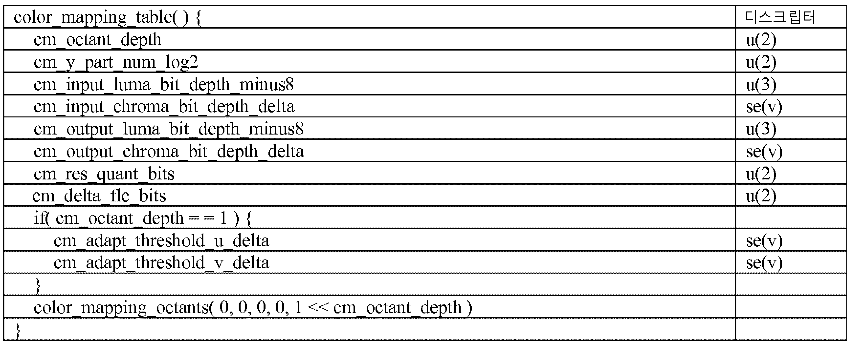
표 3. Table 3. 신택스Syntax 테이블 table
일 실시형태에서, cm_res_quant_bits는 정점 잔차 값들 res_y, res_u 및 res_v에 가산될 최소 유효 비트들의 수를 특정할 수도 있다. 각각의 컬러 성분, 각각의 파라미터, 및 각각의 옥탄트에 대한 예측 잔차의 복원이 본 명세서에서 설명된 바와 같이 수정될 수도 있다. 변수들 CMResY[yIdx][uIdx][vIdx][i], CMResU[yIdx][uIdx][vIdx][i], 및 CMResV[yIdx][uIdx][vIdx][i] 는 아래의 수학식 (14), (15), (16), 및 (17)에 나타낸 바와 같이 도출될 수도 있다:In one embodiment, cm_res_quant_bits may specify the number of least significant bits to be added to the vertex residual values res_y, res_u, and res_v. The reconstruction of each color component, each parameter, and the prediction residual for each octant may be modified as described herein. The variables CMResY [yIdx] [uIdx] [vIdx] [i], CMResU [yIdx] [uIdx] [vIdx] [i], and CMResV [yIdx] [uIdx] [vIdx] [i] 14), (15), (16), and (17)
nFLCBits = nMappingShift - res_quant_bits - cm_delta_flc_bits (14)nFLCBits = nMappingShift - res_quant_bits - cm_delta_flc_bits (14)
CMResY[yIdx][uIdx][vIdx][i] = (1 - 2 * res_coeff_s[yIdx][uIdx][vIdx][i][0]) * ((res_coeff_q[yIdx][uIdx][vIdx][i][0] ≪ nFLCBits) + res_coeff_r[yIdx][uIdx][vIdx][i][0]) (15)(Res_coeff_q [yIdx] [uIdx] [vIdx] [0]) CMResY [yIdx] [uIdx] [vIdx] [i] = 1 - 2 * res_coeff_s [yIdx] [uIdx] [vIdx] i] [0] nFLCBits + res_coeff_r [yIdx] [uIdx] [vIdx] [i] [0] (15)
CMResU[yIdx][uIdx][vIdx][i] = (1 - 2 * res_coeff_s[yIdx][uIdx][vIdx][i][1]) * ((res_coeff_q [yIdx][uIdx][vIdx][i][1] ≪ nFLCBits) + res_coeff_r[yIdx][uIdx][vIdx][i][1]) (16)(Res_coeff_q [yIdx] [uIdx] [vIdx] [1] * CMResU [yIdx] [uIdx] [vIdx] [i] = 1 - 2 * res_coeff_s [yIdx] [uIdx] [vIdx] i] [1] nFLCBits + res_coeff_r [yIdx] [uIdx] [vIdx] [i] (16)
CMResV[yIdx][uIdx][vIdx][i] = (1 - 2 * res_coeff_s[yIdx][uIdx][vIdx][i][2]) * ((res_coeff_q[yIdx][uIdx][vIdx][i][2] ≪ nFLCBits) + res_coeff_r[yIdx][uIdx][vIdx][i][2]) (17)(Res_coeff_q [yIdx] [uIdx] [vIdx] [iIdx] [iIdx] [vIdx] [i] = 1 - 2 * res_coeff_s [yIdx] [uIdx] [vIdx] i] [2] nFLCBits + res_coeff_r [yIdx] [uIdx] [vIdx] [i] [2] (17)
도 11a는 하나 이상의 개시된 실시형태들이 구현될 수도 있는 예시적인 통신 시스템(100)의 도면이다. 통신 시스템(100)은 콘텐츠, 이를테면 음성, 데이터, 비디오, 메시징, 브로드캐스트 등을 다수의 무선 사용자들에게 제공하는 다중 액세스 시스템일 수도 있다. 통신 시스템(100)은 다수의 무선 사용자들이 무선 대역폭을 포함한 시스템 자원들의 공유를 통해 이러한 콘텐츠에 액세스하는 것을 가능하게 할 수도 있다. 예를 들어, 통신 시스템들(100)은 하나 이상의 채널 액세스 방법들, 이를테면 코드 분할 다중 접속(code division multiple access, CDMA), 시분할 다중 접속(time division multiple access, TDMA), 주파수 분할 다중 접속(frequency division multiple access, FDMA), 직교 FDMA(OFDMA), 단일 반송파 FDMA(SC-FDMA) 등을 채용할 수도 있다.11A is a drawing of an
도 11a는 하나 이상의 개시된 실시형태들이 구현될 수도 있는 예시적인 통신 시스템(100)의 도면이다. 통신 시스템(100)은 콘텐츠, 이를테면 음성, 데이터, 비디오, 메시징, 브로드캐스트 등을 다수의 무선 사용자들에게 제공하는 다중 액세스 시스템일 수도 있다. 통신 시스템(100)은 다수의 무선 사용자들이 무선 대역폭을 포함한 시스템 자원들의 공유를 통해 이러한 콘텐츠에 액세스하는 것을 가능하게 할 수도 있다. 예를 들어, 통신 시스템들(100)은 하나 이상의 채널 액세스 방법들, 이를테면 코드 분할 다중 접속(CDMA), 시분할 다중 접속(TDMA), 주파수 분할 다중 접속(FDMA), 직교 FDMA(OFDMA), 단일 반송파 FDMA(SC-FDMA) 등을 채용할 수도 있다.11A is a drawing of an
도 11a에 도시된 바와 같이, 통신 시스템(100)은 무선 송수신 유닛들(WTRU들)(102a, 102b, 102c, 및/또는 102d)(이것들은 전체적으로 또는 총괄하여 WTRU(102)라고 지칭될 수도 있음), 무선 액세스 네트워크(radio access network, RAN)(103/104/105), 코어 네트워크(106/107/109), 공중전화망(public switched telephone network, PSTN)(108), 인터넷(110), 및 다른 네트워크들(112)을 포함할 수도 있지만, 개시된 실시형태들은 임의의 수의 WTRU들, 기지국들, 네트워크들, 및/또는 네트워크 엘리먼트들을 고려하는 것이 이해될 것이다. WTRU들(102a, 102b, 102c, 102d)의 각각은 무선 환경에서 동작 및/또는 통신하도록 구성된 임의의 유형의 디바이스일 수도 있다. 예로서, WTRU들(102a, 102b, 102c, 102d)은 무선 신호들을 송신 및/또는 수신하도록 구성될 수도 있고 사용자 장비(UE), 이동국, 고정식 또는 모바일 가입자 유닛, 페이저, 셀룰러 전화기, 개인 정보 단말기(personal digital assistant, PDA), 스마트폰, 랩톱, 넷북, 개인용 컴퓨터, 무선 센서, 소비자 가전기기들 등을 포함할 수도 있다.11A, the
통신 시스템들(100)은 기지국(114a)과 기지국(114b)을 또한 포함할 수도 있다. 기지국들(114a, 114b)의 각각은 하나 이상의 통신 네트워크들, 이를테면 코어 네트워크(106/107/109), 인터넷(110), 및/또는 네트워크들(112)에 대한 액세스를 용이하게 하기 위해 WTRU들(102a, 102b, 102c, 102d) 중 적어도 하나와 무선으로 인터페이싱하도록 구성된 임의의 유형의 디바이스일 수도 있다. 예로서, 기지국들(114a, 114b)은 기지국 트랜시버(base transceiver station; BTS), 노드-B, eNode B, 홈 노드 B, 홈 eNode B, 사이트 제어기, 액세스 포인트(AP), 무선 라우터 등일 수도 있다. 기지국들(114a, 114b)이 각각 단일 엘리먼트로서 묘사되지만, 기지국들(114a, 114b)은 임의의 수의 상호접속된 기지국들 및/또는 네트워크 엘리먼트들을 포함할 수도 있다.The
기지국(114a)은 RAN(103/104/105)의 일부일 수도 있는데, 이 RAN은 다른 기지국들 및/또는 네트워크 엘리먼트들(미도시), 이를테면 기지국 제어기(base station controller, BSC), 무선 네트워크 제어기(radio network controller, RNC), 릴레이 노드들 등을 또한 포함할 수도 있다. 기지국(114a) 및/또는 기지국(114b)은 셀(도시되지 않음)이라고 지칭될 수도 있는 특정 지리적 지역 내에서 무선 신호들을 송신 및/또는 수신하도록 구성될 수도 있다. 그 셀은 셀 섹터들로 더욱 세분될 수도 있다. 예를 들어, 기지국(114a)에 연관된 셀은 세 개의 섹터들로 나누어질 수도 있다. 따라서, 하나의 실시형태에서, 기지국(114a)은 세 개의 트랜시버들을, 예컨대, 셀의 각각의 섹터마다 하나씩 포함할 수도 있다. 다른 실시형태에서, 기지국(114a)은 다중 입력 다중 출력(multiple-input multiple output, MIMO) 기술을 채용할 수도 있고, 그러므로, 셀의 각각의 섹터에 대해 다수의 트랜시버들을 이용할 수도 있다.The
기지국들(114a, 114b)은 무선 인터페이스(air interface)(115/116/117)를 통해 WTRU들(102a, 102b, 102c, 102d) 중 하나 이상과 통신할 수도 있는데, 무선 인터페이스는 임의의 적합한 무선 통신 링크(예컨대, 무선 주파수(radio frequency, RF), 마이크로파, 적외선(infrared, IR), 자외선(ultraviolet, UV), 가시광선 등)일 수도 있다. 무선 인터페이스(115/116/117)는 임의의 적합한 무선 접속 기술(radio access technology, RAT)을 사용하여 확립될 수도 있다.The
더 구체적으로는, 위에서 언급했듯이, 통신 시스템(100)은 다중 액세스 시스템일 수도 있고, 하나 이상의 채널 액세스 방식들, 이를테면 CDMA, TDMA, FDMA, OFDMA, SC-FDMA 등을 채용할 수도 있다. 예를 들어, RAN(103/104/105)에서의 기지국(114a)과 WTRU들(102a, 102b, 102c)은 유니버셜 이동 통신 시스템(Universal Mobile Telecommunications System, UMTS) 지상파 무선 액세스(Terrestrial Radio Access, UTRA)와 같은 무선 기술을 구현할 수도 있는데, 이 무선 기술은 광대역 CDMA(WCDMA)를 사용하여 무선 인터페이스(115/116/117)를 확립할 수도 있다. WCDMA는 고속 패킷 액세스(High-Speed Packet Access, HSPA) 및/또는 진화형 HSPA(HSPA+)와 같은 통신 프로토콜들을 포함할 수도 있다. HSPA는 고속 다운링크 패킷 액세스(High-Speed Downlink Packet Access, HSDPA) 및/또는 고속 업링크 패킷 액세스(HSUPA)를 포함할 수도 있다.More specifically, as noted above,
다른 실시형태에서, 기지국(114a)과 WTRU들(102a, 102b, 102c)은 진화형 UMTS 지상파 무선 액세스(Evolved UMTS Terrestrial Radio Access, E-UTRA)와 같은 무선 기술을 구현할 수도 있는데, 이 무선 기술은 LTE(Long Term Evolution) 및/또는 LTE-A(LTE-Advanced)를 사용하여 무선 인터페이스(115/116/117)를 확립할 수도 있다.In another embodiment,
다른 실시형태들에서, 기지국(114a)과 WTRU들(102a, 102b, 102c)은 IEEE 802.16(예컨대, WiMAX(Worldwide Interoperability for Microwave Access)), CDMA2000, CDMA2000 IX, CDMA2000 EV-DO, 잠정 표준 2000(IS-2000), 잠정 표준 95(IS-95), 잠정 표준 856(IS-856), GSM(Global System for Mobile communications), EDGE(Enhanced Data rates for GSM Evolution), GSM 에지(GERAN) 등과 같은 무선 기술들을 구현할 수도 있다.In other embodiments, the
도 11a에서의 기지국(114b)은, 예를 들어, 무선 라우터, 홈 노드 B, 홈 eNode B, 또는 액세스 포인트일 수도 있고, 국부화된 영역, 이를테면 사업장, 홈, 차량, 캠퍼스 등에서 무선 접속을 용이하게 하기 위해 임의의 적합한 RAT를 이용할 수도 있다. 하나의 실시형태에서, 기지국(114b)과 WTRU들(102c, 102d)은 무선 근거리 네트워크(wireless local area network, WLAN)를 확립하기 위해 IEEE 802.11과 같은 무선 기술을 구현할 수도 있다. 다른 실시형태에서, 기지국(114b)과 WTRU들(102c, 102d)은 무선 개인 영역 네트워크(wireless personal area network, WPAN)를 확립하기 위해 IEEE 802.15와 같은 무선 기술을 구현할 수도 있다. 또 다른 실시형태에서, 기지국(114b)과 WTRU들(102c, 102d)은 피코셀 또는 펨토셀을 확립하기 위해 셀룰러 기반 RAT(예컨대, WCDMA, CDMA2000, GSM, LTE, LTE-A 등)를 이용할 수도 있다. 도 11a에 도시된 바와 같이, 기지국(114b)은 인터넷(110)에 대한 직접 접속을 가질 수도 있다. 따라서, 기지국(114b)은 코어 네트워크(106/107/109)를 통해 인터넷(110)에 액세스하는 것이 필요하지 않을 수도 있다.The
RAN(103/104/105)은 코어 네트워크(106/107/109)와 통신할 수도 있는데, 이 코어 네트워크는 음성, 데이터, 애플리케이션들, 및/또는 VoIP(voice over internet protocol) 서비스들을 WTRU들(102a, 102b, 102c, 102d) 중 하나 이상에 제공하도록 구성된 임의의 유형의 네트워크일 수도 있다. 예를 들어, 코어 네트워크(106/107/109)는 호 제어, 과금 서비스들, 모바일 로케이션 기반 서비스들, 선불 전화, 인터넷 접속성, 비디오 배포 등을 제공하며 그리고/또는 하이-레벨 보안 기능들, 이를테면 사용자 인증을 수행할 수도 있다. 도 11a에 도시되진 않았지만, RAN(103/104/105) 및/또는 코어 네트워크(106/107/109)는 RAN(103/104/105)과는 동일한 RAT 또는 상이한 RAT를 채용하는 다른 RAN들과 직접 또는 간접 통신할 수도 있다는 것이 이해될 것이다. 예를 들어, E-UTRA 무선 기술을 이용하고 있을 수도 있는 RAN(103/104/105)에 접속되는 것 외에도, 코어 네트워크(106/107/109)는 GSM 무선 기술을 채용하는 다른 RAN(미도시)과 또한 통신할 수도 있다.The
코어 네트워크(106/107/109)는 PSTN(108), 인터넷(110), 및/또는 다른 네트워크들(112)에 액세스하기 위한 WTRU들(102a, 102b, 102c, 102d)에 대한 게이트웨이로서 또한 역할할 수도 있다. PSTN(108)은 기존 전화 서비스(plain old telephone service, POTS)를 제공하는 회선 교환식 전화기 네트워크들을 포함할 수도 있다. 인터넷(110)은 공통 통신 프로토콜들, 이를테면 TCP/IP 인터넷 프로토콜 스위트에서의 송신 제어 프로토콜(transmission control protocol, TCP), 사용자 데이터그램 프로토콜(user datagram protocol, UDP) 및 인터넷 프로토콜(internet protocol, IP)을 사용하는 상호접속된 컴퓨터 네트워크들 및 디바이스들의 글로벌 시스템을 포함할 수도 있다. 네트워크들(112)은 다른 서비스 제공자들에 의해 소유된 및/또는 운영되는 유선 또는 무선 통신 네트워크들을 포함할 수도 있다. 예를 들어, 네트워크들(112)은 하나 이상의 RAN들에 접속된 다른 코어 네트워크를 포함할 수도 있는데, 이 하나 이상의 RAN들은 RAN(103/104/105)과는 동일한 RAT 또는 상이한 RAT를 채용할 수도 있다.The
통신 시스템(100)에서의 WTRU들(102a, 102b, 102c, 102d) 중 일부 또는 전부는 멀티-모드 능력들을 구비할 수도 있으며, 예컨대, WTRU들(102a, 102b, 102c, 102d)은 상이한 무선 링크들을 통해 상이한 무선 네트워크들과 통신하기 위해 다수의 트랜시버들을 구비할 수도 있다. 예를 들어, 도 11a에 도시된 WTRU(102c)는 셀룰러 기반 무선 기술을 채용할 수도 있는 기지국(114a)과 그리고 IEEE 802 무선 기술을 채용할 수도 있는 기지국(114b)과 통신하도록 구성될 수도 있다.Some or all of the
도 11b는 예시적인 WTRU(102)의 시스템도이다. 도 11b에 도시된 바와 같이, WTRU(102)는 프로세서(118), 트랜시버(120), 송수신 엘리먼트(122), 스피커/마이크로폰(124), 키패드(126), 디스플레이/터치패드(128), 비-착탈식 메모리(130), 착탈식 메모리(132), 전력원(134), 글로벌 포지셔닝 시스템(global positioning system, GPS) 칩셋(136), 및 다른 주변기기들(138)을 포함할 수도 있다. WTRU(102)는 전술한 엘리먼트들의 임의의 하위조합을 포함하면서도 일 실시형태와 부합할 수도 있다는 것이 이해될 것이다. 또한, 실시형태들에서는 기지국들(114a 및 114b), 및/또는, 무엇보다도, 트랜시버 스테이션(BTS), 노드-B, 사이트 제어기, 액세스 포인트(AP), 홈 노드-B, 진화형 홈 노드-B(eNodeB), 홈 진화형 노드-B(HeNB), 홈 진화형 노드-B 게이트웨이, 및 프록시 노드들과 같이 기지국들(114a 및 114b)이 비제한적으로 나타낼 수도 있는 노드들이, 도 11b에 묘사된 그리고 본원에서 설명되는 엘리먼트들의 일부 또는 전부를 포함할 수도 있다는 것을 고려한다.FIG. 11B is a system diagram of an
프로세서(118)는 범용 프로세서, 특수 목적 프로세서, 기존의 프로세서, 디지털 신호 프로세서(digital signal processor, DSP), 복수의 마이크로프로세서들, DSP 코어에 연관된 하나 이상의 마이크로프로세서들, 제어기, 마이크로제어기, 주문형 반도체(Application Specific Integrated Circuit, ASIC), 필드 프로그램가능 게이트 어레이(Field Programmable Gate Array, FPGA) 회로들, 임의의 다른 유형의 집적회로(IC), 상태 머신 등일 수도 있다. 프로세서(118)는 신호 코딩, 데이터 프로세싱, 전력 제어, 입출력 프로세싱, 및/또는 WTRU(102)가 무선 환경에서 동작하는 것을 가능하게 하는 임의의 다른 기능을 수행할 수도 있다. 프로세서(118)는 트랜시버(120)에 커플링될 수도 있는데, 그 트랜시버는 송수신 엘리먼트(122)에 커플링될 수도 있다. 도 11b가 프로세서(118)와 트랜시버(120)를 별개의 컴포넌트들로서 묘사하지만, 프로세서(118)와 트랜시버(120)는 전자 패키지 또는 칩 내에 함께 통합될 수도 있다.
송수신 엘리먼트(122)는 무선 인터페이스(115/116/117)를 통해 신호들을 기지국(예컨대, 기지국(114a))으로 송신하거나 또는 그 기지국으로부터 신호들을 수신하도록 구성될 수도 있다. 예를 들어, 하나의 실시형태에서, 송수신 엘리먼트(122)는 RF 신호들을 송신 및/또는 수신하도록 구성된 안테나일 수도 있다. 다른 실시형태에서, 송수신 엘리먼트(122)는, 예를 들어, IR, UV, 또는 가시광선 신호들을 송신 및/또는 수신하도록 구성된 송출기(emitter)/검출기일 수도 있다. 또 다른 실시형태에서, 송수신 엘리먼트(122)는 RF 신호 및 광 신호 양쪽 모두를 송신 및 수신하도록 구성될 수도 있다. 송수신 엘리먼트(122)는 무선 신호들의 임의의 조합을 송신 및/또는 수신하도록 구성될 수도 있다는 것이 이해될 것이다.The transmit and receive
덧붙여서, 비록 송수신 엘리먼트(122)는 도 11b에서 단일 엘리먼트로서 묘사되지만, WTRU(102)는 임의의 수의 송수신 엘리먼트들(122)을 포함할 수도 있다. 더 구체적으로는, WTRU(102)는 MIMO 기술을 채용할 수도 있다. 따라서, 하나의 실시형태에서, WTRU(102)는 무선 인터페이스(115/116/117)를 통해 무선 신호들을 송신 및 수신하기 위한 둘 이상의 송수신 엘리먼트들(122)(예컨대, 다수의 안테나들)을 구비할 수도 있다.In addition, although the transmit / receive
트랜시버(120)는 송수신 엘리먼트(122)에 의해 송신될 신호들을 변조하도록 그리고 송수신 엘리먼트(122)에 의해 수신되는 신호들을 복조하도록 구성될 수도 있다. 위에서 언급된 바와 같이, WTRU(102)는 멀티-모드 능력들을 가질 수도 있다. 따라서, 트랜시버(120)는 WTRU(102)가, 예를 들어, UTRA 및 IEEE 802.11과 같은 다수의 RAT들을 통해 통신하는 것을 가능하게 하는 다수의 트랜시버들을 포함할 수도 있다.
WTRU(102)의 프로세서(118)는 스피커/마이크로폰(124), 키패드(126), 및/또는 디스플레이/터치패드(128)(예컨대, 액정 디스플레이(LCD) 디스플레이 유닛 또는 유기 발광 다이오드(OLED) 디스플레이 유닛)에 커플링될 수도 있고 그것들로부터 사용자 입력 데이터를 수신할 수도 있다. 프로세서(118)는 사용자 데이터를 스피커/마이크로폰(124), 키패드(126), 및/또는 디스플레이/터치패드(128)로 또한 출력할 수도 있다. 덧붙여서, 프로세서(118)는 임의의 유형의 적합한 메모리, 이를테면 비-착탈식 메모리(130) 및/또는 착탈식 메모리(132)로부터 정보를 액세스하고 데이터를 그 메모리에 저장할 수도 있다. 비-착탈식 메모리(130)는 랜덤-액세스 메모리(RAM), 판독-전용 메모리(ROM), 하드 디스크, 또는 임의의 다른 유형의 메모리 저장 디바이스를 포함할 수도 있다. 착탈식 메모리(132)는 가입자 식별 모듈(subscriber identity module, SIM) 카드, 메모리 스틱, 보안 디지털(secure digital, SD) 메모리 카드 등을 포함할 수도 있다. 다른 실시형태들에서, 프로세서(118)는 WTRU(102) 상에, 이를테면 서버 또는 홈 컴퓨터(미도시) 상에 물리적으로 위치하지 않은 메모리로부터의 정보에 액세스하고 데이터를 그 메모리에 저장할 수도 있다.The
프로세서(118)는 전력원(134)으로부터 전력을 받을 수도 있고, WTRU(102)에서의 다른 컴포넌트들에게 전력을 분배하며 그리고/또는 그 컴포넌트들을 제어하도록 구성될 수도 있다. 전력원(134)은 WTRU(102)에 전력을 공급하는 임의의 적합한 디바이스일 수도 있다. 예를 들어, 전력원(134)은 하나 이상의 건전지 배터리들(예컨대, 니켈-카드뮴(NiCd), 니켈-아연(NiZn), 니켈 금속 수소화물(NiMH), 리듐이온(Li-ion) 등), 태양 전지들, 연료 전지들 등을 포함할 수도 있다.The
프로세서(118)는 GPS 칩셋(136)에 또한 커플링될 수도 있는데, 이 GPS 칩셋은 WTRU(102)의 현재 로케이션에 관한 로케이션 정보(예컨대, 경도 및 위도)를 제공하도록 구성될 수도 있다. GPS 칩셋(136)으로부터의 정보 외에도, 또는 그 정보 대신에, WTRU(102)는 기지국(예컨대, 기지국들(114a, 114b))으로부터 무선 인터페이스(115/116/117)를 통해 로케이션 정보를 수신하며 그리고/또는 둘 이상의 인근 기지국들로부터 수신되고 있는 신호들의 타이밍에 기초하여 자신의 로케이션을 결정할 수도 있다. WTRU(102)는 임의의 적합한 로케이션-결정 방법에 의해 로케이션 정보를 획득하면서도 일 실시형태와 부합할 수도 있다는 것이 이해될 것이다.The
프로세서(118)는 다른 주변기기들(138)에 추가로 커플링될 수도 있는데, 이 다른 주변기기들은 부가적인 특징(feature)들, 기능성 및/또는 유선 또는 무선 접속성을 제공하는 하나 이상의 소프트웨어 및/또는 하드웨어 모듈들을 포함할 수도 있다. 예를 들어, 주변기기들(138)은 가속도계, e-나침반, 위성 트랜시버, 디지털 카메라(사진들 또는 비디오용), 유니버셜 직렬 버스(universal serial bus, USB) 포트, 진동 디바이스, 텔레비전 트랜시버, 핸즈 프리 헤드셋, Bluetooth® 모듈, FM(frequency modulated) 라디오 유닛, 디지털 뮤직 플레이어, 미디어 플레이어, 비디오 게임 플레이어 모듈, 인터넷 브라우저 등을 포함할 수도 있다.The
도 11c는 일 실시형태에 따른 RAN(103) 및 코어 네트워크(106)의 시스템도이다. 위에서 언급된 바와 같이, RAN(103)은 무선 인터페이스(115)를 통해 WTRU들(102a, 102b, 102c)과 통신하는 UTRA 무선 기술을 채용할 수도 있다. RAN(103)은 코어 네트워크(106)와 또한 통신할 수도 있다. 도 11c에 도시된 바와 같이, RAN(103)는, 무선 인터페이스(115)를 통해 WTRU들(102a, 102b, 102c)과 통신하는 하나 이상의 트랜시버들을 각각 구비할 수도 있는 Node-B들(140a, 140b, 140c)을 포함할 수도 있다. Node-B들(140a, 140b, 140c)은 각각이 RAN(103) 내의 특정 셀(미도시)과 연관될 수도 있다. RAN(103)은 RNC들(142a, 142b)을 또한 포함할 수도 있다. RAN(103)은 일 실시형태와 부합하면서도 임의의 수의 Node-B들 및 RNC들을 포함할 수도 있다는 것이 이해될 것이다.11C is a system diagram of
도 11c에 도시된 바와 같이, 노드-B들(140a, 140b)은 RNC(142a)와 통신할 수도 있다. 덧붙여, 노드-B(140c)는 RNC(142b)와 통신할 수도 있다. 노드-B들(140a, 140b, 140c)은 Iub 인터페이스를 통해 각각의 RNC들(142a, 142b)과 통신할 수도 있다. RNC들(142a, 142b)은 Iur 인터페이스를 통해 서로 통신할 수도 있다. RNC들(142a, 142b)의 각각은 자신이 접속된 각각의 노드-B들(140a, 140b, 140c)을 제어하도록 구성될 수도 있다. 덧붙여서, RNC들(142a, 142b)의 각각은 외부 루프 전력 제어, 부하 제어, 입허가(admission) 제어, 패킷 스케줄링, 핸드오버 제어, 매크로다이버시티(macrodiversity), 보안 기능들, 데이터 암호화 등과 같은 다른 기능들을 수행 또는 지원하도록 구성될 수도 있다.As shown in FIG. 11C, the node-
도 11c에 도시된 코어 네트워크(106)는 미디어 게이트웨이(media gateway, MGW)(144), 모바일 교환국(mobile switching center, MSC)(146), 서빙 GPRS 지원 노드(SGSN)(148), 및/또는 게이트웨이 GPRS 지원 노드(GGSN)(150)를 포함할 수도 있다. 전술한 엘리먼트들의 각각이 코어 네트워크(106)의 부분으로서 묘사되지만, 이들 엘리먼트들 중 어느 것이라도 코어 네트워크 오퍼레이터 이외의 엔티티에 의해 소유되며 그리고/또는 운영될 수도 있다는 것이 이해될 것이다.The
RAN(103)에서의 RNC(142a)는 코어 네트워크(106)에서의 MSC(146)에 IuCS 인터페이스를 통해 접속될 수도 있다. MSC(146)는 MGW(144)에 접속될 수도 있다. MSC(146)와 MGW(144)는, WTRU들(102a, 102b, 102c)과 전통적인 지상선 통신 디바이스들 간의 통신들을 용이하게 하기 위해, 회선 교환식 네트워크들, 이를테면 PSTN(108)에 대한 액세스를 WTRU들(102a, 102b, 102c)에 제공할 수도 있다.The RNC 142a in the
RAN(103)에서의 RNC(142a)는 코어 네트워크(106)에서의 SGSN(148)에 IuPS 인터페이스를 통해 또한 접속될 수도 있다. SGSN(148)은 GGSN(150)에 접속될 수도 있다. SGSN(148)과 GGSN(150)은, WTRU들(102a, 102b, 102c)과 IP 가능 디바이스들 간의 통신들을 용이하게 하기 위해, 패킷 교환식 네트워크들, 이를테면 인터넷(110)에 대한 액세스를 WTRU들(102a, 102b, 102c)에 제공할 수도 있다.The RNC 142a in the
위에서 언급된 바와 같이, 코어 네트워크(106)는 네트워크들(112)에 또한 접속될 수도 있는데, 그 네트워크들은 다른 서비스 제공자들에 의해 소유된 그리고/또는 운영되는 다른 유선 또는 무선 네트워크들을 포함할 수도 있다.As noted above, the
도 11d는 일 실시형태에 따른 RAN(104) 및 코어 네트워크(107)의 시스템도이다. 위에서 언급된 바와 같이, RAN(104)은 무선 인터페이스(116)를 통해 WTRU들(102a, 102b, 102c)과 통신하는 E-UTRA 무선 기술을 채용할 수도 있다. RAN(104)은 코어 네트워크(107)와 또한 통신할 수도 있다.11D is a system diagram of the
RAN(104)은 eNode-B들(160a, 160b, 160c)을 포함할 수도 있지만, RAN(104)은 임의의 수의 eNode-B들을 포함하면서도 일 실시형태와 부합할 수도 있다는 것이 이해될 것이다. eNode-B들(160a, 160b, 160c)은 무선 인터페이스(116)를 통해 WTRU들(102a, 102b, 102c)과 통신하는 하나 이상의 트랜시버들을 각각 구비할 수도 있다. 하나의 실시형태에서, eNode-B들(160a, 160b, 160c)은 MIMO 기술을 구현할 수도 있다. 따라서, eNode-B(160a)는, 예를 들어, WTRU(102a)에 무선 신호들을 송신하고 그 WTRU로부터 무선 신호들을 수신하는 다수의 안테나들을 사용할 수도 있다.It will be appreciated that although
eNode-B들(160a, 160b, 160c)의 각각은 특정 셀(도시되지 않음)과 연관될 수도 있고 무선 리소스 관리 판정, 핸더오브 판정, 업링크 및/또는 다운링크에서의 사용자들의 스케줄링 등을 핸들링하도록 구성될 수도 있다. 도 11d에 도시된 바와 같이, eNode-B들(160a, 160b, 160c)은 X2 인터페이스를 통해 서로 통신할 수도 있다.Each of the eNode-
도 11d에 도시된 코어 네트워크(107)는 이동성 관리 게이트웨이(mobility management gateway, MME)(162), 서빙 게이트웨이(164), 및 패킷 데이터 네트워크(packet data network, PDN) 게이트웨이(166)를 포함할 수도 있다. 전술한 엘리먼트들의 각각이 코어 네트워크(107)의 부분으로서 묘사되지만, 이들 엘리먼트들 중 어느 것이라도 코어 네트워크 오퍼레이터 이외의 엔티티에 의해 소유되며 그리고/또는 운영될 수도 있다는 것이 이해될 것이다.The
MME(162)는 S1 인터페이스를 통해 RAN(104)에서의 eNode-B들(160a, 160b, 160c)의 각각에 접속될 수도 있고 제어 노드로서 역할할 수도 있다. 예를 들어, MME(162)는 WTRU들(102a, 102b, 102c)의 사용자들의 인증, 베어러 활성화/비활성화, WTRU들(102a, 102b, 102c)의 초기 연결(attach) 동안의 특정 서빙 게이트웨이의 선택 등을 담당할 수도 있다. MME(162)는 RAN(104)과 다른 무선 기술들, 이를테면 GSM 또는 WCDMA를 채용하는 다른 RAN들(도시되지 않음) 간의 스위칭을 위한 제어 평면 기능을 또한 제공할 수도 있다.The
서빙 게이트웨이(164)는 S1 인터페이스를 통해 RAN(104)에서의 eNode B들(160a, 160b, 160c)의 각각에 접속될 수도 있다. 서빙 게이트웨이(164)는 사용자 데이터 패킷들을 WTRU들(102a, 102b, 102c)로/로부터 일반적으로 라우팅 및 포워딩할 수도 있다. 서빙 게이트웨이(164)는 다른 기능들, 이를테면 eNode B 간(inter-eNode B) 핸드오버들 동안의 사용자 평면들의 앵커링, 다운링크 데이터가 WTRU들(102a, 102b, 102c)에 이용가능할 때의 페이징의 트리거링, WTRU들(102a, 102b, 102c)의 콘텍스트들의 관리 및 저장 등을 또한 수행할 수도 있다.Serving
서빙 게이트웨이(164)는 PDN 게이트웨이(166)에 또한 접속될 수도 있는데, 이 PDN 게이트웨이는, WTRU들(102a, 102b, 102c) 및 IP-가능 디바이스들 간의 통신들을 용이하게 하기 위해, 패킷 교환식 네트워크들, 이를테면 인터넷(110)에 대한 액세스를 WTRU들(102a, 102b, 102c)에 제공할 수도 있다.The serving
코어 네트워크(107)는 다른 네트워크들과의 통신들을 용이하게 할 수도 있다. 예를 들어, 코어 네트워크(107)는, WTRU들(102a, 102b, 102c)과 전통적인 지상선 통신 디바이스들 간의 통신들을 용이하게 하기 위해, 회선 교환식 네트워크들, 이를테면 PSTN(108)에 대한 액세스를 WTRU들(102a, 102b, 102c)에 제공할 수도 있다. 예를 들어, 코어 네트워크(107)는 코어 네트워크(107)와 PSTN(108) 간의 인터페이스로서 역할하는 IP 게이트웨이(예컨대, IP 멀티미디어 서브시스템(IP 멀티미디어 서브시스템, IMS) 서버)를 포함하거나 또는 그 IP 게이트웨이와 통신할 수도 있다. 덧붙여서, 코어 네트워크(107)는 WTRU들(102a, 102b, 102c)에 네트워크들(112)에 대한 액세스를 제공할 수도 있는데, 그 네트워크들은 다른 서비스 제공자들에 의해 소유된 그리고/또는 운영되는 다른 유선 또는 무선 네트워크들을 포함할 수도 있다.The
도 11e는 일 실시형태에 따른 RAN(105) 및 코어 네트워크(109)의 시스템도이다. RAN(105)은 무선 인터페이스(117)를 통해 WTRU들(102a, 102b, 102c)과 통신하기 위해 IEEE 802.16 무선 기술을 채용하는 액세스 서비스 네트워크(access service network, ASN)일 수도 있다. 아래에서 더 논의되겠지만, WTRU들(102a, 102b, 102c), RAN(105), 및 코어 네트워크(109)의 상이한 기능성 엔티티들 간의 통신 링크들은 참조 포인트들로서 정의될 수도 있다.11E is a system diagram of the
도 11e에 도시된 바와 같이, RAN(105)은 기지국들(180a, 180b, 180c)과 ASN(182)을 포함할 수도 있지만, RAN(105)은 임의의 수의 기지국들 및 ASN 게이트웨이들을 포함하면서도 일 실시형태와 부합할 수도 있다는 것이 이해될 것이다. 기지국들(180a, 180b, 180c)은 각각이 RAN(105)에서의 특정 셀(미도시)과 연관될 수도 있고 각각이 무선 인터페이스(117)를 통해 WTRU들(102a, 102b, 102c)과 통신하는 하나 이상의 트랜시버들을 포함할 수도 있다. 하나의 실시형태에서, 기지국들(180a, 180b, 180c)은 MIMO 기술을 구현할 수도 있다. 따라서, 기지국(180a)은, 예를 들어, WTRU(102a)로 무선 신호들을 송신하고 그 WTRU로부터 무선 신호들을 수신하는 다수의 안테나들을 사용할 수도 있다. 기지국들(180a, 180b, 180c)은 이동성 관리 기능들, 이를테면 핸드오프 트리거링, 터널 확립, 무선 자원 관리, 트래픽 분류, 서비스 품질(QoS) 정책 시행 등을 또한 제공할 수도 있다. ASN 게이트웨이(182)는 트래픽 집성 포인트로서 역할할 수도 있고 페이징, 가입자 프로파일들의 캐싱, 코어 네트워크(109)로의 라우팅 등을 담당할 수도 있다.
WTRU들(102a, 102b, 102c) 및 RAN(105) 간의 무선 인터페이스(117)는 IEEE 802.16 사양을 구현하는 R1 참조 포인트로서 정의될 수도 있다. 덧붙여서, WTRU들(102a, 102b, 102c)의 각각은 코어 네트워크(109)와 논리적 인터페이스(미도시)를 확립할 수도 있다. WTRU들(102a, 102b, 102c) 및 코어 네트워크(109) 간의 논리적 인터페이스는 R2 참조 포인트로서 정의될 수도 있는데, 이 참조 포인트는 인증, 인가, IP 호스트 구성 관리, 및/또는 이동성 관리를 위해 사용될 수도 있다.The
기지국들(180a, 180b, 180c)의 각각 간의 통신 링크는 기지국들 간의 WTRU 핸드오버들 및 데이터의 전송을 용이하게 하는 프로토콜들을 포함하는 R8 참조 포인트로서 정의될 수도 있다. 기지국들(180a, 180b, 180c) 및 ASN 게이트웨이(182) 간의 통신 링크는 R6 참조 포인트로서 정의될 수도 있다. R6 참조 포인트는 WTRU들(102a, 102b, 102c)의 각각에 연관된 이동성 이벤트들에 기초하여 이동성 관리를 용이하게 하는 프로토콜들을 포함할 수도 있다.The communication link between each of the
도 11e에 도시된 바와 같이, RAN(105)은 코어 네트워크(109)에 접속될 수도 있다. RAN(105) 및 코어 네트워크(109) 간의 통신 링크는, 예를 들어 데이터 전송 및 이동성 관리 능력들을 용이하게 하는 프로토콜들을 포함하는 R3 참조 포인트로서 정의될 수도 있다. 코어 네트워크(109)는 모바일 IP 홈 에이전트(MIP-HA)(184), 인증, 인가, 계정관리(authentication, authorization, accounting, AAA) 서버(186), 및 게이트웨이(188)를 포함할 수도 있다. 전술한 엘리먼트들의 각각이 코어 네트워크(109)의 부분으로서 묘사되지만, 이들 엘리먼트들 중 어느 것이라도 코어 네트워크 오퍼레이터 이외의 엔티티에 의해 소유되며 그리고/또는 운영될 수도 있다는 것이 이해될 것이다.The
MIP-HA는 IP 주소 관리를 담당할 수도 있고, WTRU들(102a, 102b, 102c)이 상이한 ASN들 및/또는 상이한 코어 네트워크들 간에 로밍하는 것을 가능하게 할 수도 있다. MIP-HA(184)는, WTRU들(102a, 102b, 102c)과 IP 가능 디바이스들 간의 통신들을 용이하게 하기 위해, 패킷 교환식 네트워크들, 이를테면 인터넷(110)에 대한 액세스를 WTRU들(102a, 102b, 102c)에 제공할 수도 있다. AAA 서버(186)는 사용자 인증을 담당하고 사용자 서비스들을 지원할 수도 있다. 게이트웨이(188)는 다른 네트워크들과의 상호연동을 용이하게 할 수도 있다. 예를 들어, 게이트웨이(188)는, WTRU들(102a, 102b, 102c)과 전통적인 지상선 통신 디바이스들 간의 통신들을 용이하게 하기 위해, 회선 교환식 네트워크들, 이를테면 PSTN(108)에 대한 액세스를 WTRU들(102a, 102b, 102c)에 제공할 수도 있다. 덧붙여서, 게이트웨이(188)는 WTRU들(102a, 102b, 102c)에 네트워크들(112)에 대한 액세스를 제공할 수도 있는데, 그 네트워크들은 다른 서비스 제공자들에 의해 소유된 그리고/또는 운영되는 다른 유선 또는 무선 네트워크들을 포함할 수도 있다.The MIP-HA may be responsible for IP address management and may enable the
비록 도 11e에 도시되지 않았지만, RAN(105)은 다른 ASN들에 접속될 수도 있고 코어 네트워크(109)는 다른 코어 네트워크들에 접속될 수도 있다는 것이 이해될 것이다. RAN(105) 및 다른 ASN들 간의 통신 링크는 R4 참조 포인트로서 정의될 수도 있는데, 이 참조 포인트는 RAN(105) 및 다른 ASN들 간의 WTRU들(102a, 102b, 102c)의 이동성을 조정하기 위한 프로토콜들을 포함할 수도 있다. 코어 네트워크(109) 및 다른 코어 네트워크들 간의 통신 링크는 R5 참조 포인트로서 정의될 수도 있는데, 이 참조 포인트는 홈 코어 네트워크들 및 방문된 코어 네트워크들 간의 상호연동을 용이하게 하는 프로토콜들을 포함할 수도 있다.It is to be appreciated that although not shown in FIG. 11E, the
비록 특징들과 엘리먼트들이 위에서 특정 조합들로 설명되어 있지만, 본 기술분야의 통상의 기술자는 각각의 특징 또는 엘리먼트가 단독으로 또는 다른 특징들 및 엘리먼트들과의 임의의 조합으로 사용될 수 있다는 것이 이해될 것이다. 덧붙여서, 본원에서 설명되는 방법들은 컴퓨터 프로그램, 소프트웨어, 또는 컴퓨터 또는 프로세서에 의한 실행을 위해 컴퓨터 판독가능 매체에 통합된 펌웨어에서 구현될 수도 있다. 컴퓨터-판독가능 매체들의 예들은 (유선 또는 무선 접속들을 통해 송신되는) 전자 신호들 및 컴퓨터-판독가능 저장 매체들을 포함한다. 컴퓨터-판독가능 저장 매체들의 예들은, 판독 전용 메모리(ROM), 랜덤 액세스 메모리(RAM), 레지스터, 캐시 메모리, 반도체 메모리 디바이스들, 내장형 하드 디스크들 및 착탈식 디스크들과 같은 자기 매체들, 자기-광 매체들, 그리고 CD-ROM 디스크들 및 디지털 다기능 디스크들(DVD들)과 같은 광 매체들을 포함하지만 그것들로 제한되지 않는다. 소프트웨어에 관련한 프로세서가 WTRU, UE, 단말, 기지국, RNC, 또는 임의의 호스트 컴퓨터에서의 사용을 위해 무선 주파수 트랜시버를 구현하는데 사용될 수도 있다.Although the features and elements are described above in specific combinations, it will be appreciated by those of ordinary skill in the art that each feature or element may be used alone or in any combination with other features and elements will be. In addition, the methods described herein may be implemented in a computer program, software, or firmware incorporated into a computer readable medium for execution by a computer or processor. Examples of computer-readable media include electronic signals and computer-readable storage media (transmitted via wired or wireless connections). Examples of computer-readable storage media include read-only memory (ROM), random access memory (RAM), registers, cache memories, semiconductor memory devices, magnetic media such as internal hard disks and removable disks, Optical media, and optical media such as CD-ROM disks and digital versatile disks (DVDs). A software related processor may be used to implement a radio frequency transceiver for use in a WTRU, UE, terminal, base station, RNC, or any host computer.
Claims (22)
비디오 디코더에서, 델타 값, 예측 잔차 값의 최대 유효 비트(most significant bit)들, 및 상기 예측 잔차 값의 최소 유효 비트(least significant bit)들을 수신하는 단계; 및
상기 비디오 디코더에서, 상기 예측 잔차 값을,
상기 델타 값에 기초하여 고정-길이 코딩된 최소 유효 비트들의 양을 나타내는 제 1 값을 결정하는 단계,
상기 제 1 값에 기초하여 상기 예측 잔차 값의 상기 최소 유효 비트들을 결정하는 단계; 및
상기 예측 잔차 값의 상기 최대 유효 비트들 및 상기 예측 잔차 값의 상기 최소 유효 비트들을 사용하여 상기 예측 잔차 값을 어셈블링하는 단계
에 의해 생성하는 단계를 포함하는, 3차원 룩업 테이블 파라미터 디코딩 방법.CLAIMS 1. A method for decoding three-dimensional look-up table parameters for use in video decoding,
In a video decoder, receiving a delta value, most significant bits of a prediction residual value, and least significant bits of the prediction residual value; And
In the video decoder,
Determining a first value indicative of the amount of fixed-length coded least significant bits based on the delta value,
Determining the least significant bits of the prediction residual value based on the first value; And
Assembling the prediction residual value using the least significant bits of the prediction residual value and the least significant bits of the prediction residual value,
And generating the three-dimensional look-up table parameter.
상기 예측 잔차 값은 Y 컬러 성분, U 컬러 성분, 또는 V 컬러 성분 중 하나에 연관되는, 3차원 룩업 테이블 파라미터 디코딩 방법.The method according to claim 1,
Wherein the prediction residual value is associated with one of a Y color component, a U color component, or a V color component.
상기 예측 잔차 값의 부호를 수신하는 단계; 및
상기 예측 잔차 값의 상기 부호를 사용하여 추가로 상기 예측 잔차 값을 어셈블링하는 단계를 더 포함하는, 3차원 룩업 테이블 파라미터 디코딩 방법.The method according to claim 1,
Receiving a sign of the prediction residual value; And
Further comprising assembling said prediction residual value using said sign of said prediction residual value. ≪ Desc / Clms Page number 19 >
상기 예측 잔차 값을 어셈블링하는 단계는 또한,
상기 예측 잔차 값의 상기 최대 유효 비트들을 상기 제 1 값만큼 좌측 비트 시프트하는 단계;
상기 예측 잔차 값에 상기 예측 잔차 값의 상기 최소 유효 비트들을 가산하는 단계; 및
상기 예측 잔차 값에 상기 예측 잔차 값의 상기 부호를 적용하는 단계를 더 포함하는, 3차원 룩업 테이블 파라미터 디코딩 방법.The method of claim 3,
The step of assembling the prediction residual value may further comprise:
Shifting the most significant bits of the prediction residual value by the left bit by the first value;
Adding the least significant bits of the prediction residual value to the prediction residual value; And
And applying the sign of the prediction residual value to the prediction residual value.
상기 예측 잔차 값은 컬러 성분, 3차원 룩업 테이블 파라미터, 및 3차원 룩업 테이블 옥탄트 중 적어도 하나에 연관되는, 3차원 룩업 테이블 파라미터 디코딩 방법.The method according to claim 1,
Wherein the prediction residual value is associated with at least one of a color component, a three-dimensional lookup table parameter, and a three-dimensional lookup table octant.
상기 프로세서는,
델타 값, 예측 잔차 값의 최대 유효 비트들, 및 상기 예측 잔차 값의 최소 유효 비트들을 수신하도록;
상기 델타 값에 기초하여 고정-길이 코딩된 최소 유효 비트들의 양을 나타내는 제 1 값을 결정하도록;
상기 제 1 값에 기초하여 상기 예측 잔차 값의 상기 최소 유효 비트들을 결정하도록; 및
상기 예측 잔차 값의 상기 최대 유효 비트들 및 상기 예측 잔차 값의 상기 최소 유효 비트들을 사용하여 상기 예측 잔차 값을 어셈블링하도록
구성되는, 무선 송수신 유닛(wireless transmit/receive unit, WTRU).≪ / RTI >
The processor comprising:
A delta value, a maximum significant bit of a prediction residual value, and a least significant bit of the prediction residual value;
Determining a first value indicative of the amount of fixed-length coded least significant bits based on the delta value;
Determine the least significant bits of the prediction residual value based on the first value; And
And to assemble the predictive residual value using the least significant bits of the predictive residual value and the least significant bits of the predictive residual value
A wireless transmit / receive unit (WTRU).
상기 예측 잔차 값은 Y 컬러 성분, U 컬러 성분, 또는 V 컬러 성분 중 하나에 연관되는, WTRU.The method according to claim 6,
Wherein the prediction residual value is associated with one of a Y color component, a U color component, or a V color component.
상기 프로세서는 또한,
상기 예측 잔차 값의 부호를 수신하도록; 및
상기 예측 잔차 값의 상기 부호를 사용하여 추가로 상기 예측 잔차 값을 어셈블링하도록 하도록 구성되는, WTRU.The method according to claim 6,
The processor may further comprise:
To receive the sign of the prediction residual value; And
And to further assemble the prediction residual value using the sign of the prediction residual value.
상기 프로세서는 또한,
상기 예측 잔차 값의 상기 최대 유효 비트들을 상기 제 1 값만큼 좌측 비트 시프트하도록;
상기 예측 잔차 값에 상기 예측 잔차 값의 상기 최소 유효 비트들을 가산하도록; 및
상기 예측 잔차 값에 상기 예측 잔차 값의 상기 부호를 적용하도록 구성되는, WTRU.9. The method of claim 8,
The processor may further comprise:
And to shift the most significant bits of the prediction residual value by the left bit by the first value;
Add the least significant bits of the prediction residual value to the prediction residual value; And
And apply the sign of the prediction residual value to the prediction residual value.
상기 예측 잔차 값은 컬러 성분, 3차원 룩업 테이블 파라미터, 및 3차원 룩업 테이블 옥탄트 중 적어도 하나에 연관되는, WTRU.The method according to claim 6,
Wherein the prediction residual value is associated with at least one of a color component, a three dimensional lookup table parameter, and a three dimensional lookup table octant.
비디오 인코더에서, 예측 잔차 값을 결정하는 단계;
상기 비디오 인코더에서, 상기 예측 잔차 값의 최소 유효 비트들의 양에 기초하여 델타 값을 결정하는 단계;
상기 비디오 인코더에서, 상기 델타 값을 인코딩하는 단계;
상기 비디오 인코더에서, 상기 델타 값에 기초하여 상기 예측 잔차 값의 최대 유효 비트들을 인코딩하는 단계;
상기 비디오 인코더에서, 상기 델타 값에 기초하여 상기 예측 잔차 값의 상기 최소 유효 비트들을 인코딩하는 단계를 포함하는, 3차원 룩업 테이블 파라미터 코딩 방법.CLAIMS What is claimed is: 1. A method of coding three-dimensional look-up table parameters for use in video encoding,
In the video encoder, determining a prediction residual value;
Determining, in the video encoder, a delta value based on an amount of least significant bits of the prediction residual value;
In the video encoder, encoding the delta value;
In the video encoder, encoding the most significant bits of the prediction residual value based on the delta value;
And in the video encoder, encoding the least significant bits of the prediction residual value based on the delta value.
상기 델타 값을 결정하는 단계는,
3차원 룩업 테이블 데이터를 결정하는 단계; 및
상기 3차원 룩업 테이블 데이터에 기초하여 상기 델타 값을 결정하는 단계를 포함하는, 3차원 룩업 테이블 파라미터 코딩 방법.12. The method of claim 11,
Wherein determining the delta value comprises:
Determining three-dimensional lookup table data; And
And determining the delta value based on the three-dimensional look-up table data.
상기 델타 값을 결정하는 단계는 또한,
제 1 델타 값에 기초하여 상기 3차원 룩업 테이블 데이터를 코딩하는데 요구되는 제 1 비트량을 결정하는 단계;
제 2 델타 값에 기초하여 상기 3차원 룩업 테이블 데이터를 코딩하는데 요구되는 제 2 비트량을 결정하는 단계; 및
상기 제 1 비트량 및 상기 제 2 비트량에 기초하여 상기 제 1 델타 값 및 상기 제 2 델타 값 중 하나를 상기 델타 값으로서 선택하는 단계를 포함하는, 3차원 룩업 테이블 파라미터 코딩 방법.13. The method of claim 12,
The step of determining the delta value may further comprise:
Determining a first amount of bits required to code the three-dimensional lookup table data based on a first delta value;
Determining a second amount of bits required to code the three-dimensional look-up table data based on a second delta value; And
And selecting one of the first delta value and the second delta value as the delta value based on the first bit amount and the second bit amount.
상기 제 1 델타 값 및 상기 제 2 델타 값 중 하나를 상기 델타 값으로서 선택하는 단계는,
상기 제 1 비트량이 상기 제 2 비트량보다 더 작다면, 상기 제 1 델타 값을 상기 델타 값으로서선택하는 단계; 및
상기 제 2 비트량이 상기 제 1 비트량보다 더 작다면, 상기 제 2 델타 값을 상기 델타 값으로서 선택하는 단계를 포함하는, 3차원 룩업 테이블 파라미터 코딩 방법.14. The method of claim 13,
Wherein selecting the one of the first delta value and the second delta value as the delta value comprises:
Selecting the first delta value as the delta value if the first bit amount is less than the second bit amount; And
And selecting the second delta value as the delta value if the second bit amount is less than the first bit amount.
상기 제 1 비트량을 결정하는 단계 및 상기 제 2 비트량을 결정하는 단계 중 적어도 하나의 단계는, 3차원 룩업 테이블의 하나의 옥탄트에 대한 모델 파라미터들을 코딩하는데 요구되는 비트들의 양을 합산하는 단계를 포함하는, 3차원 룩업 테이블 파라미터 코딩 방법.14. The method of claim 13,
Wherein at least one of determining the first bit amount and determining the second bit amount comprises summing the amount of bits required to code the model parameters for one octant of the three dimensional lookup table Dimensional look-up table parameter coding.
상기 예측 잔차 값의 부호를 인코딩하는 단계를 더 포함하는, 3차원 룩업 테이블 파라미터 코딩 방법.12. The method of claim 11,
And encoding the sign of the prediction residual value. ≪ Desc / Clms Page number 19 >
인코딩된 예측 잔차 값을 송신하도록 구성되는 송신기; 및
프로세서를 포함하며,
상기 프로세서는,
예측 잔차 값을 결정하도록,
상기 예측 잔차 값의 최소 유효 비트들의 양에 기초하여 델타 값을 결정하도록,
상기 델타 값을 인코딩하도록,
상기 델타 값에 기초하여 상기 예측 잔차 값의 최대 유효 비트들을 인코딩하도록, 그리고
상기 델타 값에 기초하여 상기 예측 잔차 값의 상기 최소 유효 비트들을 인코딩하도록
구성되는, WTRU.Wireless transmit / receive unit (WTRU):
A transmitter configured to transmit an encoded prediction residual; And
≪ / RTI >
The processor comprising:
To determine the prediction residual value,
And to determine a delta value based on the amount of least significant bits of the prediction residual value,
To encode the delta value,
To encode the most significant bits of the prediction residual value based on the delta value, and
And to encode the least significant bits of the prediction residual value based on the delta value
A WTRU, configured.
상기 프로세서는 또한,
3차원 룩업 테이블 데이터를 결정하도록; 그리고
상기 3차원 룩업 테이블 데이터에 기초하여 상기 델타 값을 결정하도록 구성되는, WTRU.18. The method of claim 17,
The processor may further comprise:
To determine three-dimensional look-up table data; And
And to determine the delta value based on the three-dimensional lookup table data.
상기 델타 값을 결정하도록 구성되는 상기 프로세서는,
제 1 델타 값에 기초하여 상기 3차원 룩업 테이블 데이터를 코딩하는데 요구되는 제 1 비트량을 결정하도록;
제 2 델타 값에 기초하여 상기 3차원 룩업 테이블 데이터를 코딩하는데 요구되는 제 2 비트량을 결정하도록; 그리고
상기 제 1 비트량 및 상기 제 2 비트량에 기초하여 상기 제 1 델타 값 및 상기 제 2 델타 값 중 하나를 상기 델타 값으로서 선택하도록 또한 구성되는 프로세서를 더 포함하는, WTRU.19. The method of claim 18,
Wherein the processor configured to determine the delta value comprises:
To determine a first amount of bits required to code the three-dimensional look-up table data based on a first delta value;
To determine a second amount of bits required to code the three-dimensional look-up table data based on a second delta value; And
And to select one of the first delta value and the second delta value as the delta value based on the first bit amount and the second bit amount.
상기 제 1 델타 값 및 상기 제 2 델타 값 중 하나를 상기 델타 값으로서 선택하도록 구성되는 상기 프로세서는,
상기 제 1 비트량이 상기 제 2 비트량보다 더 작다면, 상기 제 1 델타 값을 상기 델타 값으로서선택하도록; 그리고
상기 제 2 비트량이 상기 제 1 비트량보다 더 작다면, 상기 제 2 델타 값을 상기 델타 값으로서 선택하도록 구성되는 프로세서를 더 포함하는, WTRU.20. The method of claim 19,
The processor configured to select one of the first delta value and the second delta value as the delta value,
Select the first delta value as the delta value if the first bit amount is less than the second bit amount; And
And to select the second delta value as the delta value if the second bit amount is less than the first bit amount.
상기 제 1 비트량을 결정하도록 구성되는 상기 프로세서 및 상기 제 2 비트량을 결정하도록 구성되는 상기 프로세서 중 적어도 하나의 프로세서는, 3차원 룩업 테이블의 적어도 하나의 옥탄트의 각각에 대한 모델 파라미터들을 코딩하기 위해 요구되는 비트들의 양을 합산하도록 구성되는 프로세서를 포함하는, WTRU.20. The method of claim 19,
Wherein the processor configured to determine the first amount of bits and the processor configured to determine the second amount of bits are configured to code model parameters for each of the at least one octant of the three dimensional look- And to sum the amount of bits required for the WTRU.
상기 프로세서는 또한, 상기 예측 잔차 값의 부호를 인코딩하도록 구성되는, WTRU.18. The method of claim 17,
Wherein the processor is further configured to encode the sign of the prediction residual value.
Priority Applications (1)
| Application Number | Priority Date | Filing Date | Title |
|---|---|---|---|
| KR1020187021690A KR102284995B1 (en) | 2014-06-19 | 2015-06-17 | Systems and methods for model parameter optimization in three dimensional based color mapping |
Applications Claiming Priority (5)
| Application Number | Priority Date | Filing Date | Title |
|---|---|---|---|
| US201462014610P | 2014-06-19 | 2014-06-19 | |
| US62/014,610 | 2014-06-19 | ||
| US201462017743P | 2014-06-26 | 2014-06-26 | |
| US62/017,743 | 2014-06-26 | ||
| PCT/US2015/036311 WO2015195849A1 (en) | 2014-06-19 | 2015-06-17 | Systems and methods for model parameter optimization in three dimensional based color mapping |
Related Child Applications (1)
| Application Number | Title | Priority Date | Filing Date |
|---|---|---|---|
| KR1020187021690A Division KR102284995B1 (en) | 2014-06-19 | 2015-06-17 | Systems and methods for model parameter optimization in three dimensional based color mapping |
Publications (2)
| Publication Number | Publication Date |
|---|---|
| KR20170021845A true KR20170021845A (en) | 2017-02-28 |
| KR101884408B1 KR101884408B1 (en) | 2018-08-02 |
Family
ID=53496976
Family Applications (2)
| Application Number | Title | Priority Date | Filing Date |
|---|---|---|---|
| KR1020187021690A Active KR102284995B1 (en) | 2014-06-19 | 2015-06-17 | Systems and methods for model parameter optimization in three dimensional based color mapping |
| KR1020177001559A Active KR101884408B1 (en) | 2014-06-19 | 2015-06-17 | Systems and methods for model parameter optimization in three dimensional based color mapping |
Family Applications Before (1)
| Application Number | Title | Priority Date | Filing Date |
|---|---|---|---|
| KR1020187021690A Active KR102284995B1 (en) | 2014-06-19 | 2015-06-17 | Systems and methods for model parameter optimization in three dimensional based color mapping |
Country Status (8)
| Country | Link |
|---|---|
| US (2) | US10154286B2 (en) |
| EP (1) | EP3158742A1 (en) |
| JP (2) | JP6401309B2 (en) |
| KR (2) | KR102284995B1 (en) |
| CN (2) | CN106664410B (en) |
| RU (1) | RU2017101574A (en) |
| TW (1) | TWI689196B (en) |
| WO (1) | WO2015195849A1 (en) |
Families Citing this family (44)
| Publication number | Priority date | Publication date | Assignee | Title |
|---|---|---|---|---|
| US9530226B2 (en) * | 2014-02-18 | 2016-12-27 | Par Technology Corporation | Systems and methods for optimizing N dimensional volume data for transmission |
| US9893831B2 (en) * | 2015-07-31 | 2018-02-13 | Hughes Network Systems, Llc | Congestion control for Scrambled Coded Multiple Access (SCMA) |
| US10368107B2 (en) * | 2016-08-15 | 2019-07-30 | Qualcomm Incorporated | Intra video coding using a decoupled tree structure |
| JP6769231B2 (en) * | 2016-10-17 | 2020-10-14 | 富士通株式会社 | Moving image coding device, moving image coding method, moving image decoding device, moving image decoding method, and moving image coding computer program and moving image decoding computer program |
| US10999602B2 (en) | 2016-12-23 | 2021-05-04 | Apple Inc. | Sphere projected motion estimation/compensation and mode decision |
| US11259046B2 (en) | 2017-02-15 | 2022-02-22 | Apple Inc. | Processing of equirectangular object data to compensate for distortion by spherical projections |
| US10924747B2 (en) | 2017-02-27 | 2021-02-16 | Apple Inc. | Video coding techniques for multi-view video |
| US11093752B2 (en) | 2017-06-02 | 2021-08-17 | Apple Inc. | Object tracking in multi-view video |
| US10754242B2 (en) | 2017-06-30 | 2020-08-25 | Apple Inc. | Adaptive resolution and projection format in multi-direction video |
| GB2574575A (en) * | 2018-04-27 | 2019-12-18 | V Nova Int Ltd | Video decoder chipset |
| CN110662052B (en) | 2018-06-29 | 2022-07-08 | 北京字节跳动网络技术有限公司 | Updating conditions of a look-up table (LUT) |
| WO2020003279A1 (en) | 2018-06-29 | 2020-01-02 | Beijing Bytedance Network Technology Co., Ltd. | Concept of using one or multiple look up tables to store motion information of previously coded in order and use them to code following blocks |
| JP7295231B2 (en) | 2018-06-29 | 2023-06-20 | 北京字節跳動網絡技術有限公司 | Interaction between LUT and AMVP |
| JP7256265B2 (en) | 2018-06-29 | 2023-04-11 | 北京字節跳動網絡技術有限公司 | Lookup table update: FIFO, limited FIFO |
| KR20240007298A (en) | 2018-06-29 | 2024-01-16 | 베이징 바이트댄스 네트워크 테크놀로지 컴퍼니, 리미티드 | Checking order of motion candidates in lut |
| CN110662054B (en) | 2018-06-29 | 2023-01-06 | 北京字节跳动网络技术有限公司 | Method, device, computer-readable storage medium for video processing |
| WO2020003282A1 (en) | 2018-06-29 | 2020-01-02 | Beijing Bytedance Network Technology Co., Ltd. | Managing motion vector predictors for video coding |
| EP3791589A1 (en) | 2018-06-29 | 2021-03-17 | Beijing Bytedance Network Technology Co. Ltd. | Which lut to be updated or no updating |
| GB2589241B (en) | 2018-07-02 | 2023-06-07 | Beijing Bytedance Network Tech Co Ltd | Update of look-up tables |
| CN111064959B (en) | 2018-09-12 | 2023-09-01 | 北京字节跳动网络技术有限公司 | How many HMVP candidates to check |
| EP3861736A4 (en) | 2018-11-06 | 2022-03-30 | Beijing Bytedance Network Technology Co., Ltd. | INTRA POSITION DEPENDENT PREDICTION |
| CN113170122B (en) | 2018-12-01 | 2023-06-27 | 北京字节跳动网络技术有限公司 | Parameter derivation for intra prediction |
| PH12021551289A1 (en) | 2018-12-07 | 2022-03-21 | Beijing Bytedance Network Tech Co Ltd | Context-based intra prediction |
| EP3900347A2 (en) * | 2018-12-21 | 2021-10-27 | Vid Scale, Inc. | Methods, architectures, apparatuses and systems directed to improved linear model estimation for template based video coding |
| KR20240010576A (en) | 2019-01-10 | 2024-01-23 | 베이징 바이트댄스 네트워크 테크놀로지 컴퍼니, 리미티드 | Invoke of lut updating |
| CN113383554B (en) | 2019-01-13 | 2022-12-16 | 北京字节跳动网络技术有限公司 | Interaction between LUTs and shared Merge lists |
| CN113302937B (en) | 2019-01-16 | 2024-08-02 | 北京字节跳动网络技术有限公司 | Motion candidate derivation |
| AU2020226565C1 (en) | 2019-02-22 | 2024-01-11 | Beijing Bytedance Network Technology Co., Ltd. | Neighbouring sample selection for intra prediction |
| AU2020226566A1 (en) | 2019-02-24 | 2021-08-19 | Beijing Bytedance Network Technology Co., Ltd. | Parameter derivation for intra prediction |
| CN113519157B (en) * | 2019-03-04 | 2023-12-26 | 北京字节跳动网络技术有限公司 | Two-level signaling of filtering information in video processing |
| WO2020192611A1 (en) | 2019-03-22 | 2020-10-01 | Beijing Bytedance Network Technology Co., Ltd. | Interaction between merge list construction and other tools |
| CN117880494A (en) | 2019-03-24 | 2024-04-12 | 北京字节跳动网络技术有限公司 | Conditions for parameter derivation for intra prediction |
| WO2020228835A1 (en) * | 2019-05-16 | 2020-11-19 | Beijing Bytedance Network Technology Co., Ltd. | Adaptive color-format conversion in video coding |
| CN114009050B (en) | 2019-06-21 | 2023-12-22 | 北京字节跳动网络技术有限公司 | Adaptive in-loop color space transformation for video encoding and decoding |
| WO2021088951A1 (en) | 2019-11-07 | 2021-05-14 | Beijing Bytedance Network Technology Co., Ltd. | Quantization properties of adaptive in-loop color-space transform for video coding |
| CN114402379B (en) | 2019-12-11 | 2024-12-03 | 谷歌有限责任公司 | Color calibration of display modules using a reduced number of display characteristic measurements |
| CN115380525B (en) | 2020-03-30 | 2025-12-02 | 字节跳动有限公司 | High-level syntax in image headers |
| WO2023014390A1 (en) * | 2021-08-03 | 2023-02-09 | Vertiv It Systems, Inc. | System and method for modular management gateway apparatus |
| US11726941B2 (en) | 2021-08-03 | 2023-08-15 | Vertiv It Systems, Inc. | System and method for modular management gateway apparatus |
| EP4463846A1 (en) * | 2022-05-02 | 2024-11-20 | Google LLC | Compensating for non-uniform luminance in curved-edge displays |
| KR102617175B1 (en) * | 2022-08-04 | 2023-12-27 | 주식회사 라온텍 | Display device capable of compensating image distortion and image distortion compensating method thereof |
| EP4333356A1 (en) * | 2022-08-29 | 2024-03-06 | Zama SAS | Optimizing a computer program for a table lookup operation |
| EP4443879A1 (en) * | 2023-03-24 | 2024-10-09 | Samsung Electronics Co., Ltd. | Image processing device and operating method thereof |
| US12353246B2 (en) | 2023-08-29 | 2025-07-08 | Google Llc | Narrow display borders using a display-to-frame interposer |
Family Cites Families (21)
| Publication number | Priority date | Publication date | Assignee | Title |
|---|---|---|---|---|
| US6999617B1 (en) * | 1998-07-24 | 2006-02-14 | Canon Kabushiki Kaisha | Image processing method and apparatus |
| EP1331824A3 (en) | 2001-11-27 | 2005-09-14 | Samsung Electronics Co., Ltd. | Method and apparatus for encoding and decoding key value data of coordinate interpolator |
| JP2004120217A (en) | 2002-08-30 | 2004-04-15 | Canon Inc | Image processing apparatus, image processing method, program, and recording medium |
| KR100970621B1 (en) | 2003-05-26 | 2010-07-15 | 엘지전자 주식회사 | Image correction device |
| JP4067532B2 (en) | 2004-05-28 | 2008-03-26 | シャープ株式会社 | Color conversion apparatus, image forming apparatus, color conversion method, computer program, and recording medium |
| JP4479683B2 (en) | 2006-03-16 | 2010-06-09 | セイコーエプソン株式会社 | Color correction circuit and image display device having the same |
| US20070223823A1 (en) * | 2006-03-21 | 2007-09-27 | Nokia Corporation | Method, apparatus, system and computer program product for providing compression of image files |
| TW200845723A (en) * | 2007-04-23 | 2008-11-16 | Thomson Licensing | Method and apparatus for encoding video data, method and apparatus for decoding encoded video data and encoded video signal |
| CN101663896A (en) * | 2007-04-23 | 2010-03-03 | 汤姆森许可贸易公司 | Method and apparatus for encoding video data, method and apparatus for decoding encoded video data and encoded video signal |
| EP2051527A1 (en) * | 2007-10-15 | 2009-04-22 | Thomson Licensing | Enhancement layer residual prediction for bit depth scalability using hierarchical LUTs |
| US8275208B2 (en) | 2008-07-02 | 2012-09-25 | Samsung Electronics Co., Ltd. | Method and apparatus for encoding and decoding image using image separation based on bit location |
| KR20120114812A (en) | 2011-04-08 | 2012-10-17 | 삼성디스플레이 주식회사 | Liquid crystal display, device and method of modifying image signal for liquid crystal display |
| JP2013009272A (en) * | 2011-06-27 | 2013-01-10 | Toshiba Corp | Image encoding apparatus, method, and program, and image decoding apparatus, method, and program |
| US9948938B2 (en) * | 2011-07-21 | 2018-04-17 | Texas Instruments Incorporated | Methods and systems for chroma residual data prediction |
| TWI575933B (en) * | 2011-11-04 | 2017-03-21 | 杜比實驗室特許公司 | Layer decomposition in hierarchical vdr coding |
| KR20130049526A (en) * | 2011-11-04 | 2013-05-14 | 오수미 | Method for generating reconstructed block |
| US11445172B2 (en) | 2012-01-31 | 2022-09-13 | Vid Scale, Inc. | Reference picture set (RPS) signaling for scalable high efficiency video coding (HEVC) |
| CN105122797A (en) | 2013-01-04 | 2015-12-02 | 三星电子株式会社 | Method and device for encoding video under lossless encoding and method and device for decoding video under lossless encoding |
| PH12022550407A1 (en) * | 2013-04-08 | 2024-01-22 | Dolby Int Ab | Method for encoding and method for decoding a lut and corresponding devices |
| GB2516021A (en) * | 2013-07-05 | 2015-01-14 | Canon Kk | Method, device, and computer program for pre-encoding and post-decoding high bit-depth content in video encoder and decoder |
| US9648332B2 (en) * | 2013-10-28 | 2017-05-09 | Qualcomm Incorporated | Adaptive inter-color component residual prediction |
-
2015
- 2015-06-17 KR KR1020187021690A patent/KR102284995B1/en active Active
- 2015-06-17 EP EP15733050.7A patent/EP3158742A1/en not_active Ceased
- 2015-06-17 TW TW104119533A patent/TWI689196B/en active
- 2015-06-17 CN CN201580033151.XA patent/CN106664410B/en active Active
- 2015-06-17 KR KR1020177001559A patent/KR101884408B1/en active Active
- 2015-06-17 JP JP2016574146A patent/JP6401309B2/en active Active
- 2015-06-17 RU RU2017101574A patent/RU2017101574A/en not_active Application Discontinuation
- 2015-06-17 WO PCT/US2015/036311 patent/WO2015195849A1/en not_active Ceased
- 2015-06-17 CN CN201911086942.5A patent/CN110913217B/en active Active
- 2015-06-17 US US14/742,013 patent/US10154286B2/en active Active
-
2018
- 2018-09-06 JP JP2018167265A patent/JP6694031B2/en active Active
- 2018-10-17 US US16/163,075 patent/US10841615B2/en active Active
Also Published As
| Publication number | Publication date |
|---|---|
| BR112016029843A8 (en) | 2021-07-06 |
| JP2017527153A (en) | 2017-09-14 |
| CN106664410B (en) | 2019-12-03 |
| US10841615B2 (en) | 2020-11-17 |
| BR112016029843A2 (en) | 2017-08-22 |
| KR20180088515A (en) | 2018-08-03 |
| RU2017101574A3 (en) | 2018-07-19 |
| CN110913217A (en) | 2020-03-24 |
| KR102284995B1 (en) | 2021-08-04 |
| KR101884408B1 (en) | 2018-08-02 |
| EP3158742A1 (en) | 2017-04-26 |
| JP6401309B2 (en) | 2018-10-10 |
| US10154286B2 (en) | 2018-12-11 |
| JP6694031B2 (en) | 2020-05-13 |
| TWI689196B (en) | 2020-03-21 |
| CN110913217B (en) | 2022-01-25 |
| TW201620304A (en) | 2016-06-01 |
| RU2017101574A (en) | 2018-07-19 |
| CN106664410A (en) | 2017-05-10 |
| US20150373372A1 (en) | 2015-12-24 |
| US20190052904A1 (en) | 2019-02-14 |
| WO2015195849A1 (en) | 2015-12-23 |
| JP2019013029A (en) | 2019-01-24 |
Similar Documents
| Publication | Publication Date | Title |
|---|---|---|
| KR101884408B1 (en) | Systems and methods for model parameter optimization in three dimensional based color mapping | |
| JP7448572B2 (en) | Combined scalability processing for multi-layer video coding | |
| US20220400254A1 (en) | Reference picture set (rps) signaling for scalable high efficiency video coding (hevc) | |
| KR102028186B1 (en) | Systems and methods for providing 3d look-up table coding for color gamut scalability | |
| US10708605B2 (en) | Inter-layer reference picture enhancement for multiple layer video coding | |
| KR102136666B1 (en) | Inter-layer prediction for scalable video coding | |
| WO2017020021A1 (en) | Scalable high efficiency video coding to high efficiency video coding transcoding | |
| BR112016029843B1 (en) | Method for decoding three-dimensional lookup table parameters for use in video decoding, apparatus using said method, method for a video encoder to encode three-dimensional lookup table parameters for use in video encoding, and apparatus. |
Legal Events
| Date | Code | Title | Description |
|---|---|---|---|
| PA0105 | International application |
St.27 status event code: A-0-1-A10-A15-nap-PA0105 |
|
| A201 | Request for examination | ||
| E13-X000 | Pre-grant limitation requested |
St.27 status event code: A-2-3-E10-E13-lim-X000 |
|
| P11-X000 | Amendment of application requested |
St.27 status event code: A-2-2-P10-P11-nap-X000 |
|
| P13-X000 | Application amended |
St.27 status event code: A-2-2-P10-P13-nap-X000 |
|
| PA0201 | Request for examination |
St.27 status event code: A-1-2-D10-D11-exm-PA0201 |
|
| PG1501 | Laying open of application |
St.27 status event code: A-1-1-Q10-Q12-nap-PG1501 |
|
| D13-X000 | Search requested |
St.27 status event code: A-1-2-D10-D13-srh-X000 |
|
| D14-X000 | Search report completed |
St.27 status event code: A-1-2-D10-D14-srh-X000 |
|
| E902 | Notification of reason for refusal | ||
| PE0902 | Notice of grounds for rejection |
St.27 status event code: A-1-2-D10-D21-exm-PE0902 |
|
| P11-X000 | Amendment of application requested |
St.27 status event code: A-2-2-P10-P11-nap-X000 |
|
| P13-X000 | Application amended |
St.27 status event code: A-2-2-P10-P13-nap-X000 |
|
| E701 | Decision to grant or registration of patent right | ||
| PE0701 | Decision of registration |
St.27 status event code: A-1-2-D10-D22-exm-PE0701 |
|
| PA0104 | Divisional application for international application |
St.27 status event code: A-0-1-A10-A18-div-PA0104 St.27 status event code: A-0-1-A10-A16-div-PA0104 |
|
| PR0701 | Registration of establishment |
St.27 status event code: A-2-4-F10-F11-exm-PR0701 |
|
| PR1002 | Payment of registration fee |
St.27 status event code: A-2-2-U10-U12-oth-PR1002 Fee payment year number: 1 |
|
| PG1601 | Publication of registration |
St.27 status event code: A-4-4-Q10-Q13-nap-PG1601 |
|
| PR1001 | Payment of annual fee |
St.27 status event code: A-4-4-U10-U11-oth-PR1001 Fee payment year number: 4 |
|
| PR1001 | Payment of annual fee |
St.27 status event code: A-4-4-U10-U11-oth-PR1001 Fee payment year number: 5 |
|
| PR1001 | Payment of annual fee |
St.27 status event code: A-4-4-U10-U11-oth-PR1001 Fee payment year number: 6 |
|
| PR1001 | Payment of annual fee |
St.27 status event code: A-4-4-U10-U11-oth-PR1001 Fee payment year number: 7 |
|
| PN2301 | Change of applicant |
St.27 status event code: A-5-5-R10-R11-asn-PN2301 |
|
| PN2301 | Change of applicant |
St.27 status event code: A-5-5-R10-R14-asn-PN2301 |
|
| PR1001 | Payment of annual fee |
St.27 status event code: A-4-4-U10-U11-oth-PR1001 Fee payment year number: 8 |
|
| U11 | Full renewal or maintenance fee paid |
Free format text: ST27 STATUS EVENT CODE: A-4-4-U10-U11-OTH-PR1001 (AS PROVIDED BY THE NATIONAL OFFICE) Year of fee payment: 8 |