KR20160114142A - Device specific finite element models for simulating endovascular treatment - Google Patents
Device specific finite element models for simulating endovascular treatment Download PDFInfo
- Publication number
- KR20160114142A KR20160114142A KR1020167023487A KR20167023487A KR20160114142A KR 20160114142 A KR20160114142 A KR 20160114142A KR 1020167023487 A KR1020167023487 A KR 1020167023487A KR 20167023487 A KR20167023487 A KR 20167023487A KR 20160114142 A KR20160114142 A KR 20160114142A
- Authority
- KR
- South Korea
- Prior art keywords
- medical device
- simulating
- models
- stent
- device models
- Prior art date
- Legal status (The legal status is an assumption and is not a legal conclusion. Google has not performed a legal analysis and makes no representation as to the accuracy of the status listed.)
- Withdrawn
Links
- 238000012276 Endovascular treatment Methods 0.000 title abstract description 7
- 238000000034 method Methods 0.000 claims abstract description 115
- 206010002329 Aneurysm Diseases 0.000 claims abstract description 36
- 230000000004 hemodynamic effect Effects 0.000 claims abstract description 25
- 210000003484 anatomy Anatomy 0.000 claims abstract description 21
- 239000012530 fluid Substances 0.000 claims abstract description 12
- 239000008280 blood Substances 0.000 claims description 20
- 210000004369 blood Anatomy 0.000 claims description 20
- 210000004204 blood vessel Anatomy 0.000 claims description 18
- 230000017531 blood circulation Effects 0.000 claims description 13
- 238000006073 displacement reaction Methods 0.000 claims description 13
- 238000004088 simulation Methods 0.000 claims description 12
- 238000006243 chemical reaction Methods 0.000 claims description 11
- 238000004422 calculation algorithm Methods 0.000 claims description 10
- 230000010102 embolization Effects 0.000 claims description 10
- 239000002131 composite material Substances 0.000 claims description 8
- 238000002788 crimping Methods 0.000 claims description 7
- 239000007787 solid Substances 0.000 claims description 6
- 238000005094 computer simulation Methods 0.000 claims description 5
- 230000008878 coupling Effects 0.000 claims description 2
- 238000010168 coupling process Methods 0.000 claims description 2
- 238000005859 coupling reaction Methods 0.000 claims description 2
- 230000002441 reversible effect Effects 0.000 claims description 2
- 238000010408 sweeping Methods 0.000 claims description 2
- 238000004049 embossing Methods 0.000 claims 1
- 230000000116 mitigating effect Effects 0.000 claims 1
- 238000007493 shaping process Methods 0.000 claims 1
- 210000003462 vein Anatomy 0.000 claims 1
- 238000013459 approach Methods 0.000 abstract description 19
- 238000004458 analytical method Methods 0.000 abstract description 11
- 238000012856 packing Methods 0.000 abstract description 3
- 208000024172 Cardiovascular disease Diseases 0.000 abstract description 2
- 230000000694 effects Effects 0.000 abstract description 2
- 230000002792 vascular Effects 0.000 abstract 1
- 230000006870 function Effects 0.000 description 19
- 238000013461 design Methods 0.000 description 11
- 238000009826 distribution Methods 0.000 description 9
- 239000000463 material Substances 0.000 description 9
- 230000003993 interaction Effects 0.000 description 8
- 238000003860 storage Methods 0.000 description 8
- 238000011282 treatment Methods 0.000 description 8
- 230000003073 embolic effect Effects 0.000 description 7
- 230000033001 locomotion Effects 0.000 description 6
- 239000011159 matrix material Substances 0.000 description 6
- 239000013598 vector Substances 0.000 description 6
- 230000008901 benefit Effects 0.000 description 5
- 238000011161 development Methods 0.000 description 5
- 230000018109 developmental process Effects 0.000 description 5
- 201000008450 Intracranial aneurysm Diseases 0.000 description 4
- 238000004590 computer program Methods 0.000 description 4
- 238000010276 construction Methods 0.000 description 4
- 238000010586 diagram Methods 0.000 description 4
- 238000005516 engineering process Methods 0.000 description 4
- 230000008569 process Effects 0.000 description 4
- 230000001133 acceleration Effects 0.000 description 3
- 230000005540 biological transmission Effects 0.000 description 3
- 238000004891 communication Methods 0.000 description 3
- 230000010354 integration Effects 0.000 description 3
- 229910052751 metal Inorganic materials 0.000 description 3
- 239000002184 metal Substances 0.000 description 3
- 238000012986 modification Methods 0.000 description 3
- 230000004048 modification Effects 0.000 description 3
- 229910001000 nickel titanium Inorganic materials 0.000 description 3
- 230000035515 penetration Effects 0.000 description 3
- 238000012545 processing Methods 0.000 description 3
- 230000026683 transduction Effects 0.000 description 3
- 238000010361 transduction Methods 0.000 description 3
- 208000005189 Embolism Diseases 0.000 description 2
- WAIPAZQMEIHHTJ-UHFFFAOYSA-N [Cr].[Co] Chemical class [Cr].[Co] WAIPAZQMEIHHTJ-UHFFFAOYSA-N 0.000 description 2
- 210000001367 artery Anatomy 0.000 description 2
- 230000000903 blocking effect Effects 0.000 description 2
- 238000005520 cutting process Methods 0.000 description 2
- 230000001419 dependent effect Effects 0.000 description 2
- 239000000835 fiber Substances 0.000 description 2
- 238000000338 in vitro Methods 0.000 description 2
- HLXZNVUGXRDIFK-UHFFFAOYSA-N nickel titanium Chemical compound [Ti].[Ti].[Ti].[Ti].[Ti].[Ti].[Ti].[Ti].[Ti].[Ti].[Ti].[Ni].[Ni].[Ni].[Ni].[Ni].[Ni].[Ni].[Ni].[Ni].[Ni].[Ni].[Ni].[Ni].[Ni] HLXZNVUGXRDIFK-UHFFFAOYSA-N 0.000 description 2
- 230000003287 optical effect Effects 0.000 description 2
- BASFCYQUMIYNBI-UHFFFAOYSA-N platinum Chemical compound [Pt] BASFCYQUMIYNBI-UHFFFAOYSA-N 0.000 description 2
- 210000003625 skull Anatomy 0.000 description 2
- 238000001356 surgical procedure Methods 0.000 description 2
- 208000024891 symptom Diseases 0.000 description 2
- 230000007704 transition Effects 0.000 description 2
- 238000004804 winding Methods 0.000 description 2
- 206010059245 Angiopathy Diseases 0.000 description 1
- 241001589086 Bellapiscis medius Species 0.000 description 1
- 235000006679 Mentha X verticillata Nutrition 0.000 description 1
- 235000002899 Mentha suaveolens Nutrition 0.000 description 1
- 235000001636 Mentha x rotundifolia Nutrition 0.000 description 1
- 206010028813 Nausea Diseases 0.000 description 1
- 208000004717 Ruptured Aneurysm Diseases 0.000 description 1
- 206010039330 Ruptured cerebral aneurysm Diseases 0.000 description 1
- 208000003443 Unconsciousness Diseases 0.000 description 1
- 206010047513 Vision blurred Diseases 0.000 description 1
- 206010047700 Vomiting Diseases 0.000 description 1
- 239000000956 alloy Substances 0.000 description 1
- 230000004075 alteration Effects 0.000 description 1
- 229910001566 austenite Inorganic materials 0.000 description 1
- 238000013475 authorization Methods 0.000 description 1
- 230000004888 barrier function Effects 0.000 description 1
- 230000000740 bleeding effect Effects 0.000 description 1
- 230000023555 blood coagulation Effects 0.000 description 1
- 230000036760 body temperature Effects 0.000 description 1
- 210000004556 brain Anatomy 0.000 description 1
- 238000004364 calculation method Methods 0.000 description 1
- 210000001715 carotid artery Anatomy 0.000 description 1
- 210000001627 cerebral artery Anatomy 0.000 description 1
- 230000002490 cerebral effect Effects 0.000 description 1
- 210000004298 cerebral vein Anatomy 0.000 description 1
- 238000011284 combination treatment Methods 0.000 description 1
- 238000012937 correction Methods 0.000 description 1
- 238000007428 craniotomy Methods 0.000 description 1
- 239000013078 crystal Substances 0.000 description 1
- 238000013016 damping Methods 0.000 description 1
- 238000012938 design process Methods 0.000 description 1
- 238000002059 diagnostic imaging Methods 0.000 description 1
- 238000013399 early diagnosis Methods 0.000 description 1
- 239000013013 elastic material Substances 0.000 description 1
- 210000001105 femoral artery Anatomy 0.000 description 1
- 238000003384 imaging method Methods 0.000 description 1
- 239000007943 implant Substances 0.000 description 1
- 238000001727 in vivo Methods 0.000 description 1
- 238000001802 infusion Methods 0.000 description 1
- 238000001459 lithography Methods 0.000 description 1
- 238000004519 manufacturing process Methods 0.000 description 1
- 229910000734 martensite Inorganic materials 0.000 description 1
- 239000003607 modifier Substances 0.000 description 1
- 230000004899 motility Effects 0.000 description 1
- 230000008693 nausea Effects 0.000 description 1
- 238000005457 optimization Methods 0.000 description 1
- 229910052697 platinum Inorganic materials 0.000 description 1
- 230000002040 relaxant effect Effects 0.000 description 1
- 230000003252 repetitive effect Effects 0.000 description 1
- 238000011160 research Methods 0.000 description 1
- 230000004044 response Effects 0.000 description 1
- 238000000926 separation method Methods 0.000 description 1
- 208000018316 severe headache Diseases 0.000 description 1
- 238000010561 standard procedure Methods 0.000 description 1
- 238000006467 substitution reaction Methods 0.000 description 1
- 230000008961 swelling Effects 0.000 description 1
- 238000012360 testing method Methods 0.000 description 1
- 238000012549 training Methods 0.000 description 1
- 238000012546 transfer Methods 0.000 description 1
- 230000009466 transformation Effects 0.000 description 1
- WFKWXMTUELFFGS-UHFFFAOYSA-N tungsten Chemical compound [W] WFKWXMTUELFFGS-UHFFFAOYSA-N 0.000 description 1
- 229910052721 tungsten Inorganic materials 0.000 description 1
- 239000010937 tungsten Substances 0.000 description 1
- 208000019553 vascular disease Diseases 0.000 description 1
- 230000008673 vomiting Effects 0.000 description 1
- 230000003313 weakening effect Effects 0.000 description 1
Images


Classifications
-
- G—PHYSICS
- G09—EDUCATION; CRYPTOGRAPHY; DISPLAY; ADVERTISING; SEALS
- G09B—EDUCATIONAL OR DEMONSTRATION APPLIANCES; APPLIANCES FOR TEACHING, OR COMMUNICATING WITH, THE BLIND, DEAF OR MUTE; MODELS; PLANETARIA; GLOBES; MAPS; DIAGRAMS
- G09B23/00—Models for scientific, medical, or mathematical purposes, e.g. full-sized devices for demonstration purposes
- G09B23/28—Models for scientific, medical, or mathematical purposes, e.g. full-sized devices for demonstration purposes for medicine
-
- G06F19/3437—
-
- G—PHYSICS
- G09—EDUCATION; CRYPTOGRAPHY; DISPLAY; ADVERTISING; SEALS
- G09B—EDUCATIONAL OR DEMONSTRATION APPLIANCES; APPLIANCES FOR TEACHING, OR COMMUNICATING WITH, THE BLIND, DEAF OR MUTE; MODELS; PLANETARIA; GLOBES; MAPS; DIAGRAMS
- G09B23/00—Models for scientific, medical, or mathematical purposes, e.g. full-sized devices for demonstration purposes
- G09B23/28—Models for scientific, medical, or mathematical purposes, e.g. full-sized devices for demonstration purposes for medicine
- G09B23/285—Models for scientific, medical, or mathematical purposes, e.g. full-sized devices for demonstration purposes for medicine for injections, endoscopy, bronchoscopy, sigmoidscopy, insertion of contraceptive devices or enemas
-
- G—PHYSICS
- G09—EDUCATION; CRYPTOGRAPHY; DISPLAY; ADVERTISING; SEALS
- G09B—EDUCATIONAL OR DEMONSTRATION APPLIANCES; APPLIANCES FOR TEACHING, OR COMMUNICATING WITH, THE BLIND, DEAF OR MUTE; MODELS; PLANETARIA; GLOBES; MAPS; DIAGRAMS
- G09B5/00—Electrically-operated educational appliances
- G09B5/02—Electrically-operated educational appliances with visual presentation of the material to be studied, e.g. using film strip
-
- G—PHYSICS
- G16—INFORMATION AND COMMUNICATION TECHNOLOGY [ICT] SPECIALLY ADAPTED FOR SPECIFIC APPLICATION FIELDS
- G16H—HEALTHCARE INFORMATICS, i.e. INFORMATION AND COMMUNICATION TECHNOLOGY [ICT] SPECIALLY ADAPTED FOR THE HANDLING OR PROCESSING OF MEDICAL OR HEALTHCARE DATA
- G16H50/00—ICT specially adapted for medical diagnosis, medical simulation or medical data mining; ICT specially adapted for detecting, monitoring or modelling epidemics or pandemics
- G16H50/50—ICT specially adapted for medical diagnosis, medical simulation or medical data mining; ICT specially adapted for detecting, monitoring or modelling epidemics or pandemics for simulation or modelling of medical disorders
Landscapes
- Engineering & Computer Science (AREA)
- Physics & Mathematics (AREA)
- General Physics & Mathematics (AREA)
- Health & Medical Sciences (AREA)
- Medical Informatics (AREA)
- Business, Economics & Management (AREA)
- Theoretical Computer Science (AREA)
- Educational Technology (AREA)
- Educational Administration (AREA)
- General Health & Medical Sciences (AREA)
- Algebra (AREA)
- Mathematical Optimization (AREA)
- Mathematical Physics (AREA)
- Pure & Applied Mathematics (AREA)
- Mathematical Analysis (AREA)
- Computational Mathematics (AREA)
- Medicinal Chemistry (AREA)
- Chemical & Material Sciences (AREA)
- Radiology & Medical Imaging (AREA)
- Pulmonology (AREA)
- Public Health (AREA)
- Biomedical Technology (AREA)
- Data Mining & Analysis (AREA)
- Databases & Information Systems (AREA)
- Pathology (AREA)
- Epidemiology (AREA)
- Primary Health Care (AREA)
- Surgical Instruments (AREA)
- Prostheses (AREA)
Abstract
시스템들과 방법들은 심혈관계 질병의 혈관 내 처치를 계획하는데 대한 신규한 전산 접근법을 제공한다. 특히, 본원은 처치하게 될 영역의 가상 환자-특정 해부학적 모델과, 고충실도 유한요소 의료장치 모델과 전산유체역학(CFD)을 사용하여 의료장치 전개와 혈류역학적 결과들을 시뮬레이션한다. 한 실시예서, 기술한 접근법은 코일 패킹밀도, 코일형상, 동맥류 경부 크기 및 동맥류 혈류역학에서 모 혈관 흐름율의 영향들을 조사한다. 프로세서는 관련 해부학적 구조모델을 구성하는데 사용되는 환자 임상데이터를 수신한다. 프로세서는 유한요소 분석과 삼차원 빔 분석을 사용하여 구성된 의료장치 모델들에 액세스하고, 또한 해부학적 구조모델에서 선택된 의료장치의 전개를 시뮬레이션할 수 있다. 선택된 의료장치 모델들과 해부학적 구조모델 메시는, 프로세서가 전산유체역학을 사용하여 혈류역학적 결과들을 시뮬레이션하도록 한다.Systems and methods provide a novel computational approach to the planning of endovascular treatment of cardiovascular diseases. In particular, we simulate medical device deployment and hemodynamic results using a virtual patient-specific anatomical model of the area to be treated and a high fidelity finite element medical device model and computational fluid dynamics (CFD). In one embodiment, the approaches described investigate the effects of the vascular flow rate on coil packing density, coil geometry, aneurysm neck size, and aneurysm hemodynamics. The processor receives patient clinical data used to construct an associated anatomical structural model. The processor may access medical device models configured using finite element analysis and three-dimensional beam analysis, and may also simulate the deployment of a selected medical device in an anatomical structural model. Selected medical device models and anatomical structure model meshes allow the processor to use computational fluid dynamics to simulate hemodynamic results.
Description
관련출원의 상호 참조Cross reference of related application
본 출원은, 2014년 1월 27일자로 출원되고 또한 "DEVICE SPECIFIC FINITE ELEMENT MODELS FOR SIMULATING ENDOVASCULAR TREATMENT"의 명칭을 가지는 미국특허출원 제14/165,061호의 일부 계속 출원(continuation-in-part)으로서 2014년 5월 22일자로 출원되고 또한 "DEVICE SPECIFIC FINITE ELEMENT MODELS FOR SIMULATING ENDOVASCULAR TREATMENT"의 명칭을 가지는 미국특허출원 제14/285,265호의 계속출원(continuation)이다. 이 출원들 모두는 여기에 참조로서 포함된다. 또한, 상기 출원 데이터시트에서 확인되는 소정의 및 모든 우선권들, 또는 여기에 관한 소정의 보정들은 37 C.F.R §1.57 하에서 참조로 포함된다.The present application is a continuation-in-part of U.S. Patent Application No. 14 / 165,061, filed January 27, 2014, which also has the title "DEVICE SPECIFIC FINITE ELEMENT MODELS FOR SIMULATING ENDOVASCULAR TREATMENT" Filed May 22, and also continuation of U.S. Patent Application No. 14 / 285,265 entitled " DEVICE SPECIFIC FINITE ELEMENT MODELS FOR SIMULATING ENDOVASCULAR TREATMENT ". All of these applications are incorporated herein by reference. In addition, certain and all priorities identified in the application data sheet, or certain corrections relating thereto, are incorporated by reference under 37 CFR § 1.57.
정부지원 연구에 관한 선언Declaration on Government Support Research
본원은 국립과학재단(National Science Foundation)에 의해 수여된 승인번호 제1151232호 하에서 정부지원으로 이루어졌다. 미국 정부는 본원에 대한 소정의 권리를 가진다.This was done with government support under authorization number 1151232, awarded by the National Science Foundation. The United States Government has certain rights in this matter.
본원은 일반적으로 의료장치 전개 시뮬레이션(medical device deployment simulations)에 관한 것이다. 특히, 본원은 의료장치의 혈관 내 전개와 그리고 그 배치의 혈류역학의 결과(hemodynamic outcomes)를 시뮬레이션하기 위한 시스템과 방법에 관한 것이다.The present disclosure generally relates to medical device deployment simulations. In particular, the present invention relates to a system and method for simulating the hemodynamic outcomes of intravascular deployment of a medical device and its deployment.
뇌동맥류(cerebral aneurysm)는, 뇌동맥(cerebral artery) 또는 정맥 벽(wall)의 약화가 혈관벽(blood vessel wall)의 국소적인 확장 또는 팽창을 야기하는 대뇌 혈관 장애(cerebral vascular disorder)이다. 뇌동맥류는 크기와 형상으로 분류된다. 작은 동맥류는 증상이 있어도 경미한 증상을 보인다. 큰 동맥류는 극심한 두통, 메스꺼움, 시각장애, 구토 및/또는 의식상실을 일으킬 수 있다. 큰 동맥류는 파열을 일으키는 경향이 있지만, 파열된 동맥류의 대부분은 작다. 파열 후 약 50 퍼센트의 환자들이 즉시 사망한다. 이외에도, 파열된 뇌동맥류는 모든 뇌졸증의 약 10 퍼센트를 차지한다.Cerebral aneurysm is a cerebral vascular disorder in which weakening of the cerebral artery or vein wall causes local expansion or swelling of the blood vessel wall. The aneurysms are classified into size and shape. Small aneurysms have mild symptoms even with symptoms. Large aneurysms can cause severe headaches, nausea, blurred vision, vomiting and / or loss of consciousness. Large aneurysms tend to cause rupture, but most of the ruptured aneurysms are small. Approximately 50 percent of patients die immediately after a rupture. In addition, ruptured cerebral aneurysms account for about 10 percent of all strokes.
생존하는 50 퍼센트에 대해서는, 뇌동맥류로부터 출혈을 중단시킬 뿐만 아니라 재발의 잠재성을 줄이기 위하여 현재 두 가지 통상적인 치료법이 사용되며, 이는 (1) 외과적 클립핑(surgical clipping)과 (2) 혈관 내 처치(endovascular treatment)이다. 최적의 결과를 위해 이러한 수술들 중 하나는 파열 24시간 이내에 수행되어야만 한다. 외과적 클립핑은 클립을 사용하여 그 기부(base)에서 동맥류를 제거하는 것을 포함하며, 클립은 혈관 벽을 폐쇄하기 위해 남겨진다. 이 수술은 현재 개두(craniotomy)(즉, 뇌에 접근하기 위해 두개골을 절단하여 들어가는 것)의 형태로 이루어지는데, 이는 상당한 위험을 수반한다.For the surviving 50 percent, two current treatments are currently used to stop bleeding from the aneurysm, as well as to reduce the potential for recurrence, including (1) surgical clipping and (2) Endovascular treatment. For optimal results, one of these surgeries must be performed within 24 hours of rupture. Surgical clipping involves removing the aneurysm at its base using a clip, which is left to close the vessel wall. This surgery is currently in the form of a craniotomy (ie, cutting the skull to access the brain), which involves significant risk.
혈관 내 처치는, 재출혈을 방지하기 위하여 동맥류 팽창부 내측에 또는 손상입은 동맥 내측에 의료장치를 삽입하는 것을 포함한다. 이 수술은, 고동맥 또는 경동맥(femoral or carotid artery)과 마이크로카테터(microcatheter)를 통해 관내적으로(intraluminally) 이루어진다(즉, 혈관 내에서 이루어지고 또한 두개골을 절단할 필요가 없다). 종종, 동맥류 낭(aneurysm sac)내로 코일을 전개하는데 조력하기 위해, 기본적으로 팽창가능한 중공 브리지(an expandable hollow bridge)인 스텐트(stent)가 사용된다. 이 처치는, 코일 둘레에 혈액 응고(blood clotting)를 촉진하여, 궁극적으로 동맥류를 차단폐하고 또한 그 외벽에 가해지는 압력을 줄인다. Intravascular procedures include inserting a medical device into the aneurysmal dilatation or inside the damaged artery to prevent rebleeding. This operation is done intraluminally through a femoral or carotid artery and a microcatheter (ie, it is done intravascularly and does not require cutting the skull). Often, a stent, which is basically an expandable hollow bridge, is used to assist in deploying the coil into the aneurysm sac. This procedure promotes blood clotting around the coil, ultimately blocking the aneurysm and reducing the pressure exerted on its outer wall.
혈류전환 스텐트들(flow divert stents)를 포함한 다른 혈관 내 처치들이 개발되고 있는데, 이러한 방법에 제한되는 것은 아니다. 혈류전환 스텐트장치는, 동맥류의 기부(혈관 벽과 만나는 곳)에서 구멍(opening)을 차단하여, 혈액이 동맥류낭 내측으로 흐르는 것을 차단한다.Other endovascular procedures have been developed, including but not limited to flow divert stents. The blood flow switching stent device blocks the opening at the base of the aneurysm (where it meets the blood vessel wall), blocking the blood from flowing into the aneurysm sac.
동맥류 처치들은, 파열 전에 뇌동맥류 진단을 받은 환자들에 대해 수행될 수 있다는 것을 알아야 한다. 최근 의료 영상(medical imaging) 분야에서의 발전으로 인해 뇌동맥류의 조기 진단을 75 퍼센트까지 증가시켜, 이로인해 모르는 사이에 죽음을 일으키는 원인을 박멸할 수 있다는 희망을 주었다. It should be noted that aneurysm treatments may be performed on patients who have been diagnosed with aneurysms of the aneurysm prior to rupture. Recent developments in the field of medical imaging have increased the early diagnosis of aneurysms by as much as 75 per cent, hoping to eradicate the cause of death without knowing it.
불행히도, 혈관 내 처치들은 위험을 수반한다. 가장 보편적인 유형의 혈관 내 처치인, 혈관 내 코일링과 관련해, 처리 후에 혈류역학(post-procedure hemodynamics)과 관련된 재발률은, 특정 유형들의 뇌동맥류들에 관해 50 퍼센트 정도 높다. 또한, 혈관 내 뇌동맥류 처치 케이스들의 5 - 10 퍼센트에서 수술중 사망(intra-operative mortality)이 발생한다. 이와 같이, 이러한 결과들을 개선할 필요가 있다.Unfortunately, intravascular procedures involve risks. With regard to the most common type of endovascular treatment, intravascular coiling, the recurrence rate associated with post-procedure hemodynamics is about 50 percent higher for certain types of cerebral aneurysms. In addition, intra-operative mortality occurs in 5 to 10 percent of cases of intracranial aneurysms. Thus, there is a need to improve these results.
의료 시뮬레이션 위원회(The medical simulation community)는 혈관 내 의료장치 배치를 시뮬레이션하는 임상훈련도구를 개발하였다(Cotin 외의, 미국공개특허 U.S. 2008/0020362 A1 참조). 그러나, 이들 도구들은 지나치게 단순한 의료장치 모델을 구성하고, 유체역학 시뮬레이션(fluid dynamic simulations)을 무시하거나 또는 단순화시키고, 환자의 영상 데이터로부터 해부학상의 모델을 구성하지 않고, 그리고 촉각장치(haptic device)를 사용하여, 궁극적으로, 비현실적이고 또한 신뢰할 수 없는 후처치(post-treatment) 유체역학적 예견을 제공한다(Mentice, Simsuite 및 Simbionix로 알려진 의료 시뮬레이션회사에 의해 생산되는 시뮬레이션 플랫폼을 참조하라). 다른 회사는 특정 환자에 사용에 맞게 유료장치를 가상적으로 디자인하기 위한 시스템과 방법을 발명하였다(Anderson 외의, 미국특허 U.S. 7,371,067 B2를 참조). 이와 같은 발명은, 특정 해부학적 부위를 가상적으로 모델링하고 또한 해부학적 모델과 환자에 대해 특별히 디자인된 가상 의료장치 간의 상호작용(interaction)을 시뮬레이션하는데 집중하였다.The medical simulation community has developed a clinical training tool to simulate intra-vascular medical device placement (see Cotin et al., U.S. Pub. No. 2008/0020362 A1). These tools, however, can be used to construct overly simple medical device models, to ignore or simplify fluid dynamic simulations, to construct haptic devices without constructing anatomical models from the patient's imaging data, Ultimately provide unrealistic and unreliable post-treatment hydrodynamic predictions (see the simulation platform produced by a medical simulation company known as Mentice, Simsuite and Simbionix). Other companies have invented systems and methods for virtually designing a pay device for use in a particular patient (see Anderson et al., U.S. Patent No. 7,371,067 B2). This invention has focused on simulating virtual models of specific anatomical regions and also simulating the interaction between anatomical models and virtual medical devices specifically designed for patients.
여기에서 기술한 시스템들과 방법들은, 환자의 임상 데이터를 고려하여 혈관 내 의료장치 배치 수술결과들을 개선하는데 있고 또한 가장 적절한 장치(들)을 보장하기 위해 시뮬레이션을 통한 처리 후 혈류 상태들의 유체역학과 시중에서 입수할 수 있는 의료장치들의 구조역학 둘 다가 궁극적으로 사용된다.The systems and methods described herein are intended to improve the intra-vascular device placement surgical results in view of the patient ' s clinical data, and also to ensure that the fluid dynamics of the post- Both structural dynamics of commercially available medical devices are ultimately used.
본원의 장치들은 여러 특징들을 가지고, 이들 특징들 중 하나가 단독으로 원하는 속성들에 기여하지 않는다. 후행하는 특허청구범위로 나타내는 바와 같은 본원의 범위를 제한하는 일이 없이, 보다 중요한 특징들을 간략히 논의할 것이다. 이 논의를 고려한 후, 또한 "발명을 실시하기 위한 구체적인 내용"의 섹션을 정독한 후, 본원의 특징들이 현행 디자인들을 넘어서는 여러 장점들을 어떻게 제공하는지를 알게 될 것이다.The devices herein have several features, and one of these features alone does not contribute to the desired properties. Without limiting the scope of the present disclosure as set forth in the following claims, more important features will be briefly discussed. After considering this discussion, and after reading the section entitled "Specifics for carrying out the invention", you will also learn how the features of this invention provide a number of advantages over current designs.
본원의 한 양태는 의료장치 역학들을 시뮬레이션하기 위한 시스템을 제공한다. 상기 시스템은 의료장치 모델들을 저장하도록 구성되는 데이터베이스와 하나 이상의 프로세서들을 포함한다. 하나 이상의 프로세서들은 환자의 해부학적 구조모델을 가상적으로 구성하고, 해부학적 구조모델에서 다수의 의료장치 모델들의 전개를 시뮬레이션하고, 그리고 해부학적 구조모델에서 다수의 의료장치 모델들의 전개의 혈류역학의 결과를 시뮬레이션하도록 구성된다.One aspect of the present invention provides a system for simulating medical device dynamics. The system includes a database and one or more processors configured to store medical device models. The one or more processors simulate the deployment of a plurality of medical device models in an anatomical structural model and simulate the deployment of a plurality of medical device models in an anatomical structural model, .
본원의 다른 양태는, 의료장치 역학들을 시뮬레이션하기 위한 방법을 제공한다. 방법은 의료장치 모델들을 포함하는 컴퓨터 판독가능 데이터베이스를 저장하는 단계와, 환자 임상 데이터를 기반으로 한 해부학적 구조모델을 하나 이상의 프로세서들로 구성하는 단계와, 해부학적 구조모델에서 다수의 의료장치 모델들의 전개를 시뮬레이션하는 단계와, 그리고 해부학적 구조모델에서 다수의 의료장치 모델들의 전개의 혈류역학의 결과를 시뮬레이션하는 단계를 포함한다.Another aspect of the present disclosure provides a method for simulating medical device dynamics. The method includes storing a computer-readable database including medical device models, configuring an anatomical structural model based on patient clinical data into one or more processors, and analyzing a plurality of medical device models And simulating the result of hemodynamics of the deployment of a plurality of medical device models in an anatomical structural model.
본원의 다른 양태는, 의료장치 역학들을 시뮬레이션하기 위한 방법을 제공한다. 상기 방법은 환자에 대한 해부학적 구조모델과, 하나 이상의 혈관들을 포함하는 해부학적 구조모델과 그리고 혈관들 중 하나 이상의 내에서 적어도 하나의 흐름율(flow rate)을 하나 이상의 프로세서를 통해 수신하는 단계와, 데이터베이스에 저장된 의료장치 모델들의 집합으로부터 하나 이상의 의료장치 모델들의 선택을 수신하는 단계와, 해부학적 구조모델에서 선택된 의료장치 모델들의 전개를 하나 이상의 프로세서를 통해 시뮬레이션하는 단계와, 그리고 전개의 혈류역학적 결과들을 시뮬레이션하는 단계를 포함한다.Another aspect of the present disclosure provides a method for simulating medical device dynamics. The method includes receiving an anatomical structural model for a patient, an anatomical structural model comprising one or more vessels, and at least one flow rate within one or more of the vessels via one or more processors, Receiving a selection of one or more medical device models from a set of medical device models stored in a database; simulating deployment of selected medical device models in an anatomical structure model through one or more processors; And simulating the results.
본원의 다른 양태는, 혈관을 통한 가상 의료장치의 항해를 시뮬레이션하기 위한 방법을 제공한다. 상기 방법은, 하나 이상의 컴퓨터를 통해, 카테터 내에 배치된 크림프된(crimped) 의료장치를 시뮬레이션된 혈관의 중심선을 따라 동맥류의 장소까지 전진시키는 것을 모델링하는 단계와, 하나 이상의 컴퓨터를 통해, 동맥류의 장소에서 카테터로부터 크림프된 의료장치를 뽑아내는 것을 모델링하는 단계를 포함한다.Another aspect of the present disclosure provides a method for simulating navigation of a virtual medical device through a blood vessel. The method includes modeling, through one or more computers, advancing a crimped medical device disposed within the catheter to a location of the aneurysm along a centerline of the simulated vessel, Lt; RTI ID = 0.0 > crimped < / RTI > medical device from the catheter.
본원의 다른 양태는, 혈관을 통한 가상 의료장치의 항해를 시뮬레이션하기 위한 방법을 제공한다. 상기 방법은, 시뮬레이션된 혈관을 통해 가상 의료장치의 항해를 위한 경계 조건들을 규정하는 단계와, 항해 동안에 가상 의료장치에 인가되는 부하들을 규정하는 단계와, 그리고 시뮬레이션된 혈관의 중심선을 따라 동맥류의 장소까지 항해하는 동안에, 규정된 경계 조건들을 고려해, 가상 의료장치에 규정된 부하들을 인가하는 단계를 포함한다.Another aspect of the present disclosure provides a method for simulating navigation of a virtual medical device through a blood vessel. The method comprising the steps of: defining boundary conditions for navigation of the virtual medical device through the simulated vessel; defining loads to be applied to the virtual medical device during voyage; and determining the location of the aneurysm along the centerline of the simulated vessel , While taking into account the prescribed boundary conditions during the voyage to the virtual medical device.
본원의 다른 양태는, 심혈관 질환의 혈관 내 처치를 계획하기 위한 신규한 계산적 해결법을 제공한다. 특히, 본원은 처치하게 될 영역의 가상 환자-특정 해부학적 모델과, 고충실도 유한요소(high fidelity finite element) 의료장치 모델들과, 그리고 전산유체역학(computational fluid dynamics:CFD)을 사용하여 의료장치 전개 및 혈류역학적 결과들을 시뮬레이션한다. 한 실시예에서, 기술된 접근법은, 동맥류 혈류역학에서 코일 패킹밀도와, 코일형상과, 동맥류 경부(aneurysmal neck) 크기와 그리고 모 혈관(parent vessel) 흐름율의 영향들을 조사한다.Another aspect of the present disclosure provides a novel computational solution for planning an endovascular treatment of cardiovascular disease. In particular, the present invention relates to a method and system for evaluating a medical device using a virtual patient-specific anatomical model of a region to be treated, high fidelity finite element medical device models, and computational fluid dynamics (CFD) Simulate deployment and hemodynamic results. In one embodiment, the described approach examines the effects of coil packing density, coil geometry, aneurysmal neck size, and parent vessel flow rate on aneurysm hemodynamics.
본원의 다른 양태는, 의료장치 역학들을 시뮬레이션하기 위해 클라우드-기반(cloud-based) 고성능 데이터처리 시스템을 제공한다. 데이터처리 시스템은 환자 임상데이터를 수신하도록 구성되는 사용자 인터페이스를 가지는 컴퓨터 클러스터(computer cluster)를 포함한다. 환자 임상데이터는 관련 해부학적 구조모델을 가상적으로 구성하는데 사용될 수 있다. 컴퓨터 클러스터에 연결된 서버(sever)는 다수의 의료장치 모델들을 저장하도록 구성되는 데이터베이스를 가질 수 있다. 의료장치 모델들은 유한요소 분석과 삼차원 빔(beam) 분석을 사용하도록 구성될 수 있고, 또한 사용자는 데이터베이스로부터 하나 이상의 의료장치 모델들을 선택한다. 컴퓨터 클러스터는 해부학적 구조모델 내로 선택된 의료장치(들)의 전개와, 선택된 의료장치 모델들과 해부학적 구조모델 메시(mesh)를 시뮬레이션하도록 더 구성될 수 있다. 컴퓨터 클러스터는 전산유체역학을 사용하는 혈류역학적 결과들을 시뮬레이션하도록 더 구성될 수 있다.Another aspect of the present disclosure provides a cloud-based high performance data processing system for simulating medical device dynamics. The data processing system includes a computer cluster having a user interface configured to receive patient clinical data. Patient clinical data can be used to virtually construct an associated anatomical structural model. A sever connected to a computer cluster may have a database configured to store a plurality of medical device models. The medical device models can be configured to use finite element analysis and three-dimensional beam analysis, and the user also selects one or more medical device models from the database. The computer cluster may be further configured to simulate the deployment of the selected medical device (s) into the anatomical structure model and the selected medical device models and the anatomical structure model mesh. The computer clusters may be further configured to simulate hemodynamic results using computational fluid dynamics.
본원의 또 다른 양태는, 컴퓨터 클러스터로 환자 임상데이터를 수신하는 의료장치 역학을 시뮬레이션하기 위한 컴퓨터화된 방법을 제공한다. 상기 환자 임상데이터는 관련 해부학적 구조모델을 가상적으로 구성하는데 사용될 수 있다. 상기 방법은 또한, 다수의 의료장치 모델들을 포함하도록 구성되는 컴퓨터 판독가능 데이터베이스를 저장한다. 의료장치 모델들은 유한요소 분석과 삼차원 빔 분석을 사용하도록 구성될 수 있다. 사용자가 데이터베이스로부터 하나 이상의 의료장치 모델들을 선택하고, 그런 다음 컴퓨터 클러스터는 해부학적 구조모델과, 선택된 의료장치 모델과 해부학적 구조모델 메시에서 선택된 의료장치(들)의 전개를 시뮬레이션한다. 마지막으로, 상기 방법은 전산유체역학을 사용하여 혈류역학적 결과들을 시뮬레이션한다.Another aspect of the present invention provides a computerized method for simulating medical device dynamics receiving patient clinical data in a computer cluster. The patient clinical data can be used to virtually construct an associated anatomical structural model. The method also stores a computer readable database configured to include a plurality of medical device models. Medical device models can be configured to use finite element analysis and three-dimensional beam analysis. A user selects one or more medical device models from a database and then the computer cluster simulates an anatomical structural model and deployment of the selected medical device (s) in the selected medical device model and anatomic structural model mesh. Finally, the method simulates hemodynamic results using computational fluid dynamics.
한 구현예에서, 본원은 의료장치 역학을 시뮬레이션하기 위한 시스템을 제공한다. 상기 시스템은 환자의 임상데이터를 수신하도록 구성되는 사용자 인터페이스를 가지는 컴퓨터 클러스터와, 컴퓨터 클러스터에 연결되는 서버를 포함할 수 있다. 상기 임상데이터는 환자의 해부학적 구조모델을 가상적으로 구성하는데 사용될 수 있다. 서버는 유한요소 분석과 삼차원 빔 분석을 사용하도록 구성되는 다수의 의료장치 모델들을 저장하도록 구성되는 데이터베이스를 가질 수 있고, 그리고 사용자는 데이터베이스로부터 하나 이상의 의료장치 모델들을 선택하기 위해 사용자 인터페이스를 사용할 수 있다. 컴퓨터 클러스터는, 선택된 의료장치 모델들과 해부학적 구조모델 메시가 되도록 해부학적 구조모델에서 선택된 의료장치 모델들 각각의 전개를 시뮬레이션하도록 구성될 수 있다. 컴퓨터 클러스터는 전산유체역학을 사용하는 해부학적 구조모델에서 선택된 의료장치들의 전개의 혈류역학적 결과들을 시뮬레이션하기 위해 선택된 의료장치 모델과 해부학적 구조모델의 메싱(meshing)을 사용하도록 더 구성될 수 있다.In one embodiment, the present application provides a system for simulating medical device dynamics. The system may include a computer cluster having a user interface configured to receive clinical data of a patient, and a server coupled to the computer cluster. The clinical data can be used to virtually construct an anatomical structural model of a patient. The server may have a database configured to store a plurality of medical device models configured to use finite element analysis and three dimensional beam analysis and a user may use a user interface to select one or more medical device models from the database . The computer cluster can be configured to simulate the deployment of each of the selected medical device models in the anatomical structural model to be the selected medical device models and the anatomical structural model mesh. The computer clusters may be further configured to use meshing of the selected medical device model and the anatomical structural model to simulate hemodynamic results of deployment of selected medical devices in the anatomical structural model using computational fluid dynamics.
해부학적 구조모델은 하나 이상의 혈관들을 포함할 수 있고, 또한 하나 이상의 혈관들 내에서 적어도 하나의 흐름율을 더 포함할 수 있다. 컴퓨터 클러스터는 다수의 의료장치 모델들을 구성하도록 구성될 수 있다. 하나 이상의 의료장치 모델들은 색전 코일(embolic coil)일 수 있고, 그리고 하나 이상의 색전 코일들 각각은 복합 코일(complex coil) 또는 나선 코일(helical coil)일 수 있다. 하나 이상의 의료장치 모델들은 스텐트일 수 있고, 그리고 하나 이상의 스텐트들 각각은 엔터프라이즈 스텐트(enterprise stent), 뉴로폼 스텐트(Neuroform stent), 또는 혈류변환 스텐트(flow diverter)일 수 있다. 해부학적 구조모델은 전산모델(computational model)을 포함할 수 있고, 또한 의료장치 모델들 각각은 표면 메시(surface mesh)와 CAD 기하학적 구조(CAD geometry) 중 하나 또는 둘 다를 포함한다. 해부학적 구조모델에서 선택된 의료장치 모델들 각각의 전개를 시뮬레이션하는 것은, 선택된 의료장치 모델들과 해부학적 구조모델의 메싱으로부터 하나 이상의 표면 메시들과 하나 이상의 혈량(blood volume) 메시들을 생성하는 것을 포함할 수 있다. 컴퓨터 클러스터는 해부학적 모델에서 다수의 의료장치들의 전개를 자동적으로 시뮬레이션하도록 구성될 수 있다.The anatomical structure model may include one or more blood vessels, and may further include at least one flow rate within one or more blood vessels. The computer cluster may be configured to configure multiple medical device models. The one or more medical device models may be an embolic coil, and each of the one or more embolization coils may be a complex coil or a helical coil. The one or more medical device models may be a stent, and each of the one or more stents may be an enterprise stent, a neuroform stent, or a flow diverter. The anatomical structure model may include a computational model and each of the medical device models may include one or both of a surface mesh and a CAD geometry. Simulating the deployment of each of the selected medical device models in the anatomical structural model includes generating one or more surface meshes and one or more blood volume meshes from the meshing of the selected medical device models and anatomical structural models can do. The computer cluster can be configured to automatically simulate the deployment of multiple medical devices in an anatomical model.
다른 구현예에서, 본원은 의료장치 역학을 시뮬레이션하기 위한 방법을 제공하고, 상기 방법의 단계들은 컴퓨터 클러스터에 의해 수행된다. 상기 방법은 해부학적 구조모델을 구성하는데 사용되는 환자 임상데이터를 수신하는 단계와, 각각이 유한요소 분석과 삼차원 빔 분석을 사용하는 다수의 의료장치 모델들을 포함하는 컴퓨터 판독가능 데이터베이스를 저장하는 단계와, 데이터베이스로부터 의료장치 모델들 중 하나 이상의 선택을 수신하는 단계와, 해부학적 구조모델에서 선택된 의료장치 모델들의 전개를 시뮬레이션하는 단계와, 그리고 선택된 의료장치 모델들과 해부학적 구조모델의 하나 이상의 메시들을 사용하는 전산유체역학을 사용하여 전개의 혈류역학적 결과들을 시뮬레이션하는 단계를 포함할 수 있다. 전개를 시뮬레이션하는 단계는, 선택된 의료장치 모델들과 해부학적 구조모델의 하나 이상의 메시들을 생성하는 단계를 포함할 수 있다. 선택된 의료장치 모델들 각각은 색전 코일 또는 다수의 빔 요소들(beam elements)을 포함하는 혈류변환 스텐트 또는 셀(cell)들의 반복하는 기하학적 구조를 포함하는 고 다공성 스텐트(high porosity stent)일 수 있다. 하나 이상의 메시들은 표면 메시와 체적 메시(volume mesh) 중 하나 또는 둘 다를 포함할 수 있다.In another embodiment, the invention provides a method for simulating medical device dynamics, wherein the steps of the method are performed by a computer cluster. The method includes receiving patient clinical data used to construct an anatomical structural model, storing a computer-readable database each comprising a plurality of medical device models using finite element analysis and three-dimensional beam analysis, Receiving a selection of one or more of the medical device models from the database, simulating the deployment of selected medical device models in the anatomical structural model, and analyzing the selected medical device models and one or more meshes of the anatomical structural model And using the computational fluid dynamics to simulate the hemodynamic results of the deployment. The step of simulating the deployment may comprise generating one or more meshes of the selected medical device models and the anatomical structural model. Each of the selected medical device models may be a high porosity stent comprising a repetitive geometry of a blood flow-transforming stent or cells comprising an embolic coil or a plurality of beam elements. The one or more meshes may include one or both of a surface mesh and a volume mesh.
선택된 의료장치가 색전 코일이면, 하나 이상의 메시들을 생성하는 단계는, 스위프 색전 코일 표면들(swept embolic coil surfaces)를 생성하기 위해 제1직경의 원형 표면을 사용하는 빔 요소들 각각을 스위핑하는 단계와, 해부학적 구조모델과 코일 표면 메시에 메시 밀도함수를 적용하는 단계와, 혈량과 고형분 부피(solid volume)을 나타내는 하나 이상의 몸체부(body parts)들을 규정하는 단계와, 그리고 몸체부들을 메시들로 디스크레타이징(discretizing)하는 단계를 포함할 수 있다. 선택된 의료장치 모델이 고 다공성 스텐트이면, 기하학적 구조로부터 중첩하는 영역을 제외하기 위하여 다수의 체적-메시 필링 지점(volume-mesh filling points)들을 적용하는 셀들에 대해 최대 메시요소 크기와 최소 메시요소 크기를 규정하는 단계와, 스텐트를 포함하고 또한 최외각 층을 포함하는 하나 이상의 층들을 포함하는 체적 메시를 생성하는 단계와, 스텐트 표면 상에 체적 메시의 최외각 층을 투사함으로써 표면 메시를 생성하는 단계와, 표면 메시를 면 기하학적 구조(facet geometry)로 변환하는 단계와, 면 기하학적 구조에 인접한 해부학적 구조모델 내에서 메시밀도 함수를 혈량에 적용하는 단계와, 혈량과 고형분 부피를 나타내는 하나 이상의 몸체부들을 규정하는 단계와, 그리고 몸체부들을 메시들로 디스크레타이징하는 단계를 포함할 수 있다.If the selected medical device is an embolic coil, generating one or more meshes may include sweeping each of the beam elements using a first diameter circular surface to create swept embolic coil surfaces Applying a mesh density function to an anatomical structure model and a coil surface mesh, defining one or more body parts representing a blood volume and a solid volume, And discretizing the disk. If the selected medical device model is a high-porosity stent, the maximum mesh element size and minimum mesh element size for cells applying multiple volume-mesh filling points to exclude overlapping regions from the geometry Creating a volume mesh comprising one or more layers comprising a stent and also including an outermost layer; generating a surface mesh by projecting an outermost layer of the volume mesh on the stent surface; Applying a mesh density function to the blood volume within an anatomical structural model adjacent to the surface geometry, and applying one or more body parts indicative of blood volume and solids volume to the surface geometry, Defining the steps, and discretizing the bodies into meshes.
다른 구현예에서, 본원은 의료장치 역학을 시뮬레이션하기 위한 다른 방법을 제공하는데, 상기 방법의 단계들은 컴퓨터 클러스터로 수행된다. 상기 방법은 하나 이상의 혈관들과 혈관들 중 하나 이상의 내에서 적어도 하나의 흐름율을 포함하는 환자에 대한 해부학적 구조모델을 수신하는 단계와, 데이터베이스에 저장된 의료장치 모델들의 집합들로부터 하나 이상의 의료장치 모델들의 선택을 수신하는 단계와, 해부학적 구조모델에서 선택된 의료장치 모델들의 전개를 시뮬레이션하는 단계와, 전개의 혈류역학적 결과들을 시뮬레이션하는 단계를 포함할 수 있다. 전개를 시뮬레이션하는 단계는, 선택된 의료장치 모델을 마이크로카테터 모델에 접속시키는 단계와 그리고 마이크로카테터 모델을 해부학적 구조모델 내로 전진시키는 단계를 포함할 수 있다. 전개를 시뮬레이션하는 단계는, 선택된 의료장치 모델과 해부학적 구조모델 간의 접촉(contacts)을 페널티 콘택트 인포스먼트 알고리즘(penalty contact enforcement algorithm)으로 모델링하는 단계를 포함할 수 있다. 상기 방법은 의료장치 모델들의 집합에서 의료장치 모델들 중 하나 이상을 생성하는 단계를 더 포함할 수 있다.In another embodiment, the present application provides another method for simulating medical device dynamics, wherein the steps of the method are performed in a computer cluster. The method comprising: receiving an anatomical structural model for a patient comprising at least one flow rate within one or more of the one or more blood vessels and blood vessels; Receiving a selection of models, simulating the deployment of selected medical device models in the anatomical structural model, and simulating the hemodynamic results of the deployment. Simulating the deployment may include connecting the selected medical device model to the microcatheter model and advancing the microcatheter model into the anatomical structure model. The step of simulating deployment may include modeling contacts between a selected medical device model and an anatomical structural model with a penalty contact enforcement algorithm. The method may further comprise generating at least one of the medical device models from the set of medical device models.
본원의 다른 양태와, 특징과 장점들은 다음의 상세한 설명으로부터 명확하게 알 수 있을 것이다.Other aspects, features and advantages of the present application will be apparent from the following detailed description.
본원의 이들 및 다른 특징들과, 양태들과 장점들을 첨부도면들과 관련해, 본원의 실시예들과 관련해 기술하게 될 것이다. 그러나 실시예들은 단지 예시적일 뿐이고 또한 본원을 제한하고자 하는 것은 아니다. 몇몇 실시예들은, 같은 요소를 같은 지칭으로 나타내는, 첨부도면과 관련해 기술되게 된다.BRIEF DESCRIPTION OF THE DRAWINGS These and other features, aspects, and advantages of the present disclosure will be described in connection with the embodiments herein, with reference to the accompanying drawings. However, the embodiments are illustrative only and are not intended to limit the scope of the invention. Some embodiments will be described with reference to the accompanying drawings, in which like elements are designated by like reference numerals.
본원의 실시예들을 단지 예로서, 대응하는 참조기호들이 대응하는 부분들을 나타내는 첨부도면들을 참조해 기술하게 된다.Reference will now be made, by way of example only, to the embodiments of the present invention, taken in conjunction with the accompanying drawings, wherein corresponding reference symbols indicate corresponding parts.
도 1은 본원에 따른 처치(치료) 계획 방법의 흐름도이다.
도 2A - C는 혈관 내 코일들에 대한 예시적 구조들을 나타내는 도면이다.
도 3A - B는 삼차원 빔 이론을 사용하는 빔 요소들의 순차적 연결을 나타내는 도면이다.
도 4는 코일 기억형상 모델링에 대한 외력-기반 접근법의 그래프이다.
도 5는 코일 기억형상을 모델링하기 위한 복합(나선)형 코일의 예시적인 연산 형상의 그래프이다.
도 6A - D는 물리적 코일 전개들에 대한 예시적인 유한요소 코일 전개 유효성을 보여주는 도면이다.
도 7A - B는 예시적인 고 다공성 스텐트 디자인들을 보여주는 도면이다.
도 8은 도 7B의 디자인을 가지는 스텐트의 구축을 보여주는 다단계 도면이다.
도 9는 가상 스텐트 전개(deployment)를 모델링하는 방법의 흐름도이다.
도 10은 혈관 중심선을 기반으로 한 가상 카테터 네비게이션을 보여주는 도면이다.
도 11은 전개 (deployment) 동안 가상 스텐트의 방사상 경계 제약과 제약 해제의 적용을 보여주는 도면이다.
도 12A는 단일 혈관 내 코일의 표면 메시를 보여주는 도면이다.
도 12B는 코일된 두개기부-팁(basilar tip) 동맥류에서 혈량을 나타내는 체적 메시의 단면도이다 .Figure 1 is a flow chart of a method of treatment (treatment) planning according to the present application.
2A-C are diagrams illustrating exemplary structures for intravascular coils.
3A-B show sequential connections of beam elements using a three-dimensional beam theory.
4 is a graph of an external force-based approach to coil memory shape modeling.
5 is a graph of an exemplary calculated shape of a composite (helical) coil for modeling a coil memory shape.
Figures 6A-D are illustrations showing exemplary finite element coil deployment effectiveness for physical coil deployments.
Figures 7A-B are illustrations of exemplary high porosity stent designs.
Figure 8 is a multi-step diagram illustrating the construction of a stent having the design of Figure 7B.
9 is a flow diagram of a method for modeling a virtual stent deployment.
10 is a view showing a virtual catheter navigation based on a vein center line.
11 is a diagram showing the application of a radial boundary constraint and a constraint release of a virtual stent during deployment.
12A is a view showing a surface mesh of a single intravascular coil.
12B is a cross-sectional view of a volumetric mesh showing blood volume in a coiled two basilar tip aneurysm.
도면에서 설명된 다양한 특징들은 실측으로 도시되지 않을 수 있다. 따라서, 다양한 특징들은 명료화를 위해 임의적으로 확장되거나 또는 감소될 수 있다. 이외에도, 도면들 중 몇몇은 특정한 시스템, 방법 또는 장치의 요소들 모두를 나타내지 않을 수 있다. 마지막으로, 명세서와 도면 전체에 걸쳐 같은 특징을 나타내기 위해 같은 참조번호들을 사용할 수 있다.The various features described in the drawings may not be shown in scale. Accordingly, various features may be optionally expanded or reduced for clarity. In addition, some of the drawings may not denote all of the elements of a particular system, method, or apparatus. Finally, the same reference numerals can be used to denote the same features throughout the specification and drawings.
다음의 설명에서, 또한 설명의 목적을 위해, 본원의 다양한 양태들의 완전한 이해를 제공하기 위하여 많은 특정한 세부 사항들이 주어진다. 그러나, 본 기술분야의 당업자라면, 본원의 이들 특정한 세부 사항들 없이도 실시될 수 있다는 것을 이해하게 될 것이다. 다른 예에서, 본원을 불명료하게 하는 것을 피하기 위하여 공지된 구조들과 장치들이 도시되거나 또는 논의된다. 많은 경우에서, 동작이 소프트웨어에서 구현되게 되면, 동작의 설명은 소정의 당업자가 본원의 다양한 형태를 구현할 수 있도록 하는데 충분하다. 전개된 발명에 적용될 수 있는 많은 다른 및 대체적인 구성, 장치들 및 기술들이 있다는 것을 알아야 한다. 본원의 범위는 아래에 기술하는 예들에 한정되지 않는다.In the following description, for purposes of explanation, numerous specific details are set forth in order to provide a thorough understanding of the various aspects of the disclosure. However, it will be understood by those skilled in the art that the present invention may be practiced without these specific details. In other instances, well-known structures and devices are shown or discussed in order to avoid obscuring the present disclosure. In many cases, when an operation is implemented in software, the description of the operation is sufficient to enable one of ordinary skill in the art to implement various aspects of the invention. It should be understood that there are many different and alternative configurations, devices, and techniques that can be applied to the developed invention. The scope of the present application is not limited to the examples described below.
도 1은 현재 처치 계획 시스템의 개요를 보여준다. 시스템은 아래에서 기술하는 바와 같이 컴퓨터, 컴퓨터 클러스터, 프로세서, 또는 서버에 의해 수행될 수 있다. 시스템은 환자에 대한 의료 처치를 계획하기 위한 방법을 구현하는 것으로서, 방법은, 단계 100에서, 시스템의 사용자는 워크스테이션(102)에서 환자 데이터를 입력하고; 단계 110에서, 환자 데이터는 시스템 서버에 업로드되고, 여기에서 환자 데이터는 관련 해부학적 구조의 모델을 구성하는데 사용되며; 단계 120에서, 사용자는 환자의 가상 모델에서 전개하고자 하는 의료장치(122)를 선택하고; 단계 230에서, 장치 전개는 디자인처리에 따라 시뮬레이션되고; 그리고 단계 140에서, 가상 환자의 혈류역학적 결과가 아래에서 기술하는 바와 같이 시뮬레이션된다. 상기 방법은 프로세서에 의해 실행되는 하나 이상의 소프트웨어 모듈에 의해 사용될 수 있다. 소정의 실시예들에서, 시스템 단계들은 선택된 의료장치를 변경하여 사용자에 의해 반복된다. 그러나, 시스템은 또한 상이한 의료장치들 및/또는 의료장치의 상이한 크기들을 자동적으로 시뮬레이션할 수 있다. 예컨대, 여러 상이한 크기들의 복합코일들이 동맥류낭 내로 성공적으로 전개될 수 있지만, 가변적인 결과들로, 시스템은, 특정 복합코일이 바람직한 처치라는 표시를 (예컨대, 의사로부터) 수신할 수 있고, 또한 아래에서 기술하는 방법들에 따라서, 다수 크기들의 선택된 복합코일의 전개를 자동적으로 시뮬레이션할 수 있고 그리고 적절한 크기의 코일에 대한 추천을 (예컨대, 단계 150의 보고 내에서) 제공할 수 있다. 몇몇 실시예들에서, 시스템은 사용자로부터의 입력 없이도, 상이한 장치들 또는 상이한 장치 크기들을 선택할 수 있다. 바람직한 모든 시뮬레이션들이 완료되면, 단계 150에서, 시스템은 혈류역학적 결과와 그리고 각각의 선택가능한 처치조합의 의료장치 성과를 제공한다.Figure 1 shows an overview of the current treatment planning system. The system may be implemented by a computer, a computer cluster, a processor, or a server as described below. The system implements a method for planning a medical treatment for a patient, the method comprising: at
혈관 내 장치 전개 시뮬레이팅(Simulating Endovascular Device Deployment)Simulated Endovascular Device Deployment (Simulated Endovascular Device Deployment)
과거에는, 제조 동안에 의료장치들의 디자인과 최적화에 조력하기 위하여 유한요소(FE) 분석을 사용하였다. 그러나, 여러 기술적 과제로 인해 전개 동안 장치 역학을 시뮬레이터하기 위한 사용은 상당히 제한되어 왔다. 한정하는 것은 아니지만, 이러한 과제는 복합 기하학적 구조(형상)과, 비-선형적 변형과 많은 접촉 상호작용(contact interaction)을 포함한다. 본원은 혈관 내 장치 전개를 시뮬레이션하는 것과 관련된 기술적 장벽들을 극복하기 위한 신규한 FE 접근법을 제안한다. 개발된 FE 접근법들은, 혈관 내 장치들의 구조적 특성들과, 디자인 사양들과 전개 매카닉을 고려한다.In the past, finite element (FE) analysis was used to assist in the design and optimization of medical devices during manufacturing. However, due to various technical challenges, the use for simulating device dynamics during deployment has been quite limited. This includes, but is not limited to, complex geometries (shapes) and non-linear deformations and many contact interactions. We propose a novel FE approach to overcome the technical barriers associated with simulating intravascular device deployment. The developed FE approaches consider the structural characteristics of intravascular devices, design specifications and deployment mechanics.
색전 코일 모델링(Modeling Embolic Coil)Modeling Embolic Coil
도 2A에 도시된 바와 같이, 색전 코일은 직경(D2)를 가지는 얇은 금속와이어(200)로 구성되고, 이는 직경(D2)를 가지는 이차 나선구조(202)로 감기게 된다. 그런 다음, 나선구조(202)는 특정한 코일루프 직경(D3)를 가지는 삼차 구조구성(204)으로 형성된다. 코일들은 많은 상이한 삼차구조 또는 "형상"들을 가질 수 있다. 두 개의 가장 보편적인 코일 형상들은 나선(도 2B)과 복합(도 2C)이다. 도 2C를 참조하면, 복합 코일(206)들은, 각 코일루프(208)가 상이한 각도로 정렬되는 구형의, "얀-형(yarn-like)" 구조들이다. (직경 D3로 규정되는) 코일 형상과 크기는 동맥류의 필링(aneurysmal filling)과 낭(sac)내 코일 분포에 영향을 미치는 한편, 금속와이어의 두께(직경 D1)와 나선 권취(wind)의 직경(D2)는 코일 강성(stiffness)을 결정한다.As shown in Figure 2A, embolic coil is comprised of a
FE 코일 모델(FE Coil Model)FE Coil Model
FE 코일 모델에서, 색전 코일들은 삼차원(3D) 빔 이론을 사용하여 모델링될 수 있다. 도 3A - B를 참조하면, 각 코일은 순차적으로 연결된 3D 빔 요소들(300)의 셋트로 표현될 수 있는데, 각 빔은 인접한 요소(300)들에 연결되는 두 개 또는 세 개의 노드(302a, 302b)들로 구성된다. 요소(300)는 직교 벡터(orthogonal vectors)(vjy, vjx 및 vjz) 주위로 축회전(θjy, θjx 및 θjz)으로 나타낸 바와 같이, 각 노드(302a, 302b)에서 여섯 개까지의 자유도(degrees of freedom)을 가질 수 있다. 92퍼센트 백금과 8퍼센트 텅스텐재료 구성요소가 코일들에 대해 명시되었고, 이는 7.5GPa의 영 모듈(Young's modulus)과 21.3 g/cm3의 결과를 보였다. 0.39의 프와송비(Poisson ratio) 또한 규정되었는데, 코일의 스톡 금속와이어(stock metal wire)가 단단하게 권취되었고 또한 코일 필라민트 직경과 동등한 두께를 가지고 또한 주로 백금으로 이루어지는 중공(hollow) 빔 요소에 가까울 수 있다고 추정할 수 있다. 코일은 0.4mm 직경의 단단한 카테터 또는 마이크로카테터 내에 가상적으로 배치될 수 있고 또한 1.5 x D2 의 메시 해상도로 디지털적으로 디스크레타이즈될 수 있다. 보다 미세한 메시 해상도를 사용할 수 있지만, 인접한 코일 루프들 간에 상당한 과 폐쇄(overclosure)를 일으킬 수 있다.In the FE coil model, embolization coils can be modeled using a three-dimensional (3D) beam theory. 3A-B, each coil may be represented as a set of sequentially connected
소정의 적절한 접근법을 코일 기억형상(coil memory shape)을 모델링하는데 사용할 수 있다. 한 실시예에서, 코일 기억형상은 외력-기반(external force-based) 접근법을 사용하여 모델링될 수 있고; 대신에 또는 부수적으로, 예컨대 탄성 변형 에너지-기반(elastic strain energy-based) 접근법을 사용할 수 있다. 외력-기반 접근법에서, 코일 형상과 루프 크기를 명시하기 위해 집중 부하력(concentrated load force)을 빔 요소 노드들에 가할 수 있다. 코일을 특정 배열로 만들기 위해 시뮬레이션을 통해, 일정한 크기로 집중 부하력을 인가할 수 있다. 탄성 변형 에너지-기반 접근법에서, 코일 형상은 빔 요소 노드들에 초기 스트레스와 압력(strain)을 빔 요소 노드들에 인가함으로써 모델링될 수 있다. 코일이 가장 낮은 압력 에너지지점에 도달할 때까지 초기 스트레스와 압력은 빔 요소들에 내 탄성력(internal elastic force)을 가한다.Any suitable approach may be used to model the coil memory shape. In one embodiment, the coil storage geometry can be modeled using an external force-based approach; Alternatively or additionally, for example, an elastic strain energy-based approach may be used. In an external force-based approach, a concentrated load force may be applied to the beam element nodes to specify the coil shape and the loop size. Simulations can be used to apply a concentrated load force at a constant magnitude to create a specific array of coils. In an elastic strain-based approach, the coil shape can be modeled by applying initial stress and strain to the beam element nodes to the beam element nodes. The initial stress and pressure exert an internal elastic force on the beam elements until the coil reaches the lowest pressure energy point.
특히, 힘-기반 접근법에서, 코일 형상과 루프 크기를 명시하기 위하여 서브루틴을 통해 매개 변수 방정식이 적용될 수 있다. 도 4를 참조하면, 상호연결된 빔 요소들(300)은 카테터, 외장 케이스(sheath enclosure), 또는 마이크로카테터(400) 내에서 모델링될 수 있고, 또한 매개 변수 방정식에 따라 각 데카르트 방향(Cartesian direction) X, Y, Z에서 집중 부하력(402)이 빔 요소(300) 노드들(예컨대, 302a)에 가해질 수 있다(부하력(400)을 나타내는 화살표들이 3D 방향으로 향할 수 있다는 것을 알게 될 것이다). 매개 변수 방정식들은 다음의 식을 사용하여 빔 요소를 ![]()
![]()
![]()
![]()
![]()
![]()
여기서, ![]()
![]()
![]()
![]()
![]()
![]()
복합 형상력 분포(a complex shape force distribution)의 실시예가 도 5에 도시되어 있고, 이의 매개 변수 방정식 ![]()
![]()
![]()
![]()
![]()
![]()
![]()
![]()

각 축에 대해 상이한 회전 각도들이 선택되었고 또한 회전 각도들은 와이어의 주축(위치 ![]()
![]()

![]()
![]()
![]()
![]()
이는 다음과 같이 확장된다:This is extended as follows:

설명한 실시예에서, 루프 직경(D3)는 다음식을 사용하여 규정될 수 있다:In the illustrated embodiment, the loop diameter D 3 can be defined using the following equation:
![]()
![]()
이는, λ와 루프 직경(D3) 간의 관계를 나타낸다. 이 관계는, 먼저 λ의 주어진 값에 대해 ![]()
![]()
전개되면 카테터, 외장 케이스 또는 마이크로카테터(400) 축에 대해 수직인 나선 루프들을 형성하는 나선 코일들 이후에 나선력 분포를 모델링할 수 있다. 따라서, 매개 변수 방정식, ![]()
![]()
![]()
![]()
여기서 L은 각 루프의 원주로 나누어진 와이어의 길이 이다(루프들 간에 무시할 수 있을 정도의 수직 간격을 추정한다). Y와 Z축들에서 나선의 방정식은 다음과 같이 나타낼 수 있다.Where L is the length of the wire divided by the circumference of each loop (estimating negligible vertical spacing between loops). The equation of the helix on the Y and Z axes can be expressed as:

N을 방정식으로 치환하게 되면, ![]()
![]()

![]()
![]()
압력(strain)-기반 접근법에서, 초기 스트레스와 압력(strain)이 카테터(400) 내에 위치하는 빔 요소(300)들에 인가된다. 인가된 압력들과 스트레스들은 구조 상에 탄성 에너지를 부여하고, 이는 다음 식으로 주어진다:In a strain-based approach, initial stress and strain are applied to the
![]()
![]()
여기는 σ와 ε은 아래에서 규정된다. 시뮬레이션 동안, 내부 탄성력은 코일이 그의 원래 형상으로 돌아가도록 한다.Here σ and ε are defined below. During the simulation, the internal elastic force causes the coil to return to its original shape.
초기 스트레스들과 압력들은 공기 중에서 전개된 코일의 기하학적 구조를 먼저 생성함으로써 규정될 수 있다. 코일 기하학적 구조는 루프 직경과 코일 형상(즉, ![]()
![]()
![]()
![]()
운동방정식의 해법(Solving Equations of Motion)Solving Equations of Motion
구조의 동적인 운동방정식은 다음과 같이 적을 수 있다:The dynamic equations of motion of the structure can be written as:
![]()
![]()
여기서, [M], [C] 및 [K]는 구조의 질량, 댐핑 및 강성 메트릭들이다. ![]()
![]()
![]()
![]()
![]()
![]()
![]()
![]()
여기서, ![]()
![]()
![]()
![]()
![]()
![]()
다음, 나중의 시간 증분들에서 속도 ![]()
![]()
![]()
![]()
![]()
![]()

명시적인 방법은 비-반복적이어서, 따라서 시간 증분당 낮은 계산 비용과 관련된다. 그러나, 명시적인 방법은 조건부로 안정적이어서, 해법을 안정화시키기 위해 매우 작은 시간-단계(time-step)를 필요로 한다. 명시적인 방법의 안정성 한계(stability limit)는 시스템에서 가장 높은 고유값 ![]()
![]()
![]()
![]()
한계는 또한 시간으로서 나타낼 수 있고, 다음의 방정식을 사용하여 인접 노드들 간의 이동에 대한 정보를 취한다:The limit can also be expressed in terms of time and takes the information about the movement between adjacent nodes using the following equation:
![]()
![]()
여기서, ![]()
![]()
![]()
![]()
![]()
![]()
여기서 λ와 μ는 탄성계수이고 그리고 ρ는 재료밀도이다.Where λ and μ are the elastic modulus and ρ is the material density.
그런 다음, 증분 i+1 에서 변위들의 벡터 u가 다음의 방정식을 사용하여 재료 압력 ε을 계산하는데 사용된다:The vector u of displacements at increment i + 1 is then used to calculate the material pressure, e, using the following equation:
![]()
![]()
시스템에서 스트레스들 σ 는 압력의 함수로서 계산된다:Stresses σ in the system are calculated as a function of pressure:
![]()
![]()
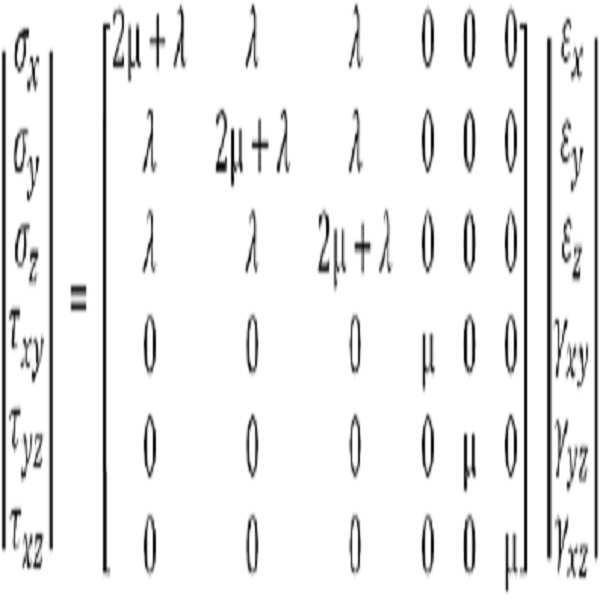
선형의 탄성재료에 대해, 스트레스와 압력 간의 관계는 다음 방정식에 의해 지배된다:For a linear elastic material, the relationship between stress and pressure is governed by the following equation:
![]()
![]()
여기서, [D]는 탄성 매트릭스이다. 이 방정식은 또한 다음과 같은 매트릭스 형태로 적을 수 있다:Here, [D] is an elastic matrix. This equation can also be written in the following matrix form:
그런 다음, ![]()
![]()
![]()
![]()
![]()
![]()
여기서, [B]는 각 요소의 형상 함수의 이차 미분을 포함하는, 압력 변위 매트릭스이다.Here, [B] is a pressure displacement matrix including a second derivative of the shape function of each element.
![]()
![]()
빔 요소들의 경우에, 형상 함수는 다음에 의해 주어진다:In the case of beam elements, the shape function is given by:

여기서, x는 노드 좌표들을 나타낸다.Where x represents the node coordinates.
접촉들의 Contact 모델링modelling (Modeling Contacts)(Modeling Contacts)
장치 전개 동안에 접촉 상호작용(contact interactions)을 모델링하기 위해 페널티 콘택트 인포스먼트 알고리즘(penalty contact enforcement algorithm)을 사용할 수 있다. 이 알고리즘은 강성 몸체(rigid bodies)들과 노드 요소들을 수반하는 접촉들에 대해 더 적합하고, 그리고 운동성 접촉(kinetic contact)모델들 보다 작은, 엄중한 제약을 제공한다. 이는 마스터/슬레이브 공식을 기반으로 하고, 슬레이브 표면은 마스터 표면에 종속된다. 슬레이브 표면이 마스터 표면의 면들을 침투할 때 접촉이 검출된다. 침투는, 침투에 대항기 위해 필요한 스프링 "강성(stiffness)" 또는 저항력을 계산함으로써 해결된다. 상기 힘은 슬레이브 노드들의 깊이, 그 질량 및 시간 증분을 사용하여 계산된다. 패널티와 운동성 접촉들의 조합 또한 장치 전개 동안에 접촉 상호작용을 모델링하는데 사용될 수 있다.A penalty contact enforcement algorithm may be used to model contact interactions during device deployment. This algorithm is more suitable for contacts involving rigid bodies and node elements, and provides a tighter constraint than kinetic contact models. It is based on the master / slave formula, and the slave surface is dependent on the master surface. Contact is detected when the slave surface penetrates the surfaces of the master surface. Penetration is solved by calculating the spring "stiffness" or resistance required to resist penetration. The force is calculated using the depth of the slave nodes, its mass, and the time increment. The combination of penalty and motility contacts can also be used to model the contact interaction during device deployment.
허용된 접촉의 유형을 규정하기 위하여 유한 슬라이딩(finite sliding) 공식을 사용할 수 있다. 이 공식은 접촉 동안에 표면들의 임의 분리, 슬라이딩, 및 회전을 허용한다. 그러나, 이 공식은, 표면들 간의 접선 운동(tangential motion)이 한(one) 시간 증분 내에 마스터 표면의 몇 크기를 초과하지 않는다고 추정한다. 이 추정은, 작은 시간 증분들 때문에, 사용하는 명시적 방법에 부합한다. 유한 슬라이딩 공식은 또한, 마스터 표면이 모든 지점들에서 연속적인 법선 속도면(continuous surface normals)을 가진다고 추정한다. 만일 마스터 법선 속도면이 불연속한다면, 슬레이브 노드들은 소정의 영역들에 국한되게 될 수 있다. 따라서, 마스터 표면은 기하학적 구조에서 소정의 날카로운 천이(transitions)들을 제거하기 위해 부드럽게 된다.A finite sliding formula can be used to define the type of contact allowed. This formula allows for random separation, sliding, and rotation of the surfaces during contact. However, this formula assumes that the tangential motion between the surfaces does not exceed some size of the master surface in one time increments. This estimate is consistent with the explicit method used, due to small time increments. The finite sliding equation also assumes that the master surface has continuous continuous surface normals at all points. If the master normal speed surface is discontinuous, the slave nodes may be confined to predetermined areas. Thus, the master surface is smoothed to remove certain sharp transitions in the geometry.
시뮬레이션 동안에 각 증분에서 마스터 표면과 각 슬레이브 노드 간에 최소 간격을 트랙하기 위해 접촉 트랙킹(contact tracking) 알고리즘을 사용할 수 있다. 트랙킹 알고리즘은 전체적 및 국부적 접촉 검색 성분(a global and a local contact search component)으로 나뉘어질 수 있다. 전체적인 검색은 트랙킹 알고리즘 중에서 가장 계산적으로 비싼 성분이고 그리고 각 슬레이브 노드에 대해 가장 인접한 마스터 표면 면을 찾는데 책임이 있다. 계산적 비용을 줄이기 위해, 버킷 정렬 알고리즘(bucket sorting algorithm)을 사용할 수 있다. 모든 100 증분마다 전체적인 검색을 구현함으로써 계산적 비용이 더 감소될 수 있다. 다음의 전체적인 검색 전까지 국부적인 검색이 후속 증분들에서 수행될 수 있다. 국부적인 검색은 단지, 마지막 증분에서 미리 트랙되었던 마스터 표면 면들만을 트랙한다.During the simulation, a contact tracking algorithm can be used to track the minimum distance between the master surface and each slave node at each increment. The tracking algorithm can be divided into a global and a local contact search component. The overall search is the most computationally expensive component of the tracking algorithm and is responsible for finding the nearest master surface for each slave node. To reduce the computational cost, a bucket sorting algorithm can be used. The computational cost can be further reduced by implementing a global search every 100 increments. A local search may be performed in subsequent increments until the next global search. The local search only tracks the master surface planes previously tracked in the last increment.
마스터와 슬레이브 표면들이 접촉하면, 슬레이브 노드가 슬립하는지 또는 고정되는지(stick)를 결정하기 위해 마찰 모델(friction model)을 사용할 수 있다. 마찰 모델은 쿨롱의 마찰법칙(Coulomb's friction law)를 따르고, 이는, 접선 운동은 마찰계수 μ와 일반 견인(normal traction) ![]()
![]()
![]()
![]()
이 방정식을 충족하는 노드들은 표면에 고정되지만, 이 방정식을 충족하지 못하는 노드들은 표면을 따라 미끄러진다.Nodes that satisfy this equation are fixed to the surface, but nodes that do not satisfy this equation are slid along the surface.
![]()
![]()
코일들을 가상적으로 전개하는 한 실시예에서, 낭(sac)내로 코일을 인도하기 위해 말단 노드에서 변위 경계 조건이 규정될 수 있으며, 이는 체내에 사용되는 임상 코일 푸셔(pusher)를 시뮬레이션한다. 페널티 콘택 인포스먼트 알고리즘은, 자가(self), 코일-대-코일, 코일-대-카테터, 및 코일-대-동맥류 상호작용들을 모델링하는데 사용될 수 있다. 코일-대-카테터 상호작용들은, 카테터의 미끄러움을 고려해 마찰이 없는 것으로 추정하였다. 0.4 및 0.2의 마찰계수들이 코일-대-동맥류와 코일-대-코일에 대해 각각 규정되었다.In one embodiment of virtually deploying the coils, a displacement boundary condition at the distal node can be defined to guide the coil into the sac, simulating a clinical coil pusher used in the body. The penalty contact infusion algorithm may be used to model self, coil-to-coil, coil-to-catheter, and coil-to-aneurism interactions. The coil-to-catheter interactions were assumed to be friction free, taking into account the slippage of the catheter. The friction coefficients of 0.4 and 0.2 were respectively defined for coil-to-aneurysm and coil-to-coil.
유한요소 코일 전개들은, 체외(in virto) 및 체내(in vivo) 전개들에 대해 엄밀하게 입증되었다. 이와 같은 한 입증이 도 6에 도시되어 있는데, 동일한 동맥류 모델들에서, 시뮬레이션한 유한요소 전개들(박스 (a) 및 (c))들은 체외 나선 및 복합 코일 전개들(박스 (b) 및 (d))과 비교하였다.Finite element coil deployments have been rigorously demonstrated for in vitro and in vivo developments. 6 shows that in simulated aneurysm models, the simulated finite element developments (Boxes (a) and (c)) can be applied to in-vitro helix and composite coil deployments (Boxes (b) and )).
스텐트 및 혈류변환 스텐트 모델링(MODELING STENTS AND FLOW DIVERTERS)MODELING STENTS AND FLOW DIVERTERS
본원은 소정의 적절한 다공성 스텐트를 효과적으로 모델링하는데 사용될 수 있는데, 고 다공성 스텐트들의 두 실시예들이 여기에서 예로 설명된다: (1) 뉴로폼 스텐트(Neuroform stent); 및 (2) 엔터프라이즈 스텐트(Enterprise stent). 두 스텐트들은 니티놀(Nitinol), 니켈-티타늄 합금으로 구성되고, 그리고 90%의 추정 다공성을 가진다. 그러나, 도 7A - B에 도시된 바와 같이, 스텐트들은 디자인이 다르다. 뉴로폼 스텐트(700)는 개방 셀 디자인(open cell design)의 특징을 가지고 그리고 여덟 개의 사인 곡선적인 크라운 부분(sinusoidal crown segments)들로 구성된다. 뉴로폼 스텐트(700)의 개방 셀 디자인은 길고 복잡한 혈관에서 유연성을 향상시키고 또한 높은 반경방향 힘(radial force)를 제공하는데, 이는 극심한 각도의 굽이(bends)에서 더 나은 혈관 조화(conformability)를 의미한다. 각 뉴로폼 스텐트(700)의 스트러트(strut)(702)는 약 70㎛의 추정 두께를 가진다.The present application can be used to effectively model any suitable porous stent, wherein two embodiments of highly porous stents are described herein by way of example: (1) Neuroform stent; And (2) an enterprise stent. Both stents consist of Nitinol, a nickel-titanium alloy, and have an estimated porosity of 90%. However, as shown in Figures 7A-B, the stents have different designs. The
엔터프라이즈 스텐트(710)는 나팔모양의 단부를 가지는 폐쇄 셀(712) 디자인의 특징을 보인다. 폐쇄 셀 디자인의 장점들은 보다 작은 다공(718) 크기를 포함하는 것인데, 이는 동맥류 경부의 더 나은 커버를 의미하고, 또한 전개 동안 동맥류 내로 감소된 스텐트 침투의 위험을 포함하는데, 이는 개방 셀 디자인들에 대해 공통적으로 좋지 않은 전개 결과이다. 그러나, 폐쇄 셀 디자인을 가지는 스텐트들은 전형적으로 (동일 스트러트 두께를 가지는 스텐트들 중에서) 낮은 반경방향 힘을 가지고 또한 극심한 각도 굽이에서 혈관 벽에 대해 열악한 조화를 가진다. 각 엔터프라이즈 스텐트(710)의 스트러트(720)는 약 90㎛의 추정 두께를 가진다.The
혈류변환 스텐트는 동맥류 낭으로부터 멀어지게 혈액의 방향을 바꾸기 위하여 동맥류 구멍(orifice)을 가로질러 전개되는 스텐트-형 장치들이다. 이들은 공통적으로, 낮은 다공성을 가지는 자가-팽창 장치들이고 또한 꼰(braided) 관형 구조들의 특징을 가진다. 혈류변환 스텐트의 한 예는 파이프라인 색전술 장치(pipeline embolization device:PED)인데, 이는 48 개의 꼰 코발트-크롬 합금 가닥들로 구성된다. 각 가닥은 거의 30 마이크론이 직경을 가진다. PED의 스텐트 다공성은, 장치 구성과 동맥의 직경 크기에 따라 65-70%로 변한다.Blood flow conversion stents are stent-type devices deployed across the aneurysmal orifice to redirect blood away from the aneurysm sac. These are, in general, self-expanding devices with low porosity and also have the characteristic of braided tubular structures. An example of a blood flow conversion stent is a pipeline embolization device (PED), which consists of 48 braided cobalt-chromium alloy strands. Each strand has a diameter of approximately 30 microns. The stent porosity of the PED changes to 65-70% depending on the device configuration and the diameter of the artery.
스텐트와Stent and 혈류변환 Blood flow conversion 스텐트Stent 기하학 구조 Geometry structure 모델링modelling (Modeling (Modeling StentStent and Flow Diverter Geometry) and Flow Diverter Geometry)
설명에 따른 한 모델링 예에서, 뉴로폼 및 엔터프라이즈 고 다공성 스텐트들이 사용자 지정 파이톤 코드(a custom built python code)를 사용하여 파이포멕스(Pyformex(pyformexl.berlios.de))에 구성되었다. 다른 프로그래밍 언어들이 스텐트 모델링에 동일하게 적합할 수 있다는 것을 이해할 수 있을 것이다. 도 8을 참조하면, 스텐트 기하학 구조의 구축은:(ⅰ) 삼각형의 요소(802)들을 사용하여 반복하는 셀 기하학 구조의 평면 기본 모델(a planar base model)(800)을 생성하는 것과, (ⅱ) 스텐트의 2D 버전(810)을 생성하기 위하여 기하학 구조를 반영하고 또한 복제하는 것과, 그리고 (ⅲ) 2D 기하학 구조(820)를 실린더(830)로 "말기(roll)" 위하여 실린더 변환을 적용하는 것을 포함한다. In one illustrative modeling example, neuroform and enterprise hyperporous stents were constructed in Pyformex (pyformexl.berlios.de) using a custom built python code. It will be appreciated that other programming languages may be equally well suited for stent modeling. 8, the construction of a stent geometry structure includes: (i) generating a
도 8에 도시된 엔터프라이즈 스텐트의 경우에, 기본 기하학적 구조를 구성하기 위하여 먼저 컴페르츠(Gompertz) 함수가 사용되었다. 이 함수는 다음과 같이 주어진다.In the case of the enterprise stent shown in FIG. 8, the Gompertz function was first used to construct the basic geometry. This function is given as
![]()
![]()
여기서 x는 위치이고, a, b 및 c들은 엔터프라이즈 장치의 고해상도 이미지들을 사용하여 결정된 계수값들이다. 최종 삼각 메시들은 스테레오리소그라피(STL) 파일로 표현되었고 또한 소정의 교차 또는 중첩 삼각 요소들을 바로잡기 위해 지오매직 스튜디오(Geomagic Studio)로 전송되었다. 그런 다음, 상기 STL 파일들은 CAD 기하학적 구조로 변환되었고 또한 아바쿼스(Abaqus), 유한요소 해결장치로 전송되었다.Where x is the position, and a, b, and c are the coefficient values determined using the high resolution images of the enterprise device. The final triangular meshes were represented by a stereo lithography (STL) file and were also transferred to Geomagic Studio to correct any intersection or overlapping triangular elements. The STL files were then converted to CAD geometry and also transferred to Abaqus, a finite element solution.
PED의 경우에, PED의 개별적인 가닥들을 모델링하기 위하여, 코일 기하학 구조를 모델링하기 위해 상기에서 기술한 것과 유사한 방식으로, 3D 빔 이론이 사용되었다. 특히, 각 PED 가닥은, 도 3A - B에 도시된 바와 같이, 30 마이크론 직경을 가지는, 순차적으로 연결된 탄성 고체 3D 빔 요소들의 셋트로 표현되었다. 가닥들은, 피치(개별적인 가닥들간의 각도), 시계방향 및 반-시계방향 가닥들의 수, PED의 직경과 길이, 및 가닥들의 직경을 명시하는, 꼬기 방식의 기본 사용자 지정 수학적 설명을 사용하여 꼬았다. 코발트-크롬 합금 재료 특성들이 빔 요소들에 도입되었다.In the case of a PED, in order to model the individual strands of the PED, 3D beam theory was used in a manner similar to that described above to model the coil geometry. In particular, each PED strand was represented by a set of sequentially connected elastic solid 3D beam elements with a 30 micron diameter, as shown in Figures 3A-B. The strands were twisted using a basic custom mathematical description of the twist type, specifying the pitch (angle between individual strands), the number of clockwise and counter-clockwise strands, the diameter and length of the PED, and the diameter of the strands . Cobalt-chromium alloy material properties were introduced into the beam elements.
스텐트 및 혈류변환 스텐트 기하학 구조들은 삼각형 및 사각형의 요소들을 사용하여 아바쿼스에서 메시되었다. 거의 6,000 - 8,000 개의 감소된-차수(reduced-order) 삼각형 셀 요소들이 각 스텐트 기하학 구조에 대해 생성되었다. 70㎛의 인위적인 쉘 두께가 쉘 요소들 모두에 적용되었고 또한 초탄성(hyperelastic) 재료 특성들이 도입되었다. 초탄성 재료 특성들은 체온에서 니티놀의 오스테나이트(austenite)와 마텐자이트(martensite) 재료 위상들의 근사치를 계산한다.Stent and Blood Flow Conversion Stent geometries were meshed in avarice using triangular and square elements. Almost 6,000 - 8,000 reduced-order triangular cell elements were generated for each stent geometry. An artificial shell thickness of 70 [mu] m was applied to all of the shell elements and also hyperelastic material properties were introduced. The superelastic material properties calculate an approximation of the austenite and martensite material phases of Nitinol at body temperature.
스텐트Stent 및 혈류변환 And blood flow conversion 스텐트Stent 전개 deployment 모델링modelling (Modeling (Modeling StentStent and Flow Diverter Deployment) and Flow Diverter Deployment)
도 9는 여기에서 기술하는 바와 같이 컴퓨터, 컴퓨터 클러스터, 또는 서버에 의해 실행되는, 가상 스텐트 또는 혈류변환 스텐트의 3-단계 시뮬레이터된 예시적 전개를 보여준다. 일반적으로, 이 프로세스는: 단계 90에서, 스텐트 또는 혈류변환 스텐트의 기하학적 구조를 카테터, 외장 케이스, 또는 마이크로카테터(902)의 형상내로 "집어넣거나(sheathing)" 또는 크림핑(crimping)하는 것과; 단계 92에서, 시뮬레이션된 혈관을 통해 동맥류(906)의 위치로 카테터(902)를 전진시키는 것과; 그리고 단계 94에서, 단계 90에서 인가된 반경 제약들(radial constraints)을 단계적인 프로세스로 기하학적 구조(900)의 전부 또는 일부 상에 이완시킴으로써 기하학적 구조(900)를 뽑아내는 것을 수반한다. 한 실시예에서, 크림핑(단계 90)은 실린더형 쉘 상에 반경 변위 경계 조건(즉, "크림퍼(crimper"))을 도입함으로써 수행될 수 있다. 한 응용에서, 크림퍼는 기하학적 구조(900)를 0.54mm 카테터(902) 내로 압축할 수 있다. 기하학적 구조(900)와 크림퍼 간에 채터진동(chatter vibration)을 감소시키기 위하여 부드러운 스템 기능을 사용하여 반경 변위의 크기(magnitude)가 시간에 맞게 적용된다.FIG. 9 shows a three-step simulated, exemplary deployment of a virtual stent or blood flow transduction stent, implemented by a computer, computer cluster, or server, as described herein. Generally, this process includes: "stepping" or "crimping" the geometry of the stent or bloodstream-transforming stent into the shape of the catheter, sheath, or microcatheter 902 at
크림핑 이후에, 카테터(902)는 혈관(904) 중심선을 따라 동맥류(906)의 위치로 전진되며, 상기 위치는 도 10에 보다 상세히 도시되어 있다. 한 응용에서, 카테터(902) 전진은, 가이드와이어를 모델링하는 기준점(reference point)(910)(도 9 참조)과, 카테터(902) 첨단의 노드들 간에 운동학적 커플링(kinematic coupling)을 통해 수행될 수 있다. 변위들과 정규 방향들은 혈관 중심선을 사용하여 계산되고, 그런 다음 기준점(910) 상에 규정된다. 다른 실시예에서, 기준점(910)은 또한, 스텐트 또는 혈류변환 스텐트의 첨단의 노드들에 연결될 수 있다.After crimping, the
도 11을 참조하면, 카테터(902) 전진 후에, 기하학적 구조(900)는 다수의 서브세트 ![]()
![]()
![]()
![]()
기하학적 구조(900)를 뽑아내기 위해(단계 94), 각 기하학적 구조 서브세트 ![]()
![]()
메싱(MESHING)MESHING
주입(implant)의 혈류역학을 결정하기 위한 계산 데이터를 제공하기 위하여 시뮬레이션된 기하학적 구조의 메싱을 수행할 수 있다. 아래에서 기술한 메싱 접근법의 예시적 구현에서, 표면 및 체적 메시들을 생성하기 위하여, 처치하지 않은 뇌동맥류의 전산 모델과, 혈관 내 장치 기하학적 구조의 스테레오리소그라피 모델이 ANSYS ICEM 12.1 소프트웨어(미국, 피츠버그, 캐논스버그에 소재하는 ANSYS 회사) 내로 전송되었다.Meshing of the simulated geometry may be performed to provide computational data for determining the hemodynamics of the implant. In an exemplary implementation of the meshing approach described below, computational models of untreated cerebral aneurysms and stereolithographic models of intravascular device geometries were developed using ANSYS ICEM 12.1 software (Pittsburgh, USA, USA) to generate surface and volume meshes, RTI ID = 0.0 > ANSYS < / RTI >
색전Embolization 코일 coil 메싱Meshing (Meshing Embolic coils)(Meshing Embolic coils)
기본 사용자 지정 코드를 사용하여 빔 요소들이 매트랩(Matlab)에서 먼저 스위프되었다. 빔 요소들은 직경(D2)를 가지는 원형 표면을 사용하여 스위프되었다. 그런 다음, 상이한 코일들을 합병하고 또한 소정의 중첩되거나 또는 교차하는 표면 요소들을 제거하기 위하여, 스위프된 색전 코일 표면들은 20㎛의 최대 삼각 메시 요소 크기로 쉬링크-랩 되었다(shrink-wrapped). 작은 메시 크기는, 쉬링크-랩핑 후에 구조적 세부사항들을 포착한 것을 보장하였다. 그런 다음, 최종 표면 메시에서 소정의 작은 구멍들을 충진하기 위하여 지오매직 스튜디오(Raindrop Geomagic, Durham, NC)을 사용하였다. 메시 밀도함수가 동맥류 체적과 코일 표면들에 적용되었다. 밀도함수가 장치 기하학적 구조와 높은 유속 경사도(gradients)를 적절하게 해결하기 위해 채용되었다. 또한, 밀도함수는 장치 근처의 메시 품질을 향상시켜, 메시 요소 크기에서 소수의 날카로운 천이들이 있게 한다. 그런 다음, 혈량과 고형분 부피에 대해 다중-몸체부들이 규정되었다. 마지막으로, 5-7백만 노드들에 대응하는, 전체 1900만-2500만의 4면(tetrahedral) 요소들로 코일과 혈량을 디스크레타이즈하기 위하여, 패치 독립 옥트리 메시 발생기(patch independent Octree mesh generator)를 사용하였다. 최종 표면과 체적 메시의 예가 도 12A - B에 나타나 있다. 특히, 도 12A는 단일 색전 코일(1200)의 4면 메시를 보여주고, 도 12B는 그 안에 삽입된 코일(1200)을 가지는 예시적 두개기부-첨단 동맥류(1220)에 대한 혈량 메시를 보여준다. 동맥류(1220) 낭 내의 빈 스폿(1230)은 코일(1200)의 존재를 나타낸다. 두개기부의 스플릿(split)(1240)의 근사치를 계산하는 것과 같은 보다 단순한 흐름과 비교하면, 해당 영역들에서 발생하는 복잡한 흐름 역학(flow dynamics)을 더 잘 해결하기 위하여 동맥류(1220) 낭의 영역에서 높은 메시밀도(즉, 단위 체적당 보다 높은 수의 삼각 또는 4면 요소들)로 혈류량을 디스크레타이즈할 수 있다.Using the default custom code, the beam elements were first swapped in Matlab. The beam elements were swept using a circular surface with a diameter (D 2 ). The swept embolus coil surfaces are then shrink-wrapped with a maximum triangular mesh element size of 20 mu m, in order to merge the different coils and also to remove any overlapping or intersecting surface elements. The small mesh size ensured that structural details were captured after shrink-wrap. Then, Geomagic Studio (Raindrop Geomagic, Durham, NC) was used to fill the desired small holes in the final surface mesh. Mesh density functions were applied to the aneurysm volume and coil surfaces. The density function was employed to properly solve the device geometry and high flow velocity gradients. The density function also improves the mesh quality near the device, allowing a few sharp transitions in mesh element size. Multi-body parts were then defined for blood volume and solids volume. Finally, a patch independent Octree mesh generator was used to diskize the coil and blood volume with a total of 19 to 25 million tetrahedral elements corresponding to 5-7 million nodes. Respectively. Examples of final surfaces and volume meshes are shown in Figures 12A-B. 12A shows a four-sided mesh of a
고 다공성 High porosity 스텐트Stent 메싱Meshing (Meshing High Porosity (Meshing High Porosity StentsStents ))
고 다공성 스텐트들에 대한 메싱 프로세스는 스텐트 표면에 가상 토포롤지의 구축을 포함할 수 있다. 규정된 설정 허용오차(set tolerance)를 사용하여 공동 표면들과 가장자리들은 병합될 수 있다. 그런 다음, 최대 및 최소 메시 요소 크기들이 가상 셀들에 대해 규정될 수 있다.The meshing process for high porosity stents may include the construction of a virtual topography roll on the stent surface. Cavities surfaces and edges can be merged using the prescribed set tolerance. The maximum and minimum mesh element sizes may then be defined for the virtual cells.
텔레스코핑 스텐트의 경우, 사용한 패널티 콘택 공식 때문에 일부 교차하는 또는 중첩하는 영역들이 존재할 수 있다. 체적-필링 접근법의 사용을 통해 중첩들은 기하학적 구조로부터 제외될 수 있다. 이 접근법에서, 단일의 텔레스코프된 스텐트 몸체에 대해 다수의 필링 지점들이 규정될 수 있다. 모든 스텐트 몸체들을 포함하는 체적 메시를 생성하기 위하여 상기와 같이 옥트리 메시 발생기를 사용할 수 있다. 체적 메시 생성 후, 옥트리 솔버(solver)는 최외각 체적 메시층을 스테트 표면에 투사하여, 여러 텔레스코핑 스텐트들로 된 단일의, 병합된 표면 메시를 형성한다. 체적 메시는 버려지고, 그리고 표면 메시는, 유지되는 비-교차 가장자리들을 가지는 면 기하학적 구조로 변환될 수 있다.In the case of a telescoping stent, there may be some intersecting or overlapping regions due to the penalty contact formulas used. Through use of the volume-filling approach, overlaps can be excluded from the geometry. In this approach, multiple filling points can be defined for a single telescoped stent body. An octree mesh generator may be used as described above to generate a volumetric mesh containing all of the stent bodies. After generating the volume mesh, the octree solver projects the outermost volumetric mesh layer onto the surface of the surface to form a single, merged surface mesh of multiple telescoping stents. The volumetric mesh is discarded, and the surface mesh can be converted to a surface geometry having non-intersecting edges to be maintained.
메시 밀도함수는 측면 스텐트(faceted stent)에 인접한 혈량에 적용될 수 있다. 최종 혈액 및 스텐트 체적 메시는 색전 코일들에 대해 요약된 동일한 기술들을 사용하여 생성될 수 있다. 마지막으로, 생성된 표면 및 체적 메시들은 유체역학 시뮬레이션을 위해 ANSYS Fluent 소프트웨어(미국 피츠버그 캐논스버그 소재 ANSYS 사)로 전송될 수 있다.The mesh density function can be applied to the blood volume adjacent to the faceted stent. The final blood and stent volume meshes can be generated using the same techniques summarized for embolization coils. Finally, the generated surface and volume meshes can be transferred to ANSYS Fluent software (ANSYS, Inc., Pittsburgh, Canonburg, USA) for fluid dynamics simulations.
혈류전환 Blood flow conversion 스텐트Stent 메싱Meshing (Meshing Flow Diverters)(Meshing Flow Diverters)
혈류변환 스텐트 가닥을 나타내는 각 세트의 빔 요소들은 먼저 기본 사용자 지정 코드를 사용하여 매트랩에서 스위프되었다. 빔 요소들은 혈류변환 스텐트의 가닥 직경과 동등한 직경을 가지는 원형 표면으로 스위프되었다. 최종 스위프 모델은 ANSYS ICEM으로 전송되었고 또한 혈류변환 스텐트 기하학적 구조 둘레에 메시 밀도함수가 적용되었다. 마지막으로, 혈액 및 혈류전환 스텐트 체적을 3000만-4000만의 4면 요소들로 디스크레타이즈하기 위하여 패치 독립 옥트리 방법이 사용되었다.Each set of beam elements representing a blood flow transduction stent strand was first swept in a MATLAB using the default custom code. The beam elements were swept into a circular surface with a diameter equal to the strand diameter of the transfusion stent. The final sweep model was transferred to the ANSYS ICEM and a mesh density function was also applied around the flow transduction stent geometry. Finally, a patch-independent Octree method was used to discrete the volume of blood and blood flow-transformed stents into 30,000 to 40,000 four-sided elements.
여기에서 사용한 용어 "프로세서"는 광범위한 용어이고, 또한 당업자에게 통상적이고 관습적인 의미를 부여하고(및 특별한 또는 맞춤형 의미에 한정되지 않는다), 또한 제한없이 컴퓨터 시스템, 상태 기계(state machine), 프로세서, 또는 컴퓨터를 구동하는 기본 명령에 응답하고 처리하는 논리회로를 사용하여 산술 또는 논리 연산을 수행하도록 설계된 것과 관련있다. 일부 실시예들에서, 용어는 관련된 ROM 및/또는 RAM을 포함할 수 있다.As used herein, the term "processor" is a broad term, and also should not be construed as limiting the present invention in any manner whatsoever (including, without limitation, special and customized meanings) Or to perform arithmetic or logic operations using logic circuits that respond to and process basic instructions that drive the computer. In some embodiments, the terms may include associated ROM and / or RAM.
본원에서 사용되는 "결정"이라는 용어는 다양한 작업들을 포함한다. 예컨대, "결정"은 계산, 컴퓨팅, 프로세싱, 도출, 조사, 검색(예컨대, 테이블, 데이터베이스 또는 다른 데이터구조에서 검색), 확인 등을 포함할 수 있다. 또한 "결정"은 수신(예컨대, 정보수신), 액세싱(예컨대, 메모리 내 데이터에 액세싱) 등을 포함할 수 있다. 또한 "결정"은 해결, 선택(selecting), 선택(choosing), 구축 등을 포함할 수 있다.The term "crystal" as used herein includes various operations. For example, "determining" can include computing, computing, processing, deriving, searching, searching (e.g., retrieving from a table, database or other data structure) The "decision" may also include receiving (e.g., receiving information), accessing (e.g., accessing data in memory), and so on. A "decision" can also include resolution, selecting, choosing, constructing, and the like.
상기에서 설명한 방법들의 다양한 작업은, 다양한 하드웨어 및/또는 소프트웨어 부품(들), 회로들, 및/또는 모듈(들)과 같은, 동작을 수행할 수 있는 소정의 적합한 수단들에 의해 수행될 수 있다. 일반적으로, 도면에 도시된 소정의 동작들은 동작들을 수행할 수 있는 기능적 수단에 대응하여 수행될 수 있다.The various tasks of the methods described above may be performed by any suitable means capable of performing the operations, such as various hardware and / or software component (s), circuits, and / or module . In general, certain operations depicted in the figures may be performed in response to functional means capable of performing operations.
본원과 관련해 설명한 (도 1 및 9의 단계들과 같은) 다양한 예시적 논리 단계들, 블록들, 모듈들 및 회로들은 범용 프로세서, 디지털 신호 프로세서(DSP), 응용 특정 집적회로(ASIC), 필드 프로그래머블 게이트 어레이 신호(FPGA) 또는 다른 프로그래머블 논리장치(PLD), 이산 게이트 또는 트랜지스터 로직, 개별적 하드웨어 부품들 또는 여기에서 설명된 기능들을 수행하도록 디자인된 이들의 조합에 의해 구현되거나 또는 수행될 수 있다. 범용 프로세서는 마이크로프로세서일 수도 있지만, 대안으로 프로세서는 소정의 상업적으로 사용 가능한 프로세서, 제어기, 마이크로 제어기, 또는 상태 기계일 수 있다. 또한 프로세서는 컴퓨팅 장치들, 예컨대, DSP와 마이크로프로세서의 조합, 다수의 마이크로프로세서들, DSP 코어와 결합된 하나 이상의 마이크로프로세서, 또는 소정의 다른 구성으로서 구현될 수 있다.The various illustrative logical steps, blocks, modules, and circuits described in connection with the present application (such as those of FIGS. 1 and 9) may be implemented or performed with a general purpose processor, a digital signal processor (DSP), an application specific integrated circuit A gate array signal (FPGA) or other programmable logic device (PLD), discrete gate or transistor logic, discrete hardware components, or any combination thereof designed to perform the functions described herein. A general purpose processor may be a microprocessor, but in the alternative, the processor may be any commercially available processor, controller, microcontroller, or state machine. The processor may also be implemented as a computing device, e.g., a combination of a DSP and a microprocessor, a plurality of microprocessors, one or more microprocessors in conjunction with a DSP core, or some other configuration.
하나 이상의 양태들에서, 여기에서 설명한 기능들은 하드웨어, 소프트웨어, 펌웨어, 또는 이들의 소정 조합으로 구현될 수 있다. 소프트웨어로 구현되는 경우, 상기 기능들은 하나 이상의 명령들 또는 코드로서 컴퓨터 판독가능 매체 상에 저장되거나 또는 전송될 수 있다. 컴퓨터 판독가능 매체는 한 장소에서 다른 장소로 컴퓨터 프로그램의 전송을 용이하게 하는 소정의 매체를 포함하는 컴퓨터 저장매체 또는 통신 매체 모두를 포함한다. 저장 매체는 컴퓨터에 의해 액세스될 수 있는 임의의 이용 가능한 매체일 수 있다. 예컨대, 이에 국한되지 않지만, 이러한 컴퓨터 판독가능 매체는 RAM, ROM, EEPROM, CD-ROM 또는 다른 광학 디스크 저장장치, 자기 디스크 저장장치, 또는 명령들 또는 데이터 구조들의 형태로 원하는 프로그램 코드를 운반하거나 저장하는데 사용될 수 있고 또한 컴퓨터에 의해 액세스될 수 있는 소정의 다른 매체들을 포함할 수 있다. 또한, 소정의 접속이 컴퓨터 판독가능 매체로 명명된다. 예컨대, 소프트웨어가 웹 사이트, 서버 또는 다른 원격 소오스로부터 동축 케이블, 광섬유 케이블, 트위스트 페어, 디지털 가입자 회선(DSL), 또는 적외선, 무선 및 마이크로웨이브와 같은 무선기술들을 사용하여 전송된다면, 동축 케이블, 광섬유 케이블, 트위스트 페어, DSL, 또는 적외선, 무선 및 마이크로웨이브와 같은 무선기술은 매체의 정의에 포함된다. 여기에서 사용하는 디스크는, 컴팩트 디스크(CD), 레이저 디스크, 광학 디스크, 디지털 다용도 디스크(DVD), 플로피 디스크 및 블루-레이 디스크를 포함하고, 여기서 디스크들은 통상적으로 데이터를 자기적으로 재생하지만, 디스크들은 레이저로 데이터를 광학적으로 재생한다. 따라서, 몇몇 양태들에서, 컴퓨터 판독가능 매체는 비-일시적 컴퓨터 판독가능 매체(예컨대, 유형 매체(tangible media))를 포함할 수 있다. 이외에도, 몇몇 양태들에서, 컴퓨터 판독가능 매체는 일시적 컴퓨터 판독가능 매체(예컨대, 신호)를 포함할 수 있다. 상기의 조합들은 또한 컴퓨터 판독가능 매체의 범위 내에 포함되어야 한다.In one or more aspects, the functions described herein may be implemented in hardware, software, firmware, or some combination thereof. When implemented in software, the functions may be stored on or transmitted over as a computer-readable medium as one or more instructions or code. Computer-readable media includes both computer storage media or communication media including any medium that facilitates transfer of a computer program from one place to another. The storage medium may be any available media that can be accessed by a computer. For example and without limitation, such computer-readable media can carry or store desired program code in the form of RAM, ROM, EEPROM, CD-ROM or other optical disk storage, magnetic disk storage, And any other medium which can be accessed by a computer. Also, the predetermined connection is termed a computer-readable medium. For example, if the software is transmitted from a web site, server, or other remote source using wireless technologies such as coaxial cable, fiber optic cable, twisted pair, digital subscriber line (DSL), or infrared, wireless and microwave, Wireless technologies such as cable, twisted pair, DSL, or infrared, wireless, and microwave are included in the definition of media. Disks used herein include compact discs (CDs), laser discs, optical discs, digital versatile discs (DVD), floppy discs and Blu-ray discs where discs typically reproduce data magnetically, The discs optically reproduce the data with a laser. Thus, in some aspects, the computer-readable medium may comprise a non-transitory computer readable medium (e.g., tangible media). In addition, in some aspects, the computer readable medium may comprise a temporary computer readable medium (e.g., a signal). Combinations of the above should also be included within the scope of computer readable media.
여기에서 기술한 방법들은 상기에서 설명한 방법을 달성하기 위한 하나 이상의 단계들 또는 동작들을 포함한다. 방법 단계 및/또는 동작들은 청구항의 범위를 벗어나지 않고 서로 교환될 수 있다. 즉, 단계들 또는 동작들의 특정 순서가 명시되지 않았다면, 특정 단계들 및/또는 동작들의 순서 및/또는 사용은 청구항의 범위를 벗어나지 않고서 수정될 수 있다.The methods described herein include one or more steps or operations for achieving the method described above. The method steps and / or operations may be interchanged with each other without departing from the scope of the claims. That is, the order and / or use of certain steps and / or operations may be modified without departing from the scope of the claims, unless a specific order of steps or acts is specified.
따라서, 특정 양태들은 본 명세서의 동작들을 수행하기 위한 컴퓨터 프로그램 제품을 포함할 수 있다. 예컨대, 컴퓨터 프로그램 제품은 저장된(및/또는 엔코드된) 명령들을 가지는 컴퓨터 판독가능 매체를 포함할 수 있으며, 상기 명령들은 상기에서 기술한 동작을 수행하기 위해 하나 이상의 프로세서들에 의해 실행될 수 있다. 특정 양태들에 대해, 컴퓨터 프로그램 제품은 패킹 재료를 포함할 수 있다.Accordingly, certain aspects may include a computer program product for performing the operations herein. For example, a computer program product may include a computer readable medium having stored (and / or encoded) instructions, which instructions may be executed by one or more processors to perform the operations described above. For certain aspects, the computer program product may comprise a packing material.
소프트웨어 또는 명령들은 전송 매체를 통해 전송될 수 있다. 예컨대, 소프트웨어가 웹 사이트, 서버 또는 다른 원격 소오스로부터 동축 케이블, 광섬유 케이블, 트위스터 페어, 디지털 가입자 회선(DSL), 또는 적외선, 무선 및 마이크로웨이브와 같은 무선기술을 사용하여 전송된다면, 동축 케이블, 광섬유 케이블, 트위스트 페어, DSL, 또는 적외선, 무선 및 마이크로웨이브와 같은 무선기술들은 전송 매체의 정의에 포함된다.The software or commands may be transmitted over a transmission medium. For example, if the software is transmitted from a web site, server, or other remote source using a wireless technology such as coaxial cable, fiber optic cable, twister pair, digital subscriber line (DSL), or infrared, wireless and microwave, Wireless technologies such as cable, twisted pair, DSL, or infrared, radio and microwave are included in the definition of transmission medium.
또한, 모듈들 및/또는 여기에서 기술한 방법들 및 기술들을 수행하기 위한 다른 적절한 수단을 다운로드할 수 있거나 및/또는 적용가능한 전자 통신장치에 의해 얻을 수 있다는 것을 이해해야 한다. 예컨대, 이러한 장치는 여기에서 설명한 방법들을 수행하기 위한 수단의 전송을 용이하게 하기 위해 서버에 접속될 수 있다. 다르게는, 여기에서 기술된 다양한 방법들은 저장수단(예컨대, RAM, ROM, 컴팩트 디스크(CD) 또는 플로피 디스크와 같은 물리적 저장매체)를 통해 제공되어, 전자 통신장치는 장치에 저장수단을 연결하거나 또는 제공할 시에 다양한 방법들을 얻을 수 있다. 또한, 여기에서 기술된 방법들과 기술들을 장치에 제공하기 위한 소정의 다른 적절한 기술이 이용될 수 있다.It should also be understood that modules and / or other suitable means for performing the methods and techniques described herein may be downloaded and / or obtained by applicable electronic communication devices. For example, such a device may be connected to a server to facilitate transmission of the means for performing the methods described herein. Alternatively, the various methods described herein may be provided through storage means (e.g., a physical storage medium such as RAM, ROM, compact disk (CD) or floppy disk) such that the electronic communication device may connect storage means to the device, You can get a variety of ways to provide. In addition, any other suitable technique for providing methods and techniques described herein to an apparatus may be used.
청구범위는 위에서 설명한 정확한 구성 및 요소로 한정되지 않는 것으로 이해되어야 한다. 다양한 수정, 변경 및 변형들이 청구항들의 범위를 벗어나지 않고서 상기에서 설명한 방법들과 장치의 배열, 동작 및 세부 사항들에 이루어질 수 있다.It is to be understood that the appended claims are not intended to be limited to the precise configuration and elements described above. Various modifications, changes, and variations may be made in the arrangement, operation and details of the methods and apparatus described above without departing from the scope of the claims.
다르게 정의되지 않는 한, (기술적이거나 과학적인 용어들을 포함하는) 모든 용어들은 당업자에게 이들의 통상적이고, 관용적인 의미를 부여할 수 있고, 여기에서 명백하게 정의하지 않는 한, 특별한 또는 맞춤 의미로 한정되는 것은 아니다. 본 명세서의 소정 특징들 또는 양태들을 기술할 때 특정 용어의 사용은, 용어가 관련되는 본 명세서의 특징 또는 양태들의 임의 특정 특징들을 포함하도록 제한되게 재정의되는 것을 의미하는 것으로 간주되지 않아야 한다는 것을 유의해야 한다. 본 명세서에서 사용되는 용어들과 어구들과, 이의 변형은 특히 첨부된 청구범위에서 명시적 언급이 없는 한, 제한에 반대되는 오픈 종료되는 것으로 해석되어야 한다.Unless defined otherwise, all terms (including technical or scientific terms) may be given their ordinary and idiomatic meanings by those skilled in the art and, unless explicitly defined herein, It is not. It should be noted that the use of certain terms when describing certain features or aspects of the present specification should not be construed as being limited to being redefined to include any particular features or aspects of the present specification to which the term relates do. The terms and phrases used herein, and variations thereof, are to be construed as open ended contrary to the restrictions, unless expressly stated to the contrary in the appended claims.
상기의 예들로서, 용어 '포함(including)'은 '포함, 제한없이', '포함하지만 제한되지 않는' 등을 의미하는 것으로 판독되어야 하고; 여기에서 사용한 용어 "포함(comprising)'은 "포함(including)', "포함(containing)' 또는 '특징으로 하는(characterized by)'과 비슷하고, 또한 포괄적 또는 오픈 종료되고 그리고 부수적인, 언급하지 않은 요소들 또는 방법 단계들을 제외하지 않으며; 용어 '가짐(having)'은 '적어도 하나를 가지는'으로 해석되어야 하고; 용어 '포함하다(includes)'는 '포함하지만 한정되지 않는'으로 해석되어야 하고; 용어 '예'는 논의에서 항목의 예시적 경우를 제공하는데 사용되고; '공지된'. '보통', '표준'과 같은 형용사와, 비슷한 의미의 용어는 기술되는 항목을 정해진 시간에 또는 현재 이용할 수 있는 항목에 제한하는 것으로 이해하여서는 안되고, 대신에 이용할 수 있거나 또는 지금 공지된 또는 미래의 소정 시간에 이용할 수 있는 공지, 보통 또는 표준 기술들을 포함하는 것으로 판독되어야 하고; '바람직하게(preferably, preferred, desired 또는 desirable)', 및 비슷한 의미의 단어들은, 소정의 특징들이 발명의 구조 또는 기능에 대단히 중요하거나, 필수적이거나 또는 매우 중요하다는 것을 의미하는 것으로 이해하여서는 안되고, 대신에 단지 발명의 특정 실시예에 사용되거나 사용되지 않을 수 있는 대체적 또는 부수적 특징들을 강조하기 위한 것으로 이해하여야 한다. 마찬가지로, 접속사 '그리고(and)'와 연계된 항목의 그룹은, 항목들 각각 및 모두가 그룹핑에 존재하는 것을 필요로 하는 것으로 판독해서는 안되고, 대신에 명시적으로 나타내지 않았다면 '및/또는'으로 판독되어야 한다. 비슷하게, 접속사 '또는(or)'과 연계된 항목의 그룹은, 이 그룹 중에서 상호 독점을 필요로 하는 것으로 판독되어서는 안되고, 차라리 명시적으로 나타내지 않는 한 '및/또는'으로 판독되어야 한다.As such, the term "including" should be read as meaning "including, without limitation", "including but not limited to", and the like; As used herein, the term " comprising " is intended to be synonymous with 'including', 'containing' or 'characterized by' The word "having" should be interpreted as having "at least one", and the term "includes" should be interpreted as including but not limited to, The term 'yes' is used to provide an example case of the item in the discussion; 'admitted'. Adjectives such as 'normal' and 'standard' But are not to be construed as limiting the present invention to those skilled in the art, and are instead intended to include known, common, or standard techniques that are available or are now known or available at some future time. , 'Preferred, desirable or desirable', and words of similar meaning are understood to mean that certain features are of vital, essential, or very important importance to the structure or function of the invention But instead should be understood to emphasize alternative or additional features that may or may not be used only in certain embodiments of the invention. Similarly, a group of items associated with a conjunction 'and' And / or " unless explicitly indicated otherwise. Similarly, the group of items associated with the conjunction ' or (or) ' Should not be read as requiring mutual monopoly among these groups, but rather should be explicitly represented That one to be read as "and / or".
값의 범위가 제공되는 경우, 상한 및 하한과 범위의 상한과 하한 사이의 중간값은 실시예들 내에 포함되는 것으로 이해된다.Where a range of values is provided, intermediate values between the upper and lower limits and the upper and lower limits of the range are understood to be encompassed within the embodiments.
여기에서 실질적으로 소정의 복수 및/또는 단수 용어들의 사용에 관해, 당업자는 콘텍스트 및/또는 애플리케이션에 적합한 그대로 복수에서 단수로 및/또는 단수에서 복수로 변환할 수 있다. 다양한 단수/복수 순열은 명확성을 위해 여기에서 명확히 주어질 수 있다. 부정 관사 'a' 또는 'an'은 복수를 배제하지 않는다. 단일 프로세서 또는 다른 유닛은 청구범위에 기재된 여러 항목의 기능을 수행할 수 있다. 특정 조치들이 상호 상이한 종속항들에서 언급되지 않는다는 단순한 사실은, 이들 조치들의 조합이 유리하게 사용될 수 없다는 것을 나타내지 않는다. 청구항의 모든 참조부호들은 범위를 제한하는 것으로 해석되어서는 안된다.With regard to the use of substantially any of the plural and / or singular terms herein, those skilled in the art will readily appreciate that one skilled in the art can translate from plurality to singular and / or singular to plural as is appropriate for the context and / or application. Various singular / plural permutations may be explicitly given herein for clarity. The indefinite article 'a' or 'an' does not exclude plural. A single processor or other unit may perform the functions of the various items recited in the claims. The mere fact that certain measures are not mentioned in mutually different dependent claims does not indicate that a combination of these measures can not be used to advantage. All references to the claims should not be construed as limiting the scope.
만일 특정 수의 추가 도입된 청구항 설명을 의도한다면, 이러한 의도는 청구항에서 명시적으로 나열되게 되고 또한 이러한 나열이 없으면 이러한 의도는 존재하지 않는 것으로 당업자는 이해하게 될 것이다. 예컨대, 이해를 돕기 위해, 다음의 첨부 청구항들은 청구항 설명을 소개하기 위하여 도입 문구 '적어도 하나'와 '하나 이상'의 사용을 포함할 수 있다. 그러나, 이러한 문구의 사용은, 동일한 청구항이 문구 '하나 이상' 또는 '적어도 하나'와 'a' 또는 'an'와 같은 부정 관사를 포함할 때에도, 부정 관사 'a' 또는 'an'에 의한 청구항 설명의 도입이 이러한 도입된 청구항 설명을 포함하는 소정의 특정 청구항을 이러한 설명들만을 포함하는 실시예들로 제한하는 것을 의미하는 것으로 해석되어서는 안되고(예컨대, 'a' 및/또는 'an'은 전형적으로 '적어도 하나' 또는 '하나 이상'을 의미하는 것으로 해석되어야 한다); 청구항 설명을 도입하는데 사용되는 부정 관사의 사용에 대해서도 마찬가지이다. 또한, 도입된 청구항의 설명의 특정한 수가 명백하게 설명된다 하더라도, 이러한 설명은 전형적으로 적어도 설명된 수를 의미하는 것으로 해석되어야 한다는 것을 당업자는 알게 될 것이다(예컨대, '두 개의 설명'의 가장 기본적인 설명은, 수식어 없이, 적어도 두 개의 설명들, 또는 두 개 이상의 설명들을 의미한다). 또한, 'A, B 및 C 중 적어도 하나'와 유사한 관례가 사용되는 경우에, 일반적으로 이러한 구조는, 나열된 항목들의 소정 조합을 포함하는, 단일 번호들을 포함하는 것과 같은 관례를 당업자가 뜻 그대로 이해하게 되는 것을 의도한다(예컨대, A, B 및 C 중 적어도 하나를 가지는 시스템은 A 단독, B 단독, C 단독, A와 B 함께, A와 C 함께, B와 C 함께, 및/또는 A, B, C 함께 를 가지는 시스템들을 포함할 수 있지만 이러한 시스템들에 한정되지는 않는다). 'A, B 및 C 중 적어도 하나'와 유사한 관례가 사용되는 경우에, 일반적으로 이러한 구조는, 나열된 항목들의 소정 조합을 포함하는, 단일 번호들을 포함하는 것과 같은 관례를 당업자가 뜻 그대로 이해하게 되는 것을 의도한다(예컨대, A, B 및 C 중 적어도 하나를 가지는 시스템은 A 단독, B 단독, C 단독, A와 B 함께, A와 C 함께, B와 C 함께, 및/또는 A, B, C 함께 를 가지는 시스템들을 포함할 수 있지만 이러한 시스템들에 한정되지는 않는다). 상세한 설명, 청구항들 또는 도면에서, 두 개 이상의 대체 용어들을 나타내는 가상적인 소정의 이접적 단어(disjunctive word) 및/또는 어구는 용어들 중 하나, 용어들 중 어느 하나, 또는 양 용어들을 포함하는 가능성을 고려하는 것으로 이해되어야 한다는 것을 당업자는 알게 될 것이다. 예컨대, 구문 "A 또는 B"는 "A" 또는 "B" 또는 "A와 B"의 가능성을 포함하는 것으로 이해되게 될 것이다.It will be understood by those skilled in the art that this intention is expressly recited in the claims, if a certain number of additional recited claims are intended, and that such intent is not present without such recitation. For example, for ease of understanding, the following appended claims may include the use of the phrases " at least one " and " more than one " However, the use of such phrases is not to be construed as an admission that a claim by an indefinite article "a" or "an", even if the same claim includes an indefinite article such as "one or more" or "at least one" The introduction of the description should not be construed to limit the scope of any particular claim, including the recited claims description, to embodiments that include only such descriptions (e.g., 'a' and / or 'an' Typically " at least one " or " at least one "); The same is true for the use of the indefinite article used to introduce the claim description. It will also be appreciated by those skilled in the art that, although specific numbers of explanations of the introduced claims should be expressly stated, these explanations should typically be interpreted to mean at least the stated numbers (e.g., the most basic explanation of the 'two descriptions' , Without modifiers, at least two descriptions, or two or more descriptions). Also, where a convention similar to 'at least one of A, B, and C' is used, such a structure will generally be understood to encompass any convention such as including single numbers, including any combination of the listed items, (For example, a system having at least one of A, B, and C is A alone, B alone, C alone, A and B together, A and C together, B and C together, and / or A, B , ≪ / RTI > C together). In the case where a convention similar to 'at least one of A, B, and C' is used, such a structure will generally be understood to include any combination of the listed items, A and B together, A and B together, B and C together, and / or A, B, C (for example, But are not limited to, systems having both). In the specification, claims, or drawings, a hypothetical predetermined disjunctive word and / or phrase that represents two or more alternate terms may include one of the terms, one of the terms, As will be appreciated by those skilled in the art. For example, the phrase "A or B" will be understood to include the possibility of "A" or "B" or "A and B".
주제는 참조를 위해 여기에서 포함되었고 또한 다양한 섹션을 찾는데 도움을 준다. 이들 주제들은 이에 관해 기술된 개념들의 범위를 제한하고자 의도하는 것은 아니다. 이러한 개념들은 명세서 전체에 걸쳐 적용 가능성을 가질 수도 있다. Topics are included here for reference and also help to find various sections. These subjects are not intended to limit the scope of the concepts described herein. These concepts may have applicability throughout the specification.
상기에서 설명한 실시예들은 본원의 기능적 원리를 설명하기 위해서만 제공되었으며, 제한적인 것으로 의도되지 않는다. 예컨대, 본원은 전반적으로 상이한 구조 구성 및 재료를 사용하여 실시될 수 있다. 당업자는 본 명세서에 설명된 실시예의 변형 및 변경이 본원의 사상 원리 도는 범위를 벗어나지 않고 이루어질 수 있음을 이해할 것이다. 본원은 다음의 첨부 청구범위의 사상 및 범위 내에서 모든 변형, 대체, 변경 및 등가물을 포함하도록 의도된다.The embodiments described above have been provided only to illustrate the functional principles of the invention and are not intended to be limiting. For example, the present application may be practiced using generally different structural constructions and materials. Those skilled in the art will appreciate that variations and modifications of the embodiments described herein may be made without departing from the spirit and scope of the disclosure. It is intended to cover all modifications, substitutions, alterations, and equivalents within the spirit and scope of the appended claims.
Claims (72)
의료장치 모델들을 저장하도록 구성되는 데이터베이스; 그리고
환자의 해부학적 구조모델을 가상적으로 구축하고;
상기 해부학적 구조모델에서 다수의 의료장치 모델들의 전개를 시뮬레이션하고; 그리고
해부학적 구조모델에서 다수의 의료장치 모델들의 전개의 혈류역학적 결과들을 시뮬레이션하도록 구성되는,
하나 이상의 프로세서를 포함하는 것을 특징으로 하는, 의료장치 역학을 시뮬레이션하기 위한 시스템.A system for simulating medical device dynamics, the system comprising:
A database configured to store medical device models; And
Constructing an anatomical structural model of the patient virtually;
Simulate deployment of a plurality of medical device models in the anatomical structural model; And
Configured to simulate hemodynamic results of deployment of a plurality of medical device models in an anatomical structural model,
The system comprising one or more processors.
의료장치 모델들을 포함하는 컴퓨터 판독가능 데이터베이스를 저장하는 단계;
환자 임상데이터를 기반으로 해부학적 구조모델을 하나 이상의 프로세서들로 구축하는 단계;
상기 해부학적 구조모델에서 다수의 의료장치 모델들의 전개를 시뮬레이션하는 단계; 그리고
상기 해부학적 구조모델에서 다수의 의료장치 모델들의 전개의 혈류역학적 결과들을 시뮬레이션하는 단계를 포함하는, 의료장치 역학을 시뮬레이션하기 위한 방법.CLAIMS 1. A method for simulating medical device dynamics, the method comprising:
Storing a computer readable database comprising medical device models;
Building an anatomical structural model with one or more processors based on patient clinical data;
Simulating deployment of a plurality of medical device models in the anatomical structural model; And
And simulating hemodynamic results of deployment of a plurality of medical device models in the anatomical structural model.
스위프 색전 코일 표면들을 생성하기 위하여 제1직경의 원형 표면을 사용하여 다수의 빔 요소들 각각을 스위핑하는 단계와;
해부학적 구조모델과 코일 표면 메시에 메시 밀도 함수를 적용하는 단계와;
혈량과 고형분 부피를 나타내는 하나 이상의 몸체부들을 규정하는 단계와; 그리고
몸체부들을 메시들로 디스크레타이징(discretizing)하는 단계를 포함하는 것을 특징으로 하는 방법.38. The method of claim 37, wherein simulating the deployment comprises meshing each of a plurality of medical device models and an anatomical structure model, and wherein meshing each of the plurality of medical device models comprises:
Sweeping each of the plurality of beam elements using a first diameter circular surface to create swept embossing coil surfaces;
Applying a mesh density function to an anatomical structure model and a coil surface mesh;
Defining one or more body parts indicative of blood volume and solid volume; And
And discretizing the body portions with meshes. ≪ RTI ID = 0.0 > 8. < / RTI >
스텐트 표면의 가상 토폴로지(virtual topology)를 구축하는 단계;
셀들에 대해 최대 메시 요소 크기와 최소 메시 요소 크기를 규정하는 단계;
상기 기하학적 구조로부터 중첩하는 영역을 제외하기 위하여 다수의 체적-메시 필링 지점들을 적용하는 단계;
스텐트를 둘러싸고 또한 최외각 층을 포함하는 하나 이상의 층들을 포함하는 체적 메시를 생성하는 단계;
스텐트 표면 상에 체적 메시의 최외각 층을 투사함으로써 표면 메시를 생성하는 단계와;
표면 메시를 면 기하학적 구조(facet geometry)형상으로 변환시키는 단계와;
상기 면 기하학적 구조에 인접한 해부학적 구조모델 내에서 혈량에 메시 밀도 함수를 적용하는 단계;
혈량과 고형분 부피를 나타내는 하나 이상의 몸체부들을 규정하는 단계; 그리고
몸체부들을 메시들로 디스크레타이징하는 단계를 포함하는 것을 특징으로 하는 방법.41. The method of claim 40, wherein simulating the deployment comprises meshing each of a plurality of medical device models and an anatomical structure model, and wherein meshing each of the plurality of medical device models comprises:
Establishing a virtual topology of the stent surface;
Defining a maximum mesh element size and a minimum mesh element size for cells;
Applying a plurality of volume-mesh peeling points to exclude overlapping regions from the geometry;
Creating a volume mesh surrounding the stent and including one or more layers including an outermost layer;
Creating a surface mesh by projecting an outermost layer of the volume mesh onto the stent surface;
Converting the surface mesh into a facet geometry shape;
Applying a mesh density function to the blood volume within an anatomical structural model adjacent to the face geometry;
Defining one or more bodies that exhibit blood volume and solids volume; And
≪ / RTI > and discretizing the bodies with meshes.
하나 이상의 혈관들과 혈관들 중 하나 이상 내에서 적어도 하나의 흐름율을 포함하는, 환자에 대한 해부학적 구조모델을 하나 이상의 프로세서들로 수신하는 단계;
데이터베이스에 저장된 의료장치 모델들의 집합으로부터 하나 이상의 의료장치 모델들의 선택을 수신하는 단계;
해부학적 구조모델에서 선택된 의료장치 모델들의 전개를 하나 이상의 프로세서들로 시뮬레이션하는 단계; 그리고
전개의 혈류역학적 결과들을 시뮬레이션하는 단계를 포함하는 것을 특징으로 하는, 의료장치 역학을 시뮬레이션하기 위한 방법.CLAIMS 1. A method for simulating medical device dynamics, the method comprising:
Receiving an anatomical structural model for a patient with one or more processors, the at least one flow rate being within one or more of the one or more blood vessels and blood vessels;
Receiving a selection of one or more medical device models from a set of medical device models stored in a database;
Simulating deployment of selected medical device models in an anatomical structure model with one or more processors; And
Lt; RTI ID = 0.0 > of: < / RTI > expanding hemodynamic results.
하나 이상의 컴퓨터를 통해, 카테터 내에 배치된 크림프된(crimped) 의료장치를 시뮬레이션 된 혈관의 중심선을 따라 동맥류의 장소로 전진시키는 것을 모델링하는 단계와; 그리고
하나 이상의 컴퓨터를 통해, 동맥류의 장소에서 카테터로부터 크림프된 의료장치를 뽑아내는 것을 모델링하는 단계를 포함하는 것을 특징으로 하는 방법.CLAIMS What is claimed is: 1. A method for simulating navigation of a virtual medical device through a blood vessel, the method comprising:
Modeling, via one or more computers, advancing a crimped medical device disposed within the catheter to a location of the aneurysm along the centerline of the simulated vessel; And
Modeling the withdrawal of the crimped medical device from the catheter at the location of the aneurysm, via one or more computers.
시뮬레이션된 혈관을 통해 가상 의료장치의 항해를 위한 경계 조건들을 규정하는 단계와;
항해 동안에 가상 의료장치에 인가하기 위한 부하를 규정하는 단계와; 그리고
규정된 경계 조건들을 고려해, 시뮬레이션된 혈관의 중심선을 따라 동맥류의 위치로 항해 동안에 가상 의료장치에 상기 규정된 부하를 인가하는 단계를 포함하는 것을 특징으로 하는, 혈관을 통해 가상 의료장치의 항해를 시뮬레이션하기 위한 방법.
CLAIMS What is claimed is: 1. A method for simulating navigation of a virtual medical device through a blood vessel, the method comprising:
Defining boundary conditions for navigation of the virtual medical device through the simulated vessel;
Defining a load for applying to the virtual medical device during voyage; And
Simulating the navigation of a virtual medical device through a vein, characterized by the step of applying the prescribed load to the virtual medical device during voyage to the location of the aneurysm along the centerline of the simulated vessel, taking into account the prescribed boundary conditions. Lt; / RTI >
Applications Claiming Priority (5)
| Application Number | Priority Date | Filing Date | Title |
|---|---|---|---|
| US201461996971P | 2014-01-27 | 2014-01-27 | |
| US61/996,971 | 2014-01-27 | ||
| US201461996972P | 2014-05-22 | 2014-05-22 | |
| US61/996,972 | 2014-05-22 | ||
| PCT/US2015/012941 WO2015112993A1 (en) | 2014-01-27 | 2015-01-26 | Medical device specific finite element models for simulating endovascular treatment |
Publications (1)
| Publication Number | Publication Date |
|---|---|
| KR20160114142A true KR20160114142A (en) | 2016-10-04 |
Family
ID=53682029
Family Applications (1)
| Application Number | Title | Priority Date | Filing Date |
|---|---|---|---|
| KR1020167023487A Withdrawn KR20160114142A (en) | 2014-01-27 | 2015-01-26 | Device specific finite element models for simulating endovascular treatment |
Country Status (4)
| Country | Link |
|---|---|
| US (2) | US12223854B2 (en) |
| EP (1) | EP3097556A1 (en) |
| KR (1) | KR20160114142A (en) |
| WO (1) | WO2015112993A1 (en) |
Families Citing this family (13)
| Publication number | Priority date | Publication date | Assignee | Title |
|---|---|---|---|---|
| US11484322B2 (en) | 2018-01-03 | 2022-11-01 | Aneuclose Llc | Aneurysm neck bridge with a closeable opening or lumen through which embolic material is inserted into the aneurysm sac |
| US11464518B2 (en) | 2008-05-01 | 2022-10-11 | Aneuclose Llc | Proximal concave neck bridge with central lumen and distal net for occluding cerebral aneurysms |
| US11471163B2 (en) | 2008-05-01 | 2022-10-18 | Aneuclose Llc | Intrasaccular aneurysm occlusion device with net or mesh expanded by string-of-pearls embolies |
| US10643360B2 (en) | 2017-02-10 | 2020-05-05 | Arizona Board Of Regents On Behalf Of Arizona State University | Real-time medical image visualization systems and related methods |
| US11432875B2 (en) * | 2017-09-28 | 2022-09-06 | Siemens Medical Solutions Usa, Inc. | Left atrial appendage closure guidance in medical imaging |
| CN113160383B (en) * | 2021-03-29 | 2022-06-21 | 中国科学院深圳先进技术研究院 | A method for constructing an internal organization model and a terminal device |
| US20230031965A1 (en) * | 2021-07-07 | 2023-02-02 | Thushan Sivapatham | Intrasaccular stent device for aneurysm treatment |
| CN113577379B (en) * | 2021-09-10 | 2022-05-17 | 齐鲁工业大学 | Bone repair bracket for directionally inducing differentiation of bone tissues |
| CN114155966A (en) * | 2021-11-11 | 2022-03-08 | 杭州脉流科技有限公司 | Method, computer device, readable storage medium and program product for simulated release of intratumoral turbulent device |
| CN114587587B (en) * | 2022-04-02 | 2022-10-14 | 哈尔滨理工大学 | A kind of method for taking foreign body with foreign body net basket forceps |
| CN116650108B (en) * | 2023-05-31 | 2025-09-23 | 强联智创(北京)科技有限公司 | A spring coil simulation method, device and equipment for surgical planning |
| CN117894471B (en) * | 2024-03-15 | 2024-06-07 | 柏意慧心(杭州)网络科技有限公司 | Method, computing device, and medium for simulating the configuration of a stent release contact |
| CN119445957B (en) * | 2025-01-09 | 2025-03-28 | 中国人民解放军空军军医大学 | Medical models for simulating vascular interventions |
Family Cites Families (4)
| Publication number | Priority date | Publication date | Assignee | Title |
|---|---|---|---|---|
| WO2004051604A1 (en) * | 2002-12-03 | 2004-06-17 | Mentice Ab | An interventional simulator system |
| EP1805744A2 (en) * | 2004-08-10 | 2007-07-11 | The General Hospital Corporation | Methods and apparatus for simulation of endovascular and endoluminal procedures |
| US7371076B2 (en) | 2006-08-02 | 2008-05-13 | A Point Technology Co., Ltd. | Chip socket structure |
| US8315812B2 (en) * | 2010-08-12 | 2012-11-20 | Heartflow, Inc. | Method and system for patient-specific modeling of blood flow |
-
2015
- 2015-01-26 KR KR1020167023487A patent/KR20160114142A/en not_active Withdrawn
- 2015-01-26 WO PCT/US2015/012941 patent/WO2015112993A1/en not_active Ceased
- 2015-01-26 EP EP15703201.2A patent/EP3097556A1/en not_active Withdrawn
-
2019
- 2019-04-26 US US16/396,005 patent/US12223854B2/en active Active
-
2025
- 2025-01-17 US US19/029,914 patent/US20250218309A1/en active Pending
Also Published As
| Publication number | Publication date |
|---|---|
| EP3097556A1 (en) | 2016-11-30 |
| US20190251866A1 (en) | 2019-08-15 |
| WO2015112993A1 (en) | 2015-07-30 |
| US20250218309A1 (en) | 2025-07-03 |
| US12223854B2 (en) | 2025-02-11 |
Similar Documents
| Publication | Publication Date | Title |
|---|---|---|
| US20250218309A1 (en) | Device specific finite element models for simulating endovascular treatment | |
| US10290230B2 (en) | Device specific finite element models for simulating endovascular treatment | |
| Dholakia et al. | Hemodynamics of flow diverters | |
| Seshadhri et al. | Impact of stents and flow diverters on hemodynamics in idealized aneurysm models | |
| Augsburger et al. | Intracranial stents being modeled as a porous medium: flow simulation in stented cerebral aneurysms | |
| Peach et al. | Personalizing flow‐diverter intervention for cerebral aneurysms: from computational hemodynamics to biochemical modeling | |
| Zhang et al. | Haemodynamic effects of stent diameter and compaction ratio on flow-diversion treatment of intracranial aneurysms: a numerical study of a successful and an unsuccessful case | |
| Fu et al. | Numerical simulation of hemodynamics in stented internal carotid aneurysm based on patient-specific model | |
| Nair et al. | Hemodynamic characterization of geometric cerebral aneurysm templates treated with embolic coils | |
| Bernardini et al. | Influence of different computational approaches for stent deployment on cerebral aneurysm haemodynamics | |
| Damiano et al. | Improving accuracy for finite element modeling of endovascular coiling of intracranial aneurysm | |
| Gu et al. | The role of simulation in the design of a semi-enclosed tubular embolus retrieval | |
| Abdollahi et al. | Virtual and analytical self-expandable braided stent treatment models | |
| Frank et al. | Numerical simulation of endovascular treatment options for cerebral aneurysms | |
| Roszelle et al. | Comparison among different high porosity stent configurations: Hemodynamic effects of treatment in a large cerebral aneurysm | |
| Wang et al. | Computational haemodynamics in two idealised cerebral wide-necked aneurysms after stent placement | |
| Abdollahi et al. | Patient-specific virtual endovascular treatment model | |
| Santos et al. | Stent-induced vascular remodeling in two-step stent-assisted coiling treatment of brain aneurysms: a closer look into the hemodynamic changes during the stent healing period | |
| Gu et al. | The wall apposition evaluation for a mechanical embolus retrieval device | |
| Fujimura et al. | Effect of catheter positions on hemodynamics and coil formation after coil embolization | |
| Babiker et al. | In vitro investigation of a new thin film nitinol-based neurovascular flow diverter | |
| Damiano | Predicting treatment outcomes of coiled intracranial aneurysms using finite element modeling and machine learning | |
| CN111671556A (en) | Aneurysm stent and method of construction thereof | |
| Nicolás et al. | Influence of a commercial antithrombotic filter on the caval blood flow during neutra and Valsalva maneuver | |
| Mut et al. | Effects of foreshortening and oversizing of flow diverting stents for intracranial aneurysms |
Legal Events
| Date | Code | Title | Description |
|---|---|---|---|
| PA0105 | International application |
Patent event date: 20160826 Patent event code: PA01051R01D Comment text: International Patent Application |
|
| PG1501 | Laying open of application | ||
| PC1203 | Withdrawal of no request for examination | ||
| WITN | Application deemed withdrawn, e.g. because no request for examination was filed or no examination fee was paid |