KR20160095747A - Apparatuses and Methods for steering torque - Google Patents
Apparatuses and Methods for steering torque Download PDFInfo
- Publication number
- KR20160095747A KR20160095747A KR1020150017094A KR20150017094A KR20160095747A KR 20160095747 A KR20160095747 A KR 20160095747A KR 1020150017094 A KR1020150017094 A KR 1020150017094A KR 20150017094 A KR20150017094 A KR 20150017094A KR 20160095747 A KR20160095747 A KR 20160095747A
- Authority
- KR
- South Korea
- Prior art keywords
- collision
- vehicle
- possibility
- time
- steering
- Prior art date
- Legal status (The legal status is an assumption and is not a legal conclusion. Google has not performed a legal analysis and makes no representation as to the accuracy of the status listed.)
- Granted
Links
Images


Classifications
-
- B—PERFORMING OPERATIONS; TRANSPORTING
- B60—VEHICLES IN GENERAL
- B60W—CONJOINT CONTROL OF VEHICLE SUB-UNITS OF DIFFERENT TYPE OR DIFFERENT FUNCTION; CONTROL SYSTEMS SPECIALLY ADAPTED FOR HYBRID VEHICLES; ROAD VEHICLE DRIVE CONTROL SYSTEMS FOR PURPOSES NOT RELATED TO THE CONTROL OF A PARTICULAR SUB-UNIT
- B60W30/00—Purposes of road vehicle drive control systems not related to the control of a particular sub-unit, e.g. of systems using conjoint control of vehicle sub-units
- B60W30/08—Active safety systems predicting or avoiding probable or impending collision or attempting to minimise its consequences
- B60W30/095—Predicting travel path or likelihood of collision
-
- B—PERFORMING OPERATIONS; TRANSPORTING
- B62—LAND VEHICLES FOR TRAVELLING OTHERWISE THAN ON RAILS
- B62D—MOTOR VEHICLES; TRAILERS
- B62D6/00—Arrangements for automatically controlling steering depending on driving conditions sensed and responded to, e.g. control circuits
- B62D6/08—Arrangements for automatically controlling steering depending on driving conditions sensed and responded to, e.g. control circuits responsive only to driver input torque
- B62D6/10—Arrangements for automatically controlling steering depending on driving conditions sensed and responded to, e.g. control circuits responsive only to driver input torque characterised by means for sensing or determining torque
-
- B—PERFORMING OPERATIONS; TRANSPORTING
- B60—VEHICLES IN GENERAL
- B60R—VEHICLES, VEHICLE FITTINGS, OR VEHICLE PARTS, NOT OTHERWISE PROVIDED FOR
- B60R1/00—Optical viewing arrangements; Real-time viewing arrangements for drivers or passengers using optical image capturing systems, e.g. cameras or video systems specially adapted for use in or on vehicles
- B60R1/02—Rear-view mirror arrangements
- B60R1/08—Rear-view mirror arrangements involving special optical features, e.g. avoiding blind spots, e.g. convex mirrors; Side-by-side associations of rear-view and other mirrors
- B60R1/081—Rear-view mirror arrangements involving special optical features, e.g. avoiding blind spots, e.g. convex mirrors; Side-by-side associations of rear-view and other mirrors avoiding blind spots, e.g. by using a side-by-side association of mirrors
-
- B—PERFORMING OPERATIONS; TRANSPORTING
- B60—VEHICLES IN GENERAL
- B60R—VEHICLES, VEHICLE FITTINGS, OR VEHICLE PARTS, NOT OTHERWISE PROVIDED FOR
- B60R21/00—Arrangements or fittings on vehicles for protecting or preventing injuries to occupants or pedestrians in case of accidents or other traffic risks
- B60R21/01—Electrical circuits for triggering passive safety arrangements, e.g. airbags, safety belt tighteners, in case of vehicle accidents or impending vehicle accidents
- B60R21/013—Electrical circuits for triggering passive safety arrangements, e.g. airbags, safety belt tighteners, in case of vehicle accidents or impending vehicle accidents including means for detecting collisions, impending collisions or roll-over
-
- B—PERFORMING OPERATIONS; TRANSPORTING
- B60—VEHICLES IN GENERAL
- B60W—CONJOINT CONTROL OF VEHICLE SUB-UNITS OF DIFFERENT TYPE OR DIFFERENT FUNCTION; CONTROL SYSTEMS SPECIALLY ADAPTED FOR HYBRID VEHICLES; ROAD VEHICLE DRIVE CONTROL SYSTEMS FOR PURPOSES NOT RELATED TO THE CONTROL OF A PARTICULAR SUB-UNIT
- B60W10/00—Conjoint control of vehicle sub-units of different type or different function
- B60W10/20—Conjoint control of vehicle sub-units of different type or different function including control of steering systems
-
- B—PERFORMING OPERATIONS; TRANSPORTING
- B60—VEHICLES IN GENERAL
- B60W—CONJOINT CONTROL OF VEHICLE SUB-UNITS OF DIFFERENT TYPE OR DIFFERENT FUNCTION; CONTROL SYSTEMS SPECIALLY ADAPTED FOR HYBRID VEHICLES; ROAD VEHICLE DRIVE CONTROL SYSTEMS FOR PURPOSES NOT RELATED TO THE CONTROL OF A PARTICULAR SUB-UNIT
- B60W30/00—Purposes of road vehicle drive control systems not related to the control of a particular sub-unit, e.g. of systems using conjoint control of vehicle sub-units
- B60W30/08—Active safety systems predicting or avoiding probable or impending collision or attempting to minimise its consequences
-
- B60R2021/013—
-
- B—PERFORMING OPERATIONS; TRANSPORTING
- B60—VEHICLES IN GENERAL
- B60W—CONJOINT CONTROL OF VEHICLE SUB-UNITS OF DIFFERENT TYPE OR DIFFERENT FUNCTION; CONTROL SYSTEMS SPECIALLY ADAPTED FOR HYBRID VEHICLES; ROAD VEHICLE DRIVE CONTROL SYSTEMS FOR PURPOSES NOT RELATED TO THE CONTROL OF A PARTICULAR SUB-UNIT
- B60W2710/00—Output or target parameters relating to a particular sub-units
- B60W2710/20—Steering systems
- B60W2710/202—Steering torque
Landscapes
- Engineering & Computer Science (AREA)
- Mechanical Engineering (AREA)
- Transportation (AREA)
- Chemical & Material Sciences (AREA)
- Combustion & Propulsion (AREA)
- Automation & Control Theory (AREA)
- Multimedia (AREA)
- Steering Control In Accordance With Driving Conditions (AREA)
- Traffic Control Systems (AREA)
Abstract
본 발명은, 조향 토크 제어하는 기술에 관한 것이다. 더욱 상세하게는 본 발명은 자차량의 사각지대에 존재하는 타차량의 상황에 기초하여 조향 토크를 제어하는 기술에 관한 것으로, 본 발명의 조향 토크 제어 장치에 있어서, 자차량에 구비된 카메라, 레이더(radar) 또는 라이더(lidar)를 이용하여 사각지대의 타차량을 검출하는 타차량 검출부와 타차량의 상대속도를 계산하는 상대속도 계산부와 상대속도에 기초하여, 차선 변경시 충돌 가능성을 판단하는 충돌 판단부 및 충돌 가능성에 기초하여 충돌 가능성이 없는 것으로 판단되면, 조향장치의 어시스트량을 증가시키고, 충돌 가능성이 있는 것으로 판단되면, 조향장치의 어시스트량을 감소시키는 제어부를 포함하는 장치 및 방법을 제공한다.The present invention relates to a technique for steering torque control. More particularly, the present invention relates to a technique for controlling a steering torque based on a situation of another vehicle existing in a blind spot of a vehicle. In the steering torque control apparatus of the present invention, a radar or a lidar, and a relative speed calculation unit for calculating a relative speed between the other vehicle detection unit and the other vehicle. Based on the relative speed, An apparatus and a method including a controller for increasing an assist amount of the steering apparatus and decreasing an assist amount of the steering apparatus when it is determined that there is no possibility of collision based on the collision determining section and the possibility of collision to provide.
Description
본 발명은 조향 토크를 제어하는 기술에 관한 것이다. 더욱 상세하게는 본 발명은 옆 차선에서 운행중인 차량의 상황에 기초하여 조향 토크를 제어하는 기술에 관한 것이다.The present invention relates to a technique for controlling a steering torque. More particularly, the present invention relates to a technique for controlling a steering torque based on a situation of a vehicle in a side lane.
일반적으로 차량에는 운전자가 쉽게 차량을 조종하기 위한 조향 토크 제어 장치가 설치되어 있다.Generally, the vehicle is provided with a steering torque control device for the driver to easily operate the vehicle.
이러한 조향 토크 제어 장치는 운전자에 의해 조작되는 조타기에 의해 동작을 수행한다. 그러나, 사각지대에 존재하는 차량을 인식하지 못한 운전자가 차선을 변경하면 차량 사고의 위험이 존재할 수 있다.This steering torque control apparatus performs an operation by a steering wheel operated by a driver. However, there may be a risk of a car accident if a driver who does not recognize the vehicle in the blind zone changes the lane.
또한, 사각지대에 존재하지 않더라도 주변환경에 의해 운전자가 옆 차선의 차량을 인식하기 어려우면 차량 사고의 위험이 존재할 수 있는 문제점이 발생한다.Also, even if the vehicle does not exist in a blind spot, there is a risk that a vehicle accident may occur if the driver is difficult to recognize the vehicle in the next lane due to the surrounding environment.
이러한 배경에서, 본 발명의 목적은, 일 측면에서, 차량의 운전자가 안전하게 차선변경을 하도록 조향 토크를 제어하는 조향 토크 제어 장치 및 방법을 제공하는 것이다.In view of the foregoing, it is an object of the present invention to provide, in one aspect, a steering torque control apparatus and method for controlling a steering torque so that a driver of a vehicle can safely change a lane.
전술한 목적을 달성하기 위하여, 일 측면에서, 본 발명은 조향 토크 제어 장치에 있어서, 자차량에 구비된 카메라, 레이더(radar) 또는 라이더(lidar)를 이용하여 사각지대의 타차량을 검출하는 타차량 검출부와 타차량의 상대속도를 계산하는 상대속도 계산부와 상대속도에 기초하여, 차선 변경시 충돌 가능성을 판단하는 충돌 판단부 및 충돌 가능성에 기초하여 충돌 가능성이 없는 것으로 판단되면, 조향장치의 어시스트량을 증가시키고, 충돌 가능성이 있는 것으로 판단되면, 상기 조향장치의 어시스트량을 감소시키는 제어부를 포함하는 조향 토크 제어 장치를 제공한다.In order to achieve the above-mentioned object, in one aspect, the present invention provides a steering torque control apparatus for detecting a vehicle in a blind spot by using a camera, a radar or a lidar provided in the vehicle, A relative speed calculation unit for calculating a relative speed between the vehicle detection unit and the other vehicle, and a collision determination unit for determining a possibility of collision at the time of lane change based on the relative speed and the collision possibility, And a controller for increasing the assist amount and decreasing the assist amount of the steering apparatus if it is determined that there is a possibility of collision.
다른 측면에서, 본 발명은, 조향 토크 제어 방법에 있어서, 자차량에 구비된 카메라, 레이더 또는 라이다를 이용하여 사각지대의 타차량을 검출하는 타차량 검출단계와 타차량의 상대속도를 계산하는 상대속도 계산단계와 상대속도에 기초하여, 차선 변경시 충돌 가능성을 판단하는 충돌 판단단계 및 충돌 가능성에 기초하여 충돌 가능성이 없는 것으로 판단되면, 조향장치의 어시스트량을 증가시키고, 충돌 가능성이 있는 것으로 판단되면, 조향장치의 어시스트량을 감소시키는 제어단계를 포함하는 조향 토크 제어 방법을 제공한다.According to another aspect of the present invention, there is provided a method for controlling a steering torque, the method comprising: detecting an other vehicle in a blind spot by using a camera, a radar or a ladder provided in the vehicle; Determining a possibility of collision at the time of lane change based on the relative speed calculation step and the relative speed, and increasing the assist amount of the steering apparatus based on the possibility of collision, And a control step of decreasing an assist amount of the steering apparatus, if judged.
이상에서 설명한 바와 같이 본 발명에 의하면, 차량에 구비된 영상장치를 이용하여 사각지대의 타차량을 검출하고, 차선 변경시 충돌 가능성을 판단함과 동시에 조향 장치의 어시스트량을 제어함으로써, 안전하게 차선을 변경할 수 있도록 하는 효과가 있다.As described above, according to the present invention, it is possible to detect other vehicles in a blind spot by using a video device provided in the vehicle, judge the possibility of collision when changing lanes, and control the amount of assist of the steering device, So that it can be changed.
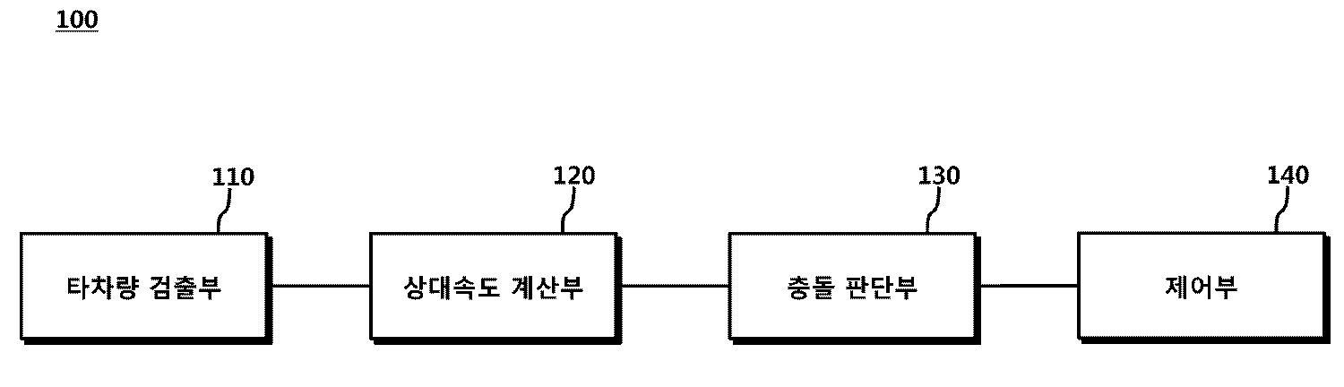
도 1은 본 발명의 일 실시 예에 따른 조향 토크 제어 장치의 구성을 도시한 도면이다.
도 2는 본 발명의 일 실시 예에 따른 상대속도 계산부의 동작을 설명하기 위한 예를 도시한 도면이다.
도 3은 본 발명의 또 다른 일 실시 예에 따른 충돌 판단부의 동작을 설명하기 위한 예를 도시한 도면이다.
도 4는 본 발명의 일 실시 예에 따른 제어부의 동작을 설명하기 위한 예를 도시한 도면이다.
도 5는 본 발명의 일 실시 예에 따른 조향 토크 제어 장치의 전체적인 동작을 설명하기 위한 도면이다.
도 6은 본 발명의 다른 일 실시 예에 따른 조향 토크 제어 장치의 전체적인 동작을 설명하기 위한 도면이다.
도 7은 본 발명의 또 다른 일 실시 예에 따른 조향 토크 제어 장치의 전체적인 동작을 설명하기 위한 도면이다.
도 8은 본 발명의 일 실시 예에 따른 조향 토크 제어 방법의 흐름도를 도시한 도면이다.1 is a diagram showing a configuration of a steering torque control apparatus according to an embodiment of the present invention.
2 is a diagram illustrating an example of operations of a relative speed calculation unit according to an embodiment of the present invention.
FIG. 3 is a diagram illustrating an exemplary operation of a conflict determination unit according to another embodiment of the present invention. Referring to FIG.
FIG. 4 is a diagram illustrating an exemplary operation of the controller according to an exemplary embodiment of the present invention. Referring to FIG.
5 is a diagram for explaining the overall operation of the steering torque control apparatus according to an embodiment of the present invention.
6 is a diagram for explaining the overall operation of the steering torque control apparatus according to another embodiment of the present invention.
7 is a diagram for explaining the overall operation of the steering torque control apparatus according to another embodiment of the present invention.
8 is a flowchart illustrating a steering torque control method according to an embodiment of the present invention.
이하, 본 발명의 일부 실시 예들을 예시적인 도면을 통해 상세하게 설명한다. 본 발명의 구성 요소를 설명하는 데 있어서, 제 1, 제 2, A, B, (a), (b) 등의 용어를 사용할 수 있다. 이러한 용어는 그 구성 요소를 다른 구성 요소와 구별하기 위한 것일 뿐, 그 용어에 의해 해당 구성 요소의 본질이나 차례 또는 순서 등이 한정되지 않는다. 어떤 구성 요소가 다른 구성요소에 "연결", "결합" 또는 "접속"된다고 기재된 경우, 그 구성 요소는 그 다른 구성요소에 직접적으로 연결되거나 또는 접속될 수 있지만, 각 구성 요소 사이에 또 다른 구성 요소가 "연결", "결합" 또는 "접속"될 수도 있다고 이해되어야 할 것이다.Hereinafter, some embodiments of the present invention will be described in detail with reference to exemplary drawings. In describing the components of the present invention, the terms first, second, A, B, (a), (b), and the like can be used. These terms are intended to distinguish the constituent elements from other constituent elements, and the terms do not limit the nature, order or order of the constituent elements. When a component is described as being "connected", "coupled", or "connected" to another component, the component may be directly connected to or connected to the other component, It should be understood that an element may be "connected," "coupled," or "connected."
도 1은 본 발명의 일 실시 예에 따른 조향 토크 제어 장치의 구성을 도시한 도면이다.1 is a diagram showing a configuration of a steering torque control apparatus according to an embodiment of the present invention.
본 발명의 일 실시 예에 따른 조향 토크 제어 장치는 자차량에 구비된 카메라, 레이더(radar) 또는 라이더(lidar)를 이용하여 사각지대의 타차량을 검출하는 타차량 검출부와 타차량의 상대속도를 계산하는 상대속도 계산부와 상대속도에 기초하여, 차선 변경시 충돌 가능성을 판단하는 충돌 판단부 및 충돌 가능성에 기초하여 충돌 가능성이 없는 것으로 판단되면, 조향장치의 어시스트량을 증가시키고, 충돌 가능성이 있는 것으로 판단되면, 조향장치의 어시스트량을 감소시키는 제어부를 포함할 수 있다.A steering torque control apparatus according to an embodiment of the present invention is a steering torque control apparatus that uses a camera, a radar or a lidar provided in a subject vehicle to calculate a relative speed of another vehicle detection unit and another vehicle, A collision determination unit for determining a possibility of collision at the time of lane change based on the relative speed calculation unit for calculating the relative speed and the relative speed and a control unit for increasing the assist amount of the steering apparatus based on the possibility of collision, The controller may include a controller for decreasing the assist amount of the steering apparatus.
도 1을 참조하면, 본 발명의 일 실시 예에 따른 조향 토크 제어 장치(100)는 자차량에 구비된 카메라, 레이더(radar) 또는 라이더(lidar)를 이용하여 사각지대의 타차량을 검출하는 타차량 검출부(110)을 포함할 수 있다.Referring to FIG. 1, a steering
차량에는 카메라, 레이더 및 라이더 장치를 이용하여 사각지대를 감지할 수 있다. 간략하게 설명하면, 카메라 장치를 이용한 사물 인식 방법은 카메라 장치를 이용하여 사물의 색상 정보를 측정하고, 측정한 색상 정보를 구별하여 인식한다. 레이더 장치를 이용한 사물 인식 방법은 파장이 짧은 마이크로파를 발사하고, 사물에 반사되어 돌아온 마이크로파를 이용하여 사물의 존재를 인식한다. 또한, 라이더를 이용한 사물 인식 방법은 전파에 가까운 성질을 가진 레이저광선을 발사하고, 사물에 반사되어 돌아온 레이저광선을 이용하여 사물의 존재를 인식한다.Vehicles can detect blind spots using cameras, radar and rider devices. Briefly, an object recognition method using a camera device measures color information of an object using a camera device, and discriminates and recognizes the measured color information. The object recognition method using a radar device emits a microwave having a short wavelength and recognizes the existence of an object by using a microwave reflected back from the object. In addition, the object recognizing method using a rider emits a laser beam having properties close to radio waves, and recognizes the existence of an object by using a laser beam reflected back from the object.
본 발명의 일 실시 예에 따른 조향 토크 제어 장치(100)는 타차량의 상대속도를 계산하는 상대속도 계산부(120)를 포함할 수 있다.The steering
자세하게 설명하면, 상대속도 계산부(120)는 카메라, 레이더 또는 라이더를 이용하여 시각별로 인식한 타차량과의 거리를 이용하여 상대속도를 계산할 수 있다. 자차량에 구비된 카메라, 레이더 또는 라이더를 이용하여 측정하였기 때문에, 측정된 거리는 상대적인 관계를 갖는다. 따라서, 상대속도를 계산하는 방법은 먼저 측정한 거리(D1)에서 일정 시간(dt)이 지난 후, 측정한 거리(D2)의 차이를 계산한 후, dt로 나눗셈을 함으로써 상대속도를 계산할 수 있다.In more detail, the relative
본 발명의 일 실시 예에 따른 조향 토크 제어 장치(100)는 상대속도에 기초하여 차선 변경시 충돌 가능성을 판단하는 충돌 판단부(130)를 포함할 수 있다.The steering
일 예로, 충돌 판단부(130)는 상대속도 계산부(120)에서 계산된 상대속도가 임계값 이하인 경우 충돌 가능성이 없는 것으로 판단하고, 계산된 상대속도가 임계값을 초과하는 경우 충돌 가능성이 있는 것으로 판단할 수 있다. 만약, 임계값이 0으로 설정되면, 상대속도가 0 이하인 경우 자차량과 타차량의 거리는 유지되거나 또는 증가될 수 있는데, 이는 자차량과 타차량이 충돌할 수 없는 것을 의미한다. 전술한 임계값은 실험에 의해 산출될 수 있다.For example, if the relative speed calculated by the
이와 달리, 상대속도가 0을 초과하는 경우 자차량과 타차량의 거리는 감소될 수 있는데 이는 자차량과 타차량이 충돌할 수 있음을 의미한다.In contrast, if the relative speed exceeds 0, the distance between the subject vehicle and the other vehicle may be reduced, which means that the subject vehicle and the other vehicle may collide with each other.
다른 일 예로, 거리 계산부가 타차량과 자차량과의 상대거리를 계산하고, 충돌 판단부(130)는 거리 계산부에서 계산한 상대거리와 상대속도 계산부(120)에서 계산된 상대속도를 이용하여 타차량과 충돌하는데 걸리는 충돌시간을 계산한다. 충돌시간은 상대거리를 상대속도로 나눗셈하여 계산할 수 있다. 충돌 판단부(130)는 계산된 충돌시간이 특정시간을 초과하는 경우 충돌 가능성이 없는 것으로 판단하고, 충돌시간이 특정시간 이하인 경우 충돌 가능성이 있는 것으로 판단할 수 있다. 전술한 특정시간은 실험에 의해 산출될 수 있다.The distance calculation unit calculates the relative distance between the other vehicle and the subject vehicle, and the
또 다른 일 예로, 거리 계산부가 타차량과 자차량과의 상대거리를 계산하고, 속도 측정부가 자차량의 속도를 측정한 후, 충돌 판단부(130)는 거리 계산부에서 계산한 상대거리와 상대속도 계산부(120)에서 계산된 상대속도를 이용하여 타차량과 충돌하는데 걸리는 충돌시간을 계산한다. 상기 충돌시간은 상대거리를 상대속도로 나눗셈하여 계산할 수 있다. 충돌 판단부(130)는 계산된 충돌시간이 특정시간을 초과하는 경우 충돌 가능성이 없는 것으로 판단한다. 충돌시간이 특정시간 이하인 경우 충돌 판단부(130)는 속도 측정부에서 측정한 자차량의 속도를 이용하여 차선변경시간을 추정하고, 추정된 차선변경시간이 계산된 충돌시간보다 미만인 경우 충돌 가능성이 없는 것으로 판단할 수 있다. 만약, 추정된 차선변경시간이 계산된 충돌시간 이상인 경우 충돌 가능성이 있는 것으로 판단할 수 있다.In another example, after the distance calculation unit calculates the relative distance between the other vehicle and the subject vehicle and the speed measurement unit measures the speed of the subject vehicle, the
본 발명의 일 실시 예에 따른 조향 토크 제어 장치(100)는 충돌 판단부(130)에서 충돌 가능성이 없는 것으로 판단되면 조향장치의 어시스트 전류량을 증가시키고, 충돌 판단부(130)에서 충돌 가능성이 있는 것으로 판단되면 조향장치의 어시스트 전류량을 감소시키는 제어부(140)를 포함할 수 있다.The steering
일 예로, 충돌 판단부(130)에서 충돌 가능성이 없는 것으로 판단되면, 제어부(140)는 조타 감지 센서의 출력값 또는 컨트롤러의 입력값을 증가시킴으로써, 조향장치의 어시스트 전류량을 증가시킬 수 있다. 만약, 충돌 판단부(130)에서 충돌 가능성이 있는 것으로 판단되면, 제어부(140)는 조타 감지 센서의 출력값 또는 컨트롤러의 입력값을 감소시킴으로써, 조향장치의 어시스트 전류량을 감소시킬 수 있다.For example, when the
다른 일 예로, 충돌 판단부(130)에서 충돌 가능성이 없는 것으로 판단되면, 제어부(140)는 조타 감지 센서의 입력값을 증가시킴으로써, 조향장치의 어시스트 전류량을 증가시킬 수 있다. 만약, 충돌 판단부(130)에서 충돌 가능성이 있는 것으로 판단되면, 제어부(140)는 조타 감지 센서의 입력값을 감소시킴으로써, 조향장치의 어시스트 전류량을 감소시킬 수 있다.Alternatively, if the
도 2는 본 발명의 일 실시 예에 따른 상대속도 계산부의 동작을 설명하기 위한 예를 도시한 도면이다.2 is a diagram illustrating an example of operations of a relative speed calculation unit according to an embodiment of the present invention.
도 2의 상황은, 자차량(210)과 사각지대에 있는 타차량(220)이 도로에 주행중인 상황이다. (A)는, 자차량(210a)과 사각지대에 있는 타차량(220a)이 230a의 거리차이(D1)를 가지고 있다. (A)에서 일정 시간(dt)이 지난 후인 (B)는, 자차량(210a)과 사각지대에 있는 타차량(220b)이 230b의 거리차이(D2)를 가지고 있다.2 is a situation in which the vehicle 210 and another vehicle 220 in a blind spot are traveling on the road. The vehicle A has a distance difference D1 between the
도 2를 참조하면, 수학식1과 같이, 상대속도 계산부는 D1에서 D2의 차이를 계산하고, dt로 나눗셈을 계산함으로써, 상대속도를 계산할 수 있다.Referring to FIG. 2, as shown in Equation (1), the relative speed calculator can calculate the relative speed by calculating the difference between D 1 and D 2 and calculating the division by dt.

이는, D1과 D2가 자차량에 구비된 장치에 의해 계산된 거리차이이므로 상대적인 관계에 있기 때문에 절대 속도가 아닌 상대속도이다.This is a relative speed, not an absolute speed, since D1 and D2 are relative distances because they are distance differences calculated by a device provided in the vehicle.
본 발명의 다른 일 실시 예에 따른 조향 토크 제어 장치는 타차량과 자차량과의 상대거리를 계산하는 거리 계산부를 더 포함하고, 충돌 판단부는, 계산된 상대거리와 상대속도 계산부에서 계산된 상대속도를 이용하여 타차량과 충돌하는데 걸리는 충돌시간을 계산한다. 계산된 충돌시간이 미리 설정한 특정시간을 초과하는 경우, 충돌 판단부는 충돌 가능성이 없는 것으로 판단하고 상기 충돌시간이 상기 특정시간 이하인 경우, 충돌 판단부는 충돌 가능성이 있는 것으로 판단할 수 있다.The steering torque control apparatus according to another embodiment of the present invention may further include a distance calculating section for calculating a relative distance between the other vehicle and the child vehicle, and the collision determining section may calculate the relative distance calculated by the relative distance calculating section Use the speed to calculate the impact time to collide with other vehicles. If the calculated collision time exceeds a preset specific time, the collision determination unit determines that there is no possibility of collision, and if the collision time is less than or equal to the specific time, the collision determination unit may determine that there is collision possibility.
타 차량과 충돌하는데 걸리는 충돌시간은 거리 계산부에서 계산된 상대거리를 상대속도 계산부에서 계산된 상대속도를 나눔으로써, 충돌시간을 계산할 수 있다. 특정시간은 실험 데이터에 의해 산출될 수 있는 값으로, 차량이 차선을 변경하는데 걸리는 평균시간과 실험 데이터의 분산을 적용하여 산출할 수 있다.The collision time required to collide with the other vehicle can be calculated by dividing the relative distance calculated by the distance calculation unit by the relative speed calculated by the relative speed calculation unit. The specific time is a value that can be calculated by the experimental data and can be calculated by applying the average time taken by the vehicle to change the lane and the variance of the experimental data.
즉, 충돌시간이 특정시간을 초과하는 경우, 자차량과 타차량은 특정시간 이후에 만날 수 있는 것으로, 충돌하기 전에 자차량은 차선변경을 완료할 수 있다.That is, when the collision time exceeds a specific time, the own vehicle and the other vehicle can meet after a specific time, and the vehicle can complete the lane change before the collision.
반면, 충돌시간이 특정시간 이하인 경우, 자차량과 타차량은 특정시간 이내에 만날 수 있는 것으로 자차량이 차선변경 중에 타차량과 충돌할 수 있다.On the other hand, when the collision time is less than a specific time, the host vehicle and the other vehicle may meet within a predetermined time, and the host vehicle may collide with another vehicle during lane change.
도 3은 본 발명의 또 다른 일 실시 예에 따른 충돌 판단부의 동작을 설명하기 위한 예를 도시한 도면이다.FIG. 3 is a diagram illustrating an exemplary operation of a conflict determination unit according to another embodiment of the present invention. Referring to FIG.
본 발명의 또 다른 일 실시 예에 따른 조향 토크 제어 장치는 타차량과 자차량과의 상대거리를 계산하는 거리 계산부 및 자차량의 속도를 측정하는 속도 측정부를 더 포함하고, 충돌 판단부는, 계산된 상대거리와 상대속도 계산부에서 계산된 상대속도를 이용하여 타차량과 충돌하는데 걸리는 충돌시간을 계산한다. 계산된 충돌시간이 미리 설정한 특정시간을 초과하는 경우, 충돌 판단부는 충돌 가능성이 없는 것으로 판단한다. 상기 충돌시간이 상기 특정시간 이하인 경우, 충돌 판단부는 속도 측정부에서 측정한 속도를 이용하여 차선변경시간을 추정한다. 추정한 차선변경시간이 계산된 충돌시간보다 미만인 경우, 충돌 판단부는 충돌 가능성이 없는 것으로 판단한다. 추정한 차선변경시간이 계산된 충돌시간보다 이상인 경우, 충돌 판단부는 충돌 가능성이 있는 것으로 판단한다.The steering torque control apparatus according to another embodiment of the present invention may further include a distance calculation section for calculating a relative distance between the other vehicle and the child vehicle and a velocity measurement section for measuring the velocity of the child vehicle, And calculates the collision time required to collide with the other vehicle using the relative speed calculated by the relative speed calculating unit. If the calculated collision time exceeds a preset specific time, the collision judging unit judges that there is no possibility of collision. If the collision time is less than the specific time, the collision determination unit estimates the lane change time using the velocity measured by the velocity measurement unit. If the estimated lane change time is less than the calculated collision time, the collision determination unit determines that there is no possibility of collision. If the estimated lane change time is greater than the calculated collision time, the collision determination unit determines that there is a possibility of collision.
도 3을 참조하면, 본 발명의 또 다른 일 실시 예에 따른 충돌 판단부는 타차량과 자차량과의 상대거리를 타차량의 상대속도 나눔으로써 충돌시간을 계산한다(S300). 충돌 판단부는 계산한 충돌시간과 특정시간을 비교한다(S310). 특정시간은 실험 데이터에 의해 산출될 수 있는 값으로, 차량이 차선을 변경하는데 걸리는 평균시간과 실험 데이터의 분산을 적용하여 산출할 수 있다.Referring to FIG. 3, the collision determination unit according to another embodiment of the present invention calculates the collision time by dividing the relative distance between the other vehicle and the subject vehicle by the relative speed of another vehicle (S300). The conflict determination unit compares the calculated collision time with a specific time (S310). The specific time is a value that can be calculated by the experimental data and can be calculated by applying the average time taken by the vehicle to change the lane and the variance of the experimental data.
S310 단계에서 충돌시간이 특정시간을 초과하는 경우, 충돌 판단부는 자차량이 차선을 변경할 때 충돌 가능성이 없는 것으로 판단할 수 있다(S320). 이는, 차선 변경시 계산된 충돌 시각 전에 자차량의 차선변경이 완료되는 것을 의미하는 것이기 때문에 충돌 가능성이 없는 것으로 판단될 수 있는 것이다.If the collision time exceeds a specific time in step S310, the collision determination unit may determine that there is no possibility of collision when the vehicle changes lanes (S320). This means that the lane change of the subject vehicle is completed before the collision time calculated at the time of lane change, so that it can be judged that there is no possibility of collision.
만약, S310 단계에서 충돌시간이 특정시간 이하인 경우, 충돌 판단부는 자차량의 속도를 이용하여 차선변경시간을 추정한다(S330). 차선변경시간을 추정하는 방법은, 차량이 차선변경을 하는 경우 이동거리에 대한 실험데이터의 평균값과 분산을 적용하여 차선변경시 이동거리를 추정하고, 추정한 이동거리를 자차량의 속도로 나눔으로써 차선변경시간을 추정할 수 있다. If the collision time is less than a specific time in step S310, the collision determination unit estimates the lane change time using the vehicle speed (S330). A method of estimating a lane change time is a method of estimating a lane change time by estimating a lane change distance by applying an average value and variance of experimental data on a lane change distance when the vehicle is changing lanes and dividing the estimated travel distance by the lane marker speed The lane change time can be estimated.
충돌 판단부는 차선변경시간과 S300단계에서 계산한 충돌시간을 비교한다(S340). 차선변경시간이 충돌시간보다 미만인 경우 충돌 판단부는 자차량이 차선을 변경할 때 충돌 가능성이 없는 것으로 판단한다(S320). 이는, 자차량이 차선 변경을 완료한 후 충돌이 예상되는 것을 의미하는 것이므로, 충돌 가능성이 없는 것으로 판단될 수 있는 것이다. S340단계에서 차선변경시간이 충돌시간 이상인 경우 충돌 판단부는 자차량이 차선을 변경할 때 충돌 가능성이 있는 것으로 판단한다(S350). 이는, 자차량이 차선 변경을 하는 도중 충돌이 예상되는 것을 의미하는 것이므로, 충돌 가능성이 있는 것으로 판단될 수 있는 것이다.The collision determination unit compares the lane change time with the collision time calculated in step S300 (S340). If the lane change time is less than the collision time, the collision determination unit determines that there is no possibility of collision when the vehicle changes lanes (S320). This means that a collision is expected after the lane vehicle completes the lane change, so it can be judged that there is no possibility of collision. If it is determined in step S340 that the lane change time is equal to or greater than the collision time, the collision determining unit determines that there is a possibility of collision when the vehicle changes lanes (S350). This means that a collision is expected during the lane change of the own vehicle, so it can be judged that there is a possibility of collision.
도 3의 또 다른 일 실시 예에 따른 충돌 판단부는 사각지대의 타차량과 충돌하는데 걸리는 시간과 미리 설정된 특정시간 및 자차량이 차선을 변경하는데 걸리는 시간을 비교한다(S310, S340). 차선 변경시간이 충돌하는데 걸리는 시간보다 짧으면, 충돌 판단부는 자차량의 충돌 가능성이 없는 것으로 판단하고(S320), 차선 변경시간이 충돌하는데 걸리는 시간과 같거나 더 많은 시간이 걸리면, 충돌 판단부는 자차량의 충돌 가능성이 있는 것으로 판단(S350)하는 단계를 도시하였다.3, the collision determination unit compares the time taken for collision with another vehicle in the blind spot to a preset specific time and a time required for the vehicle to change the lane (S310, S340). If the lane change time is shorter than the time required for the collision, the collision determination unit determines that there is no possibility of collision of the vehicle (S320). If the lane change time is longer than the collision time, It is determined that there is a possibility of collision of the vehicle (S350).
반면, 다른 일 실시 예에 따른 충돌 판단부는 사각지대의 타차량과 충돌하는데 걸리는 시간만을 미리 설정한 특정시간과 비교한다. 특정시간은 차량이 차선을 변경하는데 걸리는 시간에 대한 실험 데이터에 의해 산출될 수 있는 값으로, 실험 데이터의 평균과 분산값을 적용하여 산출될 수 있다. 다른 일 실시 예에 따른 충돌 판단부는 S330 및 S340의 단계를 수행하지 않고 차량의 충돌 가능성을 판단한다.On the other hand, the collision determination unit according to another embodiment compares only the time required for collision with the other vehicle in the blind zone to a preset specific time. The specific time can be calculated by applying the average and variance of the experimental data, which can be calculated by the experimental data on the time it takes for the vehicle to change lanes. The collision determination unit according to another embodiment determines the possibility of collision of the vehicle without performing the steps of S330 and S340.
이와 달리, 일 실시 예에 따른 충돌 판단부는 사각지대에 존재하는 타차량과 자차량의 상대속도만을 미리 설정한 임계값과 비교한다. 임계값은 사각지대의 타차량과 충돌없이 자차량이 차선을 변경하는데 요구되는 상대속도이며, 이 임계값은 실험 데이터에 의해 산출될 수 있다.Alternatively, the collision determination unit may compare only the relative speed between the vehicle and the vehicle existing in the blind zone with a preset threshold value. The threshold value is the relative speed required for the vehicle to change the lane without collision with the other vehicle in the blind spot, and this threshold value can be calculated by the experimental data.
일 실시 예에 따른 충돌 판단부는 S330 및 S340의 단계를 수행하지 않고, 충돌시간을 계산하는 S300 단계가 아닌 상대속도를 계산하는 단계와, 충돌시간을 특정시간과 비교하는 S310 단계가 아닌 계산된 상대속도와 임계값을 비교하는 단계를 수행한다.The collision determination unit according to the embodiment may calculate the relative speed instead of the step S300 in which the collision time is calculated without performing the steps of S330 and S340 and the step of comparing the collision time with the specific time, And performs a step of comparing the speed and the threshold value.
충돌시간을 계산하는 S300 단계는 상대속도를 계산하고, 계산된 상대속도와 상대거리를 이용하여 충돌시간을 계산하기 때문에, 상대속도를 계산하는 단계보다 계산 단계가 많게 된다. 많아진 계산에 의해 S300단계는 계산속도가 늦어질 수 있고, 계산에 있어 에러 가능성이 높아질 수 있다. 반면 산출된 임계값에 크게 의존하기 때문에, 충돌 판단부의 충돌 가능성 판단에 오류를 범할 수 있다.In the step S300 of calculating the collision time, since the relative velocity is calculated and the collision time is calculated using the calculated relative velocity and the relative distance, the calculation step is larger than the step of calculating the relative velocity. Due to the increased number of calculations, the calculation speed may be slowed down in step S300, and the probability of errors in calculation may increase. On the other hand, since it largely depends on the calculated threshold value, it is possible to make an error in determining the possibility of collision of the collision judgment unit.
예를 들어, 일 실시 예에 따른 충돌 판단부의 임계값이 0으로 설정되어 있는 상태에서 충돌 가능성을 판단한다. 이때, 충돌 판단부가 충돌 가능성이 없는 것으로 판단하면 차선을 변경하는 자차량은 타차량과 충돌하는 경우는 없다. 하지만, 충돌 판단부가 충돌 가능성이 있는 것으로 판단해도, 차선을 변경하는 자차량은 타차량과 충돌하지 않을 수 있다. 이는, 자차량과 타차량간의 거리와 자차량의 차선 변경시간을 고려하지 않았기 때문이다.For example, the possibility of collision is determined in a state where the threshold value of the collision determination unit according to the embodiment is set to zero. At this time, if the collision judging unit judges that there is no possibility of collision, the lane changing vehicle does not collide with the other lane. However, even if the collision judging unit judges that there is a possibility of collision, the lane changing vehicle may not collide with the other lane. This is because the distance between the subject vehicle and the other vehicle and the lane change time of the subject vehicle are not considered.
도 4는 본 발명의 일 실시 예에 따른 제어부의 동작을 설명하기 위한 예를 도시한 도면이다.FIG. 4 is a diagram illustrating an exemplary operation of the controller according to an exemplary embodiment of the present invention. Referring to FIG.
도 4는 운전자에 의해 조작되는 조타각과 전자식조향장치(EPS)의 모터와의 관계를 보여준다.4 shows the relationship between the steering angle operated by the driver and the motor of the electronic steering device (EPS).
도 4를 참조하면, 조타감지센서는 운전자에 의해 조작되는 조타각을 인식한다. 하지만 조타감지센서의 감지범위의 제한 또는 구조적인 이유에 의해, 조타감지센서는 조타각을 직접 받지 않고 게인(gain)값을 통과한 게인값을 받는다. 예를 들어, 조타감지센서가 -180도 내지 180도의 인식 범위를 갖는다면, 사용자가 조타각을 -200도로 조작하면 조타감지센서는 -180도로 인식하거나 또는 조타감지센서가 고장이 생길 수 있다. 사용자가 조타각을 200도로 조작하면 위와 같이 비슷하게 180도로 인식하거나 또는 조타감지센서가 고장이 생길 수 있다.Referring to FIG. 4, the steering sensor recognizes the steering angle operated by the driver. However, due to the limitation of the detection range of the steering sensor or the structural reason, the steering sensor receives the gain value passing the gain value without directly receiving the steering angle. For example, if the steering sensor has a recognition range of -180 degrees to 180 degrees, if the user manipulates the steering angle by -200 degrees, the steering sensor may recognize -180 degrees or the steering sensor may fail. If the user manipulates the steering angle by 200 degrees, it may be recognized that the steering angle is 180 degrees or the steering sensor may fail.
이와 같은 에러는 게인을 사용함으로 방지할 수 있다. 위와 동일한 조타감지센서가 -180도에서 180도의 인식 범위를 갖는 상황에서 게인값을 0.5로 설정하면, 조타감지센서는 -360도에서 360도의 조타각을 인식할 수 있다. 다만 이와 같은 경우, 조타감지센서의 출력값을 2배로 증폭시키거나 조타 감지 센서의 출력값을 인식한 컨트롤러의 입력값에 2배를 적용하여 제어에 적용할 수 있다.Such an error can be prevented by using a gain. If the same steering sensor as above has a recognition range of -180 degrees to 180 degrees, if the gain value is set to 0.5, the steering sensor can recognize the steering angle from -360 degrees to 360 degrees. However, in this case, the output value of the steering sensor can be doubled, or the input value of the controller that recognizes the output value of the steering sensor can be doubly applied to the control.
예를 들어, 사용자가 360도로 조타기를 조작하면 0.5게인에 의해 조타 감지 센서는 180도로 인식하게 된다. 따라서 조타 감지 센서의 출력값을 2배로 증폭하거나 또는 컨트롤러의 입력값을 2배 하면, 사용자가 조작한 360도를 인식할 수 있다.For example, when the user manipulates the steering wheel at 360 degrees, the steering sensor is recognized at 180 degrees by the gain of 0.5. Therefore, when the output value of the steering sensor is doubled or the input value of the controller is doubled, 360 degrees operated by the user can be recognized.
전술한 바를 적용하여 사용자가 조작한 조타각에 따른 조타감지센서 출력값을 이용하여 컨트롤러(MCU)에서 파워단을 조작하는 신호를 만든다. 결국 파워단은 컨트롤러에 해당되는 어시스트 전류를 만들어 내고, 이 어시스트 전류만큼 EPS 모터가 동작하여 사용자가 조타기를 쉽게 조작할 수 있게 한다. By applying the above-described method, a signal for operating the power stage at the controller (MCU) is generated by using the output value of the steering sensor according to the steering angle operated by the user. As a result, the power stage generates the assist current corresponding to the controller, and the EPS motor operates as much as the assist current so that the user can easily operate the steering wheel.
전술한 시스템에서, 게인값은 유지하되 조타 감지 센서의 출력값을 2배로 증폭시키거나, 컨트롤러의 입력값에 2배를 적용하면, 조향장치의 어시스트 전류량이 2배가 되어 차선변경을 빨리 수행할 수 있다. 이와 달리, 게인값은 유지하되 조타 감지 센서의 출력값을 0.5배로 증가시키거나, 컨트롤러의 입력값에 0.5배를 적용하면, 조향장치의 어시스트 전류량이 0.5배가 되어 차선변경을 느리게 수행할 수 있다.In the above-described system, if the gain value is maintained but the output value of the steering sensor is doubled or the input value of the controller is doubled, the amount of assist current of the steering apparatus is doubled, and the lane change can be performed quickly . Alternatively, if the gain value is maintained but the output value of the steering sensor is increased 0.5 times or 0.5 times the input value of the controller, the amount of assist current of the steering apparatus is 0.5 times, so that the lane change can be performed slowly.
따라서, 본 발명의 일 실시 예에 따른 충돌 판단부에서 충돌 가능성이 없다고 판단되면, 제어부가 조타 감지 센서의 출력값 또는 컨트롤러의 입력값을 증가시킴으로써, 조향장치의 어시스트전류량을 증가시킬 수 있다. 이와 달리, 충돌 판단부에서 충돌 가능성이 있다고 판단되면, 제어부가 상기 조타 감지 센서의 상기 출력값 또는 컨트롤러의 입력값을 감소시킴으로써, 상기 조향장치의 어시스트량을 감소시킬 수 있다.Therefore, if it is determined that there is no possibility of collision in the collision determination unit according to the embodiment of the present invention, the control unit may increase the assist amount of the steering apparatus by increasing the output value of the steering sensor or the input value of the controller. Alternatively, when it is determined that there is a possibility of collision in the collision determination unit, the control unit may reduce the assist amount of the steering apparatus by reducing the output value of the steering sensor or the input value of the controller.
전술한 시스템에서, 게인값을 2배로 하고, 조타 감지 센서의 출력값 및 컨트롤러의 입력값을 유지하면, 조향장치의 어시스트 전류량이 2배가 되어 차선변경을 빨리 수행할 수 있다. 이와 달리 게인값을 0.5배로 하고, 조타 감지 센서의 출력값 및 컨트롤러의 입력값을 유지하면, 조향장치의 어시스트 전류량이 0.5배가 되어 차선변경을 느리게 수행할 수 있다.In the above-described system, when the gain value is doubled, and the output value of the steering sensor and the input value of the controller are maintained, the amount of assist current of the steering apparatus is doubled, and the lane change can be performed quickly. In contrast, if the gain value is set to 0.5, and the output value of the steering sensor and the input value of the controller are maintained, the amount of assist current of the steering apparatus is increased to 0.5 and the lane change can be performed slowly.
따라서, 본 발명의 일 실시 예에 따른 충돌 판단부에서 충돌 가능성이 없다고 판단되면, 제어부가 조타 감지 센서의 입력값을 증가시킴으로써, 조향장치의 어시스트량을 증가시키고 충돌 가능성이 있다고 판단되면, 제어부가 조타 감지 센서의 입력값을 감소시킴으로써, 조향장치의 어시스트량을 감소시킬 수 있다.Therefore, if it is determined that there is no possibility of collision in the collision determination unit according to the embodiment of the present invention, the control unit increases the assist amount of the steering apparatus by increasing the input value of the steering sensor, By reducing the input value of the steering sensor, the assist amount of the steering apparatus can be reduced.
위의 설명에서, 게인값을 조절하면 조타 감지 센서의 입력값이 조절되기 때문에 조타 감지 센서의 입력값 조절과 게인값 조절은 효과적인 측면에서 동일하다고 할 수 있다.In the above description, since the input value of the steering sensor is controlled by adjusting the gain value, the input value control and the gain value control of the steering sensor can be said to be equivalent in terms of efficiency.
도 5는 본 발명의 일 실시 예에 따른 조향 토크 제어 장치의 전체적인 동작을 설명하기 위한 도면이다.5 is a diagram for explaining the overall operation of the steering torque control apparatus according to an embodiment of the present invention.
자차량에 구비된 카메라, 레이더(radar) 또는 라이더(lidar)를 이용하여 타차량 검출부가 사각지대의 타차량을 검출한다(S500). 카메라, 레이더(radar) 또는 라이더(lidar)를 운전자에게 보이지 않는 사각지대를 감지할 수 있도록 설치하여 사각지대에 존재하는 타차량을 포함하는 물체를 검출할 수 있다.The other vehicle detection unit detects another vehicle in the blind spot by using a camera, a radar or a lidar provided in the vehicle (S500). A camera, a radar or a lidar can be installed to detect a blind spot that is not visible to the driver, so that an object including a vehicle existing in a blind spot can be detected.
타차량 검출부에서 검출한 타차량을 포함하는 물체를 일정 시간간격으로 검출하여 타차량을 포함하는 물체와 자차량과의 상대속도를 계산한다(S510). 타차량 검출부에서 검출한 타차량이 자차량을 기준으로 D1의 거리에 위치하고, 일정 시간(dt)후에 타차량 검출부에서 검출한 타차량이 자차량을 기준으로 D2의 거리에 위치하는 경우 수학식 1을 적용하여 상대속도를 계산할 수 있다.The object including the other vehicle detected by the other vehicle detection unit is detected at a predetermined time interval, and the relative speed between the object including the other vehicle and the subject vehicle is calculated (S510). When the other vehicle detected by the other vehicle detection unit is located at a distance of D1 with respect to the subject vehicle and the other vehicle detected by the other vehicle detection unit is located at a distance of D2 with respect to the subject vehicle after a predetermined time (dt) Can be applied to calculate the relative speed.
계산된 상대속도와 미리 설정된 임계값을 비교하여 충돌 가능성을 판단한다(S520). 임계값은 실험 데이터에 의해 산출될 수 있는 값이다. 임계값이 0으로 산출되었다면, S520 단계에서 충돌가능성이 없다고 판단되면 자차량과 타차량은 충돌하는 경우는 없다.The calculated relative speed is compared with a preset threshold value to determine the possibility of collision (S520). The threshold value is a value that can be calculated by the experimental data. If the threshold value is calculated as 0, if it is determined in step S520 that there is no possibility of collision, the host vehicle and the other vehicle do not collide with each other.
하지만, S520 단계에서 충돌 가능성이 있다고 판단되면 상황에 따라서 자차량과 타차량이 충돌하지 않은 수 있다. 이는 자차량과 타차량과의 거리관계 및 상대속도에 의한 시간관계를 적용하지 않았기 때문에 생길 수 있다.However, if it is determined in step S520 that there is a possibility of collision, the vehicle may not collide with the other vehicle depending on the situation. This can happen because the distance relation between the vehicle and the other vehicle and the time relation due to the relative speed are not applied.
타차량과 자차량이 충돌하지 않지만, S520 단계에서 충돌 가능성이 있다고 판단하는 에러를 줄이기 위해서 임계값은 0이 아닌 음의 값으로 설정될 수 있다. 이는 데이터 분석에 의해 설정될 수 있다.The threshold value may be set to a negative value other than 0 in order to reduce the error that the other vehicle does not collide with the subject vehicle but it is determined that there is a possibility of collision in step S520. This can be set by data analysis.
S520 단계에서 충돌 가능성이 있는 것으로 판단되면, 제어부가 어시스트량을 감소시킨다(S530). 어시스트량을 감소시키는 방법은, 제어부가 조타 감지 센서의 출력값 또는 컨트롤러의 입력값을 감소시키는 것이 될 수 있다. 또는, 제어부가 조타 감지 센서의 입력값을 감소시키는 것이 될 수 있다. 어시스트량이 감소 됨으로써 자차량의 차선 변경을 느리게 할 수 있다.If it is determined in step S520 that there is a possibility of collision, the controller decreases the assist amount (S530). The method of reducing the amount of assist may be such that the control unit decreases the output value of the steering sensor or the input value of the controller. Alternatively, the control unit may reduce the input value of the steering sensor. The amount of assist can be reduced to slow the lane change of the own vehicle.
S520 단계에서 충돌 가능성이 없는 것으로 판단되면, 제어부가 어시스트량을 증가시킨다(S540). 어시스트량을 증가시키는 방법은, 제어부가 조타 감지 센서의 출력값 또는 컨트롤러의 입력값을 증가시키는 것이 될 수 있다. 또는, 제어부가 조타 감지 센서의 입력값을 증가시키는 것이 될 수 있다. 어시스트량이 증가됨으로써 자차량의 차선 변경을 빠르게 할 수 있다.If it is determined in step S520 that there is no possibility of collision, the controller increases the assist amount (S540). The method of increasing the assist amount may be such that the control unit increases the output value of the steering sensor or the input value of the controller. Alternatively, the control unit may increase the input value of the steering sensor. It is possible to increase the lane change of the host vehicle by increasing the assist amount.
도 6은 본 발명의 다른 일 실시 예에 따른 조향 토크 제어 장치의 전체적인 동작을 설명하기 위한 도면이다.6 is a diagram for explaining the overall operation of the steering torque control apparatus according to another embodiment of the present invention.
도 6을 참조하면, S600 단계와 S610 단계는 도 5의 S500 단계와 S510 단계와 동일한 동작을 수행한다. 상대거리 계산부가 S600 단계에서 검출된 타차량과 자차량과의 상대거리를 계산한다(S620). S600 단계에서 레이더를 사용한 경우, 상대거리 계산부는 발사한 마이크로파의 파장의 정보와 반사된 후 수신까지 걸린 시간을 이용하여 상대거리를 계산할 수 있다. S600 단계에서 라이더를 사용한 경우, 상대거리 계산부는 발사한 레이져 광선의 이동 정보와 반사된 후 수신까지 걸린 시간을 이용하여 상대거리를 계산할 수 있다. 이와 달리, S600 단계에서 카메라를 사용한 경우, 상대거리 계산부는 촬영한 영상을 이용하여 거리를 측정할 수 있다. 영상 내의 미리 거리를 알고 있는 지점을 기초하여 거리의 비례관계를 이용하여 상대거리 계산부는 거리를 알 수 있다. S610 단계에서 계산한 상대속도와 S620 단계에서 계산한 상대거리 정보를 취합하여 충돌 판단부는 자차량과 타차량이 충돌하는데 걸리는 충돌시간을 계산할 수 있다(S630). 충돌 판단부는 상대거리를 상대속도로 나눔으로써 충돌시간을 계산할 수 있다. S630단계에서 계산한 충돌시간과 미리 입력된 특정시간을 비교하여 충돌 판단부는 충돌 가능성을 판단한다(S640). 예를 들어, 미리 입력한 특정시간은 차량이 차선을 변경하는데 걸리는 시간 데이터를 기초하여 평균과 분산을 적용하여 산출될 수 있다. 자세히 설명하면, 5개의 시간 데이터인 A가 {10, 11, 9, 8, 12}인 경우 평균값은 10, 분산은 2이 된다. 또 다른 5개의 시간 데이터인 B가 {10, 8, 12, 14, 6}인 경우 평균값은 10, 분산은 8이 된다. A의 경우 특정시간은 11로 되고, B의 경우 특정시간은 14가 될 수 있다. 앞서 계산한 특정시간은 평균시간에 분산의 0.5배를 합하여 계산한 값이다. 특정시간을 산출하는 규칙은 연구에 의해 정해질 수 있다. 다만, 특정시간은 평균값과 분산에 각각 비례관계에 존재해야 한다.Referring to FIG. 6, steps S600 and S610 are the same as steps S500 and S510 of FIG. The relative distance calculation unit calculates the relative distance between the target vehicle and the target vehicle detected in step S600 (S620). In the case where the radar is used in step S600, the relative distance calculation unit can calculate the relative distance using the information of the wavelength of the emitted microwave and the time taken until the reflection is received. If the rider is used in step S600, the relative distance calculation unit may calculate the relative distance using the movement information of the emitted laser beam and the time taken until the reflection is received. On the other hand, when the camera is used in step S600, the relative distance calculation unit can measure the distance using the photographed image. The relative distance calculation unit can know the distance by using the proportional relation of distances based on the point in advance which is known in the image. The relative speed calculated in step S610 and the relative distance information calculated in step S620 are collected, and the collision determination unit may calculate the collision time required for collision between the vehicle and the other vehicle at step S630. The collision determination unit can calculate the collision time by dividing the relative distance by the relative speed. The collision determiner compares the collision time calculated in step S630 with the previously input specific time, and determines the possibility of collision (S640). For example, the specific time input in advance may be calculated by applying an average and variance based on time data that the vehicle takes to change lanes. More specifically, when A, which is five time data, is {10, 11, 9, 8, 12}, the average value is 10 and the variance is 2. If B, which is another five time data, is {10, 8, 12, 14, 6}, the average value is 10 and the variance is 8. In the case of A, the specific time is 11, and in case of B, the specific time can be 14. The specific time calculated above is calculated by adding 0.5 times the variance to the mean time. The rules for calculating a specific time can be determined by research. However, the specific time must be proportional to the mean value and variance, respectively.
S650 단계 및 S660 단계는 도 5의 S530 단계와 S540 단계와 동일하게 동작하여 제어부가 어시스트량을 감소시키거나 또는 증가시킬 수 있다.Steps S650 and S660 operate in the same manner as steps S530 and S540 of FIG. 5, so that the controller can reduce or increase the assist amount.
도 7은 본 발명의 또 다른 일 실시 예에 따른 조향 토크 제어 장치의 전체적인 동작을 설명하기 위한 도면이다.7 is a diagram for explaining the overall operation of the steering torque control apparatus according to another embodiment of the present invention.
도 7을 참조하면, 본 발명의 또 다른 일 실시 예에 따른 조향 토크 제어 장치의 S700 단계 내지 S740 단계 동작은 도 6의 S600 단계 내지 S640 단계와 동일하게 동작한다. 다만, S740 단계에서 충돌 가능성이 없는 것으로 판단되면, 속도 측정부가 자차량의 속도를 측정한다(S760). 자차량의 속도를 측정하는 방법은 자차량에 존재하는 속도 센서를 이용하여 측정하거나, 또는 자차량에 구비된 카메라, 레이더, 또는 라이더를 이용하여 일정 시간 간격으로 고정물체를 검출하고, 검출된 고정물체와의 관계와 일정 시간을 이용하여 속도를 측정할 수 있다. 간단히 설명하면, t0시각에 차량의 측방 카메라로 나무를 측정하여 차량과 나무와의 거리값(D0)을 얻고, dt시간이 지난 t1시각에 동일한 측방 카메라로 동일한 나무를 측정하여 차량과 나무와의 거리값(D1)을 얻는다. 속도 측정부가 D0-D1을 dt로 나누어 차량의 속도를 계산할 수 있다. 물론 D0와 D1은 차량 측면에 있는 나무와의 거리이기 때문에 속도 측정부는 D0거리선 및 D1거리선이 이루는 각도를 적용하여 계산해야 정확한 속도를 계산할 수 있을 것이다. S760 단계에서 계산한 자차량 속도와 추정된 차선변경거리를 이용하여 충돌 판단부가 차선변경시간을 추정한다(S770). 차선변경거리를 추정하는 방법은 차선 변경 시간에 대한 실험데이터에 의해 추정할 수 있다. 일 예로 전술한 특정시간을 산출하는 방법을 적용할 수 있다. S770 단계에서 추정된 차선변경시간과 충돌시간을 비교하여 충돌 가능성이 있는지 한번 더 판단한다(S780). 차선변경시간이 충돌시간보다 미만인 경우 충돌 가능성이 없는 것으로 판단하고, 차선변경시간이 충돌시간 이상인 경우 충돌 가능성이 있는 것으로 판단할 수 있다.Referring to FIG. 7, operation of steps S700 to S740 of the steering torque control apparatus according to another embodiment of the present invention operates in the same manner as steps S600 to S640 of FIG. However, if it is determined in step S740 that there is no possibility of collision, the speed measuring unit measures the speed of the subject vehicle (S760). The speed of the subject vehicle can be measured by using a speed sensor present in the vehicle or by detecting a fixed object at predetermined time intervals using a camera, a radar, or a rider provided in the subject vehicle, The speed can be measured using the relation with the object and the fixed time. Briefly, the distance between the vehicle and the tree (D0) is measured by a side camera of the vehicle at time t0, and the same tree is measured with the same lateral camera at time t1, The distance value D1 is obtained. The speed measuring unit D0-D1 can be divided by dt to calculate the vehicle speed. Of course, since D0 and D1 are distances from the tree on the side of the vehicle, the speed measuring unit can calculate the correct speed by calculating the angle formed by the D0 distance line and the D1 distance line. The collision judging unit estimates the lane change time using the vehicle speed calculated in step S760 and the estimated lane change distance (S770). The method of estimating the lane change distance can be estimated by the experimental data on the lane change time. For example, a method of calculating the specific time described above can be applied. In step S780, the lane change time estimated in step S770 is compared with the collision time to determine whether there is a possibility of collision. If the lane change time is less than the collision time, it is determined that there is no possibility of collision. If the lane change time is longer than the collision time, it can be determined that there is a possibility of collision.
S780 단계는 S740 단계에서 충돌 가능성이 없는 것으로 판단되어도 S740 단계에서 참조한 특정시간에 따라 충돌 가능성이 있을 수 있다. S780단계는 충돌 가능성이 있지만 S740 단계에서 충돌 가능성이 없는 것으로 판단되는 경우를 걸러내기 위한 단계일 수 있다.Even if it is determined in step S780 that there is no possibility of collision in step S740, there is a possibility of collision depending on the specific time referenced in step S740. The step S780 may be a step for filtering a case where there is a possibility of collision but it is determined that there is no possibility of collision in the step S740.
단 S740 단계에서 참조한 특정 시간에 따라 S760 내지 S780 단계가 S740 단계와 S750 단계 사이에서 수행될 수 있다.However, steps S760 to S780 may be performed between steps S740 and S750 according to the specific time referenced in step S740.
자세히 설명하면, {10, 11, 9, 8, 12}인 실험 데이터를 이용하여 특정시간을 11로 설정한 상태에서, S730 단계에서 충돌시간이 12으로 계산되었다면 S740 단계에서는 충돌 가능성이 없는 것으로 판단된다. 하지만, 자차량 속도가 낮아 차선변경시간이 13이 되면 차선 변경시 타차량과 충돌할 것이다. 즉, S760 내지 S780 단계는 S740 단계에서 NO로 판정되었을 때 수행되어야 한다.More specifically, if the specific time is set to 11 using the experimental data of {10, 11, 9, 8, 12}, if the collision time is calculated as 12 in step S730, do. However, when the lane change time is 13 due to the low vehicle speed, it will collide with other vehicles when the lane change occurs. That is, steps S760 to S780 should be performed when it is determined NO in step S740.
이와 달리, S730 단계에서 충돌 시간이 10으로 계산되었다면 S740 단계에서는 충돌 가능성이 있는 것으로 판단될 것이다. 하지만, 자차량 속도가 빨라 차선변경시간이 9가 되면 차선을 변경하는 자차량은 사각지대의 타차량과 충돌하지 않을 것이다. 즉, S760 내지 S780 단계는 S740 단계에서 YES로 판정되었을 때 수행되어야 할 것이다.On the other hand, if the collision time is calculated as 10 in step S730, it is determined that there is a possibility of collision in step S740. However, if the lane change time is 9 due to the speed of the vehicle, the lane changing vehicle will not collide with other vehicles in the blind spot. That is, steps S760 to S780 should be performed when it is determined YES in step S740.
본 발명의 일 실시 예에 따른 조향 토크 제어 장치는 운전자가 입력한 신호에 의해 타차량 검출부, 상대속도 계산부, 충돌 판단부 및 제어부의 동작을 켜거나 끌 수 있다.The steering torque control apparatus according to an embodiment of the present invention can turn on / off the operation of the other vehicle detection unit, the relative speed calculation unit, the collision determination unit, and the control unit by a signal input by the driver.
차선 변경을 하는 경우, 본 발명에 일 실시 예에 따른 조향 토크 제어 장치에 의해 차량의 운전자는 평소와 다른 조타감을 느낄 수 있다. 운전자에 따라서 전술한 다른 조타감은 불쾌감을 줄 수도 있을 것이다. 어떠한 상황에서도 동일한 조타감을 느끼고 싶은 운전자는 버튼 스위치를 이용하여 신호를 입력함으로써, 본 발명의 조향 토크 제어 장치를 끌 수 있다. 이와 달리, 평소와 다른 조타감을 느끼더라도 안전하게 차선 변경을 원하는 운전자는 버튼 스위치를 이용하여 신호를 입력하여 본 발명의 조향 토크 제어 장치를 켤 수 있다.When the lane change is made, the driver of the vehicle can feel the steering feeling different from usual by the steering torque control device according to the embodiment of the present invention. Depending on the driver, the other steering sensations described above may cause discomfort. A driver who wants to feel the same steering feel under any circumstances can turn off the steering torque control device of the present invention by inputting a signal using the button switch. Alternatively, a driver who wishes to safely change lanes even if he or she feels a different steering feeling can turn on the steering torque control device of the present invention by inputting a signal using a button switch.
이하에서는 도1 내지 도7을 이용하여 설명한 조향 토크 제어 장치가 수행하는 동작인 조향 토크 제어 방법에 대해서 간략하게 설명한다.Hereinafter, a steering torque control method, which is an operation performed by the steering torque control apparatus described with reference to Figs. 1 to 7, will be briefly described.
도 8은 본 발명의 일 실시 예에 따른 조향 토크 제어 방법의 흐름도를 도시한 도면이다.8 is a flowchart illustrating a steering torque control method according to an embodiment of the present invention.
본 발명의 일 실시 예에 따른 조향 토크 제어 방법은 자차량에 구비된 카메라, 레이더 또는 라이다를 이용하여 사각지대의 타차량을 검출하는 타차량 검출단계를 수행할 수 있다(S800).The method of controlling the steering torque according to an embodiment of the present invention may perform the step of detecting the other vehicle using the camera, the radar or the ladder provided in the vehicle (S800).
예를 들면, 타차량 검출단계에서 카메라를 이용하는 경우, 카메라가 촬영한 영상의 색상정보를 이용하여 타차량 검출할 수 있다. 카메라 장치가 촬영한 영상에 검정색과 빨강색이 있다면, 카메라 장치는 빨강색이 차량으로 검출할 수 있다. 이는 간단한 예시일 뿐이며, 차량 검출의 정확성을 높이기 위해서 추가적인 색상 정보를 이용할 수 있다.For example, when the camera is used in the other vehicle detection step, the other vehicle can be detected using the color information of the image captured by the camera. If the image taken by the camera device has black and red colors, the camera device can detect the red color as the vehicle. This is only a simple example, and additional color information can be used to enhance the accuracy of vehicle detection.
타차량 검출 단계에서 레이더를 이용하는 경우, 파장이 3[m/wave] 주기가 2[s/wave]인 빔을 발사하였고 6초 후에 발사한 빔을 받았다면 4.5m 거리에 타차량이 있음을 검출할 수 있다. 이는 간단한 예시일 뿐이며, 차량 검출의 정확성을 높이기 위해서 많은 수의 받은 빔의 정보를 이용할 수 있다. 라이더를 이용하는 경우, 레이더를 이용한 경우와 비슷하게 검출할 수 있다. 다만, 라이더는 마이크로파가 아닌 레이져광선을 사용하기 때문에 파장 및 주기에 따른 차이가 존재할 뿐이다.When the radar is used in the other vehicle detection step, the beam with a wavelength of 3 [m / wave] of 2 [s / wave] is fired. If the fired beam is received after 6 seconds, it is detected that there is another vehicle at a distance of 4.5 m can do. This is only a simple example, and a large number of received beam information can be used to improve the accuracy of vehicle detection. When a rider is used, it can be detected similarly to the case where a radar is used. However, since the rider uses the laser beam, not the microwave, there is a difference according to the wavelength and the cycle.
본 발명의 일 실시 예에 따른 조향 토크 제어 방법은 타차량의 상대속도를 계산하는 상대속도 계산단계를 수행할 수 있다(S810).The steering torque control method according to an embodiment of the present invention may perform a relative speed calculation step of calculating the relative speed of another vehicle (S810).
예를 들면, 타차량 검출 단계에서 카메라를 사용한 경우, t0시각에서 빨강색의 차량이 자차량기준으로 후방 3m 거리에 위치하는 것으로 검출되었고, 1초의 시간이 지난 t1시각에 동일한 빨강색의 차량이 자차량 기준으로 후방 1m 거리에 위치하는 것으로 검출되었다면, 수학식 1을 적용하면 타차량의 상대속도는 2[m/s]으로 계산할 수 있다.For example, if a camera is used at the detection stage of another vehicle, it is detected that the red vehicle is located at a distance of 3 meters behind the vehicle at time t0, and the same red vehicle is detected at time t1 after 1 second If it is detected that the vehicle 1 is located at a distance of 1 m behind, the relative speed of the other vehicle can be calculated as 2 [m / s] by using Equation (1).
카메라 장치를 사용하여 거리를 측정하는 방법은 미리 거리값을 알고 있는 영상의 한 점과의 위치 관계를 이용하면 거리를 측정할 수 있다.As a method of measuring the distance by using the camera device, the distance can be measured by using the positional relation with a point of the image which knows the distance value in advance.
타차량 검출 단계에서 레이더 또는 라이더를 사용한 경우, 카메라를 이용하여 상대속도를 계산하는 계산단계와 동일한 방법으로 상대속도를 계산할 수 있다.When a radar or a rider is used in the other vehicle detection step, the relative speed can be calculated in the same manner as the calculation step of calculating the relative speed using the camera.
본 발명의 일 실시 예에 따른 조향 토크 제어 방법은 S810 단계에서 계산한 상대속도에 기초하여, 차선 변경시 충돌 가능성을 판단하는 충돌 판단단계를 수행할 수 있다(S820). 계산한 상대속도와 미리 설정한 임계값을 비교하여 상대속도가 임계값 이하인 경우, 충돌 판단단계는 충돌 가능성이 없는 것으로 판단한다. 만약 상대속도가 임계값을 초과하는 경우, 충돌 판단단계는 충돌 가능성이 있는 것으로 판단한다. 임계값이 0으로 미리 설정되었다면, 상대속도가 0이하인 경우 타차량과 자차량은 충돌할 수가 없다. 또한 상대속도가 0을 초과하는 경우 타차량과 자차량은 충돌할 수 있다.The steering torque control method according to an embodiment of the present invention may perform a collision determination step of determining a possibility of collision upon lane change based on the relative speed calculated in step S810 (S820). When the calculated relative speed is compared with a predetermined threshold value and the relative speed is equal to or less than the threshold value, the collision determination step determines that there is no possibility of collision. If the relative speed exceeds the threshold value, the collision determination step determines that there is a possibility of collision. If the threshold value is preset to 0, if the relative speed is less than 0, the other vehicle and the subject vehicle can not collide. Also, if the relative speed exceeds 0, the other vehicle and the vehicle may collide with each other.
본 발명의 일 실시 예에 따른 조향 토크 제어 방법은 충돌 가능성에 기초하여 충돌 가능성이 없는 것으로 판단되면, 조향장치의 어시스트량을 증가시키고, 충돌 가능성이 있는 것으로 판단되면, 조향장치의 어시스트량을 감소시키는 제어단계를 수행할 수 있다.The steering torque control method according to an embodiment of the present invention increases the assist amount of the steering apparatus when it is determined that there is no possibility of collision based on the possibility of collision, and decreases the assist amount of the steering apparatus A control step of performing a control operation for performing a control operation.
S820 단계에서 충돌 가능성이 없다고 판단되면, 제어단계(S830)에서 조향장치의 어시스트량을 증가시켜 자차량의 차선변경을 빠르게 할 수 있다. 이와 달리 S820 단계에서 충돌 가능성이 있다고 판단되면, 제어단계(S830)에서 조향장치의 어시스트량을 감소시켜 자차량의 차선변경을 느리게 할 수 있다.If it is determined in step S820 that there is no possibility of collision, it is possible to increase the assist amount of the steering apparatus in the control step S830 to speed up the lane change of the vehicle. Alternatively, if it is determined in step S820 that there is a possibility of a collision, the assist amount of the steering apparatus may be decreased in step S830 to slow down the lane change of the vehicle.
제어단계(S830)에서 어시스트량을 증가시키는 구체적인 방법은, 조타 감지 센서의 상기 출력값 또는 컨트롤러의 입력값을 증가시키는 것이다. 또는 조타 감지 센서의 입력값을 증가시켜 어시스트량을 증가시킬 수 있다. 이와 달리 제어단계에서 조타 감지 센서의 상기 출력값 또는 컨트롤러의 입력값을 감소시키거나 또는 조타 감지 센서의 입력값을 감소시키면 어시스트량을 감소시킬 수 있다.A specific method of increasing the assist amount in the control step S830 is to increase the output value of the steering sensor or the input value of the controller. Or the amount of assist can be increased by increasing the input value of the steering sensor. Alternatively, when the output value of the steering sensor or the input value of the controller is decreased or the input value of the steering sensor is decreased in the control step, the amount of assist can be reduced.
이 외에도 본 발명의 조향 토크 제어 방법은 도 1 내지 도 7에 기초하여 설명한 본 발명의 조향 토크 제어 장치가 수행하는 각 동작을 모두 수행할 수 있다.In addition, the steering torque control method of the present invention can perform all the operations performed by the steering torque control apparatus of the present invention described with reference to Figs. 1 to 7.
이상에서, 본 발명의 실시 예를 구성하는 모든 구성 요소들이 하나로 결합되거나 결합되어 동작하는 것으로 설명되었다고 해서, 본 발명이 반드시 이러한 실시예에 한정되는 것은 아니다. 즉, 본 발명의 목적 범위 안에서라면, 그 모든 구성 요소들이 하나 이상으로 선택적으로 결합하여 동작할 수도 있다. 이상의 설명은 본 발명의 기술 사상을 예시적으로 설명한 것에 불과한 것으로서, 본 발명이 속하는 기술 분야에서 통상의 지식을 가진 자라면 본 발명의 본질적인 특성에서 벗어나지 않는 범위에서 다양한 수정 및 변형이 가능할 것이다. 본 발명의 보호 범위는 아래의 청구범위에 의하여 해석되어야 하며, 그와 동등한 범위 내에 있는 모든 기술 사상은 본 발명의 권리범위에 포함되는 것으로 해석되어야 할 것이다.While the present invention has been described in connection with what is presently considered to be the most practical and preferred embodiments, it is to be understood that the invention is not limited to the disclosed embodiments. That is, within the scope of the present invention, all of the components may be selectively coupled to one or more of them. The foregoing description is merely illustrative of the technical idea of the present invention, and various changes and modifications may be made by those skilled in the art without departing from the essential characteristics of the present invention. The scope of protection of the present invention should be construed according to the following claims, and all technical ideas within the scope of equivalents should be construed as falling within the scope of the present invention.
Claims (9)
상기 타차량의 상대속도를 계산하는 상대속도 계산부;
상기 상대속도에 기초하여, 차선 변경시 충돌 가능성을 판단하는 충돌 판단부; 및
상기 충돌 가능성에 기초하여 충돌 가능성이 없는 것으로 판단되면, 조향장치의 어시스트량을 증가시키고,
상기 충돌 가능성이 있는 것으로 판단되면, 상기 조향장치의 어시스트량을 감소시키는 제어부를 포함하는 조향 토크 제어 장치.A vehicle detection unit detecting a vehicle in a blind spot by using a camera, a radar or a lidar provided in the vehicle;
A relative speed calculation unit for calculating a relative speed of the other vehicle;
A collision determination unit for determining a collision possibility at the time of lane change based on the relative speed; And
If it is determined that there is no possibility of collision based on the possibility of collision, the assist amount of the steering apparatus is increased,
And a controller for decreasing an assist amount of the steering apparatus if it is determined that there is a possibility of the collision.
운전자가 입력한 신호에 의해 상기 타차량 검출부, 상기 상대속도 계산부, 상기 충돌 판단부 및 상기 제어부를 켜거나 끄는 것을 특징으로 하는 조향 토크 제어 장치.The method according to claim 1,
And the on-vehicle detecting unit, the relative speed calculating unit, the collision determining unit, and the control unit are turned on or off according to a signal inputted by the driver.
상기 충돌 판단부는,
상기 상대속도가 미리 설정한 임계값 이하인 경우, 충돌 가능성이 없는 것으로 판단하고 상기 상대속도가 상기 임계값을 초과하는 경우, 충돌 가능성이 있는 것으로 판단하는 것을 특징으로 하는 조향 토크 제어 장치.The method according to claim 1,
The collision determination unit may determine,
Determines that there is no possibility of collision when the relative speed is equal to or less than a preset threshold value, and determines that there is a possibility of collision if the relative speed exceeds the threshold value.
상기 타차량과 자차량과의 상대거리를 계산하는 거리 계산부를 더 포함하고,
상기 충돌 판단부는,
상기 상대거리와 상기 상대속도를 이용하여 상기 타차량과 충돌하는데 걸리는 충돌시간을 계산하고,
상기 충돌시간이 미리 설정한 특정시간을 초과하는 경우 충돌 가능성이 없는 것으로 판단하고 상기 충돌시간이 상기 특정시간 이하인 경우 충돌 가능성이 있는 것으로 판단하는 것을 특징으로 하는 조향 토크 제어 장치.The method according to claim 1,
Further comprising a distance calculation unit for calculating a relative distance between the other vehicle and the child vehicle,
The collision determination unit may determine,
Calculating a collision time required to collide with the other vehicle using the relative distance and the relative speed,
Determines that there is no possibility of collision if the collision time exceeds a preset specific time, and determines that there is a possibility of collision if the collision time is less than or equal to the specific time.
상기 자차량의 속도를 측정하는 속도 측정부를 더 포함하고,
상기 충돌 판단부는,
상기 충돌시간이 상기 특정시간 이하인 경우,
상기 속도를 이용하여 차선변경시간을 추정하고,
상기 차선변경시간이 상기 충돌시간보다 미만인 경우 충돌 가능성이 없는 것으로 판단하고 상기 차선변경시간이 상기 충돌시간 이상인 경우 충돌 가능성이 있는 것으로 판단하는 것을 특징으로 하는 조향 토크 제어 장치.5. The method of claim 4,
Further comprising a speed measuring section for measuring the speed of the subject vehicle,
The collision determination unit may determine,
If the collision time is less than or equal to the predetermined time,
Estimates the lane change time using the speed,
And determines that there is no possibility of collision if the lane change time is less than the collision time, and determines that there is a possibility of collision if the lane change time is longer than the collision time.
상기 제어부는,
상기 충돌 가능성이 없다고 판단되면, 조타 감지 센서의 출력값 또는 컨트롤러의 입력값을 증가시킴으로써, 상기 조향장치의 어시스트량을 증가시키고
상기 충돌 가능성이 있다고 판단되면, 상기 조타 감지 센서의 상기 출력값 또는 컨트롤러의 입력값을 감소시킴으로써, 상기 조향장치의 어시스트량을 감소시키는 것을 특징으로 하는 조향 토크 제어 장치.The method according to claim 1,
Wherein,
If it is determined that there is no possibility of the collision, the assist amount of the steering apparatus is increased by increasing the output value of the steering sensor or the input value of the controller
Wherein the control unit decreases the assist amount of the steering apparatus by decreasing the output value of the steering sensor or the input value of the controller when it is determined that there is a possibility of the collision.
상기 제어부는,
상기 충돌 가능성이 없다고 판단되면, 조타 감지 센서의 입력값을 증가시킴으로써, 상기 조향장치의 어시스트량을 증가시키고
상기 충돌 가능성이 있다고 판단되면, 상기 조타 감지 센서의 상기 입력값을 감소시킴으로써, 상기 조향장치의 어시스트량을 감소시키는 것을 특징으로 하는 조향 토크 제어 장치.The method according to claim 1,
Wherein,
If it is determined that there is no possibility of collision, the amount of assist of the steering apparatus is increased by increasing the input value of the steering sensor
Wherein the control unit decreases the assist amount of the steering apparatus by decreasing the input value of the steering sensor when it is determined that there is a possibility of the collision.
상기 조타 감지 센서는,
조향각 센서 또는 토크 센서인 것을 특징으로 하는 조향 토크 제어 장치.7. The method according to claim 6 or 7,
The steering sensor comprises:
Wherein the steering angle sensor is a steering angle sensor or a torque sensor.
상기 타차량의 상대속도를 계산하는 상대속도 계산단계;
상기 상대속도에 기초하여, 차선 변경시 충돌 가능성을 판단하는 충돌 판단단계; 및
상기 충돌 가능성에 기초하여 충돌 가능성이 없는 것으로 판단되면, 조향장치의 어시스트량을 증가시키고,
상기 충돌 가능성이 있는 것으로 판단되면, 조향장치의 어시스트량을 감소시키는 제어단계를 포함하는 조향 토크 제어 방법.A vehicle detecting step of detecting another vehicle in a blind spot by using a camera, a radar or a lidar provided in the vehicle;
A relative speed calculation step of calculating a relative speed of the other vehicle;
A collision determination step of determining, based on the relative speed, a possibility of collision at the time of lane change; And
If it is determined that there is no possibility of collision based on the possibility of collision, the assist amount of the steering apparatus is increased,
And decreasing an assist amount of the steering device if it is determined that there is a possibility of the collision.
Priority Applications (1)
| Application Number | Priority Date | Filing Date | Title |
|---|---|---|---|
| KR1020150017094A KR102246682B1 (en) | 2015-02-04 | 2015-02-04 | Apparatuses and Methods for steering torque |
Applications Claiming Priority (1)
| Application Number | Priority Date | Filing Date | Title |
|---|---|---|---|
| KR1020150017094A KR102246682B1 (en) | 2015-02-04 | 2015-02-04 | Apparatuses and Methods for steering torque |
Publications (2)
| Publication Number | Publication Date |
|---|---|
| KR20160095747A true KR20160095747A (en) | 2016-08-12 |
| KR102246682B1 KR102246682B1 (en) | 2021-04-30 |
Family
ID=56714714
Family Applications (1)
| Application Number | Title | Priority Date | Filing Date |
|---|---|---|---|
| KR1020150017094A Active KR102246682B1 (en) | 2015-02-04 | 2015-02-04 | Apparatuses and Methods for steering torque |
Country Status (1)
| Country | Link |
|---|---|
| KR (1) | KR102246682B1 (en) |
Citations (10)
| Publication number | Priority date | Publication date | Assignee | Title |
|---|---|---|---|---|
| JPH082434A (en) * | 1994-06-23 | 1996-01-09 | Koyo Seiko Co Ltd | Vehicle steering system |
| KR20060035880A (en) * | 2004-10-21 | 2006-04-27 | 주식회사 만도 | Vehicle collision prevention method in electric power steering system |
| KR20060035881A (en) * | 2004-10-21 | 2006-04-27 | 주식회사 만도 | Vehicle anti-collision system |
| JP2009078735A (en) * | 2007-09-27 | 2009-04-16 | Hitachi Ltd | Driving support device |
| KR20120045596A (en) * | 2010-10-29 | 2012-05-09 | 현대모비스 주식회사 | Dead side area vehicle collapse preventing device and safety method thereof |
| KR20120078783A (en) * | 2011-01-03 | 2012-07-11 | 주식회사 만도 | Vehicle cruise control system and method for controlling the same |
| WO2012160590A1 (en) * | 2011-05-20 | 2012-11-29 | 本田技研工業株式会社 | Lane change assistant information visualization system |
| KR20130021789A (en) * | 2011-08-24 | 2013-03-06 | 주식회사 만도 | Adaptive cruise control apparatus and control method for the same |
| KR20140060107A (en) * | 2012-11-09 | 2014-05-19 | 현대모비스 주식회사 | Control method for collision avoidance of vehicle and apparatus for collision avoidance of vehicle implementing the same |
| KR20140066037A (en) * | 2012-11-22 | 2014-05-30 | 현대자동차주식회사 | Apparatus for escaping collision of vehicle and method thereof |
-
2015
- 2015-02-04 KR KR1020150017094A patent/KR102246682B1/en active Active
Patent Citations (10)
| Publication number | Priority date | Publication date | Assignee | Title |
|---|---|---|---|---|
| JPH082434A (en) * | 1994-06-23 | 1996-01-09 | Koyo Seiko Co Ltd | Vehicle steering system |
| KR20060035880A (en) * | 2004-10-21 | 2006-04-27 | 주식회사 만도 | Vehicle collision prevention method in electric power steering system |
| KR20060035881A (en) * | 2004-10-21 | 2006-04-27 | 주식회사 만도 | Vehicle anti-collision system |
| JP2009078735A (en) * | 2007-09-27 | 2009-04-16 | Hitachi Ltd | Driving support device |
| KR20120045596A (en) * | 2010-10-29 | 2012-05-09 | 현대모비스 주식회사 | Dead side area vehicle collapse preventing device and safety method thereof |
| KR20120078783A (en) * | 2011-01-03 | 2012-07-11 | 주식회사 만도 | Vehicle cruise control system and method for controlling the same |
| WO2012160590A1 (en) * | 2011-05-20 | 2012-11-29 | 本田技研工業株式会社 | Lane change assistant information visualization system |
| KR20130021789A (en) * | 2011-08-24 | 2013-03-06 | 주식회사 만도 | Adaptive cruise control apparatus and control method for the same |
| KR20140060107A (en) * | 2012-11-09 | 2014-05-19 | 현대모비스 주식회사 | Control method for collision avoidance of vehicle and apparatus for collision avoidance of vehicle implementing the same |
| KR20140066037A (en) * | 2012-11-22 | 2014-05-30 | 현대자동차주식회사 | Apparatus for escaping collision of vehicle and method thereof |
Also Published As
| Publication number | Publication date |
|---|---|
| KR102246682B1 (en) | 2021-04-30 |
Similar Documents
| Publication | Publication Date | Title |
|---|---|---|
| US9457809B2 (en) | Collision possibility determination apparatus, drive assist apparatus, collision possibility determination method, and collision possibility determination program | |
| JP6246465B2 (en) | Road shoulder recognition method and system | |
| KR102005253B1 (en) | Lane assistance system responsive to extremely fast approaching vehicles | |
| JP6256531B2 (en) | Object recognition processing device, object recognition processing method, and automatic driving system | |
| CN102696060B (en) | Object detection device and object detection method | |
| US9142132B2 (en) | Collision avoidance system and method for vehicles | |
| KR20200102004A (en) | Apparatus, system and method for preventing collision | |
| KR102352931B1 (en) | Safety apparatus and safety method for risk of collision | |
| RU2720501C1 (en) | Method for determining interference, method of parking assistance, method of departure assistance and device for determining interference | |
| KR20170109806A (en) | Apparatus for avoiding side crash in vehicle and method thereof | |
| KR20180007412A (en) | Multi sensor based obstacle detection apparatus and method | |
| JP6037350B2 (en) | Inter-vehicle distance adjustment support device | |
| US11667295B2 (en) | Apparatus and method for recognizing object | |
| KR20170085752A (en) | Apparatus and method for traffic lane recognition in automatic steering control of vehilcles | |
| KR102709976B1 (en) | Method for verifying the validity of lateral movement and its device | |
| CN106032135A (en) | Method of displaying rear side obstacle and apparatus of vehicle | |
| JP5049853B2 (en) | Vehicle object detection device | |
| JP6193177B2 (en) | Motion support system and object recognition device | |
| KR20230111782A (en) | Vehicle for autonomous driving and method thereof | |
| KR102342070B1 (en) | Verification apparatus and method for autonomous emergency braking system using single lens camera | |
| KR20170087368A (en) | Blind spot detection method and blind spot detection device | |
| KR102246682B1 (en) | Apparatuses and Methods for steering torque | |
| US20230182722A1 (en) | Collision avoidance method and apparatus | |
| KR20210030524A (en) | Apparatus and Method for controlling a host vehicle | |
| KR20230107995A (en) | Method And Apparatus for Controlling Vehicle |
Legal Events
| Date | Code | Title | Description |
|---|---|---|---|
| PA0109 | Patent application |
St.27 status event code: A-0-1-A10-A12-nap-PA0109 |
|
| PG1501 | Laying open of application |
St.27 status event code: A-1-1-Q10-Q12-nap-PG1501 |
|
| R17-X000 | Change to representative recorded |
St.27 status event code: A-3-3-R10-R17-oth-X000 |
|
| P22-X000 | Classification modified |
St.27 status event code: A-2-2-P10-P22-nap-X000 |
|
| PA0201 | Request for examination |
St.27 status event code: A-1-2-D10-D11-exm-PA0201 |
|
| PN2301 | Change of applicant |
St.27 status event code: A-3-3-R10-R13-asn-PN2301 St.27 status event code: A-3-3-R10-R11-asn-PN2301 |
|
| E902 | Notification of reason for refusal | ||
| PE0902 | Notice of grounds for rejection |
St.27 status event code: A-1-2-D10-D21-exm-PE0902 |
|
| P11-X000 | Amendment of application requested |
St.27 status event code: A-2-2-P10-P11-nap-X000 |
|
| P13-X000 | Application amended |
St.27 status event code: A-2-2-P10-P13-nap-X000 |
|
| E701 | Decision to grant or registration of patent right | ||
| PE0701 | Decision of registration |
St.27 status event code: A-1-2-D10-D22-exm-PE0701 |
|
| GRNT | Written decision to grant | ||
| PR0701 | Registration of establishment |
St.27 status event code: A-2-4-F10-F11-exm-PR0701 |
|
| PR1002 | Payment of registration fee |
St.27 status event code: A-2-2-U10-U11-oth-PR1002 Fee payment year number: 1 |
|
| PG1601 | Publication of registration |
St.27 status event code: A-4-4-Q10-Q13-nap-PG1601 |
|
| PN2301 | Change of applicant |
St.27 status event code: A-5-5-R10-R13-asn-PN2301 St.27 status event code: A-5-5-R10-R11-asn-PN2301 |
|
| PN2301 | Change of applicant |
St.27 status event code: A-5-5-R10-R11-asn-PN2301 |
|
| PN2301 | Change of applicant |
St.27 status event code: A-5-5-R10-R14-asn-PN2301 |
|
| PN2301 | Change of applicant |
St.27 status event code: A-5-5-R10-R11-asn-PN2301 |
|
| PN2301 | Change of applicant |
St.27 status event code: A-5-5-R10-R14-asn-PN2301 |
|
| PN2301 | Change of applicant |
St.27 status event code: A-5-5-R10-R13-asn-PN2301 St.27 status event code: A-5-5-R10-R11-asn-PN2301 |
|
| PR1001 | Payment of annual fee |
St.27 status event code: A-4-4-U10-U11-oth-PR1001 Fee payment year number: 4 |
|
| R18 | Changes to party contact information recorded |
Free format text: ST27 STATUS EVENT CODE: A-5-5-R10-R18-OTH-X000 (AS PROVIDED BY THE NATIONAL OFFICE) |
|
| R18-X000 | Changes to party contact information recorded |
St.27 status event code: A-5-5-R10-R18-oth-X000 |