KR20160074492A - Closure cap for mounting on a liquid container - Google Patents
Closure cap for mounting on a liquid container Download PDFInfo
- Publication number
- KR20160074492A KR20160074492A KR1020167010075A KR20167010075A KR20160074492A KR 20160074492 A KR20160074492 A KR 20160074492A KR 1020167010075 A KR1020167010075 A KR 1020167010075A KR 20167010075 A KR20167010075 A KR 20167010075A KR 20160074492 A KR20160074492 A KR 20160074492A
- Authority
- KR
- South Korea
- Prior art keywords
- sealing cap
- carrier
- receiving member
- liquid
- receiving
- Prior art date
- Legal status (The legal status is an assumption and is not a legal conclusion. Google has not performed a legal analysis and makes no representation as to the accuracy of the status listed.)
- Withdrawn
Links
- 239000007788 liquid Substances 0.000 title claims abstract description 89
- 238000007789 sealing Methods 0.000 claims abstract description 159
- 235000015872 dietary supplement Nutrition 0.000 claims description 30
- 235000013361 beverage Nutrition 0.000 claims description 20
- 239000000463 material Substances 0.000 claims description 19
- 239000003814 drug Substances 0.000 claims description 13
- 239000000126 substance Substances 0.000 claims description 13
- 239000006188 syrup Substances 0.000 claims description 11
- 235000020357 syrup Nutrition 0.000 claims description 11
- 239000003205 fragrance Substances 0.000 claims description 7
- 239000004744 fabric Substances 0.000 claims description 6
- 238000004519 manufacturing process Methods 0.000 claims description 6
- 238000011068 loading method Methods 0.000 claims description 5
- 238000000034 method Methods 0.000 claims description 4
- 241001122767 Theaceae Species 0.000 claims 1
- 239000000796 flavoring agent Substances 0.000 description 9
- 235000019634 flavors Nutrition 0.000 description 9
- 230000035622 drinking Effects 0.000 description 7
- 238000002156 mixing Methods 0.000 description 7
- 239000000843 powder Substances 0.000 description 6
- XLYOFNOQVPJJNP-UHFFFAOYSA-N water Substances O XLYOFNOQVPJJNP-UHFFFAOYSA-N 0.000 description 5
- 239000006260 foam Substances 0.000 description 3
- 229910052500 inorganic mineral Inorganic materials 0.000 description 3
- 235000010755 mineral Nutrition 0.000 description 3
- 239000011707 mineral Substances 0.000 description 3
- 239000000203 mixture Substances 0.000 description 3
- 238000012986 modification Methods 0.000 description 3
- 230000004048 modification Effects 0.000 description 3
- 239000005445 natural material Substances 0.000 description 3
- 235000015097 nutrients Nutrition 0.000 description 3
- 238000012546 transfer Methods 0.000 description 3
- 230000000903 blocking effect Effects 0.000 description 2
- 235000014633 carbohydrates Nutrition 0.000 description 2
- 150000001720 carbohydrates Chemical class 0.000 description 2
- 230000035699 permeability Effects 0.000 description 2
- 238000002360 preparation method Methods 0.000 description 2
- 239000000047 product Substances 0.000 description 2
- 235000013343 vitamin Nutrition 0.000 description 2
- 229940088594 vitamin Drugs 0.000 description 2
- 229930003231 vitamin Natural products 0.000 description 2
- 239000011782 vitamin Substances 0.000 description 2
- 230000032683 aging Effects 0.000 description 1
- 238000013459 approach Methods 0.000 description 1
- 238000004140 cleaning Methods 0.000 description 1
- 239000000356 contaminant Substances 0.000 description 1
- 230000001419 dependent effect Effects 0.000 description 1
- 238000004090 dissolution Methods 0.000 description 1
- 239000003651 drinking water Substances 0.000 description 1
- 235000020188 drinking water Nutrition 0.000 description 1
- 229940079593 drug Drugs 0.000 description 1
- 230000000694 effects Effects 0.000 description 1
- 239000007911 effervescent powder Substances 0.000 description 1
- 239000000835 fiber Substances 0.000 description 1
- 238000011049 filling Methods 0.000 description 1
- 239000012530 fluid Substances 0.000 description 1
- 239000008369 fruit flavor Substances 0.000 description 1
- 235000011389 fruit/vegetable juice Nutrition 0.000 description 1
- 238000003780 insertion Methods 0.000 description 1
- 230000037431 insertion Effects 0.000 description 1
- 239000002304 perfume Substances 0.000 description 1
- 235000013599 spices Nutrition 0.000 description 1
- 230000006641 stabilisation Effects 0.000 description 1
- 238000011105 stabilization Methods 0.000 description 1
- 235000013616 tea Nutrition 0.000 description 1
Images


Classifications
-
- B—PERFORMING OPERATIONS; TRANSPORTING
- B65—CONVEYING; PACKING; STORING; HANDLING THIN OR FILAMENTARY MATERIAL
- B65D—CONTAINERS FOR STORAGE OR TRANSPORT OF ARTICLES OR MATERIALS, e.g. BAGS, BARRELS, BOTTLES, BOXES, CANS, CARTONS, CRATES, DRUMS, JARS, TANKS, HOPPERS, FORWARDING CONTAINERS; ACCESSORIES, CLOSURES, OR FITTINGS THEREFOR; PACKAGING ELEMENTS; PACKAGES
- B65D51/00—Closures not otherwise provided for
- B65D51/24—Closures not otherwise provided for combined or co-operating with auxiliary devices for non-closing purposes
- B65D51/28—Closures not otherwise provided for combined or co-operating with auxiliary devices for non-closing purposes with auxiliary containers for additional articles or materials
- B65D51/2807—Closures not otherwise provided for combined or co-operating with auxiliary devices for non-closing purposes with auxiliary containers for additional articles or materials the closure presenting means for placing the additional articles or materials in contact with the main contents by acting on a part of the closure without removing the closure, e.g. by pushing down, pulling up, rotating or turning a part of the closure, or upon initial opening of the container
- B65D51/2857—Closures not otherwise provided for combined or co-operating with auxiliary devices for non-closing purposes with auxiliary containers for additional articles or materials the closure presenting means for placing the additional articles or materials in contact with the main contents by acting on a part of the closure without removing the closure, e.g. by pushing down, pulling up, rotating or turning a part of the closure, or upon initial opening of the container the additional article or materials being released by displacing or removing an element enclosing it
- B65D51/2864—Closures not otherwise provided for combined or co-operating with auxiliary devices for non-closing purposes with auxiliary containers for additional articles or materials the closure presenting means for placing the additional articles or materials in contact with the main contents by acting on a part of the closure without removing the closure, e.g. by pushing down, pulling up, rotating or turning a part of the closure, or upon initial opening of the container the additional article or materials being released by displacing or removing an element enclosing it the element being a plug or like element closing a passage between the auxiliary container and the main container
-
- B—PERFORMING OPERATIONS; TRANSPORTING
- B65—CONVEYING; PACKING; STORING; HANDLING THIN OR FILAMENTARY MATERIAL
- B65D—CONTAINERS FOR STORAGE OR TRANSPORT OF ARTICLES OR MATERIALS, e.g. BAGS, BARRELS, BOTTLES, BOXES, CANS, CARTONS, CRATES, DRUMS, JARS, TANKS, HOPPERS, FORWARDING CONTAINERS; ACCESSORIES, CLOSURES, OR FITTINGS THEREFOR; PACKAGING ELEMENTS; PACKAGES
- B65D51/00—Closures not otherwise provided for
- B65D51/24—Closures not otherwise provided for combined or co-operating with auxiliary devices for non-closing purposes
- B65D51/28—Closures not otherwise provided for combined or co-operating with auxiliary devices for non-closing purposes with auxiliary containers for additional articles or materials
-
- B—PERFORMING OPERATIONS; TRANSPORTING
- B65—CONVEYING; PACKING; STORING; HANDLING THIN OR FILAMENTARY MATERIAL
- B65D—CONTAINERS FOR STORAGE OR TRANSPORT OF ARTICLES OR MATERIALS, e.g. BAGS, BARRELS, BOTTLES, BOXES, CANS, CARTONS, CRATES, DRUMS, JARS, TANKS, HOPPERS, FORWARDING CONTAINERS; ACCESSORIES, CLOSURES, OR FITTINGS THEREFOR; PACKAGING ELEMENTS; PACKAGES
- B65D1/00—Rigid or semi-rigid containers having bodies formed in one piece, e.g. by casting metallic material, by moulding plastics, by blowing vitreous material, by throwing ceramic material, by moulding pulped fibrous material or by deep-drawing operations performed on sheet material
- B65D1/02—Bottles or similar containers with necks or like restricted apertures, designed for pouring contents
- B65D1/0207—Bottles or similar containers with necks or like restricted apertures, designed for pouring contents characterised by material, e.g. composition, physical features
-
- B—PERFORMING OPERATIONS; TRANSPORTING
- B65—CONVEYING; PACKING; STORING; HANDLING THIN OR FILAMENTARY MATERIAL
- B65D—CONTAINERS FOR STORAGE OR TRANSPORT OF ARTICLES OR MATERIALS, e.g. BAGS, BARRELS, BOTTLES, BOXES, CANS, CARTONS, CRATES, DRUMS, JARS, TANKS, HOPPERS, FORWARDING CONTAINERS; ACCESSORIES, CLOSURES, OR FITTINGS THEREFOR; PACKAGING ELEMENTS; PACKAGES
- B65D41/00—Caps, e.g. crown caps or crown seals, i.e. members having parts arranged for engagement with the external periphery of a neck or wall defining a pouring opening or discharge aperture; Protective cap-like covers for closure members, e.g. decorative covers of metal foil or paper
- B65D41/02—Caps or cap-like covers without lines of weakness, tearing strips, tags, or like opening or removal devices
- B65D41/04—Threaded or like caps or cap-like covers secured by rotation
-
- B—PERFORMING OPERATIONS; TRANSPORTING
- B65—CONVEYING; PACKING; STORING; HANDLING THIN OR FILAMENTARY MATERIAL
- B65D—CONTAINERS FOR STORAGE OR TRANSPORT OF ARTICLES OR MATERIALS, e.g. BAGS, BARRELS, BOTTLES, BOXES, CANS, CARTONS, CRATES, DRUMS, JARS, TANKS, HOPPERS, FORWARDING CONTAINERS; ACCESSORIES, CLOSURES, OR FITTINGS THEREFOR; PACKAGING ELEMENTS; PACKAGES
- B65D81/00—Containers, packaging elements, or packages, for contents presenting particular transport or storage problems, or adapted to be used for non-packaging purposes after removal of contents
- B65D81/32—Containers, packaging elements, or packages, for contents presenting particular transport or storage problems, or adapted to be used for non-packaging purposes after removal of contents for packaging two or more different materials which must be maintained separate prior to use in admixture
-
- B—PERFORMING OPERATIONS; TRANSPORTING
- B65—CONVEYING; PACKING; STORING; HANDLING THIN OR FILAMENTARY MATERIAL
- B65D—CONTAINERS FOR STORAGE OR TRANSPORT OF ARTICLES OR MATERIALS, e.g. BAGS, BARRELS, BOTTLES, BOXES, CANS, CARTONS, CRATES, DRUMS, JARS, TANKS, HOPPERS, FORWARDING CONTAINERS; ACCESSORIES, CLOSURES, OR FITTINGS THEREFOR; PACKAGING ELEMENTS; PACKAGES
- B65D85/00—Containers, packaging elements or packages, specially adapted for particular articles or materials
- B65D85/70—Containers, packaging elements or packages, specially adapted for particular articles or materials for materials not otherwise provided for
- B65D85/72—Containers, packaging elements or packages, specially adapted for particular articles or materials for materials not otherwise provided for for edible or potable liquids, semiliquids, or plastic or pasty materials
-
- B—PERFORMING OPERATIONS; TRANSPORTING
- B65—CONVEYING; PACKING; STORING; HANDLING THIN OR FILAMENTARY MATERIAL
- B65D—CONTAINERS FOR STORAGE OR TRANSPORT OF ARTICLES OR MATERIALS, e.g. BAGS, BARRELS, BOTTLES, BOXES, CANS, CARTONS, CRATES, DRUMS, JARS, TANKS, HOPPERS, FORWARDING CONTAINERS; ACCESSORIES, CLOSURES, OR FITTINGS THEREFOR; PACKAGING ELEMENTS; PACKAGES
- B65D2217/00—Details of mixing containers or closures
- B65D2217/04—Whereby the separation between the different product compartments can be restored, e.g. for reuse
Landscapes
- Engineering & Computer Science (AREA)
- Mechanical Engineering (AREA)
- Ceramic Engineering (AREA)
- Closures For Containers (AREA)
- Details Of Rigid Or Semi-Rigid Containers (AREA)
Abstract
액체 용기에 장착하기 위한 밀폐 캡(7), 바람직하게는 스크루 밀폐 캡은 적어도 바람직하게는 재밀폐가 가능한 분출구(9)와, 적어도 하나의 전달체, 예를 들면 정제를 수용하되 상기 적어도 하나의 전달체를 액체에 접촉하도록 액체 투과성인 수용 부재(1)와, 상기 적어도 하나의 전달체를 수용 체적에 도입하거나 상기 수용 체적으로부터 꺼내기 위한 개구부를 포함한다. 밀폐 캡(7)의 사용 상태(8)에서 수용 부재(1)는 상기 개구부를 통해 수용 체적으로부터 전달체를 바꿔주기 위한 장입 위치와 수용 체적 내 전달 위치 모두로 이동할 수 있다.A sealing cap (7) for mounting in a liquid container, preferably a screw sealing cap, comprises at least an air outlet (9) capable of being resealed at least, and at least one carrier, for example a tablet, (1) which is liquid-permeable to contact the liquid, and an opening for introducing or removing the at least one carrier from or into the receiving volume. In the use state 8 of the sealing cap 7, the receiving member 1 can be moved to both the charging position for changing the carrier from the receiving volume through the opening and the transmitting position in the receiving volume.
Description
본 발명은 액체 용기, 바람직하게는 병, 더욱 바람직하게는 PET 병에 장착하기 위한 밀폐 캡, 바람직하게는 스크루 캡으로서, 적어도The present invention relates to a sealing cap, preferably a screw cap, for mounting in a liquid container, preferably a bottle, more preferably a PET bottle,
- 바람직하게는 재밀폐가 가능한 분출구와,- a spout which is preferably resealable,
- 적어도 하나의 전달체, 바람직하게는 적어도 하나의 정제(tablet)를 수용하되 상기 적어도 하나의 전달체를 액체에 접촉하도록 액체 투과성인 수용 부재와,A receiving member which is liquid pervious to receive at least one carrier, preferably at least one tablet, said at least one carrier being in contact with the liquid;
- 상기 적어도 하나의 전달체를 수용 체적에 도입하거나 상기 수용 체적으로부터 꺼내기 위한 개구부를 포함하는 밀폐 캡에 관한 것이다.And an opening for introducing the at least one carrier into or out of the receiving volume.
본 발명은 또한 본 발명에 따른 밀폐 캡으로 밀봉되는 액체 용기 내 위치하여 있는 액체와 혼합하기 위한 전달체, 바람직하게는 정제에 관한 것이다.The present invention also relates to a carrier, preferably a tablet, for mixing with a liquid located in a liquid container sealed with a sealing cap according to the invention.
마지막으로 본 발명은 본 발명에 따른 적어도 하나의 밀폐 캡과 본 발명에 따른 적어도 하나의 전달체를 함유한 시스템에 관한 것이다.Finally, the invention relates to a system comprising at least one sealing cap according to the invention and at least one carrier according to the invention.
여행 또는 운동 중에 액체를 섭취할 수 있도록 하기 위한 음료수 병, 특히 밀폐 캡이 구비되어 있는 음료수 병이 공지되어 있다. 상기 음료수 병은 대개 밀폐 캡이 나사 결합되는 나사산을 포함하고 있다. 상기 나사산은 표준화되어 있고 상기 음료수 병의 서로 다르게 표준화된 나사산은 그 수가 적다. 한편으로 이들 병에는 예를 들면 향료와 혼합될 수도 있는 광천수(mineral water) 또는 아이소토닉(isotonic) 음료가 미리 채워져 있을 수 있다. 다른 한편으로 사용자가 필요한 만큼 혼합하는 액체를 수용하도록 구성되는 병이 제공될 수 있다. 이 경우, 과즙 시럽 이외에도 분말 형태 또는 정제 형태의 발포성(effervescent) 분말을 이용할 수 있다.There is known a beverage bottle for drinking liquid during traveling or exercise, and a beverage bottle having a sealed cap, in particular. The beverage bottle usually includes a thread to which the sealing cap is threaded. The threads are standardized and the number of differently standardized threads of the beverage bottle is small. On the other hand, these bottles may be prefilled with, for example, mineral water or isotonic beverages which may be mixed with fragrances. On the other hand, a bottle may be provided in which the user is configured to receive as much liquid as necessary to mix. In this case, in addition to juice syrup, effervescent powder in powder form or in tablet form can be used.
상기 두 경우 모두에서는 사용자가 음료를 사용하는 전체 기간 동안, 즉 음료를 소비하는 처음부터 끝까지 특정 음료 혼합물에 국한되는 단점이 있는바, 이는 병에 여전히 함유되어 있는 액체에는 한번 선택된 향료만이 포함되어 있기 때문에 사용자가 음료를 소비하는 중에는 더 이상 향료를 바꿀 수 없다는 것을 의미한다.In both of these cases, there is a disadvantage that the user is confined to the particular beverage mixture during the entire period of use of the beverage, i.e. from the beginning to the end of consuming the beverage, since only the selected fragrance is included in the liquid still contained in the bottle Which means that the user can no longer change the flavor while consuming the beverage.
그러나 음료를 소비하는 처음과 끝 내내 특정 향료에 대한 요구만은 바꿀 수 없다. 사용자가 예를 들면 비-아이소토닉 음료를 결정하였고 사용자가 특정 기간 운동한 후에 아이소토닉 음료를 마시고자 하는 경우에, 병에 여전히 존재하는 액체로 인해 더 이상 가능하지도 않다.However, throughout the first and last years of consumption of beverages, only the demand for certain spices can not be changed. If the user decides, for example, a non-isotonic drink and wishes to drink an isotonic drink after the user has exercised for a certain period of time, it is no longer possible due to the fluid still present in the bottle.
발포정의 의해 음료를 제조하는 경우에는 발포정을 용해시키기 위해 화학물질을 사용할 필요가 있는데, 이 경우 음료를 제조하기 위해 순수한 천연물질만을 사용할 수 없다는 것을 의미하는 것으로, 이것은 단점으로 간주될 수 있다.When making a beverage by foam definition, it is necessary to use a chemical to dissolve the foam, which means that only pure natural materials can be used to make the beverage, which can be regarded as a disadvantage.
또한 발포성 분말과 발포정과 관련하여 분말 또는 정제가 완전히 용해되지 않고 분말 또는 정제의 일부가 사용자의 입에 들어가 매우 불쾌하게 느껴지는 단점이 있을 수 있다. Also, with respect to the foamable powders and foamed tablets, the powder or tablet may not completely dissolve and a portion of the powder or tablet may enter the user's mouth and feel very uncomfortable.
발포성 분말 또는 발포정의 부적당한 투여량, 특히 과도한 농도에 의해 불완전한 용해가 일어날 수도 있다. 정확한 투여량을 유지하는 것은 분말 또는 정제를 액체, 통상적으로 물과 혼합할 때 액체의 구체적인 존재량을 고려할 필요가 있기 때문에 통상적으로 항상 용이한 것은 아니다. Incomplete dissolution may occur due to improper doses, particularly excessive concentrations, of foamable powder or foam. Maintaining the correct dosage is usually not always easy, as it is necessary to take into account the specific abundance of the liquid when mixing the powder or tablet with the liquid, usually water.
이들 단점 중 적어도 일부는 US2010/0012193A1에 따라 해결할 수 있다. 상기 문헌은 3개의 부품, 즉 정제 용기, 용기 뚜껑과 밀폐 캡 밀폐부로 구성되어 있는 밀폐 캡이 구비된 액체 용기를 기재하고 있다. 상기 용기 뚜껑은 돌려서 열어야 하고 이어서 정제 용기에 정제를 삽입하기 위해서는 다시 돌려서 닫아야 한다. 상기 용기 뚜껑은 떨어뜨리거나 잃어버릴 수 있는 단점이 있다.At least some of these disadvantages can be addressed in accordance with US2010 / 0012193A1. The document describes a liquid container provided with three parts: a tablet vessel, a container lid and a sealing cap composed of a sealed cap seal. The lid of the container must be opened by rotation and then rotated and closed again to insert the tablet into the tablet vessel. The container lid may be dropped or lost.
따라서 본 발명의 과제는 위에서 언급한 단점을 예방함으로써 액체 용기 내 수용할 수 있는 액체에 향료 및/또는 영양소 및/또는 식이 보조제 및/또는 약제의 혼합을 가능하게 하는 액체 용기용 밀폐 캡을 제공하는 것이다. 특히 향료 및/또는 영양소 및/또는 식이 보조제를 간단하게 교환할 수 있도록 간단한 조작이 보장되어야 한다. 나아가 투여량 문제, 특히 액체 내 너무 높은 향료 및/또는 영양소 및/또는 식이 보조제의 농도는 방지되어야 한다. 이때 화학물질을 피하기 위한 가능성을 또한 제공하여 혼합하고자 하는 천연물질을 사용할 수 있어야 한다.SUMMARY OF THE INVENTION Accordingly, it is an object of the present invention to provide a sealed cap for a liquid container which enables mixing of flavors and / or nutrients and / or dietary supplements and / or medicaments into a liquid acceptable in a liquid container by preventing the above- will be. In particular, simple manipulations must be ensured to enable simple exchange of fragrances and / or nutrients and / or dietary supplements. Furthermore, dose problems, especially concentrations of too high a level of flavors and / or nutrients and / or dietary supplements in the liquids should be prevented. At this time, it is also necessary to be able to use the natural substance to be mixed by providing a possibility to avoid the chemical substance.
상기 과제는 액체 용기, 바람직하게는 병, 더욱 바람직하게는 PET 병에 장착하기 위한 밀폐 캡, 바람직하게는 스크루 캡으로서, 적어도The above object is attained by a sealing cap, preferably a screw cap, for mounting on a liquid container, preferably a bottle, more preferably a PET bottle,
- 바람직하게는 재밀폐가 가능한 분출구와,- a spout which is preferably resealable,
- 적어도 하나의 전달체, 바람직하게는 적어도 하나의 정제를 수용하되 상기 적어도 하나의 전달체를 액체에 접촉하도록 액체 투과성인 수용 부재와,- a receiving member which is liquid pervious to receive at least one carrier, preferably at least one tablet, said at least one carrier being in contact with liquid;
- 상기 적어도 하나의 전달체를 수용 체적에 도입하거나 상기 수용 체적으로부터 꺼내기 위한 개구부를 포함하는 밀폐 캡에 의해 달성된다.And an opening for introducing the at least one carrier into or out of the receiving volume.
본 발명에 따르면, 상기 수용 부재는 밀폐 캡의 사용 위치에서 조작될 수 있고 개구부를 통해 수용 체적으로부터 전달체를 바꿔주기 위한 장입 위치와 수용 체적 내 전달 위치 모두로 이동할 수 있다.According to the present invention, the receiving member can be operated in the use position of the sealing cap, and can be moved to both the charging position and the receiving position in the receiving volume for changing the carrier from the receiving volume through the opening.
이에 따라, 상기 전달체는 액체 용기로부터 밀폐 캡을 분리해야 하는 것 없이 교환될 수 있다. 또한 상기 수용 부재는 밀폐 캡에서 측면 방향, 예를 들면 밀폐 캡의 종축에 수직인 방향으로 조작될 수 있다. 상기 개구부는 또한 밀폐 캡의 측면에 위치하여 있다. 장입 위치에서 상기 개구부는 전달체를 도입하기 위해 개방되고 상기 수용 부재는 수용 체적으로부터 적어도 부분적으로 분리되어 수용 부재 상부나 내부에 위치해 있는 전달체를 꺼낼 수 있고/또는 전달체를 빈 수용 부재 상부나 내부에 위치시킬 수 있다(또는 상기 수용 부재 전체를 교환할 수 있다). 상기 전달 위치에서는 전달체 도입을 위한 개구부가 밀폐된다. 이때, 액체 용기로부터 상기 액체 용기에 부착되어 있는 밀폐 캡으로 흐르는 액체는 분출구를 통해 또는 상기 분출구에 부착되어 있는 마우스피스(mouthpiece)를 통해 밀폐 캡으로부터 빠져나올 수 있을 뿐이다. 다음, 상기 전달체를 도입하거나 꺼내기 위한 개구부는 또한 액밀(liquid-tight) 방식으로 밀폐된다.Accordingly, the carrier can be exchanged without having to separate the sealing cap from the liquid container. Further, the receiving member can be operated in the lateral direction in the sealing cap, for example, in the direction perpendicular to the longitudinal axis of the sealing cap. The opening is also located on the side of the sealing cap. In the loading position, the opening is opened for introducing a carrier and the receiving member can be at least partially separated from the receiving volume to take out the carrier located above or inside the receiving member and / (Or the whole of the receiving member can be exchanged). At the delivery position, the opening for introducing the carrier is sealed. At this time, the liquid flowing from the liquid container to the sealed cap attached to the liquid container can only escape from the sealed cap through the ejection port or through a mouthpiece attached to the ejection port. Next, the opening for introducing or removing the carrier is also sealed in a liquid-tight manner.
본 발명에 따른 밀폐 캡에 의해 밀봉되고 바람직하게는 PET 병으로서 형성되는 액체 용기는 사용 위치에서 밀폐 캡에 의해 밀봉되는 종래의 분출구 또는 병 개구부를 포함한다. 상기 밀폐 캡은 바람직하게는 표준화된 모든 물병에 맞는 스크루 캡과 관련이 있거나 서로 다른 소수의 밀폐 캡이 구비되어 있는 서로 다르게 표준화된 유형의 소수의 병 나사산을 이용할 수 있다. 상기 밀폐 캡은 통상적으로 밀폐 캡의 분출구를 밀봉하는 마우스피스를 구비하고 있고 바람직하게는 마우스피스의 위치를 이동시킴으로써 밀폐 위치 또는 밀폐된 위치로부터 해제 위치 또는 개방 위치로 전환될 수 있다. 밀폐 위치에서는 액체가 마우스피스를 통해 밀폐 캡을 통과할 수 없다. 사용 위치에서 액체 용기 내 액체는 사용자가 스포츠 활동하는 중에 운반 또는 휴대할 때에도 본 발명에 따른 밀폐 캡에 의해 안전하게 보존될 수 있다. 해제 위치에서는 액체가 밀폐 캡을 통과할 수 있어 사용자는 마실 수 있게 된다.A liquid container sealed by a sealing cap according to the present invention, and preferably formed as a PET bottle, comprises a conventional jet or bottle opening which is sealed by a sealing cap in use position. The sealing cap may preferably utilize a small number of differently threaded bottle threads of different standardized types, which are associated with screw caps for all standardized water bottles or with a small number of different sealing caps. The hermetic cap typically has a mouthpiece that seals the air outlet of the hermetic cap and can be preferably switched from the hermetically closed position to the unlocked position or open position by moving the position of the mouthpiece. In the closed position, liquid can not pass through the mouthpiece through the sealed cap. The liquid in the liquid container at the use position can be safely stored by the sealing cap according to the present invention even when the user carries or carries it during sports activities. At the disengaged position, the liquid can pass through the sealed cap, allowing the user to drink.
상기 수용 부재는 수용 부재의 벽 이외에도 밀폐 캡의 내벽에 의해 한정되는 수용 체적 내 전달 위치에서 배치 및 탈착 가능하게 고정되어 있다. 이러한 배치에 의해서 상기 액체 용기가 사용자의 입으로 안내되어 음용시 액체가 일차적으로 수용 부재를 통과하여 흐를 수 있다. 상기 수용 부재 내에 적어도 하나의 전달체가 배치되면, 음용시 상기 전달체 주변에 액체가 흐르고 그 액체에는 물질, 특히 향료 및/또는 영양소 및/또는 식이 보조제 및/또는 약제가 공급될 수 있는바, 즉 액체와 혼합이 일어난 후 사용자는 실제로 혼합물을 마시게 된다. 이에 따라 기본적으로 액체 내 원하는 물질의 너무 높은 농도를 방지할 수 있다.The receiving member is fixedly disposed and detachably secured at a transmitting position within the receiving volume defined by the inner wall of the sealing cap in addition to the wall of the receiving member. By this arrangement, the liquid container is guided to the mouth of the user, so that, when drinking, the liquid can flow primarily through the housing member. When at least one carrier is disposed in the receiving member, liquid can flow around the carrier when consumed and the liquid, in particular fragrance and / or nutrients and / or dietary supplements and / or medicaments, can be supplied to the liquid, After mixing with the user, the user actually drinks the mixture. Thereby basically avoiding too high a concentration of the desired substance in the liquid.
이와 관련하여 음용 후에 상기 액체 용기(병)를 내려놓으면 소정 분량의 액체가 일반적으로 수용 부재로부터 액체 용기로 역류할 것임을 알아야 한다. 위에서 언급한 물질들의 소정량이 상기 액체 용기 내에 위치하여 있는 잔류 액체로 이동될 수 있는데, 전달체의 구성 또는 전달 특성면에서 이를 고려할 필요가 있다.In this connection, it should be noted that when the liquid container (bottle) is lowered after drinking, a certain amount of liquid will generally flow back from the housing member to the liquid container. A certain amount of the above-mentioned materials may be transferred to the residual liquid located in the liquid container, which needs to be taken into account in terms of the configuration or transfer characteristics of the carrier.
상기 전달체가 수용 체적으로부터 떨어져 나오는 것을 막기 위해서 상기 수용 체적(수용 체적의 특정 형상과는 무관함)의 모든 면이 둘러싸여 있는 것이 바람직하다. 이때, 예를 들면 작은 개구부에 의해 구현될 수 있는 액체 투과성이 제공되더라도 상기 수용 체적의 모든 면은 여전히 둘러싸여 있다. 상기 수용 체적의 모든 면은 수용 부재 자체에 의해 또는 밀폐 캡의 또 다른 부품과 함께 수용 부재에 의해 둘러싸일 수 있다.It is preferable that all the surfaces of the receiving volume (irrespective of the specific shape of the receiving volume) are surrounded to prevent the carrier from coming off the receiving volume. At this time, all the sides of the receiving volume are still surrounded, even if liquid permeability is provided which can be realized, for example, by small openings. All sides of the receiving volume can be surrounded by the receiving member itself or by the receiving member with another part of the sealing cap.
상기 밀폐 캡을 비용 효과적으로 제조하기 위해서 수용 부재 및/또는 밀폐 캡의 다른 부품들을 플라스틱으로 제조할 수 있다. In order to cost-effectively manufacture the sealing cap, the housing member and / or other parts of the sealing cap may be made of plastic.
본 발명에 따른 액체 용기의 바람직한 구현예에 따르면, 상기 수용 부재의 액체 투과성은 수용 부재가 바람직하게는 격자형 또는 그리드형 방식으로 배치되는 통공을 포함하는 방법으로 구현된다. 또한 이러한 방법으로 상기 전달체 또는 전달체의 일부가 음용 후 액체 용기에 들어가는 것이 신뢰성 있게 방지된다.According to a preferred embodiment of the liquid container according to the invention, the liquid permeability of the receiving member is embodied in such a way that the receiving member comprises a through-hole, preferably arranged in a lattice-like or grid-like manner. Also, in this way, it is reliably prevented that the carrier or a part of the carrier enters the liquid container after drinking.
음용 전에 미리 상기 전달체와 액체가 접촉할 가능성은 기본적으로 밀폐 캡 내 수용 부재의 배치에 의존한다. 수직형 액체 용기의 경우에는 상기 수용 부재 전체가 밀폐 캡에 의해 형성되는 체적 내 위치하게 될 때 접촉이 방지될 수 있다. 이것은 한편으로 밀폐 캡에 의해 한정되고 다른 한편으로는 밀폐 캡의 에지에 의해 일부가 한정되는 가상의 표면적에 의해 한정되는 체적을 의미한다. 상기 가상의 표면적에는 밀폐 캡을 액체 용기와 연결할 수 있도록 하기 위해, 특히 상기 용기에 밀폐 캡을 돌려 닫을 수 있도록 하기 위한 재료가 실질적으로 없다. 이것은 이 경우에 사용자가 음용 중에 행동하는 것과 같이 병을 기울이는 동안에만 밀폐 캡의 접촉이 일어남을 의미한다. 따라서 본 발명에 따른 액체 용기의 바람직한 구현예에 따르면 전달 위치에서 수용 부재 전체는 밀폐 캡에 의해 형성되는 체적 내에 배치된다.The possibility of liquid contact with the carrier in advance before drinking is basically dependent on the arrangement of the housing member in the sealed cap. In the case of a vertical liquid container, contact can be prevented when the entire housing member is located in a volume formed by the sealing cap. This means a volume defined by a virtual surface area defined by the sealed cap on the one hand and partially defined by the edge of the sealed cap on the other hand. The virtual surface area is substantially free of material to enable the sealing cap to be connected to the liquid container, in particular to enable closing the sealing cap on the container. This means that in this case contact of the sealed cap occurs only while the bottle is tilted, such as when the user is drinking. Therefore, according to a preferred embodiment of the liquid container according to the present invention, the entire receiving member at the transmitting position is disposed in a volume formed by the sealing cap.
장입 위치에서 상기 수용 부재가 밀폐 캡으로부터 떨어지지 않도록 하고 잃어버리거나 더럽혀지지 않도록 하기 위해서 본 발명에 따른 액체 용기의 또 다른 바람직한 구현예에 따르면 상기 수용 부재가 밀폐 캡에 체결, 바람직하게는 탈착 가능하게 밀폐 캡에 고정된다. 상기 수용 부재가 밀폐 캡으로부터 서랍과 유사하게 끌어낼 수 있는 경우에, 정상적인 사용 중에는 완전히 빠지는 것을 방지하고 예를 들면 수용 부재를 세척하기 위한 소정의 처리에 의해서는 해제될 수 있는 고정 수단이 제공될 수 있다. 본 발명에 따르면, (상기 적어도 하나의 전달체를 수용 체적에 도입하거나 상기 수용 체적으로부터 전달체를 분리할 수 있게 하기 위해서) 상기 밀폐 캡의 사용 위치에서는 개구부가 수용 부재에 의해 액밀 방식으로 밀폐될 수 있다. 이 경우, 상기 개구부에 대해서는 별도의 밀폐부가 필요 없으며; 상기 수용 부재 자체가 개구부에 대한 밀폐부로서 이용된다. 특히, 상기 수용 부재의 전달 위치에서는 수용 부재의 액밀 영역이 밀폐 캡의 측면의 일부를 형성할 수 있는바, 즉 외부에서 볼 수 있는 밀폐 캡의 표면과 수용 부재는 서로 연속 연결된다. 그 결과, 상기 수용 부재는 밀폐 캡과 공동의 외면을 형성하고 오염물이 쌓일 수 있는 돌출부 또는 오목부가 없다.According to another preferred embodiment of the liquid container according to the present invention, in order to prevent the receiving member from falling off from the sealing cap and not being lost or stained in the loading position, the receiving member is fastened to the sealing cap, And is fixed to the cap. When the receiving member can be pulled out from the sealing cap similarly to the drawer, it is possible to provide a fixing means which can be released during normal use and which can be released, for example, by a predetermined process for cleaning the receiving member have. According to the present invention, at the position of use of the sealing cap (in order to introduce the at least one carrier into the receiving volume or separate the carrier from the receiving volume), the opening can be sealed in a liquid-tight manner by the receiving member . In this case, no separate sealing portion is required for the opening portion; The receiving member itself is used as a sealing portion with respect to the opening. In particular, at the delivery position of the housing member, the liquid-tight area of the housing member can form a part of the side surface of the closed cap, that is, the surface of the closed cap seen from the outside and the housing member are connected to each other in a continuous manner. As a result, the receiving member forms an outer surface of the sealing cap and the cavity, and there is no projection or recess in which the contaminant can accumulate.
상기 수용 부재가 전달 위치로 이동되었을 때 상기 밀폐 캡에 고정되어 있는 덮개 또는 슬라이드에 의해 개구부를 밀폐할 수도 있음은 물론이다.The opening may be sealed by a cover or a slide fixed to the sealing cap when the housing member is moved to the transfer position.
상기 수용 부재의 조작은 밀폐 캡에 대해, 특히 직선을 따라 수용 부재의 위치가 이동 가능하도록 구성되는 것이 유리할 수 있다. 이에 따라, 상기 수용 부재는 서랍과 비슷하게 밀폐 캡으로부터 밖으로 잡아당기거나 상기 캡 안으로 밀어 넣을 수 있다. 위치 이동 방향은 특히 밀폐 캡의 종축(=실질적으로 회전 대칭인 밀폐 캡의 경우에 회전축이거나 밀폐 캡이 체결되어 있는 병의 회전축 또는 밀폐 캡으로 액체가 유입되는 방향과 동일)에 수직일 수 있다. 오목부(홈) 또는 볼록부와 같은 병진(translatory) 이동을 위한 각각의 안내부가 밀폐 캡의 내측면에 제공될 수 있다. It may be advantageous that the operation of the receiving member is constructed so that the position of the receiving member is movable relative to the sealing cap, in particular along a straight line. Thus, the receiving member can be pulled out of the sealing cap or pushed into the cap, similar to a drawer. The direction of movement of the cap may be in particular perpendicular to the longitudinal axis of the sealing cap (= the rotational axis in the case of a substantially rotationally symmetrical sealing cap or the direction of the liquid entering the sealing cap or the rotational axis of the bottle with which the sealing cap is fastened). Each guide portion for translatory movement, such as a recess or groove, can be provided on the inner surface of the sealing cap.
이와 다르게 상기 수용 부재는 밀폐 캡에 대해, 특히 밀폐 캡의 종축에 평행한 축을 따라 비틀림이 가능할 수 있다.Alternatively, the receiving member can be twistable about an airtight cap, in particular along an axis parallel to the longitudinal axis of the airtight cap.
상기 밀폐 캡으로의 삽입하거나 밀폐 캡으로부터 빼내는 중에 수용 부재의 병진 및 회전 이동의 조합도 고려할 수 있다.A combination of translating and rotating movement of the receiving member during insertion into the sealing cap or removal from the sealing cap may be considered.
상기 수용 부재를 외부로부터 밀폐 캡 내 해당 개구부 안으로 밀어 넣을 수 있고 해당 개구부로부터 다시 밖으로 잡아 당겨질 수도 있는 서랍과 같이 구성함으로써 특히 간단하면서 편리하게 수용 부재를 채울 수 있다. 이것은 상기 수용 부재를 채우기 위해서 수용 부재를 해당 개구부로부터 밖으로 당길 수 있고 적어도 하나의 전달체를 수용 부재 안에 위치시킨 다음 수용 부재를 해당 개구부로 다시 밀어 넣 을 수 있는 것을 의미한다. 따라서 바닥면과 측면(그러나 수용 부재를 밀봉하는 상면은 없음)을 포함하는 하나의 수용 부재를 제공하는 것이 바람직한데, 이때 바닥면에는 통공이 배치되어 있다. 상기 수용 부재와 밀폐 캡의 분출구 사이에 액체용 통공을 가진 추가 부재가 배치되어 전달체 또는 그의 일부는 마우스피스에 도달할 수가 없다. 상기 수용 부재의 조작(밖으로 빼내고 안으로 넣기 및/또는 비틀림)을 용이하게 하기 위해서 수용 부재의 측면에는 보조장치가 각각 추가로 제공될 수 있다.It is particularly simple and convenient to fill the receiving member by constructing the receiving member such that it can be pushed into the corresponding opening in the sealing cap from the outside and pulled out again from the opening. This means that the receiving member can be pulled out of the opening to fill the receiving member, and at least one carrier can be placed in the receiving member and then the receiving member can be pushed back into the opening. It is therefore desirable to provide a receiving member comprising a bottom surface and a side surface (but no upper surface sealing the receiving member), wherein a through hole is disposed in the bottom surface. An additional member having a liquid passage hole is disposed between the housing member and the air outlet of the sealing cap so that the carrier or a part thereof can not reach the mouthpiece. Supplementary devices may be additionally provided on the side of the receiving member in order to facilitate manipulation of the receiving member (pulling out and getting in and / or twisting).
이 경우, 상기 용기를 간단하면서 비용 효과적으로 제조하기 위해서, 본 발명에 따른 또 다른 유리한 구현예에 따르면 상기 보조장치는 측면에 오목부 및/또는 돌출부를 포함한다. 상기 오목부 또는 돌출부는 사용자가 용기를 편안하게 잡을 수 있게 한다.In this case, in order to produce the container simply and cost-effectively, according to a further advantageous embodiment according to the invention, the auxiliary device comprises a recess and / or protrusion on the side surface. The recess or protrusion allows the user to comfortably hold the container.
통공을 가진 상면을 포함하여 수용 체적이 측면, 상면과 바닥면에 의해 완전히 둘러싸인 수용 부재는 그 안에 위치하여 있는 전달체와 함께 하나의 단위로 제조 및 판매할 수 있다. 상기 단위는 측면, 상면과 바닥면을 비분리 방식으로 서로 연결하여 사용 후 수용 부재와 전달체로 이루어진 새로운 단위로 대체되는 1회용 제품을 구성할 수 있다.The receiving member completely enclosed by the side, top and bottom surfaces, including the top surface with a through hole, can be manufactured and sold in one unit with the carrier positioned therein. The unit may be connected to the side, top and bottom surfaces in a non-separable manner to constitute a disposable product which is replaced with a new unit consisting of a receiving member and a carrier.
본 발명에 따른 밀폐 캡을 사용할 때 간단하게 조작할 수 있고 최적 투여를 가능하게 하기 위해서 본 발명에 따른 밀폐 캡의 수용 부재 안에 수용하기 위한 전달체, 바람직하게는 정제 형태의 전달체가 제공된다. A carrier, preferably in the form of a tablet, is provided for accommodating in a receiving member of a sealing cap according to the present invention in order to enable simple operation when using the sealing cap according to the present invention and to enable optimal administration.
따라서 본 발명에 따르면 본 발명에 따른 밀폐 캡의 수용 부재 안에서는 전달체, 바람직하게는 정제를 사용하는 것을 제공한다.Accordingly, the present invention provides the use of a carrier, preferably a tablet, in a receiving member of a closed cap according to the present invention.
액체와 접촉시 음료를 제조하거나 향료 및/또는 영양소 및/또는 식이 보조제 및/또는 약제를 방출하여 이들을 액체에 혼합할 수 있도록 하기 위해서 본 발명의 전달체의 바람직한 구현예에 따르면 상기 전달체는 음료 제조 및/또는 향료 및/또는 영양소 및/또는 식이 보조제 및/또는 약제 방출을 위한 적어도 하나의 수용성 부재를 포함할 수 있다. 상기 영양소는 탄수화물, 미네랄과 비타민을 포함한다. 여러 탄수화물, 미네랄과 비타민이 방출되는 경우에는 아이소토닉 음료를 제조할 수 있다.According to a preferred embodiment of the delivery vehicle of the present invention, in order to make a beverage in contact with a liquid or to release flavors and / or nutrients and / or dietary supplements and / or medicaments and to mix them into a liquid, / RTI > and / or at least one water-soluble component for release of flavoring and / or nutrients and / or dietary supplements and / or medicaments. The nutrients include carbohydrates, minerals and vitamins. When several carbohydrates, minerals and vitamins are released, an isotonic drink can be prepared.
상기 전달체가 수용 부재의 수용 체적 내 수용될 수 있도록 하기 위해서 상기 전달체는 수용 부재의 수용 체적보다 크지 않은 전달체 체적을 포함한다. 특히 상기 전달체는 개구부를 통한 수용 부재의 밀림 이동을 가능하게 하는 치수를 가질 것이다. 다시 말해, 상기 전달체는 수용 부재가 통과하여 장입 또는 전달 위치로 이동될 수 있는 밀폐 캡의 개구부의 단면보다는 작지만 가급적 큰 단면을 가져야 한다.In order to allow the carrier to be received within the receiving volume of the receiving member, the carrier comprises a carrier volume not greater than the receiving volume of the receiving member. In particular, the carrier will have a dimension that allows for the swinging movement of the receiving member through the opening. In other words, the carrier must have a small but preferably large cross-section than the cross-section of the opening of the sealing cap through which the receiving member can be moved to the charging or transfer position.
상기 수용성 부재를 공간적으로 안정하면서 수용성 부재가 밀폐 캡의 통과 개구부를 통해 도달할 수 없도록 추가로 기여하는 배치를 확보하기 위해서 수용성 부재들을 예를 들면 전달체 체적을 적어도 부분적으로 채우고 있는 스펀지 내에 배치할 수 있다. 따라서 본 발명에 따른 전달체의 바람직한 구현예에 따르면 상기 전달체는 스펀지, 바람직하게는 플라스틱 스펀지를 포함한다. 상기 플라스틱 스펀지는 특히 바람직하게는 액체가 수용성 부재에 쉽게 도달할 수 있는 방법으로 형성될 수 있는데, 예를 들면 굵게 짠 섬유로 제조한 스펀지 직물에 의해 얻어질 수 수 있다.The water-soluble members can be placed, for example, in a sponge that is at least partially filling the carrier volume, in order to ensure that the water-soluble member is spatially stable and that the water-soluble member further contributes to its inability to reach through the through- have. Therefore, according to a preferred embodiment of the carrier according to the present invention, the carrier comprises a sponge, preferably a plastic sponge. The plastic sponge may particularly preferably be formed in such a way that the liquid can easily reach the water-soluble member, for example by a sponge fabric made of thickly woven fibers.
조작성을 더욱 개선하기 위해서 본 발명에 따른 전달체의 바람직한 구현예에 따르면 상기 전달체는 바람직하게는 수용 부재의 수용 체적 형상에 상응하는 전달체 형상으로 전달체를 유지하게 하는 액체 투과성 그물형 직물, 특히 거즈를 포함한다. 이렇게 안정화된 전달체 형상으로 인해 특히 수용성 부재가 이미 전체적으로 또는 적어도 일부 용해되고 그 이후에 음용한 다음에 전달체를 간단하면서 편리하게 바꾸어 줄 수 있다. 상기 전달체 형상이 수용 부재의 수용 체적 형상에 상응하는 변형 구현예는 또한 수용 부재 또는 그의 수용 체적 안에 전달체가 특히 안정하게 배치되도록 한다.In order to further improve operability, according to a preferred embodiment of the carrier according to the present invention, said carrier preferably comprises a liquid pervious netting fabric, in particular gauze, for holding the carrier in a carrier shape corresponding to the receiving volume of the receiving member do. This stabilized carrier shape allows the carrier to be changed simply and conveniently, especially after the water-soluble component is already dissolved entirely or at least partially and subsequently consumed. The deformation embodiment in which the carrier shape corresponds to the receiving volume shape of the receiving member also allows the carrier to be placed particularly stably in the receiving member or its receiving volume.
상기 전달체의 외측면에 그물형 직물을 배치함으로써 제조를 단순화할 수 있는 동시에 전달체 형상의 특히 양호한 안정화를 달성할 수 있다.By arranging the net-like fabric on the outer surface of the carrier, it is possible to simplify the production and achieve a particularly good stabilization of the carrier shape.
음료 제조를 위해 화학물질의 사용을 피하고 천연물질만을 사용하기 위해서 본 발명에 따른 전달체의 바람직한 구현예에 따르면 상기 적어도 하나의 수용성 부재는 표면이 수용성 층에 의해 형성되고 내부에는 향료 및/또는 영양소 및/또는 식이 보조제 및/또는 약제를 함유한 시럽 또는 차와 같은 물질이 채워져 있는 전달체 체적 내 배치되어 있는 볼(ball)과 관련이 있다. 이 경우, 상기 수용성 층은 수용성 아이싱(icing), 특히 당(sugar) 아이싱으로부터 형성되어 화학물질 회피에 기여한다.According to a preferred embodiment of the carrier according to the invention, in order to avoid the use of chemicals for the production of beverages and to use only natural substances, said at least one water-soluble member is formed by a water-soluble layer whose surface contains perfumes and / / RTI > and / or < / RTI > balls in the delivery volume filled with materials such as syrups or teas containing dietary supplements and / or medicaments. In this case, the water-soluble layer is formed from water-soluble icing, especially sugar icing, and contributes to chemical avoidance.
물질, 특히 향료 및/또는 영양소 및/또는 식이 보조제 및/또는 약제 전달의 경시 진행은 서로 다른 아이싱 층 두께를 가진 여러 개의 볼에 의해 구현될 수 있다. 가장 얇은 아이싱 층을 가진 볼이 먼저 물질을 방출하고 더 두꺼운 아이싱 층 두께를 가진 볼은 물질을 아직 방출하지 않는다. 아이싱 층 두께가 처음에 더 얇은 볼의 물질이 소비된 후 소정의 시점에서야 비로소 아이싱 층 두께가 처음에 더 두꺼운 볼은 그 안에 저장되어 있는 물질을 방출하게 될 것이다.The aging of the materials, especially flavors and / or nutrients and / or dietary supplements and / or pharmaceuticals, can be realized by several balls having different icing layer thicknesses. The ball with the thinnest eccentric layer first releases the material and the ball with the thicker eccentric layer thickness does not yet release the material. At a given point in time after the ice layer thickness is initially consumed for the thinner ball material, the thicker ice layer thickness will initially release the material stored therein.
이와 관련하여 후속 물질은 예를 들면 이전의 물질과 동일하므로 액체 내 이들 물질의 일시적으로 일정한 농도가 달성될 수 있다. 또한 상기 볼 내부에 서로 다른 물질을 제공하여 처음에는 과일 향을 가진 음료를 제공하고 추후 소정의 시점에서는 아이소토닉 음료를 제공할 수도 있다. 이로 인해 운동선수는 하나의 단일 액체 용기만을 휴대함으로써 시간에 따라 서로 다른 음료를 마실 수 있게 되는데, 이 경우에 아이소토닉 음료도 포함된다.In this connection, the subsequent substances are, for example, identical to the previous ones, so that a constant constant concentration of these substances in the liquid can be achieved. It is also possible to provide different materials inside the ball to provide a beverage having a fruit flavor initially and to provide an isotonic drink at a later time. This allows the athlete to carry only one single liquid container and drink different beverages over time, including isotonic drinks in this case.
이에 따라 본 발명에 따른 전달체의 특히 바람직한 구현예에 따르면, 동일한 물질 또는 서로 다른 물질들을 가진 여러 개의 볼을 배치하되 상기 볼의 수용성 층은 특히 상기 물질 또는 물질들을 지속적으로 전달할 수 있기 위해서 서로 다른 층 두께를 갖는다.Accordingly, according to a particularly preferred embodiment of the carrier according to the invention, it is possible to arrange a plurality of balls with the same material or with different materials, wherein the water-soluble layer of the balls is made of different layers Thickness.
마지막으로 본 발명에 따른 밀폐 캡과 본 발명에 따른 전달체는 음료의 간단한 제조 또는 액체에 향료 및/또는 영양소 및/또는 식이 보조제 및/또는 약제의 첨가를 가능하게 하는 시스템으로서 간주될 것이다.Finally, the sealing cap according to the invention and the delivery according to the invention will be regarded as a system which makes it possible to make a simple drink or to add flavorings and / or nutrients and / or dietary supplements and / or medicaments to the liquid.
본 발명은 배경기술에서 언급한 단점을 예방함으로써 액체 용기 내 수용할 수 있는 액체에 향료 및/또는 영양소 및/또는 식이 보조제 및/또는 약제의 혼합을 가능하게 하는 액체 용기용 밀폐 캡을 제공하며, 특히 향료 및/또는 영양소 및/또는 식이 보조제를 간단하게 교환할 수 있도록 간단한 조작이 보장되며, 나아가 투여량 문제, 특히 액체 내 너무 높은 향료 및/또는 영양소 및/또는 식이 보조제의 농도는 방지되며, 이때 화학물질을 피하기 위한 가능성을 또한 제공하여 혼합하고자 하는 천연물질을 사용할 수 있는 효과가 있다.The present invention provides a sealed cap for a liquid container which enables mixing of flavors and / or nutrients and / or dietary supplements and / or medicaments in a liquid acceptable in a liquid container by preventing the disadvantages mentioned in the background art, In particular, a simple operation is ensured so that the fragrance and / or the nutrients and / or the dietary supplements can be simply exchanged, and furthermore the dose problems, in particular the concentration of the fragrances and / or nutrients and / At this time, it is also possible to use a natural substance to be mixed by providing a possibility to avoid a chemical substance.
이하, 구현예를 참조하여 본 발명을 더욱 상세하게 설명하기로 한다. 도면은 예시적인 것으로 본 발명의 개념을 설명하기 위해 사용되지만 결코 이를 제한하거나 최종적으로 나타내는 것은 아니다. 도면에서:
도 1은 본 발명에 따른 밀폐 캡을 구비한 병의 부등각 투영도이고;
도 2는 도 1의 병의 일부 노출된 단면을 도시한 부등각 투영도이고;
도 3은 도 1의 수용 부재의 부등각 투영도이고;
도 4는 밀폐 캡의 또 다른 구현예의 부등각 투영도이고;
도 5는 도 4의 밀폐 캡의 일부 노출된 단면을 도시한 부등각 투영도이고;
도 6은 도 4의 수용 부재의 부등각 투영도이고;
도 7은 반원형 측면을 가진 수용 부재를 구비한 밀폐 캡의 부등각 투영도이고;
도 8은 도 7의 밀폐 캡의 측면 부등각 투영도이고;
도 9는 상면을 가진 도 7의 수용 부재의 제1 변형예를 도시한 부등각 투영도이고;
도 10은 상면이 없는 도 7의 수용 부재의 제2 변형예를 도시한 부등각 투영도이고;
도 11은 좁은 수용 부재를 구비한 밀폐 캡의 부등각 투영도이고;
도 12는 도 11의 밀폐 캡의 측면 부등각 투영도이고;
도 13은 상면을 가진 도 11의 수용 부재의 부등각 투영도이고;
도 14는 도 11의 밀폐 캡을 수용 부재의 높이에서 잘라낸 수평 단면도이고;
도 15는 전달 위치에서 비틀림이 가능한 수용 부재를 구비한 밀폐 캡의 부등각 투영도이고;
도 16은 장입 위치에서 비틀림이 가능한 수용 부재를 구비한 도 15의 밀폐 캡의 부등각 투영도이고;
도 17은 상면을 가진 도 6의 수용 부재의 제3 변형예를 도시한 부등각 투영도이고;
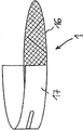
도 18은 본 발명에 따른 수용 부재에 수용할 수 있는 개략 도시한 정제의 일부 노출된 단면의 부등각 투영도이고;
도 19는 시럽이 채워져 있는 도 7의 정제의 볼의 단면도이다.Hereinafter, the present invention will be described in more detail with reference to embodiments. The drawings are illustrative and are used to illustrate the concept of the present invention but are not to be construed as limiting or ultimately. In the drawing:
BRIEF DESCRIPTION OF THE DRAWINGS Figure 1 is a isometric view of a bottle with a sealing cap according to the invention;
Figure 2 is a isometric depiction of a partially exposed cross-section of the bottle of Figure 1;
Figure 3 is a isometric view of the receiving member of Figure 1;
Figure 4 is a isometric view of another embodiment of the sealing cap;
Figure 5 is a isometric view of a partially exposed cross-section of the sealing cap of Figure 4;
Figure 6 is a isometric view of the receiving member of Figure 4;
Figure 7 is a isometric view of the sealing cap with a receiving member having a semicircular side surface;
FIG. 8 is a side elevation angular projection of the sealing cap of FIG. 7; FIG.
Fig. 9 is a isometric view showing a first modification of the receiving member of Fig. 7 having an upper surface; Fig.
10 is a isometric view showing a second modification of the receiving member of Fig. 7 without an upper surface; Fig.
11 is a isometric view of the sealing cap with a narrow receiving member;
FIG. 12 is a side elevation angular projection of the sealing cap of FIG. 11; FIG.
Figure 13 is a isometric view of the receiving member of Figure 11 with an upper surface;
Fig. 14 is a horizontal sectional view of the sealing cap of Fig. 11 taken at the height of the housing member; Fig.
15 is a isometric view of the sealing cap with a receiving member capable of torsion in the transmitting position;
Fig. 16 is a isometric view of the sealing cap of Fig. 15 with a receiving member capable of twisting at the loading position; Fig.
17 is a isometric view showing a third modification of the receiving member of Fig. 6 having an upper surface; Fig.
Figure 18 is an isometric view of a partially exposed cross-section of a schematically depicted tablet that can be received in a receiving member according to the present invention;
Figure 19 is a cross-sectional view of the tablet of Figure 7 with a syrup filled.
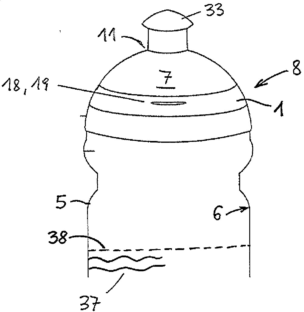
도 1은 밀폐 캡(7)이 구비된 병(5) 형태의 액체 용기를 도시하고 있다. 밀폐 캡(7)이 병(5)의 분출구(9)를 밀봉하고 있는 사용 위치(8)의 밀폐 캡(7)을 도시하고 있다. 밀폐 캡(7)은 나사산(34)에 의해 병(5)에 나사 결합되어 있다(도 2 참조). 요입부 형태(도 4 참조)를 가진 표면구조(35, 미도시)는 사용자가 밀폐 캡(7)을 병(5)에 체결하는 것을 도와 줄 수 있다.Fig. 1 shows a liquid container in the form of a
도 1에서 밀폐 위치(11)로 도시되어 있는 마우스피스(33)가 밀폐 캡(7)에 도시되어 있다. 밀폐 위치(11)에서 밀폐 캡(7)은 병(5)에 수용되어 있고 소정의 액체 수위(38)를 가진 액체(37)에 대해 불투과성이다. 마우스피스(33)는 종축(10)을 따라 마우스피스(33)의 위치를 이동시킴으로써 밀폐 위치(11)로부터 방출 위치(미도시)로 이동될 수 있다(도 2 참조). 상기 방출 위치에서 사용자가 병(5)으로부터 마실 수 있도록 하기 위해서 밀폐 캡(7)은 액체(37)에 투과성이다.A
병(5)은 사용 위치(8)에서 체적(4)의 범위를 밀폐 캡(7)과 함께 한정하는 내벽(6)을 포함하고 있다. 본 발명에 따르면 수용 부재(1)는 체적(4) 내 배치되고 상기 수용 부재는 밀폐 캡(7) 안으로 밀어 넣을 수 있다. 도 2는 이러한 구현예를 밀폐 캡(7)의 노출 단면의 부등각 투영도를 토대로 도시하고 있다. 도 3은 밀폐 캡(7)에서 떼어낸 해당 수용 부재(1)를 보여주고 있다. 수용 부재(1)는 거의 원통형인 수용 체적 형상을 가진 수용 체적(20)을 포함하고 있다. 여기에서 수용 부재(1)는 개략적으로 도시되어 있을 뿐 아래에서 더욱 자세하게 설명하기로 한다. The
수용 체적(20)은 특히 음용 중에 병(5) 안에 수용되어 있는 액체(37)와 접촉할 수 있는 적어도 하나의 전달체, 바람직하게는 적어도 하나의 정제(2)를 수용할 수 있다(도 18 참조). 이에 따라 음료를 제조하거나 상기 액체에 향료 및/또는 영양소 및/또는 식이 보조제 및/또는 약제과 같은 물질을 공급할 수 있다.The receiving
도시된 경우에서 수용 부재(1)는 바닥면(16)과 바닥면을 둘러싸고 있는 측면(17)으로 이루어져 있다. 바닥면(16)은 예를 들면 격자로부터 형성될 수 있는 통공(15)을 포함하고 있다. 수용 부재(1)는 상면을 포함하고 있지 않은바, 즉 위로 개방되어 있어 위로부터 정제(2)를 쉽게 삽입할 수 있다. 정제(2) 또는 그의 일부가 마우스피스(33)를 향해 상향으로 수용 체적(20)을 빠져나갈 수 없도록 하기 위해서 액체용 통공(15)이 형성되어 있는 추가 부재(13)가 밀폐 캡(7) 내 수용 부재(1)(-밀폐된- 장입 위치의)와 분출구(9)(또는 마우스피스(33)) 사이에 배치되어 있다. 이때 추가 부재(13)는 수용 부재(1) 바로 위에 배치되어 수용 체적(20)은 모든 면이 둘러싸이게 되고 수용 부재(1) 내 개방 체적에 상응하게 된다. 이때, 바닥 부재(16)와 추가 부재(13)는 편평하고 서로 평행하게 배치된다. In the case shown, the receiving
액체(37)는 적어도 음용 중에 바닥면(16)과 부재(13)의 통공(15)을 통해 수용 체적(20) 안으로 들어와 수용 체적(20) 내 위치해 있는 정제(2)와 접촉하게 된다. 도 2와 3에 도시되어 있는 바와 같이, 통공(15)은 규칙적인 배열로 배치되어 그리드 또는 격자 패턴을 형성한다. 통공(15)은 음료 제조 또는 정제(2)로부터 액체(37)로 물질, 특히 향료 및/또는 영양소 및/또는 식이 보조제 및/또는 약제의 전달을 가능하게 한다.The liquid 37 comes into contact with the tablet 2 which is located in the receiving
수용 부재(1)가 그의 전달 위치를 정확히 차지할 수 있게 하기 위해서 밀폐 캡(7)의 측부의 내측면에는 안내부, 여기에서는 홈(14)이 배치되어 있다. 보조장치(18), 즉 돌출부(19)는 수용 부재(1)의 조작을 위해 이용된다.In order to enable the receiving
도 4는 나사산(34)에 의해 표준화된 모든 물병, 특히 PET 병에 나사 결합될 수 있는 밀폐 캡(7)의 또 다른 구현예를 도시하고 있다. 사용자가 밀폐 캡(7)을 돌려 열도록 돕기 위해서 밀폐 캡(7)은 도 4에 도시되어 있는 표면구조를 갖는데, 이때 상기 표면구조는 세로 홈(fluting)으로서 형성되어 있다. 나아가 도 4의 밀폐 캡(7)은 도 5에 도시되어 있는 바와 같이 분리 가능하거나 젖혀질 수 있는 커버(3)를 포함하고 상기 커버는 마우스피스(33)를 덮을 수 있다.Fig. 4 shows another embodiment of the sealing
도 5는 도 4의 밀폐 캡(7)의 노출된 단면을 도시하고 있는 부등각 투영도로서; 떼어낸 해당 수용 부재(1)는 도 6에 도시되어 있다.Fig. 5 is an isometric view of the exposed cap of the sealing
도 1 내지 3에 도시되어 있는 변형예에 비해, 도 4 내지 6의 밀폐 캡(7)은 종축(10)을 따라 더 큰 연장부를 갖고 있다. 이로 인해 도 6에 도시되어 있는 수용 부재(1) 또는 상기 수용 부재의 수용 체적(20)에 상응하게 형성되는 개구부(12)에 대해 그의 치수와 형상과 관련하여 더 많은 공간이 생성된다.Compared to the variant shown in Figs. 1 to 3, the sealing
상기 2개의 구현예 모두에서, 수용 부재(1) 전체가 밀폐 캡(7)에 의해서만 형성되는 체적 안에 위치한다. 이것은 한편으로는 밀폐 캡(7)에 의해 한정되고 다른 한편으로는 밀폐 캡(7)의 에지(40)에 의해 일부가 한정되는 가상의 표면적에 의해 한정되는 체적을 의미한다. 상기 가상의 표면적에는 바람직하게는 나사산(34)에 의한 나사 연결에 의해 밀폐 캡(7)을 병(5)과 연결할 수 있도록(도 1 참조) 하기 위한 재료가 실질적으로 없다. In both of the above embodiments, the
도 6의 수용 부재(1)는 거의 원통형으로 형성되고 또한 바닥면(16)과 측면(17)을 포함한다. 따라서 수용 부재(1)는 밀폐 캡(7)이 사용 위치에 있을 때에도 밀폐 캡(7)의 해당 개구부(12) 안으로 서랍과 같이 밀어넣거나 개구부(12)로부터 밖으로 잡아당길 수 있다. 밀폐 캡(7)이 사용 위치(8)에 있는 경우에 이러한 방식으로 수용 부재(1)는 해당 개구부(12)를 통해 밀폐 캡(7) 안에 삽입되거나 그로부터 꺼내진다. 따라서 사용자는 수용 부재(1)에 정제(2)를 채우기 위해 병(5)으로부터 밀폐 캡(7)을 돌려 열 필요가 없다. 바닥면(16)은 수용 부재(1)를 밀폐 캡(7)의 해당 개구부(12) 안으로 밀어넣을 때 마우스피스(33)로부터 분리되어 떨어진다. 여기에서는 수용 부재(1)가 개략적으로 도시되어 있을 뿐 아래에서 더욱 상세하게 설명하기로 한다.The receiving
삽입된 수용 부재(1) 바로 위에는 말단이 수용 체적(20)에 연결되는 통공(15)을 가진 (환형) 부재(13)가 위치해 있다.Above the inserted
도 6에서 수용 부재(1)는 또한 예를 들면 위로 젖힐 수 있고 통공(15)이 제공되어 있는 분리 가능한 상면을 포함하여 수용 체적(20)의 모든 면이 수용 부재(1) 자체에 의해 둘러싸일 수 있다. 이 경우, 부재(13)는 생략될 수 있다. 6, the receiving
도 4 내지 6에 따른 구현예의 경우에 있어서 수용 부재(1)는 수용 체적(20)이 수용 부재(1) 자체, 즉 액체 불투과성인 원통형의 측면(17)과 액체 투과성인 바닥면(16) 및 상면(21)에 의해 완전히 둘러싸여 있는 도 17에서와 같이 배치될 수도 있다. 밀폐 캡(7)에서 부재(13)는 또한 상면(21)으로 인해 생략할 수 있다. 제조 측면에서 밀폐하기 전에 전달체(2)를 도 17에 따른 수용 부재(1)에 삽입할 수 있고 수용 부재(1)는 분리할 수 없도록 밀폐될 수 있다. 전달체(2)가 소비되거나 또 다른 전달체를 원할 때, 또 다른 (예를 들면 소비되지 않은) 전달체(2)를 구비한 또 다른 전달체(1)를 삽입한다.In the case of the embodiment according to Figs. 4 to 6, the receiving
개구부(12)에 수용 부재(1)를 편리하게 삽입하거나 개구부(12)로부터 수용 부재(1)를 꺼낼 수 있게 하기 위해서 도 6에 도시되어 있는 수용 부재는 수용 부재(1)에 대해 사용자가 힘을 가할 수 있는 측면(17)에 돌출부(19) 형태의 보조장치(18)를 포함한다. 보조장치(18)는 추가 부재, 예를 들면 측면(17) 내 오목부(미도시)를 더 포함할 수 있음은 당연하다.The receiving member shown in Fig. 6 is arranged to allow the user to apply force to the receiving
수용 부재(1) 삽입시 밀폐 캡(7)의 밀봉성이 위협받지 않도록 하기 위해서 측면(17)에는 통공(15)이 제공되지 않고 바닥면(16)에만 통공(15)이 제공된다.The through
도 7은 도 4와 동일한 유형의 밀폐 캡(7)을 재차 도시하고 있다. 밀폐 캡(7)은 수용 부재(1)의 영역에서 원통형으로 형성되어 있다. 수용 부재(1)는 도 7에 제공되어 있지만 전달 위치에서 상기 수용 부재의 측면(17)에 의해 액밀 방식으로 개구부(12)를 밀봉하는데, 이때 상기 측면은 도 8에 도시되어 있는 바와 같이 실린더 재킷의 일부이다. 따라서 측면(17)은 밀폐 캡(7)의 측면(36)의 일부를 형성한다.Fig. 7 again shows the sealing
도 7에 맞게 구성된 수용 부재(1)는 도 9에서와 같이 반원통형의 측면(17), 액체 투과성인 바닥면(16)과 액체 투과성인 상면(21)으로 이루어질 수 있고 바닥면과 상면(16, 21)은 수용 부재(1)의 측면(17)에 접하고 수용 부재(1)가 밀폐 캡(7)에 완전히 삽입되는 전달 위치에서는 측면(36)과 접할 수 있다. 그 결과, 수용 체적(20) 내 위치하여 있는 전달체(정제)(2)는 그 안에서 완전히 둘러싸이게 된다. 이 경우에 전달체(2) 전체 또는 일부는 커버(3)에 의해 덮여 있는 마우스피스(33)에 도달할 수 없다.The
도 9와 다르게 도 7의 수용 부재(1)는 도 10에 도시되어 있는 바와 같이 상면(21) 없이 형성될 수도 있다. 그러나 이 경우에는 도 5에 도시되어 있는 바와 같이 통공을 가진 추가 부재(13)가 밀폐 캡(7) 내 수용 부재(1)와 분출구(9) 또는 마우스피스(33) 사이에 배치되어야 한다.9, the
도 11과 12는 도 4와 7과 동일한 유형의 밀폐 캡(7)을 재차 도시하고 있는데, 여기에서는(도 13 참조) 밀폐 캡(7)의 전체 폭을 차지하지 않는 수용 부재(1)가 도시되어 있다. 이 경우, 수용 부재(1)는 실질적으로 장방형 형상을 갖되 측면(17)의 일부(이 경우 좁은 측면)는 밀폐 캡의 측면(36)에서 개구부(12)의 액밀 밀폐부를 형성한다. 측면(17)의 나머지 부분은 수용 부재(1)의 전달 위치에서 측면(36) 내 위치한다.11 and 12 again show the sealing
수용 부재(1)는 액체 투과성인 편평한 상면(21)과 바닥면(16)을 포함하고 있다. 수용 부재(1)를 통해 액체가 흐를 수 없도록 하기 위해서 수용 부재(1)의 높이 연장부의 영역에 있는 밀폐 캡(7)의 내부에는 차단판(배플판)(39)이 제공되어 있고, 상기 차단판은 수용 부재(1)(전달 위치의)와 밀폐 캡(7)의 측면(36) 사이에서 밀폐 캡(7)의 단면을 밀폐시킨다(도 14 참조). 안내부(볼록부, 홈)가 차단판(배플판)(39) 및/또는 밀폐 캡(7)의 내측면의 추가 위치에 부착될 수 있고 상기 안내부는 수용 부재(1)에 있는 각각의 안내부와 연동하고 상기 안내부를 따라 수용 부재(1)를 밀폐 캡(7) 안으로 밀어 넣어거나 밀폐 캡으로부터 빼낼 수 있다.The
위치 이동이 가능한 수용 부재(1)를 구비한 모든 구현예의 경우에 있어서 안내부는 일반적으로 수용 부재(1) 및/또는 밀폐 캡(7)의 내측면에 제공될 수 있다.In the case of all the embodiments having the
도 13의 수용 부재(1)는 위로 젖힐 수 있는 커버면(21)을 포함하여 전달체(2)를 바꿔줄 수 있다. 수용 체적(12)에 접근할 수 없어 전달체(2)를 꺼낼 수 없는(바닥면(16)과 상면(21)은 측면(17)에 분리되지 않게 연결됨) 1회용 제품으로서 수용 부재(1)를 제조할 수도 있을 것이고 또 다른 전달체(2)를 삽입하기 위해 수용 부재(1) 전체를 교환하여야 할 것이다.The receiving
도 13의 수용 부재(1)는 상면(21) 없이 형성될 수 있고 이때 수용 체적(20)은 도 2와 유사하게 추가 부재(13)에 의해 밀봉되어야 할 것이다.The receiving
도 15와 16은 도 4, 7 또는 11 중 하나와 동일한 유형의 밀폐 캡(7)을 재차 도시하고 있다. 이때 수용 부재(1)는 힌지(41)에 의해 밀폐 캡(7)에 비틀림이 가능하게 체결되어 있고, 여기에서 상기 힌지는 밀폐 캡(7)의 종축(10)에 평행하게 배치되어 있다. 힌지(41)는 밀폐 캡(7) 상의 수직 웹에 체결될 수 있고, 상기 웹은 측면(36) 바깥쪽에 배치되어 있다. 수용 부재(1)는 돌출부(19)에 의해 조작, 즉 수평으로 바깥쪽으로 젖혀지거나 비틀릴 수 있다.Figures 15 and 16 again show the sealing
이때 수용 부재(1)는 측면(17)이 상기 수용 부재 전체를 둘러싸도록 배치될 수 있고(즉, 여기에서 상기 수용 부재는 실린더 재킷의 형상을 가짐) 전달 위치에서(도 15) 측면(17)의 단부는 상하부에서 밀폐 캡(7)의 측면(36)과 액밀 방식으로 연결되어 있다. 이 경우, 상기 밀폐 캡의 개구부(12)는 실린더 재킷의 형태로 형상화될 것이고 밀폐 캡(7)의 사용 위치(8)에서 수용 부재(1)의 재킷(17) 전체는 액밀 방식으로 개구부를 밀봉할 것이다.At this time, the receiving
수용 부재(1) 자체는 또한 수용 체적(20)을 상면(21)과 바닥면(16)에 의해 둘러쌀 수 있다. 이 경우, 수용 부재(1)에는 제조 측면에서 이미 전달체(2)가 구비되어 있고 측면(17), 상면(21)과 바닥면(16)은 분리가 가능하지 않도록 서로 연결되어 있는 것을 생각할 수도 있다. 이 경우, 수용 부재(1)는 1회용 제품일 것이다. 이때 상기 수용 부재는 전달체(2)를 바꿔주기 위해 힌지(41)로부터 분리되어야 할 것이고 전달체(2)가 안에 위치하여 있는 새로운 수용 부재(1)가 상기 힌지에 장착되어야 할 것이다.The receiving
수용 부재(1)는 상면(21) 없이 형성될 수도 있다. 그러나 이 경우에도 도 2와 유사하게 수용 부재(1)와 분출구(9) 사이에 추가 부재(13)를 더 배치할 필요가 있다.The
수용 부재(1)(및 밀폐 캡(7)의 재킷(36))는 도 9와 10에 도시되어 있는 바와 같이 배치될 수도 있다. 도 9의 경우에, 힌지(41)는 측면(17)의 수직 단부에 힘을 가할 것이다. 전달체(2)는 측면(17)이 없는 장입 위치에서 바닥면(16)과 상면(21) 사이에 삽입될 수 있다. 도 10의 경우에, 전달체(2)는 상면(21)이 없기 때문에 위로부터 바닥면(16)에 편리하게 위치시킬 수 있다. 이 경우, 밀폐 캡(7) 내 추가 부재(13)의 단부는 상부에서 수용 체적(20)에 연결될 것이다. 측면(17)은 도 9와 도 10에 따른 구현예 모두에서 액밀 방식으로 개구부(12)를 밀봉하게 될 것이다.The housing member 1 (and the
도 4 내지 16의 수용 부재들은 밀폐 캡과 수용 부재를 적절히 조정하여 다른 유형의 밀폐에 대해서도 사용할 수 있음은 물론이다. 도 15와 16에 도시되어 있는 상기 밀폐 캡으로부터 비틀림될 수 있는 수용 부재(1) 또는 도 13에 도시되어 있는 더 좁은 수용 부재(1)는 예를 들면 도 1의 밀폐 캡에 대해 사용할 수도 있다.It is a matter of course that the receiving members of Figs. 4 to 16 can also be used for other types of sealing by appropriately adjusting the sealing cap and the receiving member. The receiving
일반적으로 모든 수용 부재의 구현예들은 이들이 비틀림 또는 위치 이동 가능 여부에 관계없이 이들이 전달 위치에서 밀폐 캡(7)의 측면(36)의 일부를 형성하지 않도록 배치될 수도 있다. 이러한 목적을 위해서 이들 수용 부재는 종축에 수직으로 더 작게 치수화되어야 할 것이다. 이 경우, 도 16에서 개구부(12)는 예를 들면 밀폐 캡(7)의 측면(36)에 의해 부분적으로 밀봉되게 될 것이다(도 8에서와 같이). 나머지 개구부(12)는 덮개(슬라이드 등)에 의해 액밀 방식으로 밀봉될 수 있는데, 상기 덮개는 손실되지 않도록 하기 위해 밀폐 캡(7)의 외측면에 연결될 수 있다. 상기 덮개는 밀폐 부재의 측면(36)의 일부를 형성할 수 있다.In general, embodiments of all receiving members may be arranged such that they do not form part of the
개구부(12)가 수용 부재(1) 또는 수용 부재(1)의 일부에 의해(예를 들면 측면(17)의 일부에 의해) 액밀 방식으로 밀봉되는 모든 구현예에서는 수용 부재(1)를 밀폐 캡(7) 안으로 밀어 넣을 때 밀폐 캡(7)과 단부가 연결되는 수용 부재(1)(의 일부)에 밀폐부가 제공된다. 이 경우, 상기 밀폐부는 양단부에서 밀폐 캡(7)과 중첩되고 상기 밀폐 캡에 걸림될 수 있다. 상술한 바와 같이 개구부(12)가 별도의 덮개에 의해 밀봉될 때 상기 밀폐부의 동일한 원리가 적용될 수 있다.In all embodiments in which the
추가 밀봉부가 한편으로는 덮개 또는 수용 부재(1)와 다른 한편으로는 밀폐 캡(7) 또는 그의 측면(36) 사이에 밀봉을 이루기 위해 제공될 수 있다.An additional seal may be provided on the one hand to provide a seal between the lid or
도 18은 본 발명에 따른 수용 부재(1)에 배치될 수 있는 정제(2)의 일부 노출된 단면의 부등각 투영도로서, 상기 정제는 개략적으로 도시되어 있다. 도 18에 도시되어 있는 정제(2)의 구현예의 경우에 상기 정제는 원통형 형상을 갖고 있다. 상기 형상은 도 6에 도시되어 있는 수용 부재(1)의 변형 구현예에 포함된다. 물론 도 3의 수용 부재(1)에 도 18의 정제(2)를 배치하는 것을 고려할 수도 있다. 다른 한편으로 정제(2)의 형상을 기본적으로 수용 체적(20)에 맞출 필요는 없다.Figure 18 is a isometric view of a part of the exposed section of the tablet 2 which can be placed in the receiving
어느 경우에나 충족시킬 필요가 있는 하나의 조건은 전달체(2)의 전달체 체적(24)은 수용 체적(20)보다 커서는 안 된다는 것이다.In any case, one condition that needs to be met is that the
정제(2)를 전달체 형상(22)으로 지속적으로 유지하기 위해서 정제(2)는 상기 전달체의 외측면(26)에 배치되는 거즈(23)를 포함한다.Tablet 2 includes
또한 도 18은 전달체 체적(24)이 플라스틱 스펀지(25)에 의해 채워져 있는 것을 단면으로 도시하고 있다. 전달체 체적(24) 내에는 또한 볼(27)이 배치되어 있다. 액체(37)는 플라스틱 스펀지(25)를 통해 볼(27)에 침투할 수 있다. 거즈(23)의 그물형 직물 또한 액체(37)에 투과성이다.Figure 18 also shows, in cross section, that the
볼(27)은 음료 제조 또는 향료 및/또는 영양소 및/또는 식이 보조제 및/또는 약제 방출을 위한 수용성 부재로서 기능하여 액체(37)에 혼합될 수 있다. 이러한 목적을 위해서 볼(27)은 도 19의 단면도에 따라 배치된다. 즉, 각각의 볼(27)이 바람직하게는 당으로 제조되는 수용성 아이싱 층(28)에 의해 형성되는 표면(29)을 갖는다. 아이싱 층(28)은 상기 볼의 내부(30)의 범위를 한정하고 소정의 아이싱 층 두께(31)를 갖고 있다. 상기 볼의 내부(30)에는 액체(37)에 첨가할 물질, 특히 향료 및/또는 영양소 및/또는 식이 보조제 및/또는 약제가 배치되어 있다. 도 19의 구현예에서는 상기 볼의 내부(30)에 시럽(32)이 채워져 있다.The
아이싱 층 두께(31)를 가진 아이싱 층(28)이 용해되었을 때에만 시럽(32)이 방출되거나 액체(37)와 혼합/액체(37)에 첨가된다.Syrup 32 is released or added to
아이싱 층 두께(31)는 서로 다른 볼(27)에서 서로 다른 두께로 제공되어 아이싱 층(28)이 용해되는 서로 다른 시간이 소요될 수 있다. 따라서 시럽(32)의 혼합 경시 진행을 구체화할 수 있다. 나아가 서로 다른 볼(27)은 상기 볼의 내부(30) 각각에 서로 다른 물질을 함유할 수 있다. 그러므로 예를 들면 볼(27)이 액체(37)와 소정의 기간 동안 접촉한 후 아이소토닉 음료를 제공하기 위해서 일부 볼(27)은 시럽(32)을 함유하는 반면에 그 외 다른 볼들(27)은 다른 물질들을 제공한다.The thickness of the
나아가 볼(27)은 서로 다른 크기로 제공될 수 있는바, 즉 도 18에 나타낸 바와 같이 서로 다른 크기의 직경을 가질 수 있다. 서로 다른 아이싱 층 두께(31)와 연동하여 볼(27)과 액체(37)의 접촉 지속시간에 따라 볼의 내부(30)에 위치하여 있는 물질(예를 들면 시럽(32))의 서로 다른 양을 방출할 수 있다.Further, the
마지막으로 서로 다른 아이싱 층 두께(31)를 가진 크기가 서로 다른 볼(27)에는 서로 다른 물질(위에서 설명한 바와 같이, 반드시 시럽(32)일 필요는 없음)을 배치할 수도 있다. 그 결과, 서로 다른 양의 서로 다른 물질과 액체(37)의 시간에 따른 혼합 진행을 결정할 수 있다.Finally, the
참조부호 리스트
1
수용 부재
2
정제(전달체)
3
커버
4
체적
5
병
6
병의 내벽
7
밀폐 캡
8
사용 위치
9
분출구
10
종축
11
밀폐 위치
12
밀폐 캡의 개구부
13
통공을 가진 추가 부재
14
홈
15
통공
16
바닥면
17
측면
18
보조장치
19
돌출부
20
수용 체적
21
커버면
22
전달체 형상
23
거즈
24
전달체 체적
25
플라스틱 스펀지
26
전달체의 외측면
27
볼
28
아이싱 층
29
볼의 표면
30
볼의 내부
31
아이싱 층 두께
32
시럽
33
마우스피스
34
나사산
35
표면구조
36
밀폐 캡(7)의 측면
37
액체
38
액체 수위
39
차단판
40
밀폐 캡의 에지
41
힌지Reference list
1 housing member
2 Tablets (Carrier)
3 cover
4 volume
5 bottles
6 bottles of inner wall
7 Sealing cap
8 Location
Exit 9
10 vertical axes
11 Sealed position
12 Opening of sealing cap
13 additional member with a through hole
14 Home
15 passage
16 bottom surface
17 side
18 auxiliary device
19 protrusion
20 Acceptable volume
21 Cover face
22 Carrier shape
23 Gauze
24 Carrier volume
25 Plastic sponge
26 Outer side of the carrier
27 ball
28 Icing layer
29 Surface of Ball
Inside of 30 balls
31 Icing Layer Thickness
32 syrups
33 mouthpiece
34 thread
35 Surface Structure
36 Side of sealing cap (7)
37 liquid
38 liquid level
39 blocking plate
40 Edge of sealing cap
41 Hinge
Claims (22)
- 바람직하게는 재밀폐가 가능한 분출구(9)와,
- 적어도 하나의 전달체, 바람직하게는 적어도 하나의 정제(2)를 수용하되 적어도 하나의 전달체(2)를 액체(37)에 접촉하도록 액체(37) 투과성인 수용 부재(1)와,
- 상기 적어도 하나의 전달체를 수용 체적(20)에 도입하거나 수용 체적(20)으로부터 꺼내기 위한 개구부(12)를 포함하되 수용 부재(1)가 밀폐 캡(7)의 사용 위치(8)에서 조작될 수 있고 개구부(12)를 통해 수용 체적으로부터 상기 전달체를 바꿔주기 위한 장입 위치와 수용 체적 내 전달 위치 모두로 이동될 수 있는 것을 특징으로 하는 밀폐 캡(7).As the sealing cap 7, preferably a screw cap, for mounting in a liquid container, preferably a bottle 5, more preferably a PET bottle, the sealing cap 7 comprises at least
- a discharge port (9) capable of being resealed,
- a receiving member (1) permeable to liquid (37) for receiving at least one carrier, preferably at least one tablet (2), for contacting at least one carrier (2)
- an opening (12) for introducing said at least one carrier into or out of the receiving volume (20), wherein the receiving member (1) is operated at the use position (8) of the sealing cap (7) And can be moved both to the charging position for changing the carrier from the receiving volume through the opening (12) and to the transmitting position in the receiving volume.
Applications Claiming Priority (1)
| Application Number | Priority Date | Filing Date | Title |
|---|---|---|---|
| PCT/EP2013/069588 WO2015039700A1 (en) | 2013-09-20 | 2013-09-20 | Closure cap for mounting on a liquid container |
Publications (1)
| Publication Number | Publication Date |
|---|---|
| KR20160074492A true KR20160074492A (en) | 2016-06-28 |
Family
ID=49226182
Family Applications (1)
| Application Number | Title | Priority Date | Filing Date |
|---|---|---|---|
| KR1020167010075A Withdrawn KR20160074492A (en) | 2013-09-20 | 2013-09-20 | Closure cap for mounting on a liquid container |
Country Status (11)
| Country | Link |
|---|---|
| US (1) | US20160272387A1 (en) |
| EP (1) | EP3046850B1 (en) |
| JP (1) | JP2016533982A (en) |
| KR (1) | KR20160074492A (en) |
| CN (1) | CN105683061A (en) |
| AU (1) | AU2013400981A1 (en) |
| CA (1) | CA2923937A1 (en) |
| IL (1) | IL244638A0 (en) |
| MX (1) | MX2016003343A (en) |
| RU (1) | RU2016107891A (en) |
| WO (1) | WO2015039700A1 (en) |
Families Citing this family (1)
| Publication number | Priority date | Publication date | Assignee | Title |
|---|---|---|---|---|
| WO2016106433A1 (en) | 2014-12-30 | 2016-07-07 | Moradi Consulting Gmbh | Discharging element in the form of a capsule for discharging additives into a liquid |
Family Cites Families (14)
| Publication number | Priority date | Publication date | Assignee | Title |
|---|---|---|---|---|
| US3302644A (en) * | 1963-07-26 | 1967-02-07 | Harold J Kennedy | Oral medicine administering device for children |
| DE3644947A1 (en) * | 1986-04-18 | 1988-04-07 | Wolfgang Gesen | Coffee machine with receiving tray for a coffee filter |
| US5249702A (en) * | 1992-01-24 | 1993-10-05 | Topp Kathy R | Beverage container and support bracket therefore |
| US5411186A (en) * | 1992-11-19 | 1995-05-02 | Robbins, Iii; Edward S. | Dispensing cap with rotatable top |
| US5707353A (en) * | 1995-12-21 | 1998-01-13 | Abbott Laboratories | Oral administration of beneficial agents |
| DE19804444C1 (en) * | 1998-02-05 | 1999-04-22 | Pagatec Vertriebs Ges Mbh | Coffee machine for fresh brewing of filter coffee |
| WO2005079169A2 (en) * | 2004-02-19 | 2005-09-01 | Jeong-Min Lee | Structure of cap having storage space |
| DE202005012919U1 (en) * | 2005-08-16 | 2005-11-24 | Ouboter, Jan Wim Anton | Screw cap for soft drinks bottle contains chamber which is closed by slide, in which mouth-freshening product is stored, so that it can be used immediately after drinking |
| US20090188886A1 (en) * | 2008-01-25 | 2009-07-30 | Florian Troesch | Liquid container system |
| US8230777B2 (en) | 2008-07-21 | 2012-07-31 | Nutra-Life, Inc. | Water container cap for holding additives to water |
| US20120279939A1 (en) * | 2008-10-27 | 2012-11-08 | Lee Jeong-Min | Bottle cap |
| JP5295803B2 (en) * | 2009-01-30 | 2013-09-18 | 株式会社吉野工業所 | Two-type mixing container |
| JP5214481B2 (en) * | 2009-01-30 | 2013-06-19 | 株式会社吉野工業所 | Spout |
| US20120017766A1 (en) * | 2010-04-19 | 2012-01-26 | Anson Ricky L | Water container cap with filter for holding additives to water |
-
2013
- 2013-09-20 RU RU2016107891A patent/RU2016107891A/en not_active Application Discontinuation
- 2013-09-20 WO PCT/EP2013/069588 patent/WO2015039700A1/en not_active Ceased
- 2013-09-20 AU AU2013400981A patent/AU2013400981A1/en not_active Abandoned
- 2013-09-20 CN CN201380080363.4A patent/CN105683061A/en active Pending
- 2013-09-20 MX MX2016003343A patent/MX2016003343A/en unknown
- 2013-09-20 JP JP2016543324A patent/JP2016533982A/en active Pending
- 2013-09-20 KR KR1020167010075A patent/KR20160074492A/en not_active Withdrawn
- 2013-09-20 EP EP13765735.9A patent/EP3046850B1/en not_active Not-in-force
- 2013-09-20 US US15/022,978 patent/US20160272387A1/en not_active Abandoned
- 2013-09-20 CA CA2923937A patent/CA2923937A1/en not_active Abandoned
-
2016
- 2016-03-17 IL IL244638A patent/IL244638A0/en unknown
Also Published As
| Publication number | Publication date |
|---|---|
| IL244638A0 (en) | 2016-04-21 |
| EP3046850A1 (en) | 2016-07-27 |
| WO2015039700A1 (en) | 2015-03-26 |
| CA2923937A1 (en) | 2015-03-26 |
| MX2016003343A (en) | 2016-06-22 |
| JP2016533982A (en) | 2016-11-04 |
| CN105683061A (en) | 2016-06-15 |
| US20160272387A1 (en) | 2016-09-22 |
| RU2016107891A (en) | 2017-10-25 |
| AU2013400981A1 (en) | 2016-05-05 |
| EP3046850B1 (en) | 2017-06-28 |
Similar Documents
| Publication | Publication Date | Title |
|---|---|---|
| JP6396511B2 (en) | Seal cap for liquid container attachment | |
| US8230777B2 (en) | Water container cap for holding additives to water | |
| US20050263414A1 (en) | Dispensing capsule | |
| CN101730651A (en) | dispenser | |
| KR20160077059A (en) | Closure cap for mounting on a liquid container | |
| US20130001111A1 (en) | Drinking bottle with multiple compartments and replaceable ampoules | |
| KR20160074492A (en) | Closure cap for mounting on a liquid container | |
| KR101440916B1 (en) | A vessel for discharging constant rate of pills | |
| WO2014020583A1 (en) | Double functions vent device for nursing bottle with functions for air venting to the inner bottle and a pediatric medicine delivery system | |
| EP3512373B1 (en) | Container assembly for cosmetic formula, kit for forming such a container assembly, and method for using such a kit | |
| CN107108087B (en) | For additive to be fed to the feed of liquid | |
| HK1234015A1 (en) | Closure cap for attachment to a liquid container | |
| HK1174596A (en) | Drinking bottle with multiple compartments and replaceable ampoules |
Legal Events
| Date | Code | Title | Description |
|---|---|---|---|
| PA0105 | International application |
Patent event date: 20160418 Patent event code: PA01051R01D Comment text: International Patent Application |
|
| PG1501 | Laying open of application | ||
| PC1203 | Withdrawal of no request for examination | ||
| WITN | Application deemed withdrawn, e.g. because no request for examination was filed or no examination fee was paid |