KR20150132430A - Fluid-filled chamber with a tensile element - Google Patents
Fluid-filled chamber with a tensile element Download PDFInfo
- Publication number
- KR20150132430A KR20150132430A KR1020157029320A KR20157029320A KR20150132430A KR 20150132430 A KR20150132430 A KR 20150132430A KR 1020157029320 A KR1020157029320 A KR 1020157029320A KR 20157029320 A KR20157029320 A KR 20157029320A KR 20150132430 A KR20150132430 A KR 20150132430A
- Authority
- KR
- South Korea
- Prior art keywords
- chamber
- junction
- barrier
- fluid
- tensile
- Prior art date
- Legal status (The legal status is an assumption and is not a legal conclusion. Google has not performed a legal analysis and makes no representation as to the accuracy of the status listed.)
- Granted
Links
Images


Classifications
-
- A—HUMAN NECESSITIES
- A43—FOOTWEAR
- A43B—CHARACTERISTIC FEATURES OF FOOTWEAR; PARTS OF FOOTWEAR
- A43B13/00—Soles; Sole-and-heel integral units
- A43B13/14—Soles; Sole-and-heel integral units characterised by the constructive form
- A43B13/18—Resilient soles
- A43B13/20—Pneumatic soles filled with a compressible fluid, e.g. air, gas
- A43B13/203—Pneumatic soles filled with a compressible fluid, e.g. air, gas provided with a pump or valve
-
- A—HUMAN NECESSITIES
- A43—FOOTWEAR
- A43B—CHARACTERISTIC FEATURES OF FOOTWEAR; PARTS OF FOOTWEAR
- A43B13/00—Soles; Sole-and-heel integral units
- A43B13/02—Soles; Sole-and-heel integral units characterised by the material
- A43B13/04—Plastics, rubber or vulcanised fibre
-
- A—HUMAN NECESSITIES
- A43—FOOTWEAR
- A43B—CHARACTERISTIC FEATURES OF FOOTWEAR; PARTS OF FOOTWEAR
- A43B13/00—Soles; Sole-and-heel integral units
- A43B13/02—Soles; Sole-and-heel integral units characterised by the material
- A43B13/12—Soles with several layers of different materials
-
- A—HUMAN NECESSITIES
- A43—FOOTWEAR
- A43B—CHARACTERISTIC FEATURES OF FOOTWEAR; PARTS OF FOOTWEAR
- A43B13/00—Soles; Sole-and-heel integral units
- A43B13/02—Soles; Sole-and-heel integral units characterised by the material
- A43B13/12—Soles with several layers of different materials
- A43B13/122—Soles with several layers of different materials characterised by the outsole or external layer
-
- A—HUMAN NECESSITIES
- A43—FOOTWEAR
- A43B—CHARACTERISTIC FEATURES OF FOOTWEAR; PARTS OF FOOTWEAR
- A43B13/00—Soles; Sole-and-heel integral units
- A43B13/02—Soles; Sole-and-heel integral units characterised by the material
- A43B13/12—Soles with several layers of different materials
- A43B13/125—Soles with several layers of different materials characterised by the midsole or middle layer
-
- A—HUMAN NECESSITIES
- A43—FOOTWEAR
- A43B—CHARACTERISTIC FEATURES OF FOOTWEAR; PARTS OF FOOTWEAR
- A43B13/00—Soles; Sole-and-heel integral units
- A43B13/14—Soles; Sole-and-heel integral units characterised by the constructive form
- A43B13/16—Pieced soles
-
- A—HUMAN NECESSITIES
- A43—FOOTWEAR
- A43B—CHARACTERISTIC FEATURES OF FOOTWEAR; PARTS OF FOOTWEAR
- A43B13/00—Soles; Sole-and-heel integral units
- A43B13/14—Soles; Sole-and-heel integral units characterised by the constructive form
- A43B13/18—Resilient soles
-
- A—HUMAN NECESSITIES
- A43—FOOTWEAR
- A43B—CHARACTERISTIC FEATURES OF FOOTWEAR; PARTS OF FOOTWEAR
- A43B13/00—Soles; Sole-and-heel integral units
- A43B13/14—Soles; Sole-and-heel integral units characterised by the constructive form
- A43B13/18—Resilient soles
- A43B13/181—Resiliency achieved by the structure of the sole
- A43B13/185—Elasticated plates sandwiched between two interlocking components, e.g. thrustors
-
- A—HUMAN NECESSITIES
- A43—FOOTWEAR
- A43B—CHARACTERISTIC FEATURES OF FOOTWEAR; PARTS OF FOOTWEAR
- A43B13/00—Soles; Sole-and-heel integral units
- A43B13/14—Soles; Sole-and-heel integral units characterised by the constructive form
- A43B13/18—Resilient soles
- A43B13/181—Resiliency achieved by the structure of the sole
- A43B13/186—Differential cushioning region, e.g. cushioning located under the ball of the foot
-
- A—HUMAN NECESSITIES
- A43—FOOTWEAR
- A43B—CHARACTERISTIC FEATURES OF FOOTWEAR; PARTS OF FOOTWEAR
- A43B13/00—Soles; Sole-and-heel integral units
- A43B13/14—Soles; Sole-and-heel integral units characterised by the constructive form
- A43B13/18—Resilient soles
- A43B13/187—Resiliency achieved by the features of the material, e.g. foam, non liquid materials
- A43B13/188—Differential cushioning regions
-
- A—HUMAN NECESSITIES
- A43—FOOTWEAR
- A43B—CHARACTERISTIC FEATURES OF FOOTWEAR; PARTS OF FOOTWEAR
- A43B13/00—Soles; Sole-and-heel integral units
- A43B13/14—Soles; Sole-and-heel integral units characterised by the constructive form
- A43B13/18—Resilient soles
- A43B13/189—Resilient soles filled with a non-compressible fluid, e.g. gel, water
-
- A—HUMAN NECESSITIES
- A43—FOOTWEAR
- A43B—CHARACTERISTIC FEATURES OF FOOTWEAR; PARTS OF FOOTWEAR
- A43B13/00—Soles; Sole-and-heel integral units
- A43B13/14—Soles; Sole-and-heel integral units characterised by the constructive form
- A43B13/22—Soles made slip-preventing or wear-resisting, e.g. by impregnation or spreading a wear-resisting layer
- A43B13/223—Profiled soles
-
- A—HUMAN NECESSITIES
- A43—FOOTWEAR
- A43B—CHARACTERISTIC FEATURES OF FOOTWEAR; PARTS OF FOOTWEAR
- A43B13/00—Soles; Sole-and-heel integral units
- A43B13/42—Filling materials located between the insole and outer sole; Stiffening materials
-
- A—HUMAN NECESSITIES
- A43—FOOTWEAR
- A43B—CHARACTERISTIC FEATURES OF FOOTWEAR; PARTS OF FOOTWEAR
- A43B21/00—Heels; Top-pieces or top-lifts
- A43B21/24—Heels; Top-pieces or top-lifts characterised by the constructive form
- A43B21/26—Resilient heels
-
- A—HUMAN NECESSITIES
- A43—FOOTWEAR
- A43B—CHARACTERISTIC FEATURES OF FOOTWEAR; PARTS OF FOOTWEAR
- A43B21/00—Heels; Top-pieces or top-lifts
- A43B21/24—Heels; Top-pieces or top-lifts characterised by the constructive form
- A43B21/26—Resilient heels
- A43B21/265—Resilient heels filled with a non-compressible fluid, e.g. gel, water
-
- A—HUMAN NECESSITIES
- A43—FOOTWEAR
- A43B—CHARACTERISTIC FEATURES OF FOOTWEAR; PARTS OF FOOTWEAR
- A43B21/00—Heels; Top-pieces or top-lifts
- A43B21/24—Heels; Top-pieces or top-lifts characterised by the constructive form
- A43B21/26—Resilient heels
- A43B21/28—Pneumatic heels filled with a compressible fluid, e.g. air, gas
-
- A—HUMAN NECESSITIES
- A43—FOOTWEAR
- A43B—CHARACTERISTIC FEATURES OF FOOTWEAR; PARTS OF FOOTWEAR
- A43B21/00—Heels; Top-pieces or top-lifts
- A43B21/24—Heels; Top-pieces or top-lifts characterised by the constructive form
- A43B21/32—Resilient supports for the heel of the foot
-
- B—PERFORMING OPERATIONS; TRANSPORTING
- B29—WORKING OF PLASTICS; WORKING OF SUBSTANCES IN A PLASTIC STATE IN GENERAL
- B29D—PRODUCING PARTICULAR ARTICLES FROM PLASTICS OR FROM SUBSTANCES IN A PLASTIC STATE
- B29D35/00—Producing footwear
- B29D35/12—Producing parts thereof, e.g. soles, heels, uppers, by a moulding technique
- B29D35/122—Soles
-
- B—PERFORMING OPERATIONS; TRANSPORTING
- B29—WORKING OF PLASTICS; WORKING OF SUBSTANCES IN A PLASTIC STATE IN GENERAL
- B29D—PRODUCING PARTICULAR ARTICLES FROM PLASTICS OR FROM SUBSTANCES IN A PLASTIC STATE
- B29D35/00—Producing footwear
- B29D35/12—Producing parts thereof, e.g. soles, heels, uppers, by a moulding technique
- B29D35/128—Moulds or apparatus therefor
-
- B—PERFORMING OPERATIONS; TRANSPORTING
- B29—WORKING OF PLASTICS; WORKING OF SUBSTANCES IN A PLASTIC STATE IN GENERAL
- B29D—PRODUCING PARTICULAR ARTICLES FROM PLASTICS OR FROM SUBSTANCES IN A PLASTIC STATE
- B29D35/00—Producing footwear
- B29D35/12—Producing parts thereof, e.g. soles, heels, uppers, by a moulding technique
- B29D35/14—Multilayered parts
- B29D35/148—Moulds or apparatus therefor
-
- B—PERFORMING OPERATIONS; TRANSPORTING
- B32—LAYERED PRODUCTS
- B32B—LAYERED PRODUCTS, i.e. PRODUCTS BUILT-UP OF STRATA OF FLAT OR NON-FLAT, e.g. CELLULAR OR HONEYCOMB, FORM
- B32B3/00—Layered products comprising a layer with external or internal discontinuities or unevennesses, or a layer of non-planar shape; Layered products comprising a layer having particular features of form
- B32B3/26—Layered products comprising a layer with external or internal discontinuities or unevennesses, or a layer of non-planar shape; Layered products comprising a layer having particular features of form characterised by a particular shape of the outline of the cross-section of a continuous layer; characterised by a layer with cavities or internal voids ; characterised by an apertured layer
- B32B3/266—Layered products comprising a layer with external or internal discontinuities or unevennesses, or a layer of non-planar shape; Layered products comprising a layer having particular features of form characterised by a particular shape of the outline of the cross-section of a continuous layer; characterised by a layer with cavities or internal voids ; characterised by an apertured layer characterised by an apertured layer, the apertures going through the whole thickness of the layer, e.g. expanded metal, perforated layer, slit layer regular cells B32B3/12
-
- B—PERFORMING OPERATIONS; TRANSPORTING
- B32—LAYERED PRODUCTS
- B32B—LAYERED PRODUCTS, i.e. PRODUCTS BUILT-UP OF STRATA OF FLAT OR NON-FLAT, e.g. CELLULAR OR HONEYCOMB, FORM
- B32B3/00—Layered products comprising a layer with external or internal discontinuities or unevennesses, or a layer of non-planar shape; Layered products comprising a layer having particular features of form
- B32B3/26—Layered products comprising a layer with external or internal discontinuities or unevennesses, or a layer of non-planar shape; Layered products comprising a layer having particular features of form characterised by a particular shape of the outline of the cross-section of a continuous layer; characterised by a layer with cavities or internal voids ; characterised by an apertured layer
- B32B3/28—Layered products comprising a layer with external or internal discontinuities or unevennesses, or a layer of non-planar shape; Layered products comprising a layer having particular features of form characterised by a particular shape of the outline of the cross-section of a continuous layer; characterised by a layer with cavities or internal voids ; characterised by an apertured layer characterised by a layer comprising a deformed thin sheet, i.e. the layer having its entire thickness deformed out of the plane, e.g. corrugated, crumpled
-
- B—PERFORMING OPERATIONS; TRANSPORTING
- B32—LAYERED PRODUCTS
- B32B—LAYERED PRODUCTS, i.e. PRODUCTS BUILT-UP OF STRATA OF FLAT OR NON-FLAT, e.g. CELLULAR OR HONEYCOMB, FORM
- B32B7/00—Layered products characterised by the relation between layers; Layered products characterised by the relative orientation of features between layers, or by the relative values of a measurable parameter between layers, i.e. products comprising layers having different physical, chemical or physicochemical properties; Layered products characterised by the interconnection of layers
- B32B7/04—Interconnection of layers
- B32B7/05—Interconnection of layers the layers not being connected over the whole surface, e.g. discontinuous connection or patterned connection
-
- B—PERFORMING OPERATIONS; TRANSPORTING
- B32—LAYERED PRODUCTS
- B32B—LAYERED PRODUCTS, i.e. PRODUCTS BUILT-UP OF STRATA OF FLAT OR NON-FLAT, e.g. CELLULAR OR HONEYCOMB, FORM
- B32B2250/00—Layers arrangement
- B32B2250/03—3 layers
-
- B—PERFORMING OPERATIONS; TRANSPORTING
- B32—LAYERED PRODUCTS
- B32B—LAYERED PRODUCTS, i.e. PRODUCTS BUILT-UP OF STRATA OF FLAT OR NON-FLAT, e.g. CELLULAR OR HONEYCOMB, FORM
- B32B2307/00—Properties of the layers or laminate
- B32B2307/70—Other properties
- B32B2307/726—Permeability to liquids, absorption
- B32B2307/7265—Non-permeable
-
- B—PERFORMING OPERATIONS; TRANSPORTING
- B32—LAYERED PRODUCTS
- B32B—LAYERED PRODUCTS, i.e. PRODUCTS BUILT-UP OF STRATA OF FLAT OR NON-FLAT, e.g. CELLULAR OR HONEYCOMB, FORM
- B32B2437/00—Clothing
- B32B2437/02—Gloves, shoes
Landscapes
- Engineering & Computer Science (AREA)
- Mechanical Engineering (AREA)
- Chemical & Material Sciences (AREA)
- Materials Engineering (AREA)
- Footwear And Its Accessory, Manufacturing Method And Apparatuses (AREA)
Abstract
신발 제품 및 다른 제품에 결합될 수 있는 유체 충전식 챔버는 외부 배리어 및 인장 요소를 포함할 수 있다. 외부 배리어는 제1 부분, 대향하는 제2 부분, 및 내부 보이드를 형성하는 내부면을 가질 수 있다. 인장 요소는 복수의 제1 접합 영역에서는 외부 배리어의 제1 부분에 고정될 수 있고, 복수의 제2 접합 영역에서는 외부 배리어의 제2 부분에 고정될 수 있다. 각각의 접합 영역은 내부면으로부터 이격된 인장 요소의 일부에 연결될 수 있다.The fluid rechargeable chamber that may be coupled to the shoe product and other products may include an external barrier and a tensioning element. The outer barrier may have a first portion, an opposing second portion, and an inner surface forming an inner void. The tensile element can be secured to the first portion of the outer barrier in the plurality of first junction regions and to the second portion of the outer barrier in the plurality of second junction regions. Each junction region may be connected to a portion of the tensile element spaced from the inner surface.
Description
본 발명은 인장 요소를 갖는 유체 충전식 챔버에 관한 것이다.The present invention relates to a fluid rechargeable chamber having a tension element.
신발 제품은 일반적으로 2개의 주요한 요소, 즉 갑피 및 밑창 구조체를 포함한다. 갑피는 발을 편안하고 확실하게 수용하기 위한 보이드를 신발의 내부에 형성하도록 함께 봉합되거나 또는 접착식으로 접합되는 다양한 재료 요소[예로써, 직물, 포움(foam), 가죽 및 합성 가죽]로부터 형성된다. 상기 재료 요소를 통한 발목 입구는 보이드로의 어세스(access)를 제공하여, 보이드(void)로의 발의 진입 및 보이드로부터의 발의 제거를 용이하게 한다. 또한, 보이드의 치수를 변경시키고 보이드 내에 발을 고정하기 위해 레이스가 사용된다.Shoe products generally include two major components, an upper and a sole structure. The upper is formed from a variety of material elements (e.g., fabric, foam, leather and synthetic leather) that are seamed together or adhesively bonded together to form a void within the shoe for comfortably and securely receiving the foot. The ankle opening through the material element provides access to the void to facilitate entry of the foot into the void and removal of the foot from the void. Also, a lace is used to change the dimensions of the void and fix the foot in the void.
밑창 구조체는 갑피의 하부에 인접하게 위치되고, 일반적으로 지면과 발 사이에 위치된다. 운동화를 포함한 많은 신발 제품에서, 밑창 구조체는 일반적으로 안창(insole), 중창(midsole) 및 겉창(outsole)을 결합한다. 보이드 내에 위치할 수 있고 보이드의 하부면에 인접할 수 있는 안창은 신발의 편안함을 강화하는 얇은 압축식 부재이다. 갑피의 하부면에 고정될 수 있고 갑피로부터 하방으로 연장되는 중창은 밑창 구조체의 중간층을 형성한다. 지면 반발력을 완화시키는(예로써, 발에 쿠션을 제공하는) 것에 부가하여, 중창은 예로써, 발의 움직임을 제한하거나 안정성을 부가할 수 있다. 중창의 하부면에 고정될 수 있는 겉창은 신발의 접지부의 적어도 일부를 형성하고, 통상적으로 매력을 강화하기 위한 질감을 갖는 내구성 있는 내마모성 재료로 제조된다.The sole structure is positioned adjacent the lower portion of the upper, generally between the ground and the feet. In many shoe products, including sneakers, the sole structure generally joins the insole, midsole and outsole. The insole, which can be located in the void and can be adjacent to the lower surface of the void, is a thin compression member that enhances the comfort of the shoe. A midsole that can be secured to the lower surface of the upper and extending downward from the upper forms an intermediate layer of the sole structure. In addition to alleviating the ground reaction force (e.g., providing foot cushioning), the midsole can, for example, limit motion or add stability to the foot. An outsole that can be secured to the lower surface of the midsole forms at least a portion of the ground portion of the shoe and is typically made of a durable, wear resistant material having a texture to enhance its attractiveness.
일반적으로, 중창은 주로 신발의 길이 및 폭 전체에 걸쳐 연장되는, 폴리우레탄 또는 에틸비닐아세테이트와 같은 포움식 폴리머 재료로 형성된다. 몇몇 신발 제품에서, 중창은, 플레이트(plates), 모더레이터(moderators), 유체 충전식 챔버, 지속 요소, 또는 움직임 제어 부재를 비롯하여, 신발의 편안함 또는 성능을 강화하는 다양한 부가적인 신발 요소를 포함할 수 있다. 몇몇 구성에서, 이러한 부가의 신발 요소 중 임의의 신발 요소는, 예로써, 겉창과 갑피 중 어느 하나와 중창 사이에 위치될 수 있거나, 중창 내에 매립될 수 있거나, 중창의 포움식 폴리머 재료에 의해 캡슐화될 수 있다. 많은 중창이 주로 포움식 폴리머 재료로부터 형성되지만, 유체 충전식 챔버 또는 다른 비포움식 구조체가 몇몇 중창 구성의 일부 또는 전체를 형성할 수 있다.Generally, the midsole is formed of a foamed polymer material, such as polyurethane or ethyl vinyl acetate, that extends throughout the length and width of the shoe. In some shoe products, the midsole may include a variety of additional shoe elements to enhance the comfort or performance of the shoe, including plates, moderators, fluid-filled chambers, permanent elements, or motion control members . In some arrangements, any of these additional shoe elements may be located, for example, between the outsole and the upper, and the midsole, or may be embedded within the midsole, or encapsulated . While many midranges are formed primarily from a foamed polymeric material, a fluid rechargeable chamber or other non-inflated structure may form some or all of some midrange configurations.
예로써, 2-박막 기술, 열성형 기술 및 블로 성형 기술을 포함하는 다양한 기술이 신발 제품 또는 다른 제품을 위한 유체 충전식 챔버를 형성하는 데 사용될 수 있다. 2-박막 기술에서, 2개의 별개의 폴리머 시트가 특정 위치에서 서로 접합된다. 열성형 기술은 2개의 폴리머 시트가 함께 접합되는 점에서 2-박막 기술과 유사하지만, 폴리머 시트를 형성 또는 달리 성형하는 데 가열된 몰드를 사용하는 것을 또한 포함할 수도 있다. 블로 성형 기술에서, 용융된 또는 달리 연성화된 폴리머 재료로 형성된 파리손(parison)은 챔버가 원하는 구성으로 공동(cavity)을 갖는 몰드 내에 위치된다. 가압 공기는 폴리머 재료가 공동의 표면에 순응하게 한다. 이후, 폴리머 재료는 냉각되고 공동의 형상으로 유지됨으로써, 챔버를 형성한다.By way of example, a variety of techniques, including 2-thin film technology, thermoforming techniques, and blow molding techniques, can be used to form fluid rechargeable chambers for shoe products or other products. In two-thin film technology, two separate polymer sheets are bonded together at specific locations. Thermoforming techniques are similar to the two-thin film technique in that two polymer sheets are bonded together, but may also include using a heated mold to form or otherwise shape the polymer sheet. In blow molding techniques, parisons formed from molten or otherwise ductile polymer material are placed in a mold having a cavity with the desired configuration of the chamber. The pressurized air causes the polymer material to conform to the surface of the cavity. Thereafter, the polymer material is cooled and held in the shape of a cavity, thereby forming a chamber.
위 설명한 각각의 기술에 후속하여, 챔버가 가압된다. 즉, 가압 유체는 챔버 안으로 분사된 뒤 챔버 내에서 밀봉된다. 가압 방법 중 하나는 폴리머 시트 또는 파리손의 잔류부에 팽창 도관을 형성하는 것을 수반한다. 챔버를 가압하기 위해, 유체는 팽창 도관을 통해 주입된 뒤, 밀봉된다. 이후, 팽창 도관을 포함하는 폴리머 시트 또는 파리손의 잔류부는, 챔버 제조를 사실상 완료하기 위해 다듬어지거나 달리 제거된다. Following each of the techniques described above, the chamber is pressurized. That is, the pressurized fluid is injected into the chamber and then sealed in the chamber. One of the methods of pressurization entails forming an expansion conduit in the remaining portion of the polymer sheet or parison. To pressurize the chamber, fluid is injected through the expansion conduit and then sealed. The remaining portion of the polymer sheet or parison, including the expansion conduit, is then trimmed or otherwise removed to substantially complete the chamber fabrication.
본 발명의 과제는 인장 요소를 갖는 유체 충전식 챔버를 제공하는 것이다.It is an object of the present invention to provide a fluid rechargeable chamber having a tension element.
유체 충전식 챔버의 다양한 특성과 유체 충전식 챔버의 제조 방법에 대해 이하 설명한다. 하나의 구성에서, 유체 충전식 챔버는 배리어 및 인장 요소를 포함한다. 배리어는 내부 보이드를 형성하는 폴리머 재료로 형성되고, 제1 부분, 제2 부분 및 측벽부를 갖는다. 제1 부분은 챔버의 제1 면을 형성한다. 제2 부분은 제1 부분에 대향하여 위치되고 챔버의 제2 면을 형성한다. 측벽부는 챔버의 측벽면을 형성하도록 제1 부분과 제2 부분 사이에서 연장된다. 인장 요소는 내부 보이드 내에 위치된다. 인장 요소는 측벽부로부터 내향으로 이격된다. 인장 요소는 (a) 복수의 이산된 제1 접합 영역에서 배리어의 제1 부분에 고정되고, (b) 복수의 이산된 제2 접합 영역에서 배리어의 제2 부분에 고정된다. 제1 접합 영역 및 제2 접합 영역 각각은 인장 요소의 비접합부에 의해 사실상 둘러싸인다.The various properties of the fluid rechargeable chamber and the method of manufacturing the fluid rechargeable chamber will now be described. In one configuration, the fluid rechargeable chamber includes a barrier and a tension element. The barrier is formed of a polymeric material that forms an inner void, and has a first portion, a second portion and a sidewall portion. The first portion forms the first side of the chamber. The second portion is located opposite the first portion and forms a second side of the chamber. The side wall portion extends between the first portion and the second portion to form a side wall surface of the chamber. The tensile element is located within the inner void. The tension element is spaced inwardly from the side wall portion. The tensile element is fixed to (a) the first portion of the barrier in the plurality of discrete first junction regions, and (b) to the second portion of the barrier in the plurality of discrete second junction regions. Each of the first junction region and the second junction region is substantially surrounded by the non-junction of the tensile element.
다른 구성에서, 유체 충전식 챔버는 배리어 및 인장층을 포함한다. 배리어는 내부 보이드를 형성하는 폴리머 재료로 형성되고, 제1 부분, 제2 부분 및 측벽부를 갖는다. 제1 부분은 챔버의 제1 면을 형성한다. 제2 부분은 제1 부분에 대향하여 위치되고 챔버의 제2 면을 형성한다. 측벽부는 챔버의 측벽면을 형성하도록 제1 부분과 제2 부분 사이에서 연장된다. 인장층은 내부 보이드 내에 위치된다. 인장층은 측벽부로부터 내향으로 이격된다. 인장층은 (a) 복수의 제1 접합 영역에서는 배리어의 제1 부분에, 그리고 (b) 복수의 제2 접합 영역에서는 배리어의 제2 부분에 고정되는 시트의 길이, 폭 및 구성을 갖는다. 제1 접합 영역 및 제2 접합 영역 각각은 인장층의 길이와 폭 모두를 따라서 다른 제1 접합 영역 및 제2 접합 영역으로부터 이격된다.In another configuration, the fluid rechargeable chamber includes a barrier and a tensile layer. The barrier is formed of a polymeric material that forms an inner void, and has a first portion, a second portion and a sidewall portion. The first portion forms the first side of the chamber. The second portion is located opposite the first portion and forms a second side of the chamber. The side wall portion extends between the first portion and the second portion to form a side wall surface of the chamber. The tensile layer is positioned in the inner void. The tensile layer is spaced inwardly from the side wall portion. The tensile layer has a length, a width and a configuration of the sheet fixed to (a) the first portion of the barrier in the plurality of first junction regions and (b) the second portion of the barrier in the plurality of second junction regions. Each of the first junction region and the second junction region is spaced apart from the other first junction region and the second junction region along both the length and the width of the tensile layer.
또 다른 구성에서, 유체 충전식 챔버는 배리어, 접합 억제부, 인장층 및 유체를 포함한다. 배리어는 내부 보이드를 형성하는 폴리머 재료로 형성된다. 접합 억제부는 배리어의 내부면에 인접하게 위치되고 복수의 구멍을 갖는다. 인장층은 내부 보이드 내에 위치된다. 인장층은 배리어의 주연부로부터 내향으로 이격된다. 인장층은 복수의 구멍을 통해 연장되는 시트의 구성을 갖고, 복수의 접합 영역에서 배리어에 고정되고, 각각의 접합 영역을 사실상 둘러싸는 비접합 영역을 갖는다. 유체는 내부 보이드 내에 위치되고, 인장 요소의 비접합 영역을 인장 상태에 두도록 가압된다.In another configuration, the fluid rechargeable chamber includes a barrier, a junction restraint, a tensile layer and a fluid. The barrier is formed of a polymeric material that forms an inner void. The junction restraining portion is located adjacent to the inner surface of the barrier and has a plurality of holes. The tensile layer is positioned in the inner void. The tensile layer is spaced inwardly from the periphery of the barrier. The tensile layer has a configuration of a sheet extending through a plurality of holes, is fixed to a barrier in a plurality of junction regions, and has a non-junction region that substantially surrounds each junction region. The fluid is located in the inner void and is pressed to place the non-bonded region of the tensile element in tension.
또 다른 구성에서, 신발 제품의 제조 방법은 위치설정, 압축, 접합, 가압 및 결합의 단계를 포함한다. 일 단계에서, 상기 방법은 두 개의 몰드부 사이에 제1 폴리머층, 제2 폴리머층 및 인장층을 위치설정하는 단계를 포함한다. 인장층은 제1 폴리머층과 제2 폴리머층 사이에 위치설정된다. 다른 단계에서, 상기 방법은, 제1 폴리머층 및 제2 폴리머층 각각과 인장층 사이에 복수의 분리 이격된 접합부를 형성하도록 몰드부들 사이에서 제1 폴리머층, 제2 폴리머층 및 인장층을 압축하는 단계를 포함한다. 다른 단계에서, 상기 방법은 내부 보이드를 형성하도록 인장층으로부터 이격된 주연부 주위에서 제2 폴리머층에 제1 폴리머층을 접합하는 단계를 포함한다. 다른 단계에서, 상기 방법은 접합부들 사이에 위치되는 인장층의 영역이 제1 폴리머층 및 제2 폴리머층으로부터 이격되도록 내부 보이드를 가압하는 단계를 포함한다. 다른 단계에서, 상기 방법은 신발 제품의 밑창 구조체에 챔버를 결합시키는 단계를 포함한다.In yet another configuration, the method of making a shoe product includes positioning, compressing, joining, pressurizing, and engaging. In one step, the method includes positioning a first polymer layer, a second polymer layer and a tensile layer between the two mold parts. The tensile layer is positioned between the first polymer layer and the second polymer layer. In another step, the method comprises compressing a first polymer layer, a second polymer layer, and a tensile layer between the mold sections to form a plurality of discrete spaced junctions between each of the first and second polymer layers and the tensile layer . In another step, the method includes bonding the first polymer layer to the second polymeric layer around the periphery spaced from the tensile layer to form the inner void. In another step, the method includes pressing the inner void so that a region of the tensile layer positioned between the bonds is spaced from the first polymer layer and the second polymer layer. In another step, the method includes joining the chamber to a sole structure of a shoe product.
본 발명의 양태를 특징화하는 신규성의 이점 및 장점을 첨부한 도면에서 구체적으로 설명한다. 그러나, 신규성의 이점 및 특징의 이해를 향상시키기 위해, 본 발명과 관련된 다양한 구성 및 개념을 설명하고 도시한 이하의 상세한 설명 및 도면을 참조할 수 있다.Advantages and advantages of novelty characterizing aspects of the present invention will now be more particularly described in the accompanying drawings. However, to improve understanding of the advantages and features of novelty, reference is made to the following detailed description and drawings, which illustrate and show various configurations and concepts related to the present invention.
상술한 설명은 첨부한 도면과 관련하여 읽을 때 보다 잘 이해할 수 있다.
도 1은 신발 제품의 측방향 입면도이다.
도 2a 및 도 2b는 도 1의 단면 라인 2A 및 2B을 따라 취한, 신발 제품의 단면도이다.
도 3은 신발 제품으로부터 유체 충전식 챔버의 사시도이다.
도 4는 챔버의 분해 사시도이다.
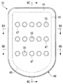
도 5는 챔버의 상부 평면도이다.
도 6은 챔버의 밑면도이다.
도 7은 챔버의 측방향 입면도이다.
도 8a 내지 도 8c는 도 5에서 단면 라인 8A 내지 8C을 따라 취한, 챔버의 단면도이다.
도 9는 챔버 제조를 위한 프로세스에 사용될 수 있는 몰드의 사시도이다.
도 10a 내지 도 10d는 챔버 제조를 위한 프로세스에서 단계를 묘사한 몰드의 사시도이다.
도 11a 내지 도 11d는 도 10a 내지 도 10d에서 단면 라인 11A 내지 라인 11D를 따라 각각 취한, 몰드의 개략적인 단면도이다.
도 12a 내지 도 12g는 도 5에 대응하는 상부 평면도이고, 챔버의 부가 구성을 도시한다.
도 13은 도 6에 대응하는 밑면도이고, 챔버의 부가 구성을 도시한다.
도 14a 및 도 14b는 도 8a에 대응하는 단면도이고, 챔버의 부가 구성을 도시한다.
도 15는 도 8c에 대응하는 단면도이고, 챔버의 부가 구성을 도시한다.
도 16은 챔버의 부가 구성의 부분 단면 사시도이다.
도 17은 도 5에 대응하는 상부 평면도이고, 도 16의 챔버의 부가 구성을 도시한다.
도 18은 도 6에 대응하는 밑면도이고, 도 16의 챔버의 부가 구성을 도시한다.
도 19a 및 도 19b는 도 17의 단면 라인 19A 및 19B를 따라 취한 것으로서, 도 16의 챔버의 부가 구성의 단면도이다.The foregoing description is better understood when read in conjunction with the appended drawings.
1 is a side elevational view of a shoe product.
2A and 2B are cross-sectional views of shoe products taken along section lines 2A and 2B of FIG.
Figure 3 is a perspective view of a fluid rechargeable chamber from a shoe product.
4 is an exploded perspective view of the chamber.
Figure 5 is a top plan view of the chamber.
6 is a bottom view of the chamber.
Figure 7 is a side elevational view of the chamber.
8A-8C are cross-sectional views of the chamber taken along section lines 8A-8C in Fig.
Figure 9 is a perspective view of a mold that may be used in a process for chamber fabrication.
10A-10D are perspective views of a mold depicting steps in a process for chamber fabrication.
Figs. 11A to 11D are schematic cross-sectional views of the mold taken along
Figs. 12A to 12G are top plan views corresponding to Fig. 5, showing an additional configuration of the chamber.
Fig. 13 is a bottom view corresponding to Fig. 6, showing an additional configuration of the chamber.
Figs. 14A and 14B are cross-sectional views corresponding to Fig. 8A, showing an additional configuration of the chamber.
Fig. 15 is a cross-sectional view corresponding to Fig. 8C, showing an additional configuration of the chamber.
16 is a partial cross-sectional perspective view of an additional configuration of the chamber.
Fig. 17 is a top plan view corresponding to Fig. 5, showing an additional configuration of the chamber of Fig. 16;
Fig. 18 is a bottom view corresponding to Fig. 6, showing an additional configuration of the chamber of Fig.
Figs. 19A and 19B are cross-sectional views of additional configurations of the chamber of Fig. 16 taken along
이하 설명 및 첨부도면에서는 유체 충전식 챔버의 다양한 구성 및 상기 챔버의 제조 방법을 개시한다. 런닝에 적합한 구성을 갖는 신발을 참조하여 챔버가 개시되어 있지만, 챔버와 관련된 개념은, 예로써 농구화, 크로스 트레이닝 신발, 풋볼화, 골프화, 하이킹화 및 부츠, 스키 및 스노우보드 부츠, 축구화, 테니스화 및 워킹화를 포함하는, 넓은 범위의 운동화 스타일에 적용될 수 있다. 또한, 챔버에 관련된 개념이, 일반적으로 드레스 슈즈, 로퍼 및 샌들을 포함하는 비운동화에 고려되는 신발 스타일에도 이용될 수 있다. 신발에 부가하여, 챔버는 풋볼 및 하키와 같은 스포츠용 헬멧, 글로브, 및 보호 패딩을 포함하는, 다른 형태의 의복 및 운동 기구에 통합될 수도 있다. 또한, 유사한 챔버가 가정용품 및 산업용품에 사용되는 쿠션 및 다른 압축 가능한 구조체에 통합될 수 있다. 따라서, 본 명세서에서 개시하는 개념을 포함하는 챔버는 다양한 제품에 사용될 수 있다.The following description and the accompanying drawings disclose various configurations of fluid-filled chambers and methods of manufacturing the chambers. Although the chamber has been disclosed with reference to a shoe having a configuration suitable for running, the concepts associated with the chamber are, for example, basketball shoes, cross training shoes, football shoes, golf shoes, hiking shoes and boots, ski and snowboard boots, ≪ / RTI > and walking). ≪ / RTI > In addition, the concept related to the chamber can also be used for footwear styles that are generally considered for non-sneaking, including dress shoes, loafers and sandals. In addition to shoes, the chamber may be incorporated into other types of apparel and exercise equipment, including sports helmets such as football and hockey, gloves, and protective padding. In addition, similar chambers may be incorporated into cushions and other compressible structures used in household and industrial appliances. Thus, a chamber incorporating the concepts disclosed herein can be used in a variety of products.
일반적인 신발 구조General Shoe Structure
도 1 내지 도 2b에는 신발(10) 제품이 갑피(20) 및 밑창 구조체(30)를 포함하는 것으로 도시되어 있다. 참조를 목적으로, 신발(10)은 3개의 일반적인 영역, 즉 전족 영역(11), 중족 영역(12) 및 뒤꿈치 영역(13)으로 분할될 수 있다. 전족 영역(11)은 일반적으로 발가락에 대응하는 신발(10) 부분과, 중족골을 지골에 연결하는 연결부를 포함한다. 중족 영역(12)는 일반적으로 발의 아치 영역에 대응하는 신발(10) 영역을 포함한다. 뒤꿈치 영역(13)은 일반적으로 종골을 포함하는 발의 뒷부분에 대응하는 신발(10) 부분을 포함한다. 영역(11-13)은 정밀하게 신발(10)의 영역을 구분하려는 의도는 아니다. 오히려, 영역(11-13)은 이하의 설명을 돕기 위해 신발(10)의 일반적인 영역으로 나타내려는 의도이다. 신발(10)에 적용되는 것에 부가하여, 영역(11-13)은 갑피(20), 밑창 구조체(30)에 적용될 수도 있고, 개별 요소에 적용될 수도 있다.1 and 2B illustrate that the
또한, 신발(10)은 외측 측면(14) 및 내측 측면(15)을 포함한다. 특히, 외측 측면(14)은 신발의 외측 영역(즉, 다른 발로부터 멀리로 향하는 표면)에 대응하고, 내측 측면(15)은 신발의 내측 영역(즉, 다른 발을 향해 대면하는 표면)에 대응한다. 외측 측면(14) 및 내측 측면(15)은 또한 각각의 영역(11-13)을 통해 연장되고, 신발(10)의 대향 측면에 대응한다. 영역(11-13)에서와 같이, 양 측면(14, 15)은 이하의 설명에 도움을 주기 위해 신발(10)의 대략적인 영역을 나타낸 것으로, 갑피(20), 밑창 구조체(30)에 또한 적용될 수 있고 그리고 신발(10)에 적용되는 것에 부가하여 개별 요소에 적용될 수도 있다.The
갑피(20)는, 발을 확실하고 편안하게 수용하기 위한 내부 보이드를 형성하도록 서로 봉합, 부착, 접합 또는 연결되는 복수의 재료 요소(예로써, 직물, 포움, 가죽 및 합성 가죽)를 포함한 사실상 종래의 구성을 갖는 것으로 도시되어 있다. 재료 요소는 내구성, 공기 투과성, 내마모성, 신축성 및 편안함과 같은 다양한 특성을 갑피(20)에 선택적으로 부여하기 위해 갑피(20)에 대해 선택되고 위치될 수 있다. 뒤꿈치 영역(13)의 발목 입구(21)는 내부 보이드로의 어세스를 제공한다. 또한, 갑피(20)는 내부 보이드의 치수를 변경하기 위해 종래의 방식으로 사용되는 레이스(22)를 포함할 수 있어, 발을 내부 보이드 내에 고정하고, 내부 보이드로의 발의 진입 및 내부 보이드로부터의 발의 제거를 용이하게 한다. 레이스(22)는 갑피(22)의 구멍을 통해 연장될 수 있고, 갑피(20)의 설부(tongue portion)는 내부 보이드 및 레이스(22) 사이에서 연장될 수 있다. 갑피(20)에는 또한, 신발(10)의 편안함을 강화하기 위해 갑피(20)의 보이드 내에 위치되고 발의 발바닥면(즉, 하부면)에 인접한 깔창(23)이 결합될 수도 있다. 본 발명의 다양한 양태는 주로 밑창 구조체(30)에 관련된 것으로, 갑피(20)는 전술한 일반적인 구성을 나타낼 수 있거나 또는 실용적으로 임의의 다른 종래의 갑피 또는 비종래의 갑피의 일반적인 구성을 나타낼 수 있다. 따라서, 갑피(20)의 전체 구조는 현저하게 상이할 수 있다.The upper 20 includes a plurality of material elements (e.g., fabric, foam, leather, and synthetic leather) that are sewn, attached, joined together or joined together to form an inner void for secure and comfortable containment of the foot. As shown in Fig. The material elements can be selected and positioned relative to the upper 20 to selectively impart various characteristics to the upper 20, such as durability, air permeability, abrasion resistance, stretchability, and comfort. The
밑창 구조체(30)는 갑피(20)에 고정되고, 갑피(20)와 지면 사이에 연장되는 구성을 갖는다. 따라서, 요컨대, 밑창 구조체(30)는 발과 지면 사이에서 연장되도록 위치된다. (발에 쿠션을 제공하는 것과 같이) 지면 반발력을 완화시키는 것에 부가하여, 밑창 구조체(30)는 견인력을 제공할 수 있고, 안정성을 부가할 수 있고, 내전(pronation)과 같이 다양한 발 움직임을 제한한다.The
밑창 구조체(30)의 주요한 요소는 중창(31) 및 겉창(32)이다. 중창(31)은 폴리우레탄 또는 에틸비닐아세테이트와 같은 폴리머 포움 재료를 포함할 수 있다. 중창(31)은 유체 충전식 챔버(33)를 포함할 수도 있다. 폴리머 포움 재료 및 챔버(33)에 부가하여, 중창(31)은 플레이트, 모더레이터, 지속 요소 또는 움직임 제어 부재를 비롯하여, 신발(10)의 편안함, 성능 또는 지면 반발력 완화 특성을 강화하는 하나 이상의 다른 신발 요소를 포함할 수 있다.The main elements of the
신발(10)의 몇몇 구성에는 없을 수 있는 겉창(32)은, 중창(31)의 하부면에 고정되고 신발(10)의 접지면의 적어도 일부를 형성하는 것으로 도시되어 있다. 겉창(32)은 지면과 결합하기 위한 내구성 및 내마모성의 표면을 제공하는 고무 재료로 형성될 수 있다. 또한, 겉창(32)은 신발(10)과 지면 사이에 견인력(즉, 마찰력) 특성을 강화하기 위해 텍스쳐화(texturization)될 수도 있다. 신발(10)의 다양한 다른 구성에서, 중창(31)이 폴리머 포움 재료, 챔버(33) 또는 이들 모두를 포함하는 방식에 따라, 겉창(32)은 폴리머 포움 재료에만, 챔버(33)에만, 또는 폴리머 포움 재료와 챔버(33) 모두에 고정될 수 있다. 몇몇 구성에서, 겉창(32)은 신발(10)에 없을 수 있다.The
챔버(33)는 중창(31)의 주연부 내에 끼워지는 형상을 갖는 것으로 도시되어 있고, 주로 뒤꿈치 영역(13)에 위치되는 것으로 도시되어 있다. 따라서, 밑창 구조체(30)가 러닝과 워킹과 같이 다양한 보행 운동 중 발과 지면 사이에서 압축될 때 발생하는 지면 반발력을 완화시키기 위해, 발이 갑피(20)에 위치될 때에는, 챔버(33)가 발의 뛰꿈치 영역 아래로(예로써, 착용자의 복숭아뼈 아래로) 연장된다. 다양한 다른 구성에서, 챔버(33)는 신발(10)의 대안적인 부분을 통해 연장될 수 있다. 예로써, 챔버(33)는 전족 영역(11)을 통해서만, 또는 중족 영역(12)을 통해서만, 또는 사실상 신발(10)의 모두를 통해서[즉, 전족 영역(11)으로부터 뒤꿈치 영역(13)까지 그리고 외측 측면(14)으로부터 내측 측면(15)까지] 연장될 수 있다. 대안으로, 챔버(33)는 신발(10)의 외측 측면(14)을 통해서만, 또는 신발(10)의 내측 측면(15)을 통해서만 연장될 수 있다. 챔버(33)는 영역과 측면의 임의의 조합을 통해 연장될 수도 있다. 다시 말해서, 다양한 구성에서, 챔버(33)는 신발(10)의 임의의 부분 또는 부분들을 통해 연장될 수 있다.The
챔버(33)는, 중창(31)의 폴리머 포움 재료 내에서 부분적으로 캡슐화되고 폴리머 포움 재료에 고정되는 것으로 도시되어 있다. 그러나, 신발(10)의 다양한 다른 구성에서, 중창(31)은 이와 달리 챔버(33)에 합체될 수 있다. 예로써, 챔버(33)는 중창(31)의 폴리머 포움 재료에 의해 사실상 둘러싸여지거나 또는 전체적으로 캡슐화될 수 있거나, 또는 폴리머 포움 재료 상에 놓여질 수 있거나, 또는 폴리머 포움 재료 아래에 놓여질 수 있거나, 또는 하나 이상의 폴리머 포움 재료의 층들 또는 영역들 사이에 놓여질 수 있다. 예로써, 챔버(33)의 일부는 중창(31)의 상부면 또는 하부면을 형성할 수 있다. 몇몇 구성에서, 중창(31)의 폴리머 포움 재료가 없을 수 있고, 챔버(33)는 갑피(20)와 겉창(32) 모두에 고정될 수 있다.The
또한, 중창(31)의 측벽은, 중창(31)의 폴리머 포움 재료에 의해 부분적으로 형성되고 챔버(33)의 일부에 의해 부분적으로 형성되는 것으로 도시되어 있지만, 측벽은 신발(10)의 다양한 다른 구성에 달리 형성될 수 있다. 예로써, 중창(31)의 측벽은 중창(31)의 폴리머 포움 재료에 의해 사실상 전체적으로 형성될 수 있다. 다른 구성에서, 중창(31)의 측벽은 챔버(33)의 노출부에 의해 사실상 전체적으로 형성될 수 있다.It should also be appreciated that while the side walls of the
또한, 다양한 구성에서, 챔버(33)는 플레이트, 모더레이터, 지속 요소 또는 움직임 제어 부재와 같은, 중창(31) 내의 하나 이상의 다른 신발 요소에 접촉하거나 또는 이들 신발 요소에 고정될 수 있다. 따라서, 챔버(33)의 전체 형상 및 챔버(33)가 신발(10)에 결합되는 방식은 현저하게 다양해질 수 있다.Also, in various configurations, the
또한, 챔버(33)가 신발(10) 내의 밀봉 챔버인 것으로 도시되고 설명되어 있지만, 챔버(33)는 신발(10) 내의 유체 시스템의 구성요소일 수도 있다. 보다 구체적으로, 신발(10)의 외부 또는 신발(10) 내의 저장조로부터의 공기로 챔버(33)를 가압하는 유체 시스템을 제공하기 위해, 펌프, 도관 및 밸브가 챔버(33)에 연결될 수 있다. 몇몇 구성에서, 챔버(33)는 착용자와 같은 개인이 유체의 압력을 조절하는 것을 허용하는 밸브 또는 다른 구조체와 결합될 수 있다. 예를 들어, 챔버(33)는, 예로써 착용자의 러닝 스타일 또는 중량에 따라 챔버(33) 내의 압력을 변화시키는 유체 시스템을 구비한, 파스크(Passke) 등에게 허여된 미국 특허 제7,210,249호 및 도쟌(Dojan) 등에게 허여된 미국 특허 제7,409,779호에 개시된 임의의 유체 시스템의 조합에 사용될 수 있다. The
챔버 구성Chamber configuration
챔버(33)는 신발 적용예에 적합한 구성을 갖는 것으로 도 3 내지 도 8c에 각각 도시되어 있다. 챔버(33)의 주요한 요소는 배리어(40), 제1 접합 억제부(45), 제2 접합 억제부(46) 및 인장 요소(50)이다.The
배리어에 대한 설명Explanation of Barrier
배리어(40)는 (a) 챔버(33)의 외부를 형성하고, (b) 가압 유체, 접합 억제부(45, 46) 및 인장 요소(50)를 수용하는 내부 보이드를 형성하고, (c) 챔버(33) 내에 가압 유체를 보유하기 위한 내구성의 밀봉 배리어를 제공한다. 배리어(40)의 외부면은 챔버(33)의 외부면을 형성하고, 배리어(40)의 내부면은 내부 보이드를 형성한다. 배리어(40)의 폴리머 재료는 (a) 배리어(40)의 상부를 형성할 수 있는, 갑피(20)를 향해 배향된 제1 배리어부(41)와, (b) 배리어(40)의 하부를 형성할 수 있는, 겉창(32)을 향해 배향된 대향하는 제2 배리어부(42)와, (c) 배리어부(41, 42)들 사이 그리고 챔버(33)의 주연부 주위에 연장되는 측벽부(43)와, (d) 제1 배리어부(41)의 주연부를 제2 배리어부(42)의 주연부에 결합하는 주연 접합부(44)를 포함한다. The
폴리머 재료의 제1 시트는 제1 배리어부(41)를 형성하는 데 사용될 수 있는 반면, 폴리머 재료의 제2 시트는 제2 배리어부(42) 및 측벽부(43)를 형성하는 데 사용될 수 있다. 넓은 범위의 폴리머 재료가 배리어(40)를 위해 사용될 수 있다. 배리어(40)용 재료의 선택에서, 배리어(40)에 의해 포함된 유체의 확산을 방지하기 위한 재료의 공학적 특성[예로써, 인장 강도, 신장 특성, 피로 특성, 동탄성 계수, 손실 타젠트(loss tangent)] 뿐만 아니라 재료의 성능이 고려될 수 있다. 예로써, 열가소성 우레탄으로 형성될 때, 배리어(40)는 대략 1.0 밀리미터의 두께를 가질 수 있지만, 예로써, 상기 두께는 0.25 내지 2.0 밀리미터의 범위일 수 있다. 열가소성 우레탄에 부가하여, 배리어(40)에 적합할 수 있는 폴리머 재료의 예에는 폴리우레탄, 폴리에스테르, 폴리에스테르 폴리우레탄 및 폴리에테르 폴리우레탄이 포함된다. 배리어(40)는, 미첼(Mitchell) 등에게 허여된 미국 특허 제5,713,141호 및 제5,952,065호에 개시된 바와 같이, 열가소성 폴리우레탄 및 에틸렌-비닐 알코올 코폴리머의 교번층을 포함하는 재료로 또한 형성될 수도 있다. 이러한 재료에 대해, 중앙층이 에틸렌-비닐 알코올 코폴리머로 형성되고, 중앙층의 인접층은 열가소성 폴리우레탄으로 형성되고, 외부층은 열가소성 폴리우레탄 및 에틸린-비닐 알코올 코폴리머의 리그라인드(regrind) 재료로 형성되는, 변경예가 사용될 수도 있다. 배리어(40)의 다른 적합한 재료는, 봉크(Bonk) 등에게 허여된 미국 특허 제6,082,025호 및 제6,127,026호에 개시된 바와 같이, 가스 배리어 재료와 엘라스토머 재료의 교번층을 포함하는 가요성 마이크로층 멤브레인이다. 부가적인 적합한 재료는 루디(Rudy)에게 허여된 미국 특허 제4,183,156호 및 제4,219,945호에 개시되어 있다. 다른 적합한 재료는, 루디에게 허여된 미국 특허 제4,936,029호 및 제5,042,176호에 개시된 바와 같이 결정질 재료를 함유한 열가소성 필름과, 봉크 등에게 허여된 미국 특허 제6,013,340호, 제6,203,868호 및 제6,321,465호에 개시되어 있는 바와 같이 폴리에스테르 폴리올을 함유한 폴리우레탄을 포함한다.A first sheet of polymeric material may be used to form the
인장 요소에 대한 설명Explanation of the tensile element
인장 요소(50)는 배리어(40)의 내부 보이드 내에 위치된 시트 또는 층의 구성을 갖는다. 인장 요소(50)는 또한 측벽부(43)로부터 내향으로 이격되고, 제1 접합 억제부(45) 및 제2 접합 억제부(46) 사이에 위치된다. 인장 요소(50)는 제1 접합 억제부(45)의 다양한 제1 구멍(47)을 통해 연장되고 복수의 이산된 제1 접합 영역(55)의 제1 배리어부(41)에 고정된다. 마찬가지로, 인장 요소(50)는 제2 접합 억제부(46)의 다양한 제2 구멍(48)을 통해 연장되고, 복수의 이산된 제2 접합 영역(56)의 제2 배리어부(42)에 고정된다. 이하 더욱 상세히 설명하는 바와 같이, 접착제 접합, 열 접합 또는 양자 모두가 인장 요소(50)를 배리어(40)에 고정하는 데 사용될 수 있다. 구멍(47, 48)이 서로에 대해 오프셋되어 챔버(33)에 걸쳐 연장되기 때문에, 그리고 인장 요소(50)가 구멍(47, 48)을 통해 연장되는 접합 영역(55, 56)에서 배리어(40)에 고정되기 때문에, 접합 영역(55, 56)은 서로에 대해 오프셋되어 인장 요소(50)에 걸쳐 교대로 연장될 수 있다.The
인장 요소(50)는 각각의 제1 접합 영역(55)에 대향한 제2 배리어부(42) 상의 위치에 접합되지 않거나 고정되지 않고, 이와 마찬가지로 인장 요소(50)는 각각의 제2 접합 영역(56)에 대향한 제1 배리어부(41) 상의 위치에 접합되지 않거나 고정되지 않는다. 즉, 인장 요소(50)는 (a) 챔버(33)에 걸쳐 다양한 위치에서 배리어부(41, 42)에 고정되고, (b) 챔버(33)의 두께에 걸쳐 대향 위치에서 각각 배리어부(42, 41)로부터 이격된다. 다음으로, 접합 억제부(45, 46)는 (a) 인장 요소(50)와 배리어부(41, 42) 사이에서의 접합을 억제할 수 있고, (b) 인장 요소(50)가 배리어부(41, 42)로부터 이격된, 챔버(33)의 부분에 걸쳐 연장될 수 있고, (c) 접합 영역(55, 56)과 같이 배리어부(41, 42)의 내부면에 인장 요소(50)가 고정되는 챔버(33)의 부분에서는 제외될 수 있다.
제1 접합 영역(55) 및 제2 접합 영역(56) 각각은 사실상 배리어(40)의 내부면으로부터 이격된 인장 요소(50)의 비접합부(53)에 의해 둘러싸여진다. 따라서, 제1 접합 영역(55) 및 제2 접합 영역(56) 각각은 다른 제1 접합 영역(55) 및 제2 접합 영역(56)으로부터 인장 요소(50)에 걸쳐 이격된다. 비접합부(53)는 연속적일 수 있고, 접합 영역(55, 56)의 외측의 인장 요소(50)의 사실상 전체를 포함할 수 있다. 또한, 비접합부(53)는 제1 배리어부(41)와 제2 배리어부(42) 사이에서 연장되고, 배리어(40) 내의 가압 유체로 인해 배리어(40)의 외향 팽창을 억제할 수 있다.Each of the
제1 접합 영역(55)은 제1 배리어부(41)에 의해 형성된 배리어(40)의 내부면의 일부 위로 분배될 수 있다. 즉, 제1 접합 영역(55)은, 제1 배리어부(41)의 영역의 30% 미만을 포함할 수 있는, 제1 배리어부(41)의 내부면의 비연속 격리 영역에 고정되어 이 영역 위로 분배될 수 있다. 마찬가지로, 제2 접합 영역(56)은 제2 배리어부(41)에 의해 형성된 배리어(40)의 내부면의 대향부 위로 분배될 수 있다. 즉, 제2 접합 영역(56)은 제2 배리어부(42)의 영역의 30% 미만을 포함할 수 있는 제2 배리어부(42)의 내부면의 비연속 격리 영역에 고정되어 이 영역 위로 분배될 수 있다. The
인장 요소(50)는, 초기 상태에서 그리고 챔버(33)의 압축 전에 사실상 평면의 시트형 또는 일반적으로 2차원인 재료층일 수 있다. 예로써, 다양한 직물, 폴리머 시트, 가죽 또는 합성 가죽을 포함하는 다양한 재료가 인장 요소(50)용으로 사용될 수 있다. 이들 재료의 조합(예로써, 직물에 접합된 폴리머 시트)도 또한 인장 요소(50)용으로 사용될 수 있다. 대안으로, 몇몇 구성에서, 인장 요소(50)는 초기 상태에서 그리고 챔버(33)의 압축 전에 외형을 가질 수 있다. 다양한 구성에서, 인장 요소(50)는 접합부를 형성하기 위해 인장 강도, 탄성 계수, 밀도 및 용량과 같은 특성을 갖는 다양한 재료를 포함할 수 있다. 다음으로, 이러한 특성들 각각은, 예로써 비교적 단단한 또는 비교적 신축성이 있는 것과 같이 임의의 범위의 값을 가질 수 있다.The
직물과 관련하여, 인장 요소(50)는 니트 재료, 직포 재료, 부직포 재료, 스페이서 재료, 웨브 재료 또는 메쉬 직물 재료, 또는 레이온, 나일론, 폴리에스테르, 폴리아크릴, 엘라스타아제, 면, 울 또는 실크를 포함하는 구성요소를 포함하거나 또는 이들로부터 형성될 수 있다. 또한, 직물은 비신축성일 수 있거나, 일방향 신축성을 나타낼 수 있거나 또는 다방향 신축성을 나타낼 수 있다. 보다 구체적으로, 인장 요소(50)에 포함된 직물 재료는 인장 파괴 전에 적어도 30%의 일방향 신장 또는 2방향 신장을 나타낼 수 있다. 다시 말해서, 다양한 구성에서, 인장 요소(50)의 재료는 다양한 정도의 탄성을 나타낼 수 있다. 따라서, 다양한 재료가 인장 요소(50)에 적합할 수 있다.In relation to the fabric, the
인장 요소(50)는 배리어(40)에 사용되는 임의의 범위의 폴리머 재료와 같은 폴리머 재료를 포함할 수 있다. 인장 요소(50)는 예로써, 열가소성 폴리머 재료를 포함할 수 있다. 다음으로, 이하 설명하는 바와 같이, 하나 이상의 열 접합이 제1 접합 영역(55)과 배리어(40) 사이 또는 제2 접합 영역(56)과 배리어(40) 사이에 형성될 수 있도록, 인장 요소(50)의 접합 영역(55, 56)이 배리어(40)에 열 접합될 수 있다. 마찬가지로, 이산된 제1 접합 영역(55) 및 이산된 제2 접합 영역(56)은 열 접합에 의해 적어도 부분적으로 배리어(40)에 고정될 수 있다.The
접합 영역(55, 56)은 2방향으로 인장 요소(50)에 걸쳐 연장된다. 예로써, 신발(10) 내에 결합될 때, 접합 영역(55, 56)은 폭 또는 중간 측방향[즉, 신발(10)의 외측 측면(14)과 내측 측면(15) 사이에서 연장되는 방향]뿐만 아니라 길이 또는 전후 방향[즉, 신발(10)의 전족 영역(11)과 뒤꿈치 영역(13) 사이에서 연장되는 방향] 모두에서 인장 요소(50)를 따라 연장된다.The
제1 접합 영역(55) 및 제2 접합 영역(56)도 또한 규칙적인 반복 패턴으로 인장 요소(50)에 걸쳐 연장된다. 보다 구체적으로, 도 3 내지 도 8c에 도시된 바와 같이, 접합 영역(55, 56)은 7개의 줄 및 5개의 열을 갖는 규칙적인 반복 패턴의 구성을 갖는다. 복수의 제1 접합 영역(55) 및 복수의 제2 접합 영역(56) 각각은 규칙적인 반복 패턴 내에서 선형으로 정렬된 그룹의 구성을 갖는 것으로 또한 도시되어 있다. 즉, 제1 접합 영역(55)은 인장 요소(50)에 걸쳐 연장되고 규칙적인 반복 패턴인 7개의 줄 중 3개에 배치되고, 제2 접합 영역(56)은 인장 요소(50)에 걸쳐 연장되고 규칙적인 반복 패턴인 7개의 줄 중 4개에 배치된다. The
제1 접합 영역(55)의 줄 및 제2 접합 영역(56)의 줄도 또한 인장 요소(50)에 걸쳐 서로 사이사이에 배치되어, 제1 접합 영역(55)의 선형 정렬 그룹은 제2 접합 영역(56)의 선형 정렬 그룹들 사이에 배치된다. 전술한 방향에 대해, 제1 접합 영역(55)의 줄 및 제2 접합 영역(56)의 줄은 전후 방향으로 서로 사이사이에 배치된다. 결국, 인장 요소(50)는 적어도 하나의 외부 시각에 대해 장애물이 최소가 된다고 하는 이점을 가질 수 있다.The rows of
인장 요소(50)의 규칙적인 반복 패턴의 줄을 따라 각각의 제1 접합 영역(55)에 가장 근접하게 이웃한 접합 영역은 하나 이상의 다른 제1 접합 영역(55)이다. 즉, 규칙적인 반복 패턴의 줄은 인장 요소(50)를 따라 서로 가장 근접하게 이웃한 제1 접합 영역(55)을 포함한다. 전술한 방향에 대해, 줄은 중간 측방향에서 서로 가장 근접하게 이웃한 제1 접합 영역(55)을 포함한다. 반대로, 인장 요소(50)의 규칙적인 반복 패턴의 열을 따라 각각의 제1 접합 영역(55)에 가장 근접하게 이웃한 접합 영역은 하나 이상의 제2 접합 영역(56)이다.The junction regions closest to each
다양한 구성에서, 접합 영역(55, 56)은 인장 요소(50)의 길이를 따라 연장되는 적어도 3개의 열과, 인장 요소(50)의 폭을 따르는 적어도 3개의 줄로 배열될 수 있다. 또한, 도 3 내지 도 8c에 도시된 바와 같이, 접합 영역(55, 56)이 줄과 열을 갖는 규칙적인 반복 패턴의 구성을 갖는 인장 요소(50)의 구성에서, 규칙적인 반복 패턴의 열과 줄은 서로에 대해 사실상 직각일 수 있다. 다른 구성에서, 규칙적인 반복 패턴의 줄과 열은 서로 사실상 직각과 다른 각도를 이룰 수 있다.In various configurations, the
도 3 내지 도 8c에 도시된 바와 같이, 각각의 접합 영역(55, 56)은 사실상 원형 형상의 구성을 갖는다. 또한, 각각의 접합 영역(55, 56)은 비세장형(non-elongate) 형상(즉, 제1 방향에서의 범위가 2 이상의 비율만큼 제2 방향에서의 범위를 초과하지 않는 2차원 형상)을 갖는다. 보다 일반적으로, 각각의 접합 영역(55, 56)은 [접합 영역(55 또는 56) 내의 임의의 2개의 점에 대해, 또한 이들 2개의 점을 연결하는 직선도 접합 영역(55 또는 56) 내에 있다는 것을 의미하는] 볼록 형상의 구성을 가질 수 있다. 즉, 접합 영역(55, 56)의 형상들은 사실상 외향 벌지(bulge)가 없을 수 있다. 사실상 원형, 비세장형, 볼록 형상의 접합 영역(55, 56)은 인장 요소(50)에 걸쳐 접합 영역(55, 56)의 컴팩트함 또는 적용성과 같은 접합 영역(55, 56)의 하나 이상의 특성을 변경시킬 수 있다.As shown in Figs. 3 to 8C, each of the
제조에 대한 일반적인 설명General description of manufacturing
챔버(33)를 제조하는 데 다양한 프로세스가 사용될 수 있다. 일반적으로, 제조 프로세스는 (a) 배리어부(41, 42) 및 측벽부(43)를 형성하는 한 쌍의 폴리머 시트를 인장 요소(50)에 고정하고, (b) 폴리머 시트의 주연부에 결합하고 측벽부(43) 주위에서 연장될 수 있는 주연 접합부(44)를 형성하는 것을 포함한다. 주연 접합부(44)는 챔버(33)의 상부면에 인접하게 도시되어 있지만, 챔버(33)의 상부면과 하부면 사이에 위치될 수 있거나, 또는 챔버(33)의 하부면에 인접할 수도 있다. 또한, 제조 프로세스는 (a) 인장 요소(50)를 챔버(33) 내에 위치설정하고, (b) 배리어부(41, 42) 각각에 인장 요소(50)의 접합 영역(55, 56)을 고정하는 것을 포함할 수 있다. 사실상 모든 제조 프로세스가 몰드를 이용하여 수행될 수 있지만, 이하 더욱 상세히 설명하는 바와 같이, 다양한 부품 또는 프로세스의 단계들 각각은 챔버(33)의 형성 중 별개로 수행될 수 있다. 즉, 다양한 다른 방법들이 챔버(33)를 형성하는 데 또한 사용될 수도 있다.Various processes may be used to manufacture the
배리어(40)와 인장 요소(50) 사이의 접합을 용이하게 하기 위해, 챔버(33)의 요소는 연성화되거나 용융되도록 가열될 수 있거나, 달리 배리어(40)와 인장 요소(50) 중 하나 또는 모두에서 폴리머 재료의 상태 변화가 시작될 수 있다. 접촉 시, 배리어(40)의 일부와 인장 요소(50)는 결합되거나 달리 고정되어, 열 접합을 통해 접합 영역(55, 56)을 형성한다. 따라서, 냉각 시, 인장 요소(50)는 배리어(40)와 영구적으로 결합된다.The elements of the
본 명세서에서 사용한 바와 같이, 용어 "열 접합" 또는 그 파생어는, 요소의 재료들이 냉각될 때 서로 고정되도록 하기 위한, 요소들 중 적어도 하나 내의 열가소성 폴리머 재료의 연성화 또는 용융을 포함하는, 2개 요소[예로써, 배리어(40) 및 인장 요소(50)] 사이의 고정 기술로서 정의된다. 마찬가지로, 용어 "열 접합"은 요소의 재료들이 냉각될 때 서로 고정되도록 하기 위한, 요소들 중 적어도 하나 내의 열가소성 폴리머 재료의 연성화 또는 용융을 포함하는 프로세스를 통해 2개의 요소를 결합시키는, 접합, 링크 또는 구조체로서 정의된다. 예로써, 열 접합은 요소들이 결합하도록 2개 이상의 요소들 각각의 열가소성 재료의 용융 또는 연성화를 포함할 수 있다. 따라서, 열 접합은 폴리머 접합부(즉, 하나의 요소의 폴리머 재료와 다른 요소의 폴리머 재료 사이의 열 접합부)를 생성할 수 있다.As used herein, the term " thermal bonding ", or its derivatives, refers to the bonding of two elements, including ducting or melting of a thermoplastic polymer material in at least one of the elements, (E.g., the
열 접합은 일반적으로 접착제의 사용을 포함하지 않지만, 열을 이용하여 요소들을 서로에 대해 직접 접합하는 것을 포함한다. 그러나, 몇몇 상황에서, 열 접합을 통한 요소들의 결합 또는 열 접합을 보완하기 위해 접착제가 사용될 수 있다. 예로써, 열 접합에 대한 대안으로서 또는 열 접합에 부가하여, 접착제, 열활성 접착제 또는 다른 고정 구조체가 요소들의 결합에 사용될 수 있다.Thermal bonding generally does not involve the use of adhesives, but involves the direct bonding of the elements to one another using heat. However, in some situations, an adhesive may be used to complement the bonding or thermal bonding of the elements through thermal bonding. By way of example, as an alternative to thermal bonding or in addition to thermal bonding, an adhesive, a thermally active adhesive or other fixing structure may be used for bonding the elements.
이러한 제조 프로세스에 후속하여, 또는 제조 프로세스의 일부로써, 유체가 내부 보이드 내로 주입되어 0과 350 kPa(즉, 대략 제곱 인치당 51 파운드) 사이로 압축될 수 있다. 가압된 유체는 배리어(40)에 외향력을 가하여, 배리어부(41, 42)를 분리시키는 경향이 있다. 그러나, 인장 요소(50)는 배리어부(41, 42)들 각각에 고정되고, 가압될 때 챔버(33)의 원하는 형상을 유지하도록 작동한다. 보다 구체적으로, 내부 보이드에 걸쳐 연장되는 인장 요소(50)의 비접합부(53)는 배리어(40) 상의 가압 유체의 외향력에 의한 인장 상태에 놓이게 되어, 배리어(4)가 외향으로 팽창되는 것을 방지하고 챔버(33)가 원하는 형상으로 유지되게 한다. 유체가 이탈하는 것을 방지하는 밀봉부를 형성하도록 주연 접합부(44)가 폴리머 시트에 결합되는 반면, 인장 요소(50)는 유체의 압력으로 인해 배리어(40)가 외향으로 확장되거나 달리 팽창되는 것을 방지한다. 즉, 인장 요소(50)는 배리어부(41, 42)의 원하는 형상을 유지하도록 챔버(33)의 팽창을 효과적으로 제한한다.Following this manufacturing process, or as part of the manufacturing process, fluid may be injected into the inner void and compressed between 0 and 350 kPa (i.e., about 51 pounds per square inch). The pressurized fluid tends to apply an exerting force to the
반응 억제부에 대한 설명Explanation of the reaction suppressing part
다양한 기술이 전술한 일반적인 제조 프로세스에서 사용될 수 있지만, 접합 억제부(45, 46)는 배리어(40)와 인장 요소(50)가, 접합 영역(55, 56)의 위치를 제외하고는, 서로 접합되지 않도록 한다. 즉, 접합 억제부(45, 46)는 접합 영역(55, 56)에서의 접합을 허용하지만, 인장 요소(50)의 비접합부(53)는 배리어(40)로부터 분리되어 결합되지 않은 상태로 남겨지도록 보장한다.Although the various techniques can be used in the above-described general manufacturing process, the
제1 접합 억제부(45)는 제1 배리어부(41)의 내부면에 인접하게 위치되고, 제2 접합 억제부(46)는 제2 배리어부(42)의 내부면에 인접하게 위치된다. 도시되어 있는 바와 같이, 접합 억제부(45, 46)는 복수의 제1 구멍(47) 및 제2 구멍(48)이 각각 통과하여 연장되는 시트의 구성을 갖는다. 챔버(33) 내에서, 제1 구멍(47)은 제2 구멍(48)에 대해 오프셋되어 챔버(33)에 걸쳐 연장될 수 있어, 구멍(47)과 구멍(48)은 서로 정렬되지 않는다. 예로써, 제1 구멍(47)은 제2 구멍(48)과 수직 방향에서 정렬되지 않을 수 있다.The first
접합 억제부(45, 46)는 접합 억제 재료 즉, 배리어(40) 및 인장 요소(50)의 다양한 재료보다 열 접합 또는 다른 형태로 접합되기 쉽지 않은 재료로 형성될 수 있다. 인장 요소(50)와 배리어(40) 사이의 열 접합을 용이하게 하지만, 배리어(40)와 접합 억제부(45, 46) 사이 또는 접합 억제부(45, 46)와 인장 요소(50) 사이 또는 양자 모두에서 열 접합을 용이하게 하지 않는 압력 및 온도의 범위가 있을 수 있다.The
재료의 이산적 시트의 구성을 갖는 것으로 도시되어 있지만, 접합 억제부(45, 46)는 하나 이상의 인장 요소(50), 제1 배리어부(41) 및 제2 배리어부(42)와 통합될 수 있다. 예로써, 하나 이상의 배리어(40) 및 인장 요소(50)는 배리어(40) 또는 인장 요소(50)의 다른 재료보다 열 접합이 쉽지 않을 수 있는, 소정 표면을 따르는 위치에 집중된 재료를 포함할 수 있다. 따라서, 제조 프로세스의 가열 및 압축 중, 접합 영역(55, 56)은 통합된 접합 억제부에 대응하지 않는 인장 요소(50) 상의 위치에서 우선적으로 형성될 수 있다.The
몇몇 구성에서 챔버(33)가 2개의 접합 억제부(45, 46)를 포함하는 것으로 도시되어 있지만, 챔버(33)는 다른 개수의 접합 억제부를 포함할 수 있다. 예로써, 다른 구성에서, 챔버(33)는 제1 배리어부(41) 또는 제2 배리어부(42)의 내부면에 인접하게 1개의 접합 억제부만을 포함할 수 있다. 대안으로, 챔버(33)의 다른 구성에서는, 제1 접합 억제부(45) 또는 제2 억제부(46) 중 하나의 범위에 사실상 대응하는 다중 접합 억제부와 같이, 동일한 배리어부에 인접한 복수의 이산적 접합 억제부이거나 별도의 접합 억제부를 포함할 수 있다. 챔버(33)의 몇몇 구성에서는 임의의 접합 억제부를 포함하지 않을 수 있다.Although the
이점에 대한 설명Explanation of benefits
챔버(40)는 몇몇 다른 형태의 유체 충전식 챔버보다 우위의 다양한 이점을 갖는다. 예로써, 챔버(40)는 재료층으로부터 비교적 효과적인 방식으로 형성될 수 있다.The
제조 프로세스Manufacturing Process
다양한 제조 프로세스가 챔버(33)를 형성하는 데 사용될 수 있지만, 적합한 가열성형 프로세스의 예를 지금 설명한다. 도 9를 참조할 때, 가열성형 프로세스에 사용될 수 있는 몰드(60)는 제1 몰드부(61) 및 제2 몰드부(62)를 포함하는 것으로 도시되어 있다. 몰드(60)는 제1 배리어부(41), 제2 배리어부(42) 및 측벽부(43)를 형성하도록 몰딩 및 접합되는 한 쌍의 폴리머 시트로부터 챔버(33)를 형성하는 데 사용된다. 또한, 가열성형 프로세스는 인장 요소(509)를 배리어(40) 내에 고정한다. 보다 구체적으로, 몰드(60)는 (a) 제1 배리어부(41)를 형성하기 위해 폴리머 시트 중 하나에 형상을 부여하고, (b) 제2 배리어부(42)를 형성하도록 폴리머 시트 중 다른 것에 형상을 부여하고, (c) 측벽부(43)를 형성하기 위해 그리고 주연 접합부(44)를 형성하여 폴리머 시트의 주연부를 결합하기 위해 폴리머 시트에 형상을 부여하고, (d) 인장 요소(50)를 각각의 배리어부(41, 42)에 접합하다. Although a variety of manufacturing processes may be used to form the
도 10a 및 도 11a에 도시된 바와 같이, 챔버(33) 제조 시, 챔버(33)의 다양한 구성요소가 몰드부(61)와 몰드부(62) 사이에 위치된다. 구성요소를 적절히 위치설정하기 위해, 셔틀 프레임 또는 다른 장치가 사용될 수 있다. 이어서, 챔버(33)의 다양한 구성요소가, 구성요소들 사이에서의 접합을 용이하게 하는 온도로 가열된다. 배리어(40)를 형성하는 인장 요소(50) 및 폴리머층(71, 72)에 사용되는 특정 재료에 따라서, 적절한 온도는 섭씨 120 내지 200 도(화씨 248 내지 392 도) 이상의 범위일 수 있다. 다양한 복사 히터 또는 다른 장치가 챔버(33)의 다양한 구성요소를 가열하는 데 사용될 수 있다. 몇몇 제조 프로세스에서, 몰드(60)는 몰드(60)와 챔버(33)의 다양한 구성요소 사이의 접촉에 의해 접합을 용이하게 하는 레벨까지 구성요소의 온도가 상승되도록 가열될 수 있다. 대안적인 제조 프로세스에서, 하나 이상의 폴리머층(71, 72), 접합 억제부(45, 46) 및 인장 요소(50)와 같은 챔버(33)의 다양한 구성요소가 몰드부(61)와 몰드부(62) 사이에 위치되기 전에 가열될 수 있다.10A and 11A, various components of the
챔버(33)의 다양한 구성요소가 배치 및 가열되면, 몰드부(61, 62)는, (a) 제1 몰드부(61)가 제1 폴리머층(71)에 접촉하고, (b) 제2 몰드부(62)의 릿지(64)가 제2 폴리머층(72)에 접촉하도록, 서로를 향해 이동되어 구성요소들 상에서 폐쇄되기 시작한다. 다음으로, 제1 폴리머층(71)의 일부는 제1 접합 억제부(45)에서 제1 구멍(47)을 통해 인장 요소(50)의 일부에 근접하게 되고 상기 일부에 노출될 수 있다. 마찬가지로, 제2 폴리머층(72)의 일부는 제2 접합 억제부(46)에서 제2 구멍(48)을 통해 인장 요소(50)의 일부에 근접하게 되고 상기 일부에 노출될 수 있다. 따라서, 구성요소는 몰드(60)에 대해 위치되고 초기 형상설정 및 위치설정이 이루어진다.When the various components of the
이후, 공기는 몰드부(61, 62)에서 다양한 진공 포트를 통해 폴리머층(71, 72) 주위의 영역으로부터 부분적으로 배기될 수 있다. 공기 배기의 목적은 몰드(60)의 다양한 외형에 폴리머층(71, 72)을 접촉시키게 하는 것이다. 이러한 점은, 폴리머층(71, 72)이 몰드(60)의 외형에 따라 적절한 형상을 갖는다는 점을 보장한다. 폴리머층(71, 72)은 몰드(60) 안으로 그리고 인장 요소(50) 주위로 연장되도록 신장될 수 있다는 점을 알아야 한다. 몰드부(61)와 몰드부(62) 사이에서 압축되기 전의 폴리머층(71, 72)의 두께는, 챔버(33)의 제조가 완료된 후 배리어(40)의 대응 부분의 두께보다 클 수 있다. 폴리머층(71, 72)의 초기 두께와 배리어(40)의 최종 두께 사이의 이러한 차이는 결과적으로 이러한 가열성형 프로세스의 스테이지에서 신장을 발생시킬 수 있다.Thereafter, air can be partially exhausted from the area around the polymer layers 71, 72 through the various vacuum ports at the
몰드부(61, 62)는 구성요소에 특정 정도의 압력을 발생시킬 수 있어, 폴리머층(71, 72)을 인장 요소(50)의 대향면에 접합 및 고정시킨다. 보다 구체적으로, 제1 폴리머층(71)의 일부는, 제1 접합 영역(55)에 대응하는 분리되고 이격된 영역에서 제1 접합 억제부(45)의 제1 구멍(47)을 통해 인장 요소(50)의 일부에 열 접합될 수 있다. 마찬가지로, 제2 폴리머층(72)의 일부는 제2 접합 영역(56)에 대응하는 분리되고 이격된 영역에서 제2 접합 억제부(46)의 제2 구멍(48)을 통해 인장 요소(50)의 일부에 열 접합될 수 있다. 제2 몰드부(62)는 인장 요소(50)의 주연부로부터 이격된 위치에서 제2 폴리머층(72)으로부터 측벽부(43)를 형성하는 주연부 공동(63)을 포함한다. 도 9 내지 도 11d에 도시된 바와 같이, 폴리머층(71, 72)은 인장 요소(50)에 열 접합되지만, 다른 제조 프로세스에서 폴리머층(71, 72)은 인장 요소(50)에 달리 고정될 수 있다. 예로써, 폴리머층(71, 72)은, 토머스(Thomas) 등에게 허여된 미국 특허 제7,070,845호에 개시되어 있는 바와 같이, 접착제에 의해, 또는 열가소성 실 또는 스트립의 사용에 의해 인장 요소(50)에 고정될 수 있다.The
도 10b 및 도 11b에 도시된 바와 같이, 몰드(60)가 더 폐쇄되면, 제1 몰드부(61) 및 릿지(64)는 제1 폴리머층(71)을 제2 폴리머층(72)에 접합하고, 이로써 제1 폴리머층(71)과 제2 폴리머층(72) 사이에 주연 접합부(44) 및 내부 보이드가 형성된다. 인장 요소(50)의 주연부는 주연부 공동(64) 및 릿지(64)로부터 내향 이격된다. 또한, 인장 요소(50)로부터 멀리 연장되는 릿지(64)의 부분은 폴리머층(71, 72)의 다른 영역들 사이에서 접합부를 형성하여 팽창 도관(73)의 형성에 기여한다.As shown in Figures 10b and 11b, when the
폴리머층(71, 72)이 몰드(60)의 다양한 외형에 접촉하게 하기 위한 제2 수단을 제공하기 위해, 인장 요소(50)에 근접한 폴리머층(71)과 폴리머층(72) 사이의 영역이 가압될 수 있다. 이러한 방법의 준비 스테이지 중, 인젝션 니들은 폴리머층(71, 72)들 사이에 위치될 수 있고, 인젝션 니들은 몰드(60)가 폐쇄될 때 릿지(64)가 인젝션 니들을 둘러싸도록 위치될 수 있다. 이후, 폴리머층(71, 72)이 릿지(64)와 결합하도록 인젝션 니들로부터 가스가 방출될 수 있다. 이로써, 팽창 도관(73)이 폴리머층(71, 72)들 사이에 형성될 수 있다(도 10c 참조). 이후, 가스가 팽창 도관(73)을 통과하여, 폴러미층(71, 72)들 사이의 인장 요소(50)에 근접한 영역으로 진입하여 이 영역을 압축시킨다. 진공과 관련하여, 내압은 폴리머층(71, 72)이 몰드(60)의 다양한 면에 접촉하는 것을 보장한다.The area between the
인장 요소(50)와 배리어(40) 사이의 접합을 용이하게 하기 위해, 보조 폴리머 재료가 인장 요소(50) 내에 추가되거나 포함될 수 있다. 가열될 때, 보조 폴리머 재료는, 배리어부(41, 42)와의 접촉에 의해 배리어(40)로부터의 재료가 보조 폴리머 재료와 섞이거나 달리 결합되게 하도록, 연성화되거나 용융되거나 달리 상태 변화를 시작할 수 있다. 따라서, 냉각 시, 보조 폴리머 재료는 배리어(40)에 영구적으로 결합될 수 있고, 이로써 인장 요소(50)는 배리어(40)에 결합된다. 예로써, 토머스 등에게 허여된 미국 특허 제7,070,845호에 개시되어 있는 바와 같이, 몇몇 구성에서는 배리어(40)와의 접합을 용이하게 하기 위해 열가소성 실 또는 스트립이 인장 요소(50) 내에 존재할 수 있거나 또는 배리어(40)와 인장 요소(50)를 고정하는 데 접착제가 사용될 수 있다. 몰드부(61, 62)에 의해 구성요소에 부여되는 압력은, 보조층 또는 열가소성 실이 폴리머층(71, 72)과의 접합부를 형성하는 것을 보장한다.An auxiliary polymeric material may be added to or contained within the
도 10c 및 도 11c에 도시된 바와 같이, 접합이 완료되면, 몰드(60)는 개방되고, 챔버(33)의 다양한 구성요소 및 폴리머층(71, 72)의 초과부는 냉각되도록 허용된다. 팽창 니들 및 팽창 도관(73)을 통해 내부 보이드로 유체가 주입될 수 있다. 몰드(60)를 빠져나올 때, 인장 요소(50)는 압축 상태로 남게 된다. 그러나, 챔버(33)가 가압될 때, 유체는 배리어부(41, 42)를 분리하게 하는 경향이 있는 외향력을 배리어(40)에 가하여 인장 요소(50)를 인장상태로 두게 한다. 보다 구체적으로, 인장 요소(50)는 제1 접합 영역(55)에서 제1 폴리머층(71)에 고정되어 접촉될 수 있는 반면, 인장 요소(50)는 제2 접합 영역(56)에서 제2 폴리머층(72)에 고정되어 접촉될 수 있다. 가압 시, 인장 요소(50)의 비접합부(53)는 내부 보이드에 걸쳐 연장될 수 있고 폴리머층(71, 72)으로부터 이격될 수 있다.10C and 11C, once the bonding is completed, the
또한, 가압 후, 챔버(33)에 인접한 팽창 도관(73)을 밀봉하기 위한 밀봉 프로세스가 사용된다. 이후, 도 10d 및 도 11d에 도시된 바와 같이, 폴리머층(71, 72)의 초과부가 제거되어, 챔버(33)의 제조가 완료된다. 대안으로서, 팽창과 초과 재료의 제거의 순서가 역으로 될 수도 있다. 이러한 프로세스에서의 최종 단계로서, 챔버(33)가 테스트된 뒤 신발(10)의 중창(31)에 합체될 수 있다.Also, after the pressurization, a sealing process is used to seal the
추가 구성Additional configuration
도 3 내지 도 8c에 도시된 바와 같이, 챔버(33)는 주로 신발(10)의 뒤꿈치 영역(13)을 통해 연장되도록 구성된다. 다른 구성에서, 챔버(33)는 대안적인 범위를 가질 수 있다. 예로써, 도 12a에 도시된 바와 같이, 챔버(33)는 신발(10)의 사실상 전체[즉, 전족 영역(11)으로부터 뒤꿈치 영역(13)까지, 그리고 또한 외측 측면(14)으로부터 내측 측면(15)까지]를 통해 연장되도록 구성될 수 있다. 도시하지는 않았지만, 또한 챔버(33)는, 전족 영역(11)에만 합체되고 발의 전방 영역 아래에 연장되는 형상도 가질 수 있다.As shown in FIGS. 3-8C, the
도 3 내지 도 8c에는, 제1 접합 영역(55)이 7개의 줄 중 3개에 배치되고 제2 접합 영역(56)이 7개의 줄 중 4개에 배치되는, 7개의 줄과 5개의 열을 갖는 규칙적인 반복 패턴으로 인장 요소(50)에 걸쳐 연장되는 것으로 도시되었지만, 접합 영역(55, 56)은 달리 구성될 수 있다. 다양한 다른 구성에서, 접합 영역(55, 56)은 다른 간격 또는 다른 개수의 줄과 열로 인장 요소(50)에 걸쳐 연장될 수 있다. 예로써, 도 12b에 도시된 바와 같이, 제1 접합 영역(55)은 인장 요소(50)에 걸쳐 연장되는 규칙적인 반복 패턴의 3개의 줄과 3개의 열로 배치된다. 다음으로, 제2 접합 영역(56)은 2개의 줄과 3개의 열로 배치되어, 규칙적인 반복 패턴이 전체적으로 5개의 줄과 3개의 열로 인장 요소(50)에 걸쳐 연장된다.3 to 8C illustrate that seven rows and five columns in which the
도 3 내지 도 8c에는 각각의 접합 영역(55, 56)이 볼록한, 사실상 원형 비세장형 형상을 갖는 것으로 도시되어 있다. 다른 구성에서, 임의의 접합 영역(55, 56)은 다른 형상을 가질 수 있다. 예로써, 도 12c에 도시된 바와 같이, 제1 접합 영역(55)은 타원 또는 다른 비세장형 구형, 사각형 또는 삼각형의 볼록 형상을 가질 수 있다. 또한, 제1 접합 영역(55)은 비세장형 직사각형, 육각형, 다이아몬드형, 사다리꼴, 다른 다각형, 또는 임의의 다른 규칙적인 기하학적 형상 또는 불규칙적인 형상의 볼록 형상도 가질 수 있다. 도 12d에 도시된 바와 같은, 다른 예로써, 제1 접합 영역(55)은 숫자 8자형의 측방향 압축식 또는 핀치형(pinched) 사각형 또는 크로스(cross)와 같은 비볼록 형상을 가질 수 있다. 또한, 제1 접합 영역(55)은 다각형 또는 임의의 다른 규칙적인 기하학적 형상 또는 불규칙한 형상을 포함하는 비볼록 형상을 가질 수도 있다. 또한, 도 12c 및 도 12d에 도시된 바와 같이, 제1 접합 영역(55)의 형상은 중간-측방향 또는 전후 방향에 대해 임의의 각도로 배향될 수 있다.3 to 8C, each of the
접합 억제부(45, 46)와 달리 또는 이에 부가하여, 접합 촉진부가 하나 이상의 인장 요소(50), 제1 배리어부(41) 또는 제2 배리어부(42)에 포함될 수 있다. 이러한 접합 촉진부는, 접합 촉진 재료 즉, 배리어(40) 및 인장 요소(50)의 다양한 다른 재료보다 열 접합이 쉬운 재료로 형성될 수 있다. 따라서, 제조 프로세스의 가열 및 압축 중에, 접합 영역(55, 56)은 합체된 접합 촉진제에 대응하는 인장 요소(50)의 표면의 위치에서 우선적으로 형성될 수 있다. Unlike or in addition to the
도 3 내지 도 8c에 도시된 바와 같이, 각각의 접합 영역(55, 56)은 사실상 유사한 크기를 갖는다. 다른 구성에서, 접합 영역(55, 56)은 다른 또는 다양한 크기를 가질 수 있다. 예로써, 도 12e에 도시된 바와 같이, 몇몇 제1 접합 영역(55)은 다른 제1 접합 영역(55)보다 크다. 또한, 접합 영역(55, 56)은, 규칙적인 반복 패턴 또는 불규칙 방식을 포함한 임의의 다른 방식으로 인장 요소(50)에 걸쳐 크기가 변할 수 있다.As shown in Figs. 3 to 8C, each of the
도 3 내지 도 8c에는 접합 영역(55, 56)이 규칙적인 반복 패턴의 구성을 갖는 것으로 도시되어 있다. 다른 구성에서, 접합 영역(55, 56)은 인장 요소(56)에 걸쳐 달리 분배될 수 있다. 예로써, 도 12f에 도시된 바와 같이, 제1 접합 영역(55)은 비패턴식이나 달리 불규칙적인 방식으로 인장 요소(50)에 걸쳐 분배될 수 있다.3 to 8C, the
도 3 내지 도 8c에서, 접합 영역(55, 56)은 패턴이 서로에 대해 사실상 직각인 줄과 열을 갖는 규칙적인 반복 패턴의 구성을 갖는 것으로 도시되어 있다. 다른 방식으로, 도 3 내지 도 8c에 도시된 패턴은 사실상 정사각형 격자에 대응한다. 다른 구성에서, 접합 영역(55, 56)은 이와 다른 패턴일 수 있다. 예로써, 도 12g에 도시된 바와 같이, 제1 접합 영역(55)의 패턴은 사실상 육각형 격자에 대응하지만, 도 13에 도시된 제2 접합 영역(56)의 패턴은 사실상 다이아몬드형 격자에 대응한다. 다음으로, 도 12g의 제1 접합 영역(55) 및 도 13의 제2 접합 영역(56)은 모두 인장 요소(50)에 걸쳐 분배될 수 있으며, 제1 접합 영역(55)은 인장 요소(50)에 걸쳐 제2 접합 영역(56)으로부터 이격된다.3 to 8C, the
또한, 챔버(33)의 높이와 챔버(33)의 폭 또는 길이 사이의 상대적인 관계는 도 3 내지 도 8c에 도시된 상대적인 관계와 상이할 수 있다. 예로써, 도 14a에 도시된 바와 같이, 챔버(33)의 폭에 대한 챔버의 높이는 도 3 내지 도 8c에 도시된 바와 같은 챔버(33)의 폭에 대한 챔버의 높이보다 크다. 따라서, 다양한 구성에서, 챔버(33)의 폭 또는 길이에 대한 챔버의 높이의 비는 도 3 내지 도 8c에 도시된 것보다 크거나 작을 수 있다.Further, the relative relationship between the height of the
도 3 내지 도 8c에 도시된 바와 같이, 제1 접합 억제부(45)는 제1 배리어부(41)에 근접하고, 제2 접합 억제부(46)는 제2 배리어부(42)에 근접한다. 그러나, 다른 구성의 챔버(33)는 보다 적은 접합 억제부를 포함할 수 있다. 예로써, 챔버(33)의 몇몇 구성에서, 접합 억제부는 배리어부(41, 42) 중 하나만에 근접할 수 있다. 도 14b에 도시된 구성과 같은 다른 구성에서, 챔버(33)는 접합 억제부를 포함하지 않을 수 있다.3 to 8C, the first
도 3 내지 도 8c에 도시된 바와 같이 접합 영역(55, 56)들 사이의 간격은 사실상 인장 요소(50)에 걸쳐 규칙적이다. 이러한 사실상 규칙적인 간격은 배리어부(41, 42)에 사실상 평행한 구성을 부여할 수 있다. 그러나, 다른 구성에서, 접합 영역(55, 56)들 사이의 간격은 챔버(33)에 외형을 부여할 수 있다. 예로써, 도 15에 도시된 바와 같이, 인장 요소(50)에 걸쳐 접합 영역(55, 56)들 사이의 간격은 전족 영역(11)에서보다 뒤꿈치 영역(13)에서 크다. 대응하게, 뒤꿈치 영역(13)에서의 배리어부(41, 42)들 사이의 거리는 전족 영역(11)에서의 배리어부(41, 42)들 사이의 거리보다 커서, 챔버(33)에 테이퍼를 부여한다. 대안으로, 접합 영역(55, 56)들 사이의 간격은 챔버(33)에서 오목부 또는 합입부 또는 돌출부를 형성할 수 있다. 접합 영역(55, 56)들 사이의 간격의 차는 두아(Dua)가 출원한 미국 특허 출원 연속 번호 제12/123,612호 및 라파포트(Rapaport) 등이 출원한 미국 특허 출원 연속 번호 제12/123,646호에 개시되어 있는 바와 유사한 외형을 부여할 수 있다.The spacing between the
도 3 내지 도 8c에는, 제1 접합 영역이 7개의 줄 중 3개에 배치되고 제2 접합 영역(56)이 7개의 줄 중 4개에 배치된, 7개의 줄과 5개의 열을 갖는 규칙적인 반복 패턴으로 인장 요소(50)에 걸쳐 연장되는 것으로 접합 영역(55, 56)이 도시되어 있다. 그러나, 다른 구성에서, 접합 영역(55, 56)은 인장 요소(50)에 걸쳐 달리 연장될 수 있다. 예로써, 도 16 내지 도 19b에 도시된 바와 같이, 제1 접합 영역(55) 및 제2 접합 영역(56) 모두는 인장 요소(50)에 걸쳐 모두 7개의 줄과 모두 5개의 열의 규칙적인 반복 패턴으로 배열된다. 보다 구체적으로, 제1 접합 영역(55)은 인장 요소(50)에 걸쳐 제2 접합 영역(56)과 체크판형 방식으로 교호한다. 결국, 제1 접합 영역(55)은 제1 방향(즉, 중간-측방향) 및 제2 방향(즉, 전후 방향) 모두에서 제2 접합 영역(56) 사이에 배치된다.3 to 8C illustrate an example of a regularly spaced array of seven rows and five columns, in which the first junction region is disposed at three of seven rows and the
따라서, 별개로 고려할 때, 제1 접합 영역(55)은 제1 규칙적인 반복 패턴의 구성을 가질 수 있고, 제2 접합 영역(56)은 제2 규칙적인 반복 패턴의 구성을 가질 수 있고, 제2 규칙적인 반복 패턴은 제1 규칙적인 반복 패턴에 대해 오프셋되어 인장 요소(50)에 걸쳐 연장될 수 있다. 이렇게 구성되면, 제1 접합 영역(55)의 적어도 2개의 줄은 인장 요소(50)에 걸쳐 제2 접합 영역(56)의 적어도 2개의 줄 사이에 배치될 수 있고, 제1 접합 영역(55)의 적어도 2개의 열은 인장 요소(50)에 걸쳐 제2 접합 영역(56)의 적어도 2개의 열 사이에 배치될 수 있다. Therefore, when considered separately, the
도 16 내지 도 19b에 도시된 교호식 구성에서, 제1 접합 영역(55)은 적어도 2개의 방향에서 제2 접합 영역(56) 사이에 배치될 수 있다. 에로써, 제1 접합 영역(55)은 중간-측방향 및 전후 방향 모두에서 제2 접합 영역(56) 사이에 배치될 수 있다.In the alternate configuration shown in Figs. 16 to 19B, the
또한, 도 16 내지 도 19b에 도시된 바와 같이, 인장 요소(50)에서의 복수의 구멍(59)은 배리어(40)의 내부면으로부터 이격된 인장 요소(50)의 일부 또는 배리어(40)와 접촉하지 않는 인장 요소(50)의 일부에서 접합 영역(55, 56)들 사이에 연장된다. 이러한 몇몇 구성에서, 구멍(59)의 범위로 인해, 비접합부(53)는, 각각 제1 접합 영역(55)을 제2 접합 영역(56)에 연결시키는, 인장 요소(50)의 복수의 이산된 부분을 포함할 수 있다. 다시 말해서, 인장 요소(50)는, 각각의 비접합부(53)가 일단부에서 이산된 제1 접합 영역(55)의 제1 배리어부(41)에 연결되고, 대향 단부에서 이산된 제2 접합 영역(56)의 제2 배리어부(42)에 연결되는, 복수의 비접합부(53)를 가질 수 있다. 따라서, 인장 요소(50)는 적어도 2개의 외부 시야각에 대해 장해물을 최소한으로 한다는 이점이 있다.16 to 19B, the plurality of
본 발명은 다양한 구성과 관련지어 명세서 및 도면에서 설명되었다. 그러나, 본 명세서의 개시 목적은, 단지 본 발명과 관련된 다양한 특징 및 개념의 일례로서 제공하는 것으로, 본 발명의 범위를 제한하기 위한 것은 아니다. 이 기술분야의 숙련자는 첨부된 청구범위에 의해 한정되는 바에 따라 다양한 수정 및 변경예가 본 발명의 범위로부터 이탈하지 않고 전술한 구성에 대해 행해질 수 있다는 점을 알 수 있다.The invention has been described in the specification and drawings in connection with various configurations. It is to be understood, however, that the present disclosure is intended to be merely illustrative of various features and concepts related to the present invention, and is not intended to limit the scope of the present invention. It will be apparent to those skilled in the art that various modifications and variations can be made to the above-described arrangements without departing from the scope of the invention as defined by the appended claims.
Claims (43)
내부 보이드(interior void)를 형성하는 폴리머 재료로 형성된 배리어와,
상기 내부 보이드 내에 위치되는 인장 요소
를 포함하고,
상기 배리어는,
상기 챔버의 제1 면을 형성하는 제1 부분과,
상기 제1 부분에 대향하여 위치되고 상기 챔버의 제2 면을 형성하는 제2 부분과,
상기 챔버의 측벽면을 형성하도록 상기 제1 부분과 제2 부분 사이에서 연장되는 측벽부
를 갖고,
상기 인장 요소는, 상기 측벽부로부터 내향으로 이격되고, (a) 복수의 이산된 제1 접합 영역에서 상기 배리어의 제1 부분에 고정되고, (b) 복수의 이산된 제2 접합 영역에서 상기 배리어의 제2 부분에 고정되고, 상기 제1 접합 영역 및 제2 접합 영역 각각은 상기 인장 요소의 비접합부에 의해 사실상 둘러싸이는 것인 유체 충전식 챔버.As a fluid rechargeable chamber,
A barrier formed of a polymeric material forming an interior void,
The tensile element < RTI ID = 0.0 >
Lt; / RTI >
The barrier includes:
A first portion defining a first side of the chamber,
A second portion positioned opposite the first portion and defining a second side of the chamber,
A side wall portion extending between the first portion and the second portion to form a side wall surface of the chamber,
Lt; / RTI &
(A) a plurality of discrete first junction regions secured to a first portion of the barrier, (b) a plurality of discrete second junction regions, Wherein each of the first junction region and the second junction region is substantially surrounded by a non-junction of the tensile element.
상기 배리어의 제1 부분과 상기 인장 요소 사이에 위치되는 접합 억제부
를 더 포함하고, 상기 접합 억제부는 상기 제1 접합 영역에는 없는 것인 유체 충전식 챔버.The method according to claim 1,
A barrier restricting portion located between the first portion of the barrier and the tension element,
Wherein the junction restraining portion is not present in the first junction region.
상기 내부 보이드 내에 위치하는 가압 유체
를 더 포함하고, 상기 가압 유체는 상기 제1 접합 영역과 제2 접합 영역 사이에 위치된 인장 요소의의 영역을 인장 상태에 놓이게 하는 것인 유체 충전식 챔버.The method according to claim 1,
The pressurized fluid located within the inner void
Wherein the pressurized fluid causes a region of the tensile element located between the first and second bonded regions to be in a tensioned state.
내부 보이드를 형성하는 폴리머 재료로 형성된 배리어와,
상기 내부 보이드 내에 위치되는 인장층
을 포함하고,
상기 배리어는,
상기 챔버의 제1 면을 형성하는 제1 부분과,
상기 제1 부분에 대향하여 위치되고 상기 챔버의 제2 면을 형성하는 제2 부분과,
상기 챔버의 측벽면을 형성하도록 상기 제1 부분과 제2 부분 사이에서 연장되는 측벽부
를 갖고,
상기 인장층은, 상기 측벽부로부터 내향으로 이격되고, (a) 복수의 제1 접합 영역에서는 상기 배리어의 제1 부분에, 그리고 (b) 복수의 제2 접합 영역에서는 상기 배리어의 제2 부분에 고정되는 시트의 구성을 갖고, 상기 제1 접합 영역 및 제2 접합 영역 각각은 상기 인장층의 길이와 폭을 따라서 다른 제1 접합 영역 및 제2 접합 영역으로부터 이격되는 것인 유체 충전식 챔버.As a fluid rechargeable chamber,
A barrier formed of a polymeric material that forms an inner void,
The tensile layer < RTI ID = 0.0 >
/ RTI >
The barrier includes:
A first portion defining a first side of the chamber,
A second portion positioned opposite the first portion and defining a second side of the chamber,
A side wall portion extending between the first portion and the second portion to form a side wall surface of the chamber,
Lt; / RTI &
(A) in a first portion of the barrier in a plurality of first junction regions, and (b) in a second portion of the barrier in a plurality of second junction regions, the tensile layer being spaced inwardly from the sidewall portion, Wherein each of the first junction region and the second junction region is spaced from the other of the first junction region and the second junction region along the length and width of the tension layer.
내부 보이드를 형성하는 폴리머 재료로 형성된 배리어와,
상기 배리어의 내부면에 인접하게 위치하고 복수의 구멍을 갖는 접합 억제부와,
상기 내부 보이드 내에 위치하는 인장층과,
상기 내부 보이드 내에 위치하는 유체
를 포함하고,
상기 인장층은, 상기 배리어의 주연부로부터 내향으로 이격되고, 복수의 구멍을 통해 연장되는 시트의 구성을 갖고, 복수의 접합 영역에서 상기 배리어에 고정되고, 각각의 접합 영역을 사실상 둘러싸는 비접합 영역을 갖고,
상기 유체는 상기 인장 요소의 비접합 영역을 인장 상태에 놓이도록 가압하는 것인 유체 충전식 챔버.As a fluid rechargeable chamber,
A barrier formed of a polymeric material that forms an inner void,
A junction restraining portion located adjacent to the inner surface of the barrier and having a plurality of holes,
A tensile layer positioned within the inner void,
The fluid located in the inner void
Lt; / RTI >
The tensile layer being spaced inwardly from a periphery of the barrier and having a configuration of a sheet extending through a plurality of apertures and being secured to the barrier in a plurality of bonding regions and substantially surrounding each bonding region, Lt; / RTI &
Wherein the fluid presses the non-bonded region of the tensile element into a tensioned state.
2개의 몰드부 사이에 제1 폴리머층, 제2 폴리머층, 그리고 제1 폴리머층과 제2 폴리머층 사이에 위치되는 인장층을 위치설정하는 단계와,
상기 제1 폴리머층 및 제2 폴리머층 각각과 상기 인장층 사이에 복수의 이산된 이격식 접합부를 형성하도록, 상기 몰드부들 사이에서 제1 폴리머층, 제2 폴리머층 및 인장층을 압축하는 단계와,
내부 보이드를 형성하도록 상기 인장층으로부터 이격된 주연부 주위에서 제2 폴리머층에 제1 폴리머층을 접합하는 단계와,
상기 접합부들 사이에 위치하는 인장층의 영역이 상기 제1 폴리머층과 제2 폴리머층으로부터 이격되도록 내부 보이드를 가압하는 단계와,
신발 제품의 밑창 구조체에 상기 챔버를 결합시키는 단계
를 포함하는, 신발 제품 제조 방법.A method of manufacturing a shoe product,
Positioning a first polymer layer, a second polymer layer, and a tensile layer positioned between the first and second polymer layers between the two mold portions;
Compressing the first polymer layer, the second polymer layer and the tensile layer between the mold portions to form a plurality of discrete spaced junctions between each of the first and second polymer layers and the tensile layer; ,
Bonding a first polymer layer to a second polymeric layer around a circumference spaced from the tensile layer to form an inner void;
Pressing the inner void so that a region of the tensile layer positioned between the bonds is spaced apart from the first polymer layer and the second polymer layer;
Bonding the chamber to the sole structure of the shoe article
≪ / RTI >
35. The method of claim 34, wherein the compressing step additionally forms a non-joined portion of a tensile layer substantially surrounding the plurality of abutments.
Applications Claiming Priority (3)
| Application Number | Priority Date | Filing Date | Title |
|---|---|---|---|
| US13/840,087 | 2013-03-15 | ||
| US13/840,087 US9603414B2 (en) | 2013-03-15 | 2013-03-15 | Fluid-filled chamber with a tensile element |
| PCT/US2014/025182 WO2014175971A2 (en) | 2013-03-15 | 2014-03-13 | Fluid-filled chamber with a tensile element |
Publications (2)
| Publication Number | Publication Date |
|---|---|
| KR20150132430A true KR20150132430A (en) | 2015-11-25 |
| KR101765807B1 KR101765807B1 (en) | 2017-08-07 |
Family
ID=51355604
Family Applications (1)
| Application Number | Title | Priority Date | Filing Date |
|---|---|---|---|
| KR1020157029320A Active KR101765807B1 (en) | 2013-03-15 | 2014-03-13 | Fluid-filled chamber with a tensile element |
Country Status (6)
| Country | Link |
|---|---|
| US (4) | US9603414B2 (en) |
| EP (2) | EP3348391B1 (en) |
| JP (1) | JP6125711B2 (en) |
| KR (1) | KR101765807B1 (en) |
| CN (2) | CN107361466B (en) |
| WO (1) | WO2014175971A2 (en) |
Families Citing this family (49)
| Publication number | Priority date | Publication date | Assignee | Title |
|---|---|---|---|---|
| US9894959B2 (en) | 2009-12-03 | 2018-02-20 | Nike, Inc. | Tethered fluid-filled chamber with multiple tether configurations |
| US9521877B2 (en) | 2013-02-21 | 2016-12-20 | Nike, Inc. | Article of footwear with outsole bonded to cushioning component and method of manufacturing an article of footwear |
| US9801428B2 (en) | 2009-12-03 | 2017-10-31 | Nike, Inc. | Tethered fluid-filled chamber with multiple tether configurations |
| US9198478B2 (en) | 2013-03-05 | 2015-12-01 | Nike, Inc. | Support members with variable viscosity fluid for footwear |
| US10806214B2 (en) | 2013-03-08 | 2020-10-20 | Nike, Inc. | Footwear fluid-filled chamber having central tensile feature |
| US9538803B2 (en) * | 2013-05-31 | 2017-01-10 | Nike, Inc. | Method of knitting a knitted component for an article of footwear |
| US20150208760A1 (en) * | 2014-01-24 | 2015-07-30 | Tung-Cheng Chen | Sole for rehabilitation footwear |
| USD767263S1 (en) * | 2015-02-17 | 2016-09-27 | Austin J. Reiser | Fillable shoe sole |
| CN107404971B (en) * | 2015-03-09 | 2020-12-04 | 耐克创新有限合伙公司 | Article of footwear having an outsole bonded to a cushioning component and method of making the article of footwear |
| USD765361S1 (en) * | 2015-03-16 | 2016-09-06 | Nike, Inc. | Shoe midsole |
| CN107404977B (en) * | 2015-04-08 | 2021-03-09 | 耐克创新有限合伙公司 | Article having a cover secured over an image to a bladder element and method of making the article |
| CN107427100B (en) | 2015-04-08 | 2020-06-30 | 耐克创新有限合伙公司 | Article and method of making the article having a cushioning assembly comprising an inner bladder member and an outer bladder member with cooperating features |
| EP3590376B1 (en) * | 2015-04-08 | 2022-02-02 | Nike Innovate C.V. | Article having bladder element with impression |
| US10842225B2 (en) | 2015-04-08 | 2020-11-24 | Nike, Inc. | Article including a bladder element with an image and method of manufacturing the article |
| US9974360B2 (en) | 2015-04-08 | 2018-05-22 | Nike, Inc. | Method of manufacturing a bladder element with an etched feature and article having a bladder element with an etched feature |
| US10123586B2 (en) * | 2015-04-17 | 2018-11-13 | Nike, Inc. | Independently movable sole structure |
| WO2016172169A1 (en) * | 2015-04-21 | 2016-10-27 | Nike Innovate C.V. | Bladder element formed from three sheets and method of manufacturing a bladder element |
| US10512301B2 (en) * | 2015-08-06 | 2019-12-24 | Nike, Inc. | Cushioning assembly for an article of footwear |
| US9814280B2 (en) * | 2015-08-12 | 2017-11-14 | Ariat International, Inc. | Heel dampening systems and footwear including the same |
| USD794287S1 (en) * | 2015-11-17 | 2017-08-15 | Nike, Inc. | Shoe |
| USD793680S1 (en) * | 2015-12-18 | 2017-08-08 | Nike, Inc. | Shoe midsole |
| USD798553S1 (en) * | 2015-12-18 | 2017-10-03 | Nike, Inc. | Shoe midsole |
| USD792066S1 (en) * | 2015-12-18 | 2017-07-18 | Nike, Inc. | Shoe midsole |
| EP3487345B1 (en) * | 2016-07-20 | 2019-11-13 | Nike Innovate C.V. | Footwear plate |
| CN106213674B (en) * | 2016-09-28 | 2020-02-11 | 杨千莹 | Breathable insole for massaging arch part |
| CN110402091A (en) | 2017-03-16 | 2019-11-01 | 耐克创新有限合伙公司 | cushioning member for an article of footwear |
| CN114668221A (en) | 2017-05-23 | 2022-06-28 | 耐克创新有限合伙公司 | Dome midsole with staged compression stiffness |
| KR102328385B1 (en) | 2017-05-23 | 2021-11-18 | 나이키 이노베이트 씨.브이. | Midsole system with graded response |
| EP4233615B1 (en) | 2017-05-23 | 2025-09-03 | NIKE Innovate C.V. | Midsole with graded response |
| IT201700089835A1 (en) * | 2017-08-03 | 2019-02-03 | Base Prot S R L | Active system with variable geometry with damping, energy dissipation and stabilization functions, which can be integrated into the soles of footwear |
| KR101869660B1 (en) * | 2017-10-18 | 2018-06-20 | 정해경 | Elastic structure for safety shoes having body correction function and safety shoes including the same |
| CN108783749A (en) * | 2018-05-31 | 2018-11-13 | 江苏伊贝实业股份有限公司 | A kind of riding boots lightweight PU outsoles and preparation process |
| US10874169B2 (en) | 2019-02-28 | 2020-12-29 | Nike, Inc. | Footwear and sole structure assemblies with adhesive-free mechanical attachments between insoles and midsoles |
| WO2021016166A1 (en) * | 2019-07-25 | 2021-01-28 | Nike Innovate C.V. | Article of footwear |
| US11291271B2 (en) * | 2019-09-25 | 2022-04-05 | Nike, Inc. | Sole structure for an article of footwear |
| WO2021211247A1 (en) | 2020-04-13 | 2021-10-21 | Nike Innovate C.V. | Footwear and sole structure assemblies with split midsoles having peripheral walls for lateral stability |
| US11918074B2 (en) | 2020-05-12 | 2024-03-05 | Nike, Inc. | Bladder for article of footwear |
| US11622603B2 (en) * | 2020-05-27 | 2023-04-11 | Nike, Inc. | Footwear with fluid-filled bladder |
| EP4157020B1 (en) | 2020-05-28 | 2025-07-02 | NIKE Innovate C.V. | Foot support systems including fluid movement controllers and adjustable foot support pressure |
| US11871812B2 (en) * | 2020-10-30 | 2024-01-16 | Nike, Inc. | Cushioning element for article of footwear |
| USD929724S1 (en) * | 2021-01-13 | 2021-09-07 | Nike, Inc. | Cushioning device for footwear |
| USD929726S1 (en) * | 2021-01-13 | 2021-09-07 | Nike, Inc. | Cushioning device for footwear |
| USD929100S1 (en) * | 2021-01-13 | 2021-08-31 | Nike, Inc. | Cushioning device for footwear |
| USD929723S1 (en) * | 2021-01-13 | 2021-09-07 | Nike, Inc. | Cushioning device for footwear |
| USD929725S1 (en) * | 2021-01-13 | 2021-09-07 | Nike, Inc. | Cushioning device for footwear |
| TWI876877B (en) | 2021-06-09 | 2025-03-11 | 荷蘭商耐克創新有限合夥公司 | Article of footwear, sole structures for articles of footwear and method of manufacturing a sole structure for an article of footwear |
| USD1001445S1 (en) * | 2021-06-16 | 2023-10-17 | Nike, Inc. | Shoe |
| US12179411B2 (en) | 2021-10-15 | 2024-12-31 | Nike, Inc. | System and method for forming textured bladder |
| USD1107397S1 (en) | 2023-05-18 | 2025-12-30 | Ariat International, Inc. | Footwear sole |
Family Cites Families (74)
| Publication number | Priority date | Publication date | Assignee | Title |
|---|---|---|---|---|
| US2677906A (en) * | 1952-08-14 | 1954-05-11 | Reed Arnold | Cushioned inner sole for shoes and meth od of making the same |
| US4183156A (en) | 1977-01-14 | 1980-01-15 | Robert C. Bogert | Insole construction for articles of footwear |
| US4219945B1 (en) * | 1978-06-26 | 1993-10-19 | Robert C. Bogert | Footwear |
| US4445283A (en) | 1978-12-18 | 1984-05-01 | Synapco Ltd. | Footwear sole member |
| DE3333694A1 (en) | 1983-09-17 | 1985-03-28 | Nitex GmbH, 3002 Wedemark | SHEET-SHAPED MATERIAL FROM PLASTIC AND LATEX FOAM, IN PARTICULAR FOR THE PRODUCTION OF INSOLES AND METHOD FOR THE PRODUCTION THEREOF |
| CA1338369C (en) * | 1988-02-24 | 1996-06-11 | Jean-Pierre Vermeulen | Shock absorbing system for footwear application |
| US4864737A (en) * | 1988-07-14 | 1989-09-12 | Hugo Marrello | Shock absorbing device |
| US5042176A (en) | 1989-01-19 | 1991-08-27 | Robert C. Bogert | Load carrying cushioning device with improved barrier material for control of diffusion pumping |
| US4936029A (en) | 1989-01-19 | 1990-06-26 | R. C. Bogert | Load carrying cushioning device with improved barrier material for control of diffusion pumping |
| EP0515440A1 (en) | 1990-02-16 | 1992-12-02 | Tretorn Ab | Stable shoe systems |
| US5572804A (en) * | 1991-09-26 | 1996-11-12 | Retama Technology Corp. | Shoe sole component and shoe sole component construction method |
| EP0605485B2 (en) * | 1991-09-26 | 2005-03-30 | Skydex Technologies, Inc. | Shoe sole component |
| US5952065A (en) | 1994-08-31 | 1999-09-14 | Nike, Inc. | Cushioning device with improved flexible barrier membrane |
| US5802739A (en) * | 1995-06-07 | 1998-09-08 | Nike, Inc. | Complex-contoured tensile bladder and method of making same |
| US6013340A (en) | 1995-06-07 | 2000-01-11 | Nike, Inc. | Membranes of polyurethane based materials including polyester polyols |
| EP1498257A1 (en) | 1995-06-07 | 2005-01-19 | Nike International Ltd | Membranes of polyurethane based materials including polyester polyols |
| US5741568A (en) | 1995-08-18 | 1998-04-21 | Robert C. Bogert | Shock absorbing cushion |
| IT1292147B1 (en) * | 1997-06-12 | 1999-01-25 | Global Sports Tech Inc | SPORTS FOOTWEAR INCORPORATING A PLURALITY OF INSERTS HAVING DIFFERENT ELASTIC RESPONSES TO FOOT STRESS |
| US6029962A (en) * | 1997-10-24 | 2000-02-29 | Retama Technology Corporation | Shock absorbing component and construction method |
| US6127026A (en) | 1998-09-11 | 2000-10-03 | Nike, Inc. | Flexible membranes |
| US6082025A (en) | 1998-09-11 | 2000-07-04 | Nike, Inc. | Flexible membranes |
| JP2000236908A (en) | 1999-02-23 | 2000-09-05 | Himiko Co Ltd | Insole or outsole of shoe |
| US6374514B1 (en) * | 2000-03-16 | 2002-04-23 | Nike, Inc. | Footwear having a bladder with support members |
| US6385864B1 (en) * | 2000-03-16 | 2002-05-14 | Nike, Inc. | Footwear bladder with controlled flex tensile member |
| US6571490B2 (en) * | 2000-03-16 | 2003-06-03 | Nike, Inc. | Bladder with multi-stage regionalized cushioning |
| US6402879B1 (en) * | 2000-03-16 | 2002-06-11 | Nike, Inc. | Method of making bladder with inverted edge seam |
| US6964119B2 (en) | 2001-06-08 | 2005-11-15 | Weaver Iii Robert B | Footwear with impact absorbing system |
| US20020194747A1 (en) | 2001-06-21 | 2002-12-26 | Passke Joel L. | Footwear with bladder filter |
| GB0221292D0 (en) * | 2001-09-13 | 2002-10-23 | Plant Daniel J | Flexible energy absorbing material and methods of manufacturing thereof |
| US20050167029A1 (en) * | 2001-11-26 | 2005-08-04 | Nike, Inc. | Method of thermoforming a fluid-filled bladder |
| US7131218B2 (en) * | 2004-02-23 | 2006-11-07 | Nike, Inc. | Fluid-filled bladder incorporating a foam tensile member |
| US6751892B2 (en) | 2002-03-18 | 2004-06-22 | Achidatex Nazareth Elite (1977) Ltd. | Minefield shoe and method for manufacture thereof |
| US6675500B1 (en) * | 2002-10-29 | 2004-01-13 | Vania Cadamuro | Shock-absorbing sole for footwear, especially but not exclusively sporting footwear |
| US7070845B2 (en) | 2003-08-18 | 2006-07-04 | Nike, Inc. | Fluid-filled bladder for an article of footwear |
| US20070063368A1 (en) * | 2004-02-23 | 2007-03-22 | Nike, Inc. | Fluid-filled bladder incorporating a foam tensile member |
| US20080066342A1 (en) * | 2004-11-12 | 2008-03-20 | Park Jang W | Shock-Absorbing Device for Shoes |
| US8256147B2 (en) * | 2004-11-22 | 2012-09-04 | Frampton E. Eliis | Devices with internal flexibility sipes, including siped chambers for footwear |
| US7513066B2 (en) * | 2005-04-14 | 2009-04-07 | Nike, Inc. | Fluid-filled bladder for footwear and other applications |
| US7409779B2 (en) * | 2005-10-19 | 2008-08-12 | Nike, Inc. | Fluid system having multiple pump chambers |
| DE102006012867A1 (en) | 2005-11-02 | 2007-05-03 | Puma Aktiengesellschaft Rudolf Dassler Sport | Shoe, in particular sports shoe |
| US7555851B2 (en) * | 2006-01-24 | 2009-07-07 | Nike, Inc. | Article of footwear having a fluid-filled chamber with flexion zones |
| US7707743B2 (en) * | 2006-05-19 | 2010-05-04 | Nike, Inc. | Article of footwear with multi-layered support assembly |
| US8312646B2 (en) * | 2006-05-25 | 2012-11-20 | Nike, Inc. | Article of footwear incorporating a tensile element |
| US7685743B2 (en) * | 2006-06-05 | 2010-03-30 | Nike, Inc. | Article of footwear or other foot-receiving device having a fluid-filled bladder with support and reinforcing structures |
| US7797856B2 (en) * | 2007-04-10 | 2010-09-21 | Reebok International Ltd. | Lightweight sole for article of footwear |
| US7950169B2 (en) * | 2007-05-10 | 2011-05-31 | Nike, Inc. | Contoured fluid-filled chamber |
| US7941941B2 (en) * | 2007-07-13 | 2011-05-17 | Nike, Inc. | Article of footwear incorporating foam-filled elements and methods for manufacturing the foam-filled elements |
| US7588654B2 (en) * | 2007-08-13 | 2009-09-15 | Nike, Inc. | Fluid-filled chambers with foam tensile members and methods for manufacturing the chambers |
| US8241450B2 (en) * | 2007-12-17 | 2012-08-14 | Nike, Inc. | Method for inflating a fluid-filled chamber |
| US8341857B2 (en) * | 2008-01-16 | 2013-01-01 | Nike, Inc. | Fluid-filled chamber with a reinforced surface |
| US8572867B2 (en) * | 2008-01-16 | 2013-11-05 | Nike, Inc. | Fluid-filled chamber with a reinforcing element |
| US8122616B2 (en) | 2008-07-25 | 2012-02-28 | Nike, Inc. | Composite element with a polymer connecting layer |
| US20120048663A1 (en) * | 2008-10-24 | 2012-03-01 | Mcdonnell Kevin | Multistructural shock absorbing system for anatomical cushioning |
| US9055782B2 (en) * | 2008-10-24 | 2015-06-16 | Kevin McDonnell | Multistructural support system for a sole in a running shoe |
| US8650775B2 (en) * | 2009-06-25 | 2014-02-18 | Nike, Inc. | Article of footwear having a sole structure with perimeter and central elements |
| NL2003367C2 (en) * | 2009-08-20 | 2011-02-22 | Sara Lee De Nv | Cushioning element, footwear, insole, deformable filling, and envelope. |
| US9119439B2 (en) * | 2009-12-03 | 2015-09-01 | Nike, Inc. | Fluid-filled structure |
| US8479412B2 (en) * | 2009-12-03 | 2013-07-09 | Nike, Inc. | Tethered fluid-filled chambers |
| US8381418B2 (en) * | 2010-05-10 | 2013-02-26 | Nike, Inc. | Fluid-filled chambers with tether elements |
| US8464439B2 (en) * | 2010-05-12 | 2013-06-18 | Nike, Inc. | Contoured fluid-filled chamber with a tensile member |
| US8470113B2 (en) * | 2010-05-12 | 2013-06-25 | Nike, Inc. | Method of manufacturing a contoured fluid-filled chamber with a tensile member |
| US8732986B2 (en) * | 2010-08-20 | 2014-05-27 | Nike, Inc. | Sole structure comprising a fluid filled member with slots |
| US9161592B2 (en) * | 2010-11-02 | 2015-10-20 | Nike, Inc. | Fluid-filled chamber with a stacked tensile member |
| US9055784B2 (en) * | 2011-01-06 | 2015-06-16 | Nike, Inc. | Article of footwear having a sole structure incorporating a plate and chamber |
| US8789294B2 (en) * | 2011-03-16 | 2014-07-29 | Nike, Inc. | Contoured fluid-filled chamber with tensile structures |
| US9021720B2 (en) * | 2011-03-16 | 2015-05-05 | Nike, Inc. | Fluid-filled chamber with a tensile member |
| US8839530B2 (en) * | 2011-04-12 | 2014-09-23 | Nike, Inc. | Method of lasting an article of footwear with a fluid-filled chamber |
| US8747593B2 (en) * | 2012-04-10 | 2014-06-10 | Nike, Inc. | Methods for manufacturing fluid-filled chambers incorporating spacer textile materials |
| US9131748B2 (en) * | 2012-04-24 | 2015-09-15 | Nike, Inc. | Sole assembly with gas and viscous fluid-filled bladder assembly |
| US9179737B2 (en) * | 2013-01-31 | 2015-11-10 | Nike, Inc. | Sole assembly with plural portions that cooperatively define chamber |
| US9730487B2 (en) * | 2013-07-12 | 2017-08-15 | Nike, Inc. | Contoured fluid-filled chamber |
| CN114668221A (en) * | 2017-05-23 | 2022-06-28 | 耐克创新有限合伙公司 | Dome midsole with staged compression stiffness |
| US10945850B2 (en) | 2018-10-25 | 2021-03-16 | Revision Technologies Llc | Interconnected implants and methods |
| EP3899745A4 (en) | 2018-12-19 | 2022-09-14 | Fivecast Pty Ltd | Method and system for visualizing data differentiation |
-
2013
- 2013-03-15 US US13/840,087 patent/US9603414B2/en active Active
-
2014
- 2014-03-13 EP EP18159874.9A patent/EP3348391B1/en active Active
- 2014-03-13 EP EP14752446.6A patent/EP2969508B1/en active Active
- 2014-03-13 JP JP2016501777A patent/JP6125711B2/en active Active
- 2014-03-13 KR KR1020157029320A patent/KR101765807B1/en active Active
- 2014-03-13 WO PCT/US2014/025182 patent/WO2014175971A2/en not_active Ceased
- 2014-03-13 CN CN201710639368.6A patent/CN107361466B/en active Active
- 2014-03-13 CN CN201480015424.3A patent/CN105142891B/en active Active
-
2015
- 2015-05-15 US US14/713,157 patent/US9603415B2/en active Active
-
2017
- 2017-03-13 US US15/457,255 patent/US11596202B2/en active Active
-
2023
- 2023-02-28 US US18/175,643 patent/US20230200492A1/en active Pending
Also Published As
| Publication number | Publication date |
|---|---|
| EP3348391A1 (en) | 2018-07-18 |
| JP6125711B2 (en) | 2017-05-10 |
| US20140259749A1 (en) | 2014-09-18 |
| CN105142891A (en) | 2015-12-09 |
| CN107361466B (en) | 2021-01-29 |
| EP2969508A2 (en) | 2016-01-20 |
| US20230200492A1 (en) | 2023-06-29 |
| WO2014175971A2 (en) | 2014-10-30 |
| US20170181499A1 (en) | 2017-06-29 |
| EP2969508B1 (en) | 2018-11-14 |
| KR101765807B1 (en) | 2017-08-07 |
| US9603414B2 (en) | 2017-03-28 |
| WO2014175971A3 (en) | 2014-12-18 |
| US9603415B2 (en) | 2017-03-28 |
| CN105142891B (en) | 2017-08-29 |
| US11596202B2 (en) | 2023-03-07 |
| US20150245687A1 (en) | 2015-09-03 |
| JP2016511129A (en) | 2016-04-14 |
| CN107361466A (en) | 2017-11-21 |
| EP3348391B1 (en) | 2020-03-04 |
Similar Documents
| Publication | Publication Date | Title |
|---|---|---|
| KR101765807B1 (en) | Fluid-filled chamber with a tensile element | |
| US11950654B2 (en) | Fluid-filled chamber with a stacked tensile member | |
| US9021720B2 (en) | Fluid-filled chamber with a tensile member | |
| CN103561602B (en) | Contoured fluid-filled chamber with tensile structure | |
| CN106235517B (en) | Method of making contoured fluid-filled chamber with tensile structure |
Legal Events
| Date | Code | Title | Description |
|---|---|---|---|
| PA0105 | International application |
Patent event date: 20151014 Patent event code: PA01051R01D Comment text: International Patent Application |
|
| A201 | Request for examination | ||
| PA0201 | Request for examination |
Patent event code: PA02012R01D Patent event date: 20151016 Comment text: Request for Examination of Application |
|
| PG1501 | Laying open of application | ||
| E902 | Notification of reason for refusal | ||
| PE0902 | Notice of grounds for rejection |
Comment text: Notification of reason for refusal Patent event date: 20161027 Patent event code: PE09021S01D |
|
| E701 | Decision to grant or registration of patent right | ||
| PE0701 | Decision of registration |
Patent event code: PE07011S01D Comment text: Decision to Grant Registration Patent event date: 20170428 |
|
| GRNT | Written decision to grant | ||
| PR0701 | Registration of establishment |
Comment text: Registration of Establishment Patent event date: 20170801 Patent event code: PR07011E01D |
|
| PR1002 | Payment of registration fee |
Payment date: 20170802 End annual number: 3 Start annual number: 1 |
|
| PG1601 | Publication of registration | ||
| PR1001 | Payment of annual fee |
Payment date: 20200715 Start annual number: 4 End annual number: 4 |
|
| PR1001 | Payment of annual fee |
Payment date: 20210715 Start annual number: 5 End annual number: 5 |
|
| PR1001 | Payment of annual fee |
Payment date: 20220718 Start annual number: 6 End annual number: 6 |
|
| PR1001 | Payment of annual fee |
Payment date: 20240619 Start annual number: 8 End annual number: 8 |
|
| PR1001 | Payment of annual fee |
Payment date: 20250616 Start annual number: 9 End annual number: 9 |