KR20150099667A - Curved body and wearable device therewith - Google Patents
Curved body and wearable device therewith Download PDFInfo
- Publication number
- KR20150099667A KR20150099667A KR1020140020974A KR20140020974A KR20150099667A KR 20150099667 A KR20150099667 A KR 20150099667A KR 1020140020974 A KR1020140020974 A KR 1020140020974A KR 20140020974 A KR20140020974 A KR 20140020974A KR 20150099667 A KR20150099667 A KR 20150099667A
- Authority
- KR
- South Korea
- Prior art keywords
- curved
- curvature
- wearable device
- display
- body housing
- Prior art date
Links
- 239000000758 substrate Substances 0.000 claims description 75
- 210000000707 wrist Anatomy 0.000 claims description 35
- 238000000034 method Methods 0.000 claims description 13
- 239000002184 metal Substances 0.000 claims description 3
- 230000007423 decrease Effects 0.000 claims description 2
- 210000003462 vein Anatomy 0.000 claims description 2
- 238000009941 weaving Methods 0.000 claims description 2
- 230000005489 elastic deformation Effects 0.000 claims 1
- 230000013011 mating Effects 0.000 claims 1
- 230000000452 restraining effect Effects 0.000 claims 1
- 238000004891 communication Methods 0.000 description 21
- 230000006870 function Effects 0.000 description 16
- 238000013461 design Methods 0.000 description 13
- XLYOFNOQVPJJNP-UHFFFAOYSA-N water Substances O XLYOFNOQVPJJNP-UHFFFAOYSA-N 0.000 description 6
- 239000011521 glass Substances 0.000 description 4
- 229920002379 silicone rubber Polymers 0.000 description 4
- 239000004945 silicone rubber Substances 0.000 description 4
- 238000004078 waterproofing Methods 0.000 description 4
- 230000001133 acceleration Effects 0.000 description 3
- 239000000853 adhesive Substances 0.000 description 3
- 230000001070 adhesive effect Effects 0.000 description 3
- 238000010276 construction Methods 0.000 description 3
- 230000010485 coping Effects 0.000 description 3
- 230000014509 gene expression Effects 0.000 description 3
- 239000000463 material Substances 0.000 description 3
- 238000005452 bending Methods 0.000 description 2
- 239000003086 colorant Substances 0.000 description 2
- 238000002591 computed tomography Methods 0.000 description 2
- 239000013256 coordination polymer Substances 0.000 description 2
- 230000000694 effects Effects 0.000 description 2
- 239000013013 elastic material Substances 0.000 description 2
- 230000036541 health Effects 0.000 description 2
- 238000007726 management method Methods 0.000 description 2
- 238000005259 measurement Methods 0.000 description 2
- 238000012986 modification Methods 0.000 description 2
- 230000004048 modification Effects 0.000 description 2
- 230000003287 optical effect Effects 0.000 description 2
- 150000003071 polychlorinated biphenyls Chemical class 0.000 description 2
- 229920001296 polysiloxane Polymers 0.000 description 2
- 230000008569 process Effects 0.000 description 2
- 230000035939 shock Effects 0.000 description 2
- 238000003860 storage Methods 0.000 description 2
- WQZGKKKJIJFFOK-GASJEMHNSA-N Glucose Natural products OC[C@H]1OC(O)[C@H](O)[C@@H](O)[C@@H]1O WQZGKKKJIJFFOK-GASJEMHNSA-N 0.000 description 1
- 239000002390 adhesive tape Substances 0.000 description 1
- 238000002583 angiography Methods 0.000 description 1
- 210000003423 ankle Anatomy 0.000 description 1
- 238000013473 artificial intelligence Methods 0.000 description 1
- 239000008280 blood Substances 0.000 description 1
- 210000004369 blood Anatomy 0.000 description 1
- 230000001413 cellular effect Effects 0.000 description 1
- 229910010293 ceramic material Inorganic materials 0.000 description 1
- 230000008878 coupling Effects 0.000 description 1
- 238000010168 coupling process Methods 0.000 description 1
- 238000005859 coupling reaction Methods 0.000 description 1
- 230000003247 decreasing effect Effects 0.000 description 1
- 238000012217 deletion Methods 0.000 description 1
- 230000037430 deletion Effects 0.000 description 1
- 230000006866 deterioration Effects 0.000 description 1
- 238000011161 development Methods 0.000 description 1
- 238000010586 diagram Methods 0.000 description 1
- 229920001971 elastomer Polymers 0.000 description 1
- 230000005611 electricity Effects 0.000 description 1
- -1 electricity Substances 0.000 description 1
- 239000008103 glucose Substances 0.000 description 1
- 230000020169 heat generation Effects 0.000 description 1
- 230000001939 inductive effect Effects 0.000 description 1
- 238000002347 injection Methods 0.000 description 1
- 239000007924 injection Substances 0.000 description 1
- 238000009434 installation Methods 0.000 description 1
- 239000007788 liquid Substances 0.000 description 1
- 238000002595 magnetic resonance imaging Methods 0.000 description 1
- 238000004519 manufacturing process Methods 0.000 description 1
- 230000007246 mechanism Effects 0.000 description 1
- 230000000877 morphologic effect Effects 0.000 description 1
- 238000003825 pressing Methods 0.000 description 1
- 238000012545 processing Methods 0.000 description 1
- 230000001603 reducing effect Effects 0.000 description 1
- 230000009467 reduction Effects 0.000 description 1
- 230000035945 sensitivity Effects 0.000 description 1
- 238000005406 washing Methods 0.000 description 1
- 238000003466 welding Methods 0.000 description 1
Images


Classifications
-
- G—PHYSICS
- G06—COMPUTING; CALCULATING OR COUNTING
- G06F—ELECTRIC DIGITAL DATA PROCESSING
- G06F1/00—Details not covered by groups G06F3/00 - G06F13/00 and G06F21/00
- G06F1/16—Constructional details or arrangements
- G06F1/1613—Constructional details or arrangements for portable computers
- G06F1/163—Wearable computers, e.g. on a belt
-
- A—HUMAN NECESSITIES
- A61—MEDICAL OR VETERINARY SCIENCE; HYGIENE
- A61B—DIAGNOSIS; SURGERY; IDENTIFICATION
- A61B5/00—Measuring for diagnostic purposes; Identification of persons
- A61B5/0002—Remote monitoring of patients using telemetry, e.g. transmission of vital signals via a communication network
-
- A—HUMAN NECESSITIES
- A61—MEDICAL OR VETERINARY SCIENCE; HYGIENE
- A61B—DIAGNOSIS; SURGERY; IDENTIFICATION
- A61B5/00—Measuring for diagnostic purposes; Identification of persons
- A61B5/24—Detecting, measuring or recording bioelectric or biomagnetic signals of the body or parts thereof
- A61B5/316—Modalities, i.e. specific diagnostic methods
- A61B5/318—Heart-related electrical modalities, e.g. electrocardiography [ECG]
- A61B5/332—Portable devices specially adapted therefor
-
- A—HUMAN NECESSITIES
- A61—MEDICAL OR VETERINARY SCIENCE; HYGIENE
- A61B—DIAGNOSIS; SURGERY; IDENTIFICATION
- A61B5/00—Measuring for diagnostic purposes; Identification of persons
- A61B5/24—Detecting, measuring or recording bioelectric or biomagnetic signals of the body or parts thereof
- A61B5/316—Modalities, i.e. specific diagnostic methods
- A61B5/369—Electroencephalography [EEG]
-
- A—HUMAN NECESSITIES
- A61—MEDICAL OR VETERINARY SCIENCE; HYGIENE
- A61B—DIAGNOSIS; SURGERY; IDENTIFICATION
- A61B5/00—Measuring for diagnostic purposes; Identification of persons
- A61B5/24—Detecting, measuring or recording bioelectric or biomagnetic signals of the body or parts thereof
- A61B5/316—Modalities, i.e. specific diagnostic methods
- A61B5/389—Electromyography [EMG]
-
- A—HUMAN NECESSITIES
- A61—MEDICAL OR VETERINARY SCIENCE; HYGIENE
- A61B—DIAGNOSIS; SURGERY; IDENTIFICATION
- A61B5/00—Measuring for diagnostic purposes; Identification of persons
- A61B5/68—Arrangements of detecting, measuring or recording means, e.g. sensors, in relation to patient
- A61B5/6801—Arrangements of detecting, measuring or recording means, e.g. sensors, in relation to patient specially adapted to be attached to or worn on the body surface
- A61B5/6802—Sensor mounted on worn items
- A61B5/681—Wristwatch-type devices
-
- G—PHYSICS
- G06—COMPUTING; CALCULATING OR COUNTING
- G06F—ELECTRIC DIGITAL DATA PROCESSING
- G06F1/00—Details not covered by groups G06F3/00 - G06F13/00 and G06F21/00
- G06F1/16—Constructional details or arrangements
- G06F1/1613—Constructional details or arrangements for portable computers
- G06F1/1633—Constructional details or arrangements of portable computers not specific to the type of enclosures covered by groups G06F1/1615 - G06F1/1626
- G06F1/1635—Details related to the integration of battery packs and other power supplies such as fuel cells or integrated AC adapter
-
- G—PHYSICS
- G06—COMPUTING; CALCULATING OR COUNTING
- G06F—ELECTRIC DIGITAL DATA PROCESSING
- G06F1/00—Details not covered by groups G06F3/00 - G06F13/00 and G06F21/00
- G06F1/16—Constructional details or arrangements
- G06F1/1613—Constructional details or arrangements for portable computers
- G06F1/1633—Constructional details or arrangements of portable computers not specific to the type of enclosures covered by groups G06F1/1615 - G06F1/1626
- G06F1/1637—Details related to the display arrangement, including those related to the mounting of the display in the housing
-
- A—HUMAN NECESSITIES
- A61—MEDICAL OR VETERINARY SCIENCE; HYGIENE
- A61B—DIAGNOSIS; SURGERY; IDENTIFICATION
- A61B2560/00—Constructional details of operational features of apparatus; Accessories for medical measuring apparatus
- A61B2560/04—Constructional details of apparatus
- A61B2560/0443—Modular apparatus
-
- A—HUMAN NECESSITIES
- A61—MEDICAL OR VETERINARY SCIENCE; HYGIENE
- A61B—DIAGNOSIS; SURGERY; IDENTIFICATION
- A61B2562/00—Details of sensors; Constructional details of sensor housings or probes; Accessories for sensors
- A61B2562/02—Details of sensors specially adapted for in-vivo measurements
- A61B2562/0219—Inertial sensors, e.g. accelerometers, gyroscopes, tilt switches
-
- A—HUMAN NECESSITIES
- A61—MEDICAL OR VETERINARY SCIENCE; HYGIENE
- A61B—DIAGNOSIS; SURGERY; IDENTIFICATION
- A61B5/00—Measuring for diagnostic purposes; Identification of persons
- A61B5/24—Detecting, measuring or recording bioelectric or biomagnetic signals of the body or parts thereof
- A61B5/316—Modalities, i.e. specific diagnostic methods
- A61B5/318—Heart-related electrical modalities, e.g. electrocardiography [ECG]
Landscapes
- Engineering & Computer Science (AREA)
- Health & Medical Sciences (AREA)
- Life Sciences & Earth Sciences (AREA)
- Physics & Mathematics (AREA)
- Theoretical Computer Science (AREA)
- Computer Hardware Design (AREA)
- Public Health (AREA)
- Biomedical Technology (AREA)
- Heart & Thoracic Surgery (AREA)
- Medical Informatics (AREA)
- Molecular Biology (AREA)
- Surgery (AREA)
- Animal Behavior & Ethology (AREA)
- General Health & Medical Sciences (AREA)
- Pathology (AREA)
- Veterinary Medicine (AREA)
- Biophysics (AREA)
- Human Computer Interaction (AREA)
- General Engineering & Computer Science (AREA)
- General Physics & Mathematics (AREA)
- Power Engineering (AREA)
- Psychiatry (AREA)
- Psychology (AREA)
- Computer Networks & Wireless Communication (AREA)
- Cardiology (AREA)
- User Interface Of Digital Computer (AREA)
- Casings For Electric Apparatus (AREA)
- Battery Mounting, Suspending (AREA)
- Measuring And Recording Apparatus For Diagnosis (AREA)
Abstract
본 실시예에는 웨어러블 장치가 개시된다. 개시된 웨어러블 장치는 실질적으로 직사각형의 개구를 구비하며, 일단에 버클을 포함하는 스트랩; 상기 스트랩의 양 끝단을 서로 엮어 체결하는 버클부; 및 상기 개구 내에 끼워져 겹합되거나 분리가능한 본체를 포함하며, 상기 본체는 전면 및 배면을 포함하고, 상기 본체는 상부에서 볼 때, 거의 직사각형의 곡면 디스플레이를 전면에 포함하고, 생체 인식 센서를 배면에 포함한다.A wearable apparatus is disclosed in this embodiment. The disclosed wearable device includes a strap having a substantially rectangular opening, the strap including a buckle at one end; A buckle for fastening both ends of the strap to each other; And a body engageable and detachable within the opening, wherein the body includes a front surface and a back surface, the body including a substantially rectangular curved surface display as viewed from the top, and a biometric sensor on the back surface do.
Description
본 발명의 다양한 실시예는 인체에 착용하는 전자 장치에 관한 것이다.
Various embodiments of the invention relate to electronic devices that are worn on the human body.
전자 장치를 휴대하는 방법은 휴대 장치를 사용자의 주머니나 가방 등에 휴대하거나, 손에 쥐어서 휴대하거나, 인체 소정 위치에 착용하여 휴대할 수 있다. 웨어러블 장치는 인체 다양한 부위에 착용되어 사용된다.The portable device can be carried by a portable device such as a pocket or a bag of a user, by being held in a hand, or by being worn at a predetermined position of a human body. Wearable devices are used in various parts of the human body.
웨어러블 장치를 인체에 착용하는 방법을 보면, As for how to wear a wearable device on a human body,
1. 시계 또는 밴드 타입으로 손목 등의 인체에 착용하는 방법이나,1.Wrist watch or band type, such as the wrist,
2. 목걸이 타입으로 스트랩을 인체에 거는 방법이나,2. How to put the strap on the human body as a necklace type,
3, 안경 타입으로 얼굴에 안경을 착용하는 방법과 유사하게 착용하는 방법이나, 3, a method of wearing similar to a method of wearing glasses on a face type of glasses,
3. 클립 타입으로 인체나 의류, 소지품의 일부에 끼우는 방법으로 착용하는 방법이나, 3. Clip type is a method to be worn by a method of putting on human body, clothing, part of belongings,
4. 각종 인체, 소지품, 액세서리에 직,간접적으로 부착하는 착용 방법 등으로 사용되고 있다.4. It is used as a method of attaching directly or indirectly to various human bodies, belongings and accessories.
또한, 웨어러블 장치의 개략적인 구성을 보면, 본체와, 착용부(스트랩이나 밴드)로 구성되며, 착용부의 구성에 따라서 인체의 다양한 부위에 착용한다. 웨어러블 장치는, The wearable device includes a main body and a wearing portion (strap or band), and is worn on various parts of the body according to the configuration of the wearing portion. The wearable apparatus comprises:
1. 본체와 착용부가 일체화되어 분리 불가능한 구조이거나, 1. A structure in which the main body and the wearing part are integrated and can not be separated,
2. 본체와 착용부가 분리 가능하여 교체가능한 구조가 있다.
2. There is a replaceable structure that can be separated from the main body and the wearing part.
그러나, 웨어러블 장치에서, 디자인 요소와, 본체가 서로 무관하게 설계되는 형태가 대부분으로, 본체 외관과 내측 착용부가 동일한 평면/곡면 형태 또는 순수 디자인 형상에 충실한 경우가 대부분이었다. However, in a wearable device, a design element and a main body are designed to be irrelevant to each other. Mostly, the main body outer appearance and the inner wear part are faithful to the same plane / curved surface shape or pure design shape.
이러한 형태는 웨어러블 장치의 부적절한 형태로 기능과 디자인을 제한하는 요소로 작용된다. This form serves as a limiting factor for function and design in an inappropriate form of wearable device.
또한, 웨어러블 장치는 본체와 착용부가 일체화되어, 인체에 안정적으로 착용될 수 있는 장점이 있는 반면에, 교체가 불가능함으로서, 다양한 디자인과 개인별 맞춤 기능을 제공하는데 있어서, 한계로 작용하는 문제가 있다. 더욱이, 웨어러블 장치에서, 본체와 착용부가 분리 및 교체가 가능하다면, 외관 디자인, 기능 관점에서 사용자 개별 맞춤이 가능한 반면, 안착 강도와, 본체 탈착 편리성 간에 모순 관계가 있고, 개인별 사용 형태나 교체 반복에 따른 착용부의 노후화가 장치의 고정 안정성에 심각한 문제를 초래할 수 있다.In addition, the wearable device has a merit that the main body and the wearable part can be integrally worn and stably worn on the human body. However, since the wearable device is not replaceable, there is a problem in providing various designs and personalized functions. Furthermore, in the wearable device, if the main body and the wearing portion can be separated and replaced, there is an inconsistency between the seating strength and the removability convenience of the main body, The deterioration of the wearing portion according to the present invention may cause a serious problem in the fixing stability of the apparatus.
따라서, 본 발명의 다양한 실시예에 따른 웨어러블 장치는 웨어러블 장치를 설계함에 있어서, 편안한 인체 착용성과, 원활한 기능 구현를 위한 본체 외관 설계와, 본체 내부의 전자 부품 배치를 효율적으로 추구한 웨어러블 장치다.Accordingly, the wearable device according to various embodiments of the present invention is a wearable device that can comfortably wear a human body, design a body appearance for smooth function implementation, and efficiently arrange electronic components inside the body when designing a wearable device.
또한, 본 발명의 다양한 실시예에 따른 웨어러블 장치는 다양한 사용에 있어, 손목의 착용 편리성을 향상시킨 웨어러블 장치다.In addition, the wearable device according to various embodiments of the present invention is a wearable device that improves the wearing convenience of the wrist in various uses.
또한, 본 발명의 다양한 실시예에 따른 웨어러블 장치는 본체 착탈이 가능하여, 사용자의 취향대로 착용부 교체가 가능한 웨어러블 장치다.In addition, the wearable device according to various embodiments of the present invention is wearable device capable of attaching / detaching the main body, so that the wearable device can be worn according to the user's preference.
또한, 본 발명의 다양한 실시예에 따른 웨어러블 장치는 생체 인식 센서가 실장된 곳이 인체 피부와 밀착되기 편리하게 구성되어서, 개인 보조 의료기기로 사용가능한 웨어러블 장치다.In addition, the wearable device according to various embodiments of the present invention is a wearable device that can be used as an individual-assisted medical device, in which the biometric sensor is mounted in a convenient manner in close contact with the human skin.
또한, 본 발명의 다양한 실시예에 따른 웨어러블 장치는 다양한 손목 곡률에 대응할 수 있는 착용 구조를 구비한 웨어러블 장치다.In addition, the wearable apparatus according to various embodiments of the present invention is a wearable apparatus having a wear structure capable of coping with various wrist curvatures.
또한, 본 발명의 다양한 실시예에 따른 웨어러블 장치는 본체의 결합 및 분리 방향성을 제공함으로서, 손목 착용시에 본체의 이탈을 방지한 웨어러블 장치다.
In addition, the wearable device according to various embodiments of the present invention is a wearable device that prevents detachment of the main body when the wrist is worn by providing the direction of engagement and disconnection of the main body.
상기한 과제들을 해결하기 위하여, 본 발명의 다양한 실시예는 실질적으로 직사각형의 개구를 구비하며, 일단에 버클을 포함하는 스트랩; 상기 스트랩의 양 끝단을 서로 엮어 체결하는 버클부; 및 상기 개구 내에 끼워져 겹합되거나 분리가능한 본체를 포함하며, 상기 본체는 전면 및 배면을 포함하고, 상기 본체는 상부에서 볼 때, 거의 직사각형의 곡면 디스플레이를 전면에 포함하고, 생체 인식 센서를 배면에 포함한다.In order to solve the above-mentioned problems, various embodiments of the present invention include a strap having a substantially rectangular opening, the strap including a buckle at one end; A buckle for fastening both ends of the strap to each other; And a body engageable and detachable within the opening, wherein the body includes a front surface and a back surface, the body including a substantially rectangular curved surface display as viewed from the top, and a biometric sensor on the back surface do.
또한, 본 발명의 다양한 실시예는 본체 하우징; 상기 본체 하우징 전면에 배치되는 곡면 디스플레이; 상기 곡면 디스플레이 하측에 적층되는 곡형 배터리; 및 상기 곡형 배터리와 본체 하우징 배면 사이에 배치되는 하나 또는 복수 개의 기판들을 포함하는 곡형 본체를 구비한다.Also, various embodiments of the present invention include a body housing; A curved surface display disposed on the front surface of the main body housing; A curved battery stacked on the lower side of the curved display; And a curved body including one or a plurality of substrates disposed between the curved battery and the back surface of the main housing.
또한, 본 발명의 다양한 실시예는 바-타입 본체 하우징; 제1곡률을 구비한 상기 본체 하우징 전면; 및 제2곡률을 구비한 상기 본체 하우징 배면을 포함하며, 상기 제1곡률보다 제2곡률이 크게 구성된다.Also, various embodiments of the present invention include a bar-type body housing; The body housing front having a first curvature; And a back surface of the main housing having a second curvature, wherein the second curvature is larger than the first curvature.
또한, 본 발명의 다양한 실시예는 제1방향으로 연장된 밴드(band extending in a first direction)로서, 상기 밴드의 일부분에 직사각형 개구(opening)를 포함하는 밴드; 상기 밴드의 양 끝단을 서로 엮어 체결하는 버클부; 및 상기 개구 내에 끼워져 결합되거나, 상기 개구로부터 분리가능한 본체를 포함하며, 상기 본체는 상기 밴드의 제1방향을 따라 휘어진 전면 및 배면을 포함하고, 상기 밴드의 제1방향을 따라 휘어진 곡면(curved) 또는 플렉서블 디스플레이를 상기 전면에 노출되도록 포함하고, 생체 인식 센서를 상기 배면에 포함한다.
Also, various embodiments of the present invention provide a band extending in a first direction, the band comprising a rectangular opening in a portion of the band; A buckle portion for binding both ends of the band by weaving each other; And a body detachable from the opening, wherein the body includes a front surface and a back surface curved along a first direction of the band, the curved surface being curved along a first direction of the band, Or a flexible display is exposed on the front surface, and a biometric sensor is included on the back surface.
이상으로 살펴본 바와 같이, 본 발명의 다양한 실시예에 따른 웨어러블 장치는 사용자의 취향대로 착용부 교체가 가능하게 되어서, 소비자 개성을 추구할 수 있게 되었고, 다양한 손목 곡률에 대응할 수 있는 착용 구조를 제공하여 손목 착용성을 향상시키게 되었다.As described above, according to various embodiments of the present invention, the wearable device can be worn according to the user's preference, thereby making it possible to pursue consumer's individuality and provide a wear structure capable of coping with various wrist curvatures Thereby improving the wearability of the wrist.
또한, 본 발명의 다양한 실시예에 따른 웨어러블 장치는 생체 인식 센서가 실장된 곳이 인체 피부와 밀착되기 편리하게 구성되어서, 개인 보조 의료기기로 사용가능하다.In addition, the wearable device according to various embodiments of the present invention can be conveniently used as an individual-assisted medical device because the biometric sensor is mounted on the body easily.
또한, 본 발명의 다양한 실시예에 따른 웨어러블 장치는 본체의 결합 및 분리 방향성을 제공함으로서, 손목 착용시에 본체의 이탈을 방지하여, 안정적으로 손목에 착용가능하게 되었다.
In addition, the wearable device according to various embodiments of the present invention provides the direction of engagement and detachment of the main body, thereby preventing the main body from being separated from the wearer's body when wrist is worn, and can be stably worn on the wrist.
본 발명의 실시예들은 첨부된 도면들과 함께 하기의 설명으로부터 명백해질 것이다.
도 1은 전자 장치를 포함하는 네트워크 환경 내부 구성을 개략적으로 나타내는 블럭 구성도이다.
도 2는 본 발명의 다양한 실시예에 따른 웨어러블 전자 장치를 나타내는 사시도이다.
도 3은 본 발명의 다양한 실시예에 따른 곡형 본체와 착용부가 분리된 웨어러블 전자 장치를 나타내는 사시도이다.
도 4는 본 발명의 다양한 실시예에 따른 곡형 본체의 전면을 나타내는 사시도이다.
도 5는 본 발명의 다양한 실시예에 따른 곡형 본체의 배면을 나타내는 사시도이다.
도 6은 본 발명의 다양한 실시예에 따른 곡형 본체가 착용부에 결합된 상태를 나타내는 측면도이다.
도 7은 본 발명의 다양한 실시예에 따른 곡형 본체에 구비된 부품들의 배치 상태를 나타내는 단면도이다.
도 8은 본 발명의 다양한 실시예에 따른 내부 브라켓과 디스플레이가 결합된 상태를 나타내는 측면도이다.
도 9는 본 발명의 다양한 일 실시예에 따른 곡형 본체에 구비된 기판 배열 상태와 전자 부품 배치 상태를 나타내는 측면도이다.
도 10은 본 발명의 다양한 실시예에 따른 곡면 디스플레이의 구성을 나타내는 분리 사시도이다.
도 11은 본 발명의 다양한 실시예에 따른 곡형 본체에 구비된 곡형 배터리를 나타내는 사시도이다.
도 12는 본 발명의 다양한 실시예에 따른 본체 하우징 전면을 나타내는 평면도이다.
도 13는 본 발명의 다양한 실시예에 따른 곡형 본체가 착용부에 장착되기 전의 상태를 각각 나타내는 일부 절개 사시도이다.
도 14는 본 발명의 다양한 실시예에 따른 웨어러블 장치에 있는 복수의 부분에 적용된 방수 구조를 나타내는 일부 절개 사시도이다.
도 15는 본 발명의 다양한 실시예에 따른 웨어러블 장치에 있는 사이드 키에 적용된 방수 구조를 나타내는 일부 절개 사시도이다.
도 16은 본 발명의 다양한 실시예에 따른 웨어러블 장치에 있는 충전 단자에 적용된 방수 구조를 나타내는 일부 절개 사시도이다.
도 17은 본 발명의 다양한 실시예에 따른 본체와 착용부 경계 영역을 각각 나타내는 단면도이다.
도 18은 본 발명의 다양한 실시예에 따른 웨어러블 장치의 조립 순서를 나타내는 예시도이다.
도 19는 본 발명의 다양한 실시예에 따른 웨어러블 장치의 본체와 착용부가 분리된 상태를 나타내는 측면도이다.
도 20은 본 발명의 다양한 일 실시예에 따른 곡형 본체가 착용부에 결합된 상태를 나타내는 측면도이다.
도 21 내지 도 24는 본 발명의 다양한 실시예에 따른 웨어러블 장치에 구비된 착용부의 다양한 실시예를 각각 나타내는 사시도이다.
도 25는 본 발명의 다양한 실시예에 따른 웨어러블 장치가 거치대에 결합된 상태를 나타내는 사시도이다.
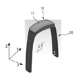
도 26은 본 발명의 다양한 실시예에 따른 거치대의 일부를 나타내는 사시도이다.
도 27은 본 발명의 다양한 실시예에 따른 웨어러블 장치의 본체 하우징 일부를 나타내는 사시도이다.BRIEF DESCRIPTION OF THE DRAWINGS Embodiments of the present invention will become apparent from the following description taken in conjunction with the accompanying drawings.
1 is a block diagram schematically showing a configuration inside a network environment including an electronic device.
2 is a perspective view showing a wearable electronic device according to various embodiments of the present invention.
3 is a perspective view showing a wearable electronic device in which a curved body and a wearer portion are separated according to various embodiments of the present invention.
4 is a perspective view illustrating a front surface of a curved body in accordance with various embodiments of the present invention.
5 is a perspective view illustrating the back side of a curved body in accordance with various embodiments of the present invention.
6 is a side view showing a state in which a curved body according to various embodiments of the present invention is coupled to a wearer.
FIG. 7 is a cross-sectional view illustrating the arrangement of parts provided in a curved main body according to various embodiments of the present invention.
8 is a side view illustrating a state in which an inner bracket and a display are combined according to various embodiments of the present invention.
FIG. 9 is a side view showing a substrate arrangement state and an electronic component placement state in a curved main body according to various embodiments of the present invention.
10 is an exploded perspective view showing a configuration of a curved display according to various embodiments of the present invention.
11 is a perspective view illustrating a curved battery included in a curved body according to various embodiments of the present invention.
12 is a plan view showing a front surface of a main body housing according to various embodiments of the present invention.
Fig. 13 is a partially cutaway perspective view showing a state before a curved body according to various embodiments of the present invention is mounted on a wearer; Fig.
14 is a partially cutaway perspective view showing a waterproof structure applied to a plurality of portions in a wearable device according to various embodiments of the present invention.
15 is a partially cutaway perspective view showing a waterproof structure applied to a side key in a wearable device according to various embodiments of the present invention.
16 is a partially cutaway perspective view showing a waterproof structure applied to a charging terminal in a wearable device according to various embodiments of the present invention.
17 is a cross-sectional view illustrating a body and a wearer interface region, respectively, in accordance with various embodiments of the present invention.
18 is an exemplary view showing a procedure of assembling a wearable device according to various embodiments of the present invention.
FIG. 19 is a side view showing a state in which a main body and a wearing portion of a wearable device according to various embodiments of the present invention are separated. FIG.
20 is a side view showing a state in which a curved body according to various embodiments of the present invention is coupled to a wearer.
21 to 24 are perspective views respectively showing various embodiments of a wearer provided in a wearable device according to various embodiments of the present invention.
25 is a perspective view showing a state in which a wearable device according to various embodiments of the present invention is coupled to a cradle.
26 is a perspective view illustrating a portion of a cradle in accordance with various embodiments of the present invention.
27 is a perspective view illustrating a portion of a body housing of a wearable device according to various embodiments of the present invention.
이하, 첨부된 도면을 참조하여 본 개시(present disclosure)를 설명한다. The present disclosure will be described below with reference to the accompanying drawings.
본 개시를 설명함에 있어서, “실질적으로 또는 대략적으로(substantially)”라는 용어는 인용된 특성, 파라미터 또는 값이 정확하게 달성될 필요는 없으며, 허용오차, 측정 오류, 측정 정확성 한계 및 당업자에게 알려진 다른 요소들을 포함하는 편차 또는 변화, 특성이 제공하고자 하는 효과를 제외하지 않는 정도로 발생할 수 있다.In describing the present disclosure, the term " substantially or substantially " does not necessarily imply that the recited characteristics, parameters, or values are to be precisely attained and that the tolerance, measurement error, measurement accuracy limit, and other factors known to those skilled in the art To the extent that the property does not exclude the effect that it is intended to provide.
본 개시는 다양한 변경을 가할 수 있고, 여러 가지 실시예를 가질 수 있는 바, 특정 실시예들이 도면에 예시되고 관련된 상세한 설명이 기재되어 있다. 그러나, 이는 본 개시를 특정한 실시 형태에 대해 한정하려는 것이 아니며, 본 개시의 사상 및 기술 범위에 포함되는 모든 변경 및/또는 균등물 내지 대체물을 포함하는 것으로 이해되어야 한다. 도면의 설명과 관련하여, 유사한 구성요소에 대해서는 유사한 참조 부호가 사용되었다.The present disclosure is capable of various modifications and various embodiments, and specific embodiments are illustrated in the drawings and detailed description of the invention is set forth. It is to be understood, however, that this disclosure is not intended to be limited to the specific embodiments, but includes all changes and / or equivalents and alternatives falling within the spirit and scope of the disclosure. In connection with the description of the drawings, like reference numerals have been used for like elements.
본 개시 가운데 사용될 수 있는“포함한다” 또는 “포함할 수 있다” 등의 표현은 개시된 해당 기능, 동작 또는 구성요소 등의 존재를 가리키며, 추가적인 하나 이상의 기능, 동작 또는 구성요소 등을 제한하지 않는다. 또한, 본 개시에서, "포함하다" 또는 "가지다" 등의 용어는 명세서상에 기재된 특징, 숫자, 단계, 동작, 구성요소, 부품 또는 이들을 조합한 것이 존재함을 지정하려는 것이지, 하나 또는 그 이상의 다른 특징들이나 숫자, 단계, 동작, 구성요소, 부품 또는 이들을 조합한 것들의 존재 또는 부가 가능성을 미리 배제하지 않는 것으로 이해되어야 한다. The use of the terms "comprises" or "comprising" may be used in the present disclosure to indicate the presence of a corresponding function, operation, or element, etc., and does not limit the presence of one or more other features, operations, or components. Also, in this disclosure, the terms "comprises" or "having ", and the like, specify that the presence of stated features, integers, But do not preclude the presence or addition of other features, numbers, steps, operations, components, parts, or combinations thereof.
본 개시에서 “또는” 등의 표현은 함께 나열된 단어들의 어떠한, 그리고 모든 조합을 포함한다. 예를 들어, “A 또는 B”는, A를 포함할 수도, B를 포함할 수도, 또는 A 와 B 모두를 포함할 수도 있다.The " or " in the present disclosure includes any and all combinations of words listed together. For example, " A or B " may comprise A, comprise B, or both A and B.
본 개시 가운데 “제 1,”“제2,”“첫째,”또는“둘째,”등의 표현들이 본 개시의 다양한 구성요소들을 수식할 수 있지만, 해당 구성요소들을 한정하지 않는다. 예를 들어, 상기 표현들은 해당 구성요소들의 순서 및/또는 중요도 등을 한정하지 않는다. 상기 표현들은 한 구성요소를 다른 구성요소와 구분 짓기 위해 사용될 수 있다. 예를 들어, 제1 사용자 기기와 제 2 사용자 기기는 모두 사용자 기기이며, 서로 다른 사용자 기기를 나타낸다. 예를 들어, 본 개시의 권리 범위를 벗어나지 않으면서 제1 구성요소는 제2 구성요소로 명명될 수 있고, 유사하게 제2 구성요소도 제1 구성요소로 명명될 수 있다.The expressions " first, " " second, " " first, " or " second, " and the like in the present disclosure may modify various elements of the disclosure, but do not limit the elements. For example, the representations do not limit the order and / or importance of the components. The representations may be used to distinguish one component from another. For example, both the first user equipment and the second user equipment are user equipment and represent different user equipment. For example, without departing from the scope of the present disclosure, the first component may be referred to as a second component, and similarly, the second component may also be referred to as a first component.
어떤 구성요소가 다른 구성요소에 "연결되어" 있다거나 "접속되어" 있다고 언급된 때에는, 그 다른 구성요소에 직접적으로 연결되어 있거나 또는 접속되어 있을 수도 있지만, 중간에 다른 구성요소가 존재할 수도 있다고 이해되어야 할 것이다. 반면에, 어떤 구성요소가 다른 구성요소에 "직접 연결되어" 있다거나 "직접 접속되어" 있다고 언급된 때에는, 중간에 다른 구성요소가 존재하지 않는 것으로 이해될 수 있어야 할 것이다. It is to be understood that when an element is referred to as being "connected" or "connected" to another element, it may be directly connected or connected to the other element, . On the other hand, when an element is referred to as being "directly connected" or "directly connected" to another element, it should be understood that there are no other elements in between.
본 개시에서 사용한 용어는 단지 특정한 실시예를 설명하기 위해 사용된 것으로, 본 개시를 한정하려는 의도가 아니다. 단수의 표현은 문맥상 명백하게 다르게 뜻하지 않는 한, 복수의 표현을 포함한다. The terminology used in this disclosure is used only to describe a specific embodiment and is not intended to limit the disclosure. The singular expressions include plural expressions unless the context clearly dictates otherwise.
다르게 정의되지 않는 한, 기술적이거나 과학적인 용어를 포함해서 여기서 사용되는 모든 용어들은 본 개시가 속하는 기술 분야에서 통상의 지식을 가진 자에 의해 일반적으로 이해되는 것과 동일한 의미를 가지고 있다. 일반적으로 사용되는 사전에 정의되어 있는 것과 같은 용어들은 관련 기술의 문맥상 가지는 의미와 일치하는 의미를 가지는 것으로 해석되어야 하며, 본 개시에서 명백하게 정의하지 않는 한, 이상적이거나 과도하게 형식적인 의미로 해석되지 않는다.Unless otherwise defined, all terms used herein, including technical or scientific terms, have the same meaning as commonly understood by one of ordinary skill in the art to which this disclosure belongs. Terms such as those defined in commonly used dictionaries are to be interpreted as having a meaning consistent with the contextual meaning of the relevant art and are to be interpreted as either ideal or overly formal in the sense of the art unless explicitly defined in this disclosure Do not.
본 개시에 따른 전자 장치는 통신 기능이 포함된 장치일 수 있다. 예를 들면, 전자 장치는 스마트 폰(smartphone), 태블릿 PC(tablet personal computer), 이동 전화기(mobile phone), 화상 전화기, 전자북 리더기(e-book reader), 데스크 탑 PC(desktop personal computer), 랩탑 PC(laptop personal computer), 넷북 컴퓨터(netbook computer), PDA(personal digital assistant), PMP(portable multimedia player), MP3 플레이어, 모바일 의료기기, 카메라(camera), 또는 웨어러블 장치(wearable device)(예: 전자 안경과 같은 head-mounted-device(HMD), 전자 의복, 전자 팔찌, 전자 목걸이, 전자 앱세서리(appcessory), 전자 문신, 또는 스마트 와치(smartwatch))중 적어도 하나를 포함할 수 있다. The electronic device according to the present disclosure may be a device including a communication function. For example, the electronic device may be a smartphone, a tablet personal computer, a mobile phone, a videophone, an e-book reader, a desktop personal computer, Such as a laptop personal computer, a netbook computer, a personal digital assistant (PDA), a portable multimedia player (PMP), an MP3 player, a mobile medical device, a camera, or a wearable device : At least one of a head-mounted-device (HMD) such as electronic glasses, an electronic garment, an electronic bracelet, an electronic necklace, an electronic app apparel, an electronic tattoo, or a smartwatch.
어떤 실시예들에 따르면, 전자 장치는 통신 기능을 갖춘 스마트 가전 제품(smart home appliance)일 수 있다. 스마트 가전 제품은, 예를 들자면, 전자 장치는 텔레비전, DVD(digital video disk) 플레이어, 오디오, 냉장고, 에어컨, 청소기, 오븐, 전자레인지, 세탁기, 공기 청정기, 셋톱 박스(set-top box), TV 박스(예를 들면, 삼성 HomeSyncTM, 애플TVTM, 또는 구글 TVTM), 게임 콘솔(game consoles), 전자 사전, 전자 키, 캠코더(camcorder), 또는 전자 액자 중 적어도 하나를 포함할 수 있다.According to some embodiments, the electronic device may be a smart home appliance with communication capabilities. [0003] Smart household appliances, such as electronic devices, are widely used in the fields of television, digital video disk (DVD) player, audio, refrigerator, air conditioner, vacuum cleaner, oven, microwave oven, washing machine, air cleaner, set- And may include at least one of a box (e.g., Samsung HomeSyncTM, Apple TVTM, or Google TVTM), game consoles, an electronic dictionary, an electronic key, a camcorder, or an electronic frame.
어떤 실시예들에 따르면, 전자 장치는 각종 의료 기기(예: MRA(magnetic resonance angiography), MRI(magnetic resonance imaging), CT(computed tomography), 촬영기, 초음파기 등), 네비게이션(navigation) 장치, GPS 수신기(global positioning system receiver), EDR(event data recorder), FDR(flight data recorder), 자동차 인포테인먼트(infotainment) 장치, 선박용 전자 장비(예: 선박용 항법 장치 및 자이로 콤파스 등), 항공 전자기기(avionics), 보안 기기, 또는 산업용 또는 가정용 로봇 중 적어도 하나를 포함할 수 있다.According to some embodiments, the electronic device may be a variety of medical devices (e.g., magnetic resonance angiography (MRA), magnetic resonance imaging (MRI), computed tomography (CT) (global positioning system receiver), EDR (event data recorder), flight data recorder (FDR), automotive infotainment device, marine electronic equipment (eg marine navigation device and gyro compass), avionics, A security device, or an industrial or home robot.
어떤 실시예들에 따르면, 전자 장치는 통신 기능을 포함한 가구(furniture) 또는 건물/구조물의 일부, 전자 보드(electronic board), 전자 사인 입력장치(electronic signature receiving device), 프로젝터(projector), 또는 각종 계측기기(예: 수도, 전기, 가스, 또는 전파 계측 기기 등) 중 적어도 하나를 포함할 수 있다. 본 개시에 따른 전자 장치는 전술한 다양한 장치들 중 하나 또는 그 이상의 조합일 수 있다. 또한, 본 개시에 따른 전자 장치는 전술한 기기들에 한정되지 않음은 당업자에게 자명하다.According to some embodiments, the electronic device may be a piece of furniture or a structure / structure including a communication function, an electronic board, an electronic signature receiving device, a projector, (E.g., water, electricity, gas, or radio wave measuring instruments, etc.). An electronic device according to the present disclosure may be one or more of the various devices described above. It should also be apparent to those skilled in the art that the electronic device according to the present disclosure is not limited to the above-described devices.
이하, 첨부된 도면을 참조하여 다양한 실시예에 따른 전자 장치에 대해서 살펴본다. 다양한 실시예에서 이용되는 사용자라는 용어는 전자 장치를 사용하는 사람 또는 전자 장치를 사용하는 장치(예: 인공지능 전자 장치)를 지칭할 수 있다.Hereinafter, an electronic device according to various embodiments will be described with reference to the accompanying drawings. The term user as used in various embodiments may refer to a person using an electronic device or a device using an electronic device (e.g., an artificial intelligence electronic device).
도 1은 다양한 실시예에 따른 전자 장치(101A)를 포함하는 네트워크 환경(100A)을 도시한다. 도 1을 참조하면, 상기 전자 장치(101A)는 버스(110A), 프로세서(120A), 메모리(130A), 입출력 인터페이스(140A), 디스플레이(150A), 통신 인터페이스(160A) 및 센서 모듈(170A)을 포함할 수 있다. 1 illustrates a
상기 버스(110A)는 전술한 구성요소들을 서로 연결하고, 전술한 구성요소들 간의 통신 신호(예: 제어 메시지)를 전달하는 회로일 수 있다.The
상기 프로세서(120A)는 예를 들면, 상기 버스(110A)를 통해 전술한 다른 구성요소들(예: 상기 메모리130A, 상기 입출력 인터페이스140A, 상기 디스플레이150A, 상기 통신 인터페이스160A, 또는 상기 센서 모듈170A)로부터 명령을 수신하여, 수신된 명령을 해독하고, 해독된 명령에 따른 연산이나 데이터 처리를 실행할 수 있다. The
상기 메모리(130A)는 상기 프로세서(120A) 또는 다른 구성요소들(예: 상기 입출력 인터페이스(140A), 상기 디스플레이(150A), 상기 통신 인터페이스(160A), 또는 상기 센서 모듈170A 등)로부터 수신되거나 상기 프로세서(120A) 또는 다른 구성요소들에 의해 생성된 명령 또는 데이터를 저장할 수 있다. 상기 메모리(130A)는 예를 들면, 커널(131A), 미들웨어(132A), 어플리케이션 프로그래밍 인터페이스(API: application programming interface)(133A) 또는 어플리케이션(134A) 등의 프로그래밍 모듈들을 포함할 수 있다. 전술한 각각의 프로그래밍 모듈들은 소프트웨어, 펌웨어, 하드웨어 또는 이들 중 적어도 둘 이상의 조합으로 구성될 수 있다.The
상기 커널(131A)은 나머지 다른 프로그래밍 모듈들, 예를 들면, 상기 미들웨어(132A), 상기 API(133A) 또는 상기 어플리케이션(134A)에 구현된 동작 또는 기능을 실행하는 데 사용되는 시스템 리소스들(예: 상기 버스110A, 상기 프로세서120A 또는 상기 메모리130A 등)을 제어 또는 관리할 수 있다. 또한, 상기 커널(131A)은 상기 미들웨어(132A), 상기 API(133A) 또는 상기 어플리케이션(134A)이 상기 전자 장치(101A)의 개별 구성요소에 접근하여 제어 또는 관리할 수 있는 인터페이스를 제공할 수 있다. The
상기 미들웨어(132A)는 상기 API(133A) 또는 상기 어플리케이션(134A)이 상기 커널(131A)과 통신하여 데이터를 주고받을 수 있도록 중개 역할을 수행할 수 있다. 또한, 상기 미들웨어(132A)는 상기 어플리케이션(134A)으로부터 수신된 작업 요청들과 관련하여, 예를 들면, 상기 어플리케이션(134A) 중 적어도 하나의 어플리케이션에 상기 전자 장치(101A)의 시스템 리소스(예: 상기 버스110A, 상기 프로세서120A 또는 상기 메모리130A 등)를 사용할 수 있는 우선 순위를 배정하는 등의 방법을 이용하여 작업 요청에 대한 제어(예: 스케쥴링 또는 로드 밸런싱)을 수행할 수 있다.The
상기 API(133A)는 상기 어플리케이션(134A)이 상기 커널(131A) 또는 상기 미들웨어(132A)에서 제공되는 기능을 제어하기 위한 인터페이스로, 예를 들면, 파일 제어, 창 제어, 화상 처리 또는 문자 제어 등을 위한 적어도 하나의 인터페이스 또는 함수(예: 명령어)를 포함할 수 있다. The
다양한 실시예에 따르면, 상기 어플리케이션(134A)은 SMS/MMS 어플리케이션, 이메일 어플리케이션, 달력 어플리케이션, 알람 어플리케이션, 건강 관리(health care) 어플리케이션(예: 운동량 또는 혈당 등을 측정하는 어플리케이션) 또는 환경 정보 어플리케이션(예: 기압, 습도 또는 온도 정보 등을 제공하는 어플리케이션) 등을 포함할 수 있다. 추가적으로 또는 대체적으로, 상기 어플리케이션(134)은 상기 전자 장치(101)와 외부 전자 장치(예: 전자 장치102A 또는 전자 장치104A) 사이의 정보 교환과 관련된 어플리케이션일 수 있다. 상기 정보 교환과 관련된 어플리케이션은 예를 들어, 상기 외부 전자 장치에 특정 정보를 전달하기 위한 알림 전달(notification relay) 어플리케이션, 또는 상기 외부 전자 장치를 관리하기 위한 장치 관리(device management) 어플리케이션을 포함할 수 있다. According to various embodiments, the
예를 들면, 상기 알림 전달 어플리케이션은 상기 전자 장치(101A) 의 다른 어플리케이션(예: SMS/MMS 어플리케이션, 이메일 어플리케이션, 건강 관리 어플리케이션 또는 환경 정보 어플리케이션 등)에서 발생한 알림 정보를 외부 전자 장치(예: 전자 장치102A 또는 전자 장치104A)로 전달하는 기능을 포함할 수 있다. 추가적으로 또는 대체적으로, 상기 알림 전달 어플리케이션은 예를 들면, 외부 전자 장치(예: 전자 장치102A 또는 전자 장치104A)로부터 알림 정보를 수신하여 사용자에게 제공할 수 있다. 상기 장치 관리 어플리케이션은, 예를 들면, 상기 전자 장치(101A)와 통신하는 외부 전자 장치(예: 전자 장치102A 또는 전자 장치104A)의 적어도 일부에 대한 기능(예: 외부 전자 장치 자체(또는, 일부 구성 부품)의 턴 온(turn on)/턴 오프(turn off) 또는 디스플레이의 밝기(또는, 해상도) 조절), 상기 외부 전자 장치에서 동작하는 어플리케이션 또는 상기 외부 전자 장치에서 제공되는 서비스(예: 통화 서비스 또는 메시지 서비스)을 관리(예: 설치, 삭제 또는 업데이트)할 수 있다. For example, the notification delivery application may transmit notification information generated in another application (e.g., an SMS / MMS application, an email application, a healthcare application, or an environment information application) of the electronic device 101A to an external electronic device Device 102A or
다양한 실시예에 따르면, 상기 어플리케이션(134A)은 상기 외부 전자 장치(예: 전자 장치102A 또는 전자 장치104A)의 속성(예: 전자 장치의 종류)에 따라 지정된 어플리케이션을 포함할 수 있다. 예를 들어, 외부 전자 장치가 MP3 플레이어인 경우, 상기 어플리케이션(134A)은 음악 재생과 관련된 어플리케이션을 포함할 수 있다. 유사하게, 외부 전자 장치가 모바일 의료기기인 경우, 상기 어플리케이션(134A)은 건강 관리와 관련된 어플리케이션을 포함할 수 있다. 한 실시예에 따르면, 상기 어플리케이션(134A)은 전자 장치(101A)에 지정된 어플리케이션 또는 외부 전자 장치(예: 서버106A, 전자 장치102A 또는 전자 장치104A)로부터 수신된 어플리케이션 중 적어도 하나를 포함할 수 있다.According to various embodiments, the
상기 입출력 인터페이스(140A)는 센서(예: 가속도 센서, 자이로 센서) 또는 입력 장치(예: 키보드 또는 터치 스크린)를 통하여 사용자로부터 입력된 명령 또는 데이터를, 예를 들면, 상기 버스(110A)를 통해 상기 프로세서(120A), 상기 메모리(130A), 상기 통신 인터페이스(160A)에 전달할 수 있다. 예를 들면, 상기 입출력 인터페이스(140A)은 터치 스크린을 통하여 입력된 사용자의 터치에 대한 데이터를 상기 프로세서(120A)로 제공할 수 있다. 또한, 상기 입출력 인터페이스(140A)는 예를 들면, 상기 버스(110A)를 통해 상기 프로세서(120A), 상기 메모리(130A), 상기 통신 인터페이스(160A), 또는 상기 센서 모듈(170A)로부터 수신된 명령 또는 데이터를 상기 출력 장치(예: 스피커 또는 디스플레이)를 통하여 출력할 수 있다. 예를 들면, 상기 입출력 인터페이스(140A)는 상기 프로세서(120A)를 통하여 처리된 음성 데이터를 스피커를 통하여 사용자에게 출력할 수 있다. The input /
상기 디스플레이(150A)는 사용자에게 각종 정보(예: 멀티미디어 데이터 또는 텍스트 데이터 등)을 표시할 수 있다.The
상기 통신 인터페이스(160A)는 상기 전자 장치(101A)와 외부 장치(예: 전자 장치102A, 전자 장치104A, 또는 서버106A) 간의 통신을 연결할 수 있다. 예를 들면, 상기 통신 인터페이스(160A)는 네트워크 통신(162A)(예: Internet, LAN(local area network), WAN(wire area network), telecommunication network, cellular network, satellite network 또는 POTS(plain old telephone service) 등), 근거리 통신(164A)(예: wifi(wireless fidelity), BT(Bluetooth), NFC(near field communication), 또는 유선 통신(예: USB(universal serial bus), HDMI(high definition multimedia interface), RS-232(recommended standard 232) 또는 POTS(plain old telephone service) 등)을 지원할 수 있다. 한 실시예에 따르면, 상기 전자 장치(101A)와 외부 장치 간의 통신을 위한 프로토콜(예: 근거리 통신 프로토콜, 네트워크 통신 프로토콜 또는 유선 통신 프로토콜)은 상기 API(133A) 또는 상기 미들웨어(132A) 중 적어도 하나에서 지원될 수 있다. 상기 전자 장치(102A,104A) 각각은 상기 전자 장치(101A)와 동일한 (예: 같은 타입의) 장치이거나 또는 다른 (예: 다른 타입의) 장치일 수 있다.The
상기 센서 모듈(170A)은 물리량을 계측하거나 전자 장치의 작동 상태를 감지하여, 계측 또는 감지된 정보를 전기 신호로 변환할 수 있다. 상기 센서 모듈(170A)은 예를 들면, 제스처 센서, 자이로 센서, 기압 센서, 마그네틱 센서, 가속도 센서, 그립 센서, 근접 센서, color 센서(예: RGB(red, green, blue) 센서), 생체 센서, 온/습도 센서, 조도 센서 또는 UV(ultra violet) 센서 중의 적어도 하나를 포함할 수 있다. The
추가적으로, 상기 센서 모듈(170A)은 예를 들면, 후각 센서(E-nose sensor), EMG 센서(electromyography sensor), EEG 센서(electroencephalogram sensor), ECG 센서(electrocardiogram sensor), IR(infra red) 센서, 홍채 인식 센서 또는 지문 인식 센서 등을 포함할 수 있다.In addition, the
도 2는 본 발명의 다양한 일 실시예에 따른 웨어러블 장치를 나타내는 사시도이다. 도 3은 본 발명의 다양한 일 실시예에 따른 곡형 본체(10)와 착용부(20)가 분리된 웨어러블 장치를 나타내는 사시도이다. 2 is a perspective view showing a wearable device according to various embodiments of the present invention. 3 is a perspective view showing a wearable device in which a
도 2, 도 3을 참조하면, 도면들에 3차원 X/Y/Z 직교 좌표계가 도시되었는데, 'Z축'은 수직 방향으로, 본체(10)의 상하 방향(두께 방향)을 의미하고, 'X축'은 제1수평 방향으로, 본체(10)의 가로 방향을 의미하며, 'Y축'은 수평 방향인데, 상기 제1수평 방향과 수직인 제2수평 방향으로, 본체(10)의 세로 방향을 의미한다. Referring to FIGS. 2 and 3, a three-dimensional X / Y / Z orthogonal coordinate system is shown in the drawings, the 'Z axis' means a vertical direction and a vertical direction (thickness direction) Axis of the
본 발명의 다양한 실시예에 따른 웨어러블 장치는 인체에 착용하는 사용자 기기로서, 예컨데 시계나 팔찌처럼 손목에 착용하기 편리한 전자 장치이거나, 통신 장치 또는 보조 의료 기기이다. 그러나, 본 발명의 다양한 실시예에 따른 웨어러블 장치는 손목 착용으로 한정될 필요는 없다. 예컨데, 본 발명의 다양한 실시예에 따른 웨어러블 장치는 인체에서 곡률이 존재하는 신체 부위에 동일하게 적용가능하다. 인체에서 곡률이 존재하는 신체 부위의 일 예로, 손목이나, 팔목, 또는 발목 등이 될 수 있다. 또한, 본 발명의 실시예에 따른 웨어러블 장치는 착용부(20)의 구성을 다양하게 구성한다면, 신체의 다양한 부위에 안정적으로 착용가능하다.A wearable device according to various embodiments of the present invention is a user device worn on a human body, for example, an electronic device that is convenient to wear on the wrist, such as a watch or a bracelet, or a communication device or an auxiliary medical device. However, the wearable device according to various embodiments of the present invention need not be limited to wrist wear. For example, the wearable device according to various embodiments of the present invention is equally applicable to a body part having curvature in the human body. An example of a body part having a curvature in the human body may be a wrist, a wrist, or an ankle. In addition, the wearable device according to the embodiment of the present invention can be stably worn on various parts of the body if the configuration of the
본 발명의 다양한 실시예에 따른 웨어러블 장치는 본체(10)(기능 장치부)와, 착용부(20)(밴드 또는 스트랩 포함)를 포함할 수 있다. 상기 본체(10)는 착용부(20)에서 강제적으로 결합되거나 분리가능하게 구성될 수 있다. 상기 본체(10)에는 외관적으로 각종 정보를 표시하기 위한 디스플레이(11)와, 각종 정보를 입력하기 위한 누름 키(사이드 키;k)나, 센서(s)나, 터치 입력부 등이 배치될 수 있다. 상기 본체(10)는 바타입 형상인데, 곡률을 구비한다. 상세히 설명하면, 상기 본체(10)는 세로 방향(Y축 방향)으로 길죽하게 연장된 형상이면서, 곡률을 구비한 형상으로 이루어진다. A wearable device according to various embodiments of the present invention may include a body 10 (functional unit) and a wearer 20 (including a band or strap). The
상기 착용부(20)는 탄성 재질로 구성되어서, 상기 본체(10)를 인체에 안정적으로 착용가능하게 하며, 인체 피부에 밀착가능하게 한다. 또한, 상기 착용부(20)는 교환가능하기 때문에, 사용자의 개성이나 취향을 나타내는 악세사리로서의 기능도 담당한다. 하지만, 상기 착용부(20)에서 본체(10)와 결합되는 부분(안착부)은 탄성 변형이 가능하게 구성하고, 인체와 밀착하는 착용면 부분은 탄성 재질로 구성되지 않을 수도 있다. 상기 착용부(20)는 상하 방향으로 개방된 개구(21)를 구비하며, 상기 개구(21) 둘레를 따라 탄성 변형을 하는 안착부(22)를 포함한다. 상기 착용부는 적어도 상기 개구(21) 주변에 탄성 부재(안착부)를 포함하며, 상기 본체(10)가 상기 착용부(20)에 결합될 때, 상기 탄성 부재를 포함하는 안착부의 적어도 일부가 상기 본체(10)의 측면을 따라 연장된 안착홈 내에 끼워질 수 있다.The
상기 개구(21)는 본체(10)가 끼워지는 개방 공간으로, 상기 안착부(22)에 의해 둘러싸이는 형상이다. 본 실시예에 따른 개구(21)는 대략적으로 두께를 가지는 직사각형으로 구성될 수 있다. 상기 개구는 상부에서 볼 때, 상기 제1방향의 사이드가, 상기 제1방향과 직교하는 방향의 사이드보다 긴, 실질적으로 직사각형 모양을 가지다. 아울러, 상기 개구(21)는 감싸는 적어도 하나의 선형부(linear portion)를 포함한다. 상기 선형부는 두 개로 구성되어, 서로 대치하면서 평행하게 구성된다. 또한, 상기 착용부(20)는 양 끝단을 서로 엮어 체결하는 버클부를 포함할 수 있다. 상기 착용부는 제1방향(Y축 방향)으로 연장된 밴드(band extending in a first direction)로서, 상기 밴드의 일부분에 개구(opening)를 포함하며, 일단에 버클부 및 타단에 상기 버클부와 착탈가능한 결착부를 포함하는 밴드를 포함하게 구성될 수 있다. 또한, 상기 곡면 디스플레이(11)는 상부에서 볼 때, 상기 개구(21)보다 작은, 실질적으로 직사각형 모양을 가지게 구성될 수 있다.The
또한, 본 발명의 실시예에 따른 웨어러블 장치는 상기 본체(10)가 기구적으로 결합/분리되는 착탈 구조를 포함하며, 상기 착탈 구조는 상기 본체 하우징(20)에 구비된 안착홈(13)과, 상기 착용부(20)에 구비된 개구(21) 및 안착부(22)를 포함한다.In addition, the wearable device according to the embodiment of the present invention includes a detachable structure in which the
상기 웨어러블 장치는 본체 하우징 표면들 중, 측면 둘레를 따라서 형성된 안착홈(13)이 구성되고, 상기 착용부에는 안착홈(13)에 끼워지는 안착부(22)를 구비할 수 있다. 상기 본체(10)가 안착부(20)에 끼워진 이후, 도면에 미도시되었지만, 기타 수단으로 상기 본체는 착용부에 더 고정될 수 있다. The wearable device may include a
상기 본체(10)는 곡형으로, 이하에서 곡형 본체라 지칭한다. 상기 곡형 본체(10)는 하기에 상세히 설명된다. 상기 안착부(22)는 탄성을 가진 재질로 구성되어 탄성 변형을 하기 때문에, 상기 곡형 본체(10)는 상기 안착부(22)에서 착탈가능하다. 또한, 상기 곡형 본체(10) 형상 및 상기 착탈 구조에 의해 상기 본체(10)는 방향성을 가지고 강제적으로 상기 착용부(20)에 결합되거나, 분리가능하다. The
상기 착용부(20)는 교환가능한(changeable) 구조이기 때문에, 다양한 디자인이나 색상으로 구현한다면, 사용자의 취향에 맞춰서 언제든지 교환가능하다. 즉, 상기 착용부(20)는 자신만의 개성을 나타내는 악세사리 개념으로 간주될 수 있다.Since the
도 4는 본 발명의 다양한 일 실시예에 따른 곡형 본체(10)의 전면(120)을 나타내는 사시도이다. 도 5는 본 발명의 다양한 일 실시예에 따른 곡형 본체(10)의 배면(121)을 나타내는 사시도이다. 도 6은 본 발명의 다양한 일 실시예에 따른 곡형 본체(10)가 착용부(20)의 안착부에 결합된 상태를 나타내는 측면도이다. 도 4 내지 도 6을 참조하여 곡형 본체(10)의 외관 구성에 대해서 상세히 설명하기로 한다. 4 is a perspective view showing a
본 발명의 실시예에 따른 곡형 본체(10)는 곡률(curvature)을 구비하면서, 직사각형을 비롯한 바-타입 형상으로, 휘어진 방향으로 연장된, 길죽한 형상으로 이루어진다. 상기 곡형 본체(10)는 본체 하우징(12)과, 상기 본체 하우징(12)에 장착된 디스플레이(11)를 포함한다. 상기 본체 하우징(12)은 전면(120)(front surface)과, 배면(121)(rear surface)과, 측면(122)(side surface)을 구비하며, 상기 전면(120) 및 배면(121)은 각각 곡률을 가지게 구성될 수 있다. 상기 전면(120)은 디스플레이(11)가 장착되는 면이고, 상기 배면(121)은 인체와 접촉하는 착용면이다. 상기 전면(120)은 제1곡률을 가지고, 상기 배면(121)은 제2곡률을 구비하는데, 상기 제1,2곡률 결정 시, 제품 디자인 및 인체 공학적으로 다양한 소비자 손목 둘레를 고려하여, 소비자 착용성을 고려한다. 본 실시예에서는 상기 제1곡률이 상기 제2곡률보다 작게 구성한다. 다시 말하면, 본 실시예에 따른 곡형 본체(10)는 전면(120)은 디스플레이(11)가 배치되어 디스플레이된 화면 보기가 편해야 하고, 배면(121)은 손목 착용감이 좋아야 하고, 센서가 배치되기 때문에 인체 손목에 밀착되는 형상을 제공해야 한다.The
상기 곡형 본체(10)는 중간보다 양 측방향 영역으로 갈수록 점차적으로 얇아지게 구성될 수 있다. 대략적으로 상기 곡형 본체(10)는 중앙에서 두껍고, 상기 중앙에서 측방으로 멀어질수록 점차적으로 얇아진다. 아울러, 상기 배면(121)은 제2곡률을 구비하는 것을 실시예로 설명하였지만, 거의 평탄한 면으로 구성가능하며, 곡률이 구비되지 않는 평탄면으로 구성될 수 있다. The
상기 곡형 본체(10) 외관 구성은 인체공학적으로 사용자 착용감을 향상시키고, 다양한 소비자 손목 둘레에 대한 호환성을 향상시킨다. 상기 곡형 본체(10)는 전면(120)에 곡면 디스플레이(11)가 구비되고, 배면(121)에 센서(13;도 4에는 센서의 인터페이싱부가 보여진다)가 구비된 피부 접촉면으로 이루어짐으로서, 외관 디자인의 자유도를 극대화하고, 다양한 사용자 모두에게 최적의 센서 성능을 제공하기 위한 형상이다. 특히, 상기 곡형 본체(10)는 외관 디자인의 자유로운 형태 대비, 피부 접촉면인 배면(121)을 거의 평탄한 면으로 구성하고, 면에 사용자의 다양한 인체 곡률에 모두 적절하게 대응할 수 있는 센서(s)를 배치한다.The outer configuration of the
또한, 본 실시예에서의 곡형 본체 하우징(12)에는 사용자 피부에 밀착되는 배면에 센서 인터페이스부(sw)가 위치하고, 상기 피부 밀착면(본체 하우징 저면)외의 일면에 디스플레이, 터치 입력부, 버튼키, 충전 단자 및 정보 인터페이스부가 위치할 수 있다.In addition, in the
상기 디스플레이(11)는 인체 곡면을 반영한 형태로 평면(LCD, OLED) 또는 곡면(플렉서블 OLED)으로 구성될 수 있다. 본 실시예에서는 곡면 디스플레이(11)를 구비하는 것으로 예시하였으나, 상기 곡면 디스플레이(11)는 평면 디스플레이로 구성될 수 있다. The
상기 곡형 본체(12) 측면에는 안착홈(13)이 구성된다. 상기 안착홈(13)은 곡형 본체 하우징(12) 측면(122)에서 계속적으로 연장되며, 상기 곡형 본체(12) 측면들 중, 상기 사용자에게 보여지는 외관 측면은 곡률을 가지게 형성된다. 상기 안착홈(13)은 상기 곡형 본체 전(120)면에 구비된 제1곡률과 동일한 곡률로 구성된다. 그러나, 상기 안착홈(13)의 곡률은 상기 제1곡률과 동일하게 구성될 수 있지만, 인체 손목 곡률이 남녀에 따라서 다양하기 때문에, 상기 제1곡률보다 크거나 작게 구성될 수 있다. 도 6에는 상기 안착홈(13)의 곡률이 상기 제1곡률과 동일하게 구성된 것이 예시되었다. 후술하겠지만, 상기 안착홈(13)은 일부 구간에서 상면 곡률과 하면 곡률을 포함하는데, 상기 하면 곡률을 달리하여, 다양한 손목 곡률에 대응한다. 상기 안착홈의 상면 곡률과 하면 곡률은 착용한 사용자의 손목 곡률에 따라서 상기 본체와의 경계 영역에서 상이하게 구성할 수 있다.A
또한, 상기 안착홈(13)은 곡률을 가지게 구비된다고 설명하였고, 상기 안착홈의 상면(33a)과 하면(33b)도 동일한 곡률을 가지게 구비된다. 상기 본체 하우징(12) 외부 측면에 있는 안착홈(13)은 동일한 폭과 두께로 곡률을 가지게 연장되어서, 상기 안착홈의 상면이나 하면도 동일한 제1곡률를 가지게 구성될 수 있다. Also, the
도 7은 본 발명의 다양한 일 실시예에 따른 곡형 본체(10)에 구비된 전자 부품들의 배치 상태를 나타내는 단면도이다. 도 8은 본 발명의 다양한 일 실시예에 따른 곡형 본체(10)를 나타내는 측면도이다. 도 9는 본 발명의 다양한 일 실시예에 따른 곡형 본체(10)에 구비된 기판 배열 상태와 전자 부품 배치 상태를 나타내는 측면도이다. 7 is a cross-sectional view showing an arrangement state of electronic components in the curved
도 7 내지 도 9를 참조하여 상기 곡형 본체(10) 내에 실장되는 전자 부품들의 배치에 대해서 설명하기로 한다. 본 실시예에서는 디스플레이(11) 하측에 적층 구조로 곡형 배터리(14)를 실장함으로서, 상기 곡형 본체(10) 중앙에서 측 방향으로 갈수록 점차적으로 상하 두께를 얇게 하는 배치로 이루어진다. 즉, 상기 곡형 본체(10)는 곡면 형태의 디스플레이(11)와, 곡형 배터리(14)와, 기판(P1~P3)을 상하 적층 구조로 구현한다.7 to 9, the arrangement of the electronic components mounted in the curved
본 실시예의 곡형 본체(10)는 사용자의 눈에 쉽게 보이는 외관면(예컨데 디스플레이 화면)과, 인체에 착용하여서 피부와 밀착되는 접촉면(본체 하우징 배면)의 곡률을 달리 설계하면서, 내부에 실장되는 전자 부품의 최적의 적층 구조에 설명한다. 본 실시예에 따른 곡형 본체(10)는 가장 큰 곡률을 가지는 외관면에 곡면 제작 자유도가 가장 높은 디스플레이(11)를 구비하고, 상기 디스플레이(11) 내측에 배터리(14)를 설치한다. 이때, 상기 배터리(14)는 곡형으로, 상기 제1곡률과 동일한 곡률을 가지게 구비한다. 상기 배터리(14)는 상기 곡면 디스플레이(11) 중앙을 기준으로 실장하되, 상기 배터리 양측 단부에 있는 실장 공간을 확보함으로서, 상기 실장 공간을 피부 접촉면(배면)의 곡률 감소에 대한 보상 구간으로 활용한다. 상기한 실장 구조는 곡형 본체(10)의 중앙에 비해, 양 단부에서의 두께 감소 효과를 가져와, 미려한 디자인 구현 및 착용부(20)와의 단차 발생을 최소화 할 수 있다. The
이하에서 상기 곡형 본체(10) 내에 실장되는 각종 전자 부품과 기판의 배치 구조에 대해서 설명하기로 한다.Hereinafter, the arrangement structure of various electronic components and substrates mounted in the curved
상기 곡형 본체(10) 내부에는 곡형 배터리(14)와, 복수 개의 각종 전자 부품(s,m,c)과, 복수 개의 기판들(P1,P2,P3)이 배치된다. 상기 곡형 본체(10)는 곡면 디스플레이(11)와, 곡형 배터리(14)와, 복수 개의 기판(P1,P2,P3)이 상하 적층 구조로 배치된다. 특히, 본 실시예에 따른 배터리(14)는 곡면 디스플레이(11)와 기판(P1) 사이의 중간 층에 배치되는데, 이는 배터리 발열에 의한 저온 화상 방지 및 배터리 폭발에 의한 사용자 피해에 대한 최소한의 안전장치의 의미를 가지며, 상하 적층형 구조로 이루어지는 것이 좋다.A
상기 곡형 본체(10)는 곡형 본체 하우징(12)과, 내부 브라켓(15)을 포함한다. 상기 곡형 본체(10)는 곡형 본체 하우징(12)에 상기 내부 브라켓(15)이 결합되어 일몸체를 구성한다. 상기 본체 하우징(12)과 내부 브라켓(15)은 독립적으로 제작되어 결합되는 구조로 예시하였으나, 상기 내부 브라켓(15)은 본체 하우징(12)에 포함되는 구성으로 이해될 수 있다. 상기 본체 하우징(12) 전면에는 접착 테이프(양면 방수 테이프)를 이용하여 상기 곡면 디스플레이(11)가 부착되고, 상기 본체 하우징(12) 내부에 상기 내부 브라켓(15)이 수용되어 고정되는 구조로 이루어진다. 상기 내부 브라켓(15)은 상기 곡면 디스플레이(11) 하측에 적층되는 곡형 배터리와, 상기 본체 하우징 전면(120)과 배면(121) 사이에 배치되는 하나 또는 복수 개의 기판들(P1,P2,P3)을 내부에 수용한다.The
또한, 본 실시예에서는 본체 하우징(12) 내부 공간, 구체적으로 상기 내부 브라켓(15)에 복수 개의 기판이 배치되는데, 분절(관절) 구조 기판을 적용하여, 전자 부품의 실장 효율화를 도모한다. 상기 언급된 분절 구조 기판은 필요 구간에서 경질 기판(P1,P2,P3)과 연질 기판(F1,F2) 구간을 적절히 제공하여, 곡면 디자인 구현을 원활하게 하고, 각 분절 구간에 전자 부품을 요구 조건에 따라 구분하여 집적 배치함으로서, 전자 장치 성능 효율화에 기여한다. 예를 들어, 노이즈에 취약한 부품과 노이즈 발생 부품을 각각 구분하여, 각각 격리된 기판에 분리 배치하고, 충격에 약한 부품과 충격 유발 부품 등을 각각 구분하여, 각각 격리된 기판 구간에 분리 배치할 수 있다. 상기 전자 부품의 내부 배치는 노이즈 발생 구간과 노이즈 민감 구간을 자연스럽게 이격할 수 있고, 경질 기판(P1,P2,P3)을 통해 전달되는 진동 충격을 연질 기판(F1,F2) 구간에서 차단하여, 전자 장치의 전기적 성능 및 내구성을 최적화하는 설계를 실시할 수 있다. 상기와 마찬가지로 기술 발전에 의해 향후, 상기 경질 기판 대신에 곡형 경질 기판 또는 연질 기판의 적용이 가능하다. 상기 기판 분절 구조에서는 기본적인 통신, 입출력 관련 부품 외에 자이로, 가속도, 기타 광센서 등 비접촉식 센서를 더 구비할 수 있다.Also, in this embodiment, a plurality of substrates are disposed in the inner space of the
상기 복수 개의 기판은 복수 개의 경질 기판(rigid PCB)과, 복수 개의 연질 기판(flexible PCB)으로 구성될 수 있다고 설명하였으며. 상기 경질 기판(P1,P2,P3)은 각종 전자 부품이 장착되는 기판으로서, 상면과 하면 모두에 각각 전자 부품들이 실장된다. 도 7에는 3개의 경질 기판이 장착되어서, 각각 제1기판(P1), 제2기판(P2) 및 제3기판(P3)이라 지칭한다. 상기 제1기판(P1)은 중앙에 배치된 기판을 지칭하고, 상기 제1기판(P1) 우측에 있는 기판을 제2기판(P2)이라 지칭하며, 상기 제1기판(P1) 좌측에 있는 기판을 제3기판(P3)이라 지칭한다. 또한, 상기 제1기판(P1)과 제2기판(P2)을 연결하는 기판을 제1연질 기판(F1)이라 지칭하고, 상기 제1기판(P1)과 제3기판(P3)을 연결하는 기판을 제2연질 기판(F2)이라 지칭한다. 상기 제1,2,3기판(P1,P2,P3)은 상기 제1,2연질 기판(F1,F2)과 각각 연결되어서, 분절 형태로 기판이 구성된다.It has been described that the plurality of substrates may be composed of a plurality of rigid PCBs and a plurality of flexible PCBs. The rigid boards P1, P2, and P3 are boards on which various electronic components are mounted, and electronic components are mounted on the top and bottom surfaces, respectively. 7, three rigid substrates are mounted, which are referred to as a first substrate P1, a second substrate P2 and a third substrate P3, respectively. The substrate on the right side of the first substrate P1 is referred to as a second substrate P2 and the substrate on the left side of the first substrate P1 is referred to as a second substrate Is referred to as a third substrate P3. A substrate connecting the first substrate P1 and the second substrate P2 is referred to as a first flexible substrate F1 and a substrate for connecting the first substrate P1 and the third substrate P3 Is referred to as a second soft substrate F2. The first, second, and third substrates P1, P2, and P3 are connected to the first and second soft substrates F1 and F2, respectively.
또한, 상기 제1,2,3기판(P1,P2,P3) 상에 각종 전자 부품을 배치하는 구성에서, 상기 기판들 중, 노이즈에 취약한 부품들과, 노이즈 발생 부품들은 서로 격리된 기판에 각각 배치되고, 충격에 약한 부품과, 충격을 유발하는 부품들은 서로 격리된 기판에 각각 배치한다.In addition, in the configuration in which various electronic components are disposed on the first, second, and third substrates P1, P2, and P3, noise-susceptible components and noise- The parts to be placed, the parts that cause impact, and the parts that cause the impact are placed on the substrate separated from each other.
예를 들어, 상기 기판들에 실장되는 전자 부품들 중, 노이즈에 취약한 부품(PAM)과, 노이즈 발생 부품(AP,CP)를 각각 제1,2경질 기판(P1,P2)에 분리 배치하고, 충격에 약한 부품(AP, CP 등의 BGA 부품)과, 충격 유발 부품(진동자;예를 들어 진동 모터) 등을 각각 제2,3경질 기판(P2,P3) 구간에 분리 배치할 수 있다. 이러한 전자 부품의 내부 배치는 노이즈 발생 구간과 노이즈 민감 구간을 자연스럽게 이격할 수 있고, 경질 기판을 통해 전달되는 진동 충격을 연질 기판 구간에서 차단함으로서, 전자 장치의 전기적 성능 및 내구성을 최적화하는 설계를 실시할 수 있다.For example, a noise-sensitive component (PAM) and noise-generating components (AP, CP) among electronic components mounted on the substrates are separately arranged on the first and second rigid boards (P1, P2) (BGA parts such as AP and CP) and shock-inducing parts (vibrators (e.g., vibration motors)) can be separately arranged in the second and third rigid boards P2 and P3. Such an internal arrangement of the electronic components can naturally separate the noise generation period and the noise sensitivity period, and the vibration impact transmitted through the rigid substrate is blocked at the soft substrate section, thereby designing the electronic device to optimize the electrical performance and durability can do.
또한, 상기 본체 하우징 배면(121) 상에 위치하는 상기 경질 기판들 중, 적어도 하나는 수평하게 배치되거나, 경사지게 배치될 수 있다. 상기 제1기판(P1)은 중앙에 배치된 기판으로서, 제1센서(s)(본체 하우징 배면에 노출되게 배치되어, 인체 피부와 밀착되어 각종 인체에 관한 정보를 획득할 수 있는 센서들)가 배치되기 때문에, 상기 제1센서(s)와 함께 수평하게 배치되어야 한다. 상기 제1센서(s)는 본체 하우징 배면에 노출되게 배치되는데, 인체 피부와 가장 밀착될 수 있는 위치, 즉 대략 본체 하우징 배면(121)의 중앙 영역에 수평하게 배치되는 것이 바람직하다. 상기 제1센서(s)는 제1기판(P1) 배면에 실장되되, 센서 인터페이스부(센서 인터페이스 윈도우)가 더 구비된다. 또한, 인쇄회로기판이 하우징 외관면 대비 기울어져 실장되는 경우에도 인쇄회로기판와 제1센서 사이에 "interposer"라는 부품을 사용하여 밸런스를 맞출 수 있다. 상기 제1센서(s)는 센서 인터페이스 윈도우가 본체 배면(121)에 노출되게 위치하고, 수평하게 위치한다. 상기 센서 인터페이스 윈도우는 센서 자체에도 구비될 수 있고, 본체 하우징의 외관에 부착될 수도 있다. 상기 제1센서(s)의 예로, 사용자의 피부 또는 인체로부터 정보를 얻을 수 있는 HRM 또는 정맥 센서를 포함할 수 있다.Also, at least one of the rigid substrates positioned on the
추가적으로, 상기 본체 하우징 배면(121)에 노출되게 배치된 제1센서(s)는 소정의 두께로 둘레를 감싸며, 배면 방향으로 돌출된 돌출부(125)가 더 구비된다. 상기 돌출부(125)는 내부에서 상기 센서 인터페이스부, 예컨데 센서 인터페이스 윈도우(SW)가 노출되며, 인체 피부에 더 밀착할 수 있게 한다. 상기 센터 인터페이스부(SW)는 배면(121)에서 평탄한 면에 위치하고, 상기 평탄한 면은 중앙 영역에 위치한다.In addition, the first sensor (s) disposed to be exposed to the back surface of the
또한, 본 실시예에서 분절 구조의 기판들을 활용하더라도, 전자 부품 실장을 위한 최소한의 수평하면서 평탄한 부품 안착 평면부(본체 하우징에서 제1기판이 배치된 영역)가 존재해야 하고, 이러한 평면부 역시 센서 등의 기능 발현을 위한 평면 안착 구조가 불가피하게 발생한다. 본 실시예에서 곡형 배터리(14) 양측 단에 확보된 공간을 실장 영역으로 활용하면 기판 평면 안착에 의한 실장 공간 손실을 상쇄할 수 있고, 특히 진동자(m)나 커넥터 등 상대적으로 두꺼운 부품을 배치하면, 상기 곡형 본체의 전체 두께의 불가피한 증가를 방지할 수 있다. 도시하지 않았지만, 상기 확보된 공간에는 보조 배터리, 후크 조립부 등 각종 메커니즘 구성이 가능하다.In addition, even though the substrates of the segmented structure are utilized in this embodiment, there must be a minimum horizontal and flat component placement plane portion (area where the first substrate is arranged in the body housing) for mounting electronic components, And the like. In the present embodiment, when the space secured at both ends of the
본 실시예에 따른 곡형 본체(10)는 상기 디스플레이(11) 하측과, 상기 배터리(14) 일측(Y축 방향) 영역에 사이에, 상기 제3기판(P3)이 배치되며, 상기 제3기판에 모터(m)와 상기 제1기판(P1)에 충전 단자(c)가 배치된다. 상기 모터(m)는 상기 배터리(14)와 수평한 상태로 병렬로 배치되고, 상기 충전 단자(c)도 상기 배터리(14)와 수평한 상태로 병렬로 배치된다. 상기 제3기판(P3) 상면에 상기 모터(m)가 배치되고, 제1기판 저면에 상기 충전 단자(c)가 배치된다. 상기 충전 단자(c)는 본체 하우징 배면(121)에 노출되게 위치한다. 상기 모터(m)는 실장되는 전자 부품들 중, 두께가 두껍거나 볼륨이 큰 부품이기 때문에, 상기 제2기판(P2)이나 제3기판(P3)에 배치되는 실장 효율성에서 좋다.The third substrate P3 is disposed between the lower side of the
또한, 상기 기판들에 실장되는 기타 입력 장치로 터치 센서, 압력 센서, 온도 센서 등을 이용한 전기적 스위치 인터페이스부 및 Tact, Dome Key 등의 물리적 스위치 인터페이스부가 사용자가 조작 가능한 본체 하우징 일면에 배치 가능하다. 충전 및 인터페이스 단자는 본체 하우징 전면이나 배면 중, 외관을 해치지 않는 위치에 선택하여 더 배치할 수 있다. 본 실시예에서 충전 단자(c)는 본체 하우징 배면(121)에 배치된다. 본 실시예에 따른 웨어러블 장치는 외관을 해치지 않는 면으로서, 본체 하우징 배면, 즉 인체와 접촉하는 면이 될 수 있다.In addition, an electrical switch interface unit using a touch sensor, a pressure sensor, a temperature sensor, and the like, and a physical switch interface unit such as a tact, a dome key, and the like can be disposed on one surface of a main body housing that can be operated by a user. The charging and interface terminals can be arranged in the front or back of the main body housing and in a position not to hurt the appearance. In this embodiment, the charging terminal (c) is disposed on the
이하에서는 상기 곡형 본체(10)의 전면에 배치되는 디스플레이(11)의 구성에 대해서 설명하기로 한다. Hereinafter, the configuration of the
도 10은 본 발명의 다양한 일 실시예에 따른 곡형 본체에 구비된 곡면 디스플레이(11)의 구성을 나타내는 분리 사시도이다. 도 10을 참조하면, 상기 디스플레이(11)는 곡률을 가지는 곡면 디자인 구현을 위해서 곡률을 구비한 연성 엘씨디(110)와, 상기 곡률과 동일한 곡률 윈도우(112)를 적용한다. 상기 곡률 윈도우(112)는 경질(rigid) 또는 연질(flexible)의 레이어(layer)를 포함한다.10 is an exploded perspective view showing a configuration of a
상기 디스플레이(11)는 인체 곡면을 반영한 형태로, 곡면(플렉서블 OLED) 형태의 엘씨디로 구성될 수 있고, 상기 엘씨디 상면에 곡면 표면 형상 또는 곡면을 표현한 곡면 윈도우(112)로, 상기 본체의 전면 디자인을 구현할 수도 있다. 상기 디스플레이(11)는 곡면의 연성 엘씨디(110) 구성에, 터치나, 압력이나, 온도를 감지하는 감지부를 더 구비하여서, 다양한 UI 활용에 최적화 된 PUI를 제공할 수 있다. 또한, 상기 윈도우(112)는 글래스 등의 세라믹 재질 및 PET, PC 등의 시트 재질로 표면을 보호하는 레이어 층을 제공할 수 있다.The
도 11은 본 발명의 다양한 일 실시예에 따른 곡형 본체에 구비된 곡형 배터리(14)를 나타내는 사시도이다. 도 11을 참조하면, 본 발명의 실시예에 따른 배터리(14)는 곡형 배터리 팩을 적용하여, 상기 본체에 실장되는 전자 부품의 실장 효율화를 도모한다. 상기 곡형 배터리(14)는 휘어 있는 형태로 실장되며, 이는 상기 곡형 본체의 외관 디자인 구현 및 인체에 착용되는 웨어러블 전자 장치의 HW 부품 실장 최적화 요소이다. 11 is a perspective view showing a
상기 배터리(14)는 휘어진 형상으로 제작되되, 소정 곡률을 가지게 구성될 수 있다. 상기 배터리(14)는 전면과 배면이 곡률을 구비한다. 상기 배터리(14)의 곡률은 디스플레이의 곡률과 동일하게 구성되어서, 상기 디스플레이의 배면과 대면한 상태로 배치가능하다. 상기 배터리(14)는 배면 중앙에 실장 공간이 존재하여, 상기 내부 공간에 하드웨어 전자 부품을 배치하여서, 실장 공간을 효율화한다. 상기 배터리(14)는 상기 디스플레이의 곡률과 동일한 곡률로 구성되지 않을 수도 있다. 아울러, 상기 배터리(14)는 디스플레이와 기판 사이에 배치되는 것으로 예시하였으나, 기판 저면에 평판형으로 구성가능하다.The
다시 도 7을 참조하면, 상기 곡형 배터리(14)와 제1기판(P1) 사이에는 별도의 레이어 부품(142)을 추가하여, 곡형 배터리(14)의 볼륨 팽창에 따른 제1기판(P1) 부품 및 배터리 파열을 방지할 수 있다. 상기 레이어 부품(142)은 상기 배터리(14)의 볼륨 팽창을 저지한다. 상기 레이어 부품(142)은 곡형 배터리(14)와 제1기판(P1)의 물리적인 지지 구조, 완충 구간으로 작용할 수도 있고, 배터리 액 누액 시 하부로의 누출을 방지하는 격막의 형태로도 구비될 수 있다. 상기 레이어 부품(142)은 금속편 또는 사출편으로 구비될 수 있다.7, a
도 12는 본 발명의 실시예에 따른 본체 하우징 전면(120)을 나타내는 평면도이다. 본 실시예에서는 스크류 보스를 배제하는 본체 하우징(12) 조립 구조를 제공한다. 전자 부품을 모듈화한 내부 브라켓과 본체 하우징(12)은 후크로 고정하고, 디스플레이 윈도우와 본체 하우징 전면(120)은 방수 테이프를 이용하여 조립함으로써, 스크류 보스 삭제를 통해 내부 실장 공간 극대화 및 방수 성능을 극대화할 수 있다. 참조부호 120a는 방수 테이프가 부착되는 부착면이다. 12 is a plan view showing a main
도 13은 본 발명의 다양한 일 실시예에 따른 곡형 본체가 착용부에 장착되기 전의 상태를 각각 나타내는 일부 절개 사시도이다. 도 13을 참조하여, 본 발명의 실시예에 따른 웨어러블 장치에 구비된 본체 착탈 구조 및 착탈 방향성에 대해서 설명하기로 한다. 본 실시예에서는 곡률을 가지는 바 타입 본체(10)의 형태적 특징과, 사용자의 다양한 인체 특성에 의해 상기 본체(10)와 안착부(22) 사이에서는 무리한 꺾임이 발생할 수 있다. 이러한 상황에 대해 본 실시예의 방향에 따라 각각 설계된 탈거력을 제공하는 구조는 본체(10)의 장방향 단부를 더욱 타이트하게 구속할 필요가 있다. 상기 본체의 장방향 치수 대비, 대응되는 안착부 치수를 작게 설계하여 착용부의 탄성을 이용하여 본체의 측면을 상대적으로 더욱 강하게 잡아 줄 수 있다. 또한 인체 착용시 과도한 꺾임이 발생하는 구간에 대해 본체와 면하는 안착부의 일부 구간에 별도의 꺾임 방지 돌기 구조가 추가될 수 있다13 is a partially cutaway perspective view showing a state before a curved body according to various embodiments of the present invention is mounted on a wearer. With reference to FIG. 13, a body detachable structure and detachment direction of a wearable device according to an embodiment of the present invention will be described. In this embodiment, excessive bending may occur between the
도 13을 참조하면, 상기 본체(10), 즉 본체 하우징(12)은 착용부(20)에서 착탈되는 구조라고 이미 설명하였다. 상기 착탈 방향성은 상기 본체(10)가 안착부(22)에 하방에서 상방으로 이동하여 결합되는 결합 방향성 및 결합된 본체(10)를 하방으로 밀어서 착용부(20)에서 분리시키는 방향을 의미한다. 상기 언급된 결합 방향성은 본체(10)가 착용부(20)에 결합된 경우, 상기 결합된 본체가 인체에서 이탈되지 않게 하는 방향을 의미한다.13, the
상기 곡형 본체 하우징(12)은 배면 또는 중간에서 전면쪽으로 갈수록 가로 방향 폭이 점차적으로 감소하여, 상기 제1착탈 방향성을 제공한다. 상기 본체 하우징(12)의 중간 부분(저면 포함)의 가로 방향(X축 방향) 폭(w1)보다 상기 전면에 있는 가로 방향 폭(w2)이 작다. 이러한 본체 하우징(12) 형상은 안착부를 기준으로 아래에서 위로 본체(10)를 결합해야 한다. 상기 본체 하우징 측면은 상기 홈(13)과 상기 전면(120) 사이를 둘러싸는 제1부분 및 상기 홈(13)과 상기 배면(121) 사이의 일부분을 둘러싸는 제2부분을 포함하며, 상기 제1방향(Y축 방향)과 직교하도록 잘라진, 상기 본체 하우징(12)의 단면에서 볼 때(when viewed in a cross-section cut perpendicularly to the first direction), 상기 제1부분의 폭(W2)이 상기 제2부분의 폭(W1)보다 작게 구성될 수 있다. 상기한 구성이 제1착탈 방향성을 제공한다.The curvilinear
또한, 상기 개구 둘레에 있는 안착부(22)에서 상기 곡형 본체 하우징(10)이 결합되거나 분리가능하게 하는 착탈 구조는 제2착탈 방향성을 제공한다. 상기 착탈 구조는 안착홈(13)과 안착부(22)를 포함한다. 상기 안착홈(13)은 상기 곡형 본체 하우징 측면(122) 둘레를 따라서 연장되며, 상기 제1곡률과 동일한 곡률로 계속적으로 연장된다. 상기 안착부(22)는 상기 안착홈(13)에 타이트하게 결합되어, 상기 곡형 본체 하우징(10)을 개구(21)에 구속시킨다. 상기 안착부(22)는 탄성 재질로서, 착탈 여부에 따라 탄성 변형을 하며, 상기 안착부의 개구는 상기 곡형 본체 하우징보다 약간 작게 구성하여, 상기 안착홈(13)에 상기 안착부가 타이트하게 결합된다. 특히, 상기 안착부(22)는 상기 곡형 본체 하우징 측면(122)들 중, 외부 측면 둘레에 위치한 안착홈에서, 상기 제1곡률과 동일한 곡률을 가지게 결합된다.Also, a detachable structure that allows the
상기 안착홈(13)은 제1상면(130)과, 제1중간면(131) 및 제1하면(132)을 포함하는 제1밀착면을 구비한다. 상기 안착홈(13)은 제1상면(130)에 대응되는 외관측 가로폭보다 제1하면(132)에 대응되는 외관측 가로폭을 더 광폭으로 구성한다. 상기 제1상면(130)은 수평한 평면 또는 거의 수평한 평면으로 구성가능하고, 상기 제1하면(132)은 수평한 평면이나 거의 수평한 평면으로 구성가능하다.The
또한, 상기 안착부(22)는 상기 제1결합면과 타이트하게 밀착하는 제2상면(220), 제2중간면(221) 및 제2하면(222)을 포함하는 제2밀착면을 포함한다. 상기 제2상면(220)은 수평한 평면이나 거의 수평한 평면으로 구성가능하고, 상기 제2하면(222)도 수평한 평면이나 거의 수평한 평면으로 구성가능하다. 상기 안착부(22)는 제2상면(220-1)에 대응되는 외관측 가로폭보다 제2하면(222)에 대응되는 외관측 가로폭을 더 광폭으로 구성함으로서, 상기 제2착탈 방향성을 제공한다. The seating
상기 안착부(22)의 제2결합면을 안착홈(13)의 제1밀착면과 대응하는 형상으로 구성되어서, 상기 본체를 착용부에 안전하게 착용시키면서, 필요 시에 안전하게 분리가능하게 한다. 이러한 착탈 구조는 인체 활동 시, 착용 압박에 의한 불의의 탈거(본체가 착용부에서 이탈되는 현상)를 방지할 수 있다.And the second engagement surface of the
이하에서는 도 14 내지 도 16을 참조하여 본 발명의 실시예에 따른 웨어러블 장치의 방수 구조에 대해서 설명하기로 한다. 도 14는 본 발명의 다양한 일 실시예에 따른 웨어러블 장치에 있는 복수의 부분에 적용된 방수 구조를 나타내는 일부 절개 사시도이다. 도 15는 본 발명의 다양한 일 실시예에 따른 웨어러블 장치에 있는 사이드 키에 적용된 방수 구조를 나타내는 일부 절개 사시도이다. 도 16은 본 발명의 다양한 일 실시예에 따른 웨어러블 장치에 있는 충전 단자에 적용된 방수 구조를 나타내는 일부 절개 사시도이다. 도 14 내지 도 16에 도시된 바와 같이, 본 실시예에 따른 웨어러블 장치는 본체 하우징과 배터리 브라켓 간의 결합으로, 유니 바디 구조를 적용함으로서, 방수 포인트를 최소화한다. 본 실시예에서는 방수를 위한 구조를 다수 포함하고 있다. 본 실시예에 따른 웨어러블 장치의 방수 구조가 적용되는 위치는 곡률 윈도우(112)가 배치된 곳과, 사이드 키(k)가 배치된 부위와, 센서(s)가 배치된 위치와, 충전 단자(c)가 배치된 위치가 될 수 있다.Hereinafter, the waterproof structure of the wearable device according to the embodiment of the present invention will be described with reference to FIG. 14 to FIG. 14 is a partially cutaway perspective view showing a waterproof structure applied to a plurality of portions in a wearable device according to various embodiments of the present invention. 15 is a partially cutaway perspective view showing a waterproof structure applied to a side key in a wearable device according to various embodiments of the present invention. 16 is a partially cutaway perspective view showing a waterproof structure applied to a charging terminal in a wearable device according to various embodiments of the present invention. As shown in FIGS. 14 to 16, the wearable device according to the present embodiment minimizes the waterproofing point by applying a uni-body structure by coupling between the main body housing and the battery bracket. The present embodiment includes many structures for waterproofing. The position to which the waterproof structure of the wearable device according to the present embodiment is applied includes a position where the
첫번째로, 본체 하우징 전면(120)에 장착되는 곡률 윈도우(112) 방수 구조는 방수 테이프(T1) 적용한다. 상기 전면(120) 둘레에 방수 테이프(T1)가 부착되는 접착면에 방수 테이프(T1)를 이용하여 상기 곡률 윈도우(112)를 부착한다. 상기 방수 테이프(T1)는 양면 테이프로서, 상면은 상기 곡률 윈도우(112)에 부착되고, 하면은 전면 접착면(120a;도 12에 도시됨)에 부착된다. 상기 방수 테이프(T1)에 의해 본체 하우징(12) 내부로 물의 침입이 방지된다.First, a waterproof tape (T1) is applied to the curvature window (112) waterproof structure mounted on the main body housing front surface (120). The
두번째로, 본체 하우징 측면(122)에 배치되는 사이드 키(k) 방수 구조는 방수 테이프(T2)를 적용한다. 물론, 상기 방수 테이프(T2)는 양면 테이프로서, 사이드 키(k)를 둘러싸는 형상으로 구비된다. 상기 방수 테이프(T2) 일면은 사이드 키가 있는 본체 하우징 내면에 부착되고, 타면은 실리콘 러버에 부착되어서, 상기 방수 테이프(T2)에 의해 물의 침입이 방지된다. 또한, 상기 사이드 키(k)는 누름에 따른 복원력을 제공하는 실리콘 러버가 구성되는데, 상기 실리콘 러버의 둘레를 따라서 방수 돌기(P)(도 15 참조)를 타이트하게 배치시킴으로서, 상기 실리콘 러버와 본체 하우징 내면 간의 물의 침입을 차단한다. 상기 실리콘 러버는 방수 돌기(P)에 의해 하측 칩임을 막고, 하측에 있는 방수 테이프(T2)에 의해 상측으로의 물의 칩입을 방지한다. Second, the side key (k) waterproof structure disposed on the
세번째로, 본체 하우징 저면(121)에 배치된 센서(s)에도 방수 테이프(T3)를 이용한 방수 구조가 적용된다. 상기 센서(s)는 센서 인터페이싱부(센서 윈도우)를 구비하는데, 상기 방수 테이프(T3)는 양면 테이프로서, 일면은 본체 하우징 내면과 부착되고, 타면은 상기 센서 인터페이싱부(sw) 저면에 부착된다. 상기 방수 테이프(T3)는 센서 인터페이싱부(sw) 저면 둘레를 따라서 부착된다.Thirdly, the waterproof structure using the waterproof tape T3 is applied to the sensor s disposed on the
네번째로, 본체 하우징 배면(121)에 배치된 충전 단자(c)에도 방수 구조가 적용된다. 상기 충전 단자(c)는 러버나 실리콘 재질의 고탄성 방수 부품(R)을 끼워넣어서, 충전 단자의 방수 구조를 한다. 상기 방수 부품(R)은 충전 단자 측면과 본체 하우징 내벽사이에 배치시켜서, 물의 침입을 방지한다. 또한, 상기 충전 단자(c)는 충전 단자 몸체와 본체 하우징 내면간에 방수 테이프(T4)를 부착하여, 충전 단자(c) 몸체 내로의 물의 침입을 방지한다. 방수 테이프 이외의 방수 부재로 본드, 실리콘 등의 각종 접착제 류 등이 사용가능하다.Fourth, a waterproof structure is also applied to the charging terminal (c) disposed on the
도 17은 본 발명의 다양한 실시예에 따른 본체와 착용부 경계 영역(A)을 각각 나타내는 단면도이다. 도 17을 참조하여 본 발명의 다양한 실시예에 따른 착용부(20)의 구성에 대해서 설명하기로 한다. 상기 착용부(20)는 안착부와, 밴드를 포함한다. 상기 본체 하우징(10)과 착용부(20) 간의 경계 영역(A)에서, 사용자가 웨어러블 장치를 손목에 착용한 경우, 상기 착용부(20)는 당겨지는 힘을 받게 된다. 이런 상태에서, 상기 본체(10)와 착용부(20) 간에 벌어짐(당겨지는 힘이 집중됨)이 발생할 수 있어서, 외관상 좋지 않다. 이를 방지하기 위하여 상기 경계 영역에 있는 착용부의 단부(20)의 내면, 즉 착용면의 일부 구간에 캐비티 형태의 살빼기 구간을 구비한다. 상기 살빼기 구간에 의해 상기 착용면의 단부는 상대적으로 다른 부분보다 얇은 두께를 가지게 된다. 따라서, 웨어러블 장치를 손목에 착용한 경우, 상기 얇은 두께를 가지는 착용부가 상대적으로 더 꺾이게 되어서, 상기 본체(10)와 착용부(20) 간의 벌어짐이 방지된다.17 is a cross-sectional view illustrating a body and a wearer interface region A, respectively, in accordance with various embodiments of the present invention. The construction of the wearing
도 18은 본 발명의 다양한 일 실시예에 따른 웨어러블 장치의 조립 순서를 나타내는 예시도이다. 도 18을 참조하여 본 실시예에 따른 웨어러블 장치의 조립 과정에 대해서 설명하기로 한다. 도 18을 참조하면, 본 실시예에서는 전자 부품을 고정하는 배터리 브라켓(내부 브라켓)을 더 구비한다. 본체 하우징과 배터리 브라켓의 결합에 의한 구조는 방수에 최적화된 유니 바디 하우징 구조의 조립성을 확보하기 위함이다. 또한, 상기 배터리 브라켓에는 각종 전자 부품을 조립, 부착, 융착, 리벳팅, 스크류 구조 등으로 고정할 수 있다. 본 실시예에서는 스크류 보스를 배제하는 조립 구조를 제공한다. 전자 부품을 모듈화 한 배터리 브라켓과 본체 하우징은 후크로 고정하고, 곡률 윈도우와 본체 하우징의 갭은 방수 테이프로 마감함으로써, 스크류 보스 삭제를 통해 내부 실장 공간 극대화 및 방수 성능을 극대화 할 수 있다. 먼저, 배터리 브라켓에 배터리가 실장되고, 배터리 배면 중앙 영역에 금속편을 고정한다. 이어서, 기판 어셈블리를 배터리 브라켓에 조립하고, 디스플레이를 배터리 브라켓에 고정한다. 마지막으로 본체 하우징을 배터리 브라켓 어셈블리에 결합하여 최종 조립이 완성된다.18 is an exemplary view showing a procedure of assembling a wearable device according to various embodiments of the present invention. The assembling process of the wearable device according to the present embodiment will be described with reference to FIG. Referring to FIG. 18, the present embodiment further includes a battery bracket (internal bracket) for fixing electronic components. The structure by combining the main housing and the battery bracket is to ensure the assemblability of the unibody housing structure optimized for waterproofing. In addition, various electronic components can be fixed to the battery bracket by assembling, attaching, welding, riveting, screw structure, or the like. In this embodiment, an assembling structure for excluding a screw boss is provided. It is possible to maximize the internal mounting space and maximize the waterproof performance by eliminating the screw boss by fixing the battery brackets and the main body housing with modularized electronic components by hooks and closing the gap between the curvature window and the main housing with waterproof tape. First, the battery is mounted on the battery bracket, and the metal piece is fixed to the central area of the back surface of the battery. Subsequently, the substrate assembly is assembled to the battery bracket, and the display is fixed to the battery bracket. Finally, the body housing is connected to the battery bracket assembly to complete the final assembly.
도 19는 본 발명의 다양한 실시예에 따른 웨어러블 장치를 나타내는 측면도로서, 본체(30)와 착용부(40)가 분리된 상태를 나타내는 도면이다. 도 20은 본 발명의 다양한 실시예에 따른 본체(30)가 착용부(40)에 결합된 상태를 나타내는 측면도이다. 도 19, 도 20을 참조하여 본 실시예에 따른 웨어러블 장치의 구성을 설명함에 있어서, 도 2, 도 3에 도시된 웨어러블 장치의 구성과 비교하여, 중복된 구성의 설명은 생략하고, 그 차이점만을 상세히 설명하기로 한다. 19 is a side view of a wearable apparatus according to various embodiments of the present invention, in which the
일반적으로 웨어러블 장치를 손목에 착용할 때, 사용자들 각각의 손목 곡률은 상이하다. 개개인의 사용자의 손목 곡률은 다르기 때문에 개개인이 느끼는 착용감도 상이하다. 특히, 남성보다 여성의 손목이 얇기 때문에, 모든 사용자에게 웨어러블 기기의 착용감을 만족시킬 수는 없다. 하지만, 본 실시예에 따른 웨어러블 장치는 본체(30)에서 착용부(40)가 착탈되는 구조로서, 착용부(40) 교체가 가능하기 때문에, 웨어러블 장치에서 제공하는 착용감도 개개인이 자신의 인체에 맞게 선택할 수 있다.Generally, when wearing a wearable device on the wrist, the wrist curvature of each of the users is different. Since the wrist curvature of individual users is different, the feeling of fit felt by individual users is also different. In particular, since the wrist of a woman is thinner than that of a male, it is not possible to satisfy the wearability of a wearable apparatus to all users. However, the wearable device according to the present embodiment has a structure in which the
도 19, 도 20에 도시된 본 실시예에 따른 웨어러블 장치는 착용부(40)에 제공된 곡률이 도 2, 도 3에 도시된 웨어러블 장치의 착용부가 제공하는 손목 곡률과는 상이하다. 본 실시예에 따른 웨어러블 장치는 착용부(40)와, 상기 착용부(40)에서 결합되거나 분리가능한 본체(30)를 포함한다. 본 실시예에서는 본체(30)와 착용부(40)가 결합되는 경계 영역(A)에서 상기 착용부 단부는 상이한 곡률을 제공함으로서, 다양한 인체 손목 곡률에 대응한다. The wearable device according to this embodiment shown in Figs. 19 and 20 differs from the wrist curvature provided by the wear part of the wearable device shown in Figs. The wearable apparatus according to the present embodiment includes a
상기 착용부(40)는 안착부(42)와 밴드부(41)를 포함하며, 상기 안착부(42)와 밴드부(41) 경계 영역(A)에서 본체가 가지고 있는 제1곡률(본체 하우징 전면과 곡면 디스플레이가 가지고 있는 곡률)과 다르게 구성한다. 또한, 상기 본체 측면에 있는 안착홈(33)이 구비한 곡률도 상기 경계 영역(A)에서 상기 제1곡률과 상이하게 구성한다. 상기 경계 영역(A)에서 상기 안착홈(33)과 안착부(42)가 제공하는 곡률이 상기 본체(30)가 제공하는 제1곡률보다 작게 구성할 경우, 상기 웨어러블 장치는 손목 곡률이 작은 사용자에게 좋은 착용감을 제공한다. 상기 착용부의 경계 영역(A)에서 상기 안착홈(33)과 안착부(42)가 제공하는 곡률이 상기 본체가 제공하는 제1곡률보다 크게 구성할 경우, 상기 웨어러블 장치는 손목 곡률이 큰 사용자에게 좋은 착용감을 제공한다. The wearing
또한, 상기 착용부의 상기 안착홈(33)은 상면(33a) 곡률과 하면(33b) 곡률을 구비하는데, 상기 경계 영역(A)에서 상기 하면(33b) 곡률은 상면(33a) 곡률보다 작게 구성하여, 인체 손목 곡률에 대응하게 구성될 수 있다.The
결과적으로, 상기 착용부의 상기 안착홈(33)과 안착부(42)에 구비된 곡률 값이 일정할 필요는 없으며, 부분적으로 상기 경계 영역(A)에 있는 안착홈(33)의 곡률값이나, 상기 안착홈의 하면(33b) 곡률값을 변경시킴으로서, 다양한 소비자 손목 곡률에 대응한다.As a result, the curvature value provided in the
도 21 내지 도 24를 참조하여 본 발명의 다양한 실시예에 따른 착용부의 구성에 대해서 설명하기로 한다. The construction of the wearing portion according to various embodiments of the present invention will be described with reference to FIGS. 21 to 24. FIG.
도 21에 도시된 착용부는 제1,2밴드(51,52)와, 제1,2밴드(51,52)를 일몸체로 배치시키는 영역 또는 형상(53)을 포함한다. 웨어러블 장치를 손목에 착용할 경우, 상기 클립(53)을 이용하여 상기 제1,2밴드(51,52)는 일몸체로 배치된다. 상기 클립(53)은 제1,2밴드(51,52)에 끼워지는 부속물로서, 일부 구간이 개방된 형상으로 이루어진다. 상기 제1밴드(51)에는 길이 방향으로 복수 개의 체결 구멍이 구비될 수 있다.The wearing portion shown in Fig. 21 includes first and
도 22에 도시된 착용부는 제1,2밴드부(61,62)와, 제1,2밴드(61,62)를 일몸체로 배치시키는 영역 또는 형상(63)을 포함한다. 웨어러블 장치를 손목에 착용할 경우, 상기 클립(63)을 이용하여 상기 제1,2밴드(61,62)는 일몸체로 배치된다. 상기 클립(63)은 밴드(61,62)에 끼워지는 부속물로서, 도 20에 도시된 클립(53)보다 더 개방된 형상으로 이루어진다.The wearing portion shown in Fig. 22 includes the first and
도 23에 도시된 착용부는 제1,2밴드부(71,72)와, 제1,2밴드(71,72)를 일몸체로 배치시키는 영역 또는 형상(73)을 포함한다. 웨어러블 장치를 손목에 착용할 경우, 상기 클립(73)을 이용하여 상기 제1,2밴드(71,72)는 서로 구속된다. 상기 클립(73)은 제2밴드(72)에 일체형으로 구비된 부속물로서, 상기 제1밴드는 상기 클립에 의해 일몸체로 배치될 수 있다. 상기 제1밴드 단에는 체결부(74)가 일체형으로 고정되고, 상기 체결부(74)의 체결 돌기가 제2밴드의 구멍에 삽입되어서, 상기 제1,2밴드(71,72)는 서로 일몸체로 구속된다.The wearing portion shown in Fig. 23 includes first and
도 24에 도시된 착용부는 제1,2밴드부(81,82)와, 제1,2밴드(81,82)를 일몸체로 배치시키는 클립(83)을 포함한다. 웨어러블 장치를 손목에 착용할 경우, 상기 클립(83)을 이용하여 상기 제1,2밴드(81,82)는 서로 구속된다. 상기 클립(83)은 제2밴드(82)에 일체형으로 구비된 부속물로서, 상기 제1밴드는 상기 클립에 의해 일몸체로 배치될 수 있다. 상기 제1밴드 단에는 체결부(84)가 일체형으로 고정되고, 상기 체결부(84)의 체결 돌기가 제2밴드의 구멍에 삽입되어서, 상기 제1,2밴드(81,82)는 서로 일몸체로 구속된다.24 includes first and
상기 도 21 내지 도 24에 도시된 착용부는 다양한 색상 구성이 가능하며, 착용면을 요철부 형상(단면이 웨이브 형상)으로 구성하여, 착용감을 향상시킨다.The wearing portions shown in Figs. 21 to 24 can be formed in various colors, and the wear surface is formed into a concave-convex shape (a cross-sectional shape is a wave shape) to improve the wearing comfort.
도 25는 본 발명의 다양한 실시예에 따른 웨어러블 장치가 충전 거치대에 결합된 상태를 나타내는 사시도이다. 도 26은 본 발명의 다양한 실시예에 따른 충전 거치대의 일부를 나타내는 사시도이다. 도 27은 본 발명의 다양한 실시예에 따른 웨어러블 장치의 본체 하우징 일부를 나타내는 사시도이다. 도 25 내지 도 27을 참조하면, 본 실시예에 따른 웨어러블 장치(10)는 충전 거치대(30)(charging cradle)에 거치되어, 안정적으로 접속 상태를 유지하기 위하여 홀딩 구조를 포함한다. 상기 홀딩 구조는 충전 거치대의 아암(300) 내면에 구비된 홀딩 돌기(310)와, 상기 본체 하우징(12)에 구비된 홀딩 홈(133)(holding recess)을 포함할 수 있다. 도면에는 한 개의 돌기(310)와 한 개의 홈(133)이 각각 도시되었지만, 상기 돌기(310)와 홈(133)은 한 쌍으로 구성될 수 있다. 상기 홈(133)과 돌기(310)의 결합으로, 상기 본체(12)는 충전 거치대(30)에 거치되어, 안정적인 접속 상태를 유지할 수 있다. 참조부호 c1은 거치대(30) 바닥에 구비된 충전 단자를 지칭한다. 상기 웨어러블 장치(10)를 충전 거치대(30)에 거치하는 방식은 위에서 아래로 이동시켜서 결합한다.25 is a perspective view showing a state in which a wearable device according to various embodiments of the present invention is coupled to a charging stand. 26 is a perspective view illustrating a portion of a charge restraint in accordance with various embodiments of the present invention. 27 is a perspective view illustrating a portion of a body housing of a wearable device according to various embodiments of the present invention. Referring to Figs. 25 to 27, the
다양한 실시예에 따르면, 본 개시에 따른 웨어러블 장치의 적어도 일부는, 예컨대, 프로그래밍 모듈의 형태로 컴퓨터로 읽을 수 있는 저장매체(computer-readable storage media)에 저장된 명령어로 구현될 수 있다. 상기 명령어는, 하나 이상의 프로세서에 의해 실행될 경우, 상기 하나 이상의 프로세서가 상기 명령어에 해당하는 기능을 수행할 수 있다. 컴퓨터로 읽을 수 있는 저장매체는, 예를 들면, 메모리가 될 수 있다. 상기 프로그래밍 모듈의 적어도 일부는, 예를 들면, 상기 프로세서에 의해 구현(implement)(예: 실행)될 수 있다. 상기 프로그래밍 모듈의 적어도 일부는 하나 이상의 기능을 수행하기 위한, 예를 들면, 모듈, 프로그램, 루틴, 명령어 세트(sets of instructions) 또는 프로세스 등을 포함할 수 있다.According to various embodiments, at least a portion of the wearable device in accordance with the present disclosure may be implemented with instructions stored, for example, in computer-readable storage media in the form of a programming module. The instructions, when executed by one or more processors, may cause the one or more processors to perform functions corresponding to the instructions. The computer readable storage medium may be, for example, a memory. At least some of the programming modules may be implemented (e.g., executed) by, for example, the processor. At least some of the programming modules may include, for example, modules, programs, routines, sets of instructions or processes, etc. to perform one or more functions.
상기 컴퓨터로 판독 가능한 기록 매체에는 하드디스크, 플로피 디스크 및 자기 테이프와 같은 마그네틱 매체(Magnetic Media)와, CD-ROM(Compact Disc Read Only Memory), DVD(Digital Versatile Disc)와 같은 광기록 매체(Optical Media)와, 플롭티컬 디스크(Floptical Disk)와 같은 자기-광 매체(Magneto-Optical Media)와, 그리고 ROM(Read Only Memory), RAM(Random Access Memory), 플래시 메모리 등과 같은 프로그램 명령(예: 프로그래밍 모듈)을 저장하고 수행하도록 특별히 구성된 하드웨어 장치가 포함될 수 있다. 또한, 프로그램 명령에는 컴파일러에 의해 만들어지는 것과 같은 기계어 코드뿐만 아니라 인터프리터 등을 사용해서 컴퓨터에 의해서 실행될 수 있는 고급 언어 코드를 포함할 수 있다. 상술한 하드웨어 장치는 본 개시의 동작을 수행하기 위해 하나 이상의 소프트웨어 모듈로서 작동하도록 구성될 수 있으며, 그 역도 마찬가지다.The computer-readable recording medium includes a magnetic medium such as a hard disk, a floppy disk and a magnetic tape, an optical recording medium such as a CD-ROM (Compact Disc Read Only Memory), a DVD (Digital Versatile Disc) A magneto-optical medium such as a floppy disk, and a program command such as a read only memory (ROM), a random access memory (RAM), a flash memory, Module) that is configured to store and perform the functions described herein. The program instructions may also include machine language code such as those generated by a compiler, as well as high-level language code that may be executed by a computer using an interpreter or the like. The hardware devices described above may be configured to operate as one or more software modules to perform the operations of this disclosure, and vice versa.
본 개시에 따른 모듈 또는 프로그래밍 모듈은 전술한 구성요소들 중 적어도 하나 이상을 포함하거나, 일부가 생략되거나, 또는 추가적인 다른 구성요소를 더 포함할 수 있다. 본 개시에 따른 모듈, 프로그래밍 모듈 또는 다른 구성요소에 의해 수행되는 동작들은 순차적, 병렬적, 반복적 또는 휴리스틱(heuristic)한 방법으로 실행될 수 있다. 또한, 일부 동작은 다른 순서로 실행되거나, 생략되거나, 또는 다른 동작이 추가될 수 있다.A module or programming module according to the present disclosure may include at least one or more of the elements described above, some of which may be omitted, or may further include other additional elements. Operations performed by modules, programming modules, or other components in accordance with the present disclosure may be performed in a sequential, parallel, iterative, or heuristic manner. Also, some operations may be performed in a different order, omitted, or other operations may be added.
그리고, 본 명세서와 도면에 개시된 본 개시의 실시예들은 본 개시의 기술 내용을 쉽게 설명하고 본 개시의 이해를 돕기 위해 특정 예를 제시한 것일 뿐이며, 본 개시의 범위를 한정하고자 하는 것은 아니다. 따라서 본 개시의 범위는 여기에 개시된 실시예들 이외에도 본 개시의 기술적 사상을 바탕으로 도출되는 모든 변경 또는 변형된 형태가 본 개시의 범위에 포함되는 것으로 해석되어야 한다.It is to be understood that the embodiments of the present disclosure disclosed in this specification and the drawings are only illustrative of specific examples in order to facilitate the understanding of the present disclosure and to facilitate the description of the present disclosure and are not intended to limit the scope of the present disclosure. Accordingly, the scope of the present disclosure should be construed as being included in the scope of the present disclosure in addition to the embodiments disclosed herein, all changes or modifications derived from the technical idea of the present disclosure.
Claims (39)
실질적으로 직사각형의 개구를 구비하며, 일단에 버클을 포함하는 스트랩;
상기 스트랩의 양 끝단을 서로 엮어 체결하는 버클부; 및
상기 개구 내에 끼워져 겹합되거나 분리가능한 본체를 포함하며,
상기 본체는 전면 및 배면을 포함하고,
상기 본체는 상부에서 볼 때, 거의 직사각형의 곡면 디스플레이를 전면에 포함하고, 생체 인식 센서를 배면에 포함하는 웨어러블 장치.In a wearable device,
A strap having a substantially rectangular opening, the strap including a buckle at one end;
A buckle for fastening both ends of the strap to each other; And
And a body that is fitted and joined within the opening,
Wherein the body includes a front surface and a back surface,
Wherein the main body includes a substantially rectangular curved display on the front side as viewed from above, and a biometric sensor on the back side.
상기 곡형 본체 하우징은 전면과 배면이 각각 제1,2곡률을 구비하되, 상기 제1곡률이 상기 제2곡률보다 작게 구성된 형상으로 이루어지는 웨어러블 장치.4. The apparatus of claim 3, wherein the body includes a curved body housing,
Wherein the curved main body housing has a first curvature and a second curvature, the first curvature being smaller than the second curvature.
상기 곡형 본체 하우징 측면 둘레를 따라서 연장되며, 상기 제1곡률과 동일하거나, 적어도 일부 구간이 동일한 곡률로 연장된 안착홈; 및
상기 안착홈에 타이트하게 결합되어, 상기 곡형 본체 하우징을 개구에 구속시키는 안착부를 포함하는 웨어러블 장치.12. The method of claim 11, wherein the detachable structure
A seating groove extending along the circumference of the curvilinear main body housing and having a curvature equal to or at least partially equal to the first curvature; And
And a seating portion tightly coupled to the seating groove for restraining the curved body housing to an opening.
제1상면과, 제1중간면 및 제1하면을 포함하는 제1밀착면을 구비하며, 상기 제1상면에 대응되는 외관측 가로폭보다 상기 제1하면에 대응되는 외관측 가로폭을 광폭으로 구성하고,
상기 안착부는
상기 제1결합면과 타이트하게 밀착하는 제2상면, 제2중간면 및 제2하면을 포함하는 제2밀착면을 구비하되, 상기 제2상면에 대응되는 외관측 가로폭보다 상기 제2하면에 대응되는 외관측 가로폭을 광폭으로 구성함으로서, 상기 제2착탈 방향성을 제공하는 웨어러블 장치.14. The apparatus according to claim 13,
And a first contact surface including a first intermediate surface and a first lower surface, wherein a width of an outer appearance side width corresponding to the first lower surface is wider than an outer appearance side width corresponding to the first upper surface In addition,
The seat
And a second contact surface including a second upper surface, a second intermediate surface, and a second lower surface tightly adhered to the first mating surface, wherein the second contact surface has a second width smaller than an outer width corresponding to the second upper surface, And the corresponding external observation lateral width is set to a wide width, thereby providing the second detachment direction.
본체 하우징;
상기 본체 하우징 전면에 배치되는 곡면 디스플레이;
상기 곡면 디스플레이 하측에 적층되는 곡형 배터리; 및
상기 곡형 배터리와 본체 하우징 배면 사이에 배치되는 하나 또는 복수 개의 기판들을 포함하는 곡형 본체를 구비하는 웨어러블 장치.In a wearable device,
A body housing;
A curved surface display disposed on the front surface of the main body housing;
A curved battery stacked on the lower side of the curved display; And
And a curved body including one or more substrates disposed between the curved battery and the back surface of the main housing.
수평하게 또는 경사지게 배치되는 적어도 하나 이상의 경질 기판; 및
상기 경질 기판과 연결된 적어도 하나 이상의 연질 기판으로 구성되어서, 상기 기판들은 분절 구조를 이루는 웨어러블 장치.19. The method of claim 18,
At least one hard substrate disposed horizontally or inclinedly; And
And at least one soft substrate connected to the rigid substrate, wherein the substrates form a segmented structure.
일측에 상기 배터리와 병렬로 배치된 진동자; 및
하면에 상기 제1센서와 병렬로 배치된 충전 단자를 포함하는 웨어러블 장치.The plasma display panel according to claim 23, further comprising a second substrate horizontally arranged in parallel from the first substrate,
A vibrator disposed in parallel with the battery on one side; And
And a charging terminal disposed on the lower surface in parallel with the first sensor.
상기 제1곡률을 구비한 연성 디스플레이; 및
상기 연성 디스플레이 상에 일몸체로 동일한 곡률로 구비된 경질 또는 연질의 레이어를 포함하는 웨어러블 장치.19. The display of claim 18, wherein the curved surface display
A soft display having said first curvature; And
And a hard or soft layer having the same curvature as one body on the soft display.
제1곡률을 구비한 상기 본체 하우징 전면; 및
제2곡률을 구비한 상기 본체 하우징 배면을 포함하며,
상기 제1곡률보다 제2곡률이 크게 구성된 곡형 본체.A bar-type body housing;
The body housing front having a first curvature; And
Said body housing backing having a second curvature,
And a second curvature larger than the first curvature.
중앙에서 가장 두껍고, 상기 중앙에서 양측 방향으로 갈수록 점차적으로 얇아지는 형상으로 이루어진 곡형 본체.30. The apparatus of claim 29, wherein the body housing has,
And the curved body has a shape that is thickest at the center and gradually becomes thinner toward the both sides from the center.
중간보다 전면쪽으로 갈수록 가로방향 폭이 점차적으로 얇아지는 형상으로 이루어진 곡형 본체.31. The apparatus of claim 30, wherein the body housing has,
Shaped body having a shape in which the lateral width becomes gradually thinner toward the front side than the middle.
상기 전면에 디스플레이가 배치되고,
상기 평면은 배면 중앙 영역에 위치하되, 인체 피부에서 정보를 수집하는 생체 인식 인터페이스부가 배치되는 곡형 본체.32. The apparatus of claim 31, wherein the body housing
A display is disposed on the front surface,
Wherein the plane is located in a central region of the back surface, wherein a biometric interface portion for collecting information on the human skin is disposed.
제1방향으로 연장된 밴드(band extending in a first direction)로서, 상기 밴드의 일부분에 직사각형 개구(opening)를 포함하는 밴드;
상기 밴드의 양 끝단을 서로 엮어 체결하는 버클부; 및
상기 개구 내에 끼워져 결합되거나, 상기 개구로부터 분리가능한 본체를 포함하며,
상기 본체는
상기 밴드의 제1방향을 따라 휘어진 전면 및 배면을 포함하고,
상기 밴드의 제1방향을 따라 휘어진 곡면(curved) 또는 플렉서블 디스플레이를 상기 전면에 노출되도록 포함하고, 생체 인식 센서를 상기 배면에 포함하는 장치.In an electronic device,
A band extending in a first direction, the band including a rectangular opening in a portion of the band;
A buckle portion for binding both ends of the band by weaving each other; And
A body fittable into the opening or detachable from the opening,
The body
A front surface and a back surface bent along a first direction of the band,
A curved or flexible display bent along a first direction of the band to expose the front surface, and a biometric sensor on the back surface.
상기 디스플레이는 상부에서 볼 때, 상기 개구보다 작은, 실질적으로 직사각형 모양을 가지는 장치.35. The apparatus of claim 34, wherein the opening has a substantially rectangular shape in which the side in the first direction is longer than the side in the direction orthogonal to the first direction when viewed from above,
Wherein the display has a substantially rectangular shape that is smaller than the opening when viewed from the top.
상기 제1방향과 직교하도록 잘라진 상기 본체의 단면에서 볼 때(when viewed in a cross-section cut perpendicularly to the first direction), 상기 제1부분의 폭이 상기 제2부분의 폭보다 작은 장치.37. The method of claim 36, wherein the side includes a first portion enclosing between the groove and the front surface and a second portion enclosing a portion between the groove and the backside,
Wherein the width of the first portion is less than the width of the second portion when viewed from a cross-section cut perpendicularly to the first direction.
Priority Applications (10)
| Application Number | Priority Date | Filing Date | Title |
|---|---|---|---|
| KR1020140020974A KR102242979B1 (en) | 2014-02-22 | 2014-02-22 | Curved body and wearable device therewith |
| EP15752844.9A EP3108472B1 (en) | 2014-02-22 | 2015-02-17 | Curved body and wearable device therewith |
| PCT/KR2015/001663 WO2015126179A1 (en) | 2014-02-22 | 2015-02-17 | Curved body and wearable device therewith |
| CN201910198395.3A CN110083200A (en) | 2014-02-22 | 2015-02-17 | Wearable device |
| CN201580021127.4A CN106233363B (en) | 2014-02-22 | 2015-02-17 | Curved body and wearable device with it |
| US14/628,575 US9639119B2 (en) | 2014-02-22 | 2015-02-23 | Curved body and wearable device therewith |
| US15/367,615 US9874901B2 (en) | 2014-02-22 | 2016-12-02 | Curved body and wearable device therewith |
| US15/375,347 US9886059B2 (en) | 2014-02-22 | 2016-12-12 | Curved body and wearable device therewith |
| US15/875,210 US10261541B2 (en) | 2014-02-22 | 2018-01-19 | Curved body and wearable device therewith |
| US16/383,911 US20190243415A1 (en) | 2014-02-22 | 2019-04-15 | Curved body and wearable device therewith |
Applications Claiming Priority (1)
| Application Number | Priority Date | Filing Date | Title |
|---|---|---|---|
| KR1020140020974A KR102242979B1 (en) | 2014-02-22 | 2014-02-22 | Curved body and wearable device therewith |
Publications (2)
| Publication Number | Publication Date |
|---|---|
| KR20150099667A true KR20150099667A (en) | 2015-09-01 |
| KR102242979B1 KR102242979B1 (en) | 2021-04-21 |
Family
ID=53878596
Family Applications (1)
| Application Number | Title | Priority Date | Filing Date |
|---|---|---|---|
| KR1020140020974A Expired - Fee Related KR102242979B1 (en) | 2014-02-22 | 2014-02-22 | Curved body and wearable device therewith |
Country Status (5)
| Country | Link |
|---|---|
| US (5) | US9639119B2 (en) |
| EP (1) | EP3108472B1 (en) |
| KR (1) | KR102242979B1 (en) |
| CN (2) | CN110083200A (en) |
| WO (1) | WO2015126179A1 (en) |
Cited By (8)
| Publication number | Priority date | Publication date | Assignee | Title |
|---|---|---|---|---|
| KR20180017551A (en) * | 2016-08-10 | 2018-02-21 | (주)파트론 | Electronics device |
| KR20180093202A (en) * | 2017-02-10 | 2018-08-21 | 삼성디스플레이 주식회사 | Electronic device |
| KR20190133844A (en) * | 2018-05-24 | 2019-12-04 | 에이아이몬 주식회사 | Biometric signal acquistiion device attached to body |
| KR20200003503A (en) * | 2018-07-02 | 2020-01-10 | 에이아이몬 주식회사 | Biometric signal acquistiion device attached to body and method of attaching the same to body |
| WO2021107727A1 (en) * | 2019-11-29 | 2021-06-03 | 정태화 | Smart band for performing cardiac arrest determination via motion noise and cardiac arrest management system using same |
| KR102366875B1 (en) * | 2021-02-03 | 2022-02-23 | 배현한 | Unlock unit and unlock method for wearable device |
| US11534922B2 (en) | 2019-08-16 | 2022-12-27 | Lg Electronics Inc. | Riding system of robot and method thereof |
| WO2023287161A1 (en) * | 2021-07-15 | 2023-01-19 | 가톨릭대학교 산학협력단 | Wearable device capable of surface electromyogram measurement |
Families Citing this family (65)
| Publication number | Priority date | Publication date | Assignee | Title |
|---|---|---|---|---|
| US9417660B2 (en) * | 2012-04-25 | 2016-08-16 | Kopin Corporation | Collapsible head set computer |
| US9582034B2 (en) | 2013-11-29 | 2017-02-28 | Motiv, Inc. | Wearable computing device |
| TWI474769B (en) * | 2014-03-04 | 2015-02-21 | Cheng Uei Prec Ind Co Ltd | Power device and assembling method thereof |
| KR102170512B1 (en) * | 2014-03-21 | 2020-10-27 | 삼성전자주식회사 | Strap uniting device for wearable device |
| KR102201921B1 (en) * | 2014-04-11 | 2021-01-12 | 삼성전자주식회사 | Wearable electronic device with buckle |
| US10398369B2 (en) * | 2014-08-08 | 2019-09-03 | Medtronic Xomed, Inc. | Wireless stimulation probe device for wireless nerve integrity monitoring systems |
| US10509439B2 (en) | 2014-09-02 | 2019-12-17 | Samsung Electronics Co., Ltd. | Curved display, display case, and electronic device including the same |
| KR101516766B1 (en) * | 2014-09-02 | 2015-05-04 | 삼성전자주식회사 | Curved Display and Electronic Device including the same |
| US9298220B2 (en) * | 2014-09-02 | 2016-03-29 | Samsung Electronics Co., Ltd. | Curved display and electronic device including the same |
| GB2531716B (en) * | 2014-10-24 | 2018-06-13 | Cambridge temperature concepts ltd | Packaging wearable sensors |
| WO2016085920A1 (en) | 2014-11-25 | 2016-06-02 | Webandz, Inc. | Geolocation bracelet, systems, and methods |
| CN106307840A (en) * | 2015-06-24 | 2017-01-11 | 鸿富锦精密电子(郑州)有限公司 | Watch buckle, watchband using watch buckle and fastener |
| US20170031326A1 (en) * | 2015-07-31 | 2017-02-02 | Kabushiki Kaisha Toshiba | Electronic device |
| CN105147266A (en) * | 2015-09-09 | 2015-12-16 | 成都创想智造科技有限公司 | Intelligent heart rate bracelet capable of measuring body temperature of old people |
| US10446329B2 (en) | 2015-09-23 | 2019-10-15 | University Of Virginia Patent Foundation | Process of forming electrodes and products thereof from biomass |
| CN105335121B (en) * | 2015-09-29 | 2020-03-24 | 联想(北京)有限公司 | Control method and electronic equipment |
| USD773057S1 (en) * | 2015-10-29 | 2016-11-29 | Scosche Industries, Inc. | Health sensor body |
| USD793962S1 (en) | 2015-10-29 | 2017-08-08 | Scosche Industries, Inc. | Cable connector body |
| UA107119U (en) * | 2015-11-06 | 2016-05-25 | Олександр В'ячеславович Залевський | MOBILE ELECTRONIC MODULE FOR CONVERTING ELECTRICAL BIOPOTENTIALS |
| KR20170058524A (en) * | 2015-11-19 | 2017-05-29 | 전자부품연구원 | Flexible Printed Circuit Board Module For Smart Band |
| CH711847A2 (en) * | 2015-11-25 | 2017-05-31 | Oréade Mft De Boîtes Sa | Folding buckle. |
| DE102015226185A1 (en) * | 2015-12-21 | 2017-06-22 | Robert Bosch Gmbh | Hand tool system |
| USD824899S1 (en) * | 2016-02-18 | 2018-08-07 | Huawei Technologies Co., Ltd. | Wearable device |
| US9817439B2 (en) * | 2016-02-29 | 2017-11-14 | JumpStartCSR, Inc. | System, method and device for designing, manufacturing, and monitoring custom human-interfacing devices |
| USD843997S1 (en) | 2016-04-20 | 2019-03-26 | Anhui Huami Information Technology Co., Ltd. | Wristband |
| WO2018006757A1 (en) * | 2016-07-08 | 2018-01-11 | 广东美的制冷设备有限公司 | Smart wristband |
| US9837682B1 (en) * | 2016-08-29 | 2017-12-05 | Microsoft Technology Licensing, Llc | Variable layer thickness in curved battery cell |
| USD802466S1 (en) * | 2016-10-14 | 2017-11-14 | Anhui Huami Information Technology Co., Ltd. | Wristband |
| US20180206734A1 (en) * | 2017-01-20 | 2018-07-26 | Kentec Inc. | Wrist type apparatus for measurement of cardiovascular health, system, and method thereof |
| WO2018165212A1 (en) * | 2017-03-06 | 2018-09-13 | Fynd Technologies, Inc. | Geolocation bracelet, system, and methods |
| USD826763S1 (en) * | 2017-03-16 | 2018-08-28 | Lung-Fei Chuang | Wristband |
| USD833412S1 (en) * | 2017-04-12 | 2018-11-13 | Huawei Technologies Co., Ltd. | Smart bracelet |
| AU201716573S (en) * | 2017-05-19 | 2017-11-15 | Decathlon Sa | Watch |
| US10103478B1 (en) * | 2017-06-23 | 2018-10-16 | Amazon Technologies, Inc. | Water resistant connectors with conductive elements |
| WO2019014229A1 (en) * | 2017-07-10 | 2019-01-17 | Ubiquiti Networks, Inc. | Wearable video camera medallion with circular display |
| USD854542S1 (en) * | 2017-08-02 | 2019-07-23 | Glaxosmithkline Consumer Healthcare Holdings (Us) Llc | Wearable device |
| USD868780S1 (en) * | 2017-08-02 | 2019-12-03 | Glaxosmithkline Consumer Healthcare Holdings (Us) Llc | Wearable device |
| USD859412S1 (en) * | 2017-08-18 | 2019-09-10 | Practech, Inc. | Wearable or handheld hybrid smart barcode scanner |
| USD829330S1 (en) * | 2017-09-26 | 2018-09-25 | Shenzhen Lookcare Industry Co., Ltd. | Sports bracelet |
| JP6995574B2 (en) * | 2017-11-10 | 2022-01-14 | 日本航空電子工業株式会社 | connector |
| US10955974B2 (en) | 2017-12-19 | 2021-03-23 | Google Llc | Wearable electronic devices having an inward facing input device and methods of use thereof |
| JP1612628S (en) * | 2017-12-19 | 2018-09-03 | ||
| CN108304065B (en) * | 2018-01-19 | 2020-07-24 | 昆山国显光电有限公司 | Intelligent wrist strap with infrared gesture recognition function and infrared detection sensor assembly |
| CN110115567A (en) * | 2018-02-07 | 2019-08-13 | 周常安 | Multipurpose physiology-detecting system |
| CN108536382A (en) * | 2018-03-27 | 2018-09-14 | 努比亚技术有限公司 | A kind of content display method, wearable terminal and storage medium |
| BE1026710B1 (en) | 2018-10-17 | 2020-05-18 | Monoa Bvba | Portable measuring device that is portable on a person's body |
| CN111096812A (en) * | 2018-10-26 | 2020-05-05 | 由昉信息科技(上海)有限公司 | Intelligent wearing device |
| USD951257S1 (en) * | 2018-11-28 | 2022-05-10 | Soo Hyun CHAE | Portable terminal |
| US11274035B2 (en) * | 2019-04-24 | 2022-03-15 | X-Celeprint Limited | Overhanging device structures and related methods of manufacture |
| US11394129B2 (en) | 2018-12-13 | 2022-07-19 | Fitbit, Inc. | Multiple band antenna structures |
| US10992029B2 (en) | 2018-12-13 | 2021-04-27 | Fitbit, Inc. | Multiple band antenna structures |
| CN109686249A (en) * | 2018-12-17 | 2019-04-26 | 武汉华星光电半导体显示技术有限公司 | Wearable device and preparation method thereof based on anisotropic cutting technique |
| KR102062259B1 (en) | 2018-12-18 | 2020-01-03 | 에이아이몬 주식회사 | Biometric signal acquisition device attached to body |
| US10474194B1 (en) * | 2019-01-30 | 2019-11-12 | Garmin Switzerland Gmbh | Wearable electronic device with an inductive user interface |
| US10575425B1 (en) * | 2019-06-11 | 2020-02-25 | Shenzhen Xiwxi Technology Co., Ltd | Waterproof housing for wearable device |
| USD863297S1 (en) * | 2019-08-06 | 2019-10-15 | Xiaojun Ke | Smart watch |
| US11194429B2 (en) * | 2019-09-05 | 2021-12-07 | Panasonic Intellectual Property Management Co., Ltd. | Information display terminal |
| US11563233B1 (en) | 2019-09-16 | 2023-01-24 | Meta Platforms Technologies, Llc | Curved battery-pack devices and accessories |
| CN110571893B (en) * | 2019-10-21 | 2025-01-28 | 深圳市爱都科技有限公司 | Chargers, Wearable Devices, and Charging Systems |
| US11055982B1 (en) * | 2020-03-09 | 2021-07-06 | Masouda Wardak | Health condition monitoring device |
| USD952862S1 (en) | 2020-04-02 | 2022-05-24 | Scosche Industries, Inc. | Health sensor |
| US11589815B1 (en) * | 2020-08-14 | 2023-02-28 | Tula Health, Inc. | Adjustable measurement device |
| CN115373253A (en) * | 2022-08-29 | 2022-11-22 | 歌尔科技有限公司 | Wearable device capable of being quickly disassembled |
| KR20240064202A (en) * | 2022-11-04 | 2024-05-13 | (주)파트론 | Heart rate sensor module including a curved mounting part |
| WO2025038013A1 (en) * | 2023-08-16 | 2025-02-20 | Алексей Геннадьевич ПРИДОРОЖНЫЙ | Backpack with multimedia device |
Citations (3)
| Publication number | Priority date | Publication date | Assignee | Title |
|---|---|---|---|---|
| US20020151775A1 (en) * | 1998-02-16 | 2002-10-17 | Yutaka Kondo | Biometric measuring device |
| KR20120038929A (en) * | 2009-04-26 | 2012-04-24 | 나이키 인터내셔널 엘티디. | Athletic watch |
| KR20130084993A (en) * | 2012-01-18 | 2013-07-26 | 나이키 인터내셔널 엘티디. | Wearable device assembly having athletic functionality |
Family Cites Families (31)
| Publication number | Priority date | Publication date | Assignee | Title |
|---|---|---|---|---|
| CH567382A5 (en) * | 1973-07-20 | 1975-10-15 | Lewa Lederwarenfabrik Gmbh | Bracelet type watch strap - has folded features for holding spring loaded pillars of watch |
| US4819860A (en) * | 1986-01-09 | 1989-04-11 | Lloyd D. Lillie | Wrist-mounted vital functions monitor and emergency locator |
| JP3185395B2 (en) * | 1992-08-18 | 2001-07-09 | カシオ計算機株式会社 | Watch structure |
| JPH08248154A (en) * | 1995-01-13 | 1996-09-27 | Seiko Epson Corp | Wrist-worn portable wireless device |
| CN1104184C (en) * | 1996-08-29 | 2003-03-26 | 松下电器产业株式会社 | Vibrator holding device |
| JP2002224064A (en) * | 2001-02-02 | 2002-08-13 | Omron Corp | Pressure pulse wave sensor |
| JP2002292336A (en) * | 2001-03-29 | 2002-10-08 | Seiko Epson Corp | Wrist-mounted electronics |
| JP3737049B2 (en) * | 2001-03-30 | 2006-01-18 | シャープ株式会社 | Heating apparatus and image forming apparatus using the same |
| JP2003046621A (en) * | 2001-08-01 | 2003-02-14 | Nec Corp | Wrist watch type communication terminal equipment |
| US7050360B2 (en) * | 2002-03-20 | 2006-05-23 | Kabushiki-Kaisya Tokyo Shinya | Wrist watch with vibration function |
| JP2005324004A (en) * | 2004-04-16 | 2005-11-24 | Denso Corp | Living body state measuring instrument |
| KR20070105107A (en) * | 2006-04-25 | 2007-10-30 | 삼성전자주식회사 | Wrist Wear Type Handheld Terminal |
| WO2008073140A2 (en) * | 2006-05-15 | 2008-06-19 | Empirical Technologies Corporation | Wrist plethysmograph |
| WO2007137264A2 (en) * | 2006-05-22 | 2007-11-29 | Nike, Inc. | Watch display comprising light sources with a translucent cover |
| EP2199877B1 (en) | 2008-11-05 | 2011-07-27 | The Swatch Group Research and Development Ltd. | Watch comprising a microphone built into the watch case |
| JP5395484B2 (en) * | 2009-03-25 | 2014-01-22 | シチズンホールディングス株式会社 | Mounting device |
| JP2010220949A (en) * | 2009-03-25 | 2010-10-07 | Citizen Holdings Co Ltd | Biometric device |
| US8105208B2 (en) * | 2009-05-18 | 2012-01-31 | Adidas Ag | Portable fitness monitoring systems with displays and applications thereof |
| US9110498B2 (en) | 2010-09-30 | 2015-08-18 | Fitbit, Inc. | Molded wristband case |
| KR20120083804A (en) * | 2011-01-18 | 2012-07-26 | 주식회사 팬택 | Portable terminal transformable into the form of a bracelet |
| JP2012237670A (en) * | 2011-05-12 | 2012-12-06 | Wakayama Univ | Thermometer and manometer provided with the same |
| WO2013188412A1 (en) * | 2012-06-11 | 2013-12-19 | Sorias Yeoshua | Watch assembly with a spare battery for readily powering an external mobile electronic device |
| US9386932B2 (en) * | 2012-10-29 | 2016-07-12 | Microsoft Technology Licensing, Llc | Wearable personal information system |
| US9568891B2 (en) * | 2013-08-15 | 2017-02-14 | I.Am.Plus, Llc | Multi-media wireless watch |
| GB2517422B (en) * | 2013-08-19 | 2017-04-05 | Arm Ip Ltd | Placement of an antenna in a wrist worn device |
| EP2891942B1 (en) * | 2014-01-02 | 2018-08-22 | LG Electronics Inc. | Wearable terminal |
| US9668367B2 (en) * | 2014-02-04 | 2017-05-30 | Microsoft Technology Licensing, Llc | Wearable computing systems |
| KR102205644B1 (en) * | 2014-02-21 | 2021-01-21 | 삼성전자 주식회사 | Wearable Device |
| US20160066859A1 (en) * | 2014-09-08 | 2016-03-10 | Aliphcom | Device-based activity classification using predictive feature analysis |
| US9953041B2 (en) * | 2014-09-12 | 2018-04-24 | Verily Life Sciences Llc | Long-term data storage service for wearable device data |
| US9612623B2 (en) * | 2014-09-16 | 2017-04-04 | Lg Electronics Inc. | Mobile terminal |
-
2014
- 2014-02-22 KR KR1020140020974A patent/KR102242979B1/en not_active Expired - Fee Related
-
2015
- 2015-02-17 WO PCT/KR2015/001663 patent/WO2015126179A1/en active Application Filing
- 2015-02-17 CN CN201910198395.3A patent/CN110083200A/en active Pending
- 2015-02-17 CN CN201580021127.4A patent/CN106233363B/en active Active
- 2015-02-17 EP EP15752844.9A patent/EP3108472B1/en active Active
- 2015-02-23 US US14/628,575 patent/US9639119B2/en active Active
-
2016
- 2016-12-02 US US15/367,615 patent/US9874901B2/en active Active
- 2016-12-12 US US15/375,347 patent/US9886059B2/en active Active
-
2018
- 2018-01-19 US US15/875,210 patent/US10261541B2/en active Active
-
2019
- 2019-04-15 US US16/383,911 patent/US20190243415A1/en not_active Abandoned
Patent Citations (3)
| Publication number | Priority date | Publication date | Assignee | Title |
|---|---|---|---|---|
| US20020151775A1 (en) * | 1998-02-16 | 2002-10-17 | Yutaka Kondo | Biometric measuring device |
| KR20120038929A (en) * | 2009-04-26 | 2012-04-24 | 나이키 인터내셔널 엘티디. | Athletic watch |
| KR20130084993A (en) * | 2012-01-18 | 2013-07-26 | 나이키 인터내셔널 엘티디. | Wearable device assembly having athletic functionality |
Cited By (10)
| Publication number | Priority date | Publication date | Assignee | Title |
|---|---|---|---|---|
| KR20180017551A (en) * | 2016-08-10 | 2018-02-21 | (주)파트론 | Electronics device |
| KR20180093202A (en) * | 2017-02-10 | 2018-08-21 | 삼성디스플레이 주식회사 | Electronic device |
| KR20190133844A (en) * | 2018-05-24 | 2019-12-04 | 에이아이몬 주식회사 | Biometric signal acquistiion device attached to body |
| KR20200003503A (en) * | 2018-07-02 | 2020-01-10 | 에이아이몬 주식회사 | Biometric signal acquistiion device attached to body and method of attaching the same to body |
| US11534922B2 (en) | 2019-08-16 | 2022-12-27 | Lg Electronics Inc. | Riding system of robot and method thereof |
| WO2021107727A1 (en) * | 2019-11-29 | 2021-06-03 | 정태화 | Smart band for performing cardiac arrest determination via motion noise and cardiac arrest management system using same |
| KR20210067655A (en) * | 2019-11-29 | 2021-06-08 | 정태화 | Smart band to perform cardiac arrest judgment through dynamic noise and cardiac arrest management system using the same |
| KR102366875B1 (en) * | 2021-02-03 | 2022-02-23 | 배현한 | Unlock unit and unlock method for wearable device |
| WO2023287161A1 (en) * | 2021-07-15 | 2023-01-19 | 가톨릭대학교 산학협력단 | Wearable device capable of surface electromyogram measurement |
| KR20230012285A (en) * | 2021-07-15 | 2023-01-26 | 가톨릭대학교 산학협력단 | wearable device with measuring surface electromyogram |
Also Published As
| Publication number | Publication date |
|---|---|
| CN110083200A (en) | 2019-08-02 |
| WO2015126179A1 (en) | 2015-08-27 |
| KR102242979B1 (en) | 2021-04-21 |
| US9639119B2 (en) | 2017-05-02 |
| US20150241917A1 (en) | 2015-08-27 |
| US20170090512A1 (en) | 2017-03-30 |
| US20190243415A1 (en) | 2019-08-08 |
| US10261541B2 (en) | 2019-04-16 |
| US20180143663A1 (en) | 2018-05-24 |
| EP3108472A4 (en) | 2017-10-04 |
| US20170083046A1 (en) | 2017-03-23 |
| US9874901B2 (en) | 2018-01-23 |
| EP3108472B1 (en) | 2020-12-02 |
| CN106233363B (en) | 2019-04-12 |
| US9886059B2 (en) | 2018-02-06 |
| CN106233363A (en) | 2016-12-14 |
| EP3108472A1 (en) | 2016-12-28 |
Similar Documents
| Publication | Publication Date | Title |
|---|---|---|
| KR20150099667A (en) | Curved body and wearable device therewith | |
| KR102170500B1 (en) | Wearable device | |
| US9993050B2 (en) | Wearable electronic device having buckle | |
| US10141133B2 (en) | Electronic device including key | |
| KR102170512B1 (en) | Strap uniting device for wearable device | |
| EP2989973A1 (en) | Electronic device and sleep monitoring method in electronic device | |
| KR20160052183A (en) | Wearable electronic device | |
| EP3300386A1 (en) | Bluetooth headset and watch including same | |
| CN108140504A (en) | Electronic equipment and electric equipment manufacturing method | |
| KR20150127487A (en) | Wearable type device | |
| KR20160024415A (en) | Cradle for electronic device | |
| CN105892570A (en) | Electronic equipment comprising display with bent region | |
| KR20160003423A (en) | Wearable type electronic device | |
| KR20150142360A (en) | Protective cover and electronic device having it | |
| KR20150082042A (en) | Electronic device having waterproof structure | |
| US9728870B2 (en) | Card connector and electronic device including the same | |
| KR20160011466A (en) | Mobile device with improved sound quality | |
| KR20150123028A (en) | Structure for assembling frames and electronic device therof | |
| KR20150082044A (en) | An electronic device including a sensor | |
| KR20160000825U (en) | Wearable device | |
| KR101884683B1 (en) | Wearable type device | |
| KR20150100469A (en) | Displaying cradle and robbery state alarming method of cradled wearable device | |
| KR20150082046A (en) | An electronic device including a button | |
| KR20160019275A (en) | Component mounting device and electronic device therewith |
Legal Events
| Date | Code | Title | Description |
|---|---|---|---|
| PA0109 | Patent application |
Patent event code: PA01091R01D Comment text: Patent Application Patent event date: 20140222 |
|
| PG1501 | Laying open of application | ||
| PA0201 | Request for examination |
Patent event code: PA02012R01D Patent event date: 20190221 Comment text: Request for Examination of Application Patent event code: PA02011R01I Patent event date: 20140222 Comment text: Patent Application |
|
| E902 | Notification of reason for refusal | ||
| PE0902 | Notice of grounds for rejection |
Comment text: Notification of reason for refusal Patent event date: 20200724 Patent event code: PE09021S01D |
|
| E701 | Decision to grant or registration of patent right | ||
| PE0701 | Decision of registration |
Patent event code: PE07011S01D Comment text: Decision to Grant Registration Patent event date: 20210121 |
|
| GRNT | Written decision to grant | ||
| PR0701 | Registration of establishment |
Comment text: Registration of Establishment Patent event date: 20210415 Patent event code: PR07011E01D |
|
| PR1002 | Payment of registration fee |
Payment date: 20210416 End annual number: 3 Start annual number: 1 |
|
| PG1601 | Publication of registration | ||
| PC1903 | Unpaid annual fee |
Termination category: Default of registration fee Termination date: 20250126 |