KR20150081731A - Battery pack, energy storage system including the battery pack, and method of operating the battery pack - Google Patents
Battery pack, energy storage system including the battery pack, and method of operating the battery pack Download PDFInfo
- Publication number
- KR20150081731A KR20150081731A KR1020140001498A KR20140001498A KR20150081731A KR 20150081731 A KR20150081731 A KR 20150081731A KR 1020140001498 A KR1020140001498 A KR 1020140001498A KR 20140001498 A KR20140001498 A KR 20140001498A KR 20150081731 A KR20150081731 A KR 20150081731A
- Authority
- KR
- South Korea
- Prior art keywords
- battery
- module
- voltage
- batteries
- management unit
- Prior art date
- Legal status (The legal status is an assumption and is not a legal conclusion. Google has not performed a legal analysis and makes no representation as to the accuracy of the status listed.)
- Withdrawn
Links
Images


Classifications
-
- H—ELECTRICITY
- H01—ELECTRIC ELEMENTS
- H01M—PROCESSES OR MEANS, e.g. BATTERIES, FOR THE DIRECT CONVERSION OF CHEMICAL ENERGY INTO ELECTRICAL ENERGY
- H01M10/00—Secondary cells; Manufacture thereof
- H01M10/42—Methods or arrangements for servicing or maintenance of secondary cells or secondary half-cells
- H01M10/4207—Methods or arrangements for servicing or maintenance of secondary cells or secondary half-cells for several batteries or cells simultaneously or sequentially
-
- H—ELECTRICITY
- H01—ELECTRIC ELEMENTS
- H01M—PROCESSES OR MEANS, e.g. BATTERIES, FOR THE DIRECT CONVERSION OF CHEMICAL ENERGY INTO ELECTRICAL ENERGY
- H01M10/00—Secondary cells; Manufacture thereof
- H01M10/42—Methods or arrangements for servicing or maintenance of secondary cells or secondary half-cells
- H01M10/425—Structural combination with electronic components, e.g. electronic circuits integrated to the outside of the casing
-
- H02J7/50—
-
- H02J7/855—
-
- H02J7/96—
-
- H—ELECTRICITY
- H01—ELECTRIC ELEMENTS
- H01M—PROCESSES OR MEANS, e.g. BATTERIES, FOR THE DIRECT CONVERSION OF CHEMICAL ENERGY INTO ELECTRICAL ENERGY
- H01M10/00—Secondary cells; Manufacture thereof
- H01M10/42—Methods or arrangements for servicing or maintenance of secondary cells or secondary half-cells
- H01M10/425—Structural combination with electronic components, e.g. electronic circuits integrated to the outside of the casing
- H01M2010/4271—Battery management systems including electronic circuits, e.g. control of current or voltage to keep battery in healthy state, cell balancing
-
- Y—GENERAL TAGGING OF NEW TECHNOLOGICAL DEVELOPMENTS; GENERAL TAGGING OF CROSS-SECTIONAL TECHNOLOGIES SPANNING OVER SEVERAL SECTIONS OF THE IPC; TECHNICAL SUBJECTS COVERED BY FORMER USPC CROSS-REFERENCE ART COLLECTIONS [XRACs] AND DIGESTS
- Y02—TECHNOLOGIES OR APPLICATIONS FOR MITIGATION OR ADAPTATION AGAINST CLIMATE CHANGE
- Y02E—REDUCTION OF GREENHOUSE GAS [GHG] EMISSIONS, RELATED TO ENERGY GENERATION, TRANSMISSION OR DISTRIBUTION
- Y02E60/00—Enabling technologies; Technologies with a potential or indirect contribution to GHG emissions mitigation
- Y02E60/10—Energy storage using batteries
Landscapes
- Engineering & Computer Science (AREA)
- Manufacturing & Machinery (AREA)
- Chemical & Material Sciences (AREA)
- Chemical Kinetics & Catalysis (AREA)
- Electrochemistry (AREA)
- General Chemical & Material Sciences (AREA)
- Microelectronics & Electronic Packaging (AREA)
- Charge And Discharge Circuits For Batteries Or The Like (AREA)
- Secondary Cells (AREA)
Abstract
배터리들 및 배터리 관리부를 포함하는 배터리 팩이 제공된다. 상기 배터리들은 모듈 스위치들을 통해 병렬로 선택적으로 연결된다. 상기 배터리 관리부는 상기 배터리들 각각의 모듈 전압을 검출하고, 충전 모드에서, 가장 낮은 모듈 전압을 갖는 배터리부터 가장 높은 모듈 전압을 갖는 배터리까지 상기 모듈 전압이 낮은 순서로 상기 배터리들이 병렬로 연결되도록 상기 모듈 스위치들을 제어하고, 방전 모드에서, 가장 높은 모듈 전압을 갖는 배터리부터 가장 낮은 모듈 전압을 갖는 배터리까지 상기 모듈 전압이 높은 순서로 상기 배터리들이 병렬로 연결되도록 상기 모듈 스위치들을 제어한다.A battery pack including batteries and a battery management unit is provided. The batteries are selectively connected in parallel via the module switches. The battery management unit detects the module voltage of each of the batteries, and in the charging mode, the battery management unit controls the battery to be connected in parallel in order of decreasing module voltage from the battery having the lowest module voltage to the battery having the highest module voltage And controls the module switches so that the batteries are connected in parallel in order of the module voltage from the battery having the highest module voltage to the battery having the lowest module voltage in the discharge mode.
Description
본 발명은 배터리 팩, 배터리 팩을 포함하는 에너지 저장 시스템, 배터리 팩의 작동 방법에 관한 것이다.The present invention relates to a battery pack, an energy storage system including the battery pack, and a method of operating the battery pack.
에너지 저장 시스템은 기본적으로, 전력 수요가 적을 때 전력을 저장해 두고 전력 수요가 많을 때 저장된 전력을 사용함으로써 에너지 효율 향상 및 전력 계통의 안정적 운영을 높이는 저장 장치를 말한다. 최근 지능형 전력망(smart grid)과 신재생에너지의 보급이 확대되고 전력 계통의 효율화와 안정성이 강조됨에 따라, 전력 공급 및 수요 조절, 및 전력 품질 향상을 위해 에너지 저장 시스템에 대한 수요가 점점 증가하고 있다. 사용 목적에 따라 에너지 저장 시스템은 출력과 용량이 달라진다. 대용량 에너지 저장 시스템의 경우, 배터리 모듈들이 병렬로 연결되는데, 전압 차가 있는 배터리 모듈들을 병렬로 연결하면 인러쉬 전류가 발생하며, 이러한 인러쉬 전류는 배터리 모듈들 또는 에너지 저장 시스템에 고장을 유발할 수 있다.An energy storage system basically means a storage device that stores power when power demand is low and uses stored power when power demand is high, thereby improving energy efficiency and stabilizing operation of power system. Recently, as the spread of smart grid and renewable energy has been expanded and the efficiency and stability of power system have been emphasized, demand for energy storage system is increasing for power supply and demand regulation and power quality improvement . Depending on the application, energy storage systems vary in output and capacity. In the case of high-capacity energy storage systems, battery modules are connected in parallel. When battery modules with voltage difference are connected in parallel, an inrush current is generated. Such an inrush current may cause failure in battery modules or energy storage system .
본 발명이 해결하려는 과제는 인러쉬 전류의 발생을 방지할 수 있는 배터리 팩 및 이를 포함하는 에너지 저장 시스템을 제공하는 것이다.A problem to be solved by the present invention is to provide a battery pack and an energy storage system including the same that can prevent the generation of an inrush current.
본 발명이 해결하려는 과제는 인러쉬 전류의 발생을 방지할 수 있는 배터리 팩의 작동 방법을 제공하는 것이다.A problem to be solved by the present invention is to provide a method of operating a battery pack that can prevent the generation of an inrush current.
본 발명의 일 측면에 따른 배터리 팩은 모듈 스위치들을 통해 병렬로 선택적으로 연결되는 배터리들, 및 상기 배터리들 각각의 모듈 전압을 검출하고, 충전 모드에서, 가장 낮은 모듈 전압을 갖는 배터리부터 가장 높은 모듈 전압을 갖는 배터리까지 상기 모듈 전압이 낮은 순서로 상기 배터리들이 병렬로 연결되도록 상기 모듈 스위치들을 제어하고, 방전 모드에서, 가장 높은 모듈 전압을 갖는 배터리부터 가장 낮은 모듈 전압을 갖는 배터리까지 상기 모듈 전압이 높은 순서로 상기 배터리들이 병렬로 연결되도록 상기 모듈 스위치들을 제어하는 배터리 관리부를 포함한다.A battery pack according to an aspect of the present invention includes a plurality of batteries selectively connected in parallel through module switches, and a battery module that detects a module voltage of each of the batteries, Controls the module switches such that the batteries are connected in parallel in order of the module voltage to a battery having a voltage, and in the discharge mode, the module voltage from the battery having the highest module voltage to the battery having the lowest module voltage And a battery management unit for controlling the module switches so that the batteries are connected in parallel in a high order.
상기 배터리 팩의 일 예에 따르면, 상기 배터리들은 가장 낮은 모듈 전압을 갖는 제1 배터리 및 두 번째로 낮은 모듈 전압을 갖는 제2 배터리를 포함할 수 있다. 상기 모듈 스위치들은 상기 제1 배터리에 대응하는 제1 모듈 스위치 및 상기 제2 배터리에 대응하는 제2 모듈 스위치를 포함할 수 있다. 상기 배터리 관리부는 상기 충전 모드에서, 상기 제1 모듈 스위치를 단락하여 상기 제1 배터리를 충전하고, 상기 제1 배터리의 모듈 전압이 상승하여 상기 제1 배터리의 모듈 전압과 상기 제2 배터리의 모듈 전압의 차이가 미리 설정된 임계 값보다 작게 되면 상기 제2 모듈 스위치를 단락하여 상기 제1 배터리와 상기 제2 배터리를 함께 충전하도록 구성될 수 있다.According to an example of the battery pack, the batteries may include a first battery having the lowest module voltage and a second battery having the second lowest module voltage. The module switches may include a first module switch corresponding to the first battery and a second module switch corresponding to the second battery. Wherein the battery management unit charges the first battery by short-circuiting the first module switch in the charging mode, and when the module voltage of the first battery rises, the module voltage of the first battery and the module voltage of the second battery The second module switch may be short-circuited to charge the first battery and the second battery together when the difference between the first and second module switches becomes smaller than a predetermined threshold value.
상기 배터리 팩의 다른 예에 따르면, 상기 배터리들은 가장 높은 모듈 전압을 갖는 제1 배터리 및 두 번째로 높은 모듈 전압을 갖는 제2 배터리를 포함할 수 있다. 상기 모듈 스위치들은 상기 제1 배터리에 대응하는 제1 모듈 스위치 및 상기 제2 배터리에 대응하는 제2 모듈 스위치를 포함할 수 있다. 상기 배터리 관리부는 상기 방전 모드에서, 상기 제1 모듈 스위치를 단락하여 상기 제1 배터리를 방전하고, 상기 제1 배터리의 모듈 전압이 하강하여 상기 제1 배터리의 모듈 전압과 상기 제2 배터리의 모듈 전압의 차이가 미리 설정된 임계 값보다 작게 되면 상기 제2 모듈 스위치를 단락하여 상기 제1 배터리와 상기 제2 배터리를 함께 방전하도록 구성될 수 있다.According to another example of the battery pack, the batteries may include a first battery having the highest module voltage and a second battery having the second highest module voltage. The module switches may include a first module switch corresponding to the first battery and a second module switch corresponding to the second battery. The battery management unit discharges the first battery by short-circuiting the first module switch in the discharge mode, and when the module voltage of the first battery falls, the module voltage of the first battery and the module voltage of the second battery May be configured to short-circuit the second module switch to discharge the first battery and the second battery together if the difference between the first module switch and the second module switch becomes smaller than a preset threshold value.
상기 배터리 팩의 또 다른 예에 따르면, 상기 배터리들은 단락 상태의 제1 모듈 스위치들을 통해 서로 병렬로 연결된 제1 배터리들, 및 개방 상태의 제2 모듈 스위치에 연결된 제2 배터리를 포함할 수 있다. 상기 배터리 관리부는 상기 제1 배터리들을 충전 또는 방전하여 상기 제1 배터리의 모듈 전압과 상기 제2 배터리의 모듈 전압의 차이가 미리 설정된 임계 값보다 작게 되면 상기 제2 모듈 스위치를 단락하여 상기 제2 배터리를 상기 제1 배터리들에 병렬로 연결하도록 구성될 수 있다.According to another example of the battery pack, the batteries may include first batteries connected in parallel to each other through first module switches in a short-circuit state, and a second battery connected to a second module switch in an open state. Wherein the battery management unit short-circuits the second module switch when the difference between the module voltage of the first battery and the module voltage of the second battery becomes less than a preset threshold value by charging or discharging the first batteries, May be connected to the first batteries in parallel.
상기 배터리 팩의 또 다른 예에 따르면, 상기 배터리들은 제1 모듈 전압을 갖는 제1 배터리, 및 제2 모듈 전압을 갖는 제2 배터리를 포함할 수 있다. 상기 배터리 관리부는 상기 제1 모듈 전압과 상기 제2 모듈 전압의 차이가 미리 설정된 임계 값보다 작은 경우, 상기 제1 배터리에 대응하는 제1 모듈 스위치를 단락하고, 상기 제1 배터리를 충전 또는 방전하지 않고 상기 제2 배터리에 대응하는 제2 모듈 스위치를 바로 단락하도록 구성될 수 있다.According to another example of the battery pack, the batteries may include a first battery having a first module voltage and a second battery having a second module voltage. Wherein the battery management unit short-circuits the first module switch corresponding to the first battery when the difference between the first module voltage and the second module voltage is less than a predetermined threshold value, and charges or discharges the first battery And directly short-circuit the second module switch corresponding to the second battery.
상기 배터리 팩의 또 다른 예에 따르면, 서로 병렬로 선택적으로 연결되는 배터리 모듈들을 포함할 수 있다. 상기 배터리 모듈들 각각은 서로 직렬로 연결되는 상기 배터리 및 상기 모듈 스위치, 및 상기 배터리의 상기 모듈 전압을 검출하고 상기 모듈 스위치의 단락 및 개방을 제어하는 모듈 관리부를 포함할 수 있다.According to another example of the battery pack, the battery pack may include battery modules selectively connected in parallel with each other. Each of the battery modules may include the battery and the module switch connected to each other in series, and a module management unit for detecting the module voltage of the battery and controlling shorting and opening of the module switch.
상기 배터리 팩의 또 다른 예에 따르면, 상기 배터리 관리부는 서로 통신 가능하게 연결되는 상기 모듈 관리부들 및 메인 관리부를 포함할 수 있다. 상기 메인 관리부는 상기 모듈 관리부들로부터 상기 배터리들의 상기 모듈 전압을 수신하고, 상기 모듈 스위치들을 제어하기 위한 제어 명령을 상기 모듈 관리부들에게 송신하도록 구성될 수 있다. 상기 모듈 관리부는 상기 메인 관리부로부터 상기 제어 명령을 수신하고, 상기 제어 명령에 따라 상기 모듈 스위치를 단락 또는 개방하도록 구성될 수 있다.According to another example of the battery pack, the battery management unit may include the module management units and the main management unit that are communicably connected to each other. The main management unit may be configured to receive the module voltage of the batteries from the module management units and transmit a control command to the module management units to control the module switches. The module management unit may be configured to receive the control command from the main management unit and to short-circuit or open the module switch in accordance with the control command.
상기 배터리 팩의 또 다른 예에 따르면, 상기 배터리 모듈들과 출력 단자 사이에 연결되는 메인 스위치를 더 포함할 수 있다. 상기 메인 관리부는 상기 메인 스위치가 개방된 상태에서 상기 모듈 스위치들이 개방 상태에서 단락 상태로 스위칭하도록 상기 메인 스위치의 단락 및 개방을 제어하도록 구성될 수 있다.According to another example of the battery pack, the battery pack may further include a main switch connected between the battery modules and the output terminal. The main management unit may be configured to control the short-circuit and the opening of the main switch so that the module switches switch from the open state to the short-circuit state with the main switch being open.
본 발명의 일 측면에 따른 에너지 저장 시스템은 대응하는 모듈 스위치들을 통해 병렬로 선택적으로 연결되는 배터리들, 및 상기 배터리들 각각의 모듈 전압을 검출하고, 충전 모드에서, 상기 모듈 전압이 낮은 순서로 상기 배터리들이 연결되도록 상기 모듈 스위치들을 제어하고, 방전 모드에서, 상기 모듈 전압이 높은 순서로 상기 배터리들이 연결되도록 상기 모듈 스위치들을 제어하도록 구성되는 배터리 관리부를 포함하는 배터리 시스템, 및 발전 시스템, 계통, 부하 및 상기 배터리 시스템 사이에서 전력을 변환하는 전력 변환 장치들, 및 상기 전력 변환 장치들을 제어하는 통합 제어기를 포함하는 전력 변환 시스템을 포함한다.An energy storage system according to an aspect of the present invention includes: batteries connected selectively in parallel via corresponding module switches; and a plurality of switches, each of which detects the voltage of each of the batteries, And a battery management unit configured to control the module switches so that the batteries are connected to each other, and to control the module switches so that the batteries are connected in a descending order of the module voltage in a discharge mode, and a power generation system, And a power conversion system including power conversion devices for converting power between the battery system and an integrated controller for controlling the power conversion devices.
상기 에너지 저장 시스템의 일 예에 따르면, 상기 배터리들은 가장 낮은 모듈 전압을 갖는 제1 배터리 및 두 번째로 낮은 모듈 전압을 갖는 제2 배터리를 포함할 수 있다. 상기 배터리 관리부는 상기 충전 모드에서, 상기 제1 배터리에 대응하는 모듈 스위치를 단락하여 상기 제1 배터리를 충전하고, 상기 제1 배터리의 모듈 전압이 상승하여 상기 제2 배터리의 모듈 전압과 실질적으로 동일해지면 상기 제2 배터리에 대응하는 모듈 스위치를 단락하여 상기 제2 배터리를 상기 제1 배터리에 병렬로 연결하도록 구성될 수 있다.According to one example of the energy storage system, the batteries may include a first battery having the lowest module voltage and a second battery having the second lowest module voltage. The battery management unit charges the first battery by short-circuiting the module switch corresponding to the first battery in the charging mode, and when the module voltage of the first battery rises, substantially equal to the module voltage of the second battery The module switch corresponding to the second battery may be short-circuited to connect the second battery to the first battery in parallel.
상기 에너지 저장 시스템의 다른 예에 따르면, 상기 배터리들은 가장 높은 모듈 전압을 갖는 제1 배터리 및 두 번째로 높은 모듈 전압을 갖는 제2 배터리를 포함할 수 있다. 상기 배터리 관리부는 상기 방전 모드에서, 상기 제1 배터리에 대응하는 모듈 스위치를 단락하여 상기 제1 배터리를 방전하고, 상기 제1 배터리의 모듈 전압이 하강하여 상기 제2 배터리의 모듈 전압과 실질적으로 동일해지면 상기 제2 배터리에 대응하는 모듈 스위치를 단락하여 상기 제2 배터리를 상기 제1 배터리에 병렬로 연결하도록 구성될 수 있다.According to another example of the energy storage system, the batteries may include a first battery having the highest module voltage and a second battery having the second highest module voltage. The battery management unit discharges the first battery by short-circuiting a module switch corresponding to the first battery in the discharge mode, and when the module voltage of the first battery falls, substantially equal to the module voltage of the second battery The module switch corresponding to the second battery may be short-circuited to connect the second battery to the first battery in parallel.
상기 에너지 저장 시스템의 또 다른 예에 따르면, 상기 배터리들은 단락된 제1 모듈 스위치들을 통해 서로 병렬로 연결된 제1 배터리들, 및 개방된 제2 모듈 스위치에 연결된 제2 배터리를 포함할 수 있다. 상기 배터리 관리부는 상기 제1 배터리들을 충전 또는 방전하여 상기 제1 배터리들의 모듈 전압이 상기 제2 배터리의 모듈 전압과 실질적으로 동일해지면 상기 제2 모듈 스위치를 단락하여 상기 제2 배터리를 상기 제1 배터리들에 병렬로 연결하도록 구성될 수 있다.According to another example of the energy storage system, the batteries may include first batteries connected in parallel with each other through shorted first module switches, and a second battery connected to an open second module switch. Wherein the battery management unit short-circuits the second module switch when the module voltage of the first batteries is substantially equal to the module voltage of the second battery by charging or discharging the first batteries, To be connected in parallel to each other.
상기 에너지 저장 시스템의 또 다른 예에 따르면, 상기 배터리들은 제1 모듈 전압을 갖는 제1 배터리, 및 제2 모듈 전압을 갖는 제2 배터리를 포함할 수 있다. 상기 배터리 관리부는 상기 제1 모듈 전압과 상기 제2 모듈 전압의 차이가 미리 설정된 임계 값보다 작은 경우, 상기 제1 배터리에 대응하는 모듈 스위치를 단락하고, 상기 제1 배터리를 충전 또는 방전하지 않고 상기 제2 배터리에 대응하는 모듈 스위치를 바로 단락하도록 구성될 수 있다.According to another example of the energy storage system, the batteries may include a first battery having a first module voltage and a second battery having a second module voltage. Wherein the battery management unit short-circuits a module switch corresponding to the first battery when the difference between the first module voltage and the second module voltage is less than a preset threshold value, So that the module switch corresponding to the second battery is directly short-circuited.
상기 에너지 저장 시스템의 또 다른 예에 따르면, 상기 전력 변환 장치들은 상기 충전 모드에서 상기 발전 시스템 및 상기 계통 중 적어도 하나로부터 수신한 전력을 상기 배터리 시스템에 공급하고 상기 방전 모드에서 상기 배터리 시스템으로부터 수신한 전력을 상기 부하 및 상기 계통 중 적어도 하나로 공급하는 양방향 컨버터를 포함할 수 있다. 상기 배터리 관리부는 실제로 병렬 연결된 배터리들의 개수를 기초로 최대 충전 허용 전류 및 최대 방전 허용 전류를 결정하고, 상기 최대 충전 허용 전류 및 상기 최대 방전 허용 전류에 관한 정보를 상기 양방향 컨버터에 제공할 수 있다. 상기 양방향 컨버터는 상기 충전 모드에서 상기 최대 충전 허용 전류보다 작은 전류를 상기 배터리 시스템에 공급하고 상기 방전 모드에서 상기 최대 방전 허용 전류보다 작은 전류를 상기 배터리 시스템으로부터 수신할 수 있다.According to another example of the energy storage system, the power conversion devices supply power received from at least one of the power generation system and the system to the battery system in the charge mode, And a bidirectional converter that supplies power to at least one of the load and the system. The battery management unit may determine a maximum charge allowable current and a maximum discharge allowable current based on the number of batteries actually connected in parallel and provide the bidirectional converter with information on the maximum charge allowable current and the maximum allowable discharge current. The bidirectional converter can supply a current smaller than the maximum charge permissible current to the battery system in the charge mode and a current smaller than the maximum discharge allowable current in the discharge mode from the battery system.
상기 에너지 저장 시스템의 또 다른 예에 따르면, 서로 병렬로 선택적으로 연결되는 배터리 모듈들을 포함할 수 있다. 상기 배터리 모듈들의 각각은 서로 직렬로 연결되는 상기 배터리 및 상기 모듈 스위치, 및 상기 배터리의 상기 모듈 전압을 검출하고 상기 모듈 스위치의 단락 및 개방을 제어하는 모듈 관리부를 포함할 수 있다.According to another example of the energy storage system, battery modules may be selectively connected in parallel with each other. Each of the battery modules may include the battery and the module switch connected to each other in series, and a module management unit for detecting the module voltage of the battery and controlling shorting and opening of the module switch.
상기 에너지 저장 시스템의 또 다른 예에 따르면, 상기 배터리 관리부는 서로 통신 가능하게 연결되는 상기 모듈 관리부들 및 메인 관리부를 포함할 수 있다. 상기 메인 관리부는 상기 모듈 관리부들로부터 상기 배터리들의 상기 모듈 전압을 수신하고, 상기 배터리 시스템의 동작 모드 및 상기 배터리들의 상기 모듈 전압을 기초로 상기 모듈 스위치들을 제어하기 위한 제어 명령을 상기 모듈 관리부들에게 송신하도록 구성될 수 있다. 상기 모듈 관리부는 상기 메인 관리부로부터 상기 제어 명령을 수신하고, 상기 제어 명령에 따라 상기 모듈 스위치를 단락 또는 개방하도록 구성될 수 있다.According to another example of the energy storage system, the battery management unit may include the module management units and the main management unit that are communicably connected to each other. The main management unit receives the module voltage of the batteries from the module management units, and sends a control command to the module management units to control the module switches based on the operation mode of the battery system and the module voltage of the batteries Gt; The module management unit may be configured to receive the control command from the main management unit and to short-circuit or open the module switch in accordance with the control command.
본 발명의 일 측면에 따라서 병렬로 선택적으로 연결되는 배터리 모듈들을 포함하는 배터리 팩의 작동 방법이 제공된다. 상기 배터리 팩의 작동 방법에 따르면, 상기 배터리 모듈들 각각의 모듈 전압이 측정된다. 상기 배터리 팩의 동작 모드가 결정된다. 상기 동작 모드가 충전 모드인 경우, 상기 모듈 전압이 낮은 순서로 상기 배터리 모듈들이 병렬로 연결된다. 상기 동작 모드가 방전 모드인 경우, 상기 모듈 전압이 높은 순서로 상기 배터리 모듈들이 병렬로 연결된다.There is provided a method of operating a battery pack including battery modules selectively connected in parallel according to an aspect of the present invention. According to the method of operating the battery pack, the module voltage of each of the battery modules is measured. The operating mode of the battery pack is determined. When the operation mode is the charge mode, the battery modules are connected in parallel in order of the module voltage. When the operation mode is the discharge mode, the battery modules are connected in parallel in order of the module voltage.
상기 배터리 팩의 작동 방법의 일 예에 따르면, 상기 배터리 모듈들은 제1 모듈 전압을 갖는 제1 배터리 모듈, 및 상기 제1 모듈 전압보다 높은 제2 모듈 전압을 갖는 제2 배터리 모듈을 포함할 수 있다. 상기 모듈 전압이 낮은 순서로 상기 배터리 모듈들을 병렬로 연결하는 단계에서, 상기 제1 배터리 모듈이 충전되고, 상기 제1 배터리 모듈의 상기 제1 모듈 전압이 상승하여 상기 제2 모듈 전압과 실질적으로 동일해지면 상기 제2 배터리 모듈이 상기 제1 배터리 모듈에 병렬로 연결되고, 상기 제1 배터리 모듈과 상기 제2 배터리 모듈이 병렬로 충전될 수 있다.According to an example of a method of operating the battery pack, the battery modules may include a first battery module having a first module voltage and a second battery module having a second module voltage higher than the first module voltage . The first battery module is charged and the first module voltage of the first battery module rises to substantially equal to the second module voltage in the step of connecting the battery modules in parallel in order of decreasing module voltage The second battery module may be connected to the first battery module in parallel, and the first battery module and the second battery module may be charged in parallel.
상기 모듈 전압이 높은 순서로 상기 배터리 모듈들을 병렬로 연결하는 단계에서, 상기 제2 배터리 모듈이 방전되고, 상기 제2 배터리 모듈의 상기 제2 모듈 전압이 하강하여 상기 제1 모듈 전압과 실질적으로 동일해지면 상기 제1 배터리 모듈이 상기 제2 배터리 모듈에 병렬로 연결되고, 상기 제2 배터리 모듈과 상기 제1 배터리 모듈이 병렬로 방전될 수 있다.Wherein in the step of connecting the battery modules in parallel in order of the module voltage, the second battery module is discharged, and the second module voltage of the second battery module is lowered to be substantially equal to the first module voltage The first battery module may be connected to the second battery module in parallel, and the second battery module and the first battery module may be discharged in parallel.
상기 배터리 팩의 작동 방법의 다른 예에 따르면, 상기 배터리 모듈들은 제1 모듈 전압을 갖는 제1 배터리 모듈, 및 상기 제1 모듈 전압보다 미리 설정된 임계 값보다 작은 크기만큼 높은 제2 모듈 전압을 갖는 제2 배터리 모듈을 포함할 수 있다. 상기 모듈 전압이 낮은 순서로 상기 배터리 모듈들을 병렬로 연결하는 단계에서, 상기 제1 배터리 모듈이 연결되고, 상기 제1 배터리 모듈이 충전되지 않고, 바로 상기 제2 배터리 모듈이 상기 제1 배터리 모듈에 병렬로 연결되고, 상기 제1 배터리 모듈과 상기 제2 배터리 모듈이 병렬로 충전될 수 있다. 상기 모듈 전압이 높은 순서로 상기 배터리 모듈들을 병렬로 연결하는 단계에서, 상기 제2 배터리 모듈이 연결되고, 상기 제2 배터리 모듈이 방전되지 않고, 바로 상기 제1 배터리 모듈이 상기 제2 배터리 모듈에 병렬로 연결되고, 상기 제2 배터리 모듈과 상기 제1 배터리 모듈이 병렬로 방전될 수 있다.According to another example of the operation of the battery pack, the battery modules include a first battery module having a first module voltage and a second battery module having a second module voltage higher than the first module voltage, 2 battery module. The first battery module is connected and the first battery module is not charged and the second battery module is directly connected to the first battery module in the step of connecting the battery modules in parallel in order of the module voltage. And the first battery module and the second battery module may be charged in parallel. The second battery module is connected and the first battery module is directly discharged to the second battery module without discharging the battery module in the step of connecting the battery modules in parallel in order of the module voltage. And the second battery module and the first battery module may be discharged in parallel.
상기 배터리 팩의 작동 방법의 또 다른 예에 따르면, 상기 배터리 모듈들이 새로 병렬로 연결될 때마다, 병렬로 연결된 상기 배터리 모듈들의 개수를 기초로 최대 충전 허용 전류 및 최대 방전 허용 전류가 결정될 수 있다. 상기 최대 충전 허용 전류 및 상기 최대 방전 허용 전류에 관한 정보가 외부에 제공될 수 있다.According to another example of the operation method of the battery pack, the maximum charge permitting current and the maximum discharge permitting current may be determined based on the number of the battery modules connected in parallel every time the battery modules are newly connected in parallel. Information on the maximum charge allowable current and the maximum allowable discharge current may be provided to the outside.
본 발명의 다양한 실시예들에 따르면 배터리 모듈들이 병렬로 연결된 대용량 배터리 시스템 또는 이를 포함하는 대용량 에너지 저장 시스템에서, 배터리 모듈들을 연결하는 순서 및 타이밍을 방전 모드 또는 충전 모드에 따라 결정함으로써 인러쉬 전류의 발생을 방지할 수 있다. 또한, 본 발명의 다양한 실시예들에 따르면 모든 배터리 모듈들을 병렬로 연결하는 동안 전기 에너지가 부하에서 사용되거나 배터리 모듈에 저장되므로, 불필요하게 소모되는 전기 에너지가 없으며 에너지 효율이 개선된다.According to various embodiments of the present invention, in the large-capacity battery system in which the battery modules are connected in parallel or the mass-capacity energy storage system including the same, the order and timing of connecting the battery modules are determined according to the discharge mode or the charge mode, Can be prevented. Also, according to various embodiments of the present invention, since electric energy is used in a load or stored in a battery module while all battery modules are connected in parallel, there is no unnecessary consumption of electric energy and energy efficiency is improved.
도 1은 일 실시예에 따른 배터리 팩의 개략적인 블록도를 도시한다.
도 2는 다른 실시예에 따른 배터리 팩의 개략적인 블록도를 도시한다.
도 3은 일 실시예에 따른 에너지 저장 시스템 및 주변 구성을 개략적으로 도시한다.
도 4는 일 실시예에 따른 에너지 저장 시스템의 개략적인 구성을 나타내는 블록도이다.
도 5은 다른 실시예에 따른 배터리 시스템의 개략적인 구성을 나타내는 블록도이다.Figure 1 shows a schematic block diagram of a battery pack according to one embodiment.
2 shows a schematic block diagram of a battery pack according to another embodiment.
FIG. 3 schematically illustrates an energy storage system and a peripheral configuration according to one embodiment.
4 is a block diagram illustrating a schematic configuration of an energy storage system according to an embodiment.
5 is a block diagram showing a schematic configuration of a battery system according to another embodiment.
본 발명의 이점 및 특징, 그리고 그것들을 달성하는 방법은 첨부되는 도면과 함께 상세하게 설명되는 실시예들을 참조하면 명확해질 것이다. 그러나 본 발명은 아래에서 제시되는 실시예들로 한정되는 것이 아니라, 서로 다른 다양한 형태로 구현될 수 있고, 본 발명의 사상 및 기술 범위에 포함되는 모든 변환, 균등물 내지 대체물을 포함하는 것으로 이해되어야 한다. 아래에 제시되는 실시예들은 본 발명의 개시가 완전하도록 하며, 본 발명이 속하는 기술분야에서 통상의 지식을 가진 자에게 발명의 범주를 완전하게 알려주기 위해 제공되는 것이다. 본 발명을 설명함에 있어서 관련된 공지 기술에 대한 구체적인 설명이 본 발명의 요지를 흐릴 수 있다고 판단되는 경우 그 상세한 설명을 생략한다.Brief Description of the Drawings The advantages and features of the present invention, and the manner of achieving them, will be apparent from and elucidated with reference to the embodiments described in conjunction with the accompanying drawings. It is to be understood, however, that the invention is not limited to the embodiments shown herein but may be embodied in many different forms and should not be construed as being limited to the preferred embodiments of the present invention. do. BRIEF DESCRIPTION OF THE DRAWINGS The above and other aspects of the present invention will become more apparent by describing in detail preferred embodiments thereof with reference to the attached drawings. DETAILED DESCRIPTION OF THE PREFERRED EMBODIMENTS Hereinafter, the present invention will be described in detail with reference to the accompanying drawings.
본 출원에서 사용한 용어는 단지 특정한 실시예를 설명하기 위해 사용된 것으로, 본 발명을 한정하려는 의도가 아니다. 단수의 표현은 문맥상 명백하게 다르게 뜻하지 않는 한, 복수의 표현을 포함한다. 본 출원에서, "포함하다" 또는 "가지다" 등의 용어는 명세서상에 기재된 특징, 숫자, 단계, 동작, 구성요소, 부품 또는 이들을 조합한 것이 존재함을 지정하려는 것이지, 하나 또는 그 이상의 다른 특징들이나 숫자, 단계, 동작, 구성요소, 부품 또는 이들을 조합한 것들의 존재 또는 부가 가능성을 미리 배제하지 않는 것으로 이해되어야 한다. 제1, 제2 등의 용어는 다양한 구성요소들을 설명하는데 사용될 수 있지만, 구성요소들은 상기 용어들에 의해 한정되어서는 안 된다. 상기 용어들은 하나의 구성요소를 다른 구성요소로부터 구별하는 목적으로만 사용된다.The terminology used in this application is used only to describe a specific embodiment and is not intended to limit the invention. The singular expressions include plural expressions unless the context clearly dictates otherwise. In the present application, the terms "comprises" or "having" and the like are used to specify that there is a feature, a number, a step, an operation, an element, a component or a combination thereof described in the specification, But do not preclude the presence or addition of one or more other features, integers, steps, operations, elements, components, or combinations thereof. The terms first, second, etc. may be used to describe various elements, but the elements should not be limited by the terms. The terms are used only for the purpose of distinguishing one component from another.
이하, 본 발명에 따른 실시예들을 첨부된 도면을 참조하여 상세히 설명하기로 하며, 첨부 도면을 참조하여 설명함에 있어, 동일하거나 대응하는 구성 요소는 동일한 도면번호를 부여하고 이에 대한 중복되는 설명은 생략하기로 한다.
DETAILED DESCRIPTION OF THE PREFERRED EMBODIMENTS Reference will now be made in detail to embodiments of the present invention, examples of which are illustrated in the accompanying drawings, wherein like reference numerals refer to the like elements throughout. .
도 1은 일 실시예에 따른 배터리 팩의 개략적인 블록도를 도시한다.Figure 1 shows a schematic block diagram of a battery pack according to one embodiment.
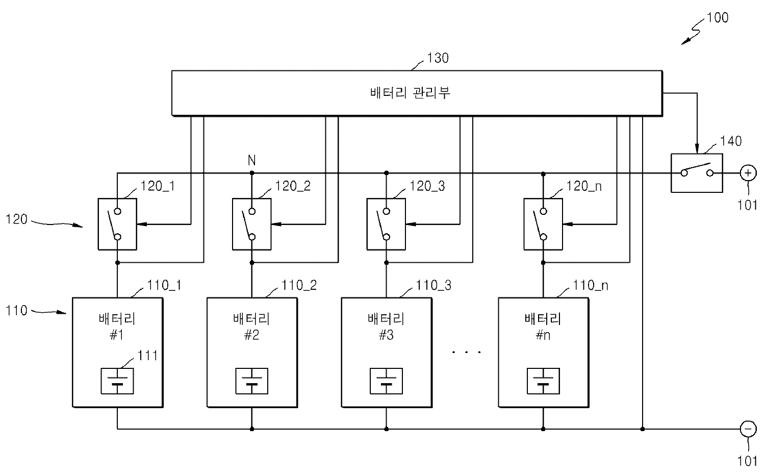
도 1을 참조하면, 배터리 팩(100)은 배터리들(110_1-110_n), 모듈 스위치들(120_1-120_n), 및 배터리 관리부(130)를 포함한다. 배터리들(110_1-110_n)은 배터리들(110)로 통칭하고, 모듈 스위치들(120_1-120_n)은 모듈 스위치들(120)로 통칭한다. 모듈 스위치들(120)은 대응하는 배터리들(110)에 각각 직렬로 연결된다. 예컨대, 제1 배터리(110_1)는 제1 모듈 스위치(120_1)에 직렬로 연결된다. 배터리들(110)의 개수와 모듈 스위치들(120)의 개수는 동일하다.Referring to FIG. 1, a
배터리들(110)은 전력을 저장하는 부분으로서, 적어도 하나의 배터리 셀(111)을 포함한다. 도 1에는 배터리(110)에 하나의 배터리 셀(111)이 포함되는 것으로 도시되어 있지만, 배터리(110)에는 복수의 배터리 셀들(111)이 포함될 수 있다. 복수의 배터리 셀들(111)은 직렬로 연결되거나, 병렬로 연결되거나, 또는 직렬과 병렬의 조합으로 연결될 수 있다. 배터리(110)에 포함되는 배터리 셀들(111)의 개수는 요구되는 출력 전압에 따라서 결정될 수 있다. The
배터리들(110)은 선택적으로 병렬로 연결될 수 있으며, 메인 단자들(101)을 통해 부하 및/또는 충전 장치에 연결될 수 있다. 메인 단자들(101)은 양방향 컨버터에 연결될 수 있으며, 배터리 팩(100)은 상기 양방향 컨버터를 통해 부하에 전력을 공급하거나, 충전 장치로부터 전력을 공급받을 수 있다.The
배터리 셀(111)은 충전가능한 이차 전지를 포함할 수 있다. 예컨대, 배터리 셀(111)은 니켈-카드뮴 전지(nickel-cadmium battery), 납 축전지, 니켈-수소 전지(NiMH: nickel metal hydride battery), 리튬-이온 전지(lithium ion battery), 리튬 폴리머 전지(lithium polymer battery) 등을 포함할 수 있다.The
배터리들(110_1-110_n)은 모듈 스위치들(120_1-120_n)을 통해 병렬로 선택적으로 연결된다. 즉, 배터리들(110_1-110_n)은 모듈 스위치들(120_1-120_n)을 통해 노드(N)에 선택적으로 연결된다. 본 명세서에서, "선택적으로 연결된다"는 용어는 외부의 제어 신호에 의해 연결되거나 연결되지 않을 수 있다는 것을 의미한다. 도 1에 도시된 바와 같이 모듈 스위치들(120)이 단락되면, 배터리들(110)은 서로 병렬로 연결되고, 모듈 스위치들(120)이 개방되면, 배터리들(110)은 서로 병렬로 연결되지 않는다. 즉, 모듈 스위치(120)가 단락되면, 대응하는 배터리(110)는 노드(N)에 연결되고, 모듈 스위치(120)가 개방되면, 대응하는 배터리(110)는 노드(N)로부터 분리된다.The batteries 110_1-110_n are selectively connected in parallel through the module switches 120_1-120_n. That is, the batteries 110_1-110_n are selectively connected to the node N through the module switches 120_1-120_n. In this specification, the term "selectively connected" means that it may or may not be connected by an external control signal. As shown in FIG. 1, when the module switches 120 are short-circuited, the
배터리 관리부(130)는 배터리들(110) 각각의 배터리 전압을 검출한다. 상기 배터리 전압은 배터리(110)의 양의 단자와 음의 단자 사이의 전압이다. 배터리(110)가 배터리 모듈을 구성하는 경우, 상기 배터리 전압은 모듈 전압으로 지칭될 수 있다. 배터리 관리부(130)는 배터리들(110)의 배터리 전압을 검출하기 위하여, 배터리들(110)의 단자들(예컨대, 배터리들(110)의 양극들)에 배선들을 통해 연결될 수 있다. 예컨대, 도 1에 도시된 바와 같이, 배터리들(110)의 음극이 음의 메인 단자(101)에 공통적으로 연결되고, 배터리들(110)의 양극이 모듈 스위치들(120)에 각각 연결되는 경우에, 배터리 관리부(130)는 배선들을 통해 음의 메인 단자(101) 및 배터리들(110)의 양극들에 연결될 수 있다.The
다른 예에 따르면, 배터리 관리부(130)는 배터리들(110)의 배터리 전압을 검출하기 위한 배터리 전압 검출부들(미 도시)을 포함할 수 있으며, 상기 배터리 전압 검출부들은 대응하는 배터리들(110)의 양 단자에 연결된 아날로그-디지털 컨버터(ADC)를 포함할 수 있다. 상기 아날로그-디지털 컨버터는 대응하는 배터리(110)의 양극과 음극 사이에 연결되는 전압 분배기(voltage divider)를 통해 배터리(110)의 배터리 전압을 디지털 신호로 변환할 수 있다.According to another example, the
배터리 관리부(130)는 배터리들(110)의 배터리 전압을 주기적으로 검출할 수 있다. 예컨대, 배터리 관리부(130)는 미리 결정된 주기(예컨대, 100ms)마다 배터리들(110) 각각의 배터리 전압을 검출할 수 있다. 서로 병렬로 연결된 배터리들(110)은 모두 동일한 배터리 전압을 가지므로, 배터리 관리부(130)는 서로 병렬로 연결된 배터리들(110)에 대해서는 하나의 배터리 전압만을 검출할 수 있다.The
배터리 관리부(130)는 배터리 팩(100)의 동작 모드 및 배터리들(110)의 배터리 전압을 기초로 배터리들(110)의 연결 순서를 결정한다. 배터리 팩(100)의 동작 모드는 충전 모드 또는 방전 모드 중 하나일 수 있다. 충전 모드는 충전 장치로부터 배터리 팩(100)에 전류가 유입되는 모드이고, 방전 모드는 배터리 팩(100)으로부터 부하로 전류가 유출되는 모드이다. 일 예에 따르면, 배터리 관리부(130)는 배터리들(110)의 배터리 전압 또는 충전 상태를 기초로 배터리 팩(100)을 충전할지 아니면 방전할지를 결정할 수 있다.The
다른 예에 따르면, 배터리 관리부(130)는 배터리 팩(100)에 연결되는 충전 장치로부터 전송되는 제어 신호를 기초로 동작 모드를 결정할 수 있다. 예컨대, 상기 충전 장치는 배터리 팩(100)에 연결되는 양방향 컨버터일 수 있으며, 동작 모드를 제어하는 제어 신호는 양방향 컨버터 또는 양방향 컨버터에 연결되는 통합 제어기로부터 수신될 수 있다.According to another example, the
배터리 관리부(130)는 결정된 연결 순서에 따라 배터리들(110)을 병렬 연결하기 위해, 모듈 스위치들(120)을 제어한다. 일 예에 따르면, 배터리 관리부(130)는 직접 제어 신호를 모듈 스위치에 인가함으로써 모듈 스위치들(120)을 제어할 수 있다. 다른 예에 따르면, 배터리 관리부(130)는 모듈 스위치들(120)의 단락 및 개방을 제어하기 위한 제어 명령을 송신하고, 상기 제어 명령을 수신한 제어 장치(미 도시)가 상기 제어 명령에 따라 모듈 스위치들(120)을 단락 또는 개방시킬 수 있다. 모듈 스위치(120)는 예컨대 릴레이, 또는 FET(Field Effect Transistor) 스위치로 구성될 수 있다.The
배터리 관리부(130)는 충전 모드에서 가장 낮은 배터리 전압을 갖는 배터리(110)부터 가장 높은 배터리 전압을 갖는 배터리(110)까지 상기 배터리 전압이 낮은 순서로 배터리들(110)이 병렬로 연결되도록 모듈 스위치들(120)을 제어하도록 구성된다.The
일 예에 따르면, 배터리 관리부(130)는 가장 낮은 배터리 전압을 갖는 배터리(110)(예컨대, 제1 배터리(110_1))에 대응하는 모듈 스위치(120)(예컨대, 제1 모듈 스위치(120_1))를 단락시킬 수 있다. 배터리 관리부(130)는 제1 배터리(110_1)를 충전시킬 수 있다. 충전에 의하여 제1 배터리(110_1)의 배터리 전압은 서서히 증가하게 된다. 제1 배터리(110_1)의 배터리 전압이 두 번째로 낮은 배터리 전압을 갖는 배터리(110)(예컨대, 제2 배터리(110_2))의 배터리 전압과 실질적으로 동일해지면, 배터리 관리부(130)는 제2 배터리(110_2)에 대응하는 모듈 스위치(120)(예컨대, 제2 모듈 스위치(120_2))를 단락시킬 수 있다. 배터리 관리부(130)는 서로 병렬로 연결된 제1 배터리(110_1)와 제2 배터리(110_2)를 함께 충전시킬 수 있다. 충전에 의하여 제1 배터리(110_1)와 제2 배터리(110_2)의 배터리 전압은 서서히 증가하게 된다. 제1 배터리(110_1)와 제2 배터리(110_2)의 배터리 전압이 세 번째로 낮은 배터리 전압을 갖는 배터리(110)(예컨대, 제3 배터리(110_3))의 배터리 전압과 실질적으로 동일해지면, 배터리 관리부(130)는 제3 배터리(110_3)에 대응하는 모듈 스위치(120)(예컨대, 제3 모듈 스위치(120_3))를 단락시킬 수 있다. 배터리 관리부(130)는 서로 병렬로 연결된 제1 배터리(110_1) 내지 제3 배터리(110_3)를 함께 충전시킬 수 있다. According to an example, the
배터리 관리부(130)는 이러한 방식으로 가장 높은 배터리 전압을 갖는 배터리(110)(예컨대, 제n 배터리(110_n))에 대응하는 모듈 스위치(120)(예컨대, 제n 모듈 스위치(120_n))까지 모든 모듈 스위치들(120)을 단락시킬 수 있다. 배터리 관리부(130)는 모든 배터리들(110)이 연결되면 필요에 따라 배터리들(110)을 충전 또는 방전시킬 수 있다.The
배터리 관리부(130)는 방전 모드에서 가장 높은 모듈 전압을 갖는 배터리(110)부터 가장 낮은 모듈 전압을 갖는 배터리(110)까지 상기 배터리 전압이 높은 순서로 배터리들(110)이 병렬로 연결되도록 모듈 스위치들(120)을 제어하도록 구성된다. The
일 예에 따르면, 배터리 관리부(130)는 가장 높은 배터리 전압을 갖는 배터리(110)(예컨대, 제1 배터리(110_1))에 대응하는 모듈 스위치(120)(예컨대, 제1 모듈 스위치(120_1))를 단락시킬 수 있다. 배터리 관리부(130)는 제1 배터리(110_1)를 방전시킬 수 있다. 방전에 의하여 제1 배터리(110_1)의 배터리 전압은 서서히 하강하게 된다. 제1 배터리(110_1)의 배터리 전압이 두 번째로 높은 배터리 전압을 갖는 배터리(110)(예컨대, 제2 배터리(110_2))의 배터리 전압과 실질적으로 동일해지면, 배터리 관리부(130)는 제2 배터리(110_2)에 대응하는 모듈 스위치(120)(예컨대, 제2 모듈 스위치(120_2))를 단락시킬 수 있다. 배터리 관리부(130)는 서로 병렬로 연결된 제1 배터리(110_1)와 제2 배터리(110_2)를 함께 방전시킬 수 있다. 방전에 의하여 제1 배터리(110_1)와 제2 배터리(110_2)의 배터리 전압은 서서히 하강하게 된다. 제1 배터리(110_1)와 제2 배터리(110_2)의 배터리 전압이 세 번째로 높은 배터리 전압을 갖는 배터리(110)(예컨대, 제3 배터리(110_3))의 배터리 전압과 실질적으로 동일해지면, 배터리 관리부(130)는 제3 배터리(110_3)에 대응하는 모듈 스위치(120)(예컨대, 제3 모듈 스위치(120_3))를 단락시킬 수 있다. 배터리 관리부(130)는 서로 병렬로 연결된 제1 배터리(110_1) 내지 제3 배터리(110_3)를 함께 방전시킬 수 있다. According to an example, the
배터리 관리부(130)는 이러한 방식으로 가장 낮은 배터리 전압을 갖는 배터리(110)(예컨대, 제n 배터리(110_n))에 대응하는 모듈 스위치(120)(예컨대, 제n 모듈 스위치(120_n))까지 모든 모듈 스위치들(120)을 단락시킬 수 있다. 배터리 관리부(130)는 모든 배터리들(110)이 연결되면 필요에 따라 배터리들(110)을 충전 또는 방전시킬 수 있다.The
본 명세서에서, "제1 값과 제2 값이 서로 실질적으로 동일하다"는 용어는 제1 값과 제2 값이 정확히 동일한 경우뿐만 아니라 제1 값과 제2 값의 차이가 미리 설정된 임계 값보다 작은 경우를 포함하는 것으로 이해되어야 한다. 예컨대, 충전 또는 방전에 의하여, 제1 배터리(110_1)의 배터리 전압이 제2 배터리(110_2)의 배터리 전압과 실질적으로 동일해진다는 것은 제1 배터리(110_1)의 배터리 전압과 제2 배터리(110_2)의 배터리 전압의 차이가 미리 결정된 임계 값보다 작아진다는 것을 의미한다. 상기 임계 값은 예컨대 배터리들(110)의 배터리 전압의 1% 내지 5% 사이에서 미리 설정될 수 있다. 예컨대, 상기 임계 값은 1V일 수 있다.As used herein, the term "the first value and the second value are substantially equal to each other" means that not only when the first value and the second value are exactly the same, but also when the difference between the first value and the second value is greater than a predetermined threshold value It should be understood that it includes a small case. For example, when the battery voltage of the first battery 110_1 becomes substantially equal to the battery voltage of the second battery 110_2 due to charging or discharging, the battery voltage of the first battery 110_1 and the battery voltage of the second battery 110_2, The difference of the battery voltages of the battery cells becomes smaller than a predetermined threshold value. The threshold can be preset, for example, between 1% and 5% of the battery voltage of the
일 예에 따르면, 제1 배터리(110_1)가 가장 낮은 배터리 전압을 갖고, 제2 배터리(110_2)가 두 번째로 낮은 배터리 전압을 갖는 경우, 배터리 관리부(130)는 충전 모드에서 제1 모듈 스위치(120_1)를 단락하여 제1 배터리(110_1)를 충전하고, 제1 배터리(110_1)의 배터리 전압이 상승하여 제1 배터리(110_1)의 배터리 전압과 제2 배터리(110_2)의 배터리 전압의 차이가 상기 임계 값보다 작게 되면 제2 모듈 스위치(120_2)를 단락하여 제1 및 제2 배터리들(110_1, 110_2)을 함께 충전하도록 구성될 수 있다. 배터리 관리부(130)는 이러한 방식으로 모든 모듈 스위치들(120)을 단락하여 모든 배터리들(110)을 병렬로 연결하도록 구성될 수 있다.According to an example, when the first battery 110_1 has the lowest battery voltage and the second battery 110_2 has the second lowest battery voltage, the
다른 예에 따르면, 제1 배터리(110_1)가 가장 높은 배터리 전압을 갖고, 제2 배터리(110_2)가 두 번째로 높은 배터리 전압을 갖는 경우, 배터리 관리부(130)는 방전 모드에서 제1 모듈 스위치(120_1)를 단락하여 제1 배터리(110_1)를 방전하고, 제1 배터리(110_1)의 배터리 전압이 하강하여 제1 배터리(110_1)의 배터리 전압과 제2 배터리(110_2)의 배터리 전압의 차이가 상기 임계 값보다 작게 되면 제2 모듈 스위치(120_2)를 단락하여 제1 및 제2 배터리들(110_1, 110_2)을 함께 방전하도록 구성될 수 있다. 배터리 관리부(130)는 이러한 방식으로 모든 모듈 스위치들(120)을 단락하여 모든 배터리들(110)을 병렬로 연결하도록 구성될 수 있다.According to another example, when the first battery 110_1 has the highest battery voltage and the second battery 110_2 has the second highest battery voltage, the
또 다른 예에 따르면, 제1 모듈 스위치(120_1) 및 제2 모듈 스위치(120_2)가 단락되어, 제1 배터리(110_1)과 제2 배터리(110_2)는 병렬로 연결된 상태이고, 제3 모듈 스위치(120_3)는 개방된 상태인 경우, 배터리 관리부(130)는 제1 및 제2 배터리들(110_1, 110_2)을 충전 또는 방전하여 제1 및 제2 배터리들(110_1, 110_2)의 배터리 전압과 제3 배터리(110_3)의 배터리 전압의 차이가 상기 임계 값보다 작게 되면 제3 모듈 스위치(120_3)를 단락하여 제3 배터리(110_3)를 제1 및 제2 배터리들(110_1, 110_2)에 병렬로 연결하도록 구성될 수 있다. 이러한 방식으로 배터리 관리부(130)는 모든 배터리들(110)을 병렬로 연결하도록 구성될 수 있다.According to another example, the first module switch 120_1 and the second module switch 120_2 are short-circuited such that the first battery 110_1 and the second battery 110_2 are connected in parallel, and the third module switch The
또 다른 예에 따르면, 제1 배터리(110_1)가 제1 배터리 전압을 갖고, 제2 배터리(110_2)가 제2 배터리 전압을 가지며, 상기 제1 배터리 전압과 상기 제2 배터리 전압의 차이가 상기 임계 값보다 작은 경우, 배터리 관리부(1300는 제1 모듈 스위치(120_1)과 제2 모듈 스위치(120_2)를 연속적으로 또는 동시에 단락하도록 구성될 수 있다. 예컨대, 배터리 관리부(130)는 제1 모듈 스위치(120_1)를 단락한 후, 제1 배터리(110_1)를 충전 또는 방전하지 않고 제2 모듈 스위치(120_2)를 바로 단락하도록 구성될 수 있다. 따라서, 배터리들(110)의 일부의 배터리 전압들의 차이가 상기 임계 값보다 작은 경우, 상기 일부의 배터리들(110)을 한꺼번에 병렬로 연결함으로써 모든 배터리들(110)을 병렬로 연결하는데 소요되는 시간이 감소될 수 있다.According to another example, if the first battery 110_1 has the first battery voltage, the second battery 110_2 has the second battery voltage, and the difference between the first battery voltage and the second battery voltage is less than the threshold The
배터리 팩(100)은 배터리들(110)과 메인 단자들(101) 사이에 연결되는 메인 스위치(140)를 더 포함할 수 있다. 메인 스위치(140)는 큰 크기의 전류가 흐를 수 있고 큰 크기의 전류의 흐름을 제어할 수 있는 예컨대 릴레이로 구성될 수 있다. 도 1에서 배터리들(110)의 양극들(즉, 노드(N))과 양의 메인 단자(101) 사이에 메인 스위치(140)가 연결되는 것으로 도시되어 있지만, 이는 예시적이며, 메인 스위치(140)는 배터리들(110)의 음극들과 음의 메인 단자(101) 사이에 연결될 수도 있다. 배터리 관리부(130)는 메인 스위치(140)의 단락 및 개방을 제어할 수 있다. 배터리 관리부(130)는 메인 스위치(140)가 개방된 상태에서 모듈 스위치들(120)이 개방 상태에서 단락 상태로 스위칭하도록 메인 스위치(140)를 제어할 수 있다. 즉, 새로운 배터리(110)를 병렬로 연결하는 순간에 메인 스위치(140)는 개방 상태일 수 있다. 메인 스위치(140)가 개방 상태인 상태에서 새로운 배터리(110)가 연결됨에 따라 메인 단자들(101)에 연결되는 충전 장치 또는 부하에 작은 인러쉬 전류라도 유입되는 것을 방지할 수 있다.The
다른 예에 따르면, 메인 스위치(140)가 단락 상태일 때, 배터리들(110)이 병렬로 연결될 수 있다. 배터리 관리부(130)는 이미 병렬로 연결된 배터리들(110)의 배터리 전압과 새로 연결될 배터리(110)의 배터리 전압이 실질적으로 동일할 때 상기 새로 연결될 배터리(110)에 대응하는 모듈 스위치(120)를 단락하기 때문에, 인러쉬 전류가 발생하지 않으며, 메인 단자들(101)에 연결되는 충전 장치 또는 부하가 손상되지 않는다.According to another example, when the
도 2는 다른 실시예에 따른 배터리 팩의 개략적인 블록도를 도시한다.2 shows a schematic block diagram of a battery pack according to another embodiment.
도 2를 참조하면, 배터리 팩(200)은 서로 병렬로 선택적으로 연결되는 배터리 모듈들(210_1-210_n), 메인 관리부(220) 및 메인 스위치(230)를 포함한다. 배터리 모듈들(210_1-210_n)은 배터리 모듈들(210)로 통칭된다. 배터리 모듈들(210) 각각은 서로 직렬로 연결되는 배터리(211) 및 모듈 스위치(213)를 포함한다. 배터리 모듈들(210)은 배터리(211)의 모듈 전압을 측정하고 모듈 스위치(213)를 제어하는 모듈 관리부(215)를 더 포함한다. 배터리 팩(200)은 배터리 시스템으로 지칭될 수 있다.Referring to FIG. 2, the
도 2에 도시된 바와 같이, 배터리들(211)은 대응하는 모듈 스위치들(213)을 통해 병렬로 선택적으로 연결될 수 있다. 즉, 배터리들(211)은 대응하는 모듈 스위치들(213)을 통해 노드(N)에 선택적으로 연결될 수 있다. 서로 다른 모듈 전압을 갖는 배터리들(211)이 병렬로 연결되면, 연결되는 순간에 인러쉬 전류가 발생한다. 본 실시예에 따르면, 배터리들(211)의 모듈 전압이 서로 실질적으로 동일할 때, 즉, 배터리들(211)의 모듈 전압의 차이가 미리 설정된 임계 값보다 작을 때, 상기 배터리들(211)이 병렬로 연결되므로 인러쉬 전류가 발생하지 않거나 감소될 수 있다.As shown in FIG. 2, the
본 실시예에 따르면, 배터리들(211)의 모듈 전압을 실질적으로 동일하게 맞추기 위하여, 더 높은 모듈 전압을 갖는 배터리(211)가 방전되거나 더 낮은 모듈 전압을 갖는 배터리(211)가 충전될 수 있다. 모듈 전압을 실질적으로 동일하게 맞추는 과정에서 배터리(211)에 저장된 전기 에너지가 낭비되지 않도록, 메인 관리부(220)는 충전 모드에서 가장 낮은 모듈 전압을 갖는 배터리(211)부터 가장 높은 모듈 전압을 갖는 배터리(211)까지 모듈 전압이 낮은 순서로 배터리들(211)이 병렬로 연결되도록 모듈 스위치들(213)을 제어한다. 또한, 메인 관리부(220)는 방전 모드에서 가장 높은 모듈 전압을 갖는 배터리(211)부터 가장 낮은 모듈 전압을 갖는 배터리(211)까지 모듈 전압이 높은 순서로 배터리들(211)이 병렬로 연결되도록 모듈 스위치들(213)을 제어한다. 가장 높은 모듈 전압을 갖는 배터리(211)의 모듈 전압이 상기 가장 낮은 모듈 전압으로 낮아지는 동안, 상기 배터리(211)에서 방전되는 전기 에너지는 부하에서 사용된다.According to the present embodiment, in order to substantially equalize the module voltages of the
배터리들(211) 및 모듈 스위치들(213)은 도 1을 참조로 앞에서 설명한 배터리들(110) 및 모듈 스위치들(120)에 각각 대응하며, 반복하여 설명하지 않는다. 메인 관리부(220)와 모듈 관리부들(215)은 통합하여, 도 1을 참조로 앞에서 설명한 배터리 관리부(130)에 대응할 수 있다. 즉, 도 1을 참조로 앞에서 도시된 배터리 관리부(130)는 서로 통신 가능하게 연결되는 메인 관리부(220)와 모듈 관리부들(215)로 구성될 수 있다.The
메인 관리부(220)와 모듈 관리부들(215)은 서로 통신 버스를 통해 연결될 수 있다. 예컨대, 메인 관리부(220)와 모듈 관리부들(215) 사이의 통신 프로토콜로는 CAN 통신이 사용될 수 있다. 그러나 이에 한정되는 것은 아니며, 통신 버스를 사용하여 데이터나 명령을 전송하는 통신 프로토콜이라면 모두 적용될 수 있다. 메인 관리부(220)는 랙 배터리 관리 시스템(battery management system, 이한 'BMS'라 지칭함)로 지칭되고, 모듈 관리부(215)는 모듈 BMS 또는 트레이 BMS로 지칭될 수 있다.The
모듈 관리부들(215)은 대응하는 배터리들(211)의 모듈 전압을 측정하고, 측정된 모듈 전압을 메인 관리부(220)로 각각 전송할 수 있다. 메인 관리부(220)는 모듈 관리부들(215)로부터 모듈 전압들을 수신하여 모든 배터리 모듈들(210)의 모듈 전압들을 수집할 수 있다. 메인 관리부(220)는 배터리 팩(200)의 동작 모드를 결정할 수 있다. 동작 모드는 충전 모드 또는 방전 모드일 수 있다. 일 예에 따르면, 메인 관리부(220)는 배터리 모듈들(210)의 모듈 전압들을 기초로 충전 상태를 결정하고, 상기 충전 상태를 미리 결정된 기준 값과 비교하여 배터리 모듈들(210)을 충전할 것인지 아니면 방전할 것인지를 결정할 수 있다. 예컨대, 상기 미리 결정된 기준 값은 50%일 수 있다. 예컨대, 배터리 모듈들(210)의 충전 상태(예컨대, 평균 충전 상태, 최소 충전 상태 또는 최대 충전 상태)가 50% 미만인 경우, 메인 관리부(220)는 배터리 팩(200)의 동작 모드를 충전 모드로 결정할 수 있다. 반대로, 배터리 모듈들(210)의 충전 상태(예컨대, 평균 충전 상태, 최소 충전 상태 또는 최대 충전 상태)가 50%를 초과하는 경우, 메인 관리부(220)는 배터리 팩(200)의 동작 모드를 방전 모드로 결정할 수 있다.The
다른 예에 따르면, 메인 관리부(220)는 통신 가능하게 연결되는 외부 장치(예컨대, 통합 제어기, 양방향 컨버터, 또는 충전 및 방전 장치)로부터 배터리 팩(200)의 동작 모드에 관한 정보를 요청하고, 상기 외부 장치는 배터리 팩(200)에 연결된 부하, 상용 전원, 발전기의 상태들을 종합적으로 판단하여 배터리 팩(200)의 동작 모드를 결정하고, 상기 결정된 동작 모드에 관한 정보를 메인 관리부(220)에게 전송할 수 있다.According to another example, the
모듈 관리부(215)는 대응하는 배터리(211)의 모듈 전압뿐만 아니라, 상기 배터리(211)를 구성하는 배터리 셀들의 셀 전압을 측정하고, 측정된 셀 전압을 메인 관리부(220)로 전송할 수 있다. 또한, 모듈 관리부(215)는 대응하는 배터리(211)의 온도, 및/또는 대응하는 배터리(211)의 충전 및 방전 전류를 측정하고, 측정된 온도 및/또는 측정된 충전 및 방전 전류를 메인 관리부(220)로 전송할 수 있다. 모듈 관리부(215)는 대응하는 배터리(211)의 온도 및/또는 충전 및 방전 전류를 측정하기 위해 온도 센서(미 도시) 및 전류 센서(미 도시)를 포함하거나, 상기 온도 센서 및 상기 전류 센서에 연결될 수 있다. 메인 관리부(220)는 배터리들(211)의 파라미터들(예컨대, 셀 전압, 충전 및 방전 전류, 온도)을 수집하여, 충전 상태(SOC, state of charge) 및/또는 건강 상태(SOH, state of health)를 결정할 수 있다.The
모듈 관리부(215)는 대응하는 모듈 스위치(213)을 제어할 수 있다. 모듈 관리부(215)는 대응하는 모듈 스위치(213)를 단락 또는 개방하도록 구성될 수 있다. 모듈 스위치(213)는 예컨대 릴레이 또는 FET로 구성될 수 있다. 모듈 관리부(215)는 메인 관리부(220)로부터 전송된 제어 명령에 따라 모듈 스위치(213)를 제어할 수 있다.The
메인 관리부(220)는 모듈 관리부(215)들로부터 배터리(211)들의 모듈 전압을 각각 수집하고, 동작 모드(예컨대, 충전 모드 또는 방전 모드)에 따라 배터리 모듈(210)들을 병렬로 연결할 순서를 결정할 수 있다. 상술한 바와 같이, 충전 모드에서 메인 관리부(220)는 모듈 전압이 낮은 순서로 배터리 모듈들(210)을 연결할 수 있다. 방전 모드에서, 메인 관리부(220)는 모듈 전압이 높은 순서로 배터리 모듈들(210)을 연결할 수 있다.The
메인 관리부(220)는 결정된 순서에 따라 배터리 모듈(210)(예컨대, 제1 배터리 모듈(210_1))(충전 모드에서는 모듈 전압이 가장 낮은 배터리 모듈, 방전 모드에서는 모듈 전압이 가장 높은 배터리 모듈)의 모듈 관리부(215)에게 대응하는 모듈 스위치(213)를 단락하라는 제어 명령을 송신할 수 있다. 대응하는 모듈 관리부(215)(예컨대, 제1 배터리 모듈(210_1)의 모듈 관리부(215))는 상기 제어 명령을 수신하고, 상기 제어 명령에 따라 대응하는 모듈 스위치(213)(예컨대, 제1 배터리 모듈(210_1)의 모듈 스위치(213))를 단락함으로써, 배터리 모듈(210_1)의 배터리(211)가 노드(N)에 연결될 수 있다. The
메인 관리부(220)는 상기 대응하는 모듈 스위치(213)의 단락을 확인한 후, 메인 스위치(230)를 단락한 후, 상기 동작 모드에 따라 상기 배터리(211)를 충전 또는 방전시킬 수 있다. 상술한 바와 같이, 모듈 관리부들(215)은 대응하는 배터리 모듈들(210)의 모듈 전압을 주기적으로 측정하고, 측정된 모듈 전압들을 메인 관리부(220)로 주기적으로 전송할 수 있다. 배터리 모듈(210_1)은 충전 또는 방전에 의해 모듈 전압이 변하게 되고, 차순위 배터리 모듈(210)(예컨대, 제2 배터리 모듈(210_2))의 모듈 전압과 실질적으로 동일해지면, 메인 관리부(220)는 상기 제2 배터리 모듈(210_2)의 모듈 관리부(215)에게 대응하는 모듈 스위치(213)를 단락하라는 제어 명령을 송신할 수 있다. 상기 모듈 관리부(215)(예컨대, 상기 차순위 배터리 모듈(210_2)의 모듈 관리부(215))는 상기 제어 명령에 따라 대응하는 모듈 스위치(213)(예컨대, 상기 차순위 배터리 모듈(210_2)의 모듈 스위치(213))를 단락함으로써, 상기 차순위 배터리 모듈(210_2)의 배터리(211)를 노드(N)에 연결할 수 있다. 배터리 모듈(210_1)과 배터리 모듈(210_2)은 병렬로 연결된다. 이러한 방식으로 모든 모듈 스위치들(213)이 단락되고, 모든 배터리 모듈들(210)은 병렬로 연결된다. 메인 관리부(220)는 메인 스위치(230)를 단락하고, 부하나 전원의 상태에 따라서 병렬로 연결된 모든 배터리 모듈(210)을 충전 또는 방전할 수 있다.The
배터리 팩(200)의 기동(startup) 방법을 설명한다. 기동 전에, 모듈 스위치들(213) 및 메인 스위치들(230)은 모두 개방 상태이고, 메인 관리부(220)와 모듈 관리부들(215)은 모두 턴 오프 상태이다.A method of starting up the
우선, 메인 관리부(220)와 모듈 관리부들(215)이 모두 턴 온된다. 모듈 관리부들(215)은 메인 관리부(220)의 제어에 의해 턴 온될 수 있다.First, both the
모듈 관리부들(215)은 대응하는 배터리들(211)의 모듈 전압들을 측정하고 측정된 모듈 전압들을 메인 관리부(220)로 전송하기 시작한다. 모듈 관리부들(215)은 주기적으로 모듈 전압들을 측정하고 메인 관리부(220)로 전송하는 것을 지속할 수 있다.The
메인 관리부(220)는 배터리 팩(200)의 동작 모드를 결정할 수 있다. 일 예에 따르면, 메인 관리부(220)는 모듈 관리부들(215)로부터 수신한 모듈 전압들을 기초로 배터리들(211)을 충전할 것인지 방전할 것인지를 결정할 수 있다. 다른 예에 따르면, 메인 관리부(220)는 배터리 팩(200)의 메인 단자(201)에 연결된 부하 또는 전원의 상태를 기초로 동작 모드를 결정할 수 있다. 메인 관리부(220)는 에너지 저장 시스템의 통합 제어기로부터 동작 모드에 관한 정보를 수신할 수 있다. 동작 모드는 충전 모드 또는 방전 모드 중 하나일 수 있다.The
동작 모드가 충전 모드로 결정된 경우, 메인 관리부(220)는 모듈 전압이 낮은 순서로 배터리 모듈들(210)을 병렬로 연결할 수 있다. 동작 모드가 방전 모드로 결정된 경우, 메인 관리부(220)는 모듈 전압이 높은 순서로 배터리 모듈들(210)을 병렬로 연결할 수 있다.If the operation mode is determined to be the charging mode, the
구체적으로, 동작 모드가 충전 모드로 결정된 경우에 대하여 설명한다. 제1 배터리 모듈(210_1)의 모듈 전압이 가장 낮고, 제2 배터리 모듈(210_2)의 모듈 전압이 2번째로 낮고, 제3 배터리 모듈(210_3)의 모듈 전압이 3번째로 낮다고 가정한다. 이러한 방식으로 제n 배터리 모듈(210_n)의 모듈 전압이 가장 높다고 가정한다. 메인 관리부(220)는 충전 모드에서 제1 배터리 모듈(210_1)부터 제n 배터리 모듈(210_n)까지 모듈 전압이 낮은 순서로 배터리 모듈들(210)을 병렬로 연결할 수 있다.Specifically, the case where the operation mode is determined as the charge mode will be described. It is assumed that the module voltage of the first battery module 210_1 is the lowest, the module voltage of the second battery module 210_2 is the second lowest, and the module voltage of the third battery module 210_3 is the third lowest. In this way, it is assumed that the module voltage of the nth battery module 210_n is the highest. The
메인 관리부(220)는 제1 배터리 모듈(210_1)의 모듈 스위치(213)를 단락시키기 위해 모듈 관리부(215)에게 제어 명령을 송신할 수 있다. 제1 배터리 모듈(210_1)의 모듈 관리부(215)는 상기 제어 명령을 수신하고, 모듈 스위치(213)를 단락시킬 수 있다. 메인 관리부(220)는 제1 배터리 모듈(210_1)의 모듈 스위치(213)가 단락되었음을 확인한 후 메인 스위치(230)를 단락시킬 수 있다.The
메인 관리부(220)는 제1 배터리 모듈(210_1)의 배터리(211)를 충전시킬 수 있다. 제1 배터리 모듈(210_1)의 모듈 전압은 상승하게 된다. 제1 배터리 모듈(210_1)의 모듈 관리부(215)은 제1 배터리 모듈(210_1)의 모듈 전압을 메인 관리부(220)로 전송하고, 메인 관리부(220)는 제1 배터리 모듈(210_1)의 모듈 전압이 제2 배터리 모듈(210_2)의 모듈 전압과 실질적으로 동일해질 때까지 대기한다.The
메인 관리부(220)는 제1 배터리 모듈(210_1)의 모듈 전압이 제2 배터리 모듈(210_2)의 모듈 전압과 실질적으로 동일해지면, 제2 배터리 모듈(210_2)의 연결을 준비할 수 있다. 메인 관리부(220)는 메인 스위치(230)를 개방시킬 수 있다. 다른 예에 따르면, 메인 관리부(220)는 메인 스위치(230)를 개방시키지 않을 수도 있다. The
메인 관리부(220)는 제2 배터리 모듈(210_2)의 모듈 스위치(213)를 단락시키기 위해 모듈 관리부(215)에게 제어 명령을 송신할 수 있다. 제2 배터리 모듈(210_2)의 모듈 관리부(215)는 상기 제어 명령을 수신하고, 모듈 스위치(213)를 단락시킬 수 있다. 메인 관리부(220)는 제2 배터리 모듈(210_2)의 모듈 스위치(213)가 단락되었음을 확인한 후 메인 스위치(230)를 단락시킬 수 있다. 제1 배터리 모듈(210_1)과 제2 배터리 모듈(210_2)은 서로 병렬로 연결된다.The
메인 관리부(220)는 제1 배터리 모듈(210_1)의 배터리(211)와 제2 배터리 모듈(210_2)의 배터리(211)를 함께 충전시킬 수 있다. 제1 배터리 모듈(210_1) 및 제2 배터리 모듈(210_2)의 모듈 전압은 상승하게 된다. 제1 배터리 모듈(210_1)의 모듈 관리부(215) 및/또는 제2 배터리 모듈(210_2)의 모듈 관리부는 제1 배터리 모듈(210_1) 및/또는 제2 배터리 모듈(210_2)의 모듈 전압을 메인 관리부(220)로 전송하고, 메인 관리부(220)는 제1 배터리 모듈(210_1) 및 제2 배터리 모듈(210_2)의 모듈 전압이 제3 배터리 모듈(210_3)의 모듈 전압과 실질적으로 동일해질 때까지 대기한다.The
메인 관리부(220)는 제1 배터리 모듈(210_1) 및 제2 배터리 모듈(210_2)의 모듈 전압이 제3 배터리 모듈(210_3)의 모듈 전압과 실질적으로 동일해지면, 제3 배터리 모듈(210_3)을 더 연결할 수 있다. 메인 관리부(220)는 이러한 방식으로 모든 배터리 모듈들(210)을 병렬로 연결할 수 있다.When the module voltages of the first battery module 210_1 and the second battery module 210_2 are substantially equal to the module voltage of the third battery module 210_3, the
동작 모드가 방전 모드로 결정된 경우에도, 앞에서 설명한 충전 모드로 결정된 경우의 기동 방법이 연결 순서를 제외하고 동일하게 적용될 수 있다.Even when the operation mode is determined to be the discharge mode, the starting method in the case of determining the charging mode described above can be applied equally except for the connection order.
기동 전에, 제2 배터리 모듈(210_2)의 모듈 전압과 제3 배터리 모듈(210_3)의 모듈 전압이 실질적으로 동일한 경우, 즉, 제2 배터리 모듈(210_2)의 모듈 전압과 제3 배터리 모듈(210_3)의 모듈 전압의 차이가 미리 설정된 임계값보다 작은 경우, 메인 관리부(220)는 제2 배터리 모듈(210_2)을 제1 배터리 모듈(210_1)에 병렬로 연결한 후, 바로 제3 배터리 모듈(210_3)을 더 병렬로 연결할 수 있다. When the module voltage of the second battery module 210_2 and the module voltage of the third battery module 210_3 are substantially equal to each other, that is, when the module voltage of the second battery module 210_2 is substantially equal to the module voltage of the third battery module 210_3, The
운용 중인 배터리 팩(200)에서 제1 배터리 모듈(210_1)을 교체한 경우, 제2 내지 제n 배터리 모듈들(210_2-210_n)의 모듈 전압들은 실질적으로 동일하고, 제1 배터리 모듈(210_1)의 모듈 전압만 상이할 수 있다. 이 경우에 배터리 팩(200)이 기동되면, 메인 관리부(220)는 제2 내지 제n 배터리 모듈들(210_2-210_n)을 모두 실질적으로 동시에 병렬로 연결할 수 있다. 즉, 메인 관리부(220)는 중간에 배터리들(211)을 충전하거나 방전하지 않고 제2 내지 제n 배터리 모듈들(210_2-210_n)을 순차적으로 연결할 수 있다. 그 후, 병렬로 연결된 제2 내지 제n 배터리 모듈들(210_2-210_n)을 충전 또는 방전시켜서 제2 내지 제n 배터리 모듈들(210_2-210_n)의 모듈 전압이 제1 배터리 모듈(210_1)의 모듈 전압과 실질적으로 동일해지면, 메인 관리부(220)는 제1 배터리 모듈(210_1)을 제2 내지 제n 배터리 모듈들(210_2-210_n)에 병렬로 연결할 수 있다.When the first battery module 210_1 is replaced in the
도 3은 일 실시예에 따른 에너지 저장 시스템 및 주변 구성을 개략적으로 도시한다.FIG. 3 schematically illustrates an energy storage system and a peripheral configuration according to one embodiment.
도 3을 참조하면, 본 실시예에 따른 에너지 저장 시스템(1)은 발전 시스템(2), 계통(3)과 연계하여 부하(4)에 전력을 공급한다. 에너지 저장 시스템(1)은 전력을 저장하는 배터리 시스템(20) 및 전력 변환 시스템(Power Conversion System, 이하 'PCS'라 함)(10)을 포함한다. PCS(10)는 발전 시스템(2), 계통(3), 및/또는 배터리 시스템(20)으로부터 제공되는 전력을 적절한 형태의 전력으로 변환하여 부하(4), 배터리 시스템(20) 및/또는 계통(3)에 공급할 수 있다.3, the
발전 시스템(2)은 에너지원으로부터 전력을 생산하는 시스템이다. 발전 시스템(2)은 발전에 의해 생성된 전력을 에너지 저장 시스템(1)에 공급할 수 있다. 발전 시스템(2)은 예컨대 태양광 발전 시스템, 풍력 발전 시스템, 및 조력 발전 시스템 중 적어도 하나를 포함할 수 있다. 예컨대, 발전 시스템(2)은 태양열이나 지열 등과 같은 신 재생 에너지를 이용하여 전력을 생산하는 모든 발전 시스템들을 포함할 수 있다. 발전 시스템(2)은 전력을 생산할 수 있는 다수의 발전 모듈들을 병렬로 배열함으로써 대용량 에너지 시스템을 구성할 수 있다.The
계통(3)은 발전소, 변전소, 송전선 등을 포함할 수 있다. 계통(3)이 정상 상태인 경우, 계통(3)은 부하(4) 및/또는 배터리 시스템(20) 에 전력을 공급하거나, 배터리 시스템(20) 및/또는 발전 시스템(2)으로부터 전력을 공급받을 수 있다. 계통(3)이 비정상 상태인 경우, 계통(3)과 에너지 저장 시스템(1) 간의 전력 전달은 중단된다.The
부하(4)는 발전 시스템(2)에서 생산된 전력, 배터리 시스템(20)에 저장된 전력, 및/또는 계통(3)으로부터 공급된 전력을 소비할 수 있다. 에너지 저장 시스템(1)이 설치된 가정이나 공장의 전기 장치들이 부하(4)의 일 예일 수 있다.The
에너지 저장 시스템(1)은 발전 시스템(2)에서 생산된 전력을 배터리 시스템(20)에 저장하거나, 계통(3)으로 공급할 수 있다. 에너지 저장 시스템(1)은 배터리 시스템(20)에 저장된 전력을 계통(3)으로 공급하거나, 계통(3)으로부터 공급된 전력을 배터리 시스템(20)에 저장할 수도 있다. 또한, 에너지 저장 시스템(1)은 계통(3)이 비정상 상태일 경우, 예컨대, 정전이 발생한 경우에 UPS(Uninterruptible Power Supply) 기능을 수행하여 발전 시스템(2)에서 생산된 전력이나 배터리 시스템(20)에 저장되어 있는 전력을 부하(4)에 공급할 수 있다.
The
도 4는 일 실시예에 따른 에너지 저장 시스템의 개략적인 구성을 나타내는 블록도이다.4 is a block diagram illustrating a schematic configuration of an energy storage system according to an embodiment.
도 4를 참조하면, 에너지 저장 시스템(1)은 전력을 변환하는 PCS(10), 배터리 시스템(20), 제1 스위치(30), 및 제2 스위치(40)를 포함할 수 있다. 배터리 시스템(20)은 배터리(21) 및 배터리 관리부(22)를 포함할 수 있다.4, the
PCS(10)는 발전 시스템(2), 계통(3), 및/또는 배터리 시스템(20)으로부터 제공되는 전력을 적절한 형태의 전력으로 변환하여 부하(4), 배터리 시스템(20) 및/또는 계통(3)에 공급할 수 있다. PCS(10)는 전력 변환부(11), DC 링크부(12), 인버터(13), 컨버터(14), 및 통합 제어기(15)를 포함할 수 있다.The
전력 변환부(11)는 발전 시스템(2)과 DC 링크부(12) 사이에 연결되는 전력 변환 장치일 수 있다. 전력 변환부(11)는 발전 시스템(2)에서 생산된 전력을 직류 링크 전압으로 변환하여 DC 링크부(12)로 전달할 수 있다. 전력 변환부(11)는 발전 시스템(2)의 종류에 따라서 예컨대 컨버터 회로, 정류 회로 등과 같은 전력 변환 회로를 포함할 수 있다. 발전 시스템(2)이 직류 전력을 생산하는 경우, 전력 변환부(11)는 발전 시스템(2)에서 생성된 직류 전력을 다른 직류 전력으로 변환하기 위한 DC-DC 컨버터 회로를 포함할 수 있다. 발전 시스템(2)이 교류 전력을 생산하는 경우, 전력 변환부(11)는 발전 시스템(2)에서 생성된 교류 전력을 직류 전력으로 변환하기 위한 정류 회로를 포함할 수 있다.The
발전 시스템(2)이 태양광 발전 시스템인 경우, 전력 변환부(11)는 일사량, 온도 등의 변동에 따라서 발전 시스템(2)에서 생산하는 전력을 최대로 얻을 수 있도록 최대 전력 포인트 추적(Maximum Power Point Tracking) 제어를 수행하는 MPPT 컨버터를 포함할 수 있다. 또한, 발전 시스템(2)에서 생산되는 전력이 없을 때에는 전력 변환부(11)의 동작이 중지됨으로써, 컨버터 회로나 정류 회로와 같은 상기 전력 변환 장치에서 소비되는 전력이 최소화 또는 감소될 수 있다.When the
발전 시스템(2) 또는 계통(3)에서의 순시 전압 강하, 또는 부하(4)에서의 피크 부하 발생 등과 같은 문제로 인하여, 직류 링크 전압의 레벨이 불안정해질 수 있다. 그러나, 직류 링크 전압은 컨버터(14) 및 인버터(13)의 정상 동작을 위하여 안정화될 필요가 있다. DC 링크부(12)는 전력 변환부(11), 인버터(13) 및 컨버터(14) 사이에 연결되어 직류 링크 전압을 일정하게 또는 실질적으로 일정하게 유지시킬 수 있다. DC 링크부(12)는 예컨대 대용량 커패시터를 포함할 수 있다.The level of the DC link voltage may become unstable due to a problem such as an instantaneous voltage drop in the
인버터(13)는 DC 링크부(12)와 제1 스위치(30) 사이에 연결되는 전력 변환 장치일 수 있다. 인버터(13)는 발전 시스템(2) 및 배터리 시스템(20) 중 적어도 하나로부터 제공되는 직류 링크 전압을 계통(3)의 교류 전압으로 변환하여 출력하는 인버터를 포함할 수 있다. 또한, 인버터(13)는 충전 모드에서 계통(3)의 전력을 배터리 시스템(20)에 저장하기 위하여, 계통(3)으로부터 제공되는 교류 전압을 직류 링크 전압으로 변환하여 출력하는 정류 회로를 포함할 수 있다. 인버터(13)는 입력과 출력의 방향이 변할 수 있는 양방향 인버터일 수 있다.The
인버터(13)는 계통(3)으로 출력되는 교류 전압에서 고조파를 제거하기 위한 필터를 포함할 수 있다. 또한, 인버터(13)는 무효 전력의 발생을 억제 또는 제한하기 위하여 인버터(13)로부터 출력되는 교류 전압의 위상과 계통(3)의 교류 전압의 위상을 동기화시키기 위한 위상 동기 루프(PLL) 회로를 포함할 수 있다. 또한, 인버터(13)는 전압 변동 범위 제한, 역률 개선, 직류 성분 제거, 과도 현상(transient phenomena) 보호 또는 감소 등과 같은 기능을 수행할 수 있다.The
컨버터(14)는 DC 링크부(12)와 배터리 시스템(20) 사이에 연결되는 전력 변환 장치일 수 있다. 컨버터(14)는 방전 모드에서 배터리 시스템(20)에 저장된 전력을 직류 링크 전압으로 DC-DC 변환하여 인버터(13)로 출력하는 DC-DC 컨버터를 포함할 수 있다. 또한, 컨버터(14)는 충전 모드에서 전력 변환부(11)에서 출력되는 직류 링크 전압 및/또는 인버터(13)에서 출력되는 직류 링크 전압을 적절한 전압 레벨(예컨대, 배터리 시스템(20)에서 요구하는 충전 전압 레벨)의 직류 전압으로 DC-DC 변환하여 배터리 시스템(20)으로 출력하는 DC-DC 컨버터를 포함할 수 있다. 컨버터(14)는 입력과 출력의 방향이 변할 수 있는 양방향 컨버터일 수 있다. 배터리 시스템(20)의 충전 또는 방전이 수행되지 않는 경우에는 컨버터(14)의 동작이 중단됨으로써, 전력 소비가 최소화 또는 감소될 수도 있다.The
통합 제어기(15)는 발전 시스템(2), 계통(3), 배터리 시스템(20), 및 부하(4)의 상태를 모니터링 할 수 있다. 예컨대, 통합 제어기(15)는 계통(3)에 정전이 발생하였는지 여부, 발전 시스템(2)에서 전력이 생산되는지 여부, 발전 시스템(2)에서 생산되는 전력량, 배터리 시스템(20)의 충전 상태, 부하(4)의 소비 전력량, 시간 등을 모니터링 할 수 있다.The
통합 제어기(15)는 모니터링 결과 및 미리 정해진 알고리즘에 따라서, 전력 변환부(11), 인버터(13), 컨버터(14), 배터리 시스템(20), 제1 스위치(30), 제2 스위치(40)의 동작을 제어할 수 있다. 예컨대, 계통(3)에 정전이 발생할 경우, 통합 제어기(15)는 배터리 시스템(20)에 저장된 전력 또는 발전 시스템(2)에서 생산된 전력이 부하(4)에 공급되도록 제어할 수 있다. 또한, 통합 제어기(15)는 부하(4)에 충분한 전력이 공급될 수 없을 경우에, 부하(4)의 전기 장치들에 대하여 우선 순위를 정하고, 우선 순위가 높은 전기 장치들에 우선적으로 전력을 공급하도록 부하(4)를 제어할 수도 있다. 또한, 통합 제어기(15)는 배터리 시스템(20)의 충전 및 방전을 제어할 수 있다.The
제1 스위치(30) 및 제2 스위치(40)는 인버터(13)와 계통(3) 사이에 직렬로 연결되며, 통합 제어기(15)의 제어에 따라서 단락 및 개방 동작을 수행하여 발전 시스템(2)과 계통(3) 사이의 전류의 흐름을 제어한다. 발전 시스템(2), 계통(3), 및 배터리 시스템(20)의 상태에 따라서 제1 스위치(30)와 제2 스위치(40)의 단락 및 개방 상태가 결정될 수 있다. 구체적으로, 발전 시스템(2) 및 배터리 시스템(20) 중 적어도 하나로부터의 전력을 부하(4)에 공급하거나, 계통(3)으로부터의 전력을 배터리 시스템(20)에 공급하는 경우, 제1 스위치(30)는 단락 상태가 된다. 발전 시스템(2) 및 배터리 시스템(20) 중 적어도 하나로부터의 전력을 계통(3)에 공급하거나 계통(3)으로부터의 전력을 부하(4)와 배터리 시스템(20) 중 적어도 하나에 공급하는 경우에는, 제2 스위치(40)는 단락 상태가 된다.The
계통(3)에서 정전이 발생한 경우에는, 제2 스위치(40)는 개방 상태가 되고 제1 스위치(30)는 단락 상태가 된다. 즉, 발전 시스템(2)과 배터리 시스템(20) 중 적어도 하나로부터의 전력을 부하(4)에 공급하는 동시에, 부하(4)에 공급되는 전력이 계통(3) 쪽으로 흐르는 것을 방지한다. 이와 같이, 에너지 저장 시스템(1)을 단독 운전 시스템(stand alone system)으로 동작시킴으로써, 계통(3)의 전력선 등에서 작업하는 인부가 발전 시스템(2) 또는 배터리 시스템(20)으로부터 전달되는 전력에 의하여 감전되는 사고를 방지할 수 있게 한다.When a power failure occurs in the
제1 스위치(30) 및 제2 스위치(40)는 큰 전류에 견딜 수 있거나 큰 전류를 처리할 수 있는 릴레이(relay)와 같은 스위칭 장치를 포함할 수 있다.The
배터리 시스템(20)은 발전 시스템(2)과 계통(3) 중 적어도 하나로부터 전력을 공급받아 저장하고, 저장하고 있는 전력을 부하(4)와 계통(3) 중 적어도 하나에 공급할 수 있다. 배터리 시스템(20)은 도 1 및 도 2를 참조로 앞에서 설명된 배터리 팩(100, 200)에 대응할 수 있다.The
배터리 시스템(20)은 전력을 저장하기 위해 적어도 하나의 배터리 셀을 포함하는 배터리(21), 및 배터리(21)를 제어 및 보호하는 배터리 관리부(22)를 포함할 수 있다. 도시되지는 않았지만, 배터리(21)는 병렬로 선택적으로 연결되는 서브 배터리들을 포함할 수 있다. 상기 서브 배터리들은 도 1을 참조로 앞에서 설명된 배터리들(110) 또는 도 2를 참조로 앞에서 설명된 배터리들(211)에 대응할 수 있다. 배터리 관리부(22)는 도 1을 참조로 앞에서 설명된 배터리 관리부(130) 또는 도 2를 참조로 앞에서 설명된 모듈 관리부들(215)과 메인 관리부(220)의 결합에 대응할 수 있다. 배터리(21)는 병렬로 선택적으로 연결되는 복수의 배터리 랙들 또는 배터리 팩들을 포함할 수 있으며, 이 경우 상기 배터리 랙 또는 배터리 팩은 상기 서브 배터리에 대응할 수 있다. 배터리(21)는 병렬로 선택적으로 연결되는 복수의 배터리 트레이들 또는 복수의 배터리 모듈들을 포함하는 배터리 랙 또는 배터리 팩일 수 있으며, 이 경우 상기 배터리 트레이 또는 배터리 모듈은 상기 서브 배터리에 대응할 수 있다. 배터리(21)는 병렬로 선택적으로 연결되는 복수의 배터리 셀들을 포함하는 배터리 트레이 또는 배터리 모듈일 수 있으며, 이 경우 상기 배터리 셀은 상기 서브 배터리에 대응할 수 있다.The
배터리 관리부(22)는 배터리(21)와 연결되며, 통합 제어기(15)로부터의 제어 명령 또는 내부 알고리즘에 따라 배터리 시스템(20)의 전반적인 동작을 제어할 수 있다. 예컨대, 배터리 관리부(22)는 과충전 보호 기능, 과방전 보호 기능, 과전류 보호 기능, 과전압 보호 기능, 과열 보호 기능, 셀 밸런싱(cell balancing) 기능 등을 수행할 수 있다.The
배터리 관리부(22)는 배터리(21)의 전압, 전류, 온도, 잔여 전력량, 수명, 충전 상태(State of Charge, SOC) 등을 얻을 수 있다. 예컨대, 배터리 관리부(22)는 센서들을 이용하여 배터리(21)의 셀 전압, 전류 및 온도를 측정할 수 있다. 배터리 관리부(22)는 측정된 셀 전압, 전류 및 온도를 기초로 배터리(21)의 잔여 전력량, 수명, 충전 상태 등을 산출할 수 있다. 배터리 관리부(22)는 측정 결과 및 산출 결과 등을 기초로 배터리(21)를 관리할 수 있으며, 상기 측정 결과 및 산출 결과 등을 통합 제어기(15)에 전송할 수 있다. 배터리 관리부(22)는 통합 제어기(15)로부터 수신한 충전 및 방전 제어 명령에 따라 배터리(21)의 충전 및 방전 동작을 제어할 수 있다.The
배터리 관리부(22)는 상기 서브 배터리들 각각의 단자 전압을 검출할 수 있다. 상기 단자 전압은 서브 배터리의 양극과 음극 사이의 전압이다. 배터리 관리부(22)는 통합 제어기(15)로부터 배터리 시스템(20)의 동작 모드에 관한 정보(예컨대, 충전 명령 또는 방전 명령)를 수신할 수 있다. 배터리 관리부(22)는 수신한 정보를 기초로 배터리 시스템(20)의 동작 모드를 결정할 수 있다. The
동작 모드를 충전 모드로 결정한 경우, 배터리 관리부(22)는 가장 낮은 단자 전압을 갖는 서브 배터리부터 가장 높은 단자 전압을 갖는 서브 배터리까지 단자 전압이 낮은 순서로 상기 서브 배터리들을 병렬로 연결할 수 있다. 배터리 관리부(22)는 서브 배터리들이 추가로 연결될 때마다, 현재 병렬로 연결되어 있는 서브 배터리들의 개수를 기초로 최대 충전 허용 전류를 결정할 수 있다. 배터리 관리부(22)는 상기 최대 충전 허용 전류에 관한 정보를 통합 제어기(15)에게 제공할 수 있다. 통합 제어기(15)는 상기 최대 충전 허용 전류 보다 작은 전류가 배터리(21)에 충전될 수 있도록 컨버터(14)를 제어할 수 있다. 다른 예에 따르면, 배터리 관리부(22)는 상기 최대 충전 허용 전류에 관한 정보를 컨버터(14)에게 제공할 수 있으며, 컨버터(14)는 상기 최대 충전 허용 전류보다 작은 전류를 배터리(21)에 공급할 수 있다.When the operation mode is determined to be the charging mode, the
동작 모드를 방전 모드로 결정한 경우, 배터리 관리부(22)는 가장 높은 단자 전압을 갖는 서브 배터리부터 가장 낮은 단자 전압을 갖는 서브 배터리까지 단자 전압이 높은 순서로 상기 서브 배터리들을 병렬로 연결할 수 있다. 배터리 관리부(22)는 서브 배터리들이 추가로 연결될 때마다, 현재 병렬로 연결되어 있는 서브 배터리들의 개수를 기초로 최대 방전 허용 전류를 결정할 수 있다. 배터리 관리부(22)는 상기 최대 방전 허용 전류에 관한 정보를 통합 제어기(15)에게 제공할 수 있다. 통합 제어기(15)는 상기 최대 방전 허용 전류 보다 작은 전류가 배터리(21)로부터 방전될 수 있도록 컨버터(14)를 제어할 수 있다. 다른 예에 따르면, 배터리 관리부(22)는 상기 최대 방전 허용 전류에 관한 정보를 컨버터(14)에게 제공할 수 있으며, 컨버터(14)는 상기 최대 방전 허용 전류보다 작은 전류를 배터리(21)로부터 뽑아낼 수 있다.When the operation mode is determined to be the discharge mode, the
도 5은 다른 실시예에 따른 배터리 시스템의 개략적인 구성을 나타내는 블록도이다.5 is a block diagram showing a schematic configuration of a battery system according to another embodiment.
도 5를 참조하면, 배터리 시스템(20)은 하위 구성 요소로서 배터리 랙(300)을 포함할 수 있으며, 배터리 랙은 하위 구성 요소로 트레이(310)를 포함할 수 있다. 배터리 랙은 도 1 및 도 2를 참조로 앞에서 설명된 배터리 팩(100, 200)에 대응할 수 있으며, 배터리 팩으로 지칭될 수 있다.Referring to FIG. 5, the
배터리 시스템(20)은 랙 관리부(Rack Battery Management System, 이하 '랙 BMS'라고 함)(320), 복수의 트레이들(310), 랙 보호회로(330) 및 버스 라인(340)을 포함할 수 있다. 랙 BMS(320)는 도 2를 참조로 앞에서 설명된 메인 관리부(220)에 대응할 수 있다. 트레이들(310)은 도 2를 참조로 앞에서 설명된 배터리 모듈(210)에 대응할 수 있다. 랙 보호회로(330)는 도 2를 참조로 앞에서 설명된 메인 스위치(230)를 포함할 수 있다.The
복수의 트레이들(310)은 배터리 랙(300)의 하위 구성으로서, 전력을 저장하고, 저장하고 있는 전력을 계통(3), 및/또는 부하(4)로 공급할 수 있다. 트레이들(310)은 배터리(311), 트레이 스위치(313) 및 트레이 BMS(315)를 각각 포함할 수 있다. 배터리(311), 트레이 스위치(313) 및 트레이 BMS(315)는 각각 도 2를 참조로 앞에서 설명된 배터리(211), 모듈 스위치(213) 및 모듈 관리부(215)에 대응할 수 있다.The plurality of
배터리들(311)은 전력을 저장하는 부분으로 적어도 하나의 배터리 셀을 포함할 수 있다. 도 5에 도시된 바와 같이 배터리들(311)은 선택적으로 병렬로 연결될 수 있다. 즉, 모듈 스위치들(213)이 모두 단락되면 배터리들(311)은 모두 병렬로 연결된다.The
트레이 BMS(315)는 배터리(311)의 상태, 예를 들어 온도나 셀 전압, 충전 및 방전 전류 등을 모니터링하고, 모니터링된 값들을 랙 BMS(320)로 전송할 수 있다. 트레이 BMS(315)는 트레이 스위치(313)의 단락 및 개방을 제어할 수 있다. 트레이 BMS(315)는 랙 BMS(320)로부터 제어신호를 수신하고, 제어신호에 따른 동작을 수행할 수 있다.The
버스 라인(340)은 랙 BMS(320)와 트레이 BMS들(315) 사이에 데이터나 명령을 전송하는 경로이다. 랙 BMS(320)와 트레이 BMS들(315) 사이에 CAN 통신 프로토콜이 사용될 수 있다. 그러나 이에 한정되는 것은 아니며, 버스 라인을 사용하여 데이터나 명령을 전송하는 모든 통신 프로토콜이 사용될 수 있다.The
랙 BMS(320)는 랙 보호회로(330)를 제어함으로써 배터리 시스템(20)을 컨버터에 접속하고 배터리 시스템(20)의 충전 및 방전 동작을 제어할 수 있다. The
랙 보호회로(330)는 랙 BMS(320)로부터의 제어에 따라서 전력 전송을 차단할 수 있다. 예를 들어, 랙 보호회로(330)는 전류를 차단하기 위한 릴레이나 퓨즈 등을 구비할 수 있다. 랙 보호회로(330)는 배터리 시스템(20)의 전압 및 전류 등을 측정하고 측정 결과를 랙 BMS(320) 또는 통합 제어기(15)로 전송할 수 있다. 예를 들어, 랙 보호회로(330)는 전압 및 전류 등을 측정하기 위한 센서를 구비할 수 있다.The
트레이 BMS들(315)은 대응하는 배터리들(311)의 트레이 전압을 측정하고, 측정된 트레이 전압을 버스 라인(340)을 통해 랙 BMS(320)로 각각 전송할 수 있다. 랙 BMS(320)는 모든 배터리 트레이들(310)의 트레이 전압을 수집할 수 있다. 랙 BMS(320)는 예컨대 통합 제어기의 제어에 따라서 배터리 랙(300)의 동작 모드를 예컨대 충전 모드 또는 방전 모드로 결정할 수 있다.The
랙 BMS(320)는 배터리들(311)의 트레이 전압 및 동작 모드(예컨대, 충전 모드 또는 방전 모드)에 기초하여, 배터리 트레이들(310)을 병렬로 연결할 순서를 결정할 수 있다. 충전 모드인 경우, 랙 BMS(320)는 트레이 전압이 낮은 순서로 배터리 트레이들(310)을 연결할 수 있다. 방전 모드인 경우, 랙 BMS(320)는 트레이 전압이 높은 순서로 배터리 트레이들(310)을 연결할 수 있다.The
본 실시예에서는 배터리 시스템(20)이 하나의 배터리 랙(300)으로 이루어진 경우에 대하여 설명하였다. 그러나 이는 예시적인 것으로 수요자에 의하여 요구되는 전압이나 용량에 따라서 복수의 배터리 랙(300)을 병렬로 연결하여 하나의 배터리 시스템을 구성할 수도 있다. 배터리 시스템(20)이 복수의 배터리 랙(300)을 포함하는 경우, 배터리 시스템(20)은 복수의 배터리 랙(300)을 제어하기 위한 시스템 BMS를 더 구비할 수 있다. 이 경우, 시스템 BMS는 도 2를 참조로 앞에서 설명된 메인 관리부(220)에 대응할 수 있고, 복수의 랙 BMS들(320)은 도 2를 참조로 앞에서 설명된 모듈 관리부(215)에 대응할 수 있다.In this embodiment, the case where the
본 발명의 다양한 실시예들은 어떠한 방법으로도 본 발명의 범위를 한정하지 않는다. 명세서의 간결함을 위하여, 종래 전자적인 구성들, 제어 시스템들, 소프트웨어, 상기 시스템들의 다른 기능적인 측면들의 기재는 생략될 수 있다. 또한, 도면에 도시된 구성 요소들 간의 선들의 연결 또는 연결 부재들은 기능적인 연결 및/또는 물리적 또는 회로적 연결들을 예시적으로 나타낸 것이며, 실제 장치에서는 대체 가능하거나 추가적인 다양한 기능적인 연결, 물리적인 연결, 또는 회로 연결들로 구현될 수 있다. 또한, "필수적인", "중요하게" 등과 같은 구체적인 언급이 없다면, 본 발명의 실시를 위하여 반드시 필요한 구성 요소가 아닐 수 있다.The various embodiments of the invention are not intended to limit the scope of the invention in any way. For brevity of description, descriptions of conventional electronic configurations, control systems, software, and other functional aspects of such systems may be omitted. Also, the connections or connection members of the lines between the components shown in the figures are illustrative of functional connections and / or physical or circuit connections and may be replaced or additionally provided with various functional connections, physical connections , Or circuit connections. Also, unless stated otherwise such as "essential "," importantly ", and the like, it may not be a necessary component for the practice of the present invention.
본 발명의 명세서(특히 특허청구범위에서)에서 "상기"의 용어 및 이와 유사한 지시 용어의 사용은 단수 및 복수 모두에 해당하는 것일 수 있다. 또한, 본 발명에서 범위(range)를 기재한 경우 상기 범위에 속하는 개별적인 값을 적용한 발명을 포함하는 것으로서(이에 반하는 기재가 없다면), 발명의 상세한 설명에 상기 범위를 구성하는 각 개별적인 값을 기재한 것과 같다. The use of the terms "above" and similar indication words in the specification of the present invention (particularly in the claims) may refer to both singular and plural. In addition, in the present invention, when a range is described, it includes the invention to which the individual values belonging to the above range are applied (unless there is contradiction thereto), and each individual value constituting the above range is described in the detailed description of the invention The same.
본 발명에 따른 방법을 구성하는 단계들에 대하여 명백하게 순서를 기재하거나 반하는 기재가 없다면, 상기 단계들은 적당한 순서로 행해질 수 있다. 반드시 상기 단계들의 기재 순서에 따라 본 발명이 한정되는 것은 아니다. 본 발명에서 모든 예들 또는 예시적인 용어(예들 들어, 등등)의 사용은 단순히 본 발명을 상세히 설명하기 위한 것으로서 특허청구범위에 의해 한정되지 않는 이상 상기 예들 또는 예시적인 용어로 인해 본 발명의 범위가 한정되는 것은 아니다. 또한, 당업자는 다양한 수정, 조합 및 변경이 부가된 특허청구범위 또는 그 균등물의 범주 내에서 설계 조건 및 팩터에 따라 구성될 수 있음을 알 수 있다.Unless there is explicitly stated or contrary to the description of the steps constituting the method according to the invention, the steps may be carried out in any suitable order. The present invention is not necessarily limited to the order of description of the above steps. The use of all examples or exemplary language (e.g., etc.) in this invention is for the purpose of describing the present invention only in detail and is not to be limited by the scope of the claims, It is not. It will also be appreciated by those skilled in the art that various modifications, combinations, and alterations may be made depending on design criteria and factors within the scope of the appended claims or equivalents thereof.
따라서, 본 발명의 사상은 상기 설명된 실시예에 국한되어 정해져서는 아니 되며, 후술하는 특허청구범위뿐만 아니라 이 특허청구범위와 균등한 또는 이로부터 등가적으로 변경된 모든 범위는 본 발명의 사상의 범주에 속한다고 할 것이다.Accordingly, the spirit of the present invention should not be construed as being limited to the above-described embodiments, and all ranges that are equivalent to or equivalent to the claims of the present invention as well as the claims .
100: 배터리 팩
101: 메인 단자들
110: 배터리들
111: 배터리 셀
120: 모듈 스위치들
130: 배터리 관리부
140: 메인 스위치
200: 배터리 팩
201: 메인 단자
210: 배터리 모듈들
211: 배터리
213: 모듈 스위치
215: 모듈 관리부
220: 메인 관리부
230: 메인 스위치
300: 배터리 랙
310: 트레이들
311: 배터리들
313: 트레이 스위치
315: 트레이 BMS
320: 랙 BMS
330: 랙 보호회로
340: 버스 라인100: Battery pack 101: Main terminals
110: batteries 111: battery cell
120: Module switches 130: Battery management section
140: Main switch 200: Battery pack
201: main terminal 210: battery modules
211: battery 213: module switch
215: module management unit 220:
230: Main switch 300: Battery rack
310: Tray 311: Batteries
313: Tray switch 315: Tray BMS
320: Rack BMS 330: Rack Protection Circuit
340: bus line
Claims (20)
상기 배터리들 각각의 모듈 전압을 검출하고, 충전 모드에서, 가장 낮은 모듈 전압을 갖는 배터리부터 가장 높은 모듈 전압을 갖는 배터리까지 상기 모듈 전압이 낮은 순서로 상기 배터리들이 병렬로 연결되도록 상기 모듈 스위치들을 제어하고, 방전 모드에서, 가장 높은 모듈 전압을 갖는 배터리부터 가장 낮은 모듈 전압을 갖는 배터리까지 상기 모듈 전압이 높은 순서로 상기 배터리들이 병렬로 연결되도록 상기 모듈 스위치들을 제어하는 배터리 관리부를 포함하는 배터리 팩.Batteries selectively connected in parallel via module switches; And
And detects the module voltage of each of the batteries. In the charge mode, the module switches are controlled so that the batteries are connected in parallel from the battery having the lowest module voltage to the battery having the highest module voltage, And in the discharge mode, controls the module switches so that the batteries are connected in parallel in order of the module voltage from the battery having the highest module voltage to the battery having the lowest module voltage.
상기 배터리들은 가장 낮은 모듈 전압을 갖는 제1 배터리 및 두 번째로 낮은 모듈 전압을 갖는 제2 배터리를 포함하고,
상기 모듈 스위치들은 상기 제1 배터리에 대응하는 제1 모듈 스위치 및 상기 제2 배터리에 대응하는 제2 모듈 스위치를 포함하고,
상기 배터리 관리부는 상기 충전 모드에서, 상기 제1 모듈 스위치를 단락하여 상기 제1 배터리를 충전하고, 상기 제1 배터리의 모듈 전압이 상승하여 상기 제1 배터리의 모듈 전압과 상기 제2 배터리의 모듈 전압의 차이가 미리 설정된 임계 값보다 작게 되면 상기 제2 모듈 스위치를 단락하여 상기 제1 배터리와 상기 제2 배터리를 함께 충전하도록 구성되는 것을 특징으로 하는 배터리 팩.The method according to claim 1,
The batteries comprising a first battery having a lowest module voltage and a second battery having a second lowest module voltage,
Wherein the module switches comprise a first module switch corresponding to the first battery and a second module switch corresponding to the second battery,
Wherein the battery management unit charges the first battery by short-circuiting the first module switch in the charging mode, and when the module voltage of the first battery rises, the module voltage of the first battery and the module voltage of the second battery The second module switch is short-circuited to charge the first battery and the second battery together when the difference between the first module switch and the second module switch becomes smaller than a preset threshold value.
상기 배터리들은 가장 높은 모듈 전압을 갖는 제1 배터리 및 두 번째로 높은 모듈 전압을 갖는 제2 배터리를 포함하고,
상기 모듈 스위치들은 상기 제1 배터리에 대응하는 제1 모듈 스위치 및 상기 제2 배터리에 대응하는 제2 모듈 스위치를 포함하고,
상기 배터리 관리부는 상기 방전 모드에서, 상기 제1 모듈 스위치를 단락하여 상기 제1 배터리를 방전하고, 상기 제1 배터리의 모듈 전압이 하강하여 상기 제1 배터리의 모듈 전압과 상기 제2 배터리의 모듈 전압의 차이가 미리 설정된 임계 값보다 작게 되면 상기 제2 모듈 스위치를 단락하여 상기 제1 배터리와 상기 제2 배터리를 함께 방전하도록 구성되는 것을 특징으로 하는 배터리 팩.The method according to claim 1,
The batteries comprising a first battery having a highest module voltage and a second battery having a second highest module voltage,
Wherein the module switches comprise a first module switch corresponding to the first battery and a second module switch corresponding to the second battery,
The battery management unit discharges the first battery by short-circuiting the first module switch in the discharge mode, and when the module voltage of the first battery falls, the module voltage of the first battery and the module voltage of the second battery The second module switch is short-circuited to discharge the first battery and the second battery together when the difference between the first module switch and the second module switch becomes smaller than a preset threshold value.
상기 배터리들은 단락 상태의 제1 모듈 스위치들을 통해 서로 병렬로 연결된 제1 배터리들, 및 개방 상태의 제2 모듈 스위치에 연결된 제2 배터리를 포함하고,
상기 배터리 관리부는 상기 제1 배터리들을 충전 또는 방전하여 상기 제1 배터리의 모듈 전압과 상기 제2 배터리의 모듈 전압의 차이가 미리 설정된 임계 값보다 작게 되면 상기 제2 모듈 스위치를 단락하여 상기 제2 배터리를 상기 제1 배터리들에 병렬로 연결하도록 구성되는 것을 특징으로 하는 배터리 팩.The method according to claim 1,
The batteries comprising first batteries connected in parallel with each other through first module switches in a shorted state and a second battery connected to a second module switch in an open state,
Wherein the battery management unit short-circuits the second module switch when the difference between the module voltage of the first battery and the module voltage of the second battery becomes less than a preset threshold value by charging or discharging the first batteries, To the first batteries in parallel.
상기 배터리들은 제1 모듈 전압을 갖는 제1 배터리, 및 제2 모듈 전압을 갖는 제2 배터리를 포함하고,
상기 배터리 관리부는 상기 제1 모듈 전압과 상기 제2 모듈 전압의 차이가 미리 설정된 임계 값보다 작은 경우, 상기 제1 배터리에 대응하는 제1 모듈 스위치를 단락하고, 상기 제1 배터리를 충전 또는 방전하지 않고 상기 제2 배터리에 대응하는 제2 모듈 스위치를 바로 단락하도록 구성되는 것을 특징으로 하는 배터리 팩.The method according to claim 1,
The batteries comprising a first battery having a first module voltage and a second battery having a second module voltage,
Wherein the battery management unit short-circuits the first module switch corresponding to the first battery when the difference between the first module voltage and the second module voltage is less than a predetermined threshold value, and charges or discharges the first battery And short-circuit the second module switch corresponding to the second battery.
서로 병렬로 선택적으로 연결되는 배터리 모듈들을 포함하고,
상기 배터리 모듈들 각각은 서로 직렬로 연결되는 상기 배터리 및 상기 모듈 스위치, 및 상기 배터리의 상기 모듈 전압을 검출하고 상기 모듈 스위치의 단락 및 개방을 제어하는 모듈 관리부를 포함하는 것을 특징으로 하는 배터리 팩.The method according to claim 1,
And battery modules selectively connected in parallel with each other,
Wherein each of the battery modules includes a battery management module that detects the module voltage of the battery and the module switch connected in series with each other, and controls a short circuit and an opening of the module switch.
상기 배터리 관리부는 서로 통신 가능하게 연결되는 상기 모듈 관리부들 및 메인 관리부를 포함하고,
상기 메인 관리부는 상기 모듈 관리부들로부터 상기 배터리들의 상기 모듈 전압을 수신하고, 상기 모듈 스위치들을 제어하기 위한 제어 명령을 상기 모듈 관리부들에게 송신하도록 구성되고,
상기 모듈 관리부는 상기 메인 관리부로부터 상기 제어 명령을 수신하고, 상기 제어 명령에 따라 상기 모듈 스위치를 단락 또는 개방하도록 구성되는 것을 특징으로 하는 배터리 팩.The method according to claim 6,
Wherein the battery management unit includes the module management units and the main management unit that are communicably connected to each other,
Wherein the main management unit is configured to receive the module voltage of the batteries from the module management units and transmit a control command to the module management units to control the module switches,
Wherein the module management unit is configured to receive the control command from the main management unit and short-circuit or open the module switch according to the control command.
상기 배터리 모듈들과 출력 단자 사이에 연결되는 메인 스위치를 더 포함하고,
상기 메인 관리부는 상기 메인 스위치가 개방된 상태에서 상기 모듈 스위치들이 개방 상태에서 단락 상태로 스위칭하도록 상기 메인 스위치의 단락 및 개방을 제어하도록 구성되는 것을 특징으로 하는 배터리 팩.8. The method of claim 7,
Further comprising a main switch connected between the battery modules and an output terminal,
Wherein the main control unit is configured to control shorting and opening of the main switch so that the module switches switch from an open state to a shorted state in a state in which the main switch is opened.
발전 시스템, 계통, 부하 및 상기 배터리 시스템 사이에서 전력을 변환하는 전력 변환 장치들, 및 상기 전력 변환 장치들을 제어하는 통합 제어기를 포함하는 전력 변환 시스템을 포함하는 에너지 저장 시스템.A plurality of batteries connected in parallel via corresponding module switches, and a control unit for detecting module voltages of each of the batteries and controlling the module switches in a charge mode so that the batteries are connected in order of decreasing module voltage, And a battery management unit configured to control the module switches so that the batteries are connected in a descending order of the module voltage in a discharge mode; And
A power conversion system including a power generation system, a system, a load, and power conversion devices for converting power between the battery system and an integrated controller for controlling the power conversion devices.
상기 배터리들은 가장 낮은 모듈 전압을 갖는 제1 배터리 및 두 번째로 낮은 모듈 전압을 갖는 제2 배터리를 포함하고,
상기 배터리 관리부는 상기 충전 모드에서, 상기 제1 배터리에 대응하는 모듈 스위치를 단락하여 상기 제1 배터리를 충전하고, 상기 제1 배터리의 모듈 전압이 상승하여 상기 제2 배터리의 모듈 전압과 실질적으로 동일해지면 상기 제2 배터리에 대응하는 모듈 스위치를 단락하여 상기 제2 배터리를 상기 제1 배터리에 병렬로 연결하도록 구성되는 것을 특징으로 하는 에너지 저장 시스템.10. The method of claim 9,
The batteries comprising a first battery having a lowest module voltage and a second battery having a second lowest module voltage,
The battery management unit charges the first battery by short-circuiting the module switch corresponding to the first battery in the charging mode, and when the module voltage of the first battery rises, substantially equal to the module voltage of the second battery And short-circuits the module switch corresponding to the second battery to connect the second battery to the first battery in parallel.
상기 배터리들은 가장 높은 모듈 전압을 갖는 제1 배터리 및 두 번째로 높은 모듈 전압을 갖는 제2 배터리를 포함하고,
상기 배터리 관리부는 상기 방전 모드에서, 상기 제1 배터리에 대응하는 모듈 스위치를 단락하여 상기 제1 배터리를 방전하고, 상기 제1 배터리의 모듈 전압이 하강하여 상기 제2 배터리의 모듈 전압과 실질적으로 동일해지면 상기 제2 배터리에 대응하는 모듈 스위치를 단락하여 상기 제2 배터리를 상기 제1 배터리에 병렬로 연결하도록 구성되는 것을 특징으로 하는 에너지 저장 시스템.10. The method of claim 9,
The batteries comprising a first battery having a highest module voltage and a second battery having a second highest module voltage,
The battery management unit discharges the first battery by short-circuiting a module switch corresponding to the first battery in the discharge mode, and when the module voltage of the first battery falls, substantially equal to the module voltage of the second battery And short-circuits the module switch corresponding to the second battery to connect the second battery to the first battery in parallel.
상기 배터리들은 단락된 제1 모듈 스위치들을 통해 서로 병렬로 연결된 제1 배터리들, 및 개방된 제2 모듈 스위치에 연결된 제2 배터리를 포함하고,
상기 배터리 관리부는 상기 제1 배터리들을 충전 또는 방전하여 상기 제1 배터리들의 모듈 전압이 상기 제2 배터리의 모듈 전압과 실질적으로 동일해지면 상기 제2 모듈 스위치를 단락하여 상기 제2 배터리를 상기 제1 배터리들에 병렬로 연결하도록 구성되는 것을 특징으로 하는 에너지 저장 시스템.10. The method of claim 9,
The batteries comprising first batteries connected in parallel with each other through shorted first module switches and a second battery connected to an open second module switch,
Wherein the battery management unit short-circuits the second module switch when the module voltage of the first batteries is substantially equal to the module voltage of the second battery by charging or discharging the first batteries, Of the energy storage system.
상기 배터리들은 제1 모듈 전압을 갖는 제1 배터리, 및 제2 모듈 전압을 갖는 제2 배터리를 포함하고,
상기 배터리 관리부는 상기 제1 모듈 전압과 상기 제2 모듈 전압의 차이가 미리 설정된 임계 값보다 작은 경우, 상기 제1 배터리에 대응하는 모듈 스위치를 단락하고, 상기 제1 배터리를 충전 또는 방전하지 않고 상기 제2 배터리에 대응하는 모듈 스위치를 바로 단락하도록 구성되는 것을 특징으로 하는 에너지 저장 시스템.10. The method of claim 9,
The batteries comprising a first battery having a first module voltage and a second battery having a second module voltage,
Wherein the battery management unit short-circuits a module switch corresponding to the first battery when the difference between the first module voltage and the second module voltage is less than a preset threshold value, And immediately short-circuit the module switch corresponding to the second battery.
상기 전력 변환 장치들은 상기 충전 모드에서 상기 발전 시스템 및 상기 계통 중 적어도 하나로부터 수신한 전력을 상기 배터리 시스템에 공급하고 상기 방전 모드에서 상기 배터리 시스템으로부터 수신한 전력을 상기 부하 및 상기 계통 중 적어도 하나로 공급하는 양방향 컨버터를 포함하고,
상기 배터리 관리부는 실제로 병렬 연결된 배터리들의 개수를 기초로 최대 충전 허용 전류 및 최대 방전 허용 전류를 결정하고, 상기 최대 충전 허용 전류 및 상기 최대 방전 허용 전류에 관한 정보를 상기 양방향 컨버터에 제공하고,
상기 양방향 컨버터는 상기 충전 모드에서 상기 최대 충전 허용 전류보다 작은 전류를 상기 배터리 시스템에 공급하고 상기 방전 모드에서 상기 최대 방전 허용 전류보다 작은 전류를 상기 배터리 시스템으로부터 수신하는 것을 특징으로 하는 에너지 저장 시스템.10. The method of claim 9,
Wherein the power conversion apparatus supplies power received from at least one of the power generation system and the system to the battery system in the charge mode and supplies power received from the battery system in the discharge mode to at least one of the load and the system Lt; RTI ID = 0.0 > bi-directional &
Wherein the battery management unit determines a maximum charge allowable current and a maximum discharge allowable current based on the number of actually connected parallel-connected batteries, provides the bidirectional converter with information on the maximum charge allowable current and the maximum allowable discharge current,
Wherein the bidirectional converter supplies a current smaller than the maximum charge permissible current to the battery system in the charge mode and a current smaller than the maximum discharge permissible current in the discharge mode from the battery system.
서로 병렬로 선택적으로 연결되는 배터리 모듈들을 포함하고,
상기 배터리 모듈들의 각각은 서로 직렬로 연결되는 상기 배터리 및 상기 모듈 스위치, 및 상기 배터리의 상기 모듈 전압을 검출하고 상기 모듈 스위치의 단락 및 개방을 제어하는 모듈 관리부를 포함하는 것을 특징으로 하는 에너지 저장 시스템.10. The method of claim 9,
And battery modules selectively connected in parallel with each other,
Wherein each of the battery modules includes a battery management module that detects the module voltage of the battery and the module switch connected in series with each other and controls the short circuit and the opening of the module switch, .
상기 배터리 관리부는 서로 통신 가능하게 연결되는 상기 모듈 관리부들 및 메인 관리부를 포함하고,
상기 메인 관리부는 상기 모듈 관리부들로부터 상기 배터리들의 상기 모듈 전압을 수신하고, 상기 배터리 시스템의 동작 모드 및 상기 배터리들의 상기 모듈 전압을 기초로 상기 모듈 스위치들을 제어하기 위한 제어 명령을 상기 모듈 관리부들에게 송신하도록 구성되고,
상기 모듈 관리부는 상기 메인 관리부로부터 상기 제어 명령을 수신하고, 상기 제어 명령에 따라 상기 모듈 스위치를 단락 또는 개방하도록 구성되는 것을 특징으로 하는 에너지 저장 시스템.16. The method of claim 15,
Wherein the battery management unit includes the module management units and the main management unit that are communicably connected to each other,
The main management unit receives the module voltage of the batteries from the module management units, and sends a control command to the module management units to control the module switches based on the operation mode of the battery system and the module voltage of the batteries And,
Wherein the module management unit is configured to receive the control command from the main management unit and to short or open the module switch according to the control command.
상기 배터리 모듈들 각각의 모듈 전압을 측정하는 단계;
상기 배터리 팩의 동작 모드를 결정하는 단계;
상기 동작 모드가 충전 모드인 경우, 상기 모듈 전압이 낮은 순서로 상기 배터리 모듈들을 병렬로 연결하는 단계; 및
상기 동작 모드가 방전 모드인 경우, 상기 모듈 전압이 높은 순서로 상기 배터리 모듈들을 병렬로 연결하는 단계를 포함하는 배터리 팩의 작동 방법.A method of operating a battery pack including battery modules selectively connected in parallel,
Measuring a module voltage of each of the battery modules;
Determining an operation mode of the battery pack;
Connecting the battery modules in parallel in order of decreasing module voltage when the operation mode is a charge mode; And
And connecting the battery modules in parallel in the order of the module voltage when the operation mode is the discharge mode.
상기 배터리 모듈들은 제1 모듈 전압을 갖는 제1 배터리 모듈, 및 상기 제1 모듈 전압보다 높은 제2 모듈 전압을 갖는 제2 배터리 모듈을 포함하고,
상기 모듈 전압이 낮은 순서로 상기 배터리 모듈들을 병렬로 연결하는 단계는,
상기 제1 배터리 모듈을 충전하는 단계;
상기 제1 배터리 모듈의 상기 제1 모듈 전압이 상승하여 상기 제2 모듈 전압과 실질적으로 동일해지면 상기 제2 배터리 모듈을 상기 제1 배터리 모듈에 병렬로 연결하는 단계; 및
상기 제1 배터리 모듈과 상기 제2 배터리 모듈을 병렬로 충전하는 단계를 포함하고,
상기 모듈 전압이 높은 순서로 상기 배터리 모듈들을 병렬로 연결하는 단계는,
상기 제2 배터리 모듈을 방전하는 단계;
상기 제2 배터리 모듈의 상기 제2 모듈 전압이 하강하여 상기 제1 모듈 전압과 실질적으로 동일해지면 상기 제1 배터리 모듈을 상기 제2 배터리 모듈에 병렬로 연결하는 단계; 및
상기 제2 배터리 모듈과 상기 제1 배터리 모듈을 병렬로 방전하는 단계를 포함하는 것을 특징으로 하는 배터리 팩의 작동 방법.18. The method of claim 17,
Wherein the battery modules include a first battery module having a first module voltage and a second battery module having a second module voltage higher than the first module voltage,
The step of connecting the battery modules in parallel in order of decreasing module voltage includes:
Charging the first battery module;
Connecting the second battery module to the first battery module in parallel when the first module voltage of the first battery module rises to become substantially equal to the second module voltage; And
And charging the first battery module and the second battery module in parallel,
Wherein the step of connecting the battery modules in parallel in order of the module voltage comprises:
Discharging the second battery module;
Connecting the first battery module to the second battery module in parallel when the second module voltage of the second battery module drops to become substantially equal to the first module voltage; And
And discharging the second battery module and the first battery module in parallel.
상기 배터리 모듈들은 제1 모듈 전압을 갖는 제1 배터리 모듈, 및 상기 제1 모듈 전압보다 미리 설정된 임계 값보다 작은 크기만큼 높은 제2 모듈 전압을 갖는 제2 배터리 모듈을 포함하고,
상기 모듈 전압이 낮은 순서로 상기 배터리 모듈들을 병렬로 연결하는 단계는,
상기 제1 배터리 모듈을 연결하는 단계;
상기 제1 배터리 모듈을 충전하지 않고, 바로 상기 제2 배터리 모듈을 상기 제1 배터리 모듈에 병렬로 연결하는 단계; 및
상기 제1 배터리 모듈과 상기 제2 배터리 모듈을 병렬로 충전하는 단계를 포함하고,
상기 모듈 전압이 높은 순서로 상기 배터리 모듈들을 병렬로 연결하는 단계는,
상기 제2 배터리 모듈을 연결하는 단계;
상기 제2 배터리 모듈을 방전하지 않고, 바로 상기 제1 배터리 모듈을 상기 제2 배터리 모듈에 병렬로 연결하는 단계; 및
상기 제2 배터리 모듈과 상기 제1 배터리 모듈을 병렬로 방전하는 단계를 포함하는 것을 특징으로 하는 배터리 팩의 작동 방법.18. The method of claim 17,
Wherein the battery modules include a first battery module having a first module voltage and a second battery module having a second module voltage that is higher than the first module voltage by a predetermined threshold value,
The step of connecting the battery modules in parallel in order of decreasing module voltage includes:
Connecting the first battery module;
Connecting the second battery module to the first battery module in parallel without charging the first battery module; And
And charging the first battery module and the second battery module in parallel,
Wherein the step of connecting the battery modules in parallel in order of the module voltage comprises:
Connecting the second battery module;
Connecting the first battery module to the second battery module in parallel without discharging the second battery module; And
And discharging the second battery module and the first battery module in parallel.
상기 배터리 모듈들이 새로 병렬로 연결될 때마다, 병렬로 연결된 상기 배터리 모듈들의 개수를 기초로 최대 충전 허용 전류 및 최대 방전 허용 전류를 결정하고, 상기 최대 충전 허용 전류 및 상기 최대 방전 허용 전류에 관한 정보를 외부에 제공하는 단계를 더 포함하는 것을 특징으로 하는 배터리 팩의 작동 방법.18. The method of claim 17,
Determining a maximum charge allowable current and a maximum discharge allowable current based on the number of the battery modules connected in parallel every time the battery modules are newly connected in parallel, To the outside of the battery pack.
Priority Applications (2)
| Application Number | Priority Date | Filing Date | Title |
|---|---|---|---|
| KR1020140001498A KR20150081731A (en) | 2014-01-06 | 2014-01-06 | Battery pack, energy storage system including the battery pack, and method of operating the battery pack |
| US14/565,353 US20150194707A1 (en) | 2014-01-06 | 2014-12-09 | Battery pack, energy storage system including the battery pack, and method of operating the battery pack |
Applications Claiming Priority (1)
| Application Number | Priority Date | Filing Date | Title |
|---|---|---|---|
| KR1020140001498A KR20150081731A (en) | 2014-01-06 | 2014-01-06 | Battery pack, energy storage system including the battery pack, and method of operating the battery pack |
Publications (1)
| Publication Number | Publication Date |
|---|---|
| KR20150081731A true KR20150081731A (en) | 2015-07-15 |
Family
ID=53495883
Family Applications (1)
| Application Number | Title | Priority Date | Filing Date |
|---|---|---|---|
| KR1020140001498A Withdrawn KR20150081731A (en) | 2014-01-06 | 2014-01-06 | Battery pack, energy storage system including the battery pack, and method of operating the battery pack |
Country Status (2)
| Country | Link |
|---|---|
| US (1) | US20150194707A1 (en) |
| KR (1) | KR20150081731A (en) |
Cited By (32)
| Publication number | Priority date | Publication date | Assignee | Title |
|---|---|---|---|---|
| KR20170013779A (en) * | 2015-07-28 | 2017-02-07 | 엘에스산전 주식회사 | Energy Management System |
| KR20170022417A (en) * | 2015-08-20 | 2017-03-02 | 삼성에스디아이 주식회사 | Battery system |
| KR20170111820A (en) * | 2016-03-29 | 2017-10-12 | 주식회사 엘지화학 | Method and apparatus for limiting maximum in/out current through connected state of battery module |
| KR20170140640A (en) * | 2016-06-13 | 2017-12-21 | 삼성에스디아이 주식회사 | Battery system |
| KR20180009569A (en) * | 2016-07-19 | 2018-01-29 | 삼성에스디아이 주식회사 | battery system |
| KR20180011584A (en) * | 2016-07-25 | 2018-02-02 | 삼성에스디아이 주식회사 | Battery system |
| KR20180044750A (en) * | 2016-10-24 | 2018-05-03 | 한화지상방산 주식회사 | Battery system and charge and discharge controlling method for battery packs |
| KR20180103211A (en) | 2017-03-08 | 2018-09-19 | 주식회사 엘지화학 | Method for operating energy storage system |
| KR20190008640A (en) * | 2017-07-17 | 2019-01-25 | 성창 주식회사 | Monitoring camera apparatus |
| CN109560542A (en) * | 2018-11-13 | 2019-04-02 | 中国电力科学研究院有限公司 | A kind of electric network synthetic stable control method for coping with feed-in DC Line Fault |
| KR20190128913A (en) * | 2018-05-09 | 2019-11-19 | 주식회사 엘지화학 | Battery control apparatus, and energy storage system including the same |
| KR20200020486A (en) * | 2018-08-17 | 2020-02-26 | 주식회사 엘지화학 | Apparatus and method for balancing battery module |
| KR20200059966A (en) * | 2018-11-22 | 2020-05-29 | 주식회사 엘지화학 | Apparatus and method for low-voltage battery rack management |
| KR20210044027A (en) * | 2019-10-14 | 2021-04-22 | 주식회사 엘지화학 | Energy Discharging Method in Parallel Battery Packs using Energy Difference between Multi-Packs Comprising the Same and the Control System Thereof |
| WO2021080247A1 (en) * | 2019-10-22 | 2021-04-29 | 주식회사 엘지화학 | Apparatus and method for controlling turn-on operation of switch units included in parallel multi-battery pack |
| KR102246451B1 (en) * | 2019-11-11 | 2021-04-30 | 주식회사 에스제이 테크 | Module battery system |
| KR20210055309A (en) * | 2019-11-07 | 2021-05-17 | 울산대학교 산학협력단 | Dynamic resistance battery cell equalization apparatus for capacity optimization of parallel connected battery cells |
| KR20210068027A (en) * | 2020-02-28 | 2021-06-08 | 동관 엠프렉스 테크놀로지 리미티드 | Battery Pack Management Systems, Battery Packs, Vehicles and How to Care |
| KR102330260B1 (en) * | 2021-06-04 | 2021-11-24 | 김도형 | Battery system and method for controlling battery system |
| WO2022149958A1 (en) * | 2021-01-11 | 2022-07-14 | 주식회사 엘지에너지솔루션 | Battery control device, battery system, power supply system, and battery control method |
| DE102021103778A1 (en) | 2021-02-17 | 2022-08-18 | Rheinisch-Westfälische Technische Hochschule (Rwth) Aachen | Transport recording for accumulator cells and method for the characterization and selection of accumulator cells |
| KR102462255B1 (en) * | 2022-02-22 | 2022-11-01 | 김태원 | Power control device for electronic products |
| KR20230006284A (en) * | 2021-07-02 | 2023-01-10 | 삼성에스디아이 주식회사 | Apparatus for controlling disconnecting switch and uninterruptible power supply including the same |
| KR20230055246A (en) * | 2021-10-18 | 2023-04-25 | 일호솔루션 주식회사 | Multi-output energy storage system |
| WO2023153843A1 (en) * | 2022-02-11 | 2023-08-17 | 주식회사 엘지에너지솔루션 | Battery cell charging method and charging apparatus |
| KR20230137706A (en) * | 2022-03-22 | 2023-10-05 | 이해명 | Modular battery cell test and battery pack verification system and method |
| WO2024101682A1 (en) * | 2022-11-08 | 2024-05-16 | 주식회사 엘지에너지솔루션 | Battery system and parallel packs control method using same |
| WO2025054385A1 (en) * | 2023-09-07 | 2025-03-13 | Expeditionary Energy, LLC | Interoperable micropower source |
| US12451705B2 (en) | 2021-02-25 | 2025-10-21 | Lg Energy Solution, Ltd. | Method of battery balancing and battery system providing the same |
| WO2025225853A1 (en) * | 2024-04-24 | 2025-10-30 | 주식회사 엘지에너지솔루션 | Battery control device and method |
| WO2025226125A1 (en) * | 2024-04-24 | 2025-10-30 | 주식회사 엘지에너지솔루션 | Apparatus and method for controlling battery |
| WO2025234568A1 (en) * | 2024-05-09 | 2025-11-13 | 주식회사 엘지에너지솔루션 | Battery control device and method |
Families Citing this family (82)
| Publication number | Priority date | Publication date | Assignee | Title |
|---|---|---|---|---|
| JP2012252580A (en) * | 2011-06-03 | 2012-12-20 | Sony Corp | Power control device, power management device and power management system |
| JP6042133B2 (en) * | 2012-08-06 | 2016-12-14 | 京セラ株式会社 | Management system, management method, control device, and power storage device |
| DE102014212933B3 (en) * | 2014-07-03 | 2015-06-25 | Siemens Aktiengesellschaft | Apparatus and method for state of charge compensation for a battery system |
| EP3487035B1 (en) | 2014-09-01 | 2021-02-17 | Vertiv Tech Co., Ltd. | Power supply system and method |
| US10097034B2 (en) * | 2014-12-16 | 2018-10-09 | Cyberpower Systems, Inc. | UPS system with network monitoring and attached battery pack information sensing functions |
| US9696782B2 (en) | 2015-02-09 | 2017-07-04 | Microsoft Technology Licensing, Llc | Battery parameter-based power management for suppressing power spikes |
| US10158148B2 (en) | 2015-02-18 | 2018-12-18 | Microsoft Technology Licensing, Llc | Dynamically changing internal state of a battery |
| US20160248125A1 (en) * | 2015-02-19 | 2016-08-25 | Microsoft Technology Licensing, Llc | Heterogeneous Battery Cell Switching |
| US9748765B2 (en) | 2015-02-26 | 2017-08-29 | Microsoft Technology Licensing, Llc | Load allocation for multi-battery devices |
| FR3033452B1 (en) * | 2015-03-03 | 2018-04-06 | Renault S.A.S. | METHOD AND SYSTEM FOR ALLOCATING A POWER REQUEST TO A PLURALITY OF BATTERIES CONNECTED IN PARALLEL |
| US10666058B2 (en) * | 2015-06-04 | 2020-05-26 | Bloom Energy Corporation | Intergrated fuel cell and energy storage systems and method of operating thereof |
| KR102392376B1 (en) * | 2015-08-20 | 2022-04-29 | 삼성에스디아이 주식회사 | Battery system |
| US9939862B2 (en) | 2015-11-13 | 2018-04-10 | Microsoft Technology Licensing, Llc | Latency-based energy storage device selection |
| US10061366B2 (en) | 2015-11-17 | 2018-08-28 | Microsoft Technology Licensing, Llc | Schedule-based energy storage device selection |
| CN107750413B (en) * | 2015-11-18 | 2022-07-22 | 艾达司股份有限公司 | Control device, power storage device, and power storage system |
| US9793570B2 (en) | 2015-12-04 | 2017-10-17 | Microsoft Technology Licensing, Llc | Shared electrode battery |
| KR101835583B1 (en) * | 2016-01-13 | 2018-03-07 | 삼성에스디아이 주식회사 | Case for energy storage system having mounting plate with opening and energy storage system including the same |
| CN105576767A (en) * | 2016-02-18 | 2016-05-11 | 冉柠恺 | Balanced lithium battery pack and balancing method thereof |
| JP6614332B2 (en) * | 2016-03-01 | 2019-12-04 | 株式会社村田製作所 | Battery pack and charge / discharge control method |
| CN106058279B (en) * | 2016-05-29 | 2018-06-05 | 合肥国轩高科动力能源有限公司 | A lithium battery pack matching method |
| WO2017218660A1 (en) * | 2016-06-15 | 2017-12-21 | Clay Rodney L | Power supply charging system |
| DE102016007937A1 (en) * | 2016-06-29 | 2018-01-04 | Man Truck & Bus Ag | Technology for operating a traction energy storage system |
| DE102016112173A1 (en) * | 2016-07-04 | 2018-01-04 | Dr. Ing. H.C. F. Porsche Aktiengesellschaft | Method of adjustment |
| TWI633738B (en) * | 2016-09-07 | 2018-08-21 | 華碩電腦股份有限公司 | Energy storage unit charging and discharging module and charging and discharging method thereof |
| KR102215350B1 (en) * | 2016-09-21 | 2021-02-15 | 가부시키가이샤 인비젼 에이이에스씨 재팬 | Power system |
| JP6775431B2 (en) * | 2017-01-23 | 2020-10-28 | 株式会社デンソーテン | Power storage device and power storage control method |
| JP6802723B2 (en) * | 2017-01-31 | 2020-12-16 | 株式会社デンソーテン | Power storage device and power storage control method |
| JP6775435B2 (en) * | 2017-01-31 | 2020-10-28 | 株式会社デンソーテン | Power storage device and power storage control method |
| US10910606B2 (en) | 2017-02-08 | 2021-02-02 | Relectrify Holdings Pty Ltd | Battery system |
| JP6323822B1 (en) * | 2017-07-07 | 2018-05-16 | Mirai−Labo株式会社 | Power supply device and power supply control method |
| CN108170248B (en) * | 2017-12-28 | 2021-07-09 | 国网山东省电力公司蒙阴县供电公司 | Vehicle solar communication energy compensation method and device |
| TWI644467B (en) * | 2017-12-29 | 2018-12-11 | Industrial Technology Research Institute | Energy storage system control method |
| WO2019145997A1 (en) * | 2018-01-23 | 2019-08-01 | Tdk株式会社 | Dc feeding system |
| WO2019163301A1 (en) * | 2018-02-23 | 2019-08-29 | パナソニックIpマネジメント株式会社 | Management device, and electricity storage system |
| DE102018108041B4 (en) * | 2018-04-05 | 2022-12-01 | Preh Gmbh | Procedure for connecting several battery blocks connected in parallel |
| US11025072B2 (en) * | 2018-10-17 | 2021-06-01 | Ess Tech, Inc. | System and method for operating an electrical energy storage system |
| JP7077204B2 (en) * | 2018-10-31 | 2022-05-30 | 株式会社豊田中央研究所 | Power supply |
| US20200161876A1 (en) * | 2018-11-15 | 2020-05-21 | Ten-D Energies, Inc. | Smart, self-connecting modular battery packs in parallel |
| US12184070B1 (en) * | 2019-03-06 | 2024-12-31 | Faith Technologies, Inc. | Controlling local generation capacity independently of the power grid |
| US11515712B2 (en) | 2019-05-22 | 2022-11-29 | Samsung Electronics Co., Ltd. | Battery including battery sub packs for increasing battery capacity |
| DE102019208047A1 (en) * | 2019-06-03 | 2020-12-03 | Robert Bosch Gmbh | Method for charging an electrical energy store, electrical energy store and device |
| DE102019208042A1 (en) * | 2019-06-03 | 2020-12-03 | Robert Bosch Gmbh | Method for operating an electrical energy store, electrical energy store and device |
| CN110474395A (en) * | 2019-08-27 | 2019-11-19 | 常州格力博有限公司 | Power Systems |
| CN112444658B (en) * | 2019-09-03 | 2024-08-02 | 广州汽车集团股份有限公司 | Power supply voltage mode management method and device and automobile |
| US20220399734A1 (en) * | 2019-11-01 | 2022-12-15 | Next-E Solutions Inc. | Electric storage system |
| US11605839B2 (en) * | 2020-02-10 | 2023-03-14 | Anduril Industries, Inc. | Battery system |
| WO2021189176A1 (en) * | 2020-03-23 | 2021-09-30 | Techtronic Cordless Gp | Multi-battery management for portable device |
| CN111431228B (en) * | 2020-03-27 | 2023-06-20 | 东莞新能安科技有限公司 | Parallel battery charge and discharge management method and electronic device |
| JP7244635B2 (en) * | 2020-03-27 | 2023-03-22 | 東莞新能安科技有限公司 | Charge/discharge management method, electronic device, and electrical system for parallel-connected battery set |
| JP7026160B2 (en) * | 2020-04-08 | 2022-02-25 | 本田技研工業株式会社 | Battery module termination device |
| US20230264596A1 (en) * | 2020-07-21 | 2023-08-24 | Lg Energy Solution, Ltd. | Apparatus and method for controlling power of parallel multi pack module |
| US20220029431A1 (en) * | 2020-07-23 | 2022-01-27 | Aurora Flight Sciences Corporation, a subsidiary of The Boeing Company | Switchable Battery Management System |
| CN111786438B (en) | 2020-07-31 | 2025-07-29 | 深圳市华宝新能源股份有限公司 | Energy storage power supply, energy storage power supply parallel control device and control method thereof |
| CA3191384A1 (en) * | 2020-09-09 | 2022-03-17 | Willem Jager | Methods and systems for operating battery packs |
| KR20220057368A (en) * | 2020-10-29 | 2022-05-09 | 주식회사 엘지에너지솔루션 | Apparatus and method for managing battery, battery managing system |
| EP4023487A1 (en) | 2021-01-04 | 2022-07-06 | Volvo Truck Corporation | A method for controlling electrical connection of battery packs |
| KR20220100332A (en) * | 2021-01-08 | 2022-07-15 | 주식회사 엘지에너지솔루션 | Battery apparatus and method of supplying voltage |
| KR102640845B1 (en) * | 2021-01-19 | 2024-02-28 | 삼성에스디아이 주식회사 | A battery pack and a method for controlling the battery pack |
| JP7292319B2 (en) * | 2021-02-25 | 2023-06-16 | プライムプラネットエナジー&ソリューションズ株式会社 | Battery system and control method |
| CN113517733A (en) * | 2021-05-07 | 2021-10-19 | 广东汇天航空航天科技有限公司 | Charging control device, charging control method and aircraft |
| US11831192B2 (en) * | 2021-07-07 | 2023-11-28 | Element Energy, Inc. | Battery management controllers and associated methods |
| DE102021207381A1 (en) | 2021-07-12 | 2023-01-12 | Ads-tec Energy GmbH | Method for commissioning a DC-coupled large-scale storage system, computer program product, control device for a DC-coupled large-scale storage system, DC-coupled large-scale storage system and power grid with a DC-coupled large-scale storage system |
| CN113690982B (en) * | 2021-08-26 | 2024-05-28 | 成都振中电气集团有限公司 | An inter-cluster voltage balancing device based on half-bridge Buck principle |
| CN113746175B (en) * | 2021-09-09 | 2022-05-27 | 深圳市赛美达电子有限公司 | Lithium battery parallel management system and method |
| US12500436B2 (en) * | 2021-10-20 | 2025-12-16 | China Energy Investment Corporation Limited | Controller, system, and method for managing discharge or charge of heterogeneous battery packs |
| KR20230106360A (en) * | 2022-01-06 | 2023-07-13 | 삼성에스디아이 주식회사 | Method of controlling battery SOC, apparatus for controlling battery SOC, and computer program for the method |
| WO2023211381A1 (en) * | 2022-04-25 | 2023-11-02 | Sun Mobility Pte Ltd | A charger for charging multiple battery packs and methods for operating the same |
| CN117242621A (en) * | 2022-04-28 | 2023-12-15 | 宁德时代新能源科技股份有限公司 | Charging control method and charging control device of battery system |
| US11789086B1 (en) * | 2022-07-06 | 2023-10-17 | Fluence Energy, Llc | Cell and rack performance monitoring system and method |
| US12054055B2 (en) * | 2022-09-30 | 2024-08-06 | Caterpillar Inc. | Single disconnect switch for multiple battery systems |
| WO2024087978A1 (en) * | 2022-10-27 | 2024-05-02 | 宁德时代新能源科技股份有限公司 | Battery tray, battery testing module, battery testing system and battery production system |
| WO2024102842A1 (en) * | 2022-11-09 | 2024-05-16 | Ess Tech, Inc. | Power balance in battery systems |
| FR3143204B1 (en) * | 2022-12-12 | 2026-01-02 | Renault Sas | ENERGY STORAGE SYSTEM BY PARALLEL BATTERIES |
| CN119343807A (en) * | 2022-12-23 | 2025-01-21 | 株式会社Lg新能源 | Battery system and battery pack connection method using the same |
| US20240332987A1 (en) * | 2023-02-07 | 2024-10-03 | Pratt & Whitney Canada Corp. | System and method for controlling an aircraft battery assembly |
| EP4415214A3 (en) * | 2023-02-07 | 2024-08-21 | Pratt & Whitney Canada Corp. | Aircraft battery charging system and method |
| KR20240139440A (en) * | 2023-03-14 | 2024-09-23 | 삼성에스디아이 주식회사 | Battery system |
| CN116780742A (en) * | 2023-05-15 | 2023-09-19 | 华为数字能源技术有限公司 | Uninterruptible power supply and its control method, related devices and systems |
| CN116666788B (en) * | 2023-07-31 | 2023-10-27 | 苏州融硅新能源科技有限公司 | Battery pack, management method thereof and battery management system |
| WO2025071892A1 (en) * | 2023-09-28 | 2025-04-03 | Fluence Energy, Llc | System and method of utilizing dc-dc converters to improve power density and improve battery utilization |
| SE547222C2 (en) * | 2023-10-10 | 2025-06-10 | Man Truck & Bus Se | Method of Connecting a Battery Pack to an Electrical system of a Vehicle, Control Arrangement, Computer Program, Computer-Readable medium, and Vehicle |
| EP4622043A1 (en) * | 2024-03-21 | 2025-09-24 | Volvo Truck Corporation | Assisted multi-battery pre-charge strategy |
-
2014
- 2014-01-06 KR KR1020140001498A patent/KR20150081731A/en not_active Withdrawn
- 2014-12-09 US US14/565,353 patent/US20150194707A1/en not_active Abandoned
Cited By (39)
| Publication number | Priority date | Publication date | Assignee | Title |
|---|---|---|---|---|
| KR20170013779A (en) * | 2015-07-28 | 2017-02-07 | 엘에스산전 주식회사 | Energy Management System |
| US10347952B2 (en) | 2015-08-20 | 2019-07-09 | Samsung Sdi Co., Ltd. | Battery system |
| KR20170022417A (en) * | 2015-08-20 | 2017-03-02 | 삼성에스디아이 주식회사 | Battery system |
| KR20170111820A (en) * | 2016-03-29 | 2017-10-12 | 주식회사 엘지화학 | Method and apparatus for limiting maximum in/out current through connected state of battery module |
| KR20170140640A (en) * | 2016-06-13 | 2017-12-21 | 삼성에스디아이 주식회사 | Battery system |
| KR20180009569A (en) * | 2016-07-19 | 2018-01-29 | 삼성에스디아이 주식회사 | battery system |
| KR20180011584A (en) * | 2016-07-25 | 2018-02-02 | 삼성에스디아이 주식회사 | Battery system |
| KR20180044750A (en) * | 2016-10-24 | 2018-05-03 | 한화지상방산 주식회사 | Battery system and charge and discharge controlling method for battery packs |
| KR20180103211A (en) | 2017-03-08 | 2018-09-19 | 주식회사 엘지화학 | Method for operating energy storage system |
| KR20190008640A (en) * | 2017-07-17 | 2019-01-25 | 성창 주식회사 | Monitoring camera apparatus |
| US11381094B2 (en) | 2018-05-09 | 2022-07-05 | Lg Energy Solution, Ltd. | Battery control apparatus and energy storage system including same |
| KR20190128913A (en) * | 2018-05-09 | 2019-11-19 | 주식회사 엘지화학 | Battery control apparatus, and energy storage system including the same |
| KR20200020486A (en) * | 2018-08-17 | 2020-02-26 | 주식회사 엘지화학 | Apparatus and method for balancing battery module |
| CN109560542A (en) * | 2018-11-13 | 2019-04-02 | 中国电力科学研究院有限公司 | A kind of electric network synthetic stable control method for coping with feed-in DC Line Fault |
| CN109560542B (en) * | 2018-11-13 | 2021-11-02 | 中国电力科学研究院有限公司 | A comprehensive stability control method for power grids to cope with in-feed DC faults |
| KR20200059966A (en) * | 2018-11-22 | 2020-05-29 | 주식회사 엘지화학 | Apparatus and method for low-voltage battery rack management |
| KR20210044027A (en) * | 2019-10-14 | 2021-04-22 | 주식회사 엘지화학 | Energy Discharging Method in Parallel Battery Packs using Energy Difference between Multi-Packs Comprising the Same and the Control System Thereof |
| WO2021080247A1 (en) * | 2019-10-22 | 2021-04-29 | 주식회사 엘지화학 | Apparatus and method for controlling turn-on operation of switch units included in parallel multi-battery pack |
| US12000900B2 (en) | 2019-10-22 | 2024-06-04 | Lg Energy Solution, Ltd. | Apparatus and method for controlling turn-on operation of switch units included in parallel multi-battery pack |
| KR20210055309A (en) * | 2019-11-07 | 2021-05-17 | 울산대학교 산학협력단 | Dynamic resistance battery cell equalization apparatus for capacity optimization of parallel connected battery cells |
| KR102246451B1 (en) * | 2019-11-11 | 2021-04-30 | 주식회사 에스제이 테크 | Module battery system |
| KR20210068027A (en) * | 2020-02-28 | 2021-06-08 | 동관 엠프렉스 테크놀로지 리미티드 | Battery Pack Management Systems, Battery Packs, Vehicles and How to Care |
| CN115552763A (en) * | 2021-01-11 | 2022-12-30 | 株式会社Lg新能源 | Battery control device, battery system, power supply system and battery control method |
| WO2022149958A1 (en) * | 2021-01-11 | 2022-07-14 | 주식회사 엘지에너지솔루션 | Battery control device, battery system, power supply system, and battery control method |
| DE102021103778A1 (en) | 2021-02-17 | 2022-08-18 | Rheinisch-Westfälische Technische Hochschule (Rwth) Aachen | Transport recording for accumulator cells and method for the characterization and selection of accumulator cells |
| WO2022175333A2 (en) | 2021-02-17 | 2022-08-25 | Rheinisch-Westfälische Technische Hochschule (Rwth) Aachen | Transport receptacle for rechargeable battery cells and methods for characterizing and selecting rechargeable battery cells |
| US12451705B2 (en) | 2021-02-25 | 2025-10-21 | Lg Energy Solution, Ltd. | Method of battery balancing and battery system providing the same |
| KR102330260B1 (en) * | 2021-06-04 | 2021-11-24 | 김도형 | Battery system and method for controlling battery system |
| KR20230006284A (en) * | 2021-07-02 | 2023-01-10 | 삼성에스디아이 주식회사 | Apparatus for controlling disconnecting switch and uninterruptible power supply including the same |
| KR20230055246A (en) * | 2021-10-18 | 2023-04-25 | 일호솔루션 주식회사 | Multi-output energy storage system |
| WO2023153843A1 (en) * | 2022-02-11 | 2023-08-17 | 주식회사 엘지에너지솔루션 | Battery cell charging method and charging apparatus |
| WO2023163449A1 (en) * | 2022-02-22 | 2023-08-31 | 김태원 | Power control device and method for electronic product |
| KR102462255B1 (en) * | 2022-02-22 | 2022-11-01 | 김태원 | Power control device for electronic products |
| KR20230137706A (en) * | 2022-03-22 | 2023-10-05 | 이해명 | Modular battery cell test and battery pack verification system and method |
| WO2024101682A1 (en) * | 2022-11-08 | 2024-05-16 | 주식회사 엘지에너지솔루션 | Battery system and parallel packs control method using same |
| WO2025054385A1 (en) * | 2023-09-07 | 2025-03-13 | Expeditionary Energy, LLC | Interoperable micropower source |
| WO2025225853A1 (en) * | 2024-04-24 | 2025-10-30 | 주식회사 엘지에너지솔루션 | Battery control device and method |
| WO2025226125A1 (en) * | 2024-04-24 | 2025-10-30 | 주식회사 엘지에너지솔루션 | Apparatus and method for controlling battery |
| WO2025234568A1 (en) * | 2024-05-09 | 2025-11-13 | 주식회사 엘지에너지솔루션 | Battery control device and method |
Also Published As
| Publication number | Publication date |
|---|---|
| US20150194707A1 (en) | 2015-07-09 |
Similar Documents
| Publication | Publication Date | Title |
|---|---|---|
| KR102415122B1 (en) | Battery system | |
| KR20150081731A (en) | Battery pack, energy storage system including the battery pack, and method of operating the battery pack | |
| US10763682B2 (en) | Energy storage system and controlling method thereof | |
| US9401616B2 (en) | Battery pack, energy storage system including battery pack, and method of charging battery pack | |
| CN104701926B (en) | Battery system and method of connecting battery to battery system | |
| US8963499B2 (en) | Battery pack, method of controlling the same, and energy storage system including the battery pack | |
| CN103683374B (en) | Battery system and energy storage system | |
| US9071056B2 (en) | Apparatus and method for managing battery cell, and energy storage system | |
| US20150222117A1 (en) | Battery tray, battery rack, energy system, and method of operating the battery tray | |
| US20130187466A1 (en) | Power management system | |
| EP2325970A2 (en) | Energy management system and grid-connected energy storage system including the energy management system | |
| KR20150085383A (en) | Battery system, energy storage system including the battery system | |
| KR20130091951A (en) | Battery pack, controlling method of the same, and power storage system including the battery pack | |
| KR20180009569A (en) | battery system | |
| EP4432506A1 (en) | Battery system |
Legal Events
| Date | Code | Title | Description |
|---|---|---|---|
| PA0109 | Patent application |
Patent event code: PA01091R01D Comment text: Patent Application Patent event date: 20140106 |
|
| PG1501 | Laying open of application | ||
| PC1203 | Withdrawal of no request for examination | ||
| WITN | Application deemed withdrawn, e.g. because no request for examination was filed or no examination fee was paid |